an audit of endocrine dysfunction in - University of Cape Town
Upload
khangminh22Category
view
0download
0
The copyright of this thesis vests in the author. No quotation from it or information derived from it is to be published without full acknowledgement of the source. The thesis is to be used for private study or non-commercial research purposes only.
Published by the University of Cape Town (UCT) in terms of the non-exclusive license granted to UCT by the author.
Univers
ity of
Cap
e Tow
n

DEVELOPMENT OF SPACE TRUSS SYSTEMS IN TIMBER
Gaylord Tonderai Mupona
A thesis submitted to the Faculty of Engineering and the Built Environment, University of Cape Town, in fulfillment of the requirements for the degree of Master of Science in Engineering.
Cape Town, 2004
DIGITISED
1 0 JUL 1012
Univers
ity of
Cap
e Tow
n

11
DECLARATION
I, Gaylord T onderai Mupona, hereby declare that this thesis is my own, unaided work. It is being submitted for the degree of Master of Science in Engineering in the University of Cape Town.!t has not been submitted before for any degree or examination in any other University.
Gaylord T. Mupona
Dated this~_ t(, day of 1\.,1c\ let·, ,2004
Univers
ity of
Cap
e Tow
n

III
ABSTRACT
Space trusses are a valuable structural form for architects and structural engineers due mainly to their efficiency in providing large unobstructed areas, associated with faster erection speeds and low maintenance cost. Most space trusses are made of steel and aluminium whilst a few are of timber. Interest is now shifting from the traditional use of timber in plane trusses of relatively short span, to new structural forms for medium to long spans. In adopting such systems in timber for non-traditional roofing applications, the challenge lies in developing structurally sound, visually neat and economically reproducible connectors for 3-dimensional configurations of timber members.
The research aimed at developing a new connector for double and triple-layer space grids in timber, intended for medium-span lightweight roofing applications. The origins of the connector date back to 1995, when it was first proposed by Zingoni as the 14FTC-U Timber Space-Truss Connector, and subsequently tested under laboratory conditions over the three years that followed. Unlike connectors for timber space grids proposed by earlier investigators, or the proprietary connector systems that are available for constructions in steel and aluminium, the 14FTC-U connector features a central core of wood in the form of a cuboctahedron or its variants, upon whose faces are attached Ushaped metal brackets that take the timber members. Thus the connector unit is predominantly wood, giving it considerable aesthetic advantages over its all-metal counterparts. While promising, the structural performance of the original connector was not adequate for practical application, hence a programme of further development was embarked upon. As reported in the thesis, the improvements of the connector have culminated in a structurally viable unit that has been successfully employed in a prototype double-layer timber grid.
Univers
ity of
Cap
e Tow
n

IV
ACKNOWLEDGENIENTS
The author acknowledges, with gratitude, the following persons and groups:
National Research Foundation of South Africa (NRF) and the University Research Committee of the University of Cape Town for the financial assistance received for this project.
Professor G. Ekama and the Department of Civil Engineering for the financial assistance received towards my tuition fees.
Professor A. Zingoni for introducing me to the subject of space structures and in guiding me through to the completion of this thesis.
Members of the technical staff, research personnel and research students for their assistance with the experimental testing.
My parents for their moral and spiritual support.
Finally, my wife Lindiwe, for her encouragement and undying support. I am indebted to you.
Univers
ity of
Cap
e Tow
n

CONTENTS
DEC LARA TION ABSTRACT ACKNOWLEDGEMENTS CONTENTS LIST OF FIGCRES LIST OF TABLES
CHAPTER 1 INTRODUCTION
1.1 Space structures 1.2 Space grids
CHAPTER 2
1.2.1 Single layer grids 1.2.2 Layered space grids
1.2.2.1 Double-layer space grids 1.2.2.2 Triple layer grids 1.2.2.3 Multi-layer grids 1.2.2.4 Advantages oflayered space grids
SPACE GRIDS: A GENERAL REVIEW 2.1 Historical development 2.2 Behaviour of double-layer grids
2.2.1 Stiffness 2.2.2 Stress distribution 2.2.3 Sensitivity to geometric imperfections
2.3 Behaviour of triple-layer grids 2.4 Comparison of double and triple-layer grids 2.5 Failure studies of space grids 2.6 Analysis of layered grids
2.6.1 The continuum approach 2.6.2 Methods based on finite-element discretization 2.6.3 Configuration processing
2.7 Design and construction studies of space grids 2.7.1 The depth 2.7.2 Bay size 2.7.3 Grid arrangement 2.7.4 Member design 2.7.5 Optimization techniques of space grids 2.7.6 Methods of construction space grids
2.8 Summary of the scope of the literature review
Page
11
III
IV
V
Vlll
X
1 1 1 3 5 7 9 10 11
12 12 14 14 15 16 16 17 18 19 19 20 20 21 21 21 22 22 23 24 25
Univers
ity of
Cap
e Tow
n

VI
CHAPTER 3 CONNECTOR SYSTEMS FOR SPACE GRIDS
3.1 Introduction 3.2 Spherical nodes
3.2.1 Solid construction 3.2.2 Hollow construction
3.3 Cylindrical nodes 3.4 Plate assemblies 3.5 Nodeless joints 3.6 Japanese systems 3.7 Connector systems for timber space grids
3.8
CHAPTER 4
3.7.1 Connectors for Bamboo Space Structures 3.7.2 Huybers' connectors 3.7.3 The KT-W joint 3.7.4 Connectors for laminated timber tubular members 3.7.5 The 14FTC-U space frame connector
3.7.5.1 Tests on the 14FTC-U connector 3.7.5.2 Summary of Phase 2 Results 3.7.5.3 Limitations of the 14FTC-U connector
Statement of research
CONNECTOR DEVELOPMENT
29 29 29 29 35 37 38 40 42 42 43 43 46 46 47 50 51 53 53
4.1 Research methodology 55 4.2 Materials selection 55 4.3 Governing criteria of the best connector 55 4.4 Statement of the best connector 56 4.5 Design details and fabrication procedures of the proposed
4.6 4.7
4.8
CHAPTER 5
connector Truncating the core Connector changes 4.7.1 First proposal 4.7.2 Second proposal 4.7.3 Third proposal 4.7.4 Final proposal Tensile tests of the connector units
CONNECTOR RESULTS AND DISCUSSION 5.1 Introduction 5.2 Tensile test results
5.2.1 First proposal 5.2.2 Second proposal 5.2.3 Third proposal 5.2.4 Final proposal
56 56 58 58 60 61 62 62
64 64 64 64 66 67 68
Univers
ity of
Cap
e Tow
n

Vll
CHAPTER 6 FABRICATION OF PROTOTYPE DOUBLE-LAYER GRID AND TEST RESULTS 70
6.1 Introduction 70 6.2 Layout dimensions and member sizes of the grid 70 6.3 Summary of component requirements 71 6.4 Assembly of the grid 72 6.5 Testing procedure 72 6.6 Results and discussion 73 6.7 Further computer simulations 76
CHAPTER 7 SUMMARY, CONCLUSIONS AND RECOMMENDATIONS 77
7.1 Summary and Conclusions 77 7.2 Recommendations 77
Univers
ity of
Cap
e Tow
n

Vlll
LIST OF FIGURES
Figure Page
1.1 A domed structure 2 1.2 Barrel vaults 2 1.3 A hypar structure 3 1.4 A single-layer grid 4 1.5 Some basic patterns of single-layer grids 5 1.6 Space truss stability 6 1.7 Regular polyhedrons (Chilton, 2000) 6 1.8 Double-layer grid 7 1.9 Double-layer grid configurations 9 1.10 Triple-layer grid 9 2.1 The relationship between the bay size ofthree different configurations
of double-layer grids and the amount of structural steel per square meter ofthe covered area 22
3.1 The Mero connector 30 3.2 Section through a typical Orona SEO space grid joint 31 3.3 Composition ofKT-I Series 32 3.4 Assemblage of the KT-I 33 3.5 KT-II Joint 33 3.6 Composition ofKT-III 34 3.7 Composition ofKT-FLD 35 3.8 The Tuball connector 36 3.9 A Tuball node with a threaded rod and coned props 36 3.10 The Nodus joint 37 3.11 The Triodetic joint 38 3.12 The Unistrut 39 3.13 The Octatube system: (a) the components; (b) assembly patterns of the
nodes 40 3.14 Typical Mai Sky System joint 41 3.15 The CaLrus System (Chilton, 2(00) 42 3.16 Bamboo-pin connection 43 3.17 Isometric sketch and cross-section of connection in roundwood
structures 44 3.18 Different combinations of the basic node element 44 3.19 Structures made of Huybers' connector 45 3.20 Details of the joint for the dome structure 45 3.21 KT -truss joint details 46 3.22 (a) Diecast plate joining the node to members, (b) The node 47 3.23 Basic components and relative proportions of the 14FTC-U connector 49 4.1 Details of the connector core 57 4.2 Drilling the access hole with a lathe machine 57 4.3 Truncating process of the core 58
Univers
ity of
Cap
e Tow
n

4.4
4.5
4.6 4.7 4.8 5.1 5.2
6.1 6.2
6.3 6.4 6.5 6.6
IX
(a) Dimensions of the U strip designed to take 32mm X 32mm timber members(b) U strip with welded steel rod
Positioning of the base of the strip upon (a) vertical square face and (b) inclined triangular face First-phase modification full connector unit with centrally welded rods Connector bonded with epoxy Configuration for the tensile testing of a connector unit Predominant failure mode of the U strip Failure mode of the connector unit by breaking of the weld at the striprod connection Dimensions of the double-layer flat space grid in timber Laboratory testing to failure of a double-layer flat space grid of machined timber members Elevation showing the loaded grid with a uniform load Ultimate failure mode of the grid structure Node numbers of the bottom and top chords of the prototype grid Load deflection curves of bottom nodes
58
59 60 61 63 65
65 70
72 73 73 74 75
Univers
ity of
Cap
e Tow
n

x
LIST OF TABLES
Table Page
5.1 Failure loads and failure mode for a connector with a 2mm thick U strip 64 5.2 Failure loads and failure mode for a connector with a 3mm thick U strip 66 5.3 Failure loads of connectors bonded with epoxy 67 5.4 Failure loads of Connectors 4 68 6.1 Member forces of the grid at failure 74
Univers
ity of
Cap
e Tow
n

CHAPTER 1:
INTRODUCTION
1.1 SPACE STRUCTURES
Space structures are structural systems that involve three dimensions. This is in contrast with a 'planar structure', such as a plane truss, which involve no more than two dimensions. In the case of a planar structure, the external loads as well as internal forces can be idealised in a single plane. This is the plane that contains the (idealised) structure itself, both in its initial unloaded state and in its deformed loaded state. In the case of a space structure, the combination of configuration, external loads, internal forces and displacements of the structure extends beyond a single plane l.
The above definition is the 'formal' definition of a space structure. However, in practice, the term 'space structure' is simply used to refer to a number of families of structures that include grids, barrel vaults, domes, towers, cable nets, membrane systems, foldable assemblies and tensigrity forms. Space structures cover an enormous range of shapes and are constructed using different materials such as steel, aluminium, timber, concrete, fibre reinforced composites, glass, or a combination of these l
.
Space structures may be divided into three categories, namely, • 'skeletal space structures 'that consist of discrete, normally elongated, elements, • 'continuous space structures' that possess a surface, these consist of components
such as slabs, shells, membranes, and • 'biform space structures' that consist of a combination of discrete and continuous
parts.
These structures are built for sport stadiums, gymnasiums, cultural centres, auditoriums, shopping malls, railway stations, aircraft hangars, leisure centres and many other purposes.
1.2 SPACE GRIDS
There are two geometric properties in space grid structures that greatly affect their architectural appearance. These are the overall shape of the surface and the pattern of individual members. Since there are innumerable possible combinations and variations it is not surprising to find that many unique structures have been built.
According to the state-of-the art report by the ASCE Task Committee on Lattice Structures (Avent et aI., 1976), for utility and economic reasons, a majority of the structures do follow regular geometric forms and can be categorised. As noted by that committee, regular spatial surfaces can be conceptually formed by translating a curve that lies in one plane (the generatrix), or by rotating the generator about a line. One important method of classifying the resulting surface is by the Gaussian curvature,
I http://www.surrey.ac.ukJeng/research/ems/ssrclintro.htm#i ntroducti on
Univers
ity of
Cap
e Tow
n

which is the product of the curvatures of the generator and of the line on the surface perpendicular to the generator. When the centres of the curvature are both on the same side of the surface, the Gaussian curvature is positive, and when they lie on opposite sides the Gaussian curvature is negative.
When the surface of revolution is formed by rotating a segment of a circle about a radius at the centre of the segment, the resulting surface is a circular dome.
Pia")
Fig.I.I. A domed structure
As can be seen from Fig.l.l, the centres of curvature of two perpendicular lines on the surface both lie on the same side of the surface. Such a surface is referred to as a surface of positive Gaussian curvature or synclastic curvature. Other domed shapes are surfaces of revolution formed by rotating generators that are non~-circular shapes such as an ellipse or parabola, about a central axis. Other surfaces of positive Gaussian curvatures can be formed by translating a generator of single curvature along a generatrix with its radius of curvature in the same direction. However, the surface of revolution with its axis of radial symmetry greatly simplifies the analysis and design and therefore, this type of dome is commonly, ifnot exclusively, used.
The surface generated by translating a curved generator along a straight generatrix is known as a cylindrical surface (e.g. a barrel vault (Fig. 1.2)). The resulting surface is classified as having a single curvature and zero Gaussian curvature.
Fig.I.2. Barrel vaults
2
Univers
ity of
Cap
e Tow
n
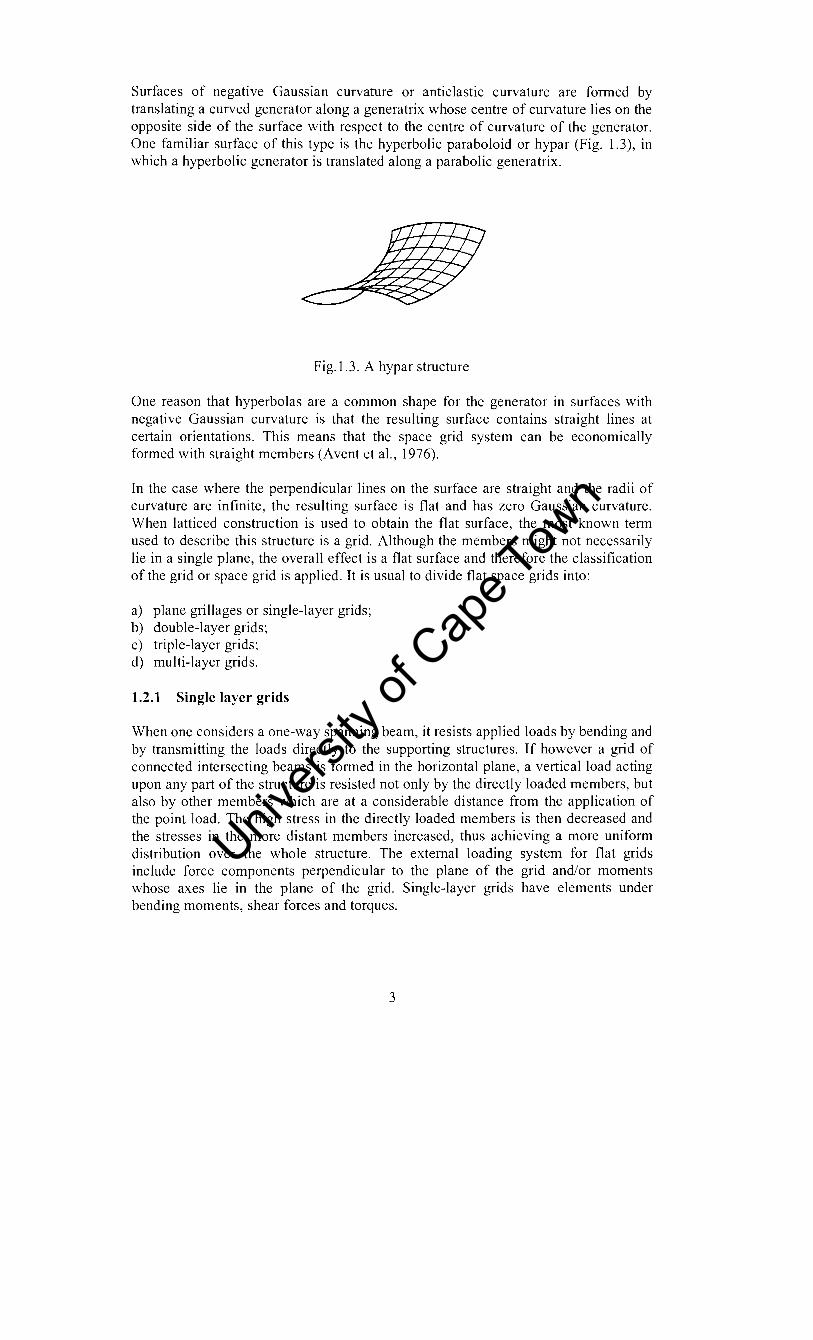
Surfaces of negative Gaussian curvature or anticlastic curvature are formed by translating a curved generator along a generatrix whose centre of curvature lies on the opposite side of the surface with respect to the centre of curvature of the generator. One familiar surface of this type is the hyperbolic paraboloid or hypar (Fig. 1.3), in which a hyperbolic generator is translated along a parabolic generatrix.
Fig.I.3. A hypar structure
One reason that hyperbolas are a common shape for the generator in surfaces with negative Gaussian curvature is that the resulting surface contains straight lines at certain orientations. This means that the space grid system can be economically formed with straight members (Avent et al., 1976).
In the case where the perpendicular lines on the surface are straight and the radii of curvature are infinite, the resulting surface is flat and has zero Gaussian curvature. When latticed construction is used to obtain the flat surface, the most known term used to describe this structure is a grid. Although the members might not necessarily lie in a single plane, the overall effect is a flat surface and therefore the classification of the grid or space grid is applied. It is usual to divide flat space grids into:
a) plane grillages or single-layer grids; b) double-layer grids; c) triple-layer grids; d) multi-layer grids.
1.2.1 Single layer grids
When one considers a one-way spanning beam, it resists applied loads by bending and by transmitting the loads directly to the supporting structures. If however a grid of connected intersecting beams is formed in the horizontal plane, a vertical load acting upon any part of the structure is resisted not only by the directly loaded members, but also by other members which are at a considerable distance from the application of the point load. The high stress in the directly loaded members is then decreased and the stresses in the more distant members increased, thus achieving a more uniform distribution over the whole structure. The external loading system for flat grids include force components perpendicular to the plane of the grid and/or moments whose axes lie in the plane of the grid. Single-layer grids have elements under bending moments, shear forces and torques.
3
Univers
ity of
Cap
e Tow
n

The reason for classifying a flat grid as a space structure is that its external load and displacement components do not all lie in the plane that contains the (idealised) configuration.
Fig. 1A. A single-layer grid
There are various types of single-layer grid structures used in civil engineering practice. Fig.l.S below illustrates two-way, three-way and four-way patterns.
. i .
! I I
I
. I • i
i
i ! I i
(a) (b)
Two-way grids
(c) (d) Three-way grids
4
Univers
ity of
Cap
e Tow
n

(e) (f) Four-way grids
Fig.1.5. Some basic patterns of single-layer grids
The two-way pattern, shown in Fig.I.5a, is the simplest pattern of flat grids. It consists of two sets of interconnected beams that run parallel to the boundary lines. The diagonal pattern, shown in Fig.l.5b, consists of two parallel sets of interconnected beams that are disposed obliquely with respect to the boundary lines. Figs.1.5c to 1.5f shows some basic three- way and four-way grid patterns.
The basic grid patterns of Fig. 1.5 are frequently used in practice. However, there are also many other grid patterns that are commonly used. These patterns are derived by removal of some elements from the basic patterns of Fig.I.5. The most popular is a rectangular grid in which the intersecting elements are perpendicular to each other and to the supporting walls. The diagonal grid is often used because of its greater rigidity, which leads to a substantial reduction in the deflections.
The fundamental difference between diagonal and rectangular grids is, in the former the beams are of varying length L and therefore even if all the beams are of the same cross-sectional dimensions and have the same flexural rigidity EI, their relative stiffness EIIL varies considerably. This means that the shorter corner beams, owing to their greater relative stiffness, in effect provide intermediate supports for the longer diagonal beams which thus become continuous beams on yielding supports with overhangs at the end (Makowski, 1981).
Single layer grids are suitable for short spans (up to 10m for steel grids), after which they become less economical. For longer spans, layered grids are more suitable as they provide an economical solution.
1.2.2 Layered space grids
They consist of parallel horizontal layers of chord elements connected with a pattern of vertical and/or inclined web elements between adjacent grids. Such a structure is referred to as either a space frame or space truss depending on the type of bracing between the two layers and the method of connecting the members.
A space truss relies on truss action achieved through full triangulation of the structure. It is commonly composed of nominally 'pin-ended' bars or members connected
5
Univers
ity of
Cap
e Tow
n
between 'node' joints. The loads on this structure are idealised as being applied directly to the node joints so that the members carry predominantly axial loads only.
Space frames (in engineering sense) are generally not triangulated, have at least some joints which are rigid (if not all) , and resist the applied loads by a combination of bending, shear and axial forces in all elements, even when loads are only applied on joints.
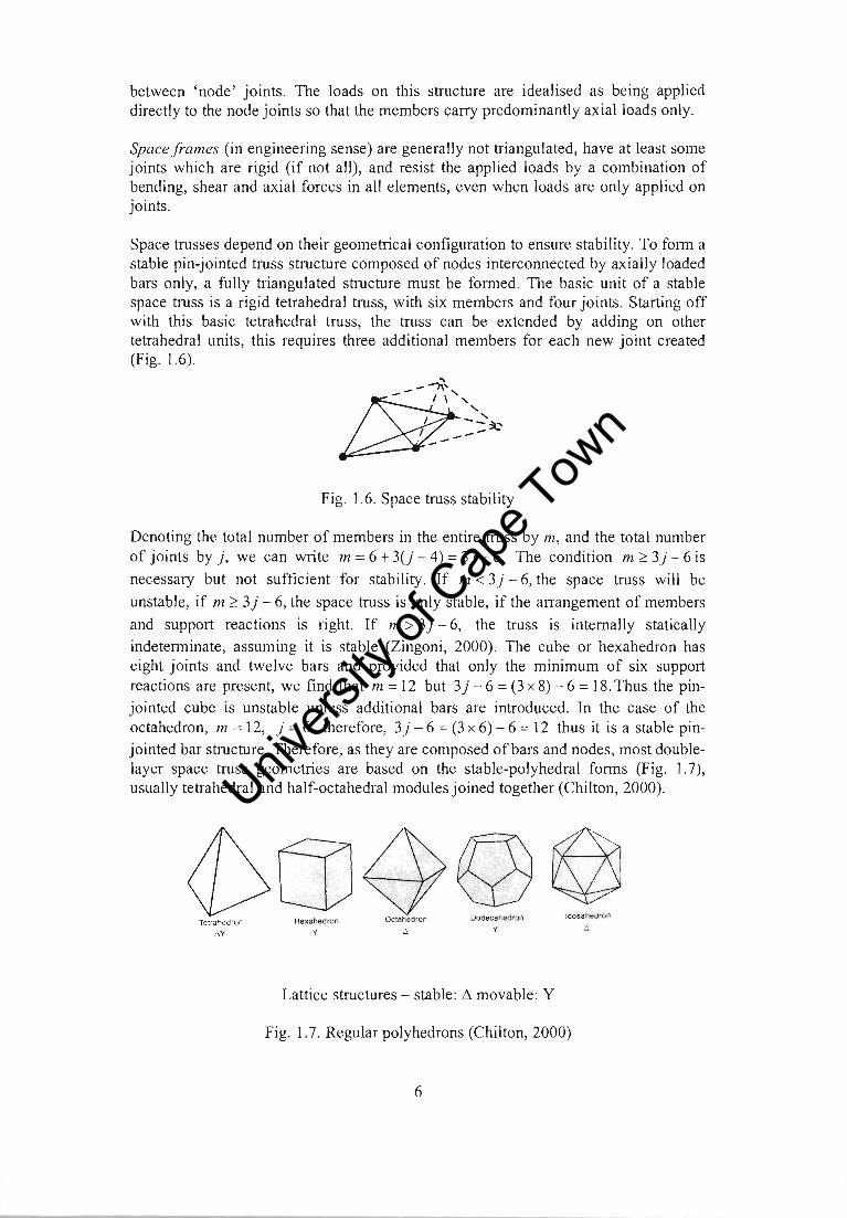
Space trusses depend on their geometrical configuration to ensure stability. To form a stable pin-jointed truss structure composed of nodes interconnected by axially loaded bars only, a fully triangulated structure must be formed . The basic unit of a stable space truss is a rigid tetrahedral truss, with six members and four joints . Starting off with this basic tetrahedral truss, the truss can be extended by adding on other tetrahedral units, this requires three additional members for each new joint created (Fig. 1.6).
- -""""\.
[SP-- / I \ '~~~ I __ -
--Fig. 1.6. Space truss stability
Denoting the total number of members in the entire truss by m, and the total number of joints by), we can write m=6+3(j-4)=3)-6. The condition m?3)-6is
necessary but not sufficient for stability. If m < 3) - 6, the space truss will be
unstable, if m ? 3) - 6, the space truss is only stable, if the arrangement of members
and support reactions is right. If m > 3) - 6, the truss is internally statically
indeterminate, assuming it is stable (Zingoni, 2000). The cube or hexahedron has eight joints and twelve bars and provided that only the minimum of six support reactions are present, we find that m = 12 but 3) - 6 = (3 x 8) - 6 = 18. Thus the pin
jointed cube is unstable unless additional bars are introduced. In the case of the octahedron, m = 12, ) = 6, therefore, 3) - 6 = (3 x 6) - 6 = 12 thus it is a stable pin
jointed bar structure. Therefore, as they are composed of bars and nodes, most doublelayer space truss geometries are based on the stable-polyhedral forms (Fig. 1.7), usually tetrahedral and half-octahedral modules joined together (Chilton, 2000).
~[jJ4>g~ Terrar.03dron Hexahedron Octahedron Oodecaneoron Icosahedron
~ y t. .w
Lattice structures - stable: ~ movable: Y
Fig. 1.7 . Regular polyhedrons (Chilton, 2000)
6
Univers
ity of
Cap
e Tow
n
1.2.2.1 Double- layer space grids
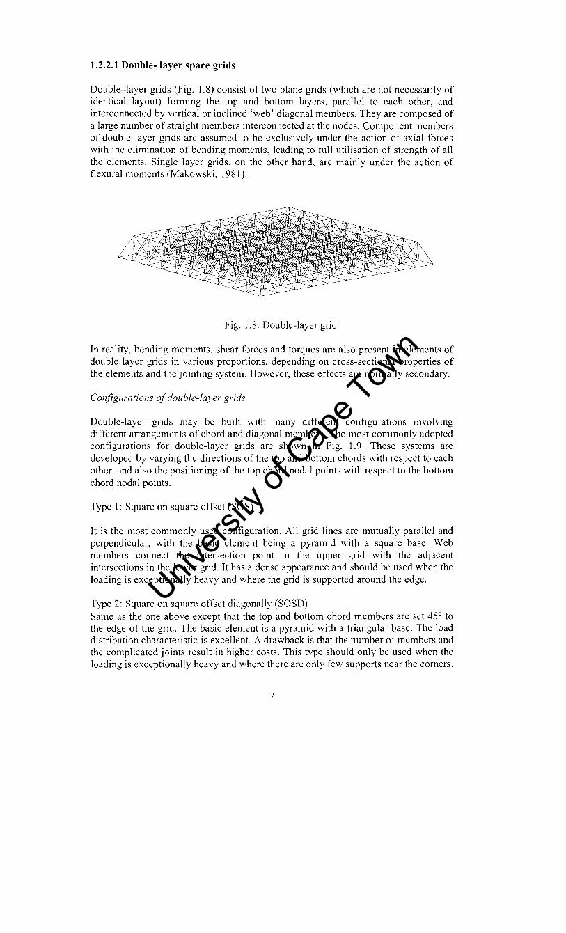
Double-layer grids (Fig. 1.8) consist of two plane grids (which are not necessarily of identical layout) fonning the top and bottom layers, parallel to each other, and interconnected by vertical or inclined 'web' diagonal members. They are composed of a large number of straight members interconnected at the nodes. Component members of double layer grids are assumed to be exclusively under the action of axial forces with the elimination of bending moments, leading to full utilisation of strength of all the elements. Single layer grids, on the other hand, are mainly under the action of flexural moments (Makowski, 1981).
Fig. 1.8. Double-layer grid
In reality, bending moments, shear forces and torques are also present in elements of double layer grids in various proportions, depending on cross-sectional properties of the elements and the jointing system. However, these effects are nonnally secondary.
COl/jigurations of double-layer grids
Double-layer grids may be built with many different configurations involving different arrangements of chord and diagonal members. The most commonly adopted configurations for double-layer grids are shown in Fig. 1.9. These systems are developed by varying the directions of the top and bottom chords with respect to each other, and also the positioning of the top chord nodal points with respect to the bottom chord nodal points.
Type 1: Square on square offset (SOS)
It is the most commonly used configuration. All grid lines are mutually parallel and perpendicular, with the basic element being a pyramid with a square base. Web members connect the intersection point in the upper grid with the adjacent intersections in the lower grid. It has a dense appearance and should be used when the loading is exceptionally heavy and where the grid is supported around the edge.
Type 2: Square on square offset diagonally (SOSD) Same as the one above except that the top and bottom chord members are set 45° to the edge of the grid. The basic element is a pyramid with a triangular base. The load distribution characteristic is excellent. A drawback is that the number of members and the complicated joints result in higher costs. This type should only be used when the loading is exceptionally heavy and where there are only few supports near the comers.
7
Univers
ity of
Cap
e Tow
n

Type 3: Square on larger square (SOLS)
It is similar to 'square on square offset' in many ways. The main difference is that the bay size of the lower chords is set at twice that of the top chords. It is suitable when high level of natural light is required, as there are large openings through which the grid gives an unobstructed path for daylight. Suitable when there are supports around the edge and where norrnalloads are to be carried. The axial loads in the lower chords will be roughly twice the value of the loads in the upper chords.
Type 4: Square on larger square set diagonally (SOLSD)
It is similar to type 3 except that the top and bottom chord members are set 45° to the edge of the grid. Suitable when the supports are near the comers.
Type 5: Square on Diagonal Square (SOD)
It has the lower chord grid set 45° to the top chord grid. Due to its open arrangement, it gives little obstruction to daylight. The arrangement with mansard edge (supported at the bottom nodes) is best when the supports are around the edges whilst that with the cornice edge (supported at the top nodes) is suited to either support around the edges or near the comers.
Type 6: Diagonal on square (DOS)
It has top members set at 45° to the edge of the grid, whilst those in the bottom layer run parallel. It is one of the most efficient grid arrangements.
Type 7: Triangle on triangle offset (TOT)
Both chord grids are triangular but the intersections in the lower grid occur below the centres of alternate triangles in the upper grid. The web members connect the intersection points on the top grid with the adjacent intersection in the lower grid.
Type 8: Triangle on hexagon
The upper (denser) grid is triangular and the lower (more open) grid is hexagonal due to the removal of some lower chord and web elements from the triangular on triangular grid.
8
Univers
ity of
Cap
e Tow
n

Type 1 Square on Square, offset
Type .. Square 011 larger Square, sel dlagonaHy
Type 2 Square on Square, set diagonally
'x' , I ,
'){ , I ,
", X , I , ,
Type 5
, , " " , ,
, ' ,>' , '
/ '
'v' " , ,
, , " " , ,
Square 011 SqUare, diagonal
Fig. 1.9. Double-layer grid configurations
, ),,'- ' '
, "
, , , ~- .,...- ~'\
, I, ' , , I ' , ,
, I, , , ,)~,
/ :f~ , I
, 1/ ~: ' I /
, /
)~- -;iE - " ." / I , " , , I ' , , , I , 'J, , .... , ......... ..' , I ' I
Type 3 Square on larger square
TypeS DIagonal 011 Square
Additional varIatIons can be introduced by changing the size of the top chord grid with respect to the bottom. All the systems except the 3-way grids have a consistent feature of having the components of each chord orthogonal. More open grid geometries are often possible in the lower layer of a double layer grid because the members are normally in tension. Lower tension chords may be longer than the upper compression members.
1.2.2.2 Triple layer grids
Fig. 1.10. Triple ~layer grid
The majority of space grid applications employ systems of the double-layer type. However triple-layer grids are also in use, particularly in covering very large spans,
9
Univers
ity of
Cap
e Tow
n

and where double-layer grids would need heavy members and could be less economical. With triple-layer grids, the number of chord panels in each direction is increased leading to the grid members being shorter, less slender and with smaller internal forces. Hence in triple-layer grids the members are typically of smaller sizes and the joints are easier to manufacture and assemble, than in equivalent double layer grid.
The choice between a double-layer and triple-layer system is usually easy in small and very large applications, but is not as straightforward in applications with intermediate spans. Consideration must also be given to the following disadvantages usually associated with triple-layer systems: • A triple-layer grid uses significantly more members and nodes; a consistent
feature that can affect the structure's cost competitiveness. • A triple-layer system uses a larger depth, leading to a taller structure subjected to
higher wind loads, and requiring more cladding.
1.2.2.3 Multi-layer grids
These are feasible for various applications especially in large span structures where the use of triple layer grids would be less economical. Other applications include the columns of layered grids supported on four corners only where the reactions are excessive.
1.2.2.4 Advantages of layered space grids
• Load sharing
The prime advantage of using space grids is that generally all elements contribute to the load carrying capacity of the structure. This reduces the cost of construction of supporting structures, as the maximum column and foundation loads are lower compared to those of planar beams and trusses. Maximum deflections are reduced compared to planar structures of equivalent span, depth and applied loading, assuming that the structural elements are similar.
• Installation of services
The open nature of space grids allows the installation of mechanical and electrical services and air-handling ducts within the structural depth and they can often be installed on the ground itself, thus obviating the hazards of working at heights. Their fixing is simplified, as there is a regular system of supports available, thus reducing or even eliminating the need for secondary steelwork. If heavy equipment is to be installed within the grids, loads can be applied directly at the nodes thus minimising bending moments in the chords.
• Robustness
Space grids are highly statically indeterminate such that buckling of any compression member under a heavy concentrated load will not lead to total collapse of the whole structure unless critical elements like highly stressed compression chords or web members adjacent to individual column supports are removed or weakened. The
10
Univers
ity of
Cap
e Tow
n

redundancy of space grid structures also assists with their resistance to damage from fire, explosion or seismic activity. In the case of fire there may be localised damage of the space grid, which allows the heat and smoke or force of the explosion to escape.
• Alodular components
Space grids are assembled from prefabricated parts, which are precisely made in the factory ensuring accuracy and speed of erection. Because of their modular nature space grids can be extended without difficulty and even taken down and reassembled elsewhere but this depends on the material used. Each of the components is light, facilitating transportation.
• Freedom of choice of support locatioll
Space grids can be supported at any node of the grid and at practically any location in plan. This gives the designer considerable freedom in space planning beneath the grid as columns can be concealed on lines of internal partitions.
• Regular geometly
The regular pleasing pattern provides an extremely attractive appearance, which becomes a valuable feature in many architectural applications. That is why many architects do not use any false ceiling; they leave the underside of the structures exposed in their designs.
• Unskilled Labour
Because space grids are put together by using precise, factory-made components, unskilled labour is adequate for their assembly and erection.
REFERENCES
1. Avent, R. R., Bass, L.O., Bradley, J.E., Buchert, K.P., Chung, S.W., Holzer, S., Howard, T.c., Schnobrich, c., Sharp, M.L., Teng, W.E, Wright, D. and Shennan, D.R. (1976). Latticed Structures: State of the art report, Journal of Structural Division, Proceedings ofASCE, Vol. 102 (11), pp. 2197 - 2226.
2. Chilton, J. (2000). Space Grid Structures, 1 sl ed., London: Architectural Press. 3. Makowski, Z.S. (1981). Allalysis, Design alld COllstructioll of Double Layer
Grids, 1 st ed., London: Applied Science Publishers. 4. Zingoni, A., Mwakali, J.A. and Salahuddin, A. (2000), Theory and Analysis of
Structures, 1 st ed., Nairobi: Unesco Publishers.
11
Univers
ity of
Cap
e Tow
n

CHAPTER 2:
SPACE GRIns: A GENERAL REVIEW
2.1 HISTORICAL DEVELOPMENT
Space grids originated with railroad truss bridges in the 19th century, although the truss system dates back much earlier. Railroad expansion not only brought the development of many common truss shapes, but also led to the development of modem truss analysis. Truss development led to an understanding of how vector based structures functioned, and to an understanding of the importance of the nodes (Bradshaw el ai, 2002). In this thesis the term 'space frame' is referring to all space grids that is inclusive of all systems that are actually space trusses. For a clear distinction reference should be made to Chapter 1.
Some authors (e.g. Chilton, 2000) argue that Alexander Graham Bell invented space frame structures in the early 1900s, others say August Foppl published the first treatise, Them'ie des Fasclnverks, on space frame structures in 1880. This treatise aided Gustave Eiffel with the analysis of his tower in 1889. Bell's obsession with the development of the first flying machines led him to investigate light structural systems. He developed a series of kites that used a tetrahedral structure, and then built architectural objects such as a windbreak wall and an observation tower in 1907, Beinn Bhreagh, USA using the tetrahedral structure (Bradshaw el ai, 2002).
The next step in the evolution of space frame structures was the development of the lamella structural system, invented in 1908 by Zollinger in Germany and refined by Keiwitt in the United States. The roof system is distinctive for its diamond-patterned vaulting, with the sides made of short members of equal length as to all lamellas. The nodal principles learned from the joining large numbers of lamellas particularly benefited the nodal development of space frame structures. One of the most notable lamella buildings was Nervi's precast concrete airplane hangar, which was constructed in 1938.
The first major commercial development of space frame structures began in the late 1930s. In 1939 Attwood received a patent for his space frame system, which latter became known as the Unistrut system. In 1940 Mengeringhausen developed a space frame system in Berlin, which latter developed into the Mero system in 1943. The system consists of individual tubular members connected at 'ball' -shaped node joints. The aesthetic appeal and popularity of this system has endured to present day, confirmed by the many alternative tube and ball systems now available. In 1945 Wachsmann and Weidlinger received a patent for their Mobilar system, which differed significantly from the Mero and Unistrut systems in that the nodes were not separated from the strut, and the geometry of connection mechanism was not as rigid as in earlier systems (Bradshaw el al,2002).
Throughout the 1940s and 1950s, these systems continued to be refined as others were being constructed. In the UK, during the 1950s, Denings of Chard developed the Space
12
Univers
ity of
Cap
e Tow
n

Deck system based on bolting together prefabricated steel pyramidal modules (l.22m x 1.22m) in plan and 1.05m or 0.61m deep. With only slight modifications to module dimensions and materials, Space Decks have been widely and successfully used for roof and floor structures ever since. The system was adopted for roof and floor construction of army barrack blocks in the early 1960s (Chilton 2000).
During the 1950s and 1960s, space grid systems were profiteering all over the world as architects explored the relatively new aesthetics of the modular grids and engineers experimented with alternative jointing systems, materials and configurations. In this period, Buckmister Fuller developed the Octet Truss system. The name is derived from the octahedron-tetrahedron geometry formed by lines linking the centres of spheres packed together in a continuum so that each sphere is surrounded by 12 more in close contact. Members of the space grid then follow these lines. The Ford Rotunda Building Ford River Rounge Plant, Dearden, Michigan, constructed in 1953, used aluminium Octet Truss grids to form the faces of a 28.4m diameter geodesic dome weighing only 8.5 tonnes (Chilton 2000).
Geodesic domes have been developed from many materials including wood, steel, aluminium, concrete, and bamboo. The geodesic domes that are considered a part of space grid structures, such as the US Pavilion at 1967 Montreal World's Fair, are those whose structure is along the arc joining two points. Geodesic domes whose structure is along the surface of the polygons defined by arcs, such as the Kaiser Dome, are considered shell structures (Bradshaw el ai, 2002).
In France, Stephane Du Chateau developed Tridirectionelle S.D.C (1957), Pyramitec (1960), Tridimatic (1965). In Canada, the Triodetic system, predominantly using aluminium as the material for bars and joints was introduced on commercial basis in 1960, by Fentiman Bros. of Ottawa. The system was innovative in its use of extruded tubular members, flattened or coined at their ends and a solid extruded aluminium hub with slots that matched the coining of the tubes. The system was applied for a totally demountable aircraft hanger (21m wide, 20m deep and 9.8m high) that was developed by the Royal Canadian Air Force. The Netherlands Pavilion at Expo 1967, Montreal, that was 74m long, 22.5m wide and 18.3m high was constructed using an external structure of Triodetic space grid.
At round the same time, the wider use of electronic computers and the development of programs to enable space grid structures to be analysed more accurately increased confidence in their use for large and longer span structures. During the late 1960s and early 1970s many of the pioneering space grid systems were superseded by the secondgeneration systems. British Steel Corporation (Tubes Division), now British Steel Tubes and Pipes, developed the Nodus system with a small range of sophisticated standard node joints, developed to suit their tubular sections and produced in different sizes with varying load qualities. Kotable examples of long-span space grids constructed in 1970 and 1973 were the British Airways maintenance hangars. The hangar roofs were diagonal double layer grids 3.66m deep and provided a column-free area of67m by 138m in plan.
13
Univers
ity of
Cap
e Tow
n

In the 1980s and early 1990s the Cubic Space Frame Space grid and Harley Space grid systems emerged in the UK being respectively a modular space frame, a development of the Unibat space truss system and a modified version of the Australian Harley space truss system.
As mentioned earlier the impact upon the development of space structures was provided by electronic computation. The introduction of computer-aided design (CAD), greatly affected the design of space structures. Dr Nooshin of the University of Surrey developed an algebra (Formex) in 1975 that is suitable for representation and processing of configurations of space structures. This made easier the problem of data preparation and graphics in the computer-aided design processes (Makowski, 1981).
Formex algebra has proved to be an extremely efficient tool for dealing with complex configurations of 3-dimensional structures. Dr Nooshin is also responsible for the development of a programming language Formian, for a comprehensive coverage of his Formian complex. Using Formian, the information generated about any space structure may be rapidly deployed for graphic visualisation or may be submitted as input data to analysis packages. The advent of computer aided design brought a major change for prefabricated space structures. In the early periods of development of space structures the main emphasis was towards standardisation and use of identical modular units, now with the vastly improved computer techniques, designers are realising the advantages of oneof-a kind configurations (Makowski, 1981).
2.2 BEHAVIOUR OF DOUBLE-LAYER GRIDS
Different space truss configurations result in considerable variation in truss structural performance, constructional characteristics, competitiveness against alternative solutions, and hence the suitability for a specific application. For instance, altering the truss configuration leads to a change in member stress distribution, stiffness, material consumption (and hence weight), degree of redundancy and sensitivity to local damage.
2.2.1 Stiffness
Schmidt and Morgan (1974a) studied the behaviour of square-on-square (SOS), squareon-square set diagonally (SOSD) and triangle-on-triangle (TOT) configurations (refer to Chapter 1) with edge supports and corner supports only. In terms of flexural stiffness when edge supported, SOSD is the stiffest followed by TOT and finally SOS. The stiffness contour shapes for all the configurations were found to be approximately the same. The research showed the advantage of inclining chords 45° to the line of support. It should be noted that besides this advantage of SOSD over SOS it does not mean that it will always be a better arrangement. Stiffness is usually of secondary importance, other layouts may have more favourable force distributions.
Schmidt and Morgan revealed that when corner supported, SOSD is a deficient system because its zero torsional rigidity does not permit load transmission to the supports via
14
Univers
ity of
Cap
e Tow
n

the free edges. No clear advantage exists in the choice of one layout against another from the stiffness point of view when corner supported. A shift from edge supported to corner supported boundary conditions causes a considerable decrease in stiffness.
El-Sheikh (1998) also did a comprehensive study on the effects of adopting different configurations. The study focussed on the behaviour of SOS, square-on-Iarger square (SOLS), square-on-diagonal square (SOD) and diagonal-on square (DOS) configurations. The study revealed that for space trusses designed to have the same strength, SOS trusses usually have the highest flexural stiffness followed in a descending order by SOD, SOLS and DOS trusses.
2.2.2 Stress distribution
Schmidt and Morgan (l974a) showed that TOT trusses have lowest maximum chord forces when edge supported, in comparison to SOS and SOSD trusses of the same dimensions. In SOS trusses the maximum forces occur at the centre whilst in SOSD trusses they occur well away from the truss centre along the diagonals changing in sign becoming tensile near the corners for the top chord members. The study revealed that TOT trusses have a similar force distribution as SOSD trusses. Overall, the study showed that the forces are more even in SOS trusses compared to the other configurations.
Change of support conditions from edge supports to corner supports introduces a considerable change in behaviour. In SOS trusses, the highest forces occur at the centre of the edges and are parallel to the edges, while falling away to low values at the truss centre. In TOT trusses the force distribution is characterised by high, relatively local forces near the corner supports.
Makowski (1981) carried out a study on the behaviour SOD and DOS double-layer grids having equal member sizes and uniformly distributed loads. Comparison was done on edge supported down to corner-supported grids. A DOS grid was found to have the maximum force as tension in the bottom and almost twice compression in the top. In the case of a SOD grid the maximum force was the same in both top and bottom chord members and was less than that of a DOS grid. The investigation reviewed that a SOD grid has an even stress distribution and a slight reduction in deflection as compared with a DOS grid.
The study on the change of supports from being edge supported through to corner supported showed that the effect of boundary conditions on member forces and deflections is small provided that there is at least one intermediate support at the middle of each edge.
EI-Sheikh (1998) showed that in terms of stress distribution SOS trusses have the least standard deviation values, followed in an ascending order by SOLS, SOD and DOS trusses.
15
Univers
ity of
Cap
e Tow
n

Looking at the work done by Schmidt and Morgan (1974a) and El-Sheikh (1998) overall, SOS space trusses clearly demonstrate the best performance relative with other configurations. It only remains to be decided whether their use is economical. The detrimental factor is undoubtedly the cost of the truss joints, and hence the space truss system to be employed.
2.2.3 Sensitivity to geometric imperfections
A space truss loading carrying capacity is greatly affected by the presence of geometric imperfections. These imperfections include member lack of fit that induces residual forces and slip that occur in some joining systems (Schmidt, et al. 1982 and EI-Sheikh, 1995). Schmidt showed that highly redundant space trusses are particularly sensitive to imperfections leading to significant reductions in their potential ultimate load carrying capacities compared to systems of low degree of indeterminacy. The sudden collapse of Hartford Coliseum, Connecticut, USA, space roof structure in 1978 under one-half of its design load is known to have been caused by these effects (Smith and Epstein, (1980), Thornton and Lew (1984) and Karpov, et al. (2003). EI-Sheikh found that trusses with imperfect compression members had their strength more reduced compared to those with imperfect tension members. Contrary to the findings by Schmidt, et ai., EI-Sheikh proved that the more dense triple-layer grids are less sensitive to imperfections when compared to double layer trusses.
Both Schmidt and EI-Sheikh employed a deterministic approach to investigate the changes in structural performance due to given lack of fit of particular members at known spatial locations (Karpov, et ai. (2003». Karpov argues that a statistical description of the initial stress problem is better. Affan and Canadine (1989) accomplished such an analysis to obtain approximate distributions for the initial bar stresses in a two layered space grid, due to given standard deviations in length, from a series of 200 computer simulations (the numerical Monte-Carlo simulations). Karpov (2003) used a cheap semi-analytical approach that employs Born-von Karman periodic boundary conditions.
2.3 REHA VIOUR OF TRIPLE-LAYER GRIDS
Not much information is available in literature on the behaviour of triple-layer grids; the infornlation reported in this section is based on the study done by one research group for Constrado in 1980. According to Bunni et al (1980), the Space Structures Research Centre of the University of Surrey has since 1973 carried out a number of analytical and experimental investigations on triple layer grids. One of the grids analysed had the top and bottom layers formed of diagonal grids, while the middle layer followed the rectangular pattern. Various boundary conditions, as well as types of loading, were considered. The study revealed that removal of the middle-layer for that particular bracing produced instability of the whole structure. It showed that the middle-layer grid, although positioned in the neutral plane of the structure and carrying only very small loads in comparison with the top and bottom layers, obviously had a fundamental
16
Univers
ity of
Cap
e Tow
n

function in providing lateral restraint against movement and thus stabilised the whole structure.
Bunni et al (1980) extended the research to cover a variety of triple-layer grids after realising that some configurations lead to better structural performance, greater rigidity or smaller cost than others. The grids studied were of DOS, SOSD, SOLS, SOD, and SOS configurations (the types refer to the configuration of the top and the middle layer). The configurations were such that the top and bottom configurations were the same. Another configuration, which combined DOS and SOS configurations, was included in the analysis. The study revealed that DOS and DOD configurations if supported along the edges and braced have very large negative forces at their comers whilst SOLS and SOS have small uplifting forces at the comers and more uniform distribution of other reactive forces along the supports. The study showed that the forces in the middle layer are generally very small in comparison with the forces in the other layers with exception of the grid that had different top and bottom layouts which had forces appreciably higher than those in other types. This was due to the difference in densities of the top and bottom layers producing a shift in the neutral axis of the system.
It was also noted that removal of the middle layer produced instability in DOS grid. For those that remained stable after the removal of the middle layer, stress distribution was not affected in any significant way since the middle layer previously carried only small loads. Change of support conditions to corner supports caused a very substantial increase in the maximum loads in the top and bottom members though these were highly localised at the comers.
2.4 COMPARISON OF DOUBLE AND TRIPLE-LAYER GRIDS
Apart from the study done by Bunni el al. (1980), EI-Sheikh (1999 (a)) is the only researcher who seems to have done a comparative study of the behaviour of double- and triple-layer space trusses (SOS type). Focus was on the weight (material consumption), stiffness and number of joints and members. A number of conclusions can be drawn from his work.
Weight
For the same depth, triple-layer trusses are heavier than their equivalent double-layer trusses. Allowing a depth increase in triple-layer trusses results in a gradual improvement in competitiveness. An increase of 100% in depth resulted in triple-layer trusses being 33.6% lighter, on average than their double layer counterparts.
Other points of significant importance in his study include: • Changing truss aspect ratio does not lead to any significant variation in the unit
weights of one-way trusses, if the main span is kept unchanged. • The unit weights of two-way trusses (with two- and three-layers of chord members)
increase with aspect ratio. • Unit weight is approximately inversely proportional to depth.
17
Univers
ity of
Cap
e Tow
n

Stiffness
Space truss stiffness (total surface load required to produce a unit central sag) can also be used as a measure of the efficiency and competitiveness of double- and triple-layer systems. EI-Sheikh discovered that double-layer trusses outperform their triple-layer equivalents (with the same depth) on a stiffness/weight basis. As the depth of the triplelayer trusses is increased their stiffness/weight ratio becomes superior to those of doublelayer trusses.
Other conclusions that can be drawn from the same study include: • The flexural stiffness per unit weight of one-way trusses (both with two and three
layers of chord members) does not change significantly in response to variations in truss aspect ratio.
• The flexural stiffness per unit weight is proportional to depth in both two and three layers of chord members.
• The flexural stiffness per unit weight of two-way trusses reduces gradually with higher aspect ratios down to levels close to those of one-way trusses.
• Two-way trusses are stiffer than one-way trusses but this superiority deteriorates with increase in aspect ratio.
Number of joints and members
In most space truss systems, truss members are prepared with member end fittings and joined together using special node connectors. The member end fittings and node connectors are usually sophisticated components that are expensive to produce and hence account for a large percentage of the total cost of the structure. For this reason, the number of joints and members (and hence member end fittings) included is a major consideration in any space truss design.
Triple-layer trusses typically involve more joints and members, a consideration that should be taken into account when comparing the two systems in space truss designs. In the study by El-Sheikh it appears that triple-layer trusses employ an average of 47.4% more joints and 73.7% more members than equivalent double-layer trusses. This finding must, however, be seen in tandem with the fact that the joints and members of triple-layer trusses would typically be of smaller size, and hence could be easier to manufacture and assemble.
2.5 FAILURE STUDIES OF SPACE GRIDS
Space trusses represent one type of structure whose postbuckling behaviour is very sensitive to both geometric and material nonlinearities. Research on the non-linear responses of space trusses has been abundant. Jagannathan el al. (1975) and Rothert et al. (1981) investigated the snap-though buckling of reticulated space trusses. Using the vector iteration method, Papadrakakis (1981) studied the postbuckling behaviour of space structures. Murtha-Smith (1988) investigated the progressive failure of double-layer grids
18
Univers
ity of
Cap
e Tow
n
using an alternative path analysis. To meet the need for an analysis strategy capable of following the elastic, progressive failure of space truss systems, an updated Space Truss Analysis Program (ST AP) has been developed by Hill et al. (1989). Blandford (1996) developed a concept of modelling of elastic and inelastic member behaviour, coupled with a geometrically non-linear finite element model. The model traces the sequence of localized buckling, and inelastic member response. Yang et al. (1997) proposed an incremental analysis procedure based on a rigorous updated Lagrangian formulation for analysing the postbuckling behaviours of space trusses, considering the effects of member buckling and yielding.
2.6 ANALYSIS OF LAYERED GRIDS
There are two distinct approaches (the continuum and finite element analysis) to the analysis of space trusses and hence leading to member sizes and forces. The application of electronic computers now enables designers to carry out the analysis (finite element analysis) of space trusses with much greater accuracy than ever before and with a marked reduction in time involved. The practical design of these structures is always based on the assumption that the cross-sectional areas of members and their shape are known before analysis. Approximate methods (e.g. the continuum approach) have been developed several years ago based on various simplifications in modelling truss structures. The accuracy of each method depended on the suitability of its simplifications and how they fitted actual truss conditions. As an aid to computer analysis there now exists packages for generating space truss configurations, details of which are given at the end of this section.
2.6.1 The Continuum Approach
For the purposes of preliminary design, it is sufficiently accurate to replace the grid with their continuum equivalent. By considering an equivalent plate, with one degree of freedom at each joint the problem size is reduced by six fold (Renton, 1970, Flower & Schmidt, 1971 and Makowski, 1981). Plate analogy allows the designer to find deflections, moments and shears at selected points for example at the mid-span of the structure, without setting up all equations and without the necessity to solve them as is the case for conventional techniques. From these solutions the moments and shears are transformed back into the particular member forces. The transformation between the truss and the plate is dependent on the framework geometry selected, and can be rather complex for non-symmetric patterns. Soare (1975) discussed an approximate method for the analysis, the equivalent continuum, and the difference in behaviour due to the bar orientation with respect to the boundary and plates with coefficients for the design of a simple square mesh double-layer grid.
Tamma and Saw (1987) as well as Bhagavan and Gopalakrishnan (1993) presented analytical results of space structures via continuum and discrete methods. Noor and Russell (1986) provided some discussion of detailed theoretical developments for an approximate continuum method for space frames including hexagonal on triangular grids. Ramaswamy (2002) outlines how different configurations of space trusses can be
19
Univers
ity of
Cap
e Tow
n

analysed using the plate analogy method. El-Sheikh (1996) argued that the continuum method, though approximate and only used for preliminary analysis, finding the solution is still time consuming. He proposed two quick methods for the initial design and rough cost estimation, the girder analogy method and the slab analogy. Although these methods are simple one has to be careful in where to apply them, as they depend on the length-towidth ratio and the boundary conditions.
2.6.2 Methods based on finite-element discretization
This method relies on the use of a powerful digital computer for the solution of the actual truss. The stiffness method of analysis is used and any of the available commercial computer programs may be used. This approach is free from the limitations of the continuum method since the design is not dependent on the existence of standard solutions for the equivalent plate. It is also not dependent on the transformations back to member forces (Kleen, 1975).
The stiffness method starts by forming a relationship between the member force and its elongation. The elongation of a member is related to the movements of the actual joints in the structure that it is connected to. Each joint in the truss must be in equilibrium with the applied loads and so each member force meeting at the joint is summed in the x, y, z directions and equated to the applied load at the joint. The unknown quantities left are joint displacements. Each joint may move in the 3 directions giving the total number of unknowns to be 3 times the number of joints in the truss. These unknowns are solved for in a simultaneous manner and this is where the bulk of the computcr time and cost is spent. Following the determination of the joint displacements, the individual member forces are found by back-substitution
When a large space truss is analysed by a computer not all the truss need to be fed into the machine since the results for some portions of the truss can be deduced from symmetry considerations (Schmidt and Morgan, 1974b). If symmetry is to be used to reduce the problem sizc then great care should be exercised in the specification of the displacement conditions along the planes of symmetry as well as carefully adjusting the applied loads and member sectional properties.
Numerous textbooks are available on the finite-element analysis of structures [for example, Zienkiewiez (1977), Bathe (1982)]. Szabo and Tarnai (1993) presented a general theory and numerical techniques based on the coefficient matrix of the equilibrium equations for single- and double-layer pin-jointed grids. There are several structural packages that exist for analyzing space trusses utilising the finite element method and the most common in South Africa are ST AD and Prokon.
2.6.3 Configuration processing
The term "configuration processing" is used to mean the creation and manipUlation of configurations (Nooshin and Disney, 2000). Nooshin in 1975 (Nooshin, 1984) developed
20
Univers
ity of
Cap
e Tow
n
Fonnex algebra, a mathematical system that provides a convenient medium for configuration processing. The concepts are general and can be used in many fields. In particular, the ideas may be employed for the generation of infonnation about various aspects of structural systems such as element connectivity, nodal coordinates, loading details, joint numbers and support arrangement. The information generated is then used for various purposes, such as graphic visualisation or input data for structural analysis. A convenient medium for using the concepts of Fonnex configuration processing is the programming language fFonnian'. 11s origins dates back to the late seventies and various versions of the language have been in use since then. EI-Sheikh (1999 (b)) used the fonnex functions embodied in Fonnian to generate node co-ordinates and member connectivity data required for the structural analysis as reported in his paper on the design of web members in space trusses.
It should be emphasised that configuration processing is not an analysis approach but a data-handling procedure developed in order to reduce costs. Reference should be made to papers by Nooshin and Disney (2000 and 2001) for readers who are not familiar with fonnex algebra fonnulations.
2.7 DESIGN AND CONSTRUCTION STUDIES OF SPACE GRIDS
The details given here refer to metal space grids. No infonnation is available in the literature for the design of space grids made of other materials. Generally the design of space grids of materials other than metals is based on principles of design of steel space grids.
Before any work can be done on the design of the grid it is necessary to detennine the basic geometry. This is the depth (or span/depth ratio), the bay size and the most suitable grid arrangement.
2.7.1 The depth
Floors may have span/depth ratios in the order of 10 to 15 whereas for roofs the ratio is from 15 to depending on the loading and supports (Kleen, 1975). Walker (1980) states that for economic reasons the span/depth ratio should be approximately 20 where supports are distributed around the edges of the grid or approximately 15 where the grid is supported at the corners only or by other systems of supports but where columns are widely spaced.
2.7.2 Bay size
The bay is usually detennined from the grid layout of the rest of the structure, cladding requirements or the member density required to keep the member forces within reasonable limits (Kleen, 1975 and Walker, 1980). The jointing scheme used will influence the selection of the bay size depending on the relative costs of the joints and
21
Univers
ity of
Cap
e Tow
n

members. According Walker, the bay size is a function of the grid depth, being related to the permissible angle between the centerline of the bracing members and the plane of the top or bottom chord members. It is recommended that this angle should not be less than 30° otherwise the loads in the bracing members and their length will be relatively excessive, nor greater than 60° otherwise the density of the bracing members in the grid will become too high. Fig. 2.1 shows the results of the study done by Eberlein (1980) on the effects of increasing the bay size on the weight per unit area. One can see the tendency, for three different types of grids, that with an increase in bay size, the unit consumption of material per unit length of the members steadily decreases. However, the sensible tendency to use longer rather than shorter bars is counteracted by the fact that a length of 3m is the greatest practical length of individual members that can be handled by a worker. If the size (and length) of the bay is greater, then the use of mechanical hoisting equipment becomes imperative.
~I 20
18 '
16 !'---'.-t-I..-141--........... -,<-
12 r----Ij-'~-
10 I-----h----'-<-~-
--"--
1,0 1,5 2,0 2,5
Grid_Ie
Fig. 2.1. The relationship between the bay size of three different configurations of double -layer grids and the amount of structural steel per square metre of the covered area
2.7.3 Grid arrangement
After obtaining some idea on the bay size and depth dimensions the next step would be to consider which grid arrangement might be appropriate for the particular building. The grid arrangements outlined in Chapter 1 have advantages and disadvantages, but generally from the point of overall economy, the grid arrangements that gives the least number of joints and members are usually preferred (Walker, 1980 and lffland, 1982). Iffland states that the finer the grid the less the weight but the penalty is more joints.
2.7.4 Member design
In the design of members, the limit state approach is used. Loads corresponding to the ultimate limit state are applied at the nodes and linear elastic analysis is carried out after sizing the members using preliminary design methods described above. Following the
22
Univers
ity of
Cap
e Tow
n

analysis, the design section incorporates a member selection package, the basic steps involved being (Kleen, 1975b): • Scanning of all the member forces for all loading conditions to record the worst
values of both tension and compression. • Member selection is carried out for each member individually by making reference to
the relevant code of practice. • Member properties are changed and reanalysis is performed, repeating this cycle to
see whether the selected still satisfy the code and joint failure criteria.
2.7.5 Optimization techniques of space grids
Recent advances in generic algorithms and evolution strategies which mimic biological evolution, based on the Darwin theory of the survival of the fittest, have added new and powerful tools to the armoury of the designer for optimizing the final design of space grids to minimum weight (Ramaswamy et al. 2002). These tools have been used for structural optimization by earlier researchers like Goldberg and Samtani (1986) for optimal design of a 10-bar truss, a truss-beam roof truss by Jenkins (1991). Lin and Hajela (1992, 1993) used generic algorithms to find the minimum weight of an 8-bar truss as well as those of a 25 and 75-member truss. Rajan (1995) developed a procedure for carrying out sizing, shape, and topology structural optimization simultaneously.
The optimal design of structural system can be classified as size, shape or topology optimal design. The nature of the design variable determines the type of the optimal design problem. In size optimization, the cross-sectional areas of the members are normally chosen as the deign variables. The objective function, which is the weight, is to be minimized under certain behavioural constraints on stresses and displacements (Ramaswamy, 2002). The dimensions of the members, such as the tubes, that comprise a space truss vary in steps, hence these dimensions have to be regarded as discrete variables of a discrete set. The resulting discrete optimization problem may be stated as follows:
minimize F(s)
subject to g j (s) ::; 0, j = 1 to 111
with Sj ERd i 1 to n
where F(s) is the objective function and g j (s) are constraints. Rd is the given set of
discrete values that the design variable S i (i = 1,2,3, .. " n) can take only from this set.
For an excellent introduction to the concepts of genetic algorithms, the reader is referred to Chapter 1 of Goldberg (1989).
Sudarshan (2000) in his undergraduate thesis developed a program for the optimization of space trusses. The program results were validated with the results obtained from expert system programs that use the principle of fully stressed design (FSD). According to Ramaswamy (2002) and Papadrakakis, et al (1998), the computational efficiency of
23
Univers
ity of
Cap
e Tow
n

evolution strategy methods can further be enhanced by combining them with artificial neural networks (ANNs). A1\TNs follow natural processes, in particular human brain functions.
2.7.6 Methods of construction of space grids
Apart from the summary by Chilton (2000) on the construction of space grids, no other sources have been found in the literature on the studies of construction methods of such structures. According to Chilton, there are several methods of erection for space grids and more than one may be used in the construction of a single grid. It has been noted that the method chosen sometimes depend on the system being used but overall grid size, site access, component size can also be determining factors.
Chilton summarized the commonly used techniques of erection, these include: 1. Assembly of all individual space grid elements or modules on a temporary staging or
scaffolding, in their permanent position. 2. Assembly of space grid elements or modules in the air, by cantilevering from existing
portions of the roof. Usually, individual or small subsets of the members are lifted into position by cranes.
3. Assembly of space grid elements or modules into larger panels (usually on the ground or a slab) before lifting them by crane and connecting them in the air to areas of the grid that have already been installed.
4. Assembly of the whole grid on the ground before lifting it on to the permanent supports by crane in one operation.
5. Assembly of a part or the whole space grid on the ground before jacking or winching it into its final position over temporary or permanent supports.
Method 4 is suitable ifthere is enough space for assembling the grid and good access for cranes. Lifting of the grid should be done such that the individual members are not overstressed and the structure is not pemlanently damaged. Where the area directly below is available but there is access for cranes method 5 is preferred. When lifting the grid it is essential to control very accurately the rate of vertical movement at all of the lifting points so that within specific predetermined limits the grid remains horizontal.
In situations where it would be difficult to lift the whole space grid as one piece, or where it is not possible to assemble the whole grid on the ground, due to lack of space, the preassembly of units into manageable area of space grid is a good compromise (method 3). Method 2 is more appropriate for heavier modules (or members) particularly when the site may not be obstructed by erection of the grid at the ground level. Method 1 is only suitable when no other means are possible, as staging and scaffolding are expensive. However, it may be necessary to use temporary supporting structures under some areas of large grids to establish a structurally stable section of space grids for subsequent connection, in the air, of larger preassembled sections or modules.
An important advantage may be gained from assembling the grid at or slightly above ground level prior to lifting it to its final position (method 4 and 5). It is much easier,
24
Univers
ity of
Cap
e Tow
n

cheaper and safer to install building services and/or roof decking when this can be carried out from the ground. Expensive temporary access scaffolding may be dispensed with and installation can proceed at the same time as space grid assembly. A further advantage is that protection from the weather is available as soon as the space grid is raised into its final position, allowing other construction operations to be taken in the dry (in wet climates) or in the shade (in hot climates).
2.8 SUMMARY OF THE SCOPE OF THE LITERt\ TURE REVIEW
The information outlined in this chapter is only a general review of the background information on space grids. The historical development of space grid structures has been given. The static behaviour of different types of configurations of space grids has been outlined. Review of the methods of analysis was done. Design and construction studies and optimization techniques of space grid structures have been outlined. Finally a description of the methods of construction was given. This chapter does not include the relevant infom1ation on which the research was based. Since the research was based on connector systems of timber space grid structures, this infom1ation is presented in the following chapter, starting with the most commonly used connectors of steel and aluminum space grids.
REFERENCES
1. Affan, A. and Calladine, c.R. (1989) Initial bar tensions in pin-jointed assembles, International Journal of Space Structures, Vol. 4(1), pp. 1 16.
2. Bathe, K.-J. (1982) Finite element procedures in engineering analysis, PrenticeHall, Inc., Englewood Cliffs, N.J.
3. Bhagavan, N., and Gopalakrishnam, N. (1993) Simplified analysis of a space grid roof system, Space Structures 4 (Parke, A.R., and Howard, C.M., eds), Vol. 1, pp. 1365-1373.
4. Bradshaw, R., Campbell, D., Gargari, M., Mirmiran, A. and Tripeny, P. (2002) Special Structures: Past, Present, and Future, Journal of Structural Engineering, Vol. 128(6), pp. 691-709.
5. Brandford, G.E. (1996) Progressive failure analysis of inelastic space structures, Computer alld Structures, Vol. 58(5), pp. 981-990.
6. Bunni, U.K., Disney, P. and Makowski, Z.S. (1980) A1ulli-layer spaceframes. A report on an investigation on triple-layer grids carried out for Constrado at the Space Structures Research Centre ofthe University of Surrey.
7. Chilton, J. (2000) Space Grid Structures, 151 ed., London: Architectural Press. 8. Eberlein, H. (1980). The Use of the MERO Industrialised System of Construction
in Double-layer Grids. Analysis, Design and Construction of Double-Layer Grids (Makowski, Z.S., ed), pp. 355-379.
9. EI-Sheikh, A.I. (1995) Sensitivity of space trusses to member geometric imperfections, International Journal of Space Structures, Vol. 10(2), pp. 89-98.
10. EI-Sheikh, A.I. (1996) Approximate analysis of space trusses, International Journal of5/Jace Structures, Vo1.l! (3), pp. 321-330.
25
Univers
ity of
Cap
e Tow
n

11. EI-Sheikh, AI. (1998) Configurations of double-layer space trusses, Structural Engineering and Mechanics, Vol. 6(5), pp. 543-554.
12. EI-Sheikh, AI. (1999 (a» Comparative studies of double- and triple-layer space trusses, Structural Engineering and Mechanics, Vol. 8(4), 383-399.
13. EI-Sheikh, AI. (1999 (b)) Design of web members in space trusses, International Journal of Space Structures, Vol. 14(1), pp. 22-33.
14. Flower, W.R. and Schmidt, L.C (1971) Analysis of space trusses as equivalent plate, Journal of Structural Division, Proceedings of ASCE, Vol. 97(12), pp. 2777-2789.
15. Goldberg, D.E. (1989) Generic Algorithms in Search, Optimization and Machine Learning, 1 sl ed, Addison-Wesley Publishing Co.
16. Goldberg, D.E., and Samtani, M.P. (1986) Engineering optimization via genetic algorithms, Proceedings of the 9th conference in Electronic Computations, ASCE, New York, 471-482.
17. Hill, CD., Blandford, G.E., and Wang, S.T. (1989) Post buckling analysis of steel space trusses, Journal of Structural Engineering, ASCE, Vol. 115, pp. 900-919.
18. Iffland, J.S.B. (1982) Preliminary planning of steel roof space trusses, Journal of Structural Division, Proceedings of ASCE, Vol. 108(11), pp. 2579-2590.
19. Jagannathan, D.S., Epstein, H.I. and Christiano, P. (1975) Non-linear analysis of reticulated space trusses, Journal of Structural Division, Proceedings ASCE, Vol. 101 (12), pp. 2641-2658.
20. Jenkins, W.M., (1991) Towards structural optimization via genetic algorithms, Computer and Structures, Vol. 40, pp. 1321-1327.
21. Karpov, E.G., Stephen, N.G., and Liu, W.K. (2003) Initial tension in randomly disordered periodic lattices, accepted to International Journal of Solids and Structures.
22. Kleen, P.W. (1975) Engineering principles of flat double-layered space frames, Seminar-Space Structures, Australian Institute of Steel Construction, pp. 24-34.
23. Lin, C.Y., and Hajela, P. (1992) Genetic algorithms in optimization problems with discrete and integer design variables, Engineering Optimization, Vol. 19, pp. 309-327.
24. Lin, CY., and Hajela, P. (1993) Genetic search strategies in large scale optimization, Proceedings of the 34th AIAAIASCEIAHS SDM Conference, ASCE, New York, pp. 2437-2447.
25. Makowski, Z.S. (1981) Analysis, Design And Construction Of Double Layer Grids, 1 sl ed., London, Applied Science Publishers.
26. Murtha-Smith, E. (1988) Alternative path analysis of space trusses for progressive collapse, Journal of Structural Engineering, ASCE, VoL 114, pp. 1978-1999.
27. Noor, A.K., and Russell, W.C (1986) Anisotropic continuum models for beamlike lattice trusses, Computational Methods in Applied Mechanics and Engineering, 57(Sep.), pp. 257-277.
28. Nooshin, H. and Disney, P. (2000) Formex configuration processing I, International Journal of Space Structures, Vol. 15(1), pp. 1-52.
29. Nooshin, H. and Disney, P. (2001) Formex configuration processing II, International Journal of Space Structures, Vol. 16(1), pp. 1-56.
26
Univers
ity of
Cap
e Tow
n

30.
31.
32.
33.
34.
35.
36.
37.
38.
39.
40.
41.
42.
43.
44.
45.
Papadrakakis, M. (1981) Post-buckling analysis of spatial structures by vector iteration method, Computer and. Structures, VOl. 14(5-6), pp. 393-402. Papadrakakis, M., Lagaros, N.D. and Tsompanakis, Y. (1998) Structural optimization using evolution strategies and neutral networks, Computer Methods in Applied Mechanics and Engineering, Vol. 156, pp. 309-333. Raj an, S.D. (1995) Sizing, shape and topology design optimisation of trusses using genetic algorithm, Journal of Structural Engineering, ASCE. Vol. 121 (1 0), pp. 1480-1487.
st Ramaswamy, G. S. Eekhout, M. Suresh, G. R. (2002). Steel Space Frames, 1 ed., London, Thomas Telford. Renton, J.D. (1970) General properties of space grids, International Journal of Mechanical Science, Vol. 12, pp. 801-810. Rothert, H., Dickel, T. and Renner, D. (1981) Snap-through buckling of reticulated space trusses, Journal of Structural Division, Proceedings of ASCE, Vol. 107(1), pp. 129-143. Schmidt, L.C. and Morgan, P.R. (1974a) Structural behaviour of regular space trusses, Civil Engineering Transactions, The Institute of Engineers, Australia, pp. 21-26. Schmidt, L.c. and Morgan, P.R. (1974b) The use of symmetry in the analysis of space trusses, Civil Engineering Transactions, The Institute of Engineers, Australia, pp. 17-20. Schmidt, L.c. and Morgan, P.R. and Hanaor, A. (1982) Ultimate load testing of space trusses, Journal of Structural Division, Proceedings of ASCE, Vol. 1 08(6), pp. 1324-1335. Smith, E.A. and Epstein, H.I. (] 980) Hartford Coliseum roof collapse: Structural collapse sequence and lessons learned, Civil Engineering, ASCE, Vol. 50, pp. 59-62. Soare, M. (1975) Contribution to the analysis of double-layer mesh grids, Proceedings of the 2nd International Conference on Space Structures (Supple, W.J. ed), Elseveir Applied Science Publishers, pp. 159-163. Sudarshan, R. (2000) Genetic algorithms and application to the optimisation of space trusses. Btech. Thesis, Indian Institute of Technology. Szabo, J., and Tarnai, T. (1993) General theory and numerical analysis of singleand double-layer pin-jointed space grids, Space Structures 4 (Parke, A.R., and Howard, C.M., eds.), Vol. 1, Thomas Telford, London, England, pp. 715-722. Tamma, K., and Saw, K. (1987) Reduced modelling and analysis of large repetitive space structures via continuum discrete concepts, Computer and Structures, Vol. 25(3), pp. 321-333. Thornton, C.H., and Lew, P. (1984) Investigation of the causes of Hartford Coliseum collapse, Proceedings of the 3rd International Conference on Space Structures (Nooshin. H., ed), Elseveir Applied Science Publishers, pp. 636-641. Walker, H.B. (1980) The Design and Construction of Double-Layer Space Frame Grids. AnalysiS. Design and Construction of Double-Layer Grids (Makowski, l.S., ed), pp. 289-330.
27
Univers
ity of
Cap
e Tow
n

46. Yang, Y.-B., Yang, c.-I., Chang T.-P., and Chang P.-K. (1997) Effects of member buckling and yielding on ultimate strengths of space trusses, Engineering Structures, Vol. 19(2), pp. 179-191.
47. Zienkiewiez, O.c. (1977) Thefillite element method, 3rd Ed., McGraw-Hill Book Co., Inc., New York, N.Y.
28
Univers
ity of
Cap
e Tow
n

CHAPTER 3:
CONNECTOR SYSTEMS FOR SPACE GRIDS
3.1 INTRODUCTION
The success of space grid structures greatly depends on the use of an efficient jointing method. Due to the proliferation of many space grid systems, a number of connector systems have been developed. The tremendous variety of the connector systems, illustrates the difficulty of achieving a simple, aesthetically pleasing joint. From the long list of the commercially available connector systems, those whose details were readily available in the literature have been described in this chapter.
Most connector systems that are commercially available are those for steel and aluminium space structures. The few connector systems for timber space structures are still under research; in any case their details have also been outlined.
The available connector systems can be classified into the following categories:
1. Spherical Nodes (a) Solid construction (b) Hollow construction
2. Cylindrical Nodes 3. Plate Assemblies 4. 'Nodeless' systems
3.2 SPHERICAL NODES
Nodes based on a sphere are probably the most aesthetically pleasing. Depending on the form of connection of the adjacent members, they can provide a very clear and uncluttered appearance to the space grid. This class, which is taken to include 'pure' and faceted spheres, can be further divided into solid and hollow types.
3.2.1 Solid construction
Solid cast steel spheres are drilled with threaded holes at the appropriate angle for connection of the adjacent members and are machined to provide appropriate bearing surfaces. The attachment of each member is usually achieved with a single bolt on its central axis. In some instances, the ends of the members come into direct contact with the nodes, whilst in others the axial forces are transmitted through the connecting bolts.
MeroKK
MERO is an abbreviation for Mengeringhausen, the inventor of the connector. The Mero KK connector consists of the following components:
29
Univers
ity of
Cap
e Tow
n

Fig. 3.1. The Mero connector
• A threaded spherical ball of hot forged steel with as many as IS-tapped holes, at different angles evenly over its surface, to receive tubular members at different angles. The sphere has flat surfaces around the threaded holes to improve the seating of the spanner sleeve. The holes are precisely drilled so that the centre lines of the tube meet at the centre ofthe sphere.
• A bolt, which is inserted through a hole in the tubular member and passes through a cone welded to the end of the tube.
• A hexagonal spanner sleeve. • A dowel pin, which goes through the threaded bolt and connects it to the end
spanner sleeve.
The following sequence is involved in installing the tubular member in the node:
• The tubes are cut to the correct lengths. • The end cones are welded to both ends of the tube. • The member and the end cones are galvanised. • The bolts are inserted through the holes at the end of the tubes. • The inserted bolts are connected to the spanner sleeves by the dowel pin. The
spanner sleeve is also galvanised. • The bolts are driven into the drilled holes in the spherical ball using the spanner
sleeve. To improve the appearance, the holes in the tubes provided for inserting the bolts may be covered with a plastic cap. The connector shown in Fig. 3.1, is suitable only for transmitting axial loads, and it is primarily used for both double and triple-layer grids.
The Mero KK connector system, the first to be commercially available, is still considered as one of the most elegant solutions for construction of space grid structures (Chilton, 2000). Its simplicity means that it can be used not only in buildings but also for shop displays and exhibition stands using lightweight materials. The connector shown in Fig.
30
Univers
ity of
Cap
e Tow
n

3.1 is the standard Mero node. In recent years, Mero has introduced four new node connectors that are particularly suitable for single-layer, shell-type space grids, which need flexural rigidity at the nodes to improve stability. These connectors are not classified as solid spheres; they are in the category of hollow spheres, cylinders and plates.
Orona SEO
The Orona SEO space grid manufactured by Orona S. Coop., San Sebastian, Spain, is a ball and tube system that was introduced in the 1980s and used for the roof of the Saint Jordi Sports Palace, constructed in Barcelona for the 1992 Olympics (Chilton, 2000).
The joint (Fig. 3.2) is a solid forged steel sphere that has a number of threaded holes, drilled according to the node location within the grid and the geometry of the connecting members. The number and position of the holes is limited only by the interference of adjacent connected members. Truncated conical end pieces are welded to the normally cold-formed steel tube members. The cones hold the connecting bolt which has a hexagonal shank for the section near the head and a normal plain/threaded section for the rest of the bolt shank. A capping sleeve that maintains the correct distance between the end of the member and the node, surrounds the hexagonal and the plain shank section of the bolt. The inner profile of the sleeve follows that of the bolt and the outer profile also has hexagonal and plain section. To tighten the bolt, the hexagonal part of the sleeve is rotated so that the threaded length of the bolt enters the node.
This connection system allows any bar to be removed easily from a completed grid at any time. By unscrewing the sleeves at both ends of the member, the bolts retract inside the tube sufficiently to enable its removal and replacement. Thus damaged bars can be restored or it may be possible to increase the load capacity of a grid by upgrading the most critically loaded elements.
During manufacture, the tubular members are assembled complete with end cones, bolts and sleeves, on an adjustable bed, ready for welding. The overall length of the component is fixed on this bed by the correct positioning of the end bolt so that tolerances in the individual member parts do not lead to accumulated errors. The threaded holes in the spherical nodes are drilled and machined by a purpose-designed robot that can be programmed manually, but is generally controlled by numerical data produced by postprocessing 0 f the structural analysis.
Fig. 3.2. Section through a typical Orona SEO space grid joint
31
Univers
ity of
Cap
e Tow
n

The KT space truss system
The KT space truss system was officially approved by the Japanese Ministry of Construction in 1989. The system consists of solid spherical nodes, hollow tubular members, solid section members, double tube members and spherically designed joint assemblies. The system consists of four series, that is KT -I, KT -II, KT -III and KT -FLD. All these series have threaded spherical nodes 60 400mm in diameter.
KT-I Series KT -I is the most basic in KT truss system and can be applied economically for small, medium and relatively large structures. Members and nodes are elegantly powder coated for general member sizes up to 165.2mm diameter. The powder coating is durable and can endure for more than 15 years. The KT -I consists of the following components (Fig. 3.3): 1. A threaded spherical node (60 300mm in diameter) 11. High strength bolt with hexagonal boss in the middle of the shank. The hexagonal
boss transmits the turning torque from the hexagonal sleeve to the bolt. lll. Hollow sleeves are inserted into left-hand-threaded holes of stub cones at tubular
bar ends. The threaded end of each bolt is inserted into the sleeve nut and then the anchor nut is attached to the threaded end of the bolt.
IV. Anchor nuts have left-hand threads. v. Hexagonal hollow sleeves are installed between the nodes and the end of the
tubular bars. The sleeves absorb the compressive stress between the nodes and the tubular bars and transmit the applied torque to bolts through the inner hexagonal sections that engage with the boss of the bolts.
VI. Spring or pushing thread on bolt shank (pushing device) to push bolts towards the node during the assembly of the space frame.
Vll. Hollow tubular bars are 27.2 - 216.3mm in diameter with a length of up to 8 meters.
During the assembly of the space frame, the threaded end of the bolt is pushed or pulled into the hexagonal sleeve and then the hexagonal sleeve is turned at the threaded hole of the node (Fig. 3.4).
Fig. 3.3: Composition ofKT-I Series
32
Univers
ity of
Cap
e Tow
n

t+-\l_. --"-'
Fig. 3.4. Assemblage of the KT-1
KT -II Series KT-II is normally suitable for the large structures with large members that exceed the range of application of powder coating process. KT-II has a much simpler joining mechanism than KT-1. KT-II consists of the following components (Fig. 3.5) 1. The threaded spherical node (155- 400mm in diameter). 11. High strength bolt with hexagonal boss and pushing thread in the middle of the
shank. The hexagonal boss transmits the turning torque from the hexagonal sleeve to the bolt. The pushing thread that engages with the thread of the stub cone pushes the bolt toward node hole.
111. Anchor nut is the same to KT -1. iv. Hexagonal sleeve is the same to KT -T. v. Hollow tubular bars, 139.8 355.6mm in diameter with a length of up to 10
meters.
Concerning the joint assembly (bolt, anchor nut and hexagonal sleeve), the tube is welded after installing bolts, anchor nuts and hexagonal sleeves to the stub cones. After completion of fabrication, the member is painted.
Fig. 3.5. KT-II Joint.
33
Univers
ity of
Cap
e Tow
n

KT-III Series The KT -III is subjected to joint elegantly compact sections such as solid sections and thick walled seamless tubes that have large sectional areas with high member stress. Bolts are screwed into the section directly. KT-III consists of the following components (Fig. 3.6): 1. The threaded spherical node (155 - 400mm in diameter). 11. High strength bolt with hexagonal boss between the two threads. The bolt has
right hand thread at the node side and left-hand thread at the member side. The bolt acts as a turnbuckle. The left-hand thread is screwed into the member directly. By this mean loss of sectional area of the member becomes minimal at the end of the member. In order to absolutely minimize the loss of sectional area, a type-2 bolt is applied. The bolt has two different diameter threads on the member side. The critical section moves from line (a) to line (b), accordingly a large bolt can be used than type-I.
Ill. Hexagonal sleeve is the same for KT-I and KT-Il. IV. Bars are square or circular solid section or thick walled seamless tubes.
Ri hI-hand Thread
Fig. 3.6. Composition ofKT-III
The significant feature is that KT-III connects the compact section with minimum loss of cross section.
KT -FLO Series The KT -FLO is designed to absorb energy beyond the yielding of members. Double tube type FLO is applied for this purpose. The joint is the same as for KT -I or II. The FLO member consists ofthe following components (Fig. 3.7): 1. The outer tube withstands the axial stress and has reinforcing tubes at both ends.
The reinforcing tube restricts the rotation at the member ends in cooperating with the inner tube when the outer tube become plastic.
11. The inner tube restricts the lateral deflection of the outer tube. A gap (g) that allows the axial movement of the inner tube caused by the plastic deformation of the outer tube is arranged between the end of the inner tube and the inner surface of the stub cone. The inner and the outer tube are connected by the positioning weld at the centre of the member. The gap (g) is defined in order to realize the required axial deformation of the member.
34
Univers
ity of
Cap
e Tow
n

Fig. 3.7. Composition ofKT-FLD
3.2.2 Hollow construction
Hollow spherical nodes are of two general types. Some are cast as almost complete spheres and these are subsequently pierced by drilled or punched holes in predetermined locations. Others are composed of two pressed steel approximate hemispheres with or without an intermediate central disc (Chilton, 2000).
The Tuballnode connector
The Tuball connector, developed by Eekhout in 1984, is a hollow sphere made of spherical graphite (Ramaswamy et ai, 2000). One fourth of the sphere comprises a cap and the rest is a cup (Fig. 3.8). The end of the circular or rectangular hollow section member to be connected is fitted at its ends with threaded solid props by welding. Working from inside the cup, high-strength bolts, normally of 8.8 or 10.9 grade (according to the British Standard Code) are driven into the threaded prop by means of a torque wrench. Coning of the ends of the tube is resorted to if tubes of large diameter are to be accommodated without congestion (Fig. 3.9) over the surface of the cup.
If the tension is to be transmitted to a node exceeds the pem1issible tensile strength of the node, the member is passed through the node by using a threaded rod to connect the ends of the tube (Fig. 3.9). Being hollow, the Tuball node tends to be lighter than a solid forged node. The Tuball node has been used successfully for building numerous space frames in India, the United Arab Emirates and the Far East using relatively unskilled labour.
35
Univers
ity of
Cap
e Tow
n

SECTiON X-X
Fig. 3.8. The Tuball connector
Fig. 3.9. A Tuball node with a threaded rod and coned props
Nodus
The joint uses a relatively complex assembly (Fig. 3.10). Special cast steel end connectors are butt-welded to the chord and web bracing members in fabrication jigs, to ensure dimensional accuracy of the space truss components. The node itself is composed of two half-castings (one plain and one with lugs for attachment of web bracing) and a spacing piece. Two configurations of lugs are available, one for connection of bracing members on the same lines as the chords and the other with bracings oriented at 45° to the chord grid. The plain casing has a hexagonal recess to receive the bolt head so that it does not protrude above the level of the top chord members, thus enabling decking to be fixed directly to the chords where square hollow sections are used. Therefore, there can be savings as secondary purlins may not be required. Because the joints are only with two orientations, the possible grid configurations are limited to variations of square on square, square on square offset or square on diagonal layouts. Within this limitation it is
36
Univers
ity of
Cap
e Tow
n

still possible to generate slightly cambered, barrel-vaulted and domed structures using the standard joint.
Fig. 3.10. The Nodus joint
3.3 CYLINDRICAL NODES
The most well known solid cylindrical node is that of the Triodetic system. The Triodetic system uses a totally different concept for the connection of individual members at the nodes. Developed during the 1950s by Fentiman Bros. of Ottawa, Canada, the Triodetic system was introduced commercially in 1960. The Triodetic system will form any possible geometry. Configurations include: flat grids, domes, cylindrical shells, folded plate, circular grids, toroids, pyramids, conoids, barrel vaults (arches) and hypars (hyperbolic paraboloids).
The joint employs an excluded '8 way' usually an aluminium hub (Fig. 3.11). The component members are circular steel tubes of a suitable quality for flattening and coining at the ends. The flattened and coined tubes are placed into the hub and held in position by upper and lower circular clamp plates (thick washers) connected by a central bolt.
The method of load transfer has been shown by test to have a good efficiency and retains a reasonable degree of flexural strength, which is desirable for both single layer and double-layer grid construction.
37
Univers
ity of
Cap
e Tow
n
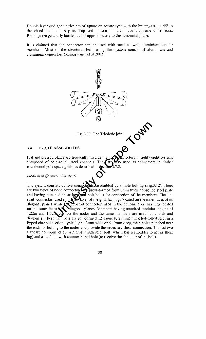
Double layer grid geometries are of square-on-square type with the bracings set at 45° to the chord members in plan. Top and bottom modules have the same dimensions. Bracings are generally located at 54° approximately to the horizontal plane.
It is claimed that the connector can be used with steel as well aluminium tubular members. Most of the structures built using this system consist of aluminium and aluminium connectors (Ramaswamy et al 2002).
Fig. 3.11. The Triodetic joint
3.4 PLATE ASSEMBLIES
Flat and pressed plates are frequently used as the node connectors in lightweight systems composed of cold-rolled steel channels. They are also used as connectors in timber roundwood pole space grids, as described in section 3.7.2.
Moduspal1 (formerly Unistrut)
The system consists of five components, assembled by simple bolting (Fig.3.I2). There are two types of node connector both press-formed from 6mm thick hot-rolled steel plate and having punched shear lugs and bolt holes for connection of the members. The 'instrut' connector, used in the top layer of the grid, has lugs located on the inner faces of its diagonal planes while the out-strut connector, used in the bottom layer, has lugs located on the outer faces of its diagonal planes. Members having standard modular lengths of I.22m and 1.52m connect the nodes and the same members are used for chords and diagonals. These members are roll-formed 12 gauge (0.27mm) thick hot-rolled steel in a lipped channel section, typically 41.3mm wide or 61.9mm deep, with holes punched near the ends for bolting to the nodes and provide the necessary shear connection. The last two standard components are a high-strength steel bolt (which has a shoulder to act as shear lug) and a steel nut with counter-bored hole (to receive the shoulder of the bolt).
38
Univers
ity of
Cap
e Tow
n

'SHEAR' LUGS
UN ISTRUT
Fig. 3.12. The Unistrut
The Octatube node connector
The Octatube node connector (Fig. 3.13) developed in 1973, by Prof. Dr Ir. Eekhout of The Netherlands (Ramaswamy, 2002) consists of an octagonal base plate to which are welded two semi-octagonal plates placed at right angles to each other. The tubes meeting at a node are flattened and connected by means of high-strength bolts. This node connector can be manufactured in any well-equipped workshop. The connector is designed for space frames meant to roof workshops, warehouses and other structures where cost rather than aesthetics is the governing criteria. It is possible to use sections other than tubes to effect the connection if a plate is welded to the ends of the member. The space frame roof of the arrival hall at Bangalore Airport was built using this system.
39
Univers
ity of
Cap
e Tow
n
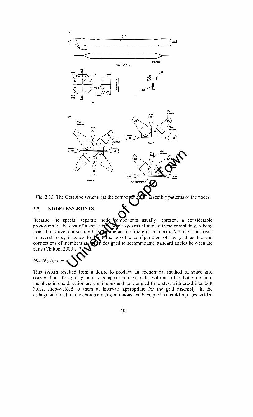
,a;
-< ----------------_:>--Holes
au. pt ...
fbi
-;'!
!J
Web """"bot
SECTION A.-A
-f] l Wok! i --
c .... a
Cuo2
Fig. 3.13. The Octatube system: (a) the components; (b) assembly patterns of the nodes
3.5 NODELESS JOINTS
Because the special separate node components usually represent a considerable proportion of the cost of a space grid, some systems eliminate these completely, relying instead on direct connection between the ends of the grid members. Although this saves in overall cost, it tends to limit the possible configuration of the grid as the end connections of members are often designed to accommodate standard angles between the parts (Chilton, 2000).
Mai Sky System
This system resulted from a desire to produce an economical method of space grid construction. Top grid geometry is square or rectangular with an offset bottom. Chord members in one direction are continuous and have angled fin plates, with pre-drilled bolt holes, shop-welded to them at intervals appropriate for the grid assembly. In the orthogonal direction the chords are discontinuous and have profiled end/fin plates welded
40
Univers
ity of
Cap
e Tow
n

to them. These match those of the continuous chords. Diagonal bracing members have simple end fin plates. Generally, square or circular hollow tubular sections are used for all members. Fig. 3.14 shows the typical Mai Sky System joint.
Fig. 3.14. Typical Mai Sky System joint
Assembly of the system is by site bolting and is usually carried out at ground level. The continuous chords of the bottom layer are laid out and automatically spaced by connection of the discontinuous chords sections in the orthogonal direction. At the same time as the chords are bolted together, the diagonals are fixed between the angled plates. A similar process is used for the assembly of the top layer of the grid.
A continuous edge beam is normally used to support the grids the top layer nodes. This is in turn supported on columns at intervals suitable to limit deflection of the grid supports. The roof decking and preliminary service installation can be carried out before the grid is lifted in position.
Catrus
Developed by EI-Sheikh of Dundee University in Scotland, and was recently introduced in the UK market licensed to Technitube, in South Yorkshire (Chilton, 2000). Primary considerations in the development of the truss system were low-cost, reliability and construction benefits.
The system uses rectangular hollow section (RHS) top chords, tubular diagonals (with flattened and bent ends) and flat steel strip lower chords. Both the upper and lower chords run continuously across the node joints which are assembled using simple bolted
41
Univers
ity of
Cap
e Tow
n

connections (obviating the need for a special node joint). The RHS top chords are drilled on the centerline of the cross-section and, as seen in Fig. 3.15, the connecting bolt passes
Fig. 3.15. The Catrus System (Chilton, 2000).
vertically through the two chord members and the flattened and drilled end of the four web bracing members. Chord members are produced in lengths to suit the particular grid dimensions of the space truss and they are spliced at suitable locations, usually midway between the nodes. This maintains member continuity and stability, and simplifies joint details. The splices in the top chords use a short length of a larger-section RHS (with the top face removed to form a U section), which is then bolted to both chord sections. Bottom chord splices can be made in three forms; by clamping the two chord sections between two short jointing plates; by a simple lapped splice (with no additional cover plates) or, at the bottom nodes; by using a flat jointing plate.
3.6 JAPANESE SYSTEMS
A number of new space frame systems have recently become available on the Japanese market. Among these are the Tomoe Unit Truss, the TM Truss, the NS Space Truss, the SS Space Truss. According to Chilton (2000) a detailed description of these is given in a paper by Kawaguchi, it was difficult for author to obtain this paper.
3.7 CONNECTOR SYSTEMS OF TIMBER SPACE GRIDS
Timber space grids are rare in comparison with steel or aluminium counterparts. In this section the timber space grid connector systems that have been used commercially and those still under research are described.
42
Univers
ity of
Cap
e Tow
n
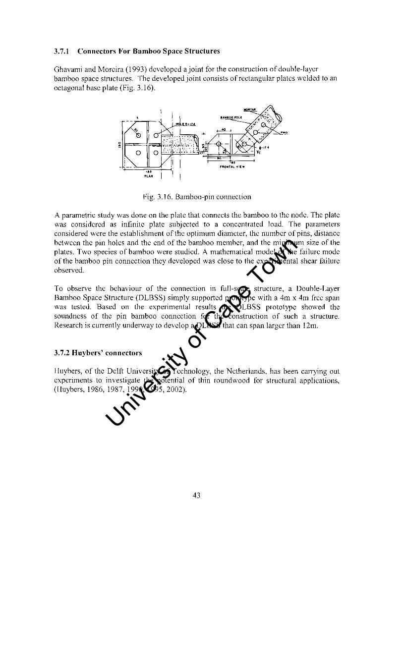
3.7.1 Connectors For Bamboo Space Structures
Ghavami and Moreira (1993) developed a joint for the construction of double-layer bamboo space structures. The developed joint consists of rectangular plates welded to an octagonal base plate (Fig. 3.16).
Fig. 3.16. Bamboo-pin connection
A parametric study was done on the plate that connects the bamboo to the node. The plate was considered as infinite plate subjected to a concentrated load. The parameters considered were the establishment of the optimum diameter, the number of pins, distance between the pin holes and the end of the bamboo member, and the minimum size of the plates. Two species of bamboo were studied. A mathematical model of the failure mode of the bamboo pin connection they developed was close to the experimental shear failure observed.
To observe the behaviour of the connection in full-scale structure, a Double-Layer Bamboo Space Structure (DLBSS) simply supported prototype with a 4m x 4m free span was tested. Based on the experimental results the DLBSS prototype showed the soundness of the pin bamboo connection for the construction of such a structure. Research is currently underway to develop a DLBSS that can span larger than 12m.
3.7.2 Huybers' connectors
Huybers, of the Delft University of Technology, the Netherlands, has been carrying out experiments to investigate the potential of thin roundwood for structural applications, (Huybers, 1986, 1987, 1990, 1995,2002).
43
Univers
ity of
Cap
e Tow
n

pipe
plate
laclng
Fig. 3.17. Isometric sketch and cross-section of connection in roundwood structures
~2 . . . . ..
• • 0 D • •
... P Q " Q .' .
Fig. 3.18. Different combinations of the basic node element
Huybers developed a simple wire lacing method for clamping galvanised steel connector plates in the pre-slotted ends of round wood poles. The procedure for installation is as follows. After cutting the slot and drilling transverse holes, the pre-drilled, plate connector is inserted. Then tubular liners are inserted in the holes and the wire lacing is passed through. The lacing tool is then used to tension the wire to a preset value, the ends of the wires are trimmed and hammered into the face of the timber (Fig. 3.17). The connectors used, were the most popular plate connectors (Fig. 3.18, Chilton, 2000).
The results obtained in the research were used in a number of actually realised structures (Fig. 3.19) such as space frames (1986 to 1990), a little dome structure of 6m height and a 27m high tower structure (1995) (Huybers, 1986, 1987, 1990, 1995). An equipment storage shed, 10.8 x 16.2 m, constructed at Lelystad, in the Netherlands has a space truss roof made of 100mm diameter larch poles, supported on eleven timber columns. The four by six bay square on square offset grid was built in 1986, using galvanised steel 6mm thick circular node and 6 x 90 x 260mm connector plates. For durability, the timber was impregnated with CCA (copper cyanide arsenic) preservative. In the UK, also in 1986, an 8.1m by 18.9m prototype agricultural building was constructed. Supported on twelve columns, the roundwood timber space truss was 1.9m deep and composed of 168 roundwood members of 100mm diameter and 2.5m lengths. The members were prepared offsite and only bolted connections were necessary to assemble the grid before it was lifted by crane on to the 200m diameter timber columns (Huybers, 1986, 1987, 1990, 1995, 2002).
44
Univers
ity of
Cap
e Tow
n

(a) (b) (c)
Fig. 3.19. Structures made of Huybers' connectors: (a) Roundwood space structures in The Netherlands and in Winchester, England; (b) A
25m-diameter dome structure of roundwood; (c) A 27m high observation tower.
Fig. 3.20. Details of the joint for the dome structure
The connector used for the dome structure was borrowed from hollow steel sphere connectors, against which the poles were connected with a central bolt (Fig.3.20). The plate in the end of the pole was provided with a cylindrical part with an internal threaded bolt.
It is clear that the space structures by Huybers' find applications where aesthetics is not of major importance.
45
Univers
ity of
Cap
e Tow
n

3.7.3 The KT -W joint
Imai of Osaka University, Japan, is researching on the KT wood space truss system (Imai el at, 2002). The system employs a KT-W joint (Fig. 3.21) previously used for steel space structures (the KT-series), that consists of a joint cone, end disk at the end of the round timber and lag screws, for anchoring the end disk. During the assembly of the space truss, a threaded bolt is pushed into the hexagonal sleeve and then the hexagonal sleeve is turned at the threaded hole of the node. The timber members are round poles of 50-300mm in diameter.
',,~ Loft haud IIlIe;d (glued)
Joint cone / Lag screw
ft .... 9 T,-__ ,Rou~J Ti.Il'bcr
KT·b'Uss Joint End·disk (G-dl~k) assembly
Fig. 3.21. KT -truss joint details
The joint cone is the interconnecting part between the KT-truss joint assembly and end disk. It is screwed into the end disk and glued to the timber member. A specially designed lag screw that increases pull-out resistance is applied in the joint system. It is claimed that the fully mechanical joint requires no skilled labour for fabrication and installation. All metal components are powder coated and the powder coating can endure more than 15 years even outdoors.
The joint was tested using Japanese cedar and cypress from relatively young and low quality trees. Tensile resistance loads were found to be as high as 216kN for 120mm diameter cypress poles and l83kN for l20mm diameter cedar poles.
3.7.4 Connectors for laminated timber tubular members
Estevez et al (1993) proposed the use of hollow timber members as structural members in double-layer space trusses. They argued that solid sections of reduced dimensions limit the length of bars because their slenderness must be kept low. This would then lead to an increased number of nodes required for the structure, thus increasing both costs and complexity of construction. They claim that the change in humidity within solid sections poses problems of dimensional variations. They also stated that the use of laminated hollow sections with large radius of gyration can be obtained using small amount of material with small thickness, therefore achieving a high perfonnance circumventing problems due to change in humidity. At the same time use of timber against biological decay become considerably easier to implement.
The node shown in Fig. 3.22 was proposed for connecting the members in the structure. It consists of a hollow sphere with a screw-on top that allows access to the inside. This
46
Univers
ity of
Cap
e Tow
n

sphere is manufactured by machining and it incorporates non-threaded drilled holes in order to let the threaded rods pass through, which are then fixed into the inside of the sphere with nuts. On the opposite end, the threaded bar is screwed into an octagonal nut onto which four solid round bars, which follow the edges of an octahedron, are welded. In order to join the node to the wood, diecast plates are fixed onto the inside of the timber member. The proposed connector is suitable for all configurations of double layer grids shown in Chapter 1 as well as curved space trusses. Estevez and his research team developed software for generating different configurations of spaces trusses and their analysis.
I • I I I It. I I 1 , I
(a) (b)
Fig. 3.22. (a) Diecast plate joining the node to members, (b) The node
Compressive tests done on the connector utilising members of dimensions 61.2mm x 60.6mm and thickness of 10.2mm showed an ultimate compressive load of 50KN and axial shortening of 4.2mm.
3.7.5 The 14FTC-U space frame connector
The 14FTC-U space-frame connector was developed by Zingoni in 1995 (Zingoni, 1998). In developing this connector Zingoni was motivated by the fact that timber as a renewable resource, its use should be encouraged ahead of steel and aluminium. Metals generally require much large amount of energy to process into finished products than timber, another good reason why the controlled use of timber for structural purposes should be encouraged. Timber is naturally attractive as a building material; space frames are intrinsically attractive as a structural form. The combination of timber as a material and space frame as a structural form is therefore likely to become popular with architects for exhibition pavilions and supermarkets.
A lot of attention shall be given to this connector unit as it forms the basis of the research reported in this thesis. The connector core is a cuboctahedron (14 faced regular solid) of wood, obtained by truncating off eight vertices of a 100mm x 100mm x 100mm laminated timber cube along the plane through the midpoints of the three mutuallyperpendicular edges of the cube framing into the vertex. The resulting core is a regular 3-dimensional figure with eight equilateral-triangle faces and six square faces, all edges being 70.7mm long (Fig. 3.23(a)). The triangular faces of the core are inclined at an angle of 35.3 degrees to the vertical, such that the sloping grid members incident upon these faces will be inclined at an angle of 54.7 degrees to the vertical. To complete the manufacture of the connector unit, steel strips bent or welded into a U shape (Fig.
47
Univers
ity of
Cap
e Tow
n

3 .23(b)) are then attached onto the eight inclined faces and four vertical faces of the core (in the general case of a connector unit in an interior position of the middle layer of a triple-layer space grid), by means of metal screws passing through the base of the U strip and driven into the wooden core (Fig.3.23(c) and Fig.3.23 (d».
The two upstands of each U strip have holes drilled into them prior to the attachment of the U strip onto a face of the wooden core. When it comes to the assembly of the space grid, a timber-member end is simply slotted between the two upstands of the U strip, and secured to the latter by means of metal screws passed through the holes in the up stands and driven into the sides of the timber-member end (Fig.3.23 (e) and Fig.3.23 (d». In the assembled grid, four of the square faces of the core will be vertical and connected to the horizontal members of either the top or bottom of the grid, the remaining two square will be horizontal and not connected to any member.
Such a core is suitable to take machined timber members of size 32mm x 32mm, for timber members of dimensions D (mm) x D (mm), where D is greater than 32mm, core and U strip dimensions are simply increased in the ratio D/32.Varients of the 14-faced regular solid may be obtained by altering the depth and angle of inclination of the truncation planes, to accommodate design variations in the angles of inclination of the sloping members of the space grid, and/or any required differences in the relative diameter sizes between sloping members and horizontal members of the space grid.
(a)
48
o (\J
/ 5rnrn dia
/ hOles~ T--H-~
(b)
+ -$-
Univers
ity of
Cap
e Tow
n
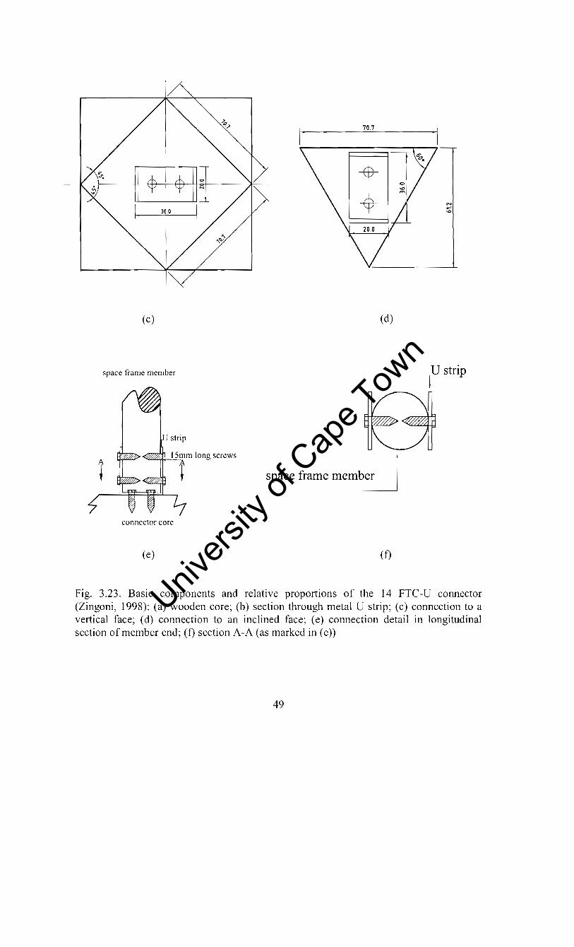
70.7
------+~~- tr $1 $II~ I 31° I
(c) (d)
space frame member j U strip
~~...!.1=..!5m.m long screws
t space frame member
connector core
(e) (0
Fig. 3.23. Basic components and relative proportions of the 14 FTC-U connector (Zingoni, 1998): (a) wooden core; (b) section through metal U strip; (c) connection to a vertical face; (d) connection to an inclined face; (e) connection detail in longitudinal section of member end; (0 section A-A (as marked in (e))
49
Univers
ity of
Cap
e Tow
n

3.7.5.1 Tests on the 14FTC-U connector
Phase 1
The performance of the 14 FTC-U connector was evaluated by Zingoni in two phases. During the first phase, (Zingoni, 1998) the connector unit consisted of a wooden cuboctahedral core with metal U-strips (2mm thick) attachments to its faces to take machined round timbers. Resistance to tension of the connection between the base of the metal U strip and the surface of the wooden connector core was investigated by subjecting a member-connector-member collinear assembly to an increasing direct tensile load. The failure mode of most of the tested specimens was the pulling out of the screws from the wooden core, although a few of the specimens failed by longitudinal splitting of the timber and as a result of the bearing pressure (upon the wood of the timber member) from the metal screws that pass through the member ends.
Failure load varied from lAOkN to 2.85kN, and was found to be dependent upon the orientation of the metal screws through the wooden core relative to the orientation of the grain of the wood of the core, the strength grade of the wood of the core, as well as the type and number of metal screws connecting the metal U-strip to the core.
The connector was then used to fabricate a 2m by 2m SOS offset grid of 1m bays. With the grid supported at the four comer nodes of the bottom layer in a manner as close to fully-pinned conditions as possible, an increasing vertical downward load was applied at one of the four upper-layer nodes. The maximum load that was carried by the grid structure before it failed was recorded at 3.15kN, which corresponds to a maximum tensile and compression member forces, assuming linear elastic behaviour of the structure up to failure, of 0.98kN and 3 .12kN respectively.
The principle mode of failure was observed to be pulling-out from the wooden core of the metal screws under tension, at the interface of the base of the metal U strip and the connector. Zingoni (1998) noted that attention needed to be focused on the strength of the connection of the metal U strip to the central core.
Phase 2
This phase was a follow-up on the investigations and recommendations of Phase 1. In this phase, investigations were carried out on the influence upon the strength of the 14FTC-U connector of factors such as strength grade of the wood of the core, number of metal screws connecting the metal U strips to the wooden core, and orientation of the metal screw through the wooden core relative to the orientation of the grain of the wood of the core (Zingoni, 1999).
Specimens of the connector cores of sides 71.7mm (based on a cube of sides 100mm) were made of cross-laminated softwood (pine), and others cut out of cross-laminated hardwood (mukwa). Similar numbers oflarge cores of sides 106.1mm, based on a cube of
50
Univers
ity of
Cap
e Tow
n

sides 150mm, were also prepared. These two sizes of the cores were intended for machined round timber members of diameters 32mm and 48mm respectively.
Two sizes of metal U strips were prepared from mild steel plates, one to go with the smaller cores and the other with the larger cores. The smaller U strips were cut out of 2mm steel plate, to a width of 12mm, and after bending, a height of 40mm and a base length of 36mm. The larger U strips were cut out of 3mm steel plate, bent to a height of 60mm and a base length of 54mm. All U strips, small and large alike, had three holes drilled in each upstand, large enough to accommodate 2.5mm diameter screws (of length 20mm); holes on one side were directly opposite those on the other side in the case of the bigger U strips, but staggered (to avoid screws running into each other) in the case of smaller U strips.
The number of screws connecting the base of the U strip to the wooden core was varied from one to three for the smaller core. For the large core the screws were varied from two to four. The holes on the U strips (to receive the screws) were positioned symmetrically with respect to the centerline of the base of the U strip. Metal screws used to attach the bases of the smaller U strips onto the smaller cores were of diameter 2.5mm and length 20mm. On the other hand, bases of the larger U strips were attached to the larger cores using metal screws of diameter 3.5mm, but the length of these screws was 35mm in some cases and 50mm in other cases.
To investigate the resistance of the connector units to tensile forces in the members of a space grid, tensile-test specimens were assembled by attaching two identical metal U strips on opposite faces of a cub octahedral wooden core (using metal screws as already described above), and attaching to these U strips short pieces of machined round timber of length approximately 250mm (and diameter 32mm in the case of smaller U strips, or diameter 48mm in the case of the larger U strips). The selected faces of the core, which were either square or triangular, were such that in some cases metal screws were oriented perpendicular to the direction of grain of the wood in the face of the core, while in other cases metal screws were oriented parallel to the direction of the grain of the wood in the face of the core, with some cases being in-between (that is, with screws inclined to the fibres of the wood). Tension was then applied to these connector units by pulling apart the ends in a tensile-testing rig as was done in phase 1 of the research.
3.7.5.2 Summary of Phase 2 Results
Smaller connector units
For the smaller connector, the lowest failure load observed was O.6kN for hardwood core with one central screw in the base of the U strip, failing as a result of the pulling out of the one screw from the core. The highest recorded failure load was 2.93kN, noted for a hardwood core with three screws in the base of the U strip, failing as a result of pulling out of the two outer screws of the base of the U strip, while the central screw of the base remained intact, this in tum causing the base of the U strip to yield into a wide V shape.
51
Univers
ity of
Cap
e Tow
n

In general failure load increased with the number of screws cOlmecting the base of the U strip to the wooden core. Three screws in the base of the U strip appeared to be the most optimum arrangement for this size of the connector, since both the pull-out frictional resistance of the screw-core internal interface and the flexural resistance of the base of the U strip were simultaneously mobilised. It was then recommended that the thickness of the U strip be increased from 2mm to 3mm. This modification resulted in the failure load being increased to an excess of 3kN. It was observed that use of hardwood in place of softwood increased the strength of the connection by an average of only 7%, and by no more than 23% at best. Zingoni then concluded that since hardwood (mubva in this case) is heavier and more expensive than softwood (pine in this case), use of hardwood for the connector core is hardly worthwhile. It was also observed that when metal screws in the base of the U strip were oriented parallel to the direction of the grain fibres of the wood on the face of the core in question, the associated pull-out resistance was generally lower than that associated with the screws oriented perpendicular or inclined to the fibres of the wood. There was no significant difference in strength between the perpendicular and inclined cases of relative grain-screw orientations, though strengths tended to be somewhat higher on average in the case of the perpendicular relative grain screw orientation. This led to the suggestion that the cross-laminated wooden cores must be cutout in such way that faces that take grid members have fibres orientated in the plane of the faces.
Larger connector units
In this case, failure loads varied from as little as 1.49kN for a softwood core with 35mmlong screws failing in pull-out mode, to a maximum of 7.46kN noted in the case of a hardwood core with three 35mm-Iong screws oriented perpendicularly to the fibres of the core. The failure mode in the latter case comprised the pulling-out of the two outer screws while the central screw remained more or less intact, with the base of the U strip having flexed into a smooth curve to accommodate this differential pulling--out of screws. It was also observed that replacing readily available softwood like pine with a tropical hardwood like mukwa does not significantly improve the strength performance of the connector. Zingoni also recommended that increasing the thickness of the U strip from 3mm to 5mm would eliminate the yielding failure of the strip, enabling the pull-out resistance of all screws in the base of the strip to be mobilized.
Computer-generated results for a typical double-layer space grid
In order to investigate the viability of the developed 14FTC-U connector from a practical point of view, a 3-dimensional computer analysis of a medium span double space grid was performed by Zingoni (1999). The grid analysed had a 20m x 20m square plan, comprising lOx 10 panels in the bottom layer and 9 x 9 panels in the top layer, the panels all being of dimensions 2m x 2m. The height of the grid was 1m.
Downward point loads of 1 kN were assumed to act on all the upper joints of the upper layer. Adopting a value of 8.8kN per square millimeter for the Young modulus of timber members, and a diameter of 48mm for all the members, a maximum vertical deflection of
52
Univers
ity of
Cap
e Tow
n
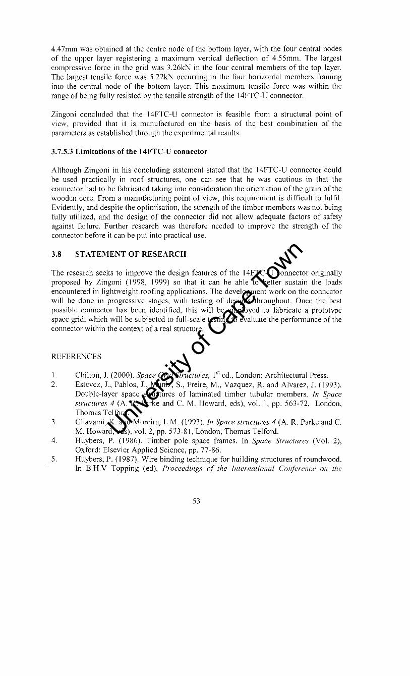
4.47mm was obtained at the centre node of the bottom layer, with the four central nodes of the upper layer registering a maximum vertical deflection of 4.55mm. The largest compressive force in the grid was 3.26kN in the four central members of the top layer. The largest tensile force was 5.22kN occurring in the four horizontal members framing into the central node of the bottom layer. This maximum tensile force was within the range of being fully resisted by the tensile strength of the 14FTC-U connector.
Zingoni concluded that the 14FTC-U connector is feasible from a structural point of view, provided that it is manufactured on the basis of the best combination of the parameters as established through the experimental results.
3.7.5.3 Limitations of the 14FTC-U connector
Although Zingoni in his concluding statement stated that the 14FTC-U connector could be used practically in roof structures, one can see that he was cautious in that the connector had to be fabricated taking into consideration the orientation of the grain of the wooden core. From a manufacturing point of view, this requirement is difficult to fulfil. Evidently, and despite the optimisation, the strength of the timber members was not being fully utilized, and the design of the connector did not allow adequate factors of safety against failure. Further research was therefore needed to improve the strength of the connector before it can be put into practical use.
3.8 STATEMENT OF RESEARCH
The research seeks to improve the design features of the 14FTC-U connector originally proposed by Zingoni (1998, 1999) so that it can be able to better sustain the loads encountered in lightweight roofing applications. The development work on the connector will be done in progressive stages, with testing of designs throughout. Once the best possible connector has been identified, this will be employed to fabricate a prototype space grid, which will be subjected to full-scale testing to evaluate the performance of the connector within the context of a real structure.
REFERENCES
1. Chilton, J. (2000). Space Grid Structures, 1 st ed., London: Architectural Press. 2. Estevez, J., Pablos, J., Muniz, S., Freire, M., Vazquez, R. and Alvarez, J. (1993).
Double-layer space structures of laminated timber tubular members. In Space structures 4 (A. R. Parke and C. M. Howard, eds), vol. 1, pp. 563-72, London, Thomas Telford.
3. Ghavami, K. and Moreira, L.M. (1993). In Space structures 4 (A. R. Parke and C. M. Howard, eds), vol. 2, pp. 573-81, London, Thomas Telford.
4. Huybers, P. (1986). Timber pole space frames. In Space Structures (Vol. 2), Oxford: Elsevier Applied Science, pp. 77-86.
5. Huybers, P. (1987). Wire binding technique for building structures of roundwood. In B.H.V Topping (ed), Proceedings of the International Conference on the
53
Univers
ity of
Cap
e Tow
n

Design and Construction of Non-Conventional Structures (Vol. 1), Edinburgh: Civil-Comp Press, pp. 115-120.
6. Huybers, P. (1990). Thin poles of roundwood for structural applications in building. Structural Engineering Review 2, pp. 169-182.
7. Huybers, P (1995). Roundwood poles in spatial structural arrangements. In lB. Obrebski (ed), Proceedings of the International Conference on Lightweight Structures in Civil Engineering, Warsaw: Magat, pp. 599-607.
8. Huybers, P. (2002). Wooden poles for larger structural applications. In Proceedings of a Special session of the 5th Space Structures Conference University of Surrey, pp.17-24.
9. Imai, K., Furukawa, T., Wakiyama, K., Tsujioka, S., Fujimoto, M., Inada, M., Takino A, Y oshinaga, M., (2002). Development of the KT -Wood space truss system with round timber as new structural material. In Proceedings of a Special session of the 5111 Space Structures Conference, University of Surrey, pp. 12-16.
10. Imai, K., Morita, T., Yamaoka, Y., Wakiyama, K. and Tsujioka, S., (1993). The KT Space truss system .. In Space structures 4 (A. R. Parke and C. M. Howard, eds), vol 2, pp. 1374-1382, London, Thomas Telford.
11. Ramaswamy, G. S. Eekhout, M. Suresh, G. R. (2002). Steel Space Frames, 1st ed., London, Thomas Telford.
12. Zingoni, A (1998). The 14FTC-U Timber Space-Frame Connector for doublelayer and triple-layer space grids of machined round timber members. In J.B. Obrebski (ed), Proceedings of International Conference on Lightweight Structures in Civil Engineering, Warsaw: Micro-Publisher J.B.O. Wydawnictwo Naukowel Agat, pp. 392-398.
13. Zingoni, A (1999). Factor s affecting the strength of the 14FTC-U timber spaceframe connector. In B. Kumar & B.H.Y. Topping (eds), Computing Developments in Civil and Structural Engineering, Edinburgh:Civil-Comp Press, pp. 113-121.
54
Univers
ity of
Cap
e Tow
n

CHAPTER 4:
CONNECTOR DEVELOPMENT
4.1 RESEARCH METHODOLOGY
The research was undertaken in phases. The first phase was to study earlier work on the ] 4FTC-U connector in detail in order to identify what was done and the recommendations made. The next phase was to search for related work on timber space truss connectors; this information is documented in the previous chapter. Materials that could be used to improve the idea behind the 14FCT -U connector were considered, and possible connector designs proposed. Several connectors were then fabricated and tested. Changes were made from the test results to improve on the performance of the connectors. The best connector was finally adopted in fabricating a prototype grid.
4.2 MATERIALS SELECTION
Materials selection was based on availability and cost. In the literature survey, it was observed that connectors are the most expensive components of space grids. From an economical point of view, the cost of the materials was considered without compromising the performance of the connector. Compatibility of the materials with other building materials and architectural finishes was also taken into consideration.
At first it was considered to change the material of the core from wood to hard carbonfibre plastic, but the cost of this material is excessive.
4.3 GOVERNING CRITERIA OF THE BEST CONNECTOR
Mitchell (1975) stated that an ideal connector would satisfy the following requirements: -
a. Permit any arrangement and number of members at the joint. b. Match the strength of the incoming members in all respects particularly axial forces. c. Use readily available materials. d. Enable mass production techniques to be applied in fabrication, with little or no
specialised equipment being required. e. Be reasonably economical in the completed structure.
Generally the proposed connector should meet the same requirements set by Mitchell. The method of assembly of the members should not unduly stress the members, e.g. tightening in the direction of the member. 10int eccentricities should be avoided; as these would induce bending moments which would result in reduced axial force carrying capacity of the members. The most ideal condition is for timber members to fail first leaving the connector intact. This would mean that the full strength of timber members would have been mobilised.
55
Univers
ity of
Cap
e Tow
n

The cost of producing the connector, together with that of the materials used, should be low. Use of readily available components of the connector was set as a priority to avoid additional costs of fabricating tools for making the components of the connector. Comparing with the existing connectors like the steel spherical nodes and the Triodetic node that have been used successfully in timber space trusses, the connector should be cheaper.
4.4 STATEMENT OF THE BEST CONNECTOR
The connector should be structurally sound, visually neat and economically reproducible for three-dimensional configuration of timber members (Zingoni, 1998).
4.5 DESIGN DETAILS AND FABRICATION PROCEDURES OF THE PROPOSED CONNECTORS
The basic concept of the 14FTC-U connector core was essentially preserved in coming up with the amended designs. The fabrication technique of the wooden core remains the same, with minor changes to suit the new design concepts. The use of steel U strips to take the timber members is also preserved, as in the original 14FTC-U connector. Thus, the changes that will be proposed in the sections to follow are really modifications or improvements of the hidden inner details, rather than new design proposals. The connector-core geometry is as proposed by Zingoni (1998). Any other variations will be explained in the respective sections of the proposed connectors. Timber used for both the core and the members was South African pine of grade designation S5.
4.6 TRUNCATING THE CORE
After joining the mid-points of the sides of the timber cube (Fig. 4.1), the cube is gripped in a lathe machine and a 30mm hole is drilled through the centre of one side of the cube right through to the opposite side (Fig 4.2). This hole serves two purposes, to hold the core during truncating and the other will be explained later. The core is set at an angle of 35.3 degrees to the horizontal on a tool mounted on the moving table of a milling machine (Fig. 4.3). During truncating, the table moves across a rotating blade set in a horizontal plane thus cutting off the veliex of the wooden cube. By turning the cube around, all the vertices are truncated off. Holes of 6mm diameter are drilled on the centroids of the 12 remaining faces.
56
Univers
ity of
Cap
e Tow
n

Fig. 4.1. Details of the connector core
Fig. 4.2. Drilling the access hole with lathe machine
57
Univers
ity of
Cap
e Tow
n

Fig. 4.1. Details of the connector core
Fig. 4.2. Drilling the access hole with lathe machine
57
Univers
ity of
Cap
e Tow
n

Fig. 4.3. Truncating process of the core
4.7 CONNECTOR CHANGES
4.7.1 First proposal
This connector consists of a wooden cuboctahedral core (fonned as already described), with metal U strip attachments to its faces to take machined timber members of size 32mm x 32mm. The U strip is fonned by bending a single flat strip of dimensions 120mm x 20mm and 2mm thickness to a base length of 36mm and a height of 42mm (Fig. 4.4(a)).
r _ 3_6 __ ,
-, 6mmdiJ
0. _ !~ ~
(a) (b)
S:ttl Umip
Fig. 4.4. (a) Dimensions of the U strip designed to take 32mm x 32mm timber members (b) U strip with welded steel rod
58
Univers
ity of
Cap
e Tow
n

The two upstands of the U strip have 6mm holes drilled in them prior to attachment of the U strips onto the face of the wooden core. Another 6mm hole is drilled in the base of the U strip, into which a mild steel rod (50mm in length) is inserted, before welding using the arc welding technique (Fig. 4.4(b)). The other free end of the rod is inserted into the wooden core and the U strip is positioned as shown in Fig. 4.5(a) onto a vertical square face and onto an inclined face of the core as shown in Fig. 4.5(b). In Fig. 4.5(a) the longitudinal axis L-L of the base of the U strip is horizontal while in Fig. 4.5(b) L-L is oriented along the direction of the maximum slope of the inclined face, the centroids of the base of the U strip coinciding with the centroids of the core face in both cases. The rods coming from the 12 faces of the core meet at the centre and are welded together through the 30mm hole, using arc-welding. The completed assembly is a connector (Fig 4.6) suitable for both double and triple-layer space grids.
L L
(a)
L
L
Fig. 4.5. Positioning of the base of the strip upon: (a) vertical square face of core; (b) inclined triangular face of core
59
Univers
ity of
Cap
e Tow
n
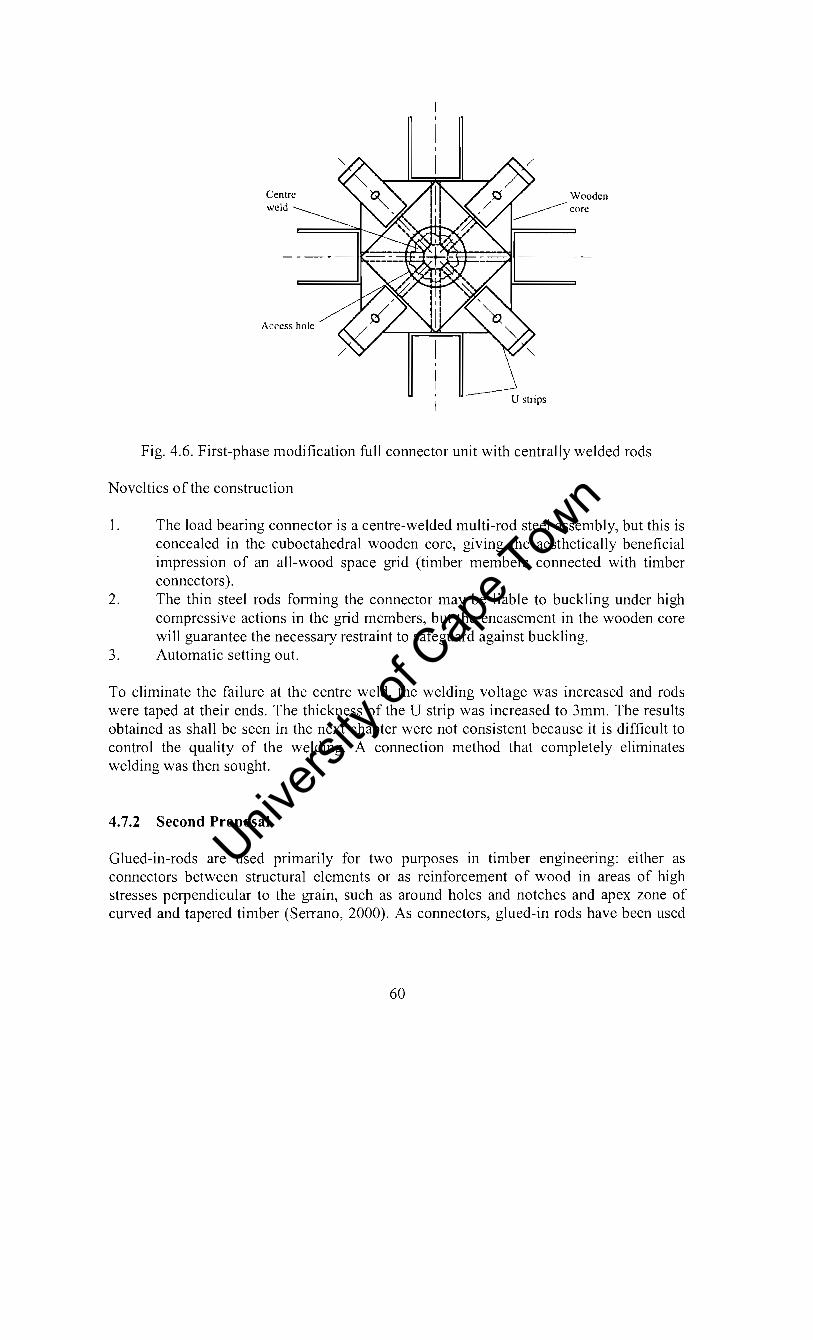
Centre weld
Access hole
U strips
Fig. 4.6. First-phase modification full connector unit with centrally welded rods
Novelties of the construction
1. The load bearing connector is a centre-welded multi-rod steel assembly, but this is concealed in the cuboctahedral wooden core, giving the aesthetically beneficial impression of an all-wood space grid (timber members connected with timber connectors).
2. The thin steel rods forming the connector may be liable to buckling under high compressive actions in the grid members, but the encasement in the wooden core will guarantee the necessary restraint to safeguard against buckling.
3. Automatic setting out.
To eliminate the failure at the centre weld, the welding voltage was increased and rods were taped at their ends. The thickness of the U strip was increased to 3mm. The results obtained as shall be seen in the next chapter were not consistent because it is difficult to control the quality of the welding. A connection method that completely eliminates welding was then sought.
4.7.2 Second Proposal
Glued-in-rods are used primarily for two purposes in timber engineering: either as connectors between structural elements or as reinforcement of wood in areas of high stresses perpendiCUlar to the grain, such as around holes and notches and apex zone of curved and tapered timber (Serrano, 2000). As connectors, glued-in rods have been used
60
Univers
ity of
Cap
e Tow
n

especially for glued-laminated timber (glulam), for many years in Europe mainly in the Nordic countries and in Germany.
In the design of this connector, the concept of glued-in-rods was borrowed but instead of applying the adhesive (epoxy) around the rods, the central hole of the wooden core was plugged at one end and filled with epoxy. As the epoxy sets the rods are cemented together thus providing the pull out resistance against tension (Fig. 4.7).
The smooth rods used in the first proposal are replaced by mild steel bolts. The sizes of the bolts are SOM6 for square faces and 60M6 for triangular faces of the core. The assembly of the connector is as follows. U strips are positioned in the same way as in the first proposal and the bolts are pushed through the base hole of the U strip into the wooden core until they sit on the inner surface of the U strip. The assembly is then bonded together by epoxy (SIKADUR 32), which is poured into the 30mrn hole plugged at one end. The properties of the epoxy are such that it can flow like honey, thus getting easily into the grooves of the bolts. To remove the air bubbles that might be trapped inside the epoxy, the connector is pressed against a vibrating machine.
The samples were left for S days for the epoxy to set before they were tested.
Fig. 4.7. Connector bonded with epoxy
4.7.3 Third proposal
From the test results of the second proposal, it was seen that greater use could be made of the timber core. In the previous proposals, the core was only useful in maintaining the required angles of the space truss members. As the failure by bending of the U strips continued to pose problems it was decided to change the U strip thickness from 3mrn to Smrn. Another problem of forming the steel strips into U shapes arose, as the machine
61
Univers
ity of
Cap
e Tow
n

previously used could not cope. Three pieces of strips were welded together to form a U strip but as will be seen from the test results, the cormection method was abandoned. A special tool was made to fonn the strips into U shapes with the help of an Amsler compressing machine. In the third proposal, the steel bolts are replaced by coach screws. Since the strength of the cormection is known to depend on the length of the screws in epoxy, the diameter of the central hole was increased to 40mm. The size of the holes on the 12 faces of the core was reduced to 4mm.
The U strips are attached to the core by driving the screws through timber until they meet at the centre of the core. Cementing is achieved using the same epoxy SIKADUR 32 as in the second proposal. As before, air bubbles that might be trapped in the epoxy during pouring are removed by pressing the cormector against a vibrating machine. The assembly was left to set for at least 5 days for the epoxy to set prior to testing.
4.7.4 Final proposal
This cormector is basically the same as the third proposal, the only difference being that the screws used are made of stainless steel of yield strength 560MPa and have threads on the whole length. The U strips are cut from 20mm x 5mm flat mild steel. Rolled steel was seen to yield during bending, especially when the axis of bending was parallel to the grain in steel. Flat steel has the advantage that the grain always runs perpendicular to the axis of bending thus eliminating the cracking problems.
Holes in the upstands of the U strips are drilled 50mm from the base. Timber members are attached to the U strips by means of high tensile steel bolts of grade 8.8 according to the British Code of Standards.
4.8 TENSILE TESTS OF THE CONNECTOR UNITS
To investigate the resistance of the cormector units to tensile forces, tensile-test specimens were assembled by attaching timber members of length 250mm on U strips on opposite faces of the core. The members had 6.3mm diameter holes drilled in them and were secured in place by 50M6 steel bolts with nuts and washers. Tension was applied to these cormector units by pulling apart the ends of the short timber members in a tensile testing rig machine (Fig. 4.8). The tensile test results are reported in the next chapter.
62
Univers
ity of
Cap
e Tow
n

Fig. 4.8 . Configuration for the tensile testing of a connector unit
REFERENCES
1. Mitchell, K. (1975). An introduction to joining systems. Seminar-Space Structures, The University of New South Wales, Australia, pp. 7-13.
2. Serrano, A. (2001). Glued-in rods for timber structures - a 3D model and finite element parameter studies, International Journal of Adhesion & Adhesives 21, pp. 115-127.
3. Zingoni, A. (1998). The 14FTC-U Timber Space-Frame Connector for double-layer and triple layer space-grids of machined round timber members. In Proceedings of International Conference on Lightweight Structures in Civil Engineering, Warsaw, Poland, pp. 392-398.
4. Zingoni, A. (1999). Factors affecting the strength of the 14FTC-U timber space-frame connector, Computing Developments in Civil and Structural Engineering, CIVILCOMP Ltd, Edinburgh, Scotland, pp. 113-121.
63
Univers
ity of
Cap
e Tow
n

CHAPTERS:
CONNECTOR RESULTS AND DISCUSSION
5.1 INTRODUCTION
In this chapter the tensile test results of the proposed connectors are outlined and reasons are given on why some of the connector were rejected. The best connector was selected for the fabrication of a prototype grid.
5.2 TENSILE TEST RESULTS
5.2.1 First Proposal
The results of the experimental testing of the first proposed connector are given below.
Test No. Failure load Ultimate Load Failure Mode (kN) (kN)
1 4.2 U strip starts to yield by bending 5.6 Weld breaks at the centre
2 4.2 U strip starts to yield by bending 5.2 Weld breaks at the centre
3 4.4 Steel plate starts to yield by bending 6 Weld breaks at the strip- rod interface
Table 5.1. Failure loads and failure mode for a connector with a 2mm thick U strip
The predominant method of failure of this connector is shown in Fig. 5.1, in this case, the metal U strip was yielding at the rod position. Another failure mode is also shown in Fig. 5.2.
64
Univers
ity of
Cap
e Tow
n

Fig. 5.1. Predominant failure mode of the U strip
Fig.5.2. Failure mode of the connector unit by breaking of the weld at the strip- rod connection
65
Univers
ity of
Cap
e Tow
n

I
I
Test N0'1 Failure I Ultimate Load Failure Mode load (kN). (kN)
I 6 . U strip starts to yield by bending 7.4 Weld breaks at the rod-plate connection
2 f..--.. 6 U strip starts to yield by bending ... 7.2 Weld breaks at the rod-plate connection
3 5 . Weld breaks at the rod-plate connection 4 6 U strip starts to by bending
6.6 Weld breaks at the rod-plate connection 5 6 U strip starts to yield by bending
7.2 Weld breaks at the rod-plate connection
Table 5.2. Failure loads and failure mode for a connector with a 3mm thick U strip
When 2mm thick U strips were used the lowest recorded ultimate failure load was 5.2 kN, failing as a result of the weld breaking at the centre-weld. The highest recorded ultimate failure load was 6 kN, failing as a result of the weld of rod-plate connection being squeezed out by the pulling force. This mode of failure is mainly due to the yielding of the U strip. When the thickness of the U strip was enhanced to 3mm, the U strip showed signs of yielding at 6kN. This corresponds to the highest ultimate load obtained when 2mm U strips were used. The lowest recorded ultimate load was 6.6kN, failing as a result of the squeezing effect of the weld at the rod-plate connection whilst the highest recorded ultimate load was 7.4kN, again failing by the same mode. The difference between the highest and the lowest ultimate loads was about O.8kN for both connectors with 2mm and 3mm thick U strips. The results show that the quality of welding is not consistent as it depends on the welder. It therefore implies that the performance of the connector would greatly depend on the level of workmanship. This is not encouraged for a structure where safety is of great importance.
Despite the care taken, it was noted that the process of welding damaged the wood through charring. This led to the proposal of another connection method.
5.2.2 Second Proposal
The ultimate failure load when the rods were welded to the U strips and bonded at the centre with an epoxy resin was found to be 3.1kN and the failure mode was pull-out of
66
Univers
ity of
Cap
e Tow
n

the rods from the core. The low load obtained is mainly due to the smooth nature of the rods and their short lengths bonded in the resin. It is known that surface roughness plays a role in pull-out resistance as well as the length bonded in the resin.
When the concept of glued in rods was used, the ultimate failure load was recorded as 8.5kN with shear failure of the core and yielding of the U strips as the modes of failure. This connection was abandoned, as it was difficult to pour epoxy into the 6mm holes and assembling the connector at once. This method of connection would be difficult to implement during mass production.
When the steel rods were replaced with steel bolts with threading at the ends, and the setup bonded together at the centre with an epoxy, an average ultimate load of 6.9kN was recorded. The dominant failure mode was pull-out of the bolts from the core, with yielding of the U strips at around 6kN. This showed that the resin performed less satisfactorily than the welding of the first proposed connector. With this arrangement, the pull-out resistance was afforded solely by the central epoxy-resin bond.
From the failure mode of this last modified connector, it was clear that additional strength could be mobilized by driving screws into the wooden core, this would provide additional pull-out resistance and then bonding the protruding lengths at the centre with the epoxy resin. As the flexural yielding of the bases of the U strips prior to pull-out failure was still evident, it was decided to further increase the plate thickness of the U strips to 5mm. It was also decided to increase the central hole diameter from 30mm to 40mm.
5.2.3 Third Proposal
When three pieces of strips were welded together to form a U strip, failure occurred at a load of 4.2kN, failing as a result of the welding of the U strip pieces breaking. This connection method was abandoned since the failure load was by far lower than the previously obtained results from the second proposed connector.
The experimental test results of the connector formed with screws bonded together with an epoxy at the centre were as tabulated in Table. 5.3.
Sample Ultimate Load (KN) Failure Mode
Timber members 7.2 Longitudinal cracking of timber and iyielding of bolt connecting the member.
Steel members 10.2 ~he coach screw snapped off where hreads start
Table. 5.3. Failure loads of connectors bonded with epoxy
The first test with timber members indicated that the connector was now stronger than the timber members as the members failed by longitudinal cracking. The reason for this is mainly due to the fact that the minimum edge distance of 7d (d is the diameter of the connecting bolt) for timber member connections required by the South African Bureau of Standards (SABS 0163-1:1994) was not adhered to. This result led us to use steel
67
Univers
ity of
Cap
e Tow
n

members to investigate the ultimate strength of the connector itself. The connector with timber members showed the cross bolt connecting the U strip to timber members failing in bearing. It became clear that ordinary mild steel could not transfer the load beyond 7KN. It was then concluded that high strength bolts should be used in place of ordinary mild steel bolts.
From second test, the coach screws snapped off where the threading starts, this result suggested that the type of the screws had to be changed again. It was concluded that a number of changes had to be done to the connector. These include increasing the end distance of the holes on U strips and timber members to at least the minimum required by the code (SABS 0163-1:1994) to avoid longitudinal splitting, replacing mild steel bolts with high strength bolts of grade 8.8, using stainless steel screws of yield strength 560MPa threaded the whole length instead of ordinary coach screws.
In terms of fabrication practicalities it was concluded that the connector was self aligning and easy to fabricate. The fabrication is a cold process and no strength loss is induced due to welding. Failure of U strips by bending was completely eliminated when the thickness was enhanced to 5mm from 3mm.
,
Final Proposal
With the recommendations from the third proposed connector implemented, the test results observed on the final connector were as tabulated in Table. 5.4.
Specimen Ultimate Load (kN) Failure mode and comment Number !
I 1 i 11.3 Withdrawal of screws
,
I 2 i
10.1 Bearing failure of timber
I 3 I 10.3 Withdrawal of screws i I
!
4 I 7.5 Withdrawal of screws, connector had a defect I
5 I
9.6 Withdrawal of screws, epoxy not :ed ~1l '
Table. 5.4. Failure loads of Connectors 4
The average ultimate load of the first three specimens of the fourth proposal was 10.6KN. As the timber members were failing in bearing at a load of about 10.1 KN, no further test could be done unless the grade of timber members had to be improved. The observed withdrawal of screws meant that the connection by bonding with an epoxy resin had reached its ultimate load carrying capacity. Any further improvement would mean increasing the size of the core and using higher-grade timber members.
68
i
Univers
ity of
Cap
e Tow
n

It is evident from the last two test results that the connector load carrying capacity depends on the level of workmanship. Any defects are likely to reduce the load carrying capacity of the connector. The resin has to be well mixed and in no case should screws be driven and taken out and then driven again into the core. This was the defect that was induced in the specimen 4. This result showed the strength provided by timber is about 3kN.
This connector was chosen as the best and it was adopted in the fabrication of a prototype roof structure. It is easy to assemble, once the cubes are truncated the rest is self-aligning. As long as the epoxy is mixed well and screws are driven properly no skilled labour is required in assembling the connector units.
As a concluding statement, the ultimate tensile load carrying capacity of the final adopted C01mector is 10.6KN.
REFERENCE
1. SABS 0163-1:1994. South African Code of Practice. The structural use of timber Part 1: Limit state design. South African Bureau of Standards, Pretoria.
69
Univers
ity of
Cap
e Tow
n

CHAPTER 6:
FABRICATION OF PROTOTYPE DOUBLE-LAYER GRID AND TEST RESULTS
6.1 INTRODUCTION
A small-scale double-layer space grid of square-on-square offset configuration utilizing the proposed connector and machined timber members was fabricated. The structure may be envisaged as the whole or a part of a lightweight roof or floor system. In this chapter a detailed account is made of the fabrication of the space grid, and results of the tests on its structural behaviour are presented.
6.2 LAYOUT DIMENSIONS AND MEMBER SIZES OF THE GRID
In plan, the grid measured 4m x 4m square at the bottom and 3m x 3m square at the top, the top and bottom layers consist of 1 m square panels as shown in Fig. 6.1. The centres of the top panels were offset to the comers of the bottom panels. The height of the structure was 500mm. All the dimensions refer to the distances between centres of connectors at the ends of the grid members. The actual member lengths are smaller than the distances between centres of connectors, owing to the space taken up by the connectors.
4 3 plan
1 300°_1 ~r
4000 ~I Elevation
Fig. 6.1 Dimensions of the double-layer flat space grid in timber
70
Univers
ity of
Cap
e Tow
n

The grid has 40 horizontal members in the bottom layer and 24 horizontal members in the top layer. The two layers are connected by 64 diagonal members each inclined at an angle of 54.7 degrees to the vertical, this angle being, of course, a consequence of the geometry of the connector. The top and bottom layers contain 16 and 25 connectors respectively. The actual length of all horizontal members, taking into account the space taken by the connectors, works out to be 890mm, while that of the diagonal members is 741mm. The space taken by the metal U strip was allowed for in these lengths.
Not all vertical square faces and inclined triangular faces of the 14-faced core require U strip attachments in assembling the grid. An examination of Fig. 6.1 reveals that five types of connectors had to be assembled, the classification being based on the number of U strip attachments required. These were as follows:
Type A:
Type B:
Type C:
Type D:
Type E:
3 U strips (2 on vertical square faces; 1 on inclined triangular face) Location: Comer node of bottom layer (4 number) 6 U strips (2 on vertical square faces; 4 on inclined triangular faces) Location: Comer nodes of top layer (4 number) 5 U strips (3 on vertical square faces; 2 on inclined triangular faces) Location: Edge nodes of bottom layer, excluding comers (12 number) 7 U strips (3 on vertical square faces; 4 on inclined triangular faces) Location: Edge nodes of top layer, excluding comers (8 number) 8 U strips (4 on vertical square faces; 4 on inclined triangular faces) Location: Interior nodes of both layers (13 number)
6.3 SUMMARY OF COMPONENT REQUIREMENTS
All the components required for the fabrication for the prototype grid structure are summarized below:
Machined timber members of cross-section 32mm x 32nul1: 890mm lengths: 64 number 741mm lengths: 64 number
Connector components: 1 OOmm x 100mm laminated-wood cores: 41 number metal U strips: 256 number metal screws 50M6: 128 number metal screws 60M6: 128 number 50M6 high tensile steel bolts (grade 8.8): 256 number nuts: 256 number washers: 256 number epoxy component A (Sikadur 32): 31 epoxy component B (Sikadur 32): 31 flat mild steel: 45m
71
Univers
ity of
Cap
e Tow
n
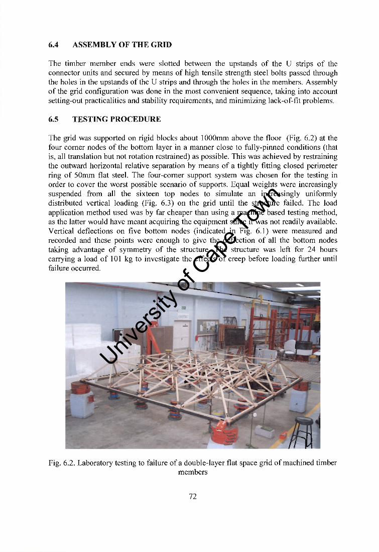
6.4 ASSEMBL Y OF THE GRID
The timber member ends were slotted between the upstands of the U strips of the connector units and secured by means of high tensile strength steel bolts passed through the holes in the upstands of the U strips and through the holes in the members. Assembly of the grid configuration was done in the most convenient sequence, taking into account setting-out practicalities and stability requirements, and minimizing lack-of-fit problems.
6.5 TESTING PROCEDURE
The grid was supported on rigid blocks about lOOOmm above the floor (Fig. 6.2) at the four comer nodes of the bottom layer in a manner close to fully-pinned conditions (that is, all translation but not rotation restrained) as possible. This was achieved by restraining the outward horizontal relative separation by means of a tightly fitting closed perimeter ring of 50mm flat steel. The four-comer support system was chosen for the testing in order to cover the worst possible scenario of supports. Equal weights were increasingly suspended from all the sixteen top nodes to simulate an increasingly uniformly distributed vertical loading (Fig. 6.3) on the grid until the structure failed. The load application method used was by far cheaper than using a machine based testing method, as the latter would have meant acquiring the equipment since it was not readily available. Vertical deflections on five bottom nodes (indicated in Fig. 6.1) were measured and recorded and these points were enough to give the deflection of all the bottom nodes taking advantage of symmetry of the structure. The structure was left for 24 hours carrying a load of 101 kg to investigate the effects of creep before loading further until failure occurred.
Fig. 6.2. Laboratory testing to failure of a double-layer flat space grid of machined timber members
72
Univers
ity of
Cap
e Tow
n

w w w w Fig. 6.3. Elevation showing the loaded grid with a unifonn load
6.6 RESULTS AND DISCUSSION
The structure failed by buckling of the comer diagonal member (Fig. 6.4). The maximum load that was carried per node by the grid structure before it failed was recorded as 139kg. This corresponds to a maximum compressive force of 9.42kN and a tensile force of 3.2SkN in the comer inclined members, assuming linear elastic behaviour of the structure up to failure, and adopting a value of 7.8kN per square millimeter for the Young modulus of timber. The Euler buckling load of this comer member is 12.2SkN, assuming pinned end conditions. The failure of the member below 12.2SkN is due to the defects like knots, initial stresses due to tightening of the bolts and the member might not have been straight because of warping. The comer diagonal members are the most critical for a comer-supported grid.
Fig. 6.4 Ultimate failure mode of the grid structure
73
Univers
ity of
Cap
e Tow
n

The member forces yielded by a computer linear-elastic analysis, considering only a quarter of the structure (because of symmetry of loading and supporting conditions) are given in Table 6.1, with the node numbers used to name the members indicated in Fig. 6.5.
21 21 '4 . '5 ..
~ 11 I 19 20
I 12 I 14 15
7 8 9 If
2 4 \
39 0 41
35 36 J,
)0 3 12 )
(, 2 28 29
Fig.6.5. Node numbers of the bottom and top chords of the prototype grid
74
Member Designation Axial Force
1-2 Bottom -1.87 1-6 Bottom 1.87 2-3 Bottom 1.87 2-7 Bottom 0 3-8 Bottom 0 6-7 Bottom 0
6-11 Bottom 1.87 7-8 Bottom 1.36
12 Bottom 1.36 8-13 Bottom 0.67 11-12 Bottom 0 12-13 Bottom 0.67 26-27 Top -5.77 26-30 Top -5.77 27-28 Top -7.47 27-31 Top -2.39 30-31 Top -2.39 30-34 Top -7.47 1-26 Inclined -9.42 2-26 Inclined 3.45 6-26 Inclined 3.45 7-26 Inclined 0.60 8-27 Inclined 0.29 2-27 Inclined -3.25 3-27 Inclined 0 7-27 Inclined 0.60 8-27 Inclined 0.29 6-30 Inclined -3.25 7-30 Inclined 0.57 11-30 Inclined 0 12-30 Inclined 0.29 7-31 Inclined -1.77 8-31 Inclined -0.29 12-31 Inclined -0.29 13-31 Inclined 0
Table. 6.1. Member forces of the grid at failure
Univers
ity of
Cap
e Tow
n

The distribution of member internal forces clearly demonstrates a number of important points.
• Due to the fewer load paths to the substructure a comer-supported space truss has a high concentration of forces towards the comer support members.
• Apart from the web members close to the comer regions of a comer-supported truss, the internal forces in the web members are in overall relatively low.
• A better stress distribution could have been obtained if the space truss was supported along all perimeter nodes, as more loads paths will be available to the substructure. However, this support configuration was chosen for the testing in order to cover the worst possible scenario of supports.
When the structure was left for 24 hours carrying a load of 101 kg the maximum creep deflection obtained was an average of 6mm, by then the deflection had stabilised. The maximum deflection just before failure was recorded as 42.75mm at the central node. The load-deflection curves of the bottom nodes are shown in Fig. 6.6, which shows that after the structure was left to undergo creep, the load-deflection trends followed the same path as before. No sign of plastic deformation is evident from the trends, thus the failure was of brittle type.
160 -
140
120
_ 100 OJ)
..:a: '-' ~ 80
COl 0
..J 60
40
20
0 0
• • • • • • • •
• • • •• • _ II ••
I / ./ .... • • • • • • • • • • • , .~" ...
• • • • • • •• • • ••• • • ••• . ... -. -. 10 20 30
Deflection (mm)
•
40
. .
50
Fig. 6.6. Load deflection curves of bottom nodes
• Node 1
• Node 2
• Node 3
• Node 4
• Node 5
The maximum deflection calculated from the computer analysis was 8 mm. The discrepancy is possibly due to the fact that the conditions at the nodes are not really pinned, during loading, timber members were possibly slipping non-linearly at the nodes, causing excessive deformations. Timber also undergoes creep deformation under constant loading, thus causing more deformations. Although the applied loads were assumed to act through the centre of the nodes, inadvertent loading eccentricities might have induced some bending moments, but their effects are insignificant compared to the axial effects.
75
Univers
ity of
Cap
e Tow
n

The grid carried a total mass of 2224kg. The mass of the entire grid was estimated at 70kg. This gives a strength-weight ratio (i.e. ratio of the total weight to the self-weight of grid) of 31.8, which compares very favorably with other lightweight roof construction.
6.7 FURTHER COMPUTER SIMULATIONS
The performance of the connector from a practical point of view was further assessed by analysing space trusses of di fferent spans. Grids of sizes between 10m by 10m and 20m by 20m, and of the same height and panel size as the prototype grid, were analyzed using a computer program (Prokon, 2002). The grids were assumed to behave as perfect trusses and having linear-elastic behaviour. All perimeter nodes were assumed to be fully restrained against translation but not rotation. A realistic load of 1 kN was applied to every top node. As long as the tensile force in any member was less than lOkN (the tensile strength of the developed connector), the grid was accepted. From the calculated maximum tensile and compressive forces, it was concluded that the connector can be used to cover a maximum span of 12m x 12m, provided fully restrained support conditions are provided to all the perimeter nodes. For such a grid, the maximum compressive and tensile forces worked out at 19. 99kN and 7. 94kN respectively. However, this assessment does not in corporate any factor of safety, and is only indicative of the potential.
76
Univers
ity of
Cap
e Tow
n

CHAPTER 7:
SUMMARY, CONCLUSIONS AND RECOMMENDATIONS
7.1 SUMMARY AND CONCLUSIONS
The epoxy resin proved to be the best solution for increasing the tensile strength of the original 14FTC-U connector. The final unit, intended for double-layer and triple-layer grids timber, is a core of laminated wood in the form of a cuboctahedron or its variants, to which is attached steel U strips by means of high-strength stainless steel screws that are bonded together at the centre by means of an epoxy resin. The connector can sustain a maximum tensile force of up to lOkN. The connector with core sides of 70.7mm is suitable for timber members of cross section 32mm x 32mm.
The full-scale testing of a prototype double-layer grid of overall dimensions 4m x 4m x O.5m resulted in the grid failing at a load level well above that is likely to occur in practice, not through connector failure but through buckling of a member, vividly demonstrating the structural soundness of the developed connector, and its potential for widespread adoption in double-layer and triple-layer timber space grids for lightweight roofing applications of small to medium span. In the test, a strength-to-weight ratio of close to 32 was achieved.
From the computer analysis done on grids of different spans it has been shown that the tensile force of 10kN (the tensile strength of the connector) cannot be reached because some members will have failed by buckling. Using the obtained strength parameters of the developed connector, it has been predicted through computer analyses that spans of up to 12m can successfully be achieved with the connector kept the same basic size as in the study.
It costs roughly US$7 per square meter to produce the timber space grid compared to the USS 1 0 per meter required for the Triodetic system. Unlike steel and aluminium, timber is a renewable resource, the use of which has to be promoted ahead of metals. Timber is naturally attractive as a building material; space grids are intrinsically attractive as a structural form. The combination of timber as a material and space frame as a structural form is therefore likely to become popular with architects for exhibition pavilions, public haIls and supermarkets.
7.2 RECOMMENDATIONS
It has been observed that buckling failure of timber members would always occur prior to the failure of the connector, it is therefore recommended to use higher quality of structural timber than the South African pine of grade S5, if one has to maximize the strength of the connector. Longer spans can be achieved by utilising the connector in triple layer grids. A triple-layer grid implies a greater depth and shorter members thus reducing member forces. To achieve greater spans of the double-layer grids and triple-
77
Univers
ity of
Cap
e Tow
n

layer grids, the connector size can be increased such that members with larger crosssections can be used. This has an effect of reducing slenderness. It is recommended to utilize the connector in grids supported on all perimeter nodes with restrains in all directions but free to rotate because, better stress distribution is obtained. This reduces excessive deflections of the grid as well as member forces since more load paths will be available to the substructure.
The creep and long-term behaviour of the resin component of the connector, as well as its performance at higher ambient temperature, have to be ascertained. It is also important to access the practicality of the variants (cores truncated at locations other than the planes through the midpoints of the sides of the cube) of the developed connector and their applications to configurations other than square-on-square offset. The variants of the connector have been mentioned to work but they have never been fabricated and tested. The load carrying capacity of larger connectors should be accessed to in order to compare them to the basic proposed connector. For mass production a mechanical tool for making U strips has to be developed to reduce production costs, as the method used was time consummg.
On the proposed connector, it is recommended that a finite element analysis be carried out to ascertain the interaction between the components of the connector. This alone can be a research topic because finite element modeling of multi-component structures is difficult.
78
Univers
ity of
Cap
e Tow
n
Copyright © 2022 FDOKUMEN