Thermodynamics Chapter 5 Homework & Solutions
37
Quentin McRae: Salt Lake Community College Thermodynamics Chapter 5 Homework with Solutions Thermodynamics Chapter 5 Homework & Solutions 7th Edition
-
Upload
khangminh22 -
Category
Documents
-
view
1 -
download
0
Transcript of Thermodynamics Chapter 5 Homework & Solutions

Quentin McRae: Salt Lake Community College
Thermodynamics Chapter 5 Homework with Solutions
Thermodynamics Chapter 5 Homework & Solutions7th Edition

Quentin McRae: Salt Lake Community College
Thermodynamics Chapter 5 Homework with Solutions
Problem 5.10 A 1-m3 rigid tank initially contains air whose density is 1.18 kg/m3. The tank is connected to a high-pressure supply line through a valve. The valve is opened, and air is allowed to enter the tank until the density in the tank rises to 7.20 kg/m3. Determine the mass of air that has entered the tank.
Cengel/Boles, Thermodynamics 7th edition 2011©The McGraw-Hill Companies.

Quentin McRae: Salt Lake Community College
Thermodynamics Chapter 5 Homework with Solutions
Solution 5.10 Answer: 6.02 kg
A rigid tank initially contains air at atmospheric conditions. The tank is connected to a supply line, and air is allowed to enter the tank until the density rises to a specified level. The mass of air that entered the tank is to be determined.
Properties The density of air is given to be 1.18 kg/m3 at the beginning, and 7.20 kg/m3 at the end.
V1 = 1 m3 1 =1.18
kg/m3
Analysis We take the tank as the system, which is a control vsince mass crosses the boundary. The mass balance for this systecan be expressed as
olume m
Mass balance: VV 1212system mmmmmm ioutin
Substituting,
kg 6.02 )m 1]( kg/m1.18)-(7.20[)( 3312 Vim
Therefore, 6.02 kg of mass entered the tank.
Cengel/Boles, Thermodynamics 7th edition 2011©The McGraw-Hill Companies.

Quentin McRae: Salt Lake Community College
Thermodynamics Chapter 5 Homework with Solutions
Problem 5.24 Air flows steadily in a pipe at 300 kPa, 77°C, and 25 m/s at a rate of 18 kg/min. Determine (a) the diameter of the pipe, (b) the rate of flow energy, (c) the rate of energy transport by mass, and (d) the error involved in part (c) if the kinetic energy is neglected.
Cengel/Boles, Thermodynamics 7th edition 2011©The McGraw-Hill Companies.

Quentin McRae: Salt Lake Community College
Thermodynamics Chapter 5 Homework with Solutions
Solution 5.24
Air flows steadily in a pipe at a specified state. The diameter of the pipe, the rate of flow energy, and the rate of energy transport by mass are to be determined. Also, the error involved in the determination of energy transport by mass is to be determined.
Properties The properties of air are R = 0.287 kJ/kg.K and cp = 1.008 kJ/kg.K (at 350 K from Table A-2b) 300 kPa
77CAir 25 m/s
18 kg/min Analysis (a) The diameter is determined as follows
/kgm 3349.0kPa) 300(
K) 2737kJ/kg.K)(7 287.0( 3
P
RTv
23
m 004018.0m/s 25
/kg)m 49kg/s)(0.33 60/18(
V
mA
v
m 0.0715
)m (0.00401844 2AD
(b) The rate of flow energy is determined from
kW 30.14 /kg)m 9kPa)(0.334 kg/s)(300 60/18( 3flow vPmW
(c) The rate of energy transport by mass is
kW 105.94
222
2mass
/sm 1000
kJ/kg 1m/s) (25
2
1K) 2737kJ/kg.K)(7 (1.008kg/s) (18/60
2
1)( VTcmkehmE p
(d) If we neglect kinetic energy in the calculation of energy transport by mass
kW 105.84K) 2737kJ/kg.K)(7 5kg/s)(1.00 (18/60mass TcmhmE p
Therefore, the error involved if neglect the kinetic energy is only 0.09%.
Cengel/Boles, Thermodynamics 7th edition 2011©The McGraw-Hill Companies.
Quentin McRae: Salt Lake Community College
Thermodynamics Chapter 5 Homework with Solutions
Problem 5.30 Air enters an adiabatic nozzle steadily at 300 kPa, 200°C, and 45 m/s and leaves at 100 kPa and 180 m/s. The inlet area of the nozzle is 110 cm2. Determine (a) the mass flow rate through the nozzle, (b) the exit temperature of the air, and (c) the exit area of the nozzle.
Cengel/Boles, Thermodynamics 7th edition 2011©The McGraw-Hill Companies.

Quentin McRae: Salt Lake Community College
Thermodynamics Chapter 5 Homework with Solutions
Solution 5.30 Answers: (a) 1.09 kg/s, (b) 185°C, (c) 79.9 cm2
Air is accelerated in a nozzle from 45 m/s to 180 m/s. The mass flow rate, the exit temperature, and the exit area of the nozzle are to be determined.
Assumptions 1 This is a steady-flow process since there is no change with time. 2 Air is an ideal gas with constant specific heats. 3 Potential energy changes are negligible. 4 The device is adiabatic and thus heat transfer is negligible. 5 There are no work interactions.
Properties The gas constant of air is 0.287 kPa.m3/kg.K P = 300 kPa(Table A-1). The specific heat of air at the anticipated 1
P = 100 kPa T = 200C AIR average temperature of 450 K is cp = 1.02 kJ/kg.C 21
V = 180 m/s V = 45 m/s 21(Table A-2). A = 110
21
Analysis (a) There is only one inlet and one exit,
and thus . Using the ideal gas relation, the specific volume and the mass flow rate of air are determined to be
m m m1 2
/kgm 0.4525kPa 300
)K 473)(K/kgmkPa 0.287( 33
1
11
P
RTv
kg/s 1.094 )m/s 45)(m 0.0110(/kgm 0.4525
11 2311
1
VAmv
(b) We take nozzle as the system, which is a control volume since mass crosses the boundary. The energy balance for this steady-flow system can be expressed in the rate form as
outin
energies etc. potential, kinetic, internal,in change of Rate
(steady) 0system
mass and work,heat,by nsferenergy tranet of Rate
outin 0
EE
EEE
20
20
0)peW (since /2)+()2/(2
12
212,
21
22
12
222
211
VVTTc
VVhh
QVhmVhm
avep
Substituting,
22
22
2/sm 1000
kJ/kg 1
2
)m/s 45()m/s 180()C200)(KkJ/kg 1.02(0 T
It yields
T2 = 185.2C
(c) The specific volume of air at the nozzle exit is
/kgm 1.315kPa 100
)K 273185.2)(K/kgmkPa 0.287( 33
2
22
P
RTv
m/s 180/kgm 1.315
1kg/s .0941
12322
2
AVAm v
→ A2 = 0.00799 m2 = 79.9 cm2
Cengel/Boles, Thermodynamics 7th edition 2011©The McGraw-Hill Companies.

Quentin McRae: Salt Lake Community College
Thermodynamics Chapter 5 Homework with Solutions
Problem 5.34 Steam enters a nozzle at 400°C and 800 kPa with a velocity of 10 m/s, and leaves at 300°C and 200 kPa while losing heat at a rate of 25 kW. For an inlet area of 800 cm2, determine the velocity and the volume flow rate of the steam at the nozzle exit.
Cengel/Boles, Thermodynamics 7th edition 2011©The McGraw-Hill Companies.

Quentin McRae: Salt Lake Community College
Thermodynamics Chapter 5 Homework with Solutions
Solution 5.34 Answers: 606 m/s, 2.74 m3/s
Heat is lost from the steam flowing in a nozzle. The velocity and the volume flow rate at the nozzle exit are to be determined.
Assumptions 1 This is a steady-flow process since there is no change with time. 2 Potential energy change is negligible. 3 There are no work interactions.
400C 800 kPa 10 m/s
STEAM 300C 200 kPa
Analysis We take the steam as the system, which is a control volume since mass crosses the boundary. The energy balance for this steady-flow system can be expressed in the rate form as Q
Energy balance:
0)pe since 22
0
out
22
2
21
1
outin
energies etc. potential, kinetic, internal,in change of Rate
(steady) 0system
mass and work,heat,by nsferenergy tranet of Rate
outin
WQV
hmV
hm
EE
EEE
or m
QVh
Vh
out
22
2
21
1 22
The properties of steam at the inlet and exit are (Table A-6)
kJ/kg 7.3267
/kgm 38429.0
C400
kPa 008
1
31
1
1
hT
P v
kJ/kg 1.3072
/kgm 31623.1
C300
kPa 020
2
32
1
2
hT
P v
The mass flow rate of the steam is
kg/s 2.082m/s) )(10m (0.08/sm 0.38429
11 2311
1
VAmv
Substituting,
m/s 606
2
22
22
22
2
kg/s 2.082
kJ/s 25
/sm 1000
kJ/kg 1
2kJ/kg 1.3072
/sm 1000
kJ/kg 1
2
m/s) (10kJ/kg 3267.7
V
V
The volume flow rate at the exit of the nozzle is
/sm 2.74 3 /kg)m 623kg/s)(1.31 (2.082 322 vV m
Cengel/Boles, Thermodynamics 7th edition 2011©The McGraw-Hill Companies.

Quentin McRae: Salt Lake Community College
Thermodynamics Chapter 5 Homework with Solutions
Problem 5.41 Refrigerant-134a enters a diffuser steadily as saturated vapor at 800 kPa with a velocity of 120 m/s, and it leaves at 900 kPa and 40°C. The refrigerant is gaining heat at a rate of 2 kJ/s as it passes through the diffuser. If the exit area is 80 percent greater than the inlet area, determine (a) the exit velocity and (b) the mass flow rate of the refrigerant.
Cengel/Boles, Thermodynamics 7th edition 2011©The McGraw-Hill Companies.

Quentin McRae: Salt Lake Community College
Thermodynamics Chapter 5 Homework with Solutions
Solution 5.41 Answers: (a) 60.8 m/s, (b) 1.308 kg/s
R-134a is decelerated in a diffuser from a velocity of 120 m/s. The exit velocity of R-134a and the mass flow rate of the R-134a are to be determined.
Assumptions 1 This is a steady-flow process since there is no change with time. 2 Potential energy changes are negligible. 3 There are no work interactions.
Properties From the R-134a tables (Tables A-11 through A-13)
kJ/kg 267.29
/kgm 0.025621
.
kPa 800
1
311
hvaporsat
P v 2 kJ/s
R-134aand 1 2
kJ/kg 274.17
/kgm 0.023375
C40
kPa 900
2
32
2
2
hT
P v
Analysis (a) There is only one inlet and one exit, and thus m m m1 2 . Then the exit velocity of R-134a is determined from the steady-flow mass balance to be
m/s 60.8 m/s 120/kg)m (0.025621
/kg)m (0.023375
1.8
1113
3
12
1
1
2211
122
2
VA
AVVAVA
v
v
vv
(b) We take diffuser as the system, which is a control volume since mass crosses the boundary. The energy balance for this steady-flow system can be expressed in the rate form as
outin
energies etc. potential, kinetic, internal,in change of Rate
(steady) 0system
mass and work,heat,by nsferenergy tranet of Rate
outin 0
EE
EEE
2
0)peW (since /2)V+()2/(2
12
212in
222
211in
VVhhmQ
hmVhmQ
Substituting, the mass flow rate of the refrigerant is determined to be
22
22
/sm 1000
kJ/kg 1
2
m/s) (120m/s 60.8kg267.29)kJ/(274.17kJ/s 2 m
It yields kg/s 1.308m
Cengel/Boles, Thermodynamics 7th edition 2011©The McGraw-Hill Companies.

Quentin McRae: Salt Lake Community College
Thermodynamics Chapter 5 Homework with Solutions
Problem 5.49 Steam flows steadily through an adiabatic turbine. The inlet conditions of the steam are 6 MPa, 400°C, and 80 m/s, and the exit conditions are 40 kPa, 92 percent quality, and 50 m/s. The mass flow rate of the steam is 20 kg/s. Determine (a) the change in kinetic energy, (b) the power output, and (c) the turbine inlet area.
Cengel/Boles, Thermodynamics 7th edition 2011©The McGraw-Hill Companies.

Quentin McRae: Salt Lake Community College
Thermodynamics Chapter 5 Homework with Solutions
Solution 5.49
Answers: (a) _1.95 kJ/kg, (b) 14.6 MW, (c) 0.0119 m2
Steam expands in a turbine. The change in kinetic energy, the power output, and the turbine inlet area are to be determined.
P = 6 MPa
Assumptions 1 This is a steady-flow process since there is no change with time. 2 Potential energy changes are negligible. 3 The device is adiabatic and thus heat transfer is negligible.
Properties From the steam tables (Tables A-4 through 6) 1
T = 400C 1
kJ/kg 3178.3
/kgm 0.047420
C400
MPa 6
1
31
1
1
hT
P vV = 80 m/s 1
and
92.0
kPa 4022
2
2 317.62 +0.92 ×2318.4 =2450.55kJ/kg
fgf hxhhx
P
STEAM m = 12 kg/s·
Analysis (a) The change in kinetic energy is determined from W·
kJ/kg 1.95
22
2221
22
/sm 1000
kJ/kg 1
2
m/s) (80m/s 50
2
VVke
(b) There is only one inlet and one exit, and thus m m m1 2 .P = 40 kPa 2
We take the turbine as the system, which is a control volume since mass crosses the boundary. The energy balance for this steady-flow system can be expressed in the rate form as
x = 0.92 2
V = 50 m/s 2
outin
energies etc. potential, kinetic, internal,in change of Rate
(steady) 0system
mass and work,heat,by nsferenergy tranet of Rate
outin 0
EE
EEE
2
0)peQ (since /2)+()2/(
21
22
12out
222out
211
VVhhmW
VhmWVhm
Then the power output of the turbine is determined by substitution to be
MW 14.6 kW 14,590(20 kg/s)(2450.55 −3178.3 −1.95)kJ/kg
outW
(c) The inlet area of the turbine is determined from the mass flow rate relation,
2m 0.0119m/s 80
)/kgm 0.047420)(kg/s 20(1 3
1
1111
1 V
mAVAm
v
v
Cengel/Boles, Thermodynamics 7th edition 2011©The McGraw-Hill Companies.

Quentin McRae: Salt Lake Community College
Thermodynamics Chapter 5 Homework with Solutions
Problem 5.52E Steam flows steadily through a turbine at a rate of 45,000 lbm/h, entering at 1000 psia and 900°F and leaving at 5 psia as saturated vapor. If the power generated by the turbine is 4 MW, determine the rate of heat loss from the steam.
Cengel/Boles, Thermodynamics 7th edition 2011©The McGraw-Hill Companies.
Quentin McRae: Salt Lake Community College
Thermodynamics Chapter 5 Homework with Solutions
Solution 5.52E
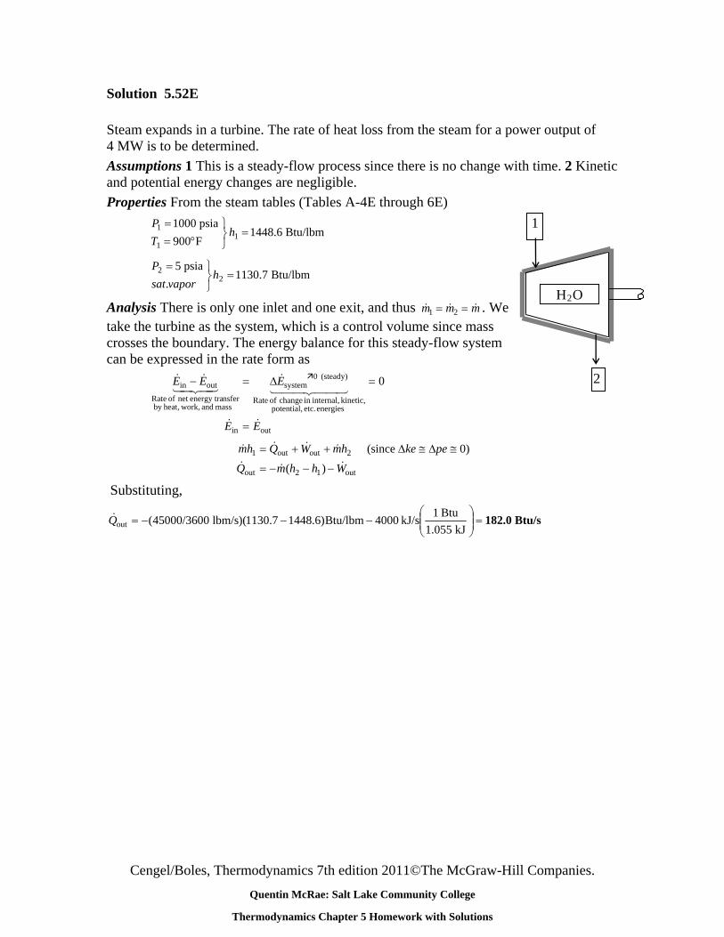
Steam expands in a turbine. The rate of heat loss from the steam for a power output of 4 MW is to be determined.
Assumptions 1 This is a steady-flow process since there is no change with time. 2 Kinetic and potential energy changes are negligible.
Properties From the steam tables (Tables A-4E through 6E)
Btu/lbm 1448.6F900
psia 10001
1
1
hT
P
Btu/lbm 1130.7.
psia 52
2
hvaporsat
P
Analysis There is only one inlet and one exit, and thus m m m1 2 . We take the turbine as the system, which is a control volume since mass crosses the boundary. The energy balance for this steady-flow system can be expressed in the rate form as
outin
energies etc. potential, kinetic, internal,in change of Rate
(steady) 0system
mass and work,heat,by nsferenergy tranet of Rate
outin 0
EE
EEE
( ) mh Q W mh ke pe
Q m h h W
1 2
2 1
out out
out out
(since 0)
Substituting,
Btu/s 182.0
kJ 1.055
Btu 1kJ/s 4000Btu/lbm)6.14487.1130)(lbm/s 45000/3600(outQ
1
H O2
2
Cengel/Boles, Thermodynamics 7th edition 2011©The McGraw-Hill Companies.

Quentin McRae: Salt Lake Community College
Thermodynamics Chapter 5 Homework with Solutions
Problem 5.68
Refrigerant-134a at 800 kPa and 25°C is throttled to a temperature of −20°C. Determine the pressure and the internal energy of the refrigerant at the final state.
Cengel/Boles, Thermodynamics 7th edition 2011©The McGraw-Hill Companies.

Quentin McRae: Salt Lake Community College
Thermodynamics Chapter 5 Homework with Solutions
Solution 5.68 Answers: 133 kPa, 80.7 kJ/kg
Refrigerant-134a is throttled by a valve. The pressure and internal energy after expansion are to be determined.
Assumptions 1 This is a steady-flow process since there is no change with time. 2 Kinetic and potential energy changes are negligible. 3 Heat transfer to or from the fluid is negligible. 4 There are no work interactions involved.
Properties The inlet enthalpy of R-134a is, from the refrigerant tables (Tables A-11 through 13),
kJ/kg 86.41C25
MPa 0.8C25@1
1
1
fhh
T
P
Analysis There is only one inlet and one exit, and thus m m m1 2 . We take the throttling valve as the system, which is a control volume since mass crosses the boundary. The energy balance for this steady-flow system can be expressed in the rate form as
0
21
21
outin
(steady) 0systemoutin
hh
hmhm
EE
EEE
P = 0.8 MPa 1
T = 25C 1
since . Then, Q W ke pe 0 R-134a
kJ/kg 218.84kJ/kg 238.41
kJ/kg 25.39,kJ/kg 25.49C20
12
2
gg
ff
uh
uh
hh
T
Obviously hf < h2 <hg, thus the refrigerant exists as a saturated mixture at the exit state, and thus T = -20C 2
P2 = Psat @ -20°C = 132.82 kPa
Also,
2861.091.212
49.2541.8622
fg
f
h
hhx
Thus, kJ/kg 80.74 45.1932861.039.2522 fgf uxuu
Cengel/Boles, Thermodynamics 7th edition 2011©The McGraw-Hill Companies.

Quentin McRae: Salt Lake Community College
Thermodynamics Chapter 5 Homework with Solutions
Problem 5.63C Would you expect the temperature of air to drop as it undergoes a steady-flow throttling process? Explain.
Cengel/Boles, Thermodynamics 7th edition 2011©The McGraw-Hill Companies.

Quentin McRae: Salt Lake Community College
Thermodynamics Chapter 5 Homework with Solutions
Solution 5.63C No. Because air is an ideal gas and h = h(T) for ideal gases. Thus if h remains constant, so does the temperature.
Cengel/Boles, Thermodynamics 7th edition 2011©The McGraw-Hill Companies.

Quentin McRae: Salt Lake Community College
Thermodynamics Chapter 5 Homework with Solutions
Problem 5.77E Water at 65°F and 20 psia is heated in a chamber by mixing it with saturated water vapor at 20 psia. If both streams enter the mixing chamber at the same mass flow rate, determine the temperature and the quality of the exiting stream.
Cengel/Boles, Thermodynamics 7th edition 2011©The McGraw-Hill Companies.

Quentin McRae: Salt Lake Community College
Thermodynamics Chapter 5 Homework with Solutions
Solution 5.77E Answers: 228°F, 0.415
Liquid water is heated in a chamber by mixing it with saturated water vapor. If both streams enter at the same rate, the temperature and quality (if saturated) of the exit stream is to be determined.
Assumptions 1 This is a steady-flow process since there is no change with time. 2 Kinetic and potential energy changes are negligible. 3 There are no work interactions. 4 The device is adiabatic and thus heat transfer is negligible.
Properties From steam tables (Tables A-5E through A-6E),
h1 hf @ 65F = 33.08 Btu/lbm
h2 = hg @ 20 psia = 1156.2 Btu/lbm
Analysis We take the mixing chamber as the system, which is a control volume since mass crosses the boundary. The mass and energy balances for this steady-flow system can be expressed in the rate form as
Mass balance: T1 = 65F
Cengel/Boles, Thermodynamics 7th edition 2011©The McGraw-Hill Companies.
H2O (P = 20 psia)
T3, x3 mmm
mmmm
mm
mmm
21
321
outin
(steady) 0systemoutin
2
0
Sat. vapor m2 =
Energy balance: m··
1
0)peke (since
0
332211
outin
energies etc. potential, kinetic, internal,in change of Rate
(steady) 0system
mass and work,heat,by nsferenergy tranet of Rate
outin
WQhmhmhm
EE
EEE
Combining the two gives 2/or2 213321 hhhhmhmhm
Substituting,
h3 = (33.08 + 1156.2)/2 = 594.6 Btu/lbm
At 20 psia, hf = 196.27 Btu/lbm and hg = 1156.2 Btu/lbm. Thus the exit stream is a saturated mixture since hf < h3 < hg. Therefore,
T3 = Tsat @ 20 psia = 228F
and
0.415
27.1962.1156
27.1966.59433
fg
f
h
hhx

Quentin McRae: Salt Lake Community College
Thermodynamics Chapter 5 Homework with Solutions
Problem 5.82 A heat exchanger is to cool ethylene glycol (cp = 2.56 kJ/kg·°C) flowing at a rate of 3.2 kg/s from 80°C to 40°C by water (cp = 4.18 kJ/kg·°C) that enters at 20°C and leaves at 70°C. Determine (a) the rate of heat transfer and (b) the mass flow rate of water.
Cengel/Boles, Thermodynamics 7th edition 2011©The McGraw-Hill Companies.

Quentin McRae: Salt Lake Community College
Thermodynamics Chapter 5 Homework with Solutions
Solution 5.82
Ethylene glycol is cooled by water in a heat exchanger. The rate of heat transfer in the heat exchanger and the mass flow rate of water are to be determined.
Assumptions 1 Steady operating conditions exist. 2 The heat exchanger is well-insulated so that heat loss to the surroundings is negligible and thus heat transfer from the hot fluid is equal to the heat transfer to the cold fluid. 3 Changes in the kinetic and potential energies of fluid streams are negligible. 4 Fluid properties are constant.
Properties The specific heats of water and ethylene glycol are given to be 4.18 and 2.56 kJ/kg.C, respectively.
Cold Water20C
Analysis (a) We take the ethylene glycol tubes athe system, which is a control volume. The energy balance for this steady-flow system can be expressed in the rate form as
s
Hot Glycol 40C 80C
)(
0)peke (since
0
21out
2out1
outin
energies etc. potential, kinetic, internal,in change of Rate
(steady) 0system
mass and work,heat,by nsferenergy tranet of Rate
outin
TTcmQ
hmQhm
EE
EEE
p
3.2 kg/s
Then the rate of heat transfer becomes
kW 327.7=C)40CC)(80kJ/kg. kg/s)(2.56 2.3()]([ glycol outinp TTcmQ
(b) The rate of heat transfer from glycol must be equal to the rate of heat transfer to the water. Then,
kg/s 1.57=C)20CC)(70kJ/kg. (4.18
kJ/s 7.327
)()]([
inoutwaterwaterinout
TTc
QmTTcmQ
pp
Cengel/Boles, Thermodynamics 7th edition 2011©The McGraw-Hill Companies.

Quentin McRae: Salt Lake Community College
Thermodynamics Chapter 5 Homework with Solutions
Problem 5.111 A house has an electric heating system that consists of a 300-W fan and an electric resistance heating element placed in a duct. Air flows steadily through the duct at a rate of 0.6 kg/s and experiences a temperature rise of 7°C. The rate of heat loss from the air in the duct is estimated to be 300 W. Determine the power rating of the electric resistance heating element.
Cengel/Boles, Thermodynamics 7th edition 2011©The McGraw-Hill Companies.

Quentin McRae: Salt Lake Community College
Thermodynamics Chapter 5 Homework with Solutions
Solution 5.111 Answer: 4.22 kW
A house is heated by an electric resistance heater placed in a duct. The power rating of the electric heater is to be determined.
Assumptions 1 This is a steady-flow process since there is no change with time. 2 Air is an ideal gas with constant specific heats at room temperature. 3 Kinetic and potential energy changes are negligible.
Properties The constant pressure specific heat of air at room temperature is cp = 1.005 kJ/kg·K (Table A-2)
Analysis We take the heating duct as the system, which is a control volume since mass crosses the boundary. There is only one inlet and one exit, and thus
. The energy balance for this steady-flow system can be expressed in the rate form as
m m m1 2
)()(
0)peke (since
0
12out12outinfan,ine,
2out1infan,ine,
outin
energies etc. potential, kinetic, internal,in change of Rate
(steady) 0system
mass and work,heat,by nsferenergy tranet of Rate
outin
TTcmQhhmQWW
hmQhmWW
EE
EEE
p
Substituting, the power rating of the heating element is determined to be
kW 4.22 kW 0.3)C7)(CkJ/kg 1.005(kg/s) 0.6()kJ/s 0.3(infan,outine, WTQW pcm
We
300
300 W
Cengel/Boles, Thermodynamics 7th edition 2011©The McGraw-Hill Companies.

Quentin McRae: Salt Lake Community College
Thermodynamics Chapter 5 Homework with Solutions
Problem 5.121 A 2-m3 rigid tank initially contains air at 100 kPa and 22°C. The tank is connected to a supply line through a valve. Air is flowing in the supply line at 600 kPa and 22°C. The valve is opened, and air is allowed to enter the tank until the pressure in the tank reaches the line pressure, at which point the valve is closed. A thermometer placed in the tank indicates that the air temperature at the final state is 77°C. Determine (a) the mass of air that has entered the tank and (b) the amount of heat transfer.
Cengel/Boles, Thermodynamics 7th edition 2011©The McGraw-Hill Companies.

Quentin McRae: Salt Lake Community College
Thermodynamics Chapter 5 Homework with Solutions
Solution 5.121 Answers: (a) 9.58 kg, (b) 339 kJ
A rigid tank initially contains air at atmospheric conditions. The tank is connected to a supply line, and air is allowed to enter the tank until mechanical equilibrium is established. The mass of air that entered and the amount of heat transfer are to be determined.
Assumptions 1 This is an unsteady process since the conditions within the device are changing during the process, but it can be analyzed as a uniform-flow process since the state of fluid at the inlet remains constant. 2 Air is an ideal gas with variable specific heats. 3 Kinetic and potential energies are negligible. 4 There are no work interactions involved. 5 The direction of heat transfer is to the tank (will be verified).
Properties The gas constant of air is 0.287 kPa.m3/kg.K (Table A-1). The properties of air are (Table A-17)
kJ/kg 02.250K 350kJ/kg 49.210K 295kJ/kg 17.295K 295
22
11
uTuThT ii
Analysis (a) We take the tank as the system, which is a control volume since mass crosses the boundary. Noting that the microscopic energies of flowing and nonflowing fluids are represented by enthalpy h and internal energy u, respectively, the mass and energy balances for this uniform-flow system can be expressed as
Mass balance: Pi = 600 kPa Ti = 22C 12systemoutin mmmmmm i
Energy balance:
)0 (since 1122in
energies etc. potential, kinetic, internal,in Change
system
mass and work,heat,by nsferenergy traNet
outin
pekeWumumhmQ
EEE
ii
The initial and the final masses in the tank are
kg 11.946
)K 350)(K/kgmkPa 0.287(
)m 2)(kPa 600(
kg 2.362)K 295)(K/kgmkPa 0.287(
)m 2)(kPa 100(
3
3
2
22
3
3
1
11
RT
Pm
RT
Pm
V
V
Then from the mass balance, m m mi 2 1 11946 2 362. . 9.584 kg
(b) The heat transfer during this process is determined from
kJ 339
out
1122in
kJ 339
kJ/kg 210.49kg 2.362kJ/kg 250.02kg 11.946kJ/kg 295.17kg 9.584
Q
umumhmQ ii
Discussion The negative sign for heat transfer indicates that the assumed direction is wrong. Therefore, we reversed the direction.
V1 = 2 m3 P1 = 100 kPa
T1 = 22C
Q·
Cengel/Boles, Thermodynamics 7th edition 2011©The McGraw-Hill Companies.

Quentin McRae: Salt Lake Community College
Thermodynamics Chapter 5 Homework with Solutions
Problem 5.124E A scuba diver’s 2-ft3 air tank is to be filled with air from a compressed air line at 120 psia and 100°F. Initially, the air in this tank is at 20 psia and 70°F. Presuming that the tank is well insulated, determine the temperature and mass in the tank when it is filled to 120 psia.
Cengel/Boles, Thermodynamics 7th edition 2011©The McGraw-Hill Companies.

Quentin McRae: Salt Lake Community College
Thermodynamics Chapter 5 Homework with Solutions
Solution 5.124E
A scuba diver's air tank is to be filled with air from a compressed air line. The temperature and mass in the tank at the final state are to be determined.
Assumptions 1 This is an unsteady process since the conditions within the device are changing during the process, but it can be analyzed as a uniform-flow process since the state of fluid at the inlet remains constant. 2 Air is an ideal gas with constant specific heats. 3 Kinetic and potential energies are negligible. 4 There are no work interactions involved. 5 The tank is well-insulated, and thus there is no heat transfer.
Properties The gas constant of air is 0.3704 psia·ft3/lbm·R (Table A-1E). The specific heats of air at room temperature are cp = 0.240 Btu/lbm·R and cv = 0.171 Btu/lbm·R (Table A-2Ea).
Analysis We take the tank as the system, which is a control volume since mass crosses the boundary. Noting that the microscopic energies of flowing and nonflowing fluids are represented by enthalpy h and internal energy u, respectively, the mass and energy balances for this uniform-flow system can be expressed as Mass balance:
12systemoutin mmmmmm i
20 psia 70F 2 ft3
120 psia, 100FAir Energy balance:
1122
1122
energies etc. potential, kinetic, internal,in Change
system
mass and work,heat,by nsferenergy traNet
outin
TcmTcmTcm
umumhm
EEE
ipi
ii
vv
Combining the two balances: 112212 )( TcmTcmTcmm ip vv
The initial and final masses are given by
lbm 2038.0)R 46070)(R/lbmftpsia 0.3704(
)ft 2)(psia 02(3
3
1
11
RT
Pm
V
22
3
3
2
22
9.647
)R/lbmftpsia 0.3704(
)ft 2)(psia 012(
TTRT
Pm
V
Substituting,
)530)(171.0)(2038.0()171.0(9.647
)560)(24.0(2038.09.647
222
T
TT
whose solution is F267.4R 727.4 2T
The final mass is then
lbm 0.8904.727
9.6479.647
22 T
m
Cengel/Boles, Thermodynamics 7th edition 2011©The McGraw-Hill Companies.

Quentin McRae: Salt Lake Community College
Thermodynamics Chapter 5 Homework with Solutions
Problem 5.129 A 0.03-m3 rigid tank initially contains refrigerant- 134a at 1.4 MPa and 100 percent quality. The tank is connected by a valve to a supply line that carries refrigerant-134a at 1.6 MPa and 36°C. Now the valve is opened, and the refrigerant is allowed to enter the tank. The valve is closed when it is observed that the tank contains saturated liquid at 1.6 MPa. Determine (a) the mass of the refrigerant that has entered the tank and (b) the amount of heat transfer.
Cengel/Boles, Thermodynamics 7th edition 2011©The McGraw-Hill Companies.

Quentin McRae: Salt Lake Community College
Thermodynamics Chapter 5 Homework with Solutions
Solution 5.129 Answers: (a) 29.8 kg, (b) 697 kJ
A rigid tank initially contains saturated R-134a vapor. The tank is connected to a supply line, and R-134a is allowed to enter the tank. The mass of the R-134a that entered and the heat transfer are to be determined.
Assumptions 1 This is an unsteady process since the conditions within the device are changing during the process, but it can be analyzed as a uniform-flow process since the state of fluid at the inlet remains constant. 2 Kinetic and potential energies are negligible. 3 There are no work interactions involved. 4 The direction of heat transfer is to the tank (will be verified).
R-134a 0.03 m3 1.4 MPa
Sat. vapor
1.6 MPa 36C
Properties The properties of refrigerant are (Tables A-11 through A-13)
R-134a
kJ/kg .33102C36
MPa 1.6
kJ/kg 134.43
/kgm 0.0009400
liquid sat.
MPa 1.6
kJ/kg 256.37
/kgm 0.01411
vaporsat.
MPa 1.4
C36@
MPa 1.6@2
3MPa 1.6@22
MPa 1.4@1
3MPa 1.4@11
fii
i
f
f
g
g
hhT
P
uu
P
uu
P
vv
vv
Q
Analysis We take the tank as the system, which is a control volume since mass crosses the boundary. Noting that the microscopic energies of flowing and nonflowing fluids are represented by enthalpy h and internal energy u, respectively, the mass and energy balances for this uniform-flow system can be expressed as
Mass balance: 12systemoutin mmmmmm i
Energy balance:
)0 (since 1122in
energies etc. potential, kinetic, internal,in Change
system
mass and work,heat,by nsferenergy traNet
outin
pekeWumumhmQ
EEE
ii
(a) The initial and the final masses in the tank are
kg 92.31/kgm 0.0009400
m 0.03
kg 127.2/kgm 0.01411
m 0.03
3
3
2
22
3
3
1
11
v
V
v
V
m
m
Then from the mass balance kg 29.79 127.292.3112 mmmi
continued on next page....
Cengel/Boles, Thermodynamics 7th edition 2011©The McGraw-Hill Companies.

Quentin McRae: Salt Lake Community College
Thermodynamics Chapter 5 Homework with Solutions
(c) The heat transfer during this process is determined from the energy balance to be
Cengel/Boles, Thermodynamics 7th edition 2011©The McGraw-Hill Companies.
kJ 697
kJ/kg 256.37kg 2.127kJ/kg 134.43kg 31.92kJ/kg 102.33kg 29.79
1122in umumhmQ ii

Quentin McRae: Salt Lake Community College
Thermodynamics Chapter 5 Homework with Solutions
Problem 5.130 A 0.3-m3 rigid tank is filled with saturated liquid water at 200°C. A valve at the bottom of the tank is opened, and liquid is withdrawn from the tank. Heat is transferred to the water such that the temperature in the tank remains constant. Determine the amount of heat that must be transferred by the time one-half of the total mass has been withdrawn.
Cengel/Boles, Thermodynamics 7th edition 2011©The McGraw-Hill Companies.

Quentin McRae: Salt Lake Community College
Thermodynamics Chapter 5 Homework with Solutions
Solution 5.130
A rigid tank initially contains saturated liquid water. A valve at the bottom of the tank is opened, and half of the mass in liquid form is withdrawn from the tank. The temperature in the tank is maintained constant. The amount of heat transfer is to be determined.
Assumptions 1 This is an unsteady process since the conditions within the device are changing during the process, but it can be analyzed as a uniform-flow process since the state of fluid leaving the device remains constant. 2 Kinetic and potential energies are negligible. 3 There are no work interactions involved. 4 The direction of heat transfer is to the tank (will be verified).
Properties The properties of water are (Tables A-4 through A-6)
kJ/kg 852.26liquid sat.
C200
kJ/kg 850.46
/kgm 0.001157
liquid sat.
C200
C200@
C200@1
3C200@11
fee
f
f
hhT
uu
T vv
Analysis We take the tank as the system, which is a control volume since mass crosses the boundary. Noting that the microscopic energies of flowing and nonflowing fluids are represented by enthalpy h and internal energy u, respectively, the mass and energy balances for this uniform-flow system can be expressed as
Mass balance: 21systemoutin mmmmmm e H2O
Sat. liquid T = 200C V = 0.3 m3
Energy balance:
)0 (since 1122in
energies etc. potential, kinetic, internal,in Change
system
mass and work,heat,by nsferenergy traNet
outin
pekeWumumhmQ
EEE
ee
Q
The initial and the final masses in the tank are
kg 129.7kg 259.4
kg 259.4/kgm0.001157
m 0.3
21
121
2
3
3
1
11
mm
mv
V
Then from the mass balance, kg 129.77.1294.25921 mmme
Now we determine the final internal energy,
kJ/kg 866.467.1743009171.046.850009171.0
C200
009171.0001157.012721.0
001157.0002313.0
/kgm 0.002313kg 129.7
m 0.3
222
2
22
33
22
fgf
fg
f
uxuux
T
x
m
v
vv
Vv
continued on next page....
Cengel/Boles, Thermodynamics 7th edition 2011©The McGraw-Hill Companies.

Quentin McRae: Salt Lake Community College
Thermodynamics Chapter 5 Homework with Solutions
Then the heat transfer during this process is determined from the energy balance by substitution to be
kJ 2308 kJ/kg 850.46kg 259.4kJ/kg 866.46kg 129.7kJ/kg 852.26kg 129.7Q
Cengel/Boles, Thermodynamics 7th edition 2011©The McGraw-Hill Companies.

Quentin McRae: Salt Lake Community College
Thermodynamics Chapter 5 Homework with Solutions
Problem 5.135 An insulated 0.15-m3 tank contains helium at 3 MPa and 130°C. A valve is now opened, allowing some helium to escape. The valve is closed when one-half of the initial mass has escaped. Determine the final temperature and pressure in the tank.
Cengel/Boles, Thermodynamics 7th edition 2011©The McGraw-Hill Companies.

Quentin McRae: Salt Lake Community College
Thermodynamics Chapter 5 Homework with Solutions
Solution 5.135 Answers: 257 K, 956 kPa
An insulated rigid tank initially contains helium gas at high pressure. A valve is opened, and half of the mass of helium is allowed to escape. The final temperature and pressure in the tank are to be determined.
Assumptions 1 This is an unsteady process since the conditions within the device are changing during the process, but it can be analyzed as a uniform-flow process by using constant average properties for the helium leaving the tank. 2 Kinetic and potential energies are negligible. 3 There are no work interactions involved. 4 The tank is insulated and thus heat transfer is negligible. 5 Helium is an ideal gas with constant specific heats.
Properties The specific heat ratio of helium is k =1.667 (Table A-2).
Analysis We take the tank as the system, which is a control volume since mass crosses the boundary. Noting that the microscopic energies of flowing and nonflowing fluids are represented by enthalpy h and internal energy u, respectively, the mass and energy balances for this uniform-flow system can be expressed as
He 0.15 m3 3 MPa 130C
Mass balance: 21systemoutin mmmmmm e
121
2121
2 (given) mmmmm e
Energy balance:
)0 (since 1122
energies etc. potential, kinetic, internal,in Change
system
mass and work,heat,by nsferenergy traNet
outin
pekeQWumumhm
EEE
ee
Note that the state and thus the enthalpy of helium leaving the tank is changing during this process. But for simplicity, we assume constant properties for the exiting steam at the average values.
Combining the mass and energy balances: 0 12 1
12 1 2 1 1 m h m u m ue
Dividing by m1/2 1221
12 22
020 TcTcTT
coruuh pe vv
Dividing by cv: vcckTTTTk p / since420 1221
Solving for T2:
K 257
K 4031.6672
1.6674
2
412 T
k
kT
The final pressure in the tank is
kPa 956 kPa 3000403
257
2
11
11
222
22
11
2
1 PTm
TmP
RTm
RTm
P
P
V
V
Cengel/Boles, Thermodynamics 7th edition 2011©The McGraw-Hill Companies.