Theoretical Design and Circuit Implementation of Integer Domain Chaotic Systems
10
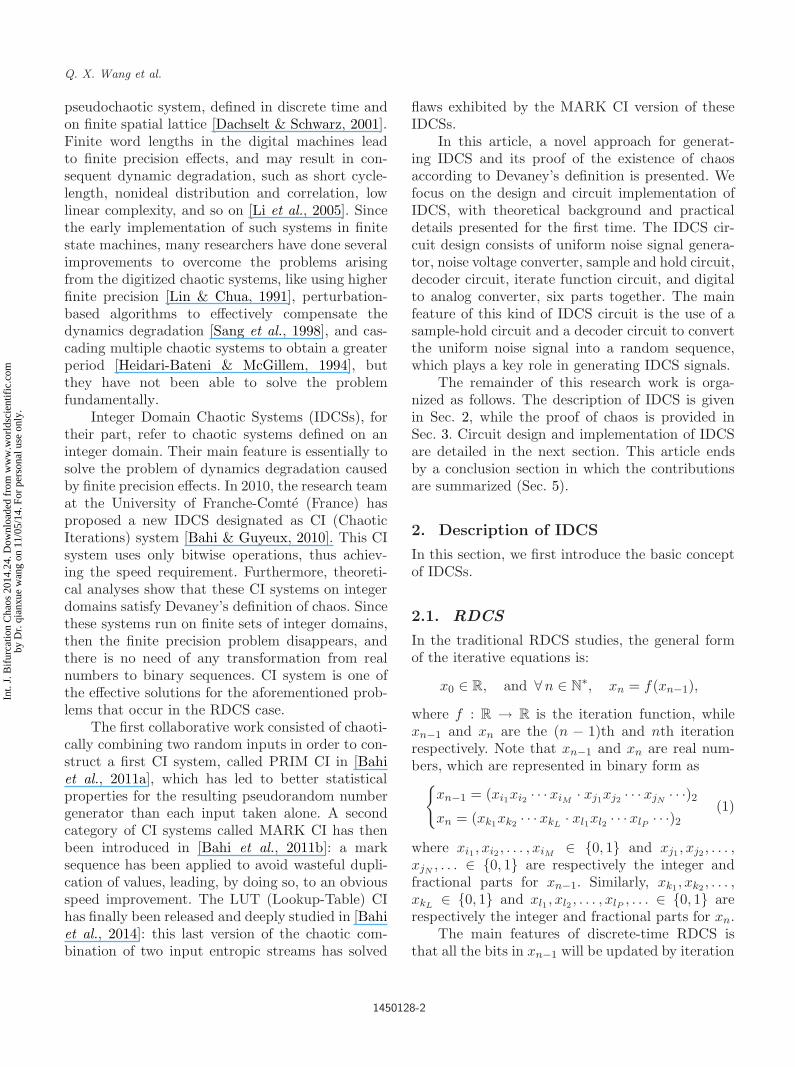
International Journal of Bifurcation and Chaos, Vol. 24, No. 10 (2014) 1450128 (10 pages) c World Scientific Publishing Company DOI: 10.1142/S0218127414501284 Theoretical Design and Circuit Implementation of Integer Domain Chaotic Systems Qianxue Wang ∗ and Simin Yu † College of Automation, Guangdong University of Technology, Guangzhou 510006, P. R. China ∗ [email protected] † [email protected] Christophe Guyeux ‡ and Jacques M. Bahi § Femto-st Institute, UMR 6174 CNRS, University of Franche-Comt´ e, Besan¸con 25000, France ‡ [email protected] § [email protected] Xiaole Fang Land and Resources Technology Center of Guangdong Province, Guangzhou 510075, P. R. China [email protected] Received February 23, 2014 In this paper, a new approach for constructing integer domain chaotic systems (IDCS) is proposed, and its chaotic behavior is mathematically proven according to Devaney’s definition of chaos. Furthermore, an analog-digital hybrid circuit is also developed for realizing the designed basic IDCS. In the IDCS circuit design, chaos generation strategy is realized through a sample- hold circuit and a decoder circuit so as to convert the uniform noise signal into a random sequence, which plays a key role in circuit implementation. The experimental observations further validate the proposed systematic methodology for the first time. Keywords : Chaos; integer domain chaotic systems; circuit implementation. 1. Introduction Currently, international research works on chaotic systems and their applications are mainly focused on real domain, leading to the study and develop- ment of the so-called Real Domain Chaotic Systems (RDCSs). RDCSs are divided into two categories: continuous-time and discrete-time chaotic systems. Continuous-time systems, including the Lorenz, Chen and Chua systems [Lorenz, 1963; Chua et al., 1986; Chen & Ueta, 1999] are defined by state (differential) equations, while discrete-time chaotic systems are given by iterative equations, such as Logistic or Henon map, Chen–Lai algorithm [May et al., 1976; Zheng et al., 2008; Chen & Lai, 1997], and so on. When a chaotic phenomenon is implemented either in digital computers or in some other digital devices, its associated chaotic system is discretized both spatially and temporally. That is, the system becomes both a discrete-time and discrete-valued ∗ Author for correspondence 1450128-1 Int. J. Bifurcation Chaos 2014.24. Downloaded from www.worldscientific.com by Dr. qianxue wang on 11/05/14. For personal use only.
-
Upload
independent -
Category
Documents
-
view
4 -
download
0
Transcript of Theoretical Design and Circuit Implementation of Integer Domain Chaotic Systems

October 21, 2014 14:21 WSPC/S0218-1274 1450128
International Journal of Bifurcation and Chaos, Vol. 24, No. 10 (2014) 1450128 (10 pages)c© World Scientific Publishing CompanyDOI: 10.1142/S0218127414501284
Theoretical Design and Circuit Implementationof Integer Domain Chaotic Systems
Qianxue Wang∗ and Simin Yu†College of Automation, Guangdong University of Technology,
Guangzhou 510006, P. R. China∗[email protected]
Christophe Guyeux‡ and Jacques M. Bahi§Femto-st Institute, UMR 6174 CNRS,
University of Franche-Comte, Besancon 25000, France‡[email protected]
Xiaole FangLand and Resources Technology Center of Guangdong Province,
Guangzhou 510075, P. R. [email protected]
Received February 23, 2014
In this paper, a new approach for constructing integer domain chaotic systems (IDCS) isproposed, and its chaotic behavior is mathematically proven according to Devaney’s definition ofchaos. Furthermore, an analog-digital hybrid circuit is also developed for realizing the designedbasic IDCS. In the IDCS circuit design, chaos generation strategy is realized through a sample-hold circuit and a decoder circuit so as to convert the uniform noise signal into a randomsequence, which plays a key role in circuit implementation. The experimental observationsfurther validate the proposed systematic methodology for the first time.
Keywords : Chaos; integer domain chaotic systems; circuit implementation.
1. Introduction
Currently, international research works on chaoticsystems and their applications are mainly focusedon real domain, leading to the study and develop-ment of the so-called Real Domain Chaotic Systems(RDCSs). RDCSs are divided into two categories:continuous-time and discrete-time chaotic systems.Continuous-time systems, including the Lorenz,Chen and Chua systems [Lorenz, 1963; Chua et al.,1986; Chen & Ueta, 1999] are defined by state
(differential) equations, while discrete-time chaoticsystems are given by iterative equations, such asLogistic or Henon map, Chen–Lai algorithm [Mayet al., 1976; Zheng et al., 2008; Chen & Lai, 1997],and so on.
When a chaotic phenomenon is implementedeither in digital computers or in some other digitaldevices, its associated chaotic system is discretizedboth spatially and temporally. That is, the systembecomes both a discrete-time and discrete-valued
∗Author for correspondence
1450128-1
Int.
J. B
ifur
catio
n C
haos
201
4.24
. Dow
nloa
ded
from
ww
w.w
orld
scie
ntif
ic.c
omby
Dr.
qia
nxue
wan
g on
11/
05/1
4. F
or p
erso
nal u
se o
nly.
October 21, 2014 14:21 WSPC/S0218-1274 1450128
Q. X. Wang et al.
pseudochaotic system, defined in discrete time andon finite spatial lattice [Dachselt & Schwarz, 2001].Finite word lengths in the digital machines leadto finite precision effects, and may result in con-sequent dynamic degradation, such as short cycle-length, nonideal distribution and correlation, lowlinear complexity, and so on [Li et al., 2005]. Sincethe early implementation of such systems in finitestate machines, many researchers have done severalimprovements to overcome the problems arisingfrom the digitized chaotic systems, like using higherfinite precision [Lin & Chua, 1991], perturbation-based algorithms to effectively compensate thedynamics degradation [Sang et al., 1998], and cas-cading multiple chaotic systems to obtain a greaterperiod [Heidari-Bateni & McGillem, 1994], butthey have not been able to solve the problemfundamentally.
Integer Domain Chaotic Systems (IDCSs), fortheir part, refer to chaotic systems defined on aninteger domain. Their main feature is essentially tosolve the problem of dynamics degradation causedby finite precision effects. In 2010, the research teamat the University of Franche-Comte (France) hasproposed a new IDCS designated as CI (ChaoticIterations) system [Bahi & Guyeux, 2010]. This CIsystem uses only bitwise operations, thus achiev-ing the speed requirement. Furthermore, theoreti-cal analyses show that these CI systems on integerdomains satisfy Devaney’s definition of chaos. Sincethese systems run on finite sets of integer domains,then the finite precision problem disappears, andthere is no need of any transformation from realnumbers to binary sequences. CI system is one ofthe effective solutions for the aforementioned prob-lems that occur in the RDCS case.
The first collaborative work consisted of chaoti-cally combining two random inputs in order to con-struct a first CI system, called PRIM CI in [Bahiet al., 2011a], which has led to better statisticalproperties for the resulting pseudorandom numbergenerator than each input taken alone. A secondcategory of CI systems called MARK CI has thenbeen introduced in [Bahi et al., 2011b]: a marksequence has been applied to avoid wasteful dupli-cation of values, leading, by doing so, to an obviousspeed improvement. The LUT (Lookup-Table) CIhas finally been released and deeply studied in [Bahiet al., 2014]: this last version of the chaotic com-bination of two input entropic streams has solved
flaws exhibited by the MARK CI version of theseIDCSs.
In this article, a novel approach for generat-ing IDCS and its proof of the existence of chaosaccording to Devaney’s definition is presented. Wefocus on the design and circuit implementation ofIDCS, with theoretical background and practicaldetails presented for the first time. The IDCS cir-cuit design consists of uniform noise signal genera-tor, noise voltage converter, sample and hold circuit,decoder circuit, iterate function circuit, and digitalto analog converter, six parts together. The mainfeature of this kind of IDCS circuit is the use of asample-hold circuit and a decoder circuit to convertthe uniform noise signal into a random sequence,which plays a key role in generating IDCS signals.
The remainder of this research work is orga-nized as follows. The description of IDCS is givenin Sec. 2, while the proof of chaos is provided inSec. 3. Circuit design and implementation of IDCSare detailed in the next section. This article endsby a conclusion section in which the contributionsare summarized (Sec. 5).
2. Description of IDCS
In this section, we first introduce the basic conceptof IDCSs.
2.1. RDCS
In the traditional RDCS studies, the general formof the iterative equations is:
x0 ∈ R, and ∀n ∈ N∗, xn = f(xn−1),
where f : R → R is the iteration function, whilexn−1 and xn are the (n − 1)th and nth iterationrespectively. Note that xn−1 and xn are real num-bers, which are represented in binary form as
xn−1 = (xi1xi2 · · · xiM · xj1xj2 · · · xjN· · ·)2
xn = (xk1xk2 · · · xkL· xl1xl2 · · · xlP · · ·)2
(1)
where xi1 , xi2 , . . . , xiM ∈ 0, 1 and xj1, xj2 , . . . ,xjN
, . . . ∈ 0, 1 are respectively the integer andfractional parts for xn−1. Similarly, xk1, xk2 , . . . ,xkL
∈ 0, 1 and xl1 , xl2 , . . . , xlP , . . . ∈ 0, 1 arerespectively the integer and fractional parts for xn.
The main features of discrete-time RDCS isthat all the bits in xn−1 will be updated by iteration
1450128-2
Int.
J. B
ifur
catio
n C
haos
201
4.24
. Dow
nloa
ded
from
ww
w.w
orld
scie
ntif
ic.c
omby
Dr.
qia
nxue
wan
g on
11/
05/1
4. F
or p
erso
nal u
se o
nly.

October 21, 2014 14:21 WSPC/S0218-1274 1450128
Theoretical Design and Circuit Implementation of Integer Domain Chaotic Systems
function f at each operation (iteration). Likewise,all the bits in xn will be updated by iteration func-tion f at each operation (iteration).
2.2. IDCS
The main ideas of CI systems are summarized there-after.
Let N ∈ 1, 2, . . . be a positive integer, B =1, 0 denotes the set of binary numbers, while B
N
is the set of binary vectors of size N . For anyn = 0, 1, 2, . . . , xn is represented by using N bits inbase-2: x0 = (x0
N−1x0N−2 · · · x0
0) ∈ BN is the initial
condition, while xn−1 = (xn−1N−1x
n−1N−2 · · · xn−1
0 ) ∈ BN
and xn = (xnN−1x
nN−2 · · · xn
0 ) ∈ BN denote the
(n − 1)th and nth iteration, respectively. In CIsystems, the iterative equation is defined as follows:
xni =
xn−1
i if i = sn
(f(xn−1))i if i = sn,(2)
where i = 0, 1, 2, . . . , N − 1, n = 1, 2, . . . , and s =(s1s2 · · · sn · · ·) is a one-sided infinite sequenceof integers bounded by N − 1 : ∀n∈N
∗, sn ∈0, 1,2, . . . , N − 1. Additionally, the iterate function fis usually the vectorial Boolean negation [Robert,1986], given by f(xn−1) = (xn−1
N−1 xn−1N−2 · · · xn−1
i · · ·xn−1
0 ), and the following notation is used:
(f(xn−1))i=sn = (xn−1N−1 xn−1
N−2 · · · xn−1i · · · xn−1
0 )i=sn
= xn−1i=sn ,
that is, (f(xn−1))i=sn is the ith component off(xn−1). Let us finally remark that, in IDCS,the one-sided infinite sequence of integers s =(s1s2 · · · sn · · ·) is usually named a chaotic strategy.
Let xk, xj be two binary digits, the correspond-ing distance be
δ(xj , xk) =
1 if xj = xk
0 if xj = xk.(3)
Using the same notations as above, we define thebinary variables negation as follows:
(Ff (k, x))j = xj · δ(k, j) + (f(x))k · δ(k, j), (4)
where j ∈ 0, 1, 2, . . . , N − 1, and k is usuallya term of chaotic strategy s while f is often the
vectorial negation recalled previously. With thesechoices, and according to Eq. (4), a more specificformula can be obtained:
Ff (k, x)
= (xN−1, xN−2, . . . , xk+1, xk, xk−1, . . . , x1, x0).
Let E = (s, x) be a couple constituted bya chaotic strategy and a Boolean vector, that is,E = (s, x) ∈ E = 0, 1, 2, . . . , N −1∞×B
N . Definefunction Gf as follows:
Gf (E) = Gf ((s, x)) = (σ(s), Ff (i(s), x)), (5)
where i(s) = s1 and σk(s) = σ σ · · · σ(s)︸ ︷︷ ︸k
,
k = 1, 2, . . . is the result for shifting k integers inthe one-sided infinite sequence s = (s1s2 · · · sn · · · )to the left. In other words,
σk(s) = sk+1sk+2 · · · sn · · · (k = 1, 2, . . .).
With all this material, IDCS is defined as follows:
E0 ∈ E and ∀ k ∈ N, Ek+1 = Gf (Ek).
Consider now two real numbers a and b, lesserthan 1, which are represented in radix-r format as
a = 0.a1a2a3 · · · an · · · =∞∑
k=1
ak
rk
b = 0.b1b2b3 · · · bn · · · =∞∑
k=1
bk
rk,
(6)
where ak, bk ∈ 0, 1, 2, . . . , r−1. Then the distancebetween a and b is given by:
d(a, b) =∞∑
k=1
|ak − bk|rk
. (7)
The above formula can be generalized to cal-culate the distance between two one-sided infinitesequences of symbols without loss of generality.These remarks lead to the definition of a new dis-tance on the set E , which is defined by:
d((s, x), (s, x)) = ds(s, s) + dx(x, x),
where s = (s1s2 · · · sn · · · ) and s = (s1s2 · · · sn · · · )are one-sided infinite sequences of integers, while x
1450128-3
Int.
J. B
ifur
catio
n C
haos
201
4.24
. Dow
nloa
ded
from
ww
w.w
orld
scie
ntif
ic.c
omby
Dr.
qia
nxue
wan
g on
11/
05/1
4. F
or p
erso
nal u
se o
nly.

October 21, 2014 14:21 WSPC/S0218-1274 1450128
Q. X. Wang et al.
and x are binary digits of N bits. More precisely,and in agreement with Eq. (7), the distance betweens and s is:
ds(s, s) =∞∑
k=1
|sk − sk|Nk
∈ [0, 1] (8)
where ∀ k ∈ N∗, sk, sk ∈ 0, 1, 2, . . . , N−1. Finally,
following the 1-norm distance, the distance betweenx and x is:
dx(x, x) =N−1∑k=0
δ(xk, xk) ∈ 0, 1, 2, . . . , N. (9)
Remark that d is a distance, as it is defined as thesum of two distances.
Before investigating the chaotic properties ofIDCS, we have to prove that Gf is continuous on themetric space (E , d). In order to do so, the followinglemma is first introduced:
Lemma 1. Let s = (s1s2 · · · sn · · ·) and s= (s1s2 · · ·sn · · ·), where sk, sk ∈ 0, 1, 2, . . . , N −1 for k = 1,2, . . . . If si = si for i = 1, 2, . . . , n, then d(s, s) ≤1
Nn . Conversely, if d(s, s) ≤ 1Nn , then si = si for
i = 1, 2, . . . , n.
Proof. If si = si (i = 1, 2, . . . , n), then
d(s, s) =n∑
i=1
|si − si|N i
+∞∑
i=n+1
|si − si|N i
=∞∑
i=n+1
|si − si|N i
≤∞∑
i=n+1
N − 1N i
= (N − 1)
1Nn+1
1 − 1N
=1
Nn.
Conversely, and due to the definition of the pro-posed distance: for any m ≤ n, if sm = sm, thend(s, s) ≥ 1
Nn . The contraposition is the desiredresult: if d(s, s) ≤ 1
Nn , then si = si (i = 1, 2, . . . , n).
To prove that chaotic iterations are an exampleof chaos, we must first set that Gf is continuous onthe metric space (E , d).
Theorem 1. Gf is a continuous function.
Proof. A continuous function is a function forwhich, intuitively, “small” changes in the input
result in “small” changes in the output. Let((s, x)n)n∈N be a sequence of the phase space E ,which converges to (s, x). We will prove that (Gf (s,x)n)n∈N converges to Gf (s, x). In mathematicalnotations, ∀((s, x)n)n∈N ∈ EN : limn→∞(s, x)n =(s, x) ⇒ limn→∞ Gf ((s, x)n) = Gf (s, x)
(1) limn→∞(s, x)n = (s, x) ⇒ ∀ δ > 0, d((s, x)n,(s, x)) < δ for large n.Thus, without loss of generality, we assume thatδ < 1.
(2) If (x)n = x, then dx((x)n, x) ≥ 1, and sod((s, x)n, (s, x)) = ds((s)n, s) + dx((x)n, x) > δ.Thus ∃n0 ∈ N, dx((x)n, x) = 0 for any n ≥ n0.
(3) As d((s, x)n, (s, x)) < δ making
d((s, x)n, (s, x)) = ds((s)n, s) + dx((x)n, x)
= ds((s)n, s) < δ.
According to Lemma 1, if the k0 first elementsof (s)n and s are the same, then ds(s, s) <N−k0 < δ. For instance, k0 = floor(−logNδ)+1is convenient. Thus ∃n1 ∈ N, ds((s)n, s) < δ forany n ≥ n1.
(4) According to Eq. (5), the correspondingGf ((s, x)n) and Gf (s, x) can be obtained:
Gf ((s, x)n) = (σ((s)n), Ff (i((s)n), (x)n))
Gf (s, x) = (σ(s), Ff (i(s), x)).
For n ≥ max(n0, n1), the k0 first elements of(s)n and s are the same and (x)n = x, so
i((s)n) = i(s).
Then,
Ff (i((s)n), (x)n) = Ff (i(s), x).
σ(s) is the result of shifting one integer in theone-sided infinite sequence to the left. So thek0 − 1 first elements of σ((s)n) and σ(s) arestill the same.
So
d(Gf ((s, x)n), Gf (s, x))
= d((σ((s)n),
σ(s) + d(Ff (i((s)n), (x)n), Ff (i(s), x))
= d((σ((s)n), σ(s) < N−(k0−1),
which makes
limn→∞Gf ((s, x)n = Gf (s, x)
true.
In conclusion, Gf is consequently continuous.
1450128-4
Int.
J. B
ifur
catio
n C
haos
201
4.24
. Dow
nloa
ded
from
ww
w.w
orld
scie
ntif
ic.c
omby
Dr.
qia
nxue
wan
g on
11/
05/1
4. F
or p
erso
nal u
se o
nly.
October 21, 2014 14:21 WSPC/S0218-1274 1450128
Theoretical Design and Circuit Implementation of Integer Domain Chaotic Systems
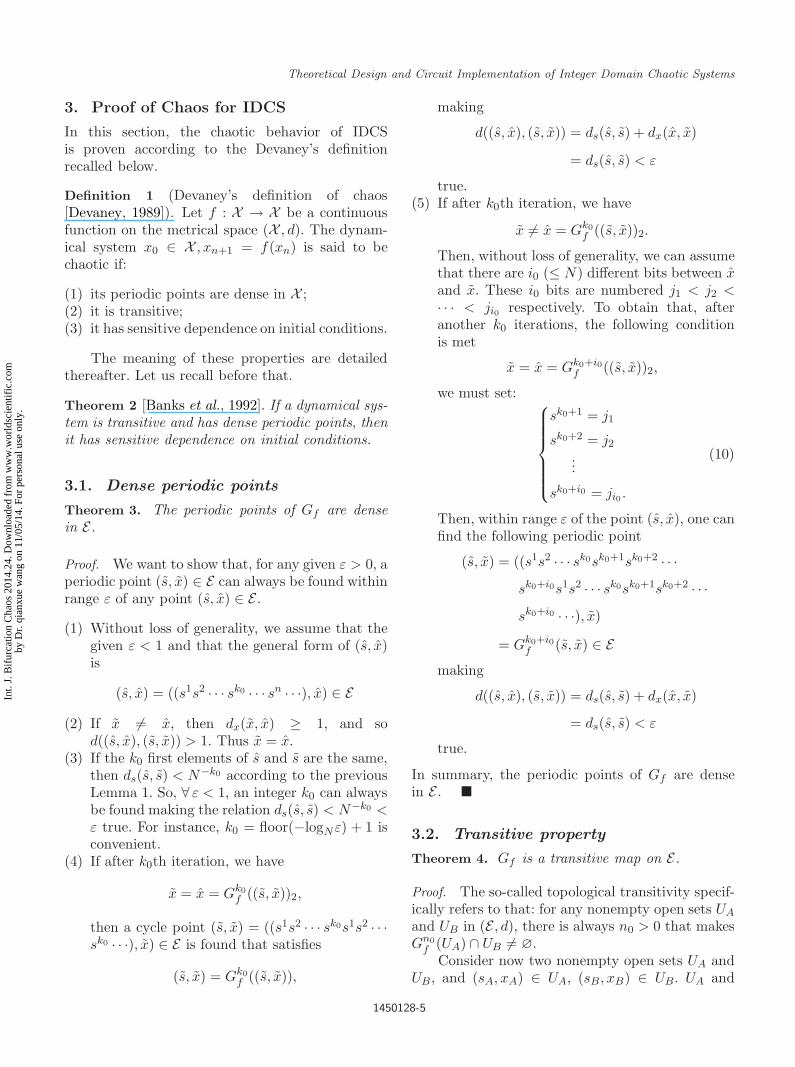
3. Proof of Chaos for IDCS
In this section, the chaotic behavior of IDCSis proven according to the Devaney’s definitionrecalled below.
Definition 1 (Devaney’s definition of chaos[Devaney, 1989]). Let f : X → X be a continuousfunction on the metrical space (X , d). The dynam-ical system x0 ∈ X , xn+1 = f(xn) is said to bechaotic if:
(1) its periodic points are dense in X ;(2) it is transitive;(3) it has sensitive dependence on initial conditions.
The meaning of these properties are detailedthereafter. Let us recall before that.
Theorem 2 [Banks et al., 1992]. If a dynamical sys-tem is transitive and has dense periodic points, thenit has sensitive dependence on initial conditions.
3.1. Dense periodic points
Theorem 3. The periodic points of Gf are densein E.
Proof. We want to show that, for any given ε > 0, aperiodic point (s, x) ∈ E can always be found withinrange ε of any point (s, x) ∈ E .
(1) Without loss of generality, we assume that thegiven ε < 1 and that the general form of (s, x)is
(s, x) = ((s1s2 · · · sk0 · · · sn · · ·), x) ∈ E(2) If x = x, then dx(x, x) ≥ 1, and so
d((s, x), (s, x)) > 1. Thus x = x.(3) If the k0 first elements of s and s are the same,
then ds(s, s) < N−k0 according to the previousLemma 1. So, ∀ ε < 1, an integer k0 can alwaysbe found making the relation ds(s, s) < N−k0 <ε true. For instance, k0 = floor(−logNε) + 1 isconvenient.
(4) If after k0th iteration, we have
x = x = Gk0f ((s, x))2,
then a cycle point (s, x) = ((s1s2 · · · sk0s1s2 · · ·sk0 · · ·), x) ∈ E is found that satisfies
(s, x) = Gk0f ((s, x)),
making
d((s, x), (s, x)) = ds(s, s) + dx(x, x)
= ds(s, s) < ε
true.(5) If after k0th iteration, we have
x = x = Gk0f ((s, x))2.
Then, without loss of generality, we can assumethat there are i0 (≤ N) different bits between xand x. These i0 bits are numbered j1 < j2 <· · · < ji0 respectively. To obtain that, afteranother k0 iterations, the following conditionis met
x = x = Gk0+i0f ((s, x))2,
we must set:
sk0+1 = j1
sk0+2 = j2
...
sk0+i0 = ji0 .
(10)
Then, within range ε of the point (s, x), one canfind the following periodic point
(s, x) = ((s1s2 · · · sk0sk0+1sk0+2 · · ·sk0+i0s1s2 · · · sk0sk0+1sk0+2 · · ·sk0+i0 · · ·), x)
= Gk0+i0f (s, x) ∈ E
making
d((s, x), (s, x)) = ds(s, s) + dx(x, x)
= ds(s, s) < ε
true.
In summary, the periodic points of Gf are densein E .
3.2. Transitive property
Theorem 4. Gf is a transitive map on E.
Proof. The so-called topological transitivity specif-ically refers to that: for any nonempty open sets UA
and UB in (E , d), there is always n0 > 0 that makesGn0
f (UA) ∩ UB = ∅.Consider now two nonempty open sets UA and
UB , and (sA, xA) ∈ UA, (sB , xB) ∈ UB. UA and
1450128-5
Int.
J. B
ifur
catio
n C
haos
201
4.24
. Dow
nloa
ded
from
ww
w.w
orld
scie
ntif
ic.c
omby
Dr.
qia
nxue
wan
g on
11/
05/1
4. F
or p
erso
nal u
se o
nly.
October 21, 2014 14:21 WSPC/S0218-1274 1450128
Q. X. Wang et al.
UB are open, and take place in a metric space, sothere exist real numbers rA > 0 and rB > 0 suchthat the open ball BA of center (sA, xA) and radiusrA is inside UA (resp., the open ball Bb of center(sB, xB) and radius rB is into UB). Without loss ofgenerality, we can suppose that rA < 1.
(1) We introduce the following notations:
(sA, xA) = ((s1As2
A · · · sn0A · · · sn
A · · ·), xA) ∈ UA
⊆ Eand
(sB , xB) = ((s1Bs2
B · · · snB · · ·), xB) ∈ UB ⊆ E .
(2) Let (s, x) ∈ UA. If x = xA, then dx(x, xA) ≥ 1,and so d((sA, xA), (s, x)) > 1. Consequently, if(s, x) ∈ BA, then d((sA, xA), (s, x)) < rA < 1,and so x = xA.
(3) If we demand that the k0 first elements of sare equal to those from sA, then we obtainds(sA, s) < N−k0. And for the given rA, aninteger k0 (that is, a sequence s) can alwaysbe found to achieve ds(sA, s) < N−k0 < rA (forinstance, k0 = floor(−logNrA) + 1).
(4) If after k0 iterations, the following condition issatisfied:
Gk0f ((sA, xA))2 = xB ,
then n0 = k0 and (s, x) = ((s1As2
A · · ·sn0A s1
Bs2B · · · sn
B · · ·), xA) ∈ UA has been foundthat satisfy:
Gn0f (s, x) = (sB , xB) ∈ Gn0
f (UA) ∩ UB ,
making
Gn0f (UA) ∩ UB = ∅
true.(5) If, after the k0th iteration,
Gk0f ((sA, xA))2 = xB ,
then, without loss of generality, we can assumethat there are i0 (≤ N) different bits betweenxB and the Boolean vector of Gk0
f ((sA, xA)).Once again, these i0 bits are numbered j1 <j2 < · · · < ji0 respectively. Define now,
sk0+1 = j1
sk0+2 = j2
...
sk0+i0 = ji0
(11)
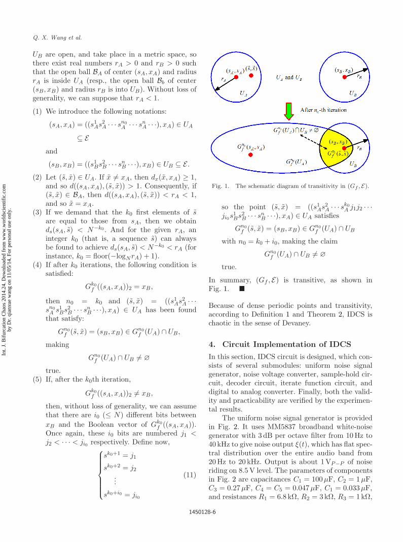
Fig. 1. The schematic diagram of transitivity in (Gf , E).
so the point (s, x) = ((s1As2
A · · · sk0A j1j2 · · ·
ji0s1Bs2
B · · · snB · · ·), xA) ∈ UA satisfies
Gn0f (s, x) = (sB, xB) ∈ Gn0
f (UA) ∩ UB
with n0 = k0 + i0, making the claim
Gn0f (UA) ∩ UB = ∅
true.
In summary, (Gf , E) is transitive, as shown inFig. 1.
Because of dense periodic points and transitivity,according to Definition 1 and Theorem 2, IDCS ischaotic in the sense of Devaney.
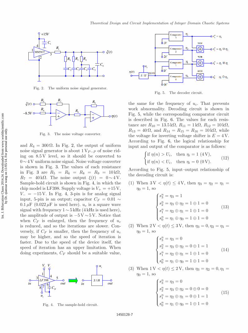
4. Circuit Implementation of IDCS
In this section, IDCS circuit is designed, which con-sists of several submodules: uniform noise signalgenerator, noise voltage converter, sample-hold cir-cuit, decoder circuit, iterate function circuit, anddigital to analog converter. Finally, both the valid-ity and practicability are verified by the experimen-tal results.
The uniform noise signal generator is providedin Fig. 2. It uses MM5837 broadband white-noisegenerator with 3 dB per octave filter from 10 Hz to40 kHz to give noise output ξ(t), which has flat spec-tral distribution over the entire audio band from20 Hz to 20 kHz. Output is about 1VP−P of noiseriding on 8.5 V level. The parameters of componentsin Fig. 2 are capacitances C1 = 100µF, C2 = 1µF,C3 = 0.27µF, C4 = C5 = 0.047µF, C1 = 0.033µF,and resistances R1 = 6.8 kΩ, R2 = 3kΩ, R3 = 1kΩ,
1450128-6
Int.
J. B
ifur
catio
n C
haos
201
4.24
. Dow
nloa
ded
from
ww
w.w
orld
scie
ntif
ic.c
omby
Dr.
qia
nxue
wan
g on
11/
05/1
4. F
or p
erso
nal u
se o
nly.
October 21, 2014 14:21 WSPC/S0218-1274 1450128
Theoretical Design and Circuit Implementation of Integer Domain Chaotic Systems
MM5837 ( )tξ
1C
1R
2R 3R 4R
1
23
4
2C 3C 4C 5C6C
15V+
Fig. 2. The uniform noise signal generator.
( )tξ
( )tη
5R
6R
7R
8R
9R
8.5V−
Fig. 3. The noise voltage converter.
and R4 = 300Ω. In Fig. 2, the output of uniformnoise signal generator is about 1VP−P of noise rid-ing on 8.5V level, so it should be converted to0∼ 4V uniform noise signal. Noise voltage converteris shown in Fig. 3. The values of each resistancein Fig. 3 are R5 = R6 = R8 = R9 = 10kΩ,R7 = 40kΩ. The noise output ξ(t) = 0∼ 4V.Sample-hold circuit is shown in Fig. 4, in which thechip model is LF398. Supply voltage is V+ = +15V,V− = −15V. In Fig. 4, 3-pin is for analog signalinput, 5-pin is an output; capacitor CF = 0.01 ∼0.1µF (0.022µF is used here). uc is a square wavesignal with frequency 1∼ 5 kHz (4 kHz is used here),the amplitude of output is −5V∼ 5V. Notice thatwhen CF is enlarged, then the frequency of uc
is reduced, and so the iterations are slower. Con-versely, if CF is smaller, then the frequency of uc
may be higher, and so the speed of iteration isfaster. Due to the speed of the device itself, thespeed of iteration has an upper limitation. Whendoing experiments, CF should be a suitable value,
398LF
cu
HC
3
8
14 5
7 6in out
V+ V−
HS /in out
cu
Fig. 4. The sample-hold circuit.
Fig. 5. The decoder circuit.
the same for the frequency of uc. That preventswork abnormality. Decoding circuit is shown inFig. 5, while the corresponding comparator circuitis described in Fig. 6. The values for each resis-tance are R10 = 13.5 kΩ, R11 = 1kΩ, R12 = 10kΩ,R13 = 40Ω, and R14 = R15 = R16 = 10kΩ, whilethe voltage for inverting voltage shifter is E = 4V.According to Fig. 6, the logical relationship forinput and output of the comparator is as follows:
if η(n) > Ui, then ηi = 1 (4V),
if η(n) < Ui, then ηi = 0 (0V).(12)
According to Fig. 5, input–output relationship ofthe decoding circuit is:
(1) When 3V < η(t) ≤ 4V, then η3 = η2 = η1 =η0 = 1, so
sn3 = η3 = 1
sn2 = η3 ⊕ η2 = 1 ⊕ 1 = 0
sn1 = η2 ⊕ η1 = 1 ⊕ 1 = 0
sn0 = η1 ⊕ η0 = 1 ⊕ 1 = 0
(13)
(2) When 2V < η(t) ≤ 3V, then η3 = 0, η2 = η1 =η0 = 1, so
sn3 = η3 = 0
sn2 = η3 ⊕ η2 = 0 ⊕ 1 = 1
sn1 = η2 ⊕ η1 = 1 ⊕ 1 = 0
sn0 = η1 ⊕ η0 = 1 ⊕ 1 = 0
(14)
(3) When 1V < η(t) ≤ 2V, then η3 = η2 = 0, η1 =η0 = 1, so
sn3 = η3 = 0
sn2 = η3 ⊕ η2 = 0 ⊕ 0 = 0
sn1 = η2 ⊕ η1 = 0 ⊕ 1 = 1
sn0 = η1 ⊕ η0 = 1 ⊕ 1 = 0
(15)
1450128-7
Int.
J. B
ifur
catio
n C
haos
201
4.24
. Dow
nloa
ded
from
ww
w.w
orld
scie
ntif
ic.c
omby
Dr.
qia
nxue
wan
g on
11/
05/1
4. F
or p
erso
nal u
se o
nly.

October 21, 2014 14:21 WSPC/S0218-1274 1450128
Q. X. Wang et al.
( 1,2,3,4)i iη =
( )nη
iU12R
13R
E−
( )nηiU
( 1,2,3,4)i iη =Comparatori
invertingcomparator
invertingattenuator
inverterinverting
voltage shifter
10R
11R
14R
15R
16R
Fig. 6. The comparator.
(4) When 0V < η(t) ≤ 1V, then η3 = η2 = η1 =0, η0 = 1, so
sn3 = η3 = 0
sn2 = η3 ⊕ η2 = 0 ⊕ 0 = 0
sn1 = η2 ⊕ η1 = 0 ⊕ 0 = 0
sn0 = η1 ⊕ η0 = 0 ⊕ 1 = 1
(16)
It can be seen in Fig. 3 that the noise outputsatisfies 0V < η(t) ≤ 4V, and η(t) is the ran-dom signal that follows an equal probability distri-bution (i.e. uniform distribution) within the range[0V, 4V]. In other words, the values in these fourintervals ([0 V, 1 V], [1 V, 2V], [2 V, 3 V], [3 V, 4 V])are uniformly distributed, and the correspondencerelationship between the size of sn and the fourintervals is:
if η(t) ∈ [0V, 1V], then sn = 0
if η(t) ∈ [1V, 2V], then sn = 1
if η(t) ∈ [2V, 3V], then sn = 2
if η(t) ∈ [3V, 4V], then sn = 3
(17)
Through the above comparison, it is known thatboth sn and sn
3sn2sn
1sn0 follow the uniform distribu-
tion, the relationship between them satisfies:
if η(t) ∈ [0V, 1V],
then sn = 0 ⇔ sn3sn
2sn1sn
0 = 0001
if η(t) ∈ [1V, 2V],
then sn = 1 ⇔ sn3sn
2sn1sn
0 = 0010
if η(t) ∈ [2V, 3V],
then sn = 2 ⇔ sn3sn
2sn1sn
0 = 0100
if η(t) ∈ [3V, 4V],
then sn = 3 ⇔ sn3sn
2sn1sn
0 = 1000
(18)
Set N = 4, get basic iterative function for IDCS,
xni =
xn−1
i if i = sn
(f(xn−1))i = xn−1i if i = sn
(19)
where sn ∈ 0, 1, 2, . . . , N − 1 = 0, 1, 2, 3 and i =0, 1, 2, 3. By comparing Eqs. (13)–(19), Eq. (19) isequivalent to another type of mathematical expres-sion as follows:
xn3 = xn−1
3 ⊕ sn3
xn2 = xn−1
2 ⊕ sn2
xn1 = xn−1
1 ⊕ sn1
xn0 = xn−1
0 ⊕ sn0
(20)
which totally corresponds to the chaotic iterationsthat have been studied in the first part of this arti-cle. According to Eq. (20), we obtain the corre-sponding circuit design iteration equation shown inFig. 7. Digital to analog converter is shown in Fig. 8,
HS /
cu
HS /
HS /
HS /
HS /
HS /
HS /
HS /
3ns
2ns
1ns
0ns
3nx
2nx
1nx
0nx
13nx −
12nx −
11nx −
10nx −
Fig. 7. The iterate function circuit.
1450128-8
Int.
J. B
ifur
catio
n C
haos
201
4.24
. Dow
nloa
ded
from
ww
w.w
orld
scie
ntif
ic.c
omby
Dr.
qia
nxue
wan
g on
11/
05/1
4. F
or p
erso
nal u
se o
nly.

October 21, 2014 14:21 WSPC/S0218-1274 1450128
Theoretical Design and Circuit Implementation of Integer Domain Chaotic Systems
Fig. 8. The digital to analog converter.
where R17 = 10kΩ, R18 = 2kΩ, R19 = 60kΩ,and R20 = R21 = 10kΩ. A DAC0832 is used, itshould be configured to allow the analog outputxn to continuously reflect the state of an applieddigital D3D2D1D0 = xn
3xn2xn
1xn0 on Flow-Through
Operation. The logic relationship is: when the inputis xn
3xn2xn
1xn0 = 0000, the output is xn = 0V;
when the input is xn3xn
2xn1xn
0 = 0001, the output isxn = 1V; . . . ; when the input is xn
3xn2xn
1xn0 = 1111,
the output is xn = 15V. The above correspondence
Fig. 9. The general IDCS circuit.
1450128-9
Int.
J. B
ifur
catio
n C
haos
201
4.24
. Dow
nloa
ded
from
ww
w.w
orld
scie
ntif
ic.c
omby
Dr.
qia
nxue
wan
g on
11/
05/1
4. F
or p
erso
nal u
se o
nly.

October 21, 2014 14:21 WSPC/S0218-1274 1450128
Q. X. Wang et al.
Fig. 10. The experimental observations of IDCS.
can be adjusted by the resistance R19. Based onFigs. 2–8, the whole basic IDCS circuit design isshown in Fig. 9, with experimental observations ofIDCS as shown in Fig. 10, respectively.
5. Conclusions
In order to solve degradation of chaotic dynamicproperties by finite precision effect in traditionalRDCS, a novel approach for generating IDCS andits proof of the existence of chaos according toDevaney’s definition is presented. We then focuson the design and circuit implementation of IDCS,with theoretical background and practical detailspresented together for the first time. By followingthese directions, hardware realization method willbe further developed in the information hiding fieldof applications for IDCS.
Acknowledgments
This work was supported by the National NaturalScience Foundation of China under Grant 61172023;by the Specialized Research Foundation of Doc-toral Subjects of Chinese Education Ministry underGrant 20114420110003; and by China PostdoctoralScience Foundation under Grant 2014M552175.
References
Bahi, J. & Guyeux, C. [2010] “Topological chaos andchaotic iterations application to hash functions,”IEEE Int. Joint Conf. Neural Networks (Barcelona,Spain), pp. 1–7.
Bahi, J., Couchot, J. F., Guyeux, C. & Wang, Q. X.[2011a] “Class of trustworthy pseudo random number
generators,” IEEE Int. Conf. Evolving Internet (Lux-embourg, Luxembourg), pp. 72–77.
Bahi, J., Fang, X. L., Guyeux, C. & Wang, Q. X. [2011b]“Evaluating quality of chaotic pseudo-random gener-ators. Application to information hiding,” Int. J. Adv.Security 4, 118–130.
Bahi, J., Fang, X. L., Guyeux, C. & Wang, Q. X. [2014]“Suitability of chaotic iterations schemes using xor-shift for security applications,” J. Netw. Comput.Appl. 37, 282–292.
Banks, J., Brooks, J., Cairns, G. & Stacey, P. [1992] “OnDevaney’s definition of chaos,” Amer. Math. Monthly99, 332–334.
Chen, G. R. & Lai, D. J. [1997] “Making a dynamical sys-tem chaotic: Feedback control of Lyapunov exponentsfor discrete-time dynamical systems,” IEEE Trans.Circuits Syst.-I 44, 250–253.
Chen, G. R. & Ueta, T. [1999] “Yet another chaoticattractor,” Int. J. Bifurcation and Chaos 9, 1465–1466.
Chua, L. O., Komuro, M. & Matsumoto, T. [1986] “Thedouble scroll family,” IEEE Trans. Circuits Syst.-I 33,1072–1118.
Dachselt, F. & Schwarz, W. [2001] “Chaos and cryptog-raphy,” IEEE Trans. Circuits Syst.-I 48, 1498–1509.
Devaney, R. L. [1989] An Introduction to ChaoticDynamical Systems, 2nd edition (Addison-Wesley,Redwood City).
Heidari-Bateni, G. & McGillem, C. D. [1994] “A chaoticdirect-sequence spread-spectrum communication sys-tem,” IEEE Trans. Commun. 42, 1524–1527.
Li, S. J., Chen, G. R. & Mou, X. Q. [2005] “Onthe dynamical degradation of digital piecewise lin-ear chaotic maps,” Int. J. Bifurcation and Chaos 15,3119–3151.
Lin, T. & Chua, L. O. [1991] “On chaos of digital filtersin the real world,” IEEE Trans. Circuits Syst.-I 38,557–558.
Lorenz, E. N. [1963] “Deterministic nonperiodic flow,”J. Atmosph. Sci. 20, 130–141.
May, R. M. et al. [1976] “Simple mathematical modelswith very complicated dynamics,” Nature 261, 459–467.
Robert, F. [1986] Discrete Iterations: A Metric Study,Springer Series in Computational Mathematics,Vol. 6.
Sang, T., Wang, R. L. & Yan, Y. X. [1998] “Perturbance-based algorithm to expand cycle length of chaotic keystream,” Electron. Lett. 34, 873–874.
Zheng, F., Tian, X. J., Song, J. Y. & Li, X. Y.[2008] “Pseudo-random sequence generator based onthe generalized Henon map,” J. China Univ. PostsTelecommun. 15, 64–68.
1450128-10
Int.
J. B
ifur
catio
n C
haos
201
4.24
. Dow
nloa
ded
from
ww
w.w
orld
scie
ntif
ic.c
omby
Dr.
qia
nxue
wan
g on
11/
05/1
4. F
or p
erso
nal u
se o
nly.