The Worldwide KAPAGEN successful replications
16
The Worldwide KAPAGEN experiment replications createdon may 28, 2010 - JLN Labs - Last update July 2nd, 2010 Toutes les informationset schémas sont publiés gratuitement( freeware ) et sont destinés à un usage personnelet non commercial All informationsand diagrams are published freely (freeware) and are intended for a private use and a non commercialuse. Due to the presenceof High Voltageand the High Poweroutputof the Kapagen, usersof this documentshouldbe verycarefull and experiencedin High-Voltageelectronicsto try anythingout ! If you do it, the risk of any resultis just yours. I take no responsibilityof anythingthatmighthappen. WARNING !!! WARNING !!! Testingsuch a deviceneedsa lot of cautionand the use of safetyprocedures , the experimentermust be veryskilledin the use of High Voltageat High Power. .. REPLICATIONS LOG BOOK from: http://www.overunity.com/index.php?topic=7679.0 I wouldlike to congratulateall the fellow experimenterswhich have been able to replicatesuccessfullymy Kapagen generator... Jean-LouisNaudin- JLNLabs Latestpublishedreplication : July 2nd, 2010 # 1 - June 9, 2010 - Kapagenreplicationby dragon I've made several attempts with differentcoils and this is one of the better ones. The whole thing is Tesla basics as you can see in the diagramof the circuit. The picture's show it runninga small40 watt bulb at around 7 watts of input, the variac is set at around 50 volts. The NST is a 120V input with a 6500 volt .02 amp output. I have 2 earth grounds on this one but the second doesn't seem to add anything and can be removed without changingthe light intensityor input requirement. Oneis required. I've found by playing with various coils and bulbs it's not so much the wattage of the bulb in as much as the resistance of the bulb or bulbs. I have no real way of measuringthe output at a wattage level, no claims are being made .... just an interestingexperiment. ..... Since I really don't know how JLN or Kapanadzeis actually going about it I've been theroizingon my own of how to accomplishit and came to the conclusion it's nothing more than a reverse tesla coil. Instead of putting HV low amps into L1 and convertingit to extreemlyhigh voltage you do just the oposite... put the HV into L2 and convert it to lower voltage and higher amps through L1. The trick is getting L1 to resonate with L2 in its reverse form. L1 being very low inductanceusing the earth ground through a load creates a psudo tank in which L1 can reach high amps. I still don't have the resonance dialed in quite right with this one although it seems to drive L1 reasonablywell ( L1 being the 6 turn coil - L2 being the 90 turn coil - L3 the reversed 30 turn ). L3 is used to raise or lower inductanceto help match the two. It might even help to make this one adjustableto some degree. Getting bulbs to light is a matter of shufflingthrough various resistancesto achieve the correct response. I've run 175 watt mercury bulbs with it but those react like FL's and in my mind doesn't really constitute wattage in as much as a voltage response. I've been doing some tests with a 150 watt halogen and it lights nicelyproduces lots of heat but is far from full bright. At 150 watt input it will be blindingly bright (sun like to your eyes), drivingit with this set up it's bright but not blindingand is using about 35 watts to get it there although I can get an orange glow with lots of heat at 10 watts. I need to do more work with this coil to dial in the resonance a bit better.... Fun stuff ....
-
Upload
khangminh22 -
Category
Documents
-
view
0 -
download
0
Transcript of The Worldwide KAPAGEN successful replications

The Worldwide KAPAGEN experiment replications
createdon may 28, 2010 - JLN Labs - Last update July 2nd, 2010Toutes les informationset schémas sont publiésgratuitement( freeware ) et sont destinés à un usage personnelet non commercial
All informationsand diagramsare published freely(freeware) and are intendedfor a private use and a non commercialuse.
Due to the presenceof High Voltageand the High Power outputof the Kapagen, users of this documentshouldbe verycarefull
and experiencedin High-Voltageelectronicsto try anythingout ! If you do it, the risk of any result is just yours. I take no
responsibilityof anythingthatmight happen.
WARNING !!! WARNING !!!
Testingsuch a device needsa lot of cautionand the use of safetyprocedures, the experimentermust be very skilled in the use of
High Voltageat High Power...
REPLICATIONS LOG BOOKfrom: http://www .overunity.com/index.php?topic=7679.0
I would like to congratulateall the fellow experimenterswhich have been able to replicatesuccessfullymy Kapagengenerator...
Jean-LouisNaudin - JLNLabs
Latestpublishedreplication: July 2nd, 2010
# 1 - June 9, 2010 - Kapagenreplicationby dragon
I've made several attempts with differentcoils and this is one of the better ones. The whole thing is Tesla basics as you can see in the diagramof the circuit. Thepicture's show it runninga small40 watt bulb at around 7 watts of input, the variac is set at around 50 volts. The NST is a 120V input with a 6500 volt .02 ampoutput. I have 2 earth grounds on this one but the second doesn't seem to add anythingand can be removed without changingthe light intensityor inputrequirement. One is required.
I've found by playing with various coils and bulbs it's not somuch the wattage of the bulb in as much as the resistanceof thebulb or bulbs. I have no real wayof measuring the output at a wattage level, no claims are being made.... just an interestingexperiment.
.....
Since I really don't know how JLN or Kapanadzeis actually going about it I've been theroizingon my own of how to accomplishit and came to the conclusionit's nothing more than a reverse tesla coil. Instead of putting HV low amps into L1 and convertingit to extreemlyhigh voltage you do just the oposite... put theHV into L2 and convert it to lower voltage and higher amps through L1. The trick is getting L1 to resonate with L2 in its reverse form.
L1 being very low inductanceusing the earth ground through aload creates a psudo tank in which L1 can reach high amps. I still don't have the resonancedialed in quite right with this one although it seems to driveL1 reasonablywell ( L1 being the 6 turn coil - L2 being the 90 turn coil - L3 the reversed 30 turn ).L3 is used to raise or lower inductanceto help match the two. It might even help to make this one adjustableto some degree.
Getting bulbs to light is a matter of shufflingthrough various resistances to achieve the correct response. I've run 175watt mercury bulbs with it but those reactlike FL's and in my mind doesn't really constitute wattage inas much as a voltage response.
I've been doing some tests with a 150 watt halogen and it lights nicelyproduces lots of heat but is far from full bright. At 150 watt input it will be blindinglybright (sun like to your eyes), drivingit with this set up it's bright but not blindingand is using about 35 watts to get it there although I can get an orange glowwith lots of heat at 10 watts.
I need to do more work with this coil to dial in the resonance a bit better....
Fun stuff....


# 2 - June 9, 2010 - Kapagensuccessfulreplicationv1.0 by romerouk
I am using 260w in the system and output is at least 500w.The bulbs are more than fully powered. After few more attempts I have destroyed 2 of them. I willhave to get some more bulbs tommorow and see how many I can connect and still keep full brightness.I tryed to measure voltage across one bulb and it shows335v-ac but all my meters are digital and I am sure it is not right.I need to get some analogic multimeters to find the amps and volts at the output.Few minutesago I have started the system using DC to power the system an now I can see that DC is the only way to keep the system runningforlonger period oftime.Using ac the spark gap becomes very hot as with dc it is much better.Also havinga capacitor 90.02mf) connectedin parallel with the load, keeps theflickeringunder control. I hope the picture attached will make all understandthe basic of it.
# 3 - June 10, 2010 - Kapagenreplicationv1.1 and 1.2 by romerouk
I have posted another 2 video-clips testing circuit with high voltage AC then using DC as power source....I am in UK, using 240vac. Every bulb is 100w and I have connected9x100w. Sorry I forgot to show that in the video... I will do it next time.I get around 1.6amp using AC to power the system but when I use DC it drops to around 1.15....tube = 5.5cm/140cm - wire 4mm stranded except the big coil = 10mm stranded MOT I have no informationabout it. the tube is PVC5mm thick
I have no connectionwith J L Naudin.He lives in France, I livein London - UK, foreignernot British. I have a lot of respect for all his work. Everythinghedoes is always well documented, tidy, showing a lot of knowledgein his work. I am very smallcomparing to him, many of us here are.I think that he is nottrying to prove overunity with kapanadze replication, it isjust showing proof of concept.Many applications. on J L Naudin website are proof of concept butenough to give us a start in many directions. For J L Naudin free energy is a fact not just supposition. I am sure he has many devices built showing extraenergy.
One thing I found is that you need both earth connectionsdirectly to the ground and about 10m distance. I didn't try longerdistanceas I don't have more lenghtin the garden.In my first attempt I had one earth was comming from the water supply and the other one from a copper pipe I fixed in the ground.That showed me2.3 amps for 500w load, then I have fixed another copper pipe in the ground at 10 m distanceand I got about 1.6a for 900w load.MOT stays just a little bitwarm in my case, maybe you have a defectiveMOT,run it withoutanythingconnectedto see if it still gets hot, check capacitor value, if it is too high mightcreate the problemsyou have.Not recommendedto start the device inside the house as it will interfere with all electricalequipment, it does in my case, I havealmost destroyed the tv, runningthe device in the garden.Itis a lot of radio waves generated by the device and this is another problem at the moment.Turn off allelectricalappliancesin the house while testing.
Kapanadzereplicationv1.1 used 1.7A X 240ac = 408 watts inputKapanadzereplicationv1.2 used 1.16A X 240ac = 281 watts input
Successall!

# 4 - June 11, 2010 - Kapagenreplicationby callanan

Not as good as a variac although much smaller. It's a 1200W AC power controller or lamp dimmer. Not very cleanor linear on a transformerbut at least givessome means of power control. Some is better then none...
http://www.jaycar.com.au/productView.asp?ID=AA0346&keywords=controller&form=KEYWORD
I am using two seperate grounds spikesand not the house ground.

# 5 - June 11, 2010 - Kapagenreplicationby retrod
Here is my first attempt, so don't laugh . I used a large variacon the 120vac input to the MOT (not shown). I had to work in the basement indoors so I used acopper water pipe feed for one ground and an iron floor drain pipe that leads outside & undergroundfor the second. The spark gap is a non resistor sparkplugwith a vice grip for a heat sink. The lamp is a 200watt 120 volt.I used the DC circuit with a smallHV cap.First results:MOT gets very warm and the 20amp mains circuit breaker trips after 15 secondsof operation. Spark gap is electric blue, notviolet. Please be carefulwith thiscircuit the voltages present are indeed dangerous.
Dave
# 6 - June 12, 2010 - Kapagenreplicationby retrod
Second attempt. After this mornings smoke test I almost gaveup. Then there were some encouragingposts and advice. Here is some progress to report. Inoticed on my set-up it works much better with high resistance loads. I started with two 40w light bulbs in series and then thought to try fluro tubes. I am up tosix tubes in series with the two original40w lamps. All the fluro tubes were removed from service a year or more ago as dim ornon lighting. It remindsme ofwhen many of us were adding LED's in series working with Dr. StifflersSEC, what fun!I have no way right now to measure input current. The voltage out of the variac is 90 volts. The spark has become very quiet with this load. I may post a shortvideo on youtube later.

# 7 - June 15, 2010 - Kapagenreplicationby woopy
Hello romero and all
OK i am almost ready for a first test. I did the coil exactlyas Romero that is 84 turns plus 22 turns plus 6 big turns.the coil 1and 2 have the same stranded wire(blue) and for the big coil (green and yellow) there is 7 strand of plain copper, the center is made with 4 stranded copper and something torsaded for connectionto one ground line, plus the main blue wire connectionto the spark gap. the mot is rated 700 watts. I will use it directly (without the cap and diode for a firsttest. What do you think ? Or can i use the MO cap (0.95 micro farad and 2100 volts) and HV diode.?
I will ground it with 2 ground line conductingto 2 galvanisedsteel bar going 1 meter deep in the ground. and separated about 15 meter. I intendto use a wirewith 3 time 1.5 mm2 bounded ,for the ground lines . I intendto begin with a halogen 500 watts what do you think ?
If it works, i will post the picturesof the constructionof the coil step by step.
good luck at all
Laurent

# 8 - June 16, 2010 - Kapagenreplicationby retrod
Some numbers & a video.
MOT is a OBJY2Input Voltage : 120vacInput current : Measuredat output of variac 4.0 amps avgLoad: Six 200w 120v LampsEarth Grounds : First: 200ft iron pipe (water well). Second:10 ft driven rod, copper clad Spark Gap : Champion J-14 with neo magnet attachedAir temperature was 68 degrees FahrenheitMOT Temp at start 84 FMOT Temp at end 107 FRun time approx 4.5 minutes
# 9 - June 16, 2010 - Kapagenreplicationby woopy
Hi all
the rain stopped shortly , and could not prevent me to have a second test.
Took all precaution as per Stefan and 3,2,1 go
yaouuh it works very fine. The bank directly connectedto thegrid does simply no light at all, but with the Kapagen it is near full brightness. i have AC current ,no cap at all. I did not make any measure but the grid fuse did not even break. another thing i have a radio on at 10 meters from the kapagen and nothing , nogrrrrrbbrrkkkkkk, at all in the radio.
OK and the rain comes again
hope that tomorrow it will be better weather to make some measurements.
just for info the bank as a resistanceof 400 ohm. when i connect the bank to the grid, my clampmetershows 130 ma at 230 volts AC just another thing the bankwas on and stopped only when i switchedoff. but when i tried totake the measre of resistance it was impossible. Than i checkedthe bulb and one was broken. Imean it seems that i probably had the arc in the bulb which makethe bulb on even if the tungsten filamentis broken. What do you think?
good luck at all
Laurent

June 18, 2010 - WorkingKAPAGENdiagramnow releasedby JLN...

Click on the pictureto enlarge
# 10 - June 21, 2010 - Kapagensuccessfulreplicationby Robert
Dear Mr. Naudin,
Good news!
I got 1800W out and the MOT stays cold even the inlet power meter indicates800W. I think that’s a real sign of OU. I have 2x150W halogen + 18x 100Wbulbs (fully bright) and all serial. If I would have more lamps I think they would shinefully too.I observed that with the 1N5408 diode didn’t work – but with the BY255 it works very well – just they get hot, so I add cooler.I don’t know way you changed the coil setup but with the coil relation 22 – 84 – 6 its working quite well.
Many thanks and br.
Robert

# 11 - June 23, 2010 - Kapagensuccessfulreplicationby Juju
Hi Guys!I made a video of my setup, is my first one!
i putted some lamps of 60w others of 100w, all in series with a fan/ventilator of 100W... i putted the fan in the end of the sequencegoing to ground, because ithaves a capacitor of 230V, i was affraid it can blow up if it takes all the primary voltage! 2 lamps in the video are not lightingwell, but i think it was someproblem with them!
this thing can feed all type of devices, not only lamps!and it is not so spooky as at seems, when the adrenalinegoes up, the fear fades! spectacular!my output dont work wellwith dc, as you can see, dont used any caps!dont took measurementsbecause my DMM cannot read alternatecurrent, only dc...
This vid is dedicated to the portuguese team in the worldcup,that win today 7-0 against North Korea
Enjoy!

All my thanksspeciallyto JLNaudin, romerouk, laurent, xenomorph, jonnyand the rest of the FE crew!
# 12 - June 25, 2010 - Kapagensuccessfulreplicationby TomB-455
Dear Mr Naudin,
I have tried to replicate your coil and it works!
most of the setup is the same as yours, m.o.t. 800 watt, in dc mode. 10x150 wats halo-bulbs fully bright!!i checkt my variac (but didn't put it on camera) and it was at 165 volts!!!exept for the 23ccw turns on the entrance of the coil, those whre nesseceryto reduce the input current.the picturesare folowingsoon. i did make a video though.. ;)
best regards,
TomB-455
This is an replicationof J.L.Naudin's 'kapagen'.
I used for this setup; (V2)M.O.T. 800 watt (D.C. setup),
10x150W halogenlamps(1500watt total) in series.Variac1,5kva.
Coil setup= prim.-88t(cw)+ 23t (ccw) , sec 7t(ccw).
The lamps are burningat 165 volts by 1.28 amps input on the 'kapagen' , these figuresfluctuatingin diffrenceof +/- 5%
# 13 - June 28, 2010 - Kapagensuccessfulreplicationbymagnetflipper

# 14 - July 1st, 2010 - Kapagensuccessfulreplicationby txqnl

# 15 - July 2nd, 2010 - Kapagensuccessfulreplicationbydon
Hi Mr. Naudin
The best (lowest input power) I could get was 707 Watts lighting18 x 100 watt light bulbs without using a variac. It used 570watts tolight 9 of the 100 watt light bulbs.
I measuredmy power usagewith a Kill-O-Meter connect to Mainsover 30 feet away frommy device.
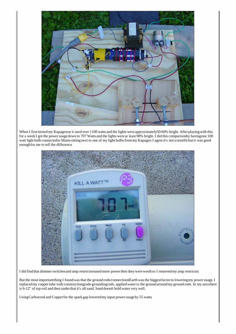
When I first turnedmy Kapagenon it used over 1100watts and the lights wereapproximately50-60% bright. Afterplayingwith thisfor a week I got the power usagedown to 707 Wattsand the lightswereat least 90% bright. I did this comparisonby havingone 100watt light bulb connectedto Mainssittingnext to one of my light bulbs frommy Kapagen. I agree it's not scientificbut it was goodenoughfor me to tell the difference.
I did find that dimmer switchesand amp restrictorsused morepower then theywereworthso I removedmy amp restrictor.
But the most importantthing I foundwas that the groundrods/connections/Earthwas the biggestfactor in loweringmy power usage. Ireplacedmy copper tube with constructiongrade groundingrods, appliedwater to the groundaroundmy groundrods. In my area thereis 6-12" of top soil and then underthat it's all sand. Sanddoesn't hold water very well.
UsingCarbonrod and Copperfor the sparkgap loweredmy inputpower usageby 55 watts.

Hereare some pictures:http://u2ecom.com/kapagen/
return to KAPAGEN project page
visitorssince May 28, 2010