the unidex® 600 hardware manual - Aerotech
106
THE UNIDEX 600 HARDWARE MANUAL P/N: EDU154 (V1.9) AEROTECH, Inc. • 101 Zeta Drive • Pittsburgh, PA. 15238-2897 • USA Phone (412) 963-7470 • Fax (412) 963-7459 Product Service: (412) 967-6440; (412) 967-6870 (Fax) www.aerotech.com
-
Upload
khangminh22 -
Category
Documents
-
view
0 -
download
0
Transcript of the unidex® 600 hardware manual - Aerotech

THE UNIDEX 600 HARDWARE
MANUAL
P/N: EDU154 (V1.9)
AEROTECH, Inc. • 101 Zeta Drive • Pittsburgh, PA. 15238-2897 • USAPhone (412) 963-7470 • Fax (412) 963-7459
Product Service: (412) 967-6440; (412) 967-6870 (Fax)
www.aerotech.com

If you should have any questions about the UNIDEX 600 board or comments regarding the documentation, pleaserefer to Aerotech online at:http://www.aerotech.com.
For your convenience, a product registration form is available at our web site.
Our web site is continually updated with new product information, free downloadable software and special pricing onselected products.
The UNIDEX 600 PC-based motion controller is a product of Aerotech, Inc.Inductosyn is a registered trademark of Farrand Industries, Inc.MS-DOS is a product of Microsoft Corporation.Windows NT and Windows 95 are products of Microsoft.
The UNIDEX 600 Motion ControllerHardware Manual Revision History:
Rev 1.0 December 08, 1995Rev 1.0a April 17,1996Rev 1.1 Sept 25,1996Rev 1.2 November 22, 1996Rev 1.3 February 14, 1997Rev 1.4 July 15, 1997Rev 1.5 May 5, 1998Rev 1.6 April 5, 1999Rev 1.7 June 19, 2000Rev 1.8 October 20, 2000Rev 1.9 March 26, 2001
© Aerotech, Inc., 2001

UNIDEX 600 Hardware Manual Table of Contents
Version 1.9 Aerotech, Inc. iii
TABLE OF CONTENTS
CHAPTER 1: INTRODUCTION ............................................................................ 1-1
1.1. Overview of the UNIDEX 600 ........................................................... 1-11.2. Options and Accessories..................................................................... 1-31.3. Safety Procedures and Warnings ........................................................ 1-4
CHAPTER 2: GETTING STARTED...................................................................... 2-1
2.1. Introduction ........................................................................................ 2-12.2. Unpacking the UNIDEX 600 System................................................. 2-12.3. Minimum Hardware Requirements and Recommended System
Configurations .................................................................................... 2-22.4. Cooling Requirements ........................................................................ 2-2
2.4.1. Power Consumption ............................................................. 2-32.5. Inspection of the UNIDEX 600 Control Board .................................. 2-42.6. UNIDEX 600 Control Board Jumper Configurations ........................ 2-5
2.6.1. Base Address Jumpers (JP7, JP8, and JP9).......................... 2-52.6.2. PC Bus Interrupt Jumpers (JP4A through JP5D) ................. 2-6
2.7. Installing the UNIDEX 600 PC Board ............................................... 2-92.8. Installing Additional Aerotech Components..................................... 2-10
2.8.1. The DR500 Drive Rack and OP500 Cable......................... 2-102.8.2. The UNIDEX 600 BB500 Breakout Module..................... 2-112.8.3. The PB8, PB16 and PB24 I/O Boards ............................... 2-112.8.4. DRC I/O Cable................................................................... 2-14
CHAPTER 3: HARDWARE CONFIGURATION ................................................ 3-1
3.1. Introduction ........................................................................................ 3-13.2. Minimum Hardware Requirements and Recommended System
Configurations .................................................................................... 3-13.2.1. Power Consumption ............................................................. 3-2
3.3. UNIDEX 600 Control Board Jumper Configurations ........................ 3-23.3.1. Base Address Jumpers (JP7, JP8, and JP9).......................... 3-43.3.2. PC Bus Interrupt Jumpers (JP4A through JP5D) ................. 3-53.3.3. Encoder Type Configuration for Differential or
Single Ended Encoders (RN3, RN4, RN1 and RN2) ........... 3-73.3.4. RS-232C Serial Port Jumper (JP2)....................................... 3-93.3.5. Processor Configuration Jumper (JP10)............................... 3-93.3.6. External Reset Jumper (JP3) ................................................ 3-9
3.3.6.1. The Single In-line Memory Module (SIMM)Sockets .......................................................................... 3-10
3.4. Installing the UNIDEX 600 PC Board ............................................. 3-113.5. Installing Additional Aerotech Components..................................... 3-13
3.5.1. The DR500 Drive Rack and OP500 Cable......................... 3-133.5.2. The UNIDEX 600 BB500 Breakout Module..................... 3-143.5.3. The PSO-PC Position Synchronization Board ................... 3-153.5.4. The RDP-PC Resolver-to-Digital Board ............................ 3-163.5.5. The BRK/BPS Fail-safe Brake........................................... 3-163.5.6. The PB8, PB16 and PB24 I/O Boards ............................... 3-163.5.7. DRC I/O Cable................................................................... 3-19

Table of Contents UNIDEX 600 Hardware Manual
iv Aerotech, Inc. Version 1.9
CHAPTER 4: TECHNICAL DETAILS.................................................................. 4-1
4.1. Test Points .......................................................................................... 4-14.2. Jumper Configurations........................................................................ 4-34.3. Encoder Signal Specifications ............................................................ 4-6
4.3.1. Differential Encoders ........................................................... 4-64.3.2. Single Ended Encoders......................................................... 4-6
4.4. Reserved Outputs................................................................................ 4-84.5. Encoder Signal Pinouts....................................................................... 4-94.6. Limit and Amplifier Fault Inputs ...................................................... 4-104.7. Serial Ports (RS-232C and RS-422) ................................................. 4-124.8. Emergency Stop Sense Input ............................................................ 4-134.9. External Reset Input ......................................................................... 4-144.10. Current Command Output................................................................. 4-154.11. Digital Input Bus Specifications ....................................................... 4-164.12. Output Bus Specifications ................................................................ 4-174.13. Amplifier Enable Outputs ................................................................. 4-184.14. The Brake Output ............................................................................. 4-194.15. Opto 22 I/O Bu (P9) ......................................................................... 4-204.16. Main Connector Pinout of the UNIDEX 600 ................................... 4-234.17. High Speed Position Latch ............................................................... 4-254.18. U600 Manual Feedrate Override/Manual Spindle Override............. 4-254.19. Mode (Aux) Output Specifications................................................... 4-264.20. Expansion Bus Pin Description (P3) ................................................ 4-274.21. Analog Inputs ................................................................................... 4-274.22. Joystick Interface .............................................................................. 4-284.23. Opto 22 Outputs and Hall Sensor Inputs (P10) Pinouts.................... 4-294.24. UNIDEX 600 Breakout Block (BB500)........................................... 4-304.25. Servo Loop ....................................................................................... 4-31
4.25.1. Servo Loop Overview........................................................ 4-314.25.2. Servo Loop Phasing............................................................ 4-32
4.26. Handwheel Interface ......................................................................... 4-344.27. Teach Pendant Interface ................................................................... 4-34
4.27.1. Teach Pendant Outputs....................................................... 4-354.28. Stepper Drive Interface..................................................................... 4-36
CHAPTER 5: TROUBLESHOOTING ................................................................... 5-1
5.1. Installation, Board Startup and Communication Problems ................. 5-25.2. Servo Related Problems...................................................................... 5-35.3. Problems Involving Fault Conditions ................................................. 5-45.4. Homing Related Problems .................................................................. 5-6
APPENDIX A: GLOSSARY OF TERMS................................................................ A-1
APPENDIX B: WARRANTY AND FIELD SERVICE .......................................... B-1
INDEX
∇ ∇ ∇

Unidex 600 Hardware Manual List of Figures
Version 1.9 Aerotech, Inc. v
LIST OF FIGURES
Figure 1-1. The UNIDEX 600 System Diagram ................................................... 1-1Figure 1-2. UNIDEX 600 Motion Control Card ................................................... 1-2
Figure 2-1. The UNIDEX 600 PC Board.............................................................. 2-4Figure 2-2. Rear Panel Connectors of the DR500 Amplifier Chassis ................. 2-10Figure 2-3. Sample Uses of the PB# Boards and the DIOSR/DRC Cables......... 2-12Figure 2-4. Sample Uses of the PB# Boards and the DRCPB and
DRCPBG4 Cables ............................................................................ 2-13Figure 2-5. DRC I/O Cable ................................................................................. 2-14
Figure 3-1. UNIDEX 600 PC Board ..................................................................... 3-3Figure 3-2. RAM SIMM Module Installation ..................................................... 3-10Figure 3-3. Installation of the UNIDEX 600 Motion Controller Board .............. 3-12Figure 3-4. Rear Panel Connectors of the DR500 Amplifier Chassis ................. 3-13Figure 3-5. Overview of the PSO-PC Option...................................................... 3-15Figure 3-6. Sample Uses of the OPTO-22 Boards and the DRC Cable .............. 3-17Figure 3-7. Sample Uses of the PB# Boards and the DRCPB and
DRCPBG4 Cables ............................................................................ 3-18Figure 3-8. DRC I/O Cable ................................................................................. 3-19
Figure 4-1. UNIDEX 600 PC Board Jumper Locations........................................ 4-4Figure 4-2. Electrical Characteristics of an Encoder Interface (Showing
Configuration of Optional Single-ended Encoder) ............................. 4-6Figure 4-3. Reserved Outputs................................................................................ 4-8Figure 4-4. Electrical Characteristics of the UNIDEX 600 Hall Effect,
Limit and Amplifier Fault Inputs ...................................................... 4-11Figure 4-5. Serial Ports 1 and 2 Pinouts.............................................................. 4-12Figure 4-6. Electrical Characteristics of the UNIDEX 600 Emergency
Stop Interface ................................................................................... 4-13Figure 4-7. External Reset Circuit....................................................................... 4-14Figure 4-8. Electrical Characteristics of the UNIDEX 600 Current
Command Output ............................................................................. 4-15Figure 4-9. Electrical Characteristics of the UNIDEX 600 Input Bus
Interface............................................................................................ 4-16Figure 4-10. Electrical Characteristics of the UNIDEX 600 Output Bus
Interface............................................................................................ 4-17Figure 4-11. Electrical Characteristics of the U600 Amplifier Enable
Output............................................................................................... 4-18Figure 4-12. Electrical Characteristics of the Brake Signal Output....................... 4-19Figure 4-13. Electrical Characteristics of the UNIDEX 600 Opto 22
Connections ...................................................................................... 4-22Figure 4-14. Electrical Characteristics of U600 High Speed Position Latch ........ 4-25Figure 4-15. Manual Feedrate Override Circuit .................................................... 4-26Figure 4-16. Electrical Characteristics of the Mode (Aux) Output ....................... 4-26Figure 4-17. Electrical Characteristics of Analog Input ........................................ 4-28Figure 4-18. Joystick Interface.............................................................................. 4-28

List of Figures UNIDEX 600 Hardware Manual
vi Aerotech, Inc. Version 1.9
Figure 4-19. UNIDEX 600 Series Servo Loop (Torque Mode) ............................ 4-31Figure 4-20. CW Motor Rotation Viewed from Mounting Flange End ................ 4-32Figure 4-21. Brushless Motor Phasing .................................................................. 4-33Figure 4-22. Handwheel Interface ......................................................................... 4-34Figure 4-23. Teach Pendant Inputs........................................................................ 4-34Figure 4-24. Teach Pendant Outputs ..................................................................... 4-35Figure 4-25. Stepper Clock and Direction Interface.............................................. 4-36Figure 4-26. SR-20DRH-25DS Cable Drawing and Pinouts................................. 4-37
∇ ∇ ∇

UNIDEX 600 Hardware Manual List of Tables
Version 1.9 Aerotech, Inc. vii
LIST OF TABLES
Table 1-1. Options and Accessories Available for the UNIDEX 600.................. 1-3
Table 2-1. Minimum Hardware Requirements and Recommendations................ 2-2Table 2-2. UNIDEX 600 Airflow (Cooling) Requirements ................................. 2-3Table 2-3. Board Power Consumption................................................................. 2-3Table 2-4. Base Address Jumper Settings............................................................ 2-6Table 2-5. PC Bus Interrupt Jumper Settings....................................................... 2-7
Table 3-1. Minimum Hardware Requirements and Recommendations................ 3-1Table 3-2. Board Power Consumption................................................................. 3-2Table 3-3. Base Address Jumper Settings............................................................ 3-4Table 3-4. PC Bus Interrupt Jumper Settings....................................................... 3-5Table 3-5. Termination Resistor Configuration for Axis 1 Encoders .................. 3-7Table 3-6. Termination Resistor Configuration for Axis 2 Encoders .................. 3-8Table 3-7. Termination Resistor Configuration for Axis 3 Encoders .................. 3-8Table 3-8. Termination Resistor Configuration for Axis 4 Encoders .................. 3-8Table 3-9. RS-232C Serial Port Jumper Settings................................................. 3-9Table 3-10. Processor Configuration Jumper Settings........................................... 3-9Table 3-11. External Reset Jumper Settings .......................................................... 3-9
Table 4-1. User Test Points.................................................................................. 4-2Table 4-2. UNIDEX 600 Encoder Signal Test Points.......................................... 4-2Table 4-3. Jumper Configurations........................................................................ 4-3Table 4-4. PC I/O Base Address Jumper Settings................................................ 4-5Table 4-5. Termination Resistor Configuration for Axis 1 Encoder .................... 4-7Table 4-6. Termination Resistor Configuration for Axis 2 Encoders .................. 4-7Table 4-7. Termination Resistor Configuration for Axis 3 Encoders .................. 4-7Table 4-8. Termination Resistor Configuration for Axis 4 Encoders .................. 4-7Table 4-9. Encoder Signals and Pinouts .............................................................. 4-9Table 4-10. Limit and Amplifier Fault Inputs ...................................................... 4-10Table 4-11. External Voltages and Resistance for the Emergency Stop
Input ................................................................................................. 4-13Table 4-12. Current Command Output Signals and Pin Locations ...................... 4-15Table 4-13. UNIDEX 600 Inputs and Locations ................................................. 4-16Table 4-14. UNIDEX 600 Outputs and Locations............................................... 4-17Table 4-15. Amplifier Enable Output Locations.................................................. 4-18Table 4-16. U600 Opto 22 Connection Information............................................ 4-21Table 4-17. Main Connector Pinouts for the UNIDEX 600 ................................ 4-24Table 4-18. Expansion Bus Pin Outs ................................................................... 4-27Table 4-19. Pinouts for Opto 22 Outputs and Hall Sensor Inputs (P10).............. 4-29Table 4-20. Teach Pendant Labels and Associated Pin Number (Inputs) ............ 4-35Table 4-21. Teach Pendant Labels and Associated Pin Number (outputs) .......... 4-35Table 4-22. P7 Stepper Drive Interface Clock and Direction Pinouts ................. 4-36

List of Tables UNIDEX 600 Hardware Manual
viii Aerotech, Inc. Version 1.9
Table 5-1. Troubleshooting for Common Installation, Startup andCommunication Problems................................................................... 5-2
Table 5-2. Troubleshooting for Servo Related Problems..................................... 5-3Table 5-3. Troubleshooting for Problems Involving Fault Conditions ................ 5-4Table 5-4. Troubleshooting for Homing Related Problems ................................. 5-6
∇ ∇ ∇

UNIDEX 600 Hardware Manual Regulatory Information
Version 1.9 Aerotech, Inc. ix
DECLARATION OF CONFORMITY
Manufacturer’s Name and Address
Aerotech, Inc.101 Zeta DrivePittsburgh, PA 15238-2897
Declares that the product:
Product Name: UNIDEX 600
Conforms to the following product specifications :
EMC: EN 55011: 1991 Class B EmissionsEN 50082-1: 1992 Immunity
IEC 801-2: 1984IEC 801-3: 1984IEC 801-4: 1988
and complies with EMC directive 89/336/EEC.
Pittsburgh, PA David F. KincelApril, 1999 Quality Assurance Manager
Ron RekowskiEngineer Verifying Compliance
General notes concerning the test setup.
This product was tested at Washington Laboratories, LTD. in Gaithersburgh, MD onDecember 12, 1995. The report number is WLL 2987F.
The UNIDEX 600 was tested in a CE compliant class B personal computer and controlledtwo DC motors and one brushless AC motor through a DR500 drive chassis. Thefollowing modifications ensure compliance with the EMC directive 89/336/EEC.
• Add ferrites, P/N TDK ZCAT3035-13304 or equivalent on the DIO andOP500 cable. There is a ferrite located on each end of each cable.
• A 25-pin Sub-D filter, P/N SCI-56-725-001 or equivalent is installed on axislimit connectors of the DR500 that interfaces to each motor.
• Add 1 ferrite, P/N TDK ZCAT3035-13304 and two toroids located on thepower cord of the DR500.
• A Schaffner filter, P/N FN2080-10-06 is installed on the DR500 AC powerinput.
• Bond shields of all cables to the DR500 chassis.• Add ferrite to each motor cable at the DR500, P/N Steward 28B-029-0A0 or
equivalent.
Failure to follow the described procedures may cause excessive emissions or reducedimmunity.
∇ ∇ ∇

Regulatory Information UNIDEX 600 Hardware Manual
x Aerotech, Inc. Version 1.9

UNIDEX 600 Hardware Manual Preface
Version 1.9 Aerotech, Inc. xi
PREFACE
This section gives you an overview of topics covered in each of the sections of thismanual as well as conventions used in this manual. This manual contains information onthe following topics:
CHAPTER 1: OVERVIEW
This chapter contains an overview of the UNIDEX 600 motion controller as well as asample system diagram. This chapter also contains precautionary notes about installingand using the U600 motion controller.
CHAPTER 2: GETTING STARTED
This chapter contains information about the components of the UNIDEX 600 system,unpacking and inspecting the equipment, and minimum hardware and softwarerequirements for proper operation.
CHAPTER 3: HARDWARE CONFIGURATION
This chapter contains information about the hardware of the UNIDEX 600 system. Thisincludes a discussion of the hardware components and individual jumper configurations.
CHAPTER 4: TECHNICAL DETAILS
This chapter supplies a variety of technical specifications for the UNIDEX 600. Thesespecifications include test points, jumper configurations, encoder signal specifications,pinouts, outputs, bus specifications, and others.
CHAPTER 5: TROUBLESHOOTING
This chapter provides a reference tool if problems with the UNIDEX 600 arise.
APPENDIX A: GLOSSARY OF TERMS
Appendix A contains a list of definitions of terms used in this manual.
APPENDIX B: WARRANTY AND FIELD SERVICE
Appendix B contains the warranty and field service policy for Aerotech products.
INDEX
The index contains a page number reference of topics discussed in this manual. Locatorpage references in the index contain the chapter number (or appendix letter) followed bythe page number of the reference.
CUSTOMER SURVEY FORM
A customer survey form is included at the end of this manual for the reader’s commentsand suggestions about this manual. Reader’s are encouraged to critique the manual andoffer their feedback by completing the form and either mailing or faxing it to Aerotech.

Preface UNIDEX 600 Hardware Manual
xii Aerotech, Inc. Version 1.9
Throughout this manual the following conventions are used:
é The terms UNIDEX 600 and U600 are used interchangeably throughout thismanual
é The text <ENTER> is used to indicate that the Enter/Return key on the keyboardis to be pressed.
é Hexadecimal numbers are listed using a preceding "0x" (for example, 0x300,0x12F, 0x01EA, etc.,) to distinguish them from decimal numbers
é Graphic icons or keywords may appear in the outer margins to provide visualreferences of key features, components, operations or notes.
é Danger and/or Warning symbols (see left) appear in the outer margins next toimportant precautions. Failure to observe these precautions could result inserious injury and/or damage to the equipment.
é The following statements apply wherever a Warning or Danger symbol appearswithin this manual. Failure to observe these precautions could result in seriousinjury to those performing the procedures and/or damage to the equipment.
To minimize the possibility of electrical shock and bodily injury, makecertain that all of the electrical power switches are in the off positionprior to making any electrical connections.
To minimize the possibility of electrical shock and bodily injury whenany electrical circuit is in use, ensure that no person comes in contactwith the circuitry.
When this controller is installed within a system, mechanical motionwill occur. Care must be exercised that all personnel remain clear ofany moving parts.
To minimize the possibility of bodily injury, make certain that allelectrical power switches are in the off position prior to making anymechanical adjustments.
é This manual uses the symbol "∇ ∇ ∇" to indicate the end of a chapter.
Although every effort has been made to ensure consistency, subtle differences may existbetween the illustrations in this manual and the component and/or software screens thatthey represent.
∇ ∇ ∇
DANGER WARNING

UNIDEX 600 Hardware Manual Introduction
Version 1.9 Aerotech, Inc. 1-1
CHAPTER 1: INTRODUCTION
In This Section:• Overview of the UNIDEX 600 ........................................... 1-1• Options and Accessories...................................................... 1-3• Safety Procedures and Warnings......................................... 1-4
1.1. Overview of the UNIDEX 600
The UNIDEX 600 is an ISA bus-based 16-bit motion control card that integrates withamplifiers, positioning stages and any number of optional accessories to form a complete,programmable, customized control system. A typical system is illustrated in Figure 1-1.
The U600 is available in four combinations: U600BASE-8MB, U600BASE-32MB,U600ULTRA-8MB, and U600ULTRA-32MB. The BASE card supports up to 8 millionmachine counts per second data rate on its encoder channels, while the ULTRA doublesthis to 16 million machine counts per second. The ULTRA card adds (to the basefeatures) support for 4 stepper axes (Clock/Direction), an RS-232C port, and an RS-422port.
Figure 1-1. The UNIDEX 600 System Diagram
DR 500 DriveChassis
Optional Digitizing Joystick andElectronic Handwheel
OP500 InterfaceCable
U600 Control Board
Software
User-supplied PC
Graphical User Interface
Rotary and LinearPositioning Stages

Introduction UNIDEX 600 Hardware Manual
1-2 Aerotech, Inc. Version 1.9
The UNIDEX 600 provides outstanding performance in a variety of demandingapplications that require one or more of the following capabilities:
• Synchronous coordination of a large number of axes
• High speed, complex shape generation
• Control of multiple processes or multiple machines
The U600 control card, shown in Figure 1-2, contains 8 megabytes of Dynamic RandomAccess Memory (DRAM) and has the ability to contain up to 32 megabytes per card. TheDRAM is managed by a burst memory controller and is accessible by the host through thePC bus. The U600 and user software provides full CNC RS-274/RS-447 G-code controlof four axes per card (16 axes per card with Encoder Expansion cards).
Figure 1-2. UNIDEX 600 Motion Control Card
The U600 offers flexibility, meaning the user can write application-specific “C” programsusing Aerotech’s software library of over 350 functions, or via Aerotech’s 32 bit customcontrols contained in Aerotech’s Software Development Kit for Windows NT/95(P/N SDK600-NT). The U600 provides support for Windows NT, and Windows 95 thatcan even run simultaneously with the user’s machine application programs.
Path
Conveyor
Y AxisX Axis
Z Axis

UNIDEX 600 Hardware Manual Introduction
Version 1.9 Aerotech, Inc. 1-3
1.2. Options and Accessories
The UNIDEX 600 supports a variety of options that include ISA bus digital I/O cards andAerotech’s option cards. Table 1-1 lists some of the Aerotech options and accessories thatcan be used with the U600 motion controller. Refer to the Aerotech Motion ControlProduct guide for other available options and accessories.
Table 1-1. Options and Accessories Available for the UNIDEX 600
Options & Accessories Description
BB500/ Breakout module when not using the DR500 chassis, requires OP500cable
BB501/ Breakout module to interface with the BA Series amplifiers, requiresOP500 cable
PB16/ Opto 22 I/O mounting rack for 8 IN/8 OUTPB24/ Opto 22 I/O mounting rack for 16 IN/8 OUTJBV/ Joystick with digitizing capability
PSO-PC/ Programmable, PC bus-based, position synchronized, laser firingcontrol card used to provide output signals based on the positions ofup to three axes.
4EN-PC/ Four-axis encoder and drive interface expansion card. Includesextension bus interconnect cabling 40 IN, 40 OUT of digital I/O, 412-bit A/D inputs, 8 channels of 16-bit D/A drive interface, 4channels of encoder position feedback, CW, CCW, and home limitinputs
DR500/ External drive chassis for use with the U600 (refer to the AerotechMotion Control Product Guide for available styles, types, andpricing information)
RDP-PC-n/ Resolver-to-digital 4-channel converter full length ISA I/O cardformat with 2 active channels
OP500/ Interconnection cable from the controller to the DR500 chassisBRKBPS-x/ Fail-safe brake control logic and power supply; specify axis (-x)
DIOSR/ Input/output extension cable (also required with AC brushless motoroperation as Hall effect inputs)
HW500/ 3.6 inch handwheel assembly and cable (25-pin male “D”)SDK600-NT Software Development kit for Windows NT/95 containing OLE
custom controlsMMI600-NT CNC MMI development kit for Windows NT/95UTIL600-NT Standard utilities, libraries, and U600 firmware for Windows NT/95

Introduction UNIDEX 600 Hardware Manual
1-4 Aerotech, Inc. Version 1.9
1.3. Safety Procedures and Warnings
The following statements apply wherever the Warning or Danger symbol appears withinthis manual. Failure to observe these precautions could result in serious injury to thoseperforming the procedures and/or damage to the equipment.
To minimize the possibility of electrical shock and bodily injury, make certain thatall of the electrical power switches are in the off position prior to making anyelectrical connections.
To minimize the possibility of electrical shock and bodily injury when any electricalcircuit is in use, ensure that no person comes in contact with the circuitry.
When this controller is installed within a system, mechanical motion willoccur. Care must be exercised that all personnel remain clear of any moving parts.
To minimize the possibility of bodily injury, make certain that all electrical powerswitches are in the off position prior to making any mechanical adjustments.
∇ ∇ ∇

UNIDEX 600 Hardware Manual Getting Started
Version 1.9 Aerotech, Inc. 2-1
CHAPTER 2: GETTING STARTED
In This Section:• Introduction ........................................................................2-1• Unpacking the UNIDEX 600 System.................................2-1• Minimum Hardware Requirements.....................................2-2• Recommended System Configurations...............................2-2• Inspection of the UNIDEX 600 Control Board ..................2-4• UNIDEX 600 Control Board Jumper Configurations ........2-5• Installing the UNIDEX 600 PC Board ...............................2-9• Installing Additional Aerotech Components ....................2-10
2.1. Introduction
This chapter steps the operator through unpacking the U600, system requirements for thePC, static precautions, and board inspection techniques. The user should read this sectionbefore attempting to install the UNIDEX 600 hardware. Hardware installation andhardware configuration are discussed in the chapters that follow.
2.2. Unpacking the UNIDEX 600 System
Before unpacking any components, visually inspect the containers of the U600 system forany evidence of shipping damage. If any such damage exists, notify the shipping carrierimmediately.
All electronic equipment is wrapped in antistatic material and packaged withdesiccant (a drying agent used to reduce moisture). Make certain that the antistaticmaterial is not damaged during unpacking.
Remove the packing list from the UNIDEX 600 container. Make certain that the itemslisted on the packing slip are contained within the package. The following items shouldbe found in every UNIDEX 600 system:
• The UNIDEX 600 PC bus-based controller• U600 software (on CD ROM), with manuals in .PDF format (installed to
\U600\Manual\*.PDF)• UNIDEX 600 packing slip (listing products shipped with the order)
The following list of additional items may be included with the UNIDEX 600 system,depending on the options and accessories that have been specified:
• The DR Series drive chassis (amplifier chassis with power supply)• The OP500 interface cable (to connect the UNIDEX 600 to the DR500)• The BB500 or BB501 breakout module (if the DR500 drive chassis is not used)• Motor connector cables (to connect the motors to the DR500 drive chassis)• JBV joystick and cable (with digitizing capability)• Handwheel assembly and cable

Getting Started UNIDEX 600 Hardware Manual
2-2 Aerotech, Inc. Version 1.9
2.3. Minimum Hardware Requirements and Recommended SystemConfigurations
Minimum hardware requirements and recommended system configurations for theUNIDEX 600 are shown in Table 2-1.
Table 2-1. Minimum Hardware Requirements and Recommendations
Equipment Minimum Recommended
Computer(microprocessor)
IBM PC Pentium 200 MHz(or higher)
or 100% compatible
Pentium
400 MHz or higher
Computer Memory 16 MB of memory(conventional & extended)
32 MB of memory(conventional & extended)
Graphics Display 800x600 800x600
Free Hard Disk Space 10 MB 20 MB or more
Mouse Any mouse supportedby the computer
Any mouse supportedby the computer
Floppy Disk Drives 3 1/2" DSHD 3 1/2" DSHD
Windows Windows NT 4.0 /Windows 2000
Windows NT 4.0 /Windows 2000
2.4. Cooling Requirements
Table 2-2 shows that a U600BASE-8MB with the specified heatsink operating in anenclosure at 57 degrees C requires 200 ft/min. (1.01 m/sec) of airflow for properoperation and 600 ft/min. (3.04 m/sec) of airflow without a heatsink.
UNIDEX 600 controllers are now equipped with integral heatsink and cooling fansthat should meet all required cooling requirements, except under extreme conditions.

UNIDEX 600 Hardware Manual Getting Started
Version 1.9 Aerotech, Inc. 2-3
Table 2-2. UNIDEX 600 Airflow (Cooling) Requirements
Airflow ft/min. (m/sec.)
Speed 0
(0)
200
(1.01)
400
(2.03)
600
(3.04)
800
(4.06)
1000
(5.07)
BASE 38 57 74 76 81 84Max Ambient Temp.with Heatsink 1 ULTRA 30 47 62 64 69 71
BASE 18 33 47 57 66 67Max Ambient Temp.without Heatsink ULTRA 14 26 39 47 55 571 Heatsink is .285” high unidirectional (A1 alloy 6061, 50 mil fin width, 150 milcenter-to-center fin spacing).
2.4.1. Power Consumption
This section is a reminder to the user if the user is installing all Aerotech boards into theirPC. Table 2-3 lists the amount of current drawn by each board depending on the voltage.This information allows the user to ensure the power supply within the PC can handle thecurrent consumption.
Table 2-3. Board Power Consumption
Power Consumption
Board +12 Volts -12 Volts +5 Volts
U600BASE-8MB .02 Amps .02 Amps 3.1 Amps
4EN-PC .02 Amps .02 Amps 1.6 Amps
PSO-PC .3 Amps .75 Amps 3.7 Amps
RDP-PC (2 axis)* .1 Amps .15 Amps .4 Amps
* Reference Oscillator unloaded, add appropriate power per driven resolver.

Getting Started UNIDEX 600 Hardware Manual
2-4 Aerotech, Inc. Version 1.9
2.5. Inspection of the UNIDEX 600 Control Board
Before touching the UNIDEX 600 control board, be sure to observe the electrostaticdischarge precautions that are listed below.
The U600 board is sensitive to static electricity. To greatly reduce the possibility ofboard damage due to electrostatic discharge, adhere to the following precautions.
1. Do not remove the U600 PC board from the antistatic bag until it isready to be installed. When removing a card from a system,immediately place the card in an antistatic bag.
2. Make certain that anyone who is handling the board (or anyassociated components) is wearing a properly grounded static strap.
3. When handling the U600 control board, hold the card by its edgesand the mounting brackets. Avoid touching board components andthe edge connectors that plug into the expansion slots.
4. Do not slide the U600 control board over any surface.
5. Avoid plastic, Styrofoam or vinyl in the work area.
6. Static charge buildup may be removed from an object by touchingthe object to a properly grounded piece of metal.
The U600 PC board was tested and inspected before being shipped from Aerotech, Inc.Vibration during shipment, however, may have loosened certain board components.
Immediately prior to installing the board into the system PC, visually inspect the U600board. Make certain that all socketed ICs are firmly seated in their sockets. If a chip hasbecome loose, carefully reinstall it into its socket. Be sure to observe the proper antistaticprecautions mentioned above. The U600 board is illustrated in Figure 2-1.
Figure 2-1. The UNIDEX 600 PC Board
WARNING
P3 P4 P5 P9 P10
P11
P7
P2
P6JTAG PORT
303438 40
3337
Test Points
15 20
Test Points
9 14
P1
JP1
JP12
JP11
JP6
JP323 25
TestPoints
21 22
15
48
Test Points
26 29Test Points
DS1
RN
1 1
80R
N3
180
RN
2 1
80R
N4
180
1
111 1
1
SIMM A
SIMM B1
1
U600xxx
JP10
JP9
JP8
JP7
JP2
15 12 11 10 3 4 5 9IRQ SELECT

UNIDEX 600 Hardware Manual Getting Started
Version 1.9 Aerotech, Inc. 2-5
2.6. UNIDEX 600 Control Board Jumper Configurations
This section summarizes the jumper and termination configurations of the UNIDEX 600control board. The control board jumpers of the UNIDEX 600 board are configured at thefactory according to the application specifications. If no specifications are available, thedefault jumper settings are used. For more details on jumper settings, refer to Chapter 3:Hardware Configuration.
2.6.1. Base Address Jumpers (JP7, JP8, and JP9)
Input/Output (I/O) base addresses for the UNIDEX 600 are assigned in hexadecimaladdress ranges. The U600 control board occupies 15 consecutive memory locations inthe input/output (I/O) channel memory of the PC holding the U600 control board. TheU600 control board is factory configured for address 0x220-0x22F. The U600 devicedriver is also set to this default address. If the U600 control board does not initializeproperly or exhibits sporadic operation, there may be another board in the computer thatis set to the same address. Use the diagnostic utility or CMOS setup program that comeswith the PC to analyze which addresses are used, then try another UNIDEX 600 address(remember to reset/reboot the device driver). The default setting for the base addressjumpers is address range (0x220-0x22F).
The address of a UNIDEX 600 board is set from jumpers JP7-JP9. These jumpers arelocated near the center of the control board. Each jumper has two pins. For each jumper,a plastic cap jumper is connected to create a unique base address. The combinations ofbase address jumper settings are shown in Table 2-4.
Each U600 control board must have a distinct address in the same PC.
JP7JP8JP9JP10

Getting Started UNIDEX 600 Hardware Manual
2-6 Aerotech, Inc. Version 1.9
Table 2-4. Base Address Jumper Settings
PC I/O BaseAddress
JP9 JP8 JP7
0x220 - 22F
(default)
0x230-23F
0x300-30F
0x310-31F
0x330-33F
0x340-34F
0x350-35F
0x360-36F
2.6.2. PC Bus Interrupt Jumpers (JP4A through JP5D)
The UNIDEX 600 generates interrupt requests to the host PC. The interrupt level isjumper selectable and is outlined in Table 2-5. This table shows the available interruptrequest (IRQ) lines that may be assigned using the PC bus interrupt jumpers.
The default interrupt configuration has JP4E installed. In this configuration, theUNIDEX 600 generates interrupt requests to the host computer on IRQ5.
IRQ15IRQ12IRQ11IRQ10
IRQ3IRQ4IRQ5IRQ9

UNIDEX 600 Hardware Manual Getting Started
Version 1.9 Aerotech, Inc. 2-7
Table 2-5. PC Bus Interrupt Jumper Settings
Jumper State Jumper Settings Function
IN
JP4A
Interrupt IRQ3(COM2)
JP4A
OUT
JP4A
IRQ3 not selected (default)
IN
JP4A
Interrupt IRQ4 (COM1)
JP4B
OUT
JP4A
IRQ4 not selected (default)
IN
JP4A
Interrupt IRQ5 (default)
JP4C
OUT
JP4A
IRQ5 not selected
IN
JP4A
Interrupt IRQ9 (AT unassigned)
JP4D
OUT
JP4A
IRQ9 not selected (default)
IN
JP5AInterrupt IRQ15 (AT unassigned)(default)
JP5A
OUT
JP5A
IRQ15 not selected
IN
JP5A
Interrupt IRQ3 (AT unassigned)
JP5B
OUT
JP5A
IRQ3 not used (default)

Getting Started UNIDEX 600 Hardware Manual
2-8 Aerotech, Inc. Version 1.9
Table 2-5. PC Bus Interrupt Jumper Settings (Cont’d)
Jumper State Jumper Settings Function
IN
JP5A
Interrupt IRQ11
JP5C
OUT
JP5A
IRQ11 not used (default)
IN
JP5A
Interrupt IRQ10
JP5D
OUT
JP5A
IRQ10 not used (default)

UNIDEX 600 Hardware Manual Getting Started
Version 1.9 Aerotech, Inc. 2-9
2.7. Installing the UNIDEX 600 PC Board
The UNIDEX 600 control board is a full-sized AT card that is installed into any of thePC’s unused 16-bit expansion slots.
The UNIDEX 600 PC control board may not fit in some smaller models of PC’s.
The procedure for installation of the UNIDEX 600 PC board is outlined in the steps thatfollow.
1. Turn OFF the power to the computer system unit and unplug the unit’spower cord from the power source.
The possibility of electrical shock exists. Make certain that the computer system’spower switch is in the OFF position and the power cord is disconnected beforeopening the computer’s cabinet.
2. Open the computer cabinet. (Refer to the PC’s User Manual fordirections for opening the cabinet.)
3. Select an unused 16-bit (full-sized) expansion slot on the computermotherboard.
4. Locate the bracket of the selected expansion slot. Remove the screwand pull the bracket out of the expansion slot.
5. Observing anti-static safeguards, line up the UNIDEX 600 PC boardwith the expansion slot and guide rails. Lower the board into the slotuntil each of its edge connectors rests on an expansion slot receptacle.Using evenly distributed pressure, push the board straight down until itis fully inserted into the expansion slot.
6. Secure the board to the chassis by reinstalling the bracket screw thatwas removed in step 4.
The LED (visible from the rear of the system) of the UNIDEX 600 board should comeON when power is first applied, then go OFF during system initialization and remainOFF. During subsequent system software resets, the LED should come ON forapproximately 1 second, and then turn OFF.
The LED should remain ON following system power up. This should disable anyamplifiers and set the output bus to the high impedance state.
If the LED does not come ON or if it stays ON following software initialization, refer tothe Troubleshooting section of this manual for help.
LED
Main 100-pinConnector (P1)
Back of PC
LED On
Reset After Reset and
LED Off
I/O OffAmps Off
I/O andAmpsunderProgramControl
Software Init.

Getting Started UNIDEX 600 Hardware Manual
2-10 Aerotech, Inc. Version 1.9
2.8. Installing Additional Aerotech Components
System installation varies with the number and types of components that have beenpurchased from Aerotech, Inc. to complement the UNIDEX 600 PC bus controller. Thefollowing descriptions may not be applicable to all systems.
2.8.1. The DR500 Drive Rack and OP500 CableThe DR500 drive chassis is an integral part of the U600 control system. It houses up tofour Aerotech amplifiers (DC servo, AC brushless, or microstepping), provides power forthe drive section of the servo system, and acts as a breakout for all control and I/Osignals. The DR500 is available in rack mount and desktop configurations. Theindividual amplifiers (a maximum of four) are inserted into the front of the DR500 panel.The back of the DR500 has all the cable connectors as well as descriptions for each. Therear panel connector layout of the DR500 is illustrated in Figure 2-2. For moreinformation, refer to the DR500 Drive Chassis Operations and Technical Manual (partnumber EDA120). Refer to the Aerotech Motion Control Product Guide for availablestyles, part numbers and pricing information.
Figure 2-2. Rear Panel Connectors of the DR500 Amplifier Chassis
The OP500 cable is used to connect the UNIDEX 600 PC board to the DR500 drivechassis. One end of this cable connects to the UNIDEX 600 PC board and the other endconnects to the J1 connector located on the back of the DR500 chassis. See Figure 2-2.
ENCODER 4 POWER OK
USA Service FAX: (412) 963-7000 USA: (412) 963-7470 Sales FAX: (412) 963-7459
101 Zeta DriveWorld Headquarters:
Pittsburgh, PA 15238 USA
UK: 0734-817274 FAX: 0734-815022Deutschland: 0911-52031 FAX: 0911-5215235
AXIS 4 AXIS 3 AXIS 2
JOYSTICK 1
ENCODER 3 POWER OK
ENCODER 2 POWER OK ENCODER 1 POWER OK
AXIS 1 1 AXIS 2 1
FROM CONTROLLER P5 1
I/O BUS POWER OK I/O BUS 1
AXIS 3 1 AXIS 4 1
MISC I/O 1
BRAKE 1
FROM CONTROLLER P1 1
XIO cable or equivalent from Controller
100 Cond Cable to Controller
Redundant amplifier signals, external +12 VDC @ 500mA
16in/8out Digital I/O and/or Hall Effect Signals,
Digital I/O cable to Opto 22, PB8, PB16 or PB24 Racks
(left) Encoder Input 3 (right) Encoder Input 4
(left) Encoder Input 1 (right) Encoder Input 2
(left) Joystick Interface (right) Brake Control
Emergency Stop, Interrupts, Analog I/O
Serial Tag
W Indicates protective grounding connection
AXIS 1
AEROTECH
NOTE: The connectors for motor power are made with (Amp 206044-1, 206070-1, and pins 66098-7)
J10
J11
J2 J3
J4 J5
J12 J14
J13
J1

UNIDEX 600 Hardware Manual Getting Started
Version 1.9 Aerotech, Inc. 2-11
2.8.2. The UNIDEX 600 BB500 Breakout Module
The main connector of the UNIDEX 600 is a 100-pin interface that is intended to connectdirectly to the DR500. If a DR500 is not used in a particular application, then the signalsfrom this 100-pin connector (explained in detail in Chapter 4: Technical Details) need tobe accessed individually or “broken out” and routed to the appropriate amplifiers, motors,etc. The BB500 Breakout Module provides an easy method of accessing the signals ofthe 100-pin output connector of the UNIDEX 600 PC board.
The BB500 is connected to the 100-pin connector of the UNIDEX 600 (accessible fromthe rear of the PC) using the OP500 cable. Connections from a user-supplied drive rackmay then be made to the terminal blocks on the BB500.
Care should be exercised when connecting a drive rack to the UNIDEX 600 breakoutmodule. Be sure that signal lines are properly connected.
For additional information regarding hardware and wiring configurations, refer to theBB500 Interface Board Option Manual, P/N EDO109. Refer to the Aerotech MotionControl Product Guide for available styles, part numbers, and pricing information.
Another version of the BB500 (the BB501) is available for applications that use brushlessamplifiers from the Aerotech BA SERIES. For information on using Aerotech’s BASERIES line of brushless motors, refer to the BA Series Users Manual, P/N EDA 121.
2.8.3. The PB8, PB16 and PB24 I/O Boards
The PB8, PB16 and PB24 options are interface boards that provide optical isolation ofUNIDEX 600 inputs and outputs (up to 16 outputs and 16 inputs) in the form of terminalblocks. An OPTO-22 option board is connected to the P9 connector (the Opto 22 I/Obus) of the UNIDEX 600 card using a 50-pin ribbon cable (provided). The PB8 provides8 outputs, the PB16 provides 8 inputs and 8 outputs, and the PB24 provides 16 inputs and8 outputs. The PB8, PB16 and PB24 options are also available on the DR500. Refer toFigure 2-3 and Figure 2-4.
IMPORTANT

Getting Started UNIDEX 600 Hardware Manual
2-12 Aerotech, Inc. Version 1.9
Figure 2-3. Sample Uses of the PB# Boards and the DIOSR/DRC Cables
U600P10
U600P10
DIOSR/DRC
ExtendedInputs/Outputs
ExtendedInputs/Outputsand Hall Effect
Inputs
PB8
DR500 or BB500 or BB501
DR 500
Outputs (8-15) Wiring
OPC
P9
P9
Input (16) and
PB8
PB16
PB24
Outputs (0-7) Wiring
Input (8) and Outputs (0-7) wiring
Outputs (0-7) Wiring
Input (16) and
PB8
PB16
PB24
Outputs (0-7) Wiring
Input (8) and Outputs (0-7) wiring
Outputs (0-7) Wiring
PB8
Outputs (8-15) Wiring
DIOSR/ DIOPB
DIOSR/DIOPB
DIOSR/DIOPB

UNIDEX 600 Hardware Manual Getting Started
Version 1.9 Aerotech, Inc. 2-13
Figure 2-4. Sample Uses of the PB# Boards and the DRCPB and DRCPBG4 Cables
For more information, refer to Chapter 4: Technical Details and the Aerotech MotionControl Product Guide.
PC
DIOSR
P9
U600 P1
P10
INPUTS (0 -15)OUTPUTS (0 - 7)
PB8, PB16, or PB24
OUTPUTS (8 - 15)
BB500
PB8 DRCPB orDRCPBG4
DRCPB orDRCPBG4 to P8
OP500 to P6 P8
P6
P5
P1
P4P2
P3
DRCPB / G4 to P8
to P8

Getting Started UNIDEX 600 Hardware Manual
2-14 Aerotech, Inc. Version 1.9
2.8.4. DRC I/O Cable
The DRC I/O cable serves two purposes when used with the DR500 Drive Chassis. Theprimary use is for applications that use brushless motors with Hall effect sensors. In suchcases, the necessary Hall effect signals are not available through the standard OP500cable, therefore, the DRC cable is connected between the UNIDEX 600/U500 and theDR500. Different versions of the DRC I/O cable are available for (1) directly connectingthe UNIDEX 600/U500 and a PB8, PB16, or PB24 interface board to allow additionalinputs/outputs; or (2), connecting the U600/U500 to the DR500 (to provide Hall effectinputs and extra I/O) with an additional connection for an optional PB8, PB16, or PB24I/O board. Refer to Figure 2-3 and Figure 2-4.
The second purpose is to allow more than four user inputs or outputs (as in the case whenthe PB8, PB16, or PB24 I/O board is used).
Figure 2-5 is an illustration of the DRC I/O cable. For additional information, refer to theAerotech Motion Control Product Guide.
Figure 2-5. DRC I/O Cable
∇ ∇ ∇
J10TODR600
Connect shield wire topin 50 this end only (Redline is #1) then coverwith heatshrink 2 pls.
15 Feet
Approx. 3” – both ends
AMP PN.3425-6050Qty. 2
ToUNIDEX 500 - P5OrUNIDEX 600 - P10
Shielded Ribbon Cable3M PN. 3659-50

UNIDEX 600 Hardware Manual Hardware Configuration
Version 1.9 Aerotech, Inc. 3-1
CHAPTER 3: HARDWARE CONFIGURATION
In This Section:• Introduction ....................................................................................... 3-1• Minimum Hardware Requirements.................................................... 3-1• Base Address Jumpers (JP7, JP8, and JP9) ....................................... 3-4• PC Bus Interrupt Jumpers (JP4A through JP5D)............................... 3-5• Encoder Type Configuration (RN3, RN4, RN1 and RN2) ................ 3-7• Installing the UNIDEX 600 PC Board ............................................ 3-11• Installing Additional Aerotech Components.................................... 3-13
3.1. Introduction
This chapter explains how to configure and install the UNIDEX 600 PC board as well asoptional hardware accessories. Configuration of the PC board includes jumper settingsand pull-up termination resistor settings. The installation portion discusses properinstallation techniques for the PC board as well as several optional accessories.
3.2. Minimum Hardware Requirements and Recommended SystemConfigurations
Minimum hardware requirements and recommended system configurations for theUNIDEX 600 are shown in Table 3-1.
Table 3-1. Minimum Hardware Requirements and Recommendations
Equipment Minimum Recommended
Computer IBM Pentium PC, 200 MHz orhigher and 100% compatibles
Pentium
400 MHz or higher
Computer Memory 16 MB of memory
(conventional & extended)
32 MB of memory
(conventional & extended)
Graphics Display 800x600 800x600
Free Hard Disk Space 10 MB 20 MB or more
Mouse Any mouse supported by thecomputer
Any mouse supportedby the computer
Floppy Disk Drives 3 1/2" double-sided, highdensity
3 1/2" double-sided, highdensity
Windows Windows NT 4.0 /Windows 2000
Windows NT 4.0 /Windows 2000

Hardware Configuration UNIDEX 600 Hardware Manual
3-2 Aerotech, Inc. Version 1.9
3.2.1. Power Consumption
This section is a reminder for the user if the user is installing all Aerotech boards intotheir PC. Table 3-2 lists the amount of current drawn by each board depending on thevoltage. This information allows the user to ensure the power supply within the PC canhandle the current consumption.
Table 3-2. Board Power Consumption
Power Consumption
Board +12 Volts -12 Volts +5 Volts
U600BASE-8MB .02 Amps .02 Amps 3.1 Amps
4EN-PC .02 Amps .02 Amps 1.6 Amps
PSO-PC .3 Amps .75 Amps 3.7 Amps
RDP-PC (2 axis)* .1 Amps .15 Amps .4 Amps
* Reference Oscillator unloaded, add appropriate power per driven resolver.
3.3. UNIDEX 600 Control Board Jumper Configurations
This section outlines the jumper and termination configurations of the U600 controlboard. Descriptions are based on six functional groups of jumpers:
• Base address jumpers• PC bus interrupt jumper• Encoder type configurations
The control board jumpers of the UNIDEX 600 board are configured at the factoryaccording to the application specifications. If no specifications are available, the defaultjumper settings are used. The locations of the UNIDEX 600 control board jumpers areshown in Figure 3-1 on page 3-3.

UNIDEX 600 Hardware Manual Hardware Configuration
Version 1.9 Aerotech, Inc. 3-3
Figure 3-1. UNIDEX 600 PC Board
JP1
Base AddressJumpers
SIMMSockets
Ext Bus
Encoder Output
External ResetJumper
Digital I/O
Pendant
Communications
RS-232C SerialPort Jumper
Hall Effect &Digital I/O 2
PC BusInterruptJumpers
Standard PCISA Bus
Termination Resistors(Remove for single-endedencoders. See Section3.3.4)
Reset LED (DS1)
P3
P4
P5
P9
P10
Identification Label
JP3
JP2
P11
P7
P2
JP7
JP8
JP9
JP10
15
12
11
10
3
4
5
9IRQSELECT
P6JTAGPORT
38 34 30
4037 33
TP
TP151617181920
TP91011121314
P1
1
1
1
JP3 JP6 JP11 JP12
232425
TP21
22
1 5
8 4
TP
26272829
TP
DS1
RN1 180 RN3 180RN2 180 RN4 180
1
1
1
AB
12 12
7172 7172
U600xxx

Hardware Configuration UNIDEX 600 Hardware Manual
3-4 Aerotech, Inc. Version 1.9
3.3.1. Base Address Jumpers (JP7, JP8, and JP9)
Input/Output (I/O) base addresses for the UNIDEX 600 are assigned in hexadecimaladdress ranges. The U600 control board occupies 15 consecutive memory locations inthe input/output (I/O) channel memory of the PC holding the U600 control board. TheU600 control board is factory configured for address 0x220-0x22F. The U600 devicedriver is also set to this default address. If the U600 control board does not initializeproperly or exhibits sporadic operation, there may be another board in the computer thatis set to the same address. Use the diagnostic utility or CMOS setup program that comeswith the PC to analyze which addresses are used, then try another UNIDEX 600 address(remember to reset/reboot the device driver). The default setting for the base addressjumpers is address range (0x220-0x22F).
The address of a UNIDEX 600 board is set from jumpers JP7-JP9. These jumpers arelocated near the center of the control board. Each jumper has two pins. For each jumper,a plastic cap jumper is connected to create a unique base address. The combinations ofbase address jumper settings are shown in Table 3-3. The locations of the UNIDEX 600control board jumpers are shown in Figure 3-1 on page 3-3.
Each U600 control board must have a distinct address in the same PC.
Table 3-3. Base Address Jumper Settings
PC I/O BaseAddress
JP9 JP8 JP7
0x220 - 22F
(default)
0x230-23F
0x300-30F
0x310-31F
0x330-33F
0x340-34F
0x350-35F
0x360-36F
JP7JP8JP9
JP10
JP7JP8
JP9JP10

UNIDEX 600 Hardware Manual Hardware Configuration
Version 1.9 Aerotech, Inc. 3-5
3.3.2. PC Bus Interrupt Jumpers (JP4A through JP5D)
The UNIDEX 600 generates interrupt requests to the host PC. The interrupt level isjumper selectable and is outlined in Table 3-4. This table shows the available interruptrequest (IRQ) lines that may be assigned using the PC bus interrupt jumpers. Thelocations of the UNIDEX 600 control board jumpers are shown in Figure 3-1 onpage 3-3.
The default interrupt configuration has JP4E installed. In this configuration, theUNIDEX 600 generates interrupt requests to the host computer on IRQ5.
Table 3-4. PC Bus Interrupt Jumper Settings
Jumper State Jumper Settings Function
JP4A IN JP4A Interrupt IRQ3(COM2)
OUT JP4A IRQ3 not selected (default)
JP4B IN JP4A Interrupt IRQ4 (COM1)
OUT JP4A IRQ4 not selected (default)
JP4C IN JP4A Interrupt IRQ5 (default)
OUT JP4A IRQ5 not selected
JP4D IN JP4A Interrupt IRQ9 (AT unassigned)
OUT JP4A IRQ9 not selected (default)
IRQ15IRQ12IRQ11IRQ10
IRQ3IRQ4IRQ5IRQ9

Hardware Configuration UNIDEX 600 Hardware Manual
3-6 Aerotech, Inc. Version 1.9
Table 3-4. PC Bus Interrupt Jumper Settings (Cont’d)
Jumper State Jumper Settings Function
JP5A IN JP5A Interrupt IRQ15 (AT unassigned)(default)
OUT JP5A IRQ15 not selected
JP5B IN JP5A Interrupt IRQ12 (AT unassigned)
OUT JP5A IRQ12 not used (default)
JP5C IN JP5A Interrupt IRQ11
OUT JP5A IRQ11 not used (default)
JP5D IN JP5A Interrupt IRQ10
OUT JP5A IRQ10 not used (default)

UNIDEX 600 Hardware Manual Hardware Configuration
Version 1.9 Aerotech, Inc. 3-7
3.3.3. Encoder Type Configuration for Differential or Single EndedEncoders (RN3, RN4, RN1 and RN2)
The UNIDEX 600 is equipped with four resistor networks (RN1, RN2, RN3 and RN4) asstandard. These resistor networks work as termination resistors when using differentialencoders. This is the default configuration of the U600 board.
The following tables describe the resistor networks and their connections. By default, thefour encoder interfaces are configured with 180 Ω termination resistor networks. Forsingle-ended encoder configuration, see section 4.3.2. Each axis has its own resistornetwork; axes one through four are networks RN3, RN4, RN1, and RN2 respectively.
If an application does not require termination resistors for all four axes, thensingle 180 Ω resistors must be re-installed for the remaining axes (as appropriate)where the resistor network was removed. The 180 Ω termination resistor(s) are notprovided.
The locations of the UNIDEX 600 termination resistors are shown in Figure 3-1 on page3-3. For additional information, refer to Chapter 4: Technical Details.
Table 3-5. Termination Resistor Configuration for Axis 1 Encoders
RN # MainPinouts
Axis Signals RN PinNumbers
180 ΩResistor *
RN3 12
11
MRK1-
MRK1+
4
3
RN3 8
7
SIN1-
SIN1+
2
1
RN3 10
9
COS1-
COS1+
8
7
* Use a 180 Ω termination resistor for standard differential encoders.
RN1 180RN2 180
RN3 180RN4 180
RN1 180RN2 180
RN3 180RN4 180

Hardware Configuration UNIDEX 600 Hardware Manual
3-8 Aerotech, Inc. Version 1.9
Table 3-6. Termination Resistor Configuration for Axis 2 Encoders
RN # MainPinouts
Axis Signals RN PinNumbers
180 ΩResistor *
RN4 20
19
MRK2-
MRK2+
8
7
RN4 16
15
SIN2-
SIN2+
6
5
RN4 18
17
COS2-
COS2+
4
3
* Use a 180 Ω termination resistor for standard differential encoders.
Table 3-7. Termination Resistor Configuration for Axis 3 Encoders
RN # MainPinouts
Axis Signals RN PinNumbers
180 ΩResistor *
RN1 28
27
MRK3-
MRK3+
6
5
RN1 24
23
SIN3-
SIN3+
2
1
RN1 26
25
COS3-
COS3+
8
7
* Use a 180 Ω termination resistor for standard differential encoders.
Table 3-8. Termination Resistor Configuration for Axis 4 Encoders
RN # MainPinouts
Axis Signals RN PinNumbers
180 ΩResistor *
RN2 36
35
MRK4-
MRK4+
2
1
RN2 32
31
SIN4-
SIN4+
6
5
RN2 34
33
COS4-
COS4+
4
3
* Use a 180 Ω termination resistor for standard differential encoders.

UNIDEX 600 Hardware Manual Hardware Configuration
Version 1.9 Aerotech, Inc. 3-9
3.3.4. RS-232C Serial Port Jumper (JP2)
The RS-232C specification (U600ULTRA only) requires the DCD and CTS inputs onserial ports 1 and 2 to be set to true (active). The signals are jumper selectable and can beeither a +12 volt or -12 volt bias depending on the setting of jumper JP6, refer toTable 3-9.
Table 3-9. RS-232C Serial Port Jumper Settings
RS-232C Voltage Bias Setting JP2
+12V bias to CTS and DCD inputs on serial ports 1 and 2 1
-12V bias to CTS and DCD inputs on serial ports 1 and 2 1
No bias 1
3.3.5. Processor Configuration Jumper (JP10)
The UNIDEX 600 controller may optionally have a clock-doubled processor. This jumper(JP10) is part of the board configuration for the processor. This is jumper selectable, butshould not be changed by the user, see Table 3-10.
Table 3-10. Processor Configuration Jumper Settings
Processor Configuration Setting (JP10)
U600BASE-xxMB (default)
U600ULTRA-xxMB
3.3.6. External Reset Jumper (JP3)
The UNIDEX 600 can be reset to its power-up state externally by pulling connector P10,pin 25 to common. The external reset is jumper selectable through JP3 and is outlined inTable 3-11.
Table 3-11. External Reset Jumper Settings
External Reset Setting (JP3)
Enable UNIDEX 600 board reset through P10-25
No external reset through P10-25 (default)

Hardware Configuration UNIDEX 600 Hardware Manual
3-10 Aerotech, Inc. Version 1.9
3.3.6.1. The Single In-line Memory Module (SIMM) Sockets
The Single In-line Memory Module (SIMM) sockets on the U600 board accept industrystandard 32 bit wide, non-parity 72-pin DRAM SIMM modules. The user can configurethe U600 to have 8, 16, or 32 Megabytes of DRAM. Refer to Figure 3-2 for installation ofthe DRAM SIMM module.
Figure 3-2. RAM SIMM Module Installation

UNIDEX 600 Hardware Manual Hardware Configuration
Version 1.9 Aerotech, Inc. 3-11
3.4. Installing the UNIDEX 600 PC Board
The UNIDEX 600 control board is a full-sized AT card that installs into any of the PC’sunused 16-bit expansion slots.
The UNIDEX 600 PC control board may not fit in some smaller models of PC’s.
The procedure for installation of the UNIDEX 600 PC board is outlined in the steps thatfollow.
1. Turn OFF the power to the computer system unit and unplug the unit’spower cord from the power source.
The possibility of electrical shock exists. Make certain that the computer system’spower switch is in the OFF position and the power cord is disconnected beforeopening the computer’s cabinet.
2. Open the computer cabinet. See the sample in Figure 3-3. (Refer to thePC’s User Manual for directions for opening the cabinet.)
3. Select an unused 16-bit (full-sized) expansion slot on the computermotherboard.
4. Locate the bracket of the selected expansion slot. Remove the screwand pull the bracket out of the expansion slot.
5. Observing anti-static safeguards, line up the UNIDEX 600 PC boardwith the expansion slot and guide rails. Lower the board into the slotuntil each of its edge connectors rests on an expansion slot receptacle.Using evenly distributed pressure, push the board straight down until itis fully inserted into the expansion slot.
6. Secure the board to the chassis by reinstalling the bracket screw thatwas removed in step 4.
7. Close and secure the PC’s cover.8. Reconnect the PC’s power cord to the power source.9. Move the PC’s power switch to the ON position and note the status of
the UNIDEX 600 board’s LED.
The LED (visible from the rear of the system) of the UNIDEX 600 board should comeON when power is first applied, then go OFF during system initialization and remainOFF. During subsequent system software resets, the LED should come ON forapproximately 5 seconds, and then turn OFF.
The LED should remain ON following system power up. This should disable anyamplifiers and set the output bus to the high impedance state.
If the LED does not come ON or if it stays ON following software initialization, refer tothe Troubleshooting section of this manual for help.
DANGER
LED
Main 100-pinConnector (P1)
Back of PC
LED On
Reset After Reset and
LED Off
I/O OffAmps Off
I/O andAmpsunderProgramControl
Software Init.

Hardware Configuration UNIDEX 600 Hardware Manual
3-12 Aerotech, Inc. Version 1.9
Figure 3-3. Installation of the UNIDEX 600 Motion Controller Board
Monitor
PC Cover
Cover Screws
Keyboard
UNIDEX 600Motion ControlAT-bus Board
PC with 80486Microprocessor
Mouse
Sample
Note: PCs vary by manufacturer.For information on opening the PCcabinet and installing PC boards,consult the user manual of the PCbeing used.

UNIDEX 600 Hardware Manual Hardware Configuration
Version 1.9 Aerotech, Inc. 3-13
3.5. Installing Additional Aerotech Components
System installation varies with the number and types of components that have beenpurchased from Aerotech, Inc. to complement the UNIDEX 600 PC bus controller. Thefollowing descriptions may not be applicable to all systems.
3.5.1. The DR500 Drive Rack and OP500 CableThe DR500 drive chassis is an integral part of the U600 control system. It houses up tofour Aerotech amplifiers (DC servo, AC brushless, or microstepping), provides power forthe drive section of the servo system, and acts as a breakout for all control and I/Osignals. The DR500 is available in rack mount, panel mount and desktop configurations.The individual amplifiers (a maximum of four) are inserted into the front of the DR500panel. The back of the DR500 has all the cable connectors as well as descriptions foreach. The rear panel connector layout of the DR500 is illustrated in Figure 3-4. For moreinformation, refer to the DR500 Drive Chassis Operations and Technical Manual, P/NEDA120. Refer to the Aerotech Motion Control Product Guide for available styles, partnumbers and pricing information.
Figure 3-4. Rear Panel Connectors of the DR500 Amplifier Chassis
The OP500 cable is used to connect the UNIDEX 600 PC board to the DR500 drivechassis. One end of this cable connects to the UNIDEX 600 PC board and the other endconnects to the J1 connector located on the back of the DR500 chassis. See Figure 3-4.
ENCODER 4 POWER OK
USA Service FAX: (412) 963-7000 USA: (412) 963-7470 Sales FAX: (412) 963-7459
101 Zeta DriveWorld Headquarters:
Pittsburgh, PA 15238 USA
UK: 0734-817274 FAX: 0734-815022Deutschland: 0911-52031 FAX: 0911-5215235
AXIS 4 AXIS 3 AXIS 2
JOYSTICK 1
ENCODER 3 POWER OK
ENCODER 2 POWER OK ENCODER 1 POWER OK
AXIS 1 1 AXIS 2 1
FROM CONTROLLER P5 1
I/O BUS POWER OK I/O BUS 1
AXIS 3 1 AXIS 4 1
MISC I/O 1
BRAKE 1
FROM CONTROLLER P1 1
XIO cable or equivalent from Controller
100 Cond Cable to Controller
Redundant amplifier signals, external +12 VDC @ 500mA
16in/8out Digital I/O and/or Hall Effect Signals,
Digital I/O cable to Opto 22, PB8, PB16 or PB24 Racks
(left) Encoder Input 3 (right) Encoder Input 4
(left) Encoder Input 1 (right) Encoder Input 2
(left) Joystick Interface (right) Brake Control
Emergency Stop, Interrupts, Analog I/O
Serial Tag
W Indicates protective grounding connection
AXIS 1
AEROTECH
NOTE: The connectors for motor power are made with (Amp 206044-1, 206070-1, and pins 66098-7)
J10
J11
J2 J3
J4 J5
J12 J14
J13
J1
DR 500

Hardware Configuration UNIDEX 600 Hardware Manual
3-14 Aerotech, Inc. Version 1.9
3.5.2. The UNIDEX 600 BB500 Breakout Module
The main connector of the UNIDEX 600 is a 100-pin interface that is intended to connectdirectly to the DR500. If a DR500 is not used in a particular application, then the signalsfrom this 100-pin connector need to be accessed individually or “broken out” and routedto the appropriate amplifiers, motors, etc. The BB500 Breakout Module provides an easymethod of accessing the signals of the 100-pin output connector of the UNIDEX 600 PCboard.
The BB500 is connected to the 100-pin connector of the UNIDEX 600 (accessible fromthe rear of the PC) using the OP500 cable. Connections from a user-supplied drive rackmay then be made to the terminal blocks on the BB500.
Care should be exercised when connecting a drive rack to the BB500 breakoutmodule. Be sure that signal lines are properly connected.
For additional information regarding hardware and wiring configurations, refer to theBB500 Interface Board Option Manual, P/N EDO109. Refer to the Aerotech MotionControl Product Guide for available styles, part numbers, and pricing information.
Another version of the BB500 (the BB501) is available for applications that use brushlessamplifiers from the Aerotech BA SERIES. The BB501 provides easy connection forapplications using brushless amplifiers versus the terminal blocks on the BB500. Foradditional information regarding hardware and wiring configurations, refer to the BB501Interface Board Option Manual, P/N EDO107. For information on using Aerotech’s BASERIES line of brushless amplifiers, refer to the BA SERIES User’s Manual, P/N EDA121.
IMPORTANT

UNIDEX 600 Hardware Manual Hardware Configuration
Version 1.9 Aerotech, Inc. 3-15
3.5.3. The PSO-PC Position Synchronization Board
The PSO-PC option consists of a controller card that is installed into the same computersystem as the UNIDEX 600 controller card. The PSO-PC card is electrically connectedto the expansion port (P3) of the UNIDEX 600 controller card. This card providesversatile, on-the-fly synchronization of a laser’s pulse and power output with the motionof axes controlled by the UNIDEX 600. This option is useful in applications requiring aseries of precision micron-width laser cuts, with less concern for system dynamics such asacceleration, deceleration and velocity. The PSO-PC card takes into account the effectsof acceleration and deceleration of the stages, and adjusts the laser output to ensure highlyaccurate laser cuts based on an output profile that is downloaded to the PSO-PC cardthrough software. A sample configuration is illustrated in Figure 3-5. For more hardwareinformation, refer to the PSO-PC Options Manual, P/N EDO105. The PSO boardprogramming is accomplished in the library interface via the AerPSOxxxx functions. Inthe CNC interface, the user can use the PSOC, PSOD, etc. CNC commands to programPSO functionality.
When using the PSO-PC option board with the U600, the PSO-PC’s dual-port RAMmust be set to D800:0000.
Figure 3-5. Overview of the PSO-PC Option
DR 500
UNIDEX 600
PSO-PC
Connecting Ribbon Cable
Synchronized Laser
Stages
DR500OP500 Cable
PC

Hardware Configuration UNIDEX 600 Hardware Manual
3-16 Aerotech, Inc. Version 1.9
3.5.4. The RDP-PC Resolver-to-Digital Board
The RDP-PC option is a resolver-to-digital card used for receiving resolver or Inductosynfeedback. A resolver is a two-phase, AC-excited rotary variable transformer that outputssinusoidally related signals. These signals, when processed by the RDP-PC, yield veryaccurate shaft position information. Single-speed resolvers provide absolute positioninformation over one shaft revolution. Inductosyns are essentially multi-pole resolversand are available in both rotary and linear varieties. Rotary and linear Inductosynstypically have pole spacings of 0.5 degrees and 2 mm, respectively, providing positioningresolutions as fine as 0.05 arc seconds and 30.5 nanometers when combined with theRDP-PC converter. Standard R/D converter accuracy is ±8 arc min/electrical cycle.Features of the RDP-PC include software selectable 10, 12, 14 or 16-bit resolution,ratiometric tracking conversion and real-time position and velocity information. Refer tothe RDP-PC Option Manual, P/N EDO112 for hardware and software setup.
3.5.5. The BRK/BPS Fail-safe Brake
The BRK/BPS option is an integral part of the UNIDEX 600 system that provides afail-safe way to maintain position on a vertical axis when power is removed from the axis.This is accomplished using a normally on electromagnetic brake that is coupled to theload. To disable the brake, a 24 VDC source (typical) is applied to the brake when theaxis is enabled for motion by the UNIDEX 600. This option includes a brake board usedto sense the switching on the motor leads of the pulse width modulated (PWM)amplifiers, and a power supply to drive the electromagnetic brake into its inactive mode.For more information, refer to the Aerotech Motion Control Product Guide and theDR500 Manual, P/N EDA120.
The physical brake device is available separately as a DR500 option.
3.5.6. The PB8, PB16 and PB24 I/O Boards
The PB8, PB16 and PB24 options are interface boards that provide optical isolation ofUNIDEX 600 inputs and outputs (up to 16 outputs and 16 inputs) in the form of terminalblocks. An OPTO-22 option board connects to the P9 connector (the Opto 22 I/O bus) ofthe UNIDEX 600 card using a 50-pin ribbon cable (provided). The PB8 provides 8outputs, the PB16 provides 8 inputs and 8 outputs, and the PB24 provides 16 inputs and 8outputs. The PB8, PB16 and PB24 options are also available on the DR500.
The additional 8 outputs (Out 8 through 15) are provided through the P10 connector witha PB-8 or a PB24. If the Hall effect inputs are used (with brushless motors), which arelocated on the P10 connector of the UNIDEX 600, refer to Section 4.21 for moreinformation on the Hall effect inputs.
Refer to Figure 3-6 and Figure 3-7.
Y AxisX Axis
Z Axis
PB8
PB16
PB24
U600P9

UNIDEX 600 Hardware Manual Hardware Configuration
Version 1.9 Aerotech, Inc. 3-17
Figure 3-6. Sample Uses of the OPTO-22 Boards and the DRC Cable
U600P10
U600P10
DIOSR/DRC
ExtendedInputs/Outputs
ExtendedInputs/Outputsand Hall Effect
Inputs
PB8
DR500 or BB500 or BB501
DR 500
Outputs (8-15) Wiring
OPC
P9
P9
Input (16) and
PB8
PB16
PB24
Outputs (0-7) Wiring
Input (8) and Outputs (0-7) wiring
Outputs (0-7) Wiring
Input (16) and
PB8
PB16
PB24
Outputs (0-7) Wiring
Input (8) and Outputs (0-7) wiring
Outputs (0-7) Wiring
PB8
Outputs (8-15) Wiring
DIOSR/DIOPB
DIOSR/DIOPB
DIOSR/DIOPB

Hardware Configuration UNIDEX 600 Hardware Manual
3-18 Aerotech, Inc. Version 1.9
Figure 3-7. Sample Uses of the PB# Boards and the DRCPB and DRCPBG4 Cables
For more information, refer to Chapter 4: Technical Details and the Aerotech MotionControl Product Guide.
PC
DIOSR
P9
U600 P1
P10
INPUTS (0 -15)OUTPUTS (0 - 7)
PB8, PB16, or PB24
OUTPUTS (8 - 15)
BB500
PB8 DRCPB orDRCPBG4
DRCPB orDRCPBG4 to P8
OP500 to P6 P8
P6
to P8
DRCPB / G4 to P8
P5
P1
P4P2
P3

UNIDEX 600 Hardware Manual Hardware Configuration
Version 1.9 Aerotech, Inc. 3-19
3.5.7. DRC I/O Cable
The DRC I/O cable serves two purposes when used with the DR500 Drive Chassis. Theprimary use is for applications that use brushless motors with Hall effect sensors. In suchcases, the necessary Hall effect signals are not available through the standard OP500cable, therefore, the DRC cable is connected between the UNIDEX 600/U500 and theDR500. Different versions of the DRC I/O cable are available for (1) directly connectingthe UNIDEX 600/U500 and a PB8, PB16, or PB24 interface board to allow additionalinputs/outputs; or (2), connecting the U600/U500 to the DR500 (to provide Hall effectinputs and extra I/O) with an additional connection for an optional PB8, PB16, or PB24I/O board. Refer to Figure 3-6. For additional information, refer to the Aerotech MotionControl Product Guide.
The second purpose is to allow more than four user inputs or outputs (as in the case whenthe PB8, PB16, or PB24 I/O board is used).
Figure 3-8 is an illustration of the DRC I/O cable. For additional information, refer to theAerotech Motion Control Product Guide.
Figure 3-8. DRC I/O Cable
∇ ∇ ∇
J10TODR500
Connect shield wire topin 50 this end only (Redline is #1) then coverwith heatshrink 2 pls.
15 Feet
Approx. 3” – both ends
AMP PN.3425-6050Qty. 2
ToUNIDEX 500 - P5OrUNIDEX 600 - P10
Shielded Ribbon Cable3M PN. 3659-50

Hardware Configuration UNIDEX 600 Hardware Manual
3-20 Aerotech, Inc. Version 1.9

UNIDEX 600 Hardware Manual Technical Details
Version 1.9 Aerotech, Inc. 4-1
CHAPTER 4: TECHNICAL DETAILS
In This Section:• Test Points.................................................................................. 4-1• Jumper Configurations ............................................................... 4-3• Encoder Signal Specifications .................................................... 4-6• Encoder Signal Pinouts .............................................................. 4-9• Limit and Amplifier Fault Inputs.............................................. 4-10• Emergency Stop Sense Input .................................................... 4-13• Current Command Output ........................................................ 4-15• Digital Input Bus Specifications............................................... 4-16• Output Bus Specifications ........................................................ 4-17• Amplifier Enable Outputs......................................................... 4-18• The Brake Output ..................................................................... 4-19• Opto 22 I/O Bu (P9)................................................................. 4-20• Main Connector Pinout of the UNIDEX 600 ........................... 4-23• High Speed Position Latch ....................................................... 4-25• U600 Manual Feedrate Override/Manual Spindle Override..... 4-25• Mode (Aux) Output Specifications........................................... 4-26• Analog Inputs ........................................................................... 4-27• Expansion Bus Pin Description (P3) ....................................... 4-27• Opto 22 Outputs and Hall Sensor Inputs (P10) Pinouts ........... 4-29• UNIDEX 600 Breakout Block (BB500) .................................. 4-30
4.1. Test Points
Test points are located at the top of the UNIDEX 600 control board. They are used as anaid in troubleshooting the motion control board and to gain easy access to the UNIDEX600 signals.
This chapter arranges test points into functional groups. These functional groups aredivided as follows:
• User Related Test Points
• Encoder Test Points
Test points for these functional groups are listed and explained in the tables that follow.

Technical Details UNIDEX 600 Hardware Manual
4-2 Aerotech, Inc. Version 1.9
Table 4-1. User Test Points
Test Point Description
TP4 Signal common
TP22 High Speed Position Latch input after RC filter
TP38 Emergency Stop input after Opto-Isolator
TP30 Axis 1 primary command
TP31 Axis 1 secondary command
TP32 Axis 2 primary command
TP33 Axis 2 secondary command
TP35 Axis 3 primary command
TP34 Axis 3 secondary command
TP36 Axis 4 primary command
TP37 Axis 4 secondary command
Table 4-2. UNIDEX 600 Encoder Signal Test Points
Test Point Description
P11-1 Channel 1 sine after RS-422 differential receiver
P11-2 Channel 1 cosine after RS-422 differential receiver
P11-5 Channel 2 sine after RS-422 differential receiver
P11-6 Channel 2 cosine after RS-422 differential receiver
P11-9 Channel 3 sine after RS-422 differential receiver
P11-10 Channel 3 cosine after RS-422 differential receiver
P11-13 Channel 4 sine after RS-422 differential receiver
P11-14 Channel 4 cosine after RS-422 differential receiver
TP29 Channel 1 marker after RS-422 differential receiver
TP28 Channel 2 marker after RS-422 differential receiver
TP27 Channel 3 marker after RS-422 differential receiver
TP26 Channel 4 marker after RS-422 differential receiver

UNIDEX 600 Hardware Manual Technical Details
Version 1.9 Aerotech, Inc. 4-3
4.2. Jumper Configurations
The following list contains a summary of all of the jumpers on the UNIDEX 600 PCBoard. Relative Jumper locations and the default settings are illustrated in Figure 4-1 andlisted in Table 4-3. An asterisk (*) following a jumper setting indicates the defaultposition. Also, if a complete motion control system was purchased from Aerotech, oursystem test department will properly configure the jumpers for you.
Table 4-3. Jumper Configurations
Jumper # Setting Explanation
JP1 OUT* Factory test use onlyOUT* No bias on ports 1 and 2 RS-232C DCD,CTS signals
1-2 Bias ports 1 and 2 RS-232C DCD, CTS signals at +12 VoltsJP22-3 Bias ports 1 and 2 RS-232C DCD, CTS signals at -12 VoltsIN UNIDEX 600 board reset through P10-25
JP3OUT* No external reset through P10-25
IN Interrupt IRQ3 (COM 2)JP4A
OUT* Interrupt 3 not used by UNIDEX 600IN Interrupt IRQ4 (COM 1)
JP4BOUT* Interrupt 4 not used by UNIDEX 600
IN* Interrupt IRQ5 (LPT)JP4C
OUT Interrupt 5 not used by UNIDEX 600IN Interrupt IRQ9 (AT unassigned)
JP4DOUT* Interrupt 9 not used by UNIDEX 600
IN* Interrupt IRQ15 (AT unassigned)JP5A
OUT Interrupt 15 not used by UNIDEX 600IN* Interrupt IRQ12 (AT unassigned)
JP5BOUT Interrupt 12 not used by UNIDEX 600
IN Interrupt IRQ11JP5C
OUT* Interrupt 11 not used by UNIDEX 600IN Interrupt IRQ10
JP5DOUT* Interrupt 10 not used by UNIDEX 6001-2* Position latch input from P10-27
JP62-3 Position latch input from Input3 (P9-25 or P1-62)IN* U600BASE-xxMB (default) DO NOT CHANGE
JP10OUT U600ULTRA-xxMB1-2 Output3 (P1-66 or P9-41) is Output3
JP112-3* Output3 (P1-66 or P9-41) is reserved Output2 (P10-31)1-2 Output2 (P1-62 or P9-43) is Output2
JP122-3* Output2 (P1-62 or P9-43) is reserved Output1 (P10-29)

Technical Details UNIDEX 600 Hardware Manual
4-4 Aerotech, Inc. Version 1.9
Figure 4-1. UNIDEX 600 PC Board Jumper Locations
The jumpers listed in Table 4-4 are used to set up the PC base address.
JP1
Base AddressJumpers
SIMMSockets
Ext Bus
Encoder Output
External ResetJumper
Digital I/O
Pendant
Communications
RS-232C SerialPort Jumper
Hall Effect &Digital I/O 2
PC BusInterruptJumpers
Standard PCISA Bus
Termination Resistors(Remove for single-endedencoders. See Section3.3.4)
Reset LED (DS1)
P3
P4
P5
P9
P10
Identification Label
JP3
JP2
P11
P7
P2
JP7
JP8
JP9
JP10
15
12
11
10
3
4
5
9IRQSELECT
P6JTAGPORT
38 34 30
4037 33
TP
TP151617181920
TP91011121314
P1
1
1
1
JP3 JP6 JP11 JP12
232425
TP21
22
1 5
8 4
TP
26272829
TP
DS1
RN1 180 RN3 180RN2 180 RN4 180
1
1
1
AB
12 12
7172 7172
U600xxx

UNIDEX 600 Hardware Manual Technical Details
Version 1.9 Aerotech, Inc. 4-5
Each UNIDEX 600 PC Board must have a unique I/O address.
Table 4-4. PC I/O Base Address Jumper Settings
PC I/O Base Address JP9 JP8 JP7
0x220 - 22F
(default)
0x230-23F
0x300-30F
0x310-31F
0x330-33F
0x340-34F
0x350-35F
0x360-36F
Each of the following sections describes the signals on the UNIDEX 600 board.Refer to the appropriate manual (the DR500 Operation & Technical Manual, P/NEDA120, the BB501 Interface Board Option Manual, P/N EDO107, or the BB500Interface Board Option Manual, P/N EDO109) for interface information and signallocations on these boards.

Technical Details UNIDEX 600 Hardware Manual
4-6 Aerotech, Inc. Version 1.9
4.3. Encoder Signal Specifications
4.3.1. Differential Encoders
The UNIDEX 600 accepts differential RS-422 type square wave encoder signals. A"times 4" multiplication is always performed on the encoder fundamental line count. Forexample, if the encoder line count is 1,000 lines, the effective machine resolution is 4,000machine steps (or counts) per revolution.
The marker and quadrature signal inputs are 26LS32 type RS-422 receivers. The sine andcosine signals are pulled to +5 volts through 10K ohm resistors see Figure 4-2.
4.3.2. Single Ended Encoders
Single ended encoders may be used with the UNIDEX 600 by connecting a 4.7K ohm 1/4watt resistor from the unused differential input to signal common, removing the 180 ohmtermination resistor and disabling the encoder feedback fault in the FAULTMASK axisparameters as illustrated below in Figure 4-2. In this configuration, only a single-endedactive high (or active low) signal is provided. Table 4-5 through Table 4-8 indicateswhich resistor networks (RNs) to remove.
Figure 4-2. Electrical Characteristics of an Encoder Interface (Showing Configuration of OptionalSingle-ended Encoder)
The removable termination resistors for axes 1-4 are grouped into three in-lineresistor networks (RN3, RN4, RN1, and RN2).
+5v
0v
UNIDEX 600 Board
26LS32
10KΩ 10KΩ
+5 VDC
Ω
Connector P1
Pull Down4.7K Ω
Resistor
4
4
Single EndedInput
(3 per axis - SINCOS, MRK)
High (+)
Typical SIN, COS, MRK inputs
+
Low (-)-
(Active High Signal)
Remove standardtermination resistor forsingle-ended encoders
180
RN1 - 4

UNIDEX 600 Hardware Manual Technical Details
Version 1.9 Aerotech, Inc. 4-7
Resistor networks RN3, RN4, RN1, and RN2 provide termination resistors for axes 1, 2,3 and 4, respectively. The following tables show the important configuration informationfor each individual axis. Included are the resistor network number, main pinouts(connector P1), axis signals, and resistor network pin numbers.
Table 4-5. Termination Resistor Configuration for Axis 1 Encoder
RN # P1 Pinout Axis Signal RN Pin # 180 Ω Resistor *
RN31112
MRK1+MRK1-
43
RN378
SIN1+SIN1-
12
RN39
10COS1+COS1-
87
Table 4-6. Termination Resistor Configuration for Axis 2 Encoders
RN # P1 Pinout Axis Signal RN Pin # 180 Ω Resistor *
RN42019
MRK2-MRK2+
87
RN41615
SIN2-SIN2+
65
RN41817
COS2-COS2+
43
Table 4-7. Termination Resistor Configuration for Axis 3 Encoders
RN # P1 Pinout Axis Signal RN Pin # 180 Ω Resistor *
RN12827
MRK3-MRK3+
65
RN12423
SIN3-SIN3+
21
RN12625
COS3-COS3+
87
Table 4-8. Termination Resistor Configuration for Axis 4 Encoders
RN # P1 Pinout Axis Signal RN Pin # 180 Ω Resistor *
RN23635
MRK4-MRK4+
21
RN23231
SIN4-SIN4+
65
RN23433
COS4-COS4+
43
* Use a 180 Ω termination resistor for standard differential encoders.

Technical Details UNIDEX 600 Hardware Manual
4-8 Aerotech, Inc. Version 1.9
4.4. Reserved Outputs
These outputs are not used at this time, they are reserved for future applications, refer toFigure 4-3. These signals are available on the BB501 board via opto-isolators at TB4,pins 6 - 7 and pins 8 - 9, respectively.
Refer to the DR500 Operation and Technical, P/N EDA120 and the BB501 InterfaceBoard Option Manual, P/N EDO107 for more information.
Figure 4-3. Reserved Outputs
Xilinx
XC5204
7407 (Open Collector)
P10-29 Reserved Out 1
P1-65, P9-43 (Output 2)
P10-31 Reserved Out 2
P1-66, P9-41 (Output3)
Output 2
Output 3
JP12
JP11
1 2
3
1
2
3

UNIDEX 600 Hardware Manual Technical Details
Version 1.9 Aerotech, Inc. 4-9
4.5. Encoder Signal Pinouts
Table 4-9 identifies the encoder signals and the corresponding P1 connector pin numberand termination locations.
Table 4-9. Encoder Signals and Pinouts
Signal Name P1 Pin Number Termination Location
Channel 1
Sine, Positive 7 RN-3-1
Sine, Negative 8 RN-3-2
Marker, Positive 11 RN-3-4
Marker, Negative 12 RN-3-3
Cosine, Positive 9 RN-3-8
Cosine, Negative 10 RN-3-7
Channel 2
Sine, Positive 15 RN-4-5
Sine, Negative 16 RN-4-6
Marker, Positive 19 RN-4-8
Marker, Negative 20 RN-4-7
Cosine, Positive 17 RN-4-3
Cosine, Negative 18 RN-4-4
Channel 3
Sine, Positive 23 RN-1-1
Sine, Negative 24 RN-1-2
Marker, Positive 27 RN-1-7
Marker, Negative 28 RN-1-8
Cosine, Positive 25 RN-1-5
Cosine, Negative 26 RN-1-6
Channel 4
Sine, Positive 31 RN-2-5
Sine, Negative 32 RN-2-6
Marker, Positive 35 RN-2-3
Marker, Negative 36 RN-2-4
Cosine, Positive 33 RN-2-1
Cosine, Negative 34 RN-2-2

Technical Details UNIDEX 600 Hardware Manual
4-10 Aerotech, Inc. Version 1.9
4.6. Limit and Amplifier Fault Inputs
The UNIDEX 600 contains three limit inputs per axis; two over travel and one home. Inaddition, each axis has one amplifier fault input and three Hall effect inputs.
The inputs are TTL level signals pulled up to +5 volts with a 10K ohm resistor. Opencollector drivers or opto-isolators are the preferred electrical interface to this bus. Refer toFigure 4-4 for electrical characteristics of the limit/amplifier inputs.
To avoid damage to the UNIDEX 600, the input level should never exceed +5 voltsor go below 0 volts.
The active polarity of the limit and amplifier fault inputs is software selectable. Limit andamplifier fault inputs are summarized in Table 4-10.
Table 4-10. Limit and Amplifier Fault Inputs
Axis Function Signal Location
1 Clockwise Rotation Limit Switch CW1 P1 - 39Counter-Clockwise Rotation Limit Switch CCW1 P1 - 40Home Limit Switch HOME1 P1 - 47Amplifier Fault AFAULT1 P1 - 73Hall Effect 1A Hall 1A P10 - 21Hall Effect 1B Hall 1B P10 - 23Hall Effect 1C Hall 1C P10 - 19
2 Clockwise Limit Switch CW2 P1 - 41Counter-Clockwise Rotation Limit Switch CCW2 P1 - 42Home Limit Switch HOME2 P1 - 48Amplifier Fault AFAULT2 P1 - 74Hall Effect 2A Hall 2A P10 - 15Hall Effect 2B Hall 2B P10 - 17Hall Effect 2C Hall 2C P10 - 13
3 Clockwise Limit Switch CW3 P1 - 43Counter-Clockwise Rotation Limit Switch CCW3 P1 - 44Home Limit Switch HOME3 P1 - 49Amplifier Fault AFAULT3 P1 - 75Hall Effect 3A Hall 3A P10 - 9Hall Effect 3B Hall 3B P10 - 11Hall Effect 3C Hall 3C P10 - 7
4 Clockwise Limit Switch CW4 P1 - 45Counter-Clockwise Rotation Limit Switch CCW4 P1 - 46Home Limit Switch HOME4 P1 -50Amplifier Fault AFAULT4 P1 - 76Hall Effect 4A Hall 4A P10 - 3Hall Effect 4B Hall 4B P10 - 5Hall Effect 4C Hall 4C P10 - 1
WARNING

UNIDEX 600 Hardware Manual Technical Details
Version 1.9 Aerotech, Inc. 4-11
Figure 4-4. Electrical Characteristics of the UNIDEX 600 Hall Effect, Limitand Amplifier Fault Inputs
Externally Supplied Voltage
4N33Optical Isolator
Pin 39
Pin 37
1
2
10k ohm
1k ohm
.01 uF
CW1
GND
5
4
UNIDEX 600Connector P1
74HC541
+5V

Technical Details UNIDEX 600 Hardware Manual
4-12 Aerotech, Inc. Version 1.9
4.7. Serial Ports (RS-232C and RS-422)
The serial ports 1 and 2 are reserved for future applications (i.e., the UNIDEX 600 Seriesteach pendant). RS-232C and RS-422 are only available on the U600ULTRA-xxMB.Refer to Figure 4-5 for pinouts.
These signals are only available directly off the UNIDEX 600, and not the BB500,BB501, or DR500.
Figure 4-5. Serial Ports 1 and 2 Pinouts
M45
(7, 17, 20, 23)D(00:31)
(2, 3, 4, 13, 15)(3, 8, 13, 15)
(16, 17, 23)(15)
(16, 17, 23)
(17)
FX-IORDFX-IOWR
A03SCC-SEL
A04
XINT 5
TP3 TP2
+5V
D00
D02
D04D05
D01
D03
D06D07
1
44
434
2
3
425
4140
393837
6
87
9
17
2836
18
23
D0
D2
D4D5
D1
D6D7
D3
RD-NWR-N
A/B-NCE-ND/C-N
INT-N
IEIIEO
INTACK-N
NC
NCNC
NC
PCLK
+5V
+5V
10FS
19
16
1513
14
22
1211
2021
27
2931
30
3334
32
24
M39AM85C30
25
GND
26
DTR-N / REQA-N
TXDA
TRXCA-NRTXCA-N
RXDA
SYNCA-NW / REQA-N
DCDA-N
RTSA-NCTSA-N
DTR-N / REQB-N
TXDBRXDB
TRXCB-N
SYNCB-NW / REQB-N
RTXCB-N
CTSB-NDCDB-N
RTSB-N
1
+5V
FS
2
4C54.01
35
X2
+V
16.384 MHZ
GND OUT3
RXD
10
5
FS
9
6M47B
R133 180M38C11
SN75158
26LS32
7RX-422
DCD
FS
DS1488
-12V
TX-422
TX-422- N
7
RX-422-N
+12V
P4-17
P4-11P4-12
P4-15P4-16
P4-13P4-14
P4-19P4-20
P4-18
+5V
M38E
8
R176
16
26LS32
4.7 K
+12V
+12V
1
R175
4.7K
3
-12V
2
1
JP2
8
3
14
6
1113
4
910
2
12
5
CTS
RTSTXD
DTRP4-7
P4-1P4-2
P4-5P4-6
P4-3P4-4
P4-9P4-10
P4-8
7
M44
DS1489
1
2
9
12
5
10
4
+5V
13
6
8
FS
11
3
14

UNIDEX 600 Hardware Manual Technical Details
Version 1.9 Aerotech, Inc. 4-13
4.8. Emergency Stop Sense Input
The UNIDEX 600 has an optically isolated global emergency stop input (refer to Figure4-6). The user must provide an external power supply to drive the on-board opto-isolator.External voltages and resistance are enumerated in Table 4-11. This input is used to sensethe activation of an external E-stop circuit.
In addition, each task on the U600 may have a separate E-stop input only affecting thattask. Refer to the on-line help for more details.
Refer to the DR500 Operation and Technical, P/N EDA120 and the BB501 InterfaceBoard Option Manual, P/N EDO107 for interface information and signal location.
Figure 4-6. Electrical Characteristics of the UNIDEX 600 Emergency Stop Interface
Table 4-11. External Voltages and Resistance for the Emergency Stop Input
External Voltage External Resistance (in Ohms)
5 VDC 0 Ω12 VDC 290 Ω, 1/4 watt
24 VDC 1KΩ, 1/2 watt
The U600 requires a parameter change before it recognizes the E-stop circuit.
Emergency Stop Switch
Operate
Stop
External Voltage
External Resistance
P1 Connector
(Normally Closed)
UNIDEX 500/U600 Board
Board device
2
3
6
5
240 Ohms, 1/4 watt
6N136Pin 97
Pin 99
100 pincable
Misc I/O (DB-25) on DR500
E-stop Opto-isolatorInput (pin # 3 on Misc I/O)
Opto-isolator Anode (pin # 4 on Misc I/O)
+
–
Switch closed forNormal Operation

Technical Details UNIDEX 600 Hardware Manual
4-14 Aerotech, Inc. Version 1.9
4.9. External Reset Input
The UNIDEX 600 can be reset to its power-up state externally by pulling connector P10,pin 25 to common through jumper JP15. Refer to Figure 4-7. If P10 (of the U600) isconnected to J10 of the DR500, the DR500 may be configured for this signal to bepresent at J11 Pin 13. This signal is available on the BB501 board via TB4, pin 4. Thissignal is not available on the BB500.
Refer to the DR500 Operation and Technical, P/N EDA120 and the BB501 InterfaceBoard Option Manual, P/N EDO107 for more information.
Figure 4-7. External Reset Circuit
7407
P10-25
10K
.01uF 7407
1K
JP3

UNIDEX 600 Hardware Manual Technical Details
Version 1.9 Aerotech, Inc. 4-15
4.10. Current Command Output
The UNIDEX 600 has eight 16 bit current command outputs. The output range is +/- 10volts into a 10K ohm load. AC servomotors and steppers require two current phases.Brush motors or self-commutating amplifiers require only one (primary). Refer to Figure4-8 and Table 4-12 for electrical characteristics of the current command interface.
The UNIDEX 600 must always be connected to an amplifier with an opto-isolated powerstage.
To avoid damage to the system, the UNIDEX 600 must not be connected to anAmplifier with a non-isolated power stage.
Figure 4-8. Electrical Characteristics of the UNIDEX 600 Current Command Output
Table 4-12. Current Command Output Signals and Pin Locations
Axis Function Signal Location Alternate Location
Axis 1 Primary Current Cmd Axis 1 ICMD1B P1-79 TP30
Secondary Current Cmd Axis 1 ICMD1A P1-80 TP31
Axis 2 Primary Current Cmd Axis 2 ICMD2B P1-81 TP32
Secondary Current Cmd Axis 2 ICMD2A P1-82 TP33
Axis 3 Primary Current Cmd Axis 3 ICMD3B P1-83 TP35
Secondary Current Cmd Axis 3 ICMD3A P1-84 TP34
Axis 4 Primary Current Cmd Axis 4 ICMD4B P1-85 TP36
Secondary Current Cmd Axis 4 ICMD4A P1-86 TP37
UNIDEX 600 PC Board
Pin 79
Pin 81
Pin 69
Pin 77
External Amplifier
Phase 1
Phase 2
Enable
Ground
Primary Current Command 1B
Secondary Current Command 1A
NOTE: Secondary Current Command 1A is only required for Brushless motors
Axis Enable AEN
16BitDAC
9.09 K
.01u
30 Ohms
3.92 K
MC4741

Technical Details UNIDEX 600 Hardware Manual
4-16 Aerotech, Inc. Version 1.9
4.11. Digital Input Bus Specifications
The U600 has 16 inputs. The inputs are TTL level signals pulled up to +5 volts with a10K ohm resistor. Open collector drivers or opto-isolators are the preferred electricalinterface to this bus. Refer to Figure 4-9 for electrical characteristics of the input bus. SeeTable 4-13 for U600 inputs and locations. Refer to Section 2.7.3. for interconnectionexamples.
To avoid damage to the U600, the input level should never exceed +5 volts or gobelow 0 volts.JP6 configures the signal accepted by Input 3, in order for it to drive the high-speedposition latch or Input 3.
Inputs IN0-IN3 are accessible through both the main P1 connector and the P9 connector.Inputs IN4-IN15 are accessible only through the P9 connector.
U600's P9 and P10 connector’s are compatible with a PB24 Opto interface board. Inputsare read using M Codes.
Figure 4-9. Electrical Characteristics of the UNIDEX 600 Input Bus Interface
Table 4-13. UNIDEX 600 Inputs and Locations
Input # Location(s) Input # Location Input # Location Input # Location(s)0 P9 - 31 / P1 - 59 5 P9 - 21 10 P9 - 11 15 P9 - 11 P9 - 29 / P1 - 60 6 P9 - 19 11 P9 - 9 Common P9 2-50 (even)2 P9 - 27 / P1 - 61 7 P9 - 17 12 P9 - 7 +5 volts P9 - 493 P9 - 25 / P1 - 62 8 P9 - 15 13 P9 - 54 P9 - 23 9 P9 - 13 14 P9 - 3
User Supplied Voltage
Optical Isolator
UNIDEX 600 PC Board
Common
BufferP1-59
P1-52
+5V
10k
1k
0.01 uF
74HC541

UNIDEX 600 Hardware Manual Technical Details
Version 1.9 Aerotech, Inc. 4-17
4.12. Output Bus Specifications
The UNIDEX 600 has 16 TTL level outputs. Refer to Figure 4-10 for electricalcharacteristics of the output bus. Outputs 0-3 are accessible through both the main P1connector and the P9 connector. Refer to Section 2.7.3. for interconnection examples.
The UNIDEX 600 connector is compatible with a PB24 Opto interface board. Outputsare activated using M Codes. Table 4-14 lists the UNIDEX 600 outputs and theirrespective locations. The 74F534 device can sink up to 24 mA of current.
*JP11 and JP12 configure the signals present at Outputs 2 and 3, refer to Table 4-14.
Table 4-14. UNIDEX 600 Outputs and Locations
Output # Location Output # Location
0 P9 - 47 / P1 - 63 9 P10 - 45
1 P9- 45 / P1 - 64 10 P10 - 43
* 2 P9- 43 / P1 - 65 11 P10 - 41
* 3 P9 - 41 / P1 - 66 12 P10 - 39
4 P9 - 39 13 P10 - 37
5 P9 - 37 14 P10 - 35
6 P9 - 35 15 P10 - 33
7 P9 - 33 Common P10 2-50 even pins
8 P10 - 47 +5 Volts P10 - 49
UNIDEX 600
+ 5VDC
270 Ohms, 1/4 watt
1
5
4
Pin 63
Pin3
Output 1
2
4N33Opto Isolator
Latch/Buffer
74F534
Figure 4-10. Electrical Characteristics of the UNIDEX 600 Output Bus Interface

Technical Details UNIDEX 600 Hardware Manual
4-18 Aerotech, Inc. Version 1.9
4.13. Amplifier Enable Outputs
Each axis has one open collector amplifier enable output (refer to Table 4-15 and Figure4-11). The active polarity of this signal is selectable via the software. (Refer to Chapter 3for additional jumper information.)
Each output is an open collector of a PS2501L-4 opto-isolator with absolute maximumratings of 30 volts and 30 mA sink capability.
Exceeding the amplifier output ratings may cause damage to the U600 control board.
Table 4-15. Amplifier Enable Output Locations
Signal Location
Amplifier Enable 1 (AEN1) P1 - 69
Amplifier Enable 2 (AEN2) P1 - 70
Amplifier Enable 3 (AEN3) P1 - 71
Amplifier Enable 4 (AEN4) P1 - 72
Figure 4-11. Electrical Characteristics of the U600 Amplifier Enable Output
UNIDEX 600
Pin 69Enable 1
30 mA maximum
Amplifer
Amp.
30 V maximum
PS2501L-4 Opto-Isolator

UNIDEX 600 Hardware Manual Technical Details
Version 1.9 Aerotech, Inc. 4-19
4.14. The Brake Output
The UNIDEX 600 is equipped with a fail-safe brake signal output using a high voltageopen collector driver (7407). Refer to Figure 4-12.
When the UNIDEX 600 is in the reset state, this output is in the high impedance state.When the brake is activated, this signal is pulled low. This output signal is referenced tothe UNIDEX 600 signal common.
Refer to the DR500 Operation and Technical, P/N EDA120 and the BB501 InterfaceBoard Option Manual, P/N EDO107 for interface information and signal location.
The maximum rating for the brake output signals are as follows:
Maximum Voltage 30 voltsMaximum Current Sink 40 mA
The brake signal is output through pin 94 of the P1 connector.
Figure 4-12. Electrical Characteristics of the Brake Signal Output
UNIDEX 600
Pin 3
Pin 94
270 Ohm, 1/4 watt
1
5
42
Brake
4N33Opto Isolator
Connector P1

Technical Details UNIDEX 600 Hardware Manual
4-20 Aerotech, Inc. Version 1.9
4.15. Opto 22 I/O Bu (P9)
UNIDEX 600’s P9 connector provides a simple interface to the PB24 Opto 22 InterfaceBoard (8 outputs/16 inputs). The P10 connector provides an additional 8 outputs (as wellas the 12 hall effect sensor inputs and the high speed position latch input) also compatiblewith a PB24 Opto 22 Interface Board (8 outputs/12 hall effect inputs and 1 position latchinput). Refer to Section 2.7.3. for interconnection examples.
UNIDEX 600’s P9 and P10 connectors are a 50 pin header, the PB24 connector is astandard edge card type connector. A 1-to-1 ribbon cable can be made to connect thetwo. The mating connectors are:
50 pin ribbon cable header P/N# 3M 3425-6050Aerotech P/N ECK 332 (or equivalent)
50 pin cable edge connector P/N# 3M 3415-0001 Aerotech P/N ECK 310 (or equivalent)
Refer to Table 4-16 for connection information. Refer to Figure 4-13 for an illustrationof the electrical characteristics of the Opto 22 interface and Figure 4-4 for an illustrationof the electrical characteristics of the Hall effect inputs.
*Refer to JP11 and JP12 for configuring the signals present at Outputs 2 and 3. SeeJP6 for configuring the signal accepted by Input 3.

UNIDEX 600 Hardware Manual Technical Details
Version 1.9 Aerotech, Inc. 4-21
The following table lists the UNIDEX 600 Interface to the PB8, PB16 and the PB24 Opto22 Interface Boards.
Table 4-16. U600 Opto 22 Connection Information
Interface CableAssembly
(model OPC)PB8, PB16A, PB16C and PB24 Board
OptoInterface
(P9)
Control Connection(edge connector on
Opto board)
ModulePosition
ConnectionDescription
Type ofModule
FieldConnection
(barrier strip)49 49 +5V int supply 47 47 0 Out 0 output 1 and 2 45 45 1 Out 1 output 3 and 4 43 43 2 * Out 2 output 5 and 6 PB8 41 41 3 * Out 3 output 7 and 8 39 39 4 Out 4 output 9 and 10 37 37 5 Out 5 output 11 and 12 35 35 6 Out 6 output 13 and 14 33 33 7 Out 7 output 15 and 16 ↓ 31 31 8 In 0 input 17 and 18 29 29 9 In 1 input 19 and 20 PB 27 27 10 In 2 input 21 and 22 16A 25 25 11 * In 3 input 23 and 24 and 23 23 12 In 4 input 25 and 26 16C 21 21 13 In 5 input 27 and 28 19 19 14 In 6 input 29 and 30 17 17 15 In 7 input 31 and 32 ↓ 15 15 16 In 8 input 33 and 34 11 13 17 In 9 input 35 and 36 11 11 18 In 10 input 37 and 38 9 9 19 In 11 input 39 and 40 PB247 7 20 In 12 input 41 and 42 5 5 21 In 13 input 43 and 44 3 3 22 In 14 input 45 and 46 1 1 23 In 15 input 47 and 48 ↓
All even pins (2-50) aresignal common.
WARNING ! Type of module (input or output) cannot beinterchanged. To do so may damage the U600
Typical Modules: IDC5, IDC5B, IAC5, IAC5A, ODC5, ODC5A, OAC5, and OAC5A

Technical Details UNIDEX 600 Hardware Manual
4-22 Aerotech, Inc. Version 1.9
Figure 4-13. Electrical Characteristics of the UNIDEX 600 Opto 22 Connections
+
Module positions 0 to 7 areOutputs
A81OPTO 22
PB8
Barrier Strip
Module No.
Install 0 OhmJumper from Padof Pin 49 to Padof + IN 1
49 50
0 1 2 3 4 5 6 7
From BB501, J11DR500, J11U600, P9,
OrU600, P10
1
50
OPC CableLength A.R.
1 2 3 4 5 6 7 98 1011 1213 1415 16
NOTES:G4 Series (not shown) must be powered externally50 Pin Ribbon Cable Terminated at Opto 22 Board with50 Pin Card Edge Connector(3M P/N 3415-0001, Aerotech P/N ECK310)Ribbon Cable Terminated at BB500 with a 50 Pin Header(3M P/N 3425-6050, Aerotech P/N ECK 332)
Module positions 0 to 7 are OutputsModule positions 8 to 15 are Inputs
A82OPTO 22
PB16
Barrier StripModule No.
Install 0 Ohm Jumper fromPad of Pin 49 to Pad of + IN 1
4950
0 1 2 3 4 5 6 7 8 9 10 11 12 13 14 15
1 2 3 4 5 6 7 98 1011 1213 1415 1617 1819 2021 2223 2524 2627 2829 3031 32
Module positions 0 to 7 are OutputsModule positions 8 to 19 are InputsModule positions 20 to 23 are not used.
A83OPTO 22
PB24
Barrier Strip
Module No.
Do NOT install 1 AMP PICO Fuse
Install1 AMPPICO Fuse
0 1 2 3 4 5 6 7 8 9 10 11 12 13 14 15 16 17 18 19 20 21 22 23
1 2 3 4 5 6 7 9 8 1011 1213 1415 1617 1819 2021 2223 2524 2627 2829 3031 3233 3435 3637 3839 4140 4243 4445 4647 48
+5V
1
4950
* Commutating Diode Plug-In Module
DC Output
LOAD
LOAD
LOAD
LOAD
OR
+VCC
IOUT
Rc
OR
* Must be used on inductive loads
AMPLIFIER
EQUIVALENT CIRCUIT ONLY
NEGATIVE TRUE LOGIC
FOR REFERENCE ONLY
Plug-In Module
EQUIVALENT CIRCUIT ONLY
NEGATIVE TRUE LOGIC
+VCC
IOUT
VAC
AC Output
Rc
ZEROVOLTAGECIRCUIT
EQUIVALENT CIRCUIT ONLY
Rc
R1
Plug-In Module
AC/DC In put
VAC OR VDC
VCC
OUTPUT
LOGIC GND(COMMON)

UNIDEX 600 Hardware Manual Technical Details
Version 1.9 Aerotech, Inc. 4-23
4.16. Main Connector Pinout of the UNIDEX 600
The UNIDEX 600’s main interface connector (P1) is accessible from the rear of the PC.The connector is a 100-pin "AMPLIMITE" high-density female connector. The matingconnector is an "AMPLIMITE" series connector, part number 759879-9. This connectoraccepts two 50-pin ribbon cables and is non-shielded.
Refer to Table 4-17 for the main connector pinouts.

Technical Details UNIDEX 600 Hardware Manual
4-24 Aerotech, Inc. Version 1.9
Table 4-17. Main Connector Pinouts for the UNIDEX 600
Pin Function Descr. Pin Function Descr.1 Common ILOCKS 2 Reserved Reserved
3 +5 Volts +5 4 +5 Volts +5
5 Encoder Common Common 6 Encoder Common Common
7 Encoder Sine Positive, Axis 1 SIN1+ 8 Encoder Sine Ground, Axis 1 SIN1-
9 Encoder Cosine Positive, Axis 1 COS1+ 10 Encoder Cosine Ground, Axis 1 COS1-
11 Marker Pulse, Axis 1 MRK1+ 12 Marker Pulse, Axis 1 MRK1-
13 Encoder Common Common 14 Encoder Common Common
15 Encoder Sine Positive, Axis 2 SIN2+ 16 Encoder Sine Ground, Axis 2 SIN2-
17 Encoder Cosine Positive, Axis 2 COS2+ 18 Encoder Cosine Ground, Axis 2 COS2-
19 Marker Pulse, Axis 2 MRK2+ 20 Marker Pulse, Axis 2 MRK2-
21 Encoder Common Common 22 Encoder Common Common
23 Encoder Sine Positive, Axis 3 SIN3+ 24 Encoder Sine Ground, Axis 3 SIN3-
25 Encoder Cosine Positive, Axis 3 COS3+ 26 Encoder Cosine Ground, Axis 3 COS3-
27 Marker Pulse, Axis 3 MRK3+ 28 Marker Pulse, Axis 3 MRK3-
29 Encoder Common Common 30 Encoder Common Common
31 Encoder Sine Positive, Axis 4 SIN4+ 32 Encoder Sine Ground, Axis 4 SIN4-
33 Encoder Cosine Positive, Axis 4 COS4+ 34 Encoder Cosine Ground, Axis 4 COS4-
35 Marker Pulse, Axis 4 MRK4+ 36 Marker Pulse, Axis 4 MRK4-
37 Encoder Common Common 38 Encoder Common Common
39 Clockwise Limit, Axis 1 CW1 40 Counter clockwise Limit, Axis 1 CCW1
41 Clockwise Limit, Axis 2 CW2 42 Counter clockwise Limit, Axis 2 CCW2
43 Clockwise Limit, Axis 3 CW3 44 Counter clockwise Limit, Axis 3 CCW3
45 Clockwise Limit, Axis 4 CW4 46 Counter clockwise Limit, Axis 4 CCW4
47 Home Limit, Axis 1 HOME1 48 Home Limit, Axis 2 HOME2
49 Home Limit, Axis 3 HOME3 50 Home Limit, Axis 4 HOME4
51 Reserved Reserved 52 Limits Common Common
53 +12 Volts +12 54 +12 Volts +12
55 -12 Volts -12 56 -12 Volts -12
57 Mode Axis 1 (Aux1 ) MODE1 58 Mode Axis 2 (Aux 2) MODE2
59 Input 0 IN0 60 Input 1 IN1
61 Input 2 IN2 62 Input 3 (See JP6) IN3
63 Output 0 OUT0 64 Output 1 OUT1
65 Output 2 (See JP12) OUT2 66 Output 3 (See JP11) OUT3
67 Mode Axis 3 (Aux 3) MODE3 68 Mode Axis 4 (Aux 4) MODE4
69 Amplifier Enable 1 AEN1 70 Amplifier Enable 2 AEN2
71 Amplifier Enable 3 AEN3 72 Amplifier Enable 4 AEN4
73 Amplifier Fault 1 AFLT1 74 Amplifier Fault 2 AFLT2
75 Amplifier Fault 3 AFLT3 76 Amplifier Fault 4 AFLT4
77 Limits Common Common 78 Limits Common Common
79 Axis 1 Primary Current Cmd ICMD1B 80 Axis 1 Secondary Current Cmd ICMD1A
81 Axis 2 Primary Current Cmd ICMD2B 82 Axis 2 Secondary Current Cmd ICMD2A
83 Axis 3 Primary Current Cmd ICMD3B 84 Axis 3 Secondary Current Cmd ICMD3A
85 Axis 4 Primary Current Cmd ICMD4B 86 Axis 4 Secondary Current Cmd ICMD4A
87 Common Common 88 Common Common
89 Joystick Potentiometer 1 Input JSW1 90 Joystick Potentiometer 2 Input JSW2
91 Joystick Button A Input JSA 92 Joystick Button B Input JSB
93 Joystick Interlock JSC 94 Brake Output BRAKE
95 Analog Input 0 AIN0 96 Analog Input 1 AIN1
97 E - Stop Cathode (See P1-99) ESTOP 98 Reserved Reserved
99 E-Stop Anode (See P1-97) OPTOA 100 Interlock Receive ILOCKR

UNIDEX 600 Hardware Manual Technical Details
Version 1.9 Aerotech, Inc. 4-25
4.17. High Speed Position Latch
The U600 provides an input for an external trigger to latch the axis positions within 60nanoseconds. This is accomplished by taking the input at connector P10-27 to common. Itis internally pulled up to the +5 V supply and then filtered with a 1K Ω resistor and a .01µF capacitor, refer to Figure 4-14. This captures the positions of all the axes on thatboard. If using 4EN-PC expansion boards, the trigger input of these boards has to bedriven by the trigger source. Also, this captures the positions of the axes on that board.
If P10 (of the U600) is connected to J10 of the BB501, this signal will be available atTB4, pin 5. If P10 (of the U600) is connected to J10 of the DR500, the DR500 may beconfigured for this signal to be present at J11, pin 14. This signal is not available on theBB500.
Refer to the DR500 Operation and Technical, P/N EDA120 and the BB501 InterfaceBoard Option Manual, P/N EDO107 for more information.
Figure 4-14. Electrical Characteristics of U600 High Speed Position Latch
4.18. U600 Manual Feedrate Override/Manual Spindle Override
The U600 provides the user with the ability to manually override the programmedfeedrate using an external potentiometer, refer to Figure 4-15. While the voltage at theanalog input varies from -10V to +10V, the MFO/MSO varies from 0% to 200%respectively. This input simultaneously varies the programmed feedrate and spindlefeedrate. Each task may be assigned a separate input by the AnalogMFOInput andAnalogMSOInput task parameters, respectively. The potentiometer should be a minimumof 10k ohms.
FPGA
JP6
TP22 +5V
10K 2 1
3
P1-62
P9-25
P10
27

Technical Details UNIDEX 600 Hardware Manual
4-26 Aerotech, Inc. Version 1.9
Figure 4-15. Manual Feedrate Override Circuit
4.19. Mode (Aux) Output Specifications
The U600 contains one for each of the first four axes used to control AS16010 drivemodules. These may also be used by the user (refer to the U600 Series User’s Guide, P/NEDU157, Appendix C: Parameters [AUX axis parameter] if the drives are not in thesystem. They are driven by an open-collector buffer (7406). Refer to the DR500Operation and Technical, P/N EDA120, the BB501 Interface Board Option Manual, P/NEDO107, and the BB500 Interface Board Option Manual, P/N EDO109 for interfaceinformation and signal locations.
Figure 4-16. Electrical Characteristics of the Mode (Aux) Output
200%
MFO
+12V
–12V
82
0%
.1uF
.1uF
82
IN4740A (10V, 1W)
IN4740A (10V, 1W)
MFO AIN 0 Locations +12V –12VU600 P1-95 P1-53 & 54 P1-55 & 56DR500 J13-24 * *BB500 P5-18 P7-4 P7-3BB501 TB1-3 * *
* UNAVAILABLE
U600
P1
3
#
X Axis – Pin 57Y Axis – Pin 58Z Axis – Pin 67U Axis – Pin 68
2201/4 W 1
2
1
2
4N33

UNIDEX 600 Hardware Manual Technical Details
Version 1.9 Aerotech, Inc. 4-27
4.20. Expansion Bus Pin Description (P3)
This bus interfaces with the Aerotech resolver, PC-PSO (laser firing), and encoderexpansion cards. Pinouts for the Expansion Bus are listed in Table 4-18.
Table 4-18. Expansion Bus Pin Outs
Pin # Description Pin # Description1 MA3 26 D42 Common 27 OPT13 MA4 28 D34 Common 29 OPT05 MCLK 30 D26 MRESET 31 MA117 MA5 32 D18 MA2 33 D169 MA6 34 D0
10 MA1 35 D1711 MINTR1 36 D1812 MA0 37 D1913 MINTR0 38 D2014 IOWR 39 D2115 MA7 40 D2216 IORD 41 D2317 MA8 42 D1418 Common 43 MWAIT19 MCS1 44 D1220 D7 45 D1521 MCS0 46 D1022 D6 47 D1323 MA9 48 D824 D5 49 D1125 MA10 50 D9
4.21. Analog Inputs
The U600 has four analog inputs. Two of these inputs are normally used for the joystickand the other two for optional MFO/MSO inputs. Each task may be assigned separatelyand enabled with the AnalogMFOInput and AnalogMSOInput task parameters. Theanalog inputs are 12 bit bipolar inputs (+10 to -10 Volts) converted to signed 15 bitnumbers. The A/D converter is an AD7874 converter. Refer to Figure 4-17. Refer to theDR500 Operation and Technical, P/N EDA120, the BB501 Interface Board OptionManual, P/N EDO107, and the BB500 Interface Board Option Manual, P/N EDO109 forinterface information and signal locations.

Technical Details UNIDEX 600 Hardware Manual
4-28 Aerotech, Inc. Version 1.9
Figure 4-17. Electrical Characteristics of Analog Input
4.22. Joystick Interface
The user can connect their own joysticks and switches to the UNIDEX 600, refer toFigure 4-18. The joy interlock input in the logic low state indicates the connection of thejoystick. The zero velocity null-point for each joystick connection is approximately 2.5volts. Refer to the DR500 Operation and Technical, P/N EDA120, the BB501 InterfaceBoard Option Manual, P/N EDO107, and the BB500 Interface Board Option Manual,P/N EDO109 for interface information and signal locations.
Figure 4-18. Joystick Interface
12 Bit
A/D
Converter
P1
69 JOY X pot.
90 JOY Y pot.
95 Analog Input 0
96 Analog Input 1
330 3ODFHV
.47 F (4 Places)
Joy X P1-89
Joy Y P1-90
Button A P1-91
Button B P1-92
Joy Interlock P1-93
Common P1-87
+5V
Com
+5V
Com
100 (Typ. 2 plc’s)
B A C
Speed Select Buttons(all N.O.)
Axis Pair Select
Exit Slew Mode
IN914
Button B
Button C
Button A
Arrows below showaxes motion that resultswhen joystick is used.
+Y
-X +X
-Y

UNIDEX 600 Hardware Manual Technical Details
Version 1.9 Aerotech, Inc. 4-29
4.23. Opto 22 Outputs and Hall Sensor Inputs (P10) Pinouts
Table 4-19 lists the pinouts for the OPTO 22 outputs and hall sensor inputs (P10).
Table 4-19. Pinouts for Opto 22 Outputs and Hall Sensor Inputs (P10)
Pin Description Pin Description
1 HALL 4C 2 Common
3 HALL 4A 4 Common
5 HALL 4B 6 Common
7 HALL 3C 8 Common
9 HALL 3A 10 Common
11 HALL 3B 12 Common
13 HALL 2C 14 Common
15 HALL 2A 16 Common
17 HALL 2B 18 Common
19 HALL 1C 20 Common
21 HALL 1A 22 Common
23 HALL 1B 24 Common
25 (JP3) User Reset Input 26 Common
27 (JP6) Position Latch Input 28 Common
29 (JP12) Reserved Out 1 30 Common
31 (JP11) Reserved Out 2 32 Common
33 OUT15 34 Common
35 OUT14 36 Common
37 OUT13 38 Common
39 OUT12 40 Common
41 OUT11 42 Common
43 OUT10 44 Common
45 OUT9 46 Common
47 OUT8 48 Common
49 +5 50 Common
Technical Details UNIDEX 600 Hardware Manual
4-30 Aerotech, Inc. Version 1.9
4.24. UNIDEX 600 Breakout Block (BB500)
The UNIDEX 600 Breakout Block (BB500) provides access to amplifier signals, encodersignals, limits, inputs and outputs when the DR500 drive rack is not used. Connector P6of the BB500 connects to the P1 connector of the UNIDEX 600 card using a 100-pincable that is supplied with the BB500. In this configuration, four inputs and four outputsare available. If using brushless motors, the user must purchase the DRC cable andconnect it between P10 of the UNIDEX 600 and P8 of the BB500. Refer to the BB500User’s Manual (EDO109) for more information.

UNIDEX 600 Hardware Manual Technical Details
Version 1.9 Aerotech, Inc. 4-31
4.25. Servo Loop
The UNIDEX 600 Series motion controllers have a dual control loop with an innervelocity loop and an outer position loop. The loop is updated every 1 or 1/4 ms. Refer toFigure 4-19 for an illustration of the Servo Loop.
Figure 4-19. UNIDEX 600 Series Servo Loop (Torque Mode)
4.25.1. Servo Loop Overview
The control loop gain settings are programmable and are dependent on the load and thedesired response. If the system load changes, the servo loop must be retuned. If the loadincreases, the gains should be increased to retain the same level of performance. If theload decreases, the gains should also be decreased. When tuning the U600 servo loops, itis desirable to use the highest gain setting possible without causing oscillation(instability). This provides the tightest control (i.e., the least amount of error).
The UNIDEX 600 utility software contains a graphics tool (PLOT.EXE or AerPlot.exe)used to display the effects of the servo loop gain settings. Refer to the U600 Series User’sGuide, P/N EDU157 (OS/2 users reference the System Utilities Manual P/N EDU145) formore information on using this graphics tool.
+ +
––
POSITION LOOP
VELOCITY LOOPCommandPosition
PositionError Velocity
Error
Integral Error
Position Feedback from Primary Feedback Device
TorqueCommand
To Amplifier
ACCELERATIONFEEDFORWARD
VELOCITYFEEDFORWARD
KI
VFF(0/1)
AFFGAIN
PGAIN
VGAIN
65536
KP
ActualPositionof Axis
ActualVelocityof Axis
++
+
+
+
+
2nd Order Digital(U600/620 only)
Filter
Velocity Feedback from Primary (or Secondary) Feedback Device
S
2s
S
*1
S
3RVLWLRQUHVROXWLRQ
9HORFLW\UHVROXWLRQ

Technical Details UNIDEX 600 Hardware Manual
4-32 Aerotech, Inc. Version 1.9
4.25.2. Servo Loop Phasing
The UNIDEX 600 expects positive clockwise (CW) motor rotation for a negative voltageoutput from the D/A. Axes using tachometer feedback with Aerotech’s amplifiers; thetachometer should be phased to produce a positive voltage for positive (CW) motorrotation. Motor rotation direction can be verified with the aerdebug utility by monitoringthe POS or IVEL parameters. Refer to Figure 4-20 for additional information.
Figure 4-20. CW Motor Rotation Viewed from Mounting Flange End
In addition, motor phasing must be considered when using brushless motors with Halleffect sensors. Figure 4-21 demonstrates the relationship between the Hall effect sensors,the back EMF of the motor, and the current command output by the U600. Therelationship between the current command and the Hall effect feedback may be shiftedthrough the application of a commutation offset.
COS
COS-N
SIN
SIN-N
MKR
MKR-N
Optional Tachometer Positive
U600 command Negative
0 Volts

UNIDEX 600 Hardware Manual Technical Details
Version 1.9 Aerotech, Inc. 4-33
Figure 4-21. Brushless Motor Phasing
Notes:1. All voltage measurements are made with reference to TP4, Signal Common/Neutral.2. Clockwise rotation is viewed looking into the front of the motor shaft.
U600 – Axis 1 BA AmplifierP1 – 80 P1 –9 = Icmd-AP1 – 79 P1 –22 = Icmd-B
BA10-80Current
Commands
DR500 – Axis 1 BA Amplifier1J1 – 3, 9 ØA1J1 – 4, 6 ØB1J1 – 5, 7 ØC
Motor BackEMF
U600 – Axis 1 DR500 Hall PositionsP10 – 21 P2 – 10 HAP10 – 23 P2 – 5 HBP10 – 19 P2 – 11 HC
Icmd – B Icmd – A
ØC ØB ØA ØC ØB
1 2 3 4 5 6
Clockwise Rotation
+5V
0V
+20V
0V
-20V
Test Setup BrushlessMotor
TP1
TP2
TP3
TP4
TP5TP6
TP7
PowerSupply
COM +5V
A
B
C
COM
+5V
HAHBHC
BLK
RED
WHT
WHT
RED
WHTORNBLU
10K OHMTYP
10K OHM TYP

Technical Details UNIDEX 600 Hardware Manual
4-34 Aerotech, Inc. Version 1.9
4.26. Handwheel Interface
This dedicated quadrature encoder input channel may be used for an operator handwheelinterface. Refer to Figure 4-22 for pinouts.
Figure 4-22. Handwheel Interface
4.27. Teach Pendant Interface
The inputs from P5 of the U600 board are used to interface to the teach pendant switchesand I/O. Refer to Figure 4-23 for pinouts and Table 4-20 for teach pendant labeling.
Figure 4-23. Teach Pendant Inputs
PEND-RD (15)
M76
RN
13I
XD (00:31) (1, 2, 3, 4, 8, 13,15, 18, 21, 23, 25)
XD00XD01XD02XD03XD04XD05XD06XD07
1817161514131211
XD08XD09XD10XD11XD12XD13XD14XD15
23456789
1817161514131211
23456789
Y0Y1Y2Y3Y4Y5Y6Y7
A0A1A2A3A4A5A6A7
Y0Y1Y2Y3Y4Y5Y6
GND
74H
C5
41
Y7
A0A1A2A3A4A5A6A7
20119 OE1-N
OE2-NVCC
+5V
GND
10
20119 OE1-N
OE2-NM51
VCC
+5V
10
74H
C5
41
C225
.01
C226
.01
C227
.01
C228
.01
C229
.01
C230
.01
C231
.01
C232
.01
C287
.01
C288
.01
C289
.01
C290
.01
C291
.01
23
45
1RN24A 15
1413
12
16
RN24C
RN24E
RN24B
RN24D
1K
1K
1K
1K
1K
23
45
1RN18A 15
1413
12
16
RN18C
RN18E
RN18B
RN18D
1K
1K
1K
1K
1K6
78
1110
9RN18GRN18F
RN18H
1K
1K
+5V +5V +5V +5V +5V +5V +5V +5V
8 9 10 11 12 13 14 15
10K
10K
10K
10K
10K
10K
10K
10K
RN
13O
RN
13N
RN
13M
RN
13L
RN
13K
RN
13J
RN
13H
+5V +5V +5V +5V +5V
11 12 13 14 15
10K
10K
10K
10K
10K
RN
22O
RN
22N
RN
21M
RN
21L
RN
21K
P5-9
P5-13
P5-19P5-17
P5-4
P5-15
P5-11
P5-6
P5-12P5-10
P5-14
P5-8
P5-16
R141 180P5-1P5-3P5-5P5-7
P5-2
P5-18
COS+COS–SIN+SIN–
+5V
2
1
14
15
R141 180 M38A
M38D
3 COS
13 SIN

UNIDEX 600 Hardware Manual Technical Details
Version 1.9 Aerotech, Inc. 4-35
Table 4-20. Teach Pendant Labels and Associated Pin Number (Inputs)
Label P5 Pin Number Label P5 Pin Number
TPBI0 9 TPBI8 8TPBI1 11 TPBI9 10TPBI2 13 TPBI10 12TPBI3 15 TPBI11 14TPBI4 17 TPBI12 16TPBI5 19 +5V 2TPBI6 4 COM 18TPBI7 6
4.27.1. Teach Pendant Outputs
The outputs from P5 of the U600 board are used to interface to the lamp indicators on theteach pendant. Refer to Figure 4-24 for pinouts and Table 4-21 for teach pendant labeling.
Figure 4-24. Teach Pendant Outputs
Table 4-21. Teach Pendant Labels and Associated Pin Number (outputs)
Label P5 Pin Number P5 Con Pin Number
TPBO0 21 22TPBO1 23 22TPBO2 25 24TPBO3 20 24
D413
PEND-RD
(15)
XD (00:31)
(1, 2, 3, 4, 8, 13,15, 18, 21, 23, 25)
XD00XD01XD02XD03XD04XD05XD06XD07
2
3
4
5
6
7
8
1R187
510
M85
P5-21
PS2501L-4
10
D0D1D2D3
D5D6D7
20
GND
+5V
CLKMR-N
M65
VCC
74ACT273
Q0Q1Q2Q3Q4Q5Q6Q7
3478
141718
256912151619
1 11PRESET
(1, 8, 10, 17, 18)
15
14
13
12
11
10
9
16
R188
510
R189
510
R190
510
P5-23
P5-22
P5-25
P5-20
P5-24
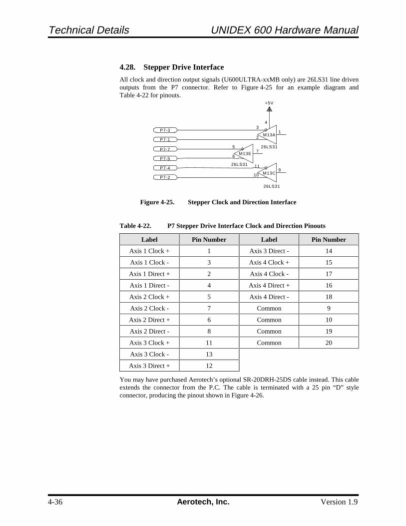
Technical Details UNIDEX 600 Hardware Manual
4-36 Aerotech, Inc. Version 1.9
4.28. Stepper Drive Interface
All clock and direction output signals (U600ULTRA-xxMB only) are 26LS31 line drivenoutputs from the P7 connector. Refer to Figure 4-25 for an example diagram andTable 4-22 for pinouts.
Figure 4-25. Stepper Clock and Direction Interface
Table 4-22. P7 Stepper Drive Interface Clock and Direction Pinouts
Label Pin Number Label Pin Number
Axis 1 Clock + 1 Axis 3 Direct - 14
Axis 1 Clock - 3 Axis 4 Clock + 15
Axis 1 Direct + 2 Axis 4 Clock - 17
Axis 1 Direct - 4 Axis 4 Direct + 16
Axis 2 Clock + 5 Axis 4 Direct - 18
Axis 2 Clock - 7 Common 9
Axis 2 Direct + 6 Common 10
Axis 2 Direct - 8 Common 19
Axis 3 Clock + 11 Common 20
Axis 3 Clock - 13
Axis 3 Direct + 12
You may have purchased Aerotech’s optional SR-20DRH-25DS cable instead. This cableextends the connector from the P.C. The cable is terminated with a 25 pin “D” styleconnector, producing the pinout shown in Figure 4-26.
P7-3
P7-1
P7-7
P7-5
P7-4
P7-2
+5V
4 3
1 2
M13A
M13C
26LS31
26LS31
7 5
6
11
10
26LS31
M13E
9

UNIDEX 600 Hardware Manual Technical Details
Version 1.9 Aerotech, Inc. 4-37
Figure 4-26. SR-20DRH-25DS Cable Drawing and Pinouts
∇ ∇ ∇
Pin 1
Connector20 Pin 3M Female
ECK01023
Shown ForReference Only
MXC Cable690B1538
TOLERANCES ONFractions Decimals Angles0 to 6 ±1/32 .xx to ±.01 ± 0 - 30°Over 6 ±1/16 .xxx to ±.005
Aerotech Inc. 101 Zeta DrivePittsburgh, PA, 15238(412)963-7470 TWX710-795-3125
A E R O T E C H
Part Code SR-20DRH-25DS
SR-20DRH-25DSCable AssemblySize
B 630B1841-1 REV
A
3B1841A1.DWG
Pin 19
DETAIL “A”Viewed from wire side of connector
“D” Female Connector
DETAIL “B”Viewed from wire side of connector
20 Pin 3M Connector
Pin 1
Jacksocket Kit
EC
K00363
Strain R
elief
To P
in 1F
irst Wire B
rown
Connector
25 Pin “D
” Fem
aleE
CK
00308
Globe B
racketE
CZ
01021
20 Conductor F
lat Ribbon C
ableS
tart with 16 ½
” long(U
se 26 conductor EC
X00439)
(Rem
ove wires 21 through 26)
Do N
ot Strain R
eliefConnector
20 pin 3M F
emale
EC
K01023
Connector25 Pin “D” Female
ECK00308
1 14 2 15 3 16 4 17 5 18 6 19 7 20 8 21 9 22 10 23 11 24 12 25 13
1234567891011121314151617181920
AXIS 1 Clock +
AXIS 1 Direction +AXIS 1 Clock -
AXIS 1 Direction -AXIS 2 Clock +
AXIS 2 Direction +
AXIS 2 Clock -
AXIS 2 Direction -Common
CommonAXIS 3 Clock +
AXIS 3 Direction +
AXIS 3 Clock -AXIS 3 Direction -
AXIS 4 Clock +
AXIS 4 Direction +
AXIS 4 Clock -
AXIS 4 Direction -
Common
Common
1 2 3 4 5 6 7 8 9 10 11 12 13
14 15 16 17 18 19 20 21 22 23 24 25
1. Axis 1 Clock + 10. Common 19. Axis 3 Direction +2. Axis 1 Clock - 11. - 20. Axis 3 Direction -3. Axis 2 Clock + 12. - 21. Axis 4 Direction +4. Axis 2 Clock - 13. - 22. Axis 4 Direction –5. Common 14. Axis 1 Direction + 23. Common6. Axis 3 Clock + 15. Axis 1 Direction - 24.7. Axis 3 Clock - 16. Axis 2 Direction + 25.8. Axis 4 Clock + 17. Axis 2 Direction -9. Axis 4 Clock - 18. Common
TB-DB25-P Phoenix 25 Pin

Technical Details UNIDEX 600 Hardware Manual
4-38 Aerotech, Inc. Version 1.9

UNIDEX 600 Hardware Manual Troubleshooting
Version 1.9 Aerotech, Inc. 5-1
CHAPTER 5: TROUBLESHOOTING
In This Section:• Installation, Board Startup and Communication Problems......... 5-2• Servo Related Problems ............................................................. 5-3• Problems Involving Fault Conditions ......................................... 5-4• Homing Related Problems.......................................................... 5-6
If you have technical support questions, please have the following information availablebefore calling:
1. The current version of the software is indicated on the installation disk or the title barof the UNIDEX 600 MMI.
2. Your customer order number. If you have purchased a DR500 from Aerotech thisnumber will be on the rear of the DR500 in the upper left-hand corner on a systemserial tag.
3. We may also need to know the type of PC you are using (brand name, CPU, availablememory), the current version of the operating system.
4. If you are developing your own application, we will need to know what compiler andversion number you are using (e.g., Borland C v3.1, Microsoft Visual C, etc.).
5. If at all possible, try to be in front of the system where the problems are occurring.

Troubleshooting UNIDEX 600 Hardware Manual
5-2 Aerotech, Inc. Version 1.9
5.1. Installation, Board Startup and Communication Problems
Some common problems that relate to installation, startup and communications are listedand diagnosed in Table 5-1.
Table 5-1. Troubleshooting for Common Installation, Startup and Communication Problems
Problem Possible Causes / Solutions See Section
Installation program fails(the install directory andsubdirectories werecreated, but nothing wasinstalled)...
Be sure you have at least 4 MB of hard disk spaceavailable.
Initialization failure,communication failure or“Error DownloadingFirmware !” error occurs...
The UNIDEX 600 board is not installed.
The UNIDEX 600 board is not seated properly.
The software address does not match the hardwareaddress.
Another device in the PC is set to the same base addressas the U600 board. Select a unique base address.
2.1-2.4, 3.4, 4.2
The board initializesproperly, but later fails.
The UNIDEX 600 board is not seated properly.
Another device in the PC is set to the same base addressas the U600 board. Select a unique base address.
2.4, 3.4, 4.2
The LED never lights upafter power up ...
The UNIDEX 600 board is not seated properly.
Another device in the PC is set to the same base addressas the U600 board. Select a unique base address.
The power supply has been overloaded and has shutdown. Install a larger power supply or removeunnecessary expansion cards to correct the problem.
2.4, 3.4, 4.2
PC Manual
The LED lights afterpower up and remains oneven after attempts toinitialize ...
The software base address does not match the baseaddress jumper settings on the UNIDEX 600 board.
Another device in the PC is set to the same base addressas the U600 board. Select a unique base address.
2.4, 3.4, 4.2
The PC power supply goesdead when the UNIDEX600 is installed ...
The power supply has been overloaded and has shutdown. Install a larger power supply to correct theproblem or remove unnecessary expansion cards.
External wiring problems exist. Remove the maininterface cable and recheck.
The UNIDEX 600 board is faulty.
4.11, PC Manual
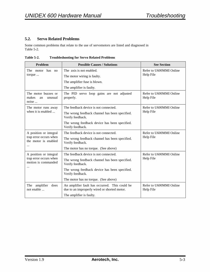
UNIDEX 600 Hardware Manual Troubleshooting
Version 1.9 Aerotech, Inc. 5-3
5.2. Servo Related Problems
Some common problems that relate to the use of servomotors are listed and diagnosed inTable 5-2.
Table 5-2. Troubleshooting for Servo Related Problems
Problem Possible Causes / Solutions See Section
The motor has notorque ...
The axis is not enabled.
The motor wiring is faulty.
The amplifier fuse is blown.
The amplifier is faulty.
Refer to U600MMI OnlineHelp File
The motor buzzes ormakes an unusualnoise ...
The PID servo loop gains are not adjustedproperly.
Refer to U600MMI OnlineHelp File
The motor runs awaywhen it is enabled ...
The feedback device is not connected.
The wrong feedback channel has been specified.Verify feedback.
The wrong feedback device has been specified.Verify feedback.
Refer to U600MMI OnlineHelp File
A position or integraltrap error occurs whenthe motor is enabled...
The feedback device is not connected.
The wrong feedback channel has been specified.Verify feedback.
The motor has no torque. (See above)
Refer to U600MMI OnlineHelp File
A position or integraltrap error occurs whenmotion is commanded...
The feedback device is not connected.
The wrong feedback channel has been specified.Verify feedback.
The wrong feedback device has been specified.Verify feedback.
The motor has no torque. (See above)
Refer to U600MMI OnlineHelp File
The amplifier doesnot enable ...
An amplifier fault has occurred. This could bedue to an improperly wired or shorted motor.
The amplifier is faulty.
Refer to U600MMI OnlineHelp File

Troubleshooting UNIDEX 600 Hardware Manual
5-4 Aerotech, Inc. Version 1.9
5.3. Problems Involving Fault Conditions
Some common problems relating to fault conditions are listed and diagnosed in Table 5-3.
Table 5-3. Troubleshooting for Problems Involving Fault Conditions
Problem Possible Causes / Solutions See Section
A position or integraltrap error occurs whenthe axis is enabled ...
The feedback device is not connected.
The wrong feedback channel has been specified.Verify the feedback.
The wrong feedback device has been specified.Verify the feedback.
The motor has no torque (the appropriate axis is notenabled, the motor wiring is faulty, the amplifier fuseis blown or the amplifier is faulty).
Refer to U600MMIOnline Help File
A position or integraltrap error occurs whenmotion is commanded...
The feedback device is not connected.
The wrong feedback channel has been specified.Verify the feedback.
The wrong feedback device has been specified.Verify the feedback.
The motor has no torque (the appropriate axis is notenabled, the motor wiring is faulty, the amplifier fuseis blown or the amplifier is faulty).
Refer to U600MMIOnline Help File
A velocity trap occurs...
The feedback device is faulty. Refer to U600MMIOnline Help File
Driver Interlock Openmessage is displayed ...
The OP500 cable is not inserted properly (e.g., there is noconnection between pins 1 and 100). Check the cables andthen acknowledge the fault.
An emergency stopcondition occurs ...
The emergency stop input is in the active state.Disable the emergency stop parameter if anemergency stop input is not desired.
Refer to U600MMIOnline Help File
A clockwise (CW) orcounter-clockwise(CCW) limit conditionalways exists ...
Limits are not connected to the UNIDEX 600.
The active polarity IO Level parameter for the limitsis set wrong.
Refer to U600MMIOnline Help File
An axis is in a CW orCCW limit condition ...
The commanded motion extended past the limit.Acknowledge the fault and then move the axis out of thelimit.
The system has been powered up in a limit condition.Acknowledge the fault and move out of the limit.
The active limit polarity parameter IO Level is setincorrectly.
Software limits are improperly set.
Refer to U600MMI OnlineHelp File

UNIDEX 600 Hardware Manual Troubleshooting
Version 1.9 Aerotech, Inc. 5-5
Table 5-3. Troubleshooting for Problems Involving Fault Conditions (Cont.)
Problem Possible Causes / Solutions See Section
An over current trap(RMS over currentfault) error hasoccurred ...
If the motor makes unusual noises or oscillates, thegain parameters may need to be adjusted.
The RMS current trap parameter is set too low.
The RMS current trap time is set too short.
The amplifier gain parameter is set too low.
The mechanical system is damaged or jammed.
The motor/amplifier may be undersized for theload.
Refer to U600MMIOnline Help File
A feedback trap hasoccurred ...
The incorrect feedback channel has been specified.
The incorrect feedback device has been specified.
The feedback device is not connected. Verifyfeedback is present
Single ended encoders are connected. Set the faultmask to ignore encoder faults.
A sinusoidal encoder is connected. The UNIDEX600 accepts square wave encoders only.
One or more encoder connections are broken.
The encoder is faulty.
A resolver-to-digital tracking loop error hasoccurred.
One or more resolver connections are broken.
The resolver reference has not been adjustedproperly.
Refer to U600MMIOnline Help File
A feedrate trap hasoccurred ...
The commanded feedrate may have exceeded therapid feedrate parameter (machine parameters).
Refer to U600MMIOnline Help File

Troubleshooting UNIDEX 600 Hardware Manual
5-6 Aerotech, Inc. Version 1.9
5.4. Homing Related Problems
Some common problems relating to the homing process are listed and diagnosed in Table5-4.
Table 5-4. Troubleshooting for Homing Related Problems
Problem Possible Causes / Solutions See Section
The axis takes a long time tohome ...
The home feedrate parameter (machineparameters) is set too low.
The maximum acceleration/decelerationparameter (axis parameters) is set too low.
Refer to U600MMI OnlineHelp File
The axis runs into a limitduring the home cycle ...
The homing direction/type parameter iswrong. (machine parameters)
The home switch is not connected.
Refer to U600MMI OnlineHelp File
Software limits are notworking ...
The home cycle may not have completedyet.
Refer to U600MMI OnlineHelp File
∇ ∇ ∇

UNIDEX 600 Hardware Manual Glossary of Terms
Version 1.9 Aerotech, Inc. A-1
APPENDIX A: GLOSSARY OF TERMS
In This Section:• Terms Used In This Manual• Definitions
This appendix contains definitions of terms that are used throughout this manual.
amplifier - An amplifier is a hardware device having an output that is a function of theinput signal.
axis - An axis is a direction along which movement occurs.
base address - A base address is a number that represents the memory location in thecomputer where input/output (I/O) information can be stored. All devices (e.g., the U600card, network cards, tape backup cards, etc.) within a computer must have unique I/Obase addresses. The default I/O base address of the U600 card is 0x300 (whichrepresents the 16 memory locations 0x300 through 0x30F). This base address can bechanged using base address jumpers JP4 through JP9 on the U600 card. The base addressmust also be configured in the UNIDEX 600 Startup software.
BB500 Breakout Module - The BB500 Breakout Module is a hardware device thatconnects directly to the U600 card to provide direct signal access (in the form of screwterminals) when a DR500 chassis is not used.
bit - The term bit is an acronym for “Binary digit” and represents a single binary number(i.e., a “1” or a “0”). In digital computers, a bit’s two states can represent an off state andan on state, a high voltage and a low voltage, the numbers 0 and 1, etc.
brushless motor - Aerotech brushless motors are three-phase, rare earth permanentmagnet servomotors which generate a sinusoidal back EMF voltage and are usuallyreferred to as AC brushless motors. Another type, usually referred to as the DC brushlessmotors, generate a trapezoidal back EMF and produce more torque ripple.
byte - A byte is a common unit of information storage made up of eight binary digits(bits). A byte can be used to represent a single ASCII character (e.g., “A”= 10000001[binary]) or binary numbers from 00000000 to 11111111 (from 0 to 255 decimal),depending on how it is used.
closed loop system - A closed loop system is a drive system that uses sensors for directfeedback of position and/or velocity. Contrast with open loop system

Glossary of Terms UNIDEX 600 Hardware Manual
A-2 Aerotech, Inc. Version 1.9
commutation - Commutation refers to the process by which every other cycle of analternating current is reversed so that a single unidirectional current is supplied. In thecase of motors, commutation refers to the switching of current to motor windings whichcauses the motor to rotate. In a DC servomotor, this is done mechanically using brushesand a commutator. A brushless motor is electronically commutated using a positionfeedback device such as an encoder that is mounted to the rotor. Stepping motors areelectronically commutated without feedback (in an open loop fashion).
DR500 Chassis/Drive Rack - The DR500 Chassis (or Drive Rack) is a housing for theaxis amplifiers (for microstepping, DC brush and brushless drivers) and the driver powersupply. The DR500 is available in rack mount, panel mount and desktop packaging.
encoder - An encoder is a rotary device that transmits a pulsed signal based on thenumber of revolutions of the device.
Hall effect switch - A Hall effect switch is a solid state switch that is activated by amagnetic field. Some AC brushless motors use Hall effect switches.
handwheel - A handwheel is an encoder-based manual control input device that can beused to simplify machine setup or testing.
hexadecimal number format - Hexadecimal number format is a method of representinglarge numbers using base 16 rather than the standard base 10. In base 16 or hexadecimalnumber format (often abbreviated "hex"), the number positions represent powers of 16(rather than powers of 10 in decimal). The decimal number positions (1’s, 10’s, 100’s,1,000’s, 10,000’s, etc.) are replaced with hexadecimal number positions (1’s, 16’s, 256’s,4096’s, etc.). Also, while the individual numerals for the decimal system are 0-9, thenumerals for the hexadecimal number system (which requires 16 unique "numerals") are0-9 then A-F (where A16=1010, B16=1110, C16=1210, D16=1310, E16=1410, andF16=1510). For simplicity in this manual, hexadecimal numbers are written with apreceding "0x" rather than using the subscript 16. For example, the hexadecimal number12A5 is written 0x12A5. Numbers without the preceding "0x" are assumed to be decimalunless otherwise indicated.
IRQ - IRQ (interrupt request) is a term associated with generating an interrupt request tothe PC. A PC has many IRQs (e.g., IRQ3 and IRQ4 are typically configured as COMports on the PC, IRQ7 is typically configured as the LPT port, et. al.). Although theU600 does not use such interrupts, custom software applications may. In these cases, theinterrupt number used by the custom software program (to interrupt the PC) must beselected on the UNIDEX 600 board (using jumpers JP3A through JP3F) as well asconfigured in the U600 software.
joystick - A joystick is manual input control device that digitizes a path using two axes.A joystick offers direct motion control for easy machine setup and testing.
jumpers - Jumpers are hardware ties that you manually position into different sockets toconfigure the hardware platform. Jumpers on the UNIDEX 600 board are used toconfigure the base address, the encoder sampling frequency, termination resistors, andother features.

UNIDEX 600 Hardware Manual Glossary of Terms
Version 1.9 Aerotech, Inc. A-3
LED - LED is an acronym for light-emitting diode. An LED is a semiconductor diodethat converts electrical energy into visible electromagnetic radiation. The UNIDEX 600board has an LED (visible from the back of the PC after installation) that is used fordiagnostic purposes.
OP500 - The OP500 is an optional cable that is used to connect the UNIDEX 600controller card to the DR500 chassis.
open loop system - An open loop system is a drive system that does not employ feedbacksensors to monitor position or velocity. Most stepper motor applications are open loop(that is, they have no feedback). The commanded position is the assumed motor position.Contrast with closed loop system.
operator - (1) An operator is one who uses the UNIDEX 600 system.
operator - (2) An operator is a programming element that is used to link terms in anexpression. Programming operators include the standard arithmetic operators (e.g., +, -, *and /), comparison operators (e.g., < and >) and Boolean operators (e.g., AND, OR andNOT) and others.
position synchronized output card - The position synchronized output card is anoptional PC-bus based card that can be used in conjunction with the U600 (via connectionP3 on the U600 card) to provide programmable laser-firing control.
resolver - A resolver is a two-phase, rotary, electromagnetic transducer in whichinductive coupling (between the rotor and stator windings) and trigonometric principlesare employed to provide absolute position information over one electrical cycle (which isone revolution for "single-step" resolvers)
resolver-to-digital card (RDP-PC) - The RDP-PC card is an optional PC-based R/Dcard that is used to receive resolver or Inductosyn feedback. Resolution is selectableamong 10-bit, 12-bit, 14-bit or 16-bit.
RMS current trap - RMS current trap is an error that occurs if the current beingcommanded to a motor exceeds a programmable limit. RMS current trap is analogous toa software “fuse”. Essentially, this fault functions the same as a physical fuse, but is donethrough software. One obvious advantage is that a “software fuse” does not have to bereplaced like a physical fuse.
servo control system - A servo control system (servo loop) is a motion control systemwhich continuously compares desired position/velocity to actual position/velocity andproduces an error correction command. Servo systems use sensors to feedback actualposition/velocity.
∇ ∇ ∇

Glossary of Terms UNIDEX 600 Hardware Manual
A-4 Aerotech, Inc. Version 1.9

UNIDEX 600 Hardware Manual Warranty and Field Service
Version 1.9 Aerotech, Inc. B-1
APPENDIX B: WARRANTY AND FIELD SERVICE
In This Section:• Laser Product Warranty• Return Products Procedure• Returned Product Warranty Determination• Returned Product Non-warranty Determination• Rush Service• On-site Warranty Repair• On-site Non-warranty Repair
Aerotech, Inc. warrants its products to be free from defects caused by faulty materials orpoor workmanship for a minimum period of one year from date of shipment fromAerotech. Aerotech’s liability is limited to replacing, repairing or issuing credit, at itsoption, for any products which are returned by the original purchaser during the warrantyperiod. Aerotech makes no warranty that its products are fit for the use or purpose towhich they may be put by the buyer, whether or not such use or purpose has beendisclosed to Aerotech in specifications or drawings previously or subsequently provided,or whether or not Aerotech’s products are specifically designed and/or manufactured forbuyer’s use or purpose. Aerotech’s liability or any claim for loss or damage arising out ofthe sale, resale or use of any of its products shall in no event exceed the selling price ofthe unit.
Aerotech, Inc. warrants its laser products to the original purchaser for a minimum periodof one year from date of shipment. This warranty covers defects in workmanship andmaterial and is voided for all laser power supplies, plasma tubes and laser systems subjectto electrical or physical abuse, tampering (such as opening the housing or removal of theserial tag) or improper operation as determined by Aerotech. This warranty is also voidedfor failure to comply with Aerotech’s return procedures.
Claims for shipment damage (evident or concealed) must be filed with the carrier by thebuyer. Aerotech must be notified within (30) days of shipment of incorrect materials. Noproduct may be returned, whether in warranty or out of warranty, without first obtainingapproval from Aerotech. No credit will be given nor repairs made for products returnedwithout such approval. Any returned product(s) must be accompanied by a returnauthorization number. The return authorization number may be obtained by calling anAerotech service center. Products must be returned, prepaid, to an Aerotech servicecenter (no C.O.D. or Collect Freight accepted). The status of any product returned laterthan (30) days after the issuance of a return authorization number will be subject toreview.
After Aerotech’s examination, warranty or out-of-warranty status will be determined. Ifupon Aerotech’s examination a warranted defect exists, then the product(s) will berepaired at no charge and shipped, prepaid, back to the buyer. If the buyer desires an airfreight return, the product(s) will be shipped collect. Warranty repairs do not extend theoriginal warranty period.
Laser Products
Return Procedure
Returned ProductWarranty Determination

Warranty and Field Service UNIDEX 600 Hardware Manual
B-2 Aerotech, Inc. Version 1.9
After Aerotech’s examination, the buyer shall be notified of the repair cost. At such timethe buyer must issue a valid purchase order to cover the cost of the repair and freight, orauthorize the product(s) to be shipped back as is, at the buyer’s expense. Failure to obtaina purchase order number or approval within (30) days of notification will result in theproduct(s) being returned as is, at the buyer’s expense. Repair work is warranted for (90)days from date of shipment. Replacement components are warranted for one year fromdate of shipment.
At times, the buyer may desire to expedite a repair. Regardless of warranty or out-of-warranty status, the buyer must issue a valid purchase order to cover the added rushservice cost. Rush service is subject to Aerotech’s approval.
If an Aerotech product cannot be made functional by telephone assistance or by sendingand having the customer install replacement parts, and cannot be returned to the Aerotechservice center for repair, and if Aerotech determines the problem could be warranty-related, then the following policy applies:
Aerotech will provide an on-site field service representative in a reasonable amount oftime, provided that the customer issues a valid purchase order to Aerotech covering alltransportation and subsistence costs. For warranty field repairs, the customer will not becharged for the cost of labor and material. If service is rendered at times other thannormal work periods, then special service rates apply.
If during the on-site repair it is determined the problem is not warranty related, then theterms and conditions stated in the following "On-Site Non-Warranty Repair" sectionapply.
If any Aerotech product cannot be made functional by telephone assistance or purchasedreplacement parts, and cannot be returned to the Aerotech service center for repair, thenthe following field service policy applies:
Aerotech will provide an on-site field service representative in a reasonable amount oftime, provided that the customer issues a valid purchase order to Aerotech covering alltransportation and subsistence costs and the prevailing labor cost, including travel time,necessary to complete the repair.
Aerotech, Inc. Phone: (412) 963-7470101 Zeta Drive Fax: (412) 963-7459Pittsburgh, PA 15238-2897 TWX: (710) 795-3125USA
∇ ∇ ∇
Returned Product Non-warranty Determination
Rush Service
On-site Warranty Repair
On-site Non-warrantyRepair
Company Address

UNIDEX 600 Hardware Manual Index
Version 1.9 Aerotech, Inc. i
NUMBERS7404-type Open Collector Driver, 4-18
AAirflow
Cooling requirements, 2-2Amplifier Chassis, 2-10, 3-13Amplifier Enable Output Locations P1, 4-18Amplifier Enable Outputs, 4-18Amplifier Fault, 4-10Amplifier Fault Inputs P1, 4-10Amplifiers
7404-type open collector drivers, 4-18available types, 2-10, 3-13state of, with respect to LED, 2-9, 3-11
Analog inputs, 4-27Antistatic Bag, 2-4Antistatic Precautions, 2-9, 3-11
BBase address, 3-2Base Address Jumpers, 2-5, 3-4
default, 2-5, 3-4BB500 Breakout Module
installation, 2-11, 3-14Brake output, 4-13Braking, 3-16Breakout Block (BB500), 4-30Breakout Module
installation, 2-11, 3-14BRK/BPS Vertical Axis Brake Option, 3-16Brushless motor phasing, 4-33
CCables
OP500, 2-10, 3-13CCW Rotation Limit Switch, 4-10Communications Failure, 5-2Communications Problems, 5-2Connectors, 3-4Cooling requirements, 2-2Coprocessor, Recommended, 2-2, 3-1Current Command Output, 4-15
signals P1, 4-15Custom Software
PC bus interrupt jumper, 2-6, 3-5Customer Order Number, 5-1CW Rotation Limit Switch, 4-10
DDefinitions of Terms, A-1
Differential Encoder Resistors, 3-4Differential Encoders, 4-6
using pull up termination resistors, 3-7Digital Input Bus Specifications, 4-16Disk Space, Recommended, 2-2, 3-1Display, Recommended, 2-2, 3-1DR500 Drive Rack, 2-10, 3-13
installation, 2-10, 3-13rear panel connections, 2-10, 3-13
DRC Cable, 3-17, 3-18, 3-19
EElectrical Characteristics of a Single Ended Encoder
Interface, 4-6Electrical Characteristics of the UNIDEX 600
Amplifier Enable Out, 4-18Electrical Characteristics of the UNIDEX 600 Brake
Signal Output, 4-19Electrical Characteristics of the UNIDEX 600 Current
Command Out, 4-15Electrical Characteristics of the UNIDEX 600 Input
Bus Interface, 4-11Electrical Characteristics of the UNIDEX 600 Opto 22
Connections, 4-22Electrical Characteristics of the UNIDEX 600 Output
Bus Interfac, 4-17Electromagnetic Brake for Vertical Axes, 3-16Emergency Stop Inputs, 4-13Encoder
’times 4’ multiplication, 4-6Encoder Resistors, 3-4Encoder Signal Pinouts, 4-9Encoder Signal Specifications, 4-6Encoder Signals and Pinouts P1, 4-9Encoders
pull up resistors, 3-7termination Resistors, 3-7using pull up termination resistors, 3-7
Errors, 5-3Expansion Slot, 2-9, 3-11Extended I/O Cable, 2-14, 3-19External Reset Jumper, 3-9
FFail Safe Brake, 4-19Fault Conditions, 5-4Field Service Information, B-1Field Service Policy, B-1Floppy Disk Drive, Recommended, 2-2, 3-1
GGain settings
Servo loop, 4-31Glossary of Terms, A-1

Index UNIDEX 600 Hardware Manual
ii Aerotech, Inc. Version 1.9
Graphics Display, Recommended, 2-2, 3-1
HHall Inputs, 4-29Handling the U600 Card, 2-4Handwheel interface, 4-34Hard Disk Space, Recommended, 2-2, 3-1Hexadecimal Address Ranges, 2-5, 3-4High speed position latch, 4-25Home Limit Switch, 4-10Homing Problems, 5-6
IICMD Signals, 4-15IN# Input Signals, 4-16Inductosyn Feedback, Receiving, 3-16Inductosyns
definition, 3-16pole spacing (typical), 3-16positioning resolutions, 3-16
InitializationLED state during, 2-9, 3-11problems during, 2-5, 3-4
Initialization Failure, 5-2Inputs
digital TTL-type, 4-16limits, 4-10
Inspecting the UNIDEX 600 Control Board, 2-4Installation, 2-9, 3-11
other Aerotech components, 3-13Installation Problems, 5-2Integral Trap Error, 5-3Interrupt the PC, 2-6, 3-5
jumper setup for custom applications, 2-6, 3-5IRQ10, 2-8, 3-6, 4-3IRQ11, 2-8, 3-6, 4-3IRQ12, 4-3IRQ15, 2-7, 3-6, 4-3IRQ3, 2-7, 3-5, 3-6, 4-3IRQ4, 2-7, 3-5, 4-3IRQ5, 2-7, 3-5, 4-3IRQ9, 2-7, 3-5, 4-3
JJoystick, 1-3Joystick interface, 4-28Jumper Configurations, 4-3Jumpers, 3-2, 3-4
base address, 2-5, 3-2, 3-4PC bus interrupt, 3-2, 3-5, 4-7
LLED, 3-4, 3-11
location, 2-9, 3-11operation states, 2-9, 3-11
LED Problems, 5-2Limit and Amplifier Fault Inputs, 4-10Limit Inputs, 4-10Limit Switch Input, 4-10
MMain Connector Pinout of the UNIDEX 600, 4-23Main Connector Pinouts for the UNIDEX 600, 4-24Manual feedrate override, 4-25Memory
conventional (recommended), 2-2, 3-1extended, 2-2, 3-1ranges for base addresses, 2-5, 3-4
Microprocessor, Recommended, 2-2, 3-1Minimum Hardware requirements, 2-2Motor Buzzes, 5-3Motor Has No Torque, 5-3Motor Related Test Points, 4-2Mouse, Recommended, 2-2, 3-1
NNo Feedback (Open Loops), A-3
OOP500 Cable, 2-10, 3-13Open Loops, A-3Options Port, 3-4OPTO 22 Boards, 3-17Opto 22 I/O Bus, 3-4, 4-20Opto 22 I/O Hall Inputs (P5) Pinouts, 4-29OUT# TTL Output Signals, 4-17Output Bus Specifications, 4-17Outputs
TTL-type, 4-17Overview of the UNIDEX 600 System, 1-1
PP1 - Current command output signals, 4-15P1 - encoder signal pinouts, 4-9P1 - Limit and fault inputs, 4-10P1 - U600 inputs, 4-16P1 - U600 outputs, 4-17P1 Connector, 3-4P10 connector, 3-4P2 Connector, 3-4P3
Pinouts - expansion bus, 4-27P3 Connector, 3-4
using the PSO-PC Card, 3-15P4 Connector, 3-4P9 - U600 inputs, 4-16

UNIDEX 600 Hardware Manual Index
Version 1.9 Aerotech, Inc. iii
P9 - U600 outputs, 4-17P9 Connector, 3-4Parameter Summary, A-1PB 16 Opto-22 Interface Board, 4-20PB 24 Opto-22 Interface Board, 4-20PB 8 Opto-22 Interface Board, 4-20PB# Boards, 3-18PC Board, 3-4PC Bus Interrupt Jumper, 3-2, 3-5PC BUS Interrupt Jumpers, 4-7PC bus reset, 3-9PC Expansion Slot, 2-9, 3-11PC Power Problems, 5-2PC-AT Base Addresses, 4-5Pinouts
P10, 4-10Pinouts - Opto 22 outputs, Hall sensor inputs
P10, 4-29Pinouts Expansion bus
P3, 4-27Pinouts for Opto 22 I/O Hall Inputs (P10), 4-29Pinouts U600
Main connector - P1, 4-24P1, 4-9, 4-10, 4-15, 4-16, 4-18P10, 4-17P9, 4-16, 4-17
Position Error, 5-3Power
Board consumption, 2-3, 3-2Power Consumption, 2-3, 3-2Precautions, 1-4PSO-PC Card, 3-15Pull Up Resistors, 3-4
RRDP-PC Card, 3-16
ratiometric tracking conversion, 3-16Resistor Networks RN16, RN19 and RN22, 3-7Resistor Networks RN16, RN22 and RN19, 3-7Resolver
definition, 3-16Resolver Feedback, Receiving, 3-16Resolver-to-digital Card, 3-16Resolver-to-digital Converter Card
accuracy, 3-16RS-232C Serial Port Jumper Settings, 3-9
SSafety Procedures, 1-4Servo loop, 4-31Servo loop phasing, 4-32
Servo Problems, 5-3Servo System
supply power, 2-10, 3-13SIMM sockets, 3-10Single Ended Encoders, 4-6
using pull up termination resistors, 3-7sockets
SIMM, 3-10Software
base address, 2-5, 3-4initialization and LED state, 2-9, 3-11
Software Limit Inputs P1, 4-10Startup Problems, 5-2Static Charge Buildup, Removing, 2-4Stepper drive interface, 4-36
TTeach pendant interface - inputs, 4-34Teach pendant interface- outputs, 4-35Technical Support Questions, 5-1Termination Resistor Configuration, 3-7Termination Resistor Networks
values, 3-7Termination Resistors, 3-4Termination Resistors for Encoders, 3-7Test Points, 4-1
motor related, 4-1The Brake Output, 4-19
UUNIDEX 600
board installation, 2-9, 3-11I/O channel memory, 2-5, 3-4installation, 3-11outputs and locations P1 & P9, 4-17TTL inputs and locations P1 & P9, 4-16
UNIDEX 600 PC Board, 3-4Unpacking the UNIDEX 600, 2-1
VVersion Number, Software, 5-1Vertical Axis Brake, 3-16
WWarnings, 1-4Warranty Information, B-1Warranty Policy, B-1
∇ ∇ ∇

Index UNIDEX 600 Hardware Manual
iv Aerotech, Inc. Version 1.9

READER’S COMMENTS
UNIDEX 600 Hardware ManualP/N EDU 154, March, 2001
Please answer the questions below and add any suggestions for improving this document. Is the information:
Yes No
Adequate to the subject? ____ ____
Well organized? ____ ____
Clearly presented? ____ ____
Well illustrated? ____ ____
Would you like to see more illustrations? ____ ____
Would you like to see more text? ____ ____
How do you use this document in your job? Does it meet your needs?What improvements, if any, would you like to see? Please be specific or cite examples.
_____________________________________________________________________
_____________________________________________________________________
_____________________________________________________________________
_____________________________________________________________________
_____________________________________________________________________
Your name ________________ Your title ________________ Company name ________________
Address ________________ ________________
Remove this page from the document and fax or mail your comments to the technical writing department of Aerotech.
AEROTECH, INC.Technical Writing Department101 Zeta DrivePittsburgh, PA. 15238-2897 U.S.A.Fax number (412) 967-6870
AEROTECHR