The selective removal of H2S over CO2 from biogas in a bubble column using pretreated digester...
8
The selective removal of H 2 S over CO 2 from biogas in a bubble column using pretreated digester effluent Nicholas Kennedy, Quan-Bao Zhao, Jingwei Ma, Shulin Chen, Craig Frear ⇑ Department of Biological Systems Engineering, Washington State University, P.O. Box 646120, Pullman, WA 99164-6120, USA article info Article history: Received 15 October 2014 Received in revised form 24 February 2015 Accepted 25 February 2015 Available online 5 March 2015 Keywords: H 2 S removal Biogas purification Anaerobic digestion Bubble column reactor Absorption abstract Raw biogas purification can be achieved using various physicochemical techniques. Unfortunately, tech- niques for the simultaneous absorption of CO 2 and H 2 S are susceptible to the corrosive nature of H 2 S. Furthermore, the absorbents utilized are often expensive, thus requiring regeneration. Concurrently, on farm digesters are now moving toward the incorporation of NH 3 recovery. One such process, air stripping, requires elevation of pH, which as a result produces an alkaline effluent. Due to this, a physicochemical H 2 S removal process was investigated in a bubble column reactor using this manure based alkaline absor- bent. Selective removal of H 2 S over CO 2 increased nearly 50% by altering the sparger configuration. Additional selectivity was achieved by decreasing the effluent height in the bubble column and increasing the superficial gas velocity. Continuous countercurrent mode of operation was tested and relatively high H 2 S removal efficiency (84%) was achieved at a biogas-to-effluent ratio (v/v) of 20:1, close to that typical- ly found on dairy digesters. Ó 2015 Elsevier B.V. All rights reserved. 1. Introduction Biogas, derived from the anaerobic digestion (AD) of dairy manure consists of methane (CH 4 ) (55–65%) and contaminants including carbon dioxide (CO 2 ) (30–45%), hydrogen sulfide (H 2 S) (300–4500 ppm) and trace levels of halogenated hydrocarbons, nitrogen, oxygen, organic silicon and water vapor [1]. These con- taminants, without pretreatment, limit the use of biogas to com- bined heat and power (CHP), whereas economic assessments have suggested that a higher value use is possible by purifying CH 4 to meet natural gas regulations or purifying and compressing it for use as a vehicle fuel [2].H 2 S, in particular, threatens every end-use of biogas because it converts to highly corrosive sulfur dioxide and sulfuric acid upon combustion. Various physical, physico-chemical, and biological upgrading technologies have been developed to separately or simultaneously remove CO 2 and H 2 S [3]. For example, water scrubbing, which is a dominant technique in biogas upgrading, is a relatively simple and inexpensive process where both CO 2 and H 2 S are able to diffuse into pressurized water. However, issues can occur when simulta- neously removing H 2 S and CO 2 due to the accumulation of sulfur, causing fouling and clogging of pipework; therefore, it is beneficial to remove H 2 S beforehand using a separate removal technique [3]. This infers higher capital, operational and maintenance costs to the project, thus decreasing the applicability of biogas upgrading on dairy digesters. One upstream gas purification process used in the natural gas and coal industry to remove H 2 S from gaseous waste streams are alkaline solvents [4]. Due to the industrial application of alkaline solvents in these industries, they have been adopted for biogas upgrading [5]. Unfortunately, in such applications the solvents are often expensive and can become quickly depleted because comparatively large volumes of CO 2 are able to absorb as well. As a result, extensive research into gas/liquid film theory, to increase the selectivity of H 2 S over CO 2 , has occurred since the 1950s result- ing in packed beds as the appropriate choice due to its ability to control gas-film resistance, the dominant resistance to mass trans- fer for H 2 S [4]. Unfortunately, the absorbents used in packed beds are often too expensive to merely discharge after saturation, thus requiring an additional reactor for the regeneration of the solvent, which represents roughly 70% of overall operational gas treatment costs [6]. An appropriate solution to the front-end purification of biogas on a farm, prior to CO 2 and water vapor removal, would be to use an alkaline solvent produced continuously on-site eliminating the need for a separate regeneration process. Ammonia (NH 3 ) removal and recovery via air stripping has been successful on var- ious effluents including landfill leachate [7], municipal wastewater [8], and slaughterhouse waste [9] with commercialization now http://dx.doi.org/10.1016/j.seppur.2015.02.046 1383-5866/Ó 2015 Elsevier B.V. All rights reserved. ⇑ Corresponding author. Tel.: +1 509 335 0194; fax: +1 509 335 2722. E-mail address: [email protected] (C. Frear). Separation and Purification Technology 144 (2015) 240–247 Contents lists available at ScienceDirect Separation and Purification Technology journal homepage: www.elsevier.com/locate/seppur
Transcript of The selective removal of H2S over CO2 from biogas in a bubble column using pretreated digester...

Separation and Purification Technology 144 (2015) 240–247
Contents lists available at ScienceDirect
Separation and Purification Technology
journal homepage: www.elsevier .com/locate /seppur
The selective removal of H2S over CO2 from biogas in a bubble columnusing pretreated digester effluent
http://dx.doi.org/10.1016/j.seppur.2015.02.0461383-5866/� 2015 Elsevier B.V. All rights reserved.
⇑ Corresponding author. Tel.: +1 509 335 0194; fax: +1 509 335 2722.E-mail address: [email protected] (C. Frear).
Nicholas Kennedy, Quan-Bao Zhao, Jingwei Ma, Shulin Chen, Craig Frear ⇑Department of Biological Systems Engineering, Washington State University, P.O. Box 646120, Pullman, WA 99164-6120, USA
a r t i c l e i n f o
Article history:Received 15 October 2014Received in revised form 24 February 2015Accepted 25 February 2015Available online 5 March 2015
Keywords:H2S removalBiogas purificationAnaerobic digestionBubble column reactorAbsorption
a b s t r a c t
Raw biogas purification can be achieved using various physicochemical techniques. Unfortunately, tech-niques for the simultaneous absorption of CO2 and H2S are susceptible to the corrosive nature of H2S.Furthermore, the absorbents utilized are often expensive, thus requiring regeneration. Concurrently, onfarm digesters are now moving toward the incorporation of NH3 recovery. One such process, air stripping,requires elevation of pH, which as a result produces an alkaline effluent. Due to this, a physicochemicalH2S removal process was investigated in a bubble column reactor using this manure based alkaline absor-bent. Selective removal of H2S over CO2 increased nearly 50% by altering the sparger configuration.Additional selectivity was achieved by decreasing the effluent height in the bubble column and increasingthe superficial gas velocity. Continuous countercurrent mode of operation was tested and relatively highH2S removal efficiency (84%) was achieved at a biogas-to-effluent ratio (v/v) of 20:1, close to that typical-ly found on dairy digesters.
� 2015 Elsevier B.V. All rights reserved.
1. Introduction
Biogas, derived from the anaerobic digestion (AD) of dairymanure consists of methane (CH4) (55–65%) and contaminantsincluding carbon dioxide (CO2) (30–45%), hydrogen sulfide (H2S)(300–4500 ppm) and trace levels of halogenated hydrocarbons,nitrogen, oxygen, organic silicon and water vapor [1]. These con-taminants, without pretreatment, limit the use of biogas to com-bined heat and power (CHP), whereas economic assessmentshave suggested that a higher value use is possible by purifyingCH4 to meet natural gas regulations or purifying and compressingit for use as a vehicle fuel [2]. H2S, in particular, threatens everyend-use of biogas because it converts to highly corrosive sulfurdioxide and sulfuric acid upon combustion.
Various physical, physico-chemical, and biological upgradingtechnologies have been developed to separately or simultaneouslyremove CO2 and H2S [3]. For example, water scrubbing, which is adominant technique in biogas upgrading, is a relatively simple andinexpensive process where both CO2 and H2S are able to diffuseinto pressurized water. However, issues can occur when simulta-neously removing H2S and CO2 due to the accumulation of sulfur,causing fouling and clogging of pipework; therefore, it is beneficialto remove H2S beforehand using a separate removal technique [3].
This infers higher capital, operational and maintenance costs to theproject, thus decreasing the applicability of biogas upgrading ondairy digesters.
One upstream gas purification process used in the natural gasand coal industry to remove H2S from gaseous waste streams arealkaline solvents [4]. Due to the industrial application of alkalinesolvents in these industries, they have been adopted for biogasupgrading [5]. Unfortunately, in such applications the solventsare often expensive and can become quickly depleted becausecomparatively large volumes of CO2 are able to absorb as well. Asa result, extensive research into gas/liquid film theory, to increasethe selectivity of H2S over CO2, has occurred since the 1950s result-ing in packed beds as the appropriate choice due to its ability tocontrol gas-film resistance, the dominant resistance to mass trans-fer for H2S [4]. Unfortunately, the absorbents used in packed bedsare often too expensive to merely discharge after saturation, thusrequiring an additional reactor for the regeneration of the solvent,which represents roughly 70% of overall operational gas treatmentcosts [6].
An appropriate solution to the front-end purification of biogason a farm, prior to CO2 and water vapor removal, would be touse an alkaline solvent produced continuously on-site eliminatingthe need for a separate regeneration process. Ammonia (NH3)removal and recovery via air stripping has been successful on var-ious effluents including landfill leachate [7], municipal wastewater[8], and slaughterhouse waste [9] with commercialization now

N. Kennedy et al. / Separation and Purification Technology 144 (2015) 240–247 241
occurring on several animal manure digester projects in the US[10]. In all cases, elevated temperature and pH were required forthe successful removal of NH3. Due to these requirements, an alka-line effluent (pH 10–12) is produced. This alkaline effluent, whichwould otherwise be discharged into a lagoon for storage, is an idealcandidate for the removal of H2S in biogas, while also simultane-ously returning the AD effluent pH back to near neutrality(pH < 7.5) for land application as a fertilizer [11].
The predominant industry choice, the packed bed, is also atquestion on agricultural farms due to its relatively high operationalcost when in comparison with other absorption apparatuses, forexample, a bubble column reactor. Additionally, clogging in apacked bed can become a serious issue when using liquids suchas manure, due to the accumulation of suspended solids (>2%), thatare above that deemed preferable for use [12]. In contrast, bubblecolumn reactors do not have issues with low solids concentrationssince there is no need for packing material.
Some additional advantages to using a bubble column are thefollowing: excellent mixing and mass transfer characteristics, lackof moving parts, easy temperature control and little to no mainte-nance, and low costs of construction and operation [13].Disadvantages include the following: inability to easily controlthe gas-film, short gas phase residence time, back mixing in boththe gas and liquid phases, and chaotic mixing characteristics thatcan make scale up difficult [14]. These disadvantages may deterthe use of bubble columns for biogas upgrading using expensivealkaline solvents that require regeneration. However, since thealkaline effluent used in this study is a byproduct that wouldotherwise be stored in lagoons for later land application, theauthors believe the advantages far outweigh the disadvantages;thus making it suitable device for biogas upgrading in thisapplication.
1.1. Selective removal of H2S over CO2 in a bubble column
The question then becomes whether or not selectivity is attain-able in a bubble column reactor knowing this absorption apparatuscannot control gas and liquid films as well as a packed bed reactor.Both species, CO2 and H2S, have similar diffusivity’s in water withH2S’s solubility only about three times greater than CO2 in water.With such similar physical properties, mass transfer becomes aparticularly important factor for the selective removal of H2S overCO2. In the majority of applications where a bubble column is uti-lized, the gas-side mass transfer can be regarded as negligible [13].Unfortunately, studies have shown that H2S has a dominant gas-side resistance to mass transfer and therefore cannot be considerednegligible [15–18]. This is why most selective H2S purification isperformed in an absorption apparatus that favors a gas-film con-trolled process (e.g. packed bed) [4].
However, CO2 has dominant resistance to mass transfer on theliquid-side, which the authors believe can be exploited in a bubblecolumn reactor. This resistance can be attributed to CO2 having a
Table 1Reaction kinetics for H2S and CO2 when reacting in water at 25 �C.
Reaction Equilibrium constant
H2S + H2O () HS� + H3O+ 9.63 � 10�8 1Forward rateconstant
Reverse rateconstant
CO2 + H2O () H2CO3 3.75 � 10�2 M�1 s�1 14.6 s�1 2Equilibrium constant
H2CO3 + H2O ()HCO3
� + H3O+1.70 � 10�4 3
HCO3� + H2O ()
CO32� + H3O+
4.69 � 102 4
slow initial reaction in solution, which is not the case when H2Sdissociates in a solution. Table 1 illustrates the difference in kinet-ics between H2S and CO2 when reacting with water at 25 �C[19,20]. The reaction between H2S and H2O can be regarded asinstantaneous and therefore equilibrium is assumed. On the otherhand, the hydration reaction occurring between CO2 and water is areversible reaction, followed by instantaneous reactions. Reaction2 is much slower than reaction 1 and because of this natural differ-ence in reaction kinetics, H2S will disassociate into solution muchfaster than CO2. This will occur regardless of the absorption appa-ratus chosen for the removal of H2S over CO2. Some apparatuseshave the ability to take further advantage of this difference andimprove the selective absorption of H2S over CO2 by manipulatingthe gas and liquid film thickness [21]. One way to achieve this is bythe use of packing material that can increase the surface area forenhanced mass transfer. Unfortunately, it is not easy to controlor manipulate the film thickness in bubbles. On the other hand,since there is a natural difference in each species’ kinetics thereshould be ways to benefit one over the other in a bubble columnby controlling the overall mass transfer from gas to liquid. Theselective removal of H2S over CO2 should increase in a bubble col-umn by decreasing the overall mass transfer of CO2 to limit reac-tions 3 and 4 from attributing to the pH reduction of the effluent.The pH directly affects whether H2S will absorb into the liquid asa physicochemical process, where at a pH below 9, the absorbedH2S will no longer exist as HS� in the bulk liquid [4]. If CO2 is lim-ited from attributing to the pH of the alkaline effluent, H2S willhave a longer time to absorb into solution before reemitting as gas-eous H2S and as a result increase the amount of biogas that can bepurified of H2S per volume absorbent.
Decreasing mass transfer can be accomplished in a bubble col-umn by decreasing the gas holdup, eg, and increasing the bubblediameter, d. One of the most important parameters for bubblecolumns, the dimensionless eg is created by gas being spargedthrough the liquid and is defined as the fraction of the total vol-ume of the system occupied by the gas bubbles [22]. The impor-tance of the gas holdup is its role in determining the interfacialarea, a, created by the bubbles as well as the overall mass transferrates between the gas and liquid phases [22]. If spherical bubblesare assumed, the specific gas–liquid interfacial area, as (cm�1), isdirectly proportional to the gas holdup and inversely proportionalto the sauter mean bubble diameter, ds (cm), by the followingequation [13]:
as ¼ 6eg=ds ð1Þ
The interfacial area is often coupled with the liquid-side masstransfer coefficient to give an overall mass transfer rate per unitvolume, kLa (s�1) [13]. If the gas holdup can be decreased by limit-ing the amount of bubbles occupying the liquid and the bubble sizeis increased by increasing the orifice size, the interfacial area willdecrease and allow less mass transfer to occur; ultimately decreas-ing kLa for both CO2 and H2S.
Other parameters that have been found to enhance selectivityin alkaline solutions are the following: low temperature [17], highgas flow rate, and pH of 9–12 [4]. The temperature of the effluentcoming out of the nutrient recovery process is around 50 �C, but,after liquid solid separation the temperature will drop to around15–20 �C, which should help the absorption of H2S. The pH of theeffluent coming out of the NH3 stripping process depends on theamount of CO2 and NH3 released during air stripping; high levelsare attainable, which should also benefit the selectivity of H2S overCO2. High gas flow rates are also typical of agricultural digesters,thus providing another opportunity for enhancement of selectivity.
The aim of this present investigation is to determine the selec-tivity of H2S over CO2 from biogas as well as the H2S removal

Table 2Experimental operating conditions of the bubble column reactor.
Name Description Value and type
Sparger Inner diameter 0.076 mType Airstone, single inlet
orificeMaximum poresize/diameter
140 lma, 0.64 cm
Operatingconditions
Temperature 16 ± 2 �CPressure 1 atmSuperficial gas velocity 0.0022–0.012 m s�1
242 N. Kennedy et al. / Separation and Purification Technology 144 (2015) 240–247
efficiency of an alkaline effluent, produced as a by-product of ADand NH3 recovery process, as a function of sparger design, effluentheight in the reactor and superficial gas velocity. Analysis of thesetreatment effects on the removal efficiency will ultimately deter-mine whether or not particular bubble column operating protocolscan allow for raw biogas to be purified of H2S at a biogas-to-efflu-ent (G/L) ratio of 22–25:1 (V/V), ratios emblematic of commercialdairy manure digesters [23]. Thereafter, countercurrent operationwas tested to verify the process’s removal efficiency identified inearlier semi-continuous tests.
Effluent height 0.066–0.48 mpH (initial) 9.8 ± 0.01
a Obtained from manufacturer (Aquatic Ecosystems, Apopka, Florida).
2. Materials and methods2.1. Operating conditions
A simple lab-scale bubble column reactor was constructed(dT = 0.072 m, HT ranged from 0.21 to 0.56 m) and placed in atemperature controlled room at 16 ± 2 �C at 1 atm (Fig. 1). Thereactor height was altered by dividing the column into three sec-tions fitted with rubber couplings that could be added or sub-tracted depending on the height required. The bubble columnreactor was operated batch-wise with respect to the liquid phaseand continuously with respect to the gas phase in Sections3.1–3.4. In Section 3.5, countercurrent mode of operation wasperformed. Table 2 gives the experimental operating conditions.During the experiment, raw dairy manure (Fig. 1: #1) was pre-treated (see method Section 2.2) using air stripping (Fig. 1: #2)to produce an alkaline effluent (Fig. 1: #3). The alkaline effluentwas pumped into an injection port located at the top of the col-umn via a peristaltic pump until the appropriate height wasachieved (Masterflex, IL, USA). Gas was fed into the columnthrough, either a single inlet orifice, C1, or an airstone sparger,C2, both located at the center bottom of the reactor. The airstonesparger dimensions were 3.8 � 3.8 cm and constructed out ofglass bonded silica (Aquatic Ecosystems, Apopka, Florida). Theinlet orifice and airstone dimensions are included in Table 2.Synthetic biogas (Fig. 1: #4), which closely represented similarconcentrations of CH4, CO2 and H2S in raw dairy manure biogaswas used during the experiments and consisted of 66% CH4,34% CO2, 0.08% H2S (Ideal Specialty Gas and Analytical Services,Houston, Texas). Gas flow rate was controlled by a rotameter(Cole-Parmer, IL). The liquid flow rate was controlled by a peri-staltic pump (Cole Parmer, Vernon Hills, IL). After contact andreaction took place (Fig. 1: #5), lean gas left at a port located at
Fig. 1. Schematic of process flow (left) (not to scale) and photo
the top of the reactor (Fig. 1: #6) and liquid left from a port atthe bottom of the reactor (Fig. 1: #7).
The selectivity of H2S over CO2 was performed by altering thesparger configuration (single inlet orifice vs. an airstone sparger)at a superficial gas velocity of 0.0037 m s�1 and effluent height of0.27 m. The superficial gas velocity was calculated by taking thevolumetric flow rate of the gas divided by the cross-sectional areaof the bubble column. To justify that altering the interfacial areawas the main reason CO2 absorption reduced when using the inletorifice sparger, 25.4-mm plastic pall rings with a surface area of210 m2 m�3 (Jaeger Products, Houston, TX) were randomly placedin the bubble column to artificially increase the gas liquid surfacearea (refer to Section 3.1). In addition, experiments were conduct-ed by varying the effluent height in the bubble column reactorwhile holding the superficial gas velocity constant at0.0073 m s�1 (refer to Section 3.2). The effluent heights tested were0.072, 0.13, 0.27, 0.42, and 0.48 m. The superficial gas velocity wasaltered while the effluent height was kept constant at 0.27 m (referto Section 3.3). The superficial gas velocities tested were 0.0022,0.0037, 0.0073, 0.011, 0.015 m s�1. Countercurrent operation wasthen tested at an effluent height of 0.072 m and gas flow rate of2.0 l min�1. The following liquid flow rates tested were 0.13,0.10, 0.08, 0.07, 0.06 and 0.13 l min�1. This provided equivalentG/L ratios of 15, 20, 25, 29, 33, and 40:1.
2.2. Pretreated dairy manure effluent
Anaerobically digested dairy effluent was obtained from a dairyprocessing manure from 5000 cows via a mesophilic complete
graph of experimental bubble column reactor (top right).

N. Kennedy et al. / Separation and Purification Technology 144 (2015) 240–247 243
mixed plug flow digester (DVO Inc., Chilton, WI), with a hydraulicretention time of around 21 days. Fiber was separated from theeffluent with a slope screen, 0.5 cm mesh (US Farms, Tulare, CA,USA). The effluent was stored in plastic buckets at 15–20 �C in atemperature controlled room. The pretreatment of the effluent,depicting a NH3 stripping process [24], involved extended physicalaeration (�46 l min�1) of post AD/fiber-separated dairy manure at35 �C for 24 h with the inclusion of 5 ml of Y-30 emulsion antifoamfor foam control (Sigma-Aldrich, MO, USA). After aeration, theeffluent was left for 24 h to settle out solids. The supernatant,now with a pH of 9.81 ± 0.02, was used that same day as an alka-line absorbent during the experimental trials or stored in freezerfor later use. Liquid samples were taken pre-NH3 stripping, post-NH3 stripping, and post-experimental and stored at 4 �C for liquidanalysis.
2.3. Analytical methods for the characterization of effluent and gas
Throughout the experiments both liquid and gas samples werecollected for analysis. Liquid samples were analyzed for total solids(TS), volatile solids (VS) and sulfide (S2�), which were conductedaccording to standard methods [25]. Alkalinity was analyzed usinga Mettler Toledo T50A Automatic Titrator (Schwerzenbach,Switzerland) (2320B) [26]. Total Ammonia Nitrogen (TAN) wasanalyzed using a Tecator 2300 Kjeltec Analyzer (Eden Prairie,MN, USA) (4500-NorgB; 4500NH3BC). Total Inorganic Carbon(TIC) was analyzed using Shimadzu TOC-500 (Kyoto, Japan) accord-ing to EPA Method 415.1. On-line pH of the effluent was analyzedwith an OM-CP-PH101 pH and temperature data logger connectedto a PHE-4200 pH probe (Omega Engineering, Stamford,Connecticut, USA). Characteristics of liquid samples are summa-rized in Table 4. Gas samples were collected from ports locatedat the top and bottom of the column and stored in 12 ml borosili-cate vials (Labco Limited, Wycombe, Buckinghamshire, England)every 15 s–5 min depending on experimental run and analyzedwith a Varian gas chromatograph (GC) (Santa Clara, California,USA), which is equipped with a thermal conductivity probe usingmethod described in Wen et al. [27]. CH4, CO2, and H2S were quan-tified based on a calibration curve. The inability to exactly pinpointthe exact time breakthrough of H2S from the liquid back to the gas
Table 3Gas holdup, and G/L ratio at 95% H2S removal.
Type eg G/L ratio
Single inlet orifice sparger 0.011 �12.0Air stone sparger 0.090 �6.0Packed with pall rings ND �8.0
Table 4Characterization of effluents.
Parameters Units Pre-NH3
strippingPost-NH3
strippingPost-experimental
VSa % 1.69 ± 0.01 1.24 ± 0.09 1.96 ± 0.42b
TSa % 3.461 ± 0.006 2.70 ± 0.09 3.7 ± 0.6b
VFAa g l�1 0.13 ± 0.07 0.05 ± 0.05 NDTPa g l�1 0.277 ± 0.005 0.055 ± 0.003 0.087 ± 0.003b
S2� g l�1 0.55 0.10 0.39TANa g l�1 1.63 ± 0.04 0.107 ± 0.003 0.27 ± 0.01TICa g l�1 1.74 ± 0.02 0.75 ± 0.01 1.1 ± 0.00pH 7.9 9.8 7.5Alkalinitya CaCO3 g l�1 12 ± 0.1 7.486 ± 0.009 7.47 ± 0.03
ND = No Detection.a Data is an average of (n = 3) with mean standard deviations at a = 0.05.b Higher concentrations were observed in B and C due to evaporative losses
during the air stripping and experimental runs.
occurred throughout many of the tests and equipment noisereduced the accuracy of H2S detection in the gas to P30 ppm.Therefore, to have greater accuracy on determining the changeeach experiment had on the G/L ratio, a target of 95% removalwas used as a comparative tool.
2.4. Gas holdup, flow regime, and selectivity
The average fractional gas holdup was estimated by measuringthe level of the aerated liquid level during operation, ZF, and that ofthe liquid at rest, ZL, according to the following equation [28]:
eg ¼ ðZF � ZLÞ=ZF ð2Þ
A high-speed camera was used to capture the flow regimes tak-ing place during the selectivity study; which are illustrated inFig. 2. Water was used as the liquid in these experiments due tothe inability to visibly capture photos of flow regimes using theeffluent. The possible flow regimes occurring in bubble columnsare commonly categorized into the following three regime types;homogeneous (bubbly flow) regime, heterogeneous (churn-turbulent) regime and slug-flow regime [14].
Data collected at the top of the reactor was used to calculate theabsorption efficiency Ai of species i, by the following equation:
Ai ¼ ðyi;in � yi;outÞ=yi;in ð3Þ
The data obtained from the experiments were used to deter-mine the selectivity of H2S over CO2 as the simultaneous absorp-tion of two distinct gases can be shown to have differentabsorption characteristics under different operating conditions. Inthe case of the simultaneous absorption of H2S and CO2, a selec-tivity factor S is used as a yardstick for H2S selectivity and can beexpressed by the following equations [5]:
S¼ SH2S=CO2
¼ðmolar concentration of H2S=molar concentration of CO2Þliquid phase
=ðmolar concentration of H2S=molar concentration of CO2Þgas phase
ð4Þ
The ratio of the targeted absorption efficiencies of H2S and CO2 canbe shown to be equal to S:
SH2S=CO2 ¼ AH2S=ACO2 ð5Þ
The absorption process is said to be selective for H2S if the ratioof the absorption performances of H2S and CO2 is greater than theratio of their partial pressures.
3. Results/discussion
3.1. Enhancing the selective removal of H2S over CO2 by spargerconfiguration
An airstone and single inlet orifice sparger were tested for theircapability of selectively removing H2S over CO2. From the pho-tographs taken during the selectivity study, two distinctly differentflow regimes took place; a bubbly regime was dominant when uti-lizing the airstone sparger and a churn-turbulent regime wasdominant when utilizing the inlet orifice sparger. As a result, thesparger choice had a significant effect on the G/L ratio at 95% H2Sremoval (Fig. 2). The H2S removal efficiency was originally as afunction of time and converted to a function of the G/L ratio bymultiplying the volumetric flow rate by the time and dividing thatby the volume of effluent inside the reactor at 16 �C and 1 atm.Converting the H2S removal efficiency as a function of time to afunction of the G/L ratio allowed for a better comparison of the dif-ference in removal of H2S using the two spargers. The G/L ratio at95% H2S removal increased by roughly 50% when using the inlet

Fig. 2. H2S removal efficiency using an inlet orifice and airstone sparger; photographs were taken with a high speed camera in water.
Fig. 3. Percent CO2 and selectivity factor when utilizing an airstone sparger, inletorifice sparger and bubble column packed with pall rings as a function of the G/Lratio.
244 N. Kennedy et al. / Separation and Purification Technology 144 (2015) 240–247
orifice sparger compared to the airstone sparger, simply by chang-ing the way the bubbles emit from the sparger. Since the G/L ratiois a volumetric ratio of gas to liquid, any increase in the G/L ratio atthe same removal efficiency (95%) will allow more biogas to bepurified of H2S per effluent with the goal of reaching the typicalG/L ratio found on agricultural digesters (21–25:1).
The airstone sparger promoted the formation of a relatively uni-form dense population of small bubbles, which increased the gasholdup compared to the inlet orifice sparger (Table 3). The gasholdup measured during the airstone experiment was 0.090, whilewhen using the inlet orifice sparger it dropped to 0.011. This dropon the gas holdup directly affects the mass transfer of H2S and CO2
by decreasing the interfacial area for mass transfer to occur.Fortunately, H2S has relatively little resistance in the liquid bulk,due to its instantaneous disassociation, and therefore H2S is stillable to completely absorb resulting in 100% removal of H2S up untilthe pH drops to around 9. Restricting the absorption of CO2 fromattributing to the pH reduction allowed for the significant increasein the G/L ratio at 95% H2S removal.
To gain better insight into the main reason why the H2S removalefficiency dropped so significantly, a comparison between the twosparger configurations on CO2 removal was measured. Fig. 3 illus-trates that there was a significant increase in CO2 absorption intothe effluent when utilizing the airstone sparger since the amountof CO2 leaving the reactor reduced to about 27% at the beginningof the experiment and over time steadily increased to its final con-centration of around 33%. This reduced the selectivity of H2Sbecause of an increase in the production of H3O+ during carbonateHCO3
� and bicarbonate CO32� formation, which subsequently
decreased the pH at a quicker rate than when using the inlet orificesparger. Any increase in CO2 absorption will impact the reductionrate of the effluent pH and effectively decrease H2S absorptionbecause the strong enhancement effect for the disassociation ofH2S occurs only at pH greater than 9. NH3 stripping has beenshown to reach pH levels as high as 11 when utilizing air strippingwith excess heat from the digester [24]. Experimental pH levelsranged from 9.70 to 9.88 and due to this range of pH there is alimitation on the extent of H2S absorption. If a higher initial pHis targeted (e.g. 10–11), the reduction of the pH will take longerto reach a pH of around 9 where H2S will release as back as agas, ultimately enhancing the G/L ratio at 95% removal. If this can-not be achieved during the aeration process, then it could beadvantageous to add in additional chemicals to raise the pH, forexample lime.
As can be seen in Table 3, the pall rings enhanced the G/L ratioat 95% H2S removal by 25% when compared to the airstone spargerbut was still significantly higher than when using the inlet orifice.
The CO2 concentration profile shown in Fig. 3 includes the pall ringexperiment and similar trends can be seen; much less CO2 cameout of the reactor when compared with the inlet orifice sparger,while being slightly more selective for H2S than the airstone sparg-er. TIC was measured from the effluent periodically during a sepa-rate set of experiments to compare the influx of carbon from CO2
absorption using the inlet orifice and airstone sparger. Fig. 4 showsthat the airstone sparger increased in TIC faster in comparison tothe inlet orifice sparger from its initial pH to around pH 8 where

Fig. 4. TIC concentration for the inlet orifice and the airstone sparger.
Fig. 5. The affect the effluent height and the superficial gas velocity has on the H2Sremoval efficiency and G/L ratio.
N. Kennedy et al. / Separation and Purification Technology 144 (2015) 240–247 245
it begins to dominate as dissolved CO2. At a pH between 9 and 10the main forms of carbon species are HCO3
� and CO32�, which fur-
ther supports that the rapid decrease in pH, when using the air-stone sparger, cannot solely be attributed to an increase in H3O+
generated from increased H2S absorption but rather an increasein CO2 absorption as well.
The selectivity factor for H2S over CO2 was calculated from thestart of the absorption experiment until complete saturation ofeffluent was achieved for both sparger configurations. A distinctdifference was found when using the airstone and the bubble col-umn packed with plastic pall rings compared to the inlet orifice(Fig. 3). The selectivity factor increased significantly after a G/Lratio of 2:1 and a large difference was achieved with the inlet ori-fice up until complete saturation of the effluent at around 23:1. Theselectivity factor was similar for both the airstone sparger andpacked bubble column, with slightly more selectivity achievedusing the packing material. Therefore, increasing the interfacialarea for mass transfer to occur by increasing the gas holdup anddecreasing the bubble size is not beneficial for the selectiveremoval of H2S over CO2 in a bubble column; rather decreasingmass transfer of both species and relying on the slow reaction ofH2CO3 to resist the production of HCO3
� and CO32� allows for an
enhancement in the selective removal of H2S over CO2. Anotherimprovement in selectivity, when using the inlet orifice comparedwith the airstone, may be attributed to the larger bubble size andthus the faster rise velocity associated with a large bubble com-pared to a small bubble. If the rise velocity increased from theincrease in the bubble size then CO2 would have less contact timefor mass transfer and thus benefit the selectivity of H2S over CO2.
From this study, selectivity was achieved using a bubble columnby altering the way the bubbles are injected into the alkaline efflu-ent. Contrary to most bubble column applications, for example fer-mentation, where high mass transfer of one species is critical forenhanced growth, an increase in the interfacial area is not benefi-cial for selectively targeting one species over another. In compar-ison, a bubble column may not allow for as high a degree ofselectivity as a packed bed. However, since there is no need forregeneration of the absorbent, due to its continual production fromthe AD and nutrient recovery process, high selectivity using acomplex reactor should not outweigh the cost benefits to using abubble column.
3.2. Improving the H2S removal efficiency by altering the effluentheight
The G/L ratio at 95% H2S removal was further enhanced bydecreasing the effluent height in the reactor. Since a significant
increase in the selectivity resulted from the use of the inlet orificein the previous sparger experiment, the same diameter inlet orificewas used as the gas injector in the remainder of experiments. Fig. 5graphically illustrates how the effluent height affects the H2Sremoval efficiency as function of G/L ratio. At a height of 0.072 mthe G/L ratio achieved roughly 21:1, while at an effluent heightof 0.48 m the G/L ratio dropped to roughly 12:1. An increase of43% on the G/L ratio, at a removal efficiency of 95%, resulted bydecreasing the effluent height. The most sensible reason whydecreasing the effluent height increased the amount of biogas thatcould be purified of H2S per volume effluent was because of the liq-uid-side resistance to mass transfer of CO2; which is attributed tothe slow production of H2CO3. Since the bubbles formed from theorifice had less time to travel through the effluent, CO2 had lesscontact time for mass transfer to occur and the slow H2CO3
reaction was able to limit the production of HCO3� and CO3
2�.
3.3. Improving the H2S removal efficiency by altering the superficialgas velocity
The G/L ratio at 95% H2S removal was also enhanced by increas-ing the superficial gas velocity. Fig. 5 graphically illustrates howthe superficial gas velocity affects the H2S removal efficiency asfunction of G/L ratio. An increase in the G/L ratio at 95% H2Sremoval resulted from 0.002 to 0.015 m s�1. The G/L ratio at 95%removal increased from around 12:1 to 17:1, which is equivalentto a 29% increase in the amount of biogas that can be purified
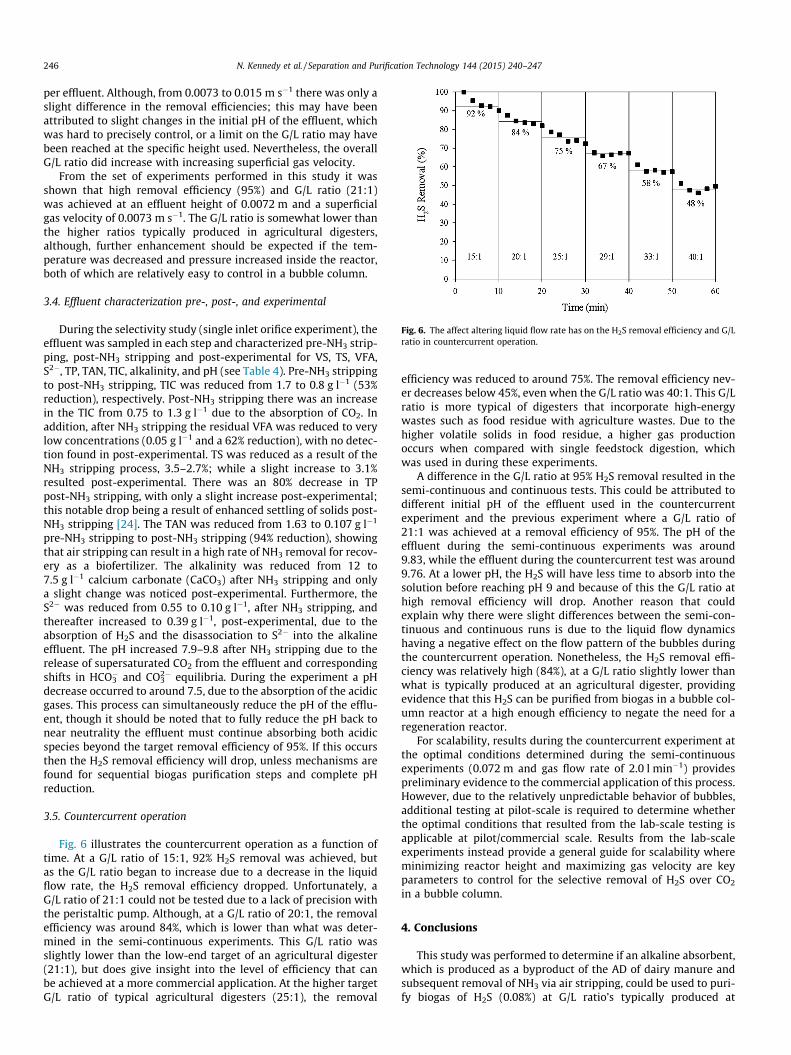
Fig. 6. The affect altering liquid flow rate has on the H2S removal efficiency and G/Lratio in countercurrent operation.
246 N. Kennedy et al. / Separation and Purification Technology 144 (2015) 240–247
per effluent. Although, from 0.0073 to 0.015 m s�1 there was only aslight difference in the removal efficiencies; this may have beenattributed to slight changes in the initial pH of the effluent, whichwas hard to precisely control, or a limit on the G/L ratio may havebeen reached at the specific height used. Nevertheless, the overallG/L ratio did increase with increasing superficial gas velocity.
From the set of experiments performed in this study it wasshown that high removal efficiency (95%) and G/L ratio (21:1)was achieved at an effluent height of 0.0072 m and a superficialgas velocity of 0.0073 m s�1. The G/L ratio is somewhat lower thanthe higher ratios typically produced in agricultural digesters,although, further enhancement should be expected if the tem-perature was decreased and pressure increased inside the reactor,both of which are relatively easy to control in a bubble column.
3.4. Effluent characterization pre-, post-, and experimental
During the selectivity study (single inlet orifice experiment), theeffluent was sampled in each step and characterized pre-NH3 strip-ping, post-NH3 stripping and post-experimental for VS, TS, VFA,S2�, TP, TAN, TIC, alkalinity, and pH (see Table 4). Pre-NH3 strippingto post-NH3 stripping, TIC was reduced from 1.7 to 0.8 g l�1 (53%reduction), respectively. Post-NH3 stripping there was an increasein the TIC from 0.75 to 1.3 g l�1 due to the absorption of CO2. Inaddition, after NH3 stripping the residual VFA was reduced to verylow concentrations (0.05 g l�1 and a 62% reduction), with no detec-tion found in post-experimental. TS was reduced as a result of theNH3 stripping process, 3.5–2.7%; while a slight increase to 3.1%resulted post-experimental. There was an 80% decrease in TPpost-NH3 stripping, with only a slight increase post-experimental;this notable drop being a result of enhanced settling of solids post-NH3 stripping [24]. The TAN was reduced from 1.63 to 0.107 g l�1
pre-NH3 stripping to post-NH3 stripping (94% reduction), showingthat air stripping can result in a high rate of NH3 removal for recov-ery as a biofertilizer. The alkalinity was reduced from 12 to7.5 g l�1 calcium carbonate (CaCO3) after NH3 stripping and onlya slight change was noticed post-experimental. Furthermore, theS2� was reduced from 0.55 to 0.10 g l�1, after NH3 stripping, andthereafter increased to 0.39 g l�1, post-experimental, due to theabsorption of H2S and the disassociation to S2� into the alkalineeffluent. The pH increased 7.9–9.8 after NH3 stripping due to therelease of supersaturated CO2 from the effluent and correspondingshifts in HCO3
� and CO32� equilibria. During the experiment a pH
decrease occurred to around 7.5, due to the absorption of the acidicgases. This process can simultaneously reduce the pH of the efflu-ent, though it should be noted that to fully reduce the pH back tonear neutrality the effluent must continue absorbing both acidicspecies beyond the target removal efficiency of 95%. If this occursthen the H2S removal efficiency will drop, unless mechanisms arefound for sequential biogas purification steps and complete pHreduction.
3.5. Countercurrent operation
Fig. 6 illustrates the countercurrent operation as a function oftime. At a G/L ratio of 15:1, 92% H2S removal was achieved, butas the G/L ratio began to increase due to a decrease in the liquidflow rate, the H2S removal efficiency dropped. Unfortunately, aG/L ratio of 21:1 could not be tested due to a lack of precision withthe peristaltic pump. Although, at a G/L ratio of 20:1, the removalefficiency was around 84%, which is lower than what was deter-mined in the semi-continuous experiments. This G/L ratio wasslightly lower than the low-end target of an agricultural digester(21:1), but does give insight into the level of efficiency that canbe achieved at a more commercial application. At the higher targetG/L ratio of typical agricultural digesters (25:1), the removal
efficiency was reduced to around 75%. The removal efficiency nev-er decreases below 45%, even when the G/L ratio was 40:1. This G/Lratio is more typical of digesters that incorporate high-energywastes such as food residue with agriculture wastes. Due to thehigher volatile solids in food residue, a higher gas productionoccurs when compared with single feedstock digestion, whichwas used in during these experiments.
A difference in the G/L ratio at 95% H2S removal resulted in thesemi-continuous and continuous tests. This could be attributed todifferent initial pH of the effluent used in the countercurrentexperiment and the previous experiment where a G/L ratio of21:1 was achieved at a removal efficiency of 95%. The pH of theeffluent during the semi-continuous experiments was around9.83, while the effluent during the countercurrent test was around9.76. At a lower pH, the H2S will have less time to absorb into thesolution before reaching pH 9 and because of this the G/L ratio athigh removal efficiency will drop. Another reason that couldexplain why there were slight differences between the semi-con-tinuous and continuous runs is due to the liquid flow dynamicshaving a negative effect on the flow pattern of the bubbles duringthe countercurrent operation. Nonetheless, the H2S removal effi-ciency was relatively high (84%), at a G/L ratio slightly lower thanwhat is typically produced at an agricultural digester, providingevidence that this H2S can be purified from biogas in a bubble col-umn reactor at a high enough efficiency to negate the need for aregeneration reactor.
For scalability, results during the countercurrent experiment atthe optimal conditions determined during the semi-continuousexperiments (0.072 m and gas flow rate of 2.0 l min�1) providespreliminary evidence to the commercial application of this process.However, due to the relatively unpredictable behavior of bubbles,additional testing at pilot-scale is required to determine whetherthe optimal conditions that resulted from the lab-scale testing isapplicable at pilot/commercial scale. Results from the lab-scaleexperiments instead provide a general guide for scalability whereminimizing reactor height and maximizing gas velocity are keyparameters to control for the selective removal of H2S over CO2
in a bubble column.
4. Conclusions
This study was performed to determine if an alkaline absorbent,which is produced as a byproduct of the AD of dairy manure andsubsequent removal of NH3 via air stripping, could be used to puri-fy biogas of H2S (0.08%) at G/L ratio’s typically produced at
N. Kennedy et al. / Separation and Purification Technology 144 (2015) 240–247 247
agricultural digesters (22–25:1). A bubble column reactor wasused as the absorption apparatus because of its low mainte-nance/operation, good mixing/mass transfer characteristics andits ability to handle solid concentrations that is characteristic ofdairy manure. From the studies performed, the following conclu-sions are established:
� The selective removal of H2S over CO2 was increased by around50% in a bubble column by altering the gas holdup in the reactorand relying on the slower H2CO3 reaction to resist CO2
absorption.� The G/L ratio, at 95% H2S removal, increased as a result of a
decrease in the alkaline effluent height and an increase thesuperficial gas velocity.� From countercurrent experiments, relatively high removal effi-
ciency of >90% was achieved at a slightly lower G/L ratio (15:1)of an agricultural digester. If the initial concentration of H2S inthe biogas was reduced to lower levels (e.g. 0.01–0.05%), viaoxygen dosing in the digester, the authors believe completeremoval of H2S could be possible at the targeted G/L ratios of22–25:1.� The bubble column reactor is an attractive absorption apparatus
in this application due to its ability to handle low solids withease that are known to be contained in dairy effluent.Whereas, in other apparatuses, such as a packed bed, suspendedsolids can negatively affect performance and cause cloggingissues. This process could be a very attractive solution for thefront-end reduction of H2S prior to other removal techniquesfor CO2 (e.g. water scrubbing and pressure swing adsorption)or as an effective technique to reduce H2S prior to combustingbiogas in an engine.
Acknowledgements
Support for this study was provided by the United StatesDepartment of Agriculture Natural Resource Conservation ServiceConservation Innovation Grant 69-3A75-10-152, the WashingtonState Department of Agriculture, and the Washington StateUniversity Agriculture Research Center. The assistance of CindyAlwine with analysis is gratefully acknowledged. In addition, theauthors would like to extend their immense gratitude and respectto Dr. Cornelius Ivory for his expert insight and advice on the topicof gas/liquid film theory.
References
[1] E. Ryckebosch, M. Drouillon, H. Vervaeren, Techniques for transformation ofbiogas to biomethane, Biomass Bioenergy 35 (2011) 1633–1645.
[2] B. Coppedge, G. Coppedge, D. Evans, J. Jensen, E. Kanoa, K. Scanlan, B. Scanlan,P. Weisberg, C. Frear, Renewable natural gas and nutrient recovery feasibilityfor DeRuyter dairy: an anaerobic digester case study for alternative off take
markets and remediation of nutrient loading concerns within the region,report to Washington State Department of Commerce, Olympia, WA, 2012.
[3] M. Persson, O. Jonsson, A. Wellinger, Biogas Upgrading to Vehicle FuelStandards and Grid Injection, Swedish Gas Center, Malmo, 2006.
[4] M. Wallin, S. Olausson, Simultaneous absorption of H2S and CO2 into a solutionof sodium carbonate, Chem. Eng. Commun. 123 (1993) 43–59.
[5] L. Dubois, Diane Thomas, Comparison of various alkaline solutions for H2S/CO2-selective absorption applied to biogas purification, Chem. Eng. Technol.(2010).
[6] B.P. Mandal, S.S. Bandyopadhyay, Simultaneous absorption of carbon dioxideand hydrogen sulfide into aqueous blends of 2-amino-2-methyl-1-propanoland diethanolamine, Chem. Eng. Sci. 60 (2005) 6438–6451.
[7] J.-S. Guo, A.A. Abbas, Y.-P. Chen, Z.-P. Liu, F. Fang, P. Chen, Treatment of landfillleachate using a combined stripping, Fenton, SBR, and coagulation process, J.Hazard. Mater. 178 (2010) 699–705.
[8] D. Katehis, V. Diyamandoglu, J. Fillos, Stripping and recovery of ammonia fromcentrate of anaerobically digested biosolids at elevated temperatures, WaterEnviron. Res. 70 (1998) 231–240.
[9] H. Siegrist, W. Hunziker, H. Hofer, Anaerobic digestion of slaughterhouse wastewith UF-membrane separation and recycling of permeate after free ammoniastripping, Water Sci. Technol.: J. Int. Assoc. Water Pollut. Res. 52 (2005) 1–2.
[10] C. Frear, S. Dvorak, Commercial Demonstration of Nutrient Recovery ofAmmonium Sulfate and Phosphorus Rich Fines from AD Effluent,Washington State University, Pullman, 2010.
[11] A. Jiang, T. Zhang, C. Frear, S. Chen, Combined Nutrient Recovery and BiogasScrubbing System Integrated in Series with Animal Manure AnaerobicDigester, Washington State University Research Foundation, USA, 2011.
[12] R. Narayan, J.R. Coury, J.H. Masliyah, M.R. Gray, Particle capture and pluggingin packed-bed reactors, Ind. Eng. Chem. Res. 36 (1997) 4620.
[13] N. Kantarci, F. Borak, K.O. Ulgen, Bubble column reactors, Process Biochem. 40(2005) 2263–2283.
[14] W.-D. Deckwer, R.W. Field, Bubble Column Reactors, Wiley, Chichester, NewYork, 1992.
[15] V. Srinivasan, R.C. Aiken, Selective absorption of H2S from CO2 – factorscontrolling selectivity toward H2S, Fuel Process. Technol. 19 (1988) 141–152.
[16] E. Bendall, R.C. Aiken, F. Mandas, Selective absorption of H2S from largerquantities of CO2 by absorption and reaction in fine sprays, AIChE J. 29 (1983)66–72.
[17] S.-M. Yih, C.-C. Sun, Simultaneous absorption of hydrogen sulfide and carbondioxide into di-isopropanolamine solution, Can. J. Chem. Eng. 65 (1987) 581–585.
[18] F.H. Garner, R. Long, A. Pennell, The selective absorption of hydrogen sulphidein carbonate solutions, J. Appl. Chem. 8 (1958) 325–336.
[19] W. Sun, S. Nesic, D. Young, R.C. Woollam, Equilibrium expressions related tothe solubility of the sour corrosion product mackinawite, Ind. Eng. Chem. Res.47 (2008) 1738–1742.
[20] J.H. Meldon, P. Stroeve, C.E. Gregoire, Facilitated transport of carbon dioxide: areview, Chem. Eng. Commun. Chem. Eng. Commun. 16 (1982) 263–300.
[21] S. Kulprathipanja, Reactive Separation Process, Taylor and Francis, 2002.[22] M. Jamialahmadi, H. Müuller-Steinhagen, Effect of superficial gas velocity on
bubble size, terminal bubble rise velocity and gas hold-up in bubble columns,Dev. Chem. Eng. Miner. Process. 1 (1993) 16–31.
[23] C. Frear, T. Ewing, S. Chen, W. Liao, Evaluation of co-digestion at a commercialdairy anaerobic digester, Clean – Soil, Air, Water 39 (2011) 697–704.
[24] Q. Zhao, S.W. Dvorak, S. Chen, C. Frear, B.J. VanLoo, Nutrient Recovery Systemsand Methods, USA, 2012.
[25] APHA, Standard Methods for the Examination of Water and Wastewater,American Public Health Association, Washington DC, 2005.
[26] L.E. Ripley, W.C. Boyle, J.C. Converse, Improved alkalimetric monitoring foranaerobic digestion of high-strength wastes, J. (Water Pollut. Control Fed.) 58(1986) 406–411.
[27] Z. Wen, C. Frear, S. Chen, Anaerobic digestion of liquid dairy manure using asequential continuous-stirred tank reactor system, J. Chem. Technol.Biotechnol. 82 (2007) 758–766.
[28] J.B. Joshi, U.P. Veera, C.V. Prasad, D.V. Phanikumar, Gas hold-up structure inbubble column reactors, Proc. Indian Natl. Sci. Acad. Part A, Phys. Sci. 64 (1998)441.