The Science of Innovation
87
Transcript of The Science of Innovation


The Science of Innovation
Copyright © 1997 TRIZ Group. All rights reserved. Printed in the UnitedStates of America. No part may be used or reproduced in any mannerwhatsoever without written permission except in the case of brief quotationsembodied in critical articles and reviews.
For more information contact:The TRIZ Group, L.L.C.5832 NanevaWest Bloomfield, MI 48322 USATel: +1 248 538 0136Fax: +1 248 671 0356
www.trizgroup.com • [email protected]
Graphic design and illustrations by Spyderhuff Design, www.spyderhuff.com
ISBN 0-9658359-0-1


The Science of Innovation

1
PrefaceIn an increasingly competitive global marketplace, winning com-
panies will be those which can deliver superior products to customersfaster. Computer technology has increased the speed of product devel-opment, but it cannot by itself foster innovation. Creativity and innovationin design and manufacturing of products remain the decisive factors forsuccess in the global marketplace. These factors will take the place inthe economic domain previously dominated by natural resources andcapital.
Today’s products and processes need to be unique, novel, and pro-vide conspicuous value to the customer. Organizations must meet thechallenge using the fewest resources, at the lowest cost, with higherquality and with shorter design cycle times. Conventional approachesfor such unconventional demands simply will not get the job done.Systematic innovation in products and processes is an imperative forcompetitive leverage. The key to meeting today’s product and processdevelopment challenges is a massive dose of innovation. Such innova-tion is possible only if the approach to its generation is equallyunconventional. TRIZ (Russian acronym for the Theory of InventiveProblem Solving) is such an approach. TRIZ does not rely on psycho-logical factors but is a highly scientific approach to engineeringinnovative solutions.
TRIZ provides two powerful tools that may become, if well under-stood and mastered, extremely useful both for engineers and managers.The first tool is the proven ability of TRIZ to enhance the creativity ofits practitioners, to break barriers of psychological inertia and, mostimportantly, change its students’ mind-sets. The second tool is a set ofthe Laws of Evolution of Technological Systems allowing objectivetechnological forecasting rather than guessing, and providing guidancefor development of next generation products and processes.
A major obstacle to widespread use of the powerful TRIZ method-ology is the lack of available information. TRIZ was developed in theformer Soviet Union over the past 50 years and although many bookson TRIZ are written in Russian, a shortage of English publications ex-ists. A tangible need is evident to provide U.S. engineers and managerswith a comprehensive and structured description of the multifacetedTRIZ methodology.

The Science of Innovation—Book One2
Technology of Innovative Engineering is a book series intended toprovide the first steps in closing this information gap. Its content isbased on the authors’ unique experience in TRIZ training including theonly university course on TRIZ in the U.S. at Wayne State University inDetroit, Michigan, since 1993 and numerous hands-on training and prob-lem-solving sessions in major corporations.
The first book, The Science of Innovation, is a brief managerialoverview of TRIZ. The following books in the series provide detailedcoverage of major elements of the TRIZ methodology, including: basicconcepts and techniques of problem solving; Laws of TechnologicalSystem Evolution and their application to conceptual development ofnext generation products and processes (technology forecasting); mod-eling/problem-solving methodology of Substance-Field Analysis;powerful and comprehensive Algorithm for Inventive Problem Solv-ing—the main analytical and solution tool of TRIZ. All concepts andtechniques discussed in the Technology of Innovative Engineering bookseries are supported by numerous real-life case studies.

3Introduction
IntroductionAdvancement of technology becomes possible by inventing novel
machines and manufacturing methods. The process by which inven-tions arise is commonly known as creativity. For millennia, creativityhas been associated with such vital attributes as talent, insight, inspira-tion, aspiration, luck, hard labor and patience. The very term “creativity”implies spontaneity and intuition. It commonly appears that the veryprocess that lets us dominate the world can hardly be controlled itself.
The main method for solving inventive problems in engineering, aswell as in all other areas of human activity, is trial-and-error. This methodrequires a consecutive generation of ideas as solutions to problems. Norules for idea generation exist, and the process of seeking a solution israther sporadic (see Figure 1). If an idea is considered weak it is dis-carded and a new idea is generated. This flow of ideas does not submitto control, with as many repeated attempts as necessary to discover asolution. A typical exchange when working on a difficult problem be-comes “Let’s try this approach... Have we failed?... Let’s try anotherone.”
Figure 1

The Science of Innovation—Book One4
For instance, while working on a design of light bulb, Thomas Edisonperformed over six thousand experiments on a huge variety of materi-als before he found a satisfactory one for a filament.
Although seemingly random, most attempts to solve a problem havea common attribute: the trials lay along a vector of psychological iner-tia. This inertia is determined by cultural and educational background,previous experiences, and common sense. Psychological inertia urgesthe problem solver to try traditional directions, confines the imagina-tion, and is the main hurdle on a road to the best solution, which usuallylies in unexplored territories.
Example 1During the 1970s, the Soviet Union launched an unmanned
Lunar Probe to the moon’s surface with the intention to trans-mit TV pictures to the Earth. A projector using a light bulb wasdesigned to illuminate the lunar surface ahead of the vehicle.However, existing light bulbs would not survive the impact oflanding on the Moon surface. The most durable bulbs were onesused in military tanks, but even those bulbs would crack at thejoint between the glass and the screw base during tests.
A new bulb design suitable for the application had to bedeveloped. The situation was reported to the program leader,Dr. N. Babakin, who asked “What is the purpose of the bulb?”The answer was obvious— to seal vacuum around the filament.The moon’s atmosphere, however, presents a perfect vacuum.Therefore, Babakin suggested lamps without bulbs (seeFigure 2).
As global technology competition becomes more fierce, an abilityto solve engineering problems expeditiously becomes critical for thesurvival of individual businesses and entire industries. Neither trial-and-error method nor techniques for its intensification, such asbrainstorming, can satisfy these needs. They must be replaced with asystematic, logical approach to technology development.
TRIZ was developed by Genrikh Altshuller starting in 1946 as ananalytical approach to creative engineering. The main axiom of TRIZstates that evolution of technological systems is governed by objectivelaws. These Laws of Technological System Evolution, discovered byAltshuller, can be employed for conscious development of technologi-

5Introduction
Figure 2
cal systems (problem-solving), replacing the inefficiencies of blindlysearching.
The Structure of TRIZ
The Laws of Technological System Evolution constitute the theo-retical foundation of TRIZ (see Figure 3). Implementation of these lawsfacilitates the creative process. However, at times a law is too big a toolfor solving a particular problem. TRIZ provides more specific tools forsolving engineering problems: the Substance-Field Analysis and theAlgorithm for Inventive Problem Solving.
The Substance-Field (Sufield) Analysis is a modeling techniquefor symbolic description of transformations of technological systems.
The Algorithm for Inventive Problem Solving (ARIZ in its Russianabbreviation) is a noncomputational set of sequential logical proceduresfor reformulating the initial problem and for resolving the conflict atthe core of the problem.
Techniques for Overcoming System Conflicts (TOSC) satisfy bothconflicting requirements, thus avoiding conventional trade-offs.
The System of Standard Approaches to Inventive Problems (Stan-dards) is based on the Sufield Analysis and on the observation that many

The Science of Innovation—Book One6
Figure 3
creative engineering problems from different fields of technology aresolved by the same generic approaches. The Standards contain typicalrecommendations on solutions for typical (from the TRIZ standpoint)classes of inventive problems.
The solution process is supported by a vast Knowledgebase of En-gineering Applications of Physical, Chemical, and Geometric Effects.These effects can be beneficially employed to solve complex engineer-ing problems effectively.

7
Chapter One
Basic Notions of TRIZ
Chapter One—Basic Notions of TRIZ

The Science of Innovation—Book One8
TRIZ is a very comprehensive methodology, composed of variousmethods and algorithms for problem solving and system development.All these tools can be applied to developing new concepts. However,even mastering the application of a few basic notions and techniques ofTRIZ, such as Ideality, System Conflict, Physical Contradiction, andothers can greatly facilitate the concept generation process. TRIZ dealsnot with the real mechanisms, machines and processes but with theirmodels. Its axioms, algorithms, and rules are not tied to a specific ob-ject and can be applied to analysis and synthesis of any technologyregardless of its nature. This makes the basic notions and techniques ofTRIZ applicable to any creative task whether it is major or minor im-provement of a product, production process, or service.
Ideal Technological System
Any technological system is not a goal in itself and is needed onlyto perform a specified function. A system is a “fee” for realization ofthis function. In assessing several systems performing the same func-tion, the better system is the one that consumes fewer resources in bothinitial construction and maintenance. Thus, an ideal system requires nomaterial to be built, consumes no energy and space, needs no mainte-nance, and cannot be broken. If all these properties are combined, animage of an ideal system as an absent system performing the requiredfunction is created.
Sometimes the concept of ideality can be practically realized. Sincea function has to be performed, some material body is responsible toperform it. One method of satisfying the requirements of ideality isdelegating performance of the function to another system. This systemmust be an already present resource: either a sub-system or a higher-level system, or else an adjacent system from the same hierarchicallevel.
Example 2To study effects of acids on metal alloys, specimens are
placed into a hermetically sealed chamber (see Figure 4). Thechamber is filled with acid, then closed, and various combina-tions of temperature and pressure are created inside. The acidis not only reacting with the specimens but also with the wallsof the chamber. To protect the walls, they are glass-coated. This

9Chapter One—Basic Notions of TRIZ
Figure 4
Figure 5

The Science of Innovation—Book One10
glass coating was cracking and had to be reapplied repeatedlyfor some tests (e.g., vibration).
The first step is to list all functions of the system’s compo-nents. The function of the acid is to react with the specimens.This function is “non-negotiable.” The conflict is associatedwith an auxiliary function—keeping the liquid at the specimens.The chamber is responsible for the auxiliary function. The cham-ber is needed only for servicing the main function. It would beideal if both main and auxiliary functions were accomplishedby only one component.
A new problem then arises of how to achieve such a condi-tion when the chamber is absent, but the acid is kept in contactwith the specimen (see Figure 5). Thus, the initial problem ofchamber protection was transformed into a very different one:How to keep the liquid around the specimen?
In this formulation, the answer is obvious. The acid can becontained inside the specimen (see Figure 6). The required con-ditions, such as pressure and temperature, can be created outsidethe specimen-chamber.
Figure 6

11
Mini- and Maxi-Problems
In the beginning of the problem-solving process, one usually facesan initial situation associated with certain disadvantages that should beeliminated. These disadvantages may be eliminated either by changinga given system, by altering one of its sub-systems, or by modifyingsome higher-level system. Thus, various problems associated with theinitial situation can be formulated.
For instance, the situation of Example 2 above could be resolvedby addressing the following problems: How to improve the protectivecoating? How to make the chamber walls corrosion-resistant? How toapply vibrations to the specimens without affecting the coating?
TRIZ divides all problems into mini-problems and maxi-problems.A mini-problem occurs when the system remains unchanged or is sim-plified, but the shortcomings disappear or a desirable improvement isachieved. A maxi-problem does not impose any constraints on the pos-sible changes; in this case, a new system based on a novel principle offunctioning can be developed.
It is suggested to start the problem-solving process by addressing amini-problem since its solution would require minimal resources andthus would be more economical and easier to implement.
System Conflicts
A problem requires creativity when attempts to improve some sys-tem attributes lead to deterioration of other system attributes. Such asituation is called a System Conflict (see Figure 7). Collisions such asweight versus strength or power versus fuel consumption lead to Sys-tem Conflict.
A System Conflict is present when:• the useful action simultaneously causes a harmful effect or,• introduction (intensification) of the useful action, or elimination
or reduction of the harmful action causes deterioration orunacceptable complication of the system or one of its parts.
A problem associated with a System Conflict can be resolved eitherby finding a trade-off between the conflicting demands, or by overcom-ing the conflict (i.e., by satisfying the opposing requirements). Trade-offsor compromise solutions do not eliminate the System Conflicts, butrather soften them, thus retaining harmful (undesirable) actions/short-
Chapter One—Basic Notions of TRIZ

The Science of Innovation—Book One12
comings in the system.An engineering problem becomes an inventive one when it has a
System Conflict that cannot be overcome by conventional means andtrade-offs are not acceptable.
From the TRIZ standpoint, to make an invention means to over-come a System Conflict. Presence of a System Conflict is the mostimportant characteristic that differentiates a complicated problem froma simple one. Thus, TRIZ is primarily interested in the development oftools for elimination of System Conflicts.
Typical System Conflicts
Analysis of thousands of inventions by Altshuller resulted in for-mulation of Typical System Conflicts, such as productivity versusaccuracy, reliability versus complexity, shape versus speed, etc. It wasdiscovered that despite the immense diversity of technological systemsand even greater diversity of inventive problems, there are only about1,250 Typical System Conflicts.
The Typical System Conflicts can be overcome by a relatively smallnumber of typical techniques. There are 40 Typical Techniques for Over-coming System Conflicts (TOSC), and each of them may contain a few
Figure 7

13Chapter One—Basic Notions of TRIZ
Figure 8
sub-techniques, totaling up to 100 (some excerpts are given in Appen-dix 1). The techniques are combined in a Conflict Matrix (a portion ofthe Conflict Matrix is shown in Figure 8). The Conflict Matrix containsattributes that are the most common for all technological systems (e.g.,weight, strength, length, surface area, power, ease of usage, etc.). Theseattributes are arranged in rows and columns. Suppose there is a need toimprove some attribute of the system. If this improvement causes dete-rioration of another attribute (i.e., a System Conflict develops), anintersection of the row and column corresponding to the conflictingattributes will show the potentially useful TOSC. Application of one ofthese techniques or their combination has a high probability of solvingthe problem.
The TOSC are formulated in a general way. If, for example, theConflict Matrix recommends “flexibility” technique, it means that so-lution of the problem relates somehow to changing the degree offlexibility or adaptability of a technological system being modified.The Conflict Matrix and the TOSC do not solve the problem, they only

The Science of Innovation—Book One14
suggest the most promising directions for searching for a solution. Theproblem solver has to interpret these suggestions and find the way oftheir application to a particular situation.
This approach, developed before the analytical approaches of ARIZand Sufield Analysis, is incorporated in the Invention Machine soft-ware package. The best problem-solving strategy is to use the analyticalapproaches, with the Conflict Matrix and/or the Invention Machine soft-ware as complementary approaches.
When using the TOSC, one can follow a simple algorithm:1. Select an attribute that needs to be improved in the Conflict
Matrix.2. Answer the following questions:
a) How can this attribute be improved using theconventional means?
b) Which attribute would deteriorate, if the conventionalmeans were used?
3. Select an attribute in the Conflict Matrix corresponding tostep 2b.
4. Using the Conflict Matrix, identify the TOSC for overcomingthe System Conflicts.
Figure 9

15
Figure 10
Chapter One—Basic Notions of TRIZ
Example 3Thermal stresses in aircraft skin structure are undesirable.
Compensation for thermal deformations is usually provided bysmall gaps left between aircraft skin sections (see Figure 9). Tosmooth the surface, a polymer-based sealant (paste) filled withpowdered metals such as nickel, silver, or gold is used to closethe gaps. Filling the gaps with the paste is a very labor-inten-sive and time-consuming process.
To various extents, disadvantages of the situation are asso-ciated with the sealant. What is an ideal sealant? Obviously, itis sealant that is absent. Such sealant does not need a manufac-turing process to be placed in between the panels, but at the
same time, degrades aerodynamic characteristics of the aircraftskin. In other words, an attribute “ease of operation” causesdeterioration of the attribute “object-affected harmful factors.”In this case, the Conflict Matrix advises one to examine appli-cability of the techniques 2 (separation), 25 (self-service), 28(non-mechanical changes in the system), and 39 (neutral envi-ronment). If the System Conflict is formulated as “ease ofoperation” versus “loss of energy” (due to drag), the Conflict
The Science of Innovation—Book One16
Matrix offers the following techniques: 2 (separation), 19 (pe-riodic action), and 13 (heels over head). It soon becomesapparent that the separation technique is repeatedly referenced,leading to the assumption that a high probability of separationof a part of the sealant could lead to a solution. In fact, it wouldbe sufficient if the sealant just covered the gap between thepanels. This would ease the process of closing the gaps, andwould not degrade the aerodynamic properties of the aircraftskin.
Solution to the problem, indeed, reflects this approach.It was proposed to make a metal cap with an elastomeric re-tainer that snaps in the gap thus making its installation veryquick (see Figure 10).
Physical Contradictions
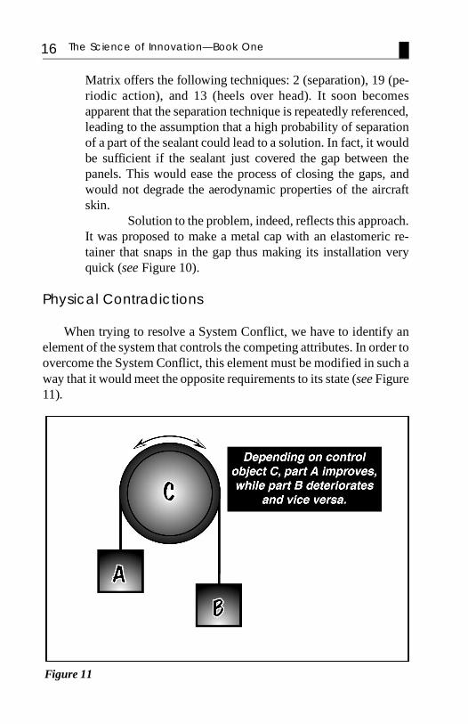
When trying to resolve a System Conflict, we have to identify anelement of the system that controls the competing attributes. In order toovercome the System Conflict, this element must be modified in such away that it would meet the opposite requirements to its state (see Figure11).
Figure 11

17Chapter One—Basic Notions of TRIZ
A situation when one and the same object ought to be in mutuallyexclusive physical states is called a Physical Contradiction.
A Physical Contradiction is formulated according to a pattern: “Toperform function F1, the element must have property P, but to performfunction F2, it must have property -P.”
A Physical Contradiction is formulated in an intensified way—tobe P and to be anti-P—and this gives it a great heuristic power. If aPhysical Contradiction is formulated correctly, the problem can be con-sidered to a large extent solved. Accordingly, from the TRIZ standpoint,to formulate an inventive problem correctly means to formulate an ap-propriate Physical Contradiction.
Overcoming Physical Contradictions
Conventional design philosophy is based on compromises (trade-offs): if an object has to be snow white and it has to be pitch black, it isusually made gray. Contrary to this approach, TRIZ offers three genericmethods for overcoming Physical Contradictions:
• separation of opposite properties in time;• separation of opposite properties in space;• separation of opposite properties between system and its
components.
Separation of opposite properties in time: at one time an objecthas property P, and at another time it has an opposite property -P.
Example 4Some buildings are supported by piles. The pile should have
a sharp tip (see Figure 12a), to facilitate the driving process.However, the sharp piles have reduced support capability. Forbetter support capacity, the piles should have blunt ends (seeFigure 12b). However, it is more difficult to drive blunt-tippedpiles. As a compromise, the piles are made with rounded tips(see Figure 12c).
Physical Contradiction: A pile should be sharp to facili-tate the driving process, and it should be blunt to provide bettersupport of the foundation.

The Science of Innovation—Book One18
This statement clearly calls for the solution providing sepa-ration of the contradictory properties in time: The pile is sharpduring the driving process, and then its base is expanded (e.g.,by a small explosive charge, as in Figure 13).
Figure 13
Figure 12

19Chapter One—Basic Notions of TRIZ
Separation of opposite properties in space: one part of an objecthas property P, while another part has an opposite property -P.
Example 5A revolute robot link has to satisfy mutually exclusive re-
quirements (see Figure 14). It should be light (for a given shape)to reduce driving motors and/or to allow for larger payloads.However, light materials usually have reduced stiffness (Young’smodulus). On the other hand, it should be rigid to reduce end-of-arm deflection and settling time in start/stop periods.However, rigid materials are usually heavy.
Figure 14
Physical Contradiction: the link must be light, but it mustbe heavy (rigid).
A simple analysis reveals that the end-of-link deflection isdetermined by the root segment of the link (the highest bend-ing moment, long projection length), while the link inertia ismainly determined by a overhang segment (see Figure 15). Thus,the contradictory requirements are separated in space.
Resolving the Physical Contradiction can be achieved ifthe link is composed of two sections: The root section, which

The Science of Innovation—Book One20
does not significantly influence the effective mass of the linkbut determines its stiffness, is made of a high Young’s modulusmaterial, while the overhang section, which does not notice-ably contribute to stiffness but determines the effective mass,is light.
Separation of opposite properties between system and its com-ponents: a system has property P, while its components are givenan opposite property -P.
Example 6A conventional bench vise is designed to hold objects of
regular shapes (see Figure 16). To hold objects of irregularshapes, special shaped jaws have to be installed. Fabrication ofsuch jaws requires a time-consuming and laborious process.
Physical Contradiction: The jaws must be rigid to clampthe part, and they must be flexible to accommodate themselvesto the part’s profile.
Figure 15

21Chapter One—Basic Notions of TRIZ
The opposite properties can be separated between the sys-tem and its parts: The jaws are replaced with the distributedelastic elements that can accommodate virtually any outline,and as an additional advantage, distribute uniformly the clamp-ing force (see Figure 17).
Figure 17
Figure 16

The Science of Innovation—Book One22

23
Chapter Two
Substance-FieldAnalysis
Chapter Two—Substance-Field Analysis

The Science of Innovation—Book One24
An infinite diversity of functions performed by the technologicalsystems can be presented as transformations of various types of energyand substances. A process performed by a technological system shouldinvolve at least three components: a tool, an article, and an energysource:
These components are described in TRIZ in terms of substancesand fields.
The term “substance” has a rather broad meaning in TRIZ: It canbe a technological system of a various degree of complexity, for in-stance, nail, keyboard, or ship.
The term “field” refers to the energy needed for interaction/con-trol of two substances. Besides genuine physical fields—electromagnetic, gravitational, strong and weak interactions—TRIZoperates with engineering fields. For example, there can be “pressurefield”, “temperature field”, “acoustic field”, etc. Fields that are mostfrequently used in the modern technology are mechanical, thermal, elec-tromagnetic (magnetic and electric), and chemical.
The model of a minimal technological system is depicted below:
An absence of even one member of this “triad” makes the system adeficient one. The necessity to have all three components can be easilyexplained. A problem usually arises due to an object being incapable ofaccomplishing a certain function (or being associated with a harmfuleffect). To control this object, it is frequently needed to introduce an-other one. Interactions between these objects are accompanied bygeneration, transformation, or absorption of energy. Hence, transitionfrom the initial technological system A to an improved technological

25Chapter Two—Substance-Field Analysis
system B can often be described as a transformation of the substance-field structure of system A.
The substance-field structure is called a sufield. If S2 or F is miss-ing, it is still a sufield, albeit incomplete!
The branch of TRIZ studying substance-field structures and theirtransformations is called the substance-field (sufield) analysis.
The basic rule for transformations of sufields is automatically de-rived from the very definition of the minimal technological system:Absence of at least one component (sufield fragment) in the sufield rep-resenting a system calls for completion of the model. This rule statesthat an object can be efficiently controlled if it becomes a component ofa sufield.
Synthesis of Sufield Structures
Synthesis of sufields frequently involves completion of an incom-plete sufield.
The solid arrows between the components indicate their useful in-teraction and direction of the action, and broken lines indicate inadequateinteractions.
Being a model of a minimal technological system, the sufield ishighly universal and describes in terms of substance-field interactionsa broad range of technological systems and their transformations.

The Science of Innovation—Book One26
Figure 18
The main purpose of improving a sufield structure (model) of a systemis to increase the system controllability. The sufield models reflect theessence of a problem and do not include its secondary features. Thesufield modeling approach provides means for recording what is givenin the problem and what should be obtained. When compiling the sufieldmodels, it is helpful to follow the simple algorithm:
1. Identification of an article S1
2. Identification of a tool S2 (if any)3. Identification of a field (if any)4. Presentation of the initial sufield model5. Compilation of a desirable sufield model6. Development of a conceptual solution
Example 7Hot rolling of metals requires lubrication of the deforma-
tion zone (see Figure 18). The liquid lubricant is usually suppliedby special brushes or sprayers. Neither technique provides uni-form distribution of the lubricant in the deformation zone, theoil splashes around, and much of it is lost. A cost-effectivemethod for the uniform lubricant supply was needed.

27
1. Identification of an article.The primary concern in this problem is delivery of the re-
quired amount of the lubricant to the deformation zone. Thelubricant can be considered an article S1.
2. Identification of a tool.The problem emerged due to absence of a proper tool that
would accurately carry S1 to the deformation zone. Thus, tosolve the problem it is necessary to complete the sufield byintroducing tool S2.
3. Identification of a field.In the original system, mechanical field (hydraulic pres-
sure), produced by the lubricant sprayers, acts on S1. However,this field is inadequate for delivery of S1 into the deformationzone. A need to transport the lubricant can be interpreted in thesufield language as a requirement to act on the lubricant with afield F.
4. Presentation of the initial sufield model.Given the above considerations, one can compose the fol-
lowing initial sufield model:
Chapter Two—Substance-Field Analysis
Now we ought to identify S2 and F. An ideal S2 would carrythe lubricant and not interfere with the rolling process. Thisimplies that S2 should disappear in the deformation area upondelivery of the lubricant. As for F, it would be ideal to use re-source fields available in the system. These are the mechanicalfield of rotating rollers and the thermal field of the deformationzone.
This discussion helps to arrive at a practical solution: Apaper impregnated with the liquid lubricant is fed between the
5. Compilation of a desirable sufield model.

The Science of Innovation—Book One28
Figure 19

29
Chapter Three
StandardApproaches to
Inventive Problems(Standards)
Chapter Three—Standard Approaches to Inventive Problems

The Science of Innovation—Book One30
Similarity in the approaches to solving problems from different fieldsof technology led Altshuller to classification of typical system transfor-mations. These transformations are recorded as the Standards thatdescribe the rules for performing synthesis and transformation of tech-nological systems.
There are three groups of the Standards:• Standards on system modification (synthesis and deconstruction
of sufield systems)• Standards on system detection and measuring• Standards on application of StandardsThe Standards are based on the Substance-Field Analysis. Their
purpose is to overcome or at least, circumvent Physical Contradictions.Two simple Standards (out of total 76) are illustrated below.
The principal idea of the Sufield Analysis is clearly seen in a Stan-dard for synthesis of a well-performing technological system. Accordingto this Standard, it is necessary in the simplest case to create a completesufield instead of an incomplete sufield:
• If an object is given that is difficult to change in accordance withthe specified requirements,
• and the specifications do not contain limitations on introductionof additional substances and fields,
• then the problem can be solved by synthesizing a complete sufieldsystem by introducing the missing components

31
plastic and then lifted with the pins pulling the plastic bristlesfrom the melt. After the required length of the bristles is reached,they are cooled by an air stream and then cut at the ends of thepins. Some plastic sticks to the pins and they frequently need tobe cleaned for each combination of size/pattern of the bristles(see Figure 20).
According to the sufield concept, a model of the problemcan be represented by S1 (molten plastic). To control S1, a pairF - S2 has to be introduced into the system. S2 should transformF into mechanical force that would act on the plastic. Due tothe difficulty to control mechanical F, it was natural to suggesttransition to magnetic field. Hence, S2 should be a ferromag-netic substance.
Figure 20
Chapter Three—Standard Approaches to Inventive Problems
Example 8Conventional technology for fabricating bristled plastic
mats uses custom-made dies. The die is a metal block with a setof protruding pins whose sizes and pattern correspond to thesizes and pattern of the bristles. The die is dipped into molten

The Science of Innovation—Book One32
Figure 21
Solution:Ferromagnetic powder is added into the molten plastic according
to the required bristle pattern (see Figure 21). Magnetic field pulls outthe powder thus forming the bristles. As an additional benefit, this solu-tion allows for fast development and alteration of the bristle patterns.
Sometimes it may be necessary to eliminate a harmful interactionin a sufield. For such a situation, a Standard on braking harmful inter-actions can be used:
• If both useful and harmful actions develop between two substancesin the sufield,
• and it is not necessary to maintain the direct connection betweenthe substances,
• but use of outside substances is prohibited or undesirable, thenthe problem can be solved by introducing a third substancebetween the two, and this third substance is a modification of twooriginal substances

33
Solid lines represent useful interaction and wavy lines representharmful interaction.
Breaking the harmful action with another substance may be unde-sirable for various reasons, such as complication of the system. Thus, aPhysical Contradiction develops: the third substance must be present,and it must be absent. The Standard suggests a way to circumvent thecontradiction: there is the third substance, but this substance is derivedfrom the system resources.
Example 9Curved sections of pipes in steel shot-blasting machines
are subjected to intensive wear. Various protective coatings areonly marginally effective (see Figure 22).
The sufield model shows that there is useful interactionbetween the pipe and the shot (the pipe guides the flying shot)and harmful interaction (wear).
Chapter Three—Standard Approaches to Inventive Problems
Thus, Physical Contradiction is: To protect the pipes, there shouldbe coating. On the other hand, there should be no coating, since it can-not survive.

The Science of Innovation—Book One34
Figure 22
The sufield model of the problem is as follows:
According to the Standard, S3 modification may be of either shot,or pipe, or both substances. Analysis of these options has shown that S3
= S1 is the most effective transformation.Solution: The shot particles themselves serve as a coating (see Fig-
ure 23). A magnet is placed outside the wear zone. It attracts some flyingshot particles that form the protective layer (S3 is stationary shots).
Solutions represented by the above model, were successfully ap-plied in many diverse practical devices.

35
Figure 23
Chapter Three—Standard Approaches to Inventive Problems

The Science of Innovation—Book One36

37Chapter Four—Laws of Technological System Evolution
Chapter Four
Laws ofTechnological
System Evolution

The Science of Innovation—Book One38
The Laws or Prevailing Trends of Evolution reflect significant,stable, and repeatable interactions between elements of technologicalsystems and between the systems and their environment in the processof evolution. These Laws are listed below.
• Increasing Ideality• Non-Uniform Evolution of Sub-Systems• Transition to a Higher-Level System• Increasing Flexibility• Shortening of Energy Flow Path• Transition from Macro- to Micro-Level
One can draw an analogy between use of the laws of technologicalevolution and the laws of mechanics. If the position of a moving objectis known for a certain moment of time, its further positions can be foundby solving the corresponding equations of motion. The Laws of Tech-nological System Evolution serve as “soft equations” describing thesystem’s “life curve” in the evolution space. If the current system con-figuration is given, the further configurations can be reliably “calculated”(forecasted) using the Laws.
Law of Increasing Ideality
The Law of Increasing Ideality states that evolution of all techno-logical systems proceeds in the direction of increasing degree of ideality.This means that in the process of evolution either the system perform-ing a certain function gets less complicated/costly, or one system (onits own or by merging with other system[s]) becomes capable of per-forming its function(s) better or of performing more functions than forwhich it was originally designed. A combination of these evolutionaryprocesses also is possible. A degree of ideality can be defined as a ratioof “Index of Functionality” to “Index of Cost”, where cost can beexpressed in dollars, size or weight of units, etc.
It is, essentially, the “Benefit-to-Cost” ratio. A truly ideal system inmost cases is a virtual reality, it exists only in our imagination. There

39Chapter Four—Laws of Technological System Evolution
are, though, some cases when the ideal system concept can be fullyrealized, such as in Example 2 above.
Example 10Ice cream is sold in cups. Thus, a scoop of ice cream that is
packaged in a waffle or “sugar cone” cup has a higher degreeof ideality—its main useful function—taste—is enhanced be-cause when a nondisposable cup is used the whole package isconsumable.
Example 11Figure 24 shows dynamics of prices for household appli-
ances from 1947 through 1997 (in 1997 dollars). Totalfunctionality of 1997 washers/dryers, TV sets, and refrigera-tors is substantially superior, while prices of today’s appliancesare also far lower than prices of their 1947 predecessors. Thecomparison clearly shows how appliances have come a longway towards more ideal systems. Many similar examples ofincreasing degree of ideality during the evolutionary process
Figure 24
AutomaticClothes Washer
AutomaticClothes Dyer
Television1 Refrigerator2
1—12 in. b/w in 1947, 25 in. color/stereo today 2—9 cu. ft. in 1947, 20 cu. ft. w/icemaker today

The Science of Innovation—Book One40
can be given. Capabilities of computers and of their memorydevices are continuously increasing while their prices are fall-ing. Although prices of modern high power/high accuracy/highspeed machine tools are increasing, the cost of a part producedon these machine tools is decreasing. At the same time, accu-racy and surface finish of the produced parts (i.e., theirperformance characteristics), are continuously improving.
Law of Non-Uniform Evolution of Sub-Systems
Various parts of a system evolve at non-uniform rates. This causesdevelopment of System Conflicts.
Technology has a hierarchical, multi-level structure. Any techno-logical system has subordinate sub-systems and serves as a componentfor a higher-level system.
The emergence of conflicts is natural for technological systems.Nonuniformity of the evolution process is caused by the hierarchicalstructure of the technological systems and determines directions of de-velopment of the technological system and approach to inventiveproblem-solving. Any change in a system, both positive and negative,causes a “wave” of consecutive changes in adjacent systems and sub-systems. Frequently, these induced changes are harmful and negateadvantages of the improvement.
Law of Transition to a Higher-level System
Technological systems evolve in a general direction from mono-systems to bi- or poly-systems.
Systems usually originate as single objects—mono-systems. Anexample of a mono-system is a pencil. Mono-systems are combined toform higher-level systems: bi-systems (i.e., pencil+eraser), or poly-sys-tems (i.e., a set of different pencils).
A higher-level system can be composed from similar or identicalsubsystems. Such a homogeneous bi- or poly-system can enhance func-tional performance of each constitutive subsystem to such a degree thatnew and useful functional properties will appear.
Transition to bi- and poly-systems (see Figure 25) represents a veryimportant and very powerful trend of evolution. Examples of bi-sys-tems which resulted in intensification of functional properties of the

41
Figure 25
Chapter Four—Laws of Technological System Evolution
original (component) mono-systems include: scissors (a bi-system oftwo knives); spectacles (a bi-system of two monocles); binoculars (abi-system of two telescopes, which are themselves bi-systems of twolenses); catamaran (a bi-system of two ship hulls providing enhancedstability); and two-barrel hunting rifle (a bi-system of two rifles).
These examples are based on combining identical components. Inother cases, the component subsystems can be similar but different insize, color, and/or functional properties. Examples of such systems area set of wrenches for hexagonal nuts of different sizes, a set of wrenchesfor hexagonal nuts and Allen bolts, a universal screwdriver with tips ofdifferent shapes (straight, Phillips, etc.) and handles of different sizes;and an “open”/”closed” sign (“open” in black letters on one side of thesign board, “closed” in red letters on the other side of the board). Such
Line of Evolution “Mono-Bi-Poly”

The Science of Innovation—Book One42
bi- and poly-systems are called shifted bi- and poly-systems, respec-tively.
Effectiveness of bi-systems and poly-systems may increase whentheir components are more diverse. Some examples of heterogeneousbi-systems comprised of diverse components are a wristwatch with acalculator; key ring with a pen knife; and a pencil with eraser. The lattercase represents an important type of inverse bi-systems—a combina-tion of components with opposite properties. An interesting applicationof combining components with opposite properties into a bi-system issuggested in Soviet Certificate of Authorship 950,241 describing a “bi-greenhouse.” In one section of this greenhouse, plants are growing thatextract carbon dioxide from the surrounding air, while emitting oxy-gen. In the other section, other types of plants are growing, such varietiesthat extract oxygen from air and emit carbon dioxide. Such a green-house does not require an air-exchange system.
Effectiveness of bi- and poly-systems is enhanced in the process oftheir convolution. The first steps of this process involve elimination ofredundant auxiliary components. This leads to forming a partially con-voluted bi- or poly-system. For example, a double-barreled gun has onlyone butt; and a multi-boiler power station may have less smoke stacksthan boilers.
The next step of evolution is a transition to a completely convolutedbi- or poly-system when one system performs two or more functions.
Example 12Protective suits for emergency rescue workers in mines have
a cooling system and an oxygen-supply system. It was pro-posed by Genrikh Altshuller to combine these two systems byusing liquid oxygen. First, the oxygen is used in the coolingsystem, second, after its low temperature increases during thecooling process, it is used for breathing. This combination hasresulted in significant weight reduction and allowed to increasethe resource of the system between recharging the life supportgear.

43
Figure 26
Chapter Four—Laws of Technological System Evolution
Law of Increasing Flexibility
In the course of evolution, technological systems develop fromrigid structures to flexible and adaptive ones (see Figure 26).
A new technological system developed to solve a specific prob-lem, performs in a specified environment, at specified regimes, etc.Its design is reflecting, accordingly, the specific needs that the systemhas to satisfy. It is characterized by rigidly defined connections be-tween the constitutive parts, which usually prevent the system fromadapting to the changing environment. Such a system demonstratesfeasibility of the main design concept. It performs satisfactorily themain task for which it was developed, but its application environ-ment, as well as performance parameters are limited. Studies ofevolution of numerous systems have demonstrated that a typical pro-cess of evolution involves phases during which the structure of thesystem is becoming less rigid and more adaptable to the changingenvironment. This trend is very universal; it can be easily recognizedin many commonly used systems.
For many systems increasing flexibility usually begins with re-placement of stationary components with moving ones, replacementof a rigid linkage or a structure by a segmented linkage/structure con-
Line of Evolution “Increasing Flexibility”

The Science of Innovation—Book One44
Figure 27
Suspension for Axle Both wheels are combined regardlessof different road conditions
Independent Suspension Each wheel responds to its roadconditions
Interconnected Suspension Motions of all wheels are adapting toroad conditions under individualwheels
Semi-active Suspension Damping forces in each strut areadapting to road and motion (braking)conditions
Active Suspension Develops forces in accordance toroad and motion conditions
Active Suspension with Develops forces in accordance withForward Sensing anticipated road conditions
nected by hinges, replacement of rigid components with flexible onessuch as hydraulic and pneumatic systems, introduction of nonlinearcomponents, etc. More advanced stages in the increasing flexibility pro-cess are characterized by using physical and chemical effects andphenomena, by implementing servo-controlled systems, etc.
Example 13Evolution of Car Suspension (see Figure 27).
Law of Shortening of Energy Flow Path
Evolution of technological systems is accompanied by shorteningthe path between energy sources and working organs.
Usually, this evolutionary process is associated with at least one ofthe two following Lines of Evolution:
1. Reduction in the number of energy transformationstages (both transformations between different formsof energy, such as electrical and mechanical,mechanical and thermal, etc., and transformations ofenergy parameters, such as mechanical transmissionstransforming speeds and torques/forces between input

45Chapter Four—Laws of Technological System Evolution
and output members);2. Proliferation of such forms of energy fields that are
easier to control. Such forms can be listed in the orderof increasing controllability as: gravitational,mechanical, thermal, magnetic, electric, andelectromagnetic.
Example 14Evolution of machine tool transmission (see Figure 28).
Law of Transition from Macro- to Micro Level
Technological systems evolve in the direction of fragmentation oftheir work organs.
Evolution of a technological system is frequently accompanied bydiversification and differentiation of characteristics and functions ofvarious segments of its working organ. In order to enhance the systemfunctionality, it is frequently needed that one segment is hard and an-other soft, one solid and another gaseous, one hot and another cold, etc.This eventually leads to heterogeneous structure of the working organ.Separation of segments with the contradictory properties leads to im-provements in functioning of the system, and also to fractionalizationof its components, as well as the materials used in the system. The lattercan be transformed into laminated or fibrous ones or, ultimately, onescomposed of fine particles. The constitutive components can be com-bined into a unitary component by some mechanical or chemical orother binding agents. These agents can be permanent or adaptable/con-trollable (e.g., by electrostatic or magnetic fields). Thus, contradictionsdeveloping in the process of evolution may be resolved by fragment-ing, or transition into micro-level. Another reason for transition intomicro-level is better controllability of a fragmented or finely dispersedmedium by various fields (mechanical, electrical, magnetic, etc.).
Example 15In the original process of plate glass production, a strip of
hot, soft glass mass was pulled from the tundish and placed ona roller conveyer which provided pulling and shaping actions,and also cooled the strip (see Figure 29a). If the conveyer hadlarge diameter rollers, it resulted in imperfect glass surface and

The Science of Innovation—Book One46
Figure 28
• Central motor/internal combustion engine• Overhead transmission shaft• Belt drives to spindles of individual machines• Internal transmissions to feed motions
• Individual electric motor• Mechanical transmissions to spindle
and feed motions
• Separate motors for motions notprecisely tied to spindle motion
• Separate electric motions synchronizedby electric means
• Separate electric motors integrated by“electronic gear box” (not shown)
• Spindle serves as shaft of spindle motor(not shown)

47Chapter Four—Laws of Technological System Evolution
Figure 29a
Figure 29b

The Science of Innovation—Book One48
a laborious polishing operation was required. Larger numberof smaller rollers resulted in improvement of the plate surface,but the smaller rollers are more difficult to align and maintain.
It was proposed by A. Pilkington (from Pilkington Broth-ers, Ltd., UK) to replace the conveyer with a bath filled withmolten tin (see Figure 29b). While such a conveyer does notrequire alignment, it provides a perfect support for the glassplate which does not require subsequent polishing.
Practical Applications of the Laws of Evolution
There are two major classes of engineering problems. One classconsists of specific problems associated with poor performance of someproduct or process. These problems can be solved by identifying andresolving system conflicts and physical contradictions. The second classinvolves the development of new products and processes in order toadvance the technology and to obtain a competitive marketing advan-tage. In such cases “creative (inventive) problem-solving” means that acertain technological system is improved and is moved up along its“life curve”. To achieve this goal, it is extremely important to under-stand the directions of evolution of the given system. The Laws ofEvolution help to identify these directions. Their most important appli-cations are in such engineering activities as Benchmarking (assessingthe state of the art of a given type of a product or a process); ValueEngineering (assessing engineering level of a new product or a processdesign); and Technological Forecasting (development of a new genera-tion of a product or a process).
Benchmarking involves analytical comparison of several designvariants of a certain product or process, available either as commercialproducts or as patented/published descriptions. In the former case, ac-tual testing can be performed. Examples of cases when benchmarkingis routinely performed are complete systems (e.g., cars of the sameweight/size/price category being analyzed and compared by car manu-facturing companies designing similar cars; military equipment andarmament, such as fighter planes, tanks, night vision binoculars, etc.)or subsystems (e.g., car air bags, anti-lock brake systems, automatictransmissions, etc.).
Benchmarking is very important to the effort of identifying newprogressive trends in competitive designs, enabling companies to in-

49Chapter Four—Laws of Technological System Evolution
corporate them in new products and services. However, the conven-tional benchmarking process is not very effective. For example, cardesign-to-production cycle is two to five years. If a competitor devel-oped a new car model with an outstanding performance characteristic(e.g., low noise and vibration levels), benchmarking starts some timeafter this car model is put on the market. The benchmarking (testingand evaluation) process itself may take six to twelve months. After theresults are analyzed and patent-related issues are resolved, the “novel”features may be approved for implementation in a new car model. How-ever, this model would be launched only after its two to five yearsdesign-to-production cycle is completed. Thus, the new model lags thecompetitive model in this feature by at least five to ten years. Duringthis time the competitor has a good opportunity to further improve itsproduct. This results in a permanent competitive disadvantage.
If knowledge of the Laws of Evolution is used in the benchmarkingprocess, the process itself becomes much more dynamic and results inmuch better competitiveness. The advantageous features of the com-petitive products are analyzed in light of the Laws of Evolution inapplication to the systems responsible for the advanced performancecharacteristics. This approach usually would result in more advancedsystems that are superior to the competitive product.
Value Engineering is the application of a cost/function analysis tech-nique to enhance engineering creativity through cross-functional ideageneration. Design alternatives are developed and evaluated to maxi-mize product value. Use of the Laws of Evolution of TechnologicalSystems can be powerful tool in deciding directions for new develop-ment and in the process of comparative evaluation of alternative designs.
The Laws of Evolution and the respective Lines of Evolution arepowerful tools for development of next generation products and pro-cesses. The use of the Laws of Evolution for this purpose is calledTechnological Forecasting. If this process is properly performed, thecompany becomes a leader in its field of business.
After selecting the system whose evolution should be forecastedusing the Laws of Evolution, its state of the art should be carefully andthoroughly assessed. This can be done by surveying patents and publi-cations related to the selected and similar systems. Usually, such surveysshow the principal directions along which the system was evolving dur-ing the recent period of its life span. Analysis of the surveyed materialallows one to formulate major system conflicts associated with the con-

The Science of Innovation—Book One50
sidered system. After this analysis has been performed, potential direc-tions of evolution in accordance with the Laws of Evolution areconsidered together with specific approaches to resolve the system con-flicts.

51
Chapter Five
Algorithm forInventive
Problem Solving(ARIZ)
Chapter Five—Algorithm for Inventive Problem Solving (ARIZ)

The Science of Innovation—Book One52
ARIZ is the main analytical and solution tool of TRIZ. The conven-tional approach to a creative problem implies a search for a solution tothe problem. Traditional thinking tries to “leap” from the given prob-lem to a solution. The more difficult the problem, the more “leaps” areneeded to find the solution. TRIZ assumes that the degree of difficultyof a problem depends to a large extent on a way it is formulated: theclearer the formulation, the easier it is to arrive at a solution. In theTRIZ approach the problem-solving as a procedure of seeking solutionis replaced with a process of problem reformulation. The problem-solv-ing process is a chain of successive reformulations of the initial problem.There is a transition from a vague, ill-defined and frequently incor-rectly formulated initial problem to a lucid formulation of the rootconflict. When a transparent understanding of the roots of a problemhas been developed, its solution either gets obvious or it becomes clearthat the problem cannot be resolved at the present time due to absenceof the required technology or lack of scientific knowledge.
Structure of ARIZ
The concept of consecutive reformulations of the initial problem isrealized in ARIZ, which is a set of successive logical procedures di-rected at reinterpretation of a given problem.
The structure of ARIZ consolidates two major concepts: Sys-tem Conflict and Ideality (see Figure 30). Since a technological problembecomes an inventive one when a System Conflict should be overcome,a program for inventive problem solving has to include special subrou-tines on revealing and clarifying these conflicts.
Solving a problem by application of ARIZ starts with a transitionfrom a vaguely (or even wrongly) defined initial problem to a mini-problem that is formulated by the rule: everything in the system remainsvirtually unchanged, but the required function is realized. The next stepis formulation of the System Conflict. Then, the Model of the Problem,which is a simplified scheme of the conflict, is formulated. The Con-flict Domain is specified so as to narrow the area of analysis. The nextstep is assessment of the available material and energy resources. Thenthe problem is treated by formulation of the Ideal Final Result (IFR).Usually, to realize the IFR, the critical component of the system in theConflict Domain must possess contradictory physical properties (e.g.,it must be cold and hot, opaque and transparent, electroconductive and

53Chapter Five—Algorithm for Inventive Problem Solving (ARIZ)
Figure 30
electroinsulative, etc.).ARIZ uses three major methods for overcoming physical contra-
dictions listed on page 17.The process of elimination of the Physical Contradiction involves
maximum utilization of material resources in the system and is sup-ported by the Knowledgebase of Effects.
If the problem has not been solved, ARIZ recommends to go backto the starting point of the analysis and reformulate the problem. As arule, absence of a solution after a thoroughly performed analysis is anindicator that a wrong problem was initially formulated. In many cases,a more general problem should be stated.
Some abbreviated examples of application of the ARIZ analysisfollow.
Applications of ARIZ
Example 16A 3 to 5 millimeter diameter steel ball is injected into a
high-speed jet and accelerated to collide with a fragment of aspacecraft shell (see Figure 31). When the speed of the ball was8 kilometer per second the installation performed adequately.

The Science of Innovation—Book One54
Figure 31
At 16 kilometer per second the balls disintegrated when enter-ing the jet due to high acceleration-induced stress. Attempts touse a stronger material for the ball failed.
Mini-ProblemIt is necessary, without major changes in the system, to
accelerate the ball while keeping it intact.System Conflict
The 16 kilometer per second jet provides required accel-eration of the ball but destroys it. The 8 kilometer per secondjet does not destroy the ball, but does not achieve the goal.
Reformulated problem: Since no material can survive thisenvironment, the ball will definitely be destroyed, but some-how it should be “reassembled.”
Model of the ProblemThe 16 kilometer per second jet accelerates the ball well,
but the ball disintegrates. Something is needed that would reas-semble the fragments and keep ability of the ball to hit the target.
Analysis of the Conflict Domain and ResourcesThe Conflict Domain is a layer of the jet in the vicinity of
the “cloud” of the fragments. The only resource available inthe Conflict Domain is the gas.

55
Figure 32
Chapter Five—Algorithm for Inventive Problem Solving (ARIZ)
IFRThe gas in the Conflict Domain should develop compres-
sive forces acting towards the center of the “cloud.”Physical Contradiction
To develop compressive forces, the gas particles shouldmove towards the center of the “cloud.” To accelerate the reas-sembled ball, these particles should move along the vector ofjet velocity.
Elimination of Physical ContradictionSeparation of opposite demands in time: compressive forces
should develop only at the moment of disintegration of the ball.Engineering Solution
The ball is covered with an explosive. Due to implosion,when the ball enters the jet, its fragments do not fly away, butbehave as a concentrated mass impacting the target (see Figure32).
Example 17The logs in paper mills drop chaotically on the conveyer
after debarking and have to be longitudinally oriented (see

The Science of Innovation—Book One56
Figure 33
Figure 33). Aligning devices (often robots) are complex, oc-cupy large floor area, and are not reliable. A simple, reliable,cost-effective method of log aligning was needed.
Mini-ProblemThe logs are to be oriented without major alterations to the
system.System Conflict
Orientation requires an aligning device, but this compli-cates the system.
Model of the ProblemSome element of the existing system should be responsible
for the orientation.Analysis of the Conflict Domain and Resources
The Conflict Domain is the surface of the conveyer.The only resource is the conveyer.
IFRThe conveyer itself orients the logs.
Physical ContradictionTo orient, different points of the conveyer surface should
have different speeds.To convey, the surface should move at one speed.

57
Figure 34
Chapter Five—Algorithm for Inventive Problem Solving (ARIZ)
Elimination of Physical ContradictionSeparation of opposite demands between system and its
components: the whole conveyer moves at one productionspeed, but its components move at different speeds.
Engineering SolutionSide belts move in opposite directions and align the logs.
The central belt conveys the logs aligned in the longitudinaldirection (see Figure 34).
Example 18The 7/24 tapered toolholders (see Figure 35) are used in
the majority of Computer Numerically Controlled (CNC) ma-chining centers. The tolerances for the male and female tapersensure contact at the front part of the connection (close to theflange) to facilitate higher stiffness. As a result, there is a smallclearance at the back that causes radial runout and reduced stiff-ness. To make interchangeability feasible, the large diameter ofthe taper is dimensioned so that there is a large guaranteed clear-ance between the flange of the toolholder and the spindle face.This leads to reduced axial accuracy of the tool.

The Science of Innovation—Book One58
Figure 35
Mini-ProblemTo improve stiffness and accuracy of the toolholder-spindle
interface without major changes in the existing system.System Conflict
Toolholder taper positions the tool, but does not providethe flange-face contact.
Model of the ProblemSome element of the existing system should provide for
the flange-face contact without hindering the positioning abil-ity of the toolholder.
Analysis of the Conflict Domain and ResourcesThe Conflict Domain is the contact area between the male
(toolholder) and female (spindle) tapers. The only resource is asurface of the male taper.
IFRThe surface of the male taper should position the toolholder
and provide for the flange-face contact.Physical Contradiction
To position the toolholder, there should be solid contactbetween the male and female tapers.

59
Figure 36
Chapter Five—Algorithm for Inventive Problem Solving (ARIZ)
To ensure the flange-face contact, there should be no con-tact between male and female tapers.
Elimination of Physical ContradictionSeparation of opposite demands between system and its
components: the surface of the whole male taper has no solidcontact with the female taper, but some points of this surfacedo.
Engineering SolutionThe male taper is covered with precision balls with man-
aged stiffness. The “springing” balls compose a virtual taperedsurface and allow for the flange-face contact (see Figure 36).

The Science of Innovation—Book One60

61Chapter Six—Knowledgebase of Engineering Applications
Chapter Six
Knowledgebase ofEngineering
Applications ofPhysical, Chemical,
and GeometricEffects

The Science of Innovation—Book One62
Often solving engineering problems involves application of little-known physical, chemical or geometric effects (structures) or use of“uncelebrated” sides of otherwise well known effects/structures. Anaverage engineer knows usually 50-100 physical effects and phenom-ena, while there are more than 6,000 effects described in scientificliterature. Each effect may be a key to solving a large group of prob-lems. Since engineering students are not usually taught how to applythese effects to practical situations, they often have problems with uti-lization of such well-known effects as thermal expansion or frequencyresonance, let alone with less recognized effects.
To assist in application of the effects to solving problems, a vastKnowledgebase of Effects was proposed by G.S. Altshuller and devel-oped by Y.V. Gorin, Y.P. Salamatov, I.L. Vikentiev, and others. ThisKnowledgebase is built on a functional principle: it contains a list offunctions (applications), commonly encountered in practice, and a cor-responding list of effects that may be employed to realize these functions.An excerpt from the Knowledgebase of physical effects is presented inAppendix 2. The whole Knowledgebase is a part of Invention Machinesoftware.
Examples of Applications of the Knowledgebase
Example 19Tube expansion is frequently performed by special hydraulic
presses (see Figure 37). This technology is not always avail-able for emergency repairs in field conditions where a simpleand reliable method is needed.
A mechanical force (high pressure) is needed to expand thetube. To control forces and generate high pressures, the data-base recommends use of several groups of effects, and amongthem phase transitions.
Solution: Water-to-ice transformation results in 9% increaseof the initial volume; this process is accompanied by genera-tion of high mechanical forces capable of expanding the tube(see Figure 38).
Example 20Grain for cereal production may contain microscopic lar-
vae of various bugs (see Figure 39). To destroy the larvae they

63
Figure 37
Figure 38
Chapter Six—Knowledgebase of Engineering Applications

The Science of Innovation—Book One64
Figure 39
have to be heated up to 65° C. However, grain starts deteriorat-ing at 70° C. Grain heating systems with precision temperaturecontrol are expensive and not very productive. A method forreliable and productive decontamination of grain was needed.
It would be ideal if a complex system for precision tem-perature control would “convolve” into a substance capable ofholding temperature within the specified range. To accomplishthis, the Knowledgebase suggests to use transition through theCurie point, which is the temperature at which a ferromagneticloses its magnetic properties.
Solution: Ferromagnetic particles having Curie point at65°C are added to the grain (see Figure 40). They can be heatedby electomagnetic inductor only up to this temperature, afterwhich the induction heating intensity decreases by about fourtimes, and the mass starts to cool. After it cools to 64.5°C, theheating cycle starts again, etc. After the treatment, the particlesare easily extracted by a magnet.

65
Figure 40
Chapter Six—Knowledgebase of Engineering Applications

The Science of Innovation—Book One66

67
Appendix One
Selected Techniquesfor OvercomingSystem Conflicts
Appendix One

The Science of Innovation—Book One68
1. Segmentation:
• divide the system into two or more independent components;• increase number of these components and reduce their sizes;• make the system disassembleable.
ExampleTargets for archery training are quickly damaged by arrows
and have to be frequently replaced. To increase efficiency ofthe training exercises it was proposed to make targets out offerromagnetic particles (see Figure 41). Applied magnetic fieldcontrols density of the ferromagnetic material in such a waythat arrow can penetrate the material. After the arrow has beenremoved, magnetic field automatically restores the target. Con-centric circles are projected on the target with the help of anoptical device.
2. Separation:
• single out and separate a part or a function which interferes withthe regular functioning of the system;
Figure 41

69Appendix One
Figure 42
• single out and separate the only useful/necessary part orproperty of the system.
ExampleTo repel the birds from the airports, it was proposed to use
tape recordings with screams of the scared birds. In this inven-tion, the sound is separated from the birds.
13. Heels over Head:
• perform an opposite action to what is required in the problem;• make stationary part(s) of the system moveable and make
moveable part(s) stationary;• turn the system upside down.
ExampleLong-distance swimming exercises can be performed in a
small swimming pool shown in Figure 42. The speed of watercan vary thus accommodating various needs and abilities ofthe swimmers.

The Science of Innovation—Book One70
15. Flexibility:
• continuously change parameters of the system or of theenvironment to always keep them in the state most suitable foreach working cycle;
• divide the system into several parts which could move relative toeach other.
ExampleTo negotiate sharp turns at high speeds, Swedish X2000
train is equipped with rubber elements that allow the wheels tobetter conform to rails’ curvature around the turns (see Figure43).
Figure 43

71
28. Non-Mechanical Changes in Systems:
• change a mechanical system into an optical, acoustical orolfactory system;
• use electricity, magnetism and/or electromagnetism in themechanical system;
• use magnetic and/or electromagnetic fields together with ferromagnetic particles.
ExampleAccuracy of a precision screw-nut assembly can be nega-
tively affected by friction between the components. To eliminatethe friction, it was proposed to replace direct contact betweenthe screw and the nut with their interaction through electro-magnetic field (see Figure 44 ). Electric currents in the windings1 and 2 create electromagnetic fields that achieve their maxi-mum value when coils of the windings are aligned against eachother. Rotation of the screw causes distortion of magnetic fluxthat leads to development of forces restoring the aligned posi-tion of the coils thus moving the nut by a precise distance.
Figure 44
Appendix One

The Science of Innovation—Book One72

73
Appendix Two
Excerpts from theKnowledgebase of
EngineeringApplications ofPhysical Effects
Appendix Two

The Science of Innovation—Book One74
Position control
Motion control
Control of particle(aerosol) flow (dust,fog, smoke)
Tracking and locationof objects
Separation of mixtures
Position stabilization
Action by magnetic field on object or ona ferromagnetic substance attached to theobject. Acting by electrical field on thecharged object. Transfer of pressure offluid or gas media. Centrifugal forces.Heat redistribution. Pressure of light.
Capillary action. Osmosis. Thoms effect.Bernulli effect. Waves. Centrifugalforces. Weissenberg effect.
Electrization. Electrical and magneticfields. Pressure of light.
Introduction of “marker” substances totransform external fields (e.g.,luminescence tracking) or to generatefields (e.g., ferromagnetic) that are easilydetected. Light reflection and emission.Photo effect. Deformation. Radiation.Luminescence. Changes in electrical andmagnetic fields. Electrical discharges.Doppler effect.
Electric and magnetic separation.Changing apparent viscosity ofseparating fluid in electrical andmagnetic fields. Centrifugal forces.Vibratory separation. Sorption.Diffusion. Osmosis.
Electrical and magnetic fields. Use ofmagneto- and electrorheological fluids.
Function (Application) Physical Effect/Phenomenon

75Appendix Two
Control of forces.Creation of highpressure.
Friction control
Destruction of objects
Accumulation ofmechanical and heatenergy
Energy transfer
Gyroscopic effect. Use of reactive forces.
Use of magnetic field (via ferromagneticsubstance). Phase transitions. Control ofheat distribution. Centrifugal forces.Changing hydrostatic forces by changesof apparent viscosity of magneto- orelectroconductive fluids in magneticfields. Use of explosives.Electrohydraulic effect. Opticalhydraulic effect. Osmosis.
Vibration. Kragelsky effect. Johnson-Rabeck effect. Action of radiation.
Electrical discharges. Electrohydrauliceffect. Resonance. Ultrasonics.Cavitation. Induced radiation.
Elastic deformations. Gyroscopic effect.
Deformations. Vibrations. Wave motions,including shock waves. Radiation. Heatconductivity. Convection. Lightreflection. Induced radiation.Electromagnetic induction.Superconductivity.
Function (Application) Physical Effect/Phenomenon

The Science of Innovation—Book One76
Use of electromagnetic fields;“substance-to-field” transition.
Electromagnetic induction. Eddycurrents. Surface induction effect.Dielectric heating. Absorption ofradiation. Thermoelectricity.
Phase transitions. Joule-Thompsoneffect. Rank effect. Magnetocalorificeffect. Thermoelectricity.
Influence of temperature and heatdistribution on natural frequencies ofstructural vibrations. Thermoelectricphenomena. Radiation spectrum.Changes in optical, electrical andmagnetic properties. Transition throughthe Curie point. Effects of Hopkins andBarkhausen.
Phase transitions (including transitionthrough the Curie point).
Measuring of natural frequencies ofstructural vibrations. Use of magneticand electrical markers.
Heating. Deformation. Magneto- orelectrostriction.
Generating interactionof moving (changing)and stationary objects
Heating
Cooling
Temperature sensing/measurement
Temperaturestabilization
Dimensionalmeasurements
Dimensional changesof objects
Function (Application) Physical Effect/Phenomenon

77
Monitoringconditions/propertiesof surfaces
Measuring surfaceproperties
Monitoring ofvolumetric properties
Changing volumetricproperties
Electric discharges. Light reflection.Electronic emission. Moire effect.Radiation.
Friction. Adsorption. Diffusion.Baushinger effect. Electric discharges.Mechanical and acoustic vibrations. UVradiation.
Introduction of “marker” substancesdependent on the state and properties ofthe considered substance. Changes ofelectrical resistance as a function ofstructure and properties of the object.Interaction with light. Electro- andmagneto- optical phenomena. Polarizedlight. X-ray and radioactive radiation.Electronic paramagnetic and nuclearmagnetic resonance. Magnetoelasticeffect. Transition through the Curiepoint. Hopkins and Barkhausen effects.Measuring the natural vibrationfrequencies of the object. Ultrasonics.Moessbauer effect. Hall effect.
Changing apparent viscosity of fluids inelectrical and magnetic fields. Action ofmagnetic field on introducedferromagnetic substance. Heating. Phasetransitions. Ionization in electrical field.UV, X-ray, radioactive radiation.Deformation. Diffusion. Electrical andmagnetic fields. Bauschinger effect.Thermoelectric, thermomagnetic and
Function (Application) Physical Effect/Phenomenon
Appendix Two

The Science of Innovation—Book One78
Construction and/orstabilization ofstructure
Detection of electricaland magnetic fields
Detection of radiation
Generation ofelectromagneticradiation
Modulation of light
Function (Application) Physical Effect/Phenomenon
magneto-optical effects. Cavitation.Photochromatic effect. Internal photoeffect.
Standing waves. Moire effect. Use ofmagnetic field. Interfering waves. Phasetransitions. Mechanical and acousticvibrations. Cavitation.
Osmosis. Electrization of objects.Electrical discharges. Piezo- andsegnetoelectric effects. Electrets.Electron emission. Electro-opticalphenomena. Hopkins and Barkhauseneffects. Hall effect. Nuclear magneticresonance. Gyromagnetic and magneto-optical phenomena.
Optico-acoustic effect. Heat distribution.Photo effect. Luminescence. Photoelasticeffect.
Josephson effect. Induced radiation.Tunnel effect. Luminescence. Hanneffect. Cherenkov effect.
Refraction and reflection. Electro- andmagneto-optical phenomena.Photoelasticity. Kerr and Faraday effects.

79
IndexIndex
A
Algorithm for Inventive Problem Solving (ARIZ) 2, 5, 14, 52Altshuller, Genrikh 4, 12, 30Article 24
B
Benchmarking 48Bi-systems 40
completely convoluted 42heterogeneous 42homogeneous 40partially convoluted 42shifted 42
C
Conflict Domain 52Convolution 42
E
Energy source 24
F
Fields 24
G
Gorin, Y.V. 62
I
Ideal Final Result (IFR) 52Ideal Technological System 8Increasing Flexibility 38Increasing Ideality 38Invention Machine 14, 62
K
Knowledgebase of Engineering Applications of Physical, Chemical, andGeometric Effects 6, 62

The Science of Innovation—Book One80
L
Laws of Evolution of Technological Systems 1, 5, 38, 48
M
Main axiom of TRIZ 4Mini- and Maxi-Problems 11Model of the Problem 52Mono-systems 40
N
Non-Uniform Evolution of Sub-Systems 38
P
Physical Contradictions 16Poly-systems 40Psychological inertia 4
S
Salamatov, Y.P. 62Separation of opposite properties 17-21
between system and its components 17, 20in space 17, 19in time 17
Shortening of Energy Flow Path 38Standard for synthesis of a well-performing technological system 30Standard on braking harmful interactions 32Standards on application of Standards 30Standards on systems detection and measuring 30Standards on systems modification 30Substance-Field Analysis 2, 25Substance-field structure 25Substances 24Sufield 25
incomplete 25System Conflicts 12System of Standard Approaches to Inventive Problems 5

81
T
Techniques for Overcoming System Conflicts (TOSC) 5, 12Technological Forecasting 48Tool 24Transition from Macro- to Micro-Level 38Transition to a Higher-Level System 38Trial-and-error 3TRIZ (Theory of Inventive Problem Solving) 1Typical System Conflicts 12
V
Value Engineering 48Vikentiev, I.L. 62
W
Wayne State University 2
Index
References1. Altshuller, G.S., Creativity as an Exact Science, Gordon and Breach, NY,
1988.
2. Altshuller G.S., And Suddenly the Inventor Appeared, Technical Innova-tion Center, Worcester, Massachusetts, 1996.
3. Arciszewski, T., “ARIZ-77: An Innovative Design Method,” Journal ofDesign Methods and Theories, Vol. 22, No. 2, pp. 796-821, 1988.
4. Fey, V., Rivin, E., Vertkin, I., “Application of the Theory of InventiveProblem-Solving to Design and Manufacturing Systems,” Annals of theCIRP, Vol. 41, pp. 107-111, 1994
5. Fey, V., Rivin, V., “TRIZ: A New Approach to Innovative Engineering andProblem-Solving,” Target, Volume 12, Number 4, p. 7-13, 1996.
6. Rivin, E., Fey, V., “Teaching Experiences on the Theory of InventiveProblem-Solving,” Proceedings of the 3rd CIRP Workshop on Design andImplementation of Intelligent Manufacturing Systems, pp. 41-43, Univer-sity of Tokyo, June 19-22, 1996
7. Stevens, T., “Methods for Madness,” Industry Week, November 18,1996, p. 34

The Science of Innovation—Book One82
AuthorsVictor R. Fey, a co-founder of The TRIZ Group and Adjunct Pro-
fessor of Mechanical Engineering of Wayne State University. A closeassociate of Genrikh Altshuller, for twenty years he has successfullyapplyed TRIZ to engineering problems in various technological areas.He has designed and conducted numerous courses on TRIZ for industryand academia and published many papers on TRIZ. He presented semi-nars on TRIZ at Ford, Chrysler, Case, UNISYS, ABB, Nokia, Ryobi,MIT, American Supplier Institute, GOAL/QPC, Technion, among oth-ers. He teaches the only graduate course on TRIZ in North Americaoffered at Wayne State.
Eugene I. Rivin, D.Sc., a co-founder of The TRIZ Group, FellowASME, Member of the CIRP, and Professor of Mechanical Engineeringof Wayne State. Dr. Rivin has published 10 books and numerous ar-ticles, and holds 50 international patents in the areas of vibration andnoise control, transmissions, machine tools, robotics, and advancedmachine elements. Several of his inventions have been implementedworldwide. He consults extensively, including many Fortune 500 com-panies and held numerous seminars on TRIZ in the US and overseas.He organized (with V. Fey) the only graduate course on TRIZ in NorthAmerica and incorporated TRIZ principles into WSU “capstone” de-sign course.