
The Reference Model for Intelligent Multimedia Presentation Systems: 1st Draft
21
The Reference Model for Intelligent Multimedia Presentation Systems: 1st Draft Salvatore Ruggieri 1 Monica Bordegoni 2 Giorgio Faconti 3 Thomas Rist 4 Panos Trahanias 5 Michael Wilson 6 1 Introduction This documentpresents a proposal of a referencemodel for intelligent multimedia presentation systems (IMMPSs). Observing an increasing number of applications where the “manual” authoring of presenta- tions is no longer feasible, the development of mechanisms for the au- tomated generation of multimedia presentations has become a shared goal across many disciplines. Since the use of multiple media for conveying information does not guarantee effective and intelligible presentations per se, these mechanisms need to be intelligent in the sense that they are able to draw appropriate design decisions. Up to now, a lot of research and developmentwork have been conducted ad- dressing aspects of automating multimedia presentation generation, and even some large-size prototypes of IMMPSs have been developed (e.g., MMI 2 , WIP, MIPS, COMET). However, no generic model has emerged so far. Each project began from scratch, relying only on the past experience of the developers. This has meant a lack of uniform logical approach to the problem. Consequently, there is no agree- ment on the terminology to be used, on the functional definition of an IMMPS, or on a generic architecture which reflects the logical structure of processes for the generation of multimedia presentations. With the proposal for a reference model, this paper tries to fill a major methodological gap and thus may provide a sound basis for ongoing and future developments of IMMPSs. There are several advantages for an agreementon a reference model. The developmentand the analysis of systems will benefit from a uniform approach to the problem. The modular development of large-size programs will be feasible, as each module has a well defined role, with well defined interfaces and communication language with the other modules. From a theoretical point of view, the analysis and comparison of systems will be made on the basic of a unique, general architecture and by means of a common terminology. These considerations are universally valid for any reference model. In the case of IMMPSs, however, they assume a deeper significance, as the literature is still confusing on the basic 1 Dipartimento di Informatica, Universit` a di Pisa, Italy and Rutherford Ap- pleton Laboratory, United Kingdom. 2 Consiglio Nazionale delle Ricerche ITIA, Milano, Italy 3 Consiglio Nazionale delle Ricerche CNUCE, Pisa, Italy 4 DFKI, Saarbr¨ ucken, Germany 5 FORTH-ICS, Greece 6 Rutherford Appleton Laboratory, United Kingdom. terminology. What we model is that part of a computational system whose tasks are to present information to the user in an effective way. Hereby, the attribute effective means, that the particular information needs of the individual users are best met under a given set of presentation constraints, such as resource limitations and the user’s knowledge and style preferences. Since in the vast majority of non-trivial applications the information needs will vary from user to user and from situation to situation, a presentation system should be able to flexibly generate various presentations for one and the same information content to be communicated. The survey by Roth and Hefley [26] provides a first attempt to overview these systems in a uniform and general way. However, the aims of this document are different. First of all, we are going to give precise definitions concerning the terminology and the architecture, and the background necessary to understand them. We start from a definition of presentation systems, and then incrementally add the notions of multimedia and intelligence. The latter is characterized by the use of explicitly encoded knowledge. The reference architecture for IMMPSs is composed of four layers - control, content, layout and presentation - and four “expert modules” - application, user, context and design. The generic notion of “expert module” is introduced, with the intention to model the provision of shared knowledge sources in a client-server (or ask-tell) fashion. The general guidelines in our proposal are aimed towards: giving a modular organization of the system, in order to make fea- sible the development and the comparison of practical large-size systems. Ideally, this modularisation breaks down the generation process into logically distinct and computationally feasible sub- tasks; having an appropriate degree of abstraction. The reference model should, on the one hand, reflect the peculiarities of multimedia generation. On the other hand, it should be general enough to capture the whole class of IMMPSs. Certainly, the generic ar- chitecture should abstract from concrete implementations, as it is always possible to rely on different mechanisms to accomplish a single generation subtask, and different formats for representing knowledge are always a choice; c 1996 S.Ruggieri et al. Proceedings of the ECAI 96 Workshop Towards a Standard Reference Model for Intelligent Multimedia Systems. Edited by G.P. Faconti, T. Rist.
-
Upload
independent -
Category
Documents
-
view
0 -
download
0
Transcript of The Reference Model for Intelligent Multimedia Presentation Systems: 1st Draft
The Reference Model for Intelligent MultimediaPresentation Systems: 1st Draft
Salvatore Ruggieri 1
Monica Bordegoni 2
Giorgio Faconti 3
Thomas Rist 4
Panos Trahanias 5
Michael Wilson 6
1 Introduction
This documentpresents a proposal of areferencemodel for intelligentmultimedia presentation systems (IMMPSs). Observing an increasingnumber of applications where the “manual” authoring of presenta-tions is no longer feasible, the developmentof mechanisms for the au-tomated generation of multimedia presentations has becomea sharedgoal across many disciplines. Since the use of multiple media forconveying information does not guarantee effective and intelligiblepresentations per se, these mechanisms need to beintelligent in thesense that they are able to draw appropriate design decisions. Up tonow, a lot of research and developmentwork have been conducted ad-dressing aspects of automating multimedia presentation generation,and even some large-size prototypes of IMMPSs have been developed(e.g., MMI2, WIP, MIPS, COMET). However, no generic model hasemerged so far. Each project began from scratch, relying only on thepast experience of the developers. This has meant a lack of uniformlogical approach to the problem. Consequently, there is no agree-ment on the terminology to be used, on the functional definition ofan IMMPS, or on a generic architecture which reflects the logicalstructure of processes for the generation of multimedia presentations.
With the proposal for a reference model, this paper tries to fill a majormethodological gap and thus may provide a sound basis for ongoingand future developments of IMMPSs. There are several advantages foran agreementon a reference model. The developmentand the analysisof systems will benefit from a uniform approach to the problem. Themodular development of large-size programs will be feasible, as eachmodule has a well defined role, with well defined interfaces andcommunication language with the other modules. From a theoreticalpoint of view, the analysis and comparison of systems will bemadeon the basic of a unique, general architecture and by means ofacommon terminology. These considerations are universallyvalid forany reference model. In the case of IMMPSs, however, they assumea deeper significance, as the literature is still confusing on the basic
1 Dipartimento di Informatica, Universita di Pisa, Italy and Rutherford Ap-pleton Laboratory, United Kingdom.
2 Consiglio Nazionale delle Ricerche ITIA, Milano, Italy3 Consiglio Nazionale delle Ricerche CNUCE, Pisa, Italy4 DFKI, Saarbrucken, Germany5 FORTH-ICS, Greece6 Rutherford Appleton Laboratory, United Kingdom.
terminology.
What we model is that part of a computational system whose tasksare to present information to the user in aneffective way. Hereby,the attributeeffective means, that the particular information needsof the individual users are best met under a given set of presentationconstraints, such as resource limitations and the user’s knowledge andstyle preferences.Since in the vastmajority of non-trivial applicationsthe information needs will vary from user to user and from situationto situation, a presentation system should be able to flexibly generatevarious presentations for one and the same information content to becommunicated.
The survey by Roth and Hefley [26] provides a first attempt tooverview these systems in a uniform and general way. However, theaims of this document are different. First of all, we are going to giveprecise definitions concerning the terminology and the architecture,and the background necessary to understand them. We start from adefinition of presentation systems, and then incrementallyadd thenotions of multimedia and intelligence. The latter is characterized bythe use of explicitly encoded knowledge.
The reference architecture for IMMPSs is composed of four layers -control, content, layout and presentation - and four “expert modules”- application, user, context and design. The generic notionof “expertmodule” is introduced, with the intention to model the provision ofshared knowledge sources in a client-server (or ask-tell) fashion.
The general guidelines in our proposal are aimed towards:� giving a modular organization of the system, in order to makefea-sible the development and the comparison of practical large-sizesystems. Ideally, this modularisation breaks down the generationprocess into logically distinct and computationally feasible sub-tasks;� having an appropriate degree of abstraction. The referencemodelshould, on the one hand, reflect the peculiarities of multimediageneration. On the other hand, it should be general enough tocapture the whole class of IMMPSs. Certainly, the generic ar-chitecture should abstract from concrete implementations, as it isalways possible to rely on different mechanisms to accomplish asingle generation subtask, and different formats for representingknowledge are always a choice;
c 1996 S.Ruggieri et al.Proceedings of the ECAI 96 WorkshopTowards a Standard Reference Modelfor Intelligent Multimedia Systems.Edited by G.P. Faconti, T. Rist.
� introducing a minimum set of explicitly encoded knowledge,calledknowledge sources, in order to characterize the term “intelligence”in intelligent multimedia presentation systems. As intelligent pre-sentation design is a knowledge intensive task, the reference modelshould exhibit the basic set of logically distinct knowledge sourcewhich are required formultimedia generation. The reference modelshould also make clear how processes and knowledge sources arerelated to each other. In particular,private knowledge sources, i.e.sources for which a single ownercomponentcan be located, shouldbe distinguished from those sources that are shared among severalcomponents;� locating an owner component for each knowledge source - whenpossible,� separating each shared knowledge source in a distinct component,called “expert module”, which are deemed to serve requests ina client-server - or ask/tell - fashion. These components can beshared with other systems. As an example, the component storingthe userknowledge is likely to be shared among all the applicationsrunning on a system ( personal computer, distributed system, oreven network);� identifying relations with existing or potential standards. On theone hand, some black box in it may be filled by existing stan-dards, such as the ones for output devices (ex.,Computer GraphicsReference Model ([8]), MIDI, etc.), and standards for knowledgeexchange (like theKnowledge Query and Manipulation Language([1])). On the other hand, the model can itself be a componentofother models. For instance, it fills most of theRun-time Layer oftheDexter Hypertext Model, or any of its extensions, like the theAmsterdam Hypermedia Model.
Many concepts in this paper are not totally new. Wherever possible,we consistently adopt terminology and concepts from otherstudies oninformation ([17]), multimedia ([2, 25, 7]), computer graphics ([8]),user models ([12, 18]), and knowledge based systems ([13, 34, 32]).
In conclusion, the model is intended to fitreal systems, such as thecited ones. This is the main aim of this work, and we constantly havebeen guided towards such a goal. However, thisdoes not necessarilymean that the proposed architecture is to be followed in an implemen-tation. It is only a logical view of these systems. A reference modelcannot be forcing the implementation of a system.
The paper is organized as follows. First, we give some basic defini-tions formedia terms andpresentation systems. Then we add knowl-edge moving towardsintelligent multimedia presentation systems. Insection 3, a reference architecture is proposed: it is composed of aknowledge server - specified in section 4 - and four layers - specifiedin section 5. In the next section, some aspects of real systems aredescribed in terms of the reference model. Finally, in appendices Aand B the MMI2 and WIP systems are presented with our terminologyand architecture, respectively.
2 Presentation Systems
A way of defining IMMPSs is to start from a definition ofpresenta-tion systems, and then incrementally add the notions ofmultimediaand intelligence. In this section, we give afunctional definition ofIMMPSs by means of this strategy. The understanding of the readershould be helped by the clarity and relative simplicity of each step, asonly one new concept is added at a time. The following sectionwilldefine a reference architecture according to the fundamental notionswe are going to introduce.
2.1 Media terms
First of all, we need to agree on some basic definitions on mediaterms. Even for the very fundamental notion ofmedia, the definitionspresented in the literature do not agree. Very often the termis con-fusing: Most of the times the term is distincted into two components,media and modality, which are not clearly perceivable as twodistinctconcepts. The reason of this misunderstanding lies on the fact that theterm “media” is used with different meanings in different contexts,such as in computer science, psychology and telecommunications.We refer the reader to [26] for a deeper discussion of this topic.
We avoid the distinction betweenmedia andmodality, since we donot see any way of characterizing properly the boundary among theseterms.
medium a single mechanismby which to express information (e.g.spoken and written language, tables, maps, photographs, pie charts,graphs, movies, etc.)
multimedia adj., referring to the use of multiple media.
simple exhibit what is produced by a one invocation of a medium(e.g., a paragraph of a text, a diagram, a computerbeep, a picture etc.)
exhibit a collection or composition of several simple exhibits.
information carrier that part of a single exhibit which communi-cates the relevant piece of information.
carried item that piece of information represented by the carrier.
context the background to a communication.
substrate the background to a simple exhibit which establishesphysical or temporal location, and often the semantic context, withinwhich information is presented.
channel an independent dimension of variation of a particular in-formation carrier in a particular substrate.
parallelism the number of channels gives the total number of in-dependent pieces of information the carrier can convey. This is ameasure of the degree of parallelism of a medium.
fission the process of splitting an exhibit into simple exhibits.
fusion the process of interpreting a collection of simple exhibitsas a whole.
abstraction a process that transforms information into informationwhose semantic content and scope are richer/higher than thecontentand scope of the initial information.
Discussion
Other terms
The Reference Model for IMMPSs: 1st Draft S.Ruggieri et al.

We do not claim that this list of terms is complete. Several othernotions - e.g.,cross-media references, coherency between media,anaphora, diexis, redundancy, etc. - are currently used. Nevertheless,an extensive characterization of media terms is out of the scope ofthis paper. We restrict ourselves to consider a set of very basic terms,which should be sufficient for our purposes.
Information carrier, carried item and substrateThe information carrier of a particular simple exhibit may be dif-
ferent for the producer and the consumer of that exhibit. Thesamecan happen for the notions of carried item and substrate. When thismismatch arises the communication between producerand consumeris likely to fail.
2.2 Presentation systems
In the following we introduce the fundamental notions ofgoalsand presentation systems. These are designed for achieving goalsby means of a presentation.
goal a high level description of a collection of data together withthe purpose or intention for communicating information.
achieving a goal presenting to the user the data described by a goalin a way that achieves the purpose or intention for communicatinginformation.
presentation the result, perceivable by the user, of achieving agoal.
presentational command a command to the system whose exe-cution affects the presentation process (ex., any-time interruptions,design constraints, etc.)
application the external system producing application data as in-put to the presentation system.
goal formulation the external system producing goals and pre-sentational commands as input to the presentation system.
presentation system a system for achieving goals and executingpresentational commands.
rendering function of transforming an internal logical representa-tion of a presentation in the primitives of a set of devices.
devices interfaces between the presentation system and the user.Generally, they are the physical artefacts necessary to thesystem todeliver the presentation (e.g., display, speaker, printeretc.)
user a person interpreting a presentation.
multimedia presentation systems a presentation system that gen-erates multimedia presentations.
Discussion
Goal formulationActually, the purpose to communicate information can be partly
embedded in the presentation system (e.g., let the user be aware ofsome information, etc.)
User as a personThe definition ofuser could be stated requiring a user to beany
external object interpreting a presentation. In principle, indeed, itcould be another computational system. However, as we are dealingwith high-level communications it seems correct to assume the userto be a person.
Presentational commandsThrough these commands, we model requests like interruptions
of the presentation process, or communications of constraints, etc.These interactions are hardly formalizable in terms of the only notionof goal.
2.3 Adding knowledge
The last point towards a full definition of IMMPSs is to introducethe notion ofknowledge. This is fundamental in order to characterizeIMMPSs as “intelligent” systems and to differentiate them within thelarger class of presentation systems.
knowledge justified true beliefs of an abstraction of data.
knowledge sources the following explicitly encoded knowledge:
user model knowledge about the user (goals and plans, capabili-ties, attitudes, knowledge or belief.)
context model knowledge about the context (discourse model,context references.)
application knowledge knowledge provided by the applicationand knowledge for reasoning about application data (term interpreta-tion, data characterization.)
design knowledge general knowledge about the design of multi-media presentation (design constraints, cognitive theory, media model,device model.)
media specific design/realization knowledge knowledge aboutthe design/realization fora specific media in a multimedia presentation.
system model knowledge about the system’s characteristics rele-vant to the presentation process.
media selection knowledge knowledge for identifying an effec-tive and coordinated collection of media for the representation andpresentation of application data.
intelligent multimedia presentation system (IMMPS) a multi-media presentation systems that designs a presentation exploiting theknowledge sources to achieve goals.
The Reference Model for IMMPSs: 1st Draft S.Ruggieri et al.
Discussion
Other knowledge sourcesThe knowledge present in an IMMPS may include other explicitly
encoded knowledge than those described asknowledge sources. Forinstance, we will discuss in section 4.2 that agoal refinement and acontent selection knowledge might be present in a system. However,the classified knowledge sources seem to be the most relevantknowl-edge, and the most used in real application. Therefore, we definedIMMPSs as systems exploitingat least the knowledge sources.Addi-tional knowledge may be present - and often is - but we do not forceit to be in every IMMPS.
Intelligence of an IMMPSThe degree of knowledge exploited in an IMMPS gives an idea
of how “intelligent” it is. Unfortunately, it is impossibleto give aformal definition of a “measure of intelligence”, as it depends onhow well the goals are fulfilled. This “how well” is related totheuser perception and understanding of the presentation, andthen it isa relative concept.
IMMPSs and presentation systemsIt is worth noting that there is no difference between IMMPSsand
presentation systems with respect to their interface with the goal for-mulation. This component does not have to know whether or notthepresentation systems is “intelligent”, in order to generate a goal. Thealternative choice of differentiating the interface for IMMPSs wouldnot be modular, since it would not allow to replace a presentationsystem with a (further revised) intelligent presentation system.
3 Architecture model
Until now we considered “what” an IMMPS is. From now on, wedeal with “how” an IMMPS is conceptually designed. Our objectiveis to give a reference architecture, i.e. a generic model of this class ofsystems. Designing a reference architecture implies relevant practicaland theoretical consequences.
The design and implementation of new systems will gain enormousadvantages from the existence of a reference model. The design pro-cess is more clear, the role and the functionalities of each part of thesystems are well-understood and unambiguous, the life-time cycle ofthe project needs less feedback between design and implementation.Finally, huge-size projects are made feasible by the existence of anunambiguous and modular organization of the system.
Theoretically, a reference model allows for comparing systems, bymeans of a single terminology and a single conceptual architecture.This is a step forward in understanding and characterizing aclass ofsystems.
The guidelines in our proposal are aimed towards:� giving a modular organization of the system, in order to makefeasible the development and comparison of practical large-sizesystems,� locating an owner component for each source of knowledge- whenpossible,� separating each shared knowledge source in a distinct component,called “expert module”, which provides the knowledge in a client-server - or ask/tell - fashion. These components can be sharedwith other systems. As an example, the component storing theuser knowledge is likely to be shared among all the applications
running on a system ( personal computer, distributed system, oreven network.) We model these components taking into accountthe mentioned considerations.
In the following, we give some basic definitions about architectureterms, knowledge and computation and client/server architecture.Next, a general view of the IMMPS reference architecture is pre-sented.
3.1 Basic glossary
reference architecture, layer, module, submodule, component areference architecture is a collection of guidelines and constraintrules for a computational system. A layer is a conceptual, gross cate-gorization of building blocks for the system. These blocks are eithermodules or interconnection structures. A module is composed of sub-modules and interconnection structures, and so on. A component is alayer, or a module or a submodule.
notification message stating the result of an operation, possiblytogether with additional informations - e.g., what caused the failure,possible repair strategies, statistics, etc.
3.2 Knowledge and Computation
First of all, we recall some definitions regarding knowledgebasedsystems (KBSs). The essential characteristic of a KBS is that knowl-edge representation and the means for knowledge manipulation areseparated.
knowledge base resource comprising a collection of machine-processable explicitly encoded knowledge, often in the form of rulesand facts that describe relations and phenomena in a domain,andpossibly also methods and heuristics for problem solving.
inference engine module managing, storing and retrieving explicitand implicit knowledge in a collection of knowledge bases.
integrity checking module for observing a (collection of) knowl-edge base(s) and creating a triggering action when its statechangesin an inconsistent way.
knowledge based system collection of (several) knowledge bases,an inference engine and possibly an integrity checking.
We anticipate that we will be interested in servers which provideknowledge. They will be a basic component of our model. Therefore,we need to introduce some concepts related to client-serverinterac-tions.
The Reference Model for IMMPSs: 1st Draft S.Ruggieri et al.

client a component that asks for services.
server a component that provides services.
service function provided by a server for a client, directly or indi-rectly. Different sets of services may be provided to different clientsor to the same client in different times.
knowledge exchange format a language and protocol for ex-changing information and knowledge. In particular, in a communi-cation between a knowledge base system acting as a server andaclient component, we distinguish several classes of messages:ask,tell, assert, unassert, deny, justify, bundle, answer : : : .
ask the client wants to know all the values for which a sentencewith possibly free variables is true in the knowledge base.
tell the server reports the answer to anask request.
assert the client wants to assert an axiom in the knowledge base.
unassert the client wants to remove an axiom from the knowledgebase.
deny the client wants to make a sentence neither an axiom of theknowledge base, nor derivable by inference.
justify the client wants a justification for a sentence which is truein the knowledge base.
tell-justify the server reports the answer to ajustify request.
ask-do-not-care the client wants to know one value for which asentence with possibly free variables is true in the knowledge base.
tell-do-not-care the server reports the answer to anask-do-not-care request.
Knowledge exchange formatThe exchange of information among the components of the system
we will introduce is by means of someknowledge exchange format(e.g., the Knowledge Query and Manipulation Language [1].)Thisformat is not explicitly dealt with. We only assume it underlies eacharrow between communicating components.
ServicesThe classification of the messages between a client and a server
gives a gross characterization of the input-output functionalities ofthose components. A further phase in the development of a formalreference model should investigate, by means of some specificationlanguage, more detailed the specification of each black box in ourarchitecture.
3.3 IMMPS = Layers and Experts
Figure 1 introduces the IMMPS reference architecture. It iscomposedof four layers - control, content, layout and presentation -which, inaddition to their private knowledge,exploit explicitly encodedknowl-edge provided by the knowledge server - composed of four “expert”
modules: application, context, user and design. The systemreceivesgoals and presentational commands from thegoal formulation, de-signs a presentation asking theapplication for application knowledge,and finally communicates the presentation to the user.
As a first convention,we stipulate that the arrows that are not pointinganywhere in the charts are intended to point to each component of thepicture. Moreover, the exchange of information among the compo-nents of the system is by means of someknowledge exchange format(e.g., the Knowledge Query and Manipulation Language [1].)Thisformat is not explicitly dealt with. We only assume it underlies eacharrow between communicating components.
IMMPS referencearchitecture the reference architecture definedin this document. Figure 1 shows a gross view of its components. Itis composed of four layers - control, content, layout and presentation- and the knowledge server - composed of four expert modules:ap-plication, user, context and design.
Goal formulation Application
User
Control Layer
Content Layer
Layout Layer
Presentation Layer
Knowledge Server
Application
Expert
Context
Expert
User
Expert
Exte
rna
l se
rve
rs
Design
Expert
Exte
rna
l clie
nts
Figure 1. IMMPS: general architecture
The Reference Model for IMMPSs: 1st Draft S.Ruggieri et al.
Discussion
Goal formulation.Although thegoal formulation and theapplication play different
roles, in most real systems they are the same object, usuallycalled“application”.
Our distinction underlines this difference: application is strictlythat part of the system concerning the application knowledge - oftenconsisting of a knowledge based system, or only of a database-whereas the goal formulation is that part concerning the useof thatknowledge.
As an example, in the MMI2 system - see appendix A and [22] -the application fits theapplication KBS and the goal formulation fitsthe input-interpretation part of the system.
External servers/clients.It is necessary to formalize some interactions of the systemwith
external servers/clients. This is the case, for example, when the userexpert acquires knowledge directly from the user, or from aninputsubsystem, or when it is shared with other systems. All the otherexperts have such kind of interactions as well. In the pictures, theinteractions with unspecified systems - calledexternal servers/clients- are denoted by dashed arrows. Our solution is analogous to theone adopted in the Computer Graphics Reference Model [8], wherethe unspecified interactions are modeled by means ofdata capturemetafiles.
Knowledge in an expert module.We anticipate that the main characteristics required for the knowl-
edge stored in an expert module are: explicitly encoded, user andcontext -dependent, shared. The generic architecture of anexpertmodule will be shown in section 5.1. Here, our concern is to makeclear that the knowledge in the knowledge server is not theonlyknowledge in an IMMPS. Each component of a layer has its ownprivate knowledge; for instance, we will show that the content layerstores the media selection knowledge.
4 Layers
Theexpert modules act as servers of knowledge for the four layers ofthe reference architecture - control, content, layout and presentation.In addition to the knowledge provided by theknowledge expert, eachlayer exploits some other private knowledge to the end of carryingout a presentation of a goal, and executing presentational commands.
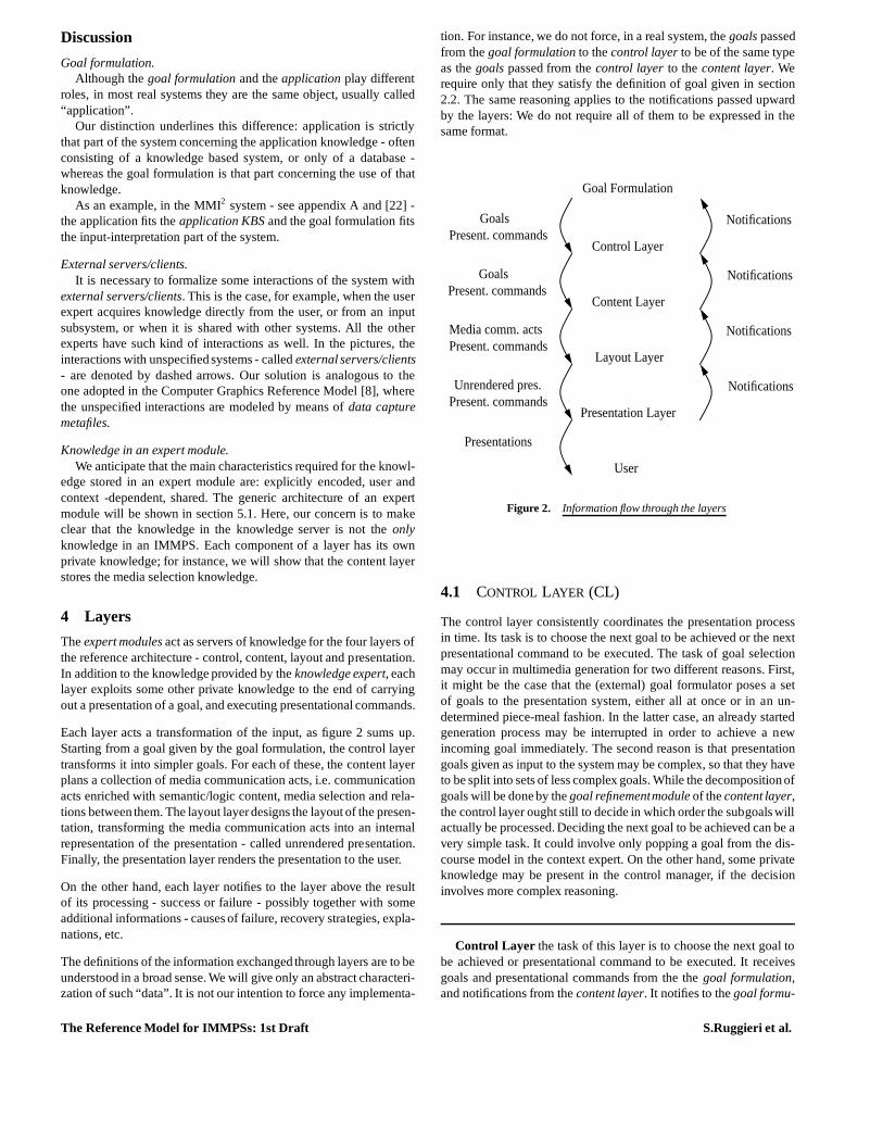
Each layer acts a transformation of the input, as figure 2 sumsup.Starting from a goal given by the goal formulation, the control layertransforms it into simpler goals. For each of these, the content layerplans a collection of media communication acts, i.e. communicationacts enriched with semantic/logic content, media selection and rela-tions between them. The layout layerdesigns the layout of the presen-tation, transforming the media communication acts into an internalrepresentation of the presentation - called unrendered presentation.Finally, the presentation layer renders the presentation to the user.
On the other hand, each layer notifies to the layer above the resultof its processing - success or failure - possibly together with someadditional informations - causes of failure, recovery strategies, expla-nations, etc.
The definitions of the information exchanged through layersare to beunderstood in a broad sense. We will give only an abstract characteri-zation of such “data”. It is not our intention to force any implementa-
tion. For instance, we do not force, in a real system, thegoals passedfrom thegoal formulation to thecontrol layer to be of the same typeas thegoals passed from thecontrol layer to thecontent layer. Werequire only that they satisfy the definition of goal given insection2.2. The same reasoning applies to the notifications passed upwardby the layers: We do not require all of them to be expressed in thesame format.
Goal Formulation
User
Notifications
Presentation Layer
Layout Layer
Control Layer
Content Layer
Notifications
Notifications
NotificationsGoalsPresent. commands
GoalsPresent. commands
Media comm. actsPresent. commands
Unrendered pres.Present. commands
Presentations
Figure 2. Information flow through the layers
4.1 CONTROL LAYER (CL)
The control layer consistently coordinates the presentation processin time. Its task is to choose the next goal to be achieved or the nextpresentational command to be executed. The task of goal selectionmay occur in multimedia generation for two different reasons. First,it might be the case that the (external) goal formulator poses a setof goals to the presentation system, either all at once or in an un-determined piece-meal fashion. In the latter case, an already startedgeneration process may be interrupted in order to achieve a newincoming goal immediately. The second reason is that presentationgoals given as input to the system may be complex, so that theyhaveto be split into sets of less complex goals. While the decomposition ofgoals will be done by thegoal refinementmodule of thecontent layer,the control layer ought still to decide in which order the subgoals willactually be processed. Deciding the next goal to be achievedcan be avery simple task. It could involve only popping a goal from the dis-course model in the context expert. On the other hand, some privateknowledge may be present in the control manager, if the decisioninvolves more complex reasoning.
Control Layer the task of this layer is to choose the next goal tobe achieved or presentational command to be executed. It receivesgoals and presentational commands from the thegoal formulation,and notifications from thecontent layer. It notifies to thegoal formu-
The Reference Model for IMMPSs: 1st Draft S.Ruggieri et al.

lation the result of the presentation process.
GF Interface the interface between thegoal formulation and thecontrol manager, performing simple scheduling operations on theinteractions and/or transformations of the content of the messages.
Control Manager this modules receives goals and presentationalcommands from the GF Interface. They are possibly transformed andstored in thecontext expert. The control managerdecides which is thenext goal to be achieved or presentational command to be executed.Then it sends the goal to the content layer, or the presentational com-mand to the components involved in its execution. From them andfrom the content layer, the control manager receives notifications,which are analysed - possibly generating a recovery strategy in caseof failure - and collected to produce notifications to the GF Interface.
Goal Formulation
GF Interface
Knowledge server
Control Manager
Content Layer
Figure 3. The Control Layer
Discussion
GF InterfaceThe intended role of this component is to convert the messages
to be exchanged between goal formulation and control manager inthe appropriate format. This task is not carried out by the underlyingknowledge exchange format, since the transformation depends on thespecific representation language(s) used in the IMMPS.
Knowledge in the control managerDeciding the next goal to be achieved can be a very simple task:
It could involve only popping a goal from the discourse modelin thecontext expert. On the other hand, some private knowledge may bepresent in the control manager, if the decision involves more complexreasoning.
4.2 CONTENT LAYER (CnL)
The objective of the content layer is to determine a set of so calledmedia communication acts. These are communication acts enrichedby semantic/logic content; they are assigned to a particular mediumwhich should be used to convey that content. Communication actsare an extension of speech acts [27] to multimedia communications(see also [4, 21]). This task is accomplished by means of coordinatedgoal refinement, content selection, and media selection.
Know
ledge server
Layout Layer
Control layer
Media
Goal
Selection Selection Content
Coordination
Refinement
Figure 4. The Content Layer
Content Layer starting from a goal passed by the control layer,the content layer generates media communication acts as an input tothe layout layer. The task is accomplished by means of coordinatedplanning, content and media selection. It receives notifications fromthe layout layer and notifies to the control layer.
Media communication acts communication acts enriched withsemantic/logic content, media selection and relations between acts.
Goal Refinement As presentation goals may be formulated at ahigh level of abstraction, they need to be refined accordingly. Theterm goal refinement is used to capture both thedecomposition of agoal into a set of subgoals and thespecialization of a goal. During goalrefinement, the content of the final presentation will be determined.From the coordination, the goal refinement component receives no-tifications. If the result of the following stages in the presentationprocess is positive, then the notification is passed to the control layer.Otherwise, an alternative strategy may be followed in orderto achievethe goal.
Content selection the function of this module is to effectivelyselect a content for (parts of ) communication acts, according to therelations between them, and in coordination with the media selection.As a result, communication acts enriched with semantic/logic contentare passed to the coordination. In a concrete system, this module may
The Reference Model for IMMPSs: 1st Draft S.Ruggieri et al.

appear as a retrieval and filter component which communicates withthe application expert. The output of the goal refinement process is aset ofcommunication acts and a structural description of the relationsthat may hold between these acts.
Media selection the function of this module is to effectively selecta coordinated collection of media - i.e., a collection of media relatedby some spatial, temporal, cognitive relationships - for (parts of)communication acts, according to the relations between them, and incoordination with the content selection. As a result, communicationacts enriched with the selected media are passed to the coordination.This component stores the media selection knowledge.
Coordination this submodule merges the communication actspassed by the content and the media selection, according to the re-lations between them passed by the goal refinement. The results -called media communication acts - are passed to the layout layer.
Discussion
Goal refinement and coordinationThe strategy followed by the goal refinement component can be
influenced by the possibility to perform some actions. If an action(selecting the appropriate content/media, structuring the layout in away that any two objects do not intersect, etc.) cannot be performed(there is lack of information to retrieve the correct content/media, thelayout has an unwanted structure, etc.) then the coordination commu-nicates the failure to appropriate components - possibly with someadditional information. A trade-off is initiated among goal refinement,content/media selection, coordination and layout layer.
Goal refinement and content selection knowledgeWe did not introduce a “goal refinement knowledge” or a “content
selection knowledge”. Basically, the function of these twocompo-nents consists of asking the application expert for the interpretationof the goal or the suitable content. However, it may happen that theapplication expert has not enough knowledge to perform the task,or the communication acts and the relations between them aretoocomplex to be simply passed forward, or - as in the MMI2 system- the goal refinement performs some kind of analysis (mainly,planrecognition, heuristics for error detection or uncompletespecificationetc.) on the goal by exploiting some private knowledge.
4.3 LAYOUT LAYER (LL)
In this layer, a layout for a presentation is designed, according tothe media communication acts passed by the content layer. The lay-out layer is composed of the layout manager, the media designandrealization and the coordination. TheLayout manager designs thegeneral layout of the presentation. It also passes medium specificcommunicative acts to the responsible generation components, eg.for text, graphics, audio, etc. Each generation component is furthersubdivided into a design and a realization part. The result is coor-dinated to the end of generating an unrendered presentationto bepassed to the presentation layer. From this, the layout layer receivesnotifications. Finally, it sends notification to the contentlayer, to re-port the result of elaborating media communicative acts. A trade-off
is possible - and in a real system, often necessary - among layoutdesign, media design, media realization and coordination.
Content Layer
PresentationLayer
......... D
esign
Layout
Manager
Know
ledge Server
Video D
esign
Graphics
Design
Text D
esign
Audio
Design
...........
Video
Graphics
TextR
ealization
Realization
Realization
Realization Layout
Coordination
Realization
Audio
Media R
ealizationM
edia Design
Figure 5. The Layout Layer
Layout Layer the task of this layer is to satisfy the media com-munication acts passed by the content layer by means of coordinatedlayout design, media design and media realization. As a result, (some)unrendered presentations are passed to the presentation layer. It isnotified by the presentation layer and notifies to the layout layer theresult of elaborating the media communication acts.
Unrendered presentation an internal representation of a piece ofpresentation, with some presentation instructions.
Layout Manager starting from the media communication actspassed by the content layer, the task of this module is the design ofthe layout structure of the presentation, together with dispatching ofthe media communication acts to the media design and realizationinvolved, and notifying to the content layer.
Media Design collection of coordinated design components, onefor each media. Each of these components stores its own mediaspe-cific design knowledge.
Media Realization collection of coordinated realization compo-nents, one for each media. Each of these components stores its ownmedia specific realization knowledge.
Layout Coordination coordination of the resulting media real-ization and layout structure, to the end of producing an unrenderedpresentation as an input to the presentation layer. It receives notifica-tions from the presentation layer and notifies to the layout managerthe result of the presentation process.
The Reference Model for IMMPSs: 1st Draft S.Ruggieri et al.
Discussion
Reply to a communication actA media communication act may require an answer to the content
layer - communicated as a notification message. This way we modelthose situations in which the goal refinement or the media/contentselection depend on information stored in the layout layer.As anexample, if the content layer needs to know if two pictures intersectthen it has to query - with a media communication acts - the layoutmanager,which will retrieve this information from its own knowledgeor from the media design/generation components.
Unrendered presentation.Achieving a goal means producing a presentation. This couldin-
volve splitting the goal in thecontrol layer into several simpler onesand separately achieving each of them. In this sense, the unrenderedpresentation cannot be said to be an internal representation of a pre-sentation, but only of a piece of it, since at thelayout layer we onlyhave a restricted view of the presentation process - i.e., achievingsimpler goals.
4.4 PRESENTATION LAYER (PL)
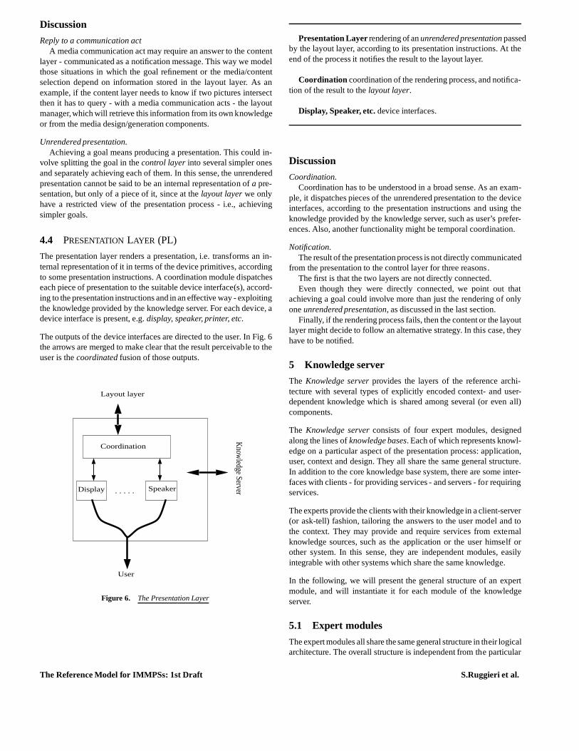
The presentation layer renders a presentation, i.e. transforms an in-ternal representation of it in terms of the device primitives, accordingto some presentation instructions. A coordination module dispatcheseach piece of presentation to the suitable device interface(s), accord-ing to the presentation instructions and in an effective way- exploitingthe knowledge provided by the knowledge server. For each device, adevice interface is present, e.g.display, speaker, printer, etc.
The outputs of the device interfaces are directed to the user. In Fig. 6the arrows are merged to make clear that the result perceivable to theuser is thecoordinated fusion of those outputs.
Knowledge Server
Layout layer
User
Coordination
Speaker Display . . . . .
Figure 6. The Presentation Layer
Presentation Layer rendering of anunrendered presentation passedby the layout layer, according to its presentation instructions. At theend of the process it notifies the result to the layout layer.
Coordination coordination of the rendering process, and notifica-tion of the result to thelayout layer.
Display, Speaker, etc. device interfaces.
Discussion
Coordination.Coordination has to be understood in a broad sense. As an exam-
ple, it dispatches pieces of the unrendered presentation tothe deviceinterfaces, according to the presentation instructions and using theknowledge provided by the knowledge server, such as user’s prefer-ences. Also, another functionality might be temporal coordination.
Notification.The result of the presentation process is not directly communicated
from the presentation to the control layer for three reasons.The first is that the two layers are not directly connected.Even though they were directly connected, we point out that
achieving a goal could involve more than just the rendering of onlyoneunrendered presentation, as discussed in the last section.
Finally, if the rendering process fails, then the content orthe layoutlayer might decide to follow an alternative strategy. In this case, theyhave to be notified.
5 Knowledge server
The Knowledge server provides the layers of the reference archi-tecture with several types of explicitly encoded context- and user-dependent knowledge which is shared among several (or even all)components.
The Knowledge server consists of four expert modules, designedalong the lines ofknowledge bases. Each of which represents knowl-edge on a particular aspect of the presentation process: application,user, context and design. They all share the same general structure.In addition to the core knowledge base system, there are someinter-faces with clients - for providing services - and servers - for requiringservices.
The experts provide the clients with their knowledge in a client-server(or ask-tell) fashion, tailoring the answers to the user model and tothe context. They may provide and require services from externalknowledge sources, such as the application or the user himself orother system. In this sense, they are independent modules, easilyintegrable with other systems which share the same knowledge.
In the following, we will present the general structure of anexpertmodule, and will instantiate it for each module of the knowledgeserver.
5.1 Expert modules
The expert modules all share the same general structure in their logicalarchitecture. The overall structure is independent from the particular
The Reference Model for IMMPSs: 1st Draft S.Ruggieri et al.
systems we are describing, namely IMMPSs and, in principle,themodules differ only in the knowledge which they store and in the in-terface operations. In the following we present this structure togetherwith a functional definition of its components, its instantiation in eachlayer, and a characterization of its interface operations.
A generic architecture
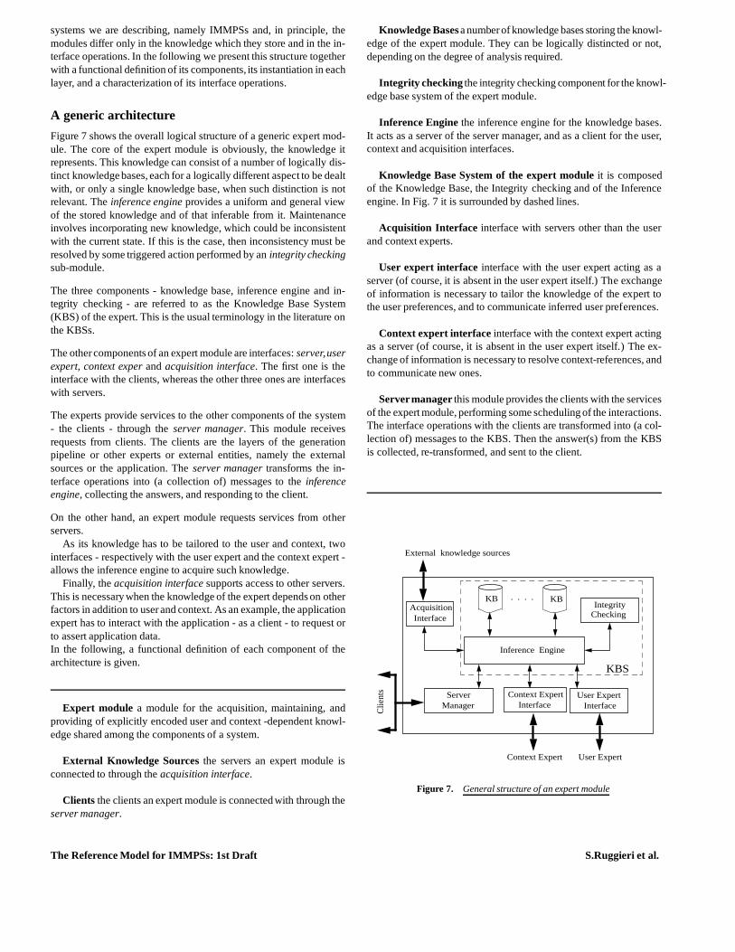
Figure 7 shows the overall logical structure of a generic expert mod-ule. The core of the expert module is obviously, the knowledge itrepresents. This knowledge can consist of a number of logically dis-tinct knowledge bases, each for a logically different aspect to be dealtwith, or only a single knowledge base, when such distinctionis notrelevant. Theinference engine provides a uniform and general viewof the stored knowledge and of that inferable from it. Maintenanceinvolves incorporating new knowledge, which could be inconsistentwith the current state. If this is the case, then inconsistency must beresolved by some triggered action performed by anintegrity checkingsub-module.
The three components - knowledge base, inference engine andin-tegrity checking - are referred to as the Knowledge Base System(KBS) of the expert. This is the usual terminology in the literature onthe KBSs.
The othercomponents of an expert module are interfaces:server,userexpert, context exper andacquisition interface. The first one is theinterface with the clients, whereas the other three ones areinterfaceswith servers.
The experts provide services to the other components of the system- the clients - through theserver manager. This module receivesrequests from clients. The clients are the layers of the generationpipeline or other experts or external entities, namely the externalsources or the application. Theserver manager transforms the in-terface operations into (a collection of) messages to theinferenceengine, collecting the answers, and responding to the client.
On the other hand, an expert module requests services from otherservers.
As its knowledge has to be tailored to the user and context, twointerfaces - respectively with the user expert and the context expert -allows the inference engine to acquire such knowledge.
Finally, theacquisition interface supports access to other servers.This is necessary when the knowledge of the expert depends onotherfactors in addition to userand context. As an example, the applicationexpert has to interact with the application - as a client - to request orto assert application data.In the following, a functional definition of each component of thearchitecture is given.
Expert module a module for the acquisition, maintaining, andproviding of explicitly encoded user and context -dependent knowl-edge shared among the components of a system.
External Knowledge Sources the servers an expert module isconnected to through theacquisition interface.
Clients the clients an expert module is connected with through theserver manager.
Knowledge Basesa numberof knowledge bases storing the knowl-edge of the expert module. They can be logically distincted or not,depending on the degree of analysis required.
Integrity checking the integrity checking component for the knowl-edge base system of the expert module.
Inference Engine the inference engine for the knowledge bases.It acts as a server of the server manager, and as a client for the user,context and acquisition interfaces.
Knowledge Base System of the expert module it is composedof the Knowledge Base, the Integrity checking and of the Inferenceengine. In Fig. 7 it is surrounded by dashed lines.
Acquisition Interface interface with servers other than the userand context experts.
User expert interface interface with the user expert acting as aserver (of course, it is absent in the user expert itself.) The exchangeof information is necessary to tailor the knowledge of the expert tothe user preferences, and to communicate inferred user preferences.
Context expert interface interface with the context expert actingas a server (of course, it is absent in the user expert itself.) The ex-change of information is necessary to resolve context-references, andto communicate new ones.
Servermanager this module provides the clients with the servicesof the expert module, performing some scheduling of the interactions.The interface operations with the clients are transformed into (a col-lection of) messages to the KBS. Then the answer(s) from the KBSis collected, re-transformed, and sent to the client.
Manager
Inference Engine
User Expert
User Expert
KB . . . .AcquisitionInterface
IntegrityChecking
KB
Context Expert
C
lient
s
External knowledge sources
Interface
KBS
Context Expert Interface
Server
Figure 7. General structure of an expert module
The Reference Model for IMMPSs: 1st Draft S.Ruggieri et al.
Discussion
Several design choices need to be commented and justified.
Knowledge in an expert module.We want to stress the characteristics required for the knowledge
stored in an expert module: Explicitly encoded, user and context-dependent, shared.
Explicitly encoded refers to the fact we are considering knowledgebased systems.
User and context -dependentrefers to the two main factors involvedin obtaining aneffective presentation.
Shared refers to the fact the knowledge is used by more than onecomponents and/or system. Therefore, it does not have to be toospecific for a particular use.
The reference resolution is performed in the expert.Alternative approaches are to require that the references are re-
solved by the client, or by the interface between the client and theexpert. The latter makes the interface too specific to our systems,whereas with the current choice we can use any knowledge inter-change format. The former is a valid solution to the problem but,to our opinion it does not respect the principle of modularity of thesystem. In fact, it implies that a client in a layer should know what toresolve andwhat not to resolve. In other words, it should know theinternal knowledge representation formalism of the experts.
Inside the expert, the reference resolution could have beendesignedas part of the server manager, simply connecting the server interfaceto the context interface. Also in this case, we have the same problem;therefore the only modular solution is to let the inference engineresolve the context-dependent references.
Several logically distinct knowledge bases.It is sometimes useful, and intuitive, to have a logically structured
view of a knowledge base. This is the reason of the presence ofseveral knowledge bases. Actually, this is not an implementativerequirement: We do not require that the logical distinctionreflects thereal implementation (for instance, the implementation could confuseall knowledge in a single knowledge base, or structure it under otherpoints of view - i.e., a knowledge base for each user, etc.). In thedescription of the four experts, we will see that it is natural to havesuch a classification of the knowledge in order to have a clearideaand a simpler definition of it.
The architecture of an expert module is generic.The architecture of an expert module is not directly constrained
by the particular systems we are describing, namely IMMPSs.Thismeans that the notion ofexpert module is generic and suitable forother applications. We actually constrain its architecture when weinstantiate clients and external knowledge sources. However, we arestill in a general setting, since we can model interactions with un-specified servers/clients. This is actually the role that the externalservers/clients play in our architecture: They are supposed to modelinteractions with unspecified systems. This allows us to merge ouruser expert with a functionally equivalent module of another applica-tion - for instance, the input system.
5.2 USEREXPERT (Ue)
To present the user expert as an instantiation of the genericarchitec-ture of an expert module, we only have to instantiatethe clients, theexternal knowledge sources andthe knowledge bases.
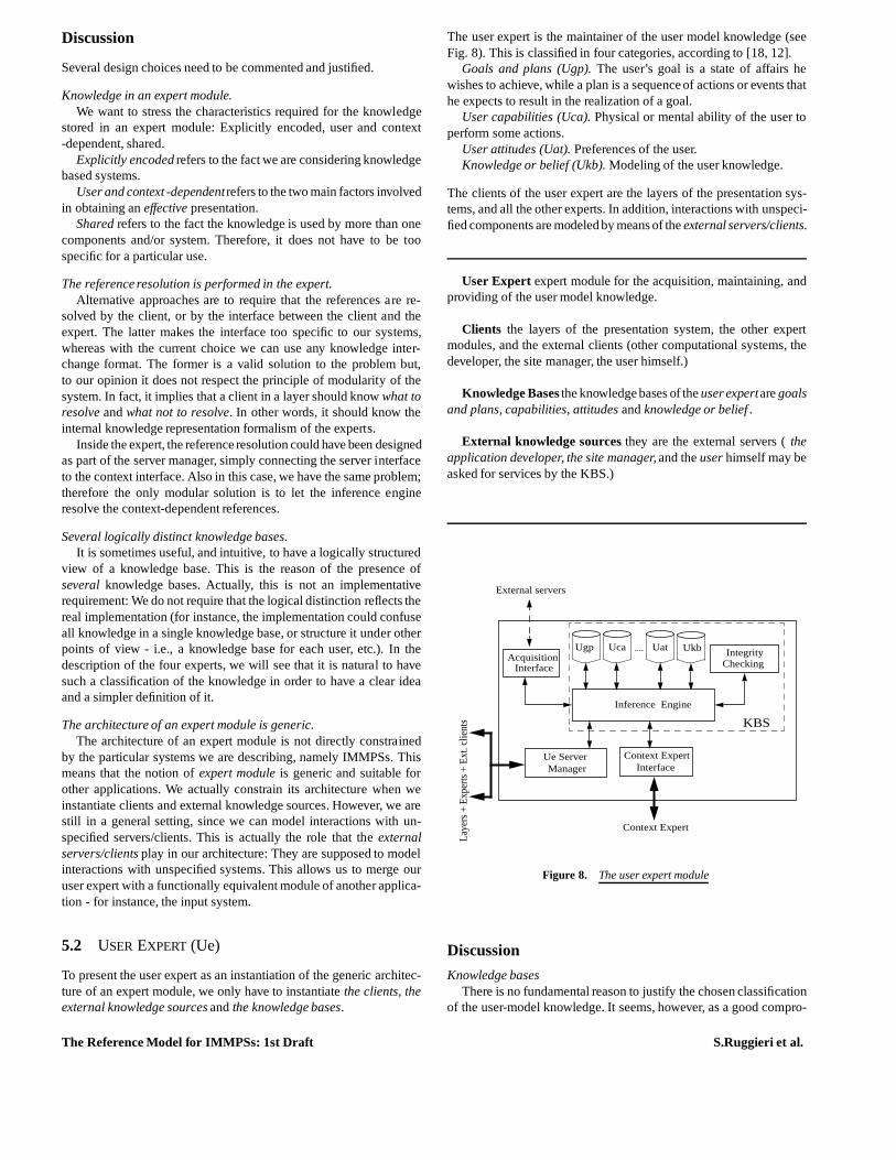
The user expert is the maintainer of the user model knowledge(seeFig. 8). This is classified in four categories, according to [18, 12].
Goals and plans (Ugp). The user’s goal is a state of affairs hewishes to achieve, while a plan is a sequence of actions or events thathe expects to result in the realization of a goal.
User capabilities (Uca). Physical or mental ability of the user toperform some actions.
User attitudes (Uat). Preferences of the user.Knowledge or belief (Ukb). Modeling of the user knowledge.
The clients of the user expert are the layers of the presentation sys-tems, and all the other experts. In addition, interactions with unspeci-fied components are modeled by means of theexternal servers/clients.
User Expert expert module for the acquisition, maintaining, andproviding of the user model knowledge.
Clients the layers of the presentation system, the other expertmodules, and the external clients (other computational systems, thedeveloper, the site manager, the user himself.)
Knowledge Bases the knowledge bases of theuser expertaregoalsand plans, capabilities, attitudes andknowledge or belief .
External knowledge sources they are the external servers (theapplication developer, the site manager, and theuser himself may beasked for services by the KBS.)
Uca
Inference Engine
UgpAcquisition
Interface
IntegrityChecking
Context Expert
Context Expert Interface
Ue Server
Laye
rs +
Exp
erts
+ E
xt. c
lient
s
KBS
Uat Ukb
Manager
External servers
....
Figure 8. The user expert module
Discussion
Knowledge basesThere is no fundamental reason to justify the chosen classification
of the user-model knowledge. It seems, however, as a good compro-
The Reference Model for IMMPSs: 1st Draft S.Ruggieri et al.

mise: A grosser categorization would be too generic and helpless indesign systems ; a finer one would be too specific and constraining.We point out again that such a classification is only from a logicalpoint of view, and it is aimed to have a clearview of what a user-modelis. It absolutely does not constraint any implementation orother viewof the user-model knowledge.
KBSIn the case of the user expert module, the KBS is a well-studied
component in the literature. It is connected with a client - the UeServer Interface - and with two servers - the Context Expert Interfaceand the Acquisition Interface. Many proposed reference models inthe literature [12] will fit this component.
We are not aware of the existence of any similar proposal for theapplication, context and design experts. It would be interesting tocompare this proposal with reference models for those components.
Interface operations: examplesHere are some examples of the services that may be offered by the
Ue server managerask: userknows?, userstereotype?, userpreferences? ;assert: userknows!, userprefers!;deny: userknows!, userprefers!.
For instance, a request likeask(user knows?(mouse)) is supposed toask the KBS about a user knowledge. A reply could be somethinglike tell(user knows?(mouse),FALSE).
Role of the Ue in an IMMPSThe user expert affects the presentation process in many ways. It
may interact withthe application expert, by affecting what is expressed;the context expert, by affecting what is expressed. As an example,
the presentation of a particular information could be omitted if theuser can easily infer it from the context;
the context expert, the control and content layers, by affecting theway the dialog proceed;
the design expert, the content, layout and presentation layers, byaffecting how the data are presented.
5.3 APPLICATION EXPERT (Ae)
Following the same approach of last section, we present the appli-cation expert as an instantiation of the generic architecture of anexpert module. We only have to instantiatethe clients, the externalknowledge sources andthe knowledge bases.
The application expert provides the components in the layers with theapplication knowledge, i.e. knowledge provided by the applicationand knowledge for reasoning about application data.
The knowledge bases are classified accordingly.Term interpretation (Ati). Knowledge for interpreting a high level
description of a collection of application data.Data characterization (Adc). Characteristics of application data
relevant to the presentation design.
The clients of the application expert are the layers of the presentationsystems. In addition, interactions with unspecified components aremodeled by means of theexternal servers/clients. The fundamentalexternal knowledge source is obviously, theapplication.
Application Expert expert module for the acquisition, maintain-ing and providing of the application knowledge.
Clients the layers of the presentation system, and the externalclients.
Knowledge Bases the knowledge bases of theapplication expertareterm interpretation anddata characterization.
External knowledgesources the fundamentalexternal knowledgesource is theapplication. In addition, someexternal servers can playthis role.
Inference Engine
User Expert
User Expert
AtiAcquisitionInterface
IntegrityChecking
Adc
Context Expert
Interface
KBS
Context Expert Interface
Ae Server
Application External servers
Manager
Laye
rs +
Ext
. clie
nts
. . . .
Figure 9. The application expert module
Discussion
Knowledge basesAgain, the classification of the application knowledge is arbitrary
and not intended to be constraining from an implementation point ofview.
Interface operations: examplesHere are some examples of the services offered by the Ae server
managerask: items( X, cost(X)< 100 ), typeof data? ;assert: (NOT ALLOWED FOR IMMPSs);deny: (NOT ALLOWED FOR IMMPSs).
For instance, a request likeask(items( X, cost(X)< 100 )) is supposedto ask the KBS for the items which cost less than 100 units. A replycould be something liketell(items( X, cost(X) < 100 ), f it1, : : : , itkg).
It is worth noting noassert or retract service is offered by the ap-plication experts, since IMMPSs are concerned withpresentation of
The Reference Model for IMMPSs: 1st Draft S.Ruggieri et al.
data and not withacquisition of data.
Role of the Ae in IMPPSsThe application expert affects the presentation process inmany
ways. It may interact with:the content and layout layer, by affecting what is expressed, since
most of content selection is guided by application data and knowl-edge;
the content layer, by affecting the way the dialog proceed - sincedifferent presentation strategies can be followed for different charac-teristics of the application data ;
the content and layout layer, by affecting how the data are pre-sented - since (media and data) selection and layout design dependon the characteristics of the application data.
5.4 CONTEXT EXPERT (Ce)
To present the context expert as an instantiation of the generic archi-tecture of an expert module, we have to instantiatethe clients, theexternal knowledge sources andthe knowledge bases.
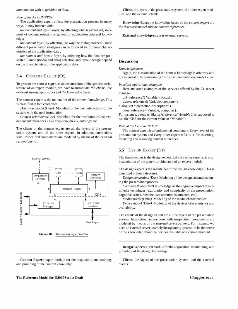
The context expert is the maintainer of the context knowledge. Thisis classified in two categories.
Discourse model (Cdm). Modeling of the past interactions of thesystem with the goal formulation.
Context references (Ccr). Modeling for the resolution of context-dependent references - like anaphora, diexis, ontology etc.
The clients of the context expert are all the layers of the presen-tation system, and all the other experts. In addition, interactionswith unspecified components are modeled by means of theexternalservers/clients.
Laye
rs +
Exp
erts
+ E
xt. c
lient
s Inference Engine
User Expert
User Expert
CdmAcquisitionInterface
IntegrityChecking
Ccm
Interface
KBS
Ce ServerManager
External servers
. . . .
Figure 10. The context expert module
Context Expert expert module for the acquisition, maintaining,and providing of the context knowledge.
Clients the layers of the presentation system, the otherexpert mod-ules, and the external clients.
Knowledge Bases the knowledge bases of thecontext expert arethe discourse model andthe context references.
External knowledge sources external servers.
Discussion
Knowledge basesAgain, the classification of the context knowledge is arbitrary and
not intended to be constraining from an implementation point of view.
Interface operations: examplesHere are some examples of the services offered by the Ce server
managerask: reference?( Variable ), focus? ;assert: reference!( Variable, computer ),
dialogue!( “interactiondescription” ) ;deny: reference!( Variable, computer ).
For instance, a request likeask(reference( Variable )) is supposed toask the KBS for the current value of “Variable”.
Role of the Ce in an IMMPSThe context expert is a fundamental component. Every layer of the
presentation system and every other expert refer to it for asserting,retracting and resolving context references.
5.5 DESIGN EXPERT (De)
The fourth expert is the design expert. Like the other experts, it is aninstantiation of the generic architecture of an expert module.
The design expert is the maintainer of the design knowledge.This isclassified in four categories.
Design constraints (Dds). Modeling of the design constraints dur-ing the presentation process.
Cognitive theory (Dct). Knowledge on the cognitive impact of mul-timedia techniques (ex., clarity and complexity of the presentation,cognitive issues, how the user attention is attracted, etc).
Media model (Dmm). Modeling of the media characteristics.Device model (Ddm). Modeling of the devices characteristics and
availability.
The clients of the design expert are all the layers of the presentationsystem. In addition, interactions with unspecified components aremodeled by means of theexternal servers/clients. For instance, weneed an external server - namely the operating system - to be the serverof the knowledge about the devices available at a certain moment.
Design Expert expert module for the acquisition, maintaining, andproviding of the design knowledge.
Clients the layers of the presentation system, and the externalclients.
The Reference Model for IMMPSs: 1st Draft S.Ruggieri et al.
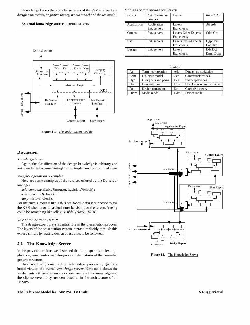
Knowledge Bases the knowledge bases of thedesign expert aredesign constraints, cognitive theory, media model anddevice model.
External knowledge sources external servers.
Ddm
Laye
rs +
Ext
. clie
nts
Inference Engine
User Expert
User Expert
AcquisitionInterface
IntegrityChecking
Context Expert
Interface
KBS
Context Expert Interface
De Server
Dct Ddc Dmm
Manager
External servers
....
Figure 11. The design expert module
Discussion
Knowledge basesAgain, the classification of the design knowledge is arbitrary and
not intended to be constraining from an implementation point of view.
Interface operations: examplesHere are some examples of the services offered by the De server
managerask: deviceavailable?(mouse), isvisible?(clock) ;assert: visible!(clock) ;deny: visible!(clock).
For instance, a request likeask(is visible?(clock)) is supposed to askthe KBS whether or not a clock must be visible on the screen. A replycould be something liketell( is visible?(clock), TRUE).
Role of the Ae in an IMMPSThe design expert plays a central role in the presentation process.
The layers of the presentation system interact implicitly through thisexpert, simply by stating design constraints to be followed.
5.6 The Knowledge Server
In the previous sections we described the four expert modules - ap-plication, user, context and design - as instantiations of the presentedgeneric structure.
Here, we briefly sum up this instantiation process by giving abroad view of the overallknowledge server. Next table shows thefundamental differences among experts, namely their knowledge andthe clients/servers they are connected to in the architecture of anIMMPS.
MODULES OF THEKNOWLEDGE SERVER
Expert Ext. Knowledge Clients KnowledgeSources
Application Application Layers Ati AdcExt. servers Ext. clients
Context Ext. servers Layers Other-Experts Cdm CcrExt. clients
User Ext. servers Layers Other-Experts Ugp UcaExt. clients Uat Ukb
Design Ext. servers Layers Ddc DctExt. clients Dmm Ddm
LEGEND
Ati Term interpretation Adc Data characterizationCdm Dialogue model Ccr Context referencesUgp User goals and plans Uca User capabilitiesUat User attitudes Ukb User knowledge and beliefDdc Design constraints Dct Cognitive theoryDmm Media model Ddm Device model
La
yers
+ E
xt.
syst
em
sApplication Expert
Application
User Expert
Context Expert
Design Expert
Ex. clients
Ex. servers
Ex. servers
Ex. servers
Ex. servers
Ex. clients
Ex. clients
Ex. clients
...
...
...
...
Figure 12. The Knowledge Server
The Reference Model for IMMPSs: 1st Draft S.Ruggieri et al.
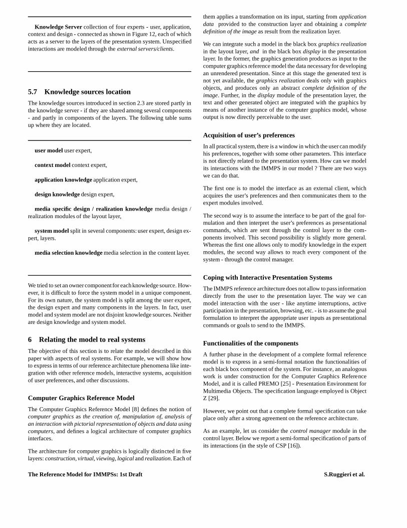
Knowledge Server collection of four experts - user, application,context and design - connected as shown in Figure 12, each of whichacts as a server to the layers of the presentation system. Unspecifiedinteractions are modeled through theexternal servers/clients.
5.7 Knowledge sources location
The knowledge sources introduced in section 2.3 are stored partly inthe knowledge server - if they are shared among several components- and partly in components of the layers. The following tablesumsup where they are located.
user model user expert,
context model context expert,
application knowledge application expert,
design knowledge design expert,
media specific design / realization knowledge media design /realization modules of the layout layer,
system model split in several components: user expert, design ex-pert, layers.
media selection knowledge media selection in the content layer.
We tried to set an ownercomponent for each knowledge source.How-ever, it is difficult to force the system model in a unique component.For its own nature, the system model is split among the user expert,the design expert and many components in the layers. In fact,usermodel and system model are not disjoint knowledge sources. Neitherare design knowledge and system model.
6 Relating the model to real systems
The objective of this section is to relate the model described in thispaper with aspects of real systems. For example, we will showhowto express in terms of our reference architecture phenomenalike inte-gration with other reference models, interactive systems,acquisitionof user preferences, and other discussions.
Computer Graphics Reference Model
The Computer Graphics Reference Model [8] defines the notionofcomputer graphics as the creation of, manipulation of, analysis ofan interaction with pictorial representation of objects and data usingcomputers, and defines a logical architecture of computer graphicsinterfaces.
The architecture for computer graphics is logically distincted in fivelayers:construction, virtual, viewing, logical andrealization. Each of
them applies a transformation on its input, starting fromapplicationdata provided to the construction layer and obtaining acompletedefinition of the image as result from the realization layer.
We can integrate such a model in the black boxgraphics realizationin the layout layer,and in the black boxdisplay in the presentationlayer. In the former, the graphics generation produces as input to thecomputer graphics reference model the data necessary for developingan unrendered presentation. Since at this stage the generated text isnot yet available, thegraphics realization deals only with graphicsobjects, and produces only an abstractcomplete definition of theimage. Further, in thedisplay module of the presentation layer, thetext and other generated object are integrated with the graphics bymeans of another instance of the computer graphics model, whoseoutput is now directly perceivable to the user.
Acquisition of user’s preferences
In all practical system, there is a window in which the usercan modifyhis preferences, together with some other parameters. Thisinterfaceis not directly related to the presentation system. How can we modelits interactions with the IMMPS in our model ? There are two wayswe can do that.
The first one is to model the interface as an external client, whichacquires the user’s preferences and then communicates themto theexpert modules involved.
The second way is to assume the interface to be part of the goalfor-mulation and then interpret the user’s preferences as presentationalcommands, which are sent through the control layer to the com-ponents involved. This second possibility is slightly moregeneral.Whereas the first one allows only to modify knowledge in the expertmodules, the second way allows to reach every component of thesystem - through the control manager.
Coping with Interactive Presentation Systems
The IMMPS reference architecture does not allow to pass informationdirectly from the user to the presentation layer. The way we canmodel interaction with the user - like anytime interruptions, activeparticipation in the presentation, browsing, etc. - is to assume the goalformulation to interpret the appropriate user inputs as presentationalcommands or goals to send to the IMMPS.
Functionalities of the components
A further phase in the development of a complete formal referencemodel is to express in a semi-formal notation the functionalities ofeach black box component of the system. For instance, an analogouswork is under construction for the Computer Graphics ReferenceModel, and it is called PREMO [25] - Presentation Environment forMultimedia Objects. The specification language employed isObjectZ [29].
However, we point out that a complete formal specification can takeplace only after a strong agreement on the reference architecture.
As an example, let us consider thecontrol manager module in thecontrol layer. Below we report a semi-formal specification of parts ofits interactions (in the style of CSP [16]).
The Reference Model for IMMPSs: 1st Draft S.Ruggieri et al.
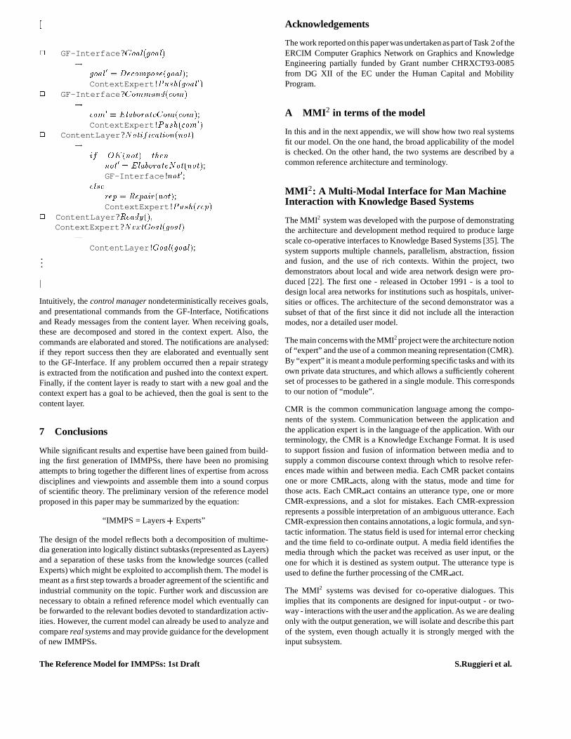
[2 GF-Interface?Goal(goal)! goal0 = Decompose(goal);ContextExpert!Push(goal0)2 GF-Interface?Command(com)! com0 = ElaborateCom(com);ContextExpert!Push(com0)2 ContentLayer?Notification(not)! if OK(not) thennot0 = ElaborateNot(not);
GF-Interface !not0;elserep = Repair(not);ContextExpert!Push(rep)2 ContentLayer?Ready();
ContextExpert?NextGoal(goal)!ContentLayer !Goal(goal);
...]Intuitively, thecontrol manager nondeterministically receives goals,and presentational commands from the GF-Interface, Notificationsand Ready messages from the content layer. When receiving goals,these are decomposed and stored in the context expert. Also,thecommands are elaborated and stored. The notifications are analysed:if they report success then they are elaborated and eventually sentto the GF-Interface. If any problem occurred then a repair strategyis extracted from the notification and pushed into the context expert.Finally, if the content layer is ready to start with a new goaland thecontext expert has a goal to be achieved, then the goal is sentto thecontent layer.
7 Conclusions
While significant results and expertise have been gained from build-ing the first generation of IMMPSs, there have been no promisingattempts to bring together the different lines of expertisefrom acrossdisciplines and viewpoints and assemble them into a sound corpusof scientific theory. The preliminary version of the reference modelproposed in this paper may be summarized by the equation:
“IMMPS = Layers+ Experts”
The design of the model reflects both a decomposition of multime-dia generation into logically distinct subtasks (represented as Layers)and a separation of these tasks from the knowledge sources (calledExperts) which might be exploited to accomplish them. The model ismeant as a first step towards a broader agreement of the scientific andindustrial community on the topic. Further work and discussion arenecessary to obtain a refined reference model which eventually canbe forwarded to the relevant bodies devoted to standardization activ-ities. However, the current model can already be used to analyze andcomparereal systems and may provide guidance for the developmentof new IMMPSs.
Acknowledgements
The work reported on this paperwas undertaken as part of Task2 of theERCIM Computer Graphics Network on Graphics and KnowledgeEngineering partially funded by Grant number CHRXCT93-0085from DG XII of the EC under the Human Capital and MobilityProgram.
A MMI2 in terms of the model
In this and in the next appendix, we will show how two real systemsfit our model. On the one hand, the broad applicability of the modelis checked. On the other hand, the two systems are described by acommon reference architecture and terminology.
MMI2: A Multi-Modal Interface for Man MachineInteraction with Knowledge Based Systems
The MMI2 system was developed with the purpose of demonstratingthe architecture and development method required to produce largescale co-operative interfaces to Knowledge Based Systems [35]. Thesystem supports multiple channels, parallelism, abstraction, fissionand fusion, and the use of rich contexts. Within the project,twodemonstrators about local and wide area network design werepro-duced [22]. The first one - released in October 1991 - is a tool todesign local area networks for institutions such as hospitals, univer-sities or offices. The architecture of the second demonstrator was asubset of that of the first since it did not include all the interactionmodes, nor a detailed user model.
The main concerns with the MMI2project were the architecture notionof “expert” and the use of a common meaning representation (CMR).By “expert” it is meant a module performing specific tasks andwith itsown private data structures, and which allows a sufficientlycoherentset of processes to be gathered in a single module. This correspondsto our notion of “module”.
CMR is the common communication language among the compo-nents of the system. Communication between the applicationandthe application expert is in the language of the application. With ourterminology, the CMR is a Knowledge Exchange Format. It is usedto support fission and fusion of information between media and tosupply a common discourse context through which to resolve refer-ences made within and between media. Each CMR packet containsone or more CMRacts, along with the status, mode and time forthose acts. Each CMRact contains an utterance type, one or moreCMR-expressions, and a slot for mistakes. Each CMR-expressionrepresents a possible interpretation of an ambiguous utterance. EachCMR-expression then contains annotations, a logic formula, and syn-tactic information. The status field is used for internal error checkingand the time field to co-ordinate output. A media field identifies themedia through which the packet was received as user input, ortheone for which it is destined as system output. The utterance type isused to define the further processing of the CMRact.
The MMI2 systems was devised for co-operative dialogues. Thisimplies that its components are designed for input-output -or two-way - interactions with the user and the application. As we are dealingonly with the output generation, we will isolate and describe this partof the system, even though actually it is strongly merged with theinput subsystem.
The Reference Model for IMMPSs: 1st Draft S.Ruggieri et al.
Goal formulation
Thegoal formulation manages input acquisition and application dataupdating. In MMI2, a goal is not directly specified by the user. Thegoal formulation processes the (multimedia) inputs from the user,building up a goal (or a presentational command) as the result of thefusion of several coordinated inputs concerned with outputgenera-tion. Using the terminology of [28], only the “attitudes”User wantsto know andUser wants are passed to the presentation system. Theyrespectively correspond to goals and presentational commands. Theyare represented as CMR packets.
Control Layer
Thecontrol manager (calleddialogue controller) classifies the CMRpassed by thegoal formulation into goal or presentational command.A pair consisting of a CMR and its classification is calleduser-desire.The classification is done on the basis of the form of the CMR, andthe form of previous system presentations.
The discourse model - stored in the context expert - is structuredsimply as a stack. The control managersimply pops the top of the stack- if not empty - to decide the next action - achieving a goal, executinga presentational command, or notifying to the goal formulation.
A notification from the content layercan contain some recovery strate-gies if the presentation process fails. These strategies are organizedas a collection of sub-goals to be achieved and notificationsto thegoal formulation, which are pushed in thediscourse model. As anexample, let us suppose that the goal formulation asks for presentingto the user the cost of a computer, and the system does not knowthecost of the monitor. A recovery strategy may be to notify to the goalformulation that the system is expecting that the application databasebeing correctly updated.
Finally, the control layer replaces anaphoric expressionsin a CMRpacket through relating it to an appropriate antecedent. Anaphoricexpressions are resolved in the context expert.
Content Layer
The role of the content layer is to convey the system’s intentions to theuser in such a way as to follow the rules of cooperativity in dialogue.
The goal refinement module performs first an analysis (calledinfor-mal semantics) of the goal in input - exploiting some private knowl-edge - in order to provide pragmatic, dialogue oriented functionalitiesbeyond the narrow range of selecting the data described by the goal(calledformal semantics). The main functionalities are repair (iden-tification of error condition which prevent straightforward handlingof goals) by means oftask plans, explanations (the determinationand provision of presentation that are more informative than for-mal semantics alone would give), and clarification (assessing goals,checking their validity, etc.). A notification to the control layer isreported if problems occur, together with a recovery strategy in theform of a collection of goals and notifications.
After this analysis, a strategy tailored to the user and the context isplanned (by a sub-module calledcommunication planner) producingcommunication acts - grouped in a CMR packet -, to the contentselection and media selection modules.
The content selection interprets the communication acts bydecom-posing them in terms of simple predicates directly interpretable by theapplication expert, and then collecting and composing the answersfrom it. It can ask the layout manager for the meaning of mediaob-jects, whose knowledge is stored in the media design and realizationof the layout layer.
Media selection exploits its media selection knowledge based oncognitive studies (see [9] for an overview), operationalized by meansof several rules for media selection. Finally, coordination collectsthe media communication acts from media and content selection andsend them - as CMR packets - to the layout layer. The notificationsfrom it are sent to the goal refinement.
To some extent, it is correct to say that goal refinement, contentand media selection, and coordination are threesequential tasks.Instead, content and media selection work concurrently, with somesynchronization.
Layout Layer
The layout manager (calledinterface expert) maintains a record ofwindow positions and provides locations for new windows. Itpassesmedia communication acts received from the content layer tothe me-dia design,media realization and coordination. From these, it receivesnotifications about the presentation process, possibly together withadditional information, which are collected and passed to the contentlayer.
The media in the MMI2 are: english language, french language, span-ish language, graphics (actually, in addition to these output media,thegesture andcommand language input media are present). Let usbriefly overview the english language and the graphics. The formerwas not developed within the MMI2 project. It was lifted out from theLoqui system, BIM’s English natural language interface to relationaldatabases, and ported to the MMI2 application domain. This involvedbuilding a new lexicon and defining the interfaces for communicationwith other MMI2 modules. The graphics media design and realiza-tion is supervised by agraphics manager, which has at its disposal anumber of graphics tools. The graphics manager� translates the CMR packets representing media communication
acts passed by the layout manager into a graphical action by re-questing a change on one of the existing window graphics tools(e.g., displaying a new network on the network tool, moving ama-chine from one room to another.) or by displaying a new graphicstool (e.g., the system tries to generate a new chart whose carrieditem is more effectively perceivable by the user.);� manages a library of graphical data structures used in some of thetools;� provides a library of functions that all the graphical analysis toolsuse;� provides an interface to answer to media communication actsask-ing about the graphics media (e.g., objects currently visible, rela-tive position of machines, etc.)
The graphic tools include tables, bar chart, pie chart, scatter plots,and network tools.
Presentation layer
The coordination module mainly consists of a window manager(SunView/X-windows), together with a component dispatching the
The Reference Model for IMMPSs: 1st Draft S.Ruggieri et al.
unrendered presentations to the suitable device interface. The only(output) device is the display.
User expert
The user expert dynamically acquires and stores knowledge aboutthe users. This knowledge enables the MMI2 system to respond morecooperatively to the current user. The knowledge of the current userthat is acquired and stored is the user’s general knowledge of thedomain of application (e.g., which domain objects the user knowsabout), the user’s knowledge of the MMI2 system (e.g., which MMI2
commands the user knows about), and user’s preferences (e.g., whichcurrency the user would prefer).
Information about the current user is derived from the discourse -stored in the context expert - , or even by the user himself (e.g.,changing his stereotype) through a graphical interface to show theinheritance network of user stereotypes, the knowledge within a par-ticular user model, the predicates permitted in user models, and anyinconsistencies between beliefs in a user model, or derivedfrom itsparents. The graphical interface is modeled as an external client ofthe user expert.
From the information in the user model, it may be possible to cate-gorise the useras a certain type of user.Further knowledge is availablebecause of the assumptions that can be made based on stored knowl-edge about different types of users. The hierarchy of user types allowsmultiple inheritance from different stereotypes.
From studies on how to obtain knowledge from human experts andusers in the application domain, the following knowledge was ob-tained and used within the user expert:� the stereotype hierarchy of users in the domain,� what domain knowledge would be known by a member of a par-
ticular user stereotype,� the rules that allow a human expert to infer the state of knowledgeof an interlocutor from the dialogue,� the way that human experts decide that an interlocutor belongs toa particular stereotype.
Application and Application expert
The role of the application expert is to provide the data described bya (part of a) goal and the denotations of the symbols used in the CMRpackets, by exploiting the application knowledge, according to theuserpreferences (e.g., currency, unit of measure preferred etc.) and thecontext. Moreover, it communicates to the context expert the relationsin the reified world of the application. The application is anexpertsystem (called NEST: a Network design Expert SysTem) providingknowledge on network design (location of machines, graphics objects,etc.) In particular, its knowledge base contains all the definitions ofthe needed objects, i.e. both the various network components and thetopological information relative to the buildings.
Context expert
This module provides contextual functionalities - essentially anaphoraand ellipses resolution - which are involved in the contextual process-ing of each move, and joins an MMI2 standard reified world with areified world of the application. The MMI2 standard world containsconceptual labels representing the reified objects of the layout, the
graphics objects, and the word sense representatives that are relevantto the communication for english, french and spanish languages. Theworld of the application is represented by means of the relevant termsof the application and the word sensesrepresentatives thatare relevantto the communication for english, french and spanish languages.
Utterance containing anaphorical or elliptical phenomenaare repre-sented by the so-called incomplete CMRs. The context expertcon-tributes to their resolution by proposing possible candidates for com-pleting them. These candidates are extracted from the stored discoursemodel. Contextual functionalities are accessed through a focusingmechanism, which emphasizes the role of phrases and relations thatlink together (anaphora and ellipsis) in discourse.
Design expert
The design expert provides knowledge about design constraints, cog-nitive impact of the used media, device model, and media character-istics. The knowledge is tailored to the user preferences and to thecontext.
B WIP in terms of the model
The current prototype of WIP [3] (WIP stands forKnowledge-BasedPresentation of Information - in German) generates multimedia ex-planations and instructions on assembling, using, maintaining or re-pairing physical devices. WIP is currently able to generatesimpleGerman or English explanations on using an espresso machine, as-sembling a lawnmower, or installing a modem, demonstratingtheclaim of language and application independence.
The major design goals of the WIP [3] system are the generation ofcoordinated presentations from a common representation, the adap-tation of these presentations to the intended target audience and situ-ation, and the incrementality of all processes constituting the designand realization of the multimedia output.
It is an important objective not to simply merge the verbalizationresults of a natural language generator and the visualization resultsof a knowledge-based graphics design component, but to carefullycoordinate natural language and graphics in such a way that they gen-erate a multiplicative improvement in communication capabilities. Inaddition, page layout is addressed as a rethorical force, influencingthe intentional and attentional state of the reader.
WIP is a highly adaptive interface since all of its output is generated onthe fly and customized for the intended target audience and situation.Another important design goal was that the incremental generationof a multimedia presentation should be supported. Incremental gen-eration is the immediate realization of parts of a stepwise providedinput. The authors claim that for systems like WIP incrementality isessential. On the one hand, WIP must be able to begin outputtingwords and graphical elements before the input is complete, when theinformation to be expressed arrives in a stream from the backendsystem. On the other hand, the system should be prepared for caseswhen the goal and the media communication acts are changed inthecourse of the media generation process. Such a change might be dueto new high priority goals, or the user’s reaction to the presentationgenerated so far.
In WIP, the design of multimedia presentation is viewed as a subareaof general communication design. The fact that communication is al-ways situated (i.e., depends on some context) is taken into account by
The Reference Model for IMMPSs: 1st Draft S.Ruggieri et al.
considering user’s preferences and design constraints (called genera-tion parameters.) The current system includes a choice between userstereotypes (e.g., novice, expert), target language (German vs En-glish), layout formats (e.g., hardcopy of instruction manual, screendisplay), and output modes (incremental vs complete).
One of the important insights in the development of WIP is that it isactually possible to extend and adapt many of the fundamental con-cepts developed to date in artificial intelligence and computationallinguistics for the generation of natural language - like coherence,speech acts, anaphora, rethorical relations - in such a way that theybecome useful for the generation of graphics and text-picture com-binations as well. A basic assumption behind the WIP model isthatnot only the generation of text and dialog contributions, but also thedesign of graphics and multimedia presentations are planning tasks.
In WIP, no recovery strategy is provided to thegoal formulation whenthe presentation process fails to achieve a goal.
In the following, we discuss more in detail the WIP system in termsof the components of our reference model.
Goal formulation
In WIP thegoal formulation is a menu-guided interface with the user.This interface allows the user to modify the generation parametersand to choose a goal to be achieved (in MMI2, instead, the goal is abuilt up by the goal formulation as a function of the user’s inputs.) Agoal is expressed in terms of a modal logic for modeling believes andintentions. For instance, the goal
(Goal P (BMB P U (LOCATION SWITCH-2 ?LOCATION)))
stands for: the presenterP has the goal to inform the userU of thelocation of the switch denoted by the constant SWITCH-2.(BMB PU x) is the predicate of mutual belief, i.e.P believesx andP believesthatU believesx, etc.
Control Layer
Control tasks such as choosing the next goal to be achieved froman input queue or the decomposition of presentation goals are per-formed by WIP’s component for presentation planning (see also nextparagraph Content Layer). The presentational commands aresent tothe components involved. For instance, the generation parameters aresent to the design expert. Differently from MMI2, no recovery strat-egy is provided by the content layer when the it fails to achieve agoal.
Content Layer
At the heart of the presentation systemis a parallel top-down planninggoal refinement module. It tries to find a presentation strategy for thegiven goal by incrementally generating a refinement-style plan inthe form of a directed acyclic graph (DAG) - stored in the contextexpert - by means of some presentation strategies. They reflect generalpresentation knowledge - stored in thegoal refinement module - orthey embody more specific knowledge of how to present a certainsubject - knowledge provided by the application expert.
An example of a presentation strategy is shown below:
Header: (Introduce System User ?object Graphics)Effect: (BMB System User (Isa ?object ?concept))Applicability Conditions:(Bel System (Isa ?object ?concept))Main Acts:(S-Depict System User ?object ?pic-obj ?picture)Subsidiary Acts:(Label System User ?object ?medium)(Provide-Background System User?object ?pic-obj ?picture Graphics)
The header is a complex communicative act, its effect refersto anintentional goal. The applicability conditions specify when a strategymay be used and constrain the variables to be instantiated. The mainand subsidiaryacts form the kernel of the strategies. The slot reportingthe media allows to define medium-independent presentationstrate-gies simply by filling it with a variable, which will be instantiatedonly when stronger constraints are required (for instance astrategy -like that shown - which instantiates the media slot.)
The leaves of the planned DAG are specifications for elementarymultimedia communication acts, which are elaborated by themediadesign and realization in the layout layer. From these, through thecoordination, the goal refinement module can acquire knowledgeabout relative position of objects, etc.
Since the goal refinement module has no direct access to the knowl-edge of the media design and realization components in the layoutlayer, it cannot consider this information when building upa candi-date strategy. Consequently, it may happen that the resultsprovidedby the generators deviate to a certain extent from the planned strategy(e.g., they are unable to perform the required task, etc.) Such devia-tions are handled by dedicated mechanisms which are:output sharing- part of a presentation is reused for different purposes - ,structuresharing - part of a DAG is shared - andstructure adding - split of partof the DAG. Restructuring methods are applied by thecoordinationmodule.
Whereas in the MMI2 system the goal refinement, selection and co-ordination tasks are performedsequentially, in the WIP system theyare performedconcurrently. This is due mainly to the concerns forincremental output generation.
Layout Layer
The WIP layout manager stores a set of document types, togetherwith some layout constraints for each, which constrain the mediadesign and realization. In addition, communicative acts asking forreply - e.g., isvisible(object) - are answered by the layout manager,after dispatching the request to the appropriate media design andrealization.
The media design and realization include the following media: graph-ics, German natural language and English natural language.In illus-trated instructions for technical equipment, graphics areused in orderto accomplish presentation tasks, such as depicting a domain objectin a certain state, showing an object’s location, or visualizing thecourse of an action. The authors operationalized certain 2Dand 3Dillustration techniques frequently used by human illustrators: the for-malization is based on a compositional semantics of pictures. Usinggraphical design strategies, graphics design is in principle a goal-driven planning process.However, it does not seem feasibleto strictly
The Reference Model for IMMPSs: 1st Draft S.Ruggieri et al.

separate a graphics design and realization phase, as some realizationoperators have side effects which are computationally expensive toanticipate. A solution to this problem is to interleave graphics designand realization and to allow for feedback.
As for graphics, the design and realization of English and Germannatural languages are strongly influenced by the quest for incrementalreasoning. Thus the form and size of basic processing units,data flow,and the interaction between the components were determinedby thisincremental processing scheme.
Finally, coordination between text ad graphics generation- namely,multimedia referring expressions andcrossmedia referring expres-sions - is performed in order to express cross-media deictic assertionslike
The on/off switch is located in the upper-left part of the picture
or the multimedia referring to world objects like
The switch on the frontside.
The authors developed a model of referring which takes into accountthat user’s and system’s knowledge about the identity of objectsdoesn’t necessarily coincide. In order to describe the links a userhas to infer in understanding a referring expression, the predicates(Coref rep1 rep2), (Encodes means information context-space) and(EncodesSame p1 p2 context-space) are stored in the context expert.
Note that in the publications on WIP the term "layout" is usedfordescribing the spatial arrangement of text picture blocks on a page(either paper or screen) only. Thus, the component called "LayoutManager" in WIP performs a subset of the tasks which are to beaccomplished by the modules "Layout Manager" and "Layout Con-trol" in Fig. 5. Tasks such as the monitoring of media generators, orthe design of crossmedia references are done by WIP’s presentationplanner.
Presentation layer
The output of WIP’s Layout component (which is a specification oftext/picture blocks together with constraints for their spatial arrange-ment) can be sent either to a window manager, or to a (postscript)printer. Furthermore, the incrementally generated text output can besent to a speech synthesizer.
User expert
The WIP stereotype usermodel distinguishesnovice andexpert users.User’s goals, preferences and knowledge are stored in the knowledgebases.
The user can modify his stereotype and preferences. This canbemodeled either as a presentational command given through the goalformulation, or by modeling the interface for acquiring theuser pref-erences as an external client of the user expert.
The user model is updated after a goal has been achieved. Fromthattime on, the user is supposedto know the information conveyedby thepresentation of the goal. For instance, the user model is updated afterthe goal “instruct how to fill the watercontainer” has been achieved,since the user is assumed to know that concept.
Finally, the user model is not supposed to be integrated withothersystems. Therefore, no external client is present. There is, however,a context expert interface to resolve context-dependent references.
Application and Application expert
WIP’s application knowledge comprises knowledge about physicaldomain objects (eg. a modem, a lawnmower, an espressomachine),and knowledge about operation procedures for that objects.The repre-sentation of this application knowledge is hybrid. While the ontologyof the domain objects and the operation procedures are representedin RAT [15] - an extension of a Terminological Logics - wireframesare used to represent geometrical information of objects and objectconstellations.
The knowledge represented in RAT is used both for the generationof text and graphics as the main source of knowledge about thedomain. Besides the domain plans the entire information concerningthe domain terminology is represented in RAT. In order to support theuser modeling, a partitioning mechanism is provided to reason aboutthe potentially conflicting views of the world the user an thesystemmay have.
Many of WIP’s presentation strategies are general in nature, how-ever, there are also strategies which are application dependent. In thecurrent reference model one may therefore distinguish between thegeneral strategies which form a private knowledge source ofWIP’spresentation planner, and a set of application dependent strategiesstored in the application expert."
To a certain extend, the same goes for the knowledgesources of WIP’smedium specific generators. For example, there is also applicationdependent knowledge how to choose a suitable view of an object ifit’s depiction has to meet standards in the area of TechnicalDrawing.
Context expert
The context knowledge consists of adocumentdesign plan, and somepredicates for managing referring expressions.
The former is a directed acyclic graph incrementally built by thegoal refinement module in the content layer, and restructured by thecoordination module in the same layer. The leaves of thedocumentdesign plan are specification for elementary acts of presentation,namely graphics and text design and realization.
Noteworthy is also that WIP does a fine-grained coordinationof textand graphics generation. For example, WIP is able to generate cross-media deictic assertions like “The on/off switch is locatedin theupper-left part of the picture”, and referring expressionswhich areitself composed of different media such as showing a picturetogetherwith the assertion: “The switch on the frontside” (cf. [6]).
Design expert
The WIP design expert stores knowledge ongeneration parameters -constraints on the document layout, like short/long presentation, etc.- given by the user, layout constraints dynamically inferred from thecontext and the user preferences, and finally knowledge on deviceavailability - acquired from the operating system modeled as externalserver/client.
REFERENCES
[1] KQML AdvisoryGroup, ‘An Overviewof KQML: A KnowledgeQueryand Manipulation Language’. http://retriever.cs.umbc.edu:80/kqml/.
The Reference Model for IMMPSs: 1st Draft S.Ruggieri et al.
[2] ‘The System Modelling Glossary’. AMODEUS Project, Esprit Bra7040. Document System Modelling/WP26, 28 June 1995.
[3] E. Andre, W. Finkler, W. Graf, T. Rist, A. Schauder, and W. Wahlster,‘WIP: The Automatic Synthesis of Multimodal Presentations’, in Intel-ligent Multimedia Interfaces, ed., M. T. Maybury, chapter 3, AAAI/TheMit Press, (1993).
[4] E. Andre and T. Rist, ‘Towards a Plan-Based Synthesis ofIllustratedDocuments’, inProceedings of ECAI ’90, Stockholm, (1990).
[5] E. Andre and T. Rist, ‘The Design of Illustrated Documents as a Plan-ning Task’, in Intelligent Multimedia Interfaces, ed., M. T. Maybury,chapter 4, AAAI/The Mit Press, (1993).
[6] E. Andre and T. Rist, ‘Referring to World Objects with Text and Pic-tures’, inProceedings of Coling ’94, Osaka, (1994).
[7] Y. Arens, E. H. Hovy, and M. Vossers, ‘On the Knowledge UnderlyingMultimedia Presentations’, inIntelligent Multimedia Interfaces, ed.,M. T. Maybury, chapter 12, AAAI/The Mit Press, (1993).
[8] ‘Computer Graphics Reference Model’. International Standard Organi-zation, ISO/IEC IS 11072, 1992.
[9] H.R. Chappel, M. D. Wilson, and B. Cahour, ‘Engineering User Mod-els to Enhance Multi-modal Dialogue’, inEngineering for Human-Computer Interaction, eds., J.A. Larson and C. Unger, 297–313, Else-vier Science Publishers, Amsterdam, (1992).
[10] Working with Computers: Theory versus Outcome, eds., G.C. Van derVeer, T.R.G. Green, J.M. Hoc, and D.M. Murray, AcademicPress, 1988.
[11] S. K. Feiner and K.R. McKeown, ‘Automating the Generation of Coor-dinate Multimedia Explanations’, inIntelligent Multimedia Interfaces,ed., M. T. Maybury, chapter 5, AAAI/The Mit Press, (1993).
[12] T. W. Finn, ‘GUMS - A General User Modelling Shell’, inUser Modelsin Dialog Systems, eds., A. Kobsa and W. Wahlster, Springer-Verlag,Berlin, (1989).
[13] G. Gazdar and C. Mellish,Natural Language Processing in PROLOG,Addison-Wesley Publishing Company, 1989.
[14] W. D. Gray, W. E. Hefley, and D. Murray, eds.Proceedings of the 1993International Workshop on Intelligent User Interfaces. ACM Press,1993.
[15] J. Heinsohn, D. Kudenko, B. Nebel, and H. J. Profitlich, ‘RAT - rep-resentation of actions using terminological logics’, Technical report,DFKI, Saarbrucken, Germany, (1992).
[16] C.A.R. Hoare,Communicating Sequencial Processes, Prentice Hall In-ternational, 1985.
[17] ‘I3 (Intelling Integration of Information) Glossary’. 8 Nov. 1994.[18] R. Kass,Acquiring a Modelof the User’s Beliefs from a Cooperative Ad-
visory, Ph.D. dissertation, Dept. of Computer and Information Science,University of Pennsylvania, PA, 1988.
[19] User Models in Dialog Systems, eds., A. Kobsa and W. Wahlster,Springer-Verlag, Berlin, 1989.
[20] J. Lee, ed. Preproceedings of the First international workshop onIntelligence and Multimodality in Multimedia Interfaces: Research andApplications, 1995. http://www.cogsci.ed.ac.uk/ john/IMMI/.
[21] M. T. Maybury, ‘Planning Multimedia Explanations Using Communca-tive Acts’, in Intelligent Multimedia Interfaces, ed., M. T. Maybury,chapter 2, AAAI/The Mit Press, (1993).
[22] ‘The MMI2 Demonstrator Systems: A Multi-Modal Interface for ManMachine Interactionwith KnowledgeBasedSystems’, TechnicalReportRAL-94-016, Rutherford Appleton Laboratory, UK, (1994).
[23] J.D. Moore,Participation in Explanatory Dialogues, ACL-MIT PressSeries in Natural Language Processing, 1995.
[24] J.D. Moore and C.L. Paris, ‘Planning Text for Advisory Dialogues’,(1989).
[25] ‘Presentation Environment for Multimedia Objects (PREMO)’. Inter-national Standard Organization, ISO/IEC 14478, 25 Aug 1995.
[26] F. Roth and E. Hefley, ‘Intelligent Multimedia Presentation Systems:Researchand Principles’, inIntelligent Multimedia Interfaces,ed., M. T.Maybury, chapter 1, AAAI/The Mit Press, (1993).
[27] J.R. Searle, ‘What is a speech act?’, inPhylosophy in America, ed.,M. Black, 221–239, (1965).
[28] D. Sedlock, G. Doe, M. Wilson, and D. Trotzig, ‘Formal and informal
interpretation for co-operative dialogue’.[29] M. Spivey,The Z Notation, Prentice Hall International, 1987.[30] Intelligent User Interfaces, eds., J.W. Sullivan and S.W. Tyler, ACM
Press, 1991.[31] A. Sutcliffe and P. Faraday, ‘Designing Presentation in Multimedia
Interfaces’, inCHI94, (1994).[32] D.S.W. Tansley and C.C. Hayball,Knowledge Based Systems Analysis
and Design, Prentice Hall International, 1993.[33] The Structure of Multimodal Dialogue, eds., M.M. Taylor, F. Neel, and
D. G. Bouwhuis, North Holland, 1989.[34] Knowledge Systems and Prolog, ed., A. Walker, Addison-Wesley Pub-
lishing Company, 1987.[35] M.D. Wilson, ‘Enhancing multimedia interfaces with intelligence’,Mul-
timedia systems and applications, (1995).
The Reference Model for IMMPSs: 1st Draft S.Ruggieri et al.