The Pennsylvania State University The Graduate School College of ...
Upload
khangminh22Category
view
3download
0
The Pennsylvania State University
The Graduate School
EVALUATING THE USE OF FLUIDIZED BED COMBUSTION FLY ASH AS
CONCRETE POZZOLAN
A Dissertation in
Civil Engineering
by
Mona Zahedi
© 2019 Mona Zahedi
Submitted in Partial Fulfillment
of the Requirements
for the Degree of
Doctor of Philosophy
December 2019

The dissertation of Mona Zahedi was reviewed and approved* by the following:
Farshad Rajabipour
Associate Professor of Civil and Environmental Engineering
Dissertation Advisor
Chair of Committee
Shelley M. Stoffels
Professor of Civil and Environmental Engineering
Tong Qiu
Associate Professor of Civil and Environmental Engineering
Aly Said
Associate Professor of Architectural Engineering
Patrick J. Fox
Head of the Department of Civil and Environmental Engineering
*Signatures are on file in the Graduate School

iii
ABSTRACT
Supplementary cementitious materials (SCM) are a key ingredient of today’s concrete and can
vastly improve the durability and sustainability of concrete mixtures. While the demand for fly ash
and other suitable pozzolans continues to escalate, the supply of high-quality and economically
available fly ash has been shrinking. To maintain and expand the market share of concrete products,
it is critical that high-quality, long-lasting and cost-competitive concrete is widely available; this
requires a stable and abundant supply of cheap fly ash. Fluidized bed combustion (FBC) fly ash is
an alternative source of fly ash that is widely available, but currently not used in concrete. This is
due to the lack of guidelines and protocols to evaluate the quality/performance of FBC fly ash and
identify necessary beneficiation procedures before it can be incorporated into concrete mixtures.
The FBC process is a cheaper and more efficient way of burning waste coal compared to
conventional pulverized coal combustion (PCC). In this technology, sulfur-absorbing minerals
(e.g., limestones) are added as kiln feed and turbulence is increased, to enable combustion at lower
temperatures (750-900°C), which in turn reduces NOx emissions. Although FBC fly ash may be a
great SCM source, its performance as concrete pozzolan is not yet well understood, and there is a
significant need for research to develop guidelines that distinguish usable sources of FBC ash.
To address these knowledge gaps, the purpose of this research is to evaluate the feasibility,
performance, hydration, and beneficiation of FBC fly ash and determine if and how this alternative
fly ash can be used as a viable pozzolan for concrete. In this study, circulating fluidized bed
combustion (CFBC) fly ashes were collected from two sources in Pennsylvania (products of
anthracite and bituminous waste coal combustion) and characterized for their physical properties,
unburned carbon content, bulk chemistry, mineralogy, and reactivity. Results were compared
against the requirements of ASTM C618-19 and areas of non-compliance were identified. Further,
the characteristics of CFBC fly ashes were linked to the fresh and hardened properties of concrete
iv
and mortar mixtures. The fly ashes were used to substitute 20% of Portland cement in concrete
mixtures, and their effect on the slump, fresh air content, hardened air properties, compressive
strength, chloride ion permeability, and water absorption rate of concrete was evaluated. Equivalent
mortar mixtures were also prepared and tested for their drying shrinkage, autogenous shrinkage,
expansion in water, resistance to sulfate attack and alkali-silica reaction. The fly ashes met the
chemical and physical requirements of ASTM C618-19, except for elevated LOI (in both fly ashes)
and elevated SO3 (in bituminous fly ash). Despite this, concrete with proper slump, air content, and
strength development was produced by adequate dosing of chemical admixtures. The high SO3
content in bituminous fly ash did not produce deleterious expansion during autogenous shrinkage
testing and the value of 14-day expansion in water was close to the ASTM threshold. Use of CFBC
fly ash was found to be most effective in mitigating chloride ion penetration and alkali-silica
reaction. This was mainly due to the contribution of CFBC fly ash in lowering the alkalinity of the
pore solution, increasing its aluminum and silicon ion concentration, as well as refining the pore
structure. Both fly ashes did not have a significant effect on drying shrinkage. Samples containing
anthracite fly ash were able to withstand severe sulfate attack, but the use of bituminous fly ash led
to premature failure.
Understanding the pozzolanic mechanism of CFBC fly ashes in concrete was one of the
main components of this research. For this purpose, X-ray diffraction (XRD), scanning electron
microscopy with energy dispersive X-ray spectroscopy (SEM-EDS), and thermogravimetric
analysis (TGA) was performed on binary paste mixtures containing 20% CFBC fly ash. Hydration
of reactive phases (calcined clay, aluminosilica glass, anhydrite, free lime) in CFBC fly ash which
made up close to 75 % of its mass, resulted in the generation of ettringite, CO3-AFm (i.e.,
hemicarboaluminate, monocarboaluminate), and C-A-S-H phases. Bituminous fly ash contributed
to greater ettringite and secondary C-A-S-H gel formation, while anthracite fly ash was responsible

v
for greater AFm phase production. Use of CFBC fly ash led to greater Si/Ca and Al/Ca values for
the C-A-S-H phase, compared to the 100% OPC mixture.
Finally, carbon neutralization/reduction techniques were investigated for their efficiency
in reducing the interference of CFBC fly ash with air-entraining admixtures (AEA) performance in
concrete. Coating of unburned carbon with sacrificial surfactants improved the slump and
compressive strength of concrete, but slightly reduced its fresh and hardened air content.
Combustion of fly ash at 500oC for 2h was very effective in reducing the AEA uptake by CFBC
fly ashes, and increased combustion temperatures did not yield any significant improvements.

vi
TABLE OF CONTENTS
List of Figures .......................................................................................................................... viii
List of Tables ........................................................................................................................... xi
Acknowledgments ................................................................................................................... xiii
Chapter 1 Introduction ............................................................................................................ 1
1.1 Motivation and Significance ...................................................................................... 1 1.2 Research Objectives .................................................................................................. 2 1.3 Organization of Contents ........................................................................................... 4
Chapter 2 Review of Coal Combustion Processes and the Performance of Raw or
Beneficiated Fly Ash in Concrete .................................................................................... 8
2.1 Coal Combustion Technologies ................................................................................. 8 2.2 Suspension Firing of Pulverized Coal (PC) and Its Products .................................... 14
2.2.1 Pulverized Coal (PC) Fly Ash ......................................................................... 15 2.2.2 Other PC Combustion Products ....................................................................... 21 2.3 Fluidized Bed Combustion (FBC) and Its Products .................................................. 24 2.3.1 Hydration Mechanism of FBC Fly Ash in Concrete ....................................... 28 2.3.2 Performance of FBC Fly Ash in Concrete ....................................................... 30 2.3.3 Beneficiation of FBC Fly Ash ......................................................................... 32
Chapter 3 Characterization of Circulating Fluidized Bed Combustion (CFBC) Fly Ash
and Its Performance in Concrete ...................................................................................... 39
3.1 Abstract ...................................................................................................................... 39 3.2 Introduction ................................................................................................................ 40 3.3 Experimental Procedures ........................................................................................... 40 3.3.1 Physical Properties and Unburned Carbon ....................................................... 41 3.3.2 Bulk Chemistry and Mineralogy....................................................................... 42 3.3.3 Pozzolanic Reactivity ....................................................................................... 43 3.3.4 Performance of CFBC Fly Ash in Mortar and Concrete ........................................ 45 3.4 Results and Discussion .............................................................................................. 47 3.4.1 Physical Properties and Unburned Carbon ....................................................... 47 3.4.2 Bulk Chemistry and Mineralogy....................................................................... 50 3.4.3 Pozzolanic Reactivity ....................................................................................... 52 3.4.4 Performance of CFBC Fly Ash in Mortar and Concrete .................................. 55
3.5 Conclusions ................................................................................................................ 59 3.6 References .................................................................................................................. 60

vii
Chapter 4 Understanding the Pozzolanic Reaction Mechanism of Fluidized Bed
Combustion Fly Ash in Concrete..................................................................................... 62
4.1 Abstract ...................................................................................................................... 62 4.2 Introduction ................................................................................................................ 63 4.3 Experimental Procedures ........................................................................................... 64 4.3.1 Batch Leaching of CFBC Fly Ash .................................................................... 65 4.3.2 XRD and SEM-EDS Analysis of Binary Paste Mixtures ................................. 65 4.3.3 Thermodynamic Analysis of CFBC Fly Ash and Binary Paste Mixtures ........ 66 4.4 Results and Discussion .............................................................................................. 67 4.4.1 Batch Leaching of CFBC Fly Ash .................................................................... 67 4.4.2 XRD of Binary Paste Mixtures ......................................................................... 68 4.4.3 SEM-EDS of Binary Paste Mixtures ................................................................ 72 4.4.4 Thermodynamic Analysis of CFBC Fly Ash and Binary Paste Mixtures ........ 84 4.5 Conclusions ................................................................................................................ 91 4.6 References .................................................................................................................. 91
Chapter 5 Performance of FBC Fly Ash in Concrete ............................................................. 94
5.1 Abstract ...................................................................................................................... 94 5.2 Introduction ................................................................................................................ 95 5.3 Experimental Procedures ........................................................................................... 95 5.3.1 Performance of CFBC Fly Ash in Mortar and Concrete .................................. 96 5.4 Results and Discussion .............................................................................................. 100
5.4.1 Performance of CFBC Fly Ash in Mortar and Concrete .................................. 100 5.5 Conclusions ................................................................................................................ 108 5.6 References .................................................................................................................. 109
Chapter 6 Performance of Beneficiated FBC Fly Ash in Concrete ........................................ 111
6.1 Abstract ...................................................................................................................... 111 6.2 Introduction ................................................................................................................ 112 6.3 Experimental Procedures ........................................................................................... 112 6.3.1 Chemical Passivation ........................................................................................ 114 6.3.2 Carbon Burn Out (CBO) ................................................................................... 114 6.4 Results and Discussion .............................................................................................. 115
6.4.1 Chemical Passivation ........................................................................................ 115 6.4.2 Carbon Burn Out (CBO) ................................................................................... 117 6.5 Conclusions ................................................................................................................ 119 6.6 References .................................................................................................................. 120
Chapter 7 Summary, Conclusions, and Future Approach ...................................................... 121
7.1 Conclusions ................................................................................................................ 122 7.2 Future Directions ....................................................................................................... 124
7.3 References .................................................................................................................. 127
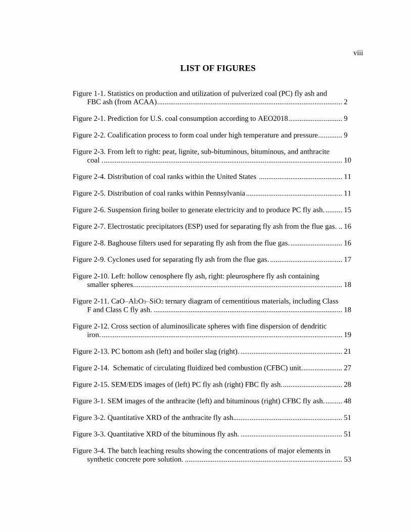
viii
LIST OF FIGURES
Figure 1-1. Statistics on production and utilization of pulverized coal (PC) fly ash and
FBC ash (from ACAA) .................................................................................................... 2
Figure 2-1. Prediction for U.S. coal consumption according to AEO2018 ............................. 9
Figure 2-2. Coalification process to form coal under high temperature and pressure. ............ 9
Figure 2-3. From left to right: peat, lignite, sub-bituminous, bituminous, and anthracite
coal . ................................................................................................................................. 10
Figure 2-4. Distribution of coal ranks within the United States ............................................. 11
Figure 2-5. Distribution of coal ranks within Pennsylvania .................................................... 11
Figure 2-6. Suspension firing boiler to generate electricity and to produce PC fly ash. ......... 15
Figure 2-7. Electrostatic precipitators (ESP) used for separating fly ash from the flue gas. .. 16
Figure 2-8. Baghouse filters used for separating fly ash from the flue gas. ............................ 16
Figure 2-9. Cyclones used for separating fly ash from the flue gas. ....................................... 17
Figure 2-10. Left: hollow cenosphere fly ash, right: pleurosphere fly ash containing
smaller spheres. ................................................................................................................ 18
Figure 2-11. CaO–Al2O3–SiO2 ternary diagram of cementitious materials, including Class
F and Class C fly ash. ...................................................................................................... 18
Figure 2-12. Cross section of aluminosilicate spheres with fine dispersion of dendritic
iron. .................................................................................................................................. 19
Figure 2-13. PC bottom ash (left) and boiler slag (right). ....................................................... 21
Figure 2-14. Schematic of circulating fluidized bed combustion (CFBC) unit. ..................... 27
Figure 2-15. SEM/EDS images of (left) PC fly ash (right) FBC fly ash. ................................ 28
Figure 3-1. SEM images of the anthracite (left) and bituminous (right) CFBC fly ash. ......... 48
Figure 3-2. Quantitative XRD of the anthracite fly ash........................................................... 51
Figure 3-3. Quantitative XRD of the bituminous fly ash. ....................................................... 51
Figure 3-4. The batch leaching results showing the concentrations of major elements in
synthetic concrete pore solution. ..................................................................................... 53

ix
Figure 3-5. The strength activity index of CFBC fly ashes and the compressive strength
of mortars containing 20% CFBC fly ash as a function of age. ...................................... 54
Figure 3-6. Calcium hydroxide content of lime-fly ash pastes per RILEM TC TRM 267
method. ............................................................................................................................ 57
Figure 3-7. Autogenous shrinkage of mortar samples (zeroed at the time of final setting). ... 58
Figure 3-8. ASR induced expansion of mortar samples in ASTM C1567 test. ...................... 58
Figure 4-1. The batch leaching results showing the concentrations of major elements in
synthetic concrete pore solution. ..................................................................................... 68
Figure 4-2. XRD of the cement paste containing anthracite fly ash. ....................................... 70
Figure 4-3. XRD of the cement paste containing bituminous fly ash. .................................... 70
Figure 4-4. XRD of cement paste containing anthracite and bituminous fly ash after 7-
days of hydration compared to control samples. ............................................................. 72
Figure 4-5. EDS elemental maps for anthracite paste samples after 90 days of hydration. .... 73
Figure 4-6. Phase identification of anthracite CFBC paste after (top) 1 day and (bottom) 7
days of hydration. ............................................................................................................ 74
Figure 4-7. Phase identification of anthracite CFBC paste after (top) 28 day and (bottom)
90 days of hydration. ....................................................................................................... 75
Figure 4-8. Phase identification of bituminous CFBC paste after (top) 1 day and (bottom)
7 days of hydration. ......................................................................................................... 76
Figure 4-9. Phase identification of bituminous CFBC paste after (top) 28 day and
(bottom) 90 days of hydration. ........................................................................................ 77
Figure 4-10. Phase identification using point EDS of (top) anthracite and (bottom)
bituminous CFBC paste. .................................................................................................. 79
Figure 4-11. Schematic of the intermixing of phases. The interaction volume is shown to
contain (left) information from C–A–S–H (dark grey) and portlandite or (right) C–
A–S–H and ettringite. ...................................................................................................... 81
Figure 4-12. Phase identification of C-A-S-H using point EDS of (top) anthracite and
(bottom) bituminous CFBC paste. ................................................................................... 82
Figure 4-13. C-A-S-H composition for PC and LC3-50 (17.0%), (50.3%) and (95.0%) at
28 days of hydration obtained by SEM-EDS (cloud of points and least intermixed
composition) and STEM-EDS. ........................................................................................ 83

x
Figure 4-14. Scatter plot for binary paste with 50% slag (left) after 4 weeks of hydration
(right) after 14 months of hydration. ............................................................................... 84
Figure 4-15. TGA results for pastes samples containing anthracite fly ash (after 1, 7, and
28 days of hydration) compared to as received anthracite fly ash. .................................. 85
Figure 4-16. TGA results for pastes samples containing bituminous fly ash (after 1, 7, and
28 days of hydration) compared to as received bituminous fly ash................................. 86
Figure 4-17. TGA results for control pastes samples (after 1, 7, and 28 days of hydration). . 87
Figure 4-18. Decomposition patterns for pure limestone, hemicarboaluminate, and
monocarboaluminate. ....................................................................................................... 88
Figure 4-19. Presence of monosulfate in limestone free mixtures. ......................................... 88
Figure 4-20. Calcium hydroxide content in paste mixtures after 1, 7, and 28 days of
hydration. ......................................................................................................................... 89
Figure 4-21. Changes in the amount of AFm phases for binary paste samples (after 1, 7,
and 28 days of hydration) compared to the control mixture. ........................................... 90
Figure 5-1. Rate of water absorption in 56-day concrete disks. .............................................. 103
Figure 5-2. Pore size distribution of paste samples using MIP. .............................................. 104
Figure 5-3. Expansion of mortar prisms in Na2SO4 solution. .................................................. 105
Figure 5-4. (a) Drying shrinkage and (b) change in mass of mortar samples. ........................ 107
Figure 6-1. Determination of organic carbon content in CFBC fly ash using LECO IR. ....... 113
Figure 6-2. Compressive strength of concrete samples after 7, 28, and 56 days of
hydration. ......................................................................................................................... 116
Figure 6-3. Surface of solution containing bituminous fly ash combusted at 600oC, after
adding 1, 2, and 3 drops of 5% AEA using a 0.05 mL pipet. .......................................... 119
Figure 6-4. Unburned carbon content (obtained from LOI and LECO testing) in CFBC fly
ash as a function of combustion temperature................................................................... 119

xi
LIST OF TABLES
Table 1-1. Desired outcomes related to each chapter. ............................................................. 6
Table 2-1. Classification of coal by rank according to ASTM D388-19................................. 13
Table 2-2. Normal range of chemical composition for fly ash produced from different
coal types (expressed as percent by weight. .................................................................... 18
Table 3-1. Lime-fly ash mortar mixture design and properties (ASTM C593-06). ................ 44
Table 3-2. Lime-fly ash paste mixture design according to RILEM TC TRM267. ................ 45
Table 3-3. Mixture designs to evaluate the effect of CFBC fly ashes on concrete
properties. ........................................................................................................................ 46
Table 3-4. Physical properties and unburned carbon content of fly ash. ................................. 48
Table 3-5. Oxide composition of cement and fly ash. ............................................................. 49
Table 3-6. Effect of CFBC fly ash on concrete properties. ..................................................... 49
Table 4-1. Chemical composition and physical properties of cement and fly ash. ................. 64
Table 4-2. Phase detection using point EDS of paste (wt.%). ................................................. 80
Table 5-1. Mortar mix proportions for ASTM C1012-18a testing. ......................................... 99
Table 5-2. Initial and final setting time of concrete................................................................. 101
Table 5-3. Initial and final setting time of paste. ..................................................................... 101
Table 5-4. Short and long-term performance of CFBC fly ash in concrete. ........................... 102
Table 5-5. Concentration of ions in the pore solution after 56 days (obtained from ICP-
AES)................................................................................................................................. 102
Table 5-6. Calculation of resistivity of pore solution using model developed by Snyder et
al. (2003). ......................................................................................................................... 102
Table 5-7. Pore parameters obtained from MIP testing. .......................................................... 104
Table 6-1. Unburned carbon content in CFBC fly ash. ........................................................... 115
Table 6-2. Properties of concrete incorporating chemically passivated CFBC fly ash
compared to that of as-received fly ash. .......................................................................... 116

xii
Table 6-3. No of drops of AEA (total volume of AEA in mL) required for raw and treated
CFBC fly ashes to obtain stable foam. ............................................................................ 117
Table 6-4. Comparison between Foam Index results and the amount of unburned carbon
from LOI and LECO IR. .................................................................................................. 117

xiii
ACKNOWLEDGEMENTS
I would like to express my gratitude to all of those who have helped me during my dissertation.
First and foremost, I would like to thank my advisor, Dr. Farshad Rajabipour, for his guidance and
patience throughout my graduate career. His immense knowledge and insistence on excellence has
had a significant impact on my personal and intellectual growth. I feel very proud to have had him
as my mentor and role model. This thesis has also benefited from the valuable feedback and
suggestions made by my committee members: Dr. Shelley Stoffels, Dr. Tong Qiu, Dr. Aly Said,
and Dr. Barry Scheetz. Thank you for devoting your time and support to this endeavor. I would like
to express my special appreciation to Dr. Patrick Fox, without whom I would have not been able
to overcome the challenges I faced during this journey. I am thankful to Dr. Steven Feldman (at the
National Institute of Standards and Technology), Nichole Wonderling, Julie Anderson, Katya
Bazilevskaya (at Penn State’s Materials Characterization Laboratory), and Dan Fura (at Penn
State’s Civil Infrastructure Testing and Evaluation Laboratory) for their invaluable insights and
technical support. I would also like to acknowledge the American Concrete Institute (ACI) and the
Pennsylvania Coal Ash Research Group (PCARG) for their financial support of this research as
well as providing valuable technical advice during this project.
I am deeply grateful for my colleagues and friends at Penn State. You have been my support
system and family throughout my stay in State College. Maryam and Khashayar, I cannot thank
you enough. To my mom and dad, thank you for your unconditional love and support during some
of the hardest years of my life. I am incredibly privileged to have been raised in such an intellectual
environment, you both inspire me every day. Lastly, to my beloved brother that is unfortunately no
longer with us, I love you with all my heart. s

1
Chapter 1
Introduction
1.1 Motivation and Significance
In recent years, reports of fly ash shortages for use in concrete have become more common in the
United States [1], [2], [3], [4]. A recent survey by the AASHTO subcommittee on materials [5] of
all State Departments of Transportation (DOTs), the Federal Aviation Administration (FAA), and
the Army Corps of Engineers showed that the concern with fly ash supply is not a minimal or
regional issue, as over 80% of the respondents indicated having issues with fly ash availability over
the past 4 years. These supply issues are in part due to a decline in the total quantity of fly ash
produced [6] (Figure 1-1) as utilities have shifted fuel sources (e.g., coal to natural gas). They are
also due to stricter air pollution and environmental regulations (e.g., [7], [8]), which affect the
quality of fly ash by increasing its carbon content (e.g., due to the use of low NOx burners and
activated carbon), and calcium and sulfur contents [9] [10]. The economic and regulatory incentives
have also encouraged the use of low sulfur western coals (yielding Class C fly ash), at the cost of
Class F fly ash, with the latter having a superior performance in mitigating alkali-silica reaction
(ASR) in concrete [11].
Based on today’s practices and standards, it is estimated that by year 2030, the supply of
ASTM C618-complient fly ash in the United States will be approximately 14 million tons, while
the demand will exceed 35 million tons [12]. The shrinking supply of high-quality and
economically available fly ash threatens the competitiveness and market share of concrete against
other materials such as asphalt (for pavements), steel (for buildings and bridges), and plastics (for
pipes). The concrete industry relies on cheap and abundant fly ash for producing economical,

2
durable, and sustainable (e.g., low CO2) concrete [10] [13]. While fluidized bed combustion fly ash
is widely available, it is not being used since its performance in concrete is not fully understood,
and guidelines (e.g., ACI documents, ASTM specifications) to evaluate and beneficiate this
alternative form of fly ash does not currently exist.
Figure 1-1. Statistics on production and utilization of pulverized coal (PC) fly ash and
FBC ash (from ACAA [6])
1.2 Research Objectives
This Ph.D. research pursues the following main objectives:
Objective 1: Characterization of as-produced FBC fly ash and its performance in concrete
Literature on the use of FBC fly ash as concrete pozzolan is limited, and lacks a complete evaluation
of the physical and chemical properties of FBC fly ash against ASTM C618 [14] – Standard
Specification for Coal Fly Ash and Raw or Calcined Natural Pozzolan for Use in Concrete. Past
10
20
30
40
50
60
70
80
90
2000 2002 2004 2006 2008 2010 2012 2014 2016
An
nu
al p
rod
uctio
n a
nd
use
(m
illio
n
ton
s)
Year
PC fly ash produced PC fly ash used in concrete
FBC ash produced

3
studies have been mainly focused on evaluating the effects of FBC fly ash on the mechanical
properties of concrete, and have reported contradictory results. To address these deficiencies, the
goal of this study is to present a complete characterization of several CFBC fly ashes produced in
Pennsylvania, and to link these properties with important characteristics of concrete. It is worth
noting that not all FBC fly ashes are created equal and their composition and properties may vary
considerably from one source to another, partly due to differences in their source coal. In this study,
two CFBC fly ashes of distinct compositions (originating from anthracite and bituminous coal
sources) are evaluated for their physical, chemical, and mineralogical properties and compared
against ASTM C618-19 requirements. The fly ashes are then used as partial (20% by mass)
replacement of Portland cement in DOT-compliant pavement concrete mixtures, and their impact
on the short and long-term performance of concrete is investigated.
Objective 2: Understanding the hydration mechanism of FBC fly ash in binary cement-based
mixtures
FBC fly ashes possess pozzolanic properties and this research is aimed at understanding the
reaction mechanism of FBC fly ash, in the presence of Portland cement and water. Few earlier
studies have looked at the hydration of self-cementitious FBC fly ashes in no-cement mortar and
paste mixtures. These fly ashes contain high contents of free lime and sulfur, which significantly
surpass ASTM C618 limits, and will most likely cause performance complications such as volume
instability, undesirable setting, and extreme heat of hydration. As such, use of self-cementitious
FBC fly ashes in concrete may not be practical or require extensive beneficiation procedures. In
this study, binary mixtures of Portland cement and CFBC fly ash (containing moderate levels of
CaO and SO3) are prepared and monitored over a duration of 90 days to evaluate their pozzolanic
reactivity and reaction products. The main crystalline phases are identified using XRD testing,
while SEM-EDS is used to determine the chemical composition of various crystalline/amorphous

4
phases (e.g., C-A-S-H, AFt, and AFm phases) within the microstructure. Thermogravimetric
analysis is performed on the control and binary mixtures, to quantify the pozzolanic reactivity of
CFBC fly ashes, by measuring changes in portlandite content with time.
Objective 3: Beneficiation of FBC fly ash and its performance in concrete
The high unburned carbon content, measured as loss-on-ignition (LOI), is a major limiting factor
for the use of FBC fly ash in concrete due to its negative effects on concrete air entrainment and
workability. Although various beneficiation techniques (e.g., size separation, electrostatic
separation, froth flotation, oil agglomeration, chemical passivation and thermal processing [15])
have been successfully used to reduce/neutralize the unburned carbon in conventional PC fly ash,
no treatment of this kind has been tested for FBC fly ash. The goal of this study is to evaluate the
effectiveness of chemical passivation and Carbon Burn Out (CBO) methods in reducing the
interference of FBC fly ash with the performance of air entraining admixture (AEA) in concrete.
In the chemical passivation method, the surface of carbon is coated with sacrificial surfactants to
prevent it from adsorbing AEA in concrete. As for the CBO approach, fly ash is combusted at
temperatures above carbon ignition (460oC) and below glass devitrification (700oC), to reduce the
unburned carbon content. The efficiency of the two methods in terms of improving the air-
entrainment property of concrete is evaluated using the Foam Index (FI) testing and fresh and
hardened air analysis of concrete.
1.3. Organization of Contents
This document is organized in 6 chapters, with the above research objectives addressed in chapters
3-5 (Table 1-1). Chapter two provides a background and literature review on coal combustion
processes and byproducts with a focus on PC and FBC fly ashes. The current state of understanding
and practice with respect to FBC fly ash is summarized, and research needs to facilitate the use of

5
FBC fly ash as a viable concrete pozzolan is highlighted. In Chapter three, two sources of CFBC
fly ash are characterized for their bulk chemistry and mineralogy (using X-ray florescence, batch
leaching, and quantitative XRD); unburned carbon (using LOI, and Leco infrared analyzer);
physical properties (moisture content, particle size, fineness, particle shape/agglomeration (via
SEM), density, soundness, and water requirement); and reactivity (strength activity index,
compressive strength of lime-fly ash mortar according to ASTM C593-06, pozzolanic reactivity of
lime-fly ash paste according to RILEM TC TRM267). The fresh (slump, fresh air content) and
hardened (compressive strength, hardened air content) properties of concrete mixtures
incorporating 20% CFBC fly ash are obtained, and mortar samples are tested for their autogenous
shrinkage and effectiveness in mitigation of alkali-silica reaction (ASR). Chapter four addresses
knowledge gaps regarding the hydration mechanism of FBC fly ash with moderate levels of CaO
and SO3. Binary mixtures incorporating 20% CFBC fly ash as a replacement of cement are prepared
and tested for their mineralogy, chemical composition, and pozzolanic reactivity at 1, 7, 28, and 90
days, using XRD, SEM-EDS, and TGA methods. Chapter five investigates the durability of
concrete (chloride ion penetration, water sorbtivity) and mortar (sulfate attack, drying shrinkage)
mixtures containing 20% CFBC fly ash. Mercury intrusion porosimetry (MIP) and pore fluid
extraction tests are used to relate concrete performance to microstructural features such as pore size
distribution and pore conductivity. In Chapter six, the effectiveness of chemical passivation and
CBO beneficiation techniques on the air entrainment properties of concrete containing CFBC fly
ash is evaluated using fresh air and hardened air analysis of concrete and foam index testing.
Chapter seven provides a summary of the findings and conclusions of this research study.

6
Table 1-1. Desired outcomes related to each chapter
Chapter Desired outcomes
Chapter 1: Fluidized Bed Combustion (FBC)
Fly Ash and its Performance in Concrete
• Characterizing CFBC fly ash for its bulk
chemistry, mineralogy, physical properties,
unburned carbon content, and reactivity
• Determining the effect of CFBC fly ash on
the fresh and hardened properties of concrete
Chapter 2: Understanding the pozzolanic
reaction mechanism of FBC fly ash in
concrete
• Identifying the main hydration products of
mixtures incorporating CFBC fly ash and
Portland cement, and monitoring their
change over time.
• Determining the composition of C-A-S-H
phase in such mixtures
Chapter 3: Performance of FBC fly ash in
concrete
• Determining the effects of CFBC fly ash on
concrete durability
• Relating concrete performance to
microstructural features
Chapter 4: Performance of beneficiated FBC
fly ash in concrete
• Evaluating the effectiveness of chemical
passivation and CBO beneficiation
techniques in reducing the interference of
carbon in CFBC fly ash with the performance
AEAs in concrete
1.4. References
[1] Engineering district notification regarding fly ash availability for cement concrete,
Pennsylvania Dep. Transp. Strike-off Lett. Available at: http://www.paconstructors.org/wp-
content/uploads/2014/09/481-14-08.pdf. Accessed: July 2019.
[2] Where has the fly ash gone?, Texas Dep. Transp. Constr. Mater. Tips. Available at:
https://ftp.dot.state.tx.us/pub/txdot-info/cst/tips/fly_ash_0412.pdf. Accessed: July 2019.
[3] Fly ash supply, Texas Dep. Transp. Tehcnical Advis. Constr. Bridg. Div. (2010).
[4] T.L. Robl, C.J. McCormick, We are running out of fly ash: The nature of regional supply

7
problems, in: DOE/FETC 3rd Conf. Unburned Carbon Util. Fly Ash, Pittsburgh, PA, 1997.
[5] AASHTO Subcommittee on Materials (SOM) fly ash task force report, (2016).
[6] American Coal Ash Association (ACAA), coal combustion products production and use
survey report, (2017). Available at: https://www.acaa-usa.org/Portals/9/Files/PDFs/2017-
Survey-Results.pdf. Accessed: July 2019.
[7] US-EPA Clean Air Interstate Rule (CAIR), (2005). Available at:
https://archive.epa.gov/airmarkets/programs/cair/web/html/index.html. Accessed: July
2019.
[8] US-EPA Cross-State Air Pollution Rule (CSAPR), (2011). Available at:
https://www.epa.gov/csapr/overview-cross-state-air-pollution-rule-csapr. Accessed: July
2019.
[9] S. Seraj, R. Cano, S. Liu, D. Whitney, D. Fowler, R. Ferron, J. Zhu, M. Juenger, Evaluating
the performance of alternative supplementary cementing material in concrete, FHWA
Report No. FHWA/TX-14/0-6717-1, (2014).
[10] ACI 232.2R, Report on the use of fly ash in concrete, Draft Rep. under Revis. Am. Concr.
Inst. (2016).
[11] M. Thomas, The effect of supplementary cementing materials on alkali-silica reaction: A
review, Cem. Concr. Res. 41 (2011) 1224–1231.
[12] Production and use of coal combustion products in the U.S., Market Forecast through 2033,
Am. Road Transp. Build. Assoc. (2015).
[13] AASHTO PP-65, Standard Practice for Determining the Reactivity of Concrete Aggregates
and Selecting Appropriate Measures for Preventing Deleterious Expansion in New Concrete
Construction, Am. Assoc. State Highw. Transp. Off. (2013).
[14] ASTM C618-19, Standard specification for coal fly ash and raw or calcined natural
pozzolan for use in concrete. ASTM International.
[15] J.C. Hower, J.G. Groppo, U.M. Graham, C.R. Ward, I.J. Kostova, M.M. Maroto-Valer, S.
Dai, Coal-derived unburned carbons in fly ash: A review, Int. J. Coal Geol. 179 (2017) 11–
27.

8
Chapter 2
Review on Coal Combustion Processes and the Performance of Raw or
Beneficiated Fly Ash in Concrete
2.1. Coal Combustion Technologies
Power generation is the main consumer of energy in the United States, and coal is the second largest
fuel source for this sector (i.e., accounting for 27.4% of the electricity generated in the United States
in 2018) [1]. According to the U.S. Energy Information Administration’s Annual Energy Outlook
2018 (AEO), coal usage is expected to remain relatively constant through 2050, despite recent wave
of coal plant retirements [2] (Figure 2-1). Coal is a combustible sedimentary rock that primarily
contains organic carbon, hydrogen, oxygen and lesser amounts of sulfur and nitrogen.
Inorganic/non-combustible compounds in coal such as aluminum and silicon oxides (e.g., in the
form of clay impurities in coal) constitute the combustion ash, but their concentration is no more
than several percentage points of coal. In fact, up to one tenth of the total mass of coal is material
with no fuel value. There are two main theories for the formation of coal, based on the origin of
vegetation that is later converted to coal. The autochthonous theory [3] is most accepted since it
explains the origin of most coals. It states that plant debris accumulate in the bottom of nearby
swamps and bogs, where oxygen content is low. The thick layer of partially decayed organic matter,
also known as peat, is then covered by sedimentation (e.g., sand or mud) and coal seam is formed.
Under gradual heat and pressure, biochemical reactions occur over thousands and millions of years
and drive much of the water and other volatiles out of peat, resulting in the formation of various
grades of coal (Figure 2-2). This coalification process constitutes three main reactions:
microbiological degradation of plant cellulose; conversion of lignin within the plant to humic

9
substances; and condensation of humic substances to larger coal molecules. Alternatively, the
allochthonous theory [3] explains that vegetation is transported by water and the then deposited on
the bottom of the sea or lake, and later compressed into solid rock. In general, the autochthonous
theory refers to sediments that are native to its location, while the allochthonous theory refers to
sediments originating from a place other than where it was found.
Figure 2-1. Prediction for U.S. coal consumption according to AEO2018 [4]
Figure 2-2. Coalification process to form coal under high temperature and pressure [5]

10
Different varieties of coal (i.e., coal types) arise because of differences in the types of plant material,
degree of coalification (i.e., coal rank), and range of impurities (i.e., coal grade). The most common
classification is that of coal rank, which refers to the degree of coalification (maturity) that has
occurred [6]. The different forms of coal in the order of increasing age/maturity are lignite, sub-
bituminous, bituminous, and anthracite (Figure 2-3).
Figure 2-3. From left to right: peat, lignite, sub-bituminous, bituminous, and anthracite coal [7]
A higher coal rank is accompanied by increases in the carbon content and calorific (heat)
value, as well as decreases in the amount of moisture and volatile material (carbon oxides,
hydrogen, and traces of sulfur and nitrogen compounds). As coal ages, the color changes from
brown to jet black, and the coal becomes harder and more brittle, making it more difficult to burn
[8]. In the United States lignite and subbituminous coals are considered as low-rank, while
bituminous coals and anthracite are classified as high-rank. As for European classifications, lignite
is known as brown coal and anthracite and bituminous coals are hard coals. Subbituminous is in
some cases considered as hard coal. The distribution of coal ranks within the United States and
Pennsylvania, is provided in Figure 2-4 and Figure 2-5, respectively. ASTM D388-17a (Standard
Classification of Coals by Rank) defines four major classes of coals, but each are also subdivided
into different groups. The higher rank coals are classified based on their fixed carbon and volatile
matter content, whereas the low-rank coals are classified in terms of heating value [3]. The different
ranks of coal are described in detail below:

11
Figure 2-4. Distribution of coal ranks within the United States [9]
Figure 2-5. Distribution of coal ranks within Pennsylvania [10]

12
• Lignite is the lowest rank of coal. It is a peat that has been transformed into a rock, and that
rock is a brown-black coal. Lignite has a heating value of less than 8300 Btu/lb (4614 kcal/kg)
and is subdivided into Lignite A and Lignite B, on the basis of heating value (Table 2-1).
Lignite constituted 9% of the total U.S. coal production in 2017 [11].
• Subbituminous coal is lignite that has been subjected to increased level of organic
metamorphism. It has a heating value of 8300-11500 Btu/lb (4614-6393 kcal/kg) and is
subdivided into Subbituminous A, Subbituminous B, and Subbituminous C groups on the basis
of heating value. Subbituminous coal constituted 45% of the total U.S. coal production in 2017
[11].
• Bituminous coal is the most abundant form of coal in the world that accounted for 46% of the
total U.S. coal production in 2017. West Virginia, Illinois, Pennsylvania, Kentucky, and Indiana
were the five main bituminous coal-producing states in 2017, contributing to 74% of total
bituminous production [11]. There are five main classifications for bituminous coal: low
volatile, medium volatile, high volatile A, high volatile B, and high volatile C. The low and
medium volatile bituminous coals are classified based on fixed carbon content (69-86 wt%) and
volatile matter (14-31 wt%), while high volatile A, high volatile B, and high volatile C
bituminous coals are subdivided on the basis of heating value from 10500 to 14000 Btu/lb (5837
to 7783 kcal/kg).
• Anthracite is a hard, black coal that burns with little flame and smoke. It is the highest rank of
coal, with fixed carbon content of 86-98 wt% and volatile matter of 2-14 wt%. Anthracite
accounted for less than 1% of the coal mined in the United States in 2017 [11]. All of the
anthracite mines in the United States are in northeastern Pennsylvania. It is subdivided into semi-
anthracite, anthracite, and meta-anthracite on the basis of carbon content. In the U.S., anthracite
is mainly used by the metals (e.g., steel) production industry.

13
Table 2-1. Classification of coal by rank according to ASTM D388-19
Although coal reserves are estimated to last for the next 200 years, many challenges exist regarding
efficient and environmentally-friendly use of coal combustion [6]. In conventional pulverized coal
(PC) fired boilers, which currently dominate the electric power generation industry, the combustion
of fuel takes place at temperatures ranging from 1150°C to 1750°C. This results in high sulfur (SOx)
and nitrogen oxides (NOx) emissions. Removal of such pollutants from the flue gas requires
expensive add-on scrubbing and desulfurization units [12], [13]. In an attempt to eliminate the need
for external emission control units while fulfilling stricter environmental regulations and enabling
the use of coals with high sulfur content, the Fluidized Bed Combustion (FBC) process was
developed and became commercially available in the 1970s. This rapidly maturing technology is
widely used in Europe, North America, and China among other places [14]. Currently in the United
States, there are 18 FBC power plants burning refuse coal (waste coal), 14 located in Pennsylvania,

14
2 in West Virginia, and one each in Montana and Utah [15]. Refuse coal refers to any by-product
of coal mining or coal cleaning operations with an ash content greater than 50 % (by weight) and a
heating value less than 6000 Btu/lb (13900 kJ/kg) [16]. In addition to waste coal, the FBC
technology is well suited to the utilization of coke, petroleum coke, oil shale, biomass, some types
of municipal solid waste, sludge, etc. [17]. The PC and FBC combustion technologies, and their
products are explained in detail in the following sections.
2.2 Suspension Firing of Pulverized Coal (PC) and Its Products
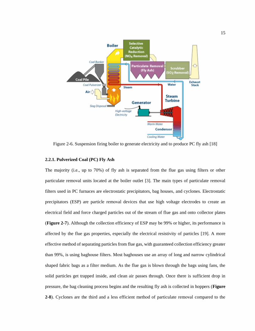
Suspension firing is the most commonly used method for burning coal to generate electricity. In
PC boilers, coal is grinded in mills to a fine powder (e.g., 65% to 85% of the particles passing No.
200 sieve) and then pneumatically transported, with approximately 10% of the combustion air,
through the burners into the furnace. There, the pulverized coal is combusted in suspension, with
continuous mixing of fuel and air (Figure 2-6).
In PC boilers, pulverized coal is combusted at temperatures ranging from 1150°C to
1750°C, depending largely on the coal rank [12]. At such high temperatures, coal undergoes two
main combustion mechanisms of devolatilization (i.e., release of volatile organic constituents in a
matter of milliseconds), and char oxidation (i.e., a series of carbon-oxygen reactions). The latter
reaction is relatively slower and in the order of several seconds. This results in melting of the
majority of mineral impurities (e.g., clays) that are present in the coal. These molten droplets will
subsequently solidify in the flue gas, primarily in the form of alumino-silica glass spheres, which
make up the resulting fly ash. Other main combustion products in a PC boiler include bottom ash,
boiler slag, and flue gas desulfurization (FGD) products. These are introduced in the following
sections.
15
Figure 2-6. Suspension firing boiler to generate electricity and to produce PC fly ash [18]
2.2.1. Pulverized Coal (PC) Fly Ash
The majority (i.e., up to 70%) of fly ash is separated from the flue gas using filters or other
particulate removal units located at the boiler outlet [3]. The main types of particulate removal
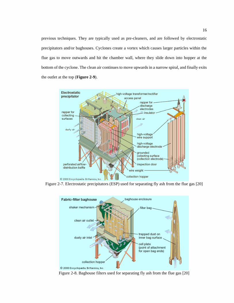
filters used in PC furnaces are electrostatic precipitators, bag houses, and cyclones. Electrostatic
precipitators (ESP) are particle removal devices that use high voltage electrodes to create an
electrical field and force charged particles out of the stream of flue gas and onto collector plates
(Figure 2-7). Although the collection efficiency of ESP may be 99% or higher, its performance is
affected by the flue gas properties, especially the electrical resistivity of particles [19]. A more
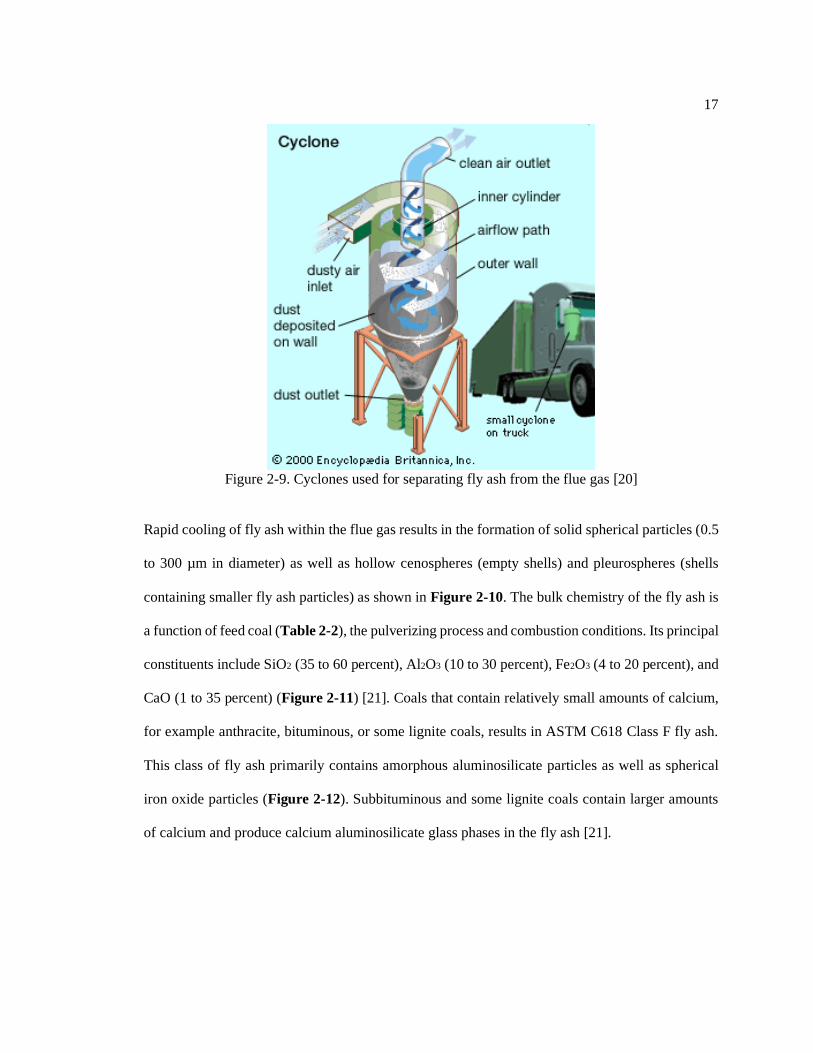
effective method of separating particles from flue gas, with guaranteed collection efficiency greater
than 99%, is using baghouse filters. Most baghouses use an array of long and narrow cylindrical
shaped fabric bags as a filter medium. As the flue gas is blown through the bags using fans, the
solid particles get trapped inside, and clean air passes through. Once there is sufficient drop in
pressure, the bag cleaning process begins and the resulting fly ash is collected in hoppers (Figure
2-8). Cyclones are the third and a less efficient method of particulate removal compared to the
16
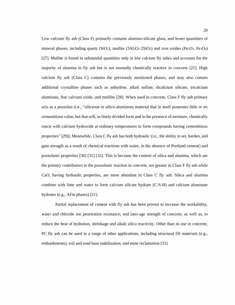
previous techniques. They are typically used as pre-cleaners, and are followed by electrostatic
precipitators and/or baghouses. Cyclones create a vortex which causes larger particles within the
flue gas to move outwards and hit the chamber wall, where they slide down into hopper at the
bottom of the cyclone. The clean air continues to move upwards in a narrow spiral, and finally exits
the outlet at the top (Figure 2-9).
Figure 2-7. Electrostatic precipitators (ESP) used for separating fly ash from the flue gas [20]
Figure 2-8. Baghouse filters used for separating fly ash from the flue gas [20]
17
Figure 2-9. Cyclones used for separating fly ash from the flue gas [20]
Rapid cooling of fly ash within the flue gas results in the formation of solid spherical particles (0.5
to 300 µm in diameter) as well as hollow cenospheres (empty shells) and pleurospheres (shells
containing smaller fly ash particles) as shown in Figure 2-10. The bulk chemistry of the fly ash is
a function of feed coal (Table 2-2), the pulverizing process and combustion conditions. Its principal
constituents include SiO2 (35 to 60 percent), Al2O3 (10 to 30 percent), Fe2O3 (4 to 20 percent), and
CaO (1 to 35 percent) (Figure 2-11) [21]. Coals that contain relatively small amounts of calcium,
for example anthracite, bituminous, or some lignite coals, results in ASTM C618 Class F fly ash.
This class of fly ash primarily contains amorphous aluminosilicate particles as well as spherical
iron oxide particles (Figure 2-12). Subbituminous and some lignite coals contain larger amounts
of calcium and produce calcium aluminosilicate glass phases in the fly ash [21].

18
Figure 2-10. Left: hollow cenosphere fly ash, right: pleurosphere fly ash containing smaller
spheres [22]
Table 2-2. Normal range of chemical composition for fly ash produced from different coal types
(expressed as percent by weight) [23]
Component Bituminous Subbituminous Lignite
SiO2 20-60 40-60 15-45
Al2O3 5-35 20-30 10-25
Fe2O3 10-40 4-10 4-15
CaO 1-12 5-30 15-40
MgO 0-5 1-6 3-10
SO3 0-4 0-2 0-10
Na2O 0-4 0-2 0-6
K2O 0-3 0-4 0-4
LOI 0-15 0-3 0-5
Figure 2-11. CaO–Al2O3–SiO2 ternary diagram of cementitious materials, including Class F and
Class C fly ash [24]

19
Figure 2-12. Cross section of aluminosilicate spheres with fine dispersion of dendritic iron [25]
[26].
For use in concrete, PC fly ash must comply with the requirements of ASTM C618. The chemical
requirements stated by this standard are a maximum SO3 content of 5%, maximum moisture content
of 3%, maximum LOI value of 6%, as well as a minimum SiO2+Al2O3+Fe2O3 content of 70% and
50% for Class F and C fly ash, respectively. The use of Class F fly ash containing up to 12.0% LOI
may be approved by the user if either acceptable performance records or laboratory test results are
made available. With regards to physical requirements, maximum fineness of 34%, minimum
strength activity index (at either 7 or 28 days) of 75%, maximum water requirement of 105%, and
maximum autoclave expansion of 0.8% are required. Some optional requirements such as the
magnitude of drying shrinkage, uniformity requirements regarding the use of air-entraining
admixtures, and sulfate resistance, may also be applied when specifically requested.
According to ASTM C618-19, PC fly ash is classified based on its bulk chemistry as Class
F (when mass fractions of SiO2+Al2O3+Fe2O3>=70%) or Class C (when mass fractions of
SiO2+Al2O3+Fe2O3>=50%). Class C fly ash has greater calcium oxide content than Class F fly ash
(approximately CaO>20). Generally, the higher the content of CaO, the lower SiO2+Al2O3+ Fe2O3,
and the greater the amount of SO3 and alkalis (Na2O and K2O) within the fly ash. Furthermore, LOI
is higher for Class F fly ashes than Class C because of the presence of more unburnt carbon.
20
Low calcium fly ash (Class F) primarily contains alumino-silicate glass, and lesser quantities of
mineral phases, including quartz (SiO2), mullite (3Al2O3·2SiO2) and iron oxides (Fe2O3, Fe3O4)
[27]. Mullite is found in substantial quantities only in low calcium fly ashes and accounts for the
majority of alumina in fly ash but is not normally chemically reactive in concrete [21]. High
calcium fly ash (Class C) contains the previously mentioned phases, and may also contain
additional crystalline phases such as anhydrite, alkali sulfate, dicalcium silicate, tricalcium
aluminate, free calcium oxide, and melilite [28]. When used in concrete, Class F fly ash primary
acts as a pozzolan (i.e., “siliceous or silico-aluminous material that in itself possesses little or no
cementitious value, but that will, in finely divided form and in the presence of moisture, chemically
reacts with calcium hydroxide at ordinary temperatures to form compounds having cementitious
properties” [29]). Meanwhile, Class C fly ash has both hydraulic (i.e., the ability to set, harden, and
gain strength as a result of chemical reactions with water, in the absence of Portland cement) and
pozzolanic properties [30] [31] [32]. This is because the content of silica and alumina, which are
the primary contributors to the pozzolanic reaction in concrete, are greater in Class F fly ash while
CaO, having hydraulic properties, are more abundant in Class C fly ash. Silica and alumina
combine with lime and water to form calcium silicate hydrate (C-S-H) and calcium aluminate
hydrates (e.g., AFm phases) [21].
Partial replacement of cement with fly ash has been proven to increase the workability,
water and chloride ion penetration resistance, and later-age strength of concrete, as well as, to
reduce the heat of hydration, shrinkage and alkali silica reactivity. Other than its use in concrete,
PC fly ash can be used in a range of other applications, including structural fill materials (e.g.,
embankments), soil and road base stabilization, and mine reclamation [31].

21
2.2.2. Other PC Combustion Products
The bottom ash and boiler slag are the un-combusted material that accumulate at the bottom of the
boiler and are fairly similar in composition to fly ash (Figure 2-13). PC boiler units are classified
as either dry bottom or wet bottom, depending on whether the bottom ash is removed in a solid or
molten state. The majority of PC boilers operate with dry bottom units; i.e., they produce bottom
ash. In the wet bottom units, the combustion temperature exceeds that of ash melting point; as such,
they produce boiler slag [32]. Because of the higher content of fly ash in dry bottom furnaces, these
boilers are larger and more expensive than wet bottom furnaces. However, they are simpler to
operate and more flexible with regards to the fuel source [3].
Figure 2-13. PC bottom ash (left) and boiler slag (right) [33]
The bottom ash is quite angular, with a large particle size (usually with 50 to 90 percent passing a
4.75 mm sieve and 0 to 10 percent passing a 0.075 mm sieve) and porous structure. Bottom ash can
be used as fine aggregates in concrete, fill, anti-skid, and sand blasting applications. The porous
structure of bottom ash makes it lighter and less durable than conventional aggregates [34]. If
grinded, bottom ash can also be used as a filler material to partially replace Portland cement in
concrete [31]. As for boiler slag, once the molten slag is quenched with water, it fractures,
crystallizes, and forms pellets. These hard, angular particles have a smooth glassy appearance and

22
can be used as blasting grit and roofing granules, mineral filler in asphalt, fill material for structural
applications, mineral additive in concrete, and snow and ice traction control material. Recently, the
supply of boiler slag has declined due to the shutdown of wet bottom boiler power plants [34].
In addition to particulate matter (i.e., fly ash), other harmful emissions must be prevented
or separated from the flue gas before it is released to the atmosphere. Most importantly, SOx and
Hg must be removed while the formation and emission of NOx, ozone, and lead (Pb) must be
mitigated.
To control SOx emission, lower sulfur coals can be used, the fuel can be cleaned from
sulfur-bearing compounds (e.g., pyrite) prior to combustion, or flue gas desulfurization (FGD) units
can be used after particulate removal units to separate sulfur oxides from flue gas (Figure 2-6).
During combustion, most of the sulfur content in coal is converted to SO2 and a small percentage
is oxidized to SO3 [32]. The Clean Air Act and Amendments of 1990 (1990 CAAA) requires major
reductions in sulfur oxide (SO2) and nitrogen oxides (NOx) emissions, the pollutants that cause acid
rain [3]. That is why most coal combustion facilities which use high-sulfur coals, decided to add
flue-gas scrubbing systems [32]. The most widely used FGD units are the wet scrubbing systems.
In these units, a limestone (CaCO3) or lime (Ca(OH)2) slurry is sprayed onto flue gas to transform
SO2 to sulfite hemi-hydrate (CaSO3.½H2O), which is further oxidized to synthetic gypsum
(CaSO4.2H2O) [32]. This process removes more than 90% of the SO2, however it does not prevent
the majority of SO3 from being released into the atmosphere [32]. Also, CO2 is produced as a by-
product of the limestone calcination. The resulting scrubber sludge can be disposed in slurry ponds,
or is dewatered and landfilled. Where a higher quality synthetic gypsum is produced, it can be used
for Portland cement or wallboard manufacturing [3]. For dewatering, hydrocyclones and vacuum
filters are employed to reduce the moisture content of the slurry to less than 10% [3].
A less common type of FGD units is the dry scrubbing systems, including spray dry
scrubbers and sorbent injection processes [3]. These FGD units are placed before particulate

23
removal units and produce dry FGD products that are collected together, and are as such comingled
with, fly ash. As a consequence, the resulting fly ash has a high sulfur content and is usually
unusable for concrete applications. A particular type of dry scrubber that has recently gained
popularity is the dry sorbent injection (DSI) process. Here, dry hydrated lime or sodium-based
sorbents (e.g., trona) are injected into humidified (~100% RH) flue gas to form sulfites and sulfates
of calcium or sodium. The unused sorbent, FGD products, and fly ash are subsequently collected
in the particulate control units. In this case, the resulting fly ash has high contents of sulfur, calcium,
and/or sodium.
To reduce the amount of NOx in the flue gas, two main approaches can be taken: furnace
combustion modification, which includes the use of low-NOX burners; and ammonia (or urea)
injection with or without catalysts. In the first method, combustion is performed at different stages,
meaning that at certain areas of the furnace, the oxygen level is kept low, and at later stages, air is
added to complete combustion. One of the main challenges of this technique is ensuring complete
fuel combustion whilst limiting the amount of NOx formation [35]. Also, such low oxygen
conditions may increase unburned carbon content and its reactivity in the resulting fly ash. The
carbon (measured as LOI) associated with a low-NOx fly ash has a greater propensity to adsorb
liquid chemical admixtures used in concrete, especially the AEA. This can lead to relatively large
increases in the AEA dosage requirement in concrete [21].
The most common ammonia (or urea) injection technology is the selective catalytic
reduction (SCR) method which reduces the amount of NOX by oxidation/reduction reactions
between ammonia and NOX, in the presence of a catalyst. The main concern with this technique is
the amount of unreacted ammonia (also known as ammonia slip) in fly ash, which may be released
in the form of vapor when in contact with water, causing odor issues. Furthermore, ammonia can
affect the leaching of trace elements in fly ash. However, since most modern SCR systems limit

24
the ammonia slip content to less than 2 ppm, the effect of unreacted ammonia on fly ash
performance in concrete is negligible [35].
The most common technologies for mercury capture, with the least negative impacts on
coal combustion products are: sorbent injection and co-removal with fly ash; and mercury oxidation
and co-removal with FGD solids. Powder activated carbon, referring to the product of heat- and
steam treatment on carbon-based materials, is the most common sorbent for mercury removal. This
highly porous powder can effectively absorb mercury and is later removed from the flue gas along
with fly ash. The captured carbon may adversely affect the properties of fly ash in concrete,
especially with regards to the increased AEA demand. Other sorbents such as specialty activated
carbon and non-carbon are advantageous, since they preserve the quality of fly ash. As for the
mercury oxidization technique, chemical addition (typically using halogen) or the catalysts from
the SCR method are used to oxidize mercury so it can be removed with the FGD solids. Oxidized
mercury is desired since it is soluble and can be removed from the downstream scrubber systems.
This is not the case for elemental mercury, which is in fact the predominant form. Although some
drawbacks of this method are increased mercury and halogen concentrations in the resulting fly
ash, these effects are insignificant compared to that of activated carbon injection [35].
2.3. Fluidized Bed Combustion (FBC) and Its Products
In an attempt to eliminate the need for external emission control units while fulfilling stricter
environmental regulations and enabling the use of coals with high sulfur contents, the fluidized bed
combustion process was developed and commercialized in the 1970s. FBC is a combustion
technology suitable for burning extremely low-grade coal (refuse coal) for power generation, with
the environmental benefit of cleaning up acid mine drainage (AMD)-producing gob piles (piles
built of accumulated waste rock, removed during coal mining, that can leach acid mine water and
25
hazardous substances into water sources). In this method, sulfur-absorbing materials (e.g.,
limestone or dolomite) are added in a powder form to the fuel along with an inert material (e.g.,
sand or ash) inside the boiler. The mixture is fluidized using air jets and combusted at temperatures
ranging from 750°C to 900°C. Fluidization refers to the dynamic fluid-like state of the solid-air
mixture within the furnace, which is caused by the passage of upwards jets of air through the
granular material. The main purpose of the inert material is to improve mixing and heat transfer
among different components, while the sulfur-sorbent is used to minimize SOx emissions in the
flue gas. Depending on the sulfur content of the fuel, the sorbent may comprise up to 50% of the
bed inventory [3]. The temperature of the furnace is high enough to allow calcination of limestone
and combustion of coal [3], but does not result in melting of clays and other mineral matter.
Temperatures are well below the threshold of nitrogen oxidization (i.e., 850 °C), and creation of
thermal NOx [12],[13],[36]. The temperature range is chosen to ensure that the reactions between
SO2 and sorbent are thermodynamically and kinetically balanced [3]. It is worth noting that the low
combustion temperatures of FBC boilers affects their electricity generation capacity. While FBC
powerplants are typically up to 300 MW in size, and can be as high as 400-600 MW, PC power
plants can exceed size of 2000 MW [37].
During the FBC process, initially, limestone is thermally decomposed (calcined per Eq. 2-
1), and porous CaO particles are formed. A significant fraction (approximately 70%-80%) of this
CaO combines with SO2 emissions and CaSO3 (calcium sulfite) is formed (Eq. 2-2) [38]. In the
presence of abundant oxygen, anhydrite (CaSO4) is produced from the oxidization of CaSO3 (Eq.
2-3) [13]. As high as 95% of the sulfur in coal is captured during these reactions.
CaCO3 + heat → CaO + CO2 (Eq. 2-1)
CaO + SO2 → CaSO3(s) (Eq. 2-2)
CaSO3(s) +1/2 O2 → CaSO4(s) (Eq. 2-3)

26
In addition to lower overall SOx and NOx emissions, FBC enables energy efficient combustion and
the use of both high and low-grade coals, as well as partial replacement of coal with biomass.
During the combustion, upwards jets of air cause the solids (pulverized fuel, limestone, and sand)
to be suspended, ensuring the gas and solids mix together turbulently for better heat transfer and
chemical reactivity. In fluidized bed combustion, the solid concentration is significantly greater
than that of PC boilers, and therefore convective heat transfer dominates over radiation [3]. This
significantly reduces the size of FBC furnaces. Furthermore, the elutriation of particles (i.e.,
separation of particles based on their size using a stream of gas or fluid flowing in a direction
usually opposite to the direction of sedimentation) at high velocities yields high amounts of fly ash
(60-80 wt% of the sotal ash produced) versus bottom ash [39][40]. Similar to PC combustion, fly
ash is collected using de-dusting systems such as electrostatic precipitators, cyclones, and bag
filters.
To further increase the gas-solid contact time, the CFBC technology was developed in the
late 1970s as a subcategory of FBC boilers. Its basic concept is using high gas velocities to entrain
a considerable portion of the heavier particles and carry them out of the boiler. The solids are then
separated from the flue gas in one or more recycling cyclones and returned to the combustion bed,
thus preventing unburnt fuel from leaving the furnace (Figure 2-14). This creates a recycling loop
through which fuel particles can pass 10 to 50 times until near-complete combustion is achieved
[41]. The prolonged combustion time also ensures that lower combustion temperatures compared
to conventional FBC and PC boilers can be used. In comparison with conventional FBC, the CFBC
technology allows a better combustion efficiency, smaller combustor size, simpler fuel feed system,
lower SOx and NOx emissions, lower limestone consumption and in turn, lower CaO content in the
ash, and lower unburned carbon and loss-on-ignition (LOI) in the ash [12].
The Pressurized Fluidized Bed Combustion (PFBC) technology, which operates at elevated
pressures (4 to 30 atmospheres) rather than atmospheric conditions, also provides similar benefits

27
as CFBC. In the PFBC process, the CaO in the combustion residue tends to stay in the form of
calcite, rather than in the form of free lime, due to the higher CO2 partial pressure in the combustor
[13]. Therefore, the content of free lime in PFBC ash is significantly lower than that of FBC ash,
and this results in low ettringite formation when the ash is used in concrete [40]. Finally, the
pressurized circulating FBC (PCFBC) is the combination of CFBC and PFBC [3].
Figure 2-14. Schematic of circulating fluidized bed combustion (CFBC) unit [42]
FBC fly ash and bottom ash constitute approximately 13wt.% of the annual 111 million tons of
coal combustion products (CCPs) produced in the United States [43]. Other main CCPs include PC
fly ash (~34wt.%), FGD materials (~47wt.%), bottom ash (~9wt.%), and boiler slag (~2wt.%) [44].
Roughly 60 – 80 % of the total FBC ash is fly ash, the rest being bottom ash. FBC fly ash has a
similar bulk chemistry (with respect to major elements) to conventional PC fly ash, except for the
absence of mullite which is a product of coal combustion at 1500°C [45]. FBC fly ash primarily
contains crystalline and amorphous alumina-silica phases (e.g., calcined clays), quartz, anhydrite,
iron oxide, calcite, and free lime [45]. However, due to the lower combustion temperature of FBC

28
boilers, the ash-forming minerals in coal are not melted but de-hydroxylated (e.g., calcined clays),
resulting in a fly ash with sub-angular particles [46] (Figure 2-15). These particles also have
internal porosity, resulting in up to 5× the surface area of PC fly ash, and this contributes to their
reactively and also increased water demand [27].
Figure 2-15. SEM/EDS images of (left) PC fly ash (right) FBC fly ash [47]
FBC bottom ash is coarser, with lower fixed carbon (i.e. solid combustible residue that remains
after a coal particle is heated and the volatile matter is expelled), and hematite (Fe2O3) content [48]
[49]. Anhydrite is the most abundant crystalline component in FBC ash and its amount in bottom
ash is expected to be higher than that of FBC fly ash [49]. In most cases, the content of SO3 and
free lime is also greater in bottom FBC ash [50]. Some of the applications of FBC ash include
surface and subsurface mine reclamation, soil stabilization, road base, structural fill, and synthetic
aggregate [31] [30]. However, the majority of FBC ash is disposed in dedicated landfills [31].
2.3.1. Hydration Mechanism of FBC Fly Ash in Concrete
FBC fly ash is reported to have self-cementitious properties due to its high contents of f-CaO (free
lime) and SO3 [51], [52], [53], [54], [55], [56], [57], [58], [46], [59], [60], [61]. To increase the
SO2-removal efficiency, the ratio of Ca/S is often increased in the boiler to 2.0–2.5, resulting in
high amounts of unreacted lime and anhydrite remaining in the fly ash [62]. The higher content of

29
f-CaO and SO3 is beneficial to the generation of C–S–H and AFt phases [58], enabling non-Portland
cement concretes with compressive strengths similar to that of Portland cement concrete [57].
Earlier studies have looked at the hydration of FBC fly ash in non-Portland cement mortar
[57] and paste [58], [46], [59], [60], [61] mixtures. They observed X-ray diffraction peaks of AFt,
portlandite, gypsum, calcium silicate hydrate [59], [46], [58], [57], quartz, calcite [57] [61], and
calcium alumino-silicate hydrate [57]. The self-cementitious properties of FBC fly ashes used in
these studies was made possible due to their high CaO (15-45%) and SO3 (5-25%) contents.
FBC fly ash has been shown to contain great amounts of dehydroxylated clays, an abundant
source of both silica (SiO2) and alumina (Al2O3). When calcined clays are used separately as a
partial replacement for Portland cement, the reaction products consist mainly of amorphous calcium
aluminosilicate hydrates (C-A-S-H), and crystalline products such as calcium aluminate hydrates
(C-A-H), C2ASH8, C4AH13 and C3AH6 [63][64]. If carbonation is not restricted, carbo-aluminates
may also be produced [65]. However, reports of C-A-S-H phases among the hydration products of
FBC fly ash has been scares [57]. In the study by Iribarne et al. [57], fragments of mortar beams
(cured for 896 to 1114 days) with 75 wt.% of sand as inert material and 25 wt.% of CFBC fly ash
as binder, were ground and the light fractions (separated by density) were analyzed using XRD.
Minor peaks of various crystalline hydrated Ca-Al silicates (CaAl2(SiO3)4.6H2O and
CaAl2Si10O24.7H2O) were detected. Due to ineffective separation of sand particles, significant
amounts of non-reactive quartz were also observed. Despite the presence of ettringite and
portlandite in previous studies, these hydration products were missing in numerous samples.
Moreover, no AFm species were detected, possibly as a result of the absence of cement in the mix.
Considering that most state DOTs in the U.S. strongly encourage partial replacement of
Portland cement with fly ash or slag, and that the future supply of these pozzolans is not keeping
up with demand, the use of FBC fly ash as a concrete pozzolan merits attention. To safely and
properly use FBC fly ash in concrete, its pozzolanic reaction and other interactions with Portland

30
cement shall be investigated. Identifying and monitoring the reaction products in cement-FBC fly
ash mixtures will be beneficial in understanding the effect of FBC fly ash on the short- and long-
term performance of concrete.
2.3.2. Performance of FBC Fly Ash in Concrete
The use of FBC fly ash in concrete is not without potential challenges, as ASTM C618 [66]
currently excludes FBC fly ash from its scope. Based on the available literature, FBC fly ash may
have high sulfur (SO3), free CaO, and unburned carbon (LOI) contents [67][68]. SO3>5 wt% may
cause flash setting and abnormal expansion at early ages, due to ettringite formation. Similarly,
hydration of free CaO can cause excessive heat and volume instability [31]. The LOI may vary
from a few tenths of percent to more than 10%, and this impacts the workability and air entrainment
performance of concrete mixtures [40],[69],[70],[71].
Studies on the use of FBC fly ash in concrete have been limited, and reported contradictory
results. Havlica et al. [13] showed that mortars containing pressurized FBC ash or conventional
FBC ash can produce similar or better strength in comparison with ordinary Portland cement (OPC)
mortars after only 3 days of hydration. Nguyen et al. [72] studied a high volume fly ash (HVFA)
cement paste and reported improved mechanical properties (compressive strength, dynamic
Young’s modulus, shear modulus, and ultrasonic wave velocity) when up to 5% of Class F fly ash
was replaced with CFBC fly ash. Glinicki et al. [73] showed that CFBC fly ash reacts
pozzolanically with portlandite and also produces a slightly higher quantity of ettringite as a result
of its SO3 content. On the other hand, Gazdič et al. [45] compared the performance of FBC fly ash
to PC fly ash at 15% and 30% cement replacement levels and reported a reduced strength in
mixtures containing FBC fly ash compared to those with PC fly ash or straight OPC. Wu et al. [74]
studied mortars containing Class F and/or CFBC fly ash and reported a reduced 28-day strength,
delayed setting, and length expansion in mortars with CFBC fly ash. The latter was attributed to

31
the higher SO3 content of the CFBC fly ash. Robl et al. [75] reported both an increase and a decrease
in mortar strength with the partial replacement of cement with CFBC fly ash, depending on the
source of cement.
In addition to the contrary results for compressive strength, very little literature is available
on the effect of FBC fly ash on concrete durability. Chi and Huang (2014) [76] evaluated the
performance of concrete mixtures containing Class F fly ash and CFBC fly ash (30% PC + 20%
CFBC, 50% PC + 20% CFBC) against water permeability (CNS 3763), chloride ion penetration
(ASTM C1202), sulfate attack (ASTM C88), and carbonation. The results were compared with
mixtures containing Class F fly ash (50%) and that of the control (100%OPC). Although tertiary
mixtures (containing PC and CFBC fly ash) had the best performance in terms of resistance to
sulfate attack, and water and chloride ion penetration, replacement of cement or Class F fly ash
with CFBC fly ash increased both water and chloride ion permeability. An increase in carbonation
depth was reported with the use of both fly ashes. In another study by Chi and Huang (2014) [77],
the effect of CFBC fly ash (5%, 10% and 15%) on the water absorption (ASTM C642), initial
surface absorption (BS 1881-208), sulfate attack resistance (ASTM C88), compressive strength
(ASTM C39), and splitting tensile strength (ASTM C496) of roller compacted concrete was
investigated. Results showed an adverse effect on water absorption with an increase in CFBC fly
ash content. Low dosages (5%) of CFBC fly ash reduced initial surface absorption and increased
the strength (compressive and tensile), while higher replacement levels (10 and 15%) improved
sulfate resistance. It must be noted that the CFBC fly ash used in both studies contained very high
contents of sulfur and lime (SO3>29, CaO>55), and low amounts of SiO2 and Al2O3, which is not
representative of a typical CFBC fly ash composition. Jóźwiak-Niedźwiedzka [78] reported lower
chloride diffusion coefficient (NordTest Build 492) and higher resistivity for concretes containing
15% and 30% CFBC fly ash. However, 30% replacement of cement with CFBC fly ash increased
the surface scaling of concretes exposed to cycles of freezing and thawing. Similarly, Glinicki and

32
Zielinski [79] showed that the use of 20%, 30%, and 40% CFBC fly ash resulted in a scaling
degradation of concrete. The effect was pronounced with increasing dosages of CFBC fly ash and
its unburned carbon content.
2.3.3. Beneficiation of FBC Fly Ash
Currently, no techniques have been specifically aimed at reducing or modifying the unburned
carbon content in FBC fly ash in order to prevent its interference with the air-entraining admixtures
in concrete. Earlier studies have investigated the use of screening (dry sieving), hydraulic
classification (wet sieving), mechanical activation (grinding), chemical activation, and
prehydration of CFBC fly ash to improve the compressive strength and/or volumetric expansion of
concrete mixtures. Robl et al. [27] showed that hydraulic classification and screening (75 μm) of
CFBC fly ash can help remove coarser size fractions and improve its performance in mortar in
terms of compressive strength. The French patented CERCHAR technology [31] was used to pre-
hydrate lime in FBC fly ash, whilst preventing the conversion of anhydrite to gypsum and ettringite.
This method was able to significantly reduce the CaO content from 13% to 0.5%, but had slight
negative effects on LOI, compressive strength, and permeability. The Polish company named
Energomar-Nord, Ltd. [80] used mechanical activation (grinding) of fly ash to improve the
compressive strength of concrete. Li et al. [46] showed that the combination of grinding and
chemical activation (1% alkali-activated activators, and/or 0.8% mixture of naphthalene-based
water reducer with adjustable solidification agent) of fly ash had the best effect in improving the
pozzolanic reactivity index of CFBC fly ash, while reducing its water requirement. Zhai et al. [67]
also reported a reduction in particle angularity and water requirement (over 10%) of CFBC fly ash,
with increased grinding time. However, this process increased the amount of f-CaO content by up
to 25%. The CaO present in CFBC fly ash is in the form packed with CaSO4 and grinding can help
crush the CaSO4 layer, releasing CaO.

33
Some of the popular techniques for the removal or modification of unburned carbon from PC fly
ash include size separation, electrostatic separation, froth flotation, oil agglomeration, chemical
passivation and thermal processing [81]. Considering that most of these methods have been
commercialized for PC fly ash, it is beneficial to investigate their effectiveness for high LOI FBC
fly ash.
2.4. References
[1] U.S. electricity generation by energy source, U.S. Energy Inf. Adm. Available at:
https://www.eia.gov/tools/faqs/faq.php?id=427&t=3. Accessed: July 2019.
[2] Annual Energy Outlook 2018 (AEO), U.S. Energy Inf. Adm. Available at:
https://www.eia.gov/pressroom/presentations/Capuano_02052018.pdf. Accessed: July
2019.
[3] B.G. Miller, Clean coal engineering technology, Elsevier Inc. (2011).
[4] Electricity, U.S Energy Inf. Adm. (Eia)-Independent Statics Anal. Available at:
https://www.eia.gov/electricity/. Accessed: July 2019.
[5] The story of coal, Available at: https://byjus.com/chemistry/coal-story/ Accessed: July
2019.
[6] I. Barnes, L. Sear, Ash utilization from coal-based power plants, DTI, (2004).
[7] Coal, West. Oregon Univ. Available at:
https://www.wou.edu/las/physci/GS361/Fossil%20fuels/Coal.htm. Accessed: July 2019.
[8] X. Shen, Coal combustion and combustion products, Coal, Oil Shale, Nat. Bitumen, Heavy
Oil Peat. I (2009).
[9] USGS, Assessing U.S. coal resources and reserves, Available at:
https://pubs.usgs.gov/fs/2017/3067/fs20173067.pdf. Accessed: July 2019.
[10] Abandoned coal mine drainage projects in Pennsylvania, Available at:
http://www.ei.lehigh.edu/envirosci/enviroissue/amd/links/Pa_projects.html. Accessed: July
2019.
[11] Types of coal, U.S. Energy Inf. Adm. Available at:
https://www.eia.gov/energyexplained/print.php?page=coal_home. Accessed: July 2019.
[12] S. Rajaram, Next generation CFBC, Chem. Eng. Sci. 54 (1999) 5565–5571.

34
[13] J. Havlica, J. Brandstetr, I. Odler, Possibilities of utilizing solid residues from pressured
fluidized bed coal combustion (PSBC) for the production of blended cements, Cem. Concr.
Res. 28 (1998) 299–307.
[14] S.N. Oka, Fluidized bed combustion, Marcel Dekker, Inc, (2004). Available at:
http://sv.20file.org/up1/887_0.pdf. Accessed: July 2019.
[15] ARIPPA, Available at: http://arippa.org/. Accessed: July 2019.
[16] Available and emerging technologies for reducing greenhouse gas emissions from coal-fired
electric generating units, (2010), Available at:
https://www.epa.gov/sites/production/files/2015-12/documents/electricgeneration.pdf.
Accessed: July 2019.
[17] A. Minchener, Fluidized bed combustion systems for power generation and other industrial
applications, J. Power Energy. 217 (2003) 9–18.
[18] PARTHA DAS SHARMA’s Weblog on “Keeping World Environment Safer and Greener,”
Available at: https://saferenvironment.wordpress.com/posts/page/5/. Accessed: July 2019.
[19] N. Noda, H. Makino, Influence of operating temperature on performance of electrostatic
precipitator for pulverized coal combustion boiler, Adv. Powder Technol. 21 (2010) 495–
499.
[20] Air pollution control, Encycl. Br. Available at: https://www.britannica.com/technology/air-
pollution-control. Accessed: July 2019.
[21] ACI 232.2R, Report on the Use of Fly Ash in Concrete, Draft Rep. under Revis. Am. Concr.
Inst. (2016).
[22] X.S. Shi, F.G. Collins, X.L. Zhao, Q.Y. Wang, Mechanical properties and microstructure
analysis of fly ash geopolymeric recycled concrete, J. Hazard. Mater. 237–238 (2012) 20–
29.
[23] User guidelines for waste and byproduct materials in pavement construction-coal fly ash,
Fed. Highw. Adm. Res. Technol. Available at:
https://www.fhwa.dot.gov/publications/research/infrastructure/structures/97148/intro.cfm.
Accessed: July 2019.
[24] B. Lothenbach, K. Scrivener, R.D. Hooton, Supplementary cementitious materials, Cem.
Concr. Res. 41 (2011) 1244–1256.
[25] W.D.A. Rickard, R. Williams, J. Temuujin, A. Van Riessen, Assessing the suitability of
three Australian fly ashes as an aluminosilicate source for geopolymers in high temperature
applications, Mater. Sci. Eng. A. 528 (2011) 3390–3397.
[26] C. V Ly, D.C. Southam, Determining the reactivity of a fly ash for production of
geopolymer, J. Am. Ceram. Soc. 92 (2009) 881–887.
35
[27] T. Robl, K. Mahboub, W. Stevens, R. Rathbone, Fluidized bed combustion ash utilization:
CFBC fly ash as a pozzolanic additive to Portland cement concrete., in: Second Int. Conf.
Sustain. Constr. Mater. Technol., Ancona, Italy, (2010).
[28] G.J. Mccarthy, K.D. Swanson, L.P. Keller, W.C. Blatter, Mineralogy of western fly ash,
Cem. Concr. Res. 14 (1984) 471–478.
[29] 232.2R-03: Use of fly Ash in concrete, Am. Concr. Inst, (2003).
[30] H. Feuerborn, E. Coal, C. Products, Coal ash utilisation over the world and in Europe, in:
Work. Environ. Heal. Asp. Coal Ash Util., Tel-Aviv, Israel, (2005).
[31] B. Will, S. Thomas, K. Mahboub, The cementitious and pozzolanic properties of fluidized
bed combustion fly ash, in: 2009 World Coal Ash Conf., Lexington, KY, USA, (2009).
[32] K.S. Sajwan, I. Twardowska, T. Punshon, A.K. Alva, Coal combustion byproducts and
environmental issues, Springer, New York, (2006).
[33] What are CCP?, Am. Coal Ash Assoc. Available at: https://www.acaa-
usa.org/AboutCoalAsh/WhatareCCPs/BoilerSlag.aspx. Accessed: July 2019.
[34] Boiler slag, Am. Coal Ash Assoc, Available at: https://www.acaa-
usa.org/aboutcoalash/whatareccps/boilerslag.aspx. Accessed: July 2019.
[35] K.J. Ladwig, G.M. Blythe, Flue-gas desulfurization products and other air emissions
controls, Coal Combust. Prod. (2017) 67–95.
[36] X. Li, Q. Chen, B. Ma, J. Huang, S. Jian, B. Wu, Utilization of modified CFBC
desulfurization ash as an admixture in blended cements: Physico-mechanical and hydration
characteristics, Fuel. 102 (2012) 674–680.
[37] C. Yin, Biomass co-firing, Biomass Combust. Sci. Technol. Eng., (2013) 84–105.
[38] E.J. Anthony, L. Jia, M. Caris, F. Preto, S. Burwell, An examination of the exothermic
nature of fluidized bed combustion (FBC) residues, Waste Manag. 19 (1999) 293–305.
[39] W. Roszczynialski, W. Nocuń-Wczelik, Studies of cementitious systems with new
generation by-products from fluidized bed combustion, J. Therm. Anal. Calorim. 77 (2004)
151–158.
[40] J. Brandštetr, J. Havlica, Phase composition of solid residues of fluidized bed coal
combustion, quality tests, and application possibilities, Chem. Pap. 50 (1996) 188–194.
[41] I. Barnes, Application of circulating fluidized bed combustion with low-rank Asian coals,
Cornerstone, Off. J. World Coal Ind, Available at: http://cornerstonemag.net/application-
of-circulating-fluidized-bed-combustion-with-low-rank-asian-coals/. Accessed: July 2019.
[42] Fluidized bed combustion technology, Available at: http://www.cfbworks.com/service/.
Accessed: July 2019.
36
[43] L. Ruhi, G.S. Dwyer, G. Schwartz, A. Romanski, S.D. Smith, N. Carolina, U. States, The
impact of coal combustion residue effluent on water resources: A North Carolina example,
Environ. Sci. Technol. 46 (2012) 12226–12233.
[44] American Coal Ash Association (ACAA), coal combustion products production and use
survey report, (2017). Available at: https://www.acaa-usa.org/Portals/9/Files/PDFs/2017-
Survey-Results.pdf. Accessed: July 2019.
[45] D. Gazdič, M. Fridrichová, K. Kulísek, L. Vehovská, The potential use of the FBC ash for
the preparation of blended cements, Procedia Eng. 180 (2017) 1298–1305.
[46] X. Li, Q. Chen, K. Huang, B. Ma, B. Wu, Cementitious properties and hydration mechanism
of circulating fluidized bed combustion (CFBC) desulfurization ashes, Constr. Build. Mater.
36 (2012) 182–187.
[47] N.T. Plaks, A.M. Palomino, A.M. Asce, B.E. Scheetz, G.D. Braun, A.M. Asce, Testing
framework for analysis of time-dependent behavior of coal combustion products, J. Mater.
Civ. Eng. 28 (2016) 1–9.
[48] Y. Jung, D. Park, Fluidized bed combustion of high ash anthracite analysis of combustion
efficiency and particle size distribution, Korean J. Chem. Eng. 5 (1988) 109–115.
[49] P. Sulovsk, Mineralogy and chemistry of conventional and fluidised bed coal ashes, Bull.
Czech Geol. Surv. 77 (2002) 1–11.
[50] R.B. Jewell, R.F. Rathbone, T.L. Robl, K.S. Cement, C. Phases, F.B.C. Ash, The
Fabrication of value added cement products from circulating fluidized bed combustion ash,
in: 2007 World Coal Ash Conf., May 7-10, Northern Kentucky, USA, (2007).
[51] E.E. Berry, E.J. Anthony, Evaluation of potential uses of AFBC solid wastes, MRS Online
Proc. Libr. Arch. 86 (1987) 353–364.
[52] A. Bland, C. Jones, J. Rose, J. Harness, Performance characteristics of concrete produced
with fluidized bed combustion ash residue, in: MRS Proceedings, 136 (1988) 136-23.
[53] I. Odler, K.H. Zysk, Hydraulic properties of fluidized bed combustion ashes, MRS Online
Proc. Libr. Arch. 178 (1989) 189–196.
[54] J.K. Solem, G.J. McCarthy, Hydration reactions and ettringite formation in selected
cementitious coal conversion by-products, MRS Online Proc. Libr. Arch. 245 (1992) 71–
79.
[55] E.J. Anthony, A.P. Iribarne, J.V. Iribarne, Study of hydration during curing of residues from
coal combustion with limestone addition, J. Energy Resour. Technol. 119 (1997) 89–95.
[56] A. Weinberg, R. Hemmings, Hydration and weathering reactions in by-products from clean
coal technologies: effects on material properties, Fuel. 76 (1997) 705–709.

37
[57] J. Iribarne, A. Iribarne, J. Blondin, E.J. Anthony, Hydration of combustion ashes - a
chemical and physical study, Fuel. 80 (2001) 773–784.
[58] G. Sheng, Q. Li, J. Zhai, F. Li, Self-cementitious properties of fly ashes from CFBC boilers
co-firing coal and high-sulphur petroleum coke, Cem. Concr. Res. 37 (2007) 871–876.
[59] G. Sheng, Q. Li, J. Zhai, Investigation on the hydration of CFBC fly ash, Fuel. 98 (2012)
61–66.
[60] E.J. Anthony, E.M. Bulewicz, K. Dudek, A. Kozak, The long term behaviour of CFBC ash
– water systems, Waste Manag. 22 (2002) 99–111.
[61] S. Lee, G. Kim, Self-cementitious hydration of circulating fluidized bed combustion fly ash,
J. Korean Ceram. Soc. 54 (2017) 128–136.
[62] E.J. Anthony, D.L. Granatstein, Sulfation phenomena in fluidized bed combustion systems,
Prog. Energy Combust. Sci. 27 (2001) 215–236.
[63] P.S. De Silva, F.P. Glasser, Hydration of cements based on metakaolin: thermochemistry,
Adv. Cem. Res. 3 (1990) 167–177.
[64] A. Dunster, J. Parsonage, M.J. Thomas, The pozzolanic reaction of metakaolinite and its
effects on Portland cement hydration, J. Mater. Sci. 28 (1993) 1345–1350.
[65] B.B. Sabir, S. Wild, J. Bai, Metakaolin and calcined clays as pozzolans for concrete: a
review, Cem. Concr. Compos. 23 (2001) 441–454.
[66] Astm, Standard Specification for Coal Fly Ash and Raw or Calcined Natural Pozzolan for
Use, Annu. B. ASTM Stand. (2010) 3–6.
[67] X. Fu, Q. Li, J. Zhai, G. Sheng, F. Li, The physical – chemical characterization of
mechanically-treated CFBC fly ash, Cem. Concr. Compos. 30 (2008) 220–226.
[68] R. Kobylecki, Unburned carbon in the circulating fluidized bed boiler fly ash, Chem.
Process Eng. 32 (2011) 255–266.
[69] R.L. Hill, R.F. Rathbone, J.C. Hower, An examination of fly ash carbon and its interactions
with air entraining agent, Cem. Concr. Res. 27 (1997) 193–204.
[70] Y. Gao, H. Shim, R.H. Hurt, E.M. Suuberg, N.Y.C. Yang, Effects of carbon on air
entrainment in fly ash concrete: The role of soot and carbon black, Energy & Fuels. 11
(1997) 457–462.
[71] J. Paya, J. Monzo, M. V. Borrachero, E. Perris, F. Amahjour, Thermogravimetric methods
for determining carbon content in fly ashes, Cem. Concr. Res. 28 (1998) 675–686.
[72] H. Nguyen, T. Chang, J. Shih, C. Chen, T. Nguyen, Influence of circulating fluidized bed
combustion (CFBC) fly ash on properties of modified high volume low calcium fly ash
(HVFA) cement paste, Constr. Build. Mater. 91 (2015) 208–215.

38
[73] M.A. Glinicki, M. Zieliński, The influence of CFBC fly ash addition on phase composition
of air-entrained concrete, Bull. POLISH Acad. Sci. 56 (2008).
[74] T. Wu, M. Chi, R. Huang, Characteristics of CFBC fly ash and properties of cement-based
composites with CFBC fly ash and coal-fired fly ash, Constr. Build. Mater. 66 (2014) 172–
180.
[75] T. Robl, A. Oberlink, J. Brien, J. Pagnotti, The utilization potential of anthracite CFBC
spent bed fly ash as a concrete additive, in: World Pf Coal Ash Conf., Denver, USA, (2011).
[76] M. Chi, R. Huang, Durability performance of concrete containing CFBC fly ash and coal-
fired fly ash, Appl. Mech. Mater. 627 (2014) 283–287.
[77] M. Chi, R. Huang, Effect of circulating fluidized bed combustion ash on the properties of
roller compacted concrete, Cem. Concr. Compos. 45 (2014) 148–156.
[78] D. Jóźwiak-Niedźwiedzka, Effect of fluidized bed combustion fly ash on the chloride
resistance and scaling resistance of concrete, Concr. Aggress. Aqueous Environ.
Performance, Test. Model. 2. 5 (2009).
[79] M.A. Glinicki, M. Zielinski, Frost salt scaling resistance of concrete containing CFBC fly
ash, Mater. Struct. 42 (2009) 993–1002.
[80] K. Ziarkowska, Flubet ® – Improving the world’s environment, Available at:
http://www.energomar-nord.com.pl/en_aktywacja_mechaniczna.html. Accessed: July
2019.
[81] J.C. Hower, J.G. Groppo, U.M. Graham, C.R. Ward, I.J. Kostova, M.M. Maroto-Valer, S.
Dai, Coal-derived unburned carbons in fly ash: A review, Int. J. Coal Geol. 179 (2017) 11–
27.

Chapter 3
Characterization of Circulating Fluidized Bed Combustion (CFBC) Fly Ash
and Its Performance in Concrete1
3.1. Abstract
Concerns over the availability and quality of conventional fly ash for use in concrete has become
widespread in recent years. Fluidized bed combustion ash, with its annual U.S. production
exceeding 14 million tons, could serve as a reasonable alternative. In this study, two
compositionally-different fly ashes from CFBC power plants were evaluated for their compliance
with ASTM C618 standard and their impact on the fresh and hardened properties of concrete. The
pozzolanic reactivity of the fly ashes was also quantified based on the emerging RILEM test
method. These fly ashes met the chemical and physical requirements of ASTM, except for elevated
LOI (in both fly ashes) and elevated SO3 (in one fly ash). Despite this, concrete with proper slump,
air content, and strength development could be produced by proper dosing of chemical admixtures.
The elevated SO3 was found not to produce deleterious expansions.
1 Accepted for publication in the ACI Materials Journal- Pozzolans Special Edition (July 2019).

40
3.2 Introduction
FBC fly ash is a potentially valuable pozzolan that is available at little cost and in large volumes.
It is currently a landfilled material. Given the recent shortage in the availability of conventional PC
fly ash [1],[2],[3], it is logical to methodically research the composition, structure, and properties
of FBC fly ash to determine which fly ash compositions may be usable as concrete pozzolan. Proper
characterization of FBC fly ash and its performance in concrete can facilitate development of
specifications and guidelines for evaluation, beneficiation, and use of this potentially valuable
pozzolanic material.
To address objective 1 of this research (as elaborated on in Chapter 1), two different
CFBC coal fly ashes were evaluated for their compliance against ASTM C618 (equivalent to
AASHTO M295) standard and their impact on the fresh and hardened properties of concrete. This
is the first study in its kind to present a complete evaluation of the physical, chemical, and
mineralogical properties of CFBC fly ashes produced in the United States and to link these
properties with important characteristics of concrete beyond strength development. The fly ashes
were sourced from two CFBC power plants in Pennsylvania that use anthracite or bituminous refuse
coal as a fuel source. These power plants generate over 2.0 million tons of CFBC fly ash per year.
3.3 Experimental Procedures
Two sources of CFBC fly ash, byproducts of anthracite and bituminous refuse coal combustion,
were acquired, homogenized, and characterized for their physical properties, bulk chemistry,
mineralogy, and pozzolanic reactivity. Areas of noncompliance with ASTM C618-19 were
identified. Further, the performance of these fly ashes in mortar and concrete mixtures was
evaluated by measuring the fresh properties (slump and fresh air content), and hardened properties

41
(strength development, hardened air structure, autogenous expansion, and ASR mitigation
efficiency) of these mixtures.
3.3.1 Physical Properties and Unburned Carbon
Both CFBC fly ashes were characterized for their as-received moisture content (ASTM C311-17),
particle size distribution (PSD using laser diffraction), fineness (ASTM C430-17), density (using
helium pycnometer), particle shape/agglomeration (via SEM), water requirement (ASTM C311-
17), soundness (ASTM C151-18), loss on ignition (ASTM C311-17), and carbon and sulfur
contents (using infrared LECO analyzer). Two samples were tested per fly ash for each of the above
tests (excluding the water requirement which was based on one sample). The results are reported
as the average of the two samples. To achieve proper fineness, the anthracite CFBC fly ash passing
#140 sieve was used in all tests. The bituminous CFBC fly ash was tested as received.
The SEM samples were prepared using a mixture of low-viscosity epoxy and fly ash (1-1
mass ratio) embedded in a molded epoxy disk, 25 mm diameter and 12.5 mm height, using a
protocol similar to [4]. The samples were polished down to 0.25 μm, and carbon coated before
imaging. Thermo Scientific™ Q250 Analytical SEM was used and operated at 10-4 mmHg, 15kV
accelerating voltage, and ~10 mm working distance. Backscattered electron (BSE) images were
obtained at 1000× magnification. Laser diffraction PSD testing was conducted by measuring the
angular variation in the intensity of light scattered as a laser beam passed through a well dispersed
sample of fly ash in water. A small amount (~0.03 g) of fly ash was added to distilled water and
the sample was sonicated for 1 min before PSD testing. The particle size distribution was computed
using a refractive index of 1.6 and absorption coefficient of 1.0, as reported by [5]. In addition to
the standard LOI test, infrared spectroscopy using a Leco analyzer was used to measure the total
carbon (organic and inorganic) and sulfur contents in each fly ash. In this technique, the sample
42
was combusted in air up to 1450oC inside the furnace, and the emitted CO2 and SO2 gases were
measured separately using infrared detectors.
3.3.2 Bulk Chemistry and Mineralogy
X-ray fluorescence (XRF) analysis was conducted on fly ash samples to determine their bulk
chemistry. Homogenous fused glass beads were prepared by heating a mixture of fly ash and
lithium borate (flux) to 1000oC. XRD with Rietveld refinement was performed to identify and
quantify the mineral and amorphous phases present in each fly ash. Fly ash samples were ground
to less than #400 sieve, mixed with 15% internal standard (highly crystalline ZnO), and placed on
spinner stage rotating at 4 rev/s. The incident X-ray beam was Cu Kα radiation (λ=1.5419 Å)
produced using 45 kV and 40 mA. Incident settings were: 0.125o divergence slit, 0.25o anti-scatter
slit, 0.04rad. Söller slits, and 15 mm beam mask. Diffracted settings were: 0.125o receiving slit,
0.04rad. Söller slits, and 0.02 mm nickel filter. Diffraction patterns were collected over the range 5-
70o 2θ with step size of 0.02o, for a total scan time of ~30 min. A PIXcel detector in scanning line
mode was used.
To monitor the dissolution rate of soluble species from CFBC fly ash into concrete pore
solution, batch leaching tests were carried out. Of special interest was the solubility of sulfur
compounds (e.g., anhydrite), which can lead to formation of ettringite and potential undesirable
setting or expansion. In the leaching test, CFBC fly ash was exposed to synthetic concrete pore
solution. The concentrations of S, Si, Al, Ca, Na, and K in the solution were measured at 1, 3, and
7 days of exposure. The results were compared with the concentrations obtained from the leaching
test of type I/II Portland cement (with composition reported in Table 3-5). The synthetic pore
solution was prepared by mixing 0.2 mol/L NaOH and 0.5 mol/L KOH with saturated lime water
to reach a pH of 13.85. Next, fly ash or Portland cement was added to the synthetic pore solution
at a mass ratio of 1:20, and the resulting solution was tumbled for 100 h. Solution samples were

43
taken at 1, 3, and 7 days of exposure, filtered (using 0.2 μm polypropylene membrane filter) and
tested using Inductively Coupled Plasma-Atomic Emission Spectroscopy (ICP-AES) to measure
the concentrations of various elements. The chemistry and mineralogy experiments were not
duplicated.
3.3.3. Pozzolanic Reactivity
The strength activity index (SAI) of the two fly ashes were measured according to ASTM C311-
17 and after 7, 28, and 56 days of curing in a lime water bath. The control mortar mixture was
prepared with w/cm=0.484 and sand/cement=2.75 by mass, using type I/II Portland cement (Table
3-5) and standard sand with absorption capacity of 0.58%. In the test mixtures, 20% of the mass of
cement was replaced with the anthracite or bituminous CFBC fly ash, and enough water was added
to reach a flow 5% of the control mortar (measured according to ASTM C1437-15). This resulted
in a net increase of the w/cm to 0.53 in mortars containing fly ash. To eliminate the effect of the
increased w/cm on the compressive strength of mortars, a second series of mortar samples were
prepared, where the w/cm was kept constant between the test and control mixtures, and enough
superplasticizer (Master Glenium 7620) was added to the test mixtures to maintain a flow of 5%
of the control mixture. For both the SAI and mortar strength experiments, three cubes were tested
at a given age.
In addition, two test methods were adopted for measuring the pozzolanic reactivity of fly
ash; ASTM C593-06 (Standard Specification for Fly Ash and Other Pozzolans for Use with Lime
for Soil Stabilization) and RILEM TC TRM267 (Tests for Reactivity of Supplementary
Cementitious Materials). According to ASTM C593-06, lime-fly ash mortars were tested for their
compressive strength. The mixture design is provided in Table 3-1, where sufficient water was
added to produce an ASTM C1437 flow of 65 to 75 %, using 10 drops of the flow table in 6 seconds.
Three 50 mm cube specimens were prepared for strength measurement at each age (7 and 28 days).

44
After casting, the samples were steam cured at 54°C for 7 days, followed by demolding and storing
at 23°C and 95%RH until the time of testing.
According to RILEM TC TRM267, lime-fly ash pastes were prepared with proportions provided
in Table 3-2, using Ca(OH)2/pozzolan mass ratio of 3.0, and a water/binder mass ratio of 1.2.
Soluble alkalis were added to reproduce the cement pore solution pH and accelerate the pozzolanic
reaction, while potassium sulfate and calcium carbonate were added to promote the formation of
AFt (ettringite) and AFm phases. The pastes were hand mixed, poured into cylindrical molds (25.4
mm diameter and 20 mm height), sealed, and cured at 40°C to accelerate the pozzolanic reaction.
After 1, 7, and 28 days, samples were demolded and ground using a mortar and pestle. To stop the
hydration reactions, ground samples were immersed in 100 mL isopropanol for 15 min. The
suspension was stirred and poured over a Büchner filter. The residue was dried in a ventilated oven
at 40°C for 8 min. TGA testing was conducted by heating the resulting samples from 30°C to
950°C, at the rate of 10°C /min. The TGA chamber was purged with N2. The unreacted Ca(OH)2
content of each sample was calculated by measuring the mass loss in the temperature range 375°C
to 480°C using the tangent method proposed by Kim and Olek [6], and correcting the results based
on an estimated mass of carbonated Ca(OH)2. The reported results (Figure 3-6) correspond to the
testing of one sample per fly ash at a given age. In addition, RILEM TC TRM267 suggests
measuring the bound water of the paste at 7 days using the “oven method”. According to this
procedure, paste samples were ground using a mortar and pestle, and dried in an oven at 105oC to
constant mass. Next, samples were calcined at 350oC for 2 hours, and the mass loss between 105oC
Table 3-1. Lime-fly ash mortar mixture design and properties (ASTM C593-06)
Sample Fly ash
(g)
Hydrated
lime (g)
Standard
Sand (g)
Water
(g) w/b
Flow
(%)
Strength (MPa)
7 days 28 days
Anthracite
CFBC 360 180 1480 421.5 0.78 65 6.73 6.13
Bituminous
CFBC 360 180 1480 388.8 0.72 67.5 12.12 10.62
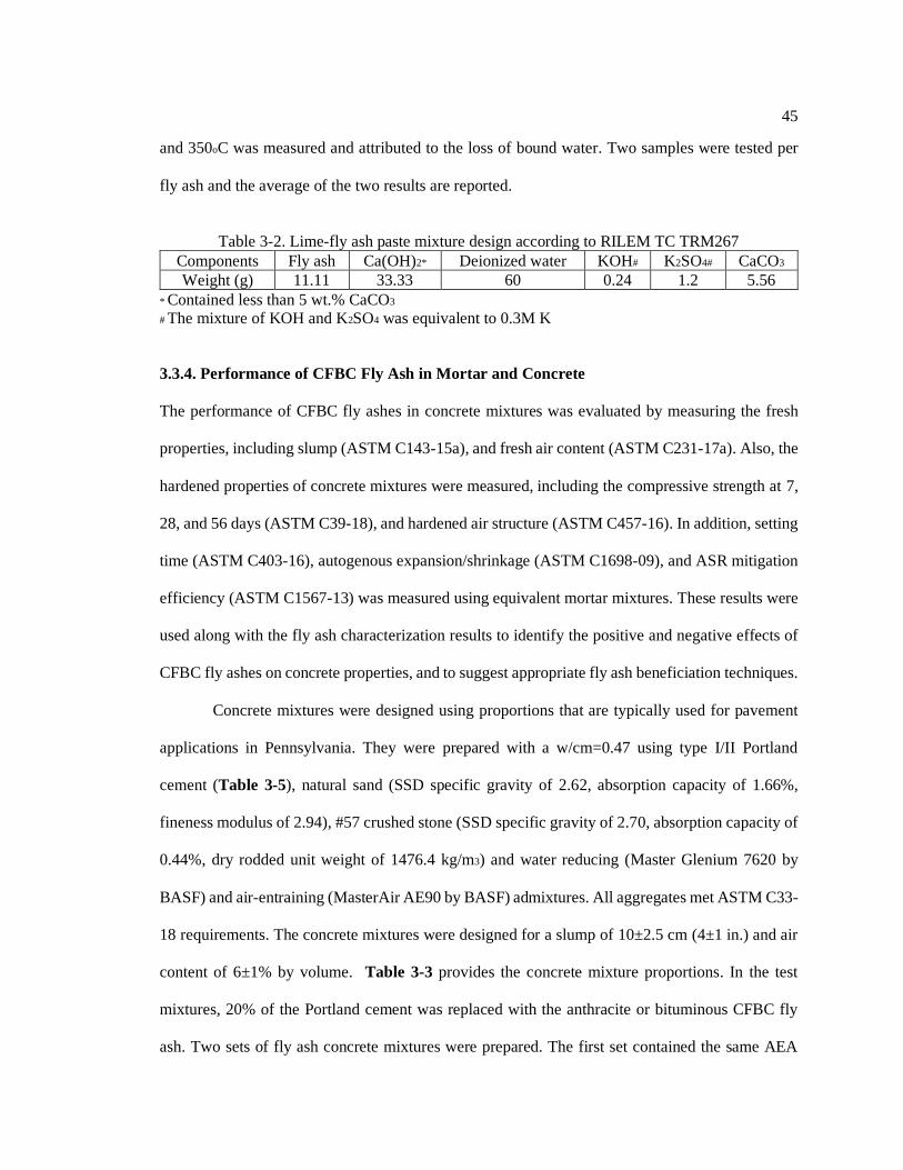
45
and 350oC was measured and attributed to the loss of bound water. Two samples were tested per
fly ash and the average of the two results are reported.
Table 3-2. Lime-fly ash paste mixture design according to RILEM TC TRM267
Components Fly ash Ca(OH)2* Deionized water KOH# K2SO4# CaCO3
Weight (g) 11.11 33.33 60 0.24 1.2 5.56
* Contained less than 5 wt.% CaCO3
# The mixture of KOH and K2SO4 was equivalent to 0.3M K
3.3.4. Performance of CFBC Fly Ash in Mortar and Concrete
The performance of CFBC fly ashes in concrete mixtures was evaluated by measuring the fresh
properties, including slump (ASTM C143-15a), and fresh air content (ASTM C231-17a). Also, the
hardened properties of concrete mixtures were measured, including the compressive strength at 7,
28, and 56 days (ASTM C39-18), and hardened air structure (ASTM C457-16). In addition, setting
time (ASTM C403-16), autogenous expansion/shrinkage (ASTM C1698-09), and ASR mitigation
efficiency (ASTM C1567-13) was measured using equivalent mortar mixtures. These results were
used along with the fly ash characterization results to identify the positive and negative effects of
CFBC fly ashes on concrete properties, and to suggest appropriate fly ash beneficiation techniques.
Concrete mixtures were designed using proportions that are typically used for pavement
applications in Pennsylvania. They were prepared with a w/cm=0.47 using type I/II Portland
cement (Table 3-5), natural sand (SSD specific gravity of 2.62, absorption capacity of 1.66%,
fineness modulus of 2.94), #57 crushed stone (SSD specific gravity of 2.70, absorption capacity of
0.44%, dry rodded unit weight of 1476.4 kg/m3) and water reducing (Master Glenium 7620 by
BASF) and air-entraining (MasterAir AE90 by BASF) admixtures. All aggregates met ASTM C33-
18 requirements. The concrete mixtures were designed for a slump of 10±2.5 cm (4±1 in.) and air
content of 6±1% by volume. Table 3-3 provides the concrete mixture proportions. In the test
mixtures, 20% of the Portland cement was replaced with the anthracite or bituminous CFBC fly
ash. Two sets of fly ash concrete mixtures were prepared. The first set contained the same AEA

46
and water reducing admixture (WRA) dosage as that of the control mixture. Generally, these test
mixtures resulted in lower slump and lower air content as described later. In the second set, the
AEA and WRA dosages were varied to achieve the target slump (10±2.5 cm) and target air content
(6±1%) in the fly ash mixtures. For each of the five mixtures, 10 concrete cylinders (diameter of
100 mm and height of 200 mm) were cast and moist cured at 23oC and 100% RH. For each mixture,
after 28 days of hydration, a 100×120×10 mm section was cut (perpendicular to the finished
surface) from the center of a concrete cylinder, and analyzed for hardened air void distribution. The
remaining nine samples per mixture were used for compressive strength testing at 7, 28, and 56
days of age. Three samples were tested at each given age.
Table 3-3. Mixture designs to evaluate the effect of CFBC fly ashes on concrete properties
Mixture Cement
(kg/m3)
Fly ash
(kg/m3)
Water
(kg/m3)
Coarse
aggregate
(kg/m3)
Fine
aggregate
(kg/m3)
AEA
(kg/m3)
WRA
(kg/m3)
Control 362 - 170 1098 643 0.47 0
Anthracite
CFBC, set 1 290 72 170 1098 639 0.47 0
Bituminous
CFBC, set 1 290 72 170 1098 640 0.47 0
Anthracite
CFBC, set 2 290 72 170 1098 639 0.94 1.40
Bituminous
CFBC, set 2 290 72 170 1098 640 0.47 0.88
Equivalent mortar mixtures were prepared with w/cm=0.47 and sand/cm=2.25. In the test mixtures,
enough superplasticizer (Master Glenium 7620 by BASF) was added to achieve a flow of the
control mix 5%. For autogenous shrinkage testing, the freshly made mortar was poured into
sealable corrugated plastic tubes (length of 420 mm and outer diameter of 29 mm) and continuously
rotated for the first 24 hours at 23oC and 50% RH. For each mixture, four samples were prepared.
The length and mass of each sample were recorded at the time of final setting and at ages of 1, 3,
5, 7, 9, 11, 13, and 15 days. This test was conducted to capture both shrinkage and expansion strains
that may occur in mixtures containing CFBC fly ash. To investigate the ASR mitigation capacity

47
of CFBC fly ashes, mortar bars were prepared and tested according to ASTM C1567-13. These
mortars contained a borderline moderately-reactive/highly-reactive river sand (class R1/R2
according to ASTM C1778-16) with SSD specific gravity 2.52 and an absorption capacity of
1.49%. The control mixture was prepared with 100% Portland cement as binder. In the test
mixtures, 20% or 40% of the cement was replaced with either CFBC fly ashes. A w/cm=0.47 was
used and no superplacticizer was included in these mixtures. During the experiment, the mass and
length change of each mortar bar was measured as a function of time and to the accuracy 0.01g and
0.0025mm. Four replicate prisms were measured.
3.4 Results and Discussion
3.4.1 Physical Properties and Unburned Carbon
The results (Table 3-4) show that both the anthracite and bituminous CFBC fly ashes satisfy ASTM
C618-19 requirements of moisture content and soundness. The latter suggests that the fly ashes
don’t pose a risk of deleterious expansion caused by the hydration of free CaO and/or MgO. Similar
results were also obtained by Wu et al. (2014) [7]. Although the fineness of the anthracite fly ash
is greater than the maximum allowable limit of 34%, when passed through #140 sieve (105 µm), it
complies with the ASTM fineness limit. Laser diffraction testing show that both fly ashes have a
similar particle size distribution with a median particle size (D50) that is close to that of
conventional PC fly ash (20-30 μm) [8]. Furthermore, SEM imaging (Figure 3-1) show that
contrary to the spherical shape of PC fly ash, CFBC fly ash particles have sub-angular shape and
internal porosity, consistent with the lower combustion temperature of FBC boilers. These may
result in higher water requirement and lower workability of concrete.

48
Table 3-4. Physical properties and unburned carbon content of fly ash
Property Anthracite CFBC Bituminous CFBC ASTM C618 limit
Moisture content (%wt) 0.12 0.18 3.0 max.
Density (g/cm3) 2.61 2.63 -
Fineness (% >45µm) 40.01 29.5 34 max.
LOI (%wt) 6.65 5.21 6.0 max.
Carbon (%wt) using Leco/IR 6.26 3.80 -
Sulfur (%wt) using Leco/IR 1.01 4.64 -
Particle size D10 (μm) 2.95 3.42 -
Particle size D50 (μm) 28.7 26.1 -
Particle size D90 (μm) 128.0 102.5 -
Soundness (AC exp. %) -0.02 -0.03 ±0.8 max.
Water requirement (%) 109.5 109.5 105 to 115 max.
1 Fineness of Anthracite fly ash passed through No. 140 sieve is 27%
Figure 3-1. SEM images of the anthracite (left) and bituminous (right) CFBC fly ash
The main area of concern is the elevated LOI values for both fly ashes, which may cause problems
for air entraining concrete. ASTM C618-19 allows a maximum 6.0% LOI for fly ash and 10% LOI
for natural pozzolans. However, up to 12.0% LOI for Class F fly ash is allowed if acceptable air
entraining performance can be proven. LOI values >3% often increase the required dosage of AEA,
and may result in inconsistent air entrainment and strength of concrete. The fresh and hardened air
properties of concrete mixtures containing CFBC fly ashes (results presented in Table 3-6) provide
a more accurate insight into their effect on producing concrete with reliable air entrainment. The
Leco/IR results show an elevated level of carbon in both fly ashes (higher in the anthracite CFBC)

49
and an elevated sulfur content in the bituminous fly ash, which is in agreement with the high sulfur
content of the bituminous coal. It should be noted that both the LOI and the Leco carbon results are
indicative of total carbon contents of the fly ashes, which include both the organic (unburned) and
inorganic (carbonates) fractions. Only the organic carbon has a significant impact on the adsorption
of air entraining admixtures in concrete.
Table 3-5. Oxide composition of cement and fly ash
Compound Portland cement Anthracite CFBC Bituminous CFBC
SiO2 19.41 50.10 37.64
Al2O3 4.61 22.54 16.88
Fe2O3 3.82 7.66 9.91
S+A+F 27.84 80.30 64.43
CaO 60.78 5.06 15.39
SO3 4.00 2.39 9.83
K2O n/a 2.90 2.09
Na2O n/a 0.35 0.24
Na2Oeq 0.90 2.26 1.62
TiO2 n/a 1.34 0.91
MgO 2.91 0.75 1.29
P2O5 n/a 0.14 0.13
CO2 1.69 n/a n/a
Table 3-6. Effect of CFBC fly ash on concrete properties
Properties Control
Anthracite
CFBC
set 1
Bituminous
CFBC
set 1
Anthracite
CFBC
set 2
Bituminous
CFBC
set 2
Slump, cm (in) 8.5 (3¼) 2.0 (¾) 4.5 (1¾) 12.5 (5) 11.5 (4.5)
Fresh air content (vol %) 6.0 1.3 1.5 6.8 6.8
7-day strength* (MPa) 21.5 24.0 25.2 19.8 22.7
28-day strength* (MPa) 30.3 35.4 35.6 27.7 31.6
56-day strength* (MPa) 32.0 36.9 37.4 32.6 33.0
Hardened air content (vol %) 7.2 2.2 3.1 8.5 8.1
Air spacing factor (mm) 0.17 0.52 0.37 0.13 0.10
* The coefficient of variation of strength measurements was 4.0% based on three 100×200mm
concrete cylinders tested for each mixture at a given age.

50
3.4.2 Bulk Chemistry and Mineralogy
The chemical requirements of ASTM C618-19, limit the sum of oxides SiO2 + Al2O3 + Fe2O3 to
50% by mass for Class F and Class C fly ash. Furthermore, fly ashes with CaO contents greater
than 18% are classified as Class C fly ash. It can be seen from the XRF results (Table 3-5) that
both fly ashes satisfy the requirements for Class F fly ash. The bituminous coal has higher sulfur
content, which requires a larger proportion of limestone to be added to CFBC boiler to capture SOx
emissions. This leads to a higher CaO content of the resulting fly ash.
Both fly ashes show CaO<18% and Na2Oeq<3.0, suggesting that they may be suitable for
mitigating ASR according to ASTM C1778-16. This is later verified using ASTM C1567 testing.
To ensure volumetric stability, and in addition to the soundness criteria, ASTM C618 limits the
SO3 content of fly ash to 5%. While the anthracite fly ash meets this criteria, the bituminous CFBC
fly ash contains 9.83% SO3 (per XRF) and 11.6% SO3 (per Leco/IR); this may result in a deleterious
expansion due to ettringite formation. This risk is further evaluated using the autogenous
shrinkage/expansion results presented below.
The XRD patterns and Rietveld quantification results are presented in Figure 3-2 and
Figure 3-3 Both fly ashes show amorphous contents close to ~50%; this is smaller than the typical
glass content of PC fly ash (>75% [4]). This was anticipated given the lower combustion
temperature of FBC boilers (<900oC) versus the conventional PC boilers (<1750 oC). Other reactive
phases include anhydrite and free lime. Also, the clay phases (talc and muscovite) are potentially
reactive, depending on their degree of calcination. As such, the sum of reactive and potentially
reactive phases is 74.5% for the anthracite fly ash, and 78.5% for the bituminous fly ash. This is
more in line with the reactive glass content of PC fly ash. Quartz and hematite phases are non-
reactive. Another notable observation is the higher quantity of anhydrite and free lime in the
bituminous fly ash, which agrees with its higher CaO and SO3 contents (Table 3-5). Previous

51
literature have also reported quartz, anhydrite, free lime or calcite as the main phases detected in
FBC fly ash [9], [10], [11], [12], [13].
Figure 3-2. Quantitative XRD of the anthracite fly ash
Figure 3-3. Quantitative XRD of the bituminous fly ash

52
The batch leaching results are provided in Figure 3-4, and lead to the following observations: (1)
Both fly ashes bind Ca out of the solution, as a result of pozzolanic reaction and possibly formation
of AFt and AFm phases. The anthracite fly ash removes Ca faster, which agrees with its lower CaO
content. (2) Both fly ashes remove a considerable quantity of alkalis from the solution, even in the
absence of solid portlandite to allow a significant degree of pozzolanic reaction. This feature can
be beneficial in mitigating ASR. (3) The anthracite fly ash is a significant source of Al, likely
originating from the clay phases. The bituminous fly ash is also a source of Al, but to a lesser
degree. The soluble Al content of the fly ashes can provide ASR mitigation benefits [14] and can
also promote formation of C-A-S-H, AFt, and AFm phases. (4) Silicon concentrations (not shown)
exhibited a similar trend as Al, with the anthracite fly ash releasing up to 185ppm Si by 7 days,
followed by the bituminous fly ash and the Portland cement, showing [Si]=27ppm and 5.7ppm at
7 days, respectively. (5) The bituminous fly ash release a significant concentration of S into the
solution, in agreement with its high SO3 and anhydrite contents. This may increase the risk of
volumetric instability as a result of ettringite formation. The sulfur contents in Figure 3-4d decline
over time, potentially due to precipitation of sulfur-bearing AFt and AFm phases.
3.4.3 Pozzolanic Reactivity
The water requirement of both fly ashes was measured as 109.5% (Table 3-4). This is larger than
ASTM C618-19 limit for PC fly ash (105%), but smaller than the limit for natural pozzolans
(115%). The elevated water requirement is in agreement with the sub-angular shape and the internal
porosity of CFBC fly ashes (Figure 3-1).
The strength activity index (SAI) of the two fly ashes are shown in Figure 3-5. The results
at 7, 28, and 56 days of age are within the range 86% to 104%, which meet the ASTM C618
minimum requirement of 75%. The anthracite fly ash shows a slightly higher SAI than the
bituminous fly ash. It is interesting to note a declining trend in the SAI results with age. It should

53
also be noted that due to their 109.5% water requirement, the fly ash SAI mortars had a higher
w/cm (=0.53) in comparison with the control mortar (100% cement) having w/cm=0.484. This
higher w/cm puts the fly ash mortars at a disadvantage with respect to strength development and
results in lowering their SAI values. Literature on SAI confirms that FBC fly ash can comply with
the requirements of Class F fly ash [9] [15], and that the higher dosage of water required for FBC
mixes adversely affects their strength [16].
Figure 3-4. The batch leaching results showing the concentrations of major elements in synthetic
concrete pore solution

54
Figure 3-5. The strength activity index of CFBC fly ashes and the compressive strength of
mortars containing 20% CFBC fly ash as a function of age
To exclude the effect of variable w/cm, a second set of test mortars were prepared at the same
w/cm=0.484 of the control mortar and with addition of superplasticizer to maintain a similar flow
in the control and test mortars (~88%). The cube compressive strength results of these mortars are
also presented in Figure 3-5. The three mixtures generally showed similar strength values at 7, 28,
and 56 days. However, mortars containing 20% CFBC fly ash had a slightly better strength than
the control at 7 days, but this advantage diminished with age as the control mortar gained better
strength over time. This may be due to the use of superplasticizer in the test mortars that gave them
a head-start in strength development versus the control mortar that did not contain a
superplasticizer.
The results of the lime-pozzolan mortar strength (ASTM C593-06) are reported in Table
3-1. They show a substantially better strength for the mortar containing the bituminous fly ash, and
this may be due to a lower w/b or higher reactivity of the bituminous fly ash; e.g., a higher amount
80
85
90
95
100
105
110
0
5
10
15
20
25
30
35
40
0 10 20 30 40 50 60
Str
en
gth
Activity I
nd
ex (
SA
I)
Co
mp
ressiv
e s
tre
ng
th (
MP
a)
Age (days)
Control Anthracite CFBC Bituminous CFBC
Anthracite SAI Bituminous SAI
55
of ettringite may form due to a substantially higher anhydrite content in the bituminous CFBC fly
ash. It is interesting to note a slight strength reduction between 7 and 28 days in both mortars, which
may indicate that some porosity-forming reactions occur after 7 days. But, it should also be born
in mind that the samples were steam cured for the first 7 days at 54oC and afterwards, they were
moist cured at 23oC and 95% RH. As such, possible changes in the moisture content of the samples
may be responsible for the observed strength retrogression.
The 7-day bound water content of the lime-fly ash pastes per RILEM TC TRM267 method
was measured as 0.0234g (2.34%) and 0.0336g (3.36%) per gram of dried paste for the anthracite
and bituminous fly ashes, respectively. The higher bound water content in the bituminous fly ash
may indicate a greater reactivity, but this may be primarily a result of ettringite formation due to
the larger SO3 content of this fly ash. The portlandite consumption over time in these pastes was
measured by TGA and the results are presented in Figure 3-6. Both fly ashes show similar degree
of pozzolanic reactivity at 28 days, with slightly higher Ca(OH)2 consumption by the anthracite fly
ash at 1 and 7 days. At 28 days, each fly ash consumed 0.74g Ca(OH)2 per gram fly ash. Increasing
the amount of FBC fly ash has been shown in the literature to increase the Ca(OH)2 consumption
due to a pozzolanic reaction. Glinicki et al. [10] reported a reduction in Ca(OH)2 content from 1.2%
to 0.4% by mass after increasing the FBC fly ash replacement level from 20% to 40%.
3.4.4 Performance of CFBC Fly Ash in Mortar and Concrete
Table 3-6 shows the fresh and hardened properties of concretes containing 20% CFBC fly ash and
compares these with the properties of the control (100% cement) mixture. Set 1 fly ash mixtures
had the same AEA dosage as the control and had no WRA. In these mixtures, the replacement of
Portland cement with CFBC fly ash resulted in a reduction of slump and fresh and hardened air
content of concrete. The air content reduction can be linked to the elevated LOI of the fly ashes;
the anthracite fly ash had a higher LOI and resulted in a lower air content. This indicates that LOI

56
reduction of these fly ashes may be beneficial for their practical application. The slump reduction
is likely due to joint effects of elevated LOI and water demand of CFBC fly ashes. On the other
hand, the 7, 28, and 56-day compressive strengths of set 1 mixtures containing CFBC fly ash were
greater than the control by approximately 18%. Most of this strength improvement is likely
attributed to the lower air content of the fly ash mixtures. According to the literature, each
percentage point of additional air content results on average in approximately 5.5% loss of
compressive strength [17], [18].
Set 2 concrete mixtures containing 20% CFBC fly ash were prepared by adding sufficient
dosages of WRA and AEA to achieve a similar/target slump and air content to those of the control
mixture. These mixtures produced compressive strength values comparable to those of the control
(100% cement) mixture at 7, 28, and 56 days of age, despite having a slightly (~1%) air content in
the fly ash mixtures. The hardened air void spacing factor for the control and set 2 fly ash concretes
was less than 0.203 mm which is maximum allowable limit by ASTM C457-16 to provide
acceptable freeze-thaw durability. Both fly ash concretes showed a smaller spacing factor than the
control, and this is advantageous.
The autogenous shrinkage/expansion results (Figure 3-7) show a small (<60µε) initial
expansion at 1 day for the control and the anthracite fly ash mortars. The mortar containing the
bituminous fly ash, however, exhibits a larger expansion, up to 247 µε at 3 days. This is likely due
to early-age ettringite formation in this mixture. All three mortars subsequently shrank as a result
of chemical shrinkage. This autogenous shrinkage was slightly larger in mortars containing CFBC
fly ash. Throughout this test, the magnitude of expansion and contraction remained below the
tensile strain capacity of concrete (~400 µε). This may suggest that the higher SO3 content in the
bituminous CFBC fly ash does not pose a serious risk of volumetric instability. If anything, the
bituminous fly ash acts as a shrinkage compensating additive. Although these results are promising,
it is advisable to monitor the volume stability of mortar or concrete containing CFBC fly ash over

57
a long term and in exposure to moisture, e.g., via ASTM C1038 test, to more confidently rule out
the risk of volume instability.
Figure 3-6. Calcium hydroxide content of lime-fly ash pastes per RILEM TC TRM 267 method
The accelerated mortar bar test (ASTM C1567) ASR results are shown in Figure 3-8. All mortars
contained a borderline moderately/highly reactive aggregate (R1/R2). Replacement of 20% cement
with CFBC fly ash reduced the 14-day ASR expansion from 0.30% in the control mixture, to 0.21%
and 0.26% in mortars containing the anthracite and bituminous fly ashes, respectively. However,
these expansions are still above the ASTM failure threshold of 0.1%. The use of 30% anthracite fly
ash and 40% bituminous fly ash was successful in mitigating the ASR. A higher efficiency of the
anthracite fly ash is in agreement with its lower CaO and higher SiO2+Al2O3 contents in comparison
with the bituminous fly ash. Longer term ASR testing (e.g., ASTM C1293) is recommended.
45
47
49
51
53
55
57
59
61
63
0 5 10 15 20 25 30
Ca
lciu
m h
yd
roxid
e c
on
ten
t (%
)
Age (days)
Anthracite Bituminous

58
Figure 3-7. Autogenous shrinkage of mortar samples (zeroed at the time of final setting)
Figure 3-8. ASR induced expansion of mortar samples in ASTM C1567 test

59
3.5 Conclusions
• FBC fly ash results from burning coal at 750 to 900oC. This lower combustion temperature, in
comparison with conventional PC boilers, results in a FBC fly ash with similar chemistry but
different mineralogy than the conventional PC fly ash. In addition, FBC fly ash particles are
sub-angular in shape and contain internal porosity as they don’t melt during the combustion
process.
• According to XRD, the two CFBC fly ashes studied contained reactive phases (thermally-
altered clays, anhydrite, free lime) and inert phases (quartz and hematite). The reactive phases
made up 74.5% and 78.5% of the mass of the fly ashes. The presence of anhydrite is a notable
difference with conventional fly ashes, and is a result of internal SOx scrubbing in FBC boilers
via injection of pulverized limestone.
• Both CFBC fly ashes met the physical and chemical requirements of ASTM C618-19, except
for a borderline high LOI in both fly ashes and high SO3% in the bituminous fly ash. The high
SO3 content did not produce a deleterious volume instability during an autogenous expansion
test.
• The CFBC fly ashes exhibited good reactivity and strength development in mortar and concrete
with a strength activity index of 86% or better at 7 days and 93% or better at 28 days. The
compressive strength of mortars and concrete containing 20% CFBC fly ash was similar to the
control mixtures at 7, 28, and 56 days.
• Concrete mixtures containing 20% CFBC fly ash and with proper dosing of water reducing and
air entraining admixtures could achieve desirable slump and fresh and hardened air contents.
These mixtures produced a similar compressive strength to that of the control mixture as early
as 7 days of age.
60
• Both fly ashes could mitigate ASR, with the anthracite fly ash being more effective due to its
lower CaO and higher Al2O3 and SiO2 contents.
• Overall, these fly ashes may be used as a beneficial pozzolan in concrete mixtures in their
present form. LOI reduction may be considered as a worthwhile beneficiation. Further research
is needed to evaluate the consistency of the FBC fly ash properties from a given resource, to
identify the reaction products of FBC fly ash in concrete, and to assess the impact of such fly
ashes on other properties and durability of concrete mixtures.
3.6 References
[1] AASHTO Subcommittee on Materials (SOM) Fly Ash Task Force Report, (2016)
[2] American Coal Ash Association (ACAA), coal combustion products production and use
survey report, (2017). Available at: https://www.acaa-usa.org/Portals/9/Files/PDFs/2017-
Survey-Results.pdf. Accessed: July 2019.
[3] American Road & Transportation Building Association & Foundation Annual Reports,
Available at: https://www.artba.org/about/artba-foundation-annual-reports/. Accessed: July
2019.
[4] R.T. Chancey, P. Stutzman, M.C.G. Juenger, D.W. Fowler, Comprehensive phase
characterization of crystalline and amorphous phases of a Class F fl y ash, Cem. Concr. Res.
40 (2010) 146–156.
[5] R.B. Jewell, Optical properties of coal combustion byproducts for particle-size analysis by
laser diffraction, Coal Combust. Gasif. Prod. 1 (2009) 1–7.
[6] T. Kim, J. Olek, Effects of sample preparation and interpretation of thermogravimetric
curves on calcium hydroxide in hydrated pastes and mortars, J. Transp. Res. Board. 2290
(2012) 10–18.
[7] T. Wu, M. Chi, R. Huang, Characteristics of CFBC fly ash and properties of cement-based
composites with CFBC fly ash and coal-fired fly ash, Constr. Build. Mater. 66 (2014) 172–
180.
[8] A.A. Ramezanianpour, Fly ash. Cement replacement materials., Springer, Berlin,
Heidelberg, (2014).
[9] J. Havlica, J. Brandstetr, I. Odler, Possibilities of utilizing solid residues from pressured

61
fluidized bed coal combustion (PSBC) for the production of blended cements, Cem. Concr.
Res. 28 (1998) 299–307.
[10] M.A. Glinicki, M. Zieliński, The influence of CFBC fly ash addition on phase composition
of air-entrained concrete, Bull. POLISH Acad. Sci. 56 (2008).
[11] J. Iribarne, A. Iribarne, J. Blondin, E.J. Anthony, Hydration of combustion ashes - a
chemical and physical study, Fuel. 80 (2001) 773–784.
[12] X. Li, Q. Chen, K. Huang, B. Ma, B. Wu, Cementitious properties and hydration mechanism
of circulating fluidized bed combustion (CFBC) desulfurization ashes, Constr. Build. Mater.
36 (2012) 182–187.
[13] G. Sheng, Q. Li, J. Zhai, Investigation on the hydration of CFBC fly ash, Fuel. 98 (2012)
61–66.
[14] T. Szeles, J. Wright, F. Rajabipour, S. Stoffels, Mitigation of alkali – silica reaction by
hydrated alumina, J. Transp. Res. Board. 2629 (2017) 15–23.
[15] T. Robl, A. Oberlink, J. Brien, J. Pagnotti, The utilization potential of anthracite CFBC
spent bed fly ash as a concrete additive, in: World Pf Coal Ash Conf., Denver, USA, (2011).
[16] D. Gazdič, M. Fridrichová, K. Kulísek, L. Vehovská, The potential use of the FBC ash for
the preparation of blended cements, Procedia Eng. 180 (2017) 1298–1305.
[17] A.M. Neville, Properties of concrete, Fourth, Prentice Hall, (2006).
[18] P.J.F. Wright, Entrained air in concrete, Proc. Inst. Civ. Eng. Part 1, 2 (1953) 337–358.

Chapter 4
Understanding the Pozzolanic Reaction Mechanism of Fluidized Bed
Combustion Fly Ash in Concrete
4.1 Abstract
The low combustion temperatures (750°C to 900°C) of fluidized bed boilers yields fly ashes with
an entirely different mineralogical and morphological properties compared to conventional
pulverized coal fly ashes. Unlike the high quantities of glassy components in PC fly ash, alumino-
silicate bearing phases in FBC fly ash are mainly de-hydroxylated. As a result, interaction of
various phases in FBC fly ash with the hydrating cement paste may differ significantly from that
of PC fly ash. To understand and characterize the hydration mechanism of FBC fly ash, in this
study, binary paste mixtures incorporating circulating bed combustion fly ashes with distinct
compositions were monitored for their bulk chemistry and mineralogy over a course of 90 days
using XRD and SEM/EDS techniques. Supplementary thermogravimetric analysis and batch
leaching tests were also conducted, to quantify the pozzolanic reactivity of CFBC fly ashes and
determine the dissolution rate of their soluble species. The main hydration products of CFBC fly
ashes in binary mixtures were found to be AFt (ettringite), CO3-AFm (i.e., hemicarbosaluminate
and monocarbo-aluminate), and C-A-S-H phases. Bituminous fly ash showed greater pozzolanic
properties, whilst mixtures containing anthracite fly ash produced higher amounts of CO3-AFm.

63
4.2 Introduction
In the last few decades, circulating fluidized bed combustion has emerged as a viable alternative to
pulverized coal combustion. In the CFBC process, particles are suspended in air and continuously
recycled back to the boiler, in an attempt to increase residence time and lower combustion
temperatures compared to PCC. Although this method significantly affects the structure of ash
forming minerals (i.e., dehydroxylated as oppose to the glassy structure of PC fly ash), it is
considered as an effective way of burning unconventional solid fuels (e.g., low volatile coal, low-
quality waste coal, large fuel particles) that are difficult or impossible to use in pulverized coal
combustion. The tendency to use more varied fuel sources in CFBC can also lead to wider variation
in ash chemistry, and the coarser fuel feed results in larger ash particles [1]. Additional
discrepancies between CFBC and PC fly ash composition arise from the use of limestone as an
internal scrubber in CFBC boilers. Depending on the amount of limestone addition, CaO and CaSO4
contents may be significantly greater for CFBC fly ash, which is equivalent to a lower
SiO2+Al2O3+Fe2O3 content. Differences in the mineralogical composition and morphology of
CFBC fly ash compared to PC fly ash will undoubtedly affect their hydration mechanism in
cementitious mixtures. While the self-cementitious property of CFBC fly ash has been the subject
of a number of studies, the pozzolanic behavior of CFBC fly ash in binary mixtures is not well
understood. To address objective 2, in the present study, two sources of CFBC fly ash that had
previously been characterized for their physical and chemical properties (Table 3-4, Table 3-5,
Figure 3-2, and Figure 3-3) are used as partial replacement of cement, to investigate their effect
on the hydration mechanism of binary mixtures.

64
4.3 Experimental Procedures
Binary paste mixtures incorporating 20% CFBC fly ash (products of anthracite and bituminous coal
combustion) are monitored for their chemical composition and mineralogy after 1, 7, 28, and 90
days of hydration using SEM-EDS and XRD techniques, respectively. The main hydration products
are identified and compared with OPC samples (cement properties provided in Table 4-1).
Supplementary thermogravimetric analysis and batch leaching testing is also conducted to
characterize CFBC fly ashes for their pozzolanic reactivity and dissolution rate of various soluble
species.
Table 4-1. Chemical composition and physical properties of cement and fly ash
Oxide (wt%) Method Portland
cement
Anthracite
CFBC
Bituminous
CFBC
SiO2
XRF
19.41 50.10 37.64
Al2O3 4.61 22.54 16.88
Fe2O3 3.82 7.66 9.91
S+A+F 27.84 80.30 64.43
CaO 60.78 5.06 15.39
SO3 4.00 2.39 9.83
K2O n/a 2.90 2.09
Na2O n/a 0.35 0.24
Na2Oeq 0.90 2.26 1.62
TiO2 n/a 1.34 0.91
MgO 2.91 0.75 1.29
P2O5 n/a 0.14 0.13
CO2 1.69 n/a n/a
Physical parameters
Density (g/cm3) Helium pycnometer 3.17 2.61 2.63
D50 (μm) Laser diffraction - 28.7 26.1
Fineness (%) ASTM C430 7.3 40.01 29.5
Cement fineness (m2/kg) Blain air permeability 400 - -
LOI (wt%) ASTM C311 2.69 6.65 5.21
1 Fineness of Anthracite fly ash passed through No. 140 sieve is 27%

65
4.3.1 Batch Leaching of CFBC Fly Ash
To monitor the dissolution rate of soluble species from CFBC fly ash into concrete pore solution,
batch leaching tests were carried out. Of special interest was the solubility of silicon and aluminum
compounds (e.g. dehydroxylated clays), which can lead to the formation of AFm and AFt phases.
Also, sulfur and calcium bearing minerals (e.g., anhydrite and free lime) were of interest due to
their potential impact on setting and volume stability of the paste; e.g., due to formation of
ettringite. Details on the test procedure can be found in section 3.4.2.
4.3.2 XRD and SEM-EDS Analysis of Binary Paste Mixtures
SEM was conducted on paste samples with w/cm=0.47, using type I/II Portland cement, and 20%
replacement of cement with anthracite or bituminous CFBC fly ash. For each mixture, 8 paste
cylinders (diameter of 25 mm and height of 25 mm) were cast in sealed containers and cured at
23oC. At various ages of hydration (i.e., 1, 7, 28, and 90 days), two samples from each mixture
were demolded and cut into disks of approximately 3mm thickness. One sample was vacuum sealed
(to prevent carbonation) and used for XRD testing on the same day, while the other was stored in
isopropanol for 7 days, to stop hydration. The disk was later embedded in low-viscosity epoxy (LR
white resin from SPI Supplies), dry polished down to 0.25 μm, and carbon coated before imaging.
Thermo Scientific™ Q250 Analytical SEM (with tungsten emitter) was used. The device was
operated under high vacuum (~10-4 Pa), accelerating voltage of 15kV and working distance of
approximately 10 mm. BSE and EDS detectors enabled imaging and mico-analysis of hydration
products in the cement-fly ash mixtures. BSE images (magnification of 800 and spot size of 5 nm)
were obtained from 10 random locations on each sample, one of which was further analyzed using
the EDS detector (magnification of 1000-2000 and spot size of 7-8 nm), to obtain surface
elemental maps. Various points of interest on 28 and 90-day samples were also selected for point
elemental analysis.

66
XRD was performed on paste samples to identify the mineralogy of hydrated phases and monitor
their evolution over time. The Malvern Panalytical XPert Pro MPD was used in a - configuration.
To improve particle/phase statistics, the disk samples were placed on a spinner stage rotating at 4
rev/s. The incident X-ray beam was Cu Kα radiation (λ=1.5419 Å) at 45 kV and 40 mA. Incident
settings were: 0.125o divergence slit, 0.25o anti-scatter slit, 0.04 rad. Söller slits, and 15 mm beam
mask. Diffracted settings were: 0.125o receiving slit, 0.04 rad. Söller slits, and 0.02 mm nickel
filter. Diffraction patterns were collected over the range 5-70o 2θ with step size of 0.02o, for a total
duration of ~30 min scan. A PIXcel detector in scanning line mode was used.
4.3.3 Thermogravimetric Analysis of CFBC Fly Ash and Binary Paste Mixtures
To better understand the role of CFBC fly ash in the generation of AFm phases and to determine
its pozzolanic reactivity, thermogravimetric analysis was conducted on binary pastes samples (mix
design provided in section 4.3.2). Raw CFBC fly ash as well as control paste samples were also
tested for comparison. The paste samples were cured in sealed containers at 23°C for 1, 7, and 28
days, after which they were demolded and ground using a mortar and pestle. To stop the hydration
reactions, 5 g of ground samples were immersed in 200 mL isopropanol for 15 min. The suspension
was stirred and poured over a Büchner filter. The residue was dried in a ventilated oven at 40°C for
8 min. TGA testing was conducted similar to the RILEM TC TRM267 procedure explained in
section 3.3.3, with the exception of N2 flow rate of 60 mL/min. portlandite and calcite contents
were determined using the Kim and Olek [2] method, and changes in the amount of AFm phases
were monitored over time.

67
4.4 Results and Discussion
4.4.1. Batch Leaching of CFBC Fly Ash
The batch leaching results are provided in Figure 4-1, and lead to the following observations: (1)
Both fly ashes bind Ca out of the solution, as a result of pozzolanic reaction and formation of
calcium aluminate phases such as ettringite and AFm. The anthracite fly ash removes Ca faster,
which agrees with its lower CaO content. (2) The anthracite fly ash is a significant source of soluble
Al and Si, likely originating from the clay phases. The bituminous fly ash is also a source of Al and
Si, but to a lesser degree. (3) The bituminous fly ash releases a significant concentration of S into
the solution, in agreement with its high SO3 and anhydrite contents. The sulfur contents in Figure
4-1d decline over time, potentially due to precipitation of sulfur-bearing AFt phases. (4) The
solubility of anhydrite (source of S) in CFBC fly ash is significantly greater than clay phases (source
of Si and Al). For this reason, a continuous increase in the concentration of Si and Al is observed
with time, while the rate of S consumption is greater than its release after day 1. (5) Slope of the
Al curve for control samples decreases with time, indicating greater solubility of Al in C3A
compared to clay minerals.

68
Figure 4-1. The batch leaching results showing the concentrations of major elements in
synthetic concrete pore solution
4.4.2. XRD of Binary Paste Mixtures
XRD patterns of hydrated paste samples are provided in Figure 4-2 and Figure 4-3. The patterns
are normalized based on the height of the dominant quartz peak at 2=26.65. At the age of 1-day,
strong portlandite and ettringite peaks are detected for both samples. Free lime is highly reactive
with water. In fact, most of the lime is slaked in less than an hour [3] [4], with it being completely
hydrated within the first couple of hours [4]. The hydration rate of CaO particles are controlled by
the surrounding CaSO4 layer. During the desulfurization process, the surface of the CaO particles

69
react with SO2 (g) and O2 (g) to produce CaSO4, which wraps the particle surfaces [3]. Although
this layer hinders reactions, it is heterogenous and the uncoated sections or thinner coated sections
may react faster with water [4] [3]. Formation of portlandite increases the pH and promotes the
dissolution of active Si and Al in cement and fly ash. Batch leaching results (Figure 4-1b) reveal
anthracite CFBC fly ash to be an abundant source of soluble Si and Al. As a result, the hydration
of Al in the presence of Ca and S (provided by anhydrite or gypsum) generates ettringite. This
coincides with the low amount of aluminate in the diffraction patterns at day 1. Reductions in sulfur
concentrations (Figure 4-1d) after 1 day of hydration further confirms the results. Previous studies
have reported AFt peaks as early as 30 min [3], and the presence of CaCO3 has been shown to
accelerate ettringite formation [5]. Since bituminous CFBC contains higher amounts of CaO and
SO3, the intensity of its ettringite and portlandite peaks, relative to its quartz peak, is greater than
that of anthracite CFBC.
With the progress of hydration, the amount of alite and belite drop significantly, which is
a good indication of C-S-H production during this time. The intensity of ettringite peaks remain
relatively unchanged, due to the availability of CaCO3 (source of carbonates) in the mixture. When
S is consumed prior to Al consumption, ettringite becomes unstable and converts to
monosulfoaluminate (C4ASH12, SO4-AFm) [6]. However, this conversion may be delayed or
stopped when large amounts of carbonates are present in the hydrated paste, as in this case [7].
When FBC fly ash contains very high amounts of S, a continuous increase in ettringite is expected
[4], [8], [9], [3]. XRD diffraction patterns show no visible change in the portlandite peak intensities.

70
Figure 4-2. XRD of the cement paste containing anthracite fly ash
Figure 4-3. XRD of the cement paste containing bituminous fly ash

71
At later ages of hydration, when S is depleted, CaCO3 reacts with the remaining Al from C3A and
calcined clay sources to generate hemicarboaluminate (𝐶4𝐴𝐶0̅.5𝐻12) and monocarboaluminate
(𝐶4𝐴𝐶̅𝐻11). portlandite is also consumed during the formation of hemicarboaluminate [10] :
𝐶3𝐴 + 𝐶𝐶̅ + 11𝐻 → 𝐶4𝐴𝐶̅𝐻11 Eq. (4-1)
𝐶3𝐴 + 0.5𝐶𝐶̅ + 0.5𝐶𝐻 + 11.5𝐻 → 𝐶4𝐴𝐶0̅.5𝐻12 Eq. (4-2)
In the presence of CaCO3, the formation of CO3-AFm is thermodynamically more
favorable compared to the formation of monosulfoaluminate [11] [12]. While the ettringite in OPC
and limestone free mixtures is known to react with C3A to produce monosulfoaluminate, when
sufficient amounts of CaCO3 are available ettringite does not decompose [10]. Strong
hemicarboaluminate peaks are detected in both fly ash mixtures as early as 7-days, with
monocarboaluminate being formed at later ages (detected in 28-days samples). This is due to the
lower content of CaCO3 in hemicarboaluminate and its subsequently faster reaction kinetics
compared to monocarboaluminate [13]. Studies on the hydration of ternary blends composed of
calcium aluminate cement, calcium sulfate hemihydrate and limestone show a similar trend [12].
Finally, the intensity of the CO3-AFm phases are greater for anthracite CFBC paste samples, as
they contain greater amounts of soluble Al (Figure 4-1b).
In general, hydration products of CFBC fly ash seem to be similar to LC3 cements, which
contain variable amounts of Portland cement, limestone and calcined clay (e.g., metakaolin).
Limestone acts as a source of calcite, while calcined clays and Portland cement provide the
necessary aluminates for the formation of carboaluminate hydrates [14][15] [16]. XRD results of
paste mixtures containing 15% limestone and 30% metakaolin show significant amounts of
hemicarboaluminate and to a lesser extent monocarboaluminate as early as 1 day [14]. Since CO3-
AFm phases are unstable compounds in sulfate and chloride environments [16], the performance
of concrete and mortar mixtures containing CFBC fly ash against sulfur and chloride ion ingress
has been evaluated and the results are provided in chapter 4.

72
The hydration mechanism of blended cement-fly ash mixtures is somewhat different from that of
pure Portland cement. Szeles et al. (2019) [17] prepared paste samples using type I/II Portland
cement with w/cm of 0.5, and monitored their hydration over a course of 3 months (10 min, 3h,
21h, 54h, 7 days, and 3 months). Results showed an increase in ettringite peaks up to 54h, after
which a decline was observed. Visible portlandite peaks were detected after 24h, and intensified
over time. After 3 months of hydration, hemicarboaluminate peaks were also observed. The
combined XRD diffraction patterns of 7-day control and CFBC paste samples are provided in
Figure 4-4.
Figure 4-4. XRD of cement paste containing anthracite and bituminous fly ash after 7-days of
hydration compared to control samples
4.4.3. SEM-EDS of Binary Paste Mixtures
To validate XRD results and identify the composition of amorphous phases, BSE images were
taken from 10 random locations per paste sample, one of which was chosen for EDS X-ray mapping
and the other for EDS point elemental analysis. The Ca, Si, Al, O, K, Mg, Na, S, and Fe elemental
maps obtained from EDS X-ray mapping were deemed sufficient for identifying the main mineral

73
phases present in each sample. An example of these maps for 90-day paste samples containing
anthracite CFBC fly ash has been provided in Figure 4-5.
Figure 4-5. EDS elemental maps for anthracite paste samples after 90 days of hydration
After compiling the elemental maps and comparing the results to the composition of minerals
detected from X-ray diffraction testing, the following phases were identified: cement particles (a),
quartz (b), muscovite (c), hematite (d), portlandite (e), calcium silicate hydrate (f), and
brucite/talc/dolomite (g) (Figures 4-6, 4-7, 4-8, 4-9). Since the hydration mechanism of clay
particles in FBC fly ash is of special interest, only BSE images containing clay particles were
chosen for EDS analysis.

74
Figure 4-6. Phase identification of anthracite CFBC paste after (top) 1 day and (bottom) 7 days of
hydration
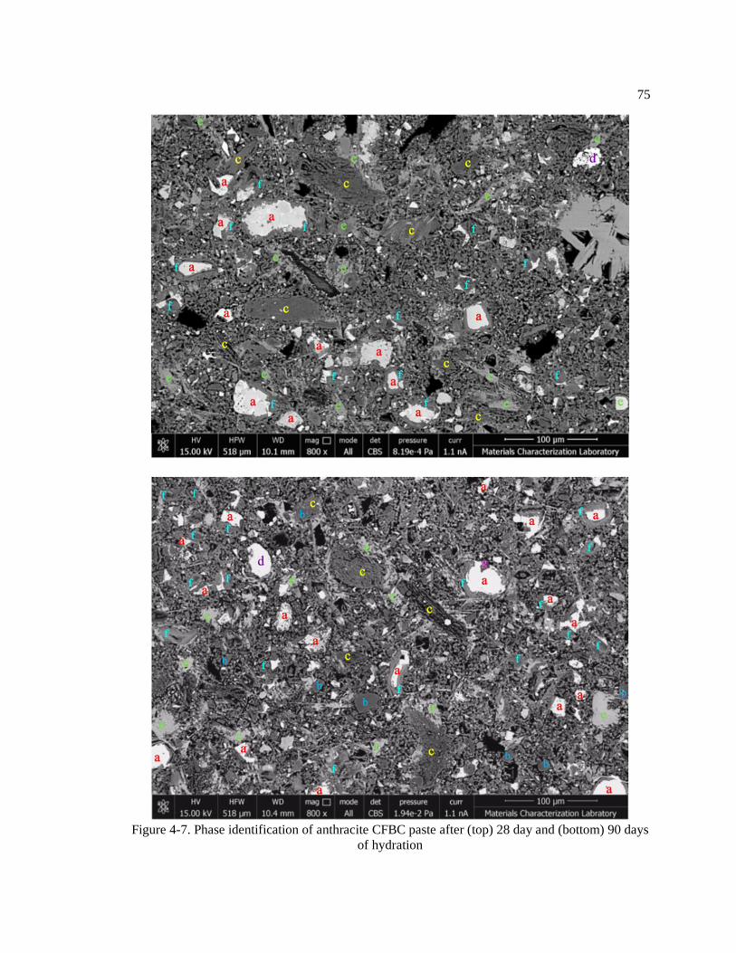
75
Figure 4-7. Phase identification of anthracite CFBC paste after (top) 28 day and (bottom) 90 days
of hydration
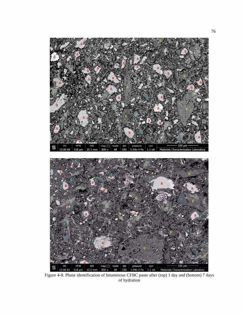
76
Figure 4-8. Phase identification of bituminous CFBC paste after (top) 1 day and (bottom) 7 days
of hydration

77
Figure 4-9. Phase identification of bituminous CFBC paste after (top) 28 day and (bottom) 90
days of hydration

78
After one day of hydration, clusters of portlandite crystals can be seen throughout the
microstructure, and to a great extent in the vicinity of clay particles. High magnification (i.e. greater
than 1500) imaging also reveals a relatively even distribution of fine needle-like ettringite crystals.
Magnesium bearing phases are found in small quantities, in the vicinity of cement particles
(periclase) or dispersed within the microstructure (possibly talc from bituminous fly ash). As
expected, quartz and hematite particles originating from the fly ash act as inert material, remaining
unreacted at all ages. After 7 days, visible signs of inner C-S-H gel can be seen on the rims of
cement particles, and increase significantly with the progress of hydration from 7 to 28 days. The
matrix phase (groundmass) is mainly composed of Al, Si, and Ca, and can therefore be classified
as C-A-S-H. Calcined clays have also been shown to react as a pozzolanic material, consuming
portlandite and forming mainly calcium aluminum silicate hydrates [14] [15].
In order to properly identify the composition of major phases, especially that of calcium
aluminate silicates, point EDS was conducted on paste samples at the age of 28, and 90 days. The
results of point EDS is presented in Figure 4-10 and Table 4-2. Table 4-2 provides the average
composition (average of 10 points) and phase category of the various points labeled in Figure 4-
10. It can be seen that the clay particles are heterogenous, some parts contain greater amounts of
Al (point 5 and 6), while others are highly rich in Si and contain very little Al (point 7 and 8). The
very light specs in clay particles contain high levels of Fe or Ti. Rims of some clay particles (point
10 and 11) contain Ca, Al, and Si bearing phases, identified as C-A-S-H. This is not the case for all
clays, as some seem to be less reactive than others. portlandite (point 9) is also abundantly formed
in the vicinity of clay particles. Similar to the EDS maps, inner C-S-H gel (point 3) has almost
completely encapsulated the cement particles at the age of 28 and 90 days. The average atomic
ratio of Ca/Si for the inner C-S-H gel is 1.39. The Ca/Si ratio of C-S-H in neat Portland cement
varies from approximately 1.2-2.3, with an average of 1.75 [18] [19] [20]. Due to the limited
resolution of EDS (1×2 μ), the composition of the thin needles could not be identified correctly.

79
Although these needles are most likely ettringite, they were shown to be rich in Ca and Si with little
Al and S, possibly affected by the surrounding C-A-S-H in the groundmass. Highly rich Mg phases
with little Ca can be found as components of anhydrous cement (point 17) and when Ca is also
significant, as dolomite (point 18). Finally, non-reactive quartz (point 15) and hematite (point 16)
minerals are distributed within the paste.
Figure 4-10. Phase identification using point EDS of (top) anthracite and (bottom)
bituminous CFBC paste
1 3 1
6
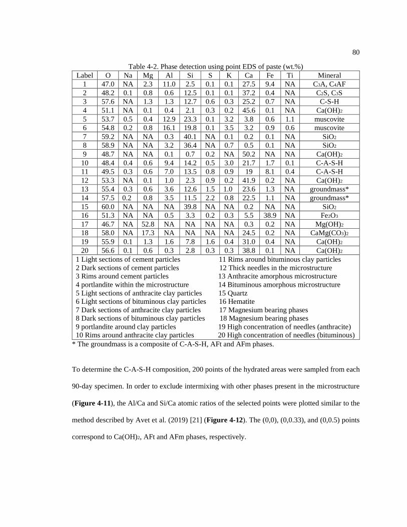
80
Table 4-2. Phase detection using point EDS of paste (wt.%)
Label O Na Mg Al Si S K Ca Fe Ti Mineral
1 47.0 NA 2.3 11.0 2.5 0.1 0.1 27.5 9.4 NA C3A, C4AF
2 48.2 0.1 0.8 0.6 12.5 0.1 0.1 37.2 0.4 NA C2S, C3S
3 57.6 NA 1.3 1.3 12.7 0.6 0.3 25.2 0.7 NA C-S-H
4 51.1 NA 0.1 0.4 2.1 0.3 0.2 45.6 0.1 NA Ca(OH)2
5 53.7 0.5 0.4 12.9 23.3 0.1 3.2 3.8 0.6 1.1 muscovite
6 54.8 0.2 0.8 16.1 19.8 0.1 3.5 3.2 0.9 0.6 muscovite
7 59.2 NA NA 0.3 40.1 NA 0.1 0.2 0.1 NA SiO2
8 58.9 NA NA 3.2 36.4 NA 0.7 0.5 0.1 NA SiO2
9 48.7 NA NA 0.1 0.7 0.2 NA 50.2 NA NA Ca(OH)2
10 48.4 0.4 0.6 9.4 14.2 0.5 3.0 21.7 1.7 0.1 C-A-S-H
11 49.5 0.3 0.6 7.0 13.5 0.8 0.9 19 8.1 0.4 C-A-S-H
12 53.3 NA 0.1 1.0 2.3 0.9 0.2 41.9 0.2 NA Ca(OH)2
13 55.4 0.3 0.6 3.6 12.6 1.5 1.0 23.6 1.3 NA groundmass*
14 57.5 0.2 0.8 3.5 11.5 2.2 0.8 22.5 1.1 NA groundmass*
15 60.0 NA NA NA 39.8 NA NA 0.2 NA NA SiO2
16 51.3 NA NA 0.5 3.3 0.2 0.3 5.5 38.9 NA Fe2O3
17 46.7 NA 52.8 NA NA NA NA 0.3 0.2 NA Mg(OH)2
18 58.0 NA 17.3 NA NA NA NA 24.5 0.2 NA CaMg(CO3)2
19 55.9 0.1 1.3 1.6 7.8 1.6 0.4 31.0 0.4 NA Ca(OH)2
20 56.6 0.1 0.6 0.3 2.8 0.3 0.3 38.8 0.1 NA Ca(OH)2
1 Light sections of cement particles 11 Rims around bituminous clay particles
2 Dark sections of cement particles 12 Thick needles in the microstructure
3 Rims around cement particles 13 Anthracite amorphous microstructure
4 portlandite within the microstructure 14 Bituminous amorphous microstructure
5 Light sections of anthracite clay particles 15 Quartz
6 Light sections of bituminous clay particles 16 Hematite
7 Dark sections of anthracite clay particles 17 Magnesium bearing phases
8 Dark sections of bituminous clay particles 18 Magnesium bearing phases
9 portlandite around clay particles 19 High concentration of needles (anthracite)
10 Rims around anthracite clay particles 20 High concentration of needles (bituminous)
* The groundmass is a composite of C-A-S-H, AFt and AFm phases.
To determine the C-A-S-H composition, 200 points of the hydrated areas were sampled from each
90-day specimen. In order to exclude intermixing with other phases present in the microstructure
(Figure 4-11), the Al/Ca and Si/Ca atomic ratios of the selected points were plotted similar to the
method described by Avet et al. (2019) [21] (Figure 4-12). The (0,0), (0,0.33), and (0,0.5) points
correspond to Ca(OH)2, AFt and AFm phases, respectively.
4 1
1

81
Figure 4-11. Schematic of the intermixing of phases. The interaction volume is shown to contain
(left) information from C–A–S–H (dark grey) and portlandite or (right) C–A–S–H and ettringite
[22]
Both anthracite and bituminous paste samples demonstrate C-A-S-H phases with Si/Ca values
predominantly in the range of 0.6-0.8. However, the Al/Ca range for the anthracite sample is
slightly broader than the bituminous (0.05-0.25 vs. 0.10-0.20). When comparing these results to
28-day control samples (C-A-S-H composition of approximately Si/Ca= 0.5 and Al/Ca=0.05 [21]),
it can be concluded that the partial substitution of cement with CFBC fly ash results in C-A-S-H
phases with higher Si and Al contents. The overall greater Al content for the anthracite sample
agrees with the higher content of soluble Al in its source fly ash. Figure 4-12 shows greater
deviation of points towards areas of high Al/Ca and Si/Ca for the anthracite sample. This may be
due to the intermixing of C-A-S-H with traces of raw fly ash, possibly underlying the selected area.
Unreacted anthracite and bituminous fly ashes correspond to points (9.24,4.90) and (2.28,1.21) on
the scatter plot, respectively. As such, intermixing with raw anthracite fly ash may cause a greater
shift of results to areas with higher Al/Ca and Si/Ca, compared to bituminous fly ash.

82
Figure 4-12. Phase identification of C-A-S-H using point EDS of (top) anthracite and
(bottom) bituminous CFBC paste

83
Previous studies on synthetized C-S-H have also reported an increase in the Al uptake when greater
supplies of soluble Al are present in the pore solution [23]. The study by Avet et al. (2019) [21]
showed an increase in both Al/Ca and Si/Ca with increasing LC3-50 contents (Figure 4-13). The
C-A-S-H composition was defined at the right edge of the cloud of points collected, corresponding
to the least amount of intermixing. Wilson et al. (2018) measured Ca/(Si+Al) for four systems with
SCMs, and found this value to be less than that of pure C-S-H in OPC mix [24]. Richardson and
Groves (1997) [25] established a linear relationship between Al/Ca and Si/Ca for the C-A-S-H
composition of Portland cement-slag blends (demonstrated as straight line in Figure 4-14 [19]).
This relationship was able to correctly estimate the increase in Si/Ca and Al/Ca with the progress
of hydration from 4 weeks to 14 months.
Figure 4-13. C-A-S-H composition for PC and LC3-50 (17.0%), (50.3%) and (95.0%) at 28 days
of hydration obtained by SEM-EDS (cloud of points and least intermixed composition) and
STEM-EDS [21]

84
Figure 4-14. Scatter plot for binary paste with 50% slag (left) after 4 weeks of hydration
(right) after 14 months of hydration [19]
4.4.4. Thermogravimetric Analysis of CFBC Fly Ash and Binary Paste Mixtures
Changes in the weight (%) of dry CFBC fly ash and binary paste samples (combusted at 110oC for
20 min) as a function of temperature (oC) is shown in Figure 4-15 and Figure 4-16. The derivative
of weight (%/oC) is also included in the graphs, to correctly identify the decomposition temperature
of various phases. The main peaks for binary paste samples occur at 150-170oC, 420-430oC, 670-
680oC, 830-850oC, which correspond to the decomposition of AFm, Ca(OH)2, AFm, and CaCO3,
respectively. A similar pattern is also observed for control mixtures, with the exception of low
intensity CaCO3 peaks occurring at 770-780oC (Figure 4-17). The AFm phases are identified as
mono- and hemicarboaluminate, based on earlier TGA testing conducted on pure mono- and
hemicarboaluminate (Figure 4-18) [20] [26]. In the absence of CaCO3, formation of monosulfate
is more favorable than CO3-AFm, as shown in Figure 4-19 [10].

85
Figure 4-15. TGA results for pastes samples containing anthracite fly ash (after 1, 7, and 28 days
of hydration) compared to as received anthracite fly ash
TGA results show little mass loss (just over 2%) during the combustion of anthracite fly ash, while
bituminous fly ash displays three major phase decomposition peaks at approximately 400oC, 630oC,
and 910oC. The first peak is most likely due to the conversion of Ca(OH)2 to CaO. As for the
remaining two, studies by Wei et al. (2015) [27] have shown that when sufficient amounts of
unburned carbon are available, iron oxide is reduced in three stages: Fe2O3 → Fe3O4 at 639°C,
Fe3O4 → FeO at 982°C, and FeO → Fe at 1124°C. The slight shift in peak position may related to
the type of carbon and its combustibility. For instance, TGA results for anthracite fly ash reveal the

86
possible development of a mass loss peak at temperatures greater than 940°C. This is because
anthracite coal is of the highest rank, containing carbon which is much harder to burn than that in
bituminous fly ash.
Figure 4-16. TGA results for pastes samples containing bituminous fly ash (after 1, 7, and 28
days of hydration) compared to as received bituminous fly ash
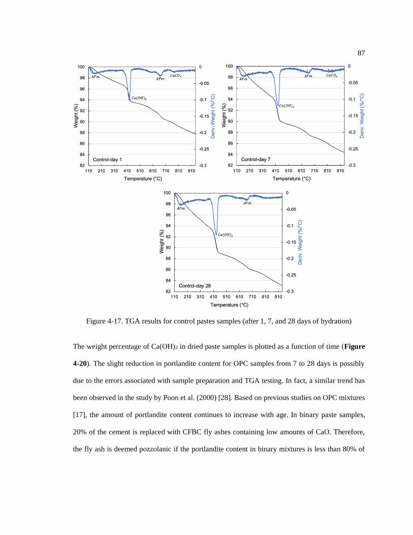
87
Figure 4-17. TGA results for control pastes samples (after 1, 7, and 28 days of hydration)
The weight percentage of Ca(OH)2 in dried paste samples is plotted as a function of time (Figure
4-20). The slight reduction in portlandite content for OPC samples from 7 to 28 days is possibly
due to the errors associated with sample preparation and TGA testing. In fact, a similar trend has
been observed in the study by Poon et al. (2000) [28]. Based on previous studies on OPC mixtures
[17], the amount of portlandite content continues to increase with age. In binary paste samples,
20% of the cement is replaced with CFBC fly ashes containing low amounts of CaO. Therefore,
the fly ash is deemed pozzolanic if the portlandite content in binary mixtures is less than 80% of

88
the control. This is not the case for anthracite fly ash, despite its high levels of soluble silica and
alumina (Figure 4-1a). However, bituminous fly ash displays slight pozzolanic properties.
Figure 4-18. Decomposition patterns for pure limestone, hemicarboaluminate, and
monocarboaluminate [26]
Figure 4-19. Presence of monosulfate in limestone free mixtures [10]

89
Figure 4-20. Calcium hydroxide content in paste mixtures after 1, 7, and 28 days of hydration
To monitor the changes in AFm content with time, TGA measurements are plotted for the
temperature range of 450oC to 850oC (Figure 4-21). Tangent lines are also included, in an attempt
to clarify the amount of weight loss due to AFm decomposition. Results show higher amounts of
AFm phases for anthracite samples compared to bituminous. This is in accordance with XRD
patterns which show greater AFm peak intensities for pastes containing anthracite fly ash.
Furthermore, the AFm content increases with hydration time. To confirm these findings, the
amount of calcite in paste samples was measured using the tangent method. Bituminous samples
contained the greatest amount of calcite and their content decreased from 3.21% at day 1 to 2.01%
at day 28. At day 1, the calcite content for control and anthracite samples was 1.26% and 0.32%,
respectively, and the peaks became undetectable at later ages.
Based on the changes in Ca(OH)2 and AFm content with time, it can be concluded that
anthracite fly ash is more involved in AFm production, whilst the strength development in
bituminous samples is attributed to both its pozzolanic reactions and AFm production. The fewer
number of C-A-S-H points collected for anthracite samples using SEM-EDS further confirms this
statement.

90
Figure 4-21. Changes in the amount of AFm phases for binary paste samples (after 1, 7, and 28
days of hydration) compared to the control mixture

91
4.5 Conclusions
CFBC fly ash contains reactive anhydrite, free lime, calcined clay, and aluminosilica glass, and its
main hydration products in binary paste mixtures were found to be ettringite, CO3-AFm, and C-A-
S-H phases:
• Calcined clays and anhydrite are responsible for the formation of ettringite at very early ages.
Mixtures containing bituminous fly ash contained greater amounts of ettringite, which agrees
with the higher anhydrite content in bituminous fly ash.
• When S is depleted, CaCO3 reacts with the remaining Al from calcined clays to form
hemicarboaluminate and monocarboaluminate. X-ray diffraction patterns revealed strong
hemicarboaluminate peaks at 7 days. The greater CO3-AFm phases in anthracite samples agrees
with the higher soluble Al and Si in the source fly ash.
• C-A-S-H is primarily formed from the reaction between C3S and C2S with portlandite, in the
presence of Al (from calcined clays). The secondary C-A-S-H phase production was greater
for samples with bituminous fly ash, as thermogravimetric analysis results revealed greater
pozzolanic reactivity for bituminous fly ash compared to anthracite fly ash. The Si/Ca and
Al/Ca values for C-A-S-H of binary paste mixtures were greater than the control.
4.6 References
[1] T. Lockwood, Techno-economic analysis of PC versus CFB combustion technology,
(2013), Available at: https://www.usea.org/publication/techno-economic-analysis-pc-
versus-cfb-combustion-technology-ccc226. Accessed: July 2019.
[2] T. Kim, J. Olek, Effects of sample preparation and interpretation of thermogravimetric
curves on calcium hydroxide in hydrated pastes and mortars, J. Transp. Res. Board. 2290
(2012) 10–18.
[3] S. Lee, G. Kim, Self-cementitious hydration of circulating fluidized bed combustion fly ash,
J. Korean Ceram. Soc. 54 (2017) 128–136.

92
[4] G. Sheng, Q. Li, J. Zhai, Investigation on the hydration of CFBC fly ash, Fuel. 98 (2012)
61–66.
[5] V.S. Ramachandran, C.M. Zhang, Hydration kinetics and microstructural development in
the 3CaO. Al2O3-CaSO4. 2H2O-CaCO3-H2O system, Mater. Struct. 19 (1986) 437–444.
[6] G. Puerta-falla, M. Balonis, G. Le Saout, The Influence of Metakaolin on Limestone
Reactivity in Cementitious Materials, in: Proc. 1st Int. Conf. Calcined Clays Sunstainable
Concr., 2015: pp. 11–20.
[7] C. Vernet, G. Noworyta, Mechanisms of limestone reactions in the system (C3A–
CaSO4ÁH2O–CH–CaCO3–H): Competition between calcium monocarbo-and monosulfo-
aluminate hydrates formation, in: 9th Int. Congr. Chem. Cem., New Delhi, India, 1992: pp.
430–436.
[8] X. Li, Q. Chen, K. Huang, B. Ma, B. Wu, Cementitious properties and hydration mechanism
of circulating fluidized bed combustion (CFBC) desulfurization ashes, Constr. Build. Mater.
36 (2012) 182–187.
[9] G. Sheng, Q. Li, J. Zhai, F. Li, Self-cementitious properties of fly ashes from CFBC boilers
co-firing coal and high-sulphur petroleum coke, Cem. Concr. Res. 37 (2007) 871–876.
[10] K. De Weerdt, M. Ben Haha, G. Le Saout, K.O. Kjellsen, H. Justnes, B. Lothenbach,
Hydration mechanisms of ternary Portland cements containing limestone powder and fly
ash, Cem. Concr. Res. 41 (2011) 279–291.
[11] T. Matschei, B. Lothenbach, F.P. Glasser, The role of calcium carbonate in cement
hydration, Cem. Concr. Res. 37 (2007) 551–558.
[12] J. Bizzozero, K.L. Scrivener, Limestone reaction in calcium aluminate cement – calcium
sulfate systems, Cem. Concr. Res. 76 (2015) 159–169.
[13] M. Zajac, A. Rossberg, G. Le, B. Lothenbach, Influence of limestone and anhydrite on the
hydration of Portland cements, Cem. Concr. Compos. 46 (2014) 99–108.
[14] M. Antoni, J. Rossen, F. Martirena, K. Scrivener, Cement substitution by a combination of
metakaolin and limestone, Cem. Concr. Res. 42 (2012) 1579–1589.
[15] J. Ambroise, M. Murat, J. Pera, Hydration reaction and hardening of calcined clays and
related minerals. IV. experimental conditions for strength improvement on metakaolinite
minicylinders, Cem. Concr. Res. 15 (1985) 83–88.
[16] V.L. Bonavetti, V.F. Rahhal, E.F. Irassar, Studies on the carboaluminate formation in
limestone filler-blended cements, Cem. Concr. Res. 31 (2001) 853–859.
[17] T. Szeles, Damage mitigation and prediction of alkali-silica reaction in concrete, Doctoral
dissertation, The Pennsylvania State University, (2019).
93
[18] I.G. Richardson, G.W. Groves, Microstructure and microanalysis of hardened ordinary
Portland cement pastes, J. Mater. Sci. 28 (1993) 265–277.
[19] I.G. Richardson, The nature of C-S-H in hardened cements, Cem. Concr. Res. 29 (1999)
1131–1147.
[20] K. Scrivener, R. Snellings, B. Lothenbach, A practical guide to microstructural analysis of
cementitious materials, Crc Press, (2018).
[21] F. Avet, E. Boehm-courjault, K. Scrivener, Investigation of C-A-S-H composition,
morphology and density in Limestone Calcined Clay Cement (LC3), Cem. Concr. Res. 115
(2019) 70–79.
[22] J.E. Rossen, K.L. Scrivener, Optimization of SEM-EDS to determine the C–A-S–H
composition in matured cement paste samples, Mater. Charact. 123 (2017) 294–306.
[23] E.L. Hôpital, B. Lothenbach, G. Le Saout, D. Kulik, K. Scrivener, Incorporation of
aluminium in calcium-silicate-hydrates, Cem. Concr. Res. 75 (2015) 91–103.
[24] W. Wilson, L. Sorelli, A. Tagnit-hamou, Unveiling micro-chemo-mechanical properties of
C–(A)–S–H and other phases in blended-cement pastes, Cem. Concr. Res. 107 (2018) 317–
336.
[25] I.G. Richardson, G.W. Groves, The structure of the calcium silicate hydrate phases present
in hardened pastes of white Portland cement/blast-furnace slag blends, J. Mater. Sci. 32
(1997) 4793–4802.
[26] O. Chowaniec, Limestone addition in cement, Doctoral dissertation, EPFL, (2012).
[27] R. Wei, D. Cang, L. Zhang, Y. Bai, Staged reaction kinetics and characteristics of iron oxide
direct reduction by carbon, Int. J. Miner. Metall. Mater. 22 (2015) 1025–1032.
[28] L. Lam, Y.L. Wong, C.S. Poon, Degree of hydration and gel/space ratio of high-volume
fly ash/cement systems, Cem. Concr. Res. 30 (2000) 747–756.

Chapter 5
Performance of FBC Fly Ash in Concrete
5.1 Abstract
Past studies have been mainly focused on evaluating the effects of FBC fly ash on the mechanical
properties of mortar and concrete. In most cases, the 28-day strength activity index of mortar
samples is compared against ASTM C618-19 limits, and very little is done in terms of durability
testing. This is because current specifications are prescriptive in nature, and lack sufficient
performance-based requirements. In fact, the long-term performance requirements of ASTM C618-
19 (i.e., drying shrinkage and resistance to sulfate attack) are optional, and apply only when
specifically requested by the purchaser. To address these deficiencies, in this study, the durability
of concrete mixtures containing CFBC fly ash was evaluated against water absorption and chloride
ion penetration. Equivalent mortars mixtures were also tested for their sulfate attack resistance,
drying shrinkage, and amount of volume expansion in water. Results showed that the replacement
of Portland cement with 20% CFBC fly ash significantly improved concretes’ resistance to chloride
ion attack, and its initial sorptivity was equal or less than that of the OPC mixture. The SO3 in
CFBC fly ash did not cause any deleterious expansion, and the drying shrinkage values were within
standard limits. While mortar bars containing anthracite fly ash were able to withstand severe
sulfate attack, the use of bituminous fly ash led to premature deterioration.

95
5.2 Introduction
FBC ash is produced in large quantities in the U.S (14.5 MT based on ACAA’s 2017 annual report),
but since it is outside the scope of concrete specifications, it is primarily used for mining
applications (14 MT) and waste stabilization/solidification (0.1 MT). This is while approximately
36.8% of PC fly ash is used as replacement for Portland cement in concrete and grout. Considering
the decade-long shutdown of pulverized coal powerplants and the strong market demand for good
quality fly ash, it is essential to investigate the performance of alternative fly ash sources in
concrete. In chapter 3, DOT compliant concrete pavement mixtures containing CFBC fly ash with
desirable slump and air content were prepared, and monitored for their strength development.
Contrary to studies by Gazdič et al. (2017) [1], Wu et al. (2014) [2], and Robl et al. (2011) [3],
samples showed compressive strength values similar to that of the control. Although these results
are very promising, additional testing is required to evaluate the effect of FBC fly ash on the
durability properties of concrete. In an attempt to complete objective 1 of this research, the long-
term performance of concrete and mortar mixtures against water adsorption, drying shrinkage
chloride and sulfate ion penetration, is evaluated.
5.3 Experimental Procedures
As-received anthracite (passed No. 140 sieve) and bituminous CFBC fly ashes were incorporated
into concrete mixtures with adequate slump and air content, and their effect on the short-term
(setting time) and long-term (chloride ion penetration and water sorptivity) properties of concrete
was investigated. Equivalent mortar samples were also prepared and tested for their drying
shrinkage, resistance to sulfate attack, and volume expansion in water. Concrete performance was

96
related to microstructural features such as pore size distribution and pore conductivity, using MIP
and pore fluid extraction methods.
5.3.1 Performance of CFBC Fly Ash in Mortar and Concrete
The performance of CFBC fly ashes (Table 4-1) in concrete mixtures was further evaluated by
measuring concretes’ setting time (ASTM C403-16), rapid chloride ion penetration (ASTM C1202-
18), and water sorptivity (ASTM C1585-13). Concrete pavement mixtures were prepared using
proportions provided in Table 3-3. In the test mixtures, 20% of the Portland cement was replaced
with the anthracite or bituminous fly ash, and enough water reducing and air-entraining admixtures
were added to achieve a slump of 10±2.5 cm (4±1 in.) and air content of 6±1% by volume (labeled
as Anthracite CFBC set 2 and Bituminous CFBC set 2 in Table 3-3).
For each mixture, 2 concrete cylinders (diameter of 100 mm and height of 200 mm) were cast and
moist cured at 23oC and 100% RH for 56 days, to be used for rapid chloride permeability (RCPT),
and water sorptivity testing. The remaining fresh concrete was wet-sieved through No. 4 sieve,
poured into plastic molds (diameter of 150 mm and height of 150 mm), capped, and monitored for
its initial and final setting time at various curing temperatures (14oC, 23oC, and 36oC). The initial
and final setting time corresponded to resistance to penetration of 3.5 MPa (500 psi) and 27.6 MPa
(4000 psi), respectively. Results are reported as the average of three samples. The setting time of
paste mixtures (ASTM C403-16), prepared with normal consistency and 20% replacement of
cement with fly ash were also tested for comparative purposes. To eliminate the effect of water
content on the setting time, similar paste mixtures with constant w/cm=0.285 were cast and tested.
RCPT was used to monitor the amount of electrical charge passed through 50 mm thick
concrete slices, during a 6 h period. For this purpose, three disk samples (diameter of 100 mm and
height of 50 mm) were cut from each 56-day concrete cylinder, coated on the sides with epoxy, and
vacuum-saturated according to the procedure described in ASTM C1202-18. During testing, a

97
potential difference of 60 V was maintained across the two ends of the disks, one side in contact
with 3% NaCl and the other with a 0.3N NaOH solution. The total charge passed in coulombs was
measured as an indicator of the sample resistance to chloride ion penetration.
Similarly, three disk samples (diameter of 100 mm and height of 50 mm) were cut from
each concrete cylinder, and used to measure the rate of water absorption by capillary suction. Prior
to testing, samples were vacuum-saturated (ASTM C1202-18), moist cured (50°C and RH of 80%)
for 3 days, and subsequently stored in separate sealable contains at 23°C for 15 days. All surfaces
except that exposed to water were sealed and the samples were placed over water (water level was
1-3 mm above the bottom of the sample), to measure their mass gain after 1, 5, 10, 20, 30, 60 min
and at specified intervals up to 7 days.
To relate concrete properties to microstructural features such as pore size distribution and
pore fluid conductivity, equivalent paste samples (diameter of 20 mm and height of 40 mm) were
cast and moist cured (at 23°C and 100% RH) for 56 days. Two replicates were prepared for each
mixture. Two small pieces (smaller than 1.5 cm diameter and 2 cm length) were cut from the center
of one sample and vacuum dried at room temperature prior to MIP testing, while the other sample
was used for pore fluid extraction testing. During MIP testing, mercury was forced into the
evacuated sample under increasing pressure, and the volume of mercury intruded was measured as
a function of pressure. The critical pore diameter (i.e., the mean size of pore entry ways that allows
maximum percolation of mercury throughout the pore system), average pore diameter, threshold
diameter (i.e., the minimum diameter of pores that form a continuous network throughout the
cement paste), and total porosity were among the parameters obtained from this technique [4]. In
most cases, the critical pore diameter can be assumed to be similar to the median pore diameter.
The pore fluid extraction setup was used to apply an axial force (rate of 133 to 178 kN/min)
to the paste specimens in a confined space, creating high tri-axial pressures that squeeze out the
pore fluid. The solution was filtered with a 0.45-μm polypropylene filter, and ICP-AES was

98
conducted to measure the concentration of sodium (Na+), potassium (K+), calcium (Ca2+), and
sulfide (S2-) ion species. Stoichiometry was used to calculate the concentration of sulfates (SO42-),
while titration with hydrochloric acid (HCl) was used to measure the concentration of hydroxides
(OH-). The model developed by Snyder et al. (2003) [5] was then used to calculate the electrical
resistivity of the pore solution:
𝜌𝑐𝑎𝑙𝑐 =1
∑ 𝑧𝑖𝑐𝑖𝜆𝑖𝑖 (Eq. 5-1)
𝜆𝑖 =𝜆𝑖
0
1+𝐺𝑖𝐼𝑀0.5 (Eq. 5-2)
𝐼𝑀 =1
2∑ 𝑧2𝑐𝑖𝑖 (Eq. 5-3)
𝜌𝑐𝑎𝑙𝑐= electrical resistivity of the solution in Ωm;
𝜆𝑖= the equivalent conductivity of a single ionic species in cm2 S/mol;
𝑧𝑖= the valence concentration of a single ionic species;
𝑐𝑖= the molar concentration of a single ionic species in mol/L;
𝜆𝑖0= the equivalent conductivity of ionic species at infinite dilution in cm2 S/mol;
𝐺𝑖= the empirical conductivity coefficient of a single ionic species in (mol/L)-1/2;
𝐼𝑀= the ionic strength (molar basis) in mol/L;
i= a single ionic species.
The values for λi0 and Gi are provided in literature [6] [5]. The formation factor, which is a measure
of concrete’s transport properties, can be calculated from the ratio of electrical resistivity of
concrete (ρb) to the electrical resistivity of the pore solution (ρ0): 𝐹 =𝜌𝑏
𝜌0 [6].
Performance of CFBC fly ash in mortar mixtures was evaluated by monitoring its drying
shrinkage (ASTM C157-17), resistance to sulfate attack (ASTM C1012-18a), and volume

99
expansion in water (ASTM C1038−14b). For ASTM C1012-18a testing, mortar mixtures were
prepared with w/cm=0.485 and sand/cm=2.75, using type I/II Portland cement and graded standard
sand. In the test mixtures, enough water was added to achieve a flow of the control mix 5%
(Table 5-1). Six mortar prims (25×25×285 mm) and nine cubes (50 mm3) were cast and stored over
water in a tightly secured container at 35°C. After 24 h, the samples were demolded and cured in
lime water until reaching a compressive strength of 20 MPa. Once the required strength was
obtained, initial comparator readings were taken and the samples were stored in Na2SO4 solution
(50 g/L). Specimens were removed for length measurements at 1, 2, 3, 4, 8, 13, 16, and 24 weeks,
after which the solution was exchanged to maintain a pH level of 7 1. The volume expansion at
6 months was compared to the requirements set by ASTM C618-19.
Table 5-1. Mortar mix proportions for ASTM C1012-18a testing
specimen cement (g) fly ash (g) sand (g) water (g) SP (g) flow (%)
control 750 - 2062.5 375 - 88
Anthracite CFBC 600 150 2062.5 409.5 - 86
Bituminous CFBC 600 150 2062.5 409.5 - 93
Equivalent mortar mixtures were used for drying shrinkage testing, with the exception of a constant
w/cm of 0.485. For each mixture, four prims (25×25×285 mm) were cast and moist cured for 24 h,
after which they were demolded and placed in lime water for 6 days. At the age of 7-days, initial
comparator readings were taken and the samples were moved to a 50% RH and 23oC environmental
chamber for drying. Comparator readings were taken up to a period of 150 days. The 28-day drying
shrinkage of samples was compared to ASTM C618-19 limits. It must be noted that the
requirements for sulfate resistance and drying shrinkage of mortars are optional, and apply only
when specifically requested by the purchaser.
The expansion of mortar bars was measured after 14 days of storage in saturated lime water
and compared against the limits of ASTM C1157-17, Standard Performance Specification for
Hydraulic Cement. The purpose of this test was to capture any possible deleterious expansion
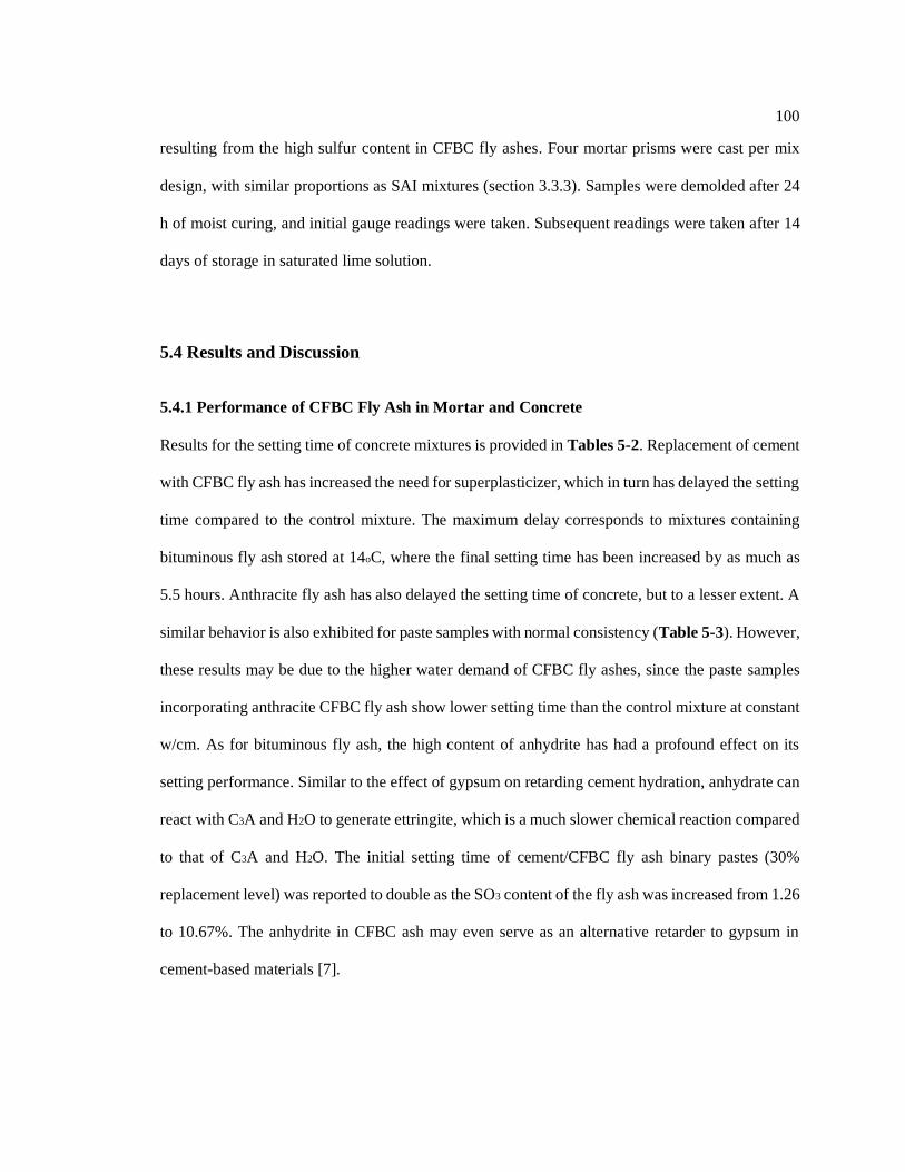
100
resulting from the high sulfur content in CFBC fly ashes. Four mortar prisms were cast per mix
design, with similar proportions as SAI mixtures (section 3.3.3). Samples were demolded after 24
h of moist curing, and initial gauge readings were taken. Subsequent readings were taken after 14
days of storage in saturated lime solution.
5.4 Results and Discussion
5.4.1 Performance of CFBC Fly Ash in Mortar and Concrete
Results for the setting time of concrete mixtures is provided in Tables 5-2. Replacement of cement
with CFBC fly ash has increased the need for superplasticizer, which in turn has delayed the setting
time compared to the control mixture. The maximum delay corresponds to mixtures containing
bituminous fly ash stored at 14oC, where the final setting time has been increased by as much as
5.5 hours. Anthracite fly ash has also delayed the setting time of concrete, but to a lesser extent. A
similar behavior is also exhibited for paste samples with normal consistency (Table 5-3). However,
these results may be due to the higher water demand of CFBC fly ashes, since the paste samples
incorporating anthracite CFBC fly ash show lower setting time than the control mixture at constant
w/cm. As for bituminous fly ash, the high content of anhydrite has had a profound effect on its
setting performance. Similar to the effect of gypsum on retarding cement hydration, anhydrate can
react with C3A and H2O to generate ettringite, which is a much slower chemical reaction compared
to that of C3A and H2O. The initial setting time of cement/CFBC fly ash binary pastes (30%
replacement level) was reported to double as the SO3 content of the fly ash was increased from 1.26
to 10.67%. The anhydrite in CFBC ash may even serve as an alternative retarder to gypsum in
cement-based materials [7].

101
Table 5-2. Initial and final setting time of concrete
Sample Initial setting time (min) Final setting time (min)
14oC 23oC 36oC 14oC 23oC 36oC
Control 420 355 250 560 480 315
Anthracite CFBC 560 450 290 785 620 370
Bituminous CFBC 670 545 340 905 700 425
Table 5-3. Initial and final setting time of paste
Sample
Normal consistency Constant w/cm (0.285)
Initial setting
time (min)
Final setting
time (min)
Initial setting
time (min)
Final setting
time (min)
Control 160 300 245 330
Anthracite CFBC 200 340 140 290
Bituminous CFBC 240 380 240 365
RCPT results can be found in Table 5-4, which show a significant reduction in the total amount of
charge passed through 56-day concrete samples, by partial substitution of cement with CFBC fly
ash. Based on ASTM C1202-18, control samples demonstrate ‘moderate’ chloride ion permeability
(2000-4000 coulombs), whilst CFBC fly ash samples are classified with ‘low’ permeability (1000-
2000 coulombs). Chloride ion penetration in concrete is greatly influenced by the concrete pore
structure and the presence of conductive ions such as Na+, K+, OH-, etc. In fact, the conductivity
(σt) of water saturated cement paste is proportional to the conductivity of the pore fluid (σ0), total
porosity (φ), and pore connectivity (β): 𝜎𝑡 = 𝜎0𝜑𝛽 [8] [9].
Pore conductivity was calculated based on the concentration of Na+, K+, Ca2+, SO42-, and
OH- using the model developed by Snyder et al. (2003) [5] and the step wise procedure provided
by Chang et. al (2018) [6]. Results showed higher pore solution resistivity for mixtures containing
CFBC fly ash, due to their lower concentration of Na+, K+, and OH- compared to the control (Table
5-5, Table 5-6).

102
Table 5-4. Short and long-term performance of CFBC fly ash in concrete
Properties Control Anthracite CFBC Bituminous CFBC
Slump (mm) 83 127 114
Fresh air content (vol %) 6.0 6.8 6.8
Hardened air content (vol %) 7.2 8.5 8.1
Air spacing factor (mm) 0.17 0.13 0.10
Compressive strength
at 56 days (MPa) 32.0 32.6 33.0
Chloride ion penetration
at 56 days (coulombs) 3035 1289 1684
Initial sorptivity
at 56 days (mm/s0.5) 15.3 15.8 9.2
Secondary sorptivity
at 56 days (mm/s0.5) 7.4 9.1 5.8
Table 5-5. Concentration of ions in the pore solution after 56 days (obtained from ICP-AES)
Specimen K
(μg/mL)
Na
(μg/mL)
S
(μg/mL)
Ca
(μg/mL)
Si
(μg/mL)
Al
(μg/mL)
Fe
(μg/mL)
Control 5908 2059 127 91.4 10.7 0.79 2.86
Anthracite 3744 1368 81.0 32.9 18.2 1.68 0.93
Bituminous 3833 1315 79.2 71.6 16.7 1.46 1.91
Table 5-6. Calculation of resistivity of pore solution using model developed by Snyder et al.
(2003) [5]
Specimen K+
(mol/L)
Na+
(mol/L)
Ca2+
(mol/L)
SO42-
(mol/L)
OH-
(mol/L)
Resistivity
(Ωm)
Control 0.151 0.090 0.002 0.004 0.252 0.187
Anthracite 0.096 0.059 0.001 0.003 0.157 0.287
Bituminous 0.098 0.057 0.002 0.002 0.157 0.287
The conditions of RCPT testing are extremely harsh. For on-site conditions (exposure to deicing
salts, seawater, etc.) where the rate of chloride ion ingress is quite slow, the higher amounts of
alumina in FBC samples can help prevent corrosion of steel by binding chloride ions out of the
pore solution. The main form of binding of the chloride ions is by reaction with C3A to form calcium
chloroaluminate (3CaO.Al2O3.CaCl2.10H2O), also known as Friedel’s salt. A similar reaction with
C4AF results in calcium chloroferrite (3CaO.Fe2O3.CaCl2.10H2O) [10]. In such conditions, greater
amount of chloride binding is expected for anthracite fly ash, as it contains greater amounts of

103
aluminum and less sulfur. It has been found that increased sulfate ion concentrations result in
slightly lower chloride binding, since sulfate ions react with C3A to form monosulphate or ettringite
[11].
Results for the absorption of water in 56-day concrete samples is provided in Figure 5-2.
The absorption follows a linear relationship with the square root of time elapsed and the constant
of proportionality is the rate of water absorption, also known as sorptivity. According to ASTM
C1585-13, the initial rate of water absorption is the slope of the line that best fits (a correlation
coefficient of greater than 0.98) the data from 1 min to 6 h. The secondary rate of water absorption
is calculated in a similar manner based on the results of 1 to 7 days (Table 5-4). The initial and
secondary representative error bars (demonstrated on Table 5-4) were measured by averaging the
standard deviation of all data points from 1 min to 6 h and from 1 to 7 days, respectively.
Figure 5-2. Rate of water absorption in 56-day concrete disks
Results show that the initial sorptivity of anthracite samples is similar to that of the control, while
the use of bituminous fly ash has reduced both the initial a secondary rate of water absorption.
Since the standard error for secondary sorptivity is quite high and in the same order as the variation

104
among results, a meaningful interpretation for these results cannot be made. Sorptivity is directly
related to pore features such as porosity, pore diameter, and pore connectivity. Of special interest
are pores greater than 24 nm (calculated using Kelvin’s equation), as they remain unsaturated at
80% RH (used for pre-conditioning samples). The initial sorptivity data is in accordance with MIP
results (Figure 5-3, Table 5-7) which shows lower volume of macropores (> 24 nm) for anthracite
and bituminous samples. Use of CFBC fly ash has resulted in a finer pore structure and lower
porosity which explains the higher formation factor of samples containing CFBC fly ash.
Figure 5-3. Pore size distribution of paste samples using MIP
Table 5-7. Pore parameters obtained from MIP testing
Specimen Porosity (%) Avg. pore
diameter (nm)
Critical pore
diameter (nm)
Threshold pore
diameter (nm)
Control 27.8 12.4 21.1 36.6
Anthracite 27.3 11.6 11.0 22.0
Bituminous 26.3 11.6 11.0 24.7
The average 14-day expansion of mortar bars stored in saturated lime is 0.008, 0.005, 0.024%, for
control, anthracite, and bituminous samples, respectively. Bituminous samples slightly surpass the
0
0.02
0.04
0.06
0.08
0.1
0.12
0.14
0.16
0.18
0.2
0.001 0.01 0.1 1
Intr
usio
n v
olu
m (
ml/g
)
Pore diameter (µm)
Control 1 Control 2 Anthracite 1
Anthracite 2 Bituminous 1 Bituminous 2

105
ASTM C1157-17 limit (0.02%), but it is safe to assume that the use of bituminous fly ash will not
lead to deleterious expansion in concrete, especially that 3 out 4 specimens had expansion values
within limit. Although these results are promising, it is advisable to monitor the volume stability of
mortar or concrete containing CFBC fly ash over a long term and in exposure to moisture, to more
confidently rule out the risk of volume instability.
Figure 5-4 shows expansion results for mortar bars stored in Na2SO4 solution. The increase
in length of samples containing CFBC fly ash is greater than the control, with the highest values
reported for samples with bituminous fly ash, at all ages. This behavior is primarily due to the high
amounts of soluble aluminum and sulfur in CFBC fly ashes. Sulfate ions react with certain
components of hydrated cement to form ettringite and gypsum that induce expansion. Hydrated
calcium aluminate and aluminum rich AFm phases transform to ettringite in the presence of sulfate
ions, while gypsum is formed in a reaction between portlandite and sodium sulfate [12][13][14].
The formation of ettringite is much more expansive that gypsum, resulting in increased capillary
pressure and cracking in hardened samples [10].
Figure 5-4. Expansion of mortar prisms in Na2SO4 solution
0.00
0.05
0.10
0.15
0.20
0.25
0.30
0.35
0.40
0 2 4 6 8 10 12 14 16 18 20 22 24
Exp
an
sio
n (
%)
Age (weeks)
Control Anthracite Bituminous

106
Based on batch leaching results (Figure 3-4), it is clear that the concentration of sulfates is
significantly high in the pore solution of samples containing bituminous fly ash, even at 7 days.
Results for the expansion of mortar bars stored in water proved that when sufficient moisture is
available, these sulfates can react with aluminum bearing phases, and cause considerable volume
expansion. This is also the case during the initial weeks of storage of samples in Na2SO4 solution.
High concentrations of sulfate ions within the sample and storage solution, promote both internal
and external sulfate attack. After 8 weeks of exposure, the standard deviation of readings becomes
significant, indicating severe microcracking in the samples. From this point on external sulfate
attack dominates and deterioration is accelerated.
For on-site conditions, where samples are subjected to cycles of wetting and drying, salt
crystallization and their accumulation inside pores will further deteriorate concrete [13].
Furthermore, at temperatures below 15°C and when sufficient amounts of carbonate ions (CO32−)
and calcium silicate are available, sulfate attack will result in the production of thaumasite [13]. In
general, the deterioration mechanism of concrete is attributed to the failure of concrete to physical
attack (salt crystallization in porous media) and chemical attack (chemical reactions leading to
expansive products) [13].
The test criteria set by ASTM C618-19 requires a maximum expansion limit of 0.1% and
0.05% after 6 months of exposure for moderate and severe sulfate resistance, respectively.
Therefore, samples containing 20% anthracite fly ash can tolerate severe sulfate attack, while the
use of bituminous fly ash should be avoided in concretes exposed to sulfates.
Mortar bars containing bituminous fly ash also show greater drying shrinkage compared to
anthracite and control samples (Figure 5-5). The higher rate of shrinkage in bituminous samples
during the initial two weeks has mainly contributed to this difference. After the two-week drying
period, all samples show a relatively constant increase in shrinkage with time. The 28-day
shrinkage of bituminous samples exceeds the control mixture by 0.017%, which is within ASTM

107
C618-19 limits (max. 0.03%). The finer capillary pore structure in bituminous mortar is the main
reason for this behavior, which has been confirmed by MIP and sorptivity test results.
(a)
(b)
Figure 5-5. (a) Drying shrinkage and (b) change in mass of mortar samples
-0.135
-0.115
-0.095
-0.075
-0.055
-0.035
-0.015
0 15 30 45 60 75 90 105 120 135 150
Le
ng
th c
ha
ng
e (
%)
Age (days)
Control Anthracite Bituminous
-8
-7
-6
-5
-4
-3
-2
-1
0
0 20 40 60 80 100 120 140
Ch
an
ge
in m
ass (
%)
Age (days)
Control Anthracite Bituminous

108
When concrete is exposed to an environment with relative humidity of less than 100%, water is
initially lost in the large capillary pores which has little to no effect on shrinkage. With the progress
of drying, water is removed from finer capillary pores (smaller than 50 nm size), which develops
internal negative pressure, that leads to the shrinkage of concrete. Continued drying also causes the
loss of physically adsorbed water from C–S–H gel [15].
5.5 Conclusions
This study evaluated the fresh and long-term properties of concrete and mortar mixtures containing
CFBC fly ash. The main findings are as follows:
• Regardless of the use of any superplasticizers, bituminous fly ash significantly retarded the
setting time of concrete due to its high anhydrite content. Lower curing temperatures (14oC)
further exacerbated this effect. The main cause of delay in the setting of mixtures containing
anthracite fly ash was the use of superplasticizer or additional water.
• Use of CFBC fly ash improved concretes’ resistance to chloride ion attack, with anthracite fly
ash being more effective in increasing the formation factor.
• The initial rate of water absorption for concrete samples containing CFBC fly ash was equal or
less than that of the control, mainly due to their lower volume of macropores (>24 nm).
• Expansion of mortar bars containing bituminous fly ash, exposed to moisture, slightly
surpassed ASTM C1038-14b limits. Further long-term testing is required to evaluated the risk
of volume instability.
• Drying shrinkage of mortar bars containing bituminous fly ash was the greatest among
mixtures, but within ASTM C618-19 limits.
• Use of anthracite fly ash is permitted in concretes exposed to severe sulfate attack, whereas
bituminous fly ash can cause premature deterioration even in moderate exposure conditions.

109
5.6 References
[1] D. Gazdič, M. Fridrichová, K. Kulísek, L. Vehovská, The potential use of the FBC ash for
the preparation of blended cements, Procedia Eng. 180 (2017) 1298–1305.
[2] T. Wu, M. Chi, R. Huang, Characteristics of CFBC fly ash and properties of cement-based
composites with CFBC fly ash and coal-fired fly ash, Constr. Build. Mater. 66 (2014) 172–
180.
[3] T. Robl, A. Oberlink, J. Brien, J. Pagnotti, The utilization potential of anthracite CFBC
spent bed fly ash as a concrete additive, World of Coal Ash Conf., Denver, USA, (2011).
[4] K.K. Aligizaki, Pore structure of cement-based materials: testing, interpretation and
requirements, CRC Press, (2005).
[5] K.A. Snyder, X. Feng, B.D. Keen, T.O. Mason, Estimating the electrical conductivity of
cement paste pore solutions from OH-, K+ and Na+ concentrations, Cem. Concr. Res. 33
(2003) 793–798.
[6] M.T. Chang, L. Montanari, P. Suraneni, W.J. Weiss, Expression of cementitious pore
solution and the analysis of its chemical composition and resistivity using X-ray
fluorescence, J. Vis. Exp. (2018) 1–9.
[7] Y. Shen, J. Qian, Z. Zhang, Investigations of anhydrite in CFBC fly ash as cement retarders,
Constr. Build. Mater. 40 (2013) 672–678.
[8] F. Rajabipour, J. Weiss, Electrical conductivity of drying cement paste, Mater. Struct. 40
(2007) 1143–1160.
[9] E.J. Garboczi, Permeability, diffusivity, and microstructural parameters: a critical review,
Cem. Concr. Res. 20 (1990) 591–601.
[10] A.M. Neville, Properties of concrete, Fourth, Prentice Hall, 2006.
[11] Q. Yuan, C. Shi, G. De Schutter, K. Audenaert, D. Deng, Chloride binding of cement-based
materials subjected to external chloride environment – A review, Constr. Build. Mater. 23
(2009) 1–13.
[12] C. Xiong, L. Jiang, Y. Xu, Z. Song, H. Chu, Q. Guo, Influences of exposure condition and
sulfate salt type on deterioration of paste with and without fly ash, Constr. Build. Mater.
113 (2016) 951–963.
[13] J. Sun, Z. Chen, Influences of limestone powder on the resistance of concretes to the
chloride ion penetration and sulfate attack, Powder Technol. 338 (2018) 725–733.
[14] T. Schmidt, B. Lothenbach, M. Romer, J. Neuenschwander, K. Scrivener, Physical and
microstructural aspects of sulfate attack on ordinary and limestone blended Portland

110
cements, Cem. Concr. Res. 39 (2009) 1111–1121.
[15] G.A. Rao, Long-term drying shrinkage of mortar - influence of silica fume and size of fine
aggregate, Cem. Concr. Res. 31 (2001) 171–175.

111
Chapter 6
Performance of Beneficiated FBC Fly Ash in Concrete
6.1 Abstract
CFBC fly ash has displayed good reactivity and strength development in mortar and concrete
mixtures. It is also beneficial to mitigating ASR and chloride ion penetration. However, its high
levels of unburned carbon content can render the fly ash as unsuitable for on-site applications by
interfering with the performance of air-entraining admixtures. In this study, the effectiveness of
chemical passivation and carbon burn out methods in neutralizing/reducing the unburned carbon
content in CFBC fly ash were investigated, using foam index testing and the measurement of fresh
and hardened air content in concrete. Results showed slight reductions in fresh and hardened air
content of mixtures containing chemically passivated CFBC fly ash, while carbon burn out was
effective in reducing the air-entraining admixture uptake of fly ash. Optimum results were obtained
with the combustion of fly ashes at 500oC for 2h.

112
6.2 Introduction
Counteracting the high unburned carbon content in fly ash with proper dosing of water reducers
and air entraining admixtures may be an ideal solution when changes in the LOI of the source fly
ash is insignificant. For most CFBC power plants, variations in fuel type and combustion process
is inevitable and will lead to inconsistencies in fly ash composition and its unburned carbon content.
In such cases, a beneficiation step is necessary to condition the ash so it is of acceptable quality for
use in concrete. A number of unburned carbon treatment techniques have been successfully tested
(e.g., size separation, froth flotation) and even commercialized (e.g., thermal processing using CBO
and STAR techniques; chemical passivation using PACT) for PC fly ash. However, the
effectiveness of such techniques for FBC fly ash is unknown. To address objective 3, anthracite
and bituminous CFBC fly ashes are treated using the chemical passivation and carbon burn out
techniques, and the efficiency of these methods in terms of reducing fly ash interference with AEA
performance is assessed.
6.3 Experimental Procedures
Previously in chapter 3, the total carbon content (wt.%) was measured using infrared spectroscopy
on as-received CFBC fly ashes. The values were found to be less than LOI, and this difference was
especially significant for bituminous fly ash. The total carbon content includes the amount of
inorganic carbon that does not interfere with AEA performance in concrete. To exclusively measure
the organic carbon, CFBC fly ash was initially treated with 10% nitric acid to dissolve the existing
carbonates. Two 150 mg duplicate of each fly ash sample were weighed and placed in separate
nickel boat liners. Enough 10% nitric acid was added dropwise to completely remove the inorganic
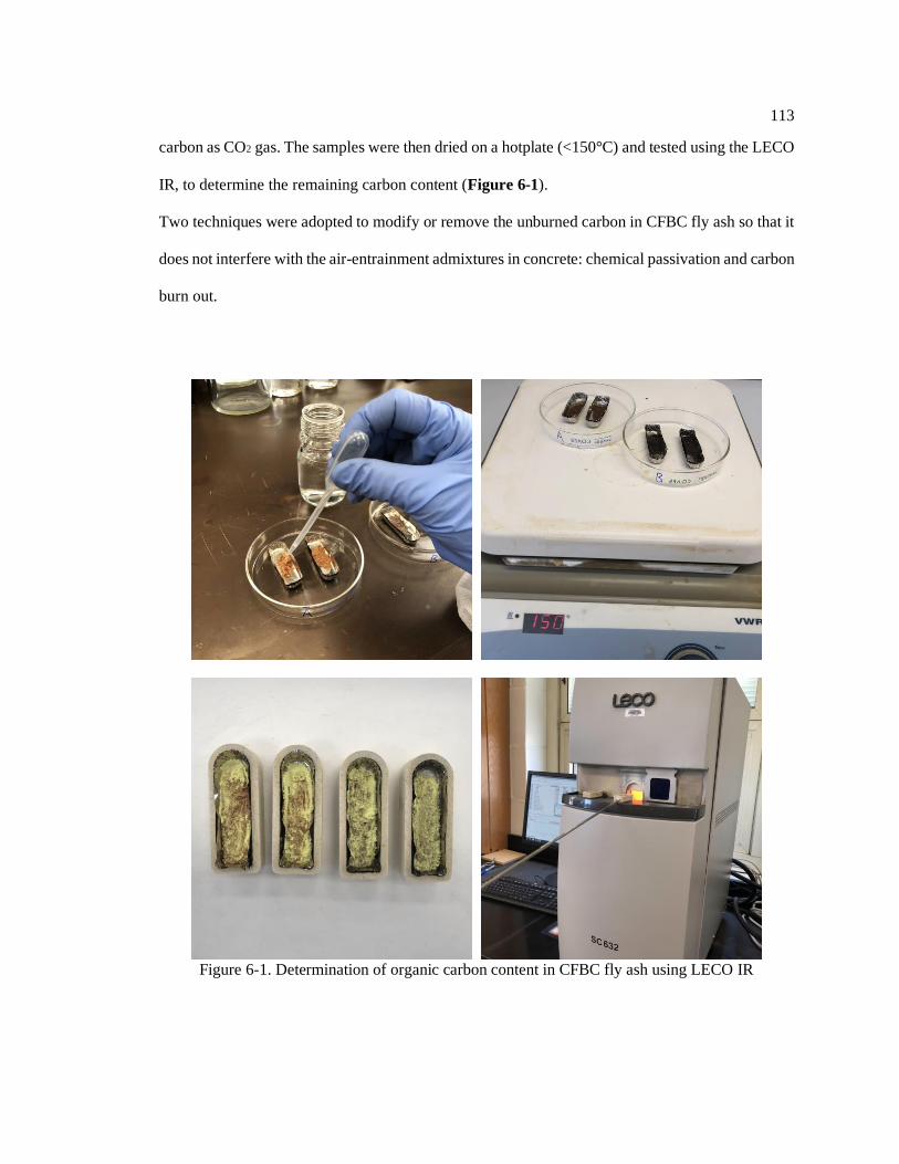
113
carbon as CO2 gas. The samples were then dried on a hotplate (<150°C) and tested using the LECO
IR, to determine the remaining carbon content (Figure 6-1).
Two techniques were adopted to modify or remove the unburned carbon in CFBC fly ash so that it
does not interfere with the air-entrainment admixtures in concrete: chemical passivation and carbon
burn out.
Figure 6-1. Determination of organic carbon content in CFBC fly ash using LECO IR

114
6.3.1 Chemical Passivation
In the chemical passivation method, PC fly ash is treated with sacrificial surfactants that cover the
surface of organic carbon, to prevent them from absorbing the air-entrainment admixture [1]. To
determine the effectiveness of chemical passivation for CFBC fly ash, anthracite and bituminous
fly ashes were sent for treatment to a building materials company with a reputation of successfully
treating over 2.5 million tons of PC fly ash using this method. The treated fly ashes were
incorporated into concrete (mix design specified in Table 3-3), and their effect on the slump, fresh
air content, hardened air content, and compressive strength of concrete (at 7, 28, and 56 days) was
compared to unbeneficiated samples.
6.3.2 Carbon Burn Out (CBO)
In the CBO approach, fly ash is combusted at temperatures above carbon ignition (460oC) and
below glass devitrification (700oC), to reduce the unburned carbon content. In this study, CFBC fly
ashes were combusted at 500, 550, 600, and 650oC, with a heating rate of 10oC/min and residence
time of 2h. LOI and LECO IR testing was conducted on the resulting ash to measure the remaining
total unburned carbon content. The performance of the raw and beneficiated fly ashes in terms of
air-entraining admixture uptake were also evaluated using foam index testing. Although standards
for foam index testing are currently not available, preparations are underway for the ASTM
standard entitled ‘New Test Method - Standard Method of Test for Determination of the Air-
Entraining Admixture Demand of a Cementitious Mixture’. The draft of this document which is
mainly based on the methodology developed by Harris et al. (2008) [2] [3] [4] and Sutter et al.
(2013) [5] [6], was used as a guideline for the foam index testing conducted in this research. This
fairly quick test can provide insight into the performance of cement/SCM mixtures in terms of their
air entrainment properties in concrete, relative to the control mixture. For this purpose, 25 mL of
distilled water was added to 8 g of cement and 2 g of CFBC fly ash, in an 8 oz. (237 mL) wide-

115
mouth glass container. The jar was capped and vigorously agitated for 30 sec (rate of 4 ± 0.5 shakes
per second and 225 ± 25 mm displacement of the sample container). One drop of 5% (by volume)
AEA solution was added to the slurry using a 50 μL pipette, and the container was shaken for
another 10 sec. The lid was removed after 20 sec. If a stable foam (for at least 60 sec) was not
observed on the surface of the slurry, another drop was added and the previous steps were repeated
(i.e., agitation for 10 sec and addition of AEA solution). The total number of drops, concentration
of AEA solution, and volume of each drop was used to calculate the foam index value for each fly
ash sample. To achieve the best results, the AEA solution strength was chosen such that a stable
foam was achieved by adding 15 ± 5 drops of AEA solution. Since beneficiated CFBC samples
required less than 10 drops of 5% AEA solution, 2% and 1% AEA solutions were also tested for
treated anthracite and bituminous fly ashes, respectively.
6.4 Results and Discussion
The organic carbon content of CFBC fly ashes is provided in Table 6-1. This value is slightly less
than the total carbon content obtained from LECO IR testing, indicating the presence of small
amounts of carbonates (e.g., CaCO3) in the fly ashes. In light of this insignificant difference, the
effectiveness of fly ash beneficiation techniques is evaluated based on the total carbon content.
Table 6-1. Unburned carbon content in CFBC fly ash
Specimen LOI Total carbon (wt.%) using
LECO IR
Organic carbon (wt.%)
using LECO IR
Anthracite CFBC 6.65 6.26 6.05
Bituminous CFBC 5.21 3.80 3.63
6.4.1 Chemical Passivation
The effect of chemically passivated CFBC fly ashes on the fresh and hardened properties of
concrete is provided in Table 6-2 and Figure 6-2.

116
Table 6-2. Properties of concrete incorporating chemically passivated CFBC fly ash compared to
that of as-received fly ash
Properties Control Anthracite
CFBC
Bituminous
CFBC
Treated
Anthracite
CFBC
Treated
Bituminous
CFBC
Slump (mm) 83 127 114 140 140
Fresh air content (vol %) 6.0 6.8 6.8 5.5 6.0
Hardened air content (vol %) 7.2 8.5 8.1 6.78 6.94
Air spacing factor (mm) 0.17 0.13 0.10 0.11 0.11
Compressive strength
at 56 days (MPa) 32.0 32.6 33.0 37.2 37.4
Figure 6-2. Compressive strength of concrete samples after 7, 28, and 56 days of hydration
Mixtures containing treated fly ash show improved slump and strength development compared to
non-beneficiated ones. The higher compressive strength is partially attributed to the lower air
content of these mixtures. Surprisingly, the air spacing factor has remained relatively unchanged.
The air spacing factor which is generally regarded as the most significant indicator of concrete
durability against freezing and thawing, is limited to 0.20 mm (0.008 in.) for moderate exposure
conditions. This criterion has been met by all samples. Despite improvements in terms of slump
0
5
10
15
20
25
30
35
40
45
0 10 20 30 40 50 60
Co
mp
ressiv
e s
tre
ng
th (
psi)
Age (days)
Control Anthracite
Bituminous Treated Anthracite
Treated Bituminous

117
and compressive strength, the chemical passivation technique has not effectively neutralized the
unburned carbon in CFBC fly ash, in order to reduce its interference with AEA performance in
concrete.
6.4.2 Carbon Burn Out (CBO)
The total carbon content (using LOI and LECO IR testing) and foam index values of raw and treated
(combusted at 500oC, 550oC, 600oC, and 650oC for 2h) fly ashes is provided in Table 6-3, and
Table 6-4. Information on the number of drops of AEA and total volume of non-diluted AEA (mL)
used to obtain a stable foam is included in Table 6-3. Results show that combustion of fly ashes at
500oC has had a profound effect on reducing the unburned carbon content and foam index value.
Little change is observed with increasing combustion temperatures.
Table 6-3. No of drops of AEA (total volume of AEA in mL) required for raw and treated CFBC
fly ashes to obtain stable foam.
Specimen Anthracite CFBC Bituminous CFBC
5% AEA 2% AEA 5% AEA 1% AEA
raw 20 (0.05) - 7 (0.0175) -
500oC 5 (0.0125) 11 (0.011) 2 (0.005) 14 (0.007)
550oC 6 (0.015) 14 (0.014) 2 (0.005) 14 (0.007)
600oC 6 (0.015) 16 (0.016) 3 (0.0075) 14 (0.007)
650oC 6 (0.015) 16 (0.016) 3 (0.0075) 13 (0.0065)
Table 6-4. Comparison between Foam Index results and the amount of unburned carbon from
LOI and LECO IR
Specimen
Anthracite CFBC* Bituminous CFBC
AEA
(mL)
LOI
(%)
Total carbon
(%)
AEA
(mL)
LOI
(%)
Total carbon
(%)
raw 0.05 6.96 6.26 0.0175 5.21 3.80
500oC 0.011 3.00 2.40 0.007 2.76 1.18
550oC 0.014 2.44 1.97 0.007 2.68 0.96
600oC 0.016 2.17 1.80 0.007 2.63 0.89
650oC 0.016 1.85 1.62 0.0065 2.41 0.80
* passed through No. 140 sieve.

118
Treated fly ashes require less than 10 drops of 5% AEA to reach a stable foam. For example, 3
drops of 5% AEA is used for the solution containing bituminous fly ash combusted at 600oC
(Figure 6-3). It is clear that 5% AEA is unable to properly distinguish the performance of various
fly ashes. For this reason, foam index testing on treated anthracite and bituminous fly ashes is
repeated using 2% and 1% AEA, respectively. The lower concentrations yield a stable foam using
10-20 drops of AEA. The second set of results show that increasing combustion temperatures
increases the AEA uptake for anthracite fly ashes, despite reductions in its unburned carbon
content. A possible explanation for this behavior might be an increase in the exposed surface area
on the fly ash. As for bituminous fly ash, changes in temperature has not had a significant effect on
the foam index value and unburned carbon content. The unburned carbon content obtained from
LOI and LECO IR testing is plotted as a function of temperature in Figure 6-4. Since the
differences in LOI and LECO IR values for anthracite fly ash is mainly attributed to the loss of
bound water, combustion of the fly ashes has helped remove the bound water, thus eliminating
errors associated with LOI testing. This is not the case for bituminous fly ash, where the
discrepancies are possibly affected by the decomposition of calcined clays (among other reactions),
rather than the loss of bound water from hydrated lime. That is why combustion temperatures of
up to 650oC have not been successful in reducing this gap.
In terms of economy and performance, optimum results were achieved by treating CFBC
fly ashes at 500oC for 2 h. Although a residence of 2 h time was sufficient for this study, for
industrial scale projects further testing is required to obtain the most efficient residence time.

119
Figure 6-3. Surface of solution containing bituminous fly ash combusted at 600oC, after adding 1,
2, and 3 drops of 5% AEA using a 0.05 mL pipet
Figure 6-4. Unburned carbon content (obtained from LOI and LECO testing) in CFBC fly ash as
a function of combustion temperature
6.5 Conclusions
• The chemical passivation technique which is currently commercialized for the treatment of PC
fly ash, was not effective on CFBC fly ashes and even led to lower air content in concrete
0
1
2
3
4
5
6
7
8
0 100 200 300 400 500 600 700
To
tal ca
rbo
n c
on
ten
t (%
)
Temperature oC
Anthracite-LOI Anthracite-LECO IR
Bituminous-LOI Bituminous-LECO IR

120
compared to non-beneficiated samples. The treated fly ashes did however improve the slump
and compressive strength at all ages.
• CFBC fly ashes were combusted at 500oC, 550oC, 600oC, and 650oC for 2h, to reduce their
unburned carbon content. Treatment at 500oC significantly improved AEA uptake and little
change was observed with the increase of combustion temperatures.
6.6 References
[1] R. Minkara, Chemical passivation, in: Coal Combust. Prod. Charact. Util. Benef., Elsevier
Ltd., 2017: pp. 327–342.
[2] N.J. Harris, K.C. Hover, K.J. Folliard, M.T. Ley, The Use of the Foam Index Test to Predict
AEA Dosage in Concrete Containing Fly Ash: Part I — Evaluation of the State of Practice,
J. ASTM Int. 5 (2008) 1–15.
[3] N. Harris, K.J. Folliard, M.T. Ley, The Use of the Foam Index Test to Predict Air-Entraining
Admixture Dosage in Concrete Containing Fly Ash: Part II — Development of a Standard
Test Method : Apparatus and Procedure, J. ASTM Int. 5 (2008) 1–15.
[4] N. Harris, K.J. Folliard, M.T. Ley, The Use of the Foam Index Test to Predict Air-Entraining
Admixture Dosage in Concrete Containing Fly Ash: Part III — Development of a Standard
Test Method : Proportions of Materials, J. ASTM Int. 5 (2008) 1–11.
[5] L.L. Sutter, R.D. Hooton, S. Schlorholtz, Methods for Evaluating Fly Ash for Use in
Highway Concrete, NCHRP Report 749, National Cooperative Highway Research
Program, Transportation Research Board of the National Academies, Washington, D.C.,
2013.
[6] L.L. Sutter, R.D. Hooton, S. Schlorholtz, Research Description and Findings, Specifications
and Protocols for Acceptance Tests of Fly Ash Used in Highway Concrete, NCHRP Report
749, National Cooperative Highway Research Program, Transportation Research Board of
the National Academies, Washington, D.C, 2012.
121
Chapter 7
Summary, Conclusions, and Future Approach
The objective of this study was to determine the feasibility of using CFBC fly ash as concrete
pozzolan. If successful, large quantities of widely available fly ash sources can supply the market,
and this will allow continued production of cheap, durable, and sustainable concrete of the 21st
century. Towards achieving this purpose, two sources of CFBC fly ash were characterized for their
physical properties, unburned carbon content, reactivity, bulk chemistry and mineralogy, and
compared against the requirements of ASTM C618-19, to identify areas of non-compliance. Next,
the fly ashes were used as partial replacement of Portland cement, and their effect on the
workability, mechanical properties, and durability (against aggressive agents and environmental
conditions) of concrete and mortar mixtures was evaluated. Concrete mixtures were tested for their
fresh (slump, fresh air content, setting time at various temperatures) and hardened (hardened air
content, compressive strength, chloride ion permeability, water absorption) properties. Equivalent
mortar mixtures were also tested for their autogenous shrinkage, drying shrinkage, expansion in
water, resistance to sulfate attack and ASR. Concrete performance was related to microstructural
features such as pore structure and pore fluid conductivity. Based on the results of the initial part
of the study, the efficiency of carbon reduction/neutralization techniques that are commercialized
for PC fly ash were investigated for CFBC fly ash. Finally, the interaction of CFBC fly ashes with
different components of Portland cement was monitored over time using XRD, SEM-EDS, and
thermogravimetric analysis of binary paste mixtures. The project findings will be used to develop
guidelines for evaluation, beneficiation and use of FBC fly ashes in concrete. These guidelines will
be submitted to ACI Committee 232 for review and potential adoption. They can be expanded in
the future by ACI and/or ASTM committees to develop specifications. By producing guidelines

122
and performance measures, concrete practitioners can distinguish good from bad fly ashes, and they
can employ feasible beneficiation techniques to improve the quality of this unconventional fly ash.
7.1 Conclusions
The key findings of this research are summarized below:
• CFBC fly ashes were in accordance with the physical and chemical requirements of ASTM
C618-19, except for the borderline high LOI in both fly ashes, and the high SO3 content in
bituminous fly ash. However, with proper dosing of chemical admixtures, concrete (20%
replacement of Portland cement with CFBC fly ash) with desirable slump, air content, and
compressive strength was achieve. The 14-day expansion of mortar bars containing
bituminous fly ash, stored in water, slightly surpassed ASTM C1038-14b limits, but the
SO3 content did not cause any deleterious expansion during autogenous shrinkage testing.
Further long-term testing is recommended.
• CFBC fly ashes showed good reactivity and strength development in mortar and concrete
mixtures. The SAI was at least 86% at 7 days and 93% at 28 days, which is greater than
the limit set by ASTM C618-19. The compressive strength of concrete containing 20%
CFBC fly ash was also similar to the control mixtures at 7, 28, and 56 days. Unlike
conventional PC fly ash, CFBC fly ash were able to contribute to the strength gain of
concrete as early as 7 days. The results of lime-pozzolan mortar strength (ASTM C593-
06), 7-day bound water content of lime-fly ash pastes (RILEM TC TRM267), and
thermogravimetric analysis on paste samples containing 20% CFBC fly ash suggest that
bituminous fly ash contains greater pozzolan reactivity compared to anthracite.

123
• The low combustion temperature (750 to 900oC) of FBC boilers, their diverse fuel supply,
and internal desulfurization process, results in a fly ash with a relatively similar chemistry
but different mineralogy than the conventional PC fly ash. Chemical analyses of CFBC fly
ash showed that the major oxides such as SiO2, Al2O3, and Fe2O3 were mainly derived from
coal, while most of CaO and SO3 originated from the capture of SO2 in the boiler by
limestone. The reactive phases identified were calcined clay, aluminosilica glass,
anhydrite, free lime which made up 74.5% and 78.5% of the mass of anthracite and
bituminous fly ashes, respectively. The non-reactive phases included quartz and hematite.
Unlike PC fly ash, FBC fly ash is absent of mullite, but can contain considerable amounts
of anhydrite, depending on the sulfur content of source coal and amount of limestone
addition. Finally, the FBC fly ash particles are sub-angular in shape and contain internal
porosity, which results in higher water demand compared to PC fly ash.
• The main hydration products of CFBC fly ash in binary paste mixtures were found to be
ettringite, hemicarboaluminate, monocarboaluminate, and C-A-S-H phases. Bituminous
fly ash contributed to greater ettringite and secondary C-A-S-H phase generation compared
to anthracite fly ash, due to its greater anhydrite content and pozzolanic reactivity. When
sulfur was depleted, the CaCO3 (from cement) reacted with the remaining aluminum and
silicon (from calcined clays and cement) to form hemicarboaluminate and
monocarboaluminate. Anthracite fly ash contained greater amounts of soluble aluminum
and silicon, which led to greater CO3-AFm phase production. For mixtures containing
CFBC fly ash, the Si/Ca and Al/Ca values for the amorphous C-A-S-H phase was greater
than the control.
• Proper dosing of CFBC fly ashes can mitigate ASR and chloride ion penetration, due to
their high alumina and silica content. They are also effective in lowering pore solution
alkalinity and refining the pore structure. Alumina replaces silica at tetrahedral sites within

124
the C-S-H creating a negative charge region capable of binding a positively charged alkali
ion. Since alkali hydroxides are the main contributor to pore solution conductivity and
alkali-silica reactions, their reduced content can increase concrete durability against ASR
induced expansion and chloride ion ingress. Mixtures containing CFBC fly ash
demonstrated acceptable performance in terms of drying shrinkage, and their rate of initial
water absorption was equal or less than the control. While anthracite fly ash did not cause
any deleterious expansion for samples stored in water or Na2SO4 solution, use of
bituminous fly ash should be avoided in sulfate rich environments. Long-term testing for
delayed ettringite formation is advised for mixtures containing bituminous fly ash.
• The chemical passivation technique which is currently commercialized for the treatment
of PC fly ash, was not effective on CFBC fly ashes and even led to lower air content in
concrete compared to non-beneficiated samples. The treated fly ashes did however improve
the slump and compressive strength at all ages. The CBO technique was carried out at
temperatures of 500oC, 550oC, 600oC, 650oC, and residence time of 2h, to reduce the
unburned carbon content in CFBC fly ash. Treatment of CFBC fly ashes at 500oC
significantly improved AEA uptake and little change was observed with the increase of
combustion temperatures.
7.2 Future Directions
This research study was focused on materials characterization, performance testing, carbon
neutralization/reduction, and understanding the hydration mechanism of CFBC fly ashes. Based on
the obtained results, the following suggestions are presented for future research:

125
• The use of two CFBC fly ashes with distinct compositions was investigated as concrete
pozzolan. CFBC powerplants in Pennsylvania mainly run on anthracite and bituminous
waste coal, and although bituminous coal is the most abundant rank of coal found in the
United States (about 46% reported in 2017), anthracite coal is relatively rare and available
in a small amount in Pennsylvania. It is therefore beneficial to evaluate the performance of
FBC fly ashes from other coal sources in concrete, especially fly ash obtained from burning
sub-bituminous coal, as it is the second most abundant type of coal in the United States
(about 45% reported in 2017) [1]. In general, testing of fly ashes from various CFBC
powerplants can help categorize areas of non-compliance in fly ashes based on coal source.
The temporal consistency of fly ashes also needs to be assessed. The feed fuel for most
CFBC burners is low quality coal, which may cause significant variations in the chemical
composition and unburned carbon content of fly ashes collected from the same powerplant
at different ages.
• In the event that the temporal consistency is low, addition of chemical admixtures is not an
effective method for counteracting the high unburned carbon content in CFBC fly ashes.
In this case, beneficiation of CFBC fly ash prior to its use in concrete is required.
Combustion of fly ash at 500oC for 2h can dramatically reduce the unburned carbon
content; however, more cost-effective approaches such as electrostatic separation need to
be investigated. Wet processing technologies (e.g., froth floatation, oil agglomeration) are
not advised, as they may affect the composition of fly ash, and the costs associated with
drying the fly ash after treatment are relatively high.
• The 14-day expansion in water for mortar bars containing 20% bituminous fly ash slightly
surpassed ASTM C1038-14b limits. Therefore, additional long-term testing (e.g., delayed
ettringite formation) is recommended to determine the volume stability of this mixture
when in contact with moisture. If the SO3 content in bituminous fly ash proves to be

126
deleterious, various methods for the management of sulfur need to be carried out. This may
include the use of sulfur absorbing materials or the employment of bituminous fly ash as a
blend with clinker, where the anhydrite in bituminous fly ash acts as a replacement for the
gypsum in cement.
• CFBC fly ash should be compared against ASTM C1709−18, Standard Guide for
Evaluation of Alternative Supplementary Cementitious Materials (ASCM) for Use in
Concrete. This specification consists of five main stages. The majority of testing specified
in the three initial stages has been completed in the current study. As part of the requirement
for stage four, the performance of ASCM shall be investigated in a broad range of concrete
mixtures, with total cementitious materials content varying from 200 to 400 kg/m3. The
test program should also include mixtures with various types of commonly used chemical
admixtures (e.g., air entraining agents, water reducers, setting time accelerators and setting
time retarders) to determine compatibility. Once all four stages are completed and
acceptable performance is demonstrated in laboratory tests, field trials for concrete
containing ASCM is carried out. A minimum of three field evaluations, each of at least one
year in duration should be performed.
• The possibility of using CFBC fly as raw material for calcium-sulfo-aluminate (CSA)
cement production should be investigated. This can be achieved by either matching the
chemistry of CSA cement by augmenting CFBC fly ash with necessary additives (e.g.,
bauxite, limestone, PC fly ash) or using CFBC fly ash as a raw material for the preparation
of CSA clinker [2] [3]. CSA cements are increasingly being used in specialized
applications for their high early age strength and shrinkage compensation properties. They
are mainly composed of CaO (approximately 35-45%), Al2O3 (approximately 20-35%),
and SO3 (8-20%) [4] [5] [6] [7] [8], and are valued at roughly twice as much as Portland
cement ($200/ton).
127
7.3 References
[1] Types of coal, U.S. Energy Inf. Adm., Available at:
https://www.eia.gov/energyexplained/print.php?page=coal_home. Accessed: July 2019.
[2] I.A. Chen, M.C.G. Juenger, Synthesis and hydration of calcium sulfoaluminate-belite
cements with varied phase compositions, J. Mater. Sci. 46 (2011) 2568–2577.
[3] R.B. Jewell, R.F. Rathbone, T.Y. Duvallet, T.L. Robl, K.C. Mahboub, Fabrication and
testing of low-energy calcium sulfoaluminate-belite cements that utilize circulating
fluidized bed combustion by-products, Coal Combust. Gasif. Prod. J. 7 (2015) 9–18.
[4] F. Winnefeld, B. Lothenbach, Hydration of calcium sulfoaluminate cements - Experimental
findings and thermodynamic modelling, Cem. Concr. Res. 40 (2010) 1239–1247.
[5] R. Trauchessec, J. Mechling, A. Lecomte, A. Roux, B. Le Rolland, Hydration of ordinary
Portland cement and calcium sulfoaluminate cement blends, Cem. Concr. Compos. 56
(2015) 106–114.
[6] F.P. Glasser, L. Zhang, High-performance cement matrices based on calcium
sulfoaluminate – belite compositions, Cem. Concr. Compos. 31 (2001) 1881–1886.
[7] Y. Hu, W. Li, S. Ma, X. Shen, Influence of borax and citric acid on the hydration of calcium
sulfoaluminate cement, Chem. Pap. 71 (2017) 1909–1919.
[8] Y. Jeong, C.W. Hargis, S. Chun, J. Moon, Effect of calcium carbonate fineness on calcium
sulfoaluminate-belite cement, Materials (Basel). 10 (2017) 6–10.

VITA
Education
2015-2019 The Pennsylvania State University, University Park, PA
PhD. Candidate in Civil Engineering; Geotechnical and Materials
2012-2014 Amirkabir University of Technology (Tehran Polytechnic), Tehran, Iran
MSc. in Civil Engineering; Structural Engineering
2006-2010 Isfahan University of Technology, Isfahan, Iran
BSc. in Civil Engineering; Structural Engineering
Academic Employment
2017-2019 Graduate Research Assistant, The Pennsylvania State University
2016-2017 Teaching Assistant, The Pennsylvania State University
Academic Awards
2019 CMT Laboratories Graduate Scholarship
2019 Marley Graduate Fellowship in Engineering
2015-2018 Penn State College of Engineering Fellowship
2015-2016 Penn State University Graduate Fellowship (UGF)
Presentations
2019 Performance of alternative and reclaimed fly ashes in concrete. Oral presentation
at the Transportation Research Board 98th Annual Meeting.
2018 Use of Fluidized Bed Combustion (FBC) fly ash as concrete pozzolan. Oral
presentation at the 9th Advances in Cement-based Materials conference, The
American Ceramics Society (ACerS).
2018 Evaluating the use of Fluidized Bed Combustion (FBC) as concrete pozzolan.
Poster presentation at the 20th Annual Pennsylvania Concrete Conference.
Publications
M. Zahedi, F. Rajabipour, Fluidized Bed Combustion (FBC) fly ash and its performance in
concrete, ACI materials journal, pozzolans special edition, (2019).
* Chapters 4 and 5 are currently in preparation for publication and will be submitted soon.
Copyright © 2022 FDOKUMEN