THE OPTIMIZATION STRENGTH THEORY OF RC ...
9
Theory and Building Practice Vol. 1, No. 1, 2019 https://doi.org/10.23939/jtbp2019.01.023 Vitalii Mitrofanov 1 , Nataliia Pinchuk 2 THE OPTIMIZATION STRENGTH THEORY OF RC ELEMENTS AND SOLUTION OF SHEAR PROBLEM 1 Center for Advanced Design Methods of Concrete Structures, 2/21, Levanevskogo Str., Poltava, 36011, Ukraine [email protected] 2 Poltava National Technical Yuri Kondratuyk University, 24, Pershotravnevyj Ave, [email protected] Mitrofanov Vitalii, Pinchuk Nataliia, 2019 The shear strength designs recommended by the MC 2010 are analyzed. It is noted that despite the multiformity of shear failure types observed in experiments, the MC 2010 takes into account only two types: on the Critical Inclined Crack (CIC) and on the web concrete crushing. It is shown the non- validity of opinion concerning exclusive great importance of interlock forces in the crack for shear bearing capacity. It is emphasized the need to reveal the cause of considered problem complication, i.e. missing information which must be included into model. Such missing information is complete system of possible shear failure types which is offered in the form of the elements classification depending on quantity of longitudinal and shear reinforcement, respective behavior under loading and failure type. This classification was assumed as a basis of the Optimization Strength Theory of Concrete Elements (OSTCE) under joint action of bending moment, shear and axial forces. The offered classification shows the great variety of possible shear failure types and allows to select the elements group with optimal practical features: minimum steel expense, plastic failure on the CIC and comparatively simple design. The fundamentals of OSTCE, its merits, practical application and well agreement with various test data are stated. Key words: shear bearing capacity factors, element classification, optimization design Introduction Despite enormous number of researches carried out to the present, shear strength design of concrete elements remains non-solved completely problem. For a long time this problem is known as “complicated” problem. According to (Peregudov & Tarasenko, 1989) the complication of problem may be induced by the so called “missing information”. Therefore solution of complex problem may be obtained after determination of the “missing information” which must be included into model. The important feature of the “missing information” is its considerable novelty in comparison with existing notions which after this ought to become more precise, generalized, profound and complete. In order to clarify the possible “missing information” of the shear strength problem it is necessary to pay attention that MC 2010 takes into account only two types of shear failure: on the Critical Inclined Crack (CIC) and on the web concrete struts crushing. Further for short the concrete elements failing on the CIC will be called “elements of group A” and elements failing on the web concrete struts crushing – “elements of group B”. The above elements groups are studied experimentally long ago during several decades and the ones have both common and different features. It is necessary to emphasize the common feature of pointed out elements: the increased quantity of longitudinal reinforcement used usually without the bars cut-off. This elements peculiarity was grounded by need in experiments to prevent from the early yielding of longitudinal reinforcement and cross section failure in order for the shear failure was obtained. The difference of elements A and B groups concerns the
-
Upload
khangminh22 -
Category
Documents
-
view
4 -
download
0
Transcript of THE OPTIMIZATION STRENGTH THEORY OF RC ...

Theory and Building Practice Vol. 1, No. 1, 2019 https://doi.org/10.23939/jtbp2019.01.023
Vitalii Mitrofanov1, Nataliia Pinchuk2
THE OPTIMIZATION STRENGTH THEORY OF RC ELEMENTS AND SOLUTION OF SHEAR PROBLEM
1Center for Advanced Design Methods of Concrete Structures, 2/21, Levanevskogo Str., Poltava, 36011, Ukraine
2Poltava National Technical Yuri Kondratuyk University, 24, Pershotravnevyj Ave,
Ó Mitrofanov Vitalii, Pinchuk Nataliia, 2019
The shear strength designs recommended by the MC 2010 are analyzed. It is noted that despite the multiformity of shear failure types observed in experiments, the MC 2010 takes into account only two types: on the Critical Inclined Crack (CIC) and on the web concrete crushing. It is shown the non-validity of opinion concerning exclusive great importance of interlock forces in the crack for shear bearing capacity. It is emphasized the need to reveal the cause of considered problem complication, i.e. missing information which must be included into model. Such missing information is complete system of possible shear failure types which is offered in the form of the elements classification depending on quantity of longitudinal and shear reinforcement, respective behavior under loading and failure type. This classification was assumed as a basis of the Optimization Strength Theory of Concrete Elements (OSTCE) under joint action of bending moment, shear and axial forces. The offered classification shows the great variety of possible shear failure types and allows to select the elements group with optimal practical features: minimum steel expense, plastic failure on the CIC and comparatively simple design. The fundamentals of OSTCE, its merits, practical application and well agreement with various test data are stated.
Key words: shear bearing capacity factors, element classification, optimization design
Introduction
Despite enormous number of researches carried out to the present, shear strength design of concrete elements remains non-solved completely problem. For a long time this problem is known as “complicated” problem. According to (Peregudov & Tarasenko, 1989) the complication of problem may be induced by the so called “missing information”. Therefore solution of complex problem may be obtained after determination of the “missing information” which must be included into model. The important feature of the “missing information” is its considerable novelty in comparison with existing notions which after this ought to become more precise, generalized, profound and complete. In order to clarify the possible “missing information” of the shear strength problem it is necessary to pay attention that MC 2010 takes into account only two types of shear failure: on the Critical Inclined Crack (CIC) and on the web concrete struts crushing. Further for short the concrete elements failing on the CIC will be called “elements of group A” and elements failing on the web concrete struts crushing – “elements of group B”. The above elements groups are studied experimentally long ago during several decades and the ones have both common and different features. It is necessary to emphasize the common feature of pointed out elements: the increased quantity of longitudinal reinforcement used usually without the bars cut-off. This elements peculiarity was grounded by need in experiments to prevent from the early yielding of longitudinal reinforcement and cross section failure in order for the shear failure was obtained. The difference of elements A and B groups concerns the
Mitrofanov Vitalii, Pinchuk Nataliia 24
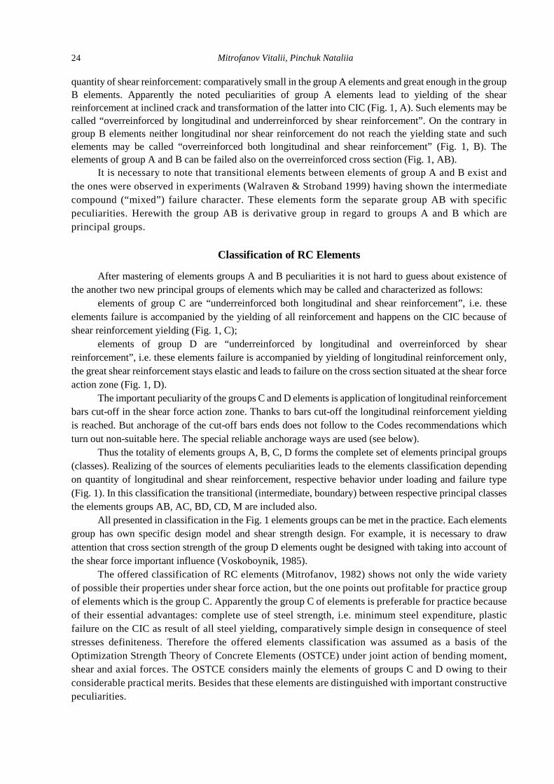
quantity of shear reinforcement: comparatively small in the group A elements and great enough in the group B elements. Apparently the noted peculiarities of group A elements lead to yielding of the shear reinforcement at inclined crack and transformation of the latter into CIC (Fig. 1, A). Such elements may be called “overreinforced by longitudinal and underreinforced by shear reinforcement”. On the contrary in group B elements neither longitudinal nor shear reinforcement do not reach the yielding state and such elements may be called “overreinforced both longitudinal and shear reinforcement” (Fig. 1, B). The elements of group A and B can be failed also on the overreinforced cross section (Fig. 1, AB).
It is necessary to note that transitional elements between elements of group A and B exist and the ones were observed in experiments (Walraven & Stroband 1999) having shown the intermediate compound (“mixed”) failure character. These elements form the separate group AB with specific peculiarities. Herewith the group AB is derivative group in regard to groups A and B which are principal groups.
Classification of RC Elements
After mastering of elements groups A and B peculiarities it is not hard to guess about existence of the another two new principal groups of elements which may be called and characterized as follows:
elements of group C are “underreinforced both longitudinal and shear reinforcement”, i.e. these elements failure is accompanied by the yielding of all reinforcement and happens on the CIC because of shear reinforcement yielding (Fig. 1, C);
elements of group D are “underreinforced by longitudinal and overreinforced by shear reinforcement”, i.e. these elements failure is accompanied by yielding of longitudinal reinforcement only, the great shear reinforcement stays elastic and leads to failure on the cross section situated at the shear force action zone (Fig. 1, D).
The important peculiarity of the groups C and D elements is application of longitudinal reinforcement bars cut-off in the shear force action zone. Thanks to bars cut-off the longitudinal reinforcement yielding is reached. But anchorage of the cut-off bars ends does not follow to the Codes recommendations which turn out non-suitable here. The special reliable anchorage ways are used (see below).
Thus the totality of elements groups A, B, C, D forms the complete set of elements principal groups (classes). Realizing of the sources of elements peculiarities leads to the elements classification depending on quantity of longitudinal and shear reinforcement, respective behavior under loading and failure type (Fig. 1). In this classification the transitional (intermediate, boundary) between respective principal classes the elements groups AB, AC, BD, CD, M are included also.
All presented in classification in the Fig. 1 elements groups can be met in the practice. Each elements group has own specific design model and shear strength design. For example, it is necessary to draw attention that cross section strength of the group D elements ought be designed with taking into account of the shear force important influence (Voskoboynik, 1985).
The offered classification of RC elements (Mitrofanov, 1982) shows not only the wide variety of possible their properties under shear force action, but the one points out profitable for practice group of elements which is the group C. Apparently the group C of elements is preferable for practice because of their essential advantages: complete use of steel strength, i.e. minimum steel expenditure, plastic failure on the CIC as result of all steel yielding, comparatively simple design in consequence of steel stresses definiteness. Therefore the offered elements classification was assumed as a basis of the Optimization Strength Theory of Concrete Elements (OSTCE) under joint action of bending moment, shear and axial forces. The OSTCE considers mainly the elements of groups C and D owing to their considerable practical merits. Besides that these elements are distinguished with important constructive peculiarities.

The optimization strength theory of rc elements and solution of shear problem 25
Fig. 1. Classification of RC elements: ρs, ρsw – longitudinal tensile
and shear reinforcement ratio respectively; σs, σsw – respective reinforcement stress; CDZ – concrete failure zone
Anchorage of bars cut-off in the elements of groups C and D
The curtailed longitudinal reinforcement is anchored usually according to Codes by means of addition after theoretical bars cut-off point the “anchorage length” which turn out usually large enough. As a result the steel economy happens negligible and elements behavior is identic to elements with continuous bars, i.e. group A elements. Therefore it was decided to make the bars cut-off near theoretical cut-off point and to use the compound reinforcement bars parts of which are connected by means of the welding or the Lenton System Couplers (Fig. 2).
a
b
Fig. 2. Beams reinforcement cages with compound reinforcement bars, parts of which are connected with the welding W (a) and the Lenton System Couplers LSC (b)
The pointed out longitudinal reinforcement construction secures the increased steel economy, reliable anchorage of bars cut-off, steel yielding and element plastic failure on the CIC. Apparently the

Mitrofanov Vitalii, Pinchuk Nataliia 26
forming inclined crack passes always through place of bars cut-off. Therefore we can govern the inclined crack width opening by means of the additional local stirrups installation.
Some features of the MC 2010 shear strength designs
The MC 2010 (fib Bulletin 57, 2010) does not clearly point out the preferable for practice RC elements and their designs. But the one looks after the design simplicity and offers for designers the so called “Levels of Approximation”. However at present there are simple in application and great on possibilities computer software. Therefore the main aim of Code developers must be search of the optimizing RC structure models which can be realized by means of simple enough software, for example with the Table Processor Excel.
The design on the crushing of web concrete struts is needed not always: only when in beams with T – or double – T section the web thickness is little enough (bw/h ≈ .05 – 0.15). This MC 2010 design is based on the so called “Modified Compression Field Theory (MCFT)” (Vecchio & Collins, 1986) the hypotheses of which lack direct experimental substantiation (Beck & Kaufmann, 2017).
In the MCFT it is attached great importance to the interlock of roughness on the adjacent crack faces. The source of such point of view were the test data (Walraven, 1981) obtained on the so called “push-off specimens” in which the loading force direction coincided with crack plane and crack roughness resistance was used completely. But interlock conditions for crack forming in the various RC structures may be quite differing from the conditions of test specimens. Nevertheless there is clear and strict “Criterion of Existence of Interlock in Crack (CEIC)” which allows to reveal the presence or the absence of interlock forces in the crack (Mitrofanov, 2008). If the CEIC is not used, any conclusions concerning the interlock in crack are not valid.
Statements of the OSTCE
1. Depending on quantity of longitudinal and shear reinforcement, respective behavior under loading and failure type the RC elements are classified on 4 principal A, B, C, D and 5 intermediate (boundary) AB, AC, BD, CD, M groups (Fig. 1) (Mitrofanov, 1982). The OSTCE considers mainly the elements of group C which are distinguished by the most economical steel expenditure and plastic failure on the CIC.
2. The element of bar structure is defined as part on the length l of which the signs of M, Q, N forces are constant. Such element definition allows to unify the element model which includes only at one CIC and critical normal crack (CNC) (Fig. 3). The end points A and B of the CIC are considered as theoretical points of curtailment or bent-up of longitudinal reinforcement (Figs. 2, 3).
3. The non-deep elements with 0Ax ¹ , c l¹ (see Fig. 6) and 1, 2l d ³ are considered. 4. The ultimate shear Qc and compression Nc forces in the concrete failure zone near end point
B of the CIC are determined depending on the failure case of the concrete truncated wedge above the CIC (Fig. 4). For the non-deep elements the cases 1 and 2 are most important with the strength criterion (Mitrofanov, 1999)
c c N cQ Af bx Na= + , (1) where for case 1
NA tga g= - = ± , (2) for case 2
( )1 wA tg tg tgg g a= + , ( )N wtga a g= - , (3)
( )1 2ct ctg m f fg = , ( ) 1...2cm f = , (4)
x – concrete failure zone height (see Fig. 3); wa – wedge angle (see Fig. 4).

The optimization strength theory of rc elements and solution of shear problem 27
Fig. 3. Element design model Fig. 4. Failure cases of concrete truncated wedge depending on ratio Qc/Nc
5. The interlock forces in СIC and the dowel action of reinforcement do not take into account
for the group C elements because the element parts I and II (see Fig. 6) as fragments of the plastic kinematic mechanism mutually rotates inducing the CIC opening without essential shear of its adjacent surfaces.
6. The forces M, Q, N in the critical section (crack) are expressed through load parameter F
MM Ff= , QQ Ff= , NN Ff= , (5)
where Mf , Qf , Nf – load functions, reflecting the element load character and depending on parameters
Ax and c (see Fig. 3). 7. Distribution of the normal cs and shear ct stresses along the concrete failure height x is
adopted uniform. 8. The stresses ss , ss ¢ , sws of the longitudinal tensile sA , compressed sA¢ and shear swA
reinforcement are restricted by the conditions of ultimate state respectively 1s s sdm fs= £ , 1s s sdm fs¢ ¢ ¢= £ , 1sw sw swdm fs= £ , (6)
where sdf , sdf ¢ , swdf – design resistances; sm , sm¢ , swm – factors of resistance use completeness of respective reinforcement.
Primary relationships of the OSTCE
The balance equations 0X =å , 0Y =å , 0 0M =å for the element part I (see Fig. 6) together
with the concrete strength criterion (5) lead to the first primary relationship as quadratic equation for the relative load parameter cP F f bd=
( ) ( )( )( )
2
2 2
2 1 2
2 2 0,
N Q N N M Q N sw sw
sw sw
P f f f A P f d f f m c Ad
m c d c d B
a w x h
x w
é ù- + + - + - -ë û
- + - = (7)
where w ,h , B , sz , sx , sx ¢ , swx – see detailed paper (Mitrofanov & Pinchuk, 2017).

Mitrofanov Vitalii, Pinchuk Nataliia 28
The second primary relationship is the volume ratio of element entire reinforcement ( )
( ) ( )1 11 1 ,s c s A sd c s A sd c sw swd
c s A sd c s A sd
V f x f l f x c f l f f
f x l f f x c l f
x x x
x x
¢ ¢= + + + +
¢ ¢+ - + é - + ùë û (8)
where 1 1s sd s cf A f bdx = , 1 1s sd s cf A f bdx ¢ ¢ ¢= , 1sA , 1sA¢ – area of longitudinal tensile and compressed reinforcement respectively, which is found from strength design of the element end cross section with CNC (see Fig. 3).
Two Principal Problems Solving
The design problems are set and solved as the problems of Non-linear Minimization with Constraints. For the strength control problem the aim function is the load parameter uF expressed from (7) through unknown value с, which is found from the condition
( ) minuF c = (9) with constraints
1s s swm m m¢= = = , (10) corresponding to the elements of group C.
Herewith the strength use completeness of reinforcement is controlled by conditions opt
s sA A£ , opts sA A¢ ¢£ , opt
sw swA A£ , (11)
in which the optimal areas optsA , opt
sA¢ , optswA of respective reinforcement are calculated from the solving
of problem of needed reinforcement determination (see lower) by the load parameter uF , found from the strength control problem solution. The problem of determination of needed areas sA , sA¢ , swA together with unknown values , , , ,A s s swx c m m m¢ is solved from the condition
( ), , , , , , , mins s s sw A s s swV A A A x c m m m¢ ¢ = (12)
with constraints (7), (6) and 0Ax c l+ - £ . The Kuhn-Tacker conditions for Minimization problem (12) lead to the optimal solution (10), which
simplifies determination of the rest unknown values. The stated strength design of the inclined sections leads to strength design of the cross sections as partial case when 0c = , Ax l= , 1s sx x= , 1s sx x¢ ¢= . This design considers the balanced reinforcement as the optimal one and takes into account the shear force influence on the cross sections strength of group D elements (Voskoboynik, 1985).
Experimental Verification of the OSTCE
The many-sided verification of the OSTCE was conducted. So, the strength criterion (1)–(4) was thoroughly experimentally verified by the specimens-wedges of usual heavy (Mitrofanov, 1982) and light-weight concretes. The significant control of (1)–(4) was fulfilled on the beams with artificial CIC, which allowed to exclude the interlock between crack sides and enabled to find reliably the experimental Qc and Nc quantities (Mitrofanov, 1999). The noted all-round tests confirmed the reality of theoretical failure cases (see Fig. 4) of concrete wedges over the CIC and reliability of the relationships (1)–(4).
It is necessary to note that in all countries of the world the strength investigations of RC elements under the shear forces action were being conducted mostly on the elements of groups A and B (see Fig. 1) without curtailment of longitudinal reinforcement in zone of action of shear forces. These tests led to the inexact notions that RC elements failure by the CIC has only brittle character.
In our researches of the group C elements the longitudinal reinforcement was used in the form of two-bars bundles in which the one bar has break in zone action of shear force and its end was welded to the

The optimization strength theory of rc elements and solution of shear problem 29
continuing bar. The tested elements revealed the positive for practice features of the group C elements: clear-cut plastic behavior in ultimate state and the most economical expense of steel.
Our investigations included the tests: 26 columns under joint action M, N, Q forces (Kotlyarov, 1992); 21 usual (Mitrofanov, 1982), 22 prestressed and 12 usual (Mikitenko, 1995) simple beams; 22 simple and 13 cantilever beams with failure by the cross sections where the concrete failure zone
was undergone the essential influence of shear force action (Voskoboynik, 1985); 4 simple beams with inclined compressive side (Mitrofanov and Artsev, 2007), 6 two-span continuous beams (Mitrofanov, 2000). All tested columns and beams were reinforced in accordance with the OSTCE for the given load. The test data of 126 beams and columns showed the mean ratio Ftest/Fcalc of experimental
ultimate load parameter Ftest to the theoretical one Fcalc equal to 1.073 with the coefficient of variation V = 9.525 %. The comparison of the test data with design results by the Code SNiP 2.03.01-84* (Gosstroy, Moscow, 2000) led to the mean ratio Ftest/Fcalc = 0.838, V = 23.06 %. The like comparison with Eurocode 2-1992 and MC 2010 produced the worst results.
There are design examples according to the OSTCE in (Mitrofanov, 2000).
Fig. 5. Character of simple beams failure
Conclusions
The offered RC elements classification includes the “missing information” in the form of principal groups C and D elements besides the known principal groups A, B and many transitional groups. All this great elements variety may take place in practice. But elements of group C are preferable thanks to their minimum steel expense and plastic failure. Therefore the OSTCE bearing a relation to the elements of groups C and D was worked out. The OSTCE is distinguished by the clarity, strictness and well conformity with experimental data.
The elements of T- and double-T section with small enough web thickness and considerable enough longitudinal and shear reinforcement (elements of group B and close transitional ones) are failed on the web concrete crushing which is highly complicated phenomenon being described by

Mitrofanov Vitalii, Pinchuk Nataliia 30
the MCFT. However the MCFT statements have not clear experimental confirmation, i.e. this problem has some “missing information” too. Perhaps the one is connected with overestimation of the interlock forces influence in cracks that can be clarified by means of the CEIC. On the other hand the model of beam with anisotropic web is attractive although the ground of the Generalized Hook Law moduluses is difficult problem also. Thus in the great “space” of multiform RC elements under shear loading the OSTCE occupies the considerable enough “region” of optimality and reliability. This region must be widened including the group B of elements together with appropriate transitional groups.
References Beck, A. & Kaufmann, W. (2017), Paradigms of Shear in Structural Concrete – Review and Experimental
Verification. Book of Abstracts for 2017 fib Symposium, Hordijk, D.A.; Lukovic, M. (Eds), Maastricht, The Netherlands, p. 344.
CADMCS (2016): Center for Advanced Design Methods of Concrete Structures, http://www.cadmcs.org (Oct. 2016).
fib Bulletin 57 (2010), Shear and punching shear in RC and FRC elements. Technical report, Proceedings of a workshop held on 15–16 October 2010, in Salo, Lake Garda, Italy.
Kotlyarov, V. A. (1992), Strength of reinforced concrete elements under joint action of the bending moments, longitudinal compressive and shear forces. Ph.D. thesis. Poltava Eng. Build. Inst., Poltava. (in Russian).
Mikitenko, S. M. (1995), Strength under bending of reinforced concrete elements with complete resistance of shear and high-strength longitudinal reinforcement. Ph.D. thesis, Poltava TU, Poltava. (in Ukrainian).
Mitrofanov, V. P. (1982), The stress-strain state, strength and cracking of the RC elements under cross bending. Ph.D. thesis, VZISI, Moscow (in Russian).
Mitrofanov, V. P. (1999), Investigation of destruction zone resistance of HSC of beams under shear forces action.Proceedings of the 5th International Symposium on Utilization of HS/HP Concrete, Holland,I., Sellevold, E. J., (Eds), Sandefjord, Norway, vol. 1, pp. 461–468.
Mitrofanov, V. P. (2000), Optimization strength theory of reinforced concrete bar elements and structures with practical aspects of its use. Bygningsstatiske Meddelelser. Danish Society for Structural Science and Engineering, 71, Dec. 2000, pp. 71–125.
Mitrofanov, V. P. & Artsev, S. I. (2007), Experimental verification of the Optimization Strength Theory of Reinforced Concrete Elements by the beams with changing height of section. Building Structures, Kiev NIISK, 67, 244–253 (in Russian).
Mitrofanov, V. P. (2008), Investigation of cracks surface roughness and shear transfer strength of cracked HSC. Proceedings of the International fib Symposium 2008, Walraven, J.C.; Stoelhorst, D. (Eds), Amsterdam, The Netherlands, CRC Press/Balkema, p. 134.
Mitrofanov, V. P. & Pinchuk, N. M. & Mitrofanov, P. B. (2014), The primary design conceptions of concrete and reinforced concrete structures in the ADM Model Code. Proceedings of the 4th International fib Congress 2014, Mumbai, India, Short paper 73, pp. 259–261.
Mitrofanov, V. & Pinchuk, N. (2017), Aspects of Implementation into practice of Optimization Strength Theory of RC Elements. Book of Abstracts for 2017 fib Symposium, Hordijk, D.A.; Lukovic,M. (Eds), Maastricht, The Netherlands, p. 352.
Peregudov, F. I. & Tarasenko, F. P. (1989), Introduction to System Analysis. Higher School, Moscow (in Russian).
Voskoboynik, P. P. (1985), Complex stress state of concrete failure zone and taking into account of the one in the strength designs of RC elements cross sections. Ph. D. Thesis, OISI, Odessa, 1985 (in Russian).
Walraven, J. & Stroband J. (1999) Shear Capacity of High Strength Concrete beams with Shear Reinforcement. Proceedings of 5th International Symposium on Utilization of HS/HP Concrete, Holand, I.; Sellevold, E. J. (Eds), Sandefjord, Norway, Vol.1, pp. 693–700.

The optimization strength theory of rc elements and solution of shear problem 31
В. Митрофанов, Н. Пінчук Центр передових методів розрахунку залізобетонних конструкцій,
Національний університет “Полтавська політехніка імені Юрія Кондратюка”, кафедра залізобетонних і кам’яних конструкцій та опору матеріалів
ОПТИМІЗАЦІЙНА ТЕОРІЯ МІЦНОСТІ ЗАЛІЗОБЕТОННИХ ЕЛЕМЕНТІВ ТА РОЗВ’ЯЗАННЯ ЗАДАЧІ МІЦНОСТІ ПОХИЛОГО ПЕРЕРІЗУ
Ó Митрофанов В., Пінчук Н., 2019
Проаналізовано розрахунок залізобетонних конструкцій на дію поперечної сили за нормами проєктування MC 2010. Зазначено, що, незважаючи на наявність декількох типів руйнування за похилим перерізом, які спостерігаються в експериментах, норми MC 2010 враховують лише два типи руйнування: за критичною похилою тріщиною (CIC) та від роздавлювання бетонного підкосу. Показано хибність переконання, що стосується виключно великого впливу сил зчеплення в тріщині на несучу здатність похилого перерізу конструкцій. Наголошено на необхідності розкриття причин складності питання, що розглядається, тобто відсутності інформації, яка повинна входити до моделі. Відсутня інформація – це повна система можливих випадків руйнування, яка запропонована у вигляді класифікації елементів залежно від кількості поздовжньої та поперечної арматури, відповідної поведінки під навантаженням та типів руйнування. Цю класифікацію покладено в основу оптимізаційної теорії міцності залізобетонних елементів (OSTCE) за спільної дії згинальних моментів, поперечних та поздовжніх сил. Запропонована класифікація показує велику різноманітність можливих випадків руйнування залізобетонних елементів та дає змогу вибирати групу елементів з оптимальними практичними характеристиками: мінімальними витратами сталі, пластичним руйнуванням за похилим перерізом та порівняно простими розрахунками. Викладено основи оптимізаційної теорії міцності залізобетонних елементів, її переваги, практичне застосування та зафіксовано добру збіжність із даними результатів різних випробувань.
Ключові слова: класифікація елементів; оптимізаційна теорія.