The Mathematical Foundation of Distributed Interleaved Systems
10
610 IEEE TRANSACTIONS ON CIRCUITS AND SYSTEMS—I: REGULAR PAPERS, VOL. 54, NO. 3, MARCH 2007 The Mathematical Foundation of Distributed Interleaved Systems Shaul Ozeri, Doron Shmilovitz, Member, IEEE, Sigmond Singer, Member, IEEE, and Luis Martinez-Salamero Abstract—The distribution and interleaving (D&I) of signals is a common method for ripple attenuation in various engineering applications in such areas as control, communication, and power electronics. Similarities to this technique may also been found in nonengineering fields such as biology and medicine. This paper presents a mathematical exploration of distributed interleaved sys- tems along with a simple frequency-domain model of interleaving. We are hoping that the insights provided by this mathematical framework and the newly proposed model for interleaved systems will lead to enhanced techniques for evaluating D&I processes, and facilitate the design of better systems. In particular, we hope this work results in new approaches to low-pass filtering that will ex- hibit fast dynamics and very efficient ripple attenuation (in theory, this can produce complete ripple removal in some cases). Index Terms—Averaging, distributed system, dynamics, electro- magnetic interference (EMI), interleaving, pulsewidth modulation (PWM), ripple, switched-mode power converter. I. INTRODUCTION T HERE are many situations in technology where the av- erage value of pulsating waveforms is needed. In some in- stances, the pulses produced by a source are applied to a system that requires that their value be averaged; on other occasions, the source produces constant value amplitude, but the inherent functioning of the absorbing system generates pulses. Pulse-generating sources are very common in communica- tion and control systems. Interestingly, a similar issue exists in medicine. In many cases, administrating a drug at a constant (basal) rate is preferable to administering the drug in pulses via a bolus [1], [2]. Switched mode converters, Class-D amplifiers, laser systems, and control systems are other examples of sys- tems that generate pulses in the course of their normal func- tioning. The application of low-pass filters to extract the average value of pulsating waveforms is quite common, as it removes the ac component to some extent. This method of averaging is attractive due to its simplicity, but the attendant disadvantages are the large amount of storage capacity needed to obtain good filtering, and the resulting slow response to control command. This arises from the tradeoff between the quality of the filtering Manuscript received August 3, 2005; revised February 28, 2006. This work was supported in part by the Israeli Science Foundation (ISF) under Grant 1250/05. This paper was recommended by Associate Editor M. K. Kazimierczuk. S. Ozeri, D. Shmilovitz, and S. Singer are with the School of Electrical En- gineering, Tel-Aviv University, Tel-Aviv 69978, Israel. (e-mail: [email protected]. ac.il; [email protected]; [email protected]). L. Martinez-Salamero is with Departamento de Ingeniería Eléctrónica, Es- cuela Técnica Superior de Ingeniería, University Rovira i Virgili, Tarragona 43007, Spain (e-mail: [email protected]). Digital Object Identifier 10.1109/TCSI.2006.886001 and the dynamics–the lower the cutoff frequency, the slower the system’s response. To correct this problem, an alternative method for averaging pulses has been developed. A train of narrow pulses is averaged by applying them to a network of transmission line segments of different lengths prior to applying them to the load where their energy is aggregated. Because of the differing lengths of the transmission-line segments, averaging is achieved by spreading the pulses in time [3]. Current pulses generated by switched-mode converters can be averaged by replacing a single converter with a group of identical converters, each of which would process of the total power. These converters are operated synchronously with a constant time shift from one to the other. This method is known as the interleaving of operating converters [4]–[9]. To relate this to the framework of medicine, single large in- jections are often replaced by multiple small-volume injections spread out over time, as this results in a smother concentration profile in the blood [1], [2]. Other solutions include sustained drug release mechanisms. The examples mentioned above demonstrate that averaging can be achieved by reconstructing the total system so that it con- sists of a network made up of elements that process the pul- sating signals. The distribution of pulses among processing elements and the synchronized time shift in their operation can be achieved either by means of control (such as power con- verters operating in an interleaved mode [4]–[9]) or through the natural properties of the system (as in the case of transmission line-based averaging [3]). As the desired averaging is achieved by arranging the func- tional elements in a suitable topology, the operation is viewed as distributed processing. Usually, the modification of the orig- inal system involves splitting up of the pulsating parts among small units. For example, in a system consisting of a source, a pulsewidth modulated (PWM) converter and a load, the single converter is actually divided into smaller converter units (actu- ally replaced by smaller converters). Even though the con- verters operate synchronously, it is advantageous to shift their operation in time one from the other, resulting in a distributed and interleaved (D&I) system. The application of interleaving techniques to a 1.5-kW power factor, corrected rectifier was presented in [4], and demonstrated advantages in terms of efficiency and electromagnetic interfer- ence (EMI). Cellular power-conversion architecture was pre- sented in [5], and indicated potential advantages in terms of re- liability and cost, and offered new solutions to challenges in practical design of such systems. Paralleled interleaved con- verters were explored in [6], which indicated the existence of 1549-8328/$25.00 © 2007 IEEE
-
Upload
khangminh22 -
Category
Documents
-
view
1 -
download
0
Transcript of The Mathematical Foundation of Distributed Interleaved Systems

610 IEEE TRANSACTIONS ON CIRCUITS AND SYSTEMS—I: REGULAR PAPERS, VOL. 54, NO. 3, MARCH 2007
The Mathematical Foundation of DistributedInterleaved Systems
Shaul Ozeri, Doron Shmilovitz, Member, IEEE, Sigmond Singer, Member, IEEE, and Luis Martinez-Salamero
Abstract—The distribution and interleaving (D&I) of signals isa common method for ripple attenuation in various engineeringapplications in such areas as control, communication, and powerelectronics. Similarities to this technique may also been found innonengineering fields such as biology and medicine. This paperpresents a mathematical exploration of distributed interleaved sys-tems along with a simple frequency-domain model of interleaving.We are hoping that the insights provided by this mathematicalframework and the newly proposed model for interleaved systemswill lead to enhanced techniques for evaluating D&I processes, andfacilitate the design of better systems. In particular, we hope thiswork results in new approaches to low-pass filtering that will ex-hibit fast dynamics and very efficient ripple attenuation (in theory,this can produce complete ripple removal in some cases).
Index Terms—Averaging, distributed system, dynamics, electro-magnetic interference (EMI), interleaving, pulsewidth modulation(PWM), ripple, switched-mode power converter.
I. INTRODUCTION
THERE are many situations in technology where the av-erage value of pulsating waveforms is needed. In some in-
stances, the pulses produced by a source are applied to a systemthat requires that their value be averaged; on other occasions,the source produces constant value amplitude, but the inherentfunctioning of the absorbing system generates pulses.
Pulse-generating sources are very common in communica-tion and control systems. Interestingly, a similar issue exists inmedicine. In many cases, administrating a drug at a constant(basal) rate is preferable to administering the drug in pulses viaa bolus [1], [2]. Switched mode converters, Class-D amplifiers,laser systems, and control systems are other examples of sys-tems that generate pulses in the course of their normal func-tioning. The application of low-pass filters to extract the averagevalue of pulsating waveforms is quite common, as it removesthe ac component to some extent. This method of averaging isattractive due to its simplicity, but the attendant disadvantagesare the large amount of storage capacity needed to obtain goodfiltering, and the resulting slow response to control command.This arises from the tradeoff between the quality of the filtering
Manuscript received August 3, 2005; revised February 28, 2006. Thiswork was supported in part by the Israeli Science Foundation (ISF) underGrant 1250/05. This paper was recommended by Associate Editor M. K.Kazimierczuk.
S. Ozeri, D. Shmilovitz, and S. Singer are with the School of Electrical En-gineering, Tel-Aviv University, Tel-Aviv 69978, Israel. (e-mail: [email protected]; [email protected]; [email protected]).
L. Martinez-Salamero is with Departamento de Ingeniería Eléctrónica, Es-cuela Técnica Superior de Ingeniería, University Rovira i Virgili, Tarragona43007, Spain (e-mail: [email protected]).
Digital Object Identifier 10.1109/TCSI.2006.886001
and the dynamics–the lower the cutoff frequency, the slower thesystem’s response.
To correct this problem, an alternative method for averagingpulses has been developed. A train of narrow pulses is averagedby applying them to a network of transmission line segments ofdifferent lengths prior to applying them to the load where theirenergy is aggregated. Because of the differing lengths of thetransmission-line segments, averaging is achieved by spreadingthe pulses in time [3].
Current pulses generated by switched-mode converters canbe averaged by replacing a single converter with a group ofidentical converters, each of which would process of thetotal power. These converters are operated synchronously witha constant time shift from one to the other. This method is knownas the interleaving of operating converters [4]–[9].
To relate this to the framework of medicine, single large in-jections are often replaced by multiple small-volume injectionsspread out over time, as this results in a smother concentrationprofile in the blood [1], [2]. Other solutions include sustaineddrug release mechanisms.
The examples mentioned above demonstrate that averagingcan be achieved by reconstructing the total system so that it con-sists of a network made up of elements that process the pul-sating signals. The distribution of pulses among processingelements and the synchronized time shift in their operation canbe achieved either by means of control (such as power con-verters operating in an interleaved mode [4]–[9]) or through thenatural properties of the system (as in the case of transmissionline-based averaging [3]).
As the desired averaging is achieved by arranging the func-tional elements in a suitable topology, the operation is viewedas distributed processing. Usually, the modification of the orig-inal system involves splitting up of the pulsating parts amongsmall units. For example, in a system consisting of a source, apulsewidth modulated (PWM) converter and a load, the singleconverter is actually divided into smaller converter units (actu-ally replaced by smaller converters). Even though the con-verters operate synchronously, it is advantageous to shift theiroperation in time one from the other, resulting in a distributedand interleaved (D&I) system.
The application of interleaving techniques to a 1.5-kW powerfactor, corrected rectifier was presented in [4], and demonstratedadvantages in terms of efficiency and electromagnetic interfer-ence (EMI). Cellular power-conversion architecture was pre-sented in [5], and indicated potential advantages in terms of re-liability and cost, and offered new solutions to challenges inpractical design of such systems. Paralleled interleaved con-verters were explored in [6], which indicated the existence of
1549-8328/$25.00 © 2007 IEEE

OZERI et al.: DISTRIBUTED INTERLEAVED SYSTEMS 611
upper limits to ripple attenuation. The stability of paralleled con-verters was investigated in [7] where small-signal modeling wasemployed.
A general methodology for distributed interleaving was intro-duced in [8], which indicated the possibility of implementationof a varying number of converter cells without centralized con-trol and automatic accommodation. A performance comparisonunder different clocking regimes was also provided in [8]. Fur-ther investigation of interleaved power conversion and its appli-cation to Forward converters was presented in [9].
It has been found that the quality of the averaging (ripple re-duction), as well as the required amount of storage, is a func-tion of the number of elements ( ) that the D&I network com-prises. The larger the , the better the averaging and the smallerthe storage required. As tends to infinity, ripple and requiredstorage approaches zero. Due to the reduced storage require-ments, a system that includes a D&I network has much faster dy-namics compared to one that employs a conventional low-passfilter to achieve averaging.
This paper provides a mathematical treatment of D&I throughalternate representations in time and frequency domains. Thesuggested treatment offers insights into the interleaving actionas well as design considerations for D&I systems. In particular,since there is a practical limit to the size of due to the re-sulting increased complexity, a design approach is proposed fordetermining the optimal value of . Switched mode convertersare often used as examples of D&I applications for the purposeof averaging and as a method to reduce ripple and storage re-quirements. However, it needs to be stressed that the results ofthis research are general and have application to a broader rangeof circuits and systems.
II. FREQUENCY-DOMAIN FORMULATION
Let us begin by considering a periodic signal processedby an interleaved system
(1)
(2)
where is the signal period and is its Fourier transform.is the angular frequency . Assume that is
processed by an interleaved multiple system consisting ofidentical elements. will be referred to as the degree of dis-tribution. The signal is first divided by so as to maintain theoverall signal power. Due to symmetry considerations, it is as-sumed that each element implies identical time shifts, , fromone to the next. Thus, each system element generates a signal ofthe form
(3)
The distributed element outputs are then summed up, yielding
(4)
Equation (4) represents the transformation that a signalundergoes due to D&I action, resulting in the D&I output signal
. Applying Fourier transform yields
(5)
The D&I action is thus linear, and in the frequency domaincan be represented as a multiplying operator
(6)
Since the initial signal is periodic with a period , it canbe expanded by a Fourier series, i.e., it has nonzero values onlyat the harmonics of the fundamental, . It is thereforemeaningful to evaluate only at the harmonic frequenciesdefined in
(7)
where is the harmonic number. Substituting (7) in (6) yields
(8)
Substituting the appropriate delay defined in (3), ac-quires the form described in (9). The appropriate delay is as-sumed to be where is the delay introducedby the th channel, the basic signal’s period and the degreeof distribution. Though it can be mathematically proved that theoptimal delay in terms of ripple rejection is the one defined in(3), this proof is not provided herein and is as-sumed due to symmetry considerations
(9)
It can easily be seen that acquires nonzero values onlyfor values of that are integer multiplies of the distribution de-gree . For these values of , it can be shown that equals1 (using L’Hopital’s derivative rule)
,(10)
This result is summarized in the matrix form of (11) wheremay be viewed as a weighting function acting on the

612 IEEE TRANSACTIONS ON CIRCUITS AND SYSTEMS—I: REGULAR PAPERS, VOL. 54, NO. 3, MARCH 2007
vector of harmonic components of , as shown in (11) atthe bottom of the page.
is a diagonal sparse matrix of infinite rank, whose el-ements are defined as
,(12)
Thus, viewing as an infinite vector of harmonics, theD&I transforms it into a meager series leaving only harmonicsof the order of integer multiples of the degree of distribution .
...
...
...
...
(13)
III. MODELING AND PHYSICAL INTERPRETATION OF D&I
Let us define a delay operator by
(14)
In doing this, the D&I operation defined by (3) lends itselfto the model illustrated in Fig. 1. Accordingly, the signal is firstdivided into signals with amplitudes reduced by the factor
. Next, each of the signals goes through an appropriate
Fig. 1. Time-domain representation of D&I systems.
delay. Finally, the delayed signals are summed up yielding.
Fig. 1 resembles finite-impulse response (FIR) digital filters,consisting of successive shift unit delay and summation as inmoving average (MA) digital filters with a rectangular window[10], [11], as depicted in Fig. 2.
The difference is that FIR filters contain the option ofchoosing the weighting coefficients, in Fig. 2, (which actu-ally constitutes the FIR filter design), whereas the D&I systemrepresents the distribution of one big power converter, or anyother unit that performs a physical work such as a medicalpump, into many small converters (or other work generating
. . .
. . .
. . .
...
...
...
...
...
...
...
...
...
...
...
...
...
...
...
...
(11)

OZERI et al.: DISTRIBUTED INTERLEAVED SYSTEMS 613
Fig. 2. Direct form structure of FIR Filter.
Fig. 3. Interpretation of D&I action in the frequency domain. (a) Representa-tion as a matched periodic bandpass filter. (b) Representation as a harmonicsselective filter.
units). The D&I systems discussed herein actually constitutea reorganization of a power/work processing initial unit (not adedicated filter unit). Ripple filtering is achieved through thisreorganization of the previously existing system, in additionto the initial functioning of the overall system. Thus, the needfor dedicated filters in the system is reduced and in somecases completely removed. Thus, as opposed to processing ofinformation signals, we deal with physical signals, and ratherthan inserting a filter (a physical one), we rearrange the systemin a way that yields a filter like behavior.
Other related realization are switched-capacitor filters [12],and some concepts in neural networks theory.
Modeling the D&I system of Fig. 1 in the frequency domainprovides additional insight. Equations (11) and (12) imply thatD&I action does not affect frequency components of atfrequencies that are integer multiples of , while the rest ofthe harmonics of are completely removed by this process.This may be represented by a periodic bandpass filter that hasno attenuation at frequencies around (and has no phaseinsertion at these frequencies, either), but has infinite attenuationat all other frequencies. This model is depicted schematicallyin Fig. 3. It should be stressed that the pass frequencies of thisspecial filter are not constant, but rather depend on the signal’sfundamental frequency, thus implying matched filter modeling.Another way to describe this action is as a harmonics bandpassfilter, as depicted in Fig. 3(b).
Some inherent properties of the D&I action should be pointedout.
(a) The dc component of the signal is not affected by D&I.(b) The lowest frequency component that can possibly pass
through the D&I is times the fundamental (pro-vided that this frequency component exists in . Thus,the ripple frequency is increased from to at least
(depending on the spectral content of ) due to the ap-plication of the D&I (easing further filtration of the ripple,if needed).
(c) Since many frequency components (in particular, the firstcomponents) are blocked by D&I, the ripple is atten-
uated and its energy is significantly decreased. The pre-cise extent to which the energy is reduced depends on thesignal’s harmonic composition.
IV. EFFECT OF THE SIGNAL’S SHAPE IN D&I SYSTEMS AND
SOME DESIGN CONSIDERATIONS FOR D&I SYSTEMS
As observed previously, D&I systems act as bandpass filterswith very unique features. Their performance depends greatlyon the input signal’s frequency composition. For this reason, aD&I system needs to be designed to perform its designated func-tion while, at the same time, taking into consideration the natureof the signal that it will be processing. These issues are elabo-rated upon in this section. A major purpose of D&I is extractionof the signal’s average and rejection of its ripple. The ripple re-duction will thus serve as a benchmark of performance. Sincethe Fourier coefficients of normally observed waveforms are adecreasing series, filtering by a D&I system may be viewed asa means of accelerating the decrease of harmonics.
A signal’s ripple, , is defined in (15) as the sum of itsac components
(15)
The application of D&I to some particular types of signalsis discussed below. In particular, this discussion will includeaspects related to design considerations.
A. Signals of Finite Bandwidth
The ripple of signals that contain a finite number of har-monics can be completely canceled out by D&I. This can bedone simply by choosing to be greater than the highest har-monic index contained in the signal. In this case, the first har-monic that could potentially pass through the D&I is higher thanany harmonic contained in the signal. For example, if the rippleis of a pure sinusoidal type, D&I of degree 2 is sufficient toreject it completely. This is because D&I blocks all the har-monics up to the second harmonic, while the signal containsonly the first harmonic. Of course, if is greater than the min-imal value yielded by the highest harmonic contained in thesignal, the ripple is still canceled. The return current of a bal-anced three-phase system may be viewed as an example of asignal of finite bandwidth. The initial signal contains only a firstharmonic while the degree of distribution is 3. Therefore, the re-turn current is theoretically zero.

614 IEEE TRANSACTIONS ON CIRCUITS AND SYSTEMS—I: REGULAR PAPERS, VOL. 54, NO. 3, MARCH 2007
B. Signals With Half-Wave Odd Symmetry
A signal, is said to exhibit half-wave odd symmetry if itobeys (16), and the Fourier series of such signals is known tocontain only odd harmonics
(16)
If the original signal, , to be processed by the D&I ex-hibits half-wave odd symmetry about its average value [that is,if the average value of was subtracted from the signal, thenthe signal would exhibit half-wave odd symmetry according to(16)], then the Fourier series of the signal’s ripple consists onlyof odd harmonics
(17)
Ripple reduction of such signals (signals that contain no evenfrequency components) by means of D&I is quite simple andefficient. Since such signals contain only odd harmonics, theripple is completely canceled out provided that is chosen tobe even. This is because the D&I only allows frequency com-ponents of even multiples of ( ) to pass through;in this case, the signal contains no such frequencies (only fre-quencies that are odd multiples of , ). This is aninteresting result since, contrary to intuition, D&I of an even de-gree such as or produces better ripple attenuation(theoretically perfect) than a higher that has an odd value.
C. Signals That Can Be Represented By Even Harmonics Only
Consider a signal whose Fourier series representation con-tains only even harmonics (in addition to the fundamental) asdescribed as
(18)
In this case, should be chosen to be an odd number so thatthe lowest frequency component that passes through the D&Isystem is calculated as
(19)
For relatively large values of , the ripple energy is dramat-ically attenuated since harmonic content is diluted for all fre-quencies in the range , (especiallysince the lowest frequency components up to , which con-tribute most of the signal’s energy, are removed). The ratio ofripple attenuation also depends on the signal’s shape. The fasterthe decrease of the harmonic’s amplitude, , the smaller therequired to obtain a given ripple attenuation.
Fig. 4. Example of a sawtooth waveform.
D. Effect of D&I On Some of the Commonly ObservedWaveforms
1) Sawtooth Waveform: Consider the sawtooth signaldefined in (20) and illustrated in Fig. 4
for
(20)
Representing this signal by its Fourier series shows that thissignal has an infinite Fourier series representation that containsboth odd and even harmonics. Thus, it does not belong to any ofthe three special categories mentioned above. Yet, some specificevaluation can be performed. By applying the ripple definition(15), the ripple of the sawtooth signal can be ex-pressed in terms of its harmonic components
(21)
Where the sign “ ” represents proportionality [and in (21)through (40) it might be used interchangeably for the “ ” sign].The coefficients (harmonic amplitudes) are seen to decrease pro-portionally to the harmonic number to the power of ( ). Afterapplication of D&I to the sawtooth signal, the dc component,
, shows no change, but the ripple changes according to (12).This ripple is expressed in (22), where is substituted for .
(22)
In inspecting (22), it is noted that it is of the same form as(21). Comparing these last two equations, we can conclude thefollowing.
a) The ripple after D&I is of the same nature as the ripple atthe D&I input, i.e., it is also a sawtooth function.
b) The ripple frequency after D&I has increased by a factorof with respect to that at the D&I input (facilitatingeasier further filtration, if needed).
c) The ripple amplitude has decreased by a factor oftherefore, its energy has been reduced by .
The ripple waveform resulting from a sawtooth waveformafter D&I, is displayed in Fig. 5 for 3 values of , whereis assumed, without loss of generality.
Since the sawtooth signal contains all frequency harmonicsand since the harmonic amplitudes decrease linearly with theharmonic index, choosing the degree of distribution is based

OZERI et al.: DISTRIBUTED INTERLEAVED SYSTEMS 615
Fig. 5. Ripple produced by a sawtooth waveform treated by D&I systems ofdegrees 7, 8, and 9.
Fig. 6. Normalized, absolute value of a sine wave direct form structure of FIRFilter.
solely on satisfying the ripple reduction requirement accordingto the ripple reduction ratio.
It should be noted that the lower limit of ripple attenuationthat can be performed by D&I is proportional to . For mostother signal waveforms, the ripple can be reduced even more ef-fectively. This is achieved by analyzing the Fourier series rep-resentation of and selecting a proper value of .
2) Absolute Value of Sine Waveform: Another example of acommonly observed waveform function which does not belongto any of the above categories is the absolute value of a sinewave, as depicted in Fig. 6 (in which, without loss of generality,the angular frequency and the amplitude are chosen equal to 1).
(23)
This kind of waveform is commonly observed in power sys-tems in which it is produced by full wave rectification of sinu-soidal voltages. The Fourier series expansion of this signal isgiven by
(24)
This waveform might incorrectly be assumed to be one ofthose with only even harmonic expansion. However, in com-paring (24) to (18), it is seen that this expansion actually con-tains both odd and even harmonics (except that the fundamental
Fig. 7. Ripple waveforms resulting from a jsin(t)j signal for D&I systems ofdegrees 7, 8, and 9.
Fig. 8. Example of triangular waveform.
frequency is doubled compared to the original nonrectified sinewave). Thus, as in the sawtooth case, there is no advantage inchoosing an odd or even degree of distribution, .
The rate at which the frequency components decrease is ap-proximated as
(25)
This high rate decrease implies that efficient ripple cancel-lation can be achieved even with relatively low values of .Fig. 7 presents the ripple waveform resulting from asignal after D&I for values of 7, 8, and 9. A relatively bigdifference is noted between the tracings. (compare this to Fig. 5where the difference is smaller). Also, the ripple is reduced at amuch faster rate as compared to the attenuation for a sawtoothwaveform, as shown in Fig. 5.
In the following waveform examples, it is seen that a morepropitious choice of yields much more efficient rippleattenuation.
3) Triangular Waveform: Consider the triangular waveformdisplayed in Fig. 8. By inspection, it can be observed that this isa signal with half-wave odd symmetry.

616 IEEE TRANSACTIONS ON CIRCUITS AND SYSTEMS—I: REGULAR PAPERS, VOL. 54, NO. 3, MARCH 2007
Fig. 9. Total ripple cancellation for a triangular waveform due to half-wave oddsymmetry.
Indeed, the triangular waveform contains only odd har-monics, as it can be seen from (26). This signal’s ripple isproportional to the series expansion of
(26)
The best choice for in this case would be an even value.This would result in a D&I action that would theoretically cancelthe ripple completely and extract the signal’s average. The sim-plest choice would be , as illustrated in Fig. 9. Obviously,the ripple is completely removed in this case.
If is odd, the harmonics that pass through D&I are at mul-tiples of ( in this example). Thus, the D&I producesa signal similar in form to the one described in (22)
(27)
Rearranging (27), and recalling that is an odd number,yields
(28)
In inspecting (28), one realizes that it has the same form as(26), implying the following.
a) The ripple after D&I remains triangular.b) The ripple frequency is times higher.c) The ripple amplitude is reduced by a factor of ;
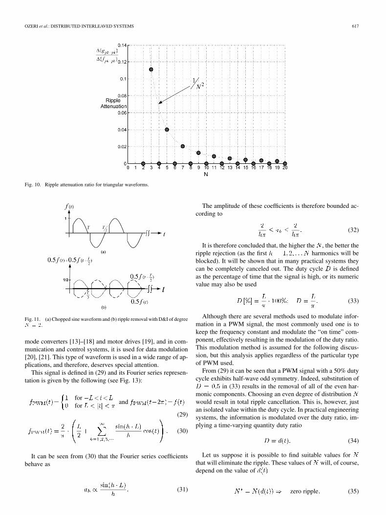
therefore, its energy has been reduced by .The ripple attenuation ratio is depicted in Fig. 10 for different
values of the interleaving degree .Therefore, when designing a D&I system for an odd func-
tion, should be chosen to be even. Even though withthe ripple is completely canceled theoretically, it may be advan-tageous to use higher even values of due to practical con-straints such as sensitivity to parameter variation (an importantissue which is beyond the scope of this article), distribution of
heat sources, component rating in the case of power conversion,and so on. If is not chosen to be even, the D&I performanceis similar to the performance achievable in the case of an abso-lute-sine type signal and much better than the performance inthe case of a sawtooth signal.
4) Chopped Sine Waveform: Another example of a half-waveodd symmetry signal is the chopped sine waveform depicted inFig. 11. Such waveforms are observed in triac-based dimmercircuits that regulate the power flow to resistive loads such as in-candescent light bulbs (providing an efficient way to control theload power by allowing only a portion of the 50/60 Hz currentto pass through). This is evidently a half-wave odd symmetrywaveform whose ripple may be totally removed by applyingD&I of an even degree, as depicted schematically in Fig. 11(b).
V. ZERO-RIPPLE OPERATION WITH PWMRECTANGULAR WAVEFORM
A PWM rectangular waveform is a very common type ofsignal in engineering applications [13]–[21]. One area in whichPWM modulation is employed in data communication is inthe digital subscriber loop (DSL) modems. A typical analogfront-end of a DSL modem is illustrated in Fig. 12. The transmitand receive channels whose operations are separated in fre-quency are connected in parallel and coupled to the telephoneline by a line coupling transformer. The received signal leveldepends on the transmission line length, which can vary from11 to a few hundred meters. Consequently, the received signallevel can vary greatly and may be as low as a few millivolts. Inorder to achieve full digitizing resolution, the signal is usuallyamplified by an amplifier with automatic gain control (AGC).The amplifier’s gain is controlled by the modem’s controller,usually by an analog signal ( in Fig. 12).
Since transmission line characteristics do not change veryquickly, the AGC programming signal, , varies at a slowrate. In many cases, a PWM signal (generated by the controller)is used to generate the analog programming signal, . Thisis actually a kind of serial, low rate analog data communication,but it satisfies the required rate and saves on the number of pinsneeded. Prior to being applied to the AGC amplifier, the PWMsignal is low-pass filtered in order to generate the programmingvoltage, . This low-pass filter is a critical element of themodem. On one hand, filtration requirements (ripple rejection)are very severe in order to prevent injection of noise into the re-ceive channel. On the other hand, this filter must not introducetoo much delay; the dynamics of are important in orderto quickly respond to line variations (such as impedance and at-tenuation variations caused by other subscribers using the line).If the dynamics are not good enough, data will be lost duringthese transitions. So, quite sophisticated (and complex) filtersare required. The suggested D&I method can replace this filterachieving (as will be shown in this section) total ripple attenua-tion (in principle) and inserting a delay on the order of the PWMsignal’s period (which is typically in the range of a few mi-croseconds, 2-3 orders of magnitude smaller than the delay in-serted by a conventionally employed low-pass filter).
In the field of power electronics, this mechanism is the mostwidely employed modulation method for controlling switched-
OZERI et al.: DISTRIBUTED INTERLEAVED SYSTEMS 617
Fig. 10. Ripple attenuation ratio for triangular waveforms.
Fig. 11. (a) Chopped sine waveform and (b) ripple removal with D&I of degreeN = 2.
mode converters [13]–[18] and motor drives [19], and in com-munication and control systems, it is used for data modulation[20], [21]. This type of waveform is used in a wide range of ap-plications, and therefore, deserves special attention.
This signal is defined in (29) and its Fourier series represen-tation is given by the following (see Fig. 13):
forfor
and
(29)
(30)
It can be seen from (30) that the Fourier series coefficientsbehave as
(31)
The amplitude of these coefficients is therefore bounded ac-cording to
(32)
It is therefore concluded that, the higher the , the better theripple rejection (as the first harmonics will beblocked). It will be shown that in many practical systems theycan be completely canceled out. The duty cycle is definedas the percentage of time that the signal is high, or its numericvalue may also be used
(33)
Although there are several methods used to modulate infor-mation in a PWM signal, the most commonly used one is tokeep the frequency constant and modulate the “on time” com-ponent, effectively resulting in the modulation of the duty ratio.This modulation method is assumed for the following discus-sion, but this analysis applies regardless of the particular typeof PWM used.
From (29) it can be seen that a PWM signal with a 50% dutycycle exhibits half-wave odd symmetry. Indeed, substitution of
in (33) results in the removal of all of the even har-monic components. Choosing an even degree of distributionwould result in total ripple cancellation. This is, however, justan isolated value within the duty cycle. In practical engineeringsystems, the information is modulated over the duty ratio, im-plying a time-varying quantity duty ratio
(34)
Let us suppose it is possible to find suitable values forthat will eliminate the ripple. These values of will, of course,depend on the value of
zero ripple (35)

618 IEEE TRANSACTIONS ON CIRCUITS AND SYSTEMS—I: REGULAR PAPERS, VOL. 54, NO. 3, MARCH 2007
Fig. 12. Typical analog front-end of a DSL modem.
Fig. 13. PWM rectangular waveform.
Since varies, it would be required to find a distribution de-gree that solves (33) for all values of (another option wouldinvolve a D&I system with an adaptive distribution degree, butthis option is not explored in this paper). According to (30), rect-angular waveforms contain all of the harmonics to infinity and,in the general case, have both odd and even harmonics. Thisimplies that (35) cannot be satisfied for continuous values of .Nevertheless, it can be shown that in most practical engineeringsystems involving PWM signals, (35) can be satisfied, providedthat assumes only discrete values.
Digital control is becoming very widely employed nowadaysin nearly all areas in which control is applied, and the sameis true with respect to digital communication systems. In suchsystems, can acquire only discrete values, and the duty ratiomay therefore be represented as a discrete quantity
(36)
where is the number of discrete levels (practically repre-senting the quantization resolution of ). It should be stressedthat must be a rational number (for instance, if the hardwarecan generate duty cycle values with a resolution of up to 1%,then ).
Since the duty ratio has discrete values, so does
(37)
Substituting the discrete value of in (31) yields
(38)
By choosing the D&I degree, , to be equal to the numberof discrete levels of (or ), yields
(39)
According to (10), applying D&I to a signal having the co-efficient of (39) blocks all the frequency components exceptthose that are equal to an integer multiple of the fundamental,
. This implies that the only frequency components leftafter D&I have the coefficients defined in (40), which are seento be equal to zero for all
(40)
It is therefore concluded that the ripple of a PWM signal witha quantized duty ratio can be completely removed by D&I, pro-vided that the degree of D&I is an integer multiple of the numberof quantized values.
VI. CONCLUSION
The effect of D&I has been mathematically explored and dis-cussed within the context of practical engineering applications.Simple modeling in terms of a periodic bandpass filter was sug-gested which furthers our understanding of the operation of D&Isystems. It is concluded that, in general, D&I is an effective toolfor averaging periodic wave signals and rejecting their ac com-ponents, without involving the drawbacks inherent in conven-tional low-pass filters such as deterioration in dynamics and theneed for bulky storage components. It was demonstrated thatthe performance of D&I systems depends greatly on the natureof the signal being processed, and that this performance can bedramatically improved by proper design of the D&I system. Theperformance of D&I systems has been shown to vary signif-icantly from one signal to the other, depending on the wave-form’s properties, including its spectral composition.
It is hoped that the extensive discussion of design considera-tions will lead to improvements in the performance of D&I sys-tems in the future.
Further research in needed to develop specific criteria forevaluating ripple attenuation in terms of peak-to-peak voltage(or current), overall ripple power, and specific harmonic power,among other parameters.

OZERI et al.: DISTRIBUTED INTERLEAVED SYSTEMS 619
REFERENCES
[1] J. Urquhart, “Controlled drug delivery: Therapeutic and pharmacolog-ical aspects,” J. Internal Medicine, vol. 248, pp. 357–376, 2000.
[2] S. Lee and E. Hitt, “Continuous subcutaneous insulin infusion: Inten-sive treatment, flexible lyfistyle,” Clinical Update, Aug. 2003.
[3] D. Shmilovitz and S. Singer, “Current averaging networks based ontransmission lines,” in Proc. IEEE ISCAS’95, Seattle, WA, May 95,pp. 2181–2184.
[4] B. A. Miwa, D. M. Otten, and M. F. Schlecht, “High efficiency powerfactor correction using interleaving techniques,” in Proc. IEEE Appl.Power Electron. Conf., Boston, MA, 1992, pp. 557–568.
[5] J. G. Kassakian and D. J. Perreault, “An assessment of cellular architec-tures for large converter systems,” in Proc. Int. Power Electron. MotionContr. Conf., Beijing, China, 1994, pp. 70–79.
[6] C. Chang and M. Knights, “Interleaving technique in distributedpower-conversion systems,” IEEE Trans. Circuits Syst. I, Fundam.Theory Appl., vol. 42, no. 5, pp. 245–251, May 1995.
[7] V. J. Thottuvelil and G. C. Verghese, “Stability analysis of paralleledDC/DC converters with active current sharing,” in Proc. IEEE PowerElectron. Special. Conf., 1996, pp. 1080–1086.
[8] D. J. Perreault and J. G. Kassakian, “Distributed interleaving of paral-leled power converters,” IEEE Trans. Circuits Syst. I, Fundam. TheoryAppl., vol. 44, no. 8, pp. 728–734, Aug. 1997.
[9] M. T. Zhang, M. M. Jovanovic, and F. C. Y. Lee, “Analysis and eval-uation of interleaving techniques in forward converters,” IEEE Trans.Power Electronics, vol. 4, p. 690, 1998.
[10] A. V. Oppenheim and A. S. Willsky, Signals and Systems. Engle-wood Cliffs, NJ: Prentice-Hall, 1983.
[11] J. G. Proakis and D. G. Manolakis, Digital Signal Processing, 3rd ed.Englewood Cliffs, NJ: Prentice-Hall, 1996.
[12] R. G. Gregorian and W. E. Nicholson, “Switched-capacitor decimationand interpolation circuits,” IEEE Trans. Circuits Syst., vol. CAS-27, no.6, pp. 509–514, Jun. 1980.
[13] G. W. Wester and R. D. Middelbrook, “Low-frequency characteriza-tion of switched dc–dc converters,” IEEE Trans. Circuits Syst., vol.CAS-21, no. 5, pp. 376–385, May 1973.
[14] V. Vorperian, “Simplified analysis of PWM converters using the modelof the PWM switch: Parts I & II,” IEEE Trans. Aerosp., Electron. Syst.,vol. 4, pp. 205–214, Apr. 1989.
[15] S. R. Sanders and G. C. Vergese, “Synthesis of averaged circuit modelsfor switched power converters,” IEEE Trans. Circuits Syst., vol. 38, no.8, pp. 905–915, Aug. 1991.
[16] D. Czarkowski and M. K. Kazimierczuk, “Static- and dynamic-circuitmodels of PWM buck-derived dc–dc convertors,” IEE Proceedings G,Circuits, Devices and Syst., vol. 139, no. 6, pp. 669–679, Dec. 1992.
[17] R. W. Erickson and D. Maksimovic, Fundamentals of Power Elec-tronics, 2nd ed. : Kluwer academic Publisher, 2001, pp. 413–420.
[18] V. Vorperian, Fast Analytical Techniques for Electrical and ElectronicCircuits. Cambridge, U.K.: Cambridge University Press, 2002.
[19] N. Mohan, T. M. Undeland, and W. P. Robbins, Power Electronics,Converters, Applications and Design, second ed. New York: Wiley,1995.
[20] “RF system and circuit challenges for WiMAX,” Intel Technol. J., vol.08, no. 03, Aug. 2004.
[21] “ATSC QAM NTSC BTSC FM front-end,” Oren SemiconductorProduct Brief, Dec. 2003.
Shaul Ozeri received the B.Sc. and M.Sc. degreesfrom Tel-Aviv University, Tel-Aviv, Israel, in 1987and 2002, respectively. He is working toward thePh.D. degree, working on high-frequency distributedacoustical projectors for medical applications.
From 1987 to 2000, he worked in the data-com in-dustry as a Senior Designer of Ethernet 802.3-basedproducts and VDSL modems. Since 2000, hehas been working in the biomedical industry,developing advanced drug delivery systems andtransdermal drug delivery systems based on a hybrid
piezo-magnet technology for the diabetic market.
D. Shmilovitz (M’98) was born in Romania in 1963.He received the B.Sc., M.Sc., and Ph.D. degrees fromTel-Aviv University, Tel-Aviv, Israel, in 1986, 1993,and 1997, respectively, all in electrical engineering.
During 1986-1990, he worked in R&D for the IAF,where he developed programmable electronic loads.During 1997–1999, he was a Post-Doctorate Fellowat New York Polytechnic University, Brooklyn,where he worked on unity power factor bidirectionalonboard chargers for electric vehicles. Since 2000,he has been with the faculty of Engineering, Tel-Aviv
University, where he established a state-of-the-art power electronics and powerquality research laboratory. His research interests include switched-mode con-verters: topology, dynamics and control, power quality and power conversionfor alternative energy sources, and general circuit theory.
Sigmond Singer (M’92) received the B.Sc. andD.Sc. degrees from the Technion, Haifa, Israel, in1967 and 1973, respectively.
In 1978, he joined the staff of the Faculty of Engi-neering, Tel-Aviv University, Tel-Aviv, Israel, wherehe is currently a Professor. During 2000 to 2004,he served as the Chairman of the Department ofInterdisciplinary Studies at Tel-Aviv University. Hisresearch interests are general circuits and systemstheory, power electronics, and energy conversion.
Dr. Singer was the recipient of the IEEE Circuitsand Systems Society’s Best Paper Award Committee 1990 Darlington Award,for his paper “Realization of Loss Free Resistive Elements.” He is currently theChairman of the IEEE section in Israel.
Luis Martínez-Salamero received the Ingeniero deTelecomunicación and the doctorate degrees fromthe Universidad Politécnica de Cataluña, Barcelona,Spain in 1978 and 1984, respectively.
From 1978 to 1992, he taught circuit theory,analog electronics, and power processing at EscuelaTécnica Superior de Ingenieros de Telecomunicaciónde Barcelona, Barcelona, Spain. During the aca-demic year 1992–1993 he was a Visiting Professorat the Center for Solid-State Power Conditioning andControl, Deparment of Electrical Engineering, Duke
University, Durham, NC. He is currently a Full Professor in the Departamentode Ingeniería Eléctrónica, Eléctrica y Automática, Escuela Técnica Superior deIngeniería, Universidad Rovira i Virgili, Tarragona, Spain. During the academicyear 2003–2004, he was Visiting Scholar at the Laboratoire d’ Architectureet d’Analyse des Systèmes ( L.A.A.S), Research National Center ( CNRS),Toulouse, France. His research interest are in the field of structure and controlof power conditioning systems for autonomous systems. He has published agreat number of papers in scientific journals and conference proceedings andholds a US patent on the electric energy distribution in vehicles by means of abidirectional dc-to-dc switching converter. He is the Director of the Grupo deAutomática y Electrónica Industrial, a research group on Industrial Electronicsand Automatic Control whose main research fields are power conditioning forvehicles, satellites and renewable energy.
Dr Martínez-Salamero was Guest Editor of the IEEE TRANS. CIRCUITS AND
SYSTEMS—I: FUNDAMENTAL THEORY AND APPLICATIONS for the August 1997Special issue on Simulation, Theory and Design of Switched-Analog Networks.He has been Distinguished Lecturer of the IEEE Circuits and Systems Societyin the period 2001-2002. He is currently the president of the Spanish Chapter ofthe IEEE Power Electronics Society