The Karoo Central Astronomy Advantage Area - Academy of ...
222
Evaluation of Alternative Telecommunication Technologies for The Karoo Central Astronomy Advantage Area
-
Upload
khangminh22 -
Category
Documents
-
view
0 -
download
0
Transcript of The Karoo Central Astronomy Advantage Area - Academy of ...

Evaluation of Alternative Telecommunication Technologies for The Karoo Central Astronomy Advantage Area


Evaluation of Alternative Telecommunication
Technologies for The Karoo Central Astronomy
Advantage Area

© Academy of Science of South Africa
August 2021
ISBN: 978-1-928496-38-0
DOI: http://dx.doi.org/10.17159/assaf.2021/0073
Published by: Academy of Science of South Africa (ASSAf)
PO Box 72135, Lynnwood Ridge, Pretoria, South Africa, 0040
Tel: +27 12 349 6600 • Fax: +27 86 576 9520
E-mail: [email protected]
Reproduction is permitted, provided the source and publisher are appropriately acknowledged.
The Academy of Science of South Africa (ASSAf) was inaugurated in May 1996. It was formed in response to the need for an Academy of Science consonant with the dawn of democracy in South Africa: activist in its mission of using science and scholarship for the benefit of society, with a mandate encompassing all scholarly disciplines that use an open-minded and evidence-based approach to build knowledge. ASSAf thus adopted in its name the term ‘science’ in the singular as reflecting a common way of enquiring rather than an aggregation of different disciplines. Its Members are elected on the basis of a combination of two principal criteria, academic excellence and significant February contributions to society.
The Parliament of South Africa passed the Academy of Science of South Africa Act (No 67 of 2001), which came into force on 15 May 2002. This made ASSAf the only academy of science in South Africa officially recognised by government and representing the country in the international community of science academies and elsewhere.
https://www.assaf.org.za/

i
Table of ContentsTable of Figures .................................................................................................................................................iii
Table of Tables ..................................................................................................................................................iii
List of Acronyms ............................................................................................................................................... iv
Units ...................................................................................................................................................................... v
Foreword ............................................................................................................................................................ vi
Acknowledgements ...................................................................................................................................... vii
Executive Summary .......................................................................................................................................viii
Oorhoofse Opsomming ................................................................................................................................. xi
1. Introduction .............................................................................................................................................. 1
1.1 Background .................................................................................................................................... 2
1.1.1 Development, and Information and Communication Technologies .......... 2
1.1.2 Development, Science and Technology .............................................................. 3
1.1.3 Balancing Scientific Endeavour and Local Needs ............................................. 3
1.2 Scope and Objectives ................................................................................................................ 4
1.3 Methodology ................................................................................................................................. 4
1.4 Study Site ......................................................................................................................................... 5
1.5 Report Outline ............................................................................................................................... 7
2. Legislative Framework........................................................................................................................... 8
2.1 Applicable Legislation ................................................................................................................ 9
2.1.1 Astronomy Geographic Advantage Areas Act and Related Regulations...................................................................................................................... 9
2.1.2 ICASA Act, Act 13 of 2000 ........................................................................................ 13
2.1.3 Electronic Communications Act and Related Regulations .......................... 13
2.2 Summary ....................................................................................................................................... 16
3. The SKA, ICT access, and social dynamics in the Karoo area ............................................... 17
3.1 Preamble ....................................................................................................................................... 18
3.2 Conceptual and Theoretical Framework ........................................................................... 19
3.3 Methodology ............................................................................................................................... 19
3.4 Key Issues ....................................................................................................................................... 20
3.5 Public Perceptions ..................................................................................................................... 21
3.6 Responses to ICT Interventions ............................................................................................... 23
3.7 The Agricultural Sector .............................................................................................................. 26
3.8 The SKA’s Social Licence to Operate .................................................................................. 27

ii
4. Alternative Telecommunication Technologies ........................................................................... 29
4.1 Preamble ....................................................................................................................................... 30
4.2 Parameters for a Viable Technology ................................................................................... 30
4.3 Existing Communication Services .......................................................................................... 30
4.4 Telecommunication Requirements of Users....................................................................... 32
4.5 Restrictions on Radio Frequency Interference .................................................................. 32
4.6 Telecommunication Technologies and Radio Frequency Interference .................. 33
4.6.1 Introduction .................................................................................................................. 33
4.6.2 Findings ........................................................................................................................... 34
4.7 Configurations of Alternative Telecommunication Technologies in the KCAAA ................................................................................................................................... 35
4.7.1 Introduction .................................................................................................................. 35
4.7.2 Findings ........................................................................................................................... 36
4.7.3 Incorporation of Future Technologies .................................................................. 39
4.8 Cost Estimates.............................................................................................................................. 39
4.9 Installation, Operation and Maintenance ......................................................................... 43
4.10 Impacts, Benefits, Concerns and Trade-offs ...................................................................... 44
5. Conclusions and Recommendations ............................................................................................. 45
5.1 Conclusions .................................................................................................................................. 46
5.2 Recommendations .................................................................................................................... 47
References........................................................................................................................................................ 49
Appendices ..................................................................................................................................................... 53
Appendix 1: Biographies of panel members .................................................................................. 54
Appendix 2: Biographies of reviewers ............................................................................................... 56
Appendix 3: Investigation: Telecommunication technologies and radio frequency interference .............................................................................................................................................. 58
Appendix 4: Investigation: Configurations of alternative telecommunication technologies in the KCAAA .................................................................................................................. 83

iii
Table of Figures
Figure 1: The study area including the SKA Core Site and Astronomy Reserve (Source: https://www.skatelescope.org/multimedia/image/ska-africa--2 /) .......................... 5
Figure 2: Envisaged MTN mobile operator coverage after reduction of emission footprint. Footprint for Vodacom envisaged to be similar ........................................ 31
Figure 3: South African Radio Astronomy Service (SARAS) protection levels (Gov Gazette: 35007, 2012) .......................................................................................................... 33
Figure 4: Approximate geographical area of the 2-D investigation into a wide area telecommunication solution ......................................................................................................... 36
Figure 5: General data network concept ................................................................................... 37
Table of Tables
Table 1: Composition of the study panel ...................................................................................... 4
Table 2: Access to the internet by the population of the study area, including place and means of access (Stats SA, 2012) ................................................................................................... 6
Table 3: Cell phone reception by farmers and workers by 2016 (modified from Atkinson, Wolpe, & Kotze, 2017) .......................................................................... 6
Table 4: Access to the internet by farmers and workers by 2016 (modified from Atkinson, Wolpe, & Kotze, 2017) .......................................................................... 7
Table 5: Associated operating radio frequency bandwidths of the three KCAAA’s ............ 10
Table 6: Broadband access targets for 2016, 2020 and 2030 (Gov Gazette: 37119, 2013) .......................................................................................................... 15
Table 7: Private sector ICT solutions ............................................................................................. 25
Table 8: Synopsis the assessment of interference levels of selected technologies ................ 35
Table 9: Option A: Microwave and Fibre Optic Backhaul Infrastructure ................................ 40
Table 10: Option B: VSAT based end user installation. ............................................................... 41
Table 11: VHF Low Band Emergency Radio Network installation. ............................................ 42

iv
List of AcronymsADSS All-dielectric self-supporting
AGA Astronomy Geographic Advantage
AGAA Astronomy Geographic Advantage Areas
AMA Astronomy Management Authority
ASSAf Academy of Science of South Africa
CAAA Central astronomy advantage area
CAPEX Capital expense
CB Citizens band
CSIR Council for Scientific and Industrial Research
DMR Digital Mobile Radio
DSI Department of Science and Innovation (formerly Department of Science and Technology)
ECA Electronic Communications Act
ECNS Electronic Communications Networks Services
ECS Electronic Communications Services
EIRP Equivalent Isotropically Radiated Power
GSM Global System for Mobile Communications (cellular)
ICASA Independent Communications Authority of South Africa
ICT Information and Communication Technology
IFC Industrial Finance Corporation
ISM Industrial, scientific and medical
ISP Internet service providers
ITU International Telecommunications Union
KCAAA Karoo Central Astronomy Advantage Areas
LAG Landbou Aksie Groep
LTE Long Term Evolution
NDP National Development Plan
NRF National Research Foundation

v
OPEX Operating expense
PPP Public-private-partnership
PSTN Public switched telephone network
RFI Radio frequency interference
SARAO South African Radio Astronomy Observatory
SKA Square Kilometre Array
US United States
USAASA Universal Service and Access Agency of South Africa
VAT Value-added tax
VHF Very High Frequency
VoIP Voice over Internet Protocol
VSAT Very-small-aperture terminal
UnitsHz Hertz
MHz Megahertz
GHz Gigahertz
W Watts
mW Milliwatts
dBm decibel-milliwatts
MB Megabyte
GB Gigabyte
Mbps Megabits per second
Gbps Gigabits per second

vi
Foreword The role of Science, Technology and Innovation (STI) in human development is undeniable. Indeed, the South African National Development Plan (NDP) states that “Developments in science and technology are fundamentally altering the way people live, connect, communicate, and transact, with profound effects on economic development.” Using an evidence-based approach, based on data sourced through the use of the best technology that is inclusive and ethical, is the basis of the mandate of the Academy of Science of South Africa (ASSAf) when providing critical service to society and advice to government on matters of critical national importance.
A key component for the advancement of human development is access to information and knowledge as well as the ability to interact and engage using Information and Communication Technologies (ICTs). When scientific endeavours infringe on this access, science needs to provide a solution. For this reason, the National Research Foundation (NRF), on behalf of the South African Radio Astronomy Observatory (SARAO) and the Square Kilometer Array (SKA), commissioned ASSAf to undertake an independent and objective evaluation of potential alternative telecommunication technologies for the areas of the Karoo Central Astronomy Advantage Area. This study is part of a process of ensuring that the SKA, a “Big Science” project, can advance and serve as a critical resource for South Africa while at the same time ensuring that the livelihoods of local communities are not compromised or exposed to adverse or negative impacts as a result of the geographic location of the SKA.
This study entitled “Evaluation of Alternative Telecommunication Technologies for the Karoo Central Astronomy Advantage Area” was designed per ASSAf’s consensus study methodology, in which a panel of experts, guided by the panel chair, undertook the research voluntarily and without any conflict of interest to ensure that it is free of partisan interest. As a result, the findings and recommendations are the best-considered outcomes within the circumstances.
This report provides a critical background into the relationship between the SKA and local communities as it relates to ICTs in the area. Based on this understanding, many potential technology solutions are proposed to ensure residents of the Karoo Central Astronomy Advantage Area are still afforded valuable access to ICTs within the parameters of affordability, desirability and feasibility.
The Academy wishes to acknowledge the support of all participants who provided information to members of the consensus study. In addition, ASSAf is most appreciative of the time and effort that members of the consensus study panel and the staff who supported them, contributed to ensuring the study’s completion.
Professor Jonathan Jansen President: Academy of Science of South Africa

vii
Acknowledgements This study was a collaborative effort involving many dedicated people. I would like to thank the following people and organisations for ensuring the success of the study:
■ The Academy of Science of South Africa (ASSAf), the President of ASSAf, Professor Jonathan Jansen and the Council for their ongoing support throughout this project.
■ The National Research Foundation (NRF) and the South African Radio Astronomy Observatory (SARAO), for commissioning and funding the project. In particular, Dr Adrian Tiplady, Mr Anton Binneman, Ms Alice Pienaar-Marais and Ms Tracey Cheetham for their guidance and support.
■ The members of the Landbou Aksie Groep, in particular Mr Dries le Roux and Mr Henk Maritz. The residents of the study area, for their candour during discussions.
■ The members of the consensus study panel for their commitment, valuable discussions and contributions to the report.
■ Mr Samuel Nlend, Mr Jason Fynn, Dr Jennifer Houghton and Dr Leti Kleyn, who generously gave their time to contribute to the information collected for the drafting of the report.
■ The peer reviewers for valuable input that led to the improvement of the report. ■ The copy editor, UVO Communication, and 45th Media for their attention to detail and
the production of the report. ■ The staff of the Academy, in particular Ms Nadia Algera, Prof Himla Soodyall, Mr Ian
Shendelana and Ms Henriette Wagener for their contribution and support throughout the project.
Prof Francesco Petruccione Chair of the Panel
viii
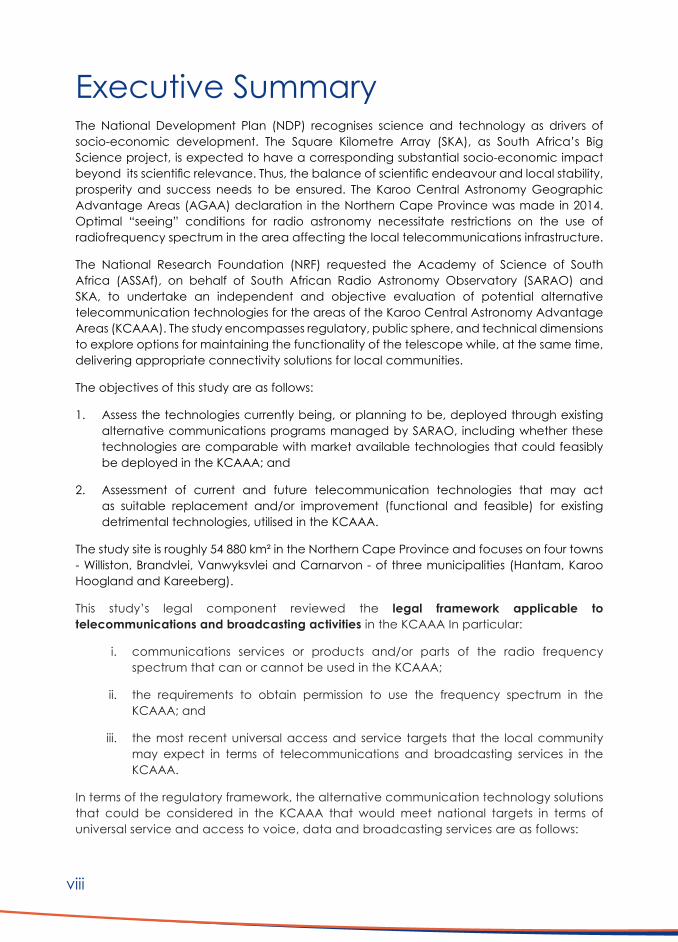
Executive Summary
The National Development Plan (NDP) recognises science and technology as drivers of socio-economic development. The Square Kilometre Array (SKA), as South Africa’s Big Science project, is expected to have a corresponding substantial socio-economic impact beyond its scientific relevance. Thus, the balance of scientific endeavour and local stability, prosperity and success needs to be ensured. The Karoo Central Astronomy Geographic Advantage Areas (AGAA) declaration in the Northern Cape Province was made in 2014. Optimal “seeing” conditions for radio astronomy necessitate restrictions on the use of radiofrequency spectrum in the area affecting the local telecommunications infrastructure.
The National Research Foundation (NRF) requested the Academy of Science of South Africa (ASSAf), on behalf of South African Radio Astronomy Observatory (SARAO) and SKA, to undertake an independent and objective evaluation of potential alternative telecommunication technologies for the areas of the Karoo Central Astronomy Advantage Areas (KCAAA). The study encompasses regulatory, public sphere, and technical dimensions to explore options for maintaining the functionality of the telescope while, at the same time, delivering appropriate connectivity solutions for local communities.
The objectives of this study are as follows:
1. Assess the technologies currently being, or planning to be, deployed through existing alternative communications programs managed by SARAO, including whether these technologies are comparable with market available technologies that could feasibly be deployed in the KCAAA; and
2. Assessment of current and future telecommunication technologies that may act as suitable replacement and/or improvement (functional and feasible) for existing detrimental technologies, utilised in the KCAAA.
The study site is roughly 54 880 km² in the Northern Cape Province and focuses on four towns - Williston, Brandvlei, Vanwyksvlei and Carnarvon - of three municipalities (Hantam, Karoo Hoogland and Kareeberg).
This study’s legal component reviewed the legal framework applicable to telecommunications and broadcasting activities in the KCAAA In particular:
i. communications services or products and/or parts of the radio frequency spectrum that can or cannot be used in the KCAAA;
ii. the requirements to obtain permission to use the frequency spectrum in the KCAAA; and
iii. the most recent universal access and service targets that the local community may expect in terms of telecommunications and broadcasting services in the KCAAA.
In terms of the regulatory framework, the alternative communication technology solutions that could be considered in the KCAAA that would meet national targets in terms of universal service and access to voice, data and broadcasting services are as follows:

ix
1. Telecommunications services (voice and data) as well as broadcasting services (cable broadcasting services), provided using fixed lines;
2. Telecommunications and broadcasting:
■ that use the radio frequency spectrum below 100 MHz or above 2 170 MHz in KCAAA1;
■ that use the radio frequency spectrum below 2 170 MHz or above 6 000 MHz in KCAAA2; or
■ that use the radio frequency spectrum below 6 000 MHz or above 25 500 MHz (25.5 GHz) in KCAAA3.
3. Telecommunications and broadcasting services that use the radio frequency spectrum within the predetermined frequency bands under protection, but are exempted from the general prohibition;
4. Other than as set out above, any use of the radio frequency spectrum between:
i. 6 000 MHz and 25 500 MHz in KCAAA3;
ii. 2 170 MHz and 6 000 MHz in KCAAA2; and/or
iii. 100 MHz and 2 170 MHz in KCAAA1 requires a permit from the AMA, that will require compliance tests to assess interference levels.
In terms of this study’s social component, the social impact of the SKA concerning the ICT infrastructure accessible to the local community and considered the history of engagement and communication, public perceptions, and the responses of local institutions and stakeholders was explored.
In terms of ICT access, the local context is that of an underserviced area, as defined by the regulations of the Independent Communications Authority of South Africa (ICASA). ICT’s are critical for the agricultural sector, business practices, safety, social integration, and education. Uncertainty about access to universal ICT services negatively impacts the local community.
The research into the local community perception of specific user ICT access requirements shows that SARAO’s strategic position in the Karoo is determined in the legislative, regulatory, political, financial, technical, and scientific arenas as well as the social area.
SARAO must act to better understand local perceptions, local knowledge systems, local poverty and its related issues, and local concerns about unequal power relations.
It is recommended that:
1. A fully-fledged and inclusive communication and engagement strategy for ICT interventions in the Karoo must be developed. The strategy should include 1) the delineation of emergent and participative engagement structures and processes, 2) a plan for communication processes, messaging and channels, and 3) the development of an evidence-based understanding of public perceptions and institutional agendas.
2. Engagement processes must be transparent and inclusive throughout. Research and plans related to changes in ICT access and infrastructure should be openly shared and communicated.

x
3. All messaging must be valid and consistent.
4. There is a need to more closely coordinate with the NRF and the DSI to align messaging, particularly in the political arena.
5. All previous failures to meet reasonable expectations and communicate consistently must be surfaced, acknowledged, and remedied where possible.
6. SARAO should reflect on its organisational culture.
The residents’ telecommunication requirements and the restrictions posed by the instrumentation of the SKA telescopes informed the investigation of viable technical options for alternative telecommunications infrastructure.
Given the user needs, the following overarching conditions guided the investigation:
1. Convenient and affordable data access at residences and immediate surroundings, for farm owners and workers.
2. Mobile phone coverage wherever possible.
3. Personal wide-area voice communications for emergency and safety.
In particular, the proposed alternative telecommunications strategy ensures the feasibility, desirability and viability of the solution. It addresses both voice and data communications, as well as safety and emergency (mobile) communication. A single technology-based network would need to be considered.
In terms of implementable and feasible telecommunications technologies in the KCAAA, the following are recommended:
1. Internet connectivity be provided to all priority farms/user locations, through VSAT, at least in the short term as an interim measure.
2. Investigating a subsidy model for the procurement of infrastructure, installation, system operations and maintenance as well as data cost of this service. This will need further detailed work and refinement once financing options and the managing and operating entity structure have been clarified.
3. In view of the lack of general telecommunications services in the area, the proposed VHF Low Band emergency communications network should be implemented as a priority, for safety, emergency and business operations. The subsidy model established for the VSAT service should extend to include the VHF installations in terms of operations and maintenance.
4. The establishment of an Operational, Management and Control Centre for safety and operational reasons, including network monitoring and management. It is necessary for both the VSAT and the VHF Low Band emergency communications network installations.
5. With the recognition that establishing a Section 21 company could be arduous given its function and duration, a public-private partnership (PPP) should be formed to oversee and undertake monitoring, administration and maintenance of the networks mentioned above.
6. SARAO be mandated to source funding of the infrastructure as recommended.

xi
Oorhoofse Opsomming Die Nasionale Ontwikkelingsplan (NOP) erken wetenskap en tegnologie as dryfvere vir sosio-ekonomiese ontwikkeling. Daar word van die Square Kilometer Array (SKA), as die grootste wetenskaplike projek in Suid-Afrika, verwag dat dit ‘n beduidende maatskaplik-ekonomiese impak sal hê buite sy wetenskaplike belang. Dus moet die balans tussen wetenskaplike strewe en plaaslike stabiliteit, welvaart en sukses verseker word. Die Karoo Central Astronomy Geographic Advantage Areas (AGAA)-verklaring in die Noord-Kaap Provinsie, is in 2014 uitgereik. Optimale waarnemings omstandighede vir radio-astronomie vereis beperkings op die gebruik van radiofrekwensiespektrum in die gebied wat die plaaslike telekommunikasie-infrastruktuur raak.
Die National Research Foundation (NRF) het die Academy of Science of South Africa (ASSAf) namens die South African Radio Astronomy Observatory (SARAO) en SKA versoek om ‘n onafhanklike en objektiewe evaluering van potensiële alternatiewe telekommunikasietegnologieë vir die gebiede van die Karoo Central Astronomy Advantage Areas (KCAAA) te onderneem. Die studie omvat regulatoriese, publieke sfeer en tegniese dimensies, wat opsies ondersoek om die funksionaliteit van die teleskoop te handhaaf en terselfdertyd toepaslike kommunikasie oplossings vir plaaslike gemeenskappe te lewer.
Die doelstellings van hierdie studie is soos volg:
1. Evalueer die tegnologieë wat tans gebruik word, of beplan word, deur middel van bestaande alternatiewe kommunikasieprogramme wat deur SARAO bestuur word, insluitend of hierdie tegnologieë vergelykbaar is met die beskikbare tegnologieë wat moontlik in die KCAAA gebruik kan word; en
2. Beoordeling van huidige en toekomstige telekommunikasietegnologieë wat kan dien as geskikte vervanging en/of verbetering (funksioneel en uitvoerbaar) vir bestaande skadelike tegnologieë, wat in die KCAAA gebruik word.
Die studieterrein beslaan ongeveer 54 880 km² in die Noord-Kaap en fokus op vier dorpe - Williston, Brandvlei, Vanwyksvlei en Carnarvon, geplaas in drie munisipaliteite (Hantam, Karoo Hoogland en Kareeberg).
Die wetlike komponent van hierdie studie het die wetlike raamwerk van toepassing op telekommunikasie- en uitsaaibedrywighede in die KCAAA nagegaan. In die besonder:
i. kommunikasiedienste of produkte en/of dele van die radiofrekwensiespektrum wat in die KCAAA gebruik kan word of nie;
ii. die vereistes om toestemming te verkry om die frekwensiespektrum in die KCAAA te gebruik; en
iii. die mees onlangse universele toegangs- en diensdoelwitte wat die plaaslike gemeenskap kan verwag in terme van telekommunikasie en uitsaaidienste in die KCAAA.

xii
In terme van die regulatoriese raamwerk is die alternatiewe kommunikasietegnologiese oplossings wat in die KCAAA oorweeg kan word wat aan nasionale teikens sal voldoen in terme van universele diens en toegang tot stem-, data- en uitsaaidienste die volgende:
1. Telekommunikasiedienste (stem en data) sowel as uitsaaidienste (kabeluitsaaidienste), gelewer met vaste lyne;
2. Telekommunikasie en uitsaaiwese:
■ wat die radiofrekwensiespektrum onder 100 MHz of hoër as 2170 MHz in KCAAA1 gebruik;
■ wat die radiofrekwensiespektrum onder 2 170 MHz of hoër as 6 000 MHz in KCAAA2 gebruik; of
■ wat die radiofrekwensiespektrum onder 6 000 MHz of hoër as 25 500 MHz (25,5 GHz) in KCAAA3 gebruik.
3. Telekommunikasie- en uitsaaidienste wat die radiofrekwensiespektrum binne die voorafbepaalde frekwensiebande onder beskerming gebruik, maar vrygestel is van die algemene verbod.
4. Behalwe soos hierbo uiteengesit, is die gebruik van die radiofrekwensiespektrum tussen:
i. 6 000 MHz en 25 500 GHz in KCAAA3;
ii. 2 170 MHz en 6 000 MHz in KCAAA2; en/of
iii. 100 MHz en 2 170 MHz in KCAAA1 benodig ‘n permit van die AMA, wat voldoeningstoetse benodig om interferensievlakke te bepaal.
In terme van die sosiale komponent van hierdie studie, is die sosiale impak van die SKA rakende die IKT (Inligtings- en Kommunikasietegnologie)-infrastruktuur toeganklik vir die plaaslike gemeenskap en die geskiedenis van betrokkenheid en kommunikasie, openbare persepsies en die antwoorde van plaaslike instellings en belanghebbendes ondersoek.
Wat IKT-toegang betref, is die plaaslike konteks dié van ‘n onderdiensgebied, soos omskryf in die regulasies van die Onafhanklike Kommunikasie-owerheid van Suid-Afrika (Okosa). IKT’s is van kritieke belang vir die landbousektor, sakepraktyke, veiligheid, sosiale integrasie en onderwys. Onsekerheid oor toegang tot universele IKT-dienste het ‘n negatiewe uitwerking op die plaaslike gemeenskap.
Die ondersoek na die persepsie van die plaaslike gemeenskap van spesifieke gebruikersvereistes vir IKT-toegang, toon dat SARAO se strategiese posisie in die Karoo bepaal word in die wetgewende, regulatoriese, politieke, finansiële, tegniese en wetenskaplike arena, sowel as op sosiale gebied.
SARAO moet plaaslike persepsies, plaaslike kennisstelsels, plaaslike armoede en die verwante kwessies daarvan en plaaslike kommer oor ongelyke magsverhoudinge beter verstaan.
Dit word aanbeveel dat:
1. ‘n Volwaardige en inklusiewe strategie vir kommunikasie en betrokkenheid vir IKT-ingrypings in die Karoo ontwikkel word. Die strategie moet insluit:

xiii
i. die afbakening van opkomende en deelnemende betrokkenheidstrukture en -prosesse,
ii. ‘n plan vir kommunikasieprosesse, boodskappe en kanale, en
iii. die ontwikkeling van ‘n bewysgebaseerde begrip van openbare persepsies en institusionele agendas.
2. Skakelprosesse moet deurgaans deursigtig en insluitend wees. Navorsing en planne rakende veranderinge in IKT-toegang en infrastruktuur moet openlik gedeel en gekommunikeer word.
3. Alle boodskappe moet geldig en konsekwent wees.
4. Daar moet meer met die NRF en die DSI (Departement van Wetenskap en Innovasie) gekoördineer word om boodskappe konsekwent oor te dra, veral op politieke gebied.
5. Alle vorige versuim om aan redelike verwagtinge te voldoen en om konsekwent te kommunikeer, moet aan die kaak gestel word, erken en waar moontlik reggestel word.
6. SARAO moet besin oor sy organisasiekultuur.
Die inwoners se telekommunikasievereistes en die beperkings wat die instrumentasie van die SKA-teleskope inhou, het die ondersoek gelei ten opsigte van lewensvatbare tegniese opsies vir ‘n alternatiewe telekommunikasie-infrastruktuur.
Gegewe die gebruikersbehoeftes, het die volgende oorkoepelende voorwaardes die ondersoek gelei:
1. Gerieflike en bekostigbare toegang tot data in wonings en onmiddellike omgewing, vir plaaseienaars en werkers.
2. Waar moontlik, dekking vir selfone.
3. Persoonlike wye-area stemboodskappe vir noodgevalle en veiligheid.
Die voorgestelde alternatiewe telekommunikasiestrategie verseker veral die uitvoerbaarheid, wenslikheid en lewensvatbaarheid van die oplossing. Dit spreek beide stem- en datakommunikasie aan, sowel as veiligheid- en (mobiele) noodkommunikasie. Slegs een tegnologie-gebaseerde netwerk moet oorweeg word.
In terme van implementeerbare en uitvoerbare telekommunikasietegnologieë in die KCAAA, word die volgende aanbeveel:
1. Internetverbindings word voorsien aan alle prioriteitsplase/ligging van verbruikers, deur middel van VSAT, ten minste op kort termyn as ‘n tussentydse maatreël.
2. Ondersoek na ‘n subsidiemodel vir die vestiging van infrastruktuur, installasie, stelselbedrywighede en instandhouding sowel as datakoste van hierdie diens. Dit sal verder gedetailleerd uitgewerk en verfyn moet word sodra die finansieringsopsies en die bestuur- en bedryfsentiteitstruktuur duidelik is.

xiv
3. In die lig van die gebrek aan algemene telekommunikasiedienste in die gebied, moet die voorgestelde VHF Lae Band-noodkommunikasienetwerk as ‘n prioriteit geïmplementeer word vir veiligheids-, nood- en sakebedrywighede. Die subsidiemodel wat vir die VSAT-diens ingestel is, moet ook die VHF-installasies insluit wat bedryf en instandhouding betref.
4. Die oprigting van ‘n bedryfs-, bestuurs- en beheersentrum vir veiligheids- en bedryfsredes, insluitend netwerkmonitering en -bestuur. Dit is nodig vir beide die VSAT- en die installasies vir die VHF Lae Band noodkommunikasienetwerk.
5. Met die erkenning dat die oprigting van ‘n Artikel 21-onderneming moeilik kan wees gegewe sy funksie en duur, moet ‘n Publiek-Private vennootskap (PPP) gevorm word om toesig te hou oor-, asook die monitering, beheer en instandhouding van die bogenoemde netwerke.
6. SARAO is verplig om befondsing te voorsien vir implementering van die infrastruktuur soos aanbeveel.

1
INTRODUCTION

2
1. INTRODUCTION1.1 Background1.1.1 Development, and Information and Communication Technologies
Access to information and knowledge is considered a human right, and a necessity for society to understand what to do and how to do it. Access to information and knowledge is one of the foundations of the ninth Sustainable Development Goal (SDG 9) of Agenda 2030. Adopted at the United Nations Sustainable Development Summit in September 2015 the SDGs aim for inclusive sustainable development.
It follows, then, that access to information and communication technologies (ICTs) has the potential to contribute to the development of an individual, a community and, consequently, a nation. Heeks (2010) describes this contribution to include:
1. Development as economic growth: effective use of ICTs facilitates both the saving and making of money at both individual and community levels.
2. Development through sustainable livelihoods: ICTs have the potential to assist individuals in developing additional livelihood practices or to practice new livelihood strategies, and thereby improving livelihoods through diversified dependence, which mitigates risk.
3. Development as freedom: access to ICTs enables choice, which, in specific contexts, results in empowerment which may increase capability and development.
Recognising the value of ICT and its role in providing access to information and knowledge to citizens, South Africa’s National Development Plan (NDP) (National Planning Commission, 2011) sets out the following goal for 2030:
“A seamless information infrastructure will be universally available and accessible and will meet the needs of citizens, business and the public sector, providing access to the creation and consumption of a wide range of converged services required for effective economic and social participation – at a cost and quality at least equal to South Africa’s main peers and competitors.”
The NDP sets out telecommunications as one type of infrastructure upon which to increase investment, making it more efficient and competitive, thereby boosting economic growth and transforming the economy:
“Like energy and transport, ICT is an enabler – it can speed up delivery, support analysis, build intelligence and create new ways to share, learn and engage. But ineffective ICT can also disable economic and social activity.”
Furthermore, the NDP states:
“Direct involvement [by the state] will be limited to interventions to ensure universal access and to help marginalised communities develop the capacity to use ICTs effectively.”
A study published in 2019 (Bahrini & Qaffas, 2019) determined that of four ICTs investigated – fixed telephone, mobile phones, internet usage and broadband adoption – all except

3
fixed telephone lines are drivers of economic growth in developing countries of Sub-Saharan Africa, amongst others. The underlying reason provided was that new ICTs contribute by “accelerating the development and adoption of innovation processes and fostering competition”. ICTs add value at a company level and sectoral level, leading to increased productivity and growth at a national level.
1.1.2 Development, Science and Technology
On the role of science and technology as drivers of development, the National Development Plan states:
“Developments in science and technology are fundamentally altering the way people live, connect, communicate, and transact, with profound effects on economic development. Science and technology are key to development, because technological and scientific revolutions underpin economic advances, improvements in health systems, education and infrastructure.” (National Planning Commission, 2011)
It follows that Big Science (large scale scientific efforts involving multiple countries, multiple institutions, large budgets, and lots of coverage) should contribute to economic development. A 2018 study by Gastrow and Oppelt reviewed literature on the relationship between Big Science (defined as large-scale globalised science) and human development. Amongst the identifications, definitions and descriptions of human development were the freedom and capability to cultivate human agency and capability, and the freedom and capability to develop self-realisation (Gastrow & Oppelt, 2018). The study found that Big Science does indeed contribute to human development at the global and national level through a number of complex systems. However, the contribution is less obvious at the local level, not necessarily completely positive and largely dependent on the local context. Gastrow and Oppelt (2018) applied the theory to the Square Kilometre Array (SKA) in South Africa. They found that while the SKA exhibited clear positive impacts at international and national levels, at the local level near to the infrastructure, while there were immediate positive gains and benefits, the impacts were not all positive.
This raises the question as to how to balance scientific endeavour with local stability and prosperity.
1.1.3 BalancingScientificEndeavourandLocalNeeds
South Africa’s Astronomy Geographic Advantage (AGA) Act promulgated into law in 2008, empowers the Minister for Science and Innovation to declare and protect astronomy advantage areas and, consequently, astronomical observations that may be undertaken by astronomy facilities located within astronomy advantage areas. The Karoo Central Astronomy Advantage Areas (KCAAAs) declaration in the Northern Cape Province was made in 2014.
Subsequent regulations, published in December 2017 and which came into force in December 2018, place restrictions on the use of the radio frequency spectrum in the KCAAA. The regulations require operators of telecommunication infrastructure in the KCAAA, unless exempted, to obtain a permit from the Astronomy Management Authority (AMA) to continue operating. The strategy for implementing the regulations seeks to optimise usage of the radio frequency spectrum by radio astronomy operations, operators and other users.

4
To support the implementation of the regulations, the South African Radio Astronomy Observatory (SARAO) has implemented a program of alternative communications with one key objective:
“Identification and deployment of alternative means of access to telecommunication services in the Karoo Central AAA that would enable continued, extended, and in some cases new, access to such services in a manner that would ensure protection of radio astronomy observations at an appropriate user cost.”
The Academy of Science of South Africa (ASSAf) was requested by the National Research Foundation (NRF), on behalf of SARAO, to undertake an independent and objective evaluation of potential alternative telecommunication technologies for the area of the KCAAA to support the programme mentioned above. The study encompasses technical, regulatory, and public sphere dimensions to explore options for maintaining the functionality of the telescope while at the same time delivering appropriate connectivity solutions for local communities.
1.2 Scope and ObjectivesThe objectives of this study are as follows:
1. Assess the technologies currently being, or planning to be, deployed through existing alternative communications programs managed by SARAO, including whether these technologies are comparable with market available technologies that could feasibly be deployed in the KCAAA; and
2. Assessment of current and future telecommunication technologies that may act as suitable replacement and/or improvement (functional and feasible) for existing detrimental technologies utilised in the KCAAA.
The evaluation is to consider the protection requirements of radio astronomy facilities in the KCAAA, the potential detrimental effect posed by the use of some telecommunication technologies in the vicinity of radio telescopes, and the operational feasibility of deployment of telecommunication infrastructure, including end-user costs.
1.3 MethodologyThe ASSAf Council approved the consensus study proposal on 12 February 2019. The study panel that undertook the study was constituted by 29 March 2019, with Prof Francesco Petruccione appointed as panel chair. The members of the panel are listed in Table 1, and their biographies provided in Appendix 1.
Table 1: Composition of the study panel
Name AffiliationProf Francesco Petruccione University of KwaZulu-NatalDr Michael Gastrow Human Sciences Research CouncilDr Senka Hadzic University of Cape TownMr Carl Kies Reutech Radar SystemsProf Justine Limpitlaw University of the WitwatersrandProf Babu Sena Paul University of JohannesburgProf Riaan Wolhuter Stellenbosch University

5
The inaugural meeting of the panel was held on 10 May 2019 during which Dr Adrian Tiplady, the Head of Strategy and Business Systems of the SKA in South Africa, presented to the panel the terms of reference of the study. The panel met on ten further occasions during the progress of the study.
Gathering of evidence, information and data were undertaken through several different activities:
■ Interviews, meetings and workshops with stakeholders ■ Literature reviews ■ Desktop investigations ■ Technical investigations conducted under the supervision of panel members
In line with ASSAf policy, the final draft report was submitted for formal peer review in October 2020. Following ASSAf Council approval, three experts were appointed representing South Africa, the greater African region and the international community beyond the African continent. The names and biographies of the reviewers are provided in Appendix 2.
The ASSAf Council approved the publication of the report in March 2021.
1.4 Study SiteThe study site is roughly 54 880 km² in the Northern Cape Province (Figure 1). The study focused on four towns – Williston, Brandvlei, Vanwyksvlei and Carnarvon – of three municipalities (Hantam, Karoo Hoogland and Kareeberg).
Figure 1: The study area including the SKA Core Site and Astronomy Reserve (Source: https://www.skatelescope.org/multimedia/image/ska-africa--2)

6
In terms of this study’s focus, access to, and use of ICTs as well as data on the level of access, and the nature of access according to the 2011 census are provided in Table 2.
Table 2: Access to the internet by the population of the study area, including place and means of access (Stats SA, 2012)
Place of Access Carnavon Vanwyksvlei Brandvlei Williston Average
From home (*) 6.60% 1.10% 3.90% 7.10% 4.68%
From cellphone 14.60% 18.00% 14.40% 19.10% 16.53%
From work 3.80% 2.20% 1.50% 2.80% 2.58%
From elsewhere 1.90% 1.10% 0.30% 1.20% 1.13%
No access 73.10% 77.60% 80.10% 69.80% 75.15%
(*) Defined as fixed-line (e.g. ADSL) only, (pers comm A. Ngyende of Stats SA)
At the time of the 2011 census, only 24.9% of the population had access to the internet. Amongst those that did have access, the dominant mode of access was by cellphone (i.e. mobile), and the remainder of the population (less than 8.5% of the population) accessed the internet from home or work or ‘elsewhere’ (i.e. fixed locations).
More recently, a survey of 117 respondents was conducted in 2016 by Agri Northern Cape to assess the level and means of access to telecommunications (voice and data) by farmers in the areas of Carnarvon, Williston, Brandvlei, Calvinia and Vanwyksvlei. The survey results, as reproduced by Atkinson, Wolpe, & Kotze (2017), are provided in Table 3 and Table 4.
Table3:Cellphonereceptionbyfarmersandworkersby2016(modifiedfromAtkinson,Wolpe,&Kotze,2017)
Number of farmers % of farmers
% of farmers mentioning that
their workers have internet
accessCellphone reception on my farm without amplifiers 34 29 45
Reception in house with repeater/booster 49 42 5
Reception in the house with antenna 34 29 19There are a few sites on my property where the phone has reception without a booster
85 73 62
No cellphone reception on my farm 8 7 4

7
Table4:Accesstotheinternetbyfarmersandworkersby2016(modifiedfromAtkinson,Wolpe,&Kotze,2017)
Number of farmers % of farmers
% of farmers mentioning that
their workers have internet
accessNo internet access 12 10 17
Access through mobile phone 57 49 44
Access through VSAT terminal 83 70 9
The internet through an internet service provider (ISP) delivering via different technologies (i.e. wireless or fixed-line)
32 28 9
Wi-fi router in the home providing data and Voice Over Internet Protocol (VOIP) connectivity
53 45 3
Important to note is that this survey was limited to farmers, however, this has direct relevance to the objectives of this study. The results indicate that, by 2016, more than 90% and 80% of farmers (and workers employed) had access to cellphone service and the internet, respectively. However, the means of access varies.
1.5 Report OutlineThis report comprises five chapters:
Chapter 1: provides the background, scope and methodology, and describes relevant details and extent of the study site.
Chapter 2: is an itemised description of legislation pertaining to the SKA over time, and highlights some challenges related to the development of various acts.
Chapter 3: describes the stakeholders and key role players of the study site and describes the nature of the relationship between the SKA and local stakeholders.
Chapter 4: details the study’s technical objectives and provides the technology solutions most suitable for the study site.
Chapter 5: summarises the findings of the study, followed by recommendations based on the findings.

8
LEGISLATIVE FRAMEWORK

9
2. LEGISLATIVE FRAMEWORKThis chapter aims to provide the legal framework applicable to telecommunications and broadcasting activities in the Karoo Central Astronomy Advantage Area (KCAAA). In particular, the following will be focused on:
1. communications services or products and/or parts of the radio frequency spectrum that can or cannot be used in the KCAAA;
2. the requirements to obtain permission to use the frequency spectrum in the KCAAA; and
3. the most recent universal access and service targets that the local community may expect in terms of telecommunications and broadcasting services in the KCAAA.
2.1 Applicable Legislation2.1.1 Astronomy Geographic Advantage Areas Act and Related Regulations
The Astronomy Geographic Advantage Areas Act (AGAA Act) came into force in 2009 in terms of Proclamation 28, published in the Government Gazette Number 32163. Relevant critical aspects of the AGAA Act are set out below.
2.1.1.1 Declaration of the KCAAA
Section 5 of the Act is headed “areas which may be declared astronomy advantage areas”; it entitles the Minister (currently the Minister for Higher Education, Science and Technology) to declare such astronomy advantage areas in the Northern Cape and elsewhere in South Africa, provided these do not fall within the boundaries of the Sol Plaatje Municipality or in a Category A municipality (in terms of the Municipal Demarcation Act, Act 27 of 1998).
The AGAA Act sets out the purposes of astronomy advantage areas, and these include “…the restriction of activities that cause or could cause… radio frequency interference… with astronomy and related scientific endeavours”.
This is in keeping with international practice on so-called “radio-quiet zones” provided for by the International Telecommunications Union (ITU) in ITU-R Recommendation RA.769-2, “Protection criteria used for radio astronomical measurements” (ITU RA.769.-2, 2003-05). Such radio-quiet zones already exist in Australia, the United States (US), and Brazil. For example, in the US, the national radio-quiet zone in which the Greenbank Observatory is situated (established 1956) prohibits most broadcasting and telecommunications, except for cable or satellite broadcasting, fixed-line telecommunications services, a citizens band (CB) radio communications and certain emergency services. The most severe restrictions are in place only in a small area, which includes a 32 km radius around the Greenbank Observatory (Hu, E. 2013).
A declaration of an area as a Central Astronomy Advantage Area (CAAA) must be preceded by, among other things, a public participation process in terms of which the Minister has compiled a permanent register of interested and affected parties for the CAAA.
Following the AGAA Act proclamation, the KCAAAs were declared in 2014 (Gov Gazette: 37434, 2014). Three KCAAAs, with associated operating radio frequency bandwidths, were declared, namely: KCAAA1, KCAAA2 and KCAAA3.

10
Table 5: Associated operating radio frequency bandwidths of the three KCAAA’s
Karoo Central Astronomy Advantage Area
Frequency range (MHz)
1 100 – 2 1702 2 170 – 6 0003 6 000 – 25 500
Thereafter, a second public participation process was conducted in 2016 by Prof JCW van Rooyen by appointment of the Minister of then Department of Science and Technology (DST). A summary of Prof Van Rooyen’s report is in Notice 621 of 2017 published in the Government Gazette Number 40706.
The purpose of the second public participation process was to allow for engagement on draft regulations to protect the KCAAA, which proposed several restrictions to protect against interference with radio astronomy. The report deals with these stakeholder opinions on a range of matters, most of which were not relevant to the scope of the current investigation. Still, for the sake of completeness, they fell under the following headings: mining, economic stagnation, aviation, technological advancement, wind farms, and weapon testing range.
On the issue of access to and use of telecommunications services, the report notes concerns raised in submissions by farmers that they wished to “develop their farms to maximum profitability for owners and workers by making use of current and future technologies, including state of the art telecommunications…” (Gov Gazette: 40706, 2017). The report notes that such activities would not harm “optical astronomy” (emphasis in the original), but did not deal in any detail with the impact thereof on radio astronomy (emphasis added) even though one of the farms was located within the proposed KCAAA albeit at a distance of 172 km. Instead, the report advised that the farmers’ submission “does not give rise to any grounds for objection against the declarations [of the Astronomy Advantage Areas]”. It noted that the persons making the submission would have further opportunities to make representations on draft regulations. As a result, the report found that:
■ “no legal ground could be found not to declare the areas as defined [that is, as Astronomy Advantage Areas]”;
■ the Minister is “legally entitled to impose restrictions on the use of the airwaves and the electro-magnetic emissions…subject to those restrictions having been subject to a public participation process, and the restrictions are rational and not imposed arbitrarily”; and
■ “when weighing the right to scientific research as guaranteed in Section 16 of the Constitution of the Republic against rational limitations in electronic communications and the electro-magnetic field as well as other relevant fields, the scientific research potential of the SKA…wins the day.”.
It is clear that the report did not deal with (nor, it seems, even consider) what access to telecommunications that make use of the radio frequency spectrum the population living within the KCAAA would be entitled to, other than in respect of one farmer. This is undoubtedly a result of the brief of the public participation process which was to deal with issues raised in the public consultations, which did not include any submissions on the communications needs of people living in the KCAAA.

11
2.1.1.2 Management of the KCAAA
The AGAA Act empowers the Minister to assign the management of a central astronomy advantage area (CAAA) to a public entity or organ of state. Such management authority is the custodian of the permanent register of interested or affected parties for the astronomy advantage area. In 2014 the Astronomy Management Authority (AMA) was assigned the responsibility of managing the CAAA (Gov Gazette: 37999, 2014).
2.1.1.3 Restrictions of Radio Frequency Spectrum Use in the KCAAA
The AGAA Act empowers the Minister to protect the use of the radio frequency spectrum for astronomy observations in a CAAA. This power is subject to the concurrence of the Independent Communications Authority of South Africa (ICASA) should the following be required:
■ Complete prohibition or restriction, in any way, of the use of specific frequencies from the radio frequency spectrum;
■ The conversion, within a reasonable time, of analogue transmissions in the radio frequency spectrum to digital transmissions;
■ Any user of the radio frequency spectrum which transmits or broadcasts to migrate into a radio frequency which more effectively protects radio astronomy observations; or
■ Exceptions where any person or organ of state which has entered into an agreement with the AMA to mitigate the impact on the radio frequency spectrum.
In terms of the AGAA Act, the Minister is empowered to declare that in a CAAA, no person may conduct any activity in any of the following categories, including:
■ the construction of or expansion in operations of any fixed radio frequency interference source;
■ activities capable of causing radio frequency interference; and
■ any other activity which may detrimentally impact astronomy and related scientific endeavours.
However, if the declaration is likely to affect broadcasting services or licencing, concurrence with ICASA is required.
Upon declaring CAAA, the Minister may also declare:
1. Any activity capable of causing radio frequency spectrum interference shall cease, subject to the payment of compensation if required the Constitution (South African Constitution, 2006);
2. Conditions under which any activity may continue to reduce or eliminate the impact of the activity on astronomy and related scientific endeavours.
In December 2017, the regulations on the protection of the KCAAA were published (Gov Gazette: 41321, 2017) and came into effect on 15 December 2018 (Gov Gazette: 41891, 2018). The protection regulations are voluminous; however, the key aspects relevant to radiofrequency spectrum interference are described below.

12
Schedules of the KCAAA protection regulations:
There are four different sets of regulations contained in the protection regulations, namely:
Schedule A Regulations to prohibit and restrict the use of specific radio frequency spectrum and certain radio activities in the KCAAA;
Schedule B Regulation on administrative matters regarding Schedule A;
Schedule C Regulations on financial compensation procedures for the KCAAA; and
Schedule D Regulations restricting interference due to electrical activities within KCAAA 1.
In this report, the focus will be on Schedule A with consequential referencing to Schedule B, where relevant.
Prohibitionsandrestrictionsontheuseofaspecificradiofrequencyspectrumandactivities:
Schedule A to the protection regulations applies to all three KCAAAs and their related frequencies.
The Schedule, read with the various extension notices (Gov Gazettes: 42762, 2019 and 43387, 2020), provides that from 18 months after the date that the protection regulations become operational (15 December 2020), no person licensed to use radio frequency spectrum or exempted operator will be allowed to use radio frequencies between 100 MHz to 25.5 GHz. The following exceptions do apply:
1. Use for radio astronomy and related scientific endeavours;
2. If AMA has granted a permit to a user or exempted operator. (The terms of applying for a permit are provided in Section 4 of Schedule B.);
3. The frequency band to be used is within the prescribed exemptions (Gov Gazette: 42531, 2019). In brief, the exemptions are as follows:
■ The band between 100 - 200 MHz for all (lawfully) existing radio communications transmissions before promulgating the protection regulations. However, a permit (with the prescribed requirements) is required to continue using such communications.
■ Any paired bands allocated to mobile services and all uplink frequency bands.
■ All space-to-earth frequency bands allocated in terms of ICASA’s National Radio Frequency Plan 2018 (Gov Gazette: 41650, 2018).
■ A frequency range between 138 - 144 MHz for fixed, mobile, amateur services, radiolocation and government services and public safety
■ A frequency range between 13.75 - 14.5 GHz for fixed satellite services (earth to space).
■ Frequency band allocations for apparatus exempt from the possession of an ICASA radio frequency spectrum licence that transmits an Equivalent Isotropically Radiated Power (EIRP) of 250 mW or less and must operate per the specifications in ICASA’s Radio Frequency Spectrum Regulations (Gov Gazette: 38641, 2015). Further to this exemption, the following restrictions apply:

13
● such radio equipment is to be used individually and not in conjunction with multiple units linked into networks, or the radiated radio-frequency power is not to be increased in any way; and
● radio frequency interference defined as: “…the detrimental effect of received radio communications signals that exceed the protection levels prescribed in the Protection Levels Regulations…for more than 5% of the time over a 24-hour period” (KCAAA Regulations, 2017) exceeding the relevant protection levels is not caused by the radio equipment at the SKA Virtual Centre or saturation level interference, defined as: “…the total received power level of (minus)-100dBm, or higher, within the transmission bandwidth of the radio communication producing the radio frequency interference level at which the saturation phenomenon occurs at a radio astronomy station or at a specified assessment point or points or within the specified area” (KCAAA Regulations, 2017), is not caused within the protection corridors, defined as meaning “…10km wide corridors of land, centred on the radio astronomical spiral arms configuration, within which SKA stations in KCAAA1 are to be positioned, that also applies (sic) to the KCAAAs 3 and 3 depending on the radio-frequency spectrum used as depicted in Annexure A of Schedule A” (KCAAA Regulations, 2017) or within a 20 km radius from the SKA Virtual Centre. Annexure A of Schedule A contains a map of protection corridors, together with some explanatory text.
4. Radio equipment, such as cellphones, portable and mobile two-way radio communications stations, used in conjunction with fixed radio base stations licensed by ICASA and included in the relevant ICASA radio-frequency spectrum licences. This equipment is also exempt from the requirement of having an individual permit, provided that the radio equipment complies with the applicable technical standards prescribed by ICASA, and that the fixed radio stations to which it connects also complies with Schedule A of the protection regulations.
The following may apply should any of the exempted radio equipment cause radio-frequency interference or saturation level interference, namely:
■ A compliance assessment is required, as well as an application for a permit. ■ The relevant AMA may investigate the radio-frequency interference or saturation level
interference caused and determine permit conditions for use. ■ A core astronomy advantage area may be declared within which all the exempted
radio equipment may not be used (Gov Gazette: 35450, 2012).
2.1.2 ICASA Act, Act 13 of 2000
The ICASA Act establishes the Independent Communications Authority of South Africa (ICASA). ICASA exercises the regulatory powers and functions provided for in the Electronic Communications Act (ECA) (Act 36 of 2005), the Broadcasting Act (Act 4 of 1999), and the Postal Services Act (Act 124 of 1998).
2.1.3 Electronic Communications Act and Related Regulations
The ECA “controls, plans, administers and manages the use and licensing of the radio-frequency spectrum except as provided for in Section 34” (ECA Act 36, 2005).
Furthermore, the ECA is the legislation that determines South Africa’s official definitions of Universal Service and Access. One of the bodies established under the ECA is the Universal

14
Service and Access Agency of South Africa (USAASA). One of the functions of USAASA is to make recommendations to enable the Minister of Communications to determine what constitutes “universal access” and “universal service”1. In 2010 the determinations (Gov Gazette: 32939, 2012) of universal access and universal service targets for Electronic Communications Services2 (ECS), Electronic Communications Networks Services3 (ECNS) and broadcasting services were issued4. The determinations are as follows:
Universal access targets for voice ECS:
■ at least one working public or community service telephone at a public access point for every 2 000 people in a geographically-founded community; and
■ access to a voice service at a public access point within a range of 1 km from any person residing in such community.
Note: Here the following criteria apply: “the service (consisting of 90 minutes calling time per month of which 30 minutes are within peak hours) is available to 95% of households on demand and is affordable to 90% of households, that is, the cost does not exceed 5% of the household’s total expenditure or income”.
Universal access targets for data ECS:
■ at least one public broadband Internet access point for every 10 000 people in a geographically founded community; and
■ access to a data ECS at a public access point within a range of 2 km from any person residing in such a community.
The following criteria apply: “the service (defined as including access to broadband and being able to use the Internet for at least 20 hours per month, of which no fewer than 10 hours are within peak times or being able to consume at least 500 MB per month) is available to 90% of households on demand and is affordable to 60% of households, that is, the cost does not exceed 5% of the households total expenditure.”
Universal access targets for broadcasting for each district municipality are access to:
■ at least one community radio broadcasting service in the most relevant languages for that community;
■ all public radio broadcasting services broadcasting in the most appropriate languages for that community;
■ all public television broadcasting services; and ■ at least one community television broadcasting service.
1 Another of the important functions of the USAASA is that it administers the Universal Service and Access Fund to which all licensees contribute financially in terms of the provisions of the ECA (section 87 read with section 89 of the ECA). The USAASA can be called upon to contribute to the funding of the provision of alternative telecommunications and broadcasting-related.
2 Defined in section 1 of the ECA as “any service provided to the public, sections of the public, the state, or the subscribers to such service, which consists wholly or mainly of the conveyance by any means of electronic communications over an electronic communications network, but excludes broadcasting services”.
3 Defined in section 1 of the ECA as “a service whereby a person makes available an electronic communications network, whether by sale, lease or otherwise –
(a) for that person’s own use for the provision of an electronic communications service or broadcasting service; (b) to another person for that other person’s use in the provision of an electronic communications service or broadcasting service; or (c) for resale to an electronic communications service licensee, broadcasting service licensee or any other service contemplated by
this Act, and “networks services” is construed accordingly
4 The determinations were, however, only valid for a period of two years and were supposed to have been replaced by new targets (section 1(b) of the Determinations). However, this has not happened and so the Determinations are no longer in force. Nevertheless, the determinations provide a useful guide as to the requirements set by the government for universal access and service a decade or so ago.

15
The following criteria apply: “all persons have access to a diverse range of television and sound broadcasting services, in terms of three categories of broadcasting service [public, commercial and community], that cater for all language and cultural groups, including persons with disability, and which provide entertainment, education and information”.
Additional universal access targets:
■ access to a public access point must be provided for a minimum of 12 hours a day and at least during the hours of 08h00 hours to 18h00 hours;
■ those persons who need assistance in using a public access point or any subscriber equipment must be assisted to the extent reasonable; and
■ access to electronic communications services public access points must be provided at affordable rates.
Without updating the Determinations or even referring to them, Government adopted a broadband policy in a document entitled “SA Connect: Creating Opportunities, Ensuring Inclusion” (Gov Gazette: 37119, 2013). This document contains several targets expressed as “broadband access in Mbps user experience”. The targets also differentiate between targets for the population and targets for schools, health facilities and government facilities. Essentially the targets are as follows:
Table 6: Broadband access targets for 2016, 2020 and 2030 (Gov Gazette: 37119, 2013)
Target Penetration measure Baseline (2013) By 2016 By 2020 By 2030
Broadband access in Mbps user experience
% of population33.7% internet access
50% at 5 Mbps90% at 5 Mbps
50% at 100 Mbps
100% at 10 Mbps
80% at 100 Mbps
Schools % of schools 25% connected 50% at 10 Mbps100% at 10 Mbps
80% at 100 Mbps100% at 1 Gbps
Health Facilities % of health facilities
13% connected 50% at 10 Mbps100% at 10 Mbps
80% at 100 Mbps100% at 1 Gbps
Government Facilities
% of government offices
50% at 5 Mbps 100% at 10 Mbps100% at 100 Mbps
Sadly, the country almost immediately fell behind the SA Connect targets. To date, the targets for 2016 have barely been met, far less the targets for 2020.
Another essential function of USAASA is the administration of the Universal Service and Access Fund to which all licensees contribute financially for the provisions of the ECA (ECA Act 36, 2005). USAASA can be consulted to contribute to the funding of alternative telecommunications and broadcasting-related services in the KCAAA.

16
2.2 SummaryIn summary, in terms of the regulatory framework, the alternative communication technology solutions that could be considered in the KCAAA, that would meet national targets in terms of universal service and access to voice, data and broadcasting services are as follows:
1. Telecommunications services (voice and data) as well as broadcasting services (cable broadcasting services) that are provided using fixed lines;
2. Telecommunications and broadcasting services that:
■ use the radio frequency spectrum below 100 MHz or above 2 170 MHz in KCAAA1; ■ use the radio frequency spectrum below 100 MHz or above 6 000 MHz in KCAAA2; or ■ use the radio frequency spectrum below 100 MHz or above 25 500 MHz in KCAAA3.
3. Telecommunications and broadcasting services that use the radio frequency spectrum within the predetermined frequency bands are under protection but are exempted from the general prohibition.
4. Other than as set out above, any use of the radio frequency spectrum between:
i. 6 000 MHz and 25 500 MHz in KCAAA3;
ii. 2 170 MHz and 6 000 MHz in KCAAA2; and/or
iii. 100 MHz and 2 170 MHz in KCAAA1
requires a permit from the AMA, which will require compliance tests to be undertaken to assess interference levels.
P O Box 72135
Lynnwood Ridge 0040
Pretoria South Africa
Tel +27 12 349 6600 l Fax+27 12 349 5461
Email: [email protected]
Academy of Science of South Africa (ASSAf)
PO Box 72135, Lynnwood Ridge, Pretoria, South Africa, 0040
Tel: +27 12 349 6600 • Fax: +27 86 576 9520
E-mail: [email protected]

17
THE SKA, ICT ACCESS, AND SOCIAL
DYNAMICS IN THE KAROO AREA

18
3. THE SKA, ICT ACCESS, AND SOCIAL DYNAMICS IN THE KAROO AREA
3.1 PreambleIn the international competition between Australia and South Africa to host the SKA’s telescope infrastructure, more than seven years (2005-2012) were spent to find the correct location. Attention was primarily paid to technical parameters, such as the need for low radio frequency interference (RFI), access to electricity, and access to information and communication technologies (ICT) infrastructure. Social parameters – such as the potential impact on local communities – did not receive as much attention. Perhaps, drawing on the ‘two cultures of science’ postulated by C.P. Snow (1959), this distinction owes something to the paradigmatic gap between the natural sciences, such as astronomy, and the human sciences. The notion that large-scale infrastructure projects can be implemented without intensive consideration of their social context may be consistent with the world view of astronomers and engineers. However, to scholars of the humanities, all infrastructure projects – even in the most remote locations - are socially embedded and can be neither understood nor effectively implemented without considering their social context.
It was inevitable that insufficient attention to social dynamics would have consequences. Not the kind of deterministic consequences that can be predicted in a physics experiment, but the messy, fraught, unpredictable, confusing, and sometimes life-or-death consequences of social impact. In part, the unforeseen consequences were brought about by SARAO falling short of some of the social objectives of the SKA, which undertook to ”manage its brand and information to stakeholders through SKA provided Internet services; to communicate information on the SKA project; to set up WiFi hotspots in the affected area; and to create a similar presence at the Farmsteads, Libraries and Schools”5.
More fundamentally, the interactive capabilities of SARAO appear to have been under-calibrated, at times, falling short in terms of open, inclusive, consistent, and meaningful engagement with local social and institutional structures. SARAO's strategic engagement capabilities may have been under-developed. For example, a detailed, evidence-based understanding of local public perceptions was not systematically cultivated, messaging to the public was at times inconsistent or contradictory, and the agendas of some special interest groups only reckoned with post hoc. Without sufficient strategic knowledge and capabilities for engagement, the SKA became vulnerable to adverse social dynamics in the geographical setting of its infrastructure base – a precarious position.
Access to ICT has become a central issue and contestation in this complex social and institutional space. Developing a concrete, mid-term, sustainable, and affordable alternative telecommunication solution seems to have been more challenging than initially expected and is not entirely achievable in the broadest sense within the constraints of the regulations. Local socio-economic impacts have been more complex and arguably more damaging,
5 SKA1_MID IEMP [2018] “SKA Stakeholder Engagement Programme” [p. 8], online at https://www.environment.gov.za/sites/default/files/docs/SKAIEMPChapter4.pdf

19
than expected. Public perceptions and institutional responses have been more adversarial than was foreseen during the bidding process.
Based on extensive documentation analysis, this section explores the social impact of the SKA concerning ICT infrastructure. The practical implications for local communities, the history of engagement and communication, public perceptions, and local institutions and stakeholders’ responses are considered. The characteristics and positions of the main social actors and institutions, and the SKA’s social licence to operate in relation to various contestations, debates, and issues, are critically examined.
3.2 Conceptual and Theoretical FrameworkThe conceptual framework employed draws on the notion of the public sphere, originally conceived by Habermas (1989). It subsequently adapted to become a heuristic for understanding the political economies and dynamic relationships between policy, the media, the private sector, and public perceptions, including those that come to bear on science and technology institutions (Bauer, 2005). This framework structures the report, focusing on critical issues, which are mapped against the analysis of institutions, stakeholders, and engagement processes. Based on this analysis, the SKA’s ‘social license to operate’ within the local public sphere and what this means for future ICT interventions in the Karoo is better understood.
3.3 MethodologyThis section draws on extensive empirical resources gathered by research commissioned by ASSAf. These resources include informal ethnographic fieldwork notes from conversations with individuals and organisational representatives in the towns and surrounding farming communities of Carnarvon, Vanwyksvlei, Swartkop, Brandvlei, and Williston. The core resource base is an extensive documentation analysis, which scanned information in the public domain to identify and thematically synthesise information about the SKA’s ICT presence in the Karoo and the associated social dynamics.
The documentation analysis included, amongst other:
■ Peer-reviewed social scientific research relevant to the SKA in the Karoo ■ Documents supplied by SARAO on request ■ Reports on the socio-economic impact of the SKA ■ Minutes of SARAO's community meetings ■ Minutes of quarterly discussions between the Landbou Aksie Groep (LAG, an agricultural
committee representing farmers in the areas affected by the SKA), SARAO and other role-players
■ Minutes of meetings of Parliamentary Portfolio Committees ■ Data supplied by an affected landowner ■ The Integrated Environmental Management Plan for the period 2018–2023, produced by
the Council for Scientific and Industrial Research (CSIR) in 2016 ■ Bidding document and annexures supplied to the international SKA Site Advisory
Committee (SSAC) by the South African bidding committee, including the Report and Recommendations of the SKA Site Advisory Committee6
■ Commitments that the South African government made through the SKA Working Team ■ Presentations made to the National Parliament, the Council of Provinces, and
6 https://www.skatelescope.org/wp-content/uploads/2012/06/117_SSAC.Report.pdf

20
Parliamentary Portfolio Committees ■ Departmental and intra-departmental annual reports ■ Documentation obtained from local stakeholders and communities
Analysis was primarily thematic and structured to focus on key issues, social actors (both institutions and the public), and the relationships between social actors.
3.4 Key IssuesLosing access to the internet is a significant disadvantage in many ways. The extent and potential curtailment of local internet access, through legislation and infrastructure changes, has therefore inevitably led to grievances and conflict amongst affected populations. Previous research has surfaced some of the social tensions related to uncertain or curtailed access. Access limitations have largely affected rural areas, and, as a consequence, the debates about access have become intertwined with other grievances felt by farmers and agri-workers, such as 1) the impacts of the land acquisition programme and 2) SARAO’s engagement efforts, which were reportedly felt to be inconsistent and disrespectful in terms of local culture.
Distinct discourses have arisen about curtailed emergency communications and the resultant threat to security in rural areas. In a communication from the LAG to ASSAf (7 August 2020), the personal nature of this discourse is revealed:
“We urgently need to look at an alternative. Due to the restrictions that the SKA will enforce, it is not possible for us to use commercial communications products and equipment that are currently available. Ambulances and police vehicles have to drive in our (desolate) area without any form of communication. As soon as I leave my house, I am also cut off from any form of communication with anyone essentially.”
“In the light of the current rural safety focus [as announced by Minister of Police], and the pressure placed on us to ensure our own safety, something needs to be done.”
“Should a situation arise where there is loss of life, the media will be informed that it is due to lack of emergency communications systems resulting from the restrictions that have been placed on the community by the SKA. At the moment, it is impossible for us to do follow-up operations and proper planning for emergency support. This is due to the lack of radio communication, any response to an emergency situation will be chaotic due to the lack of communication [amongst rural safety networks]. It is of the utmost importance that we get a system in place as soon as possible.”
(translated from Afrikaans)
Atkinson et al. (2017) take a critical approach towards understanding the underlying power relations and public perceptions relevant to the SKA’s presence in the Karoo. Their research identified a power imbalance between the SKA and local communities and identified the sources of public discontent with the SKA as being rooted within 1) social inequalities and poverties, 2) the failure of SARAO to adequately understand the full local impact of its activities, and 3) perceptions that SARAO did not engage with local communities in good faith. The many changes and contradictions in SARAO’s messaging over the last 15 years have led to a lack of trust and a perception that the organisation does not respect local

21
communities.
In a community meeting, a member of the local public directed a salient comment towards SARAO’s leadership:
“Hoekom word ’n langtermynplan nie ter tafel gelê en dan stapsgewys met die gemeenskappe daardeur gewerk om die betrokkenes met empatie voor te berei om sodoende die emosionele impak te versag nie? Elke stukkie inligting word egter met ’n skoktaktiek-beginsel vorendag gebring wat mense elke keer onkant vang en traumaties op hul inwerk.7”
[Why is a long-term plan not tabled and then gradually worked through in the communities to prepare with compassion those involved, in so doing alleviate the emotional impact? Instead, every bit of information is brought forward in a way that is shocking to people, every time catching them on the wrong foot, thereby traumatising them.]
The institutional logic and processes of SARAO’s engagement and communication practices are characterised by close systemic links between the communication systems of SARAO, the DSI, and the NRF. During the bidding phase, these institutions had an incentive to promote positive perceptions of the SKA to grow support for the project in the public sphere (Gastrow, 2017). This incentive, however, appears to have led to the communication of outcomes that were not realistic or not realistically aligned with the real needs of local communities. In addition, local voices appear to have been marginalised from the discourse: analysis of media coverage of the SKA revealed high levels of reference to the SKA organisation, government actors, and universities, but almost no connection to local communities or institutions (Gastrow, 2017).
SARAO has previously commissioned research into social impact. However, this was primarily undertaken after the finalisation of the bidding process in 2012. Socio-economic studies based on household surveys in Carnavon, Williston and Victoria-West (2008, 2010, 2015, and 2017) started early on but excluded the affected areas outside of the towns. A report on the economic impact on the agricultural sector (Kirsten, 2016), and the Integrated Environmental Management Plan (CSIR, 2016) were published in 2016. SARAO undertook a cellphone usage survey in 2011, and a follow-up survey by Agri Northern Cape in 2016. A salient lesson here is that SARAO needs to commission social research before making decisions that potentially have a social impact, rather than acting first and assessing the impact post hoc.
3.5 Public PerceptionsPublic sector documentation (Karoo Hoogland Municipality, 2020) and social impact studies (Kayamandi Development Surveys, 2015) confirm what is immediately apparent to visitors in the towns and agricultural areas surrounding the SKA: that the social context is characterised by deep poverty and inequality that have their roots in South Africa’s unjust past. In this challenging social context, local institutions and the public have distinct sets of interests and perceptions. The local institutional landscape includes public sector actors, private sector ICT actors, agricultural sector industry bodies, and a public divided along the lines of race, class, and gender.
7 Kennisgewing van Agri Kareeberg se vergadering wat SKA, in die Kareeberg Biblioteek [langs kliniek] gehou sal word op Dinsdag, 17 Mei 2016 om 10:00, with different members putting forward questions to Dr. Rob Adam.

22
While SARAO has appropriately framed its development mandate as being ancillary to its scientific mandate, local publics have conflated the development mandate of the SKA and that of the South African government – creating expectations that the SKA will support employment and development projects (Gastrow & Oppelt, 2019). Atkinson et al. (2017) found that the SKA has been framed as responsible for development failures that are administratively the responsibilities of government departments8.
In terms of ICT access, the local context is that of an underserviced area, as defined by the regulations of the Independent Communications Authority of South Africa (ICASA). Uncertainty about access to ICT’s has a profoundly negative impact on the locally affected public. ICT’s are critical for the agricultural sector, business practices, safety, social integration and education. Coupled with contestation over land acquisition and local engagement processes, this has led to negative perceptions about the SKA. The Kayamandi report (Kayamandi Development Surveys, 2015) found lower levels of optimism about science and technology gains, declining business opportunities, lowered expectations of improved access to services and lower expectations that the community will benefit from the infrastructure upgrades9. A typical local perception was that the SKA would negatively impact on the increase of community conflict. The report concluded that:
It is clear […] that the respondents in both Carnavon and Williston are becoming more and more pessimistic about the potential benefits of the project, and there has been a noticeable decline in their optimism […] It is evident that the people of both Williston and Carnavon are becoming more sceptical about the project.10
SARAO responded to these social dynamics by escalating its public engagement activity, including monthly meetings in Carnarvon, Williston, Brandvlei, and Van Wyksvlei, and the use of interpreters at community meetings. However, fieldwork observations and interviews found that subsectors of the community continued to feel excluded from engagement with SARAO. Information about the SKA, including its ICT impacts, has not always been accessible to rural communities. When information sessions were presented, some members of the public felt that their questions could not be answered. There was reportedly a sense of disrespect based on culture and language. A sense of superiority was reported concerning SKA scientists and representatives, which led to perceptions of a loss of autonomy and becoming “ondergeskik aan” [treated as subordinates] of the SKA. These findings broadly correlate with findings from extant research. Butler (2018) noted a distinct constellation of local perceptions of respect and power:
A range of attributes and behaviours qualified [for not being respected]. Not being straightforward and hence not trustworthy was one of the features of a person who was not down to earth. People using complex terminology when they speak or choosing to speak in English, as well as people who like to adopt ‘fancy’ titles for themselves, were also examples of behaviour that is not down to earth and therefore ‘not for the likes of us’.11
They send people who cannot speak Afrikaans. They send arrogant people who come with superior attitudes to us farmers and they act as if we are illiterate. And they were dishonest from the beginning. What they did was to send one person who would say one thing, and the next time, they would send somebody else who said
8 Atkinson et al. (2017: p. 108)
9 Kayamandi Development Surveys (2015: p. 146)
10 Kayamandi Development Surveys (2015: p. 147)
11 Butler (2018: p. 78–79)

23
something else. The disclosure of information was either deficient or dishonest. Look, partial disclosure is the same as lying.12
Whenever SKA has public meetings, they pack the library full of Government Gazettes, thick books … And they know our people struggle to read and write. If anybody asks them something, then they say, “we’re not sure about our answer; just check the Government Gazette.” How? I know I can’t … There are so many terms I do not understand.13
At a community forum meeting held in 2016, a question was raised about whether adequate studies had been conducted to determine if astronomy and farming are compatible. The response was an acknowledgement that SARAO had not considered its impacts on the local farming community. The response was included in the Afrikaans version of the communication but omitted from the English version – thus providing an example of inconsistent communication that breaks down local trust:
Toe Losberg en Meysdam oorspronklik gekoop is, was dit duidelik dat die vereistes oor radiofrekwensie-versteurings nie voorsiening maak vir boerderyaktiwiteite in die gebied nie.14
[When Losberg and Meysdam were initially bought, it was clear that the requirements for radio frequency interferences did not take the farming activities in the area into account.]
3.6 Responses to ICT InterventionsUnderstanding the role of private sector ICT actors sheds light on local perceptions and social dynamics. Firstly, public perceptions are characterised by a lack of trust in SARAO and commercial service providers’ relationship. Reductions in access to commercial providers are attributed by local communities to interventions by SARAO. In 2009, MTN signal was lost across Brandvlei and surrounding areas, spurring local communities’ negative perceptions. The role of tendered ICT contractors is also salient. In 2014, a contract was awarded15 for making provision for 300 stations to be installed. Research revealed differences in perception about these installations, with different facts reported by the SARAO and local farmers, respectively.
In contact, farmers held the following perceptions of the new infrastructure:
At the end of the tender period (two years), 176 installations were reportedly established, some outside of the originally defined geographic area:
■ The farming community already has access to a WiFi system through HantamNet that is cheaper than the proposed new product.
■ Top-up data is too expensive for the community. ■ Agri-workers can only obtain access to the service if the landowner subscribes to the
service. Access for agri-workers through installing a building or shed close to the primary phone is not seen as sufficient.
12 Butler (2018: p. 112)
13 Butler (2018: p. 111–112); See also Sondlo (2016).
14 SKA SA (2016: p. 7)
15 Bid awarded with specification of services, online at https://www.sarao.ac.za/wp-content/uploads/2016/06/ba_ska_n0001_0004_2014.pdf

24
■ The dependency of the agri-worker on the landowner is seen as unfair. Agri-workers cannot afford the service and are therefore dependent on the landowner for access.
By the end of 2019, the service provider had installed 277 of the 300 units.16 However, they also had a 40% cancellation rate (111 contracts) of this service during the same period.17 In the consultation between ASSAf and the LAG, users complained about poor service and the absence of intervention by SARAO to assist.
Another potential solution explored by SARAO was a trunked radio connection through a tender awarded in 2016 to ALTECH ALCOM MATOMA, a division of ALTECH RADIO HOLDINGS (Pty Ltd)18. The farming community also did not respond well to this initiative. The issues raised include:
■ Agri-workers would not be able to use the system on a pay-as-you-go basis and will be dependent on the landowner to use the service.
■ Agri-workers would, in most cases, not obtain a device. ■ Restrictions would be placed on the number of devices that can be made available to
a particular farm (one for the landowner and one for the agri-worker). The farm owner would have an option to buy additional radio devices at the bid price if more were needed at the farm.
■ End-users would cover the operational costs. The number of users would thus determine the fixed costs per user. The small number of users would not be able to maintain the system in a cost-effective manner.
■ The service would be restricted to mobile voice and limited data. ■ PTT (Push to Talk) communication was considered impractical for contacting users
unfamiliar with this mode of communication. ■ Area coverage would be restrictive.19
Notably, the information submitted to the panel by SARAO differed substantively from the information gained from farmers, among other things:
■ 370 VSAT units have been installed as of August 2020. In a recent cancellation report produced by VOX at SARAO’s request, 85 contracts had been terminated – with a small fraction being as a result of poor service (as indicated in the notice of cancellation). The top three reasons for cancellation were: 1) Service no longer required; 2) Bad debt and 3) Relocation;
■ Pay-as-you-go will be available on the mobile system; ■ Mobile devices will be made available to agri-workers on a per-farm basis; ■ The radio network runs on a subsidised basis, with end-users paying market-related costs
and SARAO subsidising the difference (therefore, a small number of users would not impact the costs incurred by the end-user).
The divergence between the perceptions of farmers and the information provided by SARAO raises three points: 1) further research would be required to establish the state of play in the field, 2) there is a gap in communication between the two groups, and 3) the status of ICT infrastructure has become politicised in the public sphere.
16 Information supplied by the SKA SA.
17 Information supplied by VOX: In 2015: 28, 2016: 39, 2017: 7, 2018: 14, and 2019: 23.
18 Bid awarded with specification of services, online at https://www.sarao.ac.za/wp-content/uploads/2017/02/ba_ska_n0004_0004.pdf
19 Copy of Telecommunication specialist’s investigation into the effect that SKA’s RFI restrictions has on the community’s communication needs and solutions to these problems, Annexure 1 dated 21 July 2016.

25
Perhaps the most exciting and promising ICT interventions have emerged from collaborative efforts by farmers to develop and implement their own private communication systems. Two systems have been established: one in the Brandvlei region (HantamNet) and one in the Carnarvon region (Telkom broadband). These allowed farmers to secure connectivity through a process that they could control.
Table 7: Private sector ICT solutions
Service provider HantamNet Telkom broadbandEconomic model Non-profit Non-profit
Operations The entire Hantamnet network consists of 65 high sites, servicing approximately 265 farms or clients over a geographical area of 60 000 - 65 000 km2.
Farmers collectively extended the current HantamNet service to a broader area by erecting towers at the cost of R60 000 per tower. The connection is then distributed via 10 antennas to cover 68 farms over an estimated geographical reach of 180 km2.
Two Telkom broadband registered lines serve this section of the farming community. The connection is distributed via antennas to cover 12 farms over an estimated geographical reach of 60 km2.
Cost Monthly contract service:
R250 – 40 GB;
R350 – 60 GB;
R535 – 100 GB.
Data supplied in the Swartkop settlement is available on a pay-as-you-go basis at R20 per GB for 30 days.
Uncapped Internet at R500/month (non-profit service).
Number of individuals benefitting
Over 100 individuals use the HantamNet supported service that is utilised by the broader Brandvlei community.
Swartkop have 30 users per month, down from 50 registered cellphone users in 2015.
12 households.
Average monthly data usage (upload and download)
Between 60 GB and uncapped.
Swartkop users range from 2 – 6 GB/month.
1 TB.
Period of the availability of services
Brandvlei – since April 2012
Swartkop – since November 2017
Since 2010.
Reason for establishing the services
Need for agricultural, business and personal use.
In the Swartkop settlement, it is currently the only means of communication.
Cancellation of other Telkom services. Cellular signal declining and erratic.
Given the key characteristics of a local agency, proven effectiveness, and alignment with the expressed needs of farmers, it is arguable that the Hantamnet model could provide

26
valuable insights into the way forward for ICT interventions in the Karoo area. The extension of similar networks, owned, operated, and controlled by farmers, would cultivate autonomy, local capabilities, and effective ICT solutions.
3.7 The Agricultural SectorMany of the farmers bring with them many generations of social ties and years of experience. […] [T]he knowledge of farmers and their mentorship role in the Karoo region play a key role in local organisations and institutions (annual town festivals, the regional show, the church and the old age home and a number of charities) as the author states that farmers keep many of these organisations alive through contributions in kind and through their time input in terms of management and coordination. The social capital of farmers is therefore core to the social fabric of any rural town and it will not be replaced very easily through alternative investments.20
Understanding social dynamics in the agricultural sector is critical for understanding the broader social impact of the SKA21. The local agricultural sector is experiencing its worst drought in decades,22 and SARAO’s rural ICT interventions take place against the background of an already stressed sector. The livestock market economy includes lamb and mutton producers, wool production and stud breeding. Agricultural losses accrue due to predators (Terblanche, 2020) and stock theft, although improved ecological management strategies have been developed23 (Blanckenberg, 2019). The reduction of agricultural land negatively affects abattoirs (Kirsten, 2016), transport and packing companies, stock agents, tradesmen, fence makers, sheep shearers, wool graders, fuel suppliers, mechanics, agricultural co-operatives, borehole and solar pump experts, stud breeders, hunters, veterinarian services, hardware stores, and supermarkets (Kirsten, 2016). SARAO has taken some measures to mitigate the effect of reduced agricultural land on the sheep farming supply chain – for example, the establishment of a feedlot. However, the key consideration for this report is the impact of changes to ICT infrastructure for the agricultural sector.
There are currently several digital technologies utilised by farmers which face future restriction, including the use of mobile applications and drones to monitor water levels and flock movements, electric fencing activators, activation cameras, surveillance cameras, tracking collars, personal trackers for emergency purposes, and vehicle tracking devices.
Inconsistent communication between SARAO and the landowners has heightened the farmers’ fear that SARAO will purchase additional land and enforce restrictive ICT regulations. Typical examples include changes in announced plans for the extent and range of land acquisition, changes in plans for mapping the constellation of antennae, and ongoing uncertainty about the impact of changes to ICT regulation and infrastructure. Landowners reportedly feel that they are “ondergeskik” (treated as subordinates of the SKA), concerned about their unequal bargaining power and the limitations of (access to) the legal system.
20 Atkinson et al. (2017: p. 29)
21 Kayamandi Development Surveys (2015, p. 20)
22 The Agriculture Drought Report 2019/2020, reported on here: - https://www.farmingportal.co.za/index.php/all-agri-news/news-of-the-day/3388-agri-sa-s-agriculture-drought-report-2019-2020 https://www.thedailyvox.co.za/difficult-conditions-ahead-for-sa-farmers/ https://www.dailymaverick.co.za/article/2019-11-13-south-africa-unprepared-for-drought-disaster-agrisa-warns-government/ https://www.polity.org.za/article/drought-stricken-farmers-ask-hard-question-will-sa-government-choose-flying-or-eating-2019-11-12
23 “Karoo Rewilding” project of the Institute for Communities and Wildlife in Africa (http://www.icwild.uct.ac.za/ska-mammals)

27
In 2009, a ‘strategy to communicate dissatisfaction with the International Bid Committee’ was adopted.24 The community mobilised, obtained legal advice, and formed advocacy groups, including Die Verenigde Karoo Beskermings Groep (The United Karoo Protection Group), Save the Karoo (focused on environmental sustainability), Kareeberg-boereforum (KBF, focused on engagement with SARAO’s Land Acquisition Programme), and Landbou Aksie Groep (LAG, focused on alternative communication and technological development), The most significant formation, with regards to ICTs, is the LAG.
The LAG was formed as a dedicated advocacy group by the broader platform of Agri SA.25 Liaison was made with SARAO on behalf of Agri SA and Agri Northern Cape regarding the interests of the members farming in the affected area. A committee consisting of representatives of the affected farming unions and associations was established. The LAG reportedly intends to hold SARAO to its original commitment to refrain from removing current forms of telecommunication until they are replaced by a service that is either equivalent or an improvement on the current service (SKA SA, 2016).
3.8 The SKA’s Social Licence to OperateAtkinson et al. (2017) bring their analysis to bear on the concept of the SKA’s ‘social licence to operate’. This refers to the positioning of the SKA in the local public sphere and the extent to which the local public and stakeholders facilitate or resist the SKA’s agenda in the area. It is critical for SARAO’s management to understand that damage to the organisation’s social license to operate is a material and existential risk to the SKA:
A Low Road Scenario, in which local conflict is strong enough to block the SKA, so that it fails to meet its targets and deadlines; at the same time, the climate for development in the region is also negatively affected. The crucial theme, here, would be that SKA lacks a “Social Licence to Operate”, resulting in various forms of overt or covert opposition, including public relations difficulties, court challenges, and even possible sabotage of equipment and scientific operations.26
The social licence to operate is arguably already weakened and in a precarious position. Atkinson et al. (2017) point out some of the fundamental tensions that underpin the various manifestations of conflict and contestation that have characterised the SKA’s presence in the Karoo, including its ICT interventions:
At the outset it should be recognised that projects of this nature are very often associated with conflict. Large projects of this nature very often disturb the long established dynamics of rural communities. They often create uncertainty, fears and opposition from within such communities. In addition they tend to create expectations of possible benefits. Rural communities often do not have the necessary capacity to effectively respond to such interventions, and the results are often heightened conflict27.
The social licence to operate cannot be understood without an analysis of power relations.
24 Copy of document: “Resolution made in the SKA workshop on 26 October 2009 at the Klerefontein support base for ongoing interaction between the Northern Cape Agricultural Unions and the South African SKA Project”, compiled by Niël Smuts on 28 October 2009.
25 In 2016 this group was still named the AgriNK/SKA forum.
26 Atkinson et al. (2017: p. 16)
27 Atkinson et al. (2017: p. 16)

28
Unpacking the components and dynamics of power relations allows the complexity of the situation to surface:
[this is] not simply a contest between development discourses, but a contest between the local and the global, feelings and the law, non-hegemonic knowledge systems and science, and poverty and enormous budgets. Power is central to the uneven nature of this contest.28
The key lesson emerging from this analysis is that the SKA’s strategic position in the Karoo is not only determined in the legislative, regulatory, political, financial, technical, and scientific arenas, but also in the social area and that the organisation’s social licence to operate should not be taken for granted. It is critical that SARAO act to better understand local perceptions, local knowledge systems, local poverty and related issues, and local concerns about unequal power relations.
28 Butler (2018: p. 18)

29
ALTERNATIVE TELECOMMUNICATION
TECHNOLOGIES

30
4. ALTERNATIVE TELECOMMUNICATION TECHNOLOGIES
4.1 PreambleThis chapter describes the technical investigations into available telecommunication technologies, including the potential for radio frequency interference (RFI), and outlines feasible configurations of technologies for the KCAAA. To provide a foundation for the technologies considered, the telecommunication requirements of the residents and the restrictions posed by the instrumentation of the SKA telescopes as provided by the regulations (sections 4.4 and 4.5, respectively), are first outlined. Furthermore, this chapter provides the cost estimates and some initial considerations for installing, operation and maintenance of the proposed technology configurations. Lastly, the perceived impacts, benefits, concerns and trade-offs to relevant stakeholders in implementing the proposed technology configurations are described.
4.2 Parameters for a Viable TechnologyFor the successful introduction, implementation and adoption of a (new) technology, a confluence of three parameters needs to be achieved:
1. Feasibility: Is it implementable? Will it work?
2. Desirability: Are the key problems being solved? Is the technology wanted or needed?
3. Viability: Is it financially sustainable? Is it affordable?
Throughout the investigations, the above three parameters were considered to ensure that the proposed telecommunication technologies and the configurations thereof are viable solutions to the SKA and stakeholders.
4.3 Existing Communication ServicesThe current telecommunications services available in the area, as provided by various operators, are:
1. GSM (cellular) coverage (in the 800 – 900 MHz band) in the major towns and surrounding areas.
2. Broadband data and voice services rendered under 1 800 MHz LTE Vodacom and MTN, but in a much more limited area than GSM coverage.
3. Some smaller localised data network internet service providers (ISP’s) providing services in the industrial, scientific and medical (ISM) bands of nominally 2.4 GHz and 5.7/8 GHz. The more extensive of these is operated by Hantamnet, reaching from Sutherland in the west to approximately halfway between Brandvlei and the SKA core site area.

31
4. VSAT services obtained at a localised residential level by individual users.
5. A legacy Marnet service utilised for general safety and emergency. The system is now outdated and difficult to maintain.
Limitations of the current telecommunications services are as follows:
■ All mobile operators’ services will be limited in the geographical area when the proclaimed regulations for the KCAAA are implemented (Chapter 2). To a large extent, the towns will not be affected, but the surrounding regions currently serviced will. The existing GSM transmissions are particularly problematic from a radio astronomy perspective. Discussions are continuing with the operators to determine how these services should be limited or the emission footprints shaped. An initial estimation of mobile operator coverage after reduction of emission footprint following the implementation of the regulations of the KCAAA (Figure 2). During a network rollout, the uncovered areas should receive priority.
■ Wireless based services from ISP’s, such as Hantamnet, could also pose a problem in some locations close to planned telescope positions and might require modification.
■ The Marnet service operates in the 80 MHz region, and while the harmonics could be problematic to SKA receivers, the carrier itself falls in the guest instrument band. The HERA installation is one such example. Although the Marnet installation is at the end of its technical lifespan and difficult to maintain, it provides a very low cost and reasonably effective service in places.
■ The VSAT service will continue, but provides a very localised service by nature.
Figure 2: Envisaged MTN mobile operator coverage after reduction of emission footprint. Footprint for Vodacom envisaged being similar.
Signal level legend
Good signal strength: >= -85 dBm
Moderate strength: >= -80 to -95 dBm
Poor signal strength: <-95 dBm

32
4.4 Telecommunication Requirements of UsersDuring a workshop with the Landbou Aksie Groep (LAG) held in July 2019, the communication concerns and requirements of users, as represented by the LAG, were obtained. The consolidated concerns and requirements, as they relate to telecommunications, are as follows:
1. Efficient and reasonably priced data access is essential for personal and business communications;
2. To deprive the residents in the area of KCAAA of the type of communications accessible to everybody elsewhere is unfair and could have legal implications;
3. Users in the area should be enabled to keep up with technology;
4. Apart from data services, Marnet type mobile emergency voice communications are also essential;
5. Access to the mobile and public switched telephone network (PSTN) services is highly desirable.
4.5 Restrictions on Radio Frequency Interference“Karl Guthe Jansky was an American physicist and radio engineer who first discovered radio waves coming from the Milky Way in August 1931. He is regarded as one of the founding figures in radio astronomy. The non-SI unit used by radio astronomers for the strength of radio sources is the Jansky, defined as: 1 Jy is equivalent to 1.10-26 (W/m2/Hz).” (Lord, 2012) The sun, for example, radiates around 700 000 Jy, and the star Virgo radiates about 200 Jy. The SKA signals are in the micro-Jansky range, which is more than 100 000 000 times smaller than that radiated by Virgo.
As already indicated, the SKA telescopes have to be extremely sensitive radio receiver instruments and are very susceptible to external radio frequency interference (RFI). To give an example: if someone were to use a 0.5 W GSM phone on the moon, the equivalent power as seen from the earth, would be 2 300 Jy which is ten times more than the Virgo signal, and 1 000 000 000 times more than what one SKA receiver is designed to observe.
RFI can be grouped into many different categories in terms of source, strength and impact on the telescope receivers. Some of these can be mitigated through feasible system design and signal processing algorithms. Unfortunately, not all RFI sources can be mitigated, which results in the requirement for RFI restrictions to protect the telescopes from being inundated with RFI, including long-term protection of the telescope sites from local RFI. This has an impact on most forms of communication and telecommunication technologies that rely on radio transmissions.
The radio astronomy protection thresholds for electromagnetic emissions in the spectrum of interest to the current telescopes of the SKA are:
■ Physical damage levels (+10 dBm) – any in-band RFI above this level will physically damage the receivers
■ Saturation levels (-100 dBm) – any in-band RFI above this level will cause the receivers to saturate, which will negate the ability of the instrument to be functional for its intended scientific application

33
Note that these levels do not indicate the maximum acceptable RFI levels within the telescope receivers’ vicinity, which are noticeably less.
To illustrate the problem, the saturation level will be reached by using a standard cellphone in the GSM band at a distance of approximately 25 km from the telescope. From approximately 20 m and less, the telescope receiver will be damaged. This is a rough guide based on ‘Free Space Loss’. Additional signal losses will influence saturation levels due to terrain effects as well as distance and frequency. The required South African Radio Astronomy Service (SARAS) protection levels are defined in Figure 3. Whether these will be exceeded due to a particular RFI source, will depend on the level and frequency of emission of the source and its location relative to the telescope(s) and telescope orientation at the time.
4.6 Telecommunication Technologies and Radio Frequency Interference
4.6.1 Introduction
A desktop assessment of the potential for interference from different sources was considered. The detailed report, including the methodology and detailed findings, is included in Appendix 3.
The following technologies were assessed:
1. Optical fibreWideband and high-speed data transmission through optical fibre cables.
Figure 3: South African Radio Astronomy Service (SARAS) protection levels (Gov Gazette: 35007, 2012).
South African RAS Protection Levels
Protection level using ITU-R RA.769-2 methodology and 1% receiver bandwith
-17.2708log10(f) -192.0714, f<2000 MHz
-0.065676log10-(f) -248.8661, f>2000 MHz
dBm
/Hz
-225
-230
-235
-240
-245
-250
-255
-260102 103 104
MHz

34
2. VSAT (very-small-aperture terminal)Satellite-based (internet) technology using two-way ground antennae as a terminal.
3. Mobile and wireless (local area network, LAN and wide area network, WAN):
i. 3rd Generation Partnership Project (3GPP) technologies, including ● GSM, Global System for Mobile Communications ● GPRS, General Packet Radio Service ● EDGE ● HSDPA, High-Speed Downlink Packet Access ● HSUPA, High-Speed Uplink Packet Access ● HSPA, High-Speed Packet Access
ii. LTE (‘Long Term Evolution’ toward 4G)
iii. CDMA2000 (Code-division multiple access)
iv. WiMAX (Worldwide Interoperability for Microwave Access)
v. WiFi (Wireless Fidelity)
vi. DMR (Digital Mobile Radio)
vii. Micro and Pico BTS (Base Transceiver Station)
4.6.2 Findings
The findings are summarised in Table 8 below. Detailed results of the assessment can be accessed in Appendix 3.

35
Table 8: Synopsis of the assessment of interference levels of selected technologies
Technology Interfering Band Applicable
Optical fibre No High
VSAT Ku-band (12-18 GHz) C-band and Ka-band
Wireless GSM 400 GSM 380 (380.2 to 399.8 MHz) & 410 (410.2 to 429.8 MHz)
GSM 450 & 480, under constraints of power and distance
GSM 800 None Under constraints of power and distance
GSM 900 None Under constraints of power and distance
GSM 1.8 - 2.5 GHz None Under constraints of power and distance
CDMA2000 None Under constraints of power and distance
WiFi and WiMAX (in 2.4 and 5+ GHz)
2.6 - 2.7 & 4.9 - 5 GHz bands
Other bands, under constraints of power and distance
DMR None High at distance >2 000 m
Micro Cell Pico Cell
None High at distance >2 000 m
The study’s conclusion suggests a hybrid fibre/wireless solution that could be set up according to relevant specifications of power, radiated power and distance.
4.7 ConfigurationsofAlternativeTelecommunicationTechnologiesin the KCAAA
4.7.1 Introduction
A technical investigation was undertaken to investigate and devise possible practical and implementable designs for wide-area telecommunication solutions for the areas in and surrounding the existing and planned locations of telescopes. The detailed report is included in Appendix 4.
The investigation involved:
■ detailed geographical mapping of locations (and occupancy) of farms; ■ cataloguing existing services (before and after application of regulations) and the basic
RFI footprints of these services; ■ investigation of technology options (backhaul, links, etc.), specifications and potential
for RFI impact through in-situ measurements; ■ understanding the planned fibre optic network of SARAO to establish the potential for
shared resources and infrastructure;

36
■ identification of geographical sites and positions for localised telecommunications provisioning through in-situ observations, and determining suitable hardware;
■ investigation of the choice of suitable frequencies for different areas; and ■ a final analysis of possible RFI impact of the technology system solution proposed.
Given the user requirements as laid on in Section 4.4, the following overarching requirements guided the investigation:
1. Convenient and affordable data access at the places of residence and immediate surrounds, for farm owners and workers.
2. Mobile phone coverage wherever possible.
3. Personal wide-area voice communications for emergency and safety.
The area of consideration is approximately bordered by Fraserburg, Carnarvon, Williston, Brandvlei, Vanwyksvlei and some distance up to Kenhardt further north (Figure 4).
4.7.2 Findings
The proposed technology solutions may essentially be separated into two categories:
1. Data and packet-based voice communications2. Safety and emergency (mobile) communications
Figure 4: Approximate geographical area of the 2-D investigation into a wide-area telecommunication solution.
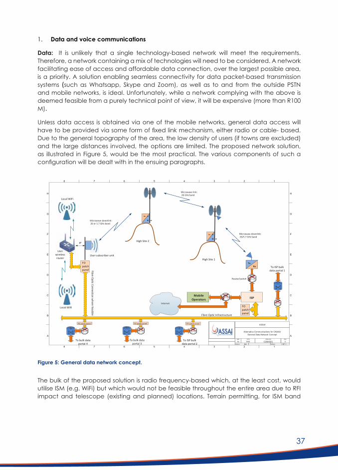
37
1. Data and voice communications
Data: It is unlikely that a single technology-based network will meet the requirements. Therefore, a network containing a mix of technologies will need to be considered. A network facilitating ease of access and affordable data connection, over the largest possible area, is a priority. A solution enabling seamless connectivity for data packet-based transmission systems (such as Whatsapp, Skype and Zoom), as well as to and from the outside PSTN and mobile networks, is ideal. Unfortunately, while a network complying with the above is deemed feasible from a purely technical point of view, it will be expensive (more than R100 M).
Unless data access is obtained via one of the mobile networks, general data access will have to be provided via some form of fixed link mechanism, either radio or cable- based. Due to the general topography of the area, the low density of users (if towns are excluded) and the large distances involved, the options are limited. The proposed network solution, as illustrated in Figure 5, would be the most practical. The various components of such a configuration will be dealt with in the ensuing paragraphs.
The bulk of the proposed solution is radio frequency-based which, at the least cost, would utilise ISM (e.g. WiFi) but which would not be feasible throughout the entire area due to RFI impact and telescope (existing and planned) locations. Terrain permitting, for ISM band
Figure 5: General data network concept.
H
G
F
E
D
C
B
A
8 7 6 5 4 3 2 1
H
G
F
E
D
C
B
A
8 7 6 5 4 3 2 1
ASSAf
Alternative Communications for CKAAAGeneral Data Network Concept
SIZE TYPE DWG NO REV
A4 DRG COM-001 0SCALE NA SHEET 1 OF 1
RxTx
Internet
Router/switch
ISP
Microwave link: 26 GHz band
Microwave downlink: 26 or 5.7 GHz band
Microwave downlink: 26/5.7 GHz band
Fibre Optic Infrastructureelbis
aef
ereh
w no
itce
nnoC
citp
O er
biF
User subscriber unit
Local WiFi
Local WiFi
Userwireless router
FO patchpanel
FO patchpanel
IP High Site 2
MobileOperators
High Site 1
R x
T x
R x
T x
To ISP bulk data portal 1
To ISP bulk data portal 2
To bulk data portal 3
To bulk data portal 4
FO patch panelFO patch panelFO patch panel

38
downlinks, 25 - 30 km from a telescope would be considered as a safe distance. In the event of RFI spillage, antennae choice needs to be carefully considered to mitigate for any impact. All areas where RFI impact must be negated (e.g. close proximity to a telescope) licensed band transmission in a frequency band above that of the SKA operational and scientific domain should be implemented.
If radio frequency-based, service to users should be in the form of downlinks from strategically chosen high sites. During the investigation, potential high areas had been determined topographically and checked for performance, however, these would need to be individually surveyed to confirm feasibility. The choice of generic antenna type at the high sites will be important not only in terms of performance but also in the containment of RFI. The preferred type of antenna for the ISM band links is the horn type.
An extended backhaul link network will be required to interconnect the positions of the high sites. It should be possible to utilise some of SARAO’s planned infrastructure, particularly their fibre optic network for backhaul communications. The present network does not make provision for additional services, but the infrastructure at terminating nodes could be shared to a certain extent. The investigation of this study assumes that additional fibre optic links will be required in addition to the infrastructure planned for telescope use. Users placed close to the fibre optic network could be connected by terrestrial overhead all-dielectric self-supporting (ADSS) lines. These are also the positions with the highest impact in terms of RFI due to proximity to existing and planned telescopes. A total of 101 such connections is envisaged at this stage, but might have to be revised after the necessary surveys.
The network described above will be functional from a technical point of view and should be capable of delivering the standard of service as expected and required. It will, unfortunately, be a costly solution due to the low density of users.
With the restrictions on wide area, terrestrial radio frequency-based services in the area, a VSAT (satellite) based service appears to offer a logical alternative. The VSAT terminal would act as a replacement for the subscriber unit in the alternative with microwave/fibre optic cable backhaul. It is also a very simple type of installation. Any active electronic equipment could act as a source of RFI. It is known that such problems were found during the initial testing of the VSAT terminal equipment bought by SARAO for distribution to the community as internet replacement. It is, therefore, essential that any new VSAT equipment be thoroughly tested for compliance before rollout. A testing campaign to this effect is currently underway.
Voice: The implementation of Picocell LTE base stations could be considered in selected positions but with due care. Due to the current non-existence of the conventional telephone network, there is preference to cover as much of the area as possible. It is, however, incompatible with the SKA scientific purpose, except for in limited locations.
The use of mobile phones at user locations for WiFi applications and LTE, should not be problematic. GSM operation, however, could be a threat within approximately 4 km from a telescope. This is clearly terrain-related.
The proposed network’s possible RFI impact was extensively investigated as best possible and deemed compliant on theoretical grounds.

39
2. Safety and emergency (mobile) communications
A network providing wide-area emergency and safety-related voice communications is a high priority to the community and considered essential. A system based on Very High Frequency (VHF) Low Band DMR type repeaters, mobile- and handheld radios was investigated. Coverage studies indicate very good coverage over the area of interest, using 12 repeater sites. Such an implementation should potentially be affordable, cost-effective and well suited to satisfy this requirement. The solution will also fit in with the network envisaged by SARAO themselves for internal use.
4.7.3 Incorporation of Future Technologies
The nature and extent of future technologies are inherently speculative. However, two possibilities are worth mentioning:
1. Pervasive satellite-linked personal communications
These have the attraction of offering almost universal access with low latency, such as Starlink or the rumoured Amazon equivalent. To date, voice services via satellite have been expensive. Starlink is intended as a fixed-/semi-fixed point data service and not a replacement for mobile phone type usage. This might change over time but will require a different mobile device as connection will not be possible via a WiFi connection on a mobile device due to permitted power levels and achievable signal strengths. Published costs at this point are still relatively high.
2. 5G
5G in its current South African format will not be permissible in the KCAAA due to the local spectral occupation, which falls in the SKA frequency band of interest. The higher region 5G spectrum (i.e. above 20 GHz) could be a future option but will require many small cells to cover a significant area. It is primarily a technology intended for densely populated environments, and practical application over a large area such as the greater SKA domain would be challenging. The distances involved are too large to ensure area coverage at that frequency.
4.8 Cost EstimatesTo assess the financial feasibility of the proposed voice, data and emergency communications technologies, preliminary indicative cost estimates were made. Table 9 outlines the costs involved in a phased installation of the option including microwave and fibre optic (Option A). Table 10 outlines the costs involved in a phased installation of the option of VSAT (Option B). Table 11 provides the cost estimates for the phased installation of an emergency communications network employing VHF Low Band DMR.
The estimations were made using some preliminary estimates of quantities and could be scaled as data is confirmed. The estimates are also highly dependent on the Rand exchange rate, as most of this equipment is imported.
The phases were based on the prioritisation by farm occupancy:
1. Phase 1 for permanently occupied farms; 2. Phase 2 for intermittent occupancy; and 3. Phase 3 for seldom occupied farms.

40
Tabl
e 9:
Opt
ion
A: M
icro
wav
e an
d Fi
bre
Opt
ic B
ackh
aul I
nfra
stru
ctur
e
SiteTy
pe&Description
Unit
Cos
tTo
tal
Qty
Tota
l all
Phas
esQ
ty
Phas
e 1
Tota
l Pha
se 1
Qty
Ph
ase
2To
tal P
hase
2Q
ty
Phas
e 3
Tota
l Pha
se 3
26 G
Hz B
ackh
aul L
ink
Site
R 25
7 30
0.00
114
R29
332
200.
0011
4R
29 3
32 2
00.0
00
R0.0
00
R0.0
0
26 G
Hz B
ackh
aul L
ink
Site
, Fib
re O
ptic
C
onne
cted
R 21
4 80
0.00
19R4
081
200
.00
19R
4 08
1 20
0.00
0R0
.00
0R0
.00
26 G
Hz S
ubsc
riber
Dow
nlin
kR
228
300.
0023
0R5
2 50
9 00
0.00
197
R 44
975
100
.00
33R7
533
900
.00
0R0
.00
26 G
Hz S
ubsc
riber
Inst
alla
tion
(2 x
AP’
s)R
101
100.
0019
4R1
9 61
3 40
0.00
147
R 14
861
700
.00
33R3
336
300
.00
14R1
415
400
.00
5.7
GHz
PTM
P D
istrib
utio
n Si
te (M
icro
wav
e ba
ckha
ul)
R 17
0 30
0.00
109
R18
562
700.
0010
9R
18 5
62 7
00.0
00
R0.0
00
R0.0
0
5.7
GHz
Sub
scrib
er In
stal
latio
n (2
x A
P’s)
R 71
100
.00
198
R14
077
800.
0018
1R
12 8
69 1
00.0
013
R924
300
.00
4R2
84 4
00.0
0
FO L
inks
(Tot
al c
ost f
or a
vera
ge lin
k d
istan
ce)
R 32
3 18
7.52
101
R32
641
939.
3910
1R
32 6
41 9
39.3
90
R0.0
00
R0.0
0
FO T
erm
inat
ions
/ lin
kR
64 2
00.0
010
0R6
420
000
.00
100
R 6
420
000.
000
R0.0
00
R0.0
0
FO S
ubsc
riber
Inst
alla
tion
(2 x
AP’
s)R
44 3
00.0
010
3R4
562
900
.00
100
R 4
430
000.
001
R44
300.
002
R88
600.
00
Allo
wan
ce L
TE P
icoc
ells
R 47
4 30
0.00
10R4
743
000
.00
10R
4 74
3 00
0.00
R0
.00
R0
.00
Subt
otal
R186
544
139
.39
R
172
916
939.
39
R 11
838
800
.00
R
1 78
8 40
0.00
Man
agem
ent c
entre
R 1
000
000.
00
R1 0
00 0
00.0
01
R 1
000
000.
00
R 0.
00
R 0.
00
Subt
otal
R187
544
139
.39
R
173
916
939.
39
R 11
838
800
.00
R
1 78
8 40
0.00
P’s &
G’s
20.0
0%
R37
508
827.
88
R 34
783
387
.88
R
2 36
7 76
0.00
R
357
680.
00
Subt
otal
R225
052
967
.26
R
208
700
327.
26
R 14
206
560
.00
R
2 14
6 08
0.00
Con
tinge
ncy
& D
esig
n15
.00%
R3
3 75
7 94
5.09
R
31 3
05 0
49.0
9
R 2
130
984.
00
R 32
1 91
2.00
Tota
l exc
l VA
T
R2
58 8
10 9
12.3
5
R 24
0 00
5 37
6.35
R
16 3
37 5
44.0
0
R 2
467
992.
00
VA
T15
%
R38
821
636.
85
R 36
000
806
.45
R
2 45
0 63
1.60
R
370
198.
80
Tota
l inc
l VA
T
R2
97 6
32 5
49.2
0
R 27
6 00
6 18
2.80
R
18 7
88 1
75.6
0
R 2
838
190.
80

41
Tabl
e 10
: Opt
ion
B: V
SAT-
base
d en
d-us
er in
stal
latio
n.
Desc
riptio
nU
nit C
ost
Tota
l Q
tyTo
tal a
ll Ph
ases
Qty
Ph
ase
1 (7
0%)
Tota
l Pha
se 1
Qty
Pha
se
2 (2
0%)
Tota
l Pha
se 2
Qty
Ph
ase
3 (1
0%)
Tota
l Pha
se 3
VSAT
-bas
ed e
nd-u
ser i
nsta
llatio
nR
44 7
50.0
039
1R1
7 49
7 25
0.00
274
R12
248
075.
0078
R3 4
99 4
50.0
039
R1 7
49 7
25.0
0
Subt
otal
R17
497
250.
00
R12
248
075.
00
R 3
499
450.
00
R 1
749
725.
00
Man
agem
ent c
entr
eR
1 00
0 00
0.00
1R1
000
000
.00
1R1
000
000
.00
0R
0.00
0R
0.00
Subt
otal
R18
497
250.
00
R13
248
075.
00
R 3
499
450.
00
R 1
749
725.
00
P’s &
G’s
20.0
0%
R3 6
99 4
50.0
020
.00%
R2 6
49 6
15.0
020
.00%
R699
890
.00
20.0
0%R3
49 9
45.0
0
Subt
otal
R22
196
700.
00
R15
897
690.
00
R4 1
99 3
40.0
0
R2 0
99 6
70.0
0
Conti
ngen
cy &
Des
ign
15.0
0%
R3 3
29 5
05.0
010
.00%
R1 5
89 7
69.0
010
.00%
R419
934
.00
10.0
0%R2
09 9
67.0
0
Tota
l exc
l VAT
R25
526
205.
00
R17
487
459.
00
R4 6
19 2
74.0
0
R2 3
09 6
37.0
0
VAT
15%
R3
828
930
.75
15%
R2 6
23 1
18.8
515
%R6
92 8
91.1
015
%R3
46 4
45.5
5
Tota
l inc
l VAT
R29
355
135.
75
R20
110
577.
85
R5 3
12 1
65.1
0
R2 6
56 0
82.5
5
Not
e: T
he V
SAT
dep
loym
ent c
ost a
llow
s for
a lim
ited
loca
l red
istrib
utio
n ne
twor
k as
wel
l. Th
e sit
e-sp
ecifi
c d
eplo
ymen
t cos
t may
var
y d
epen
din
g on
the
avai
labl
e su
ppor
ting
infra
stru
ctur
e.

42
Tabl
e 11
: VHF
Low
Ban
d Em
erge
ncy
Radi
o N
etw
ork
inst
alla
tion.
Desc
riptio
nU
nit C
ost
Tota
l Q
tyTo
tal a
ll Ph
ases
Qty
Ph
ase
1To
tal P
hase
1Q
ty
Phas
e 2
Tota
l Pha
se 2
Qty
Ph
ase
3To
tal P
hase
3
VHF
Low
ban
d DM
R Re
peat
er In
fras
truc
ture
Su
mR8
895
600
.00
Sum
R8 8
95 6
00.0
00
R0.0
00
R0.0
0
Repe
ater
site
est
ablis
hmen
t and
bac
khau
l ini
tiatia
l co
stR
20 0
00.0
012
R240
000
.00
12R2
40 0
00.0
00
R0.0
00
Subt
otal
R9 1
35 6
00.0
0
VHF
Low
ban
d DM
R m
obile
radi
osR
20 0
00.0
039
1R7
820
000
.00
274
R5 4
74 0
00.0
078
R1 5
60 0
00.0
039
R780
000
.00
VHF
Low
ban
d DM
R ha
ndhe
ld ra
dios
R16
000.
0058
7R9
392
000
.00
411
R6 5
76 0
00.0
011
7R1
872
000
.00
59R9
44 0
00.0
0
Subt
otal
R26
347
600.
00
R21
185
600.
00
R3 4
32 0
00.0
0
R1 7
24 0
00.0
0
P’s &
G’s
20.0
0%
R5 2
69 5
20.0
020
.00%
R4 2
37 1
20.0
020
.00%
R686
400
.00
20.0
0%R3
44 8
00.0
0
Subt
otal
R31
617
120.
00
R25
422
720.
00
R4 1
18 4
00.0
0
R2 0
68 8
00.0
0
Conti
ngen
cy &
Des
ign
15.0
0%
R4 7
42 5
68.0
010
.00%
R2 5
42 2
72.0
010
.00%
R411
840
.00
10.0
0%R2
06 8
80.0
0
Tota
l exc
l VAT
R36
359
688.
00
R27
964
992.
00
R4 5
30 2
40.0
0
R2 2
75 6
80.0
0
VAT
15%
R5
453
953
.20
15%
R4 1
94 7
48.8
015
%R6
79 5
36.0
015
%R3
41 3
52.0
0
Tota
l inc
l VAT
R41
813
641.
20
R32
159
740.
80
R5 2
09 7
76.0
0
R2 6
17 0
32.0
0
43
Over and above the high capital expense (CAPEX) of Option A, there would also be a significant ongoing support and maintenance cost, with an associated service provider that would need to be established. The cost and structure of such an organisation and its operations have not been considered.
The cost estimates indicate that Option B (wide-area VSAT installation) would be the much more attractive option for static internet access, financially speaking. Options regarding VSAT service providers should be considered, giving the users some choice over offerings that may have been negotiated by SARAO for current installations. For some applications, the relatively high latencies of geostationary VSAT services could be a problem.
The prospect of new satellite networks offering almost universal access with low latency, such as Starlink, could drastically change the entire data access scenario. According to current information, costs at this point are still speculative.
The Low Band DMR option is the only currently known viable option for (mobile) emergency telecommunication within the KCAAA. It is also likely to be used by the teams who will construct and maintain the extension of the telescope array. There is the option to dove-tail the two DMR networks (local community users and construction teams) from an installation and maintenance point of view, resulting in savings through economies of scale.
As per Option A, there will be a requirement for the service and support of the DMR infrastructure. It is proposed that this forms part of the required SKA emergency communications infrastructure and that a co-ordinating management structure is established to oversee maintenance and operation. This management structure should have members from all the stakeholder groups that would use this service (i.e. SARAO, LAG and any other community groups or services such as health and law enforcement). There will also be cases where radio networks will be inter-connected, such as linking the DMR with networks outside the KCAAA, but within the region such as the Marnet system. This will carry some additional costs, but it is not within the scope of this study to determine such detail. This would fall within the ambit of the management structure.
An investigation should be done in terms of the existing use of ICASA approved and licensed radios in the community, and an equitable policy should be drafted in terms of providing and subsidising mobile and handheld radio units. The indicative budget only caters for a limited number of radios per impacted farm.
4.9 Installation, Operation and MaintenanceA network of this type will not be sustainable without an entity responsible for operations and maintenance. Ideally, such an entity should also be initially involved in the installation. The entire area has been stricken with severe drought, and poverty is common. Therefore, it will be ideal if some form of community involvement can be arranged for the rollout and operation of the network.
A potentially successful model should be considered such as, a public-private-partnership (PPP) given the critical elements of regulatory control, initial capital funding, private user participation and long-term maintenance and management at ground level. This PPP structure and scope need to be dynamic as the future will be influenced by technological development. Typical participants to such a PPP structure would be the DSI, NRF and SARAO. It might include a financial support partner for initial capital. If it is a new business start-up

44
and involves job creation, it might be the Industrial Finance Corporation (IFC). Current ISP’s, like Hantamnet, could well be retained and perhaps form part of this partnership.
It is evident that any solution must be financially sustainable. Capital raising and expenditure will be required for the build phase, while for the Operating and Maintenance phase, depreciation and replacement strategies need to be considered.
4.10 Impacts,Benefits,ConcernsandTrade-offsBy giving the report’s recommendations due consideration with impetus towards funding, implementation and budgeting, it is anticipated that the social capital between the SKA project and the community will be given a boost and serve to redeem some of the negative legacies that ensued from the history to date. A high impact on social investment would be the urgent roll-out of the Low Band DMR emergency communications network.
Engagement with the community, specifically the LAG members, confirmed a positive and accepting view around the telecommunications technologies findings and recommendations of this study. However, acceptance was conditional upon due consideration on several concerns. These include:
1. Funding for the roll-out of new infrastructure, equipment and ongoing maintenance and licensing. This report makes recommendations around subsidising and business models that will assist the funding of technology solutions.
2. How the new technologies will be implemented and maintained.This relates to the issues around the roll-out of the new ICT infrastructure and the lack of support due to differences in perceived responsibility. Should SARAO be responsible for funding (and to what extent), maintenance and contractual issues, or should this lie with the users? Members of the community felt that it is because of the SKA’s presence that they now have to adopt new technologies, so SARAO should be responsible. Again, these issues are addressed through recommendations in the following chapter.
3. Community members were also concerned about losing the ability to make phone calls to landlines and other mobile phones via the GSM network. However, such phone calls would be possible through 1) the emergency radio Low Band DMR technology proposed and 2) internet-based Voice over Internet Protocol (VOIP) options (such as Skype).
4. The feasibility of operating a new radio system (the Low Band DMR system) in parallel with the old Marnet system. While the two are not compatible because they represent two very different technologies, i.e. one quite old and one new, they could be integrated through additional technological means. However, that does not negate the issue of two systems operating in close proximity at the border of the KCAAA. Ideally, all communities operating on the Marnet system (in and out of the KCAAA) should take up the new system. However, this will not be possible since SARAO would likely only validate expenditure for activities within the KCAAA. Still, it does not preclude other communities from implementing an extended DMR network (even on different bands).
5. The implementation of the emergency communication service is considered of highest priority. It should be the prime focus in any implementations to be considered, given the nature of increasing rural safety and security concerns.

45
CONCLUSIONS AND RECOMMENDATIONS

46
5. CONCLUSIONS AND RECOMMENDATIONS
5.1 ConclusionsIn terms of the regulatory framework, the alternative communication technology solutions that could be considered in the KCAAA that would meet national targets in terms of universal service and access to voice, data and broadcasting services are as follows:
1. Telecommunications services (voice and data) as well as broadcasting services (cable broadcasting services) which are provided using fixed lines;
2. Telecommunications and broadcasting:
■ that use the radio frequency spectrum below 100 MHz or above 2 170 MHz in KCAAA1;
■ that use the radio frequency spectrum below 2 170 MHz or above 6 000 MHz in KCAAA2; or
■ that use the radio frequency spectrum below 6 000 MHz or above 25 500 MHz (25.5GHz) in KCAAA3.
3. Telecommunications and broadcasting services that use the radio frequency spectrum within the predetermined frequency bands under protection but which are exempted from the general prohibition.
4. Other than as set out above, any use of the radio frequency spectrum between:
a. 6 000 MHz and 25.5 GHz in KCAAA3;b. 2 170 MHz and 6 000 MHz in KCAAA2; and/orc. 100 MHz and 2 170 MHz in KCAAA1 requires a permit from the AMA, that will require
compliance tests to assess interference levels.
In terms of stakeholder relations and ICT infrastructure in the KCAAA, the research into the local community shows that the SKA’s strategic position in the Karoo is not only determined in the legislative, regulatory, political, financial, technical, and scientific arenas but also the social area. The local context is that of an underserviced area, as defined by the regulations of the ICASA. ICT’s are critical for the agricultural sector, business practices, safety, social integration, and education. Uncertainty about access to universal ICT services negatively impacts the local community.
In terms of alternative telecommunications technology options, the findings are as follows:
■ Conventional cell-based mobile coverage is ideal but problematic in terms of RFI except in a few specific locations.
■ Data access via microwave and fibre connectivity (Option A) is technically excellent but will be very expensive to install and maintain.
■ VSAT data connectivity (Option B) is a feasible and economical option. ■ It is possible to have a combination of Options A and B, as mentioned above. ■ A VHF Low Band DMR emergency communications network is feasible and could be
implemented to provide good coverage over a sufficiently wide area.

47
5.2 RecommendationsIn terms of stakeholder relations and management in the KCAAA, the following are recommended:
1. A fully-fledged communication and engagement strategy for ICT interventions in the Karoo must be developed. The strategy should include: 1) the delineation of emergent and participative engagement structures and processes, 2) a plan for communication processes, messaging and channels, and 3) developing an evidence-based understanding of public perceptions and institutional agendas.
2. Engagement processes must be open and inclusive throughout. Research and plans related to changes in ICT access and infrastructure should be openly shared and communicated. Consultation with stakeholders and the public should take place at all stages, including at the stages of research, scoping, selecting options, tendering for contractors, implementation, and monitoring and evaluation. The engagement process should be participative and inclusive; no stakeholders or members of the public should be excluded, and the agenda and process should be set by local stakeholders and members of the public. SARAO should remain mindful of power relations and their associated social dynamics at all times. Afrikaans should be the primary language of engagement and communication. All minutes of meetings should be made publically available.
3. All messaging must be valid and consistent. Broken promises, ‘shifting goalposts’ and contradictory messaging have undermined the SKA’s social licence to operate. Communicating a set of plans, then at a later stage communicating that plans have changed, would be a risk to the organisation. It is imperative that, going forward, all messaging related to ICTs be consistent and grounded in a realistic assessment of the SARAO’s internal capacities and external risks to the SAK project. This will require time and input from SARAO’s senior management.
4. There is a need to more closely coordinate with the NRF and the DSI to align messaging, particularly in the political arena. Parliamentary records and other public platforms reveal several examples of political principals making promises on behalf of SARAO which were subsequently not met. Local publics have grown sceptical of the political principals, signalling a need to align communication to ensure consistency.
5. All previous failures to meet reasonable expectations and communicate consistently must be surfaced, acknowledged, and remedied where possible. This may cause short-term discomfort to SARAO but is necessary for the long-term healing of damaged local relationships. Without such a process, uncertainty and suspicions will remain, trust will remain broken, and adversarial positions will remain entrenched. These actions are critical for the maintenance of the SKA’s social licence to operate.
6. SARAO should reflect on its organisational culture. The history of SARAO’s engagements in the Karoo, including matters related to ICTs, can be seen through the lens of ‘the two cultures of science’ as being driven by the world view of the natural sciences, in which the primary considerations have been scientific, technical, legislative and administrative. A balanced approach would also include insights from the humanities, which centre the human, and where primary considerations include individual experiences, social dynamics, culture, the political economy and power relations. Local community contestation is not an administrative or technical problem but a social challenge to be met through analysis and strategy.

48
In terms of implementable and feasible telecommunications technologies in the KCAAA the following are recommended:
1. Internet connectivity be provided to all priority farms/user locations, by means of VSAT, at least in the interim. This connectivity should be expanded on a per-site basis to allow for farm-wide residential access.
2. A subsidy model be investigated for the installation, obtaining the radios, system operations and maintenance, and data cost of the VSAT service. Detailed suggestions on the development and structure of such a subsidy model cannot be made at this time without detailed information regarding financing options and commitments from all role players.
3. In view of the lack of general telecommunications services in the area, the proposed VHF Low Band DMR emergency communications network should be implemented as a priority, for safety, emergency and business operations.
4. An ‘Operational, Management and Control Centre’ be established for safety and operational reasons and for network monitoring and management.
5. With the recognition that establishing a Section 21 company could be arduous given its function and duration, a public-private partnership (PPP) should be formed to oversee and undertake monitoring, admin and maintenance of the networks mentioned above.
6. That SARAO be required to source the funding of the infrastructure as recommended.

49
REFERENCES

50
REFERENCES
Atkinson, D., Wolpe, R., & Kotze, H. (2017). Socio-economic assessment of SKA Phase 1 in South Africa. Retrieved October 21, 2020, from http://www.skaphase1.csir.co.za/wp-content/uploads/2017/01/SocioEconomic-Assessment.pdf
Bahrini, R., & Qaffas, A. A. (2019). Impact of information and communication technology on economic growth: Evidence from developing countries. Economies, 7(1), 1-13.
Bauer, M. W. (2005). Public perceptions and mass media in the biotechnology controversy. International Journal of Public Opinion Research, 17(1), 5-22.
Blanckenberg, M. (2019). The effects of landscape level changes in land use on mammal communities and mesopredator conflict in the Karoo: SKA research report. Institute for Communities and Wildlife in Africa.
Butler, S. S. (2018). Knowledge relativity: Carnarvon residents’ and SKA personnel’s conceptions of the SKA’s scientific and development endeavours. Thesis (MA). Stellenbosch University. Retrieved October 22, 2020, from http://scholar.sun.ac.za/handle/10019.1/103532
Chetty, L.-R. (2012, October 3). Retrieved April 10, 2020, from Institute for Ethics and Emerging Technologies: https://ieet.org/index.php/IEET2/more/chetty20121003
CSIR. (2016). Integrated Environmental Management Plan for the South African mid-frequency array of SKA Phase 1. CSIR Report Number: CSIR/02100/EMS/ER/2016/15241/B. Retrieved October 21, 2020, from http://www.skaphase1.csir.co.za/wp-content/uploads/2017/07/Final-IEMP_May-2017.pdf
Gastrow, M. (2017). The stars in our eyes: representations of the Square Kilometre Array telescope in the South African media. Cape Town: HSRC Press.
Gastrow, M., & Oppelt, T. (2018). Big science and human development - what is the connection? South African Journal of Science, 114(11/12), 7 pages. doi:https://doi.org/10.17159/sajs.2018/5182
Gastrow, M., & Oppelt, T. (2019). The Square Kilometre Array and local development mandates in the Karoo. Journal of Southern African Studies, 45(4), 711-728. Retrieved from http://hdl.handle.net/20.500.11910/15070
Government Gazette Number 32939, Notice 85 (8 February, 2012).
Government Gazette Number 35007, Notice R. 90 (10 February, 2012).
Government Gazette Number 35450, Notice 465 (22 June, 2012).
Government Gazette Number 37119, Notice 953 (6 December, 2013).
Government Gazette Number 37434, Notice 198 (2014).

51
Government Gazette Number 37999, Notice 730 (19 September, 2014).
Government Gazette Number 38641, Notice 279 (13 March, 2015).
Government Gazette Number 40706, Notice 621 (2017).
Government Gazette Number 41321, Notice 1411 (15 December, 2017).
Government Gazette Number 41650, Notice 239 (25 May, 2018).
Government Gazette Number 41891, Notice 939 (5 September, 2018).
Government Gazette Number 42531, Notice 926 (14 June, 2019).
Government Gazette Number 42762, Notice 1318 (11 October, 2019).
Government Gazette Number 43387, Notice 629 (3 June, 2020).
Habermas, J. (1989). The structural transformation of the public sphere: An inquiry into a category of bourgeois society. Cambridge: Polity Press.
Heeks, R. (2010). Do information and communciation technologies (ICTs) contribute to development? Journal of International Development, 22(5), 625-640.
Hu, E. (2013). Enter the quiet zone: where cell service, WiFi are banned. All Tech Considered. Available from: https://www.npr.org/sections/alltechconsidered/2013/10/08/218976699/enter-the-quiet-zone-where-cell-service-wi-fi-are-banned
International Telecommunications Union (ITU). Protection criteria used for radio astronomical measurements. ITU-R Recommendation RA.769-2. Approved 2003-05. https://www.itu.int/rec/R-REC-RA.769/en
Karoo Central Astronomy Advantage Area Protection Regulations. Section 1 Schedule A (2017).
Karoo Hoogland Municipality. (2020). Final Annual Report 2018/2019. Retrieved October 22, 2020, from http://www.karoohoogland.gov.za/wp-content/uploads/2020/02/Final-Annual-Report-2018-2019-KHM-nc066-January-2020.pdf
Kayamandi Development Surveys. (2015). An impact assessment of SKA and SKA-related projects on the socio-economic conditions in the Northern Cape Province.
Kirsten, J. F. (2016). An estimation of the agricultural economic and local impact of Phase 1 of the SKA. Report Prepared for the CSIR, Pretoria. Retrieved October 21, 2020, from https://www.sarao.ac.za/wp-content/uploads/2019/03/Agriculture-Economic-Study.pdf
Lord, R. (2012). Radio frequency interference and radio astronomy: why the fuss? Quest, 8(3), 18-20. Retrieved October 22, 2020
52
National Planning Commission. (2011). National Development Plan 2030: Our Future – Make it Work. Pretoria: The Presidency. Retrieved from https://www.gov.za/sites/default/files/gcis_document/201409/ndp-2030-our-future-make-it-workr.pdf
SKA SA. (2016). Northern Cape NEWS. 3. Retrieved October 22, 2020, from https://www.sarao.ac.za/wp-content/uploads/2017/05/ska_nuus_nk_23_eng.pdf
Snow, C. P. (1959). The Two Cultures. New York: Cambridge University Press.
Sondlo, A. (2016). A content analysis of how astronomy is framed in selected South African online newspapers. Unpublished Research Report toward MSc Thesis. University of the Witwatersrand. Retrieved October 22, 2020, from http://wiredspace.wits.ac.za/bitstream/handle/10539/21684/Aviwe%20Sondlo%20R.R.%2027-07-2016.pdf?sequence=1&isAllowed=y
South African Constitution (Act 36 of 2006), Section 25. The Right to Property, Bill of Rights, Chapter 2.
Stats SA. (2012). Census 2011: EA spatial data. Pretoria. Retrieved May 26, 2020, from http://www.statssa.gov.za/?page_id=964.
Terblanche, R. (2020). Ongediertes: A critical qualitative study of farmer–black-backed jackal conflict and its management around the Square Kilometre Array core site in the Northern Cape, South Africa. Thesis (PhD). Stellenbosch University. Retrieved October 22, 2020, from https://scholar.sun.ac.za/handle/10019.1/107974
The Electronics Communications Act (ECA) Act 36 2005.
Van der Merwe, C. (2012). Culprit and victim management RFI environment for a radio astronomy site. Stellenbosch: Stellenbosch University. Retrieved 10 22, 2020, from https://core.ac.uk/download/pdf/37347996.pdf

53
APPENDICES

54
APPENDICESAPPENDIX 1: Biographies of panel membersFrancesco Petruccione (UKZN)
Prof Francesco Petruccione is the Deputy-Director of the National Institute of Theoretical Physics. Since March 2008, he has been a member of the Board of the UKZN Innovation Company. In 2007 he was granted a South African Research Chair for Quantum Information Processing and Communication from the National Research Foundation. He studied Physics at the University of Freiburg i. Br. (Germany) and received his PhD in 1988. He got his “Habilitation” (Dr. rer. nat. habil.) from the same University in 1994 and worked there as Associate Professor of Theoretical Physics until 2003. In 2004 he was appointed Professor of Theoretical Physics at the University of KwaZulu-Natal. In 2005 he was awarded an Innovation Fund grant to set up a Centre for Quantum Technology.
Carl Kies (Reutech Radar Systems)
Mr Carl Kies joined Reutech Radar Systems as a graduate design engineer in 1988. In 1993 he became involved as a system design engineer working on maritime defence systems at Maritech. From 1997 Carl functioned in various roles such as systems architect and project manager in the IT industry, working with companies such as Old Mutual and Dimension Data. In 2002 he founded a software engineering firm as part of the Reunert group, Acuo Technologies. Carl became chief executive of Reutech Radar Systems in 2010.
Senka Hadzic (UCT)
Dr Senka Hadzic is a Postdoctoral Research Fellow at the University of Cape Town. She obtained her PhD in Electronics and Telecommunications Engineering at the Instituto de Telecomunicações, University of Aveiro, Portugal, in 2014. She received the Marie Curie ERCIM fellowship to conduct postdoctoral research at the Fraunhofer Institute for Open Communication Systems (FOKUS) in Germany, where she was working on wireless backhaul deployments for rural areas and developing countries. During this tenure she participated in two Research Exchange Programs - at the Swedish Institute of Computer Science (September 2014) and the University of Cyprus (March 2015). She joined the ICT4D Networking group at the Computer Science Department in March 2016, where she participates in R&D activities in cutting edge wireless communications and novel network infrastructures for poorly connected areas to expand access or improve network performance in these regions. The research focuses on the use of technologies, such as Mesh Networks, Software Defined Networks, and Dynamic Spectrum Access, including TV White Spaces and Software Defined Radios.
Babu Sena Paul (UJ)
Prof Babu Sena Paul received his B.Tech and M.Tech degrees in Radiophysics and Electronics from the University of Calcutta, West Bengal, India, in 1999 and 2003. He was with Philips India Ltd from 1999-2000. From 2000-2002 he was lecturer of Electronics and Communication Engineering Dept. at SMIT, Sikkim, India. He received his PhD degree from the Department of

55
Electronics and Communication Engineering, Indian Institute of Technology Guwahati, India. He has attended and published over sixty research papers in international and national conferences, symposiums and peer reviewed journals. He has successfully supervised several postgraduate students and post-doctoral research fellows. He joined the University of Johannesburg in 2010. He has served as the Head of the Department at the Department of Electrical and Electronic Engineering Technology, University of Johannesburg, from April 2015 to March 2018. He is currently serving as an Associate Professor and Director to the Institute for Intelligent Systems, University of Johannesburg. He was awarded the IETE Research Fellowship. He is a life member of IETE and a member of IEEE. His research interests include Mobile Communication, Vehicular Communication, Femto Cells and High Frequency Circuits.
Justine Limpitlaw
Prof Justine Limpitlaw is an independent communications law consultant who specialises in broadcasting, media, telecommunications, and space and satellite law. Her broadcasting-related experience includes work for several of South Africa’s leading broadcasting and over-the-top service providers – commercial, public and community. She has extensive experience in broadcasting licensing processes, including digital terrestrial television (DTT) and satellite television service. She is also an expert in drafting legislation, regulations and policies for broadcasting – including codes of conduct for broadcasters and model broadcasting laws – and has extensive experience in competition, local content, and independent television production matters. Limpitlaw has her BA LLB from the University of the Witwatersrand and her LLM from Yale University.
Michael Gastrow
Dr Michael Gastrow is a research specialist in the Education and Skills Development research programme. He holds an MA in Creative Writing from the University of Cape Town and is currently undertaking a PhD at the School of Journalism of the University of Stellenbosch. Before joining the HSRC in 2006, he was an industrial development consultant at B&M Analysts. His areas of research interest include innovation, skills development, and the public relationship with science. Mr Gastrow’s publication record includes the authoring and co-authoring of more than twelve peer-reviewed journal articles and fourteen conference presentations. As guest editor and contributor of two papers to a Special Issue of Innovation and Development, his most recent work is focused on Global Innovation Networks and their links to skills development.
Riaan Wolhuter
Prof Riaan Wolhuter is an extraordinary researcher at the Department of Electrical & Electronic Engineering, Stellenbosch University. He works within the DSP-Telecommunications Group, with main responsibilities in terms of Telecommunications-related postgraduate activities, such as student supervision, research and project development and lecturing in Advanced Telecommunications. His areas of research include, amongst others: adaptive communication strategies using Machine Learning principles, theoretical modelling and development of communications protocols for optimised communication over narrow band links, wide area telemetry communications strategies and applications, with a view to industrial applications, research into application and interfacing of new broadband technologies for telemetry, security and industrial control, research into routing, protocol strategies and hardware for ad hoc- and Wireless Sensor Networks, communications link reliability and error mitigation

56
APPENDIX 2: Biographies of reviewersBrian Armstrong, Wits (South Africa)
Prof Brian Armstrong is one of the foremost ICT industry leaders in South Africa, with over 30 years of top-level management experience in Telecommunications, IT, technology research and development, and systems engineering, both in South Africa and abroad. He is widely regarded as a thought leader in digitalisation, convergence and business strategy. Prof Armstrong is currently a professor in the Chair of Digital Business at the Wits Business School. He consults widely to industry and government on technological disruption and digital business and is an acclaimed public speaker on digital transformation and its socio-economic impacts. He is a non-executive director of Old Mutual Limited, the Huge Group and the Tshimologong Innovation Precinct.
Previously Prof Armstrong spent seven years at Telkom as Group Chief Operating Officer and Group Chief Commercial Officer, where he was part of the leadership team credited with turning Telkom around. In his time with Telkom, he also revived the ailing Telkom Business unit and conceived and led the acquisition of BCX and its integration into the group. He was also responsible for the group’s retail unit, and leading group strategy and transformation activities.
Before joining Telkom in 2010, Prof Armstrong was BT’s Vice President for the Middle East and Africa with overall responsibility to oversee and grow BT’s activities across the region. Before that, his work experience includes South Africa’s CSIR, ultimately as the Director of the Division for Information and Communications Technology; and South African listed ICT services group AST (now Gijima), as Managing Director of AST Networks.
Prof Armstrong completed his BSc (Eng) and MSc (Eng) at the University of the Witwatersrand in 1982 and 1984, respectively, and obtained his PhD from University College London in 1992.
Margaret Nyambura Ndung’u, GFA Consulting Group GmbH (Kenya)
Dr Margaret Nyambura Ndung’u is an Information Scientist with over 20 years of work experience in research and projects management gained from non-governmental organisations, the private sector and academia. She is a researcher and consultant in the ICT sector, where she has consulted for various national, regional and international organisations. She is published in recognised journals and conference proceedings.
She is a research associate for Research ICT Africa (RIA), an African think tank that fills a strategic gap in the development of a sustainable information society and network knowledge economy. As the secretary to the task force that collected views from stakeholders, she wrote the Kenya National ICT Master Plan (2014-2017). Since 2018, she has been a member of the Communications and Multimedia Appeals Tribunal (CAMAT), the tribunal that arbitrates disputes in the ICT and Multimedia Sector in Kenya as spelt out in the Kenya Information and Communications Act (KICA), 2013.
Dr Ndung’u has consulted for the International Trade Centre as the National Consultant on enhancing export competitiveness in the Internet Technology Enabled Services (ITES) sector in Kenya, as well as for the World Bank Group’s Digital Economy for Africa (DE4A) flagship initiative. She is currently consulting for the Policy and Regulation Initiative for Digital

57
Africa (PRIDA) as a key expert, a project of the African Union Commission. She lectures part-time at the School of Computing and Informatics, University of Nairobi and supervises MBA students at the Business School of Tshwane University of Technology in Pretoria, South Africa. She holds a PhD in Information Systems, an MBA in Management Science; and a BSc in Information Sciences
Martin Lavery, University of Glasgow (Scotland)
Dr Lavery is a Senior Lecturer, Royal Academy of Engineering (RAEng) Research Fellow and leader of the Structured Photonics Research Group at the University of Glasgow (UofG). His dynamic research group has a track record in investigating fundamental developments in Physics and successfully applying them to industry-inspired engineering challenges. Since joining the School of Engineering in September 2014, he has successfully attracted over £3.5m in research funding as Principal Investigator (PI). He is the coordinator of the H2020 Future and Emerging Technologies (FET-Open) consortium project named SuperPixels. He has been recognised as a leader in the academic community, having been awarded the 2013 Scopus Young Scientist of the Year for Physical Sciences and was the 2018 Mobile World Scholar Gold Medal winner for his accomplishments in high dimensional optical communications. He further led a team of world-leading research to develop a road map for deploying highspeed network provision for developing countries (Lavery et al., N. Photon. 12(5), 249-252, 2018) supported by the EPSRC Global Challenges Research Fund.

58
APPENDIX 3 Investigation: Telecommunication Technologies and Radio Frequency Interference
Table of Contents1. Introduction ........................................................................................................................... 59
2. Assessment Methodology .................................................................................................... 59
2.1 Modulation Techniques and Air Interfaces ................................................................60
2.2 Theory of Assessment Methods ....................................................................................60
2.3 Power Control Transmission ..........................................................................................61
2.4 Mobile Station (MS) and Base Station (BTS) Power Requirements ...........................62
2.5 Selection Criteria ...........................................................................................................62
3. Interference Levels................................................................................................................ 62
3.1 VSAT Interference Levels ..............................................................................................62
3.2 Wireless Interference Levels .........................................................................................63
4. Alternative Solution Assessment .......................................................................................... 67
4.1 Optical Fibre Solution Assessment ...............................................................................67
4.2 VSAT Solution Assessment .............................................................................................68
4.3 Wireless Solution Assessment ........................................................................................68
5. AlternativeSolutions:SpecificationsandSuggestions ...................................................... 70
5.1 Suggested Solution ........................................................................................................70
5.2 Assessment Analysis .......................................................................................................70
6. Conclusion ............................................................................................................................. 71
7. References ............................................................................................................................. 71
8. Appendices ........................................................................................................................... 73

59
1. IntroductionInterferences are one of the leading causes of data loss of radio astronomy (RA) observations. Interferences can occur due to multiples reasons, e.g. sharing of the same band by more than one user, spurious signals emitted by external sources in the frequency band under consideration. In the present study, interference due to band sharing has been excluded as the current regulations prohibit the sharing of bands used for Radio Astronomy. However, due to nonlinear effects, we carry our assessment over the entire unwanted emission domain. We also investigate the incorrect measurements that can occur due to the RA antenna sensitivity to noise from the surrounding transmitters, which are likely to cause data loss from the RA.
The present study investigates the operability of different technologies to keep the defined “Karoo quiet zone” an interference-free zone when operating with a mobile station (MS), a base station (BTS), and any other communication systems. The “Karoo quiet zone” is the interference-free area surrounding the square kilometre array (SKA). For that purpose, we conduct an assessment to determine, for each proposed telecommunication technique, the interference level that might occur based on the power radiated in the direction of the SKA and the related distance between the communication station and the RA site. The modulation techniques used by the various technologies under consideration are governed by the Power Spectral Density (PSD) has been studied.
This report is organised as follows. Section 2 provides the assessment method used in this report, Section 3 gives the interference levels, Section 4 presents and assess the proposed technologies, while Section 5 provides the selected technology specifications for their operability, and Section 6 concludes the report.
2. Assessment MethodologyThe methodology used in this study has been to assess the interference detrimental to the radio astronomy observation from the different proposed technologies in the Karoo central. Two sets of parameters are of our interest:
The spectrum: The unwanted emission domains, which consists of out-of-band and spurious domain, falling in the RA adjacent bands; and
The spectrum of certain signals reaching the RA antenna in a form of noise, and which, due to the antenna sensitivity, can be mistakenly measured.
The power: It can be in the form of power flux density (PFD), which is the power per unit area, or its spectral PFD variant (SPFD), which is the PFD per Hertz; the effective isotropic radiated power (EIRP) defined as the required power radiated by an omnidirectional antenna; and the power spectrum density (PSD) which is the power distribution over the frequency.
In the present study, the above-mentioned parameters have been investigated for each alternative technology under consideration using the transmission characteristics (uplink, downlink band and service rates), which are particular to each type of modulation used, and provide specifications involving the power radiated and the distance from the emitting station to Karoo central. Several modulation techniques are in use.

60
2.1 Modulation Techniques and Air Interfaces
Modulation techniques are of great importance as there are often some harmonics and/or some nonlinearities that cause unwanted emissions that are detrimental to radio astronomy observations. The analysis of the harmonics and the non-linear effects provides us with the power spectrum density (PSD) in the necessary bandwidth, which is sufficient to determine the behaviour in the adjacent channels or bands, as the unwanted emissions constitute 250% of the necessary band [4]. The following modulation techniques and air interfaces have been investigated:
Gaussian Minimum Shift Keying (GMSK) modulation:
GMSK experiences more interference inter symbol than its counterpart Minimum Shift Keying (MSK), with its PSD intersecting fTb (frequency-bit duration) axis for the values >1.
Phase Shift Keying (PSK):
In PSK, the information modulates the phase, and its spectrum is zero for fTb = 0.5. There are various forms of PSK, denoted as M-PSK. The efficiency of the different PSK forms increases proportionally with M, hence QPSK, AQPSK, 8-PSK modulation.
Quadrature Amplitude Modulation (QAM):
In QAM, the information modulates the amplitude and the phase, and its spectrum is zero for fTb = 0.5. There are various forms of QAM, denoted as M-QAM. Efficiency increases proportionally with M for M-QAM, hence 16-QAM and 32-QAM modulation. QAM presents a better bit error rate and spectrum amplitude than the PSK.
Orthogonal Frequency Division Multiplexing (OFDM), was also investigated because of its spectrum efficiency as radio link technology.
Code Division Multiple Access (CDMA) and Wideband CDMA (WCDMA) were also investigated in our suggested mobile trunk.
2.2 Theory of Assessment Methods
Two assessment methods were used in this study.
The determination of the spurious domain: We use this spectrum to assess the necessary bandwidth, also known as in-channel bandwidth, from where the spurious domain is derived. We identify the RA observation affected bands and provide the operability conditions based on the related PFD/EIRP level.
Another assessment method considers intermodulation and non-linear effects in RA antenna. We make use of the unwanted PSD that reaches the RA antenna in the form of noise and determine its wrongly measured level that causes 10% of the integration time loss during the RA observation estimated at 2 000 seconds according to [1] and [22] from where we specify the PDF/EIRP level.
Analytically, the spurious domain is typically 250% of the necessary bandwidth. It may affect adjacent bands that are given in [2]. The PFD provides us with the field strength of the radiated signal at the radio astronomy site, and it is derived from the relation [3]:

61
where N is the number of carriers (N = 1 in our case, 48 for OFDM), Pt is the radiated power and Gt is the antenna gain in the direction of the Karoo central area.
Taking into account that EIRP(W) = PtGt, and that PFD = 10log( dB(W/m2 ), the PFD and the
EIRP at distance d from the transmitter is related according to the equation:
PFD = EIRP - 20logd - 10.99 dB
We may also use this PFD as given in Rec ITU-R SM 1448 [4] to specify the EIRP (dB).
For bands affected by unwanted emissions, we use the attenuation of unnecessary band effects per [5, 6] to determine the EIRP. For that purpose, we determine Pt according to category A attenuation (Not allocated to a zone) given in [20] using for which the evaluation tool is given by:
43 + 10logP, or 60 dBc whichever is less stringent.
Where the duration of detrimental interference due to non-linear effects or intermodulation matters, we determine for the purpose the propagation loss level Lp(W) from where the EIRP (W) can be derived using the interference level I(W) at the RA site for N channels given by [21]:
This interference level becomes detrimental Ip(W) if it exceeds 10% of the PSD noise fluctuation ΔP that is likely to be measured by the sensitivity of RA observation and it is given by [22]:
T in oK (Kelvin) is the sum of the antenna noise temperature and the ambient, K Boltzmann’s constant. Δƒ is the bandwidth channel equal to the Doppler shift corresponding to 3 km/s in velocity (v), which is given by with B emitter bandwidth, c light speed, t the observation time set to 2000 seconds.
We make use of temperatures as given in [22] when necessary, however, due to the difficulties of having the exact temperature, where not measured, we determine Lp(W) from where EIRP can be derived after measuring the RA antenna line’s temperature.
2.3 Power Control Transmission
Another important criterion in suggesting a solution is the operator MS and BTS specifications on control in compliance to [7]. For the mobile and the base station, assuming equal received and transmit power, the received/transmit power control is given by the relation [8]:
Pt + Pr = -73dBm,
where and are transmit and received power, respectively, executed by the base station for the reverse link and by the mobile for the forward link.

62
In the next section, we suggest a certain number of technologies, provide their detrimental interference level as per assessment, and outline the advantages that one technology offers over another.
2.4 Mobile Station (MS) and Base Station (BTS) Power Requirements
Transmission power and modulation types are given in Table I and II of Appendix 3.A. These given values are the nominal powers for an acceptable quality of service, will be serving as well as reference for our assessment methods in determining the required specifications for both, the public network, and the personal network.
2.5 Selection Criteria
The selected technology is based on the coordination distance and the radiated power evaluated herein. This evaluation is carried out in a worst-case scenario of a line-of-sight situation, and unless otherwise stated for RA antenna requirements, a reference of 0 dBi antenna gain is assumed for the radio astronomy. The obtained parameters from the evaluation must be within the margins of the prescribed transmission requirements.
3. Interference LevelsIn this section, we present the level of interference of different wireless technologies as measured by the different RA government bodies, emphasising the parameters enumerated above.
3.1 VSAT Interference Levels
The VSAT transmission type constitutes about 69.3% of uplink fixed space station (FSS) transmissions, representing 15.28% of the total bandwidth. It is therefore essential to focus on FSS transmission characteristics.
For the VSAT transmission type, a single entry generally requires a PSD of around –50 dBW/Hz. In some cases, this could be exceeded (e.g. ‒42 dBW/Hz). The Single-Entry characteristics for the FSS in the 10-17 GHz band can be found in Table 4.1 of [9].
VSAT terminals typically have small aperture sizes, transmit at relatively low equivalent isotropic radiated power (EIRP) levels.
Unwanted emission C-band: EIRP 48 dBpW for receive only and 49 dBpW for transmit and receive (to be revised accordingly whether the system adopted is prior or after 1994. [10]
Unwanted emission Ku-band: EIRP 54 dBpW for receive only and 55 dBpW for transmit and receive (to be revised accordingly whether the system adopted is prior or after 1994. [10]
Unwanted emission Ka-band: EIRP 60 dBpW for receive only and 67 dBpW for transmit and receive (to be revised accordingly whether the system adopted is prior or after 1994. [10]

63
3.2 Wireless Interference Levels
We present the mobile and other wireless LAN and WAN technologies interference background that are part of our solution.
3.2.1 3GPP technologies
Considering the sensitivity of the radio astronomy observation antennas, we will exclude from our assessment the related 3GPP released 99, UMTS WCDMA. Therefore, we will avoid it and focus on the remaining 3GPP release as shown in Table III Appendix 3.A. 3GPP Release 5 introduced High-Speed Downlink Packet Access (HSDPA) in 2002. In 2004, 3GPP Release 6 introduced Enhanced uplink (UL) - also referred to as High-Speed UL Packet Data Access (HSUPA). The combination of HSDPA and HSUPA technologies is referred to simply as High-Speed Packet Access (HSPA). The next evolution of the UMTS standard was HSPA evolution, also known as HSPA+ or evolved HSPA, introduced in 2007 with 3GPP Release 7 and 8 in Table III, Appendix 3.A shows the advantages of one compared to another during their evolution.
3.2.1.1 GSM Spurious Emissions
GSM radiated spurious emissions presented here relate to the BTS and the MS belonging to the trunk GSM (T-GSM).
■ BTS Spurious emissions levels ■ The specifications currently only apply to the frequency bands of T-GSM in their
geographical sharing space. These specifications and methods of measurement within these bands are under consideration and confined in Table IV (a) Appendix 3.A.
■ The spurious emissions from the mobile set (MS) ■ The spurious emissions are given in Appendix 3.A, Table IV (b) [7]. Because the MS is mobile,
provisions must be made such that the notion of power control and the requirements defined in this report are applied.
3.2.1.2 Releases 96-5 Spurious Emission
The spurious emissions levels for the BTS transmissions requirements are given in [7] and are valid from release 96 to 5 and apply to the frequency band 30 MHz to 4 GHz. The measurements conducted within this frequency band are shown for the BTS in the following Table V Appendix 3.A.
Table V shows that the BTS or UTRAN spurious emissions are considerable. Therefore, care must be taken when proposing solutions of which frequency bands fall within the range of Table V Appendix 3.A.LTE Spurious Emissions.
The primary goals of the LTE standard are increased network capacity and higher data transfer rate. This is achieved using Orthogonal Frequency Division Multiplexing (OFDM) technology, a multi-carrier technique that better exploits wider channel bandwidths than traditional narrow-band systems such as GSM above. We are interested accordingly in LTE 3GPP released 8 (LTE) and 10 (Advanced LTE), and their key characteristics are given in Table VI, Appendix 3.A [11].

64
Although Table VI shows a bandwidth efficiency when comparing releases 8 and 10, we must not lose sight that there is, in general, a significant increase in bandwidth which, according to the level of spurious emissions, is not, a priori, in favour of RA observations. As for GSM, this report focuses on base and mobile stations emission and reception.
As a base station, Evolved Universal Terrestrial Radio Access (E-UTRA) operates in a Time Division Duplex mode (TDD) or in Frequency Division Duplex (FDD) mode over many frequency bands as presented in Table 5.2.1 of [12].
As a mobile station, User Equipment (UE) operating frequency range is given in Table 5 7 4-1 of [15]. UE Transmission Power Classes defines the maximum output power for any transmission bandwidth within the channel bandwidth. Power class 3 has been identified for UE, and its maximum is 23 dBm with a tolerance of ±2 dB according to the signalling network number [13].
3.2.1.3 E-UTRA Unwanted Emissions
In terms of unwanted emissions, this spectrum is evaluated herein as Adjacent Channel Leakage Power Ratio (ACLR). ALCR is the ratio of the filtered mean power centred on the assigned channel frequency of the filtered mean power centred on an adjacent channel frequency [13]. Its level is given in Table VII, Appendix A for LTE-FDD [14] and the generalised result for ACLR can be found in [15].
In Table VII Appendix 3.A, one can notice that the ACLR does not depend on the bandwidth. We will therefore apply Table VIII Appendix 3.A to all E-UTRAN radio bands and channel bandwidth. Due to the scarcity of TDD measurements, we are investigating releases 8 and 10 in frequency bands of which both FDD and TDD co-exist. These frequency bands are 1850-1910 uplink, 1930-1990 downlink, 2500-2570 uplink and 2620-2690 downlink.
3.2.1.4 User Equipment (UE) Spurious Emissions
UE unwanted emissions are compatible with the FDD/TDD frequency bands of the above section for releases 8 and 10. Table VIII Appendix 3.A provides this E-UTRAN UE co-existence and their respective spurious emissions levels.
According to Table VIII Appendix 3.A, the spurious emissions are relative of an acceptable level. It is also important to note that the high frequency characterising these UEs is more likely to attenuate during propagation. These two remarks work in favour of using the UE of this type. However, their bandwidth is larger than the previous MS, which is a critical element that may hinder their deployment.
3.2.2 The CDMA2000
CDMA 2000 is a 3GPP2 standard that is identifiable by its variants which are [24]:
■ CDMA2000 1X networks (phase 1 or IS-2000 1X) support a peak data rate of 153.6 kbps ■ CDMA2000 1xEV-DO, commercial in Korea, enables peak rates of up to 2.4 Mbps. ■ CDMA2000 1xEV-DV will be capable of delivering data of 3.09 Mbps
EV-DO is not of our interest here as it does provide data only.

65
3.2.2.1 Frequency Bands
CDMA2000 standard is an efficient and robust technology that provides voice and data communications through various spectrum bands in all cellular and PCS spectrum. These frequency bands are:
CDMA2000 networks have already been deployed in the 450 MHz, 800 MHz, 1700 MHz, and 1900 MHz bands.
CDMA2000 can also be implemented in other frequencies such as 900 MHz, 1800 MHz and
2100 MHz as deployments in 2100 MHz and other bands were expected since 2004.
The high spectral efficiency of CDMA2000 permits high traffic deployments in any 1.25 MHz channel of the spectrum.
3.2.2.2 BTS Spurious Emission Levels
When transmitting CDMA2000 in rate 1 or rate 3 spreading factor [25], Tables VIII and IX Appendix 3.A provides the limits of spurious emissions as measured, knowing that All frequencies in the measurement bandwidth should satisfy the restrictions on |∆f| where ∆f = centre frequency – closer edge frequency, f, of the measurement filter. Measurements apply when the measurement frequency is at least 11.25 MHz (spreading rate 1) or 12.5 MHz (spreading rate 3) from the CDMA centre frequency. Its spurious emissions [25] are given in Table IX, Appendix 3.A.
This Table suggests that CDMA2000 implemented with cellular operating in the range of 925-1880 MHz is a viable solution due to the acceptable spurious emission level.
3.2.2.3 MS Spurious Emissions
MS CDMA2000 spurious emissions [25] are given in Table X of Appendix 3.A. From that Table, one can notice the low level of spurious emissions, particularly for frequencies between 1.920-1.80 GHz and 2.110-2.170 GHz.
3.2.3 WiMax (802.16a)
The Worldwide Interoperability for Microwave Access (WiMAX) system is broadband access that operates in the 2– 11 GHz band. WIMAX can be viewed as the biggest competition to UMTS/LTE. It is a wireless broadband defined in the IEEE standard 802.16. The standard 802.16d provides the standard for the fixed WIMAX, while mobile WIMAX is defined in IEEE 802.16e. With a channel bandwidth adjustable in the range of 1.5 to 20 MHz, it uses OFDMA as data radio link technology (air interface) for improved multipath performance in non-line-of-sight environments. Its Scalable OFDMA (SOFDMA) [16] is known as IEEE 802.16e supports scalable channel bandwidths from 1.25 to 20 MHz. In an OFDM system, the input data stream is divided into several parallel sub-streams of reduced data rate (thus increased symbol duration). Each sub-stream is modulated and transmitted on a separate orthogonal sub-carrier.

66
3.2.3.1 Modulation Technique
■ BPSK, QPSK ■ 16-QAM, 64-QAM, 256-QAM.
Mobile WiMAX system is its ability to dynamically reconfigure the DL/UL ratio to adapt to the network traffic profile to maximise spectrum utilisation. However, the system is not immune to spurious emissions at the BTS level and at the mobile station level (Tables XI and XII Appendix 3.A).
3.2.3.2 BTS Spurious Emissions
Table XI Appendix 3.A provides us with the spurious emission levels from the base station for categories A and B of spurious emission levels [17].
As per Table XI Appendix 3.A, a WiMAX transmitter can offer, for frequency band 2.302 to 2.397 GHz, a favourable spurious emission level. Furthermore, making use of a 64 and 256-QAM can significantly improve bandwidth efficiency.
3.2.3.3 MS Spurious Emissions
The power of any narrow-band spurious emission should not exceed the maximum level specified in the following Table XII Appendix 3.A [17] with a favourable band 2505MHz - 2535MHz in terms of spurious emissions.
3.2.4 WiFi (802.11a/b/g)
3.2.4.1 Frequency Bands and Technology
The technology makes use of the OFDMA with 64 channels as radio link technology. The different frequencies, the related technologies, and service rates are presented in Table XIII Appendix 3.A.
3.2.4.2 Modulation Techniques
■ BPSK, QPSK, ■ 16 and 64-QAM
3.2.4.3 Unwanted Emissions
We rely here on the measurements conducted from a PC WiFi card and the USB WiFi device [18]. The results of these observations are given in Table XIV Appendix 3.A [18]. The Table shows that the frequencies in the range of 5-7 GHz, the spurious emissions are acceptable for both the user interface USB and the connected computer. At the time of this investigation, the measurements above the range of frequencies mentioned above had not yet been conducted.

67
3.2.5 Digital Mobile Radio
Digital mobile radio (DMR) is another digital public or land mobile radio for the business and commercial sector. It can match other radio services since it uses time division multiple access (TDMA) link technology.
3.2.5.1 Frequency Bands
DMR uses UHF and VHF bands. The two repeaters in use are 902-928 MHz and 420-450 MHz; however, we will focus on the UHF band of 420-450 MHz.
Several bandwidths are in use at 6.25, 12.5 and 25 KHz, and we will focus on 6.25 KHz bandwidth.
3.2.5.2 Modulation Technique
4-FSK is used as a modulation technique with TDMA as an air interface, and its necessary band is similar in shape to the previous 4-FSK studied in this report. More details on the DMR technique is given in the next section.
3.2.6 Micro and Pico BTS
Another way of operating with BTS is to avoid it being a multi-carrier BTS. In that range one can get a Micro or a Pico cell, using the same technology as prescribed in Section 3.2.2. Being a single carrier BTS, its level of power emission changes. The power level is given in Table II Appendix 3.A, while the spurious emission levels are shown in Table XV of the same Appendix 3.A [23]. From Table XV Appendix 3.A, one can notice a low spurious emission level of Micro and Pico BTS with the Micro BTS being even lower.
4. Alternative Solution AssessmentThis section assesses all alternative solutions enumerated in the previous section. The assessment is done under the line-of-sight condition, which is, for our case, the worst scenario.
4.1 Optical Fibre Solution Assessment
Fibre solution extended by wired connection through IP (Internet Protocol) switch offering data and voice services is the ideal as we do not have to worry about interferences.
However, the scattered geographical location and the area’s demography makes this solution costly unless for private purposes.
The extension can also be done using one of the wireless solutions investigated and developed in Section 4.2.

68
4.2 VSAT Solution Assessment
4.2.1 Spectrum advantages and disadvantages
C-band presents a larger bandwidth, which is not required in terms of spurious emission frequency and power levels. However, its use of the QAM technique, which is more efficient spectrum-wise than the PSK modulation, can compensate for the gap. Most importantly, C-band is robust to rainfall attenuation.
Ku-band presents more power and is better for satellite applications that need smaller bandwidth and smaller dish size. However, it is more likely to interfere in the 14-14.44 RA band though the band is not a primary allocation, and it presents higher attenuation to rainfall.
Ka-band presents the largest bandwidth and consequently, can offer the service rates at the same level as 3G systems. However, this bandwidth can hinder its use, more so as its modulation technique is PSK based. A solution of M-PSK with M>4 and EIRP reduction can help to curve the spurious emission power level.
4.2.2 Spectrum assessment
The spectrum assessment of VSAT technologies is given in the following Table XVI Appendix A. If this assessment has resulted in not having any band affected by a possible interference in the C- and Ka-bands, that is not the case for the Ku-band, where a 14.0-14.44 GHz band may be affected by the unwanted emissions from adjacent bands.
The spurious domain is separated from the necessary band by 1.25 MHz for 100kbps, which is a narrow band case. In the case of 512 kbps, the necessary band is 853.33 KHz > 500 KHz.
4.3 Wireless Solution Assessment
4.3.1 GSM solution assessment
We assess solutions where the modulation technique is not GMSK, and we focus on the simple case in terms of bandwidth (M=2). Knowing that the increase in M is essentially for bandwidth efficiency, we will only investigate M>2 if there is RA interference for M=2. The GSM assessment is done for both downlink (DL) and uplink (UL) over all the different bands and technologies. GSM 400 band assessment
The investigation conducted has shown that a RA band of 406.1-410 MHz is more likely to experience interference from the technology. The investigation results are put together in Table XVII, Appendix 3.B.
GSM 380, as well as GSM410 bands, are likely to affect the RA band, according to Table XVII. This band, however has its permissible level for the RA observation given in RA 769.1/2 recommendations which can be used to determine the specifications while using such technology. A more efficient 8- or 16-QAM modulation technique can be implemented together with specified requirements in Section 5.

69
4.3.1.1 GSM 800 band assessment
GSM 700 as part of 2.5G can be aligned with the following GSM800 assessment. The investigation’s results can be found in Table XVIII Appendix B.
According to Table XVIII’s assessment, there is no direct interference in any of RA observation bands. However, due to inter-modulation, we will proceed with further investigations.
4.3.1.2 GSM 900 band assessment
This spectrum assessment includes 2.75G and 3G and is given in Table XIX that can be found in Appendix 3.B.
From Table XIX, there is no direct RA observation band affected by unwanted emissions. However, we cannot rule out inter-modulations that can occur and cause interference. There is one thing to notice here, the use of QAM brings about downlink bandwidth efficiency, paving the way to 4G.
4.3.1.3 1.8-2.5 GHz Band assessment
The assessment in Table XX Appendix 3.B relates to the 3rd and 4G spectrum. We did not emphasise IMT2000, as it is an international spectrum. From Table XX Appendix 3.B, one notices an increase in bit rate while keeping the same necessary band (e.g. 3G). Therefore, no RA band was affected directly. This is due to the QAM technique used at this stage of wireless communications.
4.3.2 CDMA2000
CDMA2000 was deployed in different all-cellular and PCS systems over several frequency bands due to its flexibility. Among the bands, one can cite 450MHz, 800MHz, 1700MHz, 900MHZ, 1800MHz and 2100MHz. Therefore, the spectrum analysis above holds as well for the CDMA2000, where necessary.
4.3.3 Wifi and Wimax in a 2.5 GHz and 5GHz
Parameters used for assessment are given in Tables IX, X and XI Appendix A. These parameters exploited have affected two RA observation bands: 2.6-2.7 GHz and 4.9-5 GHz.
4.3.4 DMR assessment
UHF bands: 400-470 MHz, 450-520 MHz, 350-400 MHz;
VHF band: 136-174 MHz.
Modulation technique 4-FSK;
Spurious emission levels: -38 dBm for f<1Ghz, -30 dBm otherwise.
RA band directly affected not reported.

70
5. AlternativeSolutions:SpecificationsandSuggestionsIn this assessment, we are interested in providing the radiated power and the distance from the RA site suitable for the required power flux density and the propagation loss.
5.1 Suggested Solution
Considering the information of Section 4, we are suggesting the network map in Figure 1. Therefore, it needs to assess the transmitted (TRX) power and the distance from the BTS/MS to the RA site. In this assessment, we do not want to limit the scope of solutions. Therefore, any wireless technology could be chosen and set up according to the specifications given in this section and in Appendix 3.B: Power transmitted (Pt) or equivalent isotropic radiated power (EIRP) and the distance from the RA site to the station.
We have left aside the VSAT solution as it is an awarded tender however, its specifications as given herein hold. The results of this assessment are shown in Appendix 3.B.
5.2 Assessment Analysis
From the various wireless solutions investigated in this report, 3 key points drive our selection in terms of communication technology:
■ The bandwidth and type of modulation: As the bandwidth is larger, the more significant might the detrimental interference due to Doppler shift become.
■ The carrier frequency: The smaller it is, the less is its propagation loss and therefore, likely to bring about noise at the RA observation site.
Pt, EIRP
BTS/MS
DistanceRA Site
Fiber-to-radio
Pt, EIRP Distance
Branch Office for Wireless Technology BTS/MS
Figure 1: Network solution map

71
■ The required transmission power: Several key parameters are to consider here:
■ At the same bandwidth or carrier frequency, the lowest required transmitted power for the same distance is more likely to protect the RA observation.
■ The lesser distance or spurious emission requirement is more likely to protect the RA observations like Pico and Micro (M1) in a GSM900 band at the same transmitted power.
Considering these observations, we therefore suggest a solution given in Appendix 3.B. Note that the power as proposed here is the maximum, the distance is minimum, and the assessment was done in a worst-case scenario of line-of-sight transmitter and receiver.
The advantages and disadvantages of an alternative solution are:
■ WiFi: It is easy to deploy and provides a nearby mobility solution in a cost-effective way. However, it is short-range (few meters) and the low rate may lead to the consideration of an alternative.
■ Wimax: It serves mobility to more than 100 users in high-speed voice and data however, it requires a line-of–sight transmission.
■ UMTS: It enhanced Internet mobility, brought multimedia communications and increased traffic volume with broadband services. However, it is expensive with low battery performance and poor video signal.
■ CDMA: It is a robust technology that brought broadband, offering a high spectral efficiency. It provides voice and data in all cellular networks. However, any increase in the number of users wanting the quality of service, near-far issues and strict orthogonality are the main problems.
■ LTE: It increases network capacity, therefore achieving a high user data transfer; however, there is still much complexity in its architecture that requires a trade-off.
6. ConclusionIn this report, we assessed various alternative communications solutions, and gave their respective specifications for operation in the Karoo region. The specifications provided are based on the considerations made herein in accordance with the ITU-R series. We suggested a hybrid fiber-wireless solution, set up according to the specifications of power, radiated power and distance.
7. References[1] World Radio Communication Conference, Geneva, Switzerland, 9 June-4 July 2003.
[2] www.satellite-evolution.com, May/June 2011.
[3] Rec ITU-R SM 329-11.
[4] Rec ITU-R SM 1448.
[5] 3GPP TS 44.060.
[6] 3GPP TS 45.004.
72
[7] 3GPP TS 45.005.
[8] 3GPP TS 45.002.
[9] Rep. ITU-R 2365.
[10] Rep. ITU-R S.2278.
[11] Visit www.ni.com/rf-academy Introduction to LTE Device Testing, From Theory to Transmitter and Receiver Measurements.
[12] Release 12, 3GPP TS 36.521-1 V12.6.0 (2015-06).
[13] Release 12 3GPP TS 36.521-1 V12.6.0 (2015-06).
[14] LTE PHY Layer Measurement Guide Base Station Analyser Application, Viavi Solutions Inc 2015.
[15] 3GPP TS 36.101 version 11.21.0 Release 11, ETSI TS 136 101 V11.21.0 (2017-11).
[16] WiMax Forum V2-8.
[17] Wimax Forum DRAFT-T23-005-R015v05-B.
[18] A. Azoulay, T. Letertre, B. Despres, “Characterization of spurious emissions of wireless devices in a reverberation chamber”, 0-7803-8443-1/04 IEEE, pp. 128-132.
[19] ITU-R RA. 1237-1, “Protection of the RA service from unwanted emissions resulting from applications of wideband digital modulation”. 1997-2003.
[20] Rev WRC-12 Appendix 3.
[21] ITU-R RA.1031-2, “Protection of the radio astronomy service in frequency bands shared with other services”, 1994-1995-2007.
[22] ITU-R RA. 769-1 and 2.
[23] ETSI TS 145 005 Digital cellular telecommunications system, Radio transmission and reception (3GPP TS 45.005 version 10.0.0 Release 10), 2011.
[24] 3GPP2, 1xEV-DO (HRPD) Overview
[25] Rec. ITU-R M.1581-1
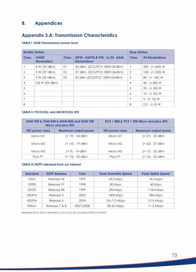
73
8. Appendices
Appendix 3.A: Transmission CharacteristicsTABLE I: GSM Transmission power level
Mobile Station Base StationClass GMSK
ModulationClass QPSK, AQPSK,8-PSK, 16/32- QAM
ModulationsClass All Modulations
1 8 W (39 dBm) E1 33 dBm, (DCS/PCS 1800=30dBm) 1 320 - (< 640) W
2 5 W (37 dBm) E2 27 dBm, (DCS/PCS 1800=26dBm) 2 160 - (< 320) W
3 2 W (33 dBm) E3 23 dBm (DCS/PCS 1800=22dBm) 3 80 - (< 160) W
4 0,8 W (29 dBm) 4 40 - (< 80) W
5 5 20 - (< 40) W
6 6 10 - (< 20) W
7 7 5 - (< 10) W
8 8 2,5 - (< 5) W
TABLE II: PICOCELL and MICROCELL BTS
GSM900&GSM850&MXM850andGSM700Micro and pico-BTS
DCS1800&PCS1900Microandpico-BTS
TRX power class Maximum output power TRX power class Maximum output powerMicro M1
Micro M2
Micro M3
(> 19) - 24 dBm
(> 14) - 19 dBm
(> 9) - 14 dBm
Micro M1
Micro M2
Micro M3
(> 27) - 32 dBm
(> 22) - 27 dBm
(> 17) - 22 dBm
Pico P1 (> 13) - 20 dBm Pico P1 (> 16) - 23 dBm
TABLE III 3GPP released from our interest
Standard 3GPP Release Year Peak Downlink Speed Peak Uplink SpeedGSM Release 96 1997 43.2 kbps 14.4 kpps
GPRS Release 97 1998 80 kbps 40 kbps
EDGE Release 98 1999 296 kbps 118.4 kbps
HSDPA Release 5 2002 1800 kbps 384 kbps
HSUPA Release 6 2004 3.6-7.2 Mbps 5.76 Mbps
HSPA+ Release 7 & 8 2007/2008 28-42 Mbps 11.5 Mbps
Released 96 for GSM is identified as 2G and 2.5G, including GPRS and EDGE.

74
TABLE IV T-GSM spurious emissions levels [7]
BTS Frequency band Power measured (dBm)GSM 400 460.4 –467.6 MHz and 488.8 – 496.0 MHz. ≤- 57
GSM 700 728 – 746 MHz and 747 – 763 MHz ≤- 57
T-GSM 810 851 – 866 MHz ≤- 57
GSM 900 921 – 960 MHz ≤- 57
TABLE IV (b) MS spurious emission emissions levels [7]
MS Frequency Band Spurious level (dBm)T-GSM380 and T-GSM 410 390.2 - 400 MHz and 420.2 - 430 MHz -62 dBm
T-GSM400 460.4 – 467.6 MHz and 488.8 - 496 MHz -67 dBm
T-GSM810 791 - 821 MHz and 851- 866 MHz -66 dBm and -79 dBm
T-GSM900 921 - 925 MHz and 925 - 935 MHz 935 –960 MHz.
-60 dBm and -67 dBm -79 dBm
TABLE V: BTS Spurious emission levels release 96/5
Band Δf Normal BTS Maximum power limit
Multiple carrier BTS Maximum power limit
9 kHz to 1 GHz ≥ 2 MHz -36 dBm (250 nW) -25 dBm
≥ 5 MHz -36 dBm -20-4,2*(Δf - 5) dBm
≥ 10 MHz -36 dBm -36 dBm
1 GHz to 12.75 GHz ≥ 2 MHz -30 dBm (1 μW) -25 dBm
≥ 5 MHz -30 dBm -20-3*(Δf - 5) dBm
≥ 10 MHz -30 dBm -30 dBm
TABLE VI: LTE Characteristics
Characteristics LTE released 8 LTE released 10Peak Downlink Data Rate 300 Mb/s 3 Gb/s
Peak Uplink Data Rate 75 Mb/s 1500 Mb/s
Peak DL Spectrum Efficiency 15 bps/Hz 30 bps/Hz
Peak UL Spectrum Efficiency 3.75 bps/Hz 15 bps/Hz
Bandwidth Up to 20 MHz Up to 100 MHz
Modulation Schemes QPSK, 16-QAM, 64-QAM QPSK, 16-QAM, 64-QAM

75
TABLE VII LTE-FDD/TDD spurious emissions
LTE Transmitted Signal
Signal Channel Bandwidth
(BWchannel) [Mhz]
eNB Adjacent Channel Centre Frequency Offset
Below the First or Above the Last Carrier Center
Frequency
Assumed Adjacent
Channel Carrier
(Informative)
Filter on the Adjacent
Channel Frequency and Corresponding Filter
Bandwidth
ACLR Limit
1.4, 3.0, 5, 10,
15, 20
BWChannel LTE of same BW Square (BWConfig)
+
44.2dB
2 x BWChannel LTE of same BW Square (BWConfig) 44.2dB
Table VIII: ETRAN UE emission co-existence
E-UTRAN UE Co-existence E-UTRAN Downlink UE Uplink Spurious Emission1 2010 MHz – 2025 MHz 860 MHz- 895MHz -50
2 1850 MHz – 1910 MHz 1475.9 - 1510.9 -50
3 1930 MHz – 1990 MHz 1884.5 - 1915.7 -50
2570 MHz – 2620 MHz 2620 - 2645
TABLE IX BTS CDMA2000 spurious emission levels
For|∆f|withintherange
Frequency bandwidth Measurement bandwidth
Emission limit (dBm)
> 4 MHz for spreading rate 1
> 12.5 MHz for spreading rate 3
9 kHz < f < 150 kHz
150 kHz < f < 30 MHz
30 MHz < f < 1 GHz
1 GHz < f < 12.75 GHz
1 kHz
10 kHz
100 kHz
1 MHz
–36
–36
–36
–30
Measurement Frequency (MHz)
Measurement bandwidth (kHz)
Emission limit (dBm)
893.5-1 919.6 300 −41
925-935 100 -67
935-960 100 −79
1 805-1 880 100 -71

76
TABLE X MS CDMA2000 spurious emissions
Frequency band M e a s u r e m e n t bandwidth
Maximum level (dBm)
Note
30 MHz ≤ f < 1 GHz 100 kHz −57
1 GHz ≤ f ≤ 12.75 GHz 1 MHz −47 Apart from the frequencies covered by Table 12, for which additional receiver spurious emission requirements apply
1 920 ≤ f ≤ 1 980 MHz 1 MHz –61 Mobile transmit band
2 110 ≤ f ≤ 2 170 MHz 1 MHz –76 Mobile receive band
TABLE XI WiMax BTS A and B categories spurious emissions
Band Emission level Measurement bandwidth30MHz-1GHz -13 dBm (A) 100 KHz
1 GHz-13.45 GHz -13 dBm (A) 1 MHz
9 kHz ≤ f < 150 kHz -36 dBm (B) 1 kHz
50 kHz ≤ f < 30 MHz -36 dBm (B) 10 kHz
30 MHz ≤ f < 1 000 MHz –36 dBm (B) 100 kHz
1 GHz ≤ f < 13.45 GHz -30 dBm (B) 30 kHz If 2.5 × BW <= | fc − f | < 10 × BW
300 kHz If 10 × BW <= | fc − f | < 12 × BW
1 MHz If 12 × BW <= | fc − f |
Depending on 2302.5 ≤ fc ≤ 2397.5 and 791 ≤ f < 2570 MHz
-52—49 dBm 1 MHz
TABLE XII WiMax MS spurious emissions
Spurious frequency (f) range Measurement bandwidth Maximum Emission Level (dBm)
9kHz <= f < 150kHz 1kHz -54
150kHz <= f < 30MHz 10kHz -54
30MHz <= f < 1000MHz 100kHz -54
1000MHz <= f < 2505MHz 1MHz -47
2505MHz <= f < 2535MHz 1MHz -70
2535MHz <= f 1MHz -47

77
TABLE XIII: WiFi variants
IEEE Standard 802.11a 802.11b 802.11g 802.11n 802.11ac
Year 1999 1999 2003 2009 2014
Frequency 5GHz 2.4 GHz 2.4 GHz 2.4 and 5 GHz 2.4 and 5 GHz
Max Rate 54Mbps 54Mbps 54Mbps 600Mbps 1.3Gbps
TABLE XIV Radiated power of in-band and spurious emissions of the USB and PC WiFi devices
Frequency (MHz) Radiated power (dBm) USB Radiated power (dBm) PC2462,5 12.4 18.5
4925 -58.4 -62
7387.5 -55.7 -63.3
Above No detectable radiation No detectable radiation
TABLE XV: Micro and Pico spurious emissions [23]
GSM900&GSM850&MXM850 &GSM700(dBm)
DCS1800&PCS1900&MXM1900(dBm)
Micro BTS M1
Micro BTS M2
Micro BTS M3
Pico BTS P1
-91
-86
-81
-70
-96
-91
-86
-80

78
Appendix 3.B Spectrum AssessmentsTable XVI: VSAT spectrum assessment
Technology C-band Ku-band Ka-bandFrequency band 4-8 GHz (6 GHz unused) 11-14 GHz 18-40 GHz
Downlink
Uplink
3.7-4.2 GHz
5.925-6.425 GHz
10.9-12.75 GHz
14 GHz
18-20 GHZ
26.5-40GHz
Modulation used QAM PSK, ACM Q-PSK and ACM.
Data rate 64-128kbps 100kbps and 512kbp 10/20 Mbps
Necessary band 24,2 KHz (1)167 KHz, <500KHz 2.5MHz
Unwanted emission domain
250 KHz 501,8 MHz <26.487 and > 40.12 GHz
RA band affected None. 14.0-14.44 None
TABLE XVII: GSM400 spectrum assessment
Technology GSM 380 GSM 410 GSM 450 Band GSM 480 BandDownlink (DL) band Uplink (UL) band
390.2-399.8 MHz 380,2-389,8 MHz
420.2-429.8 MHz 410,2-419 .8MHz
460,4-467,6 MHz 450,4-457,6 MHz
488.8 - 496 MHz 478.8 - 486 MHz
UL Modulation DL Modulation
GMSK GMSK
8-PSK/16-QAM GMSK/PSK/QAM
GMSK/8-PSK GMSK /8-PSK
GMSK/ 8-PSK GMSK/8-PSK
Necessary band UL Necessary band DL
10KHz 73.44 KHz
9.6 /5,832 KHz 47.1/86.4/70 KHz
16.416/13.33 KHz 24.2 /76 KHz
16.4/13.3 KHz 49.04/76 KHz
Unwanted band ULUnwanted band DL
25KHz 183.36 KHZ
14.58/11.6 KHz118/216/175 KHz
41.04/28 KHz60.48/190 KHz
41/28 KHz123/190 KHz
RA band affected 406.1-410 MHz 406.1-410.0 MHz None None
TABLE XVIII GSM 800 Assessment spectrum assessment
Technology GSM 810/GPRS GSM 810/ EDGE GSM 810/GSM GSM 710/750 BandDownlink (DL) bandUplink (UL) band
728 -746 MHz806 - 821 MHz
728 -746 MHz806 - 821 MHz
728 -746 MHz806 - 821 MHz
698-716/747-763 MHz728-746/777-793 MHz
Rate ULRate DL
40/14.4 Kbps20/80 kbps
118.4 kbps60 kbps
14,4 kbps
UL Modulation DL Modulation
8-PSK/GMSK GSMK8-PSK
GMSK/8-PSK8-PSK
Necessary band ULNecessary band DL
80 KHz40/160 KHz
236.8 KHz120 KHz
16.416/28.8 KHz 76 KHz
Unwanted band ULUnwanted band DL
200 KHz 100/400 KHz
592 KHz.300 KHz
41.04 /72 KHz190 KHz
RA band affected None None None None

79
TABLE XIX: GSM900 band spectrum assessment
Technology GSM 900/GPRS GSM 900/ EDGE GSM 900/HSPDA GSM900/HSPA+Downlink (DL) bandUplink (UL) band
935-960 MHz890-915 MHz
935-960 MHz890-915 MHz
935-960 MHz890-915 MHz
935-960 MHz890-915 MHz
Rate ULRate DL
40 kbps114 kbps
118.4 kbps384 Kbps
2 Mbps7.2 Mbps
22 Mbps
UL Modulation DL Modulation
8-PSK8-PSK
8-PSK8-PSK
8-PSKQAM
8-PSK
Necessary band ULNecessary band DL
80 KHz228 KHz
236.8 KHz768 KHz
4 MHz 11.52 MHz
35.2 MHz
Unwanted band ULUnwanted band DL
200 KHz570 KHz
592 KHz.1920 KHz
10 MHz 28.8 MHz
88 MHz
RA band affected None None None None
TABLE XX: 4G spectrum assessment
Technology HSPA+ LTE (Release 8) LTE(Release 10) IMT2000Rate ULRate DL
28-42 Mbps 114 kbps
75 Mb/s 300 Mb/s
1500 Mb/s3 Gb/s
UL Modulation DL Modulation
8-PSK8-PSK
QPSK, 16-QAM, 64-QAM
QPSK, 16-QAM, 64-QAM
Necessary band ULNecessary band DL
44.8-67.2 MHz 228 KHz
236.8 KHz768 KHz
6.45 MHz 42 MHz
Unwanted band ULUnwanted band DL
112-168 MHz 592 KHz1920 KHz
16.01MHz 85 MHZ
RA band affected None None None
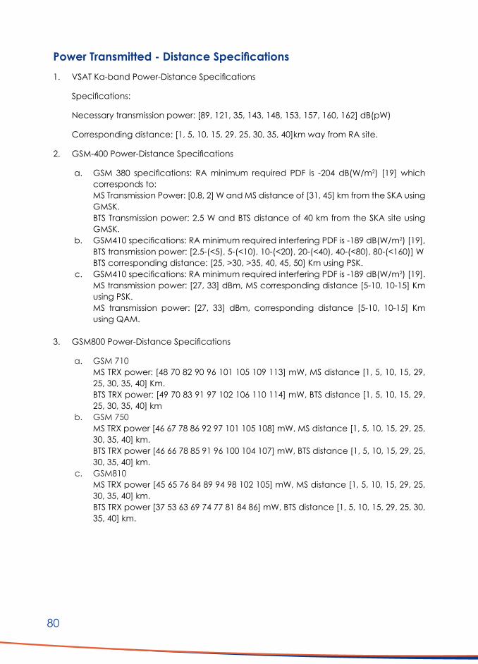
80
PowerTransmitted-DistanceSpecifications1. VSAT Ka-band Power-Distance Specifications
Specifications:
Necessary transmission power: [89, 121, 35, 143, 148, 153, 157, 160, 162] dB(pW)
Corresponding distance: [1, 5, 10, 15, 29, 25, 30, 35, 40]km way from RA site.
2. GSM-400 Power-Distance Specifications
a. GSM 380 specifications: RA minimum required PDF is -204 dB(W/m2) [19] which corresponds to:MS Transmission Power: [0.8, 2] W and MS distance of [31, 45] km from the SKA using GMSK.BTS Transmission power: 2.5 W and BTS distance of 40 km from the SKA site using GMSK.
b. GSM410 specifications: RA minimum required interfering PDF is -189 dB(W/m2) [19], BTS transmission power: [2.5-(<5), 5-(<10), 10-(<20), 20-(<40), 40-(<80), 80-(<160)] WBTS corresponding distance: [25, >30, >35, 40, 45, 50] Km using PSK.
c. GSM410 specifications: RA minimum required interfering PDF is -189 dB(W/m2) [19].MS transmission power: [27, 33] dBm, MS corresponding distance [5-10, 10-15] Km using PSK.MS transmission power: [27, 33] dBm, corresponding distance [5-10, 10-15] Km using QAM.
3. GSM800 Power-Distance Specifications
a. GSM 710MS TRX power: [48 70 82 90 96 101 105 109 113] mW, MS distance [1, 5, 10, 15, 29, 25, 30, 35, 40] Km.BTS TRX power: [49 70 83 91 97 102 106 110 114] mW, BTS distance [1, 5, 10, 15, 29, 25, 30, 35, 40] km
b. GSM 750MS TRX power [46 67 78 86 92 97 101 105 108] mW, MS distance [1, 5, 10, 15, 29, 25, 30, 35, 40] km.BTS TRX power [46 66 78 85 91 96 100 104 107] mW, BTS distance [1, 5, 10, 15, 29, 25, 30, 35, 40] km.
c. GSM810 MS TRX power [45 65 76 84 89 94 98 102 105] mW, MS distance [1, 5, 10, 15, 29, 25, 30, 35, 40] km.BTS TRX power [37 53 63 69 74 77 81 84 86] mW, BTS distance [1, 5, 10, 15, 29, 25, 30, 35, 40] km.

81
4. GSM900 Power-Distance Specifications
a. GSM900-PMS TRX power [62 89 105 115 123 129 135 140 144] mW, MS distance [1 5 10 15 29 25 30 35 40] km.BTS TRX power [76 110 129 141 151 159 166 172 177] mW, BTS distance [1 5 10 15 29 25 30 35 40] km.
b. GSM900-E MS TRX power [76 111 130 143 152 160 167 173 179] mW, MS distance [1 5 10 15 29 25 30 35 40] km.BTS TRX power [76 111 130 143 152 160 167 173 179] mW, BTS distance [1 5 10 15 29 25 30 35 40] km.]
5. UMTS/ITM200/LTE 1.8-2.5 GHz band Power-Distance Specifications
a. 1800 DCS MS TRX power [182 264 309 340 363 382 398 413 426] mW, MS distance [1 5 10 15 29 25 30 35 40] km. BTS TRX power [224 325 381 418 447 470 490 508 524] mW, BTS at [1 5 10 15 29 25 30 35 40] km away.
b. 1900 PCS MS TRX power [164 237 278 305 326 343 358 371 383] mW, MS distance [1 5 10 15 29 25 30 35 40] km.BTS TRX power [200 289 339 373 399 420 438 453 468] mW, BTS at [1 5 10 15 29 25 30 35 40] km away.
c. LTE - FDD/TDD 1850-1910 Uplink and 1930-1990 DownlinkUTRAN TRX power [170 246 289 317 339 357 372 386 398] mW, UTRAN distance [1 5 10 15 29 25 30 35 40] km away. UE necessary propagation loss [169 244 286 314 336 353 369 382 394] respectively at [1 5 10 15 29 25 30 35 40] km away.
d. FDD/TDD 2500-2570 Uplink and 2620-2690 DownlinkUTRAN transmitted power [199 289 339 372 398 419 436 452 466] mW, UTRAN distance [1 5 10 15 29 25 30 35 40] km away. UE necessary propagation loss [198 286 335 368 393 414 432 447461] respectively at [1 5 10 15 29 25 30 35 40] km away.
6. GPP2 CDMA Power-Distance Specifications
MS TRX power [150 217 254 279 298 314 328 340 350] mW, MS distance [1 5 10 15 29 25 30 35 40] km.
BTS TRXpower [129 187 219 240 257 271 283 293 302] mW, BTS at [1 5 10 15 29 25 30 35 40] km away.
7. WiFi 802.11a/b/g Power-Distance Specifications
WiFi device necessary power [0.2 0.6 1.8 4.1 8.3 15.4 26.5 43] mW, operating respectively at [1500 2000 2500 3000 3500 4000 4500 5000] m from the RA site. (Less power is needed for lesser distances).

82
8. WiMax 802.16a Power-Distance Specifications
WiMax device necessary power [0.7 2.5 7 16.3 33.1 61.2, 105.4 171.2] mW, operating respectively at [1500, 2000, 2500 3000 3500 4000 4500 5000] m from the RA site.
9. DMR Power-Distance Specifications
DMR repeater TRX power [0.50 0.59 0.65 0.69 0.73 0.85 0.94 1 1.05] mW, DMR repeater distance [100 200 300 400 500 1000 1500 2000 2500] m away from of RA site.
10. Micro and Pico Cells Power-Distance Specifications
a. Micro GSM900 BTSMicro GSM900 BTS (M3) TRX power [0.8764 1.0163 1.1158 1.1922 1.2550 1.4722 1.6163 1.7269 1.8180] mW, Micro GSM900 BTS (M3) distance [100 200 300 400 500 1000 1500 2000 2500] m away.Micro GSM900 BTS (M1) TRX power [0.7722 0.9058 0.9944 1.0625 1.1185 1.3121 1.4405 1.5391 1.6203] mW, Micro GSM900 BTS (M1) distance [100 200 30 0 400 500 1000 1500 2000 2500] m away.
b. Pico GSM900 BTSPico GSM900 BTS (P1) TRX power [0.8664 1.0163 1.1158 1.1922 1.2550 1.4722 1.6163 1.7269 1.8180] mW, Pico GSM900 BTS (P1) distance [100 200 300 400 500 1000 1500 2000 2500] m away.

83
Appendix 4
Investigation:ConfigurationsofAlternativeTelecommunication Technologies in the KCAAA
Table of Contents1. Background ............................................................................................................................................ 86
2. Objectives ............................................................................................................................................... 86
3. Geographical Area of Interest ......................................................................................................... 86
4. Current Telecommunication Services ............................................................................................ 87
5. Envisaged Limitation of Current Telecommunication Services .............................................. 88
6. Summary of User Requirements ....................................................................................................... 89
7. Methodology of Investigation ........................................................................................................... 91
8. FeasibilityofDifferentNetworkConfigurations ............................................................................ 91
8.1 Introduction .................................................................................................................................. 91
8.2 General Network Concept (Option A) ............................................................................... 91
8.2.1 Data Transport Method: Fibre Optic Connectivity ........................................... 93
8.2.1.1 General FO connection types ........................................................... 93
8.2.1.2 Existing fibre optic cable infrastructure ........................................... 93
8.2.1.3 Network-wide external data sources............................................... 94
8.2.2 Alternative Data Transport Methods..................................................................... 95
8.2.2.1 Wireless connectivity ............................................................................. 95
8.2.2.2 Satellite connectivity ............................................................................. 95
8.2.3 Network Concept ....................................................................................................... 95
8.2.4 High Site Selection and Positioning ....................................................................... 96
8.2.5 Frequency Selection .................................................................................................. 96
8.2.5.1 Downlinks: ISM band 5.7/8 GHz ......................................................... 96
8.2.5.2 Downlinks: K/Ka band 25-28 GHz ....................................................103
8.2.6 Backhaul Design ........................................................................................................106
8.2.6.1 Network requirement ..........................................................................106
8.2.6.2 High site equipment ............................................................................106
8.2.6.3 Backhaul link frequency.....................................................................106
8.2.6.4 Link calculations ...................................................................................106
8.2.6.5 Power supplies .......................................................................................106
8.2.6.6 High site layout and implementation ............................................107

84
8.2.7 Antenna Characteristics .........................................................................................108
8.2.8 Fibre Optic Connections ........................................................................................112
8.2.9 User Site Installations .................................................................................................112
8.2.9.1 Subscriber units ......................................................................................112
8.2.9.2 Local access points .............................................................................112
8.2.9.3 Subscriber site unit antennas ............................................................113
8.2.10 Overall Network Layout ..........................................................................................113
8.2.11 Mobile Device Impact ............................................................................................118
8.2.12 LTE Picocells ................................................................................................................122
8.2.13 Network integration..................................................................................................125
8.2.14 Existing internet service provider network investigation ...............................125
8.3 VSAT Internet Connectivity (Option B) ..............................................................................128
8.3.1 Background ................................................................................................................128
8.3.2 RFI Risks .........................................................................................................................129
8.3.3 Costing .........................................................................................................................129
9. Emergency and Wide Area Voice Communications Network ............................................129
9.1 Background ................................................................................................................................129
9.2 VHF Low Band DMR for Emergency and Safety Use .....................................................130
9.3 Preferred Radio Type for Emergency Use .........................................................................130
9.4 ESCS Coverage Prediction ....................................................................................................130
9.5 Summary on ESCS ....................................................................................................................134
10. Implementation Considerations ....................................................................................................134
11. Cost Estimates ......................................................................................................................................135
12. Possible Business Models and Organisational Structures .......................................................135
13. Conclusions and Recommendations ...........................................................................................136
13.1 Mobile Coverage .....................................................................................................................136
13.2 Data access via Microwave and Fibre Connectivity (Option A) .............................136
13.3 Data access via VSAT (Option B) ........................................................................................137
13.4 Safety and Emergency Communications ........................................................................138
13.5 Operational and Business Model ........................................................................................138
13.6 Cost Estimates............................................................................................................................138
14. References ............................................................................................................................................139
15. Addenda ...............................................................................................................................................139
Addendum A: Cost Estimate ..........................................................................................................140
Addendum B: List of High Sites (Option A) .................................................................................143

85
Addendum C: Summary of links in Unlicensed Band ..........................................................147
Addendum D: Summary of links in Licensed Band (Option A) ..........................................152
Addendum E: List of interconnecting High Site links (Option A) ........................................158
Addendum F: List of Fibre Optic Connections (Option A) .................................................162
Addendum G: Link design examples (Option A) ................................................................165
Addendum H: Equipment datasheets ..................................................................................171
Addendum I: Complete list of user sites incorporated in investigation ............................188

86
1. Background Due to the nature of the present and future scientific activities carried out by the Square Kilometer Array (SKA) project, any form of intended radio transmission and unintended emissions must be strictly regulated in the Karoo Central Astronomy Advantage Area (KCAAA). Such regulations already impact the daily personal and business activities of all residents of the primarily rural surrounding community, specifically in terms of telecommunication. This is set to increase as regulations are more stringently enforced in future. This investigation attempts to identify the feasibility and possible extent of telecommunication technology solutions to alleviate such impact. Such solutions should also ideally provide some future proofing and replace what has been available to the users and enable them to keep up with technological advances in the field, as would an ordinary citizen outside of the KCAAA.
2. Objectives The objectives of this investigation are:
1. To define the characteristics and shortcomings of the present mix of telecommunication systems in use by the greater community in the KCAAA;
2. To define the present and future telecommunication requirements for this community;3. To present details of the options investigated; and4. To present cost estimates for the proposed solutions.
Compliance with the radio frequency interference (RFI) requirements of the SKA project is clearly of paramount importance. It should be the first consideration in any selection of technology network hardware and architecture.
3. Geographical Area of InterestThe geographical area of interest is approximately bordered by the towns of Fraserburg, Carnarvon, Williston, Brandvlei, Vanwyksvlei and some distance up to up to Kenhardt further north. See Figure 1.

87
4. Current Telecommunication ServicesThe current telecommunications services available in the area, as provided by various operators, are:
1. GSM coverage (in the 800 – 900 MHz band) by primarily Vodacom and MTN in the major towns and surrounding areas.
2. Broadband data and voice services rendered under 1800 MHz LTE by the same operators, but in a more limited area.
3. Some smaller localised data network Internet service providers (ISP’s) providing services in the ISM bands of 2.4 – 5.7/8 GHz. The more extensive of these is operated by Hantamnet, reaching from Sutherland in the west up to approximately halfway between Brandvlei and the SKA core site area.
4. VSAT services obtained on a localised residential level by individual users.5. A legacy Marnet service utilised for general safety and emergency. The system is now
outdated and challenging to maintain.
Figure 1: Approximate geographical area of interest

88
5. Envisaged Limitation of Current Telecommunication ServicesAll services by mobile operators will be limited in this geographical area once the proclaimed regulations for the KCAAA are implemented. To a large extent, the towns will not be affected, but the surrounding regions currently serviced will. The current GSM transmissions are particularly problematic from a radio astronomy perspective. Discussions are continuing with operators to determine how these services should be limited or the emission footprints shaped. The reduced mobile coverage footprint is provided in Figure 2. During the rollout of an alternative telecommunication technology solution, the uncovered areas should receive priority.
Wireless based services from ISP’s, such as Hantamnet, could also pose a problem in locations close in proximity to planned telescope positions and might well require modification.
Marnet operates in the 80 MHz region, and while the harmonics could be problematic to telescope receivers, the carrier itself falls in the guest instrument band. The HERA installation is one example. The Marnet installation is at the end of its useful life and challenging to maintain.
The current VSAT service will continue and provides a localised service by nature.
Figure 2: Envisaged mobile operator coverage after reduction of emission footprint

89
6. Summary of User RequirementsDuring a workshop with the Landbou Aksie Groep (LAG) in July 2019, telecommunication requirements were submitted by the LAG. The requirements are provided below with minor edits and some consolidation. There are overlaps between certain common issues.
Table 1: Requirements and comments from the LAG in terms of telecommunications
Item Requirement / Comment
1 A common telecommunication infrastructure could be used in the area for both SARAO and farmers
2 Data telecommunication is essential for conducting (farming) business
3 A form of broadcast telecommunication is required (group telecommunication)
4 A good and cost-effective internet connection (which would allow Voice Over Internet Protocol, VoIP) at farmsteads would be acceptable
5 Cell phone service is preferred but has now been suspended
6 A requirement for voice telecommunications across the region, not just on farmsteads
7 Voice telecommunications (Marnet type) is essential from a safety and security point of view
8 The Marnet band is problematic for SARAO, and the system is deteriorating due to obsolescence
9 Marnet impact to be assessed, as it is the fallback backbone
10 Low band Digital Mobile Radio (DMR), as chosen by SARAO, could be an acceptable form of radio frequency (RF) voice telecommunications in SKA area
11 Emergency telecommunications required by all in the area
12 Mobile (vehicle) telecommunication is required
13 Farmers are falling behind financially because of telecommunications technology backlog
14 Emerging technologies such as wireless cameras cannot be used
15 Availability of electricity is limited and must be considered in the choice of solutions
16 Cell extenders were installed to improve reach
17 Cell infrastructure roll-out stopped. Not economically feasible
18 Certainty regarding the right to telecommunication is needed
19 Communication is essential for modern-day farming (managing drought)
20 Conflict between SARAO’s right to science and the farmer’s right to telecommunications
21 Cost of equipment and service must be considered as it is a great concern
22 Satellite data costs very high
23 In the 90s cell infrastructure started to be rolled out
24 There would likely be many different types of systems
25 It is SARAO’s problem to solve, as they are restricting the use of viable telecommunication systems
26 Lost Telkom lines should be reinstalled (fibre)
27 Farmers will become more obstructive unless this situation is addressed quickly in a material way
28 High frustration levels with VOX (VSAT) service levels
29 Signal coverage by mobile operators have disappeared in places, even though user contracts still exist
30 SARAO does not allow new cell towers to be erected

90
Item Requirement / Comment
31 The original promise made by SARAO; “That which you have you’ll keep (always have)”. Not the case now
32 New tower installations were blocked, for example, to “protect natural heritage sites”
33 SARAO promised a regular (every 3 years) review of the situation
34 SARAO promised that they would have a modern and competitive infrastructure
35 Some areas have temporary occupation such as hunters - often also with connectivity requirements
36 Some farmers have all they need at the farmstead in terms of data. Access needs to be provided to farm workers
37 Mobile operators have an obligation to provide infrastructure in rural areas
38 Technology is evolving, and the farmers would like to be able to keep up
39 Telecommunication companies have licenses, hence exclusivity
40 Telkom stopped the land line service, which existed since 1948. It should be replaced with an equivalent
41 The farmers use Hantamnet, a wireless internet ISP backbone on 2.4 and 5.8GHz. They are under the impression that with minor modifications, it will be allowed to continue
42 The right to have telecommunication in an area where the farmers could have installed a form of telecommunication
43 The telecommunication needs are very much the same as those available in the city
44 There are many well know areas with spots of reception, and there is a concern that these will disappear
45 There is a belief that a solution should be practically realisable
46 There is confusion around the exempted frequency regulation
47 There should be options to integrate/link any solution to other regional systems, i.e. DMR to Marnet
48 Tracking wild animals is a requirement. SARAO promised a solution for this
49 Trunk radio was proposed by SARAO as a potential option but it is now not a certainty
The requirements mentioned above were consolidated into the following common issues:
1. Efficient and reasonably priced data access is essential for personal and business telecommunications;
2. To deprive the KCAAA community of the type of telecommunications accessible to everybody elsewhere is unfair and could have legal implications;
3. Users in the area to be enabled to keep up with technology;4. Undertakings given by the SARAO have not been implemented;5. Apart from data services, the Marnet-type emergency voice telecommunications are
also essential; and6. Access to the mobile and public switched telephone network (PSTN) services is highly
desirable.

91
7. Methodology of InvestigationThe methodology included the following:
■ Gathering of information on farm occupancies, type of utilisation and the priority for permanent telecommunication access.
■ Determining the services rendered by existing operators, before and after application of regulations.
■ Determining the basic RFI footprints for existing services, including mobile operator- and ISM bands.
■ Investigation of options for the provision of telecommunications backhaul links to the different possible telecommunications nodes.
■ Provide a feasible backhaul link systems design. ■ Obtaining information on the SARAO planned fibre optic (FO) network infrastructure for
considerations of a possible shared resource. ■ Investigation and identification of various sites or positions in terms of telecommunications
infrastructure. ■ Investigation into suitable selections of hardware for high sites, user subscriber sites and
user access points (APs). ■ Investigate the choice of suitable frequencies for different geographical areas. ■ Investigate the potential RFI impact of proposed technology solutions on telescopes and
determine guidelines for safe distances, if possible.
The topography, specific locations of the telescopes and any other considered RF infrastructure will be fundamental. RFI implications are, therefore, considered throughout the investigation and not dealt with separately.
8. FeasibilityofDifferentNetworkConfigurations8.1 Introduction
From Table 1, three key requirements can be identified:
1. Convenient and affordable data access at the places of residence and immediate surrounds for farm owners and workers.
2. Mobile phone coverage wherever possible.3. Personal wide-area voice telecommunications for emergency and safety.
These three requirements form the framework of this investigation.
8.2 General Network Concept (Option A)
Unless data access is secured via one of the mobile networks, general data access will have to be provided through some form of fixed link mechanism, either RF or cable-based. Due to the general topography of the area, the low density of users (if towns are excluded) and the large distances involved, the options are limited. The general principle, as per Figure 3, appears to be the most practical. The various components of such a configuration will be explained in the following paragraphs.

92
Figu
re 3
: Gen
eral
dat
a ne
twor
k co
ncep
t
H G F E D C B A
87
65
43
21
H G F E D C B A
87
65
43
21
AS
SA
f
Alte
rnat
ive
Com
mun
icat
ions
for C
KAA
AG
ener
al D
ata
Net
wor
k C
once
pt
SIZE
TYP
ED
WG
NO
REV
A4D
RGCO
M-0
010
SCAL
EN
ASH
EET
1 O
F 1
RxTx
Inte
rnet
Rout
er/s
witc
h
ISP
Micr
owav
e lin
k: 2
6 GH
z ban
d
Micr
owav
e do
wnl
ink:
26
or 5
.7 G
Hz b
and
Micr
owav
e do
wnl
ink:
26/
5.7
GHz b
and
Fibr
e Op
tic In
frast
ruct
ure
elbisaef erehw noitcennoC citpO erbiFUse
r sub
scrib
er u
nit
Loca
l WiFi
Loca
l WiF
i
Use
rw
irele
ss
rout
er
FO
patc
hpa
nel
FO
patc
hpa
nel
IPHi
gh Si
te 2
Mob
ileO
pera
torsHi
gh S
ite 1
Rx
Tx
Rx
Tx
To IS
P bu
lk
data
por
tal 1
To IS
P bu
lk
data
por
tal 2
To b
ulk
data
po
rtal
3To
bul
k da
ta
port
al 4
FO p
atch
pan
elFO
pat
ch p
anel
FO p
atch
pan
el

93
A user is connected to a cloud-connected ISP via some form of a dedicated link. Such a link could be either an FO cable or wireless. In the latter case, it will be very likely that several users will be connected via a topographically, suitably placed high site with the necessary user downlink infrastructure. These high sites will require interconnectivity to establish the back-end connection to the ISP. The data transport channel will have a significant influence on both cost and service quality.
8.2.1 Data Transport Method: Fibre Optic Connectivity
8.2.1.1 General FO connection types
Fibre-based connections have some obvious advantages, such as:
■ Total lack of RFI. ■ Vast bandwidth, i.e. high-speed data throughput. ■ The initial cost could be offset by relatively low maintenance costs later. ■ Repeater/regeneration station intervals could be as far apart as 120 to150 km.
Fibre-based connections also come with some potential disadvantages:
■ Potentially high initial capital cost. ■ Lack of suitable routes and servitudes, as this involves terrestrial-based installation over
long distances. Soil properties and route profiles would have considerable bearing on design and layout.
■ Availability of suitable connection nodes in a reasonable proximity for data provider access.
■ Ignoring the technicalities of the different fibre types, FO infrastructure is available in two broad categories:
■ Underground in sleeves (laid in trenches with access manholes): This is generally an expensive option and very much dependent on soil types. For example, rocky terrain would require specialised machine trenching.
■ Overhead (strung on poles instead of the older traditional copper cables): This method is known as All-Dielectric Suspended System (ADSS) and is very easy to erect, provided the route is accessible and poles can be installed at all. Auguring usually is the simplest way and done quite quickly. Unfavourable terrain could also be bridged by going overhead. This type of cabling is seen along many roads where it simply replaced copper cabling on the same poles. It is unknown why the area’s pole infrastructure was removed when copper cabling became obsolete and a target for theft.
8.2.1.2 Existing fibre optic cable infrastructure
There is no significant distributed FO infrastructure in the area, apart from what has already been installed by SARAO. The details of these existing and planned routes are shown in Figure 4.
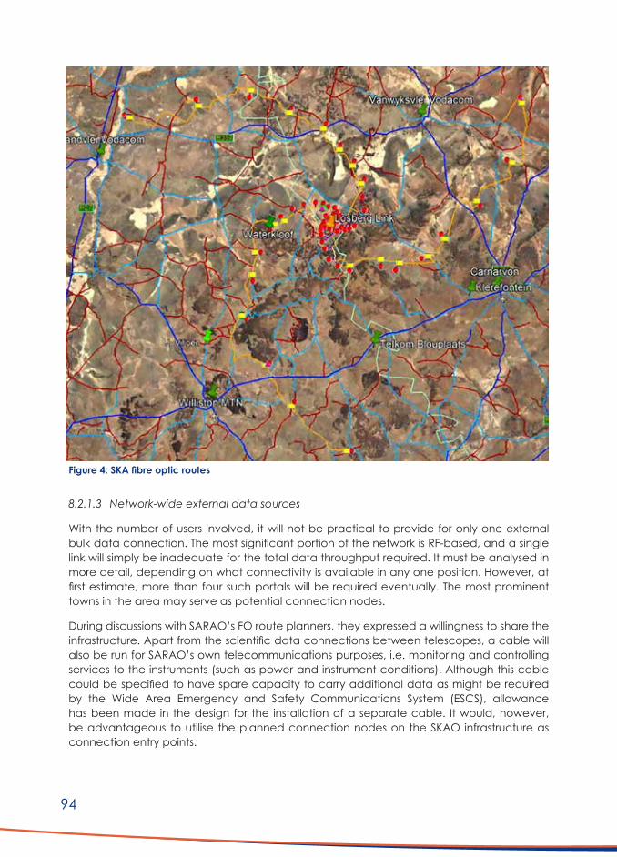
94
8.2.1.3 Network-wide external data sources
With the number of users involved, it will not be practical to provide for only one external bulk data connection. The most significant portion of the network is RF-based, and a single link will simply be inadequate for the total data throughput required. It must be analysed in more detail, depending on what connectivity is available in any one position. However, at first estimate, more than four such portals will be required eventually. The most prominent towns in the area may serve as potential connection nodes.
During discussions with SARAO’s FO route planners, they expressed a willingness to share the infrastructure. Apart from the scientific data connections between telescopes, a cable will also be run for SARAO’s own telecommunications purposes, i.e. monitoring and controlling services to the instruments (such as power and instrument conditions). Although this cable could be specified to have spare capacity to carry additional data as might be required by the Wide Area Emergency and Safety Communications System (ESCS), allowance has been made in the design for the installation of a separate cable. It would, however, be advantageous to utilise the planned connection nodes on the SKAO infrastructure as connection entry points.
Figure4:SKAfibreopticroutes

95
8.2.2 Alternative Data Transport Methods
8.2.2.1 Wireless connectivity
The second possibility for data transfer between an ISP and the end-user is through a type of RF-based carrier. These are convenient, can span long distances depending upon terrain (approximately 80m), and offer high capacity in the case of a sufficiently high carrier frequency and favourable Signal to Noise (SNR) environment. The disadvantage lies in the inherent RFI threat for the telescopes.
8.2.2.2 Satellite connectivity
Satellite connectivity seems an obvious choice, offering terrain independent service. Subscription cost, however, is a consideration and cause of general complaint (based on feedback obtained from the LAG). The absence of RFI cannot be guaranteed as the ground terminal equipment can be a source of electromagnetic interference (EMI) and has found to require expensive shielding in some cases.
8.2.3 Network Concept
The most practical solution appears to be in the form of a vast area network containing different technologies, each one appropriate for the specific location. For example, some farms are very closely situated to telescope sites, so fibre is an obvious choice in terms of practicality and RFI avoidance. Therefore, the following components are envisaged:
1. FO connections indicated by proximity, or reasonable proximity, of fibre node connection points
2. FO feeds will be overhead ADSS-based for reasons including cost and terrain3. Locations not within economic reach of FO cabling will be connected by means of RF
downlinks from suitably situated high sites (should they be available). Ideally, such high sites should serve more than one farm or user in PTMP mode.
4. Where possible, the downlink frequency and equipment should operate in the licence-exempt 5.7/8 GHz ISM band. This is purely for reasons of cost but will depend on the position relative to the telescopes.
5. In other cases, where an RFI safe distance cannot be guaranteed, the operating frequency will have to be moved out of SARAO’s band of interest, i.e. above 25 GHz.
6. Backhaul interconnects between high site nodes should either be by FO or RF links. The same RFI requirements, as abovementioned, will apply.
7. To facilitate the proposed WiFi calling over LTE, the entire network will have to be connected to the mobile operator networks at the back-end. Portals will have to be created for this purpose.
8. A number of small LTE-based Picocells should also be established, particularly where a slightly bigger community exists outside of towns. The RFI for these Picocells must be carefully determined as they will operate in the 1.8 GHz range, falling directly into SARAO’s band of interest.
9. It is evident that apart from connectivity to the mobile operating back-end, a portal will also be required to the broader Internet to enable data traffic across all platforms and applications.

96
10. It is difficult to compartmentalise the different design aspects of, among other things: ■ High site selection ■ End-user connectivity type ■ Frequency selection ■ Link type and design ■ Hardware type and configuration options ■ RFI implications
These issues are all interlinked, and the design process is by necessity iterative. However, they will be categorised as best possible, and some overlap will be unavoidable. The extent and particulars of the envisaged fibre links will be presented in Section 8.2.1.
8.2.4 High Site Selection and Positioning
Accepted performance by the user-directed RF downlinks will, amongst others, depend on the topographical positioning of the Rx/Tx unit of the downlink high site, relative to the user position. Therefore, the perfect high site should have the following characteristics:
■ Suitable elevation above the surrounding terrain; ■ Line of sight (LOS) RF propagation possibility to all surrounding desired points of
telecommunication without any intrusion into the first Fresnel zone of the particular frequency;
■ Acceptably close LOS distances to all surrounding desired points of telecommunication; ■ Ease of access by road for installation and maintenance; ■ Availability of convenient and reliable power supply; and ■ Terrain suitable for construction, or placement, of a suitable weatherproof equipment
enclosure.
A site satisfying all of the above is rare, and selecting a site usually requires a degree of compromise in several aspects.
During the concept design process, a total of 123 sites were identified. The list is contained in Table 7 (Addendum B). It is important to note that these positions were selected purely from a topographical radio propagation point of view. It was not feasible to visit each position to assess the suitability. Site suitability will have to be confirmed in the detailed design and engineering stage.
8.2.5 Frequency Selection
8.2.5.1 Downlinks: ISM band 5.7/8 GHz
Downlink signal strength prediction
Initially, the extent to which the unlicensed ISM band at 5.725 - 8.875 GHz could be used to downlink the data service from as many high sites as possible was determined. The reason is the availability of a range of excellent equipment at a reasonable cost. Ideally, a high site should host a Point-to-Multi-Point (PTMP) base station with a sector antenna. The latter will enable the site to service more than one user with a single Tx/RX unit, provided the users

97
are situated within the angular spread of the antenna. The sector antenna is commonly available with 45°, 60°, 90° and 120° E-plane (horizontal) -3 dB polar characteristics. More directional antennas are available for single Point-to-Point (PTP) link applications. The choice of antenna type is essential, as will be shown later.
Safe distance
Although there will be many variations due to terrain, it would be helpful to determine as best as possible a safe distance for all 5.7 GHz transmissions relative to telescope locations. From Figure 5, an average distance of 25 - 30 km is evident. The emission footprints from all the proposed unlicensed band high sites were subsequently calculated and are presented in Figures 6 to 9. The calculations were done using a worst-case approach, with 6 dBi omnidirectional antennas and a calculated Effective Isotropic Radiated Power (EIRP) of 30 dBm, as per the ISM band regulations. From Figure 6 to 9, it is evident that the safe saturation level of -100 dBm is not exceeded at any telescope.

98
Figu
re 5
: 5.7
GHz
em
issio
n fo
otpr
int f
rom
UL-
BH27

99
Figu
re 6
: Unl
icen
sed
band
: Bra
ndvl
ei a
rea:
Hig
h Si
tes
emiss
ion
omni
dire
ctio
nal f
ootp
rint

100
Figu
re 7
: Unl
icen
sed
band
: Van
wyk
svle
i are
a: H
igh
Site
s em
issio
n om
nidi
rect
iona
l foo
tprin
t

101
Figu
re 8
: Unl
icen
sed
band
: Car
narv
on a
rea:
Hig
h Si
tes
emiss
ion
omni
dire
ctio
nal f
ootp
rint
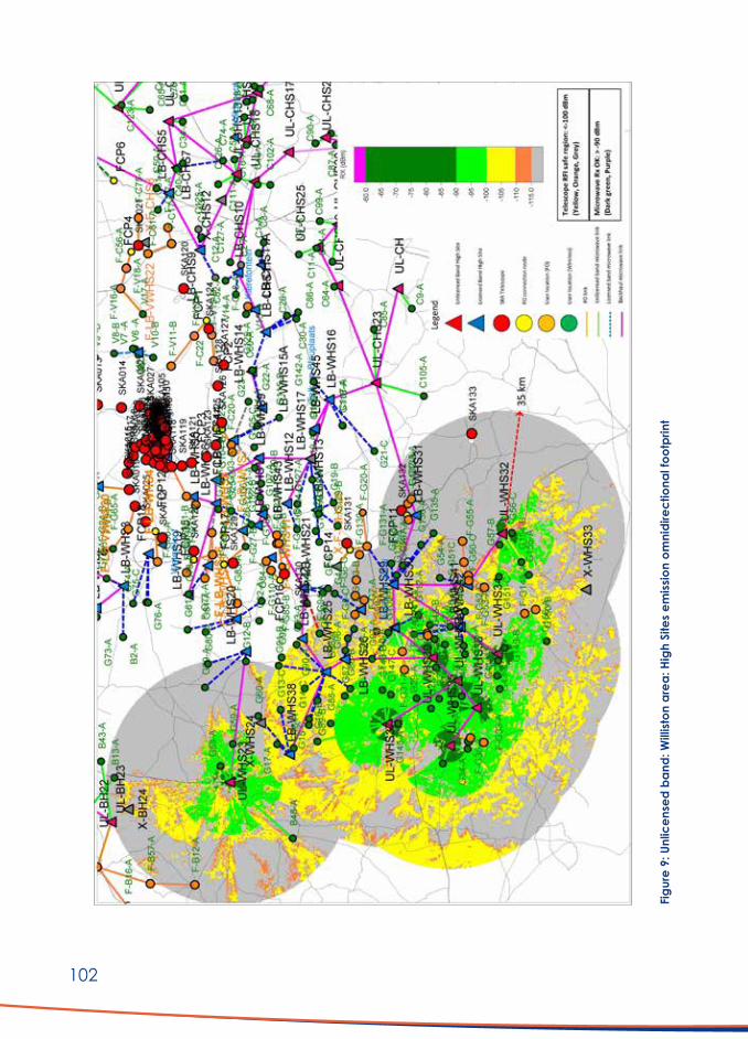
102
Figu
re 9
: Unl
icen
sed
band
: Will
iston
are
a: H
igh
Site
s em
issio
n om
nidi
rect
iona
l foo
tprin
t

103
Theoretical basis for calculations
All calculations were based on the Longley-Rice propagation model, widely accepted for this purpose. The terrain was modelled using a 1 arcsec Digital Elevation Model (DEM), available from the US Geographical Services. Equipment specifications were in line with those of available equipment in this band. Typical equipment data sheets are included in Addendum G.
Individual link calculations
More than one link appears to be possible for many user sites but not necessarily feasible or acceptable for signal strength margin and bit error rate (BER). Therefore, a large number of such permutations between high sites and users were investigated. From calculations made, the final links selected (shown in Figures 6 to 9) should all be functional. The unlicensed links and associated performance parameters are included in Table 4 (Addendum B).
8.2.5.2 Downlinks: K/Ka band 25-28 GHz
Where calculations indicated a possible RFI threat by 5.7 GHz transmissions, utilising the spectrum above SARAO’s band of interest was investigated. This will typically involve operation between 26 and 28 GHz. Higher frequencies will unnecessarily limit the link distances, and there is a higher probability of impact by atmospheric conditions. Similar to the 5.7 GHz case, the downlinks as per the system layout were selected through a process of elimination between hundreds of different high site - user link combinations. As for the 5.7 GHz band case, these links have all been calculated using specifications from standard commercially available microwave equipment and were checked for an acceptable link margin. For interest, a few detailed link calculation results are included in Addendum G (Link design examples). The list of proposed 26 GHz downlinks is included as per Table 5 (Addendum C).
All the links should be fully functional. To avoid the cost of individual transmitters and antennas at the high site for each downlink, PTMP microwave radios can be deployed with suitable sector antennas where allowed by the positions of the subscribers. These are not as common as standard PTP radios but are available.
26 GHz Downlink footprint
The emissions by these transmissions fall outside SARAO’s band of interest and doesn’t need to be individually calculated. There is, of course, always the remaining possibility of equipment EMI due to internal mixing and conversion. The exact figures for these are difficult to obtain from manufacturers; manufacturers routinely state compliance with the Euro- or US emission standards. However, a good approximation for such emissions from good quality equipment is in the order of -40 dBm. If we first calculate the normal signal strength for the case of a link between high sites ‘F-LB-WHS7’ and ‘G115-B’, an SSL footprint, as shown in Figure 10, is obtained. Assuming a commonly used Intermediate Frequency of 13 MHz for the transmitter, an emission level of -40 dBm and aiming the antenna directly at telescope ‘SKA125’, results as per Figure 11 are obtained. The potential RFI hazard is clearly very low.

104
Figu
re 1
0: N
orm
al 2
6 G
Hz li
nk e
miss
ion
foot
prin
t fro
m F
-LB-
WHS
7

105
Figu
re 1
1: 1
3 M
Hz E
MI e
miss
ion
foot
prin
t fro
m F
-LB-
WHS
7

106
8.2.6 Backhaul Design
8.2.6.1 Network requirement
To enable Internet access for all connected users, a fully interconnected network is required. Such a network will require connectivity via some suitable portal, with sufficient bandwidth, to an ISP bulk data provider. Such interconnections can be established using terrestrial FO links or be RF-based. The fundamentals of RF transmission theory are beyond this report’s scope, and it is adequate to note that channel bandwidth must be sufficient to support the data throughput required. The latter is also directly related to the particular carrier frequency. In the current application, a mix of FO and RF links will be required. FO links are dealt with in a subsequent section.
8.2.6.2 High site equipment
The rationale behind the choice of high site positions has been discussed in Section 8.2.4. These sites will host the downlink equipment for the two respective bands and the inter-high site link radios and complementary equipment. The block schematic for a typical high site is shown in Figure 12. These sites are exposed and subject to extreme environmental conditions, and it is imperative that carrier-grade equipment of a reputable make and proven reliability be utilised. Many high sites are unlikely to have easy access, and replacement of faulty gear could become a cumbersome and expensive exercise. Inter-site microwave radios will certainly not be PTMP as for the downlinks but will consist of a pair of PTP’s for each backhaul link together with the correct antenna for each particular link. The considerations for antenna selection are discussed in a subsequent section.
8.2.6.3 Backhaul link frequency
In keeping with the motivation for the frequency choice in the K/Ka-band for some downlinks, the inter-site backhaul links should also operate in that band. Some of the links are close to telescope positions and any possibility of RFI should be eliminated.
8.2.6.4 Link calculations
The design and verification of the high site interconnecting links followed the same process as discussed earlier for the ISM and Ka-band downlinks. All links, as per the system layout, should be functional and with an adequate SSL margin. The complete list of high site interconnecting links is presented in Table 6 (Addendum D), together with their predicted performance parameters.
8.2.6.5 Power supplies
Microwave link equipment typically requires 48 VDC supplies. The availability of mains connections is most unlikely for most sites, so virtually all the power supplies will have to be solar-based with suitably sized backup battery storage. This is not a problematic and common practice for many remote telecommunications sites. In this case, however, the regulator/chargers for batteries are often switched mode types and can be an RFI source. Prior testing of such equipment will be required.

107
8.2.6.6 High site layout and implementation
Given the nature of the bulk of the high site positions, conventional construction methods (where concrete bases are cast and towers/masts erected thereon) will not be practical. Similarly, excavation in rocky substrates will be impractical. It is suggested that a standard type of high site design be conceived where all subcomponents can be bolted together once carried up to the position. Such a design could consist of a two-compartment steel cabinet (one each for power supply and RF equipment) on a steel base. The same base should serve as a mounting position for a 6 - 9m pole type mast, the height shown to be adequate in almost all cases. Mast stays can be chemically anchored into whatever substrate exists at the location. This standard type of mini-site design has been successfully executed by the cell companies elsewhere. Each site will have unique challenges. Therefore, detailed surveys will be required. A concept layout is presented in Figure 12.
Figure 12: High site block diagram and general construction
H
G
F
E
D
C
B
A
8 7 6 5 4 3 2 1
H
G
F
E
D
C
B
A
8 7 6 5 4 3 2 1
ASSAf
Alternative Communications for CKAAAHigh Site Block Schematic and Construction Outline
SIZE TYPE DWG NO REV
A4 DRG COM-002 0SCALE NA SHEET 1 OF 1
Microwave link: 26 GHz band
Data Switch
3 Day Standby Capacity
Charge controller
48 VDC Link & Switch solar supply
Microwave link: 26 GHz band
Microwave downlink: 5.7 or 26 GHz band
IP
IPIP
DownlinkRF unit
Backhaullink
RF unit
Backhaullink
RF unit
Microwave antennas
9m pole type mast bolted to
base mount
Dual compartment equipment cabinet on
base
Solar panels on mast support
frames
Mast stay with chem anchors
Mechanical design to allow for pre-manufacture and
assembly on site

108
8.2.7 Antenna Characteristics
The selection of antennas for the downlinks discussed above is a vital aspect. Due to the operating frequency envisaged, the link budget will be significantly influenced by increased distance. There are several such cases in the network, therefore antennas should have the following general characteristics:
■ Suitability for the frequency and bandwidth involved ■ High gain (which is associated with narrow beamwidth) ■ High front to back power ratios ■ Low sidelobe radiation in both E- and H-planes ■ Environmentally robust ■ Availability
Two types of antenna were investigated for the inter-site link and high site-based downlink components:
Parabolic dish type
This is the most common type of antenna for microwave frequency applications and is widely used. It might also be a good choice in this case for many of the links, both at 5.7 and 26 GHz. However, performance in close proximity to telescope is important to consider.
By way of an example, high site ‘UL-CHS13’ has been proposed for downlinking to (amongst others) farm ‘C126-A’. A 60° sector antenna is selected for the high site and a more directional 1.5° unit for each of the users. All transmission EIRP levels are within the allowable limits for the ISM band, assuming the following telescope receiver parameters in the particular band:
■ Saturation receive level: -100 dBm ■ Off-boresight gain: 0 dBi ■ On-boresight gain: 40 dBi
The predicted signal strength level (SSL) footprint is presented in Figure 13. The telescope ‘SKA021’ (34km away) is clearly illuminated over the spiral telescope saturation level of -100 dBm. Figure 14 illustrates the results that were one attempt to rectify the situation by changing the 60° sector antenna to one with a highly directional 1.5° beamwidth. Perhaps counter-intuitively the situation is even worse. When the antenna characteristic is examined (see datasheets in 15.5 Addendum H), it can be seen that although directional, the remaining sidelobes still play a significant role and, off-boresight, the effective omni-gain is still around 0 dBi.
Horn type
If we take the same scenario and change to a horn antenna, the situation is much better, as can be seen from Figure 15. This was the motivation for proposing the operation of all downlinks posing RFI risk in the Ka-band. In some cases, the problem can be avoided by utilising horn antennas. Therefore, to avoid any risk of blanket, constructive, conjugated RFI, the use of horn antennas is recommended for the 5.7/8 GHz band in particular.

109
Figu
re 1
3: 5
.7 G
Hz fo
otpr
int f
rom
UL-
CHS
-13
with
60°
sec
tor p
arab
olic
ant
enna

110
Figu
re 1
4: 5
.7 G
Hz fo
otpr
int f
rom
UL-
CHS
-13
with
dire
ctio
nal 1
.5° p
arab
olic
ant
enna

111
Figu
re 1
5: 5
.7 G
Hz fo
otpr
int f
rom
UL-
CHS
-13
with
dire
ctio
nal h
orn
ante
nna

112
8.2.8 Fibre Optic Connections
FO connections would be ideal, excluding considerations of cost and installation. In this case, the routes planned for the telescope FO service cables were viewed relative to their location from the farms/users in the vicinity. The decision for a subscriber FO connection was attractive, based on distance and the availability of a suitable connection node. Connections can only be terminated at a planned fibre connection point (FCPx in the layouts) or at a telescope. In some cases, due to the terrain, it is very problematic to establish a wireless link, and so FO was the only option. The connections shown on the layouts are schematic and actual routes will have to be planned in accordance with roads and other topography. The distances in Table 7 (Addendum F) attempt to obtain realistic installation figures and were measured as best possible. It is foreseen that all of these connections will be overhead in the form of ADSS cabling on poles. The FO connections are indicated by orange lines on the layouts.
A consideration to be kept in mind is the installation schedule for the main telescope FO routes. It might be that at least some of the connection points are only available after several years. It might be necessary to provide an interim service via ISM wireless. Until such time as the telescope is built, RFI will probably not be a threat anyway. Provision for such an interim arrangement is made in the cost estimates (Section 11).
8.2.9 User Site Installations
For a user to receive service via the network, some terminal infrastructure will be required. Figure 2 presents a typical setup. The following section discusses the main components.
8.2.9.1 Subscriber units
For the service to be accessible, an end terminal is required (i.e. a user subscriber unit). In the case of RF links, this would consist of a receiver, an antenna and a data switch with a power supply. For RF-based links, these would then be in one of the two frequency domains, as appropriate to the particular position. Subscriber units, often Power over Ethernet (POE) powered, are available for both cases. An FO patch panel will be required for FO link connections, with pigtails connected to an FO-enabled router.
8.2.9.2 Local access points
The subscriber unit can provide a data connection to one or more Access Points (AP’s) on the greater premises. Regardless of the operating frequency band of the subscriber unit itself, these AP’s should utilise the 5.7/8 GHz ISM band as the potential RFI impact is much less compared to 2.4 GHz operation. It is foreseen that one AP will be in the main building with secondary AP’s in other buildings or mounted outside to provide connectivity to users (e.g. employees) in the vicinity via an antenna with suitable but limited beamwidth. Short, low power, local wireless data links can also be deployed to outbuildings and housing. In both cases, RFI implications should be checked first.

113
8.2.9.3 Subscriber site unit antennas
Antennas for linking up to the particular high sites will usually be directional or reasonably so. Antenna gains in the ISM band would typically be in the order of 12 – 17 dBi and must be balanced with Tx power to not exceed the regulatory limit for this type of equipment. For Ka-band links, gains could be higher. The figures utilised for the link designs in both cases are provided in the corresponding link tables. Indoor AP antennas would be omni, with approximate unity gain. Outdoor antennas providing connectivity to the immediate vicinity could be panel types with moderate directivity and gain.
8.2.10 Overall Network Layout
Based on the investigations and calculations as set out in the sections above, a possible system layout was configured. The system layout is divided into four geographical areas:
■ Brandvlei Area: Figure 16 ■ Vanwyksvlei Area: Figure 17 ■ Carnarvon Area: Figure 18 ■ Williston Area: Figure 19
For the readability of the layouts, a key to the site- and link-type symbols is included on each figure. The following naming convention was followed:
■ All FO connected site names start with an “F-“ notation ■ All FO connected sites and links have orange identifiers ■ Brandvlei location names start with “B” ■ Vanwyksvlei location names start with “VW” ■ Carnarvon location names start with “C” ■ Williston location names start with “G” ■ All high site names start with the area designator and have “H” or “HS” in the name ■ All unlicensed band sites and links are prefixed “UL-“ ■ All licensed band sites and links are prefixed “LB-“ ■ All FO connection points are in yellow and named FCPx ■ All farm names and symbols are in green, except for those FO connected ■ Roads are indicated in black ■ Telescope positions are designated by red dots
It is believed that the overall concept can be technically functional, in accordance with the requirements as stated.

114
Figu
re 1
6: P
ropo
sed
link
layo
ut: B
rand
vlei
are
a

115
Figu
re 1
7: P
ropo
sed
link
layo
ut: V
anw
yksv
lei a
rea

116
Figu
re 1
8: P
ropo
sed
link
layo
ut: C
arna
rvon
are
a

117
Figu
re 1
9: P
ropo
sed
link
layo
ut: W
illist
on a
rea

118
8.2.11 Mobile Device Impact
There is another concern that when a standard mobile phone, with multiband and WiFi capability, might be switched on at any of the user locations could, in itself, be a cause of RFI. The level will be significantly influenced by individual terrain. Therefore, an attempt was made to quantify this risk as best possible. Detailed phone specifications are difficult to extract from manufacturers but, from references, the following power levels and antenna characteristics appear realistic. They are also in keeping with experience in other projects. All of the emissions fall into the SKA observation band.
Table 2: Mobile radio emissions
Emission type Max power level (dBm) Antenna gain (dBi)GSM (900 MHz nom) 33 -2
LTE (1.8 GHz) 23 -3
WiFi (2.4 GHz) 20 -3
WiFi (5.7/8 GHz) 20 -3
With GSM, active power control is exercised with maximum power emitted at switch on, where polling to authenticate with a base station takes place. After doing so, power is reduced to a lower level. However, even in a GSM non-service environment, the phone might still emit polling sequences for short periods. With LTE, the power level is more constant, and the authentication procedure somewhat different. However, that will not have a significant influence on our calculations. Observe the case where a phone is switched on outside in the open at one of the user sites (F-B53-A) in the vicinity of a telescope, such as SKA005 in the Brandvlei area. The emission footprint from the phone and the corresponding receive signal levels at the telescope were calculated and are presented in Figures 20 to 22. In this case, a saving grace with the telescope is that it can only decline to a maximum of 15° from the vertical. Also, the gain at that angle is a maximum of 0 dBi, possibly less depending on the terrain profile along the transmission path. The LTE and 5.7 GHz WiFi emissions should not be a concern. In this case, however, the GSM emission at the telescope is still below saturation, but it is something to take cognisance of. It will probably not be problematic with newer phones, but with older phones having higher output power, emissions may be problematic.

119
Figu
re 2
0: M
obile
pho
ne R
FI fo
otpr
int:
900
MHz
GSM

120
Figu
re 2
1: M
obile
pho
ne R
FI fo
otpr
int:
1800
MHz
LTE

121
Figu
re 2
2: M
obile
pho
ne R
FI fo
otpr
int:
5.7
GHz
WiF
i
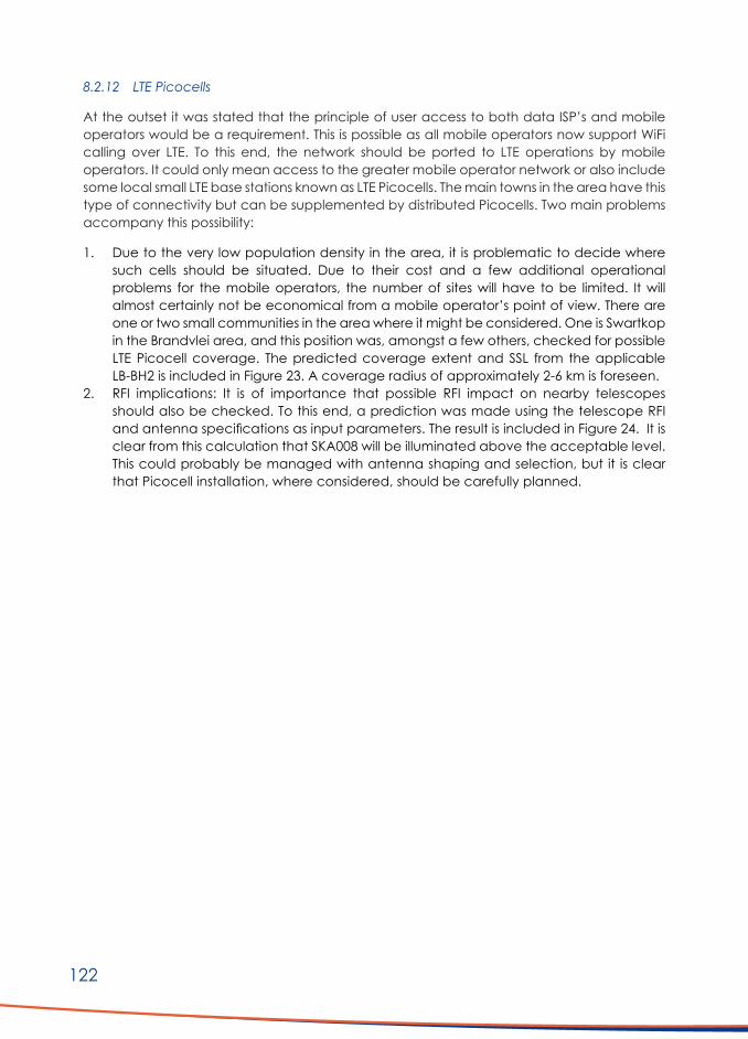
122
8.2.12 LTE Picocells
At the outset it was stated that the principle of user access to both data ISP’s and mobile operators would be a requirement. This is possible as all mobile operators now support WiFi calling over LTE. To this end, the network should be ported to LTE operations by mobile operators. It could only mean access to the greater mobile operator network or also include some local small LTE base stations known as LTE Picocells. The main towns in the area have this type of connectivity but can be supplemented by distributed Picocells. Two main problems accompany this possibility:
1. Due to the very low population density in the area, it is problematic to decide where such cells should be situated. Due to their cost and a few additional operational problems for the mobile operators, the number of sites will have to be limited. It will almost certainly not be economical from a mobile operator’s point of view. There are one or two small communities in the area where it might be considered. One is Swartkop in the Brandvlei area, and this position was, amongst a few others, checked for possible LTE Picocell coverage. The predicted coverage extent and SSL from the applicable LB-BH2 is included in Figure 23. A coverage radius of approximately 2-6 km is foreseen.
2. RFI implications: It is of importance that possible RFI impact on nearby telescopes should also be checked. To this end, a prediction was made using the telescope RFI and antenna specifications as input parameters. The result is included in Figure 24. It is clear from this calculation that SKA008 will be illuminated above the acceptable level. This could probably be managed with antenna shaping and selection, but it is clear that Picocell installation, where considered, should be carefully planned.

123
Figu
re 2
3: L
TE C
over
age
pred
ictio
n fro
m S
war
tkop
LB-
BH2

124
Figu
re 2
4: L
TE 1
800
MHz
RFI
foot
prin
t fro
m S
war
tkop
LB-
BH2
125
8.2.13 Network integration
The proposed network will require the following additional components or subsystems:
An Operations Control and Management centre (OCMC)
Such a centre will be required from where all the high sites and other network critical parameters can be monitored and even remotely configured with the right network equipment and management software. It should be a dedicated, secure area and placed where external connectivity is relatively easy and access to the SKA fibre network is possible. A likely position would be in Carnarvon.
Connection to a mobile operator
This connection will have to be established via a Layer 3 type switch, with adequate bandwidth connectivity to one or more mobile operators. This switch can be in the OCMC or wherever the mobile portal can be accessed.
Connection to one or more bulk data ISPs
In keeping with the connectivity requirement for mobile connection, a similar setup will be required for any ISP connected to the network.
8.2.14. Existing internet service provider network investigation
There are a few internet service providers in the area, primarily WiFi based. The most extensive of these networks is run by Hantamnet, a small business based in Calvinia. It was deemed beneficial to briefly analyse this network for coverage and possible impact on the SKA’s scientific activities. The LAG provided the different site positions and equipment details. The Hantamnet network stretches from approximately Sutherland in the West to fairly close to the SKA core site eastwards. If one peruses the high site positions established by Hantamnet, it is clear that the positions were selected with some care, and in fact, a few of the points were deemed very suitable for the concept currently being proposed. The calculated emission footprints are included in Figure 25 and Figure 26. The results indicate no threat from any of the western sites, but there are a few of their equipment sites closer to the core and sites where the existing intersite links pass over a future telescope position that needs further investigation. The analysis is not complete, but the problem areas seem to be relatively limited and could likely be mitigated by different antenna selection and rerouting. The possible impact should be confirmed by on-site measurement.

126
Figu
re 2
5: H
anta
mne
t WiF
i em
issio
n fo
otpr
ints
: Nor
th

127
Figu
re 2
6: H
anta
mne
t WiF
i em
issio
n fo
otpr
ints
: Sou
th

128
8.3 VSAT Internet Connectivity (Option B)
8.3.1 Background
As set out in Section 8.2 to 8.2.10, the network will be functional from a technical point of view and should be capable of delivering the standard of service as expected and required. It does, however, suffer from the drawback of being an extensive system, servicing a relatively low number of users. It will also be expensive, featuring a high initial capital cost/user. Therefore, it was deemed advisable to investigate a possible alternative where the most expensive portion of the network, the backhaul infrastructure, could be substituted by an alternative service supplied and maintained by a third party. With the restrictions on wide area and terrestrial RF-based services in the area, a VSAT (satellite) based service appears to offer a logical alternative. No extended infrastructure, which would be limited to the user end terminal, is required. Several options are available from satellite service providers, such as Vox, MorClick, Ishara and BCS. As can be expected, there is variation in pricing for the different packages available in terms of speed and monthly data requirements, primarily set by the satellite owner/operator.
A typical configuration for a VSAT end-user setup is shown in Figure 27. The same principle is followed as set out in Section 8.2.9. The VSAT terminal will replace the subscriber unit and service one or more access points in the immediate surroundings.
Figure 27: Local user VSAT block diagram
H
G
F
E
D
C
B
A
8 7 6 5 4 3 2 1
H
G
F
E
D
C
B
A
8 7 6 5 4 3 2 1
ASSAf
Alternative Communications for CKAAALocal User VSAT Block Schematic
SIZE TYPE DWG NO REV
A4 DRG COM-003 0SCALE NA SHEET 1 OF 1
Switch/Router
Charge controller
48 VDC Link & Switch solar supply
Local small area WiFi AP
VSATdecoder
VSAT Datalink
5.8 GHz local low power microwave link
5.8 GHz local low power microwave link
Local small area WiFi AP
Farmhouse WiFi AP

129
8.3.2 RFI Risks
Any active electronic equipment could emit unwanted EMI and act as a source of RFI. Such problems were found during the initial testing of the VSAT terminal equipment, intended as Internet replacement, bought by SARAO for distribution to the community. Against the recommendation of SARAO’s RFI group, these problems were not solved prior to deployment. Therefore, to avoid the same mistake, any new VSAT equipment should be thoroughly tested for compliance before rollout. To this effect, a testing campaign is currently underway.
8.3.3 Costing
The fact that the satellite-based backhaul data infrastructure is independently maintained by a service provider is an advantage. The packages typically have a once-off installation fee plus monthly costs depending on speed and data cap. The installation cost varies but could cost up to R 13 000. A high up-front cost is balanced by lower monthly fees. From the many options, a 5 – 10 Mbps service typically varies between R1 000 and R 1 500 per month. This is a competitive rate, given the relatively low deployment cost and operational flexibility. To compare the VSAT option (Option B) with the alternative using a microwave network (Option A), a comparative cost estimate using a few realistic assumptions has been included in Addendum A. It is clear from the comparison between the two options that there is a significant difference in capital expenditure. Although Option A’s configuration is possibly ideal, with a high potential level of service, the capital cost may be problematic. The broader rollout of a VSAT service, perhaps with some associated subsidy model, should be given consideration. It has the advantage of a short implementation timeline and could later be augmented by other infrastructure.
9. Emerg ency and Wide Area Voice Communications Network9.1 Background
One of the most important user requirements received (Section 6) was the need for wide-area emergency and safety communications. The system offered by SARAO in response to this requirement was a Digital Mobile Radio (DMR) VHF High Band Trunked Radio (TRS) system that was supposed to cover the geographical area concerned. However, the outcome of investigations to determine the specifications for SARAO’s own on-site radio communications installation indicated a potential RFI problem from the TRS. The decision was subsequently made to implement a VHF Low Band digital mobile radio (DMR) system for use on-site and in the surrounding areas. The TRS might still be implemented but to a limited and revised extent. The details are still uncertain at this stage. The main advantage of Low Band over Mid- and High Band is the increased coverage obtained due to the better propagation characteristics associated with a lower frequency. With the digital facility, very convenient additional facilities are obtained. These include:
■ Ease of connection to outside telecommunication networks, including mobile phones ■ Short messaging service between radios and to outside devices ■ Very extensive call group options ■ Individual calls between users
Such a Low Band DMR system offers very similar facilities as a mobile phone network, with the proviso that actual data throughput is much restricted due to the narrow channel width, as required by licensing requirements.

130
9.2 VHF Low Band DMR for Emergency and Safety Use
The Marnet radio network still in use in the area is now obsolete and problematic to maintain. It seems logical to investigate the possibility to extend the Low Band DMR to the areas on which the investigations of this report are focused. There is the possibility to utilise some of the existing mobile phone base station masts and other physical facilities, should such an implementation prove feasible. The use of existing Marnet masts could also be considered for the establishment of a new radio-based wide area Emergency and Safety Communications System (ESCS).
9.3 Preferred Radio Type for Emergency Use
Personal radio communications can be utilised by means of fixed base station radios, vehicle-mounted units or handheld personal radios. Base station radios are required in fixed locations, such as offices, homes, or control centres. An important requirement recently forwarded by a spokesman for the LAG, was that the mobile component should not be based on mobile radios but on the use of more versatile handheld units. This provides the option of a single radio being transferrable between users and vehicles, with associated convenience and cost-saving. The only disadvantage for such an approach is the more limited range of such radios due to reduced power output and antenna efficiency when compared to a vehicle-mounted unit. This typically translates to extra repeaters to cover a particular area. However, the requirement has merit, and the coverage calculations and repeater placements were carried out with this in mind.
9.4 ESCS Coverage Prediction
For the purpose of this coverage study, the following repeater sites were considered:
Table 3: Possible DMR VHF Low Band repeater sites
Site name Latitude Longitude Antenna mounting height
Brandvlei Vodacom -30.4645484 20.482111 35m
Vanwyksvlei Vodacom -30.3470893 21.8100935 35m
Wildeperdeberg -30.9041428 22.3740469 150m
Williston MTN -31.325259 20.917913 35m
Telkom Blouplaat -31.1536207 21.5968909 40m
Calvinia Sentech -31.384463 19.781619 45m
Halfweg Transnet -30.003784 20.146622 35m
Kolke Transnet -29.535177 20.782550 35m
Kenhardt Vodacom -29.3035 21.0649 40m
Bloekomhoogte -30.1872 20.9994 20m
Waterkloof SKA -30.746502 21.169547 30m
Fraserburg MTN -31.915556 21.511111 30m
Blomberg Marnet (See “Comments on coverage predictions”)
-31.109 21.01 15m
Fraserburg Marnet -32.123656 21.669049 15m

131
The predicted coverage of the different repeater sites was calculated using a 1-arcsec Digital Elevation Model (DEM) as terrain reference and suitable radio propagation software. Calculation input parameters were as follows:
Table 4: VHF Low Band calculation parameters
Parameter Value/DescriptionPropagation algorithm Longley-Rice IRRT
Antenna mounting heights Repeaters: As per the repeater site listHandheld radio: 1.5m
Repeater power output 43 dBm
Repeater sensitivity -110 dBm
Repeater antenna & gain Folded dipole / 2.5 dBi
Repeater duplexer insertion loss 1.2 dB
Repeater combiner loss 1.5 dB
Repeater coupler losses 1.0 dB
Antenna cable losses < 1 dB / 100m
Handheld power output 36 dBm
Handheld sensitivity -105 dBm
Mobile antenna & gain End fed whip / -7 dBi
Centre frequency 40 MHz nom.
The signal strength key is included in both figures 27 and 28. For readability, only three levels are indicated:
Table 5: Signal strength key
Signal quality Level ColourVery good -70 dBm or better Blue
Good -100 dBm or better Light green
Marginal -105 to -100 dBm Yellow
Poor -105 or worse Red
The coverage prediction plots are included as per Figure 27 and Figure 28.
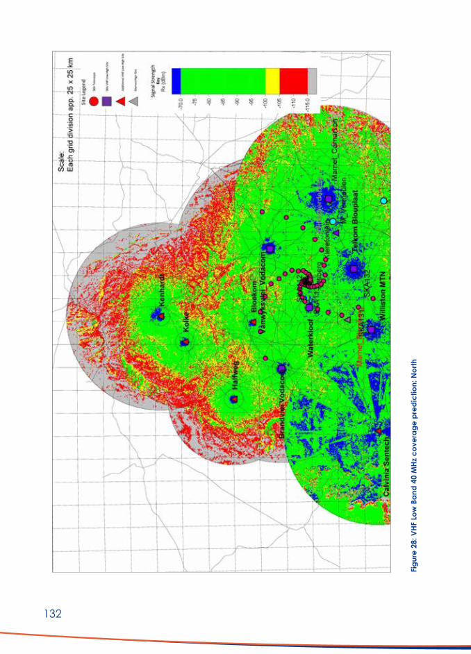
132
Figu
re 2
8: V
HF L
ow B
and
40 M
Hz c
over
age
pred
ictio
n: N
orth

133
Figu
re 2
9: V
HF L
ow B
and
40 M
Hz c
over
age
pred
ictio
n: S
outh

134
Comments on coverage predictions
From the coverage studies, it was clear that the use of Blomberg should not be necessary. From a maintenance point of view, it is an advantage to utilise an existing site with an established infrastructure. The coverage over the required area is predicted to be very good with the use of the first twelve repeater sites (Table 4). Due to the extended area and handheld radio requirements, the envisaged SKA mobile radio sites should be utilised together with a few additional ones.
9.5 Summary on ESCS
The proposed ESCS should be technically feasible and functional if implemented following best practice.
Being a DMR type network, backhaul connectivity between the different high site repeater nodes will be required. Most of these sites already have fibre connectivity, while in a few cases microwave backhaul will have to be implemented. This infrastructure will have to be accessible from an ESCS Control Centre.
A cost estimate for the ESCS is discussed in Section 11, but the envisaged implementation cost is reasonable for a network of such an extent given the potential benefits. A key influence in the final cost will be the quantity and cost of individual radios given the potentially large number of units required.
A key factor in the success of the ESCS will be the affordability of the service and specifically, the cost per user radio. It appears likely that some subsidy models will need to be devised. Some speculative options are provided in the cost estimate.
The desirability of the ESCS is beyond debate, and its implementation should be a priority.
10. Implementation ConsiderationsIt is believed that, from a technical perspective, the concept of Option A as set out in Section 8.2 should be functional. However, some practical problems may be encountered, and they include:
i. The high sites identified for topographical suitability in terms of radio propagation might not be accessible for several reasons. Access and installation could be impossible or just not cost-effective.
ii. Fibre routes are proposed, but detailed route planning will be required.
iii. The signal level calculations have been made using widely accepted algorithms and elevation data. However, it is not possible to express topography accurately in mathematical form, and it will be wise to confirm some key findings by field measurements.
iv. The organisational and operational model for such an undertaking is briefly discussed in Section 12 and will be a key element in the success of such a network.
v. The cooperation of all role players in the geographical area, including cell companies, will be vital. In this regard, a general willingness was found up to this point.

135
vi. Sufficient and feasible financing of the project will clearly be a significant and difficult challenge with all the related problems and permutations. Active participation of government, SARAO and all user organisations will be required.
vii. Should the lower-cost alternative of the VSAT (Option B) be selected, a user subsidy supporting installation and service must be considered to render it attractive and practical for all parties. Provided the necessary precautions are taken, RFI risks will also be reduced in this case.
viii. The ESCS implementation should be of the highest priority. However, modern digital radios are far more expensive than the old Marnet units, and a subsidy model should be considered together with some affordable network fee to allow for network maintenance.
11. Cost EstimatesPreliminary cost estimates for each network described are provided in Addendum A.
It should be noted that at the time of writing, the world’s economic circumstance, particularly in South Africa is volatile. The Rate of Exchange (RoX) is particularly variable and will greatly influence the costing. It should also be noted that the estimate for Option A is based on a conservative approach regarding possible RFI in the area. Actual measurements are planned on existing Hantamnet sites, and it might prove feasible to relax some of the assumed constraints after those results are available. If the VSAT option (Option B) is implemented, the solution will be much more affordable. The estimates include a few simple subsidy models.
12. Possible Business Models and Organisational StructuresThis vital aspect of the project is not simple and will require in-depth investigation by suitably qualified experts. To this end, some discussions took place with senior people in SARAO’s Land Management section and with GR Two (consultants assisting SARAO with land acquisition, servitudes and similar aspects). Some interesting comments were made and are included below with their permission:
1. The entire area has been stricken with severe drought, and poverty is common. Therefore, it will be ideal if community involvement can be arranged for the roll-out and operation of the network.
2. A potentially successful model to consider, could be a Public-Private Partnership (PPP) given the critical elements of regulatory control, initial capital funding, private user participation and long-term maintenance and management at ground level. This is a strategic necessity as the project is larger and more complex than any one party of a typical PPP structure could unilaterally contribute to.
3. A solution underlying this PPP structure and scope needs to be dynamic as the future will be influenced by technological development.
4. Typical participants to such a PPP structure would be: ■ DSI, NRF, and SARAO. ■ A financial support partner for initial capital. If the PPP is a new business start-up and
involves job creation, the Industrial Finance Corporation (IFP) could be approached.
136
■ Selected private sector service provider/s. These are usually appointed by tender following careful output requirement specifications. In this instance, preference should be given to local service providers (e.g. Hantamnet) and whoever is active in the area.
■ Users of the solution (e.g. affected farm owners, farm workers, Co-Op’s and service providers to this group) as well as emergency services.
5. SARAO’s legal advisors should clear legislative and regulatory controls, but sufficient precedents are in existence to act as a guideline. It is important to note that it would need to fit in with existing governance structures provincially and/or nationally (e.g. the NRF).
6. Financial sustainability. This is a key aspect. Comments in this regard are as follows: ■ Capital raising and expenditure will be required for the building phase. ■ For the Operating and Maintenance phase, depreciation and replacement
strategies need to be considered. ■ Given the type of project, consideration should be given to redundancy due to
technological advancement in future. ■ Financial ownership is critical as a PPP typically has elements of co-ownership
between the three PPP partners.
13. Conclusions and RecommendationsFurther to the above, the key conclusions and recommendations of the investigation are summarised below.
13.1 Mobile Coverage
Due to the current non-existence of the conventional telephone network, there is preference to cover as much of the area as possible. This is, however, incompatible with the SKA scientific purpose, except in limited locations.
The implementation of Picocell LTE base stations could be considered in selected areas but with due care.
13.2 Data access via Microwave and Fibre Connectivity (Option A)
■ A network facilitating ease of- and affordable data connection, over the largest possible area, is a priority.
■ A solution enabling seamless connectivity for data packet-based transmission systems, such as Whatsapp, as well as to and from the outside PSTN and mobile networks, is ideal.
■ It is very unlikely that a single technology-based network will meet the requirements. A solution containing a mix of technologies should be considered.
■ A network complying with the above is deemed feasible from a purely technical perspective, but expensive.
■ The bulk of such a solution will be RF-based. ■ The lowest cost RF solution will be obtained by utilising equipment in the ISM, i.e. WiFi
bands. Still, it will only be possible in specific locations due to RFI considerations close to telescope positions.
■ Although greatly influenced by terrain, ISM band downlinks 25 – 30 km should be regarded as an approximate safe distance from any telescope. However, the RFI spillage will, in some cases, be manageable by antenna choice.

137
■ Licensed band transmission in a frequency band above that of the SKA domain should be implemented wherever RFI is a threat.
■ Service to users, when RF-based, should be in the form of downlinks from strategically chosen high sites.
■ High site positions were determined topographically with RF system design principles as a basis but will require individual surveys to determine practical feasibility.
■ An extended backhaul link network will be required to interconnect link the high site positions.
■ The links, as proposed in the layouts, have individually been checked for adequate performance.
■ The choice of generic antenna type will be important not only in terms of performance but also for RFI containment. The preferred type for the ISM band links, in particular, is the horn type.
■ It should be possible to utilise some of SARAO’s planned infrastructure for backhaul telecommunications, particularly node connection points on their FO network. Users placed close to the FO network could be connected by terrestrial overhead ADSS. These are also the positions with the highest RFI threat. A total of 101 such connections have been identified at this stage, but might have to be revised after the necessary surveys.
■ The proposed network’s potential RFI impact was extensively investigated as best possible and deemed compliant on theoretical grounds.
■ The use of mobile phones at user locations for WiFi applications and mostly LTE, should not be problematic. GSM operation, however, could be a threat within approximately 4 km from a telescope. This is clearly terrain-related.
■ Complementary to the two items above, it is recommended that on-site measurements be conducted to confirm the different analyses.
■ An Operational Central Management Centre (OCMC) should be established for network monitoring and management in some central location with good cloud connectivity.
■ The breakout ports to the cloud and mobile operator networks should be available in the OCMC.
13.3 Data access via VSAT (Option B)
The Option A network, as set out in Section 8.3, will be functional from a technical point of view and should be capable of delivering the standard of service as expected and required. It will, unfortunately, be a costly solution due to the low density of users. A VSAT (satellite) based service appears to offer a logical alternative with the restrictions on wide area, terrestrial RF-based services in the SKA area. The VSAT terminal will replace the subscriber unit in the alternative with microwave/fibre optic cable backhaul. It is also a very simple type of installation, and network maintenance will be much less of a concern.
RFI Risks
Any active electronic equipment could act as a source of RFI. It is known that such problems were found during the initial testing of the VSAT terminal equipment bought by the SKA for distribution to the community as internet replacement. It is, therefore, essential that any new VSAT equipment is thoroughly tested for compliance prior to rollout. A testing campaign to this effect is currently underway.

138
VSAT Costing
The satellite-based backhaul data infrastructure is independently maintained by a service provider, which offers a huge advantage, provided it is an affordable option. The packages typically have a once-off installation fee plus monthly cost depending on speed and data cap. A 5 – 10 MBps service typically varies between R1 000 and R 1 500 per month. A comparative cost estimate using a few realistic assumptions has been included in Section 11. It is clear from the estimates that the difference in capital expenditure for the VSAT option compared to the microwave/fibre optic option is extensive. The latter is possibly an ideal one with a high potential service level, but the capital cost could be problematic in the present general national financial situation. Perhaps with some associated subsidy model, the wider rollout of a VSAT service is to be seriously considered. It has the obvious advantage of a short implementation timeline and might well be augmented at a later stage by other infrastructure.
13.4 Safety and Emergency Communications
A network providing wide-area emergency and safety-related voice communications is a very high priority to the community. A system based on VHF Low Band DMR type repeaters, mobile- and handheld radios was investigated. Coverage studies indicate very adequate coverage over the area of interest, using 12 repeater sites. Such an implementation should potentially be affordable, cost-effective and well suited to satisfy this requirement. The solution will also fit in with the network envisaged by SARAO’s own internal use. It is recommended that the implementation of such a service be a high priority.
13.5 Operational and Business Model
The operational and business model selected for whichever combination of options will require separate and in-depth analysis, with more exact information regarding financial possibilities. At this stage, it would appear that some form of community involvement would be desirable (and advisable), and a form of PPP could be a strong consideration.
13.6 Cost Estimates
The cost estimates included in this investigation will require refinement as market conditions stabilise.
In the case of Option A, bulk financing upfront for the entire project is unlikely due to the extent involved. It will also not be feasible or practical to roll out the network immediately and in totality. A phased approach for implementation is, therefore, a logical conclusion. This is less of a requirement for Option B and the ESCS.

139
14. References
1 ASSAf TOR, April 2019 Independent Study on Alternative Communications for Use in the KCAAAs
2 SKA-TEL-INSA-0007025 Concept Design Report for The Mobile Radio System
3 GOV GAZETTE, 25 MAY 2018 National Radio Frequency Plan 2018, as updated
4 Recommendation ITU-R P.526-14 Propagation by diffraction
5 SKA-TEL-SKO-0000202 SKA EMI/EMC Standards and Procedures
6 ETSI TS 151 026 V5.0.0 (2002-06) https://www.etsi.org/deliver/etsi_ts/151000_151099/151026/05.00.00_60/ts_151026v050000p.pdf
Digital cellular telecommunications system (Phase 2+); GSM Repeater Equipment Specification (3GPP TS 51.026 version 5.0.0 Release 5)
7 ETSI TR 103 494 V1.1.1 (2018-01) https://www.etsi.org/deliver/etsi_tr/103400_103499/103494/01.01.01_60/tr_103494v010101p.pdf
Broadband Radio Access Networks (BRAN); Study of central coordination of WAS/RLANs operating in the 5 GHz frequency band
8 https://www.sciencedirect.com/topics/engineering/radio-access-technology
Radio Access Technology
9 https://www.3gpp.org/technologies/keywords-acronyms/98-lte
3GPP: The Mobile Broadband Standard: LTE
10 https://www.3gpp.org/technologies/keywords-acronyms/98-lte
IMT 2020: Radio Interface Standardization Trends in ITU-R
11 https://www.3gpp.org/specifications-groups/ran-plenary/ran_ah1-itu/home
RAN AHG-ITU
12 Recommendation ITU-R M.2012 LTE Advanced Wireless MAN Advanced
13 Datasheets of antennas and radios Various as required
15. Addenda
Number Title Page
A Cost Estimate 57
B List of High Sites (Option A) 59
C Summary of links in Unlicensed Band 62
D Summary of links in Licensed Band (Option A) 66
E List of interconnecting High Site links (Option A) 71
F List of Fibre Optic Connections (Option A) 74
G Link design examples (Option A) 78
H Equipment datasheets 84
I Complete list of user sites incorporated in investigation 100

140
Add
endu
m A
: Cos
t Est
imat
e
Opt
ion
A: M
icro
wav
e an
d Fi
bre
Opt
ic B
ackh
aul I
nfra
stru
ctur
e
SiteTy
pe&Description
Unit
Cos
tTo
tal
Qty
Tota
l all
Phas
esQ
ty
Phas
e 1
Tota
l Pha
se 1
Qty
Ph
ase
2To
tal P
hase
2Q
ty
Phas
e 3
Tota
l Pha
se 3
26 G
Hz B
ackh
aul L
ink
Site
R 25
7 30
0.00
114
R29
332
200.
0011
4R
29 3
32 2
00.0
00
R0.0
00
R0.0
0
26 G
Hz B
ackh
aul L
ink
Site
, Fib
re O
ptic
C
onne
cted
R 21
4 80
0.00
19R4
081
200
.00
19R
4 08
1 20
0.00
0R0
.00
0R0
.00
26 G
Hz S
ubsc
riber
Dow
nlin
kR
228
300.
0023
0R5
2 50
9 00
0.00
197
R 44
975
100
.00
33R7
533
900
.00
0R0
.00
26 G
Hz S
ubsc
riber
Inst
alla
tion
(2 x
AP’
s)R
101
100.
0019
4R1
9 61
3 40
0.00
147
R 14
861
700
.00
33R3
336
300
.00
14R1
415
400
.00
5.7
GHz
PTM
P D
istrib
utio
n Si
te
(Mic
row
ave
back
haul
)R
170
300.
0010
9R1
8 56
2 70
0.00
109
R 18
562
700
.00
0R0
.00
0R0
.00
5.7
GHz
Sub
scrib
er In
stal
latio
n (2
x A
P’s)
R 71
100
.00
198
R14
077
800.
0018
1R
12 8
69 1
00.0
013
R924
300
.00
4R2
84 4
00.0
0
FO L
inks
(Tot
al c
ost f
or a
vera
ge lin
k d
istan
ce)
R 32
3 18
7.52
101
R32
641
939.
3910
1R
32 6
41 9
39.3
90
R0.0
00
R0.0
0
FO T
erm
inat
ions
/ lin
kR
64 2
00.0
010
0R6
420
000
.00
100
R 6
420
000.
000
R0.0
00
R0.0
0
FO S
ubsc
riber
Inst
alla
tion
(2 x
AP’
s)R
44 3
00.0
010
3R4
562
900
.00
100
R 4
430
000.
001
R44
300.
002
R88
600.
00
Allo
wan
ce L
TE P
icoc
ells
R 47
4 30
0.00
10R4
743
000
.00
10R
4 74
3 00
0.00
R0
.00
R0
.00
Subt
otal
R186
544
139
.39
R
172
916
939.
39
R 11
838
800
.00
R
1 78
8 40
0.00
Man
agem
ent c
entre
R 1
000
000.
00
R1 0
00 0
00.0
01
R 1
000
000.
00
R 0.
00
R 0.
00
Subt
otal
R187
544
139
.39
R
173
916
939.
39
R 11
838
800
.00
R
1 78
8 40
0.00
P’s&G’s
20.0
0%
R37
508
827.
88
R 34
783
387
.88
R
2 36
7 76
0.00
R
357
680.
00
Subt
otal
R225
052
967
.26
R
208
700
327.
26
R 14
206
560
.00
R
2 14
6 08
0.00
Con
tinge
ncy&De
sign
15.0
0%
R33
757
945.
09
R 31
305
049
.09
R
2 13
0 98
4.00
R
321
912.
00
Tota
l exc
l VA
T
R2
58 8
10 9
12.3
5
R 24
0 00
5 37
6.35
R
16 3
37 5
44.0
0
R 2
467
992.
00
VAT
15%
R3
8 82
1 63
6.85
R
36 0
00 8
06.4
5
R 2
450
631.
60
R 37
0 19
8.80
Tota
l inc
l VA
T
R2
97 6
32 5
49.2
0
R 27
6 00
6 18
2.80
R
18 7
88 1
75.6
0
R 2
838
190.
80

141
Opt
ion
B: V
SAT-
base
d en
d-us
er in
stal
latio
n.
Desc
riptio
nUn
it C
ost
Tota
l Q
tyTo
tal a
ll Ph
ases
Qty
Ph
ase
1 (7
0%)
Tota
l Pha
se 1
Qty
Ph
ase
2 (2
0%)
Tota
l Pha
se 2
Qty
Ph
ase
3 (1
0%)
Tota
l Pha
se 3
VSA
T-ba
sed
end
-use
r ins
talla
tion
R 44
750
.00
391
R17
497
250.
0027
4R1
2 24
8 07
5.00
78R3
499
450
.00
39R1
749
725
.00
Subt
otal
R17
497
250.
00
R12
248
075.
00
R 3
499
450.
00
R 1
749
725.
00
Man
agem
ent c
entre
R 1
000
000.
001
R1 0
00 0
00.0
01
R1 0
00 0
00.0
00
R 0.
000
R 0.
00
Subt
otal
R18
497
250.
00
R13
248
075.
00
R 3
499
450.
00
R 1
749
725.
00
P’s &
G’s
20.0
0%
R3 6
99 4
50.0
020
.00%
R2 6
49 6
15.0
020
.00%
R699
890
.00
20.0
0%R3
49 9
45.0
0
Subt
otal
R22
196
700.
00
R15
897
690.
00
R4 1
99 3
40.0
0
R2 0
99 6
70.0
0
Con
tinge
ncy&De
sign
15.0
0%
R3 3
29 5
05.0
010
.00%
R1 5
89 7
69.0
010
.00%
R419
934
.00
10.0
0%R2
09 9
67.0
0
Tota
l exc
l VA
T
R2
5 52
6 20
5.00
R1
7 48
7 45
9.00
R4
619
274
.00
R2
309
637
.00
VAT
15%
R3
828
930
.75
15%
R2 6
23 1
18.8
515
%R6
92 8
91.1
015
%R3
46 4
45.5
5
Tota
l inc
l VA
T
R2
9 35
5 13
5.75
R2
0 11
0 57
7.85
R5
312
165
.10
R2
656
082
.55
N
ote:
The
VSA
T d
eplo
ymen
t cos
t allo
ws f
or a
limite
d lo
cal r
edist
ribut
ion
netw
ork
as w
ell.
The
site-
spec
ific
dep
loym
ent c
ost m
ay v
ary
dep
end
ing
on th
e av
aila
ble
supp
ortin
g in
frast
ruct
ure.

142
VHF
Low
Ban
d Em
erge
ncy
Radi
o N
etw
ork
inst
alla
tion.
Desc
riptio
nUn
it C
ost
Tota
l Q
tyTo
tal a
ll Ph
ases
Qty
Ph
ase
1To
tal P
hase
1Q
ty
Phas
e 2
Tota
l Pha
se 2
Qty
Ph
ase
3To
tal P
hase
3
VHF
Low
ban
d D
MR
Repe
ater
In
frast
ruct
ure
Su
mR8
895
600
.00
Sum
R8 8
95 6
00.0
00
R0.0
00
R0.0
0
Repe
ater
site
est
ablis
hmen
t and
ba
ckha
ul in
itiat
ial c
ost
R 20
000
.00
12R2
40 0
00.0
012
R240
000
.00
0R0
.00
0
Subt
otal
R9 1
35 6
00.0
0
VHF
Low
ban
d D
MR
mob
ile ra
dio
sR
20 0
00.0
039
1R7
820
000
.00
274
R5 4
74 0
00.0
078
R1 5
60 0
00.0
039
R780
000
.00
VHF
Low
ban
d D
MR
hand
held
rad
ios
R16
000.
0058
7R9
392
000
.00
411
R6 5
76 0
00.0
011
7R1
872
000
.00
59R9
44 0
00.0
0
Subt
otal
R26
347
600.
00
R21
185
600.
00
R3 4
32 0
00.0
0
R1 7
24 0
00.0
0
P’s &
G’s
20.0
0%
R5 2
69 5
20.0
020
.00%
R4 2
37 1
20.0
020
.00%
R686
400
.00
20.0
0%R3
44 8
00.0
0
Subt
otal
R31
617
120.
00
R25
422
720.
00
R4 1
18 4
00.0
0
R2 0
68 8
00.0
0
Con
tinge
ncy
& D
esig
n15
.00%
R4
742
568
.00
10.0
0%R2
542
272
.00
10.0
0%R4
11 8
40.0
010
.00%
R206
880
.00
Tota
l exc
l VA
T
R3
6 35
9 68
8.00
R2
7 96
4 99
2.00
R4
530
240
.00
R2
275
680
.00
VA
T15
%
R5 4
53 9
53.2
015
%R4
194
748
.80
15%
R679
536
.00
15%
R341
352
.00
Tota
l incl
VA
T
R4
1 81
3 64
1.20
R3
2 15
9 74
0.80
R5
209
776
.00
R2
617
032
.00

143
Addendum B: List of High Sites (Option A)
Site Name Latitude Longitude Elevation (m)
Brandvlei Vodacom -30.464548 20.482111 933
F-BH19 -30.274136 20.4798641 960
F-LB-VWHS10 -30.224844 22.2274669 1091.31
F-LB-VWHS20 -30.564024 21.3352981 1019.94
F-LB-VWHS22 -30.663312 21.7327364 1073.7
F-LB-WHS11 -31.007872 21.1260952 1304.98
F-LB-WHS18 -30.845602 21.1009589 1123.22
F-LB-WHS27 -31.237022 20.9708645 1263.97
F-LB-WHS4 -30.693291 21.1358365 1280.01
F-LB-WHS46 -30.918334 20.9430427 1145.95
F-LB-WHS7 -30.910046 21.4750549 1522.7
F-LB-WHS8 -30.933895 21.2060319 1470.49
Klerefontein -30.975666 21.995933 1325.14
LB-BH1 -30.146744 21.2437472 984.69
LB-BH12 -30.302725 20.7291056 984.63
LB-BH14 -30.376403 20.8869722 1005.15
LB-BH15 -30.371956 21.0533444 1009.97
LB-BH2 -30.09575 21.0979444 931.3
LB-BH20 -30.204264 20.5469167 927.03
LB-BH25 -30.174853 20.6737583 942.94
LB-BH26 -30.073564 20.9106306 905.9
LB-BH3 -30.143689 20.8907889 958.23
LB-BH31 -30.346947 20.8040417 976.99
LB-BH36 -30.383611 20.9555556 1012
LB-BH37 -30.418056 20.9061111 990
LB-BH38 -30.396111 21.0311111 1018
LB-BH4 -30.067222 20.8077778 940
LB-BH6 -30.188481 20.5302667 917.06
LB-BH8 -30.116614 20.1859556 986.13
LB-CHS1 -30.478858 22.2985222 1110.86
LB-CHS10 -30.917003 21.972725 1392.23
LB-CHS11 -30.989592 21.7965083 1354.57
LB-CHS11A -30.96198 21.8627429 1335.11
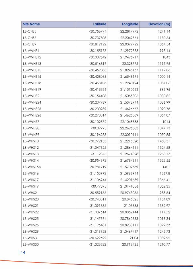
144
Site Name Latitude Longitude Elevation (m)
LB-CHS5 -30.756794 22.2817972 1241.14
LB-CHS7 -30.737808 22.2049861 1130.64
LB-CHS9 -30.819122 22.0379722 1364.54
LB-VWHS1 -30.155175 21.2972833 993.14
LB-VWHS12 -30.339542 21.9496917 1043
LB-VWHS13 -30.516819 22.328775 1195.96
LB-VWHS15 -30.459083 21.8245167 1119.86
LB-VWHS16 -30.408083 21.6548194 1000.14
LB-VWHS18 -30.463103 21.2940194 1037.06
LB-VWHS19 -30.418836 21.1510583 996.96
LB-VWHS2 -30.154408 21.5065806 1080.82
LB-VWHS24 -30.237989 21.5373944 1036.99
LB-VWHS25 -30.200289 21.4696667 1090.78
LB-VWHS26 -30.270814 21.4626389 1064.07
LB-VWHS7 -30.102572 22.1045333 1014
LB-VWHS8 -30.09795 22.2626583 1047.13
LB-VWHS9 -30.196253 22.3010111 1070.85
LB-WHS10 -30.972133 21.2215028 1450.31
LB-WHS12 -31.047325 21.2864111 1324.58
LB-WHS13 -31.12375 21.2674028 1258.13
LB-WHS14 -30.954872 21.6784611 1322.55
LB-WHS15A -30.981919 21.5702639 1401
LB-WHS16 -31.153972 21.5966944 1367.8
LB-WHS17 -31.106944 21.4201639 1366.41
LB-WHS19 -30.79595 21.0141056 1052.35
LB-WHS2 -30.559156 20.9743056 983.54
LB-WHS20 -30.943311 20.846025 1154.09
LB-WHS21 -31.091386 21.03555 1382.97
LB-WHS22 -31.087614 20.8852444 1175.2
LB-WHS25 -31.147394 20.7860833 1099.34
LB-WHS26 -31.196481 20.8233111 1099.33
LB-WHS29 -31.319928 21.0467417 1242.73
LB-WHS3 -30.629622 21.04 1039.92
LB-WHS30 -31.323522 20.918425 1210.77

145
Site Name Latitude Longitude Elevation (m)
LB-WHS31 -31.377661 21.2537444 1124.3
LB-WHS38 -31.055058 20.5403917 1024.11
LB-WHS41 -31.491936 20.9200806 1165.7
LB-WHS42 -31.510417 21.0455944 1171
LB-WHS43 -30.984194 21.2546083 1417.03
LB-WHS44 -30.865186 21.3554333 1358.23
LB-WHS45 -31.117011 21.5096139 1340
LB-WHS5 -30.806917 21.3057917 1227.93
LB-WHS6 -30.865383 21.2856306 1440.38
LB-WHS9 -30.975139 21.4216333 1521.32
Telkom Blouplaat -31.153621 21.5968909 1369.97
UL-BH10 -29.787613 20.0708929 1002.13
UL-BH17 -30.377684 20.054522 949.34
UL-BH18 -30.324727 20.2438846 944.97
UL-BH21 -30.463285 20.4840281 924.5
UL-BH22 -30.544807 20.3849778 981.6
UL-BH23 -30.598188 20.3407381 990.67
UL-BH27 -30.176494 20.3628 941.03
UL-BH29 -30.021978 20.4172472 923.02
UL-BH33 -30.035017 20.6048056 880.04
UL-BH34 -29.775472 20.3422889 941.37
UL-BH41 -29.876389 20.0122222 1006
UL-BH42 -29.996389 20.1308333 982
UL-BH5 -30.096735 20.6107961 883.79
UL-BH7 -29.890512 20.137102 1001.88
UL-BH9 -30.082181 19.9747243 973.72
UL-CHS13 -30.910844 22.2647413 1357.18
UL-CHS14 -30.932127 22.3663449 1596.47
UL-CHS15 -30.960517 22.5082856 1547.99
UL-CHS16 -31.030958 22.6084978 1391.17
UL-CHS17 -31.043211 22.3321088 1469.46
UL-CHS18 -30.956321 22.2429468 1441.34
UL-CHS19 -31.173064 21.9365319 1346.03
UL-CHS20 -31.170312 22.1195542 1369.6

146
Site Name Latitude Longitude Elevation (m)
UL-CHS21 -31.22323 22.3529407 1519.37
UL-CHS22 -31.327224 21.9295637 1336.57
UL-CHS23 -31.272754 21.6478381 1467.41
UL-CHS24 -31.136158 22.377067 1511.22
UL-CHS25 -31.121383 22.0515631 1332.73
UL-CHS3 -30.778159 22.7113447 1529.98
UL-CHS4 -30.60425 22.4577439 1262
UL-CHS6 -30.734272 22.4181121 1302.67
UL-VWHS3 -30.147567 21.7475371 942.9
UL-VWHS4 -30.015529 21.6400401 1013.24
UL-VWHS5 -30.22163 21.8379347 945
UL-WHS23 -30.901874 20.4579525 1009.12
UL-WHS32 -31.598555 21.1993609 1265.32
UL-WHS34 -31.587548 20.8403888 1253.9
UL-WHS35 -31.464924 20.5650675 1289.23
UL-WHS36 -31.53378 20.6780762 1222.95
UL-WHS37 -31.304508 20.6301727 1233.07
UL-WHS39 -31.420628 20.8283359 1164.69
UL-WHS40 -31.48441 20.7594164 1302.55
Vanwyksvlei Vodacom -30.347089 21.8100935 981
Wildeperdeberg -30.904143 22.3740469 1410
Williston MTN -31.325259 20.9179125 1218

147
Addendum C: Summary of links in Unlicensed Band
Site name S1
Site name S2
Frequency (MHz)
Tr Ant gain (dBi) S1
Tr Ant gain (dBi) S2
Rx signal (dBm) S1
Rx signal (dBm) S2
B13-A UL-BH22 5700 16 16 -74.38 -74.38
B15-A UL-BH34 5700 36.6 36.6 -44.3 -44.3
B20-A UL-BH41 5700 16 16 -71.17 -71.17
B21-A UL-BH42 5700 36.6 36.6 -42.24 -42.24
B23-A UL-BH5 5700 29 29 -35.61 -35.61
B26-A UL-BH17 5700 16 16 -75.27 -75.27
B29-A UL-BH29 5700 16 16 -74.74 -74.74
B35-A UL-BH33 5700 29 29 -82.38 -82.38
B43-A UL-BH23 5700 24 24 -83.7 -83.7
B44-A UL-BH7 5700 29 29 -44.36 -44.36
B45-A F-BH19 5700 16 16 -76.9 -76.9
B46-A UL-BH21 5700 16 16 -76.18 -76.18
B47-A UL-BH18 5700 16 16 -73.62 -73.62
B48-A UL-WHS23 5700 40 40 -47.76 -47.76
B4-A F-BH19 5700 16 16 -68.95 -68.95
B52-A UL-BH7 5700 29 29 -47.74 -47.74
B54-A UL-BH34 5700 36.6 36.6 -39.29 -39.29
B58-A UL-BH9 5700 29 29 -49.89 -49.89
B59-A UL-BH9 5700 29 29 -41.6 -41.6
B5-A UL-BH33 5700 16 16 -51.02 -51.02
B5-A UL-BH5 5700 29 29 -47.03 -47.03
B60-A UL-BH42 5700 16 16 -65.56 -65.56
B62-A UL-BH9 5700 29 29 -48.03 -48.03
B65-A UL-BH22 5700 29 29 -77.52 -77.52
B66-A UL-BH27 5700 16 16 -61.68 -61.68
B69-A UL-BH10 5700 29 29 -43.81 -43.81
B70-A UL-BH27 5700 16 16 -73.56 -73.56

148
Site name S1
Site name S2
Frequency (MHz)
Tr Ant gain (dBi) S1
Tr Ant gain (dBi) S2
Rx signal (dBm) S1
Rx signal (dBm) S2
B9-A UL-BH18 5700 16 16 -73.24 -73.24
C101-A UL-CHS20 5700 29 29 -54.24 -54.24
C102-A UL-CHS18 5700 29 29 -44.47 -44.47
C105-A UL-CHS23 5700 29 29 -84.19 -84.19
C111-A UL-CHS13 5700 29 29 -55.69 -55.69
C111-A UL-CHS18 5700 29 29 -44.93 -44.93
C116-A V34-B 5700 16 16 -65.08 -65.08
C123-A UL-CHS4 5700 29 29 -71.22 -71.22
C126-A UL-CHS13 5700 17 17 -85.4 -85.4
C128-A UL-CHS14 5700 29 29 -47.4 -47.4
C14-A UL-CHS20 5700 29 29 -53.42 -53.42
C43-A UL-CHS18 5700 29 29 -33.36 -33.36
C46-A UL-CHS15 5700 29 29 -39.06 -39.06
C47-A UL-CHS4 5700 29 29 -52.52 -52.52
C52-A UL-CHS13 5700 29 29 -43.57 -43.57
C59-A UL-CHS15 5700 29 29 -42.98 -42.98
C61-A UL-CHS4 5700 29 29 -50.37 -50.37
C62-A UL-CHS15 5700 29 29 -55.07 -55.07
C64-A UL-CHS19 5700 29 29 -51.74 -51.74
C65-A UL-CHS4 5700 29 29 -50.35 -50.35
C68-A UL-CHS15 5700 29 29 -34.19 -34.19
C71-A UL-CHS6 5700 29 29 -47.81 -47.81
C76-A UL-CHS3 5700 29 29 -57.9 -57.9
C79-A UL-CHS15 5700 29 29 -36.98 -36.98
C7-A UL-CHS25 5700 29 29 -57.68 -57.68
C85-A UL-CHS23 5700 29 29 -54.87 -54.87
C87-A UL-CHS21 5700 29 29 -47.51 -47.51
C89-A UL-CHS21 5700 29 29 -37.78 -37.78

149
Site name S1
Site name S2
Frequency (MHz)
Tr Ant gain (dBi) S1
Tr Ant gain (dBi) S2
Rx signal (dBm) S1
Rx signal (dBm) S2
C90-A UL-CHS24 5700 29 29 -69.7 -69.7
C94-A UL-CHS24 5700 29 29 -37.24 -37.24
C94-A UL-CHS21 5700 29 29 -49.99 -49.99
C99-A UL-CHS20 5700 29 29 -45.18 -45.18
C9-A UL-CHS22 5700 17 17 -78.17 -78.17
F-B19-A F-BH19 5700 16 16 -69.67 -69.67
F-B63-A UL-BH23 5700 19 19 -73.11 -73.11
F-G156-A UL-WHS34 5700 17 17 -79.95 -79.95
F-G66-A F-LB-WHS4 5700 16 16 -63.91 -63.91
F-G68-A F-LB-WHS18 5700 16 16 -64.3 -64.3
F-G69-A F-LB-WHS18 5700 16 16 -73.19 -73.19
F-G77-A F-LB-WHS18 5700 16 16 -64.88 -64.88
F-G7-A F-LB-WHS27 5700 16 16 -72.85 -72.85
F-V37-A F-LB-VWHS10 5700 16 16 -73.34 -73.34
F-V38-A F-LB-VWHS10 5700 16 16 -67.35 -67.35
F-V39-A F-LB-VWHS10 5700 16 16 -57.63 -57.63
G142-A Telkom Blouplaat 5700 16 16 -59.3 -59.3
G145-A UL-WHS37 5700 16 16 -63.73 -63.73
G146-B UL-WHS37 5700 16 16 -73.46 -73.46
G147-C UL-WHS37 5700 16 16 -72.22 -72.22
G149-B UL-WHS34 5700 29 29 -39.66 -39.66
G150-B UL-WHS34 5700 29 29 -54.41 -54.41
G151-C UL-WHS32 5700 29 29 -52.95 -52.95
G154-B UL-WHS32 5700 29 29 -55.49 -55.49
G155-A UL-WHS32 5700 29 29 -54.08 -54.08
G16-B UL-WHS37 5700 16 16 -79.9 -79.9
G21-C Telkom Blouplaat 5700 16 16 -61.4 -61.4
G28-A UL-WHS40 5700 29 29 -51.82 -51.82

150
Site name S1
Site name S2
Frequency (MHz)
Tr Ant gain (dBi) S1
Tr Ant gain (dBi) S2
Rx signal (dBm) S1
Rx signal (dBm) S2
G29-A UL-WHS37 5700 16 16 -74.67 -74.67
G32-A UL-WHS35 5700 29 29 -45.72 -45.72
G34-A UL-WHS35 5700 29 29 -46.62 -46.62
G35-A UL-WHS36 5700 22 16 -67.35 -67.35
G37-C UL-WHS36 5700 16 16 -69.35 -69.35
G38-A UL-WHS39 5700 29 29 -40.5 -40.5
G39-B UL-WHS40 5700 29 29 -48.26 -48.26
G40-B UL-WHS40 5700 29 29 -44.32 -44.32
G41-A UL-WHS34 5700 29 29 -47.06 -47.06
G42-A UL-WHS34 5700 29 29 -51.17 -51.17
G43-A UL-WHS34 5700 29 29 -56.35 -56.35
G47-A UL-WHS39 5700 29 29 -45.53 -45.53
G48-B UL-WHS39 5700 29 29 -45.73 -45.73
G56-C UL-WHS32 5700 29 29 -54.42 -54.42
G58-A UL-WHS23 5700 29 29 -45.56 -45.56
G59-A UL-WHS23 5700 29 29 -51.72 -51.72
G87-A UL-WHS37 5700 16 16 -76.87 -76.87
G92-A G91-B 5700 29 29 -38.93 -38.93
UL-BH17 B10-A 5700 17 17 -78.57 -78.57
UL-CHS14 C16-A 5700 17 17 -95.28 -95.28
UL-CHS18 C127-A 5700 17 17 -83.15 -83.15
UL-CHS25 UL-CHS20 5700 17 17 -74.01 -74.01
UL-WHS32 G57-B 5700 17 17 -92.07 -92.07
UL-WHS36 F-G36-A 5700 16 23 -66.38 -66.38
V52-A UL-VWHS5 5700 29 29 -51.44 -51.44
V53-A UL-VWHS5 5700 29 29 -43.77 -43.77
V54-A UL-VWHS5 5700 29 29 -53.08 -53.08
V55-A UL-VWHS5 5700 29 29 -55 -55

151
Site name S1
Site name S2
Frequency (MHz)
Tr Ant gain (dBi) S1
Tr Ant gain (dBi) S2
Rx signal (dBm) S1
Rx signal (dBm) S2
V56-A UL-VWHS5 5700 29 29 -54.91 -54.91
V57-B UL-VWHS5 5700 29 29 -51.49 -51.49
V58-A UL-VWHS5 5700 29 29 -40.98 -40.98
V58-A C115-A 5700 17 17 -41.9 -41.9
V59-B UL-VWHS3 5700 29 29 -43.1 -43.1
V60-A UL-VWHS3 5700 29 29 -43.63 -43.63
V61-A UL-VWHS4 5700 29 29 -49.3 -49.3
V62-B UL-VWHS4 5700 29 29 -66.62 -66.62
V63-A UL-VWHS4 5700 29 29 -73.68 -73.68
V64-B UL-VWHS3 5700 29 29 -50.2 -50.2
V67-B UL-VWHS3 5700 29 29 -54.99 -54.99
V69-A UL-VWHS3 5700 29 29 -55.08 -55.08

152
Addendum D: Summary of links in Licensed Band (Option A)
Site name S1
Site name S2
Frequency (MHz)
Tr Ant gain (dBi) S1
Tr Ant gain (dBi) S2
Rx signal (dBm) S1
Rx signal (dBm) S2
B11-A LB-BH12 26000 36.6 36.6 -51.05 -51.05
B11-A LB-BH25 26000 36.6 36.6 -53.51 -53.51
B14-A LB-BH26 26000 36.6 36.6 -54.89 -54.89
B17-A LB-WHS2 26000 36.6 36.6 -55.27 -55.27
B24-A LB-BH20 26000 36.6 36.6 -56.5 -56.5
B30-A LB-WHS2 26000 36.6 36.6 -44.01 -44.01
B32-A LB-BH26 26000 36.6 36.6 -56.02 -56.02
B33-A LB-BH3 26000 36.6 36.6 -50.36 -50.36
B34-A LB-BH3 26000 36.6 36.6 -50.91 -50.91
B38-A LB-BH20 26000 36.6 36.6 -42.98 -42.98
B39-A LB-BH26 26000 36.6 36.6 -54.87 -54.87
B3-A LB-BH2 26000 36.6 36.6 -47.69 -47.69
B40-A LB-BH4 26000 36.6 36.6 -55.71 -55.71
B42-A LB-BH4 26000 36.6 36.6 -57.16 -57.16
B50-A LB-BH3 26000 36.6 36.6 -53.41 -53.41
B51-A LB-BH26 26000 36.6 36.6 -49.91 -49.91
B51-A LB-BH3 26000 36.6 36.6 -51.48 -51.48
B55-A LB-BH14 26000 36.6 36.6 -52.88 -52.88
B55-A LB-BH36 26000 36.6 36.6 -53.78 -53.78
B55-A LB-BH37 26000 36.6 36.6 -45.01 -45.01
B55-A LB-BH38 26000 36.6 36.6 -58.1 -58.1
B56-A LB-BH2 26000 36.6 36.6 -49.09 -49.09
B61-A LB-BH15 26000 36.6 36.6 -53.17 -53.17
B64-A LB-BH14 26000 36.6 36.6 -44.56 -44.56
B67-A LB-BH12 26000 36.6 36.6 -46.96 -46.96
B7-A LB-BH3 26000 36.6 36.6 -55.82 -55.82
C107-A LB-WHS16 26000 36.6 36.6 -52.97 -52.97
C110-A LB-VWHS13 26000 36.6 36.6 -47.73 -47.73
C113-A LB-CHS9 26000 36.6 36.6 -45.17 -45.17
C121-A LB-VWHS13 26000 36.6 36.6 -107.99 -107.99
C125-A LB-CHS9 26000 36.6 36.6 -49.74 -49.74
C129-A LB-CHS11A 26000 36.6 36.6 -97.9 -97.9

153
Site name S1
Site name S2
Frequency (MHz)
Tr Ant gain (dBi) S1
Tr Ant gain (dBi) S2
Rx signal (dBm) S1
Rx signal (dBm) S2
C12-A LB-CHS9 26000 36.6 36.6 -53.75 -53.75
C1-A Klerefontein 26000 36.6 36.6 -69.55 -69.55
C26-A LB-CHS11 26000 36.6 36.6 -52.22 -52.22
C2-A LB-CHS10 26000 36.6 36.6 -41.19 -41.19
C30-A LB-CHS11 26000 36.6 36.6 -54.33 -54.33
C32-A LB-VWHS13 26000 36.6 36.6 -55.91 -55.91
C34-A LB-CHS5 26000 36.6 36.6 -40.72 -40.72
C50-A LB-CHS7 26000 36.6 36.6 -45.5 -45.5
C51-A LB-CHS7 26000 36.6 36.6 -49.19 -49.19
C60-A LB-CHS11 26000 36.6 36.6 -56.18 -56.18
C60-A LB-WHS15A 26000 36.6 36.6 -55.76 -55.76
C74-A LB-CHS5 26000 36.6 36.6 -57.69 -57.69
C82-A LB-CHS10 26000 36.6 36.6 -46.44 -46.44
C86-A LB-CHS11 26000 36.6 36.6 -55.59 -55.59
C8-A Klerefontein 26000 36.6 36.6 -82.78 -82.78
F-B1-A LB-BH14 26000 36.6 36.6 -54.67 -54.67
F-B1-A LB-BH31 26000 36.6 36.6 -42.99 -42.99
F-B31-A LB-BH2 26000 36.6 36.6 -58.82 -58.82
F-C18-A LB-CHS11A 26000 36.6 36.6 -67.84 -67.84
F-G131-A LB-WHS29 26000 36.6 36.6 -57.51 -57.51
F-G140-A LB-WHS30 26000 36.6 36.6 -51.57 -51.57
F-G143-A LB-WHS41 26000 36.6 36.6 -54.29 -54.29
F-G50-C LB-WHS42 26000 36.6 36.6 -59.62 -59.62
F-G52-C LB-WHS42 26000 36.6 36.6 -36.35 -36.35
F-G69-A LB-WHS6 26000 36.6 36.6 -53 -53
F-G85-B LB-WHS22 26000 36.6 36.6 -45.61 -45.61
F-G94-A LB-WHS21 26000 36.6 36.6 -92.28 -92.28
F-V24-A LB-VWHS12 26000 36.6 36.6 -51.38 -51.38
F-V88-A LB-VWHS18 26000 36.6 36.6 -54.94 -54.94
G100-A LB-WHS30 26000 36.6 36.6 -65.4 -65.4
G104-B LB-WHS44 26000 36.6 36.6 -37.74 -37.74
G105-C F-LB-WHS7 26000 36.6 36.6 -50.22 -50.22
G106-A F-LB-WHS7 26000 36.6 36.6 -54.76 -54.76

154
Site name S1
Site name S2
Frequency (MHz)
Tr Ant gain (dBi) S1
Tr Ant gain (dBi) S2
Rx signal (dBm) S1
Rx signal (dBm) S2
G10-A LB-VWHS19 26000 36.6 36.6 -45.03 -45.03
G111-A LB-WHS21 26000 36.6 36.6 -131.29 -131.29
G112-A LB-WHS30 26000 36.6 36.6 -109.94 -109.94
G113-A LB-WHS41 26000 36.6 36.6 -53.3 -53.3
G114-A F-LB-WHS7 26000 36.6 36.6 -58.61 -58.61
G115-B F-LB-WHS7 26000 36.6 36.6 -58.5 -58.5
G116-A Telkom Blouplaat 26000 24 24 -79.39 -79.39
G118-A LB-WHS16 26000 36.6 36.6 -52.79 -52.79
G119-A LB-WHS17 26000 36.6 36.6 -49.74 -49.74
G120-B LB-WHS9 26000 36.6 36.6 -83.26 -83.26
G121-A LB-WHS9 26000 36.6 36.6 -55.85 -55.85
G124-C LB-WHS12 26000 36.6 36.6 -84.72 -84.72
G125-A LB-WHS13 26000 36.6 36.6 -53.76 -53.76
G127-A LB-WHS17 26000 36.6 36.6 -57.71 -57.71
G128-A LB-WHS13 26000 36.6 36.6 -35.26 -35.26
G129-B LB-WHS13 26000 36.6 36.6 -51.84 -51.84
G12-B LB-WHS20 26000 36.6 36.6 -42.67 -42.67
G135-A LB-WHS29 26000 36.6 36.6 -61.19 -61.19
G136-A LB-WHS29 26000 36.6 36.6 -58.08 -58.08
G137-A LB-WHS29 26000 36.6 36.6 -49.96 -49.96
G138-A LB-WHS29 26000 36.6 36.6 -49.88 -49.88
G139-A LB-WHS29 26000 36.6 36.6 -43.01 -43.01
G13-C LB-WHS38 26000 36.6 36.6 -57.35 -57.35
G141-A LB-WHS41 26000 36.6 36.6 -57.61 -57.61
G14-C LB-WHS25 26000 36.6 36.6 -58.29 -58.29
G152-B F-LB-WHS8 26000 36.6 36.6 -43.69 -43.69
G15-C LB-WHS25 26000 36.6 36.6 -59.45 -59.45
G17-A LB-WHS38 26000 36.6 36.6 -47.19 -47.19
G18-A LB-WHS38 26000 36.6 36.6 -40.6 -40.6
G19-B LB-WHS17 26000 36.6 36.6 -58.24 -58.24
G19-B LB-WHS13 26000 36.6 36.6 -48.53 -48.53
G1-A LB-WHS21 26000 36.6 36.6 -87.15 -87.15
G23-C F-LB-WHS7 26000 36.6 36.6 -56.34 -56.34

155
Site name S1
Site name S2
Frequency (MHz)
Tr Ant gain (dBi) S1
Tr Ant gain (dBi) S2
Rx signal (dBm) S1
Rx signal (dBm) S2
G25-C LB-WHS6 26000 36.6 36.6 -54.17 -54.17
G25-C LB-WHS10 26000 36.6 36.6 -53.07 -53.07
G2-A LB-WHS21 26000 36.6 36.6 -51.18 -51.18
G4 C F-LB-WHS27 26000 36.6 36.6 -53.41 -53.41
G44-A LB-WHS41 26000 36.6 36.6 -52.41 -52.41
G45-A LB-WHS41 26000 36.6 36.6 -48.82 -48.82
G46-A LB-WHS41 26000 36.6 36.6 -42.73 -42.73
G49-A LB-WHS41 26000 36.6 36.6 -48.85 -48.85
G54-A LB-WHS42 26000 36.6 36.6 -52.69 -52.69
G60-A LB-WHS38 26000 36.6 36.6 -58.21 -58.21
G61-A F-LB-WHS46 26000 36.6 36.6 -58.24 -58.24
G62-A LB-VWHS19 26000 36.6 36.6 -52.62 -52.62
G63-C LB-VWHS18 26000 36.6 36.6 -44.06 -44.06
G64-A LB-VWHS18 26000 36.6 36.6 -53.12 -53.12
G70-A LB-WHS6 26000 36.6 36.6 -38.85 -38.85
G72-A LB-WHS3 26000 36.6 36.6 -48.55 -48.55
G73-A LB-WHS3 26000 36.6 36.6 -88.78 -88.78
G74-A F-LB-WHS4 26000 36.6 36.6 -58.75 -58.75
G75-C F-LB-WHS4 26000 36.6 36.6 -58.02 -58.02
G76-A F-LB-WHS4 26000 36.6 36.6 -58.09 -58.09
G78-A F-LB-WHS18 26000 36.6 36.6 -54.55 -54.55
G78-A LB-WHS19 26000 36.6 36.6 -19.57 -19.57
G79-A LB-WHS20 26000 36.6 36.6 -59.18 -59.18
G80-B LB-WHS20 26000 36.6 36.6 -55.97 -55.97
G81-A F-LB-WHS46 26000 36.6 36.6 -54.14 -54.14
G82-A F-LB-WHS46 26000 36.6 36.6 -50.82 -50.82
G84-A F-LB-WHS46 26000 36.6 36.6 -53.62 -53.62
G86-B LB-WHS25 26000 36.6 36.6 -53.17 -53.17
G88-A UL-WHS37 26000 36.6 36.6 -51.57 -51.57
G89-B LB-WHS25 26000 36.6 36.6 -53.07 -53.07
G8-B LB-WHS2 26000 36.6 36.6 -44.01 -44.01
G90-A LB-WHS25 26000 36.6 36.6 -52 -52
G91-B LB-WHS25 26000 36.6 36.6 -57.7 -57.7
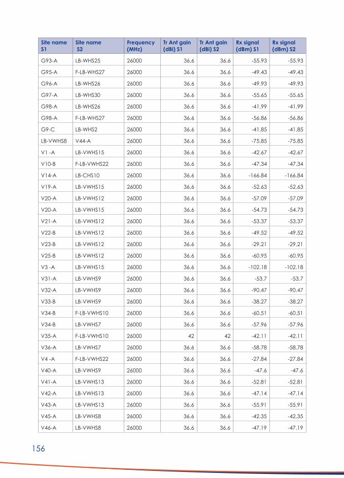
156
Site name S1
Site name S2
Frequency (MHz)
Tr Ant gain (dBi) S1
Tr Ant gain (dBi) S2
Rx signal (dBm) S1
Rx signal (dBm) S2
G93-A LB-WHS25 26000 36.6 36.6 -55.93 -55.93
G95-A F-LB-WHS27 26000 36.6 36.6 -49.43 -49.43
G96-A LB-WHS26 26000 36.6 36.6 -49.93 -49.93
G97-A LB-WHS30 26000 36.6 36.6 -55.65 -55.65
G98-A LB-WHS26 26000 36.6 36.6 -41.99 -41.99
G98-A F-LB-WHS27 26000 36.6 36.6 -56.86 -56.86
G9-C LB-WHS2 26000 36.6 36.6 -41.85 -41.85
LB-VWHS8 V44-A 26000 36.6 36.6 -75.85 -75.85
V1 -A LB-VWHS15 26000 36.6 36.6 -42.67 -42.67
V10-B F-LB-VWHS22 26000 36.6 36.6 -47.34 -47.34
V14-A LB-CHS10 26000 36.6 36.6 -166.84 -166.84
V19-A LB-VWHS15 26000 36.6 36.6 -52.63 -52.63
V20-A LB-VWHS12 26000 36.6 36.6 -57.09 -57.09
V20-A LB-VWHS15 26000 36.6 36.6 -54.73 -54.73
V21-A LB-VWHS12 26000 36.6 36.6 -53.37 -53.37
V22-B LB-VWHS12 26000 36.6 36.6 -49.52 -49.52
V23-B LB-VWHS12 26000 36.6 36.6 -29.21 -29.21
V25-B LB-VWHS12 26000 36.6 36.6 -60.95 -60.95
V3 -A LB-VWHS15 26000 36.6 36.6 -102.18 -102.18
V31-A LB-VWHS9 26000 36.6 36.6 -53.7 -53.7
V32-A LB-VWHS9 26000 36.6 36.6 -90.47 -90.47
V33-B LB-VWHS9 26000 36.6 36.6 -38.27 -38.27
V34-B F-LB-VWHS10 26000 36.6 36.6 -60.51 -60.51
V34-B LB-VWHS7 26000 36.6 36.6 -57.96 -57.96
V35-A F-LB-VWHS10 26000 42 42 -42.11 -42.11
V36-A LB-VWHS7 26000 36.6 36.6 -58.78 -58.78
V4 -A F-LB-VWHS22 26000 36.6 36.6 -27.84 -27.84
V40-A LB-VWHS9 26000 36.6 36.6 -47.6 -47.6
V41-A LB-VWHS13 26000 36.6 36.6 -52.81 -52.81
V42-A LB-VWHS13 26000 36.6 36.6 -47.14 -47.14
V43-A LB-VWHS13 26000 36.6 36.6 -55.91 -55.91
V45-A LB-VWHS8 26000 36.6 36.6 -42.35 -42.35
V46-A LB-VWHS8 26000 36.6 36.6 -47.19 -47.19

157
Site name S1
Site name S2
Frequency (MHz)
Tr Ant gain (dBi) S1
Tr Ant gain (dBi) S2
Rx signal (dBm) S1
Rx signal (dBm) S2
V47-A LB-VWHS8 26000 36.6 36.6 -48.31 -48.31
V48-A LB-VWHS9 26000 36.6 36.6 -53.33 -53.33
V49-A LB-VWHS8 26000 36.6 36.6 -55.27 -55.27
V5 -A F-LB-VWHS22 26000 36.6 36.6 -30.28 -30.28
V50-A F-LB-VWHS10 26000 36.6 36.6 -60.95 -60.95
V51-B LB-VWHS7 26000 36.6 36.6 -33.95 -33.95
V6 -A F-LB-VWHS22 26000 36.6 36.6 -35.23 -35.23
V65-A LB-VWHS2 26000 36.6 36.6 -53.77 -53.77
V66-A LB-VWHS2 26000 36.6 36.6 -47.82 -47.82
V68-B LB-VWHS16 26000 36.6 36.6 -56.57 -56.57
V7 -A F-LB-VWHS22 26000 36.6 36.6 -60.4 -60.4
V70-A LB-VWHS24 26000 36.6 36.6 -45.78 -45.78
V71-B LB-VWHS2 26000 36.6 36.6 -53.95 -53.95
V72-A LB-VWHS24 26000 36.6 36.6 -61.03 -61.03
V73-A LB-VWHS25 26000 36.6 36.6 -26.69 -26.69
V74-A LB-VWHS25 26000 36.6 36.6 -32.66 -32.66
V75-A LB-VWHS26 26000 36.6 36.6 -42.26 -42.26
V75-A LB-VWHS24 26000 36.6 36.6 -91.55 -91.55
V76-B LB-VWHS1 26000 36.6 36.6 -59.89 -59.89
V76-B LB-BH1 26000 36.6 36.6 -61.67 -61.67
V77-A LB-VWHS1 26000 36.6 36.6 -102.22 -102.22
V81-B LB-VWHS16 26000 36.6 36.6 -41.81 -41.81
V82-B LB-VWHS16 26000 36.6 36.6 -47.65 -47.65
V83-B LB-VWHS16 26000 36.6 36.6 -38.61 -38.61
V84-B LB-VWHS16 26000 36.6 36.6 -47.1 -47.1
V89-B LB-VWHS18 26000 36.6 36.6 -53.4 -53.4
V8-B F-LB-VWHS22 26000 36.6 36.6 -90.34 -90.34
V9 -B LB-VWHS15 26000 36.6 36.6 -96.3 -96.3
V90-A LB-VWHS19 26000 36.6 36.6 -52.56 -52.56
V91-A LB-VWHS19 26000 36.6 36.6 -45.25 -45.25
V92-B LB-VWHS18 26000 36.6 36.6 -44.04 -44.04
V93-A LB-VWHS18 26000 36.6 36.6 -53.14 -53.14
V95-A LB-VWHS15 26000 36.6 36.6 -51.66 -51.66

158
Addendum E: List of interconnecting High Site links (Option A)
Site name S1
Site name S2 Frequency (MHz)
Tr Ant gain (dBi) S1
Tr Ant gain (dBi) S2
Rx signal (dBm) S1
Rx signal (dBm) S2
LB-BH2 LB-BH1 26000 36.6 36.6 -59.01 -59.01
LB-BH20 LB-BH12 26000 36.6 36.6 -62.37 -62.37
LB-BH25 LB-BH12 26000 36.6 36.6 -72.71 -72.71
LB-BH26 LB-BH2 26000 36.6 36.6 -60.99 -60.99
LB-BH3 LB-BH2 26000 36.6 36.6 -62.37 -62.37
LB-BH31 LB-BH14 26000 36.6 36.6 -53.32 -53.32
LB-BH31 LB-BH12 26000 36.6 36.6 -53.43 -53.43
LB-BH36 LB-BH14 26000 36.6 36.6 -50.81 -50.81
LB-BH38 LB-BH15 26000 36.6 36.6 -44.68 -44.68
LB-BH38 LB-BH36 26000 36.6 36.6 -51.84 -51.84
LB-BH38 LB-BH37 26000 36.6 36.6 -56.82 -56.82
LB-BH4 LB-BH25 26000 36.6 36.6 -60.6 -60.6
LB-BH4 LB-BH3 26000 36.6 36.6 -56.31 -56.31
LB-BH6 LB-BH20 26000 36.6 36.6 -41.36 -41.36
LB-BH6 LB-BH12 26000 36.6 36.6 -64.22 -64.22
LB-CHS11 LB-CHS10 26000 36.6 36.6 -74.32 -74.32
LB-CHS7 LB-CHS5 26000 36.6 36.6 -52.17 -52.17
LB-CHS9 LB-CHS7 26000 36.6 36.6 -61.06 -61.06
LB-VWHS1 LB-BH1 26000 36.6 36.6 -48.59 -48.59
LB-VWHS13 LB-CHS1 26000 36.6 36.6 -48.36 -48.36
LB-VWHS13 LB-CHS7 26000 36.6 36.6 -65.56 -65.56
LB-VWHS15 LB-VWHS12 26000 36.6 36.6 -60.79 -60.79
LB-VWHS16 LB-VWHS15 26000 36.6 36.6 -60.39 -60.39
LB-VWHS19 LB-BH38 26000 36.6 36.6 -78.24 -78.24
LB-VWHS19 LB-VWHS18 26000 36.6 36.6 -62.8 -62.8
LB-VWHS2 LB-VWHS1 26000 36.6 36.6 -62.1 -62.1
LB-VWHS24 LB-VWHS2 26000 36.6 36.6 -76.05 -76.05
LB-VWHS24 LB-VWHS15 26000 36.6 36.6 -69.38 -69.38
LB-VWHS25 LB-VWHS2 26000 36.6 36.6 -79.63 -79.63
LB-VWHS26 LB-VWHS18 26000 36.6 36.6 -65.36 -65.36
LB-VWHS26 LB-VWHS24 26000 36.6 36.6 -52.67 -52.67
LB-VWHS8 V44-A 26000 36.6 36.6 -75.85 -75.85

159
Site name S1
Site name S2 Frequency (MHz)
Tr Ant gain (dBi) S1
Tr Ant gain (dBi) S2
Rx signal (dBm) S1
Rx signal (dBm) S2
LB-VWHS8 LB-VWHS7 26000 36.6 36.6 -59.08 -59.08
LB-VWHS8 LB-VWHS7 26000 36.6 36.6 -59.08 -59.08
LB-VWHS8 F-LB-VWHS10 26000 36.6 36.6 -58.53 -58.53
LB-VWHS9 LB-VWHS8 26000 36.6 36.6 -56.18 -56.18
LB-WHS15A LB-WHS14 26000 36.6 36.6 -55.51 -55.51
LB-WHS17 LB-WHS12 26000 36.6 36.6 -58.46 -58.46
LB-WHS17 LB-WHS16 26000 36.6 36.6 -60.62 -60.62
LB-WHS17 LB-WHS13 26000 36.6 36.6 -71.12 -71.12
LB-WHS21 LB-WHS22 26000 36.6 36.6 -58.44 -58.44
LB-WHS22 LB-WHS21 26000 36.6 36.6 -58.44 -58.44
LB-WHS25 LB-WHS22 26000 36.6 36.6 -56.22 -56.22
LB-WHS26 LB-WHS25 26000 36.6 36.6 -75.22 -75.22
LB-WHS3 LB-VWHS19 26000 36.6 36.6 -64.87 -64.87
LB-WHS3 LB-WHS2 26000 36.6 36.6 -54.81 -54.81
LB-WHS30 LB-WHS29 26000 36.6 36.6 -56.79 -56.79
LB-WHS31 LB-WHS29 26000 36.6 36.6 -62.4 -62.4
LB-WHS38 LB-WHS25 26000 36.6 36.6 -64.82 -64.82
LB-WHS41 LB-WHS29 26000 36.6 36.6 -63.36 -63.36
LB-WHS42 LB-WHS29 26000 36.6 36.6 -62.62 -62.62
LB-WHS43 LB-WHS10 26000 36.6 36.6 -44.7 -44.7
LB-WHS43 LB-WHS21 26000 36.6 36.6 -64.1 -64.1
LB-WHS44 LB-WHS6 26000 36.6 36.6 -50.87 -50.87
LB-WHS45 LB-WHS16 26000 36.6 36.6 -54.02 -54.02
LB-WHS6 LB-WHS19 26000 36.6 36.6 -65.5 -65.5
LB-WHS6 LB-WHS5 26000 36.6 36.6 -50.99 -50.99
LB-WHS6 LB-WHS44 26000 36.6 36.6 -50.87 -50.87
LB-WHS9 LB-WHS17 26000 36.6 36.6 -58.63 -58.63
LB-WHS9 LB-WHS44 26000 36.6 36.6 -57.99 -57.99
LB-WHS9 LB-WHS43 26000 36.6 36.6 -59.58 -59.58
UL-BH18 UL-BH17 26000 36.6 36.6 -61.52 -61.52
UL-BH21 LB-BH12 26000 36.6 36.6 -68.99 -68.99
UL-BH22 UL-BH21 26000 36.6 36.6 -62.15 -62.15
UL-BH23 UL-BH22 26000 36.6 36.6 -60.42 -60.42

160
Site name S1
Site name S2 Frequency (MHz)
Tr Ant gain (dBi) S1
Tr Ant gain (dBi) S2
Rx signal (dBm) S1
Rx signal (dBm) S2
UL-BH27 LB-BH12 26000 36.6 36.6 -76.47 -76.47
UL-BH27 LB-BH8 26000 36.6 36.6 -61.02 -61.02
UL-BH27 UL-BH18 26000 36.6 36.6 -62.02 -62.02
UL-BH29 UL-BH27 26000 36.6 36.6 -64.63 -64.63
UL-BH33 UL-BH34 18000 36.6 36.6 -72.41 -72.41
UL-BH33 UL-BH5 26000 36.6 36.6 -51.13 -51.13
UL-BH34 UL-BH29 26000 36.6 36.6 -66.01 -66.01
UL-BH42 LB-BH8 26000 36.6 36.6 -58.44 -58.44
UL-BH5 LB-BH25 26000 36.6 36.6 -55.33 -55.33
UL-BH7 UL-BH10 26000 36.6 36.6 -57.48 -57.48
UL-BH7 UL-BH41 26000 36.6 36.6 -56.74 -56.74
UL-BH7 UL-BH42 26000 36.6 36.6 -56.39 -56.39
UL-BH9 UL-BH17 26000 36.6 36.6 -81.36 -81.36
UL-BH9 UL-BH42 26000 36.6 36.6 -61.7 -61.7
UL-CHS13 LB-CHS9 26000 36.6 36.6 -64.05 -64.05
UL-CHS14 UL-CHS13 26000 36.6 36.6 -54.78 -54.78
UL-CHS15 UL-CHS14 26000 36.6 36.6 -58.13 -58.13
UL-CHS16 UL-CHS15 26000 36.6 36.6 -56.9 -56.9
UL-CHS17 UL-CHS18 26000 36.6 36.6 -57.31 -57.31
UL-CHS18 LB-CHS10 26000 36.6 36.6 -65.1 -65.1
UL-CHS21 UL-CHS20 26000 36.6 36.6 -63.59 -63.59
UL-CHS21 UL-CHS17 26000 36.6 36.6 -62.04 -62.04
UL-CHS23 LB-WHS16 26000 36.6 36.6 -58.22 -58.22
UL-CHS23 LB-WHS31 26000 36.6 36.6 -70.2 -70.2
UL-CHS23 UL-CHS22 26000 36.6 36.6 -65.68 -65.68
UL-CHS23 UL-CHS19 26000 36.6 36.6 -77.72 -77.72
UL-CHS24 UL-CHS21 26000 36.6 36.6 -54.7 -54.7
UL-CHS25 UL-CHS20 26000 36.6 36.6 -53.13 -53.13
UL-CHS25 UL-CHS19 26000 36.6 36.6 -56.92 -56.92
UL-CHS3 UL-CHS16 26000 36.6 36.6 -66.62 -66.62
UL-CHS4 LB-CHS5 26000 36.6 36.6 -80.92 -80.92
UL-CHS4 UL-CHS3 26000 36.6 36.6 -67.15 -67.15
UL-CHS6 LB-CHS5 26000 36.6 36.6 -57.65 -57.65

161
Site name S1
Site name S2 Frequency (MHz)
Tr Ant gain (dBi) S1
Tr Ant gain (dBi) S2
Rx signal (dBm) S1
Rx signal (dBm) S2
UL-CHS6 UL-CHS15 26000 36.6 36.6 -65.25 -65.25
UL-CHS6 UL-CHS13 26000 36.6 36.6 -64.3 -64.3
UL-VWHS3 LB-VWHS2 26000 36.6 36.6 -63.7 -63.7
UL-VWHS4 UL-VWHS3 26000 36.6 36.6 -60.81 -60.81
UL-VWHS5 UL-VWHS3 26000 36.6 36.6 -56.57 -56.57
UL-VWHS5 LB-VWHS15 26000 36.6 36.6 -65.17 -65.17
UL-VWHS5 LB-VWHS7 26000 36.6 36.6 -66.27 -66.27
UL-WHS23 LB-WHS20 26000 36.6 36.6 -69.54 -69.54
UL-WHS32 LB-WHS42 26000 36.6 36.6 -74.82 -74.82
UL-WHS34 LB-WHS41 26000 36.6 36.6 -57.44 -57.44
UL-WHS35 UL-WHS36 26000 36.6 36.6 -77.61 -77.61
UL-WHS39 LB-WHS30 26000 36.6 36.6 -58.01 -58.01
UL-WHS39 LB-WHS26 26000 36.6 36.6 -78.77 -78.77
UL-WHS40 UL-WHS39 26000 36.6 36.6 -54.42 -54.42
UL-WHS40 UL-WHS37 26000 36.6 36.6 -63.8 -63.8
UL-WHS40 UL-WHS36 26000 36.6 36.6 -54.24 -54.24

162
Addendum F: List of Fibre Optic Connections (Option A)
From To Distance (km)F-109B F-G123B 7.65
F-B19 F-B49 6.90
F-B1-A F-B25-A 11.18
F-B22 F-G11C 0.58
F-B25-A F-B8-A 10.01
F-B28 F-B36 4.85
F-B31 F-B28 10.35
F-B49 F-BH19 7.27
F-B53 F-B37 4.37
F-B57 F-B12 14.52
F-B6 F-B22 5.75
F-B63 F-B57 18.15
F-B63-A F-B16 16.28
F-C17-A F-C97-A 5.41
F-C31 F-VWHS21 21.07
F-C58 F-C18-A 10.97
F-C81-A F-C17-A 8.36
FCP1 F-V12-A 6.73
FCP1 F-C58-A 9.78
FCP1 F-C88-A 5.12
FCP10 F-V87-A 2.76
FCP11 F-G134A 1.73
FCP12 F-G101B 15.18
FCP13 F-G102C 6.56
FCP14 F-G131A 8.28
FCP14 F-WHS28 7.82
FCP15 F-G67-A 4.86
FCP15 F-G68-A 6.37
FCP16 F-G110-A 4.37
FCP16 F-G109-B 4.60
FCP17 F-G26-C 9.20
FCP17 F-G83-A 13.42
FCP18 F-WHS46 4.03
FCP19 F-B19-A 8.05
FCP2 F-V13-A 9.74
FCP2 F-C22-A 0.46
FCP20 F-V27-A 15.34
FCP3 F-C3-A 14.49
FCP4 F-V18-A 6.00

163
From To Distance (km)FCP5 F-V29-A 4.77
FCP5 F-V30-A 5.75
FCP5 F-VWHS10 10.64
FCP7 F-B31-A 7.44
FCP7 F-B68-A 10.03
FCP8 F-V78-A 4.78
FCP8 F-V78-A 4.37
FCP8 F-B6-A 9.80
FCP9 F-V79-A 2.47
FCP9 F-V88-A 5.50
F-G101B F-G71B 2.23
F-G102C F-C20 0.58
F-G102C F-G103A 2.58
F-G102C F-WHS7 2.00
F-G110A F-G27B 3.34
F-G110A F-WHS11 1.96
F-G123A F-G108B 1.15
F-G123B F-G122B 2.82
F-G130A F-G6C 9.20
F-G131A F-G130A 3.91
F-G132A F-G133A 2.07
F-G134A F-G132A 4.23
F-G144A F-G143A 0.81
F-G148A F-G156A 3.82
F-G24B F-V24 3.13
F-G26C F-WHS8 5.41
F-G31A F-G140A 5.98
F-G36A F-G33A 4.60
F-G50-C F-G51-AC 4.60
F-G50-C F-G53-A 6.56
F-G50-C F-G52-C 1.73
F-G51C F-G55A 6.90
F-G5C F-G7C 3.68
F-G65A F-G24B 8.17
F-G68A F-G69A 7.22
F-G68A F-WHS18 3.93
F-G68A F-G77A 8.11
F-G6C F-G5C 5.75
F-G7C F-G153B 6.33
F-G83A F-WHS46 5.13

164
From To Distance (km)F-G94A F-G85B 7.48
F-V16A F-V17-A 11.04
F-V16A F-V18-A 12.00
F-V26-A F-C92-A 0.23
F-V27-A F-V26-A 8.43
F-V27-A F-V86-B 4.60
F-V29-B F-V28-A 5.32
F-V38-A F-V37-A 6.10
F-V79-B F-V80-A 10.27
F-V94-B F-G24-B 3.50
F-VWHS10 F-V39-A 2.07
F-VWHS10 F-V38-A 6.21
SKA005 F-B53-A 4.80
SKA010 F-B27-A 6.21
SKA012 F-V85-A 2.22
SKA016 F-VWHS20 13.46
SKA019 F-G65-A 7.82
SKA021 F-C81-A 5.11
SKA021 F-CHS8-A 2.42
SKA021 F-C25-A 8.97
SKA027 F-C48-A 10.98
SKA027 F-C31-A 14.78
Total length nom 675.96
Add 10% 67.60
Total length 743.55
Average length/site 7.36

165
Addendum G: Link design examples (Option A)
5.7 GHz
F = 5700.00 MHz K = 1.33 %F1 = 100.0, 60.0
CHS23 G114-A
LatitudeLongitude
True azimuth (°)Vertical angle (°)
Elevation (m)
31 16 21.92 S021 38 52.22 E
339.58-0.29
1467.41
30 58 14.70 S021 31 02.48 E
159.640.05
1362.06
Antenna modelAntenna gain (dBi)
Antenna height (m)TX loss (dB)RX loss (dB)
SP2-5.2 (TR)29.00
9.000.000.00
SP2-5.2 (TR)29.00
9.000.000.00
Diffraction loss 2.43
Radio modelTX power (dBm)
EIRP (dBm)
Aurora 580018.5047.50
Aurora 580018.5047.50
Receive signal (dBm)Thermal fade margin (dB)
Effective fade margin (dB)
-64.8721.3121.31
-64.8721.3121.31
Annual 2-way multipath availability (%) 99.89878
CHS23 G114-A
Annual 2-way multipath unavailability (sec) 31921.89
Annual rain availability (%) 100.00000
Annual rain + multipath availability (%) 99.89878
CHS23-G114-A.p15April 9, 2020

166
v16-v17.p15
April 9, 2020
F = 5700.00 MHz K = 1.33 %F1 = 100.0, 60.0
v16 v17
LatitudeLongitude
True azimuth (°)Vertical angle (°)
Elevation (m)
30 37 03.68 S021 55 16.63 E
228.420.26
1051.37
30 40 31.00 S021 50 46.16 E
48.46-0.32
1099.84
Antenna modelAntenna gain (dBi)
Antenna height (m)TX loss (dB)RX loss (dB)
SP2-5.2 (TR)29.0012.00
0.000.00
SP2-5.2 (TR)29.0012.00
0.000.00
Diffraction loss 0.99
Radio modelTX power (dBm)
EIRP (dBm)
Aurora 580018.5047.50
Aurora 580018.5047.50
Receive signal (dBm)Thermal fade margin (dB)
Effective fade margin (dB)
-51.8334.1734.16
-51.8334.1734.16

167
F = 5700.00 MHz K = 1.33 %F1 = 100.0, 60.0
UL-VWHS3 V69-A
LatitudeLongitude
True azimuth (°)Vertical angle (°)
Elevation (m)
30 08 51.24 S021 44 51.13 E
209.590.22
942.90
30 16 52.31 S021 39 36.26 E
29.650.31
1022.30
Antenna modelAntenna gain (dBi)
Antenna height (m)TX loss (dB)RX loss (dB)
SP2-5.2 (TR)29.00
9.000.000.00
SP2-5.2 (TR)29.00
3.000.000.00
Radio modelTX power (dBm)
EIRP (dBm)
Aurora 580018.5047.50
Aurora 580018.5047.50
Receive signal (dBm)Thermal fade margin (dB)
Effective fade margin (dB)
-55.0830.9230.92
-55.0830.9230.92
Multipath fading method – Vigants – Barnett
UL-VWHS3-V69-A. p15 April 10, 2020

168
Licensed Band 26+ GHz
F = 26000.00 MHz K = 1.33 %F1 = 100.0, 60.0
UL-BH29 UL-BH7
LatitudeLongitude
True azimuth (°)Vertical angle (°)
Elevation (m)
30 01 19.12 S020 25 02.09 E
298.250.04
923.02
29 53 25.84 S020 08 13.57 E
118.39-0.25
1001.88
Antenna modelAntenna gain (dBi)
Antenna height (m)TX loss (dB)RX loss (dB)
SB 1 – 250C (TR)36.60
9.001.001.00
SB 1 – 250C (TR)36.60
9.001.001.00
Radio modelTX power (dBm)
EIRP (dBm)
FlexiHopper26_4s_8E116.0051.60
FlexiHopper26_4s_8E116.0051.60
Receive signal (dBm)Thermal fade margin (dB)
Effective fade margin (dB)
-67.0314.9714.97
-67.0314.9714.97
Annual 2-way multipath availability (%) 95.32028
Annual 2-way multipath unavailability (sec)
1475797.69
Annual rain availability (%) 99.85988
Annual rain + multipath availability (%) 95.18016
UL-BH29-UL-BH7.p15 April 9, 2020Multipath fading method – Vigants - Barnett
Rain fading method – Rec. ITU-R P.530-8/13 (R837-5)

169
F = 26000.00 MHz K = 1.33 %F1 = 100.0, 60.0
LB-WHS13 LB-WHS17
LatitudeLongitude
True azimuth (°)Vertical angle (°)
Elevation (m)
31 07 25.50 S021 16 02.65 E
82.750.44
1258.13
31 06 25.00 S021 25 12.59 E
262.67-0.46
1366.41
Antenna modelAntenna gain (dBi)
Antenna height (m)TX loss (dB)RX loss (dB)
SB 1 – 250C (TR)36.60
9.001.001.00
SB 1 – 250C (TR)36.60
9.001.001.00
Diffraction loss 12.44
Radio modelTX power (dBm)
EIRP (dBm)
FlexiHopper26_4s_8E116.0051.60
FlexiHopper26_4s_8E116.0051.60
Receive signal (dBm)Thermal fade margin (dB)
Effective fade margin (dB)
-71.1210.8810.88
-71.1210.8810.88
Annual 2-way multipath availability (%) 99.81955
LB-WHS13 LB-WHS17
Annual 2-way multipath unavailability (sec)
56908.10
Annual rain availability (%) 99.80145
Annual rain + multipath availability (%) 99.62099
April 9, 2020

170
F = 26000.00 MHz K = 1.33 %F1 = 100.0, 60.0
UL-BH29 UL-BH34
LatitudeLongitude
True azimuth (°)Vertical angle (°)
Elevation (m)
30 01 19.12 S020 25 02.09 E
345.14-0.06
923.02
29 46 31.70 S020 20 32.24 E
165.18-0.13
941.37
Antenna modelAntenna gain (dBi)
Antenna height (m)TX loss (dB)RX loss (dB)
SB 1 – 250C (TR)36.60
9.001.001.00
SB 1 – 250C (TR)36.60
9.001.001.00
Radio modelTX power (dBm)
EIRP (dBm)
FlexiHopper26_4s_8E116.0051.60
FlexiHopper26_4s_8E116.0051.60
Receive signal (dBm)Thermal fade margin (dB)
Effective fade margin (dB)
-66.0115.9915.99
-66.0115.9915.99
Annual 2-way multipath availability (%)Annual 2-way multipath unavailability (sec)
97.41352815672.16
UL-BH29 UL-BH34
Annual rain availability (%) 99.87648
Annual rain + multipath availability (%) 97.29001
UL-BH29-UL-BH34. P15 April 9, 2020

171
Addendum H: Equipment datasheets
ISM band WiFi equipment datasheets (Typical: AP’s & PTMP)
cnPilot™ E501S Outdoor Sector SPECIFICATION SHEET
cnPilot™ E501S Outdoor Sector IP67 802.11ac 90° ~ 120° Outdoor Sector Access Point
Perfect for demanding, high density applications and longer range coverage across
large areas, including: industrial or education campuses, enterprise and hospitality
complexes, public parks and recreational areas, or just about any demanding outdoor
environment requiring cost-effective, controller managed WLAN access points.
THE cnPILOT WI-FI NETWORK
HIGHLIGHTSOperational superiority – The E501S with integrated sector antenna supports 256 client associations, 16 SSIDs, WPA-2 encryption, Dynamic VLANs, DFS channels, Access Control Lists (ACL), and more. The 802.11ac E501S is the essential workhorse for today’s demanding, high density outdoor Wi-Fi networks.
High performance WiFi network - All cnPilot’s Enterprise access points (APs) support features like controller-less roaming, dynamic channel selection, automatic transmit power control, band steering, and more – essential features for easy Wi-Fi operations.
Mesh Rapidly setup multi-hop mesh networks either dedicating one radio (e.g.: 5 GHz) for mesh backhaul, or using both bands for client access simultaneously.
Wireless Backhaul Integration – the aux PoE port on the E501S offers PoE out, eliminating the need for a second power line – perfect for powering on a standard 802.3af camera, or on Cambium’s PMP 450 or ePMP backhaul subscriber modules (SMs) for wireless backhaul enabled Wi-Fi hotspots.
Resilience - Dual on-board Active/Standby memory banks ensure higher availability. The E501S can store two versions of the software – defaulting to a working operational software if needed – reducing the likelihood of site visits and increasing network up-time.
DESIGNED FOR THE OUTDOORS• 802.11ac, 256 users, 16 SSIDs
• 900~1200 coverage
• 23 dBm front-back ratio
• UV rated IP-67 enclosure
• Operating Temp: -300C ~ +600C
• Electrical heater for cold start
• Ruggedized - ESD protection, industrial- grade components
• Packaged with wall mount brackets
• Special LTE coexistence filters
• Light weight ~ 1Kg
cnMAESTRO - WIFI CONTROLLER
• Guest Access: Custom splash pages, vouchers, social login
• Zero-touch provisioning
• Inventory tracking
• Map location
• Monitoring: key stats, alarms
• Mass (bulk) upgrade
• Integrated troubleshooting: Wi-Fi APs, Clients & Cambium SMs
• Controller: Cloud or Virtual On-premises (NOC) controller

172
cnPilot™ E501S Outdoor Sector SPECIFICATION SHEET
ACCESS POINT SPECIFICATIONS
Frequency Bands 2.4 GHz: 2.4 – 2.4835 GHz Channels 1 – 13 (ETSI/CE), Channels 1 – 11 (US)
5 GHz: 5.15 – 5.85 GHz
SSID Security WPA-2 (802.11i): WPA2-Enterprise (802.1x/EAP) & WPA2-Preshared-keys, Open
Max SSID 16
Max Concurrent Clients 256
Max Range Client: 213 m (700 Ft); Actual range will vary based on local RF conditions & client capability. Mesh: 2.4 GHz: 3,000 m (9840 Ft.) 5 GHz: 1,500 m (4,900 Ft.)
Max Data Rates 1.01 Gbps
Ethernet Ports Dual Gigabit Ethernet ports (2 x 10/100/1000Base-T)
Antenna Dual polarized. 2x2 MIMO. Integrated Sector antenna
Antenna Gains 10.5 dBi on 2.4GHz 13 dBi on 5GHz
Power Supply 56V/30W Gigabit passive PoE injector
PoE Out Aux port: capable of 802.3af Power out or Canopy power (for supported Cambium ePMP or PMP450 SMs)
Transmit Power 29dBm @ 2.4GHz 28dBm @ 5 GHz
Power Consumed Typical: 8W Max: 12.95W (no auxiliary device connected)
Dimensions (CM) 30 x 20.4 x 6.5 cm (without bracket)
Weight Without bracket: 881 g (0.88 Kg); with Bracket: 1,063 g (1.06 Kg)
Operating Temperature -300C ~ +600C
Mounting Options Pole mount bracket (included) or wall-mount (with included bracket or without)
LTE Co-Existence Special filter for rejecting interference on 2.4 GHz from adjacent LTE bands 38, 40
Physical Security Kensington Lock bracket
Visaul Status Two (2) multi-color LEDs indicating Access Point & cnMaestro connectivity status
SPECIFICATIONS
INTERNET
CONTROLLER: CLOUD OR ON-PREMISES (NOC)
NOC: Setup controller to tunnel user traffic
Monitor, configure, upgrade all APs
User access: Data with limits
SMS notifications
CLIENTS
cnPILOT APS
OVER-THE-AIR
AirTime fairness
Client (Zap compatible) perf testing
Guest access limits
Client location API per AP
VLAN pooling
Outdoors: Power CPEs from APs
AP FEATURES
Multi-hop Mesh
autoPilot controller
Controller-less roaming
autoRF dynamic Tx power control
cnCheckin guest access
Location APIs
USER TRAFFIC OPTIONS
Local breakout (LBO)
External GW tunneling – L2TP, L2oGRE, PPoE
VLAN pooling and per VLAN per SSID tagging
CONTROLLER
cnMaestro

173
cnPilot™ E501S Outdoor Sector SPECIFICATION SHEET
SPECIFICATIONS
Controller modes • Autonomous Controller-less operations (E.g.: roaming) • Cloud Managed • On-premise virtualized controller
Secure WLAN • WPA-TKIP, WPA2 AES, 802.1x • 802.11w (Protected Management Frames)
Hotspot 2.0/Passpoint Yes
Captive Portal • cnMaestro Controller • Stand-alone AP based • Redirection to external RADIUS • Server DNS logging
Authentication • RADIUS based 802.1x including EAP-SIM/AKA, EAP-PEAP,
EAP-TTLS, and EAP-TLS • MAC authentication (local database or External RADIUS server)
Accounting Yes. Supports RADIUS based accounting to multiple AAAs
Scheduled SSID Turn SSID ON/OFF on a daily/weekly/time of day basis
Guest Access Yes. With Active Directory Integration • Vouchers • Rate limiting • Splash page creation on cnMaestro
VLAN VLAN pooling, Dynamic VLAN assignment from RADIUS server. VLAN per SSID per user
Data Limiting Dynamic rate limiting of client traffic per SSID
Subscriber QoS WMM
Client Isolation Yes
Controller-Less Fast Roaming
Yes. 802.11r, Opportunistic Key Caching supports Enhanced roaming. Disconnect for sticky clients
Airtime Fairness Yes
Meshing Multi-hop meshing supported (3)
WI-FI FEATURES
ACS: Automatic Channel Selection
autoTune: Autonomous dynamic off-channel scans w/o disconnecting clients. Periodic scans and scheduled scanning
Automatic Tx Power Control
autoRF: Autonomous controller-less transmit power control
NAT Yes
DHCP Server Yes
Firewall Yes. NAT logging
ACL, DNS-ACL Yes. L2, L3 or DNS based access control
Band Steering Band Balancing
Yes
Airtime Fairness Yes
Tunneling • L2TP • L2oGRE • PPPoE
Tools • Packet capture • Sniffer
• IP connectivity • Auto logging
• Wi-Fi analyzer
• ZapD (Open source) compliant performance test tool
Services NTP server config Syslog servers SNMP traps support DNS proxy
cnPilot’s dependent resource state awareness feature (ADRES) turns SSID ON/OFF based on underlying resource connectivity state
APIs Presence Location APIs
Certifications FCC, ETSI, CE EN 60601-1-2 (Medical EMC) UL2043 Plenum rated
cnMAESTRO WI-FI CONTROLLER
Common Framework Single-pane-of-glass common manager for Cambium’s cnPilot WiFi, ePMP and PMP wireless backhaul products
On-Boarding Secure zero touch fast on-boarding
Provisioning Easy zero touch virtual network provisioning Provision before install (pre-provision)
Device Inventory Inventory tracking
Troubleshooting ezDetect: Advanced end to end troubleshooting of WiFi Access Point and Client devices on one single screen. Extends to Wireless backhaul (PTP), Wi-Fi Hotspot & Clients . Includes Packet capture and Wireless Analyzer functions
Intuitive Views Map location Hierarchical Dashboard views
Client Insight Client history with client manufacturer view
Monitoring & Alarms Alarms and events management – Critical/Major/Minor Key statistics graphs and sticky alarm summary display
Configuration GUI based configuration or template based configuration options
Software Upgrade Bulk upgrade with ability to upgrade multiple WiFi APs
Multiple Admins Multiple admin provisioning per account
Guest Portal (ezCheck In)
Create free or paid guest sessions – Limit by Time, Rate and Bytes. Includes portal customization and built-in social login

174
cnPilot™ E501S Outdoor Sector SPECIFICATION SHEET
© 2017 Cambium Networks Ltd. All rights reserved.
cnPilot_E501S3.2.1v0.2 05082017
Ordering Information: cnPilot Outdoor E501S
Regulatory Model Number (common to all SKUs): C000100P501A
Sales part # Region
PL-501SPXXA-<US/EU/RW> E501S for US, EU or RoW with PoE injector. XX = US, EU and various other country cords supported models XX examples: IN (India), UK (The United Kingdom), AN (Australia & NZ), CN (China), BR (Brazil) etc
PL-501S000A-<US/EU/RW> E501S model without a PoE injector. Available in US, EU or RoW models
Discover more information on cnPilot at: http://community.cambiumnetworks.com/
2D GAIN PATTERNS

175
ePMP™ 3000L Access Point SPECIFICATION SHEETePMP™ 3000L Access Point SPECIFICATION SHEET
Cambium Networks’ ePMP product line has set
the standard for high performance, scalability
and reliability in harsh interference environments
all at a compelling price. The ePMP 3000L is the
third generation access point (AP) that carries on
the interference tolerance mechanisms with an
emphasis on high-performance in low-density point
to multipoint sectors. The ePMP 3000L is a 2X2
MIMO connectorized access point that can support
a wide variety of deployments including 90/120
degree sectors, narrow-sector horns or even 360
degree omni coverage. In addition, the ePMP 3000L
continues interference mitigation techniques with
support of TDD synchronization using GPS and
the robust software from the ePMP product line.
The ePMP 3000L AP system consists of the ePMP
3000L AP, an optional 2X2 sector antenna and a
wide variety of subscriber modules with varying
form factors and link budgets.
The ePMP 3000L system boasts high packet per
second performance, peak throughput of 600 Mbps
and supports subscriber modules with up to 600
Mbps of peak throughput.
KEY ADVANTAGES:
• MicroPOP Applications: ePMP 3000L is ideally suited for areas with low density or small numbers of subscribers. With support for narrow-band sectors and omnis, coverage can be added exactly where needed.
• Frequency Reuse: Supports GPS synchronization and SM Transmit power control to allow for frequency re-use.
• Unmatched Performance and Scalability: With the efficient Cambium Networks MAC protocol and advanced air-fairness scheduler the ePMP 3000L supports high performance and low consistent latency to subscribers.
KEY SPECIFICATIONS:
• 2X2 MIMO support with peak throughput of 600 Mbps
• 256QAM-5/6, 80 MHz support
• Supports a wide frequency range: 4910 to 5950 MHz
• Frequency re-use with GPS sync and interference mitigation
• Supports up to 64 subscriber modules
• Connectorized for use with Cambium Networks 90/120 degree sector antenna. Also compatible with RF Elements Twistport(tm) Adaptor for ePMP
• Cloud or on-premises network management with cnMaestro
ePMP™ 3000L Access Point

176
ePMP™ 3000L Access Point SPECIFICATION SHEET
SPECIFICATIONS
PRODUCT
Model/Part # See table below for full set of Model and Part Numbers
SPECTRUM
Channel Spacing Configurable on 5 MHz increments
Frequency Range 4910 - 5970 MHz (exact frequencies as allowed by local regulations))
Channel Width 20 | 40 | 80 MHz
INTERFACE
MAC (Media Access Control) Layer Cambium Proprietary
Physical Layer 2X2 MIMO/OFDM
Ethernet Interfaced 100/1000BaseT, rate auto negotiated
Powering Methods Supported 29 V Cambium POE (included)
Protocols Used IPv4/IPV6 , UDP, TCP, IP, ICMP, SNMPv2c, HTTPS, STP, SSH, IGMP Snooping
Network Management HTTPS, SNMPv2c, SSH
VLAN 802.1Q with 802.1p priority
PERFORMANCE
ARQ Yes
Nominal Receive Sensitivity (w/FEC) @20 MHz Channel MCS0 = -89 dBm to MCS8 (256 QAM-3/4) = -66 dBm (per chain)
Nominal Receive Sensitivity (w/FEC) @40 MHz Channel MCS0 = -87 dBm to MCS9 (256QAM-5/6) = -64 dBm (per chain)
Nominal Receive Sensitivity (w/FEC) @80 MHz Channel MCS0 = -84 dBm to MCS9 (256QAM-5/6) = -59 dBm (per chain)
Modulation Levels (Adaptive) MCS0 (BPSK) to MCS 9 (256 QAM 5/6)
GPS Synchronization Yes, via Internal GPS Connector for optional external GPS antenna (Model N000900L030A)
Quality of Service Three level priority (Voice, High, Low) with packet classification by DSCP, COS, VLAN ID, IP & MAC Address, Broadcast, Multicast and Station Priority, MIR/CIR support
LINK BUDGET
Antenna 90/120 Degree 2X2 Sector Antenna (C050900D021B) Available
Transmit Power Range 0 to +29 dBm (combined, to regional EIRP limit) (1 dB interval)
PHYSICAL
Sector Antenna Connection 2 x 50 ohm, RP (Reverse Polarity) SMA Also compatible with RF Elements Twistport™ Adaptor for ePMP
GPS Antenna Connection 1 x 50 ohm, RP (Reverse Polarity) SMA; Optional external GPS Puck Antenna avaialble model N000900L030A
Surge Suppression 1 Joule Integrated. C000000L065A - 30V Gigabit surge suppressor recommended for optimal surge protection
Environmental IP67 and IP68 Compliant
Temperature -22°F to +140°F (-30°C to +60°C)
Power Consumption 12 Watts (Up to 15 Watts in extreme cold temperatures when heater is activated.)
Input Voltage 30 Volts Nominal (14V to 30V Range) (note that 14V minimum must be maintained at radio connector under all conditions including long cable lengths)
Weight 0.5 kg (1.1 lbs.) without bracket
Dimensions 84 x 223 x 32 mm (3.3 x 8.8 x 1.3 inches) without brackets

177
Antenna data sheets: ISM band
Omni directional:
Regulatory Compliance: RoHS 2011/65/EU Compliant | ISO 9001:2015 Document version: TS-A-OMNI-0496 REV1
www.poynting.tech 1
OMNI-496 ©2018 Poynting Antennas (Pty) Ltd. All rights reserved Product Specifications may change without prior notice Revised: August 2018
OMNI-496
ANTENNAS | OMNI-496 SERIES
DUAL BAND WI-FI MARINE ANTENNA 2400-2500, 3300-3800 & 5000-6000 MHz HIGH GAIN OMNI-DIRECTIONAL ANTENNA
APPLIC
ATIO
N A
REA
S
2400-2700, 3300-3800 & 5000-6000 MHz 7.5 dBi Increase
x Mb/s Omni-Directional 2.4-2.5 & 5-6 GHz Urban
IP 68 -40°C to +80°C UL 94 HB IoT & M2M Rural/Farm
• Dual band 2.4 GHz and 5 GHz Wi-Fi antenna • This antenna also supports the Wi-Fi/WiMax/LTE 3.3GHz- 3.8Ghz
frequencies with a max gain of 7.5dBi • Compliant with IEEE 802.11a, 802.11b, 802.11g, 802.11n,
802.11ac wireless standard • Easy mounting with feed through 1-inch marine standard
mounts • Robust and All-weather proof (IP 68) • UV and Saltwater protected against tempestuous weather
conditions • Various mounting options available • This antenna is designed for Wi-Fi coverage on deck of the
vessel
Marine
Transportation
Product Overview
The OMNI-496 Dual-Band Wi-Fi Omni directional antenna, developed by Poynting Antennas, can connect to any Wi-Fi access point
whether it is older Wi-Fi technology or new dual band 802.11ac enabled Wi-Fi technology. These antennas can resolve channel saturation
and provide the ultimate in Wi-Fi performance and flexibility. The OMNI-496 is an IP68 marine version of its urban, industrial & commercial
counterpart; the OMNI-296.
The antenna operates in two frequency bands 2.4 GHz and 5 GHz, offering excellent utilization of the radio spectrum. This Antenna has a
maximum 6dBi gain at 2.4GHz band and 7.5dBi gain at the 5GHz band, which offers the best performance with reliable connections. The
antenna has a N-Type female connector at its base which can be terminated to a cable of the desired type and length.
Features
• On deck marine applications / Yachts / Boats / Ferries • Enhanced LTE Reception • IoT and M2M • Poor data signal reception • Improve data transmission connection reliability & stability • Wi-Fi Applications

178
Regulatory Compliance: RoHS 2011/65/EU Compliant | ISO 9001:2015 Document version: TS-A-OMNI-0496 REV1
www.poynting.tech 2
OMNI-496 ©2018 Poynting Antennas (Pty) Ltd. All rights reserved Product Specifications may change without prior notice Revised: August 2018
Antenna Overview
Frequency Bands 2400 – 2500, 3300 – 3800 & 5000 - 6000 MHz
Peak Gain 7.5 dBi
Coax Cable Type N/A
Coax Cable Length N/A
Connector Type N Type female
Frequency bands
The OMNI-496 is suitable for the following frequency bands | 2400-2500| 3300-3800 MHz | 5000-6000 MHz |
Indicates the frequency bands which OMNI-496 supports
Technical Drawings
With Standard Marine Mounting: With Standard L-Bracket Mounting:

179
Antenna Type Standard Performance ParabolicReflector Antenna
Size, nominal 2 ft | 0.6 m
Polarization Dual
Standard RF Connector Type NFemale
Standard RF Connector Suffix NS (append suffix to modelnumber)
Operating Frequency Band 5.25 5.85 GHz
Half Power Beamwidth, Horizontal 6.2 degrees
Half Power Beamwidth, Vertical 6.2 degrees
CrossPolarization Discrimination 30 dB
Front to Back Ratio (F/B) 38 dB
Gain, Low Frequency 28.5 dBi
Gain, Mid Frequency 29 dBi
Gain, High Frequency 29.5 dBi
VSWR 1.5:1
Return Loss 14 dB
SPECIFICATIONS
General
Electrical
SPD2-5.20.6 M | 2 FT STANDARD PERFORMANCE PARABOLIC REFLECTOR ANTENNA, DUAL-POLARIZED, 5.25-5.85GHZThe SP Standard Performance Series by RadioWaves offers a fullline of cost effective standard performance parabolic antennasengineered to deliver reliable radio links. Designed for bothunlicensed and licensed band applications, RadioWaves fieldproven preassembled SP antennas and robust polemountsensure “set and forget” installation with minimal postinstallationmaintenance. If it’s rugged, it must be RadioWaves!
FEATURES AND BENEFITS
Standard Performance Parabolic Antennas – Excellentperformance for a wide range of licensed and unlicensedapplicationsFully Preassembled at the Factory – Simplifies installation onsite and guarantees “factorytested” qualityWarranty – Industry leading 7year warranty
© RadioWaves, Inc. 2018. All Rights Reserved.1 Contact Us: +1.978.459.8800 | radiowaves.com

180
Fine AzimuthAdjustment
+/ 10 degrees
Fine ElevationAdjustment
+/ 30 degrees
Mounting PipeDiameter, Min
2 inch | 5.08 cm
Mounting PipeDiameter, Max
4.5 inch | 11.4 cm
Net Weight 22 lbs | 9.9 kg 26 lbs | 11.7 Kg withRD radome
Wind VelocityOperational
90 mph | 145 km/h
Wind Velocity SurvivalRating
125 mph | 201 km/h
MechanicalConfiguration
SP2
Axial Force (FA) 222 lbs | 988 N 122 lbs | 543 Nm withRD radome
Side Force (FS) 14 lbs | 62 N 24 lbs | 107 Nm withRD radome
Twisting Moment (MT) 225 ftlbs | 305 Nm 194 lbs | 263 Nm withRD radome
OperatingTemperature Range
40 to +60 C
Max Pressure, PSIG,(if waveguideinterface)
5
FCC undeclared
Industry Canada Compliance undeclared
ETSI undeclared
RoHScompliant Yes
Package Type Cardboard
Gross Weight 25 lbs | 11.3 kg
Dimensions, L x W x H 28 x 8 x 28in | 71 x 20 x 71 cm
Shipping Volume 3.63 cu ft | 0.1 cu m
Mechanical
Regulatory Compliance
Shipping Information
*Additional OEM interfaces and adapters may be available. Contact RadioWaves for a complete and current list of available adapters.
© RadioWaves, Inc. 2018. All Rights Reserved.2 Contact Us: +1.978.459.8800 | radiowaves.com
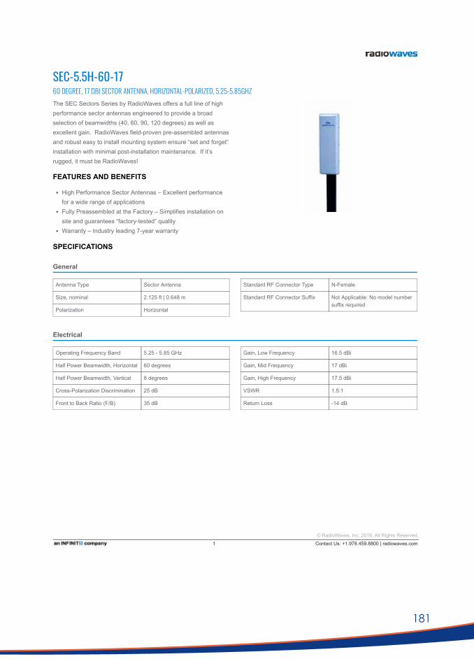
181
Antenna Type Sector Antenna
Size, nominal 2.125 ft | 0.648 m
Polarization Horizontal
Standard RF Connector Type NFemale
Standard RF Connector Suffix Not Applicable: No model numbersuffix required
Operating Frequency Band 5.25 5.85 GHz
Half Power Beamwidth, Horizontal 60 degrees
Half Power Beamwidth, Vertical 8 degrees
CrossPolarization Discrimination 25 dB
Front to Back Ratio (F/B) 35 dB
Gain, Low Frequency 16.5 dBi
Gain, Mid Frequency 17 dBi
Gain, High Frequency 17.5 dBi
VSWR 1.5:1
Return Loss 14 dB
SPECIFICATIONS
General
Electrical
SEC-5.5H-60-1760 DEGREE, 17 DBI SECTOR ANTENNA, HORIZONTAL-POLARIZED, 5.25-5.85GHZThe SEC Sectors Series by RadioWaves offers a full line of highperformance sector antennas engineered to provide a broadselection of beamwidths (40, 60, 90, 120 degrees) as well asexcellent gain. RadioWaves fieldproven preassembled antennasand robust easy to install mounting system ensure “set and forget”installation with minimal postinstallation maintenance. If it’srugged, it must be RadioWaves!
FEATURES AND BENEFITS
High Performance Sector Antennas – Excellent performancefor a wide range of applicationsFully Preassembled at the Factory – Simplifies installation onsite and guarantees “factorytested” qualityWarranty – Industry leading 7year warranty
© RadioWaves, Inc. 2018. All Rights Reserved.1 Contact Us: +1.978.459.8800 | radiowaves.com

182
PTP 820S SPECIFICATION SHEET
Rev05292017
PTP 820SLicensed Microwave Radio
All-Outdoor Specifications RADIO• 6-38 GHz • 1+0, 1+1 HSB, 2+0 Radio Features • Protection: 1+1 HSB • QPSK to 2048 QAM w/ACM • Advanced Frequency Reuse (AFR)
ETHERNETEthernet Interfaces • Traffic Interfaces – 1 x 10/100/1000Base-T
(RJ-45) and 2 x 1000base-X (SFP) or 2 x 10/100/1000 Base-T (electrical SFP)
• Management Interface - 1 x 10/100 Base-T (RJ-45)
• Optical SFP Types - Optical 1000Base-LX (1310 nm) or SX (850nm) Note: SFP devices must be of industrial grade (-40°C to +85°C)
Ethernet Features • MTU – 9600 Bytes • Quality of Service
o Multiple Classification criteria (VLAN ID, p-bits, IPv4, DSCP, IPv6 TC, MPLS EXP)
o 8 priority queues o Deep buffering (configurable up to
64 Mbit per queue) o WRED o Hierarchical QoS – high service
granularity* o P-bit marking/remarking
• 4K VLANs • VLAN add/remove/translate • Frame Cut Through – controlled latency
and PDV for delay sensitive applications • Header De-Duplication – Capacity
boosting by eliminating inefficiency in all layers (L2, MPLS, L3, L4, Tunneling – GTP for LTE, GRE)
• Adaptive Bandwidth Notification (ABN) • Network Resiliency - G.8032 and Multiple
Spanning Tree Protocol (MSTP)* • Ethernet OAM – ITU-T Y.1731 FM, ITU-T
Y.1731 PM*
SYNCHRONIZATIONSynchronization Distribution • Sync Distribution over any traffic interface
(GE/FE) • Sync-E (ITU-T G.8261, G.8262) • SSM/ESMC Support for ring/mesh
applications (ITU-T G.8264) • Sync-E Regenerator mode, providing PRC
grade (ITU-T G.811) performance for smart pipe applications.
IEEE-1588 • Optimized Transport for reduced PDV • IEEE-1588 TC STANDARDMEF • Carrier Ethernet 2.0 (CE 2.0)** Supported Ethernet Standards • 10/100/1000base-T/X (IEEE 802.3) • Ethernet VLANs (IEEE 802.3ac) • Virtual LAN (VLAN, IEEE 802.1Q) • Class of service (IEEE 802.1p) • Provider bridges (QinQ – IEEE 802.1ad) • Link aggregation (IEEE 802.3ad) • Auto MDI/MDIX for 1000baseT • RFC 1349: IPv4 TOS • RFC 2474: IPv4 DSCP • RFC 2460: IPv6 Traffic Classes Security • AES 256-bit Encryption • Secured protocols (HTTPS, SNMPV3, SSH,
SFTP) • Radius authentication and authorization Standards Compliance • EMC: EN 301 489-1, EN 301 489-4, Class B
(Europe), FCC 47 CFR, part 15, class B (US), ICES-003, Class B (Canada), TEC/EMI/TEL-001/01, Class B (India)
• Surge: EN61000-4-5, Class 4 (for PWR and ETH1/PoE ports)
• Safety: EN 60950-1, IEC 60950-1, UL 60950-1, CSA-C22.2 No.60950-1, EN
60950-22, UL 60950-22, CSAC22.2.60950-22
• Ingress Protection: IP66-compliant • Storage: ETSI EN 300 019-1-1 Class 1.2 • Transportation: ETSI EN 300 019-1-2 Class
2.3
TECHNICAL SPECIFICATIONMechanical Specifications • Dimensions: 230mm(H), 233mm(W),
98mm(D), 6.0kg • Pole Diameter Range (for Remote Mount
Installation): 8.89 cm – 11.43 cm Environmental Specifications • -33°C to +55°C (-45°C to +60°C extended) Power Input Specifications • Standard Input: -48 VDC • IDU DC Input range: -40 to -60 VDC Power Consumption Specifications • Maximum Power Consumption 6-11 GHz:
40W; 13-38 GHz: 35W
PoE Injector Mechanical Specifications • Dimensions – 134mm(H), 190mm(W),
62mm(D), 1 kg
PoE Injector Environmental Specifications • 33°C to +55°C (-45°C to +60°C extended)
PoE Injector Power Input Specifications • Standard Input: -48 or +24 VDC (Optional) • DC Input range: ±(18/40.5 to 60) VDC
(+18VDC extended range is supported as part of the nominal +24VDC support)
PoE Injector Interfaces • GbE Data Port supporting
10/100/1000Base-T • Power-Over-Ethernet (PoE) Port • DC Power Port –40V to -60V (a PoE
supporting two redundant DC feeds each supporting ±(18-60)V is available)
* Planned for future release. ** Certification pending.
K & Ka-band equipment datasheets
Microwave PTP:

183
PTP 820S SPECIFICATION SHEET
Rev05292017
Specifications
TRANSMIT POWER Frequency (GHz)
Transmit Power (dBm) 6 7 8 10-11 13-15 18 23 24 UL HP 26 28-38 QPSK 29 28 28 27 24 22 20 18 21 18 8 PSK 29 28 28 27 24 22 20 18 21 18
16 QAM 28 27 27 26 23 21 20 18 20 17 32 QAM 27 26 26 25 22 20 20 18 19 16 64 QAM 27 26 26 25 22 20 20 18 19 16
128 QAM 27 26 26 25 22 20 20 18 19 16 256 QAM 27 26 24 25 20 20 18 16 17 14 512 QAM 25 24 24 24 20 18 18 16 17 14
1024 QAM 25 24 24 23 20 18 17 15 16 13 2048 QAM 23 22 22 21 18 16 16 14 15 12
RECEIVE SENSITIVITY Frequency (GHz)
Modulation Channel Spacing 6 7 8 10 11 13 15 18 23 24 26 28-31 32 38
QPSK
3.5 & 5 MHz
-96.5 -96.0 -96.0 -95.5 -96.5 -95.5 -94.5 -96.0 -95.0 -94.5 -94.5 -94.5 -94.0 -94.0
16 QAM -90.0 -89.0 -89.0 -89.0 -89.5 -88.5 -88.0 -89.0 -88.0 -87.5 -88.0 -87.5 -87.5 -87.0
32 QAM -86.5 -85.5 -85.5 -85.5 -86.0 -85.0 -84.5 -85.5 -84.5 -84.0 -84.5 -84.0 -84.0 -83.5
64 QAM -83.0 -82.5 -82.5 -82.0 -83.0 -82.0 -81.0 -82.5 -81.5 -81.0 -81.0 -81.0 -80.5 -80.5
128 QAM -79.5 -79.0 -79.0 -78.5 -79.5 -78.5 -77.5 -79.0 -78.0 -77.5 -77.5 -77.5 -77.0 -77.0
256 QAM -76.5 -75.5 -75.5 -75.5 -76.5 -75.0 -74.5 -75.5 -75.0 -74.5 -74.5 -74.0 -74.0 -73.5
QPSK
7 MHz
-93.5 -93.0 -93.0 -92.5 -93.5 -92.5 -91.5 -93.0 -92.0 -91.5 -91.5 -91.5 -91.0 -91.0
8 PSK -87.5 -87.0 -87.0 -86.5 -87.5 -86.5 -85.5 -87.0 -86.0 -85.5 -85.5 -85.5 -85.0 -85.0
16 QAM -87.0 -86.5 -86.5 -86.0 -87.0 -86.0 -85.0 -86.5 -85.5 -85.0 -85.0 -85.0 -84.5 -84.5
32 QAM -83.5 -83.0 -83.0 -82.5 -83.5 -82.5 -81.5 -83.0 -82.0 -81.5 -81.5 -81.5 -81.0 -81.0
64 QAM -80.5 -80.0 -80.0 -79.5 -80.5 -79.5 -78.5 -80.0 -79.0 -78.5 -78.5 -78.5 -78.0 -78.0
128 QAM -77.5 -76.5 -76.5 -76.5 -77.5 -76.0 -75.5 -76.5 -76.0 -75.5 -75.5 -75.0 -75.0 -74.5
256 QAM -74.0 -73.5 -73.5 -73.0 -74.0 -73.0 -72.0 -73.5 -72.5 -72.0 -72.0 -72.0 -71.5 -71.5
512 QAM -72.0 -71.5 -71.5 -71.0 -72.0 -71.0 -70.0 -71.5 -70.5 -70.0 -70.0 -70.0 -69.5 -69.5
1024 QAM (strong FEC) -68.5 -68.0 -68.0 -67.5 -68.5 -67.5 -66.5 -68.0 -67.0 -66.5 -66.5 -66.5 -66.0 -66.0
1024 QAM (light FEC) -68.0 -67.0 -67.0 -67.0 -67.5 -66.5 -66.0 -67.0 -66.0 -65.5 -66.0 -65.5 -65.5 -65.0
QPSK
10 MHz
-92.0 -91.5 -91.5 -91.0 -92.0 -91.0 -90.0 -91.5 -90.5 -87.0 -90.0 -90.0 -89.5 -89.0
8 PSK -87.0 -86.0 -86.0 -86.0 -87.0 -85.5 -85.0 -86.0 -85.5 -81.5 -85.0 -84.5 -84.5 -84.0
16 QAM -85.5 -85.0 -85.0 -84.5 -85.5 -84.5 -83.5 -85.0 -84.0 -80.5 -83.5 -83.5 -83.0 -82.5
32 QAM -82.0 -81.5 -81.5 -81.0 -82.0 -81.0 -80.0 -81.5 -80.5 -77.0 -80.0 -80.0 -79.5 -79.0
64 QAM -79.0 -78.5 -78.5 -78.0 -79.0 -77.5 -77.0 -78.5 -77.5 -74.0 -77.0 -77.0 -76.5 -76.0
128 QAM -75.5 -75.0 -75.0 -74.5 -75.5 -74.5 -73.5 -75.0 -74.0 -70.5 -73.5 -73.5 -73.0 -72.5
256 QAM -72.5 -72.0 -72.0 -71.5 -72.5 -71.5 -70.5 -72.0 -71.0 -67.5 -70.5 -70.5 -70.0 -69.5
512 QAM -70.0 -69.5 -69.5 -69.0 -70.0 -68.5 -68.0 -69.5 -68.5 -65.0 -68.0 -68.0 -67.5 -67.0
1024 QAM (strong FEC) -67.0 -66.5 -66.5 -66.0 -67.0 -66.0 -65.0 -66.5 -65.5 -62.0 -65.0 -65.0 -64.5 -64.0 1024 QAM (light FEC) -66.5 -65.5 -65.5 -65.5 -66.5 -65.0 -64.5 -65.5 -65.0 -61.0 -64.5 -64.0 -64.0 -63.5
QPSK
14 MHz
-90.5 -90.0 -90.0 -89.5 -90.5 -89.5 -88.5 -90.0 -89.0 -88.5 -88.5 -88.5 -88.0 -88.0
8 PSK -84.5 -84.0 -84.0 -83.5 -84.5 -83.5 -82.5 -84.0 -83.0 -82.5 -82.5 -82.5 -82.0 -82.0
16 QAM -83.5 -83.0 -83.0 -82.5 -83.5 -82.5 -81.5 -83.0 -82.0 -81.5 -81.5 -81.5 -81.0 -81.0
32 QAM -80.5 -79.5 -79.5 -79.5 -80.5 -79.0 -78.5 -79.5 -79.0 -78.5 -78.5 -78.0 -78.0 -77.5
64 QAM -77.5 -76.5 -76.5 -76.5 -77.5 -76.0 -75.5 -76.5 -76.0 -75.5 -75.5 -75.0 -75.0 -74.5
128 QAM -74.0 -73.5 -73.5 -73.0 -74.0 -73.0 -72.0 -73.5 -72.5 -72.0 -72.0 -72.0 -71.5 -71.5

184
PTP 820S SPECIFICATION SHEET
Rev05292017
Frequency (GHz)
Modulation Channel Spacing 6 7 8 10 11 13 15 18 23 24 26 28-31 32 38
256 QAM
14 MHz
-71.5 -70.5 -70.5 -70.5 -71.0 -70.0 -69.5 -70.5 -69.5 -69.0 -69.5 -69.0 -69.0 -68.5
512 QAM -68.5 -68.0 -68.0 -67.5 -68.5 -67.5 -66.5 -68.0 -67.0 -66.5 -66.5 -66.5 -66.0 -66.0
1024 QAM (strong FEC) -65.5 -65.0 -65.0 -64.5 -65.5 -64.5 -63.5 -65.0 -64.0 -63.5 -63.5 -63.5 -63.0 -63.0
1024 QAM (light FEC) -65.0 -64.0 -64.0 -64.0 -65.0 -63.5 -63.0 -64.0 -63.5 -63.0 -63.0 -62.5 -62.5 -62.0
QPSK
20 MHz
-89.0 -88.5 -88.5 -88.0 -89.0 -88.0 -87.0 -88.5 -87.5 -84.0 -87.0 -87.0 -86.5 -86.0
8 PSK -84.0 -83.5 -83.5 -83.0 -84.0 -83.0 -82.0 -83.5 -82.5 -79.0 -82.0 -82.0 -81.5 -81.0
16 QAM -82.5 -82.0 -82.0 -81.5 -82.5 -81.0 -80.5 -82.0 -81.0 -77.5 -80.5 -80.5 -80.0 -79.5
32 QAM -79.0 -78.5 -78.5 -78.0 -79.0 -77.5 -77.0 -78.5 -77.5 -74.0 -77.0 -77.0 -76.5 -76.0
64 QAM -76.0 -75.0 -75.0 -75.0 -76.0 -74.5 -74.0 -75.0 -74.5 -70.5 -74.0 -73.5 -73.5 -73.0
128 QAM -73.0 -72.0 -72.0 -72.0 -73.0 -71.5 -71.0 -72.0 -71.5 -67.5 -71.0 -70.5 -70.5 -70.0
256 QAM -70.0 -69.5 -69.5 -69.0 -70.0 -68.5 -68.0 -69.5 -68.5 -65.0 -68.0 -68.0 -67.5 -67.0
512 QAM -67.5 -66.5 -66.5 -66.5 -67.5 -66.0 -65.5 -66.5 -66.0 -62.0 -65.5 -65.0 -65.0 -64.5
1024 QAM (strong FEC) -64.5 -63.5 -63.5 -63.5 -64.5 -63.0 -62.5 -63.5 -63.0 -59.0 -62.5 -62.0 -62.0 -61.5
1024 QAM (light FEC) -63.5 -63.0 -63.0 -62.5 -63.5 -62.5 -61.5 -63.0 -62.0 -58.5 -61.5 -61.5 -61.0 -60.5
2048 QAM -60.0 -59.5 -59.5 -59.0 -60.0 -59.0 -58.0 -59.5 -58.5 -55.0 -58.0 -58.0 -57.5 -57.0
QPSK
25MHz
-87.5 -86.5 -86.5 -86.5 -87.0 -86.0 -85.5 -86.5 -85.5 -82.0 -85.5 -85.0 -85.0 -84.0
8 PSK -82.5 -82.0 -82.0 -81.5 -82.5 -81.5 -80.5 -82.0 -81.0 -77.5 -80.5 -80.5 -80.0 -79.5
16 QAM -80.5 -80.0 -80.0 -79.5 -80.5 -79.5 -78.5 -80.0 -79.0 -75.5 -78.5 -78.5 -78.0 -77.5
32 QAM -77.5 -77.0 -77.0 -76.5 -77.5 -76.0 -75.5 -77.0 -76.0 -72.5 -75.5 -75.5 -75.0 -74.5
64 QAM -74.5 -74.0 -74.0 -73.5 -74.5 -73.5 -72.5 -74.0 -73.0 -69.5 -72.5 -72.5 -72.0 -71.5
128 QAM -71.5 -71.0 -71.0 -70.5 -71.5 -70.5 -69.5 -71.0 -70.0 -66.5 -69.5 -69.5 -69.0 -68.5
256 QAM -68.5 -67.5 -67.5 -67.5 -68.5 -67.0 -66.5 -67.5 -67.0 -63.0 -66.5 -66.0 -66.0 -65.5
512 QAM -66.0 -65.0 -65.0 -65.0 -66.0 -64.5 -64.0 -65.0 -64.5 -60.5 -64.0 -63.5 -63.5 -63.0
1024 QAM (strong FEC) -63.0 -62.5 -62.5 -62.0 -63.0 -61.5 -61.0 -62.5 -61.5 -58.0 -61.0 -61.0 -60.5 -60.0
1024 QAM (light FEC) -62.5 -61.5 -61.5 -61.5 -62.5 -61.0 -60.5 -61.5 -61.0 -57.0 -60.5 -60.0 -60.0 -59.5
2048 QAM -58.5 -58.0 -58.0 -57.5 -58.5 -57.0 -56.5 -58.0 -57.0 -53.5 -56.5 -56.5 -56.0 -55.5
QPSK
28 MHz ACCP
-87.5 -87.0 -87.0 -86.5 -87.5 -86.5 -85.5 -87.0 -86.0 -85.5 -85.5 -85.5 -85.0 -85.0
8 PSK -83.0 -82.5 -82.5 -82.0 -83.0 -82.0 -81.0 -82.5 -81.5 -81.0 -81.0 -81.0 -80.5 -80.5
16 QAM -81.0 -80.5 -80.5 -80.0 -81.0 -79.5 -79.0 -80.5 -79.5 -79.0 -79.0 -79.0 -78.5 -78.0
32 QAM -77.5 -77.0 -77.0 -76.5 -77.5 -76.0 -75.5 -77.0 -76.0 -75.5 -75.5 -75.5 -75.0 -74.5
64 QAM -74.5 -74.0 -74.0 -73.5 -74.5 -73.0 -72.5 -74.0 -73.0 -72.5 -72.5 -72.5 -72.0 -71.5
128 QAM -71.5 -70.5 -70.5 -70.5 -71.0 -70.0 -69.5 -70.5 -69.5 -69.0 -69.5 -69.0 -69.0 -68.5
256 QAM -68.5 -67.5 -67.5 -67.5 -68.0 -67.0 -66.5 -67.5 -66.5 -66.0 -66.5 -66.0 -66.0 -65.5
512 QAM -66.0 -65.0 -65.0 -65.0 -66.0 -64.5 -64.0 -65.0 -64.5 -64.0 -64.0 -63.5 -63.5 -63.0
1024 QAM (strong FEC) -63.0 -62.5 -62.5 -62.0 -63.0 -61.5 -61.0 -62.5 -61.5 -61.0 -61.0 -61.0 -60.5 -60.0
1024 QAM (light FEC) -62.0 -61.5 -61.5 -61.0 -62.0 -60.5 -60.0 -61.5 -60.5 -60.0 -60.0 -60.0 -59.5 -59.0
2048 QAM -58.5 -58.0 -58.0 -57.5 -58.5 -57.0 -56.5 -58.0 -57.0 -56.5 -56.5 -56.5 -56.0 -55.5
QPSK
30 MHz &
28 MHz ACAP
-87.5 -87.0 -87.0 -86.5 -87.5 -86.0 -85.5 -87.0 -86.0 -85.5 -85.5 -85.5 -85.0 -84.5
8 PSK -82.5 -81.5 -81.5 -81.5 -82.5 -81.0 -80.5 -81.5 -81.0 -80.5 -80.5 -80.0 -80.0 -79.0
16 QAM -81.0 -80.0 -80.0 -80.0 -80.5 -79.5 -79.0 -80.0 -79.0 -78.5 -79.0 -78.5 -78.5 -77.5
32 QAM -77.0 -76.5 -76.5 -76.0 -77.0 -76.0 -75.0 -76.5 -75.5 -75.0 -75.0 -75.0 -74.5 -74.0
64 QAM -74.5 -73.5 -73.5 -73.5 -74.0 -73.0 -72.5 -73.5 -72.5 -72.0 -72.5 -72.0 -72.0 -71.0
128 QAM -71.0 -70.5 -70.5 -70.0 -71.0 -70.0 -69.0 -70.5 -69.5 -69.0 -69.0 -69.0 -68.5 -68.0
256 QAM -68.0 -67.5 -67.5 -67.0 -68.0 -67.0 -66.0 -67.5 -66.5 -66.0 -66.0 -66.0 -65.5 -65.0
512 QAM -66.0 -65.5 -65.5 -65.0 -66.0 -64.5 -64.0 -65.5 -64.5 -64.0 -64.0 -64.0 -63.5 -63.0
1024 QAM (strong FEC) -63.0 -62.0 -62.0 -62.0 -62.5 -61.5 -61.0 -62.0 -61.0 -60.5 -61.0 -60.5 -60.5 -59.5
1024 QAM (light FEC) -62.0 -61.0 -61.0 -61.0 -62.0 -60.5 -60.0 -61.0 -60.5 -60.0 -60.0 -59.5 -59.5 -58.5
2048 QAM -58.0 -57.5 -57.5 -57.0 -58.0 -56.5 -56.0 -57.5 -56.5 -56.0 -56.0 -56.0 -55.5 -55.0

185
Antenna Type Standard Performance ParabolicReflector Antenna
Size, nominal 2 ft | 0.6 m
Polarization Dual
Standard RF Connector Type NFemale
Standard RF Connector Suffix NS (append suffix to modelnumber)
Operating Frequency Band 5.25 5.85 GHz
Half Power Beamwidth, Horizontal 6.2 degrees
Half Power Beamwidth, Vertical 6.2 degrees
CrossPolarization Discrimination 30 dB
Front to Back Ratio (F/B) 38 dB
Gain, Low Frequency 28.5 dBi
Gain, Mid Frequency 29 dBi
Gain, High Frequency 29.5 dBi
VSWR 1.5:1
Return Loss 14 dB
SPECIFICATIONS
General
Electrical
SPD2-5.20.6 M | 2 FT STANDARD PERFORMANCE PARABOLIC REFLECTOR ANTENNA, DUAL-POLARIZED, 5.25-5.85GHZThe SP Standard Performance Series by RadioWaves offers a fullline of cost effective standard performance parabolic antennasengineered to deliver reliable radio links. Designed for bothunlicensed and licensed band applications, RadioWaves fieldproven preassembled SP antennas and robust polemountsensure “set and forget” installation with minimal postinstallationmaintenance. If it’s rugged, it must be RadioWaves!
FEATURES AND BENEFITS
Standard Performance Parabolic Antennas – Excellentperformance for a wide range of licensed and unlicensedapplicationsFully Preassembled at the Factory – Simplifies installation onsite and guarantees “factorytested” qualityWarranty – Industry leading 7year warranty
© RadioWaves, Inc. 2018. All Rights Reserved.1 Contact Us: +1.978.459.8800 | radiowaves.com
Antenna data sheets: K/Ka-band
Directional: parabolic

186
Fine AzimuthAdjustment
+/ 10 degrees
Fine ElevationAdjustment
+/ 30 degrees
Mounting PipeDiameter, Min
2 inch | 5.08 cm
Mounting PipeDiameter, Max
4.5 inch | 11.4 cm
Net Weight 22 lbs | 9.9 kg 26 lbs | 11.7 Kg withRD radome
Wind VelocityOperational
90 mph | 145 km/h
Wind Velocity SurvivalRating
125 mph | 201 km/h
MechanicalConfiguration
SP2
Axial Force (FA) 222 lbs | 988 N 122 lbs | 543 Nm withRD radome
Side Force (FS) 14 lbs | 62 N 24 lbs | 107 Nm withRD radome
Twisting Moment (MT) 225 ftlbs | 305 Nm 194 lbs | 263 Nm withRD radome
OperatingTemperature Range
40 to +60 C
Max Pressure, PSIG,(if waveguideinterface)
5
FCC undeclared
Industry Canada Compliance undeclared
ETSI undeclared
RoHScompliant Yes
Package Type Cardboard
Gross Weight 25 lbs | 11.3 kg
Dimensions, L x W x H 28 x 8 x 28in | 71 x 20 x 71 cm
Shipping Volume 3.63 cu ft | 0.1 cu m
Mechanical
Regulatory Compliance
Shipping Information
*Additional OEM interfaces and adapters may be available. Contact RadioWaves for a complete and current list of available adapters.
© RadioWaves, Inc. 2018. All Rights Reserved.2 Contact Us: +1.978.459.8800 | radiowaves.com

187
www.rfelements.com
Product Datasheet
RF elements®, UltraHorn™ CC are trademarks of RF elements s.r.o., Humenne, Slovakia.All rights of respective trademark owners reserved.
© RF elements 2019
UltraHorn™ CC 5-24 Rev-OCT 2019
Product ID: UH-CC-5-24
UltraHorn™ CC 5-24
PRODUCT DIMENSIONS
V/H Gain (IEEE)90
0
45
90
135
180
135
45
-20 -10-30
5.1 5.2 5.3 5.4 5.5 5.6 5.7 5.8 5.9 6.4
16
24
26
22
18
20
6
14
12
8
10
0
2
4
6.0 6.1 6.2 6.3
Gai
n / d
Bi
AZIMUTH PATTERN ELEVATION PATTERN GAIN
V/H - Port Pattern Azimuth 5.6 GHz V/H - Port Pattern Elevation 5.6 GHzFrequency / GHz
PERFORMANCEFrequency Range 5180 - 6400 MHz
Gain 24 dBi
Azimuth/Elevation BW -3 dB H 11° / V 11°
Azimuth/Elevation BW -6 dB H 16° / V 15°
Polarization Dual Linear H + V
Front-to-Back Ratio 40 dB
Beam Efficiency** 99%
VSWR Max 5180-5850 MHz 1.6
VSWR Max 5850-6400 MHz 1.8
TECHNICAL DATAAntenna Connection 2x N Female Bulkhead Connector
Antenna Type Horn
Materials UV Resistant ABS Plastic, Polycarbonate, Polypropylene, Aluminium, Stainless Steel
Enviromental IP55
Pole Mounting Diameter 30-80 mm (we recommend as close to 80mm as possible)
Temperature -30°C to +55°C (-22°F to +131°F)
Wind Survival 160 km/hour
Wind Loading 197 N at 160 km/hour
Mechanical Adjustment ± 25° Elevation, ± 25° Azimuth
Weight 8.7 Kg / 19.1 lbs – single unit 9.7 Kg / 21.4 lbs – single unit incl. package
Single Unit Retail Box: 570 x 570 x 660 mm / 22.4 x 22.4 x 26 inch
90
0
45
90
135
180
135
45
-20 -10-30
ULTIMATE NOISE-REJECTING DIRECTIONAL HORN ANTENNA WITH CARRIER CLASS PERFORMANCE
The UltraHorn™ CC 5-24 is a horn antenna with high gain, high directivity, and symmetrical radiation pattern. Symmetrical beam with equal horizontal and vertical beam widths, combined with zero side lobes, offers impeccable performance in terms of interference rejection. No need to spend extra money for radomes, shrouds, or any other additional shielding.
UltraHorn™ CC 5-24 Antenna is suitable for point-to-point links in high noise areas. Thanks to the unique radiation characteristics, UltraHorn™ CC 5-24 delivers excellent performance as narrow beam sector antenna, offering versatile tool for precise network planning. UltraHorn™ CC 5-24 is dual polarization antenna system (H+V) equipped with two N-female connectors.
348mm
635
mm
572mm
615mm
ø45
9mm
**Beam efficiency defined up to first null

188
Addendum I: Complete list of user sites incorporated in investigation
Farm Designation Latitude Longitude Elevation (m)
B10-A -30.3067191 20.0450955 920.09
B11-A -30.2532813 20.6871373 944.31
B13-A -30.6068705 20.4723909 936.63
B14-A -30.0522491 21.012607 876.1
B15-A -29.7388539 20.5383584 941.08
B17-A -30.5213447 20.873845 1002.08
B18-A -30.5203453 20.8729285 996.63
B2-A -30.6292654 20.8888252 901.5
B20-A -29.9240003 19.9568079 977.51
B21-A -30.0076575 20.0814068 980.41
B23-A -30.1022087 20.5945405 885
B24-A -30.1267628 20.4617199 900.81
B26-A -30.4814938 20.0188368 902.58
B29-A -30.042868 20.3026135 904.78
B3-A -30.1293232 21.0671928 886.44
B30-A -30.5304781 20.9759265 960.76
B32-A -29.9714334 20.9118027 884.08
B33-A -30.1208654 20.9509795 905.82
B34-A -30.1203542 20.954976 910.02
B35-A -29.8332275 20.6394729 926.14
B38-A -30.2256389 20.5632117 900.27
B39-A -30.0395174 20.8135479 906
B4-A -30.2983924 20.4260504 933
B40-A -29.9718864 20.8387659 880.88
B41-A -30.4242978 21.2951176 967.39
B42-A -30.0048827 20.697651 873.49
B43-A -30.5728724 20.5208751 934.15
B44-A -29.8591349 20.1060678 974.84
B45-A -30.344109 20.3532522 926.29
B46-A -30.5096435 20.6119891 980.68
B47-A -30.2944097 20.2236768 925.89
B48-A -31.0634367 20.2906804 974.55

189
Farm Designation Latitude Longitude Elevation (m)
B5-A -30.0405233 20.609215 879.39
B50-A -30.1845131 20.8136284 892.74
B51-A -30.089642 20.8508619 879.71
B52-A -29.8496462 20.1890165 959
B54-A -29.8744526 20.3470347 905
B55-A -30.4497542 20.90054 1001.16
B56-A -30.1333414 21.0601943 887
B58-A -30.1118508 19.8917712 919.12
B59-A -30.0745889 19.941146 931.61
B60-A -30.0299533 20.1446878 959.02
B61-A -30.3657483 21.0892461 992.02
B62-A -30.0283495 20.0124512 963.77
B64-A -30.3464791 20.8937957 977.9
B65-A -30.4742242 20.3229493 967.82
B66-A -30.1989872 20.3673963 932.78
B67-A -30.3112429 20.684458 960.55
B69-A -29.766218 20.1080834 980.94
B7-A -30.123678 21.0036991 925
B70-A -30.2154372 20.2705164 923.2
B9-A -30.3420713 20.1942642 926.11
C1-A -30.9704 22.03102 1251.81
C100-A -31.11399 21.49794
C101-A -31.21699 22.25804 1396.16
C102-A -30.9975 22.234 1318.2
C105-A -31.39621 21.60986 1249.7
C107-A -31.18918 21.51966 1231.69
C11-A -31.1187 22.04769 1315.69
C110-A -30.47374 22.3285 1103.39
C111-A -30.91287 22.25215 1301
C113-A -30.82274 22.07548 1167.86
C114-A -30.15692 22.05634
C115-A -30.20525 21.81044 937.53
C116-A -30.21459 22.04823 970.7

190
Farm Designation Latitude Longitude Elevation (m)
C117-A -30.2346 21.5055
C118-A -30.27005 21.64067
C12-A -30.86015 21.95665 1416.63
C120-A -30.35271 21.49433
C121-A -30.36274 22.50221 1121.09
C122-A -30.3952 21.36757
C123-A -30.61382 22.46539 1172.19
C125-A -30.815107 22.09968 1150.21
C126-A -30.86446 22.23392 1271.11
C127-A -30.89759 22.0027 1379
C128-A -30.92849 22.43424 1381.45
C129-A -30.9394 21.84915 1269.85
C14-A -31.15879 22.00802 1299.69
C16-A -30.93547 22.35208 1404.64
C2-A -30.9254 21.99506 1362
C21-A -30.44181 22.45956 1107.8
C26-A -31.04432 21.84605 1292.1
C30-A -31.06841 21.83705 1290.55
C32-A -30.41743 22.34978 1087.55
C34-A -30.77305 22.29511 1160
C40-A -30.75739 22.27763
C43-A -30.96531 22.23434 1318.06
C46-A -30.94884 22.48599 1366.25
C47-A -30.67519 22.54762 1197.05
C50-A -30.70645 22.21962 1105.92
C51-A -30.71082 22.15573 1095.4
C52-A -30.90506 22.30807 1279.57
C59-A -30.93416 22.48102 1354
C60-A -30.95691 21.68213 1311.08
C61-A -30.5418 22.51972 1162.01
C62-A -30.8909 22.65001 1273.96
C64-A -31.1642 21.93352 1283.21
C65-A -30.68627 22.45166 1230.58

191
Farm Designation Latitude Longitude Elevation (m)
C68-A -30.96884 22.51966 1476.04
C7-A -31.07287 22.02819 1322.65
C71-A -30.77116 22.41853 1266.87
C74-A -30.87563 22.30404 1241.56
C76-A -30.77476 22.48711 1269
C79-A -30.95347 22.52708 1359.25
C8-A -30.98274 22.06286 1259.86
C82-A -30.88618 21.94802 1381.62
C85-A -31.26694 21.8077 1230
C86-A -31.07278 21.85636 1279.22
C87-A -31.1639 22.35562 1459.71
C89-A -31.23716 22.33717 1453.78
C9-A -31.36334 21.8707 1273.99
C90-A -31.11175 22.35974 1485.62
C94-A -31.15098 22.38952 1490.27
C99-A -31.12549 22.12844 1332.56
F-B1-A -30.3663666 20.7847013 950
F-B12-A -30.8118056 20.1538558 956.56
F-B16-A -30.6396691 20.0902489 966
F-B19-A -30.2778406 20.5455676 925.18
F-B22-A -30.3630382 21.1877078 939.31
F-B25-A -30.4424872 20.7402406 957.42
F-B27-A -30.4773974 21.4592909 979
F-B28-A -30.2928233 21.0256771 973.82
F-B31-A -30.2247076 21.0548549 942.55
F-B36-A -30.3357737 21.0395944 994.11
F-B37-A -30.2747154 20.8248425 933.34
F-B49-A -30.3308422 20.5342755 914.59
F-B53-A -30.2503556 20.8522719 910.98
F-B57-A -30.6979023 20.1578582 969.16
F-B6-A -30.3192091 21.1828518 930.09
F-B63-A -30.5621969 20.2076858 979.23
F-B68-A -30.2276013 21.1796711 911.57

192
Farm Designation Latitude Longitude Elevation (m)
F-B8-A -30.5184982 20.7175667 1003.9
F-BH19 -30.2741358 20.4798641 960
F-C17-A -30.74678 22.05582 1116
F-C18-A -30.94386 21.87181 1285.43
F-C20-A -30.90403 21.46052
F-C22 -30.85785 21.70916
F-C56-A -30.63168 21.9815 1046.07
F-C75-A -30.66129 22.13107 1076.04
F-C81-A -30.6867 22.02544 1076.7
F-C92-A -30.38971 22.18662 1054.38
F-C97-A -30.73722 22.10366 1104.99
F-G101-B -30.7905846 21.3071003 1121.4
F-G102-C -30.9045223 21.4598066
F-G103-A -30.9072691 21.4388625 1340.91
F-G108-B -31.0225341 21.1675038 1295.17
F-G109-B -31.0361149 21.0991566
F-G11-C -30.3629186 21.1877877
F-G110-A -31.007792 21.0881977 1161.03
F-G122-A -31.022397 21.1928868 1317.85
F-G123-B -31.0277921 21.1680535 1300.04
F-G130-A -31.2337543 21.1357813 1110.82
F-G131-A -31.2532322 21.1604413 1098.59
F-G132-A -31.3573441 21.2885229 1103.25
F-G133-A -31.3660994 21.3022905 1091.93
F-G134-A -31.3587043 21.2400448 1092.12
F-G140-A -31.3442545 20.8468576 1031.94
F-G143-A -31.4076443 20.901289 1060.16
F-G144-A -31.4092763 20.8946101 1061.6
F-G148-A -31.6573576 20.96116 1168.91
F-G153-B -31.2228032 20.9570482 1145.3
F-G156-A -31.6855152 20.9732104 1151.26
F-G20-A -31.2418981 21.2609438
F-G24-B -30.6029189 21.1502072 999.25

193
Farm Designation Latitude Longitude Elevation (m)
F-G26-C -30.9424446 21.1583842 1189
F-G27-B -30.9956924 21.1152233
F-G31-A -31.3497226 20.7926101 1028
F-G33-A -31.5525321 20.5751398 1050.94
F-G36-A -31.5186385 20.5887465 1055.05
F-G5-C -31.2233183 21.0132059 1150
F-G50-C -31.5126278 21.0746614 1140.08
F-G51C -31.5013343 21.1143597 1109.45
F-G52-C -31.5139689 21.0592107 1133.08
F-G53-A -31.5538678 21.0390175
F-G55-A -31.497832 21.1772814
F-G6-C -31.2258086 21.0599109 1120.56
F-G65-A -30.6417938 21.2089741 1031.14
F-G66-A -30.7169703 21.1124189 1111.8
F-G67-A -30.7916178 21.0801396 1071.23
F-G68-A -30.8581278 21.1336456 1106.14
F-G69-A -30.8559877 21.199208 1133
F-G7-A -31.2463286 21.0004845 1169.94
F-G71-B -30.8145288 21.2812969 1185.23
F-G77-A -30.8381925 21.0636917 1070.35
F-G83-A -30.9214695 20.9895299 1090.8
F-G85-B -31.0777492 20.9233318 1142.89
F-G94-A -31.1325509 20.9006437 1121.19
F-V11-B -30.748897 21.6928577 1107.99
F-V12-A -30.8075124 21.782932 1136.98
F-V13-B -30.8521372 21.7864506 1163.76
F-V16-A -30.6176895 21.9212859 1051.37
F-V18-A -30.6323057 21.9820313 1049.89
F-V24-A -30.3113572 22.0153857 993.3
F-V26-A -30.3913213 22.1874646 1058.85
F-V27-A -30.4489034 22.2249338 1049.99
F-V28-A -30.3637676 22.261605 1100.44
F-V29-B -30.3270125 22.2507914 1078.42

194
Farm Designation Latitude Longitude Elevation (m)
F-V30-B -30.2891154 22.2704864 1023.75
F-V37-A -30.2682356 22.1407363 989
F-V38-A -30.2474911 22.1842697 1021.95
F-V39-A -30.2342671 22.2399252 1037.74
F-V78-A -30.3085992 21.3094007
F-V79-B -30.3708306 21.4311312 972.99
F-V80-A -30.355358 21.5104215 1015.49
F-V85-B -30.5088704 21.5277382 996.88
F-V86-B -30.3964036 21.5391316 1007.07
F-V87-B -30.4040203 21.5018485 985.16
F-V88-A -30.3965287 21.3668528 978.33
F-V94-B -30.5797184 21.1410607 986.81
G1-A -31.1401036 21.0211305 1190
G10-A -30.4387967 21.1220087 963
G100-A -31.3077617 20.9033447 1098.06
G104-B -30.8792801 21.3532931 1221.94
G105-C -30.9631751 21.4536617 1354.78
G106-A -30.9648789 21.3922691 1268.44
G107-A -30.9894517 21.26852 1321.97
G111-A -31.1001588 20.989139 1197.94
G112-A -31.3853875 20.9559665 1051.48
G113-A -31.4145443 20.9267393 1050.84
G114-A -30.9707501 21.517356 1362.06
G115-B -31.0265226 21.5425651 1316.73
G116-A -31.1131951 21.4999795 1340.66
G118-A -31.1881406 21.5208981 1230.54
G119-A -31.1125742 21.3584258 1181.49
G12-B -30.9440635 20.8173255 1087
G120-B -30.9820086 21.3462222 1258.63
G121-A -30.9789969 21.3051976 1276.21
G124-C -31.0742703 21.2101028 1235.39
G125-A -31.1308658 21.1732217 1204.52
G126-A -31.1220223 21.205447

195
Farm Designation Latitude Longitude Elevation (m)
G127-A -31.0743675 21.2852232 1310.97
G128-A -31.1291318 21.2565623 1191.95
G129-B -31.1774453 21.2213881 1153
G13-C -31.0327409 20.6731348 1026
G135-A -31.4230882 21.2005542 1159.11
G136-A -31.3916306 21.166062 1111.72
G137-A -31.3442774 21.1037944 1068
G138-A -31.3150267 21.1096228 1080.48
G139-A -31.3286353 21.0748636 1069.96
G14-C -31.1059371 20.6458576 990.63
G141-A -31.3740167 20.8982746 1065.21
G142-A -31.1142098 21.6503183 1285.7
G145-A -31.3333648 20.6317924 1104.97
G146-B -31.2931223 20.7318925 1022.32
G147-C -31.3147522 20.7183665 1030
G149-B -31.6064139 20.8579704 1163.22
G15-C -31.1052063 20.6279035 989.26
G150-B -31.7137598 20.878507 1168.03
G151-C -31.5911225 21.0706341 1154.65
G152-B -30.9569312 21.2237324 1247.93
G154-B -31.6484904 21.1149369 1177.34
G155-A -31.6677243 21.0768514 1188.6
G16-B -31.1268567 20.5785725 998.32
G17-A -31.0238872 20.5707073 978.45
G18-A -31.0662513 20.5591731 981
G19-B -31.1665364 21.2898513 1147.69
G2-A -31.1536036 21.0347691 1171.81
G21-C -31.270496 21.4444434 1159
G22-A -30.9558575 21.6827255
G23-C -30.9475693 21.5892985 1351.87
G25-C -30.9058482 21.2639512 1181.22
G28-A -31.4178008 20.676933 1064.96
G29-A -31.3807624 20.7074283 1043.19

196
Farm Designation Latitude Longitude Elevation (m)
G32-A -31.4478658 20.512304 1035
G34-A -31.5112932 20.5558815 1045.71
G35-A -31.5140625 20.579233 1053.99
G37-C -31.4795472 20.6890915 1095.73
G38-A -31.4303228 20.7994824 1116.16
G39-B -31.4386459 20.7061113 1074
G4 C -31.1706668 21.0195592 1183.66
G40-B -31.4962075 20.7133801 1114.82
G41-A -31.5871036 20.7745071 1142.52
G42-A -31.5936147 20.7352334 1098.01
G43-A -31.589538 20.8199545 1152.83
G44-A -31.5044497 20.8388163 1166
G45-A -31.5012679 20.8645704 1139.89
G46-A -31.4670495 20.9214281 1095.35
G47-A -31.4532236 20.8683768 1108.11
G48-B -31.4267064 20.8843794 1079.39
G49-A -31.5042534 20.9669845 1128.08
G54-A -31.4399151 21.0669097 1086.69
G56-C -31.6240832 21.2025855 1151.81
G57-B -31.5926533 21.1669213 1134.16
G58-A -30.8786547 20.5059847 957.09
G59-A -30.9104892 20.5718047 997.24
G60-A -30.9756293 20.6547872 1002.97
G61-A -30.7944 20.9111163 1027
G62-A -30.4403124 21.2307699 946.25
G63-C -30.4815306 21.3196678 1008.39
G64-A -30.5389114 21.2851033 980.47
G70-A -30.8723714 21.2689092 1210.39
G72-A -30.5865959 21.0620998 975.88
G73-A -30.6292865 20.8892877 961.89
G74-A -30.6547301 20.9881856 998.52
G75-C -30.6889516 20.9921857 1006
G76-A -30.69316 20.9911272 1002.7
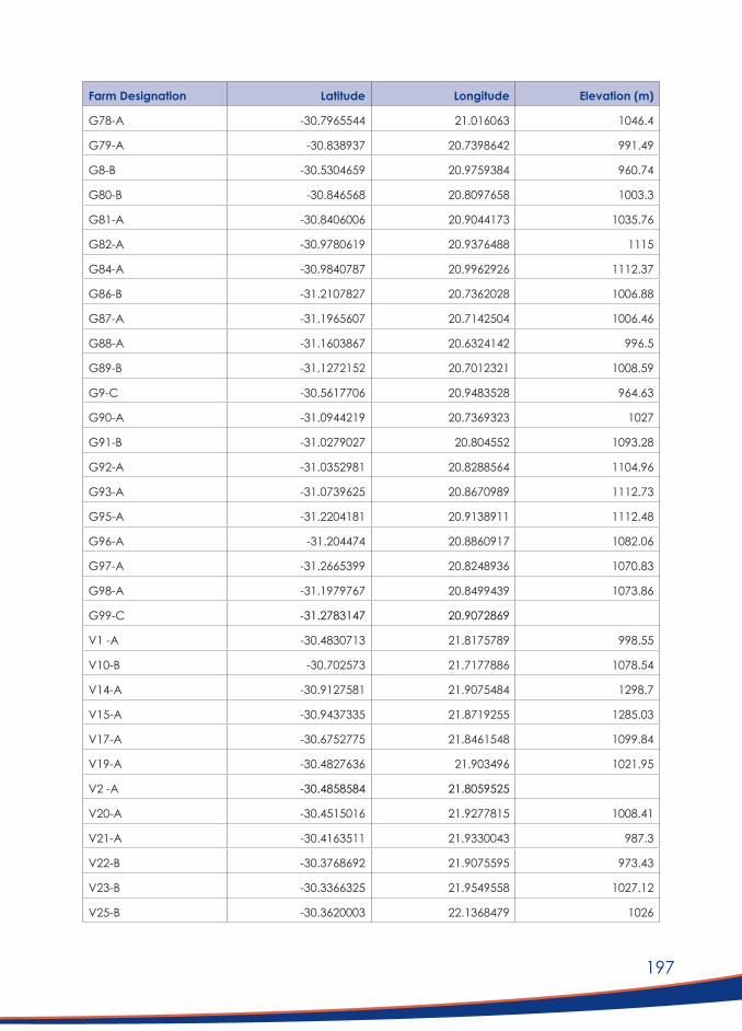
197
Farm Designation Latitude Longitude Elevation (m)
G78-A -30.7965544 21.016063 1046.4
G79-A -30.838937 20.7398642 991.49
G8-B -30.5304659 20.9759384 960.74
G80-B -30.846568 20.8097658 1003.3
G81-A -30.8406006 20.9044173 1035.76
G82-A -30.9780619 20.9376488 1115
G84-A -30.9840787 20.9962926 1112.37
G86-B -31.2107827 20.7362028 1006.88
G87-A -31.1965607 20.7142504 1006.46
G88-A -31.1603867 20.6324142 996.5
G89-B -31.1272152 20.7012321 1008.59
G9-C -30.5617706 20.9483528 964.63
G90-A -31.0944219 20.7369323 1027
G91-B -31.0279027 20.804552 1093.28
G92-A -31.0352981 20.8288564 1104.96
G93-A -31.0739625 20.8670989 1112.73
G95-A -31.2204181 20.9138911 1112.48
G96-A -31.204474 20.8860917 1082.06
G97-A -31.2665399 20.8248936 1070.83
G98-A -31.1979767 20.8499439 1073.86
G99-C -31.2783147 20.9072869
V1 -A -30.4830713 21.8175789 998.55
V10-B -30.702573 21.7177886 1078.54
V14-A -30.9127581 21.9075484 1298.7
V15-A -30.9437335 21.8719255 1285.03
V17-A -30.6752775 21.8461548 1099.84
V19-A -30.4827636 21.903496 1021.95
V2 -A -30.4858584 21.8059525
V20-A -30.4515016 21.9277815 1008.41
V21-A -30.4163511 21.9330043 987.3
V22-B -30.3768692 21.9075595 973.43
V23-B -30.3366325 21.9549558 1027.12
V25-B -30.3620003 22.1368479 1026

198
Farm Designation Latitude Longitude Elevation (m)
V3 -A -30.504429 21.7758725 993.94
V31-A -30.1364927 22.2382851 1010.45
V32-A -30.1936502 22.309381 1019.03
V33-B -30.1944298 22.2837092 1012.09
V34-B -30.2154281 22.0466864 967.39
V35-A -30.2164294 22.050248 968.15
V36-A -30.2265545 22.0468805 970.23
V4 -A -30.6667589 21.729161 1057.63
V40-A -30.2330298 22.325518 1013.69
V41-A -30.460156 22.3833444 1102.66
V42-A -30.476464 22.3310499 1083.17
V43-A -30.4174291 22.3498897 1087.64
V44-A -30.1266663 22.1759389 1014
V45-A -30.082623 22.2415623 1025.65
V46-A -30.0600761 22.2796615 1030.27
V47-A -30.0828564 22.312488 1034.28
V48-A -30.121071 22.3242939 1014.86
V49-A -30.0894805 22.3712029 1055.96
V5 -A -30.6646871 21.7258369 1061.97
V50-A -30.1572205 22.0557239 970.61
V51-B -30.0938364 22.1081776 1014.45
V52-A -30.1285748 21.8347222 941.13
V53-A -30.2296271 21.881523 943.17
V54-A -30.1763997 21.9560766 944.96
V55-A -30.14125 21.9692701 959.31
V56-A -30.1112461 21.9334773 969.49
V57-B -30.1601632 21.9192339 938.73
V58-A -30.2071446 21.8101983 938.51
V59-B -30.1781281 21.7690539 932.67
V6 -A -30.6565894 21.7424197 1057.21
V60-A -30.143131 21.7040175 924.87
V61-A -29.9429317 21.6330992 921.09
V62-B -30.0215399 21.6883132 926.46
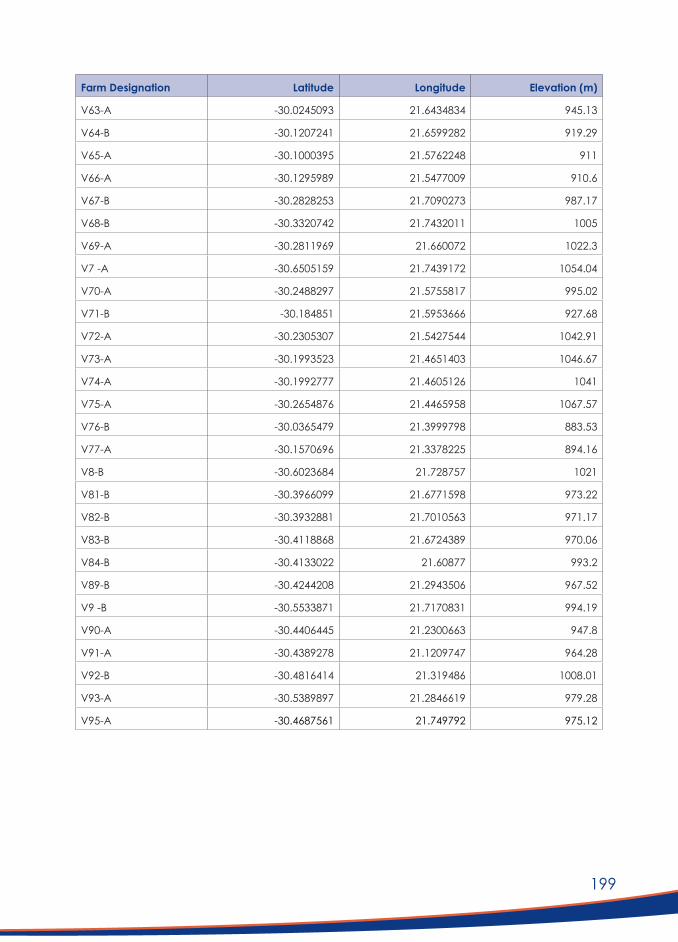
199
Farm Designation Latitude Longitude Elevation (m)
V63-A -30.0245093 21.6434834 945.13
V64-B -30.1207241 21.6599282 919.29
V65-A -30.1000395 21.5762248 911
V66-A -30.1295989 21.5477009 910.6
V67-B -30.2828253 21.7090273 987.17
V68-B -30.3320742 21.7432011 1005
V69-A -30.2811969 21.660072 1022.3
V7 -A -30.6505159 21.7439172 1054.04
V70-A -30.2488297 21.5755817 995.02
V71-B -30.184851 21.5953666 927.68
V72-A -30.2305307 21.5427544 1042.91
V73-A -30.1993523 21.4651403 1046.67
V74-A -30.1992777 21.4605126 1041
V75-A -30.2654876 21.4465958 1067.57
V76-B -30.0365479 21.3999798 883.53
V77-A -30.1570696 21.3378225 894.16
V8-B -30.6023684 21.728757 1021
V81-B -30.3966099 21.6771598 973.22
V82-B -30.3932881 21.7010563 971.17
V83-B -30.4118868 21.6724389 970.06
V84-B -30.4133022 21.60877 993.2
V89-B -30.4244208 21.2943506 967.52
V9 -B -30.5533871 21.7170831 994.19
V90-A -30.4406445 21.2300663 947.8
V91-A -30.4389278 21.1209747 964.28
V92-B -30.4816414 21.319486 1008.01
V93-A -30.5389897 21.2846619 979.28
V95-A -30.4687561 21.749792 975.12
200
NOTES:


P O Box 72135
Lynnwood Ridge 0040
Pretoria South Africa
Tel +27 12 349 6600 l Fax+27 12 349 5461
Email: [email protected]
Academy of Science of South Africa (ASSAf)
PO Box 72135, Lynnwood Ridge, Pretoria, South Africa, 0040
Tel: +27 12 349 6600 • Fax: +27 86 576 9520
E-mail: [email protected]

Academy of Science of South Africa (ASSAf)
ASSAf Research Repository http://research.assaf.org.za/
A. Academy of Science of South Africa (ASSAf) Publications A. ASSAf Consensus Study Reports
2021
Evaluation of Alternative
Telecommunication Technologies for
the Karoo Central Astronomy Advantage Area
Academy of Science of South Africa (ASSAf)
Academy of Science of South Africa (ASSAf)
Academy of Science of South Africa (ASSAf), (2021). Evaluation of Alternative
Telecommunication Technologies for the Karoo Central Astronomy Advantage Area. [Online]
Available at: DOI http://dx.doi.org/10.17159/assaf.2021/0073
http://hdl.handle.net/20.500.11911/199
Downloaded from ASSAf Research Repository, Academy of Science of South Africa (ASSAf)

Academy of Science of South Africa (ASSAf)
ASSAf Research Repository http://research.assaf.org.za/
A. Academy of Science of South Africa (ASSAf) Publications A. ASSAf Consensus Study Reports
2021
Evaluation of Alternative
Telecommunication Technologies for
the Karoo Central Astronomy
Advantage Area
Academy of Science of South Africa (ASSAf)
Academy of Science of South Africa (ASSAf)
Academy of Science of South Africa (ASSAf), (2021). Evaluation of Alternative
Telecommunication Technologies for the Karoo Central Astronomy Advantage Area. [Online]
Available at: DOI http://dx.doi.org/10.17159/assaf.2021/0073
http://hdl.handle.net/20.500.11911/199
Downloaded from ASSAf Research Repository, Academy of Science of South Africa (ASSAf)