The inverse approach of FlexPaint [robotic spray painting
11
T oday, industrial painting automation with robots is very efficient and fast and often used in production lines. However, a big disadvantage is the off-line programming paradigm for the painting robots. This is time-consuming and can be justified economically only for large lot sizes. Hence, a totally new approach to robot programming is required to enable painting of small lot sizes. The objective of the FlexPaint project is to automate robot programming applications of small lot sizes with a very high number of part variants (http://www.flexpaint.org). Figure 1 gives an overview of the part variance used during the project in shape and size. A solution for this ambitious task was found in a close cooperation of researchers in academia and private institutions, together with engineers in small and large enterprises and even customer involvement. It was this close cooperation that made possible the start of a new paradigm for robot programming in industrial automation and, particularly, in painting applications. This article reports the new approach, referred to as an inverse approach, that automatically generates the painting motion. This approach opens new markets for robotic applications. The automatic robot program generation enables, for the first time, painting parts of a lot size of one. The principle of this new approach is based on formalizing the technological knowledge in a geometry library and a process library. Laser range sensors are used to obtain an accurate scan of the part. Process-relevant classes of features are detected as specified in the geometry library. Feature classes are linked in the process library to basic paint strategies, which are grouped to automatically generate the robot paint tool trajectory. Finally collisions-free and exe- cutable robot motions are automatically obtained for the actual robot kinematics. Painting results for several parts, e.g., different motors with gearboxes, will result with this new approach. An Inverse Approach to the Painting Process A method for flexible automation of small lot sizes in painting must fulfill strategic, economic, and financial objectives. Studying example cases within FlexPaint shows that target goals can be specified for typical applica- tions. The average human programming effort for robot painting should be reduced by 75%, and the human BY GEORG BIEGELBAUER, ANDREAS PICHLER, MARKUS VINCZE, CHRISTIAN L. NIELSEN, HENRIK JOHN ANDERSEN, AND KURT HAEUSLER 1070-9932/05/$20.00©2005 IEEE IEEE Robotics & Automation Magazine SEPTEMBER 2005 24 © 1996, 1997 DIGITAL STOCK The Inverse Approach of FlexPaint The Inverse Approach of FlexPaint Automatic Generation of Robot Painting Motions for Unknown Parts
-
Upload
independent -
Category
Documents
-
view
3 -
download
0
Transcript of The inverse approach of FlexPaint [robotic spray painting

Today, industrial painting automation withrobots is very efficient and fast and often used inproduction lines. However, a big disadvantage isthe off-line programming paradigm for the paintingrobots. This is time-consuming and can be justified
economically only for large lot sizes. Hence, a totally new approachto robot programming is required to enable painting of small lot sizes.
The objective of the FlexPaint project is to automate robot programming applications of small lot sizeswith a very high number of part variants (http://www.flexpaint.org). Figure 1 gives an overview of the partvariance used during the project in shape and size. A solution for this ambitious task was found in a closecooperation of researchers in academia and private institutions, together with engineers in small and largeenterprises and even customer involvement. It was this close cooperation that made possible the start of anew paradigm for robot programming in industrial automation and, particularly, in painting applications.
This article reports the new approach, referred to as an inverse approach, that automatically generates thepainting motion. This approach opens new markets for robotic applications. The automatic robot programgeneration enables, for the first time, painting parts of a lot size of one. The principle of this new approachis based on formalizing the technological knowledge in a geometry library and a process library. Laser rangesensors are used to obtain an accurate scan of the part. Process-relevant classes of features are detected asspecified in the geometry library. Feature classes are linked in the process library to basic paint strategies,which are grouped to automatically generate the robot paint tool trajectory. Finally collisions-free and exe-cutable robot motions are automatically obtained for the actual robot kinematics. Painting results for severalparts, e.g., different motors with gearboxes, will result with this new approach.
An Inverse Approach to the Painting ProcessA method for flexible automation of small lot sizes in painting must fulfill strategic, economic, and financialobjectives. Studying example cases within FlexPaint shows that target goals can be specified for typical applica-tions. The average human programming effort for robot painting should be reduced by 75%, and the human
BY GEORG BIEGELBAUER, ANDREAS PICHLER, MARKUS VINCZE, CHRISTIAN L. NIELSEN, HENRIK JOHN ANDERSEN, ANDKURT HAEUSLER
1070-9932/05/$20.00©2005 IEEEIEEE Robotics & Automation Magazine SEPTEMBER 200524
© 1996, 1997 DIGITAL STOCK
The Inverse Approach of FlexPaintThe Inverse Approach of FlexPaintAutomatic Generation of Robot Painting Motions for Unknown Parts

SEPTEMBER 2005 IEEE Robotics & Automation Magazine 25
painting supervision should bereduced by 90%. The FlexPaint sys-tem should provide automaticallygenerated painting strategies, whichreduce the paint material waste bymore than 10%. Providing an eco-nomically efficient solution for lotsizes less than 10,000 is as important asdecreasing the painting errors by 10%.
A further requirement is to assurethat the new system works at least aswell as previously installed paintingprocesses. To obtain a painting qual-ity similar to that of a humanpainter, acquiring the worker’s tech-nical knowledge and trying toimplement it into the FlexPaint sys-tem is necessary. Adapting humanpainting knowledge makes the sys-tem very efficient and flexible andeventually enables a lot size of one.
The objective is to develop amethod that can fulfill the spraypainting task similar to a humanpainter, who is able to evenly paint aparticular geometry he/she has neverseen before. A possible solution is toutilize computer-aided design (CAD)data to calculate a paint path and tomeasure the actual part location.However, three-dimensional (3-D)CAD data is only available to the endusers in rare cases, and, hence, thisapproach is limited to very few appli-cations. Truly flexible automationrequires an inverse approach thatdoes not require any CAD data.
The FlexPaint approach is to auto-matically obtain robotic paint pathsfrom range sensor data and to auto-matically generate a feasible, complete,and executable robot program. Thegoal is to be able to paint any order ofparts coming along the conveyor. Thetechnical challenge is to detect thegeometry of the part on the conveyor,to automatically infer from the geom-etry the robotic painting trajectory,and to automatically generate a colli-sion-free robot program.
Related WorkFirst approaches to obtain an auto-matic tool path in 3-D are knownfrom milling turbine blades by con-sidering planar cross sections [1], [2]
Figure 1. Example of parts to be painted automatically: (a) a FINI compressor tank; (b)a ROSSI gearbox with motor; (c) a truck steering column from MAN; (d) car mirrorsfrom FICO; and (e) small parts from MAN.
(a) (b)
(c)
(d) (e)
Figure 2. A flowchart of the FlexPaint system.
Range Sensor Data
Paint Trajectory
Detection Part Geometry
Generation Paint Trajectory
EstablishmentCollision-Free Robot Motion
Work Cell Model
Procedure Library
Geometry Library
SimplifiedSolid Model
or using a grid cell approach [3]. Assisting the programmerwith virtual reality tools and automated path planning in sim-ulations is another approach [4].
Another related work is the automatic generation of a 3-Dpaint path, which has been attempted in the SmartPainterproject. The painting motion was generated by virtually fold-ing out the surfaces to be painted, putting on the paintingmotion, folding back the surfaces, and letting the paintingmotions follow the unfolded surfaces [5], [6]. However, thisstrategy is only applicable when 3-D models of the objects areavailable and the curvature of the objects is relatively small.
The patented technology from Advanced Robotics Tech-nologies uses a two-dimensional (2-D) digital photo as input
(U.S. Patent 5,429,682). The user decides on the screenwhere to apply paint strokes. The path planning for a robot isthen done automatically.
The FlexPaint IdeaThe FlexPaint approach is based on the observation that theparts in Figure 1 comprise a large number of elementarygeometries with typical characteristics for an entire productfamily. Examples are rib sections (cooling ribs), cylindricalsurfaces [both shown on the motor in Figure 1(b)], and cav-ities [shown at the top of Figure 1(b) and in Figure 1(c)].Another type of surface is the surface of the rearview mir-ror. These surfaces are smooth, free-form surfaces, which
are very difficult to representusing simple geometric attribut-es such as cylinders, spheres, andboxes. Hence, the goal is tospecify these elementary geome-tries in such a way that genericmethods for detecting and forpath planning can be developedand that the variety of geome-tries seen in the applications isencompassed. Figure 2 gives anoverview of how the FlexPaintsystem works.
The “detection part geome-try” module uses the geometricdefinitions of the geometrylibrary to describe the part givenby the range sensor data. Addi-tionally, a simplified solid modelis calculated, which represents aconvex hull approximation of thepart. It is utilized to model thepart when generating collision-free motions.
The geometric part description is used to generate thepainting trajectory of the spray gun. The “establishment col-lision-free robot motions” module takes the tool trajectoryand calculates the actual arm trajectory for a given robotmanipulator and finally generates the program in a specificrobot language.
Detection of Process-Relevant FeaturesThe specification of elementary geometry types is based onthe constraints of the painting process. The idea is to linkelementary geometries to a process model. The elementarygeometry types are defined in the geometry library andrelated to the process knowledge, which is specified in theprocedure library (see Figure 2). For example, a free-formsurface needs painting normal to the surface, a cavity needsspraying into the cavity, and a rib section requires sprayingparallel to the ribs.
Range image processing typically starts from segmentation,e.g., see compar ison in [7]. Finding features is then
IEEE Robotics & Automation Magazine SEPTEMBER 200526
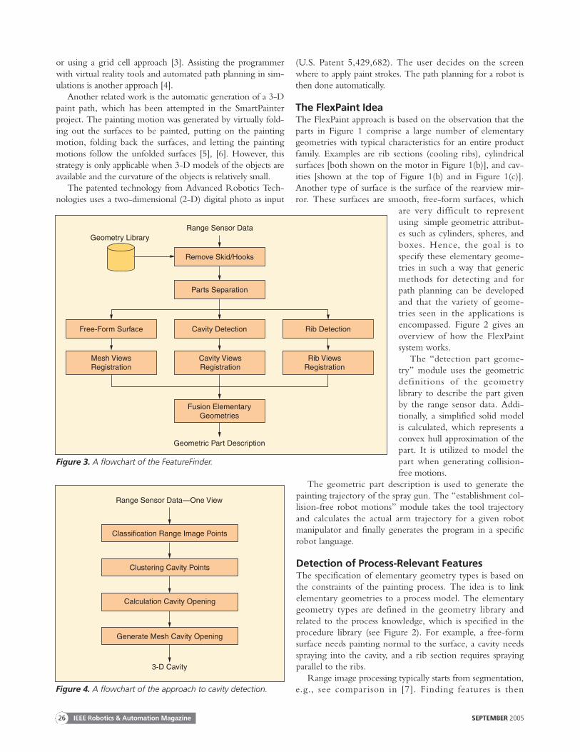
Figure 3. A flowchart of the FeatureFinder.
Range Sensor Data
Remove Skid/Hooks
Parts Separation
Cavity Detection
Fusion ElementaryGeometries
Geometric Part Description
Geometry Library
Free-Form Surface
Mesh ViewsRegistration
Cavity ViewsRegistration
Rib ViewsRegistration
Rib Detection
Figure 4. A flowchart of the approach to cavity detection.
Range Sensor Data—One View
Classification Range Image Points
Clustering Cavity Points
Calculation Cavity Opening
Generate Mesh Cavity Opening
3-D Cavity

constrained to defined geometric properties such as planes orconics [8], [9]. However, for the task at hand, anotherapproach is needed, because the geometry of the features isnot known. The features are defined by attributes (lower thansurrounding rim, parallel ribs). Hence, a more genericapproach to feature detection is required, which detects classesof features. The tool developed is called FeatureFinder. Figure3 shows the procedure.
The range image of the part scanned on the conveyor istaken with a laser triangulation sensor from IVP (Sweden),which is based on the sheet-of-light technique. Triggeringthe camera with a signal of a rotary encoder measures theactual conveyor motion to assure that scans are equidistant.Up to 600 scans/s can be taken. The resolution for a scan-ning width of 2 m is 1.2 mm, which is sufficient for mostpainting applications.
The calibrated images are segmented into the individualparts after subtracting the skid (e.g., FICO mirrors in Figure1) or the hook (e.g., ROSSI gearbox); see Figure 3. The nextstep in Figure 3 is to detect the elementary geometries cavityand rib sections. The remaining part surfaces are free-formsurfaces, which are represented as a mesh using the Visualiza-tion Tool Kit (VTK) (http://public.kitware.com/vtk). Afterdetection, the individual range images are merged in a regis-tration step, first for each type of feature, then for all elemen-tary geometries. Because feature detection is the key torobust trajectory planning, the following explains theapproach in detail.
Cavity DetectionA cavity is defined as a region where surface points are locallylower (in the sense of an outward surface normal) than a sur-rounding rim. The challenge is to develop a robust procedureto handle the noise and shadows of the range data. Figure 4presents the approach.
The triangulation range sensor presents the data with anatural neighborhood of points in the scan line and normal tothe scan line. For each range-image pixel these two orthogo-nal directions are investigated. Figure 5 shows an example ofsuch a scan line.
To classify (the “classification range image points” modulein Figure 4) these cavity points, each pixel, referenced as p inFigure 5, in such a scan line is tested as belonging to a cavityor not. From each pixel pi vectors �v′
i and �v′′i are calculated to
two neighbor pixels pi− j and pi− j−1. This pair of vectors isgenerated outward until pixel p0 is reached. The sequenceterminates either at a rim of the cavity or at the end of thescan line. The change of the vectors must fulfill several crite-ria. The vectors have to turn clockwise, calculated with thecross product
�v′i × �v′′
i < 0, (1)
and the angle α between the two vectors (2) must exceed aminimum. Typical values for this minimum angle are 1.5–5°.
α = arccos
( �v′i · �v′′
i
‖ �v′i‖2 · ‖ �v′′
i ‖2
)(2)
After a clockwise turn has been detected, the vectors mustturn counterclockwise
�v′i × �v′′
i > 0 (3)
and must also exceed a minimum angle (2). If all these criteriaare fulfilled for the pixel pi , one rim of the cavity is found and�v′i = �a i .
This search is repeated for the pixels pi to pn . Notice thatthe vectors first must change counterclockwise (3) and thenclockwise (1) and must fulfill the minimum angle criteria (2).If these criteria are fulfilled with the vector �b i , the oppositeside of the rim is found.
Finding the vectors �a i and �b i identifies pi as a potential cav-ity point. These vectors must match the factor f (4), whichdetermines the shape and depth of the cavity. Typical valuesfor f are 1.1–1.4.
SEPTEMBER 2005 IEEE Robotics & Automation Magazine 27
Figure 5. The range image pixels of a scan line .
z
x y
p0
pi-j
pi−j−1
pi
pn
ci
biniai
”vi
’vi α

‖ �a i‖2 + ‖ �b i‖2
‖ �c i‖2> f, f > 1, �c i = �a i − �b i (4)
The values depend on the noise in the image and have beenselected manually in the prototype. The automatic selectionof the thresholds is the subject of future investigations.
This procedure is repeated for each scan line and is alsoexecuted on lines in the scan direction to find a closed rimaround classified cavity points. The opening vector �n is calcu-lated from (5).
�n =�d
‖ �d‖2, �d =
m∑k=0
�ak + �bk (5)
The vector �n is later also used to find the lid plane of thecavity for the paint planner (compare the “calculation cavityopening” module in Figure 4), where the index m is thenumber of classified cavity points.
A typical problem of range images are shadows due to thetriangulation sensor principle. Using the sheet of light, tech-nology shadow cannot be averted in the range image. Thesemissing shadow points can be added to the range data withan interpolation. Figure 6(b) shows several of these interpo-lated pixels especially located in the flange area of the gear-box and the motor.
The cavity points classified are clustered (see the “clusteringcavity points” module in Figure 4) using VTK methods. Cavitypoints are triangulated using mesh generation in a small neigh-borhood. A connectivity filter clusters a minimum of 30 pointsinto the final cavity patches, as shown in Figure 7.
The rim of the cavity is detected with an accuracy in therange of the resolution 1.2 mm. Using the interpolationpoints, the cavities discovered also include potential areas ofsensor shadow. This is important to detect the full cavityregion for the painting process (see the “generate mesh cavityopening” module in Figure 4). The cavity is then representedas the mesh that covers the opening, or lid, of the cavity. Themesh representation also has the advantage that it allows sig-nificant data reduction to render automated generation of thepainting trajectory fast.
Rib DetectionA rib section is defined by a minimal number (five) ofequidistant parallel lines. Figure 8 outlines the approach.The first step is to use VTK to generate a pseudo 3-D gray-scale image out of the 3-D range data where the gray levelrepresents the depth. Then an edge map is generated usingthe Canny algorithm [10]; compare the “edge detection”module in Figure 8 and see the result in Figure 9.
Figure 9 shows that there are many short line segments.The challenge is now to extract the rib section out of thisedge image by finding long, parallel, and equidistant lines (seethe “grouping parallel line segments” module in Figure 8).The described methods in [11] and [12] have been adopted tosolve this problem.
First, the short edge segments are grouped to a set oflong lines depending on three criteria. The angle A (6)between the axis of a line base segment L b and a line seg-ment L i must not exceed a minimum threshold δa . Themaximum orthogonal distance D0 (7) of the two endpoints of the line segment L i (e i1 and e i2 ) related to theaxis of the line base segment L b must not exceed a mini-mum threshold δn.
A(L b, L i) < δa (6)
max{D0(L b, e i1),D0(L b, e i2)} < δn (7)
IEEE Robotics & Automation Magazine SEPTEMBER 200528
Figure 7. The screen shot of the FeatureFinder shows themesh of the free-form surface (light) and the detected cavitylid planes (dark).
Figure 6. (a) The range image and below the extracted cavitypoints. (b) The interpolated shadow points in the flange areacan be seen in the point cloud.
(a)
(b)

The last criteria must either fulfill (8), where the distanceD of the two endpoints (e i and e j) of the two correspondingline segments must not exceed the minimum threshold δn, or(9), which describes the overlap length ϑ of the line seg-ments, where ϕL i is the orthogonal projection of L i to L j.
D(e i, e j) < δn (8)
ϑ(ϕL i , L j) > 0 (9)
These long lines are grouped to a set of parallel longlines. This is done by applying (6) adopted to long linesegments.
As the last step, the set of long lines is filtered to find sets oflong lines with similar length L (10) and relative closeness(11). The criteria of similar length is determined by a ratio ofthe two lines not exceeding the threshold δpg1 . The closenessis determined by the quotient of the distance between themiddle points (emidi and emidj ) of the lines and the average
length Lavg of the these lines exceeding the threshold δpg2 .
L(L i)
L(L j)> δpg1 (10)
D(emidi, emidj)
Lavg(L i, L j)> δpg2 . (11)
This procedure finds rib sections. The rib lines are mappedback into the 3-D space of the range image. The result of arib section found is presented in Figure 10.
After grouping parallel lines, a feature vector (distance,overlap, length, number of lines) is generated and used forclassifying rib sections. In the last step, the groups are mergedand the boundary of the merged regions calculated usingVTK. Finally, the rib section is again represented with a mesh(see Figure 11).
Planning of the Robot Painting MotionsThe “generate painting trajectory” module, shown in Fig-ure 12, which is referenced as paint planner, specifies a trajec-tory of the spray gun, which satisfies the requested paint
Figure 11. This picture shows the free-form surface (dark) andthe marked rib section (light).
SEPTEMBER 2005 IEEE Robotics & Automation Magazine 29
Figure 8. A flowchart of the approach to rib detection.
Range Sensor Data—One View
Edge Detection
Grouping Parallel Line Segments
Generation Boundary Ribs Section
Mesh Representation Ribs Section
3-D Ribs Section Figure 10. The result of grouping line segments from theedge image using colinearity, proximity, overlap, and paral-lelism. These lines are mapped back into 3-D space.
Figure 9. The result of the Canny edge detection to a pseudo3-D gray-scale image for the range image of Figure 6.

quality. In this module, only spray gun motions are consideredin relation to process quality. Avoidance of collisions betweenthe spray gun and its surroundings are not considered in thismodule, neither is the accessibility of the spray gun. Thesetwo issues are handled by the “collision-avoidance” module inthe next processing step.
The geometric part description is input to the “generatemain surfaces” module in Figure 12 through a file in theVRML format, which is a triangulated geometry specifica-tion. This file not only consists of direct geometric measure-ments but also of a specification of the feature type of thesurrounding geometry for each triangular patch, such asfree-form geometry, rib section, and cavity as generated inthe FeatureFinder.
The process-related input is a procedure library (seeFigure 12) that specifies a number of painting procedures foruse in robotic painting. These procedures describe all geo-metric painting procedures (such as distance and anglesbetween the spray gun and the surface, the speed of the spraygun, and the distance between the paint strokes) in casemore than one stroke must be executed in order to cover thesurface with paint. The parameters of the spray gun (air andpaint flow) are also specified in the painting procedures.
The relationship between the specific geometric part spec-ifications and the painting procedures is specified in thegeometry library (see Figure 12). This relationship ensuresthat the individual areas of the part surfaces are treated asplanned. For instance, a free-form surface requires anothertreatment in order to meet the respective paint quality of anyother kind of cavity structure.
The approach of the “generate painting trajectory”module is to substitute the original part geometry specifica-tion by mesh surfaces into a set of virtual surfaces (planes)having fixed directions in Cartesian space and to relate thepainting procedures to these virtual surfaces instead of relatingthem to the original surfaces. This gives the advantage thatcontinuous paint strokes can be achieved even though the sur-face has an irregular shape.
Establishment of virtual surfaces (see the “generate virtualsurfaces” module in Figure 12) occurs in two steps. In the firststep, a number of main faces are specified. The main faceshave no position, but only a normal vector direction in 3-Dspace. The normal vector direction of each patch in the partspecification is evaluated in relation to the orientations of themain faces, and related to that main face for which the devia-tion is smallest. When all patches are related to main faces,they are again sorted into virtual surfaces according to theirrelationship to geometric features and their position in 3-Dspace. Each virtual surface is related to a main face, and it hasthe same normal vector direction as the main face. In contrastto the main faces each virtual surface has a position in 3-Dspace and a feature description. All patches related to a mainface are distributed to a number of virtual surfaces, each rep-resenting only patches of one specific feature description andonly patches that are within a specified distance from the vir-tual surface measured in the direction of the normal vector ofthe virtual surface. The size of each virtual surface is adaptedto cover all patches represented by it. Figure 13 shows thegenerated main faces.
The virtual surfaces are a number of flat regions in 3-Dspace, each representing one feature, and, accordingly, thecorresponding painting procedures are related to them and
IEEE Robotics & Automation Magazine SEPTEMBER 200530
Figure 13. Generation of the main faces on the motor andgearbox (reduced VRML format).
Figure 14. The calculated paint strokes located on the mainfaces.
Figure 12. A flowchart of the generate painting trajectoryreferred to as PaintPlanner.
GeometryLibrary
ProcedureLibrary
Generate Main Surfaces
Geometric Part Description
Generate Virtual Surfaces
Plan Process
Paint Trajectory
specific paint strokes are specified (see the “plan process”module in Figure 12). The paint strokes are calculated andspecified by the use of homogeneous transformations. Theoutput from the module is a file describing the start and stoppositions of the spray gun specified by homogeneous transfor-mations and corresponding to each stroke; a set of paint para-meters are specified. The generation of robot programs innative robot language is performed by the collision-avoidancemodule. Figure 14 presents the calculated paint strokes locatedon the main faces.
Anticollision Detection of the Robot MotionsThe output from the paint planner is a specification of therequired paint trajectories. This description contains the posi-tion and orientation of the start and end pose of the paint gun
for each paint stroke. The paint trajectories were createdwithout consideration of the spatial representation of the paintgun or the kinematics of the robot. The collision avoidancesoftware provided by AMROSE Robotics ApS is responsiblefor converting this task description into a robot program thatresults in the specified paint strokes, while it avoids collisionand respects the limitations of the robot actually used in thepaint cell.
Before the FlexPaint project, the AMROSE tools havebeen successfully used for automatic generation of robot pro-grams in welding and painting applications [13], [14]. Withinthe FlexPaint project, the tools have been adapted to handlethe specific FlexPaint application outlined below.
The AMROSE collision avoidance software (MotionPlan-ner) consists of three independent successive modules: The
“tool planner,” the “robot plan-ner,” and the “output modifier.”These modules gradually refinethe task description provided bythe paint planner until thegeneric task description is finallyconverted into a robot program.Figure 15 is a flowchart showingthe sequence of the modules.
Tool PlannerThe first module in the chain isthe tool planner. If the originaltask description results in colli-sions between the paint gunand the par t, then the toolplanner will make the minimal
SEPTEMBER 2005 IEEE Robotics & Automation Magazine 31
Figure 15. A flowchart showing the AMROSE modules referred to as MotionPlanner.
Workpiece andPaint Gun Model
Task Description/Paint Trajectories (.tag file)
Collision-Free Paint Trajectories (.tag file)
Collision-Free Robot Motion (.tag file)
Robot/WorkcellModel
Robot ControlSpec. Setup
Paint Planner
Robot Program
Tool Planner
Robot Planner
Output Modifier
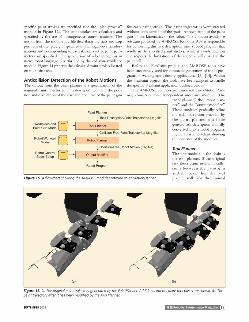
Figure 16. (a) The original paint trajectory generated by the PaintPlanner. Additional intermediate tool poses are shown. (b) Thepaint trajectory after it has been modified by the Tool Planner.
(a) (b)

modification of the task to remove the collisions. The toolplanner has the freedom to modify the pose of the paint gunby translating and rotating it around the specified tool centerpoint within certain limits specified by the paint procedure.The tool planner can also refine the paint trajectory byinserting additional targets if it is necessary to move the toolaround an obstacle or through a narrow passage. The combi-nation of strategies by which the tool planner modifies apaint trajectory is programmable and can hence be controlledby the selected paint procedure. In addition to the taskdescription, the tool planner also takes geometry files withspatial information about the paint tool and the part beingpainted as input. Figure 16 shows an example of a paint tra-
jectory generated by the paint planner and the resulting painttrajectory after it has been modified by the tool planner.
The existing tool planner strategies were generalized tohandle paint tasks. The handling of paint events for turningon and off paint flow especially added additional complexity.Another important extension is the ability to specify differ-entiated collision-avoidance behavior for different parts inthe scene, thereby allowing the paint fan to be obstructed bythe hooks or frame holding the part but not the part itself.
Robot PlannerThe robot planner further refines the task description byselecting proper robot configurations and inserting intermedi-ate targets such that the complete robot motion is fullydefined. The input to the robot planner is the collision-freepaint trajectories, and the output is a robot motion that isguaranteed to be collision free and within the limitations ofthe robot, i.e., joint limits and joint speed limits. The built-inpath planner [14], [15] has certain completeness properties,meaning that if a feasible robot path exists, it will eventually befound. The path planner has the ability to handle joint depen-dencies that often exist in paint robot wrists, such as the Hol-low Wrist from ABB, and has the ability to work with thespecial task constraint due to the symmetric paint fan. Havinga symmetric paint fan allows the robot planner an additionalfreedom to make discrete rotations of the paint gun. The pathplanner does not have a general mechanism for avoiding singu-larities because singular configurations are not really a problem.The problem is that joint speeds can reach the upper limit and,hence, force the tool motion to slow down when the robot
IEEE Robotics & Automation Magazine SEPTEMBER 200532
Figure 18. On the left, the sensor setup is shown. The cameras are mounted on the two horizontal bars. The two lasers that spanthe laser plane are mounted on the vertical bar in the middle. The sensor calibration object is fixed to the conveyor frame. On theright, the IRB 5400-02 painting robot from ABB is shown. In the background, two ROSSI parts are shown hanging on the conveyor.
Figure 17. The generated robot program viewed in an off-linesimulation tool.

approaches a singular configuration. This is why we avoid theviolation of joint speed limits instead of avoiding singularities.
Output ModifierFinally, the output modifier converts the collision-free robotmotion into a robot program in the specific language used bythe robot controller.
The resulting robot program can be inspected in a 3-Dsimulation tool such as RobotStudio from ABB or ViewPL3from AMROSE (see Figure 17), but in a real paint line, thegenerated program will be sent directly to the robot controllerand executed when the part reaches the paint cell.
Experimental ResultsThe system is already implemented as a prototype and hasbeen tested in ABB’s technical center in Eichen, Germany.The purpose of these experiments was to prove the basicsystem concept. It was realized that process quality has to beoptimized by establishing validated painting procedures forthe individual geometric primitives. The painting proce-dures used were established by preceding experiments. Theprototype system used two CCD cameras, one laser plane,and one robot (see Figure 18). Since the surface was onlyscanned from one side of the part (see Figure 10 where onlyone side of the cylindrical rib section is detected), it wasonly possible to perform automatic spray painting of thescanned surface. However, it was observed that a uniformpaint layer covers all the free-form, cavity, and rib surfaceson these parts.
The results of processing a ROSSI gearbox with motorare presented. The scanned range image can be seen in Fig-ure 6, and the results from the feature finder, the paint plan-ner, and the motion planner are shown in Figures 7, 11, 13,14, 16, and 17. Figure 19 shows the ABB robot executingautomatically generated collision-free programs. The resultfor the other par ts can be viewed on videos athttp://www.flexpaint.org.
The prototype installation demonstrated its capability ofrealizing the following production constraints: 1) any seriesof parts of the industrial parts shown in Figure 1 can be
scanned, and 2) the motion of the conveyor requires a pro-cessing time of about 30 s. Range image processing requiresabout 5 s on a PC, and path planning can be executed in 30s on a high-end PC.
Conclusions and OutlookWe presented an approach to automatically spray paint partfamilies. The approach uses a sensing cell in front of thepainting cell (see Figure 18), where the part geometry isacquired. From the part geometry, the process-relevant fea-tures are extracted and the corresponding paint routines aregrouped to obtain optimal painting trajectories. Finally, acollision-free robot path and the executable program aregenerated. All steps are fully automatic, and no interventionof an operator is needed. The individual tools (feature find-er, paint planner, and motion planner) exist in prototypeversions. First implementations at industrial users show thatthe approach is feasible.
Presently, automatic painting assumes a nonmoving part.In the near future, conveyor tracking will be implemented.This will enable painting the parts while they, on the movingconveyor, continuously pass by the robot. Another improve-ment will be to avoid robot singularities while painting. Anonline solution is possible where the motion planner works ina closed loop with the robot controller. The problem is thatconventional robot controllers do not allow external softwareto interact with the online control of the robot at a level thatis necessary for online path planning.
At present, mainly convex parts can be painted automatical-ly, while complex concave shapes cannot. ATENSOR plannedto improve the FlexPaint process for commercialization byusing additional sensors mounted on the robot arm to scanwith outside and fixed sensors the sections of the part that arenot visible. Another extension will be methods to automaticallyextract information other than the existing geometric features.
Even though the project is primarily aimed towards robot-ic spray painting, the inverse approach proposed can beapplied to obtaining process motions for a large range ofprocesses in the field of surface treatment. Examples ofprocesses in which the approach can be applied are powderpainting, washing and cleaning with liquid (including high-pressure cleaning), washing and cleaning with physical contactbetween tool and part, degreasing, sandblasting, polishing,sealing (e.g., for corrosion protection), inspection systems,polishing, grinding, deburring, and gluing.
If it is possible to formalize the technological processknowledge into a geometry and process library and to adaptthe process described, this process-oriented approach willenable the production of a lot size of one and become a newrobot programming paradigm.
AcknowledgmentsThis work was mainly supported by the European researchand technical development (RTD) project FlexPaint (GRD1-1999-10693). A patent is pending for the feature finder andthe paint planner.
SEPTEMBER 2005 IEEE Robotics & Automation Magazine 33
Figure 19. The IRB 5400-02 from ABB is shown painting theROSSI part.

KeywordsAutomated robot programming, feature detection, path gen-eration, collision avoidance, spray painting.
References[1] K.S. Kwok, C.S. Louks, and B.J. Driessen, “Rapid 3-D digitizing and
tool path generation for complex shapes,” in Proc. IEEE Int. Conf.Robotics Automation, Leuven, Belgium, 1998, pp. 2789–2794.
[2] X. Sheng and M. Krmker, “Surface reconstruction and extrapolationfrom multiple range images for automatic turbine blades repair,” in Proc.IEEE IECON Conf., Aachen, Germany, 1998, vol. 3, pp. 1315–1320.
[3] W.C. Tse and Y.H. Chen, “A robotic system for rapid prototyping,” inProc. IEEE Int. Conf. Robotics and Automation, Albuquerque, NM, 1997,vol. 3, pp. 1815–1820.
[4] E. Freund, D. Rokossa, and J. Rossmann, “Process-oriented approachto an efficient off-line programming of industrial robots,” in Proc. IEEEIECON Conf., Aachen, Germany, 1998, pp. 208–213.
[5] P. Hertling, L. Hog, L. Larsen, J.W. Perram, and H.G. Petersen, “Taskcurve planning for painting robots—Part I: Process modeling and calibra-tion,” IEEE Trans. Robot. Automat., vol. 12, no. 5, pp. 324–330, Apr. 1996.
[6] M.M. Olsen and H.G.A. Petersen, “A new method for estimating para-meters of a dynamic robot model,” IEEE Trans. Robot. Automat., vol.17, no. 1, pp. 95–100, 2001.
[7] A. Hoover, G. Jean-Babtiste, X. Jiang, P.J. Flynn, H. Bunke, D.B. Gold-gof, D.W. Eggert, A. Fitzgibbon, and R.B. Fisher, “An experimentalcomparison of range image segmentation algorithms,’’ IEEE Trans. Pat-tern Anal. Machine Intell., vol. 18, no. 7, pp. 1–17, 1996.
[8] C. Robertson, R.B. Fisher, N. Werghi, and A.P. Ashbrook, “Fitting ofconstrained feature models to poor 3D data,” in Proc. Adaptive Comput-ing Design Manufacture (ACDM 2000), Plymouth, UK, 2000, pp.149–160.
[9] D. Marshall, G. Lukacs, and R. Martin, “Robust segmentation of prim-itives from range data in the presence of geometric degeneracy,” IEEETrans. Pattern Anal. Machine Intell., vol. 23, no. 3, pp. 304–314, 2001.
[10] J. Canny, “A computational approach to edge detection,’’ IEEE Trans.Pattern Anal. Machine Intell., vol. 8, no. 6, Nov. 1986.
[11] Q. Iqbal and J.K. Aggarwal “Applying perceptual grouping to content-based image retrieval: Building images,” in Proc. IEEE Int. Conf. Comput-er Vision Pattern Recognition, Fort Collins, CO, 1999, vol. 1, pp. 42–48.
[12] D.G. Lowe, “Three-dimensional object recognition from single two-dimensional images,” Artificial Intell., vol. 31, no. 3, pp. 355–395, 1987.
[13] N.J. Jacobsen, K. Ahrentsen, R. Larsen, and L. Overgaard, “Automaticrobot welding in complex ship structures,” in Proc. 9th Int. Conf. Com-puter Application Shipbuilding, Yokohama, Japan, 1997, vol. 1, pp.419–430.
[14] K.K. Gupta and A.P. del Pobil, “Partical motion planning in robotics:Current approaches and future directions.” New York: Wiley, 1998.
[15] J.C. Latombe, Robot Motion Planning. Boston, MA: Kluwer, 1991.
Georg Biegelbauer graduated in 2001 with an M.Sc. degreein the field of computer science from the Vienna University ofTechnology, Austria. Since 2001, he has been a researcher atthe Automation and Control Institute and worked on theEuropean Commission (EC) project FlexPaint. His work isrelated to range sensing for robot applications, and he is cur-rently working on the EC project FibreScope. His interests arerange sensors and three-dimensional imaging.
Andreas Pichler graduated in 2000 with a degree in elec-trical engineering from the Vienna University of Technolo-gy, Austria. From June–August 2002, he worked on the ECproject FlexPaint (G1RD-CT-1999-00033). From October2002–July 2003 he was worked as a visiting researcher at the
Department of Informatics at the Vision Laboratory ofRobert B. Fisher at the University of Edinburgh, Scotland.Since 2004, he has been with Profactor GmbH. His researchinterests include three-dimensional image understanding andits application in robotics and flexible automation.
Markus Vincze graduated in 1988 with a degree inmechanical engineering from Vienna University of Technolo-gy (VUT), Austria, and in 1990 with an M.Sc. from Rensse-laer Polytechnic Institute, New York. He finished his Ph.D. atVUT in 1993. With a three-year grant from the AustrianAcademy of Sciences, he worked as guest researcher at Help-Mate Robotics Inc. and at the Vision Laboratory of GregoryHager at Yale University, Connecticut. Presently, he is withthe Automation and Control Institute at VUT, where he leadsnational and European projects in the area of robust sensingfor service robots and industrial applications. With Hager, heedited an issue, “Robust Vision for Vision-Based Control ofMotion,” for the IEEE and is the author or coauthor of morethan 100 papers. His special interests are vision techniques forreal-world robotics solutions.
Christian L. Nielsen received the M.Sc. degree in com-puter systems engineering from the Maersk Mc-KinneyMoller Institute for Production Technology, University ofSouthern Denmark, in 2000. He is currently employed byAMROSE Robotics ApS, where he works on robotics,motion planning, and industrial software.
Henrik John Andersen started his study at Aalborg Uni-versity, Denmark, in 1990 and finished in 1995 with anM.Sc. degree. He was employed at Aalborg University from1995–2002, where he received his Ph.D. in 2001. Duringthis period, he worked on research projects related to auto-matic process control using robot technologies, and his fieldof teaching was primarily robotics. In 2002, he started hisown company, Inropa Aps, which provides innovative solu-tions for automatic robotized painting.
Kurt Haeusler received the master’s degree (Dipl.-Ing.)and the Ph.D. degree (Dr. techn.) in mechatronics from theUniversity of Linz, Austria, in 1996 and 2002, respectively.From 1996–2003, he was with Profactor Produktions-forschungs GmbH, Steyr, Austria, where he was manager ofa group working on sensor-based robotics and mechatronicssystems. Now he is with the ATENSOR GmbH & CoKG.His research interests include the application of fuzzy-logicsystems to robot motion planning and flexible automation.From February 2000–October 2002, he was the ProjectCoordinator of the European Commission project FlexPaint(G1RD-CT-1999-00033).
Address for Correspondence: G. Biegelbauer, Automationand Control Institute, Vienna University of Technology,Gusshausstrasse 27–29, 1040 Vienna, Austr ia. E-mail:[email protected].
IEEE Robotics & Automation Magazine SEPTEMBER 200534