Self-healing epoxy composites: preparation, characterization and healing performance
Upload
khangminh22Category
view
0download
0
Citation: Säckl, G.; Duchoslav, J.;
Pugstaller, R.; Marchfelder, C.;
Haselgrübler, K.; Aufray, M.; Stifter,
D.; Wallner, G.M. The Interaction of
Waterborne Epoxy/Dicyandiamide
Varnishes with Metal Oxides.
Polymers 2022, 14, 2226. https://
doi.org/10.3390/polym14112226
Academic Editor:
Agnieszka Kowalczyk
Received: 18 March 2022
Accepted: 27 May 2022
Published: 30 May 2022
Publisher’s Note: MDPI stays neutral
with regard to jurisdictional claims in
published maps and institutional affil-
iations.
Copyright: © 2022 by the authors.
Licensee MDPI, Basel, Switzerland.
This article is an open access article
distributed under the terms and
conditions of the Creative Commons
Attribution (CC BY) license (https://
creativecommons.org/licenses/by/
4.0/).
polymers
Article
The Interaction of Waterborne Epoxy/Dicyandiamide Varnisheswith Metal OxidesGary Säckl 1,2,3,*, Jiri Duchoslav 2,4 , Robert Pugstaller 1,3, Cornelia Marchfelder 1,3, Klaus Haselgrübler 2,Maëlenn Aufray 5 , David Stifter 2 and Gernot M. Wallner 1,3
1 Christian Doppler Laboratory for Superimposed Mechanical-Environmental Ageing of Polymeric HybridLaminates (CDL-AgePol), Johannes Kepler University Linz, Altenberger Straße 69, 4040 Linz, Austria;[email protected] (R.P.); [email protected] (C.M.); [email protected] (G.M.W.)
2 Center for Surface and Nanoanalytics (ZONA), Johannes Kepler University Linz, Altenberger Straße 69,4040 Linz, Austria; [email protected] (J.D.); [email protected] (K.H.); [email protected] (D.S.)
3 Institute of Polymeric Materials and Testing (IPMT), Johannes Kepler University Linz, Altenberger Straße 69,4040 Linz, Austria
4 Centre for Electrochemical Surface Technology (CEST), Viktor Kaplan Straße 2, 2700 Wiener Neustadt, Austria5 CIRIMAT, Universite de Toulouse, CNRS, INP-ENSIACE, T 4 allée Emile Monso-BP44362,
CEDEX 4, 31030 Toulouse, France; [email protected]* Correspondence: [email protected]
Abstract: For delayed crosslinking of waterborne epoxy varnishes, dicyandiamide (DICY) is oftenused as a latent curing agent. While, for amine-based curing agents such as diaminoethane (DAE),chemical interactions with metal oxides are well described, so far, no studies have been performedfor DICY and waterborne epoxy varnishes. Hence, in this work X-ray photoelectron spectroscopy(XPS) was used to investigate reactions of DICY and varnishes with technical surfaces of Al, Zn, andSn. To directly study the reaction of DICY with metal oxides, immersion tests in a boiling solution ofDICY in pure water were performed. A clear indication of the formation of metal–organic complexeswas deduced from the change in the N1s peak of DICY. To understand the interfacial interaction andconsequently the interphase formation during coating of waterborne epoxy varnishes, advanced cryoultra-low-angle microtomy (cryo-ULAM) was implemented. Interestingly, a comparable reactionmechanism and the formation of metal complexes were confirmed for varnishes. The coatingsexhibited a pronounced enrichment of the DICY hardener at the metal oxide–polymer interface.
Keywords: XPS; epoxy; DICY; varnish; coating; interface; interphase; ultra-low-angle microtomy
1. Introduction
Epoxy-based varnishes are used as protective coatings, adhesives, or encapsulants [1–6].For crosslinking of epoxy resins, which are often based on the Diglycidyl ether of bisphenol-A (DGEBA), diamines are well established. For high-temperature adhesives and coatingsystems, dicyandiamide (DICY) is of high relevance due to its latent curing characteris-tics [7,8]. If epoxy–diamine liquid mixtures are applied to metal substrates, metal–organiccomplexes or chelates are formed due to reactions of amines with metal oxides [9,10]. As aconsequence, an interphase with properties differing from the bulk material of the poly-meric adhesive is generated. Thicknesses of the interphase of several hundred micrometershave been reported [10]. Such coating–substrate reactions have been studied in detail fordifferent amine curing agents, such as diaminoethane (DAE). However, no systematicinvestigations have been performed for DICY and various metals. X-ray photoelectronspectroscopy (XPS) has already been successfully applied to confirm such interactions of,e.g., DETA with metal surfaces [11–13]. For DICY, a chemical interaction with Al oxidesurfaces was ascertained [7].
The main objective of this work was to study the reaction of DICY with various metaloxides by both simple immersion testing of metals in DICY–water solutions and application
Polymers 2022, 14, 2226. https://doi.org/10.3390/polym14112226 https://www.mdpi.com/journal/polymers

Polymers 2022, 14, 2226 2 of 12
of a waterborne epoxy varnish on metal substrates. In contrast to other studies [7,9–13], theinvestigations were focused on technical surfaces of Al, Zn, and Sn sheets. Furthermore, thewaterborne epoxy varnish was applied under ambient conditions and subsequently curedat 200 ◦C. The metal sheets, the individual components of the epoxy model varnish [14],and the cured coatings were characterized by XPS, which allows for a unique verticalsensitivity and a shallow information depth of under 10 nm. Depth profiling by, e.g., Ar ionsputtering is not feasible for obtaining chemical information on organic materials due tothe destructive nature of the sputtering process [15]. As an alternative, cryo ultra-low-anglemicrotomy (cryo-ULAM) has been proven to be capable of removing parts of polymericcoatings without destroying the underlying chemistry [15,16]. Hence, specific focus wasplaced on cryo-ULAM and the analysis of the metal–polymer interface.
2. Materials and Methods2.1. Materials and Sample Preparation
Sheets of pure metal (Al, Zn, and Sn) with thicknesses ranging from 0.5 to 0.8 mmwere purchased from Polymet (Dietzenbach, Germany). For XPS analysis, the sheets werecleaned with tetrahydrofuran and subsequently with isopropanol in an ultra-sonic bath for30 min. Each cleaning step was performed two consecutive times.
For immersion testing, the sheets with an original size of 170 × 200 mm2 were cutinto pieces with a size of 5 × 5 mm2. Pure DICY powder (Sigma-Aldrich, Vienna, Austria)was diluted in water up to a concentration of 3 wt% under stirring. Water was chosen as asolvent for DICY since it is also a component of waterborne epoxy coatings. Furthermore,to mimic the elevated temperature during curing, the solution was brought to boilingtemperature and the metals were then immersed for 30 min, as schematically shown inFigure 1a. After immersion, the samples were rinsed with pure water and transferred tothe XPS chamber after drying in air. As a reference, the same procedure was also carriedout with pure boiling water.
Polymers 2022, 14, 2226 3 of 13
(a)
(b)
Figure 1. (a) Schematic representation of the immersion tests and (b) cryo-ULAM preparation fol-lowed by an XPS linescan.
2.2. Analytical Characterization A LEXT OLS4000 laser confocal microscope was used to examine the topography of
the metal substrates (Olympus, Hamburg, Germany). The tapers produced by cryo-ULAM were also characterized using a ContourGT-K optical profiler (Bruker, Rheinstet-ten, Germany). Furthermore, SEM investigations were performed on a JSM6400 system (Jeol, Tokyo, Japan) with a working distance of 39 mm and an accelerating voltage of 15 kV. The XPS apparatus used in this study was a Theta Probe system (Thermofisher, Loughborough, UK). The acquisition and evaluation of the data were performed with the Avantage software package provided by the system’s manufacturer. A monochromatic Al Kα X-ray source (1486.6 eV) was employed. For investigation of the materials in the refer-ence state and the immersed metal samples, a spot size of 400 µm was selected. For lines-cans on ULAM cuts, a smaller spot size of 150 µm and a step size of 50 µm were chosen. To compensate for charging effects during acquisition, an FG02 dual flood gun (Ther-mofisher, UK) was used to neutralize the region of interest with low-energy electrons and Ar ions. The spectra were charge-corrected by referencing the C-C/C-H peak to 285.0 eV. Furthermore, for data evaluation the background of the photoelectron peaks was sub-tracted using the so-called smart background function of the Avantage evaluation soft-ware. For quantification of the elemental composition, the area under the peaks was nor-malized using Scofield sensitivity factors. For fitting of high-resolution (HR) spectra, a product of a Lorentzian and Gaussian-shaped peak was used.
Figure 1. (a) Schematic representation of the immersion tests and (b) cryo-ULAM preparationfollowed by an XPS linescan.

Polymers 2022, 14, 2226 3 of 12
The epoxy resin used for the formulation of the waterborne epoxy model varnisheswas purchased from Olin Corporation (Clayton, MO, USA). The epoxy equivalent weight(EEW) ranged from 860 to 930 g/mol. For stabilization, an emulsifier based on a poloxamerwas added, with a relative concentration of approximately 10 wt% with respect to theprimary epoxy content. The epoxy and poloxamer dry blend were dispersed in 45 wt%water. As crosslinking agent, DICY was used with a chosen over-stoichiometric ratio of1.1 to 1.0 (DICY to epoxy). More detailed information on the formulation and processingof the waterborne epoxy model varnish is given in [14]. The varnish was applied with adrawbar onto metal sheets and then pre-cured, resulting in an average coating thickness ofapproximately 5 µm. In a final step, the coatings were fully cured at 200 ◦C for 2 h under aN2 atmosphere.
A Leica Ultracut UCT ultramicrotome with a standard glass knife was employed.The coated metals were cut into pieces with a size of 4 × 12 mm2 and glued onto acustomized aluminum sample holder. The sample holder was slightly tilted with anangle ≤3◦, providing a wedge-shaped section, which revealed the underlying coatingmaterial and the metal surface as depicted in Figure 1b. During the cutting process, thesample and knife were cooled in a chamber purged with liquid nitrogen to a temperature of0 ◦C (cryo-ULAM). As successfully proven for other polymeric coatings [16], cooling allowsfor minimization of smearing effects. For optical and scanning electron microscopy (SEM),the obtained tapers were sputter coated with a 20 nm thick gold layer using a CCU-010high vacuum sputter coating system (Safematic, CH, Zizers, Switzerland).
2.2. Analytical Characterization
A LEXT OLS4000 laser confocal microscope was used to examine the topographyof the metal substrates (Olympus, Hamburg, Germany). The tapers produced by cryo-ULAM were also characterized using a ContourGT-K optical profiler (Bruker, Rheinstetten,Germany). Furthermore, SEM investigations were performed on a JSM6400 system (Jeol,Tokyo, Japan) with a working distance of 39 mm and an accelerating voltage of 15 kV. TheXPS apparatus used in this study was a Theta Probe system (Thermofisher, Loughborough,UK). The acquisition and evaluation of the data were performed with the Avantage softwarepackage provided by the system’s manufacturer. A monochromatic Al Kα X-ray source(1486.6 eV) was employed. For investigation of the materials in the reference state andthe immersed metal samples, a spot size of 400 µm was selected. For linescans on ULAMcuts, a smaller spot size of 150 µm and a step size of 50 µm were chosen. To compensatefor charging effects during acquisition, an FG02 dual flood gun (Thermofisher, UK) wasused to neutralize the region of interest with low-energy electrons and Ar ions. The spectrawere charge-corrected by referencing the C-C/C-H peak to 285.0 eV. Furthermore, fordata evaluation the background of the photoelectron peaks was subtracted using the so-called smart background function of the Avantage evaluation software. For quantificationof the elemental composition, the area under the peaks was normalized using Scofieldsensitivity factors. For fitting of high-resolution (HR) spectra, a product of a Lorentzianand Gaussian-shaped peak was used.
3. Results and Discussion3.1. Chemical Structure of Components for the Waterborne Epoxy Varnish
The main components of the model varnish were analyzed by XPS. The epoxy resin(DGEBA), which is based on O and C, showed two different peaks in the C1s HR spectrum(see Figure 2a). While the peak at 285.0 eV was assigned to C-C (and C-H) bonds, the peakthat shifted by 1.8 eV to a higher binding energy was related to C-O bonds. The numbern of repeating units was nominally 4. Therefore, C-O-C and C-OH groups dominatedover the epoxy end groups, which reportedly exhibit a shift of 2.0 eV [17]. Consequently,differentiation between epoxy and the other C-O bonds was difficult. The binding energy ofthe O1s peak at 533.2 eV was equally assigned to C-O bonds [17]. Furthermore, in Figure 2bHR spectra of the emulsifier used for the model varnish are depicted. Two C1s peaks and

Polymers 2022, 14, 2226 4 of 12
one O1s peak were ascertained. However, the peak positions varied slightly comparedwith the epoxy resin (see Table 1). The binding energy shift of 1.4 eV of the C1s C-O bondswas comparable to that of other C-O bond-containing polymeric materials [17]. The O1speak revealed a binding energy of 532.6 eV, which was lower compared with the epoxyresin. Moreover, the intensity of the three peaks was different (see Table 1). These slightdifferences are presumably related to aromatic–aliphatic C-O-C bonds in epoxies, whereasthe emulsifier exhibits aliphatic C-O-C bonds only.
Polymers 2022, 14, 2226 5 of 13
Figure 2. (a) C1s (left) and O1s (right) HR spectra of the epoxy resin, (b) C1s (left) and O1s (right) HR spectra of the emulsifier, and (c) C1s (left) and N1s (right) HR spectra of DICY.
Table 1. Binding energies and concentrations of evaluated functional groups of the components.
C1s N1s O1s C-C C-O -C≡N (2) C-N3 (1) -C≡N/NH2 (3 + 5) C=N-C (4) C-O
Epoxy 285.0
(59.4 at%) 286.8
(24.4 at%)
533.2 (16.2 at%)
Emulsifier 285.0
(14.3 at%) 286.4
(57.4 at%)
532.6 (28.3 at%)
DICY 285.0
(4.7 at%)
287.0 (16.0 at%)
288.9 (16.4 at%)
399.9 (46.7 at%)
398.6 (16.2 at%)
3.2. Metal Oxides and Their Interaction with DICY in an Aqueous Enviroment Since the model varnish was water-based, the chemical interaction of DICY and the
metal surfaces was investigated and mimicked by immersion in a boiling water environ-ment. Pure water (for reference) and the solution of DICY were brought to boiling and the Al, Sn, and Zn specimens were immersed for 30 min. The specimens were investigated before and after these treatments. As mentioned above, the metal sheets exhibited tech-nical surfaces. The arithmetic surface roughness Ra and the maximum valley height Rz for the different metal sheets varied slightly. As measured by confocal microscopy, the following roughness values were deduced considering a cut-off wavelength of 250 µm:
Figure 2. (a) C1s (left) and O1s (right) HR spectra of the epoxy resin, (b) C1s (left) and O1s (right) HRspectra of the emulsifier, and (c) C1s (left) and N1s (right) HR spectra of DICY.
Table 1. Binding energies and concentrations of evaluated functional groups of the components.
C1s N1s O1s
C-C C-O -C≡N (2) C-N3 (1) -C≡N/NH2 (3 + 5) C=N-C (4) C-O
Epoxy 285.0(59.4 at%)
286.8(24.4 at%)
533.2(16.2 at%)
Emulsifier 285.0(14.3 at%)
286.4(57.4 at%)
532.6(28.3 at%)
DICY 285.0(4.7 at%)
287.0(16.0 at%)
288.9(16.4 at%)
399.9(46.7 at%)
398.6(16.2 at%)

Polymers 2022, 14, 2226 5 of 12
In Figure 2c, the C1s spectrum of DICY is depicted. Three different peaks are dis-cernible. The weak C-C peak is most likely related to slight contamination. The strongpeak at 287.0 eV can be attributed to C bound to the nitrile group [18]. The C bound tothe three N atoms had a higher energy shift of 288.9 eV. The intensity of both peaks wascomparable. In the asymmetric N1s spectrum, two peaks could be fitted. The nitrogenatoms of the amine and nitrile had approximately the same binding energy and were thuscombined into one peak at 399.9 eV [19–21]. The N in the imine was assigned to a lowerbinding energy of 398.6 eV [18,19,21]. The ratio of the two peaks was in good agreementwith the chemical structure of DICY. A I398.6eV: I399.9eV ratio of 0.35 was obtained, which isclose to the theoretical value of 0.33, resulting from the DICY molecule having one iminegroup, two amine groups, and one nitrile group.
3.2. Metal Oxides and Their Interaction with DICY in an Aqueous Enviroment
Since the model varnish was water-based, the chemical interaction of DICY and themetal surfaces was investigated and mimicked by immersion in a boiling water environ-ment. Pure water (for reference) and the solution of DICY were brought to boiling and theAl, Sn, and Zn specimens were immersed for 30 min. The specimens were investigatedbefore and after these treatments. As mentioned above, the metal sheets exhibited technicalsurfaces. The arithmetic surface roughness Ra and the maximum valley height Rz for thedifferent metal sheets varied slightly. As measured by confocal microscopy, the followingroughness values were deduced considering a cut-off wavelength of 250 µm:
Al: Ra = 0.47 µm; Rz = 4.11 µmZn: Ra = 0.25 µm; Rz = 3.12 µmSn: Ra = 0.26 µm; Rz = 6.75 µm
The roughness values of Al and Sn after the immersion treatments were comparableto the reference. The roughness of the Zn surfaces increased significantly after immersionin pure water (Ra = 0.43 µm and Rz = 19.98 µm) and in the DICY solution (Ra = 0.35 µmand Rz = 12.00 µm). Moreover, the Zn substrate revealed an inhomogeneous brownishcolor after immersion in the DICY solution.
3.2.1. Effect of Immersion on XPS Spectra of Metal Substrates
In Figure 3a–c, the XPS HR spectra of the corresponding metals are depicted before andafter immersion in pure water and in the DICY–water solution. Since the chemical shift inthe metallic and oxidic Zn was too small to be separated for the Zn2p peak, the LMM Augersignal was considered. For all metals, the treatment in pure water or in the solution ofDICY in water resulted in an increase in the thickness of the oxide layer. The correspondingmetal peaks were not discernible after immersion treatments. The respective oxide layerthicknesses exceeded the information depth of XPS. Moreover, the peak width and bindingenergy of the oxidic components of Al and Sn decreased slightly after immersion in theboiling liquids. Hence, a change in the chemical structure was indicated, associated with ahydroxylation of the oxide layers.
For Zn, a difference between the treatment with pure water and with the DICYsolution was observed. A detailed analysis of the chemical changes can be accomplished bydetermining the modified Auger parameter [22]. The obtained modified Auger parameterbefore and after immersion was compared with references for ZnO and Zn(OH)2. In thereference state and after immersion of Zn in boiling water, modified Auger parameters of2010.0 eV and 2009.9 eV were deduced. These values are comparable to findings reportedin the literature for ZnO (2009.9 eV) [22]. After immersing the specimen in the boiling DICYsolution, the modified Auger parameter changed to 2009.1 eV, which is representative forZn(OH)2 (2008.9 eV) [22]. Since, for the Zn specimen immersed in pure water, no changewas observed for the oxidic component in the LMM spectrum, just the spectrum for thesample boiled in the DICY–water solution is illustrated and compared to pure DICY inFigure 4. Clear indications of interaction of the hardener DICY with the Zn oxide surface

Polymers 2022, 14, 2226 6 of 12
are discernible. After the dissolution of Zn at the surface in contact with the DICY solution,the following reactions are proposed to occur:
H2O H+ + OH− (1)
-NH2 + H+ -NH3+ (2)
Zn2+ + 4OH− Zn(OH)2 + 2OH− [Zn(OH)4]2− (3)
Polymers 2022, 14, 2226 6 of 13
Al: Ra = 0.47 µm; Rz = 4.11 µm Zn: Ra = 0.25 µm; Rz = 3.12 µm Sn: Ra = 0.26 µm; Rz = 6.75 µm The roughness values of Al and Sn after the immersion treatments were comparable
to the reference. The roughness of the Zn surfaces increased significantly after immersion in pure water (Ra = 0.43 µm and Rz = 19.98 µm) and in the DICY solution (Ra = 0.35 µm and Rz = 12.00 µm). Moreover, the Zn substrate revealed an inhomogeneous brownish color after immersion in the DICY solution.
3.2.1. Effect of Immersion on XPS Spectra of Metal Substrates In Figure 3a–c, the XPS HR spectra of the corresponding metals are depicted before
and after immersion in pure water and in the DICY–water solution. Since the chemical shift in the metallic and oxidic Zn was too small to be separated for the Zn2p peak, the LMM Auger signal was considered. For all metals, the treatment in pure water or in the solution of DICY in water resulted in an increase in the thickness of the oxide layer. The corresponding metal peaks were not discernible after immersion treatments. The respec-tive oxide layer thicknesses exceeded the information depth of XPS. Moreover, the peak width and binding energy of the oxidic components of Al and Sn decreased slightly after immersion in the boiling liquids. Hence, a change in the chemical structure was indicated, associated with a hydroxylation of the oxide layers.
Figure 3. HR spectra of the metal photoelectric and Auger peaks before and after immersion in boiling water and the DICY–water solution for (a) Al, (b) Zn, and (c) Sn.
For Zn, a difference between the treatment with pure water and with the DICY solu-tion was observed. A detailed analysis of the chemical changes can be accomplished by determining the modified Auger parameter [22]. The obtained modified Auger parameter before and after immersion was compared with references for ZnO and Zn(OH)2. In the reference state and after immersion of Zn in boiling water, modified Auger parameters of 2010.0 eV and 2009.9 eV were deduced. These values are comparable to findings reported in the literature for ZnO (2009.9 eV) [22]. After immersing the specimen in the boiling DICY solution, the modified Auger parameter changed to 2009.1 eV, which is representa-tive for Zn(OH)2 (2008.9 eV) [22]. Since, for the Zn specimen immersed in pure water, no change was observed for the oxidic component in the LMM spectrum, just the spectrum for the sample boiled in the DICY–water solution is illustrated and compared to pure DICY in Figure 4. Clear indications of interaction of the hardener DICY with the Zn oxide surface are discernible. After the dissolution of Zn at the surface in contact with the DICY solution, the following reactions are proposed to occur:
H2O ⇌ H+ + OH- (1)
-NH2 + H+ ⇌ -NH3+ (2)
Figure 3. HR spectra of the metal photoelectric and Auger peaks before and after immersion inboiling water and the DICY–water solution for (a) Al, (b) Zn, and (c) Sn.
Polymers 2022, 14, 2226 8 of 13
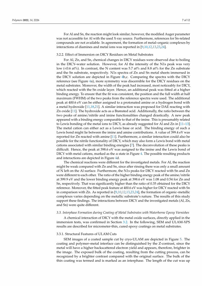
Figure 4. XPS N1s HR peaks of pure DICY (a), DICY residues on Zn (b), and DICY residues on Sn (c). The suggested chemical products and interactions are depicted in (d).
3.3. Interphase Formation during Coating of Metal Substrates with Waterborne Epoxy Varnishes A chemical interaction of DICY with the metal oxide surfaces, directly applied in the
immersion tests, was confirmed in Section 3.2. In the following, SEM and ULAM-XPS re-sults are described for micrometer-thin, cured epoxy coatings on metal substrates.
3.3.1. Structural Features of ULAM Cuts SEM images of a coated sample cut by cryo-ULAM are depicted in Figure 5. The
coating and polymer–metal interface can be distinguished by the Z-contrast, since the metal will have a higher backscattered electron yield and appears, therefore, brighter in the image. The exposed bulk of the coating, resulting from the cutting process, can be recognized by a brighter contrast compared with the original surface. The bulk of the thin coating was termed and is marked as an interphase. The length of the cut was up to several hundred micrometers. In Figure 5, a magnification of the transition from the interphase to the polymer–metal interface is depicted. The detailed image clearly reveals strip-like structures, which are presumably related to epoxy residues smeared by the glass knife into the valleys and grooves of the microrough technical surface of the metal sheets. Fur-thermore, the glass knife might also deform the surface of the metal substrate.
Figure 4. XPS N1s HR peaks of pure DICY (a), DICY residues on Zn (b), and DICY residues on Sn (c).The suggested chemical products and interactions are depicted in (d).
Polymers 2022, 14, 2226 7 of 12
For Al and Sn, the reaction might look similar; however, the modified Auger parameterwas not accessible for Al with the used X-ray source. Furthermore, references for Sn-relatedcompounds are not available. In agreement, the formation of metal–organic complexes byinteractions of diamines and metal ions was reported in [9,10,12,13,23,24].
3.2.2. Effect of Immersion on DICY Residues on Metal Substrates
For Al, Zn, and Sn, chemical changes in DICY residues were observed due to boilingin the DICY–water solution. However, for Al the intensity of the N1s peak was verylow (<0.6 at%). In contrast, the N content was 5.7 at% and 8.8 at% for the Zn substrateand the Sn substrate, respectively. N1s spectra of Zn and Sn metal sheets immersed inthe DICY solution are depicted in Figure 4b,c. Comparing the spectra with the DICYreference (see Figure 4a), more symmetry was discernible for the DICY residues on themetal substrates. Moreover, the width of the peak had increased, most noticeably for DICY,which reacted with the Sn oxide layer. Hence, an additional peak was fitted at a higherbinding energy. To ensure that the fit was consistent, the position and the full width at halfmaximum (FWHM) of the two peaks from the reference spectra were used. The additionalpeak at 400.6 eV can be either assigned to a protonated amine or a hydrogen bond witha metal hydroxide [11,18,21]. A similar interaction was proposed for DAE reacting withZn oxide [11]. The hydroxide acts as a Brønsted acid. Additionally, the ratio between thetwo peaks of amine/nitrile and imine functionalities changed drastically. A new peakappeared with a binding energy comparable to that of the imine. This is presumably relatedto Lewis bonding of the metal ions to DICY, as already suggested for Al and Zn in [11–13].The metal cation can either act as a Lewis base or acid. The binding energy of such aLewis bond might lie between the imine and amine contributions. A value of 399.4 eV wasreported for Zn reacted with amine [11]. Furthermore, a similar interaction could also bepossible for the nitrile functionality of DICY, which may also form a Lewis bond with metalcations associated with similar binding energies [7]. The deconvolution of these peaks isdifficult. Hence, the peak at 398.6 eV was assigned to the imine and the Lewis bond ofDICY with metal cations, marked as the α state in Figure 4. The possible resulting productsand interactions are depicted in Figure 4d.
The chemical reactions were different for the investigated metals. For Al, the reactionmight be weak compared with Zn and Sn, since after rinsing there was only a small amountof N left on the Al surface. Furthermore, the N1s peaks for DICY reacted with Sn and Znwere different to each other. The ratio of the higher binding energy peak of the amine/nitrileat 399.9 eV and the lower binding energy peak at 398.6 eV was 1.08 and 0.54 for Zn andSn, respectively. That was significantly higher than the ratio of 0.35 obtained for the DICYreference. Moreover, the fitted peak feature at 400.6 eV was higher for DICY reacted with Snin comparison with Zn. As reported in [9,10,12,13,23,24], the formation of organic–metalliccomplexes varies depending on the metallic substrate’s nature. The results of this studysupport these findings. The interactions between DICY and the investigated metals (Al, Zn,and Sn) were quite different.
3.3. Interphase Formation during Coating of Metal Substrates with Waterborne Epoxy Varnishes
A chemical interaction of DICY with the metal oxide surfaces, directly applied in theimmersion tests, was confirmed in Section 3.2. In the following, SEM and ULAM-XPSresults are described for micrometer-thin, cured epoxy coatings on metal substrates.
3.3.1. Structural Features of ULAM Cuts
SEM images of a coated sample cut by cryo-ULAM are depicted in Figure 5. Thecoating and polymer–metal interface can be distinguished by the Z-contrast, since themetal will have a higher backscattered electron yield and appears, therefore, brighter inthe image. The exposed bulk of the coating, resulting from the cutting process, can berecognized by a brighter contrast compared with the original surface. The bulk of thethin coating was termed and is marked as an interphase. The length of the cut was up

Polymers 2022, 14, 2226 8 of 12
to several hundred micrometers. In Figure 5, a magnification of the transition from theinterphase to the polymer–metal interface is depicted. The detailed image clearly revealsstrip-like structures, which are presumably related to epoxy residues smeared by the glassknife into the valleys and grooves of the microrough technical surface of the metal sheets.Furthermore, the glass knife might also deform the surface of the metal substrate.
Polymers 2022, 14, 2226 9 of 13
Figure 5. SEM images of a cryo-ULAM cut at magnifications of 50× (left) and 500× (right).
In Figure 6, the same ULAM cut is depicted as a 3D image acquired by white light interferometry. The original coating’s surface was wavy, and the thickness varied slightly. As evaluated from the linescan, the angle of the cut was 3.0°. During microtomy, the un-derlying metal substrate was cut or deformed, since the depth significantly exceeded the thickness of the coating, which was around 5 µm. Considering the obtained angle, the taper shown in Figure 5 is realistic and sufficient for obtaining several XPS linescan posi-tions at a spot size of 150 µm.
Figure 6. White light interferometric 3D image (left) and linescan (right) of the cut.
3.3.2. Elemental Composition of Epoxy Coatings on Metal Substrates Immediately after ULAM-cutting, the samples were transferred to the XPS vacuum
chamber. In Figure 7, XPS linescans over tapers of coated Al, Zn, and Sn are depicted. At an X-ray spot size of 150 µm, a step size of 50 µm was chosen for the scans. A clear differ-ence in the elemental composition was obtained for the surface of the coating, the uncov-ered interphase, and the metal–polymer interface. For Al and Zn, the N content on the coating’s surface was below the detection limit. In contrast, N was detectable on the sur-face of the coating on the Sn. However, the content was slightly lower compared with the uncovered interphase. The low content of DICY on the coating’s surface is presumably related to segregation phenomena driven by differences in the size of DGEBA and DICY molecules [25]. Considering only epoxy and DICY, the nominal concentration of N should be 0.8 at%. Comparable values were measured in the interphase region of the coatings on the Al, Zn, and Sn.
Figure 5. SEM images of a cryo-ULAM cut at magnifications of 50× (left) and 500× (right).
In Figure 6, the same ULAM cut is depicted as a 3D image acquired by white lightinterferometry. The original coating’s surface was wavy, and the thickness varied slightly.As evaluated from the linescan, the angle of the cut was 3.0◦. During microtomy, theunderlying metal substrate was cut or deformed, since the depth significantly exceeded thethickness of the coating, which was around 5 µm. Considering the obtained angle, the tapershown in Figure 5 is realistic and sufficient for obtaining several XPS linescan positions at aspot size of 150 µm.
Polymers 2022, 14, 2226 9 of 13
Figure 5. SEM images of a cryo-ULAM cut at magnifications of 50× (left) and 500× (right).
In Figure 6, the same ULAM cut is depicted as a 3D image acquired by white light interferometry. The original coating’s surface was wavy, and the thickness varied slightly. As evaluated from the linescan, the angle of the cut was 3.0°. During microtomy, the un-derlying metal substrate was cut or deformed, since the depth significantly exceeded the thickness of the coating, which was around 5 µm. Considering the obtained angle, the taper shown in Figure 5 is realistic and sufficient for obtaining several XPS linescan posi-tions at a spot size of 150 µm.
Figure 6. White light interferometric 3D image (left) and linescan (right) of the cut.
3.3.2. Elemental Composition of Epoxy Coatings on Metal Substrates Immediately after ULAM-cutting, the samples were transferred to the XPS vacuum
chamber. In Figure 7, XPS linescans over tapers of coated Al, Zn, and Sn are depicted. At an X-ray spot size of 150 µm, a step size of 50 µm was chosen for the scans. A clear differ-ence in the elemental composition was obtained for the surface of the coating, the uncov-ered interphase, and the metal–polymer interface. For Al and Zn, the N content on the coating’s surface was below the detection limit. In contrast, N was detectable on the sur-face of the coating on the Sn. However, the content was slightly lower compared with the uncovered interphase. The low content of DICY on the coating’s surface is presumably related to segregation phenomena driven by differences in the size of DGEBA and DICY molecules [25]. Considering only epoxy and DICY, the nominal concentration of N should be 0.8 at%. Comparable values were measured in the interphase region of the coatings on the Al, Zn, and Sn.
Figure 6. White light interferometric 3D image (left) and linescan (right) of the cut.
3.3.2. Elemental Composition of Epoxy Coatings on Metal Substrates
Immediately after ULAM-cutting, the samples were transferred to the XPS vacuumchamber. In Figure 7, XPS linescans over tapers of coated Al, Zn, and Sn are depicted.At an X-ray spot size of 150 µm, a step size of 50 µm was chosen for the scans. A cleardifference in the elemental composition was obtained for the surface of the coating, theuncovered interphase, and the metal–polymer interface. For Al and Zn, the N content onthe coating’s surface was below the detection limit. In contrast, N was detectable on thesurface of the coating on the Sn. However, the content was slightly lower compared withthe uncovered interphase. The low content of DICY on the coating’s surface is presumably

Polymers 2022, 14, 2226 9 of 12
related to segregation phenomena driven by differences in the size of DGEBA and DICYmolecules [25]. Considering only epoxy and DICY, the nominal concentration of N shouldbe 0.8 at%. Comparable values were measured in the interphase region of the coatings onthe Al, Zn, and Sn.
Polymers 2022, 14, 2226 10 of 13
The HR spectra of the C1s peak (not shown) along with the linescans were compara-ble to the spectra of the epoxy resin presented in Section 3.1. Furthermore, the overall concentration of O and C was in agreement with the epoxy oligomer. However, differ-ences were discernible at the interface of the metal and the polymer. As discussed in the previous subsection, the glass knife also cut and deformed the metal. However, the origi-nal surface roughness as well as the grooves induced by the glass knife led to thin epoxy residues on the uncovered metal substrate. Interestingly, the N content increased at this uncovered interface just for Zn and Sn (see Figure 7b,c). For Al, the N content was almost constant, even though the relative amount of C decreased significantly. Consequently, for the investigated metals a relative enrichment of DICY at the interface was confirmed. The enrichment of DICY at the interface was pronounced for Zn and even more so for Sn. Segregation of an amine-based hardener near the surface was also reported for Cu sub-strates [26]. While the segregation of the DICY hardener varied for the different metals, the concentration of N and, consequently, the concentration of DICY in the uncovered interphase of the coatings on the different metals were comparable.
Figure 7. In (a), the schematic of an ULAM cut is depicted, along which XPS linescans have been performed, with (b) Al, (c) Zn, and (d) Sn as the substrate materials, respectively. The signal of N is Figure 7. In (a), the schematic of an ULAM cut is depicted, along which XPS linescans have beenperformed, with (b) Al, (c) Zn, and (d) Sn as the substrate materials, respectively. The signal of N ismultiplied by a factor of 10 in all graphs for better visibility. The light grey area labeled “interphase”represents the uncovered part of the coating with a thickness of 5 µm.
The HR spectra of the C1s peak (not shown) along with the linescans were compa-rable to the spectra of the epoxy resin presented in Section 3.1. Furthermore, the overallconcentration of O and C was in agreement with the epoxy oligomer. However, differenceswere discernible at the interface of the metal and the polymer. As discussed in the previoussubsection, the glass knife also cut and deformed the metal. However, the original surfaceroughness as well as the grooves induced by the glass knife led to thin epoxy residues onthe uncovered metal substrate. Interestingly, the N content increased at this uncovered in-terface just for Zn and Sn (see Figure 7b,c). For Al, the N content was almost constant, eventhough the relative amount of C decreased significantly. Consequently, for the investigated

Polymers 2022, 14, 2226 10 of 12
metals a relative enrichment of DICY at the interface was confirmed. The enrichment ofDICY at the interface was pronounced for Zn and even more so for Sn. Segregation of anamine-based hardener near the surface was also reported for Cu substrates [26]. While thesegregation of the DICY hardener varied for the different metals, the concentration of Nand, consequently, the concentration of DICY in the uncovered interphase of the coatingson the different metals were comparable.
3.3.3. Chemical Changes near the Interface
While the C1s HR peaks of the coating’s surface, interphase, and interface regions werecomparable to the reference spectrum of the epoxy oligomer, a clear change in chemistrywas discernible in the N1s spectra. In Figure 8a–c, the HR spectra of the N1s peak deter-mined for the uncovered interphase region and the interface with the metal are depicted.The concentration of N was quite low. Nevertheless, a dominant amine/nitrile peak at399.9 eV was detected in the uncovered interphase. Hence, not all of the functional groupswere reacting during double-stage curing. Similar to the reference spectra of DICY, a smallpeak contribution at a binding energy of 398.6 was ascertained. At the interface of themetal and epoxy coating, the N1s peak became more symmetric. A comparable effect wasobserved after immersion of the metals in the DICY–water solution. The peak at 400.6 eVassociated with hydrogen bonds or protonated amine was more pronounced for Zn and Sn.Furthermore, the intensity at the lower binding energy close to the imine peak at 398.6 eVwas higher at the interface, especially for Zn and Sn. However, this peak revealed a slightlyhigher binding energy than imine (398.6 eV). As reported in [11], it is presumably relatedto Lewis bonding of metal cations with the amine or nitrile. The N1s peak features, whichhave also been described for diamines [11–13,24], confirmed interactions of metal ions withdiamines during application and double-stage curing of waterborne varnishes on Al, Zn,and Sn. Chemical reactions and the potential formation of metal–organic complexes arefavored near the interface. Diffusion of such complexes into the bulk of the coating termedthe interphase could not be ascertained unambiguously. The concentration of the imine orLewis bonding of metal cations with amine or nitrile moieties was too low in the interphase.However, a peak presumably related to hydrogen bonds or protonated amine (close to400.6 eV) was also detected in the interphase, especially for the epoxy–Sn sample.
Polymers 2022, 14, 2226 11 of 13
multiplied by a factor of 10 in all graphs for better visibility. The light grey area labeled “interphase” represents the uncovered part of the coating with a thickness of 5 µm.
3.3.3. Chemical Changes Near the Interface While the C1s HR peaks of the coating’s surface, interphase, and interface regions
were comparable to the reference spectrum of the epoxy oligomer, a clear change in chem-istry was discernible in the N1s spectra. In Figure 8a–c, the HR spectra of the N1s peak determined for the uncovered interphase region and the interface with the metal are de-picted. The concentration of N was quite low. Nevertheless, a dominant amine/nitrile peak at 399.9 eV was detected in the uncovered interphase. Hence, not all of the functional groups were reacting during double-stage curing. Similar to the reference spectra of DICY, a small peak contribution at a binding energy of 398.6 was ascertained. At the interface of the metal and epoxy coating, the N1s peak became more symmetric. A comparable effect was observed after immersion of the metals in the DICY–water solution. The peak at 400.6 eV associated with hydrogen bonds or protonated amine was more pronounced for Zn and Sn. Furthermore, the intensity at the lower binding energy close to the imine peak at 398.6 eV was higher at the interface, especially for Zn and Sn. However, this peak revealed a slightly higher binding energy than imine (398.6 eV). As reported in [11], it is presuma-bly related to Lewis bonding of metal cations with the amine or nitrile. The N1s peak features, which have also been described for diamines [11–13,24], confirmed interactions of metal ions with diamines during application and double-stage curing of waterborne varnishes on Al, Zn, and Sn. Chemical reactions and the potential formation of metal–organic complexes are favored near the interface. Diffusion of such complexes into the bulk of the coating termed the interphase could not be ascertained unambiguously. The concentration of the imine or Lewis bonding of metal cations with amine or nitrile moie-ties was too low in the interphase. However, a peak presumably related to hydrogen bonds or protonated amine (close to 400.6 eV) was also detected in the interphase, espe-cially for the epoxy–Sn sample.
Figure 8. N1s peak in the interphase (i.e., the bulk of the epoxy coating) and at the epoxy–metal interface for (a) Al, (b) Zn, and (c) Sn.
Figure 8. N1s peak in the interphase (i.e., the bulk of the epoxy coating) and at the epoxy–metalinterface for (a) Al, (b) Zn, and (c) Sn.

Polymers 2022, 14, 2226 11 of 12
4. Summary and Conclusions
The main objective of this study was to elucidate potential interactions of waterborneepoxy varnishes based on the latent curing agent DICY and Al, Zn, and Sn metal substrates.Therefore, analytical investigations in different material states were carried out. As areference, the main components of the varnish formulation (i.e., epoxy resin, emulsifier, andDICY) and the surface of the metal substrate were characterized by XPS. Furthermore, themetal substrates were exposed to boiling water and a solution of DICY in water. Structuralchanges in the surface were examined. Finally, the epoxy varnish was applied to thesubstrates, pre-coated, and fully cured. To uncover the bulk of the coating, a potentialinterphase, and the epoxy–metal interface, the coated metals were cut by cryo-ULAM andcharacterized and scanned by XPS.
After immersion of the metal substrates in the DICY–water solution, clear indicationsof the formation of metal–organic complexes were discernible. The N1s peak of DICYresidues on the metal substrate revealed further subpeaks attributable to protonated amineor hydrogen bonds and Lewis bonds of the metal ions with the amine and nitrile function-ality of DICY, which were not detectable for DICY in the reference state. These structuralchanges were much more pronounced for Zn and Sn as compared with Al. Furthermore,immersion in boiling water or the aqueous DICY solution lead to an increase in the oxidelayer’s thickness and a clear change of the Zn oxide to Zn(OH)2. XPS linescans of tapersprepared by cryo-ULAM and taken from coated Al, Zn, and Sn revealed an enrichment ofDICY close to the interface. The enrichment was more pronounced for Zn and Sn. Further-more, a quite similar reaction was confirmed for the coatings as well as the metals immersedin aqueous DICY solutions. Indications of the formation of metal–organic complexes atthe interface of the epoxy coating and the metal surface were deduced. These findings onthe investigated waterborne epoxy varnish coated onto metal substrates are in agreementwith the epoxy amine–metal interphase formation concept established for different aminehardeners and water-free adhesives [9,10,12,13,23,24].
Author Contributions: Conceptualization, G.M.W., G.S. and M.A.; methodology, G.M.W., D.S.,R.P., C.M. and G.S.; software, G.S.; validation, G.M.W. and D.S.; formal analysis, J.D. and G.S.;investigation, J.D., K.H., R.P. and G.S.; resources, C.M. and R.P.; data curation, G.S.; writing—originaldraft preparation, G.S.; writing—review and editing, G.M.W., D.S., M.A. and G.S.; visualization,G.S.; supervision, G.M.W. and D.S.; project administration, G.M.W.; funding acquisition, G.M.W. Allauthors have read and agreed to the published version of the manuscript.
Funding: The financial support by the Austrian Federal Ministry for Digital and Economic Affairs,the National Foundation for Research, Technology, and Development, and the Christian DopplerResearch Association is gratefully acknowledged.
Institutional Review Board Statement: Not applicable.
Informed Consent Statement: Not applicable.
Data Availability Statement: Not applicable.
Acknowledgments: This research work was carried out in close collaboration with the Center forElectrochemical Surface Technology (CEST), which is funded within the framework of the COMETprogram of the Competence Centers for Excellent Technologies (Project 865864) run by the FFG andwith financial contributions from BMVIT, BMDW, and the Provinces of Lower and Upper Austria.The financial support is gratefully acknowledged. “Open Access Funding by the University of Linz”.
Conflicts of Interest: The authors declare no conflict of interest.
References1. Nothdurft, P.; Riess, G.; Kern, W. Copper/Epoxy Joints in Printed Circuit Boards: Manufacturing and Interfacial Failure
Mechanisms. Materials 2019, 12, 550. [CrossRef] [PubMed]2. Wegmann, A. Chemical resistance of waterborne epoxy/amine coatings. Prog. Org. Coat. 1997, 32, 231–239. [CrossRef]3. Neisiany, R.E.; Khorasani, S.N.; Lee, J.K.Y.; Ramakrishna, S. Encapsulation of epoxy and amine curing agent in PAN nanofibers by
coaxial electrospinning for self-healing purposes. RSC Adv. 2016, 6, 70056–70063. [CrossRef]

Polymers 2022, 14, 2226 12 of 12
4. Tabish, M.; Zhao, J.; Wang, J.; Anjum, M.J.; Qiang, Y.; Yang, Q.; Mushtaq, M.A.; Yasin, G. Improving the corrosion protectionability of epoxy coating using CaAl LDH intercalated with 2-mercaptobenzothiazole as a pigment on steel substrate. Prog. Org.Coat. 2022, 165, 106765. [CrossRef]
5. Zhang, S.; Park, J.; Paik, K.-W. Joint Morphologies and Failure Mechanisms of Anisotropic Conductive Films (ACFs) During aPower Handling Capability Test for Flex-On-Board Applications. IEEE Trans. Compon. Packag. Manuf. Technol. 2016, 6, 1820–1826.[CrossRef]
6. Kim, T.-W.; Lee, T.-I.; Pan, Y.; Kim, W.; Zhang, S.; Kim, T.-S.; Paik, K.-W. Effect of Nanofiber Orientation on Nanofiber SolderAnisotropic Conductive Films Joint Properties and Bending Reliability of Flex-on-Flex Assembly. IEEE Trans. Compon. Packag.Manuf. Technol. 2016, 6, 1317–1329. [CrossRef]
7. Bengu, B.; Boerio, F.J. Interaction of Epoxy/Dicyandiamide Adhesives with Metal Substrates. J. Adhes. 2006, 82, 1133–1155.[CrossRef]
8. Raetzke, K.; Shaikh, M.Q.; Faupel, F.; Noeske, P.-L.M. Shelf stability of reactive adhesive formulations: A case study fordicyandiamide-cured epoxy systems. Int. J. Adhes. Adhes. 2010, 30, 105–110. [CrossRef]
9. Aufray, M.; Roche, A.A. Epoxy–amine/metal interphases: Influences from sharp needle-like crystal formation. Int. J. Adhes.Adhes. 2007, 27, 387–393. [CrossRef]
10. Aufray, M.; Roche, A.A. Properties of the Interphase Epoxy–Amine/Metal: Influences from the Nature of the Amine and theMetal. In Adhesion; Possart, W., Ed.; WILEY-VCH Verlag GmbH & Co. KGaA: Weinheim, Germany, 2005; pp. 89–102.
11. Ballerini, G.; Ogle, K.; Barthés-Labrousse, M.-G. The acid–base properties of the surface of native zinc oxide layers: An XPS studyof adsorption of 1,2-diaminoethane. Appl. Surf. Sci. 2007, 253, 6860–6867. [CrossRef]
12. Barthés-Labrousse, M.-G. Mechanisms of Formation of the Interphase in Epoxy-Amine/Aluminium Joints. J. Adhes. 2012,88, 699–719. [CrossRef]
13. Barthés-Labrousse, M.-G.; Mercier, D.; Debontridder, F. Formation of the Interphase in Epoxy-Amine/Aluminium Joints: Fromsurface corrosion to metal bonding. In Surface Properties and Engineering of Complex Intermetallics; Belin-Ferré, E., Ed.; WorldScientific Publishing Co. Pte. Ltd.: Hackensack, NJ, USA, 2010; Volume 3, pp. 265–291.
14. Marchfelder, C.; Pugstaller, R.; Wallner, G.; Brüggemann, O.; Aufray, M. Effect of Epoxy Structure on Properties of WaterborneCoatings and Electrical Steel Laminates. Polymers 2022, 14, 1556. [CrossRef] [PubMed]
15. Greunz, T.; Strauß, B.; Schausberger, S.E.; Heise, B.; Jachs, B.; Stifter, D. Cryo ultra-low-angle microtomy for XPS-depth profilingof organic coatings. Anal. Bioanal. Chem. 2013, 405, 7153–7160. [CrossRef] [PubMed]
16. Greunz, T.; Duchaczek, H.; Sagl, R.; Duchoslav, J.; Steinberger, R.; Strauß, B.; Stifter, D. Quantification of the toxic hexavalentchromium content in an organic matrix by Xray photoelectron spectroscopy (XPS) and ultra-low-angle microtomy (ULAM). Appl.Surf. Sci. 2017, 396, 665–671. [CrossRef]
17. Beamson, G.; Briggs, D. The XPS of Polymers Database; Surface Spectra: Manchester, UK, 2000.18. Graf, N.; Yegen, E.; Gross, T.; Lippitz, A.; Weigel, W.; Krakert, S.; Terfort, A.; Unger, W.E.S. XPS and NEXAFS studies of aliphatic
and aromatic amine species on functionalized surfaces. Surf. Sci. 2009, 603, 2849–2860. [CrossRef]19. Ederer, J.; Janoš, P.; Ecorchard, P.; Tolasz, J.; Štengl, V.; Beneš, H.; Perchacz, H.; Pop-Georgievski, O. Determination of amino
groups on functionalized graphene oxide for polyurethane nanomaterials: XPS quantitation vs. functional speciation. RSC Adv.2017, 7, 12464–12473. [CrossRef]
20. Jansen, R.J.J.; van Bekkum, H. XPS of nitrogen-containing functional groups on activated carbon. Carbon 1995, 33, 1021–1027.[CrossRef]
21. Lin, K.; Yang, S.; Shi, Z.; Fan, Q.; Liu, Z.; Liu, L. Knitting a sweater with UV-induced in situ polymerization of poly(pyrrole-co-citralnitrile) on Ni-rich layer oxide cathode materials for lithium ion batteries. J. Power Sources 2022, 520, 230768. [CrossRef]
22. Duchoslav, J.; Steinberger, R.; Arndt, M.; Stifter, D. XPS study of zinc hydroxide as a potential corrosion product of zinc: RapidX-ray induced conversion into zinc oxide. Corros. Sci. 2014, 82, 356–361. [CrossRef]
23. Drouet, C.; Salles, F.; Fritah, Z.; Marsan, O.; Thouron, C.; Aufray, M. Further insight on amine-metal reaction in epoxy systems.J. Surfin. 2021, 23, 100959. [CrossRef]
24. Mercier, D.; Barthés-Labrousse, M.-G. The role of chelating agents on the corrosion mechanisms of aluminium in alkaline aqueoussolutions. Corros. Sci. 2009, 51, 339–348. [CrossRef]
25. Satoru, Y.; Keiji, T. Entropy-driven segregation in epoxy-amine systems at a copper interface. Soft Matter 2021, 17, 1359–1367.26. Aoki, M.; Shundo, A.; Okamoto, K.; Ganbe, T.; Tanaka, K. Segregation of an amine component in a model epoxy resin at a copper
interface. Polym. J. 2019, 51, 359–363. [CrossRef]
Copyright © 2022 FDOKUMEN