photoacid generators for catalytic decomposition ... - SMARTech
Upload
khangminh22Category
view
0download
0
THE INSTITUTE OF PAPER CHEMISTRY
Appleton, Wisconsin
STRESS CORROSION CRACKING OF CONTINUOUS
DIGESTERS FOR KRAFT PULPING
Project 3544
A Final Report
to the
DIGESTER CRACKING RESEARCH COMMITTEE
January, 1983
-ii-
SCC in Alkaline Sulfide Media 68
V. STATISTICS OF CRACKING IN CONTINUOUS DIGESTERS 74
Introduction 74
Kamyr Continuous Digester Systems 77
Digester Fabrication 83
Cracking Characteristics in Kamyr Continuous Digesters 89
Cracking Statistics 91
Distribution of Cracking 92
Crack Morphology 92
Cracking in Base Metal 93
Cracking at the Cone Transition Weld 93
Deep Cracking (> 1/2") 94
Impregnation Vessel Versus Digester Cracking 94
Cracking Outside of the Impregnation Zone 95
Nozzle Cracking 95
Vertical Welds versus Horizontal Welds 96
Average Crack Penetration 96
Onset of Cracking 97
Metallography 97
Nondestructive Examination 98
Summary 101
Digester Cracking Versus Fabrication Variables 101
Digester Cracking Versus Operation 117
Acid Cleaning 118
Wood Species 120
Chip Versus Sawdust Digesters 123
Vapor Phase/Two Vessel Systems 123
-iii-
White Liquor Characteristics Versus Cracking 124
Detailed Questionnaire Results at Six Selected Mills 129
SUMMARY 134
VI. REMEDIES FOR VESSEL CRACKING 135
Introduction 135
Repair by Grinding 136
Repair by Welding 136
Crack Prevention by Shot Peening 139
Crack Prevention by Stainless Alloy Overlays 140
Crack Prevention by Thermal Spray Coatings 142
Thermal Stress Relief in situ 143
Anodic Protection 143
VII. CHEMISTRY AND ELECTROCHEMISTRY OF KRAFT LIQUORS AT SELECTED MILLS 145
Introduction 145
Experimental Approach 146
Objective 146
Mill Site Selection 147
Liquor Sampling Site 148
Apparatus 151
Electrode Materials 156
Grab Sampling 160
Chemical Analysis 160
Procedure 162
Results of Chemical Analyses 164
White Liquor 164
Cooking Liquors 167
Trace Elements 173
-iv-
Organic Species 177
Summary 178
Electrochemical Behavior in Cooking Liquors 178
Rest Potentials 178
Polarization Curves 183
Corrosion Rates 190
Ag/Ag2S Reference Electrode Calibration 190
Discussion 191
VIII. UNRESOLVED ISSUES 194
IX. REFERENCES 198
X. ACKNOWLEDGMENTS 202
XI. APPENDIX 203
THE INSTITUTE OF PAPER CHEMISTRY
Appleton, Wisconsin
STRESS CORROSION CRACKING OF
CONTINUOUS DIGESTERS FOR KRAFT PULPING
PREFACE
The pulping industry was suddenly introduced to a problem of serious
proportions when the continuous digester vessel at the Pine Hill, Alabama, mill
ruptured during routine operation in September 1980. The top of the vessel was
separated from the lower vessel by failure of the weld at the bottom of the
cone. Examination of this weld revealed extensive cracking of the heat-affected
zone, such that the remaining ligament could no longer withstand the operating
pressure. Further investigation showed that cracking had occurred in many of
the girth welds in the top 55 feet of the vessel. The branched crack morphol-
ogy and the preferred cracking path between grains in the metal suggested that
the cracking was due to stress corrosion. The vessel required extensive repairs
but was returned to service after four months.
The extent of the problem with continuous digesters was revealed as the
news of the incident spread and other mills undertook careful examination of
their vessels using more sophisticated nondestructive evaluation (NDE) methods.
In view of the safety concerns involved, a TAPPI Task Group (TA 4561) was formed
to facilitate exchange of information related to digester cracking. Earlier
instances of digester cracking in the impregnation zone came to light. NDE
experiences suggested that relatively deep cracks could exist, but be masked
from view unless the surface was carefully prepared and then examined using wet
fluorescent magnetic particle techniques. When these methods were used, it
became apparent that many of the Kamyr continuous digesters had serious cracking
in the welds at the impregnation zone of the digester. When cracks were
j
Page 2 TAPP1/IPC
Final Report Project 3544
located, they were removed by grinding (or arc-air gouging and grinding) and
rewelding in the field when the corrosion allowance on the wall was gone.
Reinspection of the vessels after a period of operation frequently
revealed the initiation of new cracks in areas where no cracking had been pre-
viously observed, as well as cracking of the areas repaired earlier. Other
remedial measures were attempted -- including stainless weld overlaying, shot
peening, thermal spray coating, in situ stress relieving, and anodic
protection -- with mixed results.
Faced with the prospect of continued cracking and ineffective remedial
measures, the TAPPI Task Group organized industry support for a research program
to investigate digester cracking and to identify effective control measures.
Funds to support this program were solicited from companies whose pulp mills
operated Kamyr digesters, and support was eventually received from more than
eighty-five per cent of these companies. Kamyr, Inc. provided matching funds,
and several related firms provided some additional funding. The representatives
of sponsoring companies formed a new group -- the Digester Cracking Research
Committee (DCRC) -- to monitor the progress of the research program. The
Institute of Paper Chemistry agreed to administer the research program. A
research subcommittee of the Task Group solicited proposals for research programs
from various research agencies and, after reviewing the proposals, eventually
settled on three research contractors.
Although the thrust of the TAPPI/IPC research program was to be focused
on identifying effective measures to control digester cracking, the DCRC first
authorized the Institute of Paper Chemistry to review and document the current
state of understanding of stress corrosion cracking (SCC) in digesters. This
TAPPI/IPC Page 3Project 3544 Final Report
review was divided into three parts: (i) a review of the current understanding
of SCC in alkaline sulfide media, (ii) an attempt to correlate SCC susceptibility
with details of digester fabrication or operation in North America, and (iii) a
chemical and electrochemical characterization of carbon steel in actual digester
liquors. The effort was to provide a detailed resource document for the industry,
as well as an assessment of actual digester conditions that promote cracking,
with the latter assessment as a starting point for the balance of the research
program. To achieve this goal, the IPC program was designed as a "crash" program
to be completed by the end of 1982 -- and before the subsequent studies of
remedial measures reached full stride.
Since several continuous digesters have escaped cracking after prolonged
operation, an intensive effort was made to determine if some feature of these
digesters differed from those at mills exhibiting marked SCC susceptibility.
In an attempt to identify the reason for different SCC behavior, six mills were
selected for intensive study, three of which have digesters immune to cracking
and three of which have vessels exhibiting marked SCC susceptibility. None of
the six vessels were stress relieved in the impregnation zone. An on-site visit
was made to each mill to sample pulping liquors for chemical analysis, to conduct
electrochemical studies on pressure vessel steels exposed to cooking liquors,
and to delve into the details of digester fabrication and operation. By com-
paring data obtained at immune and susceptible mills, it was hoped that a
correlation between SCC susceptibility and some aspect of digester use would be
apparent. Survey questionnaires were also distributed to the rest of the mills
operating Kamyr digesters, in an attempt to relate routine operation practices
to cracking behavior. Information on repair method effectiveness was also
gathered. The final aspect of the IPC program was a detailed literature survey
Page 4 TAPPI/IPCFinal Report Project 3544
of SCC of carbon steel in alkaline media, to provide corrosion specialists on
the DCRC and the contractors to the DCRC with an up-to-date review of the current
understanding of SCC as it affects the DCRC program.
Since much of the information obtained from survey forms, pulp mill
visits, and conversations with engineers and consultants was given in confidence,
care has been taken in this report to preserve the confidentiality of this infor-
mation. In general, the sources of information discussed in this report are not
identified unless permission has been received or the information is already in
the public domain. Since sources cannot be checked, special care has been taken
to identify hearsay and other tenuous sources of information in the text.
In some cases, companies operating continuous digesters have chosen not
to cooperate with the surveys conducted as part of this program. As the cracking
problems came under control and concerns for safety waned, these companies have
exercised their right to preserve the confidentiality of their information. The
point is raised only to caution the reader about the possibility of inaccurate
conclusions based on an incomplete data base.
Virtually all of the information cited in this report was obtained from
mills in North America. In a few instances, data were included from mills in
Europe and Australia to supplement the North American data base. These supple-
mentary data will be clearly identified in the text.
This report is written for a variety of audiences, with some sections
addressed to the nontechnical executive and others addressed to the corrosion
specialist. Some sections are tutorial and are intended as background reading
for those unfamiliar with stress corrosion cracking. The intended readership

TAPP1/IPC Page 5Project 3544 Final Report
and the level of detail in each section is indicated are a footnote at the start
of each section.
i
Page 6 TAPPI/1PCFinal Report Project 3544
EXECUTIVE SUMMARY
The Institute of Paper Chemistry has completed a preliminary examina-
tion of stress corrosion cracking (SCC) in Kamyr continuous digesters. The
objectives of this study were to: (i) review the current understanding of SCC in
alkaline sulfide media, (ii) correlate SCC susceptibility with details of
digester fabrication or operation, and (iii) characterize the liquor chemistry
and electrochemistry in the vicinity of observed cracking. Chemical and
electrochemical tests were conducted in actual liquors at six mill sites --
three with cracked vessels and three with immune vessels. Questionnaire respon-
ses, including detailed surveys conducted at the six selected mills, were
analyzed in the search for correlations between cracking susceptibility and
digester conditions. A "crash program" was instituted, with a plan to provide
a final report within 120 days, so the information obtained would be available
for use in the balance of the Digester Cracking Research Committee studies.
A detailed review of stress corrosion cracking in alkaline sulfide
media is provided in the text, together with a tutorial introduction to the
topic. Caustic cracking of carbon steels is characterized as a common occurrence
requiring high stresses, intermediate caustic concentrations, and an electro-
chemical potential within a narrow range. The effects of metallurgical variables
on cracking are relatively minor.
Large, nonstress relieved vessels were more susceptible to cracking
than small, stress relieved vessels. No other correlations between cracking
susceptibility and details of digester operation and fabrication were found,
although many possible correlations were examined and discarded. Specifically,
cracking susceptibility appears to be unrelated to the following: age of the
TAPPI/IPC Page 7Project 3544 Final Report
vessel, fabricator, metallurgy of construction materials, acid cleaning prac-
tices, average white liquor characteristics, wood species pulped, types of re-
covery and recausticizing systems, digester operating practices, final product,
water source, and bleaching conditions.
No correlation was found between cooking liquor characteristics and SCC
susceptibility. The average white liquor compositions reported by mills in
their responses to questionnaires could not be related to cracking susceptibil-
ity. Similarly, analyses of raw white and make up liquor samples taken from
immune and susceptible mills revealed no liquor characteristics that controlled
cracking susceptibility. White liquors and make up liquors were similar at both
immune and susceptible mills. However, the characteristics of cooking liquors
in the impregnation zone of continuous digesters -- the actual site of cracking
-- remain unknown.
Electrochemical studies of the short term behavior of carbon steels in
make up liquor revealed conditions appropriate for cracking at both immune and
susceptible mills. Pressure vessel steels exposed to make up liquors exhibited
a slow, spontaneous passivation (i.e., protective film formation) process accom-
panied by a drift of the electrochemical potential into the range required for
caustic cracking under laboratory conditions. Base metal and weld metal behaved
similarly. Oxidation/reduction processes involving species in the make up
liquor prevented further drifting, so potentials remained stable in the regime
of high SCC susceptibility. However, no attempt was made in this phase of the
research program to determine if the rest potentials of the vessels themselves
duplicated the behavior of test coupons.
The reasons for immunity to SCC at certain mills remain unknown. The
electrochemical conditions for cracking appear to be satisfied for short term
Page 8 TAPPI/IPCFinal Report Project 3544
tests. However, other conditions for cracking -- high tensile stress, access of
the electrolyte to the metal, etc. -- may remain unsatisfied in immune vessles.
Remedial measures of various types have been employed in digesters.
The most durable measure in current use is weld overlaying of affected welds
with stainless alloys. Shot peening, plasma spray coating, anodic protection,
and in situ stress relieving are all under active study, but results are too
limited to judge the long-term effectiveness of these measures.

TAPPI/IPC Page 9Project 3544 Final Report
AN INTRODUCTION
TO
STRESS CORROSION CRACKING*
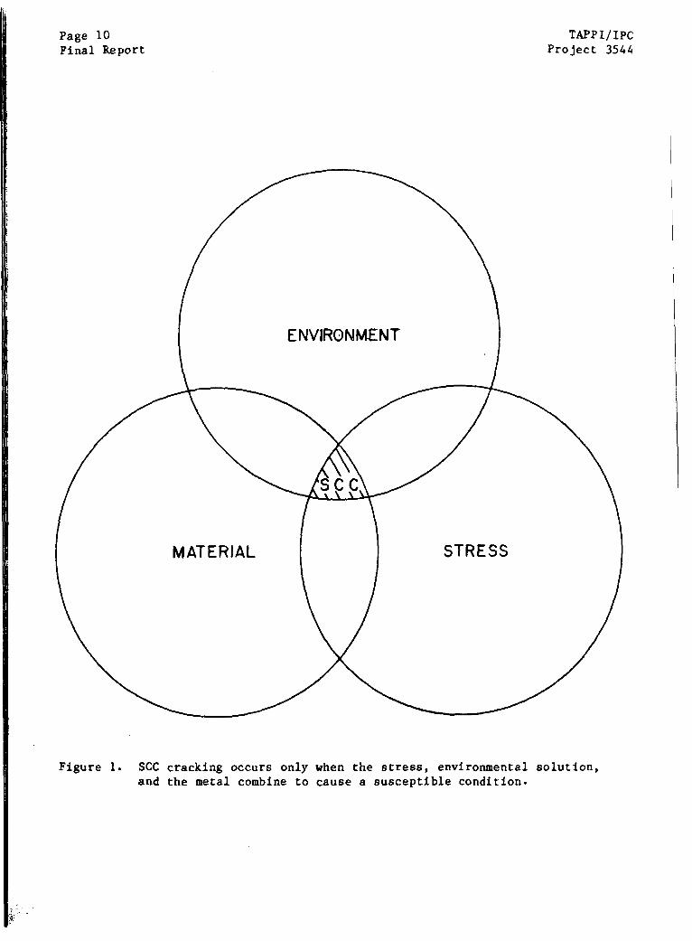
Stress corrosion cracking (SCC) is a term describing the initiation and
growth of a crack in a susceptible metal due to the simultaneous action of a
static (or nearly static) tensile stress and an aggressive environment. As
shown schematically in Fig. 1, all three components -- stress, environment, and
a susceptible alloy -- must be simultaneously present for stress corrosion
cracking to occur. Removal of one of these components, e.g., stress, will pre-
vent the initiation of a crack or the continued growth of an existing crack.
For reasons discussed later, stress corrosion will not occur when an alloy is
alternately exposed to stress and an appropriate environment.
For many years it was thought that an alloy would exhibit SCC in only a
few specific environments. For example, copper alloys were notoriously prone to
SCC in environments containing ammonia, but showed little cracking tendency in
environments containing chlorides. Aluminum alloys seemed immune to cracking
in ammoniacal solutions, but showed remarkable susceptibility to chloride-
induced SCC. Pure metals seemed immune to any form of SCC. Unfortunately, the
list of specific environments causing SCC grew discouragingly long as more and
more environments were found to cause cracking in each alloy. It is now
recognized that, while many environments may not cause SCC, there are many that
will induce SCC in most alloys.
At first, it may seem unusual that the most aggressive environments
from the corrosion standpoint are generally not the most potent environments for
*An introduction to the topic for the nonspecialist.
Page 10Final Report
TAPPI/IPCProject 3544
Figure 1. SCC cracking occurs only when the stress, environmental solution,and the metal combine to cause a susceptible condition.
TAPP1/IPC Page 1]Project 3544 Final Report
crack growth. Those environments that are capable of high rates of metal
removal by corrosion are equally capable of dissolving and removing incipient
cracks or blunting cracks by dissolution at their crack tips. In effect, the
rate of general dissolution in very aggressive media is greater than the rate of
growth of a crack
The alloy/environment combinations which are most likely to cause
stress corrosion cracking are those which are capable of establishing a protec-
tive film on the metal surface. A metal with such a film is said to be passive,
since the film prevents continued dissolution of the metal. Metals which are
freely corroding in the absence of a protective film are said to be active. Every
film formed during corrosion is not necessarily a passive film, since many
corrosion products do not form the tight, adherent films required for protection.
Rust, for example, is a diffuse precipitate of corrosion products that offers
little protection for the underlying iron. When iron is alloyed with chromium
in sufficient quantities, however, the surface is protected by a very thin pro-
tective film of chromium-rich oxide, and the alloy is "stainless" in many
environments,
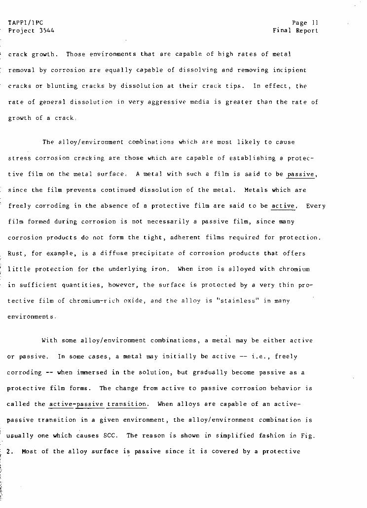
With some alloy/environment combinations, a metal may be either active
or passive. In some cases, a metal may initially be active -- i.e., freely
corroding -- when immersed in the solution, but gradually become passive as a
protective film forms. The change from active to passive corrosion behavior is
called the active-passive transition. When alloys are capable of an active-
passive transition in a given environment, the alloy/environment combination is
usually one which causes SCC. The reason is shown in simplified fashion in Fig.
2. Most of the alloy surface is passive since it is covered by a protective
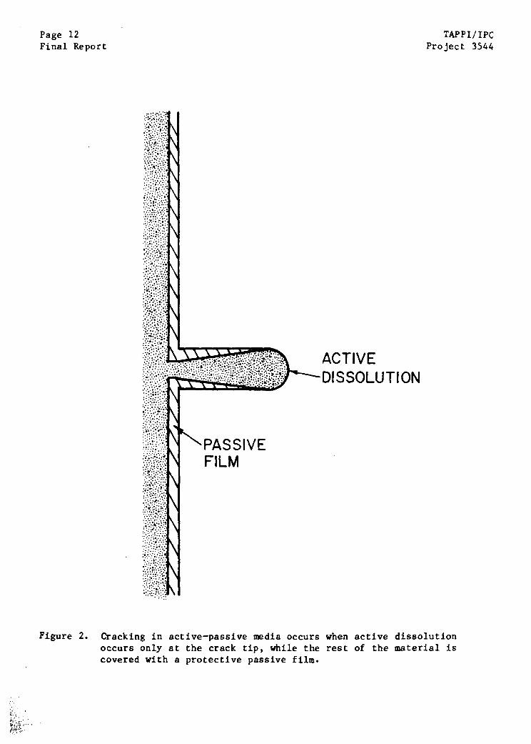
Page 12Final Report
TAPPI/IPCProject 3544
ACTIVEDISSOLUTION
PASSIVEFILM
Cracking in active-passive media occurs when active dissolutionoccurs only at the crack tip, while the rest of the material iscovered with a protective passive film.
Figure 2.
TAPPI/IPC Page 13Project 3544 Final Report
film; dissolution and cracklike behavior are only observed at the isolated active
sites.
The role of the tensile stress is to cause plastic deformation at the
tip of the growing crack; this ruptures the protective film and permits renewed
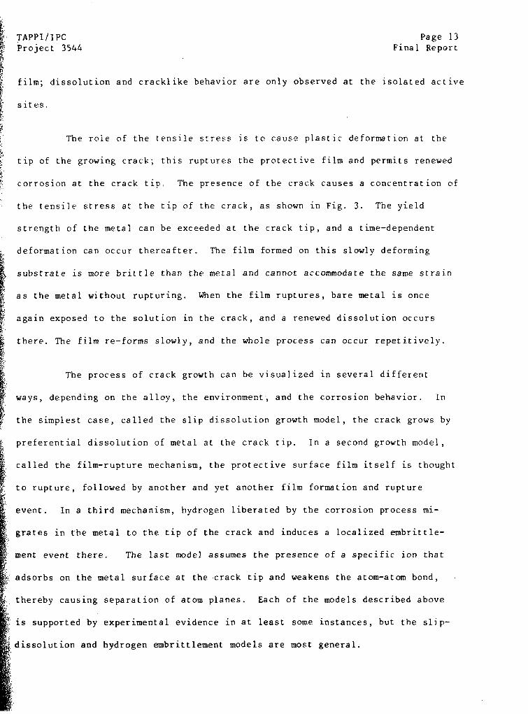
corrosion at the crack tip. The presence of the crack causes a concentration of
the tensile stress at the tip of the crack, as shown in Fig. 3. The yield
strength of the metal can be exceeded at the crack tip, and a time-dependent
deformation can occur thereafter. The film formed on this slowly deforming
substrate is more brittle than the metal and cannot accommodate the same strain
as the metal without rupturing. When the film ruptures, bare metal is once
again exposed to the solution in the crack, and a renewed dissolution occurs
there. The film re-forms slowly, and the whole process can occur repetitively.
The process of crack growth can be visualized in several different
ways, depending on the alloy, the environment, and the corrosion behavior. In
the simplest case, called the slip dissolution growth model, the crack grows by
preferential dissolution of metal at the crack tip. In a second growth model,
called the film-rupture mechanism, the protective surface film itself is thought
to rupture, followed by another and yet another film formation and rupture
event. In a third mechanism, hydrogen liberated by the corrosion process mi-
grates in the metal to the tip of the crack and induces a localized embrittle-
ment event there. The last model assumes the presence of a specific ion that
adsorbs on the metal surface at the crack tip and weakens the atom-atom bond,
thereby causing separation of atom planes. Each of the models described above
is supported by experimental evidence in at least some instances, but the slip-
dissolution and hydrogen embrittlement models are most general.
Page 14Final Report
TAPPI/IPCProject 3544
Tensile stresses are concentrated at the tip of a crack, therebyfacilitating film rupture and renewed dissolution there.
Figure 3.
TAPPI/IPCProject 3544
Page 15Final Report
a.
DISSOLUTION
C.
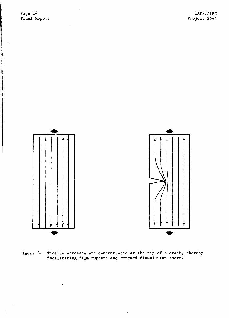
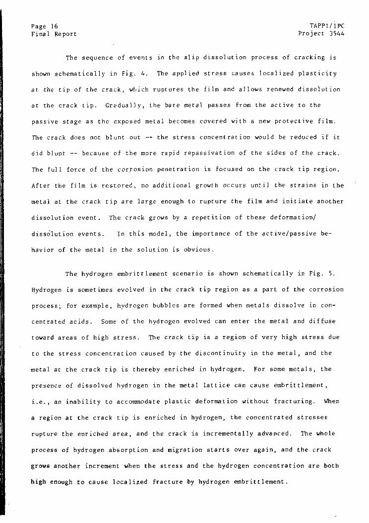
Schematic drawing of the slip-dissolution model for SCC.
I b.
d
""';·::'·'..·· "':"" "'··· '�;:·..··::·.·· ··'···:· ·�:,:: ""'.. ��·.·..::· .:'····I
LIP
Figure 4.
Page 16 TAPPI/IPC
Final Report Project 3544
The sequence of events in the slip dissolution process of cracking is
shown schematically in Fig. 4. The applied stress causes localized plasticity
at the tip of the crack, which ruptures the film and allows renewed dissolution
at the crack tip. Gradually, the bare metal passes from the active to the
passive stage as the exposed metal becomes covered with a new protective film.
The crack does not blunt out -- the stress concentration would be reduced if it
did blunt -- because of the more rapid repassivation of the sides of the crack.
The full force of the corrosion penetration is focused on the crack tip region.
After the film is restored, no additional growth occurs until the strains in the
metal at the crack tip are large enough to rupture the film and initiate another
dissolution event. The crack grows by a repetition of these deformation/
dissolution events. In this model, the importance of the active/passive be-
havior of the metal in the solution is obvious.
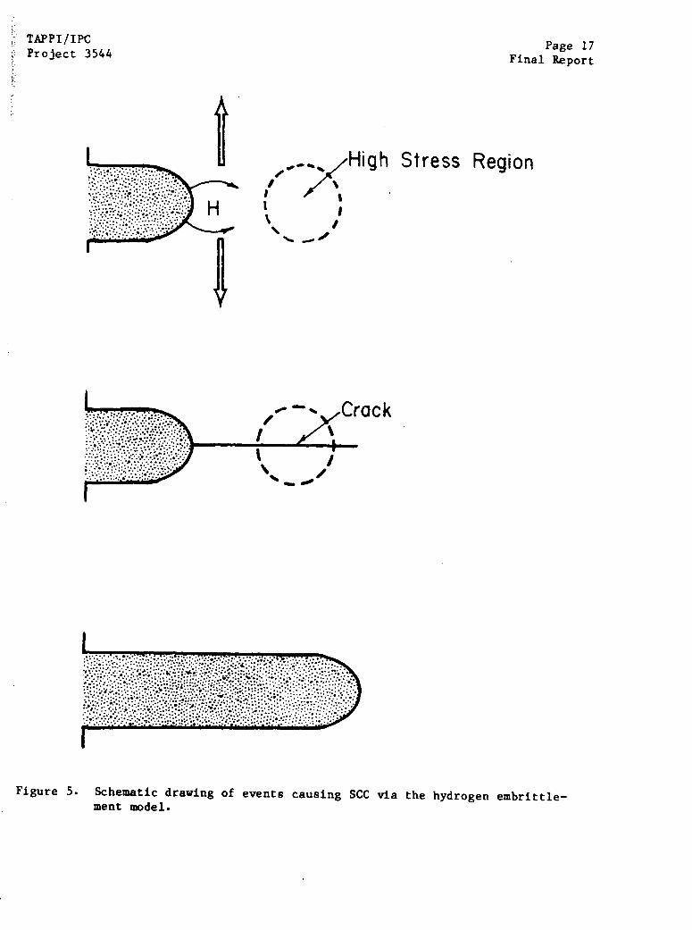
The hydrogen embrittlement scenario is shown schematically in Fig. 5.
Hydrogen is sometimes evolved in the crack tip region as a part of the corrosion
process; for example, hydrogen bubbles are formed when metals dissolve in con-
centrated acids. Some of the hydrogen evolved can enter the metal and diffuse
toward areas of high stress. The crack tip is a region of very high stress due
to the stress concentration caused by the discontinuity in the metal, and the
metal at the crack tip is thereby enriched in hydrogen. For some metals, the
presence of dissolved hydrogen in the metal lattice can cause embrittlement,
i.e., an inability to accommodate plastic deformation without fracturing. When
a region at the crack tip is enriched in hydrogen, the concentrated stresses
rupture the enriched area, and the crack is incrementally advanced. The whole
process of hydrogen absorption and migration starts over again, and the crack
grows another increment when the stress and the hydrogen concentration are both
high enough to cause localized fracture by hydrogen embrittlement.
TAPPI/IPCProject 3544
Page 17Final Report
rack
Figure 5. Schematic drawing of events causing SCC via the hydrogen embrittle-ment model.
Stress Region
Page 18 TAPPI/IPC
Final Report Project 3544
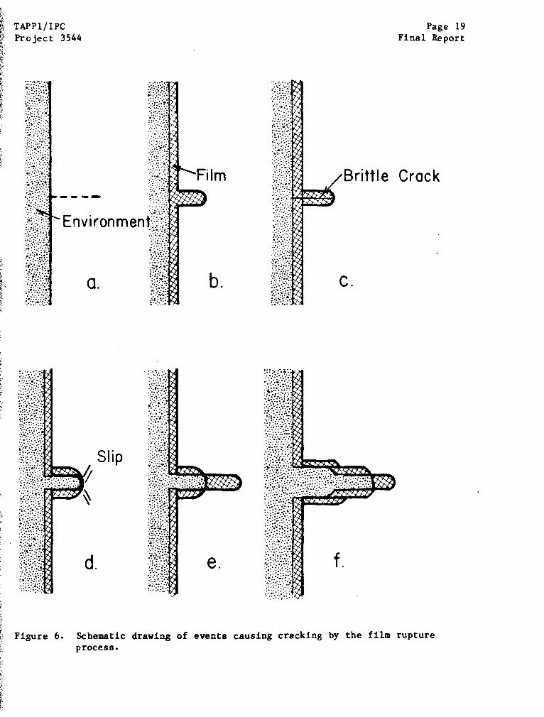
The film rupture model shown in Fig. 6 is thought to occur when the
film formed on the surface of a metal exposed to the environment is thick and
brittle. In this case, the crack tip is covered with the film, which is then
ruptured by the crack tip stresses. The crack tip is then exposed to the solu-
tion and the thick film re-forms and is again ruptured, causing incremental
advances in the crack front. The process is similar to that occurring in the
slip dissolution model, except that the crack advances by rupturing the thick
film, rather than by active dissolution.
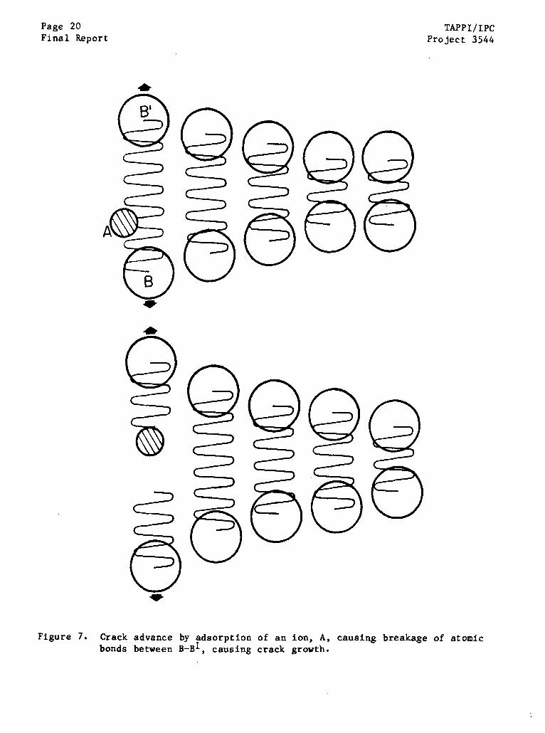
The specific adsorption model is shown schematically in Fig. 7. In
this case, a specific ion migrates down the narrow groove of the crack and
adsorbs on the metal surface in the highly stressed region of the crack tip.
The ion interferes with the normal bonding between atoms, and the cohesion of
the metal is lost when the atom-atom bond ruptures. The crack grows by an atom
spacing increment every time a specific adsorption event takes place.
For iron-base alloys, SCC is usually thought to occur either by hydro-
gen embrittlement or by slip-dissolution processes. Steels and other iron-base
alloys generally do not form the type of film required for growth by the film
rupture mechanism in environments known to cause cracking -- hydroxide, car-
bonate, nitrate, and sulfide media. The specific adsorption process may be
occurring, but it is a difficult process to verify because of the localized
nature of the damage process. The hydrogen embrittlement model is most
appropriate for high-strength steels, since lower-strength steels normally
deform instead of developing the high stresses required for fracture in the pres-
ence of hydrogen.
TAPPI/IPCProject 3544
Page 19Final Report
Environment
Slip
d.
Film
b
e.
e Crack
C.
f.
Schematic drawing of events causing cracking by the film ruptureprocess.
Figure 6.
Page 20Final Report
TAPPI/IPCProject 3544
Figure 7. Crack advance by adsorption of an ion, A, causing breakage of atomicbonds between B-B1, causing crack growth.
TAPPI/IPC Page 21Project 3544 Final Report
Crack Path
In some cases, a stress corrosion crack follows some microstructural
feature of the affected metal, whereas in other cases, the crack seems to follow
the plane that experiences the highest tensile stress normal to it. A common
crack path in SCC is in the region between the individual grains that exist in
metals. Grains are microscopic crystals of metal with different orientations,
and the boundary between these grains is often particularly susceptible to
cracking because it has a composition that differs from that of the bulk metal.
In this case, the crack path is said to be intergranular. When the crack path
cuts across the grains, the path is said to be transgranular. Often, the crack
will grow with both intergranular and transgranular paths.
Stress
A tensile stress is necessary to induce crack advance in stress corro-
sion cracking. Compressive stresses do not tend to open up cracks and permit
access of electrolyte to the crack tip, nor will they provide the forces neces-
sary for the hydrogen-assisted crack growth.
Stresses required for crack initiation and growth can be different be-
cause of stress concentration effects. For smooth specimens, the nominal applied
stress often must be high enough to cause localized yielding at some area on the
surface of the metal. In other cases, nominal stresses well below the yield
strength of the alloy will permit initiation of stress corrosion cracks. At
present, it is not possible to predict the nominal applied stress below which
cracking will not occur, although such a threshold stress can usually be demon-
strated empirically.
The presence of a crack, notch, or other surface flaw can dramatically
reduce the nominal stress required for crack growth. The rate of crack growth
Page 22 TAPPI/IPCFinal Report Project 3544
is usually related to applied stress intensity, rather than applied stress. The
stress intensity is usually expressed as a product of the applied nominal
stress, an expression containing the crack length, and a third expression that
depends on the exact geometry of the cracking situation. For example, for a
single edge crack of length a, subject to a nominal stress (S), the stress
intensity (K) is given by
K = S/a · (1,] /7) (1)
Based on stress intensity expressions such as that given above, the same driving
force for crack growth can be obtained with a high stress and a short crack, or
a low stress and a long, deep crack. The same rate of growth is expected at a
given stress intensity level, regardless of the contributions to K from the
three terms in Eq. (1).
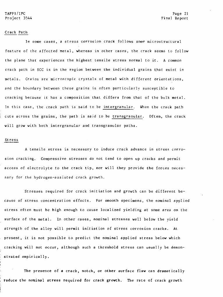
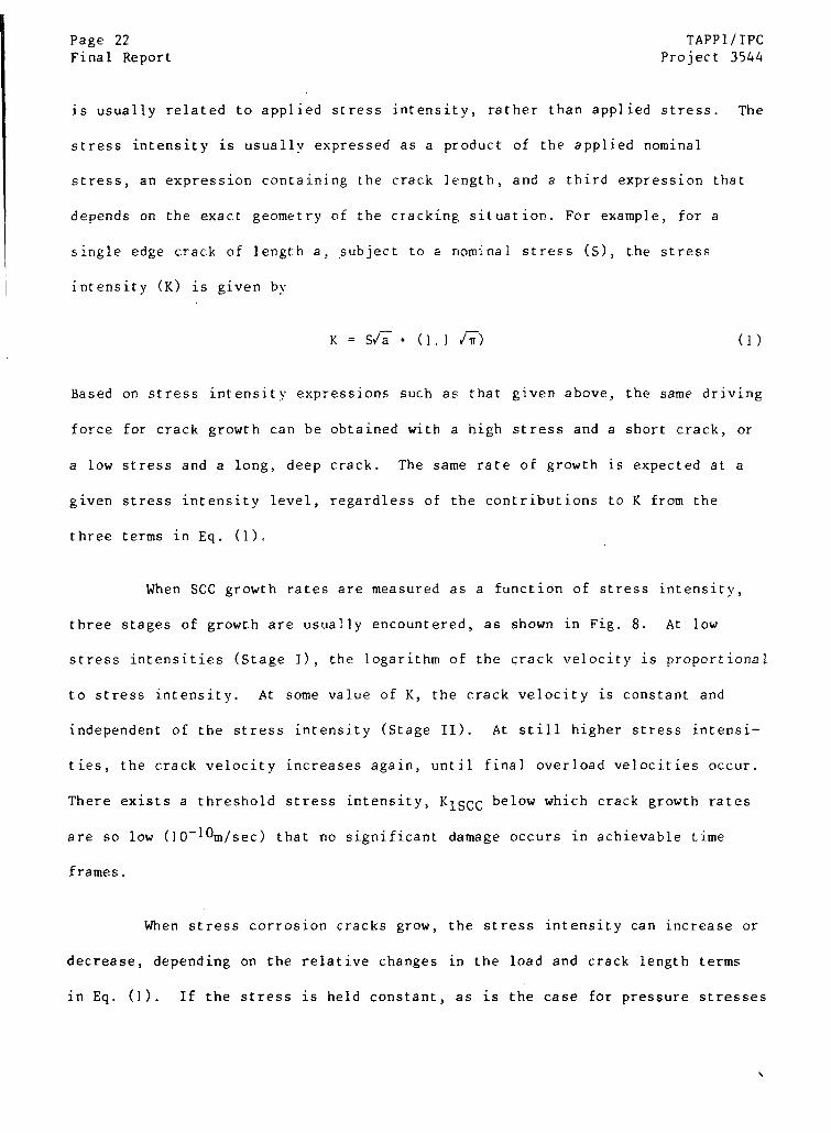
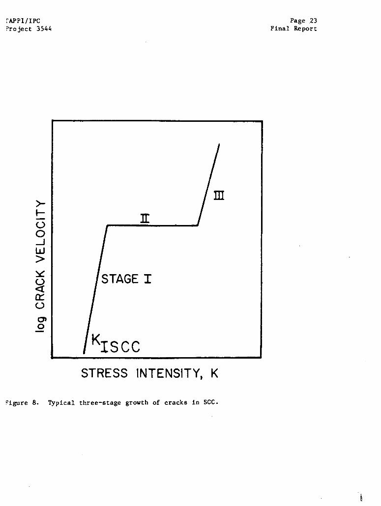
When SCC growth rates are measured as a function of stress intensity,
three stages of growth are usually encountered, as shown in Fig. 8. At low
stress intensities (Stage I), the logarithm of the crack velocity is proportional
to stress intensity. At some value of K, the crack velocity is constant and
independent of the stress intensity (Stage II). At still higher stress intensi-
ties, the crack velocity increases again, until final overload velocities occur.
There exists a threshold stress intensity, KiSCC below which crack growth rates
are so low (10-10m/sec) that no significant damage occurs in achievable time
frames.
When stress corrosion cracks grow, the stress intensity can increase or
decrease, depending on the relative changes in the load and crack length terms
in Eq. (1). If the stress is held constant, as is the case for pressure stresses
APPI/IPCProject 3544

Page 24 TAPPI/IPC
Final Report Project 3544
in a thick-wall vessel for example, the stress intensity increases as the crack
lengthens. If, on the other hand, the stresses arise from a constant deflection
condition such as differential thermal expansion, the stress will likely decrease
faster than the crack length term increases, and the net stress intensity de-
creases as the crack grows,
Stresses large enough to cause stress corrosion cracking can arise in
several different ways. The most obvious stresses are structural stresses asso-
ciated with containment of pressure or structural stability. Stresses can also
arise from mismatch of mating parts during fit-up in fabrication, or as a con-
sequence of welding without a subsequent stress relief treatment. These latter
stresses are always present, even during periods when direct stresses are
missing, and they are therefore called residual stresses. Another source of
applied stress is differential thermal expansion of structures or components
during operation. All of the direct stresses can fluctuate periodically during
routine operation, and there is some evidence that these periodic changes can
enhance crack initiation and growth.
Temperature
Since corrosion is a thermally activated process, it is not surprising
to find that increases in temperature can exacerbate stress corrosion cracking.
This acceleration of cracking is probably due to enhanced dissolution at the
crack tip (in the slip-dissolution process) or enhanced hydrogen mobility (in the
hydrogen embrittlement model). The temperature may also influence the propen-
sity of the metal to reside in the active-passive transition region.
Potential
Every metal immersed in an electrolyte exhibits a voltage gradient in
the vicinity of the metal-liquid interface, and this potential has a profound
TAPP1/IPC Page 25
Project 3544 Final Report
effect on the SCC behavior. The magnitude and sign of the voltage are deter-
mined by the nature of the oxidation (i.e,, corrosion) and reduction reactions
that occur on the metal surface. Two or more reactions occur at the metal-
electrolyte interface. When metal atoms go into the electrolyte as ions, they
leave behind electrons as in the reaction . . .
[Oxidation] Fe + Fe ++ + 2e- (2)
The electrons thus created must be consumed by some reaction at the metal sur-
face, or the dissolution reaction will soon stop. A common reaction that con-
sumes electrons is the hydrogen evolution reaction, which occurs at high pH by
reaction
[Reduction] 2H20 + 2e- + 20H- + H2 (3)
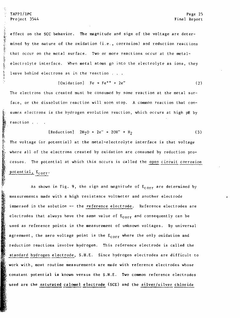
The voltage (or potential) at the metal-electrolyte interface is that voltage
where all of the electrons created by oxidation are consumed by reduction pro-
cesses. The potential at which this occurs is called the open circuit corrosion
potential, Ecorr.
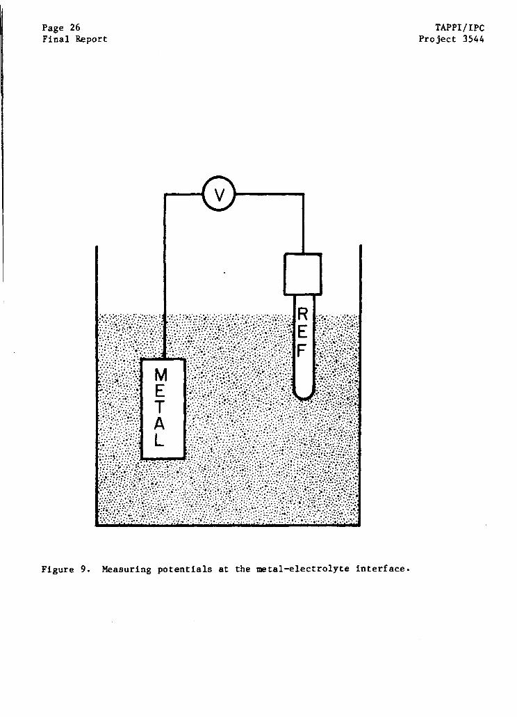
As shown in Fig. 9, the sign and magnitude of Ecorr are determined by
measurements made with a high resistance voltmeter and another electrode
immersed in the solution -- the reference electrode. Reference electrodes are
electrodes that always have the same value of Ecorr and consequently can be
used as reference points in the measurement of unknown voltages. By universal
agreement, the zero voltage point is the Ecorr where the only oxidation and
reduction reactions involve hydrogen. This reference electrode is called the
standard hydrogen electrode, S.H.E. Since hydrogen electrodes are difficult to
work with, most routine measurements are made with reference electrodes whose
constant potential is known versus the S.H.E. Two common reference electrodes
used are the saturated calomel electrode (SCE) and the silver/silver chloride
Page 26 TAPPI/IPCFinal Report Project 3544
Page 28 TAPPI/IPC
Final Report Project 3544
adjusting the concentration of oxidizing species in the solution; these changes
could be followed by monitoring changes in Ecorr,
`t is often convenient to study the behavior of metals in electrolytes
by artificially biasing the balance between oxidation and reduction to maintain
a potential other than the normal Ecorr This can be done by connecting the
specimen to a source (or sink) for electrons to lower (or raise) the potential
at the metal surface. The positive terminal of a battery is a good sink for
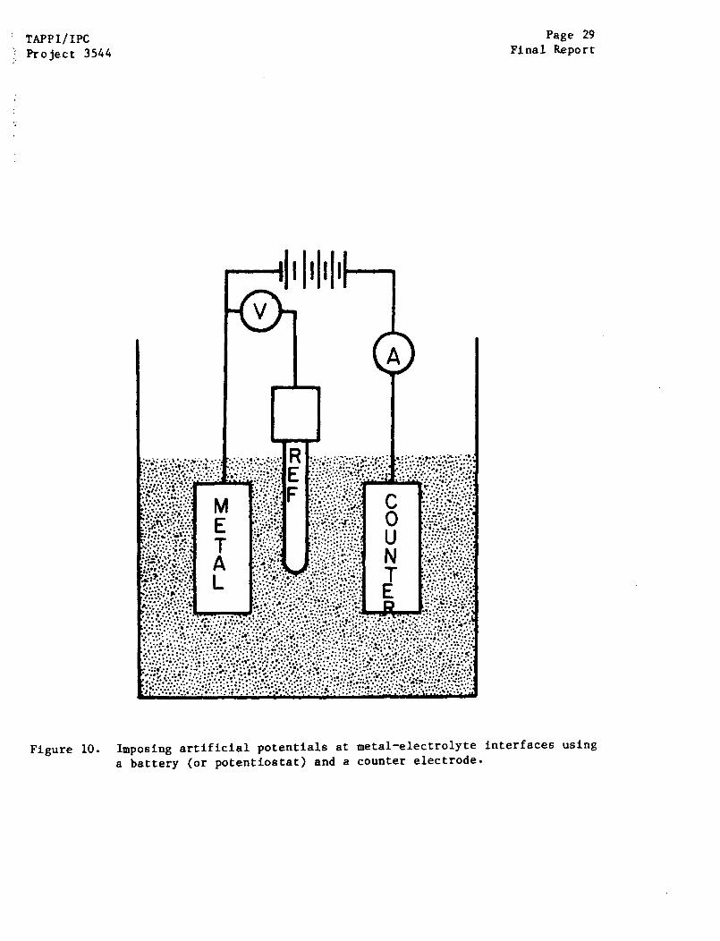
electrons, and connecting the metal surface to a battery as shown in Fig. 10 will
raise the potential. Conversely, connecting the metal to the negative terminal
will lower the potential. By choosing the voltage and polarity of the battery,
any potential can be imposed on the surface. The current that flows to or from
the battery is measured via the ammeter A in Fig. 10.
In practice, an electronic potentiostat is used in place of the bat-
teries described above. With the potentiostat, a reasonable potential can be
imposed on a metal surface by a simple programming adjustment. Thus, potentials
other than Ecorr can be imposed on the metal surface to examine what the be-
havior of the surface would be if Ecorr had been allowed to drift to the imposed
potential. Similarly, the rate of corrosion can be accelerated or decelerated by
selecting higher or lower potentials, and this is the basis for cathodic protec-
tion. If a protective film can form, an artificial potential can be chosen that
will establish this passive film more quickly than would normally occur, and
this is the basis for anodic protection. Finally, a potential in the middle of
the active-passive transition can be artificially imposed on a test specimen to
examine the SCC behavior of the metal.
By monitoring the potential versus current during gradual increases or
decreases in potential, it is possible to determine whether a metal is active,
TAPPI/IPCProject 3544
Page 29Final Report
Figure 10. Imposing artificial potentials at metal-electrolyte interfaces using
a battery (or potentiostat) and a counter electrode.
Page 30 TAPPI/IPCFinal Report Project 3544
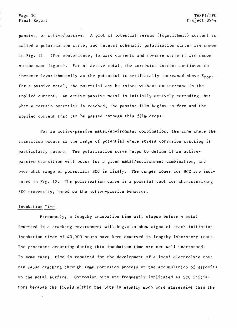
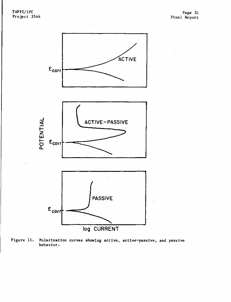
passive, or active/passive. A plot of potential versus (logarithmic) current is
called a polarization curve, and several schematic polarization curves are shown
in Fig. 11. (For convenience, forward currents and reverse currents are shown
on the same figure). For an active metal, the corrosion current continues to
increase logarithmically as the potential is artificially increased above Ecorr.
For a passive metal, the potential can be raised without an increase in the
applied current. An active-passive metal is initially actively corroding, but
when a certain potential is reached, the passive film begins to form and the
applied current that can be passed through this film drops.
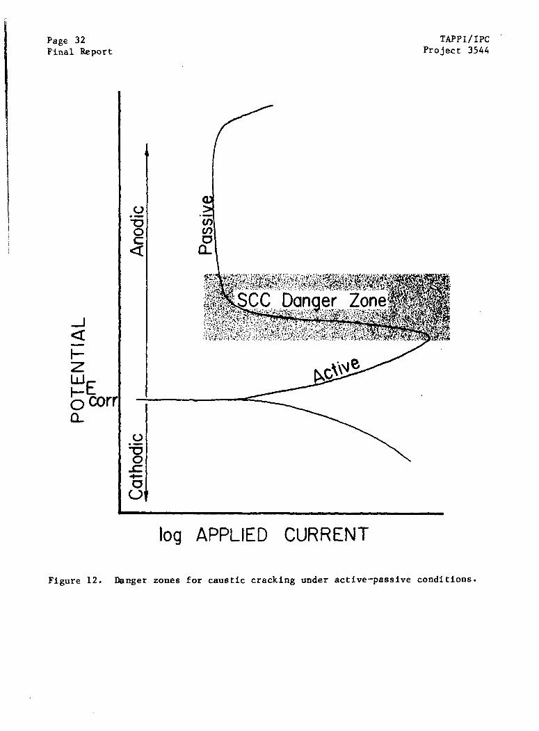
For an active-passive metal/environment combination, the zone where the
transition occurs is the range of potential where stress corrosion cracking is
particularly severe. The polarization curve helps to define if an active-
passive transition will occur for a given metal/environment combination, and
over what range of potentials SCC is likely. The danger zones for SCC are indi-
cated in Fig. 12. The polarization curve is a powerful tool for characterizing
SCC propensity, based on the active-passive behavior.
Incubation Time
Frequently, a lengthy incubation time will elapse before a metal
immersed in a cracking environment will begin to show signs of crack initiation.
Incubation times of 40,000 hours have been observed in lengthy laboratory tests.
The processes occurring during this incubation time are not well understood.
In some cases, time is required for the development of a local electrolyte that
can cause cracking through some corrosion process or the accumulation of deposits
on the metal surface. Corrosion pits are frequently implicated as SCC initia-
tors because the liquid within the pits is usually much more aggressive than the
TAPPI/IPCProject 3544
Ecorr
Page 31Final Report
ACTIVE- PASSIVE
ASSIVEr 'log CURRENT
Figure 11. Polarization curves showing active, active-passive, and passivebehavior.
a-Ecorr
Ecorr
Page 32Final Report
TAPPI/IPCProject 3544
log APPLIED CURRENT
Figure 12. Danger zones for caustic cracking under active-passive conditions.
TAPPI/IPC Page 33
Project 3544 Final Report
bulk liquid. Similarly, unique environments can develop under sediments or
corrosion products and cause cracking after a period of apparent incubation.
Passive films also exhibit "aging" behavior, and the incubation period may be
the time required to age a film to the right conditions for cracking. A final
interpretation of incubation times in service experience is that the nature of
the environment can change during operation, and crack growth only starts when
the changes bring a specific electrolyte into contact with the metal surface.
Regardless of the origins, an incubation period is frequently observed before
cracks initiate in laboratory and service conditions.
Testing for SCC Behavior
Many test methods have been used to characterize stress corrosion
cracking susceptibility in metals, ranging from simple exposure of self-stressed
coupons to complex slow extension rate tests (SERT) at controlled potentials.
Since stress corrosion frequently takes years to develop in service, most SCC
tests use some technique to accelerate the onset of cracking. For example, the
stress applied to a test coupon might be high compared with actual service
stress, or the potential might be controlled to promote cracking. Selection of
an accelerated test method depends on the specific information sought. Some
types of SCC information that are frequently sought are:
(i) Evidence of any susceptibility to crack initiation in the environment
(ii) Threshold stress intensity for crack growth in a cracked specimen
(iii) Threshold stress for crack initiation in a smooth specimen
(iv) Crack velocity at a selected stress intensity
Different tests would be chosen to provide the different types of information.
In general, SCC testing involves one of four test methods:
A. Prolonged exposure of self-stressed, smooth specimens (i, iii)
Page 34 TAPPI/IPCFinal Report Project 3544
B. Prolonged exposure of self-stressed, precracked specimens (ii, iv)
C. Slow extension rate tests (SERT) on smooth tensile specimens (i, iii)
D. Electrochemical tests (i, iii)
Types A, B, C, and D are discussed in turn below.
Perhaps the simplest test to characterize SCC in a specific environment
is an exposure of a smooth, highly stressed specimen to the environment for a
prolonged period, with intermittent visual examination. Many methods have been
used to stress the specimen during exposure, but some methods have been used
more generally. A common self-stressed specimen is the U-bend, a strip of metal
bent into a "U" shape and fastened at the straight shank portions with a nut and
bolt. If care is taken in the assembly (an ASTM standard, G30, is available),
the stresses at the apex of the "U" are tensile and well above the yield
strength. A C-ring is a similar type of smooth, self-stressed specimen which
has the advantage of a simple formula that can be used to calculate stresses in
the apex of the "C" (ASTM Standard Method G38). In many cases, a jig is used to
load a tensile specimen or a bent beam to a known stress level.
Exposure of self-stressed specimens is an inexpensive approach toward
determining the susceptibility to SCC and the threshold stress required for ini-
tiation, but the testing can be tedious when incubation times are long. Usually,
no information on growth rates can be obtained from this type of specimen.
Precracked specimens are frequently used to characterize crack growth
behavior because the prior existence of a sharp crack before exposure reduces
the incubation time for cracking. The usual practice is to select a specimen
for which the stress intensity expression is known, precrack the specimen with
a small fatigue load, load the crack by spreading the crack planes with a bolt
TAPPI/IPC Page 35Project 3544 Final Report
or fixture, and then expose the self-stressed, precracked specimen to the test
environment. The progress of the crack is monitored visually at intervals
during the exposure, and the crack growth rate calculated based on incremental
growth. Hudak and Saxena (1) have recently compiled a detailed description of
the test methodology for this type of test.
When the precracked specimen is a bolt-loaded specimen such as a double
cantilever beam (DCB) or a wedge-open loaded (WOL) specimen, the load falls rapidly
and the stress intensity decreases as the cracks grow in the specimen. Thus,
the crack grows at ever diminishing stress intensity and eventually ceases to
grow at all. As discussed above, the stress intensity where growth stops is the
threshold stress intensity, and this quantity can be determined by testing bolt-
loaded, self-stressed specimens.
Tests with precracked, self-stressed specimens are also useful for
determining the relationship between the crack velocity (V), and the stress
intensity (K), and for determining the threshold stress intensity for crack
growth (KiSCC). No information on crack initiation at smooth surfaces is ob-
tained. The costs of specimen preparation and loading are high, and the pro-
cedures are complicated if artifacts are to be avoided. In spite of the
precrack, long incubation times are often observed. In many cases, the cracks
emanating from the precrack are grossly branched, in which case the stress
intensity expressions are no longer valid.
SERT tests are used to obtain rapid assessment of SCC susceptibility to
metal/environment combinations. The test involves comparison of cracking behav-
ior in two tensile specimens pulled to failure -- one in an inert environment
and one in the environment of interest. When a metal/environment combination
Page 36 TAPPI/IPCFinal Report Project 3544
will not produce SCC, the features of the fracture surface and the characteristic
ductilities of the two tensile tests (reduction in area due to necking, total
elongation) will be similar. If SCC is possible, the specimen tested in the
aggressive environment will exhibit multiple cracks along the length of the
test specimen, and the ductility will be severely reduced. Strain rates on the
order of 10-5 to 10-7 in/in/sec are typically used, which yields SCC infor-
mation in periods ranging from a few hours to a few weeks. Because a fracture is
insured in a short time, incubation effects are largely eliminated.
The success of the SERT test is based on its similarity to the
microscopic processes occurring at the crack tip during SCC. The slow defor-
mation in the tensile test simulates the deformation at the crack tip. A metal
which repassivates quickly will not show evidence of excessive localized disso-
lution following the film rupture events induced by the slow strain process.
Similarly, the specimen which is actively corroding is not significantly
affected by the slow deformation since there will be no film to rupture. Only
those active-passive alloy/environment combinations will reveal excessive
corrosion penetration as a result of the slow tensile deformation.
SERT tests can provide a rapid qualitative assessment of SCC suscep-
tibility, including the ranking of alloys and environments based on SCC suscep-
tibility. However, the SERT test provides no quantitative engineering infor-
mation such as allowable stress or crack velocity versus stress intensity. The
SERT test is strictly qualitative. Moreover, there is some concern that the
SERT test is too fast to allow the hydrogen embrittlement mechanism to operate,
or for the development of localized environments in pits and other crevices.
Electrochemical methods can be used in stress corrosion studies to ac-
celerate cracking, to clarify the processes occurring and to provide a rapid
TAPPI/IPC Page 37Project 3544 Final Report
method for screening the SCC behavior of large numbers of metal/environment
combinations.
The simplest use of electrochemical methods is the imposition of a
controlled potential on a SERT specimen or a self-stressed coupon during expo-
sure. This action accelerates cracking by maintaining optimal conditions for
retention of an active/passive transition on the metal surface during testing.
In general, the imposition of an artificial potential using a potentiostat is
thought to simulate the naturally occurring processes involving gradual film
formation and changes in oxidizing species. However, it must be recognized that
the ability to maintain an artificial potential at the active/passive transition
in the laboratory does not insure that this same potential will occur naturally
in the field; nor is there ironclad assurance that the SCC behavior in the
laboratory will resemble that occurring in the field in every respect.
Polarization curves can be used to ascertain whether the metal of
interest exhibits active/passive behavior in the range of potentials likely to
be encountered in actual service. The ability to detect SCC susceptibility with
polarization curves is considerably enhanced if slow (0.3 mV/sec) and fast (150
mV/sec) voltage scan rates are used to generate polarization curves for com-
parison. Parkins (2) has found that the curves generated with fast and slow
scans generally overlap in the potential range where no SCC is observed in long-
term tests, whereas the fast and slow scans are different in potential regimes
where cracking is likely. The different SCC regimes are shown schematically in
Fig. 13. If an alloy can establish a protective film as soon as a passivating
potential is reached, there will be little chance for cracking by localized
dissolution. On the other hand, if a film is formed slowly, the currents
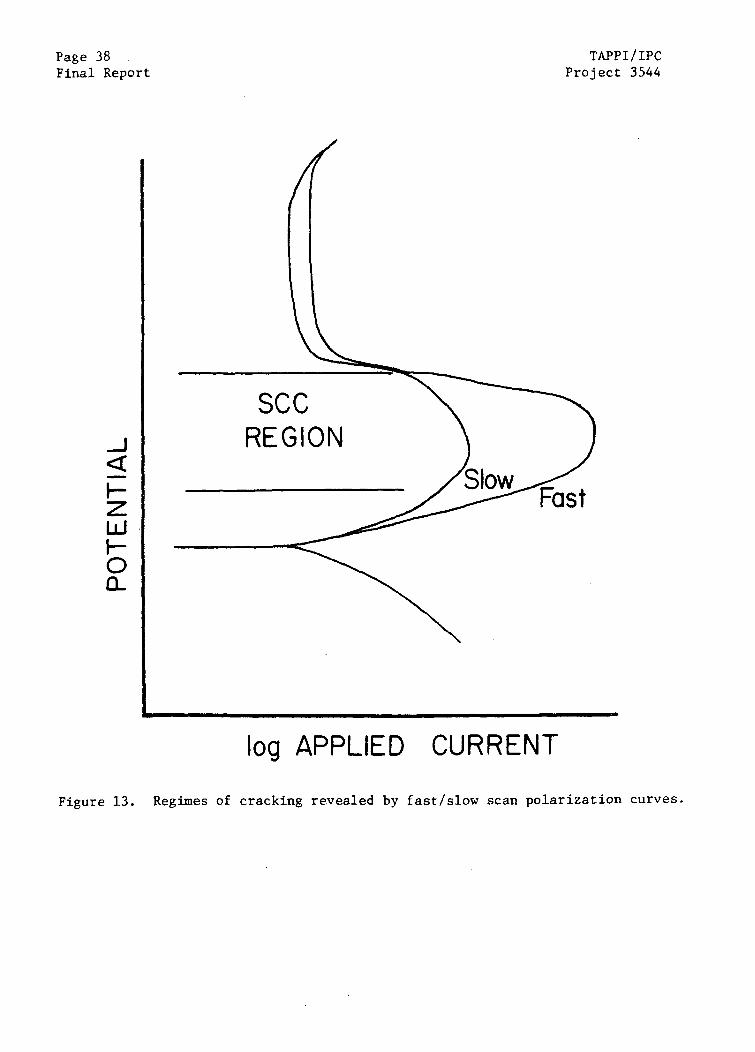
Page 38Final Report
TAPPI/IPCProject 3544
SCCREGION
log APPLIED CURRENT
Figure 13. Regimes of cracking revealed by fast/slow scan polarization curves.
TAPPI/IPC Page 39Project 3544 Final Report
flowing in the fast and slow scan will be different, marking the likelihood of
considerable crack growth whenever the passive film is ruptured at the crack
tip.
The fast/slow scan technique has shown some correlation with SCC
susceptibility in laboratory tests, but the test method has not yet been exten-
sively studied. Since the method provides a very rapid assessment of SCC be-
havior of a metal/environment combination, the fast/slow scan method is best
suited for rapidly screening SCC behavior under numerous conditions. A potential
pitfall with this accelerated test method is the possibility of alternative
oxidation/reduction reactions masquerading as corrosion reactions during polari-
zation scans. If such redox reactions occur, they could exhibit fast/slow scan
behavior that erroneously predicts SCC immunity or susceptibility.
In recent years, a test involving step changes in potential (from
below Ecorr to the passive regime) with measurement of the rate of current decay
has been used to predict the rates of crack growth under SCC conditions. If the
corrosion current falls slowly, extensive dissolution occurs and any potential
cracks that form after a film rupture event will soon be neutralized by blunting
at the crack tip. On the other hand, very rapid repassivation will be evident
in a rapid transient in the corrosion current, and this rapid repassivation
suggests that ruptured films will be restored so quickly that SCC will not
occur. In the intermediate regime, where slow repassivation is indicated by a
gradual reduction in the corrosion current, is the regime where SCC is indi-
cated. Metals which exhibit intermediate current transients in a specific
environment are likely candidates for SCC in that environment. The method is
also relatively new, and unproven, but is so rapid that it can be used to screen
Page 40 TAPPI/IPCFinal Report Project 3544
the behavior of numerous metal/environment combinations, to reduce the numbers
of detailed tests such as SERT testing,
Remedies for SCC
The methods for controlling stress corrosion cracking usually involve
removal of one of the key ingredients for SCC shown in Fig. I -- namely ten-
sile stress, specific environment, or a susceptible material. The removal of
one ingredient for SCC will effectively remedy the SCC problem.
Stresses can be removed or reduced in a variety of ways. A thermal
treatment to reduce the built-in residual stresses is a common approach; but
such treatments are usually reserved for new equipment since the high tem-
perature treatment can have unexpected effects when the residues from prior
operation are not completely removed. Tensile stresses can also be reduced by
shot peening, since peening puts the first few mils of metal surfaces in a state
of compression. When possible, operating stresses can be reduced by reducing
pressures or decreasing loading. In some cases, alternative fabrication methods
can be effective in lowering residual stresses as, for example, in temper bead
welding repairs.
The environment causing SCC can either be modified by removing or
altering the aggressive species, or be excluded from the affected metal by the use
of coatings. In many cases SCC can be reduced by reducing contamination of the
environment by aggressive chemical species. In other cases, the aggressive
species are major constituents of an environment that cannot be significantly
changed, and changing the environment is impractical. In these cases, coatings
can be used to isolate the susceptible metal from the environment. The number
of different coatings is considerable, ranging from paints to weld overlays and

TAPPI/IPC Page 41
Project 3544 Final Report
thermally sprayed metal coatings. The adhesion and durability of coatings is
always a concern.
Changing materials to eliminate SCC is often a good alternative when
cracking occurs in small, easily replaceable components. SCC tests can usually
identify superior alloys for use in any application where SCC is a problem. In
the case of large, fixed pieces of equipment, the only practical materials
change is the change in surface metallurgy by application of coatings, such as
weld overlays and thermally sprayed coatings.
A final alternative for reduction in SCC is the installation of a
cathodic or anodic protection system to maintain the potential at the metal sur-
face outside of the SCC danger zone. Cathodic protection systems reduce the
potential, whereas anodic protection systems raise the potential. In either
case, an apparatus is installed to sense the potential of the metal surface and
then pass a current through the metal/electrolyte interface to achieve a safe
potential. Currents required for protection can be large (in some cases,
impractically high) or small, depending on the conditions. Anodic protection
systems can only be used in circumstances where the metal is passive or can be
made passive at achievable potentials. The use of protection systems to control
corrosion is a common industrial practice, but the use of these types of protec-
tion to control SCC is not well established at present.

Page 42 TAPPI/IPCFinal Report Project 3544
SCC IN ALKALINE MEDIA*
Introduction
There have been several excellent review articles published recently
dealing with stress corrosion cracking of low-to-medium strength steels (2, 3,
4). Rather than provide an exhaustive review of these articles and the related
literature, this section will focus primarily on those aspects of stress corro-
sion cracking which are relevant to cracking of continuous digester vessels.
The three principal constituents of kraft cooking liquors -- caustic,
sulfide, and carbonate/bicarbonate -- have all been implicated in stress corro-
sion cracking of carbon steels under some conditions. Caustic cracking of car-
bon steels is a well-known phenomenon since the early studies of SCC of riveted,
high-pressure boilers. Stress corrosion cracking of higher strength steels in
sulfide media is also well known in the petroleum and petrochemical industries,
although this form of cracking is usually associated with acidic, rather than
alkaline, pH conditions. Stress corrosion cracking has also been reported in
higher strength pipeline steels exposed to carbonate/bicarbonate mixtures.
Stress corrosion cracking of steels also occurs in a variety of environments
unrelated to kraft liquor conditions, such as nitrate solutions and anhydrous
ammonia. Some of the highest strength steels may even be susceptible to
cracking in relatively pure water via hydrogen embrittlement, as described in
the previous section.
Since the etiology of stress corrosion cracking of continuous digesters
is still uncertain, each of the three species -- caustic, sulfide, carbonate/
*This section is written for the corrosion specialist.
TAPPI/IPC Page 43Project 3544 Final Report
bicarbonate -- must be considered for its potential contribution to digester
cracking. Consequently, this section will begin by examining the possibilities
of sulfide and carbonate/bicarbonate cracking before turning to a more thorough
scrutiny of caustic cracking in sulfide media.
Although a detailed discussion of cooking liquor chemistry will be pre-
sented in a later section, some discussion of liquor chemistry in the vicinity
of digester cracking is appropriate here as a basis for discussion. The
overwhelming majority of digester cracks have been observed in the impregnation
zone of continuous digesters, wherein cooking liquor is diffused into the chips
prior to cooking. Because of the low-temperature cooking that occurs in the top
circulation line, the liquor entering the top of the vessel with the chips has
a caustic concentration somewhat lower than that of a typical white liquor. The
liquor entering the vessel will contain approximately 40 g/L NaOH, 25-35 g/L
Na2S, 20 g/L Na2CO 3, and a few grams per liter of the sulfoxy compounds Na2S0 3,
Na2S203, and Na2 SO4. Unless polysulfide pulping is practiced, the concentration
of Na2Sx will be quite low -- on the order of a few hundred parts per million as
elemental sulfur. There is also a significant organic component of the liquor
due to the low-temperature cooking that occurs. As the chip slug progresses
down the impregnation zone, additional low-temperature cooking takes place, which
will increase the organic component of the liquor at the expense of the inorgan-
ic. The temperature of the liquor will range from approximately 200°F at the
inlet to about 300"F at the top of the cooking zone.
The digester also experiences a variety of non-steady state environ-
ments that could be implicated in cracking. During start-up, for example, a
batch cook is typically performed which will expose the impregnation zone to
Page 44 TAPPI/IPC
Final Report Project 3544
higher than normal temperatures and perhaps higher than normal concentrations
of inorganic species. During routine acid cleaning, the top portions of the
vessel are usually not immersed in the acid, but they are exposed to the gaseous
products of the acid cleaning process, notably hydrogen sulfide gas from the
decomposition of iron sulfide films and other sulfur compounds. The role of
these environmental excursions on stress corrosion cracking of digester vessels
is not yet established,
The steels involved in cracking are low-to-medium strength steels con-
taining about 0.25% carbon and silicon up to 0,35% by weight. The base metal
structure is a ferrite - pearlite microstructure produced by the hot rolling (or
subsequent normalizing) of the plates. The pressure vessel steels have tensile
strengths in the range of 55-70 ksi, with yield strengths on the order of 35
ksi, and good ductility. A variety of weld processes are used to fabricate the
vessel, but the weld metals used are all of the 70 class, i.e., chosen to devel-
op a 70-ksi tensile strength in the weld metal.
Thus, the materials of construction and the routine environmental con-
ditions at the site of vessel cracking are relatively well known, but the
effects of nonroutine operation are unknown. The alloys involved are low-to-
medium strength pearlitic steels exposed to a hot caustic solution also con-
taining carbonate and a variety of sulfur compounds.
TAPPI/IPC Page 45Project 3544 Final Report
THE POTENTIAL FOR SULFIDE CRACKING*
Sulfide cracking is a term frequently used to denote a form of stress
corrosion cracking which is promoted by the presence of hydrogen sulfide gas
dissolved in the cracking media. It is generally agreed that sulfide cracking
occurs as a result of a hydrogen embrittlement process involving the evolution
and transport of atomic hydrogen to the tip of a crack, which grows by repeated
hydrogen embrittlement events. Hydrogen sulfide appears to promote cracking by
assisting in the generation of atomic hydrogen at the surface and by inter-
fering with the formation of molecular hydrogen gas, thereby enhancing the
uptake of nascent hydrogen in the vicinity of the crack tip.
Sulfide cracking susceptibility is a strong function of the pH of the
sulfide environment, with a diminished SCC susceptibility at high pH. Hudgins
and co-workers (5) found, for example, that the time to failure for high-
strength steels exposed to a very aggressive sulfide solution increased signifi-
cantly as the pH was increased above 6, with no failures at all detected when
the pH was 9 or above. Dvoracek (6) found that the threshold stress for the
onset of cracking of precracked specimens of high-strength steel increased as
the pH increased from 3 to 8. Kahout and McGuire (7) reported that a high-
strength steel would crack in a sulfide medium at a pH of 4, whereas no cracking
was observed when the pH was 8.
*Emphasis is placed on acid sulfide cracking; caustic cracking and sulfide
cracking in alkaline sulfide media are indistinguishable. Only alkali metalsulfides have appreciable solubility in aqueous solutions, and these alkali
metal sulfides hydrolyze strongly via
Na2S + NaHS + NaOH
to form alkaline solutions.
Page 46 TAPP1/IPC
Final Report Project 3544
The strong effect of pH on cracking susceptibility may be related to
the ease with which hydrogen can be absorbed in a steel. Hydrogen enters steels
much more readily from sulfide solutions when the pH is below 5. This may be a
consequence of the effect of the hydrogen ion activity, but may also be a result
of the change in the stable sulfur species as the pH increases. Pourbaix (8)
reports that dissolved H2 S is stable at low pH, but is transformed into the HS-
species when the pH is about 5 (H2 S/HS- has a pK = 6.7). At still higher pH
values, the stable species is the S= ion (HS-/S= has a pK = 15). It appears
that the sulfur species must be present as H2S in an acidic medium for signifi-
cant sulfide cracking to occur,
It is debatable whether the pH of the moisture condensed on the walls
of the impregnation zone during acid cleaning would fall below a pH of 8 or 9 as
is required for sulfide cracking. The impregnation zone is usually not immersed
in the cleaning acid, but some moisture will be present on the upper walls
because of condensation. Strongly alkaline deposits are to be expected in this
upper region as a residue from operation with the caustic cooking liquors, even
after routine washing of the zone with water prior to acid cleaning. Since
hydrogen sulfide gas evolved during acid cleaning is a very weak acid (pK =
6.7), it is unlikely to neutralize the caustic when it dissolves in the condensed
moisture, even when the H2S concentration is several thousand parts per million
(as one gas analysis would indicate). The only source of an acid strong enough
to acidify the condensed moisture into the cracking range is vaporized acid
(typically HC1) from the cleaning acid. Significant quantities of acid could be
transported into the impregnation zone by evaporation and condensation since the
cleaning acid is heated and the upper walls of the vessel will be relatively
cool. However, it is unlikely that condensate from a dilute acid solution
TAPPI/IPC Page 47
Project 3544 Final Report
(3-5% HC1, typically) would acidify strongly alkaline deposits in the upper
portions of the vessel. If the moisture condensed on the walls was acidified
into the cracking regime, most cracking should be expected adjacent to the upper
cooking screens where acidification would be highest, yet there seems to be no
such correlation (see later sections). Thus, it seems unlikely that the acid
cleaning process could lower the pH sufficiently to induce sulfide cracking in
the impregnation regions of the vessel.
A more compelling argument against sulfide cracking of digester vessels
during acid cleaning is the observation of very limited cracking in the low-to-
medium strength steels and weld metals used in continuous digester vessels. In
an acidified chloride solution saturated with H2 S gas at pH = 3.8, the threshold
stress for cracking of smooth specimens was above the yield strength for all
quenched and tempered steels whose yield strength was above 85 ksi (9). For a
normalized steel, stresses just below the yield strength were required to obtain
cracking in 21 days in this very aggressive environment. In another study (10),
the threshold stress intensities for crack growth in precracked specimens exposed
to acidified, H2 S-saturated environments increased with decreasing strength of
the steel. Although no steels were examined whose yield strengths were below 60
ksi, these medium-strength steels required a stress intensity of 25 to 45 ksi /in
for crack growth in a very aggressive medium. An approximate fracture mechanics
calculation shows that a tensile stress above 70 ksi (i.e., much greater than
the yield strength) would be required to propagate a l/8"-deep crack in this
acidified, H2 S-saturated solution. For comparison, a 1/8"-deep crack in a steel
with a yield strength of 180 ksi would grow when the stress was only 22 ksi.
The National Association of Corrosion Engineers (NACE) recommends the
use of steels with hardness below Rc 22 for H2S service. These steels include
Page 48 -TAPPI/IPC
Final Report Project 3544
hot rolled carbon steel similar to the pressure vessel steels used in digesters.
The Rc 22 hardness corresponds to a tensile strength of about 110 ksi. Thus,
all of the steels used in digester vessel construction should be resistant to
sulfide cracking according to the NACE criteria. Several authors have verified
the resistance of low-strength carbon steels to sulfide cracking. Ishizuka and
Onishi (1]) verified that two mild steels with yield strengths near 40 ksi were
immune to sulfide cracking in a very aggressive environment, even though they
were loaded to the yield strength. Bates (12) exposed a number of welded plain
carbon steels, including A285 (a common digester steel) and several other steels,
to H2S-containing salt brines in oil refinery applications. The A285 steel was
immune to sulfide cracking after an 18-month exposure, as were the other steels
whose hardnesses were below Rc 22 (and whose tensile strengths were below 110
ksi). Others have shown that steels that satisfy the NACE criteria can crack,
but only in the most aggressive acid sulfide media (13, 14).
Welds may or may not be more susceptible than base metal to sulfide
cracking. In most cases, sulfide cracking is observed in the heat-affected zone
(HAZ) of welds when the local hardness in this zone exceeds Rc 22. However, the
tests described above involving A285 -- a digester vessel material -- did not
crack in the as-welded condition, even though the local hardness in the HAZ
slightly exceeded the Rc 22 criteria (12).
Cracking occurring in acidified sulfide media is generally branched and
transgranular, in contrast to the branched intergranular cracking reported in
most examinations of digester cracks. This difference in crack morphology also
argues against a sulfide cracking mechanism for digester weldments.
Finally, as described in a later section, there is no strong correla-
tion between cracking susceptibility and acid cleaning practices.
TAPP1/IPC Page 49
Project 3544 Final Report
Thus, the circumstantial evidence against cracking via a sulfide/
hydrogen - embrittlement mechanism is convincing. The evidence is:
(i) Questionable acidification of condensate on vessel walls during
acid cleaning of the lower vessel
(ii) Low susceptibility to sulfide cracking exhibited by low-strength
steels in the digester steel grades
(iii) Transgranular cracking morphology for sulfide cracking versus
intergranular cracking in digester weldments
(iv) No correlation between acid cleaning frequency and cracking.
Although some tests might be appropriate to resolve unequivocally the
question of susceptibility of digester-type weldments to sulfide cracking, the
available evidence suggests that digester cracking is not a consequence of acid
sulfide cracking during acid cleaning.
The Potential for Carbonate/Bicarbonate Cracking
Parkins and his co-workers have shown that carbonates (specifically
aluminum carbonate) and mixtures of sodium carbonates and sodium bicarbonates
can cause stress corrosion cracking of a variety of low-strength steels (15, 16,
17, 18). Similar results have been reported by Herbsleb et al. (19) and
Wender-Kalsch et al. (20, 21) Cracking in carbonate/bicarbonate solutions is
intergranular, as is cracking in continuous digester weldments. SCC is observed
in a variety of C03 =/HC03- mixtures with pH values in the range 8 to 10.5. As
little as 0.25N Na2HCO3 (bicarbonate) will cause SCC in steels, but 2N Na2C03
(carbonate) will not induce cracking at 22°C or at 90°C. Stress corrosion
cracking occurs only within a narrow range of potential (-0.625 to -0.45 VSCE)
which is slightly more positive than the potential for cracking in caustic. As
Page 50 TAPPI/IPCFinal Report Project 3544
seen in subsequent chapters, this potential range cannot easily be reached by
digester steels exposed to kraft liquors. Herbsleb (19) has reported that a
pipeline steel was susceptible to SCC under slow extension rate conditions,
whereas statically loaded specimens in the same solutions at the same potentials
did not show any cracking.
Since carbonate/bicarbonate cracking is a relatively new phenomenon,
the available information is inadequate to determine whether this type of
cracking has a role in digester cracking. What little information is available
suggests that carbonates are not directly involved in digester cracking.
Carbonate/bicarbonate cracking has not been reported in the pH range (12-14)
associated with kraft cooking liquors; Sutcliffe et al. (15) reported cracking
only below a pH of 10.5. Moreover, most kraft liquors contain carbonate only in
concentrations at or below the lower threshold for cracking in SERT tests (0.25 N
Na2CO3). At the high pH of the kraft cooking liquors, nearly all of the
carbonate/bicarbonate ions will exist as alkali carbonate since pK2 is ~ 10 for
H2CO 3. Strongly alkaline carbonate solutions do not appear to be potent SCC
activators that characterize less alkaline C03=/HCO3- mixtures.
In the final analysis, it must be acknowledged that carbonates/
bicarbonates are known to induce SCC in low-strength steels, but the role of
these species in cracking associated with kraft liquors cannot be judged because
of the scarcity of relevant data. An experimental assessment of the role of
carbonates in digester cracking would be required to resolve this issue
unequivocally.
TAPPI/IPC Page 51Project 3544 Final Report
SCC of Carbon Steels in Caustic Solutions
Service Performance
Plain carbon steels are wellknown for their susceptibility to inter-
granular stress corrosion cracking in caustic. The problem first became
apparent in the early part of this century when a number of riveted, high-
pressure steam boilers failed (22, 23). In subsequent years, a number of
failures have occurred in components and structures as a result of stress corro-
sion cracking of steel in caustic solutions.
Schmidt et al. (24) have summarized the results of a 1951 survey of
caustic cracking experience, in which a variety of tanks, evaporators, pipes, and
related equipment failed after exposure to caustic soda. Welds were a common
site for caustic cracking. In many cases, cracking was observed after 10 or 15
years of successful operation, whereas in other cases, cracking took place in a
few months. A variety of different steels exhibited cracking, including one
welded vessel fabricated from A-285C steel -- a common steel used in fabrication
of continuous digester vessels. Most failures were reported after exposure to
concentrated caustic solutions containing more than 30% caustic.
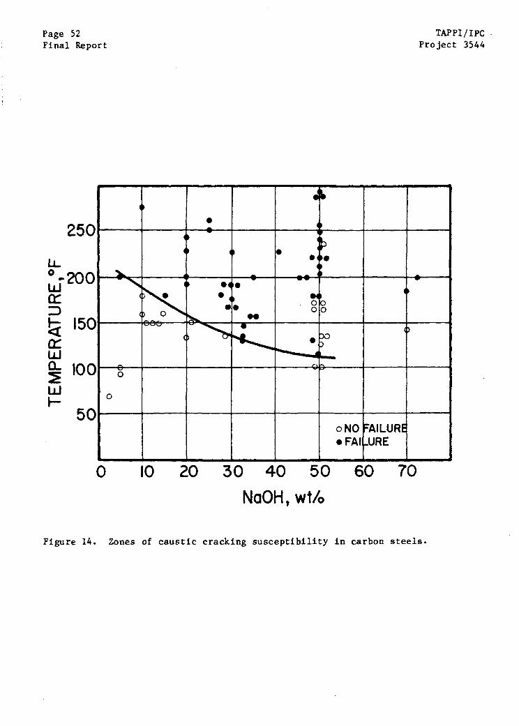
Based on their field measurements, Schmidt et al. (24) identified
regions where the temperature and NaOH concentration would and would not cause
cracking of carbon steel. As shown in Fig. 14, only two failures were reported
in solutions containing 10% or less sodium hydroxide, both of which occurred
above 200"F. The beneficial effects of stress relief of weldments were also
cited.
In the years since Schmidt reported the results of his survey, caustic
cracking has been reported in a variety of carbon steel structures, a few of
which are described below. Ashbaugh (25) described a number of instances of
Page 52Final Report
250
LL
TAPPI/IPCProject 3544
0 10 20 30 40 50 60 70
NaOH, wt/o
Figure 14. Zones of caustic cracking susceptibility in carbon steels.
TAPPI/IPC Page 53
Project 3544 Final Report
caustic cracking in petrochemical plants, most of which were associated with
contaminated steam systems and piping for handling caustic. Stress corrosion
cracking of disks in steam turbines has been attributed to caustic cracking in
the highly stressed areas at the keyways and blade attachment areas (26,27).
Longitudinal cracking in a welded joint in a caustic soda evaporator was
reported by Naumann and Spies (28). Stress corrosion cracking was also reported
in the welds of carbon steel dissolving tanks used in the alkaline Bayer process
(29,30). These tanks were filled with a sodium aluminate solution whose NaOH
concentration is 100-150 grams/liter -- which is close to the caustic levels in
kraft liquors -- in the temperature range 45-60'C.
In view of digester cracking conditions, it is interesting to note that
Artem'ev et al. (29) implicated dissolved sulfur compounds as the key factor in
rapid weld cracking of Bayer process dissolving vessels. Vessels which crack
rapidly were found to contain as much as 3.5 g/L of total sulfur in various
states of oxidation, whereas those vessels with long service experience had only
0.08 g/L total sulfur. Laboratory tests indicated that the sulfur compounds
prevented the passivation of the steel walls of the dissolving tanks and main-
tained the potential in the regime for cracking. Treatment of the dissolving
liquor with a strong oxidant -- hydrogen peroxide or potassium persulfate --
oxidized the sulfur components to an innocuous state, which allowed passivation
and protection of the vessel from cracking.
In 1967, the NACE published its Corrosion Data Survey (31) -- a compen-
dium of corrosion and stress corrosion cracking experience, including SCC in hot
caustic solutions. Based on these findings, a recommendation was made regarding
materials of construction in contact with hot caustic. As shown in Fig. 15,

TAPPI/IPC
rinal Report Project 3544
20C
16C
12C
8C
40
I
CONSIDER NICKEL AL OYS
STRESS RELIEVE WELDS
)CAREON STEEL
NO STRESS RELIEF REQ D
I I0 10
Figure 15.
I20 30
NaOH, wt/o40 50
Materials recommendations for service in caustic media (CorrosionData Survey).
280
240
LL0
TAPPI/IPC Page 55Project 3544 Final Report
materials recommended included carbon steel without stress relief at low tem-
peratures, carbon steel with stress relief of welds and other highly stressed
areas at intermediate temperatures, and the use of nickel alloys at still
higher temperatures.
To summarize, stress corrosion cracking of carbon steels in contact
with hot caustic solutions continues to be a problem of recurring concern.
Welds appear to be particularly susceptible to caustic cracking, but this
susceptibility can be decreased by an appropriate stress relief treatment of
the welds.
Reviews of Caustic Cracking
There have been several review articles published recently which sum-
marize the results of laboratory and field investigations of caustic cracking
of plain carbon steels (2,3,4,32,33). A voluminous literature is cited, since
there have been numerous investigations on this subject. The salient features
of caustic cracking studies relevant to digester cracking are cited in the
paragraphs to follow, but a detailed summary of caustic cracking is beyond the
scope of this report. The reader is referred to the review articles and the
cited literature for more information.
Caustic Cracking Morphology
The usual morphology of caustic cracking in carbon steels involves an
intergranular crack path, with occasional reports of mixed intergranular/trans-
granular growth. The crack path in quenched and tempered steels follows prior
austenite grain boundaries, whereas in ferritic-pearlite steels, the path
generally follows ferrite-ferrite boundaries, with occasional growth along the
interface between ferrite and pearlite colonies (34,35).
Final Report Project 354.
NaOH Concentration
Stress corrosion cracking occurs in caustic solutions over a wide range
of compositions, ranging from 5% to more than 70% NaOH. Cracking appears to be
most severe in the intermediate caustic range, near 30% NaOH. In some tests of
short duration, lasting only a month or so, the range of NaOH concentrations
causing cracking is compressed to 20-35% NaOH (36), Based on these results,
Berk and Waldek (36) identified a "caustic danger zone" where temperature and
caustic concentrations were likely to cause stress corrosion cracking.
The cooking liquors used in continuous digesters have a caustic con-
centration that is at the lower extreme of that causing caustic cracking.
Cooking liquors entering the vessel contain about 5% NaOH, plus an additional
caustic contribution from hydrolysis of Na2S, so a hydroxide concentration
corresponding to about 8% NaOH is typical; Based on this low caustic concen-
tration alone, exposure of carbon steels in kraft cooking liquors may require
long incubation times or imposed potentials to induce caustic cracking.
Temperature
Caustic cracking of carbon steel occurs over a wide range of temper-
atures, with the lower temperature threshold for cracking dependent on the
caustic concentration (Fig. 14), At low caustic concentrations, a higher tem-
perature is required for cracking, according to the field data reported by
Schmidt et al, (24). At higher concentrations of caustic, however, no correla-
tion could be found relating temperature and time-to-cracking. Bohnenkamp (4)
and others (37) have confirmed the inverse relationship between temperature and
time-to-failure in laboratory tests at controlled potentials.
Since autoclave testing is required for caustic cracking studies at
temperatures above the atmospheric boiling temperature, there have been few
TAPPI/IPC Page 57Project 3544 Final Report
laboratory studies of caustic cracking in plain carbon steels at digester
operating temparatures. Robinson and Nel (38) examined the effect of tem-
peratures as high as 250eC (482°F) and concluded that cracking susceptibility in
50% NaOH decreased as temperatures increased from 210°C (410°F) to 240°C
(464'F). For a mild steel exposed to 33% NaOH, Singbeil and Tromans (39) found
that the stage II crack velocity decreased logarithmically as 1/T increased
(Arrhenius behavior). That is, crack growth rates increased with increasing
temperature, with an apparent activation energy of 24 kJ/mol. Berry (40) also
reported Arrhenius behavior for crack velocities obtained with a quenched and
tempered steel exposed to 33% NaOH at temperatures ranging from room temperature
to as high as 115°C (240°F).
Temperature is also known to affect the rest potential for some steels
exposed to caustic solutions; in some instances, temperature determined whether
the rest potential resided within the range of potentials required for cracking.
For example, McCord et al. (27) found that the rest potentials of two quenched
and tempered steels remained in the cracking range during exposure to 28% and
35% NaOH solutions in a temperature range of 60°C (140°F) to ]20°C (248°F). In
a 20% NaOH solution, however, one of the steels exhibited a rest potential 600
mV above the cracking zone at temperatures from 60°C (140°F) to 85°C (185°F).
The potential fell to within the cracking range only above 85°C (185°F).
To summarize, most studies of temperature effects in caustic cracking
of carbon steels have been conducted below the range of temperatures that exist
in continuous digesters. At these lower temperatures, there is every indication
that caustic cracking obeys thermally activated kinetics; i.e., crack velocities
increase exponentially with increasing temperature. Above the atmospheric
boiling temperature, little is known about the SCC of plain carbon steels in
Page 58 TAPPI/IPCFinal Report Project 3544
caustic, although there has been a continuing effort to characterize caustic
cracking of stainless alloys and quenched and tempered steels at elevated tem-
peratures.
Potential
It is now well established that caustic stress corrosion depends
strongly on the electrochemical potential of the carbon steel immersed in the
caustic solution. Several reports have shown that caustic cracking occurs only
within a small range of potentials which are slightly noble to the anodic peak
at the active-passive transition (2,4,32,33). The range of potentials is
broadened as the concentration of sodium hydroxide is raised, as shown in Fig.
16, with the mid-range potential for cracking located at approximately -0.7
VSHE. Bohnenkamp (4) found that the potential region associated with cracking
did not vary as the temperature was increased from 70°C (158°F) to 120°C
(248°F); the latter temperature is relevant to cracking in digesters.
Although the potential region associated with cracking of carbon steels
appears to be relatively independent of the composition of the steel, Parkins
(2) does report that carbon steels containing Si and Mo can exhibit unusually
wide potential regions where cracking is observed. In some cases, a second zone
of cracking is reported at a higher range of potentials, as shown for the case
of a quenched and tempered Cr-Mo steel in Fig. 17 (41). Parkins (2) also reports
that the potential required for caustic cracking depends on the carbon content
of the steel.
The rest potentials for carbon steel may or may not reside within the
range required for cracking, which may explain why some investigators report
difficulty in cracking steels in the laboratory without imposed potential.
I
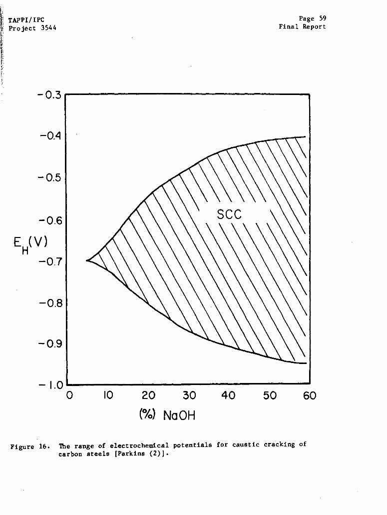
TAPPI/IPCProject 3544
-0.3
-0.4
-0.5
-0.6
EH(V)-0.7
-0.8
-0.9
- 1.0
Figure 16.
Page 59Final Report
0 10 20 30 40 50 60
(%) NaOH
The range of electrochemical potentials for caustic cracking of
carbon steels [Parkins (2)].

Page 60Final Report
Figure 17. *s
TAPPI/IPCProject 3544
.2
-0.8 -0.6 -0.4POTENTIAL, V vs Hg/HgO
-02
he electrochemical potential dependence for caustic crackingusceptibility of two steels.

TAPPI/IPC Page 61
Project 3544 Final Report
Reinoehl and Berry (32) found the initial potential of a steel immersed in
caustic at 93°C (200°F) was well above the range of potentials required for
cracking, but drifted downward as time elapsed. The rate of downward drift of
potentials varied with time, depending on the caustic concentration; above 20%
NaOH, the potentials drifted downward into the cracking regime, and SCC was
observed. Below 20% NaOH, the rest potential occurred well above the regime
associated with cracking, and no SCC was observed. Humphries and Parkins (42)
and Harrison, et al. (41), on the other hand, reported that their specimens were
initially active when immersed in caustic, with a potential of ~0.900 VSHE, but
the potential drifted upward, through the cracking range in some cases. An
example of the change in potential with time is shown in Fig. 18. The drift
behavior of the open circuit potential apparently depends on many factors,
.including composition of the steel, surface preparation, and caustic con-
centration. (The role of oxidizing species is addressed below). When investi-
gations fail to produce caustic cracking in laboratory circumstances without
impressed potentials, it is likely that the potential of the steel does not
spontaneously reside within the critical cracking regime for a sufficient period
of time to permit crack initiation and growth.
Several investigators have pointed out that the critical regime for
cracking in caustic coincides with the zone where magnetite (Fe304) is the
stable solid in equilibrium with sodium hydroxide, and the HFeO 2- ion is the
stable dissolved species. The Pourbaix (43) diagram for iron shown in Fig. 19
indicates that the regions of stability of these species coincide with the
caustic cracking regime. Bohnenkamp (4) cites evidence that the surface film
stable at -700 mVSHE is magnetite, whereas y-Fe203 forms at higher potentials,
approximately -300 mVSHE. The magnetite (Fe304) film is implicated in cracking,
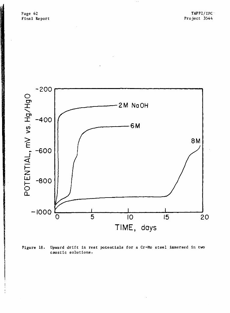
Page 62Final Report
-200
-400
-600
-800
TAPPI/IPCProject 3544
Figure 18. Upward drift in rest potentials for acaustic solutions.
Cr-Mo steel immersed in two
20
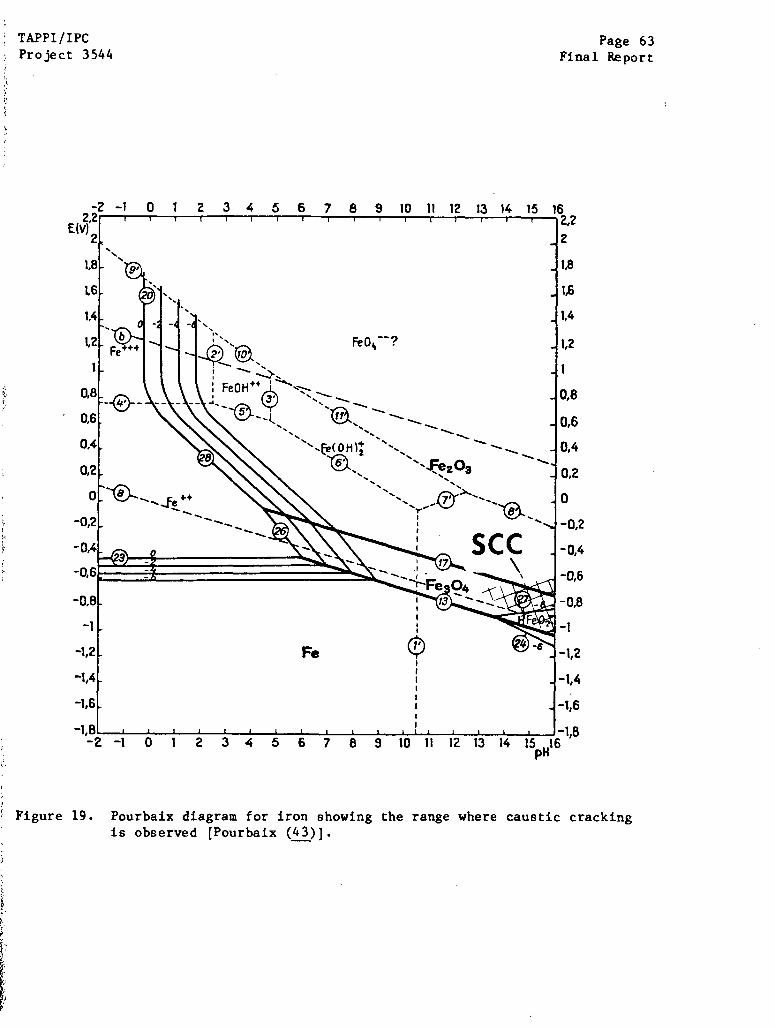
TAPPI/IPCProject 3544
Page 63Final Report
Figure 19. Pourbaix diagram for iron showing the range where caustic crackingis observed [Pourbaix (43)].
Page 64 TAPPI/IPC
Final Report Project 3544
in contrast to the hematite (Fe2 03) film formed at higher potentials, because the
magnetite film is thought to be much less ductile than hematite (44) and there-
fore more likely to rupture during crack tip deformation. The dihypoferrite
ion (HFeO2-), is the soluble product of the active dissolution that follows the
rupture of the film at the crack tip. When the solubility product of the
HFeO2- is exceeded, Fe304 is precipitated, and the crack tip is repassivated by
the magnetite film to await another film rupture event.
Stress/Stress Intensity
Stresses high enough to induce plastic deformation at some point in the
surface of the test specimen are required for the onset of stress corrosion
cracking in unnotched carbon steel specimens, according to Robinson and Nel
(38) and Bohnenkamp (4). Stress intensities as low as 18 MPa /m (16.4 ksi Vin)
can induce crack growth at 10- ]0 m/s (0,1 inches/year) in mild steel, according
to Singbeil and Tromans (39). Similar, but somewhat lower, threshold stress
intensities are reported for quenched and tempered steels (2). Apparently, some
localized plastic deformation is required to induce film rupture and subsequent
crack growth,
Metallurgy
Parkins (2) concludes that all plain carbon steels are susceptible to
caustic cracking, but some steels are more prone toward caustic cracking than
others.
The effect of carbon content on caustic cracking of iron and steel is
somewhat controversial. Robinson and Nel (35) concluded that a high carbon
content was detrimental since high carbon, fully killed steels were most suscep-
tible to cracking, whereas intermediate carbon, semikilled steels and lower
TAPPI/IPC Page 65
Project 3544 Final Report
carbon rimmed steels were much less prone to caustic cracking. A zone-refined
iron specimen, presumably with a very low carbon content, would not crack under
the most aggressive caustic conditions. On the other hand, Bohnenkamp (4)
could not induce caustic cracking in a high carbon (0.33 C) steel under con-
ditions which would readily crack low carbon Armco iron. Mazille and Uhlig (37)
found that increasing the carbon content from 0.09% to 0.24% decreased the time
to failure at 85%C (185°F), 105°C (221"F), and 125°C (257°F). The opposite be-
havior was reported by Hugo et al. '(45), who found that 0.02% C steel cracked
readily in boiling 35% NaOH, whereas higher carbon steels (0.17% C, 0.39% C) also
stressed above yield were virtually uncracked. Zhagalaya et al. (46) found that
high carbon steels (0.35 - 0.45 C) were more resistant to caustic cracking than
low carbon steels (0.04 to 0.20 C), but all of the steels did exhibit caustic
cracking. Additions of titanium to low carbon steels to reduce the dissolved
carbon content by TiC precipitation increased the resistance to caustic cracking
(4,47). In one study (47), the reduction in dissolved carbon did not stop the
initiation of cracks, but rather impeded the growth of cracks. Parkins (2) has
suggested that caustic cracking of plain carbon steels might be avoided by using
carbon contents exceeding 0.2%.
Relatively little is known about the role of metallurgical structure on
i caustic cracking susceptibility, which is surprising in view of the suscep-
tibility of welds to caustic cracking in service. Both quenched and tempered
,steels and ferritic-pearlitic steels exhibit cracking in similar ranges of poten-
tial, according to Harrison et al. (41). Parr and Straub (23), in some of the
early work on caustic cracking, reported cracking of a variety of early steels
in caustic. In this study, "Flange steel" -- a predecessor of modern day A-285
steels -- exhibited cracking regardless of whether or not the structure was
ferritic-pearlitic, martensitic, or spheroidic. Johnston and McCord (48) also
Page 66 TAPP1/IPC
Final Report Project 3544
examined alkaline sulfide cracking of pearlite, bainitic, and martensitic struc-
tures in a Cr-Mo-V steel. As-quenched martensite was susceptible to cracking at
potentials cathodic to hydrogen, but none of the other structures exhibited a
significant degree of cracking in the alkaline sulfide media (0.6 M Na2 S). The
as-quenched martensite was also found to be immune to caustic cracking in 0.6 M
NaOH solution. Hurst and Cowen (49) reported that tempering a martensitic 2-1/4
Cr-I Mo steel reduced the range of potentials where caustic cracking could be
induced at 116 C (240 F). These authors also examined caustic cracking in weld-
ments exposed to 30% NaOH over the temperature range of 50°C (]22°F) to 300°C
(572°F) and found that as-welded structures exhibited a high degree of suscep-
tibility to caustic cracking, as did as-quenched structures. Cracks were
usually confined to the base metal adjacent to the weld, and to the fusion line.
Effects of Additional Species
Species added to caustic solutions appear to affect caustic cracking in
one of two ways: (i) the chemical species play a direct role in film stability
or dissolution characteristics, or (ii) the chemical species affects the rest
potential relative to the potential range for cracking. These two effects can
be discriminated by conducting tests at controlled potentials, as done by
Humphries and Parkins (42), These investigators found that PbO, Pb304, and ZnO
additions had little effect on when tests were performed at controlled poten-
tials, rather than the rest potential.
Aeration of the caustic solution had a beneficial effect on cracking
susceptibility independent of potential, as did additions of Na2SiO 3. On the
other hand, Na2 HPO4 additions completely suppressed caustic cracking over the
complete range of potentials normally causing cracking in 35% NaOH solutions, as
did additions of two organic inhibitors, valonea and quebracho.
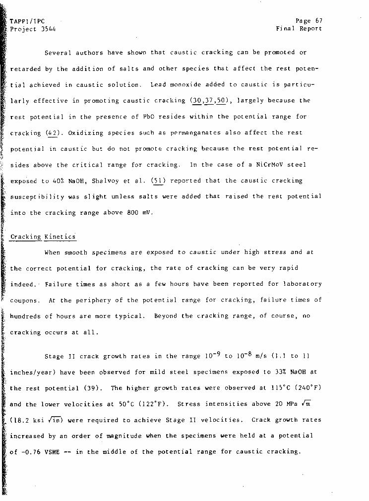
TAPPI/IPC Page 67
Project 3544 Final Report
Several authors have shown that caustic cracking can be promoted or
retarded by the addition of salts and other species that affect the rest poten-
tial achieved in caustic solution. Lead monoxide added to caustic is particu-
larly effective in promoting caustic cracking (30,37,50), largely because the
rest potential in the presence of PbO resides within the potential range for
cracking (A2). Oxidizing species such as permanganates also affect the rest
potential in caustic but do not promote cracking because the rest potential re-
sides above the critical range for cracking. In the case of a NiCrMoV steel
exposed to 40% NaOH, Shalvoy et al. (51) reported that the caustic cracking
susceptibility was slight unless salts were added that raised the rest potential
into the cracking range above 800 mV,
Cracking Kinetics
When smooth specimens are exposed to caustic under high stress and at
the correct potential for cracking, the rate of cracking can be very rapid
indeed. Failure times as short as a few hours have been reported for laboratory
coupons. At the periphery of the potential range for cracking, failure times of
hundreds of hours are more typical. Beyond the cracking range, of course, no
cracking occurs at all.
Stage II crack growth rates in the range 10-9 to 10-8 m/s (1.1 to 11
inches/year) have been observed for mild steel specimens exposed to 33% NaOH at
the rest potential (39). The higher growth rates were observed at 115°C (240°F)
and the lower velocities at 50°C (122°F). Stress intensities above 20 MPa /m
(18.2 ksi /1n) were required to achieve Stage II velocities. Crack growth rates
increased by an order of magnitude when the specimens were held at a potential
of -0.76 VSHE -- in the middle of the potential range for caustic cracking.

Page 68 TAPPI/IPCFinal Report Project 3544
Controlling Caustic Cracking
Based on the preceding information, it is clear that caustic cracking
can be controlled in carbon steels by (i) reducing tensile stresses, (ii)
shifting the metal potential out of the cracking regime, (iii) adding appropriate
inhibitors such as quebracho, or (iv) reducing caustic concentration. The most
common method for effectively reducing tensile stresses associated with fabrica-
tion (welding stress, fit-up, etc.) has been stress relief of replacement com-
ponents (24). Shot peening of welds has effectively stopped caustic cracking
in some cases (49,52), but not in others (30). Shot peening, of course, intro-
duces a compressive layer in the surface of the peened metal, thereby preventing
initiation under residual stresses left by fabrication. In one case (30),
cathodic protection was used to adjust the potential of a tank that had cracked
in a caustic solution and had been repaired by welding. Subsequent failure of
the tank occurred because of cracking by the caustic residue on the outside of
the tank.
SCC in Alkaline Sulfide Media
Recent studies by Singbeil and Tromans deserve special consideration
because of their emphasis on caustic cracking in an alkaline sulfide medium
representative of kraft white liquor (39,53,54,55). These studies have shown
that stress corrosion cracking in alkaline sulfide media resembles caustic
cracking in most respects, with only small differences in the potential cracking
range and anodic current densities.
In agreement with earlier results of Wensley and Charleton (56),
Singbeil and Tromans (53) found that the substitution of approximately one-half
mole of NaOH with Na2 S in a 3.5 M caustic solution had only small effects on the
electrochemical behavior of an AISI 1018 carbon steel. The addition of the
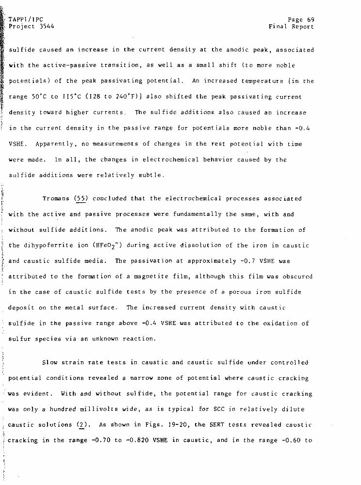
TAPPI/IPCProject 3544
Page 69Final Report
sulfide caused an increase in the current density at the anodic peak, associated
with the active-passive transition, as well as a small shift (to more noble
potentials) of the peak passivating potential. An increased temperature [in the
range 50°C to 115°C (128 to 240°F) also shifted the peak passivating current
density toward higher currents. The sulfide additions also caused an increase
in the current density in the passive range for potentials more noble than -0.4
VSHE. Apparently, no measurements of changes in the rest potential with time
were made. In all, the changes in electrochemical behavior caused by the
sulfide additions were relatively subtle.
Tromans (55) concluded that the electrochemical processes associated
with the active and passive processes were fundamentally the same, with and
without sulfide additions. The anodic peak was attributed to the formation of
the dihypoferrite ion (HFeO2-) during active dissolution of the iron in caustic
f and caustic sulfide media. The passivation at approximately -0.7 VSHE was
attributed to the formation of a magnetite film, although this film was obscured
in the case of caustic sulfide tests by the presence of a porous iron sulfide
deposit on the metal surface. The increased current density with caustic
sulfide in the passive range above -0.4 VSHE was attributed to the oxidation of
sulfur species via an unknown reaction.
Slow strain rate tests in caustic and caustic sulfide under controlled
potential conditions revealed a narrow zone of potential where caustic cracking
was evident. With and without sulfide, the potential range for caustic cracking
was only a hundred millivolts wide, as is typical for SCC in relatively dilute
caustic solutions (2). As shown in Figs. 19-20, the SERT tests revealed caustic
'cracking in the range -0.70 to -0.820 VSHE in caustic, and in the range -0.60 to
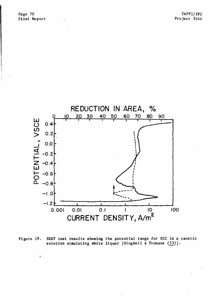
Page 70Final Report
REDUCTION IN0 10 20 30 40 50
0.4
0.2
0.0
-0.2
-0.4
-0.6
-0.8
-1.20.001 0.01
AREA60 70
0.1
CURRENT DENSITY,
Figure 19.
80
10
A/m2
90
TAPPI/IPCProject 3544
100
SERT test results showing the potential range for SCC in a causticsolution simulating white liquor [Singbeil & Tromans (53)).
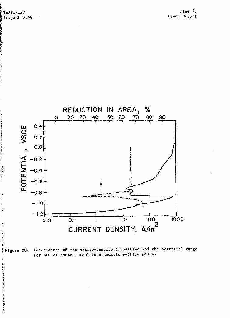
TAPPI/IPCProject 3544
Page 71Final Report
REDUCTION IN AREA,
CURRENT DENSITY,
100
A/m 2
Figure 20. Coincidence of the active-passive transition and the
for SCC of carbon steel in a caustic sulfide media.
potential range
Page 72 TAPPI/IPCFinal Report Project 3544
-0.70 VSHE in caustic sulfide tests. Extensive secondary cracking and inter-
granular fracture were associated with the losses in reduction in area. The
potentials associated with caustic cracking coincide with the active-to-passive
transition observed in the polarization curves.
Complementary studies were conducted to determine the crack growth
characteristics in caustic and caustic sulfide media. Precracked, self-loaded
crack specimens (DCB type) were exposed to caustic and caustic sulfide solutions
at 92°C (and at the peak cracking potential) for 400 hours, followed by crack
length measurement and calculation of crack growth rates. The velocity of
cracking was calculated by dividing the apparent growth increment by the total
exposure time, thereby ignoring any incubation periods preceding resumption of
crack propagation. Classical three-stage growth behavior was observed in
caustic. The Stage II growth rates ranged from 2.9 x10 -9 m/s (3.3 inches/year)
in the caustic to 8.8 x 10⁻¹ 0 m/s (0.9 inches/ year) in the caustic sulfide
media. Crack growth morphology was intergranular and microbranched, with occa-
sional transgranular growth but no significant macrobranching of the crack,
Crack growth kinetics were consistent with a slip-dissolution mechanism
for growth, based on reasonable assumptions about processes occurring at the
crack tip. Thermodynamic considerations precluded the operation of a hydrogen-
assisted mode of crack growth, since the potential and pH apparently prevented
the evolution of hydrogen within the crack tip. However, the potential drop
down the crack tip under impressed potentials, as described by Doig and Flewitt
(57), was not specifically considered and may alter the conclusion rejecting
hydrogen-assisted growth mechanisms.
Thus, with the exception of a small shift in the kinetics of dissolu-
tion processes, the best available simulation of stress corrosion cracking in a
TAPPI/IPC Page 73
Project 3544 Final Report
digester environment shows a strong resemblance to classical caustic cracking.
If this resemblance does indeed indicate that digester cracking is due to
caustic cracking, the extensive data base described above for caustic cracking
becomes meaningful for consideration of cracking in continuous digester weld-
ments. The electrochemical data generated in actual mill liquors in this
program -- to be described in subsequent sections -- will tend to reinforce this
view of digester cracking as an instance of caustic cracking modified, to some
extent, by the presence of species not specifically considered by Singbeil and
Tromans (53)
Page 74 TAPPI/IPC
Final Report Project 3544
STATISTICS OF CRACKING IN CONTINUOUS DIGESTERS
Introduction
Approximately 140 Kamyr continiuous digesters have been placed in opera-
tion in North America since the late 1950's. These digesters are all quite
similar in design, function, operation, and fabrication history, although some
differences exist because of developments in materials and evolution in design.
The vessels range from small, 150 ton per day sawdust digesters to large, 1300
ton per day chip digesters. Most Kamyr digesters employ the kraft or soda pulp-
ing process, although some vessels are used for sulfite and neutral sulfite semi-
chemical pulping as well. The vessels were designed by a single firm, and most
were fabricated in the field by a single firm or its Canadian counterpart. Only
a few different welding processes were employed in the fabrication of digester
vessels. About half of the vessels were completely stress relieved in the
field; the balance were not stress relieved or only partially stress relieved.
In spite of the broad similarity of the Kamyr continuous digesters,
some digesters have experienced severe, repeated cracking in the weldments of
the impregnation zone, while other, similar digesters have escaped cracking
altogether. For example, the Pine Hill vessel suffered severe cracking leading
to vessel failure while another vessel of the same size, using the same pulping
process, fabricated at nearly the same time, has escaped stress corrosion crack-
ing. Thirty-three vessels which were not stress relieved had serious cracking
in the impregnation zone of the vessel, whereas eighteen exhibited no cracking
at all. Of the stress relieved vessels, seven had severe cracking; 23 had no
cracking at all.
TAPPI/lPC Page 75Project 3544 Final Report
The different SCC susceptibilities of nominally similar vessels raises
some intriguing questions about possible correlations between cracking and some
hidden features of digester operation or fabrication. Is cracking confined to
welds made with a certain welding procedure? Is there a correlation between
cooking liquor composition and cracking susceptibilty? Are vessels which have
been immune to cracking likely to start cracking if they inadvertently change
operating practices that bring them into a cracking regime? Are there changes
in pulping practices which susceptible mills can use to retard future crack
growth?
One objective of the IPC program was to search for correlations between
cracking susceptibility and details of vessel fabrication, design, or operation.
The effort was approached in three ways. First, the TAPPI Task Group survey was
updated, computer coded, and then scrutinized for correlations between cracking
and general operating practices. Second, six mills -- three susceptible to
cracking and three immune -- were asked to cooperate by filling out a detailed
questionnaire about pulp mill operation, liquor characteristics, recovery prac-
tices, etc., to ascertain whether immune and susceptible mills differed in their
pulping practices. Third, these same six mills were visited for on-site chemi-
cal and electrochemical characterization of cooking liquors. The third approach
is described in a later Section; the results of the first two surveys, together
with comments of welding consultants, vendors, inspectors, and insurers, are
presented in this section.
Although most readers will be familiar with the Kamyr continuous
digester, a brief introduction to the operation and nomenclature of the digester
system is presented first for those unfamiliar with the topic. Subsequent

Page 76 TAPPI/IPC
Final Report Project 3544
sections deal with a general description of cracking, cracking susceptibility
versus vessel fabrication variables, cracking susceptibility versus operation
variables, and a summary.
TAPPI/IPC Page 77Project 3544 Final Report
Kamyr Continuous Digester Systems
Most Kamyr continuous digesters share certain characteristics,
regardless of whether they are single vessel hydraulic systems of earlier design
or large two-vessel systems of more recent design. In every case, the con-
tinuous digester is designed to accept wood chips (or sawdust) on a continuous
basis, expose the chips to cooking liquors at temperatures and pressures
appropriate for delignification, extract the spent liquors from the cooked chips,
and eject the cooked pulp for further processing. In some cases, pulp washing
is also accomplished within the continuous digester. Usually, the pulping pro-
cess is accomplished within a single large pressure vessel, although two vessel
systems are also in use. The process is continuous in that the mass.of chips
moves continuously through the system, with each process occurring on the chips
as they pass different stages within the vessel.
A typical single-vessel, hydraulic Kamyr continuous digester is shown
schematically in Fig. 21. The key elements of the system include (58,59):
(i) A system for steaming chips at low pressure
(ii) A high-pressure feed system that injects chips into the high-
pressure process, using cooking liquor as a vehicle
(iii) A top separator which screens chips from the excess recirculating
liquor, and directs them to the impregnation zone of the digester
vessel
(iv) A recirculation system for heating cooking liquor extracted from
the chips at screens, and returning the hot liquor to the chip mass
for cooking
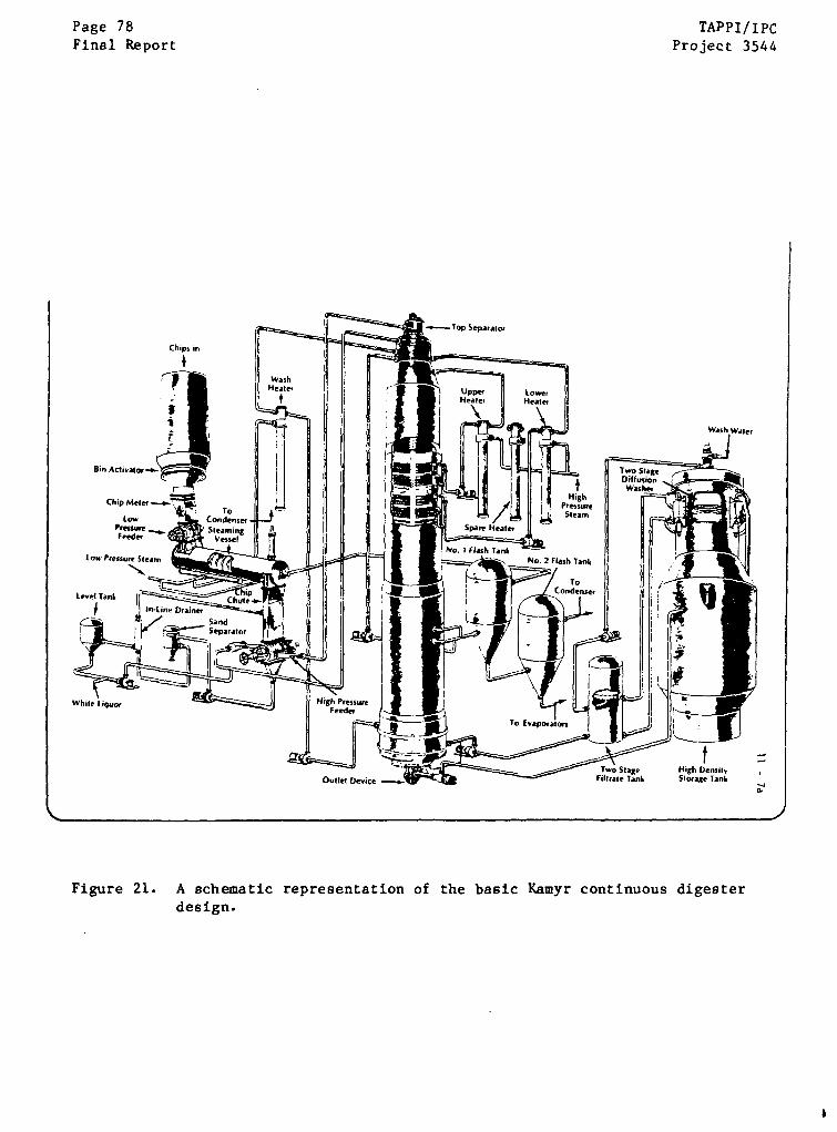
Page 78Final Report
TAPPI/IPCProject 3544
Wash Waer
tHigh DensilyStorage Tank
Figure 21. A schematic representation of the basic Kamyr continuous digesterdesign.
TAPPI/IPC Page 79
Project 3544 Final Report
(v) An extraction system for extracting spent liquor from the cooked
chips
(vi) A cooling system for reducing the temperature of the chip mass and
for achieving blow consistencies
(vii) An outlet device which expels the chips to atmospheric pressure
In some cases, washing of the pulp is accomplished in the lower regions
of the vessel by injecting and extracting wash waters. In a two-vessel system,
the chips are impregnated with liquor first in a small impregnation vessel,
followed by cooking in the digester proper. In some cases, the top separator is
inverted so that live steam can be directed onto the top of the chip mass in a
vapor space at the top of the digester.
Although continuous pulping can be achieved with a variety of pro-
cesses, only the kraft process is considered here since it is the only process
associated with digester cracking. In this kraft process, the chips are first
exposed to cooking liquor and condensate in the chip chute following the low-
pressure steaming vessel. A recirculating liquor flow is used to pack chips
into the pockets of the high-pressure feed mechanism. Liquor is present in the
chip chute because of leakage from the top recirculation line at the high-pressure
feed pump and from condensate from the steaming vessel. The level in the chip
chute is maintained by pumping the excess liquor to the makeup liquor line,
where it is mixed with fresh white liquor and pumped into the top circulation
flow. As the pocket in the high-pressure feed mechanism is rotated 90° from
the chip chute, the chips in the pocket are flushed to the top separator using
liquor as a vehicle flowing in top circulation line. At the top separator, the
excess liquor from the recirculation.flow is screened from the chips and is
Page 80 TAPPI/IPCFinal Report Project 3544
returned to recirculation flow. Makeup liquor consisting of fresh white liquor
and some excess from the chip chute is added to the top recirculation flow at
the top separator or the adjacent piping. The chips are added to the chip mass
in the impregnation zone by a rotating screw drive mechanism.
The chip mass slowly passes from the top to the bottom of the vessel,
and pulp is removed by the outlet device on the bottom. The uppermost region of
the vessel is the impregnation zone, where the chips absorb the cooking liquors
entering with the chip mass. As the chip plug moves downward, it enters the
cooking zone where temperatures are raised by recirculating heated liquors
through the chips in two cook zones. The liquor is extracted at screens on the
periphery of the chip mass, whereupon it is heated in heat exchangers and returned
to the cook zone via a central pipe perforated at the appropriate cooking zone.
Delignification occurs as the chip mass passes through the cooking zones.
Continued descent of the chip plug exposes it to the extraction zone
where the spent liquor is removed at screens. Several successive processes
involve washing, cooling, and wetting the chip mass preparatory to the blow.
The outlet device ejects the cooled pulp in a reversal of the high-pressure feed
process. Removal of pulp from the bottom of the-vessel allows the chip mass to
descend gradually.
Several transitions occur in the digester vessel diameter traversing
from top to bottom, as shown schematically in Fig. 22. There is an internal cone
at the top of the vessel, with the apex of the cone at the outlet of the top
separator. This cone extends to the full diameter of the upper portion of the
vessel. Each screen is preceded by a transition in the vessel diameter to pro-
vide a plenum for extracted liquor behind the screen, while maintaining constant
TAPPI/IPC Page 81
Project 3544 Final Report
chip plug cross-section. Screens, dummy plates, and backing bars are welded to
the vessel below each of these transitions. The nomenclature associated with
the welds at transitions in vessel diameter is shown in Fig. 22.
Changes in liquor conditions in the impregnation zone where cracking is
most prevalent have not been determined. The chips and liquor typically enter
this zone at a temperature of approximately 230 F (110°C). The temperature
gradually increases as the chips approach the cooking zone. At the top of the
cooking zone, the temperature of the vessel will have risen to approximately
I 310°F (154 C). In the actual cooking zones, the recirculating liquors achieve
temperatures of 330°F (165°C), and the full delignification process occurs.
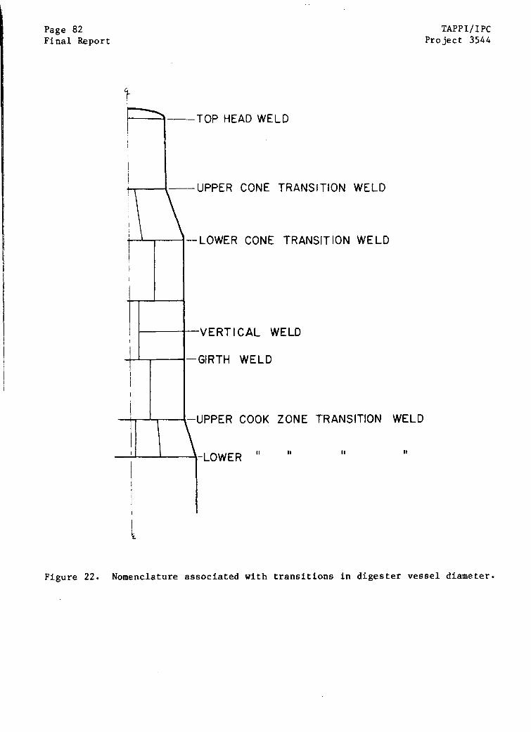
Page 82Final Report
TAPPI/IPCProject 3544
TOP HEAD WELD
-UPPER CONE TRANSITION WELD
-LOWER CONE TRANSITION WELD
-VERTICAL WELD
-GIRTH WELD
-UPPER COOK ZONE TRANSITION WELD
II
Figure 22. Nomenclature associated with transitions in digester vessel diameter.

TAPPI/IPC Page 83
Project 3544 Final Report
Digester Fabrication
A variety of construction methods have been used in the fabrication of
continuous digester vessels. In most cases, the top and bottom heads and the
cone section were assembled in the shop using the most convenient and economi-
cal welding procedure -- usually shielded metal arc welding (SMAW) with E7018
electrodes because of the complex geometry. Depending on the crane lift capac-
ity and the size of the vessel, some rings were also assembed in the shop by
joining half-cylinder sections by SMAW or by submerged arc welding (SAW). For
most of the larger vessels, however, vessels were constructed by field welding
girth and vertical seams. For smaller vessel sections, the ring was usually
fabricated on the ground, lifted into place as a complete ring, and girth welded
to the supporting ring. For larger vessels, two or more partial-cylindrical
sections were set in place at the horizontal seam, the vertical welds were com-
pleted, and then the horizontal girth seam was completed. Transition sections
were fabricated from several -- usually six -- prefabricated sections.
During construction of the vessel, the welding engineer and the con-
struction superintendent had some latitude regarding the welding procedure used
to complete a given joint, based on economics and practicality. For the largest
mechanical erector, the welding engineer at the regional office where the
construction was scheduled would control the welding specification for each type
of welded joint in the vessel. In the usual case, several welding procedures
might be qualified (according to the ASME code and any local codes) for joining
specific base metals. For example, for joining A516-70 steel to A516-70 steel,
as many as three welding procedures might be qualified for that joint -- one
SMAW, one SAW, and a third FCAW-EG (flux cored arc weld - electrogas) procedure.
Then, for each A516/A516 welded joint in the vessel, one of the qualified pro-
cesses would be selected as the preferred method by the regional welding manager.
Page 84Final Report
TAPPI/IPCProject 3544
During construction, however, occasions might arise wherein the intended process
might be supplanted by the choice of a different qualified procedure to complete
a given joint. As a result, the final record of the actual welding procedure
used for any joint will reside in the construction superintendent's reports made
during vessel construction.
Virtually all of the welds in continuous digesters (Kamyr type) in
North America have been made using one of three welding processes. The
following list gives the welding processes and consumables used when most of the
digesters were constructed. The consumables do not necessarily represent
current practice.
(i) SMAW
(ii) SAW
(iii) FGAW-EG
This procedure involves "stick" welding with E7018 elec-
trodes (low hydrogen, powdered iron) and a 200°F minimum
preheat for sections thicker than 1 1/4". The details of
the welding procedure are shown in Table I. This manual
procedure has been used, in one circumstance or another,
for most types of joints in continuous digester vessels.
This submerged arc weld procedure is typically done with
Linde 43 wire and Linde Grade 50 flux. The welding proce-
dure is detailed in Table I. This procedure has been used
for horizontal welding of girth seams, and for shop welding
of various seams in the downflat position.
This electrogas process is a process in which a flux cored
wire is fed into a weld pool contained by the plates and a
cooled copper shoe, and protected by a CO2 cover gas. The
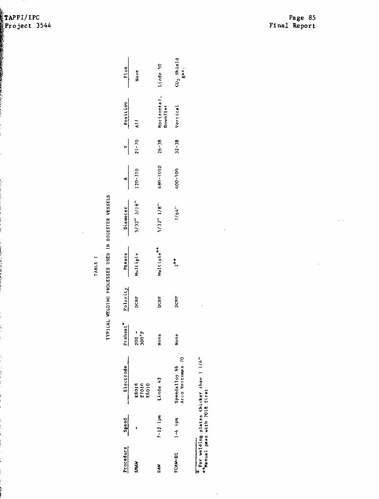
TAPPI/IPCProject 3544
Page 85Final Report
00
Page 86 TAPPT/IPCFinal Report Project 3544
electrogas process was used exclusively for vertical welds
in ring assembly. The copper shoe moved up as the weld is
solidified. The flux cored wire used most often was McKay
Speed Alloy 66, although other wires have been used. Welding
details are outlined in Table 1.
The choice of welding procedure for any joint was dictated by con-
venience, economics, and practicality. SAW welding is preferred for horizontal
girth welds because of the high rate of metal deposition. However, the use of
SAW requires a simple geometry that allows set-up of the automatic welding
machine. Consequently, the girth weld joining a transition ring to the ring
immediately below was never made with SAW -- the automatic apparatus could not be
set up on the angled surface above the joint. These joints would be field
welded by SMAW. The electrogas process was apparently used only for making ver-
tical welds, since the weld pool had to be confined in the groove by the copper
shoe and gravity. Electrogas welding of vertical welds in rings was a very com-
mon practice after 1965, but was not used before that date. SMAW welding was
ubiquitous -- being used when geometry or other concerns prevented the use of a
higher deposition-rate process, or when the vessel diameter was small.
Vessels have all been fabricated from low-to-medium strength carbon
steels of ASTM type A516-70, A212-B-FBX and A285-C. The compositions and
strength properties of these alloys are shown in Table II. In recent years,
A516-70 has supplanted A212-B-FBX. In many cases, vessels are constructed
from two different steels, with one steel being used for the lower portion and a
second steel used for the upper portion of the vessel. All of these steels are
carbon-manganese steels with a ferritic-pearlitic microstructure, purchased in
the hot-rolled or normalized condition, depending on thickness. Cylindrical
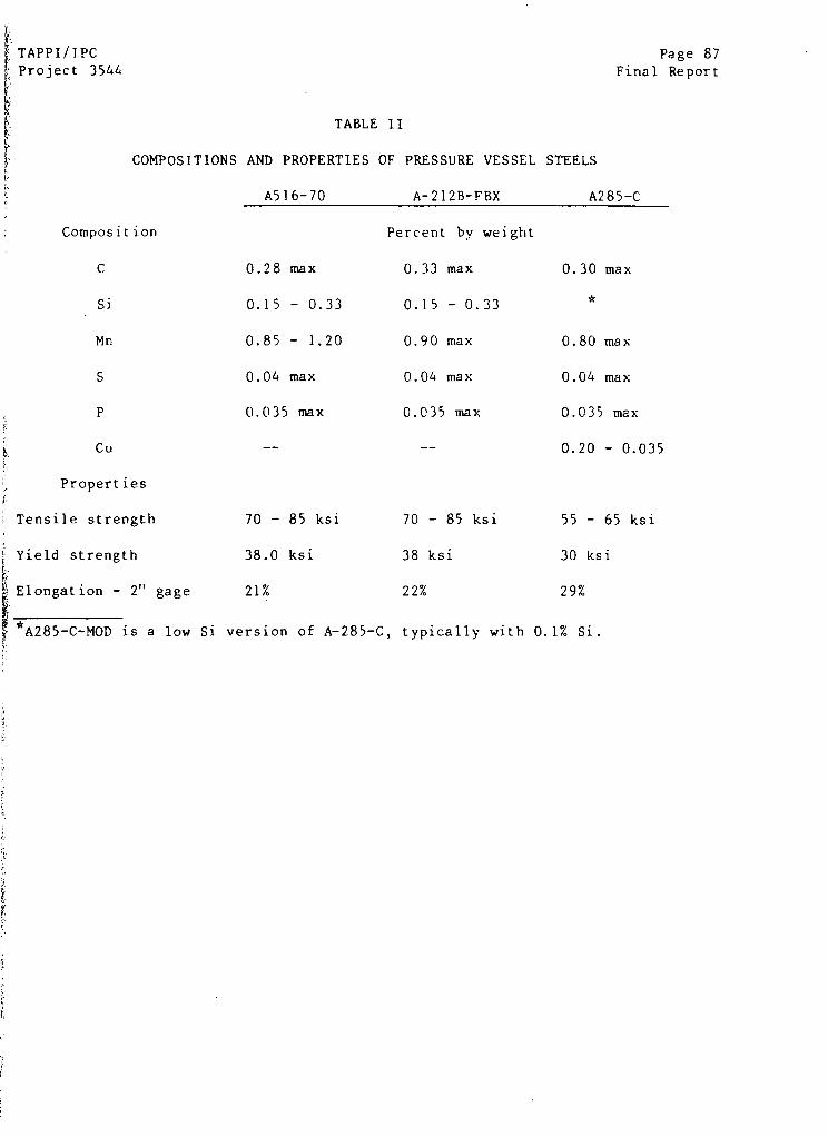
TAPPI/IPC
Project 3544
'
Page 87Final Report
COMPOSITIONS
TABLE II
AND PROPERTIES OF PRESSURE VESSEL
A516-70 A-212B-FBX
STEELS
A285-C
Composition P
C 0.28 max
Si 0.15 - 0.33
Mn 0.85 - 1.20
S 0.04 max
P 0.035 max
Cu --
Properties
Tensile strength 70 - 85 ksi
Yield strength 38.0 ksi
Elongation - 2" gage 21%
*A285-C-MOD is a low Si version of A-285-C,
ercent by weight
0.33 max
0.15 - 0.33
0.90 max
0.04 max
0.035 max
70 - 85 ksi
38 ksi
22%
0.30 max
*
0.80 max
0.04 max
0.035 max
0.20 - 0.035
55 - 65 ksi
30 ksi
29%
typically with 0.1% Si.
Page 88 TAPPI/IPCFinal Report Project 3544
sections are cold-rolled to shape on a three-roll press, without subsequent
stress relief or normalizing anneals unless specified by the customer or required
by the Code.
Many vessels have stainless clad surfaces included in the construction,
at least at the top and bottom head regions. The top and bottom heads are
usually clad with 304L stainless steel, according to ASTM SA264-TP304L. Some
vessels are completely clad internally with an austentic stainless steel. Other
vessels have clad regions in the area of maximum cooking temperature or in the
extraction region.
About one third of the vessels were fabricated with a low silicon ver-
sion of A285-C in the impregnation zone of the digester vessel. This material,
designated A285-C-MOD, has a maximum Si content of 0.10 w/o, whereas no condition
for Si content is imposed by the ASTM specification for A285-C. In some of the
vessels, the welds were made with a lower Si alloy (E6010 or E7010) in the last
passes on the internal welds, so that the weld cap exposed to liquor was low in
Si.
Stress relieving of vessels is done according to the minimum require-
ments of the ASME or local code in force at the time of construction, unless the
customer specifies a more extensive stress relief. Generally speaking, the ASME
Code now requires that those portions of the vessel thicker than ].5 inches
receive a stress relief anneal at 1100°F (593°C) minimum for one hour at temp-
erature for each inch of thickness or some similar treatment at somewhat lower
temperatures for longer times. Stress relief is usually effected by insulating
the vessel to the appropriate height and heating with gas/oil burners. Carbon
steel vessels fabricated before June, 1964 were required by the code to undergo
TAPPI/IPC Page 89project 3544 Final Report
stress relief if the wall thickness exceeded 1" for A212 vessels or 1 1/4" for
A285 vessels. In many vessels, the transition from thicknesses requiring stress
relief to those that do not occurs at or near the cooking zone transition.
Consequently, many vessels are stress relieved up to some elevation in the im-
pregnation zone, but not above. Some vessels were stress relieved at the request
of the mill purchasing the vessel. Of the 103 carbon steel vessels in kraft
pulping service for which stress relief conditions are known, 19 have had no
stress relief (usually small sawdust digesters), 47 have been partly stress
relieved, and 37 have been completely stress relieved, flange-to-flange. Impreg-
nation vessels are usually not stress relieved because of their small size and
relatively thin walls, although some mills have specified stress relief of these
small vessels.
After the vessel is fabricated and the stress relief procedures
completed, the digester internals are installed. The central distribution pipe
is installed with triangular gusset plates welded to the vessel shell supporting
the concentric pipes. The top separator is also installed. The screens and
dummy plates above the screens are also attached after the stress relief treat-
ment, usually by manual stick welding to the shell.
As required by the ASME Code, all vessels are hydrotested after
construction to demonstrate the integrity of the vessel before service. Since
the design pressure of virtually all Kamyr digesters is 165 psi at the top (and
Higher by the hydraulic head at the bottom of the vessel), the typical over-
pressure used in the hydrotest is 250 psig at the top of the vessel.
Cracking Characteristics in Kamyr Continuous Digesters
The resistance to weld cracking exhibited by the various Kamyr
digesters varies widely, not only in severity, but also in crack morphology.
Page 90 TAPPI/IPC
Final Report Project 3544
Some vessels have exhibited no cracking of any sort, whereas other vessels have
experienced through-wall cracking and even vessel failure. Some cracked vessels
exhibit long, interconnecting longitudinal* cracks in the heat-affected zone,
while other vessels exhibit numerous long transverse* cracks. In some vessels,
cracking is restricted entirely to the weld metal; in others, the heat-affected
zone is susceptible.
The objectives of this subsection are to catalog the various types of
cracking reported by the various mills, and to give some appreciation for the
prevalence of a specific type of cracking. The attempt to correlate this crack-
ing experience with digester operation or fabrication is reserved for subsequent
subsections. The TAPPI Task Group settled on a system for grading severity of
cracking in vessels as follows:
Grade A - Severe Cracking; > 1/4" deep, > 2" long
Grade B - Moderate Cracking; 1/16" < depth < 1/4"
Grade C - Incipient Cracking; < 1/16" deep
Grade D - No Significant Cracking
This grading system is preserved in this report.
As of January 1983, 107 Kamyr vessels involved in alkaline pulping had
been inspected, with reports forwarded to the TAPPI Task Group or to the
Institute of Paper Chemistry. Most of these reports are documented, although
some were made verbally by credible respondents. About two-thirds of the status
reports on digester inspection are considered up-to-date. The remaining one-
third are considered incomplete because of infrequent inspections or a failure
Longitudinal cracks run parallel to the direction of the weld pass. Transverse
cracks are perpendicular to the weld pass.
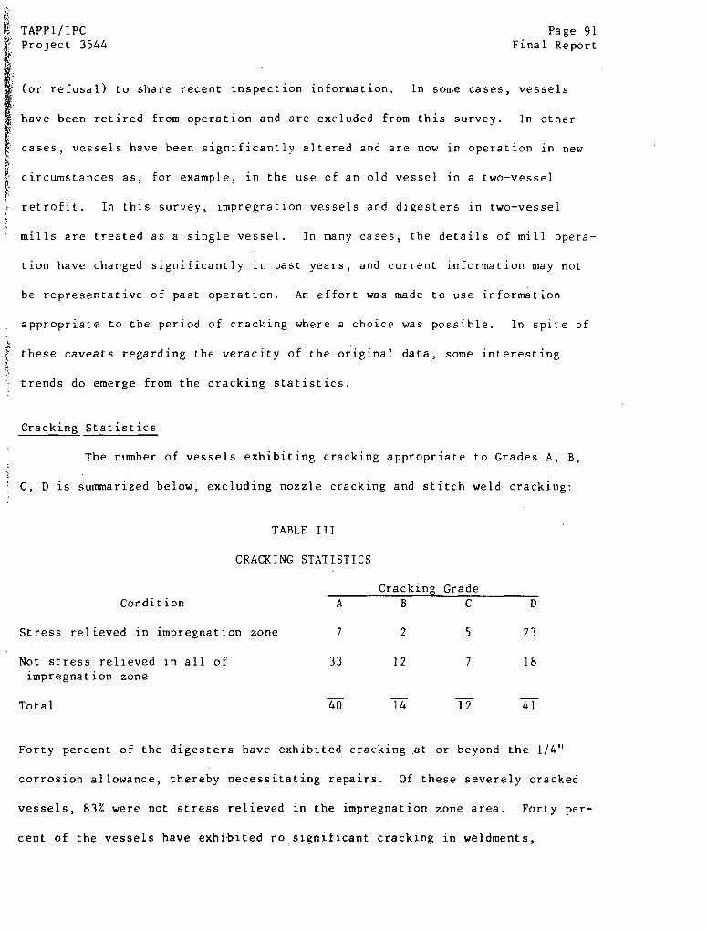
TAPPI/IPC Page 91Project 3544 Final Report
(or refusal) to share recent inspection information. In some cases, vessels
have been retired from operation and are excluded from this survey. In other
cases, vessels have been significantly altered and are now in operation in new
circumstances as, for example, in the use of an old vessel in a two-vessel
retrofit. In this survey, impregnation vessels and digesters in two-vessel
mills are treated as a single vessel. In many cases, the details of mill opera-
tion have changed significantly in past years, and current information may not
be representative of past operation. An effort was made to use information
appropriate to the period of cracking where a choice was possible. In spite of
these caveats regarding the veracity of the original data, some interesting
trends do emerge from the cracking statistics.
Cracking Statistics
The number of vessels exhibiting cracking appropriate to Grades A, B,
C, D is summarized below, excluding nozzle cracking and stitch weld cracking:
TABLE III
CRACKING STATISTICS
Cracking Grade
Condition A B C D
Stress relieved in impregnation zone 7 2 5 23
Not stress relieved in all of 33 12 7 18
impregnation zone
Total 40 14 12 41
Forty percent of the digesters have exhibited cracking at or beyond the 1/4"
corrosion allowance, thereby necessitating repairs. Of these severely cracked
vessels, 83% were not stress relieved in the impregnation zone area. Forty per-
cent of the vessels have exhibited no significant cracking in weldments,
Page 92 TAPPI/IPC
Final Report Project 3544
including 18 vessels which were not stress relieved. Two thirds of the non-
stress-relieved vessels have exhibited cracking of A or B severity.
Distribution of Cracking
At one mill or another, cracks of "A" severity were observed in each of
the welds in the impregnation zone of the typical Kamyr digester, including
horizontal, vertical, transition, and top head welds. In addition, cracks were
frequently observed in the welds which joined the downcomer support gusset plate
to the shell wall. Many mills reported extensive cracking in and around nozzles
in the upper regions of the vessel, Many vessels, including those otherwise
immune to cracking, exhibited cracking in stitch welds attaching dummy plates
and screens to the vessel wall. In some cases, downcomer pipes were cracked in
welds, as well. Localized corrosion in the form of erosion corrosion gouges
were common in the cone wall. Corrosion of the heat-affected zones of welds was
also commonly reported.
Crack Morphology
The morphology of cracking varied greatly from mill to mill. The most
severe cracking from the standpoint of digester reliability was relatively deep,
contiguous cracking in the heat-affected zones (HAZ) of girth welds. This lon-
gitudinal cracking mode was occasionally found to crack 90% of the circumference
of a weld to a depth of 1/2" or more. Severe cracking was also observed in the
HAZ of the fillet welds attaching the downcomer pipe support to the shell.
Longitudinal cracking was also observed in the weld metal itself, although the
penetration of this type of cracking seemed to be less than that observed in the
HAZ area. Short transverse and longitudinal cracks in the weld metal were often
very shallow (- 1/16"-1/8"), giving the appearance of crazing. In at least two

TAPPI/IPCProject 3544
Page 93Final Report
mills, transverse cracks initiated at the HAZ had propagated well into the base
metal of the plates adjacent to the weld, producing cracks three to four inches
long and ]/2" deep. Cracks observed at nozzles were frequently observed to
radiate outward from the nozzle weld (transverse cracking).
Most reports of cracking of weldments described several varieties of
cracks occurring simultaneously, usually with differing severity. For example,
severe longitudinal cracking of girth welds might be accompanied by shallow
transverse cracking of the weld metal.
Cracking in Base Metal
The carbon steel of the plate material was virtually immune to cracking
at sites removed from any weld, although examination of the broad expanse of
plate area has not been especially careful. Transverse cracks can penetrate
into the base metal, well removed from any influence of microstructural changes
associated with the weldment. Cracks initiated at the fillet welds attaching
the downcomer pipe support have also penetrated the shell, indicating growth
through base metal located some distance from the heat-affected zone of the
weld. In one case, the small region of A285-C-MOD base metal between the
attachment of the cone and the adjacent girth weld exhibited shallow cracking.
The effect of metallurgical changes on this region due to the heat input from
several adjacent welds is not clear.
Cracking at the Cone Transition Weld
The cone transition weld is especially susceptible to cracking in con-
~tinuous digesters. The lower cone transition weld is the weld at which the Pine
.Hill vessel ruptured, although all of the welds in the impregnation zone were
cracked in that vessel. In the sixteen vessels containing cracks deeper than
Page 94 TAPPI/IPCFinal Report Project 3544
1/2", ten exhibited these deep cracks in the upper or lower cone transition
welds. Most of these welds were cracked to 1/2" deep in the HAZ region, but at
least one mill reported 1/2"-deep transverse cracks at the lower cone transition
weld. In three cases, Grade A cracks were found at the lower cone transition
weld and the adjacent vertical welds in the cone, but no cracking was found
elsewhere in the vessel.
Deep Cracking (> 1/2")
Severe cracking -- deeper than ]/2" -- was observed in sixteen continuou
digesters, thirteen of which had not been stress relieved at the affected weld
As mentioned above, nine of these cases involved cracking at the welds asso-
ciated with the cone transitions, mostly the lower transition. Two of the deep
cracks were associated with growth of cracks which initiated at the downcomer
support and propagated into the shell Two of the sixteen cracks deeper than
1/2" were in girth welds not at the cone and two cracks deeper than 1/2" were
found in vertical welds, In at least five cases, cracks either penetrated the
shell or were chased through the shell wall in an attempt to grind out the crack
before repair welding. Two of these through-wall cracks were reported to be 18"
and 12" long.
Impregnation Vessel Versus Digester Cracking
In two vessel systems, the impregnation vessel (IV) is generally more
susceptible to cracking than the second vessel -- the actual digester. Several
cases have been cited where welds in impregnation vessels cracked, with no
cracking reported in the digester proper. This does not imply that second
vessel digesters are immune to cracking, however. At one mill, a crack initiated
at the downcomer support weld and penetrated the vessel wall in two years of
operation, but the deepest crack in the impregnation vessel was only 035" deep.
TAPPI/IPC Page 95Project 3544 Final Report
Cracking Outside of the Impregnation Zone
Virtually all of the cracking occurring in continuous digesters has
occurred in the impregnation zone of the vessels. However, there have been a
few reports of cracking in locations at or below the cooking zone. One Canadian
mill reported cracking in virtually all of the girth welds in the entire vessel.
In another case, cracks less than 1/4" deep were found at the bottom of pits in
the cook/extraction zone by grinding through the pits and conducting wet
fluorescent magnetic particle (WFMT) inspections. A third mill reported
cracking in the stress relieved portion of the digester vessel -- presumably in
the zone below the cooking region. A fourth mill reported ]/2"-deep cracks in a
transition weld in the stress relieved area -- presumably also below the
impregnation zone.
Nozzle Cracking
Many of the mills providing inspection reports describe significant
cracking of various nozzles in the impregnation zones of their vessels. In vir-
tually every case, the most severe nozzle cracks were oriented predominantly
transverse to the nozzle weld, emanating radially outward from the axis of the
nozzle. With this orientation, nozzle cracking is unlikely to lead to vessel
failure similar to that observed at Pine Hill, provided a regimen of routine
inspections is maintained.
The influence of fatigue stresses on nozzle cracking may be signifi-
cant. Stresses induced by pipe flexure could be transmitted to the nozzle welds
and promote crack initiation. The influence of these cyclic stresses on nozzle
cracking is, at present, unknown.
Page 96 TAPPI/IPCFinal Report Project 3544
Vertical Welds Vs. Horizontal Welds
Vertical welds in the impregnation zone are generally less affected by
cracking than the horizontal girth welds, although many exceptions have been
reported. In many instances, the severity of cracking is similar for horizontal
welds and adjacent vertical welds. At one mill, for example, both vertical and
horizontal welds in an inpregnation vessel exhibited Grade A cracking, but the
cracks in the vertical welds were three times as deep as those in the girth
welds. In other cases, the reverse is true. In at least eleven instances, the
vertical welds in vessels were reported to be as severely cracked, or more so,
as the adjacent girth welds.
Average Crack Penetration
Crude estimates of average crack growth rates can be obtained from
reports of inspection and reinspection data, where cracks initiated in the
intervening period. In this analysis, the actual growth rate may be seriously
underestimated since the incubation period preceding crack growth is uncertain.
Carried to extreme, for example, all of the growth observed in a yearly inspec-
tion could occur on the day before an annual shutdown, and the actual growth
rate would be 350 times higher than the average calculated growth rate. There
is the additional possibility that growth rates may be too high because all
cracks were not discovered during the initial inspection. In spite of these
uncertainties, some of the higher crack penetrations reported are listed below:
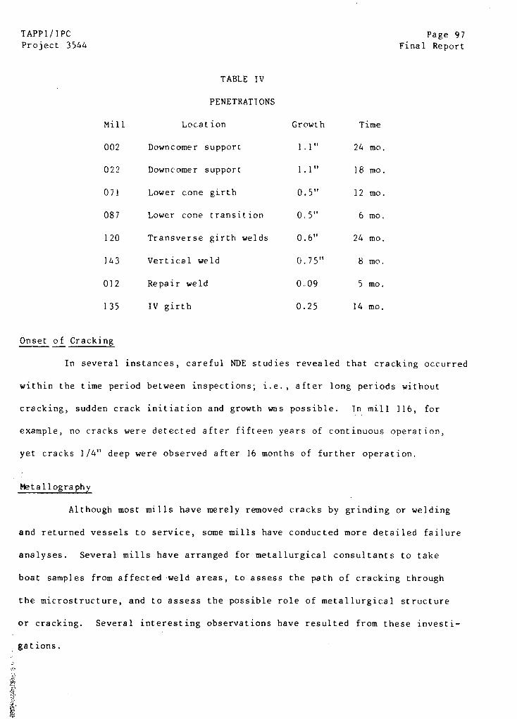
TAPPI/IPC Page 97Project 3544 Final Report
TABLE IV
PENETRATIONS
Mill Location Growth Time
002 Downcomer support 1.1" 24 mo.
022 Downcomer support 1.1" 18 mo.
071 Lower cone girth 0.5" 12 mo.
087 Lower cone transition 0.5" 6 mo.
120 Transverse girth welds 0.6" 24 mo.
143 Vertical weld 0.75" 8 mo.
012 Repair weld 0.09 5 mo.
135 IV girth 0.25 14 mo.
Onset of Cracking
In several instances, careful NDE studies revealed that cracking occurred
within the time period between inspections; i.e., after long periods without
cracking, sudden crack initiation and growth was possible. In mill 116, for
example, no cracks were detected after fifteen years of continuous operation,
yet cracks 1/4" deep were observed after 16 months of further operation.
Metallography
Although most mills have merely removed cracks by grinding or welding
and returned vessels to service, some mills have conducted more detailed failure
analyses. Several mills have arranged for metallurgical consultants to take
boat samples from affected weld areas, to assess the path of cracking through
the microstructure, and to assess the possible role of metallurgical structure
or cracking. Several interesting observations have resulted from these investi-
gations.
Page 98 TAPPI/IPCFinal Report Project 3544
In several separate studies, the composition, hardness, and microstruc-
ture of several weldments were determined in cracked vessels. The composition
of several weld metals and a base metal are given in Table V. The welds and
base metals have typical compositions, with the exception of a slightly high Si
content in the one base metal. The hardnesses at the weldments are also shown in
Table 1I, and these too are unremarkable. The high hardness of the HAZ is evi-
dence of a martensitic structure formed at the junction with the weld metal.
Limited metallography failed to reveal any unusual microstructural features of
the welds.
Crack initiation was found in several of the metallographic studies
reported in confidence. Cracks typically initiated at the bottom of minute
corrosion pits located in the HAZ of the welds, or in the weld metal itself.
Cracks grew along ferrite-ferrite boundaries in the weld metal or along acicular
ferrite boundaries in the metastable structure in the HAZ. There was some evi-
dence of growth by preferential dissolution of ferrite in pearlite in one
instance of crack growth through the base metal.
Nondestructive Examination
Considerable effort was expended by the TAPPI Task Group in an attempt
to determine optimum NDE methods for evaluating cracking. Eventually, the Task
Group recommended internal inspection by wet fluorescent magnetic particle
methods (WFMT) after careful grinding of the weld surface. Different orienta-
tions of the magnetizing yoke were effective in identifying transverse and
longitudinal cracks. The use of qualified inspectors was also emphasized.
Alternative inspection methods were also used by some mills as the
optimum inspection method was being sought, including ultrasonic testing (UT) by
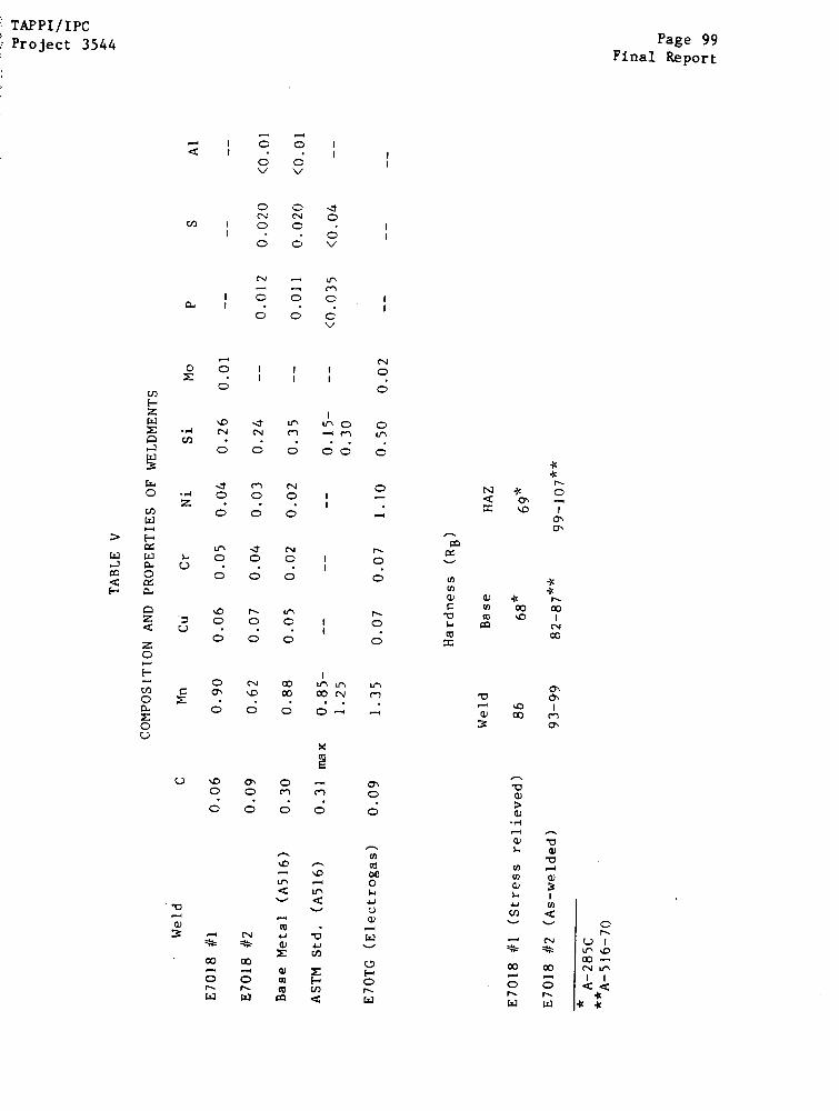
TAPPI/IPCProject 3544 Page 99
Final Report

Page 100 TAPPI/IPCFinal Report Project 3544
shear wave reflection from the outside of the vessel, dry fluorescent magnetic
particle testing, and acoustic emission (AE) testing, The success of these
alternative NDE measures was generally lower than that of the WFMT method.
UT conducted with the vessel still hot is an attractive method of
inspection because of the minimal preparation and downtime associated with the
method. However, it appears that the resolution of the method may only allow
detection of cracks deeper than 1/4" on the interior weld surface. In at least
four cases, hot UT methods failed to indicate cracks as deep as 1/4"; these were
later revealed by WFMT methods. In at least three cases, no evidence of
cracking was found by either hot UT or by WFMT methods. In one case, 1/4"-deep
cracks detected by hot UT were confirmed by subsequent WFMT. Consequently, hot
UT seems appropriate only as a tool for detecting gross cracking without vessel
downtime.
Acoustic emission testing is also attractive because it is a relatively
noninvasive NDE method that does not require extensive downtime on the vessel.
In this method, the vessel is instrumented with sensors capable of detecting
the acoustic emissions that accompany an abrupt crack advance event. The vessel
is pressurized to a pressure 10% above the previous high pressure value while
the detector array is monitored for evidence of crack advance. Acoustic
emission sites are then located by triangulation based on time of flight analy-
sis of the sound waves emitted.
Although AE methods would be much less time consuming than WFMT,
several mills have reported an inability to detect relatively large cracks using
this method. In many cases, there was acceptable correlation between AE and
WFMT examinations, but five mills reported detecting emission sources that could
TAPPI/1PC Page 101Project 3544 Final Report
not be confirmed by WFMT, or failing to detect by AE sources known to exist from
WFMT. One respondent complained of poor lateral resolution of cracking loca-
tions (+ 7 ft x + 3 ft). Grading of AE cracks by intensity of emission is still
an evolving technology. Initially, one AE inspector recommended action only for
Grade A and B sources, but recently changed its recommendation to include more
detailed inspection for Grade C sources (the minimum detectable source) as well.
Although some mills have installed permanent AE apparatus and are relying on
this approach for routine vessel inspection (with the consent of their insurer),
some questions remain regarding the conservatism of this NDE approach.
Noted in passing are some reported events which occurred during mag-
netic particle inspections. In one case, dry fluorescent magnetic particle
testing (DFMT) was first used, followed by WFMT. The WFMT revealed significant
cracks that had not been detected by DFMT methods. In another case, shallow
transverse WFMT indications occurred in the weld after a day of "aging" the
freshly ground surface in air. These recurrent indications could be induced
repeatedly by grinding and "aging" sequences.
Summary
Nearly every conceivable crack morphology has been reported in con-
tinuous digester weldments. Most cracking is restricted to the non-stress-
relieved impregnation zone of Kamyr digesters. The most serious cracking has
occurred in the HAZ of girth welds in transition areas and downcomer support
welds, although through-wall cracking has also been reported in vertical welds.
High crack growth rates have been inferred from repeated NDE evaluations of welds.
DIGESTER CRACKING VERSUS FABRICATION VARIABLES
Since some vessels have cracked whereas others have not, an attempt was
made to relate cracking susceptibility to the conditions used in fabrication of
Page 102 TAPPI/IPC
Final Report Project 3544
the digester vessels. Through the responses of the mills and the cooperation of
Kamyr, some of the general characteristics of each vessel -- such as alloys used,
stress relief treatment, size, etc. -- were determined for correlation with
cracking susceptibility. A more detailed scrutiny was made of the six specific
mills selected for special attention. For these latter mills, detailed vessel
fabrication procedures were obtained from the mill, Kamyr, Inc. or the mechani-
cal erector, so cracking susceptibility at any weld could be related to exact
welding procedure for that weld. As discussed earlier, the field construction
notes must be consulted to ensure that the actual procedures are identified
since erection drawings may have been modified in the field.
There is a strong correlation between immunity from cracking at any
weld and the stress relief of that weld. Forty-five of seventy vessels*
without stress relief of the welds in the impregnation zone exhibited Grade A or
B cracking in those welds. On the other hand, only nine of thirty-seven vessels
stress relieved in the impregnation zone exhibited grade A or B cracks, whereas
twenty-three have shown no cracking susceptibility at all. Apparently, stress
relieving of the impregnation zone reduces the probability of A or B cracking
from a 70% probability down to 25%.
In contrast to what might be expected, there is some difference be-
tween vessels which were partially stress relieved (below a certain elevation)
and vessels which received no postweld heat treatment at all. For example, of
the 45 vessels with Grade A or B cracking, only five received no stress relief;
of the 18 vessels with no cracking (Grade D performance), eleven received no
*Two-vessel systems are taken as a single vessel and are combined as being
cracked if either the impregnation vessel or the digester vessel exhibited
cracking in non-stress-relieved welds.
TAPPI/IPC Page 103Project 3544 Final Report
weld heat treatment. These statistics are puzzling until it is realized that the
the vessels receiving no postweld heat treatment are smaller than those receiving
a partial treatment, and size appears to affect cracking susceptibility.
There is also an apparent correlation between mechanical erector and
cracking susceptibility which may or may not be significant. Of the 44 vessels
showing A or B cracking, all but one were constructed by one company. On the
other hand, 36 of 46 vessels showing no cracking were constructed by this same
company. The remaining ten vessels were constructed by seven different erectors.
Again, these statistics may be misleading, in that the principal mechanical
fabricator is usually involved in manufacturing large and small vessels, whereas
the other fabricators concentrate on construction of the smaller, less suscep-
tible digester vessels.
The effect of size and throughput on cracking susceptibility is shown
schematically in Fig. 23 and 24. The preponderance of immunity (type D) is seen
for vessels with small throughput, and the preponderance of susceptibility (type
A) is seen in vessels with large throughput. Moreover, for those sixteen vessels
exhibiting deep cracking (> 1/2" deep), all but three were larger than 600 air
dry tons/day. Since actual vessel size (diameter) is not directly proportional
to throughput, some of the SCC data has been replotted in Fig. 24 on the basis
of actual vessel diameter in the impregnation zone. Using this criterion,
larger vessels appear to be slightly more susceptible to severe (type A or B)
cracking than smaller vessels. However, impregnation vessels are relatively
small in diameter, yet these vessels have exhibited severe cracking.
There appears to be little correlation between date of construction and
CC susceptibility, as shown in Fig. 25. Most of the vessels were built in the
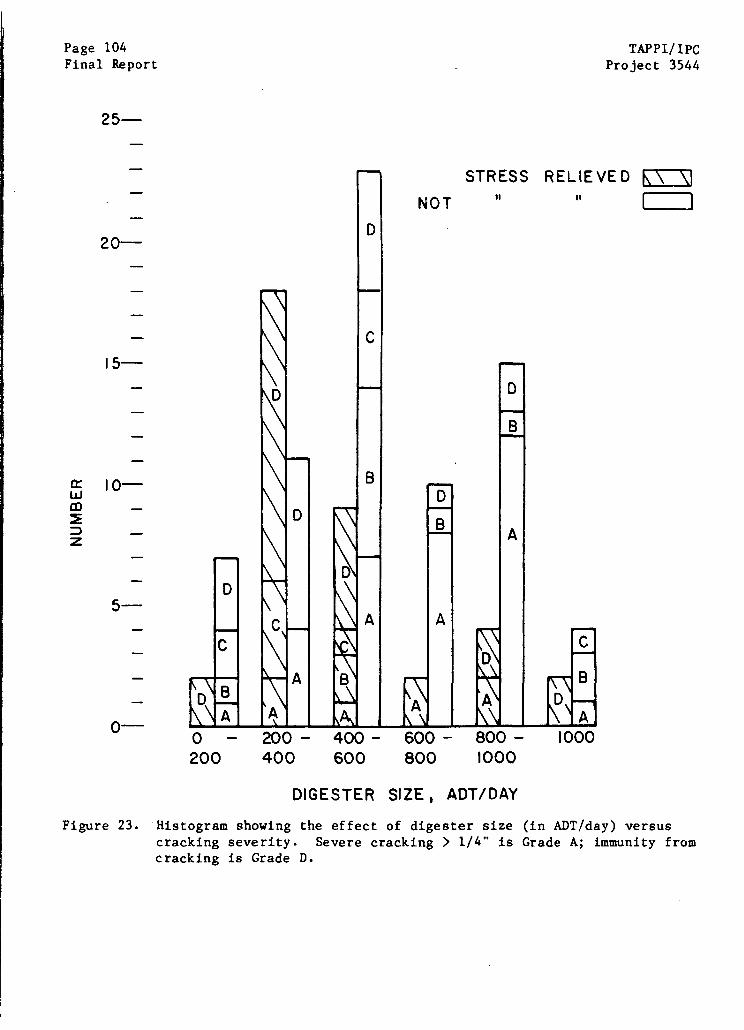
Page 104Final Report
TAPPI/IPCProject 3544
25-
20-
10-
5-
0-
DIGESTER SIZE, ADT/DAY
Figure 23. Histogram showing the effect of digester size (in ADT/day) versuscracking severity. Severe cracking > 1/4" is Grade A; immunity fromcracking is Grade D.

TAPPI/IPCProject 3544
Page 105Final Report
STRESS RELIEVEDNOT STRESS RELIEVED
100 %
80
0
60
40
20
DIAMETERFigure 24. Histogram showing the interrelation between vessel size, stress
relief treatment, and cracking susceptibility. A = most severe;D = no cracking.
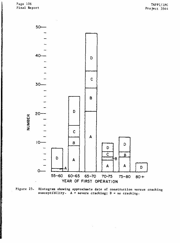
Page 106Final Report
TAPPI/IPCProject 3544
50-
40-
30-
Figure 25.
75-80 80 +
Histogram showing approximate date of construction versus cracking
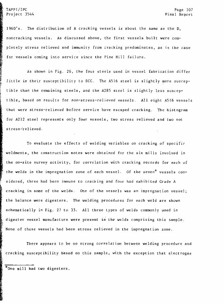
TAPPI/IPC Page 107Project 3544 Final Report
1960's. The distribution of A cracking vessels is about the same as the D,
noncracking vessels. As discussed above, the first vessels built were com-
pletely stress relieved and immunity from cracking predominates, as is the case
for vessels coming into service since the Pine Hill failure.
As shown in Fig, 26, the four steels used in vessel fabrication differ
little in their susceptibility to SCC. The A516 steel is slightly more suscep-
tible than the remaining steels, and the A285 steel is slightly less suscep-
tible, based on results for non-stress-relieved vessels. All eight A516 vessels
that were stress-relieved before service have escaped cracking. The histogram
for A212 steel represents only four vessels, two stress relieved and two not
stress-relieved.
To evaluate the effects of welding variables on cracking of specific
weldments, the construction notes were obtained for the six mills involved in
the on-site survey activity, for correlation with cracking records for each of
the welds in the impregnation zone of each vessel. Of the seven* vessels con-
sidered, three had been immune to cracking and four had exhibited Grade A
cracking in some of the welds. One of the vessels was an impregnation vessel;
the balance were digesters. The welding procedures for each weld are shown
schematically in Fig. 27 to 33. All three types of welds commonly used in
digester vessel manufacture were present in the welds comprising this sample.
None of these vessels had been stress relieved in the impregnation zone.
There appears to be no strong correlation between welding procedure and
cracking susceptibility based on this sample, with the exception that electrogas
I *One mill had two digesters.
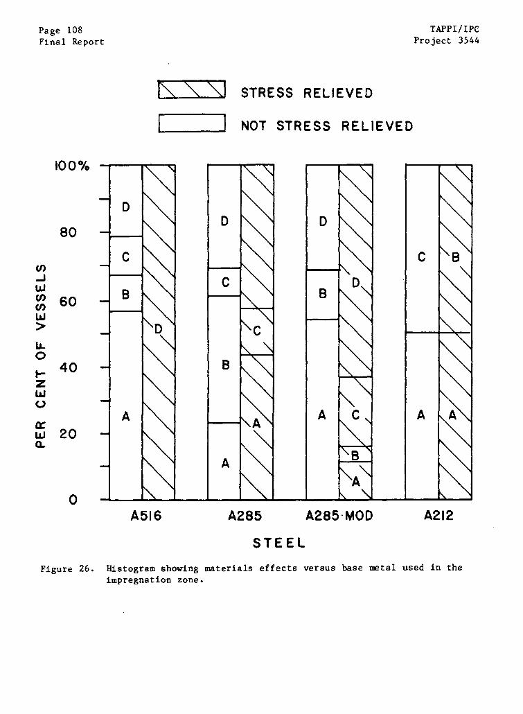
Page 108Final Report
TAPPI/IPCProject 3544
STRESS RELIEVED
NOT STRESS RELIEVED
100%
80
60
20
0A516 A285 A285-MOD A212
STEEL
Figure 26. Histogram showing materials effects versus base metal used in theimpregnation zone.
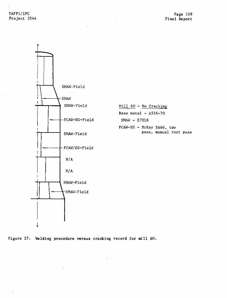
TAPPI/IPCProject 3544
Page 109Final Report
SMAW-Field
SAW
SMAW-Field
-FCAW-EG-Field
SMAW-Field
Mil 60 - No Cracking
Base metal - A516-70
SMAW - E7018
FCAW-EG - McKay SA66, twopass, manual root puss
FCAW/EG-Field
N/A
N/A
SMAW-Field
Figure 27. Welding procedure versus cracking record for mill 60.
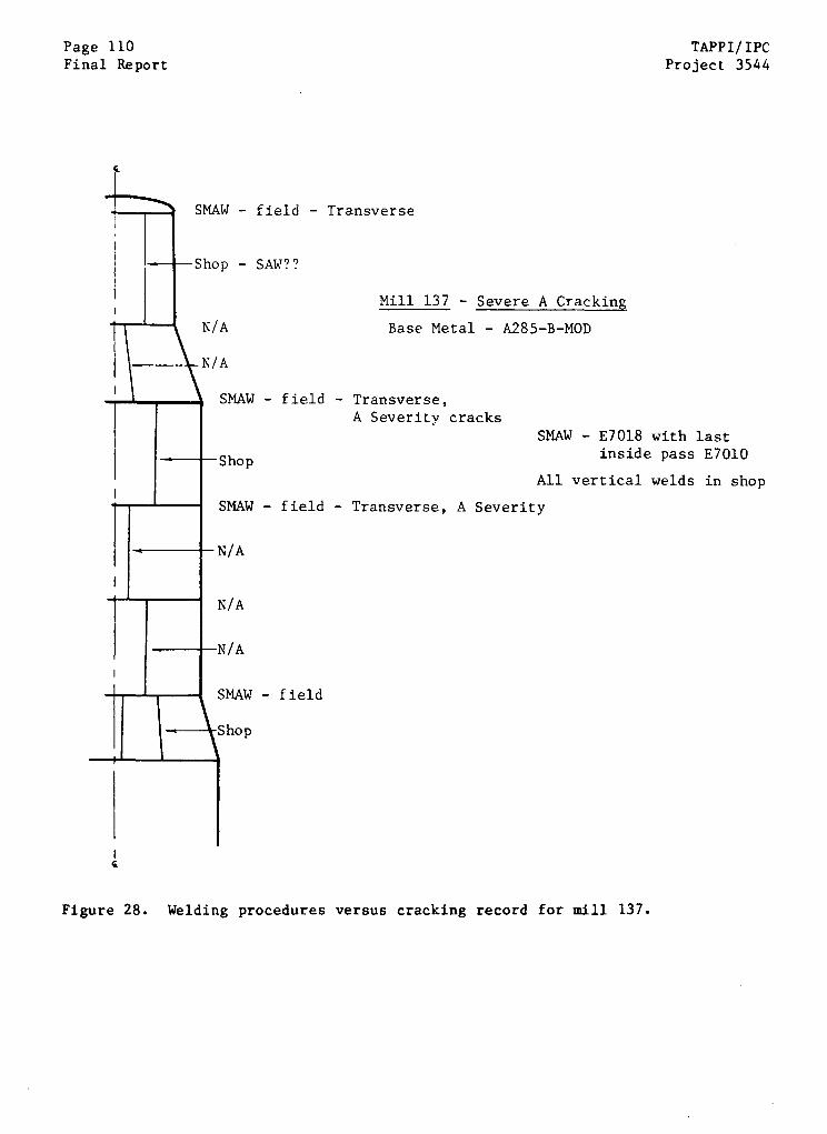
Page 110Final Report
TAPPI/IPCProject 3544
SMAW - field - Transverse
-Shop - SAW??
Mill 137 - Severe A Cracking
A Base Metal - A285-B-MOD
A
SMAW - field - Transverse,A Severity cracks
SMAW - E7018 with lastinside pass E7010Shop
All vertical welds in shop
SMAW - field - Transverse, A Severity
- field
Figure 28. Welding procedures versus cracking record for mill 137.
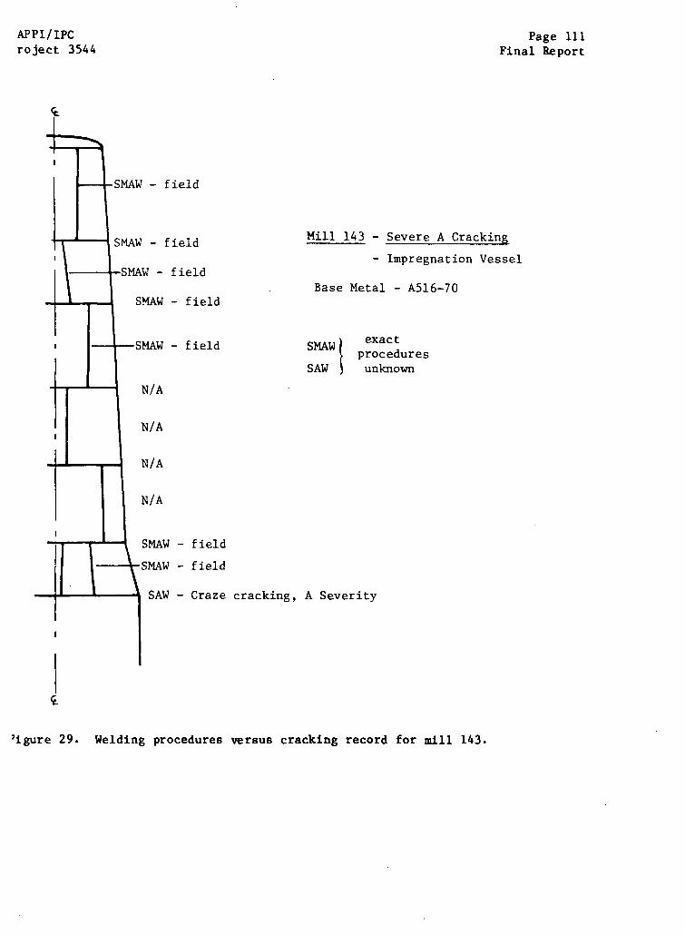
APPI/IPCroject 3544
Page 111Final Report
- field
Mill 143 - Severe A Cracking
- Impregnation Vessel
Base Metal - A516-70
SMA exactprocedures
SAW unknown
- field
- field
- Craze cracking, A Severity
igure 29. Welding procedures versus cracking record for mill 143.
field
field
- field
- field
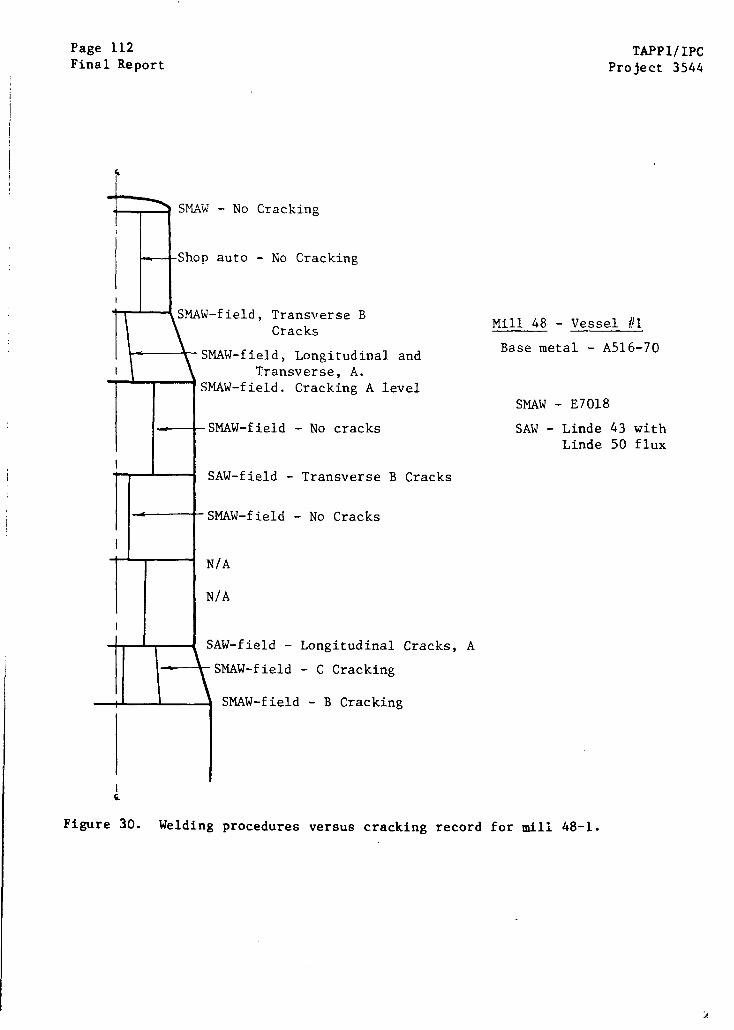
Page 112Final Report
TAPPI/IPCProject 3544
SMAW - No Cracking
Shop auto - No Cracking
SMAW-field, Transverse BCracks
SMAW-field, Longitudinal andTransverse, A.
SMAW-field. Cracking A level
SMAW-field - No cracks
Mill 48 - Vessel
Base metal - A516-70
SMAW - E7018
SAW - Linde 43 withLinde 50 flux
SAW-field - Transverse B Cracks
SMAW-field - No Cracks
N/A
N/A
SAW-field - Longitudinal Cracks, A
SMAW-field - C Cracking
SMAW-field - B Cracking
Welding procedures versus cracking record for mill 48-1.Figure 30.
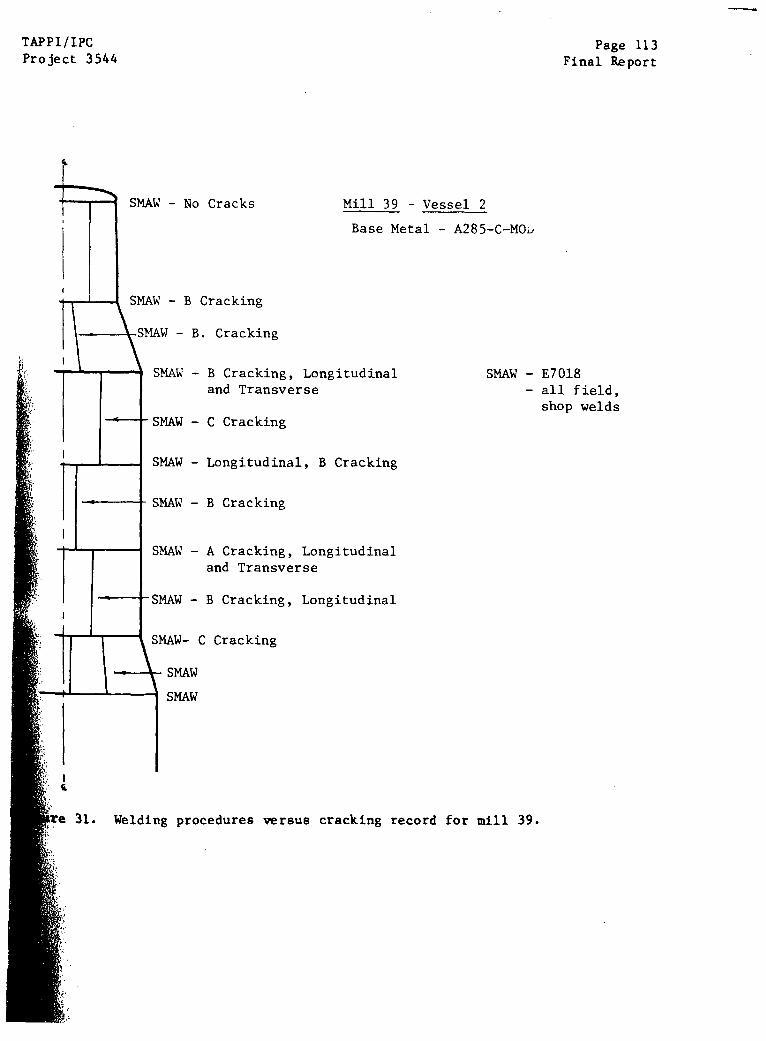
TAPPI/IPCProject 3544
Page 113Final Report
SMAW - No Cracks Mill 39
Base Me
SMAW - B Cracking
SMAW - B. Cracking
SMAW - B Cracking, Longitudinaland Transverse
SMAW - C Cracking
- Vessel 2
etal - A285-C-MOO
SMAW - E7018- all field,
shop welds
SMAW - Longitudinal, B Cracking
SMAW - B Cracking
SMAW - A Cracking, Longitudinaland Transverse
SMAW - B Cracking, Longitudinal
SMAW- C Cracking
SMAW
SMAW
e 31. Welding procedures versus cracking record for mill 39.
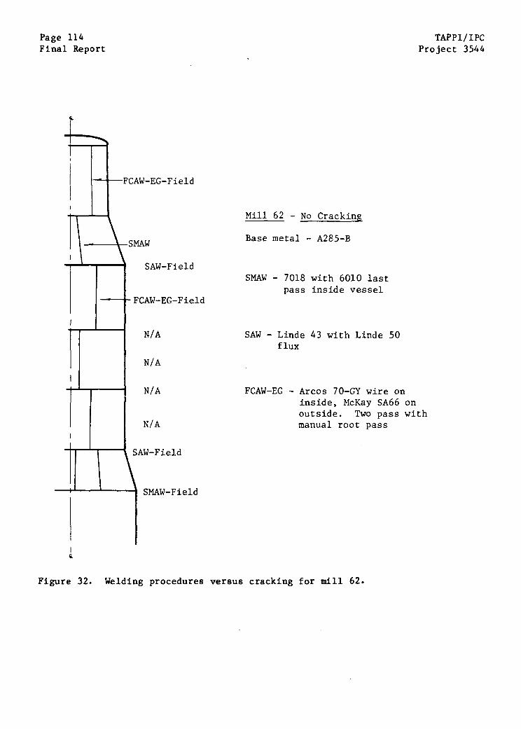
Page 114Final Report
TAPPI/IPCProject 3544
'CAW-EG-Field
SMAW
Mill 62 - No Cracking
Base metal - A285-B
SAW-FieldSMAW - 7018 with 6010 last
pass inside vesselFCAW-EG-Field
SAW - Lindeflux
FCAW-EG -
43 with Linde 50
Arcos 70-GY wire oninside, McKay SA66 onoutside. Two pass withmanual root pass
SMAW-Field
Figure 32. Welding procedures versus cracking for mill 62.
N/A
N/A
N/A
N/A
SAW-Field
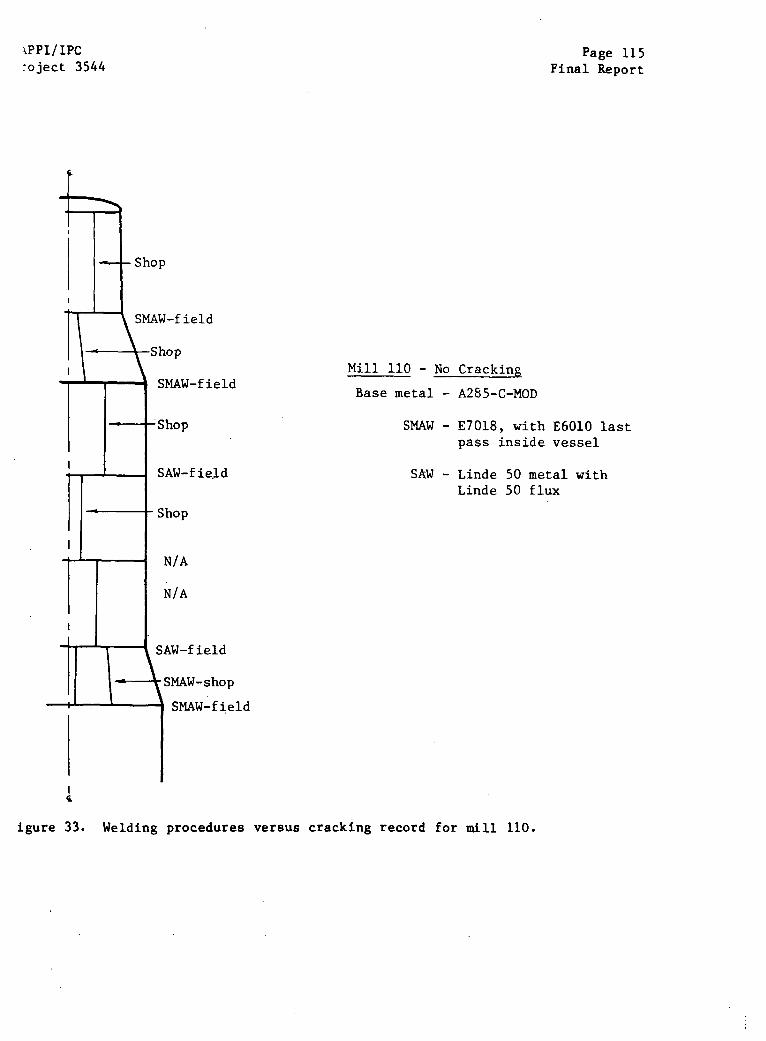
PPI/IPCject 3544
Page 115Final Report
SMAW-field
Shop
SMAW-fieldMill 110 - No Cracking
Base metal - A285-C-MOD
SMAW - E7018, with E6010 lastpass inside vessel
SAW - Linde 50 metal withLinde 50 flux
SAW-field
SAW-field
SMAW-shop
SMAW-field
igure 33. Welding procedures versus cracking record for mill 110.
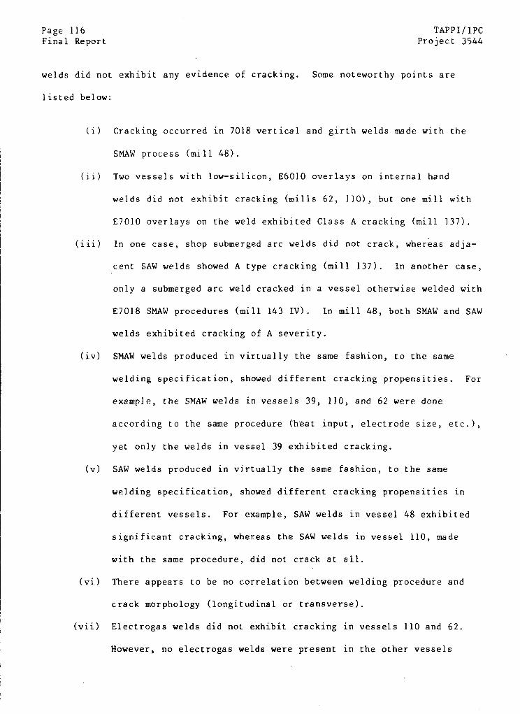
Page 116 TAPPI/IPCFinal Report Project 3544
welds did not exhibit any evidence of cracking. Some noteworthy points are
listed below:
(i) Cracking occurred in 7018 vertical and girth welds made with the
SMAW process (mill 48).
(ii) Two vessels with low-silicon, E6010 overlays on internal hand
welds did not exhibit cracking (mills 62, 110), but one mill with
E7010 overlays on the weld exhibited Class A cracking (mill 137).
(iii) In one case, shop submerged arc welds did not crack, whereas adja-
cent SAW welds showed A type cracking (mill 137). In another case,
only a submerged arc weld cracked in a vessel otherwise welded with
E7018 SMAW procedures (mill 143 IV). In mill 48, both SMAW and SAW
welds exhibited cracking of A severity.
(iv) SMAW welds produced in virtually the same fashion, to the same
welding specification, showed different cracking propensities. For
example, the SMAW welds in vessels 39, 110, and 62 were done
according to the same procedure (heat input, electrode size, etc.),
yet only the welds in vessel 39 exhibited cracking.
(v) SAW welds produced in virtually the same fashion, to the same
welding specification, showed different cracking propensities in
different vessels. For example, SAW welds in vessel 48 exhibited
significant cracking, whereas the SAW welds in vessel 110, made
with the same procedure, did not crack at all.
(vi) There appears to be no correlation between welding procedure and
crack morphology (longitudinal or transverse).
(vii) Electrogas welds did not exhibit cracking in vessels 110 and 62.
However, no electrogas welds were present in the other vessels
APPI/IPC Page 117roject 3544 Final Report
where cracking of SAW and SMAW welds had occurred. Electrogas welds
are known to crack in other vessels not included in the present sample.
Based on the above observations, there appears to be no correlation
etween the cracking susceptibility of a given weld and the welding procedure
sed to fabricate that weld.
Aside from good correlations between cracking susceptibility and
igester throughput and stress relief treatment, it appears that the fabrication
ariables (that can still be identified long after vessel construction) do not
nave a significant effect on the likelihood of cracking in a given vessel.
However, many variables in fabrication cannot be obtained many years after
vessel construction. The skill and diligence of the welding crew, the sequence
f welding operations, conditions of weld heat input -- those and many other
potentially important variables are lost from view. If these fabrication
variables have a role in the code that controls cracking susceptibility, it is
unlikely that the code will ever be deciphered.
DIGESTER CRACKING VERSUS OPERATION
Since the obvious fabrication variables do not seem to affect digester
cracking significantly, is the difference between immune and susceptible vessels
caused by differences in operating procedures? To examine this question, data
were analyzed from two sources. First, the updated version of the TAPPI Task
Group questionnaire requested rudimentary information about plant operations -
white liquor composition, acid cleaning practices, wood species pulped -- and
many mills provided this information. A second source of information was the
survey questionnaire filled out at each of the six mills selected for an on-site
visit. The same detailed questionnaire (included as an Appendix) was submitted
Page 118 TAPPI/IPCFinal Report Project 3544
to three susceptible and three nonsusceptible mills with the hope of trying to
identify differences between the two types of mills. In some cases, personnel
from the selected mills balked at the length and detail of this latter survey,
so this survey is not as complete as desired. A third source of information --
chemical and electrochemical characterizations of cooking liquors at the six
mill sites -- is reserved for discussion in a subsequent section.
In February 1981, the TAPPI Task Group requested in its questionnaire
some fundamental details of pulping processes at each mill. Many of the mills
responded by providing information regarding liquor chemistries, wood species
pulped, and acid cleaning practices. A renewed request for information as part
of this DCRC program at the Institute brought additional responses, together
with new information on inspection results. With the updated data base, an
attempt to correlate cracking susceptibility with operation was made.
Acid Cleaning
The similarity of kraft pulping processes in North America, and the
widespread occurrence of cracking combine to confound identification of pulping
practices that promote cracking. For example, virtually every mill operating a
continuous digester and responding to the questionnaire finds it convenient to
clean internal screens by acid cleaning, i.e., circulating an inhibited hot,
dilute acid solution through the plugged screens. Of the 60 vessels in North
America for which a response is available, only 4 are not acid cleaned.
The fifty-six vessels which are cleaned with acid are typically exposed
to a similar cleaning procedure. After the vessel is washed and filled with
water to the cooking screen level, inhibited acid is added at a pump suction to
raise the acid concentration to about 3-5%. The dilute acid mixture is heated
TAPPI/IPC Page 119
Project 3544 Final Report
and recirculated through the various screens until the acid residual reaches a
prescribed level. The tank is then drained, perhaps rinsed with water, and
passivated by exposure to white liquor. In all but two responses, hydrochloric/
muriatic acid is described as the acid used; sulfamic and formic acids are used
in the two exceptional cases. There is no correlation between cracking suscep-
tibility and acid used in acid cleaning. Too few responses were obtained
regarding the inhibitor used to evaluate the possible role of inhibitors on SCC.
Frequent acid cleaning also does not induce cracking in digester vessels. For
example, two non-stress-relieved vessels have been cleaned every 3-4 months
without developing cracks during operation for more than a decade. Conversely,
severe cracking has been reported for vessel 71, which is acid cleaned only
every three years.
Some exceptional circumstances involving acid cleaning practices are
noteworthy. Four of the vessels in the North American survey are not acid
cleaned. These four vessels have not shown any evidence of cracking in shell
welds. All four vessels have been stress relieved, however, and would be
expected to be less susceptible to cracking for reasons described earlier.
Nonetheless, these vessels which have never been acid cleaned are (statistic-
ally) less susceptible than stress-relieved vessels that have been acid
cleaned. On the other hand, a European mill that has never been acid cleaned
showed severe and repeated cracking after a short period of operation.
Similarly, impregnation vessels in two-vessel systems have no extraction screens
requiring acid cleaning, yet cracking has been severe in these impregnation
vessels. At best, the evidence regarding cracking in vessels that have not been
acid cleaned is contradictory.
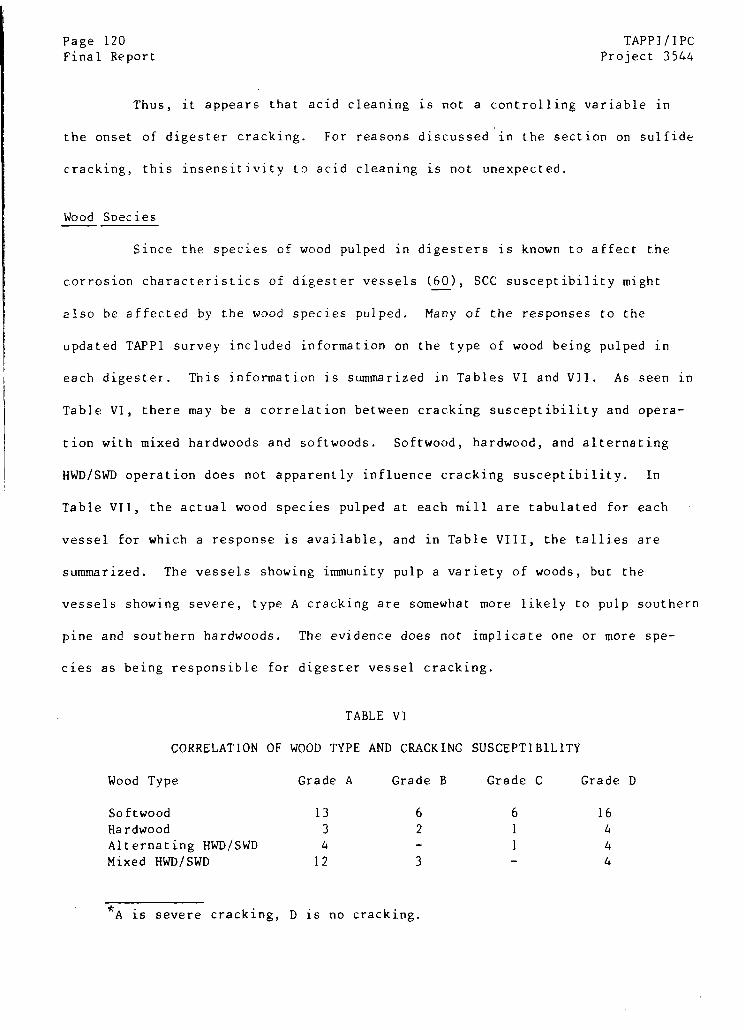
Page 120 TAPPI/IPC
Final Report Project 3544
Thus, it appears that acid cleaning is not a controlling variable in
the onset of digester cracking. For reasons discussed in the section on sulfide
cracking, this insensitivity to acid cleaning is not unexpected.
Wood Soecies
Since the species of wood pulped in digesters is known to affect the
corrosion characteristics of digester vessels (60), SCC susceptibility might
also be affected by the wood species pulped. Many of the responses to the
updated TAPP1 survey included information on the type of wood being pulped in
each digester. This information is summarized in Tables VI and VII. As seen in
Table V1, there may be a correlation between cracking susceptibility and opera-
tion with mixed hardwoods and softwoods. Softwood, hardwood, and alternating
HWD/SWD operation does not apparently influence cracking susceptibility. In
Table VII, the actual wood species pulped at each mill are tabulated for each
vessel for which a response is available, and in Table VIII, the tallies are
summarized. The vessels showing immunity pulp a variety of woods, but the
vessels showing severe, type A cracking are somewhat more likely to pulp southern
pine and southern hardwoods. The evidence does not implicate one or more spe-
cies as being responsible for digester vessel cracking.
TABLE VI
CORRELATION OF WOOD TYPE AND CRACKING SUSCEPTIBILITY
Wood Type Grade A Grade B Grade C Grade D
Softwood 13 6 6 16
Hardwood 3 2 1 4
Alternating HWD/SWD 4 - 1 4
Mixed HWD/SWD 12 3 - 4
*A is severe cracking, D is no cracking.
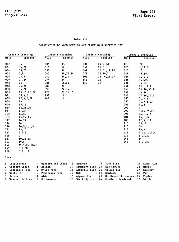
TAPPI/IPCProject 3544
Page 121Final Report
TABLE VII
CORRELATION OF WOOD SPECIES AND CRACKING SUSCEPTIBILITY
Grade A CrackingMill Species
Grade B Cracking Grade C CrackingMill Species Mill Species
Grade D CrackingMill Species
1414,2419,235,919,514,242414,2414,2425,16,27,2419,5,210,9,7,281415,1614,25,2614,2414,2415,27,1614,241410,9,1,2,515,245,3,82310,28,2219,519,5,22,28,75,3,285,3,1,21
22,7,2822,718,21,19,2922,28,725,16,26,272215
245,19,82318,195,19,215,3,2814,2422,5,7,129,26,30,914,2425,26,26,275,19,217,22,21,55,2819,16,29,2614,1,4,724,1,1422,5,1,715,192419,52,28,10,5,45,28,22145,21,23
1 Douglas-fir2 Western Larch3 Lodgepole Pine4 White Fir5 Spruce6 Western Hemlock
789
101112
Western Red CedarBalsamWhite PinePonderosa PineAlderCottonwood
13 Redwood14 Southern Pine15 Loblolly Pine16 Oak17 Alpine Fir18 Black Spruce
19 Jack Pine20 Red Spruce21 Balsam Fir22 Hemlock23 Northeast Hardwoods24 Southern Hardwoods
25 Sweet Gum26 Maple27 Hickory28 Fir29 Poplar30 Birch
005016031041042074086088090129134148
006052069078109141147
152424
28,13,2414,241416,262424,1427,16,151414
002011014022024039043048058063071075076079085087102105112114118122127128131143144149150
001009015018029036038056057060061065080091093097098101108110113115121133145146
Code
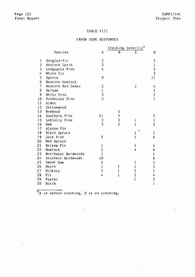
Page 122 TAPPI/IPC
Final Report Project 3544
TABLE VIII
CRACK CODE RESPONSES
Cracking Severity
Species A B C D
1 Douglas-fir 2 5
2 Western Larch 3 1
3 Lodgepole Pine 4 24 White Fir 2
5 Spruce 9 11
6 Western Hemlock
7 Western Red Cedar 2 2 4
8 Balsam 1 1
9 White Pine 3 2
10 Ponderosa Pine 3 111 Alder
12 Cottonwood
13 Redwood 1
14 Southern Pine 11 5 5
15 Loblolly Pine 3 2 1 116 Oak 3 2 1 217 Alpine Fir
18 Black Spruce 1 1
19 Jack Pine 5 1 620 Red Spruce
21 Balsam Fir 1 1 4
22 Hemlock 2 4 623 Northeast Hardwoods 1 1
24 Southern Hardwoods 10 6
25 Sweet Gum 2 1 126 Maple 1 1 1 3
27 Hickory 3 1 2 128 Fir 4 1 2 4
29 Poplar 1 2
30 Birch 1
*A is severe cracking, D is no cracking.

TAPPI/IPC Page 123> Project 3544 Final Report
Chip Versus Sawdust Digesters
Since sawdust digesters are usually smaller than chip digesters, it is
to be expected that the sawdust digesters would be somewhat less susceptible to
cracking. However, it also seems likely that the sawdust vessels have not
received the NDE attention focused on larger chip digesters, and so mills would
be less likely to find cracks in the sawdust digesters. Indeed, less cracking
susceptibility is seen. Of the eight sawdust vessels for which information is
available, all but one are in the Grade C and Grade D categories; one vessel has
exhibited Grade B sources; but none have demonstrated severe Grade A cracking.
Vapor Phase/Two Vessel Systems
Both steam phase digester systems and two-vessel systems reflect the
general cracking tendencies of the hydraulic digesters. This is not surprising
for two-vessel systems but may be surprising in the case of vapor phase
digesters. In these steam phase vessels, the nominal impregnation zone is not
immersed in a chip/liquor slurry, but is instead exposed to injected steam and
any volatile species evolved from the chip mass. Even though the top of the
vessel is not immersed, at least one vapor phase vessel has exhibited cracking
in the steam phase region, with deep cracking in a vertical weld. Apparently,
the species responsible for cracking can be deposited on the vessel walls and
form a liquid layer capable of causing cracking.
Page 124 TAPPI/IPCFinal Report Project 3544
White Liquor Characteristics Versus Cracking
Many of the mills responding to the updated questionnaire provided
information regarding their white liquor characteristics. As is usually the
case, this information was provided in a variety of formats and terminologies,
but the data have been condensed into three representative quantities: active
alkali expressed as Na20 g/L, total titratable alkali expressed as Na20 g/L,
and percent sulfidity on an AA basis. Active alkali (AA) includes the NaOH and
Na2S present in the white liquor, converted into equivalent grams per liter of
an imaginary Na20 compound. Total titratable alkali includes the AA plus the
Na2CO3 content of the liquor, expressed in grams per liter of equivalent Na20.
Sulfidity is the ratio of Na2S to active alkali, with all quantities expressed
as Na20 in the calculation
White liquor conditions are quite uniform from mill to mill. As shown
in Table IX, the AA values ranged from 69 to 119 g/L as Na20, but most active
alkali figures are in the 85-110 g/L range. Typically, the TTA values are
higher by about 10-15 g/L as Na20. Sulfidities vary from 21 to 42%, with most
in the 25-35% range. One Kamyr digester pulps without Na2S using the soda
process, rather than the kraft process. The white liquor properties reported in
Table IX are similar to those previously reported for continuous digester opera-
tion (61,62).
* Additional information on white liquor correlations versus liquor charac-teristics is presented in the detailed account of liquor sampling at sixselectd mills.
*Sulfidities may also be expressed on a TTA basis, in which case the denomina-tor in the sulfidity expression is the TTA (as Na20). All sulfidities aretaken as AA basis sulfidities where the intent of the survey response isunclear. The error in the sulfidity number is certainly less (~ 10%) than theroutine changes in sulfidity at a typical mill.
TAPPI/IPC Page 125
Project 3544 Final Report
There is no significant correlation between the average white liquor
properties and propensity toward cracking in continuous digesters. As shown in
Fig. 34, the combinations of sulfidity and active alkali span the same range for
seriously cracked vessels and for immune vessels. Removing data for stress
relieved vessels and considering only non-stress-relieved vessels does not alter
this pattern, as shown in Fig. 35. Considering sulfide concentration, rather
than sulfidity as in Fig. 34-35, will not affect the basic message of these
figures since the liquor data for cracked and uncracked mills will continue to
show the broad similarities shown in these figures. Comparisons with total
titratable alkali only have the effect of shifting the scale on the abscissa to
concentrations 10-20 grams per liter higher than those shown in Fig. 34 and 35.
Similarly, causticizing efficiency does not correlate with the susceptibility to
SCC in vessels. Based on these results, it is clearly evident that the general
white liquor characteristics used with any vessel do not control digester vessel
cracking susceptibility.
A further attempt to relate cracking susceptibility to general mill
operations was made by consulting published summaries of pulp mill information
(63) -- products, equipment, water use, etc. -- and comparing these variables for
:immune and susceptible mills. No justification is made for the attempted corre-
lations, other than the reminder that recovery, recausticizing, and papermaking
practices can often change the liquor conditions in the kraft mill.
The following mill variables were examined for possible correlation
with cracking susceptibility.
(1) Production of bleached and unbleached hardwood or softwood pulp
(2) Final mill product(3) Black liquor oxidation practices
(4) Black liquor evaporator stages

Page 126Final Report
45
40
TAPPI/IPCProject 3544
*SEVERE CRACKINGoNO CRACKING
0 0000
90 100 110ACTIVE ALKALI g/l Na20
Figure 34. Cracking susceptibility versus white liquor properties.
35
: 303
25
20
00
80 120
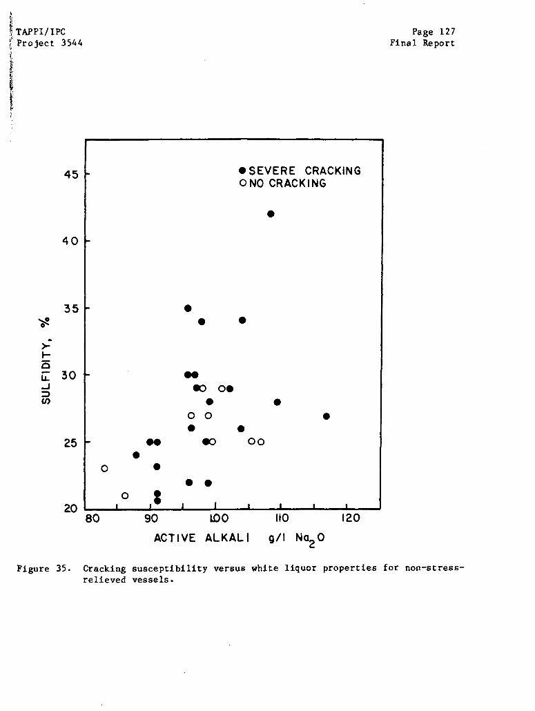
TAPPI/IPCProject 3544
45
40
35
3
25
2080 90 LO 10
Page 127Final Report
120
ACTIVE ALKALI
Figure 35.
g/ N20
Cracking susceptibility versus white liquor properties for non-stress-relieved vessels.
*SEVERE CRACKINGONO CRACKING
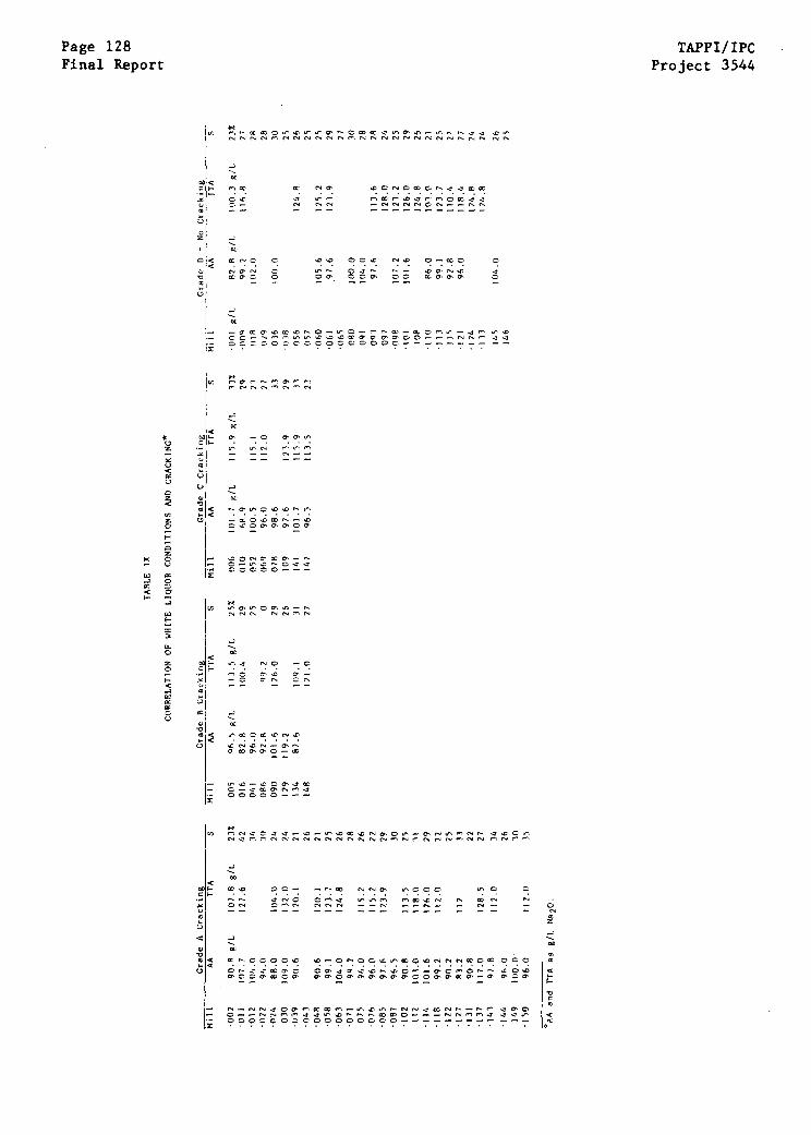
Page 128Final Report
TAPPI/IPCProject 3544
TAPP1/IPC Page 129Project 3544 Final Report
(5) Recausticizing system design
(6) Recovery boiler type
(7) Bleaching practices, sequence
(8) Water usage
(9) Water source
None of these variables affected cracking susceptibility of the con-
tinuous digester vessels. For example, the digesters at mills with bleach plants
are no more susceptible to cracking than those without bleaching capabilities,
even though some of the by-products of bleaching chemical generation are usually
disposed of in the recovery process stream. Twenty-eight of forty-one mills
reporting severe, Grade A cracking in their digesters also operate bleach
plants; for Grade D immunity, the fraction of mills operating bleach plants is
12 out of 39. There is also no apparent correlation between cracking and bleach
lant sequence. Fine paper mills are as susceptible as kraft linerboard mills.
lack liquor oxidation does not correlate with cracking susceptibility, nor does
he recausticizing system design. Cracking occurs with equal frequency at mills
ith Combustion Engineering (CE) and Babcock and Wilcox (B & W) recovery boilers.
racking is equally likely for mills using river water, lake water, or well
later. None of these variables was found to affect overall susceptibility to
igester cracking.
etailed Questionnaire Results at Six Selected Mills
The six mills selected for on-site liquor chemistry measurements were
lso asked to fill out the detailed questionnaire found in the Appendix. The
uestionnaire had three sections dealing with digester operation, recovery prac-
ices, and recausticizing practices. Because of the detail involved, less than
otal success was achieved in obtaining fully completed questionnaires from all
ills. In many cases, the information requested was simply not available because
Page 130 TAPPI/IPCFinal Report Project 3544
measurements have not been made. However, responses were obtained from both
immune and susceptible mills for possible correlation with their susceptibility.
The recovery and recausticizing practices at all of the mills responding
were similar.
With the exception of minor changes in liquor chemistry and wood spe-
cies used at each mill, the details of the recovery procedure were not different
from mill to mill. Water added to the recausticizing process stream came from
the same source. Temperatures and concentrations at each of the stages in the
recausticizing process varied by only a few percent from mill to mill, and no
trend was apparent for correlation with cracking susceptibility. Few additives
were used in the recausticizing process stream. One of the mills whose digester
had Grade A cracking used a small amount of corn starch to promote settling of
suspended solids; another mill added Nalco polymer at the lime mud washer and
dregs washer. One mill added spent acid from the bleach generator to the white
liquor clarifier, but no other process streams were mixed with the recausticizing
liquors in any of the mills.
The recovery processes used at the immune and susceptible mills
responding to the questionnaire were also very similar. Every mill used a
defoaming agent in the pulp washing stages, although a different agent was used
at each of the mills and no correlation was possible. There was no correlation
of cracking with diffusion and drum washing practices. The liquor evaporation
processes were also virtually identical at each of the mills. One mill did not
practice black liquor oxidation, and that mill had a digester with severe
cracking. The rest of the responding mills oxidized strong black liquor to a
very low residual sulfide level. Kerosene was added to suppress foaming at one
TAPP1/IPC Page 131Project 3544 Final Report
mill with an immune digester. All of the mills employed multiple effect, long-
tube-vertical evaporation, and all experienced some moderate problems with scale
buildup in the first effects every four to twelve months. The concentration of
solids into the recovery boiler was virtually the same from mill to mill (close
to 70%). Half of the mills did not operate tall oil recovery plants, but there
was no correlation with cracking susceptibility. B & W and CE recovery boilers
were in use at the mills, but the boiler type did not correlate with cracking
susceptibility. A variety of precipitators was in use, but nothing associated
with precipitator operation or design could be related to cracking suscep-
tibility. Nothing but concentrated black liquor and occasional fuel (oil or
natural gas) was burned in the recovery boilers surveyed. Only one of the four
mills -- a mill with severe digester cracking -- added salt-cake makeup at the
recovery boiler; the salt cake came from tall oil recovery or was purchased.
All of the mills claimed a high degree of reduction efficiency of 90% or higher.
Only one of the mills was able to provide a detailed analysis of black liquor
composition, so no relationship between black liquor and cracking conditions was
possible. Combustion conditions were also the same at all of the mills. Thus,
because of a high degree of similarity of recovery processes at the mills
visited, no correlations with cracking susceptibility could be identified --
immune and susceptible mills were virtually the same.
Similarly, most of the routine digester operations were similar at the
different mills, so no correlation between cracking and digester operations was
possible. An exception was a two-vessel, steam phase digester that had exhibi-
ted severe cracking -- the operation of this vessel was naturally somewhat dif-
ferent from that used at hydraulic vessels. The method of chip level sensing
was not a significant variable in cracking, since most mills employ top separa-
tor screw torque sensors or paddle sensors to detect complete filling of their
Page 132 TAPPI/1PCFinal Report Project 3544
vessels. The top circulation temperatures ranged from 220°F to 240°F. The
retention time for chips in the impregnation zone (or vessel) ranged from 30 to
55 minutes, again without a significant correlation with cracking behavior. All
of the mills admitted some black liquor to the cooking liquor at a few gallons
per minute, usually only during upset conditions. One of the mills (a mill with
severe cracking) added black liquor in the summer only at a rate equal to one-
fifth of the white liquor flow rate to the vessel. Impregnation zone temper-
atures of 230-240°F were reported; upper and lower cooking temperatures were in
.the range 280-310 F and 340-365°F, respectively. (In the vapor phase digester,
of course, cooking occurs by direct admission of live steam at the top of the
vessel).
In all cases but one, routine acid cleaning using inhibited hydrochloric
acid was practiced by all of the mills; formic acid was used in the exceptional
case. No correlation with cracking was evident in acid cleaning practices, as
expected from arguments presented earlier.
Batch cook start-up practices follow the Kamyr recommendations, so
there is little variation from mill to mill, and none that correlate with
cracking susceptibility. One mill without a high susceptibility to cracking
fills the digester with black liquor before adding chips or cooking liquor. In
every case, the vessel is completely filled with chips before beginning the
batch cook, so the impregnation zone does not appear to be bathed in raw white
liquor without the moderating influence of chips during this time.
In general, vessels are acid cleaned and air dried during any prolonged
shutdown period. Therefore, cracking is probably unrelated to lay-up procedures
during shutdown.

TAPPI/lPC Page 133Project 3544 Final Report
The detailed responses to the questionnaire augment the observations
made from the general TAPPI Task Group survey questionnaire -- kraft mills are
similar in operation and design, and those minor differences that separate the
individual mills cannot be unequivocally related to digester operation.

Page 134 TAPPI/lPCFinal Report Project 3544
SUMMARY
Based on the preceding sections, it is clear that cracking is not re-
stricted to some vessels operated beyond the limits of some acceptable pulping
chemistry. Furthermore, it is clear that the macroscopic variables associated
with pressure vessel construction, such as welding procedure and base metal
selection, do not control digester cracking susceptibility, with the exception
of benefits accrued from stress relief. It is comforting to learn that opera-
tion within the normal bounds of kraft pulping will not expose a vessel to
unusual jeopardy from stress corrosion cracking. It is equally frustrating to
learn that cracking in continuous digester vessels cannot be suppressed by
changing pulping operations to conform with those in use at mills where vessels
have been immune.
TAPPI/IPC Page 135Project 3544 Final Report
REMEDIES FOR VESSEL CRACKING
INTRODUCTION
The objective of this section is to provide a brief account of the
interim measures taken to remedy SCC in continuous digester vessels and, where
possible, to summarize the record of success or failure of each measure. Many
mills have resorted to untested measures in an attempt to repair the damage
caused by stress corrosion cracking and, occasionally, to prevent its future
recurrence. In some cases, repeated inspections have demonstrated the success
or failure of these remedial measures. Some of the information gathered in this
repair/reinspection process has been shared with the TAPPI/IPC Program on
Digester Cracking and is summarized below.
A cautionary note must be expressed concerning the nature and accuracy
of this section. This section is based on the voluntary responses of a fraction
of the mills that have employed remedial measures, so the survey is necessarily
incomplete. Reports of success or failure of a given remedial measure based on
such a small sampling may not give a true picture of the effectiveness of that
measure. Descriptions and accounts of repair method effectiveness cited here
may be influenced by the individual biases of the reporters. In some cases, the
success or failure of a remedial measure may be very sensitive to the skill and
experience of the operator making the repair, or on the willingness of the mill
to pay for (and wait for) a proper repair. In such cases, a poor execution of
an acceptable repair measure can taint what otherwise might be an attractive
remedy. Conversely, a successful implementation of a repair at one mill does
not ensure the same degree of success at another mill. Finally, the repair of
digester damage and attempts to prevent future occurrences is a new venture. In
Page 136 TAPPI/IPCFinal Report Project 3544
some cases, mills have learned from early mistakes that should not continue to
haunt a remedial measure that has been improved.
A number of repair/preventative measures have been used in continuous
digester vessels, ranging from simple grinding to complete overlaying of a
vessel. Each of the following sections deals with the details of the repair/
prevention measure, and the current assessment of its success.
REPAIR BY GRINDING
It appears that some relief from recurrent cracking is obtained when
welds with shallow cracks are ground to remove the cracks or to prepare the sur-
face for WFMT inspection. In several cases, reinspection 6 months after
grinding revealed no new indications in the ground areas, although cracking was
detected in adjacent, previously unground areas. However, it is likely that the
cracks in previously unground surfaces were also present at the time when the
first grinding was done. In at least one case, ground welds did not exhibit
recurrence of cracking in the affected welds after a 12-month exposure to
cooking liquors.
Unfortunately, there is also.abundant evidence that surface grinding
alone is generally inadequate to prevent the recurrence of cracking at digester
weldments. This is particularly true for the recurrence of short longitudinal
and transverse cracks appearing in the weld cap region.
REPAIR BY WELDING
When cracks penetrate the vessel to a depth exceeding the 1/4" corro-
sion allowance, there is little option but to grind out the cracked areas and
reweld with an appropriate procedure. In virtually every case, welding has been
TAPPI/IPC Page 137Project 3544 Final Report
performed manually using low hydrogen E7018 electrodes and some preheat. The
typical preheat ranges from 200 F to 400°F, with the 200°F preheat recommended
by the ASME code for original construction only for walls exceeding 1 1/4" in
thickness. The universal practice is to complete enough passes to restore the
original wall thickness. In two instances, the repaired welds were given a
complete postweld heat treatment ( 1000-1100°F for 2 hours). In another
vessel, the repair welds were applied using the temper-bead welding technique,
with more than 75 weld passes used to complete a weld buildup of one-half inch.
(In temper bead welding, a portion of the weld bead from the previous pass is
removed before the next pass is made, to ensure that the heat supplied by the
current pass "tempers" or stress relieves the previous weld). Another mill has
used a low silicon electrode in its weld repair program.
The large number of vessels which have recracked after repair welding
is distressing. Repaired fillet welds attaching the downcomer support to the
shell have shown through-wall cracking at the repair in eighteen months. In
several other vessels, repeated recracking of repair welds has led mills to a
routine of overlaying repaired welds with a stainless alloy. The morphology of
cracking in weld repairs is similar to that reported for the original welds,
with the most serious cracking occurring in the HAZ of repair weldments. In
many cases, the recracking is less severe than the original cracking, but the
exposure times are also much shorter than for the original welds.
The postweld stress relief treatments were only marginally successful
in suppressing recracking of repaired welds. At one mill, repaired-and-
stress-relieved welds had exhibited cracking within six months, with additional
cracking in the next six-month period. At another mill, the heat-treated weld
Page 138 TAPPI/IPC
Final Report Project 3544
repairs exhibited cracking less than 1/8" deep after a 14-month exposure to
digester conditions.
For unknown reasons, some weld repairs made in digesters have not exhib-
ited any evidence of recracking. Several mills reported that weld repairs made
early in the life of a vessel to remedy localized corrosion problems are intact
and without cracking after many years of service. Preheat temperatures in the
range of 70°F to 400°F had no mitigating effect on recracking. In one vessel, a
weld repaired with 450 F preheat did not crack. Weld repairs have survived 12-
month exposures without cracking in a number of vessels that had previously
exhibited deep cracks.
Welded repairs in the stress relieved zone of a vessel can apparently
induce cracking where none was previously encountered. In two stress relieved
vessels with long service without cracking, weld repairs made to correct a
localized corrosion problem were cracked within six to fifteen months -- the only
cracks evident in the vessel.
The effect of the temper bead welding procedure on recracking suscep-
tibility is unknown at present, since reinspection of the repaired area is not
scheduled for 12 months. The effect of low Si weld repairs is also uncertain
due to the lack of reinspection data.
Thus, the record of recracking in weld repaired areas is scattered.
Some repair welds endure without recracking, and some crack so quickly that
shell penetration occurs within a year. Obvious differences in welding proce-
dures that correlate with recracking are not evident, although the documentation
of repair welding procedures is usually scanty. There is, at present, no
TAPPI/IPC Page 139Project 3544 Final Report
alternative to repair welding when cracking or localized corrosion penetrates
the corrosion allowance. Frequent recracking of repaired welds has provoked
considerable attention to alternative measures to prevent recracking, as
described below.
CRACK PREVENTION BY SHOT PEENING
At present, at least 12 vessels have resorted to shot peening of origi-
nal or repair welds in an attempt to suppress stress corrosion cracking by
inducing compressive residual stress patterns in the surface of the weldment.
The usual practice has been to grind the welds as completely as possible to
remove pits and other surface irregularities before peening with steel shot in
the 170 to 250 size range. In the early peening efforts, little attention was
directed toward questions of coverage and intensity. As evidence of recracking
at peened areas become available, greater care was taken to insure complete
coverage (150% is typical) at a controlled intensity, using coverage-indicating
coatings and Almen gage strips, respectively. The peening process is relatively
fast and economical.
There is little doubt that a one-time shot peening application is
insufficient to suppress cracking in weldments. After a single peening opera-
tion, most of the mills reporting reinspection data found that their vessels had
some evidence of recracking. At one mill where shot peening was carefully exam-
ined, cracking had recurred in peened welds six months after peening, although
the severity of cracking appeared to be reduced on peened areas. A similar
experience was reported at a second mill, where areas of recracking after 6
months were ground slightly and repeened. In this latter vessel, recracking was
associated with pits that had not been completely removed prior to peening.

Page 140 TAPPI/TPCFinal Report Project 3544
After a second six-month exposure, the evidence of recracking was reduced still
more, approaching acceptable levels of recurrence. The peening, exposure, exami-
nation, and repeening process may be effective in discovering areas where inade-
quate peening took place in earlier repairs, so that repeening can be done to
those areas. It is clear that this repeening process is much more effective
than a single peening application. Several mills have adopted this repetitive
peening procedure.
There have been no reports of any systematic examination of the prin-
cipal peening variables -- shot size and type, intensity, coverage, etc. -- on
the efficiency of peening as a remedy for cracking. In a single investigation,
there was no significant effect of shot size in the range 230 to 250. It is
possible, therefore, that the peening conditions currently being used are not
optimized for increased cracking resistance. The long-term endurance of shot
peening as an effective remedy is also uncertain because of the shallow depth of
the compressive layer and the unknown role of corrosion in eliminating the pro-
tective layer.
CRACK PREVENTION BY STAINLESS ALLOY OVERLAYS
There is little doubt that stainless weld overlays endure in the con-
tinuous digester environment. A TAPPI Task Group has chronicled the performance
of weld overlays in continuous digesters for a number of years and concluded
that their performance in continuous digesters was far better than in batch
digesters where continual maintenance is required (64,65).
The record of performance of stainless overlays has also been good in
recent years as a remedial measure to alleviate cracking. In several cases,
stainless overlays have been the measure of last resort because of repeated

TAPPI/IPC Page 141Project 3544 Final Report
cracking associated with weld repairs and other remedial measures. In every
case, the placement of stainless steel, Inconel, or similar overlays has pre-
vented continued degeneration of digester weldments.
Most of the overlays placed over digester welds have been Inconel 82
material placed with automatic MIG techniques. In some cases, 308 and 309
stainless steels, Inconel 182 (SMAW), Eutectic 2222XHD, and Incoweld A have also
been used with success. Difficulty in manual placement of Inconel 182 material
was reported to have been resolved by placing a 7018 overlay on the weld before
attempting the Inconel weld. The use of pulsed-arc MIG techniques in placement
of Inconel 82 weld overlays has eliminated most of the difficulties associated
with manual overlays with Inconel 182.
There has been concern about the HAZ adjacent to the outermost passes
of the overlay and the effect of these zones on crack initiation and growth in
the substrate metal. In one case, this concern was obviated by a complete
overlaying of the interior of the vessel -- an impregnation vessel in this case.
Examination of the HAZ region adjacent to overlays after 6-month and 12-month
exposures to cooking liquors has revealed some very shallow cracking in the zone
of both Inconel and stainless steel overlays. There has been no evidence of con-
tinued penetration of this mode of cracking. As might be predicted from the
results of the Cavanan surveys (64,65), dye penetrant tests have shown no evi-
dence of cracking in stainless overlays themselves. The irregular surface of
the overlay makes high resolution examination difficult, but it seems clear that
no serious defects have occurred in the stainless overlay material. The longest
known exposure of a stainless alloy as a remedy for cracking is now approaching
4 1/2 years. Of course, the Cavanan study (64,65) documents much longer exposure.
Page 142 TAPPI/IPC
Final Report Project 3544
Although no mill has reported attempts to use stainless liners welded
to the inside of digester vessels, the experience with stainless-clad top heads
indicates that the welds holding the plates in place may be susceptible to
attack. Many mills have encountered stress corrosion cracking of the stainless
cladding in the heat-affected zones of welds in the top head area. Welded
stainless liners in the impregnation zone may suffer a similar fate.
CRACK PREVENTION BY THERMAL SPRAY COATINGS
The experience with plasma sprayed metal coatings as barriers pre-
venting liquor contact with welds has been restricted to one mill site. Three
plasma sprayed metal coatings -- Metco 444, Alloy 2148, and Hastelloy C -- were
applied to welds in a severely cracked vessel. In some cases, the metal coatings
were sprayed over welds that had first been shot peened. Careful surface prep-
aration was used in each case.
The coatings were intact after a 6-month exposure in the digester
vessel, but had separated from the carbon steel wall after a total exposure of
14 months. There was little evidence of attack in the metal coatings them-
selves, but all three coatings had debonded from the vessel wall in large
patches. The decohesion was similar for peened and unpeened substrates.
Based on speculation that the coating had come loose because of corro-
sion that initiated at pores in the coating, the Metco 444 plasma sprayed
coating was replaced and sealed with a silicone sealant. The sealant was
selected to seal the pores in the plasma sprayed coating, thereby preventing the
initiation of corrosion that leads to coating delamination. After a 6-month
exposure, the sealed coating was inspected and found to be intact. The silicone
sealer was again sprayed on the plasma sprayed surface, and the vessel was
TAPP1/IPC Page 143Project 3544 Final Report
returned to service. The next inspection will reveal whether the durability of
the sealed coating will exceed the six-month durability of the unsealed Metco
444 coating.
THERMAL STRESS RELIEF IN SITU
In three cases, repaired vessels were stress relieved in situ in the
impregnation zone area in an attempt to reduce residual stresses associated with
the weldments. In one case, there had been extensive refabrication of the
impregnation zone, and the stress relief was similar to heat treatment of a new
vessel. However, in the other cases, the vessels were stress relieved at each
of several girth welds in the impregnation zone after the vessel had cracked in
service. A technique was developed to stress relieve individual welds without
removing the internal and external attachments to the vessel. No problems were
encountered in this in situ annealing.
In the refurbished vessel and one of the other stress relieved vessels,
there was extensive cracking of the stress-relieved welds after 6 months of
operation.
In the case of the third vessel, reinspection after a year of operation
revealed only a very shallow cracking in the welds that were stress relieved in
situ. The shallow cracking was no worse at the site of an extensive repair made
before stress relieving was done.
ANODIC PROTECTION
Anodic protection is theoretically possible in digesters if the labora-
tory results indicating a narrower range of potentials for SCC in alkaline
sulfide media are relevant to actual digester conditions. The practical
Page 144 TAPPI/IPCFinal Report Project 3544
implementation of an anodic protection system for preventing cracking in
digesters requires durable hardware and evidence of sustained maintenance of a
potential outside of the cracking potential range.
At present, there are four anodic protection systems in various stages
of operation in the United States. The oldest of these was installed in 1979 in
a soda digester to reduce excessive localized corrosion. In 1981, an inspection
of the vessel for cracking revealed shallow cracking in several welds in the
impregnation zone. It was unknown whether or not these cracks occurred in the 9
years before the anodic protection system was in place. Some of the cracks were
removed by grinding at this inspection. In a subsequent inspection one year
later, there was no evidence of cracking in the areas of the weld that were
ground the previous year. Based on this limited evidence, one might conclude
that anodic protection has suppressed cracking in a soda digester. However, the
evidence is far from unequivocal, and more concrete evidence of protection will
be sought in future years.
The operation of two of three anodic protection systems on kraft
digesters has not been trouble-free. Some problems have been encountered in the
hardware used in the protection system -- problems not unexpected as a new tech-
nology is readied for commercial usage. However, because of the interruptions,
there can be no interpretation of the effectiveness of anodic protection as a
control measure for kraft digester cracking. The third anodic protection
system for kraft digesters was brought on line in the Fall of 1982.
TAPPI/IPC Page 145
Project 3544 Final Report
CHEMISTRY AND ELECTROCHEMISTRY OF KRAFT LIQUORS AT SELECTED MILLS
INTRODUCTION
At the start of this program, very little was known about the actual
chemical and electrochemical conditions that existed in the impregnation zone of
continuous digesters. To be sure, the incoming white liquor characteristics
were known and controlled, but the chemistry of the liquor after it had been
recirculated while in contact with wood chips was not known. The rate of con-
sumption of cooking chemicals during the low-temperature cooking that occurred
in the impregnation zone was also unknown. Finally, there was virtually no
published information regarding -the electrochemical behavior of carbon steel in
these environments.
This primitive level of understanding presented three problems affecting
the resolution of the digester cracking situation. On one hand, the uncertainty
regarding the actual environments present at the site of cracking prevented an
understanding of the role of cooking liquor variables on stress corrosion
cracking propensity. If the role of these liquor variables is not clear, the
modification of liquor chemistry to attempt to control cracking can only be done
by trial and error. On the other hand, the poor understanding of actual liquor
chemistry at the sight of cracking confounds the choice of an appropriate test
medium for use in laboratory tests that will be used to check the effectiveness
of candidate remedies. Finally, the inadequate understanding of the electro-
chemistry has confused the degree of protection required for successful use of
anodic protection measures.
The Institute of Paper Chemistry proposed an intensive study of the
chemistry and electrochemistry of the kraft cooking liquors with an early
Page 146 TAPPI/IPCFinal Report Project 3544
completion date so that the results would be useful to the DCRC steering commit-
tee and its research contractors. A turn-around time of four months was antici-
pated. The study involved visits to six mills -- three with severe cracking
susceptibility and three with no susceptibility -- to characterize the cooking
liquors and determine if some characteristic of the liquors could be correlated
with cracking susceptibility. At the same time, liquors were to be analyzed to
determine the chemical composition of accessible liquors, in an attempt to
define liquor conditions inside the impregnation zone of the digester vessel. A
third aspect of the site visit, the gathering of detailed operating information,
has already been described in Section V. The DCRC accepted the Institute's
prepared work plan; this section describes the approach used in the subsequent
study and the results of the chemical and electrochemical studies of liquor
characteristics.
EXPERIMENTAL APPROACH
Objective
The objectives of the mill visits were to analyze the chemical com-
position of liquors relevant to continuous digester operation and to determine
the electrochemical behavior of carbon steel exposed to these liquors. These
objectives were accomplished by using an apparatus that continuously passed
extracted liquor samples through a series of chambers where the temperature con-
ditions spanned the range of interest in the digester, and where electrochemical
measurements could be made in situ on liquors in the apparatus. In addition,
provisions were made for occasional grab sampling of liquors for chemical analy-
sis, or for isolating grab samples of liquors that caused any change in the
redox potential of the liquor. Using this apparatus, the chemical charac-
teristics of cooking liquors were determined for each of the six mills visited,
APPI/IPC Page 147roject 3544 Final Report
ogether with an electrochemical characterization of a carbon steel and a weld
etal in these liquors.
ill Site Selection
Six mills were selected for study, based on cracking susceptibility,
eographical location, diversity of kraft processes used, and willingness to
ooperate in the program. Since the effect of stress relief was already
pparent, none of the digesters selected for study were stress relieved in the
mpregnation zone. Characteristics of the selected mills included:
Small and large digesters
Older and newer digesters
* Southern, Midwestern, Eastern, and Canadian mills
A vapor phase digester and hydraulic digesters
*A two-vessel digester and one-vessel digesters
Digesters with all of the common welds and base metals
Digesters with a range of cooking liquor chemistries
Digesters involved in the manufacture of a variety of final products
o preserve the confidentiality of the information obtained at the mills, the
nills were coded as follows:
Mill 60 - a relatively new hydraulic digester of medium size without
significant cracking; alternate SWD/HWD pulping
*Mill 62 - a small hydraulic digester without significant cracking;
alternating HWD/SWD pulping
*Mill 110 - an older hydraulic digester without significant cracking;
pulping SWD
*Mill 137 - a smaller, older hydraulic digester; alternate HWD/SWD
pulping with serious cracking
Page 148 TAPP]/]PC
Final Report Project 3544
Mill 143 - a large two-vessel, steam-phase digester pulping SWD,
with serious cracking
Mill 48 - a newer, large hydraulic vessel pulping mixed SWD/HWD,
with serious cracking.
All of the uncracked vessels had been inspected with magnetic particle
methods and had been found free of cracks. All of the cracked vessels had
cracking serious enough to warrant repairs. The Pine Hill vessel was specific-
ally excluded from consideration.
All of the mills contacted expressed considerable reluctance and, in
several cases, outright refusal, to grant permission to tap into the high
pressure portions of the vessel during operation, because of safety concerns and
concerns about accidental loss of vessel production. Thus, it was not possible
to sample liquors directly from the top circulation line or the impregnation
zone, although mill 143 with the two-vessel system did provide a grab sample
from the high-pressure line connecting the impregnation vessel to the digester
vessel. In another case, top recirculation liquor was obtained at a leaking
valve at Mill 60, but some slight flashing of this sample caused it to be
slightly concentrated. The Institute proposal provided for sampling of cooking
liquors at the low-pressure side of a feed pump, and then raising the tem-
perature and pressure of the continuously sampled liquor in an apparatus
designed to simulate conditions thought to exist in the impregnation zone of
the digester.
Liquor Sampling Site
Liquors for this study were taken from the suction of the makeup liquor
pump in all cases but one, the exception being taken.from the chip chute recir-
culation pump suction. The makeup liquor is usually pumped to the top of the
APPI/TPC Page 149roject 3544 Final Report
igester vessel where it is intermingled with the top recirculation liquor.
he makeup liquor is composed of two parts -- fresh white liquor from storage
nd the overflow from the chip chute via the level tank, as shown in Fig. 21.
'he liquor in the chip chute is continually replenished by leakage into the chip
hute from the top recirculation line at the high-pressure feeder and by
ondensate from the steaming vessel, The net flow from the top recirculation
.ine to the chip chute is high -- on the order of several hundred gallons per
ninute A small portion of the chip chute liquor enters the high-pressure feed
socket and is pumped to the top of the digester along with the chips. A larger
Portion of the chip chute liquor passes through the level tank and back into the
nakeup line. Thus, as shown schematically in Fig. 36, the top recirculation
line, the chip chute recirculation line, and the makeup liquor line all contin-
jously exchange liquors during routine digester operation.
The liquor entering the top of the digester vessel is similar to the
liquor in the makeup liquor line, but is somewhat depleted in caustic con-
centration due to the low-temperature cooking that occurs in the chip chute and
the top recirculation line. The volume of the top recirculation loop is rela-
tively small compared with the capacity of the makeup liquor pump. Consequently,
the liquor pumped into the top circulation loop will completely change-out the
top recirculation liquor in a relatively short time -- a few minutes would be
typical. In spite of this rapid replenishment of the top recirculation line
with makeup liquor, some of the cooking chemicals -- particularly NaOH -- will
be consumed before the chips and liquor enter the digester vessel at the top
separator. The concentration of NaOH in the liquor at the top of the vessel may
be only half that of the white liquor entering the process stream ahead of the
makeup pump. The concentration of Na2S will also be reduced relative to white
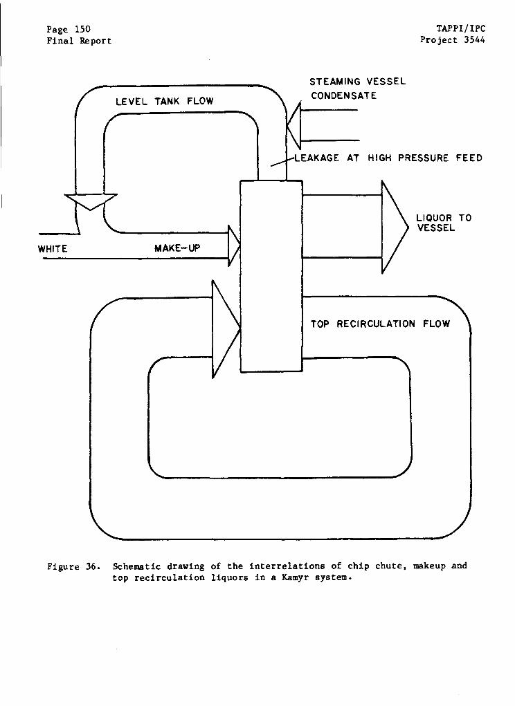
Page 150Final Report
TAPPI/IPCProject 3544
Figure 36. Schematic drawing of the interrelations of chip chute, makeup andtop recirculation liquors in a Kamyr system.
XPPI/IPC Page 151roject 3544 Final Report
iquor, but to a lesser degree since the sulfide does not participate as
trongly in the low-temperature cooking process. Thus, the makeup liquors
ampled in this program should be viewed as representing the upper bound on
austic sulfide concentration that might enter a vessel; the actual con-
entrations in liquor entering the vessel will be somewhat lower.
Apparatus
The apparatus used for chemical sampling and for the in situ electro-
ahemical studies is shown schematically in Fig. 27. The entire apparatus was
assembled with stainless steel and Teflon materials of construction. The
apparatus was connected to the drain valve at the suction of the makeup liquor
pump via a Teflon-lined flexible metal hose. The liquors passed through the
apparatus and were exhausted into the drain. A fine mesh screen filter was used
to screen the incoming liquor, to prevent chip fines and other solids from
plugging lines or affecting let-down regulator operation. Two testing chambers
were used -- one at a low test temperature representative of top recirculation
temperatures (200°F) and a second chamber for electrochemical testing at temper-
atures as high as high as 285°F (140°C). The second chamber was pumped to a
pressure of 50-60 psi to suppress boiling of the liquors in contact with the
liquor heaters. The chambers were heated at the bottom with cartridge heaters
and along their length with heating tapes placed to maintain temperature unifor-
mity. After departing the second chamber, the liquor was cooled to room
temperature and let down to atmospheric pressure through a back pressure regu-
lating valve. The liquor then passed through an automatic sampling system
before being discharged to the drain.
The temperatures in the two chambers were controlled by a proportional
temperature controller which adjusted the current applied to cartridge heaters
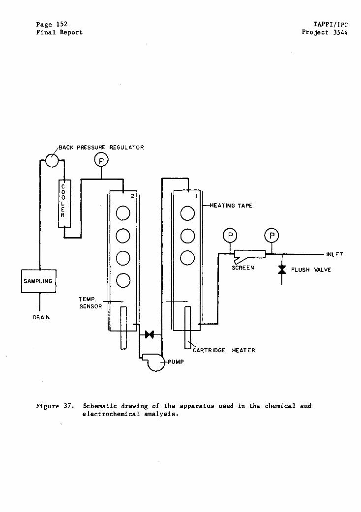
Page 152Final Report
PRESSURE REGULATOR
TEMPSENSOR
DRAIN
Figure 37.
TAPE
TAPPI/IPCProject 3544
FLUSH VALVE
HEATER
Schematic drawing of the apparatus used in the chemical andelectrochemical analysis.
TAPP1/IPC Page 153Project 3544 Final Report
in the base of each chamber. Heating tapes positioned along the length of each
chamber were excited with variable transformers to adjust for a constant tem-
perature profile. Each of the chambers was completely insulated to minimize the
heating load to that provided by a single 20 A, 110 VAC circuit that was rou-
tinely available in the mills.
The pressure in the second chamber was maintained by a high-pressure
metering pump that also controlled the throughput of liquor through the appara-
tus. The metering pump selected had a throughput of 0,3 liters per hour. The
pump employed was a valveless design which used a stainless steel plunger
rotating in a matching graphite pump head. Frequent repairs were made to this
pump because of the abrasive and corrosive nature of the liquors. After several
early failures, the plumbing was modified with valves that permitted replacement
of pump elements "on the fly"; a heat exchanger was also installed to cool the
liquor before it entered the pump. A bypass line was also installed to allow
purging of any air from the apparatus by rapid flushing with the liquor.
The filter was completely stainless steel with a stainless screen that
passed 125-micron particles but retained most of the fines present in the
liquors. The screen included a "Y" arrangement for flushing the screen, but
manual cleaning was often required, as well. Pressure gages before and after
the screen indicated plugging by their different readings.
The back pressure regulator was a Mitey-mite type of regulator which
could be adjusted to control pressures in the range 0 to 100 psig by adjusting
the pressurization of the top element. The regulator was protected from harm-
ful temperatures by a heat exchanger in the inlet side.
Page 154 TAPPI/IPCFinal Report Project 3544
The apparatus was set up to sample the liquors automatically in the
event of a significant change in redox potential at a gold electrode in the
first chamber. A schematic diagram of the sampling apparatus is shown in Fig.
38. A Potentiodyne Model 3010 Corrosion Rate Meter was utilized to detect the
redox potential and to trigger an automatic sampling of the liquor if the redox
potential of the liquor changed significantly during testing. If a shift
occurred in the redox potential, a timing and logic circuit was energized to
capture the liquor responsible for the change. Automatic valves were opened and
closed to pass the liquor through the sampling bottle. After a period of time
determined by the timing circuit, the position of the automatic valves was
reversed, trapping the liquor sample in the sample bottle and bypassing the
sample bottle with liquor subsequently leaving the apparatus. The timing cir-
cuit was adjusted so that the liquor causing the change in redox potential in
chamber 1 was the same liquor trapped in the sample bottle.
Test electrodes were installed in the test chambers using the conven-
tional Petrolite 3-electrode probes mounted in a modified pipe plug fitting.
Three stations were used in test chamber 1 and four in test chamber 2. Each
station was fitted with three electrodes -- a steel electrode, a silver/silver
sulfide reference electrode, and a graphite counter electrode, with the exception
of station 3, which had a gold foil electrode in place of carbon steel. The
carbon steel electrodes were cylinders about 2.9 cm (1.125") high by 1 cm (.38")
in diameter, with a 9 cm2 (1.4 m2) surface area exposed to the liquor. The gold
foil exposed about one half of this surface area. All electrodes were mounted
to the threaded glass-to-metal seals in the electrode assembly using Hypalon
gaskets. One base metal electrode and one weld metal electrode were exposed in
chamber 1; two of each type were exposed in chamber 2.

Page 155Final Report
SAMPLEBOTTLE
POTENTIODYNE 101
TO DRAIN
REDOX ELECTRODE
DELAY, RESETTIMED RELAY
Figure 38. Schematic design of the automatic sampling apparatus.
I~~~~~~~~~~~~~~~~~~~~~~~~~
Page 156 TAPPI/IPCFinal Report Project 3544
The open circuit electrode potential and the corrosion rate of each of
the test specimens were determined with a Potentiodyne Model 1010 Corrosion Rate
Meter. This instrument automatically examined each of the electrodes in turn,
first measuring the open circuit potential, and then measuring the corrosion
rate using a linear potential method. In alternate scans, the corrosion rate
was measured by alternate anodic and cathodic (]0 mV) steps about the corrosion
potential. Past experience has shown that the linear polarization measurements
do not alter the open circuit potential in kraft liquors. The potentials and
linear polarization curves were automatically recorded on a chart.
Polarization curves were also generated using the exposed electrodes
and a Potentiodyne Analyzer. During these scans, the electrode station was
temporarily disconnected from the Model 1010 instrument and connected instead to
the Analyzer. Generally speaking, only the redundant electrodes in chamber 2
and the gold electrode were scanned before the test was about to be terminated,
to insure that the act of taking polarization curves did not affect the spon-
taneous film formation at the steel electrodes. In those cases where the tem-
perature of Chamber 2 was changed during the tests, the Analyzer was also used
to clean the electrode surface by potentiostatting the specimen below the H2
evolution potential for 5 minutes at the new condition.
Electrode Materials
The test specimens used in the current program were manufactured from a
weld that had been removed from a continuous digester that had shown severe
cracking. The base metal was A516-70 and the weld metal was an E7018 multipass
girth weld taken from the region of the lower cone transition. The specimens
were oriented with the long axis of the specimen aligned along the rolling
APPI/IPC Page 157roject 3544 Final Report
irection of the plate and the longitudinal direction of the weld. Although
ests on the HAZ were also proposed to the DCRC, these tests were not performed
ecause HAZ material was not available from the specially welded plates that are
et to be welded for the DCRC program.
The reference electrodes chosen for this program were the Ag/Ag2S type
suitable for direct immersion in the caustic cooking liquors. These reference
electrodes were prepared by anodizing silver billets in a 100 g/L NaOH + 33 g/L
Na2 S solution for a few minutes. The reference potential of this electrode
depends weakly on the sulfide concentration of the alkaline test media, but the
changes were small over the range of sulfides encountered in the different
liquors.
This reference electrode was calibrated versus a calomel reference
electrode at temperatures ranging from room temperature up to 280°F (137°C),
using makeup liquors from Mills 60 and 48. In this calibration, a double salt
bridge with a wetted asbestos wick was used to isolate the calomel electrode
from the poisonous effects of sulfide media. The contributions from liquid
junction potentials and thermal junction potentials in this arrangement are
unknown but thought to be small. The salt bridge arrangement is shown in Fig.
39. As shown in Fig. 40, the potential of the Ag/Ag2S was approximately -0.870
VSCE (-0.630 VSHE) in both of the liquors used. A stable reference potential
was obtained within 30 minutes of immersion in the liquor. (Measurement of the
potential of several Ag/Ag2 S electrodes in test chambers 1 and 2 also showed
that their potentials agreed within 1 mV in any liquor.) There was a slight
tendency for the potential of Ag/Ag2 S to increase as the temperature was raised
from 70°F to 280°F, but the changes were small and scattered. In future
discussions, the potential of Ag/Ag2S is standardized at -0.870 VSCE.
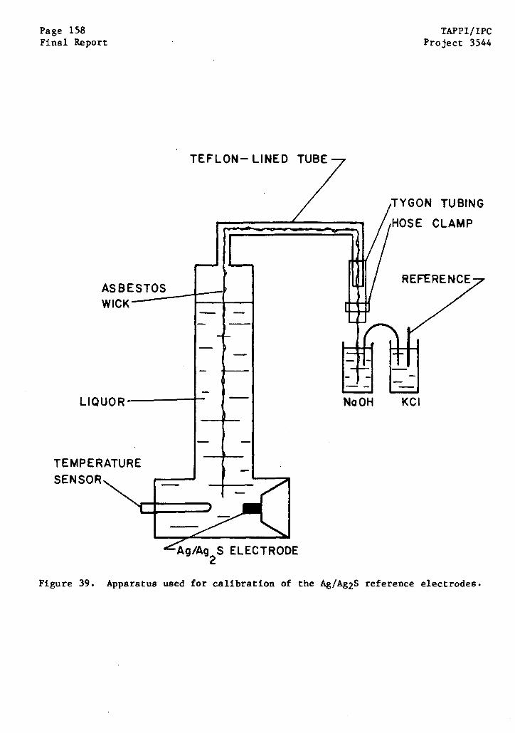
Page 158Final Report
TAPPI/IPCProject 3544
TEFLON- LINED TUBE
ASBESTOSWICK
LIQUOR
TEMPERATURESENSOR
eITYGON TUBING
HOSE CLAMP
NaOH KCI
jt2
Figure 39. Apparatus used for calibration of the Ag/Ag2S reference electrodes.
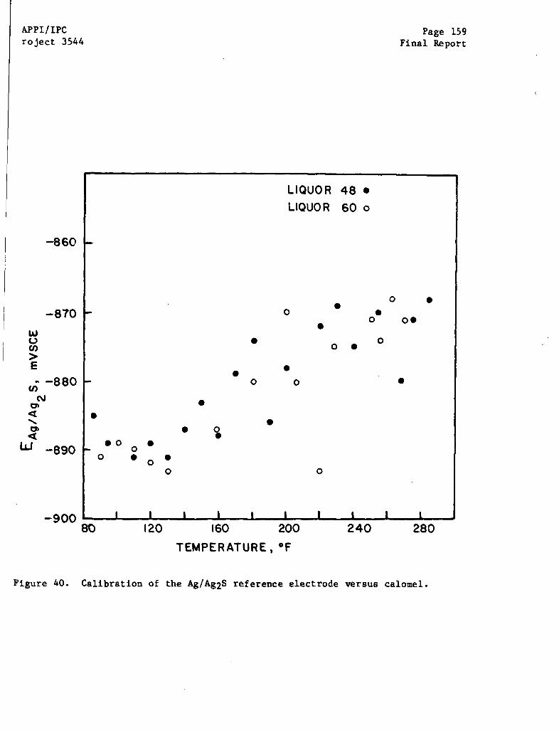
APPI/IPCroject 3544
-860
-870
Page 159Final Report
80 120 160 200 240
Figure 40. Calibration of the Ag/Ag2S reference electrode versus calomel.
280
Page 160 TAPPI/IPCFinal Report Project 3544
Grab Sampling
Although the apparatus was in place to allow sampling during any redox
excursions, only one such excursion took place. Most sampling was done at
periodic intervals during the mill visit, instead. Samples were taken by
allowing the liquor to flow through a double-valved, stainless steel sample
bottle until the gas in the bottle was completely purged. The double valves
were then closed and capped with blank tube fittings, with care taken not to
introduce air into the bottle. The sample bottles were then cooled to room tem-
perature, packed in several plastic bags with absorbent vermiculite (in case of
leakage), and air expressed to the Institute for chemical analysis. At the out-
set, care was taken to insure that specimens were analyzed within hours of
collection. Repeated measurements on a single specimen indicated that the
liquors were very stable if contact with air was avoided, and chemical analyses
later in the program were done as convenient.
Chemical Analysis
The liquors obtained in grab sampling were analyzed using a variety of
techniques to ascertain chemical composition. Most of the tests conducted were
focused on inorganic species, since the identification of organic species in
these liquors is often difficult and uncertain. The sulfide concentration of
the liquors was determined by a potentiometric titration with mercurous chloride
and by the standard ABC titration. Good agreement between duplicate tests was
obtained. The caustic concentration was determined using the ABC method and
TAPPI standard T624; good agreement was obtained with the two methods. The
sulfoxy compounds S03= , S04= , S203= (thionates and other sulfoxy compounds were
not found) and chloride were determined using ion chromatography. Carbonate
concentration was determined using the ABC titration and ion chromatography;

APP1/IPC Page 161roject 3544 Final Report
ood agreement was again observed. The presence of trace inorganic ions was
Characterized by emission spectroscopy and by energy dispersive X-ray analysis
EDAX) on dried solids in the scanning electron microscope (SEM).
Polysulfide measurements at first presented some difficulty because of
:he high color of the liquors and the interference with colorimetric methods for
olysulfide analysis. The ultraviolet spectrophotometer method for polysulfide
Determination was affected by excessive absorption of the incident and scattered
light by the colored solution. Similarly, the Mead Amalgam method for poly-
sulfide analysis was confounded by problems with detection of a colorimetric
endpoint for completion of a polysulfide reduction by sodium amalgam. A simi-
lar problem was encountered in the colorimetric endpoint for oxidation of poly-
sulfide by Na2SO3 according to the TAPPI standard method T624. In all of
these cases, an initial procedure is the elimination of the characteristic poly-
sulfide color by oxidizing or reducing the polysulfide compounds, and this color
change could not be detected in the presence of chromophores in the liquors.
After repeated testing, it became apparent that (i) the reduction (or
oxidation) of polysulfide was essentially complete after an exposure of the test
solution to the amalgam (or Na2S0 3) for a few minutes at 50°C, and (ii) no
conflicting reactions occurred unless the test solution was exposed to the
amalgam (or Na2S0 3) for much longer periods. Thus, a reproducible change in the
sulfide (or Na2S203) content of the liquor could be achieved, and a meaningful
polysulfide measurement made by exposing the test solution to the reductant (or
Dxidant) for a few minutes without concern for any color change in the end
point.
In the final analysis, the Mead Amalgam method was used to determine
the polysulfide concentration of the sampled liquors, with a timed exposure to
Page 162 TAPPI/IPCFinal Report Project 3544
the sodium amalgam for a few minutes at 50°C. Even this step did not completely
resolve all of the problems with polysulfide determination, since the same test
conducted on makeup liquor samples immediately after sampling a liquor caused a
foaming of the liquor and meaningless results from the polysulfide analysis.
The only organic compounds specifically determined in the makeup
liquors were the simple organic acids - formic, lactic, and acetic. The con-
centrations of these acids were determined using ion chromatography.
Procedure
Once the apparatus was set up at a mill site with the electrodes
installed, a routine procedure was followed to start the electrochemical
testing. The makeup liquor was flushed through successive stages of the
apparatus to remove chip fines (ahead of the screen) and entrapped air bubbles
beyond the screen. After the flushing procedure was completed, the pump bypass
was closed and a stable flow rate was established through the apparatus. The
temperature controllers for both chambers were then turned on, and a stable tem-
perature profile was obtained by adjusting the proportional controllers and the
variable transformer settings to the heating tapes. Once the system was
operating as desired, cables from the two Potentiodyne corrosion rate devices
were attached to the electrodes, and the routine for measuring potentials and
corrosion rates began.
While the apparatus was operating, various tasks were completed
including: (i) gathering samples and shipping them to the Institute from the
nearest commercial airport, (ii) sampling liquids and conducting in situ measure-
ments of sulfide and polysulfide, and (iii) running polarization curves on gold
and the redundant electrodes in chamber 2. In practice, considerable effort was
APP1/1PC Page 163roject 3544 Final Report
equired to keep all elements of the apparatus operating because of the high
olids content of the liquors and their tendency to plug plumbing.
The specimens in chamber #1 were exposed continuously at a temperature
n the range 195-200'F for the duration of the electrochemical testing effort
it any mill. In chamber #2, the electrodes were usually passivated more quickly,
nd little additional information resulted from the continued exposure at the
same temperature. Consequently, once the electrodes in the second chamber exhib-
ited stable passivity for a day or two at 285°F, polarization curves were run
n all electrodes, the temperature of the test chamber was lowered to 240°F, the
electrodes were cleaned by evolving hydrogen gas on the surface, and the
electrodes began a repassivation at the new temperature. In other cases, the
temperature in chamber #2 was kept at 285°F to demonstrate that the passivity
established at this temperature was indeed stable.
Cyclic polarization curves were run on the gold electrode and the
duplicate electrodes in chamber #2 as the opportunity arose. Polarization
curves were run using an inert gold electrode to differentiate redox reactions
in the liquor from oxidation reactions involving dissolution. Cyclic polariza-
tion curves were run on all electrodes near the end of the tests in any chamber
at the current temperature. In general, an anodic scan was conducted first to
assess the extent of passivity (in the case of the steel electrodes) or the
anodic redox reactions (in the case of gold and completely passivated steel).
Thereafter, the potential was scanned to and held at - 0.600 V Ag/Ag2S to clean
the surface by hydrogen evolution for 5 minutes. After this hydrogen cleanup,
the potential was again scanned in the anodic direction to determine the electro-
chemical characteristics of the active metal surface. The scan rate used in all
of the polarization curves was 1 mV/sec.
Page 164 TAPPI/IPCFinal Report Project 3544
RESULTS OF CHEMICAL ANALYSES
White Liquor
At several mills, raw white liquor samples were taken at the outlet of
the white liquor clarifier or storage tank for chemical analysis. The com-
position of the liquors is shown in Table X. No white liquors could be obtained
from the 6th mill. The NaOH concentration ranged from 82 to 115 g/L, and the
Na2S concentration ranged from 21 to 46 g/L, giving active alkalis in the
range 91 to 118 g/L as (Na20) and sulfidities ranging from 26 to 31% (AA basis).
The minor constituents of the white liquors (and the makeup liquors
described subsequently) do not conform to the reported values for the
equilibrium constant for the reaction
Na2S203 + Na2S -> Na2S03 + Na2S2.
Haeglund and Roald (69) have reported an equilibrium constant for this reaction,
K, with a value of 1.6 x 10⁻⁴ , where
[Na2SO3] [Na2S2]
K [Na2S203] [Na2S]
For the concentrations measured in these liquors, the equilibrium constant would
be closer to 1 x 10- 3. The reason for the discrepancy is not clear.
The average data do not support a strong correlation between active
alkali, sulfidity, and SCC susceptibility, as seen in Table X. To be sure, the
3 vessels that have experienced cracking are also the vessels that have the
highest sulfidity, but mill 60 is nearly as high in sulfidity, yet no cracking
is observed. Wensley (67) has suggested that mills with high sulfidity and low
caustic are more susceptible to stress corrosion cracking; mills 143 and 48 do
fulfill that condition, and these vessels have cracked. However, mill 137 has
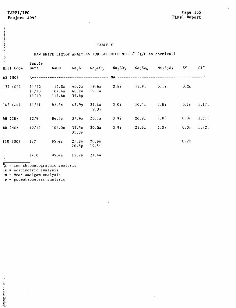
TAPPI/IPCProject 3544
Page 165Final Report
TABLE X
RAW WHITE LIQUOR ANALYSES FOR SELECTED MILLS* (g/L as chemical)
Sample
sill Code Date
62 (NC)
NaOH Na2S Na2 CO3 Na2SO3 Na2SO4 Na2S203 S° C1-
<---------------------------------- NA -------------------------------------- >
137 (CR) 11/1011/1011/10
112.8a107.4a115.6a
40.2a40.2a39.6p
19.6a19.7a
2.8i 12.9i 6.1i 0.2m
143 (CR) 11/21
48 (CR) 12/9
82.6a 4 5 .9 p 21.4a19.3i
84.2a 37.9a 36.la
3.0i
3.9i
10.4i
20.9i
5.8i
7.8i
O.lm 1.17i
0.3m 1.51i
102.Oa 35.5a3 5 .3 p
30.Oa 3.9i 23.6i 7.0i 0.3m 1.72i
0.2m95.4a 21.8a 26.8a20.8p 19.5i
1/10 q5.4a 15.7a 21.4a
1 = ion chromatographic analysis
a = acidimetric analysism = Mead amalgam analysisp = potentiometric analysis
60 (NC)
110 (NC)
12/19
1/7
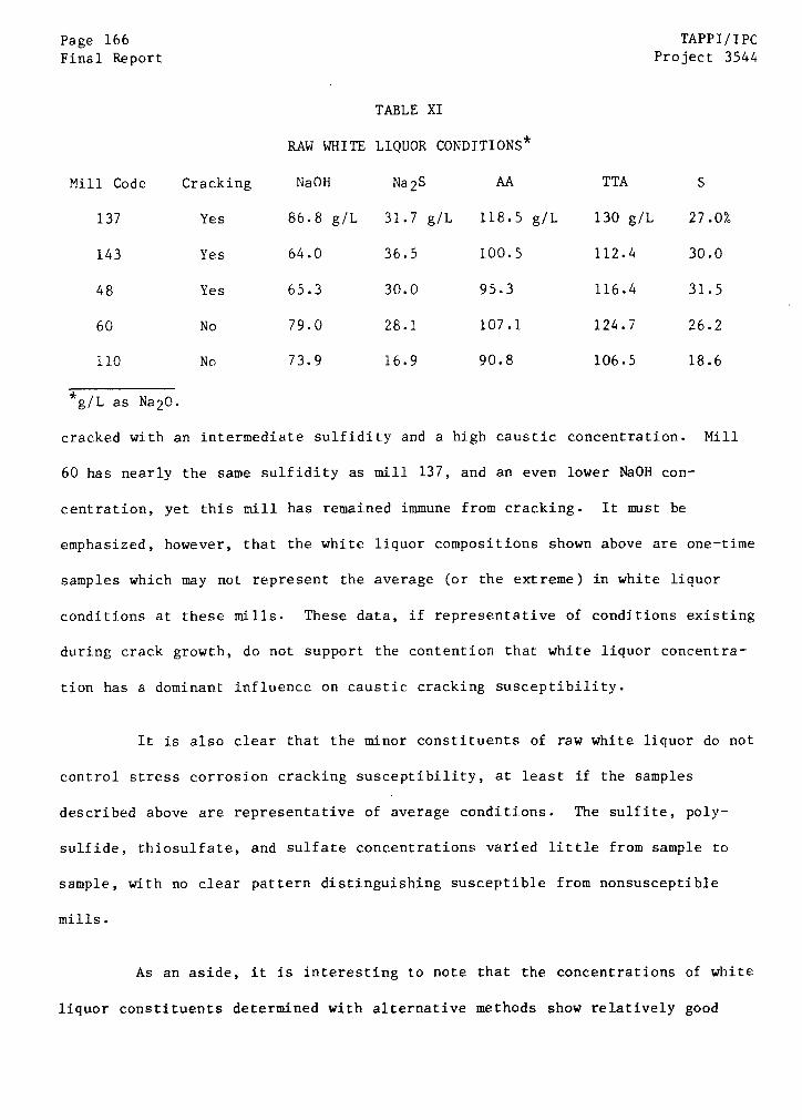
Page 166 TAPPI/IPCFinal Report Project 3544
TABLE XI
RAW WHITE LIQUOR CONDITIONS*
Mill Code Cracking NaOH Na2S AA TTA S
137 Yes 86.8 g/L 31.7 g/L 118.5 g/L 130 g/L 27.0%
143 Yes 64.0 36.5 100.5 112.4 30.0
48 Yes 65.3 30.0 95.3 116.4 31.5
60 No 79.0 28.1 107.1 124.7 26.2
110 No 73.9 16.9 90.8 106.5 18.6
g/L as Na2O.
cracked with an intermediate sulfidity and a high caustic concentration. Mill
60 has nearly the same sulfidity as mill 137, and an even lower NaOH con-
centration, yet this mill has remained immune from cracking. It must be
emphasized, however, that the white liquor compositions shown above are one-time
samples which may not represent the average (or the extreme) in white liquor
conditions at these mills. These data, if representative of conditions existing
during crack growth, do not support the contention that white liquor concentra-
tion has a dominant influence on caustic cracking susceptibility.
It is also clear that the minor constituents of raw white liquor do not
control stress corrosion cracking susceptibility, at least if the samples
described above are representative of average conditions. The sulfite, poly-
sulfide, thiosulfate, and sulfate concentrations varied little from sample to
sample, with no clear pattern distinguishing susceptible from nonsusceptible
mills.
As an aside, it is interesting to note that the concentrations of white
liquor constituents determined with alternative methods show relatively good
TAPPI/IPC Page 167Project 3544 Final Report
agreement, particularly for sulfide and carbonate analyses. To obtain the good
agreement between the ABC acidimetric and other techniques, it was important to
insure that the formaldehyde solution in the "B" step was at neutral pH before
it was used to fix the hydrosulfide ion.
Cooking Liquors
The results of the chemical analyses of major and minor constituents in
the cooking liquors (makeup liquor, in nearly all cases) are shown in Table
XII, In the case of the organic-laden cooking liquors, some difficulty was
experienced in obtaining good agreement among different test methods used to
determine a given species concentration. There was no pattern to those occa-
sions when, for example, the carbonate concentration in the ABC titration was
unaccountably low compared with the more accurate ion chromatography value. In
spite of these unexplained discrepancies, the overall agreement among various
methods was generally very good.
Comparing Tables X and XII shows clearly that the makeup liquor is
considerably different in composition from the raw white liquor because of the
component added to the makeup liquor by recirculation through the level tank.
Compared with white liquor, the cooking liquor has a lower NaOH and a higher
Na2 CO3 concentration, as might be expected from the low-temperature cooking
thought to occur in the recirculating liquor lines. The sulfidity of the
cooking liquor is slightly lower than the raw white liquor due to the modest
consumption occurring during the low-temperature cooking.
Once again, it is very difficult to detect a correlation between the
concentration of major and minor inorganic species in the cooking liquor and the
susceptibility of the vessel to cracking. Indeed, the cooking liquors are
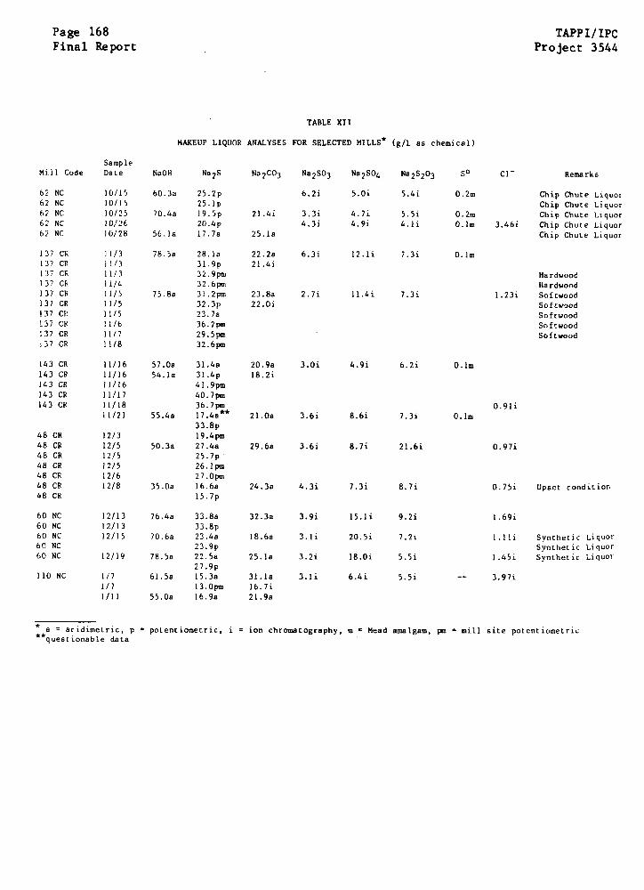
Page 168Final Report
TAPPI/IPCProject 3544
TABLE XII
MAKEUP LIQUOR ANALYSES FOR SELECTED MILLS* (g/L as chemical)
SampleMill Code Date NaOH Na2S Na2CO3 Na2SO3 Na2SO4 Na 2S203
60.3a 25.2p
25.1p70.4a 19
.5p20.4p
56.1a 17.7a
21.4i
25.as
6.2i 5.0i
3.3i 4.7i4.3i 4.9i
5.4i
5.5i4.1i
0.2m
0.2m0.1m
Chip Chute LiquorChip Chute LiquorChip Chute Liquor
3.46i Chip Chute LiquorChip Chute Liquor
137 CR ]1/3137 CR 11/3137 CR 11/3137 CR 11/4137 CR 11/5137 CR 11/5137 C. 11/5137 CR 11/6137 CR 11/7137 CR 11/8
78.5a 28.la31.9p32.9pm32.6pm
75.8a 31.2pm32.3p23.7a36.2pm29.5pm32.6pm
22.2a21.4i
23.8a22.0i
6.3i 12.1i 7.3i O.lm
2.7i 11.4i 7.3i
HardwoodHardwood
1.23i SoftwoodSoftwoodSoftwoodSoftwoodSoftwood
57.0a 31.4a54.la 31.4p
41.9pm40.7pm36.7pm
55.4a 17.4a33.8p
19.4pm50.3a 27.4a
25.7p26.1pm27.0pm
35.Oa 16.6a15.7p
76.4a 33.8a33.8p
70.6a 23.4a23.9p
78.5a 22.5a27.9p
61.5a 15.3a13.0pm
55.0a 16.9a
20.9a18.2i
3.0i 4.9i 6.2i
21.Oa 3.6i 8.6i 7.3i
29.6a 3.6i 8.7i 21.6i
24.3a 4.3i 7.3i 8.7i
32.3a 3.9i 15.1i 9.2i
18.6a
25.1a
31.1a16.7i21.9a
3.1i
3.2i
3.1i
20.5i
18.0i
6.4i
7.21
5.5i
5.5i
O.lm
0.lm0.91i
0.97i
0.75i Upset condition
1.69i
1.lli
1.45i
3.97i
Synthetic LiquorSynthetic LiquorSynthetic Liquor
* a = acidimetric, p**questionable data
= potentiometric, i = ion chromatography, m = Mead amalgam, pm = mill site potentiometric
62 NC62 NC62 NC62 NC62 NC
10/1510/1510/2510/2610/28
SO C- Remarks
143 CR143 CR143 CR143 CR143 CR
48 CR48 CR48 CR48 CR48 CR48 CR48 CR
60 NC60 NC60 NC60 NC60 NC
110 NC
11/1611/1611/1611/1711/1811/21
12/312/512/512/512/612/8
12/1312/1312/15
12/19
1/71/71/11
APPI/IPC Page 169
roject 3544 Final Report
erhaps more uniform in composition than the raw white liquors, apparently due
o a "buffering" action that accompanies the low-temperature cooking in recir-
ulation lines. The absence of a strong correlation between inorganic liquor
hemistry and cracking is especially evident in the results for mill 60, which
as concentrations of most species in the range found in those vessels that have
racked.
Caution is again required in the broad interpretation of such a small
sample of cooking liquor. In most cases, only one week was spent at the mill,
and only a small number of samples were taken. Insofar as these samples repre-
sent the normal cooking liquor chemistry, that chemistry does not appear to
ontrol cracking susceptibility. This cautionary note is especially relevant in
View of the labile nature of the liquor chemistries. Relatively large changes
are seen in the day-to-day liquor chemistries presented in Table XI1, and it is
lear that the "average" composition of a liquor may have little physical
meaning when such large fluctuations are possible.
On the other hand, it is interesting to note that significant changes
in mill operation have only a small effect on liquor chemistry. For mill 137,
for example, swings between hardwood and softwood pulping have little effect on
cooking liquor composition. Similarly, a period of operation with synthetic
liquor also has only a small effect on liquor composition. As will be seen
later, these changes in operation had little effect on the electrochemical
behavior of steel immersed in cooking liquors.
One nonroutine event that had a significant impact on both the chem-
istry and electrochemistry of cooking liquors took place at mill 48 on December
8. At 10 AM, an upset condition occurred as a result of screen cleaning in the

Page 170 TAPP1/IPCFinal Report Project 3544
level tank recirculation line. Large amounts of live steam were apparently
directed into the line, with the result that the liquors were considerably
diluted. A sample taken at that period showed a much more dilute liquor than
had been detected previously at the mill. As will be seen later, this change
also affected the electrochemical behavior of steel immersed in the makeup
liquor, as well.
The results of three special analyses of cooking liquors are displayed
in Table XIII The first is a summary of five ion chromatographic analyses per-
formed on a single sample of chip chute liquor, taken in five separate sample
bottles kept sealed until the analysis was begun. The first analysis took place
a few hours after the sample was taken and shipped to the Institute for analy-
sis. The last analysis took place 120 hours after the sample was taken. There
is no trend to the scatter in composition of the sulfoxy compounds, indicating
that the sampling procedure was adequate. Furthermore, it was apparent that no
changes in liquor chemistry were likely during shipment of the liquors from
remote mills by air express.
The data from mill 60 presented in Table XIII address the uncertainty
about the composition of the top recirculation liquor as it compares with makeup
liquor. Liquor was obtained from the top recirculation line at mill 60, using
leakage from the drain valve in the line. Liquor was flowing from a faulty weld
adjacent to the valve at a steady drip rate. Some flashing was occurring as the
liquor was depressurized, but since the liquor in the line was close to the
atmospheric boiling temperature, the amount of flashing was small. This top
recirculation liquor was gathered and analyzed and found to have the composition
shown in the table. The concentration of the inorganic chemicals in this liquor
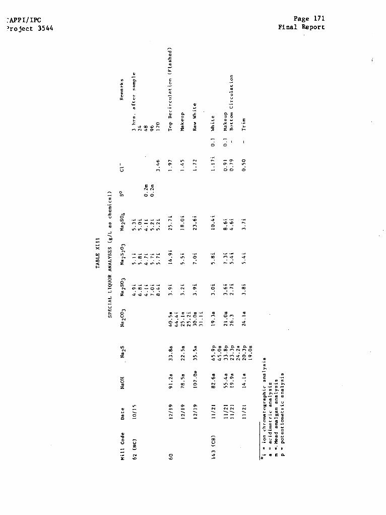
APPI/IPCroject 3544
Page 171Final Report

Page 172 TAPPI/IPCFinal Report Project 3544
was similar to, but somewhat higher than, that of the makeup liquor, which is
attributed to the evaporation of a portion of the water originally in the
sample. It is noteworthy that the proportions of NaOH, Na2S and Na2CO 3 are vir-
tually identical to those found in the makeup liquor sample taken at the same
time.
The third set of data in Table XITI, gathered at mill 143 on November
11, also addresses the question of degree of cooking in the impregnation zone.
One of the liquors taken on that date was from the bottom circulation line that
carries chips from the bottom of the impregnation vessel to the top of the
digester. This liquor is thought to be representative of the liquor present at
the bottom of the impregnation zone of one-vessel digesters and will indicate
the degree of cooking and the composition of the liquor at that location. The
second liquor, taken from the trim recirculation line, is essentially represen-
tative of that in the cooking zone of the vessel. It is clear from these data
that a large amount of cooking chemical is consumed in the impregnation zone
before high temperature cooking has begun. Less than half of the active alkali
remains after the impregnation zone is traversed. The (room temperature) pH at
the bottom of the impregnation zone has dropped to 11.9 for both bottom cir-
culation and trim liquors. Once again, although considerable amounts of cooking
chemicals have been consumed, only the carbonate shows an increase in con-
centration among the inorganic compounds.
The implications of these results regarding the effects of chemical
composition on cracking susceptibility are noteworthy. It appears that the
changes in chemical composition of the liquor as it passes from the top of the
digester to the cooking zone are much larger than any changes in liquor from
APPI/IPC Page 173Project 3544 Final Report
mill to mill. Every vessel will experience a range of caustic and sulfide con-
entrations along the length of the vessel. If a critical liquor composition
as instrumental in causing cracking, the vessels with a high concentration of
he damaging species should be cracked at levels closer to the cooking zone.
Conversely, mills with lower concentrations of damaging species would be
xpected to reach the critical concentration at higher elevations, since less
chemical has to be removed by cooking. However, there is no evidence that such
distribution of cracking occurs -- the same welds are cracked in most vessels
regardless of chemistry.
Trace Elements
Trace contaminants were also determined in the liquors taken at each
nill site, to determine if trace metals or other trace elements in the liquors
an be correlated with cracking susceptibility. Two types of analyses were per-
formed. The samples were reduced to sulfated ash and analyzed in the emission
spectrograph; in addition, small quantities of liquors were evaporated to salt
and analyzed using the EDAX analyzer in the scanning electron microscope. The
emission spectrographic results are summarized in Table XIV. Silicon was present
t a few hundred parts per million, whereas Fe, Al, Cu, Ca, and Mn were present
in concentrations of only a few parts per million. Nickel and mercury -- poten-
ial contaminants from caustic manufacturing -- were not found. Two typical
DAX spectra are shown in Fig. 41 and 42 for liquors from susceptible and non-
susceptible mills. While peak heights in these spectra are not exactly propor-
ional to the concentration of elements present, they do provide a qualitative
icture of the species which are present. In addition to major Na and S peaks,
here is evidence of some quantity of potassium, silicon, chlorine and aluminum.
here is no difference in these trace elements, or those detected in the emission
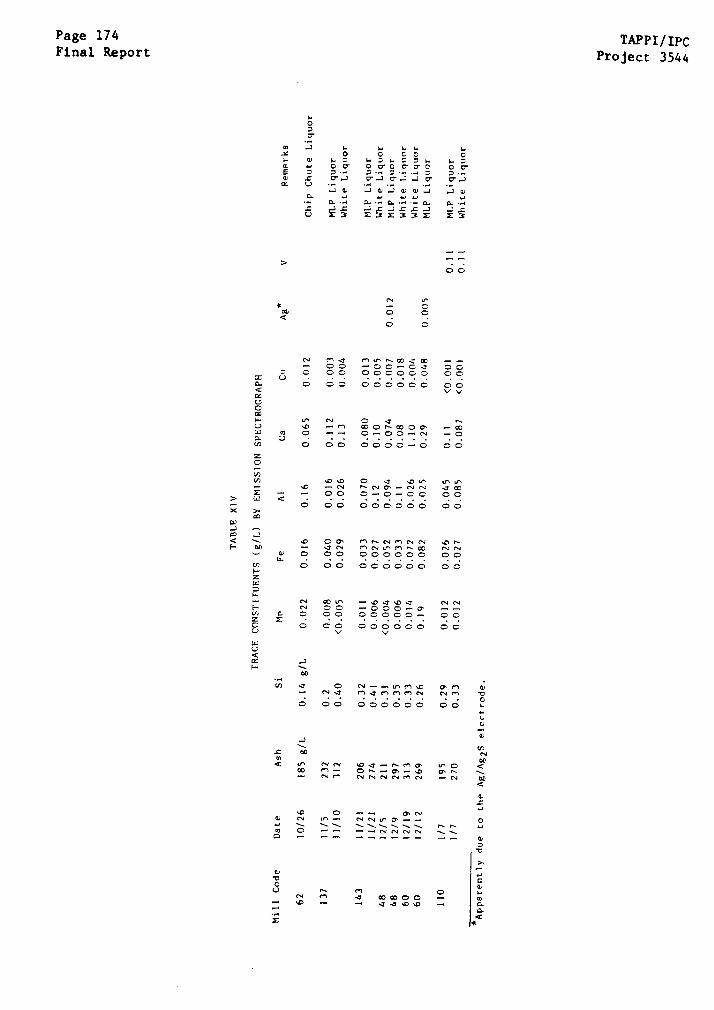
Page 174Final Report
TAPPI/IPCProject 3544
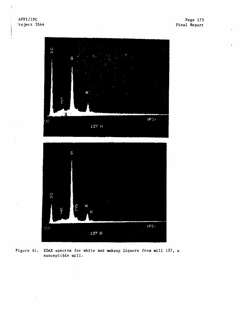
.APPI/IPCProject 3544
Page 175Final Report
Figure 41. EDAX spectra for white and makeup liquors from mill 137, asusceptible mill.
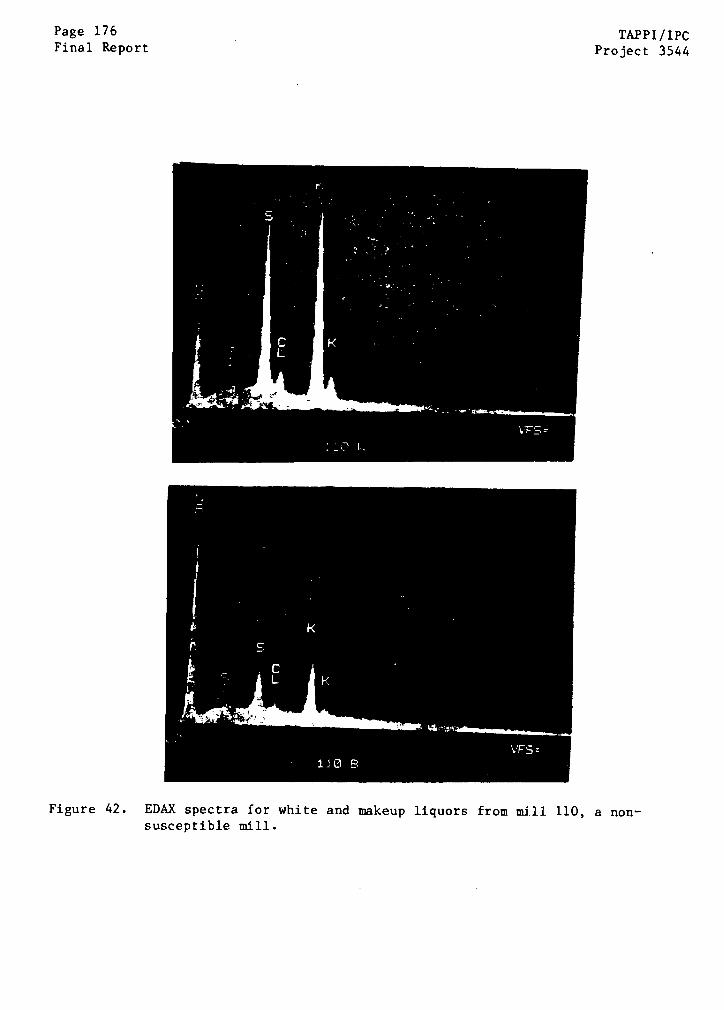
Page 176Final Report
TAPPI/IPCProject 3544
Figure 42. EDAX spectra for white and makeup liquors from mill 110, a non-susceptible mill.
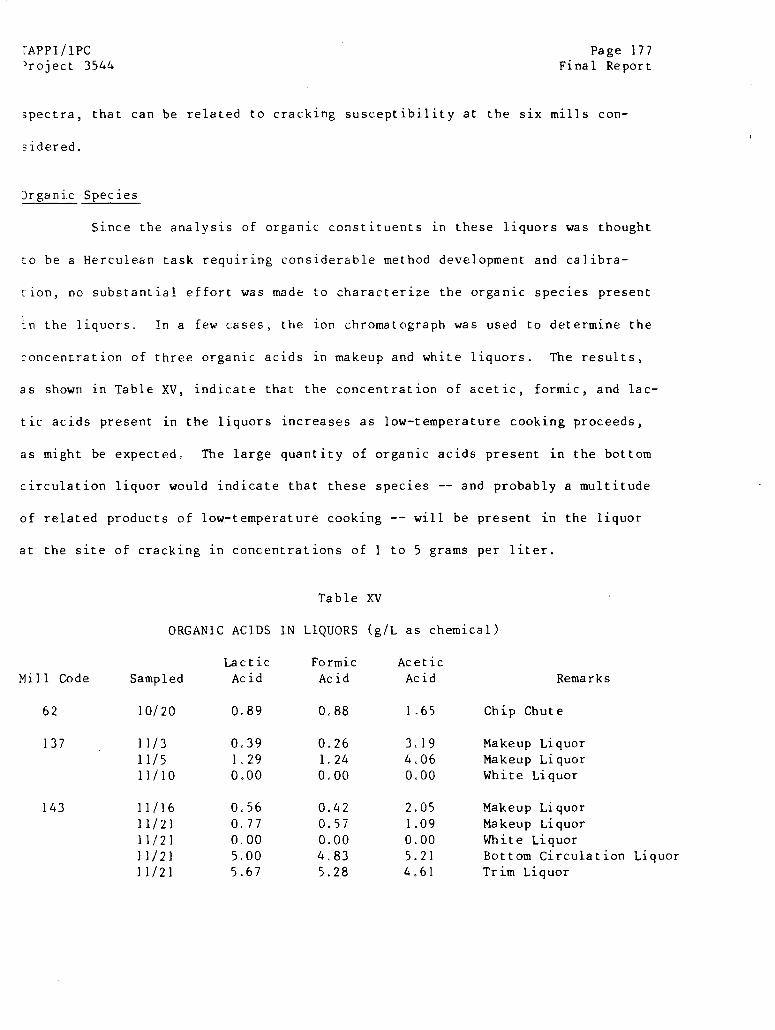
APPI /PCproject 3544
Page 177Final Report
spectra, that can be related to cracking susceptibility at the six mills con-
idered.
Drganic Species
Since the analysis of organic constituents in these liquors was thought
to be a Herculean task requiring considerable method development and calibra-
tion, no substantial effort was made to characterize the organic species present
in the liquors. In a few cases, the ion chromatograph was used to determine the
concentration of three organic acids in makeup and white liquors. The results,
as shown in Table XV, indicate that the concentration of acetic, formic, and lac-
tic acids present in the liquors increases as low-temperature cooking proceeds,
as might be expected. The large quantity of organic acids present in the bottom
circulation liquor would indicate that these species -- and probably a multitude
of related products of low-temperature cooking -- will be present in the liquor
at the site of cracking in concentrations of 1 to 5 grams per liter.
ORGANIC ACIDS
LacticSampled Acid
10/20 0.89
11/3 0.3911/5 1.2911/10 0.00
11/16 0.5611/21 0.7711/21 0.0011/21 5.0011/21 5.67
Table XV
IN LIQUORS (g
FormicAcid
0.88
0.261.240,00
0.420.570.00
4.835.28
/L as chemical)
AceticAcid Remarks
1,65 Chip Chute
3.19 Makeup Liquor4.06 Makeup Liquor0.00 White Liquor
2.05 Makeup Liquor1.09 Makeup Liquor0.00 White Liquor5.21 Bottom Circulation Liquor4.61 Trim Liquor
Mill Code
62
137
143
Page 178 TAPPI/IPCFinal Report Project 3544
Summary
In spite of an intensive analytical effort, no correlations have been
found which relate SCC susceptibility to major, minor, or trace constituents of
cooking liquors. Several explanations fit these observations, including the
following possibilities.
(i) There is no correlation between cracking and cooking liquors in
normal circumstances.
(ii) There is a correlation between cracking and cooking liquor
characteristics, but the damaging conditions are not always present
and were absent when the current sampling was done.
(iii) There is a correlation between cracking and cooking liquor charac-
teristics, but the damaging species was not considered (organics?)
or the correlation is not simple.
As will be seen in the next section, (i) is the most likely explanation.
ELECTROCHEMICAL BEHAVIOR IN COOKING LIQUORS
Rest Potentials
Both the weld metal and the base metal were initially active when
immersed in the caustic cooking liquors, with an initial potential on the order
of -150 mV Ag/Ag2S (-1.02 VSCE). This potential is typical of that for bare
steels exposed to caustic solutions in the absence of a significant con-
centration of oxidizing species (2,4,42). Three were no consistent differences
in the potenials of weld metal and base metal; small differences are attributed
to small differences in surface condition. The redox potential of the gold
electrode was rapidly stabilized in the vicinity of +150 to 170 mV Ag/Ag2S and
TAPPI/IPC Page 179Project 3544 Final Report
remained steadfast at this potential unless the electrode was polarized with the
potentiostat. If the gold redox electrode was disturbed, a half-hour transient
would occur as the electrode returned to its normal redox potential.
As soon as the carbon steel electrodes were immersed in the cooking
liquor, the rest potentials began to drift upward as observed by Humphries and
Parkins (42), Harrison et al. (41) and Reinoehl and Berry (32) for tests in pure
caustic (See Fig. 18). The rate of upward drift in potential is shown for
several electrodes in a cooking liquor at two temperatures in Fig. 43. The rate
of upward drift is dependent on temperature, with a more rapid rise at 284°F
than at 200°F. The rate of drift of the open circuit potential does not depend
on whether the electrode is a base metal or a weld metal. The galvanic effect
of coupling weld metals and base metals should be small, since the potential
difference between weld metal and base metal is only a few millivolts.
The upward drift of the potential ceased as the potential of the steel
approached that of the gold redox electrode. In some cases, particularly at the
lower temperatures, the steel electrode did not quite reach a stable rest poten-
tial in the time available for exposure. The rest potential for both base metal
and weld metal usually stabilized at about -90 mV Ag/Ag2S (-0.060 VSCE) at
200°F. The corresponding rest potential at 280°F was +50 mV Ag/Ag2S (-0.820
VSCE). Some variations were observed from mill to mill, generally attributed to
upset conditions in the apparatus (pump failure) preventing the attainment of a
stable rest potential. In mill 110 the rest potentials were a little higher
than in the other mills ( - + 150 mVSCE), perhaps because of the relatively low
sulfide content at this site.
Examination of partially passivated specimens after rinsing revealed
electrodes covered with patches of a blue-black film thought to be magnetite.
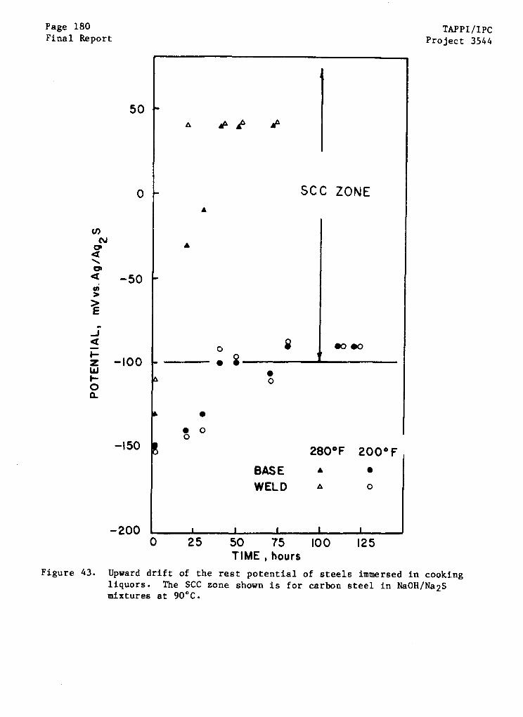
Page 180Final Report
TAPPI/IPCProject 3544
BASEWELD
0 25 50 75TIME , hours
A
I
100 125
Figure 43. Upward drift of the rest potential of steels immersed in cookingliquors. The SCC zone shown is for carbon steel in NaOH/Na2Smixtures at 90°C.
50
0
-200 I
TAPPI/IPC Page 181Project 3544 Final Report
The rest of the surface was covered with a reddish-brown corrosion product indic-
ative of active corrosion in the caustic before exposure to the air. The
electrodes achieving a stable rest potential were covered with a thick black
deposit over an adherent black film. The rise in open circuit potential is
associated therefore with a gradual passivation of the electrodes by the forma-
tion and growth of patches of magnetite. A fully passivated metal would be
covered with a nonprotective FeS deposit on top of a protective magnetite
deposit.
The film formed in the cooking liquors was very fragile and could be
destroyed by any of several different events. Impressing a potential below the
hydrogen evolution potential would reactivate the electrodes by removing the
film, restoring the -200 mV Ag/Ag2S rest potential and initiating a renewal of
the upward drift of potential. Similarly, upset conditions in the apparatus
(with loss of temperature in a chamber because of blockage, for example) could
also activate the samples by damaging the protective film.
In one interesting series of events, the screen cleaning event at mill
48 that caused a marked drop in the concentration of makeup liquor chemicals
also caused a reactivation of partially passivated specimens in both high- and
low-temperature chambers. Potentials in the high-temperature chamber dropped
from +40 to -195 mV during this excursion, for example. This was the only
active-passive reversal associated with the liquor chemistry observed in any of
the six mills. All other transitions were attributed to upsets in the flow of
liquor through the test apparatus by blockage with fines, or potentiostatic
manipulations of electrode potential.
It is most interesting to note that the stable rest potential achieved
by the base metal and weld metal electrodes at all of the mills lies within the
Page 182 TAPPI/IPC
Final Report Project 3544
potential range where SCC was observed in laboratory tests in simulated white
liquor. Singbeil and Tromans (54,55) report SCC at 200"F only in the potential
range + 50 mV about -0.88 VSCE (i.e., - 0.83 to -0.93 VSCE). Within the resolu-
tion of the tests, the stable rest potential at 200°F was found to be in this
range in actual cooking liquors at both temperatures tested. Thus, the stable
rest potential in cooking liquors at both immune and susceptible mills comes to
reside in that narrow regime where caustic cracking has been observed in the
laboratory.
It is reasonable to conclude, based on the potentials achieved, that
all of the liquors tested would support caustic cracking processes if a carbon
steel was subjected to an appropriate tensile stress. Apparently, immune mills
have been immune, not because of some ideal liquor chemistry, but rather because
one of the other necessary conditions for caustic cracking -- high tensile
stresses, access of liquor to the metal through scale buildup, a susceptible
metallurgical structure -- was not satisfied.
In light of this observation about the virulence of liquors at all
mills surveyed, the experience with SCC at stitch welds becomes more meaningful.
In many mills that were otherwise immune to cracking (and graded as having D
type immunity), the non-stress-relieved stitch welds attaching dummy plates and
screen plates to the vessel were cracked. This is a very common occurrence,
considered more of a maintenance item than a real concern at most mills.
However, even these welds of low quality would not be cracked unless the liquor
was conducive to SCC even in the otherwise immune vessels, as described above.
This suggests that the mills which have not exhibited cracking have cooking
liquors which would crack carbon steels if all other conditions of stress,
metallurgical structure, etc., were satisfied.
TAPP1/IPC Page 183Project 3544 Final Report
Experience with welded carbon steel piping in the liquor circulation
lines also.supports the concept of a critical potential range for cracking.
Cracks have not been reported in any of these non-stress-relieved pipe welds,
even though they are exposed to much the same liquors as the top of the vessel.
It is likely, as has been observed for other situations involving flow rates of
active-passive media, that the high flow rate will cause the piping welds to
remain active and not achieve a rest potential in the critical regime for
cracking. If the potential is active and outside of the range required for
caustic cracking, no cracking should be observed in pipe welds.
Polarization Curves
The polarization curves generated on gold and steels in liquors at the
different mills demonstrate why the rest potential resides in the cracking
range, rather than continuing to rise beyond the danger zone as shown for expo-
sures to pure caustic (Fig. 18). Apparently, an oxidation reaction involving
unknown species in the liquor will occur on electrodes at potentials noble to
the redox potential of gold. In fact, this oxidation is probably instrumental
in establishing the redox potential of gold in these liquors.
As shown in Fig. 44, the anodic polarization curves for the gold
electrode are virtually the same at all of the mills and at different times at
the same mill. Since gold is inert, the oxidation reaction occurring on the
gold surface must involve the oxidation of some species present in sufficient
quantity in the liquor. According to Biernat and Robins (68), several reactions
involving sulfur compound oxidation are possible at the potentials of interest,
but uncertainty about the concentration of species present, the activity coef-
ficients of these species, their overpotentials, and the hydrodynamics at the
Page 184 TAPPI/IPC
Final Report Project 3544
redox electrode prevent identification of the oxidation reaction occurring at
+200 Ag/Ag2S. Some possible reactions include:
2S= + S2= + 2e- Eo = -0.524 + 0.03 log [S2=]
[S=]2S= 4 SO + 2e- Eo = -0.476 - 0.03 log [S= ]
2S= + 3H20 - S20 3= + 6H+ + 8e- Eo = -0.006 - 0.04 pH + 0.007 log [S203
= ]
[S=]2
Whatever the actual reaction, raising the potential of gold above 200 mV Ag/Ag2S
will only occur when a cathodic reaction is available that can consume 100
mA/cm 2 of electrons liberated by this liquor oxidation reation.
The same oxidation of some species in cooking liquor apparently occurs
on the surface of steel electrodes that have been rendered more or less inert by
formation of a passive film. As shown in Fig. 45, passivated steel and gold
show the same anodic polarization curve above +150 mV Ag/Ag 2S, indicating that
the same oxidation reaction occurs on both metals.
If a passivated steel specimen is to continue its spontaneous upward
drift in rest potential beyond the anodic peak at 200 mV Ag/Ag 2S, some cathodic
process must be available to consume the ~ 100 mA/cm 2 of electrons liberated at
that peak by liquor oxidation on the inert metal surface. The failure of the
rest potential of steel to continue to drift upward beyond the anodic peak
suggests that the concentration of oxidizing species is insufficient to consume
this large current of electrons. Indeed, an analysis of the cathodic polariza-
tion curves in Fig. 46 suggests that the diffusion-limited current density (iL)
for the available cathodic reaction is only about 1 mA/cm 2. Thus, because of the
anodic peak at +200 mV/Ag/Ag 2S and the dearth of oxidizing species in the
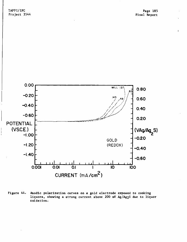
TAPPI/IPCProject 3544
0.00
-0.20
-0.40
-0.60
POTENTIAL(VS.C.E.)
-1.00
-1.20
-1.40
0.001
Page 185Final Report
0.01 0.1 10
CURRENT (mA/cm2 )
0.80
0.60
0.40
0.20
(VAg/Ag S)
-0.20
-0.40
-0.60
100
Figure 44. Anodic polarization curves on a gold electrode exposed to cookingliquors, showing a strong current above 200 mV Ag/Ag2S due to liquoroxidation.
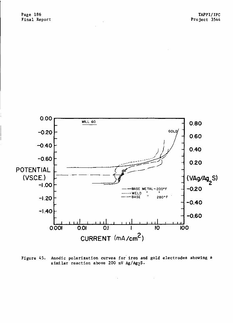
Page 186Final Report
0.00
-0.20
-0.40
-0.60
POTENTIAL(VS.C.E.)
-1.00
-1.20
-1.40
0.001 0.01 0.1 I 10
TAPPI/IPCProject 3544
0.80
0.60
0.40
0.20
(VAg/Ag S)
-0.20
-0.40
-0.60
100
CURRENT
Figure 45.
(mA/cm2 )
Anodic polarization curves for iron and gold electrodes showing asimilar reaction above 200 mV Ag/Ag 2S.

TAPPI/IPC Page 187
Project 3544 Final Report
liquor, the potential of steel (and of gold) will be trapped below this anodic
peak. That is, the rest potentials come to a stable position in the cracking
range because the anodic reaction involving liquor oxidation acts as a ceiling
for the upward drift of the rest potential.
The potential of the gold electrode is comfortably above the cracking
range because it is a true redox electrode. The stable rest potential of the
steel is somewhat lower because carbon steel has an additional anodic dissolu-
tion peak at ~ - 30 mV Ag/Ag2S. This peak is revealed when the steel surfaces
are cleaned by hydrogen evolution for five minutes, followed by an anodic scan
with the active steel surface. As shown in Fig. 47, a large anodic peak asso-
ciated with the active-passive transition of iron occurs at -30 mV Ag/Ag2S
(-0.900 VSCE), exactly as shown by Singbeil and Tromans (53-55). This anodic
peak apparently contributes to the reactions that determine Ecorr on a passive
steel specimen, causing Ecorr to fall in the cracking range, some 100 mV below
the true redox potential.
Thus, it appears that the stable rest potential of steels exposed to
cooking liquors will dwell in the cracking regime because cooking liquors, in
contrast to pure caustic solutions, contain some chemical species that is
electroactive in the range of normal potentials achieved by iron in caustic.
Reactions involving this electroactive species place a ceiling on the upward drift
of the rest potential of steel, causing the potential to reside in the danger
zone for stress corrosion cracking. The stable rest potentials reside in the
danger zone with liquors from both immune and susceptible mills, which dispels
the notion the immune mills are immune because of their unique liquor chemistry.
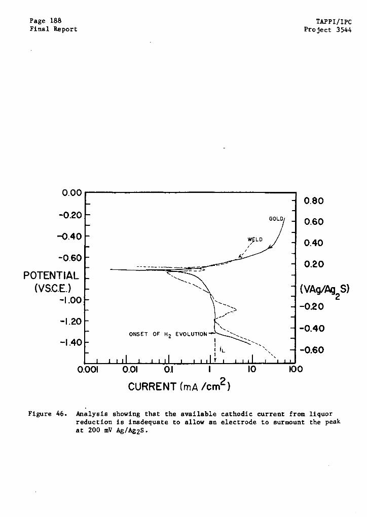
Page 188Final Report
TAPPI/IPCProject 3544
0.00
-0.20
-0.40
-0.60
POTENTIAL(VS.C.E.)
-1.00
-1.20
-1.40
0.001
GOL
LD
Figure 46. Analysis showing that the available cathodic current from liquorreduction is inadequate to allow an electrode to surmount the peakat 200 mV Ag/Ag2S.
I

TAPPI/IPCProject 3544
0.00
-0.20
-0.40
-0.60
POTENTIAL(VS.C.E.)
-1.00
-1.20
Page 189Final Report
WELD
Figure 47. Anodic behavior of steel electrodes in makeup liquor following acti-vation by hydrogen evolution at -600 mV Ag/Ag2S.
Page 190 TAPPI/IPCFinal Report Project 3544
Corrosion Rates
The corrosion rates measured by the linear polarization method were
initially quite high for the active steels, but soon fell to steady state values
in the range 1-5 mils per year. The instantaneous corrosion rates were higher
at higher temperatures, but fell to the steady state value more quickly than at
the lower temperature, as would be expected from the passivation characteristics
described above. There was no evidence of any significant differences in the
corrosion rate of the base metals and weld metals studied.
Ag/Ag2S Reference Electrode Calibration
As an aside, it is interesting to note that the transition from cathod-
ic to anodic behavior (after a cleanup polarization of both steel and gold in
the hydrogen evolution regime) occurs at the same potential, -300 mV Ag/Ag2S
(-0.930 VSHE). This transition appears to be associated with the H2 /H+ reduc-
tion and oxidation half cell, whereby the hydrogen evolved on the electrode
during cleanup is oxidized above E°H+/H 2 , regardless of the substrate material.
Examples of the polarization curves corresponding to this reaction are shown in
Fig. 47, when the present calibration of EAg/Ag2 S = -0.630 VSHE is used. This
observation not only validates the use of a silver-silver sulfide reference
electrode, but also indicates a procedure for obtaining a thermodynamically
meaningful reference voltage for use as a benchmark in white liquor studies at
elevated temperatures and pressures. This benchmark apparently can be obtained
by electrolytically evolving hydrogen gas on the surface of an electrode and
then executing a slow scan in the noble direction to determine the potential
where the anodic oxidation of the gaseous hydrogen begins.
TAPPI/IPC Page 191Project 3544 Final Report
Discussion
The chemical and electrochemical studies of cooking liquors have
refined the understanding of the processes occurring during SCC of continuous
digesters. For example, there do not appear to be any fundamental differences
in the cooking liquor chemistries in the six immune and susceptible vessels.
This result confirms the conclusions drawn from analysis of the statistics of
liquor chemistries and cracking susceptibility. There also is no evidence for
periodic swings through the potential range needed for cracking. Instead, the
electrochemical studies show that the potentials drift to the danger zone and
remain there, even in digester vessels without evidence of cracking. The
characteristics of the cooking liquor are such that spontaneous departure from
this potential regime where cracking can occur is unlikely.
Apparently, those mills that have avoided cracking in their digesters
are fortunate to have either stresses below the threshold for cracking or a sur-
face scale that restricts access of the electrolyte to the weldment surface. The
exact reason for immunity of these vessels is not yet apparent.
With some added understanding of the electrochemistry of the SCC pro-
cess, some alternative remedial measures might be considered that can force the
rest potential from the regime where there is danger of caustic cracking.
Certainly, anodic protection is a very attractive method for shifting the rest
potential out of the danger zone, provided the durability of the system can be
demonstrated. Perhaps, because the potential range where cracking is observed
is apparently so narrow, slight cathodic polarization of the vessel might also
be effective since large potential shifts will not be necessary. A penalty in
higher corrosion rates would probably be paid with cathodic protection. It may
Page 192 TAPPI/IPCFinal Report Project 3544
also be possible to force the rest potential out of the danger zone by the addi-
tion of more oxidizing species to the cooking liquor. If present in sufficient
quantities, the ceiling at 200 mV Ag/Ag2S could be surpassed, and a spontaneous
potential drift out of the danger zone might be possible. Polysulfide is an
oxidizing species already present in liquors to some extent, and it is interest-
ing to speculate on the possible advantages of increasing its concentration in
cooking liquors as a means of avoiding continued caustic cracking.
A legitimate question yet to be addressed is the reason for the
remarkable increase in digester cracking incidents if industry-wide changes in
cooking liquor practices are not responsible. There may be several explanations
for the apparent epidemic of digester cracking incidents. Perhaps the simplest
explanation is that there were no incidents of cracking in the early years of
Kamyr digester operation because few, if any, mills looked for cracking with the
zeal shown in the post-Pine Hill era. Furthermore, there may be an unexplained
incubation period for the onset of cracking that is now being completed for the
numerous mills built in the mid-to-late 1960's. Even the most susceptible
vessels apparently operated for more than ten years before cracking became
evident, and for many vessels, that decade of incubation is drawing to an end.
Moreover, the vintage digesters built in the late 1950's and early 1960's were
nearly all stress relieved according to an early version of the ASME Code, and
these vessels would be much more unlikely to crack during the early years of
operation. Only now are we beginning to see the legacy of the change in the
ASME Code.
Another interesting phenomenon related to the current cracking episodes
is the possibility of nonpropagating cracks. To be sure, several vessels have

TAPPI/IPC Page 193Project 3544 Final Report
exhibited isolated deep cracks, but most of the cracking reported has been rela-
tively shallow -- less than 1/4" deep in most cases, regardless of the length of
exposure time. One wonders whether these cracks rapidly initiate and grow to a
depth of about 1/4", followed by much slower growth or even cessation of growth.
This would explain why a vessel inspected carefully after a decade of operation
exhibits shallow cracks that reappear to the same depth after only one addi-
tional year. Perhaps rapid cracking is restricted to the last weld pass with
much slower growth in the underlying passes that had been stress relieved by
later passes. This may explain the apparent increase in cracking episodes in
recently reinspected digesters.
Page 194 TAPPI/IPCFinal Report Project 3544
UNRESOLVED ISSUES
Inevitably, as a research program draws to an end, pivotal issues that
cannot be addressed with time and funds available become more clearly defined.
This certainly was the case for the present study, since the program was deli-
berately structured with a limited scope and short duration. While several
questions have been resolved by this study, many unresolved questions remain to
be addressed in subsequent studies. Some of these remaining issues are iden-
tified in this section.
Certainly, the central issue yet to be resolved is the reason for the
different susceptibilities to cracking exhibited by different vessels. Based on
current results, the susceptibility of a vessel to stress corrosion cracking is
not simply related to some obvious detail of vessel fabrication or use, nor is
susceptibility related to average white liquor compositions. The limited chemi-
cal analyses conducted during a few weeks of operation at a few mills in this
study also failed to unearth a simple correlation between cracking susceptibil-
ity and liquor properties. The electrochemical studies conducted in this
program may have changed the pivotal question from "Why do some vessels crack?"
to "Why don't all vessels crack?", but the question remains unanswered.
In the absence of the simplest kind of correlations between cracking
and digester characteristics, a more sophisticated approach to the issue would
be required. Perhaps the link between cracking and digester operation is too
subtle to be revealed unless multivariate analyses are performed which will
show, for example, that only certain combinations of metallurgy, temperature,
and liquor chemistry will cause cracking. On the other hand, cracking may be
controlled by some quantity not considered in the present study -- for example,
TAPP1/IPC Page 195Project 3544 Final Report
the concentration of an organic compound derived from the low-temperature
cooking process. Perhaps cracking occurs only intermittently during some upset
condition or some nonroutine event in digester operation. At this stage, it is
unclear whether any of these possibilities controls cracking susceptibility.
It is debatable whether the search for more subtle reasons for cracking
susceptibility can be (or should be) pursued in view of diminishing returns.
The data base regarding digester fabrication and routine operation is probably
inadequate to support much more complexity in the search for links between
susceptibility and routine operation. The situation is even worse for non-
routine events such as liquor excursions, thermal shocks, etc. -- this data base
is virtually nonexistent. If there is no simple cause and effect relationship
for cracking in digesters -- as the current study suggests -- it is questionable
whether further effort should be expended to examine cracking statistics in
search of a more complicated relationship between cracking and digester use.
Another question raised by the current study is the relevance of the
electrochemical studies to the electrochemical behavior of actual vessels. The
conclusion of the electrochemical studies is that carbon steels exposed to
cooking liquors spontaneously achieve potentials in the range necessary for
cracking. However, the differences between the in situ electrochemical tests
and the actual conditions at the vessel must be recognized. The test coupons
were only exposed to liquors for a fraction of the time a vessel spends in con-
tact with liquors, so the long term behavior of carbon steels was not examined.
The cooking liquors at the impregnation zone will have somewhat lower caustic
concentration and higher organic loads than the makeup liquors used for the
electrochemical studies at the mill sites. The role of the surface film
Page 196 TAPPI/IPCFinal Report Project 3544
normally found on the inside of digester vessels was not considered. The range
of potentials where cracking susceptibility was expected was based on laboratory
studies in simulated liquors, rather than SCC tests in actual liquors, While
these differences between actual and simulated conditions are thought to be of
secondary importance, it is possible that the simulation of impregnation zone
conditions may not be representative of actual conditions, and vessel walls
might not respond as test coupons have responded.
The preponderance of shallow cracks in most vessels raises another
intriguing question about the propagation of cracks. With notable exceptions,
most of the cracking observed in vessels is less than 1/4 inch deep, regardless
of exposure time. Even for vessels with a few deeper cracks of grade A
severity, most of the cracks are less than 1/4 inch deep. In many cases,
shallow cracks were found in vessels inspected carefully for the first time
after many years of service, yet the same pattern of shallow cracking was found
after only six months of additional exposure. This observation may be an indi-
cation of rapid initiation and early growth of a crack, followed by much slower
average propagation of cracks deeper than 1/8 inch. Deeper cracks may be
encountering a weld structure that is more resistant to crack growth due to the
tempering effects of the subsequent passes. Alternatively, the residual
stresses driving crack growth may be restricted to the surfaces of vessels, so
that deep cracks propagate into areas where the driving force for continued
growth is reduced.
Many other questions relevant to digester cracking remain unresolved.
Some of these questions are listed below.
(i) What are the magnitude and distribution of residual stresses in
weldments, and what is their role in digester cracking?
TAPPI/IPC Page 197Project 3544 Final Report
(ii) Do fatique loads contribute to the growth of cracks at nozzles,
downcomer supports, or girth and vertical welds?
(iii) What is the role of organic species on cracking in kraft
cooking liquors?
(iv) Why do vessel size and throughput apparently affect cracking
susceptibility?
(v) What is the species involved in the redox reaction that restricts
the upward drift of rest potentials of carbon steel, causing the
potential to reside in the cracking regime?
(vi) How do liquors entering the vessel differ from makeup liquors
as a consequence of the brief, low-temperature cooking occurring
in the top recirculation line?
(vii) What is the long-term durability of various repair measures used
to remedy vessel cracking?
Page 198 TAPPI/IPCFinal Report Project 3544
REFERENCES
1. S. Hudak and A. Saxena. Int. J. of Fracture. 14:453(1978).
2. R. N. Parkins. Fundamental Aspects of Stress Corrosion Cracking. NACE,Houston, 1969. p. 601.
3. C. S. Carter and M. V. Hyatt. Stress Corrosion Cracking and HydrogenEmbrittlement of Iron Base Alloys. NACE, Houston, 1977. p. 524
4. K. Bohnenkamp. Fundamental Aspects of Stress Corrosion Cracking. NACE,Houston, 1969. p. 374.
5. C. M. Hudgins, R. L. McGlasson, P. Mehdizadeh, and W. M. Rosborough.Corrosion. 22:238(1966).
6. L, M. Dvoracak. Corrosion. 26:177(1970).
7. G. B. Kahout and W. J. McGuire. Materials Protection. 7:17(1968).
8. M. Pourbaix. Lectures on Electrochemical Corrosion. Plenum Press, 1973.p. 44.
9. E. Snape. Corrosion. 23:154(1967).
10. R. S. Treseder and T. M. Swanson. Corrosion. 24:31(1968).
11. H. Ishizuka and K. Onishi. Japan Chem. Quart., 3, 2:30(1967).
12. J. F. Bates. Corrosion. 24:32(1968).
13. H. L. Logan and H. T. Yoken. Proc. 2nd Int. Conf. on Metallic Corrosion,NACE, 1963. p. 109.
14. M. F. Baldy. Corrosion. 13:263(1957).
15. J. M. Sutcliffe, R. R. Fessler, W. K. Boyd and R. N. Parkins. Corrosion.28:313(1972).
16. R. N. Parkins. Corrosion Science. 20:147(1980).
17. R. N. Parkins, P. W. Slattery, and B. S. Poulson. Corrosion/81, Toronto.NACE. Paper No. 96, 1981.
18. T. Zakrocymski and R. N. Parkins. Corrosion Science. 20:723(1980).
19. G. Herbsleb, B. Pfeiffer, R. Popperling and W. Schwenk. Z.Werkstofftechnik. 9:1(1978).
20. K. J. Kessler and E. Wender-Kalsch. Werkstoffe und Korrosion.28:78(1977).
TAPPI/IPC Page 199
Project 3544 Final Report
21. E. Wender-Kalsch. Werkstoffe und Korrosion. 31:534(1980).
22. S. W. Parr. Bulletin #94 of the Engineering Experiment Station.
University of Illinois, Urbana. Jan. 1, 1917.
23. S. W. Parr and F. Straub. Bulletin #177 of the Engineering Experiment
Station. University of Illinois, Urbana. June 5, 1928.
24. H. W. Schmidt, P. J. Gegner, G. Heinemann, C. F. Pogacar and E. H. Wyche,
Corrosion. 7:295(1951).
25. W. G. Ashbaugh. Chemical Engineering Progress. 66, 10:44(1970).
26. F. V. Lyle, A. J. Bursle, H. C. Burghard, Jr. and G. R. Leverant.
Corrosion/80, Chicago. NACE. Paper No. 233: 1980.
27. T. G. McCord, B. W. Bussert, R. M. Curran and G. C. Gould. Materials
performance. 15, 2:25(1976).
28. F. K. Naumann and F. Spies. Praktische Metallographie. 7:637(1970).
29. V. I. Artem'ev, et al. Protection of Metals. 15, 1:45-8(1979).
30. F. A. Champion. Chem. Ind. 13:967(1957).
31. Corrosion Data Survey. NACE, Houston, TX. 1967.
32. J. E. Reinoehl and W. E. Berry. Corrosion. 28, 4:151(1972).
33. H. Graefen. Werkstoffe und Korrosion. 20:305(1969).
34. C. D. Weir. Proc. Inst. Mechanical Engineers (London). 163:18(1950).
35. F. P. A. Robinson and L. G. Nel. Proc. 2nd Int. Conf. on Metallic
Corrosion. New York, NACE. 1963. 172 p.
36. A. A. Berk and W. F. Waldeck. Chemical Engineering. June, 1950. 235 p.
37. H. Mazille and H. H. Uhlig. Corrosion. 28:428(1972).
38. F. P. A. Robinson and L. G. Nel. Proc. 2nd Int. Conf. on Metallic
Corrosion. New York, NACE. 1963. 172 p.
39. D. Singbeil and D. Tromans. Metallurgical Transactions 13A:1091(1982).
40. W. E. Berry. 5th Symposium on Line Pipe research. American Gas
Association. 1974.
41. R. P. Harrison, D. DeG. Jones and J. F. Newman. Stress Corrosion Cracking
and Hydrogen Embrittlement of Iron Base Alloys. NACE, Houston. 1969.
659 p.
Page 200 TAPPI/IPC
Final Report Project 3544
42. M. J. Humphries and R. N. Parkins, Corrosion Science. 7:747(1967).
43. M. Pourbaix. Atlas of Electrochemical Equilibria in Aqueous Solutions.
NACE, Houston. 1974.
44. R. B. Diegle and D. A. Vermilyea. J. E. Chem. Soc. 122:180(1975).
45. M. Hugo, J. Bellot, and E. Herzog. AGARD Conference Proceedings #98.
Report AGARD-CP-98, NATO, 1972.
46. Z. N. Zhagalaya, I. 1. Marchak, and R. K. Melekhov. Soviet Materials
Science. 9, 3:342(1973).
47. R. B. Diegle and D. A. Vermilyea. Corrosion. 32:303(1976).
48. D. R. Johnston and T. G. McCord. Proc. 26th NACE Conf. NACE, Houston,
TX. p. 227.
49. P. Hurst and H. C. Cowen. Nuclear Technology. 55:449(1981).
50. W. E. Schroeder, A. A. Berk and R. A. O'Brien. Met. and alloys.
8:320(1937).
51. R. Shalvoy, S. K. Duglin and R. J. Lindinger. Corrosion/81, Toronto.
NACE 1981. Paper #9.
52. R. Parkins. Brit. Welding J. 1955. p. 495.
53. D. Singbeil and D. Tromans. J. E. Chem. Soc. 128:2065(1981).
54. D. Singbeil and D. Tromans. Pulp and paper industry corrosion problems,
Vol. 3. NACE, Houston. 1982. p. 40.
55. D. Tromans. J. Electrochemical Society. 127:1253(1980).
56. D. Wensley and R. Charleton. Corrosion. 36:385(1980).
57. P. Doig and P. E. J. Flewitt. Metallurgical Transactions. 12A:923(1981).
58. Sven Rydholm. Pulping Processes. Interscience Publishers. New York.
59. Sven Rydholm. Continuous Pulping Processes. TAPPI Special Technical
Publication No. 7, 1970.
60. H. MacLean and J. A. F. Gardner. Pulp and Paper Mag. Canada. 1953.
p. 125.
61. J. W. Crellin. Proc. 68th Annual Meeting, CPPA. January 1982:A5.
62. B. Helberg. TAPPI 59, 5:52(1976).
63. Lockwood's Directory of the Paper and Allied Trades. Vance Publ. Co.,
New York, NY. 1982.
TAPPI/IPC Page 201Project 3544 Final Report
64. H. M. Cavanan and Z. S. Blanchard. TAPPI 52, 1:75(1959).
65. H. M. Cavanan and Z. S. Blanchard. TAPPI 57, 3:99(1974).
66. R. G. MacDonald and J. Franklin, eds. The Pulping of Wood. McGraw-Hill,
New York, NY. 1969.
67. D. Wensley. Private communication.
68. R. J. Biernat and R. G. Robins. Electrochimica Acta. 17:1261(1972).
69. B. Haeglund and B. Roald. Norsk Skogindustri 351 (Oct. 1955).
Page 202 TAPP1/IPCFinal Report Project 3544
ACKNOWLEDGMENTS
The assistance and cooperation of many individuals were instrumental in
the successful completion of this program. Because of the severe time
constraints, their efforts were frequently above and beyond the call of duty.
Jim Tierney and Mike Heath conducted the bulk of the mill site experimental
work. Bill Kreuger assisted in the design and construction of the apparatus.
Mike Heath, Marcia Borchardt, LeRoy Borchardt, Sue Pociask, and Mary Block were
involved in chemical analytical work.
The cooperation of consultants, inspectors, insurers, and the personnel
at the mill sites is also appreciated. Although they must remain anonymous,
their help was absolutely vital in those areas of mill experimentation and
questionnaire completion. Finally, the constructive comments of the DCRC
Steering Committee Members were helpful and are much appreciated.
THE INSTITUTE OF PAPER CHEMISTRY
Ronald A. Yeske
Senior Research Associate
Engineering Division
Approved by:
E. James DavisDirector
Engineering Division
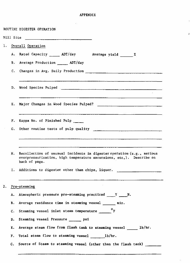
APPENDIX
ROUTINE DIGESTER OPERATION
Mill Site
1. Overall Operation
A. Rated Capacity _ ADT/day
B. Average Production ADT/day
C. Changes in Avg. Daily Production
D.
E.
F.
G.
Average yield
Wood Species Pulped
Major Changes in Wood Species Pulped?
Kappa No. of Finished Pulp
Other routine tests of pulp quality
H. Recollection of unusual incidents in digester operation (e.g., seriousoverpressurization, high temperature excursions, etc,). Describe onback of page.
I. Additions to digester other than chips, liquor.
2. Pre-steaming
A. Atmospheric pressure pre-steaming practiced Y _ N.
B. Average residence time in steaming vessel min.
C. Steaming vessel inlet steam temperature 0F
D. Steaming vessel Pressure psi
E. Average steam flow from flash tank to steaming vessel __ lb/hr.
F. Total steam flow to steaming vessel lb/hr.
G. Source of Steam to steaming vessel (other than the flash tank)
%
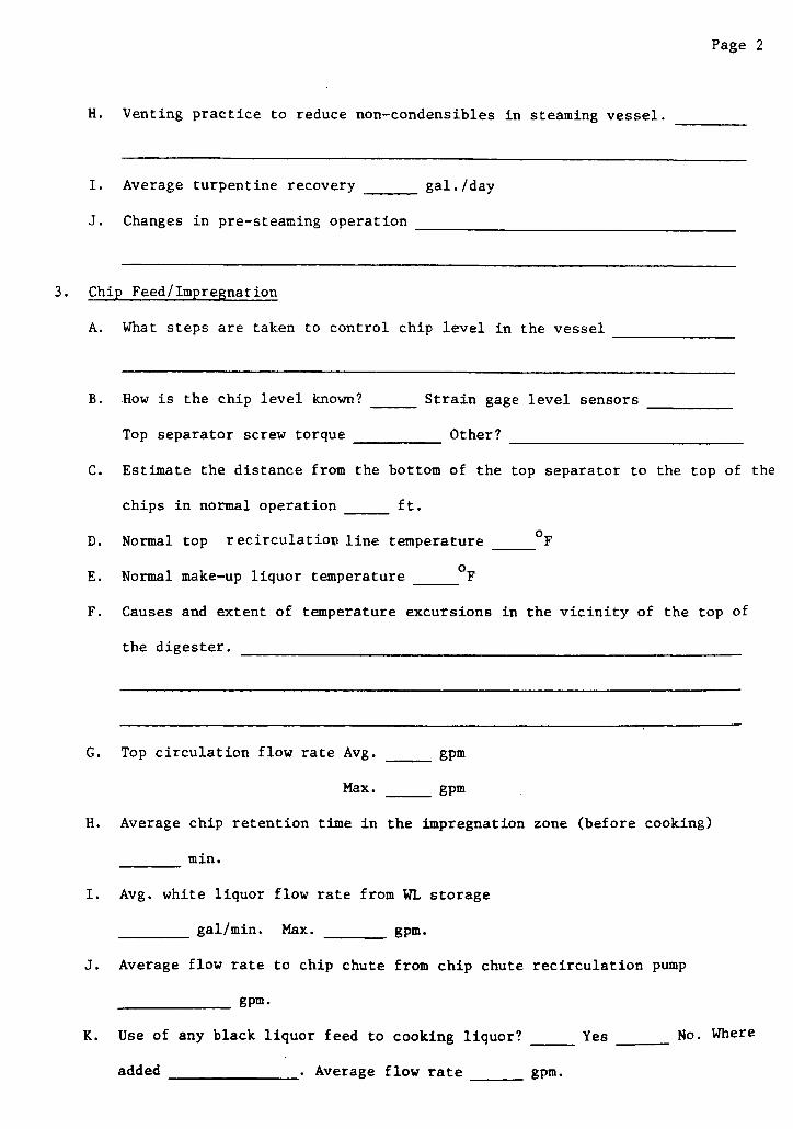
Page 2
H. Venting practice to reduce non-condensibles in steaming vessel.
I. Average turpentine recovery _ gal./day
J. Changes in pre-steaming operation
3. Chip Feed/Impregnation
A. What steps are taken to control chip level in the vessel
B. How is the chip level known? _ Strain gage level sensors
Top separator screw torque Other?
C. Estimate the distance from the bottom of the top separator to the top of the
chips in normal operation ft.
D. Normal top recirculation line temperature OF
E. Normal make-up liquor temperature OF
F. Causes and extent of temperature excursions in the vicinity of the top of
the digester.
G. Top circulation flow rate Avg. _ gpm
Max. __gpm
H. Average chip retention time in the impregnation zone (before cooking)
min.
I. Avg. white liquor flow rate from WL storage
gal/min. Max. gpm.
J. Average flow rate to chip chute from chip chute recirculation pump
_ gpm.
K. Use of any black liquor feed to cooking liquor? Yes No. Where
added . Average flow rate gpm.
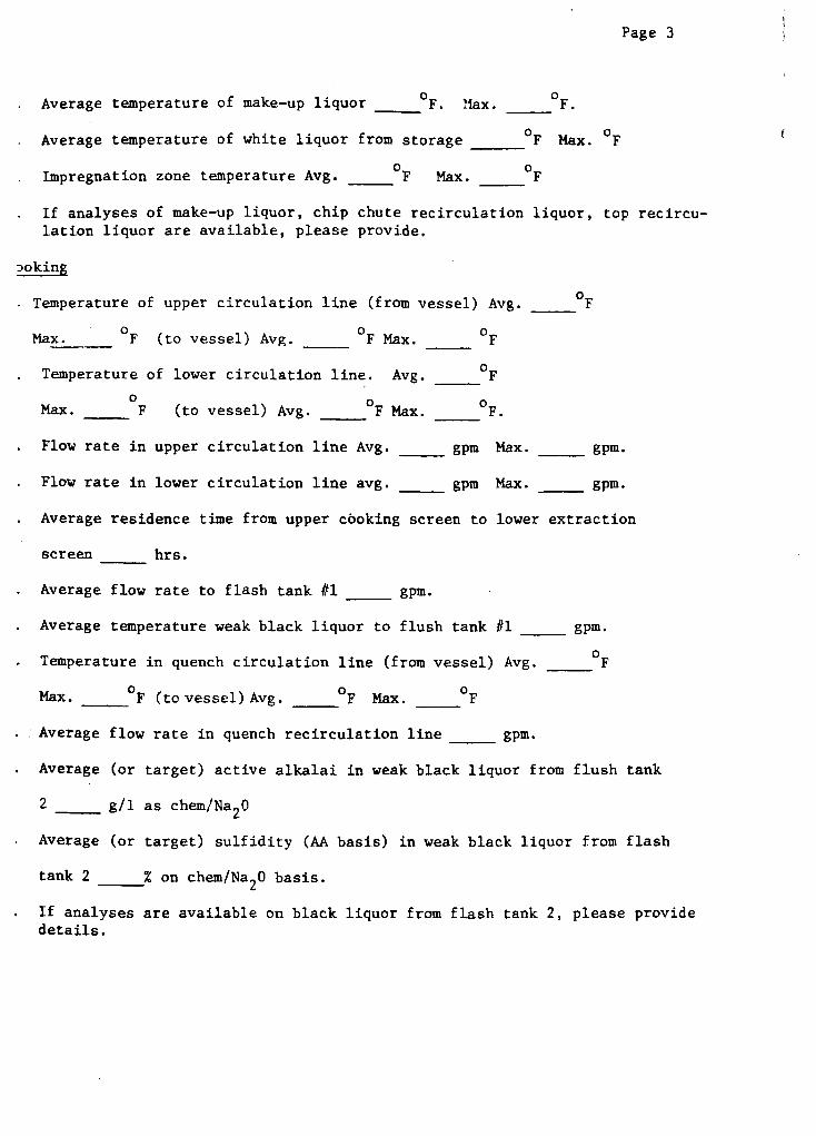
Page 3
Average temperature of make-up liquor OF. "lax. OF.
Average temperature of white liquor from storage _F Max. F
Impregnation zone temperature Avg. F Max. F
If analyses of make-up liquor, chip chute recirculation liquor, top recircu-lation liquor are available, please provide.
poking
Temperature of upper circulation line (from vessel) Avg. F
Max. F (to vessel) Avg. F Max. F_
Temperature of lower circulation line. Avg. F
Max. __ F (to vessel) Avg. _ F Max. _ F.
Flow rate in upper circulation line Avg. _ gpm Max. _ gpm.
Flow rate in lower circulation line avg. _ gpm Max. _ gpm.
Average residence time from upper cooking screen to lower extraction
screen hrs.
Average flow rate to flash tank #1 gpm.
Average temperature weak black liquor to flush tank #1 __ gpm.
Temperature in quench circulation line (from vessel) Avg. F
Max. _ F (to vessel) Avg. _ F Max. _ F
Average flow rate in quench recirculation line gpm.
Average (or target) active alkalai in weak black liquor from flush tank
2 g/l as chem/Na2 0
Average (or target) sulfidity (AA basis) in weak black liquor from flash
tank 2 % on chem/Na20 basis.
If analyses are available on black liquor from flash tank 2, please providedetails.
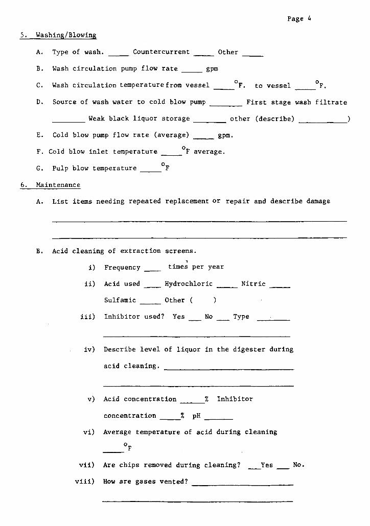
Page 4
5. Washing/Blowing
A. Type of wash. Countercurrent Other
B. Wash circulation pump flow rate _ gpm
C. Wash circulation temperature from vessel F. to vessel °F.
D. Source of wash water to cold blow pump First stage wash filtrate
Weak black liquor storage other (describe) )
E. Cold blow pump flow rate (average) _ gpm.
F. Cold blow inlet temperature _ F average.
G. Pulp blow temperature F
6. Maintenance
A. List items needing repeated replacement or repair and describe damage
B. Acid cleaning of extraction screens.
i) Frequency times per year
ii) Acid used Hydrochloric _ Nitric
Sulfamic Other ( )
iii) Inhibitor used? Yes No Type
iv) Describe level of liquor in the digester during
acid cleaning. __
v) Acid concentration % Inhibitor
concentration _ % pH
vi) Average temperature of acid during cleaning
F
vii) Are chips removed during cleaning? __Yes No.
viii) How are gases vented?
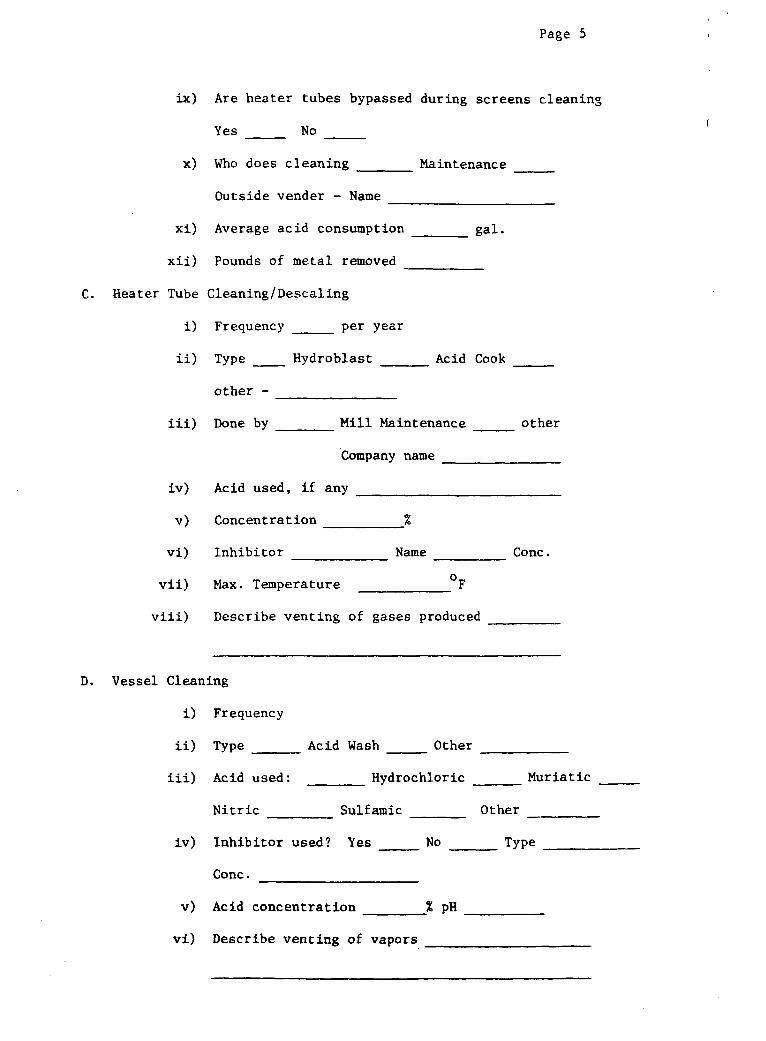
Page 5
ix) Are heater tubes bypassed during screens cleaning
Yes No
x) Who does cleaning Maintenance
Outside vender - Name
xi) Average acid consumption
xii) Pounds of metal removed
Tube Cleaning/Descaling
i) Frequency _ per year
ii) Type Hydroblast
other -
iii) Done by Mill Maintel
_ gal.
Acid Cook
nance
Company name
iv)
v)
vi)
vii)
viii)
Acid used, if any
Concentration %
Inhibitor _Name
Max. Temperature F
Describe venting of gases produced
Conc.
D. Vessel Cleaning
i) Frequency
ii) Type Acid Wash Other
iii) Acid used: Hydrochloric Muriatic
Nitric Sulfamic Other
iv) Inhibitor used? Yes No Type
Conc.
v) Acid concentration % pH
vi) Describe venting of vapors
C. Heater
other
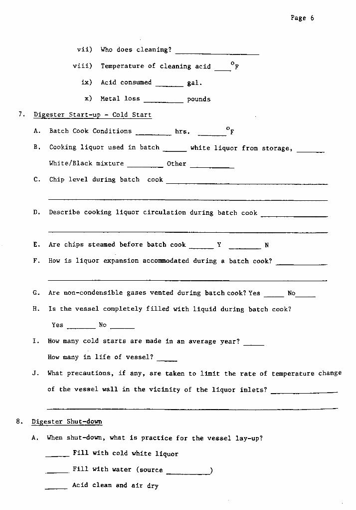
Page 6
vii) Who does cleaning?
viii) Temperature of cleaning acid _ F
ix) Acid consumed gal.
x) Metal loss pounds
7. Digester Start-up - Cold Start
A. Batch Cook Conditions hrs. °F
B. Cooking liquor used in batch white liquor from
White/Black mixture Other
C. Chip level during batch cook
storage,
D. Describe cooking liquor circulation during batch cook
E. Are chips steamed before batch cook Y N
F. How is liquor expansion accommodated during a batch cook?
G. Are non-condensible gases vented during batch cook? Yes No
H. Is the vessel completely filled with liquid during batch cook?
Yes No
I. How many cold starts are made in an average year?
How many in life of vessel?
J. What precautions, if any, are taken to limit the rate of temperature change
of the vessel wall in the vicinity of the liquor inlets?
8. Digester Shut-down
A. When shut-down, what is practice for the vessel lay-up?
Fill with cold white liquor
Fill with water (source )
Acid clean and air dry
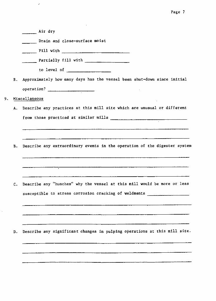
Page 7
Air dry
Drain and close-surface moist
Fill with
Partially fill with
to level of
B. Approximately how many days has the vessel been shut-down since initial
operation?
9. Miscellaneous
A. Describe any practices at this mill site which are unusual or different
from those practiced at similar mills
B. Describe any extraordinary events in the operation of the digester system
C. Describe any "hunches" why the vessel at this mill would be more or less
susceptible to stress corrosion cracking of weldments
D. Describe any significant changes in pulping operations at this mill site.
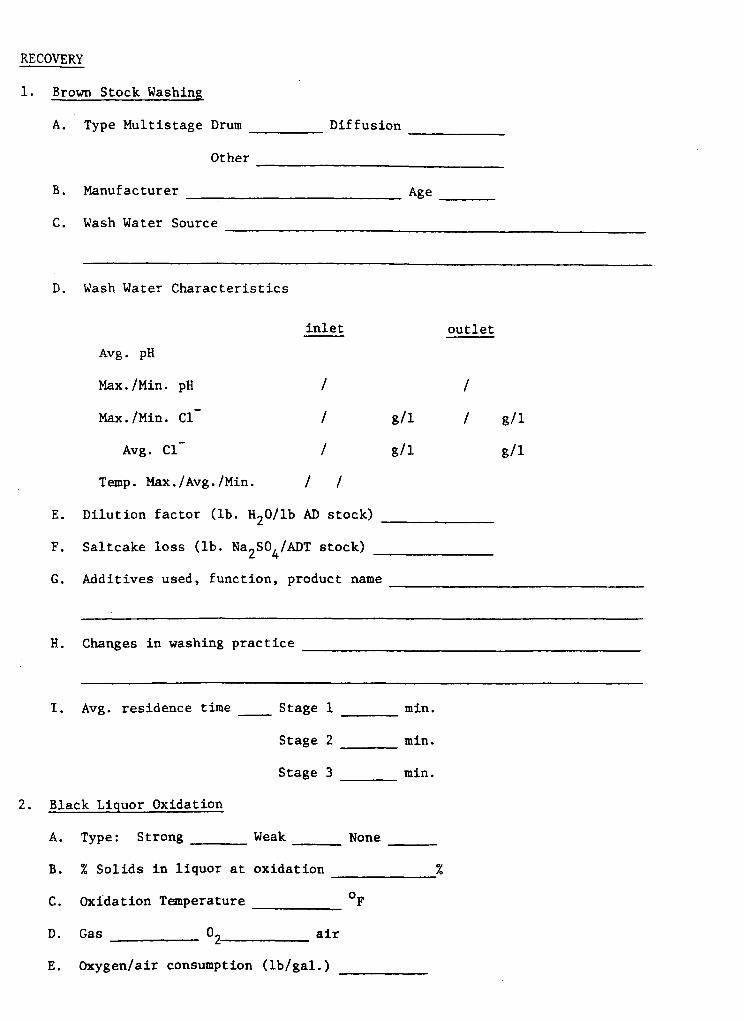
RECOVERY
1. Brown Stock Washing
A. Type Multistage Drum
Other
B. Manufacturer
C. Wash Water Source
D.
Diffusion
Age
Wash Water Characteristics
inlet
Avg. pH
Max./Min. pH /
Max./Min. C- /
Avg. Cl /
Temp. Max./Avg./Min. / /
E. Dilution factor (lb. H20/lb AD stock)
F. Saltcake loss (lb. Na2SO4/ADT stock) _
G. Additives used, function, product name
H. Changes in washing practice
I. Avg. residence time __ Stage 1
Stage 2
Stage 3
2. Black Liquor Oxidation
A. Type: Strong Weak
B. % Solids in liquor at oxidation
C. Oxidation Temperature
D. Gas 0 air
E. Oxygen/air consumption (lb/gal.)
min.
min.
min.
None
°F
outlet
/
/g/l
g/l
g/1
g/1
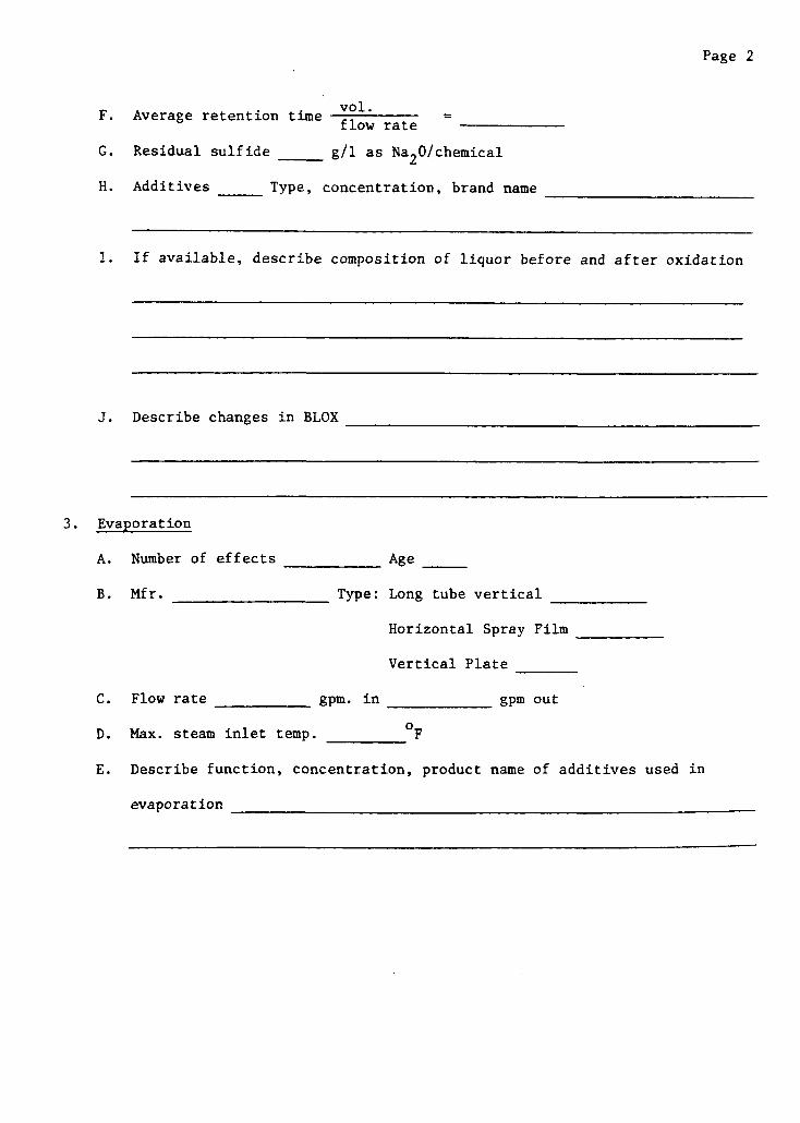
Page 2
vol.F. Average retention time flow r
flow rate
G. Residual sulfide _ g/l as Na2 0/chemical
H. Additives Type, concentration, brand name
I. If available, describe composition of liquor before and after oxidation
J. Describe changes in BLOX___
3. Evaporation
A. Number of effects
B. Mfr.
Age _
Type: Long tube vertical
Horizontal Spray Film
Vertical Plate
C. Flow rate gpm. in gpm out
D. Max. steam inlet temp. F
E. Describe function, concentration, product name of additives used in
evaporation
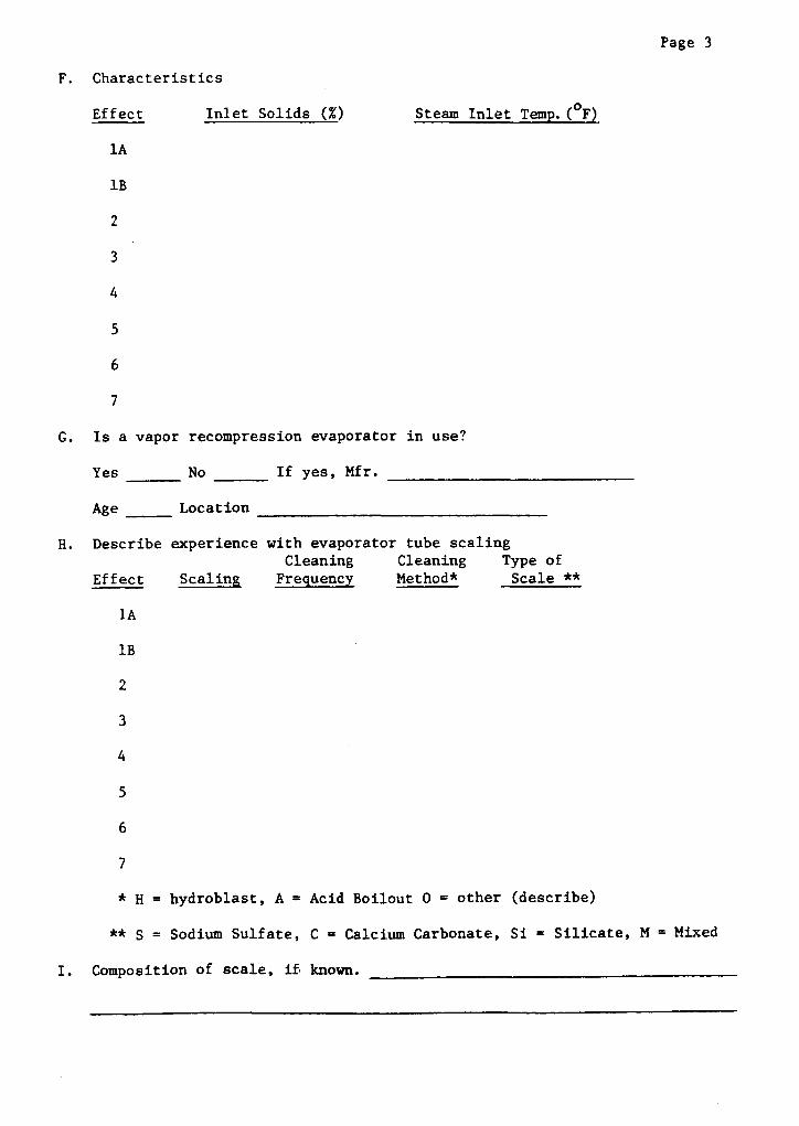
F. Characteristics
Effect Inlet Solids (%)
1A
1B
Steam Inlet Temp. (F)
2
3
4
5
6
7
G. Is a vapor recompression evaporator in use?
Yes No If yes, Mfr.
Age Location
H. Describe experience with evaporator tube scalingCleaning Cleaning Type (
Effect Scaling Frequency Method* Scal(
1A
1B
ofe **
2
3
4
5
6
7
* H = hydroblast, A = Acid Boilout O = other (describe)
** S = Sodium Sulfate, C = Calcium Carbonate, Si = Silicate, M = Mixed
I. Composition of scale, if known.
Page 3
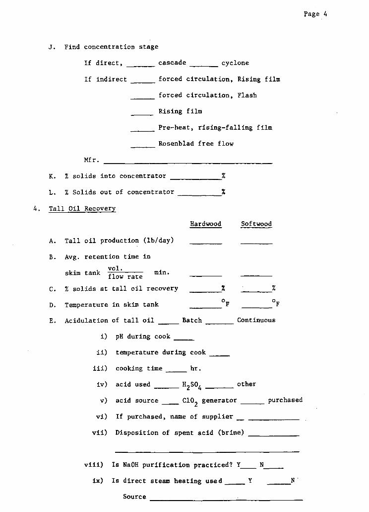
page 4
J. Find concentration stage
If direct, cascade cyclone
If indirect forced circulation, Rising film
forced circulation, Flash
Rising film
Pre-heat, rising-falling film
Rosenblad free flow
Mfr.
K. % solids into concentrator %
L. % Solids out of concentrator %
4. Tall Oil Recovery
Hardwood Softwood
A. Tall oil production (lb/day)
B. Avg. retention time in
vol.skim tank min.
flow rate
C. % solids at tall oil recovery %
D. Temperature in skim tank F
E. Acidulation of tall oil Batch Col
i) pH during cook
ii) temperature during cook
iii) cooking time hr.
iv) acid used H2S04 oth
v) acid source C102 generator
vi) If purchased, name of supplier _
vii) Disposition of spent acid (brine)
F
ntinuous
her
purchased
Is NaOH purification practiced? Y___ N
Is direct steam heating used Y _ N
Source
viii)
ix)
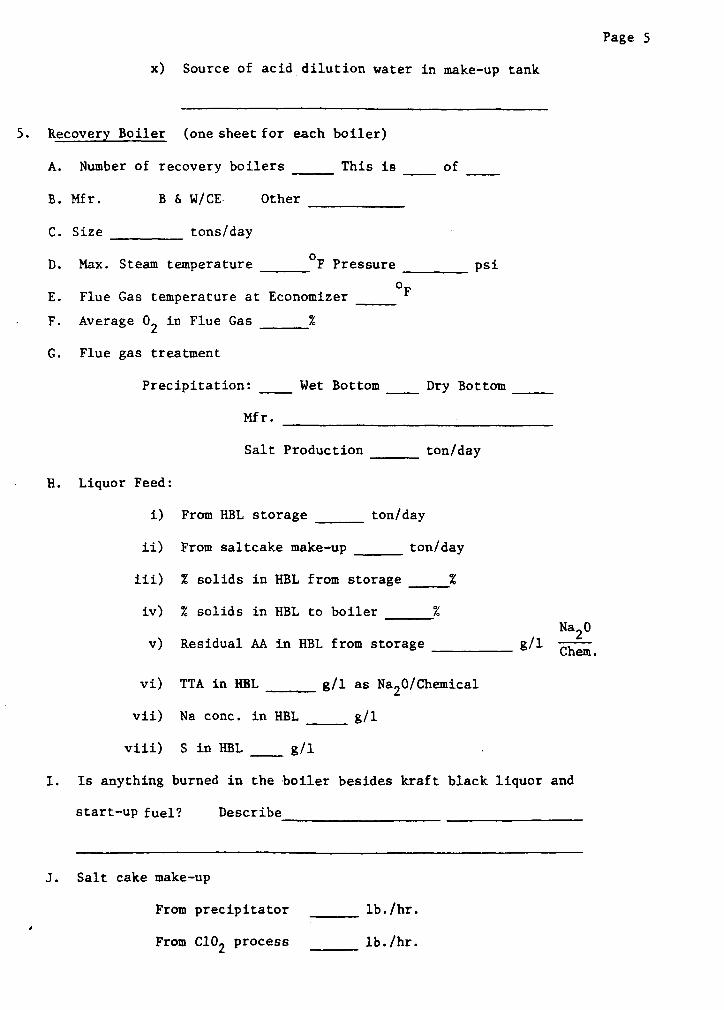
Page 5
x) Source of acid dilution water in make-up tank
5. Recovery Boiler (one sheet for each boiler)
A. Number of recovery boilers This is
B. Mfr. B & W/CE Other
C. Size tons/day
D. Max. Steam temperature OF Pressure
FE. Flue Gas temperature at Economizer _
F. Average 02 in Flue Gas %
G. Flue gas treatment
Precipitation: Wet Bottom
Mfr.
Salt Production
H. Liquor Feed:
i)
ii)
iii)
iv)
v)
of
psi
_ Dry Bottom
ton/day
From HBL storage ton/day
From saltcake make-up ton/day
% solids in HBL from storage %
% solids in HBL to boiler %Na20
Residual AA in HBL from storage g/1 Chem-------- Chem.
vi) TTA in HBL ___ g/l as Na20/Chemical
vii) Na conc. in HBL g/l
viii) S in HBL g/l
I. Is anything burned in the boiler besides kraft black liquor and
start-up fuel? Describe_
J. Salt cake make-up
From precipitator
From C102 process
lb./hr.
lb./hr.
---
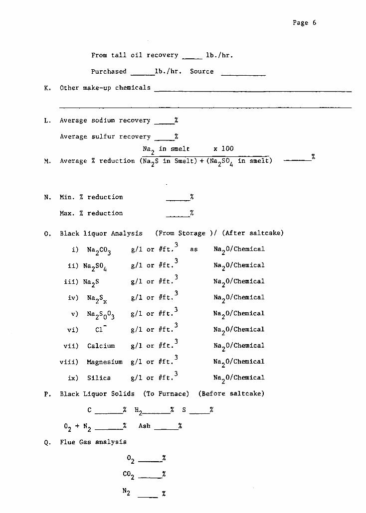
Page 6
From tall oil recovery lb./hr.
Purchased lb./hr. Source
K. Other make-up chemicals
L. Average sodium recovery %
Average sulfur recovery %
Na2 in smelt x 100
M. Average % reduction (Na2S in Smelt) + (Na2SO4 in smelt)
N. Min. % reduction %
Max. % reduction %
O. Black liquor Analysis (From Storage )/ (After saltcake)
i) Na2CO3
ii) Na 2 S04
iii) Na2S
iv) Na2Sx
v) Na2S003
vi) Cl
vii) Calcium
viii) Magnesium
ix) Silica
g/l or #ft.
g/1
g/l
g/l
g/l
g/l
g/1
g/1
g/l
as
or #ft.3
or #ft.3
or #ft.3
or #ft.3
or #ft.3
or #ft. 3
or #ft. 3
or #ft. 3
Na2 0/Chemical
Na20/Chemical
Na2 0/Chemical
Na20/Chemical
Na20/Chemical
Na2 0/Chemical
Na20/Chemical
Na20/Chemical
Na20/Chemical
P. Black Liquor Solids (To Furn
C % H2
02 + N2 % AshQ. Flue Gas analysis
Q. Flue Gas analysis
lace
% S
Z
) (Before saltcake)
02
CO2
N2
%
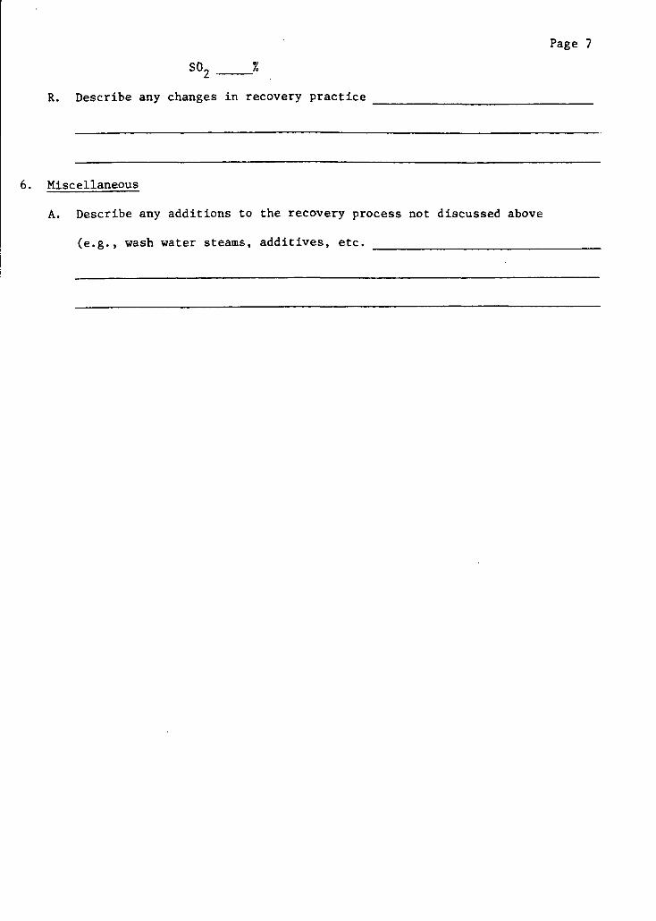
Page 7
SO _ %
R. Describe any changes in recovery practice
6. Miscellaneous
A. Describe any additions to the recovery process not discussed above
(e.g., wash water steams, additives, etc.
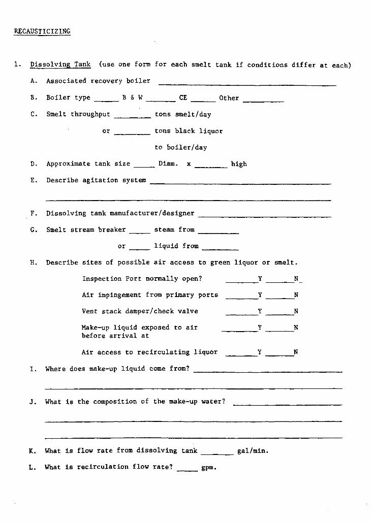
RECAUSTICIZING
1. Dissolving Tank (use one form for each smelt tank if conditions differ at each)
A. Associated recovery boiler
B. Boiler type B & W CE Other
C. Smelt throughput tons smelt/day
or tons black liquor
to boiler/day
D. Approximate tank size _ Diam. x high
E. Describe agitation system
F. Dissolving tank manufacturer/designer
G. Smelt stream breaker steam from
or liquid from
H. Describe sites of possible air access to green liquor or smelt.
Inspection Port normally open? Y N
Air impingement from primary ports Y N
Vent stack damper/check valve Y N
Make-up liquid exposed to air Y Nbefore arrival at
Air access to recirculating liquor Y N
I. Where does make-up liquid come from?
J. What is the composition of the make-up water?
K. What is flow rate from dissolving tank gal/min.
L. What is recirculation flow rate? _ gpm.
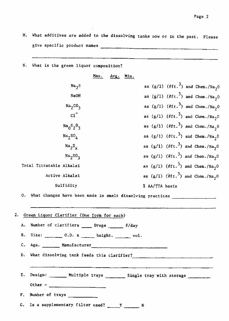
Page 2
M. What additives are added to the dissolving tanks now or in the past. Please
give specific product names
N. What is the green liquor composition?
Max. Avg. Min.
Na2 S
NaOH
Na2CO3
Cl
Na0S203
Na2SO4
Na2Sx
Na2SO3
Total Titratable Alkalai
Active Alkalai
Sulfidity
O. What changes have been
as (g/l) (#ft.3 )
as (g/l) (#ft.3 )
as (g/l) (#ft.3 )
as (g/l) (#ft.3 )
as (g/l) (#ft. 3 )
as (g/l) (#ft. 3)
as (g/l) (#ft. 3 )
as (g/l) (#ft. 3 )
as (g/l) (#ft.3 )
as (g/l) (lft. 3 )
% AA/TTA basis
made in smelt dissolving practices
and Chem./Na20
and Chem./Na2 0
and Chem./Na20
and Chem./Na20
and Chem./Na20
and Chem./Na20
and Chem./Na20
and Chem./Na20
and Chem./Na20
and Chem./Na20
2. Green Liquor Clarifier (One form for each)
A. Number of clarifiers Dregs _ /day
B. Size: O.D. x height. vol.
C. Age. Manufacturer
D. What dissolving tank feeds this clarifier?
E. Design: Multiple trays
Other -
F. Number of trays
G. Is a supplementary filter used?
Single tray with storage
Y N
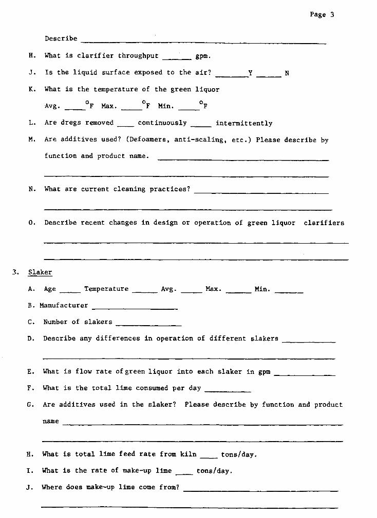
Page 3
Describe
H. What is clarifier throughput gpm.
J. Is the liquid surface exposed to the air? Y N
K. What is the temperature of the green liquor
Avg. F Max. _ F Min. _ F
L. Are dregs removed _ continuously _ intermittently
M. Are additives used? (Defoamers, anti-scaling, etc.) Please describe by
function and product name.
N. What are current cleaning practices?
O. Describe recent changes in design or operation of green liquor clarifiers
3. Slaker
A. Age Temperature Avg. _ Max. Min.
B. Manufacturer
C. Number of slakers
D. Describe any differences in operation of different slakers
E. What is flow rate of green liquor into each slaker in gpm
F. What is the total lime consumed per day
G. Are additives used in the slaker? Please describe by function and product
name
H. What is total lime feed rate from kiln tons/day.
I. What is the rate of make-up lime tons/day.
J. Where does make-up lime come from?
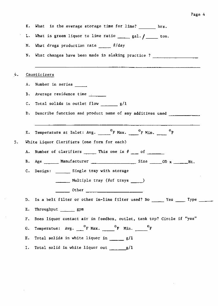
Page 4
K. What is the average storage time for lime? h
L. What is green liquor to lime ratio _ gal./
M. What dregs production rate #/day
N. What changes have been made in slaking practice ?
hrs.
ton.
4. Causticizers
A. Number in series
B. Average residence time
C. Total solids in outlet flow g/l
D. Describe function and product name of any additives used
E. Temperature at Inlet: Avg. _ F Max. _ F Min. _ F
5. White Liquor Clarifiers (one form for each)
A. Number of clarifiers This one is # of
B. Age _ Manufacturer Size OD x _ Ht.
C. Design: Single tray with storage
Multiple tray (#of trays
Other
D. Is a belt filter or other in-line filter used? No Yes Type
E. Throughput __ gpm
F. Does liquor contact air in feedbox, outlet, tank top? Circle if "yes"
G. Temperatue: Avg. OF Max. OF Min. F
H. Total solids in white liquor in g/l
I. Total solid in white liquor out g/l
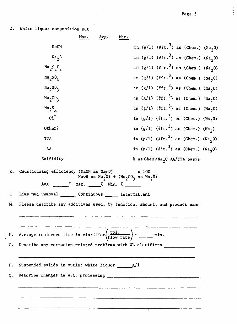
J. White liquor composition out
Max.
NaOH
Na2S
Na2S203
Na2S04
Na2S03Na SO
Na2C03
Na2Sx
Cl
Other?
TTA
AA
Sulfidity % as Chem Na20 AA/TTA basis
K. Causticizing efficiency (NaOH as Na 0) x 100NaOH as Na20) + (Na2CO3 as Na20)
Avg. % Max. % Min. %
L. Lime mud removal Continuous Intermittent
M. Please describe any additives used, by function, amount, and product name
N. Average residence time in clarifier(fl rate) = min.
O. Describe any corrosion-related problems with WL clarifiers
P. Suspended solids in outlet white liquor
Q. Describe changes in W.L. processing
~___g/l
Page 5
Avg. Min.
in
in
in
in
in
in
in
in
in
in
in
(g/l)
(g/l)
(g/l)
(g/l)
(g/l)
(g/l)
(g/l)
(g/l)
(g/l)
(g/l)
(g/l)
(#ft. 3 )
(#ft.3 )
(#ft.3 )
(#ft.3 )
(#ft. 3)
(#ft. 3)
(#ft.3 )
(#ft. 3 )
(#ft.3)
(#ft. 3)
(#ft. 3 )
as
as
as
as
as
as
as
as
as
as
as
(Chem.)
(Chem.)
(Chem.)
(Chem.)
(Chem.)
(Chem.)
(Chem.)
(Chem.)
(Chem.)
(Chem.)
(Chem.)
(Na20)
(Na20)
(Na20)
(Na 2O)
(Na20)
(Na2 O)
(Na20)
(Na20)
(Na2 )
(Na20)
(Na 2O)
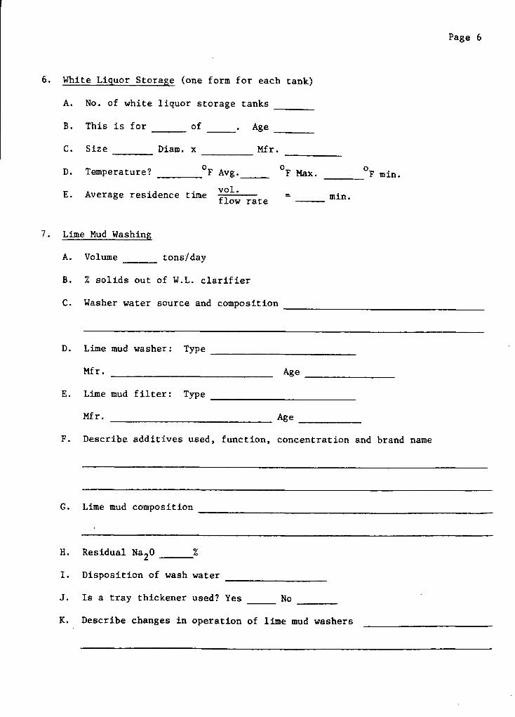
6. White Liquor Storage (one form for each tank)
A. No. of white liquor storage tanks
B. This is for of _ . Age
C. Size Diam. x Mfr.
D. Temperature? _F Avg._ F Max
E. Average residence timeflo ratflow rate
OF min.
min.
7. Lime Mud Washing
A. Volume tons/day
B. % solids out of W.L. clarifier
C. Washer water source and composition
D. Lime mud
Mfr.
E. Lime mud
washer: Type
Age
filter: Type
Mfr. Age
F. Describe additives used, function, concentration and brand name
G. Lime mud composition
H. Residual Na20 %
I. Disposition of wash water
J. Is a tray thickener used? Yes No
K. Describe changes in operation of lime mud washers
Page 6
$
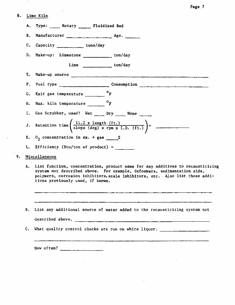
Page 7
8. Lime Kiln
A. Type: Rotary Fluidized Bed
B. Manufacturer
C. Capacity
D. Make-up: Limestone
Lime
Age.
tons/day
ton/day
ton/day
E. Make-up source
F. Fuel type Consumption
G. Exit gas temperature F
H. Max. kiln temperature OF
I. Gas Scrubber, used? Wet Dry None
J. Retention time 11.2 x length (ft.)slope (deg) x rpm x I.D. (ft.) -
K. 02 concentration in ex. + gas %
L. Efficiency (Btu/ton of product) =
9. Miscellaneous
A. List function, concentration, product name for any additives to recausticizingsystem not described above. For example, defoamers, sedimentation aids,polymers, corrosion inhibitors,scale inhibitors, etc. Also list those addi-tives previously used, if known.
B. List any additional source of water added to the recausticizing system not
described above. _
C. What quality control checks are run on white liquor.
How often?
Copyright © 2022 FDOKUMEN