the influence of angular acceleration through critical speeds ...
80
THE INFLUENCE OF ANGULAR ACCELERATION THROUGH CRITICAL SPEEDS ON AMPLITUDES OF WHIRL OF A ROT A TING SHAFT by Francis Howitt The sis submitted in partial fulfilment of the requirements for the degree of Master of Engineering. Depa rtment of Mechanical Engineering McGill University January,1961
-
Upload
khangminh22 -
Category
Documents
-
view
1 -
download
0
Transcript of the influence of angular acceleration through critical speeds ...

THE INFLUENCE OF ANGULAR ACCELERATION
THROUGH CRITICAL SPEEDS ON AMPLITUDES OF
WHIRL OF A ROT A TING SHAFT
by
Francis Howitt
The sis submitted in partial fulfilment
of the requirements for the degree
of Master of Engineering.
Depa rtment of Mechanical Engineering
McGill University
January,1961

- i-
SUMMARY
A detailed analysis of the phenomenon of whirling and the
application of steady- state theory to transient conditions. The
equations of mot ion for a simple rotor system subjected to
uniform ac cele ration are set up and a method of solution demon
strated. These solutions are shown to be applicable to the case
of simply supported, accelerating, vertical, slender shafts.
The theoretical results are found to be in satisfactory
agreement with those obtained experimentally and provide a
qualitative guide, not only to the effect of angular acceleration,
but also to the relative influences of shaft balance, mass,
stiffness, and viscous damping upon amplitudes of whirl.

-ii-
ACKNOWLEDGEMENTS
The author acknowledge s with gratitude the guidance and
encouragement of his research director, Professer A. R. Edis,
and the counsel of Dr. B. G. Newman, in this project , and thanks
Mr. F. G. Corrick and the staff of the McGill Mechanical Engineer
ing Department Workshop for their assistance in the construction
of the apparatus.

- iii -
CONTENTS
Page
Acknowle dgement s ii
List of Illustrations iv
Introduction 1
Evolution of Whirling Theory 2
Application of Jeffcott' s Theory to an Accelerating Shaft 15
Solution of the Equations of Motion of an Accelerating Rotor 21
Analysis of the Solutions to the Equations of Motion . 28
Application of Simple Rotor Theory to a Real System 35
Apparatus 37
Procedure 41
Table of Observations 44
Table of Re sults 48
Graphs 52
Discussion of Re sults 61
Conclusions 65
Appendix -- Evaluation of the Integrais
~ta.
a nd 5• at+ (--a-- bt)i dt
Bibliography
S•at +
• t.
( (ù~ + bt)i dt
67
75

Figure(s)
1
2
3
4
5
6 - 23
24
25
- iv -
ILLUSTRATIONS
Rankine' s Theory of Whirling
Jeffcottr s Theory of Whirling
Effect of striking a rota ting membe r
Simple st rota ting system
Apparatus
Graphs of maximum amplitude of whirl versus
angular acceleration of shaft
Path of integration in the z, plane
Path of integration in the z&. plane
Page( s)
3
10
13
16
38
53 - 60
69
72

1
INTRODUCTION
Many modern machines are run above their minimum
critical speed and no difficulties are encountered providing the
operating speed is not near the whirling speed. Numerous
investigations have be en made in order that the c ritical speeds
of the most complex systems may be calculated with the maximum
accuracy, and account taken of system stiffness, inertia, and
damping.
Little effort however, has be en directed towards di sc ove ring
what happens when a machine passes through a critical speed,
although eve ry time it is started or stopped it may have to traverse
one. It is obvious that if the dangers of whirling are to be kept to
a minimum, not only the steady state conditions for whirl, but also
the effect of transient conditions, must be considered.
The object of this thesis is to derive an equation relating the
amplitude of whirl of a rotor to its angular acceleration, and to
compare this with the observed maximum amplitudes of whirl of
shafts accelerating through their critical speeds.

2
EVOLUTION OF WHIRLING THEORY
The basic theory of whirling is well-established and accepted
by most workers in this field. Unfortunately however, it is not
generally known by ether engineers due to the perpetuation in text
books of earlier, but erroneous, explanations of the phenomenon.
It is the refere felt desirable to establish the validity of current
concepts before attempting to extend steady- state whirling theory
to transient conditions.
This is best achieved by tracing the history ofwhirling via
the original papers of major contributors, accurately noting their
as sumptions, theo ries and fin ding s. The se summa ries show the
limitations of the earlier ideas and provide convincing evidence in
support of current theories. No attempt has been made to reproduce
the analyses of the various writers however, since the important
ones may already be found in numerous secondary sources.
The phenomenon of whirling was first reported by Rankine(i)*,
who communicated the results of a mathematical investigation of the
action of the centrifugai force in long !ines of shafting. He considered
a shaft rotating about a straight line AB and reasoned that any small
deflection of the centre line of the shaft from the axis AB, would give
rise on the one hand to a centrifugai force tending to make the
deflection become greater, and on the other hand, to an elastic stress
resisting the deflection and tending to straighten the centre line again,
(Figure 1). Equating the two quantities he obtained, as be expected,
integrais identical in form with tho se obtained by Pois son in his
investigation of the transverse vibrations of elastic rods. He then
* Numbers in parenthesis refer to the Bibliography at the end of
the paper

Shaft .........
'
3
. f~th of rotating shaft. certre line. ,' \ 1
1 1 .. 1
___:::~~ ___ B~ari!}l{ axis J ---+ ________ .,.-~-~ (=Axis of sta\tionhry shaft) . ~"'
A
1
Shaft deflection maintained by centrifugal force due to rotation about bearing axis AB.
Fig.l.
Rankine' s The ory of W'hirling.
B

4
proceeded to de rive a size and strength relationship for a shaft
such that for an indefinitely small deflection the stiffness would
be grea ter than the centrifugai force and centrifugai whirling
would thus be impossible.
Rankine confined his attention to long, slender shafts, -
simply supported and cantilevered, -- because, he argued, the
effect of an additional rotating load at a point not near a bearing
was not of much practical importance, since if "a shaft is so long
and so rapid in its rotation as to require precautions against cen
trifugai whirling, the first precaution is to avoid loading it with
rotating masses which are not very near the bearings".
The next contributor to the subject was Greenhill (2) who
inve stigated the stability of a rota ting shaft subject to thrust and
twisting, such as the propeller shaft of a ship, assuming that under
the combined action of thrust, torque and centrifugai whirling, the
straight form of such a shaft would become un stable, and the central
line of the shaft would become slightly displaced into a spiral. Like
Rankine he assumed that a whirling shaft revolved bodily about the
axis of the bearings with the imparted angular velocity. He deduced
that "the number of revolutions which would make the straight form
of the shaft unstable by centrifugai whirling, is exactly the same as
the number of lateral vibrations the shaft would make if still and
slightly displaced, the same thrust and twisting couple acting on
the shaft in both cases", and he cited the work of Rayleigh {3) and
of Rankine {1) in support of his conclusions.
It is noteworthy that neither Rankine nor Greenhill attempted
to substantiate their theories with experimental evidence, thus
setting a lamentable precedent which has persisted until the present day.

5
The literature of whirling abounds with theoretical analyses but
there is a dearth of experimental results. Future researchers
should note tha:t the first inve stigator to correlate the ory and practice,
Dunkerley {4), is generally regarded as the founder of whirling theory.
In fact, Dunkerley claimed no great originality for his work but
quoted Rankine and Greenhill and attributed the theoretical analysis
in his paper to Professer Osborne Reynolds-- who presented the
paper to the Royal Society. Nevertheless, it is Dunkerley who is
usually credited with the ideas expounded in the work and it remains
of major importance, since it is frequently quoted and accepted by
many texts as a sound analysis of the phenomenon of whirling. * Dunkerley claimed that "every shaft, HOWEVER NEARLY
BALANCED, when driven at a particular speed bends and, unless
the amount of deflection be limited, might even break". He also
noted however, that above this "critical" speed the shaft would
again run true, -- a fact previously unreported. The critical
speed depended upon "the manner in which the shaft is supported,
its size and modulus of elasticity, and the size, weight and position
of any pulleys it carries". In many cases, observed Dunkerley,
the period of whirl of the shaft coincided with the natural pe riod of
lateral vibration, as might naturally be expected; however in the
case of a loaded shaft, pulleys could give rise to righting moments
* E. g., the explanation "The Whirling of Shafts" by R. V. Southwell
in "An Introduction to the Theory of Elasticity for Engineers and
Physicists", 2nd Ed., Oxford University Press, 1941, pp. 208-209,
is exactly the same as Dunkerley' s.

6
tending to straighten the shaft and "generally, in a loaded shaft,
the period of whirl is less than the natural period of vibration, to
an extent depending upon the size and positions of the pulleys".
It was also noted that, "as in the vibration of rods, so in the
whirling of shafts, there are a series of periods at which the shaft
whirls "·
The theory expounded in the paper was merely an extension
of the earlier work on unloaded shafts, using the ordinary elastic
solid equations, to the loaded cases. Two methods of analysis were
adopted. In the first, the period of whirl was calculated taking both
the shaft and pulleys into account together, but the solutions proved
too complicated for practical use. A second method was therefore
devised whereby the period of whirl was first calculated for the shaft
alone, using the Bernoulli-Eulerian method as before, and then for
each of the pulleys in turn, neglecting the shaft. These periods of
whirl were then combined, using an approximate formula, to give
the period of whirl of the whole system. Dunkerley claimed that a
shaft and pulley system with individual periods of whirl of N1
for the
shaft and Na. for the pulley, was analogous to a spring carrying weights
w, and w'l.. The period of whirl of the whole system could thus be
obtained in the same way as the frequency of a spring carrying the
combined weight (W1 + W2.}.
Therefore, period of whirl of {shaft + pulley} combined,
N 1 N2. Ne= . Similarly for a three-element system
JNa. + N~ 1 2.
N 1 Na.N3
Ne= /Na.Nz. + Nz.Na. + Na.Nz.." Al12. 2.3 31
Application of these formulae however
gave errors of up to +8. 6 °/o, (where percentage error
= iOOX (observed period of whirl-calculated period)) observed period ·

7
Dunkerley attributed this to the fact that the formula was only strictly
true for loads applied at the same point, and he therefore modified his
original equation to Ne= N,Nz. where "a" is an empirical constant JN~ + N~a
dependant upon the particular system and is the multiplier of the great-
est term in the denominator. Using a value of a=. 885, {determined
by trial and error), Dunkerley obtained an error range of + 6. 3 to
- 6. 1 °/o for the calculated periods of whirl of the systems tested.
However agreement between theory and observation was not by
itself sufficient evidence of the general applicability of Dunkerley' s
formulae declared Chree (5) in a detailed examination of the phenomenon
of whirling, and, although he described Dunkerley' s paper as "elaborate
and important", he dismissed the derivation of the formula
NN NG =
1 2. as mathematically unconvincing and in general not
,JN '- + Na. 1 2.
strictly true. Nor could he see any indication that Dunkerley bad
grasped the real nature of the connection between the speed of whirling
and the frequency of the lateral vibrations of the shaft when stationary.
Chree claimed that whirling was due, not to forced vibrations being set
up with a frequency equal to one of the na tura! pe riods, but to the
indirect action of the rotation in reducing to zero the righting forces
which naturally act on the shaft when displaced laterally. Thus when
a shaft rota ting about it s longitudinal axis wa s di splace d la te rail y, the
elastic stresses tended to return it to the undisturbed position, as
when the shaft was stationary, "but the centrifugai forces have exactly
the opposite tendency: they thus re duce the righting forces, and so
diminish the frequency of vibration". At the critical speed the frequency
of vibration becomes zero and the shaft !oses its stability, like a ship
whose center of gravity coïncides with its metacenter. This was

8
important said Chree, for a rotating shaft may be subjected to periodic
forces like any other shaft, and in considering their effect, it was
necessary that one should consider the frequency of the lateral
vibrations of the shaft AS REDUCED BY ROTATION, not the
frequency when stationary.
Chree also criticized Dunkerley' s applications of the Euler
Bernoulli elastic theory as being 11cumbrous mathematically and
the formulae to which they lead, and which were employed by Dunkerley,
often admit of great simplification, without appreciable diminution
of accuracy under his experimental conditions". Nevertheless,
although Chree avoided using Dunkerley' s approximate formula,
his analysis was based on the same elastic solid equations and it
produced results for Dunkerley' s experiments which were rarely
better, and usually worse than Dunkerley' s predictions for the
period of whirl. The paper won considerable acceptance however,
and Chree' s analysis of whirling is the one given in sorne current
texts. * Much of its influence can be ascribed to the fact that Chree' s
theory of variation of lateral frequency of vibration with speed of
rotation, appeared to offer a simple explanation of Dunkerley' s
observations that, a rotor is stable above its first critical speed
and, it possesses more than one critical; whereas Dunkerley1 s
hypothe sis, that at the c ritical speed, the centripetal force due to
bodily rotation of the rotor is exactly equal to the elastic force
whatever the deflection, would appear to indicate that at higher
speeds the elastic forces would be inadequate and the shaft would
break, instead of running true as is actually observed.
* E. g .• J. E. Younger' s "Advanced Dynamics", The Ronald Press
Co., 1958, pp. 262-263.

9
Dunke rley' s 11mathematically unconvincing 11 formula for the
lowest whirling speed of a system in terms of the lowest whirling
speeds of its components, did gain general acceptance however,
despite Chree' s censure, for it manifestly gave good results, and
it was eventually shown to be fundamentally sound by a new inve stigator,
Jeffcott (6), in an analysis of the periods of lateral vibration of
loaded shafts.
The following year however, the new investigator presented
a paper {7) which challenged the assumptions of ali the earlier work.
Until now it had been taken as axiomatic by every writer that shafts
revolved bodily around the axis of their bearings with the imparted
angular velocity: Jeffcott disputed this and argued that 11when a
shaft whose centre of mass does not lie on its axis of figure (the
shaft then being said to be 'out of balance'), is rotated, its
geometrical axis ceases to remain straight and in coïncidence with
the axis of the bearings, but becomes bent and rotates round the
latter axis". No previous writer had considered unbalance as a
factor. Jeffcott however, attributed the bending of shafts upon
rotation solely to this cause, and stated that the bending was greatest
when the speed of rotation was close to the free lateral vibrations
of the shaft, which was then said to fwhirlt.
He applied his hypothesis to "the case of a light shaft supported
freely in bearings at its ends and carrying a mass 1 m' at the center
of its span, the mas s center however being slightly eccentric by a
distance 1 a' from the elastic center of the shaft", (Figure 2).
Assuming the weight of the shaft and the moment of the inertia of
the mass to be negligible, the motion of the cross-section at the
center of the span would, by his hypothesis, b e governed by three

10
/
Centre of mass
Bearing axis, (=Axis of stationar.y shaft).
" Elastic centre line,
' (=Axis of rotation).
Fig.2.
Jeffcott•s Theory of Whirling.
11
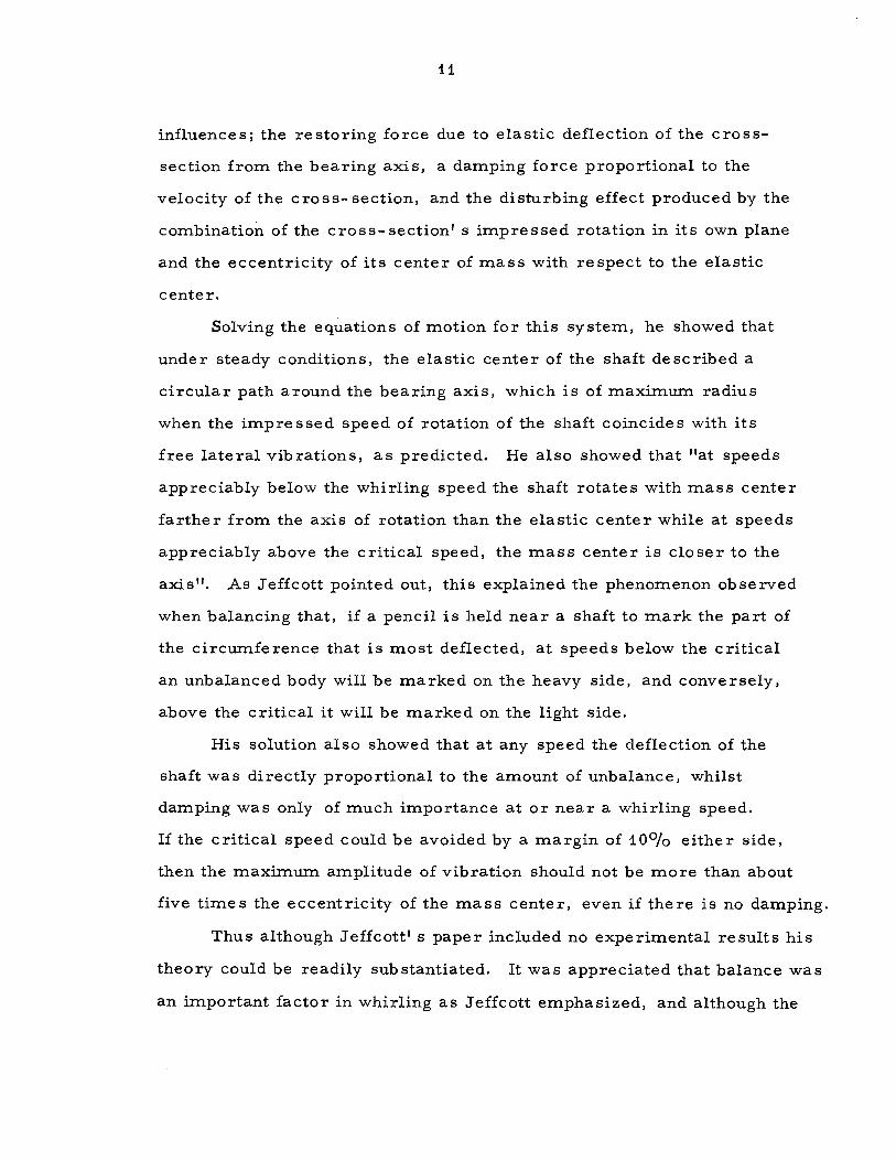
influences; the restoring force due to elastic deflection of the cross
section from the bearing axis, a damping force proportional to the
velocity of the cross- section, and the disturbing effect produced by the
combination of the cross-section' s impressed rotation in its own plane
and the eccentricity of its center of mass with respect to the elastic
center.
Solving the equations of motion for this system, he showed that
under steady conditions, the elastic center of the shaft described a
circular path around the bearing axis, which is of maximum radius
when the impressed speed of rotation of the shaft coïncides with its
free lateral vibrations, as predicted. He also showed that "at speeds
appreciably below the whirling speed the shaft rota tes with mas s center
farther from the axis of rotation than the elastic center while at speeds
appreciably above the critical speed, the mass center is closer to the
axis". As Jeffcott pointed out, this explained the phenomenon observed
when balancing that, if a pencil is held near a shaft to mark the part of
the circumfe renee that is most deflected, at speeds below the c ritical
an unbalanced body will be marked on the heavy side, and conversely,
above the critical it will be marked on the light side.
His solution also showed that at any speed the deflection of the
shaft was directly proportional to the amount of unbalance, whilst
damping was only of much importance at or near a whirling speed.
If the critical speed could be avoided by a margin of 10°/o either side ,
then the maximum amplitude of vibration should not be more than about
five times the eccentricity of the mass center, even if there is no damping.
Thus although Jeffcott1 s paper included no experimental results his
theory could be readily substantiated. It was appreciated that balance was
an important factor in whirling as Jeffcott emphasi zed, and although the

12
concept of an elastic rather than a fixed axis seemed unusual it was
found that a rotating member when struck would vibrate in a fixed
plane, (Figure 3), a fact completely at variance with the old theories.
Nevertheless old ideas die hard and some writers have continued to
nurse that of a fixed axis, the early theories have be en modified to
take into account unbalance, and attempts made to explain the
balancing phenomena reported by Jeffcott. * Most workers in the field however, eventually accepted and
used the new theory and their labours have provided additional
confirmation of the soundness of Jeffcott' s ideas. Morris (8) has
forcefully expounded the limitations and objections to the earlier
works, showing that Chree 1 s theory is dynamically unsound and
stating that, contrary to Dunkerley 1 s ideas, a perfectly balanced
shaft bas no speed of instability. He also extended Jeffcott' s theory
to more complex rotor systems.
More recently Johnson {9) has demonstrated mathematically
the fact that a free vibration of a rotating shaft can be built up in
any fixed plane and that such mot ion is independant of the speed of
rotation and therefore identical with that of a stationary shaft. The
phenomenon has been clearly demonstrated in an apparatus described
by the same author in a later paper {10). This apparatus has been set
up at the Cambridge University Engineering Laboratory and incorporates
a shaft with a whirling speed of only 13 r. p. m.: at such low speeds the
fallacy of a fixed axis of rotation is convincingly apparent.
There is still a dearth of experimental data on whirling to draw
attention to the inadequacies of the original theories, but the situation
is gradually improving.
* E. g., see A. H. Church1 s "Mechanical Vibrations", John Wiley and
Sons Inc., 1957, pp. 91-92.

13
1 1
1
( Free vibrations due 1 to hanuner blow are in one _ ---\plane, ( e.s for e. ..... _,--- -\Bte.tione.ry she.ft)~ \ , , \ / , 'V,
Fig.J.
Effect of striking e. rote.ting member.

14
.An excellent paper by Downham (11), analyses a series of experi
mental studies of the effects of large rotor inertia, and of asym
metrical bea ring stiffne ss, upon whirling. He notes that using
Jeffcott1 s theory it may be shown that although increasing rotor
inertia decreases the natural frequency of a system, it increases
the value of the c ritical speed; a fact that may be confirmed by
expe riment. Dunke rley expected the cri tic al to be reduced below
the natural frequency but experimental limitations prevented him
from detecting his error.
Summarizing; Jeffcott' s theory appears to offer a complete
explanation of ali known whirling phenomena. The concept of an
elastic axis of rotation is less obvious than the original hypothesis,
but it can be demonstrated practically, and as will be seen later,
it is mathematically simple. A good augury for the future is that
the theory may now be found in a few textbooks. *
* E. g. , N. O. Mykle stad' s "Fundamentals of Vibration Analysis",
McGraw-Hill Book Co. Ltd. , 1956, pp. 56-59.

15
APPLICATION OF JEFFCOTT' S THEORY
TO AN ACCELERA TING SHAFT
The simplest rotating system is that analysed by Jeffcott,
namely a simply supported vertical shaft carrying a concentrated
mass M at the center of its span, the weight of the shaft and the
moment of inertia of the mass are assumed to be negligble.
Suppose the shaft is initially straight and balanced, then upon
rotation there will be no disturbing influence and the axis of the
shaft will remain coïncident with the axis of the bearings. If
however, the mass is eccentric by a distance t from the centre
of the shaft, it will give rise to a disturbing force when the shaft
is rotated and the shaft will be deflected from its initial axis.
Suppose rectangular co-ordinates be set up at the intersection
of the bearing axis with the plane through the centre of mass; x and
y are the co-ordinates of the elastic center E, and the line joining
the centre of mass G with the elastic center E makes an angle e
with the x-axis, {Figure 4). The co-ordinate s of G are evidently
{x+ t co se) and {y + E sine), thus the equation of motion of M
parallel to the x-axis will be
d~ dx M dt1.. {x+ Eco se) + R dt+ Kx = 0 Eq. 1.
where R is the coefficient of damping due to viscous resistance
(e. g. : air damping and bea ring friction) and K is the shaft stiffne ss
(the elastic restoring force per unit displacement}.
Similarly the equation of motion of M parallel to the y-axis
will be
d~ d Md 1.. {y+ E sine}+ R ~ + Ky= 0
t dt Eq. 2.
These two equations describe the motion of M at any instant UNDER
ANY CONDITIONS.

16
""1
x-axis.
y-axis.
1.
1
/
Axis of rotation.~ . Bearing axis.
Fig.4.
Simplest rotating system.

17
Suppose the shaft rotates about its elastic center with a steady
speed (1). Then at time t, 9 = (l)t and the equations become
d~ dx M dtt. {x+ E sos(l)t) + R dt+ Kx = 0
and
M :~{y + E sinC'ù\t) + R * + Ky = 0
But (a) =constant, d'- da.x 2. dta. {x+ E cos(l)t) = dtt. - E(l) coswt
and
Substituting these values in equations 3 and 4
dz.x dx 2. M--+ R-+ Kx =ME w COS(I)t
dtL dt and
da. y R~+ Ky= ME (1) a.
sin wt M dtL + dt
Eq. 3,
Eq. 4.
Eq. 5,
Eq. 6.
The solutions to these two differentiai equations are weil known:
each contains two terms, the first is an oscillatory motion whose
amplitude decreases with time and thus becomes negligible, the second
is a vibration of amplitude
MEwa.
,J(K - M(I)L )L + R (a)a.
Furthe r examination of the solutions reveals that the sum of their squares is constant,
i.e.: a. 2. 2..
x + y = { OE) = constant.
Therefore the path of the elastic center under steady conditions must be
a circle about 0 of radius equal to the vibration amplitude.
Obviously the radius will be maximum when K = Mwa. and thus
the critical speed wc = ~. Although the re suit in this simple case
is the same as that obtained using the olde r theories the anal y sis is

18
significantly different. Jeffcott has assum.ed a disturbing force of
Mew"- and shown that this will cause the elastic center to describe
a circular path around the bearing axis. The older theories however,
assumed circular motion of the center of mass about the bearing axis
and stated that this produced a disturbing force of M{OG)w L. Thus
although the theories may agree as to the cri tic al speed they will
predict different amplitudes of whirl.
It has already been noted that the equations
dL dx M dt,_(x + e cos 9) + R dt+ Kx = 0 Eq. 1
and dL dv ·
M dtL(y + e sin 9) + R ill+ Ky = 0 Eq. 2
are valid not only for constant speeds of rotation but for any con
ditions. Suppose the system be accelerated from rest at a uniform
rate c.), then at time t, e = f e.it a..
Sub stituting this identity in equations 1 and 2
d& 1·'~- dx M-d L(x + f. cos zwt ) + R- + Kx = 0
t dt Eq. 7
and d'~- ~· ~ ~
M dtL(Y + f. sin 2 wt ) + R dt + Ky = 0 Eq. 8.
But ~=constant,
d'- 1 . a. d dx . 1 . t.) dtL(x + f. cos z wt ) = dt (dt - ec.lt sm z wt
d l.x . 1t. a. .1. . L . .1. . a. .= dtL - ew t cos 2 wt - ew sin 2 wt .
dL 2. d 1y t. Similarly - .. (y+ f. sin .1. ~t ) = - ec.l1 t'- sin+ ~ta.+ f.W cos t wt.
dt• 2 dtL
Sub stituting in equations 7 and 8
dl.x dx .t. t. ~tl. . ,;,ta. M dtL + R dt+ Kx =Me (w t cos -
2- + w sin -
2-] Eq. 9,
Mda.y ~ [ ... a. . ..ït,_ . ~t'~-dtL + R dt+ Ky = Me w t sm -
2- - wcos -
2- ] Eq. 10.

19
These are the equations of motion for constant acceleration of
the simplest of al! rotating systems, unfortunately they possess no
simple solutions. A possible approach however is indicated by
Lewis (12) in "Vibration During Acceleration Through a Critical
Speed". This paper was an attempt to describe the motion of a
single mass elastic system, with linear damping, such as this,
unde r the action of an exciting pe riodic force of constant amplitude
but changing frequency; the equation of the system being:-
w.. . ( 2. ) - x + dx + kx = P cos 1rht + cr g
where W, g, d, k, P, h and cr are ali constants, and x and t are the
variables, {x and x being the second and first order derivatives
respectively of x with respect to t). It was claimed that this
corresponded with the case of a machine with uniform acceleration.
In fact this is not correct, for the amplitude of the disturbance in-
creases with time, as well as the frequency, and the exciting force
should therefore have been .... not P cos (1rht~+ cr), but
P[(l1Tht)z.cos(1Thtt.+ cr)+ 21Th sin (1rht2. + cr)]-- as hasjust b e en
demonstrated.
Although the equation was wrong the solution was most ingenious
and Lewis' s method is closely followed in this analysis. The paper
is al so importa nt because it was the fi rst attempt to examine the
effects of acceleration, the results appeared reasonable, the error
therefore passed unnoticed, and the paper has remained the standard
work on the subj ect. Thus McCann a nd Bennett (13), who used an
electric-analog computer to inve stigate vibration du ring ac cele ration
through critical speeds, followed Lewis and assumed an exciting
force of constant amplitude. The only work that has been done on the
c o rrect equa t ion is that o f B a ker (1 4 ), at M. I. T ., who u sed a
differentia! analyser to solve it, and obtained curves of vibration

20
amplitudes for various rates of constant angular acceleration and
deceleration. None of these writers, incidentally, appear to have
attempted any experimental verification of their results.
It is evident therefore, that much work remains to be done in
this field. Although Baker has obt ained particular solutions to the
basic equation of an accelerating single rotor system, a need still
exists for a general solution which will display the relative influences
not only of acceleration, but also of rotor eccentricity, mas s, damping,
and stiffness, upon amplitude of whirl. The need for practical testing
of findings has already been emphasized.
A single rotor system remains the obvious choice for analysis,
since it is not only the simplest but, as will be seen later, its
behaviour should be characteristic of more complex systems. Its
equations of motion have been derived, all that remains is to solve
them.

21
SOLUTION OF THE EQUATIONS OF MOTION OF
AN ACCELERATING ROTOR
It has be en shown that the motion of a smoothly ac cele ra ting
rotor can be described by the two equations :
dt.x dx . a.t. ~ta. . ~tL M dt'-+ Rdt + Kx =Me: [w t cos -
2- + w sin-
2-] Eq. 9,
and ~ d .a. t. ci.t'" . t.>ta.
M dt&.+ R 7t + Ky= Me: [fa) t sin -2-- w cos2] Eq. 10.
Consider equation 9, this can be re-arranged in the form
d a. x R dx K . a. t. .dt t. . w t a.. dt a. + M dt+ Mx= e: (fa) t cos - 2- + fa) sin -
2-] Eq. 11.
To find the complementary function of this equation put
d'"x dx K dta. + R dt+ M x= 0 Eq. 12.
Then the roots of 12 are A and B where
-~+)(~)~- 4~ M A= -- a+ bi Eq. 13,
2
and
-j(~)a.-R K - 4-
B= M M
a - bi Eq. 14, --2
assuming (R)~ K - <4-M M'
a and b are real numbers and i=.f-1:
Thus R
a=--2M
Eq. 15,
and Eq. 16.
Therefore • 2. • ...
( )( [ • 2. 2. 6) t . 6) t ]
D - A D - B)x = e: w t cos -2
- + w sin -2
-

22
. t. . t. 1 [.z. t. (l)t .. (l)t ]
x= (D _ A)(D _ B) E (1) t cos - 2- + w s1n - 2-
. t. . t.. 1 { 1 [. 1. t.. (l)t . (l)t ]
=A _ B D _ A E (1) t cos - 2- + (1) sin - 2-
1 [.1. 2. ~tl. . ~tt. e: (1) t cos -
2- + (1) sin -
2- ] }
D-B
-1 At -1 -At But (D - A) f(t) = e D e f(t)
1 At J -At . a. 2.. ~ta.. . w t t.. x= A _ B { e e E [ (1) t cos -
2- + (1) sin -
2- ] dt
Bts -Bt .1. a.. ~tt. . wt"' - e e E [(1) t cos -
2- + w sin -
2- ] dt } Eq. 17,
and similarly,
1 AtJ-At ·&t.. wt2... ~ta.. y= A _ B { e e E [ w t sin -
2- - (1) cos -
2-] dt
Bt} -Bt .z. &. • ~tz. . ,.;t1 - e e E [(1) t sm -
2- - (1) cos -
2-] dt } Eq. 18.
Consider the integral terms in equation 17;
-At . a. z. w t . w t J . t.. • l.
e E [(1) t cos -2
- -r w sin -2-] dt
J
-At . . c.it t. • C:,t t. = e E [(l)t ((l)t cos -2-) + (1) sin -
2-] dt
-At . w t t. J -At . w t z. -At w t t.. = E { e (l)t sin -2-- e (1) sin -
2- dt - Ae cos -
2-
J 2 -At w t &. J -At . w t a. - A e cos-
2-dt+ e (1) sin-
2-dt}
-At . . wt a. A -At ,.;ta. f 2 -At wt t. = E { e fill t s1n -
2- - e cos -
2- - A e cos -
2- dt } .
Similarly
S -B t . a.. "' w ta. . c.»t .1. - B t . 6> t L B - B t w t 2.. e E [w t sin -
2-- (1) sin -
2-] dt = E { e falt sin -
2- - e cos-
2-
2 - Bt (l)t J • L
- B e cos -2
- dt }

23
• t... • t.. E { . wt wt x= wt sin--- Acos---
A- B 2 2 AtJA2 -At w.t Ld e e cos -
2- t
. wt ,_ wt" BtJ 2 -Bt ~t ,_ - wt sin -
2- + B cos -
2- + e B e cos -
2- dt }
€: wt,_ =A_ B }{- (A- B) c.os -
2--
AtJ 2 -At wt t... e A e cos -2
- dt
BtJ 2 -Bt wt t.. + e B e cos -
2- dt} Eq. 19.
In the same way equation 18 becomes:-
E wtt.. Ats 2 -At Y= A_ B {- (A- B) sin -
2-- e A e
• t. • (a) t
s1n -2
- dt
BtJ 2 -Bt ~ta. + e B e sin -2
- dt } Eq. 20.
But from equations 13 and 14 ...
1 1 1 -i _..::.._._= =-=-A - B - a + bi + a + bi 2bi 2b
At {-a+bi)t -at e = e = e {cos bt + i sin bt)
-At { a - bi )t at { 1.
e = e = e cos bt - sin bt)
Bt {- a - bi)t -at . e = e = e {cos bt - 1 sin bt)
-Bt ( a + bi )t at e = e = e {cos bt + i sin bt)
Substituting these values in 19 ...
wtt.. i -at x=E{- cos-
2-+ Zbe (cosbt+i sin bt) (a - 2iab - b )e {cos bt -J 2 2 at
. . wt1. i -at 1 sm bt) cos -
2- dt -
2b e (cos bt - i sin bt) (a + 2iab - b ) J 2 2
at · t &. e {cosbt+isinbt)cosw
2 dt} Eq. 21.

Z4
But x is a real deflection and therefore the imaginary terms must
equate to zero.
wt e at 1. a. . wt . a. -at J . 1. x= e: {- cos -Z- + Zb [cos bt e (zab cos bt +{a - b) smbycos -zdt
J at( a. L :\ wt 1. -sin bt e -Zab sin bt +{a - b) cos b!f cos-Z- dt
,( at( a. ,_ . ~ wta. - cos bJe - Zab cos bt- (a - b ) sm bt.J cos -Z- dt
f at a. 2. ~ wt 2. - sin bt e r- z ab sin bt + (a - b ) cos b!J cos -z- dt ] }
wta. e -at s at wt a. = E {- COS -Z- + -b- [cos bt e rz ab COS bt COS -Z-
2. .. wt a.) + (a - b ) sin bt cos -Z- dt
5 at wt L 1. 1 wtL) + sin bt e (zab sin bt cos -Z-- (a - b) cosbtcos2 dt]}
Eq. ZZ.
Now ....
wt'" wtL wt~ z cos bt cos -z- =cos ( -z- + bt) + cos ( -z-- bt)
wta. wtL (-z- + bt)i ( - - bt)i
[ e z ] =Real part of e +
Similarly .... wt.. wtL
. t. ( -z- + bt)i . { -z- - bt)i Zsinbtcosw~ =Realpartof[-ie +1e ]
In se rting the se values in equation ZZ .... . L . a.
wt . wt . . a. -at s ( -Z- + bt)l {-- bt)l wt e at Z
x= Real part of {e: {- cos -Z- + b [cos bt e (zab {e + e . 2. • t.
wt . wt . { -+ bt)l { - - bt)l
'&. ,_ z z ) - i(a - b )(e - e ) dt

25
• a.. • 'L
( (a); + bt)i ( (a): - bt)i
+sin btJea'(- 2iab(e - e )
wt~ wt~ &. 2. ( -2- + bt)i ( -2- - bt)i
- (a - b )( e + e ) ) dt ] } )
• 2. -at w t e /. 1. t.
=Real part of (E {- cos -2
- + b ['\.cos bt {2ab - i{a - b ))
wt'-
J at + ( -
2- + bt)i
+ sin bt (- 2iab - {a'" - ba.))) e dt .
1
~ r at + { (1): - bt)i +(cos bt (2ab + i(a'-- ba.))+ sin bt {2iab - {a2.- b'-)))J e dt]})
• 2.. -at =Real part of (E {- cos w: + T [{cos bt - i sin bt)(2ab - i(at.- ba.))
wt'l. 2 'l. 'l. J at + ( -- + bt)i
e dt + (cos bt + i sin bt)(2ab + i{a - b ))
wt2.
S at + ( -
2- - bt) i
e dt]} ) Eq. 23.
It may similarly be shown that ....
. t. -at . wt e 2. a.
y =Real part of (E {- sm -2
- - b [i(cos bt - i sin bt)(2ab - i(a - b ))
. ,.
S at + ( w; + bt)i
e dt+ i{cos bt + i sin bt)(2ab + i(a~ - b"'))
wta..
Seat+ (2- bt)i
dt]} )
Thus
wt .. x=Realpartof{E[- cos-
2-+ F]}
Eq. 24.
Eq. 25,

26
and
y= Real part of {E: [-• 2.
. wt l"F] ll s1n --- § 2
Eq. 26,
where -at
~tl. a. J at + ( - 2- + bt)i
F =~[{cos bt - i ,_
sin bt){2ab - i(a - b )) e ili
+ (cos bt + i sin bt)(2ab + i(a._- b'"nJ• at+
• 2.
( wt b)" --- t 1 2
dt]
Eq. 27.
• 1.
J at+ ( w; + bt)i s at + The integral s e dt and e
• 2..
( wt - bt)i 2
dt
may be evaluated by the method expounded in Lewis' s paper {12),
as demonstrated in the Appendix.
Summarising the results obtained;- if the simple rotor system
shown in Figure 4 is subjected to angular acceleration from rest for
time t at a uniform rate ~, its elastic center E will be deflected a
distance r from its initial equilibrium position.
r = Jx'- + y,_
~t,_ where x= Real part of {E: [- cos -
2- + F]}
y = Re al part of { E: [-
"2.
sin~- iF]} 2
Eq. 25,
Eq. 26,
E: = eccentricity of the center of mass of the rotor with
respect to the elastic center of the system.
i=Ff
-at e
F = b [(cos bt-
c.) t 1.
S at + ( -
2- + bt)i
i sin bt){2ab - i(a'"'- ~)) e dt
. 1
+{cos bt + i sin bt)(2ab + i(a'-- b1
)) e j at+ (wt - bt)i 2
dt]
Eq. 27,

27
Eq. 15,
Eq. 16,
R =coefficient of viscous damping,
M =mass of rotor,
K = shaft stiffne s s,
and from the Appendix ...
c.»t~ -v
e J at + (2 + bt)i Ri' loo e dt= -. [
2w ,/z• + v 0 1
z'- z loo e-v dv - e 1 1 -- dv]
0 ,./z,+ v
' ~
S at + { w ~ - bt)i ff. 1
e dt = -. [- 2Trl(.e z~ + 2w r -v
e """"F~=-dv
,./z;_ + v
where
' z .. - za. - e ..
iw ~ z =-- (t + u )
' 2 1
1 u = -:- (b - ai)
1 (a)
1 i (b . ) 1. z =- -. - a1 ' 2w
iw a. z =- - (t + u)
L 2 2.
u,_ = ~ (- b - ai) (o)
1 i ( b ')a. z =- -. - - a1 1. 2 (o)
0
-v e
;:== dv] ,Jz.,. + v
K.. = 0 when arg. z < Tr and K..= 1 when arg. z > Tr.
Eq. A6,
Eq. A11,
Eq. A2,
Eq. A3,
Eq. A4,
Eq. A7,
Eq. A8,
Eq. A9,

28
ANALYSIS OF THE SOLUTIONS
TO THE EQUATIONS OF MOTION
It is immediately apparent that although exact solutions to the
equations of motion have been ohtained , the labour involved in their
evaluation would be considerable.
An examination of the solutions however, reveals a number of
terms referring solely to the initial conditions, namely:-
Soo e-v dv in equation Ab
0 ,Jz,• + v
and in equation 11,
-- z: and z~ being the values of z, and zL re spectively when t = 0.
The se repre sent the constants of integration corre sponding to the
imposed initial conditions; x= 0, dx = 0, y= 0, and~= 0 at t =O. dt dt
In any practical system some damping will be pre sent and the
contribution to the amp l i tude of the damped harmonie vibrations due
to these terms will be negligible in the vicinity of the critical speed,
hence the se terms may be omitted when computing the maximum
amplitude du ring accele ration.
Therefore ....
F ~ e ~at [(cos bt - i sin bt)(2ab - i(a' - b' ))(-ji;, e z,'- z, f ../z: ~vv dv) 0
+ (c o s bt + i sin bt)(2ab + i(a • - b))(-ji;; e z~- z, [ .jz: ~vv dv)]
Eq. 28.

Z9
• 2.
. ~ But
1 z, - z, e =e
at+ ( wzt + bt)i . 2. at wt
= e {cos--+ z i sin w; )(cos bt + i sin bt)
• 1.
1 at+ z - z
and e 2. ~ = e ( wzt - bt}i . a.
at wt = e {cos--+ z • 1.
1. . Cl) t )( b . 1. . bt) s1n -Z- cos 1 - s1n .
Sub stituting in equation Z8
. e {( i ) at { wt . . wt )( b . b ) -at Jf . a. · z..
F :;: -b- - Z 6, e cos -Z- + 1 s 1n -Z- cos t - 1 s1n t
(cos bt + i sin bt)[(Zab- i(az.- 1{)) Soo e-v dv ,Jz, + v
0
+ (Zab+ i(a~- ~)) Soo e-v dv]} ,Jz~. +v
0
But (cos bt - i sin bt)(cos bt + i sin bt) = (cos 2.bt + sin a.bt) = 1
2. a.. + (Zab + i(a - b ))
roo e-v dv]
J ,Jz +v 0 1
Consider now the integral terms in equation Z9 ....
Eq. 29.
roo e-v dv and loo e-v dv where z =- izw [t + (b - ai) ]a. j_ . 1 z + v "z... + v 1 Cl) o IV 1 o •
d i~[ {b+ai)]a. F . . .. ' d h h an z~., =- - t - . rom 1nspect1on 1t 1S ev1 ent t at t ese definite int~grals ar~not cyclic terms but complex quantities whose
value varies smoothly with t ....
thus Soo e-v dv decreases as t increases, A/z,+v
0
whilst l roo e-v dv l increases to a maximum as lt - (b: ai) l j
0 ,.jzl. + v
approaches zero, and thereafter steadily decreases.

30
R a=--
2M bo-!-J~-(~)~ and
l 1 JKz 1 ( MR )a. b + ai = M - .s..
Thus the critical speed (a)c =ta) tc~ J~ -t ( ~ ).,_, since the critical
speed is that speed which give s the maximum amplitude. It is
obviously close to the value for constant speed conditions but it
cannot be exactly the same. Inspection of equation 29 reveals why
this is so.
Consider the expression
((2ab - i(aa. - bt. )) Joo -;==e -:::;::v~dv + {2ab + i(a;r.. - tf)) 100
e-v dv]
0 "z 1 + v
0 A/z,_ + v
the imaginary parts are of opposite sign, therefore the expression oo -v
is maximum NOT when 1 e dv is maximum, but a little 0
,/zt. + v
Soo -v
e dv has further decreased in value. ,./z
1 + v
0
later when
the critical speed of an ACCELERATING rotor is slightly HIGHER
than for a shaft running at constant speed. Similarly it may be shown
that the critical speed of a DECELERATING shaft is LOWER than the
constant speed c ritical.
Lewis (i2) has shown that if
31T 1T 2 > arg. z >- 2
then if z is large, the definite integral 500
e-v dv may be ,.jz+v
0
evaluated using the formula ....
ioo e-v -t{ 1 1.3 1.3.5 -:=::::;::=:.. dv = z 1 - - + -- + } ,.Jz + v 2z (2z)a.- (2z).J · · ·
0
Eq. 30.

31
For small values of z ....
Joo e-v r 3 f 2z (2z)a. -;==;==-dv = (1 - 2tq,v 71" e - 2z { 1 + - + + ... } ,Jz+v 1.3 1.3.5
0
Eq. 31,
where 1<.=0 if arg.z<TI
= 1 if arg. z) 71" as before.
It may be deduced from Lewis' s paper that in the region of the
critical speed the z1-expression is less than 6°/o of the z~.-expression.
Under these conditions equation 31 is obviously applicable and since
arg. z > 71" ••••
F =- ..!.. IT (cos ~t,_ + i . c:.»tz. . 2. ~. r= 3 s1n -
2- )(2ab + 1(a - b }hv 71" e -
c' b,J2~ 2
2 f { 1
2za. (2z,l za. + -- +
1. 3 1. 3. 5 + ... }) Eq. 32.
But i w [ (b + ai) ] a.
zz. =- 2 t- ~
and t _ ffi [ (b + ai} ] z2. - .,J - 2 t - ~ , Eq. 33,
also, at the critical speed, z,_ is small and therefore in a severe
approximation such as this, it and its higher terms may be neglected.
Thus 1 . t z.
F =-(cos~+ c . b 2
. . ~t ,_ }[2 b '{ 2.- b,_}] rffi.TI 3 [ - (b + ai} l) 1 s1n 2
a + 1 a 2
. e + t . fa) c fa)
Eq. 34 ,
whe re tc = time at the cri ti cal speed.
. ka. k3 Ev1dently F œ (k + -. + -. ) -- approximately -- where
c 1 fa) fa)
k1
, k,_ and k3
are COMPLEX constants for the particular system.

32
x = Real part of { E [-~t2..
F]} Eq. 25, But cos -2- +
y= Real part of {E [-~t2.
iF]} Eq. 26, sin---2
and amplitude r =J x 1 + ya..
"[ li! ~] Hence it may be deduced that r ::;: K + ,...-: + . whe re max 1 ,., w w
K1
, K2.. and K3
are REAL constants for the particular system.
Consider now the case of an undamped system; a= 0 and under K
steady conditions the critical speed, wc = M =b. When the undamped
system is accelerating, if the shift in the critical is neglected ....
tc (a) =-.-=b
c ti)
[t - (b +. a. i) ] __ 0 since a=O, c (a)
h. F a,...-: c "' (a)
. [ Ka.] r :;: K, + r;:,_ max JI w
bfi 3 and if -2
-:- e >> 1 then r w max
Thus the maximum amplitude of whirl of an accelerating
undamped system is inversely proportional to the square root of
the ac cele ration, providing ~ is small relative to the shaft stiff-
ness. For larger values of w •...
Ks. r ~ [K, +F] max .-1 fù
and in the case of a damped system ....
. ~ ~ r ::;: [K + ,.-:- + . max • ~ fù w
Eq. 35 .
The soundne s s of the se deductions is confirmed by the ir applicability
to the mechanical analog solutions of Baker {14) of the same equation:
these solutions also demonstrate the 11 shift in the critical" upon
acceleration that was predicted earlier, a convincing demonstration
of the validity of the analysis and the approximations.

33
The analysis also makes an assessment of the relative
importance of the system constants possible. It is evident from
the equations
wtl. x= Real part of {e: [- cos -
2- + F]}
y= Real part of {e: [-. a.
. w t 1. F]} Sln ---2
and r=Jx'~-+y'l.
That the amplitude of whirl at any irs tant is exactly proportional
to the eccentricity of the center of mass with respect to the elastic
center. The relation of shaft stiffness, viscous damping and rotor
R 1J K R 1. mass in the constants a,(= M ), and b, (= 2 4 M - ( M ) ), clearly
indicates that the effect ofboth the stiffness and the damping is
inversely proportional to the mass. This infers that the EFFECTIVE
stiffness of a hollow shaft in whirl is greater than that of the equivalent
solid shaft.
It may be deduced from the equation ....
·a. ·&, ~ ( . 1 wt wt . ~ z. i'rr 3 b + ai) F ::;: -{cos---tsin- )[2ab + 1(a - b )] { -. e + [t - . ] }
c b 2 2 2w c w
Eq. 34,
that the maximum amplitude of an undamped rotor is approximately
proportional to the stiffness term b, for a given acceleration.
J K R a. Since b (= -f- 4 M - ( M ) )is reduced when damping (R) is present,
it is reasonable to expect that the presence of damping will re duce
the amplitude and this is normally so. Inspection of equation 34
reveals however, that under certain circumstances heavy damping . . [2ab + i(a1
- b2.)] R may increase the amphtude, smce F œ and a=--.
c b M The se findings are confirmed by Baker 1 s re sults.

34
A qualitative guide to the effects of the different factors is
expecially valuable of course, as it is unlikely that ali constants
will be known in any given system. If they are known, then the
formulae given for the evaluation of 500
e-v dv in equations '*'z+v
0
30 and 31, permit computation of the amplitude of whirl at any
instant, to any degree of accuracy. This is extremely laborious
however, even if interest is restricted to critical conditions, and
transients are neglected. It must also be remembered that only
an extremely simple, idealized system has been considered thus
far, the exact analysis of a practical system would be even more
complex. The exact solutions are therefore solely of academie
interest and the importance of the analysis must reside in the
approximations and their pertinence to real systems.

35
APPLICATION OF SIMPLE ROTOR THEORY TO
A REAL SYSTEM
Any rota ting system which ope rates above its minimum
whirling speed is normally carefully balanced and adequately
damped in order to keep the amplitude of whirl to a minimum.
Suppose such a system was nevertheless found to vibrate excess-
ively at the critical speed, it would obviously be most helpful if
equation 35, -- r = [K, + ~ + ~3 ] -- were applicable, since max. Il/ w w
the measurement of whirl amplitude at three different accelerations
would permit the evaluation of the constants, and r would then max.
be known for any value of c.). This would show whether the vibration
could be kept within acceptable limits merely by increasing the
angular acceleration.
Equation 35 however, only related to a single rotor of negligible
inertia carried on a weightless shaft. Morris (8) has shown that
Jeffcott' s theory can be extended to a rotor of appreciable inertia
but the re sulting equations of motion are complex, even for steady
conditions. A bare shaft may have a negligible moment of inertia
but it is equivalent to an infinite number of thin disks, each rotating
about the e lastic axis connecting them. Such a system will have an
infinite number of possible modes of vibration, whereas the ideal
rotor with all its mass concentrated at the center of gravity has only
one mode of transverse vibration and one critical speed. Nevertheless,
since a bare shaft is essentially an infinit e number of connected ideal
rotors, its behaviour may be expected to be similar to that of the ideal
system. This view is supported by Robertson (15}, who states that the
unbalanced whirl theory of an ideal rotor is applicable to the primary
unbalance whirl of a rotor with di stribut e d inertia, e x cept that the

36
mass used in the equations of motion is then not the actual mass
of the rotor but an equivalent mas s, the as ses sment of which, he
admits, is difficult. A paper by Taylor (16), provides experimental
confirmation of the relevance of ideal rotor theory to actual rotor
behaviour. His graphs show that the deflection at the center of a
round uniform shaft corresponded closely with the predicted deflection
of an equivalent single rotor system, at all speeds throughout his
tests. It is also clear from his results that there is comparatively
little viscous damping in an actual system. Taylor quotes a damp
ing coefficient of. 07 and Baker1 s graphs, which cover a range of
coefficients from . 1 to . 4, show that for an accelerating system
this is very small.
It must be remembered however that both Robertson' s and
Taylor' s papers are concerned with constant speed conditions and
that an accelerating shaft is subjected to additional torsional
stresses. Neverthless if the moment of inertia is small and there
is little friction these stresses will be very small, and it would
appear that the behaviour of a round, uniform shaft passing through
its primary critical speed will be approximately the same as that
of an equivalent undamped simple rotor. It was therefore decided
to conduct a series of tests upon a set of such shafts to confirm
that the predicted amplitude/acceleration relationship,
• ( Ka. ] -- r ~ K +~ -- was applicable. max. 1
"' w
37
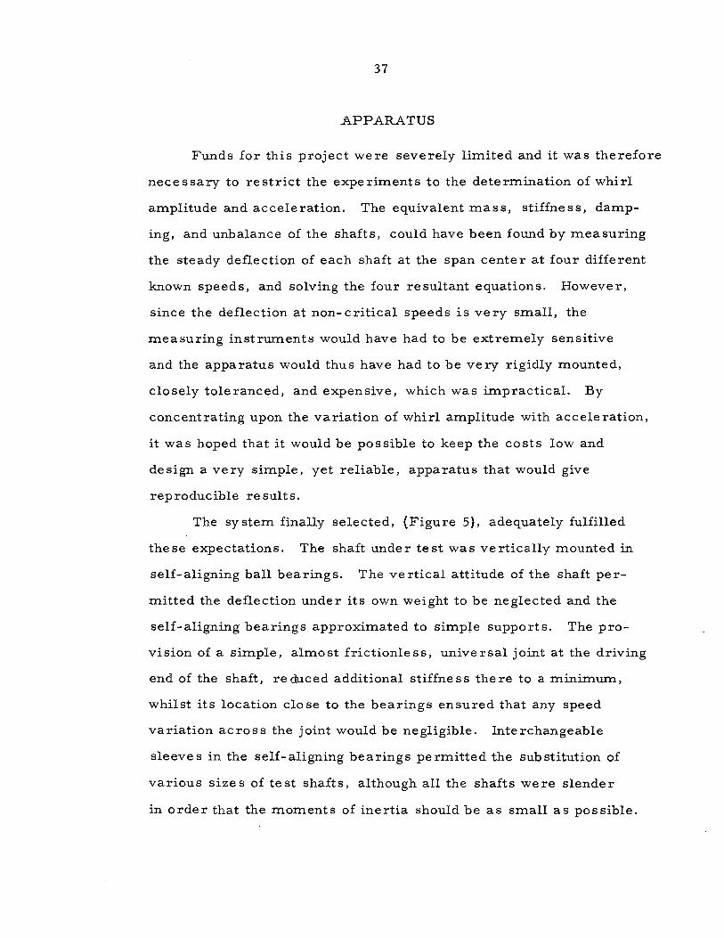
APPARATUS
Funds for this project we re seve rely limited and it was therefore
necessary to restrict the experiments to the determination of whirl
amplitude and acceleration. The equivalent mass, stiffness, damp
ing, and unbalance of the shafts, could have been found by measuring
the steady deflection of each shaft at the span center at four different
known speeds, and solving the four resultant equations. However,
since the deflection at non-critical speeds is very small, the
measuring instruments would have had to be extremely sensitive
and the apparatus would thus have had to be very rigidly mounted,
closely toleranced, and expensive, which was impractical. By
concentra ting upon the variation of whirl amplitude with ac cele ration,
it was hoped that it would be possible to keep the costs low and
design a very simple, yet reliable, apparatus that would give
reproducible re sults.
The system finally selected, (Figure 5), adequately fulfilled
these expectations. The shaft under test was vertically mounted in
self-aligning bail bearings. The vertical attitude of the shaft per
mitted the deflection under its own weight to be neglected and the
self-aligning bearings approximated to simpJe supports. The pro
vision of a simple, almost frictionless, universal joint at the driving
end of the shaft, re duced additional stiffne ss the re to a minimum,
whilst its location cio se to the bea rings ensured that any speed
variation across the joint would be negligible. Interchangeable
sleeve s in the self-aligning bea rings permitted the substitution of
various sizes of test shafts, although ali the shafts were slender
in order that the moments of inertia should be as small as possible.

Plate P.
38
A;-mounted in a single row ùeep-Lroove ball bearil16·
Shaft; -mounted in 8elf-ali~nir~ ball bearings.
Take-up spool B.
Unit mounted in s e li'-alit:ninc l.Jall bearint:;;;s.
.Bronze wire.
'ii erome ter t;auce t-1.
c.
'n'eight W.
Ayparutus .

39
Since the bea rings we re qui te free- running this meant that even at
high accelerations the torque in the shaft would be low and its
effects could be neglected, (the torque required to overcome shaft
inertia was never more than . 27 lb. -in. for maximum acceleration).
The falling weight W provided the motive force which was
transmitted to the shaft smoothly and positively by the system of
reels and take-up spools. Since the force was virtually constant
and the viscous friction in such a system is negligible, the shaft
reels and spool are subjected to a steady acceleration. Thus if
J shaft, J A' J B and J C we re the moments of ine rtia of the test
shaft, re el A, spool B and reel C re spectively and ca) f , w sha t A'
wB and wC were their corresponding angular accelerations then,
neglecting friction:-
where re = radius of reel C and x= linear acceleration of weight
W. The linen cord and the bronze wire were both extremely light
and flexible and could the refere be ignored.
In this system ca) h f = c.) , w = ca)C and x= re c.)C. s at A B
Suppose rA= radius of reel A and rB =radius of spool B, then
. . rA rA
wC = wB = rB w A = rB w shaft ·
Thus equation 36 be come s ....
rA re rA . (Jshaft + JA' + (JB + JC)-'] c.) h f =W. rC (i - -- w ).
rB s a t g rB shaft
Eq. 37.

40
Eq. 38 w = ----------------------------------~~---shaft r W. r t. r A C A
Jshaft + J A+ (JB +Je) rB + --g- rB
w = ---------k, + ka. w
Eq. 39
where k1
and ka. are constants for a given system.
It is evident that w f may be varied by changing W or the sha t
moment of inertia of any part of the system. In this case the
moments of ine rtia we re made fairly large and an adequate range
of values of acceleration could be obtained by merely altering W --
note that if the moments of inertia were negligible then g r
wshaft ~ r rB and variation of W would have no effect . CA
A stop-watch was used to measure the time taken by the
weight to accelerate the shaft from rest through a known number
of revolutions and hence the acceleration could be computed
directly. The maximum amplitude o f whirl was determined by
means of the micrometer gauge M, which was screw ed in until
the indicator paper clipped to the gauge plate P was marked by
the thin smear of eng ine er' s blue on the a ccelerating shaft.

41
PROCEDURE
The shaft to be tested was mounted in the apparatus, as
shown in Figure 5, and then accelerated through its critical speed
by allowing weight W to fall a distance of approximately 11 feet.
After each run , the micrometer gauge was adjusted until a blue mark
showed that the shaft had just touched the indicator paper on plate P
during its acceleration. An average of 12 runs was required to find
this position, but the results were consistent and reproducible, and
the gauge wa s found to me a sure the maximum amplitude with an
accuracy of.±.. 001 in. ; a change of gauge position of . 002 in.
producing either excessively heavy marking or no marking at ali ,
depending upon the direction of movement.
Subtraction of the gauge reading at this position, from the
reading when the paper was just touching the stationary shaft,
("zero reading"), gave the maximum amplitude directly and the
result was checked by the insertion of feeler gauges between the
paper and the stationary shaft. Equal mark density on the "zero
reading" and "maximum amplitude" papers served as an additional
check on the accuracy of the readings.
The weight was timed over every run and the standard deviation
of the times calculated for each value of W. It was found that a
deviation of less than . 25 secs. could be consistently achieved and
this was judged compatible with probable operator reaction times
and stop-watch accuracy. The latter was checked by comparing two
stop-watche s with one another ove r 1 sec. , 5 sec. , 20 sec. , 1 min.
and 5 min. intervals and against a rated watch over a period of a
quarter of an hour without detecting any appreciable error.

42
Since the transmission system was completely free from slip,
descent of the weight through a known distance would accelerate the
shaft through a known number of revolutions. The weights of the cord
and wire were negligible, and the two reels were separated by a
sufficiently large distance for the line of action of the linen cord
to be virtually constant, hence the angular acceleration of the shaft 2x number of revs. of shaft
could be assumed constant and equal to (time of fall)2 ·
Once the maximum amplitude at a given acceleration had been found
the weight W was changed and the maximum amplitude was determined
for the new ac cele ration.
Passage through the critical speed was readily detected by the
strong shaft vibrations experienced at that point and efforts were made
to find out whether sufficient energy was being absorbed by the shaft
at is critical speed to effectively alter the rate of acceleration. Tests
were run at accelerations raising the shaft to speeds just above or
below the critical, and the times and weights recorded were compared,
but no significant energy absorption could be detected:- inertias and
weights had been deliberately kept high when designing the apparatus
in arder to eliminate such effects.
When the maximum amplitude had been found for an adequate
range of accelerations, the shaft was changed for another of the same
length,(42 in. overall, 40 :6
in. between bearing centers), but
different size or material, and the whole procedure was repeated.
A total of twelve shafts was tested in this way consisting of three
shaft materials, (SAE 1020 steel, Alcan 65 ST aluminum alloy and
Tobin bronze), in four different sizes, {3/8, 1/2, 5/8 and 3/4 in.
diameter), the pairs of brass bushes for each shaft size enabling the
same bearings to be used throughout.

43
The weights used varied from approximately 3 lbs. to nearly
50 lbs. and gave shaft accelerations of from 5 to 50 revs. /sec. 2
.
Howeve r it proved impracticable to test any shaft ove r the full range
because the duration of each run was strictly limited by the dropping
height and only the smallest shafts attained their critical speeds at
the lower value of acceleration. In addition the number of runs at
high accelerations was kept as low as possible, since they placed
a severe strain on the apparatus and dropping a 50 lb. weight not
only involved severe handling difficultie s, but also required the
replacement of the bronze wire after every drop due to failure of
the wire on the over- run.
A further problem at high accelerations was the fact that the
maximum amplitude of the shaft on acceleration through the critical
speed was less than that on deceleration through the critical, hence
very careful observation was needed to tell whether the shaft was
marking the indicator paper on acceleration, or only on the over- run;
i f the amplitude w a s small it was virtually impossible.

44
TABLE OF OBSERVATIONS
Length of shafts = 42 in. Distance between bearing centers = 40 :6
in.
T = time taken to accelerate the shaft smoothly through N
revolutions (correct to nearest 1/10th of a second}.
r = maximum amplitude ( + . 001 in.} of center of shaft max. -
during pe riod of acceleration.
Ste el Shaft s
Shaft No. 1.
Nominal dia. = 3/4 in.
T secs. 2.8 2.6
N revs. 58~ 4
60
r in. . 050 . 049 max.
Shaft No. 2.
Nominal dia. = 5/8 in.
T secs.
N revs.
r in. max.
Shaft No. 3.
4. 1
63 ·
. 761
3.7
63
. 602
Nominal dia. = 1/2 in.
T secs.
N revs.
r in. max.
3.8
63
. 100
3. 6
63
. 091
2.4
60
.048
3.4
63
. 478
3. 1
63
.074
Actual dia. =. 749 in.
2.0 1.7
60 60
. 048 . 048
Actual dia. = . 624 in.
3. 1
63
. 398
2.9
63
. 305
2. 5
63
.126
Actual dia. = . 500 in.
2.8
63
. 047
2.4
63
. 039

45
Shaft No. 4.
Nominal dia . = 3/8 in. Actual dia. = . 374 in.
T secs. 4.9 4.2 3. 6 3.4 2.9 2.4
N revs. 63 63 63 63 63 63
r in. .213 . 179 . 160 . 137 .124 . 090 max.
Aluminum Shaft s
Shaft No. 5.
Nominal dia. = 3/4 in. Actual dia. = . 749 in.
T secs. 2.5 2.3 2.2 1.9 1.7
N revs. 59 59 60 60 60
r 1n. .084 . 081 . 078 . 072 .070 max.
Shaft No. 6.
Nominal dia. = 5/8 in . Actual dia. =. 624 in.
T secs. 2.9 2.6 2.3 2. 1 1.8
N revs. 63 63 63 63 63
r in. . 445 max.
. 405 . 348 . 346 . 339
Shaft No. 7.
Nominal dia. = 1/2 in. Actual dia. =. 499 in.
T secs. 3.4 3.0 2.8 2.6 2. 4 2.1
N revs. 63 63 63 63 63 63
r in. 1. 050 . 676 . 594 . 500 . 41 4 . 266 max.

Shaft No. 8.
Nominal dia. = 3/8 in.
T secs.
N revs.
r 1n. max.
5.0
63
. 464
3.7
63
. 365
46
3.2
63
. 275
Bronze Shafts
Shaft No. 9.
Nominal dia. = 3/4 in.
T secs. 2.8 2.6
N revs. 58~ 4
60
r in. . 050 . 049 max.
Shaft No. 10.
Nominal dia. = 5/8 in.
T secs.
N revs.
r in. max.
Shaft No. 1 i.
4. 1
63
. 761
3.7
63
. 602
Nominal dia. = 1/2 in.
T secs.
N revs.
r in. max.
3.8
63
.100
3.6
63
.091
2.4
60
. 048
3.4
63
. 478
3. 1
63
. 074
Actual dia. = . 37 6 in.
2.8
63
. 222
2.4
63
.174
2.2
63
.147
Actual dia. = . 749 in.
2.0 1.7
60 60
. 048 .048
Actual dia. = • 624 in.
3. 1
63
. 398
2.9
63
. 305
Actual dia. = . 499
2.8
63
. 047
2.4
63
. 039
2.5
63
.126
47
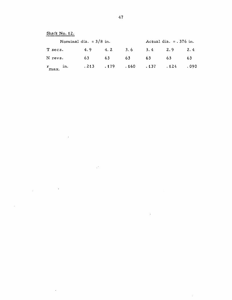
Shaft No. 12.
Nominal dia. = 3/8 in. Actual dia. =. 376 in.
T secs. 4.9 4.2 3. 6 3.4 2.9 2.4
N revs. 63 63 63 63 63 63
r 1n. .213 . 179 . 160 .137 . 124 . 090 max.

48
TABLE OF RESULTS
Comparisons of observed maximum shaft amplitudes and
those predicted by the equation for an undamped rotor ....
.K!:. r = K
1 + r-: ,
max. Il/ w
the constants K 1 and Ka. being determined by substitution of two
of the observed values of r max.
2N Angular acceleration of shaft, w =----,_
T
Shaft No. 1. . 2
w revs./sec. ;
r in. {observed); max.
Equation;
r in. (predicted); max.
Shaft No. 2.
. 1 2 ..., revs. sec. ;
r in. (observed); max.
Equation;
r in. (predicted); max.
Shaft No. 3. . 2
w revs. /sec. ;
r in. {observed); max.
Equation;
r in. (predicted); max.
Steel Shafts
15
.124
23
.113
31
.105
.:..ill. r =. 071 + r-:-max 11 (a)
.1.24
1.5
. 445
r max.
. 440
1.1.
1.. 050
r max.
. 882
.1.1.4 . 1. 08
1.9 24
. 405 . 348
1.340 =. 097 +j w . 405 . 370
14 1.6
. 676 • 594
5.32 =- .724+,r-;:;-
. 71.2 . 606
48
. 1.01.
. 1.01.
29
. 346
. 346
1.9
. 500
. 500
39
. 339
. 31.2
3 . -'' d1a 4 .
i" dia 8 .
1. . 2" d1a.
22 29
. 41.4 . 266
. 41.3 . 266

49
Shaft No. 4. ~" dia 8 .
C:, revs./sec. 2
5.0 9 . 2 12 16 22 26 ;
r in. {observed); . 464 . 365 . 275 . 222 .174 . 147 max.
1. 376 Equation; r =- . 123 +J max. (Il)
r in. (predicted); . 493 . 321 . 275 . 221 . 171 .147 max.
Aluminum Shafts
Shaft No. 5. 3 . 4
" d1a.
c.i revs. /sec. 2
19 22 25 42 ; 33
r in. (observed); . 084 . 081 . 078 . 072 .070 max.
Equation; = . 041 + J .1866 r . max. (Il)
r in. {predicted; . 084 . 081 . 078 . 07 3 . 070 max.
Shaft No. 6. %" dia.
c.i revs./sec . 2
13 15 22 26 ; 17
r in. (observed); . 604 . 527 . 478 . 369 . 303 max.
Equation; 3.70
r = - . 422 + r-;;-max.
r in. {predicted); . 604 . 534 . 476 . 372 . 303 max.
Shaft No. 7. 1 . -•• d1a 2 .
c.i revs./sec. 2
9 . 2 13 26 ; 15 22
r in. (observed); . 785 . 611 . 551 . 416 . 361 max.
Equation; ..LQ1.
r = - . 242 + ;-;;;-max.
r in. (predicted); . 773 . 611 . 552 . 414 . 361 max.

50
Shaft No. 8. 3 0 B 11 d1a.
~ revs./sec. 2
6.8 8.3 12 15 24 29 ;
r in. {ob se rved); .913 . 806 . 629 . 505 0 352 0 231 max.
Equation; ~ r = - . 432 + r-;:; max.
r in . {predicted); . 937 . 806 . 599 0 490 . 296 . 231 max.
Bronze Shafts
Shaft No. 9. ! " dia.
~ revs./sec. 2
; 15 18 21 30 42
r in. (observed); . 050 . 049 . 048 .048 .048 max.
Equation; =. 0432 \J . Q2~5 r . max. (a)
r in. {predicted); . 0500 . 0495 0 0490 . 0480 0 0473 max.
Shaft No. 10. 5 . -" d1a 8 .
~ revs. /sec. 2
; 7.5 9.2 11 13 15 20
r in. {observed); . 761 0 602 . 478 . 398 . 305 0126 max.
Equation; 4.4S
r =- .875+;-;:;-max.
r in. {predicted); 0 761 . 603 . 485 . 368 . 281 .126 max.
Shaft No. 11. 1 2" dia.
,;, revs. /sec. 2
8.7 ; 9.7 13 16 22
r in. {observed); . 100 max.
. 091 . 074 . 047 . 039
Equation; ~ r =-. 064 +r-;:; max.
r in. (predicted); .100 max.
. 092 .070 . 057 . 039

51
Shaft No. 12. 3 . -" d1a 8 .
w revs. /sec. 2
5.2 7.1 9.7 11 15 22 ;
r in. {observed); . 213 . 179 . 160 .137 . 124 . 090 max.
Equation; ~ r =- .026 +JT max.
r in. {predicted); . 213 .178 .150 .140 .115 . 090 max.

52
GRAPHS
The effect of angular acceleration upon maximum amplitude
of whirl is represented graphically in the following figures.
The values of K1
and K:z. derived for each shaft have been
sub stituted in the equation r = K + Jft:.; and in figures 6 - 17 max. 1 lit/ w
the observed results, shown in red, are compared with these
predicted curve s of amplitude against e.ngular acceleration.
Collation of the results for different shafts is further facilitated
by the provision ofboth dimensional and non-dimensional scales,
the symbol .A indicating the non-dimensional form of amplitude
maximum amplitude (r ), in. { = max. }
radius of gyration of shaft, in.
and A the non-dimensional form of angular acceleration
_ angular acceleration (w ), rads. 1 sec.2. {- (natural angular frequency, rads./ sec~) } '
whilst in figures 18- 23 the predicted curves are brought together
for each shaft material, figures 18 - 20 showing the non-dimensional,
and figures 21 - 23 the dimensional curves.

5 3
-l- li'k 1- l i-
'
_-t- t-~-l_ Ci 1
1-t-!
1 '\ J.
. • 1~ i-L- J\ i'' ±=-- _ j t-
!-'
+++-+-+ -+-t--+-t-1--+--t- t-
~ i
-
l l
i \ -
- 1 ~f'\ 1 1
'
- ~t.~ 1 1-
~t~ l-ll- 1--: '" : ~tlB.
f\ ! - i- i rh - - -
- - t- t-
-f+ _;l+--t-
['\ -t - 1 -
i- - t .
' - 1 1
- ~~ -t--
1ti 1-t-
rr 1- - - 1- -+
- t~ 1 .·
t- 1 1
~ . - 1-
t- - Î 1-
1 ..
l-1- -+-t-t-t-+-t-4 -t-1--+-t-H-11--+-t L! t-
i -r- - 1-+-- ++--r+·H-f-I--1L+++-,....t+·H-H-t---t--t---H·--t- l +r ÏT -1--' t- - t-1-H-i
r-- t++4+~~HH~~++~+r~rH~-r-G~+-.,~....,_~_tt~~~~_t~' ~ - î---r-r-r-t- t
1 r t ~ - +- ï 1:--+---1 1
r-+-'-t--r r J. ' 1 1 1 1 '
j - tl -H-t-t-t-t--t--t--r-t-li i+-+ -+--+---+ u ~ :_1-=t p-l±_j :o ~- li _rl-; ~ 1 -~--
1
[ 1 H-t- H -r, o · re 1r s ~Ta ~è :ii ~ W-q ++++HH-+H++++-++1--+-t-H-l (H J±! .htr~H-:-rr t.c11 1 ht1 ·- :nM 1--"--P iio_I
~~
1-t- r-1-1
J

1 ~.
1 1 ~ t '"'! -+
j.. •---r-.
• 1 • +--
t 1 , •
1-r -171 • 1 _ _,
-·~- ~ ' -T--t
~ j .
T--t--+- ·
1
- 1
A~ r"'ax. ;y,
. L
· p,n 1
. - 6 ~
1! . ~
1 •
1,__
f • -
1 •
. t -·
ï~:.-t ;- 1 ~ : ~~ 1--4. t 1---,-'
• .... 1- t r .... Î.,.
-·- i · ' r.~. ·
t ......... i
- ~ -,-"1' ,_ - i l
_, ' l-
!
~ t . L ~ . .
1
1 •
" l
1- -~ --t'" -·
r
~ 4.
1
3
1 1 • .
r-i . ! ( 1 i .
rmu. . i Y1
' . An
' (()
11 ·n7 .ln
-~ - -- -- J
Î 1
. !
\ - '
:\
54 J(
\ : f\ :.
1-
- t l -t
. . '
00? '
. Î
• 1 . 1
1\ "
0
•. 1
l ... --
1 . .. . .. r ' " ~
+ .
1
l/2't dia. stea!L l 'sha "t ... ; . ~-
J t- . ..;....
+ 1 ' 1
f • •
t • ' l 1 l
' . ~ -i j 1 i
. '
r • , t
, 1
1---t --r--- --t ... ! t - · .
' · · J - r ·-,
1 1 · 1 nn,;f .. . .....,
. -' 0 "' ; · b 2. .. ~:, . _ , re s . s pC • fA"
• 1
' li'iu q
• t ' l. e. •.•
_, 1
3/8'' dia. stee.,..· sha!ft.
:~~ . . . 1: "r-.:.
"":::::: . ··-~ : . !---
---r---
• 0 revs ./s~c: ~
( ·---+---+--+- ...u nlun •. A'H--_,._· -l---+-----0.-ln...t.lj.la- ----1- -·a~-

.
55
-t: 1- 1- -+ ;t= ~ -h-l.là .. 1 1 1
' _)_ """ . ~ -1-r- - Î f-
r- f-· r- -
1 ' 1 1
~l-
- f- 1- - r-T 1- 1--
- -
ïlllm~ -tJi 1 ' 111;-;rt PL Fl .
\. ,_ 1-
1 r-
1'--I Ll
r-
....
H-_±
· l 1 T'
~7a· ts 12.~ i . -. u ~ a.c · i lJ.
' ' ; lJill i - - bn r--
--
i l"" .
r-s 1-- ,h a.:·11: - - -- ,-- ,_
1- r- - ! a 1-- - f- - - r-- - r- r-- f- 1--. -.( t-- 1- r-- 1-. 1
- r- - ~ ..... !:-- 1-- r- -
\.-. 1"---' ~1 l -r-- - r-
t-J~rr -+ - r- h-- -t+
1 :-""=r +~--- 1 _j___ r r- ï ·r
1 1 1 j_ 1 : - -1 - 1 --~ :+ 1 -ir f-
1 1- 1 j-+-- -- - 1 .!_l H-- 1 l
J ' ll 1
- ~ ~ r-- 1 - 1- -, cr. -:rë &~-y;JJ ' 2. 1-j-~ rJ± 4-j- ' ilG,. - t -1
L 1 ' ~ m +- , ! !+ oo.a. 1 1 f+L li +-ri f-
-+-r- ±tL- -~~ Et 1
:_~t +i - 1 -- ' ! ! · ~; 1--+ I . t !- ..:...w l - j- r-- H-i-__.__
1 'l - . r,_t , 1 ;- h--Y+ -i 1 -~-~= ' • t
~-r~r 1 ' i . t ,_._.1_,

56
}\! ~.J.. f- 1-1
1 1 -:- ~ 1- 1- i 1- 1- 1-
_l 1-:..!1 ~: 1- f-t 1 .L h '
1 1 1 : : r.-· +
-t=' ~ -~ -- T :
tn R ~ 1
1-
1- - 1-
1-
l( 1 1-
1-
· 1- 1
- -
_(') '-!.re lr 6-!1 ~Fi 12.
Fi-P.~ -
ft"' lrtr:
- -
i
l' l\ +-
-1- · ir ·- 1- -
- 1\ t=r H~~~ ~ ~L . n· - 1-- - - 1 i i
_J_ L , • - Jr - - - -ri + - 1-1 - - t 1
11 ;rn 1 - - - 1- 1-
~ . ~ 1- . 1 - ~! . - 1-- -['\ ·- c-+ - i 1-
-i ~i . _j..
! - 1- 1- ._._ I T ït- -j 1
:jj_ ~ ± -+ 1 _] p._ W-i--
' 1- ......._
1- .-r + 1 1----- ·j . -1
- 1--t t-L -t---
1- - 1- 1- - i'-~·- -'11 H- -+--
J. r---.,..1 1 1 1
~: ·- • .j_ 1- 1-1 1 .
~i 1
i rLI- p ' + 1-- l - 1 1- .-::-~ j 1 .!. H ~- ~~--- q . tr - ( - r-- rr- - 1 t- -f 1 '
1-- - 1- - H -! 1 ' ' r Li ll~ JL 1 1
t- ~--~- a· ,.,+ ~~~ .
,-~< o·:rè ~s.~;.s ,_ ~ - ! - ~ c .. . 1 1 - --'-f-1 i r f- tL .. H. nn~ !+ ·:-+ i 1- f~-=+-H f- ( - iCIF ... ', ( Il? 1 1-
h -; 1-' [ tt-+ r-j r- '
=~ ~] J--,_j lliJ l:rJ J j ... -
- - f-'--f-- . __j j - -f-j- H- : : r-t. h · -~~ -~ ~ t:f· 1 .. t+ - w--f+ ~ -t= ·-r1 J_j_j l 1-- -
-+-1=-1 --r--f" - j - - L ' ' r

------~--------~l
57

'
1 t i 1. - -t •
j 1 l • 1 1
; 1 • ' -1 ~
' 1 + . t • . 1-- l j ••
-,-· ~ _;_ t- ~Î L. 1 · -· • - -+--,
11 ; • •· .• • T .
't-- + -1 i j . 1 . . ~ ,.... rf .
1 • . -.f- .-+1'
• 1 ·- · trJ t ~-t7- , r . i- ...- 1
- .. f i ~-· -rl-j 1 1 - . t~-- i
• t -,-J ·- • Î ' ' 1
. t t
1-j L : , 1 1
; j :-t _;_
' , ,..l..... - . 1 ~
t l 1 t 1 .
1 +
j .
j ••
()Q 1 1 •
.6 r ' • -
1 1 .
. ï ~ . --· ! . • •• -~ 1 • j t •
·-: H 't 1 . t .j.....; •• ' •
1"1 ' ..,{ C1~
t ~-...-- . '-l-- __ __. _ _._
• • 1
+--t--!-..... . ...J_
··t~t-; t-_J
1
·-+
' ' 1 . 1 •
' t
• .L f; 1
1 t : ! L . 1 ... +
(
(
 . . ' ; r"'~~-r 1 Yl
:
?()
t
.2,0
1
' 1~
1.5
t 1
.10 .l.U
•• t ,1 •
1 t .
·-~ -·-· -· -r
.. .•. 1 . . - ~
; t 1
• j • 1
; .
i ;
·\·: ..
1 • l . • 1 •
r•
. ' '
58
\ .
.. t· 1 .
...
• , L.
...
-t- 1 --.j'
• 1 ~ . . .
1- • • ·-
1-i-r-· . t-r- ..
'.,
1 t·•--
1·"""
1
-~Ti.i îil ;-r=
:' . 1 + ·- T : ' .
t 1 . 1 r
1-~---.--+ r- . ' ... --
~· . _, -t
- . . 1 l'iu
' , 1 1
/2'1 . (ii.
-· t j
1 . ~ t
- ..... - .. . ~- ·- . ~
.16 ~ . j .
proilz~ shalft ..
!
' t
• L 1--h- •! · r · . 1 • -· -- - 1. ,-~~- .. .
---1--j - ... ·-·- f-·- . . .. t. ,
1 •.• ' '1 , , .. 1--., -;-,-
. 1 '
' ~ .~ : . . . . ! .! -- ·--, ~ ~-: H-·-~""' . . , -. . .. . . .. L..J.. "'-.. 1 • J 1
. !..- . ' , - ' ·"-..: 1 t 1
·j t·• 1- H' T 1 ~- "} ... ' t - , 1-t.. r.· ·. 1 'Ç,___ : 1 1 L,- 1 i.. ,. . . . -......:. 1 --l-l. + --· ·-- ' 1 '
O. ri-; ·r··- l. o· · 1 2.. t ~. ,_ - ; , , - ~ • : re s . s ~ c ..
()(A
1 ... t-
- - . ; : . i
• 1 • 1 1 • ,. . '
\ . ·\·· . . .
' 1
' 1
' ' ' • 1
1 •. '
• t . t +-
· Fi.2' l7
1 • /8" . i$.. pronz ~ she!ft'. '
< 0 .0 re~s./s~o~ ~---+----4-----~~-+----4-----~---+~--4-----~~-+----4-•
~---+----+----4----*( ---~----~--· ~L~()----4----+----~·~·()~~.~~ ------ ---
. ~-r--
1
i I

59
1 + 1- Lf-+- ffir· H- f- i 1 . 1 r,' i -:i-:1
1 1
r-F 1 l-L d-'-h
1 1
\-Y+1 ·3 '1' 1- 1- - 1 · i .H~f 1'1-1-- Il 1
.!- ~-H
_! ~-~tt
1
1 1- -l- - L ~lt 1-ttt--~~{-- --t· 1 - .1~ 1
~~\ 1--' -~- 1 1 1 hlr :-- -~-+- - --~ -l-+ ti= ~ili~ t:: - - , ...
++ ! 1 1
1-+-1-++ f-H'-+-+-t-++++-1-H-l-+1"\-:-1-++ + l 1 1 _L rT1 +-1
++-H-+-H - j_.1
1-l--1--l-l-l--+-l-IT ...... ffi 1 L +-t-- .( -- r-l.
1 1 1 -ri-- ; 1 H-1-+1-1-1-- - -
t-+-1-+-t-H-++-1-++-H- -1-++~·1-f~ ~ff -t-+-t-fl-j 1-1-+-+-1-+-l +++-~- 1 1 1 1 1 ti- ~ .::..: t 1
H -+-H-+-H-++-
J-+-t--1-H-l-t--t-+++++-,,- t !- \ 1-l t--1 [\ "'.! --+t - t...; T n- H 1 j-.,.. ( t 1 1-i- !-_ '-l ~! ~ ;j ~~- - 1'-.._. ... _, : P -l,l·-- 1 H-- i
1-HH-+-+++~+~~·--H-1·-+-1_-+-1-l-ql 1 ~1---'N-t-t- N f- + =1)-: ... - 11l 1t , .~~ +t- r-=t ri tl r

60
lf:t r~-+t ; :_j ~ ~m dJ ~ !Tt 1
1
, P\ 1 l'i !- !'~ 1 - - 1 - 1 !- - - ~ f\ 1
1 [j 1 11 I.J \J L t " !- R~ I-l !-1
·!--~ 1
lili !i:~t t- !-ë_èf .-1
t-r -~ 'i..
. !- ~ ~ 1-h-x t-
~ !- 1+ +--ri- 1 1 )-.. t" l J+ 1\ t l - 1 ! 1
f- R-.t 1 t- t- -
' 1 " 1 1-l± 1 1 ....... _ J'.
k - ~"l_ !t-l r l rt lA.. 1--.-1 1 ' 1 ' ' J ' 1 h ._
1 H-~-1 '!-.. -;..... : nJ ~ ' k]~. ' i T 1 'lll v J th ' N-. '
h -i '7" 'f!:.:... _j __ j t-? . 1 ~ -f/i li':' . éli. p.. ~~ t- ++-- -t t-t- j-+--1-1- L:-~
t~ ·-dr ~l: ~h ~-+ r-,J i-+-+ t=f - .J __ - ï' -l-
i 1 ,_] LJ- j· 1 ' ~~ 1 1 1 ' '
H-i~-~ ::c ~ - 1 ~ : rer: -1 k-6 . f' ~· ~_s~ ~t}_... l ~ dt -i + 1 1 ~ 1
-r- mt= =i' ;- 1 j h-'t tJ-t- !- 'J 18= l 1-- hl/0 . _ru..a 1 1 --LLJ_
H- l'-# !
~-tt ~~-±-f 1~· +r --~\ -If_ f-~ f- 1
ri-: ·, r- ~~-- - 1 _...L 1 1 1
t-f++ -H+-~ 1- -1 ·1 ++ -W+ 'J~ -' 1 1 1
~ - 1
j ll' ~+t-- +l ~ 1 Hi! '1- r&- ' >- ·! + ~--+ l i ' " 1
!- -L +- -+-- 1- ~
~ -· ·-H- -f--,-+ -- t -,- .L . .j
1
+.:rr Jt -t + - lÎI ~m~ ~ùTn shr "'ta~ : I'T! 1 J_ T :_ ~ L . t r lr - ---l i..,. i
_. t ..- l t- i : 1 : 1 1 '
-'tt .tl - _, _ f-1-i-1 Î' ~~ ~~
l"~ d~~ · -r--i- ~+ · rr l,-~ Jti 1--!' _! ;_; +--- -.l
va~~ rf ·-l- - ' __.__ ·!-- --t-- !--;=-ct tf=t- ----t-.4- +-H + -i-f- ~~-=+= ~=R=
_J -1 '-t -?' · Ti- +; ~-r t ' 1 - :-+T 1 -j
!---1-- +--1 it - L;_. J : r f-- ; t-Lij _j__ 1-Ti ~-'- ~+ ~_. ~:t -p! -1 r± 1---h f- ;- ! --1 §! ~~~
~ -=t' j ~=_;_ ~1 !_ 1
sfJ l- ---1 t--LQ- ï -t-i--~ i 1 1 r-;- - i ---: -1-1-- T . . lî ' ,--~
1
Il 1
1 1 lt-l-- i-t--~ · ~( -f-1
tt! ~ ~d : rè' re~/s ~èi. ._ç ~~±î ,_, ' . - T Q_j~ 1 ' ~c . :J_ - ,-L- 1
-If ~ -!_ ___ J
l-- ' lj-r 4- li~ 1 1 j h- ! r 1 r i t-+ ' 1~ 1 ; t-j - -f-ffi -i i i 1 1 1 - - jT
-1- '~i . • ! ! f 1 ; -~ 1 ' 1 - l-' ~ i ~ -~ r -, f • ï r l l +-· :-r" . - - -
r.lll • . 1 '
\~ii ~~ 1 CL flCL f li1 -· 1 ~L 1--
H 1 :-i ~ -t 1 _j_.__~ -' i l- r--; 4iu 23
- - ll~ !~~ IJ_ t-T -T-R-- !-+ ~ . t--- . ;-t ~ Ft: ~-~rti 1
!- r 1 ~>onze shtl+ t-f- ll·t+ -ïrl-1 Î ~ 1 ·1-r ~~ 1-i-t-- 1 t ~llJ • 1 ti 1 i Il i Tt-1
i+-_L_,! -·-1 1 J - FE -+_Li__ ;~ f---i-- 1 ~- -1-t--L t i 1 --+---- · ~ ' +·TI ---': · -
ht J : 1 c:: ~- ~ -
1 . 3(:4 ~ ~~ ~-~rn -~ .tt-~ 1 tli ~ t t- t- - 1- ~- ti - (_L - ~-+t - r - +-
t 1
1 ~ii= ~!l p-_ ~ ~f- f-L! lf p j r-tm !- f -
llft- ti_!_ i i- j ' ~r- - 1r -----+-+-
~~+t Fh 1 1 1
1( . ~ ......... ...... - ~ Ir n T, -+--+-1
. ,_,___'b,
~ ~.1 1 - 1 "-1-- • . : Lt-- _, T T -f-+-t- ! --ii!_ - l++ +-- .
1 j ·-+
~ ~ J.
v.:Jit ~-dia l'T'-'-- ~ ~~ ~t!f - 1 . . r+ . J. - . - 1+-:P::t . '·]= t-1 -H i-r-1 1 _ _j_ ,---j- . .. -. . l H--i - .. . 1_Lj :
1 i c 1 ' 1 1 f2 'f. .iL , r -1-+~ 1 J H ~ ( 1
1 ~- 1 ~-~ +- H- H w.~ lrs-.-J~ ~c~___j__ ,~) +tt -1
1.---4 rl- 0 . ,-- fFi ·-~ ~d r . + r __ .__ 1 -.
1 1 - i 1 1 j
-- ; f -· ·-+ t-t= 1 ~- G+-r-- i 1 ; l n_f ,_ ~---
1 1 1 --. -+ 1 1 -i . 1--- !- !- 1- î r -j·
1 1 ~{-f-)- - 1 1 :1 :-f::-- LLj 1 1
1 1 -t it -t4 Ht - 1--
L 1---1~± ~-~ ~-+ - ~- - r--ft 'i - • l ---.--:----: ; !- -+ --1 -1-
- H.-- ~1---rl~-1 - - - H-1 1 - 1 !-j_ r-- ! : l 1 ·+ - +-1 + ·--+- 1
1 J.__j_

61
DISCUSSION OF RESULTS
lt is important when considering the results of any investigation
to bear in mind both the initial as sumptions in the theoretical analysis
and the accuracy of the experimental observations.
Ample evidence exists, as has already been shown, that
Jeffcott1 s theory correctly describes the mechanism of whirling for
a shaft under steady conditions and it seems reasonable therefore
that the theory should also be applicable to transient conditions.
By the same token, since the behaviour of a round uniform shaft,
in the region of its primary critical speed under steady conditions
is analogous to that of an ideal single rotor, the same relationship
should hold under transient conditions . It has also been observed
that the viscous damping of a typical rotor system is low compared
with its stiffness and, since only heavy damping has much effect on
an ACCELERATING rotor, undamped theory will be applicable.
Unfortunately, facilities were not available for determining
the mass, stiffness, and unbalance of each shaft in terms of its
ideal rotor equivalent, and the only measurements possible were
the maximum amplitudes and the a~celerations. However, by a
series of bold approximations in the theoretical analysis of an
accelerating ideal rotor, it has been shown that in the undamped
case, the maximum amplitude of whirl, r ~ K + ~ where K1 max. 1 Il/ w
and Kz. are constants. The los s in accuracy is justified since the
original solutions were too complex for general use, whereas the
new formula is attractively simple and clearly indicate s the effect
of acceleration upon whirl amplitude; obviously at low rates of
acceleration, r œ ~. max. Il/ w

62
The experimental observations that have been made, provide
the rneans to establish the validity of this relationship, and thus justify
the assumptions upon which it is based. The accuracy of these obser-
vations, within the lirnits of the apparatus, was ensured by using
simple techniques and by rnaking an average of twelve drops per
shaft with each weight. The maximum amplitude recorded was
readily checked, as described earlier, and the value of the weights
used provided a guide to the accuracy of the acceleration readings.
On the ba sis of this data it is e stirnated that, allowing for errors
due to flexure of the apparatus, the maximum amplitude was
recorded with an accuracy of+ 2°/o, and the accelerations are correct
to within + 10°/o. This is a satisfactory performance for such a
simple apparatus and adequately indicates the influence of acceleration
upon whirl amplitude.
The intuitive expectancy that increasing the acceleration decreases
the maximum amplitude of whirl is confirrned, although the experirnents
indicate that the change is greatest at low values of a c celeration and
there appears to be a limit below which the amplitude cannot be reduced
by increasing the acceleration. . Kz..
The equatlon r = K + ,-: also max. 1 Il/ (&)
predicts this re suit, and the figures 6 - 17 show that curve s obtained
f rom this equation give values of w a nd r that coincide with the max.
observed values within the lirnits of experimental accuracy. In sorne
cases K1
is negative, indicating that the amplitude w ill becorne zero
and then attain a negative minimum as the acceleration increases; this
seerns unlike ly and is c ontrary to Baker• s solution s , (1 4 ). It should b e
rernembered though that the formula for r cornpletely ignores the max.
rnovernent of the critical speed with change of acceleration and this Ieads
to appreciable erro r a t high values of ~. Neverthe less

63
at ail the accelerations te sted, the formula did hold and the exper-
iments thus offer convincing evidence of the validity of the analysis
and the utility of the approximation over a wide range, although
further work will be necessary before they are firmly established.
The analysis predicted that the amplitude of whirl of any
shaft was directly proportional to the initial unbalance E , thus the
deflection of a well-balanced shaft will be law irrespective of its
stiffness . Figures 18- 23 confirm that shaft amplitude at any
acceleration is not merely a function of material properties and/or
shaft dimensions. The small amplitudes obtained with the three
! 11 diameter shafts {Figures 21 - 23) indicate that balance is probably
the critical factor, since the absence of a sleeve between these shafts
and the bearings has eliminated a source of unbalance common to all the
others.
It was also shawn in the analysis of the solution that the max-
imum whirl amplitude of an undamped shaft is approximately
proportional to b =ft , thus for a shaft of given dimensions and
unbalance ....
r a max.
Modulus of elasticity of shaft material Shaft density
Considering the mate rials used in the se expe riments
b =b =1.1. b ' steel · aluminum · z bronze
therefore the amplitude of whirl of the bronze shafts s hould be
appreciably less than their steel a nd aluminum c ounte r parts, assum
ing simila r d e grees of u nb a lance , and this hypothe sis is c onfirm e d
by figures 18 - 23. The increase of amplitude with stiffness may be
ascribed to the rai sing of the c r itical speed and the consequent
increase in the unbalanc e force s at the critical.

64
It will be observed however, that the amplitudes of the
aluminum shafts tend to be higher than that of their steel equivalents,
although b . ~ b , this discrepancy may be ascribed alum1num steel
to the neglect of damping. Geiger (i7) has ascertained by experiment
that when a steel crankshaft passes through a critical speed,
60 - 65 °/o of the total energy of torsional oscillation is conve rted
into heat by the internai damping of the material and that only the
remaining 40 - 35 °/o is accounted for by external damping at the
bearings and from windage. Although the proportions will vary
from material to material as the internai damping varies, the
damping characteristics of the individual metal will evidently have
a marked effect on whatever damping is present, and they may be
supposed to be of similar importance in a whirling shaft.
Kimball and Lovell (i8) place the metals aluminum, brass,
phosphor bronze, and mild steel, (ali cold rolled), in that arder
of increasing damping capacity, a result only partially confirmed
by Foppl {i9) however, who reports that aluminum and steel have
much stronger damping characteristics than bronze. Nevertheless
they ali agree that steel has the grea test damping capacity of the
materials named, and although the coefficient of viscous damping
of any practi cal rotor system is small, it is clearly sufficient for
the maximum amplitude of whirl of a steel shaft to be perceptibly
lower than that of a corresponding aluminum shaft at low accelerations.
The effect of damping however, is to reduce the sensitivity of a sys
tem; therefore its response to a change of acceleration is also
reduced; hence the amplitude/acceleration curves are steeper for
aluminum than for steel, as shawn in figures 18, i9, 21 and 22.

65
CONCLUSIONS
It has been shown that angular acceleration has a strong
influence upon amplitudes of whirl at critical speeds. Increasing
the angular acceleration decreases the amplitude, the effect being
most marked at low accelerations.
Jeffcott' s theory of whirling, although difficult to apply, offers
an explanation of the phenomena observed and forecasts that the
maximum amplitude of whirl, r , is approximately equal to max.
(K1 +/!) for an ideal single undamped rotor; where ~ is the
angular acceleration, and K1
and K,_ are constants. Thus at low
ac cele rations ....
r œ ~ (approximately). max. Il/ w
The theory also predicts that the amplitude of whirl of such a
system is directly proportional to the eccentricity of the center
of mass with respect to the elastic center of the shaft; that the
amplitude increases as the stiffness increases; that damping reduces
the amplitude of whirl at low accelerations at the expense of reducing,
or even completely eliminating the effect, at high accelerations, and
that the effect of the stiffne s s and damping is inversely proportional
to the rotor mass.
It is claimed that undamped single rotor theory is applicable
to the practical case of a vertical simply supported, round, uniform
shaft and experiments carried out on a set of such systems have
provided results that accord with ideal rotor theory. Since only a
very simple apparatus was available for these tests however, further
work will be necessary to establish the validity of ali the predictions, and
toassess their applicability to more complex systems.

66
The complete solution is too complex for ready application
but its validity is sub stantiated by its ability to reproduce re sults
that agree with Baker' s (14) mathematical-machine solutions of
the same equation. It is suggested that it would be interesting to
repeat these experiments with both solid and round shafts, using
more sophisticated equipment which would allow the determination
of the equivalent shaft eccentricities, mass, stiffness, and damping.
The se re sults would not only permit verification of the relative
importance of each constant, but knowledge of typical figures would
enhance the value of Baker' s graphs.

67
APPENDIX
c.) t 2.
Je at+ { - 2- + bt)i dt EVALUATION OF THE INTEGRALS
AND
c.»t~
5 at + ( -
2- - bt)i
e dt
Consider the integral
wta.
St at + ( -
2- + bt)i
I = e dt. ' 0
Let z, =-iC:, 2 2 (t + u 1 )
where iwu t =(a+ bi)t 1
i.e. : i . 1
u = - -:- (a + b1) = -:- (b - ai) 1 (o) (o)
From equation A2 . . . . t = ~ - u1
dt ~ dZ
1 =,_j~
Suppose Z1
= Z 1t when t = 0, then
Thus
Zl 1
wta.
iw ~ -u =-2 '
i 2 2
C:, (b - ai)
Eq. A1.
Eq. A2.
Eq. A3.
Eq. A4.
I = 1 5t eat + ( -2
- + bt)i . dt=
0
rt -z + z , J6;. J e • ' . 2 . Z . dZ, 0 (o) 1
= jii•z,• l t e- 2 1
r-:7 dZ 1 IV z,
0
Let z, =x,+ iy1 where x1
and y1
are real numbers. Now
i w a. 2t 1 a. -2
[t + -. (b - ai) + "72: (b - 2abi - aa.)] . (o) (o)
z, --
Eq. A5.

68
Separating real and imaginary parts ....
ab x =- at--.-'
x, b But t = - - - -:
a w
parabola {Figure 24).
and
Y, --. a. a&
6)[_.!.,_ ] h . f 2
a 1 - w., t e equat10n o a
This parabola is the path of integration in the z, -plane which
is equivalent to the real axis in the t-plane. Consider now the
integral r, = ./1i e2
•' J' ~ 0
dZ;; t is real and Z 1
is complex
Çt e -Z, hence ) ~ dZ, re presents an integration along the real axis
0 '
in a complex plane.
Point A on the parabola corresponds to the point z,t when
t = 0, whilst point B corresponds to Z 1
at time t. Now
It -Z
e • ,r2. dZ, only possesse s a singularity at the origin, thus
0 •
integrating along the path oo AB oo (shown in red), no singularity r r
is enclosed, hence by Cauchyt s theorem
S -z, Jz: dZ 1 = 0. c
Thus the integral may be written
St -z,
_e __ dZ =
0 JZ; Sz -z
_e __ dZ =
z ,JZ '
dZ- dZ.

y l
69
----------~------~~------~-------------------- x l
:a
~-----------1----------\-------------------- oo r
~--------------+---------------~-----------------~r
Pa th 01' in""Gl!u-re:. t.i.on in the z - plane . .L

70
If, in the integral 1 oor . . . , Z is put equal to {Z, f + V), whilst z, t
Soor
in the integral ... , Z is put equal to (Z1
+ V), where V is
z, a real number,then the equation becomes
1 -Z
= e 1 S oo e-V - Z soo e-V
Jz,' + V dV - e 1 ,J z, + v dV. 0 0
Thus
Let
r,=Jf [ io"",J z,~-:v dV- .z.•- z,J"" .-v 0 ,J z, +v
In the case of I~ ....
iéd 2 Za. =- T (t + u:L)
where iC:,u t =(a - bi)t, .... thus
i 1 u = - -:- {a - bi) = -:- {- b - ai) ~ (a) (o)
dV]
Eq. A6.
Eq. A7.
Eq. A8.
From equation A7 .... t = ~ - u . ·. dt ~ dZt--~ 2 c:, z,_ · ,J c.) 'l.
If Z2.. = Zi, when t = 0,
th en
Th us
z;_ = - i26, u: = - ;c.) (- b - ai)
2.
c.) tL
St at + ( -
2- - bt)i
r'l. = e dt 0
e 2. lt -Z
JZ: dZ1 .
0 2.
Eq. A9.
Eq. AfO.

71
Suppose z,_ =x~,.+ iy'L where x,_ and Y~,. are real nurnbers.
Th en ab x,_= - at + -.(a)
• 2. 2.
and c.) t. 2bt 1 2. 2.
y,_ = - -2
[ t - -.- + -=- (b - a ) ] (a) (a)
(a) x,. a thus y2. =- 2 [ at. - c.)'- ] the equation of a parabola again {Figure 25).
In th~s case C and D represent the points Zi and Z2.' when the
time is 0 and t respectively, but this time the path of integration
oor CDoor {shown in red) may enclose the singularity at the origin
giving Hankel' s integral for the gamma-function.
. . . î e-::. dZ,. =- z,J; if the singularity is enclosed. c ""z'2.
-V -V -Z' 2J; + e 7.
e ----dV
-Z e a. e ----dV 1
00
0 ,jz~ +v 100
o Jz,_ +v
and
I = [ - 2J; '<.. e a. + F zr a. (a)
s oo __ e_-_v_ dV -
o .Jz~ +v J"" .-v dV]
o ,Jz,_ +v
Eq. A11.
where K.= 1 if the singularity is enclosed {i.e. if arg. Zz.> Tr)
and 1(.= 0 if it is not {i.e. if arg. Z2.. < Tr).

72
.Pa t h ol' i:nte~ration i n the z.J - p l ane . "-

73
BIBLIOGRAPHY
1.. W. J. Macquorn Rankine,
"On the Centrifugai Force of Rota ting Shafts",
The Engineer, Vol. 27, 9 April, 1869, p. 249.
2. A. G. Greenhill,
"On the Strength of Shafting When Exposed Both to Torsion
and to End Thrust11 ,
Proc. Inst. Mech. Eng. , April, 1883.
3. J. W. Strutt, Baron Rayleigh,
"The Theory of Sound", Vol. l, Chap. 8, i877.
4. S. Dunke rley,
"On the Whirling and Vibration of Shafts",
Phil. Trans., June, 1894.
5. C. Chree,
"The Whirling and Transverse Vibrations of Rotating Shafts 11 ,
Phil. Mag., Vol. 7, 1904.
6. H. H. Jeffcott,
"The Periods of Lateral Vibration of Loaded Shafts -- the
Rational Derivation of Dunkerleyt s Empirical Rule for
Determining Whirling Speeds 11 ,
Proc. Roy. Soc., A 95, June , 1918.
7. H. H. Jeffcott,
"The Lateral Vibration of Loaded Shafts in the Neighbourhood
of a Whi r ling Speed. The Effec t of Wan t of Balance ",
Phil. Mag. , Vol. 37 , March, 1919.
8. J. Morris ,
"The Strength of Sha fts in Vibration" ,
C r o sby, L o c kwood and Son, 1929.

,...
74
9. D. C. Johnson,
"Free Vibration of a Rotating Elastic Body",
Aircraft Engineering, Vol. 24, No. 282, August 1952, pp. 234-236.
10. D. C. Johnson,
"Apparatus for Demonstrating Shaft Whirl",
Engineering, Vol.178 , No. 4622, 27 August 1954, pp. 266-267.
11. E. Downham,
"The ory of Shaft Whirling", Parts l, Il, Ill, IV, and v.
The Enginee r, Vol. 204, No s. 5307-5311, 1957, pp. 518-522,
552-555, 588-591, 624-628, and 660-665.
12. F.M. Lewis,
13.
"Vibration During Acceleration Through a Critical Speed",
A. S.M.E. Trans. Vol. 54, No. 24, (App. Mechs. ), 15 December,
1932, pp.253-259.
G. D. McCann Jr. and R. R. Bennett,
"Vibration of Multifrequency Systems During Acceleration
Through Criti cal Speeds 11,
A. S.M.E. Trans., Vol. 71, Dec. 1949, pp. 375-382.
14. J. G. Baker,
"Mathematical-Machine Determination of the Vibration of an
Ac cele rated Unbalanced Rotor",
A. S.M.E. Trans. Vol. 61, 1939, pp. A-145- A-150.
15. D. Robertson,
"The Whirling of Shafts", Parts I and II.
The Engineer, Vol.158, 1934, pp . 216,217,228,229,231.

j
75
16. H. D. Taylor,
"Critical- Speed Behaviour of Unsymmetrical Shafts",
A. S.M.E. Trans. Vol. 62, 1940 ; pp. A-71 - A-79.
17. C. Geiger,
"Mitteilungen aus den Forschungsanstalten des GHH- Konzerns",
No. 6, 1934.
18. A. L. Kimball and D. E. Lovell,
"Internai Friction in Solids 11,
A. S.M.E. Trans. Vol. 48, 1926, p. 479.
19. o. Foppi,
"The Practical Importance of the Damping Capacity of Metals
Especially Steel s",
Journal of the Iron and Steel Institute, No. II, Vol. 134, 1936,
pp. 39 3-423.