The Haus am Horn in Weimar - Climate adapted design & Energy efficiency of a Bauhaus and World...
107
The Haus am Horn in Weimar Climate adapted design and energy efficiency of a Bauhaus and World Cultural Heritage site Paper for Module 1 Conservation of architectural heritage: History, theory and practice Katja Breitenfelder, Eng. Architect (Dipl.‐Ing. FH), GE Prof. Th. Coomans & Prof. L. Verpoest Master of Conservation of Monuments and Sites Academic year 2011‐12, RLICC, KU Leuven, Belgium
Transcript of The Haus am Horn in Weimar - Climate adapted design & Energy efficiency of a Bauhaus and World...
The Haus am Horn in Weimar
Climate adapted design and energy efficiency
of a Bauhaus and World Cultural Heritage site
Paper for Module 1
Conservation of architectural heritage:
History, theory and practice
Katja Breitenfelder, Eng. Architect (Dipl.‐Ing. FH), GE
Prof. Th. Coomans & Prof. L. Verpoest
Master of Conservation of Monuments and Sites
Academic year 2011‐12, RLICC, KU Leuven, Belgium

T H E H A U S A M H O R N I N W E I M A R | I
Content
Content I
1 Introduction 01
1.1 Background 01 1.2 Aim of the paper 01 1.3 Structure of the paper 02 1.4 Methodology 02
2 Theoretical background 03
2.1 Climate adapted design 03 2.1.1 Climate and comfort 03 2.1.2 Building design 03 2.2 Energy efficiency in cultural heritage buildings 04 2.2.1 Environmentally sustainable heritage conservation 04 2.2.2 Energy performance assessment 04 2.2.3 Energy efficiency policies 05
2.2.3.1 Energy efficiency policies at European level 05 2.2.3.1 Regulatory and legislative framework in Germany 06
2.3 Principles of conservation 06
3 History 08
3.1 Historical background 08 3.1.1 Modern movement 08 3.2 The Haus Am Horn & The State Bauhaus 09 3.2.1 The State Bauhaus in Weimar 09 3.2.2 The Bauhaus Exhibition 1923 09 3.2.3 Origin of the Haus Am Horn 09 3.2.4 Standard houses 10 3.2.5 Georg Muche 10 3.2.6 Walter Gropius 10 3.3 Design of the building 11 3.3.1 Later housing developments 12 3.4 History of the building 12
4 Architecture 14
4.1 Location & Orientation 14 4.2 Building form & Facade 14 4.3 Building type 14 4.4 Building structure & Use 15 4.4.1 Original state 15 4.4.2 Current state 15
II | C O N T E N T
5 Materials & Technology 16
5.1 Original state 16 5.1.1 Materials 16 5.1.2 Building services 16 5.1.3 Structural defects & Maintenance 16 5.2 Reconstruction 1995-99 17 5.2.1 Inventory & Damage 17 5.2.2 Reconstruction measures 17 5.2.3 Building services 17 5.3 Current state 18
6 Climate adapted design & Energy efficiency 19
6.1 Original state 19 6.1.1 Building construction 19 6.1.2 Heat insulation & Air tightness 19
6.1.2.1 Aim 19 6.1.2.2 Building form & Sa/vol ratio 19 6.1.2.3 Heat insulation 19 6.1.2.4 Thermal storage mass 20 6.1.2.5 Zoning 20 6.1.2.6 Air tightness 20
6.1.3 Summer heat protection 20 6.1.3.1 Aim 20 6.1.3.2 Glazing percentage & Solar energy gains 20 6.1.3.3 Sun shading 20 6.1.3.4 Thermal storage mass 20 6.1.3.5 Indoor climate during the summer 20
6.1.4 Natural ventilation 21 6.1.4.1 Aim 21 6.1.4.2 Fluegas & ventilation chimneys 21 6.1.4.3 Natural window ventilation 21
6.1.5 Daylight & Exposure 21 6.1.5.1 Aim 21 6.1.5.2 Daylight supply & Glare protection 21 6.1.5.3 Shading & Room depths 22
6.1.6 Energy performance 22 6.1.6.1 Gains 22 6.1.6.2 Losses 22 6.1.6.3 Heating demand 22 6.1.6.4 Electricity demand 22 6.1.6.5 Gas demand 22 6.1.6.6 Primary energy demand 23
6.1.7 Evaluation 23
T H E H A U S A M H O R N I N W E I M A R | III
6.2 Current state 24 6.2.1 Building construction 24 6.2.2 Heat insulation & Air tightness 24 6.2.3 Summer heat protection 24 6.2.4 Natural ventilation 24 6.2.5 Daylight & Exposure 24 6.2.6 Energy performance 24
6.2.6.1 Gains 24 6.2.6.2 Losses 25 6.2.6.3 Heating demand 25 6.2.6.4 Electricity demand 25 6.2.6.5 Gas demand 25 6.2.6.6 Primary energy demand 25
6.2.7 Evaluation 25 6.3 Conclusions & Recommendations 26 6.3.1 Conclusions 26 6.3.2 Recommendations 26
7 The workshop “Reworking the Bauhaus in Dessau” 27
7.1 Task 27 7.2 Framework program 27 7.3 Energy concept for the Steel House 28 7.3.1 The Steel House 28 7.3.2 Analysis & Evaluation 28 7.3.3 Concept & Proposal 28 7.4 Conclusion 29
8 Conclusion 30
Illustrations 31
Bibliography 63
Appendices 69
A Climate adapted design - Principles 71 B Haus Am Horn - Historic time 81 C Haus Am Horn - Component list 83 D Workshop presentations - “Reworking the Bauhaus in Dessau” 87
T H E H A U S A M H O R N I N W E I M A R | 1
1. Introduction 1.1 Background At a time when major climate change and the aspiration for sustainable economic and social development while maintaining standards of living have become major issues, the renovation of buildings is to be considered from an overall point of view, not just in terms of energy performances but also in terms of comfort, quality of life, environmental impact and resource consumption1. Energy efficiency and building conservation are two important aspects of sustainability. The key lies in balancing the historical value of the building, implementing efficient energy consumption and satisfying the needs and comfort of the occupants. For centuries, buildings were designed taking into account the climatic environment of the different sites and using local resources and materials. Traditional architecture indeed provides excellent examples of suitable concepts and constructional measures for controlling indoor climate by the selective use of outdoor climate factors - designed to achieve maximum building comfort with the minimum use of raw materials and energy. Although many, if not most, larger post-World War II buildings primarily provide interior conditions through the application of energy-consuming systems, most earlier Modern Movement buildings were designed to take advantage of daylight, open-window ventilation, and frequently thermal mass to mitigate heat buildup during the summer. In planning for a building’s renovation, a starting point for improving its environmental performance and energy efficiency should be considerations of its original properties. It is necessary to understand how the building was originally intended to operate in order to save considerable resources and energy already in the phase of the planning. In addition, the needs and comfort criteria applying for the original design might have changed over the time. Especially buildings that were innovative at their time often failed in some performance parameters caused by inadequate construction, technical equipment or inexperienced craftsmanship. For many monuments also running costs become substantial due to increasing energy costs. The “Haus am Horn” in Weimar is an early example of climate adapted and energy-efficient design of the Bauhaus era. It was built to a design by the youngest Bauhaus master Georg Muche, supported by Walter Gropius’ architectural office, as a model house and exhibit on the occasion of the first Bauhaus exhibition in 1923. It was the only Bauhaus building in Weimar and a prototype for residential housing in which numerous functional, material, technological and ecological innovations were implemented. After a series of changes and modernisations, the Haus am Horn was restored to its original form in 1999. Inscribed as a UNESCO World Cultural Heritage site since 1996, the building is used today as a venue for events and exhibitions (figure 1.1). 1.2 Aim of the paper The aim of the paper is to assess the strengths and weaknesses of the building’s original and current state according to climate adapted design and energy efficiency in order to make appropriate recommendations for improvement. It is based on an integrated approach striking a balance between the conservation of the listed building as a World Cultural Heritage site, the requirements of long-term use, and improving the building’s energy efficiency. The paper is written as part of module 1 of the Master of Conservation of Monuments and Sites, namely “Conservation of architectural heritage: History, theory and practice”. For this module, the students were expected to write a paper focusing on one thematic area of the Erasmus Intensive Program 2011-12 "Reworking the Bauhaus in Dessau - An overall energy concept for the buildings of the Bauhaus era in Dessau“, illustrating this with examples of Modern buildings from their home country. The presented paper deals with “The response of the MOMO-monument to climatic conditions” and its preliminary results were presented
1 International Energy Agency (IEA) 2010, Foreword.
2 | T H E H A U S A M H O R N I N W E I M A R
during the Dessau workshop (Bauhaus Dessau Foundation, 14-28 April 2012). Here, the participating international students were seeking for integrated solutions in interdisciplinary expert groups formed by members of six thematic areas2. The experiences gained are integrated in the paper. 1.3 Structure fo the paper The paper is structured in the following chapters: (1) Introduction, (2) Theoretical background, (3) History, (4) Architecture, (5) Material & Technology, (6) Climate adapted design & energy efficiency, (7) The workshop “Reworking the Bauhaus in Dessau”, (8) Conclusions. 1.4 Methodology This research adopts a desk research method, which involves Internet research, literature review, documentation analysis and correspondence with relevant authorities. Besides, visiting the building under study allowed its analysis on-site.
2 The six thematic areas of the Dessau workshop were: (1) the process of aging and maintenance, (2) the life cycles of materials and repair, (3) the response of the MOMO-monument to climatic conditions, (4) the response of the MOMO-monument to functional requests, (5) the cultural value of the MOMO-monument, (6) the performance of the MOMO-monument.
T H E H A U S A M H O R N I N W E I M A R | 3
2. Theoretical background
2.1 Climate adapted design The connection between energy saving and reduction of CO2 is indisputably a challenge for the further development of the human society. The conception of climate adapted buildings has to consider the connections between local climate and energy consumption3. The principles of climate adapted design are described more in detail in Appendix A. The long-term developed fundamentals of climate adapted design for sites in different climatic zones (e.g. heat storage, heat isolation, passive utilization of solar energy, cross ventilation, shadowing) are to combine with current developments in the ranges design, construction, material and energy technologies. The objective is a better climate behavior of buildings dependent on site and utilization4. Traditional architecture indeed provides excellent examples of suitable concepts and constructional measures for controlling indoor climate by the selective use of outdoor climate factors5. For the conception of buildings the following climatic factors are important6:
- Insulation, - Temperature of air and its short-term and long-term fluctuations, - Relative humidity, - Air movements, - Precipitation. -
2.1.1 Climate and comfort When designing an individual building the general outdoor climate is to be regarded as a given condition. The following climatic elements influence the thermal comfort7:
- Temperature, - Humidity, - Wind. - Precipitation, - Solar radiation and sky conditions.
Comfort is a subjective experience, and not all people agree about optimal comfort. To handle comfort, it is necessary to define a “comfort zone”, where the majority of people experience well-being. The Comfort Diagram comprises a comfort zone, where 80% of the population is satisfied. 2.1.2 Building Design A main purpose of buildings is to give shelter for privacy and thermal comfort. A standard recommendation is that local materials should be used as far as possible. However, the choice of materials should take into account not only the production, transportation and construction costs and energy, but also the life-cycle cost of the building including its operation and demolition and the possible recycling of material8.
3 Schütze, Willkomm 2000: 3 ff. 4 Ibid. 5 Ibid. 6 Ibid. 7 Rosenlund 2000: 5 ff. 8 Rosenlund 2000: 8ff.
4 | T H E H A U S A M H O R N I N W E I M A R
Historically, passive techniques were the only way to cool buildings, while heating could be obtained by burning wood or coal. Still today there are good reasons to adopt passive techniques for9:
- Heating and cooling, - Form of the building, - Orientation (orientation with respect to the sun is important: solar diagram), - Natural Ventilation, - Thermal properties: Thermal resistance and thermal capacity of building materials are influenced by
three factors10: density, conductivity and specific heat. The combination of thermal properties has influence on the time lag and the attenuation of building elements.
2.2 Energy efficiency in cultural heritage buildings 2.2.1 Environmentally sustainable heritage conservation The conservation of heritage buildings makes an important contribution to environmental, social and economic sustainability. The environmental sustainability benefits afforded by the retention of built heritage (through conservation and appropriate maintenance) include the substantial reduction in building, demolition and new construction waste, and the conservation of embodied energy in the existing buildings1112. While it has been recognised as a global priority to continue to use existing heritage building stock, their energy efficiency can be improved13. Existing building stock has been regarded as a significant source of wasted energy in relation to energy consumption. Actions to improve energy efficiency for heritage places - either as a particular goal for environmental reasons or as part of an alteration or adaptation - should optimise traditional building performance by reducing and monitoring energy usage and complying with relevant legislation14. 2.2.2 Energy performance assessment Energy performance assessment is the basic tool for calculating energy performance - weather of new buildings or existing building stock. It is carried out by collecting information on the building’s characteristics and components, as well as its energy systems and energy consumption. An assessment generally includes, as a minimum, an analysis of15:
- The form, area and other details of the building. - The thermal, solar and daylight properties of the building envelope and its air permeability. - Space heating installation and hot water supply, including their efficiency, responsiveness and
controls. - Ventilation, air-conditioning systems and controls, and fixed lighting. - Fuel and renewable energy sources.
9 Rosenlund 2000: 8ff. 10 Rosenlund 2000: 12f. 11 Embodied energy is the energy consumed by all of the processes associated with the production of a building (Balderstone 2004: 1). Recurring embodied energy savings increase dramatically once a building reaches over 50 years in age (Rypkema 2006). The reuse of building materials generally provides a 95% saving of embodied energy that would otherwise be wasted. Retaining building materials in situ has a much higher embodied energy saving than their removal and reuse. Some materials including bricks and tiles can suffer damage losses up to 30% in reuse (Rowe 2008). 12 The concept of preservation-based sustainability is the basis of a more comprehensive approach and programmmes emphasizing design, construction and operation for obtaining a “high green performance” building to reduce environmental impacts through energy efficiency, use of recycled materials, storm water management, and other innovations. Cf. American Society of Heating, Refrigerating and Air Conditioning Engineers (ASHRAE), 2009; International Energy Agency (IEA) 2010. 13 Chartered Institution of Building Services Engineers (CIBSE) 2002: 1. 14 Consideration should be given to the many simple and cost effective actions that can be undertaken to improve the energy efficiency of heritage buildings, including, where appropriate, the introduction of insulation and double or secondary glazing. Life-cycle analyses of building fabric: structure, envelope, interior elements and systems - and ongoing management and use - need to be considered as part of the conservation process to achieve optimum energy efficiency outcomes. Rowe 2008. 15 International Energy Agency (IEA) ed., 2010b: 11.
T H E H A U S A M H O R N I N W E I M A R | 5
Other elements, such as lighting systems and installed equipment and appliances, may also be included in the assessment16. This information is input into an authorized calculation model that assesses the building’s energy consumption under local climatic conditions. Assessment methodologies generally use software tools to calculate energy performance and ratings, which will often be based on annual energy use in specific terms, such as the number of kilowatt hours used per square metre (kWh/m2/year). A comprehensive software system can also help provide recommendations for upgrading the building to improve efficiency17. Energy performance calculation is central to the preparation of an energy performance certificate18. For existing buildings, certification and particularly the advice on options to improve energy performance help to raise awareness of energy efficiency opportunities when renovating and/or refurbishing. This is, after design, the most cost-effective time to implement energy efficiency upgrades. Some building certification schemes have extended their scope beyond energy performance to include assessment of a building’s environmental values, measuring aspects such as the use of sustainable materials and components, land use, water use and waste handling (cf. Section 2.2.1). Environmental assessment offers substantial benefits in terms of reflecting the total impact of a building on the environment19. 2.2.3 Energy efficiency policies The standards of energy efficiency in cultural heritage buildings must be improved in order to meet the demands of sustainable development and fight climate change20. The necessary decrease in buildings energy consumption shall however go hand in hand with the preservation of built heritage. Rules and energy regulation which are strictly enacted within the European frame can somehow be toned down on national level21. 2.2.3.1 Energy efficiency policies at European level At the European level, the main policy driver related to the energy use in buildings is the European Directive on Energy Performance of buildings (EPBD, 2002/91/EC)22. Implemented in 2002, the Directive has been recast in 2010 (EPBD recast, 2010/31/EU)23 with more ambitious provisions. The Directive requires minimum energy standards for new and existing buildings that undergo major renovation. Despite the Directive admits a few exception for listed buildings, the International Energy Standards cannot be completely waived. Energy performance requirements can be excluded only “where compliance with requirements would unacceptably alter their character or appearance” (Art. 4/3). At the same time, the policy officially introduces the concept of energy balance towards nearly zero-energy buildings and incentives the decreasing of 20% of environmental emissions and the increasing of 20% of renewable energy technologies within 2020. Member States shall adopt the Directive, either at national or regional level and set minimum requirements, also for existing buildings24.
16 In very low-energy buildings, it also becomes more important to address the impact of appliances and other energy-using equipment, and to take a holistic approach when looking at energy use. Behavioural effects of building users can be significant and must also be addressed. International Energy Agency (IEA) ed., 2010b: 23. 17 International Energy Agency (IEA) ed., 2010b: 11. 18 Energy performance certification provides a means of rating individual buildings how efficient (or inefficient) they are in relation to the amount of energy needed to provide users with expected degrees of comfort and functionality. Common standards have been developed to support harmonisation in Europe (through the European Committee for Standardisation (CEN) and in North America through the Residential Energy Services Network (RESNET) programme. The programmes reflect international standards contained in the International Energy Conservation Code (IECC), those of the American Society of Heating, Refrigerating and Air-Conditioning Engineers (ASHRAE) and those developed by the International Organisation for Standardisation (ISO). International Energy Agency (IEA) ed., 2010b: 11. 19 Environmental assessment can be a particularly good choice for large buildings that have a significant impact on the surrounding environment; but it is likely to prove too complicated and expensive for smaller buildings. International Energy Agency (IEA) ed., 2010b: 23. 20 UNDP-EE, 2011. 21 Or even disappear in some cases. Byström, Sara, 2010. 22 Directive 2002/91/EU of the European Parliament and of the Council of 19 May 2010 on the energy performance of buildings. 23 Directive 2010/31/EU of the European Parliament and of the Council of 19 May 2010 on the energy performance of buildings (recast). 24 Besides, the European Heritage Legal Forum (EHLF) was founded as a European consultation body in 2008 in Brussels. It is composed of representatives of several European countries who investigate the effect of EU legislation on European Cultural Heritage (Göhner 2011).
6 | T H E H A U S A M H O R N I N W E I M A R
2.2.3.2 Regulatory and legislative framework in Germany For years the European Union as well as national and federal administrations in Germany were engaged in supporting energy efficiency measures by law, realizing the ambitious aims of the energy efficiency legislation of the EU and the energy policy concept of the German government. The dena-guidelines25, set up by the German Energy Agency (dena) without involvement of the German Cultural Heritage authorities, admits no exceptions for built heritage26. The German Energy Saving Ordinance (EnEV)27 converts the EU directives into amendments28. In §24(1) EnEV2009 it is clearly stated that matters of cultural heritage have priority over the implementation of energy efficiency measures. Thus, listed monuments are excepted from the requiremnts of the ordinance. The amendment of the Directive [2010/31/EU] on the energy performance of buildings came into effect in 2010 and became national law in all the Member States. In Germany the directive will lead to an amendment of the EnEV, presumably in 201229. The preservation of historic monuments in Germany is under responsibility of the Federal States ("Länder"). Each of the State has established a State Office for Historical Monuments ("Landesdenkmalpflege”). Accordingly, each States provides its own regional heritage preservation law. Weimar is located in the Federal state Thuringia. Here, the ”Thüringer Gesetz zur Pflege und zum Schutz der Kulturdenkmale“ (Thuringian law for the maintenance and protection of cultural monuments)30 of April 2004 (amended in 2007) applies.
2.3 Principles of conservation
Aiming at limiting energy expenditures may lead the preservation of existing buildings, but each intervention gives attention to the physical impact on architectural heritage and matters of vulnerability, physical alteration, and decreasing of immaterial and material value31. The development of conservation principles in the second half of the 20th century had the main objective of protecting cultural property32 around the globe against various threats. These principles or guidelines, promulgated either as charters, recommendations, resolutions, declarations or statements, were drafted and adopted mainly by international organisations, such as UNESCO and ICOMOS33. The most significant guideline was the International Charter for the Conservation and Restoration of Monuments and Sites34, commonly known as the Venice Charter, which set a remarkable benchmark for principles governing architectural conservation and restoration35. Since its adoption internationally in 1964, the Venice Charter has been used as a reference point for the development of a number of other conservation documents around the world36. The preamble of the Venice Charter already stressed the common responsibility to safeguard historic monuments “in the full richness of their authenticity”; however, the Charter did not define the authentic monument values. This was the task of the Nara conference (1994). The Nara Document on Authenticity37 tried
25 Cf. Deutsche Energie-Agentur (dena), 2012. 26 Göhner 2011; cf. Byström, Sara, 2010. 27 Bundesministerium der Justiz, 2009. Verordnung über energiesparenden Wärmeschutz und energiesparende Anlagentechnik bei Gebäuden (Energieeinsparverordnung - EnEV) (revision 2009). Berlin. 28 On national level, the “Gesetz zur Einsparung von Energie in Gebäuden zur Umsetzung der Richtlinie 2002/91/EG“ (Law for energy saving in buildings implementing Directive 2002/91/EG) of 2005 (emended in 2009) transposes the European Directive on Energy Performance of Buildings (EPBD, 2002/91/EC). It allows national regulations (EnEV) to enter into force (Energieeffizienz-online.info, 2012). 29 Göhner 2011. 30 Cf. Thüringer Ministerium für Bildung, Wissenschaft und Kultur, 2012. 31 Cf. Goven, François, 2010. 32 Including historical monuments, buildings, groups of buildings, sites and towns. 33 Ahmad 2006: 292. 34 ICOMOS, 1964. International Charter for the Conservation and Restoration of Monuments and Sites (the Venice Charter). Paris. 35 Ahmad 2006: 292 f. The Charter has helped to broaden the concept of historic buildings, the application of modern technology in conservation works, international cooperation and, most important of all, has provided a set of principles for the protection of architectural heritage and sites. Petzet 2009: 16 ff. 36 Ahmad 2006: 292 f. 37 Lemaire, Stovel 1994.
T H E H A U S A M H O R N I N W E I M A R | 7
to define the test of authenticity and explicitly included the immaterial/intangible values of cultural heritage38. In connection with the practice of the UNESCO World Heritage Convention39 of 1972 the concepts of authenticity and integrity, which are so important for the principles of conservation, have also been further developed. Evaluations of monuments, ensembles and sites and their special values are therefore closely linked to questions of authenticity and integrity. The term integrity has always been used for the characterisation of certain qualities and values of cultural properties. Article 1 of the Convention sets the requirement of certain values from the point of view of history, art or science when dealing with monuments40. Today, apart from the Venice Charter and further international principles of conservation developed on its basis, also national und regional principles play an important role41. The Burra Charter42 (1979, revised 1999) provides the basic principles and procedures for the conservation of heritage places and has been widely adopted as the standard guidelines for heritage conservation practice also in other parts of the world. It recognises social and aesthetic values as part of cultural significance43, as well as intangible values referred to by UNESCO as an integral aspect of heritage significance44. Other important principles of conservation outlined in the documents regard the maintenance and repair of heritage buildings. The Venice Charter refers under the heading “conservation” (Art. 4) to the necessary maintenance of monuments and sites: “It is essential to the conservation of monuments that they be maintained on a permanent basis”45. The principle of compatibility states, that preference should be given to traditional techniques and materials. Treatments that may cause damage to historic materials should generally be avoided46. Another point that is of importance for all preservation work involves the principle of reversibility: interventions necessary in connection with repair work should be “undoable”47 and their extent and depth should be minimised48. Adopting this principle, the valuable historic fabric can be returned to its original state without damaging its substance. Recognising existing heritage conservation documents, the ICOMOS International Scientific Committee for Twentieth Century Heritage (ISC 20C) is developing guidelines for the conservation of heritage sites of the twentieth century during 2011-2012. As a contribution to this debate, the International Conference "Intervention Approaches for the Twentieth-Century Architectural Heritage-CAH 20thC" adopted on 16 June 2011 the text “Approaches for the Conservation of Twentieth-Century Architectural Heritage, Madrid Document 2011"49. Besides specifying the main principles for preserving this category of heritage, the document recognizes the increasing demand for an energy efficiency improvement of architectural heritage sites and adopts the principle of environmentally sustainably: “Care must be taken to achieve an appropriate balance between environmental sustainability and the conservation of cultural significance” (Art. 8). Negative impact by energy conservation measures on the cultural significance of heritage sites should be avoided. Conservation should take into account contemporary approaches to environmental sustainability that is interventions should be executed with sustainable methods and support its development and management. Thus, the retention of ancient buildings or the re-using of components in-situ and allowing for their energy upgrading in benign ways, can be fully in accordance with the principles of heritage conservation and sustainability.
38 Petzet 2009: 18. 39 UNESCO, 1972. Convention concerning the Protection of World Cultural and Natural Heritage. Paris. 40 Petzet 2009: 17. 41 Petzet 2009: 14. 42 ICOMOS-Australia, 1999. The Australia ICOMOS Charter for Places of Cultural Significance (the Burra Charter). (revision November 1999). 43 The Burra Charter defines in Article 1 “cultural significance” as “aesthetic, historic, scientific, social or spiritual value for past, present or future generations”. 44 Ahmad 2006: 297. 45 Cf. Petzet 2009: 29 and The Burra Charter, Article 1/5: Definitions and Article 15 “Maintenance”. 46 Petzet 2009: 29. 47 Cf. The Burra Charter, Article 15/2 under the heading “Change”. 48 Petzet 2009: 30. 49 ICOMOS ISC 20C, 2011.
8 | T H E H A U S A M H O R N I N W E I M A R
3. History The house “Am Horn” was built to the design of the youngest Bauhaus-master Georg Muche with assistance of Walter Gropius’ architectural office on occation of the large Bauhaus exhibition 1923 (figure 3.1-3.2). It is considered an important early work of modern housing which outlines at the same time a way of life. As “Gesamtkunstwerk” it shows the work of all those affiliated with the Bauhaus Weimar. The model house is the only realized Bauhaus architecture in Weimar and was declared, along with the Bauhaus buildings of Weimar and Dessau, a World Heritage Site by the UNESCO in 1996. Besides the outstanding architectural achievements, this recognized the most significant “School of Art” of the 20th century50.
3.1 Historical background 3.3.1 The Modern Movement In the twentieth century, architecture, urban planning and landscape were transformed during a brief, inspiring and unique period in parallel with cubism and abstraction in art. Building trends in Europe and America were diverging from their historical precedents and following modes originated during the initial phase of Modernism beginning in the 1920s. The first buildings were designed during a period of great change in both the philosophy of architecture and the technology of construction. The Modern Movement jettisoned all “historic ballast”, thus declaring the new form “purified” of even the simplest ornament, as an expression of the respective new function (“form follows function”) in contrast to the conserved old form as “document of history”51. The distinction between ‘fine arts’ and ‘applied arts’ was reduced, and the tendency was to design decorative features in reference to function52. The emerging of modern architecture was strongly linked to the development of natural sciences and technology in the twentieth century, thus employing innovative materials and technology5354. The city became a primary focus; it was seen as an organic machine functionally associated with the needs of the working class, the requirements of hygiene, economy and psychology55, which lead to the involvement with modern housing. In Germany, in the crisis years after the First World War (1914-1918), more than 1 million homes were lacking. As incentives for private building were missing caused by the lack of solvent tenants, the local authorities were forced to act for the first time as investors in social housing. Due to the economic situation, priority was set on low buildings costs which should be achieved by the rationalization of construction. In this context the ideas of the Bauhaus developed.
50 Donath et al. 1999: 10; cf. UNESCO WHC 1996. 51 In contrast, the “classic” conservation practice of the 20th century, developed at the turn of the century, concentrated exclusively on the mere conservation of monuments of artistic and historic value. Petzet 2009: 14. 52 Jokilehto 2000: 104. 53 Jokilehto 2000: 102. 54 “Modern architecture was a cultural imperative which expressed innovative ideas, the early buildings retaining their potency to this day. It is as much the spirit which generated these forms as the forms themselves which represent an essential ingredient of our intellectual heritage” (Cunningham, 1998: Foreword). 55 Jokilehto 2000: 104.
T H E H A U S A M H O R N I N W E I M A R | 9
3.2 The Haus Am Horn & The State Bauhaus 3.2.1 The State Bauhaus in Weimar The State Bauhaus Weimar was founded by the German architect Walter Gropius on April 1, 1919 (figure 3.3). Formed by the combination of the former Schools of Art and of Applied Arts of the Grand Duchy of Saxony56, this new type of avant-garde school has become one of the most important design academies of the 20th century57. Connected with the political, enconomic and cultural situation of the Weimar Republic, the Bauhaus became, time and again, subject of controversy. This is the reason for both changes of location, to Dessau 1925 and to Berlin in 1932, and for the change of directors with Hannes Meyer as of 1928 and Ludwig Mies van der Rohe 1930. Finally the Bauhaus Berlin dissolved by itself on 19 July 193358. Under the direction of Walter Gropius world renowed teachers have been brought to Weimar till 1923, namely Lyonel Feininger, Georg Muche, Johannes Itten, Wassily Kandinsky, Paul Klee, Gerhard Marcks, László Moholy-Nagy and Oskar Schlemmer. As “master-craftsmen” of the different Bauhaus workshops they provided an art pedagogic education promoting individual talents and hence, the development of individuality59. The focus of the training concept was on “construction” which should evolve from joint efforts of all disciplines (figure 3.4)60. The idea intrinsic in the Bauhaus foundation 1919 to convey a way of working which is connecting art and craftsmanship, Gropius converted, in view of the more and more important industrialization, into “art and technology - a new unity” in 192361. Therewith, Gropius gave the Bauhaus a distinctive profile as first design academy of the world62. 3.2.2 The Bauhaus Exhibition 1923 In this context, outstanding importance is attached to the Bauhaus exhibition in summer 1923 which is regarded as the first impressive work presentation with many representatives of the modern movement63. On the initiative of the Thuringian Ministry of Education the State Bauhaus Weimar presented its work and education results to the public (figure 3.5-3.6)64. Besides exhibitions in the main building, the program comprised lectures, dance and music events and as highlight the realization of the model house Am Horn as a “synthesis of the arts”, involing all of the institution’s workshops65. 3.2.3 Origin of the Haus Am Horn The idea of an own Bauhaus settlement traces back to 1921, when Walter Gropius initiated a student competition dealing with the creation of missing work and living space for the State Bauhaus. The only remaining work is the utopian design of the student Walter Determann (figure 3.7)66. The foundation of the Bauhaus housing cooperative in 1921 and the employment of the Hungarian architect Fred Forbat for the urban planning marked the beginning of the true background of the house “Am Horn”. At the edge of the park close to Goethe’s gardenhouse, the state Thuringia provided the land “Am Horn” for which Forbat developed in close cooperation with Gropius’ architecture office, a modern housing concept for 56 The building of the former had been constructed in two phases, in 1904 and 1911, to the designs of Henry van de Velde (1863-1957), then Director of the School of Applied Arts, replacing the original structure of 1860, the year the School was founded. 57 Donath et al. 1999: 11. 58 Sparkassen Finanzgruppe 2001, Bauhaus. 59 Donath et al. 1999: 11. 60 Donath et al. 1999: 11. 61 Preoccupation with industrial and machinable manufacturing became the Credo of all Bauhaus work. 62 Donath et al. 1999: 11; cf. Sparkassen Finanzgruppe 2001, Bauhaus. 63 Winkler 2009: 38. 64 Whereas the “box of bricks on a large scale”, developed by Walter Gropius from 1922, was mainly based on a conceptional approach and the housing designs by Farkas Molnár, Marcel Breuer and Carl Fieger presented at the Bauhaus exhibition were only exemplary and illustrated in a graphic way, the Haus Am Horn could be realised. Cf. Freundeskreis der Bauhaus-Universität Weimar e.V. 2000: 10 ff. 65 Donath et al., 1999: 11; cf. Freundeskreis der Bauhaus-Universität Weimar e.V. 2000: 30. 66 The student Walter Determann developed the utopian vision of an economically and socially self-supporting university campus southern of Weimar coming with agricultural estate, kindergarten, workshops, boarding homes and houses for teachers. With an extension of 450 x 300 metres the symmetric complex in an expressionistic style is larger than the historic centre of Weimar. Donath et al., 1999: 12.
10 | T H E H A U S A M H O R N I N W E I M A R
the Bauhaus (figure 3.8)67. In the economic plight of the post-war period and at the peak of inflation only one single-family home, the experimental house “Am Horn” could be realised. 3.2.4 Standard houses Already since 1922, Walter Gropius has been developing his “Box of bricks on a large scale” (figure 3.9-3.10)68, the “Honeycomb” which proposed prefabricated modules that could be assembled to form different standard houses (figure 3.11-3.12). This should ensure minimised time and costs as well as individual adaption to the needs of families, and prevent houses and settlements of a uniform design. Gropius considered the industrialization of housing, along the lines of the American automobile production, as a way to overcome the housing shortage69. This not only meant for him the exploration of new materials, constructions and technologies, but also the question of needs and people’s ways of life and the relation between men and nature within a rapidly changing industrial society70. 3.2.5 Georg Muche Georg Muche (1895-1987) was the youngest Bauhaus master and head of the weaving workshop from 1920 to 1927. Originally acting as painter, graphic designer and pedagog, he has been intensively dealing with housing since 1922. Besides the Haus Am Horn, Muche designed a fifteen-floor apartment house with story gardens, spurred on by a journey to the USA in 1924. This was followed by further experiments on one-family houses, such as the steel house in Dessau-Törten, next to the row house settlement of Walter Gropius, developed in conjunction with Richard Paulick in 192671. 3.2.6 Walter Gropius Walter Gropius (1883-1969) was one of the most important representatives influencing the 20th century’s modern architecture. After collaborating at the office of Peter Behrens he established his own office in close cooperation with Adolf Meyer in 1910, setting up projects like the Fagus plant in Alfeld a.d. Leine, the factory site at the Cologne Werkbund Exhibition or the competition design for the Chicago Tribune Tower. His involvement with housing is demonstrated in projects such as the House Auerbach in Jena and numerous urban planning projects like the settlement Dessau-Törten. During his time at the Bauhaus where he served as director from 1919 to 1928, Gropius designed the Bauhaus building and the Meisterhäuser (Masters’ Houses) in Dessau72.
67 The design envisaged the main building of the school at the highest point of the ground, surrounded by factory-like workshop buildings. The center of the complex was marked by a fairground, enclosed by multi-storey buildings serving as student residences. The transition to the park was formed by detached houses, which should be used as dwelling and studios for the Bauhaus masters. Donath et al., 1999: 12. 68 “Baukasten im Großen”. 69 “The new aim is the factory-made mass-production of residentual houses for stock, which are no longer manufactured on-site, but in special factories as components, ready to assembly.” (Gropius). Donath et al., 1999: 12. 70 Donath et al., 1999: 12. 71 Sparkassen Finanzgruppe 2001, Bauhaus. 72 Sparkassen Finanzgruppe 2001, Bauhaus.
T H E H A U S A M H O R N I N W E I M A R | 11
3.3 Design of the building With the experimental house “Am Horn” Gropius’ concept of the “Large box of bricks” was basically demonstrated for the first time. Muche´s spatial concept was based on the principle of “Honeycomb” providing a large main cube as living room and surrounding rooms with minimised area (figure 3.13)73. The room concept of the Haus Am Horn is revolutionary in so far as it involves social and societal aspects in planning and adapts to housing needs of its inhabitants. Muche´s design should represent the “ideal residential house” responding to the “cultural, social, economic and hygienic requirements of the times”74. The dwelling should serve as “facility, caring for human physical and mental health”, being improved by “scientific research and technical inventions”75. Designed for the use by a modern family without domestic staff, the “functional and economic” arrangement of rooms - equipped with modern building services - should relieve women of traditional housework76. Aspects of the Bauhaus’ standard houses were found in structural work and interior fittings. The structures were made for rational, serial production and the associated reduced construction costs. Priority has been given to materials and constructions “promising a new, synthetic architectural concept” (Gropius) and high economy77. The model house aimed to gather experience in dealing with new, industrial construction materials78. The technical equipment was based on the newest products on the market79. The interior showed furniture and carpet designs by students, and other designs achievements manufactured at the Bauhaus workshops (figure 3.14). Material choice and colour of furniture and mounting parts was in line with the interior colour concept providing each room with its own special quality (figure 3.15)80. Following the design and planning of Georg Muche, construction works were carried out by Walter Gropius’ private office under the supervision of Adolf Meyer81. The building was erected under aggravating circumstances. The experimental house had to be completed within four months. The construction period dropped into the age of inflation. For this reason, the choice of the building materials and structures was limited82. The financing was problematic 83. Donations lost permanently in value. Finally the industrialist Adolf Sommerfeld from Berlin financed the building84, hence becoming owner of the property. In total 40 innovative construction companies used the opportunity to demonstrate their innovations while retaining profit share85. Besides a few local firms, most companies came from various regions in Germany. The shell construction company, the Soziale Bauhütte Weimar, worked at cost price86.
73 The spatial hierarchy was reflected in the external appearance by the increased hight of the main volume (Sparkassen Finanzgruppe 2001, Das Versuchshaus des Bauhauses). The spatial concept focused on human comunity and, by doing so, was contrasted with later modern appoaches based on single room concepts and the opening and connecting of architecture to nature (Siebenbrodt 2007: 115). 74 Muche, G., 1924. Das Versuchshaus des Bauhauses. In: Meyer 2009: 15. 75 Muche, G., 1924. Das Versuchshaus des Bauhauses. In: Meyer 2009: 15. 76 Muche, G., 1924. Das Versuchshaus des Bauhauses. In: Meyer 2009: 15, vgl. Matz 2001: 23. 77 Citation from Walter Gropius: “In terms of structural engineering materials and technologies were used resulting in reduced costs and, otherwise, perceived as advanced technologies. In general, priority was given to artifical materials.“ Muche, G., 1924. Das Einfamilienhaus des Staatlichen Bauhauses. In: Velhagen & Klasings Monatshefte, Vol. 38, no. 9 (May 1924), p. 331 ff.; quoted from Matz 2001: 28 f. 78 The experimental house should be used to test new, industrial building materials for improving their constuctional and physical properties. German standards as the “Deutsche Industrienorm“ (DIN) were still under construction. Donath et al. 1999: 21, 25. 79 Donath et al. 1999: 25; cf.Matz 2001: 28 f. 80 Sparkassen Finanzgruppe 2001, Das Versuchshaus des Bauhauses. 81 Heading the exhibition commission, Georg Muche had the opportunity to coordinate the work of the Bauhaus workshops which were involved in the buildings’ interior fittings and furnishing. Winkler 2009: 64. 82 “The construction period dropped into the age of inflation. For this reason, the choice of the building materials and structures was limited. That we neverless succeded in erecting a building with the current state of technology, was mainly thanks to the cooperation of the industries involved”. (Meyer, A., 1925. Der Aufbau des Versuchshauses. In: Meyer 2009: 24). 83 The German government gave a clear moral support, but only a ridiculous small amount of money. Only a few sponsors from industry could be found. The Dollar kings in the USA did not reply to Gropius’ written demands or rejected them. Winkler 2009: 64. 84 Walter Gropius together with his private architecture office in Berlin had already realised some construction projects for Adolf Sommerfeld, among others the design of the house Sommerfeld in Berlin-Dahlem. Winkler 2009: 64. 85 Winkler 2009: 64. 86 Winkler 2009: 64.
12 | T H E H A U S A M H O R N I N W E I M A R
3.3.1 Later housing developments After the experience with the Haus Am Horn, the former actors continued addressing the issue of modern housing in different ways. The common goal was to base the future of modern standard houses on flexible and functional design solutions. An article by Gropius entiteled “housing industry“ presented design variations of the experimental house by Adolf Meyer and Marcel Breuer. The proposals of “single-family houses with hightened living room” should demonstrate the ”adaptibility of the type“ (figure 3.16)87. Muche, heading a small working group at the Bauhaus, continued his efforts on modern housing and in 1924, Muche, Breuer and Molnar presented their designs at the Bauhaus Exhibition in Stuttgart. After the house „Am Horn“, Gropius und Adolf Meyer designed the House Auerbach in Jena. The functional design and building construction of the two-storey villa was clearly influenced by experiences previously gained (figure 3.17)88.
3.4 History of building
The house “Am Horn” was built as experimental house in the framework of the Bauhaus Exhibition 1923 within a construction time of four months. Shortly after its use as exhibition building for the Bauhaus, all temporary elements and furnishings were removed89. In 1924, Adolf Sommerfeld sold the house to the lawyer F.A. Kühn, in 1926, 1927 and 1933, arranging for the construction of extensions according to plans of the architect Ernst Flemming, “which - although following the principles of modern design - progressively falsified the original concept” (figure 3.18)90. The German Labour Front purchased the building in 1938, which should provide space for a school complex. However the project failed due to the war preparations and the building was rented out to a family of army officers. After the Second World War the city of Weimar acted as trustee. In 1951 the house became public property and was rented out since that time. In the following two centuries the building was occupied by various families, sometimes simultaneously. Depending on the individual functional needs of its inhabitants further structural changes were made91. Since 1970, Prof. Bernd Grönwald has made efforts to maintain the house “Am Horn” which was partly opened to the public and listed as a monument in 1973. The Bauhaus-University used the central room and the adjecant niche as a museum92. After the German reunification in 1990, the property reverted back to the city of Weimar. Since the middle of the 1990s - the house was in urgent need of renovation - the interest in the preservation of the monument increased. In 1996, the Bauhaus buildings in Weimar and Dessau - including the house “Am Horn” - were listed as an UNESCO World Cultural Heritage site93. The Cycle of Friends of the Bauhaus-University Weimar signed a lease contract for the land in the same year94 intending to provide the building for public use. The planned restoration as “Cultural Capital 1999” Project95 was decided, public funds raised and sponsors
87 Freundeskreis der Bauhaus-Universität Weimar 200: 24 f. 88 Ibid. 89 Donath et al. 1999: 24 f. 90 Donath et al. 1999: 24 f.; cf. Siebenbrodt 2007: 117 f. 91 The niche next to the central room had been separated by a wall until the 1980s. There was a door in the wall between the guest room and niche. A bathtub was installed in the pentry. The bath room partly served as kitchen for a seperated dwelling, WC and bathtub were removed and reinstalled later. In 1958, a chimney was installed in the kitchen, as the original chimney of the heating system was shut down due to insufficient functionality. Orther chimneys had been previously built in the children´s room and the room of the Gentleman after replacing the central heating by single stoves in the absence of adequate fuel. In the course of further maintenance and retrofitting measures, the interior has undergone several changes over time, among others in windows, doors and floors. The metal window frames, assimilating the roller blinds, were removed. The smooth door-cases were temporarily covered with ornamented, mounted jambs (Donath et al. 1999: 24 f.; cf. Sparkassen Finanzgruppe 2001, Bauliche Veränderungen nach 1923). 92 Siebenbrodt 2007: 117 f. 93 Donath et al: 10; comp. UNESCO WHC 1996. 94 The leasing contract included the option to errect an additional building on the site until 2002, functionally complementing the existing one by means of a sustainable usage concept (Donath et al: 54 ff.; comp. Freundeskreis der Bauhaus-Universität Weimar e.V. 2000: 116 ff.). 95 ”Cultural Capital Project of the Circle of Friends of the Bauhaus-University Weimar“ (Donath et al: 54 ff.; comp. Freundeskreis der Bauhaus-Universität Weimar e.V. 2000: 116 ff.; Winkler 2009: 66).
T H E H A U S A M H O R N I N W E I M A R | 13
sought96. The decision favoured the reconstruction of the building to its original state 1923 allowing people to experience the concept of the exhibition house again97. Intense historical and technical investigations supported the restauration work in 1998/99, being mainly in the hands of the office Schettler & Wittenberg in Weimar (figure 3.19-3.20). The use as residential building has been abandoned. Since that time, the Cycle of Friends offers an open use concept for the house “Am Horn”, facilitating exhibitions, presentations and workshops, lectures and cultural events98. The focus is on the function as a museum - as place of memory of the Bauhaus history99. For a short time a design institute was accommodated in three rooms, yet colliding with the house’s opening to a broad public (figure 3.21)100. Today the house “Am Horn” is exclusively used and maintained by the Cycle of Friends of the Bauhaus-University. It can be rented on hourly or daily basis. The house is opened with assistance of students on Wednesdays, Saturdays and Sundays attracting 5.000 visitors per year101.
96 The Sparkasse Weimar and the Sparkassen-Kulturstiftung Hessen-Thüringen presented acted as sponsors and provided considerable funds (Freundeskreis der Bauhaus-Universität Weimar e.V. 2000: 116 ff; comp. Winkler 2009: 66). 97 Two options of historic preservation were discussed and to choose from: (1) Preservation of the historic structure and maintaining the residential function, (2) Reconstruction of the original state 1923 (Freundeskreis der Bauhaus-Universität Weimar e.V. 2000: 4; comp. Winkler 2009: 66). 98 The Bauhaus University Weimar supports the house by a rental payment which does not cover the building’s running costs (Siebenbrodt 2007: 117 f.; comp. Sparkassen Finanzgruppe 2001, Weltkulturerbe). 99 The Cycle of Friends of the Bauhaus-University Weimar acts as contact for visitors of the house “Am Horn” and offers guided tours (Siebenbrodt 2007: 118; comp. Winkler 2009: 66). 100 Donath et al: 54 ff. 101 Every year from March to October, three to four exhibitions are organised on subjects covering Bauhaus, architecture, design and fine arts from 1900 to the present day. In autumn and winter the house is mainly used by the Bauhaus-University as vanue for scientific events, presentations etc. The tradition of a festival with foreign students from the 1970s has been picked up and extended to an international summer festival, jointly organized by the foreign students of the Bauhaus-University and the Academy for Music „Franz Liszt“ (Siebenbrodt 2007: 118).
14 | T H E H A U S A M H O R N I N W E I M A R
4. Architecture 4.1 Location & Orientation The building was erected on a 2.500m2 site forming part of the settlement area „Am Horn“ on the south-east of the city center of Weimar. Separated from the adjacent Ilmpark by a residental road, it is located on a hillside slightly sloping to southwest (figure 4.1-4.3). In 1923, the property was situated on the outskirts, beyond all other exhibition places. Due to the less overgrown, elevated location at that time, the house was immediately recognisable for the visitors coming from the Ilmpark from a far distance (figure 4.4-4.5)102. The house was built 12m away from the road and 5m from the neighboring land103, hence shifted far into the garden - behind the building line - and slightly twisted from the north-south axis to the east (figure 4.2-4.3)104. The main facades are thus oriented towards north-northeast, east-northeast, south-southwest and west-southwest. The property can be accessed from the residential road. The garden leads to the entrance on the northeast side of the building (figure 4.6). Over almost 90 years, the site has hardly changed. The former outermost region is meanwhile a popular city position; war, post-war era and the restrictive policy of former GDR towards private property left little room for changes. Remaining are the surrounding villas in the north, complemented by a few new buildings from the period after the German reunification, and the small garden plots adjacent on the east and southeast side. Five-storey prefabricated concrete buildings towards the south give witness to the socialist housing policy105. On the former settlement area of the Bauhaus, a residential quarter has been developed in the context of the urban development project “Neues Bauen am Horn” since 1999, where new housing types of the 21st century should be tested (figure 4.7)106.
4.2 Building form & Facade The building shell consists in a double cube107: from the flat roof of a one-storey cube of low hight soars a second cube, smaller and nearly twice as high (4.0 clear hight)108. The slightly sloped mono-pitch- and tent roof underscores the cubic principle of the structure. The plain facade is structured by corner risalits and window openings cut in the shape of squares and lying rectangles109, a plinth is missing (figure 4.8-4.13).
102 Corresponding to an exhibition site, the garden seemed to be very extroverted supporting the presentation of the model house by its simplicity. Donath, H., 1999. Der Garten des Hauses „Am Horn“. In: Donath et al. 1999: S. 42. 103 Building specification no. 9.2.1923, file Wohnhaus Straße am Horn Nr. 61, SBAW. Quoted from Matz 2001:18 f. 104 The positioning of the building on the site contrasted with the surrounding villas and renforced the impression of “otherness” and “innovation” of the exhibition house (Donath et al. 1999: p.43), similar to that of a sculpture or a Greek temple (Winkler 1993: 101). 105 Cf. Matz 2001: 18f. 106 The project “Neues Bauen am Horn“ started in 1996 with establishing a project office at the Bauhaus-University in cooperation with the “Landesentwicklungsgesellschaft” and the city of Weimar. Based on a development plan, nine European architecture offices have been charged with model designs for new housing types of the 21st century. The project for the world´s fair EXPO 2000 Hannover should be completed in 1999, the year Weimar was cultural capital. Indeed, the construction of private houses was started until the end of 2000 (Stock 2005, Bauhaus-Universität Weimar 2005a/2005b). The architectural form of realised designs goes in line with the design principles for domestic architecture of the Bauhaus era. 107 Winkler 1993: 101. 108 Hence a central structure with a square floorplan (Wünsche 1997:.31 ff.). 109 The have been arranged according to a harmonising graphic pattern, but are primarily corresponding to functional requirements of associated rooms (Matz 2001: 20f.). Muche describes the design principle as follows:”The exterior, that means the true architectural form of the building outlined here, arises from the arrangement and spatial equipment of the interiors. The artistic and architectural tool for design is the proportion in all component parts, especially in the structure of the facades by a symmetric vertical separation and an asymmetric regular arrangement defined through the dimensions and the depth of window openings. Principally, mere decorative forms were in any event avoided (..)“ (Muche, G., 1924. Das Einfamilienhaus des Staatlichen Bauhauses. In: Velhagen & Klasings Monatshefte, Vol. 38, no. 9. (May 1924), 331 ff.; cited from Winkler 1993: 80).
T H E H A U S A M H O R N I N W E I M A R | 15
4.3 Building type The type of the experimental house orientated towards models of antiquity and the Italian renaissance. Indeed, the layout of the building is symmetrically arranged along the longitudinal and transverse axes, reminding of antique houses with Atrium und Tablinum110. The similarity with North-Itatlian Cinquecento-villas, in particular with country mansions of Andrea Palladio (1508-1580)111 is apparent. In particular his Villa Rotonda (figure 4.14) shows clear similarities to the model house in Weimar112.
4.4 Building structure & Use 4.4.1 Original state The external appearance is reflected in the hierarchy of the interior rooms (figure 4.15). The residential building had a square ground plan of 12.7 x 12.7m. The center was formed by the living room with a floor area of about 6 x 6m and a height of 4.15m, illuminated through two toplight strips113. The only connection to the outside was provided through the link between the main room and the adjacent office niche. The guest-room, the WC and the kitchen were attached by the corridor. The kitchen was designed as a purely functional working kitchen allowing a free view from the dining room to the children’s room. The central room gave access to the dining room, the room of the Lady and the room of the Gentleman, and the bath room. A staircase connected the corridor with the basement accommodating a boiler-, laundry- and storage room (figure 4.16-4.26). 4.4.2 Current state With the reconstruction in 1998/99 the original building structure has been restored. Hence, visitors can experience the spatial configuration of the original state once again114. The furniture has been partially restored by replicas. Besides the use as a museum, the house “Am Horn” is used for events and presentations of the Bauhaus-University (Chapter 3.4). The central living room serves as exhibition and presentation area. The same applies to the office niche and the room of the Gentleman. Also the former children´s room and the room of the Lady are used for exhibitions, though the original furniture was (partly) reconstructed. The kitchen facilities were reproduced in the style of the original form, equally addressing today’s requirements. The reconstructed bathroom functions as a museum space as well, whereas the WC facilities are used by visitors. In the former guest-room the Cycle of Friends of the Bauhaus-University established its permanent office. The basement rooms accommodate heating equipment and serve as storage area (figure 4.27-4.45).
110 The work of the master builder from Vincenca was inspired by the architectural scriptures of Vitruv and the ancient ruins of Rome. Contrary to the late Renaissance und the beginning Baroque he strived to reduce ornamental elements to a minimum and therefore to express the clarity and grandness of the structure, and the beauty of perfect proportions (Winkler 1993: 100 f.). 111 Normally Andrea di Pietro della Gondola. 112 This concerns the location on a slope, as the clear design of the building with the elevated central room and the symmetric floorplan following the proportions according to the golden rule. Besides, there are significant deviations to the villa type: the missing axes, axis-undependent windows and the indeed symmetric, but relaxed floorplan which is mirrored around the longitudinal axis and not around a lateral axis as in the case of the Villa Rotonda. (Wolsdorff 1980: 27; cf. Matz 2001: 21 f). 113 Generating a spherical mood. 114 Upon inquiry to the restoration office Wittenberg, no plan documents of the current state have been provided.
16 | T H E H A U S A M H O R N I N W E I M A R
5. Materials & Technology
5.1 Original state 5.1.1 Materials The walls consisted of large-format leightweight concrete blocks (Jurko-stones) of 54x32x10cm for the outer walls and 32x26x8cm for the inner walls. Their low net weight allowed a fast and cheap workmanship, breathing walls and a good heat and sound insulation115. The double-layer exterior walls with an insulating layer made of 6cm thick turf panels (Torfoleum) in between promised substantial savings compared to brickwork in terms of material, transport and labor costs, built area and heating demand (figure 5.1-5.3)116. The outer facade was coated with a silver-grey mineral finishing plaster (Terranova-Edelputz). A system of hollow bricks and armoured concrete (Berra-Hohlsteindecke) was used for ceilings and roof, covered with an insulating layer out of turf panels and cement flooring, and sloping concrete with bitumen sheeting (Ruberoid) respectively (figure 5.3-5.7). Window and door lintels and the peripheral tie beams around the exterior walls were made of reinforced concrete. The basement walls were constructed of mixed masonry (natural stone, concrete and leightweight concrete blocks). External and internal staircases were made of artifical stone. Also for interior fittings, innovative products from various companies were used, such as ceramic ventilation chimneys, radiators117, different types of wooden windows (turning sash-, top-hung sash-, pivoted sash window) with polished plate glass, double windows with wrought iron frames and internal opaque glazing for the toplights of the living room, colored opaque glass for window bands, foodboards and wall panels in kitchen and bathroom, and rubber, Triolin118 and artificial stone as floor covering (figure 5.8-5.10)119. The interior room were painted with distempers. 5.1.2 Building services The coal- and coke-burning boiler for the central heating system was located in the basement, and also a laundry system with gas heating and electric drive. Kitchen and bath were equipped with gas water heaters. A gas stove in the kitchen and electrical installations (light, bell, telephone system) completed the technical building equipment (figure 5.11-5.15)120. 5.1.3 Structural defects & Maintenance Right after the building’s completion, first construction defects occured. To make the house attractive for potential buyers first repairs were made in January 1924: Due to moisture damage at the roof connection, a subsequent sealing with bitumen was necessary121; cracks in gutters and leaking window jointing resulted in the penetration of moisture into underlying walls with spalling of plaster and painting. The lack of waterproofing caused the penetration of moisture into the cellar. Simultaneously it was pointed out, that the moisture caused by the residential use would be harmful to the house, which hence should remain uninhabited122. In the following centuries the central heating was replaced by single stoves in the absence of appropriate fuel. Chimneys were built in the childrens´s room and the room of the gentleman. In 1958, a chimney was installed in the kitchen, as the original ventilation chimney was shut down due to insufficient functionality123.
115 Meyer 2009: 26. Cf. Wittenberg, 1999. Schwerpunkte der denkmalpflegerischen Sanierung. In: Donath et al. 1999: 26; Matz 2001: 28 f. 116 Meyer 2009: 26. 117 Radiators were installed in all living rooms on the ground floor. 118 As a replacement for linoleum, as there was a luxury tax on this material. 119 Meyer 2009: 40; cf. Matz 2001: 28 f. 120 Meyer 2009: 39, 43 ff.; cf. Matz 2001: 28 f. 121 The roof sealing with Ruberoid was unsufficient. 122 Donath et al. 1999: 24 f. 123 Ibid.
T H E H A U S A M H O R N I N W E I M A R | 17
5.2 Reconstruction 1995-99 5.2.1 Inventory & Damage In the course of the technical building assessment serious moisture damage of the structure was detected. Cracks in the gutter, leaking window connections and defective roof and basement sealings124 had significantly affected the condition of the building (figure 5.16). Thermographic recordings of the building envelope attested weak points in the thermal insulation125. The original mounting component, such as floor covering, doors and installations were either no longer existing or completely deteriorated. All original build-in components were stored safely during the reconstruction and preserved. Based on studies by restorers, the original color scheme of the interiors could be largely reconstructed (figure 5.17)126. 5.2.2 Reconstruction measures Due to present standards and knowledge of building physics, it was not always possible to use original designs during the reconstruction of the building shell. The destroyed wall structure was restored using a mineral levelling mortar. Large sections of the outer walls were replaced by leightweight concrete insulation blocks with a 6 cm thick core insulation made of cork (figure 5.18)127. The roof structure above the living room was removed and replaced by a brick ceiling with pressed concrete and foam glass insulation (figure 5.19). Eaves boards and window sills made of reinforced concrete were repaired. During the restoration of the facade, the original Terranova plaster was applied once again. The exterior surfaces of the basement walls received a subsequent vertical sealing (figure 5.20). The interior surfaces were coated with a vapour-permeable restoration plaster128. The reconstruction of interior fittings was difficult, as formerly serially manufactured products were costly or no longer producable due to changes in manufacturing techniques. Opaque glass was replaced by acrylic glass and Triolin and rubber flooring by linoleum. Metal components were nickel-plated and colored. The metal window frames were renewed. Nearly all turning sash and top-hung sash windows were preserved. All non-original windows were replaced by modern versions with double glazing129. The origional tabular lamps (Soffitenlampen) were reconstructed130. The interior rooms were painted with synthetic resins (fig. 5.21-27)131. 5.2.3 Building Services A condensing gas-fired boiler132 was installed in the basement. The old radiators were replaced by round tubular heating elements. Due to lower supply temperatures additional panel radiators were installed. For water heating, an electric continuous-flow water heater was provided in the bath room and an electric water heater in the kitchen. Besides additional electrical connections, data network, broadband cable network, telephone-, alarm- and bellsystem, entry phone, exterior lighting, lightning protection, earth termination system and equipotential bonding connection were installed (figure 5.29-5.30).
124 Moisture damage in the basement was partly caused by improperly executed foundations of later extensions. Donath et al: 26; cf. Freundeskreis der BU Weimar 2000: 55 ff. 125 Donath et al: 26. The Torfoleum insulation largely still fulfilled its task and could be preserved. 126 The reconstruction of the original color scheme was difficult, as no original plans or color designs were remaining. The formerly used distemper was easily washable and therefore remained only fragmented. 127 BIOTON natural insulation block, 24 cm. 128 Freundeskreis der BU Weimar 2000: 55 ff. 129 Only the window catches were reconstructed according to original models. Donath et al: 26; cf. Freundeskreis der BU Weimar 2000: 55 ff. 130 Freundeskreis der BU Weimar 2000: 81 ff. 131 Freundeskreis der BU Weimar 2000: 55 ff. 132 Wall-hung boiler.

18 | T H E H A U S A M H O R N I N W E I M A R
5.3 Current state Despite of subsequent structural sealing in the course of restoration, the building shows today moisture damage in the plinth area of walls with spalling of plaster on the facade. To compensate the high air humidity in the basement, an electrical dehumidifier is being operated during the periods of use (figure 5.31-5.33).
T H E H A U S A M H O R N I N W E I M A R | 19
6. Climate adapted design & Energy efficiency
6.1 Original state 6.1.1 Building construction Existing information on materials and construction of the original state (Chapter 5.1.1) is summarized in the component list in Appendix C. Upon inquiring into the matter from the restoration office Wittenberg, no additional planning documents have been provided. Hence the actual execution of single building components remains unclear133. 6.1.2 Heat insulation & Air tightness 6.1.2.1 Aim Aim of the design was the reduction of transmission heat losses and heat demand by means of a high-quality and “fully implemented insulation of floors, walls and ceilings“134. Surrounding rooms should protect the central room “from cooling caused by outdoor temperature”135. 6.1.2.2 Building form & Sa/vol ratio The small heat-transferring surface in proportion to the heated building volume had a positive effect on achieving this aim. The compact design of the house “Am Horn” resulted in a good A/V-ratio of 0.88136. 6.1.2.3 Heat insulation Decisive for the reduction of transmission heat losses is the high insulation level of the heat-transferring surface, complied with the intended “high-quality and complete thermal insulation”137 and a small glazing area of the external envelope. In the scope of energetic considerations during the planning, a comparison of variants was made between conventional brickwork and an innovative solution with improved thermal insulation, drawn upon technical developments in lightweight construction, supplementing by peat-based insulation materials (figure 6.2-6.3)138. Accordingly, the exterior walls achieved the insulating value of a 75 cm thick traditional brick wall139. By using 6-8cm thick polished plate glass an improvement should be obtained compared to conventional window glass140. The low heat conduction of lightweight concrete blocks and peat plates indeed resulted in low heat transfer coefficients, however the single glazing with high heat conduction does not meet current requirements. The top lights of the main room were formed as box-type windows and contributed to the reduction of the heat losses. The actual execution of single components (structure, heat transfer coefficients)141 and the continuity of
133 Missing information concerns the structure of single building components as well as technical data on materials and layer thicknesses. As a result, an accurate calculation of heat-transfer coefficients and thermal heat capacities of building components was not possible. Sources of information were the publication of the Cycle of Friends of the Bauhaus-University Weimar on the restoration in 1998/99 (Freundeskreis der Bauhaus-Universität Weimar 2000), combined with the plans for the building permit application 1923 by Georg Muche and Gropius’ architecture office (Bauhaus Archiv Berlin 2009: 149; cf. figure 6.1) and the drawings presented on the First Bauhaus Exhibition 1923 (Meyer 2009: 20 f.; cf. figure 4.15). 134 Meyer 2009: 32; cf. Freundeskreis der BU Weimar e.V. 2000: 35. 135 Muche, G., 1924, Das Versuchshaus des Bauhauses. In: Meyer 2009: 19. 136 Calculation according to EnEV 2009. Typical values of detached houses vary between 0.8 and 1.0. 137 Freundeskreis der BU Weimar e.V. 2000: 35. 138 Till that time, peat based insulating materials were mainly used in cold-storage houses. Freundeskreis der BU Weimar e.V. 2000: 35; cf. Meyer 2009: 32f. 139 Meyer 2009: 33; cf. Freundeskreis der BU Weimar e.V. 2000: 35. 140 Meyer 2009: 39. 141 Cf. Chapter 6.1.1 “Building construction” and Appendix C.
20 | T H E H A U S A M H O R N I N W E I M A R
thermal insulation remain unclear. Existing documents indicate an interruption in the thermal insulation of the building envelope at the entrance to the basement142, and thermal bridges at connection points143. 6.1.2.4 Thermal storage mass The thermal storage capacity of massive components appears positive. The heat demand was reduced due to the delayed release of stored heat. In this context, the partition walls of the central living room were constructed with the thickness of exterior walls144. However, it is yet unclear whether these walls were core insulated as well. 6.1.2.5 Zoning An additional advantage is the principle of inner zoning: The central room was protected from strong heat losses by surrounding buffer rooms in winter time145. The thermal storage capacities of the above mentioned thick interior walls increased the desired buffer effect. The arrangement of subordinate rooms in the north and the storm porch were supporting the concept. 6.1.2.6 Air tightness To reduce heat losses, a sufficient air tightness of the external envelope has to be ensured, except for calculated ventilation openings. There is no information on planning of air tight connections. 6.1.3 Summer heat protection 6.1.3.1 Aim The high-quality thermal insulation of the external envelope should also improve the summer heat protection of living rooms and ensure human comfort in summer. 6.1.3.2 Glazing percentage & Solar energy gains The design objective was achieved by a small glazing area of the building envelope of 3.7%146, however, small solar energy gains had to be expected in the transitional period. The largest part of window areas, including the top light strips of the central room, were oriented to southeast and southwest, where the most intensive solar radiation is expected. The risk of overheating in summer was countered by abdicating large-format window openings. 6.1.3.3 Sun shading As a sun screen, inside roller blinds were installed in all living rooms147. Besides, the frosted glazing of the top lights in the central acted as stationary sunscreen. 6.1.3.4 Thermal storage mass Also the thermal heat capacity of massive components had a favorable effect by reducing temperature peaks when the ambient temperatures were high. During longer hot spells, thermal masses only came into effect on cooling of the building by airing during night and morning hours. Through the above mentioned buffer effect the central room was protected from overheating.
142 Cf. floor plans in figure 4.15. The walls bordering the staircase were executed as simple partition walls (uninsulated). 143 Lintels, ring beams, window- and door frames. 144 As were interior walls in the basement (unheated area); cf. figure 4.15, Ground- and basement floor plan. 145 Cf. figure 4.15, Ground- and basement floor plan; comp. Freundeskreis der BU Weimar e.V. 2000: 35. 146 Definition and calculation according to EnEV 2009. 147 except for the kitchen and the ancillary rooms on the north side.
T H E H A U S A M H O R N I N W E I M A R | 21
6.1.3.5 Indoor climate during the summer Heat loads, caused by the residential use (persons, artificial light, electrical equipment) are further factors influencing indoor climate in summer. However, it is likely that these were fairly low. 6.1.4 Natural ventilation 6.1.4.1 Aim The ventilation concept is based on natural window ventilation combined with fluegas and ventilation chimneys for discharge of room exhaust air and fluegas (heating- and gas-fired bathroom boiler). 6.1.4.2 Fluegas & ventilation chimneys At first sight, the concept makes a favourable impression, a closer examination however reveals a number of shortcomings. Whereas the discharge of fluegas by the fluegas pipes of the chimneys should not have been a problem, it is likely that the ventilation of living rooms did not work. The same applies to the ventilation chimney in the kitchen which should additionally discharge the fluegas of the gas stove148. This required controlled ventilation by inhabitants to avoid high ventilation heat losses. 6.1.4.3 Natural window ventilation Generally, cross ventilation was only possible if the doors of the living area remained open (figure 6.4). The toplights of the central room seem to be planned mainly for lighting. This would explain why it was only possible to open one top-hung window mechanically, whereas pivoting windows could not be reached from below (figure 6.5). Hence, using the thermal chimney effect was hardly possible. Ventilation in hot summers had to be ensured by the niche and adjacent rooms. The admission of air for the heating boiler remains unclear and was possibly solved by opening basement windows149. 6.1.5 Daylight & Exposure 6.1.5.1 Aim Aim of the design was to provide living spaces with a uniform illumination and glare-free natural lightning. 6.1.5.2 Daylight supply & Glare protection The living rooms adjacent to the outside had a good natural lighting. Windows with barless glazing and small frames150 promised a maximum incidence of light. The windows in bath room and WC and both toplights illuminating the corridor received matte glazing. On the positive side, we can mention the daylight supply of the basement rooms by cellar windows. The optimal daylighting increased living comfort and reduced electricity demand and running costs of the building. The primary energy demand decreased having a favorable effect on the energy balance of the building. The use of artificial light, necessary on sunny days with lowered blinds for glare protection151 is to be considered as critical (figure 6.6). A clear deficit of the design is the daylight supply of the central living room. The box-type windows of toplight strips with frosted glazing on the inside provided a diffuse light. The niche established the only direct link to the outside and its window contributed to indirect lighting. It is clear that the benefits of the glare-free lighting did not outweigh the disadvantage of frosted glazing demanding the use of artificial light in morning and evening hours or in murky weather. 148 Cf. Chapter 5.1.3. The ventilation chimney in the kitchen was shut down in 1958 due to insufficient functionality. 149 The heating of living rooms by individual stoves in the following centuries considerably increased the necessary air change - frequent room ventilation had to compensate oxygen consumption. 150 Matz 2001: 28 f. 151 There is no information on functional chracteristics and light transmission of the window blinds.
22 | T H E H A U S A M H O R N I N W E I M A R
6.1.5.3 Shading & Room depths Shading by neighboring buildings or vegetation was not to be inspected. Shallow room depths had a favorable effect on the natural lighting of living spaces. 6.1.6 Energy performance In planning of the experimental house, an energetic concept for “heat protection” and the supply with heating was developed, which should guarantee the well-being of the residents in winter and summer and lead to low fuel consumption and heating costs152. The interaction between the insulation value of the heat-transferring surface ensuring low transmission heat losses and the building equipment required for heat production (central heating system) was subject to detailed examination. Within the scope of a cost-benefit analysis, the effects of planning decisions on construction costs (heat insulation, heating system), fuel consumption and heating costs were examined (figure 6.7). Due to the fact that specific energy consumption values were not available, only a general evaluation of the building’s energy balance was possible. 6.1.6.1 Gains The small glazing area and the frosted glazing of the southern toplight windows likely resulted in low solar energy gains during the transitional period and in winter. However, internal heat gains from thermal storage mass of solid components contributed to a positive energy balance. 6.1.6.2 Losses It is likely that ventilation heat losses were relatively high due to the necessary window ventilation (particularly in the winter). As ventilation was controlled by the inhabitants, the benefits of air change and fresh air supply greatly outweigh here. The evidence suggests that transmission heat losses via the building envelope were limited through physical measures153. The amount of heat losses resulting from gaps in the heat insulation, thermal bridges or lacking air-tight connections is not known. 6.1.6.3 Heating demand Aim of the energetic concept was the reduction of heat demand. Although no rough calculation is available154, it can be assumed that the heat demand was relatively low thanks to appropriate measures in design and construction. Due to the negative influence of above mentioned transmission heat losses, the heat demand calculated in the planning was likely to be lower than the actual amount required155. 6.1.6.4 Electricity demand There is no information on the electricity demand for electrical equipment (laundry, light and bell system, telephone). The overall good daylight supply may have kept the electricity demand for lightening within reasonable limits. 6.1.6.5 Gas demand Given the lack of data, no quantitative statement can be made as regards the gas demand156 for hot water and cooking (laundry, gas-fired bathroom boiler, water heater, gas stove).
152 Bauhaus-Universität Weimar e.V. 2000: 35. 153 Single glazed windows indeed result in high transmission heat losses, however, the glazing area was kept small. 154 Necessary plan documents, component- and material specifications were not provided upon inquiry. 155 In the following centuries, the original concept was dismissed and the living rooms heated with individual stoves. 156 The ngas demand was covered by town gas, recovered as a waste product from coke production.
T H E H A U S A M H O R N I N W E I M A R | 23
6.1.6.6 Primary energy demand Although no energy balance is available, from a present-day perspective, the primary energy demand stemming from the use of the building may have remained within moderate limits. 6.1.7 Evaluation From today’s point of view, one can indeed speak of approaches to climate adapted and energy-efficient design in this experimental house. The specific accomplishment of the design is based on comprehensive energetic reflections on the heat protection of the building by using innovative building materials and technologies, and their implementation through measures in design and construction. Besides the high insolating level of the heat-transferring building envelope, these include the compact design, the small glazing area, thermal storage mass, an effective floorplan based on the zoning of functions with subordinate rooms on the north side, and sun protection. Another positive feature worthy of mention is the overall good daylight supply of the building. Exemplary from today´s perspective is the calculation of the expected fuel demand and heating costs already in the phase of planning. By examining the interactions between heat losses and heating technique, a complex consideration and evaluation of the building from the energetic point of view took place. Therewith, a level had been reached in 1923, which was not standard in German design until 2002, with the introduction of the German Energy Saving Ordinance (EnEV)157. Unfortunately, the design concept reached its limits in the implementation: interruptions in the heat isolating building shell, thermal bridges and insufficient air tightness increased transmission heat losses and hence the heat demand. The extract ventilation through chimneys did not work, the necessary window ventilation was difficult. Design and execution mistakes caused structural defects reducing the occupant comfort and the building’s serviceability. Alongside the experimental character of the model house and the lack of experience in dealing with new industrial materials and technologies, the aggravating circumstances of the erection certainly played an important role158. It is questionable to what extent passive solar energy gains were considered in the planning. The south-facing top lights were likely to yield small energy gains due to their opaque glazing - this by no means represented a “passive sun house”, as cited in the literature159. Also the demand for gas and electricity was disregarded in favor of modern equipment and design considerations. In addition there are two essential characteristics of the modern architecture: the use of innovative industrial materials took presedence over the use of local resources. The energy demand for the manufacture of building materials and CO2-emissions from production processes or building enrgy use have played no part at the period when the building was erected.
157 Cf. Freundeskreis der BU Weimar e.V. 2000: 35. 158 Age of inflation, completition within four months, the shell construction company, the Soziale Bauhütte Weimar, worked at cost price (cf. Chapter 3.3 Design of the building). Donath et al. 1999: 24ff. 159 Cf. Donath et al. 1999: 21.
24 | T H E H A U S A M H O R N I N W E I M A R
6.2 Current state With the restoration of the building to its original state of 1923, essential aspects of climate adapted design are transferable to the current sitution. Regarding the energy efficiency of the present state, a reasonable number of issues remain open160. Major changes in the course of refurbishment 1998/99 are presented in the following. Account is taken here of the fact that today, in view of the change of use, other requirements are placed on the user comfort. Due to the absence of plan documents and details, an evalution of the current state was only possible to a limited extent. 6.2.1 Building construction Information on materials and construction of the original state (Chapter 5.2.2) is summarized in the component list in Appendix C. 6.2.2 Heat insulation & Air tightness A substantive change is the heating of the basement. This yields a changed area of heat insulated surface and a lower A/V-ratio. There is no indication that there is any subsequent insulation of basement walls and floor. Information on implemented “structural measures to improve the thermal insulation” (including thermal bridges, airtight connections) is lacking161. For substituting large sections of external walls adequate materials have been implemented complying with the efficient heat insulation of existing walls162. It should be noted that only some windows received a double glazing. 6.2.3 Summer heat protection Shading caused by large trees (figure 6.8) situated on the southern-facing side offer protection from intensive summer heat whilst at the same time reducing solar heat gains in winter and during the transitional period. The re-installed window blinds provide sun protection from the inside. 6.2.4 Natural ventilation Natural ventilation is provided solely by windows. The problem is that airing is only possible in periods of use, thus not being guaranteed, in particular on hot summer times and in winter. Supply of fresh air has proven to be insufficient on-site163. 6.2.5 Daylight & Exposure Shading by vegetation reduces the daylight supply on the southern side. 6.2.6 Energy performance The choice of building equipment for heating and hot water preparation should be consistent with the original concept of an economical consumtion of energy. 6.2.6.1 Gains Shading of the facade results in a further reduction of solar energy gains through transparent components (windows). Interior heat gains through thermal storage mass of solid components remain positive.
160 Did the restoration follow an energetic concept? Inhowfar potentials of the original state were used to take advantage - to which extent changes and improvements were made? Was the concept of use adapted to the building? Inhowfar does the building satisfy current requirements with regard to comfort, building physics, primary energy demand and running costs? Which improvements are necessary or useful and at which places? Inhowfar these improvements comply with principles of sustainable conservation? 161 In particular regarding the subsequent heat insulation of basement walls and floor. Upon inquiring into the matter from Mr. Wittenberg, responsible architect for the restoration of the house “Am Horn”, no information has been provided. 162 Leightweight concrete insulation blocks with core insulation made of cork. See Chapter 5.2.2. Reconstruction measures. 163 Stale and unmoved air in the exhibition rooms.
T H E H A U S A M H O R N I N W E I M A R | 25
6.2.6.2 Losses Due to the building’s limited period of use ventilation heat losses decreased. The amount of transmission heat losses through the building envelope remains unclear. The replacement of individual windows with double glazed windows should bring about only small improvements. There is no information on measures designed to correct weaknesses with regard to construction164. 6.2.6.3 Heat demand Values of the required heat demand are not available. During the exhibition period from mid-March until the beginning of November it is aimed to maintain a consistent temperature of 18-20°C in all rooms165. Hereof, the house is intensively used on 3 opening days/week166. A relative high heat demand is hence expected in spring and autumn, as all rooms are heated due to the building’s use as a museum. A further demand derives from the heating of the likely uninsulated basement167. The total demand is reduced as the heating system runs in “frost protection mode” (approx. 8°C) in winter and is only heated up about 10 times in the case of use168. 6.2.6.4 Electricity demand As the building is only used in limited periods, the electricity demand should be relatively low despite numerous modern installations. In the case artificial light is needed, lighting is necessary in all rooms on the ground floor as the building is used as a museum. It remains unclear weather this results in an increased electricity demand169. The same applies to the influence of the electrical dehumidifier operating in the basement. . 6.2.6.5 Gas demand The gas demand results from the heat demand for the condensing boiler, the amount is not known. 6.2.6.6 Primary energy demand The primary energy demand should be less than at original state, in particular compared to a present residential use, as a modern efficient heating system is used and the building is used for a limited time. However it is not possible to estimate the influence of the heated basement. 6.2.7 Evaluation The reconstruction of the building allowed taking best advantage of substantial potentials of the building’s original state with regard to climate adapted design and energy efficiencyn. To what extent these have been changed or improved could not be made sufficiently clear during the investigation owing to the lack of information. The building is deemed to satisfy the essential requirements arising from the use as a museum. A major shortcoming is the way the building is ventilated by the exhibition stuff. Structural defects (moist basement walls), however, cause little impairment of the current use. Through the use of energy-efficient building technology and changes in building use, a lower primary energy demand can be expected today. The influence of the heated basement is unclear. Regarding the evaluation of the current state, a number of issues remain unresolved. Therefore, it could not be established weather the building is in need of an energy efficiency improvement.
164 Interruptions of heat insulation, thermal bridges, lacking airtight connections. 165 There is no night-time reduction in heating. Information from Mr. Siebenbrodt, 1st Chairman of the Cycle of Friends of the Bauhaus-University Weimar. E-Mail, received on 10 March 2012. 166 Approx. 125 opening days/year, plus additional opening days during vacations. 167 The target room temperature in the basement is not known. 168 Information from Mr. Siebenbrodt, 1st Chairman of the Cycle of Friends of the Bauhaus-University Weimar. 169 In general, a reduced electricity demand for lightening can be expected due to the limited exhibition period from mid-March until the beginning of November. The dimming of rooms for presentation purposes may slightly increase the demand (During an on-site visit, the window blinds in the “room of the lady” were pulled down for presentation purposes). Energy-saving lamps are likely used today.
26 | T H E H A U S A M H O R N I N W E I M A R
6.3 Conclusions & Recommendations 6.3.1 Conclusions The comprehensive energetic considerations about the heat protection of the building and their realization by passive measures already in 1923 are exemplary from the today´s point of view and set the course for future developments. Deficits in construction and building physics came about from the building’s experimental character and influenced occupant comfort. Today´s considerations on energy efficiency were not possible at that time. The restoration of the building used essential potentials of climate adapted design and energy efficiency of the original state. Modifications have arised in the main from the application of modern heating technology and the museum function. Inspite of correcting deficits in construction and building physics, weak points in heat insulation and jointing have not been consequently eliminated. The building fullfils the present requirements well, an exception is the insufficient ventilation. The heating of the uninsulated cellar shows, that the restoration followed no energetic concept. For a more accurate assessment and binding recommendations essential data and documents were missing. 6.3.2 Recommendations Nevertheless the following studies and measures can be recommended: Studies
- Detailed documentation of the original building structure170, - Verification of the heat insulation on its consistency (termal bridges), - Checking of air leaking joints if any, - Preservation studies and energetic assessment on the heating of the cellar, - Energy balance considering the present function including heat demand and required insulation for a
heated, or rather unheated cellar, - Causal analysis on the renewed moisture penetration of the basement, - Preservation studies and energetic assessment on the shading stock of trees.
Measures
- Night time heat reduction of the heating system, - Development of a ventilation concept and instruction of the exhibition stuff:
- Regular airing during times of utilization, especially morning ventilation on hot summer days,
- Additional ventilation outside of times of utilization, especially regular airing in the winter171;
- Eliminating the causes of moisture penetration of the cellar, correcting structural defects;
- Sensors for checking the air quality, if needed.
170 According to Siebenbrodt, no detailed documentation of the building structure has been carried out. Cf. Siebenbrodt 2007: 118. 171 On frost-free days.
T H E H A U S A M H O R N I N W E I M A R | 27
7. The workshop „Reworking the Bauhaus in Dessau“
7.1 Task Task of the Dessau Workshop was to develop concepts and strategies for improving the energy-efficiency of three buildings of the Bauhaus era located in the Törten Estate172, namely “Haus Anton” (Walter Gropius, 1926-28), Housing with Balcony Access (Hannes Meyer, 1930) and Steel House (George Muche, Richard Paulick, 1926-27). The concepts to be developed should be based on an integrated approach including
- Analysis of the monument as - “Artifact” (history, original design, changes), and - “Manufact” (construction, building physics; performance, user comfort);
- Value assessment of the monument; - Evaluation of the need for intervention (improving performance, comfort, energy-efficiency).
7.2 Framework program Guided excursions to different Bauhaus sites173 and lectures by renowed specialists provided the students with the necessary background information. Of great assistance was the presentation on the recent renovation of the Bauhaus Building (Walter Gropius 1925-26)174. In 1994, the Bauhaus Dessau was turned into a public foundation175. Inscribed as a UNESCO World Cultural Heritage site in 1996 and in need of renovations, the Bauhaus was completely refurbished between the years 1996 and 2006176. Due to the building’s high total energy demand and operational costs177 an energetic renovation was carried out in 2011. Analysing the energy performance revealed that more than 50% of transmission heat losses were caused by poor insulation qualities of the windows. As changes were restricted by conditions of heritage protection178 different use or comfort zones were defined allowing to undertake structural changes were necessary and therefore to meet current use requirements179.
172 Gropius designed an estate of terraced houses with kitchen gardens measuring between 350 and 400 m2, to grow vegetables and practice small-scale animal husbandry, thus supporting self-sufficiency. In three phases of construction, 314 terraced houses were built with a floor space of between 57 and 75 m2, according to three different house types. Aim of the project was to counteract the housing shortage with affordable housing. This was supposed to be guaranteed by the rational manufacture of residential housing using suitable new building materials and industrial products and the construction by specialised labour brigades (Stiftung Bauhaus Dessau, 2012b). 173 Bauhaus Building and Master’s houses (Walter Gropius 1925/26), Törten Estate (Walter Gropius 1926-28), Konsum Building (Walter Gropius, 1928), Housing with Balcony Access (Hannes Meyer, 1930), Historical Employment Office (Walter Gropius 1927/28), Bauhaus buildings in Weimar etc. 174 The renovation project was presented by guided tours and lectures including: Markgraf, Monika (Bauhaus Dessau Foundation), “Das Bauhaus als Kulturdenkmal: energetische Sanierung des Bauhausgebäudes“ (20 April 2012); Brenne, Winfried (Winfried Brenne Architekten, Berlin), Matt, Christian (Transsolar Energietechnik GmbH, Stuttgart, Munich, New York), “Denkmal und Energie. Einblicke in die energetische Sanierung vom Bauhaus Dessau“ (20 April 2012). 175 The Bauhaus Dessau Foundation has three departments: the Workshop, the Collection and the Academy. 176 The purpose was “to meet the requirements of contemporary use and primarily to preserve and make visible the historic and artistic value of the building”. Cf. Markgraf, 2006. 177 Monika Markgraf stated that in the years before the renovation, the Bauhaus Dessau Foundation spent 2/3 of its budget for covering the high operational costs of the Bauhaus Building. 178 In order to preserve the values of the Bauhaus building and in accordance with its status as a listed UNESCO World Cultural Heritage site, changes of the original windows are not allowed on the main facades. 179 The former Workshop area, for instance, is now unheated and not used as office or work space anymore. Here, it is intended to install temporary boxes as exhibition space. The office area moved to another wing on the backside of the building, were thermal insulated windows, reconstructed following the original design, could be integrated. To provide user comfort and reduce transmission heat losses a sensor system was installed measuring air quality and challenging the users to open the windows for ventilation when necessary. Measures included the use of renewable energies by the (temporary) installation of photovoltaic elements on the roof of the former studio building.
28 | T H E H A U S A M H O R N I N W E I M A R
7.3 Energy concept for the Steel House I was part of an international group of students180 developing an energy concept for the Steel House. Appendix D presents the results of the intermediate and final presentation. 7.3.1 The Steel House The Steel House was built to a design by George Muche and Richard Paulick during the first construction phase of the Törten Estate between 1926 and 1927. The experimental house - originally planned as a model that could potentially be extended - remained the only building of its kind in Dessau. Due to a series of defects such as inadequate thermal insulation and ventilation caused by the use of metal as building material181 contemporary critics judged the building to be uninhabitable. During its use as residential house the building underwent a series of structural changes182. Inhabited into the 1990s, in 1993 the Steel House was restored “in line with monumental preservation regulations”183. Since 2001, it has been used by the Bauhaus Dessau Foundation serving today as museum and exhibition space. The Foundation intends a future use as habitation and workshop area. 7.3.2 Analysis & Evaluation The historical, architectural and technical analysis of the Steel House revealed that
- The ‘experiment’ failed in meeting the requirements and performance level of the intended use caused by inexperience in dealing with new materials and technologies.
- Changes made by the inhabitants altered the original structure. - During the restoration in 1993 most of the original structure was replaced harming the monument’s
authenticity; technical failures led to a poor performance today. We concluded that it is not possible to improve the building’s performance level and to meet the requirements of the intended use (comfort) without harming the monument’s values and authenticity. 7.3.3 Concept & Proposal We proposed the future function as a Steel House Museum. Two proposals were made and evaluated according to five criteria:
- Authenticity, - Function, - Building techniques, - Energy consumption, - Cost.
180 Ivana Vassiljevic, Serbia; Sonia Boruga, Romania; Katja Breitenfelder, Germany; Katrin Talvik, Estonia and Rajesh Gupta, India. 181 The building is a steel plate construction, consisting of a steel skeleton load bearing structure with 3 mm thick steel plates mounted onto the outer walls. The house has no basement. 182 In 1945 the Steelhouse was partially damaged during bomb attack on Törten. The interior steel walls were bricked in. 183 Stiftung Bauhaus Dessau, 2012a.
T H E H A U S A M H O R N I N W E I M A R | 29
Proposal 1: ‘Simulation of the original environment’ Non-original parts of the building envelope are replaced using efficient construction materials. Boxes ‘rebuilt’ with materials of the original state (1927), the restorations in 1945 and 1993 (current state) are placed into single rooms allowing to ‘experience’ the respective environment and provide exhibition space184. Proposal 2: ‘Rebuilding original stages’ Simultating the environment of different states is made by maintaining the current envelope in one part of the building and reconstructing non-original parts of exterior and interior walls in other parts using materials of the original state and the restoration in 1945185.
7.4 Conclusion The main conclusions of the Dessau Workshop are:
- Due to their experimental character, most early buildings of the Bauhaus era have a poor energy performance leading to high energy consumption and running costs.
- Numerous monuments have been restored in recent years disregarding energetic aspects and are now in (urgent) need of a “renovation of the renovation”.
- Each intervention should respect the monument’s values, authenticity and integrity. It should be based on a comprehensive historical, architectural and technical analysis and a value assessment of the building.
- Following the guiding principles of conservation may impose restrictions on the implementation of energy saving measures.
- Preserving the monument’s values and authenticity can go hand-in-hand with changes of use and energy conservation measures by using the potentials inherent in the structure.
184 This solution preserves less of the monument’s authenticity, but leads to low energy consumption. 185 Here, the monument’s authenticity is preserved in a better way, but energy consumption is high.
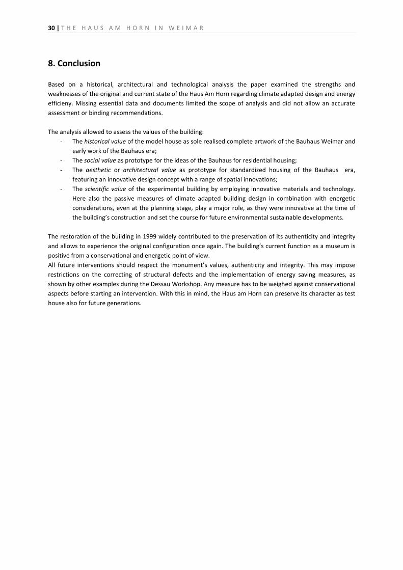
30 | T H E H A U S A M H O R N I N W E I M A R
8. Conclusion Based on a historical, architectural and technological analysis the paper examined the strengths and weaknesses of the original and current state of the Haus Am Horn regarding climate adapted design and energy efficieny. Missing essential data and documents limited the scope of analysis and did not allow an accurate assessment or binding recommendations. The analysis allowed to assess the values of the building:
- The historical value of the model house as sole realised complete artwork of the Bauhaus Weimar and early work of the Bauhaus era;
- The social value as prototype for the ideas of the Bauhaus for residential housing; - The aesthetic or architectural value as prototype for standardized housing of the Bauhaus era,
featuring an innovative design concept with a range of spatial innovations; - The scientific value of the experimental building by employing innovative materials and technology.
Here also the passive measures of climate adapted building design in combination with energetic considerations, even at the planning stage, play a major role, as they were innovative at the time of the building’s construction and set the course for future environmental sustainable developments.
The restoration of the building in 1999 widely contributed to the preservation of its authenticity and integrity and allows to experience the original configuration once again. The building’s current function as a museum is positive from a conservational and energetic point of view. All future interventions should respect the monument’s values, authenticity and integrity. This may impose restrictions on the correcting of structural defects and the implementation of energy saving measures, as shown by other examples during the Dessau Workshop. Any measure has to be weighed against conservational aspects before starting an intervention. With this in mind, the Haus am Horn can preserve its character as test house also for future generations.

T H E H A U S A M H O R N I N W E I M A R 31
ILLUSTRATIONS
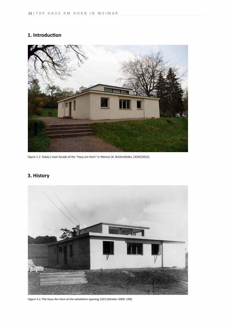
T H E H A U S A M H O R N I N W E I M A R32
Figure 1.1: Today‘s main facade of the “Haus am Horn“ in Weimar [K. Breitenfelder, 14/04/2012].
3. History
Figure 3.1: The Haus Am Horn at the exhebition opening 1923 [Winkler 2009: 199].
1. Introduction
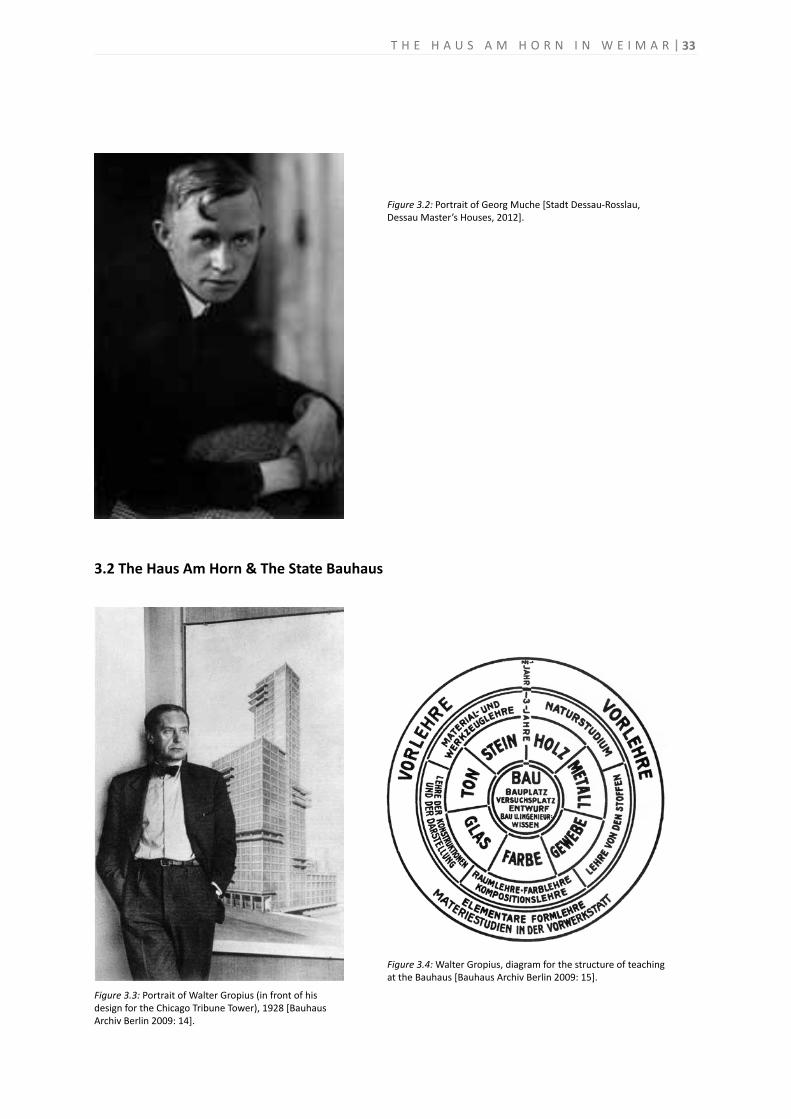
T H E H A U S A M H O R N I N W E I M A R 33
3.2 The Haus Am Horn & The State Bauhaus
Figure 3.3: Portrait of Walter Gropius (in front of his design for the Chicago Tribune Tower), 1928 [Bauhaus Archiv Berlin 2009: 14].
Figure 3.4: Walter Gropius, diagram for the structure of teaching at the Bauhaus [Bauhaus Archiv Berlin 2009: 15].
Figure 3.2: Portrait of Georg Muche [Stadt Dessau-Rosslau,Dessau Master’s Houses, 2012].
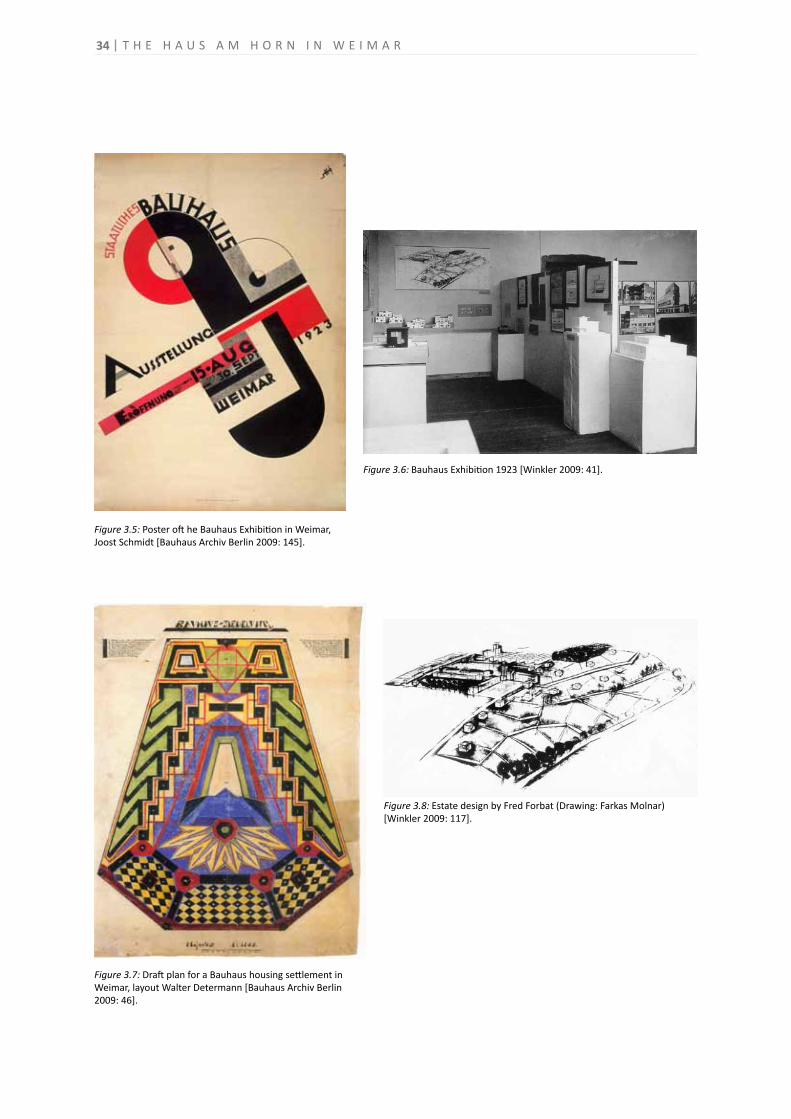
Figure 3.5: Poster oft he Bauhaus Exhibition in Weimar, Joost Schmidt [Bauhaus Archiv Berlin 2009: 145].
Figure 3.6: Bauhaus Exhibition 1923 [Winkler 2009: 41].
Figure 3.7: Draft plan for a Bauhaus housing settlement in Weimar, layout Walter Determann [Bauhaus Archiv Berlin 2009: 46].
Figure 3.8: Estate design by Fred Forbat (Drawing: Farkas Molnar)[Winkler 2009: 117].
34 T H E H A U S A M H O R N I N W E I M A R
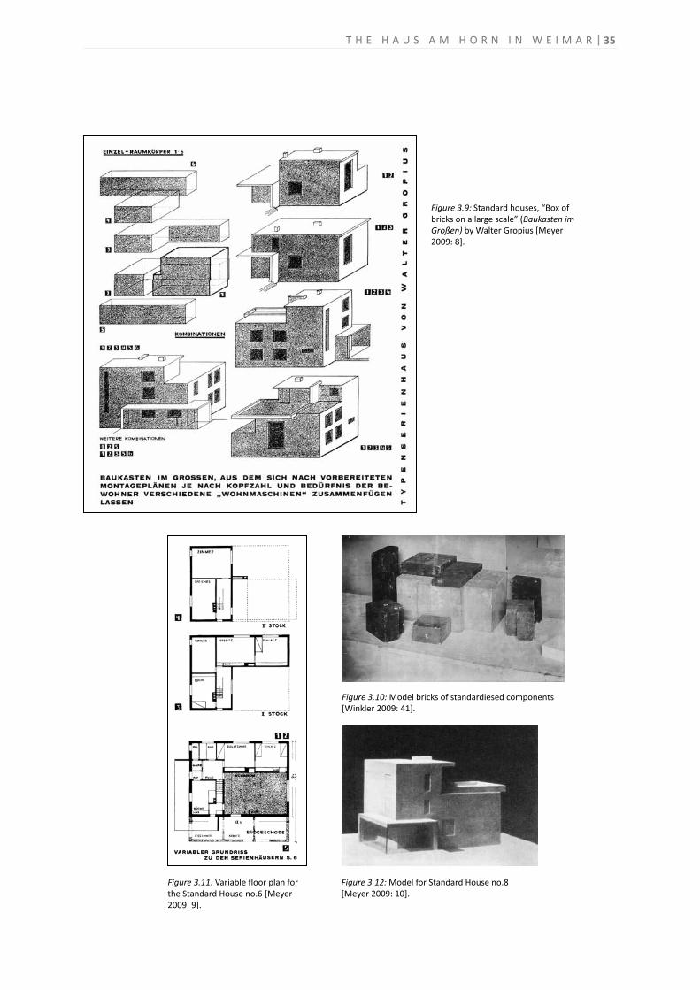
35
Figure 3.11: Variable floor plan for the Standard House no.6 [Meyer 2009: 9].
Figure 3.9: Standard houses, “Box of bricks on a large scale” (Baukasten imGroßen) by Walter Gropius [Meyer2009: 8].
Figure 3.10: Model bricks of standardiesed components [Winkler 2009: 41].
Figure 3.12: Model for Standard House no.8[Meyer 2009: 10].
T H E H A U S A M H O R N I N W E I M A R
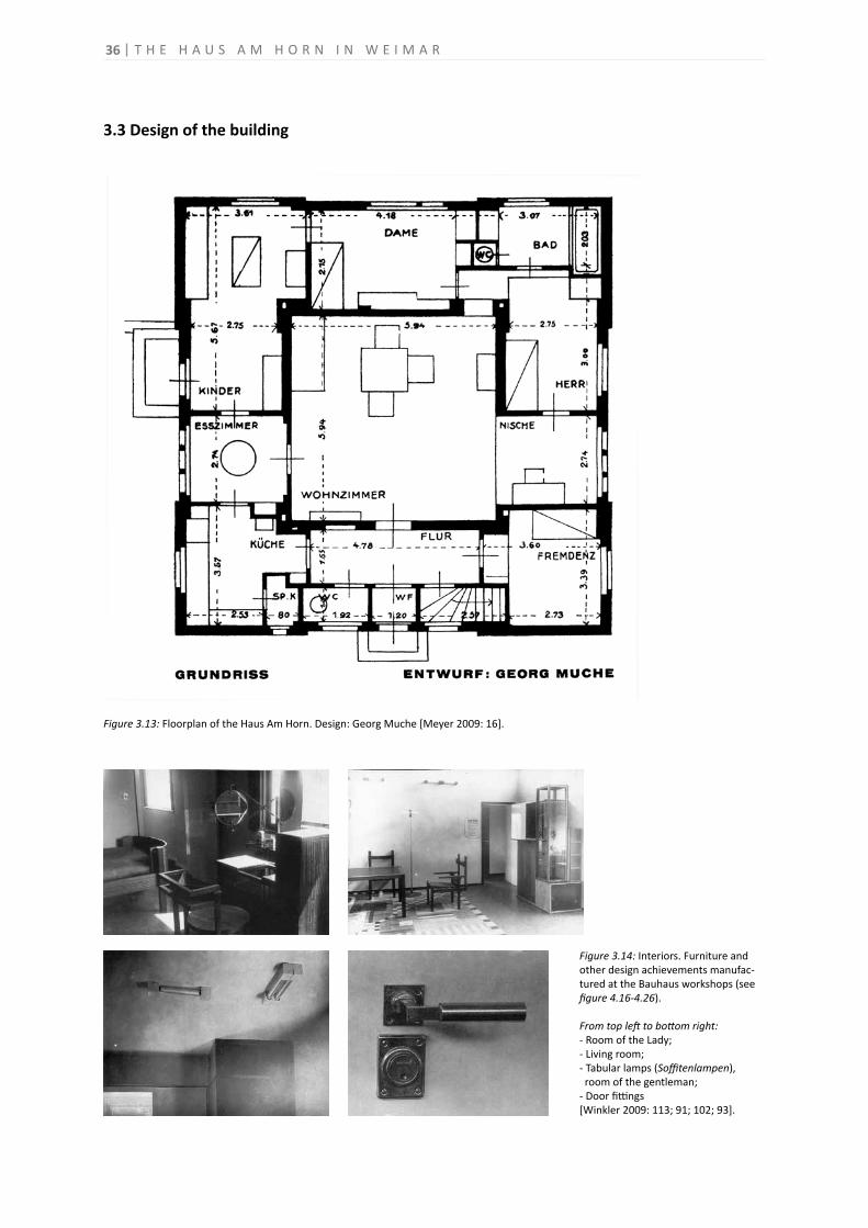
36
3.3 Design of the building
Figure 3.13: Floorplan of the Haus Am Horn. Design: Georg Muche [Meyer 2009: 16].
Figure 3.14: Interiors. Furniture and other design achievements manufac-tured at the Bauhaus workshops (see figure 4.16-4.26).
From top left to bottom right:- Room of the Lady; - Living room;- Tabular lamps (Soffitenlampen), room of the gentleman;- Door fittings[Winkler 2009: 113; 91; 102; 93].
T H E H A U S A M H O R N I N W E I M A R
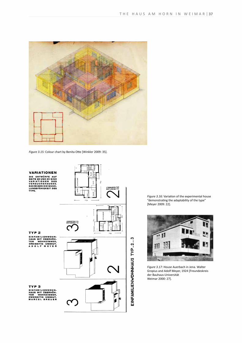
37
Figure 3.15: Colour chart by Benita Otte [Winkler 2009: 35].
Figure 3.16: Variation of the experimental house “demonstrating the adaptability of the type” [Meyer 2009: 22].
Figure 3.17: House Auerbach in Jena. Walter Gropius and Adolf Meyer, 1924 [Freundeskreis der Bauhaus-UniversitätWeimar 2000: 27].
T H E H A U S A M H O R N I N W E I M A R
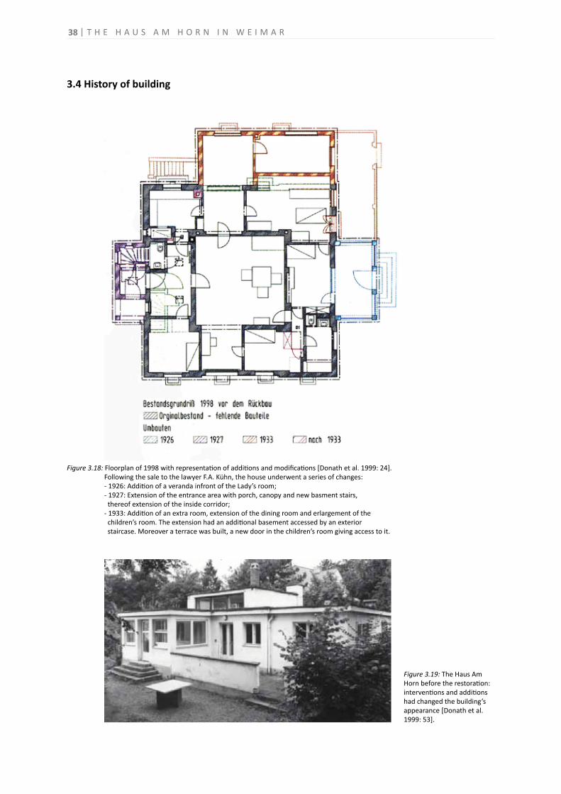
38
3.4 History of building
Figure 3.18: Floorplan of 1998 with representation of additions and modifications [Donath et al. 1999: 24]. Following the sale to the lawyer F.A. Kühn, the house underwent a series of changes: - 1926: Addition of a veranda infront of the Lady’s room; - 1927: Extension of the entrance area with porch, canopy and new basment stairs, thereof extension of the inside corridor; - 1933: Addition of an extra room, extension of the dining room and erlargement of the children’s room. The extension had an additional basement accessed by an exterior staircase. Moreover a terrace was built, a new door in the children’s room giving access to it.
Figure 3.19: The Haus Am Horn before the restoration: interventions and additions had changed the building’s appearance [Donath et al. 1999: 53].
T H E H A U S A M H O R N I N W E I M A R
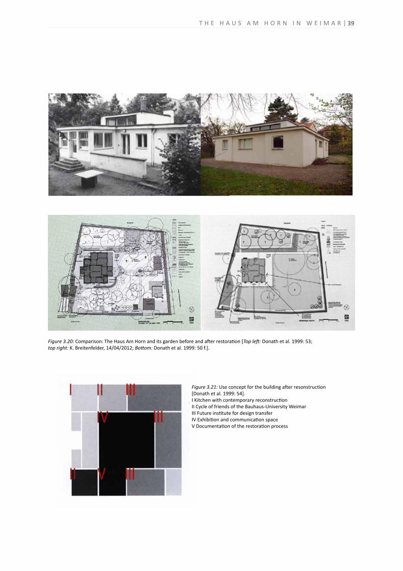
39
Figure 3.21: Use concept for the building after resonstruction[Donath et al. 1999: 54].I Kitchen with contemporary reconstructionII Cycle of friends of the Bauhaus-University WeimarIII Future institute for design transferIV Exhibition and communication spaceV Documentation of the restoration process
Figure 3.20: Comparison: The Haus Am Horn and its garden before and after restoration [Top left: Donath et al. 1999: 53;top right: K. Breitenfelder, 14/04/2012; Bottom: Donath et al. 1999: 50 f.].
T H E H A U S A M H O R N I N W E I M A R
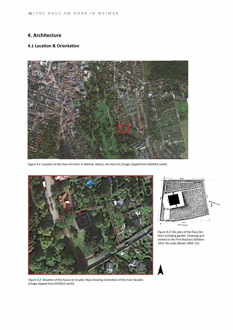
40
4. Architecture
4.1 Location & Orientation
Figure 4.1: Location of the Haus Am Horn in Weimar. Adress: Am Horn 61 [image clipped from GOOGLE earth].
Figure 4.2: Situation of the house on its plot. Map showing orientation of the main facades[image clipped from GOOGLE earth].
Grafiken © 2012 DigitalGlobe, GeoBasis-DE/BKG, GeoContent, GeoEye -
Wenn Sie alle auf dem Bildschirm sichtbarenDetails anzeigen möchten, verwenden Sie
den Link Drucken neben der Karte.
FußMeter
300100
Am Horn
Figure 4.3: Site plan of the Haus AmHorn including garden. Drawings pre-sented on the First Bauhaus Exhition 1923. No scale [Meyer 2009: 21].
T H E H A U S A M H O R N I N W E I M A R
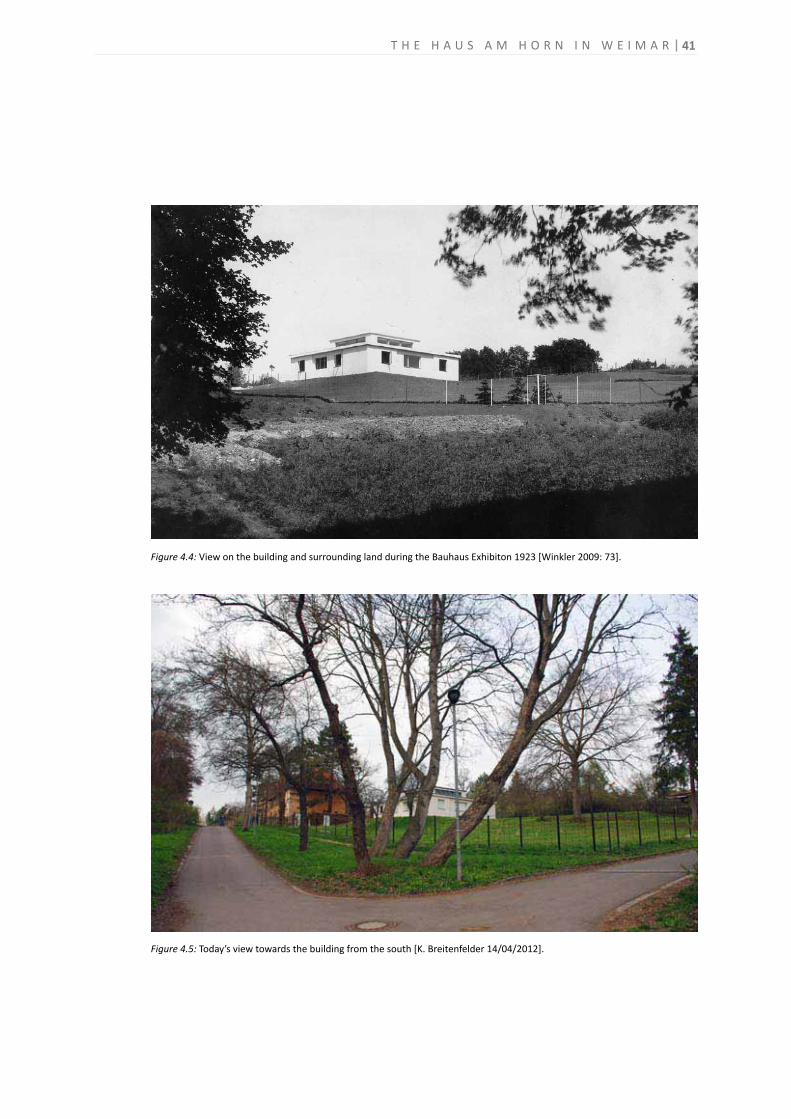
41
Figure 4.4: View on the building and surrounding land during the Bauhaus Exhibiton 1923 [Winkler 2009: 73].
Figure 4.5: Today’s view towards the building from the south [K. Breitenfelder 14/04/2012].
T H E H A U S A M H O R N I N W E I M A R

42
Figure 4.7: Urban development project “Neues Bauen am Horn”. Master plan and images[Masterplan: Bauhaus-Universität Weimar 2005b; images: K. Breitenfelder 14/04/2012].
Mit dem Projekt neues bauenam horn zur Konversion einesehemaligen Kasernengeländesentsteht in Weimar seit 1996ein Quartier, das den hohenAnsprüchen für beispielhafteStadtentwicklung – unter ande-rem als Projekt der expo 2000Hannover – gerecht wird. Als einen weiteren Beitrag zur
Förderung der Baukultur, hat dieLandesentwicklungsgesellschaftThüringen neun namhafte euro-päische Architekturbüros mitMusterplanungen beauftragt.Auf bislang noch freien Parzel-len sollten sie zeigen, wie siesich, ohne die konkreten Vorga-ben eines Bauherren, angemes-sene Wohnkozepte für diesen
Ort vorstellen. In einem dis-kursiven Verfahren, das unterder Leitung von Prof.AdolfKrischanitz, dem Verfasser desBebauungplans, den gegenseiti-gen Austausch vor Ort beinhal-tete, entstanden die folgendenPlanungen, die ein Angebot aninteressierte Bauherren sind.
Neun Musterplanungen
neue
sba
uen
amho
rn
Figure 4.6: View towards the building from the residential road and access to the Ilmpark in the south[K. Breitenfelder 14/04/2012].
T H E H A U S A M H O R N I N W E I M A R
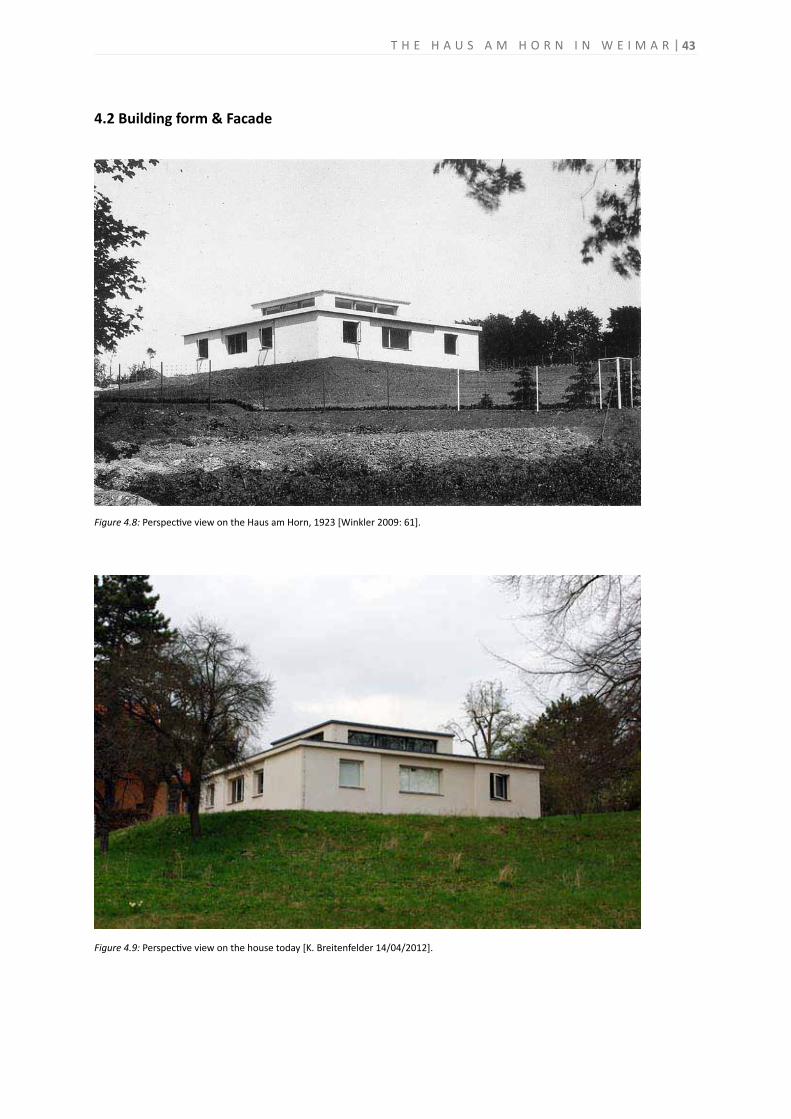
43
4.2 Building form & Facade
Figure 4.8: Perspective view on the Haus am Horn, 1923 [Winkler 2009: 61].
Figure 4.9: Perspective view on the house today [K. Breitenfelder 14/04/2012].
T H E H A U S A M H O R N I N W E I M A R
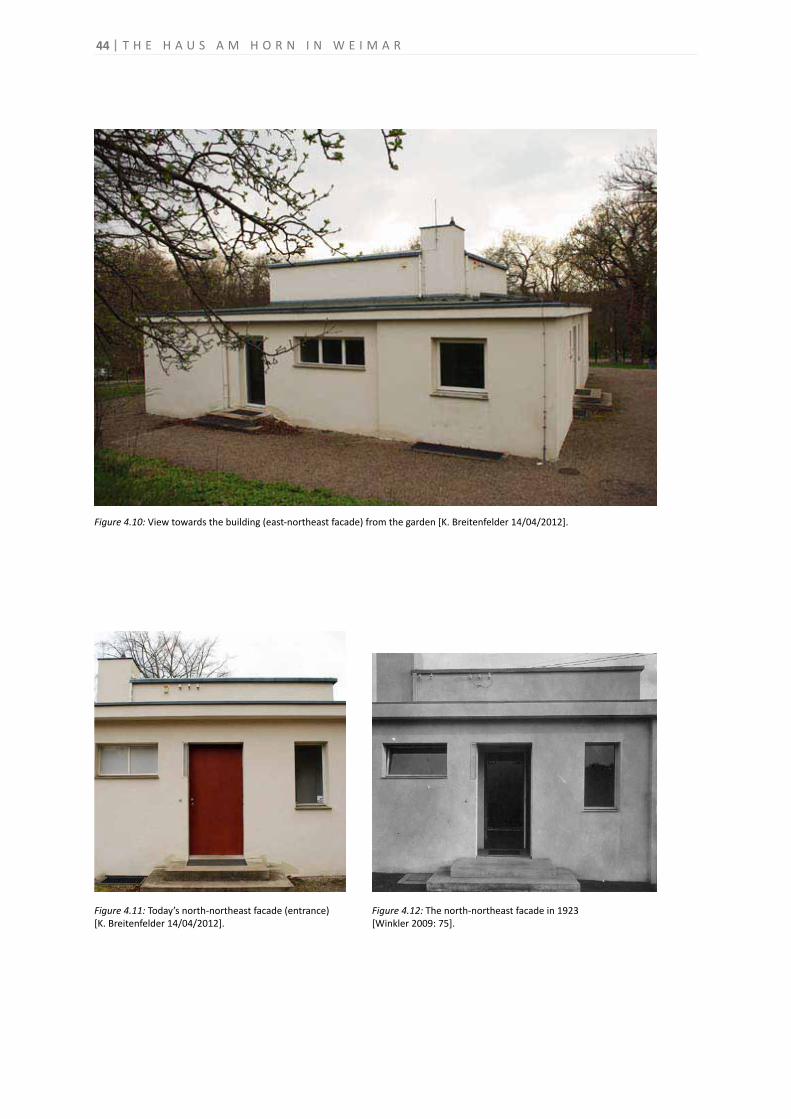
44
Figure 4.11: Today’s north-northeast facade (entrance)[K. Breitenfelder 14/04/2012].
Figure 4.12: The north-northeast facade in 1923[Winkler 2009: 75].
Figure 4.10: View towards the building (east-northeast facade) from the garden [K. Breitenfelder 14/04/2012].
T H E H A U S A M H O R N I N W E I M A R
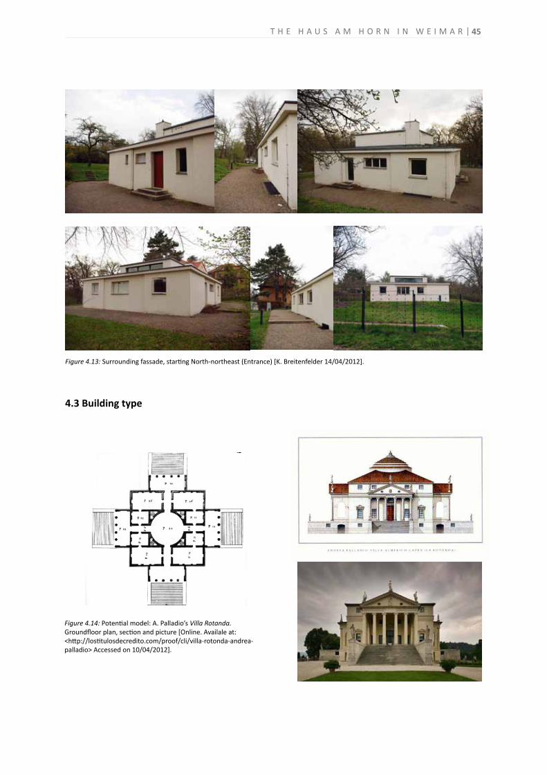
4.3 Building type
Figure 4.14: Potential model: A. Palladio’s Villa Rotanda. Groundfloor plan, section and picture [Online. Availale at: <http://lostitulosdecredito.com/proof/cli/villa-rotonda-andrea-palladio> Accessed on 10/04/2012].
45
Figure 4.13: Surrounding fassade, starting North-northeast (Entrance) [K. Breitenfelder 14/04/2012].
T H E H A U S A M H O R N I N W E I M A R
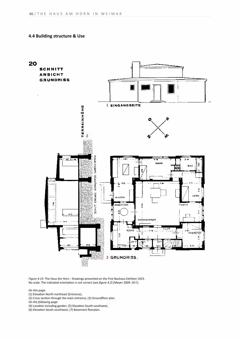
46
4.4 Building structure & Use
Figure 4.15: The Haus Am Horn - Drawings presented on the First Bauhaus Exhition 1923.No scale. The indicated orientation is not correct (see figure 4.2) [Meyer 2009: 20 f.].
On this page:(1) Elevation North-northeast (Entrance),(2) Cross section through the main entrance, (3) Groundfloor plan.On the following page:(4) Location including garden, (5) Elevation South-southwest,(6) Elevation South-southwest, (7) Basement floorplan.
1
3
2
T H E H A U S A M H O R N I N W E I M A R
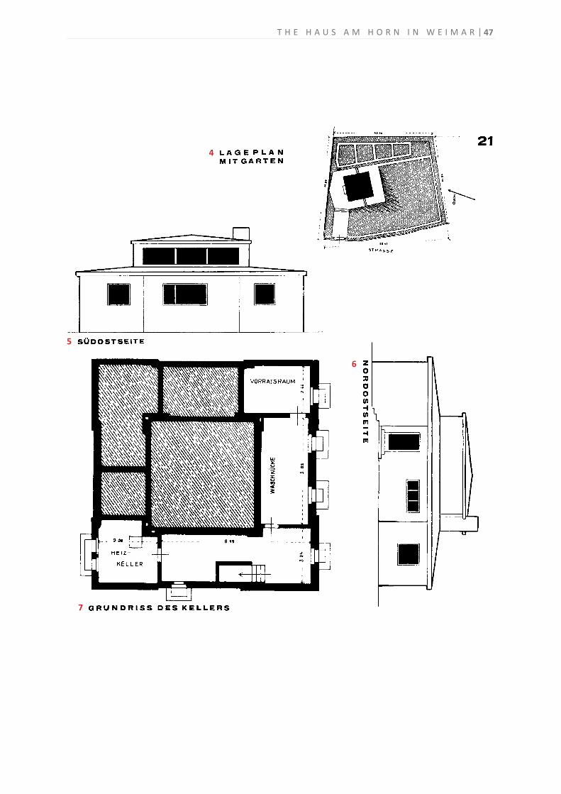
47
4
5
6
7
T H E H A U S A M H O R N I N W E I M A R
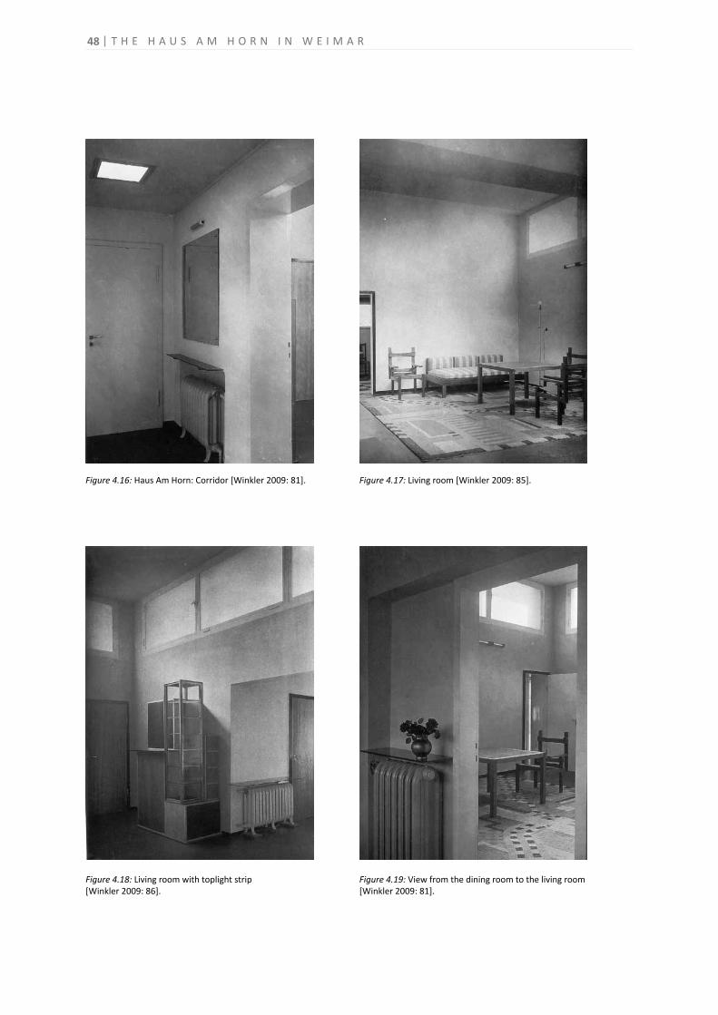
48
Figure 4.16: Haus Am Horn: Corridor [Winkler 2009: 81]. Figure 4.17: Living room [Winkler 2009: 85].
Figure 4.18: Living room with toplight strip[Winkler 2009: 86].
Figure 4.19: View from the dining room to the living room [Winkler 2009: 81].
T H E H A U S A M H O R N I N W E I M A R
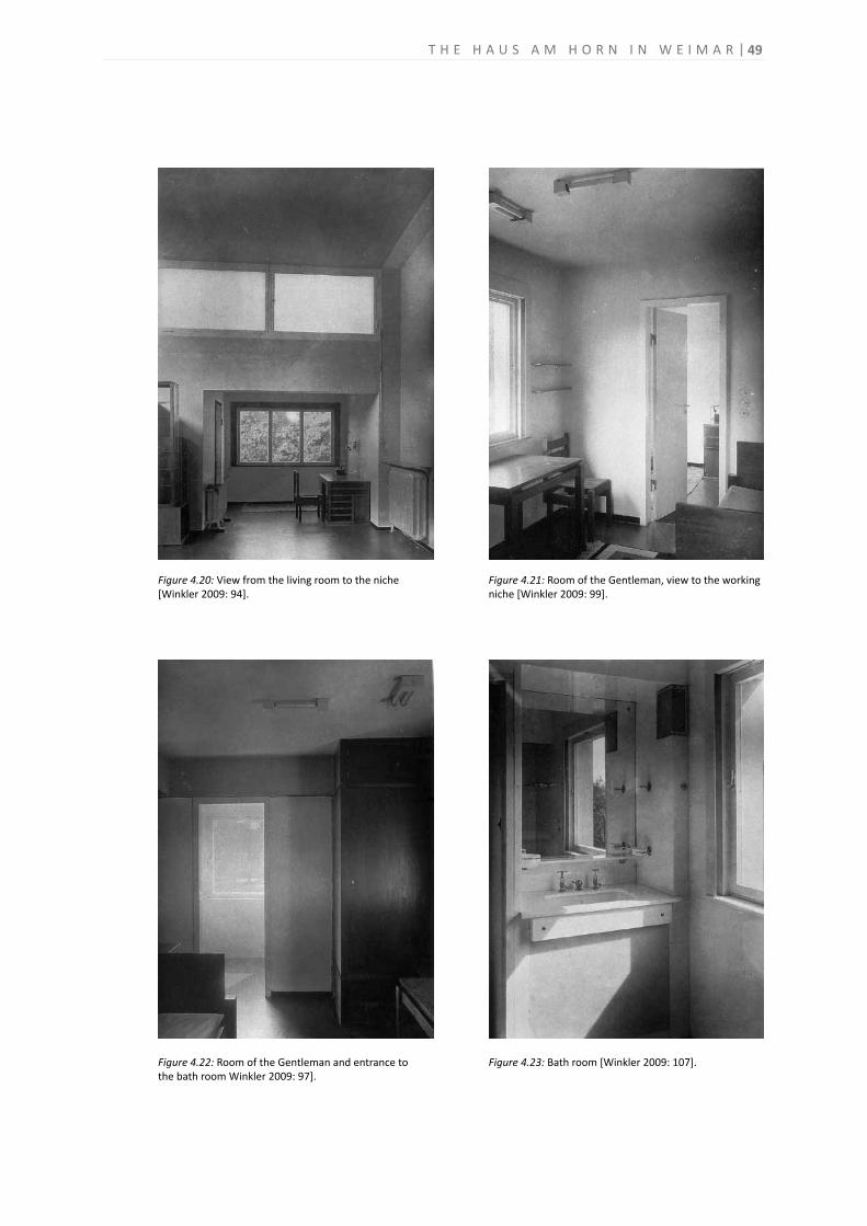
49
Figure 4.20: View from the living room to the niche[Winkler 2009: 94].
Figure 4.21: Room of the Gentleman, view to the working niche [Winkler 2009: 99].
Figure 4.22: Room of the Gentleman and entrance tothe bath room Winkler 2009: 97].
Figure 4.23: Bath room [Winkler 2009: 107].
T H E H A U S A M H O R N I N W E I M A R
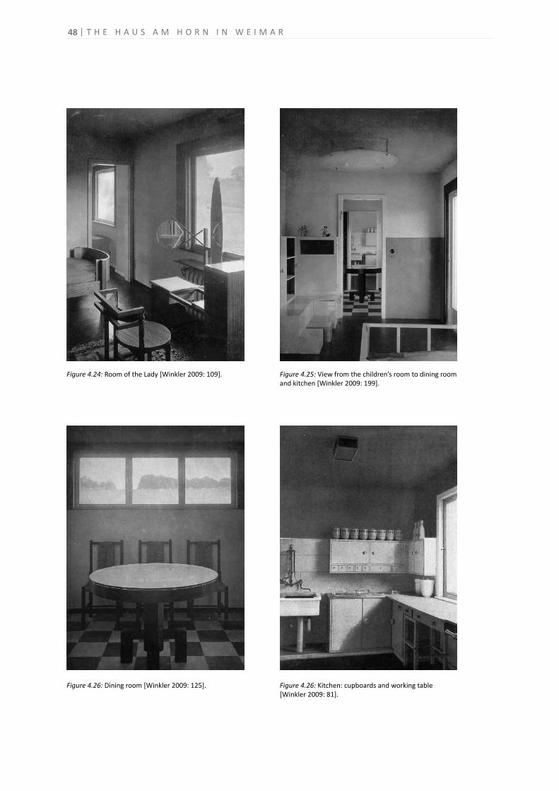
48
Figure 4.24: Room of the Lady [Winkler 2009: 109]. Figure 4.25: View from the children’s room to dining room and kitchen [Winkler 2009: 199].
Figure 4.26: Dining room [Winkler 2009: 125]. Figure 4.26: Kitchen: cupboards and working table[Winkler 2009: 81].
T H E H A U S A M H O R N I N W E I M A R
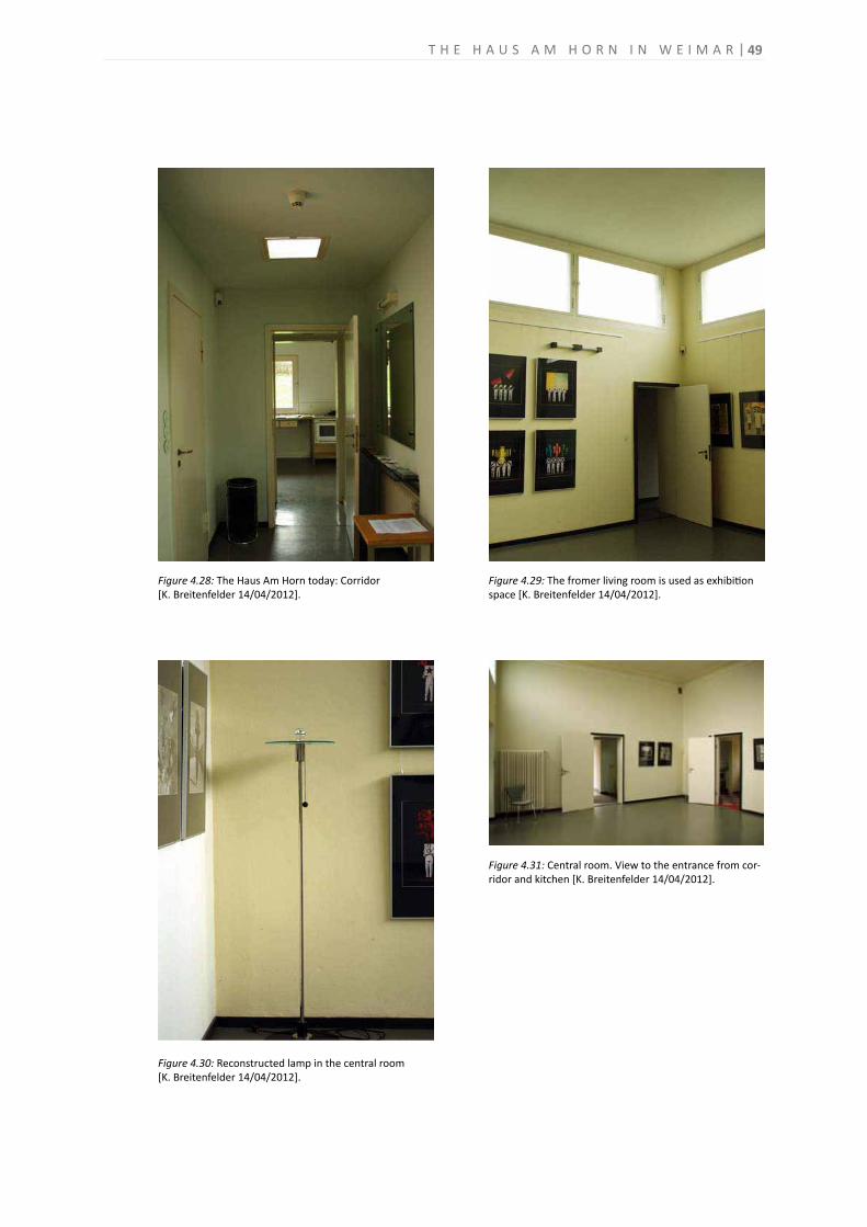
49
Figure 4.28: The Haus Am Horn today: Corridor[K. Breitenfelder 14/04/2012].
Figure 4.29: The fromer living room is used as exhibition space [K. Breitenfelder 14/04/2012].
Figure 4.30: Reconstructed lamp in the central room[K. Breitenfelder 14/04/2012].
Figure 4.31: Central room. View to the entrance from cor-ridor and kitchen [K. Breitenfelder 14/04/2012].
T H E H A U S A M H O R N I N W E I M A R

50
Figure 4.32: View from the central room to the niche[K. Breitenfelder 14/04/2012].
Figure 4.33: Former room of the Gentleman, view to the niche [K. Breitenfelder 14/04/2012].
Figure 4.34: Exhibition in the former room of the Gentle-men [K. Breitenfelder 14/04/2012].
Figure 4.35: The reconstructed bathroom functions todayas museum space [K. Breitenfelder 14/04/2012].
T H E H A U S A M H O R N I N W E I M A R
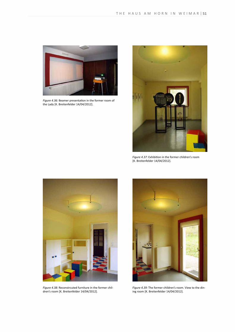
51
Figure 4.36: Beamer presentation in the former room of the Lady [K. Breitenfelder 14/04/2012].
Figure 4.37: Exhibition in the former children’s room[K. Breitenfelder 14/04/2012].
Figure 4.38: Reconstrcuted furniture in the former chil-dren’s room [K. Breitenfelder 14/04/2012].
Figure 4.39: The former children’s room. View to the din-ing room [K. Breitenfelder 14/04/2012].
T H E H A U S A M H O R N I N W E I M A R
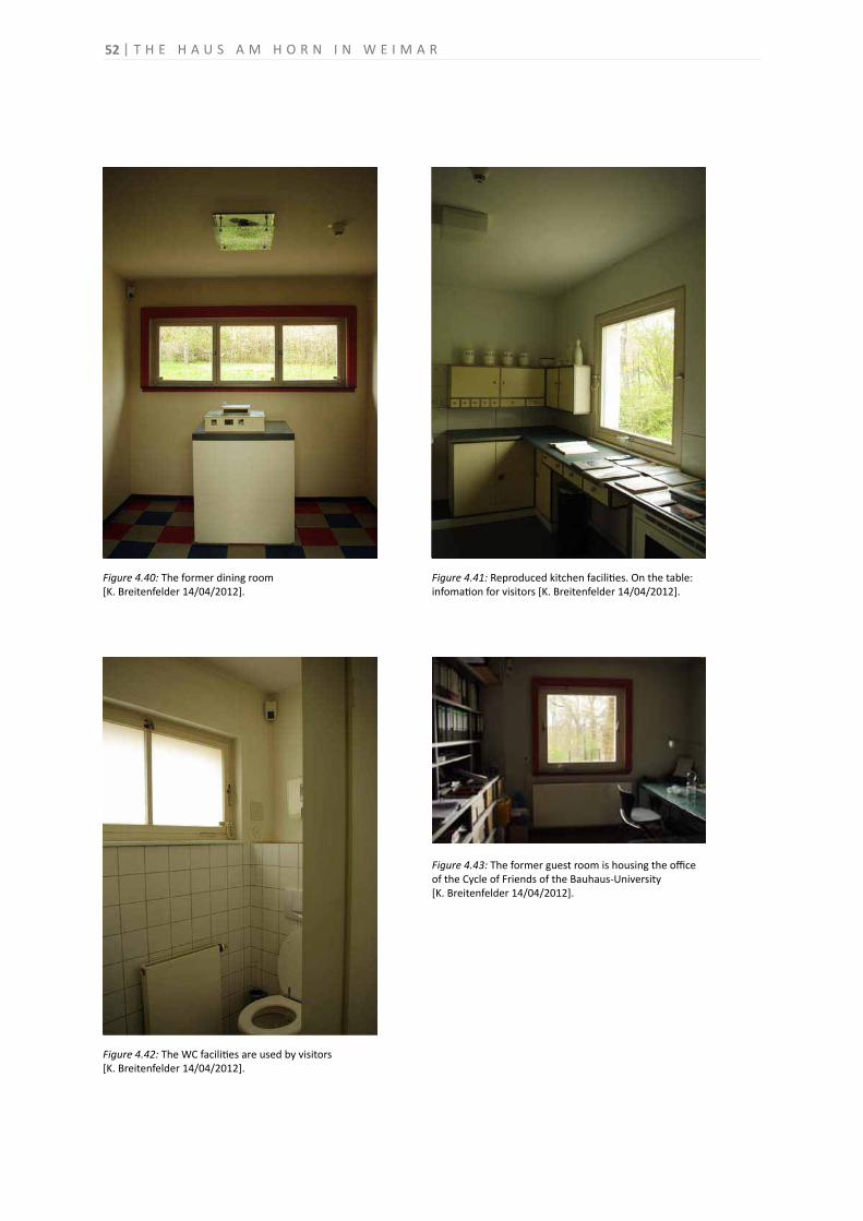
52
Figure 4.40: The former dining room[K. Breitenfelder 14/04/2012].
Figure 4.41: Reproduced kitchen facilities. On the table: infomation for visitors [K. Breitenfelder 14/04/2012].
Figure 4.42: The WC facilities are used by visitors[K. Breitenfelder 14/04/2012].
Figure 4.43: The former guest room is housing the office of the Cycle of Friends of the Bauhaus-University[K. Breitenfelder 14/04/2012].
T H E H A U S A M H O R N I N W E I M A R
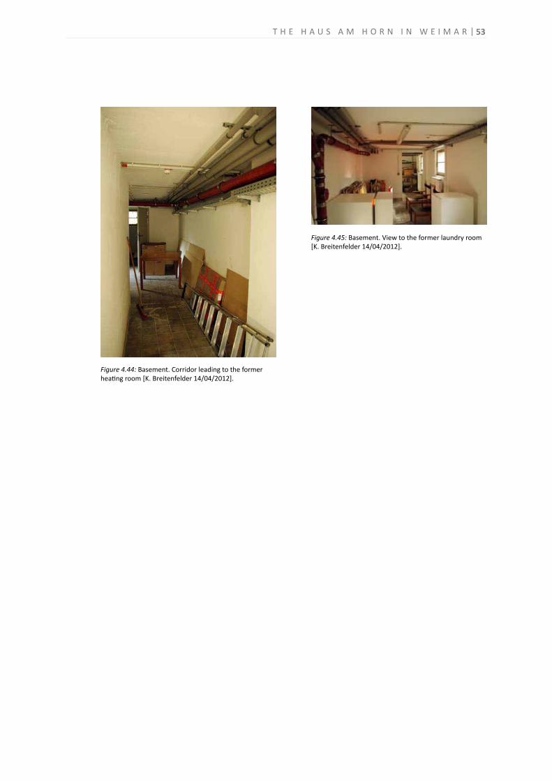
53
Figure 4.44: Basement. Corridor leading to the former heating room [K. Breitenfelder 14/04/2012].
Figure 4.45: Basement. View to the former laundry room[K. Breitenfelder 14/04/2012].
T H E H A U S A M H O R N I N W E I M A R
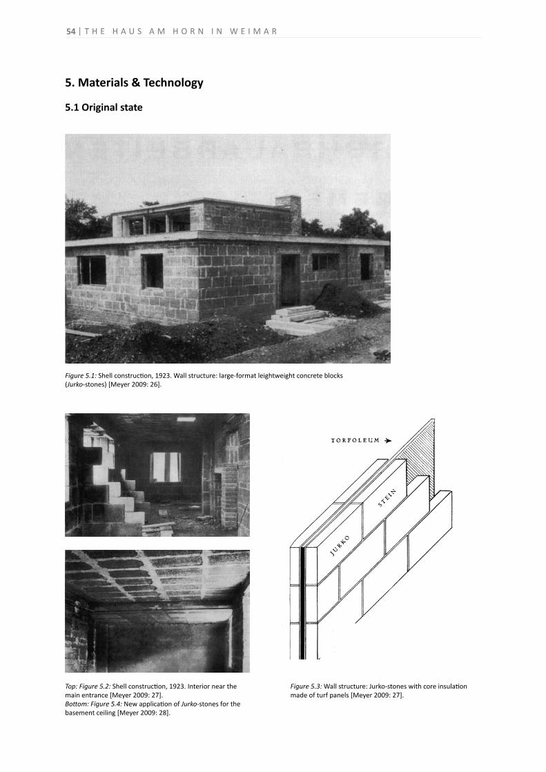
54
5. Materials & Technology
5.1 Original state
Top: Figure 5.2: Shell construction, 1923. Interior near the main entrance [Meyer 2009: 27].Bottom: Figure 5.4: New application of Jurko-stones for the basement ceiling [Meyer 2009: 28].
Figure 5.1: Shell construction, 1923. Wall structure: large-format leightweight concrete blocks(Jurko-stones) [Meyer 2009: 26].
Figure 5.3: Wall structure: Jurko-stones with core insulation made of turf panels [Meyer 2009: 27].
T H E H A U S A M H O R N I N W E I M A R
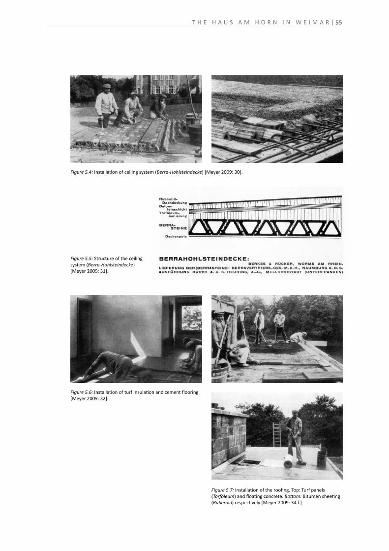
55
Figure 5.4: Installation of ceiling system (Berra-Hohlsteindecke) [Meyer 2009: 30].
Figure 5.6: Installation of turf insulation and cement flooring [Meyer 2009: 32].
Figure 5.5: Structure of the ceiling system (Berra-Hohlsteindecke)[Meyer 2009: 31].
Figure 5.7: Installation of the roofing. Top: Turf panels (Torfoleum) and floating concrete. Bottom: Bitumen sheeting (Ruberoid) respectively [Meyer 2009: 34 f.].
T H E H A U S A M H O R N I N W E I M A R
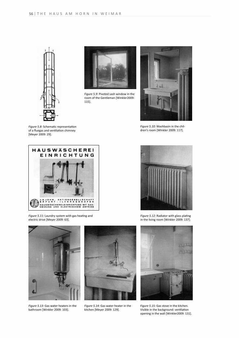
Figure 5.8: Schematic representation of a fluegas and ventilation chimney [Meyer 2009: 29].
Figure 5.13: Gas water heaters in the bathroom [Winkler 2009: 103].
Figure 5.12: Radiator with glass plating in the living room [Winkler 2009: 137].
Figure 5.9: Pivoted sash window in the room of the Gentleman [Winkler2009: 115].
Figure 5.14: Gas water heater in the kitchen [Meyer 2009: 129].
Figure 5.15: Gas stove in the kitchen. Visible in the background: ventilation opening in the wall [Winkler2009: 131].
Figure 5.11: Laundry system with gas heating and electric drive [Meyer 2009: 63].
Figure 5.10: Washbasin in the chil-dren’s room [WInkler 2009: 117].
56 T H E H A U S A M H O R N I N W E I M A R
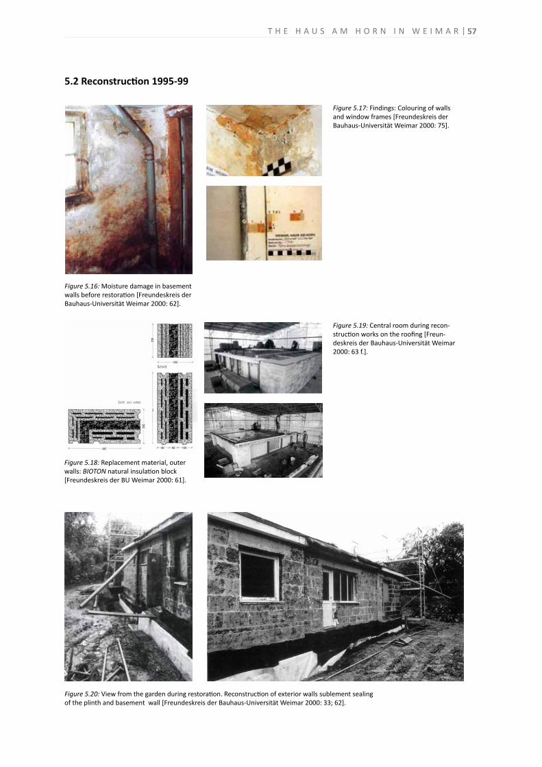
5.2 Reconstruction 1995-99
Figure 5.19: Central room during recon-struction works on the roofing [Freun-deskreis der Bauhaus-Universität Weimar 2000: 63 f.].
Figure 5.16: Moisture damage in basement walls before restoration [Freundeskreis der Bauhaus-Universität Weimar 2000: 62].
Figure 5.20: View from the garden during restoration. Reconstruction of exterior walls sublement sealingof the plinth and basement wall [Freundeskreis der Bauhaus-Universität Weimar 2000: 33; 62].
Figure 5.17: Findings: Colouring of walls and window frames [Freundeskreis der Bauhaus-Universität Weimar 2000: 75].
Figure 5.18: Replacement material, outer walls: BIOTON natural insulation block [Freundeskreis der BU Weimar 2000: 61].
57T H E H A U S A M H O R N I N W E I M A R
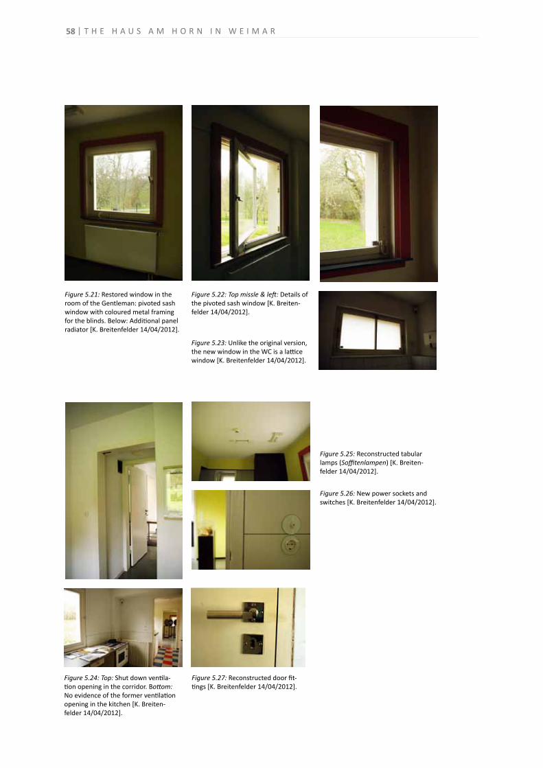
Figure 5.21: Restored window in the room of the Gentleman: pivoted sash window with coloured metal framing for the blinds. Below: Additional panel radiator [K. Breitenfelder 14/04/2012].
Figure 5.24: Top: Shut down ventila-tion opening in the corridor. Bottom: No evidence of the former ventilation opening in the kitchen [K. Breiten-felder 14/04/2012].
Figure 5.26: New power sockets and switches [K. Breitenfelder 14/04/2012].
Figure 5.23: Unlike the original version, the new window in the WC is a lattice window [K. Breitenfelder 14/04/2012].
Figure 5.27: Reconstructed door fit-tings [K. Breitenfelder 14/04/2012].
Figure 5.25: Reconstructed tabular lamps (Soffitenlampen) [K. Breiten-felder 14/04/2012].
Figure 5.22: Top missle & left: Details of the pivoted sash window [K. Breiten-felder 14/04/2012].
58 T H E H A U S A M H O R N I N W E I M A R
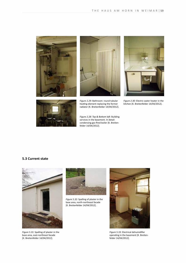
5.3 Current state
Figure 2.28: Top & Bottom left: Building services in the basement. In detail: condensing gas-fired boiler [K. Breiten-felder 14/04/2012].
Figure 2.29: Bathroom: round tubular heating element replacing the former radiator [K. Breitenfelder 14/04/2012].
Figure 2.30: Electric water heater in the kitchen [K. Breitenfelder 14/04/2012].
Figure 5.31: Spalling of plaster in the base area, east-northeast facade[K. Breitenfelder 14/04/2012].
Figure 5.32: Spalling of plaster in the base area, north-northeast facade[K. Breitenfelder 14/04/2012].
Figure 5.33: Electrical dehumidifier operating in the basement [K. Breiten-felder 14/04/2012].
59T H E H A U S A M H O R N I N W E I M A R
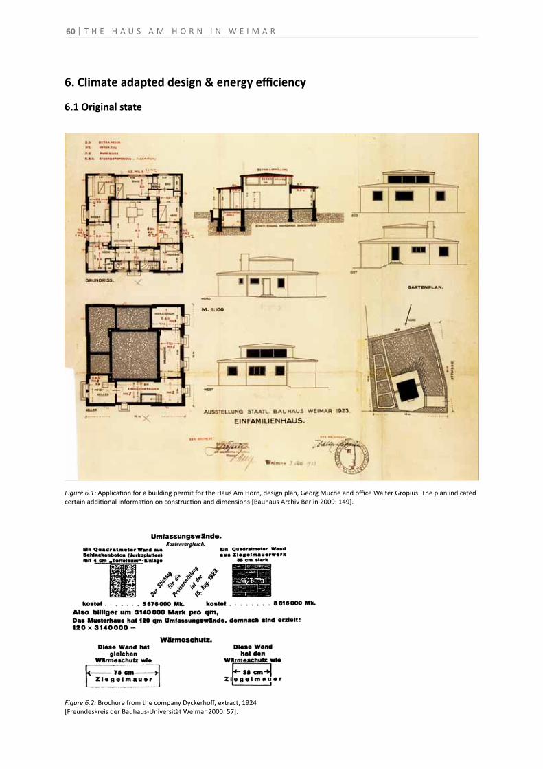
6. Climate adapted design & energy efficiency
6.1 Original state
Figure 6.1: Application for a building permit for the Haus Am Horn, design plan, Georg Muche and office Walter Gropius. The plan indicated certain additional information on construction and dimensions [Bauhaus Archiv Berlin 2009: 149].
Figure 6.2: Brochure from the company Dyckerhoff, extract, 1924[Freundeskreis der Bauhaus-Universität Weimar 2000: 57].
60 T H E H A U S A M H O R N I N W E I M A R
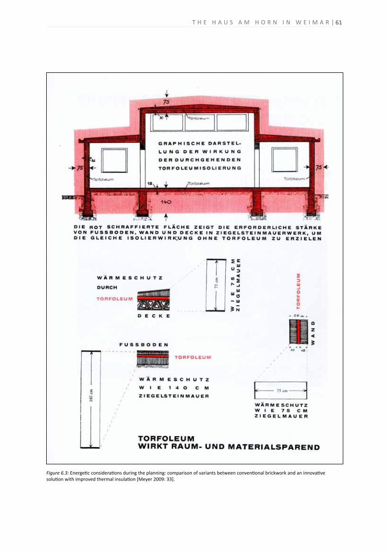
Figure 6.3: Energetic considerations during the planning: comparison of variants between conventional brickwork and an innovativesolution with improved thermal insulation [Meyer 2009: 33].
61T H E H A U S A M H O R N I N W E I M A R
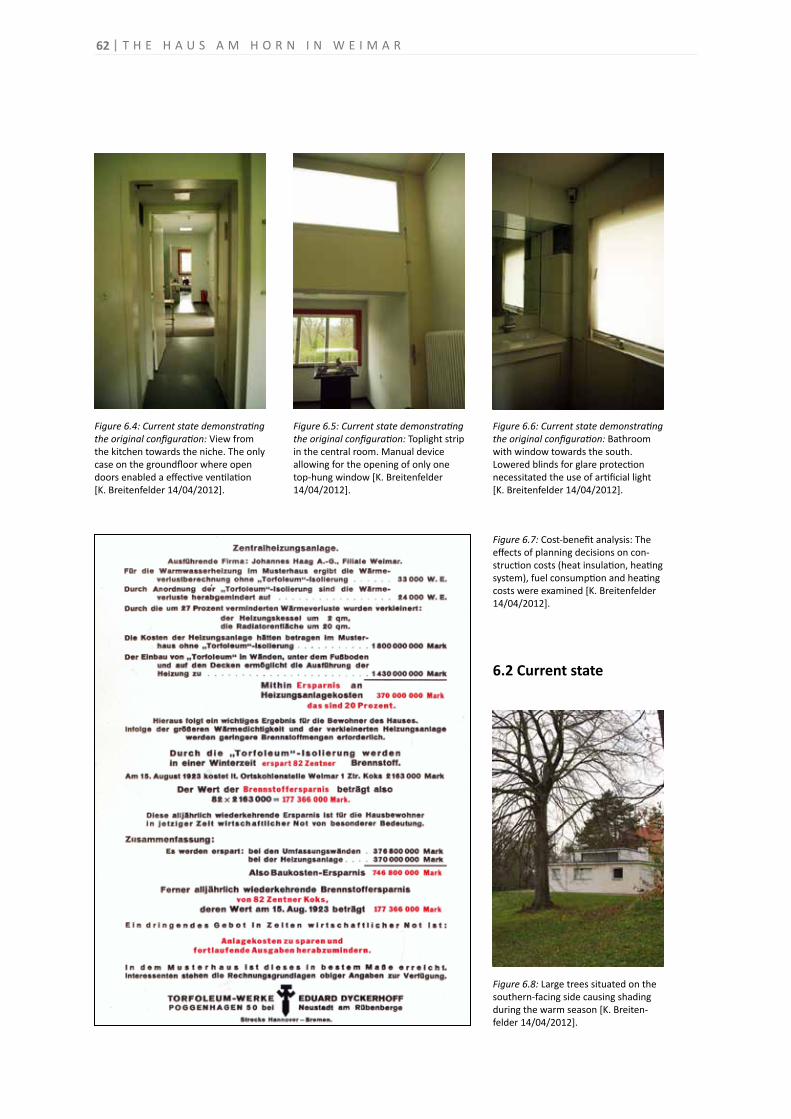
Figure 6.4: Current state demonstrating the original configuration: View from the kitchen towards the niche. The only case on the groundfloor where open doors enabled a effective ventilation[K. Breitenfelder 14/04/2012].
Figure 6.6: Current state demonstrating the original configuration: Bathroom with window towards the south.Lowered blinds for glare protection necessitated the use of artificial light[K. Breitenfelder 14/04/2012].
Figure 6.8: Large trees situated on the southern-facing side causing shading during the warm season [K. Breiten-felder 14/04/2012].
Figure 6.5: Current state demonstrating the original configuration: Toplight strip in the central room. Manual device allowing for the opening of only one top-hung window [K. Breitenfelder 14/04/2012].
6.2 Current state
Figure 6.7: Cost-benefit analysis: The effects of planning decisions on con-struction costs (heat insulation, heating system), fuel consumption and heating costs were examined [K. Breitenfelder 14/04/2012].
62 T H E H A U S A M H O R N I N W E I M A R

T H E H A U S A M H O R N I N W E I M A R 63
BIBIOGRAPHY
64 | H A U S A M H O R N I N W E I M A R
Theoretical background
Publications American Society of Heating, Refrigerating and Air Conditioning Engineers (ASHRAE), 2009. ASHRAE Handbook. Vol. 1, Fundamentals. Atlanta: ASHRAE. Bridgwood, Barry; Lennie, Lindsay, 2009. History, Performance and Conservation. London / New York: Taylor & Francis. Chartered Institution of Building Services Engineers (CIBSE), 2002. Guide to Building Services for Historic Buildings: Sustainable Services for Traditional Buildings. London: CIBSE. Cunningham, Allen, 1998. Modern Movement Heritage. 1998. London / New York: E & FN SPON. Dahl, Torben ed., 2010. Climate and Architecture. Abingdon, Oxon / New York: Routledge. Diesendorf, Mark, 2007. Greenhouse Solutions with Sustainable Energy. UNSW Press. English Heritage ed., 2008. Energy Conservation in Traditional Buildings. London: English Heritage. Givone, Barach ed., 1998. Climate Considerations in Building and Urban Design. New York: Van Norstrank Reinhold. Jokilhto, Jukka, 1999. A History of Architectural Conservation. Oxford: Butterworth-Heinemann. Lefèvre, Roger-Alexandre ed., 2010. Climate change and cultural heritage. Proceedings of the Ravello International Workshop, 14 - 16 May 2009 and Strasbourg European master-doctorate course, 7-11 September 2009. Bari: Edipuglia. Prudon, Theodore H. M. 2008. Preservation of modern architecture. Hoboken, NJ: Wiley. Petzet, Michael, 2009. International Principles of Preservation. International Council on Monuments and Sites (ICOMOS) ed. Berlin: Bäßler Verlag. Stein, Karl, 2010. Greening Modernism. New York/London: W.W. Norton & Company. Thumann, A.; Younger, W. J., 2008. Handbook of Energy Audits. 7th ed. Lilburn: The Fairmont Press. Willkomm, Wolfgang, 1985. Construction suited to the Climatic Conditions. In: Weber, H., 1985. International Construction Systems. Springe: Bison-Werke Bahre & Greten GmbH, p. 11-123.
Electronic sources Ahmad, Yahaya, 2006. The Scope and Definitions of Heritage: From Tangible to Intangible. In: International Journal of Heritage Studies. Vol. 12, No. 3, May 2006. London: Routledge, p. 292–300. [online] Available at: < http://www.sonoma.edu/users/p/purser/Anth590/intang1.pdf> [Accessed 5 January 2012].
T H E H A U S A M H O R N I N W E I M A R | 65
Balderstone, Susan, 2004. Built Heritage: A Major Contributor to Environmental, Social and Economic Sustainability. Sustainability Discussion Paper, March 2004. [online] Available at: < http://www.heritage.vic. gov.au/pages/pdfs/sustainable.pdf> [Accessed 7 January 2012]. Byström, Sara, 2010. From the 2002 to the 2010 European directive. In: Heritage: A Model for Sustainable Development. Proceedings of the European Symposium, 4-10 October 2010, Paris: ICOMOS France, Euromed Heritage, p.44. [online] Available at: <http://www.euromedheritage.net/intern.cfm?menuID=16&submenuID= 20&subsubmenuID=24> [Accessed 5 January 2012]. Deutsche Energie-Agentur (dena), 2012. Energy Performance Certificate for Buildings. Information about the activities of the German Energy Agency. [online] Available at: <http://www.zukunft-haus.info/fileadmin/ zukunft-haus/energieausweis/Aktuelle_Projektinformation_Energieausweis_dena_ENGLISCH.pdf> [Accessed 4 April 2012]. Göhner, W. K., 2011. The impact of EU Legislation on Cultural Heritage - Observatory Function of EHLF and implementation in the Federal Republic of Germany. Presentation on the International conference “Energy Management in Cultural Heritage”, 6-8 April 2011, Dubrovnic. [online] Available at: <http://www.dnk.de/ Im_Fokus/n2372?node_id=2372&from_node=2402&beitrag_id=810> [Accessed 14 December 2011]. Goven, François, 2010. The necessity of a cultural approach. In: Heritage: A Model for Sustainable Development. Proceedings of the European Symposium, 4-10 October 2010, Paris: ICOMOS France, Euromed Heritage, p.20. [online] Available at: <http://www.euromedheritage.net/intern.cfm?menuID= 16&submenuID=20&subsubmenuID=24> [Accessed 5 January 2012]. ICOMOS France, Euromed Heritage eds., 2010. Heritage: A Model for Sustainable Development. Proceedings of the European Symposium, 4-10 October 2010, Paris. [online] Available at: <http://www.euromedheritage.net/ intern.cfm?menuID=16&submenuID=20&subsubmenuID=24> [Accessed 5 January 2012]. International Energy Agency (IEA) ed., 2010a. Advanced and Sustainable Housing Renovation. [online] Available at: <http://www.iea-shc.org/publications/downloads/Advanced_and_Sustainable_Housing_Renovation.pdf> [Accessed 10 April 2009]. International Energy Agency (IEA) ed., 2010b. Energy performance certification of buildings. A policy to improve energy efficiency. [online] Available at: <http://www.iea.org/papers/pathways/buildings_certification.pdf> [Accessed 10 April 2009]. Jokilehto, Jukka, 2000. Continuity and change in recent heritage. In: Identification and Documentation of Modern Heritage, World Heritage Paper 5, 2000, Paris: UNESCO World Heritage Centre, p. 102-109. [online] Available at: <http://whc.unesco.org/uploads/activities/documents/activity-38-1.pdf> [Accessed 6 April 2012]. Rosenlund, Hans, 2000. Climatic Design of Buildings using Passive Techniques. Building Issues, Vol. 10. Lund: Lund University Press. [online] Available at: <http://sheltercentre.org/sites/default/files/Climatic_Design_of_ Buildings_using_Passive_Techniques.pdf> [Accessed 10 April 2012]. Rowe, David, 2008. Heritage Buildings and Sustainability. Melbourne: Heritage Council of Victoria. [online] Available at: <http://www.dpcd.vic.gov.au/__data/assets/pdf_file/0003/44859/Sustainability_Heritage_tech_-leaflet.pdf> [Accessed 10 April 2012].
66 | H A U S A M H O R N I N W E I M A R
Rypkema, Donavan D., 2006. Economics, Sustainabilty, and Historic Preservation. In: Forum Journal, Winter 2006, vol.20, no.2, Washington D.C: National Trust for Historic Preservation. Excerpted in: Preservation Seattle: Historic Seattle’s online monthly preservation magazine. [online] Available at: <http://historicseattle.org/ preservationseattle/publicpolicy/defaultSEPT06.htm> [Accessed 4 April 2011]. Schütze, Thorsten; Willkomm, Wolfgang, 2000. Klimagerechtes Bauen in Europa. Planungsinstrumente für klimagerechte, energiesparende Gebäudekonzepte in verschiedenen europäischen Klimazonen. Hamburg: Fachhochschule Hamburg. [online] Available at: <http://www.staedtebauliche-klimafibel.de/pdf/Klimag-B-EU-2000.pdf> [Accessed 4 April 2012]. UNESCO World Heritage Centre ed., 2003. Identification and Documentation of Modern Heritage. World Heritage Paper 5. Paris. [online] Available at: <http://whc.unesco.org/uploads/activities/documents/activity-38-1.pdf> [Accessed 6 April 2012]. UNDP-EE, 2011. International conference Energy Management in Cultural Heritage. Conference summary. [online] Available at: <http://www.ee.undp.hr/attachments/438__programme%20summary%2031%203% 202011.pdf> [Accessed 14 December 2011].
German legislation
Bundesministerium der Justiz, 2009. Gesetz zur Einsparung von Energie in Gebäuden (Energieeinsparungsgesetz - EnEG). (revision March 2009) [online] Available at: <http://www.energieeffizienz-online.info/fileadmin/edl-richtlinie/Downloads/Energieeffizienzstandards/Gesetze/N_G/N-G_Energieeinsparungsgesetz_in_Gebaeuden __2005_.pdf> [Accessed 4 April 2012]. Bundesministerium der Justiz, 2009. Verordnung über energiesparenden Wärmeschutz und energiesparende Anlagentechnik bei Gebäuden (Energieeinsparverordnung - EnEV). (revision 2009) [online] Available at: <http://www.gesetze-im-internet.de/bundesrecht/enev_2007/gesamt.pdf> [Accessed 4 April 2012]. Thüringer Ministerium für Bildung, Wissenschaft und Kultur, 2012. Thüringer Gesetz zur Pflege und zum Schutz der Kulturdenkmale (Thüringer Denkmalschutzgesetz - ThürDSchG ). (revision December 2007) [online] Available at: <http://www.thueringen.de/de/tmbwk/kulturportal/denkmalpflege_archaeologie_ kulturgutschutz/denkmalschutzgesetz/content.html> [Accessed 4 April 2012].
European community legislation Directive 2002/91/EU of the European Parliament and of the Council of 19 May 2010 on the energy performance of buildings. In: Official Journal of the European Union, L 1, Vol. 46, 4 January 2003, p. 65-71 [online] Available at: <http://eur-lex.europa.eu/LexUriServ/LexUriServ.do?uri=OJ:L:2003:001:0065:0065: EN:PDF> [Accessed 4 April 2012]. Directive 2010/31/EU of the European Parliament and of the Council of 19 May 2010 on the energy performance of buildings (recast). In: Official Journal of the European Union, L 153, Vol. 53, 18 June 2010, p. 13-35. [online] Available at: <http://www.buildup.eu/publications/9631> [Accessed 4 April 2012].
T H E H A U S A M H O R N I N W E I M A R | 67
Conventions, charters and related documents ICOMOS ISC 20C, 2011. Approaches for the Conservation of Twentieth-Century Architectural Heritage, Madrid Document 2011. Madrid. [online] Available at: <http://icomos-isc20c.org/sitebuildercontent/sitebuilderfiles/ madriddocumentenglish.pdf> [Accessed 6 April 2012]. Lemaire, Raymond, and Stovel, Herb eds., 1994. The Nara Document on Authenticity. Nara, Japan. [online] Available at: <http://whc.unesco.org/uploads/events/documents/event-833-3.pdf> [Accessed 5 January 2012]. ICOMOS-Australia, 1999. The Australia ICOMOS Charter for Places of Cultural Significance (the Burra Charter). (revision November 1999) [online] Available at: <http://australia.icomos.org/wp-content/uploads/BURRA_ CHARTER.pdf> [Accessed 5 January 2012]. ICOMOS, 1964. International Charter for the Conservation and Restoration of Monuments and Sites (the Venice Charter). Paris. [online] Available at: <http://www.icomos.org/charters/venice_e.pdf> [Accessed 5 January 2012]. UNESCO, 1972. Convention concerning the Protection of World Cultural and Natural Heritage. Paris. [online] Available at: <http://whc.unesco.org/archive/convention-en.pdf> [Accessed 14 December 2011].
The Haus Am Horn & The State Bauhaus
Publications Bauhaus Archiv Berlin, ed., 2009. Bauhaus: a conceptual model. Book to the exhibition Bauhaus: A Conceptual Model, 22 July - 4 October 2009, Berlin, Bauhaus Archiv Berlin, Stiftung Bauhaus Dessau, Klassik Stiftung Weimar. Ostfildern: Hatje Cantz'. Donath, Heiko et al., 1999. Das Haus „Am Horn“. Denkmalpflegerische Sanierung und Zukunft des Weltkulturerbes der UNESCO in Weimar. Frankfurt am Main: Sparkassen-Kulturstiftung Hessen-Thüringen. Haspel, Jörg, ed. 2008. Welterbestätten des 20. Jahrhunderts: Defizite und Risiken aus europäischer Sicht. Internationale Fachtagung des Deutschen Nationalkomitees von ICOMOS, Berlin, 9. - 12. September 2007. Petersberg: Imhof. Frampton, Kenneth, 2007. Modern architecture, a critical history. 4th ed.London: Thames & Hudson Ltd. Freundeskreis der Bauhaus-Universität Weimar e.V. ed., 2000. Haus Am Horn. Rekonstruktion einer Utopie. Weimar: Bauhaus-Universität Weimar. Matz, Stefan, 2001. (Un)geliebtes Muster - neue Einsichten zum Haus Am Horn. Weimar: VDG. Meyer, Adolf, 2009. Bauhausbücher 3: Ein Versuchshaus des Bauhauses in Weimar. 5th unchanged reprint of the 1st ed. 1924. Weimar: Bauhaus-Universität Weimar. Siebenbrodt, Michael, 2007. Das Haus am Horn in Weimar - Bauhausstätte und Weltkulturerbe: Bau, Nutzung und Denkmalpflege. In: Haspel, J. et al. eds. Heritage at Risk - Special Edition 2006: The Soviet Heritage and European Modernism. Berlin: Henrik Bäßler Verlag, pp.112-118.
68 | H A U S A M H O R N I N W E I M A R
Sharp, Dennis ed., 2000. The modern movement in architecture: selections from the DOCOMOMO registers. Rotterdam: DOCMOMO. Wingler Hans M., 2002. Das Bauhaus: 1919-1933; Weimar, Dessau, Berlin und die Nachfolge in Chicago seit 1937. 4th ed. Köln: DuMont. Winkler, Klaus-Jürgen, 1993. Die Architektur am Bauhaus in Weimar. Berlin: Verlag für Bauwesen. Winkler, Klaus-Jürgen ed., 2009. Bauhaus-Alben 4. Bauhausausstellung 1923, Haus am Horn, Architektur, Bühnenwerkstatt, Druckerei. Weimar: Bauhaus-Universität Weimar. Wolsdorff, Christian, 1980. Georg Muche als Architekt. In: Georg Muche. Das künstlerische Werk 1912-1927, Berlin: Bauhaus-Archiv, 1980, p. 24-30. Wünsche, Konrad, 1997. Bauhaus. Versuche das Leben zu ordnen. Berlin: Wagenbach Klaus GmbH. Markgraf, Monika ed., 2006. Archäologie der Moderne. Sanierung Bauhaus Dessau. Berlin: Jovis Verlag.
Electronic sources Bauhaus-Universität Weimar, 2005a. Neues Bauen Am Horn. [online] Available at: http://www.uni-weimar.de/horn/> [Accessed 3 March 2009]. Bauhaus-Universität Weimar, 2005b. Neues Bauen Am Horn. Neun Musterplanungen. [online] Available at: <http://www.uni-weimar.de/horn/download/Musterplanungen_horn.pdf> [Accessed 3 March 2009]. Deutsche UNESCO-Kommission e.V., 2012. Das Bauhaus und seine Stätten in Weimar und Dessau. [online] Available at: <http://www.unesco.de/311.html> [Accessed 5 January 2012]. Sparkassen Finanzgruppe, 2001: Eine Reise durch das Haus Am Horn. [online] Available at: <http://www.hausamhorn.de> [Accessed 5 January 2012]. Stadt Dessau-Rosslau, Dessau Master’s Houses, 2012. Georg Muche. [online] The Dessau Master’s Houses. Available at: <http://www.meisterhaeuser.de/en/master_Georg_Muche.html> [Accessed 3 March 2012]. Stiftung Bauhaus Dessau, 2012a. The Steel House by Georg Muche and Richard Paulick. [online] Available at: <http://www.bauhaus-dessau.de/index.php?The-steel-house-by-georg-muche-and-richard-paulick> [Accessed 25 May 2012]. Stiftung Bauhaus Dessau, 2012b. Törten Estate by Walter Gropius. [online] Available at: <http://www.bauhaus-dessau.de/index.php?toerten-estate-by-walter-gropius> [Accessed 25 May 2012]. Stock, Adolf, 2005. Neues Bauen am Horn - Weimar erinnert sich an die Bauhaus-Moderne. Deutschland Radio, Länderreport, Sendung vom 03.05.2005 . [online] Available at: <http://www.dradio.de/dkultur/sendungen/ laenderreport/401867/> [Accessed 3 March 2012]. UNESCO WHC, 1996. Advisory Body Evaluation. Bauhaus and its Sites in Weimar and Dessau. [online] Available at: <http://whc.unesco.org/pg.cfm?cid=31&id_site=729> [Accessed 5 January 2012].
T H E H A U S A M H O R N I N W E I M A R 69
APPENDICES

T H E H A U S A M H O R N I N W E I M A R70
T H E H A U S A M H O R N I N W E I M A R | 71
APPENDIX A
Climate adapted design - Principles The connection between energy saving and reduction of CO2 is indisputably a challenge for the further development of the human society. Possibly it is decisive for her survival. Heating, cooling, ventilation, supply with warm water and electrical power of buildings have a high portion of the total energy consumption. Savings in this scope will only be effective on the basis of a climate adapted building whose conception has to consider the connections between local climate and energy consumption1. The long-term developed fundamentals of climate adapted design for sites in different climatic zones (e.g. heat storage, heat isolation, passive utilization of solar energy, cross ventilation, shadowing) are to combine with current developments in the ranges design, construction, material and energy technologies. The objective is a better climate behavior of buildings dependent on site and utilization2. In times, when technical facilities to generate an indoor climate independent of the outdoor climate were not yet available, climate adapted constructions with utilization of the positive and with reduction of the negative climatic influences were the only possibility to create bearable indoor climate for the human organism. Therefore traditional architecture offers a large supply of suitable construction concepts and measures to control the indoor climate by selective use of outdoor climatic factors3. Such traditional construction concepts cannot be simply copied in the today´s industrial society. However, they serve as a base to bring about the preconditions for a good indoor climate without expensive domestic engineering at the planning4. For the conception of buildings, which serve to protect people from unfavorable climatic influences, especially the following climatic factors are important above all5: - Insolation (direct and diffuse), - Temperature of air and its short-term and long-term fluctuations (day/year), - Relative humidity (dependent on the air temperature), - Air movements (intensity and direction), - Precipitation (quantity and time appearance).
1. Climate zones The main climate zones of the earth are (figure. A.1)6: - Cold climate, - Temperate climate, - Hot-arid climate, - Warm-humid climate.
1 Schütze, Willkomm 2000: 3 ff. 2 Ibid. 3 Ibid. 4 Ibid. 5 Ibid. 6 Rosenlund 2000: 6 ff.
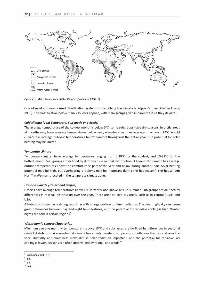
72 | T H E H A U S A M H O R N I N W E I M A R
Figure A.1: Main climatic zones (after Köppen) [Rosenlund 2000: 6].
One of most commonly used classification system for describing the climate is Köppen’s (described in Evans, 1980). The classification below mainly follows Köppen, with main groups given in parentheses if they deviate. Cold climate (Cold Temperate, Sub-arctic and Arctic) The average temperature of the coldest month is below 0°C; some subgroups have dry seasons. In arctic areas all months may have average temperatures below zero; elsewhere summer averages may reach 22°C. A cold climate has average outdoor temperatures below comfort throughout the entire year. The potential for solar heating may be limited7. Temperate climate Temperate climates have average temperatures ranging from 0-18°C for the coldest, and 10-22°C for the hottest month. Sub groups are defined by differences in rain fall distribution. A temperate climate has average outdoor temperatures above the comfort zone part of the year and below during another part. Solar heating potential may be high, but overheating problems may be important during the hot season8. The house “Am Horn” in Weimar is located in the temperate climate zone. Hot-arid climate (Desert and Steppe) Deserts have average temperatures above 0°C in winter and above 18°C in summer. Sub groups are de fined by differences in rain fall distribution over the year. There are also cold dry areas, such as in central Russia and USA. A hot-arid climate has a strong sun shine with a large portion of direct radiation. The clear night sky can cause great differences between day and night temperatures, and the potential for radiative cooling is high. Winter nights are cold in certain regions9. Warm-humid climate (Equatorial) Minimum average monthly temperature is above 18°C and subclasses are de fined by differences in seasonal rainfall distribution. A warm-humid climate has a fairly constant temperature, both over the day and over the year. Humidity and cloudiness make diffuse solar radiation important, and the potential for radiative sky cooling is lower. Seasons are often determined by rainfall and winds10.
7 Rosenlund 2000: 6 ff. 8 Ibid. 9 Ibid. 10 Ibid.
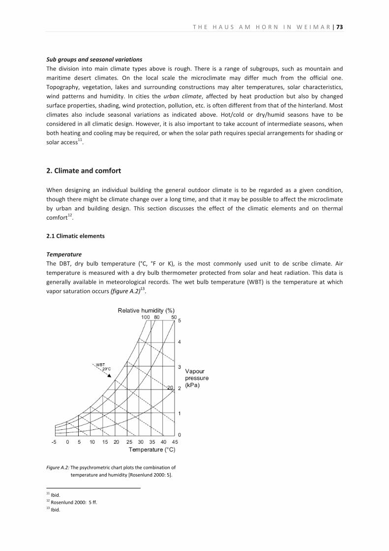
T H E H A U S A M H O R N I N W E I M A R | 73
Sub groups and seasonal variations The division into main climate types above is rough. There is a range of subgroups, such as mountain and maritime desert climates. On the local scale the microclimate may differ much from the official one. Topography, vegetation, lakes and surrounding constructions may alter temperatures, solar characteristics, wind patterns and humidity. In cities the urban climate, affected by heat production but also by changed surface properties, shading, wind protection, pollution, etc. is often different from that of the hinterland. Most climates also include seasonal variations as indicated above. Hot/cold or dry/humid seasons have to be considered in all climatic design. However, it is also important to take account of intermediate seasons, when both heating and cooling may be required, or when the solar path requires special arrangements for shading or solar access11.
2. Climate and comfort When designing an individual building the general outdoor climate is to be regarded as a given condition, though there might be climate change over a long time, and that it may be possible to affect the microclimate by urban and building design. This section discusses the effect of the climatic elements and on thermal comfort12. 2.1 Climatic elements Temperature The DBT, dry bulb temperature (°C, °F or K), is the most commonly used unit to de scribe climate. Air temperature is measured with a dry bulb thermometer protected from solar and heat radiation. This data is generally available in meteorological records. The wet bulb temperature (WBT) is the temperature at which vapor saturation occurs (figure A.2)13.
Figure A.2: The psychrometric chart plots the combination of
temperature and humidity [Rosenlund 2000: 5].
11 Ibid. 12 Rosenlund 2000: 5 ff. 13 Ibid.
74 | T H E H A U S A M H O R N I N W E I M A R
Humidity Air contains a certain amount of vapour, which is called air humidity. It can be specified as absolute humidity in grams per kg, or as relative humidity RH (%) which describes the portion of vapour in relation to saturation. Hotter air can contain more vapor than colder, and when cooled to the limit - the dew point - the surplus condenses. Meteorological data on humidity is commonly available14. Wind At local level wind is the most irregular and varying component of the climate. It is affected by topography, vegetation and surrounding buildings; closeness to the sea may create on and off shore winds. Wind is described by its speed and direction. Frequency diagrams, wind roses, are often drawn for each month of the year or for the main seasons15. Precipitation Precipitation may vary considerably between seasons. Data on monthly means, extreme values and maximum precipitation during 24 hours are commonly found. Snow is most often measured in melted form, but data on snow depth may be available. Combinations with other elements could be interesting in relation to building design, e.g. at strong winds it rains ‘horizontally’ (driving rain)16. Solar radiation and sky conditions The sun may be described as the ‘engine’ of the climate since it supplies a large amount of energy to the earth. The sun’s path is regular and depends on the latitude and the time of the year. The season also determines the total amount of irradiation through the length of the day. High altitudes give more intense solar radiation, because there is less absorption in the relatively thinner layer of atmosphere. The position of the sun may be determined with the help of solar diagrams (figure A.4). There is one diagram for each latitude, making it possible to read the altitude (vertical angle) and the azimuth (horizontal angle) of the sun at every hour of every day of the year. The relation between direct and diffuse radiation varies with the sky conditions. Humid air or overcast skies increase the diffuse part. Overlays to the solar diagram may give data on solar radiation on horizontal or other surfaces, but corrections for cloudiness and humidity must always be considered. Reflections from the ground and adjacent buildings, and shading from adjacent buildings and vegetation, affect the total solar radiation17. 2.2 Comfort The human being exchanges heat with its environment through conduction (by direct contact), convection (transported by air), radiation (mainly short-wave visual light and long-wave heat) and evaporation/ condensation (heat released through change of state of water, also called latent heat). Factors influencing the heat balance are environmental, such as air and mean radiant temperatures, vapour pressure and air motion, but also individual. The thermal equilibrium must be maintained within narrow limits for survival, and the range of comfort is even narrower. Comfort is a subjective experience, and not all people agree about optimal comfort. To handle comfort, it was necessary to define a “‘comfort zone” where the majority of people experience well-being. This is normally done by the votes of a population in an experimental situation18. 14 Ibid. 15 Ibid. 16 Ibid. 17 Rosenlund 2000: 5 ff. 18 Ibid.
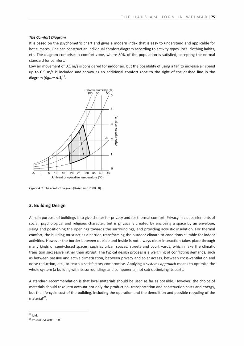
T H E H A U S A M H O R N I N W E I M A R | 75
The Comfort Diagram It is based on the psychometric chart and gives a modern index that is easy to understand and applicable for hot climates. One can construct an individual comfort diagram according to activity types, local clothing habits, etc. The diagram comprises a comfort zone, where 80% of the population is satisfied, accepting the normal standard for comfort. Low air movement of 0.1 m/s is considered for indoor air, but the possibility of using a fan to increase air speed up to 0.5 m/s is included and shown as an additional comfort zone to the right of the dashed line in the diagram (figure A.3)19.
Figure A.3: The comfort diagram [Rosenlund 2000: 8].
3. Building Design A main purpose of buildings is to give shelter for privacy and for thermal comfort. Privacy in cludes elements of social, psychological and religious character, but is physically created by enclosing a space by an envelope, sizing and positioning the openings towards the surroundings, and providing acoustic insulation. For thermal comfort, the building must act as a barrier, transforming the outdoor climate to conditions suitable for indoor activities. However the border between outside and inside is not always clear: interaction takes place through many kinds of semi-closed spaces, such as urban spaces, streets and court yards, which make the climatic transition successive rather than abrupt. The typical design process is a weighing of conflicting demands, such as between passive and active climatization, between privacy and solar access, between cross-ventilation and noise reduction, etc., to reach a satisfactory compromise. Applying a systems approach means to optimize the whole system (a building with its surroundings and components) not sub-optimizing its parts. A standard recommendation is that local materials should be used as far as possible. However, the choice of materials should take into account not only the production, transportation and construction costs and energy, but the life-cycle cost of the building, including the operation and the demolition and possible recycling of the material20.
19 Ibid. 20 Rosenlund 2000: 8 ff.
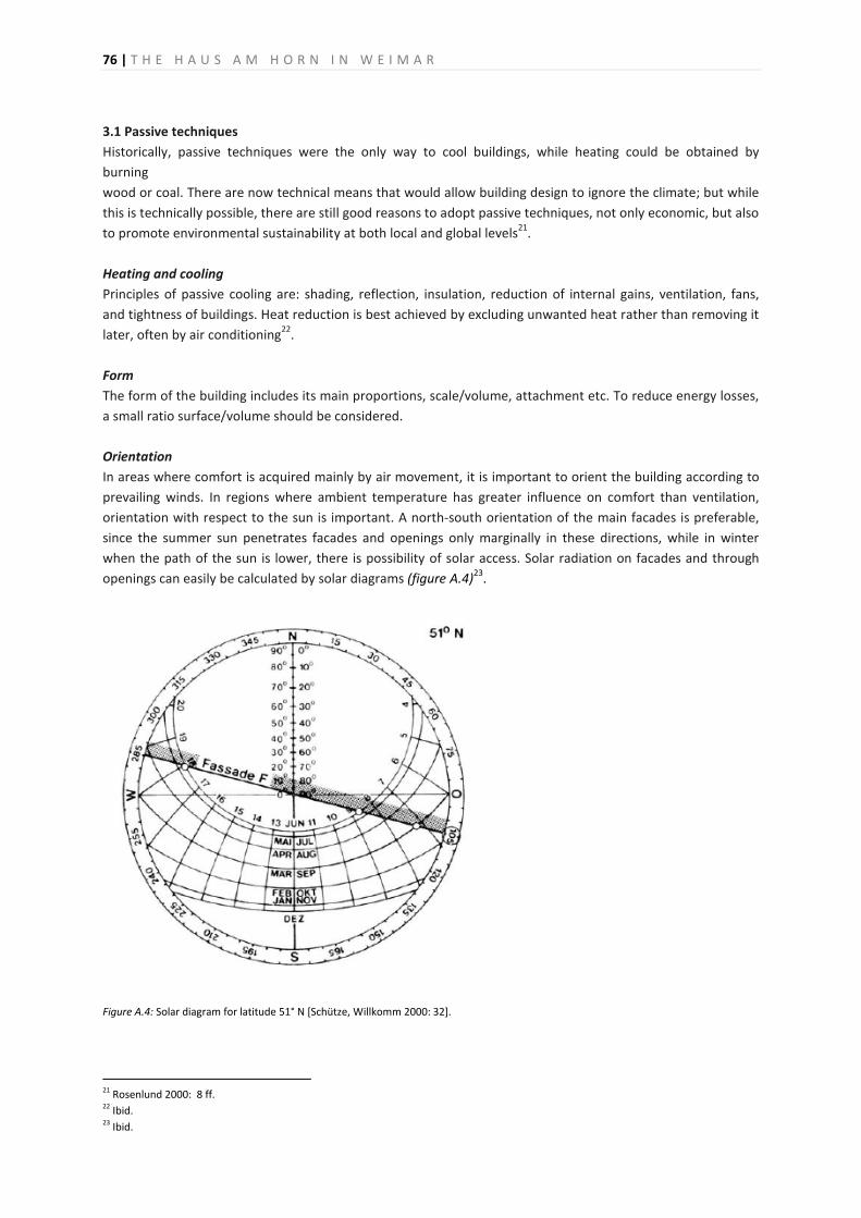
76 | T H E H A U S A M H O R N I N W E I M A R
3.1 Passive techniques Historically, passive techniques were the only way to cool buildings, while heating could be obtained by burning wood or coal. There are now technical means that would allow building design to ignore the climate; but while this is technically possible, there are still good reasons to adopt passive techniques, not only economic, but also to promote environmental sustainability at both local and global levels21. Heating and cooling Principles of passive cooling are: shading, reflection, insulation, reduction of internal gains, ventilation, fans, and tightness of buildings. Heat reduction is best achieved by excluding unwanted heat rather than removing it later, often by air conditioning22. Form The form of the building includes its main proportions, scale/volume, attachment etc. To reduce energy losses, a small ratio surface/volume should be considered. Orientation In areas where comfort is acquired mainly by air movement, it is important to orient the building according to prevailing winds. In regions where ambient temperature has greater influence on comfort than ventilation, orientation with respect to the sun is important. A north-south orientation of the main facades is preferable, since the summer sun penetrates facades and openings only marginally in these directions, while in winter when the path of the sun is lower, there is possibility of solar access. Solar radiation on facades and through openings can easily be calculated by solar diagrams (figure A.4)23.
Figure A.4: Solar diagram for latitude 51° N [Schütze, Willkomm 2000: 32].
21 Rosenlund 2000: 8 ff. 22 Ibid. 23 Ibid.
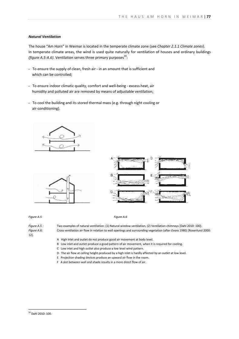
T H E H A U S A M H O R N I N W E I M A R | 77
Natural Ventilation
The house “Am Horn” in Weimar is located in the temperate climate zone (see Chapter 2.1.1 Climate zones). In temperate climate areas, the wind is used quite naturally for ventilation of houses and ordinary buildings (figure A.5-A.6). Ventilation serves three primary purposes24: - To ensure the supply of clean, fresh air - in an amount that is sufficient and which can be controlled; - To ensure indoor climatic quality, comfort and well-being - excess heat, air humidity and polluted air are removed by means of adjustable ventilation; - To cool the building and its stored thermal mass (e.g. through night cooling or air-conditioning).
Figure A.5 Figure A.6 Figure A.5 : Two examples of natural ventilation: (1) Natural window ventilation, (2) Ventilation chimneys [Dahl 2010: 100]. Figure A.6: Cross ventilation air flow in relation to wall openings and surrounding vegetation (after Evans 1980) [Rosenlund 2000: 12].
A High inlet and outlet do not produce good air movement at body level. B Low inlet and outlet produce a good pattern of air movement, when it is required for cooling. C Low inlet and high outlet also produce a low level wind pattern. D The air flow at ceiling height produced by a high inlet is hardly affected by an outlet at low level. E Projection shading devices produce an upward air flow in the room.
F A slot between wall and shade results in a more direct flow of air.
24 Dahl 2010: 100.
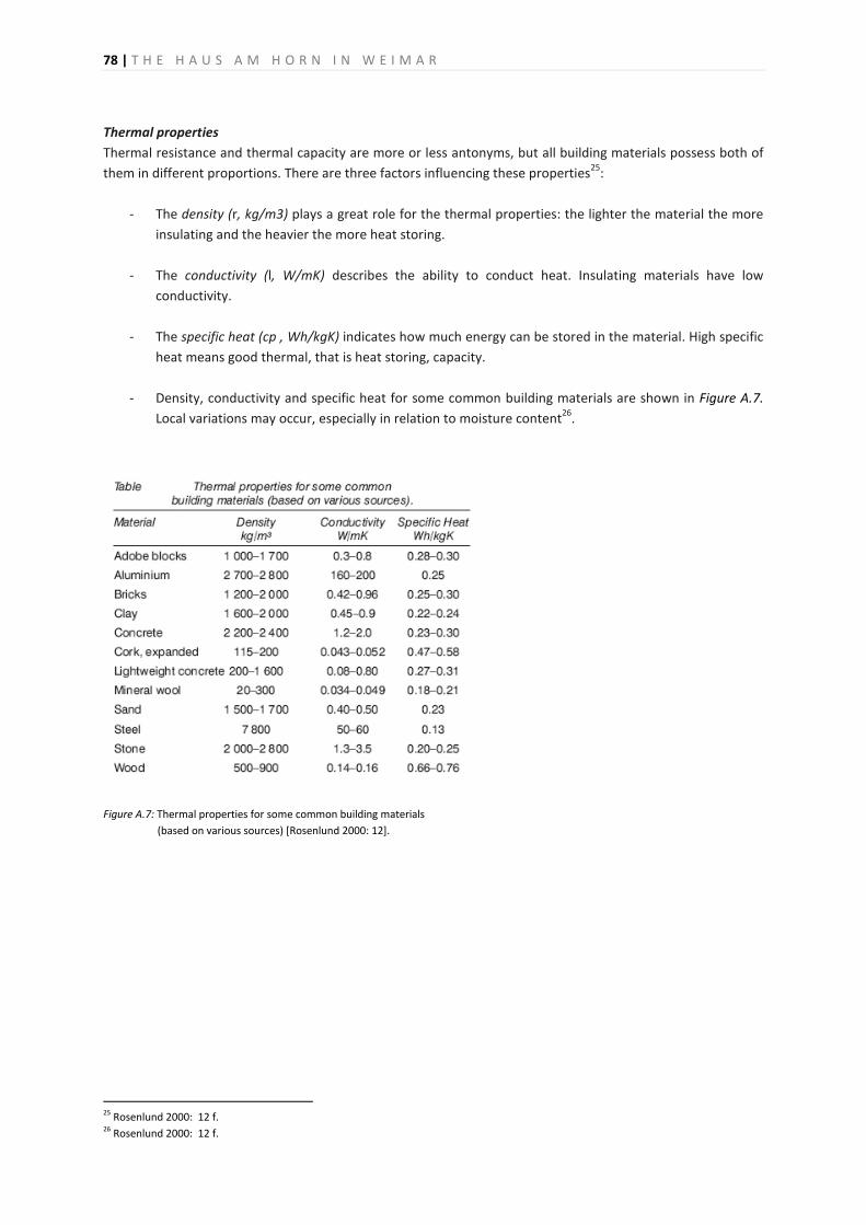
78 | T H E H A U S A M H O R N I N W E I M A R
Thermal properties Thermal resistance and thermal capacity are more or less antonyms, but all building materials possess both of them in different proportions. There are three factors influencing these properties25:
- The density (r, kg/m3) plays a great role for the thermal properties: the lighter the material the more insulating and the heavier the more heat storing.
- The conductivity (l, W/mK) describes the ability to conduct heat. Insulating materials have low
conductivity.
- The specific heat (cp , Wh/kgK) indicates how much energy can be stored in the material. High specific heat means good thermal, that is heat storing, capacity.
- Density, conductivity and specific heat for some common building materials are shown in Figure A.7.
Local variations may occur, especially in relation to moisture content26.
Figure A.7: Thermal properties for some common building materials
(based on various sources) [Rosenlund 2000: 12].
25 Rosenlund 2000: 12 f. 26 Rosenlund 2000: 12 f.
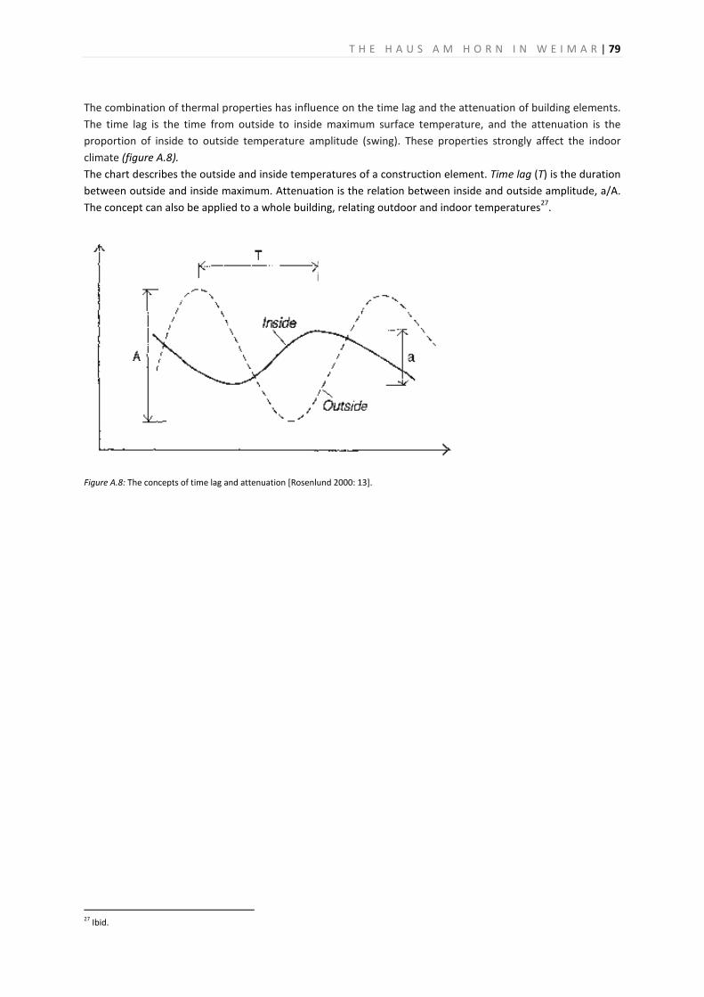
T H E H A U S A M H O R N I N W E I M A R | 79
The combination of thermal properties has influence on the time lag and the attenuation of building elements. The time lag is the time from outside to inside maximum surface temperature, and the attenuation is the proportion of inside to outside temperature amplitude (swing). These properties strongly affect the indoor climate (figure A.8). The chart describes the outside and inside temperatures of a construction element. Time lag (T) is the duration between outside and inside maximum. Attenuation is the relation between inside and outside amplitude, a/A. The concept can also be applied to a whole building, relating outdoor and indoor temperatures27.
Figure A.8: The concepts of time lag and attenuation [Rosenlund 2000: 13].
27 Ibid.

80 | T H E H A U S A M H O R N I N W E I M A R
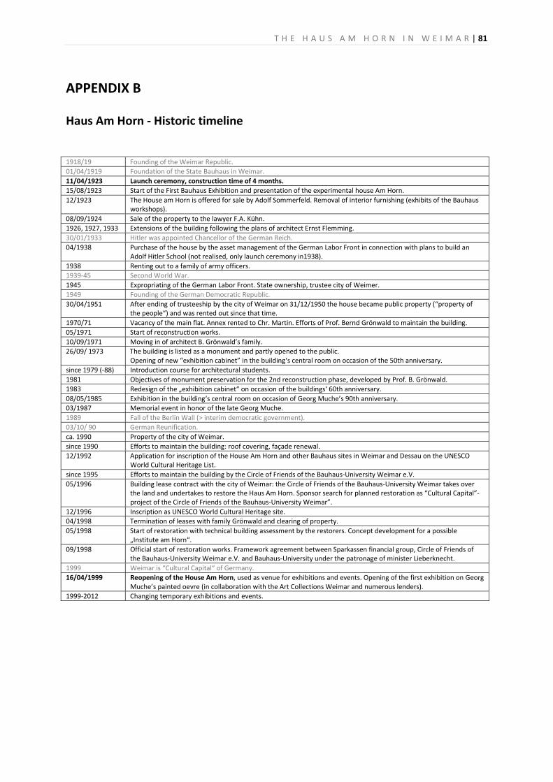
T H E H A U S A M H O R N I N W E I M A R | 81
APPENDIX B
Haus Am Horn - Historic timeline 1918/19 Founding of the Weimar Republic.01/04/1919 Foundation of the State Bauhaus in Weimar.11/04/1923 Launch ceremony, construction time of 4 months.15/08/1923 Start of the First Bauhaus Exhibition and presentation of the experimental house Am Horn. 12/1923 The House am Horn is offered for sale by Adolf Sommerfeld. Removal of interior furnishing (exhibits of the Bauhaus
workshops). 08/09/1924 Sale of the property to the lawyer F.A. Kühn.1926, 1927, 1933 Extensions of the building following the plans of architect Ernst Flemming.30/01/1933 Hitler was appointed Chancellor of the German Reich.04/1938 Purchase of the house by the asset management of the German Labor Front in connection with plans to build an
Adolf Hitler School (not realised, only launch ceremony in1938). 1938 Renting out to a family of army officers.1939-45 Second World War. 1945 Expropriating of the German Labor Front. State ownership, trustee city of Weimer.1949 Founding of the German Democratic Republic.30/04/1951 After ending of trusteeship by the city of Weimar on 31/12/1950 the house became public property (“property of
the people“) and was rented out since that time. 1970/71 Vacancy of the main flat. Annex rented to Chr. Martin. Efforts of Prof. Bernd Grönwald to maintain the building.05/1971 Start of reconstruction works. 10/09/1971 Moving in of architect B. Grönwald’s family.26/09/ 1973 The building is listed as a monument and partly opened to the public.
Opening of new “exhibition cabinet” in the building‘s central room on occasion of the 50th anniversary. since 1979 (-88) Introduction course for architectural students.1981 Objectives of monument preservation for the 2nd reconstruction phase, developed by Prof. B. Grönwald. 1983 Redesign of the „exhibition cabinet“ on occasion of the buildings‘ 60th anniversary.08/05/1985 Exhibition in the building‘s central room on occasion of Georg Muche’s 90th anniversary. 03/1987 Memorial event in honor of the late Georg Muche.1989 Fall of the Berlin Wall (> interim democratic government).03/10/ 90 German Reunification. ca. 1990 Property of the city of Weimar. since 1990 Efforts to maintain the building: roof covering, façade renewal.12/1992 Application for inscription of the House Am Horn and other Bauhaus sites in Weimar and Dessau on the UNESCO
World Cultural Heritage List. since 1995 Efforts to maintain the building by the Circle of Friends of the Bauhaus-University Weimar e.V. 05/1996 Building lease contract with the city of Weimar: the Circle of Friends of the Bauhaus-University Weimar takes over
the land and undertakes to restore the Haus Am Horn. Sponsor search for planned restoration as “Cultural Capital”-project of the Circle of Friends of the Bauhaus-University Weimar”.
12/1996 Inscription as UNESCO World Cultural Heritage site.04/1998 Termination of leases with family Grönwald and clearing of property.05/1998 Start of restoration with technical building assessment by the restorers. Concept development for a possible
„Institute am Horn“. 09/1998
Official start of restoration works. Framework agreement between Sparkassen financial group, Circle of Friends of the Bauhaus-University Weimar e.V. and Bauhaus-University under the patronage of minister Lieberknecht.
1999 Weimar is “Cultural Capital“ of Germany.16/04/1999
Reopening of the House Am Horn, used as venue for exhibitions and events. Opening of the first exhibition on Georg Muche’s painted oevre (in collaboration with the Art Collections Weimar and numerous lenders).
1999-2012 Changing temporary exhibitions and events.

82 | T H E H A U S A M H O R N I N W E I M A R
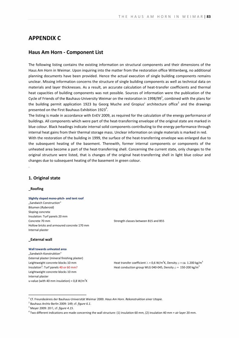
T H E H A U S A M H O R N I N W E I M A R | 83
APPENDIX C
Haus Am Horn - Component List The following listing contains the existing information on structural components and their dimensions of the Haus Am Horn in Weimar. Upon inquiring into the matter from the restoration office Wittenberg, no additional planning documents have been provided. Hence the actual execution of single building components remains unclear. Missing information concerns the structure of single building components as well as technical data on materials and layer thicknesses. As a result, an accurate calculation of heat-transfer coefficients and thermal heat capacities of building components was not possible. Sources of information were the publication of the Cycle of Friends of the Bauhaus-University Weimar on the restoration in 1998/991, combined with the plans for the building permit application 1923 by Georg Muche and Gropius’ architecture office2 and the drawings presented on the First Bauhaus Exhibition 19233. The listing is made in accordance with EnEV 2009, as required for the calculation of the energy performance of buildings. All components which were part of the heat-transferring envelope of the original state are marked in blue colour. Black headings indicate internal solid components contributing to the energy performance through internal heat gains from their thermal storage mass. Unclear information on single materials is marked in red. With the restoration of the building in 1999, the surface of the heat-transferring envelope was enlarged due to the subsequent heating of the basement. Therewith, former internal components or components of the unheated area become a part of the heat-transferring shell. Concerning the current state, only changes to the original structure were listed, that is changes of the original heat-transferring shell in light blue colour and changes due to subsequent heating of the basement in green colour. .
1. Original state
_Roofing Slightly sloped mono-pitch- and tent roof „Sandwich Construction“ Bitumen (Ruberoid) Sloping concrete Insulation: Turf panels 20 mm Concrete 70 mm Strength classes between B15 and B55 Hollow bricks and armoured concrete 170 mm Internal plaster
_External wall Wall towards unheated area „Sandwich-Konstruktion“ External plaster (mineral finishing plaster) Leightweight concrete blocks 10 mm Heat transfer coefficient λ = 0,6 W/m2K, Density ρ = ca. 1.200 kg/m3 Insulation4: Turf panels 40 or 60 mm? Heat conduction group WLG 040-045, Density ρ = 150-200 kg/m3
Leightweight concrete blocks 10 mm Internal plaster u-value (with 40 mm insulation) = 0,8 W/m2K
1 Cf. Freundeskreis der Bauhaus-Universität Weimar 2000. Haus Am Horn. Rekonstruktion einer Utopie. 2 Bauhaus Archiv Berlin 2009: 149; cf. figure 6.1. 3 Meyer 2009: 20 f.; cf. figure 4.15. 4 Two different indications are made concerning the wall structure: (1) insulation 60 mm, (2) insulation 40 mm + air layer 20 mm.
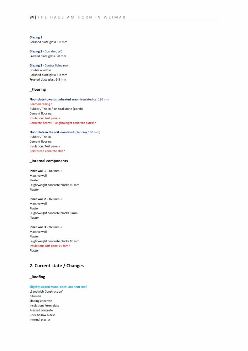
84 | T H E H A U S A M H O R N I N W E I M A R
Glazing 1 Polished plate glass 6-8 mm Glazing 2 - Corridor, WC Frosted plate glass 6-8 mm Glazing 3 - Central living room Double window Polished plate glass 6-8 mm Frosted plate glass 6-8 mm
_Flooring Floor plate towards unheated area - insulated ca. 190 mm Beamed ceiling? Rubber / Triolin / artifical stone (porch) Cement flooring Insulation: Turf panels Concrete beams + Leightweight concrete blocks? Floor plate in the soil - insulated (planning 180 mm) Rubber / Triolin Cement flooring Insulation: Turf panels Reinforced concrete slab?
_Internal components Inner wall 1 - 100 mm + Massive wall Plaster Leightweight concrete blocks 10 mm Plaster Inner wall 2 - 160 mm + Massive wall Plaster Leightweight concrete blocks 8 mm Plaster Inner wall 3 - 260 mm + Massive wall Plaster Leightweight concrete blocks 10 mm Insulation: Torf panels 6 mm? Plaster
2. Current state / Changes
_Roofing Slightly sloped mono-pitch- and tent roof „Sandwich Construction“ Bitumen Sloping concrete Insulation: Form glass Pressed concrete Brick hollow blocks Internal plaster
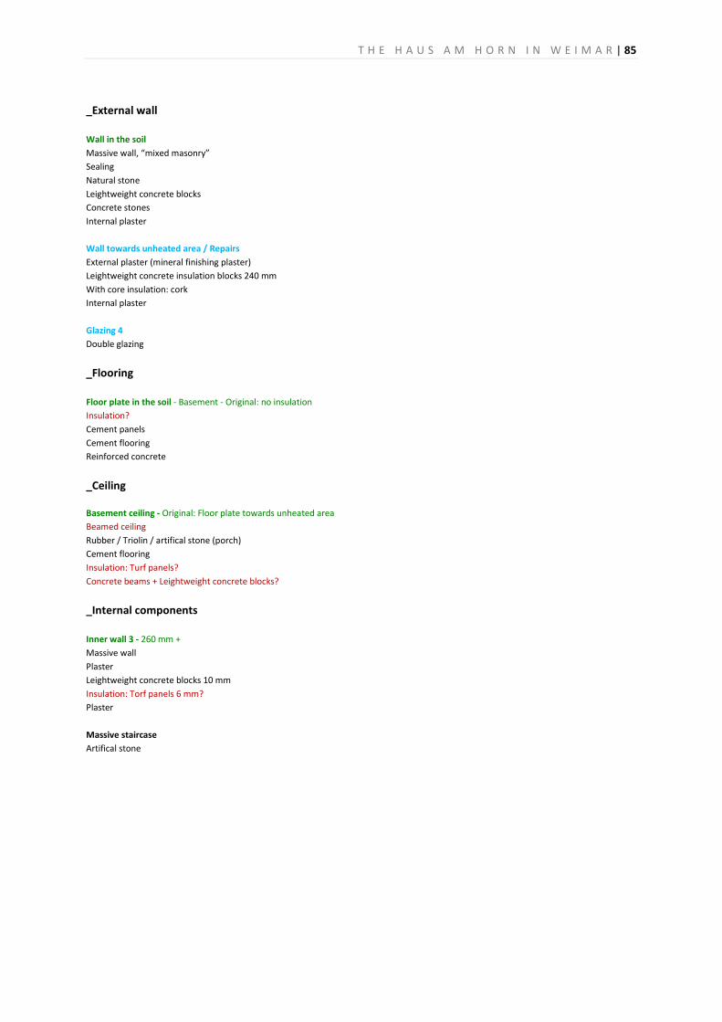
T H E H A U S A M H O R N I N W E I M A R | 85
_External wall Wall in the soil Massive wall, “mixed masonry” Sealing Natural stone Leightweight concrete blocks Concrete stones Internal plaster Wall towards unheated area / Repairs External plaster (mineral finishing plaster) Leightweight concrete insulation blocks 240 mm With core insulation: cork Internal plaster Glazing 4 Double glazing
_Flooring Floor plate in the soil - Basement - Original: no insulation Insulation? Cement panels Cement flooring Reinforced concrete
_Ceiling
Basement ceiling - Original: Floor plate towards unheated area Beamed ceiling Rubber / Triolin / artifical stone (porch) Cement flooring Insulation: Turf panels? Concrete beams + Leightweight concrete blocks?
_Internal components Inner wall 3 - 260 mm + Massive wall Plaster Leightweight concrete blocks 10 mm Insulation: Torf panels 6 mm? Plaster Massive staircase Artifical stone

86 | T H E H A U S A M H O R N I N W E I M A R
APPENDIX D
Workshop presenta ons -“Reworking the Bauhaus in Dessau”
T H E H A U S A M H O R N I N W E I M A R 87
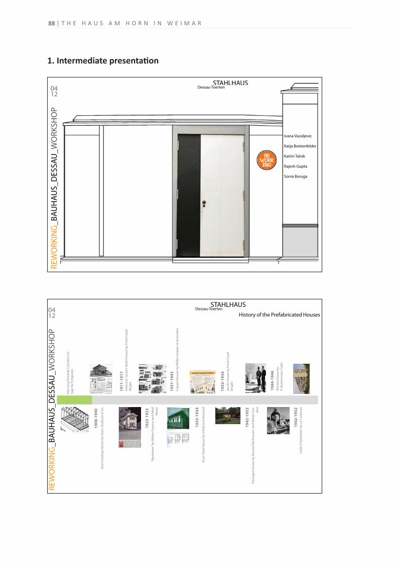
1. Intermediate presenta on
STAHLHAUS Dessau-Toerten
RE
WO
RK
ING
_B
AU
HA
US
_D
ES
SA
U_
WO
RK
SH
OP
0412
STAHLHAUS Dessau-Toerten
Ivana Vassiljevic
Katja Breitenfelder
Katrin Talvik
Rajesh Gupta
Sonia Boruga
STAHLHAUS Dessau-Toerten
RE
WO
RK
ING
_B
AU
HA
US
_D
ES
SA
U_
WO
RK
SH
OP
0412 History of the Prefabricated Houses
Ma
nn
ing
Po
rta
ble
Co
lon
ial C
ot-
tag
e f
or
Em
igra
nts
19
08
-19
40
19
11
-19
17
1
92
2-1
92
3
19
31
-19
42
1
93
3-1
93
4
19
33
-19
34
19
44
-19
46
1
94
2-1
95
2
1
94
2-1
95
2
Se
ars
Cat
alo
g H
om
es
by
Se
ars
, Ro
eb
uck
& C
o.
Am
eri
can
Sys
tem
-Bu
ilt H
ou
ses
by
Fra
nk
Llo
yd
Wri
gh
t
“Ba
uk
ast
en
” b
y W
alt
er
Gro
piu
s a
nd
Ad
olf
Me
yer
Co
pp
er
Ho
use
s b
y W
alt
er
Gro
piu
s &
Ass
oci
ate
s
Str
an
-Ste
el H
ou
se b
y O
'De
ll a
nd
Ro
wla
nd
Jaco
bs
Ho
use
by
Fra
nk
Llo
yd
Wri
gh
t
Pa
cka
ge
d H
ou
se b
y K
on
rad
Wa
chsm
an
n a
nd
Wa
lte
r G
ro-
piu
s
Wic
hit
a H
ou
se b
y
R. B
uck
min
ste
r Fu
ller
Un
ité
d'H
ab
ita
tio
n b
y Le
Co
rbu
sie
r
T H E H A U S A M H O R N I N W E I M A R88
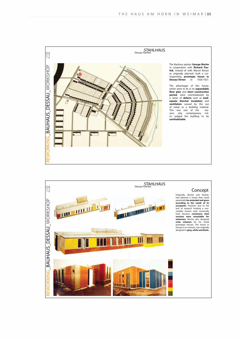
STAHLHAUS Dessau-Toerten
RE
WO
RK
ING
_B
AU
HA
US
_D
ES
SA
U_
WO
RK
SH
OP
0412
The Bauhaus painter George Muche
in cooperation with Richard Pau-
lick, instead of with Marcel Breuer
as originally planned, built a cor-
responding prototype house in
Dessau-Törten in 1926-1927.
The advantages of this house,
which were to lie in its expandable
floor plan and short construction
period, were overshadowed by
a series of defects such as inad-
equate thermal insulation and
ventilation caused by the use
of metal as a building material.
This was one of the rea-
sons why contemporary crit-
ics judged the building to be
uninhabitable.
STAHLHAUS Dessau-Toerten
RE
WO
RK
ING
_B
AU
HA
US
_D
ES
SA
U_
WO
RK
SH
OP
0412
Originally, Muche and Paulick,
had planned a house that could
potentially be extended and grow
according to the needs of its
occupants. However due to the
lack of research funding a non-
variable houses were eventually
built because customary steel
sections were unsuitable for
extension. Muche also designed
color schemes for his metal
prototype houses. The house in
Dessau is in contrast, was originally
designed in grey, white and black.
Concept
89T H E H A U S A M H O R N I N W E I M A R
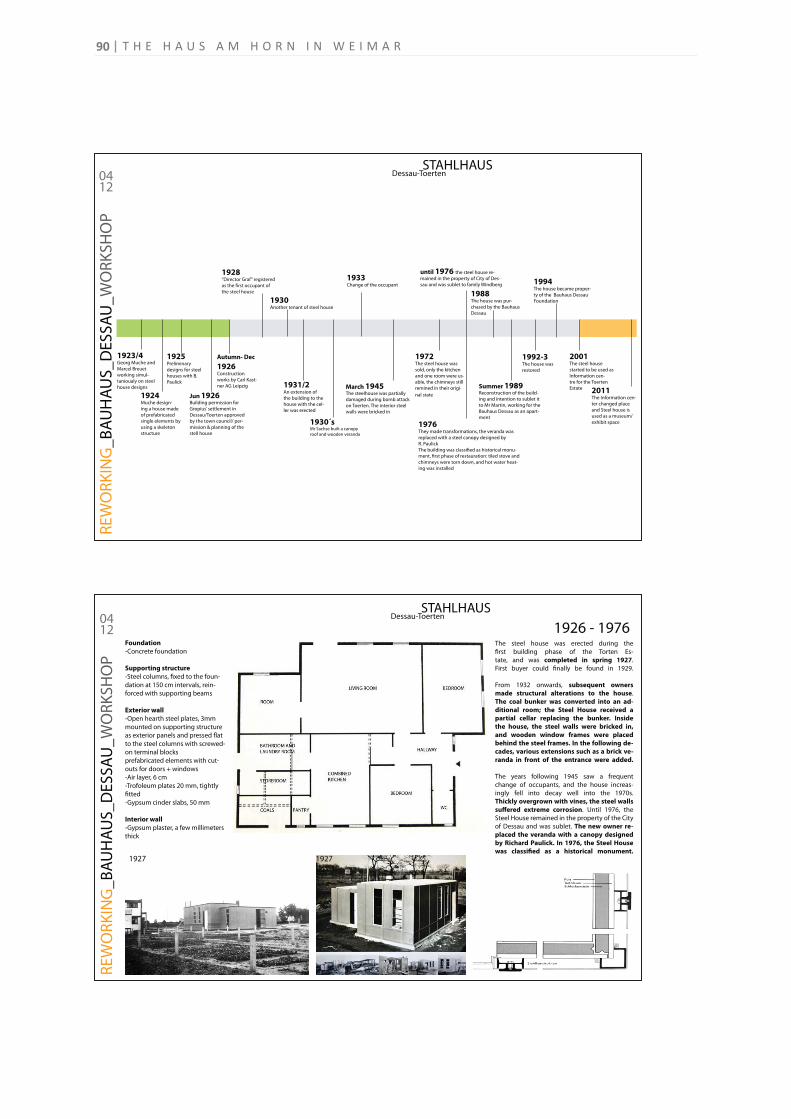
STAHLHAUS Dessau-Toerten
RE
WO
RK
ING
_B
AU
HA
US
_D
ES
SA
U_
WO
RK
SH
OP
0412
1923/4 Georg Muche and
Marcel Breuet
working simul-
tanioualy on steel
house designs
1924 Muche design-
ing a house made
of prefabricated
single elements by
using a skeleton
structure
1925Preliminary
designs for steel
houses with B.
Paulick
Jun 1926Building permission for
Gropius’ settlement in
Dessau/Toerten approved
by the town council/ per-
mission & planning of the
stell house
Autumn- Dec
1926Construction
works by Carl Kast-
ner AG Leipzig
1928“Director Graf” registered
as the first occupant of
the steel house
1930Another tenant of steel house
1931/2An extension of
the building to the
house with the cel-
ler was erected
1930´sMr Sachse built a canopy
roof and wooden veranda
1933Change of the occupant
March 1945The steelhouse was partially
damaged during bomb attack
on Toerten. The interior steel
walls were bricked in
1972The steel house was
sold, only the kitchen
and one room were us-
able, the chimneys still
remined in their origi-
nal state
1976They made transformations, the veranda was
replaced with a steel canopy designed by
R. Paulick
The building was classified as historical monu-
ment, first phase of restauration: tiled stove and
chimneys were torn down, and hot water heat-
ing was installed
1988The house was pur-
chased by the Bauhaus
Dessau
Summer 1989Reconstruction of the build-
ing and intention to sublet it
to Mr Martin, working for the
Bauhaus Dessau as an apart-
ment
1992-3The house was
restored
1994The house became proper-
ty of the Bauhaus Dessau
Foundation
2001The steel house
started to be used as
Information cen-
tre for the Toerten
Estate
until 1976 the steel house re-
mained in the property of City of Des-
sau and was sublet to family Windberg
2011The Information cen-
ter changed place
and Steel house is
used as a museum/
exhibit space
STAHLHAUS Dessau-Toerten
RE
WO
RK
ING
_B
AU
HA
US
_D
ES
SA
U_
WO
RK
SH
OP
0412 1926 - 1976
Foundation
-Concrete foundation
Supporting structure
-Steel columns, fixed to the foun-
dation at 150 cm intervals, rein-
forced with supporting beams
Exterior wall
-Open hearth steel plates, 3mm
mounted on supporting structure
as exterior panels and pressed flat
to the steel columns with screwed-
on terminal blocks
prefabricated elements with cut-
outs for doors + windows
-Air layer, 6 cm
-Trofoleum plates 20 mm, tightly
fitted
-Gypsum cinder slabs, 50 mm
Interior wall
-Gypsum plaster, a few millimeters
thick
The steel house was erected during the
first building phase of the Torten Es-
tate, and was completed in spring 1927.
First buyer could finally be found in 1929.
From 1932 onwards, subsequent owners
made structural alterations to the house.
The coal bunker was converted into an ad-
ditional room; the Steel House received a
partial cellar replacing the bunker. Inside
the house, the steel walls were bricked in,
and wooden window frames were placed
behind the steel frames. In the following de-
cades, various extensions such as a brick ve-
randa in front of the entrance were added.
The years following 1945 saw a frequent
change of occupants, and the house increas-
ingly fell into decay well into the 1970s.
Thickly overgrown with vines, the steel walls
suffered extreme corrosion. Until 1976, the
Steel House remained in the property of the City
of Dessau and was sublet. The new owner re-
placed the veranda with a canopy designed
by Richard Paulick. In 1976, the Steel House
was classified as a historical monument.1927 1927
T H E H A U S A M H O R N I N W E I M A R90
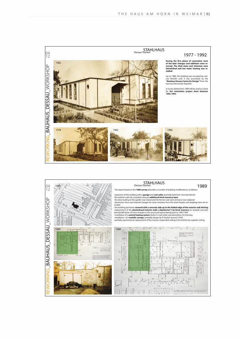
STAHLHAUS Dessau-Toerten
RE
WO
RK
ING
_B
AU
HA
US
_D
ES
SA
U_
WO
RK
SH
OP
0412
During the first phase of restoration most
of the later changes and additions were re-
moved. The tiled stove and chimneys were
demolished and hot water heating was in-
stalled.
Up to 1988, the building was occupied by vari-
ous families until it was purchased by the
“Bauhaus Dessau Centre for Design“ from the
German Democratic Republic.
A survey dating from 1989 will be used as a base
for the restoration project done between
1992-1993.
1977 - 1992
1978 1982
1982
1986
STAHLHAUS Dessau-Toerten
RE
WO
RK
ING
_B
AU
HA
US
_D
ES
SA
U_
WO
RK
SH
OP
0412 The report based on the 1989 survey describes a number of building modifications, as follows:
-extension of the building with a garage and coal cellar (partially built from concrete blocks)
-the exterior wall was insulated using an additional brick masonry layer
-the door leading to the garden was closed and the former coal room entrance was replaced
-dimension, form and material changes for some windows from the street façade and sleeping room are re-
corded
-the building perimeter covered with a concrete slab up to the folded edge of the exterior wall skirting
-replacement of the plasterboard interior walls („Gipskarton“) by brick masonry (or aerated concrete)
and identification of some changes in the structural layout dating back to 1945/1946
-installation of a central heating system (boiler in coal cellar) and demolition of chimneys
-installation of a metallic canopy, probably design by R. Paulick (around 1976)
-partially, asymmetrical replacement of the massive suspended ceiling in the kitchen by a plaster ceiling
1989
1991
1989 1989
1989
91T H E H A U S A M H O R N I N W E I M A R
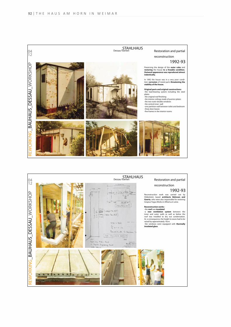
STAHLHAUS Dessau-Toerten
RE
WO
RK
ING
_B
AU
HA
US
_D
ES
SA
U_
WO
RK
SH
OP
0412
Preserving the design of the outer cube and
restoring the house to a liveable condition.
Outward appearance was reproduced almost
indentically.
In 1992 the house was in a very poor condi-
tion: corrosion of metal parts threatening the
stability of the house.
Original parts and original constructions:
-the load-bearing system including the steel
plates
-the original roof finishing
-the interior ceilings made of pumice plates
-the two outer double windows
-the central inner wall
-one partition wall between toilet and bedroom
-three door leaves
-five frames in the interior rooms
Restoration and partial
reconstruction
1992-93
STAHLHAUS Dessau-Toerten
RE
WO
RK
ING
_B
AU
HA
US
_D
ES
SA
U_
WO
RK
SH
OP
0412
Reconstruction work was carried out by
Hildesheim based architects Behnsen and
Goertz, who were also responsible for restoring
Gropius’ Fagus Works in Alfred a.d. Leine.
Reconstruction works:
-the roof was insulated
-a new ventilation system between the
inner and outer walls as well as below the
roof was installed to dry out condensation.
As a consequence, the height to eaves had to be
raised by approximately 10cm
-the windows were equipped with thermally
insulated glass
Restoration and partial
reconstruction
1992-93
T H E H A U S A M H O R N I N W E I M A R92
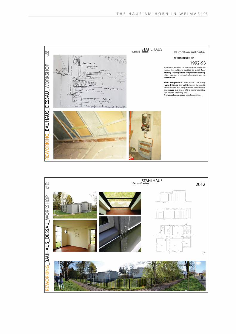
STAHLHAUS Dessau-Toerten
RE
WO
RK
ING
_B
AU
HA
US
_D
ES
SA
U_
WO
RK
SH
OP
0412
In order to avoid to set the radiators inside the
rooms, the architects decided to install floor
heating. The magnesite composition flooring,
which was only preserved in fragments, was re-
constructed.
Small compromises were made concerning
room divisions: the wall between the combi-
nation kitchen and living area and the bedroom
was moved in a favour of the former combina-
tion kitchen and living area.
The housekeeping area was changed too.
Restoration and partial
reconstruction
1992-93
STAHLHAUS Dessau-Toerten
RE
WO
RK
ING
_B
AU
HA
US
_D
ES
SA
U_
WO
RK
SH
OP
0412
2012
93T H E H A U S A M H O R N I N W E I M A R
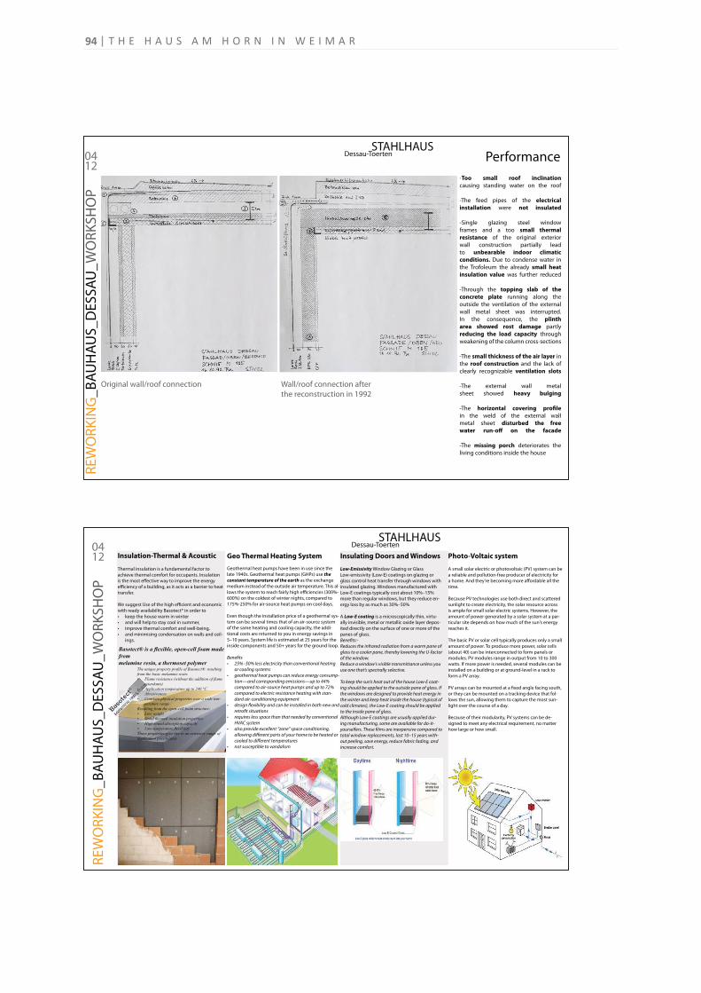
STAHLHAUS Dessau-Toerten
RE
WO
RK
ING
_B
AU
HA
US
_D
ES
SA
U_
WO
RK
SH
OP
0412
Performance
-Too small roof inclination
causing standing water on the roof
-The feed pipes of the electrical
installation were not insulated
-Single glazing steel window
frames and a too small thermal
resistance of the original exterior
wall construction partially lead
to unbearable indoor climatic
conditions. Due to condense water in
the Trofoleum the already small heat
insulation value was further reduced
-Through the topping slab of the
concrete plate running along the
outside the ventilation of the external
wall metal sheet was interrupted.
In the consequence, the plinth
area showed rost damage partly
reducing the load capacity through
weakening of the column cross-sections
-The small thickness of the air layer in
the roof construction and the lack of
clearly recognizable ventilation slots
-The external wall metal
sheet showed heavy bulging
-The horizontal covering profile
in the weld of the external wall
metal sheet disturbed the free
water run-off on the facade
-The missing porch deteriorates the
living conditions inside the house
Original wall/roof connection Wall/roof connection after
the reconstruction in 1992
STAHLHAUS Dessau-Toerten
RE
WO
RK
ING
_B
AU
HA
US
_D
ES
SA
U_
WO
RK
SH
OP
0412 Insulation-Thermal & Acoustic Geo Thermal Heating System Insulating Doors and Windows Photo-Voltaic system
Thermal insulation is a fundamental factor to
achieve thermal comfort for occupants. Insulation
is the most effective way to improve the energy
efficiency of a building, as it acts as a barrier to heat
transfer.
We suggest Use of the high efficient and economic
with ready availability Basotect® in order to
keep the house warm in winter
and will help to stay cool in summer,
improve thermal comfort and well-being,
and minimising condensation on walls and ceil-
ings.
-
Geothermal heat pumps have been in use since the
late 1940s. Geothermal heat pumps (GHPs) use the constant temperature of the earth as the exchange
medium instead of the outside air temperature. This al-
lows the system to reach fairly high efficiencies (300%-
600%) on the coldest of winter nights, compared to
175%-250% for air-source heat pumps on cool days.
Even though the installation price of a geothermal sys-
tem can be several times that of an air-source system
of the same heating and cooling capacity, the addi-
tional costs are returned to you in energy savings in
5–10 years. System life is estimated at 25 years for the
inside components and 50+ years for the ground loop.
Benefits
-
-
Low-Emissivity Window Glazing or Glass
Low-emissivity (Low-E) coatings on glazing or
glass control heat transfer through windows with
insulated glazing. Windows manufactured with
Low-E coatings typically cost about 10%–15%
more than regular windows, but they reduce en-
ergy loss by as much as 30%–50%
A Low-E coating is a microscopically thin, virtu-
ally invisible, metal or metallic oxide layer depos-
ited directly on the surface of one or more of the
panes of glass.
Benefits:-
-
-
-
A small solar electric or photovoltaic (PV) system can be
a reliable and pollution-free producer of electricity for
a home. And they're becoming more affordable all the
time.
Because PV technologies use both direct and scattered
sunlight to create electricity, the solar resource across
is ample for small solar electric systems. However, the
amount of power generated by a solar system at a par-
ticular site depends on how much of the sun's energy
reaches it.
The basic PV or solar cell typically produces only a small
amount of power. To produce more power, solar cells
(about 40) can be interconnected to form panels or
modules. PV modules range in output from 10 to 300
watts. If more power is needed, several modules can be
installed on a building or at ground-level in a rack to
form a PV array.
PV arrays can be mounted at a fixed angle facing south,
or they can be mounted on a tracking device that fol-
lows the sun, allowing them to capture the most sun-
light over the course of a day.
Because of their modularity, PV systems can be de-
signed to meet any electrical requirement, no matter
how large or how small.
T H E H A U S A M H O R N I N W E I M A R94
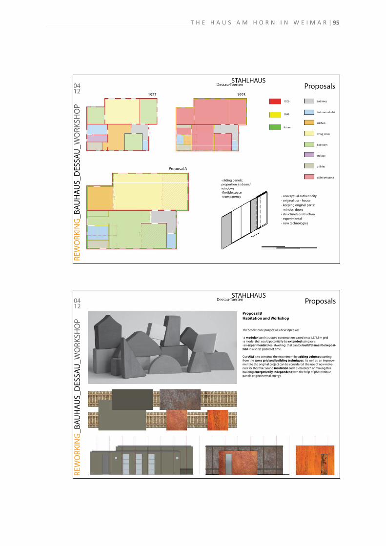
STAHLHAUS Dessau-Toerten
RE
WO
RK
ING
_B
AU
HA
US
_D
ES
SA
U_
WO
RK
SH
OP
0412
1926
1993
future
entrance
bathroom/toilet
kitchen
living room
bedroom
storage
utilities
exibition space-sliding panels:
proportion as doors/
windows
-flexible space
-transparency - conceptual authenticity
- original use - house
- keeping original parts: windos, doors
- structure/construction
- experimental
- new technologies
Proposals19931927
Proposal A
STAHLHAUS Dessau-Toerten
RE
WO
RK
ING
_B
AU
HA
US
_D
ES
SA
U_
WO
RK
SH
OP
0412
Proposal B
Habitation and Workshop
The Steel House project was developed as:
-a modular steel structure construction based on a 1.5/4.5m grid
-a model that could potentially be extended using rails
-an experimental steel dwelling that can be build/dismantle/reposi-
tion in a short period of time.
Our AIM is to continue the experiment by adding volumes starting
from the same grid and building techniques. As well as, an improve-
ment to the original project can be considered the use of new mate-
rials for thermal/ sound insulation such as Basotech or making this
building energetically independent with the help of photovoltaic
panels or geothermal energy.
Proposals
95T H E H A U S A M H O R N I N W E I M A R
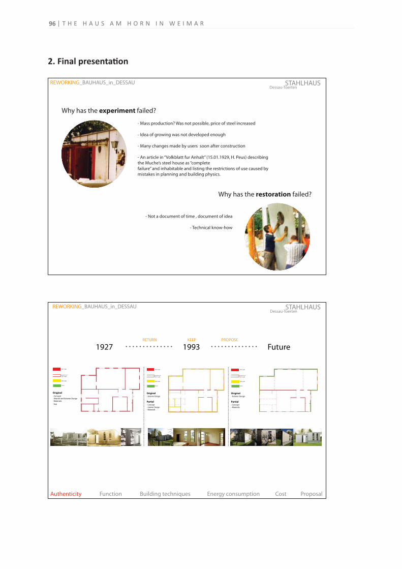
Dessau-ToertenSTAHLHAUS
Authenticity Function Building techniques Energy consumption Cost Proposal
1927 1993 Future
1927 walls
positions of
1927 walls
1993 walls
future
- Concept
- Interior and Exterior Design
- Materials
- Use
Original
1927 walls
positions of
1927 walls
1993 walls
future
- Concept
- Materials
Partial
Original- Exterior Design
RETURN KEEP PROPOSE
- Concept
- Interior Design
- Materials
Partial
Original- Exterior Design
1927 walls
positions of
1927 walls
1993 walls
future
REWORKING_BAUHAUS_in_DESSAU
2. Final presenta on
Dessau-ToertenSTAHLHAUS REWORKING_BAUHAUS_in_DESSAU
Why has the experiment failed?
Why has the restoration failed?
- Not a document of time , document of idea
- Technical know-how
- Mass production? Was not possible, price of steel increased
- Idea of growing was not developed enough
- Many changes made by users soon after construction
- An article in “Volkblatt fur Anhalt” (15.01.1929, H. Peus) describing
the Muche’s steel house as “complete
failure” and inhabitable and listing the restrictions of use caused by
mistakes in planning and building physics.
T H E H A U S A M H O R N I N W E I M A R96
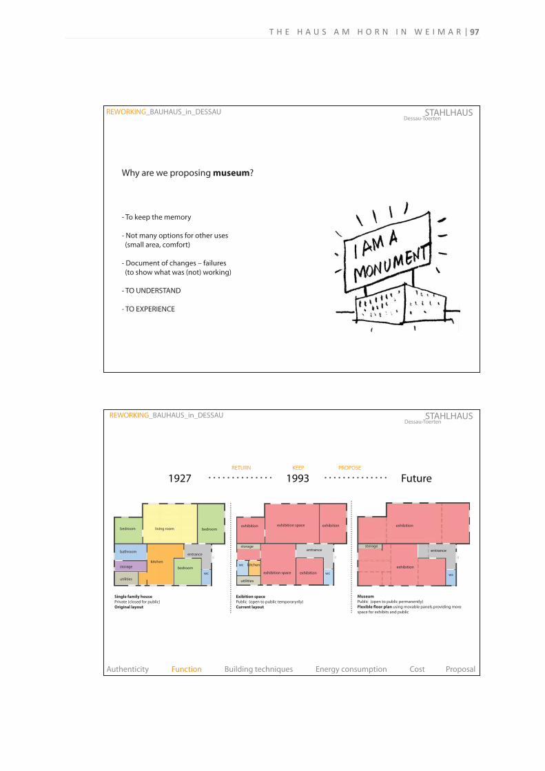
Single family house
Private (closed for public)
Original layout
utilities
storage bedroom
bedroombedroom living room
kitchen
wc
bathroomentrance
Museum
Public (open to public permanently)
Flexible floor plan using movable panels providing more
space for exhibits and public
exhibition
storageentrance
exhibition
wc
Exibition space
Public (open to public temporaryrily)
Current layout
exhibition space
utilities
storage
kitchen
entrance
exhibition
exhibition space exhibition
exhibition
wc
wc
Dessau-ToertenSTAHLHAUS
Authenticity Function Building techniques Energy consumption Cost Proposal
1927 1993 Future
REWORKING_BAUHAUS_in_DESSAU
RETURN KEEP PROPOSE
Dessau-ToertenSTAHLHAUS REWORKING_BAUHAUS_in_DESSAU
Why are we proposing museum?
- To keep the memory
- Not many options for other uses
(small area, comfort)
- Document of changes – failures
(to show what was (not) working)
- TO UNDERSTAND
- TO EXPERIENCE
97T H E H A U S A M H O R N I N W E I M A R
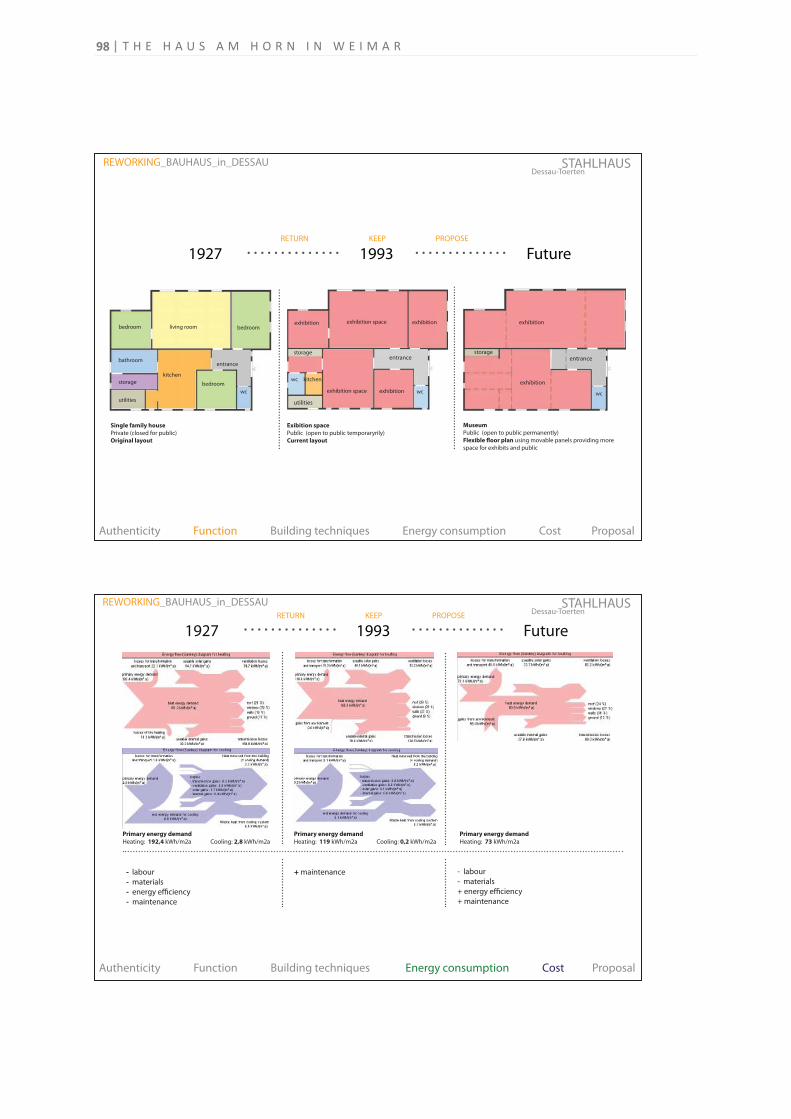
- labour
- materials
- energy efficiency
- maintenance
+ maintenance
- labour
- materials
+ energy efficiency
+ maintenance
Primary energy demand
Heating: 192,4 kWh/m2a Cooling: 2,8 kWh/m2a
Primary energy demand
Heating: 119 kWh/m2a Cooling: 0,2 kWh/m2a
Primary energy demand
Heating: 73 kWh/m2a
Dessau-ToertenSTAHLHAUS
1927 1993 Future
REWORKING_BAUHAUS_in_DESSAU
Authenticity Function Building techniques Energy consumption Cost Proposal
RETURN KEEP PROPOSE
Single family house
Private (closed for public)
Original layout
utilities
storage bedroom
bedroombedroom living room
kitchen
wc
bathroomentrance
Museum
Public (open to public permanently)
Flexible floor plan using movable panels providing more
space for exhibits and public
exhibition
storageentrance
exhibition
wc
Exibition space
Public (open to public temporaryrily)
Current layout
exhibition space
utilities
storage
kitchen
entrance
exhibition
exhibition space exhibition
exhibition
wc
wc
Dessau-ToertenSTAHLHAUS
Authenticity Function Building techniques Energy consumption Cost Proposal
1927 1993 Future
REWORKING_BAUHAUS_in_DESSAU
RETURN KEEP PROPOSE
T H E H A U S A M H O R N I N W E I M A R98
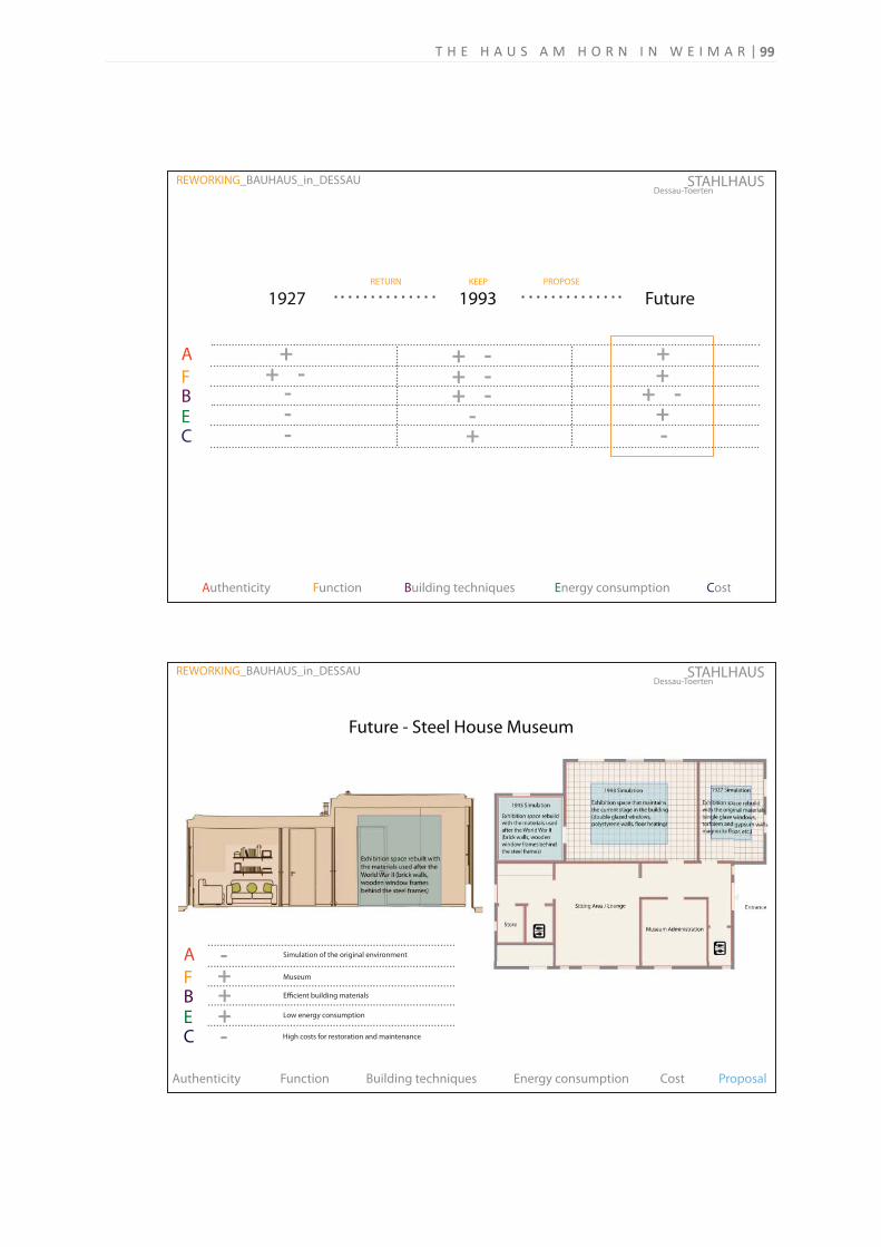
Future - Steel House Museum
Dessau-ToertenSTAHLHAUS REWORKING_BAUHAUS_in_DESSAU
Authenticity Function Building techniques Energy consumption Cost Proposal
A
FB
CE
- + + + -
Simulation of the original environment
Museum
Efficient building materials
Low energy consumption
High costs for restoration and maintenance
A
FB
CE
+ + - + + - - - -
+ - + - - +
+ + - + -
Dessau-ToertenSTAHLHAUS
1927 1993 Future
REWORKING_BAUHAUS_in_DESSAU
Authenticity Function Building techniques Energy consumption Cost
RETURN KEEP PROPOSE
99T H E H A U S A M H O R N I N W E I M A R
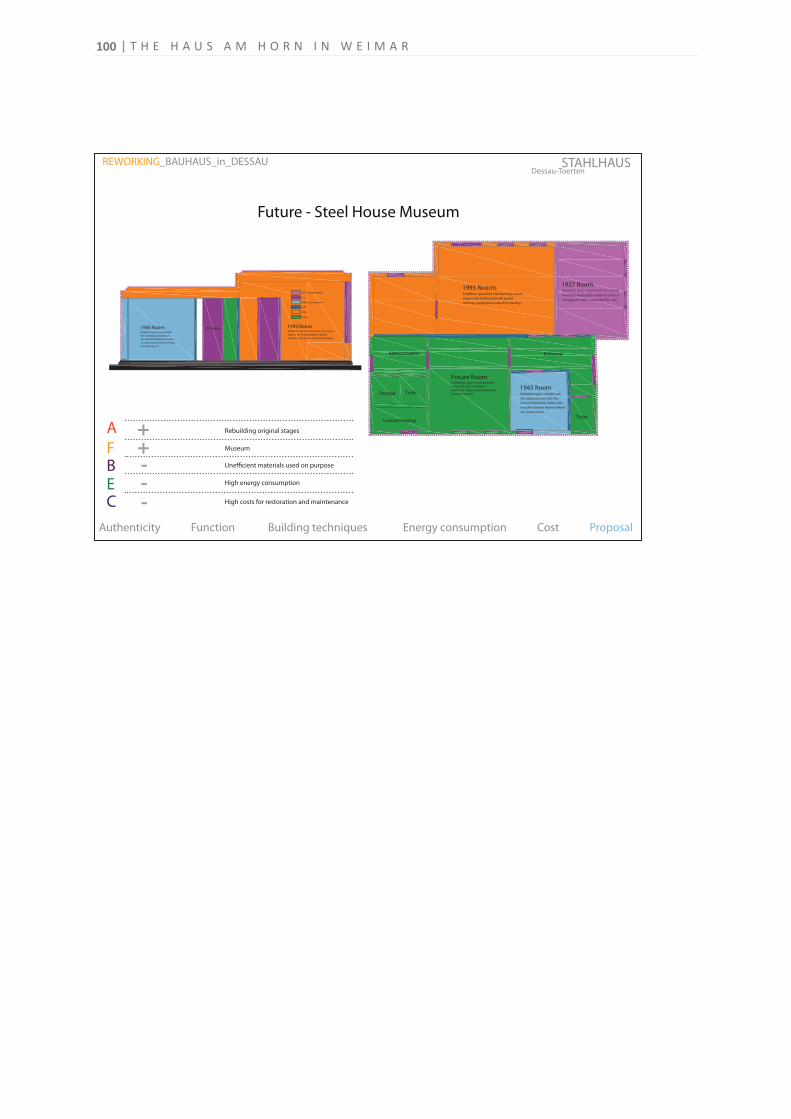
100
A
FB
CE
Rebuilding original stages + + - - -
Museum
Unefficient materials used on purpose
High energy consumption
Dessau-ToertenSTAHLHAUS REWORKING_BAUHAUS_in_DESSAU
Authenticity Function Building techniques Energy consumption Cost Proposal
Future - Steel House Museum
High costs for restoration and maintenance
T H E H A U S A M H O R N I N W E I M A R