
The Explanation of the Design Patterns by the Symmetry Concepts
11
The Explanation of the Design Patterns by the Symmetry Concepts Siniša Vlajić, Dušan Savić, Antović Ilija Department of Software Engineering, Faculty of Organizational Sciences, Jove Ilića 154, Belgrade, Serbia. e-mail: [email protected], [email protected], [email protected] ABSTRACT The aim of this paper is to establish a connection between software engineering and other science disciplines, such as mathematics, physics, and alike ,with the intent to use the knowledge from these disciplines to create a new software system which will be more stable and sustainable than existing systems. To this aim, this paper formally explains the design patterns through the concepts of symmetry; symmetry transformations and symmetry groups. We give the formal definition of design patterns and explain when and how the design patterns are occurring. Therefore, we have made the formal basis to create stable and sustainable software systems, based on symmetry concepts, which will be both changeable but also immune to change. We have defined the theorems that connect concepts of symmetry and class diagrams and pointed out the cases when classes make a symmetry transformation and when a set of classes make the symmetry and no-symmetry group. Finally, we have given an example to show the process of making design patterns by using the symmetry concepts. KEY WORDS Design patterns, Symmetry concepts 1. Introduction The book Design Patterns: Elements of Reusable Object- Oriented Software [1] has launched an avalanche in the world of software engineering and put the patterns in the center of software development in a very practical way. It is one of the most important source in understanding object-oriented design theory and practice. Design patterns are one of the most important mechanisms in the development of sustainable software systems. Up to now, many design patterns are made and used in the development of numerous software systems. Design patterns are primarily seen as a generic solution that can be applied several times in different problem- situations. In addition, design patterns provide great flexibility in the program during its maintenance and upgrades. These positive pattern features (re-usability and easy maintenance) have led to formalisation of the design pattern (Figure 1). With this notion a lot of pattern languages are made (Balanced pattern specification language (BPSL), Design Pattern Modelling Language (DPML),…, LePUS`: A Formal Language for Modelling Design Patterns) [2] to : a) better understand patterns and their composition b) accurately describe patterns to avoid their duplication and to simplify the process of the pattern repository management, and to c) allow the development of the tool support in activities related to patterns in the software development process. Fig. 1: The formalisms for describing the design patterns However, these languages neither give a precise formal definition of design patterns in a general sense, nor explain when and how the patterns are occurring. If we understand the patterns as a solution to a problem in a context [3], then we can say that these pattern languages are focused on a precise definition and specification of solutions, while less attention is paid to the problem being solved. Formalization of patterns, from the perspective of the problem, is described in the paper of Holger Kampffmeyer and Steffen Zschaler a [4], in which design patterns are formalized and classified according to their purpose (problem-solving) by DPIO (Design Patterns Intent Ontology). The above formalisms in a conceptual way explain the connection between a problem and a solution of the pattern, without going into a deeper understanding of the relationship between elements of the problem and solution of the pattern. This paper tries to point out the connection between the elements of the problem and the solution of the pattern and to formally explain the process of transforming (T) the problem into the solution through the symmetry concepts (symmetry transformations and symmetry groups) (Figure 2). GOF DESIGN PATTERNS PROBLEM SOLUTION BSPL DPML Lepus Formalisms Ontology Pattern DPIO
-
Upload
universityofbelgradefos -
Category
Documents
-
view
0 -
download
0
Transcript of The Explanation of the Design Patterns by the Symmetry Concepts

The Explanation of the Design Patterns by the Symmetry Concepts
Siniša Vlajić, Dušan Savić, Antović Ilija Department of Software Engineering, Faculty of Organizational Sciences,
Jove Ilića 154, Belgrade, Serbia. e-mail: [email protected], [email protected], [email protected]
ABSTRACT The aim of this paper is to establish a connection between software engineering and other science disciplines, such as mathematics, physics, and alike ,with the intent to use the knowledge from these disciplines to create a new software system which will be more stable and sustainable than existing systems. To this aim, this paper formally explains the design patterns through the concepts of symmetry; symmetry transformations and symmetry groups. We give the formal definition of design patterns and explain when and how the design patterns are occurring. Therefore, we have made the formal basis to create stable and sustainable software systems, based on symmetry concepts, which will be both changeable but also immune to change. We have defined the theorems that connect concepts of symmetry and class diagrams and pointed out the cases when classes make a symmetry transformation and when a set of classes make the symmetry and no-symmetry group. Finally, we have given an example to show the process of making design patterns by using the symmetry concepts. KEY WORDS Design patterns, Symmetry concepts 1. Introduction The book Design Patterns: Elements of Reusable Object-Oriented Software [1] has launched an avalanche in the world of software engineering and put the patterns in the center of software development in a very practical way. It is one of the most important source in understanding object-oriented design theory and practice. Design patterns are one of the most important mechanisms in the development of sustainable software systems. Up to now, many design patterns are made and used in the development of numerous software systems. Design patterns are primarily seen as a generic solution that can be applied several times in different problem-situations. In addition, design patterns provide great flexibility in the program during its maintenance and upgrades. These positive pattern features (re-usability and easy maintenance) have led to formalisation of the design pattern (Figure 1). With this notion a lot of pattern languages are made (Balanced pattern specification language (BPSL), Design Pattern Modelling Language (DPML),…, LePUS`: A Formal Language for Modelling
Design Patterns) [2] to : a) better understand patterns and their composition b) accurately describe patterns to avoid their duplication and to simplify the process of the pattern repository management, and to c) allow the development of the tool support in activities related to patterns in the software development process. Fig. 1: The formalisms for describing the design patterns However, these languages neither give a precise formal definition of design patterns in a general sense, nor explain when and how the patterns are occurring. If we understand the patterns as a solution to a problem in a context [3], then we can say that these pattern languages are focused on a precise definition and specification of solutions, while less attention is paid to the problem being solved. Formalization of patterns, from the perspective of the problem, is described in the paper of Holger Kampffmeyer and Steffen Zschaler a [4], in which design patterns are formalized and classified according to their purpose (problem-solving) by DPIO (Design Patterns Intent Ontology). The above formalisms in a conceptual way explain the connection between a problem and a solution of the pattern, without going into a deeper understanding of the relationship between elements of the problem and solution of the pattern. This paper tries to point out the connection between the elements of the problem and the solution of the pattern and to formally explain the process of transforming (T) the problem into the solution through the symmetry concepts (symmetry transformations and symmetry groups) (Figure 2).
GOF DESIGN PATTERNS
PROBLEM SOLUTION
BSPL DPML Lepus
Formalisms
Ontology Pattern
DPIO
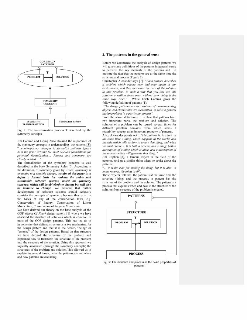
Fig. 2: The transformation process T described by the symmetry concepts Jim Copline and Liping Zhao stressed the importance of the symmetry concepts in understanding the patterns [5]: “...contemporary attempts to formalize patterns ignore both the prior art and the most relevant foundations for potential formalization.... Pattern and symmetry are closely related ... ". The formalization of the symmetry concepts is well described in the book Symmetry Rules [6]. According to the definition of symmetry given by Rosen: Symmetry is immunity to a possible change, the aim of this paper is to define a formal basis for making the stable and sustainable software systems, based on symmetry concepts, which will be abl eboth to change but will also be immune to change. We maintain that further development of software systems should seriously consider the concepts of symmetry because they exist in the bases of any of the conservation laws, e.g. Conservation of Energy, Conservation of Linear Momentum, Conservation of Angular Momentum. We have derived our theory on the base analysis of the GOF (Gang Of Four) design pattern [1] where we have observed the structure of solutions which is common to most of the GOF design patterns. This has led us to hypothesize that defined structure is a key mechanism for the design pattern and that it is the "core", "being" or "essence" of the design patterns. Based on that structure we have defined the structure of the problem and explained how to transform the structure of the problem into the structure of the solution. Using this approach we logically associated (through the symmetry concepts) the structures of the problem and solution.This allowed us to explain, in general terms, what the patterns are and when and how patterns are occurring.
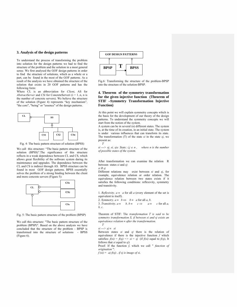
2. The patterns in the general sense Before we commence the analysis of design patterns we will give some definitions of the patterns in general sense to perceive the key elements of the patterns and to indicate the fact that the patterns are at the same time the structure and process (Figure 3). Christopher Alexander says [7]: “Each pattern describes a problem which occurs over and over again in our environment, and then describes the core of the solution to that problem, in such a way that you can use this solution a million times over, without ever doing it the same way twice.” While Erich Gamma gives the following definition of patterns [1]: “The design patterns are descriptions of communicating objects and classes that are customized to solve a general design problem in a particular context“. From the above definitions, it is clear that patterns have two important parts, the problem and solution. The solution of a problem can be reused several times for different problem domains, from which stems a reusability concept as an important property of patterns. Also, Alexander points out : “The pattern is, in short, at the same time a thing, which happens in the world, and the rule which tells us how to create that thing, and when we must create it. It is both a process and a thing; both a description of a thing which is alive, and a description of the process which will generate that thing.” Jim Coplien [8], a famous expert in the field of the patterns, told us a similar thing when he spoke about the patterns: “… it is the rule for making the thing, but it is also, in many respect, the thing itself”. These experts tell that the pattern is at the same time the structure (thing) and the process. A pattern has the structure of the problem and the solution. The pattern is a process that explains when and how it the structure of the solution from structure of the problem is created. Fig. 3: The structure and process as the basic properties of
patterns
STRUCTURE
T
PATTERNS
PROBLEM SOLUTION
PROCESS
T
GOF DESIGN PATTERNS
PROBLEM SOLUTION
SYMMETRY TRANSFORMATION
SYMMETRY CONCEPTS
SYMMETRY GROUP
3. Analysis of the design patterns To understand the process of transforming the problem into solution for the design patterns we had to find the structure of the problem and the solution in a most general sense. We first analysed the GOF design patterns in order to find the structure of solutions, which as a whole or a part, can be found in the most of the GOF patterns. As a result of the analysis we have obtained the structure of the solution that exists in 20 GOF patterns and has the following form: Where CL is an abbreviation for Client, AS for AbstractServer and CSi for ConcreteServeri (i = 1..n, n is the number of concrete servers). We believe the structure of the solution (Figure 4) represents “key mechanism”, "the core", "being" or "essence" of the design patterns.
Fig. 4: The basic pattern structure of solution (BPSS)
We call this structure: “The basic pattern structure of the solution (BPSS)”.The significance of this structure reflects in a weak dependence between CL and CS, which allows great flexibility of the software system during its maintenance and upgrades. The dependence between the CL and CS is indirect through AS. BPSS structure can be found in most GOF design patterns. BPSS essentially solves the problem of a strong binding between the client and more concrete servers (Figure 5): Fig. 5: The basic pattern structure of the problem (BPSP) We call this structure: "The basic pattern structure of the problem (BPSP)". Based on the above analysis we have concluded that the structure of the problem - BPSP is transformed into the structure of solutions - BPSS (Figure 6).
Fig.6: Transforming the structure of the problem-BPSP into the structure of the solution-BPSP. 4. Theorem of the symmetry transformation for the given injective function (Theorem of STIF –Symmetry Transformation Injective Function) At this point we will explain symmetry concepts which is the basis for the development of our theory of the design patterns. To understand the symmetry concepts we will start from the notion of the system. A system can be in several (n) different states. The system is, at the time of its creation, in an initial state. The system is under various influences that can transform its state. The transformation (T) of the state si in the state sj, we present as: T si ---> sj, si, sj State; i,j n , � where n is the number of possible states of the system. After transformation we can examine the relation R between states si and sj: si R sj Different relations may exist between si and sj, for example, equivalence relation or order relation. The equivalence relation between two states exists if it satisfies the following conditions: reflexivity, symmetry and transitivity. 1. Reflexivity. a �a for all a (every element of the set is equivalent to itself). 2. Symmetry. a �b � b �a for all a, b. 3. Transitivity. a ��b, b ��c ��a ��c for all a, b, c. Theorem of STIF: The transformation T is said to be symmetry transformation S, if between si and sj exists an equivalence relation after the transformation. T si ---> sj �si Between states si and sj there is the relation of equivalence if there is the injective function f which satisfies: f(si) = f(sj) => si = sj (if f(si) equal to f(sj), It follows that si equal to sj) Proof: If the function f, which we call " function of origination ": f (si) = a) f(sj) , if sj is image of si,
CL
CS1
CS2
CSn
CL
CS1
AS
CS2 CSn
T
GOF DESIGN PATTERNS
BPSP
BPSS

b) si State= { s1,s2,…,sn} – set of states si, sj State, where is i,j�1..n (si,sj are elements of State) if => sj is image of si , where is criteria that determines when sj is image of si. If the function f is applied to si and sj, we obtain : f(si) = f(sj) => sk = sk It follows: f(si) = f(sj) => si = sj which can be presented as follows: sk = sk f ↑ T f ↑ si ---> sj Based on the above, we can conclude that there exists the equivalence relation ≡ between si and sj: si ≡ sj, which is realized by the equality operation = between si and sj: si = sj if there is a injective function f for which applies: if f(si) = f(sj), then si = sj, for all si and sj. Thus the theorem is proven. The transformation T between si and sj is symmetry transformation because
between si and sj exist equivalence relation for the injective "function of origination" f, for which applies: if f(si) = f(sj), then si = sj Symmetry transformation is essentially a function fst which maps si in sj: fst (si,sj) The theorem of STIF will be presented by UML class diagram (Figure 7). System has many states. Transformation T is defined between two states si and sj. After transformation between si and sj a relation exists. If between si and sj there is an equivalence relation after transformation then a symmetry transformation is executed. The equivalence relation exists if it is defined by function of origination (f). The equivalence relation is realized by Equality operation.
Fig. 7: The theorem of STIF
is performed on gives the same result
1
111 (sj)
*System State T
Relation
Equivalence relation ()
1 (si)
Symmetry transformation (S) - fst
Function of origination (f)
*
The transformation T is said to be symmetry transformation S, if between si and sj exist the equivalence relation after the transformation.
Between states si and sj exist the equivalence relation, if exist the injective function f, for which applies: f(si) = f(sj) => si = sj
Equality operation

5. The Application of the theorem of STIF at the class diagram The theorem of STIF (Figure 8) can be applied at the class diagram of the UML [9]. The concepts of the theorem are mapped in the concepts of the class diagram. The system is represented by the class diagrams. The states of the system(s1, s2 ,..., sn) are the classes.
,..., Yn-1) of the class diagram. The transformation of the system states are operations of the classes. The relations between the states of the system are relationships between classes. The equivalence relation between the states of the system are has (aggregation) and is (generalization) relationships between classes, which will be further explained in more detalis.
For the "function of origination" f needs to define criteria which determinates when sj is an image of si. In the case of class diagram, the criteria is defined as: si has sj si is original, while sj is image. b) si is sj si is original, while sj is an image. This means that the "function of origination" for class diagram is defined as follows: if si HAS sj or si IS sj => sj is image of si If function f apply to si and sj, we obtain: f(si) = f(sj), sj = sj, It follows: f(si) = f(sj) => si = sj This means that IS and HAS relationships, between classes si and sj, realize equivalence relation between these classes. It follows that there is a symmetry transformation between si and sj. 6. Theorems of the Symmetry Group realised by the Class diagram There are two theorems that realise symmetry group by IS (first theorem) and HAS (second theorem) relationship of the class diagram.
6.1 Theorem of the Symmetry Group realised by the IS relationship of the Class diagram If the classes Y1, Y2 ,..., Yn inherit class Y (Figure 8), between each pair of classes ({Y1,Y}, {Y2,Y},...,{Yn,Y}) a symmetry transformation exists according to the theorem of STIF. This set of symmetry transformations makes the symmetry group. Fig. 8 IS relationships between class Y and the classes Y1, Y2 ,..., Yn Proof: The above statement is true if it is proven that each of these symmetry transformations is invertible and the set of the symmetry transformation satisfies the following 4 axioms [Coplien 2001] which defines the group: 1. Closure. For all a, b G, the set G is closed under composition: ab, ba G. 2. Associativity. For all a, b, c G, the composition is associative: (ab)c = a(bc). 3. Existence of an Identity Element. For all a G, there exists an element e G such that ae = a = ea. 4. Existence of Inverses. For each a G, there exists an a-1� G such that aa-1 = e = a-1a. If the function of origination f applied to each pair, S1 S1 f(Y1) ---> f(Y) => Y ---> Y S2 S2 f(Y2) ---> f(Y) => Y ---> Y ... Sn Sn f(Yn) ---> f(Y) => Y ---> Y the equality exists betwen S1,S2,...,Sn (S1 = S2 = ... = Sn). This means that all symmetry transformations are the
si sj
sj
si
Y2 Y1
Y
Yn ...
same if classes Y, Y1, Y2, ..., Yn are under of the influence of the injective function f. This set of symmetry transformations makes the symmetry group because: a) Closure. For all s1, s2 G the set G is closed under composition: s1s2, s2s1 G, G S1� S2, …, Sn)
s1 s2 Y ---> Y ---> Y
Result of s1s2 is equal to S where S is equal to any of these symmetry transformations: S1 = S2 = ... = Sn = S The same goes for s2s1:
s2 s1 Y ---> Y ---> Y
b) Associativity. For all s1,s2,s3 G, the composition is associative: (s1s2)s3 = s1(s2s3), G ��S1� S2, …, Sn�)
s1 s2 s3 s1 s2 s3 (Y ---> Y ---> Y ) ---> Y = Y ---> (Y ---> Y ---> Y)
s1s2 s3 s1 s2s3 Y ---> Y ---> Y = Y ---> Y ---> Y
3. Existence of an Identity Element. For all s G, there exists an element e G such that se = s = es, G ��S1� S2, …, Sn�)
s e s e s (Y ---> Y ---> Y) = (Y ---> Y) = Y ---> Y ---> Y
e can be any of the symmetry transformations from the set G. ’
4. Existence of Inverses. For each s G, there exists an s-1� G such that ss-1 = e = s-1s, G ��S1� S2, …, Sn��
s s-1 e s-1 s (Y ---> Y ---> Y) = (Y ---> Y) = Y ---> Y ---> Y
s-1 and e can be any of the symmetry transformations from the set G.
6.2 Theorem of the Symmetry Group realised by the HAS relationship of the Class diagram
If the classes Y1, Y2 ,..., Yn has the class X (Figure 9), between each pair of the classes ({Y1,X}, {Y2,X},...,{Yn,X}) exists the symmetry transformation according to the theorem of STIF. This set of the symmetry transformations makes the symmetry group.
Fig. 9:HAS relationships between classes Y1, Y2 ,..., Yn and class Y
Proof for above theorem is performed in a similar way as the proof of the Theorem of the Symmetry Group realised by the IS relationship of the Class diagram. We mark the symmetry group with::
fsg (Y,X)
The symmetry group consists of a set symmetry transformation between pairs (Y1, X), (Y2, X ),..., (Yn, X), for which an equivalence relation is defined.
fsg (Y,X) = fst(Y1,X) + fst(Y2,X),..., + fst(Yn, X),
fst(Y1,X) = fst(Y2,X),..., = fst(Yn,X)
7. Theorems of the no-Symmetry Group realised by the Class diagram There are two theorems that realise no-symmetry group by has (first theorem) and is (second theorem) relationship of the class diagram. 7.1: Theorem of the No-Symmetry Group realised by the HAS relationship of the Class diagram If the class X has (related to) several classes Y1, Y2 ,..., Yn (Figure 10), between each pair of classes ({X,Y1},{X,Y2},...,{X,Yn}) there exists the symmetry transformation according to the theorem of STIF. This set of the symmetry transformations does not make the symmetry group. Fig. 10:HAS relationships between class Y and classes Y1, Y2 ,..., Yn Proof: The above statement is true if it is proven that set of symmetry transformations does not satisfy one of the following 4 axioms [CoplienSym1] which define the group, as it is explained in the proof of the Theorem of the Symmetry Group realised by the IS relationship of the Class diagram. If the function of origination f applied to each pair,
S1 S1 f(X) ---> f(Y1) => Y1 ---> Y1
X
Y2
Y1
Yn
X
Y2
Y1
Yn
S2 S2 f(X) ---> f(Y2) => Y2 ---> Y2
...
Sn Sn f(X) ---> f(Yn) => Yn ---> Yn
the inequality exists between S1,S2,…,Sn (S1 ≠ S2 ≠ ... ≠ Sn). Thit means, the symmetry transformations are not the same if the classes X,Y1,Y2,...,Yn are under the influence of the injective function f. This set of the symmetry transformation does not make the symmetry group because it does not satisfy one of the axioms (closure) which define the group:
a) Closure. For all s1, s2 G the set G is closed under composition: s1s2, s2s1 G, G ��S1� S2, …, Sn�)
These sets of the symmetry transformations S1 � S2, ..., Sn cannot, among themselves, make the composition. In this way, it is proved that the given a set of symmetry transformations does not make the symmetry group. 7.2: Theorem of the No-Symmetry Group realised by the IS relationship of the Class diagram If class X inherits the classes Y1,Y2,...,Yn (Figure 16):
Fig. 11: IS relationships between classes Y1, Y2 ,..., Yn and class Y
between each pair of the classes ({X,Y1},{X,Y2},...,{X,Yn}) exists the symmetry transformation according to the theorem of STIF. This set of the symmetry transformations does not make a symmetry group. The proof for the above theorem is performed in a similar way as the proof of Theorem of the No-Symmetry Group realised by the HAS relationship of the Class diagram.
We mark the No-Symmetry group with:
fnsg (X,Y) The No-Symmetry group consists of the set of the symmetry transformations between pairs (X,Y1), (X,Y2 ) ,..., (X,Yn), for which is not defined equivalence relation. fnsg (X,Y) = fst(X,Y1) + fst(X,Y2),..., + fst(X,Yn),
fst(X,Y1) ≠ fst(X,Y2),..., ≠ fst(X,Yn) 8. The explanation of the design pattern by the symmetry concepts The design patterns will be explained by the symmetry concepts through the example of the program that will be written in intuitive object pseudocode which is similar to the Java programming language. If the pattern is considered as a relation beetwen the problem and its solution, then the pattern can be explained as follows: For the given original X there is an image Y1, which can be represented by the relation of a symmetry transformation beetwen X and Y1 (Figure 12): fst(X,Y1) Example in object pseudocode: class X // fst (X,Y1) { Y1 y1; X() {y1 = new Y1(); } void m() { y1.m(); } } class Y1 { void m() {…}} class Main { public static void main(String arg[]) { X x = new X(); x.m(); } } Fig. 12: The symmetry transformation between X and Y1 When the symmetry transformation between X and Y1 is broken (symmetry breaking), then symmetry transformation (this is moment when the pattern begins to occur):
fst(X,Y1)
becomes no-symmetry group (problem in the pattern)(Figure 13):
fst(X,Y1) + fst(X,Y2)
which can be marked with:
fnsg(X,Y)
fst(X,Y1) X Y1
Yn
X
Y2
Y1
Yn
X
Y2
Y1 fnsg(X,Y)
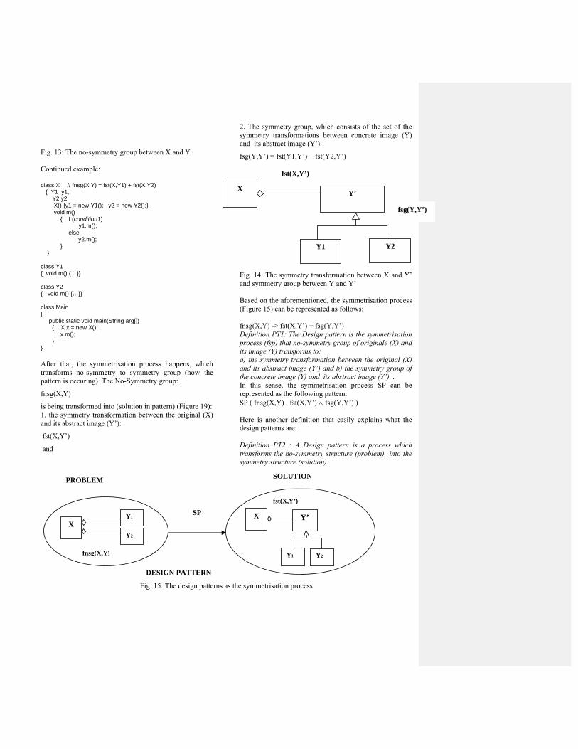
Fig. 13: The no-symmetry group between X and Y Continued example: class X // fnsg(X,Y) = fst(X,Y1) + fst(X,Y2) { Y1 y1; Y2 y2; X() {y1 = new Y1(); y2 = new Y2();} void m() { if (condition1) y1.m(); else y2.m(); } } class Y1 { void m() {…}} class Y2 { void m() {…}} class Main { public static void main(String arg[]) { X x = new X(); x.m(); } } After that, the symmetrisation process happens, which transforms no-symmetry to symmetry group (how the pattern is occuring). The No-Symmetry group:
fnsg(X,Y)
is being transformed into (solution in pattern) (Figure 19): 1. the symmetry transformation between the original (X) and its abstract image (Y’):
fst(X,Y’)
and
2. The symmetry group, which consists of the set of the symmetry transformations between concrete image (Y) and its abstract image (Y’):
fsg(Y,Y’) = fst(Y1,Y’) + fst(Y2,Y’) Fig. 14: The symmetry transformation between X and Y’ and symmetry group between Y and Y’ Based on the aforementioned, the symmetrisation process (Figure 15) can be represented as follows: fnsg(X,Y) -> fst(X,Y’) + fsg(Y,Y’) Definition PT1: The Design pattern is the symmetrisation process (fsp) that no-symmetry group of originale (X) and its image (Y) transforms to: a) the symmetry transformation between the original (X) and its abstract image (Y’) and b) the symmetry group of the concrete image (Y) and its abstract image (Y’) . In this sense, the symmetrisation process SP can be represented as the following pattern: SP ( fnsg(X,Y) , fst(X,Y’) fsg(Y,Y’) ) Here is another definition that easily explains what the design patterns are: Definition PT2 : A Design pattern is a process which transforms the no-symmetry structure (problem) into the symmetry structure (solution).
Fig. 15: The design patterns as the symmetrisation process
fsg(Y,Y’)
X
Y1
Y’
Y2
fst(X,Y’)
fsg(Y,Y’)
PROBLEM SOLUTION
X
Y1
Y’ X
Y2
Y1 SP
DESIGN PATTERN
Y2fnsg(X,Y)
fst(X,Y’)

class X // fst(X,Y’) + fsg(Y,Y’) { Y y; X(Y y1) {y1 = y;} void m() { y.m(); } }
abstract class Y’ { abstract void m(); }
class Y1 extends Y { void m() {…} }
class Y2 extends Y { void m() {…}}
class Main { public static void main(String arg[]) { X x; if (condition1) x = new X(new Y1()); else x = new X(new Y2()); x.m(); } }
9. The examples of the design pattern explained by the symmetry concepts Here, we will explain the Builder and Bridge GOF patterns by the symmetry concepts. Builder pattern provides an independent construction of a complex object from its representation, so that the same construction process can create different representations. The construction process should not be changed when adding a new representation. This pattern has the following elements: Director (original) and ConcreteBuilder (image), which is represented by the set of elements: ConcreteBuilder1, ConcreteBuilder2 ,..., ConcreteBuildern. Between Director and ConcreteBuilder a no-symmetry group (problem in the pattern), is formed, which can be marked: fnsg(Director,ConcreteBuilder) The Director, which is responsible for the construction process, is connected to an n different ConcreteBuilder, where each ConcreteBuilder is connected to a concrete representation of the product. If we inserted a new ConcreteBuildera we would have to change the structure of Director. In this case we have to change a construction process.
If we want to ensure that the process of the construction is independent of the presentation we introduce a new element Builder (abstract image) which together with the Director establishes symmetry transformation: fst(Director,Builder) whereas with the ConcreteBuilder element establish symetry group: fsg(ConcreteBuilder,Builder) Accordint to PT1 Builder pattern has a form: fnsg(Director,ConcreteBuilder) -> fst(Director,Builder) + fsg(ConcreteBuilder,Builder) Bridge pattern provides an independent abstraction of an operation from its implementations. One abstraction of an operation can have more implementations (realisations). This pattern has the following elements: Abstraction (original) and ConcreteImplementor (image), which is represented by the set of elements: ConcreteImplementor1,ConcreteBuilder concreteImplementor ,..., ConcreteBuildern. Between Abstraction and ConcreteImplementor no-symmetry group (problem in the pattern), is formed, which can be marked: fnsg(Abstraction,ConcreteImplementor) The Abstraction, which is responsible for the description of the abstraction of operation, is connected with an n different ConcreteImplementor(CI), where each ConcreteImplementor provides concrete implementation of operation (it gives n different implementations). If we inserted a new ConcreteImplementora we would have to change the structure of Abstraction, i.e. we would have to change abstraction of operation. If we want to ensure that abstraction of the operation is independent of its implementation we introduce a new element of the Implementer (abstract image), which together with Abstraction element establish symmetry transformation: fst(Abstraction,Implementor) whereas with ConcreteImplementor element establishes symetry group: fsg(CI,Implementor) Accordint to PT1 Bridge pattern has a following form: fnsg(Abstraction,CI) -> fst(Abstraction,Implementor) + fsg(CI,Implementor) In a similar way it can be explained, in whole or any part all remains GOF patterns, which are presented in Table 1:
GOF patterns / Elements of pattern Original Abstract image Concrete image Abstract Factory Client AbstractFactory ConcreteFactoryi
Client AbstractProductA ProductAiClient AbstractProductB ProductBi
Builder Director Builder ConcreteBuilder
Comment [F1]: Profesore, ovde ste negde stvljali slovo i na kraju naziva paterna.
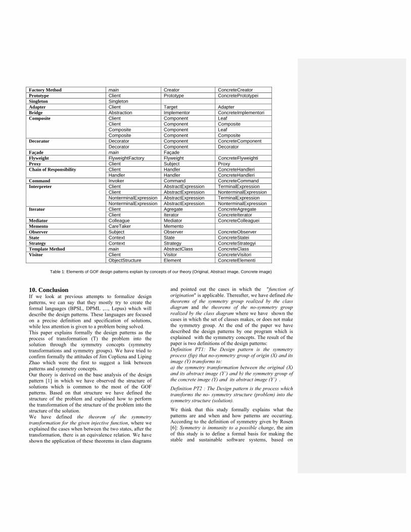
Factory Method main Creator ConcreteCreator Prototype Client Prototype ConcretePrototypei Singleton Singleton Adapter Client Target Adapter Bridge Abstraction Implementor ConcreteImplementori Composite Client Component Leaf
Client Component Composite Composite Component Leaf Composite Component Composite
Decorator Decorator Component ConcreteComponent Decorator Component Decorator
Façade main Façade Flyweight FlyweightFactory Flyweight ConcreteFlyweighti Proxy Client Subject ProxyChain of Responsibility Client Handler ConcreteHandleri
Handler Handler ConcreteHandleriCommand Invoker Command ConcreteCommand Interpreter Client AbstractExpression TerminalExpression
Client AbstractExpression NonterminalExpression NonterminalExpression AbstractExpression TerminalExpression NonterminalExpression AbstractExpression NonterminalExpression
Iterator Client Agregate ConcreteAgregate Client Iterator ConcreteIterator
Mediator Colleague Mediator ConcreteColleaguei Memento CareTaker Memento Observer Subject Observer ConcreteObserver State Context State ConcreteStatei Strategy Context Strategy ConcreteStrategyi Template Method main AbstractClass ConcreteClass Visitor Client Visitor ConcreteVisitori
ObjectStructure Element ConcreteElementi
Table 1: Elements of GOF design patterns explain by concepts of our theory (Original, Abstract image, Concrete image) 10. Conclusion If we look at previous attempts to formalize design patterns, we can say that they mostly try to create the formal languages (BPSL, DPML ,..., Lepus) which will describe the design patterns. These languages are focused on a precise definition and specification of solutions, while less attention is given to a problem being solved. This paper explains formally the design patterns as the process of transformation (T) the problem into the solution through the symmetry concepts (symmetry transformations and symmetry groups). We have tried to confirm formally the attitudes of Jim Copliena and Liping Zhao which were the first to suggest a link between patterns and symmetry concepts. Our theory is derived on the base analysis of the design pattern [1] in which we have observed the structure of solutions which is common to the most of the GOF patterns. Based on that structure we have defined the structure of the problem and explained how to perform the transformation of the structure of the problem into the structure of the solution. We have defined the theorem of the symmetry transformation for the given injective function, where we explained the cases when between the two states, after the transformation, there is an equivalence relation. We have shown the application of these theorems in class diagrams
and pointed out the cases in which the "function of origination" is applicable. Thereafter, we have defined the theorems of the symmetry group realized by the class diagram and the theorems of the no-symmetry group realized by the class diagram where we have shown the cases in which the set of classes makes, or does not make the symmetry group. At the end of the paper we have described the design patterns by one program which is explained with the symmetry concepts. The result of the paper is two definitions of the design patterns: Definition PT1: The Design pattern is the symmetry process (fsp) that no-symmetry group of origin (X) and its image (Y) transforms to: a) the symmetry transformation between the original (X) and its abstract image (Y’) and b) the symmetry group of the concrete image (Y) and its abstract image (Y’) .
Definition PT2 : The Design pattern is the process which transforms the no- symmetry structure (problem) into the symmetry structure (solution).
We think that this study formally explains what the patterns are and when and how patterns are occurring. According to the definition of symmetry given by Rosen [6]: Symmetry is immunity to a possible change, the aim of this study is to define a formal basis for making the stable and sustainable software systems, based on
symmetry concepts, which will be able to change but will also be immune to change. We consider that further development of software systems should seriously consider the concepts of symmetry because they exist in the bases of all conservation laws (Conservation of Energy, Conservation of Linear Momentum, Conservation of Angular Momentum, ...). In this sense, Noether's Theorem, states that there is a one-to-one correspondence between conservation laws and symmetries of differentiable physical systems. Nobel laureate PW Anderson, said: "It is only slightly overstating the case to say that physics is the study of symmetry." We believe that in times to come, “Conservation Laws of the software system“ and the study of symmetry in this context, will bring software systems and the physical systems close togather and enable the use the considerable knowledge from the physics in the software engineering. References [1] GAMMA, E., HELM, R., JOHNSON, R., VLISSIDES, J. 1994. Design Patterns. Addison-Wesley Professional, Reading, Massachusetts. [2] TOUFIK, T. 2007. Design Pattern Formalisation Techniques, IGI Publishing, Hershey, Pennsylvania. [3] FOWLER, M.2006: Writing software patterns. http://www.martinfowler.com/articles/writingPatterns.html [4] KAMPFFMEYER, H., ZSCHALER, S. 2007: Finding the Pattern You Need: The Design Pattern Intent Ontology, in MoDELS, Springer-Verlag, volume 4735/2007, 211-225. [5] COPLIEN, J., ZHAO, L. 2001. Symmetry Breaking in Software Patterns, LNCS, Springer-Verlag, volume 2177/2001,37-54. [6] ROSEN, J. 2008. Symmetry rules – how science and nature are founded on symmetry, Springer-Verlag Berlin Heidelberg. [7] CHRISTOPHER, A., ISHIKAWA S., SILVERSTEIN, M., JACOBSON, M., FIKSDAHL-KING, I., ANGEL, S. A Pattern Language. Oxford University Press, New York, 1977. [8] COPLIEN, J. 1996: Software Patterns, SIGS, New York. [9] OMG. 2010. Unified Modeing Language Specification, version 2.3, http://www.omg.org /spec/UML/2.3/Superstructure/PDF.