Highest Value-For-Money Digital Soldering Station Model SS ...
Upload
khangminh22Category
view
4download
0
The Ersa soldering primerSoldering made easy

2
Man had scarcely learned how to use metals for his purposes when the desire to join them arose in him. Many of the pieces of jew-elry, tools and weapons we know from the Bronze Age owe their usefulness and beauty to the art of soldering.
Today, soft soldering in the electron-ics industry has developed into a full-fledged production technol-ogy, encompassing the fields of mechanics, chemistry, physics and metallurgy. Ernst Sachs, the founder of Ersa (the company name consists of the initial letters of his first and last name) contributed to this development. In 1921 he devel-oped the first electrically operated soldering iron for the industry that was manufactured in series. Since that time, Ersa has committed itself to the further development and perfection of soldering technology with great passion and extending its full power of innovation.
Today, Ersa stands for the most comprehensive product range in the soft soldering technology world-wide and for more than 90 years of industry experience and innovation, know-how and highest product quality.
The Ersa soldering iron product range covers ultra-fine solder-ing tips, classical soldering irons powered from the standard power net and special soldering tools up to the 550 W hammer soldering iron. Ersa’s electronically temperature-controlled soldering stations repre-sent the industry standard, as does the extensive range of rework and
as a joining metal. And that was, after all, already 4,000 years ago!
From then on, soldering technology was on its way. It first spread around the Mediterranean. The Cretans showed it to the Etruscans who then taught it to the Romans, Tunisians, Spaniards, followed by many others, including the less developed cultures of the time – the Swiss, Bohemians, Hungarians, Teutons and Scandina-vians. From culture to culture, from generation to generation, the craft of soldering was continuously improved and refined.
The ancient Romans already laid down and soldered 400 km of leaden water pipes, conjured up stoves and bathtubs from bronze sheets, not to mention the excellent craftsmanship of their armorers and goldsmiths. Apart from craftsmanship in solder-ing, our understanding of the sci-ence of soldering has grown and has been refined over the centuries.
Today, it is difficult to say who first discovered how to "glue" metals. One thing is certain - the gold-smiths of ancient Egypt knew how to join gold and silver already more than 5,000 years ago. Their col-leagues in Troy were also master craftsmen long before the ancient Teutons could even dream of such handicraft. Soldering really "came of age" when tin was discovered
Soldering – a never-ending storyfor more than 5,000 years already

33
inspection systems, wave-, reflow- and selective soldering systems. The line of Ersa screen printers complements the product range.
Ersa’s quality soldering tools are used in the hobby area, such as, for example, in model-making or tiffany
Page
The history of soldering 2
The art of soldering 5
What is needed to solder? 6
Health 9
THT soldering 10
SMD soldering 13
BGA soldering / rework 16
Miniature and 18 microsoldering irons
Universal soldering irons 19
Standard, hammer and 20 high-speed soldering irons
Power and gas 21 soldering irons
Soldering stations 22
Multifunctional soldering 23 and desoldering stations
Hybrid rework station 26
Solder fume extractions 27
Tiffany soldering 28
Accessories 30
Seminars, references 31
A soldering iron heated up in burning fire: Soldering technology around 1536
soldering, in the craft sector, in labo-ratories and in industrial electronics manufacturing.
New challenges for the soldering technology were raised by the ban on certain hazardous substances (RoHS) in 2006. Since 1 July 2006 electric and electronic equipment may not contain any lead, mercury, hexavalent chromium, PBB (Po-lybrominated biphenyls) or PBDE (Polybrominated diphenyl ethers).
In many cases this restriction entailed having to depart from the use of the well-known soft solders based on tin and lead.
By publication of this small primer, Ersa would like to facilitate your entry into the "World of Soldering", and raise your enthusiasm for a modern technology with a long history.
Content

4
To imagine today’s world without soft soldering is not possible. It is the means to fabricate safely functioning, electrically conducting connections. Regardless of whether we talk about power technology, drive technology, telecommunica-tions, automation or electronic controls – in all those fields sol-dered connections have a decisive share that everything functions in a way as has been foreseen and planned by the developers and
visionaries of the products. Today, soft soldering is such a common place occurrence, that no one wastes any further thought on it. We take the daily use of our computers, mobile phones and play stations for granted, the modern comforts provided for by electronics found in modern automobiles is expected as a matter of course, and we fly – privately or on business – to the farthest spots in the world.
Consequential damage because of the failure of a solder joint in an iPod is relatively limited. It is a different matter altogether, though, if the electronics in an airplane full of vacationers, in a space shuttle, or in an implanted pacemaker fails.
Such failures are immanently life-threatening. But not to worry – the highest quality demands apply for those applications, and rightfully so!
Aside from soldering in consumer electronic products, there are numerous other applications such as, to name but a few, alternative power generation with wind turbines or solar parks, R&D departments and in work performed by crafts-men such as electricians and plumbers. Let us not forget the many part-time and hobby users for whom there are no limits curtailing their phantasies and artistic free-dom when handling a soldering iron and solder.
Solder joints hold the world together Connecting pacemakers and solar parks

5
1
2
3
2
1
5
In a soldering process two metal parts are joined by means of a molten metallic bonding agent (solder), whereby the melting point of the bonding agent is always lower than that of the metal parts to be joined. If the melting point is below 450 ºC, then it is a soft soldering process, if it is above, it is called hard soldering or brazing. Welding, on the other hand, is the process where two metals will be heated up to their melting point, at which time they will, together with a filler material, form a pool of molten
material causing coalescence. In soft soldering, the seams between the metals to be joined will be filled with a tin alloy. It is important that the alloy does not simply stick to the foreign metals' surface after cooling but unites with the metal. For this purpose, a
The prepared parts and the solder are heated
The liquid solder flows into the gap and fills it
The solidified solder joins the parts together
SolderSoldering tip
Soldering tip
Flux
Oxide layer
Direction of soldering
Liquid solder
Solidified solder
Base materialConductor
small quantity of the foreign metals must dissolve and unite with the tin alloy forming a mix of crystals – the so called diffusion zone. That is the task of the tin, whereas the alloy's other components are responsible for the solder liquefaction and the joint's mechanical stability. A solder joint consists of the following layers:Base metalDiffusion zoneSolidified solderDiffusion zoneBase metal
Reaction of the flux during manual soldering on a PCB using flux cored solder wire
The art of soldering What’s behind it?
To achieve the highest mechanical stability, i.e. to assure the durability of the solder joint, the diffusion zone may neither be too thick nor too thin. Its ideal thickness is
0.5 µm. The formation of the diffu-sion zone depends on the tempera-ture, the solder time and the alloy used. If the diffusion zone is too thick, the solder joint will be brittle
and porous, whereas the formation of a zone which is too thin indicates that an insufficient connection or no mechanical connection at all has been formed.
Cross section of a solder joint

6
380 °C
Heat is required to melt the solder. This is the soldering iron's job.
Temperatures of 200 ºC – 450 ºC are required depending on solder joint and solder alloy. In the fi eld of electronics, the usual temperature lies between 250 ºC and 375 ºC.
In order to have the proper temper-ature for any soldering application,
the soldering iron's thermal output and an effi cient heat transfer to the solder joint to be made is decisive. One either selects a soldering iron that performs within the tempera-ture range required, or a soldering station with temperature control is used. Temperature-controlled soldering stations enable the user to work on different applications without loss of solder joint quality,
because of the precise control of the preset temperature at the soldering iron tip.
Both the soldering station's regis-tration of the actual tip temperature should be highly precise, and the heating element should be powerful and recover quickly in order to avoid over-heated or cold solder joints.
Soldering tip temperatureprocess window Iron tip
temperature
Lead-Freesolder jointprocess window
Sensor actually measurestip temperature nearsolder joint!
150 W heating element
i-TIP for betterheat transfer and longer life!
Temperature curve of controlled tip temperature when soldering multiple joints
What do you need for soldering? The basics – the 5 essential factors
1. The soldering ironto provide the heat required

7
The soldering tip is the "heart" of the soldering iron and responsible for the heat transfer from the heating element via the solder to the solder joint. Depending on the soldering iron and the application, different types of tips are available. Prerequisites for good solder joints are the correct soldering iron tip shape, perfect heat transfer, a good condition of the tip and a reliable performance over time. In addition, the soldering tip has to convey also the necessary amount of sensitivity back to the operator.
Traditional soldering tips are made of copper which conducts heat well and is inexpensive, but the tip oxidizes heavily when heated and releases copper particles into the solder until it has been "corroded" entirely. To maintain the tip in operational shape, it requires intensive care. Today, only coated soldering tips are used in electronics production – the largest fi eld of application for soft soldering.
ERSADUR long-life tips have been conceived for continuous operation and for high-quality results. They are galvanically plated with an iron coating and protected against corro-sion and oxidation by an additional chrome layer in a very special manu-facturing process, developed and used exclusively by Ersa. And their perfect thermal conductivity protects the heating element from overheat-ing and premature wear. Ersa offers
a comprehensive range of soldering tips for the diverse requirements.
Proper tip care increases tip lifetime considerably: • Never clean the long-life tip before
putting the soldering iron into its holder, since the solder remaining on the tip prevents oxidation of the solder track.
• Always keep the long-life solder-ing tip covered with solder, as otherwise it becomes passive and will no longer wet properly.
Passive tips can be reactivated by the application of the lead- and halogen-free Ersa TIP REACTIVA-TOR. All that is needed is to wipe the hot tip on the surface of the regen-eration compound. Furthermore, the hot tips should regularly be cleaned with a moist viscose sponge before soldering. Alternatively the tips can
be dry cleaned using the Ersa "dry sponge", a sponge made of special metal wool. Dry cleaning has proven to be advantageous in lead-free soldering. The soldering tips are not cooled abruptly, and contaminated tips resulting from dirty sponges are avoided. Due to the slightly abrasive properties of the special wire mesh, passive layers that accumulated on the tip can easily be removed. Tip life is thus increased considerably in lead-free hand soldering.
The base material made of highly conduc-tive electrolytic copper ensures unhindered heat transfer from the heating element to the ERSADUR LF coating
ERSADUR LF coating (up to 600 micron) is factory pre-tinned with lead-free solder at working end
Iron-plating
Chrome-plating prevents corrosion and solder collection on undesirable spots
Cross-section of an ERSADUR soldering tip, non-scale representation
Nickel-plating
Ersa TIP REACTIVATOR. A comprehen-sive range of accessories is available at www.ersa.com
2. The soldering tip to transfer the heat from the heating element to the tip
How to take solder joint quality to its peak – ERSADUR long-life soldering tips

8
Metallic bonding agents (solders), mostly in the shape of a wire or a bar, are available as diverse alloys.
Soft solders consisted mostly of a mix of tin (Sn) and lead (Pb). Since the implementation of the RoHS directives on 01 July 2006 the use of solders containing lead is prohibited. Lead-free solders are usually alloys containing silver (Ag) and copper (Cu).
The alloy's composition determines melting temperature and physical properties of the joint. Criteria for the choice of an alloy are: produc-tion process, specification of the product, field of application, cost of the alloy.
Fluxes are used to attain the best possible bonding between solder and metal. They provide for metal-lically clean surfaces of the parts to be soldered, remove the oxides as well as other flow-inhibiting contaminations and prevent the formation of new oxides during the soldering process. A difference is
made between acidic (as used in plumbing) and acid-free products (as used in electrical and electronic applications). It is most common to use solder wire with one or more flux cores in electronics production, whereas bar solder is the form of choice in plumbing as well as in the radiator and auto body work.
4. The fluxfor the abil ity to wet
Solder wire with one or with multiple flux cores
Alloy Flux type Melting point / range
L-Sn60Pb40 EN 29454/1.1.2 (F-SW 26/DIN 8511) 183 °C – 190 °C
L-Sn60Pb38Cu2 EN 29454/1.1.2 (F-SW 26/DIN 8511) 183 °C – 190 °C
L-Sn63Pb37 EN 29454/1.1.3 (F-SW 32/DIN 8511), free of halogen 183 °C eutectic
L-Sn62Pb36Ag2 EN 29454/1.1.3 (F-SW 32/DIN 8511), free of halogen 178 °C – 190 °C
Alloy – lead-free / complying RoHS-WEEE
L-Sn95,5Ag3,8Cu0,7 EN 29454/1.1.2 (F-SW 26/DIN 8511) 217 °C eutectic
L-Sn96,5/Ag3,5 EN 29454/1.2.3 (F-SW 33/DIN 8511), free of halogen 221 °C eutectic
L-Sn99,3Cu0,7 EN 29454/1.2.3 (F-SW 33/DIN 8511), free of halogen 227 °C eutectic
Examples of some common alloys
Prerequisites for good soldering results are:
Suitable soldering iron Suitable fluxes
Clean surfaces of where to solder Suitable solder alloy
Sound soldering tip Correct soldering time
What do you need for soldering? The basics – the 5 essential factors
3. The solderfor the connection

9
Safety first, especially while solder-ing. The VDE and GS emblems en-sure the electrical safety of soldering equipment. The use of the VDE sign obligates the manufacturer to monitor production accordance with test guidelines and to conduct tests ac-cording to the regulations determined by the VDE testing institute.
Health protection during soldering
The breathing zone is very close to the soldering process during manual soldering, and the solder is added by hand. Thus there is the danger of contaminated air and hands or items which may have been touched
Flux vapors can be damaging to the operator's health and should be kept out of the breathing area. Suitable devices for this purpose are solder fume extractions, which extract the smoke and associated vapors from the workplace and remove particles and gases. Modern fume extractions can be programmed to operate only when the soldering process is taking place, thus saving energy.
One should never eat, drink or smoke in rooms where soldering is pre-formed. Contaminations which remain on the hands can enter the human organism through food or cigarette smoke.
Hands should be washed thoroughly after soldering.
5. A safe and clean working environment to ensure quality and health
Noxious gases develop in every solder-ing process

10
Preparation
The most important prerequisite for a good solder joint is absolute cleanliness. Conductor and com-ponent must be free of dirt, oil and oxides. They can be removed with solvents or flux.
Prior to soldering ERSADUR solder-ing tips should be cleaned while hot with a moist sponge or with a metal-lic dry sponge. Do not file the tip as you would copper tips, because this would damage the protective coat-ing and render the tip unusable.
Soldering process
The soldering process has three phases: wetting, flowing, and bond-ing, whereas the working tempera-ture is the most important criterion. It is best to work at the lowest temperature at which the three phases can progress smoothly. This requires some experience. A
temperature-controlled soldering station will definitely facilitate this work. Place the tip on the joint to be soldered after cleaning and heat up the joint. Then feed the flux-cored solder wire between the soldering tip and the joint and melt as much
solder as is required to wet the com-plete joint. Then remove the solder wire first and right after that the soldering tip to prevent overheat-ing the solder. Allow the solder to solidify, avoiding any vibrations or jarring during this time.
Best solder qualitydue to the right preparation and correct soldering parameters
Wetting the soldering iron tip Soldering a joint
The selection of the right soldering tip is decisive for good soldering results

25°
11
Solder joint quality
When the leads of the components mounted on the board are crimped, a good solder joint has been formed when the contour of the soldered lead is still visible. This will not be the case, if an excessive amount of sol-der has been used to form the joint.
A further quality attribute is the wetting angle. This consideration is based on the fact that good wetting of the pad, discernible through a small wetting angle, has given rise to the formation of a diffusion zone (intermetallic zone). Wetting angles of up to 25º identify a good joint, wetting angles of up to 50º are still tolerable in manual soldering.
Correct! Wrong!
Another quality indicator is what the solder surface actually looks like. It should be smooth and shiny, without any porous areas visible. Grainy surfaces indicate either overheating of the solder or an excessive solder-ing time. Using lead-free solders, especially silver loaded alloys, matt surfaces may form.
The only absolute quality indicator for a sound and strong solder joint is the formation of the diffusion zone. In the diffusion zone, intermetallic compounds of copper and tin are formed, whose presence is the final proof of quality (mixed crystals, see page 5). Unfortunately, the only way
to make this zone visible is through a destructive test (sectioning of the joint). If the diffusion zone is too thick, the solder joints have no ten-sile strength and become brittle. The higher the soldering temperature and the longer the soldering duration, the thicker the diffusion zone will be. Therefore the joint should be made at the lowest suitable temperature and within shortest soldering times.
As soon as the last solder joint has been made, the soldering iron is placed securely into the holder. At this time, the tip should not be cleaned, because the remaining sol-der on the tip prevents oxidization.
Soldering time
The soldering process should be completed within 2 to maximum 5 seconds with a correctly dimen-sioned soldering tip. When solder-ing electronic components with lead-free solders, experience
shows that more time is required. But even here requiring more than 5 seconds is not permissible, and it indicates that either the tempera-ture setting is too low or the solder-ing iron lacks the necessary power.
Copper
TinComponent
Copper
TinComponent

12
1. 2.
To achieve good results in desoldering, it is essential to select the right equipment. One can choose between desoldering wicks (desoldering using the principle of capillary action), mechanical desoldering pumps or electronically temperature-controlled de-soldering systems. These are divided in desoldering systems with conductive heat or those with hot air.
Sucking up the old, molten solder rem-nants with a mechanical solder sucker (desoldering pump)Temperature-controlled desoldering iron
Desoldering
Reheating is not recommended for repairing a faulty solder joint. It is better to remove the solder and to resolder the joint. When using a de-soldering pump, the solder joint has to be heated with the soldering iron until the solder has molten. Then the tip is removed and the desoldering pump is placed on the joint to extract the solder.
Using a heated desoldering tool, the hollow desoldering tip is placed on the joint to be repaired, making certain that there is good thermal contact. Once the solder has mol-ten, it is extracted.
Desoldering is also dependent on proper tip selection. For example, the desoldering tip's inner diameter
Desoldering with a desoldering pump
temperature-controlled desoldering irons (also see pages 24/25). Please note that basically it has to be dis-tinguished between the desoldering of through-hole components and the desoldering of SMD components.
Desoldering with a temperature-controlled soldering iron
should be the same size as the diameter of the through-hole or even slightly larger (by max. 0.3 mm, see above drawing). The best desoldering results with least damage to PCB or the components can be achieved with
Soldering tip
Desoldering (suction) tip
Heated desoldering
(suction) tip
Desoldering with a solder wick
Correct desoldering made easyThe right tool for each application
13
C.CAPAC./MELF
SOT&DPAK
TSOP/SOIC
PLCC/LCCC
BQFP/PQFP
13
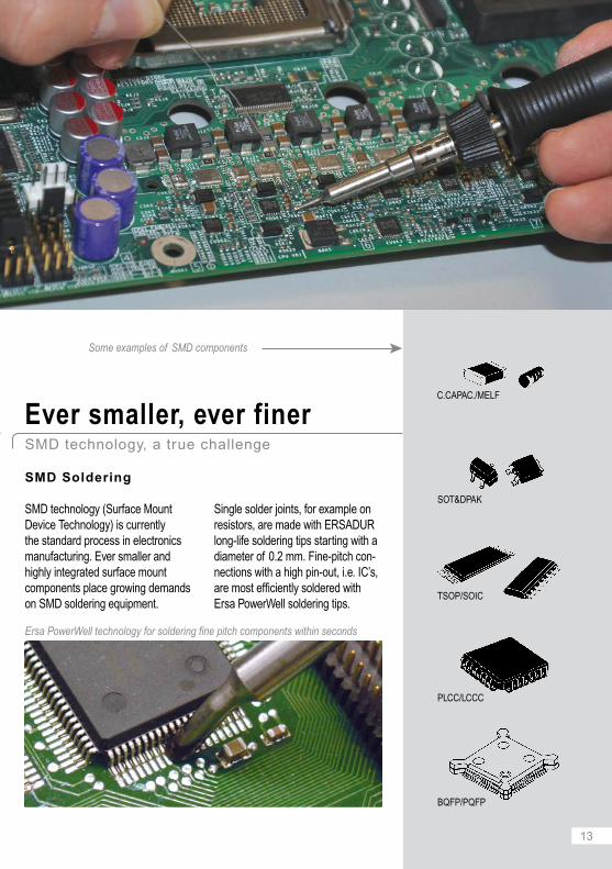
Ersa PowerWell technology for soldering fine pitch components within seconds
Some examples of SMD components
SMD Soldering
SMD technology (Surface Mount Device Technology) is currently the standard process in electronics manufacturing. Ever smaller and highly integrated surface mount components place growing demands on SMD soldering equipment.
Single solder joints, for example on resistors, are made with ERSADUR long-life soldering tips starting with a diameter of 0.2 mm. Fine-pitch con-nections with a high pin-out, i.e. IC’s, are most efficiently soldered with Ersa PowerWell soldering tips.
Ever smaller, ever finerSMD technology, a true challenge

14
3
4 5 6
2,3
1 2
i-TOOL
Good solder joint, sufficient solder and good fillet
Wrong: insufficientsolder
Wrong: too muchsolder
At first glance, soldering fine-pitch components by hand seems to be a tough job. Yet it is easy, with the right equipment at hand:
Insert an Ersa PowerWell i-TIP (1) into the i-TOOL soldering iron (2) and set a tip temperature of 285 ºC to 360 ºC (depending on the alloy used – tin/lead or lead-free).
Then position the component (3) and fix two corner pins.
Add flux cream (also see page 30) to the pins on all 4 sides. Clean the front and concave portion of the PowerWell tip with a damp sponge or the Ersa dry sponge.
Fill the concave portion with solder to slightly above the rim by melting
the solder wire, until a small dome occurs (4). Take care not to add too much solder.
Place the i-TOOL lightly on the flat section of the pins (5), and pull the tip across the pins towards you (6) without exercising pressure.
Repeat steps (4) to (6) to solder the remaining sides.
Soldering fine-pitch componentsProcess guide description

1515
SMD desoldering in 3 seconds – with the Ersa desoldering tweezers
SMD Desoldering
To desolder or rework a damaged SMD component, the suitable tools are required to remove the component from the board. When using desoldering tweezers, it is extremely important to select the proper pair of desoldering tips. After having desoldered the component, the pad has to be cleared of the residual solder (e. g. with a suitable soldering tip and a no-clean desol-dering wick). Afterwards the new component can be positioned and
Desoldering wick
Soldering tip
Desoldering tips
Some examples of different desoldering tip shapes:
to desolder and remove MELF’s
to desolder and remove SOIC’s
to desolder and remove QFP and PLCC components
soldered. An optional IR heating plate is a very useful addition – par-ticularly in lead-free hand soldering applications.
More comprehensive instructions on SMD desoldering is available in the process description "SMD desoldering" on our website at www.ersa.com. For the soldering and desoldering of BGAs or other high pin-out SMDs, particularly those with hidden joints, we recommend the semi-automatic Ersa rework stations (see page 31).
Solder melting and removal with a desoldering wick
Ersa desoldering tweezers
The compact CHIP TOOL VARIO desoldering tweezers are perfect for precise desoldering of very small SMDs.

16
D
B
C
Dynamic IR - Top
Dynamic IR - Bottom
IRS
MIC AccuTCs
Zone 1 Zone 2 Zone 3 Zone 4
Zone 1 Zone 2 Zone 3 Zone 4 Zone 5
IRSoft
RPC
B
CA
Solder remaining on the pads is removed with a soldering iron. To do so the residual solder is coated with fl ux. Then a fl at soldering tip (e. g. 0102ADLF40 or 0102ZDLF150) is moved over the pad without applying any force. The solder adheres to the larger surface area of the tip, thereby levelling off the remaining solder of the connection pads. Flux residues are fi nally cleaned off (e. g. using Ersa FLUX-REMOVER).
3. Reballing –Reusing the BGA
Desoldered BGA’s can be refi t with new solder balls and re-attached to the board. This process is referred to as reballing. Residual solder is removed from the BGA by means of a soldering station. Lying on
its back, the component is coated with fl ux fi rst. Then the new solder balls are attached, for example by means of a stencil. These solder balls are heated up to the melting point with the rework station to fi rmly connect with the BGA body. Now the BGA is ready to be re-attached.
4. Application of fl uxor solder paste
The component and the connec-tion pads are now fl uxed, or, as the case may be, solder paste is added through stencil printing. The type of technique applied depends on the application, components and the skill level of the operators. For the commonly used PBGA’s the application of fl ux is mostly suffi cient.
Rework designates the repair or touch-up of electronic components such as Ball Grid Arrays (BGAs) or SMTs. This chapter describes the process steps for BGA rework:
1. Desoldering the BGA
The rework station heats the printed circuit board from the bot-tom, whereas the BGA body itself is heated from the top.
The real-time temperature of the component controls the pre-set temperature curve so that all solder joints melt at the same time. Then the vacuum suction cup is placed on the BGA and once all joints have molten the BGA is lifted off.
2. Removal of residual solder, cleaning
A: Component for rework B: PCB C: Adjacent component (top side) D: Adjacent component (bottom side) AccuTCs: Thermocouples (4 each) IntelligentIRS: Non-contact infrared sensor DynamicIR Top: Top IR radiator (4 zones) DynamicIR Bottom: Bottom IR radiator (5 zones) RPC: Refl ow Process Camera IRSoft: Control & documentation software MIC: Microprocessor controls the DynamicIR heating system
Principle of a rework station
Rework or repair solderingThe rework process demonstrated on the example of a BGA (Ball Grid Array)

1717
Rework – Repair of high-terminal count IC’sto successfully repair SMT assemblies, the several points must be observed:
Dimensions and properties of the assembly have an influence on its temperature requirement
PCB holders and supports keep the assembly flat and prevent warpage
A gentle and controlled heating process, continuously monitored, prevents damage of components or the board
Accurate component placement is a prerequisite for a good soldering result
Operators that are well trained will understand the process and ensure good results
1. Remove BGA 2. Remove residual solder from the pads of the board
3. Reballing – addion of new solder balls
4. Application of flux or solder paste 5. Placement of the new or reballed component
6. Resolder the BGA on the prepared surfaces of the board
Rework process steps
5. Placing the component
Once the pad has been prepared, the component has to be placed. Since all solder joints of a BGA are hidden under the component body, a component placement unit is re-quired. Successful visual placement by hand requires an operator with extensive experience and excellent skills. If the component is placed on solder paste deposits, great care has to be taken not to squash the solder depot, since doing so may lead to shorts after soldering.
6. Resoldering the BGA
The component is heated to the melt-ing temperature of the solder alloy used via a controlled temperature curve. The heating continues until all solder joints have melted and remained so for some seconds.
During this time durable and lasting solder joints are formed. After resoldering, the board is cooled in a similar fashion as had been done after desoldering.
These process steps are gener-ally applicable for all surface mount
components. Subject to the type of connections (wired, hidden) they may slightly vary.

18
The MINOR S miniature solder-ing iron with a rating of 5 W and a maximum tip temperature of 440 ºC is an ideal tool for ultrafi ne soldering applications on micro IC’s and under a microscope. It can either operate with a 6 V transformer or a 6 V battery.
Besides electronics the MINOR S can also be used in watch repair, in the photographic industry and in dental technology.
The MULTITIP soldering irons are especially short, light and easy-to-handle soldering irons with minimal distance between soldering tip and the handle's front part. They are ideally suited for small solder joints. Its internally heated soldering tip provides an enhanced degree of effi ciency.
The MULTITIP is available for 15 W and 25 W which makes it suitable for micro soldering joints and medium-sized joints, as for example, on distributor strips or in the hobby sector.
Miniature soldering iron Ersa MINOR S
Micro soldering ironsErsa MULTITIP Series
MIN
OR
S, 5
WM
ULT
ITIP
ser
ies,
15/
25 W
Ersa MINOR S (5 W), a featherweight at 6 g for ultrafine soldering applications
Ersa MULTITIP (15/25 W) internally heated soldering iron for small to medium solder joints
19
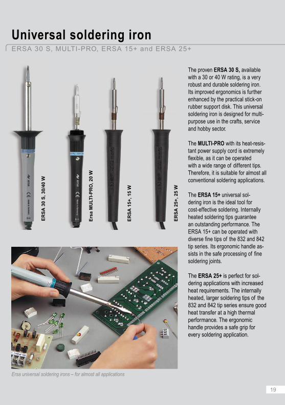
The proven ERSA 30 S, available with a 30 or 40 W rating, is a very robust and durable soldering iron. Its improved ergonomics is further enhanced by the practical stick-on rubber support disk. This universal soldering iron is designed for multi-purpose use in the crafts, service and hobby sector.
The MULTI-PRO with its heat-resis-tant power supply cord is extremely fl exible, as it can be operated with a wide range of different tips. Therefore, it is suitable for almost all conventional soldering applications.
The ERSA 15+ universal sol-dering iron is the ideal tool for cost-effective soldering. Internally heated soldering tips guarantee an outstanding performance. The ERSA 15+ can be operated with diverse fi ne tips of the 832 and 842 tip series. Its ergonomic handle as-sists in the safe processing of fi ne soldering joints.
The ERSA 25+ is perfect for sol-dering applications with increased heat requirements. The internally heated, larger soldering tips of the 832 and 842 tip series ensure good heat transfer at a high thermal performance. The ergonomic handle provides a safe grip for every soldering application.
Universal soldering ironERSA 30 S, MULTI-PRO, ERSA 15+ and ERSA 25+
Ersa universal soldering irons – for almost all applications
ER
SA
30
S, 3
0/40
W
ER
SA
15+
, 15
W
ER
SA
25+
, 25
W
Ers
a M
ULT
I-P
RO
, 20
W
20
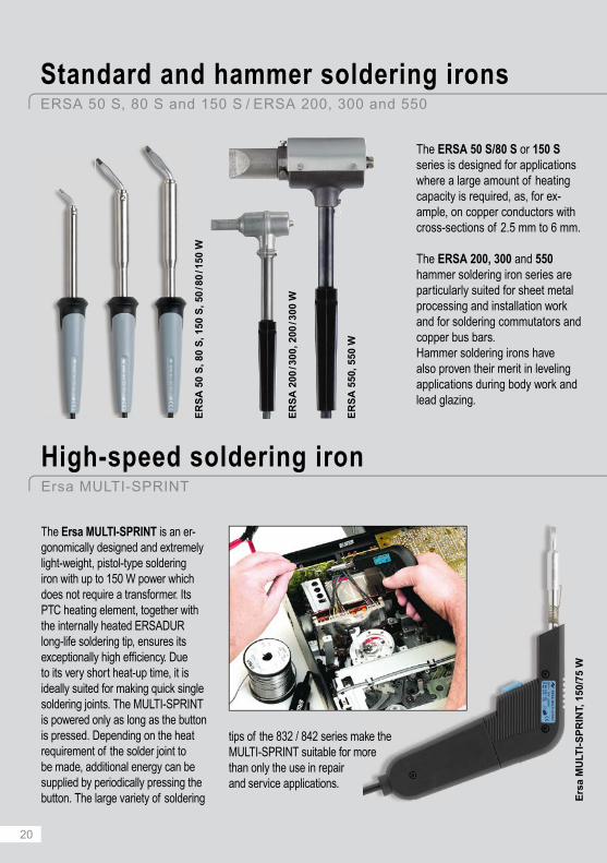
The Ersa MULTI-SPRINT is an er-gonomically designed and extremely light-weight, pistol-type soldering iron with up to 150 W power which does not require a transformer. Its PTC heating element, together with the internally heated ERSADUR long-life soldering tip, ensures its exceptionally high effi ciency. Due to its very short heat-up time, it is ideally suited for making quick single soldering joints. The MULTI-SPRINT is powered only as long as the button is pressed. Depending on the heat requirement of the solder joint to be made, additional energy can be supplied by periodically pressing the button. The large variety of soldering
tips of the 832 / 842 series make the MULTI-SPRINT suitable for more than only the use in repairand service applications.
Ers
a M
ULT
I-S
PR
INT,
150
/75
W
High-speed soldering ironErsa MULTI-SPRINT
The ERSA 50 S/80 S or 150 S series is designed for applications where a large amount of heating capacity is required, as, for ex-ample, on copper conductors with cross-sections of 2.5 mm to 6 mm.
The ERSA 200, 300 and 550 hammer soldering iron series are particularly suited for sheet metal processing and installation work and for soldering commutators and copper bus bars.Hammer soldering irons have also proven their merit in leveling applications during body work and lead glazing.
ER
SA
200
/ 300
, 200
/ 300
W
ER
SA
550
, 550
W
ER
SA
50
S, 8
0 S
, 150
S, 5
0 / 8
0 / 1
50 W
Standard and hammer soldering ironsERSA 50 S, 80 S and 150 S / ERSA 200, 300 and 550

21
The MULTI-TC and PTC 70 are powerful and robust, temperature-controlled soldering irons. Both tools offer an outstanding heat-up rating.
Due to their high thermal per-formance, and because of the large selection of soldering tips, the MULTI-TC and PTC 70 are suitable for fi ne soldering joints in electronics as well as for joints with medium heat requirements. The MULTI-TC is furthermore also used anywhere else where standard irons with 150 W power are in use, including, for example, lead glass and Tiffany soldering.
Ersa gas soldering irons are fueled with commercially available lighter gas and are fi red up through the piezo ignition. Compared with electri-cal soldering irons, the INDEPEN-DENT 75 has between 15 – 75 W, and the INDEPENDENT 130 be-tween 25 – 130 W performance. Both irons are available in the BASIC-SET and PROFI-SET versions.
Aside from handling the usual types of electronic components, the selec-tion of tips available enables the INDEPENDENT to also handle SMD soldering, micro-welding, forming and cutting of synthetic materials and the processing of shrink sleeves.
Ers
a M
ULT
I-TC
, 75
WE
rsa
IND
EP
EN
DE
NT
75,
15
– 75
W
Ers
a IN
DE
PE
ND
EN
T 1
30, 2
5 –
130
W
Gas soldering ironsErsa INDEPENDENT 75 and INDEPENDENT 130
Power soldering ironErsa MULTI-TC and PTC 70
Ers
a P
TC 7
0, 7
5 W

22
RT 80: sleek soldering iron with a large selection of soldering tips
The digital soldering station Ersa RDS 80 offers the proven and tested Ersa RESISTRONIC temperature control technology with a strong heating power of 80 W. The ceramic PTC heating element (Positive Temperature Coeffi cient) acts as the temperature sensor in this control system. Due to its very high ramp-up capability of up to 190 W, the station reaches operat-ing temperature very fast.
Digital soldering stationErsa RDS 80 – high performance for low cost
guarantees the immediate supply of heat and a heat-up from room temperature to 280 ºC within 60 seconds. The BASIC TOOL 60 soldering iron uses the internally heated ERSADUR long-life solder-ing tips of the 832/842 series and provides very high performance.
Due to the wide range of 832/842 soldering tips, the Ersa ANA-LOG 60, which is also available as an antistatic version, covers a wide range of applications with the most varied soldering requirements.
The electronically temperature-con-trolled ANALOG 60 is Ersa's basic soldering station model. It has the tried and proven RESISTRONIC
temperature control technology with the PTC heating element serving as the temperature sensor. The high heat-up rating of 190 W
The basic soldering stationErsa ANALOG 60

23
The soldering stations i-CON NANO and i-CON PICO, two models of the i-CON product family, fulfi ll all the needs of today’s electronics manu-facturing while requiring minimal space. They are designed for con-tinuous operation in the electronic
Small footprint (145 x 80 mm) – saves valuable space
Antistatic as per MIL-SPEC/ESA (only i-CON NANO)
Three fi xed temperature settings or continuously adjustable temperature settings from 150 ºC to 450 ºC
Three selectable power levels
Ultra-light and ergonomic soldering tool with max. 80 W power
Wide range of low-cost exchangeable long-life soldering tips
Automatic stand-by and sleep function for low energy consumption and longer tip life
Password interlock for maximum process control
Calibration function for a precise tip temperature
Complete parameterization through PC software and Micro-SD card
manufacturing environment as well as for special applications in labora-tories and R&D departments.
Due to the simple and user-friendly operating concept, the fac-tory settings provide for a variable
adjustment of operating tempera-ture as well as the setting of stand-by time and calibration value.
Further adjustments such as fi xed temperatures, power level, interlock and shutdown functions are avail-able with the free PC software and an optionally available micro smart SD card.
Micro-SD card with SD-card and USB adapter
The concept of the Ersa i-CON stations ensures that each applica-tion is processed with the optimal parameters. They stand for the highest level of process safety and quality control at low investment and operating cost.
Multifunctional soldering stationsErsa i-CON NANO and i-CON PICO – small, powerful and versatile
Ersa i-CON PICO

24
i-TOOL soldering iron with 150 W micro heating element technology
Low-cost exchangeable long-life tips of the i-TIP series
User friendly “One-Touch” operation
Three power levels – no overshoot
Process window and alarms
Interface to control peripheral equipment on the workplace, such as heat-ing plate and solder fume extraction systems
Stand-by control for tools, heating plate and solder fume extraction system
i-TOOL calibration
Tools for SMT and conventional soldering applications
Automatic tool recognition
The stations of the i-CON product family are Ersa's innovative solution for intelligent manual soldering. The need to be able to cope with higher working temperatures and with pro-gressively smaller process windows when working with lead-free solders, poses no problem whatsoever for the i-CON product family.
The i-CON is available as a single station or as double iron station. The
single station i-CON1 is delivered to-gether with the i-TOOL soldering iron. The i-TOOL is extremely small, ultra-light and ergonomic. It is powered by a 150 W micro heating element, which realizes short heat-up times (within 9 seconds up to 350 ºC!) and rapid heat recovery.
The microprocessor which stores the temperature calibration of the iron is located in the PCB which is
installed in the handle. This now allows for each individual i-TOOL to be calibrated independent of the soldering station.
In contrast to the concept followed by the cartridge-type soldering tips, only the tip itself is exchanged at the i-TOOL. The cost-intensive heating element remains.
The double iron soldering station i-CON2 can be operated either with a second i-TOOL or with the SMD desoldering tweezers CHIP TOOL
i-CON1 with i-TOOL soldering iron with high-performance micro heating element
Soldering miniature and densely placed SMD components with the i-TOOL and i-TIPS, starting at a 0.2 mm diameter.
Ers
a i-
CO
N2
wit
h i-
TOO
L a
nd
CH
IP T
OO
L
High-end soldering and desoldering stationsThe Ersa i-CON product family for highest productivity and process safety
2525
*
*
*
*
*
User-friendly controls: quick programming & lock, huge multi-functional display with i-Op controls, menu in 7 languages, online help
High-mass through-hole desoldering with the X-TOOL VARIO
respectively with the desoldering irons X-TOOL or X-TOOL VARIO.
The CHIP TOOL facilitates safe and quick desoldering, of the smallest chips up to large PLCC’s. To remove the residual solder and to desol-der wired components – also on
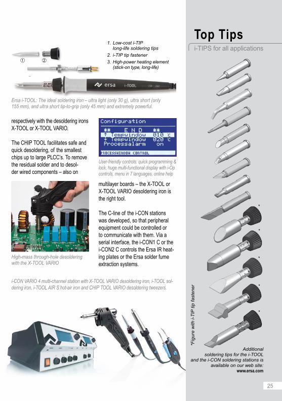
1. Low-cost i-TIPlong-life soldering tips
2. i-TIP tip fastener
3. High-power heating element (stick-on type, long-life)
multilayer boards – the X-TOOL or X-TOOL VARIO desoldering iron is the right tool.
The C-line of the i-CON stations was developed, so that peripheral equipment could be controlled or to communicate with them. Via a serial interface, the i-CON1 C or the i-CON2 C controls the Ersa IR heat-ing plates or the Ersa solder fume extraction systems.
Additionalsoldering tips for the i-TOOL
and the i-CON soldering stations is available on our web site:
www.ersa.com
*Fig
ure
with
i-T
IP ti
p fa
sten
er
Ersa i-TOOL: The ideal soldering iron – ultra light (only 30 g), ultra short (only 155 mm), and ultra short tip-to-grip (only 45 mm) and extremely powerful.
High-end soldering and desoldering stationsThe Ersa i-CON product family for highest productivity and process safety
Top Tipsi-TIPS for all applications
i-CON VARIO 4 multi-channel station with X-TOOL VARIO desoldering iron, i-TOOL sol-dering iron, i-TOOL AIR S hot-air iron and CHIP TOOL VARIO desoldering tweezers.

26
Complete system with HR 100 A, IR heating plate, stand for HYBRIDTOOL and PCB holder.
HYBRID TOOL with 200 W heating element, positioning laser integrated in grip
3 exchangeable hybrid adapters (6 x 6 mm, 10 x 10 mm and 20 x 20 mm)
Silent rework fan (below 40 dB)
Integrated vacuum pump and vacuum pen; tool holder and K-type thermo-couple input socket; USB interface; LED display
2-channel temperature recording:TC & IRS; AccuTC and Flexpoint thermocouple holder
Tool holder with z-axis height adjustment
x-y PCB holder (290 mm x 250 mm)
800 W IR heating plate with glass cover:125 mm x 125 mm IR high-performance heating element
Rework profi le and documentation software Ersa IRsoft
The Ersa HR 100 A applies the Ersa Hybrid Rework Technology for a safe desoldering and replace-ment of small SMD components. Its medium wave length IR radiation, combined with a safe stream of hot air ensures optimal heat transfer to the component.
The HYBRID TOOL offers a gentle and homogeneous warming of all sizes of components, from 0201 chips up to 20 x 20 mm SMD’s and larger. Exchangeable hybrid adapters target the thermal energy available (up to 200 W) on to the component, all the while protecting neighboring areas and not blowing away or moving adjacent chips.
Its user-friendly handling permits even operators with little experience to safely and effi ciently operate the HR 100. More experienced opera-tors, on the other hand, can not only variably adjust the air fl ow as well
as the heat output, but also record and run profi les. A positioning laser whose laser point makes it possible to keep track of the component worked on through the complete process is integrated in the grip of the ergonomic hybrid tool.
Hybrid Rework StationErsa HR 100 A – The innovative combination of hot air and infrared radiation

27
The Ersa EASY ARM 1 is a compact yet powerful fi lter unit to effi ciently clean the process air at the workplace. Both i-CON1 C, i-CON2 C and i-CON VARIO can be connected to the EASY ARM 1 with an interface cable. The solder fume extraction has three fi ltration levels to remove noxious gases.
With the solder fume extraction EASY ARM 2, Ersa offers the user
a further compact and highly ef-fi cient fume extraction unit for either one or two workplaces. One or two units i-CON1 C / i-CON2 C / i-CON VARIO can be connected to the EASY ARM 2 via interface cable.
Both EASY ARM systems are provided with a stand-by mode and operate only when the soldering sta-tions they are connected to are being used. The EASY ARM 1 and 2 are
easy to install and can be placed very fl exibly. Due to their very low noise level, they can be operated in virtually all environments, be it repair shops, development facilities or laboratories.
To accommodate different working conditions and applications, a vari-ety of extraction arms and nozzle shapes which can easily and quickly be exchanged are available to meet different working conditions.
CLEAN-AIR solder fume extractionsErsa EASY ARM 1 and EASY ARM 2 – protecting environment, health and resources
Q&A 1: So, how can you get rid of them? By using a solder fume extraction unit to clear the air from particles and gases.
Q&A 2: How does that work? Active carbon in the filters absorbs harmful gas molecules; result: a clean working environment.
Ers
a E
AS
Y A
RM
2
Ers
a E
AS
Y A
RM
1
Noxious gases develop in every solder-ing process.

28
Plumbing and tinsmith workFor the joining of sheet metal and metal pipes, the joints to be soldered have to be bare. This calls for a good prior cleaning. After this, the flux – either solder grease or solder fluid, a zinc chloride solution – is applied. Then the area to be soldered is heated with the tip of the soldering iron. Once the soldering area is sufficiently hot, solder is added and the solder gap is filled. The aggressive flux residues are removed after cooling to avoid the risk of future corrosion.
Tiffany soldering (Lead glass soldering)
Soldering a Tiffany object generally involves three individual steps:• Spot soldering• Rough soldering• Finishing
Prior to the actual soldering process, copper foil is glued on the glass edg-es. The next step is spot soldering,
this procedure is accurately followed, and if a sufficient amount of solder is applied, the desired, half-round and convex seams are achieved. The lack of visual quality of the seam at this stage is optimized during the finishing soldering step, in which the soldering tip is dragged slowly and from the beginning of the seam until the end at an even speed. The seam worked on should always lie flat on the bench.
i. e. the glass parts are fastened or connected by taking a drop of solder with the tip of the soldering iron and carefully applying it to the solder joint. Each spot soldering operation should only take about a second. During rough soldering the gap between the glass is filled with solder after flux has been applied. For this purpose the tip and solder are moved together along the joint. Always drag the soldering iron, never push it. Only if
The soldering iron heats up the complete overlapped width
Solder flows into the gap and fills it
Soldering tip
Soldering tip
Solder
Solder
SolderSoldering tip
Glass
Solder
Glass
SolderSoldering tip
Copper foil
Copper foil
Tiffany or sheet metal solderingSoldering beyond the field of electronics
Tiffany soldering Step 1: spot soldering Step 2: rough soldering
Guiding the soldering iron when soldering a broad seam
Guiding the soldering iron when soldering a narrow seam

29
832 GDLF 832 MDLF832 LDLF 832 VD
The types VD, GDLF, LDLF and MDLF of the comprehensive 832 tip series are particularly suited for Tiffany work. On account of their
shapes and their high mass (excel-lent because of the ensuing heat retention capacity), the seams be-tween the glass parts can quickly
The MULTI-TC soldering iron is very light, robust and powerful. The Ersa SENSOTRONIC Control with the PT-1000 temperature sensor in the tip reacts immediately when heat is withdrawn.
The MULTI-TC is provided with a 2.2 mm wide, chisel-shaped sol-dering tip. Together with the Tiffany soldering tips, the slim MULTI-TC is superbly suited for the use in Tiffany work.
Due to its precise temperature con-trol, the DIGITAL 2000 A soldering station completely eliminates the
and easily be fi lled with solder. And the ERSADUR fi nish warrants a long tip lifetime.
possibility to overheat any glass components or the copper foil, and the station has tremendous power reserves, making it comparable and putting it on an equal level with unregulated 150 W soldering irons.
The Ersa SENSOTRONIC control with its internally heated soldering tip, where the temperature sensor is mounted directly below the tip, provides for precise temperature control and ensures uniform
temperature levels at the soldering joint.
The long-life ceramic PTC heating element provides up to 290 W heat-up rating which means that the powerful soldering iron is ready for use in only 60 seconds.
The DIGITAL 2000 A is provided with a 2.2 mm wide, chisel-shaped soldering tip. Particularly good results are achieved with the optionally available tip versions 832 VD, 832 GDLF, 832 CDLF and 832 MDLF, which are specifi cally offered for Tiffany applications.
ERSADUR Tiffany soldering tipsErsa DIGITAL 2000A, Ersa MULTI-TC and ERSADUR soldering tips
Tiffany lamp
Ers
a M
ULT
I-TC
, 75
Wat
t
ERSADUR Tiffany soldering tips
Ers
a D
IGIT
AL
200
0 A
wit
h P
OW
ER
TO
OL

30
Ersa tool holders or stick-on rubber supports to safely and ergonomically put down the soldering iron during work stoppages or during heat-up.
Ersa viscose cleaning sponges for moist or special metal wool for dry cleaning of the hot soldering tip prior to the soldering process.
Further peripherals and accesso-ries can be obtained from your local Ersa distributor and at www.ersa.com. Or just ask for our catalog!
Auxiliary products and practical accessoriesEverything for your soldering needs from one source
Ers
a so
lder
bat
hs
Ers
a so
lder
wir
e an
d
sold
er w
ire
dis
pen
ser
Ers
a D
TM
100
tem
per
a-tu
re m
easu
rin
g d
evic
e
Ers
a S
OL
DA
PU
LLT
des
old
erin
g p
um
p
Ers
a V
AC
X d
eso
lder
ing
pu
mp
Ers
a S
MD
flu
x an
d f
lux
crea
m
Ers
a ti
p e
xch
ang
er
Ers
a d
eso
lder
ing
wic
ksE
rsa
TIP
-RE
AC
TIV
ATO
R
Ers
a F
LUX
-RE
MO
VE
R

3131
More than 5,000 customers worldwide use Ersa’s patented IR-Rework technology.
Ersa rework stations deploy the DynamicIR Heating Technology, programmable top and bottom Ersa HR 600
Today more than ever, cost-effec-tive production and highest quality in the electronics manufacturing industry is the basis for profi table competitiveness. A key ingredient for being competitive is a well-qualifi ed staff, which is up-to-date on current technology and process.
Ersa Know-How Seminars are ide-al for transmitting this knowledge to
those of your staff members with process responsibility in electronic manufacturing. In these seminars, theoretical and practical knowledge is presented in a neutral fashion in workshops and presentations by reputed experts in their fi eld.
For further information go to our website www.ersa.com and click "Events".
IR rework stationsErsa IR/PL 550, IR/PL 650 and HR 600 – from mobile phone boards up to XXL boards
Optical solder joint inspectionERSASCOPE inspection systems – the patented original
Ersa Know-How SeminarsExper t knowledge for professional users comprehensively impar ted
heating zones as well as the ac-curate, user-friendly and motorized "Auto Pick & Place" feature. Sys-tem control, process documenta-tion and visualization is handled by the Ersa rework software IRSoft/HRSoft.
Since its introduction over 10 years ago more than 3,000 customers worldwide profi t
from the pos-sibility to non-destructively inspect hidden
solder joints.
Regardless of whether the joints are under a fl ip-chip, or whether areas are to be inspected where other microscopes have come to their limits – the ERSASCOPE technology offers a considerable added value to any quality assur-ance program!

KatalogErsa Lötkolben, Löt- und Entlötstationen, Lötrauchabsaugungen, Hybrid-Rework & Zubehör
2296
58 -
061
2 | t
echn
isch
e Ä
nder
unge
n vo
rbeh
alte
n | ©
201
2 by
Ers
a G
mbH
Ersa Global ConnectionsWir sorgen weltweit für gute Verbindungen
Ersa Electronics Production Equipment
9759
6 -
02/2
015
• s
ubje
ct to
cha
nges
• ©
by
Ers
a G
mbH
, Ger
man
y
Technical data and further detailed information on our range of hand soldering equipment is
available in our "Soldering Tools" catalog. This is available in printed form and as PDF, as are the "Rework & Inspection" catalog.
Aside from the extensive selection of hand soldering tools, rework stations and inspection systems for
non-destructive inspection, Ersa, as Europe’s largest manufacturer of soldering systems, also offers a complete range of selective, wave and reflow soldering systems, as well as stencil printers for the industrial electronic manufacturing industry.
Please refer to our brochures and our website www.ersa.com for further information.
Ersa GmbHLeonhard-Karl-Straße 2497877 Wertheim/GermanyTel. +49 9342 800-0Fax. +49 9342 [email protected]
Ersa FranceChevigny Saint Sauveur, [email protected]
Ersa North AmericaPlymouth, [email protected]
Ersa Asia PacificHong Kong, [email protected]
Ersa ShanghaiShanghai, [email protected]
Copyright © 2022 FDOKUMEN