The effect of stage temperature drop on MVC thermal performance
9
The effect of stage temperature drop on MVC thermal performance Fuad N. Alasfour, Hassan K. Abdulrahim ⁎ Mechanical Engineering Department, Kuwait University, P.O. Box 5969, Safat 13060, Kuwait abstract article info Article history: Received 6 March 2010 Received in revised form 27 July 2010 Accepted 27 July 2010 Available online 15 September 2010 Keywords: Mechanical vapor compression Desalination Thermal performance Exergy destruction The aim of this research is to study the thermal performance of MVC desalination system. A hybrid MSF–MVC desalination system is proposed in this study, and a parametric study was carried out to study the effects of MVC brine temperature and temperature drop across MVC stage on system performance in terms of specific power consumption, pressure ratio, feed to distillate ratio, specific heat transfer area, distillate product and exergy destruction. The analysis was performed using steady state mathematical model for hybrid MSF–MVC system; the model is based on first and second laws of thermodynamics. Results showed that as temperature drop across the stage increases, the specific power consumption increases, and distillate water production decreases. On the other side as MVC brine temperature increases, the specific heat transfer area decreases. Results showed that the increase in the temperature drop across stage causes an increase in exergy destruction. © 2010 Elsevier B.V. All rights reserved. 1. Introduction The concept of desalting seawater using vapor compression is not new; it has been applied during World War II through shipboard use. The unique characteristic of vapor compression is re-using the energy of vapor which is generated in the last effect in steam ejector or compressor, to act as a heat source for the first effect [1]. Mechanical vapor compression (MVC) is one of the promising, low-temperature desalination systems. Vapor compression desalination system is considered as low-temperature distillation systems; such systems are characterized by a number of advantages, such as: (1) low corrosion rate, (2) operation reliability and flexibility, (3) high thermodynamic efficiency, (4) minimal scaling rates, (5) high purity distillate, and (6) low energy costs [2]. MVC system considered as a viable desalination option which can alternate Reverse Osmosis (RO) system; it is compact and can be driven by electric motor, gas or steam turbine or diesel engine [3,4]. The latest developments in MVC desalination industry showed that MVC can be supplied as a self-contained automatic package, and pre tested, pre wired and pre assembled with few requirements on site with proper capacity. MVC desalination system characterized by its compactness, efficient utilization of energy, small amount of civil work and limited erection requirements, low capital cost, ease of operation and transportability [5,6], MVC system can be used for small and medium scale water desalination units which ranges from 1 to 5000 m 3 /day. Market data showed a rapid progress and expansion of MVC systems, especially in the single effect configuration [7]. Latest reports showed that MVC, under development, can be able to produce up to 10,000 m 3 /d [8]. Industrial experiences showed that MVC system can operate economically at low range of temperatures of 60 to 70 °C, with low possibilities of scale formation and corrosion, with no need of condenser or cooling water system [9]. Water intake and pretreatment requirement for such system is inherently simple, and it is not sensitive to contamination of seawater by oil and/or other organic matter compared to RO system [10]. The oxygen content in MVC is very low, due to removal of non condensable gases; such condition should reduce the risk of crevice corrosion in heat exchanger [11]. Reports indicated that MVC water production is characterized by high level of quality, 5 ppm TDS or less, and it does not have to be located near heat source or sink, which can leads to minimize the ecological effects [12]. Thermodynamically, MVC system is operated under heat pump principle, where steam continuously recycled and kept the latent heat exchanged in the evaporation and condensation processes within the system [13]. MVC desalination system can be integrated with conventional desalination systems such as MSF [14] and other friendly renewable systems such as; solar system [15], photovoltaic system [16] and wind system [17,18]. The thermo- economic analysis showed that MVC efficiency is significantly higher than traditional Multi-Stage Flashing (MSF), Multi-Effect Evaporation (MEE) or Thermal Vapor Compression (TVC). There are several barriers to achieve the operation of large scale MVC system, one of the most important is the absence of specially designed steam compressor of a capacity comparable to MSF system [4]. In practice growing demand of MVC is limited by several constraints such as: limitation of compressor volumetric flow rate, compressor head, operating temperature, and heat transfer capacity of evaporator [19]. Desalination 265 (2011) 213–221 ⁎ Corresponding author. Tel.: + 965 2 498 5799; fax: + 965 2 484 7131. E-mail addresses: [email protected] (F.N. Alasfour), [email protected] (H.K. Abdulrahim). 0011-9164/$ – see front matter © 2010 Elsevier B.V. All rights reserved. doi:10.1016/j.desal.2010.07.054 Contents lists available at ScienceDirect Desalination journal homepage: www.elsevier.com/locate/desal
Transcript of The effect of stage temperature drop on MVC thermal performance

Desalination 265 (2011) 213–221
Contents lists available at ScienceDirect
Desalination
j ourna l homepage: www.e lsev ie r.com/ locate /desa l
The effect of stage temperature drop on MVC thermal performance
Fuad N. Alasfour, Hassan K. Abdulrahim ⁎
Mechanical Engineering Department, Kuwait University, P.O. Box 5969, Safat 13060, Kuwait
⁎ Corresponding author. Tel.: +965 2 498 5799; fax:E-mail addresses: [email protected] (F.N
[email protected] (H.K. Abdulrahim).
0011-9164/$ – see front matter © 2010 Elsevier B.V. Aldoi:10.1016/j.desal.2010.07.054
a b s t r a c t
a r t i c l e i n f oArticle history:Received 6 March 2010Received in revised form 27 July 2010Accepted 27 July 2010Available online 15 September 2010
Keywords:Mechanical vapor compressionDesalinationThermal performanceExergy destruction
The aim of this research is to study the thermal performance of MVC desalination system. A hybrid MSF–MVCdesalination system is proposed in this study, and a parametric study was carried out to study the effects ofMVC brine temperature and temperature drop across MVC stage on system performance in terms of specificpower consumption, pressure ratio, feed to distillate ratio, specific heat transfer area, distillate product andexergy destruction.The analysis was performed using steady state mathematical model for hybrid MSF–MVC system; the modelis based on first and second laws of thermodynamics. Results showed that as temperature drop across thestage increases, the specific power consumption increases, and distillate water production decreases. On theother side as MVC brine temperature increases, the specific heat transfer area decreases. Results showed thatthe increase in the temperature drop across stage causes an increase in exergy destruction.
+965 2 484 7131.. Alasfour),
l rights reserved.
© 2010 Elsevier B.V. All rights reserved.
1. Introduction
The concept of desalting seawater using vapor compression is notnew; it has been applied during World War II through shipboard use.The unique characteristic of vapor compression is re-using the energyof vapor which is generated in the last effect in steam ejector orcompressor, to act as a heat source for the first effect [1]. Mechanicalvapor compression (MVC) is one of the promising, low-temperaturedesalination systems. Vapor compression desalination system isconsidered as low-temperature distillation systems; such systemsare characterized by a number of advantages, such as: (1) lowcorrosion rate, (2) operation reliability and flexibility, (3) highthermodynamic efficiency, (4) minimal scaling rates, (5) high puritydistillate, and (6) low energy costs [2].
MVC system considered as a viable desalination option which canalternate Reverse Osmosis (RO) system; it is compact and can bedriven by electric motor, gas or steam turbine or diesel engine [3,4].The latest developments in MVC desalination industry showed thatMVC can be supplied as a self-contained automatic package, and pretested, pre wired and pre assembled with few requirements on sitewith proper capacity. MVC desalination system characterized by itscompactness, efficient utilization of energy, small amount of civilwork and limited erection requirements, low capital cost, ease ofoperation and transportability [5,6], MVC system can be used for smalland medium scale water desalination units which ranges from 1 to5000 m3/day. Market data showed a rapid progress and expansion ofMVC systems, especially in the single effect configuration [7].
Latest reports showed that MVC, under development, can be ableto produce up to 10,000 m3/d [8]. Industrial experiences showed thatMVC system can operate economically at low range of temperaturesof 60 to 70 °C, with low possibilities of scale formation and corrosion,with no need of condenser or cooling water system [9]. Water intakeand pretreatment requirement for such system is inherently simple,and it is not sensitive to contamination of seawater by oil and/or otherorganic matter compared to RO system [10]. The oxygen content inMVC is very low, due to removal of non condensable gases; suchcondition should reduce the risk of crevice corrosion in heatexchanger [11].
Reports indicated that MVC water production is characterized byhigh level of quality, 5 ppm TDS or less, and it does not have to belocated near heat source or sink, which can leads to minimize theecological effects [12]. Thermodynamically, MVC system is operatedunder heat pump principle, where steam continuously recycled andkept the latent heat exchanged in the evaporation and condensationprocesses within the system [13]. MVC desalination system can beintegrated with conventional desalination systems such as MSF [14]and other friendly renewable systems such as; solar system [15],photovoltaic system [16] and wind system [17,18]. The thermo-economic analysis showed that MVC efficiency is significantly higherthan traditional Multi-Stage Flashing (MSF), Multi-Effect Evaporation(MEE) or Thermal Vapor Compression (TVC).
There are several barriers to achieve the operation of large scaleMVC system, one of the most important is the absence of speciallydesigned steam compressor of a capacity comparable to MSF system[4]. In practice growing demand of MVC is limited by severalconstraints such as: limitation of compressor volumetric flow rate,compressor head, operating temperature, and heat transfer capacityof evaporator [19].
Nomenclature
A Heat transfer area, (m2)D Distillate, (kg/s)ΔT MVC effect temperature drop, (°C)ΔTm Mean temperature difference, (°C)e Stream specific exergy, (kJ/kg)Ex Rate of exergy, (kW)ExD Rate of exergy destruction, (kW)h Specific enthalpy, (kJ/kg)h0 Specific enthalpy at Te, (kJ/kg)hi Heat transfer coefficient internal, (kW/m2 °C )ho Heat transfer coefficient external surface, (kW/m2 °C )k Thermal conductivity of the tube material, (kW/m °C)LMTD Logarithmic mean temperature difference, (°C )m Mass flow rate, (kg/s)Mw Molecular weight, (kmol)P or p Pressure, (bar)Pr Prandtl numberQtrans Rate of heat transfer, (kW)Re Reynolds numberRfi Internal fouling resistance, (m2 °C/kW )Rfo External fouling resistance, (m2 °C/kW )s Stream specific entropy, (kJ/kg K)s0 Specific entropy at Te, (kJ/kg K)T, t Temperature, (°C)t0 Environment temperature, (°C)To Top brine temperature, (°C)U Overall heat transfer coefficient, (kW/m2 °C)v Stream specific volume, (m3/kg)w Stream salinity˙Wcomp Rate of vapor compressor work, (kW)y Mole fraction of the salts in the seawatery0 Mole fraction of the salts in the seawater at reference
salinity; 45,000 ppm
SubscriptsB, b BrineBPE Boiling point elevationC Condensatecomp Compressorcw Cooling waterD Distillatee Environment, or exitevap EvaporatorF FeedHEX Heat exchangeri Inner, or inlet, or stage numbero OuterS Steamv Vapor
Greek Symbolsηevap Thermal efficiency of the evaporatorηm Mechanical efficiencyλs Latent heat of steam, (kJ/kg)λv Latent heat of vapor, (kJ/kg)
AbbreviationsLMTD Logarithmic mean temperature differenceMEE Multi effect evaporation
MIGD Million imperial gallon per dayMSF Multistage flashingMSF-BR Multistage flashing with brine recirculationMVC Mechanical vapor compressionTBT Top brine temperatureTVC Thermal vapor compressionRO Reverse osmosisVC Vapor compression
214 F.N. Alasfour, H.K. Abdulrahim / Desalination 265 (2011) 213–221
2. Literature review
Several researchers studied MVC desalination system in the light ofenergy analysis [20–22], exergy analysis [23,24], modeling [25], andeconomics [4,11,26–28]. In the field of energy analysis, Darwish [20]presented the basic characteristics of MVC system. He studied the effectof design and operation parameters; evaporator temperature, compres-sion ratio, feed temperature and concentration ratio. His conclusionsindicated that it is essential to bring feed temperature close to theevaporating temperature in order to reduce power consumption, thisreduction can be achieved either by increasing the size of themulti flowheat exchanger and/or supply of an auxiliary heat.
Narmine et al. [9] investigated thoroughly the thermal perfor-mance of 5 m3/d MVC system, their experimental and theoreticalresults indicated that the potable water production rate increases byincreasing the operating temperature from 70 to 90 °C, and theevaporator temperature has a good effect on heat transfer coefficient.
Bahar et al. [13] conducted an experimental research on MVCsystem, the desalination plant capacity was 1 m3/d. They evaluatedthe performance of MVC system under variable conditions includingbrine flow rate, compressor rotational speed, and feed concentration.Their results showed that the distillate production increases with theincrease of brine flow rate andwith salinity reduction; they found thatthe performance enhancedwith lower values of salinity concentrationand at elevated values of compressor speed, their results showed thatthe highest performance ratio obtained was 2.52.
Ettouny et al. [29] studied the characteristics of MVC system as afunction of design and operating parameters. They investigatedspecific power consumption and specific heat transfer area, inaddition to new design features such as dimensions of evaporator,demister, and ventilating orifice. Their results showed a noticeabledecrease in specific power consumption and specific heat transferarea at elevated values of MVC inlet temperatures. Results alsoshowed that specific power consumption decreases at low values oftemperature difference between boiling brine and steam condensate,while specific heat transfer area increases.
Desportes and Scharfe [30] presented and investigated the basicdesign parameters of MVC system, they compared the design of two1500 m3/d units, and highlighted on the key design parameters thatimprove the energy efficiency in the range of 14-17 kWh/m3 to below9 kWh/m3.
In the field of exergy analysis, Vesa [31] reviewed the designparameters of a 500 m3/dMVC system in addition to operation features.The exergetic efficiency was evaluated for heat exchangers and found tobe90%,which ishigh compared tootherprocesses. The investigation leadto a conclusion that pre heaters were highly effective since temperaturedifferences are low, which in turn reduces exergy destructions andprovided an adequate performance regarding useful energy.
Mabrouk et al. [25] investigated a new design of hybrid MSF–MVCsystem, their analysis was based on energy, exergy and thermo-economic methodologies; their results showed that the performanceratio of the proposedMSF–MVC systemwas 2.4 times the performanceratio of the conventionalMSF system. In addition, their exergetic studyshowed that the exergy destruction has a minimum value at suctionpressure condition of 8 kPa.
215F.N. Alasfour, H.K. Abdulrahim / Desalination 265 (2011) 213–221
Hamed et al. [1] performed a thermodynamic analysis of TVCbased on first and second laws of thermodynamics. The values ofexergy losses were compared against MEE and MVC desalinationsystems. Their results showed that TVC system yields the least exergydestruction among the three systems, and the level of exergy losses inTVC can be significantly reduced by increasing the number of effectsand thermo-compressor entrainment ratio, or by decreasing Top BrineTemperature (TBT) and heat input temperatures of first effect.
In the modeling and simulation aspects, Aybar [32] studied theoperation characteristics of low temperature MVC system. Mass andenergy balance equations have been used, in addition to LMTDmethod for heat transfer analysis. Three main independent para-meters were investigated in the study; evaporation side pressure,condensation side pressure, and water inlet temperature. The studyinvestigated the effect of three parameters on compressor work anddistill mass flow rate.
In the field of optimization Marcovecchio et al. investigated theoptimum operational condition in for a desalination systems; andMVC [33]. They investigated the optimal design of MVC desalinationprocess using a detailed mathematical model of the process and aglobal optimization algorithm.
Finally in the area of economic analysis, Lara and Holtzapple [11]presented a detailed economic study of MVC system operating at highoperating temperature of 172 °C, they found that MVC system candeliver the following advantages; low compression work and smallheat transfer area.
In this paper an attempt is made to investigate the thermalperformance of MVC desalination system using hybrid MSF–MVCsystem, the primary focus of this work is to perform a parametricstudy to investigate the effects of MVC brine temperature andtemperature drop across MVC stage on MVC thermal performance,several parameters will be investigated in this research; specificpower consumption, pressure ratio, feed to distillate ratio, specificheat transfer area, distillate product and exergy destruction.
3. MVC description
In MVC desalination system, a centrifugal vapor compressor isused to compress the low temperature vapor formed in last effect to a
(a)
Blowdown
Feedseawater
Product
Evaporator
MechanicalCompressor
1 2
5
7
5
4
T1
Tv1
6 3
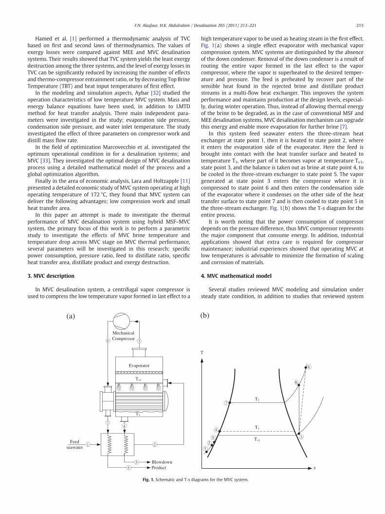
Fig. 1. Schematic and T-s diagr
high temperature vapor to be used as heating steam in the first effect.Fig. 1(a) shows a single effect evaporator with mechanical vaporcompression system. MVC systems are distinguished by the absenceof the down condenser. Removal of the down condenser is a result ofrouting the entire vapor formed in the last effect to the vaporcompressor, where the vapor is superheated to the desired temper-ature and pressure. The feed is preheated by recover part of thesensible heat found in the rejected brine and distillate productstreams in a multi-flow heat exchanger. This improves the systemperformance and maintains production at the design levels, especial-ly, during winter operation. Thus, instead of allowing thermal energyof the brine to be degraded, as in the case of conventional MSF andMEE desalination systems, MVC desalination mechanism can upgradethis energy and enable more evaporation for further brine [7].
In this system feed seawater enters the three-stream heatexchanger at state point 1, then it is heated to state point 2, whereit enters the evaporation side of the evaporator. Here the feed isbrought into contact with the heat transfer surface and heated totemperature T1, where part of it becomes vapor at temperature Tv1,state point 3, and the balance is taken out as brine at state point 4, tobe cooled in the three-stream exchanger to state point 5. The vaporgenerated at state point 3 enters the compressor where it iscompressed to state point 6 and then enters the condensation sideof the evaporator where it condenses on the other side of the heattransfer surface to state point 7 and is then cooled to state point 5 inthe three-stream exchanger. Fig. 1(b) shows the T-s diagram for theentire process.
It is worth noting that the power consumption of compressordepends on the pressure difference, thus MVC compressor representsthe major component that consume energy. In addition, industrialapplications showed that extra care is required for compressormaintenance; industrial experiences showed that operating MVC atlow temperatures is advisable to minimize the formation of scalingand corrosion of materials.
4. MVC mathematical model
Several studies reviewed MVC modeling and simulation understeady state condition, in addition to studies that reviewed system
(b)
Tv1
T2
T1
T
s
3
6s
6
4
2
1
7
5
ams for the MVC system.
216 F.N. Alasfour, H.K. Abdulrahim / Desalination 265 (2011) 213–221
operation, novel configurations, processes, economics, and systemoptimization. In this study a hybrid MSF–MVC is proposed, and MVCmathematical model will be presented. The following MVC basicassumptions will be considered during modeling [27]:
Horizontal falling film evaporator.Distillate is generated as saturated vapor at a temperature of Tv.Brine leaving the evaporator is at saturated liquid phase with atemperature of Tb and salinity of wb.Condensate leaving the tube bundle is at saturated liquid phaseand at a temperature of Ts.Pressure losses of vapor in the connections are ignored.Distillate and brine streams leave the pre heater at sametemperature.The compression process of vapor is isentropic rather thanisothermal.No auxiliary heat utilization for feed preheating.
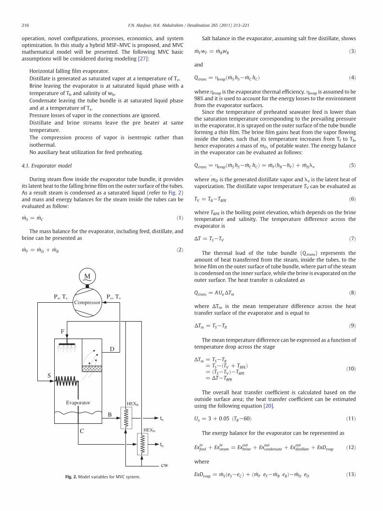
4.1. Evaporator model
During steam flow inside the evaporator tube bundle, it providesits latent heat to the falling brine film on the outer surface of the tubes.As a result steam is condensed as a saturated liquid (refer to Fig. 2)and mass and energy balances for the steam inside the tubes can beevaluated as follow:
mS = mC ð1Þ
The mass balance for the evaporator, including feed, distillate, andbrine can be presented as
mF = mD + mB ð2Þ
F
D
B
S
C
M
Pv, TvPs, TsCompressor
cw
te
te
HEXD
HEXBEvaporator
Fig. 2. Model variables for MVC system.
Salt balance in the evaporator, assuming salt free distillate, shows
mFwF = mBwB ð3Þ
and
Qtrans = ηevap mS hS−mC hCð Þ ð4Þ
where ηevap is the evaporator thermal efficiency. ηevap is assumed to be98% and it is used to account for the energy losses to the environmentfrom the evaporator surfaces.
Since the temperature of preheated seawater feed is lower thanthe saturation temperature corresponding to the prevailing pressurein the evaporator, it is sprayed on the outer surface of the tube bundleforming a thin film. The brine film gains heat from the vapor flowinginside the tubes, such that its temperature increases from Tf to Tb,hence evaporates a mass of ˙mD1 of potable water. The energy balancein the evaporator can be evaluated as follows:
Qtrans = ηevap mS hS−mC hCð Þ = mF hB−hFð Þ + mDλv ð5Þ
where ˙mD is the generated distillate vapor and λv is the latent heat ofvaporization. The distillate vapor temperature TV can be evaluated as
TV = TB−TBPE ð6Þ
where TBPE is the boiling point elevation, which depends on the brinetemperature and salinity. The temperature difference across theevaporator is
ΔT = TS−TV ð7Þ
The thermal load of the tube bundle (Qtrans) represents theamount of heat transferred from the steam, inside the tubes, to thebrine film on the outer surface of tube bundle, where part of the steamis condensed on the inner surface, while the brine is evaporated on theouter surface. The heat transfer is calculated as
Qtrans = AUoΔTm ð8Þ
where ΔTm is the mean temperature difference across the heattransfer surface of the evaporator and is equal to
ΔTm = TS−TB ð9Þ
Themean temperature difference can be expressed as a function oftemperature drop across the stage
ΔTm = TS−TB= TS− TV + TBPEð Þ= TS−TVð Þ−TBPE= ΔT−TBPE
ð10Þ
The overall heat transfer coefficient is calculated based on theoutside surface area; the heat transfer coefficient can be estimatedusing the following equation [20].
Uo = 3 + 0:05 TB−60ð Þ ð11Þ
The exergy balance for the evaporator can be represented as
Exinfeed + Exinsteam = Exoutbrine + Exoutcondensate + Exoutdistillate + ExDevap ð12Þ
where
ExDevap = mS eS−eCð Þ + mF eF−mB eBð Þ−mD eD ð13Þ
217F.N. Alasfour, H.K. Abdulrahim / Desalination 265 (2011) 213–221
In Eq. (13), e represents the stream specific exergy; summation ofthermal, chemical and pressure exergies of the stream, where
e = eth + ech + epeth = h−h0ð Þ−Te s−s0ð Þ
ech=
�Ru⋅Te⋅ ln
yy0
� �Mw
ep = 100 P−Peð Þ v0
ð14Þ
For more details regarding the evaluation of stream exergy refer toAlasfour and Abdulrahim, [34].
4.2. Compressor model
Since the enthalpy of the steam can be evaluated before and aftercompression, the compressor specific work is calculated using thefollowing equation
Wcomp = mDhS−hVð Þηm
ð15Þ
where ηm is the mechanical efficiency of the compressor.The exergy destruction in the compressor can be evaluated as
ExDcomp = Pshaft−mD eS−eDð Þ ð16Þ
where Pshaft is the shaft power supplied to the compressor.
4.3. Heat exchanger model
A plate type heat exchanger is used in this model for preheatingfeed by recovering thermal energy from the condensate and the brine.The two streams flow through two heat exchangers to exchange heatwith the feed stream [17]. The heat transfer area for each heatexchanger can be calculated as follows:
For the distillate heat exchanger, HEXD
mD hC−heð Þ = AHEXDUD LMTDHEXD
ð17Þ
where he is the enthalpy of the condensate at a temperature of te. Thelogarithmic mean temperature difference is evaluated using the
Fig. 3. Flow sheet for single effec
following equation
LMTDHEXD=
tC−tFð Þ− te−tcwð Þln tC−tFð Þ= te−tcwð Þð Þ ð18Þ
The correlations of heat transfer coefficient [29]
1UD
=1ho
+1hi
+ Rf ;o + Rf ;i +δk
ð19Þ
where δ is the plate thickness, the inner and outer convective heattransfer coefficients are calculated using the following correlations[21]
hi = 0:2536 Re0:65i Pr0:4i k=Deð Þho = 0:2536 Re0:65o Pr0:4o k =Deð Þ ð20Þ
where Re = De ρV = μ ; and De = 4 wdð Þ= 2 w + dð Þ, w is the platewidth and d is the plate spacing. The dimensions of the plate heatexchanger used in this work are, δ=0.9 mm, w=1.2 m andd=4 mm. For the brine heat exchanger, HEXB, The energy balance is
mB hB−heð Þ = AHEXBUB LMTDHEXB
ð21Þ
and
LMTDHEXB=
tB−tFð Þ− te−tcwð Þln
tB−tFð Þ = te−tcwð Þð Þ ð22Þ
5. Model solving
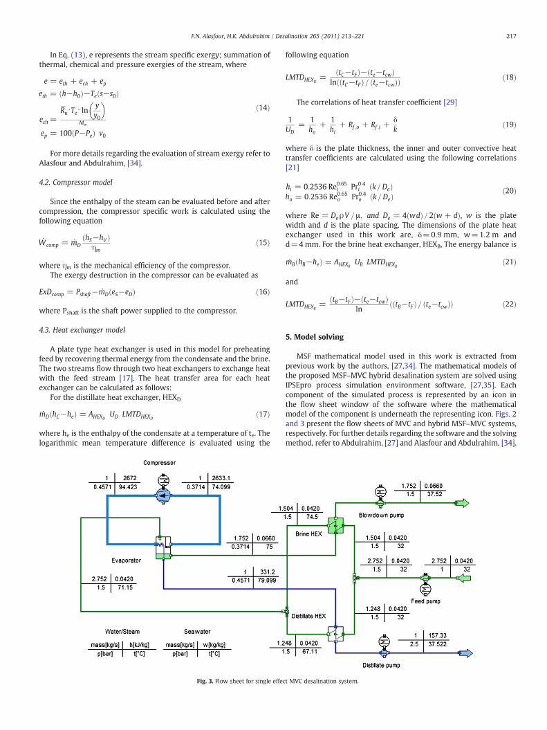
MSF mathematical model used in this work is extracted fromprevious work by the authors, [27,34]. The mathematical models ofthe proposed MSF–MVC hybrid desalination system are solved usingIPSEpro process simulation environment software, [27,35]. Eachcomponent of the simulated process is represented by an icon inthe flow sheet window of the software where the mathematicalmodel of the component is underneath the representing icon. Figs. 2and 3 present the flow sheets of MVC and hybrid MSF–MVC systems,respectively. For further details regarding the software and the solvingmethod, refer to Abdulrahim, [27] and Alasfour and Abdulrahim, [34].
t MVC desalination system.
0.0
10.0
20.0
30.0
40.0
Sp. P
ower
Con
sum
ptio
n, k
W-h
/m3
40.0 80.0 120.0
MVC brine temperature (Tb), oC
T = 2oC
T = 4oCT = 6oC
T = 10oC
T = 8oC
Ettouney, 1999
Ettouney, 1999
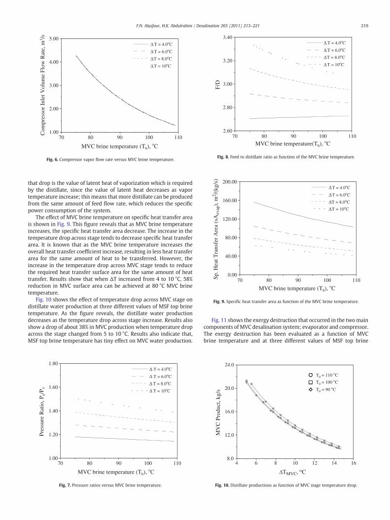
Fig. 5. Specific power consumption versus MVC brine temperature.
218 F.N. Alasfour, H.K. Abdulrahim / Desalination 265 (2011) 213–221
6. Results and discussion
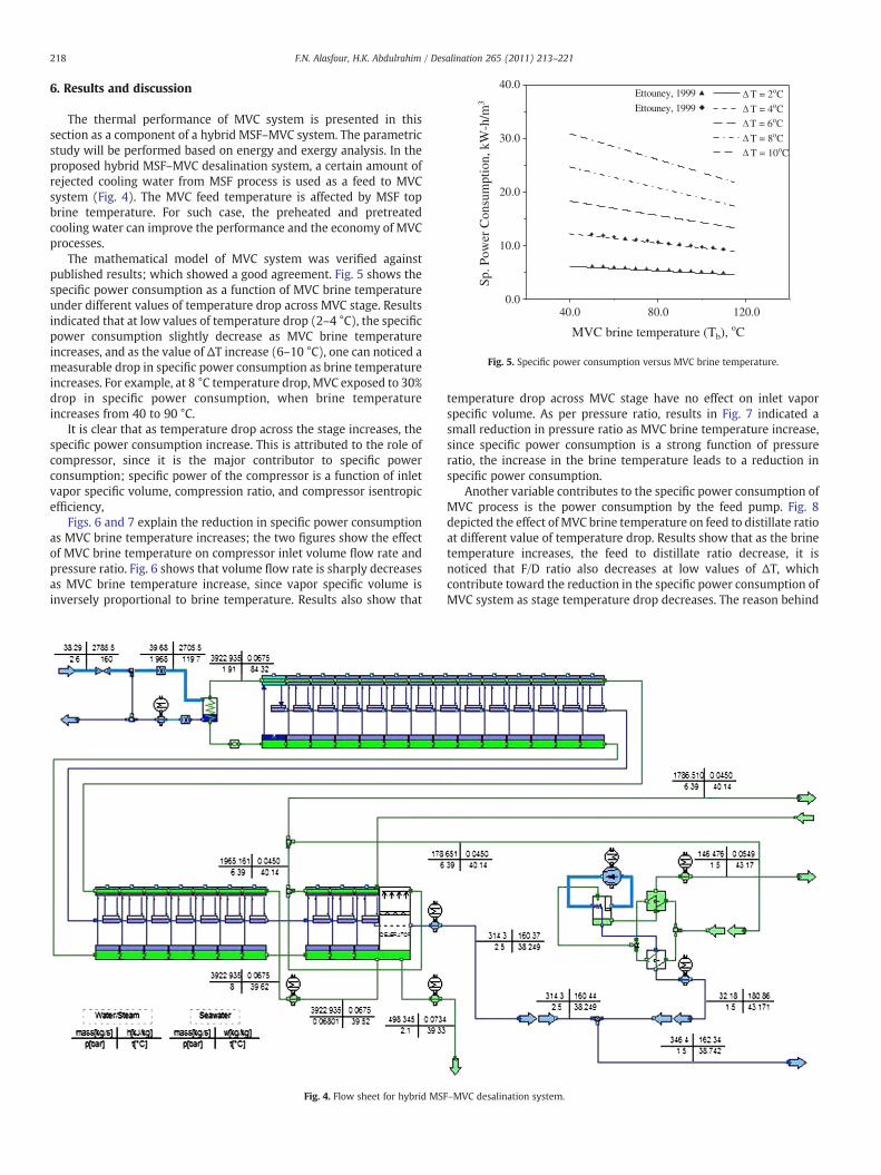
The thermal performance of MVC system is presented in thissection as a component of a hybrid MSF–MVC system. The parametricstudy will be performed based on energy and exergy analysis. In theproposed hybrid MSF–MVC desalination system, a certain amount ofrejected cooling water from MSF process is used as a feed to MVCsystem (Fig. 4). The MVC feed temperature is affected by MSF topbrine temperature. For such case, the preheated and pretreatedcooling water can improve the performance and the economy of MVCprocesses.
The mathematical model of MVC system was verified againstpublished results; which showed a good agreement. Fig. 5 shows thespecific power consumption as a function of MVC brine temperatureunder different values of temperature drop across MVC stage. Resultsindicated that at low values of temperature drop (2–4 °C), the specificpower consumption slightly decrease as MVC brine temperatureincreases, and as the value of ΔT increase (6–10 °C), one can noticed ameasurable drop in specific power consumption as brine temperatureincreases. For example, at 8 °C temperature drop, MVC exposed to 30%drop in specific power consumption, when brine temperatureincreases from 40 to 90 °C.
It is clear that as temperature drop across the stage increases, thespecific power consumption increase. This is attributed to the role ofcompressor, since it is the major contributor to specific powerconsumption; specific power of the compressor is a function of inletvapor specific volume, compression ratio, and compressor isentropicefficiency,
Figs. 6 and 7 explain the reduction in specific power consumptionas MVC brine temperature increases; the two figures show the effectof MVC brine temperature on compressor inlet volume flow rate andpressure ratio. Fig. 6 shows that volume flow rate is sharply decreasesas MVC brine temperature increase, since vapor specific volume isinversely proportional to brine temperature. Results also show that
Fig. 4. Flow sheet for hybrid MS
temperature drop across MVC stage have no effect on inlet vaporspecific volume. As per pressure ratio, results in Fig. 7 indicated asmall reduction in pressure ratio as MVC brine temperature increase,since specific power consumption is a strong function of pressureratio, the increase in the brine temperature leads to a reduction inspecific power consumption.
Another variable contributes to the specific power consumption ofMVC process is the power consumption by the feed pump. Fig. 8depicted the effect of MVC brine temperature on feed to distillate ratioat different value of temperature drop. Results show that as the brinetemperature increases, the feed to distillate ratio decrease, it isnoticed that F/D ratio also decreases at low values of ΔT, whichcontribute toward the reduction in the specific power consumption ofMVC system as stage temperature drop decreases. The reason behind
F–MVC desalination system.
70 80 90 100 1101.00
2.00
3.00
4.00
5.00C
ompr
esso
r In
let V
olum
e Fl
ow R
ate,
m3 /
s
MVC brine temperature (Tb), oC
T = 4.0oC
T = 6.0oC
T = 10oC
T = 8.0oC
Fig. 6. Compressor vapor flow rate versus MVC brine temperature.
70 80 90 100 1102.60
2.80
3.00
3.20
3.40
F/D
T = 4.0oC
T = 6.0oC
T = 10oC
T = 8.0oC
MVC brine temperature(Tb), oC
Fig. 8. Feed to distillate ratio as function of the MVC brine temperature.
70 80 90 100 1100.00
40.00
80.00
120.00
160.00
200.00
Sp. H
eat T
rans
fer
Are
a (s
Aev
ap),
m2 /
(kg/
s)
T = 4.0oC
T = 6.0oC
T = 10oC
T = 8.0oC
MVC brine temperature (Tb), oC
Fig. 9. Specific heat transfer area as function of the MVC brine temperature.
219F.N. Alasfour, H.K. Abdulrahim / Desalination 265 (2011) 213–221
that drop is the value of latent heat of vaporization which is requiredby the distillate, since the value of latent heat decreases as vaportemperature increase; this means thatmore distillate can be producedfrom the same amount of feed flow rate, which reduces the specificpower consumption of the system.
The effect of MVC brine temperature on specific heat transfer areais shown in Fig. 9. This figure reveals that as MVC brine temperatureincreases, the specific heat transfer area decrease. The increase in thetemperature drop across stage tends to decrease specific heat transferarea. It is known that as the MVC brine temperature increases theoverall heat transfer coefficient increase, resulting in less heat transferarea for the same amount of heat to be transferred. However, theincrease in the temperature drop across MVC stage tends to reducethe required heat transfer surface area for the same amount of heattransfer. Results show that when ΔT increased from 4 to 10 °C, 58%reduction in MVC surface area can be achieved at 80 °C MVC brinetemperature.
Fig. 10 shows the effect of temperature drop across MVC stage ondistillate water production at three different values of MSF top brinetemperature. As the figure reveals, the distillate water productiondecreases as the temperature drop across stage increase. Results alsoshow a drop of about 38% in MVC production when temperature dropacross the stage changed from 5 to 10 °C. Results also indicate that,MSF top brine temperature has tiny effect on MVC water production.
70 80 90 100 1101.00
1.20
1.40
1.60
1.80
Pres
sure
Rat
io, P
s/P v
T = 4.0oC
T = 6.0oC
T = 10oC
T = 8.0oC
MVC brine temperature (Tb), oC
Fig. 7. Pressure ratios versus MVC brine temperature.
Fig. 11 shows the exergy destruction that occurred in the twomaincomponents of MVC desalination system; evaporator and compressor.The exergy destruction has been evaluated as a function of MVCbrine temperature and at three different values of MSF top brine
4 6 8 10 12 14 16
TMVC, oC
8.0
12.0
16.0
20.0
24.0
MV
C P
rodu
ct, k
g/s
T0 = 110 oC
T0 = 100 oC
T0 = 90 oC
Fig. 10. Distillate productions as function of MVC stage temperature drop.
50 60 70 800.8
0.9
1.0
1.1
1.2
ExD
evap
, MW
0.28
0.30
0.32
0.34
0.36
ExD
com
p, M
W
T0 = 110 oC
T0 = 100 oC
T0 = 90 oC
Evap
Comp
TMVC = 5 oC
MVC brine temperature (Tb), oC
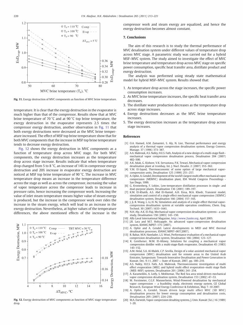
Fig. 11. Exergy destruction of MVC components as function of MVC brine temperature.
220 F.N. Alasfour, H.K. Abdulrahim / Desalination 265 (2011) 213–221
temperature. It is clear that the exergy destruction in the evaporator ismuch higher than that of the compressor. Results show that at MVCbrine temperature of 70 °C and at 90 °C top brine temperature, theexergy destruction in the evaporator represents 2.5 times thecompressor exergy destruction, another observation in Fig. 11 thatboth exergy destructions were decreased as the MVC brine temper-ature increased. The effect of MSF top brine temperature show that forbothMVC components that the increase inMSF top brine temperaturetends to decrease exergy destruction.
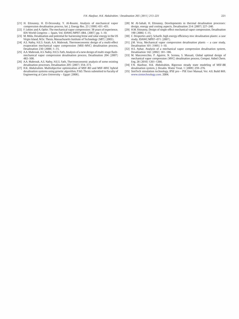
Fig. 12 shows the exergy destruction in MVC components as afunction of temperature drop across MVC stage. For both MVCcomponents, the exergy destruction increases as the temperaturedrop across stage increase. Results indicate that when temperaturedrop changed from 5 to 8 °C, an increase of 14% in compressor exergydestruction and 20% increase in evaporator exergy destruction arenoticed at MSF top brine temperature of 90 °C. The increase in MVCtemperature drop means an increase in the temperature differenceacross the stage as well as across the compressor, increasing the valueof vapor temperature across the compressor leads to increase inpressure ratio, hence increasing the compressor work. Increasing thevalue of inlet steam temperature means higher value of steam exergyis produced, but the increase in the compressor work over rides theincrease in the steam exergy, which will lead to an increase in theexergy destruction. Nevertheless, at higher values of the temperaturedifferences, the above mentioned effects of the increase in the
4 6 8 10 12 14 16
0.7
0.8
0.9
1.0
1.1
Exe
rgy
Des
truc
tion,
MW
0.14
0.16
0.18
Exe
rgy
Des
truc
tion,
MW
Evap
Comp
TMVC, oC
T0 = 110 oC TBT MVC = 50 oCT0 = 100 oC
T0 = 90 oC
Fig. 12. Exergy destruction of MVC components as function of MVC stage temperaturedrop.
compressor work and steam exergy are equalized, and hence theexergy destruction becomes almost constant.
7. Conclusions
The aim of this research is to study the thermal performance ofMVC desalination system under different values of temperature dropacross MVC stage. A parametric study was carried out for a hybridMSF–MVC system. The study aimed to investigate the effect of MVCbrine temperature and temperature drop across MVC stage on specificpower consumption, specific heat transfer area, distillate product andexergy destruction.
The analysis was performed using steady state mathematicalmodel for hybrid MSF–MVC system. Results showed that:
1. As temperature drop across the stage increases, the specific powerconsumption increases.
2. As MVC brine temperature increases, the specific heat transfer areadecreases.
3. The distillate water production decreases as the temperature dropacross stage increases.
4. Exergy destructions decreases as the MVC brine temperatureincreases.
5. The exergy destruction increases as the temperature drop acrossstage increases.
References
[1] O.A. Hamed, A.M. Zamamiri, S. Aly, N. Lior, Thermal performance and exergyanalysis of a thermal vapor compression desalination system, Energy Convers.Manage. 37 (1996) 373–387.
[2] A.A.Mabrouk, A.S. Nafey, H.E.S. Fath, Analysis of a new design of amulti-stageflash -mechanical vapor compression desalination process, Desalination 204 (2007)482–500.
[3] A.K. Adak, G. Kishore, V.K. Servastava, P.K. Tewari, Mechanical vapor compressiondesalination plant at trombay, Int. J. Nucl. Desalin. 2 (2007) 353–362.
[4] Y.M. El-Sayed, Thermoeconomic of some option of large mechanical vapor-compression units, Desalination 125 (1999) 251–257.
[5] A.Ophir,A.Gendel, Development of theworld's largestmulti effectmechanical vaporcompression (MEMVC) desalination plant, IDA World Congress Proceedings -San Diego, 1999.
[6] G. Kronenberg, F. Lokiec, Low-temperature distillation processes in single- anddual-purpose plants, Desalination 136 (2001) 189–197.
[7] K.M. El-Khatib, A.S. Abd El-Hamid, A.H. Eissa, M.A. Khedr, Transient model,simulation and control of a single effect mechanical vapor compression (SEMVC)desalination system, Desalination 166 (2004) 157–165.
[8] J. Ji, R. Wang, L. Li, H. Ni, Simulation and analysis of a single-effect thermal vapor-compression desalination system at variable operation conditions, Chem. Eng.Technol. 30 (2007) 1633–1641.
[9] N.H. Aly, A.K. El-Fiqi, Mechanical vapor compression desalination systems - a casestudy, Desalination 158 (2003) 143–150.
[10] Alfa Laval International Magazine, http://www.2unite.org. April 2005.[11] J.R. Lara and M.T. Holtzapple. An advanced vapor-compression desalination
system, IDAWC/MP07–175 (2007).[12] A. Ophir and A. Gendel. Latest developments in MED and MVC thermal
desalination processes, IDAWC/MP07–067(2007).[13] R. Bahar, M.N. Hawlader, L.S. Woei, Performance evaluation of a mechanical vapor
compression desalination system, Desalination 166 (2004) 123–127.[14] K. Genthener, M.M. El-Allawy, Solutions for coupling a mechanical vapor
compression distiller with a multi-stage-flash evaporator, Desalination 45 (1983)143–152.
[15] A.M. Helal, S.A. Al-Malek, C.P. Sevilla, Design of a solar-assisted mechanical vaporcompression (MVC) desalination unit for remote areas in the United ArabEmirates, Symposium: Towards Innovative Desalination and Power Generation inKuwait. Dec. 9-11, 2007 — State of Kuwait, 2007, pp. 180–210.
[16] A.S. Nafey, H.E.S. Fath, A.A. Mabrouk, Thermoeconomic investigation of multieffect evaporation (MEE) and hybrid multi effect evaporation–multi stage flash(MEE–MSF) systems, Desalination 201 (2006) 241–254.
[17] A. Karameldin, A. Lotfy, S. Mekhemar, The Red Sea area wind-driven mechanicalvapor compression desalination system, Desalination 153 (2002) 47–53.
[18] M. Forstmeier, C.G.F. Mannerheim, Wind-Powered desalination by mechanicalvapor compression — a feasibility study, electronic energy system, GE GlobalResearch, European Wind Energy Conference & Exhibition, May 7–10 2007.
[19] A. Ophir, A. Gendel, Steam driven large multi effect MVC (SD MVC)desalination process for lower energy consumption and desalination costs,Desalination 205 (2007) 224–230.
[20] M.A. Darwish, Vapor compression desalting systems, J. Univ. Kuwait (Sci.) 16 (1989)1–20.
221F.N. Alasfour, H.K. Abdulrahim / Desalination 265 (2011) 213–221
[21] H. Ettouney, H. El-Dessouky, Y. Al-Roumi, Analysis of mechanical vaporcompression desalination process, Int. J. Energy Res. 23 (1999) 431–451.
[22] F. Lokiec and A. Ophir. Themechanical vapor compression: 38 years of experience,IDA World Congress — Spain, Vol. IDAWC/MP07–084, (2007) pp. 1–10.
[23] M. Miilu. Desalination and potential for harnessing brine and solar energy in the USVirgin Island, M.Sc. Thesis, Massachusetts Institute of Technology (MIT) (2003).
[24] A.S. Nafey, H.E.S. Fatah, A.A. Mabrouk, Thermoeconomic design of a multi-effectevaporation mechanical vapor compression (MEE–MVC) desalination process,Desalination 230 (2008) 1–15.
[25] A.A. Mabrouk, A.S. Nafey, H.E.S. Fath, Analysis of a new design of multi-stage flash-mechanical vapor compression desalination process, Desalination 204 (2007)482–500.
[26] A.A. Mabrouk, A.S. Nafey, H.E.S. Fath, Thermoeconomic analysis of some existingdesalination processes, Desalination 205 (2007) 354–373.
[27] H.K. Abdulrahim. Multiobjective optimization of MSF–RO and MSF–MVC hybriddesalination systems using genetic algorithm, P.hD. Thesis submitted to Faculty ofEngineering at Cairo University – Egypt (2006).
[28] M. Al-Sahali, H. Ettouney, Developments in thermal desalination processes:design, energy and costing aspects, Desalination 214 (2007) 227–240.
[29] H.M. Ettouney, Design of single-effect mechanical vapor compression, Desalination190 (2006) 1–15.
[30] C. Desportes and J. Scharfe. high energy efficiency mvc desalination plants: a casestudy, IDAWC/MP07–071 (2007).
[31] J.M. Veza, Mechanical vapor compression desalination plants — a case study,Desalination 101 (1995) 1–10.
[32] H.S. Aybar, Analysis of a mechanical vapor compression desalination system,Desalination 142 (2002) 181–186.
[33] M. Marcovecchio, P. Aguirre, N. Scenna, S. Mussati, Global optimal design ofmechanical vapor compression (MVC) desalination process, Comput. Aided Chem.Eng. 28 (2010) 1261–1266.
[34] F.N. Alasfour, H.K. Abdulrahim, Rigorous steady state modeling of MSF-BRdesalination system, J. Desalin. Water Treat. 1 (2009) 259–276.
[35] SimTech simulation technology, IPSE pro – PSE User Manual, Ver. 4.0, Build 869,www.simtechnology.com. 2004.