Distributed average consensus with stochastic communication failures
i
THE COPPERBELT UNIVERSITY
SCHOOL OF ENGINEERING
MECHANICAL ENGINEERING DEPARTMENT
FINAL YEAR PROJECT REPORT
INVESTIGATION ON LOW LIFT PUMPS FAILURES
(NWSC - Bulangililo Works)
BY
KANYIMBO PENJANI
MASENDEKE DARLINGTON M.
2011

2
3
THE COPPERBELT UNIVERSITY
SCHOOL OF ENGINEERING
MECHANICAL ENGINEERING DEPARTMENT
FINAL YEAR PROJECT REPORT
INVESTIGATION ON LOW LIFT PUMPS FAILURES:
A CASE FOR
NKANA WATER AND SEWERAGE COMPANY
Bulangililo Works.
BY
KANYIMBO PENJANI (COMPUTER No: 07074485)
MASENDEKE DARLINGTON M.(COMPUTER No: 07030193)
“Report submitted in partial fulfilment of the requirement for the Degree of Bachelor of
Engineering, Copperbelt University.”
4
2011
DECLARATION
We declare that the work contained herein is our own work and all the works of other people
included in this project has been plainly and accordingly acknowledged and without any doubt,
this project has not been previously presented at this University or any other institution for
similar purposes.
This project was undertaken by:
KANYIMBO PENJANI MASENDEKE DARLINGTON M.
Signature:__________________ Signature:___________________
Date:______________________ Date:_______________________
Supervised by:
The Head of Mechanical Engineering Department
MR. MWABA C.
Signature:______________________
Date:__________________________
Co-Supervisor: External Supervisor
MR. KUCHEBA AM. MR. BUPE R. (NWSC)
Signature:______________________ Signature: _____________________
Date:__________________________ Date:_________________________
5
ACKNOWLEDGEMENTS
We would like to whole heartedly acknowledge the help and support rendered to us through the
achievement of this project and the program at large. There are many names we would have
loved to mention but in honour of time and space, we would like to acknowledge the following;
Our supervisor; Mr. Mwaba C. co-supervisor; Mr. Kucheba AM. Mr. Njovu External supervisor;
Mr. Bupe R. Mr Mwenge R.and Mr. Yowela W. from Afred H knight,Mr. Mwaba B. Mr.
Kangwa, Mr.Simukonda D. Mr. Muwowo G. Mr. Lungu from NWSC Mr. Silwamba J. from
Mopani, Mr. Munsaka R. from Sulzer, Mr Langi E. Mr. Bwalya S.from SKF.
We would like to further acknowledge the help and support of our class mates EM 5 and EE 5,
Mr Masendeke A, Nanja A. the Kanyimbo stronghold, the CBU UCZ fellowship, Linah
Chelemu, Zyambo V.,Kachingwe M and many more.

6
DEDICATION
KANYIMBO PENJANI
Coming to the end of this first phase of light is humbling and gives deep appreciations of what
worth people are. In the illumination of day and the uncertainty of night my life gives full
witness of how one cannot and should never think one was meant to make it independently. The
necessity of working with friends, family and individuals has modelled in my life simplification
and ability to see in midst of unsettled situations. I therefore, dedicate this work to the unborn,
born and unknown, born and known, dead and known, dead and unknown.
MASENDEKE DARLINGTON
To my beloved mum and Dad- you have always wished the best for me. This has come true. To
my beloved brother, Alvin. You have really been my mentor and my source of inspiration. I
appreciate all that you‟ve done for me. To my beloved late brother, Henry. I always miss you.

7
TABLE OF CONTENTS DECLARATION ………………………………………………………………………………………………………………………………………..iv
ACKNOWLEDGEMENT……………………………………………………………………………………………………………………………..v
DEDICATION……………………………………………………………………………………………………………………………………………vi
LIST OF FIGURES…………………………………………………………………………………………………………………………….………..4
LIST OF TABLES…………………………………………………………………………………………………………………………………….
13
CHAPTER ONE ....................................................................................................................................... 14
1 INTRODUCTION .............................................................................................................................. 14
1.2 PROBLEM STATEMENT ................................................................................................................. 15
1.3 AIM.............................................................................................................................................. 15
1.4 OBJECTIVES .................................................................................................................................. 15
1.5 PROJECT METHODOLOGY ............................................................................................................ 15
1.6 GANTT CHART .............................................................................................................................. 16
1.7 BACKGROUND ............................................................................................................................. 16
1.8 PUMP DETAILS ............................................................................................................................. 17
CHAPTER TWO ...................................................................................................................................... 20
PUMP DESCRIPTION .............................................................................................................................. 20
2.1 POSITVE DISPLACEMENT .............................................................................................................. 20
2.2 NON POSITIVE DISPLACEMENT PUMPS ........................................................................................ 21
2.2.1 CENTRIFUGAL PUMPS ............................................................................................................... 22
2.2.2 COMPONENTS OF A CENTRIFUGAL PUMP. ................................................................................ 23
2.2.2.1 SHAFT ................................................................................................................................ 24
2.2.2.2 WEARING RINGS ................................................................................................................ 26
2.2.2.3 IMPELLER ........................................................................................................................... 26
2.2.2.4 CASING............................................................................................................................... 29
2.2.2.5 BEARINGS........................................................................................................................... 31
2.2.2.6 LUBRICATION ..................................................................................................................... 35
2.2.2.7 SUCTION NOZZLE ............................................................................................................... 36
2.2.2.8 DISCHARGE NOZZLE ........................................................................................................... 36
2.2.2.9 STUFFING BOX.................................................................................................................... 37
8
2.2.2.10 STUFFING BOX COVER ...................................................................................................... 37
CHAPTER THREE .................................................................................................................................... 38
CHARACTERISTICS AND OPERATIONS OF CENTRIFUGAL PUMPS............................................................. 38
3.1 PUMP PERFORMANCE CURVE ...................................................................................................... 39
3.1.1 NET POSITIVE SUCTION HEAD................................................................................................ 40
3.1.2 EFFECIENCY CURVE ............................................................................................................... 41
3.1.3 THE SYSTEM CURVE .............................................................................................................. 42
3.1.4 SELECTION OF PUMP ............................................................................................................. 45
3.1.5 PUMP OPERATING POINT ...................................................................................................... 46
3.2 TYPICAL FORCES ON IMPELLERS ................................................................................................... 47
3.2.1 AXIAL FORCE ......................................................................................................................... 48
3.2.2 RADIAL FORCE……………………………………………………………………………………………………………………….44
3.3 PUMP PIPING ............................................................................................................................... 52
3.4 VIBRATION MONITORING CONCEPT ............................................................................................. 55
3.5 VIBRATION MEASUREMENT AND PARAMETERS ........................................................................... 55
3.5.1 VIBRATION AMPLITUDE......................................................................................................... 55
3.5.2 VIBRATION FREQUENCY ........................................................................................................ 56
3.5.3 VIBRATION PHASE ................................................................................................................. 57
CHAPTER FOUR ..................................................................................................................................... 58
PRACTICAL DATA FROM SITE ................................................................................................................. 58
4.1 BEARINGS .................................................................................................................................... 58
4.2 LUBRICATION ............................................................................................................................... 61
4.3 SHAFT ALIGNMENT ...................................................................................................................... 61
4.4 VIBRATIONS ................................................................................................................................. 63
4.5 MATERIALS USED ......................................................................................................................... 67
4.6 TEMPERATURE MEASUREMENTS ................................................................................................. 67
4.7 PIPE NETWORK ............................................................................................................................ 68
CHAPTER FIVE ................................................................................................................................... 69
RESULTS AND ANALYSIS ................................................................................................................ 69
5.1. BEARINGS ................................................................................................................................ 69
5.2 LUBRICATION .......................................................................................................................... 71
5.3 VIBRATIONS ............................................................................................................................. 71
9
5.4 TEMPERATURE ........................................................................................................................ 73
5.5 SHAFT ALIGNMENT ................................................................................................................ 73
5.6 PIPE NETWORK ........................................................................................................................ 74
CHAPTER SIX ..................................................................................................................................... 89
CONCLUSION AND RECOMMENDATIONS .................................................................................... 89
6.1 ROOT CAUSE OF FAILURE ..................................................................................................... 89
6.2 RECOMMENDATION ............................................................................................................... 90
6.3 CHALLENGES ........................................................................................................................... 92
6.4 CONCLUSION ........................................................................................................................... 92
6.5 APPENDIX ................................................................................................................................. 93
6.6 REFERENCES ............................................................................................................................ 94

10
LIST OF FIGURES
Fig 1 Gantt chart………………………………………………………………………...10
Fig 2 Low Lift pumps Failure rate……………………………………………….……...11
Fig 3 Position of bearing on the Shaft…………………………………………………...13
Fig 4 Cross section of a centrifugal pump……………………………………………….17
Fig 5 Components of a centrifugal pump………………………………………………..18
Fig 6 Shaft ……………………………………………………………………………….19
Fig 7 Closed Impeller…………………………………………………………………….22
Fig 8 Open Impeller……………………………………………………………………...22
Fig 9 Special Open Impeller…………………………………………………………..…22
Fig 10 Non Clogging Impeller…………………………………………………………...22
Fig 11 Wear Resistant Closed Impeller………………………………………………….23
Fig 12 Wear Resistant Open Impeller………………………………………………...…23
Fig 13 Typical centrifugal pump casing………………………………………………....23
Fig 14 Volute casing……………………………………………………………………..24
Fig 15 Diffuser casing…………………………………………………………………...25
Fig 16 Classifications of Bearings…………………………………………………….. 28
Fig 17 liquid flow direction……………………………………………………………...33
Fig 18 Pump performance curves………………………………………………………..34
Fig 19 Efficiency Curve……………………………………………………………….....36
Fig 20 System Curve……………………………………………………………………..37
11
Fig 21 Combination of Pump and system curves………………………………………..39
Fig 22 Pump operating point……………………………………………………………..41
Fig 23 Forces on end suction centrifugal pump………………………………………….42
Fig 24 Axial thrust on rotating impeller…………………………………………………44
Fig 25 Radial force in centrifugal pumps……………………………….……………….45
Fig 26 Radial forces in a double and single volutes design….………………………….46
Fig 27 Misalignment in pipe system…………………………………………….……….47
Fig 28 Design of discharge section………………………………………………………47
Fig 29 design of the suction side…………………………………………………………48
Fig 30 suction length in relation to diameter…………………………………………….48
Fig 31 Vibration signature……………………………………………………………….50
Fig 32 Bearings used for low lift pumps………………………………………………...52
Fig 33 Pump with external water cooling system……………………………………….54
Fig 34 low lift pump……………………………………………………………………..54
Fig 35 Laser Alignment System…………………………………………………………56
Fig 36 Vibration spectra and trends……………………………………………………..59
Fig 37 Pipe network…………………………………………………………………....62a
Fig 38 (a) welded bearing components, (b) Decolorized bearing due to heat…………..64
Fig 39 Shaft with welded inner race……………………………………………………..65
Fig 40 Brittle fractured bearings…………………………………………………………67
12
Fig 41 System curve……………………………………………………………………..80
Fig 42 pump curve…………………………………………………………………….…81
Fig 43 combination of system and pump curve………………………………………….82
Fig 44; Impeller with two vanes curved from the eye…………………………………...83
13
LIST OF TABLES
Table 1, Bearing operating characteristics……………………………………………...11
Table 2; Categories of Positive Displacement Pumps…………………………………..13
Table 3, classification of centrifugal pumps…………………………………………….14
Table 4; Bearing parameters…………………………………………………………….51
Table 5 Technical specifications and characteristics……………………………………53
Table 6 Alignment results……………………………………………………………….55
Table 7; Vibration readings……………………………………………………………..56
Table 8; diagnosis report on vibrations………………………………………………....58
Table 9; pump and pipe material………………………………………………………..59
Table 10 Temperature reading results…………………………………………………..60
Table 11 Fittings on the suction side……………………………………………………60
Table 12 Fittings on the discharge side…………………………………………………60
Table 13 Head and flow rate values of system curve…………………………………...79
Table 14 Head and flow rate values of pump curve…………………………………….80
14
CHAPTER ONE
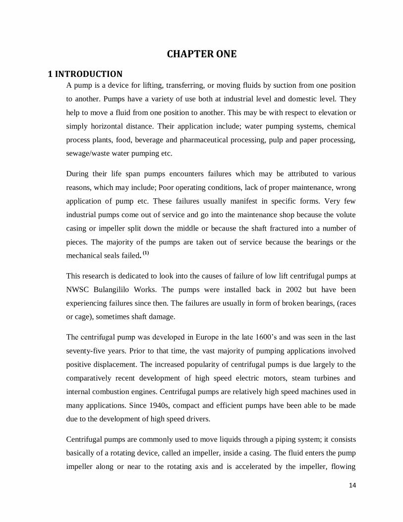
1 INTRODUCTION A pump is a device for lifting, transferring, or moving fluids by suction from one position
to another. Pumps have a variety of use both at industrial level and domestic level. They
help to move a fluid from one position to another. This may be with respect to elevation or
simply horizontal distance. Their application include; water pumping systems, chemical
process plants, food, beverage and pharmaceutical processing, pulp and paper processing,
sewage/waste water pumping etc.
During their life span pumps encounters failures which may be attributed to various
reasons, which may include; Poor operating conditions, lack of proper maintenance, wrong
application of pump etc. These failures usually manifest in specific forms. Very few
industrial pumps come out of service and go into the maintenance shop because the volute
casing or impeller split down the middle or because the shaft fractured into a number of
pieces. The majority of the pumps are taken out of service because the bearings or the
mechanical seals failed. (1)
This research is dedicated to look into the causes of failure of low lift centrifugal pumps at
NWSC Bulangililo Works. The pumps were installed back in 2002 but have been
experiencing failures since then. The failures are usually in form of broken bearings, (races
or cage), sometimes shaft damage.
The centrifugal pump was developed in Europe in the late 1600‟s and was seen in the last
seventy-five years. Prior to that time, the vast majority of pumping applications involved
positive displacement. The increased popularity of centrifugal pumps is due largely to the
comparatively recent development of high speed electric motors, steam turbines and
internal combustion engines. Centrifugal pumps are relatively high speed machines used in
many applications. Since 1940s, compact and efficient pumps have been able to be made
due to the development of high speed drivers.
Centrifugal pumps are commonly used to move liquids through a piping system; it consists
basically of a rotating device, called an impeller, inside a casing. The fluid enters the pump
impeller along or near to the rotating axis and is accelerated by the impeller, flowing
15
radially outward into a diffuser or volute chamber(casing), from where it exits into the
down or upstream piping system. Centrifugal pumps are used for large discharge through
small heads.
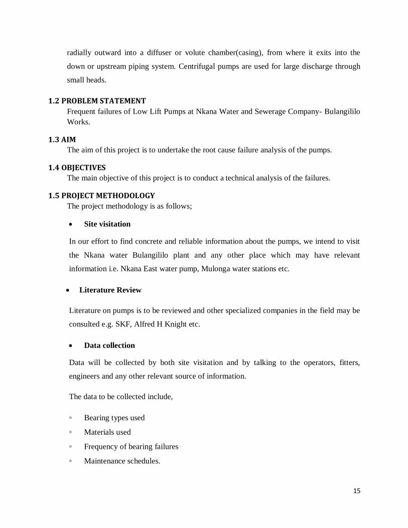
1.2 PROBLEM STATEMENT
Frequent failures of Low Lift Pumps at Nkana Water and Sewerage Company- Bulangililo
Works.
1.3 AIM
The aim of this project is to undertake the root cause failure analysis of the pumps.
1.4 OBJECTIVES
The main objective of this project is to conduct a technical analysis of the failures.
1.5 PROJECT METHODOLOGY
The project methodology is as follows;
Site visitation
In our effort to find concrete and reliable information about the pumps, we intend to visit
the Nkana water Bulangililo plant and any other place which may have relevant
information i.e. Nkana East water pump, Mulonga water stations etc.
Literature Review
Literature on pumps is to be reviewed and other specialized companies in the field may be
consulted e.g. SKF, Alfred H Knight etc.
Data collection
Data will be collected by both site visitation and by talking to the operators, fitters,
engineers and any other relevant source of information.
The data to be collected include,
◦ Bearing types used
◦ Materials used
◦ Frequency of bearing failures
◦ Maintenance schedules.

16
Data analysis
Conclusion and writing of report.
1.6: GANTT CHART
The following Gantt chart illustrates the pattern of work flow.
Fig1:Gantt chart
1.7 BACKGROUND
Nkana water and Sewerage Company Bulangililo Water Works has for the past nine (9)
years been experiencing frequent breakdowns of their low lift pumps. The pumps were
installed in 2002 in an attempt to rehabilitate the water works however, the pumps have
been failing and this has led to maintenance personnel changing the bearings of the pumps
nearly every month. Whenever there is a failure, it is usually in the form of damaged
bearing. Therefore, after every failure the bearings are replaced with new ones. This has
been the case since the installation of the new pumps. The failure, in addition to the low

17
performance of the pumps has led to low efficiency of operations. The water works i.e.
Bulangililo, has four low lift pumps out of which only three are supposed to be running at a
time. This however has not been the case due to failures and general low output which has
led to all the four been usually operated in hope of getting a desirable water inflow.
The following graph in figure 2 gives a summary of failure rate as reflected in the log
books for operation records.
Fig 2:Low Lift pumps Failure rate
The colors in the graph represent a particular pump; the graph shows which pump had a
problem and how many times during that month. For instance, we can tell that in the month
of January 2011, pump 2 failed three times, pump 3 failed twice and pump 4 failed once.
This has been the trend for the pumps since inception.
1.8 PUMP DETAILS
The following are the specification of the low lift pumps in discussion;
MAKE: MATHER AND PLATT- CENTRIFUGAL PUMPS
MODEL: 14/16 BKN
18
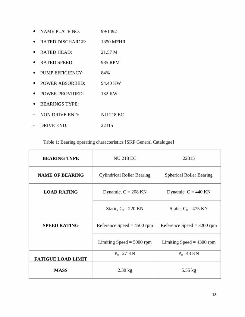
NAME PLATE NO: 99/1492
RATED DISCHARGE: 1350 M³/HR
RATED HEAD: 21.57 M
RATED SPEED: 985 RPM
PUMP EFFICIENCY: 84%
POWER ABSORBED: 94.40 KW
POWER PROVIDED: 132 KW
BEARINGS TYPE:
◦ NON DRIVE END: NU 218 EC
◦ DRIVE END: 22315
Table 1: Bearing operating characteristics [SKF General Catalogue]
BEARING TYPE
NU 218 EC
22315
NAME OF BEARING
Cylindrical Roller Bearing
Spherical Roller Bearing
LOAD RATING
Dynamic, C = 208 KN
Dynamic, C = 440 KN
Static, Co =220 KN
Static, Co = 475 KN
SPEED RATING
Reference Speed = 4500 rpm
Reference Speed = 3200 rpm
Limiting Speed = 5000 rpm
Limiting Speed = 4300 rpm
FATIGUE LOAD LIMIT
Pu = 27 KN Pu = 48 KN
MASS
2.30 kg
5.55 kg

19
Figure 3 shows the location of the bearings and their positioning with reference to the impeller.
The arrangement is that of a cantilever setup and the impeller over hangs on the far end of the
arrangement. The shaft is 0.875m away from the coupling with the bearing being at a distance of
0.28m from the impeller and the second being at a distance of 0.59m from the impeller.
Fig 3: Position of bearing on the Shaft

20
CHAPTER TWO
2. PUMP DESCRIPTION A pump is a mechanical device which uses suction to raise or move liquids, compress
gasses, or force air into inflatable objects such as tyres. A pump displaces a volume by
mechanical action; it creates a vacuum in an enclosed space by the removal of a gas.
Pumps are generally classified as follows;
Positive Displacement.
Non-positive Displacement.
2.1 POSITVE DISPLACEMENT
These are inherently pumps of low capacity and high discharge velocity. Positive
displacement pumps are constant flow machines; they produce a constant flow at a given
speed no matter what the discharge pressure. The pump traps a fixed amount of a fluid and
forces it into the discharge pipe.
Although used to pump a great variety of liquids, positive displacement pumps are also
capable of pumping slurries in small volumes or in consistencies that cannot be handled
by centrifugal pumps. Positive displacement pumps are subdivided into three categories:
reciprocating pumps, rotary pumps, and pneumatic (ejector) pumps, as shown in table 2
below.
Table 2: Categories of Positive Displacement Pumps
CATEGORY EXAMPLE
Reciprocating Pumps Plunger
Rotary Pumps Lobe, Progressive cavity, Screw
Pneumatic Pumps Ejector
Some positive displacement pumps work using an expanding cavity on the suction side and
a decreasing cavity on the discharge side. Liquid flows into the pump as the cavity on the
21
suction side expands and the liquid flows out of the discharge as the cavity collapses. The
volume is constant given each cycle of operation.
The pumps in focus under this study are centrifugal which fall under non-positive
displacement pumps. We shall therefore base our attention on non-positive displacement
pumps.
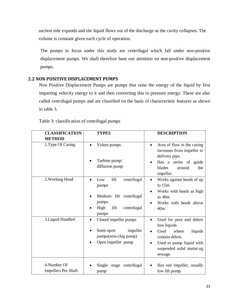
2.2 NON POSITIVE DISPLACEMENT PUMPS
Non Positive Displacement Pumps are pumps that raise the energy of the liquid by first
imparting velocity energy to it and then converting this to pressure energy. These are also
called centrifugal pumps and are classified on the basis of characteristic features as shown
in table 3.
Table 3: classification of centrifugal pumps
CLASSIFICATION
METHOD
TYPES DESCRIPTION
1.Type Of Casing Volute pumps
Turbine pump/
diffusion pump
Area of flow in the casing
increases from impeller to
delivery pipe.
Has a series of guide
blades around the
impeller.
2.Working Head Low lift centrifugal
pumps
Medium lift centrifugal
pumps
High lift centrifugal
pumps
Works against heads of up
to 15m
Works with heads as high
as 40m
Works with heads above
40m
3.Liquid Handled Closed impeller pumps
Semi-open impeller
pumps(non-clog pump)
Open impeller pump
Used for pure and debris
free liquids
Used where liquids
contain debris
Used to pump liquid with
suspended solid matter.eg
sewage.
4.Number Of
Impellers Per Shaft
Single stage centrifugal
pump
Has one impeller, usually
low lift pump.

22
Multi-stage centrifugal
pumps
Has 2 or more impellers,
used for high working
heads.
5.Number Of
Entrances To The
Impeller
Single suction/entry pump
Double entry/suction
pump
Water is admitted on one
side of impeller.
Water is admitted from
both sides of impeller,
axial thrust is neutralized.
6. Direction Of Flow
Through Impeller.
Radial flow pump
Axial flow pump
Mixed flow pump
Usually used in all
centrifugal pumps
Delivers huge quantities
of water at low heads,
suitable for irrigation
purposes
Used for irrigation
purposes
2.2.1 CENTRIFUGAL PUMPS
The centrifugal pumps is by far the most prolific member of the pump family, they are
widely used because of their design simplicity, high efficiency, wide range of capacity,
head, smooth flow rate and ease of operation and maintenance.
Centrifugal pumps include radial, axial and mixed flow units. A radial flow pump is
commonly referred to as a straight centrifugal pump, the common type of which is the
volute pump. In this type of pump, fluid enters the pump through the eye of the impeller,
which rotates at high speed. The fluid is accelerated radially outward from the casing. If
properly primed a partial vacuum is created that continuously draws more fluid in the
pump. In the axial flow centrifugal pump the rotor is a propeller and fluid flows parallel to
the axis of the shaft. In mixed flow, the direction of the liquid from the impeller acts as an
in between that of the radial and axial flow pumps. Figure 4 shows a centrifugal pump and
the flow of fluid through it.
They have real impellers with a series of blade attached to a rotating disc. The blades
normally slope backwards, away from the direction of rotation. As the impeller rotates the
curvature of the blade pushes the liquid out into the casing that surrounds it.

23
Fig 4: Cross section of a centrifugal pump [14]
This collects the displaced fluids and directs it into the piping. The centrifugal force arises
because the radius at which an individual particle leaves the impeller is larger than that at
which it enters. As liquid is displaced out into the casing, more liquid is pushed in to
replace it. This process takes place continuously to create a pumping action.
2.2.2 COMPONENTS OF A CENTRIFUGAL PUMP.
A centrifugal pump has two main components:
Rotating masses comprised of an impeller and a shaft
Stationary masses comprised of a casing, casing cover, and bearings.
The general components, both stationary and rotary, are depicted in figure 5. Each of the
component plays a distinguished role that cannot be over looked.
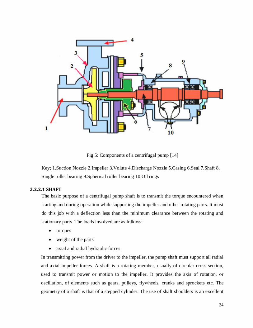
24
Fig 5: Components of a centrifugal pump [14]
Key; 1.Suction Nozzle 2.Impeller 3.Volute 4.Discharge Nozzle 5.Casing 6.Seal 7.Shaft 8.
Single roller bearing 9.Spherical roller bearing 10.Oil rings
2.2.2.1 SHAFT
The basic purpose of a centrifugal pump shaft is to transmit the torque encountered when
starting and during operation while supporting the impeller and other rotating parts. It must
do this job with a deflection less than the minimum clearance between the rotating and
stationary parts. The loads involved are as follows:
torques
weight of the parts
axial and radial hydraulic forces
In transmitting power from the driver to the impeller, the pump shaft must support all radial
and axial impeller forces. A shaft is a rotating member, usually of circular cross section,
used to transmit power or motion to the impeller. It provides the axis of rotation, or
oscillation, of elements such as gears, pulleys, flywheels, cranks and sprockets etc. The
geometry of a shaft is that of a stepped cylinder. The use of shaft shoulders is an excellent
25
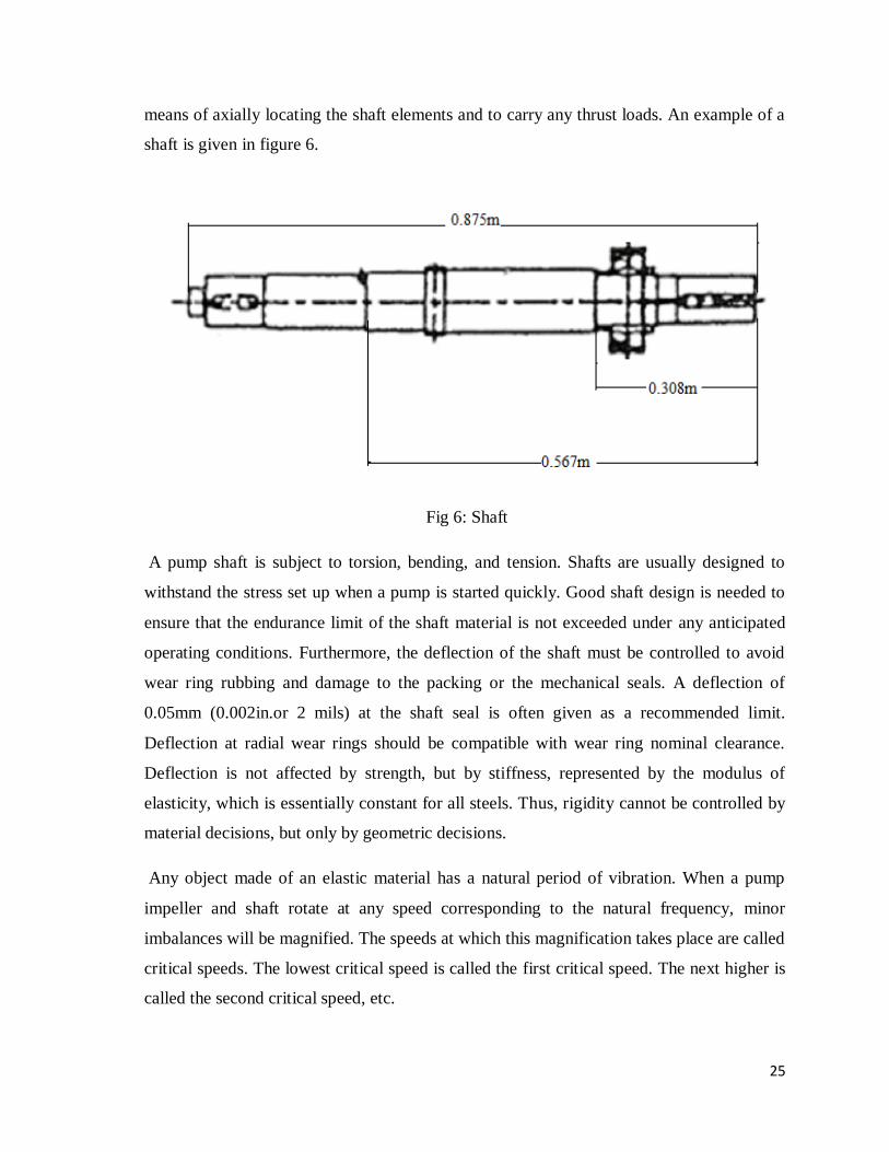
means of axially locating the shaft elements and to carry any thrust loads. An example of a
shaft is given in figure 6.
Fig 6: Shaft
A pump shaft is subject to torsion, bending, and tension. Shafts are usually designed to
withstand the stress set up when a pump is started quickly. Good shaft design is needed to
ensure that the endurance limit of the shaft material is not exceeded under any anticipated
operating conditions. Furthermore, the deflection of the shaft must be controlled to avoid
wear ring rubbing and damage to the packing or the mechanical seals. A deflection of
0.05mm (0.002in.or 2 mils) at the shaft seal is often given as a recommended limit.
Deflection at radial wear rings should be compatible with wear ring nominal clearance.
Deflection is not affected by strength, but by stiffness, represented by the modulus of
elasticity, which is essentially constant for all steels. Thus, rigidity cannot be controlled by
material decisions, but only by geometric decisions.
Any object made of an elastic material has a natural period of vibration. When a pump
impeller and shaft rotate at any speed corresponding to the natural frequency, minor
imbalances will be magnified. The speeds at which this magnification takes place are called
critical speeds. The lowest critical speed is called the first critical speed. The next higher is
called the second critical speed, etc.

26
In centrifugal pump nomenclature:
A rigid shaft means one with an operating speed lower than its first critical speed;
A flexible shaft is one with an operating speed higher than its first critical speed.
The shaft critical speed can be reached and passed without danger because frictional forces
(surrounding liquid, stuffing box packing, and various internal leakage joints) tend to
restrain the deflection for a short duration.
2.2.2.2 WEARING RINGS
Wearing rings (for casing or impeller) provide an easily and economically renewable
leakage joint. There are various types of wearing ring designs, and the selection of the
most desirable type depends on the following:
liquid being handled
pressure differential across the leakage joint
rubbing speed
pump design (i.e., sewage vs. clean liquid)
In leakage joints involving a flat-type wearing ring, the leakage flow is a function of the
following:
area
length of the joint
pressure differential across the joint
If the path is broken by relief chambers, the velocity energy in the leakage jet is
dissipated in each relief chamber, thereby increasing the resistance. As a result, with
several relief chambers and several leakage joints for the same actual flow through the
joint, is less resulting in higher pump performance and operating efficiency.
2.2.2.3 IMPELLER
The impeller is the main rotating part that provides the centrifugal acceleration to the fluid.
They are often classified in many ways.
Based on major direction of flow in reference to the axis of rotation
Radial flow
Axial flow
Mixed flow
27
Based on suction type
Single-suction: Liquid inlet on one side.
Double-suction: Liquid inlet to the impeller symmetrically
Closed impellers require wear rings and these wear rings present another maintenance
problem. Open and semi-open impellers are less likely to clog, but need manual adjustment
to the volute or back-plate to get the proper impeller setting and prevent internal re-
circulation. Vortex pump impellers are great for solids and "stringy" materials but they are
up to 50% less efficient than conventional designs. The number of impellers determines the
number of stages of the pump. A single stage pump has one impeller only and is best for
low head service. A two-stage pump has two impellers in series for medium head service.
Open Impeller
An open impeller consists of vanes attached to a central hub without any form of sidewall or
shroud.
Disadvantage of an open impeller
Structural weakness – if the vanes are long, they must be strengthened by ribs or a
partial shroud. Generally, open impellers are used in small inexpensive pumps or
pumps that handle abrasive liquids.
Advantage of an open impeller
It is capable of handling suspended matter with a minimum of clogging.
The open impeller rotates between two side plates, between the casing walls of the volute.
The clearance between the impeller vanes and sidewalls allows a certain amount of water
recirculation, which increases as wear increases. To restore the original efficiency, both the
impeller and the side plates must be replaced. This is a much greater expense than would be
encountered by an enclosed impeller where simple rings form the leakage point.
Semi-Open Impeller
The semi-open impeller incorporates a shroud or an impeller back wall. This shroud may or
may not have “pump-out” vanes, which are located at the back of the impeller shroud.
Function of the “pump-out” vanes
To reduce the pressure at the back hub of the impeller;
28
To prevent foreign matter from lodging in the back of the impeller and interfering
with the proper operation of the pump and the stuffing box.
Enclosed Impeller
The enclosed impeller is used universally in centrifugal pumps that handle clear liquids. It
incorporates shrouds or enclosing sidewalls that totally enclose the impeller “waterways”
from the suction eye to the impeller periphery. This design prevents the liquid recirculation
that occurs between an open or semi-open impeller and its side plates. A running joint must
also be provided between the impeller and the casing to separate the discharge and suction
chambers of the pump. The running joint is normally formed by a relatively short cylindrical
surface on the impeller shroud that rotates within a slightly larger stationary cylindrical
surface. If one or both surfaces are made removable, the “leakage joint” can be repaired
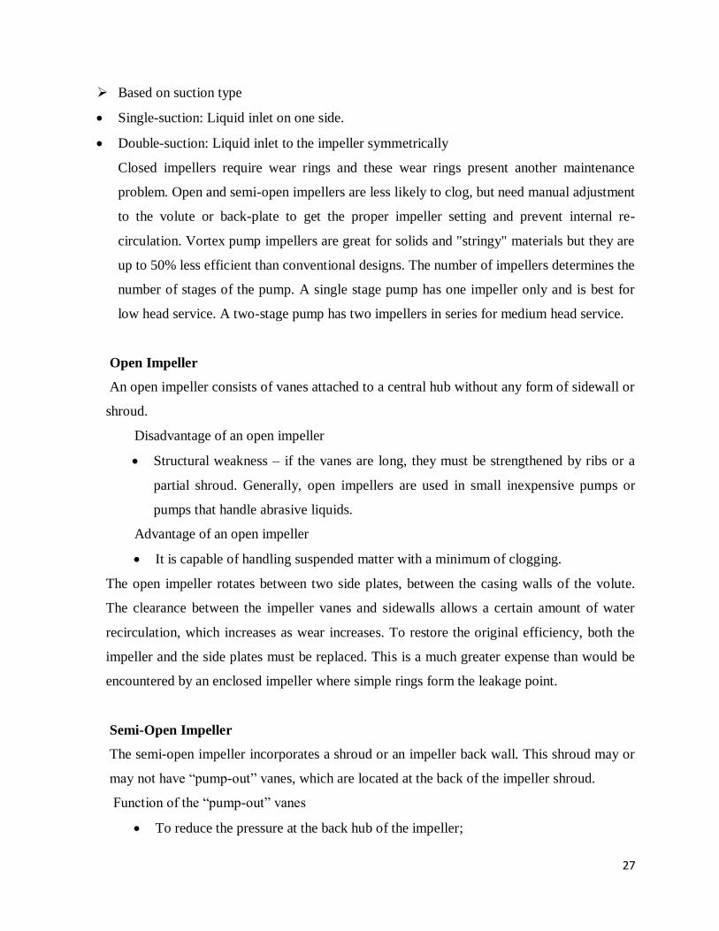
when wear causes excessive leakage. Some examples of impellers are given below;
Fig 7: Closed Impeller Fig 8: Open Impeller
The Closed impeller of figure 7 is used for pumping clean liquids.
The Open Impeller in figure 8 is designed for liquids containing solid particles, abrasive
liquid or stock up to 8%consistency
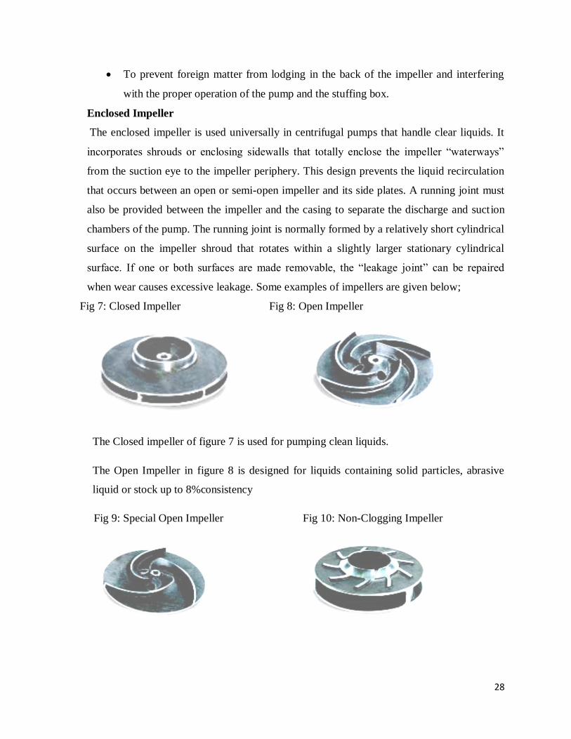
Fig 9: Special Open Impeller Fig 10: Non-Clogging Impeller
29
The Special Open Impeller in figure 9 is suitable for liquids containing bigger solids
particles and long fibers, abrasive liquids or stock up to 8% consistency.
The Non Clogging Impeller in figure 10 is used for sludge or slurries containing big solid
particles.
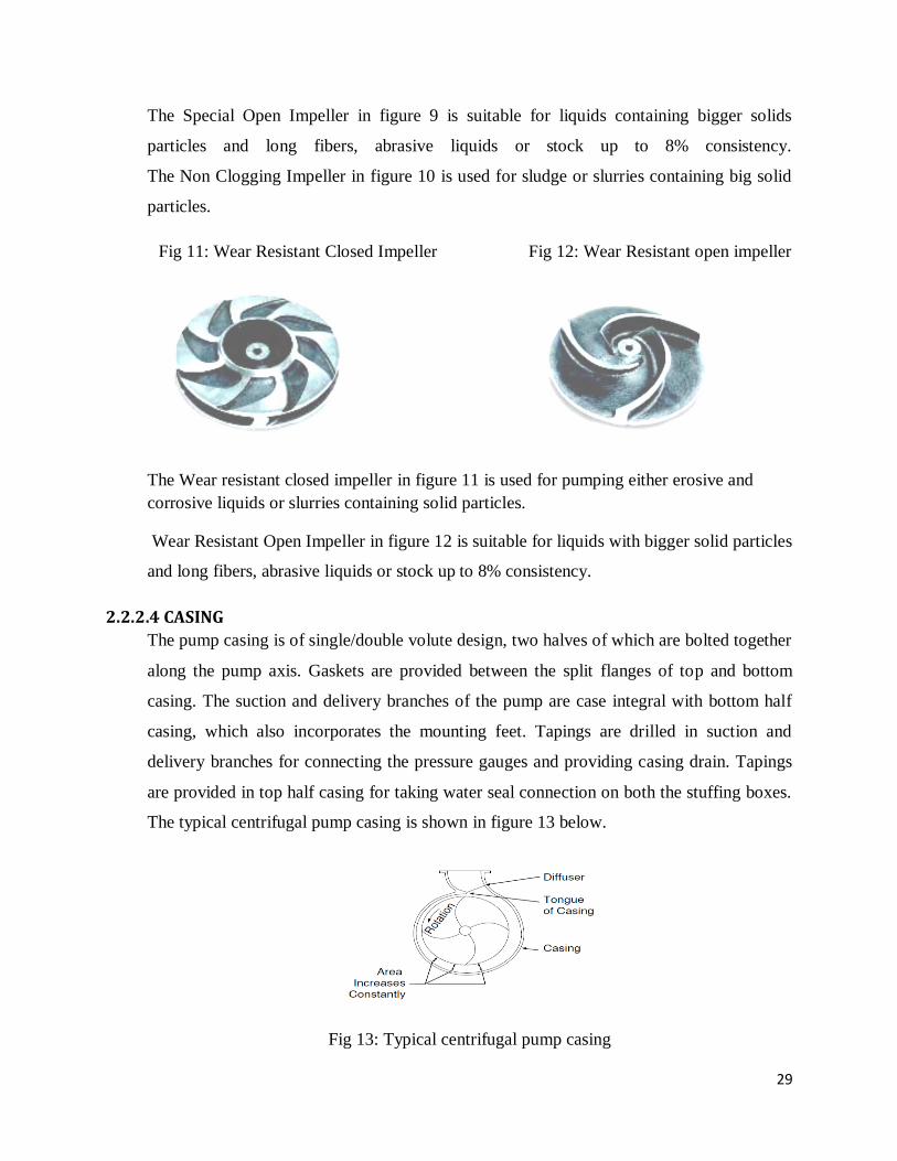
Fig 11: Wear Resistant Closed Impeller Fig 12: Wear Resistant open impeller
The Wear resistant closed impeller in figure 11 is used for pumping either erosive and
corrosive liquids or slurries containing solid particles.
Wear Resistant Open Impeller in figure 12 is suitable for liquids with bigger solid particles
and long fibers, abrasive liquids or stock up to 8% consistency.
2.2.2.4 CASING
The pump casing is of single/double volute design, two halves of which are bolted together
along the pump axis. Gaskets are provided between the split flanges of top and bottom
casing. The suction and delivery branches of the pump are case integral with bottom half
casing, which also incorporates the mounting feet. Tapings are drilled in suction and
delivery branches for connecting the pressure gauges and providing casing drain. Tapings
are provided in top half casing for taking water seal connection on both the stuffing boxes.
The typical centrifugal pump casing is shown in figure 13 below.
Fig 13: Typical centrifugal pump casing
30
The pump casing is an air tight chamber surrounding the pump impeller encloses and
contains the discharge and, sometimes, the suction nozzles. The casing collects the high-
velocity flow from the impeller and converts some of the velocity energy into pressure. The
casing may be one piece or of axial or radial–split design. It has provision to fix stuffing
box and house packing materials which prevent external leakage. The essential functions of
the casing are to guide water to and from the impeller.
The following three types of casings are commonly employed:
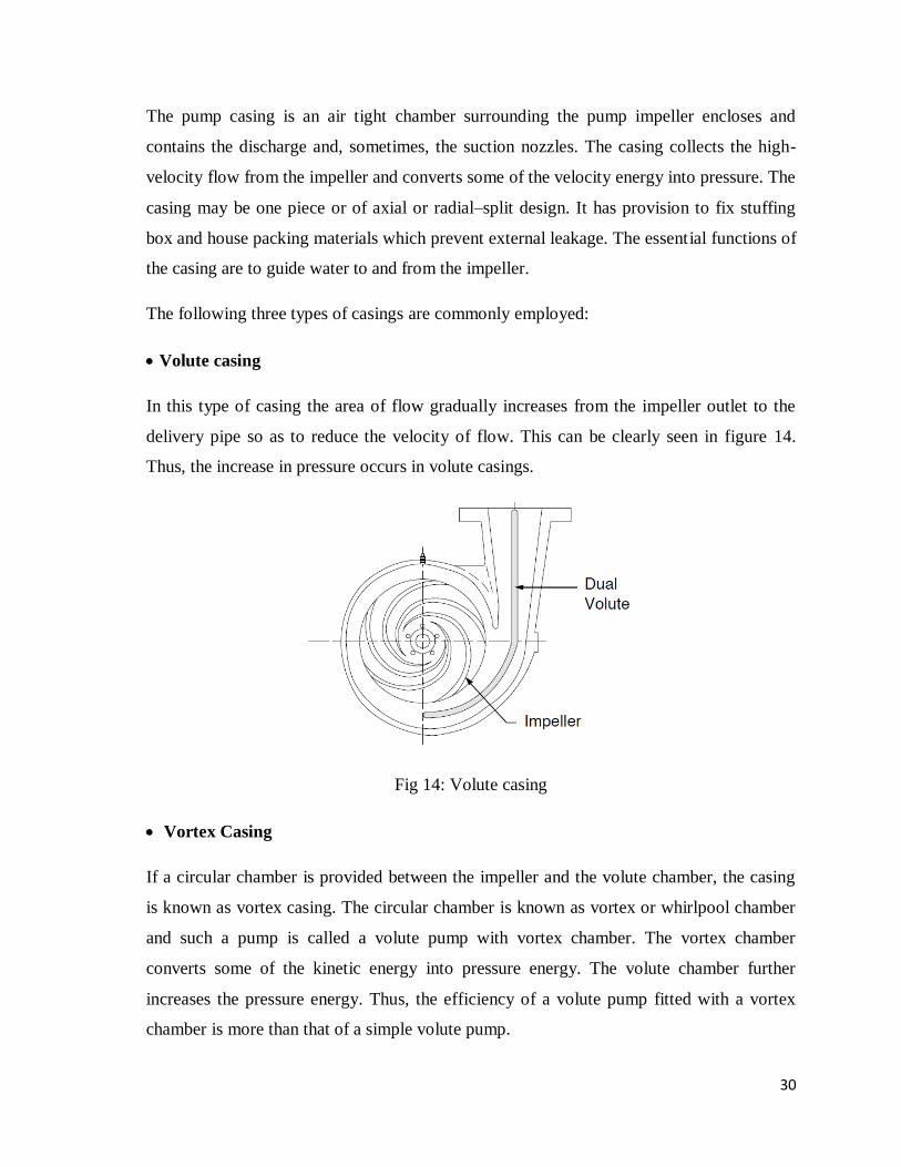
Volute casing
In this type of casing the area of flow gradually increases from the impeller outlet to the
delivery pipe so as to reduce the velocity of flow. This can be clearly seen in figure 14.
Thus, the increase in pressure occurs in volute casings.
Fig 14: Volute casing
Vortex Casing
If a circular chamber is provided between the impeller and the volute chamber, the casing
is known as vortex casing. The circular chamber is known as vortex or whirlpool chamber
and such a pump is called a volute pump with vortex chamber. The vortex chamber
converts some of the kinetic energy into pressure energy. The volute chamber further
increases the pressure energy. Thus, the efficiency of a volute pump fitted with a vortex
chamber is more than that of a simple volute pump.
31
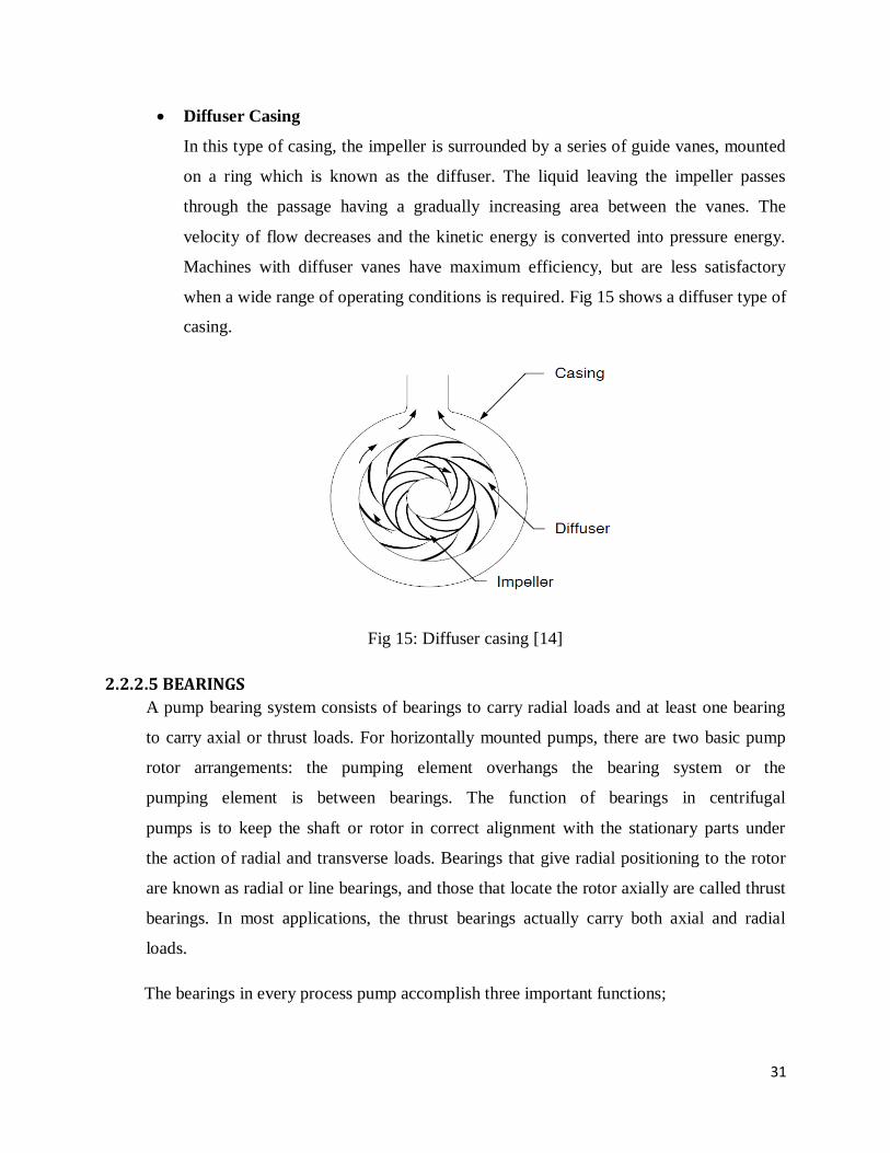
Diffuser Casing
In this type of casing, the impeller is surrounded by a series of guide vanes, mounted
on a ring which is known as the diffuser. The liquid leaving the impeller passes
through the passage having a gradually increasing area between the vanes. The
velocity of flow decreases and the kinetic energy is converted into pressure energy.
Machines with diffuser vanes have maximum efficiency, but are less satisfactory
when a wide range of operating conditions is required. Fig 15 shows a diffuser type of
casing.
Fig 15: Diffuser casing [14]
2.2.2.5 BEARINGS
A pump bearing system consists of bearings to carry radial loads and at least one bearing
to carry axial or thrust loads. For horizontally mounted pumps, there are two basic pump
rotor arrangements: the pumping element overhangs the bearing system or the
pumping element is between bearings. The function of bearings in centrifugal
pumps is to keep the shaft or rotor in correct alignment with the stationary parts under
the action of radial and transverse loads. Bearings that give radial positioning to the rotor
are known as radial or line bearings, and those that locate the rotor axially are called thrust
bearings. In most applications, the thrust bearings actually carry both axial and radial
loads.
The bearings in every process pump accomplish three important functions;
32
They locate the rotating element in its correct position relative to the stationary
parts of the pump.
They allow the shaft to rotate with the least amount of friction to maximize the
pump operating efficiency.
They absorb all the radial and axial loads which are transmitted through the shaft
during the different operating modes.
The thrust bearing of the cantilever-type pump carries not only the entire thrust load but
also its share of the radial load. The thrust bearing must be capable of supporting the axial
loads in both directions because thrust reversal can be expected with most pumps,
especially during the starting process. In same designs, a separate (usually smaller) thrust
bearing is installed for the thrust reversal. Typically, the thrust bearing is pressed on the
shaft and locked in the bearing housing; thus the thrust bearing determines the axial
location of the shaft and the impeller. The radial bearing is also pressed on the shaft but is
free to slide in the frame or in the bearing housing. This protects the bearings from
excessive axial loads generated by unequal thermal expansion of the shaft and frame.
Bearing Arrangement
The Face to Face arrangement and the Back to Back arrangement can both accommodate
axial loads in either direction, but only by one bearing at a time. In view of this similarity,
it is frequently assumed that these arrangements are interchangeable. Not in end suction
process pumps.
The Back to Back arrangement is the only one that can accommodate a tilting moment.
Consequently this one must be used when the thrust bearing is located close to the source
of a tilting moment. As that can occur as a result of shaft misalignment, the Back to Back
arrangement must always be used in an end suction pump where it is close to the shaft
coupling. The thrust bearing in a “double-ender” type of pump is located at the opposite
end of the shaft from the coupling. But if we continue to use the Back to Back
arrangement in this pump style, it will ensure that the maintenance team doesn‟t have to
remember which bearing style goes in which pump. Therefore, every time a double
angular contact bearing is used, it should be mounted in the Back to Back arrangement.
33
To ensure that these bearings provide long-lasting, trouble-free service, it must be
recognized that they are only a part of the total bearing arrangement. Other important
aspects include the support and the protection of these bearings. Such support includes a
strong shaft and housing to minimize the effect of any externally induced stresses or
vibration. A strong shaft that will minimize the effect of vibration is essential to the
support of the pump bearings. Therefore the slenderness ratio of the shaft must be kept at
as low a level as is possible.
Bearing Frame and Housing.
A bearing frame is a member of an end suction pump to which is assembled the liquid end
and rotating element. A bearing housing is a pump component into which the bearings are
mounted. In the case of the end suction pump, the frame also serves as the bearing housing.
Frames or bearing housings serve the purpose of providing bore alignment for the bearings,
an oil or grease reservoir of adequate capacity, heat dissipation by convection or other
means and protective shaft seals to keep out dirt and moisture and keep oil in. In addition,
frames also serve as a mounting means for the wet end and provide a pedestal foot or feet
to the base. Obviously, housings must be sturdy enough to withstand the real life distortion
forces they will be subjected to without distorting to a point that their bearing alignment is
threatened.
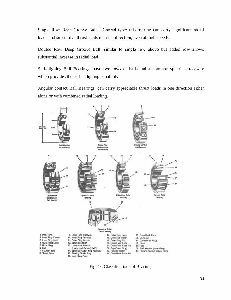
Bearing Classification
Bearings for pumps are classified in many ways. Figure 16 shows the classification of
bearings. Line verses thrust describe the bearing‟s ability to handle radial or axial thrust
loads and how the bearing positions the rotor. Cylindrical roller bearings have no inherent
axial thrust handling capability. The outboard bearing is made up of two angular contact
ball bearings, back to back. These bearings can take both radial and thrust loads. The
inboard ball bearing takes up thrust loads imposed in the direction of the driver and the
outboard ball bearing takes up any thrust the inlet of the pump.
The bearings most used on pumps are the single and double deep groove ball, the double
row self-aligning and the single and double row angular contact.
34
Single Row Deep Groove Ball – Conrad type: this bearing can carry significant radial
loads and substantial thrust loads in either direction, even at high speeds.
Double Row Deep Groove Ball: similar to single row above but added row allows
substantial increase in radial load.
Self-aligning Ball Bearings: have two rows of balls and a common spherical raceway
which provides the self – aligning capability.
Angular contact Ball Bearings: can carry appreciable thrust loads in one direction either
alone or with combined radial loading.
Fig: 16 Classifications of Bearings
35
Corresponding Cylindrical Roller Bearings can offer higher radial load carrying capacity
than their ball bearing counterparts. Rubber lined, cut less bearings are used in water
service in applications involving sand and grit. They are designed to provide a
hydrodynamic wedge under the shaft and lift it clear of the bearing. They can operate dry
for short start up periods.
Bearing failures are one of the three highest failure areas on centrifugal pumps. These
failures are caused by excessive operation at low flows, excessive axial thrust loads due to
obstructions, improper upstream piping or wear, improper or inadequate lubrication,
misalignment and piping strains, dirt and moisture.
2.2.2.6 LUBRICATION
Grease is the most common lubricant for pump bearings. It requires relatively little
attention and service and usually gives long bearing life. Oil-bath lubricant is used much
less frequently because returning the oil in the bearing housing possesses some technical
difficulties, especially on vertical pumps. Force-fed oil lubrication is used very
infrequently. Although it ensures the lowest bearing operating temperatures, provides the
best protection from bearing contamination, and gives the longest bearing life, it requires
expensive auxiliary equipment, which also needs service and attention.
The lubricant separates the rolling elements and raceway contact surfaces, and minimizes
the effect of friction. The selection of the lubricant is a consideration of its viscosity, and
depends on the operating temperature, the bearing size and its rotational speed.
While the bearing manufacturer can identify the minimum viscosity required for these
conditions, the selected lubricant should provide a higher viscosity than the minimum
identified.
Grease Lubrication
Lubricating grease is essentially a soap thickening agent in mineral or synthetic oil. When
selecting the right grease, the base oil should be able to satisfy the bearing‟s lubrication
requirements. When using grease, two rules must be followed;
◦ Do not apply too much grease to a bearing as it will cause the grease to overheat
and reduce the lubricating effectiveness.
36
◦ Do not mix different types of grease as many of their contents and preservatives
are incompatible.
Oil Lubrication
Mineral oils are still the most common lubricating oil in general service pumps, while
synthetic oils tend to be more resistant to higher temperatures and seem to require less
frequent change in these applications. The oil level in the bearing housing should be
maintained at the centerline of the lowest ball in the race, and the oil must be able to enter
the bearing from both sides. An increasingly popular method of pump bearing
Lubrication is the Oil Mist system where the mist is a collection of atomized oil droplets
that are sprayed in the bearings by compressed air. The Purge Oil Mist system
incorporates a static oil bath for the bearings, while the Pure Oil Mist system comprises
the only form of lubrication used. The latter is gradually taking over almost exclusively as
it has been found that the Purge System is less effective. The Pure Oil Mist System is used
to fill the bearing housing as much as possible with oil in order to minimize the entry of
contaminants.
2.2.2.7 SUCTION NOZZLE
This directs the flow of liquid to the eye of the impeller. A hand hole cover is provided for
cleaning and inspection purposes. A gasket is provided between the hand hole cover and
the suction pipe and also between the suction pipe and casing in order to avoid leakage. To
prevent the entrance of solid particles, debris etc. into the pump is provided with a strainer
at its lower end. The lower end of the pipe is also fitted a non-return foot valve which does
not permit the liquid to drain out of the suction pipe when the pump is not working.
This also helps in priming. The suction cover encloses the suction opening of the casing
and also contains the suction nozzle of the pump. On some designs, the suction cover is an
integral part of the pump casing.
2.2.2.8 DISCHARGE NOZZLE
This is a pipe connected at its lower end to the outlet of the pump and it delivers the liquid
to the required height. A regulating valve is provided on the delivery pipe to regulate the
supply of water.
37
2.2.2.9 STUFFING BOX
The primary function of a stuffing box is to prevent leakage at the point where the shaft
passes out through the pump casing. For general service pumps, a stuffing box consists of a
cylindrical recess that accommodates a number of rings of packing seal cage and gland
around the shaft or shaft sleeve. If sealing liquid to the box is desired, a lantern ring or seal
cage is used, which separates the rings of packing into approximately equal sections. The
packing is compressed to give the desired fit on the shaft or sleeve by a gland that can be
adjusted in an axial direction. A small leakage from the stuffing box is required to provide
lubrication and cooling.
2.2.2.10 STUFFING BOX COVER
The stuffing box cover, also called the back head or adapter, encloses the inboard opening
of the casing and also contains the stuffing box.

38
CHAPTER THREE
3. CHARACTERISTICS AND OPERATIONS OF CENTRIFUGAL PUMPS. A centrifugal pump is made up of a set of rotating vanes that are enclosed within a housing.
These vanes are utilized to impart energy to a liquid through centrifugal force thereby
building up a velocity head. At the periphery of the pump impeller, the liquid is directed
into a volute which commonly has an increasing cross sectional area along its length so that
as the liquid travels along the chamber and its velocity is reduced. Since the energy level of
the liquid cannot be dissipated at this point, the conversion of energy law (Bernoulli‟s
theorem) requires the liquid loses velocity energy as it moves along the chamber, it must
increase the energy related to pressure. Hence the increase in pressure.
A centrifugal pump has two main parts, a rotating element i.e. an impeller and shaft, and a
stationary element which is made up of a casing, stuffing box and bearings. The pump
transfers the energy provided by a prime mover such as an electric motor, steam turbine, or
gasoline engine to energy within the energy being pumped. The energy within the pump is
present as a velocity energy, pressure energy, or a combination of both. The liquid being
pumped surrounds the impeller and as the impeller rotates, the rotating motion of the
impeller imparts a rotating motion to the liquid. There are two components to the motion
imparted to the liquid by the impeller; one motion is in the radial direction outward the
centre of the impeller. This motion is caused by the centrifugal force due to the rotation of
the liquid, which acts in a direction outward from the centre of the rotating impeller.
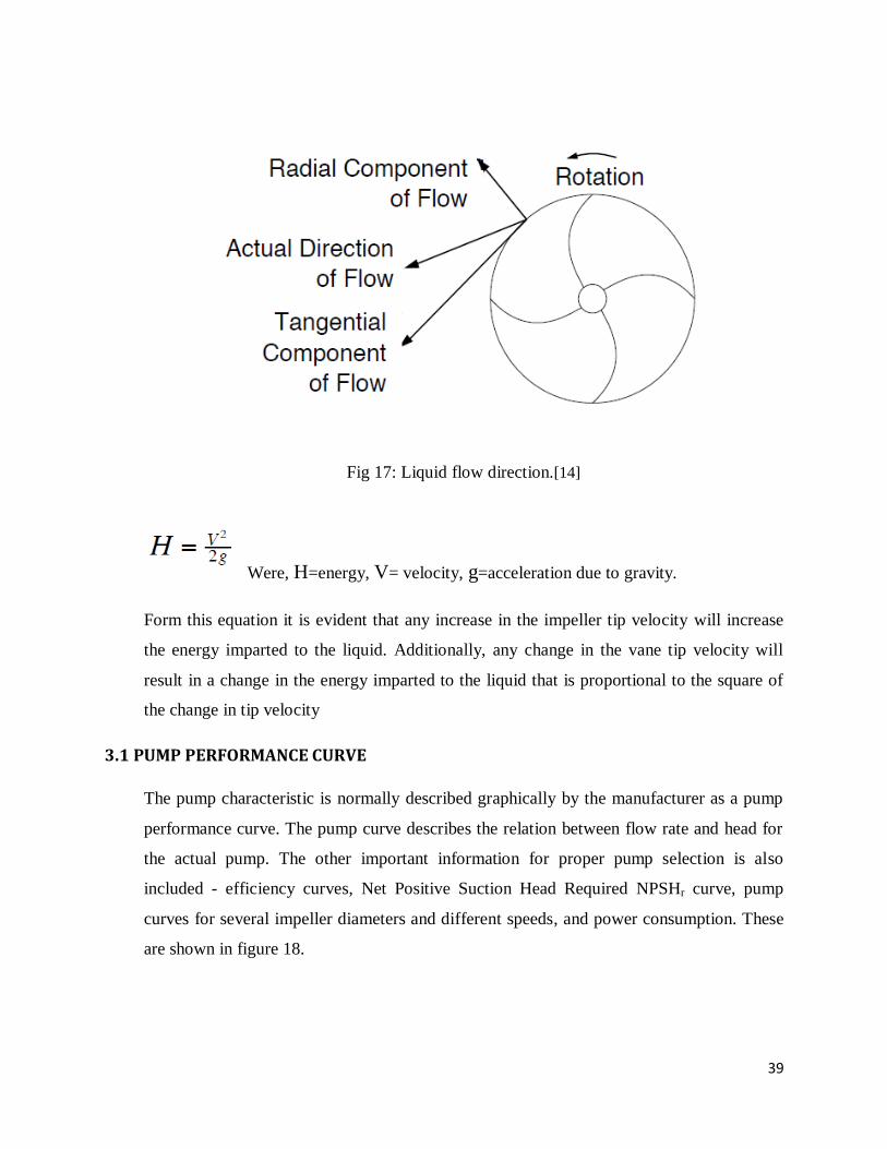
Secondly, as the liquid leaves the impeller, it tends to move in a direction tangential to the
outside diameter of the impeller. The actual liquid direction is as a result of the two flow
direction as shown in figure 17.
The amount of the energy being added to the liquid by the rotating impeller is related to the
velocity with which the liquid moves. The energy expressed as pressure energy will be
proportional to the square of the resultant exit velocity.
39
Fig 17: Liquid flow direction.[14]
Were, H=energy, V= velocity, g=acceleration due to gravity.
Form this equation it is evident that any increase in the impeller tip velocity will increase
the energy imparted to the liquid. Additionally, any change in the vane tip velocity will
result in a change in the energy imparted to the liquid that is proportional to the square of
the change in tip velocity
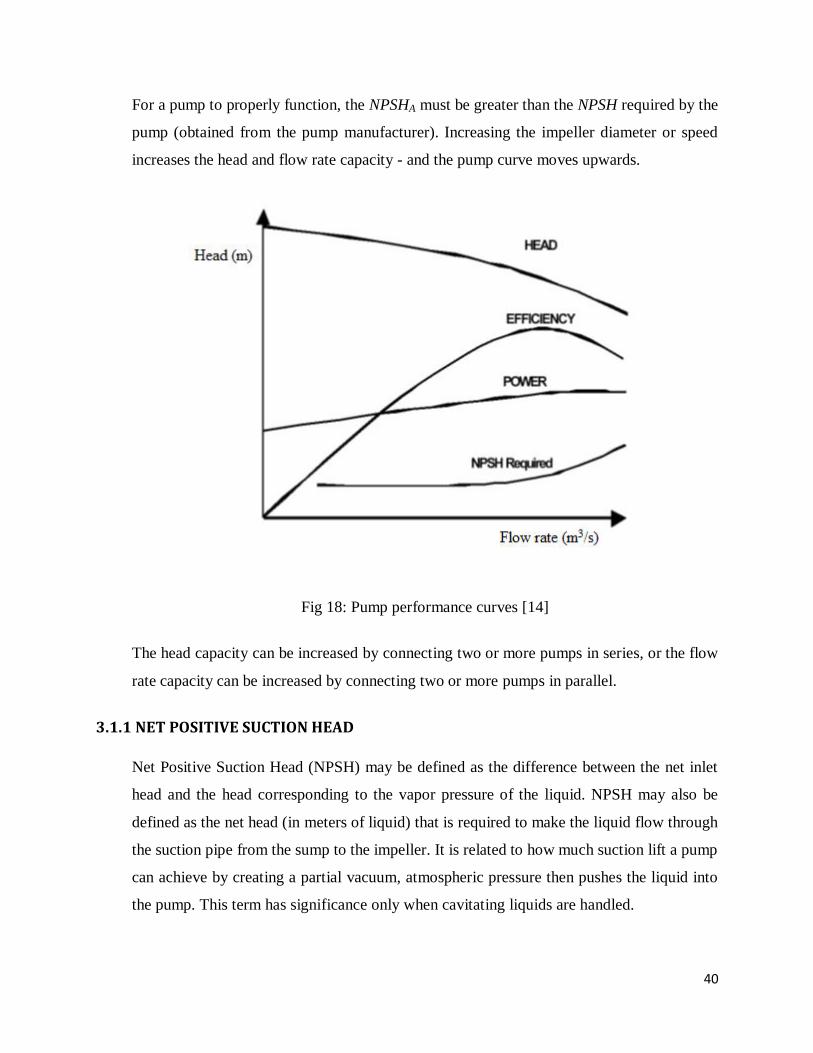
3.1 PUMP PERFORMANCE CURVE
The pump characteristic is normally described graphically by the manufacturer as a pump
performance curve. The pump curve describes the relation between flow rate and head for
the actual pump. The other important information for proper pump selection is also
included - efficiency curves, Net Positive Suction Head Required NPSHr curve, pump
curves for several impeller diameters and different speeds, and power consumption. These
are shown in figure 18.
40
For a pump to properly function, the NPSHA must be greater than the NPSH required by the
pump (obtained from the pump manufacturer). Increasing the impeller diameter or speed
increases the head and flow rate capacity - and the pump curve moves upwards.
Fig 18: Pump performance curves [14]
The head capacity can be increased by connecting two or more pumps in series, or the flow
rate capacity can be increased by connecting two or more pumps in parallel.
3.1.1 NET POSITIVE SUCTION HEAD
Net Positive Suction Head (NPSH) may be defined as the difference between the net inlet
head and the head corresponding to the vapor pressure of the liquid. NPSH may also be
defined as the net head (in meters of liquid) that is required to make the liquid flow through
the suction pipe from the sump to the impeller. It is related to how much suction lift a pump
can achieve by creating a partial vacuum, atmospheric pressure then pushes the liquid into
the pump. This term has significance only when cavitating liquids are handled.
41
NPSH is a dimensional parameter that can be used to check cavitation in pump, the
minimum NPSH depends upon the pump design, its speed and the discharge.
NPSH (a) is the Net Positive Suction Head Available; it is a function of the system in
which the pump operates. It is the excess pressure of the liquid in feet absolute over its
vapor pressure as it arrives at the pump suction, to be sure that the pump selected does not
cavitate.
NPSH(r) is the Net Positive Suction Head Required by the pump, which is read from the
pump performance curve. NPSH required is a function of the pump design and is
determined based on actual pump test by the vendor. As the liquid passes from the pump
suction to the eye of the impeller, the velocity increases and the pressure decrease. There
are also pressure losses due to shock and turbulence as the liquid strikes the impeller. The
centrifugal force of the impeller vanes further increases the velocity and decreases the
pressure of the liquid. The NPSH required is the positive head in feet absolute required at
the pump suction to overcome these pressure drops in the pump and maintain the majority
of the liquid above its vapor pressure. NPSH(r) may be thought of as friction loss caused by
the entry to the pump suction.
The NPSH is always positive since it is expressed in terms of absolute fluid column height.
The term "Net" refers to the actual pressure head at the pump suction flange and not the
static suction head.
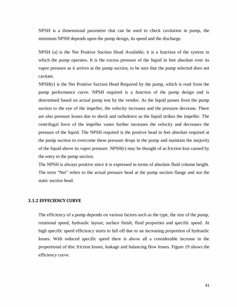
3.1.2 EFFECIENCY CURVE
The efficiency of a pump depends on various factors such as the type, the size of the pump,
rotational speed, hydraulic layout, surface finish, fluid properties and specific speed. At
high specific speed efficiency starts to fall off due to an increasing proportion of hydraulic
losses. With reduced specific speed there is above all a considerable increase in the
proportional of disc friction losses, leakage and balancing flow losses. Figure 19 shows the
efficiency curve.
42
Fig 19: The Efficiency Curve.
The actual head capacity curve stipulates the output of the centrifugal pump. From this the
water-kW can be calculated by means of the following formula;
kW = (Q*H)/ 102
Q is in m3 /s
H is in m.
Due to additional mechanical losses, the input of power has to be higher. The efficiency of
the pump therefore is:
Efficiency = kilowatt output/kilowatt input = ( Q * H ) / power-kW
As the water kilowatt is zero at no flow, the efficiency curve starts at zero, rising steadily to
a maximum and then decreasing with increasing flow.
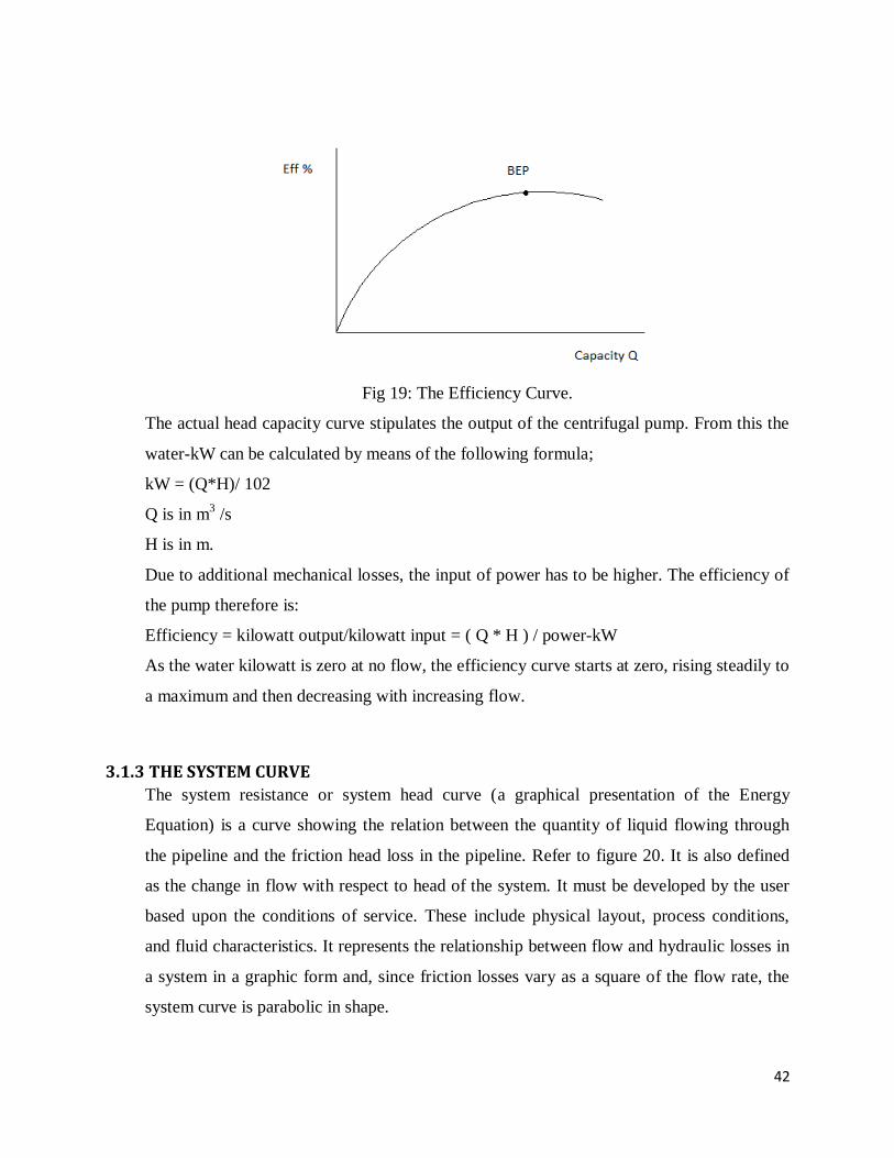
3.1.3 THE SYSTEM CURVE
The system resistance or system head curve (a graphical presentation of the Energy
Equation) is a curve showing the relation between the quantity of liquid flowing through
the pipeline and the friction head loss in the pipeline. Refer to figure 20. It is also defined
as the change in flow with respect to head of the system. It must be developed by the user
based upon the conditions of service. These include physical layout, process conditions,
and fluid characteristics. It represents the relationship between flow and hydraulic losses in
a system in a graphic form and, since friction losses vary as a square of the flow rate, the
system curve is parabolic in shape.
43
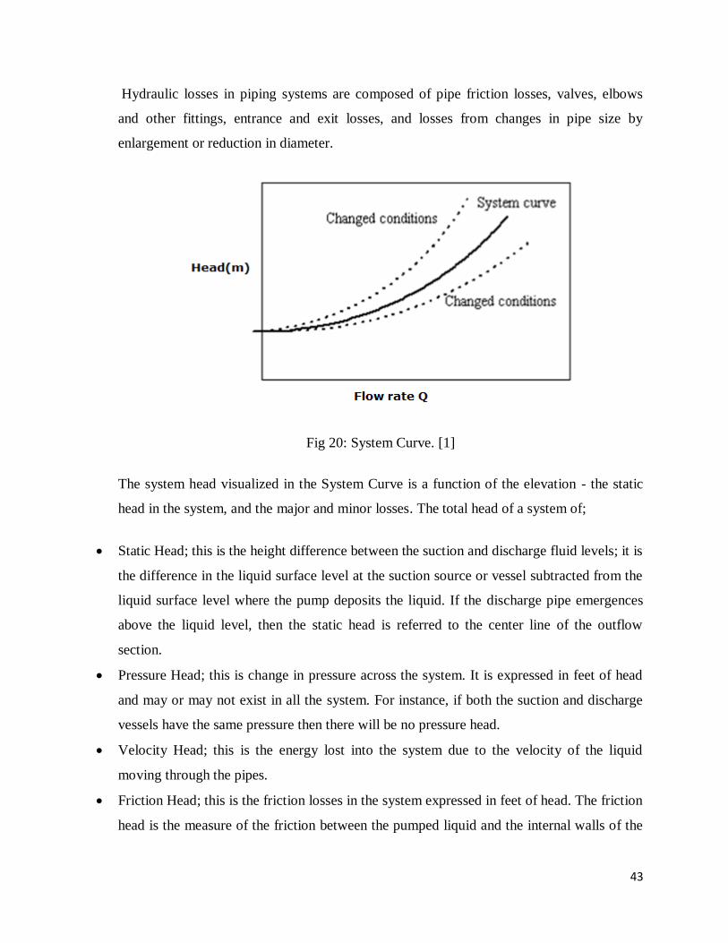
Hydraulic losses in piping systems are composed of pipe friction losses, valves, elbows
and other fittings, entrance and exit losses, and losses from changes in pipe size by
enlargement or reduction in diameter.
Fig 20: System Curve. [1]
The system head visualized in the System Curve is a function of the elevation - the static
head in the system, and the major and minor losses. The total head of a system of;
Static Head; this is the height difference between the suction and discharge fluid levels; it is
the difference in the liquid surface level at the suction source or vessel subtracted from the
liquid surface level where the pump deposits the liquid. If the discharge pipe emergences
above the liquid level, then the static head is referred to the center line of the outflow
section.
Pressure Head; this is change in pressure across the system. It is expressed in feet of head
and may or may not exist in all the system. For instance, if both the suction and discharge
vessels have the same pressure then there will be no pressure head.
Velocity Head; this is the energy lost into the system due to the velocity of the liquid
moving through the pipes.
Friction Head; this is the friction losses in the system expressed in feet of head. The friction
head is the measure of the friction between the pumped liquid and the internal walls of the
44
pipe, valves, connections and accessories in the suction and discharge piping. Because the
velocity head and the friction head are energies lost in the system, this energy would never
reach the final point where it is needed. Therefore, these heads must be calculated and
added to the pump at the moment of design and specifications. It is also necessary to know
these values especially when they are significant, at the moment of analyzing a problem in
the pump. The friction head and velocity head can be measured with pressure gauges in an
existing system.
The sum of these four heads is called system head;
HT= Hs + Hp + Hf + Hv
Where
HT is system head, Hs is the Static head, Hp is Pressure head, Hf is Friction head and Hv is
Velocity head.
However, we know that;
Hf = f Lv2 /2gd
Where
f is Darcy‟s frictional coefficient or factor
L is the length of the pipe
v is the average fluid velocity
d is the inside pipe diameter
g is the acceleration due to gravity.
Darcy‟s equation can be applied for calculating the head loss to friction, for both laminar as
well as turbulent flows. The only difference will be in the evaluation of the frictional
coefficient „f‟.
Frictional losses in Laminar flow has the following friction factor;

45
f = 64/Re
Where Re is Reynolds number.
Substituting this in Hf we have;
Hf = 64 L v2 /Re 2gd
This is called the Hagen- Poiseuille equation.
For the frictional losses in turbulent flow the friction factor is dependent on both the
Reynolds number and the relative roughness of the pipe. The relative roughness is given
by;
Relative roughness = Pipe inside surface roughness/Pipe inside diameter = € /D
Where D is diameter and € is absolute roughness.
3.1.4 SELECTION OF PUMP
A pump can be selected by combining the System Curve and the Pump Curve as illustrated
in figure 21.
Fig 21: Combination of Pump and system curves. [1]
46
The operating point is where the system curve and the actual pump curve intersect.
The system curve shows the complete picture of the dynamic system. This permits the
purchase, Installation and maintenance of the best pump for the system. The system curve
is most useful when mated with the pump family curve. This is why the family curves are
the most useful to the design engineer, the maintenance engineer, and purchasing
personnel. The pump always operates at the intersection of the system curve and the pump
curve.
The main criteria of the selection of the type of pump are the values of discharge (Q), Head
(H) and speed (N). From these values the specific speed of the pump is calculated and
subsequently the type of motor can be decided. When the specific speed is low and it is
possible to increase the pump speed, it is better to use multistage pumps, head and the
number of stages is decided on the basis of the head and the type of pump to be used.
The type of impeller is another aspect of pump selection.
Impeller shrouded type; used for pumping fresh clean water.
Impeller-unshrouded or propeller type; used for pumping solid-liquid mixture or near
plastic material.
Mixed flow impeller with diffuser vanes; used for deep well or submersible pumps.
Axial flow pumps are employed for very low heads of about 6m and for large discharges.
Radial flow pumps are used when the head is high.
3.1.5 PUMP OPERATING POINT
When a pump is installed in a system the effect can be illustrated graphically by
superimposing pump and system curves as shown in figure 22. The operating point will
always be where the two curves intersect.
If the actual system curve is different in reality to that calculated, the pump will operate at a
flow and head different to that expected. For a centrifugal pump, an increasing system
resistance will reduce the flow, eventually to zero, but the maximum head is limited as
shown in figure 22. Even so, this condition is only acceptable for a short period without
causing problems.

47
Fig 22: Pump operating point
An error in the system curve calculation is also likely to lead to a centrifugal pump
selection, which is less than optimal for the actual system head losses. Adding safety
margins to the calculated system curve to ensure that a sufficiently large pump is selected
will generally result in installing an oversized pump, which will operate at an excessive
flow rate or in a throttled condition, which increases energy usage and reduces pump life.
3.2 TYPICAL FORCES ON IMPELLERS
The principal forces on impellers are primarily exerted during operation when the impeller
or group of impellers is turning within the volute at the design speed. Although other
forces, such as pressure or head, can be imposed on the interior and exterior surfaces of
impellers, these forces are generally imposed equally to all of the surfaces of the impeller
during a static or non-operating state.
The primary forces exerted on impellers during operation are axial forces (the forces
normal or parallel to the impeller eye) and radial forces (those forces that are exerted
perpendicular to the impeller eye like suction). The application of these two common
48
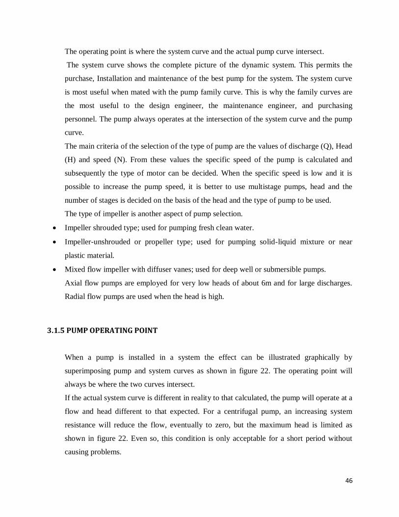
forces for a typical end-suction centrifugal pump is shown in the figure 23.
Fig 23: Forces on end suction centrifugal pump. [1]
Although each of these applied forces is generally provided for by the pump manufacturer
in the original design of the pumping unit, it is important for system designers to have a
basic understanding of the forces.
3.2.1 AXIAL FORCE
The axial force, also known as thrust, on an impeller is the sum of the unbalanced forces
acting on the impeller in the axial direction, or parallel to the pump shaft. Although the
maximum axial force is typically applied only to one side of the impeller, it can reverse
direction or even alternate should a change in the pump‟s operating conditions occur.
Axial forces are the result of one or more of the following conditions:
pressure distribution at the mechanical seal or packing leakage zone
pressure distribution within the leakage zone of the hub
pressure difference at opposite ends of the shaft
momentum of the incoming or outgoing fluid flow

49
pressure distribution at the hub in the fluid passages (between vanes)
Pressure difference between both sides of the vanes (in the axial direction).
Depending on the origin of the source, each of these forces is further defined as
mechanical or fluid-induced. Mechanical forces are those resulting from a mechanical
influence, such as rotor imbalance or vibrations. Fluid-induced forces result due to the
direct influence from the working fluid.
Most axial forces imposed in a horizontal centrifugal pump are fluid-induced forces.
Axial forces also act in vertical turbine and submersible pumps. However, in these cases it
is usually referred to as down thrust or up thrust with the combined effect of hydraulic and
mechanical forces due to the weight of the rotating impeller stack and drive shaft.
As seen in Figure 22, the application of axial thrust on a rotating impeller is generally
unbalanced, with the resulting value dependent on the lower pressure region within the
suction eye versus the higher pressure resulting from the impeller discharge exerted on the
outer surfaces of the impeller. To prevent lateral movement of the rotating assembly, this
force differential is typically resisted in a single thrust bearing or multiple thrust bearings
if the load is too high for a single bearing to withstand. The thrust bearing is usually
located in either the pump frame or the driver e.g. Electric motor.
In addition to lowering the axial forces, a hydraulic balance line also offers inherent
advantages for installations with sandy conditions, as these contaminants are continuously
flushed out of the packing or mechanical seal zone to avoid abrasive wear on the running
surfaces of the seal/packing and the shaft sleeve. In many high head or capacity end-
suction centrifugal pumps, the differential of axial forces between the discharge and
suction components of the impeller can cause high loading and premature failure of the
thrust bearing. In these cases remediation methods, such as a hydraulic balance line as
shown in Figure 24, are often used to provide a path for circulating water from the higher
pressure region of the impeller discharge back to the suction port.
Another method commonly used to reduce axial thrust loads on high head centrifugal
pumps is through the drilling of small bypass holes through the impeller, providing a path

50
of recirculating fluid between the suction eye and the higher pressure region of pressure
behind the impeller
Fig 24: Axial thrust on rotating impeller. [1]
This method should be used with extreme care, as decreased efficiency and performance is
often a penalty paid for this fix.
A final method involves the installation of wear rings on the back side and front side of
the impeller. Should a system designer wish to provide an installation with reduced axial
thrust, use of a double-suction pump may also be considered. Although not an automatic
solution, a double-suction pump properly configured and installed provides an alternative
to the typical single-suction centrifugal pump for applications with projected high axial
force loads and may be a valid consideration for installations using existing drivers with
limited thrust bearing capacities.

51
3.2.2 RADIAL FORCE
In addition to the axial forces within an operating pump, most centrifugal pumps also
work with a component of radial force, or thrust, which is also shown in Figure 23 as a
force exerting perpendicular to the shaft and acting on the periphery of the impeller from
the discharge water impacting the volute. Radial forces that exist around the edge of a
single impeller are proportional to the pump‟s total head (in feet), the impeller diameter,
and the vane width of the impeller.
Radial forces are typically more of a concern for high head and high speed volute type
centrifugal pumps, especially those with large diameter impellers, and are not generally as
much of a concern with vertical turbine or submersible pumps due to the difference of
design and construction between the respective unit
Fig 25: Radial force in centrifugal pumps. [14]
As shown in Figure 25 an impeller within a volute type of centrifugal pump is surrounded
by a volute with unequal distances around the periphery between the edge of the impeller
and the volute casing. This differential of space results in differing values of radial forces,
while the diffuser type of pump is encircled with a bowl and diffuser providing a relatively
uniform spacing between the impeller discharge and the diffuser, resulting in a more
uniform value of the radial force surrounding the impeller.
52
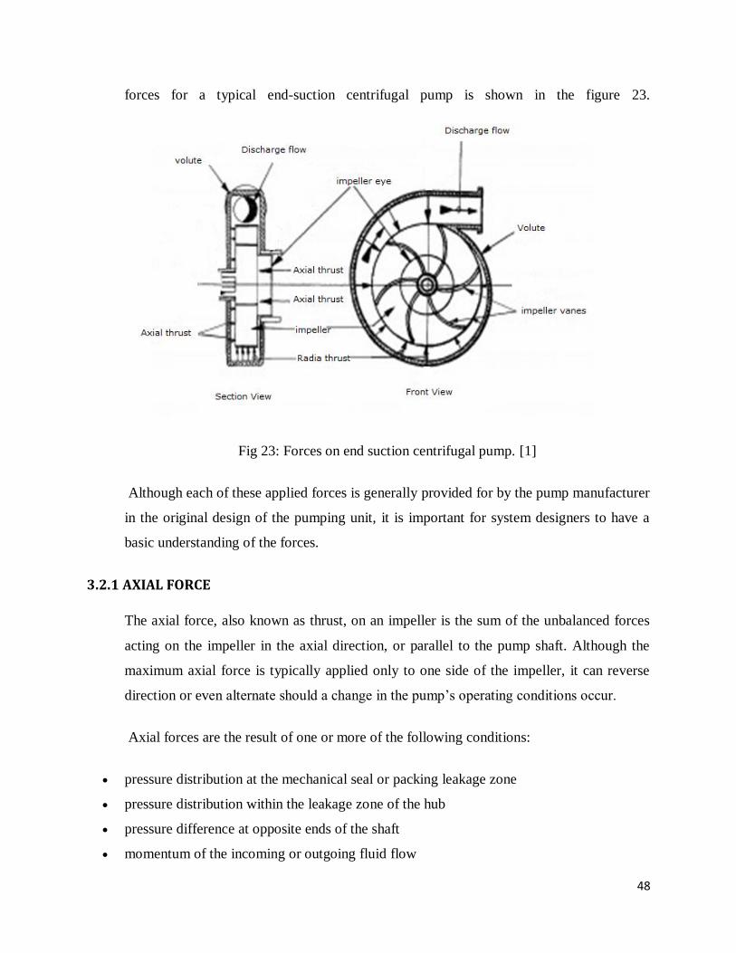
Unbalanced radial force usually results in increased shaft deflection, which in turn can
lead to premature seal or packing failure, bearing and wear ring damage and failure, and
premature motor bearing failure for those units with direct driven electric motors.
In extreme cases, prolonged operation with extreme unbalanced radial forces can result in
shaft breakage.
Fig 26: Radial forces in a double and single volutes design. [15]
In response to the problems associated with radial forces on high head volute pumps,
many manufacturers have developed a modified volute pattern, called a double volute, as
shown in Figure 26. A double volute style of pumps includes an added internal discharge
vane to a standard volute pump, thus providing a reasonably uniform distance between the
impeller periphery and the volute around the impeller‟s entire circumference. This added
feature greatly lowers the unbalanced radial forces within the pump and extends the life of
all rotating components.
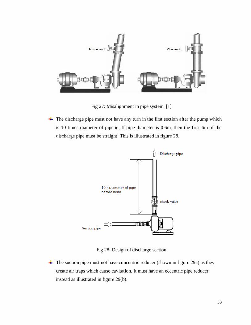
3.3 PUMP PIPING Flange bolts should not be used to unite misaligned piping to the pump as shown in
figure 27. This damages the flange faces and stresses the pump casing.
53
Fig 27: Misalignment in pipe system. [1]
The discharge pipe must not have any turn in the first section after the pump which
is 10 times diameter of pipe.ie. If pipe diameter is 0.6m, then the first 6m of the
discharge pipe must be straight. This is illustrated in figure 28.
Fig 28: Design of discharge section
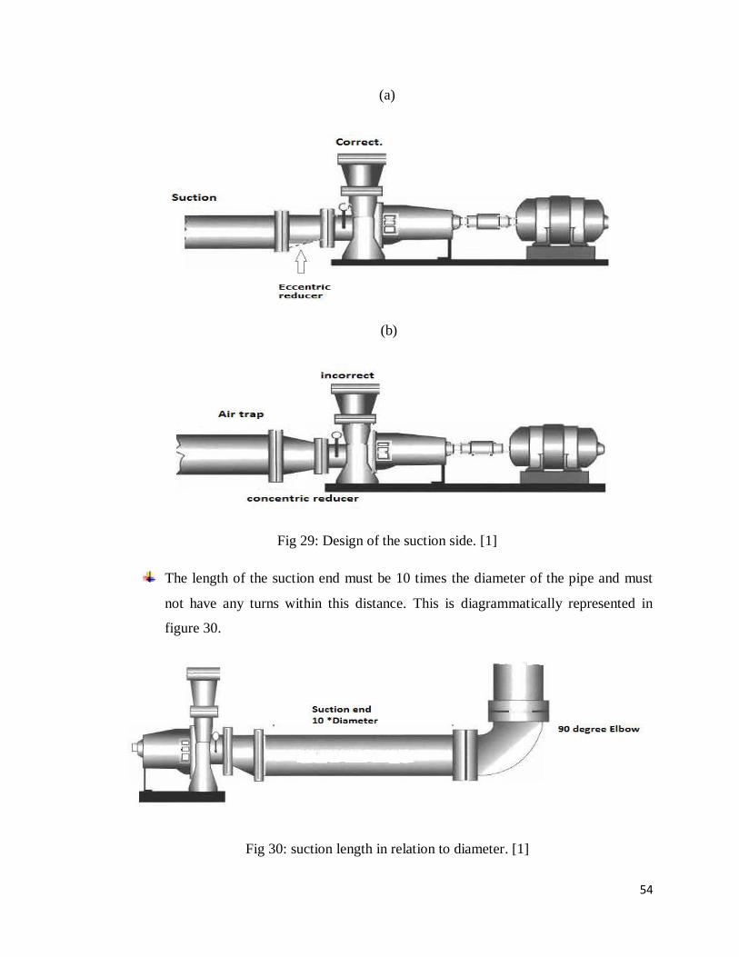
The suction pipe must not have concentric reducer (shown in figure 29a) as they
create air traps which cause cavitation. It must have an eccentric pipe reducer
instead as illustrated in figure 29(b).
54
(a)
(b)
Fig 29: Design of the suction side. [1]
The length of the suction end must be 10 times the diameter of the pipe and must
not have any turns within this distance. This is diagrammatically represented in
figure 30.
Fig 30: suction length in relation to diameter. [1]

55
3.4 VIBRATION MONITORING CONCEPT
Mechanical vibration may be simply defined as the oscillatory motion of a machine or
machine component about a position of rest. This arises as a result of normal transmission
of cyclic forces within the structure. These forces may be due to inherent design factors, or
may be due to developing and deteriorating defects.
Developing and deteriorating defects give rise to changing vibration characteristics. Thus
all rotating machines do vibrate.
Nonetheless, depending on the characteristics of the vibration, the levels of vibration may
be acceptable or not. These characteristics when measured, recorded and trended can be
analyzed for instantaneous severity, and type of defect. Thus, a vibration-based machine
health monitoring program will always include diagnosis of machinery defects through
analysis of the measured vibration characteristics.
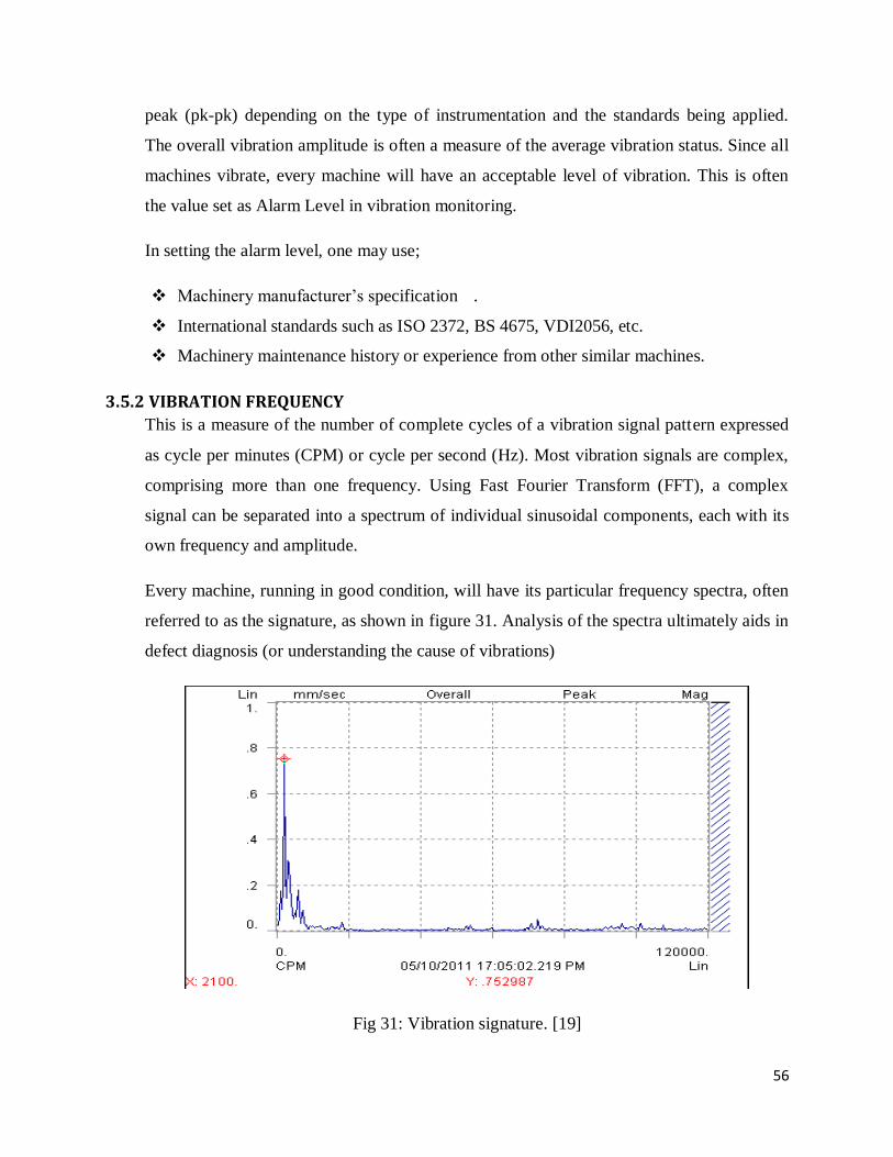
3.5 VIBRATION MEASUREMENT AND PARAMETERS
Vibratory motion of rotating machines is normally measured by means of a transducer
connected to a processing instrument such as Fast Fourier Transform analyzer. The
transducer may be mounted on the machine bearings or mounted pointing at the rotating
shaft. The transducer picks up the vibratory signal for subsequent processing.
Depending on the complexity of the rotating machine and the anticipated type of defects,
the type and location of vibration transducers may be decided. Furthermore, the appropriate
type and level of signal processing and subsequent analysis method can be adopted.
An extreme method might require complicated signal filtering, time averaging, frequency
analysis, re-synthesis and then statistical distribution analysis. For general condition
monitoring, the processed vibration signal is normally quantified in terms of amplitude,
frequency and phase.
3.5.1 VIBRATION AMPLITUDE
Vibration amplitude is normally expressed as an assessment of the overall severity of the
vibrations. It may be expressed in displacement (microns), velocity (mm/s) or acceleration
(g), depending on the type of information required and the type of defects being monitored.
The measurements may be expressed as Root Mean Square (RMS), Peak (pk) or peak to
56
peak (pk-pk) depending on the type of instrumentation and the standards being applied.
The overall vibration amplitude is often a measure of the average vibration status. Since all
machines vibrate, every machine will have an acceptable level of vibration. This is often
the value set as Alarm Level in vibration monitoring.
In setting the alarm level, one may use;
Machinery manufacturer‟s specification .
International standards such as ISO 2372, BS 4675, VDI2056, etc.
Machinery maintenance history or experience from other similar machines.
3.5.2 VIBRATION FREQUENCY
This is a measure of the number of complete cycles of a vibration signal pattern expressed
as cycle per minutes (CPM) or cycle per second (Hz). Most vibration signals are complex,
comprising more than one frequency. Using Fast Fourier Transform (FFT), a complex
signal can be separated into a spectrum of individual sinusoidal components, each with its
own frequency and amplitude.
Every machine, running in good condition, will have its particular frequency spectra, often
referred to as the signature, as shown in figure 31. Analysis of the spectra ultimately aids in
defect diagnosis (or understanding the cause of vibrations)
Fig 31: Vibration signature. [19]

57
3.5.3 VIBRATION PHASE
This is a measure of the relative position of a vibrating part at a given time with respect to
another or a fixed point. The information is useful in diagnosing machinery defects.
Various defects in a rotating machine cause cyclic forces, and depending on the response of
the machinery structure, the resultant vibrations generated will exhibit particular
characteristics.
In general, the rotating element (rotor), as a mass rotates with some residual imbalance
(irrespective of how well balanced it may be, such as to ISO 1940). This generates the
centrifugal force that strains against the shaft, bearings and support system, which together
form the stiffness/damper system. Amongst the defects that generate vibrations in rotating
machines are;
Unbalanced rotors
Cracked shafts
Misaligned rotors
Bent rotors
Worn bearings
Damaged gears
Some defects are more aggravated by others. Furthermore, high vibrations cause more
defects, resulting into a cause and effect vicious cycle, which would rapidly lead to failure
if not checked.

58
CHAPTER FOUR
4. PRACTICAL DATA FROM SITE The following is the information gotten about the operations and maintenance of the pumps
under discussion;
The maintenance of the low lift pumps is done on a preventative basis. Preventative
maintenance is time driven type of maintenance and the tasks are based on elapsed time or
hours of operation. The workers inspect the pumps daily to notice any irregularity. This
program assumes that machines will degrade within a time frame depending on its
particular classification.
4.1 BEARINGS
The bearings used are the 22315 spherical roller bearings on the drive end and NU 218 EC
single roller bearing on the non-drive end. The spherical roller bearing is the out board
while the single roller bearing is the in board. On the other three pumps, the NU 218 EC
has been replaced with 22218 single roller bearing and their lubrication system has been
changed to oil lubrication in pursuit of better performance. Figure 32 shows the spherical
and single roller bearings.
22315 spherical roller bearings NU 218 EC single roller bearing
Fig 32: Bearings used for low lift pumps.[18]
For specifications of NU 218 EC refer to table1.
The specifications of the bearings are as shown in table 4;

59
Table 4: Bearing parameters [18]
BEARING
22135-Drive end
22218-Non Drive end.
TYPE OF ROLLING
ELEMENT
SPHERICAL ROLLER SPHERICAL ROLLER
PRINCIPAL DIAMETER: D= 160mm, d= 75mm
B= 55
D=160mm, d= 90mm
B=40
BASIC LOAD RATING C= 490 kN
Co= 475 kN
C= 325Kn
C0=375Kn
FATIGUE LOAD RATING
Pu= 48 kN
Pu= 39 KN
REFERENCE SPEED
3 200 r/min
3 800r/min
MASS
5,55 kg
3,40 kg
The bearing modification however, has not met the expectation for which it was intended.
The failure rate still remains unchanged and has brought about oil contamination on the
environment. The oil at time leaks due to improper sealing and mixes with water that flows
back into the river. This poses the danger of the same oil being sucked in by the pumps
thereby causing more damage on the pipe lining. The bearings on the drive end are fitted
with the aid of a hydraulic machine whilst the non-drive end bearing is manually fitted. The
single roller bearing supports the axial load while the double spherical roller bearing
supports both the axial and radial loads. In case of failure, the double spherical roller
bearing is the one that gets damaged often. In addition, the bearing house gets heated up
that they have even made a water cooling system for it externally by means of a pipe
running water over the housing as illustrated in figure 33.

60
Fig 33: Pump with external water cooling system
Without the incorporation of the external water cooling system, the bearing would fail
within a day. Figure 34 is the diagrammatic representation of the low lift pump;
Fig 34: Low lift pump

61
Key;
1. Suction nozzle. 2. Inspection box. 3. Impeller. 4. Casing. 5. Single roller bearing.
6. Shaft. 7. Spherical roller bearing. 8. Bearing housing. 9. Seal
4.2 LUBRICATION
The pumps use two types of lubricants, namely; GX 350 oil and Energrease LS3-NLGI 3
(multipurpose industrial grease) lubricants. Table 5 shows the technical specifications and
characteristics of the Energrease LS3-NLGI 3.
Table 5: Technical specifications and characteristics.
CLASS
Energrease LS3-NLGI 3
DESCRIPTION
All purpose industrial and automotive
BASE OIL VISCOSITY
At 40oC--120mm
2/s
At 100 oC--12mm
2/s
TEMPERATURE LIMITS LTL1)
-30oC
HTPL2)
+120
THICKENER/ BASE OIL Lithium soap/mineral oil
Initially all the pumps used grease lubricant until the bearing housing on three pumps
where modified by introducing a seal to allow the use of oil as a lubricant. One pump with
the bearing types 22315 double spherical roller bearing on the drive end and NU 218 EC
single roller bearing on the non-drive end is grease lubricated while the other three with
bearing types 22315 double spherical roller bearing and 22218 single roller bearings are oil
lubricated. The lubrication is done at least once every two days.
4.3 SHAFT ALIGNMENT
Before the pumps are commissioned, it is ensured that the motor shaft and the pump shafts
are properly aligned and that no damage is caused when the pump shaft is turned. The
coupling is flexible type of coupling and the halves are free to move relative to each other.

62
The shaft can be misaligned angularly or radially. Radial misalignment (also known as
offset or parallel misalignment) refers to the distance between two shaft centerline and is
generally measured in thousandth of an inch. Theoretically, radial misalignment is
measured at the coupling centerline.
Angular misalignment refers to the condition when the shafts are not parallel but are in the
same plane with no offset. For this type of misalignment it is possible for the mating shafts
to be in the same plane at the coupling face intersection but to have an angular relationship
such that they are not collinear.
The alignment is checked with the aid of a laser alignment device which offers the
advantage of eliminating mechanical linkage and run out gauges. This greatly increases the
accuracy and repeatability of the data obtained. Laser alignment system incorporates a
micro processing unit, which eliminates recording errors. Figure 35 shows a Laser
Alignment System.
Fig 35: Laser Alignment System. [15]
Table 6 shows alignment readings for the low lift pump before commissioning it;

63
Table 6: Alignment results.[Alfred H Knight- alignment report].
Position
Direction
Readings in mm
Vertical
Parallel
0.037
Angular
0.025/100
Horizontal
Parallel
-0.050
Angular
0.010/100
4.4 VIBRATIONS
Before the commissioning of the pumps, the vibrations are checked and it is ensured that
they are within accepted range. A vibration analyzer measures the amplitude, frequency
and phase of vibration. Also when vibration occurs at several frequencies, it separates one
frequency from another so that each individual vibration characteristic can be measured.
The vibration pickup senses the velocity of the vibration and converts it into an electrical
signal. The analyzer receives this signal, converts it to the corresponding amplitude and
frequency. The amplitude is measured in terms of peak-to-peak displacement in mils (1 mil
= .001") and is indicated on the amplitude meter. Vibration monitoring as a condition
monitoring technique, is the continuous or regular measurement and trending of
mechanical vibrations of a machine for the purposes of ascertaining the machine‟s dynamic
behavior.
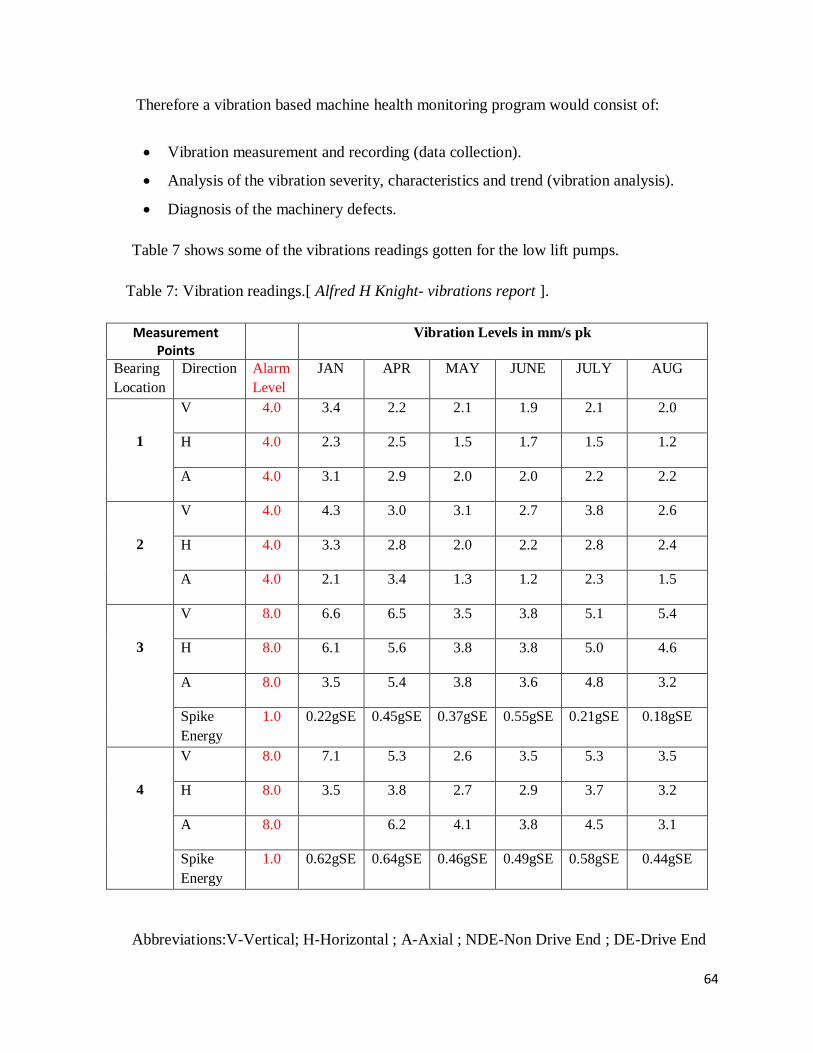
64
Therefore a vibration based machine health monitoring program would consist of:
Vibration measurement and recording (data collection).
Analysis of the vibration severity, characteristics and trend (vibration analysis).
Diagnosis of the machinery defects.
Table 7 shows some of the vibrations readings gotten for the low lift pumps.
Table 7: Vibration readings.[ Alfred H Knight- vibrations report ].
Measurement Points
Vibration Levels in mm/s pk
Bearing
Location
Direction Alarm
Level
JAN APR MAY JUNE JULY AUG
1
V 4.0 3.4 2.2 2.1 1.9 2.1 2.0
H 4.0 2.3 2.5 1.5 1.7 1.5 1.2
A 4.0 3.1 2.9 2.0 2.0 2.2 2.2
2
V 4.0 4.3 3.0 3.1 2.7 3.8 2.6
H 4.0 3.3 2.8 2.0 2.2 2.8 2.4
A 4.0 2.1 3.4 1.3 1.2 2.3 1.5
3
V 8.0 6.6 6.5 3.5 3.8 5.1 5.4
H 8.0 6.1 5.6 3.8 3.8 5.0 4.6
A 8.0 3.5 5.4 3.8 3.6 4.8 3.2
Spike
Energy
1.0 0.22gSE 0.45gSE 0.37gSE 0.55gSE 0.21gSE 0.18gSE
4
V 8.0 7.1 5.3 2.6 3.5 5.3 3.5
H 8.0 3.5 3.8 2.7 2.9 3.7 3.2
A 8.0 6.2 4.1 3.8 4.5 3.1
Spike
Energy
1.0 0.62gSE 0.64gSE 0.46gSE 0.49gSE 0.58gSE 0.44gSE
Abbreviations:V-Vertical; H-Horizontal ; A-Axial ; NDE-Non Drive End ; DE-Drive End

65
The Vibration Spectra and Trends are as follows;
Fig 36: Vibration spectra and trends. [Alfred H Knight - vibrations report].
From the vibration readings, a report is prepared which summarizes and gives the
diagnosis/recommendations based on the results. This is as shown in table 9;
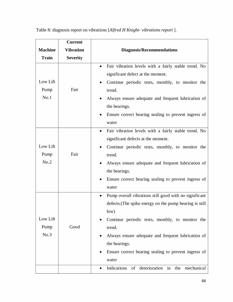
66
Table 8: diagnosis report on vibrations [Alfred H Knight- vibrations report ].
Machine
Train
Current
Vibration
Severity
Diagnosis/Recommendations
Low Lift
Pump
No.1
Fair
Fair vibration levels with a fairly stable trend. No
significant defect at the moment.
Continue periodic tests, monthly, to monitor the
trend.
Always ensure adequate and frequent lubrication of
the bearings.
Ensure correct bearing sealing to prevent ingress of
water
Low Lift
Pump
No.2
Fair
Fair vibration levels with a fairly stable trend. No
significant defects at the moment.
Continue periodic tests, monthly, to monitor the
trend.
Always ensure adequate and frequent lubrication of
the bearings.
Ensure correct bearing sealing to prevent ingress of
water
Low Lift
Pump
No.3
Good
Pump overall vibrations still good with no significant
defects.(The spike energy on the pump bearing is still
low)
Continue periodic tests, monthly, to monitor the
trend.
Always ensure adequate and frequent lubrication of
the bearings.
Ensure correct bearing sealing to prevent ingress of
water
Indications of deterioration in the mechanical

67
Low Lift
Pump
No.4
Slightly Rough
looseness on the pump DE hold down bracket.
The hold down bolts on the pump DE hold down
bracket, often works loose.
This must be re-tightened frequently. The current
fastener should be replaced with one that has only
one strong washer. The excess washers and nuts
should be removed. Note that if this is not attended
to, the bracket would continue loosening and the
vibration levels might deteriorate again.
4.5 MATERIALS USED
The materials used for the pump and pipe are as shown in table 9.
Table 9: pump and pipe materials
Component Material
Impeller Bronze
Casing Cast iron
Shaft Steel
Pipes Mild Steel
4.6 TEMPERATURE MEASUREMENTS
The bearing - housing temperatures measured using an Infra-Red Thermometer, are as tabulated
below;
Table 10: Temperature reading results
PUMP No.
TEMPERATURE READING ( 0C )
1
46.8
2
40.8
3
38.8
4
29.0
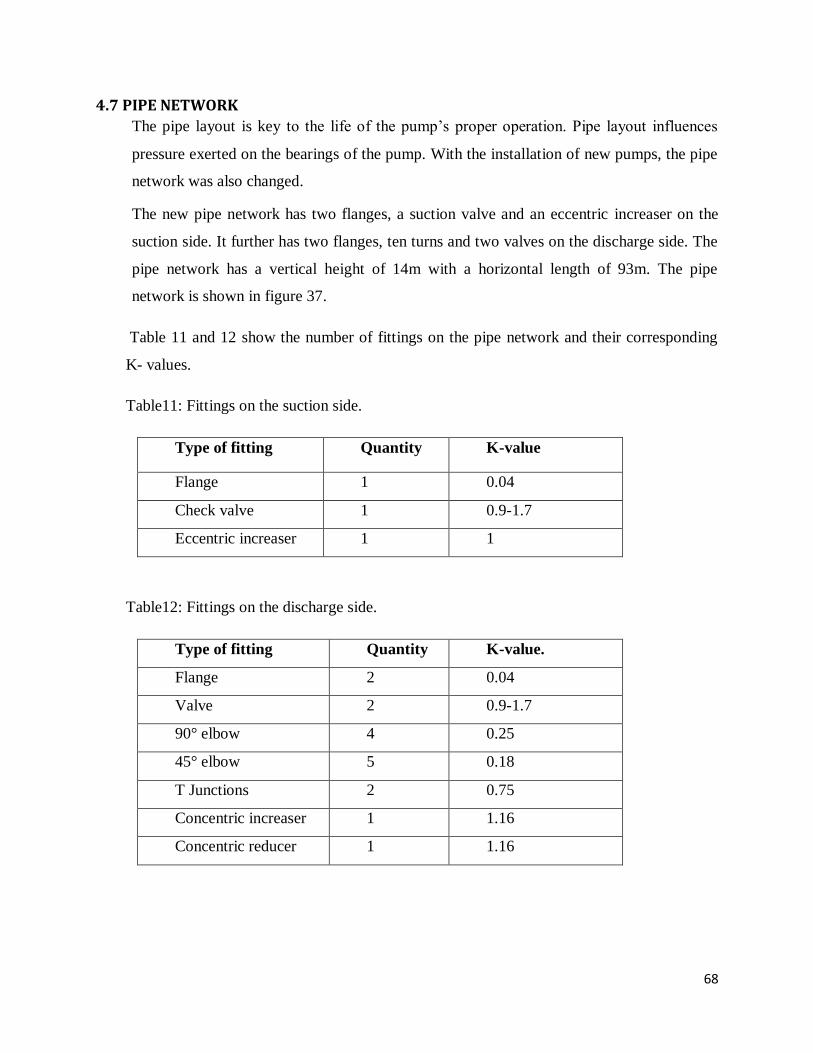
68
4.7 PIPE NETWORK
The pipe layout is key to the life of the pump‟s proper operation. Pipe layout influences
pressure exerted on the bearings of the pump. With the installation of new pumps, the pipe
network was also changed.
The new pipe network has two flanges, a suction valve and an eccentric increaser on the
suction side. It further has two flanges, ten turns and two valves on the discharge side. The
pipe network has a vertical height of 14m with a horizontal length of 93m. The pipe
network is shown in figure 37.
Table 11 and 12 show the number of fittings on the pipe network and their corresponding
K- values.
Table11: Fittings on the suction side.
Type of fitting Quantity K-value
Flange 1 0.04
Check valve 1 0.9-1.7
Eccentric increaser 1 1
Table12: Fittings on the discharge side.
Type of fitting Quantity K-value.
Flange 2 0.04
Valve 2 0.9-1.7
90° elbow 4 0.25
45° elbow 5 0.18
T Junctions 2 0.75
Concentric increaser 1 1.16
Concentric reducer 1 1.16
69
CHAPTER FIVE
5. RESULTS AND ANALYSIS
5.1. BEARINGS
The bearing parameters are within the working parameters of the pump. They are the right
application and have an appropriate speed range. The type of bearing used i.e. spherical
roller bearing can withstand both axial and radial forces. This makes them a suitable
application for the low lift pumps.
However, the bearings are under a risk of being over heated all the time that an additional
cooling system of a water pipe has been improvised. Without which they would fail within
a day. Heat is caused by friction of the moving components of the pumps. This is
minimized by lubrication which prevents body to body contact of rotating elements.
Lubrication creates a smooth motion of bearings with a minimum clearance at maximum
load. However, if the lubricant is lost or overheated its effect is absent thereby leading to
increase in friction which produces a lot of heat and burns the bearing. Some of the effects
of heat on the lubricant are;
Decrease in viscosity; heat reduces the viscosity of the lubricant which reduces its ability
to support the load. This reduction in viscosity means more asperity to asperity contact
which leads to more friction and more heat being produced.
Formation of a "varnish" residue and then "coke" at the elevated temperature. This
"coking" will destroy the ability of the grease or oil to lubricate the bearing. It will also
introduce solid particles into the lubricant creating a three body abrasion and causing a
rise in temperature.
In addition to the heat generated by overloading, overheating of bearings also comes about
as a result of oil leakage. The pumps are lubricated using oil which comes out due to loose
seal fittings that close the bearing housing. This usually occurs in the night when the
pumps are un-monitored. The deficiency in lubricant is evidenced by the state of bearing
when failure occurs; they are burnt out with no lubricant and at times weld to each other
and to the raceways. This is shown in figure 38.
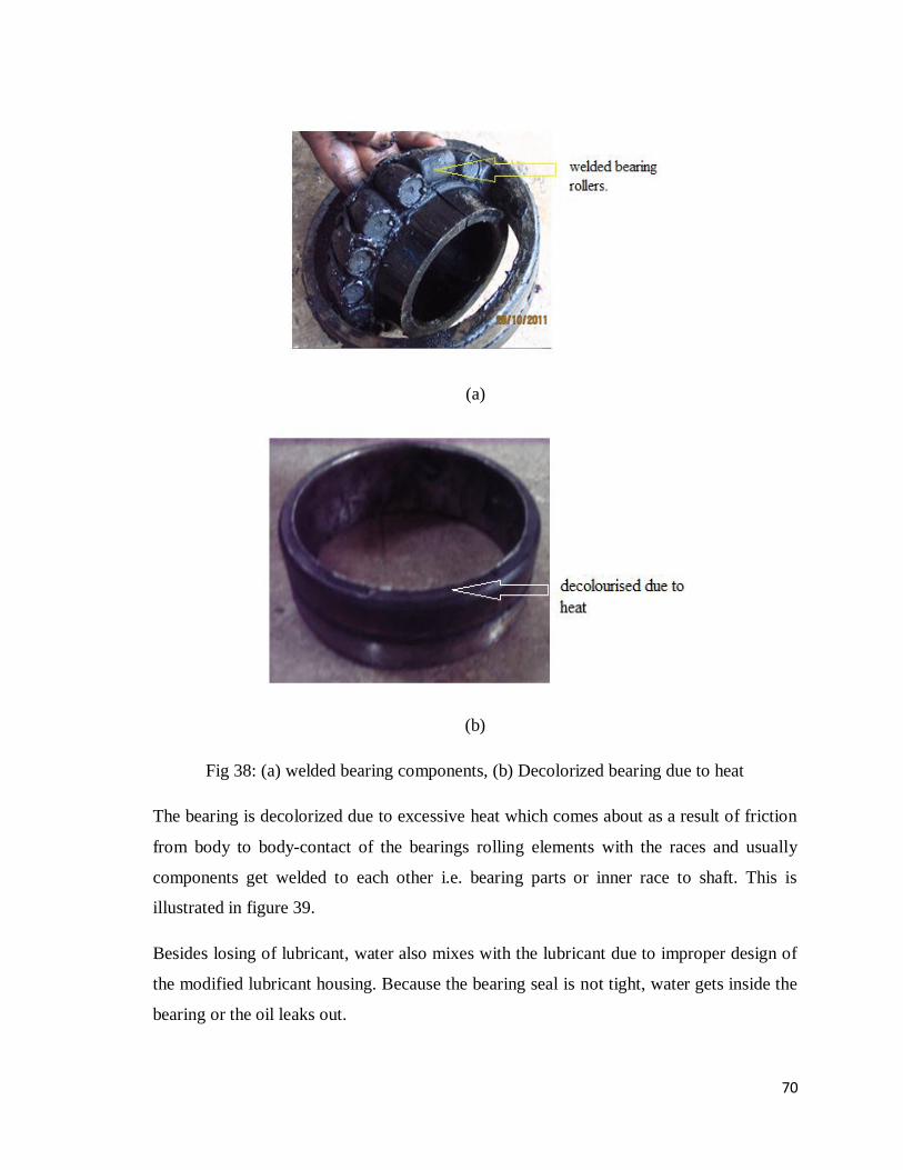
70
(a)
(b)
Fig 38: (a) welded bearing components, (b) Decolorized bearing due to heat
The bearing is decolorized due to excessive heat which comes about as a result of friction
from body to body-contact of the bearings rolling elements with the races and usually
components get welded to each other i.e. bearing parts or inner race to shaft. This is
illustrated in figure 39.
Besides losing of lubricant, water also mixes with the lubricant due to improper design of
the modified lubricant housing. Because the bearing seal is not tight, water gets inside the
bearing or the oil leaks out.
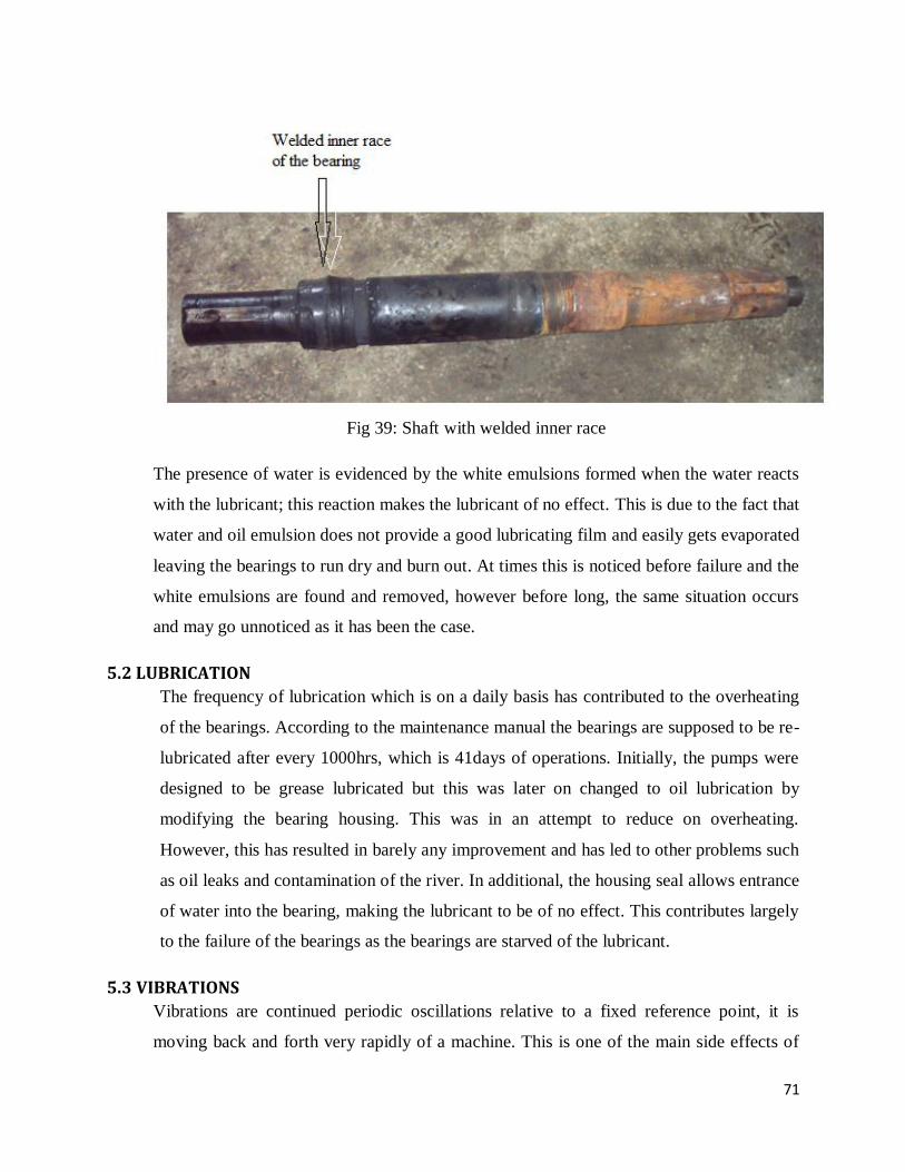
71
Fig 39: Shaft with welded inner race
The presence of water is evidenced by the white emulsions formed when the water reacts
with the lubricant; this reaction makes the lubricant of no effect. This is due to the fact that
water and oil emulsion does not provide a good lubricating film and easily gets evaporated
leaving the bearings to run dry and burn out. At times this is noticed before failure and the
white emulsions are found and removed, however before long, the same situation occurs
and may go unnoticed as it has been the case.
5.2 LUBRICATION
The frequency of lubrication which is on a daily basis has contributed to the overheating
of the bearings. According to the maintenance manual the bearings are supposed to be re-
lubricated after every 1000hrs, which is 41days of operations. Initially, the pumps were
designed to be grease lubricated but this was later on changed to oil lubrication by
modifying the bearing housing. This was in an attempt to reduce on overheating.
However, this has resulted in barely any improvement and has led to other problems such
as oil leaks and contamination of the river. In additional, the housing seal allows entrance
of water into the bearing, making the lubricant to be of no effect. This contributes largely
to the failure of the bearings as the bearings are starved of the lubricant.
5.3 VIBRATIONS
Vibrations are continued periodic oscillations relative to a fixed reference point, it is
moving back and forth very rapidly of a machine. This is one of the main side effects of
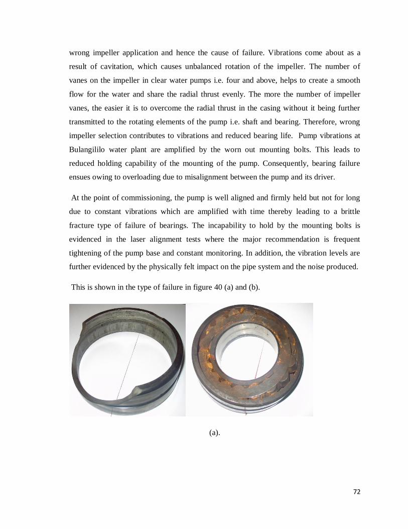
72
wrong impeller application and hence the cause of failure. Vibrations come about as a
result of cavitation, which causes unbalanced rotation of the impeller. The number of
vanes on the impeller in clear water pumps i.e. four and above, helps to create a smooth
flow for the water and share the radial thrust evenly. The more the number of impeller
vanes, the easier it is to overcome the radial thrust in the casing without it being further
transmitted to the rotating elements of the pump i.e. shaft and bearing. Therefore, wrong
impeller selection contributes to vibrations and reduced bearing life. Pump vibrations at
Bulangililo water plant are amplified by the worn out mounting bolts. This leads to
reduced holding capability of the mounting of the pump. Consequently, bearing failure
ensues owing to overloading due to misalignment between the pump and its driver.
At the point of commissioning, the pump is well aligned and firmly held but not for long
due to constant vibrations which are amplified with time thereby leading to a brittle
fracture type of failure of bearings. The incapability to hold by the mounting bolts is
evidenced in the laser alignment tests where the major recommendation is frequent
tightening of the pump base and constant monitoring. In addition, the vibration levels are
further evidenced by the physically felt impact on the pipe system and the noise produced.
This is shown in the type of failure in figure 40 (a) and (b).
(a).
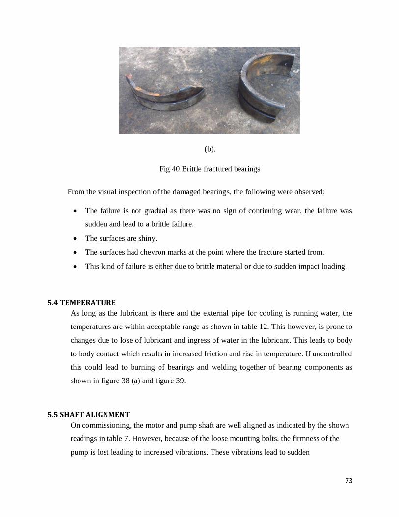
73
(b).
Fig 40.Brittle fractured bearings
From the visual inspection of the damaged bearings, the following were observed;
The failure is not gradual as there was no sign of continuing wear, the failure was
sudden and lead to a brittle failure.
The surfaces are shiny.
The surfaces had chevron marks at the point where the fracture started from.
This kind of failure is either due to brittle material or due to sudden impact loading.
5.4 TEMPERATURE
As long as the lubricant is there and the external pipe for cooling is running water, the
temperatures are within acceptable range as shown in table 12. This however, is prone to
changes due to lose of lubricant and ingress of water in the lubricant. This leads to body
to body contact which results in increased friction and rise in temperature. If uncontrolled
this could lead to burning of bearings and welding together of bearing components as
shown in figure 38 (a) and figure 39.
5.5 SHAFT ALIGNMENT
On commissioning, the motor and pump shaft are well aligned as indicated by the shown
readings in table 7. However, because of the loose mounting bolts, the firmness of the
pump is lost leading to increased vibrations. These vibrations lead to sudden

74
misalignment which results into brittle fracture of the bearing. Refer to figures 40 (a) and
( b).
5.6 PIPE NETWORK
The pipe network is used to come up with the system curve. The system curve is a graph
that is used for determining the correct pump to use by superimposing with the pump
performance curve. The following are the calculations for the system head.
CALCULATING THE ACTUAL SYSTEM HEAD
(i) System Head When Q=1350m3/hr. = 0.375 m
3/s
The system head is obtained from;
H =
Where = Static head.
= Frictional losses in the pipe.
= Velocity head loss.
= Other losses
1. Velocity head loss
HV = +
=
+
Where = suction velocity
= discharge velocity.
Now
Vs =
=
=
=0.0995 m2
Thus,
Vs =

75
= 3.769 m/s
And
=
Note: the discharge has two diameters such that = .
Hence, = 3.769m/s
=
= 0.203m
2
=
=
=1.847 m/s.
Thus,
=
=
= 0.724 m.
=
=
+
=0.8979 m.
= + = 0.724 + 0.8979 = 1.6219 m.
2. Frictional losses in the pipe
=
=
= 0.16921 m
=
=
+
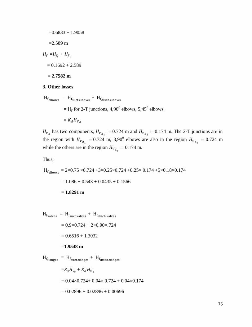
76
=0.6833 + 1.9058
=2.589 m
= +
= 0.1692 + 2.589
= 2.7582 m
3. Other losses
= +
= for 2-T junctions, 4,900 elbows, 5,45
0 elbows.
=
has two components, 0.724 m and 0.174 m. The 2-T junctions are in
the region with 0.724 m, 3,90
0 elbows are also in the region
0.724 m
while the others are in the region 0.174 m.
Thus,
= 2×0.75 ×0.724 +3×0.25×0.724 +0.25× 0.174 +5×0.18×0.174
= 1.086 + 0.543 + 0.0435 + 0.1566
= 1.8291 m
= +
= 0.9×0.724 + 2×0.90×.724
= 0.6516 + 1.3032
=1.9548 m
= +
= +
= 0.04×0.724+ 0.04× 0.724 + 0.04×0.174
= 0.02896 + 0.02896 + 0.00696
77
= 0.0649 m
=
= 1.16 × 0.174
= 0.2016 m
=
= 1.16 × 0.174
= 0.2016 m
=
= 1×0.724
= 0.724 m
Entrance losses; =
=
= 0.5 × 0.724
= 0.362 m.
Exit losses; =
=
= 1 × 0.174
= 0.174 m.
Thus, 1.8291 +1.9548 + 0.0649 + 0.2016 +0.2016 + 0.724 + 0.362 + 0.174
= 5.512 m
4. Static head
= 14 m

78
The system head is;
H =
= 14 + 2.7582 +1.6219+5.512
= 23.8921
H = 23.89 m
ii. CALCULATING HEAD AT FLOW RATE OF Q = 2025M3/HR = 0.5625M
3/s
1. Velocity head Loss.
Hv = Hvsuction + Hvdischarge.
=
Now
=
= 0.0995m2
Thus
Vs=
=5.653m/s
And
Vd1=
where ad1=as
Vd1= 5.653 m/s

79
Vd2 =
ad2 =
= 0.203 m2
Vd2 =
= 2.771 m/s
Hv= Hvs + Hvd1 + Hvd2.
=
=
= 1.62877 + 1.62877 + 0.39136
= 3.6488978
Hv= 3.6489m
2. Other Losses.
Hf elbows =Hfsuct.elbows + Hfdisch.elbows
Hf for 2 T-junctions, 4, 90oelbows, 5, 45
o elbows
= Ks.Hvds + Kd1.Hvd1 + Kd2.Hvd2
=
= 4.11491m
Hf valves= Hf.suct.valves+ Hf.disch.valves
=Ks HVs + Kd Hvd
=

80
=1.46592 + 2.93184
=4.39776m
Hf.flanges= Hf.suct+ Hf.disch
=Ks Hvs + Kd Hvd
=
=0.065152 + 0.065152 + 0.015656
=0.14596m
Hf. concentric increaser = Kd2. Hvd2
=
=0.454024m
Hf concentric reducer = Kd2 . Hvd2
=
=0.454024
=0.454m
Hf eccentric increaser = Ks .Hvs
=
=1.6288m
Entrance Losses; hen = K
=K. Hvs
=

81
=0.8144m
Exit Losses; hex = K
=K. Hvd2
=
=0.3914m
HO= Hf.elbows+Hf.valves+Hf.flanges+Hf.concentric increaser+Hf.concentric reducer +Hf.eccentric increaser
+ hen + hex
=4.1149+4.3978+0.14596+0.454+3.2576+0.8144+0.3914
=12.40126m
3. Frictional Losses in the Pipe.
Hf =
=
= 0.35137 +1.53726 + 4.64699
= 6.53562m
4. Static Head
Hs = 14 m
H = HS + Hf +Hv + Ho
=14 + 6.53562 + 3.6489 + 12.4013
=36.5858.
Head = 36.5858m.

82
iii. CALCULATING SYSTEM HEAD WHEN Q=675M3/HR = 0.1875 M
3/S
The system head is obtained from;
H =
Where = Static head.
= Frictional losses in the pipe.
= Velocity head loss.
= Other losses
2. Velocity head loss
HV = +
=
+
Where = suction velocity
= discharge velocity.
Now
Vs =
=
=
= 0.0995 m2
Thus,
Vs =
= 1.884 m/s
And
=
Note: the discharge has two diameters such that = .
83
Hence,
= 1.884m/s
=
= 0.203m2
=
=
= 0.924 m/s.
Thus,
=
=
= 0.1809m.
=
=
+
= 0.2244 m.
= +
= 0.1809 + 0.2244
= 0.4053m.
2. Frictional losses in the pipe
=
84
=
= 0.1707466 m
=
=
+
= 0.1707466 + 0.5167049
= 0.6875 m
= +
= 0.1707 + 0.6875
= 0.8582 m
2. Other losses
= +
= for 2-T junctions, 4,900 elbows, 5,45
0 elbows.
=
has two components, 0.1809 m and 0.0435 m. The 2-T junctions are
in the region with 0.1809 m, 3,900 elbows are also in the region 0.1809 m
while the others are in the region 0.0435 m.
Thus,
= 2×0.75 ×0.1809 +3×0.25×0.1809 +0.25× 0.0435 +5×0.18×0.0435
= 0.27135 + 0.135675 + 0.010875 + 0.03915
= 0.45705 m
= +
= +
= 0.9×0.1809 + 2×0.9×0.1809

85
= 0.16281+ 0.32562
= 0.48843 m
= +
= +
= 0.04×0.1809+ 0.04× 0.1809 + 0.04×0.0435
= 0.007236 + 0.007236 + 0.00174
= 0.016212 m
=
= 1.16 × 0.0435
= 0.05046 m
=
= 1.16 × 0.0435
= 0.05046 m
=
= 1×0.1809
= 0.1809 m
Entrance losses; =
= = 0.5 × 0.1809 = 0.09045 m.
Exit losses; =
= = 1 × 0.0435 = 0.0435 m.
Thus, 0.45705 + 0.48843 + 0.016212 + 0.05046 + 0.05046 + 0.1809 + 0.09045 +
0.0435
= 1.377462m
4. Static head

86
= 14 m
The system head is;
H =
= 14 + 0.8582 + 0.4053+ 1.377462
= 16.640962
H = 16.64 m
5.2 DRAWING OF SYSTEM CURVE
From the obtained values of head versus flow, the system curve was drawn as shown in
figure 41.
Fig 41: System curve

87
This was drawn based on the values from table 13.
Table 13: Head and flow rate values of system curve
Head
values(y-axis)
14 16.64 23.89 36.59
Flow rate
Q(x-axis)
0 674 1350 2025
From the pump manual book, the following was the given pump characteristic curve i.e.
figure 42.
Fig 42: pump curve
This is drawn from the values of heads and flow rates values given in table 14;
Table 14: Head and flow rate values of pump curve.

88
Head
(m)
32 30 25 23.5 21.5 20 18
Flowrate
(m3/hr)
0 200 850 1140 1350 1500 1660
In order to know the actual head and flow rate of the pump, we superimpose the pump and
system curves and take note of the point of intersection. This is shown in figure 43.
Fig 43: combination of system and pump curve
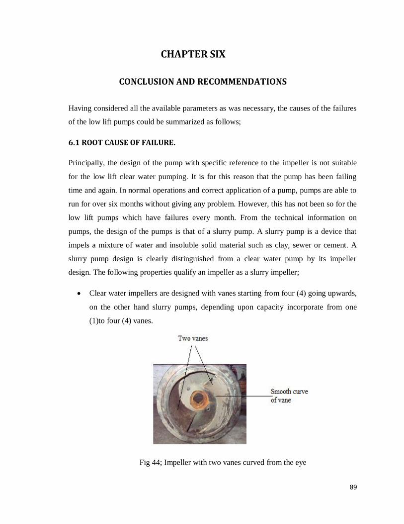
89
CHAPTER SIX
CONCLUSION AND RECOMMENDATIONS
Having considered all the available parameters as was necessary, the causes of the failures
of the low lift pumps could be summarized as follows;
6.1 ROOT CAUSE OF FAILURE.
Principally, the design of the pump with specific reference to the impeller is not suitable
for the low lift clear water pumping. It is for this reason that the pump has been failing
time and again. In normal operations and correct application of a pump, pumps are able to
run for over six months without giving any problem. However, this has not been so for the
low lift pumps which have failures every month. From the technical information on
pumps, the design of the pumps is that of a slurry pump. A slurry pump is a device that
impels a mixture of water and insoluble solid material such as clay, sewer or cement. A
slurry pump design is clearly distinguished from a clear water pump by its impeller
design. The following properties qualify an impeller as a slurry impeller;
Clear water impellers are designed with vanes starting from four (4) going upwards,
on the other hand slurry pumps, depending upon capacity incorporate from one
(1)to four (4) vanes.
Fig 44; Impeller with two vanes curved from the eye
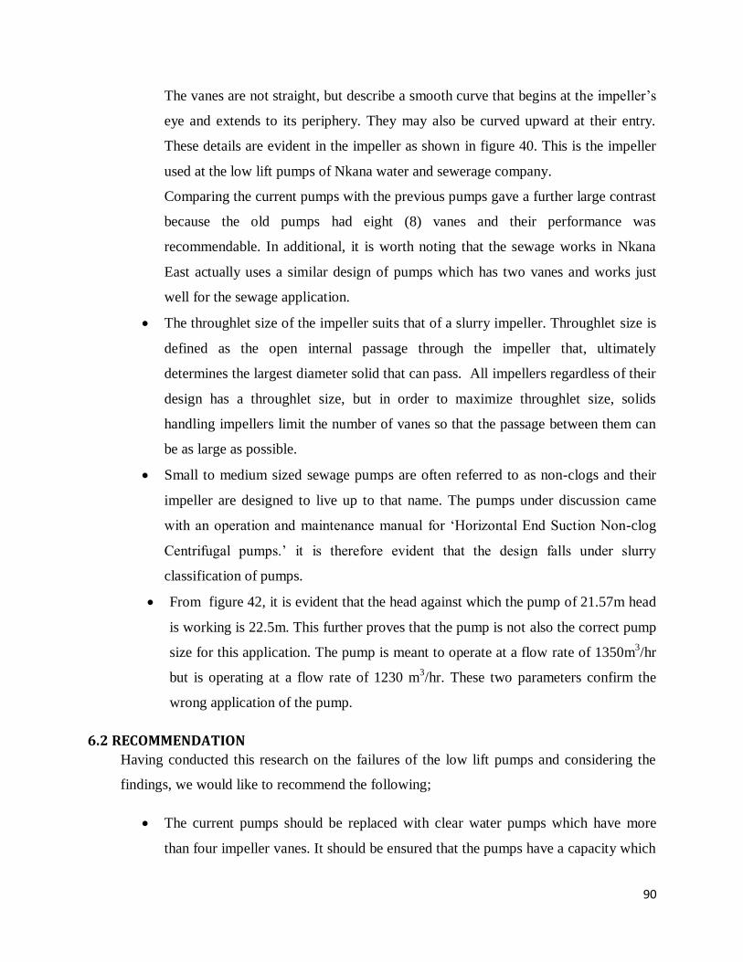
90
The vanes are not straight, but describe a smooth curve that begins at the impeller‟s
eye and extends to its periphery. They may also be curved upward at their entry.
These details are evident in the impeller as shown in figure 40. This is the impeller
used at the low lift pumps of Nkana water and sewerage company.
Comparing the current pumps with the previous pumps gave a further large contrast
because the old pumps had eight (8) vanes and their performance was
recommendable. In additional, it is worth noting that the sewage works in Nkana
East actually uses a similar design of pumps which has two vanes and works just
well for the sewage application.
The throughlet size of the impeller suits that of a slurry impeller. Throughlet size is
defined as the open internal passage through the impeller that, ultimately
determines the largest diameter solid that can pass. All impellers regardless of their
design has a throughlet size, but in order to maximize throughlet size, solids
handling impellers limit the number of vanes so that the passage between them can
be as large as possible.
Small to medium sized sewage pumps are often referred to as non-clogs and their
impeller are designed to live up to that name. The pumps under discussion came
with an operation and maintenance manual for „Horizontal End Suction Non-clog
Centrifugal pumps.‟ it is therefore evident that the design falls under slurry
classification of pumps.
From figure 42, it is evident that the head against which the pump of 21.57m head
is working is 22.5m. This further proves that the pump is not also the correct pump
size for this application. The pump is meant to operate at a flow rate of 1350m3/hr
but is operating at a flow rate of 1230 m3/hr. These two parameters confirm the
wrong application of the pump.
6.2 RECOMMENDATION
Having conducted this research on the failures of the low lift pumps and considering the
findings, we would like to recommend the following;
The current pumps should be replaced with clear water pumps which have more
than four impeller vanes. It should be ensured that the pumps have a capacity which

91
matches with the system requirement. The pumps should be selected based on how
well the system curve matches with the pump performance curve. The pump
operating point will be identified as the point, where the system curve crosses the
pump performance curve when they are superimposed on each other. The pump
must have the following specifications;
o Head-25m-30m
o Flow rate 1350m3/hr
o Speed >1450rpm
Mounting bolts should be secured by introducing spring washers to improve on
anchorage or by any other appropriate means. Vibration monitoring program and
more frequent planned maintenance should be instituted to avoid catastrophic
failures.
Many bends in the pipe network should be avoided to minimize frictional losses and
it should be ensured that the pipe discharges water from the top of the discharge
reservoir.
The bearing must not be over lubricated as is the cases at present were lubrication is
being done on almost a daily basis. Lubrication must be done after every 1000hours
of operations which is 41 days or one month and eleven days. Over lubrication
leads to overheating whose effects is totally undesired. As for type of lubricant to
use, we recommend grease to be used instead of oil. Grease has the advantage of
being easily retained in the bearing arrangement and contributes to sealing of the
arrangement against contaminants, moisture or water.
Oil lubrication is used in applications which have high speed while grease
lubrication is used in application with lower speeds like our case at low lift pumps,
Bulangililo. This means that for modification to have fully been compatible with
system, the speed should have been changed as well.
We recommend that the company uses a predictive type of maintenance. Predictive
maintenance is a condition driven preventative maintenance program. It uses direct
monitoring of mechanical conditions, pump efficiency and other indicators to
determine the actual loss of efficiency for the pumps in the plant. The predictive
maintenance ensures the maximum interval between repairs and minimizes the
92
number and cost of unscheduled outages created by pump failures. A
comprehensive predictive maintenance management program utilizes a combination
of the most cost effective tools, which is vibration monitoring, thermography,
tribology etc.
Bearings should be installed in a dry, dust-free room away from metalworking or
other machines producing dust. To protect the bearing and mounting position from
contamination by dust, dirt and moisture, bearings should be covered or wrapped
with waxed paper or foil.
6.3 CHALLENGES
The following were the challenges faced in the research;
The plant does not have most measuring instruments such as tachometer, flow-
meters and pressure gauges. This made it hard for collection of the actual
operating parameters.
The pumps under investigation had insufficient design literature and did not
give all the required information for operation such as type of lubricant to be
used.
Effort to contact the pump manufacturers was futile as there was no email
address provided and their website offered no credible means of communicating
with them.
6.4 CONCLUSION
In conclusion, having considered the information concerning centrifugal pumps and
the operating conditions of Bulangililo water works, the current low lift pump are
unsuitable as they have the impeller type which is typical characteristic of
slurry/sewer pumps. From the superimposition of the pump and system curves the
actual head and flow rate are different from the pump rating, proving that the pump is
not the correct size as while. The miss application of the pumps has been the core
reason of the high rate of failure besides operational errors like oil leakage. We
sincerely hope the pumps will be worked on as soon as possible for the benefit of the
company, the workers and the community at large.

93
6.5 APPENDIX
PROBLEM POSSIBLE CAUSE
PUMP OPERATES WITH NOISE OR
VIBRATIONS
Misalignment between pump and driver
Rotating parts rubbing against stationary parts
Worn bearings
Incorrect direction of rotation
Damaged impeller or incorrectly mounted
Impeller or casing partially filled with solid matter
System requirements too far out on head-capacity
curve
Suction strainers filled with solid matter
Incorrect layout of suction sump
Air enters pump during operation
Piping imposes strain on pump
Rotating elements not balanced
Excessive radial forces on rotating parts
Too small distance between impeller outer diameter
and volute tongue
Bent shaft misalignment of pump parts
Faulty shape of volute tongue
Improper installation of bearings
Improper lubrication of bearings
Obstruction to flow in suction or discharge piping.
BEARINGS FAIL PREMATURELY Damaged impeller
Rotating elements not balanced
Excessive axial and radial forces on rotating parts
Bent shaft
Misalignment between pump and driver
Pump operates for prolonged time at low flow rate
Cracked or damaged bearing housing
Improper base plate or foundation
Faulty lubrication system
Excessive grease in the bearings
Dirt or water ingress into bearing housing
Excessive suction pressure
Inadequate cooling of bearing
PUMP OVERHEAT OR SEIZES Pump allowed to run dry
Simultaneous operation of poorly matched pumps
Worn or damaged bearings
Poor lubrication
Internal misalignment from too much pipe strain,
poor foundations, or faulty repair work
94
6.6 REFERENCES
1. L. Bachus and A. Custodio (2003), Know and Understand Centrifugal Pumps,Elservier Ltd,
Britain.
2. Ron palgrave (2003), Troubleshooting Centrifugal Pumps and their systems, Elsevier Ltd,
Great Britain.
3. R.Rayner (2006), Pump Users Handbook, 4th Edition, Elsevier Advanced Technology Ltd,
Great Britain.
4. PareshGirdhar and Octo Moniz (2005), Practical Centrifugal Pumps, Software services Pvt.Ltd,
Netherlands.
5. A.S.Rangwala (2005), Turbo-Machinery Dynamics, McGraw Hill Companies, United States of
America.
6. E.T.George (2006), Handbook of Lubrication and Tribology, 2nd
Edition, Taylor and Francis
Group, United States of America.
7. Nestor Perez (2004), Fracture Mechanics, kluwer Academic Publishers, United States of
America.
8. Michael Clifford (2010),An introduction to Mechanical Engineering, Hodder Education,
United Kingdom.
9. John Moubray (1997), Reliability – Centered Maintenance, 2nd
Edition, Butterworth –
Heinemann, United Kingdom.
10. KugelfischerGeog (1989), FAG Rolling Bearings – Standardprogramme, Catalogue WL
41510/2EA, Germany.
11. Winterthur (2007),Sulzer centrifugal Pump Handbook, 2nd
Edition, Elsevier Ltd, Switzerland.
12. Robert L. Sanks, Pumping Station Design, 2nd Edition, Butterworth Heinemann, USA.
13. Myles. K (1996), Pumps Principles and Practice, 3rd Edition, Sulzer, Perskor printers Ltd,
South Africa.
14. www.cheresources.com/centrifugal pumps. 20th October, 2011. 23:00hrs
15. John Piotrowski(2007), Shaft Alignment Handbook, 3rd
Edition, Taylor and Francis group,
United State of America.
16. www.applitudexchange.com/bearings in centrifugal pumps.20th October, 2011.23:30hrs.
17. Keith Mobley(1999), Vibrations Fundamentals, Butterworth-Heinemann,United States of
America.
18. SKF General Catalogue, (2005),Germany.
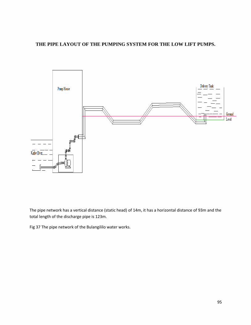
95
THE PIPE LAYOUT OF THE PUMPING SYSTEM FOR THE LOW LIFT PUMPS.
The pipe network has a vertical distance (static head) of 14m, it has a horizontal distance of 93m and the
total length of the discharge pipe is 123m.
Fig 37 The pipe network of the Bulangililo water works.
Copyright © 2022 FDOKUMEN