The calcium looping cycle for CO2 capture from power generation, cement manufacture and hydrogen...
20
chemical engineering research and design 89 (2011) 836–855 Contents lists available at ScienceDirect Chemical Engineering Research and Design journal homepage: www.elsevier.com/locate/cherd Review The calcium looping cycle for CO 2 capture from power generation, cement manufacture and hydrogen production C.C. Dean, J. Blamey, N.H. Florin, M.J. Al-Jeboori, P.S. Fennell ∗ Imperial College of Science, Technology and Medicine, London SW7 2AZ, United Kingdom abstract Calcium looping is a CO 2 capture scheme using solid CaO-based sorbents to remove CO 2 from flue gases, e.g., from a power plant, producing a concentrated stream of CO 2 (∼95%) suitable for storage. The scheme exploits the reversible gas–solid reaction between CO 2 and CaO(s) to form CaCO 3 (s). Calcium looping has a number of advantages compared to closer-to-market capture schemes, including: the use of circulating fluidised bed reactors—a mature technology at large scale; sorbent derived from cheap, abundant and environmentally benign limestone and dolomite precursors; and the relatively small efficiency penalty that it imposes on the power/industrial process (i.e., estimated at 6–8 percentage points, compared to 9.5–12.5 from amine-based post-combustion capture). A further advantage is the synergy with cement manufacture, which potentially allows for decarbonisation of both cement manufacture and power production. In addition, a number of advanced applications offer the potential for significant cost reductions in the production of hydrogen from fossil fuels coupled with CO 2 capture. The range of applications of calcium looping are discussed here, including the progress made towards demonstrating this technology as a viable post-combustion capture technology using small-pilot scale rigs, and the early progress towards a 2MW scale demonstrator. © 2010 The Institution of Chemical Engineers. Published by Elsevier B.V. All rights reserved. Keywords: Calcium looping; CCS; CO 2 capture; Power generation; Cement manufacture Contents 1. Introduction .................................................................................................................. 837 2. Basics of the cycle ............................................................................................................ 837 2.1. Sorbent deactivation .................................................................................................. 838 2.2. Sorbent performance ................................................................................................. 839 3. Energy efficiency, economics and integration with cement production ................................................... 840 3.1. The impact of Ca-looping on energy efficiency of power generation ............................................... 840 3.2. Economic studies on the Ca-looping cycle ........................................................................... 842 3.3. Integration of Ca-looping and cement production .................................................................. 842 4. Pilot plant trials for Ca-looping technologies ............................................................................... 846 4.1. Ca-looping for fuel-gas production without CO 2 capture ........................................................... 846 4.2. CANMET Energy and Technology Centre ............................................................................. 846 4.3. INCAR .................................................................................................................. 847 4.4. Stuttgart ............................................................................................................... 847 4.5. Other post-combustion pilot plants .................................................................................. 847 4.6. Future scale up of post-combustion Ca-looping ..................................................................... 848 ∗ Corresponding author. E-mail address: [email protected] (P.S. Fennell). Received 28 May 2010; Received in revised form 28 September 2010; Accepted 7 October 2010 0263-8762/$ – see front matter © 2010 The Institution of Chemical Engineers. Published by Elsevier B.V. All rights reserved. doi:10.1016/j.cherd.2010.10.013
-
Upload
independent -
Category
Documents
-
view
1 -
download
0
Transcript of The calcium looping cycle for CO2 capture from power generation, cement manufacture and hydrogen...
Journal Identification = CHERD Article Identification = 620 Date: May 17, 2011 Time: 5:47 am
chemical engineering research and design 8 9 ( 2 0 1 1 ) 836–855
Contents lists available at ScienceDirect
Chemical Engineering Research and Design
journa l homepage: www.e lsev ier .com/ locate /cherd
Review
The calcium looping cycle for CO2 capture from powergeneration, cement manufacture and hydrogen production
C.C. Dean, J. Blamey, N.H. Florin, M.J. Al-Jeboori, P.S. Fennell ∗
Imperial College of Science, Technology and Medicine, London SW7 2AZ, United Kingdom
a b s t r a c t
Calcium looping is a CO2 capture scheme using solid CaO-based sorbents to remove CO2 from flue gases, e.g., from a
power plant, producing a concentrated stream of CO2 (∼95%) suitable for storage. The scheme exploits the reversible
gas–solid reaction between CO2 and CaO(s) to form CaCO3(s). Calcium looping has a number of advantages compared
to closer-to-market capture schemes, including: the use of circulating fluidised bed reactors—a mature technology at
large scale; sorbent derived from cheap, abundant and environmentally benign limestone and dolomite precursors;
and the relatively small efficiency penalty that it imposes on the power/industrial process (i.e., estimated at 6–8
percentage points, compared to 9.5–12.5 from amine-based post-combustion capture). A further advantage is the
synergy with cement manufacture, which potentially allows for decarbonisation of both cement manufacture and
power production. In addition, a number of advanced applications offer the potential for significant cost reductions in
the production of hydrogen from fossil fuels coupled with CO2 capture. The range of applications of calcium looping
are discussed here, including the progress made towards demonstrating this technology as a viable post-combustion
capture technology using small-pilot scale rigs, and the early progress towards a 2 MW scale demonstrator.
© 2010 The Institution of Chemical Engineers. Published by Elsevier B.V. All rights reserved.
Keywords: Calcium looping; CCS; CO2 capture; Power generation; Cement manufacture
. . . . . . . . . . . . . . . . . . . . . . . . . . . . . . . . . . . . . . . . . . . . . . . . . . . . . . . . . . . . . . . . . . . 837
. . . . . . . . . . . . . . . . . . . . . . . . . . . . . . . . . . . . . . . . . . . . . . . . . . . . . . . . . . . . . . . . . . . 837
. . . . . . . . . . . . . . . . . . . . . . . . . . . . . . . . . . . . . . . . . . . . . . . . . . . . . . . . . . . . . . . . . . . 838. . . . . . . . . . . . . . . . . . . . . . . . . . . . . . . . . . . . . . . . . . . . . . . . . . . . . . . . . . . . . . . . . . . 839nt production. . . . . . . . . . . . . . . . . . . . . . . . . . . . . . . . . . . . . . . . . . . . . . . . . . . 840power generation . . . . . . . . . . . . . . . . . . . . . . . . . . . . . . . . . . . . . . . . . . . . . . . 840. . . . . . . . . . . . . . . . . . . . . . . . . . . . . . . . . . . . . . . . . . . . . . . . . . . . . . . . . . . . . . . . . . . 842. . . . . . . . . . . . . . . . . . . . . . . . . . . . . . . . . . . . . . . . . . . . . . . . . . . . . . . . . . . . . . . . . . 842
. . . . . . . . . . . . . . . . . . . . . . . . . . . . . . . . . . . . . . . . . . . . . . . . . . . . . . . . . . . . . . . . . . . 846apture . . . . . . . . . . . . . . . . . . . . . . . . . . . . . . . . . . . . . . . . . . . . . . . . . . . . . . . . . . . 846. . . . . . . . . . . . . . . . . . . . . . . . . . . . . . . . . . . . . . . . . . . . . . . . . . . . . . . . . . . . . . . . . . . 846. . . . . . . . . . . . . . . . . . . . . . . . . . . . . . . . . . . . . . . . . . . . . . . . . . . . . . . . . . . . . . . . . . . 847. . . . . . . . . . . . . . . . . . . . . . . . . . . . . . . . . . . . . . . . . . . . . . . . . . . . . . . . . . . . . . . . . . . 847. . . . . . . . . . . . . . . . . . . . . . . . . . . . . . . . . . . . . . . . . . . . . . . . . . . . . . . . . . . . . . . . . . . 847
Contents
1. Introduction . . . . . . . . . . . . . . . . . . . . . . . . . . . . . . . . . . . . . . . . . . . . . . .2. Basics of the cycle . . . . . . . . . . . . . . . . . . . . . . . . . . . . . . . . . . . . . . . . .
2.1. Sorbent deactivation . . . . . . . . . . . . . . . . . . . . . . . . . . . . . . .2.2. Sorbent performance . . . . . . . . . . . . . . . . . . . . . . . . . . . . . .
3. Energy efficiency, economics and integration with ceme3.1. The impact of Ca-looping on energy efficiency of3.2. Economic studies on the Ca-looping cycle . . . . . . . .3.3. Integration of Ca-looping and cement production
4. Pilot plant trials for Ca-looping technologies . . . . . . . . . . . .4.1. Ca-looping for fuel-gas production without CO2 c4.2. CANMET Energy and Technology Centre. . . . . . . . . .4.3. INCAR . . . . . . . . . . . . . . . . . . . . . . . . . . . . . . . . . . . . . . . . . . . . . . .4.4. Stuttgart . . . . . . . . . . . . . . . . . . . . . . . . . . . . . . . . . . . . . . . . . . . .4.5. Other post-combustion pilot plants . . . . . . . . . . . . . . .
4.6. Future scale up of post-combustion Ca-looping . . . . . . .∗ Corresponding author.E-mail address: [email protected] (P.S. Fennell).Received 28 May 2010; Received in revised form 28 September 2010; A
0263-8762/$ – see front matter © 2010 The Institution of Chemical Engidoi:10.1016/j.cherd.2010.10.013
. . . . . . . . . . . . . . . . . . . . . . . . . . . . . . . . . . . . . . . . . . . . . . . . . . . . . . . . . . . . . . 848
ccepted 7 October 2010neers. Published by Elsevier B.V. All rights reserved.

Journal Identification = CHERD Article Identification = 620 Date: May 17, 2011 Time: 5:47 am
chemical engineering research and design 8 9 ( 2 0 1 1 ) 836–855 837
5. Advanced applications of Ca-looping technology—H2 production . . . . . . . . . . . . . . . . . . . . . . . . . . . . . . . . . . . . . . . . . . . . . . . . . . . . . . . . 8485.1. Combined shift and carbonation reactions . . . . . . . . . . . . . . . . . . . . . . . . . . . . . . . . . . . . . . . . . . . . . . . . . . . . . . . . . . . . . . . . . . . . . . . . . . 8485.2. Sorption-enhanced reforming (SER). . . . . . . . . . . . . . . . . . . . . . . . . . . . . . . . . . . . . . . . . . . . . . . . . . . . . . . . . . . . . . . . . . . . . . . . . . . . . . . . . . 8495.3. In situ CO2 capture using solid fuels . . . . . . . . . . . . . . . . . . . . . . . . . . . . . . . . . . . . . . . . . . . . . . . . . . . . . . . . . . . . . . . . . . . . . . . . . . . . . . . . . 8505.4. Zero emission coal process . . . . . . . . . . . . . . . . . . . . . . . . . . . . . . . . . . . . . . . . . . . . . . . . . . . . . . . . . . . . . . . . . . . . . . . . . . . . . . . . . . . . . . . . . . . 8505.5. ENDEX configuration for Ca-looping . . . . . . . . . . . . . . . . . . . . . . . . . . . . . . . . . . . . . . . . . . . . . . . . . . . . . . . . . . . . . . . . . . . . . . . . . . . . . . . . . 850
6. Conclusions . . . . . . . . . . . . . . . . . . . . . . . . . . . . . . . . . . . . . . . . . . . . . . . . . . . . . . . . . . . . . . . . . . . . . . . . . . . . . . . . . . . . . . . . . . . . . . . . . . . . . . . . . . . . . . . . . . 851Acknowledgements . . . . . . . . . . . . . . . . . . . . . . . . . . . . . . . . . . . . . . . . . . . . . . . . . . . . . . . . . . . . . . . . . . . . . . . . . . . . . . . . . . . . . . . . . . . . . . . . . . . . . . . . . . 851References . . . . . . . . . . . . . . . . . . . . . . . . . . . . . . . . . . . . . . . . . . . . . . . . . . . . . . . . . . . . . . . . . . . . . . . . . . . . . . . . . . . . . . . . . . . . . . . . . . . . . . . . . . . . . . . . . . . . 851
1
CbfdIpabrCrripC‘fHfh1(opo(c
gataTutrccwlpthch
2
At
(1999) is shown in Fig. 2. In this example, the heat necessaryfor calcination is provided by oxy-combustion of coal, how-
. Introduction
arbon Capture and Storage (CCS) is a range of technologieseing developed to help mitigate climate change by isolatingrom the atmosphere a significant fraction of the CO2 pro-uced during fuel combustion (e.g., coal, gas and biomass).
n the case of coal-fired power stations, the technology couldrevent up to ∼90% of the CO2 from being emitted to thetmosphere; greater net emission reduction may be possi-le if coal is co-fired with biomass by accounting for the CO2
emoved from the atmosphere during the biomass growth.CS involves capture, purification and compression of the CO2
eady for transportation to a permanent storage location. Thiseview focuses on CO2 capture, which is the most costly stagen the CCS process; for information on the topics of trans-ort and storage please refer to Steeneveldt et al. (2006). TheO2 capture technology closest to market is post-combustion
scrubbing’ using amine-based solvents, which has been usedor industrial-scale separation of CO2 for several decades.owever, there are issues associated with amine-scrubbing
or CO2 capture from a combustion flue-gas, including theigh cost of manufacturing the solvent (e.g., MEA at ∼USD250/tonne) (Rao and Rubin, 2002), the high efficiency penalty∼9.5–12.5 percentage points) (Xu et al., 2010), degradationf the solvent due to reactions with O2 and SO2 (frequentlyresent in industrial flue gases), and the handling and disposalf large quantities of degradation products/waste solvent
which raises both environmental and health and safety con-erns).
Research into a range of alternative CO2 capture technolo-ies, which aim to address such issues, are being pursuedll over the world and one promising technology involveshe use of a solid CO2 sorbent using calcium-based materi-ls, known as ‘The Calcium Looping Cycle’ or ‘Ca-looping’.his process offers a number of advantages, including; these of well established fluidised bed technology; it is a high-emperature process and so high-grade excess heat can beecovered to provide additional energy to drive a steamycle, thus reducing the overall efficiency penalty of the pro-ess; the materials used to perform the CO2 capture areidely available and environmentally benign (derived from
imestones/dolomites); the affinity of the materials to SO2
rovides simultaneous partial desulphurisation of the indus-rial flue gas; and, the waste material from the processas potential uses elsewhere in industry, most notably theement industry. These advantages are discussed in detailerein.
. Basics of the cycle
n extensive review of the Ca-looping cycle for CO2 cap-ure has recently been published (Blamey et al., 2010); the
main features of which are summarised herein. For furtherinformation, see also reviews by Stanmore and Gilot amongstothers (Stanmore and Gilot, 2005; Harrison, 2008; Anthony,2008; Florin and Harris, 2008a; Li and Fan, 2008), and the IEAGHG High Temperatures Solid Looping Cycles Network (IEA,2010).
The Ca-looping process uses a CaO-based sorbent, typicallyderived from limestone, reacting via the reversible reactiondescribed in Eq. (1). The forwards step is known as calcinationand is an endothermic process which readily goes to comple-tion under a wide range of conditions. The backwards step isknown as carbonation:
CaCO3(s) = CaO(s) + CO2(g) �H◦ = +178 kJ/mol (1)
CO(g) + H2O(g) = CO2(g) + H2(g) �H◦ = −41 kJ/mol (2)
The equilibrium vapour pressure of CO2 over CaO accord-ing to Eq. (1) can be calculated as a function of temperature;partial pressures of CO2 greater than the equilibrium partialpressure at a given temperature will favour carbonation, whilethose lower than the equilibrium will favour calcination (seeFig. 1). As a result, if a sorbent is cycled between two vessels atsuitable temperatures, carbonation of sorbent can be effectedin one and calcination in the other. The objective of CO2 cap-ture is to obtain a pure stream of CO2 suitable for storage; onemethod of achieving this is by separation of CO2 (3–30% byvolume) from an exhaust gas obtained from power stationsor industry (i.e., post-combustion CO2 capture). A typical Ca-looping process for CO2 capture as proposed by Shimizu et al.
Fig. 1 – Equilibrium vapour pressure of CO2 over CaO as afunction of temperature (McBride et al., 2002).

Journal Identification = CHERD Article Identification = 620 Date: May 17, 2011 Time: 5:47 am
838 chemical engineering research and design 8 9 ( 2 0 1 1 ) 836–855
Fig. 2 – Typical example scheme for Ca-loopingpost-combustion CO2 capture (enthalpies calculated usingdata provided by McBride et al. (2002).
Table 1 – Physical properties of calcium compoundsrelevant to the Ca-looping cycle (Perry and Green, 1997).
Molar mass(g/mol)
Density(g/cm3)
Molar vol.(cm3/mol)
CaCO3 100.1 2.71 36.9CaO 56.1 3.32 16.9CaSO4 136.1 2.96 46.0CaS 72.1 2.8 25.8Ca(OH)2 74.1 2.2 33.7
transition to conditions that accelerate the rate of sintering of
ever other methods have been suggested such as providing anexternal heat source (Alvarez and Abanades, 2005).
The calciner temperature (>850 ◦C) is dictated by the highCO2 partial pressure necessary to produce a near pure stream(Fig. 1), and may also be chosen as a compromise betweenhigher temperatures, which increase the rate of calcination atthe expense of rapid degradation of the sorbent (see Section2.2) and milder temperatures which protect the sorbent; thecarbonator temperature is chosen as a compromise betweenthe higher equilibrium (maximum) capture at lower temper-atures and a decreased rate of reaction. Both carbonator andcalciner can use fluidised bed technology, owing to the goodgas–solid contacting and uniform bed temperature, and whichhas the advantage of having being developed and deployed ona large scale (Cuenca and Anthony, 1995; Grace et al., 1997)for circulating fluidised beds. The Ca-looping cycle can also beapplied to gasification/pre-combustion techniques, where itcan be used to increase hydrogen production by removing CO2
from the products of the water gas shift (Eq. (2)) and reformingreactions e.g. Eq. (9) (Harrison, 2008; Florin and Harris, 2008a),
thus enhancing the maximum production of H2. Current pilotFig. 3 – Carrying capacity of CaO sorbent through 50 CO2 capturevs. time (TGA data for Havelock limestone).
plant trials of the Ca-looping cycle for post-combustion CO2
capture are discussed in Section 4, while application of the Ca-looping cycle to more advanced capture techniques, includingpre-combustion to generate fuel gases, are discussed in Sec-tion 5.
2.1. Sorbent deactivation
Ideally, CaO sorbent would be continually cycled betweencarbonator and calciner reacting with and evolving 1 mol ofCO2 per mol CaO each cycle. However, the rate of carbon-ation of CaO makes a transition from a fast to a very slowdiffusion-controlled rate through the product layer (see insetFig. 3) (Bhatia and Perlmutter, 1983; Mess et al., 1999; Alvarezand Abanades, 2005), preventing full conversion to CaCO3 ona timescale useful for industrial purposes. The conversionof CaO to CaCO3 at this transition is often defined as themaximum carbonation conversion or ‘carrying capacity’ ofthe sorbent and is well known to decrease upon cycling ofthe sorbent through multiple CO2 capture-and-release cycles(Curran et al., 1967; Barker, 1973; Deutsch and Heller-Kallai,1991; Silaban and Harrison, 1995; Aihara et al., 2001; Abanades,2002; Abanades and Alvarez, 2003; Fennell et al., 2007a).
Loss in sorbent reactivity can be caused by a number of fac-tors: sintering of the porous CaO during the high temperaturecalcination stage (the major cause of loss in reactivity); com-peting sulphation/sulphidation reactions; loss of bed materialthrough attrition causing elutriation of fines; and ash fouling.
CaO formed by calcination of CaCO3 is very porous (Barker,1973) because, as shown in Table 1, there is a marked reductionin molar volume from CaCO3 to CaO resulting in a theoreticalporosity of 0.54. However, CaO used for Ca-looping is proneto sintering (i.e., changes in pore shape, pore shrinkage andgrain growth, at elevated temperatures), which causes a reduc-tion in reactive surface area and a drop-off in reactivity. The
CaO occurs at approximately 900 ◦C (Borgwardt, 1989a), while
-and-release cycles represented in terms of mass change
Journal Identification = CHERD Article Identification = 620 Date: May 17, 2011 Time: 5:47 am
chemical engineering research and design 8 9 ( 2 0 1 1 ) 836–855 839
iftctce
fc(AaD2asr(brb12t2ssimt
C
C
C
C
�
o(2estrpipseioca
ncreasing partial pressure of CO2 and steam have also beenound to increase the rate of sintering (Borgwardt, 1989b). Sin-ering of CaO can therefore be expected to be severe in thealciner, which in the example scheme in Fig. 2 is expectedo be operating above 900 ◦C at 101 kPa CO2. There is also aontribution of reactive sintering that is particular to cyclingxperiments (Gonzalez et al., 2008).
CaO has a very strong affinity to SO2 and will readilyorm CaSO4 in the oxidising conditions expected in post-ombustion systems (see Eq. (3) for direct sulphation and Eq.4) for indirect sulphation, i.e., sulphation of the carbonate).s a result, CaO derived from limestone has been used assorbent for SO2 on an industrial scale (Smith, 2007); e.g.,rax Power Station (coal-fired, 3.96 GW) (Drax Power Station,008) in the UK captured 90% of its sulphur emissions usingn independent wet limestone–gypsum flue gas desulphuri-ation plant. CaO can form CaS upon reaction with H2S undereducing conditions (see Eq. (5) for direct sulphidation and Eq.6) for indirect sulphidation, again, sulphidation of the car-onate). Sulphated sorbent requires very high temperatures oreducing conditions to be regenerated, though sulphided sor-ent can be regenerated more readily (Lyngfelt and Leckner,989; Hayhurst and Tucker, 1991; Anthony and Granatstein,001); both reactions can be considered as resulting in reac-ive sites lost for carbonation. Grace and co-workers (Ryu et al.,006; Sun et al., 2007) investigated the effect of sulphate andulphide formation on CO2 uptake of sorbent and found thatulphate formation is a more significant problem as it resultsn pore blockage from the formation of CaSO4, which has a
uch larger molar volume (see Table 1). This pore blockagehen prevents access of CO2 to the centre of a particle:
aO(s) + SO2(g) + ½O2(g) = CaSO4(s) �H◦ = −502 kJ/mol (3)
aCO3(s) + SO2(g) + ½O2(g)
= CaSO4(s) + CO2(g) �H◦ = −324 kJ/mol (4)
aO(s) + H2S(g) = CaS(s) + H2O(g) �H◦ = −61.3 kJ/mol (5)
aCO3(s) + H2S(g) = CaS(s) + CO2(g) + H2O(g)
H◦ = +117 kJ/mol (6)
There has been a large volume of research publishedn the attrition characteristics of limestone for SO2 capture
Anthony and Granatstein, 2001; Smith, 2007; Chen et al.,008; Saastamoinen et al., 2008; Scala et al., 2008; Blameyt al., 2010). However, there is less research regarding lime-tone for CO2 capture. Fennell et al. (2007a) showed thathe most significant attrition occurred in the early cycles ofepeated calcination/carbonation cycling experiments. Pilotlant studies published by Alonso et al. (2010) observed signif-
cant attrition of sorbent at the start of the experiment, whileilot plant studies published by D.Y. Lu et al. (2008) showedignificant attrition throughout operation (>60% of materialnded up as fine material in the cyclones after 25 cycles, reduc-ng the CO2 capture rate significantly). For further discussionf attrition on a pilot plant scale, see Section 4. The mechani-
al stability of the sorbent is therefore receiving considerablettention and is likely to be a critical factor in the selection oforiginal limestone for large-scale testing; on this basis, there isa drive towards standardised testing of the mechanical stabil-ity of limestone to determine suitability for use in a fluidisedenvironment (Schueppel, 2009; Zuberbuehler, 2009).
An important aspect of scale up to a typical proposedsystem, such as that described in Fig. 2, is the effect of fuel-combustion in the calciner. The combustion of the fuel resultsin two undesirable effects: the introduction of fine ash andchars into the cycle, which have the potential to deposit ontothe surface of a particle and result in undesirable side reac-tions and low temperature melt formation; and higher localtemperatures related to fuel-combustion (Joutsenoja et al.,1999; Scala et al., 2003; Corella et al., 2006). Accordingly,Hughes et al. (2009) report lower reactivity of sorbent thananticipated and the formation of a dense shell on the sur-face of particles when combusting high-ash hardwood pelletsin the calciner; a similar problem has been described byKuramoto et al. (2003).
There have been a number of attempts to model the decayrate of the maximum carbonation conversion upon cycling,which focus on the reactivity towards CO2 disregarding sul-phation, attrition and ash fouling effects (Abanades, 2002;Abanades and Alvarez, 2003; Wang and Anthony, 2005, 2007;Grasa and Abanades, 2006; Lysikov et al., 2007; Gonzalez et al.,2008). For descriptions of these decay equations and a dis-cussion of their individual merits and drawbacks please referto Blamey et al. (2010). It should be noted that most of themodels proposed are semi-empirical and cannot currently beused to predict the behaviour of individual limestones fromtheir intrinsic properties. The authors’ preferred equation dueto its accurate representation of the loss of reactivity overlarge numbers of cycles (>20) is Eq. (7), proposed by Grasaand Abanades (2006), where aN is the maximum carbonationconversion of the sorbent in cycle N, a∞ is the residual (final)conversion of the sorbent after a very large number of cycles,and k is a decay rate constant:
aN =(
11/(1 − a)
+ kN
)+ a∞ (7)
It is likely that in a realistic system where sulphation,attrition and ash fouling are unavoidable, a∞ will tend tozero, however in small scale tests a residual capacity of∼60 mg CO2/g sorbent is found, which is competitive withother CO2 sorbents (Rodriguez et al., 2008b). A real systemwill also differ in that the residence time of the sorbent inthe calciner or carbonator may not be sufficient to allow fullcalcination or maximum carbonation, making application ofthese formulas difficult; such matters are under investigationby Abanades and co-workers (Grasa et al., 2009; Rodriguezet al., 2010).
2.2. Sorbent performance
There is currently a great deal of work being conducted toimprove sorbent performance upon cycling. This can be doneby alteration of the process conditions or by sorbent enhance-ment. There are numerous process variables which will affectsorbent performance, the most important of which is the tem-perature of the calciner. However, steam partial pressure in thecarbonator, the residence time of the particles in the calcinerand the carbonator, the presence of ash, sulphur and other
minor species, and particle size are likely to also play signifi-cant roles. The temperature of the calciner can be decreased
Journal Identification = CHERD Article Identification = 620 Date: May 17, 2011 Time: 5:47 am
840 chemical engineering research and design 8 9 ( 2 0 1 1 ) 836–855
if the partial pressure of CO2 is reduced, thus minimisingthe extent of sorbent sintering upon cycling; the two sim-plest ways of doing this are by lowering the total pressure(Ewing et al., 1979; Alvarez and Abanades, 2005; Sakadjianet al., 2007) (see also the Endex process, Section 5.5) or byintroducing steam into the calciner (Alvarez and Abanades,2005; Wang et al., 2008, 2009). The main research areas for sor-bent enhancement are doping of natural limestones with traceamounts of organic salts, the production of synthetic sorbents,the hydration of spent sorbent, and thermal pre-treatment; anideal enhanced sorbent will display high mechanical strengthwhile maintaining its reactive surface area over repeatedcycling, without being prohibitively expensive—for economicassessments see work by Romeo and co-workers (Romeo et al.,2009a; Lisbona et al., 2010).
There is considerable variability in the reactivity and fri-ability of natural limestones, which should be investigatedbefore selecting a sorbent (Laursen et al., 2000; Ryu et al., 2006;Alvarez, 2007; Fennell et al., 2007a). These properties dependon impurities and the conditions/age of formation. Dolomiteshave shown a reduced decay rate upon cycling, despite a lowerinitial reactivity owing to a lower amount of CaO per unitmass (Dobner et al., 1977; Silaban et al., 1996); natural sor-bents such as shells have also been studied and have beenshown to exhibit mildly increased reactivity in comparisonto natural limestone in some cases (Ives et al., 2008; Li et al.,2009). Doping of natural limestones has been investigated;however the results have been variable (Salvador et al., 2003;Fennell et al., 2007b; Florin and Harris, 2008b; Sun et al., 2008),even when the same dopant has been used. The efficacy ofdoping is highly dependent on the concentration of dopantused; too low a concentration will have no effect, too highmay contribute to pore blocking and potentially agglomera-tion of particles. ‘Synthetic sorbents’ are also being developed.Examples include: precipitated CaCO3 from a slurry bubblecolumn (Agnihotri et al., 1999; Gupta et al., 2004; Florin andHarris, 2008c) to enhance the reactive surface area of the sor-bent; sorbents derived from different calcium precursors, e.g.,calcium acetate, calcium ethanoate (Lu et al., 2006; H. Lu etal., 2008; Liu et al., 2010a) with particular success using aMgO support (Liu et al., 2010b) to similarly enhance the reac-tive surface area; dispersal of CaO within an inert porousmatrix such as mayenite (Li et al., 2005, 2006; Pacciani et al.,2008a) to improve mechanical stability; and use of cemen-titious binders (Manovic and Anthony, 2009a,b) to improvemechanical stability. Sorbent reactivity can be periodicallyimproved by hydration of calcined sorbent, though this is oftenat the expense of mechanical strength of the sorbent (Hugheset al., 2004; Fennell et al., 2007b; Manovic and Anthony, 2007;Manovic et al., 2008; Sun et al., 2008; Zeman, 2008). Ther-mal preactivation/pre-treatment, by treating sorbent at hightemperature under N2, has been found to improve long-termreactivity of sorbents (Manovic and Anthony, 2008a,b).
All studies of sorbent enhancement should consider thatsorbent reactivity is dependent on several variables: calci-nation temperature and time; carbonation temperature andtime; CO2 concentration in carbonation and calcination; and,the difficulty in defining ‘normal’ behaviour in a limestone,which may be used as a reference. These factors are impor-tant, in that they make comparisons between different studiesdifficult. For example, very different results are obtained fordeactivation rates when calcination is conducted under mild
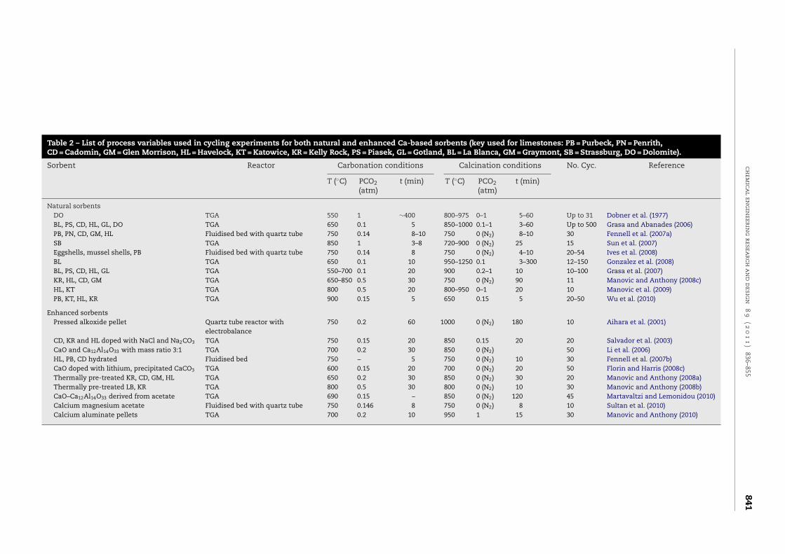
vs. severe conditions (Grasa and Abanades, 2006; Manovic andAnthony, 2008a,c; Manovic et al., 2009; Wang et al., 2010) andalso due to increases in carbonation temperature (Manovicand Anthony, 2008c) (both of which are reported to be dueto the effect of sintering, see Section 2.1). Longer carbona-tion times can regenerate the sorbent (Barker, 1973; Lysikovet al., 2007; Chen et al., 2009) though the effect of this is some-what inconsistent elsewhere (Manovic and Anthony, 2008c). Ahigher CO2 concentration during carbonation has been shownto improve the uptake of some synthetic sorbents (Paccianiet al., 2008b). In cases where the CO2 concentration is higherduring calcination this consistently leads to a more rapid drop-off in reactivity (Li et al., 2005; Lu et al., 2009); however there arecases where the effect of CO2 concentration in calcination isonly noticeable over the first five cycles (Manovic et al., 2009).The presence of SO2 leads to a reduction in carbonation reac-tivity owing to the competing sulphation reaction (see Section2.1). For a summary of the process variables used in cyclingexperiments investigating the performance of both enhancedand natural sorbents please refer to Table 2.
3. Energy efficiency, economics andintegration with cement production
3.1. The impact of Ca-looping on energy efficiency ofpower generation
As previously mentioned, key advantages of Ca-loopinginclude the potential for retrofitting to existing power stationsor other stationary industrial CO2 sources and the relativelylow parasitic energy demand imposed on the existing pro-cesses. The Ca-looping cycle requires heat at the calciner toeffect the following; the endothermic calcination of CaCO3;raising the temperature of the recycled sorbent from car-bonator to calciner temperature (+250 ◦C); and, raising thetemperature of fresh limestone from ambient (+900 ◦C) whichmay be required to maintain the overall reactivity of the lime-stone in the system. As shown in Fig. 2, this heat can beprovided by in situ oxy-fired combustion of fuel in the cal-ciner. Additional energy is also required to separate O2 fromN2 and for CO2 compression. Critically, because this process isoperating at relatively high temperatures (>650 ◦C), the major-ity of the energy input can be recuperated from the hot gasand solid streams exiting the system to drive a steam cycle.Heat generated by the exothermic carbonation reaction is alsoavailable which may be integrated with the steam cycle.
Accordingly, Rodriguez et al. (2008a) considered the para-sitic energy demand simply in terms of the amount of the totalfuel demand (fp) that is diverted to the calciner, i.e., 1 − fp; theyshowed 1 − fp to be strongly dependent on the quality of thefuel used in the calciner and calculated a minimum value of0.3 for an ideal fuel containing no sulphur or ash (assuming acarbonator efficiency of 70%, Ca/C molar ratio of 3 and purgeflow rate of 0.13 mol/s). The sensitivity of this parameter, 1 − fp,is shown in Table 3, with data reproduced from their work.
Abanades et al. (2007) incorporated the efficiency penaltyowing to O2 separation and CO2 compression (6% and 5%respectively) describing the overall plant efficiency accordingto Eq. (8):
�capture = �ref · fp + �oxy · (1 − fp) − 0.05 · fp (8)
where �ref is the energy efficiency of the existing process, fp
is the fraction of fuel used in the main power plant �oxy is theenergy efficiency of the power generated by the calciner.
Journ
alIden
tification
=C
HER
DA
rticleId
entifi
cation=
620D
ate:May
17,2011T
ime:5:47
am
chem
ical
eng
ineerin
gresea
rcha
nd
desig
n8
9(2
01
1)
836–855841
Table 2 – List of process variables used in cycling experiments for both natural and enhanced Ca-based sorbents (key used for limestones: PB = Purbeck, PN = Penrith,CD = Cadomin, GM = Glen Morrison, HL = Havelock, KT = Katowice, KR = Kelly Rock, PS = Piasek, GL = Gotland, BL = La Blanca, GM = Graymont, SB = Strassburg, DO = Dolomite).
Sorbent Reactor Carbonation conditions Calcination conditions No. Cyc. Reference
T (◦C) PCO2(atm)
t (min) T (◦C) PCO2(atm)
t (min)
Natural sorbentsDO TGA 550 1 ∼400 800–975 0–1 5–60 Up to 31 Dobner et al. (1977)BL, PS, CD, HL, GL, DO TGA 650 0.1 5 850–1000 0.1–1 3–60 Up to 500 Grasa and Abanades (2006)PB, PN, CD, GM, HL Fluidised bed with quartz tube 750 0.14 8–10 750 0 (N2) 8–10 30 Fennell et al. (2007a)SB TGA 850 1 3–8 720–900 0 (N2) 25 15 Sun et al. (2007)Eggshells, mussel shells, PB Fluidised bed with quartz tube 750 0.14 8 750 0 (N2) 4–10 20–54 Ives et al. (2008)BL TGA 650 0.1 10 950–1250 0.1 3–300 12–150 Gonzalez et al. (2008)BL, PS, CD, HL, GL TGA 550–700 0.1 20 900 0.2–1 10 10–100 Grasa et al. (2007)KR, HL, CD, GM TGA 650–850 0.5 30 750 0 (N2) 90 11 Manovic and Anthony (2008c)HL, KT TGA 800 0.5 20 800–950 0–1 20 10 Manovic et al. (2009)PB, KT, HL, KR TGA 900 0.15 5 650 0.15 5 20–50 Wu et al. (2010)
Enhanced sorbentsPressed alkoxide pellet Quartz tube reactor with
electrobalance750 0.2 60 1000 0 (N2) 180 10 Aihara et al. (2001)
CD, KR and HL doped with NaCl and Na2CO3 TGA 750 0.15 20 850 0.15 20 20 Salvador et al. (2003)CaO and Ca12Al14O33 with mass ratio 3:1 TGA 700 0.2 30 850 0 (N2) 50 Li et al. (2006)HL, PB, CD hydrated Fluidised bed 750 – 5 750 0 (N2) 10 30 Fennell et al. (2007b)CaO doped with lithium, precipitated CaCO3 TGA 600 0.15 20 700 0 (N2) 20 50 Florin and Harris (2008c)Thermally pre-treated KR, CD, GM, HL TGA 650 0.2 30 850 0 (N2) 30 20 Manovic and Anthony (2008a)Thermally pre-treated LB, KR TGA 800 0.5 30 800 0 (N2) 10 30 Manovic and Anthony (2008b)CaO–Ca12Al14O33 derived from acetate TGA 690 0.15 – 850 0 (N2) 120 45 Martavaltzi and Lemonidou (2010)Calcium magnesium acetate Fluidised bed with quartz tube 750 0.146 8 750 0 (N2) 8 10 Sultan et al. (2010)Calcium aluminate pellets TGA 700 0.2 10 950 1 15 30 Manovic and Anthony (2010)

Journal Identification = CHERD Article Identification = 620 Date: May 17, 2011 Time: 5:47 am
842 chemical engineering research and design 8 9 ( 2 0 1 1 ) 836–855
Table 3 – Minimum efficiency penalties and associated operating parameters of Ca-looping calculated as the split of fueluse (1 − fp) on an existing power generation process for different types of fuels (Rodriguez et al., 2008a).
S/C ratio Ash/C ratio Purge/C ratio Sorbent Conv. LHV (MJ/kg) (1 − fp) Min.
N/A N/A 0.13 0.196 34 0.30N/A 0.25 0.18 0.255 25 0.330.05 N/A 0.29 0.280 34 0.35
stone calcination to produce CaO which is then mixed with
Fig. 4 – Sensitivity analysis showing the impact of varying
0.12 0.56 0.41
Assuming 40% of total fuel consumption was allocatedto the calciner (i.e., fp = 0.6) (Shimizu et al., 1999; Abanadeset al., 2004, 2005), the resulting energy efficiency of powergeneration from the additional fuel utilised in the CO2 cap-ture process was calculated as 35.6% from a baseline of 43% inthe reference case. When heat recuperation is considered (asdiscussed above), Romeo et al. (2008) computed an efficiencypenalty of only 4.5% from 44.9% (the supercritical steam cyclereference case) to 40.4%. The inclusion of essential auxiliarypower consumption components (O2 separation, 47 MWe; CO2
compression, 53 MWe; other, 15 MWe) gave a final efficiencyof 26.7% for the utilisation of the extra fuel used in the cal-ciner to generate electricity (accounted for within the figurefor the overall efficiency penalty). The study also identifiedthe potential modifications of the existing supercritical steamcycle for integration with Ca-looping based on the tempera-ture and physical location of the high temperature streamsexiting the Ca-looping system.
3.2. Economic studies on the Ca-looping cycle
The economics of the Ca-looping cycle have been evaluatedby Abanades et al. (2007) considering three main cost com-ponents: the main power plant, the oxy-fired calciner andthe carbonator. He calculated a likely range of costs from7.1 USD/tCO2 to 31.2 USD/tCO2 avoided, incorporating an opti-mistic and pessimistic estimate using data from the IPCCSpecial Report on CSS (i.e., for fuel cost, capital cost, vari-able cost and fixed charge factor) (Metz et al., 2005) reflectingthe impact of different cost parameters on the overall costof capture. MacKenzie et al. (2007) estimated the cost of CO2
avoided at 19 USD/tCO2 which compares competitively withestimates for amine scrubbing, e.g., 32.5–80 USD/tCO2 (Davidand Herzog, 2000; Herzog, 1998) (figures converted to 2006 USDfrom Canadian dollars, using mean exchange rate June 2006).Their study included a sensitivity analysis and identified thecost of limestone and the assumed Ca/C ratio as having themost significant influence on the cost (Fig. 4).
Romeo et al. (2009b) examined the impact on the cost ofCO2 avoided of varying the Ca/C molar ratio and purge rate(as a percentage of the solids inventory); they showed that theimpact of purge rate on the capture cost was more significantfor higher Ca/C ratios (Ca/C > 4) because at higher Ca/C ratios,increasing the purge rate does not lead to an increase in CO2
capture capacity while the cost rises monotonically with purgerate. The study examined the effect of these process vari-ables purging both from the carbonator and calciner. Purgingfrom the carbonator allows a lower possible capture cost to bereached because material is removed before a further energy-intensive calcination step is required. However, purging fromthe calciner allows material to be removed as CaO which canprovide both an energy and CO2 credit to cement produc-tion. Purging from the carbonator, the optimum configuration
(i.e., resulting in the minimum capture cost) comprised a Ca/Cratio of 4 and a purge rate of 2% giving a minimum cost of0.290 21 0.39
19.8 USD/tCO2. Purging from the calciner suggested an opti-mum configuration of Ca/C = 5 and a purge rate of 1–2%, givinga minimum cost of 20.5 USD/tCO2. The results showed con-sistently, regardless of purge location or fuel type, that theminimum costs could be achieved with higher Ca/C ratios andlower purge rates. In all cases studied the cost of CO2 cap-ture remained competitive (<29 USD/tCO2) (figures convertedto USD from euros using mean exchange rate January 2008).However, this does not take into account the potential for inte-gration with cement manufacture, detailed below.
3.3. Integration of Ca-looping and cement production
One major advantage for the Ca-looping cycle over many com-peting technologies is that the exhausted/purged CaO can beused as a raw material in cement production, presenting anopportunity to partially decarbonise both power generationand the cement process.
Cement production is both a highly resource and energyintensive process. Approximately 1.5 tonnes of raw materialsare required to produce 1 tonne of cement. Limestone repre-sents ∼85 wt.% of the raw feed while the remainder comprisesclay (∼13 wt.%) and additives (e.g., SiO2, Al2O3, Fe2O—<2 wt.%)(Alsop et al., 2007). The first step in the process involves lime-
critical cost parameters by ±30% on CO2 capture cost(MacKenzie et al., 2007).
Journal Identification = CHERD Article Identification = 620 Date: May 17, 2011 Time: 5:47 am
chemical engineering research and design 8 9 ( 2 0 1 1 ) 836–855 843
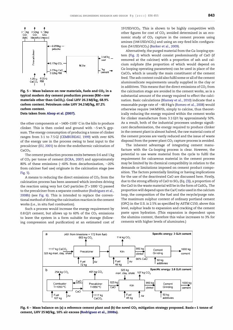
Fig. 5 – Mass balance on raw materials, fuels and CO2 in atypical modern dry cement production process (RM = rawmaterials other than CaCO3). Coal LHV 26.3 MJ/kg, 68.9%carbon content. Petroleum coke LHV 34.2 MJ/kg, 87.2%carbon content.Data taken from Alsop et al. (2007).
tcsropC
o8fF
ctt2tw
0ti
Fc
he other components at ∼1400–1500 ◦C in the kiln to producelinker. This is then cooled and ground with ∼5 wt.% gyp-um. The energy consumption of producing a tonne of clinkeranges from 3.1 to 7.5 GJ (CEMBUREAU, 1999) with over 60%f the energy use in the process owing to heat input to therecalciner (EU, 2001) to drive the endothermic calcination ofaCO3.
The cement production process emits between 0.6 and 1 kgf CO2 per tonne of cement (ECRA, 2007) and approximately0% of these emissions (∼60% from decarbonisation, ∼20%rom calciner fuel use) originate in the calcination stage (seeig. 5).
A means to reducing the direct emissions of CO2 from thealcination process has been assessed which involves drivinghe reaction using very hot CaO particles (T > 1000 ◦C) passedo the precalciner from a separate combustor (Rodriguez et al.,008b) (see Fig. 6). This is intended to replace the conven-ional method of driving the calcination reaction in the cementorks (i.e., in situ fuel combustion).
Such a process would increase the energy requirement by.8 GJ/t cement, but allows up to 60% of the CO2 emissions
o leave the system in a form suitable for storage (follow-ng compression and purification) at an estimated cost ofig. 6 – Mass balance on (a) a reference cement plant and (b) theement, LHV 25 MJ/kg, 10% air excess (Rodriguez et al., 2008a).
19 USD/tCO2. This is shown to be highly competitive withother figures for cost of CO2 avoided determined in an eco-nomic study of CO2 capture in the cement process usingamines (144 USD/tCO2) and using an oxy-fired kiln configura-tion (54 USD/tCO2) (Barker et al., 2009).
Alternatively, the purged material from the Ca-looping sys-tem (Fig. 2) which would consist predominantly of CaO (ifremoved at the calciner) with a proportion of ash and cal-cium sulphate (the proportion of which would depend onCa-looping operating parameters) can be used in place of theCaCO3 which is usually the main constituent of the cementfeed. The ash content could also fulfil some or all of the cementaluminosilicate requirements usually supplied in the clay orin additives. This means that the direct emissions of CO2 fromthe calcination stage are avoided in the cement works, as is asubstantial amount of the energy required to effect the calci-nation. Basic calculations (Blamey et al., 2010) indicate that areasonable purge rate of ∼48.9 kg/s (Romeo et al., 2008) wouldotherwise require 144 MWth, simply to calcine, thus theoret-ically reducing the energy required within the cement worksfor clinker manufacture from 3.1 GJ/t by approximately 50%.As a result, both of the industrial processes undergo signifi-cant decarbonisation, the energy required to produce clinkerin the cement plant is almost halved, the raw material costs ofthe cement process are vastly reduced and the issue of wastedisposal from the power plant CO2 capture process is avoided.
The inherent advantage of integrating cement manu-facture with the Ca-looping process is clear. However, thepotential to use waste material from the cycle to fulfil therequirement for calcareous material in the cement processmay be limited by its chemical compatibility in relation to thedemands or limitations imposed on cement product compo-sition. The factors potentially limiting or having implicationsfor the use of the deactivated CaO are discussed here. Firstly,due to the strong affinity of CaO to SO2 (Eq. (3)), a proportion ofthe CaO in the waste material will be in the form of CaSO4. Theproportion will depend upon the Ca/C ratio used in the calciumloop, the composition of the fuel and the recycle/purge rate.The maximum sulphur content of ordinary portland cement(OPC) in the U.S. is 2.5% as specified by ASTM C150; above thislevel, sulphur leads to expansion and cracking of the cementpaste upon hydration. (This expansion is dependent upon
the alumina content, therefore this value increases to 3% forcements with higher levels of aluminates.)novel CO2 mitigation strategy proposed. Basis = 1 tonne of
Journal Identification = CHERD Article Identification = 620 Date: May 17, 2011 Time: 5:47 am
844 chemical engineering research and design 8 9 ( 2 0 1 1 ) 836–855
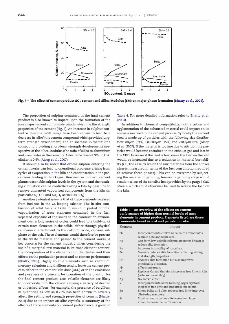
Fig. 7 – The effect of cement product SO3 content and Silica Modulus (SM) on major phase formation (Bhatty et al., 2004).
Table 4 – An overview of the effects on cementperformance of higher than normal levels of traceelements in cement product. Elements listed are thosecommonly found in coal and petroleum coke.
Element Impact
Sb Incorporates into clinker as calcium antimonates,reduces alite and belite size.
As Can form low-volatile calcium arsenates known toreduce alite formation.
Ba Improves burnability of materials.Be Severely reduces alite formation affecting setting
and strength properties.Cr Reduces alite formation but also improves
grindability of clinker.Pb Effects uncertain.Ni Replaces Ca and therefore increases free lime in kiln
(reduces burnability).Ag No known effect.V Incorporates into alites forming larger crystals;
increases free lime and imparts a tan colour.Zn Enters belite and alite, reduces free lime; improves
clinkering reactions.
The proportion of sulphur contained in the final cementproduct is also known to impact upon the formation of thefour major cement compounds which determine the strengthproperties of the cement (Fig. 7). An increase in sulphur con-tent within the 0–3% range have been shown to lead to adecrease in ‘alite’ (the cement compound which provides long-term strength development) and an increase in ‘belite’ (thecompound providing short-term strength development) irre-spective of the Silica Modulus (the ratio of silica to aluminiumand iron oxides in the cement). A desirable level of SO3 in OPCclinker is 0.6% (Alsop et al., 2007).
It should also be noted that excess sulphur entering thecement works can lead to operational problems arising fromcycles of evaporation in the kiln and condensation in the pre-calciner leading to blockages. However, in modern cementplants reasonable sulphur levels in the system and the result-ing circulation can be controlled using a kiln by-pass line toremove unwanted vapourised components from the kiln (inparticular K2O, Cl and Na2O3 as well as SO3).
Another potential issue is that of trace elements releasedfrom fuel use in the Ca-looping calciner. The in situ com-bustion of solid fuels is likely to result in partial or totalvapourisation of trace elements contained in the fuel.Repeated exposure of the solids to the combustion environ-ment over a long series of cycles could lead to a build-up ofcertain trace elements in the solids, either through physicalor chemical attachment to the calcium oxide, calcium sul-phate or the ash. These elements would therefore be presentin the waste material and passed to the cement works. Akey concern for the cement industry when considering theuse of a marginal raw material is its trace element content,the incorporation of the elements into the clinker and theireffects on the production process and on cement performance(Bhatty, 1995). Highly volatile elements such as cadmium,mercury, selenium and thallium tend to leave the cement pro-cess either in the cement kiln dust (CKD) or in the emissionsand pose less of a concern for operation of the plant or forthe final cement product. Less volatile elements are likelyto incorporate into the clinker causing a variety of desiredor undesired effects. For example, the presence of berylliumin quantities as low as 0.25% has been shown to severelyaffect the setting and strength properties of cement (Bhatty,
2003) due to its impact on alite crystals. A summary of theeffects of trace elements on cement performance is given inTable 4. For more detailed information refer to Bhatty et al.(2004).
In addition to chemical compatibility, both attrition andagglomeration of the exhausted material could impact on itsuse as a raw feed to the cement process. Typically the cementfeed is made up of particles with the following size distribu-tion: 88 �m (83%), 88–300 �m (15%) and >300 �m (2%) (Alsopet al., 2007). If the material is too fine due to attrition the par-ticles would become entrained in the exhaust gas and lost inthe CKD. However if the feed is too coarse the load on the kilnwould be increased due to a reduction in material burnabil-ity (i.e., the ease by which the raw materials form the clinkerphases, measured in terms of the fuel consumption requiredto achieve these phases). This can be overcome by subject-ing the material to grinding, however a grinding stage wouldresult in a loss of the sensible heat provided by the purged CaOstream which could otherwise be used to reduce the load onthe kiln.
Sr Small amounts favour alite formation; largeramounts favour belite formation.

Journ
alIden
tification
=C
HER
DA
rticleId
entifi
cation=
620D
ate:May
17,2011T
ime:5:47
am
chem
ical
eng
ineerin
gresea
rcha
nd
desig
n8
9(2
01
1)
836–855845
Table 5 – Summary of current Ca-looping pilot plant trials.
University Nominal size Calciner technology Carbonator technology Additional features Operations
University of Vienna, Vienna, Austria 100 kWth CFBC CFB gasifier/carbonator Fast internally circulatingfluidised bed
Increased H2 production frombiomass from 40% to 75% (v/v),while allowing a lower gasificationtemperature and lower taremissions
CANMET Energy and Technology Centre,Ottawa, Canada
75 kWth CFBC, ID 100 mm, height5 m
BFB, two stages designed toseparatecombustion/sulphation andcarbonation, ID 100 mm,height 5 m
CO2 recycling in calciner toallow oxy-firing
Good levels of CO2 capture fromsimulated flue gas and fuel gas;attrition and accelerated sorbentdeactivation found to be a problem
INCAR-CSIC, Oviedo, Spain 30 kWth CFBC, ID 100 mm, height6 m
CFB, ID 100 mm, height6.5 m
Two interconnectedcirculating fluidised bedreactors; allows continuousoperation
Good levels of CO2 capture fromsimulated flue gas; in situ capturefrom biomass combustion
University of Stuttgart, Stuttgart, Germany 10 kWth BFB, ID 114 mm CFB, ID 71 mm, height12.4 m
Solid looping rate betweenthe beds is controlled by acone valve; allowscontinuous operation
Good levels of CO2 capture
Ohio State University, Columbus, USA 120 kWth Rotary kiln Entrained bed Capture from stoker boiler;hydrator between calcinerand carbonator
Good levels of CO2 capture;hydration vessel resulted in thereactivity of the sorbent beingmaintained upon cycling
Technical University of Darmstadt,Germany
1 MWth CFBC, horizontal crosssection, 37 m2, 1.5 MWth
CFB, horizontal crosssection, 194 m2, 1 MWth
Ratio of calciner:carbonator 2:1
Construction in progress

Journal Identification = CHERD Article Identification = 620 Date: May 17, 2011 Time: 5:47 am
846 chemical engineering research and design 8 9 ( 2 0 1 1 ) 836–855
4. Pilot plant trials for Ca-loopingtechnologies
Several independent projects have been initiated in orderto scale-up Ca-looping technology, including pilot plant tri-als with CO2 capture in the USA, Canada and Spain (up to∼120 kWth) the details of which have been summarised above(Table 5). In addition, larger scale demonstrations are planned(∼2 MWth). To date, these projects have demonstrated goodlevels of CO2 capture efficiency (∼80–90%), with future workneeding to focus on process efficiency and generating a CO2
stream suitable for storage. The most relevant pilot studies arediscussed below.
4.1. Ca-looping for fuel-gas production without CO2
capture
The Ca-looping process has been developed on a large scalefor improving the heating value of product gas from gasifica-tion processes by removing CO2 and driving gasification (seeSection 5); however, the emphasis has not, as yet, been onproducing CO2 suitable for storage. In the 1960s–1980s Con-solidation Coal Company developed the CO2 Acceptor Process,culminating in pilot plant trials in Rapid City, South Dakota,USA (Curran et al., 1967; Fink et al., 1974; Basu, 2006); unfor-tunately, many of these results are not in the public domain.The CO2 Acceptor Process consisted of two bubbling fluidisedbeds with solid particle streams linking the two: one gasi-fier/carbonator operating at 10 bar and 825 ◦C under steam;and one combustor/calciner operating at 1000 ◦C.
More recently, the AER (Adsorption Enhanced Reforming)process has been developed by a consortium under the Euro-pean Commission’s 6th Framework Programme (EuropeanCommission, 2010a) to enhance the steam gasification of
biomass. Pilot plant investigations of the AER process havebeen performed at the Vienna University of Technology,Fig. 8 – Schematic diagram of the 75 kWth pi
Austria, using so-called Fast Internally Circulating FluidizedBed (FICFB) technology. The reactor consists of a dual fluidisedbed system with a gasifier/carbonator operating at 600–700 ◦Cat atmospheric pressure and a combustor/calciner, which canhandle 100 kWth fuel power. Much work has been done onsuitability of sorbents for the process, with a focus on findinga sorbent with a suitable mechanical strength and reactivitywithout susceptibility for melt formation (Pfeifer et al., 2007;Soukup et al., 2009). AER operation can increase H2 productionfrom biomass – in comparison to an analogous process with-out CO2 sorbent, which has been scaled up and is availablecommercially – from ∼40% to ∼75% (v/v) – while allowing alower gasification temperature and producing lower tar emis-sions (due to catalytic cracking by CaO) (Pfeifer et al., 2009).The process has been modeled (Proell and Hofbauer, 2008)and has been subject to much larger trials in an 8 MWth fuelinput CHP unit in Guessing, Austria (Koppatz et al., 2009). Thetrials at Guessing were deemed successful in demonstratingthe feasibility of the AER process on an industrial scale, andfuture work will focus on varying process parameters suchthat the observed H2 production of 50% can be increasedto that observed on a smaller scale. While results from theAER process should be watched keenly for application of Ca-looping techniques for CO2 capture with storage in mind, itwould take considerable modification of the existing setup tobe directly applicable.
4.2. CANMET Energy and Technology Centre
The CANMET Energy and Technology Centre, Ottawa (CETC-O),a division of Natural Resources Canada, have a 75 kWth dualfluidised bed system setup (see Fig. 8), which has been used totest the Ca-looping cycle for CO2 capture. Hughes et al. (2005)published the early design and process analysis of the facility.
The dual fluidised bed consists of two reactors: one is a CFBCcalciner upgraded for operation with oxy-fuel using flue gaslot plant at CETC-O (Hughes et al., 2005).

Journal Identification = CHERD Article Identification = 620 Date: May 17, 2011 Time: 5:47 am
chemical engineering research and design 8 9 ( 2 0 1 1 ) 836–855 847
ricoabvctdcttwrimtC
ficshtfiotaRmiA(e
oAc2ettslrswfisCototc(
4
ItC
ecycle; and the other a BFB combustor/carbonator, dividednto two stages allowing separate combustion/sulphation andarbonation. D.Y. Lu et al. (2008) described more than 50 hf operating experience with three different calciner oper-ting modes; electrically heated, and oxy-combustion withiomass (low-ash wood pellet) and bituminous coal (high-olatile medium-sulphur eastern bituminous). Operation wasontinuous following an initial calcination period. CO2 cap-ure of ∼95% was achieved in the first few cycles of operation,ropping to 71% after 25 cycles. In oxy-fuel experiments, CO2
oncentrations of ∼85% were observed, which are expectedo be improved upon as the unit design is improved. Attri-ion was found to be a significant problem in the systemith ∼50% of the limestone (Havelock), which started in the
ange 0.4–0.8 mm, becoming smaller than 0.1 mm and becom-ng collected in cyclones. The authors conclude that attrition
ade a significant contribution to the decay in reactivity ofhe sorbent and is therefore an important consideration ina-looping processes.
Symonds et al. (2009a) used the same system in a batchashion to investigate CO2 capture from a simulated syngasn comparison to post-combustion capture. The only modifi-ations to the system described above were the addition of ateam generator before the carbonator and a shell-and-tubeeat exchanger for steam condensation after the carbona-or. Two different calcination environments were tested: purebre/hardwood blend wood pellets in O2 air enriched and inxy-fuel fired conditions. Three different carbonation condi-ions were tested: CO2 (8%) in air, CO2/steam (8/17%) in air,nd simulated syngas (N2/CO2/CO/H2/H2O, 12/8/42/21/17%).esults obtained showed deterioration in sorbent perfor-ance with the more severe calcination environment and
mprovement in sorbent performance when steam was added.further improvement was observed using simulated syngas
as observed in previous tests on a smaller scale (Symondst al., 2009b).
The reactor used is the adaptation of a system previ-usly used by Anthony and co-workers (Salvador et al., 2003;banades et al., 2004; Jia et al., 2007); reviews by Anthony ando-workers (Anthony and Granatstein, 2001; Anthony et al.,007; Anthony, 2008). Salvador et al. (2003) and Abanadest al. (2004) both used mild (15% CO2, balance air) calcina-ion conditions and achieved high CO2 capture efficiencies:he former highlighted that promising sorbent enhancementtrategies demonstrated in the TGA do not necessarily trans-ate to the larger scale; and the latter showed that performingepeated cycles of full carbonation and calcination showedimilar trends in reactivity to those seen in lab-scale tests,hile developing a model to calculate CO2 concentration pro-les within the reactor. Jia et al. (2007) focused on attritionhowing a marked difference in the extent of attrition betweenadomin and Havelock (both Canadian) limestones with mostf the attrition occurring over the first couple of calcinations;he authors also reported a marked decrease in attrition ratesf partially sulphated sorbent at the expense of sorbent reac-ivity, though sulphation extent would have to be carefullyontrolled to limit deactivation of the sorbent for CO2 captureLu et al., 2009).
.3. INCAR
NCAR-CSIC has developed a 30 kW test facility comprising
wo interconnected circulating fluidised bed (CFB) reactors.ontinuous experiments for several hours using relativelymild calcination conditions (air-fired, 800–900 ◦C) have beenperformed, following a relatively long start-up time to com-plete initial calcination. Once a steady state was reached, CO2
capture efficiencies were consistent and stable between 70%and 90%, depending on the ‘freshness’ of sorbent (maximumactivity of material 0.2–0.3, average T = 650 ◦C). Attrition duringthe first cycle was intense and therefore fresh limestone wasadded periodically batch-wise. Once the material had beencalcined, solids had a typical particle size below 100 �m andattrition was no longer a serious problem (Abanades et al.,2009, Alonso et al., 2010). Gonzalez et al. (2010) presented theresults of attrition analysis on experiments in the test plant atINCAR. They found that for one limestone, there was a markeddecrease in average particle size at the start of operation (froman initial size of 100–400 �m to 90% of the solids being lessthan 100 �m), which then appeared to stabilise on continuedoperation. A second limestone was also tested, which had asmaller initial particle size and showed minor change dur-ing continuous operation (all less than 100 �m). The authorspresent a literature review on attrition of limestones beforesuccessfully applying several attrition models to their results.In a separate work, Abanades (2009) investigated validation ofin situ CO2 capture using CaO from biomass combustion – i.e.combusting biomass in the carbonator – using the 30 kW testplant. They obtained a CO2 capture efficiency of higher than70% with sufficiently high solids circulation rates of CaO andsolids inventories with a carbonator operation temperature of700 ◦C.
4.4. Stuttgart
The University of Stuttgart has a 10 kWth pilot plant con-sisting of a CFB carbonator and BFB calciner (air blown) withthe solid looping rate between the beds controlled by a conevalve (Charitos et al., 2008; Hawthorne et al., 2008). A hydro-dynamic study of the apparatus has been published (Charitoset al., 2010a). A parametric study has been performed onthe apparatus with the riser used as the calciner and BFBas the carbonator and a CO2 capture efficiency of >90% wasreported. The CO2 capture efficiency was found to decreasewith decreasing CaO looping ratio (CaO looping rate betweenbeds/CO2 flow to carbonator) and space time (number of molesof CaO in carbonator/CO2 flow to carbonator) (Charitos et al.,2010b).
A larger 200 kWth facility has been designed and built atthe University of Stuttgart comprising a dual-CFB Ca-loopingsystem (Hawthorne et al., in press). This system has beendesigned to demonstrate >90% CO2 capture whilst provid-ing the required temperatures with its own process heat(as opposed to electrical heating in the 10 kWth plant), thusdemonstrating Ca-looping under more realistic operating con-ditions. The larger facility has been designed to accommodatea wide range of solid looping and make-up flow rates and isintended to run 24 h a day for 7 days at a time. The resultsof these long-term runs will be used for future scale up andeconomic evaluation of Ca-looping technology.
4.5. Other post-combustion pilot plants
Ohio State University has developed a 120 kWth plant todevelop a process named the Carbonation–Calcination Reac-tion (CCR) process. The CCR process is described as the
following: CaO/Ca(OH)2 is injected into an entrained bed reac-tor, whereupon it reacts with CO2 and SO2 between 450 and
Journal Identification = CHERD Article Identification = 620 Date: May 17, 2011 Time: 5:47 am
848 chemical engineering research and design 8 9 ( 2 0 1 1 ) 836–855
650 ◦C; it is then calcined at a high temperature between 850and 1300 ◦C. The calciner could be a flash or entrained bedcalciner, a fluidised bed, or a rotary kiln. There is a third unit,the hydrator, used to ‘reactivate’ the sorbent (see Section 2.2).The pilot facility consists of a stoker furnace, whose flue gas isfed into an entrained bed carbonator operating at 500–625 ◦C,the solids from which are passed into an electrically heatedrotary calciner operating at 980 ◦C. In work published by Wanget al. (2010), the calcined sorbent was removed, hydrated off-line, and passed to the flue gas duct. They were successful inachieving CO2 capture efficiencies of >90% and SO2 captureefficiencies of ∼100%. By investigating the capture efficienciesof various sorbents at various Ca/C ratios, they found consider-ably better capture efficiencies at lower Ca/C ratios for sorbentderived from Ca(OH)2 with an average size of 3 �m than sor-bent derived from pulverised lime (average size of 18 and300 �m) and ground lime (600 �m). The use of the hydrationvessel resulted in the reactivity of the sorbent being main-tained upon cycling. However, the use of particles as low as3 �m in an industrial-scale process for cyclical CO2 captureincorporating CFB reactors may be extremely challenging dueto the difficulty in repeatedly separating such small particlesfrom a gas stream; the collection efficiency of cyclones (anintegral part of CFB design) rapidly drops off at particle diam-eters below 5–20 �m (Ray et al., 1997), depending on cycloneconditions.
4.6. Future scale up of post-combustion Ca-looping
The European Commission, under the 7th Framework Pro-gramme, has recently part-funded a D 6.87 million project forthe development of post-combustion CO2 using Ca-looping ina large test facility (European Commission, 2010b). The project,named ‘CaOling’ (CaO looping), brings together ENDESA(Spain), HUNOSA (Spain), Natural Resources Canada (Canada),Foster Wheeler (Spain), CSIC (Spain), Lappeenranta Universityof Technology (Finland), University of Stuttgart (Germany) andImperial College London (UK). The project focus is the devel-opment of a 2 MWth Ca-looping pilot plant built to captureCO2 from the flue gases from a 50 MWe CFB coal power plantat La Pareda, operated by HUNOSA. The project is seen as anecessary step towards a pre-industrial demonstration plant(10 s of MWth in scale).
The Technical University of Darmstadt is also developing ademonstration plant for CO2 capture using post-combustionCa-looping technologies (LISA—LImeStone-based Absorptionof CO2) and construction of a 1 MWth capture plant as anextension to a 1052 MWe hard coal-fired power plant (net effi-ciency 45.6%) is underway.
The projected efficiency loss for 87% CO2 capture of the unitis estimated to be <3% points (less than e.g. amine scrubbing),with CO2 compression a further 3%. The carbonator is to be aCFB unit with a thermal duty up to 1 MWth operating at 650 ◦C,and the calciner is to be a CFB unit with a thermal duty up to1.5 MWth operating at 900 ◦C. The plan is to demonstrate CO2
capture from coal, biomass and/or RDF combustor (1 MWth)(Epple, 2009; Strohle et al., 2009a,b).
5. Advanced applications of Ca-loopingtechnology—H2 production
Looking further into the future, Ca-looping technology under-pins a range of advanced power schemes for the production
of electricity and/or hydrogen coupled with the produc-tion of a concentrated stream of CO2 suitable for storage,or alternative industrial processes. These include: com-bined shift-carbonation (i.e., Han and Harrison, 1994) sorbentenhanced reforming (SER) (e.g., Balasubramanian et al., 1999;Johnsen et al., 2006), in situ CO2 capture, e.g., HyPr-RING (Linet al., 2004a), Endex configuration (Ball and Gray, 1999; Sceats,2009) and the zero-emission coal concept (ZECA) (Gao et al.,2008a,b). These processes, which offer significant potential forefficiency and economic improvements, although involvinghigher technical complexity, are discussed in turn below.
H2 is an important chemical feedstock in the chemicaland petroleum sectors and there is an increasing interest inthe use of H2 as a clean-green energy carrier in a future H2
energy economy, owing to debatable environmental and effi-ciency benefits. At present, most H2 (i.e., 96%) is produced fromfossil fuels, resulting in an equivalent amount of CO2 beingreleased to the atmosphere to that if the fuel was burnt directly(ignoring efficiency losses)—undermining the potential bene-fits of a H2 energy economy. Given the enormous increase inproduction that would be necessary to support a transitionto a H2 energy economy, there is clear scope for improvedmethods of production coupled with CCS (Franzese et al.,2009).
5.1. Combined shift and carbonation reactions
Although we classify H2 production as an ‘advanced appli-cation’ of Ca-looping technology, a process coupling thecarbonation reaction (Eq. (1)) with the water-gas shift reac-tion (Eq. (2)) for the production of hydrogen and the separationof CO2 was patented in 1931 by Gluud and Keller (US Patent,1931). Although no data was offered, the patent describes theproduction of H2 by reacting equivalent quantities of steamand CO over a bed of CaO and some amount of MgO at tem-peratures between 300 ◦C and 600 ◦C at atmospheric pressure;in addition, they described the production of a pure streamof CO2 and sorbent regeneration by calcining the sorbent at900–1000 ◦C in an apparatus that was externally heated. Inthis process, the removal of CO2 gas as solid CaCO3 shiftsCO conversion beyond the standard equilibrium balance, andthus promotes the output of H2. Combining the shift and car-bonation reactions represents a process simplification andimproves efficiency by eliminating the need for the input ofan excessive quantity of steam.
Fig. 9 shows thermodynamic modeling results for the com-bined shift and carbonation reaction system predicting theH2 mol fraction as a function of temperature and pressure.In the presence of CaO, the H2 mol fraction is increased inthe 400–600 ◦C temperature range due to the removal of CO2
from the gas phase altering the equilibrium balance. Abovethis temperature, the conditions favour calcination and there-fore H2 production returns to the level predicted for the systemwithout CaO present. Increasing the pressure to 15 atm isshown to improve H2 production above 700 ◦C due to carbon-ation taking place at higher temperatures.
More recently, Han and Harrison (1994) have publishedresults from their study of the combined shift and carbonationreactions conducted in a laboratory-scale fixed bed reactor.Their study investigated temperature (400–650 ◦C), pressure(5 atm and 15 atm), synthesis gas composition, gas residencetime and sorbent type (i.e., limestone and dolomite precur-
sors). The optimal temperature for the process representsa trade-off between thermodynamic and kinetic limitations,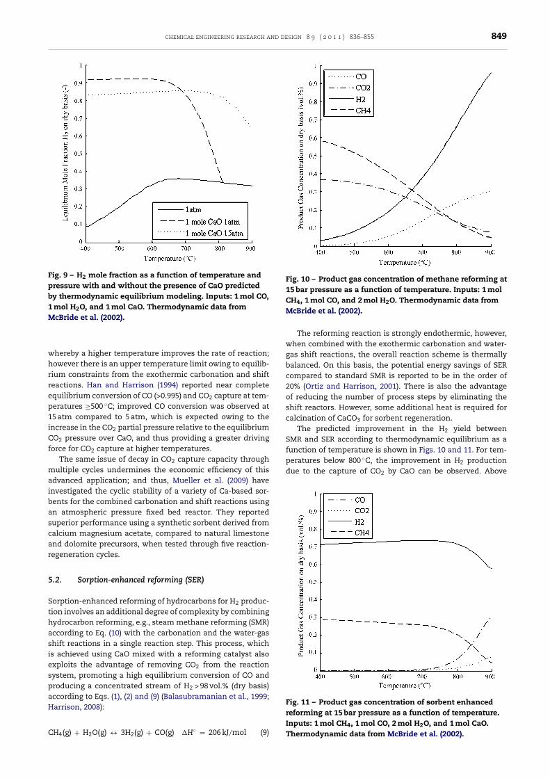
Journal Identification = CHERD Article Identification = 620 Date: May 17, 2011 Time: 5:47 am
chemical engineering research and design 8 9 ( 2 0 1 1 ) 836–855 849
Fig. 9 – H2 mole fraction as a function of temperature andpressure with and without the presence of CaO predictedby thermodynamic equilibrium modeling. Inputs: 1 mol CO,1 mol H2O, and 1 mol CaO. Thermodynamic data fromMcBride et al. (2002).
whrrep1iCf
maibascar
5
SthasiespaH
C
Fig. 10 – Product gas concentration of methane reforming at15 bar pressure as a function of temperature. Inputs: 1 molCH4, 1 mol CO, and 2 mol H2O. Thermodynamic data from
2
due to the capture of CO2 by CaO can be observed. Above
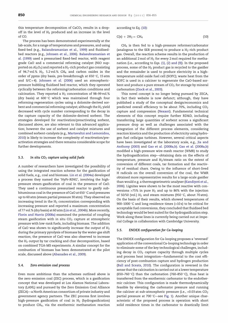
Fig. 11 – Product gas concentration of sorbent enhancedreforming at 15 bar pressure as a function of temperature.Inputs: 1 mol CH4, 1 mol CO, 2 mol H2O, and 1 mol CaO.
hereby a higher temperature improves the rate of reaction;owever there is an upper temperature limit owing to equilib-ium constraints from the exothermic carbonation and shifteactions. Han and Harrison (1994) reported near completequilibrium conversion of CO (>0.995) and CO2 capture at tem-eratures ≥500 ◦C; improved CO conversion was observed at5 atm compared to 5 atm, which is expected owing to thencrease in the CO2 partial pressure relative to the equilibriumO2 pressure over CaO, and thus providing a greater driving
orce for CO2 capture at higher temperatures.The same issue of decay in CO2 capture capacity through
ultiple cycles undermines the economic efficiency of thisdvanced application; and thus, Mueller et al. (2009) havenvestigated the cyclic stability of a variety of Ca-based sor-ents for the combined carbonation and shift reactions usingn atmospheric pressure fixed bed reactor. They reporteduperior performance using a synthetic sorbent derived fromalcium magnesium acetate, compared to natural limestonend dolomite precursors, when tested through five reaction-egeneration cycles.
.2. Sorption-enhanced reforming (SER)
orption-enhanced reforming of hydrocarbons for H2 produc-ion involves an additional degree of complexity by combiningydrocarbon reforming, e.g., steam methane reforming (SMR)ccording to Eq. (10) with the carbonation and the water-gashift reactions in a single reaction step. This process, whichs achieved using CaO mixed with a reforming catalyst alsoxploits the advantage of removing CO2 from the reactionystem, promoting a high equilibrium conversion of CO androducing a concentrated stream of H2 > 98 vol.% (dry basis)ccording to Eqs. (1), (2) and (9) (Balasubramanian et al., 1999;arrison, 2008):
H (g) + H O(g) ↔ 3H (g) + CO(g) �H◦ = 206 kJ/mol (9)
4 2 2McBride et al. (2002).
The reforming reaction is strongly endothermic, however,when combined with the exothermic carbonation and water-gas shift reactions, the overall reaction scheme is thermallybalanced. On this basis, the potential energy savings of SERcompared to standard SMR is reported to be in the order of20% (Ortiz and Harrison, 2001). There is also the advantageof reducing the number of process steps by eliminating theshift reactors. However, some additional heat is required forcalcination of CaCO3 for sorbent regeneration.
The predicted improvement in the H2 yield betweenSMR and SER according to thermodynamic equilibrium as afunction of temperature is shown in Figs. 10 and 11. For tem-peratures below 800 ◦C, the improvement in H production
Thermodynamic data from McBride et al. (2002).
Journal Identification = CHERD Article Identification = 620 Date: May 17, 2011 Time: 5:47 am
850 chemical engineering research and design 8 9 ( 2 0 1 1 ) 836–855
this temperature decomposition of CaCO3 results in a drop-off in the level of H2 produced and an increase in the levelof CO.
The process has been demonstrated experimentally at thelab-scale, for a range of temperatures and pressures, and usingfixed-bed (e.g., Balasubramanian et al., 1999) and fluidised-bed reactors (e.g., Johnsen et al., 2006). Balasubramanian etal. (1999) used a pressurised fixed-bed reactor, with reagentgrade CaO and a commercial reforming catalyst (NiO sup-ported on Al2O3) and reported a H2-rich product gas consistingof 94.7 vol.% H2, 5.2 vol.% CH4 and carbon oxides in theorder of ppms (dry basis, pre-breakthrough at 650 ◦C, 15 atmand S/C = 4). Johnsen et al. (2006) used an atmospheric-pressure bubbling fluidised bed reactor, which they operatedcyclically between the reforming/carbonation conditions andcalcination. They reported a H2 concentration of 98–99 vol.%(dry basis) at 600 ◦C which was maintained through fourreforming-regeneration cycles using a dolomite-derived sor-bent and commercial reforming catalyst; although the H2 yielddecreased with cycle number corresponding to the decay inthe capture capacity of the dolomite-derived sorbent. Thestrategies developed for reactivation/preactivating sorbent,discussed above, are also relevant to this advanced applica-tion; however the use of sorbent and catalyst mixtures andcombined sorbent-catalysts (e.g., Martavaltzi and Lemonidou,2010) is likely to increase the complexity of reactivation/pre-activation strategies and there remains considerable scope forfurther developments.
5.3. In situ CO2 capture using solid fuels
A number of researchers have investigated the possibility ofusing the integrated reaction scheme for the gasification ofsolid fuels, e.g., coal and biomass. Lin et al. (2004a) developeda process they named the ‘HyPr-RING’, involving the high-pressure steam-gasification of coal in the presence of CaO.They used a continuous pressurised reactor to gasify sub-bituminous coal in the presence of CaO at 650 ◦C and pressuresup to 60 atm (steam partial pressure 30 atm). They observed anincreasing trend in the H2 concentration corresponding withincreasing pressure and reported a maximum concentrationof 77 vol.% (dry basis) at 60 atm (Lin et al., 2004b). More recently,Florin and Harris (2008a) examined the potential of couplingsteam gasification with in situ CO2 capture at atmosphericpressure with low-rank fuels, including biomass. The additionof CaO was shown to significantly increase the output of H2
during the primary pyrolysis of biomass by the water-gas shiftreaction; the presence of CaO was also observed to increasethe H2 output by tar cracking and char decomposition, basedon combined TGA-MS experiments. A similar concept for thecombustion of biomass has been demonstrated at the pilotscale, discussed above (Abanades et al., 2009).
5.4. Zero emission coal process
Even more ambitious than the schemes outlined above isthe zero emission coal (ZEC) process, which is a gasificationconcept that was developed at Los Alamos National Labora-tory (LANL) and pursued by the Zero Emission Coal Alliance(ZECA)—a North American consortium of private industry andgovernment agency partners. The ZEC process first involves
high-pressure gasification of coal in H2 (hydrogasification)to produce CH4, via the exothermic methanation reactionaccording to Eq. (10):
C(s) + 2H2 = CH4 (10)
CH4 is then fed to a high-pressure reformer/carbonator(analogous to the SER process) to produce a H2-rich productgas. Overall, the reaction scheme results in the production ofan additional 2 mol of H2 for every 2 mol required for metha-nation (i.e., according to Eqs. (1), (2) and (9)). In the proposedprocess, some of the H2 product gas is recycled to the gasifierand the remainder is used to produce electricity in a high-temperature solid oxide fuel cell (SOFC); waste heat from theSOFC is used in a calciner to regenerate the CaO-based sor-bent and produce a pure stream of CO2 for storage by mineralcarbonation (Ziock et al., 2003).
This novel concept is no longer being pursued by ZECA,in fact their website is now defunct; although, they havepublished a study of the conceptual design/economics andpredicted overall efficiency to be about 70%, including CO2
capture and compression (Nexant). Fundamental technicalelements of this concept require further RD&D, includingtransferring large quantities of sorbent across a significantpressure drop as well as challenges associated with theintegration of the different process elements, consideringreaction kinetics and the production of electricity using hydro-gen fuel cells/gas turbines. However, several critical aspectshave been investigated at the laboratory scale, e.g., Jia andAnthony (2003) and Gao et al. (2008a,b). Gao et al. (2008a,b)modified a high-pressure wire-mesh reactor (WMR) to studythe hydrogasification step—obtaining data on the effects oftemperature, pressure and H2/steam ratio on the extent ofconversion of different coals, tar formation and the reactiv-ity of residual chars. Owing to the influence of short-livedH radicals on the overall conversion of the coal, the WMRobtained more representative results for a large-scale gasifierthan would e.g. a thermogravimetric analyser (Kandiyoti et al.,2006). Lignites were shown to be the most reactive with con-versions >75% in pure H2 and up to 86% with the injectionof 50/50 (vol.) H2 and steam mixtures (950 ◦C, about 70 atm).On the basis of their results, which showed temperatures of900–1000 ◦C and long residence times (>10 s) to be critical foracceptable fuel conversions, they concluded that fluidised bedtechnology would be best suited for the hydrogasification step.Work along these lines is currently being carried out at Impe-rial College in collaboration with Cambridge University.
5.5. ENDEX configuration for Ca-looping
The ENDEX configuration for Ca-looping proposes a ‘reversed’application of the conventional Ca-looping technology in orderto eliminate some of the key technological challenges, includ-ing decay in CO2 capture capacity through multiple cyclesand process heat integration—fundamental to the cost effi-ciency of post-combustion capture and hydrogen production(Ball and Sceats, 2010). The configuration is reversed in thesense that the calcination is carried out at a lower temperature(650–760 ◦C) than the carbonation (760–850 ◦C), thus heat istransferred from the exothermic carbonator to the endother-mic calciner. This configuration is made thermodynamicallyfeasible by elevating the carbonator pressure and runningthe calciner at sub-atmospheric pressure (i.e., <0.03 atm CO2
partial pressure at 700 ◦C—see Fig. 1). Another unique char-
acteristic of the proposed process is operation with shortsolid residence times in the carbonator to drastically limit
Journal Identification = CHERD Article Identification = 620 Date: May 17, 2011 Time: 5:47 am
chemical engineering research and design 8 9 ( 2 0 1 1 ) 836–855 851
tceiiaoetisvrsoctibttaA
6
TctpCbwbrmeocpegsc
hpte
vwepw
A
TCItt(
he extent of conversion to about 2–4% (Sceats, 2009). In theonventional process, as discussed above, maintaining a highxtent of carbonation to minimise heat input to the calciners a critical challenge. However, with the Endex configuration,t is asserted that the reduced temperature in the calcinernd the limited carbonation extent will eliminate the drop-ff in CO2 capture capacity with cycling. There is limitedxperimental data available in the literature to demonstratehese benefits: Grasa et al. (2009) reported a minor decreasen the rate of decay in CO2 capture capacity for one limestoneorbent partially carbonated (1 min vs. 5 min) through 60 con-entional Ca-looping cycles, using a TGA. The implications ofapid cycling of material on the mechanical stability of theorbent particles must also be examined. Moreover, a numberf engineering concerns remain regarding the novel processonfiguration which requires transport of sorbent particleshrough a pressure gradient, and the disadvantage of produc-ng a sub-atmospheric stream of CO2 that must be pressurisedefore transport and storage. The requirement to compresshe flue gas imposes an additional energy penalty. Some ofhese issues may be resolved with further experimental worknd experience with the planned 10 MWth demonstrator inustralia (Sceats, 2009).
. Conclusions
he Ca-looping cycle has multiple potential benefits as a CO2
apture process for both post- and pre-combustion applica-ions. It requires careful integration with the steam cycle of aower station if it is to be incorporated as a post-combustionO2 capture process inexpensively. The degradation of the sor-ent’s ability to take up CO2 is manageable, though furtherork into both maintaining the overall reactivity of the sor-ent and regenerating that reactivity, for multiple cycles ofeaction, is ongoing. Such work will lead to further improve-
ents in the efficiency of the CO2 capture process. However,ven without improvements in the reactivity, the overall costf CO2 capture is low (∼19 USD/tonne avoided), owing to theheap sorbent (essentially, crushed rock) and the low energyenalty (∼6–8%, including compression). These benefits areven more pronounced when the Ca-looping process is inte-rated into cement production, where the use of the spentorbent can result in a reduction of the energy required in theement works on the order of 50%.
Multiple demonstrations are currently being planned orave been conducted. Current projects look set to test therocess at the scale of 1–2 MWth within 3 years. Soon afterhat, projects on the order of 10 MWth are planned, with rapidxpansion to full scale thereafter.
In the future, the role of CaO looping for H2 production,ia the water-gas shift reaction may become more important,ith savings both in terms of overall energy usage and CO2
mitted to the atmosphere. The versatility of the cycle, cou-led with the cheapness of the raw materials used, point toidespread usage in the future.
cknowledgements
he authors wish to thank the EPSRC for DTA studentships forharles Dean and John Blamey, and the Grantham Institute at
mperial College for funding Dr Florin. The research leadingo these results has received funding for Dr Al-Jeboori from
he European Community’s Seventh Framework ProgrammeFP7/2007–2013) under GA 241302-Caoling project.References
Abanades, J.C., 2002. The maximum capture efficiency of CO2
using a carbonation/calcination cycle of CaO/CaCO3.Chemical Engineering Journal 90 (3), 303–306.
Abanades, J.C., 2009. Experimental investigation of a CFB reactorto capture CO2 from flue gases with CaO. In: 1st IEA GHG HighTemperature Solid Looping Cycles Network Meeting.INCAR-CSIC, Oviedo, Spain.
Abanades, J.C., Alonso, M., Rodriguez, N., Gonzalez, B., Grasa, G.,Murillo, R., 2009. Capturing CO2 from combustion flue gaseswith a carbonation calcination loop. Experimental results andprocess development. Energy Procedia 1 (1), 1147–1154.
Abanades, J.C., Alvarez, D., 2003. Conversion limits in the reactionof CO2 with lime. Energy & Fuels 17 (2), 308–315.
Abanades, J.C., Anthony, E.J., Lu, D., Salvador, C., Alvarez, D., 2004.Capture of CO2 from combustion gases in a fluidized bed ofCaO. American Institute of Chemical Engineers. AIChE Journal50 (7), 1614–1622.
Abanades, J.C., Anthony, E.J., Wang, J., Oakey, J.E., 2005. Fluidizedbed combustion systems integrating CO2 capture with CaO.Environmental Science & Technology 39 (8), 2861–2866.
Abanades, J.C., Grasa, G., Alonso, M., Rodriguez, N., Anthony, E.J.,Romeo, L.M., 2007. Cost structure of a postcombustion CO2
capture system using CaO. Environmental Science andTechnology 41 (15), 5523–5527.
Adsorption Enhanced Reforming. From http://www.aer-gas.de/(last accessed on 19/05/10).
Agnihotri, R., Mahuli, S.K., Chauk, S.S., Fan, L.S., 1999. Influenceof surface modifiers on the structure of precipitated calciumcarbonate. Industrial & Engineering Chemistry Research 38(6), 2283–2291.
Aihara, M., Nagai, T., Matsushita, J., Negishi, Y., Ohya, H., 2001.Development of porous solid reactant for thermal-energystorage and temperature upgrade usingcarbonation/decarbonation reaction. Applied Energy 69 (3),225–238.
Alonso, M., Rodriguez, N., Gonzalez, B., Grasa, G., Murillo, R.,Abanades, J.C., 2010. Carbon dioxide capture from combustionflue gases with a calcium oxide chemical loop. Experimentalresults and process development. International Journal ofGreenhouse Gas Control 4 (2), 167–173.
Alsop, P.A., Chen, H., Tseng, H., 2007. The Cement PlantOperations Handbook, fifth edition. Tradeship Publications,Surrey, UK (Chapter 17).
Alvarez, D., 2007. Behavior of different calcium-based sorbents ina calcination/carbonation cycle for CO2 capture. Energy &Fuels 21 (3), 1534–1542.
Alvarez, D., Abanades, J.C., 2005. Determination of the criticalproduct layer thickness in the reaction of CaO with CO2.Industrial and Engineering Chemistry Research 44,5608–5615.
Anthony, E.J., 2008. Solid looping cycles: a new technology forcoal conversion. Industrial & Engineering Chemistry Research47 (6), 1747–1754.
Anthony, E.J., Bulewicz, E.M., Jia, L., 2007. Reactivation oflimestone sorbents in FBC for SO2 capture. Progress in Energyand Combustion Science 33 (2), 171–210.
Anthony, E.J., Granatstein, D.L., 2001. Sulfation phenomena influidized bed combustion systems. Progress in Energy andCombustion Science 27 (2), 215–236.
Balasubramanian, B.A., Ortiz, A.L., Kaytakoglu, S., Harrison, D.P.,1999. Hydrogen from methane in a single-step process.Chemical Engineering Science 54 (15–16), 3543–3552.
Ball, R., Gray, B.F., 1999. Thermal stabilization of chemicalreactors. II. Bifurcation analysis of the Endex CSTR.Proceedings of the Royal Society of London. Series A:Mathematical, Physical and Engineering Sciences 455 (1992),4223–4243.
Ball, R., Sceats, M.G., 2010. Separation of carbon dioxide from fluegas emissions using Endex principles. Fuel 89 (10), 2750–2759.
Journal Identification = CHERD Article Identification = 620 Date: May 17, 2011 Time: 5:47 am
852 chemical engineering research and design 8 9 ( 2 0 1 1 ) 836–855
Barker, R., 1973. Reversibility of the reaction CaCO3 = CaO + CO2.Journal of Applied Chemistry and Biotechnology 23 (10),733–742.
Barker, D.J., Turner, S.A., Napier-Moore, P.A., Clark, M., Davison,J.E., 2009. CO2 capture in the cement industry. GHTGT-9.Energy Procedia 1 (2009), 87–94.
Basu, P., 2006. Combustion and Gasification in Fluidized Beds.CRC Press, Boca Raton, FL, USA (Chapter 3).
Bhatia, S.K., Perlmutter, D.D., 1983. Effect of the product layer onthe kinetics of the CO2–lime reaction. AIChE Journal 29 (1),79–86.
Bhatty, J.I., 1995. Role of Minor Elements in Cement Manufactureand Use, Research and Development Bulletin (RD109T).Portland Cement Association, Skokie, IL, USA.
Bhatty, J.I., 2003. Effect of minor elements on clinker and cementmanufacture: a laboratory analysis. Portland CementAssociation Internal Report, Serial No. 2147, IL, USA.
Bhatty, J.I., Miller, F.M., Kosmatka, S.H., 2004. Innovations inPortland Cement Manufacturing. Portland CementAssociation, IL, USA.
Blamey, J., Anthony, E.J., Wang, J., Fennell, P.S., 2010. The calciumlooping cycle for large-scale CO2 capture. Progress in Energyand Combustion Science 36 (2), 260–279.
Borgwardt, R.H., 1989a. Sintering of nascent calcium oxide.Chemical Engineering Science 44 (1), 53–60.
Borgwardt, R.H., 1989b. Calcium oxide sintering in atmospherescontaining water and carbon dioxide. Industrial &Engineering Chemistry Research 28 (4), 493–500.
CEMBUREAU, 1999. CEMBUREAU Best Available Techniques forthe Cement Industry.
Charitos, A., Hawthorne, C., Bidwe, A.R., He, L., Scheffknecht, G.,2008. Design of a dual fluidised bed system for thepost-combustion removal of CO2 using CaO. Part II. Scaledcold model investigation. In: 9th International Conference onCirculating Fluidized Beds, Hamburg, Germany.
Charitos, A., Hawthorne, C., Bidwe, A.R., Korovesis, L., Schuster,A., Scheffknecht, G., 2010a. Hydrodynamic analysis of a10 kWth calcium looping dual fluidized bed forpost-combustion CO2 capture. Powder Technology 200 (3),117–127.
Charitos, A., Hawthorne, C., Bidwe, A.R., Sivalingam, S., Schuster,A., 2010b. Parametric investigation of the calcium loopingprocess for CO2 capture in a 10 kWth dual fluidized bed.International Journal of Greenhouse Gas Control 4 (5),776–784.
Chen, Z.X., Grace, J.R., Lim, C.J., 2008. Limestone particle attritionand size distribution in a small circulating fluidized bed. Fuel87 (7), 1360–1371.
Chen, Z.X., Song, H.S., Portillo, M., Lim, J.C., Grace, J.R., Anthony,E.J., 2009. Long-term calcination/carbonation cycling andthermal pretreatment for CO2 capture by limestone anddolomite. Energy and Fuels 23, 1437–1444.
Corella, J., Toledo, J.M., Molina, G., 2006. Steam gasification of coalat low-medium (600–800 degrees C) temperature withsimultaneous CO2 capture in fluidized bed at atmosphericpressure: the effect of inorganic species. 1. Literature reviewand comments. Industrial & Engineering Chemistry Research45 (18), 6137–6146.
Cuenca, M.A., Anthony, E.J., 1995. Pressurized Fluidized Beds.Blackie Academic & Professional.
Curran, G.P., Fink, C.E., Gorin, E., 1967. Carbon dioxide-acceptor[coal] gasification process. Studies of acceptor properties.Advances in Chemistry Series 69, 141.
David, J., Herzog, H., 2000. The cost of carbon capture. In:Presented at the MIT Carbon Sequestration Forum,Cambridge, MA, October 31–November 1, p. 2000.
Deutsch, Y., Heller-Kallai, L., 1991. Decarbonation andrecarbonation of calcites heated m CO2. Part 1. Effect of thethermal regime. Thermochimica Acta 182 (1), 77–89.
Dobner, S., Sterns, L., Graff, R.A., Squires, A.M., 1977. Cycliccalcination and re-carbonation of calcined dolomite.
Industrial & Engineering Chemistry Process Design andDevelopment 16 (4), 479–486.
Drax Power Station, 2008. Environmental Performance Review.Drax Power Ltd.
ECRA, 2007. Carbon capture technology—options and potentialsfor the cement industry. Technical Report TR 044/2007.
Epple, B., 2009. Steam generation and power plants. Bwk 61 (4),156–168.
European Commission, 2010a. Community Research andDevelopment Information Service (CORDIS), 6th FrameworkProgramme (FP6). From http://cordis.europa.eu/fetch?CALLER=FP6 PROJ&ACTION=D&DOC=1&CAT=PROJ&QUERY=1202995103012&RCN=75092 (last accessed on19/05/10).
European Commission, 2010b. Community Research andDevelopment Information Service (CORDIS), 7th FrameworkProgramme (FP7). From http://cordis.europa.eu/fetch?CALLER=FP7 PROJ EN&ACTION=D&DOC=35&CAT=PROJ&QUERY=01280242e800:de09:7985c889&RCN=93423 (lastaccessed on 19/05/10).
EU, Commission of the European Union, 2001. IntegratedPollution Prevention and Control: Reference Document onBest Available Techniques in the Cement and LimeManufacturing Industries.
Ewing, J., Beruto, D., Searcy, A.W., 1979. Nature of CaO producedby calcite powder decompostion in vacuum and in CO2.Journal of the American Ceramic Society 62 (11–1), 580–584.
Fennell, P.S., Pacciani, R., Dennis, J.S., Davidson, J.F., Hayhurst,A.N., 2007a. The effects of repeated cycles of calcination andcarbonation on a variety of different limestones, as measuredin a hot fluidized bed of sand. Energy & Fuels 21 (4), 2072–2081.
Fennell, P.S., Davidson, J.F., Dennis, J.S., Hayhurst, A.N., 2007b.Regeneration of sintered limestone sorbents for thesequestration of CO2 from combustion and other systems.Journal of the Energy Institute 80 (2), 116–119.
Fink, C.E., Sudbury, J.D., Curran, G.P., 1974. CO2 acceptorgasification process. In: Symposium on Coal Gasification andLiquefaction. University of Pittsburgh, School of Engineering.
Florin, N.H., Harris, A.T., 2008a. Enhanced hydrogen productionfrom biomass with in situ carbon dioxide capture usingcalcium oxide sorbents. Chemical Engineering Science 63 (2),287–316.
Florin, N.H., Harris, A.T., 2008b. Screening CaO-based sorbents forCO2 capture in biomass gasifiers. Energy & Fuels 22 (4),2734–2742.
Florin, N.H., Harris, A.T., 2008c. Preparation and characterizationof a tailored carbon dioxide sorbent for enhanced hydrogensynthesis in biomass gasifiers. Industrial & EngineeringChemistry Research 47 (7), 2191–2202.
Franzese, P.P., Rydberg, T., Russo, G.F., Ulgiati, S., 2009. Sustainablebiomass production: a comparison between Gross EnergyRequirement and Emergy Synthesis methods. EcologicalIndicators 9 (5), 959–970.
Gao, L., Paterson, N., Dugwell, D., Kandiyoti, R., 2008a.Zero-emission carbon concept (ZECA): equipmentcommissioning and extents of the reaction with hydrogenand steam. Energy & Fuels 22 (1), 463–470.
Gao, L., Paterson, N., Dugwell, D., Kandiyoti, R., 2008b. The zeroemission carbon concept (ZECA): extents of reaction withdifferent coals in steam/hydrogen, tar formation and residualchar reactivity. Energy & Fuels 22 (4), 2504–2511.
Gluud, W., Keller, K., 1931. Production of hydrogen. US Patent1,816,523.
Gonzalez, B., Alonso, M., Abanades, J.C., 2010. Sorbent attrition ina carbonation/calcination pilot plant for capturing CO2 fromflue gases. Fuel 89 (10), 2918–2924.
Gonzalez, B., Grasa, G.S., Alonso, M., Abanades, J.C., 2008.Modeling of the deactivation of CaO in a carbonate loop athigh temperatures of calcination. Industrial & EngineeringChemistry Research 47 (23), 9256–9262.
Grace, J.R., Avidan, A., Knowlton, T.M., 1997. Circulating Fluidized
Beds. Blackie Academic & Professional, London, UK(Chapter 1).
Journal Identification = CHERD Article Identification = 620 Date: May 17, 2011 Time: 5:47 am
chemical engineering research and design 8 9 ( 2 0 1 1 ) 836–855 853
G
G
G
G
H
H
H
H
H
H
H
H
H
I
I
J
J
J
J
rasa, G.S., Abanades, J.C., 2006. CO2 capture capacity of CaO inlong series of carbonation/calcination cycles. Industrial &Engineering Chemistry Research 45 (26), 8846–8851.
rasa, G.S., Abanades, J.C., Alonso, M., Gonzalez, B., 2007.Reactivity of highly cycled particles of CaO in acarbonation/calcination loop. Chemical Engineering Journal137 (3), 561–567.
rasa, G.S., Abanades, J.C., Anthony, E.J., 2009. Effect of partialcarbonation on the cyclic CaO carbonation reaction. Industrial& Engineering Chemistry Research 48 (20), 9090–9096.
upta, H., Iyer, M.V., Sakadjian, B.B., Fan, L.S., 2004. Reactiveseparation of CO2 using pressure pelletised limestone.International Journal of Environmental Technology andManagement 4 (1), 3.
an, C., Harrison, D.P., 1994. Simultaneous shift reaction andcarbon dioxide separation for the direct production ofhydrogen. Chemical Engineering Science 49 (24, Part 2),5875–5883.
arrison, D.P., 2008. Sorption-enhanced hydrogen production: areview. Industrial & Engineering Chemistry Research 47 (17),6486–6501.
awthorne, C., Charitos, A., Perez-Pulido, C.A., Bing, Z.,Scheffknecht, G., 2008. Design of a dual fluidised bed systemfor the post-combustion removal of CO2 using CaO. Part I. CFBcarbonator reactor model. In: 9th International Conference onCirculating Fluidized Beds, Hamburg, Germany.
awthorne, C., Dieter, H., Bidwe, A., Schuster, A., Scheffknecht,G., Unterberger, S., KaB, M., in press. CO2 Capture with CaO ina 200 kWth Dual Fluidised Bed Pilot Plant. Energy Procedia.
ayhurst, A.N., Tucker, R.F., 1991. The reductive regeneration ofsulphated limestone for flue-gasdesulphurization—thermodynamic considerations ofconverting calcium-sulphate to calcium-oxide. Journal of theInstitute of Energy 64 (461), 212–229.
erzog, H., 1998. The economics of CO2 capture. In: Presented atthe 4th International Conference on Greenhouse Gas ControlTechnologies, Interlaken, Switzerland, August 30–September2.
ughes, R.W., Lu, D.Y., Anthony, E.J., Wu, Y.H., 2004. Improvedlong-term conversion of limestone-derived sorbents forin situ capture of CO2 in a fluidized bed combustor. Industrial& Engineering Chemistry Research 43 (18), 5529–5539.
ughes, R.W., Lu, D.Y., Anthony, E.J., Macchi, A., 2005. Design,process simulation and construction of an atmospheric dualfluidized bed combustion system for in situ CO2 capture usinghigh-temperature sorbents. Fuel Processing Technology 86(14–15), 1523–1531.
ughes, R.W., Macchi, A., Lu, D.Y., Anthony, E.J., 2009. Changes inlimestone sorbent morphology during CaO–CaCO3 looping atpilot scale. Chemical Engineering & Technology 32 (3),425–434.
EA, 2010. IEA High Temperature Looping Cycles Website. Fromhttp://www.co2captureandstorage.info/networks/looping.htm(last accessed on 19/05/10).
ves, M., Mundy, R.C., Fennell, P.S., Davidson, J.F., Dennis, J.S.,Hayhurst, A.N., 2008. Comparison of different natural sorbentsfor removing CO2 from combustion gases, as studied in abench-scale fluidized bed. Energy & Fuels 22 (6), 3852–3857.
ia, L., Anthony, E.J., 2003. Mineral carbonation and ZECA. In:Greenhouse Gas Control Technologies, vols. I and II,Proceedings, pp. 671–676.
ia, L., Hughes, R., Lu, D., Anthony, E.J., Lau, I., 2007. Attrition ofcalcining limestones in circulating fluidized-bed systems.Industrial & Engineering Chemistry Research 46 (15),5199–5209.
ohnsen, K., Ryu, H.J., Grace, J.R., Lim, C.J., 2006.Sorption-enhanced steam reforming of methane in a fluidizedbed reactor with dolomite as CO2-acceptor. ChemicalEngineering Science 61 (4), 1195–1202.
outsenoja, T., Heino, P., Hernberg, R., Bonn, B., 1999. Pyrometrictemperature and size measurements of burning coal particles
in a fluidized bed combustion reactor. Combustion and Flame118 (4), 707–717.Kandiyoti, R., Herod, A.A., Bartle, K.D., 2006. Solid Fuels andHeavy Hydrocarbon Liquids: Thermal Characterisation andAnalysis. Elsevier, Oxford, UK (Chapter 3).
Koppatz, S., Pfeifer, C., Rauch, R., Hofbauer, H.,Marquard-Moellenstedt, T., Specht, M., 2009. H-2 rich productgas by steam gasification of biomass with in situ CO2
absorption in a dual fluidized bed system of 8 MW fuel input.Fuel Processing Technology 90 (7–8), 914–921.
Kuramoto, K., Ahibano, S., Fujimoto, S., Kimura, T., Suzuki, Y.,Hatano, H., Lin, S.Y., Harada, M., Morishita, K., Takarada, T.,2003. Deactivation of Ca-based sorbents by coal-derivedminerals during multicycle CO2 sorption under elevatedpressure and temperature. Industrial & EngineeringChemistry Research 42 (15), 3566–3570.
Laursen, K., Duo, W., Grace, J.R., Lim, J., 2000. Sulfation andreactivation characteristics of nine limestones. Fuel 79 (2),153–163.
Li, Z.S., Cai, N.S., Huang, Y.Y., Han, H.J., 2005. Synthesis,experimental studies, and analysis of a new calcium-basedcarbon dioxide absorbent. Energy & Fuels 19 (4), 1447–1452.
Li, Z.S., Cai, N.S., Huang, Y.Y., 2006. Effect of preparationtemperature on cyclic CO2 capture and multiplecarbonation-calcination cycles for a new Ca-based CO2
sorbent. Industrial & Engineering Chemistry Research 45 (6),1911–1917.
Li, F.X., Fan, L.S., 2008. Clean coal conversion processes—progressand challenges. Energy & Environmental Science 1, 248–267.
Li, Y.J., Zhao, C.S., Chen, H.C., Duan, L.B., Chen, X.P., 2009. CO2
capture behavior of shell during calcination/carbonationcycles. Chemical Engineering & Technology 32 (8), 1176–1182.
Lin, S., Harada, M., Suzuki, Y., Hatano, H., 2004a. Developing aninnovative method, HyPr-RING, to produce hydrogen fromhydrocarbons. Energy Conversion and Management 43 (9–12),1283–1290.
Lin, S., Suzuki, Y., Hatano, H., Harada, M., 2004b. Continuousexperiment regarding hydrogen production by coal/CaOreaction with steam (I) gas products. Fuel 83 (7–8), 869–874.
Lisbona, P., Martinez, A., Lara, Y., Romeo, L.M., 2010. Integrationof carbonate CO2 capture cycle and coal-fired power plants. Acomparative study for different sorbents. Energy & Fuels 24,728–736.
Liu, W.Q., Low, N.W.L., Feng, B., Wang, G.X., da Costa, J.C.D., 2010a.Calcium precursors for the production of CaO sorbents formulticycle CO2 capture. Environmental Science & Technology44 (2), 841–847.
Liu, W.Q., Feng, B., Wu, Y.Q., Wang, G.X., Barry, J., da Costa, J.C.D.,2010b. Synthesis of sintering-resistant sorbents for CO2
capture. Environmental Science & Technology 44 (8),3093–3097.
Lu, H., Reddy, E.P., Smirniotis, P.G., 2006. Calcium oxide basedsorbents for capture of carbon dioxide at high temperatures.Industrial & Engineering Chemistry Research 45 (11),3944–3949.
Lu, H., Khan, A., Smirniotis, P.G., 2008. Relationship betweenstructural properties and CO2 capture performance ofCaO-based sorbents obtained from different organometallicprecursors. Industrial & Engineering Chemistry Research 47(16), 6216–6220.
Lu, D.Y., Hughes, R.W., Anthony, E.J., 2008. Ca-based sorbentlooping combustion for CO2 capture in pilot-scale dualfluidized beds. Fuel Processing Technology 89 (12), 1386–1395.
Lu, D.Y., Hughes, R.W., Anthony, E.J., Manovic, V., 2009. Sinteringand reactivity of CaCO3-based sorbents for in situ CO2 capturein fluidized beds under realistic calcination conditions.Journal of Environmental Engineering-ASCE 135 (6), 404–410.
Lyngfelt, A., Leckner, B., 1989. Sulphur capture in fluidized-bedboilers—the effect of reductive decompostion of CaSO4.Chemical Engineering Journal and the BiochemicalEngineering Journal 40 (2), 59–69.
Lysikov, A.I., Salanov, A.N., Okunev, A.G., 2007. Change of CO2
carrying capacity of CaO in isothermal
recarbonation–decomposition cycles. Industrial & EngineeringChemistry Research 46 (13), 4633–4638.
Journal Identification = CHERD Article Identification = 620 Date: May 17, 2011 Time: 5:47 am
854 chemical engineering research and design 8 9 ( 2 0 1 1 ) 836–855
MacKenzie, A., Granatstein, D.L., Anthony, E.J., Abanades, J.C.,2007. Economics of CO2 capture using the calcium cycle witha pressurized fluidized bed combustor. Energy & Fuels 21,920–926.
Manovic, V., Anthony, E.J., 2007. Steam reactivation of spentCaO-based sorbent for multiple CO2 capture cycles.Environmental Science & Technology 41 (4), 1420–1425.
Manovic, V., Lu, D., Anthony, E.J., 2008. Steam hydration ofsorbents from a dual fluidized bed CO2 looping cycle reactor.Fuel 87 (15–16), 3344–3352.
Manovic, V., Anthony, E.J., 2008a. Thermal activation ofCaO-based sorbent and self-reactivation during CO2 capturelooping cycles. Environmental Science & Technology 42 (11),4170–4174.
Manovic, V., Anthony, E.J., 2008b. CO2 looping cycle performanceof a high-purity limestone after thermal activation/doping.Energy & Fuels 22 (5), 3258–3264.
Manovic, V., Anthony, E.J., 2008c. Parametric study on the CO2
capture capacity of CaO-based sorbents in looping cycles.Energy and Fuels 22, 1851–1857.
Manovic, V., Anthony, E.J., 2009a. Long-term behavior ofCaO-based pellets supported by calcium aluminate cementsin a long series of CO2 capture cycles. Industrial & EngineeringChemistry Research 48 (19), 8906–8912.
Manovic, V., Anthony, E.J., 2009b. Screening of binders forpelletization of CaO-based sorbents for CO2 capture. Energy &Fuels 23, 4797–4804.
Manovic, V., Anthony, E.J., 2010. CO2 Carrying Behaviour ofCalcium Aluminate Pellets under High-Temperature/High-CO2 Concentration Calcination Conditions. Industrialand Engineering Chemistry Research 49 (15), 6916–6922.
Manovic, V., Charland, J.P., Blamey, J., Fennell, P.S., Lu, D.Y.,Anthony, E.J., 2009. Influence of calcination conditions oncarrying capacity of CaO-based sorbent in CO2 looping cycles.Fuel 88 (10), 1893–1900.
Martavaltzi, C.S., Lemonidou, A.A., 2010. Hydrogen productionvia sorption enhanced reforming of methane: Development ofa novel hybrid material—reforming catalyst and CO2 sorbent.Chemical Engineering Science 24, 2589–2595.
McBride, B.J., Zehe, M.J., Gordon, S., 2002. NASA GlennCoefficients for Calculating Thermodynamic Properties ofIndividual Species. National Aeronautics and SpaceAdministration, Clevelan, OH, USA.
Mess, D., Sarofim, A.F., Longwell, J.P., 1999. Product layer diffusionduring the reaction of calcium oxide with carbon dioxide.Energy & Fuels 13 (5), 999–1005.
Metz, B., Davidson, O., de Coninck, H., Loos, M., Meyer, L. (Eds.),2005. Special Report on Carbon Dioxide Capture and Storage,Intergovernmental Panel on Climate Change. CambridgeUniversity Press, Cambridge, UK.
Mueller, C.R., Pacciani, R., Bohn, C.D., Scott, S.A., Dennis, J.S.,2009. Investigation of the enhanced water gas shift reactionusing natural and synthetic sorbents for the capture of CO2.Industrial & Engineering Chemistry Research 48 (23),10284–10291.
Nexant, I. Zero Emission Coal Alliance Project Conceptual Designand Economics. From http://www.nexant.com/docs/service/energy technology/zeca.pdf (last accessed on05/05/10).
Ortiz, A.L., Harrison, D.P., 2001. Hydrogen production usingsorption-enhanced reaction. Industrial & EngineeringChemistry Research 40 (23), 5102–5109.
Pacciani, R., Mueller, C.R., Davidson, J.F., Dennis, J.S., Hayhurst,A.N., 2008a. Synthetic Ca-based solid sorbents suitable forcapturing CO2 in a fluidized bed. The Canadian Journal ofChemical Engineering 86 (3), 356–366.
Pacciani, R., Mueller, C.R., Davidson, J.F., Dennis, J.S., Hayhurst,A.N., 2008b. How does the concentration of CO2 affect itsuptake by a synthetic Ca-based solid sorbent? AIChE Journal54 (12), 3308–3311.
Perry, R.H., Green, D.W., 1997. Perry’s Chemical Engineers’
Handbook, seventh edition. McGraw-Hill, New York, USA.Pfeifer, C., Puchner, B., Hofbauer, H., 2007. In-situ CO2-absorptionin a dual fluidized bed biomass steam gasifier to produce ahydrogen rich syngas. International Journal of ChemicalReactor Engineering 5, 15.
Pfeifer, C., Puchner, B., Hofbauer, H., 2009. Comparison of dualfluidized bed steam gasification of biomass with and withoutselective transport of CO2. Chemical Engineering Science 64(23), 5073–5083.
Proell, T., Hofbauer, H., 2008. H2 rich syngas by selective CO2
removal from biomass gasification in a dual fluidized bedsystem—process modelling approach. Fuel ProcessingTechnology 89 (11), 1207–1217.
Rao, A.B., Rubin, E.S., 2002. A technical, economic, andenvironmental assessment of amine-based CO2 capturetechnology for power plant greenhouse gas control.Environmental Science and Technology 36 (20), 4467–4475.
Ray, B.M., Luning, P.E., Hoffmann, A.C., 1997. Post cyclone (PoC):an innovative way to reduce the emission of fines fromindustrial cyclones. Industrial and Engineering ChemistryResearch 36 (7), 2766–2774.
Rodriguez, N., Alonso, M., Grasa, G., Abanades, J.C., 2008a. Heatrequirements in a calciner of CaCO3 integrated in a CO2
capture system using CaO. The Chemical Engineering Journaland The Biochemical Engineering Journal 138 (1–3), 148–154.
Rodriguez, N., Alonso, M., Grasa, G., Abanades, J.C., 2008b. Processfor capturing CO2 arising from the calcination of the CaCO3
used in cement manufacture. Environmental Science &Technology 42 (18), 6980–6984.
Rodriguez, N., Alonso, M., Abanades, J.C., 2010. Average activity ofCaO particles in a calcium looping system. ChemicalEngineering Journal 156 (2), 388–394.
Romeo, L.M., Abanades, J.C., Escosa, J.M., Pano, J., Giminez, A.,Sanchez-Biezma, A., Ballesteros, J.C., et al., 2008. Oxyfuelcarbonation/calcination cycle for low cost CO2 capture inexisting power plants. Energy Conversion and Management 49(10), 2809–2814.
Romeo, L.M., Lara, Y., Lisbona, P., Martínez, A., 2009a. Economicalassessment of competitive enhanced limestones for CO2
capture cycles in power plants. Fuel Processing Technology 90(6), 803–811.
Romeo, L.M., Lara, Y., Lisbona, P., Escosa, J.M., 2009b. Optimizingmake-up flow in a CO2 capture system using CaO. ChemicalEngineering Journal 147 (2–3), 252–258.
Ryu, H., Grace, J.R., Lim, C.J., 2006. Simultaneous CO2/SO2 capturecharacteristics of three limestones in a fluidized-bed reactor.Energy & Fuels 20 (4), 1621–1628.
Saastamoinen, J., Pikkarainen, T., Tourunen, A., Rasanen, M.,Jantti, T., 2008. Model of fragmentation of limestone particlesduring thermal shock and calcination in fluidised beds.Powder Technology 187 (3), 244–251.
Sakadjian, B.B., Iyer, M.V., Gupta, H., Fan, L.S., 2007. Kinetics andstructural characterization of calcium-based sorbentscalcined under subatmospheric conditions for thehigh-temperature CO2 capture process. Industrial &Engineering Chemistry Research 46 (1), 35–42.
Salvador, C., Lu, D., Anthony, E.J., Abanades, J.C., 2003.Enhancement of CaO for CO2 capture in an FBC environment.Chemical Engineering Journal 96 (1–3), 187–195.
Scala, F., Chirone, R., Salatino, P., 2003. The influence of fine charparticles burnout on bed agglomeration during the fluidizedbed combustion of a biomass fuel. Fuel Processing Technology84 (1–3), 229–241.
Scala, F., Montagnaro, F., Salatino, P., 2008. Sulphation oflimestones in a fluidized bed combustor: the relationshipbetween particle attrition and microstructure. CanadianJournal of Chemical Engineering 86 (3), 347–355.
Sceats, M.G., September 2009. The Endex Configuration for CaOLooping Reactors. IEA, Oviedo.
Schueppel, B., 2009. Attrition test for calcium-based sorbentmaterials. In: 1st IEA GHG Solid Looping Cycles Network
Meeting. INCAR-CSIC, Oviedo, Spain.
Journal Identification = CHERD Article Identification = 620 Date: May 17, 2011 Time: 5:47 am
chemical engineering research and design 8 9 ( 2 0 1 1 ) 836–855 855
S
S
S
S
S
S
S
S
S
S
S
S
SLooping Cycles Network Meeting. INCAR-CSIC, Oviedo,Spain.
himizu, T., Hirama, T., Hosoda, H., Kitano, K., Inagaki, M.,Tejima, K., 1999. A twin fluid-bed reactor for removal of CO2
from combustion processes. Chemical Engineering Research& Design 77 (A1), 62–68.
ilaban, A., Harrison, D.P., 1995. High temperature capture ofcarbon dioxide: characteristics of the reversible reactionbetween CaO(s) and CO2(g). Chemical EngineeringCommunications 137, 177–190.
ilaban, A., Narcida, M., Harrison, D.P., 1996. Characteristics ofthe reversible reaction between CO2(g) and calcined dolomite.Chemical Engineering Communications 146, 149–162.
mith, I.M., 2007. Properties and Behaviour of SO2 Adsorbents forCFBC. IEA Clean Coal Centre, London.
oukup, G., Pfeifer, C., Kreuzeder, A., Hofbauer, H., 2009. In situCO2 capture in a dual fluidized bed biomass steamgasifier—red material and fuel variation. ChemicalEngineering & Technology 32 (3), 348–354.
tanmore, B.R., Gilot, P., 2005. Review—calcination andcarbonation of limestone during thermal cycling for CO2
sequestration. Fuel Processing Technology 86 (16), 1707–1743.teeneveldt, R., Berger, B., Torp, T.A., 2006. CO2 capture and
storage—closing the knowing-doing gap. ChemicalEngineering Research and Design 84 (A9), 739–763.
trohle, J., Galloy, A., Epple, B., 2009a. Feasibility study on thecarbonate looping process for post-combustion CO2 capturefrom coal-fired power plants. In: Gale, J., Herzog, H., Braitsch,J. (Eds.), Greenhouse Gas Control Technologies 9, vol. 1.Elsevier Science B.V., Amsterdam, pp. 1313–1320.
trohle, J., Lasheras, A., Galloy, A., Epple, B., 2009b. Simulation ofthe carbonate looping process for post-combustion CO2
capture from a coal-fired power plant. Chemical Engineering& Technology 32 (3), 435–442.
ultan, D.S., Mueller, C.R., Dennis, J.S., 2010. Capture of CO2 usingsorbents of calcium magnesium acetate (CMA). Energy andFuels 24, 3687–3697.
un, P., Grace, J.R., Lim, C.J., Anthony, E.J., 2007. Removal of CO2 bycalcium-based sorbents in the presence of SO2. Energy &Fuels 21 (1), 163–170.
un, P., Grace, J.R., Lim, C.J., Anthony, E.J., 2008. Investigation ofattempts to improve cyclic CO2 capture by sorbent hydrationand modification. Industrial & Engineering ChemistryResearch 47 (6), 2024–2032.
ymonds, R.T., Lu, D.Y., Macchi, A., Hughes, R.W., Anthony, E.J.,2009a. CO2 capture from syngas via cycliccarbonation/calcination for a naturally occurring limestone:
modelling and bench-scale testing. Chemical EngineeringScience 64 (15), 3536–3543.Symonds, R.T., Lu, D.Y., Hughes, R.W., Anthony, E.J., Macchi, A.,2009b. CO2 capture from simulated syngas via cycliccarbonation/calcination for a naturally occurring limestone:pilot-plant testing. Industrial & Engineering ChemistryResearch 48 (18), 8431–8440.
Wang, J.S., Anthony, E.J., 2005. On the decay behavior of the CO2
absorption capacity of CaO-based sorbents. Industrial &Engineering ChemistryResearch 44 (3), 627–629.
Wang, J.S., Anthony, E.J., 2007. A common decay behavior in cyclicprocesses. Chemical Engineering Communications 194(10–12), 1409–1420.
Wang, Y., Lin, S., Suzuki, Y., 2008. Limestone calcination with CO2
capture (II): decomposition in CO2/steam and CO2/N2
atmospheres. Energy & Fuels 22 (4), 2326–2331.Wang, Y., Lin, S., Suzuki, Y., 2009. Limestone calcination with CO2
capture (III): characteristics of coal combustion duringlimestone decomposition. Energy & Fuels 23, 2804–2809.
Wang, W., Ramkumar, S., Li, S., Wong, D., Iyer, M., Sakadjian, B.B.,Statnick, R.M., Fan, L.S., 2010. Subpilot demonstration of thecarbonation–calcination reaction (CCR) process:High-temperature CO2 and sulfur capture from coal-firedpower plants. Industrial & Engineering Chemistry Research 49(11), 5094–5101.
Wu, Y., Blamey, J., Anthony, E.J., Fennell, P.S., 2010. MorphologicalChanges of Limestone Sorbent Particles DuringCarbonation/Calcination Looping Cycles in aThermogravimetric Analyzer (TGA) and Reactivation withSteam. Energy & Fuels 24, 2768–2776.
Xu, G., Jin, H.G., Yang, Y.P., Xu, Y.J., Lin, H., Duan, L.Q., 2010. Acomprehensive techno-economic analysis method for powergeneration systems with CO2 capture. International Journeyof Energy Research 34 (4), 321–332.
Zeman, F., 2008. Effect of steam hydration on performance oflime sorbent for CO2 capture. International Journal ofGreenhouse Gas Control 2 (2), 203–209.
Ziock, H.J., Anthony, E.J., Brosha, E.L., Garzon, F.H., Guthrie, G.D.,Johnson, A.A., Kramer, A., Lackner, K.S., Lau, F., Mukundan, R.,Nawaz, M., Robison, T.W., Roop, B., Ruby, J., Smith, B.F., Wang,J., 2003. Technical Progress in the Development of ZeroEmission Coal Technologies.
Zuberbuehler, U., 2009. Need for standardisation of test methodsfor sorbent/material characterisation. In: 1st IEA GHG Solid