Communicating Coastal and Marine Biodiversity Conservation ...
Upload
independentCategory
view
0download
0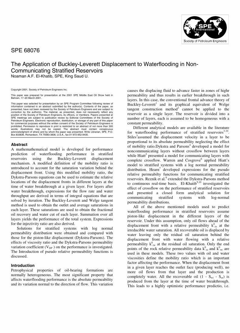
Copyright 2001, Society of Petroleum Engineers Inc.
This paper was prepared for presentation at the 2001 SPE Middle East Oil Show held inBahrain, 17–20 March 2001.
This paper was selected for presentation by an SPE Program Committee following review ofinformation contained in an abstract submitted by the author(s). Contents of the paper, aspresented, have not been reviewed by the Society of Petroleum Engineers and are subject tocorrection by the author(s). The material, as presented, does not necessarily reflect anyposition of the Society of Petroleum Engineers, its officers, or members. Papers presented atSPE meetings are subject to publication review by Editorial Committees of the Society ofPetroleum Engineers. Electronic reproduction, distribution, or storage of any part of this paperfor commercial purposes without the written consent of the Society of Petroleum Engineers isprohibited. Permission to reproduce in print is restricted to an abstract of not more than 300words; illustrations may not be copied. The abstract must contain conspicuousacknowledgment of where and by whom the paper was presented. Write Librarian, SPE, P.O.Box 833836, Richardson, TX 75083-3836, U.S.A., fax 01-972-952-9435.
AbstractA mathemathematical model is developed for performanceprediction of waterflooding performance in stratifiedreservoirs using the Buckley-Leverett displacementmechanism. A modified definition of the mobility ratio isuntroduced to account for the saturation variation behind thedisplacement front. Using this modified mobility ratio, theDykstra-Parsons equations can be used to estimate the relativelocations of the displacement fronts in different layers at thetime of water breakthrough at a given layer. For layers afterwater breakthrough, expressions for the flow rate and waterthroughput are derived in terms of integral equations that aresolved by iteration. The Buckley-Leverett and Welge tangentmethod is used to obtain the outlet and average saturations ineach layer. These saturations are used to obtain the fractionaloil recovery and water cut of each layer. Summation over alllayers yields the performance of the total system. Expressionsfor the injectivity ratio are also derived.
Solutions for stratified systems with log normalpermeability distribution were obtained and compared withthose for the piston-like displacement (Dykstra-Parsons). Theeffects of viscosity ratio and the Dykstra-Parsons permeabilityvariation coefficient (VDP ) on the performance is investigated.The Introduction of pseudo relative permeability functions isdiscussed.
IntroductionPetrophysical properties of oil-bearing formations arenormally heterogeneous. The most significant property thataffects waterflooding performance is the absolute permeabilityand its variation normal to the direction of flow. This variation
causes the displacing fluid to advance faster in zones of highrpermeability and thus results in earlier breakthrough in suchlayers. In this case, the conventional frontal advance theory ofBuckley-Leverett1 and its graphical equivalent of Welgetangent construction method2 cannot be applied to thereservoir as a single layer. The reservoir is divided into anumber of layers, each is assumed to be homogeneous with aconstant permeability.
Different analytical models are available in the literaturefor waterflooding performance of stratified reservoirs3-10.Stiles3assumed the displacement velocity in a layer to beproportional to its absolute permeability neglecting the effectof mobility ratio.Dykstra and Parsons4 developed a model fornoncommunicating layers without crossflow between layerswhile Hiatt5 presented a model for communicating layers withcomplete crossflow. Warren and Cosgrove6 applied Hiatt’smodel to stratified systems with a log normal permeabilitydistribution. Hearn7 developed expressions for the pseudorelative permeabilty functions for communicating stratifiedreservoirs. Reznik et al.8 extended the Dykstra-Parsons methodto continuous real-time basis. El-Khatib9,10 investigated theeffect of crossflow on the performance of stratified reservoirsand presented a closed form analytical solution forcommunicating stratified systems with log-normalpermeability distributions.
All of the above mentioned models used to predictwaterflooding performance in stratified reservoirs assumepiston-like displacement in the different layers of thereservoir. Under this assumption, only oil flows ahead of thedisplacement front with a relative permeability k0
ro at theirreducible water saturation. All recoverable oil is displaced bywater leaving only the reidual oil saturation behind thedisplacement front with water flowing with a relativepermeability k0
rw at the residual oil saturation. Only the endpoints of the rock relative permeability data k0
ro and k0rw are
used in these models. These two values with oil and waterviscosities define the mobility ratio which is an importantfactor affecting the performance. When the displacement frontin a given layer reaches the outlet face (producing well), nomore oil flows from that layer and the production iscompletely water. All the recoverable oil (1 - Swi - Sor) isproduced from the layer at the time of water breakthrough.This leads to a highly optimistic performance predictio, i.e.
SPE 68076
The Application of Buckley-Leverett Displacement to Waterflooding in Non-Communicating Stratified ReservoirsNoaman A.F. El-Khatib, SPE, King Saud U.
2 NOAMAN A.F. EL-KHATIB SPE 68076
higher fractional recovery and lower water cut. This isparticularly aggrevated at high (unfavorable) mobility ratioswhere early breakthrough occurs with appreciable amounts ofrecoverable oil left behind the displacement front.
As opposed to piston-like displacement, the frontaladvance theory shows that the saturation at the displacementfront Sw
* is less than (1 – Sor) and is determined by drawing atangent to the fractional flow curve (fw – Sw) from the point ofinitial conditions (Swi, 0). The point of tangency determines theoutlet water saturation and water cut, Sw
* and f*w at the time of
water breakthrough. The intercept of the tangent with thehorizontal line of fw=1 determines the average saturation Sw
which is also below (1 – Sor). The oil recovery from the layerat time of breakthrough is (Sw – Swi) and is equal to therecoprical of the slope of the tangent line. After breakthrough,as water injection continues, more of the oil that is left behindthe displacement front is recovered and the water fraction fw
increases steadily approaching the value of one as the oilrecovery approaches the ultimate oil recovery of (1 - Swi - Sor).The outlet saturation Swl and the water cut fwl at any time afterbreakthrough are those at the point of tangency to thefractional flow curve of a line with slope equals to therecoprical of the pore volumes of water injected into the layer(dimensionless time). Again, the intercept of the tangent withthe horizontal line of fw=1 locates the average saturation whichdetermines the oil recovery at that time.
The difficulty of applying the frontal advance method to astratified system with several layers stems from the fact that ata given time, each layer would be at a different stage ofdisplacement conditions. It is required to estimate the porevolumes of water injected into the different layers at a givenreal time. Since no crossflow is allowed between differentlayers in noncommunicating systems, each layer can be treatedindividually. The waterflooding performance in terms offractional recovery and water cut vs. dimensionless timerelative to each layer is the same for all layers. The problem isto find the dimensionless time in each layer at a given realtime and to add recovered oil volumes and water flow rates toobtain the overall performance of the reservoir. Such aprocedure was presented by Willhite11 and uses tables for theperformance of the different layers to lookup and interpretperformance. This method is clearly inadqute for automaticcomputations. Snyder and Ramey12 used a one-dimensionalfinite difference numerical simulator to solve for the watersaturation in each layer and combined the cells in a series-parallel pattern.
In this work an exact analytical solution is presented forthe flow rates in the different layers before and after waterbreakthrough. Expressions are also derived for the relativedimensionless times and front locations in the different layersat a given instant of real time (i.e. time of brakthrough in agiven layer). Once the dimensionless time in a layer isestimated, the frontal advance procedure is used to determineoil recovery and water cut from that layer. Since this is donefor all layers at the same time, a simple summation over alllayers results in the performance of the stratified system. To
perform the computations in analytical rather than graphicalmanner, all needed is to express the relative permeabilitycurves in forms of algebraic equations.
AssumptionsThe following assumptions are made:1. The system is linear, horizontal and of constant thickness.2. The flow is isothermal, incompressible and obeys Darcy’slaw.3. Capillary and gravity forces are negligible4. The system is devided into a number of homogeneouslayers each with uniform thickness and constant permeability.5. The system is a noncommunicating with no crossflowallowed between the different layers.6. The relative permeability characteristics are the same for alllayers.7. The initial fluid saturation is uniform at the irreduciblewater saturation.8. The porosity is assumed constant in all layers.
For convenience, the layers are arranged in decreasingorder of permeability. The examples presented in this paperare for log- normal permeability distributions. However, theprocedure developed can be applied for any arbitrarydistribution.
Mathematical ModelThe basic equations of the mathematical model are presentedin this section. A detailed derivation of the model is given inthe appendix.
Performance before Water Breakthrough. Before waterbreakthrough in the first(most permeable) layer, the locationof the displacement front in any layer j ,Xfj in terms of Xf1 isgiven by
]))2
1(()
1(211)[
1( 2
111
XXk
kX i
fi γγ
γγ
γγ −−−−−−
=
(1)The dimensionless time of the different layers is given by
*DfiDi tXt = (2)
The fractional oil recovery R and total dimensionless timeτ are given by
t
n
iiDi
h
ht∑=
∆= 1τ (3)
andτ=R (4)
The expression for the injectivity ratio IR is
∑= −−
∆=
n
ii
ii
tR
X
hk
cI
1 )1
(1
1
γγ
(5)
During this period
SPE 68076 THE APPLICATION OF BUCKLEY-LEVERETT DISPLACEMENT TO WATERFLOODING IN NON-COMMUNICATING RESERVOIRS 3
0=wf (6)
Performance after Water Breakthrough. At the time ofbreakthrough in layer j, the location of the displacement frontfor lyer i (j<i≤n) is given by
])1
(11)[1
(2
2
j
ifi k
kX
γγ
γγ −−−−
= (7)
The dimensionless times tDi for these layers are obtainedby applying Eq.(2) to each layer.
For the layers i=1,2,…….,j-1,
11
−−
∆=∆ jj
ii k
kηη (8)
]1)[2
1(
0
*
11 −+==∆ −−−
j
ij
o
Djj k
kt
γγ
ληη (9)
and
ioldii ηηη ∆+= (10)
where η is a function of the dimensionless time tDi as definedby the integral equation, Eq.(A-30). The dimensionless timestDi for these layers are obtained by solving Eq.(A-30)numerically for each layer. Using the definition of the integralI ,Eq.(A-9), and integration by parts, Eq.(A-30) can beexpressed in a form more convenient for iterative solution.
−−= ∫
Di
D
t
t wt
wDDiDii f
dfIttIt
/1
/12'
'*2*2
*
)/1(5.0λ
η (11)
Equation (11) is solved for tDi by the Newton-Raphson methodwhere the integral is evaluated numerically to obtain the valueof η for an assumed value tDi . A corrected value of tDi isobtained using the iteration scheme
0)/1(5.0)(/1
/12'
'*2*2
*
=
−−−= ∫
Di
D
t
t wt
wDDiDiiDi f
dfIttIttf
λη
(12)
)('
)(
Di
DioldDi
newDi tf
tftt −= (13)
From Eq.(A-30)
)/1()(' DiDiDi tIttf −= (14)
The dimensionless time for the total system τ is obtainedfrom the individual layers dimensionless times using Eq.(3).The frontal advance theory is applied to layers 1≤i≤ j to obtainthe outlet saturation and water cut by drawing a tangent to thefractional flow curve with slope 1/tDi. The average saturationin each of these layers is also obtained from the intersection ofthe tangent at fw=1. The computations are carried outnumerically using analytical equations for the relativepermeability curves.
Using Eqs. (A-13) and (A-27) for the total flow rates in layersbefore anf after breakthrough respectively, the water cut forthe system is given by
∑ ∑
∑
− −
−
−−
∆+
∆
∆
=j
i
j
i
j
i
iio
DiDi
ii
j
iwi
DiDi
ii
wj
k
k
hk
tIt
hk
ftIt
hk
f
1 1
2
2
0
1
)1
(1)/1(
)/1(
γγ
λ(15)
The fractional oil recovery (in PV) can be expressed as
∆+∆−= ∑ ∑= +
j
i
n
jifiDiwiw
tj hXthSS
hR
1 1
*)(1
(16)
The injectivity ratio can be expressed as
to
j
i
j
i
j
i
iio
DiDi
ii
Rc
k
k
hk
tIt
hk
I0
1 1
2
2
0
)1
(1)/1(
λγ
γλ∑ ∑
− − −−
∆+
∆
= (17)
Conversion to Real Time. For Constant Injection Rate:
t
t
q
LAt
ϕτ= (18)
Rintt IPP /)(∆=∆ (19)
For Constant Pressure DropBefore breakthrough in the first layer
])2
1([
2110
1
*2
XXPk
tLt
to
D
γγ
λϕ −−
∆= (20)
At time of breakthrough in layer j
toj
Dj Pk
tLt
∆+=
0
*2 )
2
1(
λϕ
γγ
(21)
Rintt Iqq )(= (22)
Results and DiscussionThe relative permeability relations used in this study are
5.0 3Drw SK =
(23)
)1( 2Dro SK −= (24)
where
orwi
wiwD
SS
SSS
−−−=
1(25)
4 NOAMAN A.F. EL-KHATIB SPE 68076
Figure 1 shows the relative permeability, the fractionalflow and the total mobility curves for an oil/water viscosityratio of 2.5. It is to be noted that the mobility ratio as definedfor piston-like displacement does not apply for the case ofBucley-Leverett displacement. In this case, the oil and watermobilities in the flooded zone are not constant but vary from
the values of owλ and zoro at the injection point to the values of
*wλ and λ*
o at the oil/water interface. The oil mobility of the
unflooded zone is constant at ooλ with λw = 0. The effective
mobility ratio for the displacement γ as defined by Eq.(7) is
based on an average total mobility in the invaded zone asgiven by Eq.(6). Table 1 shows the values for the mobilities atdifferent zones in the reservoir as well as the conventionaland effective mobility ratios for different values of oilviscosities with a water viscosity of 1 cp.
0 .0 0.2 0 .4 0.6 0.8 1.0
D im . W ater Saturation S D
0.0
0 .2
0 .4
0 .6
0 .8
1 .0
Rel
. Per
m. ,
Wat
er C
ut
&T
ota
l Mo
bili
ty
K rw
fw
Kro
λt
Fig. 1 - Rel. Perm . , W ater Cut ant Total Mobility Curves
µ / µ = 2.5o w
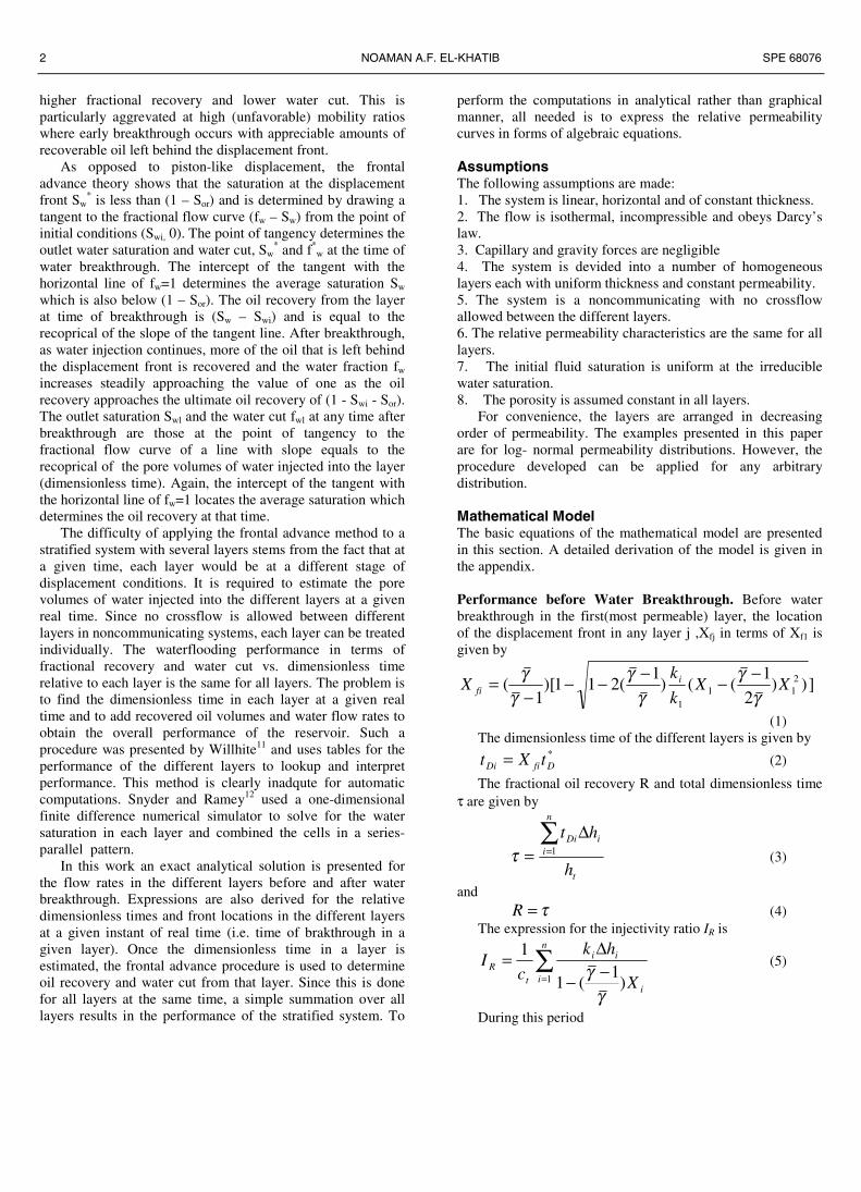
Figures 2-4 show the performance results for a run withoil/water viscosity ratio of 2.5 and permeability variationcoefficient VDP of 0.5 for both piston-like and Buckley-Leverett displacement. This corresponds to a mobility ratio of1.25 for piston-like and 0.75 for Buckley-Leverettdisplacement.
Figure 2 shows the fractional oil recovery (verticalcoverage) as function of the dimensionless time τ. Oilrecovery is reported in terms of the recoverable oil volume (1– Swi – Sor). Before B.T. in the first layer, oil recovery for bothB-L and piston like displacement is equal to the dimensionlesstime since all injected water remains in the reservoir and anequal amount of oil is produced. Earlier breakthrough willoccur in the case of B-L displacement. This is because not all
of the recoverable oil is displaced from the invaded zone in theBL case and so the injected water will move faster. As thedisplacement process continues, more of the oil left behimdthe displacement front will be recovered and eventually allrecoverable oil will be produced. This however will takelonger time (PV injected) than for the PL case in which oilrecovery reaches unity when water B.T. occurs in the lastlayer. The fractional oil recovery in the B-L displacement casedoes not reach a value of one at that time.
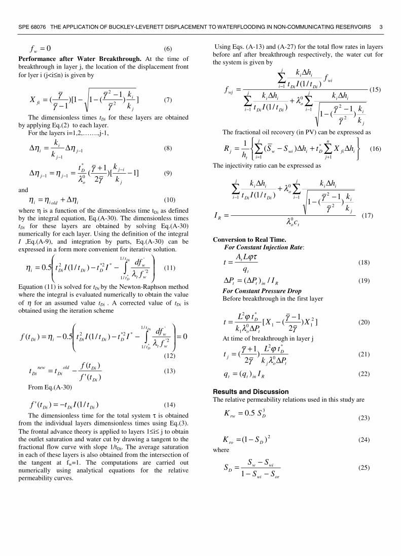
Table 1 . Mobilities and Mobility Ratios
µo cp. 10 5 2.5 1 0.5
0wλ 0.5 0.5 0.5 0.5 0.5
SD* 0.560 0.653 0.743 0.848 0.907
fw* 0.8198 0.8520 0.8863 0.9292 0.9555
*tλ .107278 .163101 .231702 .327778 .390193
tλ .159054 .277101 .300333 .386197 .432851
0oλ .1 .2 .4 1.0 2.0
γ 5.0 2.5 1.25 0.5 0.25
γr 1.5905 1.1355 0.7508 0.3862 0.2164
0 2 4 6 8
D im ensionless Tim e
0.0
0.2
0.4
0.6
0.8
1.0
Rec
ove
ry F
acto
r R
------------ PL_______ BL
Visc. Ratio = 2.5
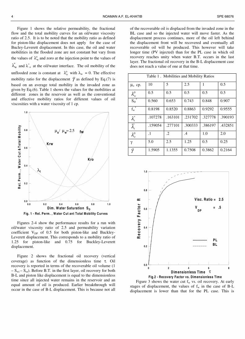
Fig.2 - Recovery Factor vs. Dim ensionless Tim eτ
V = .5DP
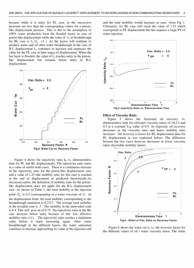
Figure 3 shows the water cut fw vs. oil recovery. At earlystages of displacement, the values of fw in the case of B-Ldisplacement is lower than that for the PL case. This is
SPE 68076 THE APPLICATION OF BUCKLEY-LEVERETT DISPLACEMENT TO WATERFLOODING IN NON-COMMUNICATING RESERVOIRS 5
because while it is unity for PL case. in the successivelayersare are less than the corresponding values for a piston-like displacement process. This is due to the assumption of100% water production from the flooded layers in case ofpiston-like displacement while the value of fw at breakthroughfor BL case is fw
*(fw* <1 ) .As the layers will continue to
produce water and oil after water breakthrough in the case ofB-L displacement fw continues to increase and surpasses thevalue for the PL case at later stages of displacement. When thelast layer is flooded, the value of fw reaches unity in the piston-like displacement but remains below unity in B-Ldisplacement.
0.0 0.2 0.4 0.6 0.8 1.0
Recovery Factor R
0.0
0.2
0.4
0.6
0.8
1.0
Wat
er C
ut
fw
------------ PL_______ BL
Visc. Ratio = 2.5
Fig.3- W ater Cut vs. Recovery Factor
V = .5DP
Figure 4 shows the injectivity ratio IR vs. dimensionlesstime for PL and BL displacements. The injectivity ratio startsat a value of onefor both cases. There is a continuous increaseof the injectivity ratio for the piston-like displacement caseand a value of 1.25 (the mobility ratio for this run) is reachedat the end of displacement as predicted theoretically.Asdiscussed earlier, the definition of mobility ratio for the piston-like displacement does not apply for the B-L displacementcase. As shown in Table 1, the total mobility at the injection
point owλ is 0.5 (corresponding to a water viscosity of 1). At
the displacement front, the total mobility corresponding to thebreakthrough saturation is 0.2317. The average total mobilityin the invaded zone is .3 . The mobility in the uninvaded zoneis 0.4. This will give an of 0.75 The injectivity ratio in the BLcase decreses below unity because of this low effectivemobility ratio (<1) . The injectivity ratio reaches a minimumvalue before it starts increasing again. After waterbreakthrough in the different layers, the water saturationcontinues to increase approaching its value at the injection end
and the total mobility would increase as seen from Fig 1.Ultimately, for BL case will reach the value of 1.25 whichcorresponds to PL displacement but this requires a large PV ofwater injection.
0 2 4 6 8
Dim ensionless Tim e
0.0
0.4
0.8
1.2
1.6
2.0
Inje
ctiv
ity
Rat
io I
R
------------ PL_______ BL
Visc. Ratio = 2.5
Fig.4 -Injectivity Ratio vs. Dimensionless Timeτ
V DP = .5
Effect of Viscosity RatioFigure 5 shows the fractional oil recovery vs.
dimensionless time for oil/water viscosity ratios of 10,2.5 and0.5 at a constant VDP value of 0.5. As expected, oil recoverydecreases as the viscosity ratio and hence mobility ratioincreases. Oil recovery is lower for BL displacement than forPL displacement as was explained before. The differencebeween the two cases however decreases at lower viscosityratios (favorable mobility ratios).
0 2 4 6
Dim ensionless Tim e
0.0
0.2
0.4
0.6
0.8
1.0
Rec
ove
ry F
acto
r R
10
.5
------------ PL_______ BL
Visc. Ratio
Fig.5 - Effect of V isc. Ratio on Recovery Factor
τ
2.5
V DP = .5
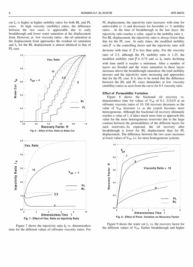
Figure 6 shows the water cut fw vs. the recovery factor forthe different values of oil / water viscosity ratios. The water
6 NOAMAN A.F. EL-KHATIB SPE 68076
cut fw is higher at higher mobility ratios for both BL and PLcases. At high viscosity (mobility) ratios, the differencebetween the two cases is appreciable due to earlybreakthrough and lower water saturation at the displacementfront. However, at low viscosity ratios , the oil saturation atthe displacement front approaches the residual oil saturationand fw for the BL displacement is almost identical to that ofPL case.
0.0 0.2 0.4 0.6 0.8 1.0
Recovery Factor R
0.0
0.2
0.4
0.6
0.8
1.0
Wat
er C
ut
fw
10
2.5
.5
______ BL
----------- PL
Visc. Ratio
Fig. 6 - Effect of Visc. Ratio on W ater Cut
VDP = .5
0 2 4 6 8 10
Dim ensionless Time
0.0
1.0
2.0
3.0
4.0
5.0
Inje
ctiv
ity
Rat
io I
R
.5
------------ PL_______ BL
Visc. Ratio
Fig. 7 - Effect of Visc. Ratio on Injectivity Ratio τ
2.5
10VDP = .5
Figure 7 shows the injectivity ratio IR vs. dimensionlesstime for the different values of oil/water viscosity ratios. For
PL displacement, the injectivity ratio increases with time forunfavorable (> 1) and decreases for favorable (< 1) mobilityratios . At the time of breakthrough in the last layer, theinjectivity ratio reaches a value equal to the mobility ratio γ .For BL displacement, the injectivity ratio is always lower thanthat for the PL case. At early times, the modified mobilityratioγ is the controlling factor and the injectivity ratio will
decrease with time if γ is less than unity. For the viscosity
ratio of 2.5, although the PL mobility ratio is 1.25, themodified mobility ratioγ is 0.75 and so IR starts declining
with time untill it reachrs a minimum. After a number oflayers are flooded and the water saturation in these layersincreases above the breakthrough saturation, the total mobilityincreses and the injectivity starts increasing and approachesthat for the PL case. It is also to be noted that the differencebetween the BL and PL cases diminishes at low viscosity(mobility) ratios as seen from the curve for 0.5 viscosity ratio.
Effect of Permeability VariationFigure 8 shows the fractional oil recovery vs.
dimensionless time for values of VDP of 0.1, 0.5,0.9 at anoil/water viscosity ratios of 10. Oil recovery decreases as thevalue of VDP increases i.e as the system becomes moreheterogeneous. Although the fractional oil recovery ultimatelyreaches a value of 1, it takes much more time to approach thisvalue for the more heterogeneous reservoirs due to the largecontrast between the permeabilities of the different layers forsuch reservoirs..As expected, the oil recovery afterbreakthrough is lower for BL displacement than for PLdisplacement. The difference between the two cases increasesat lower values of VDP, i.e. for more homogeneous systems.
0 2 4 6 8
D im ensionless Tim e
0.0
0.2
0.4
0.6
0.8
1.0
Rec
ove
ry F
acto
r R
VDP
.1
.9
.5
Fig. 8 - Effect of Perm . Variation on Recovery Factor
-------- PL_____ B L
τ
Viscosity Ratio = 10
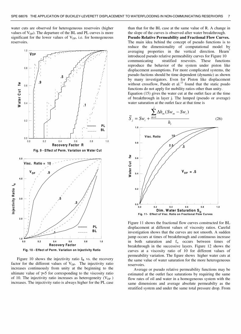
Figure 9 shows the water cut fw vs. the recovery factor forthe different values of VDP. Earlier breakthrough and higher
SPE 68076 THE APPLICATION OF BUCKLEY-LEVERETT DISPLACEMENT TO WATERFLOODING IN NON-COMMUNICATING RESERVOIRS 7
water cuts are observed for heterogeneous reservoirs (highervalues of VDP). The departure of the BL and PL curves is moresignificant for the lower values of VDP, i.e. for homogeneousreservoirs.
0.0 0.2 0.4 0 .6 0.8 1.0
Recovery Factor R
0.0
0.2
0.4
0.6
0.8
1.0
Wat
er C
ut
fw
V
.1
.9
Fig. 9 - Effect of Perm . Variation on W ater Cut
-------- PL_____ BL
.5
DP
0.0 0.2 0.4 0.6 0.8 1.0
Recovery Factor
1.0
2.0
3.0
4.0
5.0
Inje
ctiv
ity
Rat
io I
R
.5
Fig. 10 - Effect of Perm. Variation on Injectivity Ratio
-------- PL_____ BL
Visc. Ratio = 10
.9
.5
.1
VDP
Figure 10 shows the injectivity ratio IR vs. the recoveryfactor for the different values of VDP. The injectivity ratioincreases continuously from unity at the beginning to theultimate value of γ=5 for corresponding to the viscosity ratioof 10. The injectivity ratio increases as heterogeneity (VDP )increases. The injectivity ratio is always higher for the PL case
than that for the BL case at the same value of R. A change inthe slope of the curves is observed after water breakthrough.Pseudo Relative Permeability and Fractional Flow Curves.The main idea behind the concept of pseudo functions is toreduce the dimensionality of computational model byaveraging properties in the vertical direction. Hearn7
introduced pseudo relative permeability curves for Figure 10communicating stratified resevoirs. These functionsreproduce the behavior of the system under piston likedisplacement assumptions. For more complicated systems, thepseudo fuctions should be time dependent (dynamic) as shownby many investigators. Even for Piston like displacementwithout crossflow, Pande et al.13 found that the static psudofunctions do not apply for mobility ratios other than unity.Equation (15) gives the water cut at the outlet face at the timeof breakthrough in layer j. The lumped (pseudo or average)water saturation at the outlet face at that time is
t
j
mimm
ij h
SwSwhSwS
)(~ 1
∑=
−∆+= (26)
0.0 0 .2 0.4 0.6 0.8 1.0
Dim . W ater Saturation SD
0.0
0.2
0.4
0.6
0.8
1.0W
ater
Cu
t f
w
10
2.5 .5
Visc. Ratio
Fig. 11- Effect of Visc. Ratio on Fractional Flow Curves
VDP = .5
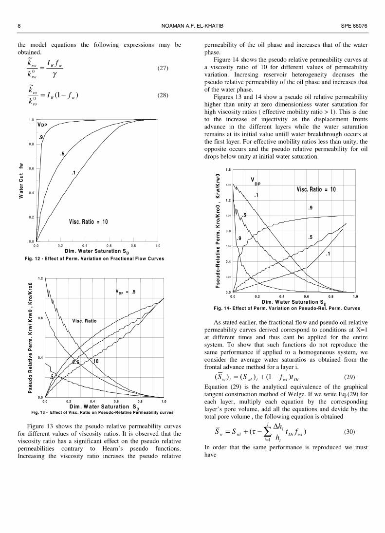
Figure 11 shows the fractional flow curves constructed for BLdisplacement at different values of viscosity ratios. Carefulinvestigation shows that the curves are not smooth. A suddenjump occurs at times of breakthrough and continuous increasein both saturation and fw occurs between times ofbreakthrough in the successive layers. Figure 12 shows thecurves at a viscosity ratio of 10 for different values ofpermeability variation. The figure shows higher water cuts atthe same value of water saturation for the more heterogeneousreservoirs.
Average or pseudo relative permeability functions may beestimated at the outlet face saturations by requiring the sameflow rates of oil and water in a homogeneous system with thesame dimensions and average absolute permeabilty as thestratified system and under the same total pressure drop. From
8 NOAMAN A.F. EL-KHATIB SPE 68076
the model equations the following expressions may beobtained.
γ
wR
rw
rw fI
k
k=
0
~(27)
)1(~
0 wR
ro
ro fIk
k−= (28)
0.0 0 .2 0.4 0 .6 0.8 1 .0
Dim . W ater Saturation SD
0.0
0.2
0.4
0.6
0.8
1.0
Wat
er C
ut
fw
V
.1
.9
Fig. 12 - E ffect of Perm . Variation on Fractional Flow Curves
.5
DP
Visc. Ratio = 10
0.0 0.2 0.4 0.6 0.8 1.0
D im . W ater Saturation SD
0.0
0.4
0.8
1.2
Pse
ud
o R
elat
ive
Per
m. K
rw/ K
rw0
, Kro
/Kro
0
102.5
.5
Visc. Ratio
Fig. 13 - Effect of Visc. Ratio on Pseudo-Relative Permeability curves
VDP = .5
Figure 13 shows the pseudo relative permeability curvesfor different values of viscosity ratios. It is observed that theviscosity ratio has a significant effect on the pseudo relativepermeabilities contrary to Hearn’s pseudo functions.Increasing the viscosity ratio incrases the pseudo relative
permeability of the oil phase and increases that of the waterphase.
Figure 14 shows the pseudo relative permeability curves ata viscosity ratio of 10 for different values of permeabilityvariation. Incresing reservoir heterogeneity decrases thepseudo relative permeability of the oil phase and increases thatof the water phase.
Figures 13 and 14 show a pseudo oil relative permeabilityhigher than unity at zero dimensionless water saturation forhigh viscosity ratios ( effective mobility ratio > 1). This is dueto the increase of injectivity as the displacement frontsadvance in the different layers while the water saturationremains at its initial value untill water breakthrough occurs atthe first layer. For effective mobility ratios less than unity, theopposite occurs and the pseudo relative permeability for oildrops below unity at initial water saturation.
0.0 0.2 0.4 0.6 0.8 1.0
D im . W ater Saturation SD
0 .20
0 .60
1 .00
1 .40
0.0
0.4
0.8
1.2
1.6
Pse
ud
o-R
elat
ive
Per
m. K
ro/K
ro0
, K
rw/K
rw0
V
.1
.9
Fig. 14- Effect of Perm. Variation on Pseudo-Rel. Perm. Curves
.5
DPVisc. Ratio = 10
.1
.5
.9
As stated earlier, the fractional flow and pseudo oil relativepermeability curves derived correspond to conditions at X=1at different times and thus cant be applied for the entiresystem. To show that such functions do not reproduce thesame performance if applied to a homogeneous system, weconsider the average water saturatios as obtained from thefrontal advance method for a layer i.
Diwiiwliw tfSS )1()()( −+= (29)
Equation (29) is the analytical equivalence of the graphicaltangent construction method of Welge. If we write Eq.(29) foreach layer, multiply each equation by the correspondinglayer’s pore volume, add all the equations and devide by thetotal pore volume , the following equation is obtained
)(1
wi
j
iDi
t
iwlw ft
h
hSS ∑
=
∆−+= τ (30)
In order that the same performance is reproduced we musthave
SPE 68076 THE APPLICATION OF BUCKLEY-LEVERETT DISPLACEMENT TO WATERFLOODING IN NON-COMMUNICATING RESERVOIRS 9
wwi
j
iDi
t
i ffth
h )
1
τ=∆∑
=
(31)
It is apparent from equations (3) and (15) that equation (31) isnot satisfied. We can therefore conclude that the pseudofunctions derived can only be applied to predict the behavioral the outlet face (production well).
Conclusions
1. A mathematical model is developed for applying theBuckley-Leverett frontal advance theory to immiscibledisplacement in noncommunicating stratifiedreservoirs. The developed model gives more accurateresults as compared to conventional models thatassume piston like displacement.
2. An effective mobility ratio based on the average totalmobility in the invaded zone is introduced to accountfor variable saturation behind the displacement front.This effective mobility ratio rather than theconventional mobility ratio controls the BLdisplacement before water breakthrough. Using thiseffective mobility ratio, Dykstra-Parsons equationscan be applied to determine the locations of thedisplacement fronts in the different layers beforebreakthrough.
3. Oil recovery after breakthrough and water cut arealways less for BL displacement than those for PLdisplacement with the difference becoming morenoticeable at high mobility ratios (unfavorable) andfor low values of the permeability variationcoefficient, VDP (less heterogeneous reservoirs).
4. The injectivity ratio is governed by the effectivemobility ratio at early times and by the conventionalmobility ratio at later times. The injectivity ratio forBL displacement is always less than that for PLdisplacement. with the difference increasing at high(unfavorable) mobility ratios. The injectivity ratioincreses as the reservor heterogeneity (VDP) andviscosity ratio increase. The ultimate value of theinjectivity ratio is equal to the PL mobility ratio.
5. The fractional flow and pseudo relative perrmeabilityformulas derivrd for the model cant be used forsimulation of the entire system. These functionscorrespond only to the conditions at the outlet face atdifferent times.
Nomenclature
A = area, L2 , ft
2 [m
2]Ct = total formation capacity, L3, md. Ft[fw = water cut, dimensionlessfw* = water cut at breakthrough, dimensionless
ht = total formation thickness, L, ft [m]∆h = formation thickness of a layer, L, ft [m]IR = injectivity ratio, dimensionlessk = absolute horizontal permeability, L2, md [µm2]
kroo
= oil relative permeability at Swi , dimensionless
k̃ro = pseudo relative permeability for oil, dimensionless
krwo = water relative permeability at Sor , dimensionless
k̃rw = pseudo rel. permeability for water, dimensionless
L = length, L, ft [m]n = number of layers∆P = pressure drop, M/ Lt, psi[kPa]Q = flow rate, L3/ t , bbl/d [m3/s]R = vertical coverage, dimensionlessSD = dimensionless water saturationSor = residual oil saturation, fractionSw = water saturation, fractionSwi = initial water saturation, fraction∆S = displaceable oil saturation, fractiont = time, t, d [s]VDP = Dykstra–Parsons variation coefficient,x = distance from inlet face , L, ft [m]Xf = dimensionless distance of the displacement frontϒ = mobility ratio , dimensionlessη = function defined by Eq.(A-30)λ = phase mobility, Lt/M, cp-1 [1/Pa.s]µ = viscosity, m/Lt, cp.[Pa.s]τ = dimensionless timeϕ = porosity, fractionSubscriptsi = initial , irreducibleD = dimensionlessm = meano = oilr = relativet = totalw = water
Superscripts
* = breakthrough‘ = derivative- = average~ = pseudo
AcknowledgementThe author wishes to acknowledge the support provided by thePetroleum Engineering Department of King Saud Universityduring this study.
10 NOAMAN A.F. EL-KHATIB SPE 68076
References1. Buckley, S.E. and Leverett, M.C.: "Mechanism of Fluid
Displacement in Sands," Trans., AIME (1942) 146,107.
2. Welge, H.J.: "A Simplified Method for Computing OilRecovery by Gas or Water Drive," Trans., AIME(1952) 195, 91–98.
3. Stiles, W.E.: “Use of Permeability Distribution inWater-flood Calculations,” Trans., AIME (1949) 186,9-13.
4. Dykstra, H. and parsons, R.L.: "The Prediction of Oilrecovery by Waterflooding," Secondary Recovery ofOil in the United States, 2nd ed., API (1950) 160–174.
5. Hiatt, N.W.: "Injected–fluid Coverage of Multi–wellReservoirs with Permeability Stratification," Drill andProd. Prac., API (1958) 165, 165–194.
6. Warren, J.E. and Cosgrove, J.J.: "Prediction ofWaterflood Behavior in a Stratified System," Soc. Pet.Eng. J. (June 1964) 149–157.
7. Hearn, C.L.: "Simulation of Stratified Waterflooding byPseudo Relative Permeability Curves," J. Pet. Tech.(July 1971), 805–813.
8. Reznik, A.A., Enick, R.M. and Panvelker, S.B.: "AnAnalytical Extension of the Dykstra–Parsons VerticalStratification Discrete Solution to a Continuous, Real–Time Basis," Soc. Pet. Eng. J. (1984) 24, 643–656.
9. El–Khatib, N.A.: "The Effect of Crossflow onWaterflooding of Stratified Reservsoirs," Soc. Pet. Eng.J. (April, 1985), 291–302.
10. El–Khatib, N.A.: “Waterflooding Performance ofCommunicating Stratified Reservoirs with Log-NormalPermeability Distribution,” SPEREE (Dec. 1999)2,542-49.
11. Willhite, P.G.: Waterflooding, SPE Textbook Series,Vol 3, Richardson,TX. (1986) 139-45.
12. Snyder, R.W. and Ramey, H.J. Jr.: “Applications ofBuckley-Leverett Displacement Theory toNoncommunicating Layered Systems,” J. Pet. Tech.(Nov. 1967), 1500-06.
13. Pande, K.K., Ramey, H. J. Jr., Brigham, W.E. and Orr,F.M. Jr.: "Frontal Advance Theory for Flow inHeterogeneous Porous Media, paper SPE 16344presented at SPE California Regional Meeting,Ventura, California, April 8–10, 1987.
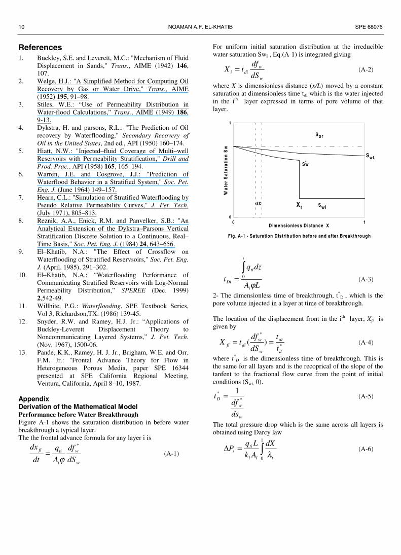
AppendixDerivation of the Mathematical ModelPerformance before Water BreakthroughFigure A-1 shows the saturation distribution in before waterbreakthrough a typical layer.The the frontal advance formula for any layer i is
w
w
i
tifi
dS
df
A
q
dt
dx *
ϕ= (A-1)
For uniform initial saturation distribution at the irreduciblewater saturation SwI , Eq.(A-1) is integrated giving
w
wdii dS
dftX = (A-2)
where X is dimensionless distance (x/L) moved by a constantsaturation at dimensionless time tdi which is the water injectedin the ith layer expressed in terms of pore volume of thatlayer.
0 1D im ensionless D istance X
0
1
Wat
er S
atu
rati
on
Sw
Swi
Sor
Sw*
Xf dX
Fig. A-1 - Saturation Distribution before and after Breakthrough
SwL
LA
dzq
ti
t
ti
Di ϕ
∫= 0 (A-3)
2- The dimensionless time of breakthrough, t*D , which is the
pore volume injected in a layer at time of breakthrough.
The location of the displacement front in the ith layer, Xfi isgiven by
*
*
)(d
di
w
wdifi t
t
dS
dftX == (A-4)
where t*D is the dimensionless time of breakthrough. This is
the same for all layers and is the recoprical of the slope of thetanfent to the fractional flow curve from the point of initialconditions (Swi, 0).
w
w
D
ds
dft
** 1= (A-5)
The total pressure drop which is the same across all layers isobtained using Darcy law
∫=∆1
0 tii
tit
dX
Ak
LqP
λ(A-6)
SPE 68076 THE APPLICATION OF BUCKLEY-LEVERETT DISPLACEMENT TO WATERFLOODING IN NON-COMMUNICATING RESERVOIRS 11
Noting that λt in the uninvaded zone is constant at λo0 and
from the frontal advance theory, X in the invaded zone isgiven by Eq.(A-4), Eq.(A-6) can be written as
}1
{0
0
''*
o
fif
t
wDi
ii
tit
Xdft
Ak
LqP
w
λλ−
+=∆ ∫ (A-7)
Using the following definition of average total mobility
**'*
''*
1It
f
df
D
w
f
o t
w
t
w
==∫ λ
λ(A-8)
where
∫=x
o t
wdfxI
λ
'
)( (A-9)
and
∫=='*
'** )/1(
wf
o t
wD
dftII
λ(A-10)
equation (A-7) becomes
}1
{0o
fi
t
f
ii
tit
XX
Ak
LqP
λλ−
+=∆ (A-11)
Defining an effective mobility ratio as
oo
t
λλγ = (A-12)
equation (A-11) may be arranged for the total flow rate as
))1
(1(
0
fi
toiiti
XL
PAkq
γγλ−−
∆= (A-13)
Equation (A-13) is similar to the equation used in deriving thelocation of the displacement front in the Dykstra-Parsonsmodel with the modified mobilty ratio γ replacing the
conventional mobility ratio γ defined as
w
o
ro
rw
o
w
k
k
µµ
λλγ
0
0
0
0
== (A-14)
So the following equations can be used (see ref. ,9)Before water breakthrough in the first(most permeable) layer,the location of the displacement front in any layer j ,Xfj interms of Xf1 is given by
]))2
1(()
1(211)[
1( 2
111
XXk
kX i
fi γγ
γγ
γγ −−−−−−
=
(A-15)
Equation (A-15) may br used to obtain the front location inlayer i in terms of that in any layer j by replacing k1 by kj andX1 by Xj.
The dimensionless time of the different layers is given by*DfiDi tXt = (A-16)
The fractional oil recovery R and total dimensionless timeτ are given by
τ=R (A-17)
t
n
iiDi
h
ht∑=
∆= 1τ (A-18)
where the total dimensionless time τ is based on the total porevolume of the system
LA
dzq
t
t n
iti
ϕτ
∫∑== 0 1
(A-19)
The expression for the injectivity ratio IR is
∑= −−
∆=
n
ifi
ii
tR
X
hk
cI
1 )1
(1
1
γγ
(A-20)
where ct is the total formation capacity
i
n
iit hkc ∆= ∑
=1
(A-21)
During this period
0=wf (A-22)
To convert to real time for the case of constant totatpressure drop , Substituting for qt from Eq.(A-13) into thefrontal advance formula, Eq.(A-1) and and using X=x/l , weget
w
w
fi
toifi
dS
df
XL
Pk
dt
dX *
2
0
))1
(1(γ
γϕ
λ−−
∆= (A-23)
Integrating Eq.(A-23) and rearranging we obtain
])2
1([
20
*2
ii
toi
D XXPk
tLt
γγ
λϕ −−
∆= (A-24)
The time of breakthrough in layer i is obtained by setting Xi=1
toi
Di Pk
tLt
∆+=
0
*2*
)2
1(
λϕ
γγ
(A-25)
Performance after Water Breakthrough. After waterbreakthrough in a layer i, the total pressure drop across the
12 NOAMAN A.F. EL-KHATIB SPE 68076
layer is obtained by substituting Eq.(A-2) into Eq.(A-6) and
noting that at X=1, Diw
tf /1'
=
∫=
=∆Diw tf
t
wDi
ii
tit
dft
Ak
LqP
/1
0
''
λ(A-26)
Using the definition for the integral I as given by Eq.(A-9) ,equation(A-26) may be written as
( ))/1(0
0
DiDio
toiiti tItL
PAkq
λλ ∆
= (A-27)
Since
LA
dtqdt
i
tiDi ϕ
= (A-28)
then for two layers i and j , both after breakyhrough
)/1(
)/1(
DiDi
DjDj
j
i
Dj
Di
tIt
tIt
k
k
dt
dt= (A-29)
Integrating this equation for a given interval of real time anddefining a function η as
dD
z
t
D dttItzD
)/1()(*∫=η (A-30)
the integration may be written as
jj
ii k
kηη ∆=∆ (A-31)
At the time of breakthrough in layer j, the location of thedisplacement front for lyer i (j<i≤n) is obtained from Eq.(A-15) by replacing 1 by j and setting Xj=1
])1
(11)[1
(j
ifi k
kX
γγ
γγ −−−−
= (A-32)
For the two layers i after and j before breakthrough , from Eqs.(A-13) and (A-27) and (A-28) we get
)/1(
)1
(1*2
2
DiDi
D
Dj
j
i
Dj
Di
tIt
t
t
k
k
dt
dt γγ −−
= (A-33)
Setting i=j-1 and integrating from time of breakthrough inlayer j-1( tD = Xfi tD
* where Xfi is given be Eq(A-32) ) andtime of breakthrough in layer j (tD = tD
* ), the followingequation is obtained
]1)[2
1(
0
*
11 −+==∆ −−−
j
ij
o
Djj k
kt
γγ
ληη (A-34)
Applying Eq.(A-31) to layers i≤j-1 we get
11
−−
∆=∆ jj
ii k
kηη (A-35)
and
ioldii ηηη ∆+= (A-36)
To convert to real time, substituting for qt from Eq.(A-27) intoEq.(A-28)
( )dttItL
Pkdt
DiDi
tiDi )/1(2ϕ
∆= (A-37)
Integtating from time of breakthrough *it to any time t
iti
i Pk
Ltt ηϕ
∆+=
2* (A-38)
where *it is given by Eq.(A-25 )
SI Metric Conversion Factorsbbl x 1.589 873 E – 01 = m3
cp x 1.0* E – 03 = Pa.sft x 3.048* E – 01 = mft2 x 9.290 304* E – 02 = m2
*Conversion factor is exact.
Copyright © 2022 FDOKUMEN