TFG_Daniel_Lopez_Madrid.pdf - e-Archivo
104
Systems and Automation Engineering Department Bachelor's Degree in Industrial Electronics and Automation Engineering Bachelor Thesis DESIGN AND CONSTRUCTION OF AN AUTONOMOUS RACE ROBOT FOR NATCAR CONTEST Author: Daniel López Madrid Tutor: Mohamed Abderrahim Fichouche Leganés, June 2014
-
Upload
khangminh22 -
Category
Documents
-
view
3 -
download
0
Transcript of TFG_Daniel_Lopez_Madrid.pdf - e-Archivo

Systems and Automation Engineering Department
Bachelor's Degree in Industrial Electronics and Automation
Engineering
Bachelor Thesis
DESIGN AND CONSTRUCTION OF AN AUTONOMOUS RACE ROBOT
FOR NATCAR CONTEST
Author: Daniel López Madrid
Tutor: Mohamed Abderrahim Fichouche
Leganés, June 2014

DANIEL LÓPEZ MADRID Design and Construction of an Autonomous Race Robot for Natcar Contest

DANIEL LÓPEZ MADRID Design and Construction of an Autonomous Race Robot for Natcar Contest
BACHELOR THESIS Page i
Title: DESIGN AND CONSTRUCTION OF AN AUTONOMOUS RACE ROBOT FOR NATCAR CONTEST
Author: Daniel López Madrid
Tutor: Mohamed Abderrahim Fichouche
BOARD OF EXAMINERS
President:
___________________________________________
Chair:
___________________________________________
Clerk:
___________________________________________
Done the defense and reading of the Bachelor Thesis on the __ of ______ of 20__ in
Leganés, at the School of Engineering of Carlos III University of Madrid, agree on award the
CALIFICATION of
CHAIR
CLERK PRESIDENT

DANIEL LÓPEZ MADRID Design and Construction of an Autonomous Race Robot for Natcar Contest
BACHELOR THESIS Page ii
ACKNOWLEDGEMENTS
First, I would like to thank my family for believing in me and supporting me through all
the good and bad moments during these last four years of my life.
I would also like to thank my girlfriend for constantly pushing me to be the best I can be
and being a source of joy since we met.
I want to personally extend my thanks to Mohamed Abderrahim for his support, guidance,
and the trust he placed in me when I needed it the most.
Last but not least, I would like to express my gratitude to the UCLA IEEE chapter, that
made this project possible through its fund and organizing specialized lectures to help the
participants of the Natcar contest.

DANIEL LÓPEZ MADRID Design and Construction of an Autonomous Race Robot for Natcar Contest
BACHELOR THESIS Page iii
ABSTRACT
A Natcar is an autonomous robot that uses magnetic and optical sensors to follow a track
as fast as possible. The track is marked with a 1-inch wide tape and the wire carries a 100mA, 75
KHz sinusoidal signal. This project combines many different aspects of engineering including
systems integration, mechatronics, digital design and analog design. A different approach was
utilized in solving the most common problems that every person or team building a Natcar has
to face. Instead of creating a traditional Natcar, every aspect of this project focused on
improvement and aimed to create new techniques to change the way Natcars are built in the
future. To achieve that, new technologies such as 3D printing and computer vision were
employed.
Index Terms: Natcar, autonomous robot, system integration
DANIEL LÓPEZ MADRID Design and Construction of an Autonomous Race Robot for Natcar Contest
BACHELOR THESIS Page iv
RESUMEN
Natcar es un robot autónomo que usa sensores magnéticos y ópticos para navegar lo más
rápido posible a lo largo de una pista. Dicha pista está marcada con una cinta blanca de una
pulgada de ancho y bajo ella se sitúa un cable por el que circula una corriente eléctrica alterna
de 100 mA y 75 KHz. Este proyecto combina diferentes aspectos y áreas de ingeniería tales como
integración de sistemas, mecatrónica y diseño tanto analógico como digital. Esta vez se ha
intentado hacer una apuesta diferente a como resolver los problemas más comunes que
cualquier persona o equipo que esté construyendo un Natcar se va a encontrar. En vez de crear
un Natcar tradicional, cada detalle de su diseño ha sido objetivo de mejora que pretende
desarrollar nuevas técnicas que cambiaran la forma en la que los Natcars serán construidos en el
futuro. Para conseguir esto, nuevas tecnologías tales como impresión en 3D y visión artificial han
sido utilizadas en el proyecto.
Palabras clave: Natcar, robot autónomo, integración de sistemas.

DANIEL LÓPEZ MADRID Design and Construction of an Autonomous Race Robot for Natcar Contest
BACHELOR THESIS Page v
CONTENTS
1. INTRODUCTION ......................................................................................................... 1
2. TECHNICAL BACKGROUND AND STATE OF THE ART ................................................ 4
2.1 3D Printing ............................................................................................................. 4
2.2 CAD Software ........................................................................................................ 6
2.3 Microcontroller ..................................................................................................... 7
2.4 Line Scan Camera (TSL1401-DB) ......................................................................... 10
2.5 Image Processing ................................................................................................. 12
2.6 Magnetic Sensors ................................................................................................ 14
2.7 Analog Front End ................................................................................................. 15
2.8 Sensor Fusion ...................................................................................................... 15
2.9 PWM Modulation ................................................................................................ 15
2.10 Unicycle Model ................................................................................................ 17
2.11 Control System ................................................................................................ 18
2.12 Ziegler-Nichols Method ................................................................................... 19
2.13 Twiddle ............................................................................................................ 20
2.14 Power System .................................................................................................. 21
2.15 Chassis ............................................................................................................. 21
2.16 Propulsion System ........................................................................................... 22
2.17 Encoders .......................................................................................................... 23
2.18 Gears ................................................................................................................ 24
2.19 Bearing ............................................................................................................. 25
2.20 Micromouse ..................................................................................................... 26
DANIEL LÓPEZ MADRID Design and Construction of an Autonomous Race Robot for Natcar Contest
BACHELOR THESIS Page vi
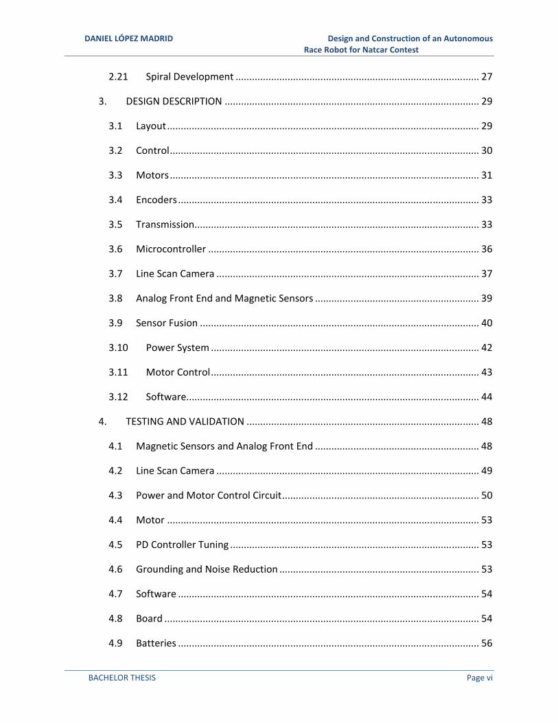
2.21 Spiral Development ......................................................................................... 27
3. DESIGN DESCRIPTION ............................................................................................. 29
3.1 Layout .................................................................................................................. 29
3.2 Control ................................................................................................................. 30
3.3 Motors ................................................................................................................. 31
3.4 Encoders .............................................................................................................. 33
3.5 Transmission ........................................................................................................ 33
3.6 Microcontroller ................................................................................................... 36
3.7 Line Scan Camera ................................................................................................ 37
3.8 Analog Front End and Magnetic Sensors ............................................................ 39
3.9 Sensor Fusion ...................................................................................................... 40
3.10 Power System .................................................................................................. 42
3.11 Motor Control .................................................................................................. 43
3.12 Software........................................................................................................... 44
4. TESTING AND VALIDATION ..................................................................................... 48
4.1 Magnetic Sensors and Analog Front End ............................................................ 48
4.2 Line Scan Camera ................................................................................................ 49
4.3 Power and Motor Control Circuit ........................................................................ 50
4.4 Motor .................................................................................................................. 53
4.5 PD Controller Tuning ........................................................................................... 53
4.6 Grounding and Noise Reduction ......................................................................... 53
4.7 Software .............................................................................................................. 54
4.8 Board ................................................................................................................... 54
4.9 Batteries .............................................................................................................. 56

DANIEL LÓPEZ MADRID Design and Construction of an Autonomous Race Robot for Natcar Contest
BACHELOR THESIS Page vii
4.10 Chassis ............................................................................................................. 57
4.11 Transmission .................................................................................................... 58
5. CONCLUSIONS ......................................................................................................... 61
6. FUTURE WORK ........................................................................................................ 63
7. REFERENCES ............................................................................................................ 64
8. ANNEX: BUDGET ..................................................................................................... 72
8.1 Materials cost ...................................................................................................... 72
8.2 Labor cost ............................................................................................................ 73
8.3 Final Budget ......................................................................................................... 73
9. ANNEX: GANTT DIAGRAM ....................................................................................... 74
10. ANNEX: CODE .......................................................................................................... 75
10.1 Main Code ........................................................................................................ 75
10.2 Line Scan Camera in Processing ...................................................................... 88
10.3 Encoder Testing Code ...................................................................................... 90

DANIEL LÓPEZ MADRID Design and Construction of an Autonomous Race Robot for Natcar Contest
BACHELOR THESIS Page viii
FIGURES
Fig. 1. Natcar is a design contest created by UC Davis and National Semiconductor and run
in conjunction with UC Berkeley. It is currently sponsored by Texas Instruments [2]. ................. 1
Fig. 2. Natcars ready for the competition, notice how all of them have the same design
with minimum modifications [4]. ................................................................................................... 3
Fig. 3. Makerbot Replicator as the one used to print the custom designed parts [6]. ...... 4
Fig. 4. Schematic diagram of FDM process [8]. ................................................................... 5
Fig. 5. CAD software like OpenSCAD allows engineers to design new components with
great accuracy. ................................................................................................................................ 7
Fig. 6. Arduino is the prototyping platform with the largest community [18]. .................. 8
Fig. 7. Teensy 2.0++ has more than 40 I/O pins while the Arduino nano only has 28
[20][21]. .......................................................................................................................................... 8
Fig. 8. Technical specifications of the Beaglebone Black [25]. ......................................... 10
Fig. 9. Representation of the real object seen by the camera and the output generated by
it. Notice how it detects the black background on the sides and on the hole of the donut and how
it gets different intensities through the body due to the topping [31]. ....................................... 11
Fig. 10. Example of a cycle of reading in the TSL1401 [31]............................................... 12
Fig. 11. Comparison of the original image and the result after applying the Sobel operator
[36][37]. ........................................................................................................................................ 13
Fig. 12. PWM signal with a duty cycle variation from nearly 100% to almost 0% [45]. .. 16
Fig. 13. PWM signals with different duty cycles and the perceived power by the load [46].
....................................................................................................................................................... 16
Fig. 14. Unicycle model illustration [47]. .......................................................................... 17
Fig. 15. Block diagram of closed loop PID controller [49]. ................................................ 18
Fig. 16. Different types of system based on their stability [52]. ....................................... 20
Fig. 17. Carbon fiber RC chassis [54]. ................................................................................ 22
Fig. 18. DC motor diagram. Notice how the same-sign magnetic poles repel and create
movement [57]. ............................................................................................................................ 23
DANIEL LÓPEZ MADRID Design and Construction of an Autonomous Race Robot for Natcar Contest
BACHELOR THESIS Page ix
Fig. 19 Gear nomenclature [62] ........................................................................................ 25
Fig. 20. Cross section of a ball bearing. It can be appreciated how there is a set of spheres
between the inner and outer races [63]. ...................................................................................... 26
Fig. 21. Typical Micromouse layout [66]. .......................................................................... 27
Fig. 22. Steps of the spiral development process [68]. ..................................................... 28
Fig. 23 Final version of the car with the custom built chassis and the differential drive
configuration. ................................................................................................................................ 29
Fig. 24 Final version of the chassis of the car. .................................................................. 30
Fig. 25 Pololu's 37D mm motor with 64 counts/rev built-in encoder [74]. ...................... 32
Fig. 26 Faulhaber 2657CR, one of the best available motors in the market for this
application [75]. ............................................................................................................................ 33
Fig. 27 View of the complete transmission and wheel system including the motor mounts
generated in OpenSCAD. .............................................................................................................. 34
Fig. 28 Back view (left) and front view (right) of the motor mounts created in OpenSCAD.
....................................................................................................................................................... 34
Fig. 29 Inserting the nuts into the motor mount using the heat from the soldering iron.
....................................................................................................................................................... 35
Fig. 30 Diagram of the wheel and motor mount system [81]. ......................................... 35
Fig. 31 Wheel model generated in OpenSCAD. ................................................................ 36
Fig. 32 Parallax TSL1401 Line scan camera module [84]. ................................................. 37
Fig. 33 Illustration of the track finding algorithm developed. .......................................... 39
Fig. 34 Analog front end circuit schematic. ...................................................................... 40
Fig. 35 Results of the simulations for different sensor fusion models [85]. ..................... 41
Fig. 36 Illustration of the calibration algorithm for the AFE sensors. ............................... 42
Fig. 37. Block diagram of the first version of the power system. ..................................... 42
Fig. 38. First version of the motor control circuit. ............................................................ 43
Fig. 39 WebIDE from Adafruit interface. .......................................................................... 44
Fig. 40 Screenshot of Sublime text 2. ............................................................................... 45
Fig. 41 Mounted AFE circuit (left) and sensors (right). ..................................................... 49

DANIEL LÓPEZ MADRID Design and Construction of an Autonomous Race Robot for Natcar Contest
BACHELOR THESIS Page x
Fig. 42 Positioning of the camera and use of the LEDs to increase the quality of the
readings. ........................................................................................................................................ 50
Fig. 43 Line scan camera LEDs used to illuminate its reading zone. ................................. 50
Fig. 44 Schematic of the final version of the power circuit. ............................................. 52
Fig. 45 Schematic of the motor control system. ............................................................... 52
Fig. 46 Wheel separator to correct the alignment of the wheel axis. .............................. 54
Fig. 47 PCB view of the main board circuit including the microcontroller, the power circuit
and the motor control system. ..................................................................................................... 55
Fig. 48 Top view of the last version of the board adapted for a single 7.4V batteries. ... 56
Fig. 49 Comparision of the bottom views of the first version (left) and the last version
(right) of the main board. ............................................................................................................. 56
Fig. 50 Distribution chosen using paper models of the components. .............................. 58
Fig. 51 The three versions of the chassis. The first version built on wood, the second on
aluminum and the third on wood with aluminum reinforcements. ............................................ 58
Fig. 52 Final version of the motor mount. ........................................................................ 59
Fig. 53 Finished wheel system. Notice the ball bearing in the center, the wheel itself (blue)
and the spur gear (black). ............................................................................................................. 59
Fig. 54 Iterations done for the motor mount following spiral development. .................. 60
Fig. 55 Mounted transmission system. Notice the separator and the anti-slip "homemade"
tires. .............................................................................................................................................. 60

DANIEL LÓPEZ MADRID Design and Construction of an Autonomous Race Robot for Natcar Contest
BACHELOR THESIS Page xi
TABLES
Table 1. Main differences of ABS and PLA plastics [10]. ..................................................... 6
Table 2. Comparison of technical specifications of the Arduino Nano, Teensy 2.0++ and
the Beaglebone Black [20], [22]–[24]. ............................................................................................ 9
Table 3. Ziegler Nichols values for different controller configurations [51]. ................... 19
Table 4. Materials cost for the project ............................................................................. 72
Table 5. Labor cost for the project.................................................................................... 73
Table 6. Final cost for the project ..................................................................................... 73
DANIEL LÓPEZ MADRID Design and Construction of an Autonomous Race Robot for Natcar Contest
BACHELOR THESIS Page 1
1. INTRODUCTION
One of the most common problems in today’s education system, particularly in fields like
engineering, is that students do not get a comprehensive approach to learning that combines
theory and practical experience and the understanding of how the different fields are related.
Normally, it is just theory and a limited hands-on experience and combination of the different
subjects that they have been studying.
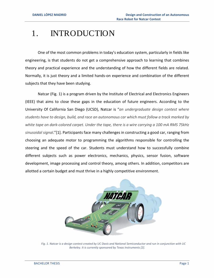
Natcar (Fig. 1) is a program driven by the Institute of Electrical and Electronics Engineers
(IEEE) that aims to close these gaps in the education of future engineers. According to the
University Of California San Diego (UCSD), Natcar is “an undergraduate design contest where
students have to design, build, and race an autonomous car which must follow a track marked by
white tape on dark-colored carpet. Under the tape, there is a wire carrying a 100 mA RMS 75kHz
sinusoidal signal.”[1]. Participants face many challenges in constructing a good car, ranging from
choosing an adequate motor to programming the algorithms responsible for controlling the
steering and the speed of the car. Students must understand how to successfully combine
different subjects such as power electronics, mechanics, physics, sensor fusion, software
development, image processing and control theory, among others. In addition, competitors are
allotted a certain budget and must thrive in a highly competitive environment.
Fig. 1. Natcar is a design contest created by UC Davis and National Semiconductor and run in conjunction with UC
Berkeley. It is currently sponsored by Texas Instruments [2].

DANIEL LÓPEZ MADRID Design and Construction of an Autonomous Race Robot for Natcar Contest
BACHELOR THESIS Page 2
In order to participate on any of the organized competitions, the cars have to comply with
some basic rules[3].
• The car must be fully electric powered.
• The car cannot have more than four wheels.
• The car cannot exceed 35.5cm in width, 90cm in length and 23cm in height (except
for the flag mentioned later).
• All the systems aboard must be powered by a battery that may not cost more than
$30.
• Participants must build their own DC-to-DC converter and motor control circuitry
for their car.
• Each car must have an emergency switch, which can be easily operated while the
car is moving, and an opaque flag at a minimum height of 24.5cm, which is used
to trigger the race timers.
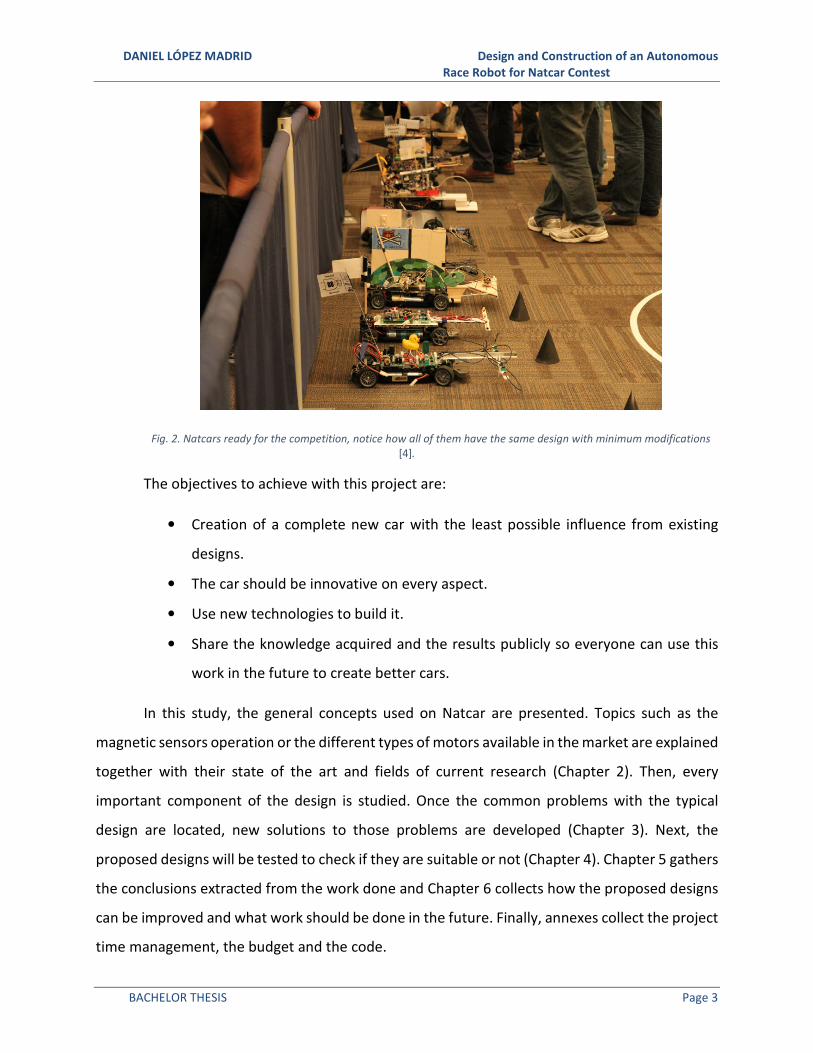
In examining the Natcar design stage, one notices a large majority of the cars are nearly
identical (see Fig. 2). This is because most of the participants use the same chassis,
microcontroller and algorithms. The current design favored by the vast majority of the
participants has been chosen for years. The differences between the cars are limited to slight
modifications in the control algorithms and their tuning methods. With that configuration, there
is no room for further improvements from what has already been achieved. Therefore, it was the
stated aim of this project to design a newer, more efficient and unique Natcar. To create an
innovative design that could beat the status quo Natcar, as well as to push other students to
consider new approaches in developing their projects, it was necessary to push the creativity and
the rules to the limits. To maximize the knowledge acquired during the development of this
project, new technologies and techniques such as 3D printing and computer vision will be used
to learn more about them. In addition, this approach to the Natcar contest and the use of these
technologies will be useful in the future because of the acquired skills and their multiple
professional applications in engineering.
DANIEL LÓPEZ MADRID Design and Construction of an Autonomous Race Robot for Natcar Contest
BACHELOR THESIS Page 3
Fig. 2. Natcars ready for the competition, notice how all of them have the same design with minimum modifications
[4].
The objectives to achieve with this project are:
• Creation of a complete new car with the least possible influence from existing
designs.
• The car should be innovative on every aspect.
• Use new technologies to build it.
• Share the knowledge acquired and the results publicly so everyone can use this
work in the future to create better cars.
In this study, the general concepts used on Natcar are presented. Topics such as the
magnetic sensors operation or the different types of motors available in the market are explained
together with their state of the art and fields of current research (Chapter 2). Then, every
important component of the design is studied. Once the common problems with the typical
design are located, new solutions to those problems are developed (Chapter 3). Next, the
proposed designs will be tested to check if they are suitable or not (Chapter 4). Chapter 5 gathers
the conclusions extracted from the work done and Chapter 6 collects how the proposed designs
can be improved and what work should be done in the future. Finally, annexes collect the project
time management, the budget and the code.

DANIEL LÓPEZ MADRID Design and Construction of an Autonomous Race Robot for Natcar Contest
BACHELOR THESIS Page 4
2. TECHNICAL BACKGROUND AND
STATE OF THE ART
2.1 3D Printing
According to Create It Real, 3D printing is “a technology which makes it possible to build
real objects from virtual 3D objects. This is done by “cutting” the virtual object in 2D slices and
printing the real object slice by slice. Slices are printed on top of each other and since each slice
has a given thickness, e.g. 0.5mm, the real object gains volume every time a slice is added” [5].
Fig. 3. Makerbot Replicator as the one used to print the custom designed parts [6].
This relatively new technology allows everyone to create custom-designed parts at a low
cost and at high speed compared with other traditional prototyping methods. The printer used
is a Makerbot Replicator [6], shown in Fig. 3, which relies on a method known as fused deposition
modeling (FDM) [7]. FDM works via an additive principle. By depositing material in layers, a plastic
filament is unwound from a coil and then melted to produce the part. A Schematic representation
of the process is illustrated in Fig. 4.

DANIEL LÓPEZ MADRID Design and Construction of an Autonomous Race Robot for Natcar Contest
BACHELOR THESIS Page 5
Fig. 4. Schematic diagram of FDM process [8].
These printers can work with different types of plastic, among which the most common
ones are PLA and ABS [9]. Both types are thermoplastic materials. When they are heated, they
become moldable and soft, and if they are cooled down, they return to their solid state. They are
unique in that this process can be done repeatedly. They also have good mechanical properties
that allow the resultant printed parts to have an adequate structural strength while remaining
lightweight. The main differences between these two types of plastic are presented in Table 1.
The most important ones are the temperature at which they melt (ABS requires around 230°C
while PLA only needs 195°C), the need of printing on a hot surface (only ABS requires it) and an
active cooling system (only PLA), the biodegradability (only PLA is). ABS is naturally stronger,
more flexible, and has a higher temperature resistance. Because of this, it is more suitable for
professional and engineering applications while PLA can achieve greater printing speeds and
better finishing suited for schools and hobbyists[10].

DANIEL LÓPEZ MADRID Design and Construction of an Autonomous Race Robot for Natcar Contest
BACHELOR THESIS Page 6
Fusion
temperature
Hot printing
surface Biodegradable
Active
cooling Uses
ABS 230 Yes No No Professionals and engineers
PLA 195 No Yes Yes Hobbyists and schools
Table 1. Main differences of ABS and PLA plastics [10].
All this is possible thanks to the RepRap project, an open source organization that created
the open-source 3D printer and revolutionized the field. RepRap made it possible for anyone
interested in the field to build their own 3D printer. Its ultimate goal is to create 3D printers that
can print more 3D printers [11]. Nowadays people from all over the world are contributing to this
project and helping to create better printers at lower prices [12]. In addition, new materials are
being developed, this open many new possibilities for the technology [13]. For example, the new
materials based on nylon allow to print flexible part and the ones based on carbon fiber can
create high performance printed objects [14].
2.2 CAD Software
CAD stands for “Computer-aided design”. This technology uses computer systems to help
and support the development, creation or modification of designs [15]. It can be used in a wide
range of applications and fields. CAD allows the designer to be more productive and precise,
while at the same time is fully capable of exporting designs in formats that will preserve its future
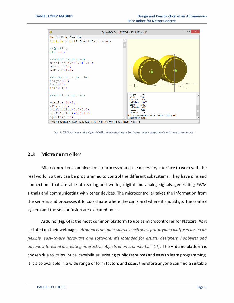
use on the industry or fabrication. In this project, OpenSCAD, a powerful CAD software used
widely on the 3D printing community, is used to design the motor mounts and wheel systems
(Fig. 5). New improvements are being developed for this software; one of the most remarkable
ones is the Object Oriented Mechanics Library (OOML), a set of tools that brings the power of
C++ to OpenSCAD allowing the use of recursion among other procedures [16].
DANIEL LÓPEZ MADRID Design and Construction of an Autonomous Race Robot for Natcar Contest
BACHELOR THESIS Page 7
Fig. 5. CAD software like OpenSCAD allows engineers to design new components with great accuracy.
2.3 Microcontroller
Microcontrollers combine a microprocessor and the necessary interface to work with the
real world, so they can be programmed to control the different subsystems. They have pins and
connections that are able of reading and writing digital and analog signals, generating PWM
signals and communicating with other devices. The microcontroller takes the information from
the sensors and processes it to coordinate where the car is and where it should go. The control
system and the sensor fusion are executed on it.
Arduino (Fig. 6) is the most common platform to use as microcontroller for Natcars. As it
is stated on their webpage, “Arduino is an open-source electronics prototyping platform based on
flexible, easy-to-use hardware and software. It's intended for artists, designers, hobbyists and
anyone interested in creating interactive objects or environments.” [17]. The Arduino platform is
chosen due to its low price, capabilities, existing public resources and easy to learn programming.
It is also available in a wide range of form factors and sizes, therefore anyone can find a suitable

DANIEL LÓPEZ MADRID Design and Construction of an Autonomous Race Robot for Natcar Contest
BACHELOR THESIS Page 8
Arduino for their project. Most students prefer the nano version due its reduced dimensions and
relying on the fact that Natcars do not require a high number of pins on the microcontroller.
Fig. 6. Arduino is the prototyping platform with the largest community [18].
Because it is an open-source platform, Arduino specifications and design files are available
free. This has caused the creation of Arduino compatible alternatives that can run the same
programs with little to no code modification and usually have superior capabilities than the
original ones at even lower prices. A good example is the Teensy (Fig. 7). It has more analog and
PWM pins than its Arduino equivalent, and the Teensy community has created some quality
libraries that make its programming even easier[19].
Fig. 7. Teensy 2.0++ has more than 40 I/O pins while the Arduino nano only has 28 [20][21].
The rise of smartphones has also led to the creation and development of high computing
power and reduced size microprocessors. Thanks to this, new platforms have emerged powered
by these new microprocessors. These technologic advances allow them to be several orders of
magnitude more powerful in terms of RAM memory and CPU speed than the previous
generations of prototyping platforms (Arduino, MBed or Launchpad); they are authentic
miniature computers. They even run fully capable Linux based operating systems [22]. With all
this new power come lots of new possibilities such as real internet connectivity, more advanced
image processing, connectivity of peripherals and development of the algorithms in more

DANIEL LÓPEZ MADRID Design and Construction of an Autonomous Race Robot for Natcar Contest
BACHELOR THESIS Page 9
convenient languages with on the fly compilation of the code (saving considerable time during
the debugging process) among many others.
Arduino Nano Teensy 2.0++ Beaglebone black
Price 35 € 17 € 35 €
Processor ATMega 328 AT90USB1286 ARM Cortex-A8
Clock speed 16 MHz 16 MHz 1 GHz
RAM 2 KB 8 KB 512 MB
Flash 32 KB 128 KB 4 GB
Min power 40 mA 60 mA 170 mA
GPIO 14 46 66
ADC 8, 10-bit 8, 10-bit 7, 12-bit
PWM 6 9 8
UART 1 1 5
Ethernet N/A N/A 10/100
Video out N/A N/A microHDMI
Audio out N/A N/A Analog / microHDMI
Table 2. Comparison of technical specifications of the Arduino Nano, Teensy 2.0++ and the Beaglebone Black [20],
[22]–[24].
One of this new and interesting platforms is the Beaglebone Black (BBB), see comparison
with Arduino Nano in Table 2 , an open-source device manufactured by Texas Instruments that
is characterized by its very powerful ARM Cortex microprocessor that makes possible to run all
types of software such as Android Linux distributions like Ubuntu or Debian [25], see Fig. 8. The
problem is that with all this power comes a greater abstraction layer to manage it. For example,
in the BBB the physical inputs and outputs are managed by two specialized and independent
processors denominated Programmable Real-time Unit Sub System (PRUSS) [26]. They allow very
fast reading and writing on these pins (up to 50MHz [27]) however they need to write and
execute specialized code making the software aspect more complex than the Arduino level
alternatives [28], [29].
DANIEL LÓPEZ MADRID Design and Construction of an Autonomous Race Robot for Natcar Contest
BACHELOR THESIS Page 10
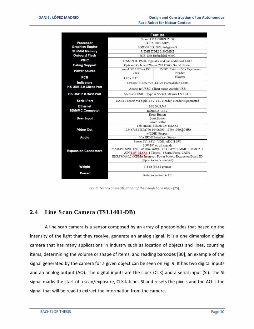
Fig. 8. Technical specifications of the Beaglebone Black [25].
2.4 Line Scan Camera (TSL1401-DB)
A line scan camera is a sensor composed by an array of photodiodes that based on the
intensity of the light that they receive, generate an analog signal. It is a one dimension digital
camera that has many applications in industry such as location of objects and lines, counting
items, determining the volume or shape of items, and reading barcodes [30], an example of the
signal generated by the camera for a given object can be seen on Fig. 9. It has two digital inputs
and an analog output (AO). The digital inputs are the clock (CLK) and a serial input (SI). The SI
signal marks the start of a scan/exposure, CLK latches SI and resets the pixels and the AO is the
signal that will be read to extract the information from the camera.

DANIEL LÓPEZ MADRID Design and Construction of an Autonomous Race Robot for Natcar Contest
BACHELOR THESIS Page 11
Fig. 9. Representation of the real object seen by the camera and the output generated by it. Notice how it detects the
black background on the sides and on the hole of the donut and how it gets different intensities through the body due to the
topping [31].
The period between SI signals is denominated the integration period. During that time,
each of the pixels receives a certain amount of light that a photodiode transforms to an electric
signal. There is a capacitor connected to the photodiode that is charged with the current coming
from it. These capacitors are then all disconnected from their photodiodes and proceed to be
connected, one at a time, to the AO. With every new CLK signal the built-in shift register advances
to the next capacitor. This process is repeated until all capacitors have been passed. Then the AO
goes into a high impedance state and there is a general reset of all the pixels and the integration
period starts over again [31]. An illustration of this process is shown in Fig. 10.
Because these sensors are light-integrating devices, the more time they are exposed to
the light, the higher the output voltage will be. This behavior can be regulated by modifying the
time difference between the clock cycle for the last pixel and the next SI signal [30] [32].
They also usually include some kind of lens system to focus correctly the light over the
active area of the sensor in order to obtain the best results.

DANIEL LÓPEZ MADRID Design and Construction of an Autonomous Race Robot for Natcar Contest
BACHELOR THESIS Page 12
Fig. 10. Example of a cycle of reading in the TSL1401 [31].
2.5 Image Processing
Image processing is the extraction of useful information from an image. This is
accomplished by utilizing several different algorithms that check for patterns or characteristics
and then generate the desired output. This output can be another image, measurements or a
high level description [33]. One of the most commonly used techniques of image processing used
on the Natcar world is the Sobel operator [34]. It is used to calculate the position of the track
from the image obtained through the linescan camera. This method involves calculating the
derivatives of each pixel with respect to the previous and the next pixel. This way, the pixels with
greater derivative values correspond to the edge of the track because of the high contrast of the
track borders and their surroundings [35]. An example of the application of this algorithm is
shown in Fig. 11.

DANIEL LÓPEZ MADRID Design and Construction of an Autonomous Race Robot for Natcar Contest
BACHELOR THESIS Page 13
Fig. 11. Comparison of the original image and the result after applying the Sobel operator [36][37].
The most advanced techniques on computer vision bring the possibility of not only do
simple things like finding the edges of an object, but they can even recognize and classify them
and track their position. One of the most used devices in research in this field is the Microsoft
Kinect, an affordable digital camera that integrates a depth sensor and a multi microphone array.
The data obtained with the Kinect can be used to track the movements of parts of the body of a
person and classify them [38].

DANIEL LÓPEZ MADRID Design and Construction of an Autonomous Race Robot for Natcar Contest
BACHELOR THESIS Page 14
2.6 Magnetic Sensors
The car needs to consistently know its position in relation to the track. Most cars use two
different methods to achieve this; they sense it optically and magnetically. The optical sensor is
a linescan camera that finds the track based on the different intensities that it receives from the
space in front of the car. The magnetic sensors work based on the on electromagnetic induction
principle. They use coils and the magnetic field generated by the wire below the track to generate
a voltage that depends on the distance between the coils and the track.
Electromagnetic induction was first discovered by Michael Faraday when he noticed that
when the magnetic field through a conductor element (magnetic flux) varies, a certain current is
then generated on the conductor [39]. Faraday discovered that the current was proportional to
the rate of change of the magnetic flux and years later, Heinrich Lenz added that the current
generated on the conductor is directed to oppose the change in the magnetic flux [39]. This
phenomenon is described on the Faraday-Lenz law (1).
� = −���
�� (1)
This way the coils will generate a voltage proportional to the varying magnetic field that
crosses them [40][41]. This magnetic field decays with the distance to the wire that generates it.
� =
�� (2)
Where � is the magnetic permeability of the propagation material, in this case it will be
air.
However, what generates the current on the coil is not the magnetic field, it is the
magnetic flux [42], and it can be expressed as (3).
�� = �� (3)
Where � is the coil’s perpendicular area to the magnetic field.

DANIEL LÓPEZ MADRID Design and Construction of an Autonomous Race Robot for Natcar Contest
BACHELOR THESIS Page 15
2.7 Analog Front End
The analog front end (AFE) is the part in charge of improving and adapting the signal
coming from the magnetic sensors so it can be correctly processed by the microcontroller. It
usually scales the generated magnetic sensors voltage inside the limits that the microcontroller
analog-digital converter (ADC) can manage. It also uses different combinations of capacitors to
filter as much noise as possible. The AFE is usually composed of the same circuit repeated as
many times as magnetic sensors the car has.
2.8 Sensor Fusion
Sensor fusion gathers the techniques used to combine the signals from different sensors
and extracts useful information from them that would be impossible to obtain if the sensors
would had been treated individually. The sensors can be of the same type and measure the same
physical quantities or the complete opposite case [34]. The research on this area is focused on
the effective combination of entire networks of sensors. It has multiple applications including
distributed systems to monitor dangerous substances, autonomous surveillance systems of
infrastructures and sensing systems for supervise the activity of borders and harbors [43], [44].
2.9 PWM Modulation
PWM stands for pulse width modulation. It is a technique that modifies the time that a
signal with a given period (�) is on the on state (���), also denominated as duty cycle (�) (4).
PWM is used to control the amount of energy transmitted to a load. A PWM signal with varying
duty cycle can be seen in Fig. 12.
� =���
� (4)

DANIEL LÓPEZ MADRID Design and Construction of an Autonomous Race Robot for Natcar Contest
BACHELOR THESIS Page 16
Fig. 12. PWM signal with a duty cycle variation from nearly 100% to almost 0% [45].
PWM is commonly used on motor control systems because of its relative simplicity and
capacity to maintain a constant torque with no electric energy waste. Other systems choose to
modify the electric current or connect an electric resistance in order to control the motors speed,
with the adverse effect of lowering the torque and causing energy losses.
Many electric components such as resistors or motors (acting as variable resistors) handle
the received power by integrating it. This allows the system to reduce or increase the motor
power by modifying the time that the motor is provided with energy (Fig. 13) instead of modifying
the current or the voltage (5) [46].
� = �� (5)
Fig. 13. PWM signals with different duty cycles and the perceived power by the load [46].

DANIEL LÓPEZ MADRID Design and Construction of an Autonomous Race Robot for Natcar Contest
BACHELOR THESIS Page 17
2.10 Unicycle Model
The unicycle model (illustrated in Fig. 14) is one of the simplest approximations to study
a robot kinematics but still it is powerful. It considers that the robot has a single wheel of radius
� that turns at an angular speed�.
= �� (6)
From (6) it is can be noticed how the system has a linear speed . In addition, the unicycle
has a certain angular speed ! with respect to the z-axis. This information can be used to calculate
the movement on the x and y-axis. The resultant expressions are (7), (8) and (9).
"# = cos ' (7)
(# = sin ' (8)
'# = ! (9)
Fig. 14. Unicycle model illustration [47].
One of the most advanced system modeling technique is the Neuro Fuzzy systems. It is
based on the creation of an artificial neural network that can learn by itself how to solve complex
real world problems [48].

DANIEL LÓPEZ MADRID Design and Construction of an Autonomous Race Robot for Natcar Contest
BACHELOR THESIS Page 18
2.11 Control System
The objective of the control system is to guide the car as fast and accurate as possible
along the track. To accomplish this, it receives the inputs from the sensors and calculates how
accurate is the actual position of the car with respect to the desired one. Next, it translates that
information into a set of instructions for the motors to make the car follow the path correctly.
This means that it tries to minimize the error of the system. In order to achieve this a PID
controller is implemented. P stands for proportional, I for integral and D for Derivative. The
controller works on a closed loop to get feedback from the sensors on how the system behaves,
it then takes that feedback and subtracts it from the reference signal (desired position) to create
the denominated error signal. Next, this error signal is used as input to three expressions that try
to minimize the current error (proportional part), the accumulated error (integral section) and
the future one (derivative component). With these calculations, a control signal is created and
applied to the system and then the cycle starts again. This process along with the expressions for
the proportional, integral and derivative parts can be observed in Fig. 15.
Fig. 15. Block diagram of closed loop PID controller [49].

DANIEL LÓPEZ MADRID Design and Construction of an Autonomous Race Robot for Natcar Contest
BACHELOR THESIS Page 19
The control system is divided in two PID controllers for steering and speed. The controller
in charge of steering takes primary importance because it is essential to follow the track. It is
worth noting that many successful Natcars derive a fixed speed.
The latest advances in research on this field are focused on the development of adaptive
PID controllers and self-tuning methods that can improve the performance of these controllers
in nonlinear, dynamic systems [50].
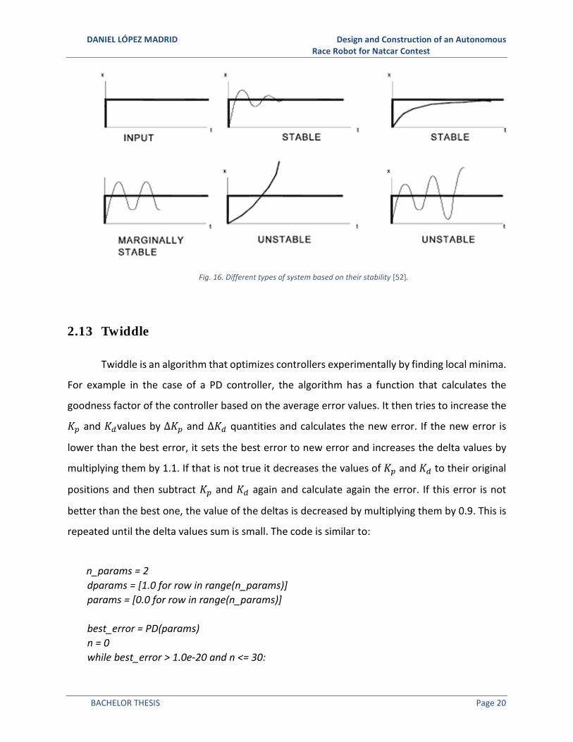
2.12 Ziegler-Nichols Method
It is a heuristic PID controller tuning method that works by setting the proportional (+,),
derivative (+�) and integral (+-) gains to zero and then increasing the proportional one until the
car reaches a stable oscillation movement, also called a marginally stable system (see Fig. 16).
Next make +, = 0.6, +- = 2+,/�4 and +� = +,�4/8 where +4 is the value of +, when the car
oscillates and �4 the period of the oscillation. In Natcar, the use of PD controllers is a common
technique, and in this case the values are +, = 0.5+4 and+� = +,�4/8. For other systems the
values are presented in Table 3.
+, +- +�
PPPP 0.50 +4 - -
PIPIPIPI 0.45 +4 1.20 +,/T_u -
PDPDPDPD 0.80 +4 - +,�4/8
PIDPIDPIDPID 0.60 +4 2 +,/�4 +,�4/8
some overshootsome overshootsome overshootsome overshoot 0.33 +4 2+,/�4 +,�4/3
no overshootno overshootno overshootno overshoot 0.20 +4 2+,/�4 +,�4/3
Table 3. Ziegler Nichols values for different controller configurations [51].
DANIEL LÓPEZ MADRID Design and Construction of an Autonomous Race Robot for Natcar Contest
BACHELOR THESIS Page 20
Fig. 16. Different types of system based on their stability [52].
2.13 Twiddle
Twiddle is an algorithm that optimizes controllers experimentally by finding local minima.
For example in the case of a PD controller, the algorithm has a function that calculates the
goodness factor of the controller based on the average error values. It then tries to increase the
+, and +�values by ∆+, and ∆+� quantities and calculates the new error. If the new error is
lower than the best error, it sets the best error to new error and increases the delta values by
multiplying them by 1.1. If that is not true it decreases the values of +, and +� to their original
positions and then subtract +, and +� again and calculate again the error. If this error is not
better than the best one, the value of the deltas is decreased by multiplying them by 0.9. This is
repeated until the delta values sum is small. The code is similar to:
n_params = 2
dparams = [1.0 for row in range(n_params)]
params = [0.0 for row in range(n_params)]
best_error = PD(params)
n = 0
while best_error > 1.0e-20 and n <= 30:

DANIEL LÓPEZ MADRID Design and Construction of an Autonomous Race Robot for Natcar Contest
BACHELOR THESIS Page 21
for i in range(len(params)):
params[i] += dparams[i]
err = run(params)
if err < best_error:
best_error = err
dparams[i] *= (1.0+t_param)
else:
params[i] -= 2.0 * dparams[i]
err = run(params)
if err < best_error:
best_error = err
dparams[i] *= (1.0+t_param)
else:
params[i] += dparams[i]
dparams[i] *= (1.0-t_param)
n += 1
2.14 Power System
It is the component group that is in charge of delivering enough power, and with a
minimum quality, to the rest of the systems. It is also responsible reducing the amount of electric
noise on all the electronic components of the car. It is normally composed of different voltage
regulators to supply the system the varying voltage levels it requires.
2.15 Chassis
The chassis is the structure that supports the rest of the car components. It is a crucial
element that must protect the most delicate sections, while remaining lightweight. The most
advanced chassis (see Fig. 17) are made of composite materials, including carbon fiber, that lower
the weight and increase the mechanical properties [53].

DANIEL LÓPEZ MADRID Design and Construction of an Autonomous Race Robot for Natcar Contest
BACHELOR THESIS Page 22
Fig. 17. Carbon fiber RC chassis [54].
2.16 Propulsion System
Brushed dc motors are used to drive and propel the car. This motors generate torque
based on “the fact that magnet poles repel and unlike magnetic poles attract each other” [55].
They can be divided in two parts, the stator and the rotor. The stator is constructed of permanent
magnets and remains stationary. In contrast, the rotor moves and has an armature with two or
more wire windings around an iron core. These wires are connected to the exterior through a
commutator (also called brush). The commutator applies an electric current to the wires thus
generating a magnetic field that interacts with those from the permanent magnets. This creates
a force that causes the rotor to rotate. Once the rotor has made half a turn, the current and
therefore also the magnetic field on the rotor are reversed to continue with the rotation
movement. This process is illustrated in Fig. 18 and it is repeated every time the coils leave one
of the permanent magnets and approach the other one [56].

DANIEL LÓPEZ MADRID Design and Construction of an Autonomous Race Robot for Natcar Contest
BACHELOR THESIS Page 23
Fig. 18. DC motor diagram. Notice how the same-sign magnetic poles repel and create movement [57].
The brushless DC motors, on the other hand are faster, more efficient, and more powerful
than its brushed alternatives. These motors have a reversed structure compared to the brushed
ones, where the permanent magnets are on the rotor and the coils on the stator. They usually
have more than one pair of poles and the polarity of the current flowing through each coil is
controlled electronically. This removes the problems generated by the brushes including sparks,
electric noise, friction and exhaustion. However, DC motors require complex and accurate
systems to operate properly.
The most advanced brushed motors are characterized by their high efficiency combined
with great speed and torque. They achieve this by using new technologies including ironless cores
[56].
2.17 Encoders
Encoders are devices that can translate angular positions into digital signals. They can be
divided into absolute or incremental types depending upon if they measure the position globally
or refer to its initial position. The most commonly used encoders are incremental due to their
simplicity and lower price. In addition, the global position of the wheels is not valuable
DANIEL LÓPEZ MADRID Design and Construction of an Autonomous Race Robot for Natcar Contest
BACHELOR THESIS Page 24
information for Natcar systems. The encoders chosen for this project are based on the hall effect
[58]. They work by having two series of permanent magnets placed with a known offset respect
to each other (normally 45 degrees) and two hall sensor effects that detect the crossing of each
one of the individual magnets in front of them. With that information, it creates a signal that can
be read from the microcontroller. The minimal step that the encoders can sense is called a count.
The accuracy of the encoders is measured on counts per revolution.
Advanced devices used in industry to monitor high precision processes can achieve
resolutions higher than 750,000 counts/rev [59].
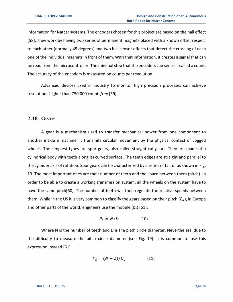
2.18 Gears
A gear is a mechanism used to transfer mechanical power from one component to
another inside a machine. It transmits circular movement by the physical contact of cogged
wheels. The simplest types are spur gears, also called straight-cut gears. They are made of a
cylindrical body with teeth along its curved surface. The teeth edges are straight and parallel to
the cylinder axis of rotation. Spur gears can be characterized by a series of factor as shown in Fig.
19. The most important ones are their number of teeth and the space between them (pitch). In
order to be able to create a working transmission system, all the wheels on the system have to
have the same pitch[60]. The number of teeth will then regulate the relative speeds between
them. While in the US it is very common to classify the gears based on their pitch (��), in Europe
and other parts of the world, engineers use the module (8) [61].
�� = 9/: (10)
Where N is the number of teeth and D is the pitch circle diameter. Nevertheless, due to
the difficulty to measure the pitch circle diameter (see Fig. 19). It is common to use this
expression instead [61].
�� = (9 + 2)/:� (11)

DANIEL LÓPEZ MADRID Design and Construction of an Autonomous Race Robot for Natcar Contest
BACHELOR THESIS Page 25
Where :� is the external diameter. To convert between both systems this is the
expression used
8 = 25.4/�� (12)
Fig. 19 Gear nomenclature [62]
2.19 Bearing
A bearing is a mechanical component that reduces the friction between an axis and the
pieces connected to it. Natcars and radio control cars use a type of bearing called ball bearing
(shown in Fig. 20). They work by placing a set of spheres between the inner and outer parts (also

DANIEL LÓPEZ MADRID Design and Construction of an Autonomous Race Robot for Natcar Contest
BACHELOR THESIS Page 26
known as races) of the mechanism. As the balls rolls when one of the races rotates, the friction
is much lower than if both flat surfaces were sliding on each other.
Fig. 20. Cross section of a ball bearing. It can be appreciated how there is a set of spheres between the inner and outer
races [63].
Most of the research done in this field is focused on the use of the ceramic materials that
can be used on medical applications including hip prosthesis [64].
2.20 Micromouse
Micromouse is a similar project to Natcar that also tries to help the students learn
important skills that they could use in their future jobs. As stated by their organizers, “it is an
engineering design competition created by IEEE where small robotic mice solve a 16x16 maze.
The mice are completely autonomous robots that must find their way from a predetermined
starting position to the central area of the maze unaided. The mouse will need to keep track of
where it is, discover walls as it explores, map out the maze and detect when it has reached the
goal” [65]. It is more software based than Natcar. The participating Micromouse teams can buy
pre-built motor controllers and DC-DC converters. However, they must construct much more
complex algorithms than those utilized for this project. It is a more popular contest than Natcar
and therefore more information available about it. Due to the similarity of the typical

DANIEL LÓPEZ MADRID Design and Construction of an Autonomous Race Robot for Natcar Contest
BACHELOR THESIS Page 27
Micromouse layout (shown in Fig. 21) and the Natcar approach that will be used on this project,
some of that information may also applied to Natcar.
Fig. 21. Typical Micromouse layout [66].
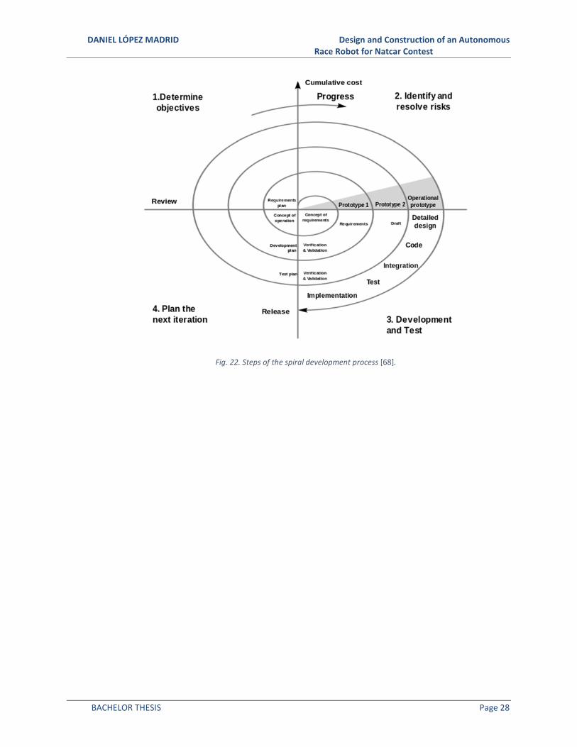
2.21 Spiral Development
This method is adapted from software development. It is based on the creation of a very
early first prototype where the design and theoretical assumptions can be checked. Then, a new
model will keep the successful parts and try to solve the problems found. This process is repeated
until a product that fulfills the requirements is reached [67]. The process is illustrated in Fig. 22
and will be used in this project to design and build the motor mounts and the wheels.
DANIEL LÓPEZ MADRID Design and Construction of an Autonomous Race Robot for Natcar Contest
BACHELOR THESIS Page 28
Fig. 22. Steps of the spiral development process [68].

DANIEL LÓPEZ MADRID Design and Construction of an Autonomous Race Robot for Natcar Contest
BACHELOR THESIS Page 29
3. DESIGN DESCRIPTION
3.1 Layout
For the race, a car with a high top speed that is able to make turns as fast as possible is
desired. Usually people use a 1/10th or 1/8th scale RC cars as the base for their robots [69]. This
option presents some advantages and disadvantages. For example, it provides an excellent but
expensive chassis [70], [71]. The build and overall quality is notable and the control system is
rather intuitive. It uses one motor that normally provides power to the rear wheels and a servo
to control the steering. However, the system is restricted in size compared to what can be found
in the RC market and there is no room for improvement.
A different approach was chosen in the current project where a differential steering car
with two motors and four wheels is used, as shown in Fig. 23. The advantages are closer turns
and greater speed during the curves. In addition, having two motors lets the weight to be better
distributed and a higher torque can be achieved. The most important disadvantages for this
layout are that it is necessary to design and manufacture the car de novo and the control is not
as intuitive as with the typical layout.
Fig. 23 Final version of the car with the custom built chassis and the differential drive configuration.
DANIEL LÓPEZ MADRID Design and Construction of an Autonomous Race Robot for Natcar Contest
BACHELOR THESIS Page 30
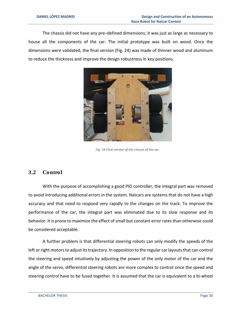
The chassis did not have any pre–defined dimensions; it was just as large as necessary to
house all the components of the car. The initial prototype was built on wood. Once the
dimensions were validated, the final version (Fig. 24) was made of thinner wood and aluminum
to reduce the thickness and improve the design robustness in key positions.
Fig. 24 Final version of the chassis of the car.
3.2 Control
With the purpose of accomplishing a good PID controller, the integral part was removed
to avoid introducing additional errors in the system. Natcars are systems that do not have a high
accuracy and that need to respond very rapidly to the changes on the track. To improve the
performance of the car, the integral part was eliminated due to its slow response and its
behavior. It is prone to maximize the effect of small but constant error rates than otherwise could
be considered acceptable.
A further problem is that differential steering robots can only modify the speeds of the
left or right motors to adjust its trajectory. In opposition to the regular car layouts that can control
the steering and speed intuitively by adjusting the power of the only motor of the car and the
angle of the servo, differential steering robots are more complex to control since the speed and
steering control have to be fused together. It is assumed that the car is equivalent to a bi-wheel

DANIEL LÓPEZ MADRID Design and Construction of an Autonomous Race Robot for Natcar Contest
BACHELOR THESIS Page 31
differential robot. With this assumption, the equations that determine the movement of the car
can be calculated. However, they are still too difficult to control the car, so it is useful to assume
that the car behaves like a unicycle following these expressions:
� =�?@AB
�C (13)
�D =�?EAB
�C (14)
Where F and FD are the speeds of the right and left motors respectively. F is the speed
of the car, G is the steering, H is the distance between wheels and I is the radius of the wheel.
Then the system takes the error of the sensors and the error of the camera and calculates the
angle that the track has with respect to the car.
J = atanM
NOPQENRS�R�TR (15)
Where : is the distance between the sensors and the reading area of the camera in front
of the car. Now, a PD controller can be implemented to calculate the value of G:
G = +, ∙ J + +� ∙ J# (16)
J# =VEVWTSX
∆� (17)
The speed can be fixed or can be calculated with another PD controller, although without
encoders it is hard to calculate the real speed at each PWM value. Therefore, the car will have a
fixed speed value until the encoders are implemented.
3.3 Motors
To get an initial estimation for the motors that the car would need, an online resource
was used [72]. It is a simplified version of the Society of Robots RMF (Robot Motor Factor)
calculator [73]. This calculator estimate the torque that the motors would need to meet based
on factors like max speed, acceleration, weight of the car and efficiency of the motor.
DANIEL LÓPEZ MADRID Design and Construction of an Autonomous Race Robot for Natcar Contest
BACHELOR THESIS Page 32
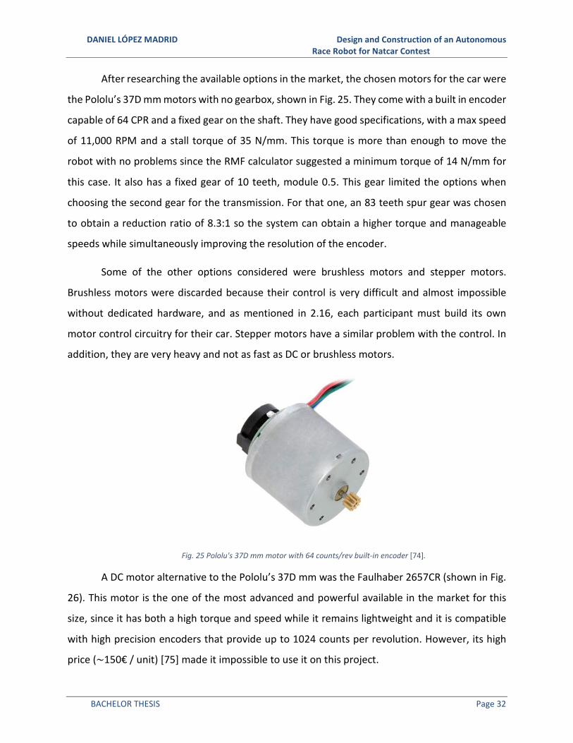
After researching the available options in the market, the chosen motors for the car were
the Pololu’s 37D mm motors with no gearbox, shown in Fig. 25. They come with a built in encoder
capable of 64 CPR and a fixed gear on the shaft. They have good specifications, with a max speed
of 11,000 RPM and a stall torque of 35 N/mm. This torque is more than enough to move the
robot with no problems since the RMF calculator suggested a minimum torque of 14 N/mm for
this case. It also has a fixed gear of 10 teeth, module 0.5. This gear limited the options when
choosing the second gear for the transmission. For that one, an 83 teeth spur gear was chosen
to obtain a reduction ratio of 8.3:1 so the system can obtain a higher torque and manageable
speeds while simultaneously improving the resolution of the encoder.
Some of the other options considered were brushless motors and stepper motors.
Brushless motors were discarded because their control is very difficult and almost impossible
without dedicated hardware, and as mentioned in 2.16, each participant must build its own
motor control circuitry for their car. Stepper motors have a similar problem with the control. In
addition, they are very heavy and not as fast as DC or brushless motors.
Fig. 25 Pololu's 37D mm motor with 64 counts/rev built-in encoder [74].
A DC motor alternative to the Pololu’s 37D mm was the Faulhaber 2657CR (shown in Fig.
26). This motor is the one of the most advanced and powerful available in the market for this
size, since it has both a high torque and speed while it remains lightweight and it is compatible
with high precision encoders that provide up to 1024 counts per revolution. However, its high
price (~150€ / unit) [75] made it impossible to use it on this project.

DANIEL LÓPEZ MADRID Design and Construction of an Autonomous Race Robot for Natcar Contest
BACHELOR THESIS Page 33
Fig. 26 Faulhaber 2657CR, one of the best available motors in the market for this application [75].
3.4 Encoders
The encoders are used to implement a closed loop feedback on the speed control of the
car. They synchronize both motors to correct the small differences and imperfections that cause
the motors to run at slightly different speeds for the same PWM values. The ones that come with
the Pololu motors have 64 counts/rev [74], that added to the transmission factor introduced by
the gears creates an accuracy (�) of 0.59388/\]^_�, which is a good value for this purpose.
� =(#�-abc/ N?)∙� d�ce-cc-��_gda��
hij∙��C
hij= 0.59388/\]^_� (18)
3.5 Transmission
As there was no information from other people doing this type of car layout, documents
available for Micromouse that describe a similar structure were consulted [76]–[82]. With this
information, a transmission system was designed. It can be divided into the motor mount and
the wheel system. The motor mount houses the motor, and it is attached to the chassis. A general
view of the whole system is shown in Fig. 27. OpenSCAD was used to design all the components

DANIEL LÓPEZ MADRID Design and Construction of an Autonomous Race Robot for Natcar Contest
BACHELOR THESIS Page 34
Fig. 27 View of the complete transmission and wheel system including the motor mounts generated in OpenSCAD.
The motor mounts have openings for the shafts, the motor, their screws and the screws
to fix the motor mount to the chassis. They also have holes for the nuts that will keep these last
screws in place. The detailed model is shown in Fig. 28.
Fig. 28 Back view (left) and front view (right) of the motor mounts created in OpenSCAD.
These holes are smaller than the nuts required to use a technique common in the 3D
printing world. It consists of placing the nut on top of the hole and heating the metal with a
solder. This way, the plastic melts and the nuts stay perfectly inside of it as shown in Fig. 29.

DANIEL LÓPEZ MADRID Design and Construction of an Autonomous Race Robot for Natcar Contest
BACHELOR THESIS Page 35
Fig. 29 Inserting the nuts into the motor mount using the heat from the soldering iron.
The wheel system (shown in Fig. 30) consists of two bearings, a gear and the wheel itself.
The gear is fixed to the wheel and the only elements in contact with the shaft are the ball
bearings. These bearings are model MF95ZZ, which have a flange that makes it possible to fix
them on the top and bottom of the wheel’s shaft hole. They are also very cheap and have good
mechanical properties.
Fig. 30 Diagram of the wheel and motor mount system [81].
The wheels were designed on OpenSCAD. A wide wheel design was chosen (shown in Fig.
31) to increase the traction, and to be able to attach the gear and the bearings with high
precision.

DANIEL LÓPEZ MADRID Design and Construction of an Autonomous Race Robot for Natcar Contest
BACHELOR THESIS Page 36
Fig. 31 Wheel model generated in OpenSCAD.
3.6 Microcontroller
For the microcontroller, at the beginning of the project, the beaglebone black (BBB) was
chosen because of its power and capabilities. The idea was to write the software in Python
avoiding the compilation steps and set up a web server to allow real time debugging and data
monitoring from any web enabled device. However, some problems appeared with the
implementation of the camera routine. In the normal mode, the BBB manages the physical inputs
and outputs as any regular Linux device, which is writing and reading to special system files. This
method is simple and works with no problems at frequencies up to 1.20 KHz [83]. Any signal with
a frequency higher than that would not be correctly measured. The key part is that the BBB has
two dedicated hardware processors (PRU) that manage these activities [28]. They can go up to
50 MHz but to be able to work directly with them, it is necessary to patch the kernel and write
special software that uses shared memory space between the PRU units and the main program
[27], [29]. This technique is not officially supported by the manufacturer and is difficult to
accomplish [25]. Therefore, a simpler device that allows easy I/O management was chosen. The
best options were Arduino and MBed; the chosen one was Arduino due to its plentiful community

DANIEL LÓPEZ MADRID Design and Construction of an Autonomous Race Robot for Natcar Contest
BACHELOR THESIS Page 37
generated content and documentation [23]. It has multiple libraries to implement motor control,
Bluetooth communications and PID tuning. Teensy was also taken into consideration since it is
an Arduino compatible platform that includes a more powerful processor, more RAM and
EEPROM memory as well as more analog pins and better control for PWMs [20]. From this point
Teensy, more specifically Teensy 2.0++, became the chosen platform for the microcontroller and
all the software previously written for the BBB was adapted to it.
3.7 Line Scan Camera
The TSL1401-DB (Fig. 32) is manufactured by Parallax [84]. It is the sensor that most of
the Natcars mount [34] and it is capable of obtaining very good results. It is composed of a 128-
sensor array of photodiodes that measure the intensity of the light that arrives to them. In order
to work correctly, it includes a lens system that allows you to modify the focal point of the camera
to obtain the best results [31].
Fig. 32 Parallax TSL1401 Line scan camera module [84].
The datasheet provides many examples and useful tips on how to use the camera and
obtain better quality data [31]. As it was explained on 2.4, at each cycle every pixel is going to
receive a certain amount of light during a period. During this time, every pixel charges its own
built-in capacitor with a voltage that is dependent on the intensity of the light that it is receiving.

DANIEL LÓPEZ MADRID Design and Construction of an Autonomous Race Robot for Natcar Contest
BACHELOR THESIS Page 38
In addition, it is important to remark that the signal saturates at 3.3V, so these values have to be
chosen carefully.
Although the line scan camera does not output a full image, the resultant array with the
information from all the photodiodes can be considered as an image with a resolution of 128x1.
To calculate the position of the track on this image it is necessary to perform some calculations.
The most commonly used technique is the application of the Sobel operator [35], which consists
of calculating the derivatives on each pixel’s intensity with respect to the previous and next pixel.
This way the pixels with a greater result would be the ones that correspond to the edge of the
track. In the real world, this method is not reliable because it is based on derivatives and
therefore is heavily affected by noise. Instead, a new algorithm was developed, illustrated in Fig.
33. First, it dismisses the pixels that have a value above and below a certain threshold to avoid
reading errors (usual in practice). Then it calculates the maximum value of the signal (red dot in
the Fig. 33) and finds the leftmost and rightmost pixels that are above a certain threshold level
(blue line and dots in Fig. 33). That level has been set empirically to 85% of the maximum to
achieve the best results. Next, it calculates the middle point in between the leftmost and
rightmost pixels and that becomes the calculated position for the track (green line in Fig. 33)
Contrary to the Sobel operator, this algorithm is capable of obtaining high accuracy and
repeatability results.

DANIEL LÓPEZ MADRID Design and Construction of an Autonomous Race Robot for Natcar Contest
BACHELOR THESIS Page 39
Fig. 33 Illustration of the track finding algorithm developed.
The line scan camera is used instead of a 2D conventional camera because its data is faster
and easier to process. Had a 2D camera been chosen, a more powerful microcontroller would be
necessary in order to do actual image processing and analysis.
3.8 Analog Front End and Magnetic Sensors
Since the frequency of the current flowing through the track wire is known, a correct
combination of inductance and capacitors can be chosen to resonance at that. In this case, the
chosen values were 2mH for the inductance and 2nF for the capacitors.

DANIEL LÓPEZ MADRID Design and Construction of an Autonomous Race Robot for Natcar Contest
BACHELOR THESIS Page 40
Fig. 34 Analog front end circuit schematic.
The current analog front end (AFE) circuit is shown in Fig. 34. The car consists of three of
these sensing circuits, one for each sensor, although it can be scaled up to make room for more
sensors. It was designed to use it with the Beagle Bone Black, which has a maximum analog input
voltage of 1.8V. Due to this constraint, it was necessary to choose smaller than usual inductors
and a diode with a small forward voltage. The current AFE circuits utilize 2mH inductors and high
frequency Schottky diodes with a 410mV forward voltage.
The operational amplifier initially chosen was the LM6144BIN. This component seemed
ideal because of its high gain bandwidth product, its efficient packaging and the fact that the
datasheet stated that it could be operated in single supply mode. Later in the development
process was found that this component was not suitable for its use in the AFE circuit.
3.9 Sensor Fusion
Typically, Natcars use the magnetic sensors as their principal method to sense the track.
The combination of the information coming from each one of the sensors is a key aspect of the
design of the Natcar that will determine its successfulness. The sensors’ signals pass through the
AFE where they are conditioned and adapted to the microcontroller. Next, a mathematical model
is applied to obtain a linear error function to use on the control system. Fig. 35 shows the result
of the simulations of some of the most common models. The most appropriated method is the
one in green due to its high linearity on the [-5, 5] cm interval.
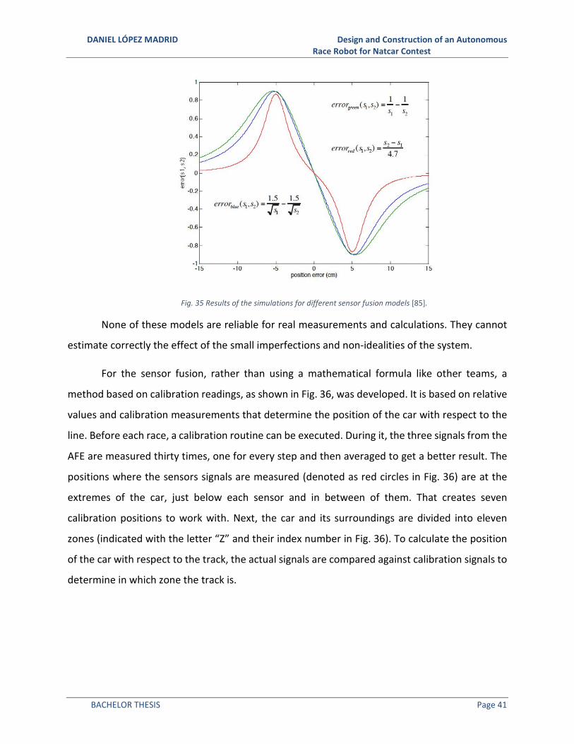
DANIEL LÓPEZ MADRID Design and Construction of an Autonomous Race Robot for Natcar Contest
BACHELOR THESIS Page 41
Fig. 35 Results of the simulations for different sensor fusion models [85].
None of these models are reliable for real measurements and calculations. They cannot
estimate correctly the effect of the small imperfections and non-idealities of the system.
For the sensor fusion, rather than using a mathematical formula like other teams, a
method based on calibration readings, as shown in Fig. 36, was developed. It is based on relative
values and calibration measurements that determine the position of the car with respect to the
line. Before each race, a calibration routine can be executed. During it, the three signals from the
AFE are measured thirty times, one for every step and then averaged to get a better result. The
positions where the sensors signals are measured (denoted as red circles in Fig. 36) are at the
extremes of the car, just below each sensor and in between of them. That creates seven
calibration positions to work with. Next, the car and its surroundings are divided into eleven
zones (indicated with the letter “Z” and their index number in Fig. 36). To calculate the position
of the car with respect to the track, the actual signals are compared against calibration signals to
determine in which zone the track is.
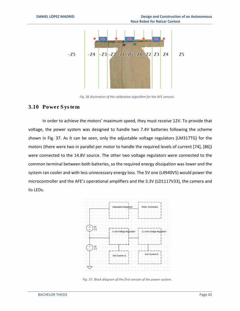
DANIEL LÓPEZ MADRID Design and Construction of an Autonomous Race Robot for Natcar Contest
BACHELOR THESIS Page 42
Fig. 36 Illustration of the calibration algorithm for the AFE sensors.
3.10 Power System
In order to achieve the motors’ maximum speed, they must receive 12V. To provide that
voltage, the power system was designed to handle two 7.4V batteries following the scheme
shown in Fig. 37. As it can be seen, only the adjustable voltage regulators (LM317TG) for the
motors (there were two in parallel per motor to handle the required levels of current [74], [86])
were connected to the 14.8V source. The other two voltage regulators were connected to the
common terminal between both batteries, so the required energy dissipation was lower and the
system ran cooler and with less unnecessary energy loss. The 5V one (L4940V5) would power the
microcontroller and the AFE’s operational amplifiers and the 3.3V (LD1117V33), the camera and
its LEDs.
Fig. 37. Block diagram of the first version of the power system.

DANIEL LÓPEZ MADRID Design and Construction of an Autonomous Race Robot for Natcar Contest
BACHELOR THESIS Page 43
Most Natcars use batteries with capacities of 1000 mAh or 1200mAh batteries. These
batteries provide more capacity than the one necessary therefore and in order to reduce the
weight of the car, 500 mAh batteries were chosen for this project.
3.11 Motor Control
The motor circuit controls the energy provided to the motors based on the PWM signal
generated by the microcontroller. A simple circuit was used (shown in Fig. 38). It has an N-channel
MOSFET that controls the motor current and some diodes to protect the rest of the circuit from
the current generated by the motor when it stops. There is one of these circuits for each motor
Fig. 38. First version of the motor control circuit.
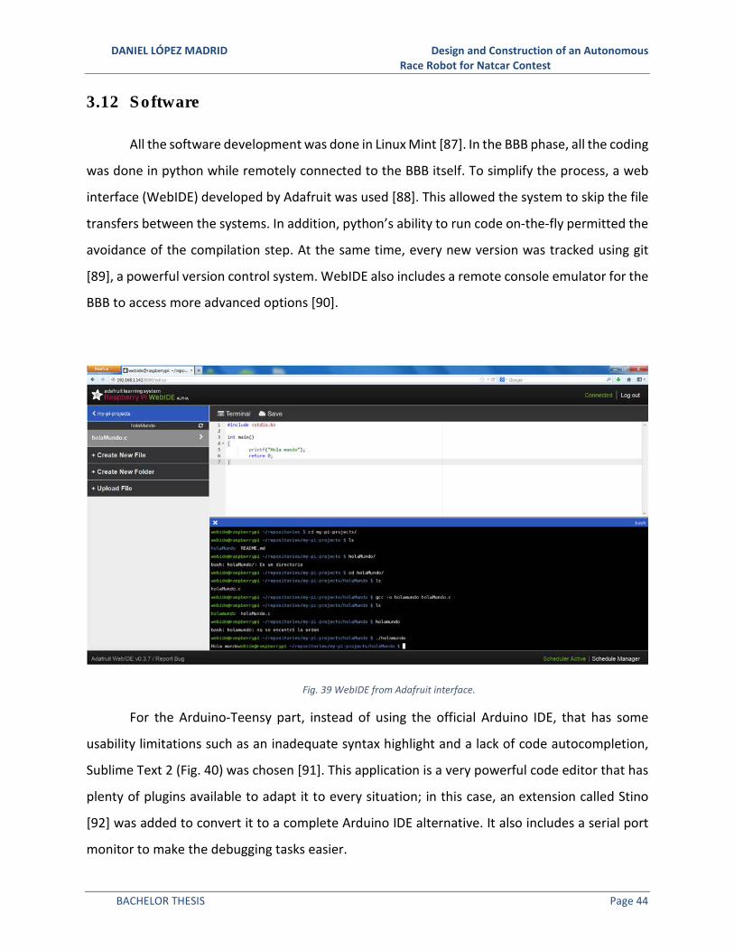
DANIEL LÓPEZ MADRID Design and Construction of an Autonomous Race Robot for Natcar Contest
BACHELOR THESIS Page 44
3.12 Software
All the software development was done in Linux Mint [87]. In the BBB phase, all the coding
was done in python while remotely connected to the BBB itself. To simplify the process, a web
interface (WebIDE) developed by Adafruit was used [88]. This allowed the system to skip the file
transfers between the systems. In addition, python’s ability to run code on-the-fly permitted the
avoidance of the compilation step. At the same time, every new version was tracked using git
[89], a powerful version control system. WebIDE also includes a remote console emulator for the
BBB to access more advanced options [90].
Fig. 39 WebIDE from Adafruit interface.
For the Arduino-Teensy part, instead of using the official Arduino IDE, that has some
usability limitations such as an inadequate syntax highlight and a lack of code autocompletion,
Sublime Text 2 (Fig. 40) was chosen [91]. This application is a very powerful code editor that has
plenty of plugins available to adapt it to every situation; in this case, an extension called Stino
[92] was added to convert it to a complete Arduino IDE alternative. It also includes a serial port
monitor to make the debugging tasks easier.

DANIEL LÓPEZ MADRID Design and Construction of an Autonomous Race Robot for Natcar Contest
BACHELOR THESIS Page 45
Fig. 40 Screenshot of Sublime text 2.
The TimerOne library from PJRC [93], the Teensy creators, was very helpful. It allows
modifying the frequency of the PWM signals of the Teensy that normally is 1 KHz, too fast for
some applications.
The software is modular. It is divided in different components, each one of them performs
a specialized task. These functions can be individually tested to isolate and identify errors.
The modules are:
void setup(): It initializes the pins modes, the timer frequency and interrupt and the serial
port. Then checks for any calibration data stored in the EEPROM memory [94]. If that is the case,
it loads the values to the memory.
void ReadCamera(): It performs the camera reading routine. It sends the CLK and SI signals
to the linescan camera and stores the values of AO in a global array to use them in other
functions.

DANIEL LÓPEZ MADRID Design and Construction of an Autonomous Race Robot for Natcar Contest
BACHELOR THESIS Page 46
float FindLine(): It takes the data array from the camera and analyzes it to find where the
line is. Then, it returns the index number of the pixel where the track has its center.
int Clip (int my_var): It verifies that the values read from the magnetic sensors are
between certain limits. If the signal value is too high or too low, it gets clipped to the maximum
or minimum values allowed respectively.
void Calibration(): It starts when the calibration button is pressed on the board. Next, the
car enters in calibration mode waiting to be placed on the first spot. When the car is in the correct
position, the operator presses the OK button and the calibration starts: the sensor values are
read thirty times with 15ms between readings. Then the acquired data is averaged to remove the
noise and stored. Once this routine is completed, a LED blinks indicating that the calibration on
that position has been done and that the car is waiting to be placed in the next position. This
procedure is repeated in the six calibration positions remaining. When the process is finished,
the data is stored on the EEPROM memory to use it in the future runs and a LED blinks again to
indicate that the car is ready to run.
void GetSensorsData(): This procedure is similar to Calibration(). It reads the current
values from the sensors ten times waiting 3ms between measurements. Then it averages the
data from each sensor and stores them in global variables.
int FindZoneSensors(): It combines the calibration data and the information from
GetSensorsData() to calculate the actual position of the car based on the magnetic sensors. It
also keeps track of in which side of the car was the track previously in case the car distances itself
from it. Finally, it returns the index code of the zone where the track currently is.
float CalcErrorSensors(): It transforms the error zone indices into numerical values that
can be used the controllers along with the camera error.
void WVPD(): it contains the PD controller algorithms for the angular speed (G) and the
linear speed (F).

DANIEL LÓPEZ MADRID Design and Construction of an Autonomous Race Robot for Natcar Contest
BACHELOR THESIS Page 47
For the G part (19), it calculates the angle between the longitudinal axis of the car and
the track. Then it calculates the time that has gone since the last time the controller was executed
and computes the derivative error based on it. Next, the PD controller itself is executed.
G = (+k_G ∗ m_nop + +�_G ∗ p_�]�_m_nop); (19)
For v (20), each zone has a maximum speed determined empirically. Then based on if the
car has to turn and how fast has to be the turn (that is, angle andG), that maximum speed is
reduced to a certain value.
F = �r�s[mu (v]_p)] ∗ (1 − (+k_F ∗ m_nop + +�_F ∗ G)); (20)
Although, this method was not fully tested. Most of the times the car will run at a fixed
speed that depends on the position of a potentiometer on the board. Finally, It takes F and G
and calculates the pwm values for the left and right motors. It also certifies that the PWM values
calculated are inside the maximum values and there are not negative values at any time. It also
prevents the saturation of the signals by maintaining the ratio between them even if one of them
is greater than the maximum.
void StopInterrupt(): This interruption is triggered by the emergency switch. It stores the
previous state of the car and stops the motors. To resume the previous state, the switch has to
be reset and the OK button has to be pressed
void loop(): It is the main loop of the program. It calls the other functions and it is executed
continuously.
The original code can be found in 10.1.

DANIEL LÓPEZ MADRID Design and Construction of an Autonomous Race Robot for Natcar Contest
BACHELOR THESIS Page 48
4. TESTING AND VALIDATION
4.1 Magnetic Sensors and Analog Front End
After the analog front end circuit (final version shown in Fig. 41) was built it had to be
calibrated it so each sensor would read the same values in the same conditions while
simultaneously limiting the max voltage to what the microcontroller ADC can read safely. This
was achieved by building a small test track and using an oscilloscope attached to the sensors to
test it. During the initial tests, it was discovered that the original operational amplifier was
suffering ringing effects due to the high frequency of the generated signal by the sensors. In
theory, the amplifier should have worked at that frequency with no problem, and reducing the
frequency would make the system work correctly. To solve this problem, the component model
was changed to MCP6022, which has similar characteristics and the circuit worked perfectly.
After this, the value of the cutoff frequency of the low pass filter and the maximum level were
adapted to it. Next, their range was measured to confirm that they were suitable for the car. The
results were good but there was room for additional improvement. Therefore, the inductors were
replaced by bigger ones to achieve better sensitivity. These new sensors had better range, but
their combined weight was bending the thin aluminum chassis. It was found that another way to
increase the first sensors sensitivity was to put them a little bit higher. There was found to be an
ideal placement at about 5mm higher than they were previously. The chassis was then adapted
to put the original sensors at that point.
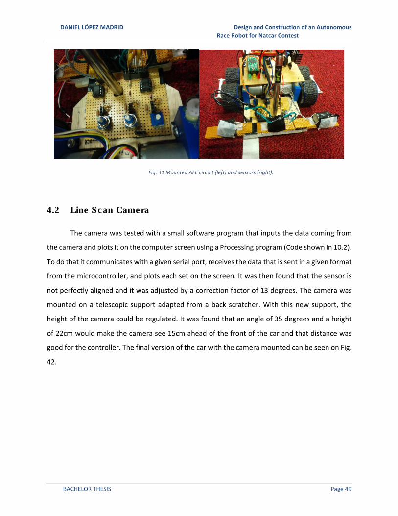
DANIEL LÓPEZ MADRID Design and Construction of an Autonomous Race Robot for Natcar Contest
BACHELOR THESIS Page 49
Fig. 41 Mounted AFE circuit (left) and sensors (right).
4.2 Line Scan Camera
The camera was tested with a small software program that inputs the data coming from
the camera and plots it on the computer screen using a Processing program (Code shown in 10.2).
To do that it communicates with a given serial port, receives the data that is sent in a given format
from the microcontroller, and plots each set on the screen. It was then found that the sensor is
not perfectly aligned and it was adjusted by a correction factor of 13 degrees. The camera was
mounted on a telescopic support adapted from a back scratcher. With this new support, the
height of the camera could be regulated. It was found that an angle of 35 degrees and a height
of 22cm would make the camera see 15cm ahead of the front of the car and that distance was
good for the controller. The final version of the car with the camera mounted can be seen on Fig.
42.
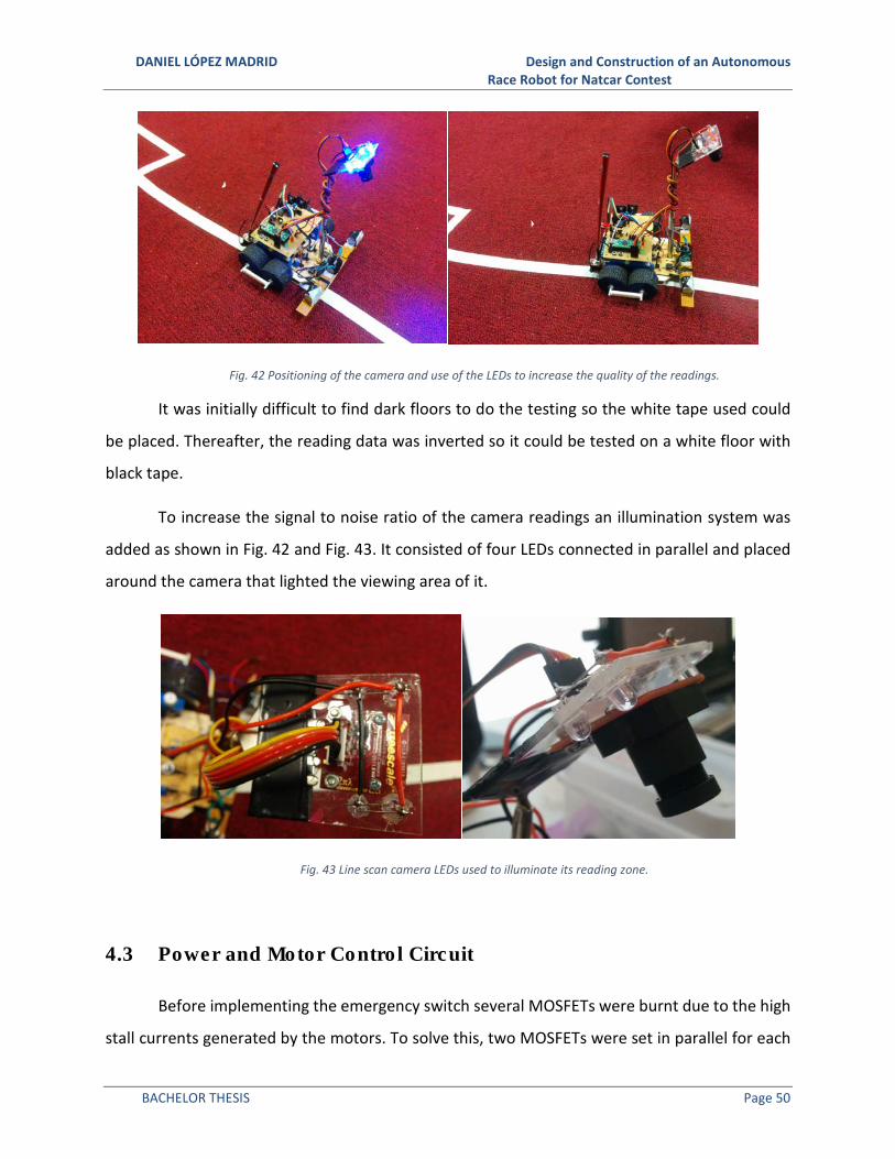
DANIEL LÓPEZ MADRID Design and Construction of an Autonomous Race Robot for Natcar Contest
BACHELOR THESIS Page 50
Fig. 42 Positioning of the camera and use of the LEDs to increase the quality of the readings.
It was initially difficult to find dark floors to do the testing so the white tape used could
be placed. Thereafter, the reading data was inverted so it could be tested on a white floor with
black tape.
To increase the signal to noise ratio of the camera readings an illumination system was
added as shown in Fig. 42 and Fig. 43. It consisted of four LEDs connected in parallel and placed
around the camera that lighted the viewing area of it.
Fig. 43 Line scan camera LEDs used to illuminate its reading zone.
4.3 Power and Motor Control Circuit
Before implementing the emergency switch several MOSFETs were burnt due to the high
stall currents generated by the motors. To solve this, two MOSFETs were set in parallel for each

DANIEL LÓPEZ MADRID Design and Construction of an Autonomous Race Robot for Natcar Contest
BACHELOR THESIS Page 51
motor to double the current that the system could manage. The heat sinks were also changed
for larger ones. All these effects prevented the further burning of transistors.
To take advantage of all the motors’ power, the two batteries system was implemented,
with its own share of issues. Most of these issues arose from the new variable voltage regulators
that powered the motors. In theory, the regulators should not burnout because there were two
of each in parallel for each motor. However small imperfections rendered the balancing
imperfect resulting in most of the current flowing through a single regulator from each pair and
eventually causing their burnout. In addition, an extra voltage regulator was added to the design.
It outputs 3.3V to power the linescan camera and the camera LEDs. The camera could be powered
also at 5V but this new voltage acted as a voltage limiter for its output.
After some test runs it was evident that it was impossible to use all the power from the
motors and run them at full speed. To mediate this the battery system could be transformed
again to a single 7.4V battery and solve all of the problems brought on by the previous
configuration. The final circuit’s schematic is shown in Fig. 44.
The motor control system was tested and checked that the PWM signal worked correctly.
A low pass filter was added in parallel with the motors to reduce the noise generated by them.
Better diodes were found so only two of them were needed, contrary to the original four of the
first version (shown in Fig. 38). The final version with the changes is shown in Fig. 45.

DANIEL LÓPEZ MADRID Design and Construction of an Autonomous Race Robot for Natcar Contest
BACHELOR THESIS Page 52
Fig. 44 Schematic of the final version of the power circuit.
Fig. 45 Schematic of the motor control system.

DANIEL LÓPEZ MADRID Design and Construction of an Autonomous Race Robot for Natcar Contest
BACHELOR THESIS Page 53
4.4 Motor
The motors were tested using an external power source to check if they could withstand
the maximum voltage during extended periods. Then a small program was written to test the
encoders and measure the speeds of the motors (Code in 10.3). Next, the motors were calibrated.
Surprisingly they did not need major adjustments and it could be considered that they run at the
same speed with no modifications.
4.5 PD Controller Tuning
At the beginning, the Ziegler Nichols method was used to get a first approximation of
which values should be used. This method however was not getting desirable results. After
spending some time on controller tuning research, twiddle was the chosen method to tune the
controller variables. With a little extra tuning by hand, the final values that were working well
were +, = 0.8 and+� = 0.35.
4.6 Grounding and Noise Reduction
The custom-made transmission and motor mounts caused the motors to generate a high
amount of noise that had an influence on the rest of the system. To identify the problem, the
voltage between different ground points in the circuit was measured. To try solving it, two
separators were added between the wheels shafts that adjusted that distance to an optimum
value as it can be seen in Fig. 46. Another solution was to put filters on the motor connections
(capacitors in Fig. 45) and make the connections on the board shorter and thicker to reduce their
electrical resistance. Before that, the noise levels were so high that the camera could not work
correctly and the emergency switch was randomly activated.

DANIEL LÓPEZ MADRID Design and Construction of an Autonomous Race Robot for Natcar Contest
BACHELOR THESIS Page 54
Fig. 46 Wheel separator to correct the alignment of the wheel axis.
4.7 Software
The traditional algorithms for Natcar were tested on the car once it was built. It was found
that the Sobel operator experienced troubles finding the track due to its high susceptibility to
electrical noise. Therefore, a new solution was needed. The algorithm described on 3.7 was
implemented and tested, obtaining great accuracy and repeatability.
A PID controller was also tested and the results concluded that the integral part was
unnecessary for the correct operation of the car.
Another area subjected to study was the sensor fusion. It was found that the
mathematical model extracted from the simulations was not accurate enough in the real world,
so the new algorithm based in zones (described in 3.9) was used to improve the obtained results.
4.8 Board
The first version of the board was built on a protoboard where the circuit schematics were
tested. It included:
• Three LEDs (red, yellow and green) to show the system status to the operator
• Calibration and OK buttons
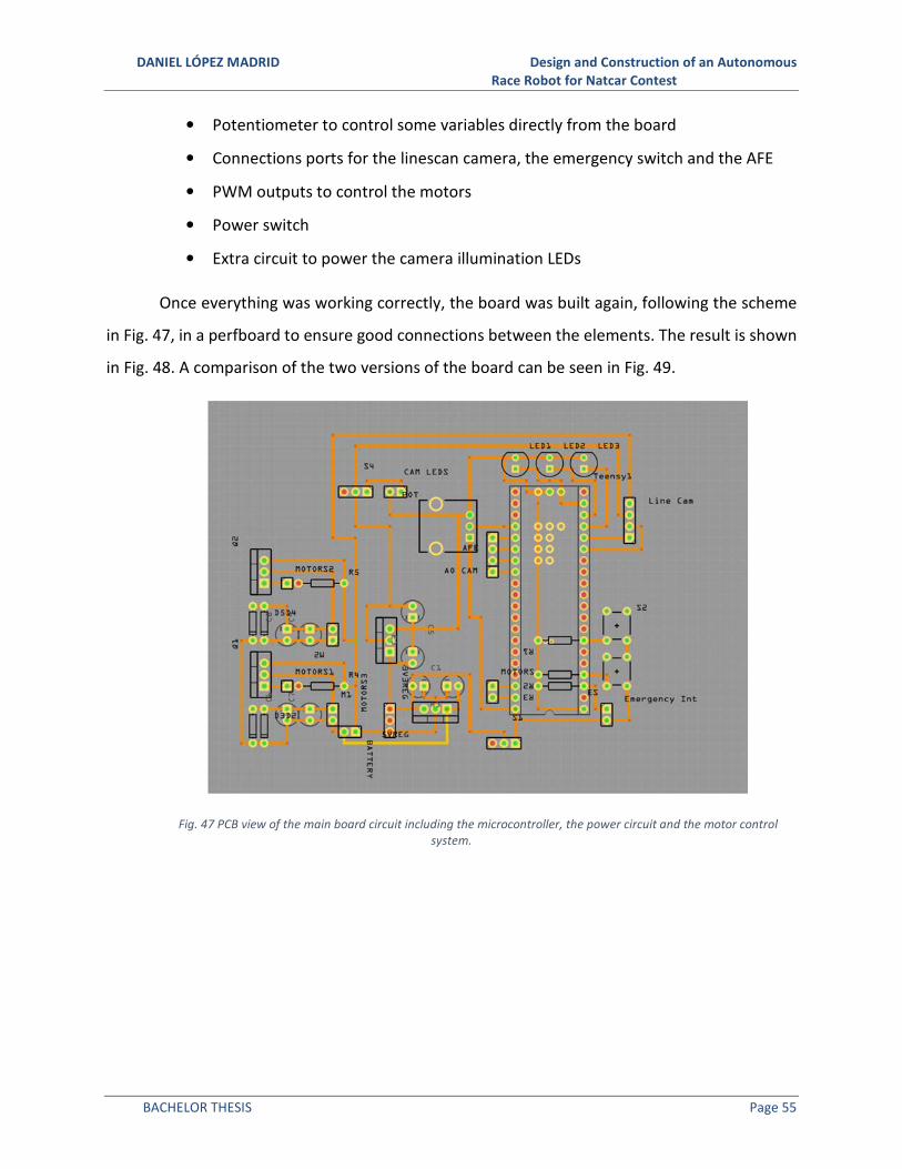
DANIEL LÓPEZ MADRID Design and Construction of an Autonomous Race Robot for Natcar Contest
BACHELOR THESIS Page 55
• Potentiometer to control some variables directly from the board
• Connections ports for the linescan camera, the emergency switch and the AFE
• PWM outputs to control the motors
• Power switch
• Extra circuit to power the camera illumination LEDs
Once everything was working correctly, the board was built again, following the scheme
in Fig. 47, in a perfboard to ensure good connections between the elements. The result is shown
in Fig. 48. A comparison of the two versions of the board can be seen in Fig. 49.
Fig. 47 PCB view of the main board circuit including the microcontroller, the power circuit and the motor control
system.

DANIEL LÓPEZ MADRID Design and Construction of an Autonomous Race Robot for Natcar Contest
BACHELOR THESIS Page 56
Fig. 48 Top view of the last version of the board adapted for a single 7.4V batteries.
Fig. 49 Comparison of the bottom views of the first version (left) and the last version (right) of the main board.
4.9 Batteries
Due to the high power consumption of the car, it was necessary to have a good recharge
strategy. During the test sessions, there was at least one pair of batteries ready to use. In total,
there were seven batteries. While doing the camera and sensors tests, the battery life was good.
However, during the test runs the car could only complete a few laps before the batteries were

DANIEL LÓPEZ MADRID Design and Construction of an Autonomous Race Robot for Natcar Contest
BACHELOR THESIS Page 57
empty, so the duration of these tests was as short as possible. The batteries take about a half
hour to recharge. To minimize this time two chargers were used.
4.10 Chassis
The first version was built on wood; it was a good option due to its low weight and
stiffness. To calculate the correct dimensions for it, a model of the different components was
built in paper to test the different configurations (Fig. 50), the chosen option presents a good
weight distribution and has no space wasted. However, its thickness rendered the car too close
to the floor. To solve the problem, a new version was built in aluminum. This version was thinner
(1.5mm versus the 5mm of the wood version) but the chassis was not stiff enough and its
extremes were bending due to the magnetic sensors and battery weight. A wood frame was
added to increase the stiffness while maintaining the thinness. Finally, a last version was built to
reduce the bending. It was made of wood with aluminum reinforcements where thinness was
required. A side-by-side comparison of the three versions is shown in Fig. 51.
The emergency switch was fixed with hot glue and the motor mounts and camera support
screwed. The magnetic sensors were fixed in place using tape. They are mounted in a detachable
module to allow working in them separately.

DANIEL LÓPEZ MADRID Design and Construction of an Autonomous Race Robot for Natcar Contest
BACHELOR THESIS Page 58
Fig. 50 Distribution chosen using paper models of the components.
Fig. 51 The three versions of the chassis. The first version built on wood, the second on aluminum and the third on
wood with aluminum reinforcements.
4.11 Transmission
Once there were valid designs for all the components, the motor mount (Fig. 52) and the
wheels (Fig. 53) were printed. In order to deal with the printer calibration, component tolerances
and material properties several pieces were printed. The chosen plastic was ABS because of its

DANIEL LÓPEZ MADRID Design and Construction of an Autonomous Race Robot for Natcar Contest
BACHELOR THESIS Page 59
properties and because the printer used did not have an active cooling system. Therefore had
PLA been chosen, the required quality could not be achieved.
Fig. 52 Final version of the motor mount.
Fig. 53 Finished wheel system. Notice the ball bearing in the center, the wheel itself (blue) and the spur gear (black).
A method called spiral development (described in 2.21) was used to accomplish great
results. The pieces were printed and tested on the car to check if they fitted correctly with the
adequate size. On every iteration, the designs were improved until they met the requirements as
shown in Fig. 54. The printer that was used had a very low success ratio and therefore a great
amount of time was spent on failed prints.

DANIEL LÓPEZ MADRID Design and Construction of an Autonomous Race Robot for Natcar Contest
BACHELOR THESIS Page 60
Fig. 54 Iterations done for the motor mount following spiral development.
Once the final parts were printed, the transmission system was assembled and mounted
on the chassis. A layer of anti-slip material was added to the wheels to improve the traction (Fig.
55).
Fig. 55 Mounted transmission system. Notice the separator and the anti-slip "homemade" tires.

DANIEL LÓPEZ MADRID Design and Construction of an Autonomous Race Robot for Natcar Contest
BACHELOR THESIS Page 61
5. CONCLUSIONS
Once the Natcar has been finished, it can be said that the objectives enumerated in
Chapter 1 have been successfully accomplished. The designed and built car incorporates
innovative components including the transmission and wheel system. New techniques and
algorithms were developed to improve the response of the car in the races. In addition, new
technologies were used in its construction including 3D printing (to build the motor mounts and
the wheels) and computer vision (to locate the track using the camera). Furthermore, this project
will be available publicly in order to allow students in the future to use the knowledge acquired
here to create better Natcars.
In comparison with traditional Natcars, this project performed at the same level or even
better. During the trial runs for the UCLA Natcar Competition, it was one of the fastest cars but
due to technical problems, it was impossible to compete in the final stage. The problem was
originated in the first version of the board. The adjustable voltage regulators burnt during the
trials because of maybe an incorrect current balance between them (there were two of them in
parallel for each motor). Because of this, the board was improved to the final version where those
components are no longer present.
It was found that the two-battery system was not necessary since all the motors’ power
could not be used because of control limitations. The final single battery system avoided the
problems generated by the adjustable voltage regulators and reduced the weight of the car.
Not all the innovative elements could be implemented correctly. For example, the
beaglebone black, despite its superior capabilities, had to be abandoned because of its difficult
interface with the analog digital converter performing at high frequencies.
It is important to remark also the problems experienced while building the design due to
imperfections in the components used. The most noticeable example is the first operational
amplifier used for the analog front end. It was supposed to work at the required frequencies but
it was found that it created a ringing effect and therefore had to be replaced with a similar model

DANIEL LÓPEZ MADRID Design and Construction of an Autonomous Race Robot for Natcar Contest
BACHELOR THESIS Page 62
that worked correctly. Another problem was that the line scan camera had an error in its readings
of thirteen degrees that then had to be corrected by software.
It was also proven that the line scan camera provides better quality results and
repeatability than the inductive sensors. Sometimes, because of patterns present on the carpet
or shadows, the camera algorithm did not correctly identify the track. To solve this the
illumination system was added and it made the algorithm operation more accurate.
3D Printing was an innovative choice to build the custom motor mounts. However, it
consumed more time than expected due to faulty calibration of the printer and the quality of the
plastics used. It was common to find the machine working defectively because of incorrect
alignment between layers or because of a blocked extruder. Assessing its complexity with the
problems found, 3D printing should be used only when it is strictly necessary unless it is possible
to use a good quality printer and material.
The electrical noise generated by the motors was also found to be a great challenge.
Initially it caused the rest of the systems to fail and even randomly activated the emergency
switch. This was found to be a result of slightly incorrect alignment of the wheels shafts and the
motor itself. To solve this problem, the separators were added to fix the alignment and a low-
pass filter was introduced to overcome the noise generated by the motor itself.
As a personal statement, I want to remark how much I grew with every part of this project.
From designing the transmission in OpenSCAD to implementing the camera routine in the
software, it was a productive learning experience spending late hours in the lab troubleshooting
the components and solving new problems. Natcar is a project that includes sections from many
different areas and each one had its own challenges to overcome. It was very fulfilling assembling
the different modules and checking that they actually worked together. I believe I did a great job
trying to create a different Natcar and I would be interested in working on similar projects in the
future.

DANIEL LÓPEZ MADRID Design and Construction of an Autonomous Race Robot for Natcar Contest
BACHELOR THESIS Page 63
6. FUTURE WORK
Although the car is finished and works as expected, there are some aspects that could be
improved to make it even faster and more reliable. Here are some options that can contribute to
improving the Natcar:
• Reduce the size of the car, the motors are too powerful for the car and smaller
ones will suit it better for the same requirements. In addition, the main board and
the AFE board could be made smaller thus saving valuable space for other
components.
• Implement the encoders. With this, the PD controller can achieve better results
because of the feedback provided by these components.
• Adding Bluetooth communication would reduce the testing and debugging times
while being able to provide valuable real time metrics.
• Reduce the noise from the transmission by using commercial components instead
of 3D printing them.
• Port the code to the BBB and implement the camera routine for it. The BBB would
allow the use of algorithms that are more complex and communication protocols,
and the substitution of the line scan camera by a regular 2D camera that can
capture more information.
• Implement a speed control system to allow the car to have variable speeds
depending on its situation (entering a curve, straight line, exiting curve, zigzags,
etc…)
• Substitute the inductive sensors by a second line scan camera. As it was found in
this study, the line scan camera results are more reliable and accurate than the
ones from the inductive sensors. It would also allow discarding the AFE circuit.

DANIEL LÓPEZ MADRID Design and Construction of an Autonomous Race Robot for Natcar Contest
BACHELOR THESIS Page 64
7. REFERENCES
[1] UCSD IEEE, “ViaCar - IEEE UCSD.” [Online]. Available:
http://ieee.ucsd.edu/projects/viacar/. [Accessed: 15-May-2014].
[2] UCB IEEE, “NATCAR RACE RESULTS.” [Online]. Available:
http://california.eecs.berkeley.edu/natcar/results.html. [Accessed: 19-May-2014].
[3] UCSD IEEE, “Rules - ViaCar.” [Online]. Available: http://ieee.ucsd.edu/viacar/rules.php.
[Accessed: 15-May-2014].
[4] J. Sharf, “Jacob’s Website.” [Online]. Available:
http://jsharf.bol.ucla.edu/projects.html#robotarm. [Accessed: 20-May-2014].
[5] Create It Real Aps., “3D Printer Technology – Animation of layering.” [Online]. Available:
http://www.createitreal.com/index.php/en/3d-printer/48. [Accessed: 15-May-2014].
[6] Makerbot Inc., “Replicator.” [Online]. Available: http://store.makerbot.com/replicator.
[Accessed: 22-Mar-2014].
[7] THRE3D Inc., “How Fused Deposition Modeling Works.” [Online]. Available:
https://thre3d.com/how-it-works/material-extrusion/fused-deposition-modeling-fdm.
[Accessed: 15-May-2014].
[8] E. Kouhi, S. Masood, and Y. Morsi, “Design and fabrication of reconstructive mandibular
models using fused deposition modeling,” Assem. Autom., vol. 28, no. 3, pp. 246–254, Jan.
2008.
[9] THRE3D Inc., “What is 3D Printing? An Intro to 3D Printing | THRE3D.” [Online]. Available:
https://thre3d.com/what-is-3d-printing. [Accessed: 15-May-2014].
[10] Black Flag Investments Inc., “PLA vs ABS - The tale of two Thermoplastics.” [Online].
Available: http://www.makergeeks.com/pla-vs-abs2.html. [Accessed: 15-May-2014].
[11] RepRap Org, “RepRap - RepRapWiki.” [Online]. Available: http://reprap.org/wiki/RepRap.
[Accessed: 20-May-2014].
[12] Pirate3D, “Buccaneer by Pirate3D.” [Online]. Available: http://pirate3d.com/buccaneer.
[Accessed: 12-Jun-2014].

DANIEL LÓPEZ MADRID Design and Construction of an Autonomous Race Robot for Natcar Contest
BACHELOR THESIS Page 65
[13] Polymakr Inc., “Welcome to The Polymakr.” [Online]. Available:
http://www.polymakr.com/web/about.html. [Accessed: 09-Jun-2014].
[14] Proto-Pasta Inc., “Carbon Fiber Reinforced PLA.” [Online]. Available: http://www.proto-
pasta.com/shop/cfpla. [Accessed: 09-Jun-2014].
[15] K. L. Narayan, Computer Aided Design and Manufacturing. New Delhi: Prentice Hall of
India, 2008.
[16] I. Robotics, “start · The C++ Object Oriented Mechanics Library.” [Online]. Available:
http://iearobotics.com/oomlwiki/doku.php?id=start. [Accessed: 09-Jun-2014].
[17] Arduino, “Arduino.” [Online]. Available: http://www.arduino.cc/. [Accessed: 16-May-
2014].
[18] Arduino Inc., “Arduino - FAQ.” [Online]. Available: http://arduino.cc/en/Main/FAQ.
[Accessed: 19-May-2014].
[19] PJRC, “Teensyduino - Add-on for Arduino IDE to use Teensy USB development board.”
[Online]. Available: https://www.pjrc.com/teensy/teensyduino.html. [Accessed: 22-Mar-
2014].
[20] PJRC, “Teensy USB Development Board.” [Online]. Available:
http://www.pjrc.com/teensy/index.html. [Accessed: 19-May-2014].
[21] Arduino Inc., “Arduino - ArduinoBoardNano.” [Online]. Available:
http://arduino.cc/en/Main/ArduinoBoardNano. [Accessed: 19-May-2014].
[22] Brandon, “Arduino Uno vs Raspberry Pi vs BeagleBone Black.” [Online]. Available:
http://blog.mcmelectronics.com/post/Arduino-Uno-Raspberry-Pi-and-BeagleBone-
Black#.U3Wuy_mBN8E. [Accessed: 16-May-2014].
[23] R. Meike, “Arduino Uno vs BeagleBone vs Raspberry Pi | MAKE.” [Online]. Available:
http://makezine.com/2013/04/15/arduino-uno-vs-beaglebone-vs-raspberry-pi/.
[Accessed: 16-May-2014].
[24] PJRC, “Using External Power and USB with the Teensy USB development board.” [Online].
Available: https://www.pjrc.com/teensy/low_power.html. [Accessed: 20-May-2014].
[25] T. Instruments, “BeagleBoard.org - BeagleBone Black.” [Online]. Available:
http://beagleboard.org/Products/BeagleBone+Black. [Accessed: 22-Mar-2014].
[26] eLinux, “Ti AM33XX PRUSSv2 - eLinux.org.” [Online]. Available:
http://elinux.org/Ti_AM33XX_PRUSSv2. [Accessed: 19-May-2014].

DANIEL LÓPEZ MADRID Design and Construction of an Autonomous Race Robot for Natcar Contest
BACHELOR THESIS Page 66
[27] HipsterCircuits, “PyPRUSS – One library to rule them all | Hipstercircuits.” [Online].
Available: http://hipstercircuits.com/pypruss-one-library-to-rule-them-all/. [Accessed:
02-Jun-2014].
[28] S. McIntyre, “First steps with the BeagleBone PRU - boxysean.com.” [Online]. Available:
http://boxysean.com/blog/2012/08/12/first-steps-with-the-beaglebone-pru/. [Accessed:
19-May-2014].
[29] HipsterCircuits, “BeagleBone PRU DDR memory access – the right way.” [Online].
Available: http://hipstercircuits.com/beaglebone-pru-ddr-memory-access-the-right-
way/. [Accessed: 19-May-2014].
[30] Parallax, “TSL1401 Linescan Sensor Daughterboard | 28317 | Parallax Inc.” [Online].
Available: http://www.parallax.com/product/28317. [Accessed: 22-Mar-2014].
[31] Parallax, “Linescan Camera Module.” [Online]. Available:
http://www.parallax.com/sites/default/files/downloads/28317-TSL1401-DB-Manual.pdf.
[Accessed: 22-Mar-2014].
[32] TAOS Inc., “tsl1410 datasheet.” [Online]. Available:
https://www.google.com/url?sa=t&rct=j&q=&esrc=s&source=web&cd=9&cad=rja&uact=
8&ved=0CEQQjBAwCA&url=http://www.taosinc.com/getfile.aspx?type=press&file=tsl14
10r-e29.pdf&ei=qHB1U7XlEcywoQS0moHIAQ&usg=AFQjCNE1Bmnvt-
MsMr9usEReb49mNWqV7A&sig2=_zWnhN4m1BUrzbJAkyrDoA. [Accessed: 15-May-
2014].
[33] T. Acharya and A. K. Ray, Image Processing: Principles and Applications. John Wiley & Sons,
2005, p. 425.
[34] UCLA IEEE, “Sensor Systems - UCLA IEEE Natcar.” [Online]. Available:
http://www.natcar.ieeebruins.org/index.php?title=Sensor_Systems. [Accessed: 16-May-
2014].
[35] U. of Edinburgh, “Feature Detectors - Sobel Edge Detector.” [Online]. Available:
http://homepages.inf.ed.ac.uk/rbf/HIPR2/sobel.htm. [Accessed: 22-Mar-2014].
[36] D. W. Kennedy, “Bikesgray - Wikipedia, the free encyclopedia.” [Online]. Available:
http://en.wikipedia.org/wiki/File:Bikesgray.jpg. [Accessed: 16-May-2014].
[37] D. W. Kennedy, “Bikesgraysobel - Wikipedia, the free encyclopedia.” [Online]. Available:
http://en.wikipedia.org/wiki/File:Bikesgraysobel.jpg. [Accessed: 16-May-2014].

DANIEL LÓPEZ MADRID Design and Construction of an Autonomous Race Robot for Natcar Contest
BACHELOR THESIS Page 67
[38] Microsoft Inc., “Human Pose Estimation for Kinect - Microsoft Research.” [Online].
Available: http://research.microsoft.com/en-us/projects/vrkinect/. [Accessed: 12-Jun-
2014].
[39] Georgia State University, “Faraday’s Law.” [Online]. Available: http://hyperphysics.phy-
astr.gsu.edu/hbase/electric/farlaw.html#c1. [Accessed: 17-May-2014].
[40] Georgia State University, “Magnetic fields of currents.” [Online]. Available:
http://hyperphysics.phy-astr.gsu.edu/hbase/magnetic/magcur.html. [Accessed: 17-May-
2014].
[41] Georgia State University, “Magnetic field.” [Online]. Available: http://hyperphysics.phy-
astr.gsu.edu/hbase/magnetic/magfie.html#c1. [Accessed: 17-May-2014].
[42] Georgia State University, “Magnetic Flux.” [Online]. Available: http://hyperphysics.phy-
astr.gsu.edu/hbase/magnetic/fluxmg.html#c1. [Accessed: 17-May-2014].
[43] Swedish Civil Contingencies Agency, “Sensor data fusion: state of the art survey.” [Online].
Available: https://www.msb.se/Upload/Om
MSB/Forskning/Kunskapsoversikt/Sensor_data_fusion_survey.pdf. [Accessed: 12-Jun-
2014].
[44] J. L. Crowley and Y. Demazeau, “Principles and Techniques for Sensor Data Fusion.”
[Online]. Available: http://www-prima.inrialpes.fr/jlc/papers/SigProc-Fusion.pdf.
[Accessed: 12-Jun-2014].
[45] CyrilB, “Pwm - Wikipedia, the free encyclopedia.” [Online]. Available:
http://en.wikipedia.org/wiki/File:Pwm.svg. [Accessed: 18-May-2014].
[46] AllAboutCircuits.com, “Pulse Width Modulation : Dc Motor Drives.” [Online]. Available:
http://www.allaboutcircuits.com/vol_3/chpt_11/1.html. [Accessed: 18-May-2014].
[47] S. Lavalle, “13.1.2.3 A simple unicycle.” [Online]. Available:
http://planning.cs.uiuc.edu/node660.html. [Accessed: 17-May-2014].
[48] J. Mira and A. Prieto, Eds., Connectionist Models of Neurons, Learning Processes, and
Artificial Intelligence, vol. 2084. Berlin, Heidelberg: Springer Berlin Heidelberg, 2001.
[49] TravTigerEE, “PID en updated feedback - Wikipedia, the free encyclopedia.” [Online].
Available: http://en.wikipedia.org/wiki/File:PID_en_updated_feedback.svg. [Accessed:
16-May-2014].

DANIEL LÓPEZ MADRID Design and Construction of an Autonomous Race Robot for Natcar Contest
BACHELOR THESIS Page 68
[50] V. D. Yurkevich, “PID Controllers | Advances in PID Control | InTechOpen.” [Online].
Available: http://www.intechopen.com/books/advances-in-pid-control. [Accessed: 09-
Jun-2014].
[51] MStarLabs, “Ziegler-Nichols Tuning Rules for PID.” [Online]. Available:
http://www.mstarlabs.com/control/znrule.html. [Accessed: 22-Mar-2014].
[52] R. Beardmore, “Control System Stability.” [Online]. Available:
http://www.roymech.co.uk/Related/Control/Stability.html. [Accessed: 20-May-2014].
[53] D. Kopeliovich, “Carbon Fiber Reinforced Polymer Composites [SubsTech].” [Online].
Available:
http://www.substech.com/dokuwiki/doku.php?id=carbon_fiber_reinforced_polymer_co
mposites. [Accessed: 21-Jun-2014].
[54] Tamiya Inc., “1/10 R/C TA05 MS Chassis Kit.” [Online]. Available:
http://www.tamiya.com/english/products/42103ta05_ms/index.htm. [Accessed: 20-
May-2014].
[55] Various, “DC motor - Wikipedia, the free encyclopedia.” [Online]. Available:
http://en.wikipedia.org/wiki/DC_motor. [Accessed: 17-May-2014].
[56] MIT CIPD and M. CIPD, Designing with D.C. Motors. MIT, Mech. Engineering, CIPD, 2009.
[57] Wapcaplet, “Electric motor cycle - Wikipedia, the free encyclopedia.” [Online]. Available:
http://en.wikipedia.org/wiki/File:Electric_motor_cycle_2.png. [Accessed: 17-May-2014].
[58] N. US Department of Commerce, “The Hall Effect.” [Online]. Available:
http://www.nist.gov/pml/div683/hall_effect.cfm. [Accessed: 02-Jun-2014].
[59] RLS Inc., “RoLinTM rotary incremental magnetic encoder system.” [Online]. Available:
http://www.rls.si/en/rolin-rotary-incremental-magnetic-encoder-system--17595.
[Accessed: 09-Jun-2014].
[60] American Gear Manufacturers Association, Gear Nomenclature, Definition of Terms with
Symbols. American Gear Manufacturers Association.
[61] Commercial Gear Inc., “Diametral Pitch Spur Gears.” [Online]. Available:
http://www.commercialgear.com/pdfs/Diametral-Pitch-Spur-Gears.pdf. [Accessed: 18-
May-2014].
[62] C. Pemberton, “Gear nomenclature.” [Online]. Available:
http://en.wikipedia.org/wiki/Gear.

DANIEL LÓPEZ MADRID Design and Construction of an Autonomous Race Robot for Natcar Contest
BACHELOR THESIS Page 69
[63] Silberwolf, “Four-point-contact-bearing din628 type-qj 180-ex - Wikipedia, the free
encyclopedia.” [Online]. Available: http://en.wikipedia.org/wiki/File:Four-point-contact-
bearing_din628_type-qj_180-ex.png. [Accessed: 18-May-2014].
[64] J. R. T. Jeffers and W. L. Walter, “Ceramic-on-ceramic bearings in hip arthroplasty: state of
the art and the future.,” J. Bone Joint Surg. Br., vol. 94, no. 6, pp. 735–45, Jun. 2012.
[65] UCSD IEEE, “Micromouse - IEEE UCSD.” [Online]. Available:
http://ieee.ucsd.edu/projects/micromouse/. [Accessed: 19-May-2014].
[66] Nakajima and S. Jing, “Taiwan micromouse and intelligent robot contest.” [Online].
Available:
https://www.facebook.com/photo.php?fbid=475339879163824&set=a.41702344499546
8.95465.216425295055285&type=3&permPage=1.
[67] B. Boehm, “Spiral Development: Experience, Principles, and Refinements.” [Online].
Available: http://www.sei.cmu.edu/reports/00sr008.pdf. [Accessed: 19-May-2014].
[68] Conny, “Spiral model (Boehm, 1988) - Wikipedia, the free encyclopedia.” [Online].
Available: http://en.wikipedia.org/wiki/File:Spiral_model_(Boehm,_1988).svg. [Accessed:
19-May-2014].
[69] UCLA IEEE, “Chassis - UCLA IEEE Natcar.” [Online]. Available:
http://www.natcar.ieeebruins.org/index.php?title=Chassis. [Accessed: 12-Jun-2014].
[70] R2Hobbies Inc., “1/10 RC TEH-R31 EP 3-Belt Drive Drift Car Chassis Kit.” [Online]. Available:
http://www.r2hobbies.com/1-10-rc-teh-r31-ep-3-belt-drive-drift-car-chassis-kit.html.
[Accessed: 12-Jun-2014].
[71] AMainHobbies, “Kyosho MA-020 AWD Mini-Z Chassis Set [KYO32150B] | RC Cars & Trucks
- A Main Hobbies.” [Online]. Available:
http://www.amain.com/product_info.php/cPath/1_44_3436_3438_3476_3478_3479/pr
oducts_id/275352/n/Kyosho-MA-020-AWD-Mini-Z-Chassis-Set. [Accessed: 12-Jun-2014].
[72] WebDelCIRE, “Calcular el torque de los motores para un robot velocista o de sumo |
C.I.r.E.” [Online]. Available: http://webdelcire.com/wordpress/archives/3228. [Accessed:
18-May-2014].
[73] Society of Robots, “How to Build a Robot Tutorials - Society of Robots.” [Online]. Available:
http://www.societyofrobots.com/RMF_calculator.shtml. [Accessed: 18-May-2014].
[74] Pololu, “Pololu - Motor with 64 CPR Encoder for 37D mm Metal Gearmotors (No
Gearbox).” [Online]. Available: http://www.pololu.com/product/1440/. [Accessed: 22-
Mar-2014].

DANIEL LÓPEZ MADRID Design and Construction of an Autonomous Race Robot for Natcar Contest
BACHELOR THESIS Page 70
[75] Dr. Fritz Faulhaber GmbH & Co. KG, “Faulhaber 2657CR - shop.premacon.com.” [Online].
Available: http://shop.premacon.com/product_info.php?products_id=337. [Accessed: 12-
Jun-2014].
[76] P. Harrison, “Micromouse wheels made by rapid prototyping.” [Online]. Available:
http://www.micromouseonline.com/2012/05/24/printed-wheels-complete-decimus-
mechanicals/#axzz2li3qrV6o. [Accessed: 02-Jun-2014].
[77] P. Harrison, “Micromouse stub axles glued on.” [Online]. Available:
http://www.micromouseonline.com/2012/06/25/stub-axles-and-
superglue/#axzz2li3qrV6o. [Accessed: 02-Jun-2014].
[78] P. Harrison, “Micromouse motor mounts rapid prototyped by shapeways.” [Online].
Available: http://www.micromouseonline.com/2012/05/16/shapeways-motor-mounts-
arrive/#axzz2li3qrV6o. [Accessed: 02-Jun-2014].
[79] P. Harrison, “Four wheel micromouse is difficult to turn accurately.” [Online]. Available:
http://www.micromouseonline.com/2013/02/24/four-wheel-micromouse-difficult-to-
turn/. [Accessed: 02-Jun-2014].
[80] G. Ye, “Printed Motor Mount Assembling Trial | Micromouse USA.” [Online]. Available:
http://micromouseusa.com/?p=228. [Accessed: 02-Jun-2014].
[81] G. Ye, “some updates for motor mount gearing system | Micromouse USA.” [Online].
Available: http://micromouseusa.com/?p=303. [Accessed: 02-Jun-2014].
[82] Robot-Dreams, “RoboGames 2011 – Line Follower Robots – Better Traction | Robots
Dreams.” [Online]. Available: http://www.robots-dreams.com/2011/04/robogames-
2011-line-follower-robots-better-traction.html. [Accessed: 02-Jun-2014].
[83] B. Hammel, “Reading Analog Values and Efficacy of the Beaglebone Black’s ADC.” [Online].
Available: http://www.thebrokendesk.com/post/reading-analog-values-and-efficacy-of-
the-beaglebone-blacks-adc/. [Accessed: 18-May-2014].
[84] Parallax, “Parallax Linescan Imaging Sensor Daughterboard TSL1401 - RobotShop.”
[Online]. Available: http://www.robotshop.com/en/parallax-linescan-imaging-sensor-
daughterboard-tsl1401.html. [Accessed: 19-May-2014].
[85] D. Liccardo, “NATCAR Magnetic Sensor Modeling.” [Online]. Available: http://www-
inst.eecs.berkeley.edu/~ee40/calbot/sensor_datasheets/sensorModeling.pdf. [Accessed:
12-Jun-2014].

DANIEL LÓPEZ MADRID Design and Construction of an Autonomous Race Robot for Natcar Contest
BACHELOR THESIS Page 71
[86] Mouser Inc., “LM317, 1.5 A Adjustable Output, Positive Voltage Regulator.” [Online].
Available: http://www.mouser.com/ds/2/308/LM317-D-111941.pdf. [Accessed: 12-Jun-
2014].
[87] Linux Mint, “Main Page - Linux Mint.” [Online]. Available: http://www.linuxmint.com/.
[Accessed: 12-Jun-2014].
[88] Adafruit, “Overview | Adafruit WebIDE | Adafruit Learning System.” [Online]. Available:
https://learn.adafruit.com/webide/overview. [Accessed: 19-May-2014].
[89] Git, “Git.” [Online]. Available: http://git-scm.com/. [Accessed: 12-Jun-2014].
[90] Adafruit, “Using the WebIDE | Adafruit WebIDE | Adafruit Learning System.” [Online].
Available: https://learn.adafruit.com/webide/use. [Accessed: 12-Jun-2014].
[91] Sublime Text Inc., “Sublime Text: The text editor you’ll fall in love with.” [Online]. Available:
http://www.sublimetext.com/. [Accessed: 12-Jun-2014].
[92] R. Will, “Stino.” [Online]. Available: http://robot-will.github.io/Stino/. [Accessed: 20-May-
2014].
[93] PJRC, “TimerOne & TimerThree Arduino Libraries.” [Online]. Available:
https://www.pjrc.com/teensy/td_libs_TimerOne.html. [Accessed: 12-Jun-2014].
[94] Arduino Inc., “Arduino - EEPROM.” [Online]. Available:
http://arduino.cc/es/Reference/EEPROM. [Accessed: 12-Jun-2014].

DANIEL LÓPEZ MADRID Design and Construction of an Autonomous Race Robot for Natcar Contest
BACHELOR THESIS Page 72
8. ANNEX: BUDGET
In this chapter, an estimated cost of the project is done. It is divided in cost of materials
and labor used in research and the actual car building process.
8.1 Materials Cost
The IEEE, as the organizers of the competition allotted a materials budget of around 250
€ for each team. In Table 4 the cost for the materials of this project can be seen.
CONCEPT CPU QUANTITY TOTAL
Teensy++ 2.0 18.35 € 1 18.35 €
BeagleBone Black 33.05 € 1 33.05 €
L4940V5 Voltage Regulator - 5V 0.70 € 2 1.40 €
LD1117V33 Voltage Regulator - 3.3V 1.43 € 2 2.87 €
LM317TG Voltage Regulator - Adjustable 1.43 € 8 11.47 €
Li-Po Battery - 500mAh 7.4v 3.64 € 7 25.48 €
Motor with 64 CPR Encoder 18.35 € 2 36.69 €
LM6144BIN Op Amp 4.61 € 2 9.22 €
MCP6022 Op Amp 1.07 € 2 2.13 €
IRF530 N-Channel MOSFET 0.58 € 12 6.97 €
TSL1401-DB Parallax Linescan Camera 36.76 € 1 36.76 €
HPI Spur Gear 83T 48P 4.04 € 4 16.15 €
MF84ZZ Flanged Metal Bearing 0.73 € 8 5.82 €
Back Scratcher Camera Support 1.83 € 1 1.83 €
Heatsink TO-220 0.70 € 8 5.59 €
Others: Resistors, potentiometers, capacitors,
inductors, LEDs, headers, switches, buttons, wood,
nuts, perfboards, 3D printer plastic, screws,
washers and tape
- - 18.38 €
TOTAL 232.18 € Table 4. Materials cost for the project

DANIEL LÓPEZ MADRID Design and Construction of an Autonomous Race Robot for Natcar Contest
BACHELOR THESIS Page 73
8.2 Labor Cost
In Table 5, the cost of the hours spent on in documentation and research, the building
process and the testing and troubleshooting is presented.
Activity Time (Hours) Cost/Hour Cost
Documentation and Research 220 7.00 € 1,540 €
Building process 180 12.00 € 2,160 €
Testing and Troubleshooting 120 10.00 € 1,200 €
Total 520 4,900 € Table 5. Labor cost for the project
8.3 Final Budget
In Table 6 is shown a summary of the different costs for this project as well as the final
total cost.
Concept Cost
Material cost 232 €
Labor cost 4,900 €
SUBTOTAL 5,132 €
I.V.A. (21%) 1,078 €
Total 6,210 € Table 6. Final cost for the project

DANIEL LÓPEZ MADRID Design and Construction of an Autonomous Race Robot for Natcar Contest
BACHELOR THESIS Page 74
9. ANNEX: GANTT DIAGRAM

DANIEL LÓPEZ MADRID Design and Construction of an Autonomous Race Robot for Natcar Contest
BACHELOR THESIS Page 75
10. ANNEX: CODE
10.1 Main Code
//////////////////
// Libraries
///////////////////
#include <TimerOne.h>
#include <math.h>
#include <EEPROM.h>
///////////////////
// CONSTANTS
///////////////////
const float MYPI = 3.1415926535;
const int NPIXELS = 130;
const int PIXELWINDOW = 1;
const int MINREADING = 5;
const int MAXREADING = 1000;
const int NBLINKSCALIBDONE = 3;
const int TIMEBETWEENCALIBREADINGS = 15; //in ms
const int NCALIBPOS = 7;
const int NCALLIBREADINGS = 30;
const int NDATAREADINGS = 10;
const int TIMEBETWEENDATAREADINGS = 10; //ms
const int DISTANCESENSORSTOCAM = 165; //mm
const float VMAX [6] = {0.9, 0.2, 0.3, 0.4, 0.5, 0.7}; //max speeds at the different zones
const float CENTERZONESENSORREAD = 0.95 ;
const float SAMPLETIME = 10; //in ms
const float MAXPWMSPEED = 4.0; //speed at max PWM in m/s
const float MAXPWM = 240; //max duty cycle for the PWM
const float RADIUS = 22; //wheel radius in mm
const float L = 100; //distance to the camera reading in mm
const float SINGLEVMAX = 240;
///////////////////
//PINS
///////////////////
Commented [DL1]:

DANIEL LÓPEZ MADRID Design and Construction of an Autonomous Race Robot for Natcar Contest
BACHELOR THESIS Page 76
//motor pins
const int pin_motor_pwm_left = 25;
const int pin_motor_pwm_right = 26;
//cam pins
const int SI_pin = 13; //GPIO OUT
const int CLK_pin = 12; //GPIO OUT
const int AO_pin = A0; //GPIO IN
//sensor pins
int pin_start_callibration = 3; //GPIO IN
int pin_callibration = 0; //GPIO IN
int pin_led_callibration = 15; //GPIO OUT
const int pin_AFE_left =A1; //ADC
const int pin_AFE_center = A2; //ADC
const int pin_AFE_right =A3; //ADC
int led = 6;
////////////////////
// Variables
////////////////////
//cam variables
float CLK_duty = 0.1 * 1 ;
float CLK_freq = 10000*1;
int pixels[NPIXELS];
int diff_thresh = 3;
int max_tresh = 100;
int dp=0;
int pos_diff = 0;
int neg_diff = 0;
int pos_edge = 0;
int neg_edge = 127;
int prev_pos_edge = 0;
int line_pos = 63;
int turnAngle = 71;
int motorSpeed;
float result = 0;

DANIEL LÓPEZ MADRID Design and Construction of an Autonomous Race Robot for Natcar Contest
BACHELOR THESIS Page 77
int last_known_pos = 0;
boolean off_track = false;
boolean left_side = true;
float my_cam_error = 0;
int peak_left = 0;
int peak_right = 0;
int diff_positive = 0;
int diff_negative = 0;
//Car variables
int last_good_pos = 0;
float v = 0;
float motor_left_PWM = 0;
float motor_right_PWM = 0;
//PID variables for w and v
float Kp_w = 0.85;
float Kd_w = 0.2;
float Kp_v = 0;
float Kd_v = 0;
float angle = 0 ;
float cam_error = 0 ;
float sensor_error = 0 ;
float e_dot_angle = 0;
float prev_cam_error = 0 ;
float prev_sensor_error = 0 ;
float prev_angle = 0 ;
unsigned long current_time = 0;
unsigned long prev_time = 0;
int prev_pwm_left = 0;
int prev_pwm_right = 0;
//Sensors variables
float sensor_left = 0;

DANIEL LÓPEZ MADRID Design and Construction of an Autonomous Race Robot for Natcar Contest
BACHELOR THESIS Page 78
float sensor_center = 0;
float sensor_right = 0;
int temp_readings [NCALLIBREADINGS];
int sum_readings_left = 0;
int sum_readings_center = 0;
int sum_readings_right = 0;
int callib_left [NCALIBPOS];
int callib_center[NCALIBPOS] ;
int callib_right[NCALIBPOS];
int max_left = 0;
int max_center = 0;
int max_right = 0;
int zone = 0;
int pwm_value = 0;
int stopped = 0;
int my_speed = 0;
int addr = 0;
int EEPROM_value = 0;
void setup(void)
{
pwm_value = 100;
pinMode(SI_pin, OUTPUT);
pinMode(CLK_pin, OUTPUT);
pinMode(AO_pin, INPUT);
pinMode(pin_start_callibration, INPUT);
pinMode(pin_callibration, INPUT);
pinMode(pin_led_callibration, OUTPUT);
pinMode(pin_AFE_left, INPUT);
pinMode(pin_AFE_center, INPUT);
pinMode(pin_AFE_right, INPUT);
Timer1.initialize(10000);
Timer1.pwm(pin_motor_pwm_left, 0);
Timer1.pwm(pin_motor_pwm_right, 0);
attachInterrupt(1, StopInterrupt, FALLING);
digitalWrite(led, HIGH);

DANIEL LÓPEZ MADRID Design and Construction of an Autonomous Race Robot for Natcar Contest
BACHELOR THESIS Page 79
Serial.begin(115200);
EEPROM_value = EEPROM.read(addr);
if(EEPROM_value==1){
addr++;
for(int i=0; i<NCALIBPOS; i++){
callib_left[i] = 4*EEPROM.read(addr);
callib_center[i] = 4*EEPROM.read(addr+1);
callib_right[i] = 4*EEPROM.read(addr+2);
addr = addr+3;
Serial.print(i);
Serial.print(" left");
Serial.print (callib_left[i]);
Serial.print(" center");
Serial.print (callib_center[i]);
Serial.print(" right");
Serial.print (callib_right[i]);
}
}
}
float FindLine(){
int mymax=0, mypos = 0,line_pos=0, leftmost = 150, rightmost = 0;
for (int i = 5; i < (NPIXELS-5); i++)
{
if(pixels[i]> 0.8*mymax && i<leftmost && pixels[i]<1000 && pixels[i]>400)
{
leftmost = i;
}
if(pixels[i]> 0.8*mymax && i>rightmost && pixels[i]<1000 && pixels[i]>400)
{
rightmost = i;
}
if(leftmost<rightmost){

DANIEL LÓPEZ MADRID Design and Construction of an Autonomous Race Robot for Natcar Contest
BACHELOR THESIS Page 80
line_pos = (leftmost + rightmost)/2;
//Serial.println(line_pos);
return (line_pos - 74);
}
else
{
// Serial.print("Error! ");
// Serial.print ("leftmost= ");
// Serial.print (leftmost);
// Serial.print (" rightmost= ");
// Serial.println (rightmost);
}
}
}
void ReadCamera()
{
digitalWrite(CLK_pin, LOW);
delayMicroseconds (CLK_duty*1000000.0/CLK_freq);
digitalWrite (CLK_pin, HIGH);
digitalWrite (SI_pin, HIGH);
for (int i = 0; i < NPIXELS; i++) {
pixels[i] = analogRead (AO_pin);
digitalWrite (CLK_pin, LOW);
delayMicroseconds ((1.0 - CLK_duty)*1000000.0/CLK_freq);
digitalWrite (CLK_pin, HIGH);
digitalWrite (SI_pin, LOW);
}
delayMicroseconds (CLK_duty*1000000.0/CLK_freq);
//FOR PROCESSING
// Serial.print (NPIXELS);
// Serial.print (",");
// for(int i=0; i<NPIXELS; i++){
// Serial.print (pixels[i]);
// Serial.print (",");
// //delay(1);
// }
// Serial.println("");

DANIEL LÓPEZ MADRID Design and Construction of an Autonomous Race Robot for Natcar Contest
BACHELOR THESIS Page 81
}
int Clip (int my_var){
if(my_var>MAXREADING){
my_var=MAXREADING;
}
else if(my_var<MINREADING){
my_var = MINREADING;
}
return my_var;
}
void Callibration()
{
Serial.println("Callibration started");
analogWrite(pin_led_callibration, 120);
delay(200);
analogWrite(pin_led_callibration, 0);
for(int i=0; i < NCALIBPOS; i++)
{
while (digitalRead(pin_callibration)==0)
{
delay(10); // debounce
Serial.println(i);
}
analogWrite(pin_led_callibration, 120);
int sum_readings_left = 0;
int sum_readings_center = 0;
int sum_readings_right = 0;
for(int j=0; j<NCALLIBREADINGS; j++)
{
Serial.print("analogleft");
Serial.print(analogRead(pin_AFE_left));
Serial.print("clipleft");
Serial.println(Clip(analogRead(pin_AFE_left)));
sum_readings_left += Clip(analogRead(pin_AFE_left));

DANIEL LÓPEZ MADRID Design and Construction of an Autonomous Race Robot for Natcar Contest
BACHELOR THESIS Page 82
sum_readings_center += Clip(analogRead(pin_AFE_center));
sum_readings_right += Clip(analogRead(pin_AFE_right));
delay(TIMEBETWEENCALIBREADINGS);
}
callib_left[i] = (sum_readings_left/NCALLIBREADINGS);
callib_center[i] = (sum_readings_center/NCALLIBREADINGS);
callib_right[i] = (sum_readings_right/NCALLIBREADINGS);
analogWrite(pin_led_callibration, 0);
}
for(int i=0; i<NCALIBPOS; i++){
Serial.print(i);
Serial.print(" => ");
Serial.print("left=");
Serial.print(callib_left[i]);
Serial.print(" center=");
Serial.print(callib_center[i]);
Serial.print(" right=");
Serial.println(callib_right[i]);
}
addr = 0;
EEPROM.write(addr, 1);
addr++;
for(int i=0; i<NCALIBPOS; i++){
EEPROM.write(addr, callib_left[i]/4);
EEPROM.write(addr+1, callib_center[i]/4);
EEPROM.write(addr+2, callib_right[i]/4);
addr = addr+3;
}
for(int i=0; i<NBLINKSCALIBDONE; i++){
analogWrite(pin_led_callibration, 120);
delay(200);
analogWrite(pin_led_callibration, 0);
delay(200);
}

DANIEL LÓPEZ MADRID Design and Construction of an Autonomous Race Robot for Natcar Contest
BACHELOR THESIS Page 83
}
void GetSensorsData()
{
float sum_readings_left = 0;
float sum_readings_center = 0;
float sum_readings_right = 0;
for(int j=0; j<NDATAREADINGS; j++)
{
sum_readings_left += Clip(analogRead(pin_AFE_left));
sum_readings_center += Clip(analogRead(pin_AFE_center));
sum_readings_right += Clip(analogRead(pin_AFE_right));
delay(TIMEBETWEENDATAREADINGS);
}
sensor_left = (sum_readings_left/NDATAREADINGS);
sensor_center = (sum_readings_center/NDATAREADINGS);
sensor_right = (sum_readings_right/NDATAREADINGS);
// Serial.print("left=");
// Serial.print(sensor_left);
// Serial.print(" center=");
// Serial.print(sensor_center);
// Serial.print(" right=");
// Serial.println(sensor_right);
}
int FindZoneSensors(){
GetSensorsData();
if (sensor_center > (callib_center[3] * CENTERZONESENSORREAD)){
last_good_pos = 0;
return 0;
}
if (sensor_right > (callib_right[5] * CENTERZONESENSORREAD)){
last_good_pos = 1;
return 3;
}
DANIEL LÓPEZ MADRID Design and Construction of an Autonomous Race Robot for Natcar Contest
BACHELOR THESIS Page 84
if (sensor_left > (callib_left[1] * CENTERZONESENSORREAD)){
last_good_pos = -1;
return -3;
}
else if ((sensor_center > callib_center[4]) && (sensor_right>callib_right[3])){
last_good_pos = 1;
return 1;
}
else if ((sensor_center > callib_center[2]) && (sensor_left>callib_left[3])){
last_good_pos = -1;
return -1;
}
else if ((sensor_center > callib_center[5]) && (sensor_right>callib_right[4])){
last_good_pos = 1;
return 2;
}
else if ((sensor_center > callib_center[1]) && (sensor_left>callib_left[2])){
last_good_pos = -1;
return -2;
}
else if ((sensor_center < callib_center[5]) && (sensor_right>callib_right[6])){
return 4;
}
else if ((sensor_center < callib_center[1]) && (sensor_left>callib_left[0])){
return -4;
}
else if ((sensor_center < callib_center[5]) && (sensor_right<callib_right[6]) &&
(last_good_pos>0)){
return 5;
}
else if ((sensor_center < callib_center[1]) && (sensor_left<callib_left[0]) &&
(last_good_pos<0)){

DANIEL LÓPEZ MADRID Design and Construction of an Autonomous Race Robot for Natcar Contest
BACHELOR THESIS Page 85
return -5;
}
return 0;
}
float CalcErrorSensorsByZone(){
zone = FindZoneSensors();
float error_sensors = 0;
if(zone == 0){
error_sensors = 0;
}
else if(abs(zone) == 1){
error_sensors = zone/abs(zone)*30;
}
else if(abs(zone) == 2){
error_sensors = zone/abs(zone)*40;
}
else if(abs(zone) == 3){
error_sensors = zone/abs(zone)*60;
}
else if(abs(zone) == 4){
error_sensors = zone/abs(zone)*75;
}
else if(abs(zone) == 5){
error_sensors = zone/abs(zone)*100;
}
Serial.println(error_sensors);
return error_sensors;
}
void WVPD(){
cam_error = FindLine();
sensor_error = CalcErrorSensorsByZone();
angle = 13+180.0*atan2(cam_error-sensor_error, DISTANCESENSORSTOCAM)/MYPI;
current_time = millis();

DANIEL LÓPEZ MADRID Design and Construction of an Autonomous Race Robot for Natcar Contest
BACHELOR THESIS Page 86
e_dot_angle = (angle - prev_angle)/ ((current_time - prev_time)*1000.0);
prev_time = current_time;
prev_angle = angle;
// v = analogRead(A4)/20.0;
v = 90;
motor_left_PWM = v+(Kp_w * angle + Kd_w * e_dot_angle);
motor_right_PWM = v-(Kp_w * angle + Kd_w * e_dot_angle);
if(motor_right_PWM>=motor_left_PWM && motor_right_PWM>MAXPWM){
float ratio = motor_left_PWM/motor_right_PWM;
motor_left_PWM = MAXPWM * ratio;
motor_right_PWM = MAXPWM;
}
else if(motor_right_PWM<motor_left_PWM && motor_left_PWM>MAXPWM){
float ratio = motor_right_PWM/motor_left_PWM;
motor_right_PWM = MAXPWM * ratio;
motor_left_PWM = MAXPWM;
}
else if (motor_left_PWM<0)
{
motor_left_PWM = 0;
}
else if (motor_right_PWM<0)
{
motor_right_PWM = 0;
}
Serial.print("Angle = ");
Serial.print(angle);
Serial.print(" leftpwm = ");
Serial.print(motor_left_PWM);
Serial.print(" rightpwm = ");
Serial.print(motor_right_PWM);
Serial.print(" Kp = ");
Serial.print(Kp_w);
Serial.print(" my_speed = ");

DANIEL LÓPEZ MADRID Design and Construction of an Autonomous Race Robot for Natcar Contest
BACHELOR THESIS Page 87
Serial.println(my_speed);
Timer1.setPwmDuty(pin_motor_pwm_left, motor_left_PWM);
Timer1.setPwmDuty(pin_motor_pwm_right, motor_right_PWM*my_speed);
}
void StopInterrupt ()
{
prev_pwm_left = motor_left_PWM;
prev_pwm_right = motor_right_PWM;
motor_left_PWM = 0;
motor_right_PWM = 0;
Serial.println("stop");
Timer1.setPwmDuty(pin_motor_pwm_left, motor_left_PWM);
Timer1.setPwmDuty(pin_motor_pwm_right, motor_right_PWM);
digitalWrite(17, HIGH);
while (digitalRead(pin_callibration)==0)
{
Serial.println("waiit");
delay(80); // debounce
}
motor_left_PWM = 100;
motor_right_PWM = 100;
Serial.println("resume");
Timer1.setPwmDuty(pin_motor_pwm_left, motor_left_PWM);
Timer1.setPwmDuty(pin_motor_pwm_right, motor_right_PWM);
digitalWrite(17, LOW);
}
void loop()
{
if (digitalRead(pin_start_callibration) == 1){
Callibration();}
WVPD();
}

DANIEL LÓPEZ MADRID Design and Construction of an Autonomous Race Robot for Natcar Contest
BACHELOR THESIS Page 88
10.2 Line Scan Camera in Processing
import processing.serial.*;
int end = 10, counter = 0;
String serial;
Serial port;
void setup() {
port = new Serial(this, Serial.list()[3], 115200); /
port.clear();
serial = port.readStringUntil(end);
serial = null;
size(600, 360);
fill(204, 102, 0);
noStroke();
background(255);
}
void draw() {
while (port.available() > 0) {
serial = port.readStringUntil(end);
}
if (serial != null) {
String[] a = split(serial, ',');
for(int i=0;i<float(a[0])-1;i++){
float x = 4*i;
float y = 360-10*float(a[i]);
float x2 = 4*(i+1);
float y2 = 360-10*float(a[i+1]);
if (y>50 && y2>50){
line (x,y, x2,y2);
stroke(126);
ellipse(x, y, 3, 3);
}
}

DANIEL LÓPEZ MADRID Design and Construction of an Autonomous Race Robot for Natcar Contest
BACHELOR THESIS Page 89
}
counter ++;
if (counter == 10)
{
counter=0;
background(255);
}
}

DANIEL LÓPEZ MADRID Design and Construction of an Autonomous Race Robot for Natcar Contest
BACHELOR THESIS Page 90
10.3 Encoder Testing Code
#include <Encoder.h>
Encoder knobLeft(1, 0);
Encoder knobRight(3, 2);
void setup() {
Serial.begin(9600);
Serial.println("Encoder Test:");
}
long positionLeft = -999, myLeft=0, oldLeft=0;
long positionRight = -999, myRight=0, oldRight=0;
unsigned int rpmleft = 0, oldrpmleft = 0, rpmcountleft=0;
unsigned int rpmright = 0, oldrpmright = 0, rpmcountright=0;
unsigned long timeoldleft, timeoldright, timeold=0;
void loop() {
long newLeft;
long newRight;
newLeft = knobLeft.read();
newRight = knobRight.read();
if (newLeft != positionLeft ) {
positionLeft = newLeft;
rpmcountleft++;
myLeft=newLeft;
}
if (newRight != positionRight ) {
positionRight = newRight;
rpmcountright++;
myRight=newRight;
}
if ((millis() - timeold)>=1000)
{
rpmright = (-myRight+oldRight)*60.0/64.0);

DANIEL LÓPEZ MADRID Design and Construction of an Autonomous Race Robot for Natcar Contest
BACHELOR THESIS Page 91
rpmleft = (-myLeft+oldLeft)*60.0/64.0);
timeold = millis();
rpmcountright = 0;
rpmcountleft = 0;
oldRight=myRight;
oldLeft=myLeft;
Serial.print(" , A RPM = ");
Serial.print(rpmleft,DEC);
Serial.print(" , B RPM = ");
Serial.println(rpmright,DEC);
}
if (Serial.available()) {
Serial.read();
Serial.println("Reset to zero");
knobLeft.write(0);
}
}