ANEXO A - e-Archivo
146
ANEXO A
-
Upload
khangminh22 -
Category
Documents
-
view
0 -
download
0
Transcript of ANEXO A - e-Archivo

ANEXO A

Hoja de datos
La serie AXIS M32 ofrece una excelente calidad de ima-gen con barrido progresivo en alta resolución; las AXIS M3204 y AXIS M3204-V ofrecen una resolución de un megapíxel o HDTV 720p y las AXIS M3203/-V tienen una resolución SVGA. Proporcionan múltiples secuencias H.264 y secuencias Motion JPEG, sea a frecuencia de imagen máxima u optimizadas individualmente para que se adapten a varias necesidades de calidad y a las restric-ciones del ancho de banda.
El diseño mecánico de las cámaras de red AXIS M32 está adaptado para un ajuste flexible del campo de visión, lo que facilita la instalación. La alimentación a través de Ethernet suministra alimentación eléctrica a las cámaras a través de la red, lo cual elimina la necesidad de cables de alimentación y reduce los costes de instalación.
La serie AXIS M32 está compuesta por cámaras de red rentables y compactas que resultan perfectas en los lugares donde se requieren domos discretos a prueba de manipulaciones o de agresiones, como por ejemplo en comercios o colegios. Ofrecen prácticas funciones como alimentación a través de Ethernet, un objetivo varifocal y un contador de píxeles.
serie de cámaras de red aXIs M32Domos fijos discretos y asequibles para una videovigilancia profesional.
> excelente calidad de imagen
> Múltiples secuencias H.264
> alimentación a través de ethernet
> Contador de píxeles
> Funciones de vídeo inteligente
Las AXIS M3203-V y AXIS M3204-V, resistentes a las agresiones, y las AXIS M3203 y AXIS M3204, con carca-sa a prueba de manipulaciones, son cámaras domo fijo adaptadas específicamente para la videovigilancia dis-creta en interiores expuestos.
El contador de píxeles ayuda al instalador a verificar que la resolución de píxeles de un objeto o un rostro cumpla los requisitos normativos aplicables o los específicos del cliente para la identificación.
La serie AXIS M32 incluye características inteligentes como detección de movimiento y detección de intentos de manipulación de la cámara, como bloqueos o pintura pulverizada.

especificaciones técnicas – serie de cámaras de red aXIs M32
www.axis.com
©2012 Axis Communications AB. AXIS COMMUNICATIONS, AXIS, ETRAX, ARTPEC y VAPIX son marcas comerciales registradas o solicitudes de registro de marca comercial de Axis AB en diferentes jurisdicciones. Todos los demás nombres de empresas, productos y denominaciones sociales son marcas comerciales registradas de su respectivo titular. Nos reservamos el derecho de introducir modificaciones sin previo aviso.
4125
0/ES
/R3/
1207
dimensiones accesorios opcionalesVersatile adjustment of camera angle at installation
Image balance
ring
Tilt adjustment screw
Locking screw for pan adjustment
94 m
m
144 mm 89 mm
127 mm
132
mm
Versatile adjustment of camera angle at installation
Image balance
ring
Tilt adjustment screw
Locking screw for pan adjustment
94 m
m
144 mm 89 mm
127 mm
132
mm Varios kits de montaje
Kit de montaje en falsos techos, cubierta transparente o ahumada
Monitor de instalación AXIS T8414
Carcasas opcionales con cubierta ahumada o carcasa negra
Módulo Ethernet de audio y E/S AXIS P8221
CámaraModelos AXIS M3203: resolución SVGA, carcasa a prueba de manipulaciones
AXIS M3203-V: resolución SVGA, carcasa a prueba de agresiones AXIS M3204: MP/HDTV 720p, carcasa a prueba de manipulaciones AXIS M3204-V: 1 MP/HDTV 720p, carcasa a prueba de agresiones
sensor de imagen CMOS RGB de barrido progresivo de 1/4”
objetivo AXIS M3203/-V: varifocal 2,8 – 10 mm, visión de 66° – 18°*, F1.7, iris fijo AXIS M3204/-V: varifocal 2,8 – 10 mm, visión de 80° – 22°*, F1.7, iris fijo*ángulo de visión horizontal
sensibilidad lumínica
0,9 – 100000 lux, F1.7
Velocidad de obturación
1/24500 s a 1/6 s
ajuste del ángulo de la cámara
Horizontal 360°, vertical 170°, rotación 340°
Movimiento horizontal/vertical y zoom
PTZ digital, posiciones predefinidas, ronda de vigilancia
VídeoCompresión de vídeo
H.264 (MPEG-4 Parte 10/AVC)Motion JPEG
Resoluciones AXIS M3203/-V: de de 800x600 a 160x90 AXIS M3204/-V: de 1280x800 a 160x90**1440x900 (1.3 MP) resolución escalable disponible vía VAPIX®
Velocidad de imagen H.264
30 imágenes por segundo en todas las resoluciones
Velocidad de imagen Motion jPeG
30 imágenes por segundo en todas las resoluciones
transmisión de vídeo
Múltiples secuencias configurables individualmente en H.264 y Motion JPEGVelocidad de imagen y ancho de banda controlablesVBR/CBR H.264
ajustes de la imagen
Compresión, color, brillo, nitidez, contraste, equilibrio de blancos, control y zona de exposición, compensación de contraluz, configuración más precisa del comportamiento con poca luz, duplicación de imágenesRotación – incluye Corridor FormatSuperposición de texto e imágenes, máscara de privacidad
Redseguridad Protección por contraseña, filtrado de direcciones IP, cifrado
HTTPS**, autenticación Digest, registro de acceso de usuarios
Protocolos compatibles
IPv4/v6, HTTP, HTTPS**, QoS Layer 3 DiffServ, FTP, CIFS/SMB, SMTP, Bonjour, UPnP™, SNMPv1/v2c/v3(MIB-II), DNS, DynDNS, NTP, RTSP, RTP, TCP, UDP, IGMP, RTCP, ICMP, DHCP, ARP, SOCKS
Integración del sistemaInterfaz de programación de aplicaciones
API abierta para integración de software, incluida la especificación de ONVIF disponible en www.onvif.org, así como VAPIX® y AXIS Camera Application Platform de Axis Communications, especificaciones disponibles en www.axis.comAdmite AXIS Video Hosting System (AVHS) con conexión de cámara con un solo clic
Vídeo inteligente Detección de movimiento por vídeo y alarma antimanipulación activaSoporte para la Plataforma de aplicaciones de cámaras AXIS que permite la instalación de aplicaciones adicionales
activadores de eventos
Vídeo inteligente
acciones de eventos
Carga de ficheros: FTP, http, recursos compartidos de red e e-mail; notificación: e-mail, http y TCP; salida de activación externa; grabación de vídeo a edge storage; memoria pre y post alarma
Flujo de datos Información de eventos
ayudas de instalación integradas
Contador de píxeles
GeneralCarcasa Cubierta transparente de policarbonato
Módulo de cámara interna metálica con elementos electrónicos encapsuladosColor: NCS S 1002-B blanco AXIS M3203/M3204: carcasa de plástico a prueba de manipulaciones AXIS M3203-V/M3204-V: carcasa de metal a prueba de impactos, 1.000 Kg
Memoria 128 MB de RAM, 128 MB de Flash
alimentación Alimentación a través de Ethernet IEEE 802.3af, Clase 2 (máx. 4,2 W)
Conectores RJ-45 10BASE-T/100BASE-TX PoE
edge storage Soporte de grabaciones en recurso compartido de red (Network Attached Storage o servidor de ficheros)
Condiciones de funcionamiento
0 ºC a 50 ºC Humedad relativa: 15 a 85% (sin condensación)
Homologaciones EN 55022 Clase B, EN 61000-3-2, EN 61000-3-3, EN 55024,FCC Parte 15 Subparte B Clase B, ICES-003 Clase B, VCCI Clase B,C-tick AS/NZS CISPR 22, KCC Clase B, UL
Peso AXIS M3203/M3204: 430 g, AXIS M3203-V/M3204-V: 580 g
accesorios incluidos
Guía de instalación, CD con software de instalación y gestión, llave para tornillos a prueba de manipulaciones, descodificador Windows (1 licencia de usuario)
software de gestión de vídeo
AXIS Camera Companion (incluido), AXIS Camera Station y software de gestión de vídeo de los Partners de Desarrolló de Aplicaciones Axis (no incluidos). Para más información consulte www.axis.com/products/video/software
encontrará más información en www.axis.com**Este producto incluye software desarrollado por OpenSSL Project para su uso en el kit
de herramientas OpenSSL. (www.openssl.org)

DATASHEET
AXIS Q7401 offers the highly efficient H.264 video compression, which drastically reduces bandwidth and storage requirements without compromising image quality. Motion JPEG is also supported for increased flexibility.
AXIS Q7401 can deliver multiple, individually configu-rable video streams simultaneously at full frame rate in all resolutions up to D1 (720x480 in NTSC, 720x576 in PAL). This means that several video streams can be con-figured with different compression formats, resolutions and frame rates for different needs.
The video encoder also enables users to adjust image settings such as contrast, brightness and saturation to improve images before encoding takes place.
AXIS Q7401 Video Encoder is a high performance, single channel solution that integrates an analog camera into an IP-based video surveillance system. With outstanding video processing capabilities, AXIS Q7401 delivers superb video quality and significant savings in bandwidth and storage.
AXIS Q7401 Video EncoderFull-featured video surveillance with outstanding H.264 performance.
> Superb video quality
> Multiple H.264 streams
> Image setting adjustment
> Intelligent video capabilities
> Power over Ethernet
> Audio support
> Local storage
AXIS Q7401 includes intelligent capabilities such as enhanced video motion detection, active tampering alarm and audio detection. The encoder’s external in-puts and outputs can be connected to devices such as sensors and relays, enabling the system to react to alarms and activate lights or open/close doors.
Support for Power over Ethernet (IEEE802.3af) enables the unit, as well as the analog camera that is connected to it, to receive power through the same cable as for data transmission. This makes for easy installation since no power outlet is needed.
AXIS Q7401 also supports two-way audio and has an SD/SDHC memory card slot for local storage.
Technical specifications – AXIS Q7401 Video Encoder
www.axis.com
©2012 Axis Communications AB. AXIS COMMUNICATIONS, AXIS, ETRAX, ARTPEC and VAPIX are registered trademarks or trademark applications of Axis AB in various jurisdictions. All other company names and products are trademarks or registered trademarks of their respective companies. We reserve the right to introduce modifications without notice.
4660
9/EN
/R1/
1202
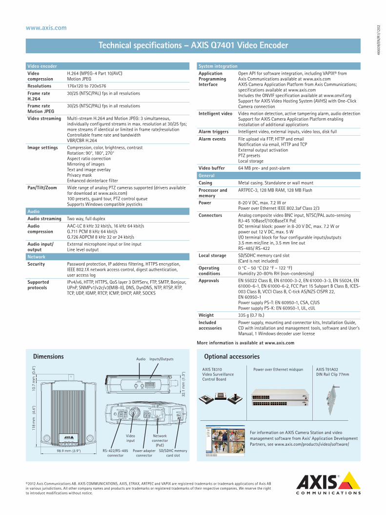
Video encoderVideo compression
H.264 (MPEG-4 Part 10/AVC) Motion JPEG
Resolutions 176x120 to 720x576
Frame rate H.264
30/25 (NTSC/PAL) fps in all resolutions
Frame rate Motion JPEG
30/25 (NTSC/PAL) fps in all resolutions
Video streaming Multi-stream H.264 and Motion JPEG: 3 simultaneous, individually configured streams in max. resolution at 30/25 fps; more streams if identical or limited in frame rate/resolution Controllable frame rate and bandwidth VBR/CBR H.264
Image settings Compression, color, brightness, contrastRotation: 90°, 180°, 270° Aspect ratio correctionMirroring of imagesText and image overlayPrivacy maskEnhanced deinterlace filter
Pan/Tilt/Zoom Wide range of analog PTZ cameras supported (drivers available for download at www.axis.com)100 presets, guard tour, PTZ control queue Supports Windows compatible joysticks
AudioAudio streaming Two way, full duplex
Audio compression
AAC-LC 8 kHz 32 kbit/s, 16 kHz 64 kbit/sG.711 PCM 8 kHz 64 kbit/s G.726 ADPCM 8 kHz 32 or 24 kbit/s
Audio input/output
External microphone input or line input Line level output
NetworkSecurity Password protection, IP address filtering, HTTPS encryption,
IEEE 802.1X network access control, digest authentication, user access log
Supported protocols
IPv4/v6, HTTP, HTTPS, QoS layer 3 DiffServ, FTP, SMTP, Bonjour, UPnP, SNMPv1/v2c/v3(MIB-II), DNS, DynDNS, NTP, RTSP, RTP, TCP, UDP, IGMP, RTCP, ICMP, DHCP, ARP, SOCKS
System integrationApplication Programming Interface
Open API for software integration, including VAPIX® from Axis Communications available at www.axis.comAXIS Camera Application Platform from Axis Communications; specifications available at www.axis.comIncludes the ONVIF specification available at www.onvif.orgSupport for AXIS Video Hosting System (AVHS) with One-Click Camera connection
Intelligent video Video motion detection, active tampering alarm, audio detectionSupport for AXIS Camera Application Platform enabling installation of additional applications
Alarm triggers Intelligent video, external inputs, video loss, disk full
Alarm events File upload via FTP, HTTP and email Notification via email, HTTP and TCP External output activation PTZ presets Local storage
Video buffer 64 MB pre- and post-alarm
GeneralCasing Metal casing. Standalone or wall mount
Processor and memory
ARTPEC-3, 128 MB RAM, 128 MB Flash
Power 8-20 V DC, max. 7.2 W or Power over Ethernet IEEE 802.3af Class 2/3
Connectors Analog composite video BNC input, NTSC/PAL auto-sensing RJ-45 10BaseT/100BaseTX PoEDC terminal block: power in 8-20 V DC, max. 7.2 W or power out 12 V DC, max. 5 WI/O terminal block for four configurable inputs/outputs3.5 mm mic/line in, 3.5 mm line out RS-485/ RS-422
Local storage SD/SDHC memory card slot (Card is not included)
Operating conditions
0 °C – 50 °C (32 °F – 122 °F)Humidity 20-80% RH (non-condensing)
Approvals EN 55022 Class B, EN 61000-3-2, EN 61000-3-3, EN 55024, EN 61000-6-1, EN 61000-6-2, FCC Part 15 Subpart B Class B, ICES-003 Class B, VCCI Class B, C-tick AS/NZS CISPR 22, EN 60950-1Power supply PS-T: EN 60950-1, CSA, C/USPower supply PS-K: EN 60950-1, UL, cUL
Weight 335 g (0.7 lb.)
Included accessories
Power supply, mounting and connector kits, Installation Guide, CD with installation and management tools, software and User’s Manual, 1 Windows decoder user license
More information is available at www.axis.com
Dimensions Optional accessories
For information on AXIS Camera Station and video management software from Axis' Application Development Partners, see www.axis.com/products/video/software/
98.9 mm
(4.6
’’)11
8 m
m
(3.9’’)
10.7
mm
(0.4
’’)
32.1
mm
(1.3
’’)
RS-422/RS-485 connector
Video input
Audio Inputs/Outputs
Network connector
(PoE)Power adapter
connectorSD/SDHC memory
card slot
AXIS T8310 Video Surveillance Control Board
Power over Ethernet midspan AXIS T91A02 DIN Rail Clip 77mm

SucceSS Story
Axis video servers help build wireless monitoring system for city fire prevention department.
MissionFire may happen anytime and anywhere. So to be able to know the fire conditions on site and give corre-sponding solutions timely, the officers of the Fire Prevention Center hope to find a flexible and mobile video solutions.
SolutionWith more than 140 pieces of AXIS 250S Video Server scattered throughout each Fire Prevention Base in Shen Zhen, the Fire Prevention Center can now receive first-rate video images streaming live from the fire-fighting site. The general commander can now give quicker and rational feedbacks to the fire site.
resultWith high quality video and audio transmitted from the fire site back to the Fire Prevention Center, the information can be easily stored in the hard disk of the computer in real time. This provides valuable informa-tion for future investigation and analysis.
customerShenzhen Xiyi Technology started out as an IT company, specializing in digital surveillance. Due to the arising trends in digital surveillance in the recent years, they have developed into a products and solution company.
organization: Fire Prevention center and Shenzhen Xiyi technology
Location: Shen Zhen, china
Industry segment: Government
Application: Live transmission of real-time conditions at fire-fighting sites

www.axis.com
remote monitoring disaster conditionsAs we all know, fire misfortunes cases cannot be forecasted in advance. But once it happens, the fire-fighters have to be dispatched to the site immediately, and the contingent support group should join them at a continuous interval. To realize this purpose, the Fire Prevention Center got some of their fire-fighters to attach the AXIS 250S Video Server and Xinyi’s tiny cameras wirelessly onto their helmet. This will allow the Fire Prevention Center to know the conditions in real time and the general commander can now give quicker and rational feedbacks to the fire site.
New applications with Axis video serverWith the combinations of the AXIS 250S Video Server and Xiyi’s wireless products, new applications have arisen. Now you can take the AXIS 250S Video Server and Xiyi’s tiny cameras with you wherever you go. And you can always send the video images to any destina-tions through wireless microwave network or WLAN. If the distance is far away, the transmission problem still can be solved by microwave connection technology. Thus, a set of mobile and flexible wireless video solution is born.
complete solutionsWith the advancement in technology, there is a para-digm shift from equipment selling to solutions selling. Therefore the combination of many cameras, video servers and wireless transportation equipments, result in a complete customer, equipment and access control management solution, which ensures that the whole monitoring system is fully utilized, secured and reliable.
307
10/E
N/E
2/0
80
2
“Even in a very harsh environment, Axis video server can still provide us excellent video sequenc-
ing images. Its compact and small size gives us great convenience, mobility and flexibility.”
Neil Gong, Technical Manager of ShenZhen Xiyi Technology.
©2004-2008 Axis Communications AB. AXIS COMMUNICATIONS, AXIS, ETRAX, ARTPEC and VAPIX are registered trademarks or trademark applications of Axis AB in various jurisdictions. All other company names and products are trademarks or registered trademarks of their respective companies. We reserve the right to introduce modifications without notice.

Hoja de datos
Vea y grabe vídeo y audio de alta calidad de hasta 100 cámaras con compresión de vídeo H.264, MPEG-4 y Motion JPEG. La compatibilidad con la compresión de vídeo H.264 facilita la op-timización del ancho de banda y la eficiencia de almacenamiento al reducir significativamente la tasa de bits sin comprometer la calidad de imagen.
Las grabaciones programadas y controladas por eventos se acti-van por movimiento o entradas externas. AXIS Camera Station utiliza la detección de movimiento basada en la cámara para aho-rrar ancho de banda y espacio en disco. La grabación manual se puede activar directamente en la interfaz de visualización en vivo.
Potente función de búsqueda con visualización cronológica de grabaciones y función de exportación. La compatibilidad con Planos permite captar una visión panorámica de la zona super-visada, así como obtener un acceso ràpido a cualquier cámara de red Axis que haya en la instalación.
AXIS Camera Station es un completo sistema de supervisión y grabación para hasta 100 cámaras. Diseñado para los productos de vídeo en red de Axis, este software ofrece una fácil instalación y configuración con detección automática de cámaras, configuración de múltiples dispositivos y un potente asistente de configuración de eventos.
aXIs Camera stationUn completo software de gestión de vídeo para la supervisión, grabación, reproducción y gestión de eventos.
> Hasta 100 cámaras
> Grabación programada y controlada por eventos
> Fácil instalación
> Manejo intuitivo
> Control de cámaras PtZ y domo
> Planos
> Visualización y control remoto
La interfaz de usuario se ha desarrollado para ofrecer un mane-jo intuitivo y sencillo con herramientas de navegación que faci-litan el acceso rápido a las cámaras y grabaciones del sistema.
El control de las cámaras PTZ y domo con un joystick o ratón ofrece un control sensible y preciso de la función de movimiento horizontal, vertical y zoom. La compatibilidad con el control PTZ digital está disponible tanto en la visualización en vivo como en la reproducción.
El cliente Windows se puede instalar en cualquier ordenador, para permitir la visualización y el control remoto desde cualquier parte a través de la red corporativa o de Internet.

CámaraModelos Compatible con los productos de vídeo en red de Axis que ejecutan el
firmware 4.30 ó superior
Número de canales Hasta 100
VídeoCompresión de vídeo
H.264 (MPEG-4 Parte 10/AVC)MPEG-4 Parte 2Motion JPEG
Resoluciones Compatible con las resoluciones de los productos de vídeo Axis conectados
Velocidad de grabación
3000 ips o más con el hardware recomendado
audiotransmisión de audio
Audio unidireccional
Compresión de audio
AAC G.711 G.726
servidor de grabaciónseguridad Múltiples niveles de acceso de usuario con protección por contraseña
utilizando usuarios de dominios locales o Windows (servicio Active Directory)
Instalación y configuración
Detección automática de cámarasConfiguración de múltiples dispositivosPotente asistente de configuración de eventos
almacenamiento de las grabaciones
Base de datos de grabación limitada sólo por el espacio en discoGrabación directa en discos locales y de redLa duración por cámara puede estar limitada para cumplir los requisitos legales localesGrabación de fallos en las cámarasBloqueo de grabaciones prioritarias
Cliente Cliente de AXIS Camera Station (para Windows) incluido para la visualización, reproducción y administración local y remota
Visualización en directoVisualización en directo
Configuración flexible con visión en vivo para hasta 50 cámaras, Axis’ Corridor FormatTM, múltiples monitoresSecuencia de cámara/visión, visión de planos
Compatibilidad con PtZ
Control de cámaras PTZ y domo mediante la utilización de un ratón o joystickZoom de áreaControl PTZ digital en visualización en vivo y reproducción
Mejora de la imagen
Calidad mejorada del vídeo en vivo y grababo en condiciones desafiantes como nieve y niebla
ReproducciónBúsqueda de grabaciones
Se pueden buscar grabaciones a partir de la fecha y la horaVisualización cronológica, búsqueda inteligente, marcadores
Reproducción Velocidad de reproducción: hasta 64x o frame a frameGráfico cronológico para facilitar la visión completa de los eventos
Reproducción sincronizada
Reproducción o vídeo y audio para hasta 25 cámaras
exportación Exportación manual y programadaImágenes individuales en formato JPEG o secuencias de vídeo en formato ASFFirma digital en grabaciones exportadasReproductor independiente
activadores y eventosGrabación de eventos
Eventos activados por detección de movimientos, Alarma por manipulación (Active Tampering Alarm), AXIS Cross Line Detection,entradas externas, activación manual o por activaciones de sistema, alarmas del sistema y alarmas del dispositivo
Grabación programada
La programación por cámara permite personalizar las grabaciones de días laborables y fines de semana
detección de movimiento
Detección de movimiento avanzada basada en la cámara para reducir el uso de ancho de banda
Control de entrada/salida
Control avanzado de las entradas/salidas digitales de las cámaras
Notificación de alarma
Indicación visual, alerta sonora, notificación en bandeja de sistema, conmutador de cámara/visión, ir a PTZ predefinida, procedimiento de alarmas por correo electrónico, reconocimiento de alarmas
Registros Registros de alarmas, eventos y auditoríaTodos los eventos se pueden filtrar por día, hora y/o cámara
sistemaRequisitos mínimos del sistema
Windows 7 Professional, Vista Business, XP Professional (servidores y/o clientes), 2008 Server R2, 2008 Server, 2003 Server (solo servidor, 64 bit OS recomendado para sistemas más grandes)Utilice siempre los paquetes de servicio más recientesEntorno de tiempo de ejecución Microsoft .NET (incluido en el paquete de instalación)
Requisitos informáticos mínimos del cliente
CPU: Intel P4 o superior, 2 GHz (Intel Core i7 recomendado para grandes sistemas)RAM: 1 GB (4 GB recomendado para grandes sistemas)Tarjeta gráfica con aceleración de hardware DirectX 9.0 completa y memoria de vídeo integrada de 256 MB o superior ¡Importante! Utiliza el último driver para tarjeta de vídeo y DirectX runtime
Requisitos informáticos mínimos del servidor
CPU: Intel P4 o superior, 2 GHz (Intel Xeon recomendado para grandes sistemas)1 GB de RAM (8 GB recomendado para grandes sistemas)
Red recomendada Red de 100 Megabits (red Gigabit recomendada para grandes sistemas)
Configuración de disco duro recomendada
A 30 ips en VGA: hasta 15 cámaras por disco duro
GeneralIdiomas Inglés, francés, italiano, alemán, español, polaco, ruso, coreano,
japonés, chino, sueco, danés, turco, árabe y persa
Licencias Licencias básicas de AXIS Camera Station para 4 ó 10 cámaras/canales para su uso en un único PC/servidor dedicadoLicencias adicionales para +1, +5 ó +20 y hasta 100 cámaras/canalesLicencia de soporte de un año incluida en la licencia básica 4/10La asistencia y las actualizaciones futuras requieren una licencia de soporte anualLa versión de prueba de 30 días se puede actualizar a una versión con licencia
Registro de licencia
Puede registrarse automáticamente a través de Internet, o manualmente en www.axis.com en el periodo de gracia de cinco días
accesorios incluidos
Guía de instalaciónCD con software y manual de usuario
especificaciones técnicas – aXIs Camera station
www.axis.com
©2011 Axis Communications AB. AXIS COMMUNICATIONS, AXIS, ETRAX, ARTPEC y VAPIX son marcas comerciales registradas o solicitudes de registro de marca comercial de Axis AB en diferentes jurisdicciones. Todos los demás nombres de empresas, productos y denominaciones sociales son marcas comerciales registradas de su respectivo titular. Nos reservamos el derecho de introducir modificaciones sin previo aviso.
4471
5/ES
/R1/
1110
Más información disponible en www.axis.com
accesorios opcionales aXIs Camera station one – gratuito
Solución de software para visualizar y grabar vídeo en vivo procedente de una única cámara de red Axis
Cuadro de control para videovigilancia AXIS T8310 para un control preciso de las cámaras pan/tilt/zoom
Módulo de audio con E/S AXIS P8221 mejora los sistemas de vigilancia por vídeo con E/S adicional y una calidad de audio excelente

AXIS 2460 Network DVR
Sofisticado, y a la vez de una brillante sencillez, el AXIS 2460 Network DVR sitúa la grabación de vídeo digital en un nivel de adelanto técnico completamente nuevo. Conéctelo directamente a una red TCP/IP y acceda a distancia a toda una serie de herramientas de administración de sistemas y vídeo digital, utilizando un navegador web estándar. Admite hasta cuatro cámaras analógicas, dispone de su propio servidor web incorporado y no requiere ningún tipo de mantenimiento externo. ¡Sin necesidad de cintas, enredos ni costosas piezas móviles!
Con su capacidad para conservar las secuencias importantes de vídeo durante períodos de tiempo más prolongados que cualquier otra solución de grabación de vídeo digital, el AXIS 2460 proporciona un recurso de grabación local practicamente inagotable para la videovigilancia, utilizando la revolucionaria tecnología* APViS™ (Axis Prioritized Video Storage –almacenamiento priorizado de vídeo de Axis–).
Utilizado como un sistema independiente único, en pequeños negocios, o como un componente autónomo, dentro de un sistema de videovigilancia distribuida a escala global, el AXIS 2460 es la solución perfecta para uso en grandes cadenas de establecimientos minoristas, franquicias o cualquier negocio que requiera un cómodo acceso a imágenes de videovigilancia, en directo o grabadas.
*Pendiente de concesión de patente
Vídeo digital. Grabación a escala local. Visionado a escala global
Almacena las secuencias importantes de vídeo durante más tiempo, utilizando la revolucionaria tecnología APViS
Sistema tolerante a los fallos, con duplicación simultánea de las bases de datos y almacenamiento distribuido de las imágenes de vídeo
Sistema completo y libre de mantenimiento
Funcionalidad de cortafuegos incorporada
Visionado, grabación, reproducción y administración simultáneas a través de un navegador web
Diseñada para redes

Tecnología innovadora APViS™Almacena las secuencias importantes de vídeo más tiempo
Las grabaciones de vídeo más antiguas pueden contener pruebas visuales de una importancia vital. Cuando el disco duro de cualquier DVR convencional se llena, son simplemente las grabaciones más antiguas las que se borran de forma indiscriminada, con objeto de dejar espacio libre para las grabaciones nuevas. Se trata de la lógica FIFO estándar. La primera imagen grabada (First In) es la primera imagen que se borra (First Out). ¿Es esa realmente la forma más inteligente de gestionar un sistema moderno de videovigilancia?
Mediante la utilización de la innovadora tecnología APViS, el AXIS 2460 Network DVR hace un uso más eficiente del valioso espacio libre existente en el disco, con objeto de conservar las grabaciones de vídeo durante más tiempo. Utilizando de forma inteligente los datos sobre incidentes y alarmas, distingue las secuencias de vídeo “importantes” de las “menos importantes”.
Haciendo uso de dicho criterio, el AXIS 2460 es capaz de almacenar las secuencias de vídeo de máxima prioridad, a su velocidad original de grabación, durante un período de tiempo cuatro veces más largo que cualquier solución convencional de almacenamiento, basada en la lógica FIFO –y durante un período de tiempo dieciséis veces más largo, utilizando un sistema de reducción progresiva de la frecuencia de imágenes–. En la práctica, ¡esa puede ser la dramática diferencia que existe entre disponer de pruebas visuales o no disponer de ellas!
EjemploEn el siguiente gráfico se ilustran los tiempos típicos de almacenamiento con el modo de grabación APViS “ampliado”, frente a los tiempos de almacenamiento “FIFO” convencionales, basándose en la siguiente configuración:
Frecuencia de imágenes original de la grabación: 10 imágenes
por segundo
Tamaño medio de cada imagen = 8 kB
1 cámara
4 discos duros IDE de 40 GB
Grabación continua de baja prioridad y una única grabación de
alarma de alta prioridad, de 30 minutos de duración
En las aplicaciones de seguridad, la calidad uniforme de las imágenes grabadas tiene una importancia vital. Con tres resoluciones diferentes disponibles para cada cámara conectada, el AXIS 2460 graba las imágenes en formato JPEG-vídeo y garantiza una calidad constante y elevada de todas y cada una de las imágenes.
La utilización, única en su género, de un sistema de duplicación simultánea de las bases de datos y de almacenamiento distribuido de las imágenes de vídeo en todos los discos duros disponibles permite al AXIS 2460 tolerar el posible fallo de un disco duro sin que se produzca una pérdida completa de las grabaciones. La implicación práctica de un fallo de un disco duro queda limitada a una reducción relativa de la frecuencia de imágenes de las grabaciones.
Tres niveles de protección a nivel de usuario, mediante contraseña, con funcionalidad cortafuegos incorporada, para un acceso remoto
al sistema a través de redes TCP/IP, con la debida seguridad.
Vídeo seguro. Almacenamiento seguro
� �� �� ��� ��� ��� ��� ����������� ��� �������������� ������
�
�
�
�
�
������
����� �������� � ��������� ��������� ����������������� �������� � ��������� ����

Configuración flexible de la redInstalación independiente o como componente de un sistema distribuido a escala global
Dado que más del 90% de las grabaciones de vídeo archivadas a menudo ni se visionan, la grabación descentralizada de imágenes de vídeo evita una utilización innecesaria de las redes y resulta muy útil cuando el ancho de banda de la red es limitado.
El AXIS 2460 Network DVR lleva incorporado su propio servidor web, y puede accederse a él de forma segura desde cualquier lugar geográfico, por distante que se encuentre, utilizando para ello el navegador Internet Explorer de Microsoft.Instalando un único AXIS 2460 en cada lugar, las organizaciones
disponen ahora de la oportunidad de establecer un gran sistema de almacenamiento de imágenes de vídeo, distribuido a escala global, que les permitirá visionar y gestionar las citadas imágenes desde cualquier lugar, a través de redes TCP/IP.
������������ ���
���� ����
������� ����������
��� � ��������
������ ������ �� ��������������
���
���
���
�����������
��������
�������
������
������
����� � ������ ������� �� ����������
��� � ��� �� ���� �������� � ��� �� ���� ������
������� ����������
���� ����
������������ ��� ������������ ���
���� ����
������� ����������
Sistema distribuido a escala global, con varios AXIS 2460 Network DVR

1955
7/ES
/R1/
0208
Caracteristicas clave• Visionado remoto en directo, grabación,
reproducción y administración simultáneas a través de un navegador de la web
• Imágenes digitales de calidad elevada y uniforme, que no se deterioran con el paso del tiempo
• Modos de grabación contínuo, de incidentes/alarmas, manual y programado
• Extracción de instantáneas y ficheros AVI al disco duro de un PC o a cualquier soporte digital elegido
• Sistema libre de mantenimiento, que no requiere ninguna intervención física durante el funcionamiento normal del mismo
• Sistema completo, que no requiere ningún componente adicional de software
• Visualización “Quad-View”
• Ajustes de la compresión, la resolución y la frecuencia de imágenes, seleccionables por el usuario
• Notificación de incidentes mediante correo electrónico
• Ajustes del tampón de prealarma y la duración de la grabación
Requisitos del sistema• Red Ethernet o módem compatible v.90
soportado
• Internet Explorer 5.x ó superior
• Soporta los protocolos TCP/IP estándar para Internet y puede ser utilizada con: Windows 95/98, NT/2000, Me y XP
SistemaEthernet 100baseTX Fast ó Ethernet 10baseT
• CPU: procesador RISC de 32 bits ETRAX 100 LX de AXIS
• Memoria flash: 4 MB
• RAM: 32 MB
• Basada en el sistema operativo Linux, versión 2.4
• Se entrega de forma opcional con 0, 2 ó 4 discos duros IDE
Instalación• Conexión física a la red con un cable par
trenzado RJ-45
• Conexión directa a las cámaras de vídeo PAL o NTSC mediante conectores BNC
Actualizaciones del software• La memoria flash permite la realización
centralizada y a distancia de actualizaciones del software a través de la red, utilizando el protocolo FTP sobre el protocolo TCP/IP. Actualizaciones disponibles en el web de Axis: www.axis.com
Mandos e indicatores del panel frontalIndicadores LED
• 4 indicadores de vídeo, 4 indicadores de activación de alarmas, 1 indicador de alimentación, 1 indicador de estado, 1 indicador de actividad del disco y 1 indicador de actividad de la red
Pulsadores
• 1 pulsador de apagado/encendido
Resolución• QCIF: 176 x 144 (PAL), 176 x 112 (NTSC)
• CIF: 352 x 288 (PAL), 352 x 240 (NTSC)
• 4CIF: 704 x 576 (PAL), 704 x 480 (NTSC)
Frecuencia de imágenes de la grabación• 1 cámara: CIF, compresión normal: 25/30 fps
(PAL/NTSC)
• 4 cámaras: CIF, compresión normal: 25/30 (PAL/NTSC)*
*Número total de imágenes con cámaras sincronizadas
Seguridad• Protección mediante contraseña a nivel de
usuario
• El sistema de cortafuegos IP incorporado protege contra el acceso ilícito desde ordenadores no autorizados
Capacidad de almacenamiento• 80 GB, 160 GB ó la instalada por el integrador
del sistema
• Duración del almacenamiento dependiente de los ajustes de la imagen
• La duración de las imágenes CIF almacenadas, según los diferentes modos de grabación y compresión AVPiS de que se dispone, son las indicadas a continuación:
Conexiones
Conector de la red
• Conexión RJ-45 a redes Ethernet de 10/100 Mb
Entradas de vídeo
• 4 entradas de vídeo compuestas, con terminación Hi Z de 75 ohmios
• Detección automática de PAL y NTSC
Conector único de bloque de terminales
• 4 entradas de alarma aisladas ópticamente
• 1 relé de salida
Conector serie
• D-SUB RS-232 de 9 pins, máx. 230 Kbps
• D-SUB RS-232 ó RS-485/422 de 9 pins, máx. 38,4 Kbps, semidúplex
Alimentación
• 50/60 Hz, 115/230V, Max 1A (normalmente 60W)
Condiciones de funcionamiento • Temperatura: 5 – 40º C
• Humedad: 8 – 80%
Dimensiones y peso• Dimensiones físicas: 430 x 320 x 100 mm
• Se entrega con soportes para montaje en un bastidor de 48 cm. aprx. (19 pulgadas)
• Peso: sin discos = 7 kg, con 2 discos = 8,2 kg, con 4 discos = 9,4 kg
Aprobaciones• Compatibilidad electromagnética (EMC)
– CE EN55022 Clase B, EN55024
– FCC Clase A
• Seguridad
– EN 60950, incluida en las listas C-UL
www.axis.com/esPara más información, visite la página Web:
Especificaciones técnicas - AXIS 2460 Network DVR
© 2002, Axis Communications AB. Axis es una marca comercial registrada y ThinServer es una marca comercial de Axis Communications AB.Todos los restantes nombres de compañías y productos son marcas comerciales o marcas comerciales registradas de sus respectivas compañías.Nos reservamos el derecho a introducir modificaciones sin previo aviso.
����������������
����������������������������������������
���������� �������� ����������
Alta
Normal
Baja
(Datos basados en un modelo equipado con 4 discos duros de 40 GB, grabando a partir de 4 cámaras a 1 imagen por segundo, procedente de cada una de ellas)
������
8 kB
13 kB
17 kB
45 dias
27 dias
20 dias
96 dias
57 dias
42 dias
253 dias
149 dias
110 dias

Las Fibras Ópticas del Futuro

El DóndeEstamos
El Futuro
Avanzando conl Fib Fibra
ÓpticaPruebasla Fibra
Cables Ópticos

¿Dónde estamos?
Fibra óptica instalada en el mundo

Base de fibra instalada (Global)Source: KMI Research/ Draka
met
ers
r Kilo
mn
Fibe
rM
illio
n

Intalaciones anuales (Global)Source: KMI Research/Draka
met
ers
r Kilo
mn
Fibe
rM
illio
n

Instalaciones anuales (Cableado Estructurado UK)Source: BSRIA
ese
Met
ren
Cab
leM
illio
n

¿Dónde estamos?
Tendencias en fibra Multimodo

Previsiones en fibra Multimodo

¿Cómo hemos llegado hasta aquí?
E tá d tá d tá dEstándares, estándares, estándares…

Estándares de Fibra Óptica
Brand-Rex cree firmemente en el valor de los estándares paraproporcionar una base sólida para nuestra industria, y participaproporcionar una base sólida para nuestra industria, y participaactivamente en 12 grupos de estandarización
BSI (5) Cenelec (3)( )IEC (4)

ITU-T Recomendaciones para fibra óptica
G 651 1
G.657 A B
G.652A B C D
G.651.1
A,B A,B,C,D
G.656 G.653A,B
ITU-T
G.655 G.654C,D,E A,B,C
ITU-TInternational Telecommunication Union -Telecommunication Standardization Sector (www.itu.int)

IEC y Cenelec especificaciones para fibra óptica
10Graded index multimode
60 20
10(5)
Intraconnect 60(4)
20(3)
Step index multimode
Intraconnect
Singlemode
50 30
60793
50(10)
40
30(4)
Plastic clad glass Singlemode40(9) Multimode
PlasticIEC
International Electrotechnical Commission (www.iec.ch )
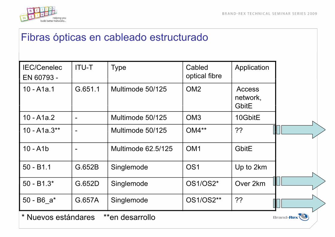
Fibras ópticas en cableado estructurado
IEC/Cenelec EN 60793 -
ITU-T Type Cabled optical fibre
ApplicationEN 60793 p
10 - A1a.1 G.651.1 Multimode 50/125 OM2 Access network, GbitEGbitE
10 - A1a.2 - Multimode 50/125 OM3 10GbitE
10 - A1a 3** - Multimode 50/125 OM4** ??10 A1a.3 Multimode 50/125 OM4 ??
10 - A1b - Multimode 62.5/125 OM1 GbitE
50 - B1.1 G.652B Singlemode OS1 Up to 2km
50 - B1 3* G 652D Singlemode OS1/OS2* Over 2km50 - B1.3 G.652D Singlemode OS1/OS2 Over 2km
50 - B6_a* G.657A Singlemode OS1/OS2** ??
* Nuevos estándares **en desarrollo

Brand-Rex G.652D Low water Peak fibreMayor ventana de operación para aplicaciones
dB/km G.652.B
Mayor ventana de operación para aplicacionesde multiplexado (CWDM)
Menor diámetro de campo modal para mejorar elMenor diámetro de campo modal para mejorar el rendimiento de curvatura
fMejoras en la protección de la fibra, con coloresmás vivos fácilmente diferenciables
G.652.D
1260/1310 nm CWDM 1625 nm
nm

Nueva recomendación ITU-T G.657
ITU-T G.657SERIES G: TRANSMISSION SYSTEMS AND MEDIA DIGITALSERIES G: TRANSMISSION SYSTEMS AND MEDIA, DIGITAL SYSTEMS AND NETWORKS
Características de fibra monomodo insensible a las pérdidas porcurvatura

Pérdidas por Macrocurvaturas en G652D comparado con G657AG657A
G.657 AG.657 A
10 vueltas 30mm diámetro,
0 25 dB a 1550 nm y 1 0 dB a 1625 nm0.25 dB a 1550 nm y 1.0 dB a 1625 nm
1 lt 20 diá t
G.652 D
1 vuelta 20mm diámetro
0.75 dB a 1550 nm y 1.5 dB a 1625 nm
100 vueltas 60mm diámetro,
1.0 dB a 1625 nm
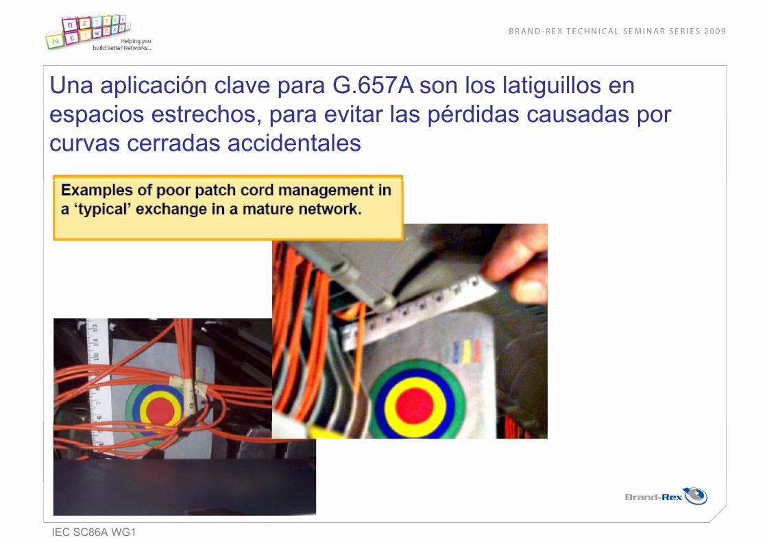
Una aplicación clave para G.657A son los latiguillos en espacios estrechos, para evitar las pérdidas causadas porespacios estrechos, para evitar las pérdidas causadas porcurvas cerradas accidentales
IEC SC86A WG1

Curvas cerradas y láser de alta potencia
Cristal debilitado porel calor revestimiento
• Las nuevas aplicaciones de
láser de alta potencia el calor, revestimientoquemado
ptelecomunicación utilizaránamplificadores Raman con potenciastípicas de 500mW a ~ 2Wtípicas de 500mW a 2W
• Para curvas menores de15mm de diámetro se puede dañar la fibradiámetro, se puede dañar la fibraG652D
L d ñ d j i i t
Revestimientoquemado
• Los daños pueden ser envejecimientodel revestimiento, oxidación o quemado del revestimiento, y en ycasos extremos fusión del cristal.
IEC SC86A WG1

Opciones para limitar los daños potenciales a las fibras
•Limitar la potencia ópticaMejorar la manipulación y gestión de los latiguillos•Mejorar la manipulación y gestión de los latiguillos
•Mejorar la tecnología en las fibras potencialmente en riesgo
Promovido por BT a través de ITU-T e IEC en los dos últimos años
IEC TR 62547 Guidelines for the measurement of high-power damage sensitivity of singlemode fibres to bends – Guidance for the interpretation of resultsinterpretation of results
Publicado por IEC en 2009Publicado por IEC en 2009

Pérdidas por Macrocurvaturas en G652D, G657A y G657B
G.657 B
10 vueltas 30mm diámetro
0.03 dB a 1550 nm y 0 1 dB 1625G 657 A 0.1 dB a 1625 nm
1 vuelta 20mm diámetro
G.657 A
10 vueltas 30mm diámetro
0.1 dB a 1550 nm y 0.2 dB a 1625 nm
1 lt 15 diá t
diámetro,
0.25 dB a 1550 nm y 1.0 dB a 1625 nmG 652 D 1 vuelta 15 mm diámetro
0.5 dB a 1550 nm y 1 0 dB a 1625 nm
1 vuelta 20mm diámetro
0.75 dB a 1550 nm y
G.652 D
100 vueltas 60mm diámetro, 1.0 dB a 1625 nm0.75 dB a 1550 nm y
1.5 dB a 1625 nm,
1.0 dB a 1625 nm

Nueva fibra monomodo G.657B
Perfil de salto de índice
Indice de refracción del Nuevo diseño
núcleoΔn
0 5 10 15radius (μm)
Courtesy of Draka

Nueva fibra monomodo G.657B
Courtesy of Draka

Nueva fibra monomodo G.657B: curvaturas a 1550nm
SpecificationSpecificationdB/turn
radius max loss
SpecificationSpecificationTrenchTrench--assistedassisted
G.657BG.657Bradius
15
10
max loss0.003
0 110
7.5
0.1
0.5
specification
mm dB/turn
bend radius (mm)
Courtesy of Draka

Tensión superficial en la fibra frente a diámetro de curvatura
Surface in tension
TR 62048 Optical fibres –Reliability – Power law theory
En revisión
Bend diameter (mm)

Nuevas fibras monomodo G.657A/G.657B
Fibra óptica monomodo insensible a las pérdidas por curvatura
El núcleo de la fibra está diseñado para guiar más estrechamente la luzp g
G.657A – Beneficios para pigtails y latiguillos en espacios estrechos, y paraproteger la red de pérdidas potenciales de señal causados por curvaturasproteger la red de pérdidas potenciales de señal causados por curvaturasaccidentales
G 657B Beneficios para aplicaciones de larga distancia que utilicen lásersG.657B - Beneficios para aplicaciones de larga distancia que utilicen lásersde alta potencia (Raman), minimizando el riesgo de daños a la fibra
SGORIESGOLa vida útil de la fibra óptica puede comprometerse por curvas cerradasdebido a la tensión en la superficie exterior de la fibra

OM4 fibra óptica cableada según ISO/IEC 11801 (borrador)

Brand-Rex Z50 (OM4)
Todos nuestros cables que utilizan la fibra Z50 contienen fibra ópticaTodos nuestros cables que utilizan la fibra Z50 contienen fibra ópticacon la mayor especificación de ancho de banda para 50/125, queestá siendo estandarizada por ISO/IEC y IEC como OM4
Brand-Rex lleva ofreciendo fibra Z50 (OM4) desde hace 4 años
Admite mayores pérdidas para enlaces de 300m o inferioresPermite enlaces de 550m si se cumple la atenuación máxima de 10GPotencial para enlaces extendidos de 40G/ 100G si IEEE lo apruebaaprueba

IEC y Cenelec especificaciones parea CABLES de fibra óptica
1-1General requirements
-5 -1-2
1 1
Air blown 5(1)
1 2(3)
Test methods
Air blown cabling
-4 -2
60794
4(3)
-3
2(10)
Indoor cablesAerial cables-3(9)
Outdoor blcables
IEC International Electrotechnical Commission (www.iec.ch )

Aplicaciones de Fibra Óptica Soplada

FTTH (fibre to the house) Fibra hasta el puesto
House CHouse
C
C
House
House
C C C
C
House
House
C
B Multi dwelling unit B
A
A

Conectando la fibra desde el nodo hasta el hogar
A B C
XHouse
X X
Splice closure72 splices 72 fibre cable Splice closure
72 splices24 fibre cable
x3Splice closure24 splices x 3
2 fibre cable x 36
) C blA C
a) Cables y empames
MCMicroduct 1 way protected
HouseXSplice closure
72 splices12 way protected microducts x 3 with two
fibres in each
Microduct connection box x
3
1 way protected microduct x 12 x 3 with 2
fibres in each
b) Fibra soplada sin empalmes) p p

MicroBloTM Un rango extendido de cables MicroBloTM
•MicroCables desde 2 a 96 fibras en 3 tamaños
•Permite al diseñador de redes una grangflexibilidad para enlaces urbanos de cortadistancia o larga distancia en areas rurales
•Microductos protegidos desde individuales hasta24 microductos, para entrramiento directo, tendido o interiortendido, o interior
•El cable puede continuar desde rutas de exterior h t l t d t i ió d t d l difi i
2 a 12f
hasta el punto de terminación dentro del edificio
•Costes diferidos y distribuidos12 a 72f
HFbbbBMCddWNMz
•A prueba de futuro / facilmente ampliable•Flexibilidad•Seguridad96f g•Fácil reparación

Distancia de instalación optimizadaPruebas en Brand-Rex
>1km fig 8 <500m y12 curvas
Un microducto recto ofrece la mayor distancia de soplado
L d l di t i d l dLas curvas reducen la distancia de soplado
Diseñar la red con puntos de acceso permitecontinuar soplando para alcanzar la máximadistancia

En desarrollo – conectividad robusta de microductos y cajasde terminación de fibrade terminación de fibra

Instalación en Suecia de FTTH
HF008UNI04LU 3.4
Cable miniaturizado de 4 fibrasCaracterísticas Físicas:Características Físicas:Diámetro Cable : 3.4 mmPeso: 11.0 kg/km

Cable óptico resistente al fuego
• Los datos son críticos paral i i iócualquier organización
• Asegura la transmisión enAsegura la transmisión en una situación de incendio
• ¿Deberían todas las redes• ¿Deberían todas las redestener enlaces resistentes al fuego?
HFbbbUNIddLSTALUFS

Pruebas en enlaces multimodo
Estándarespublicados
Estándaresfuturos
ISO/IEC 11801Nuevo método
para medirISO/IEC 11801Generic cabling
ISO/IEC 11801Generic cabling
penlaces multimodo
ISO/IEC 14763-3Testing of optical fibre cabling
ISO/IEC 14763-3 + Amd 1Testing of optical fibre cabling
Impacto en:•instaladoresest g o opt ca b e cab g est g o opt ca b e cab g
IEC 61280 4 1
•Equipos de test•Formación
IEC 61300-3-43 IEC 61280-4-1 FDIS approved
Publish Q3 2009

ULR
REGISTERED FIRM
CABLE ULTRACAT CATEGORÍA 5e
CABLES PARA REDES (LAN)
DESCRIPCIÓN:• Conductor de cobre suave de 0.5 mm (24 AWG).• Aislamiento de polietileno.• Conductores pareados y cableados.• Cubierta de PVC
ESPECIFICACIONES:ANSI/TIA/EIA 568 B2 ISO/IEC 11801IEC 61156-5NMX-I-248-NYCE NMX-I-236/02-NYCENOM-001-SEDENEC Art. 800
APLICACIONES:Instalación con un solo piso (CM) o entre pisos (CMR).
Cableado estructurado de máxima velocidad, para las siguientes redes:10 BASE T (IEEE 802.3)100 BASE TX (FAST ETHERNET)16/100 Mb/s Token Ring (IEEE 802.5)ATM 55/155 Mb/s100 Mb/s TP-PMD (ANSI X3T9.5)1000 BASE T (GIGABIT ETHERNET) VENTAJAS: Para las frecuencias de normaComo cable, brinda margen adicional de:• 3 Ω en impedancia de entrada.• 3 dB en perdida por retorno RL.• 6 dB en (PSNEXT).Como enlace, se logra margen adicional de: • 1 dB en perdida de inserción. • 10 dB en ACR. CERTIFICACIÓN:
ETL; 3164364
- Los valores mostrados son nominales sujetos a tolerancias de manufactura
Código de Número Color Categoria de Diámetro Espesor de DIámetro Peso neto Longitud nominal producto de de flama sobre aislamiento cubierta externo del cable de empaque pares cubierta mm mm mm kg/km m 66445872 Amarillo 66445812 4 Azul CM 66445832 Gris 66445972 Amarillo 66445912 Azul CMR 66445932 Gris
1 2.0 70 68 4 4.0 59 58 8 5.8 54 53 10 6.5 53 51 16 8.3 50 47 31.25 11.7 46 41 62.5 17.0 41 35 100 22.0 38 31 200* 32.5* 34* 25* 250* 36.8* 32* 23* 350* 44.8* 30* 20*
Impedancia Resistencia Capacitancia Perdida Retraso Características de Transmisión en 100 m característica máxima del mutua por diferencial Frecuencia Atenuación PS NEXT PS ELEFEXT de conductor a máxima / retorno (skew) en @ 20ºC, Paradiafonía, Telediafonía, 1 a 250 c.d @ (NVP) mínimo máximo MHz dB, potencia total potencia total MHz 20ºC (dB) ns/100 m máximo dB dB mínimo mínimo
28 + 5 log (ƒ)10 > ƒ > 1
2820 > ƒ > 10
28 - 7 • log (ƒ/20)100 > ƒ ≥ 20
(ƒ en MHz)
45.9 pF/m
(68 %)
45
1 a 100MHz
85.3 Ω/km100 ± 12 Ω
* Valores típicos, no hay de norma para estas frecuencias
Nota: Valores nominales, sujetos a tolerancia de manufactura
0.96 0.51 5.1 30 305

ULR
REGISTERED FIRM
CABLE ULTRACAT CATEGORÍA 6
CABLES PARA REDES (LAN)
DESCRIPCIÓN:• Conductor de cobre suave de 0.57 mm• Aislamiento de polietileno.• Conductores pareados y cableados. • Separador de polietileno para alto desempeño contra diafonía.• Cubierta de PVC
ESPECIFICACIONES:ANSI/TIA/EIA 568- B2.1 ISO/IEC 11801 NMX-1-248-NYCE NMX-1-236/02-NYCEIEC 61156-5NOM-001-SEDENEC Art. 800
APLICACIONES:Instalación de un solo piso (CM) o entre pisos (CMR).
Cableado estructurado de máxima velocidad, para las siguientes redes:10 BASE T (IEEE 802.3)100 BASE TX (FAST ETHERNET)16/100 Mb/s Token Ring (IEEE 802.5)ATM 55/155/1200 Mb/s100 Mb/s TP-PMD (ANSI X3T9.5)1000 BASE T (GIGABIT ETHERNET) VENTAJAS: Para las frecuencias de normaComo cable, brinda margen adicional de:• 3 Ω en impedancia de entrada.• 3 dB en perdida por retorno RL.• 6 dB en (PSNEXT).Como enlace, se logra margen adicional de: • 1 dB en perdida de inserción. • 10 dB en ACR. CERTIFICACIÓN:
ETL; 3164364
Código de Número Color Categoría de Diámetro Espesor de DIámetro Peso neto Longitud nominal producto de de flama sobre aislamiento cubierta externo del cable de empaque pares cubierta mm mm mm kg/km m 66446875 Amarillo 66446815 azul CM 0.96 0.65 6.7 42 305 66446835 Gris 66446975 Amarillo 66446935 Gris CMR 66446915 Azul
1 1.8 78 76 4 3.6 69 64 8 5.3 65 58 10 5.9 63 56 16 7.5 60 52 31.25 10.5 56 46 62.5 15.2 51 40 100 19.6 48 36 200 28.5 44 30 250 32.2 42 24 350* 39.5* 34 16 400* 43.0* 33 14 500* 49.0* 32 13 600* 54.5* 30 10
Impedancia Resistencia Capacitancia Perdida Retraso Características de Transmisión en 100 m característica máxima del mutua por diferencial Frecuencia Atenuación PS NEXT PS ELEFEXT de conductor a máxima / retorno (skew) en @ 20ºC, Paradiafonía, Telediafonía 1 a 250 c.d @ (NVP) mínimo máximo MHz dB, potencia total potencia total MHz 20ºC (dB) ns/100 m máximo dB dB mínimo mínimo
28 + 5 log (ƒ)10 > ƒ > 1
2820 > ƒ > 10
28 - 7 • log (ƒ/20)250 > ƒ > 20
(ƒ en MHz)
45.9 pF/m
(66 %)
45
1 a 250MHz
70 Ω/km100 ± 12 Ω
* Valores típicos, no hay de norma para estas frecuencias
Nota: Valores nominales, sujetos a tolerancia de manufactura
4

ULR
REGISTERED FIRM
CABLE SIN BLINDAR (UTP) CATEGORÍA 5e CMX USO INTERIOR-EXTERIOR
CABLES PARA REDES (LAN)
DESCRIPCIÓN:• Conductor de cobre sólido de 0,5 mm (24 AWG).• Aislamiento de polietileno.• Conductores pareados y cableados.• Cinta Poliéster.• Cubierta exterior de PVC negro (antillama y resistente a intemperie).
ESPECIFICACIONES: NMX-I-236/02ANSI/TIA/EIA 568 B2 NOM-001-SEDEISO/IEC 11801 NEC (NFPA)
APLICACIONES:Instalación en trayectorias en condiciones de intemperie; radiación solar, lluvia, inmersión en agua por periodos cortos.10 BASE T (IEEE 802.3)4/16 Mb/s Token Ring (IEEE 802.5)100 Mb/s TP-PMD (ANSI X3T9.5) 55/155Mb/s ATM1000BASE-T (IEEE802.3 ab)
Código Número Espesor de DIámetro Categoría Peso neto Longitud de de pares cubierta externo nominal de flama aproximado empaque mm mm kg/km m 664457 4 0.55 7.0 CMX 55 305
4 4.1 53 49 25 10 6.5 47 41 (20≥f) 16 8.2 44 37 45 31 11.7 40 31 85.3 Ω/km 100Ω±15 45.9 25-7Log(f/20) 100 22.0 32 21 (100≥f≥20) 200* 32.0* 28* 18* 250* 35.0* 26* 16*
Resistencia Impedancia Capacitancia Retorno Retraso Características de Transmisión en 100 m a c.d. por característica mutua estructural diferencial Frecuencia Atenuación Paradiafonía Telediafonía conductor Ζo nominal mínimo máximo MHz máxima mínima en mínima en máxima a de 1 a 100 pF/m (f en MHz) (skew) dB potencia total potencia total @ 20ºC MHz dB ns (PSNEXT) (PSELFEXT) dB dB
*Valores típicos, no hay normalizados a esta frecuencia
CABLE SIN BLINDAR (UTP) CATEGORÍA 5e USO EXTERIOR
DESCRIPCIÓN:• Conductor de cobre suave de 0.5 mm (24 AGW).• Aíslamiento de polietileno.• Conductores pareados y cableados.• Compuesto de relleno.• Cubierta de polietileno color negro, resistente a la intemperie.
ESPECIFICACIONES:ANSI/TIA/EIA 568 B-2 NMX-I-236/02ISO/IEC 11801
APLICACIONES:Enlaces en exterior para terminales de cableado estructurado y otros equipos de alta velocidad. De acuerdo al código nacional de instalaciones NOM-001-SEDE, estos cables solo se pueden instalar en interiores si van protegidos dentro de un tubo counduit metálico.10 BASE T (IEEE 802.3) 4/16 Mb/s Token Ring (IEEE 802.5)100 Mb/s TP-PMD (ANSI X3T9.5) 55/155 Mb/s ATM 1000 BASE-T (IEEE 802.3 ab)
Código Diámetro Diámetro Peso Longitud de Pares nominal sobre externo neto nominal de producto aislamiento nominal aproximado empaque mm mm kg / km m 664464 4 0.90 6.0 35 305
Notas: Dimensiones nominales, sujetas a tolerancia de manufactura
4 4.1 53 49 25 10 6.5 47 41 (20≥f) 16 8.2 44 37 45 31 11.7 40 31 85.3 Ω/km 100Ω±15 45.9 25-7Log(f/20) 100 22.0 32 21 (100≥f≥20) 200* 32.0* 28* 18* 250* 35.0* 26* 16*
Resistencia Impedancia Capacitancia Retorno Retraso Características de Transmisión en 100 m a c.d. por característica mutua estructural diferencial Frecuencia Atenuación Paradiafonía Telediafonía conductor Ζo nominal mínimo máximo MHz máxima mínima en mínima en máxima a de 1 a 100 pF/m (f en MHz) (skew) dB potencia total potencia total @ 20ºC MHz dB ns (PSNEXT) (PSELFEXT) dB dB
*Valores típicos, no hay normalizados a esta frecuencia

ULR
REGISTERED FIRM
CABLES PARA REDES (LAN)
- Los valores mostrados son nominales sujetos a tolerancias de manufactura
CABLE BLINDADO (FTP) CATEGORÍA 5e CM
DESCRIPCIÓN:• Conductor de cobre sólido de 0.5 mm (24 AWG).• Aislamiento de polietileno.• Conductores pareados y cableados.• Hidro dren.• Cinta plástica aluminizada.• Cubierta exterior de PVC antillama.
ESPECIFICACIONES:ANSI/TIA/EIA 568 B2 NOM-001-SEDEISO/IEC 11801 NEC artículo 800NMX-I-236/02
APLICACIÓN:Cableado estructurado blindado con las siguientes redes: 10 BASE T (IEEE 802.3)100 BASE-VG (100BASE-NE)4/16 Mb/s Token Ring (IEEE 802.5)55/155 Mb/s ATM100 Mb/s TP-PMD (ANSI X3T9.5)1000 BASE-T (IEEE 802.3 ab)
CERTIFICACIÓN:
ETL; 3164364
Código Número Diámetro Peso neto Espesor de Color de Longitud de de pares externo kg/km cubierta cubierta empaque mm mm m 66444515 4 6.5 38 0.5 Azul 305
*Valores típicos, no hay normalizados a esta frecuencia
4 4.1 53 49 25 10 6.5 47 41 (20≥f) 16 8.2 44 37 45 31 11.7 40 31 85.3 Ω/km 100Ω±15 45.9 25-7Log(f/20) 100 22.0 32 21 (100≥f≥20) 200* 32.0* 28* 18* 250* 35.0* 26* 16*
Resistencia Impedancia Capacitancia Retorno Retraso Características de Transmisión en 100 m a c.d. por característica mutua estructural diferencial Frecuencia Atenuación Paradiafonía Telediafonía conductor Ζo nominal mínimo máximo MHz máxima mínima en mínima en máxima a de 1 a 100 pF/m (f en MHz) (skew) dB potencia total potencia total @ 20ºC MHz dB ns (PSNEXT) (PSELFEXT) dB dB

ULR
REGISTERED FIRM
- Los valores mostrados son nominales sujetos a tolerancias de manufactura
CABLE BLINDADO (FTP) CATEGORÍA 6 CM
DESCRIPCIÓN:• Conductor de cobre sólido de 0.57 mm.• Aíslamiento de polietileno.• Conductores pareados y cableados.• Separador de polietileno para asegurar alto desempeño en diafonía.• Cinta plástica aluminizada e hilo dren.• Cubierta de PVC.
ESPECIFICACIONES:ANSI/EIA/TIA 568-B2.1 IEC 61156-5ISO/IEC 11801 NOM-001-SEDENMX-I-248, NEC (NFPA) NMX-I-236/02-NYCE
APLICACIONES:Instalación en un solo piso, redes blindadas para sistemas. 10 BASE T (IEEE 802.3)16 TOKEN RING (IEEE 802.5)100 BASE BG 100 Mb/s TP-PMD (ANSI X3T9.5) 1.2 Gb/s ATM1000 BASE T (IEEE802.3 ab)
CERTIFICACIÓN:A12354 para el sistema de calidad bajo ISO 9000
CERTIFICACIÓN:
ETL; 3164364
CABLES PARA REDES (LAN)
20+5 Log10 (f) 10 6.0 57.3 44.870 /km 100±15 (1-100 MHz) 45.9 (1-10 MHz) 45 16 7.7 54.2 40.7 100±22 (100-200 MHz) 31 10.7 50.0 34.9 100±32 (200-250 MHz) 25 (10-20MHz) 100 19.8 42.3 24.8 200 29.0 37.8 18.8 25-7 Log10 (f) 250 32.8 36.3 16.8 (20-250 MHz) 350* 40.5* 34.0* 14.5* 400* 43.1* 32.0* 12.0*
Resistencia Impedancia Capacitancia Retorno Retraso Características de Transmisión en 100 m a c.d. por de entrada mutua estructural diferencial Frecuencia Atenuación Paradiafonía Telediafonía conductor nominal mínimo máximo MHz máxima mínima en mínima en máxima a pF/m (f en MHz) (skew) dB potencia total potencia total @ 20ºC dB ns (PSNEXT) (PSELFEXT) dB dB
*Valores típicos, no hay normalizados a esta frecuencia
Código Categoría Número Diámetro Peso neto Espesor de Longitud de de de pares externo kg/km cubierta empaque flama mm mm m 66496615 CM 4 7.6 51 0.52 305

ULR
REGISTERED FIRM
CORDÓN FLEXIBLE SIN BLINDAR (UTP) CATEGORÍA 5e CM
CORDÓN FLEXIBLE SIN BLINDAR (UTP) CATEGORÍA 5 CM
CABLES PARA REDES (LAN)
DESCRIPCIÓN:• Conductor multifilar de cobre estañado.• Aislamiento de polietileno.• Conductores pareados y cableados.• Cubierta exterior de PVC antillama.
ESPECIFICACIONES:Excede: ANSI/TIA/EIA 568 A NOM-001-SEDEISO/IEC 11801 NEC art. 800NMX-I-248NMX-I-236/03-NYCE
APLICACIONES:Conexión de salida al equipo en área de trabajo o en distribuidores para Gigabit Ethernet entre otras redes: 10 BASE T (IEEE 802.3)100 BASE-VG (100BASE-NE)4/16 Mb/s Token Ring (IEEE 802.5)55/155 Mb/s ATM100 Mb/s TP-PMD (ANSI X379.5)1000 BASE-T (IEEE 802.3 ab)
CERTIFICACIÓN:
ETL; 3164364
Código Número Diámetro Peso neto Espesor de Longitud de de pares externo kg/km cubierta empaque mm mm m 664556 4 6.5 38 0.5 305
4 4.9 56 25 10 7.8 50 (20≥f≥) 16 9.9 47 85.3 Ω/km 100Ω±15 45.9 45 31 14.1 43 25-7Log(f/20) 100 26.4 36 (100≥f≥20) 200 34.8* 31* 250 40.3* 29* 350 49.5* 27*
Resistencia Impedancia Capacitancia Retorno Retraso Características de Transmisión en 100 m a c.d. por característica mutua estructural diferencial Frecuencia Atenuación Paradiafonía conductor de 1 a 100 nominal mínimo máximo MHz máxima mínima en máxima a MHz pF/m (f en MHz) (skew) dB potencia total @ 20ºC dB ns (PSNEXT) dB
*Valores típicos, no hay normalizados a esta frecuencia
- Los valores mostrados son nominales sujetos a tolerancias de manufactura
DESCRIPCION:• Conductor multifilar de cobre.• Aislamiento de polietileno.• Conductores pareados y cableados.• Cubierta exterior de PVC.
ESPECIFICACIONES: NMX-I-236/03-NYCEANSI/TIA/EIA 568-A5 NOM-001-SEDEISO/IEC 11801 NEC artículo 800NMX-I-248-NYCE
APLICACIONES:Conexión de salida al equipo en área de trabajo o en distribuidores, para las siguientes redes:10 Mbps (BASE T) (IEEE 802.3)4/16 Mbps Token Ring (IEEE 802.5)100 Mbps TP-PMD ATM-55/155 Mbps
CERTIFICACIÓN:
ETL; 3164364
Número Número Peso Espesor Diámetro Longitud de de de Kg/Km de cubierta exterior empaque producto pares mm mm reelex m 654460 4 34.8 0.52 4.7 305
4 4.9 53 10 7.8 47 24 (7 x 32) 79 100±15 45.9 16 9.9 44 31.25 14.1 39 100 26.4 32
Calibre Resistencia Impedancia Capacitancia Características de Transmisión en 100 m AWG (mm) óhmica característica mutua Frecuencia Atenuación Atenuación de nominal Ω nominal MHz máxima paradiafonía mínima Ω/km de 1 a 100 MHz pF/m dB dB

ULR
REGISTERED FIRM
DESCRIPCIÓN:• Conductor de cobre o acero recubierto de cobre. • Aislamiento de polietileno celular.• Cinta de poliéster aluminizado.• Malla de aluminio.• Cubierta de PVC.
Código Longitud Peso Conductor Diámetro Diámetro Cubrimiento Impedancia Velocidad Capacitancia Atenuación de kg/km central aislamiento exterior de la de nominal empaque Resistencia a mm mm malla Ω propagación pF/m @ dB/100m m c.d. nominal % % MHz 5 2.7 55 5.3 800071 500 47 1.02 mm 4.50 6.7 60 75±3 82 52 211 10.0 (18 AWG) (0.177") (0.264") 300 11.7 803071 300 450 14.5 102 Ω/ km 550 16.1 809218 150 (caja) 750 18.6 1,000 21.5
APLICACIÓN:TV por satélite (DTH), por cable, o por microonda (MVS), TV abierta UHF, VHF (2 al 13), conexión de TV a equipo de video en cinta (VHS) o disco (DVD).
ESPECIFICACIONES:ANSI/SCTE 74 (IPS-SP-001)
CATV 6/60
DESCRIPCIÓN:• Conductor de cobre o acero recubierto de cobre.• Aislamiento de polietileno celular.• Cinta de poliéster aluminizado.• Malla de aluminio.• Cubierta de PVC color negro.
CATV 59/22
Código Longitud Peso Conductor Diámetro Diámetro Cubrimiento Impedancia Velocidad Capacitancia Atenuación de kg/km central aislamiento exterior de la de nominal empaque Resistencia a mm mm malla Ω propagación pF/m @ dB/100m m c.d. nominal % % MHz 5 2.8 800080 500 34 0.64 mm 3.65 6.15 40 85±3 81 48 55 6.7 (22 AWG) (0.144") (0.242") 211 12.5 800084 100 (rollo) 270 13.9 270 Ω/ km 300 14.6 450 17.7
APLICACIÓN:TV abierta UHF, VHF (2 al 13), conexión de TV a equipo de video en cinta (VHS) o disco (DVD).
DESCRIPCIÓN:• Conductor de cobre o acero recubierto de cobre.• Aislamiento de polietileno celular.• Cinta de poliéster aluminizado.• Malla de aluminio.• Cubierta de PVC color negro.
CATV 59/40
Código Longitud Peso Conductor Diámetro Diámetro Cubrimiento Impedancia Velocidad Capacitancia Atenuación de kg/km central aislamiento exterior de la de nominal empaque Resistencia a mm mm malla Ω propagación pF/m @ dB/100m m c.d. nominal % % MHz 5 2.8 800070 500 35 0.81 mm 3.71 6.05 40 75±3 81 53 55 6.7 (20 AWG) (0.146") (0.238") 211 12.5 800074 100 (rollo) 300 14.6 161.4 Ω/ km 450 17.7 800111 500 (marfil) 550 19.5
APLICACIÓN:TV por microondas (MVS), TV abierta UHF, VHF (2 al 13), en zonas con bajo nivel de in-terferencia, conexión de TV a equipo de video en cinta (VHS) o disco (DVD).
CABLES COAXIALES

ULR
REGISTERED FIRM
CABLES COAXIALES
RG 59 B/U
DESCRIPCIÓN:• Conductor central, alambre de cobre.• Aislamiento de polietileno sólido.• Malla de cobre.• Cubierta de PVC color negro.
APLICACIÓN:Sistemas de seguridad, vigilancia, antenas de TV abierta VHF (2 al 13), TV en circuito cerrado.
Código Peso neto Diámetro del Diámetro de Diámetro Cobertura de Longitud de conductor central aislamiento externo la malla empaque kg/km mm mm % m 804281 56.5 0.574 mm 3.71 6.15 95 500 (23 AWG)
Resistencia conductor Impedancia Velocidad de Capacitancia central a c.d. característica propagación Ω/km Ω % pF/m MHz dB/100 m 10 3.6 100 11.3 64.3 75±3 66 68 200 16.4 400 23.2 700 31.6 1,000 39.5
Atenuación
CARACTERÍSTICAS MECÁNICAS
CARACTERÍSTICAS ELÉCTRICAS
ESPECIFICACIONES DE REFERENCIA:MIL-C-17
Código Longitud Peso Conductor Diámetro Diámetro Cubrimiento Impedancia Velocidad Capacitancia Atenuación de kg/km central aislamiento exterior de la de nominal empaque Resistencia a mm mm malla Ω propagación pF/m @ dB/100m m c.d. nominal % % MHz 5 2.8 800057 500 36 0.81 mm 3.66 6.15 60 75±3 81 53 55 6.7 (20 AWG) (0.144") (0.242") 211 12.5 300 14.6 161.4 Ω/ km 450 17.7 550 19.5
CATV 59/60
APLICACIÓN:TV por microonda (MVS), TV abierta UHF, VHF (2 al 13), en zonas urbanas estándar, conexión de TV a equipo de video en cinta (VHS) o disco (DVD).
ESPECIFICACIONES:ANSI/SCTE 74 (IPS-SP-001)
DESCRIPCIÓN:• Conductor de cobre o acero recubierto de cobre.• Aislamiento de polietileno celular.• Cinta de poliéster aluminizado.• Malla de aluminio.• Cubierta de PVC color negro.
DESCRIPCIÓN:• Conductor de cobre sólido.• Aislamiento de polietileno sólido.• Malla de cobre.• Cubierta de PVC color negro.
Código Longitud Peso Conductor Diámetro Diámetro Cubrimiento Impedancia Velocidad Capacitancia Atenuación de kg/km central aislamiento exterior de la de nominal empaque Resistencia a mm mm malla Ω propagación pF/m @ dB/100m m c.d. nominal % % MHz 10 3.6 800069 500 48.5 0.574 mm 3.71 6.15 80 75 ± 3 66 72.6 100 11.3 (23 AWG) (0.146") (0.242") 200 16.4 400 23.2 64.3 Ω/ km 700 31.6 1,000 39.5
RG 59 B/U-80%
APLICACIÓN:TV en circuito cerrado, antenas de TV abierta VHF (2 al 13).

ULR
REGISTERED FIRM
CABLES COAXIALES
DESCRIPCIÓN:• Conductor central de cobre sólido.• Aislamiento de polietileno sólido.• Malla de cobre estañado.• Cubierta de PVC color negro.
RG 58/U
Código Longitud Peso Conductor Diámetro Diámetro Cubrimiento Impedancia Velocidad Capacitancia Atenuación de kg/km central aislamiento exterior de la de nominal empaque Resistencia a mm mm malla Ω propagación pF/m @ dB/100m m c.d. nominal % % MHz 10 4.0 800021 500 39 0.81 mm 3.07 4.95 95 53.5 ± 2 66 94 100 13.0 (20 AWG) (0.121") (0.195") 200 18.5 400 28.0 33.23 Ω/ km 700 38.5 900 45.0 1,000 48.0
DESCRIPCIÓN:• Conductor de acero recubierto con cobre.• Separador helicoidal de polietileno.• Aislamiento de polietileno sólido tubulado.• Malla de cobre.• Cubierta de PVC color negro.
RG 62/U
Código Longitud Peso Conductor Diámetro Diámetro Cubrimiento Impedancia Velocidad Capacitancia Atenuación de kg/km central aislamiento exterior de la de nominal empaque Resistencia a mm mm malla Ω propagación pF/m @ dB/100m m c.d. nominal % % MHz 10 3.0 800004 500 50 0.64 mm 3.53 6.0 95 93 ± 4 84 43.4 100 9.0 (22 AWG) (0.139") (0.236") 200 12.6 400 17.4 700 24.0 252.6 Ω/ km 900 26.9 1,000 28.4
APLICACIÓN:Antenas en automóviles, redes THIN-ETHERNET para datos.
APLICACIÓN:Antenas en automóviles, algunas redes para datos particulares.
RG 8/U
Código Longitud Peso Conductor Diámetro Diámetro Cubrimiento Impedancia Velocidad Capacitancia Atenuación de kg/km central aislamiento exterior de la de nominal empaque Resistencia a mm mm malla Ω propagación pF/m @ dB/100m m c.d. nominal % % MHz 10 1.8800027 500 147 2.15 mm 7.42 10.4 90 50±2 66 98.9 100 6.1 (7/21 AWG) (0.292") (0.409") 200 8.8 400 13.3 700 21.2 6.66 Ω/ km 900 25.2 1,000 26.3
DESCRIPCIÓN:• Conductor multifilar de cobre.• Aislamiento de polietileno sólido.• Malla de cobre.• Cubierta de PVC color negro.
APLICACIÓN:Antenas para radios transmisores o telefonía celular.

ULR
REGISTERED FIRM
CABLES COAXIALES
DESCRIPCIÓN:• Conductor multifilar de cobre.• Aislamiento de polietileno sólido.• Malla de cobre estañado.• Cubierta de PVC.
RG 174
Código Longitud Peso Conductor Diámetro Diámetro Cubrimiento Impedancia Velocidad Capacitancia Atenuación de kg/km central aislamiento exterior de la de nominal empaque Resistencia a mm mm malla Ω propagación pF/m @ dB/100m m c.d. nominal % % MHz 10 10.5 808216 760 15.5 0.40 mm 1.52 3.0 93 50 ± 2 66 99 100 26.4 (7/34 AWG) (0.060") (0.119") 200 40.3 400 61.0 700 86.7 124.9 Ω/ km 900 99.2 1,000 109.5
DESCRIPCIÓN:• Conductor sólido de cobre.• Aislamiento de polietileno celular.• Cinta de poliéster aluminizado.• Malla de cobre estañado en calibre 34 AWG.• Cubierta de PVC negro.
CECBV 75-2
APLICACIONES:Distribución de señales digitalesen centrales telefónicas, conexión de equipo PCM, o RDI.
ESPECIFICACIONES:TM 239889-8
Código Longitud Peso Diámetro del Diámetro de Diámetro Cobertura Adherencia de neto conductor aislamiento externo de la malla malla-cubierta empaque kg/km central mm mm % N 802004 500 m 31 0.404 mm 2.0 4.0 95 10 a 35 (26 AWG) (.079") (0.158")
Resistencia Impedancia Pérdida por Velocidad Capacitancia Atenuación conductor retorno estructural de propagación nominal @ dB/100 m central a c.d. Ω mínima (dB) % pF/m MHz 1.02 1.7 30 4.22 3.4 de 15 a 90 MHz 17.18 6.8 137 Ω/km 75±3 78 58±3 22.36 7.8 25 77.76 14.7 de 90 a 200 MHz 137.00 19.8 200.00 24.2
APLICACIÓN:Antenas de equipo portátil y usos varios en elec-trónica.
Nota: Algunos códigos pueden aparecer con dígitos aadicionales, alfanuméricos. estos se usan para identificar al cliente o características adicionales al producto estándar.

HP and Microsoft® solutionsHP and Microsoft bring together one of the world’s leading hardware and software innovations, applications, resources, and support to help you and your business be more productive, achieve more from your investment, and keep your business running smoothly. For more than 25 years, we’ve been successful at working collaboratively, investing considerable resources in technology, engineering, support, and programs.
Through this partnership, we are dedicated to developing and delivering highly scalable industry-standard information technology in both core businesses and new strategic markets while offering unmatched ownership satisfaction and value. We also combine our respective strengths to bring you complete confidence around integrated technology solutions and world-class service that improve performance, reliability, scalability, and efficiency.
Microsoft Windows Server 2008 R2 on HP Converged InfrastructureIntegrated, comprehensive solutions for greater efficiency and productivityData sheet
2
About Windows® Server 2008 R2Windows Server 2008 R2 builds upon the award-winning foundation of Windows Server 2008, expanding existing technology and adding innovations that enable you to quickly save money and improve efficiency. New virtualization tools, Web resources, management enhancements, and exciting Windows 7 integration help you increase the reliability, flexibility, and efficiency of your converged infrastructure. It also includes:•Built-in hypervisor and live migration•Windows 7 services such as BranchCache,
DirectAccess, and Remote Desktop Services•Power management to reduce power consumption
up to 18%1
Why HP for Windows Server 2008 R2?With HP and Microsoft, one of the world’s leading technology brand meets the world’s leading operating system. Together, we provide best-of-brand solutions that meet your needs on many different levels. More businesses trust to run their Windows Server and other environments on HP servers. And together we are committed to delivering integrated technologies that drive all aspects of your business. This partnership includes tight integration with HP server, storage, and networking platforms, enabling continuous uptime, as well as management tools used to maintain complex environments and automate resource-intensive tasks and services.
Here are some of the reasons why you should run Windows Server 2008 R2 on HP converged infrastructure:•We sells more x86 Windows-based deployments
than any other company in the world.2
•HP can give your business proven 64-bit certified server solutions to meet your business needs. For more information, visit www.hp.com/go/windowscert.
•HP builds on Microsoft’s live migration capability with automatic failover and failback of HP StorageWorks CA/CLX software across Microsoft Windows Server 2008 R2.
•HP is a four-time Microsoft Worldwide Enterprise Alliance Partner of the Year.3
•HP ProLiant systems are designed to operate reliably for years of constant use and are thoroughly tested with Windows operating systems and solutions.
•HP ProLiant is a preferred development platform for Microsoft server products.
•HP ProLiant is a leading platform for virtualized server environments, with tools for easy deployment, unified server hardware and application management, built on energy-efficient technology.
•HP Integrity servers provide customers with highly scalable platform for mission-critical server and database consolidation—up to 256 logical processors, 2 terabytes of memory, and 192 I/O slots. Visit www.hp.com/go/integrity/windows
•HP Insight Control for Microsoft System Center and HP Insight software provide powerful management capabilities to help you unlock your infrastructure’s potential with deeper insight, more precise control, and ongoing enhancement so you get more from the time, money, and energy resources invested. For more information, visit www.hp.com/go/insightcontrol
•HP simplifies sizing and configuration tasks, based on your specific application requirements, with HP ActiveAnswers. Our engineering and integration testing help you use your HP infrastructure investment quickly and effectively. We also supplement these server and storage sizing tools with reference configurations, performance improvement insights, benchmarks, best practices, and solution white papers. Windows Server 2008 R2 and Exchange 2010 materials are coming soon. For more information, visit www.hp.com/go/activeanswers
•HP StorageWorks is innovating storage to give you breakthrough savings, extreme flexibility, and total confidence. With over 30 years of experience in the storage business, we’re bringing industry-standard server leadership and economies of scale to the world of storage to help you easily deploy, enhance, and protect Microsoft server deployments. Plus, you can manage more and adapt easily in a physical or virtualized environment—with less budget, time, and energy.
1 Internal Microsoft study comparing Windows Server 2003 SP2 and Windows Server 2008 R2 on an HP DL585 G5 (Shanghai processor).
2 IDC WW Q109 Server Tracker.3 HP was named Microsoft Enterprise Alliance Partner of the Year in 2007,
2005, 2003, and 2000.

•Virtualize storage for Windows Server R2 environments with HP LeftHand P4000 SAN Solutions or HP StorageWorks Enterprise Virtual Arrays (EVAs). HP LeftHand SANs can lower costs by up to 50 percent and improve capacity utilization by up to 33 percent.4 The solutions also scale nondisruptively to meet the high levels of data availability virtualized applications often demand. HP EVAs offer up to 50 percent lower administrative costs compared to traditional disk arrays.5
•HP servers and storage are the leading hardware infrastructure for Microsoft Exchange Server, SQL Server, and SharePoint Server as well as many other industry-standard business applications.6
•Reduce networking real estate by up to 75 percent with HP Virtual Connect (VC) architecture; with HP Flex-10 technology, this industry-leading combination can reduce hardware costs by up to 50 percent and maintenance costs by up to 80 percent. http://h20195.www2.hp.com/v2/GetPDF.aspx/4AA2-6520ENW.pdf
•HP provides a sizing tool for Hyper-V R2 that helps you quickly assess server and storage needs for virtualizing your environment. The tool is flexible in its acceptance of user requirements and supports input from the Microsoft Assessment and Planning (MAP) toolkit.
•HP offers a complete portfolio of infrastructure design, migration, and implementation support and services for Windows Server operating systems running on HP infrastructures.
HP certification and support for Windows Server 2008 R2You can search for HP certifications for ProLiant ML, DL, SL, and BL servers as well as Integrity servers on the Microsoft Windows Server Catalog (visit www.windowsservercatalog.com). For ProLiant servers, you can also view the HP ProLiant OS Support Matrix (www.hp.com/go/windowscert). ProLiant platforms are the first to be certified (only at the time of this publication) for the new Microsoft Windows Server 2008 R2 Power Additional Qualifier.
You can download drivers from www.hp.com by clicking the “Support and Drivers Link”. This link provides a path to download drivers for both ProLiant and Integrity servers by product family and by series of server. Once the exact server is located, you will find Windows Server 2008 R2 drivers available for
download. Drivers for HP ProLiant and BladeSystem servers can be also found by clicking on the server name in the HP ProLiant OS Support Matrix. You can also search for HP certifications for StorageWorks products on the Microsoft Windows Server Catalog (visit www.windowsservercatalog.com) or by viewing the HP Single Point of Connectivity Knowledge (SPOCK) Web site (visit http://h20272.www2.hp.com; an HP Passport account is required to enter the SPOCK website).
HP Insight software supportGet more from every hour, watt, and dollar that you invest in your infrastructure—physical and virtual. HP Insight software unlocks the potential of your infrastructure to help you make more informed decisions, accomplish more in less time, and deliver better service to your business.
HP Insight Control is essential infrastructure management software, giving you total control of your server infrastructure—onsite or remotely. With a single, easy-to-use management console, you can proactively monitor server health and performance. You can also deploy new servers quickly and manage virtual machines—which means increased flexibility to quickly respond to your business. The savings are tangible—up to $ USD 48,380 per 100 users.7
Providing advanced infrastructure management, HP Insight Dynamics helps you continuously analyze and improve your converged infrastructure. This software is one of the world’s first integrated solution that lets you visualize, plan, and change physical and virtual resources in the same way. It makes your infrastructure change-ready, with the freedom and flexibility of virtualization delivered across your physical infrastructure.
HP Insight Software support for Windows Server 2008 R2 includes HP Insight Foundation Suite for ProLiant and Insight Control 6.0, as well as Insight Dynamics 6.0
4 Calculation based on aggregate best practice guidelines.5 “Comparative Management Cost Survey; Workload Weighting for
Mid-range Storage Array Administrators,” Edison Group, February 2009; sponsored by HP.
6 2008 Radicati Group market share study.7 IDC: Gaining Business Value and ROI with HP Insight Control, May 2009.
3
Get connectedwww.hp.com/go/getconnected
Current HP driver, support, and security alerts delivered directly to your desktop
Share with colleagues
© Copyright 2009–2010 Hewlett-Packard Development Company, L.P. The information contained herein is subject to change without notice. The only warranties for HP products and services are set forth in the express warranty statements accompanying such products and services. Nothing herein should be construed as constituting an additional warranty. HP shall not be liable for technical or editorial errors or omissions contained herein.
Microsoft and Windows are U.S. registered trademarks of Microsoft Corporation.
4AA2-9552ENW, Created October 2009; Updated July 2010, Rev. 1
Why HPHP provides you with a comprehensive range of proven server and storage offerings to run Microsoft software solutions with ease and efficiency. We give you the choice you demand to best meet your business and IT requirements. We work closely with Microsoft in the integration and testing of our combined solution offering, so you can take advantage of standards-based, quality offerings that you can rely on. We also offer a wide variety of services to help you meet your objectives throughout the entire product life cycle.
For more informationTo answer any questions you have about running Windows Server 2008 R2 on HP Converged Infrastructure, contact your HP representative or visit the following sites for more information:
HP Windows Server 2008 R2: www.hp.com/go/ws2008r2
Microsoft Windows Server 2008 R2: www.microsoft.com/windowsserver2008
HP ProLiant Server Support for Windows Server: www.hp.com/go/ossupport
HP Integrity servers: www.hp.com/go/integrity/windows
HP ProLiant servers: www.hp.com/go/proliant
HP Storage Solutions for Microsoft: www.hp.com/storage/microsoft
HP Care Pack services: www.hp.com/services
For additional technical specifications, please visit www.hp.com/go/ws2008r2
HP ServicesHP can provide technical support for your HP infrastructure and Microsoft Windows Server software, with HP Care Pack services that let you choose the level and priority of support—making it fast and easy to resolve problems if they arise. HP Services offers a complete portfolio of comprehensive services and cost-saving updates to help you enhance the performance and availability of software from HP and other leading vendors. Services can be configured for OS-only support, or can be configured to support the OS plus the standard Microsoft Windows Server applications installed on the server.
•Standard Support gives your IT team direct access to HP IT Response Centers. Support is available throughout standard business hours on standard business days.
•HP 24x7 Software Technical Support provides comprehensive around-the-clock services and cost-saving updates to help you enhance the performance and availability of software from HP and other leading vendors.
•HP Support Plus delivers onsite hardware support and over-the-phone software support 13 hours a day, 5 days a week. Service coverage encompasses HP products and selected multivendor hardware and software.
• HP Support Plus 24 delivers onsite hardware support and over-the-phone software support around-the-clock 365 days a year.
•HP Proactive 24 delivers onsite hardware support and over-the-phone software support, plus proactive problem identification and solutions recommendation, with remote monitoring, and an assigned account manager to manage the proactive services.
•HP Critical Service delivers onsite hardware support and over-the-phone software support, plus proactive problem identification and solutions recommendation, with remote monitoring, and an assigned support team to manage the proactive services.
•HP Installation and Startup Services makes certain that your new HP hardware or software is installed smoothly, efficiently, and with minimal disruption of your IT and business operations.
hp pavilion f50/f70D5063/D5064
15-inch/17-inch LCD Monitor
(15-inch/17-inch Viewable Image)
User’s Guide
Notice
Important Safety Instructions
What the f50 Monitor Offers
What the f70 Monitor Offers
Unpacking the Monitor
Setting Up the Monitor
How to Install the Drivers
Adjusting the Monitor
Using the Monitor
Troubleshooting
LCD Monitor Quality andPixel Policy for f50 Monitor
LCD Monitor Quality and PixelPolicy for f70 Monitor
Technical Specifications for thef50 Monitor
Technical Specifications for thef70 Monitor
HP f70 Audio SystemPerformance Specifications
Care and Cleaning
Environmental Information
Regulatory Information

hp pavilion f50/f70 LCD MonitorNotice
Notice
The information contained in the documents accompanying this product is subject to change without notice.Hewlett-Packard makes no warranty of any kind with regard tothis material, including, but not limited to, the implied warrantiesof merchantability and fitness for a particular purpose.HP shall not be liable for errors contained herein or for incidentalor consequential damages in connection with the furnishing, performance, or use of this material.HP assumes no responsibility for the use or reliability of its software on equipment that is not furnished by HP.These documents contain proprietary information that is protectedby copyright. All rights are reserved. No part of these documents may be photocopied, reproduced, or translated to another language without the prior written consent of HP.Hewlett-Packard CompanyHome Products DivisionP.O. Box 4010Cupertino, CA 95014-4010USA© Copyright Hewlett-Packard Company, 2001. All rights reserved.Hewlett-Packard is a registered trademark of Hewlett-Packard Company in the United States of America and other countries. Other brand or product names are trademarks of their respective holders.
2

hp pavilion f50/f70 LCD Monitor
f50 15-inch LCD Monitor f70 17-inch LCD Monitor
hp pavilion f50/f70D5063/D506415-inch/17-inchLCD Monitor(15-inch/17-inch Viewable Image)
User’s Guide
3

hp pavilion f50/f70 LCD MonitorImportant Safety Ins t ruct ions
Important Safety Instructions
CAUTION: The lightning flash with arrowhead symbol inside an equilateral triangle is intended to alert the user to the presence of uninsulated, dangerous voltage which may be of sufficient magnitude to constitute a risk of electric shock.
WARNING: The exclamation point within an equilateral triangle is intended to alert the user to the presence of important operating and servicing instructions in the literature accompanying the appliance.
WARNING: If you are unsure that you can lift the equipment safely, do not try to move it without help.
WARNING: Before you connect any cables or install the HP monitor, refer to the above safety instructions. Also, refer to the set up poster and the documentation included with the PC and the video adapter to ensure this equipment is correctly installed.
WARNING: For your safety, always connect equipment to a grounded wall outlet. Always use a power cord with a properly grounded plug, such as the one provided with the equipment, or one in compliance with your national safety standards. This equipment can be disconnected from the power by removing the power cord from the power outlet. This means the equipment must be located close to an easily accessible power outlet.
!
!
!
!
4 English

hp pavilion f50/f70 LCD MonitorImportant Safety Ins t ruct ions
WARNING: Use the monitor with the power adapter supplied with your HP monitor only.
To avoid electrical shock, do not open the monitor cover or the power adapter. There are no user-serviceable parts inside. Only qualified service personnel should service these parts.
Make sure the computer is turned off before connecting or disconnecting a display peripheral.
Working in Comfort
Thank you for selecting HP monitor equipment.To optimize your comfort and productivity, it’s important that you set up your work area correctly and use your HP equipment properly. With that in mind, we have developed some setup and use recommendations based on established ergonomic principles for you to follow.These recommendations can be found in the online version of the Working in Comfort guide, which is preloaded on the hard disk of your HP computer. They can also be found on the HP Working in Comfort Web site at http://www.hp.com/ergo/ along with other information.
!
5
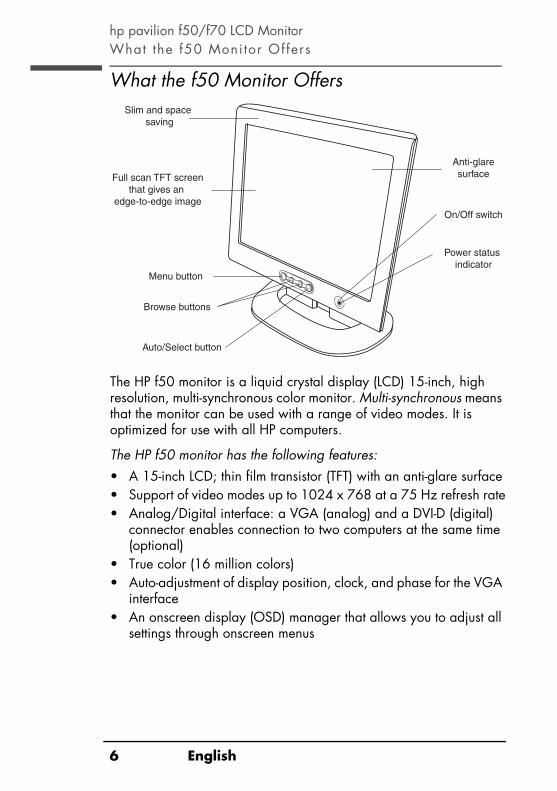
hp pavilion f50/f70 LCD MonitorWhat the f50 Moni tor Offers
What the f50 Monitor Offers
The HP f50 monitor is a liquid crystal display (LCD) 15-inch, high resolution, multi-synchronous color monitor. Multi-synchronous means that the monitor can be used with a range of video modes. It is optimized for use with all HP computers.
The HP f50 monitor has the following features:• A 15-inch LCD; thin film transistor (TFT) with an anti-glare surface• Support of video modes up to 1024 x 768 at a 75 Hz refresh rate• Analog/Digital interface: a VGA (analog) and a DVI-D (digital)
connector enables connection to two computers at the same time (optional)
• True color (16 million colors)• Auto-adjustment of display position, clock, and phase for the VGA
interface• An onscreen display (OSD) manager that allows you to adjust all
settings through onscreen menus
Full scan TFT screenthat gives an
edge-to-edge image
Slim and space saving
Anti-glaresurface
Menu button
Browse buttons
Auto/Select button
On/Off switch
Power status indicator
6 English

hp pavilion f50/f70 LCD MonitorWhat the f50 Moni tor Offers
• Power-management system (VESA1 standard) controlled from suitably equipped HP computers to automatically reduce the power consumption of the monitor
NOTE: As an ENERGY STAR partner, HP has determined that this product meets ENERGY STAR guidelines for energy efficiency.
• Low power consumption: 36 W maximum• Compliance with stringent Swedish Low Emissions guidelines
TCO '99• Plug and Play capability (compliant with VESA DDC standard,
version 3, revision 1 at the levels DDCI, DDC/2B, DDC/C1, version 1) that enables the monitor to identify itself to suitably equipped HP computers
1. VESA is the Video Electronics Standards Association.
7

hp pavilion f50/f70 LCD MonitorWhat the f70 Moni tor Offers
What the f70 Monitor Offers
The HP f70 monitor is a liquid crystal display (LCD) 17-inch, high resolution, multi-synchronous color monitor. Multi-synchronous means that the monitor can be used with a range of video modes. It is optimized for use with all HP computers.
Menu button
Browse buttons
Full scan TFT screenthat gives an
edge-to-edge image
Slim and space saving
Anti-glaresurface
On/Off switch
LCD modulepower status
indicator
Headphoneconnector
Microphoneconnector
Audio base powerstatus indicator
Volume control
Auto/Select button
Audio base with stereo speakers
8 English

hp pavilion f50/f70 LCD MonitorWhat the f70 Moni tor Offers
The HP f70 monitor has the following features:• A 17-inch LCD; thin film transistor (TFT) with an anti-glare surface• Support of video modes up to 1280 x 1024 at a 75 Hz
refresh rate• Analog/Digital interface: a VGA (analog) and a DVI-D (digital)
connector enables connection to two computers at the same time (optional)
• True color (16.7 million colors)• Auto-adjustment of display position, clock, and phase for the VGA
interface• Audio base with Polk Audio active stereo speakers• All-in-one audio and microphone cable• An onscreen display (OSD) manager that allows you to adjust all
settings through onscreen menus• Power-management system (VESA2 standard) controlled from
suitably equipped HP computers to automatically reduce the power consumption of the monitor
NOTE: As an ENERGY STAR partner, HP has determined that this product meets ENERGY STAR guidelines for energy efficiency.
• Plug and Play capability (compliant with VESA DDC standard, version 3, revision 1 at the levels DDCI, DDC/2B, DDC/C1, version 1) that enables the monitor to identify itself to suitably equipped HP computers
• Slot for security lock
2. VESA is the Video Electronics Standards Association.
9

hp pavilion f50/f70 LCD MonitorUnpacking the Moni tor
Unpacking the Monitor
Check for the following items. If they are missing or damaged, consult your retailer immediately.• 1 liquid crystal display (LCD)• 1 power cord• 1 DC adapter with an attached DC cable• 1 video cable (VGA)• 1 video cable (DVI-D) (select models only)• 1 Quick User’s Guide• 1 warranty booklet• 1 CD-ROM disc
10 English

hp pavilion f50/f70 LCD MonitorSet t ing Up the Moni tor
Setting Up the Monitor
Place the monitor on a flat, sturdy surface. Ensure that the operating site is free from excessive heat and moisture. For best performance, make sure nothing is resting on the monitor.
WARNING: Before you connect any cables or install the HP monitor, refer to the safety instructions at the beginning of this manual. Refer also to the documentation that came with the computer to ensure this equipment is correctly installed.
Connecting two computers to the monitor
The LCD monitor has two video signal connectors on the rear panel: one analog (VGA) and one digital (DVI-D). This allows you to connect the monitor to two computers at the same time.
When two computers are connected, you need to use the Input Priority setting on the onscreen display (OSD) to switch from one video signal to the other. See “Input Priority” on page 33. The LCD must be set to one signal or the other to operate properly.
!
DVI VGA
Video connectors
11

hp pavilion f50/f70 LCD MonitorSet t ing Up the Moni tor
Connecting the cables to the f50 monitor
Look at the following diagram and follow the steps listed below to connect the cables to the f50 15-inch LCD monitor.
CAUTION: This monitor is equipped with an auto-sensing power supply for voltage ranges 100—240 V~, 50/60 Hz. Use the monitor with the supplied DC adapter only.
Powersource
Powercord
DC adapterwith attached DC cable
Video cable(VGA)
Videoconnectors
VGADVI
12 English

hp pavilion f50/f70 LCD MonitorSet t ing Up the Moni tor
To connect the cables to the f50 monitor:1 Make sure the computer is turned off.2 Plug the video cable into the correct video connector (VGA or
DVI-D) on the back of the monitor and into the corresponding video connector on the computer. Secure the cable by tightening the thumbscrews.
NOTE: The f50 monitor comes with both a VGA and a DVI-D connector. Some models come with a VGA cable, and others come with a DVI-D cable as well. Using both video connectors, you can connect this monitor to two computers at the same time. You may need to purchase the DVI-D cable.
3 Plug the DC adapter cable into the connector on the back of the monitor.
4 Plug the power cord into the DC adapter and into the main power source.
5 Turn on the main power source (for example, a surge protector), and then turn on the power switch for both the computer and the monitor.
To disconnect the cables from the f50 monitor:1 Turn off the power switch for the monitor and the computer and
then turn off the main power source.2 Disconnect the power cord from the main power source and from
the DC adapter cable.3 Disconnect the DC adapter cable from the connector at the back
of the monitor.4 Unscrew the thumbscrews on the video cable(s) and disconnect the
video cable(s).
VGA cable → VGA connector
DVI-D cable → DVI-D connector
13

hp pavilion f50/f70 LCD MonitorSet t ing Up the Moni tor
Connecting the cables to the f70 monitor
Look at the following diagram and follow the steps listed below to connect the cables to the f70 17-inch LCD monitor.
CAUTION: This monitor is equipped with an auto-sensing power supply for voltage ranges 100—240 V~, 50/60 Hz. Use the monitor with the supplied DC adapter only.
To connect the cables to the f70 monitor:1 Make sure the computer is turned off.2 Plug the video cable into the correct video connector (VGA or
DVI-D) on the back of the monitor and into the corresponding video connector on the computer. Secure the cable by tightening the thumbscrews.
VGA cable → VGA connector
DVI-D cable → DVI-D connector
Video cable (VGA)
Microphone(pink)
Audio out(green)
OR
DVI
Audio cable
Volume control
DC adapterwith attached DC cable
Power source
DC In cable
VGA
Video connectors
Power cord
14 English

hp pavilion f50/f70 LCD MonitorSet t ing Up the Moni tor
NOTE: The f70 monitor comes with both a VGA and a DVI-D connector. Some models come with a VGA cable, and others come with a DVI-D cable as well. Using both video connectors, you can connect this monitor to two computers at the same time. You may need to purchase the DVI-D cable.
3 Plug the audio cable into the correct connectors on the computer. Connect the green plug to the Audio Out connector and the pink plug to the Microphone connector on the computer.
CAUTION: Do not connect the audio cable to the Speaker Out connector on the computer: the audio system of the monitor could be damaged. The audio cable must be connected to the Audio Out connector. HP recommends you keep the audio cable connected to the Audio Out connector on the computer at all times when using the f70 monitor.
4 Plug the DC adapter cable into the connector at the rear of the monitor base.
5 Plug the power cord into the DC adapter.6 Make sure the DC In cable is connected from the back of the
monitor column to the back of the LCD panel. This cable should always be connected.
7 Make sure the volume is turned to the minimum setting on both the audio base and on the keyboard (if the keyboard has a volume control feature).
green → Audio Out connector
pink → Microphone connector
Speaker Out connector
15

hp pavilion f50/f70 LCD MonitorSet t ing Up the Moni tor
NOTE: For the best performance and sound range of the f70 monitor, use the keyboard for the primary volume control and use the audio base as a secondary volume control.
8 Turn on the main power source (for example, a surge protector), and then turn on the power switch for both the computer and the monitor.
NOTE: The audio base is always on when the monitor is connected to a power source, even when the computer and the LCD panel are turned off. To see if the monitor is receiving power, check the power status indicator (LED) on the side of the audio base and check the light indicator on the front of the LCD panel.
To disconnect the cables to the f70 monitor:1 Turn off the power switch for the monitor and the computer, and
then turn off the main power source.2 Disconnect the power cord from the main power source and the
DC adapter cable.3 Disconnect the DC adapter cable from the connector at the rear of
the monitor base.4 Disconnect the audio cable from the computer connectors.5 Unscrew the thumbscrews on the video cable(s) and disconnect the
video cable(s).
Connecting the speakers to the f70 monitor
The f70 monitor comes with two built-in stereo speakers in the audio base. If you bought the monitor with an HP Pavilion home PC, you will have two sets of speakers: an external set shipped with the computer, and a built-in set that is part of the monitor.The external speakers of the computer connect to a Speaker Out connector identified on the set up poster for the computer. These speakers will provide the best sound for most HP Pavilions.If you want to use the built-in monitor speakers, you must connect them to a Line Out or an Audio Out connector on the back of the computer. Use the audio cable provided for connecting the built-in monitor speakers and the microphone to the computer; see step 3 in “Connecting the cables to the f70 monitor” on page 14.
16 English

hp pavilion f50/f70 LCD MonitorSet t ing Up the Moni tor
If the computer does not have a Line Out or Audio Out connector, you can purchase a sound card with a Line Out connector to use the internal monitor speakers.If you are not sure which connector you have and the sound quality is poor, make sure the external PC speakers are connected to the Speaker Out connector and not the Audio Out connector. Make sure the audio cable from the monitor is not connected to the Speaker Out connector on the computer.
Securing the f70 monitor
The f70 monitor can be secured to a desk or to any other fixed object, using a Kensington lock security cable. The cable can be attached to a slot located on the rear of the monitor.
NOTE: The Kensington lock is not an HP accessory. It cannot be ordered from HP. Contact your retailer for more information.
To secure the monitor:1 Insert the lock in the slot located on the rear of the monitor.2 Turn the key to lock the cable to the monitor.3 Remove the key and store it in a safe place.
Slot for lock
17

hp pavilion f50/f70 LCD MonitorSet t ing Up the Moni tor
Connecting additional devices to the f70 monitor
The following diagram shows additional devices that can be connected to the monitor. On the side of the audio base, the f70 monitor has one headphone connector and one microphone connnector. You can use these connectors to connect various compatible devices.
Headphone connector
Microphone connector
Headphoneconnector
Microphoneconnector
18 English

hp pavilion f50/f70 LCD MonitorHow to Ins tal l the Drivers
How to Install the Drivers
The HP monitor comes with driver software that allows you to take advantage of the Plug and Play feature of the Windows® Me, Windows 2000, or Windows XP operating system. This software enables the computer to communicate with the monitor and use all the monitor features. Without this software, the monitor settings and display images will not be correct.
NOTE: HP computers may ship with the Plug and Play drivers preinstalled. If you have an older computer, these drivers may not be preinstalled and you may need to install the drivers from the CD-ROM disc that came with the monitor.
You can also download the latest version of a driver from the HP Monitors Support Web site at: http://www.hp.com/go/monitorsupport/
Windows 2000 Users
NOTE: The procedure for installing the driver for your operating system may vary.
To install the driver for the f50 or f70 monitor:1 Click Start, select Settings, and then click Control Panel.2 Double-click Display.3 Click the Settings tab.4 Click Advanced Properties or Advanced, and select the
Monitor tab.5 Click Properties.6 Click the Driver tab.7 Click Update Driver and click Next.8 Select the recommended option and then click Next.9 Select the Specify a Location box.10 Find and open the f50.inf (f50 15-inch) or the f70.inf (f70
17-inch) file on the CD-ROM disc in the Drivers directory, and click OK.
11 Click Next to install the selected monitor.
19

hp pavilion f50/f70 LCD MonitorHow to Ins tal l the Drivers
Windows Me Users
NOTE: The procedure for installing the driver for your operating system may vary.
To install the driver for the f50 or f70 monitor:1 Click Start, select Settings, and then click Control Panel.2 Click Display.3 Select the Settings tab.4 Click the Advanced button.5 Select the Monitor tab.6 Click the Change button.7 Select the Specify a Location box.8 Find and open the f50.inf (f50 15-inch) or the f70.inf (f70
17-inch) file on the CD-ROM disc in the Drivers directory, and click OK.
9 Click Next to install the selected monitor.
Windows XP Users
NOTE: The procedure for installing the driver for your operating system may vary.
To install the driver for the f50 or f70 monitor:1 Click Start.2 Click Control Panel.3 Click Appearance and Themes.4 Click Display.5 Select the Settings tab.6 Click the Advanced button.7 Select the Monitor tab.8 Click Properties.9 Select the Driver tab.10 Click Update Driver and click Next.11 Select the recommended option and then click Next.12 Select the Specify a Location box.
20 English

hp pavilion f50/f70 LCD MonitorHow to Ins tal l the Drivers
13 Find and open the f50.inf (f50 15-inch) or the f70.inf (f7017-inch) file on the CD-ROM disc in the Drivers directory, and click OK.
14 Click Next to install the selected monitor.If the installation procedure of the monitor driver for the Windows 2000, Windows Me, or Windows XP operating system is different, or if you need more detailed installation information, please refer to the Microsoft Windows information that came with the computer.
21

hp pavilion f50/f70 LCD MonitorAdjus t ing the Moni tor
Adjusting the Monitor
The monitor display has several adjustable settings which may need to be fine-tuned occasionally. Adjust the monitor:• When the monitor is installed for the first time.• If the resolution (number of pixels on the display) or refresh rate
(vertical scan frequency rate) has been changed.• If the graphic card has been changed.• If the monitor is connected to a different computer.• After using the Mode Recall function. See “To use Mode Recall” on
page 31.
NOTE: For best performance, it is recommended that you select a video mode of 1024 x 768 @ 60 Hz for the f50 monitor and 1280 x 1024 @ 60 Hz for the f70 monitor on the computer.
Using the monitor controls
There are five controls for the f50 monitor and six controls for thef70 monitor that perform the following operations:
NOTE: The volume control is available only on the f70 monitor.
Menu
Left Browse/Brightness
Auto/Select
On/Off Volume(f70 only)
Right Browse/Contrast
22 English

hp pavilion f50/f70 LCD MonitorAdjus t ing the Moni tor
Monitor control buttons
*NOTE: For the best performance and sound range of the f70 monitor, use the keyboard for the primary volume control and use the audio base as a secondary volume control.
Auto-Adjustment function
You can easily optimize the screen performance for the VGA interface by using the Auto button and the auto-adjustment pattern on the CD-ROM disc provided.1 Insert the provided CD-ROM disc into the computer. Run the
program D:\F50.exe or D:\F70.exe to display a pattern used for setup.
2 Press the Auto button to produce a stable, centered image.The optimizer utility on the CD-ROM contains the drivers for Windows Me, Windows 2000, or Windows XP. For the f50 monitor, use the D:\Drivers\f50.inf file. For the f70 monitor, use the D:\Drivers\f70.inf file.
Control button/icon
Function when not in Display Manager
Function inDisplay Manager
Menu: Opens and closes the Display Manager window
Closes setting screens and exits Display Manager
Left Browse/Brightness: Shortcut to Brightness setting screen
Navigates through setting option icons and adjusts settings
Right Browse/Contrast: Shortcut to Contrast setting screen
Navigates through setting option icons and adjusts settings
Auto/Select: Performs an auto-adjustment which will optimize the image quality
Acts as an Enter (Select) key to select setting screen options
On/Off On/Off: Turns the monitor on or off
Turns the monitor on or off
Volume control Volume control*: Adjusts volume setting (f70 only)
Adjusts volume setting
23

hp pavilion f50/f70 LCD MonitorUsing the Moni tor
Using the Monitor
Using Display Manager
The monitor comes pre-configured to provide the best viewing image. However, you can fine-tune the display using Display Manager. The monitor has control buttons that you can use to open Display Manager to select and adjust display settings.
To adjust display settings:1 Press the Menu button to open Display Manager.2 Press a Browse button to navigate through the setting option icons;
see the following setting options table.3 When the menu option you want is selected, press the Select
button to open the setting screen for that option.4 Adjust the setting using the onscreen instructions that follow.5 To exit Display Manager, press the Menu button.
Display Manager screen in analog mode
Display Manager screen in digital mode
24 English

hp pavilion f50/f70 LCD MonitorUsing the Moni tor
Setting Options
The icons at the top of the Display Manager window represent the different setting options, shown in the following table:
Icon Setting option Setting description
HorizontalPosition*
Adjusts the horizontal position of the screen image.
VerticalPosition*
Adjusts the vertical position of the screen image.
Clock* Adjusts the frequency of the pixel clock to minimize vertical bars.
Phase* Adjusts the phase value to minimize horizontal bars.
Auto Config* Adjusts the main settings and produces a stable, centered image.
Color Adjusts the tint of white, and the red, green, and blue (RGB) mix for colors.
Contrast Adjusts the difference between the light and dark areas.
Brightness Adjusts the brightness.
OSD Manager(OSD stands for onscreen display)
Adjusts the position, timeout, and notification features of the Display Manager window.
Mode Recall Resets the display to original factory settings for color, brightness, phase, and clock.
Backlight Info Shows the status of the light behind the panel.
Serial Number Shows the serial number of the display.
Mode Info Shows the current resolution and refresh rate; shows if you’re in analog or digital mode; and shows how many user settings have been adjusted.
Input Priority Sets which video input is active: analog or digital. Shows status of the video input that is active.
Languages Shows the language of the OSD window.
25

hp pavilion f50/f70 LCD MonitorUsing the Moni tor
*NOTE: Horizontal Position, Vertical Position, Clock, Phase, and Auto Config settings do not need to be adjusted for displays operating in digital mode; therefore these icons do not appear in digital mode.
Horizontal Position, Vertical Position, Clock, Phase, Contrast, or Brightness settings
To change Horizontal Position, Vertical Position, Clock, Phase, Contrast or Brightness settings:
1 Open the setting screen you want to adjust. See “Using Display Manager” on page 24.
2 Press the Browse buttons to adjust the setting. The setting is automatically saved as you adjust it.
26 English

hp pavilion f50/f70 LCD MonitorUsing the Moni tor
3 Press the Menu button to exit the setting screen.• In the Horizontal Position screen, pressing the left Browse button
moves the horizontal position to the left, and pressing the right Browse button moves the horizontal position to the right.
• In the Vertical Position screen, pressing the left Browse button moves the vertical position down, and pressing the right Browse button moves the vertical position up.
• In the Clock screen, pressing the left Browse button sets the clock to an earlier time, and pressing the right Browse button sets the clock to a later time.
• In the Phase screen, pressing the left Browse button decreases phase setting values, and pressing the right Browse button increases phase setting values.
• In the Contrast screen, pressing the left Browse button decreases the contrast, and pressing the right Browse button increases the contrast.
• In the Brightness screen, pressing the left Browse button decreases the brightness, and pressing the right Browse button increases the brightness.
Auto Config settings
With Auto Config you can reset Horizontal Position, Vertical Position, Clock, and Phase to optimize the image quality. When using this option, please view a full Windows screen, such as Windows Explorer, or use the test pattern provided on the CD before pressing the Select button on the Auto Config menu. These test pattern files are named F50.exe and F70.exe.
To change settings with Auto Config:1 Open the Auto Config setting screen. See “Using Display
Manager” on page 24. A window with a red bar appears.
27

hp pavilion f50/f70 LCD MonitorUsing the Moni tor
2 Press the Select button to proceed with the reset, or press the Menu button to exit without resetting.
3 If you reset the settings, press the Menu button to exit the setting screen.
Color settings
To change Color settings:Open the Color setting screen. See “Using Display Manager” on page 24. Four options appear: Bluish, White, Reddish, and User. Bluish, White, and Reddish refer to tints of white. This setting lets you manually adjust the red, green, and blue (RGB) mix for color generation.
To adjust tints of white:1 Press the Browse buttons to select a tint of white.2 Press the Menu button to save the tint setting and exit the setting
screen.
28 English

hp pavilion f50/f70 LCD MonitorUsing the Moni tor
To adjust User Color:1 Press the Browse buttons until User is selected.2 Press the Select button to open the User Color window.
3 Press the Browse buttons to select the color you want to adjust.4 Press the Select button to activate the adjustable setting for the
color.5 Press the Browse buttons to change the color value. The value is
automatically saved as you change it.6 Press the Menu key to exit the setting screen.After you change a color value, you can reset the values to the original factory color settings by selecting Reset and pressing the Menu key.You can choose to keep the color values as they were before any adjustments were made by selecting EXIT WITHOUT SAVE and pressing the Menu key.
29

hp pavilion f50/f70 LCD MonitorUsing the Moni tor
OSD settings
To change OSD settings:1 Open the OSD setting screen. See “Using Display Manager” on
page 24. Five options appear: Protected OSD, OSD Timeout, Inform On/Off, H Position, and V Position.
2 Press the Browse buttons to select the option you want to adjust.3 Press the Select button to display its setting screen.
NOTE: Protected OSD is not available for use.
To adjust OSD Timeout:You can set the OSD (Display Manager) screen to turn off automatically when you are not using it.1 Press the Browse buttons to select how long the Display Manager
screen appears before automatically turning off. The setting is automatically saved as you adjust it.
2 Press the Menu button to exit the setting screen.
To adjust Inform On/Off:Turning Inform on displays the chosen resolution and refresh rate for three seconds, whenever you change them. Turning Inform off prevents this information from being displayed.1 Press the Browse buttons to select On or Off. The setting is
automatically saved as you adjust it.2 Press the Menu button to exit the setting screen.
30 English

hp pavilion f50/f70 LCD MonitorUsing the Moni tor
To adjust OSD H Position:You can adjust the horizontal position of the OSD (Display Manager) screen.1 Press the Browse buttons to position the OSD screen. The setting is
automatically saved as you adjust it.2 When the screen is in the horizontal position you want, press the
Menu button to exit the setting screen.
To adjust OSD V Position:You can adjust the vertical position of the OSD (Display Manager) screen.1 Press the Browse buttons to position the OSD screen. The setting is
automatically saved as you adjust it.2 When the screen is in the vertical position you want, press the
Menu button to exit the setting screen.
Mode Recall
Using Mode Recall restores original factory settings for Color, Brightness, Phase, and Clock. This will re-establish default color settings for the best possible brightness.
To use Mode Recall:1 Open the Mode Recall setting screen. See “Using Display
Manager” on page 24. A window with a red bar appears.
2 Press the Select button to proceed with Mode Recall, or press the Menu button to exit without resetting.
3 If you reset with Mode Recall, press the Menu button to exit the setting screen.
31

hp pavilion f50/f70 LCD MonitorUsing the Moni tor
Backlight Info
The Backlight Info window shows the elapsed time of usage for the light behind the display screen. The expected lifespan of the backlight is approximately 30,000 to 40,000 hours. At some point after the maximum usage time of the backlight has been exceeded, you may notice a decrease in brightness of up to 50%. At this point, the backlight needs to be replaced to restore full brightness.
CAUTION: The backlight can be replaced only by a trained technician. Please contact the HP Support Center for assistance. Do not attempt to replace the light yourself.
NOTE: Do not use a screen saver with the LCD monitor, as the backlight will be used. It is recommended that you enable an automatic power saving mode, or switch off the monitor when not in use.
To view Backlight Info:1 Open the Backlight Info setting screen. See “Using Display
Manager” on page 24. The elapsed time is displayed.2 Press the Menu button to exit the setting screen.
Serial Number
You may need to provide the display serial number to HP Support technicians to help them serve you better during a Support call.
To view a Serial Number:1 Open the Serial Number setting screen. See “Using Display
Manager” on page 24. The serial number is displayed.2 Press the Menu button to exit the setting screen.
Mode Info
The Mode Info screen shows whether the current video input mode is analog (1) or digital (2); shows the current resolution and refresh rate; and shows how many User settings you have changed, and how many preset settings have not been changed.
32 English

hp pavilion f50/f70 LCD MonitorUsing the Moni tor
To view Mode Info:1 Open the Mode Info setting screen. See “Using Display Manager”
on page 24. The Video Input mode, the resolution and refresh rate, and the number of Preset and User values are displayed.
2 Select the Preset or User values with the Browse buttons.3 Press the Select button. The Preset or User mode information screen
is displayed.4 Press the Menu button to exit the setting screen.
Input Priority
You can use this setting to switch between the two video inputs, analog and digital. The default active video input is analog (1). If you are connecting a PC to the digital input (2), you need to change the input priority in the Input Priority screen.
NOTE: You only need to set the digital input when you connect two PCs to the monitor.
To set Input Priority:1 Open the Mode Info setting screen. See “Using Display Manager”
on page 24.2 Press the Browse buttons to switch between Input 1 (analog) and
Input 2 (digital). 3 Press the Select button to confirm the new setting. A confirmation
screen is displayed.4 Press the Menu button to exit the setting screen.
Language of Display Manager
You can choose to view Display Manager in English, German, French, Italian, or Spanish.
To change the language of Display Manager:1 Open the Languages setting screen. See “Using Display
Manager” on page 24.2 Press the Browse buttons to choose the language you would like.
The setting is automatically saved.3 Press the Menu button to exit the setting screen.
33

hp pavilion f50/f70 LCD MonitorTroubleshoot ing
Troubleshooting
If you are having trouble with the monitor, these tips may help you solve the problem. Try the following steps before calling HP.If you find:
No picture and the light indicator on the front of the LCD panel is off:• Check that the monitor is turned on.• Check that the power cord is properly connected.• Check the electrical outlet.• Connect the monitor to another computer to determine if there is a
problem with the computer rather than with the monitor.
No picture and the light indicator on the front of the LCD panel is on:• Check that the computer is turned on.• Check that the monitor is not in power-saving mode.• Adjust the Contrast and Brightness through the onscreen display or
the control buttons.• Check that the video cable has no bent pins.• Connect the monitor to another computer to determine if there is a
problem with the computer rather than the monitor.
Picture is fuzzy:• Adjust the monitor using the Auto-Adjustment function. See
“Auto-Adjustment function” on page 23.• If you are running the Windows Me, Windows 2000, or
Windows XP operating system, install the Plug and Play driver (.inf file). See “How to Install the Drivers” on page 19.
• For the f50 monitor, change the resolution to the recommended resolution of 1024 x 768 @ 60 Hz.
• For the f70 monitor, change the resolution to the recommended resolution of 1280 x 1024 @ 60 Hz.
Pixels are missing:• See “LCD Monitor Quality and Pixel Policy for the f50 Monitor” on
page 36.• See “LCD Monitor Quality and Pixel Policy for the f70 Monitor” on
page 37.
34 English

hp pavilion f50/f70 LCD MonitorTroubleshoot ing
Colors are not pure:• Check that the video cable has no bent pins and is firmly attached
to both the computer and monitor video connectors.• Restore the original factory colors setting. See “To use Mode
Recall” on page 31.• Adjust the RGB (red, green, and blue) colors. See “To change
Color settings” on page 28.
Picture is not centered:• Adjust the monitor using the Auto-Adjustment function. See
“Auto-Adjustment function” on page 23.
No sound (f70 monitor only):• Check to see that the power status indicator (LED) on the side of
the audio base is turned on.• Make sure the main power supply is turned on.• Check to see if the audio cable is plugged in properly.• Adjust the volume setting on the audio base and the keyboard.
Make sure the Mute setting on the keyboard and in the Volume Controls of the computer is turned off.
35

hp pavilion f50/f70 LCD MonitorLCD Moni tor Qual i ty and Pixel Pol icy for f50 Moni tor
LCD Monitor Quality and Pixel Policy for f50 Monitor
f50 15-inch monitor
The HP f50 TFT monitor uses high-precision technology, manufactured according to HP standards, to guarantee trouble-free performance. Nevertheless, the display may have cosmetic imperfections that appear as small bright or dark spots. This is common to all LCD displays used in products supplied by all vendors and is not specific to the HP D5063 LCD. These imperfections are caused by one or more defective pixels or sub-pixels.• A pixel consists of one red, one green, and one blue sub-pixel.• A defective whole pixel is always on (a bright spot on a dark
background), or it is always off (a dark spot on a bright background). The first is the more visible of the two.
• A defective sub-pixel (dot defect) is less visible than a defective whole pixel and is small and only visible on a specific background.
The HP D5063 display does not have more than:• 10 total dot defects.• 10 defective full pixels.• 10 defective red sub-pixels.• 4 defective green sub-pixels (green is most visible).• 10 defective blue sub-pixels.• No more than two adjacent (less than 2.5 mm edge-to-edge) and
defective pixels.• No more than two pairs of two adjacent defective pixels.To locate defective pixels, the monitor should be viewed under normal operating conditions, in normal operating mode at a supported resolution and refresh rate, from a distance of approximately 50 cm (16 in.).HP expects that, over time, the industry will continue to improve its ability to produce LCDs with fewer cosmetic imperfections and HP will adjust guidelines as improvements are made.
36 English

hp pavilion f50/f70 LCD MonitorLCD Moni tor Qual i ty and Pixel Pol icy for f70 Moni tor
LCD Monitor Quality and Pixel Policy forf70 Monitor
f70 17-inch monitor
The HP f70 TFT monitor uses high-precision technology, manufactured according to HP standards, to guarantee trouble-free performance. Nevertheless, the display may have cosmetic imperfections that appear as small bright or dark spots. This is common to all LCD displays used in products supplied by all vendors and is not specific to the HP D5064 displays. These imperfections are caused by one or more defective pixels or sub-pixels.• A pixel consists of one red, one green, and one blue sub-pixel.• A defective whole pixel is always on (a bright spot on a dark
background), or it is always off (a dark spot on a bright background). The first is the more visible of the two.
• A defective sub-pixel (dot defect) is less visible than a defective whole pixel and is small and only visible on a specific background.
The HP D5064 display does not have more than:• 15 total dot defects.• 10 defective full pixels.• 10 defective red sub-pixels.• 4 defective green sub-pixels (green is most visible).• 10 defective blue sub-pixels.• No more than two adjacent (less than 2.5 mm edge-to-edge) and
defective pixels.• No more than two pairs of two adjacent defective pixels.To locate defective pixels, the monitor should be viewed under normal operating conditions and in normal operating mode at a supported resolution and refresh rate, from a distance of approximately 50 cm (16 in.).HP expects that, over time, the industry will continue to improve its ability to produce displays with fewer cosmetic imperfections and HP will adjust guidelines as improvements are made.
37

hp pavilion f50/f70 LCD MonitorTechnical Speci f icat ions for the f50 Monitor
Technical Specifications for the f50 Monitor
f50 15-inch monitor
Liquid Crystal Display (LCD)
Display Size 15-in. (38 cm) diagonal and viewable image
Type TFT liquid crystal displayInput Signal Video 0.7 V (0,7 V) p-p analog RGB
Synchronization Separated H/V (TTL level)Interface Input Connector Analog R, G, B separate H,V
sync. 15-pin mini D-SUB + Digital DVI-D
ScanningFrequency
Horizontal 30–60 kHzVertical 56–75 Hz
Max. Resolution(H x V)
1024 x 768 @ 75 Hz
Recommended Resolution
(H x V)
1024 x 768 @ 60 Hz
Power Source AC/DC Adapter Input Rating:100–240 V~, 2 A maxOutput Rating:12 V , 4.16 A (4,16 A)Frequency: 50/60 HzPower Consumption: less than 36 W in operating mode
Operating Environment
Temperature 5° C to 40° CHumidity 20% RH through 85% RH
(without condensation)Storage
EnvironmentTemperature –20° C to 60° C Humidity 8% RH through 85% RH
(without condensation)Dimensions H x W x D
With stand: 400 x 365 x 215 mm(15.7 x 14.4 x 8.5 in)
Weight With stand: 4.8 Kg (10.6 lbs)Tilt Stand Tilt Angle: Down 5, up 25 degrees
38 English

hp pavilion f50/f70 LCD MonitorTechnical Speci f icat ions for the f70 Moni tor
Technical Specifications for the f70 Monitor
f70 17-inch monitor
Liquid Crystal Display (LCD)
Display Size 17-in. (43 cm) diagonal and viewable image
Type TFT liquid crystal displayInput Signal Video 0.7 Vp-p analog RGB
Synchronization Separated H/V (TTL level)Interface Input Connector 15-pin D-SUB (Analog)
DVI-D (Digital)ScanningFrequency
Horizontal 30–80 kHzVertical 56–75 Hz
Max. Resolution(H x V)
1280 x 1024 @ 75 Hz
Recommended Resolution
(H x V)
1280 x 1024 @ 60 Hz
Power Source AC/DC Adapter Input Rating:100–240 V~, 2 A maxOutput Rating:12 V , 4.16 A (4,16 A)Frequency: 50/60 HzPower Consumption: less than 75 W inoperating mode
Operating Environment
Temperature 10° C to 35° CHumidity 20% RH through 80% RH
(without condensation)Storage
EnvironmentTemperature –10° C to 60° CHumidity 8% RH through 85% RH
(without condensation)Dimensions H x W x D
With standard stand: 468 x 419 x 206 mm18.4 x 16.5 x 8.1 in.
Weight With standard stand: 6.1 Kg (13.42 lbs)Tilt Stand Tilt Angle: Down 5, up 25 degrees
Security Lock Monitor cabinet is provided with a slot allowing the use of Kensington lock device
39

hp pavilion f50/f70 LCD MonitorHP f70 Audio System Performance Speci f icat ions
HP f70 Audio System Performance Specifications
NOTE: The purpose of this document is to specify the nominal electrical and acoustical performance of the audio system for the HP Pavilion f70 flat panel LCD computer display.
Amplifier Performance
Output power per channel into 8 ohm loads, both channels driven, 1 kHz, with 12 V regulated supply:
> 3 W @ <5% THD
Signal-to-Noise ratio, grounded inputs, maximum gain, A-weighted, referred to full output:
> 85dB
Crosstalk, 22 kHz bandwidth, 1 kHz, shorted inputs, at maximum gain:
better than –50dB
Nominal THD below 2 W, 1 kHz, 30 kHz measurement bandwidth:
< 0.1% (0,1%)
Sensitivity (input voltage to produce full output):
–400 mV rms @ 1 kHz
Input impedance: 10kStorage
PerformanceFrequency response: 150 Hz—23 kHz, –3 dB @
230 Hz and 22 kHzMaximum SPL: @ 0.5 m (0,5 m): 99 dB
C-weighted (calculated)Idle current draw: 40 mA
40 English

hp pavilion f50/f70 LCD MonitorCare and Cleaning
Care and Cleaning
To maximize the screen lifespan of this product and to prevent damage to the liquid crystal display, it is recommended that you:• Do not let liquid get on or into the monitor.• Do not store or use the monitor in locations exposed to heat, direct
sunlight, or extreme cold.• Do not store or use the monitor in a dusty environment or in
locations exposed to high humidity.• Do not press sharp or pointed objects against the monitor.• Avoid touching or pressing the screen of the monitor.• Avoid setting contrast and brightness to their maximum levels for
prolonged periods.• Turn off the monitor when not in use.• Do not place anything on or against the audio base (f70 17-inch
monitor only).• Use a soft brush or cloth to clean the audio base (f70 17-inch
monitor only).• Clean the screen with isopropyl alcohol or ethyl alcohol diluted
with water (1:1) to prevent damage to the screen’s anti-glare coating.
To clean the screen:1 Turn off the monitor and remove the power plug (pull the plug, not
the cable).2 Soak a soft gauze cloth with isopropyl alcohol or ethyl alcohol
diluted with water (1:1) and gently wipe the surface of the monitor. Do not dust it or wipe it with a cloth dampened with pure water.
3 Dry with a clean, soft cotton cloth.
CAUTION: Never use pure water to clean the LCD screen. Do not use cleaning solutions containing fluoride, acids, or alkalis. Do not use ketone substances such as acetone or solvents such as xylene or toluene to clean the monitor. Do not use benzene, thinner, ammonia, or any volatile substance to clean the monitor's screen or cabinet. These chemicals may damage the monitor.
41

hp pavilion f50/f70 LCD MonitorEnvironmental In formation
Environmental Information
HP has a strong commitment to the environment. The HP monitor has been designed with respect for the environment as much as possible.HP can also take back your old monitor for recycling when it reaches the end of its useful life.HP has a product take-back program in several countries. The collected equipment is sent to one of HP's recycling facilities in Europe or the USA. As many parts as possible are reused. The remainder is recycled. Special care is taken with batteries and other potentially toxic substances; these are reduced to harmless components through a special chemical process. If you require more details about HP's product take-back program, contact your dealer or your nearest HP sales office.
42 English

hp pavilion f50/f70 LCD MonitorRegulatory Informat ion
Regulatory InformationDECLARATION OF CONFORMITY
According to ISO/IEC Guide 22 and CEN/CENELEC EN 45014
Manufacturer’s name: HEWLETT-PACKARD France Manufacturer’s address: 5 Avenue Raymond Chanas-Eybens 38053 GRENOBLE Cedex 09 - FRANCE Declares that the products : Product Name HP 15" (LCD) Color Monitor HP 17" (LCD) Color Monitor Model Number D5063** D5064**
(* can be any alphanumerical character) Conform to the following Product Specifications :
§ SAFETY - International: IEC 60950:1991 +A1 +A2 +A3 +A4 / GB4943-1995.
- Europe : EN 60950:1992 +A1 +A2 +A3 +A4 +A11. § ELECTRO-MAGNETIC COMPATIBILITY
- CISPR22:1997 / EN55022:1998 Class B - CISPR24:1997 / EN55024:1998 - IEC 61000-3-3:1994 / EN61000-3-3:1995 - GB9254-1998 - FCC Title 47 CFR, Part 15 Class B 1) - ICES-003, Issue 3 - VCCI-B - AS/NZ 3548:1995
Products bearing the CE marking(2) also comply with:
• IEC 61000-3-2:1995 / EN 61000-3-2:1995. + A14 Those products comply with the requirements of the following Directives and carry the CE-markinaccordingly: EMC Directive 89/336/EEC and Low Voltage Directive 73/23/EEC, both amended bythe Directive 93/68/EEC.
1) This device complies with Part 15 of the FCC rules. Operation is subject to the following two conditions
(1) This device may not cause harmful interference, and (2) This device must accept any interference received, including interference that may cause undesired operation.
2) All products sold in the European Economic Area (EEA) bear the CE marking.
Grenoble Didier CABARET July 2001 Quality Manager For Compliance Information ONLY, contact : USA contact : Hewlett Packard Company, Corporate Product Regulations Manager 3000 Hanover Street, Palo Alto, CA 94304. (Phone (+1) (650) 857-1501)
43

hp pavilion f50/f70 LCD MonitorRegulatory Informat ion
For Compliance Information ONLY, contact:
USA contact: Hewlett-Packard CompanyCorporate Product Regulations Manager3000 Hanover StreetPalo Alto, CA 94304Phone : (+1) (650) 857-1501
Notice for the USA: FCC Class B Statement
Federal Communications Commission Radio Frequency Interference Statement Warning:This equipment has been tested and found to comply with the limits for a Class B digital device, pursuant to Part 15 of the FCC Rules. These limits are designed to provide reasonable protection against harmful interference in a residential installation. This equipment generates, uses, and can radiate radio frequency energy and, if not installed and used in accordance with the instructions, may cause harmful interference to radio communications. However, there is no guarantee that interference will not occur in a particular installation. If this equipment does cause harmful interference to radio or television reception, that can be determined by turning the equipment off and on, the user is encouraged to correct the interference by one or more of the following measures:
• Reorient or relocate the receiving antenna.• Increase the distance between the equipment and the receiver.• Connect the equipment to an outlet on a different circuit to the one the receiver is
connected to.• Consult your dealer or an experienced radio/TV technician for help.
Safety Warning for USA
If the power cord is not supplied with the monitor, select the proper power cord according to your national electric specifications.
• USA: use a UL listed type SVT detachable power cord.
Notice for Canada
This Class “B” digital apparatus complies with all requirements of the Canadian Interference-Causing Equipment Regulations (ICES.003).
Cet appareil numérique de la Classe B est conforme a la norme MB-003 du Canada.
MPRII Statement
The monitor complies with MPRII guidelines for upper limits of electrostatic and magnetic field emissions, from the Swedish National Board of Measurement and Testing.
44 English

hp pavilion f50/f70 LCD MonitorRegulatory Informat ion
Notice for Korea
Notice for Germany
Notice for Japan (Class B)
Hinweis für Deutschland: GeräuschemissionLärmangabe nach Maschinenlärmverordnung — 3 GSGV(Deutschland)
LpA < 70db am Arbeitsplatz normaler Betrieb nach EN27779: 11.92
45

hp pavilion f50/f70 LCD MonitorRegulatory Informat ion
TCO '99 (European Union Only)
Congratulations! You have just purchased a TCO '99 approved and labeled product! Your choice has provided you with a product developed for professional use. Your purchase has also contributed to reducing the burden on the environment and to the further development of environmentally adapted electronics products.This product meets the requirements for the TCO '99 scheme which provides for an international environmental and quality labeling of personal computers. The labeling scheme was developed as a joint effort by the TCO (The Swedish Confederation of Professional Employees), Svenska Naturskyddsforeningen (The Swedish Society for Nature Conservation), Statens Energimyndighet (The Swedish National Energy Administration), and SEMKO AB.The requirements cover a wide range of issues: environmental, ergonomic, usability, reduction of electric and magnetic fields, energy consumption and electrical safety.
Why do we have environmentally labeled computers?In many countries, environmental labeling has become an established method for encouraging the adaptation of goods and services to the environment. The main problem, as far as computers and other electronics equipment are concerned, is that environmentally harmful substances are used both in the products and during their manufacture. Since it is not so far possible to satisfactorily recycle the majority of electronics equipment, most of these potentially damaging substances sooner or later enter nature.There are also other characteristics of a computer, such as energy consumption levels, that are important from the viewpoints of both the work (internal) and natural (external) environments. Since all methods of electricity generation have a negative effect on the environment (for example, acidic and climate-influencing emissions, radioactive waste), it is vital to save energy. Electronics equipment in offices is often left running continuously and thereby consumes a lot of energy.
46 English

hp pavilion f50/f70 LCD MonitorRegulatory Informat ion
What does the environmental labeling involve?The environmental demands have been developed by Svenska Naturskyddsforeningen (The Swedish Society for Nature Conservation). These demands impose restrictions on the presence and use of heavy metals, brominated and chlorinated flame retardants, CFCs (freons) and chlorinated solvents, among other things. The product must be prepared for recycling, and the manufacturer is obliged to have an environmental policy which must be adhered to in each country where the company implements its operational policy.The energy requirements include a demand that the computer and/or monitor, after a certain period of inactivity, shall reduce its power consumption to a lower level in one or more stages. The length of time to reactivate the computer shall be reasonable for the user.Below, you will find a brief summary of the environmental requirements met by this product. The complete environmental criteria document may be ordered from:TCO DevelopmentSE-114 94 Stockholm, SwedenFax: +46 8 782 92 07Email (Internet): [email protected] information regarding TCO '99 approved and labeled products may also be obtained over the Internet, using the address: http://www.tco-info.com/
47

hp pavilion f50/f70 LCD MonitorRegulatory Informat ion
Environmental requirements
Flame retardants:Flame retardants are present in printed circuit boards, cables, wires, casings and housings. Their purpose is to prevent, or at least to delay, the spread of fire. Up to 30% of the plastic in a computer casing can consist of flame retardant substances. Most flame retardants contain bromine or chloride, and those flame retardants are chemically related to another group of environmental toxins, PCBs. Both the flame retardants containing bromine or chloride and the PCBs are suspected of giving rise to severe health effects, including reproductive damage in fish-eating birds and mammals, due to the bio-accumulative*1 processes. Flame retardants have been found in human blood and researchers fear that disturbances in foetus development may occur.The relevant TCO '99 demand requires that plastic components weighing more than 25 grams must not contain flame retardants with organically bound bromine or chlorine. Flame retardants are allowed in the printed circuit boards since no substitutes are available.
Cadmium:*2*Cadmium is present in rechargeable batteries and in the colour-generating layers of certain computer displays. Cadmium damages the nervous system and is toxic in high doses. The relevant TCO '99 requirement states that batteries, the colour-generating layers of display screens and the electrical or electronics components must not contain any cadmium.
Mercury:*2*Mercury is sometimes found in batteries, relays and switches. It damages the nervous system and is toxic in high doses. The relevant TCO '99 requirement states that batteries may not contain any mercury. It also demands that mercury is not present in any of the electrical or electronics components associated with the labeled unit. There is however one exception. Mercury is, for the time being, permitted in the back light system of flat panel monitors as there today is no commercially available alternative. TCO aims on removing this exception when a mercury free alternative is available.
48 English

hp pavilion f50/f70 LCD MonitorRegulatory Informat ion
CFCs (freons):The relevant TCO '99 requirement states that neither CFCs nor HCFCs may be used during the manufacture and assembly of the product. CFCs (freons) are sometimes used for washing printed circuit boards. CFCs break down ozone and thereby damage the ozone layer in the stratosphere, causing increased reception on earth of ultraviolet light with e.g. increased risks of skin cancer (malignant melanoma) as a consequence.
Lead:*2*Lead can be found in picture tubes, display screens, solders and capacitors. Lead damages the nervous system and in higher doses, causes lead poisoning. The relevant TCO '99 requirement permits the inclusion of lead since no replacement has yet been developed.
*1 Bio-accumulative is defined as substances which accumulate within living organisms.
*2* Lead, Cadmium and Mercury are heavy metals which are Bio-accumulative.
49

hp pavilion f50/f70 LCD MonitorRegulatory Informat ion
50 English

Realize Your Potential
Quidway® S3300 Switches

Pro
du
ct Bro
chu
re
Qu
idw
ay® S3
30
0 Sw
itches
2

Pro
du
ct Bro
chu
re
Qu
idw
ay® S3
30
0 Sw
itches
1
S3326C-HI S3328TP-EI-MC S3328TP-SI/EI
Product Overview
Quidway® S3300 switches (S3300 for short) are next-generation Layer-3 100-megabit Ethernet switches developed
by Huawei to carry various services on Ethernets, which provide powerful Ethernet functions for carriers and
enterprise customers. Utilizing next-generation high-performance hardware and Huawei Versatile Routing Platform
(VRP) software, the S3300 supports enhanced selective QinQ, line-speed cross-VLAN multicast duplication, and
Ethernet OAM. It also supports carrier-class reliability networking technologies including Smart Link (applicable to
tree networks) and RRPP (applicable to ring networks). The S3300 can be used as an access device in a building
or a convergence and access device on a campus network. The S3300 supports easy installation, automatic
configuration, and plug-and-play, which dramatically reduces the network deployment cost of customers.
The S3300 is a case-shaped device with a 1 U high chassis, provided in a standard version (SI), an enhanced version
(EI), and an advanced version (HI). SI supports Layer-2 functions and basic Layer-3 functions. EI supports complex
routing protocols and abundant features. HI supports higher-specification MAC addresses, routes, and multicast
table entries, and more powerful hardware capabilities.
Product Appearance
Provides twenty-two 10/100Base-•
TX ports and two gigabit Combo
ports (10/100/1000Base-T or
100/1000Base-X); a two-port
gigabit optical-port card can be
selected as the uplink interface
card.
Supports dual pluggable power •
supplies, AC power supplies,
and DC power supplies.
Provides twenty-four •
10/100Base-TX ports, two
1000Base-X SFP ports, and
two gigabit Combo ports
(10/100/1000Base-T or
100/1000Base-X).
Supports AC power supplies. •
Provides twenty-four •
10/100Base-TX ports, two
1000Base-X SFP ports, and
two gigabit Combo ports
(10/100/1000Base-T or
100/1000Base-X).
Two models: one supports AC •
power supplies and the other
supports DC power supplies.

Pro
du
ct Bro
chu
re
Qu
idw
ay® S3
30
0 Sw
itches
2
3328TP-PWR-EI
S3352P-PWR-EI
S3328TP-EI-24S
S3352P-EI-24S
S3352P-SI/EI
3352P-EI-48S
Provides twenty-four 10/100Base-•
TX ports, two 1000Base-X SFP
ports, and two gigabit Combo
ports (10/100/1000Base-T or
100/1000Base-X).
Supports dual pluggable power •
supplies, AC power supplies, and
PoE supplies.
Provides forty-eight 10/100Base-•
TX ports, two 100/1000Base-X
SFP ports, and two 1000Base-X
SFP ports.
Supports dual pluggable power •
supplies, AC power supplies, and
PoE supplies.
Provides twenty-four •
100Base-FX SFP ports, two
1000Base-X SFP ports, and
two gigabit Combo ports
(10/100/1000Base-T or
100/1000Base-X).
Two models: one supports AC •
power supplies and the other
supports DC power supplies.
Provides twenty-four 10/100Base-•
TX ports, twenty-four 100Base-FX
SFP ports, two 100/1000Base-X
SFP ports, and two 1000Base-X
SFP ports.
Two models: one supports AC •
power supplies and the other
supports DC power supplies.
Provides forty-eight 10/100Base-•
TX ports, two 100/1000Base-X
SFP ports, and two 1000Base-X
SFP ports.
Two models: one supports AC •
power supplies and the other
supports DC power supplies.
Provides forty-eight 100Base-FX •
SFP ports, two 100/1000Base-X
SFP ports, and two 1000Base-X
SFP ports.
Two models: one supports AC •
power supplies and the other
supports DC power supplies.

Pro
du
ct Bro
chu
re
Qu
idw
ay® S3
30
0 Sw
itches
3
Product Features
Powerful Surge Protection
The S3300 adopts the Huawei patented built-in surge protection technology that can effectively defend •
against lightning induced over-voltage. Each port has a surge protection capability of 6 KV. Compared with
the conventional surge protection design, the Huawei patented surge protection technology greatly reduces
the possibility of lightning damage on the device in severe environments or even in scenarios where grounding
cannot be implemented.
Unique Fan-Free Design
In the S3300 series, three non-PoE models that have 24 electrical ports adopt a fan-free design, which •
dramatically reduces the power consumption and noise of the device. In addition, this design reduces mechanical
faults and protects the device against damages caused by condensed water and dust.
The S3300 adopts next-generation highly-integrated chips and power-saving circuit design to ensure even heat •
dissipation. It also supports idle port sleep to further reduce power consumption.
The S3300 emits low radiation and complies with the radiation standards of electric appliances, so it has no •
harm to human body and is more environmentally friendly.
Powerful Service Support
The S3300 supports enhanced selective QinQ by using chips. This function adds outer VLAN tags to packets •
without occupying ACL resources to support multi-service provisioning.
The S3300 supports 1,024 multicast groups (the 33HI supports 2,048 multicast groups) and protocols including •
IGMP snooping, IGMP filter, IGMP fast leave, and IGMP proxy. The S3300 supports line-speed cross-VLAN
multicast replication, multicast load balancing among bundled ports, and controllable multicast, meeting
requirements for IPTV and other multicast services.
The S3300 supports Multi-VPN-Instance CE (MCE) to isolate users of different VPNs on a device, ensuring user •
data security and reducing customer expenditures.
Multiple models of the S3300 support PoE and comply with IEEE 802.3af and 802.3at (PoE+). By using this •
function, the S3300 can supply power over the Ethernet to the connected standard PDs such as IP Phones,
WLAN APs, and Bluetooth APs. Each port can provide up to 30 W of power. This reduces the power cable layout
and management cost for terminal devices. The S3300 can also be configured to provide power for PDs at
specified time as required.
Security and QoS
The S3300 provides various security protection measures. It can defend against Denial of Service (DoS) attacks, •
attacks to networks, and attacks to users. DoS attacks include SYN Flood attacks, Land attacks, Smurf attacks,
and ICMP Flood attacks. Attacks to networks refer to STP BPDU/root attacks. Attacks to users include bogus
DHCP server attacks, man-in-the-middle attacks, IP/MAC spoofing attacks, DHCP request flood attacks, and DoS
attacks by changing the CHADDR field of packets.

Pro
du
ct Bro
chu
re
Qu
idw
ay® S3
30
0 Sw
itches
4
The S3300 listens to the MAC/IP address, address lease, VLAN ID, and port number about a DHCP user by •
establishing and maintaining a DHCP snooping binding table. In this way, IP addresses and access ports of DHCP
users can be tracked. The S3300 directly discards invalid packets that do not match binding entries, such as ARP
spoofing packets and packets with bogus IP addresses, to prevent hackers or attackers from initiating man-in-
the-middle attacks to campus networks by using ARP packets. The trusted port feature of DHCP snooping is used
to ensure the validity of the DHCP server.
The S3300 supports strict ARP learning to prevent ARP spoofing attackers from exhausting ARP entries so that •
authorized users can connect to the Internet. It also supports IP source check to prevent DoS attacks caused by
MAC address spoofing, IP address spoofing, and MAC/IP address spoofing. The URPF function provided by the
S3300 can check packet transmission paths to authenticate the packets received, which can protect the network
against the spread of source address spoofing attacks.
The S3300 supports centralized MAC address authentication and 802.1x authentication. User information •
such as the user account, IP address, MAC address, VLAN ID, access port number, and flag indicating whether
antivirus software is installed on the client can be bound statically or dynamically, and user policies (VLAN, QoS,
and ACL) can be delivered dynamically.
The S3300 can limit the number of source MAC addresses learned on a port to prevent attackers from exhausting •
MAC address entries by using bogus source MAC addresses. In this way, MAC addresses of authorized users can
be learned and flooding is prevented.
The S3300 can implement complex traffic classification based on information such as the five-tuple, IP priority, •
ToS, DSCP, IP protocol type, ICMP type, TCP source port number, VLAN ID, Ethernet frame protocol type, and
CoS. The S3300 supports inbound and outbound ACLs. The S3300 supports flow-based two-rate three-color
CAR. Each port supports eight priority queues, WRED congestion prevention mechanism, and multiple queue
scheduling algorithms such as WRR, DRR, SP, WRR+SP, and DRR+SP. This ensures the quality of voice, video and
data services.
Good Expandability and High Reliability
The S3300 switches support Intelligent Stacking (iStack) and plug-and-play. Multiple S3300s start to construct a •
virtual switch automatically after being connected by stacking cables. Stacked switches are classified into active,
standby, and slave switches. After a standby switch is configured, the duration of service interruption caused by
faults on the active switch is reduced. The S3300 supports intelligent upgrade, freeing customers from upgrading
the software version of a switch after adding the switch to a stack. Utilizing the iStack technology, multiple
switches can be interconnected to expand the system capacity and can be managed by using a single IP address,
which greatly reduces the cost of system expansion, operation, and maintenance. Compared with traditional
networking technologies, iStack has advantages in expansibility, reliability, and system architecture.

Pro
du
ct Bro
chu
re
Qu
idw
ay® S3
30
0 Sw
itches
5
Besides the traditional STP, RSTP, and MSTP, the S3300 supports enhanced Ethernet reliability technologies •
such as Smart Link (applicable to tree networks) and RRPP (applicable to ring networks), which implements
millisecond-level protective link switchover and ensures network reliability. In addition, the S3300 supports multi-
instance for Smart Link and RRPP to implement load balancing among links, further improving bandwidth usage.
The S33HI supports the Smart Ethernet Protection (SEP) protocol, a ring network protocol applied to the link •
layer of an Ethernet network. SEP is applicable to open ring networks and can be deployed independently from
the upper-layer aggregation devices to provide millisecond-level switchover without interrupting services. SEP
features simplicity, high reliability, high switchover performance, convenient maintenance, and flexible topology,
enabling customers to manage and deploy networks conveniently.
Considerate Maintenance-Free and Manageability
The S3300 adopts a unique maintenance-free design and supports automatic configuration (auto-config), freeing •
network administrators from heavy configuration workload when deploying a batch of sites.
The S3300 supports BFD and provides millisecond-level detection for protocols such as OSPF, IS-IS, VRRP, and PIM •
to improve network reliability. Complying with IEEE 802.3ah and 802.1ag, the S3300 supports point-to-point
Ethernet fault management to detect faults on user links. Ethernet OAM improves the network management
and maintenance capabilities on the Ethernet and ensures a stable network. The S33HI provides hardware-based
OAM and BFD functions and supports 3.3-millisecond high-precision detection.
The S3300 supports port-based and VLAN-based traffic statistics and NQA, which enables network administrators •
to better manage networks.
The S3300 supports the GARP Registration Protocol (GVRP). The GVRP technology implements dynamic •
configuration of VLANs. In a complex networking environment, GVRP can simplify VLAN configuration and
reduce network communication faults caused by incorrect configuration of VLANs. This reduces the manual
configurations of network administrators and ensures correct VLAN configurations.
Various IPv6 Features
The S3300 hardware supports both IPv4 and IPv6, IPv6 over IPv4 tunnels (including manual tunnels, 6-to-4 •
tunnels, and ISATAP tunnels), and Layer-3 line-speed forwarding. Therefore, the S3300 can be deployed on IPv4
networks, IPv6 networks, and networks that run IPv4 and IPv6 simultaneously. This makes the networking flexible
and meets the requirements for the network transition from IPv4 to IPv6.
The S3300 supports various IPv6 routing protocols including RIPng and OSPFv3. It uses the IPv6 Neighbor •
Discovery Protocol (NDP) to manage packets exchanged between neighboring nodes. The S3300 supports the
Path MTU Discovery (PMTU) mechanism. That is, it selects a proper MTU on the path from the source to the
destination to optimize network resource usage and obtain the maximum throughput.

Pro
du
ct Bro
chu
re
Qu
idw
ay® S3
30
0 Sw
itches
6
Product Specifications
Item S3300SI S3300EI S3300HI
Port
100-Mbit/s port
S3328TP-EI/S3328TP-SI/S3328TP-PWR-EI/S3328TP-EI-MC: twenty-four 10/100Base-T portsS3352P-EI/S3352P-SI/S3352P-PWR-EI: forty-eight 10/100Base-T portsS3328TP-EI-24S: twenty-four 100Base-FX portsS3352P-EI-24S: twenty-four 10/100Base-T ports and twenty-four 100Base-FX portsS3352P-EI-48S: forty-eight 100Base-FX portsS3326C-HI: twenty-two 10/100Base-T ports
1000-Mbit/s port
28-port device (SI/EI): two 1000Base-X ports and two 10/100/1000Base-T or 100/1000Base-X ports52-port device (SI/EI): two 100/1000Base-X ports and two 1000Base-X portsS3326C-HI: two gigabit Combo ports (10/100/1000 BASE-T+100/1000 BASE-X)
Forwarding performance
28-port device (SI/EI): 9.6 Mpps52-port device (SI/EI): 13.2 Mpps
3326C-HI: 9.23 Mpps
Port switching capacity
28-port device (SI/EI): 12.8 Gbit/s52-port device (SI/EI): 17.6 Gbit/s
S3326C-HI: 12.4 Gbit/s
Backplane switching capacity
64 Gbit/s
MAC address table
Supports 16 K MAC address entries.Supports automatic learning and aging of MAC addresses.Supports static, dynamic, and blackhole MAC address entries.Supports packet filtering based on source MAC addresses.
Supports 32 K MAC address entries.Same as EI for the other items.
VLAN features
Supports up to 4,096 VLANs.Supports guest VLANs, voice VLANs, and super VLANs.Supports VLAN assignment based on MAC addresses, protocols, and IP subnets.Supports basic QinQ and selective QinQ.Supports 1:1 and N:1 VLAN switching.
Reliability
Supports RRPP ring topology, intersecting rings, and multi-instance.Supports the Smart Link tree topology and Smart Link multi-instance to implement millisecond-level switchover between active and standby links.Supports STP, RSTP, and MSTP.Supports BPDU protection, root protection, and loopback protection.Supports SEP.
Supports Enhanced Trunk (E-Trunk).Same as EI for the other items.
N/ASupports BFD for OSPF, BFD for IS-IS, BFD for VRRP, and BFD for PIM.
Same as EI.
IPv4 routing
Supports static routing, RIP v1, RIP v2, and ECMP.
N/ASupports OSPF, IS-IS, and BGP.
Same as EI.
IPv6 routingSupports static routing and RIPng.
Supports static routing, RIPng, and OSPF v3.
Same as EI.

Pro
du
ct Bro
chu
re
Qu
idw
ay® S3
30
0 Sw
itches
7
Item S3300SI S3300EI S3300HI
IPv6 features
Supports Neighbor Discovery (ND).Supports PMTU.Supports IPv6 Ping, IPv6 Tracert, and IPv6 Telnet.Supports manually configured tunnels.Supports 6-to-4 tunnels.Supports ISATAP tunnels.Supports ACLs based on the source IPv6 address, destination IPv6 address, Layer-4 port, or protocol type.Supports MLD v1/v2 snooping.
Multicast
Supports 1024 multicast groups.Supports IGMP v1/v2/v3 snooping and fast leave.Supports multicast VLAN and cross-VLAN multicast replication.Supports multicast load sharing among bundled ports.Supports controllable multicast.Supports port-based multicast traffic statistics.
Supports 2048 multicast groups.Same as EI for the other items.
N/ASupports IGMP v1/v2/v3, PIM-SM, and PIM-DM.
Same as EI.
QoS/ACL
Supports rate limit on packets sent and received by a port.Supports packet redirection.Supports port-based traffic policing and two-rate three-color CAR.Supports eight queues on each port.Supports multiple queue scheduling algorithms including WRR, DRR, SP, WRR+SP, and DRR+SP.Supports WRED (the S3300HI only)Supports re-marking of the 802.1p priority and DSCP priority.Supports packet filtering based on Layer 2 to Layer 4 information, filtering out invalid frames based on the source MAC address, destination MAC address, source IP address, destination IP address, port number, protocol, and VLAN ID.Supports queue-based rate limit and traffic shaping on ports.
Security
Supports hierarchical user management and password protection.Supports DoS attack defense, ARP attack defense, and ICMP attack defense.Supports binding of the IP address, MAC address, port number, and VLAN ID.Supports port isolation, port security, and sticky MAC.Supports blackhole MAC addresses.Supports limit on the number of MAC addresses to be learned.Supports IEEE 802.1X authentication and the limit on the maximum number of users on a port.Supports multiple authentication methods including AAA, RADIUS, HWTACACS+, and NAC.Supports SSH v2.Supports CPU protection.Supports blacklisting and whitelisting.
Surge protectionEach port has a surge protection capability of 6 KV. Each port has a surge protection capability of 15 KV after an extra surge protection device is added.

Pro
du
ct Bro
chu
re
Qu
idw
ay® S3
30
0 Sw
itches
8
Item S3300SI S3300EI S3300HI
Management and maintenance
Supports iStack (except the S33HI).Supports MAC Forced Forwarding (MFF).Supports auto-config and HGMP.Supports remote configuration and maintenance by using Telnet.Supports Virtual Cable Test (VCT).Supports Ethernet OAM (IEEE 802.3ah and 802.1ag).Supports Dying gasp power-off alarm (the S3328TP-EI-MC and the S3326C-HI only).Supports local port mirroring, Remote Switched Port Analyzer (RSPAN), and packet forwarding on an observing port.Supports SNMP v1/v2/v3 and RMON.Supports MUX VLAN and GVRP.Supports the Network Management System (NMS) and Web management.Supports SSH v2.Supports HTTPS (the S3300HI only).Supports 802.3az EEE (the S3300HI only).Supports system logs and multi-level alarms.
Operating environment
Operating temperature: 0°C to 50°C (long term); –5°C to 55°C (short term); relative humidity: 10% to 90% (non-condensing)
Power supply
AC:Rated voltage: 100 V to 240 V, 50/60 HzMaximum voltage: 90 V to 264 V, 50/60 HzDC:Rated voltage: –48 V to –60 VMaximum voltage: –36 V to –72 VNote: Models supporting PoE do not use DC power supplies.
Dimensions: width x depth x height
S3328TP-EI/SI, S3328TP-EI-24S, S3352P-EI/SI, S3326C-HI, S3318P-EI-MC: 442 mm x 220 mm x 43.6 mmS3328TP-PWR-EI, S3352P-EI-48S, S3352P-EI-24S, S3352P-PWR-EI: 442 mm x 420 mm x 43.6 mm
Weight
S3328TP-EI/SI/-MC < 2.5 kgS3328TP-EI-24S < 2.6 kgS3352P-EI/SI < 3 kgS3352P-EI-24S/48S < 4.8 kgS3328TP-PWR-EI < 4.03 kg (excluding power modules)S3352P-PWR-EI < 4.31 kg (excluding power modules)S3326C-HI < 3.3 kg (excluding power modules)
Power consumption
S3328TP-EI/SI /-MC < 20 WS3328TP-EI-24S < 55 WS3352P-EI/SI < 38 WS3352P-EI-24S < 66 WS3352P-EI-48S < 92 W S3328TP-PWR-EI < 875 W, PoE power = 740 WS3352P-PWR-EI< 880 W, PoE power = 740 WS3326C-HI < 62 W

Pro
du
ct Bro
chu
re
Qu
idw
ay® S3
30
0 Sw
itches
9
Applications
Serving as Access Devices in Buildings
The S3300 can connect to 100-Mbit/s DSLAMs as an aggregation switch in buildings. In this case, the selective QinQ
function is configured on the S3300; outer VLAN tags identify the locations of the DSLAMs or campus, and the inner
VLAN tags identify users. The S3300 can also connect to home gateways directly or supply power to PSEs such as
wireless APs or IP phones through PoE. This enables the S3300 to better support multi-service deployment, unified
planning, fine management, and convenient maintenance of customers.
Campus switch
S3300
Wireless AP
powered by PoE
MAN
Home
gateway
DSLAM

Pro
du
ct Bro
chu
re
Qu
idw
ay® S3
30
0 Sw
itches
10
Application of IPv4/IPv6
The S3300 supports both IPv4 and IPv6 and various tunnel protocols. In the initial phase of IPv6, IPv4 and IPv6
coexist on most networks. With the dual-protocol stack and rich tunnel protocols, the S3300 can be used to build
networks flexibly and save costs on network migration.
IPv4 backbonenetwork
IPv4 network
IPv6 network
Quidway®
S3300IPv6 network
IPv6 tunnelsIPv6 server IPv6 tunnels

Pro
du
ct Bro
chu
re
Qu
idw
ay® S3
30
0 Sw
itches
11
Order Information
Product Description
S3326C-HI (supports two pluggable AC and DC power supplies, with the input voltage of 220 VAC or –48 VDC)
S3328TP-EI-MC (supports AC power supplies, with the input voltage of 220 V)
S3328TP-SI (supports AC and DC power supplies, with the input voltage of 220 VAC or –48 VDC)
S3328TP-EI (supports AC and DC power supplies, with the input voltage of 220 VAC or –48 VDC)
S3328TP-EI-24S (supports AC and DC power supplies, with the input voltage of 220 VAC or –48 VDC)
S3352P-SI (supports AC and DC power supplies, with the input voltage of 220 VAC or –48 VDC)
S3352P-EI (supports AC and DC power supplies, with the input voltage of 220 VAC or –48 VDC)
S3352P-EI-48S (supports AC and DC power supplies, with the input voltage of 220 VAC or –48 VDC)
S3352P-EI-24S (supports AC and DC power supplies, with the input voltage of 220 VAC or –48 VDC)
S3328TP-PWR-EI (supports two pluggable AC power supplies and PoE supplies, with the input voltage of 220 V)
S3352P-PWR-EI (supports two pluggable AC power supplies and PoE supplies, with the input voltage of 220 V)
Stacking cables
2-port GE optical-port card (the 33HI only)
AC power module (the S3300HI only)
DC power module (the S3300HI only)
250 W PoE power supply unit
500 W PoE power supply unit
GE-SFP Optical Module
Electrical module, SFP, GE, electrical port modules (100 m, RJ45)
Optical module, ESFP, GE, multimode modules (850 nm, 0.5 km, LC)
Optical module, SFP, GE, single-mode modules (1310 nm, 10 km, LC)
Optical module, eSFP, GE, single-mode modules (1310 nm, 40 km, LC)
Optical module, eSFP, GE, single-mode modules (1550 nm, 40 km, LC)
Optical module, eSFP, GE, single-mode modules (1550 nm, 80 km, LC)
Optical module, ESFP, GE, single-mode modules (1550 nm, 100 km, LC)
FE/STM-1-SFP Optical Module
Optical module, SFP, 100M/155M, single-mode modules (1310 nm, 2 km, LC)
Optical module, ESFP, 100M/155M, single-mode modules (1310 nm, 15 km, LC)
Optical module, eSFP, FE, single-mode modules (1310 nm, 40 km, LC)
Optical module, eSFP, FE, single-mode modules (1550 nm, 80 km, LC)

Pro
du
ct Bro
chu
re
Qu
idw
ay® S3
30
0 Sw
itches
12
BIDI-SFP Optical Module
Optical module, SFP, GE, BIDI, single-mode modules (TX1490/RX1310, 10 km, LC)
Optical module, SFP, GE, BIDI, single-mode modules (TX1310/RX1490, 10 km, LC)
Optical module, SFP, FE, BIDI, single-mode modules (TX1310/RX1550, 15 km, LC)
Optical module, SFP, FE, BIDI, single-mode modules (TX1550/RX1310, 15 km, LC)
CWDM-SFP Optical Module
Optical transceiver, eSFP, 1571 nm, 100 Mbit/s to 2.67 Gbit/s, 0 dBm, 5 dBm, 28 dBm, LC, 80 km
Optical transceiver, eSFP, 1591 nm, 100 Mbit/s to 2.67 Gbit/s, 0 dBm, 5 dBm, 28 dBm, LC, 80 km
Optical transceiver, eSFP, 1551 nm, 100 Mbit/s to 2.67 Gbit/s, 0 dBm, 5 dBm, 28 dBm, LC, 80 km
Optical transceiver, eSFP, 1511 nm, 100 Mbit/s to 2.67 Gbit/s, 0 dBm, 5 dBm, 28 dBm, LC, 80 km
Optical transceiver, eSFP, 1611 nm, 100 Mbit/s to 2.67 Gbit/s, 0 dBm, 5 dBm, 28 dBm, LC, 80 km
Optical transceiver, eSFP, 1491 nm, 100 Mbit/s to 2.67 Gbit/s, 0 dBm, 5 dBm, 28 dBm, LC, 80 km
Optical transceiver, eSFP, 1531 nm, 100 Mbit/s to 2.67 Gbit/s, 0 dBm, 5 dBm, 28 dBm, LC, 80 km
Optical transceiver, eSFP, 1471 nm, 100 Mbit/s to 2.67 Gbit/s, 0 dBm, 5 dBm, 28 dBm, LC, 80 km
For more information, visit www.huawei.com or contact the local sales office of Huawei.

Pro
du
ct Bro
chu
re
Qu
idw
ay® S3
30
0 Sw
itches
13

HUAWEI TECHNOLOGIES CO., LTD.
Huawei Industrial Base
Bantian Longgang
Shenzhen 518129, P.R. China
Tel: +86-755-28780808
www.huawei.com
Trademark Notice
, HUAWEI, and are trademarks or registered trademarks of Huawei Technologies Co., Ltd.
Other trademarks, product, service and company names mentioned are the property of their respective owners.
Copyright © Huawei Technologies Co., Ltd. 2011. All rights reserved.
No part of this document may be reproduced or transmitted in any form or by any means without prior written consent of Huawei Technologies Co., Ltd.
NO WARRANTY
THE CONTENTS OF THIS MANUAL ARE PROVIDED “AS IS”. EXCEPT AS REQUIRED BY APPLICABLE
LAWS, NO WARRANTIES OF ANY KIND, EITHER EXPRESS OR IMPLIED, INCLUDING BUT NOT LIMITED
TO, THE IMPLIED WARRANTIES OF MERCHANTABILITY AND FITNESS FOR A PARTICULAR PURPOSE,
ARE MADE IN RELATION TO THE ACCURACY, RELIABILITY OR CONTENTS OF THIS MANUAL.
TO THE MAXIMUM EXTENT PERMITTED BY APPLICABLE LAW, IN NO CASE SHALL HUAWEI
TECHNOLOGIES CO., LTD BE LIABLE FOR ANY SPECIAL, INCIDENTAL, INDIRECT, OR CONSEQUENTIAL
DAMAGES, OR LOST PROFITS, BUSINESS, REVENUE, DATA, GOODWILL OR ANTICIPATED SAVINGS
ARISING OUT OF OR IN CONNECTION WITH THE USE OF THIS MANUAL.
Realize Your PotentialRealize Your Potential

OTN Management System (OMS)
IntroductionThe OMS allows users to manage a singleOTN ring, or a network consisting of severalOTN rings.
FeaturesThe OTN management software is designedto provide a user-friendly way of managingcomplete OTN networks (see Figure 1).Network management includes theconfiguration of hardware modules(hardware management), the creation ofvarious services over the network(connection management), and themonitoring and logging of any defects thatmight occur in the network.
Hardware ManagementThe OMS can be used to configure thehardware modules that make up thenetwork. Nodes, common logic cards, opticaltransceivers, interface cards and theirsubmodules can be created and configuredeasily. Also the OTN Link Module (OLM) thatis used to interconnect different OTN-150/600/2500 rings (subnetworks) can bemanaged via the OMS software. Once the
FEATURES
Centralized or distributed networkmanagement
� Hardware management
� Connectionmanagement
� Alarm monitoring
� Event logging
User-friendly graphicaluser interface
Multiple OTN-150/600/2500/X3M rings can be managedsimultaneously
Runs on a standard PC
Client-server architecture
network is operational, the OMS is used tomonitor the correct operation of thehardware modules.
Connection ManagementVia the OMS, the user can create services onthe network or remove them from thenetwork. Connections are made by definingthe ports to be interconnected. The OMSitself allocates the transmission channels topoint-to-point or multi point services in orderto achieve an optimal bandwidth allocation.Figure 2 is an example of a point-to-point linkbetween a PBX and its digital telephone set.
Database ManagementThe OMS contains a network database withall kinds of user information, such assubnetwork name, node names, nodeconfigurations (with the installed commonlogic cards and interface cards), services,alarms and fault indications.This database can be used to restore thenetwork configuration in case the settings inone or more nodes are lost due to ahardware defect.
OTN Management System (OMS)
CONTACT US
Siemens NV
International Sales Office OTN
Atealaan 34
B-2200 HERENTALS
Belgium
Fax: +32 14 25 25 70
E-mail: [email protected]
www.siemens.be/otn
Ref. No.: A31003-Z3931-S330-6-765
Issued November, 2003
Specifications subject to change as
design improvements are implemented

Operation
Hardware and SoftwareThe OMS runs on "low cost" hardware,i.e. a standard PC, and operates underMicrosoft® Windows® NT v4.0,Windows® 2000 (OMS v2.4 andhigher), andWindows® XP (OMS v3.0 and higher).
The OMS consists of a server softwaremodule and one or more client softwaremodules. Both software modules(server and client) can run on the sameOMS PC, or they can be distributed overmultiple PCs (e.g. 1 server and 2clients).
OMS ServerThe OMS server module is connected tothe OTN hardware and provides allcommunication with the hardware. Itcontains a database with the hardwareand the services present in the network.It is also responsible for network alarmand event monitoring. The OMS servermakes all this information available tothe OMS client(s).
OMS ClientThe OMS client module is the system'suser interface (OMS GUI). It interactswith the OMS server and presents thenetwork information in a user-friendlyway to the network operator. It alsoallows the network operator toconfigure the hardware and the servicespresent in the network. Multiple OMSclients can be active simultaneously.The OMS GUI is password protected
Single Client OMS ConfigurationFigure 3 shows a client connected to anOMS server. Both software modules runon the same PC.
Multiple Client OMS ConfigurationMultiple OMS clients can be connectedto an OMS server (see Figure 4)allowing network management frommultiple locations or by multiple users.
Remote Client OMS ConfigurationA remote OMS client can be connectedto the OMS Server via a TCP/IPconnection over a modem link. In thisway the remote OMS client can managethe OTN network from a remotelocation (see Figure 5).
Microsoft®, Microsoft® Windows® NT, Windows® XP, Microsoft® Windows®2000 and Windows® XP are registeredtrademarks of Microsoft Corporation inthe United States and/or othercountries. Internet Explorer is a product ofMicrosoft Corporation.
Graphical User Interface (GUI)The network configuration is presentedto the operator via a graphical userinterface (GUI). The use of differentcolors makes it easy to locate faults inthe network. By means of multipleviews, different parts of the networkcan be monitored on the OMS screensimultaneously.The OMS command structure is basedon the use of menus, objects and the PCmouse. All commands can be activatedby clicking with the PC mouse on therelevant field and entering theadditional information via the keyboard.
Monitoring and Error ReportingDuring normal operation, the OMScontinuously polls all the OTN nodes inthe network about status changes andcompares the results with the actualinformation resident in its networkdatabase. If a fault or change occurs,the OMS will display an alarm message.The messages on the OMS screenindicate the nature and the location ofpossible errors, allowing rapid faultclearings.
Logging Network EventsThe OMS registers a number of events,e.g. synchronization losses, networkreconfiguration, node failure andinterface card errors. It also providesextended reporting features. The eventscan be displayed on the OMS GUI andare stored in the OMS database.
Off-line OperationThe OMS allows the user to configurethe network and the services withoutbeing connected to the network, eithervia the GUI or via scripting.Once installed, the network can beactivated by downloading the preparednetwork database to the OTN nodes.
When existing services are beingreplaced with new ones, the newservices can first be configured off-linevia the OMS, and then be establishedphysically according to the updateddata. In this way, the unavailability of aservice is restricted to a minimum.
Extra Features Provided by OMSAdd-on's mmmmmmmmmmmmAdditional (non-standard) functionalitycan be provided by means of OMS Add-on’s.
Internal Alarm forwarding Via an alarm relay module, the status ofinternal OTN network alarms can besent to alarm devices such as acousticor visual signals (e.g. bells, beepers orlamps). This alarm relay module canalso be used to convey network alarmsto a third-party higher-level alarmmanagement system. Every internalalarm severity level (warning-minor-major-critical) corresponds with acontact on the alarm relay module thatwill be closed if an alarm with the
corresponding severity occurs in thenetwork.Another way to forward OTN networkalarms from the OMS to another alarmmanagement platform is to use SNMP(Simple Network ManagementProtocol). The SNMP agent on OMSoffers basic alarm forwarding andretrieval to an SNMP basedmanagement system.
Since the OMS uses CORBA (CommonObject Request Broker Architecture) forits internal communication amongprocesses and for its communicationtowards its clients, the OMS CORBAinterface (the so-called IDL, InterfaceDescription Language) can also be usedto send OTN network alarms to thirdparty equipment.
External Alarm ManagementVia the RSXMM or RS232MM interfacecard, the status of alarm contactsexternal to the OTN network can bedisplayed on the OMS screen. At anycontact input, the OMS user can definemessages for both states of the externalmake-and-break contact. This messageis displayed according to the contactstatus. The status of the externalcontacts can also be sent to contacts onan alarm relay module located at theOMS PC. In this way the status ofexternal contacts can be sent to alarmdevices such as acoustic or visualsignals (e.g. bells, beepers or lamps).
Figure 1: OMS Connected to the OTN Network Figure 2: Service Connected over OTN
Figure 4 Multiple Client OMS Configuration
Figure 3 Single Client OMS Configuration
Figure 5 Remote Client OMS Configuration

OTN Management System (OMS)
IntroductionThe OMS allows users to manage a singleOTN ring, or a network consisting of severalOTN rings.
FeaturesThe OTN management software is designedto provide a user-friendly way of managingcomplete OTN networks (see Figure 1).Network management includes theconfiguration of hardware modules(hardware management), the creation ofvarious services over the network(connection management), and themonitoring and logging of any defects thatmight occur in the network.
Hardware ManagementThe OMS can be used to configure thehardware modules that make up thenetwork. Nodes, common logic cards, opticaltransceivers, interface cards and theirsubmodules can be created and configuredeasily. Also the OTN Link Module (OLM) thatis used to interconnect different OTN-150/600/2500 rings (subnetworks) can bemanaged via the OMS software. Once the
FEATURES
Centralized or distributed networkmanagement
� Hardware management
� Connectionmanagement
� Alarm monitoring
� Event logging
User-friendly graphicaluser interface
Multiple OTN-150/600/2500/X3M rings can be managedsimultaneously
Runs on a standard PC
Client-server architecture
network is operational, the OMS is used tomonitor the correct operation of thehardware modules.
Connection ManagementVia the OMS, the user can create services onthe network or remove them from thenetwork. Connections are made by definingthe ports to be interconnected. The OMSitself allocates the transmission channels topoint-to-point or multi point services in orderto achieve an optimal bandwidth allocation.Figure 2 is an example of a point-to-point linkbetween a PBX and its digital telephone set.
Database ManagementThe OMS contains a network database withall kinds of user information, such assubnetwork name, node names, nodeconfigurations (with the installed commonlogic cards and interface cards), services,alarms and fault indications.This database can be used to restore thenetwork configuration in case the settings inone or more nodes are lost due to ahardware defect.
OTN Management System (OMS)
CONTACT US
Siemens NV
International Sales Office OTN
Atealaan 34
B-2200 HERENTALS
Belgium
Fax: +32 14 25 25 70
E-mail: [email protected]
www.siemens.be/otn
Ref. No.: A31003-Z3931-S330-6-765
Issued November, 2003
Specifications subject to change as
design improvements are implemented

OPEN TRANSPORT NETWORK (OTN)OTN-X3M-N42C NODE
IntroductionThe Open Transport Network (OTN) is a private communication system providing an extension over fi ber for voice, data, LAN and video communications. The system is based on “nodes” interconnected by two point-to-point fi ber-optic links forming two counter-rotating rings. This topology, in combination with the system’s built-in fault recovery features, ensures extremely high system availability. This sheet describes the N42C node to be used for OTN-X3M.
DescriptionThe OTN system is completely modular. The common equipment consists of the 19” mountable chassis with one or two system power supply modules (redundant) and one or two BORA-X3M/ETX/ULM common logic cards (redundant). Two hot-swap optical transceiver modules are plugged on each BORA-X3M/ETX/
ULM common logic card. The N42C nodes have eight universal interface slots for interface modules in any mixture. Moreover, two extra slots are provided for extension cards.
The chassis is made of zinc-plated steel, offering excellent mechanical strength and fi re resistance.
A Node Support Module (NSM) is part of the N42C node, but can be replaced if needed. It offers additional functionality (external alarm contacts, beeper, fan control and monitoring etc.) and is hot-swap replaceable.
The common logic card BORA-X3M/ETX/ULM is the node’s central control block. It holds the connections and confi guration settings that are programmed by the network operator via the OTN Management System (OMS). In case two common logic cards are installed in one node, one of them functions as a hot standby card.
Very high system availablity and reliability
Wide choice of interfaces to match specifi c applications
Universal interface slots
Redundant common logic card
Redundant AC or DC power supply
Replaceable cooling shelf with 3 temperature controlled fans provides excellent cooling
Choice of hot-swappable optical transceivers to meet fi ber and/or distance requirements
Extremely fast reconfi guration times in case of cable breaks or equipment failures
Hot swap: all traffi c-carrying elements can be replaced without shutting down the node
Bit Error Rate better than 10-9
Standard 19” rack mountable
For OTN-X3M networks
FEATURES

The Optical Transceivers convert the ring’s optical signal to an equivalent electrical signal, and vice versa. The distance that can be spanned between two consecutive OTN nodes in the network depends on the type of fi ber and the types of Optical Transceivers used.
The optical transceiver modules provide an OC-12C/48C /OC192C (Optical Carrier) connection in SONET mode or an optical STM-4C/16C/64C (Synchronous Transport Module) connection in SDH mode.
The OTN-X3M network can extend over a couple of hundred meters or up to thousands of kilometers. In this way, OTN-X3M offers a solution for mixed transmission over medium to large distances.
All available interface cards have been designed to operate on the physical level of the various communications standards.In this way all traffi c for voice, data, LAN and video is handled completely transparent for the higher protocol levels.
OperationThe N42C node can be used in OTN-X3M networks. It is compatible with N42 and N415 nodes, which can work at the same backbone speeds.
For detailed information about the common logic cards, please refer to the following specifi cation sheets:
BORA622-X3M, • Ref. No. AD-S138-E-6
BORA2500-X3M, • Ref. No. AD-S153-E-3
BORA2500-X3M-ETX, • Ref. No. AD-S154-E-3
BORA2500-X3M-ULM, • Ref. No. AD-S139-E-5
BORA10G-X3M-ETX, • Ref. No. AD-S405-E-3
Ordering informationN42C nodeS30826-B30-X (For OTN-X3M)
Power Supply Units90-264 VAC and 125 VDC V30812-A5020-A4218-60 VDC V30812-A5020-A43
N42C node
Common Logic Card(s): BORA622-X3M, BORA2500-X3M, BORA2500-X3M-ETX or BORA2500-X3M-ULM, BORA10G-X3M-ETX
The BORA card has two hot-swap optical transceiver modules for OTN-X3M dual ring connection (single mode and multi-mode fi ber optics available). Different modules for different distances are available.
Specifi cationsDimensionsThis chassis is 19” rack mountableWidth 484 mmHeight (8 HU) 355 mmDepth 317 mm
Power consumptionmax. 400 W
WeightApprox. 18 kg (including 2 PSUs, and a BORA2500-X3M card)
CoolingA fan tray at the bottom of the node contains 3 fans which cool the node when required. The fan speed is controlled based on the internal temperature in the node. Failure of a fan can be detected and the fan tray can be replaced while the node remains operational.
CE markingEMC directive 2004/108/ECLVD directive 2006/95/EC
MTBF (25°C / 77°F)MTBF of the power supply module: 11 years
EMC tight, designed for 10GHz radiation
The node is made in vibration resistant (according to IEC 68-2-6) and fi re resistant zinc-plated steel.
Interface slots The 8 interface slots can
accommodate any combination of interface cards. Max. 784 Mbps capacity per interface card, 100 % user bandwidth utilization.
270 Watt System Power Supply Unit(s), 10 TE width
Supply voltage: 90 to 264 VAC (including 125 VDC) or 18 to 60 VDC, or any combination of both. Extension cards
Two extra slots are provided for auxiliary cards
Node Support Module (is part of the N42C node)
Front accessible via 25-pin SUB-D connector 4 optically isolated digital IN, 4 optically isolated digital OUT (2 alarm relays, 2 general purpose), beeper, fan control & monitoring, node number, NSM self test button. Contains all active elements in node chassis, hot-swap replaceable
Fan tray containing 3 temperature controlled fans. Tray can be replaced while the node is in operation
OTN Systems NV
Atealaan 34, 2200 Herentals, BelgiumFax: +32 14 25 20 23E-mail: [email protected] www.otnsystems.com - www.otn.be
Ref. No.: AB-S408-E-2Issued January, 2010Specifi cations subject to change as design improvements are implemented

OPEN TRANSPORT NETWORK (OTN)OTN-X3M-N415 NODE
IntroductionThe Open Transport Network (OTN) is a private communication system providing an extension over fi ber for voice, data, LAN and video communications. The system is based on “nodes” interconnected by two point-to-point fi ber-optic links forming two counter-rotating rings. This topology, in combination with the system’s built-in fault recovery features, ensures extremely high system availability. This sheet describes the N415 node to be used for OTN-X3M.
DescriptionThe OTN system is completely modular. The common equipment consists of the 19” mountable chassis with one or two system power supply modules (redundant) and one BORA-X3M/ETX/ULM common logic card. Two hot-swap optical transceiver modules are plugged on the common logic card. The N415 nodes have four universal interface slots for interface modules in any mixture.
Very high system availability and reliability
Wide choice of interfaces to match specifi c applications
Universal interface slots
Redundant AC or DC power supply
Choice of hot-swappable optical transceivers to meet fi ber and/or distance requirements
Extremely fast reconfi guration times in case of cable breaks or equipment failures
Hot-swap: all interface cards can be replaced without shutting down the node.
Bit Error Rate better than 10-9
Standard 19” rack mountable
For OTN-X3M networks
FEATURES

A Node Support Module (NSM) is part of the N415 node, but can be replaced if needed. It offers additional functionality (external alarm contacts, beeper, fan control and monitoring etc.) and is integrated with the fan unit of the node.
The common logic card BORA-X3M/ETX/ULM is the node’s central control block. It holds the connections and confi guration settings that are programmed by the network operator via the OTN Management System (OMS).
The OTN-X3M network can extend over a couple of hundred meters or up to thousands of kilometers. In this way, OTN-X3M offers a solution for mixed transmission over medium to large distances.
All available interface cards have been designed to operate on the physical level of the various communications standards.
Specifi cationsDimensionsThis chassis is 19” rack mountableWidth 482 mmHeight (3 HU) 133 mmDepth 290 mm
Power consumptionmax. 180 W
WeightApprox. 9 kg (including 2 PSUs, and a BORA2500-X3M card)
CoolingThe node is equipped with a self-regulating fan unit with dual fans.
CE markingEMC directive 2004/108/ECLVD directive 2006/95/EC
MTBF (25°C / 77°F)MTBF of the power supply module: 11 years
EMC tight, designed for 10GHz radiation
In this way all traffi c for voice, data, LAN and video is handled completely transparent for the higher protocol levels.
OperationThe N415 node can be used in OTN-X3M networks.
For detailed information about the transceivers and common logic cards, please refer to the following specifi cation sheets:
BORA2500-X3M, • Ref. No. AD-S153-E-3BORA2500-X3M-ETX, • Ref. No. AD-S154-E-3BORA622-X3M, • Ref. No. AD-S138-E-6BORA2500-X3M-ULM, • Ref. No. AD-S139-E-5BORA10G-X3M-ETX, Ref. • No. AD-S405-E-3
4
3
Interface CardInterface CardInterface CardBORAInterface Card N
SM
/FA
N
PSU
1
PSU
2
2
21
1| Common Logic Card: BORA-X3M, BORA-X3M-ETX, BORA-X3M-ULM. The common Logic card has two hot-swap optical transceiver
modules (single mode and multi-mode fi ber optics available). Different modules for different distances are available.
2| Interface slots The 4 interface slots can accommodate any combination
of interface cards. Max. 784 Mbps capacity per interface slot,
100 % user bandwidth utilization.
3| 120 Watt System Power Supply Unit(s), 10 TE width Supply voltage: 90 to 264 VAC (including 125 VDC) or
18 to 60 VDC, or any combination of both.
4| Node Support Module Front accessible via 25-pin SUB-D connector,
4 optically isolated digital IN, 4 optically isolated digital OUT (2 alarm relays, 2 general purpose), beeper, fan unit with dual fans,
fan control & monitoring, node number, NSM self-test button. Contains all active elements in node chassis.
N415 node
Ordering informationN415 node S30826-B22-X (For OTN-X3M)
Power Supply Units100-240 VAC and 125 VDC V30812-A5020-A59(AC)18-60 VDC V30812-A5020-A60(DC)
OTN Systems NV
Atealaan 34, 2200 Herentals, BelgiumFax: +32 14 25 20 23E-mail: [email protected] www.otnsystems.com - www.otn.be
Ref. No.: AB-S118-E-6Issued January, 2010Specifi cations subject to change as design improvements are implemented

ET100E Fast Ethernet (10/100 Mbps) Interface Card
IntroductionThanks to its design, OTN can handle nearlyall existing communication standards forvoice, data, LAN and video. The FastEthernet interface card is only one of themany interfaces presently available for OTN.For more information, contact the addressoverleaf.
DescriptionThe Fast Ethernet interface card is fullycompliant with the IEEE 802.3 standard andallows to create fully transparent Ethernetnetworks through the OTN. Via the OTNmanagement software, Fast Ethernet cardsmounted in the OTN nodes are easilyinterconnected and are able to operate inhalf or full duplex Ethernet mode.In OTN networks, the bandwidth throughthe OTN is selectable from 1 Mbps up to196 Mbps via the OMS, depending of theOTN network type.
The card can be used in point-to-point andmultipoint configurations. Point-to-pointconnections can be set up between twocards connected via OTN, implying both willbe using the same bandwidth on the OTNring. The complete transmission path canoperate in full duplex mode.In order to realize a multipointconfiguration (network), ET100E cards inother nodes belonging to the same Ethernetsubnetwork have also access to the OTNbandwidth. This way, a maximum of one100 Mbps Ethernet card belonging to thesame Ethernet subnetwork can beconfigured in each node of the OTN ring.One OTN node can be equipped withseveral ET100E cards, provided that eachcard belongs to a different Ethernetsubnetwork. In an OTN-X3M node, theinterface slots can be interconnectedallowing multiple ET100E cards, belongingto the same Ethernet subnetwork, to beused in such OTN-X3M node.Multipoint connections between ET100Ecards installed in different OTN nodes of thesame Ethernet subnetwork use the samebandwidth. The interface between theinterface card and the connected deviceoperates in half or full duplex mode.The ET100E card offers a bandwidth of 100Mbps or 10 Mbps (selectable via the OTNManagement System (OMS) or via autonegotiation) to the connected devices.However, the bandwidth used through theOTN network is allocated by the OTNmanagement system, and is selectablestepwise. This way, the OTN network allowsto save bandwidth for 100 Mbps (resp. 10Mbps) Ethernet networks which are notfully loaded.
FEATURES
Compliant with IEEE802.3 Flow control accordingto IEEE 802.3x
Physical connection:10/100BASE-T
6 Switched Ethernetports
Eliminates distancelimitations ofconventional Ethernetnetworks
Independent Ethernetnetworks on a singleOTN system
Bandwidth through theOTN selectable from 1 Mbps up to 196 Mbpsper Ethernet network
Fully transparent for allhigher layer protocols
Self learning addresses, aging table
Half / full duplexEthernet operation(10/20, 100/200 Mbps)
Auto negotiation (can be disabled via themanagement system)
Extensive alarm andfault indicators
VLAN transparent IEEE 802.1Q
For OTN-150/600/2500and OTN-X3M networks
The bandwidth setting applies to the entireEthernet subnetwork, and can be changedvia the OTN network management systemat all times.Consequently, the maximum number of100 Mbps subnetworks which can beconfigured in an OTN network depends ontheir OTN bandwidth setting.OTN allows to create Fast Ethernetnetworks covering more than one hundredkilometers without affecting networkperformance. This unique feature of OTNmakes it very useful in stretched networks.
OperationThe ET100E card houses a sophisticatedbuffering mechanism guaranteeingmaximum performance and transparency.The card itself acts as a 7 ports store andforward switch.Each Fast Ethernet card on the OTNnetwork has an address which is added toall packets coming from the connectedequipment and which have to beforwarded to the OTN ring. The packetscirculate on the OTN ring and are copied toall the ET100E cards being addressed. Thismeans that only packets sent to theequipment located in other OTN nodes aretransported on the OTN ring. Local traffic isblocked in the port switch.
ET100E

ET100E Fast Ethernet (10/100 Mbps) Interface Card
CONTACT US
Siemens NV
International Sales Office OTN
Atealaan 34
B-2200 HERENTALS
Belgium
Fax: +32 14 25 25 70
E-mail: [email protected]
www.siemens.be/otn
Ref. No.: A31003-Z3931-S254-1-765
Issued November, 2003
Specifications subject to change as
design improvements are implemented
Ordering InformationCardET100E S30824-Q105-X101The ET100E interface card can beinstalled in the N22 and N215 nodes forOTN-150/600/2500, and in the N42 nodefor OTN-X3M.
OMS Software ReleaseV2.2 and up (OTN-150/600/2500)V4.0 and up (OTN-X3M)
SpecificationsCompatibilityIEEE 802.3
CertificationFCC Part 15 CIA PendingCE Marking
EMC directive 89/336/EECLVD directive 73/23/EEC
Circuits6 Switched ET ports
Line Data Rate10/100 Mbps (selectable via the OMS orthrough auto negotiation)
Bandwidth on OTNOTN-150/600/2500 between 1 and 196 Mbps, selectable stepwise via theOMS and depending of the OTN networktype.
ConnectorsRJ45 jack connectors (10/100BASE-T)
Status & Control InformationCard active/inactive
Card typeMonitor selectionMonitor activeData in input bufferData in output bufferExcessive collisionsPacket too longBuffer statusPacket removedInput buffer overflow
On Board IndicationsLink (up/down)Activity (receive/transmit)100 (10/100 Mbps)FDX (HDX/FDX)
Card SizeDouble Eurocard 200 x 233.4 mm
WeightApprox. 495 g
Reliability (MTBF)at 25°C (77°F)20 years (= 5708 FITS)
When the addressed card receivesits packets, it will remove themfrom the ring upon recognizing theaddress.
ApplicationsParallel NetworksA number of LAN's may coexist ina single organization for severalreasons. With multiple parallelLANs each department has theability to grow and change itsfunctions without affecting otherdepartments' LANs. The use ofstandard Ethernet equipment suchas fiber optic repeaters andswitches makes the networks quitecomplicated and requires extrahardware and cabling. Using theOTN allows the different LANs tocoexist in a single OTN network,which is not only a cost effectivesolution, but it also makes networkmanagement more easy.
Stretched NetworksToday, applications tend to shiftfrom low speed data interfaces,e.g. V.24, to LAN interfaces. Someof these applications, e.g. ticketvending and SCADA (SupervisoryControl And Data Acquisition) in arailway environment, cover a largegeographical area. This problem isoften solved by combining remotebridges and PCM type ofequipment. However, this solutionnot only limits the performancesignificantly, it is also veryexpensive. OTN's Ethernetinterface allows to span longdistances without any loss inperformance and in a native wayand hence it is ideally suited forthis type of application.
Factory AutomationVarious types of interfaces are
available to interconnect PLC(Programmable Logic Controller)equipment. Low speed PLCs areequipped with RS232 interfaces,whereas medium speed equipment usesthe RS485-Fieldbus (see RS485specification sheet), and high speedbuses run on Ethernet. The fact that OTNis fiber based and very reliable and thatit can span very long distances make itvery useful in plant automationapplications.
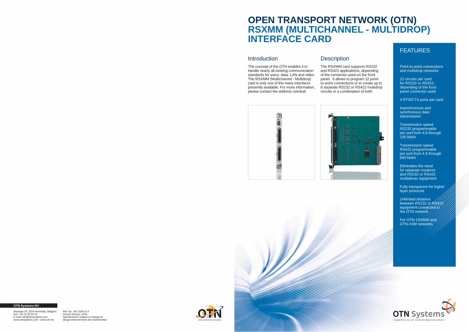
OPEN TRANSPORT NETWORK (OTN)RSXMM (MULTICHANNEL - MULTIDROP)INTERFACE CARD
IntroductionThe concept of the OTN enables it to handle nearly all existing communication standards for voice, data, LAN and video. The RSXMM (Multichannel - Multidrop) card is only one of the many interfaces presently available. For more information, please contact the address overleaf.
DescriptionThe RSXMM card supports RS232 and RS422 applications, depending of the connector used on the front panel. It allows to program 12 point-to-point connections or to create up to 6 separate RS232 or RS422 multidrop circuits or a combination of both.
Point-to-point connections and multidrop networks
12 circuits per card for RS232 or RS422, depending of the front panel connector used
4 RTS/CTS ports per card
Asynchronous and synchronous data transmission
Transmission speed RS232 programmable per port from 4.8 through 100 kbit/s
Transmission speed RS422 programmable per port from 4.8 through 600 kbit/s
Eliminates the need for separate modems and RS232 or RS422 multiplexer equipment
Fully transparent for higher layer protocols
Unlimited distance between RS232 or RS422 equipment connected to the OTN network
For OTN-150/600 and OTN-X3M networks
OTN Systems NV
Atealaan 34, 2200 Herentals, BelgiumFax: +32 14 25 20 23E-mail: [email protected] www.otnsystems.com - www.otn.be
Ref. No.: AE-S246-E-9Issued January, 2010Specifi cations subject to change as design improvements are implemented
FEATURES

A point-to-point circuit only requires one port, whereas a multidrop circuit needs two - making the following combinations possible (Point-to-point/Multidrop): 12/0 - 10/1 - 8/2 - 6/3 - 4/4 - 2/5 - 0/6.
In an RS232 or RS422 multidrop network, the master device simultaneously sends data to all of the slave devices that are connected to the multidrop circuits. The slave devices can reply to the master, one at a time.
A multidrop circuit can be programmed with the RTS (Request To Send) either enabled or disabled.When the RTS is enabled on a particular multidrop circuit, the device connected to those ports can only transmit data if it has activated its RTS. When the RTS is disabled on a specifi c multidrop circuit, the device connected to the latter can send data at any point in time.
On top of the functionality described above, the RSXMM interface card also has 4 separate RTS/CTS ports. When an external device activates its RTS signal, the RSXMM card will reply by activating the corresponding CTS signal provided the card is ready to accept data.
A higher layer protocol must be used on a multidrop network in order to prevent several devices from transmitting at the same time.
The Tx/Rx ports of the RSXMM card are full duplex ports that can be used for terminals and devices supporting the software controlled data transmission (Xon/Xoff).
For devices that do not allow software controlled data transmission, one can use either the RTS/CTS ports described above indicating local network availability, or else additional Tx/Rx ports for the control signals are used. For synchronous transmission, a second circuit (signal pair) is used for clock signals and, if necessary, a third one for RTS/CTS in the case of hardware data fl ow control. The transmission speed can be programmed for each port of the interface card separately. It is clear that both
circuits of a point-to-point link, and all circuits on a multidrop network must operate at identical speeds.
OperationIncoming data signals are sampled at 6.67 times the rate of the incoming data signal. These samples are inserted into the OTN frame and transmitted through the network. Hence, the transmission speed selected on a channel is the maximum speed possible, but any lower speed can also be transmitted.
In the receiving node, these bits are stripped from the OTN frame, re-assembled to the original signal and forwarded to the connected equipment. In a multidrop confi guration, the received information is also copied and transmitted on the ring towards the next port of the multidrop network, etc..
In a point-to-point confi guration, a circuit transmits information using the bits (bandwidth) in the OTN frame on which it receives information. In other words, the full duplex operation uses a minimum amount of bandwidth. In a multidrop network, the slave devices transmit data towards the master in a separate channel. Hence, a multidrop network uses two times the bandwidth of a point-to-point link of the same bit rate.
ApplicationsTerminal to host connectionsIn many cases, terminals are located well beyond the distance limitations set forth in the RS232/RS422 specifi cation. To overcome these limitations, baseband modems are often used. The OTN allows a much more fl exible and structured solution and RS232/RS422 distance limitations are completely eliminated.
Voiceband modems eliminationData communication in many larger networks is done using modems connected to voice circuits, which is expensive and often limits the bit rate. OTN offers a cost effective solution, especially when combined with other transmission services.
Control information transmissionRS232/RS422 is a very popular standard used by many equipment manufacturers. For example:
SCADA: transmission of • monitoring and control data;CCTV: controlling • pan - tilt - zoom;PA (Public Address): control • of amplifi er equipment;PIS (Passenger Information • System): broadcasting information.This equipment is very often connected in a multidrop network with a specifi c polling protocol running on top. The RSXMM card is fully transparent and ideally suited for connecting this type of equipment.
Ordering informationCardRSXMM S30824-Q70-X
The RSXMM card can be installed in the N22 and N215 nodes for OTN-150/600, and in the N42, N42C and N415 nodes for OTN-X3M.
OMS software releaseV2.2 and up (OTN-150/600) V4.0 and up (OTN-X3M)
Specifi cationsThe RSXMM card S30824-Q70-X is compatible with the RS232 (FB-52365-A), RS232MM (FB-52441-A) and RS422 (FB-52384-A) interface cards. With respect to point-to-point connections, it is also compatible with the RS422MD4 (FB-52384-F0A) and RS422MD6 (FB-52384-E0A) interface cards. Connections can be set up between e.g. an RSXMM and an RS232MM card.
Compatibility RS232 EIA/TIA-232-E and CCITT V.28RS422 EIA RS422 and CCITT V.11
CE markingEMC directive 2004/108/ECLVD directive 2006/95/EC
No. of Ports 12 ports point-to-point or 6 ports multidrop (RTS/• CTS handshaking) or a combination of point-to-point and multidrop: 12/0, 10/1, 8/2, 6/3, 4/4, 2/5 or 0/64 RTS/CTS port•
Data rate 0 up to 100 kbps (RS232) 0 up to 600 kbps (RS422) selectable per channel
Bandwidth on OTNProgrammable per point-to-point service: RS232: from 32 kbps up to 1024 kbps RS422: from 32 kbps up to 4096 kbps
Note: 2 times the number of bits are used for a multidrop network
Transmission Async./Sync.Full duplex
Connectors one 50 Pin Champ for RS232 and one for RS422, both shielded
Status informationCard active/inactiveCard typeReceive dataTransmit dataRTS status
On-board indications per circuitCard active/inactiveRTS status
WeightApprox. 425 g
Card size Double Eurocard200 x 233.4 mm
Reliability (MTBF) at 25°C (77°F): 44 years

OPEN TRANSPORT NETWORK (OTN)BROADBAND OPTICAL RING ADAPTER CARD: BORA622-X3M
IntroductionThanks to its design, the OTN (Open Transport Network) can handle nearly all existing communication standards for voice, data, LAN and video.
The system is based on dual, self-healing, counter-rotating optical rings. On top of this the OTN-X3M version of the product offers redundant central control for increased reliability and non-stop servicing.
The ring is synchronous, bandwidth is reserved by the OMS (OTN Management System) for each application, resulting in a never-blocking and fully predictable system behavior.
The BORA622-X3M, simplifi ed to “BORA” in the remainder of this sheet,
is the node’s redundant common logic card, interfacing between the interface cards and the optical ring. The BORA realizes a ring with a capacity of 622 Mbps.
An N415 node can be equipped with one BORA. An N42 or N42C can be equipped with one or two BORA cards. If two BORA cards are present, one of the cards acts as hot standby card, and can take over in less than 50 ms after detection of a failure of the active BORA.
The BORA has two hot-pluggable SFP (Small Form Factor Pluggable) modules. Different modules for different distances are available for multimode and single-mode fi ber. The BORA is SDH STM-4c and SONET OC-12c compatible.
OTN-X3M is the fully redundant version of the Open Transport Network
The BORA622-X3M common logic card is the OTN-X3M node’s central control block, to be used in the N42, N42C and N415 nodes
SDH STM-4c and SONET OC-12c compliant
Works together with the Node Support Module, offering alarm inputs/outputs, fan control & monitoring, and a built-in ‘get-attention’ audio alarm
On-board EngineeringOrder Wire (EOW) with handsfree headset
10/100 Base-T Ethernet port for connection to OMS (OTN Management System) over standard IP
Allows remote software downloads without node shutdown
The BORA622-X3M has two SFP type hot-pluggable optical transceivers that can be replaced during node operation
OTN’s hardware-based designHardware-based versus software-based systemsThe OTN-X3M switching and redundancy functionality is based on a hardware design, not a software approach. The advantages of hardware-based versus software-based system design are high reliability and transport speed.
Software-based switching systems have one or more fast microprocessors that interrogate the system data and route and switch the data to the appropriate interface cards. The disadvantage of a software-based approach the complexity of the control software which can affect operating speed and reliability.
OTN’s hardware-based system designThe hardware-based design of the OTN provides the native transport of user data between the optical interfaces and the interface card in the hardware, without invasive data analysis. For that purpose the OTN system was engineered to collect/distribute node user data, insert/drop the interface card data into a TDM-based frame structure and transmit/receive the TDM frame between OTN nodes without fi rmware interaction.
The OTN system provides reliable high-speed, fault-tolerant network transport with a variety of external interface protocol options.
Ordering informationNodesThe BORA622-X3M cards can be installed in the N42 or N42C nodes, 1 or 2 per node. The N415 node can be equipped with one BORA622-X3M card.
OMS software releaseOMS v5.2 and up•
BORA622-X3M-8 for N42 or N42C nodes: S30824-Q123-X102
BORA622-X3M-4 for N415 nodes: S30824-Q123-X107
SFP (Small Form Factor Pluggable) modules: see separate sheet.
OTN Systems NV
Atealaan 34, 2200 Herentals, BelgiumFax: +32 14 25 20 23E-mail: [email protected] www.otnsystems.com - www.otn.be
Ref. No.: AD-S138-E-7Issued November, 2009Specifi cations subject to change as design improvements are implemented
FEATURES

FunctionsThe BORA integrates the following functions on one card:
Microcontroller and in-band management channelA fast PowerQUICC® microprocessor running embedded Linux, and an in-band 10 Mbps Ethernet ring, interconnecting all nodes and the network management system offer the necessary power and fl exibility for the intelligent management of the node.
Controlling redundancy take-overIf two BORA cards are present, a dedicated hardware circuit on each BORA common logic card decides together with the same circuit on the ‘other’ BORA card, which of both BORA cards is in control. For that reason it monitors its own BORA card, and communicates with the circuit on the ‘other’ BORA card by means of heartbeat signals. Via a fail-safe handshaking mechanism, one of the BORAs assumes the active role, whereas the other one goes in hot stand-by-Mode.
Controlling the node and interface cardsThe BORA card tests and manages the node and the interface cards. For that purpose, a management channel offers 192 kbps full duplex HDLC-based communication between the BORA and any of the interface cards.
The BORA displays the actual ring and node status, facilitating fast troubleshooting. Special hardware allows the common logic card to remotely reset and power down individual interface cards if needed.
Managing and interfacing the optical ringThe OTN ring is managed in a distributed way by all BORAs connected to it. Upon startup the BORAs select a ring master, initialize and close the ring, and loop back if required due to broken fi bers or removed nodes. No single point of failure exists.
Controlling the data exchange between interface cards and optical ringA data connection can be either fi xed or switched. A switcheable data connection can be controlled by external control programs (e.g. video). Using user domains (reserved system resources), dynamic bandwidth allocation can be combined with non-
blocking operation. The switching speed depends upon the ring size, but is faster than 50 ms. Fixed connections can only be modifi ed by the OMS.
The BORA determines which data is exchanged between interface cards and the ring, making sure no interface card will disturb data from other interface cards.
With a 32 kbps granularity the BORA can extract up to 570 Mbps of data from the ring, and exchange up to 196 Mbps with every interface card in the node.
A star shaped data path between the BORA and the interface cards allows simultaneous data transfer at full speed between the BORA card and any interface card, and avoids any mutual disturbances.
Interfacing the OMSThe OTN Management System is used to confi gure the BORA cards; however, once confi gured, the BORA cards can carry out all functions, including fault recovery, ring management and interface card replacement, without the OMS being on-line.
A 10 Mbps Ethernet ring carrying IP interconnects the OMS to all the nodes in an OTN-X3M ring.
The BORA gathers all status information from the node, the ring and the interface cards, and makes it accessible to the OMS. The BORA also receives and checks all commands from the OMS, and carries them out or passes them on to the relevant interface card.
Engineering Order Wire (EOW)The BORA provides an interface for an Engineering Order Wire. This service voice channel may be used during installation or maintenance activities provided the optical ring is operational. A service engineer can access the EOW channel by plugging a headset with microphone into the EOW interface on the BORA front panel.
External clock synchronizationAlthough it is not needed for the correct operation of the OTN-X3M network, it is possible to synchronize the network to an external clock source.
An E1,T1 or 36.864 MHz TTL clock signal must be provided to the clock input of the Master BORA card, which is the BORA to which all other BORA cards in the ring are synchronized and which is located in the node having the lowest node number (address).
Functional blocksIn order to carry out all these tasks, the BORA card is equipped with two SDH/SONET termination blocks, several fi eld-programmable gate arrays (FPGA) and a microprocessor platform.
Two SDH/SONET termination blocks terminate the SDH signal, perform synchronization and clock recovery and transfer the OTN-X3M data as SDH/SONET payload over the optical link.
The main gate array (GRIA-E = Gigabit Ring Interface Adapter - Enhanced) contains the logic to support the optical rings (i.e. generation and recognition of time-multiplexed OTN frames, synchronization with the other nodes and node reconfi guration), and exchanges data in an add/drop fashion between ring and interface cards. New FPGA confi guration data can be downloaded from the OMS.
The redundancy control gate array (RCGA) contains the logic to check the BORA and to decide, together with an identical circuit on the other BORA card, on an active or stand-by state of its card.
An industrial microcontroller running embedded Linux, initializes, controls and checks the BORA card and the interface cards. The microcontroller also receives control data from the OMS, and stores it in a non-volatile RAM memory.
The data add and drop handling in an OTN-X3M node and the ring reconfi guration mechanism are not performed by the microprocessor.
If the latter should fail, the gate array continues to process the OTN ring data, in which case only the microprocessor’s tasks described above are not supported, but it can be reset without disturbing the node add/drop functionality.
In case of common logic card takeover, the ‘fi xed’ connections are enabled immediately. Switched connections (such as video) are rebuilt by the system controlling the application.
A fl ash EPROM contains the microprocessor’s program and consists of a fi xed (BOOT) and adjustable part, so it is possible to load a new fi rmware version from the OMS. During “downloading” the network remains operational. New embedded code, not affecting the GRIA-E, can be activated without disturbing the fi xed connections, thus enhancing the system’s maintainability.
Specifi cationsConnectors
ETH• A twisted-pair RJ45 connector (10/100 BASE-T Ethernet standard) for the connection of the OMS (IP/UDP protocol).
EOW• Two 3.5 mm jacks for the EOW (Engineering Order Wire) headset with microphone (S26361-F2D87-L1).
SFP slots• Two slots for SFP optical modules. The SFP modules use LC optical connectors.
CLK• An SMB50 Ohm connector to connect an external TTL clock input signal to which the master node synchronizes (36.864 MHz or 2.048 MHz (E1), 1.544 MHz (T1) auto-select).
On-board indicationsThe 4-character alphanumeric display shows the BORA622-X3M type and data regarding node operation and monitoring information. A push-button allows for scrolling through extended data sets.
The Ethernet RJ45 connector LEDs indicate the OMS/OVS link status.
The SDH and BER LEDs report data transmission errors, whereas the SY LED indicates the ring’s synchronization status.
An EOW LED (“CALL”) is lit when an EOW headset is plugged in at one of the nodes in the ring.
ResetA hidden reset button allows to reset the microcontroller, without disturbing the node add/drop functionality.
Status informationThe following status information is available on board:
Optical link status• SFP type (I, S1, L1, L2, V2)•
Firmware version• Interface card status•
Temperature sensorA temperature sensor is provided on the BORA622-X3M. The measured temperature is displayed.
CE markingEMC directive 2004/108/ECLVD directive 2006/95/EC
System data rateSDH data rate: 622.08 Mbps (STM-4/OC-12)Payload data rate: 570.570 Mbps
Optical data rate Optical data rate = SDH/SONET data rate = 622.08 Mbps (STM-4/OC-12)
Card sizeThe BORA622-X3M uses one system card slot position in an N42, N42C or N415 node.
Weight (with two SFPs)BORA622-X3M approx. 520 g
Reliability (MTBF) at +25°C (+77°F)20.4 years (=5598 FITS)
ElectroMagnetic CompatibilityEmission: EN61000-6-4, EN55022 Class BImmunity: EN61000-6-2
Power consumption at +25°C (+77°F) (with two SFPs)BORA622-X3M 3.6 A @ +5V 0 A @ +12V 0 A @ -12V
Eye safetyThe integrated optical transceiver modules are class 1 laser products and comply with IEC 825-1, EN60825 and FDA21 CFR 1040.10.
Transceiver typesThe hot-pluggable SFP (Small Form Factor Pluggable) modules convert the OTN ring’s optical signal to an equivalent electrical signal, and vice versa.
The SFP’s can be replaced via the front of the BORA.
The I (Intra-Offi ce), S1 (Short Haul), L1, L2 and V2 (Long Haul) transceiver types are available. Their optical characteristics are listed in a separate sheet.
OperationThe OTN data is transmitted between nodes in an STM-4c or OC-12c concatenated container. The SDH/SONET link layer carries out the clock synchronization, bit error rate measurement and word alignment.
The BORA places the OTN frame in the SDH/SONET payload. The OTN frame carries both data (for the interface cards) and control signals (such as the Engineering Order Wire-EOW and inter-node communication). As a result, the
SDH or SONET overhead bytes are not used by the OTN application, and may be modifi ed by other devices without disturbing OTN.
The add/drop functionality between interface cards and OTN frame is implemented in the GRIA-E gate array, and works on a 32 kbps level (cfr. the other members of the OTN family).Error checking tests are carried out on the optical level (Optical Signal Loss), on the SDH level (B1, B2 and B3 Bit Error Rate tests) and on the embedded OTN frame (CRC check).

Open Transport Network (OTN) H.264/AVC 16(4) Port Video Interface Card
IntroductionThe OTN concept allows handling nearly all existing communication standards for voice, data, LAN and video. The H.264/AVC video interface card is only one of the many interfaces presently available for OTN-X3M. For more information and other data sheets, contact the address overleaf.
DescriptionThe H.264/AVC cards are used to transmit up to 16 PAL or NTSC video signals via OTN-X3M.
Note: A 4-port version is also available for installations with a limited number of cameras per site.
Analog CVBS video signals are digitized and compressed by the video input circuit, and transmitted over the OTN-X3M network to one or more analog or IP video outputs. For IP outputs, the compressed digital video data is mapped into IP packets, while for analog outputs, the compressed digital video data is decompressed and converted to an analog PAL or NTSC signal. A single H.264/AVC card can be used both as input and output (analog & IP).
All OTN video cards provide high-quality video using the bandwidth offered by OTN-X3M.
The H.264/AVC card offers a higher compression ratio than the MPEG card (which uses MPEG2/4 compression) and the VID4E card (which uses M-JPEG compression). This allows an even higher number of video connections to be transmitted simultaneously through OTN-X3M.
OperationThe H.264/AVC video interface cards provide fi xed or switched connections between video inputs and outputs, both in point-to-point and multidrop confi gurations.
Bandwidth for fi xed or switched video applications is allocated by the
FEATURES
16 or 4 PAL/NTSC video input/output ports
H.264 Advanced Video Codec
Integrated IP streaming
RS422/232/485 port for PTZ
For OTN-X3M
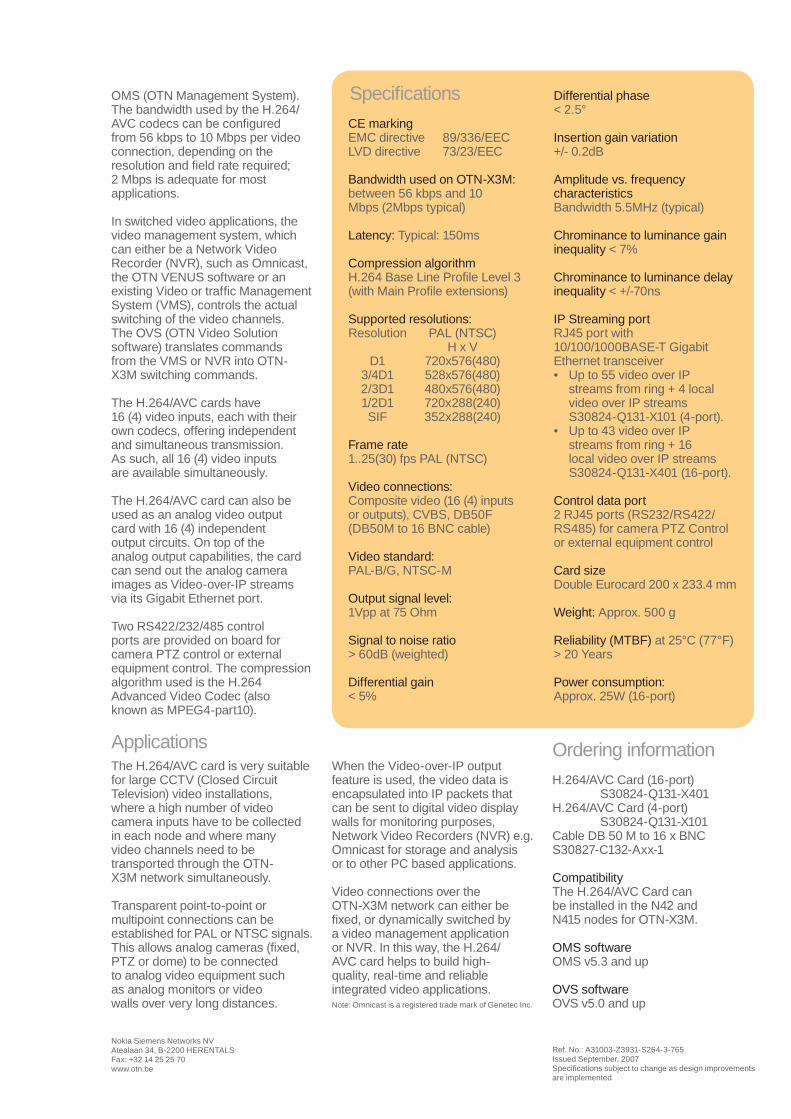
Specifi cationsCE markingEMC directive 89/336/EECLVD directive 73/23/EEC
Bandwidth used on OTN-X3M: between 56 kbps and 10 Mbps (2Mbps typical)
Latency: Typical: 150ms
Compression algorithmH.264 Base Line Profi le Level 3 (with Main Profi le extensions)
Supported resolutions: Resolution PAL (NTSC) H x V D1 720x576(480) 3/4D1 528x576(480) 2/3D1 480x576(480) 1/2D1 720x288(240) SIF 352x288(240)
Frame rate1..25(30) fps PAL (NTSC)
Video connections:Composite video (16 (4) inputs or outputs), CVBS, DB50F (DB50M to 16 BNC cable)
Video standard:PAL-B/G, NTSC-M
Output signal level:1Vpp at 75 Ohm
Signal to noise ratio> 60dB (weighted)
Differential gain< 5%
Differential phase< 2.5°
Insertion gain variation+/- 0.2dB
Amplitude vs. frequency characteristicsBandwidth 5.5MHz (typical)
Chrominance to luminance gain inequality < 7%
Chrominance to luminance delay inequality < +/-70ns
IP Streaming portRJ45 port with 10/100/1000BASE-T Gigabit Ethernet transceiver
Up to 55 video over IP streams from ring + 4 local video over IP streams S30824-Q131-X101 (4-port).Up to 43 video over IP streams from ring + 16 local video over IP streams S30824-Q131-X401 (16-port).
Control data port2 RJ45 ports (RS232/RS422/RS485) for camera PTZ Control or external equipment control
Card sizeDouble Eurocard 200 x 233.4 mm
Weight: Approx. 500 g Reliability (MTBF) at 25°C (77°F)> 20 Years
Power consumption: Approx. 25W (16-port)
•
•
Nokia Siemens Networks NVAtealaan 34, B-2200 HERENTALSFax: +32 14 25 25 70www.otn.be
OMS (OTN Management System).The bandwidth used by the H.264/AVC codecs can be confi gured from 56 kbps to 10 Mbps per video connection, depending on the resolution and fi eld rate required; 2 Mbps is adequate for most applications.
In switched video applications, the video management system, which can either be a Network Video Recorder (NVR), such as Omnicast, the OTN VENUS software or an existing Video or traffi c Management System (VMS), controls the actual switching of the video channels. The OVS (OTN Video Solution software) translates commands from the VMS or NVR into OTN-X3M switching commands.
The H.264/AVC cards have 16 (4) video inputs, each with their own codecs, offering independent and simultaneous transmission. As such, all 16 (4) video inputs are available simultaneously.
The H.264/AVC card can also be used as an analog video output card with 16 (4) independent output circuits. On top of the analog output capabilities, the card can send out the analog camera images as Video-over-IP streams via its Gigabit Ethernet port.
Two RS422/232/485 control ports are provided on board for camera PTZ control or external equipment control. The compression algorithm used is the H.264 Advanced Video Codec (also known as MPEG4-part10).
ApplicationsThe H.264/AVC card is very suitable for large CCTV (Closed Circuit Television) video installations, where a high number of video camera inputs have to be collected in each node and where many video channels need to be transported through the OTN-X3M network simultaneously.
Transparent point-to-point or multipoint connections can be established for PAL or NTSC signals. This allows analog cameras (fi xed, PTZ or dome) to be connected to analog video equipment such as analog monitors or video walls over very long distances.
When the Video-over-IP output feature is used, the video data is encapsulated into IP packets that can be sent to digital video display walls for monitoring purposes, Network Video Recorders (NVR) e.g. Omnicast for storage and analysis or to other PC based applications.
Video connections over the OTN-X3M network can either be fi xed, or dynamically switched by a video management application or NVR. In this way, the H.264/AVC card helps to build high-quality, real-time and reliable integrated video applications.
Ref. No.: A31003-Z3931-S264-3-765Issued September, 2007Specifi cations subject to change as design improvements are implemented
Ordering informationH.264/AVC Card (16-port) S30824-Q131-X401 H.264/AVC Card (4-port) S30824-Q131-X101Cable DB 50 M to 16 x BNCS30827-C132-Axx-1
CompatibilityThe H.264/AVC Card can be installed in the N42 and N415 nodes for OTN-X3M.
OMS softwareOMS v5.3 and up
OVS softwareOVS v5.0 and upNote: Omnicast is a registered trade mark of Genetec Inc.