Electronic properties of graphite-like ion tracks in insulating tetrahedral amorphous carbon
Upload
independentCategory
view
1download
0
Tetrahedral Mesh Improvement UsingMulti-face Retriangulation
Marek Krzysztof Misztal1, Jakob Andreas Bærentzen1, Francois Anton1 andKenny Erleben2
1 Informatics and Mathematical Modelling, Technical University of Denmark{mkm,jab,fa}@imm.dtu.dk
2 Department of Computer Science, University of [email protected]
Summary. In this paper we propose a simple technique for tetrahedralmesh improvement without inserting Steiner vertices, concentrating mainlyon boundary conforming meshes. The algorithm makes local changes to themesh to remove tetrahedra which are poor according to some quality criterion.While the algorithm is completely general with regard to quality criterion, wetarget improvement of the dihedral angle. The central idea in our algorithmis the introduction of a new local operation called multi-face retriangulation(MFRT) which supplements other known local operations. Like in many pre-vious papers on tetrahedral mesh improvement, our algorithm makes localchanges to the mesh to reduce an energy measure which reflects the qualitycriterion. The addition of our new local operation allows us to advance themesh to a lower energy state in cases where no other local change would leadto a reduction. We also make use of the edge collapse operation in order toreduce the size of the mesh while improving its quality. With these operations,we demonstrate that it is possible to obtain a significantly greater improve-ment to the worst dihedral angles than using the operations from the previousworks, while keeping the mesh complexity as low as possible.
1 Introduction and Motivation
For many types of physical simulation, the tetrahedral mesh representationis the natural choice. For instance, finite element computations in 3D usuallyemploy tetrahedral meshes which are far better at adapting to boundaries andchanges in scale than e.g. regular voxel grids.
For 2D triangulations, Delaunay triangulation is often a natural choicesince it leads to a mesh which is optimal in the sense that the minimal anglesare maximized which is a reasonable quality criterion in 2D. In 3D however,it is less clear what quality criterion we should strive for and a 3D Delaunay
2 M. K. Misztal, J. A. Bærentzen, F. Anton and K. Erleben
tetrahedralization may contain very flat sliver tetrahedra with extreme dihe-dral angles, and extreme dihedral angles are often precisely what we wish toavoid since they may lead to problems, such as great interpolation errors or ill-conditioned stiffness matrices in some finite element computations (althoughin the anisotropic case they might be desirable) or problems with interpolationaccuracy [21].
Consequently, in this paper and in other recent work [12], the goal is tooptimize a tetrahedralization obtained through either Delaunay or other meth-ods in order to improve some criterion – particularly dihedral angles. However,little is known about globally optimal meshes in the sense that the smallestdihedral angle is maximal or that the largest dihedral angle is minimal. Con-sequently, one strives instead for a set of simple, local transformations whichimprove the mesh by removing poorly shaped tetrahedra. The best one canhope for in this case is a good local minimum, and whether one attains sucha minimum is highly dependent on one’s vocabulary of local transformations.It is this vocabulary which we extend by the addition of two local transforma-tions which are highly beneficial to the mesh quality yet have not previouslybeen used in tetrahedral mesh optimization.
The most powerful way of improving triangle or tetrahedral meshes isthrough the insertion of more vertices (as shown in [12]). Indeed this is some-times the only way to improve quality. Unfortunately, one pays the price ofadding (sometimes significantly) more tetrahedra, and finding the optimalplace to put a vertex can be hard. Besides, many applications (such as dy-namic meshes) require their own Steiner vertex insertion routines. For thesereasons, we opine that it is very worthwhile to explore to what extent ourmesh improvement vocabulary can be augmented without adding vertices.
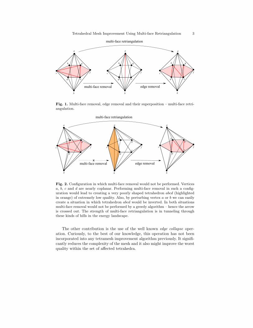
Our main contribution is the multi-face retriangulation operation. Assumea set of tetrahedra which we can divide into upper and lower tetrahedra. Anyupper tetrahedron shares a face with precisely one lower tetrahedron (andvice versa) and the upper tetrahedra all share a vertex (the upper vertex) asdo the lower tetrahedra (the lower vertex). We can say that the set of tetra-hedra is sandwiched between the upper and the lower vertex (as illustrated inFigure 1). The union of the triangular faces shared between upper and lowertetrahedra can be seen as a triangulation of a polygon. Our proposed oper-ation simply retriangulates this polygon to obtain better sets of upper andlower tetrahedra. Multi-face retriangulation can also be seen as a compositionof the known multi-face removal and edge removal operations (as shown inFigure 1) [9, 12]. However, multi-face retriangulation is more powerful thanthe concatenation of these two operations: in the case of some configurationsmulti-face removal followed by edge removal would never be selected becausevery poor or inverted tetrahedra would result from the multi-face removaloperation (as illustrated in Figure 2). Additionally, multi-face retriangulationworks on boundaries whereas concatenation of multi-face removal and edgeremoval does not.
Tetrahedral Mesh Improvement Using Multi-face Retriangulation 3
Fig. 1. Multi-face removal, edge removal and their superposition – multi-face retri-angulation.
Fig. 2. Configuration in which multi-face removal would not be performed. Verticesa, b, c and d are nearly coplanar. Performing multi-face removal in such a config-uration would lead to creating a very poorly shaped tetrahedron abcd (highlightedin orange) of extremely low quality. Also, by perturbing vertex a or b we can easilycreate a situation in which tetrahedron abcd would be inverted. In both situationsmulti-face removal would not be performed by a greedy algorithm – hence the arrowis crossed out. The strength of multi-face retriangulation is in tunneling throughthese kinds of hills in the energy landscape.
The other contribution is the use of the well known edge collapse oper-ation. Curiously, to the best of our knowledge, this operation has not beenincorporated into any tetramesh improvement algorithm previously. It signifi-cantly reduces the complexity of the mesh and it also might improve the worstquality within the set of affected tetrahedra.
4 M. K. Misztal, J. A. Bærentzen, F. Anton and K. Erleben
2 Related Work
Clearly, whether mesh improvement is needed depends on how the mesh wasgenerated. Broadly speaking, there are three ways of producing tetrahedralmeshes from a boundary representaion of an object. First, if the bound-ary is a piecewise linear complex (in particular – triangulated manifold), wecould use constrained Delaunay tetrahedralization to produce a conformingmesh [19, 22]. Alternatively, we could use an advancing fronts method whichwould build the tetrahedralization out from the boundary. As mentioned, theformer approach will often have problems with sliver tetrahedra even after De-launay refinement, unless the boundary satisfies a set of strict conditions [3,19]limiting the practical applications of this approach, and the latter tends toproduce some bad tetrahedra around areas where the front collides on it-self [16]. These problems are compounded if the boundary mesh has poorlyshaped triangles. An alternative approach is the centroidal Voronoi tessel-lation based Delaunay tetrahedralization [6] which can, however, still leavesome poorly shaped tetrahedra. We conclude that the mesh optimization islikely to be useful as a step following both Delaunay based methods and alsoadvancing fronts based methods.
A third and alternative strategy is to force the boundary to conform toan isosurface of an implicit function rather than a mesh. The spatial domainis first divided into tetrahedra, and a subset which approximates the shapewell is selected. In a subsequent compression step, the boundary vertices ofthis subset are forced to lie precisely on the isosurface [15]. However, we notethat the compression step is an optimization procedure because, generally, notonly the boundary vertices are moved but also the interior vertices in orderto improve the quality of the mesh. In recent work, Labelle and Shewchukwere able to demonstrate good provable bounds on the dihedral angles usingsuch a method [13]. However, methods which fit meshes to isosurfaces [13,15]cannot be expected to capture sharp edges and corners because the verticesare not constrained to lie in particular positions. Consequently, in some casesthey simply do not apply.
Most of the existing work for tetrahedral mesh improvement uses the fol-lowing three types of mesh operations:
1. Mesh smoothing – relocation of the mesh points in order to improve meshquality without changing mesh topology.
2. Topological operations – reconnection of the vertices in the mesh (withoutdisplacing them).
3. Vertex insertion – adding extra vertices into the mesh (through eg. split-ting of the edges, faces or tetrahedra) and reconnecting affected regionsof the mesh.
Tetrahedral Mesh Improvement Using Multi-face Retriangulation 5
2.1 Mesh Smoothing
One of the best known smoothing methods, Laplacian smoothing, in whicha vertex is moved to the centroid of the vertices to which it is connected,is a popular and quite effective choice for triangular meshes. In tetrahedralmeshes, however, it often produces poor tetrahedra [7]. Optimal (with regardto linear interpolation error) Delaunay vertex placement has been investigatedby Chen and Xu [2]. More general mesh smoothing algorithms are based onnumerical optimization. One of the most popular local algorithms for meshsmoothing was suggested by Freitag et al. [8]. This method relocates one vertexat a time. Given one vertex, its new position is found, so that the minimumquality of all the tetrahedra adjacent to this vertex is maximized (this requiresnon-smooth optimization). This procedure is performed for each vertex in themesh and can be iterated until a stable configuration is attained. It can alsobe performed on the boundary of the mesh, given extra constraints for theposition of the vertex. Another optimization based approach, using generalizedlinear programming, was presented by Amenta et al. [1], but this one is notas general as Freitag’s and is not well suited for dihedral angles optimization.Mesh smoothing can also be performed by continuous optimization in thespace of coordinates of all vertices of the mesh (as in [10]), but Freitag’smethod has advantages over this approach – it is easier to use with non-smooth quality measures, and its characterised by stable behavior even if theinitial quality of the mesh is very low.
2.2 Topological Operations
Reconnection of the mesh can be pictured as picking a set of adjacent tetra-hedra and replacing them with another set of tetrahedra, of higher minimumquality, filling in the same volume. This can be performed in a more or lessarbitrary manner (as small polyhedron re-tetrahedralization in [14]), or canbe organized into a set of topological operations, such as:
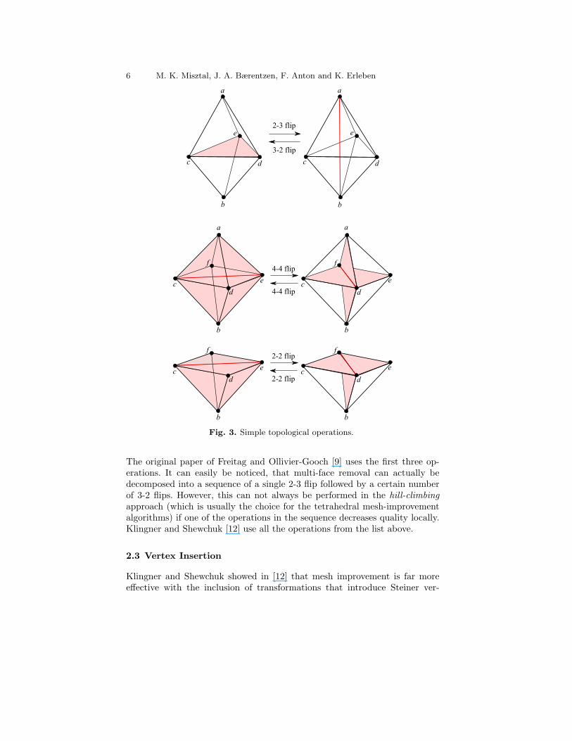
• 2-3 flip and its inverse, 3-2 flip, as shown in Figure 3.• 4-4 flip and its version for boundary configuration, 2-2 flip, illustrated in
in Figure 3 – ambiguous, requires specifying which edge pair of vertices isgoing to be connected after the operation.
• Edge removal is illustrated in Figure 1 – generalizes 3-2 flip, 4-4 flip and 2-2flip; ambiguous, requires specifying the final triangulation of the link of theremoved edge, which can be performed by using triangulation templates,as in [9] or by using Klincsek’s algorithm [11] in order to maximize theminimal quality of the created set of tetrahedra, as in [12]. Edge removalcan be performed for boundary edges.
• Multi-face removal of de Cougny and Shephard [5] is the inverse to theedge removal, as shown Figure 1 – generalizes 2-3 flip and 4-4 flip; requiresdynamic programming in order to select the subset of faces sandwichedbetween two vertices, which gives the best improvement.
6 M. K. Misztal, J. A. Bærentzen, F. Anton and K. Erleben
Fig. 3. Simple topological operations.
The original paper of Freitag and Ollivier-Gooch [9] uses the first three op-erations. It can easily be noticed, that multi-face removal can actually bedecomposed into a sequence of a single 2-3 flip followed by a certain numberof 3-2 flips. However, this can not always be performed in the hill-climbingapproach (which is usually the choice for the tetrahedral mesh-improvementalgorithms) if one of the operations in the sequence decreases quality locally.Klingner and Shewchuk [12] use all the operations from the list above.
2.3 Vertex Insertion
Klingner and Shewchuk showed in [12] that mesh improvement is far moreeffective with the inclusion of transformations that introduce Steiner ver-
Tetrahedral Mesh Improvement Using Multi-face Retriangulation 7
tices. Proper placement of Steiner vertices is a hard problem. Klingner andShewchuk describe a sophisticated and rather complex algorithm for vertexinsertion which mimics Delaunay vertex insertion and, together with opti-mization based smoothing and topological operations, allows them to improvethe meshes so that all dihedral angles are between 31◦ and 149◦, or, using adifferent objective function, between 23◦ and 136◦.
3 Tetrahedral Mesh Quality Improvement
Our mesh improvement algorithm is based on the algorithm proposed byKlingner and Shewchuk [12] (which in turn extends one by Freitag andOllivier-Gooch [9]) which uses vertex smoothing by Freitag et al. [8], edgeremoval, multi-face removal and vertex insertion (most of the operations theyuse can be performed on the boundary of the mesh). In turn, our algorithmuses the following set of operations:
• Vertex-smoothing as in Freitag et. al [8],• Topological operations:
– edge removal,– multi-face removal,– multi-face retriangulation.
• Edge collapse.
Vertex smoothing and edge removal can be performed for the boundaryvertices and edges, if the boundary is sufficiently flat around them. Addition-ally, vertex smoothing can be performed along straight ridges on the boundaryof the mesh, if the surface patches separated by the ridge are sufficiently flat.Multi-face removal and edge removal are implemented essentially the sameway as in [20].
3.1 Multi-face Retriangulation
Multi-face retriangulation can be seen as a composition of multi-face removaland edge removal, however, it can be also performed on the boundary of themesh. It includes the 4-4 and 2-2 flips. Multi-face retriangulation does notchange the number of tetrahedra in the mesh. So far as we know, it has neverappeared in the literature.
The reasons in favor of using MFRT alongside multi-face removal and edgeremoval are:
• In some cases, the configuration produced by multi-face removal is of lowerquality, as illustrated in Figure 2. Thus a greedy approach would not selectthat configuration even if the subsequent edge removal led to a state oflower energy than the initial configuration.
8 M. K. Misztal, J. A. Bærentzen, F. Anton and K. Erleben
• In some cases the configuration produced by multi-face removal includesinverted tetrahedra, and no approach would select that (also shown inFigure 2). However, MFRT cannot produce inverted tetrahedra, as thebest triangulation of the multi-face cannot be worse than the initial oneand we assume we run our algorithm on valid tetrahedral meshes.
• MFRT can be applied to boundary configurations. To see this, let us onlyconsider a set of lower tetrahedra in Figure 1. In such a configuration,multi-face consists of boundary faces and it cannot be removed using multi-face removal, but it can easily be retriangulated. However, if the multi-face is not sufficiently flat, which is the case when the angles between thenormals to the faces are greater than 0◦, MFRT can change the geometryof the boundary of the mesh, which is usually not desirable.
• MFRT does not change the number of tetrahedra. This property is a directconsequence of a well known fact that every triangulation of a polygon hasthe same number of triangles.
In our implementation, the input is a single face f we wish to remove.We find the apices a and b of the two tetrahedra adjoining f . Among the setof all faces sandwiched between a and b we find the connected componentthat contains f . For the multi-face defined like that, we find the optimaltriangulation of its bounding polygon using Klincsek’s algorithm. The routineis similar for a boundary face f , although in this case we have to make surethat the retriangulated multi-face is sufficiently flat (otherwise geometry ofthe boundary might change).
3.2 Edge Collapse
Edge collapse (also known as edge contraction or half-edge contraction) isa well known mesh operation which has been used as a primary tool forsimplifying 2D and 3D meshes in numerous works, such as [4,17]. It identifiesone of the vertices of an edge e with the other, removes e and all faces andtetrahedra which contain it. This can, however, lead to invalid configurations(violating the simplicial complex criterion) or alter the surface geometry of themesh, unless certain conditions are fulfilled, described in detail by Natarajanand Edelsbrunner in [17]. If edge collapse is not performed for the boundaryedges, which is the case in our implementation, those conditions simplify tothe following:
Lk(e) = Lk(a) ∩ Lk(b),
where a and b are the vertices of the edge e, and Lk(σ) denotes the link ofa simplex σ which, in tetrahedral meshes, can be defined as a set of thosesimplices (vertices, edges and faces) in the mesh, that do not intersect withσ, but are contained by the one of the tetrahedra containing σ. In our imple-mentation this is performed if the minimum quality of the set of tetrahedraaffected by the operation increases, or if it does not decrease below a certainquality threshold qmin, which is a global parameter of our algorithm.
Tetrahedral Mesh Improvement Using Multi-face Retriangulation 9
3.3 Quality Measures
Both the smoothing algorithm and the topological operations which we areusing are indifferent to the tetrahedron quality measure. In order to be ableto compare our results to those provided in [12] and [9], we are using:
• The minimum sine measure – the minimum sine of a tetrahedron’s sixdihedral angles, penalizes both small and large dihedral angles.
• The minimum biased sine measure, which is like the minimum sine mea-sure, but if a dihedral angle is obtuse, its sine is multiplied by 0.7 (beforechoosing the minimum). This quality measure penalizes large angles moreaggressively than the small angles.
Many quality measures have been proposed for tetrahedral meshes reviewedby [21], [10]. Our two choices are well behaved and very intuitive, althoughnon-smooth.
4 Implementation
Our mesh improvement schedule follows that of Klingner and Shewchuk [12](pseudo code is shown in Algorithm 1). Same as in their work, we use ashort list of quality indicators in order to measure progress in lowest qualitytetrahedra improvement. Those are: the quality of the worst tetrahedron in theentire mesh and seven thresholded means of the qualities of all the tetrahedrain the mesh. A mean qθ with threshold θ is computed the following way:
qθ =1
#{tetrahedra in M}∑t∈M
min(q(t), θ),
where M is the mesh and q is the tetrahedron quality measure we use. For ourquality measures we use thresholded means with thresholds sin(1◦), sin(5◦),sin(10◦), sin(15◦), sin(25◦), sin(35◦) and sin(45◦). A quality indicator designedlike that is a good measure of how narrow the distribution of the tetrahedronqualities is and allows us to detect the quality improvement even if the mini-mum quality does not change. The minimum quality alone is much less efficientas a mesh quality indicator – it leads to premature termination of the meshimprovement algorithm and significantly worse final results. We consider theimprovement in the mesh quality sufficient if either the quality of the worsttetrahedron improves, or if one of the thresholded means increases by at least0.0001.
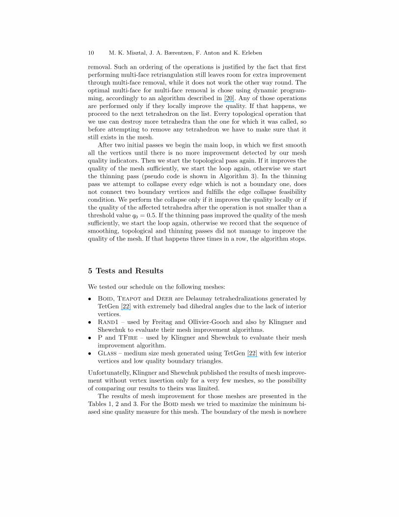
We begin mesh improvement with a vertex smoothing pass, followed bya topological pass. In the topological pass, pseudo code of which is shown inAlgorithm 2, we first obtain the list of all the tetrahedra in the mesh and thentry to remove every tetrahedron t on the list by first trying to remove its edgesusing the edge remove operation and then, if we have not succeeded, by try-ing to remove its faces using multi-face retriangulation followed by multi-face
10 M. K. Misztal, J. A. Bærentzen, F. Anton and K. Erleben
removal. Such an ordering of the operations is justified by the fact that firstperforming multi-face retriangulation still leaves room for extra improvementthrough multi-face removal, while it does not work the other way round. Theoptimal multi-face for multi-face removal is chose using dynamic program-ming, accordingly to an algorithm described in [20]. Any of those operationsare performed only if they locally improve the quality. If that happens, weproceed to the next tetrahedron on the list. Every topological operation thatwe use can destroy more tetrahedra than the one for which it was called, sobefore attempting to remove any tetrahedron we have to make sure that itstill exists in the mesh.
After two initial passes we begin the main loop, in which we first smoothall the vertices until there is no more improvement detected by our meshquality indicators. Then we start the topological pass again. If it improves thequality of the mesh sufficiently, we start the loop again, otherwise we startthe thinning pass (pseudo code is shown in Algorithm 3). In the thinningpass we attempt to collapse every edge which is not a boundary one, doesnot connect two boundary vertices and fulfills the edge collapse feasibilitycondition. We perform the collapse only if it improves the quality locally or ifthe quality of the affected tetrahedra after the operation is not smaller than athreshold value q0 = 0.5. If the thinning pass improved the quality of the meshsufficiently, we start the loop again, otherwise we record that the sequence ofsmoothing, topological and thinning passes did not manage to improve thequality of the mesh. If that happens three times in a row, the algorithm stops.
5 Tests and Results
We tested our schedule on the following meshes:
• Boid, Teapot and Deer are Delaunay tetrahedralizations generated byTetGen [22] with extremely bad dihedral angles due to the lack of interiorvertices.
• Rand1 – used by Freitag and Ollivier-Gooch and also by Klingner andShewchuk to evaluate their mesh improvement algorithms.
• P and TFire – used by Klingner and Shewchuk to evaluate their meshimprovement algorithm.
• Glass – medium size mesh generated using TetGen [22] with few interiorvertices and low quality boundary triangles.
Unfortunatelly, Klingner and Shewchuk published the results of mesh improve-ment without vertex insertion only for a very few meshes, so the possibilityof comparing our results to theirs was limited.
The results of mesh improvement for those meshes are presented in theTables 1, 2 and 3. For the Boid mesh we tried to maximize the minimum bi-ased sine quality measure for this mesh. The boundary of the mesh is nowhere
Tetrahedral Mesh Improvement Using Multi-face Retriangulation 11
Boid Teapot Deer
0 30 60 90 120 150 180
0.0 180.0
0 30 60 90 120 150 180
0.0 180.0
0 30 60 90 120 150 180
0.1 179.8
2179 tets 3677 tets 2678 tets
0 30 60 90 120 150 180
0.5 179.2
0 30 60 90 120 150 180
1.0 177.5
0 30 60 90 120 150 180
0.9 178.5
1831 tets 3123 tets 2342 tets
0 30 60 90 120 150 180
0.9 178.7
0 30 60 90 120 150 180
2.2 176.2
0 30 60 90 120 150 180
2.4 173.6
1854 tets 3060 tets 2327 tets
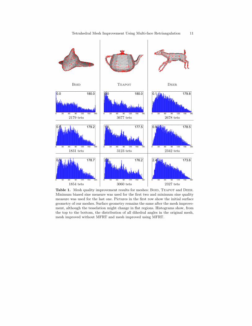
Table 1. Mesh quality improvement results for meshes: Boid, Teapot and Deer.Minimum biased sine measure was used for the first two and minimum sine qualitymeasure was used for the last one. Pictures in the first row show the initial surfacegeometry of our meshes. Surface geometry remains the same after the mesh improve-ment, although the tesselation might change in flat regions. Histograms show, fromthe top to the bottom, the distribution of all dihedral angles in the original mesh,mesh improved without MFRT and mesh improved using MFRT.
12 M. K. Misztal, J. A. Bærentzen, F. Anton and K. Erleben
P Rand1
0 30 60 90 120 150 180
1.3 177.9
0 30 60 90 120 150 180
0.3 179.0
926 tets 5104 tets
0 30 60 90 120 150 180
22.0 142.7
0 30 60 90 120 150 180
10.9 163.9
0 30 60 90 120 150 180
11.2 168.3
855 tets 5736 tets 5730 tets
0 30 60 90 120 150 180
24.9 139.7
0 30 60 90 120 150 180
14.2 158.9
0 30 60 90 120 150 180
14.2 163.3
855 tets 4739 tets 4574 tets
0 30 60 90 120 150 180
24.9 139.7
0 30 60 90 120 150 180
15.1 157.6
0 30 60 90 120 150 180
15.8 162.4
782 tets 3358 tets 3327 tets
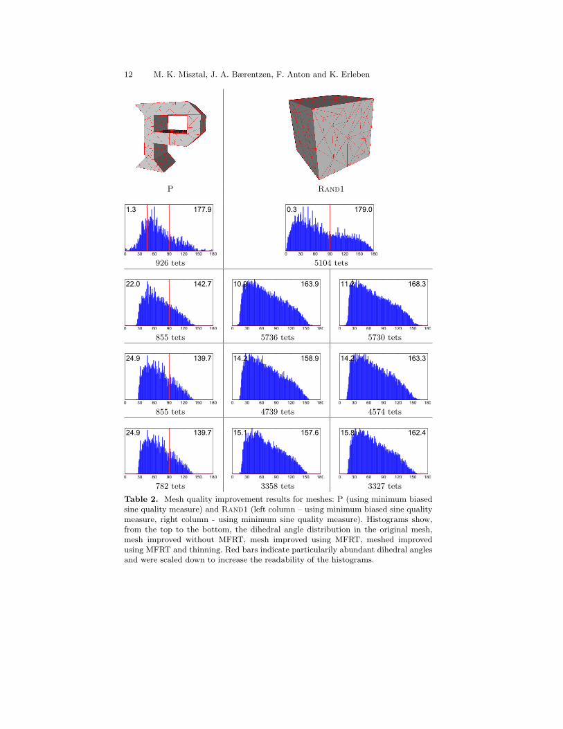
Table 2. Mesh quality improvement results for meshes: P (using minimum biasedsine quality measure) and Rand1 (left column – using minimum biased sine qualitymeasure, right column - using minimum sine quality measure). Histograms show,from the top to the bottom, the dihedral angle distribution in the original mesh,mesh improved without MFRT, mesh improved using MFRT, meshed improvedusing MFRT and thinning. Red bars indicate particularily abundant dihedral anglesand were scaled down to increase the readability of the histograms.
Tetrahedral Mesh Improvement Using Multi-face Retriangulation 13
Glass TFire
0 30 60 90 120 150 180
0.8 172.2
0 30 60 90 120 150 180
19.5 144.4
77632 tets 1104 tets
0 30 60 90 120 150 180
2.5 175.7
0 30 60 90 120 150 180
25.0 139.0
0 30 60 90 120 150 180
25.0 144.8
72542 tets 1099 tets 1101 tets
0 30 60 90 120 150 180
2.4 175.1
0 30 60 90 120 150 180
27.4 138.3
0 30 60 90 120 150 180
25.0 144.3
71016 tets 1095 tets 1094 tets
0 30 60 90 120 150 180
3.3 175.1
0 30 60 90 120 150 180
27.4 138.4
0 30 60 90 120 150 180
25.0 144.3
69776 tets 1071 tets 1034 tets
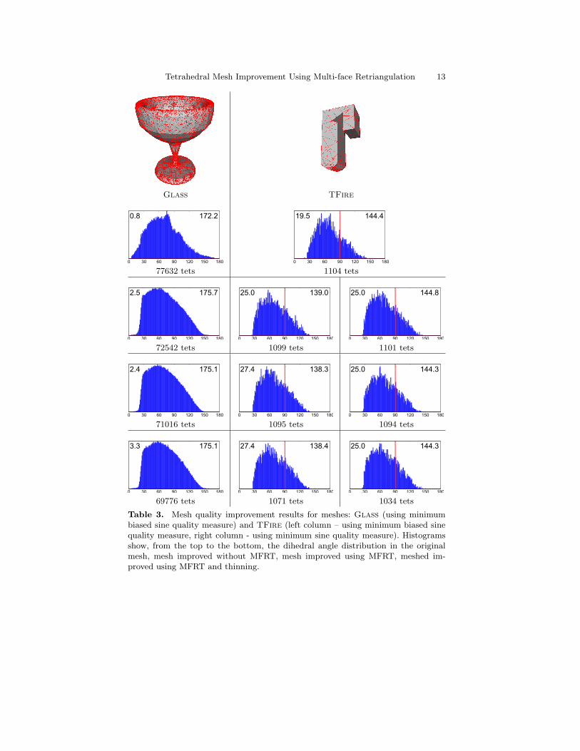
Table 3. Mesh quality improvement results for meshes: Glass (using minimumbiased sine quality measure) and TFire (left column – using minimum biased sinequality measure, right column - using minimum sine quality measure). Histogramsshow, from the top to the bottom, the dihedral angle distribution in the originalmesh, mesh improved without MFRT, mesh improved using MFRT, meshed im-proved using MFRT and thinning.
14 M. K. Misztal, J. A. Bærentzen, F. Anton and K. Erleben
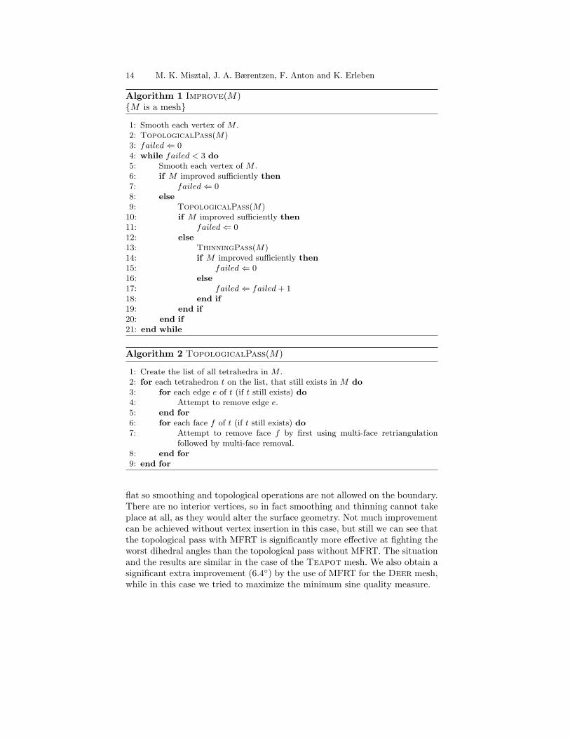
Algorithm 1 Improve(M){M is a mesh}
1: Smooth each vertex of M .2: TopologicalPass(M)3: failed⇐ 04: while failed < 3 do5: Smooth each vertex of M .6: if M improved sufficiently then7: failed⇐ 08: else9: TopologicalPass(M)
10: if M improved sufficiently then11: failed⇐ 012: else13: ThinningPass(M)14: if M improved sufficiently then15: failed⇐ 016: else17: failed⇐ failed + 118: end if19: end if20: end if21: end while
Algorithm 2 TopologicalPass(M)
1: Create the list of all tetrahedra in M .2: for each tetrahedron t on the list, that still exists in M do3: for each edge e of t (if t still exists) do4: Attempt to remove edge e.5: end for6: for each face f of t (if t still exists) do7: Attempt to remove face f by first using multi-face retriangulation
followed by multi-face removal.8: end for9: end for
flat so smoothing and topological operations are not allowed on the boundary.There are no interior vertices, so in fact smoothing and thinning cannot takeplace at all, as they would alter the surface geometry. Not much improvementcan be achieved without vertex insertion in this case, but still we can see thatthe topological pass with MFRT is significantly more effective at fighting theworst dihedral angles than the topological pass without MFRT. The situationand the results are similar in the case of the Teapot mesh. We also obtain asignificant extra improvement (6.4◦) by the use of MFRT for the Deer mesh,while in this case we tried to maximize the minimum sine quality measure.

Tetrahedral Mesh Improvement Using Multi-face Retriangulation 15
Algorithm 3 ThinningPass(M)
1: for each edge e ∈M that is not on the boundary do2: if e still exists then3: Find the vertices a and b of e.4: if b is not a boundary vertex then5: Attempt to collapse edge e: a← b.6: if success then7: Smooth a.8: end if9: end if
10: if a is not a boundary vertex and e still exists then11: Attempt to collapse edge e: b← a.12: if success then13: Smooth b.14: end if15: end if16: end if17: end for
For Rand1 the use of MFRT allows us to narrow the dihedral angles rangeby as much as 8◦ for both sine and biased sine quality measures. Additionally,edge collapse allows us to decrease the complexity of the meshes by almost35% and to narrow the dihedral angles range by almost 3◦ for sine qualitymeasure – ultimately we obtain 15.8◦–162.4◦, and by 2◦ for biased sine qualitymeasure – ultimately we obtain 15.1◦–157.6◦. For comparison, the best resultsFreitag and Ollivier-Gooch [9] obtained for the same mesh was 15.0◦–166.7◦
for minmax cosine quality measure (and 12.5◦-167.3◦ for sine quality measure).Mesh P also benefits significantly from the use of MFRT – it narrows thedihedral range by 6◦, but in this case the thinning pass does not improve theextreme quality values.
The TFire mesh also benefit from adding the MFRT and the edge collapseoperation, although not as significantly as the previous ones. Still, our result24.9◦–139.7◦ is better than 21.3◦–147.1◦ obtained by Klingner and Shewchuk[12].
In case of the Glass mesh, we can notice that our mesh improvementalgorithm actually expands the dihedral angles range. This is due to the lackof extremely obtuse angles in the original mesh, and due to the fact, that themesh operations we use choose to “sacrifice” good quality tetrahedra in orderto locally improve the worst tetrahedron. However, we can notice that the westill benefit from inclusion of MFRT and thinning in the mesh improvementalgorithm.
16 M. K. Misztal, J. A. Bærentzen, F. Anton and K. Erleben
6 Discussion and Future Work
Our results show that using the multi-face retriangulation operation along-side smoothing and topological operations from the previous works can leadto better improvement of the dihedral angles and should be included in thestandard repertoire of the topological operations for tetrahedral meshes. Forthe meshes we tested, we obtained a narrowing of the range of dihedral anglesby up to 8◦ without inserting a single Steiner vertex. Additionally, edge col-lapse can also improve the worst dihedral angles and decrease the complexityof the mesh by up to 35%, esspecially when the initial quality of the mesh isvery poor.
However, during our experiments we have noticed that the mesh improve-ment algorithm is still prone to get stuck in the local minima, even if we usemulti-face retriangulation – in a few cases, running the algorithm with somemesh operations “switched off” (for instance operations on the boundary ofthe mesh) leads to better results than running the algorithm with the fullrepertoire of mesh operations. This is, of course, a consequence of using agreedy, hill-climbing approach. This could possibly be improved by applyinga randomized approach.
It is also important to notice that our algorithm is designed for validinput meshes. If the initial mesh has inverted tetrahedra the algorithm mightfail to remove them. Also, the tetrahedron quality measures we used are notparticularily well suited for meshes with inverted tetrahedra, since they losecontinuity as the tetrahedron gets inverted.
In the future we are going to further investigate the possibilities of meshimprovement without Steiner vertex insertion, also with other quality mea-sures, such as the volume-length measure [18] V/l3rms, where V is the signedvolume of a tetrahedron and lrms is the root-mean-squared edge length.
Acknowledgments
We thank Frederik Gottlieb for the implementation of the core part of thedata structure that we are using, Bryan Klingner, Jonathan Richard Shewchukand Mads Fogtmann Hansen for meshes, geometric models and discussion. Wewould also like to thank Vedrana Andersen for helping us give this paper itsfinal shape and anonymous reviewers for useful suggestions.
References
1. N. Amenta, M. Bern, and D. Eppstein. Optimal point placement for meshsmoothing. In Proceedings of the eighth annual ACM-SIAM symposium on Dis-crete algorithms, pages 528–537. Society for Industrial and Applied MathematicsPhiladelphia, PA, USA, 1997.
Tetrahedral Mesh Improvement Using Multi-face Retriangulation 17
2. L. Chen and J. Xu. Optimal delaunay triangulation. J. Comp. Math, 22:299–308, 2004.
3. L.P. Chew. Guaranteed-quality delaunay meshing in 3d (short version). InProceedings of the thirteenth annual symposium on Computational geometry,pages 391–393. ACM New York, NY, USA, 1997.
4. B. Cutler, J. Dorsey, and L. McMillan. Simplification and improvement oftetrahedral models for simulation. In SGP ’04: Proceedings of the 2004 Euro-graphics/ACM SIGGRAPH symposium on Geometry processing, pages 93–102,New York, NY, USA, 2004. ACM.
5. Hugues L. de Cougny and Mark S. Shephard. Refinement, derefinement andoptimization of tetrahedral geometric triangulations in three dimensions. Un-published manuscript, 1995.
6. Q. Du and D. Wang. Tetrahedral mesh generation and optimization based oncentroidal voronoi tessellations. Int. J. Numer. Meth. Eng, 56:1355–1373, 2002.
7. Lori A. Freitag. On combining laplacian and optimization-based mesh smooth-ing techniques. In In Trends in Unstructured Mesh Generation, pages 37–43,1997.
8. Lori A. Freitag, Mark Jones, and Paul Plassmann. An efficient parallel algo-rithm for mesh smoothing. In Proceedings of the Fourth International MeshingRoundtable, 1995.
9. Lori A. Freitag and Carl Ollivier-Gooch. Tetrahedral mesh improvement us-ing swapping and smoothing. International Journal for Numerical Methods inEngineering, 40:3979–4002, 1997.
10. Mads F. Hansen, Jakob A. Bærentzen, and Rasmus Larsen. Generating qualitytetrahedral meshes from binary volumes. In Proceedings of VISAPP 2009, 2009.
11. G.T. Klincsek. Minimal triangulations of polygonal domains. Annals of DiscreteMathematics, 9:121–123, 1980.
12. Bryan M. Klingner and Jonathan R. Shewchuk. Agressive tetrahedral meshimprovement. In Proceedings of the 16th International Meshing Roundtable,pages 3–23, October 2007.
13. Franois Labelle and Jonathan Richard Shewchuk. Isosurface stuffing: Fast tetra-hedral meshes with good dihedral angles. ACM Transactions on Graphics,26(3):57, 2007.
14. Jianfei Liu and Shuli Sun. Small polyhedron reconnection: A new way to elimi-nate poorly-shaped tetrahedra. In Proceedings of the 15th International MeshingRoundtable, pages 241–257, 2006.
15. N. Molino, R. Bridson, J. Teran, and R. Fedkiw. A crystalline, red green strategyfor meshing highly deformable objects with tetrahedra. In Proc. InternationalMeshing Roundtable, 2003.
16. P. Moller and P. Hansbo. On advancing front mesh generation in threedimensions. International Journal for Numerical Methods in Engineering,38(21):3551–3569, 1995.
17. V. Natarajan and H. Edelsbrunner. Simplication of three-dimensional densitymaps. IEEE Transactions on Visualization and Computer Graphics, 10:587–597,2004.
18. V. N. Parthasarathy, C. M. Graichen, and A. F. Hathaway. A comparisonof tetrahedron quality measures. Finite Elements in Analysis and Design,15(3):255–261, 1994.

18 M. K. Misztal, J. A. Bærentzen, F. Anton and K. Erleben
19. Jonathan R. Shewchuk. Tetrahedral mesh generation by Delaunay refinement.In Proceedings of the fourteenth annual symposium on Computational geometry,pages 86–95. ACM New York, NY, USA, 1998.
20. Jonathan R. Shewchuk. Two discrete optimization algorithms for the topologicalimprovement of tetrahedral meshes. Unpublished manuscript, 2002.
21. Jonathan R. Shewchuk. What is a good linear finite element? interpolation,conditioning, anisotropy, and quality measures. Unpublished manuscript, 2002.
22. Hang Si. Tetgen, a quality tetrahedral mesh generator and three-dimensionaldelaunay triangulator, v1.3 user’s manual. Technical report, WIAS, 2004.
Copyright © 2022 FDOKUMEN