TeSys U All-in-one motor starters - Elektronabava
82
A4/1 TeSys U TeSys U All-in-one motor starters Introduction A4/2 TeSys U - Power bases, control modules, connectors Type of product Range Page Standard power base, basic control functionalities Direct and reversing Up to 18.5 kW A4/10 TeSys U - Communication components Parallel type cabling system Principle and components A4/16 Bus type cabling systems Principle, panorama and components A4/21 LUFP communication gateway A4/30 TeSys U - Accessories Short circuit current limiter A4/31 Handles and accessories for rotary control A4/32 Handles and accessories for integration into a MCC drawer A4/33 TeSys U with Altistart U01 Soft starters and Variable speed controllers A4/34 Technical Data for Designers A4/41 Chapter A4 TeSys
-
Upload
khangminh22 -
Category
Documents
-
view
0 -
download
0
Transcript of TeSys U All-in-one motor starters - Elektronabava

A4/1
TeS
ys U
TeSys UAll-in-one motor starters
Introduction A4/2
TeSys U - Power bases, control modules, connectors Type of product Range Page
Standard power base, basic control functionalities Direct and reversing
Up to 18.5 kW
A4/10
TeSys U - Communication components
Parallel type cabling systemPrinciple and components A4/16
Bus type cabling systems Principle, panorama and components A4/21
LUFP communication gateway A4/30
TeSys U - Accessories
Short circuit current limiter A4/31
Handles and accessories for rotary control A4/32
Handles and accessories for integration into a MCC drawer
RE
SE
TT
ES
T
0
A4/33
TeSys U with Altistart U01 Soft starters and Variable speed controllers A4/34
Technical Data for Designers A4/41
Chapter
A4 TeS
ys
A4/2
TeS
ys U
Introduction
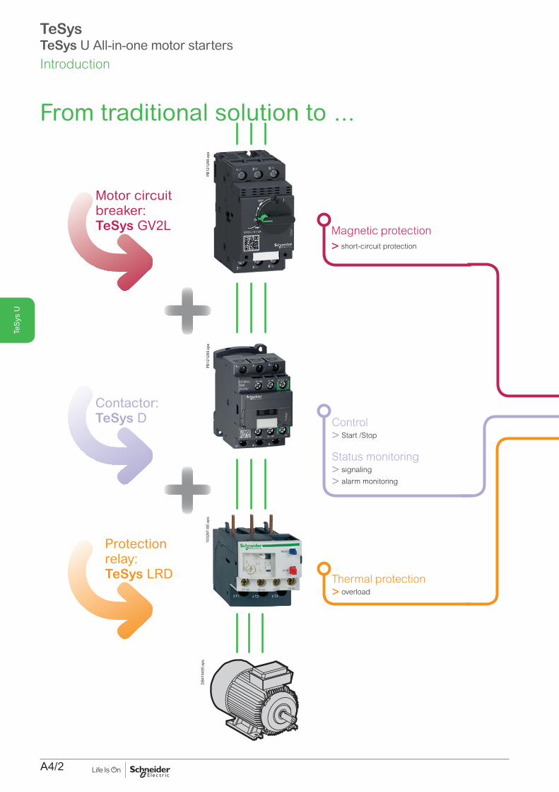
Motor circuit breaker: TeSys GV2L Magnetic protection
> short-circuit protection
Contactor: TeSys D Control
> Start /Stop
Status monitoring> signaling
> alarm monitoring
Protection relay: TeSys LRD Thermal protection
> overload
From traditional solution to ...
DB4
1449
0.ep
sPB
1212
88.e
psPB
1212
89.e
ps10
3287
-SE.
eps
TeSysTeSys U All-in-one motor starters

A4/3
TeS
ys U
. ..TeSys U starter-controller
TeSys U starter-controller
> All basic or advanced protection and control functions in one block
TeSys U can be used in
80 %of motor protection and control applications.
DB4
1449
0.ep
s
DB4
3279
5.ep
s
and more...
> Overload indication and alarm
> Status report, remote control via communication bus
TeSysTeSys U All-in-one motor startersIntroduction

A4/4
TeS
ys U
DB4
1449
0.ep
sD
B432
795_
r.eps
All in onep Optimising space in enclosures.
p Total coordination (No contact welding on short circuit).
p Reduces installation times.
1
Simplicity of choicep Controlled power.
p Protection functions ensured.
p Signaling functions, communication with PLC ensured.
2
Universal mountingp On DIN rail or grid.
3
Conventional projet designp Conventional control scheme with start , stop push buttons.
4
Basic scheme of a TeSys U starter-controller
1/L1
3/L2
5/L3
2/T
1
4/T
2
6/T
3
M3 a
U1
V1
W1
A2A1
13 14
DB4
1449
1R.e
ps
C. U.
Power circuit Control circuit
p Protection and power control functions acting on a single set of contact (QF1).
p The control unit (CU) monitors the voltage and current. In case of fault, it releases the coil, causing tripping.
p The coil is controlled by manual orders from an operator. Automatic control from a PLC is achieved with other diagrams.
Electrically simple5
Introduction
TeSysTeSys U All-in-one motor starters

A4/5
TeS
ys U
TeSysTeSys U All-in-one motor starters
p 7.5 kW / 1-phase 230 V / 50-60 Hz.
p 18.5 kW / 3-phase 400-440 V / 50-60 Hz.
p 18.5 kW / 3-phase 500 V / 50-60 Hz.
p 22 kW / 3-phase 690 V / 50-60 Hz.
p Non-reversing or reversing.
Motor up to
DB4
1449
0.ep
sD
B432
795_
r.eps
Common characteristics Short-circuit protection
b Isc: v 50 kA at y 400 V v 10 kA at 500 V v 4 kA at 690 V. b Up to 690 V AC.
Overload protection b From 0.15 to 38 A, 6 setting ranges (tripping 14.2 x I setting). b Test button. b Adjustment lock. b Coil choice: 24 V, 48…72 V, 110...240 V DC/AC.
3 power contacts b For non-reversing (reversing with reverser block). b Imax, for 12 A power base (direct - reversing): v 12 A at up to 500 V / 50 Hz v 9 A > 500 V, up to 690 V. b Imax, for 38 A power base (direct - reversing): v 38 A at up to 500 V / 50 Hz v 21 A > 500 V, up to 690 V.
1 NO contact 1 NC contact
b 5 A / max. 690 V AC or 250 V CC.
Other monitoring contacts b 5 A / max. 690 V AC or 250 V DC.
Communication modules b Modbus, b Ethernet, b CANopen, b DeviceNet, b Advantys stb, b Profibus DP, b AS-interface.
Dimensions b Base: b Base + reverser block:
154
45126
DB4
1631
9.ep
s
224
45126
DB4
1632
0.ep
s
Introduction

A4/6
TeS
ys U
Power BaseThis is the basic constituent of the motor starter, it is composed of the power contacts, the control coil, the opening / closing mechanism of the protection device and the control pad.
Additional lateral blockComposed of the protection device signaling contacts.
Control unitComposed of the power base management processor and setting knobs.
Auxiliary moduleDepending on its type, it integrates load status contacts or a communication processor or an alarm processor.
Control terminal blockIt is composed of two terminals "coil control", 1 NO auxiliary contact, 1 NC auxiliary contact. It can be eventually connected to an auxiliary communication module via a dedicated cable.
Additional blockIt includes protection device additional signaling contacts. By default, this is a simple shutter.
Power base C Cavity for control terminal block
A Cavity for control unit D Cavity for additional contact block or shutter
B Cavity for auxiliary module E Space for additional block fastening
A
B
C
D
E
DB4
1449
3.ep
sTeSysTeSys U All-in-one motor startersIntroduction
The modularity principle

A4/7
TeS
ys U
DB4
1449
4R.e
ps
23
4
6
7
18
19
20
21
22
89
1011
1213
1415
16
17
1
A
B
C
D
24
Power base1- LUB Non reversing power base -
1 rotation direction
Control units2- LUCM
Multifunctional control unit
3- LUCB/LUCC/LUCD Advanced control units
4- LUCA Standard control unit
5- LUCL Magnetic protection control unit
Auxiliary module6- LUFN Auxiliary contacts module
Communication auxiliary modules11- LUFC00
Telefast parallel liaison module, with RJ45 connector
12- ASILUFC5/ASILUFC51 AS-Interface c. m.
13- LULC033 Modbus c. m
14- LULC07 Profibus DP c. m
15- LULC08 CANopen c. m.
16- LULC09 DeviceNET c. m.
17- LULC15 Advantys STB c. m.
Shutters18- LU9C1
Shutter for module cavity
23- Shutter for contacts additional block cavity
Control terminal blocks19- LU9BN11 Terminal block for imbedded auxiliary contacts
20- LU9BN11C Coil terminal block with its
connecting cable
21- LU9BN11L Coil terminal block with its connecting cable
Additional contacts blocks22- LUA1 Additional contacts
24- LUA8 side-mounting additional contacts
E
5
23
TeSysTeSys U All-in-one motor starters
Components overview
Load monitoring auxiliary modules7- LUFW10
Overload alarm module
8- LUFDH11 Overload alarm module with manual reset
9- LUFDA01/LUFAD10 Overload alarm module with automatic reset/remote reset
10- LUFV2 Motor load indication module
Introduction

A4/8
TeS
ys U
Control terminal blocks2- LU9MR1C
Base/block assembling connector, with terminal block for imbedded auxiliary contacts
3- LU9M1 Coil terminal block for wired control
4- LU9MRC Coil terminal block with its connecting cable for communicating control (only compatible with a selection of com. modules).
5-LU9MRL Coil terminal block with its connecting cable for communicating control (only compatible with a selection of com. modules).
Reverser block1- LU2MB0pp
vertical-mounting reverser block
TeSysTeSys U All-in-one motor starters
Additional components overview
DB4
1449
5R.e
ps
1
2 3
4
5
6
Evoluting reversing power base 6- Pre-assembled reversing
power base LU2B12
Introduction

A4/9
TeS
ys U
Terminal blocks for electrical remote control
2- LU9MR1 Terminal block for 2 direction control (pulse or maintained control)
3- LU9M1 Terminal block for power base coil interlocking. With direction of rotation monitoring contacts
TeSysTeSys U All-in-one motor starters
DB4
1449
7.ep
s
3
1
2
Reverser block1- LU6MB0pp
Side-mounting reverser block
Additional components overview
Introduction

A4/10
TeS
ys U
1 direction:LUB12, LUB32, LUB38
1 direction:LUB120, LUB320, LUB380
PB12
1245
.eps
2 direction:LU2B12pp, LU2B32pp, LU2B38pp
PB12
1247
.eps
LU9MR1C
PB12
1248
.eps
LU6MB0pp
PB10
8393
.eps
LU9MR1
PB12
1250
.eps
LU2MB0pp
PB10
8394
.eps
LU9M1
PB12
1249
.eps
PB12
1246
.eps
Product references
Power basesTeSys U starters are composed with separate elements: power component + control units + auxiliary components.The power base includes the electro mechanical parts. It is selected according to:
b Motor power to be handled b Number of direction of rotation to be controlled: 1 or 2 b Type of control to be acheived: Basic or Advanced.
Basic control1- direction rotation control2 - direction rotation controlOverload + Short circuit protectionMain power monitoringStatus signaling contacts
Advanced controlFunctions of basic control + Digital display of electrical values+ Overload alarms+ Network/bus communication
Function Max motor standard power (400 V)
Lip_in (400 V)
References
kW A Basic ctrl Advanced ctrl5.5 12 LUB12 LUB120
1-direction rotation 15 32 LUB32 LUB32018.5 38 LUB38 LUB3805.5 12 LU2B12pp (1) LUB120 + reverser
block ass.2-direction rotation 15 32 LU2B32pp (1) LUB320 + reverser
block ass.18.5 38 LU2B38pp (1) (2) LUB380 + reverser
block ass.(1) Replace the 2 dots by the coil voltage code below – AC is 50-60 Hz.(2) With BL or FU code only.Coil voltage (V) 24c 24a 48...72 c
or a110...220 c and 110...240a
Code BL B ES FU
Reverser blocks - assembliesA reverser block assembly has to be added to the power base (LUB120 to 380) to build an ‘Advanced control’ with ‘2-direction of rotation’ TeSys U starter.Reverser blocks with 2 mounting possibilities:
b vertical mounting– mounted aspect: refer to LU2B12, 32, 38 b side mounting, on a Din rail.
DB4
1634
7.ep
s
Vertical mounting
DB3
6120
.eps
Side mounting
Blocks ReferencesVertical mounting
Side mounting
1 Reverser block
LU2MB0pp (1)
LU6MB0pp(1)
2 Aux. contacts connector
LU9MR1C LU9MR1
3 Coil supply connector
LU9M1 LU9M1
(1) Replace the 2 dots by the coil voltage code below – AC is 50-60 Hz.
Coil voltage (V) 24c 24a 48...72 c or a
110...220 c and 110...240a
Code BL B ES FU
2
1
3
1
2
3
Main technical caracteristics Power bases 1-direction power base overall dimensions (HxWxD) : 154 x 45 x 126 mm2-direction power base (assembly with vertical mounting reverser block) overall dimensions (HxWxD): 224 x 45 x 126 mm Power bases are delivered with protective blanking plates.3 power poles, for connections of a 1-phase or 3-phase motorScrew clamp power terminals, for up to 2 x 6 mm² conductorsScrew clamp control terminals, for up to 2 x 1.5 mm² conductorsLUB12,32,38 imbedded terminals:
b coil supply, b NO (13-14) contact (for control push button) b NC (21-22) contact (for control push button).
Additional signaling contact modules provide more possibilities.
Reversing assemblies LU2MB0, LU6MB0: 3 power poles, for connections of a 1-phase or 3-phase motor, screw clamp power terminals, for up to 2 x 6 mm² conductorsLU9 connectors: screw clamp control terminals, for up to 2 x 1.5 mm² conductors
LU2MB0pp, LU6MB0pp provide terminals for power circuits. LU9MR1C, LU9MR1 provide signalling contact terminals (82-81-84) that indicate the direction of rotation.LU9M1 provides coil supply terminals (A2-A1-A3) and 2 NO contact terminals (A1-B1, A3-B3) for direction control.
TeSysTeSys U All-in-one motor starters - Power bases
Characteristics:pages A4/42 to A4/44, A4/52
Curves:pages A4/54 to A4/59
Dimensions:pages A4/60 and A4/61
Schemes:pages A4/62 to A4/74

A4/11
TeS
ys U
TeSys U starters are composed with separate elements: power component + control units + auxiliary modules.The control unit includes electronic components and the current adjustment dial. The control uinit is selected according to:
b Motor power to be handled.Type of protection: thermal+magnetic or magnetic only.
Control units for power bases with basic controlLUCA - thermal + magnetic (standard) units
b Protection against overload: 14.2 x lr (setting current). b Protection against short circuit: 13 x lr max (max setting current). b Protection against missing or unbalanced phases. b Protection against insulation fault (protection of equipment only). b Class 10 tripping. b Frequency 50...60 Hz.
LUCL - magnetic units b Protection against short circuits. b To be used when a standard power base is connected to a motor drive or a soft starter, as they provide the overload protection.
Note: both LUCA and LUCL units can be used in the advanced power bases LUB120 and LUB320.
Maximum standardized power ratings of 3 phases motors 50/60 Hz
Setting range
Lip_in mounting on the power base - Rating
DB4
1449
9.ep
s
400/440 V 500 V 690 V Control unit product reference (1)
kW kW kW A A Thermal + magnetic
Magnetic
LUCA LUCL0.09 - - 0.15...0,6 12 and 32 LUCAX6pp LUCLX6pp
0.25 - - 0.35...1,4 12 and 32 LUCA1Xpp LUCL1Xpp
1.5 2.2 3 1.25...5 12 and 32 LUCA05pp LUCL05pp
5.5 5.5 9 3...12 12 and 32 LUCA12pp LUCL12pp
7.5 9 15 4.5...18 32 LUCA18pp LUCL18pp
15 15 18.5 8...32 32 LUCA32pp LUCL32pp
18.5 18.5 22 9.5...38 38 LUCA38pp (2) LUCL38pp (2)
(1) Replace the 2 dots by the coil voltage code below – AC is 50-60 Hz. (2) With BL or FU code only.
Coil voltage (V) 24c 24a 48...72 c or a
110...220 c and 110...240a
Code BL B ES FU
LUCA, LUCB, LUCC, LUCD, LUCL series
PB12
1268
.eps
Product references
DB4
1449
9.ep
s
1
32
4
LUCApppp
1 Extraction and locking handle.
2 Sealing of locking handle.
3 Ir adjustment dial.4 Locking of settings by sealing
the transparent cover.
TeSysTeSys U All-in-one motor starters - Control units
Characteristics:pages A4/45 to A4/47, A4/53
Curves:pages A4/54 to A4/56
Schemes:page A4/60

A4/12
TeS
ys U
Product references
Control units for power bases with advanced controlLUCB, LUCC, LUCD control and diagnostic unitsMotor protection, fault diagnostic.Protection against
b overload: 14.2 x lr (setting current).Simulation of an overload by depressing the test push button.
b short circuit: 13 x lr max (max setting current). b missing or unbalanced phases. b insulation fault (protection of equipment only).
Overload alarm management: b locally: with one of the LUF family module b Remotely: with LULC031, LULC033, LULC07, LULC08, LULC09 or LULC15
(thermal alarm only) communication module.Reset:
b manual b automatic, with a communication module.
LUCM multifunctional control unitMotor protection, operational values display and diagnostic.To be associated with 24 V DC coil only.LUCMppBL: tripping class 5 to 30, single phase, three phaseSame functions as LUCBpppp with complementary functions:
b in working mode: display of electrical values, setting parameters and events b in configuration mode: display of protection and alarm settings.
These functions are available for local display on a display panel, and for remote display via a RJ45 Modbus connector.LUCM is not compatible with LUB38.
Note: a 24 V DC power supply is required during the configuration process.
Maximum standardized power ratings of 3 phases motors 50/60 Hz
Setting range
Lip_in mounting on the power base - Rating
DB4
1449
9.ep
s
Protection type:- overload- short-circuit- Main power fault- alarm
DB4
1450
4.ep
s
400/440 V 500 V
600 V Multifunctional
kW kW kW A A Class 10 Class 10 Class 20 Class 5...301P 3P 3P 3P 3P 1P 3P 1 - 3P- 0.09 - - 0.15...0,6 12 and 32 LUCBX6pp LUCCX6pp LUCDX6pp LUCMX6BL0.09 0.25 - - 0.35...1,4 12 and 32 LUCB1Xpp LUCC1Xpp LUCD1Xpp LUCM1XBL0.55 1.5 2.2 3 1.25...5 12 and 32 LUCB05pp LUCC05pp LUCD05pp LUCM05BL2.2 5.5 5.5 9 3...12 12 and 32 LUCB12pp LUCC12pp LUCD12pp LUCM12BL4 7.5 9 15 4.5...18 32 LUCB18pp LUCC18pp LUCD18pp LUCM18BL7.5 15 15 18.5 8...32 32 LUCB32pp LUCC32pp LUCD32pp LUCM32BL18.5 18.5 22 9.5...38 38 LUCB38pp (1) LUCD38pp (1)
Cial. ref. of the control unit: replace dots by the coil code.Coil voltage (V) 24c 24a 48...72 c and 48a 110...220 c and
110...240aCoil code BL B ES FU
Magelis XBT NU HMI terminal (optional)Provides display and modification of the LUCM multifunctional control unit settings.Modbus protocol – dialog up to 8 TeSys U(2)- Pre-loaded application and alarm pages, multi-language.
Designation ReferencesMagelis TeSys U terminal XBTNU400Connecting cable XBTNU400 to LUCM ppBL, L = 2.50 m (2) XBTZ938(1) With BL or FU code only.(2) A Modbus hub or - junction must be used when connecting several TeSys U.
XBTNU400
PF08
0536
_N40
0.ep
s
LUCM12BL
PB12
1251
.eps
DB4
1450
9.ep
s
1234
LUCBpppp, LUCCpppp, LUCDpppp control units
1 Extraction and locking.2 Handle sealing of locking.3 Handle 4 Ir adjustment dial test push button.
1
2
3
45
6
DB4
1451
0.ep
s
LUCMppBL control unit1 Extraction and locking handle.2 Built-in LCD display (2 lines, 12 characters).3 4 button keyboard.4 RJ45 connector for RS485 Modbus communication 5 Connector for external 24 V DC power supply.6 Sealing of locking handle.
TeSysTeSys U All-in-one motor starters - Control units
Characteristics:page A4/45
Curves:pages A4/54 to A4/56
Schemes:page A4/63

A4/13
TeS
ys U
Product references
LUA8E20
PB12
1252
.eps
LUFV2
PB12
1255
.eps
LUFDH11
PB12
1257
.eps
LUFDA01
PB12
1258
.eps
LUFV2 typical response curve
20
%
124
100
200
1
2.2 kW1
4 kW2
7.5 kW3
23
mA
DB4
3663
0.ai
LUFDA10
PB12
1259
.eps
LUFW10
PB12
1256
.eps
LUFN02
PB12
1253
.eps
LUA1C20
PB12
1254
.eps
DB4
1450
1.ep
s
B
C
E
LUA8E20
LUFNpp
LUA1Cpp
Signaling module and blocks They provide dry contacts of Normally Open (NO) or Normally Closed (NC) type for signaling purpose. The monitored status can be either the motor running status or the protection device status, depending on the commercial reference of the module or block.
Common electrical characteristicsStandard operating voltage: 24…250 V AC/DC.Maximum current: 5 A.
Compatibility - PositioningThe signaling module and blocks can be use in any power baseLUA8E20 is clipped on the E side of the power baseLUFN11, LUFN02, LUFN02 inserted into B cavityLUA1C20, LUA1C11 inserted into C cavityNote: B and C cavities may be already used for reverser-starter, communication.
Signaling module and blocks Output ReferencesModule Motor running status: ON / OFF
1 NO + 1 NC LUFN112 NC LUFN022 NO LUFN20
Block Protection status: OPEN / CLOSED (OF) STANDBY / TRIPPED (SD)
2 NO LUA1C201 NO + 1 NC LUA1C11
Side block Protection status: OPEN / CLOSED (OF)
2 NO LUA8E20
Function modulesThey provide analog output or dry contacts of Normally Open (NO) or Normally Closed (NC) type for measurement or signaling purpose.
Common electrical characteristicsStandard operating voltage: 24…250 V AC/DC.Maximum current: 5 A.
Compatibility - PositioningThe function modules can only be used in a LUB120, LUB320 or LUB380 power base, in cavity B.
Function modules Outputtype
References
Electrical value: average current in each phase.The signal is the image of the pourcentage of In.External 24 V DC power supply needed
Analog: 4-20 mA
LUFV2
Contact closes if average current in the phases = 105 % of In
1 NO LUFW10
Contacts change state if tripping is caused by overload 1 NO + 1 NC LUFDH11
Contact opens if overload tripping is reset with control pad or remotly
1 NC LUFDA01
Contact closes if overload tripping is reset with control pad or remotly
1 NO LUFDA10
TeSysTeSys U All-in-one motor starters - Signaling Modules/Blocks - Function modules
Characteristics:pages A4/48 to A4/52
Schemes:pages A4/62 to A4/64

A4/14
TeS
ys U
Product references
LUFC00
PB12
1260
.eps
LULC033
PB12
1261
.eps
LULC07
PB12
1261
.eps
LU9BN11C
PB12
1264
.eps
LU9MRC
PB12
1266
.eps
LU9MRL
PB12
1267
.eps
LU9BN11L
PB12
1264
.eps
LULC15
PB12
1290
.eps
ASILUFC51
PB12
1262
.eps
Auxiliary parallel wiring module (1)
Auxiliary parallel wiring module for Modicon Telefast system Inputs They collect the FWD, REV controls from an automation process.An RJ45 parallel port is used, for connection to the 24 V DC outputs of a PLC.OutputsThey give the position of the control pad and the state of the poles,They provide 24 V DC controls to the LUB120, 320 or 380 power base coil via the LU9BN11C adapter (A2, A1) or to the LU2B12, 32, 38 power base coil with a LU9MRC adapter (A2, A1, A3).
Compatibility - PositioningThe paralle wiring module can only be used in any TeSys U power base, with LUCppp control unit with coil voltage Compatible with:
b Modicon TM3 (map I/O controllers for RJ45 M221, M241, M25) b Modicon STB modules (I/O for automation island) b Modicon Telefast (interfaces RJ45/HE10).
The parallel wiring module is inserted in cavity B.Note: the parallel wiring module must be connected to a LU9G02 or LU9G03 Telefast distributionNote: more details on parallel wiring page A4/16.
Designation ReferencesTeSys U power base parallel wiring module LUFC00
Communication modules Communication modulesThese modules send the control pad position and pole state to a communicating system (PLC, monitoring system,…)They collects the Forward, Reverse motor controls from an automation process.The status and controls are coded according to an industrial communication protocol, depending on the communication module.Bus cable connection, external power supply by crew clamp terminals.Connector for coil control (to A1-A3-A2) via a prewired connection (LU9BNp for 1-direction control, LU9MRp for 2-direction control)
Compatibility - PositioningThe communication modules can only be used in a LUB120, LUB320 or LUB380 power base, in cavity B.
Designation ReferencesTeSys U Modbus communication module LULC033TeSys U AS-Interface communication module ASILUFC51TeSys U Profibus DP communication module LULC07TeSys U CANopen communication module LULC08TeSys U DeviceNet communication module LULC09TeSys U Advantys STB communication module LULC15Note: Ethernet communication can be acheived with LULC033 + ConneXium TeSys Port (ref.
TCSEQM113M13M)Note: more details on bus-type communication page A4/21.
Prewired connectorsThey provide the necessary electrical link between a parallel or communication module and the coil supply connector, on the power base or reverser block. Thus, ON-OFF (1 direction) or FORWARD-REVERSE (2 direction) controls can be acheived.Prewired connection References Compatibility
with modules1 direction Short cable Side connection LU9BN11C LUFC00, LULC033,
ASILUFC51Bottom connection LU9BN11L LULC07, 08, 09, 15
2 direction Long cable Side connection LU9MRC LUFC00, LULC033, ASILUFC51
Bottom connection LU9MRL LULC07, 08, 09, 15
TeSysTeSys U All-in-one motor starters - Communication modules
Introduction:pages A4/16 to A4/19, A4/21 to A4/23
Characteristics:pages A4/24 to A4/29, A4/49 to A4/53
Schemes:pages A4/64 to A4/67
i

A4/15
TeS
ys U

A4/16
TeS
ys U
Point-to-point wiring
DB4
1637
5.ep
s
b The control inputs and signaling outputs of the starter are grouped in a single socket, usually RJ45. They are individually connected to PLC outputs and inputs.
b The wires run in parallel in a multicore cable equipped with a multipin connectors, RJ45 in the case of Telefast type system.
b 3 parallel wiring systems are available: v Modicon TM3, based on a RJ45 I/O module for M221, M241, M25 PLC v Modicon STB, based on I/O modules for automation island v Modicon Telefast: RJ45 / HE10 interfaces. b Simple way of proximity wiring. Quick cabling.
It is suitable for machine control panels when a large number of TeSys U starter-controller are installed.
PB10
5089
.eps
informationsParallel cabling systems
DB4
1637
4.ep
s b The control and signaling terminals of the starters are connected to the output and input terminals of a PLC. No specific connectors or cables are required.
b Conventional wiring mode, without optimization of the cabling time. May be suitable when a very small number of starters is used, with a very small number of links.
TeSysTeSys U All-in-one motor starters - Parallel-type cabling systemsIntroduction
A4/17
TeS
ys U
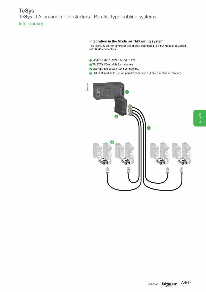
Integration in the Modicon TM3 wiring systemThe TeSys U starter-controller are directly connected to a I/O module equipped with RJ45 connectors.
1 Modicon M221, M241, M251 PLC's2 TM3XTY I/O module for 4 starters3 LU9Rpp cables with RJ45 connectors,4 LUFC00 module for TeSys parallel connection (1 or 2 direction of rotation).
1
2
3
4
DB4
3285
2.ep
s
TeSysTeSys U All-in-one motor starters - Parallel-type cabling systemsIntroduction

A4/18
TeS
ys U
TeSysTeSys U All-in-one motor starters - Parallel-type cabling systems
Integration in the Modicon Advantys STB systemAdvantys STB is a solution for remote I/O modules.These communicate with the Modicon PLCs range thanks to a serial liaison, using the Advantys STB protocol.In this example an Advantys I/O module is used to facilitate wiring.Each of its four terminals receives a preassembled RJ45 cable connected to a TeSys U starter-controller.
1 TeSys U LUB120, 320 or 380 power base (equipped with 24 V DC LUCppppBL control modules)
2 TeSys module for parallel RJ45 wiring: LUFC00 + LU9BN11C (one direction) or LU9MRC (2 directions for LU2B12, 32 or 38 power base)
3 RJ45 cables (2 connectors): y 3 m: LU9Rpp > 3 m: 490 NTW000pp (5, 12, 40 or 80 m)
4 PLC: Modicon range5 I/O Modicon Advantys module: STB EPI 2145K
1
2
3
5
4
Introduction

A4/19
TeS
ys U
Integration in the Modicon Telefast systemThe wiring hubb LU9G0p facilitates the connection to Modicon Premium PLCs.It adapts RJ45 connectors to HE10 available on the Telefast I/O modules.Connection: up to 8 TeSys U per hubb.
1 TeSys U LUB120, 320 or 380 power base (equipped with 24 V DC LUCppppBL control units)
2 TeSys Module for parallel wiring RJ45: LUFC00 + LU9BN11C (one direction) or LU9MRC (2 directions for LU2B12, 32 or 38 power base)
3 RJ45 cables (2 connectors): y 3 m: LU9Rpp > 3 m: 490 NTW000pp (5, 12, 40 or 80 m)4 Telefast RJ45 / HE10 splitter box: LU9G02 or LU9G03 (different TeSys U
connection capacities)5 HE10 cables (2 connectors): TSXCDPppp
6 PLC: Modicon Premium range7 I/O module: TSX DMY 28FK
TeSysTeSys U All-in-one motor starters - Parallel-type cabling systems
1
2
3
6
5 74
Introduction

A4/20
TeS
ys U
TeSysTeSys U All-in-one motor starters - Parallel-type cabling systems
1
2
DF5
6696
4.ep
s Components for connection of a starter - 1 direction of rotationDesignation Reference
1
3
DF5
1091
8.ep
s
1 Parallel connection module, RJ45 output 2 coil control inputs, 3 signal outputs LUFC00
2 Pre wired connector, one direction of rotation, for LUB120, 320 or 380 power base coil connection and one contact for emergency stop
LU9BN11C
Components for connection of a starter - 2 directions of rotationDesignation Reference
1 Parallel connection module, RJ45 output LUFC00
3 Pre wired connector, 2 directions of rotation, for LU2B12, 32 or 38 power base coil connection and one contact for emergency stop
LU9MRC
PF51
1528
.tif
LU9G02
PF51
1529
.tif
LU9G03
Telefast RJ45/ HE10 splitter boxDesignation Reference
Splitter box Connection to TeSys U: 4 RJ45 connectors: for 1 to 4 TeSys U, 1 or 2 directions 4 RJ45 connectors: for 1 to 4 TeSys U, 1 direction Connection to PLC: 1 x HE10 connector - 20 chanels, for pole status, alarms 1 x HE10 connector - 20 chanels, for control. 24 V DC auxiliary power supply required
LU9G02
Splitter box Connection to TeSys U: 8 RJ45 connectors: for 1 to 8 TeSys U, 1 or 2 directions Connection to PLC: 1 x HE10 connector - 20 chanels, for pole status, alarms 1 x HE10 connector - 20 chanels, for control. 24 V DC auxiliary power supply required.
LU9G03
RJ45 connection cables, with 2 RJ45 connectors0.3 m LU9R031 m LU9R103 m LU9R30
HE10 connection cables, with 2 HE10/20 way connectorsSection: AWG 22 / 0.324 mm²
0.5 m TSXCDP0531 m TSXCDP1032 m TSXCDP2033 m TSXCDP3035 m TSXCDP503Section: AWG 28 / 0.080 mm² (flat cable)
1 m ABFH20H1002 m ABFH20H2003 m ABFH20H300
HE10 connection cables, with 1 x HE10/40 way connector (PLC side) and 1x HE10/20 way connector (Splitter box side)Section: 0.324 mm²
0,5 m BMXFCC0531 m BMXFCC1032 m BMXFCC2033 m BMXFCC3035 m BMXFCC50310 m BMXFCC1003
Cable with stripped wires (PLC side)1 x HE10/20 ways connector (Splitter box side)Section: AWG 22 / 0.324 mm²
3 m TSXCDP3015 m TSXCDP501
DB4
1470
8.ep
s
RJ45 cables.
DB4
1470
7.ep
s
HE10 cables.
Product references
Characteristics:page A4/51
Schemes:pages A4/67 and A4/68

A4/21
TeS
ys U
TeSysTeSys U All-in-one motor starters - Bus-type cabling systems
Application functionality, topology
1 Geographically expanded processMany motors are scattered on the site, the process control requires individual control to ensure safety and proper operation.TeSys U is a suitable communicating actuator. The integration of a bus communication module in the starter-controller saves space in the control board and simplifies wiring, compared to solutions based on conventional components (circuit breaker + contactor).
2 Application: automatic motor control / monitoringThanks to a communication bus, starter-controllers are part of an automation system controlled by a PLC and (or) various communicating controllers.These equipment can then share the status and alarm information related to each motor control and perform specific treatments.
3 Bus- type connectionThis type of connection allows different topologies (star, ring ...) and supports various protocols dialogue. It is therefore recommended for geographically expanded process, in order to to simplify wiring and ensure multiple-controller management.
Available TeSys U status and controls via a communication moduleControl unit LUCA LUCB
LUCC LUCD
LUCM
Starter status (ready, running, fault) b b bStart and Stop commands b b bThermal overload alarm b bRemote reset via the bus b bIndication of motor load b bFault signalling and differentiation b bRemote programming and monitoring of all functions b“Log” function b“Monitoring” function bAlarms (overcurrent, ...) b
PB10
5092
.eps
b The bus wiring interconnects TeSys U starters controllers and components of the installation via a single the cable.
b Commands and status are coded according to the selected protocol and transmitted on the communication bus.
b This wiring is simple, usually a shielded (or not) pair of wires, suitable for monitored automation, regardless of the number of TeSys U and their locations.
DB4
1637
6.ep
s
Introduction

A4/22
TeS
ys U
TeSysTeSys U All-in-one motor starters - Bus-type cabling systems
Network Architecture Component references
AS InterfaceCabling system for rapidly connecting sensors and actuators to the controller. A single cable provides both data transmission and power to sensors. 2 1 13
554
1 ASILUFC5 or ASILUFC51
2 LU9BN11C
3 LU9MRC
4 XZCG0142
5 TCSATV01N2
Details page A4/24 CANopen
Etoile
5
4
1 1 12 2 3
1 LULC08
2 LU9BN11L
3 LU9MRL
4 TSXCANCppp
5 TSXCANTDM4
6 TSXCPP110
Bus
111
22 3
444
5
Details page A4/25
Introduction

A4/23
TeS
ys U
Network Architecture Component references
ModbusEtoile Bus 1 LULC033
2 LU9BN11C
3 LU9MRC
4 VW3A8306Rppp
5 LU9GC3
6 VW3A8306TF
112
66
11122 3
4
5
2
Details page A4/26Advantys STB
Starter-controllers communicate using ADVANTYS STB protocol to fit into a remote I/O architecture.
113
4
2
5
6
1 LULC15
2 LU9BN11L
3 LU9MRL
4 LU9RDDppp
5 LU9RCD
6 STBXBE1100Details page A4/27Profibus-DP (Decentralized Peripherals)
is used for connecting actuators and sensors to a central controller for applications in industrial production.The standard bus provides a number of diagnostic means
c 24 V
113
4
2
6
5 1 LULC07
2 LU9BN11L
3 LU9MRL
4 LU9RPB010 LU9RPB100 LU9RPB400
5 LU9AD7
6 LU9GC7Details page A4/28DeviceNet
Details page A4/29
c 24 V
21
13
1 LULC09
2 LU9BN11L
3 LU9MRL
TeSysTeSys U All-in-one motor starters - Bus-type cabling systemsIntroduction

A4/24
TeS
ys U
TeSysTeSys U All-in-one motor starters - AS-Interface communication modules
The ASILUFC5 communication module, combined with the power base and control unit is used to control TeSys U starters-controllers via DeviceNet bus.The LULC09 communication module is slave type.
Module SpecificationsI/O terminal block
b Powered by external 24 V DC (power supply not included): v 2 x configurable inputs for binary sensors v 1 x 24 V DC output - 0.5 A local auxiliary command.
Connectors b For TeSys U 24 V DC coil (common, direction 1, direction 2). b For AS-Interface bus.
Signaling b Module Status - Error - 24 V, by LED.
Tesys componentsDescription Mark Max number
of slaves References
AS-Interface communication module 1 31 ASILUFC562 ASILUFC51
Pre-wired connector: coil - LUB powerbase 2 - LU9BN11CPre-wired connector: coil - LUB2B powerbase 3 - LU9MRC
Connection of the communication moduleBy a "Y" cable with:
b TeSys U side, 2 connectors (bus + power), b Bus side, one connector to be connected to the AS-Interface TCSATV01N2
tap-off.
Description ReferencesAS-Interface / TeSys U branch cable, L = 2 m XZCG0142AS-Interface Tap-off TCSATV01N2
1
2
DB4
1463
5.ep
s
3
DB4
1463
6.ep
s
1 Green LED: AS-Interface voltage present2 Red LED: AS-Interface or module fault3 Outputs for starter commands4 Black connector for connection to c 24 V
auxiliary power supply5 Yellow connector for connection to the AS-Interface system
1 2
3 4 5
PB12
1291
.eps
Product references
Characteristics:pages A4/49, A4/51, A4/53
Schemes:pages A4/64, A4/70, A4/72

A4/25
TeS
ys U
TeSysTeSys U All-in-one motor starters - CANopen communication module
1 LED indicating module status2 Fault signalling LED3 LED indicating c 24 V supply ON for outputs
OA1, OA3 and LO14 SUB-D connector for bus link5 c 24 V supply connection6 Discrete input7 Discrete input8 Discrete output9 Outputs for starter commands
The LULC08 communication module, combined with the power base and control unit is used to control TeSys U starters-controllers via CANopen bus.The LULC08 communication module is slave type.
Module SpecificationsI/O terminal block
b Powered by external 24 V DC (power supply not included): v 2 x configurable inputs for binary sensors v 1 x 24 V DC output - 0.5 A local auxiliary command.
Connectors b For TeSys U 24 V DC coil (common, direction 1, direction 2). b For CANopen bus.
Signaling b Module Status - Error - 24 V, by LED.
Tesys componentsDescription Item References
CANopen communication module 1 LULC08Pre-wired connector: coil - LUB powerbase 2 LU9BN11LPre-wired connector: coil - LUB2B powerbase 3 LU9MRL
Compatibility of CANopen communication module with control units
LUCA ppBL / B ppBL / C ppBL / D ppBL All versions marketed after 2T0481 (1)
LUCMppBL All versions u V3.2LUCMT1BL All versions u V3.2(1) This “date code” is made up as follows:
2T or 2C: factory code. 04, 05, 06 and so on: year of manufacture. 08: week. 1: 1st day of the week.
How to get information on the design of a CANopen architecture and the choice of network accessoriesConsult the library of downloadable documents on schneider-electric.com by searching on the name of the communication protocol.
1
2
3
DB4
1463
7.ep
sD
B414
638.
eps
Product references
1 2 3
4
68 7
5
9
PB12
1303
.eps
Characteristics:pages A4/50, A4/51, A4/53
Schemes:page A4/66

A4/26
TeS
ys U
TeSysTeSys U All-in-one motor starters - Modbus communication module
LULC033 communication module, combined with the power base and control unit is used to control TeSys U starters-controllers via Modbus.
Module SpecificationsI/O terminal block
b Powered by external 24 V DC (power supply not included): v 2 x configurable inputs for binary sensors (on LULC033 only) v 1 x 24 V DC output - 0.5 A local auxiliary command.
ConnectorsFor TeSys U 24 V DC coil (common, direction 1, direction 2).
b RJ45, For Modbus line.
Signaling b Module Status - Error - 24 V, by LED.
Tesys componentsDescription Item Bin. input References
Modbus communication module 1 2 LULC033Pre-wired connector: coil - LUB powerbase 2 - LU9BN11CPre-wired connector: coil - LUB2B powerbase 3 - LU9MRC
Modbus hubDescription Length
(m)References
Modbus communication distributor - LU9GC3Cables fitted with 2 x RJ45 connectors 0.3 VW3A8306R03
1 VW3A8306R103 VW3A8306R30
Tees derivations 0.3 VW3A8306TF031 VW3A8306TF10
Description ReferencesRS 485 line terminator VW3A8306R
Compatibility of Modbus communication modules Communication modules (software version) LUCLC033
from V2.1LUCLC033 from V2.2
Power base
LUBpp / LU2Bp2 b b
LUTMppBL b b
Control unit
LUCAppBL b
LUCBppBLLUCCppBLLUCDppBL
b
LUCMppBL b (1)
LUCBTppBLLUCDTppBL
b
LUCMTppBL b
(1) Except LUCM ppBL V1.04 and V1.06.
How to get information on the design of a Modbus architecture and the choice of network accessoriesConsult the library of downloadable documents on schneider-electric.com by searching on the name of the communication protocol.
1 Module status signalling LED2 24 V supply connection3 RJ45 connector for RS485 Modbus link4 2 discrete inputs5 1 discrete output6 Outputs for starter commands
LULC033
1
2
DB4
1463
9.ep
s
3
DB4
1464
0.ep
sD
B414
709.
eps
Product references
PB12
1552
.eps
1
245
3
6
Characteristics:pages A4/49, A4/51, A4/53
Schemes:pages A4/65 and A4/73

A4/27
TeS
ys U
TeSysTeSys U All-in-one motor starters - Advantis STB communication module
Communication module LULC15 allows direct connection of TeSys U starter-controllers and controllers on an Advantys STB island, between two segments or at the end of a segment. The starter-controller will then be able to make use of the services provided by Advantys STB: self-addressing, autobaud, fallback positions.
Module SpecificationsI/O terminal block
b Powered by external 24 V DC (power supply not included): v 2 x configurable inputs for binary sensors (on LULC033 only) v 1 x 24 V DC output - 0.5 A local auxiliary command.
Connectors b For TeSys U 24 V DC coil (common, direction 1, direction 2). b For Advantys STB bus.
Signaling b Com - Error - 24 V, by LED.
Tesys componentsDescription Item References
Advantys STB communication module 1 LULC15Pre-wired connector: coil - LUB powerbase 2 LU9BN11LPre-wired connector: coil - LUB2B powerbase 3 LU9MRL
Cables Description Length
(m)References
Cables fitted with connectors, one straight and one elbowed
0.3 LU9RCD031 LU9RCD103 LU9RCD305 LU9RCD50
Cables fitted with two straight connectors 0.3 LU9RDD031 LU9RDD103 LU9RDD30
Compatibility of Advantys STB communication module with control units
LUCAppBL / BppBL / CppBL / DppBL All versions marketed after 2T0481 (1)
LUCMppBL All versions u V3.2LUCMT1BL All versions u V3.2(1) This “date code” is made up as follows:
2T or 2C: factory code. 04, 05, 06 and so on: year of manufacture. 08: week. 1: 1st day of the week.
How to get information on the design of a Advantys STB architecture and the choice of network accessoriesConsulter la librairie des documents téléchargeables sur le site schneider-electric.com en faisant une recherche sur le nom du protocole de transmission.
1 Two-colour LED indicating module status2 Fault signalling LED3 LED indicating that c 24 V supply is ON4 Bus connectors
5 c 24 V supply connection
6 Discrete input
7 Discrete input
8 Discrete output
9 Outputs for starter commands
LUB + LULC15 + LU9BN11L
1
2
DB4
1464
1.ep
s
LU2B + LULC15 + LU9MRL
3
DB4
1464
2.ep
s
Product references
PB12
1553
.eps
1 2 3
4
59 768
Characteristics:pages A4/50, A4/51, A4/53
Schemes:page A4/67

A4/28
TeS
ys U
TeSysTeSys U All-in-one motor starters - Profibus DP communication module
When used in conjunction with the power base and control unit, communicationmodule LULC07 allows TeSys U starter-controllers to be controlled via Profibus DP(Deported Periphery) bus.Communication module LULC07 is of the slave type.
Module SpecificationsI/O terminal block
b Powered by external 24 V DC (power supply not included): v 2 x configurable inputs for binary sensors v 1 x 24 V DC output - 0.5 A local auxiliary command.
Connectors b For TeSys U 24 V DC coil (common, direction 1, direction 2). b For Profibus DP bus.
Signaling b Com - Error - 24 V, by LED.
Tesys componentsDescription Item References
Profibus DP communication module 1 LULC07Pre-wired connector: coil - LUB powerbase 2 LU9BN11LPre-wired connector: coil - LUB2B powerbase 3 LU9MRL
Components for connection to the bus and to the installationThe 24 V DC -Aux supply to Profibus DP modules LULC07 must pass through power supply module LU9GC7.LULC07 modules must be connected to the LU9GC7 splitter box in order to be powered.The number of TeSys U starter-controllers that can be powered by an LU9GC7module is limited by the maximum current (1.5 A) which it can deliver.The c 24 V supply for the inputs/outputs must be provided separately..Description Length
(m)References
Profibus DP power supply module - LU9GC7Profibus DP connector - LU9AD7Profibus DP cables 2-wire
100 TSXPBSCA100400 TSXPBSCA400
Profibus DP cables4-wire
10 LU9RPB010100 LU9RPB100400 LU9RPB400
How to get information on the design of a Profibus DP architecture and the choice of network accessoriesConsult the library of downloadable documents on schneider-electric.com by searching on the name of the communication protocol.
1 Two-colour LED indicating module status
2 Fault signalling LED
3 LED indicating c 24 V supply ON for outputs OA1, OA3 and LO1
4 SUB-D connector for bus link
5 c 24 V supply connection6 Discrete input
7 Discrete input
8 Discrete output
9 Outputs for starter-controller commands (non-reversing and reversing)
LU2B + LUCpppBL + LULC07 + LU9MRL
3
DB4
1464
4.ep
s
LUB + LUCpppBL + LULC07 + LU9BN11L
1
2
DB4
1464
3.ep
s
Product references
PB12
1554
.eps
1 2 3
4
578
9
6
Characteristics:pages A4/50 and A4/53
Schemes:page A4/66, A4/67

A4/29
TeS
ys U
TeSysTeSys U All-in-one motor starters - DeviceNet communication module
1 LED indicating module status2 Fault signalling LED3 LED indicating c 24 V supply ON for outputs
OA1, OA3 and LO1 and 24 V bus4 DeviceNet connector for bus link
5 c 24 V supply connection
6 Discrete input
7 Discrete input
8 Discrete output
9 Outputs for starter-controller commands (non-reversing and reversing)
When used in conjunction with the power base and control unit, communication module LULC09 allows TeSys U starter-controllers to be controlled via DeviceNet bus.Communication module LULC09 is of the slave type.
Module SpecificationsI/O terminal block
b Powered by external 24 V DC (power supply not included): v 2 x configurable inputs for binary sensors v 1 x 24 V DC output - 0.5 A local auxiliary command.
Connectors b For TeSys U 24 V DC coil (common, direction 1, direction 2). b For DeviceNet bus.
Signaling b Com - Error - 24 V , by LED.
Tesys componentsDescription Item References
DeviceNet communication module 1 LULC09Pre-wired connector: coil - LUB powerbase 2 LU9BN11LPre-wired connector: coil - LUB2B powerbase 3 LU9MRL
How to get information on the design of a DeviceNet architecture and the choice of network accessoriesConsult the library of downloadable documents on schneider-electric.com by searching on the name of the communication protocol.
LUB + LUCpppBL + LULC07 + LU9BN11L
1
2
DB4
1464
5.ep
s
LU2B + LUCpppBL + LULC07 + LU9MRL
3
DB4
1464
6.ep
s
Product references
Characteristics:pages A4/50, A4/51, A4/53
Schemes:page A4/66
PB12
1555
.eps
9 4
578 6
1 2 3

A4/30
TeS
ys U
IntroductionLUFP communication gateways allow connection between the Modbus serial link and Fipio, Profibus DP or DeviceNet field buses.
After configuration, these gateways manage information which can be accessed by the Modbus serial link and make this information available for read/write functions (command, monitoring, configuration and adjustment) on the field buses.
An LUFP communication gateway consists of a box which can be clipped onto a 35 mm omega rail, allowing connection of up to 8 Slaves connected on the Modbus serial link.
Example of architectureConfigurationof gatewayby PC
TeSys U starter-controllers
Fipio Profibus DP DeviceNet
LUFP
ATS 48 ATV 312
(1)
Modbus
DF5
1151
7.ep
s
Communication gateway LUFPDescription Reference
Fipio / Modbus gateway LUFP1Profidus DP / Modbus gateway LUFP7DeviceNet / Modbus gateway LUFP9
DescriptionFront panel of the product
1 LED indicating : - communication status of the Modbus serial links, - gateway status, - communication status of the Fipio, Profibus DP or DeviceNet bus.
2 Connectors for connection to Fipio, Profibus DP or DeviceNet buses.
Underside of product
3 RJ45 connector for connection of the Modbus serial link4 RJ45 connector for link to a PC5 c 24 V power supply Software set-upFor the Fipio bus, software set-up of the gateway is performed using either PL7 Micro/Junior/Pro software or ABC Configurator software.For the Profibus DP and DeviceNet buses, software set-up is performed using ABC Configurator.This software is included in the TeSys U user’s manual.
(1) Connection kit for PowerSuite software workshop.
5615
12.e
psD
F526
109-
17-M
.eps
1
2
3
4
5
PB12
1557
.eps
TeSysTeSys U All-in-one motor starters - LUFP communication gatewaysProduct references
Schemes:page A4/68

A4/31
TeS
ys U
TeSysTeSys U All-in-one motor starters - Current limiter blocks - Accessories
DB4
3611
5.ep
s
LUALB1
PB11
1917
.eps
LA9LB920
Short-circuit current limiter blockTo be connected in series and upstream of a TeSys U starter-controller. It increases its ability to withstand the short circuit current from 50 kA to 100 or 130 kA under 400 V.Principle: under the action of a short-circuit, the opening of two contacts of each phase of the limiter creates a resistive arc. The current then decreases to a value tolerable by a TeSys U power base.
Limiter blocks and accessoriesDescription Breaking
capacity Iq (kA)Ie (A)
Ith (A)
Mounting Unit reference
y 440 V 690 VLimiter-disconnector (1 x LUAFL1 cartridge supplied)
130 70 - 32 Direct on power base up to 15 kW/32 A
LUALB1 (1)
Limiter 100 35 32 63 Separate LA9LB920 (2)
limiter cartridge for LUALB1
130 70 - - Limiter-disconnector LUALF1
(1) Must be connected to one power base only.(2) Can be connected to multiple TeSys U power bases in parallel with limitation :
b Total Ith max 63 A b Total nominal current (Ie) 32 A from motor with simultaneous start (LA9LB920 could not
withstand higher inrush peak current)
DB4
3611
6.ep
s
LU9SP0
Phase barrierEnsures a complementary electrical insulation between phases. 690 V AC network: compulsory.440 V AC network: compulsory when assembling a UL508 type E compliant motor starter (Self Protected Starter).Description Use Mounting Reference
Phase separator LUB or LU2B 12 or 120 LUB or LUB2B 32 or 320 LUALB1
Live terminals L1, L2, L3
LU9SP0
Clip-in labelsCan be clipped on any TeSys U power base, on LU6MB0pp inverser block, and Linergy HK busbar system.
Marking accessoryDescription Sold by lot of Reference per unit
Clip-in label 8 x 18 mm 100 LAD90
PB11
3928
.eps
LU9ET1S
Safety-chain identification - Red labelThe red sticker is dedicated to TeSys U LUCA, LUCB, LUCC, LUCD and LUCL control units.
Description Reference per unitRetrofit safety-chain identification sticker LU9ET1S
LUALF1
PB11
3846
.eps
Product references
Characteristics:page A4/48
Dimensions:page A4/61

A4/32
TeS
ys U
TeSysTeSys U All-in-one motor starters - Rotary handles
Extended rotary handleAllows a circuit breaker or a TeSys U starter-controller installed in back of an enclosure to be operated from the front panel.The rotary handle can be black or red/yellow, IP54 or IP65. It includes a function for locking the circuit breaker or the starter in the O (OFF) or | (ON) position (depending on the type of rotary handle) by means of up to 3 padlocks with a shank diameter of 4 to 8 mm.The extension shaft must be adjusted to the depth of the enclosure.The IP54 rotary handle is fixed with a nut (Ø22) to make it easier to assemble.
Mounting kit1 TeSys U Power base bracket; its horseshoe shaped sides hold the rotary mechanism facing the original handle.2 Mechanism, shaft and handle; the shaft enters the handle attached to the door during closing.
Long shaft b to be cut to the required length. Equipped with a connection endpiece.
Shaft support plate for deep enclosure b Provides horizontal guiding of the shaft, when the door is open.
Spacer base (retrofit accessory) b Fixed on a side of the box, for heightening an GVAPppp handle.
Handle b Delivered as a single unit, to be fitted on a side of the enclosure.
Note: references below are suitable for TeSys U power bases after 2004.
"Laser Square" Tool b On the principle of an angle extended with a laser beam, the "Laser Square"
facilitates tracing the piercing marks on the door or the sides of an enclosure.
"Safety" stickers b Marking: Electrical hazard, etc.
Description Tripping indication
Reference
Mounting kit Black handle, with error status, IP54 p LU9APN21Red handle, with error status, IP54 p LU9APN22Red handle, without error status, IP65 - LU9APN24
Separate elements
Long shaft = 315 mm - GVAPA1Shaft (u 300 mm) support plate for deep enclosure
- GVAPK12
Spacer base - GVAPP1Black handle, IP54 p GVAPB54Red handle, IP54 p GVAPR54Black handle, IP65 GVAPB65Red handle, IP65 GVAPR65
Tool "Laser square" plotting tool GVAPL01"Safety" stickers French (x10) GVAPSFR
English (x10) GVAPSENGerman (x10) GVAPSDESpanish (x10) GVAPSESChinese (x10) GVAPSCNPortuguese (x10) GVAPSPTRussian (x10) GVAPSRUItalian (x10) GVAPSIT
External handle protection frame for TeSys U
Yellow frame GVAPYPHPBlack frame GVAPBPHP
1
2
LU9APN21 mounting kit
GVAPP1 spacer base (retrofit accessory)
DB4
1454
0.ep
s
GVAPA1 long shaft
PB10
6291
.eps
PB10
6296
.eps
GVAPL01 "Laser square" plotting tool
PB10
6297
.eps
GVAPR54 red handle, IP 54
PB10
6289
.eps
GVAPK12 shaft support plate for deep enclosure
PB12
1242
.eps
GVAPYPHP external handle protection frame
Product references
Dimensions:page A4/61

A4/33
TeS
ys U
TeSysTeSys U All-in-one motor starters - Handle mounting kit for MCC drawers
MCC drawers (Motor Control Center)The drawers are composed of:
b a fixed part, in the frame of the panel, b a fully withdrawable part, integrating the protection, control and automation
components.
With a height of 3/4/6/8/12/18/24/36 modules, they allow the assembling of motor protection/control feeders:
b Direct, one direction of rotation b Direct, 2 directions of rotation b Star-delta b Dahlander (2 speeds) b 2-speed, separate winding b Motor drives from 0 to 500 kW b Soft starters of 0 to 75 kW.
Mounting kit and handle for MCC drawerTogether, this provides manual control of a TeSys U starter-controller from the front face of the drawer. As the clamping part on top of TeSys U control pad is open, the kit may be used on TeSys U power bases before 2005.
Mounting kit + small handleDescription Item Reference
Handle with mounting kit for MCC drawer
1 + 2 + 3 LU9AP20
RE
SE
TT
ES
T
0
1
2
3
DB1
2340
4.ep
sPB
1212
43.e
psPB
1118
07_1
04.e
ps
Product references

A4/34
TeS
ys U
TeSysTeSys U All-in-one motor starters - Use with soft starter / Variable Speed Drive - LUCL control module
IntroductionWhen installed upstream of a variable speed controller or soft start unit, control unit LUCLpp, used in conjunction with an LUB12 or LUB32 power base, provides:
v isolation, v short-circuit protection of the motor starter.
(variable speed controller-based or soft start unit-based motor starters).
Note: control unit LUCL, when used in conjunction with power base LUB12 or LUB32, conforms to standard IEC 60947-6-2.
Installation regulationsWhen the length of the cable between the TeSys U starter and the variable speed controller is more than 1.5 m, the c.s.a. of the cable between the variable speed controller and the TeSys U starter (S2) must be equal to the c.s.a. of the cable upstream of TeSys U (S1).
Description of LUCL magnetic control unit
1 Extraction and locking handle2 Sealing of locking handle3 Dial for magnetic adjustment of motor In 4 Locking of settings by sealing the transparent cover
ReferencesDescription Line current of the
variable speed controller or soft start unit
Reference(1)
AMagnetic control unit 0.15…0.6 LUCLX6pp
0.35…1.4 LUCL1Xpp
1.25…5 LUCL05pp
3…12 LUCL12pp
4.5…18 LUCL18pp
8…32 LUCL32pp
(1) Standard control circuit voltage:Volts 24 48…72 110…240
c BL (2) (3) – –a B – –c or a – ES (4) FU (5)
(2) Voltage code to be used for a starter-controller with communication module.(3) d.c. voltage with maximum ripple of ±10 %.(4) c: 48…72 V, a: 48 V.(5) c: 110…220 V, a: 110…240 V.
LUB pp LUCLpp
S1 (mm2 / AWG)
S2 (mm2 / AWG)
Altivar or Altistart
DF5
3857
4.ep
s
Product references
PB12
1270
.eps
1
3
4
1
3
4
2
Characteristics:pages A4/46 and A4/47
A4/35
TeS
ys U
TeSysTeSys U All-in-one motor starters - LUCL control module compatibility
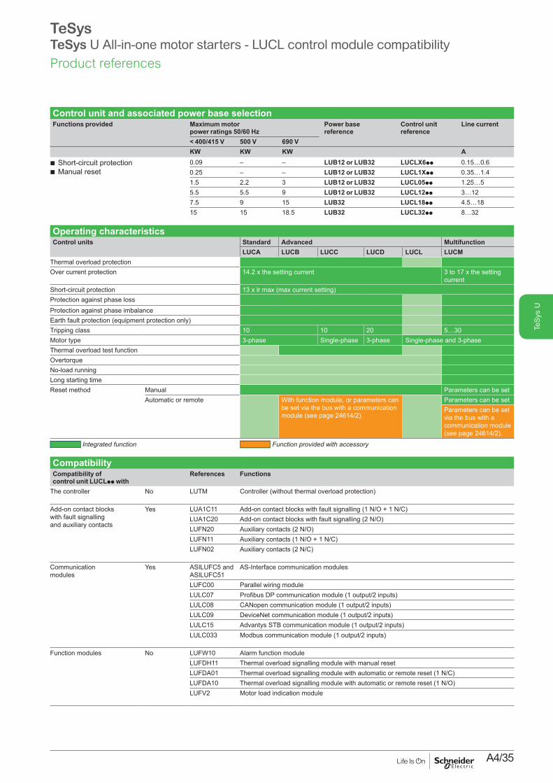
Control unit and associated power base selectionFunctions provided Maximum motor
power ratings 50/60 HzPower base reference
Control unit reference
Line current
< 400/415 V 500 V 690 VKW KW KW A
b Short-circuit protection b Manual reset
0.09 – – LUB12 or LUB32 LUCLX6pp 0.15…0.60.25 – – LUB12 or LUB32 LUCL1Xpp 0.35…1.41.5 2.2 3 LUB12 or LUB32 LUCL05pp 1.25…55.5 5.5 9 LUB12 or LUB32 LUCL12pp 3…127.5 9 15 LUB32 LUCL18pp 4.5…1815 15 18.5 LUB32 LUCL32pp 8…32
Operating characteristicsControl units Standard Advanced Multifunction
LUCA LUCB LUCC LUCD LUCL LUCMThermal overload protectionOver current protection 14.2 x the setting current 3 to 17 x the setting
currentShort-circuit protection 13 x lr max (max current setting)Protection against phase lossProtection against phase imbalanceEarth fault protection (equipment protection only)Tripping class 10 10 20 5…30Motor type 3-phase Single-phase 3-phase Single-phase and 3-phaseThermal overload test functionOvertorqueNo-load runningLong starting timeReset method Manual Parameters can be set
Automatic or remote With function module, or parameters can be set via the bus with a communication module (see page 24614/2).
Parameters can be setParameters can be set via the bus with a communication module (see page 24614/2).
Integrated function Function provided with accessory
CompatibilityCompatibility of control unit LUCLpp with
References Functions
The controller No LUTM Controller (without thermal overload protection)
Add-on contact blocks with fault signalling and auxiliary contacts
Yes LUA1C11 Add-on contact blocks with fault signalling (1 N/O + 1 N/C)LUA1C20 Add-on contact blocks with fault signalling (2 N/O)LUFN20 Auxiliary contacts (2 N/O)LUFN11 Auxiliary contacts (1 N/O + 1 N/C)LUFN02 Auxiliary contacts (2 N/C)
Communication modules
Yes ASILUFC5 and ASILUFC51
AS-Interface communication modules
LUFC00 Parallel wiring moduleLULC07 Profibus DP communication module (1 output/2 inputs)LULC08 CANopen communication module (1 output/2 inputs)LULC09 DeviceNet communication module (1 output/2 inputs)LULC15 Advantys STB communication module (1 output/2 inputs)LULC033 Modbus communication module (1 output/2 inputs)
Function modules No LUFW10 Alarm function moduleLUFDH11 Thermal overload signalling module with manual resetLUFDA01 Thermal overload signalling module with automatic or remote reset (1 N/C)LUFDA10 Thermal overload signalling module with automatic or remote reset (1 N/O)LUFV2 Motor load indication module
Product references

A4/36
TeS
ys U
TeSysTeSys U All-in-one motor starters - with Altistart U01 soft starter
Introduction
The Altistart U01 is a soft start/soft stop unit for asynchronous motors. It is designed primarily for combinations with TeSys U controller-starters.
When combined with a TeSys U 1 controller by means of a connector 2, the Altistart U01 3 is a power option which provides the “Soft start/soft stop” function. The result is a unique, innovative motor starter.
Using the Altistart U01 starter enhances the starting performance of asynchronous motors by allowing them to start gradually, smoothly and in a controlled manner. It prevents mechanical shocks, which lead to wear and tear, and limits the amount of maintenance work and production downtime.The Altistart U01 limits the starting torque and current peaks on starting, on machines which do not require a high starting torque.
The Altistart U01 is designed for the following simple applications:b Conveyorsb Conveyor beltsb Pumpsb Fansb Compressorsb Automatic doors and gatesb Small cranesb Belt-driven machines, etc.
The Altistart U01 is compact and easy to install. It complies with standards IEC/EN 60947-4-2, carries UL, CSA, C-Tick, CCC certifications and e marking.
b ATSU01N2ppLT soft start/soft stop units {Control two phases of the motor power supply to limit the starting current and for
deceleration { Internal bypass relay {Motor power ratings ranging from 0.75 kW to 15 kW {Motor supply voltages ranging from 200 V to 480 V, 50/60 Hz.
An external power supply is required for controlling the starter.
Descriptionb Altistart U01 soft start/soft stop units are equipped with:
{A potentiometer for setting the starting time 6 {A potentiometer for setting the deceleration time 8 {A potentiometer for adjusting the start voltage threshold according to the motor
load 7 { 1 green LED 4 to indicate that the unit is switched on { 1 yellow LED 5 to indicate that the motor is powered at nominal voltage, if
it is connected to the starter {A connector 9:
- 2 logic inputs for Run/Stop commands- 1 logic input for the BOOST function- 1 logic output to indicate the end of starting- 1 relay output to indicate the starter has a power supply fault or the motor has
reached a standstill at the end of the deceleration stage
Introduction
45678
1
2
3
9
DF5
3656
6.ep
s
Characteristics:pages A4/75 and A4/76
References:page A4/38
Dimensions:page A4/77
Schemes:pages A4/78 to A4/81
Ref.

A4/37
TeS
ys U
TeSysTeSys U All-in-one motor starters - Altistart U01 soft starter
ATSU01N2pppLT soft start unit functionsb 2-wire controlThe run and stop commands are controlled by a single logic input. State 1 of logic input LI2 controls starting and state 0 controls stopping.
+ 24 V LI1 LI2
Wiring diagram for 2-wire control
Altistart U01 control terminals
DF5
3656
7.ep
s
b 3-wire controlThe run and stop commands are controlled by 2 different logic inputs. Stopping is achieved when logic input LI1 opens (state 0). The pulse on input LI2 is stored until input LI1 opens.
LI1 LI2+ 24 V
Wiring diagram for 3-wire control
Altistart U01 control terminals
DF5
3656
8.ep
s
b Starting timeControlling the starting time means that the time of the voltage ramp applied to the motor can be adjusted to obtain a gradual starting time, dependent on the motor load.
b Voltage boost function via logic inputActivating the BOOST logic input enables the function for supplying a starting overtorque capable of overcoming any mechanical friction.When the input is at state 1, the function is active (input connected to the + 24 V) and the starter applies a fixed voltage to the motor for a limited time before starting.
200 mst
Application of a voltage boost equal to 100% of the nominal motor voltage
Voltage ramp
U100%
Un
50% Un
Initial voltage
DF5
3653
7.ep
s
b End of starting { application function for logic output LO1
ATSU01N2ppLT soft start/soft stop units are equipped with an open collector logic output LO, which indicates the end of starting when the motor has reached nominal speed.
Introduction
Characteristics:pages A4/75 and A4/76
References:page A4/38
Dimensions:page A4/77
Schemes:pages A4/78 to A4/81
Ref.

A4/38
TeS
ys U
TeSysAltistart U01 soft starter
Soft start/soft stop units for 0.75 to 15 kW motors (can be combined with the TeSys U starter)Motor StarterMotor power (1) Nominal
currentReference
230 V 230 V 400 V 460 VkW HP kW HP A3-phase supply voltage: 200…480 V 50/60 Hz
0.751.1
11.5
1.52.23
23
6 ATSU01N206LT
1.5–
2–
–4
5–
9 ATSU01N209LT
2.23
3–
5.5–
7.5–
12 ATSU01N212LT
45.5
57.5
7.511
1015
22 ATSU01N222LT
7.5 10 15 20 32 ATSU01N232LT
AccessorieDescription Used for starter Reference
Power connector between ATSU01N2ppLT and TeSys U
ATSU01N2ppLT VW3G4104
TeSys U starter and soft start unit combinations Numerous possibilities for combinations and options are offered.Please consult the “TeSys U Starters-open version” specialist catalogue.
Motor power Soft starter TeSys UVoltage Power base Control unit (2)
230 VkW/HP
400 VkW
460 VHP
0.75/1 1.5 2 ATSU01N206LT LUB12 LUCp05BL1.1/1.5 2.2/3 3 ATSU01N206LT LUB12 LUCp12BL1.5/2 – – ATSU01N209LT LUB12 LUCp12BL– 4 5 ATSU01N209LT LUB12 LUCp12BL2.2/3 – – ATSU01N212LT LUB12 LUCp12BL3/– 5.5 7.5 ATSU01N212LT LUB32 LUCp18BL4/5 7.5 10 ATSU01N222LT LUB32 LUCp18BL5.5/7.5 11 15 ATSU01N222LT LUB32 LUCp32BL7.5/10 15 20 ATSU01N232LT LUB32 LUCp32BL
Example of a starter-motor combination with:1 non-reversing power base for DOL starting (LUBp2BL)2 control unit (LUCMppBL)3 power connector (VW3G4104)4 Altistart U01soft start/soft stop unit (ATSU01N2ppLT)
(1) Standard motor power ratings, HP power ratings indicated according to standard UL508.(2) Depending on the configuration of the chosen TeSys U starter, replace the p with A for
standard, B for expandable, and M for multifunction.
Product references
ATSU01N222LT
1096
80SE
.eps
1
2
4
LUBp2BL
LUCM ppBL
ATSU 01N2ppLT
3
DF5
3657
0.ep
s
Introduction:pages A4/36 and A4/37
Characteristics:pages A4/75 and A4/76
Dimensions:page A4/77
Schemes:pages A4/78 to A4/81
i

A4/39
TeS
ys U
CoordinationThe standard defines tests at different levels of current; the purpose of these tests is to place the equipment in extreme conditions. The standard defines 2 types of coordination, according to the condition of the components after testing: type 1 and type 2.Type 1 coordination requires that in a short-circuit condition, the contactor or starter must not present any danger to personnel or installations and must not be able to resume operation without repair or the replacement of parts.The product combinations given below provide type 1 coordination
Soft start-soft stop unit/TeSys U starter controller combination with magnetic protection TeSys U / Altistart 48: type 1 coordinationPower400 V (kW)
TeSys U references (protection + power switching)
Soft start unit reference Class 10 Class 20
5.5 LUB32 + LUCL32 or LUCL18 – ATS48D17
7.5 LUB32 + LUCL32 ATS48D17 ATS48D22
11 LUB32 + LUCL32 ATS48D22 ATS48D32
15 LUB32 + LUCL32 ATS48D32 ATS48D38
Variable speed controller/TeSys U starter controller combination with magnetic protection TeSys U / Altivar 21 UL Type 1/IP 20: type 1 coordinationPower400 V (kW)
TeSys U references (protection + power switching)
Variable speed controller reference
0.75 LUB12 + LUCL05 ATV21H075N4
ATV21HU15N4
2.2 LUB12 + LUCL12 ATV21HU22N4
3 LUB12 + LUCL12 ATV21HU30N4
4 LUB12 + LUCL12 ATV21HU40N4
5.5 LUB32 + LUCL32 or LUCL18 ATV21HU55N4
7.5 LUB32 + LUCL32 or LUCL18 ATV21HU75N4
11 LUB32 + LUCL32 ATV21HD11N4
15 LUB32 + LUCL32 ATV21HD15N4
TeSys U / Altivar 21 IP 54: type 1 coordinationPower400 V (kW)
TeSys U references (protection + power switching)
Variable speed controller reference
0.75 LUB12 + LUCL05 ATV21W075N4/N4C
1.5 LUB12 + LUCL12 or LUCL05 ATV21WU15N4/N4C
2.2 LUB12 + LUCL12 ATV21WU22N4/N4C
3 LUB12 + LUCL12 ATV21WU30N4/N4C
4 LUB12 + LUCL12 ATV21WU40N4/N4C
5.5 LUB32 + LUCL32 or LUCL18 ATV21WU55N4/N4C
7.5 LUB32 + LUCL32 or LUCL18 ATV21WU75N4/N4C
11 LUB32 + LUCL32 ATV21WD11N4/N4C
15 LUB32 + LUCL32 ATV21WD15N4/N4C
Product references
TeSysTeSys U All-in-one motor starters - Coordination with soft starters / Variable speed controllers
+ PB12
1558
.eps
DB4
3279
5_1.
eps
+ PB12
1559
.eps
DB4
3279
5_1.
eps
+ PB12
1560
.eps
PB10
5087
.eps

A4/40
TeS
ys U
Variable speed controller/TeSys U starter controller combination with magnetic protection (continued)TeSys U / Altivar 31: type 1 coordinationPower400 V (kW)
TeSys U references (protection + power switching)
Variable speed controller reference
0.37 LUB12 + LUCL05 ATV31H037N4
0.55 LUB12 + LUCL05 ATV31H055N4
0.75 LUB12 + LUCL05 ATV31H075N4
1.1 LUB12 + LUCL12 ATV31HU11N4
1.5 LUB12 + LUCL12 ATV31HU15N4
2.2 LUB12 + LUCL12 ATV31HU22N4
3 LUB32 + LUCL18 ATV31HU30N4
4 LUB32 + LUCL18 ATV31HU40N4
5.5 LUB32 + LUCL32 ATV31HU55N4
7.5 LUB32 + LUCL32 ATV31HU75N4
TeSys U / Altivar 61: type 1 coordinationPower400V (kW)
TeSys U references (protection + power switching)
Variable speed controller reference
0.75 LUB12 + LUCL05 ATV61H075N4
1.5 LUB12 + LUCL12 ATV61HU15N4
2.2 LUB12 + LUCL12 ATV61HU22N4
3 LUB32 + LUCL18 ATV61HU30N4
4 LUB32 + LUCL18 ATV61HU40N4
5.5 LUB32 + LUCL32 ATV61HU55N4
7.5 LUB32 + LUCL32 ATV61HU75N4
TeSys U / Altivar 71: type 1 coordinationPower400V (kW)
TeSys U references (protection + power switching)
Variable speed controller reference
0.75 LUB12 + LUCL05 ATV71H075N4
1.5 LUB12 + LUCL12 ATV71HU15N4
2.2 LUB12 + LUCL12 ATV71HU22N4
3 LUB32 + LUCL18 ATV71HU30N4
4 LUB32 + LUCL18 ATV71HU40N4
5.5 LUB32 + LUCL32 ATV71HU55N4
Products coordination
TeSysTeSys U All-in-one motor starters - Coordination with Soft starters / Variable speed controllers
DB4
3279
5_1.
eps
+ PB12
1561
.eps
DB4
3279
5_1.
eps
+ PB12
1562
.eps
DB4
3279
5_1.
eps
+ PF10
1004
.eps

A4/41
TeS
ys UTechnical
Data for DesignersTe
Sys
U
ContentsCharacteristics .................................... A4/42 to A4/53 Curves ................................................ A4/54 to A4/59 Dimensions ......................................... A4/60 to A4/61 Schemes ............................................. A4/62 to A4/74 Altistart U01 Soft starter ..................... A4/75 to A4/81

A4/42
TeS
ys U
TeSysTeSys U All-in-one motor starters
EnvironmentProduct certifications UL, CSA, CCC, GOST, ASEFA.
ABS, BV, DNV, GL, LROS.ATEX.
Conforming to standards IEC/EN 60947-6-2, CSA-22.2 N° 60947-4-1-14 UL 60947-4-1: with phase barrier LU9 SP0
Rated insulation voltage (Ui) Conforming to IEC/EN 60947-1, overvoltage category III, degree of pollution: 3
V 690
Conforming to UL508, CSA C22-2 n°14
V 600
Rated impulse withstand voltage (Uimp)
Conforming to IEC/EN 60947-6-2
kV 6
Degree of protectionConforming to IEC/EN 60947-1(protection against direct finger contact)
Front panel outside connection zone
IP 40
Front panel and wired terminals IP 20Other faces IP 20
Protective treatment Conforming to IEC/EN 60068 “TH”Conforming to IEC/EN 60068-2-30 Cycles 12Conforming to IEC/EN 60068-2-11 h 48
Ambient air temperature around the device
Storage °C -40…+85Operation °C Power bases and standard and advanced control units: -25… +70.
(At temperatures above 60°C and up to 70°C, for starter-controller LUB32, LUB38, leave a minimum gap of 9 mm between products).Power bases and multifunction control units: -25…+60. (At temperatures above 45 °C, leave a minimum gap of 9 mm between products. At temperatures above 55 °C and up to 60 °C, leave a gap of 20 mm between products.)
Maximum operating altitude m 2000
Operating positions In relation to normal vertical mounting plane
30˚
30˚
5207
16.e
ps
90˚ 90˚52
0717
.eps
Flame resistance Conforming to UL 94 V2Conforming to IEC/EN 60695-2-12
°C 960 (parts supporting live components)°C 650
Environmental restrictions Cadmium and silicone-free, recyclableShock resistance1/2 sine wave = 11 ms
Conforming to IEC/EN 60068-2-27 (1)
Power poles open: 10 gnPower poles closed: 15 gn
Vibration resistance 5…300 Hz
Conforming to IEC/EN 60068-2-6 (1)
Power poles open: 2 gnPower poles closed: 4 gn (2)
Resistance to electrostatic discharge
Conforming to IEC/EN 61000-4-2
kV In open air: 8 - Level 3kV On contact: 8 - Level 4
Immunity to radiated high-frequency disturbance
Conforming to IEC/EN 61000-4-3
V/m 10 - Level 3
Immunity to fast transient currents
Conforming to IEC/EN 61000-4-4
kV All circuits except for serial link: 4 - Level 4kV Serial link: 2 - Level 3
Immunity to dissipated shock waves
Conforming to IEC/EN 60947-6-2 Common mode Serial modeUc a 24…240 V,Uc c 48…220 V
kV 2 1
Uc = 24 V c Not applicableImmunity to conducted high-frequency disturbance
Conforming to IEC/EN 61000-4-6
V 10
Radiated emission and conducted
Conforming to CISPR 11 and EN 55011
Class A
(1) Without modifying the contact states, in the most unfavourable direction.(2) 2 gn with Advantys STB or CANopen communication modules.
Characteristics
References:pages A4/10 to A4/14
Curves: pages A4/54 to A4/59
Dimensions: pages A4/60 and A4/61
Schemes: pages A4/62 to A4/74
Ref.

A4/43
TeS
ys U
TeSysTeSys U All-in-one motor starters
Power circuit connection characteristicsConnection to Ø4 mm screw clamp terminalsPower base, control unit or reverser block type LUB12 + LUCA
or LUCB or LUCCor LUCD
LUB32/LUB38 + LUCA or LUCB or LUCC or LUCD
LUB12 + LUCM
LUB32 + LUCM
LU2B LU2MLU6M
Flexible cablewithout cable end
1 conductor mm2 2.5…10 2.5…10 2.5…10 2.5…10 2.5…102 conductors mm2 1.5…6 1.5…6 1.5…6 1.5…6 1.5…6
Flexible cablewith cable end
1 conductor mm2 1…6 1…6 1…6 1…6 1…62 conductors mm2 1…6 1…6 1…6 1…6 1…6
Solid cablewithout cable end
1 conductor mm2 1…10 1…10 1…10 1…10 1…102 conductors mm2 1…6 1…6 1…6 1…6 1…6
Screwdriver Philips n° 2 or flat screwdriver: Ø6 mmTightening torque N.m 1.9…2.5 1.9…2.5 1.9…2.5 1.9…2.5 1.9…2.5
Control circuit connection characteristicsConnection to Ø3 mm screw clamp terminals
Flexible cable without cable end
1 conductor mm2 0.75…1.5 0.75…1.5 0.75…1.5 0.75…1.5 0.75…1.52 conductors mm2 0.75…1.5 0.75…1.5 0.75…1.5 0.75…1.5 0.75…1.5
Flexible cable with cable end
1 conductor mm2 0.34…1.5 0.34…1.5 0.34…1.5 0.34…1.5 0.34…1.52 conductors mm2 0.34…1.5 0.34…1.5 0.34…1.5 0.34…1.5 0.34…1.5
Solid cable without cable end
1 conductor mm2 0.75…1.5 0.75…1.5 0.75…1.5 0.75…1.5 0.75…1.52 conductors mm2 0.75…1.5 0.75…1.5 0.75…1.5 0.75…1.5 0.75…1.5
Screwdriver Philips n° 1 or flat screwdriver: Ø5 mmTightening torque N.m 0.8…1.2 0.8…1.2 0.8…1.2 0.8…1.2 0.8…1.2
Control circuit characteristicsRated voltageof control circuit
a 50/60 Hz V 24…240 24…240 – – –c V 24…220 24…220 24 24 –
Voltage limits c 24 V (1) V 20…27 20…27 20…28 20…28 –Operation a 24 V V 20…26.5 20…26.5 – – –
a or c 48…72 V V a 38.5…72. c 38.5…93 – – –a 110…240 V V a 88…264 a 88…264 – – – c 110…220 V V c 88…242 c 88…242 – – –
Drop-out c 24 V V 14.5 14.5 14.5 14.5 –a 24 V V 14.5 14.5 – – –a or c 48…72 V V 29 29 – – –a 110…240 V, c 110…220 V V 55 55 – – –
Typical consumption c 24 V mA 130 220 150 200 120I max while closing a 24 V mA 140 220 – – 2360
a or c 48…72 V mA 280 280 – – 2300a 110…240 V, c 110…220 V mA 280 280 – – 1000
I rms sealed c 24 V mA 60 80 70 75 120a 24 V mA 70 90 – – (2)
a or c 48…72 V mA 35 45 – – (2)
a 110…240 V, c 110…220 V mA 35 25 – – (2)
Heat dissipation W 2 3 1.7 1.8 –Operating time Closing ms 24 V: 70; 48 V: 60; u 72 V: 50 75 65 –
Opening ms 35 35 35 35 –Resistance to micro-breaks ms 3 3 3 3 –Resistance to voltage dips IEC/EN 61000-4-11 At least 70 % of Uc for 500 ms –Mechanical durability In millions of operating cycles 15 15 15 15 –Maximum operating rate In operating cycles per hour 3600 3600 3600 3600 –
Main pole characteristicsNumber of poles 3 3 3 3 –Isolation conforming to IEC/EN 60947-1
Possible Yes Yes Yes Yes –Padlocking 1 padlock with Ø6.9 mm shank –
Rated thermal current A 12 32/38 12 32 –Rated operational current (Ue y 440V)
To IEC/ EN 60947-6-2
Category AC-41 θ y 70°C: 12 A θ y 70°C: 32/38 A θ y 55°C: 12 A θ y 55°C: 32 A –Category AC-43 θ y 70°C: 12 A θ y 70°C: 32/38 A θ y 55°C: 12 A θ y 55°C: 32 A –
Rated operational voltage V 690 (3) 690 (3) 690 (3) 690 (3) –Frequency limits Of the operating current Hz 40…60 40…60 40…60 40…60 –Power dissipated in the power circuits
Operational current A 3 6 9 12 18 25 32 38 –Power dissipated in all three poles W 0.1 0.3 0.6 1.1 2.4 4.6 7.5 10.6 –
Rated breaking capacity on short-circuit V 230 440 500 690 –kA 50 50 (25 for
LUB38)10 4 –
Total breaking time ms 2 2 2 –Thermal limit With Isc max on 440 V kA²s 90 120 90 120 –(1) Voltage with maximum ripple of ±10 %. (2) No consumption sealed. (3) For 690 V, use phase barrier LU9SP0.
Characteristics
References:pages A4/10 to A4/14
Curves: pages A4/54 to A4/59
Dimensions: pages A4/60 and A4/61
Schemes: pages A4/62 to A4/74
Ref.

A4/44
TeS
ys U
TeSysTeSys U All-in-one motor starters
Specific characteristics of power bases LU2B and reverser blocks LU2M or LU6M Duration of inrush phase a 50/60 Hz ms 25
c ms 15Maximum operating time
Without change of direction ms 75With change of direction ms 150
General characteristics of auxiliary contacts Conventional thermal current (Ith)
For ambient temperature θ < 70 °C A 5
Frequency of the operational current Hz Up to 400Minimum switching capacity λ = 10-8 U min V 17
I min mA 5Short-circuit protection Conforming to IEC/EN 60947-5-1 A gG fuse: 4
Short-time rating Permissible for 1 s A 30500 ms A 40100 ms A 50
Insulation resistance mΩ 10Non-overlap time Guaranteed between
N/C and N/O contactsms 2 (on energisation and on de-energisation)
Specific characteristics of auxiliary contacts built-into the power baseLinked contacts Conforming to IEC/EN 60947-4-1 Each power base has 1 N/O contact and 1 N/C contact which are mechanically linkedMirror contact Conforming to IEC/EN 60947-1 The N/C contact fitted in each power base reliably represents the state of the power
contacts (safety scheme)Rated operational voltage (Ue) V Up to a 690; c 250Rated insulation voltage (Ui)
Conforming to IEC/EN 60947-5-1 V 690Conforming to UL, CSA V 600
Specific characteristics of auxiliary contacts in modules LUFN, of auxiliary contacts LUA1and of reverser blocks LU2M and LU6M
Rated operational voltage (Ue) V Up to a 250; c 250Rated insulation voltage (Ui)
Conforming to IEC/EN 60947-5-1 V 250Conforming to UL, CSA V 250
Rated operational power of contacts Conforming to IEC/EN 60947-5-1
a.c. supply, categories AC-14 and AC-15Electrical durability (valid for up to 3600 operating cycles/hour) on an inductive load such as the coil of an electromagnet: making current (cos φ 0.7) = 10 times the power broken (cos φ = 0.4)
d.c. supply, category DC-13Electrical durability (valid for up to 1200 operating cycles/hour) on an inductive load such as the coil of an electromagnet, without economy resistor, the time constant increasing with the load.
V 24 48 115 230 400 440 690 V 24 48 125 2501 million operating cycles
VA 60 120 280 560 960 1050 1440 W 120 90 75 68
3 million operating cycles
VA 16 32 80 160 280 300 420 W 70 50 38 33
10 million operating cycles
VA 4 8 20 40 70 80 100 W 25 18 14 12
0,1 0,2 0,3 0,40,5
0,60,7
0,80,9
1 2 3 45
67
8910
0,1
0,2
0,30,4
0,60,5
0,80,7
7
1
2
3
54
6
810
Milli
ons
of o
pera
ting
cycl
es
Current broken in A
DF5
1059
4.ep
s
0,1 0,2 0,3 0,40,5
0,60,7
0,80,9
1 2 3 45
67
8910
0,1
0,2
0,30,4
0,60,5
0,80,7
7
1
2
3
54
6
810
48 V
250 V
125 V
24 V
Milli
ons
of o
pera
ting
cycl
es
Current broken in A
DF5
1059
5.ep
s
Characteristics
References:pages A4/10 to A4/14
Curves: pages A4/54 to A4/59
Dimensions: pages A4/60 and A4/61
Schemes: pages A4/62 to A4/74
Ref.

A4/45
TeS
ys U
TeSysTeSys U All-in-one motor starters - Control units
Characteristics of standard control units LUCAProtection Motor type 3-phase
Conforming to standard IEC/EN 60947-6-2, UL 60947-4-1, CSA C22-2 n°14Overload protection
Tripping class conforming to UL 508, IEC/EN 60947-6-2
10
Frequency limits of the operational current Hz 40…60Temperature compensation °C - 25…+ 70Protection against phase imbalance Yes
Short-circuit protection
Tripping threshold 13 x Ir max (max current setting)Tripping tolerance ± 20 %
Characteristics of advanced control units LUCB, LUCC and LUCDControl unit type LUCB LUCC LUCD
Protection Motor type 3-phase Single-phase 3-phaseConforming to standard IEC/EN 60947-6-2,
CSA C22-2 n°14IEC/EN 60947-6-2, CSA C22-2 n°14
IEC/EN 60947-6-2, CSA C22-2 n°14
Overload protection
Tripping class conforming to UL 508, IEC/EN 60947-6-2
10 10 20
Frequency limits of the operational current Hz 40…60 40…60 40…60Temperature compensation °C -25…+70 -25…+55 -25…+70Protection against phase imbalance Yes – Yes
Short-circuit protection
Tripping threshold 13 x Ir max. 13 x Ir max. 13 x Ir max.Tripping tolerance ±20 % ±20 % ±20 %
Characteristics of multifunction control units LUCMProtection Motor type Parameters can be set: single-phase or 3-phase
Conforming to standard IEC/EN 60947-6-2Overload protection
Tripping class conforming to IEC/EN 60947-6-2
5, 10, 15, 20, 25, 30 (selectable)
Frequency limits of the operational current Hz 50…60Temperature compensation °C -25…+55
Communication interface for terminal on enclosure door
Physical interface RS 485 multi-dropConnections RJ45 on front panelProtocol Modbus RTUMaximum transmission speed bit/s 19 200 (self-configuration up to this value)Maximum return time ms 200
Display Type LCD, 2 lines of 12 charactersLanguage version Multilanguage (English, French, German, Italian, Spanish)Precision ±5 %Resolution 1 % of Ir
Auxiliary supply External type V c 24, with maximum ripple of ±10 %.Heat dissipation W 0.8
Configuration table for protection devices and alarms on multifunction control units LUCMTripping Alarm Adjustment of tripping
thresholdAdjustment of time before tripping
Adjustment of alarm threshold
Factory setting Factory setting Range Default value Range Default value Range Default value
Overcurrent Activated (1) – 3…17 Ir 14.2 – – – –Overload Activated (1) Activated 0.5…32 A (2) Ir min Class: 5…30 5 10…100 % of
the thermal state85 %
Earth fault Activated Activated 0.2…5 Ir min 0.3 Ir min 0.1…1.2 s 0.1 s 0.2…5 Ir min 0.3 Ir minPhase imbalance Activated Activated 10…30 % 10 % 0.2…20 s 5 s 10…30 % 10 %Torque limitation Deactivated Deactivated 1…8 Ir 2 Ir 1…30 s 5 s 1…8 Ir 2 IrNo-load running Deactivated Deactivated 0.3…1 Ir 0.5 Ir 1…200 s 10 s 0.3…1 Ir 0.5 IrLong starting time Deactivated Deactivated 1…8 Ir Ir 1…200 s 10 s 1…8 Ir Ir
Configuration of additional functions on multifunction control units LUCMFactory setting Setting range
Reset Manual Manual, automatic or remoteTime before reset 120 s 1…1000 sType of load 3-phase motor 3-phase motor, single-phase motor
Self-cooled Self-cooled, force cooledLanguage English English, French, German, Italian, SpanishDisplay Average current Average current, thermal state of motor, current in phase 1 / 2 / 3, earth leakage current, phase imbalance,
cause of last 5 faults(1) This function cannot be deactivated.(2) The setting range depends on the rating of the control unit used.
Characteristics
References:pages A4/11 to A4/14
Curves: pages A4/54 to A4/59
Dimensions: pages A4/60 and A4/61
Schemes: pages A4/62 to A4/74
Ref.

A4/46
TeS
ys U
TeSysTeSys U All-in-one starters - Control units
Characteristics of magnetic control unit LUCLProtection Motor type 3-phase
Conforming to standard When used in conjunction with an LUB12, LUB32 or LUB38 power base, magnetic control unit LUCL conforms to standard IEC 60947-6-2.
Short-circuit protection Tripping threshold 14.2 x In (max. setting current)Tripping tolerance ±20 %
EnvironmentProduct certifications CE
Conforming to standards When used in conjunction an LUB power base, control unit LUCL conforms to standard 60947-6-2.
Rated insulation voltage (Ui) Conforming to IEC/EN 60947-1, overvoltage category III, degree of pollution: 3
V 690
Rated impulse withstand voltage (Uimp)
Conforming to IEC/EN 60947-6-2 kV 6
Safety separation of circuits SELV
Conforming to IEC/EN 60947-1 appendix N
V Between the control or auxiliary circuit and the main circuit: 400Between the control and auxiliary circuits: 40
Degree of protectionConforming to IEC/EN 60947-1(protection against direct finger contact)
Front panel outside connection zone
IP 40
Front panel and wired terminals IP 20Other faces IP 20
Protective treatment Conforming to IEC/EN 60068 “TH”Conforming to/EN 60068-2-30 Cycles 12Conforming to IEC/EN 60068-2-11
h 48
Ambient air temperature around the device
Storage °C - 40…+ 85Operation °C Power bases and standard and advanced control units: - 25… + 70.
(At temperatures above 60°C and up to 70°C, for Ie = 32 A, leave a minimum gap of 9 mm between products).Power bases and multifunction control units: - 25…+ 60. (At temperatures above 45 °C, leave a minimum gap of 9 mm between products. At temperatures above 55 °C up to 60 °C, leave a gap of 20 mm between products.)
Maximum operating altitude m 2000
Operating positions In relation to normal vertical mounting plane
DF5
6802
8.ep
s
DF5
6802
9.ep
s
Flame resistance Conforming to UL 94 V2Conforming to IEC/EN 60695-2-12
°C 960 (parts supporting live components)°C 650
Environmental restrictions Cadmium and silicone-free, recyclableShock resistance1/2 sine wave = 11 ms
Conforming to IEC/EN60068-2-27 (1)
Power poles open: 10 gnPower poles closed: 15 gn
Vibration resistance 5…300 Hz
Conforming to IEC/EN 60068-2-6 (1)
Power poles open: 2 gnPower poles closed: 4 gn (2)
Resistance to electrostatic discharge
Conforming to IEC/EN 61000-4-2
kV In open air: 8 - Level 3kV On contact: 8 - Level 4
Immunity to radiated high-frequency disturbance
Conforming to IEC/EN 61000-4-3
V/m 10 - Level 3
Immunity to fast transient currents
Conforming to IEC/EN 61000-4-4
kV All circuits except for serial link: 4 - Level 4kV Serial link: 2 - Level 3
Immunity to dissipated shock waves
Conforming to IEC/EN 60947-6-2 Common mode Serial modeUc a 24…240 V,Uc c 48…220 V
kV 2 1
Uc = 24 V c Not applicableImmunity to conducted high-frequency disturbance
Conforming to IEC/EN 61000-4-6
V 10
(1) Without modifying the contact states, in the most unfavourable direction.(2) 2 gn with Advantys STB or CANopen communication modules.
Characteristics
References:page A4/34
Schemes: pages A4/63
Ref.

A4/47
TeS
ys U
TeSysTeSys U All-in-one starters - Control units
Power circuit connection characteristics of LUCLPower base and control unit type LUB12 + LUCL LUB32 + LUCL LUB38 + LUCLConnection to Ø4 mm screw clamp terminals
Flexible cable without cable end
1 conductor mm2 2.5…10 2.5…102 conductors mm2 1.5…6 1.5…6
Flexible cable with cable end
1 conductor mm2 1…6 1…62 conductors mm2 1…6 1…6
Flexible cable without cable end
1 conductor mm2 1…10 1…102 conductors mm2 1…6 1…6
Screwdriver Philips n° 2 or flat screwdriver: Ø6 mmTightening torque N.m 1.9…2.5 1.9…2.5
Control circuit connection characteristics of LUCLConnection to Ø3 mm screw clamp terminals
Flexible cable without cable end
1 conductor mm2 0.75…1.5 0.75…1.52 conductors mm2 0.75…1.5 0.75…1.5
Flexible cable with cable end
1 conductor mm2 0.34…1.5 0.34…1.52 conductors mm2 0.34…1.5 0.34…1.5
Flexible cable without cable end
1 conductor mm2 0.75…1.5 0.75…1.52 conductors mm2 0.75…1.5 0.75…1.5
Screwdriver Philips n° 2 or flat screwdriver: Ø5 mmTightening torque N.m 0.8…1.2 0.8…1.2
Control circuit characteristics of LUCLRated control circuit voltage
a 50/60 Hz V 24…240 24…240c V 24…220 24…220
Voltage limits c 24 V (1) V 20…27 20…27Operation a 24 V V 20…26.5 20…26.5
a or c 48…72 V V a 38.5…72. c 38.5…93 a 38.5…72. c 38.5…93a 110…240 V V a 88…264 a 88…264c 110…240 V V c 88…242 c 88…242
Drop-out c 24 V V 14.5 14.5a 24 V V 14.5 14.5a or c 48…72 V V 29 29a 110…240 V, c 110…220 V V 55 55
Typical consumption c 24 V mA 130 220I max while closing a 24 V mA 140 220
a or c 48…72 V mA 280 280a 110…240 V, c 110…220 V mA 280 280
I rms sealed c 24 V mA 60 80a 24 V mA 70 90a or c 48…72 V mA 35 45a 110…240 V, c 110…220 V mA 35 25
Heat dissipation W 2 3Operating time Closing ms 24 V: 70; 48 V: 60; u 72 V: 50 24 V: 70; 48 V: 60; u 72 V: 50
Opening ms 35 35Resistance to micro-breaks ms 3 3Resistance to voltage dips IEC/EN 61000-4-11 At least 70 % of Uc for 500 msMechanical durability In millions of operating cycles 15 15Maximum operating rate In operating cycles per hour 3600 3600
Main pole characteristics of LUCLNumber of poles 3 3Isolationconforming to IEC/EN 60947-1
Possible Yes YesPadlocking 1 padlock with Ø6.9 mm shank 1 padlock with Ø6.9 mm shank
Rated thermal current A 12 32 (38 A for LUB38)Rated operational current (Ue y 440 V)
Conforming to IEC/EN 60947-6-2
Category AC-41 θ y 70 °C: 12 A θ y 70 °C: 32 A (38 A for LUB38)Category AC-43 θ y 70 °C: 12 A θ y 70 °C: 32 A 38
Rated operational voltage V 690 (3) 690 (3) 690Frequency limits Of the operating current Hz 40…60 40…60 40...60Power dissipated in the power circuits
Operational current A 3 6 9 12 18 25 32 38Power dissipated in all three poles
W 0.1 0.3 0.6 1.1 2.4 4.6 7.5 10.5
Rated breaking capacity on short-circuit V 230 440 500 690kA 50 50 10 4
Total breaking time ms 2 2 2Thermal limit With Isc max on 440 V kA2s 90 120(1) d.c. voltage with maximum ripple of ± 10 %. (2) No consumption sealed. (3) For 690 V, use phase barrier LU9SP0.
Characteristics
References:page A4/34
Schemes: page A4/63
Ref.

A4/48
TeS
ys U
TeSysTeSys U All-in-one motor starters - Current limiters - Function modules
Characteristics of limiter-disconnector LUALB1Rated insulation voltage (Ui)conforming to standard IEC/EN 60947-1
V 690
Conventional thermal current (Ith)conforming to standard IEC/EN 60947-1
A 32
Operating threshold I rms kA 50Breaking capacity V 440 690
kA 130 70Mounting Directly on the upstream terminals of the starter-controller
CablingSolid cable 1 conductor mm2 1.5…10
2 conductors mm2 1.5...6Flexible cable without cable end 1 conductor mm2 1…10
2 conductors mm2 1…6Flexible cable with cable end 1 conductor mm2 1...6
2 conductors mm2 1...6Screwdriver Phillips n°2 or flat screwdriver Ø6 mmTightening torque N.m 1.9…2.5
Characteristics of current limiter LA9LB920Rated insulation voltage (Ui)conforming to standard IEC/EN 60947-1
V 690
Conventional thermal current (Ith)conforming to standard IEC/EN 60947-1
A 63
Operating threshold I rms A 1000Breaking capacity V 440 690
kA 100 35Mounting SeparateCabling
Solid cable 1 conductor mm2 1.5…252 conductors mm2 1.5...10
Flexible cable without cable end 1 conductor mm2 1.5…252 conductors mm2 2.5…10
Flexible cable with cable end 1 conductor mm2 1.5…162 conductors mm2 1.5…4
Screwdriver Phillips n°2 or flat screwdriver Ø6 mmTightening torque N.m 2.2
Characteristics of thermal overload alarm function modules LUFW10Activation threshold Fixed at 88 % of the thermal tripping stateHysteresis between activation and switching off 5 %Display By LED on front panelSupply Powered by the control unitDiscrete output characteristics Type N/O contact
AC-15 230 V max; 400 VA 100 000 operating cyclesDC-13 24 V; 50 W 100 000 operating cycles
Conventional thermal current (Ith) For ambient temperature θ < 70 °C
A 2
Short-circuit protection Conforming to IEC/EN 60947-5-1
A gG fuse: 2
Characteristics of thermal overload fault signalling and reset modulesModule type LUFDH11 LUFDA01 LUFDA10
Fault signalling By LED on front panelExternal power supply V a/c 24… 240Module consumption mA 7 at c 24
1.1 at a 240 Discrete outputs Type 1 N/C+ 1 N/O 1 N/C 1 N/O
AC-15 230 V max; 400 VA 100 000 operating cyclesDC-13 24 V; 50 W 100 000 operating cycles
Conventional thermal current (Ith) For ambient temperature θ < 70 °C
A 2
Short-circuit protection Conforming to IEC/EN 60947-5-1
A gG fuse: 2
Reset input Conductor c.s.a. mm2 0.2 minLength m 500 (R = 50 Ω , L = 52.8 mH, Cp = 93 pF)
Characteristics
References:pages A4/13, A4/31
Dimensions: page A4/61
Ref.

A4/49
TeS
ys U
TeSysTeSys U All-in-one motor starters - Function and communication modules
Characteristics of motor load indication function module LUFV2Analogue output 4 - 20 mASignal delivered Value of I average/Ir ratio within the range of 0 to 2 for LUCB and LUCD
Value of I average/Ir ratio within the range of 0 to 3 for LUCCLoad impedance Minimum kΩ –
Maximum Ω 500Typical Ω 100
Signal characteristics with advanced control unit
Precision ±6 %
Signal characteristics with multifunction control unit
Precision ±10 %Resolution 1 % of Ir
Supply External c 24 V
Characteristics of AS-Interface communication modules ASILUFC5 and ASILUFC51Module type ASILUF C5 ASILUF C51
Product certification AS-Interface V2.1 n° 52901 AS-Interface V2.1 n° 52303AS-Interface profile 7.D.F.0 7.A.7.EAmbient air temperature °C Operation -25…+70Cycle time ms 5 10Addressing 31 slaves 62 slavesAS-Interface supply V 29.5...31.5Current consumption On the
AS-Interface busmA Normal operation: 25mA Fault condition: 30
On 24 V supply for the outputs
mA 200
Auxiliary supply V c 24 ±30 %Number of outputs 2 dedicated to starter-controller coil operationSwitching capacity of the solid state outputs 0.5 A/24 V (outputs protected against short-circuits)Indication/diagnostics By 2 LEDs on front panel
Characteristics of Modbus communication module LULC033Physical interface RS 485 multi-dropConnections RJ45 on front panelProtocol Modbus RTUMaximum transmission speed bit/s 19 200 (self-configuration up to this value)Maximum return time ms 30Addressing By switches: from 0...31Ambient air temperature °C Operation -25…+55Discrete inputs Number 2 (to be assigned according to the configuration)
Supply V c 24Input current mA 7
Nominal input values Voltage V c 24 (positive logic)Current mA 7
Response time Change to state 1 ms 10 (±30 %)Change to state 0 ms 10 (±30 %)
Input type Resistive
Solid state outputs Number 3, of which 2 dedicated to starter-controller coil operationSupply V c 24Max. current mA 500
Protection gI fuse A 1Switching capacity 0.5 A/24 V
Indication/diagnostics By 3 LEDs on front panel
Characteristics
References:pages A4/13, A4/24, A4/26
Schemes: pages A4/64, A4/72, A4/73
Ref.

A4/50
TeS
ys U
TeSysTeSys U All-in-one motor starters - Communication modules
Characteristics of CANopen, Profibus DP and DeviceNet communication modulesCommunication module Profibus DP
LULC07CANopen LULC08
DeviceNet LULC09
Services Conformity class NA S 20 (Schneider Electric) NAStandard Profibus DP CIADS-301 V4.02
DR 303-2IEC 62026-1, overvoltage category III, degree of pollution: 3
Profile LVSG V1.0 MS (Motor Starter) and MMS (Motor Management Starter)
– ODVA (Open DeviceNet Vendor Association) MS (Motor Starter)
Protocol Profibus DP CAN 2.0A (2B passive) CAN 2.0A (2B passive)Address 1…125 0…127 (by switches) 0…63
Structure Physical interface 9-way SUB-D male 9-way SUB-D female “Open Style” connectorBinary rate 9600 Kbits/s…12 Mbits/s 10, 20, 50, 125, 250, 500
and 1000 Kbits/s (by switches)
125…500 kbaud
Cables 2 shielded twisted pairs
Supply for the discrete outputs and control
c 24 V V 20…28Current consumption A 1.5 (max)Protection by gl fuse A 2
Ambient air temperature °C Operation -25…+55
Logic inputs Number 2 (to be assigned according to the configuration)Supply V c 24Input current mA 7Nominal input values Voltage V c 24 (positive logic)
Current mA 7Response time Change to state 1 ms 10 (±30 %)
Change to state 0 ms 10 (±30 %)Input type Resistive
Discrete outputs Number 3, of which 2 dedicated to starter-controller coil operationMax. current mA 500Short-circuit protection YesSwitching capacity 0.5 A / c 24 V
Indication/diagnostics By 3 LEDs on front panel
Characteristics of Advantys STB communication module LULC15Physical interface CANConnections Fire WireProtocol CAN 2.0 and CAN 2.B (passive mode)Transmission speed kbit/s 800Addressing Self-addressingSupply for the discrete outputs and control
c 24 V V 20…28Current consumption A 1.5 (max)Protection by gl fuse A 2
Ambient air temperature °C Operation -25…+55
Discrete inputs Number 2 ( to be assigned according to configuration)Supply V c 24Input current mA 7Nominal input values Voltage V c 24 (positive logic)
Current mA 7Response time Change to state 1 ms 10 (± 30 %)
Change to state 0 ms 10 (± 30 %)Input type Resistive
Discrete outputs Number 3, of which 2 dedicated to starter-controller coil operationMax. current mA 500Short-circuit protection YesSwitching capacity 0.5 A / c 24 V
Indication/diagnostics By 3 LEDs on front panel
Characteristics
References:pages A4/25, A4/27, A4/28, A4/29
Schemes: pages A4/66 and A4/67
Ref.

A4/51
TeS
ys U
TeSysTeSys U All-in-one motor starters - Function and communication modules
Connection characteristicsModule type LUFW10,
LUFDH11, LUFDA01 and LUFDA10
LUFV2 ASILUFC5 and ASILUFC51
Inputs and 24 V auxiliary supply
Outputs
Connectors Pitch 5.08 3.81 5.08 3.81
Flexible cable without cable end
1 conductor mm² 0.2…1.5 0.14…1 0.2…1.5 0.14…1
2 identical conductors mm² 0.2…1 0.14…0.75 0.2…1 0.14…0.75
Flexible cable with cable end
Without insulated ferrule
1 conductor mm² 0.25…1.5 0.25…1 0.25…1.5 0.25…1
2 identical conductors mm² 0.25…1 0.25…0.34 0.25…1 0.25…0.34
With insulated ferrule
1 conductor mm² 0.25…1.5 0.25…0.5 0.25…1.5 0.25…0.5
2 identical conductors(Use a double cable end)
mm² 0.5…1 0.5 0.5…1 0.5
Solid cable without cable end
1 conductor mm² 0.2…1.5 0.14…1 0.2…1.5 0.14…1
2 identical conductors mm² 0.2…1 0.14…0.5 0.2…1 0.14…0.5
Conductor size 1 conductor AWG24… AWG16 AWG26… AWG16 AWG24… AWG16 AWG26… AWG16
Tightening torque N.m 0.5…0.6 0.20…0.25 0.5…0.6 0.20…0.25
Flat screwdriver mm 3.5 2.5 3.5 2.5
Module type LULC033, LULC08 and LULC15
LUFC00 LULC09
Inputs and 24 V auxiliary supply
Connection on the bus
Connectors Pitch 3.81 3.81 3.81 5 (Open Style) DeviceNet
Flexible cable without cable end
1 conductor mm² 0.14…1 0.14…1 0.14…1 0.2…2.5
2 identical conductors mm² 0.14…0.75 0.14…0.75 0.14…0.75 0.5…1.5
Flexible cable with cable end
Without insulated ferrule
1 conductor mm² 0.25…1 0.25…1 0.25…1 0.25…2.5
2 identical conductors mm² 0.25…0.34 0.25…0.34 0.25…0.34 0.25…1
With insulated ferrule
1 conductor mm² 0.25…0.5 0.25…0.5 0.25…0.5 0.25…2.5
2 identical conductors(Use a double cable end)
mm² 0.5 0.5 0.75 0.5…1.5
Solid cable without cable end
1 conductor mm² 0.14…1 0.14…1 0.14…1 0.2…2.5
2 identical conductors mm² 0.14…0.5 0.14…0.5 0.14…0.5 0.14…0.5
Conductor size 1 conductor AWG26… AWG16 AWG26… AWG16 AWG26… AWG16 AWG24… AWG16
Tightening torque N.m 0.20…0.25 0.20…0.25 0.20…0.25 0.5…0.6
Flat screwdriver mm 2.5 2.5 2.5 3.5
Characteristics
References:pages A4/13, A4/24 to A4/29
Schemes: pages A4/64, A4/66 to A4/73
Ref.

A4/52
TeS
ys U
Characteristics
TeSysTeSys U All-in-one motor starters - Operating status indication
Knob positions - Poles and Signaling contact statesTeSys U operating status Position
of rotary knob
Indication on front panel
N/O pole contact
N/C pole contact
N/O contact any fault
N/C ontact any fault N/O contact
product ready
N/C contact Rotary knob on OFF position
References of add-on contact blocks and auxiliary contact modules Terminal referencing
– – – LUFN11 31-32
LUA1C20 97-98
LUA1C11 95-96
LUA1C20 17-18
–
or – – – LUFN02 31-3241-42
LUA1C200 No terminal block
LUA1C110 No terminal block
LUA1C200 No terminal block
LUA8E20 57/58 67/68
or – – LUFN20 33-3443-44
LUB9N11 21-22
– – LUA1C11 17-18
–
or – – LUFN11 43-44
– – – LUA1C110 No terminal block
–
or – – LUB9N11 13-14
– – – – –
OffOFF
0
Ready to operate 0
Start 1
Tripped on short-circuit TRIP I>>
Tripped on thermal overload
Manual reset mode TRIP 0
Automatic reset on thermal overload fault mode
0
Remote reset mode 0
N/O contact in closed position. N/C contact in open position.
References:pages A4/10 and A4/13
Schemes: pages A4/71 and A4/74
Ref.

A4/53
TeS
ys U
Characteristics
TeSysTeSys U All-in-one motor starters - Available status
Data profile under AS-InterfaceControl unit present in the product Standard
LUCAAdvancedLUCB, CC, CD
MultifunctionLUCM
Status D0 Ready (available)D1 Poles closed (running)
Commands D0 Start - forward runningD1 Start - reverse running
Main registers accessible with Modbus, CANopen, Advantys STB, Profibus DP and DeviceNet communication modules.For other registers and for further information, please consult the User's Manual Communication variables on the website www.schneider-electric.comControl unit present in the product Standard Advanced MultifunctionMarking Register 0…Register 99 Words…Bits Commercial reference, serial number, software versionLog Register 100…Register 450 Words…Bits Fault log, Operating log, Log of last 5 tripsStatus Register 451…Register 464 Words…Bits Alarm signalling (bits), Fault signalling (bits)Values Register 465…Register 473 Words Irms phase 1, phase 2, phase 3. Motor load, thermal status
Earth leakage current. Phase imbalance and phase failure
Register 474…Register 599 Words…Bits ReservedConfiguration Register 600…Register 699 Words…Bits Protection and alarm thresholds, fallback mode and reset
modeCommands Register 700…Register 714 Words…Bits Commands
Status and values
Register 452 Bit 0 Short-circuit faultBit 1 Overcurrent faultBit 2 Thermal overload fault
Register 455 Bit 0 Ready (available)Bit 1 Poles closedBit 2 FaultBit 3 AlarmsBit 4 Tripped ("TRIP" position)Bit 5 Fault acknowledgement allowedBit 6 ReservedBit 7 Motor runningBit 8 Motor current % (bit 0)Bit 9 Motor current % (bit 1)Bit 10 Motor current % (bit 2)Bit 11 Motor current % (bit 3)Bit 12 Motor current % (bit 4)Bit 13 Motor current % (bit 5)Bit 14 ReservedBit 15 Motor starting
Register 461 Bit 3 Thermal overload alarmRegister 465 Word Thermal status valueRegister 466 Word Motor load value (Im/Ir)
Configuration Register 602 Bit 0 Manual reset on thermal overload faultBit 1 Remote reset on thermal overload faultBit 2 Automatic reset on thermal overload fault
Register 682 Value 0 Fallback mode validationValue 1 Outputs OA1 and OA3 unchangedValue 2 Outputs OA1 and OA3 forced to 0Value 3 Outputs OA1 and OA3 unchanged,
signalling existence of communication failureValue 4 Outputs OA1 forced to 1 and OA3 unchangedValue 5 Outputs OA3 forced to 1 and OA1 unchanged
Commands Register 700 Bit 0 LO1 output commandRegister 704 Bit 0 OA1 output command
Bit 1 OA3 output commandBit 2 ReservedBit 3 Fault acknowledgementBit 4 ReservedBit 5 Trip testBit 6…15 Reserved
Data accessible
References:pages A4/24 to A4/29
Schemes: pages A4/64 and A4/65
Ref.

A4/54
TeS
ys U
Tripping curves for control units LUCA, LUCB, LUCDAverage operating times at 20 °C according to multiples of the setting current, tolerance : ± 20 %.
x the setting current (Ir)
Tim
e (s
)
10,1
1
10
100
1000
102 3 4 5 6 7 8 12 20 3014
1
3
2
5625
09.e
ps
1 LUCD, 3 poles from cold state, class 20.2 LUCA, LUCB, 3 poles from cold state, class 10.3 LUCA, LUCB, LUCD, 3 poles from hot state.
Tripping curves for control units LUCCAverage operating times at 20 °C according to multiples of the setting current, tolerance : ± 20 %.
x the setting current (Ir)
Tim
e (s
)
1 102 3 4 5 6 7 8 12 20 30140,1
1
10
100
1000
2
1
5605
75.e
ps
1 LUCC, single-phase, cold state.2 LUCC, single-phase, hot state.
Curves
TeSysTeSys U All-in-one motor starters
References:pages A4/11 and A4/12
Characteristics:page A4/45
Schemes:page A4/63
Ref.

A4/55
TeS
ys U
Tripping curves for control units LUCMCold state curvesAverage operating times at 20 °C according to multiples of the setting current, tolerance : ± 20 %.
10,1
1
10
100
1000
1011
2 3 4 5 6 7 8 9 1213 15 17 19
2014 16 18
10000
30
x the setting current (Ir)
Tim
e (s
)
Class 30Class 25Class 20Class 15Class 10Class 5
5209
36.e
ps
Curves
TeSysTeSys U All-in-one motor starters
References:page A4/12
Characteristics:page A4/45
Schemes:page A4/63
Ref.

A4/56
TeS
ys U
Tripping curves for control units LUCMHot state curvesAverage operating times at 20 °C according to multiples of the setting current, tolerance : ± 20 %
10,1
1
10
100
1000
1011
2 3 4 5 6 7 8 9 1213 15 17 19
2014 16 18
10000
30
x the setting current (Ir)
Tim
e (s
)
Class 30Class 25Class 20Class 15Class 10Class 5
5209
37.e
ps
Curves
TeSysTeSys U All-in-one motor starters
References:page A4/12
Characteristics:page A4/45
Schemes:pages A4/62 and A4/63
Ref.

A4/57
TeS
ys U
Current limitation on short-circuitUe = 460 V
peak
cur
rent
(kA)
Prospective Isc (kA)0,1
0,1
1
10
100
10,2 0,4 0,6 0,8 102 3 4 6 8 10020 30 40 60 80
1
2
3
DF5
1092
3.ep
s
1 Maximum peak current2 32 A, 38 A power base3 12 A power base
Thermal limit on short-circuitUe = 460 V
0,11
10
100
1000
10,2 0,4 0,6 0,8 102 3 4 6 8 10020 30 40 60 80
1
2
Sum
of I
²dt (
A²s)
103
Prospective Isc (kA)
DF5
1057
7.ep
s
1 32 A, 38 A power base2 12 A power base
Curves
TeSysTeSys U All-in-one motor starters
References:page A4/10
Characteristics:pages A4/42, A4/44 to A4/52
Schemes:pages A4/62 to A4/74
Ref.

A4/58
TeS
ys U
Use in category AC-41
21 3 4 5 6 7 8 9 10 12 32 400,5
0,6
0,8
1
2
3
5
4
6
8
10LU
B 1
2
LUB
32
Milli
ons
of o
pera
ting
cycl
es
Current broken in A
5209
46.e
ps
Use in category AC-43Ue y 440 V Ue = 690 V
21 3 4 5 6 7 8 9 10 12 32 380,5
0,6
0,8
1
2
4
5
3
6
8
10
LUB
12
LUB
32
LUB
38
(1)
0,55
0,75
1,5
2,2
4
5,5
7,5
230 V
400 V
0,75
0,55
1,5
2,2
4 5,5
7,5
11 15
kW
1,5
2,2
5,5
7,5
11 15
440 VkW
kW
0,55
0,75
Milli
ons
of o
pera
ting
cycl
es
Current broken in A
DB4
3612
5.ep
s
21 3 4 5 6 7 8 9 2110 12 32 400,5
0,6
0,8
1
2
4
3
5
6
8
10
LUB
12
LUB
32
LUB
38
(1)
24
Milli
ons
of o
pera
ting
cycl
es
Current broken in A
5209
48.e
ps
(1) Plain curve: LUB32 + LUB38, doted curve: LUB38 only.
Curves
TeSysTeSys U All-in-one motor starters
References:page A4/10
Characteristics:pages A4/42, A4/44 to A4/52
Dimensions:pages A4/60 and A4/61
Schemes:pages A4/62 to A4/74
Ref.

A4/59
TeS
ys U
Use in category AC-44Ue y 440 V Ue = 690 V
21 3 5 10 20 1003017080
666040
50 200
0,1
0,2
0,4
0,3
0,50,6
0,81
0,01
0,02
0,04
0,03
0,050,06
0,08
LUB
12
LUB
32
Current broken in A
Milli
ons
of o
pera
ting
cycl
es52
0949
.eps
21 3 5 10 20 100301268054
6040
50 200
0,1
0,2
0,4
0,3
0,50,6
0,81
0,01
0,02
0,04
0,03
0,050,06
0,08
LUB
12
LUB
32
Current broken in A
Milli
ons
of o
pera
ting
cycl
es52
0950
.eps
Curves
TeSysTeSys U All-in-one motor starters
References:page A4/10
Characteristics:pages A4/42, A4/44 to A4/52
Dimensions:pages A4/60 and A4/61
Schemes:pages A4/62 to A4/74
Ref.

A4/60
TeS
ys U
Dimensions
TeSysTeSys U All-in-one motor starters
DimensionsStarter-controllers LUB: non-reversing LU2B: reversing
Rail mounting Screw fixing Rail mounting Screw fixing126
a (1)
154
X1
X1 45
X2
X2
DF5
1094
3.ep
s 126
135 (1)73
DF5
6884
1.ep
s 30 Ø4 (2)
163…
167
DF5
1094
4.ep
s
224
45
DF5
6884
3.ep
s
120/
125
DF5
6884
4.ep
s
233…
237
29 Ø4 (2)
DF5
1094
7.ep
s
aWith Modbus module 135With Advantys STB, CANopen, Profibus DP or DeviceNet modules
147
Minimum electrical clearance: X1 = 50 mm for Ue = 440 V and 70 mm for Ue = 500 and 690 V, X2 = 0Reverser block for mounting separately from power base
Rail mounting Screw fixing
45113
115
DF5
6884
6.ep
s
113
DF5
6884
7.ep
s
36
10
4
Ø4
DF5
6884
8.ep
s
Sets of busbars and plug-in power socketsGV2G445 and GV2G454 GV2Gppp with terminal block GV1G09 GV2G245 and G254
95
la
18
p
DF5
6884
9.ep
s
GV1 G09
38D
F511
518.
eps
l
DF5
6885
1.ep
s
IGV2G245 (2 x 45) 89GV2G254 (2 x 54) 98
I P GV2G554 GV2G345 et G354GV2G445 (2 x 45) 179 45 260
DF5
6885
2.ep
s
l
DF5
6885
3.ep
s
GV2G454 (2 x 54) 206 54
aNumber of tap-offs 5 6 7 8 IGV2G445 (2 x 45) 224 269 314 359 GV2G345 (2 x 45) 134GV2G454 (2 x 54) 260 314 368 422 GV2G354 (2 x 54) 152
AK5JB144 AK5PC13, PC33, PC33L
79
82
30
4581
438452
DF5
6885
4.ep
s
45,5
35,538
DF5
6885
5.ep
s
(1) Depth with communication module.(2) Retractable fixing lugs.
References:pages A4/10 and A4/11
Characteristics:page A4/42
Curves:pages A4/54 to A4/59
Schemes:pages A4/61 to A4/74
Ref.

A4/61
TeS
ys U
Dimensions
TeSysTeSys U All-in-one motor starters
Dimensions, mountingLimiter-disconnector LUALB1 Disconnector LUALB10
Current limiter LA9LB920
a (1) 45
9315
4
DF5
6885
6.ep
s
653,5
146
2ØM4
103
115
51 X1X1
DB4
3255
4.ep
s
X1: Electrical clearance = 30 mm for Ue y 690 Va
With Modbus module 135With Advantys STB, CANopen, Profibus DP or DeviceNet modules
147
Door interlock mechanismsLU9APN21, LU9APN22, LU9APN24 Door cut-out
79,5
237,
4
0,5...4
43 a
60
6
= =
DB1
2740
9.ep
s
48
= =
==
48
4Ø3,5 (1)16
16
Ø3,5
Ø22
DB1
2663
4.ep
s
(1) For IP65 only.
aMini Maxi
LU9APNpp 191 300LU9APNpp + GVAPK12
300 483
Addressing consolesXZMC11 ASITERV2
3080
209
DF5
6886
0.ep
s
195
84 35
DF5
6886
1.ep
s
Splitter boxesLU9GC3 (Modbus) LU9G02 and LU9G03 LU9GC7 (Profibus DP)
Rail mounting Screw fixing Rail mounting Screw fixing
128 45
154
DF5
6886
2.ep
s
128
DF5
6886
3.ep
s
30
Ø4 (2)
163…
167
DF5
1094
5.ep
s
4565
170
DF5
6886
7.ep
s
65
DF5
6886
5.ep
s
163…
167
30
Ø4 (2)
DF5
1094
6.ep
s
(1) Depth with communication module.(2) Retractable fixing lugs.
References:pages A4/20, A4/31, A4/32
Ref.

A4/62
TeS
ys U
Schemes
TeSysTeSys U All-in-one motor starters - Terminal identifications
12, 32, 38 A power bases with standard, advanced or multifunction control unitLUB LU2BNon-reversing Reversing
13/N
O
14/N
O
21/N
C
22/N
C
2/T
1
4/T
2
6/T
3
A1
A2
1/L1
3/L2
5/L3
Control Unit
DF5
6877
2.ep
s
84 8281
2/T
1
4/T
2
6/T
3
2/T
1
4/T
2
6/T
3
A3
B3
A1
B1
A2
1/L1
3/L2
5/L3
Control Unit
Pre-wired
Reverser
DF5
6877
3.ep
s
With control unit LUCC or LUCMConnection of a single-phase motor
13/N
O
14/N
O
21/N
C
22/N
C
2 4 6
A1
A2
1 3 5
L1 L2
M
U V
Control Unit
DF5
6877
4.ep
s
Control terminal block
A3
B3
A1
B1
A2
LU2B Reverser Motor Controller
DF5
6877
5.ep
s
Reverser blocksLU2M LU6M
Control terminal blocks
1/L1
3/L2
5/L3
A3
2/T
1
4/T
2
6/T
3
B3
A1
S1
S2
S3
B1
A2 84 8281
Reverser
DF5
6877
6.ep
s
S1
S2
S3
A3
B3
A1
B1
A2
LU6M Reverser Block
DF5
6877
7.ep
s
With pre-wired connector LU9MRC
S1
S2
S3
LU6M
LU9M RC
Reverser Block
Pre-wired coil
DF5
6877
8.ep
s
Control terminal block Basic scheme
A3
B3
A1
B1
A2
LU2M Reverser Motor Controller
DF5
6877
9.ep
s
LU6M
A1
A3
A2
S1
22
A2
A1
21
1413
S3
B1
B3
S2
(1) S1 Start next stageS2 Electrical interlockingS3 Maintaining contactB1 Maintain forward runningB3 Maintain reverse runningA1 Pulse forward runningA2 CommonA3 Pulse reverse running(1) Electronically operated
bistable electromagnet.
Forw
ard
Rev
erse
Forw
ard
Rev
erse
DF5
6878
0.ep
s
Add-on contact blocks Add-on contact modulesLUA1C11 LUA1C20 LUA8E20 LUFN20 LUFN11 LUFN02
17/NO 18/NO
95/NC 96/NC
DF5
6878
1.ep
s 17/NO 18/NO
97/NO 98/NO
DF5
6878
2.ep
s OI 5758
6768DF5
6878
3.ep
s 33/NO 34/NO
43/NO 44/NO
DF5
6878
4.ep
s
31/NC 32/NC
43/NO 44/NO
DF5
6878
5.ep
s 31/NC 32/NC
41/NC 42/NC
DF5
6878
6.ep
s
References:pages A4/10 and A4/11
Characteristics:pages A4/42 and A4/43
Curves:pages A4/54 to A4/59
Ref.

A4/63
TeS
ys U
Control unitsStandard control units LUCA Advanced control units LUCB, LUCC, LUCD
Basic scheme Basic schemehd
A1
A2
LUCA
1 2 3 4
tr
5 6
Supply and Detection of
start sequence
Thermal overload memory
Control A.S.I.C.
Power Base InterfaceSensor
L1
Sensor L2
Sensor L3
DF5
6878
7.ep
s
1 and 2 Trips3 and 4 Electromagnet5 Power base rating6 N/C
A1
7 8 9 10 11 12
1 2 3 4 5 6
A2
LUCp
tr
Supply and Detection of
start sequence
Therm. overload memory
Control A.S.I.C.
Power Base InterfaceSensor
L1
Sensor L2
Sensor L3
Test
Interface module
DF5
6878
8.ep
s
1 and 2 Trips3 and 4 Electromagnet5 Power base rating6 N/C7 Earth8 Thermal status/Set9 Reset mode/Reset10 (lm/Ir)11 Vc2 12 Vc1
Multifunction control units LUCMControl terminal block
654
D(B
)D
(A)
+ 5
V
754
LUCM
0 V
8
Multifunction Control Unit
24 V Aux
DF5
6878
9.ep
s
Basic scheme
A1
7 8 9 10 11 12
1 2 3 4 5 6
A2
LUCM
D(B) D(A)
+ 5 V0 V
ESC ENT
RS485
4578
RJ45
Supply and detection of
start sequence
Thermal overload memory
Control A.S.I.C.
Power Base InterfaceSensor
L1
Sensor L2
Sensor L3
Supply
Display and Parameter Entry
Interface module24 V Aux
DF5
6879
0.ep
s
1 and 2 Trips3 and 4 Electromagnet5 Power base rating6 N/C7 Earth8 N/C9 Earth10 (lm/Ir)11 Rx/Tx 12 Vc1
Schemes
TeSysTeSys U All-in-one motor starters - Terminal identifications
References:pages A4/11 and A4/12
Characteristics:pages A4/45 to A4/47
Curves:pages A4/54 to A4/56
Ref.

A4/64
TeS
ys U
Function modulesAlarm LUFW10
Indication of motor load LUFV24-20 mA output
07 08
LUFW 10 Alarms Module
DF5
6879
1.ep
s
4...20 mA
NC
LUFV 2 Analogue output Module
24 V Aux 24 V Aux
DF5
6879
2.ep
sBasic scheme Basic scheme
07 08
LUFW 10
Input interface
Advanced Control Unit or Multifunction Control Unit
LED Supply
Relais bistable
DF5
6879
3.ep
s
LUFV 2
4...20 mA
Input interface
Advanced Control Unit or Multifunction Control Unit
Supply
µP - Analogue/Digital converter
Isolation
Digital/Analogue converter
Voltage/Current converter
DF5
6879
4.ep
s
100 Ω < load < 500 Ω c 30 V max and 40 mA min
Communication modulesCommunication modules ASILUFC5 and ASILUFC51Without pre-wired coil connection With pre-wired coil connection LU9BN11C
Com
OA
1
OA
3 AS-i
AS-Interface ModuleASILUF C5 or ASILUF C51
DF5
6879
5.ep
s
AS-iLU9B N11C
AS-Interface ModuleASILUF C5 or ASILUF C51
Pre-wired coil
DF5
6879
6.ep
s
With pre-wired coil connection LU9MRC
AS-iLU9M RC
AS-Interface ModuleASILUF C5 or ASILUF C51
Pre-wired coil
DF5
6879
7.ep
s
Basic schemeASILUF C5
Com
OA
1
OA
3 AS-i
A2SI
ASILUF C51
Output interface
DELReady-Fault-Pole
or
DF5
6879
8.ep
s
Schemes
TeSysTeSys U All-in-one motor starters - Terminal identifications
References:pages A4/13, A4/24
Characteristics:pages A4/48 to A4/53
Ref.

A4/65
TeS
ys U
Schemes
TeSysTeSys U All-in-one motor starters - Terminal identifications
Communication modules (continued)Modbus communication module LULC033
With pre-wired coil connection LU9BN11C Without pre-wired coil connection
Com
LO1
654
D(B
)D
(A)
0 V
854
LUL C031
LU9B N11C
Modbus Module
24 V Aux
Pre-wired coil
DF5
6880
1.ep
s
Com
OA
1
LI1
LI2
LO1
OA
3
654
D(B
)D
(A)
0 V
854
LUL C033 Modbus Module
24 V Aux
24 Vc COM
DF5
6880
0.ep
s
With pre-wired coil connection LU9MRC With pre-wired coil connection LU9BN11C
Com
LO1
54
D(B
)D
(A)
0 V
854
LUL C031
LU9M RC
Modbus Module
Pre-wired coil
24 V Aux
DF5
6880
3.ep
s
LI1
LI2
LO1
654
D(B
)D
(A)
0 V
854
LUL C033
LU9B N11C
Modbus Module
Pre-wired coil
24 V Aux COM
24 V c
DF5
6880
2.ep
s
Basic scheme With pre-wired coil connection LU9MRC
LUL C031
Com
Com
OA
1
OA
3
LO1
D(B)
D(A)
0 VRS485
AL1
AL2
4
5
8
ModbusRJ45
24 V
Input interface
LED Address
Output interfaceSupply
Ready-Fault-Pole
Advanced Control Unit or Multifunction Control Unit
24 V Aux
DF5
6880
5.ep
s
LI1
LI2
LO1
54
D(B
)D
(A)
0 V
854
LUL C033
LU9M RC
Modbus Module
Pre-wired coil
24 V Aux COM
24 V c
DF5
6880
4.ep
s
Basic scheme
ModbusRJ45
Com LI1
LI2
OA
1
OA
3
LO1
D(B)
D(A)
0 VRS485
AL1
AL2
4
5
8
x 6
LUL C033Control unit interface
LED Address
I/O interfaceSupply
Ready-Fault-Pole
Advanced Control Unit or Multifunction Control Unit
COM
Output interface
24 V Aux
24 V c
Controller
Controller interface
DF5
6880
6.ep
s
References:page A4/26
Characteristics:pages A4/49 to A4/53
Ref.

A4/66
TeS
ys U
Communication modules (continued)Profibus DP communication module LULC07 CANopen communication module LULC08Without pre-wired coil connection Without pre-wired coil connection
Com
OA
1
LO1
LI1
LI2
OA
3
LUL C07
Bus
Profibus DP Module
DF5
6880
7.ep
s
Com
OA
1
LO1
LI1
LI2
OA
3
LUL C08
Bus
Canopen Module
DF5
6880
8.ep
s
With pre-wired coil connection LU9BN11LC With pre-wired coil connection LU9BN11LC
LU9B N11L
LO1
LI1
LI2
LUL C07
Bus
Profibus DP Module
Pre-wired coil
DF5
6880
9.ep
s
LU9B N11L
LO1
LI1
LI2
LUL C08
Bus
Canopen Module
Pre-wired coilD
F568
810.
eps
With pre-wired coil connection LU9MRC With pre-wired coil connection LU9MRC
LU9M RL
LO1
LI1
LI2
LUL C07
Bus
Profibus DP Module
Pre-wired coil
DF5
6881
1.ep
s
LU9M RLLO
1
LI1
LI2
LUL C08
Bus
Canopen Module
Pre-wired coil
DF5
6881
2.ep
s
Basic scheme Basic scheme
LUL C07
Com LI2
LI1
OA
1
OA
3
LO1
AL1
AL2
x 6
Control unit interface
LED Address
I/O interfaceSupply
Ready-Fault-Pole
Advanced Control Unit or Multifunction Control Unit Controller
Controller interface
DF5
6881
3.ep
s
LUL C08
Com LI2
LI1
OA
1
OA
3
LO1
AL1
AL2
x 6
Control unit interface
LED Address
I/O interfaceSupply
Ready-Fault-Pole
Advanced Control Unit or Multifunction Control Unit Controller
Controller interface
DF5
6881
4.ep
s
DeviceNet communication module LULC09Without pre-wired coil connection Basic scheme
Com
OA
1
LO1
LI1
LI2
OA
3
LUL C09
Bus
DeviceNet Module
DF5
6881
5.ep
s
LUL C09
Com LI2
LI1
OA
1
OA
3
LO1
AL1
AL2
x 6
24 V
c
Control unit interface
LED Address
I/O interfaceSupply
Ready-Fault-Pole
Advanced Control Unit or Multifunction Control Unit Controller
Controller interface
DF5
1095
2.ep
s
With pre-wired coil connection LU9BN11LC
LU9B N11L
LO1
LI1
LI2
LUL C09
Bus
DeviceNet Module
Pre-wired coil
DF5
6881
7.ep
s
With pre-wired coil connection LU9M RL
LU9M RL
LO1
LI1
LI2
LUL C09
Bus
DeviceNet Module
Pre-wired coil
DF5
6881
8.ep
s
Schemes
TeSysTeSys U All-in-one motor starters - Terminal identifications
References:pages A4/25, A4/28, A4/29
Characteristics:pages A4/49 to A4/53
Ref.

A4/67
TeS
ys U
Schemes
TeSysTeSys U All-in-one motor starters - Terminal identifications
Communication modules (continued) Advantys STB communication module LULC15 Parallel wiring modulesWithout pre-wired coil connection Without pre-wired coil connection
Com
OA
1
LO1
LI1
LI2
OA
3
LUL C15Bus
In Out
Advantys STB Module
DF5
6881
9.ep
s
87654321Com
OA
1
OA
3
LUF C00 Parallel bus Module
Link // RJ45
DF5
6882
0.ep
s
With pre-wired coil connection LU9BN11LC With pre-wired coil connection LU9BN11LC
LO1
LI1
LI2
LUL C15Bus
In OutLU9B N11L
Advantys STB Module
Pre-wired coil
DF5
6882
1.ep
s
87654321
LUF C00
LU9B N11C
Parallel bus Module
Pre-wired coilLink // RJ45
DF5
6882
2.ep
sWith pre-wired coil connection LU9MRC With pre-wired coil connection LU9MRC
LU9M RL
LO1
LI1
LI2
LUL C15
Bus
In Out
Advantys STB Module
Pre-wired coil
DF5
6882
3.ep
s
87654321
LUF C00
LU9M RC
Parallel bus Module
Pre-wired coilLink // RJ45
DF5
6882
4.ep
s
Basic scheme Basic scheme
LUL C15
Com LI2
LI1
OA
1
OA
3
LO1
AL1
AL2
x 6
OUT
IN
Control unit interface
LED Address
I/O interfaceSupply
Ready-Fault-Pole
Advanced Control Unit or Multifunction Control Unit Controller
Controller interface
DF5
6882
5.ep
s
Com
OA
3
OA
1
87654321
LUF C00
RJ45
Reay- Fault- Pole
DF5
6882
6.ep
s
1 Forward running2 Reverse running3 Output common4 Selector in position 5 Pole state6 Reserved7 Fault8 Input common
Profibus DP power supply module LU9GC7
OUTIN
LU9 GC7
24 V Aux.
Filter
DF5
6882
7.ep
s
References:pages A4/20, A4/27, A4/28
Characteristics:pages A4/49 to A4/53
Ref.

A4/68
TeS
ys U
Schemes
TeSysTeSys U All-in-one motor starters - Terminal identifications
Communication modules (continued)Wiring hub and splitter boxesModbus hub LU9GC3 Parallel wiring splitter box LU9G02 Parallel wiring splitter box LU9G03
LU9 GC3
0 V
0 V
D (
A) +
D (
B) –
12
34
56
78
RJ45
X1
12
34
56
78
RJ45
X9
X2
X3
X4
X5
X6
X7
X8
X10
RJ45
RJ45
RJ45
RJ45
RJ45
RJ45
RJ45
RJ45
Shie
ldin
g
Shie
ldin
g
Shie
ldin
g
N/CN/CN/CD (B) –D (A) +N/C24 V (1)0 V
N/C N/C N/C
D (B) –D (A) +
N/CN/C 0 V
LU9 G02
Com
Com
12
34
56
78
910
1112
1314
1516
1718
1920
12
34
56
78
910
1112
1314
1516
1718
1920
(2)
12
34
56
78
(3)
RJ45
X1
X2
X3
X4
X5
X6
X7
X8
X10
X9
RJ45
RJ45
RJ45
RJ45
RJ45
RJ45
12
34
56
78
RJ45
Fault X1Fault X2Fault X3Fault X4Fault X5Fault X6Fault X7Fault X8Pole state X1Pole state X2Pole state X3Pole state X4Pole state X5Pole state X6Pole state X7Pole state X8 + 24 V AuxCom+ 24 V AuxCom
Forward running X1Forward running X2Forward running X3Forward running X4Forward running X5Forward running X6Forward running X7Forward running X8Reverse running X1Reverse running X2Reverse running X3Reverse running X4N/CN/CN/CN/C+ c 24 VCom+ c 24 VCom
Forward runningReverse runningOutput common
N/CPole state
N/CFault
+24 V Aux
Forward runningN/C
Commun des sortiesN/C
Pole stateN/C
Fault+ 24 V Aux
24 V Aux
Inpu
ts
Out
puts
LU9 G03
Com
Com
12
34
56
78
910
1112
1314
1516
1718
1920
12
34
56
78
910
1112
1314
1516
1718
1920
(2)
12
34
56
78
(3)
RJ45
X1
X2
X3
X4
X5
X6
X7
X8
X10
X9
RJ45
RJ45
RJ45
RJ45
RJ45
RJ45
12
34
56
78
RJ45
Fault X1Fault X2Fault X3Fault X4Fault X5Fault X6Fault X7Fault X8Pole state X1Pole state X2Pole state X3Pole state X4Pole state X5Pole state X6Pole state X7Pole state X8 + 24 V AuxCom+ 24 V AuxCom
Forward running X1Forward running X2Forward running X3Forward running X4Forward running X5Forward running X6Forward running X7Forward running X8Reverse running X1Reverse running X2Reverse running X3Reverse running X4Reverse running X5Reverse running X6 Reverse running X7 Reverse running X8+ c 24 VCom+ c 24 VCom
Forward runningReverse runningOutput common
N/CPole state
+ 24 VFault
+ 24 V Aux
24 V Aux
Inpu
ts
Out
puts
(1) Not connected on connectors X1 to X8. Only present on RJ45 IN and OUT connectors.(2) 20-way HE10 input connector.(3) 20-way HE10 output connector.(4) Wire colours and corresponding HE10 connector pin numbers.
GatewaysLUFP1 LUFP7 LUFP9
87654321
LUF P1
X2 Fip I/O
54
D(B
)D
(A)
0 V
8549
X1
Fip I/O - Modbus Gateway
24 V Aux
DF5
6883
0.ep
s
87654321
LUF P7
X2 Profibus
54
D(B
)D
(A)
0 v
8549
X1
Profibus - Modbus Gateway
24 V Aux
DF5
6883
1.ep
s
54321
LUF P9
X2 DeviceNet
54
D(B
)D
(A)
0 V
854
X1
DeviceNet - Modbus Gateway
24 V Aux
DF5
6883
2.ep
s
Colours of TSXCDPppp connection cable wires (4)
1 White2 Brown3 Green4 Yellow5 Grey6 Pink7 Blue8 Red9 Black10 Violet11 Grey-pink12 Red-blue13 White-green14 Brown-green15 White-yellow16 Yellow-brown17 White-grey18 Grey-brown19 White-pink20 Pink-brown
References:pages A4/20 and A4/30
Dimensions:pages A4/61 and A4/68
Ref.

A4/69
TeS
ys U
TeSysTeSys U All-in-one motor starters - Non-reversing basic applications
Non-reversing starter-controllers LUB
1/L1
3/L2
5/L3
2/T
1
4/T
2
6/T
3
M3
U1
V1
W1
Control Unit
DF5
1044
9.ep
s
2-wire control via 2-position switch 3-wire control, pulsed start with maintaining contact
Connection of a motor load indicator module LUFV2
A2A1
StartStop
DF5
1045
0.ep
s
A2A1
13 14
DF5
1045
1.ep
s
4...20 mA
NC
LUFV 2 Analogue output Module
24 V Aux24 V Aux
DF5
1045
6.ep
s
Connection of thermal overload fault signalling modules LUFDA10Automatic reset Remote reset
Z1
Z2
07 08
LUF DA10
A1
24…230 V
A2
X1
X2
– QF1
– V1
– S1
Automatic or remote reset
DF5
1051
3.ep
s
Z1
Z2
07 08
LUF DA10
A1
24…230 V
A2
X1
X2
– QF1 – S2
– V1
– S1
Automatic or remote reset
DF5
1051
4.ep
s
Control via Modbus communication module LULC033Without pre-wired coil connection
A1A2
Com
OA
1
LI1
LI2
LO1
OA
3
654
D(B
)D
(A)
GN
D
854
Modbus
LUL C033
– S2– S1
Modbus Module
24 Vc
24 VAux COM
DF5
1060
0.ep
s
Schemes
References:pages A4/10 to A4/14
Ref.
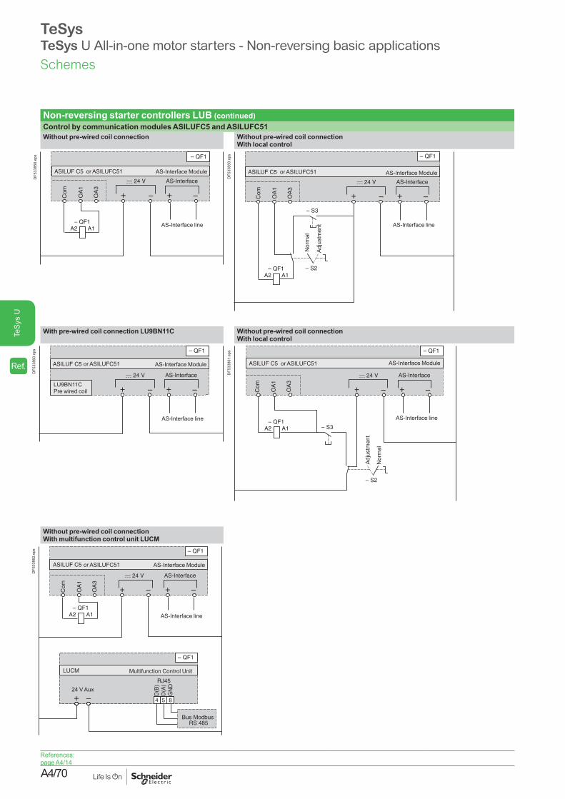
A4/70
TeS
ys U
TeSysTeSys U All-in-one motor starters - Non-reversing basic applications
Non-reversing starter controllers LUB (continued)Control by communication modules ASILUFC5 and ASILUFC51Without pre-wired coil connection Without pre-wired coil connection
With local control
A1A2
Com
OA
1
OA
3
AS-Interface
ASILUF C5 AS-Interface Module
AS-Interface line
or ASILUFC51
DF5
3385
8.ep
s
A1A2
Com
OA
1
OA
3
AS-Interface
ASILUF C5
Adju
stm
ent
Nor
mal
AS-Interface Module
AS-Interface line
or ASILUFC51
DF5
3385
9.ep
s
With pre-wired coil connection LU9BN11C Without pre-wired coil connectionWith local control
AS-Interface
ASILUF C5 AS-Interface Module
LU9BN11C Pre wired coil
AS-Interface line
or ASILUFC51
DF5
3386
0.ep
s
A1A2
Com
OA
1
OA
3
AS-Interface
ASILUF C5Ad
just
men
t
Nor
mal
AS-Interface Module
AS-Interface line
or ASILUFC51
DF5
3386
1.ep
s
Without pre-wired coil connectionWith multifunction control unit LUCM
A1A2
Com
OA
1
OA
3
AS-Interface
654
D(B
)D
(A)
GN
D
854
RJ45
Bus Modbus RS 485
ASILUF C5
LUCM Multifunction Control Unit
24 V Aux
AS-Interface Module
AS-Interface line
or ASILUFC51
DF5
3386
2.ep
s
Schemes
References:page A4/14
Ref.

A4/71
TeS
ys U
Standard or advanced power baseON/OFF control (1 direction of rotation)Push buttons wiring
DB41
4426
_b.e
ps
A1
A2
95NC 17 18NO96
13NO 21 22NC14
A1
A2 13 NO 21 22NC14
21 22
OFFONa
a
LU9B N11
A1
A2
95NC 17 18NO96
33 43 4434
13NO 21 22NC14
NONO
A1
A2
95NC 17 18NO96
33 43 4434
13NO 21 22NC14
NONO
ON indication"Motor RUN" indicator wiring "Motor starter READY" indicator wiring
A1
A2
95NC 17 18NO96
33 43 4434
13NO 21 22NC14
NONO
A1
A2
95NC 17 18NO96
33 43 4434
13NO 21 22NC14
NONO
A1
A2
95NC 17 18NO96
33 43 4434
13NO 21 22NC14
NONO
RUN a
a
43 44
33 43 4434
NONO
LUF N20
DB4
1442
8.ep
s
READYa
a
LUA8 E20
A1
A2
95NC 17 18NO96
33 43 4434
13NO 21 22NC14
NONO
33 43 4434
DB4
1442
9.ep
s
ALARM indicationProtection device status indicator wiring
A1
A2
95NC 17 18NO96
33 43 4434
13NO 21 22NC14
NONO
95
97NO 17 18NO98
a
a
ALARM
Protection OK
LUA1 C20
A1
A2
95NC 17 18NO96
33 43 4434
13NO 21 22NC14
NONO
A1
A2
97NO 17 18NO98
33 43 4434
13NO 21 22NC14
NONO
DB4
3255
2.ep
s
TeSysTeSys U All-in-one motor starters - Non-reversing basic applicationsSchemes
References:pages A4/10 to A4/13
Ref.

A4/72
TeS
ys U
TeSysTeSys U All-in-one motor starters - Reversing basic applications
Reversing starter-controllers LUB2-wire control via 3-position switch
3-wire control, pulsed start with maintaining contact
2/T
1
4/T
2
6/T
3
2/T
1
4/T
2
6/T
3
U1
W1
V1
M 3
1/L1
3/L2
5/L3
Control Unit
5611
48.e
ps
A3
B3
A1
B1
A2
LU2B Reverser Motor Controller
Stopforward running
reverse running
5611
49.e
ps
A3
B3
A1
B1
A2
LU2B
Stop forward running
and reverse running
Reverser Motor Controller
Stop forward running
Stop reverse running
Start forward running
Start reverse running
5611
50.e
ps
Control by communication modules ASILUFC5 and ASILUFC51
3-wire control, pulsed start with maintaining contact and limit switches
With pre-wired coil connection LU9MRCWith multifunction control unit LUCM
AS-Interface
654
D(B
)D
(A)
GN
D
854
Bus ModbusRS 485
LUCM
ASILUF C5
24 V Aux
AS-Interface Module
Multifunction Control Unit
LU9M RC Pre wired coil
AS-Interface line
or ASILUFC51
DF5
1095
5.ep
s
A3
B3
A1
B1
A2
LU2B
Stop forward running
and reverse running
Reverser Motor Controller
Stop forward running
Stop reverse running
Start forward running
Start reverse running
Limit switch forward running
Limit switch reverse running
5611
52.e
ps
Control by communication modules ASILUFC5 and ASILUFC51Without pre-wired coil connectionWith running direction pilot lights and limit switches
53 54 81 84
82
A3
B3
A1
B1
A2
Com
OA
1
OA
3 AS-Interface
LU2B ASILUF C5/C51 AS-Interface ModuleReverser Motor
Controller
AS-Interface line
DF5
1051
6.ep
s
Schemes
References:pages A4/10 and A4/24
Ref.
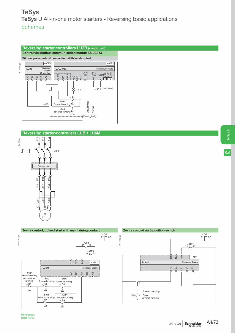
A4/73
TeS
ys U
TeSysTeSys U All-in-one motor starters - Reversing basic applications
Reversing starter controllers LU2B (continued)Control via Modbus communication module LULC033Without pre-wired coil connection. With local control
A3
B3
A1
B1
A2
Com
OA
1
LI1
LI2
LO1
OA
3
654
D(B
)D
(A)
GN
D
854
Modbus
LU2B LULC 033 Modbus Module
Adju
stm
ent
Nor
mal
Start reverse running
Start forward running
Reverser Motor
Controller 24 Vc
24 VAux COM
DF5
1060
1.ep
s
Reversing starter-controllers LUB + LU6M
2/T
1
4/T
2
6/T
3
2/T
1
4/T
2
6/T
3
U1
W1
V1
M 3
1/L1
3/L2
5/L3
1/L1
3/L2
5/L3
Control Unit
5611
55.e
ps
3-wire control, pulsed start with maintaining contact 2-wire control via 3-position switch
A3
B3
A1
B1
A2
21 22
S1
S2
S3
13 14
A2A1
LU6M
S5 S6 S8
S7 S9
Reverser Block
Stop forward running
and reverse running
Stop forward running
Stop reverse running
Start forward running
Start reverse running
DF5
6541
2.ep
s
A3
B3
A1
B1
A2
21 22
S1
S2
S3
A2A1
LU6M Reverser Block
Stopforward running
reverse running
DF5
1095
6.ep
s
Schemes
References:page A4/10
Ref.

A4/74
TeS
ys U
Power base with vertical mounting reverser blockFW/REV/OFF control (2 directions of rotation) FW/REV controlPush buttons wiring FW, REV indicators wiring
33 43 4434
NONO
A1
A2 A1 A3 B1 B3
1 2
95
8182 84
NC 17 18NO96
A2 A1 A3 B1 B3
1 2
8182 84
A2 A1 A3 B1 B3
1 2
8182 84
A2 A1 A3 B1 B3
REV FWOFF
a
a
DB4
1443
0R.e
ps
33 43 4434
NONO
A1
A2 A1 A3 B1 B3
1 2
95
8182 84
NC 17 18NO96
33 43 4434
NONO
A1
95NC 17 18NO96
A2 A1 A3 B1 B3
1 2
8182 84
1 2
8182 84
33 43 4434
NONO
95NC 17 18NO96
a
a
RUN FW
RUN REV
33 34
33 43 4434
NONO
8182 84
LUFN20
DB4
1443
1R.e
ps
TeSysTeSys U All-in-one motor starters - Reversing basic applicationsSchemes
References:pages A4/10 and A4/13
Ref.

A4/75
TeS
ys U
TeSysAltistart U01 Soft starter
Environmental characteristicsType of starter ATSU01N2ppLT
Conformity to standards Altistart U01 electronic starters have been developed to conform to the strictest international standards and the recommendations relating to electrical industrial control devices (IEC, EN), in particular standard IEC/EN 60947-4-2.
Electromagnetic compatibility EMCConducted and radiated emissions
CISPR 11 level B, IEC 60947-4-2, level B
Harmonics IEC 1000-3-2, IEC 1000-3-4EMC immunity EN 50082-2, EN 50082-1Electrostatic discharge IEC 61000-4-2 level 3Immunity to radiated radio-electrical interference
IEC 61000-4-3 level 3
Immunity to electrical transients IEC 61000-4-4 level 4Voltage/current impulse IEC 61000-4-5 level 3Conducted and radiated emissions
IEC 61000-4-6 level 3
Immunity to conducted interference caused by radio-electrical fields
IEC 61000-4-11
Damped oscillating waves IEC 61000-4-12 level 3e marking The starters carry e marking in accordance with the European low voltage directives
IEC/EN 60947-4-2.Product certifications UL, CSA, C-Tick and CCCDegree of protection IP 20Degree of pollution 2 conforming to IEC/EN 60947-4-2Vibration resistance 1.5 mm peak to peak from 3 to 13 Hz, 1 gn from 13 to 150 Hz, conforming to IEC/EN
60068-2-6Shock resistance 15 gn for 11 ms conforming to IEC/EN 60068-2-27Relative humidity 5…95 % without condensation or dripping water conforming to IEC 60068-2-3Ambient temperature around the unit
Storage °C -25…+70 conforming to IEC/EN 60947-4-2Operation °C -10…+40 without derating, up to 50°C with current derating of 2 % per °C above 40°C
Maximum operating altitude m 1000 without derating (above this, derate the current by 2.2 % per additional 100 m)Operating positionMaximum permanent angle in relation to the normal vertical mounting position
Electrical characteristicsType of starter ATSU01N2ppLT
Category of use Conforming to IEC 60947-4-2 Ac-53bRated operating voltage 3-phase a voltage V 200 - 10 % to 480 + 10 % Frequency Hz 50 - 5 % to 60 + 5 %Output voltage Maximum 3-phase voltage equal to line supply voltageControl supply voltage 24 V c, 100 mA ±10 %Rated operating current A 6...32Adjustable starting time s 1...10Adjustable deceleration time s 1...10Starting torque % 30.... 80 % of DOL motor starting torqueType of starter ATSU 01N206LT 01N209LT 01N212LT 01N222LT 01N232LT
Control power supply consumption 24 V c, 65 mA 24 V c, 100 mAPower dissipated At full load at end of starting W 1.5 1.5 1.5 2.5 2.5
In transient state at 5 times the rated operating current
W 61.5 91.5 121.5 222.5 322.5
Type of starter ATSU01N206LT to ATSU01N222LT ATSU01N232LTUse
Starting time s 1 5 10 1 5 10Maximum number of cycles per hour
100 20 10 50 10 5
10° 10°
Starting time
Full voltage state or starter at standstill
Operating cycle
t
I
Characteristics
References:page A4/38
Dimensions:page A4/77
Schemes:pages A4/78 to A4/81
Ref.

A4/76
TeS
ys U
TeSysAltistart U01 Soft starter
Electrical characteristics (continued)Logic input power supply (electrically isolated between power and control) + 24 V, COM
24 V ±10 %IsolatedMax. current 100 mA
Logic inputs LI1, LI2, BOOST Stop, run and boost on start-up functions
Logic inputs with impedance 27 kΩ; 24 V power supply (U max 40 V)Max. current 8 mAState 0 if U < 5 V and I < 0.2 mAState 1 if U > 13 V and I > 0.5 mA
Logic output LO1End of starting signal
Open collector logic output:External 24 V power supply (minimum 6 V, maximum 30 V)Max. current 200 mA
Relay outputR1A R1C
Normally open (N/O) contactMinimum switching capacity: 10 mA for 6 V cMaximum switching capacity on inductive load (cos φ = 0.5 and L/R = 20 ms): 2 A for 250 V a or 30 V c (AC-15)Maximum operating voltage 440 V
LED signalling Green LED Starter powered upYellow LED Nominal voltage reached
Connections (maximum connection capacity and tightening torque)Power circuit Connection to Ø4 mm screw clamps
Flexible wire without cable end 1 conductor mm2 1.5…10 8 AWG2 conductors mm2 1.5…6 10 AWG
Flexible wire with cable end 1 conductor mm2 1…6 10 AWG2 conductors mm2 1…6 10 AWG
Rigid wire 1 conductor mm2 1…10 8 AWG2 conductors mm2 1…6 10 AWG
Tightening torque N.m 1.9…2.5
Control circuit Screw connectorFlexible wire without cable end 1 conductor mm2 0.5…2.5 14 AWG
2 conductors mm2 0.5…1.5 16 AWGFlexible wire with cable end 1 conductor mm2 0.5…1.5 16 AWG
2 conductors mm2 0.5…1.5 16 AWGRigid wire 1 conductor mm2 0.5…2.5 14 AWG
2 conductors mm2 0.5…1 17 AWGTightening torque N.m 0.5
Torque characteristics (typical curves)
00 0,25 0,5 0,75 1
N/Ns
U
0,85 U
0,6 U
T
Tr
3 Tn
2 Tn
Tn
DF5
3693
0.ep
s
The diagram opposite shows the torque/speed characteristic of a cage motor in relation to the supply voltage. The torque varies in line with the square of the voltage at a fixed frequency. The gradual increase in the voltage prevents the instantaneous current peak on power-up.
Characteristics
References:page A4/38
Dimensions:page A4/77
Schemes:pages A4/78 to A4/81
Ref.

A4/77
TeS
ys U
TeSysAltistart U01 Soft starter
TeSys U combination (non-reversing power base) and ATSU01N206LT to ATSU01N212LT
TeSys U combination (non-reversing or reversing power base) and ATSU01N206LT to ATSU01N212LT
Mounting on 5 (35 mm) rail with VW3G4104 connector Side by side mounting
15028
4
45
9
DF5
3657
1.ep
s
99135
154
72,2
9
124
DF5
3657
2.ep
s
TeSys U combination (non-reversing power base) and ATSU01N222LT to ATSU01N232LT
TeSys U combination (non-reversing or reversing power base) and ATSU01N222LT to ATSU01N232LT
Mounting on 5 (35 mm) rail with VW3G4104 connector Side by side mounting
314
45
170
9
DF5
3657
3.ep
s 99135
72,2
154
9
DF5
3657
4.ep
s
VW3G4104 connector
44,820
646
,6
28
DF5
3657
5.ep
s
Dimensions
References:page A4/38
Characteristics:pages A4/75 and A4/76
Schemes:pages A4/78 to A4/81
Ref.

A4/78
TeS
ys U
TeSysAltistart U01 Soft starter
ATSU01N2ppLT soft start/soft stop unitsPower wiring Power wiring with reversing unit
2/T
1
4/T
2
6/T
3
2/T
1
4/T
2
6/T
3
1/L1
3/L2
5/L3
1/L1
3/L2
5/L3
M1 3
A1
CU
– QF1
ATSU 01N2ppLT
TeSys U
TeSys U
DF5
3657
6.ep
s
2/T
1
4/T
2
6/T
3
2/T
1
4/T
2
6/T
3
1/L1
3/L2
5/L3
1/L1
3/L2
5/L3
M1 3
CU
– QF1
A1
ATSU 01N2ppLT
TeSys U with reversing unitTeSys U
DF5
3657
7.ep
s
Compatible componentsCode Description
A1 Soft start/soft stop unitQF1 TeSys U controller-starterCU TeSys U control unit
Schemes
References:page A4/38
Characteristics:pages A4/75 and A4/76
Dimensions:page A4/77
Ref.

A4/79
TeS
ys U
TeSysAltistart U01 Soft starter
ATSU01N2ppLT soft start/soft stop units (continued) Automatic 2-wire control Without deceleration With and without deceleration
– QF1
– S1
LUA1 C20
R1
A
A1
A2
17
18
R1
C
LI1
LI2 + 2
4 V
BO
OS
T
LO
1
CO
MA1
+
–
c 24 V
ATSU 01N2ppLT
DF5
3657
8.ep
s
– QF1
– S2
A1
A2
A1+
–
c 24 V
– S1
ATSU 01N2ppLT
R1
A
R1
C
LI1
LI2 + 2
4 V
BO
OS
T
LO
1
CO
M
LUA1 C20
17
18
Stop
Run
Stop
Run
DF5
3657
9.ep
s
Functional diagrams
10 s
tt1
U1
Power supply voltage
Green LED
Logic input LI2Pushbutton S1
Logic output LO1
Yellow LED
Motor voltage
DF5
3658
0.ep
s
t2 tt1
10 s
U1
Power supply voltageGreen LED
Logic input LI2Pushbutton S2
Logic output LO1
Yellow LED
Motor voltage
Pushbutton S1
DF5
3658
1.ep
s
Automatic 3-wire control Without deceleration With deceleration
– QF1
– S2
– QF1
14 13
A1
A2
A1+
–
c 24 V
– S1
R1A
R1C
ATSU 01N2ppLT
LI1
LI2 + 2
4 V
BO
OS
T
LO
1
CO
M
LUA1 C20
17
18
DF5
3658
2.ep
s
– QF1
– QF1
– S2
A1
14
13
A2
A1+
–
c 24 V
– S1
ATSU 01N2ppLT
R1
A
R1
C
LI1
LI2 + 2
4 V
BO
OS
T
LO
1
CO
M
LUA1 C20
17
18
DF5
3658
3.ep
s
Functional diagrams
500 ms
tt1
10 s
U1
Power supply voltageGreen LED
Pushbutton S1
Logic output LO1
Yellow LED
Motor voltage
Logic input LI2
Pushbutton S2
DF5
3658
5.ep
s
t
10 s
t1
Power supply voltageGreen LED
Logic output LO1
Yellow LED
Motor voltage
Logic input LI2Pushbutton S2Logic input LI1Pushbutton S1
DF5
3658
4.ep
s
A1: Soft start/soft stop unitS1, S2: XB4B or XB5B pushbuttonsQF1: TeSys U controller-startert1: Acceleration time can be controlled by a potentiometert2: Deceleration time can be controlled by a potentiometerU1: Starting time can be controlled by a potentiometer
Schemes
References:page A4/38
Characteristics:pages A4/75 and A4/76
Dimensions:page A4/77
Ref.

A4/80
TeS
ys U
TeSysAltistart U01 Soft starter
ATSU01N2ppLT soft start/soft stop units (continued) Automatic 3-wire control, with reversing unit Without deceleration With deceleration
A3
B3
A1
A2
B1
A1
ATSU 01N2ppLT
R1A
R1C
CO
M
BO
OS
TLO
1
LI2
LI1 + 2
4 V
– S2
– S1
– S3
c 24 V+
–
LUA1 C20
17
18
QF1
LU2B p2BL
Run direction 1
Run direction 2
Stop
DF5
3658
6.ep
s
A3
B3
A1
A2
B1
LU2B p2BL
A1QF1
ATSU 01N2ppLT
R1
A
R1
C
CO
M
BO
OS
T
LO
1
LI2
LI1 + 2
4 V
– S2
– S1
c 24 V
– S3
+
–
LUA1 C20
17
18
Run direction 1
Run direction 2
Stop
DF5
3658
7.ep
s
QF1: TeSys U controller-starter with reversing unitA1: Soft start/soft stop unitS1, S2, S3: XB4B or XB5B pushbuttonsS3: minimum depression time 500 ms
QF1: TeSys U controller-starter with reversing unitA1: Soft start/soft stop unitS1, S2, S3: XB4B or XB5B pushbuttons
Boost on starting and end of starting signalA1
ATSU 01N2ppLT
R1
A
R1
C
LI1
LI2 + 2
4 V
BO
OS
T
LO
1
CO
M
To PLC
DF5
3658
8.ep
s
A1: Soft start/soft stop unit
Schemes
References:page A4/38
Characteristics:pages A4/75 and A4/76
Dimensions:page A4/77
Ref.

A4/81
TeS
ys U
TeSysAltistart U01 Soft starter
ATSU01N2ppLT soft start/soft stop units (continued) Automatic control with Modbus communication module, with and without decelerationWithout reversing unit With reversing unit
A1
LO
1C
OM D(B
)D
(A)
Gnd
A1
–+–+c 24 VLU9B N11C
LUL C031
4 5 8
ATSU 01N2ppLT
R1A
R1C
Modbus Module
CO
M
BO
OS
T
LO
1
LI2
LI1 + 2
4 V
c 24 V
+
13
14
Pre-wired coil24 V Aux.
DF5
3658
9.ep
s A1
LO
1C
OM D(B
)D
(A)
Gnd
A1
–+–+c 24 V
LUL C031
4 5 8OA
1
OA
3
CO
M
ATSU 01N2ppLT
R1A
R1C
Modbus Module
CO
M
BO
OS
T
LO
1
LI2
LI1 + 2
4 V
c 24 V
+
A3
B3
A1
A2
B1
LU2B p2BL
QF1
24 V Aux.
DF5
3659
0.ep
s
Function Register Bit Value Function Register Bit ValuePowering down TeSys U and ATSU Powering up TeSys U and ATSU
– 704 0 0 Forward 704 0 1Reverse 704 1 1
Automatic control without deceleration Powering down TeSys U and ATSURun 700 0 1 Forward 704 0 0Stop 704 0 0 Reverse 704 1 0Automatic control with deceleration Automatic control without deceleration
Run 700 0 1 Run 700 0 1Soft stop 700 0 0 Stop forward 704 0 0
Stop reverse 704 1 0Automatic control with deceleration (forward or reverse)
Run 700 0 1Soft stop 700 0 0
A1: Soft start/soft stop unit A1: Soft start/soft stop unitQF1: TeSys U controller-starter with reversing unit
Automatic control with AS-Interface communication module, without decelerationWithout reversing unit With reversing unit
CO
M
BO
OS
T
LO
1
LI2
LI1 + 2
4 V
A1
++AS-Interfacec 24 VLU9B N11C
ASI LUFC5
ATSU 01N2ppLT
R1A
R1C
13
14
c 24 V
+
Pre-wired coil
DF5
3659
1.ep
s
CO
M
BO
OS
T
LO
1
LI2
LI1 + 2
4 V
A1
++AS-Interfacec 24 V
ASI LUFC5
ATSU 01N2ppLT
R1A
R1C
A3
B3
A1
A2
B1
LU2B p2BL
QF1
OA
1
OA
3
CO
M
c 24 V
+
DF5
3659
2.ep
s
Function Bit Value Function Bit ValuePower-up and automatic control without deceleration Power-up and automatic control without deceleration
Run D0 1 Run forward D0 1Stop D0 0 Stop D0 0
Run reverse D1 1Stop D1 0
A1: Soft start/soft stop unit A1: Soft start/soft stop unitQF1: TeSys U controller-starter with reversing unit
Schemes
References:page A4/38
Characteristics:pages A4/75 and A4/76
Dimensions:page A4/77
Ref.

A4/82
TeS
ys U