TEPEx_catalog_2017-2018.pdf - Ex-Baltic
138
-
Upload
khangminh22 -
Category
Documents
-
view
1 -
download
0
Transcript of TEPEx_catalog_2017-2018.pdf - Ex-Baltic


TEP Ex is a regional leader in manufacturing of explosion-protected electrical equipment. Through continuous development of new products and markets, modernization of tech-nology and investment in company employ-ees and organization, we continue the tradi-tion of more than 60 years of experience in the field.
Long-term company policy relies on our peo-ple and delivery of innovative products from our own development teams. Aiming for ex-cellence is for us one of the most important corporate values. Our products are intended for use in potentially explosive atmospheres of gases, vapors and dust in industries such
as refineries, offshore installations, petrochemical industry, chemical industry, pharmaceutical industry, food pro-cessing, shipbuilding and underground mining.
The production program includes Ex light fittings, Ex instal-lation material and accessories, Ex control units, Ex signal devices, Ex terminals, Ex distribution cabinets up to 630 V and 500 A.
In accordance with national regulative, all of our products and systems for quality assurance are certified by an authorized certification institution in the Republic of Croatia –Ex Agency. At European level, the certification was car-ried out according to the ATEX Directive 2014/34/EU by an authorized certification notified body CESI and Ex Agen-cy.
All of our products and systems for quality assurance are certified according to certification was carried out according to the GOST TR CU (Technical Regulation Customs Un-ion) certificates are official documents certifying the con-formity of the production with the standards of the Customs Union formed by Belarus, Kazakhstan and Russian Feder-ation. The production process is conducted according to high standards of ISO 9001 (Quality Assurance System) and ISO 14001 (Environmental Management System), ensuring high quality products with constant care for envi-ronment.
Based on our long history in producing supreme quality explosion protected electrical equipment, we are ready to deal with every demand or specific requirement of our cus-tomers.
If you would need any additional information regarding our products or our company, we will be glad to answer your questions, with the professional approach from our Com-munication team.
About us
2 make your work surroundings safer

Examples of today's Ex products
3 www.tepex.hr
Explosion protected products from the middle of the last century

The electrical equipment installed in areas with risk
of explosion must be designed and tested in such
way that it does not cause arcing or high
temperatures which would provide a source of
ignition for such a mix. For this reason, these
materials must be provided only by companies
able to attach the relevant product certificate of
compliance with international standards.
This certificate, issued by competent and
government authorized laboratories along with a
test report, proves that the product is totally safe
and suitable for installation in the concerned plant.
TEPEx Quality System conforms to the requirements of: EN ISO 9001:2008 and EN ISO/IEC 80079-34:2011. All our Ex-protected products are certified in
accordance with the European standard ATEX
Directive 2014/34/EU , also obtained the
certifications for the Russian market (Custom union),
EAC.
Production
4 make your work surroundings safer

5 www.tepex.hr
Ex LED light fittings
Following new trends in Ex lighting, and the advent of LED sources in explosive areas, TEPEx al-ready in 2013. started production of Ex light fitting with LED light source (LED FLXE 118). Current-ly, several types of Ex certified LED lamps (pendant/max. 80W and linear LED lamps with 36W).
The main advantages of LED lighting over conventional (mercury, fluorescent, metal-halide ...) lighting.
Durability
Energy efficiency
selectable color temperature
environmentally friendly
In 2017. we plan to start production of Ex pendant light fittings ~120W, and linear LED light fitting in GRP (Polyester) housing, Ex e type PSF 52 LED, PSF 28 LED.
Ex LED linear
light fitting type PSF 52 LED
Modern LED lighting has a significantly longer service life than conventional lighting, does not contain harmful compounds (mercury, cadmium ...), does not emit UV rays and releases significantly less heat energy.
When creating light-technical calculations it should be noted that the LED lighting (directional light) contribute to the reduction of light pollution of the atmosphere and losses on light scattering.

Contents
Ex BULKHEAD LIGHT FITTINGS, PENDANT LIGHT FITTINGS, FLOODLIGHTS
Bulkhead light fitting 0403.24 14
Pendant light fitting PLFM 16
Pendant light fitting PLFS 20
Pendant light fitting PLFL 22
Floodlight RLF 24
Ex FLUORESCENT LIGHT FITTINGS, EMERGENCY LIGHT FITTING
Fluorescent light fitting PSF 28
Emergency light fitting PSF E 30
Fluorescent light fitting FLX 32
Emergency light fitting FLXE LED 36
Fluorescent light fitting SIF 38
Ex LED LIGHT FITTINGS
Bulkhead light fitting 0403.24 LED 20 40
Pendant light fitting PLFM 20 LED 42
Pendant light fitting 0401.35 LED 30 44
Pendant light fitting PLFS 50 LED 46
Linear LED light fitting FLX 310 LED 48
Linear LED light fitting PSF LED 50
Ex INSTALLATION EQUIPMENT
Installation switch SKX SW 54
Junction boxes RK 01 56
Junction boxes JBX 58
Terminal boxes SKX …./E 60
Terminal boxes SKX …./E INOX (AISI 316L) 70
CONTROL UNITS
Control units SKX 12 …. SKX 15 80
Control units SKX 16 .... SKX 20 92
Grounding device GGCD 102
DISTRIBUTION CABINETS, BUSBAR ENCLOSURES
Distribution cabinets R3002....R3006 106
Busbar enclosure SKX 110
SIGNALLING DEVISE, PLUGS AND SOCKETS, ACCESSORIES
Signal horn dHH, 114
Signal bell dHW 116
Telephone dST1 118
Torchlights DF, headlamp DS 120
Plugs and sockets 122
Adapter ADP 128
Multicore bushing RSM 130
Electronic ballast SMP 132
Cable glands, adapters, reducers, locknuts 134
6 make your work surroundings safer
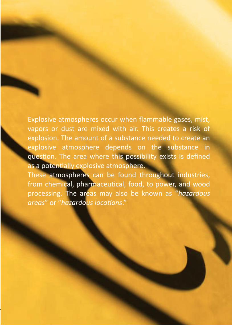
Explosive atmospheres occur when flammable gases, mist, vapors or dust are mixed with air. This creates a risk of explosion. The amount of a substance needed to create an explosive atmosphere depends on the substance in question. The area where this possibility exists is defined as a potentially explosive atmosphere. These atmospheres can be found throughout industries, from chemical, pharmaceutical, food, to power, and wood processing. The areas may also be known as “hazardous areas” or “hazardous locations.”

GUIDE FOR EXPLOSION PROTECTION
Categories / Protection levers / Zones
PRIMARY Preventing the
formation of an explosive atmosphere
SECONDARY Avoidance of the
ignition of an explosive atmosphere
TERTIARY Mitigation of the effects
of an explosion to an acceptable extent
Equipment and products operating in hazardous areas are required to meet stringent criteria. They must be “protected” to avoid the possibility of them becoming a source of ignition. If the danger of explosion cannot be completely or only partly avoided by measures of preventing the formation of an hazardous explosive atmosphere, then measures must be taken that avoid the ignition of the explosive atmosphere.
Integrated explosion protection
AREAS CATEGORIES EPL ZONES EXPLOSIVE ATMOSPHERE
Mining - I M1 Ma
/ >1,5% CH4
M2 Mb <1,5% CH4
Other than mines - II
1G, 1D Ga, Da 0, 20 Continuously, long term ог frequently
2G, 2D Gb, Db 1, 21 Likely to occur
3G, 3D Gc, Dc 2, 22 Not likely to occur, short period
EPL - Equipment Protection Level G - Gas D - Dust
a - very high protection level b - very high protection level c - extended protection level
450C
300C
200C
135C
100C
85C
T1 T2 T3 T4 T5 T6 Temp. Class
I methane
IIA
ammonium, ethane,
propane, benzene, methanol
ethyl n-butanol,
n-butyl alcohol
benzine, kerosene , n-hexane, diesel fuel
etileter, acetilaldehid,
benzaldehyde, dibutileter, diheksileter
- -
IIB LPG mix ethylene hydrogen sulphide etileter, dietileter - -
IIC hydrogen acetylene - - - carbon disulphide
Ga
s G
rou
ps
Ma
xim
um
Su
rfac
e
Te
mp
era
ture
Dust Groups
IIIA Combustible flyings
IIIB Non-conductive dust
IIIC Conductive dust
Dust Flash point [C]
layer cloud
Minimum ignition energy (cloud)
[mJ]
Lower Explosion Limit (cloud) [g/m3]
Cellulose 270 480 80 55
Sugar 400 370 30 45
Strach 380 400 25 25
Wheat 220 500 60 65
Sawdust 260 470 40 35
Aluminium powder 490-700 550-800 15-160 40-140
Zinc 540 690 960 460
Asphalt 550 510 40 35
make your work surroundings safer 8

Types of protection for explosive atmosphere of flammable gases, vapors, mists or dusts EN/IEC 60079-0 - General Requirements
Type of protection Standard Concept Symbol Category EPL
Flameproof EN/IEC 60079-1 d 2G M2
Gb Mb
Increased safety EN/IEC 60079-7 e 2G M2
Gb Mb
Pressurized EN/IEC 60079-2 px, py, pz M2, 2G, 3G
2D, 3D Mb, Gb, Gc
Db, Dc
Intrinsic safety EN/IEC 60079-11 ia, ib, ic M1, M2, 1G, 2G, 3G
1D, 2D, 3D Ma, Mb, Ga, Gb, Gc
Da, Db, Dc
Type of protection “n” EN/IEC 60079-15 nA nC nR
3G Gc
Powder filling EN/IEC 60079-5 q M2, 2G Mb, Gb
Oil - immersion EN/IEC 60079-6 o M2, 2G Mb, Gb
Encapsulation EN/IEC 60079-18 ma mb Mc
M1, M2, 1G, 2G, 3G 1D, 2D, 3D
Ma, Mb, Ga, Gb,Gc Da, Db, Dc
Protection by enclosures
EN/IEC 60079-31 tD
ta, tb, tc 1D, 2D, 3D Da, Db, Dc
Optical radiation EN/IEC 60079-28 op _a op _b op _c
1G, 2G, 3G Ga, Gb, Gc
Type of protection for non-electrical equipment EN 13463-1 / IEC 80079-36
Flow restricting EN 13463-2 fr 3G, 3D /
Flameproof EN 13463-3 d M2, 2G /
Constructional safety EN 13463-5
prIEC 80079-37 c
M2, 1G, 2G, 3G 1D, 2D, 3D
Mb, Ga, Gb, Gc Da, Db, Dc
Control of ignition sources
EN 13463-6 prIEC 80079-37
b M2, 1G, 2G, 3G
1D, 2D, 3D Mb, Ga, Gb, Gc
Da, Db, Dc
Liquid immersion EN 13463-8
prIEC 80079-37 k
M1, M2, 1G, 2G, 3G 1D, 2D, 3D
Ma, Mb, Ga, Gb, Gc Da, Db, Dc
Pressurized EN/IEC 60079-2 p M2, 2G, 2D
3G, 3D /
Type of protection
9 www.tepex.hr
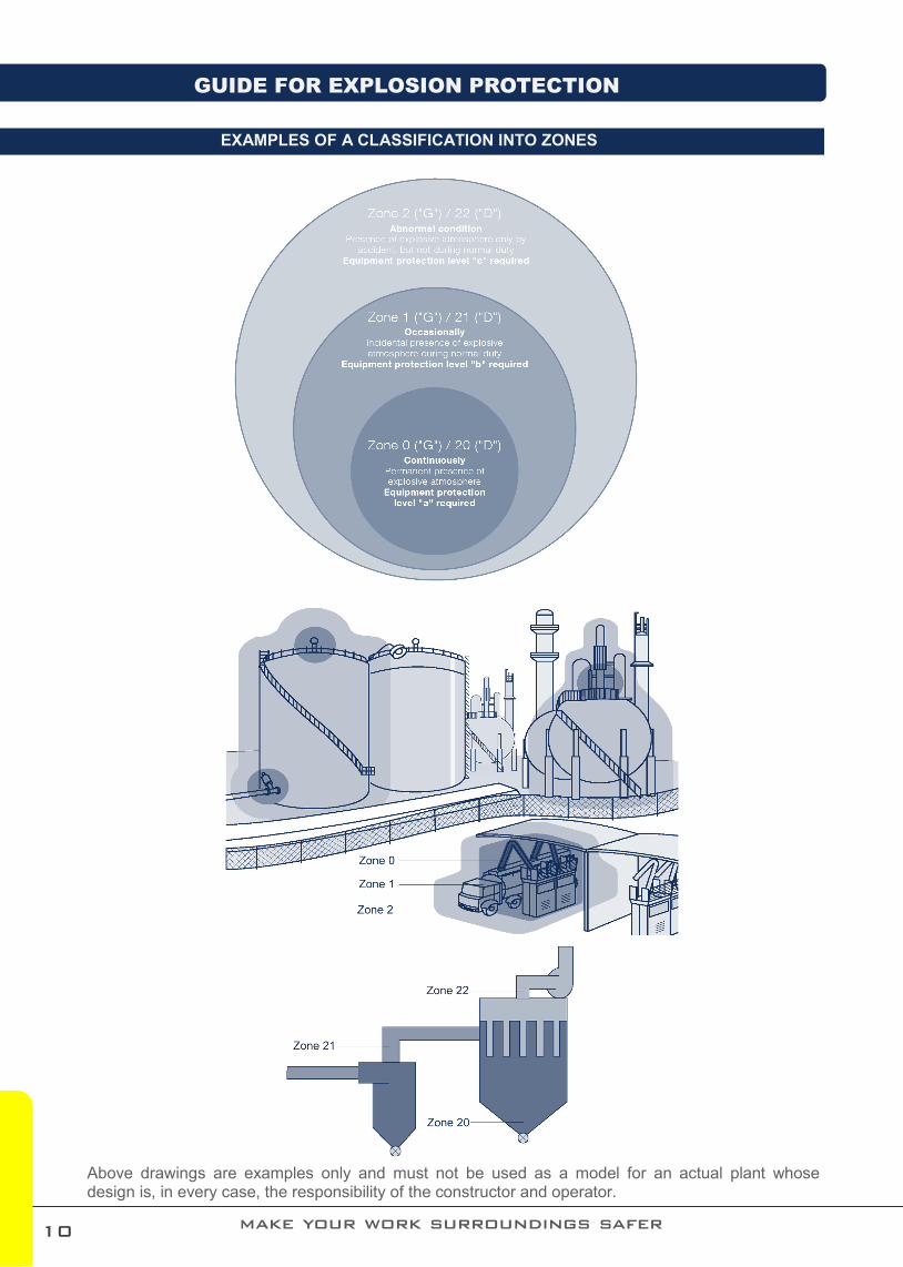
EXAMPLES OF A CLASSIFICATION INTO ZONES
GUIDE FOR EXPLOSION PROTECTION
make your work surroundings safer
Above drawings are examples only and must not be used as a model for an actual plant whose design is, in every case, the responsibility of the constructor and operator.
10

Typical Electrical Equipment Marking According to 2014/34/EU
No. Description
1 Manufacturer’s name and address
2 Product identification
3 Technical data
4 Indication of the Equipment Category and Hazardous Atmosphere
5 Marking of explosion protection
6 Conformity symbol , EU symbol
7 Notified body (ExNB)
8 Standard ambient temperature (-20 ÷ +40C), unless stated on label
9 Certificate number and product number
3
4
5
6
7
8
9
11 www.tepex.hr
1
2

NOTES

Light fittings

Certificate: EXA 15 ATEX 0070X RU C-HR.AB24.B.03246
Marking: 0722
Apparatus category: II 2GD, I M2
Marking of explosion protection: Ex d e IIC T3-T2 Gb Ex tb IIIC T130° Db Ex d e I Mb
Ambient temperature: -40ºC ≤ Ta ≤ +40/50/60ºC - type II 2GD -20ºC ≤ Ta ≤ +40ºC - type I M2
Degree of protection: IP 64, category 1 - type II 2GD IP 54, category 1 - type I M2
Resistance to shock: IK 08
Protection class : I (protective earthing)
Rated voltage: 230V AC, 110V AC, 24V AC/DC
Frequency: 50Hz (60Hz on request)
Rated power: See selection table
Light output ratio: η=0,68%
Lamps: Incandescent lamps, E 27 lampholder, up to 100W Halogen lamps, E 27 lampholder, (77W A ECO)
Connecting terminals: Terminals L1 + N for 2 x 4 mm² flexible/solid Terminals PE for 2 x 4 mm² flexible/solid/stranded Tightening torque for screw clamp 2,2 Nm
Cable entry: 1 x M25x1.5 cable gland (through-wiring possible) 1 x M25x1.5 plug
Cover fixing: M 6, Hexagonal screw; without switch
Packing: The packing contains: 1 pcs 360x240x205 mm
Housing: 0403.24/10, /11, /12 - aluminium powder painted casting 0403.24/20 - cast iron Diffuser: borosilicate glass protected with steel gird
14
0403.24
CONSTRUCTION
TECHNICAL DATA
Zone
1 21 2 22
IP 64
+60
-40
C
● incandescent
lamps up to 100 W and halogen lamps up to 77 W
● Through-wiring
possible
● For use in under-
ground mines
make your work surroundings safer
IM2
E27

Model code Apparatus category
Explosion protection
Rated voltage Max. wattage Luminou
s flux WEIGHT
0403.24/10
II 2G
Ex d e IIC T2,T3 Gb
100W max. 60W max.
77W max. / A ECO
1500 lm 800 lm
1320 lm 4,3 kg
230/110 V AC 230/110 V AC, 24 V AC/DC
230 V AC
0403.24/11,12 (signal red or green
glass)
Ex d e IIC T3 Gb
40W max. 450 lm 4,3 kg 230 V AC
0403.24/20 I M2 Ex d e I Mb 100W max. 1500 lm 7,5 kg 230 V AC
Sketch Description Code Sketch Description Code
Ex d lampholder E27 set
0403.24 10-110
Ex e cable gland M25
SPU 25
Gasket 0403.24 0403.24 10-120
II M2 Ex e I Cable gland
0403.24 20-120
Replacement glass 0403.24 10-130
Ex e plug M25 SPC 25
Light bulb 40W, 60W, 100W
0403.24 20-110
I M2 Ex e I
Plug M25 0403.24 20-130
MODEL CODE
SPARE PARTS AND ACCESSORIES
POLAR CURVE DIMENSION DRAWING (all dimensions are in mm)
15
MOUNTING Two brackets with two screws M6
Bulkhead light fitting
www.tepex.hr
All technical data is relevant at the time of print.

PLFM
CONSTRUCTION
Zone
Housing: aluminium powder painted casting Diffuser: borosilicate glass Accessories: protected galvanized steel gird (INOX on request), assembly kit for wall, pipe and ceiling
mounting
TECHNICAL DATA
Certificate: EXA 14 ATEX 0056X and 0056X/1 RU C-HR.AB24.B.03245
Marking: 0722
Apparatus category: II 2GD
Marking of explosion protection: Ex d e IIC T6-T3 Gb Ex d IIC T6-T3 Gb Ex tb IIIC T80ºC - T155ºC Db
Ambient temperature: -20ºC ≤ Ta ≤ +40ºC [ATEX] -50ºC ≤ Ta ≤ +40ºC [EAC]
Degree of protection: IP 66, category 1
Resistance to shock: IK 08
Protection class : I (protective earthing)
Rated voltage: 230V AC PLFM FLASH - see model code table
Frequency: 50Hz (60Hz on request)
Rated power: See model code table
Light output ratio: η=0,75%
Cable entry: 2 x M20x1.5 II 2G Ex d e IIC Gb, II 2D Ex tb IIIC Db ADP 23/1 II 2G Ex d e IIC Gb, II 2D Ex tb IIIC Db
Connecting terminals: L, N, PE; max. 2 x 2,5 mm2 solid, flexible terminal for external -PA connection; max 2x6 mm2
Weight: 3,5 kg —> PLFM 100/., PLFM FLASH-. 4,5 kg —> PLFM 20 LED-. , PLFM 70 HSE-.
Packing: The packing contains: 2 pcs 340x260x170 mm
1 21 2 22
IP 66
+40
-20
C
16
● Low weight/3,5 kg
● Up to 70W HSE
(5900 lm)
make your work surroundings safer
E27

Pendant light fitting
www.tepex.hr
PLFM ... - .
Basic type code Maximal wattage and type of sources: 100 - A incandescent lamp 100W max,
A ECO halogen lamp 105W max, QT halogen lamp 100W max.
100/1 - LME mixed discharge lamp 100W max. 100/2 - TC-SB compact fluorescent lamp 23W max. 100/3 - LED BULB lamp 15W max. 20 LED - LED MODUL special 20W max. FLASH - XENON MODUL special 5W max. 70 HSE - HSE-I high pressure sodium discharge lamp 70W,
HSE-I high pressure sodium discharge lamp 50W. Type of entries:
1 – indirect entry – type with Ex e junction box, 2 – indirect entry – type with Ex d adapter ADP 23/1,
MODEL CODE
Model code Max. wattage Lamp type Nominal voltage Luminous flux Lamp holder
Temp. class (gas)
T0 MAX (dust)
Ta=40°C Ta=40°C
PLFM 100 - .
100 W A 230V 1340 lm E27 T4 130°C
116 W Osram 105 W Philips A ECO 230 V 2135 lm Osram
1980 lm Philips E27 T4 130°C
100 W QT 230 V 1800 lm Osram E27 T4 130°C
PLFM 100/1 - . 100 W LME 230 V, 50 Hz 1100 lm E27 T3 155°C
PLFM 100/2 - . 22 W Osram 23 W Philips TC-SB 230 V, 50 Hz 1440 lm E27 T6 80°C
PLFM 100/3 - . 12 W Osram 13 W Philips
LED 230 V, 50 Hz 810 lm Osram 1055 lm Philips
E27 T6 80°C
PLFM 20 LED - . 20 W LED modul 230 V, 50 Hz 1300 lm - T6 80°C
PLFM FLASH - . 5 W XENON 10–100 V DC
4J/90Hz - T6 80°C 110 V AC 230 V AC
PLFM 70 HSE - . 70 W HSE 230 V,
50 Hz 5900 lm Osram 5600 lm Philips E27 T4 130°C
50W HSE 230 V, 50 Hz 3600 lm Osram 3500 lm Osram E27 T4 130°C
MOUNTING
With vertical suspension on the bolt with ring bolt head M8 Wall mounting bracket
Pendant, on pipe, wall, ceiling
17
All technical data is relevant at the time of print.

PLFM 1 2 22
SPARE PARTS AND ACCESSORIES
Sketch Description Code Sketch Description Code
Replacement glass PLFM
PLFM 10-120
Ex e cable gland M25
SPU 25
Wire guard PLFM PLFM 10-130
Ex e plug M25, SPC 25
Gasket PLFM PLFM 10-140
Light bulb According to
type table
Lampholder with internal reflector
PLFM 10-150 PLFM fixing
bracket for tube R 2”
PLFM 20-120
Ballast set PLFM 10-170
PLFM mounting bracket (ceiling
mounting) PLFM 20-130
Adapter ADP 23 PLFM 20-110
PLFM mounting bracket (wall mounting)
PLFM 20-140
DIMENSION DRAWING (all dimensions in mm)
PLFM 20 LED, 1300 lm
PLFM 100-., PLFM 70 HSE With external reflector
PLFM 100-., PLFM 70 HSE Without external reflector
POLAR CURVE
18
Zone
1 21 2 22
make your work surroundings safer

Pendant light fitting
www.tepex.hr 19

PLFS Zone
1 21 2 22
CONSTRUCTION
Housing: aluminium powder painted casting Diffuser: borosilicate glass Accessories: protected galvanized steel gird, assembly kit for wall, pipe and ceiling mounting
TECHNICAL DATA
Certificate: CESI 06 ATEX 052 RU C-HR.AB.B.03244
Marking: 0722
Apparatus category: II 2GD
Marking of explosion protection:
Ex d e IIC T4,T5,T6 Ex tD A21 IP66 T80°C / T130°C Ex d e IIC T3/T4
Ambient temperature: -20ºC ≤ Ta ≤ +40ºC / +50ºC [ATEX] -50ºC ≤ Ta ≤ +40ºC / +50ºC [EAC]
Degree of protection: IP 66/67, category 1
Resistance to shock: IK 08
Protection class : I (protective earthing)
Rated voltage: 230 V (-10% / +6%) (other voltage on request) 12 V AC/DC, 24 V AC/DC, 110 V AC, 230 V AC-lamp type PLFS-T/FLASH
Frequency: 50Hz (60Hz on request)
Rated power: See model code table
Light output ratio: η=0,66% - 0,75%
Cable entry: two entries Ex e M25x1,5
Connecting terminals:
L1, L2, L3, N; max. 2 x 2,5 mm2 solid, flexible terminal for protective earthing conductor connection -PE; max 2x6mm2 terminal for external -PA connection; max 2x6mm2 tightening torque for screw clamp 1,2 Nm
Cable gland and plug: II 2GD Ex e M25 IP66 tightening torque for gland screw 2,5 Nm tightening torque for gland and plug 3,5 Nm
Weight: 8,6 kg
Packing: The packing contains: 2 pcs 610x390x280 mm
IP 66 IP 67
+50
-50
C
20
● Heavy duty con-
struction, alumini-um enclosure and borosilicate glass
● Up to 150W HIE,
12500 lm
make your work surroundings safer
E27

Pendant light fitting
www.tepex.hr
Model code Max. wattage Lamp type Lamp holder
Temp. class (gas)
T0 MAX (dust) Luminous flux
Ta=40°C Ta=50°C Ta=40°C
PLFS-T/200
max. 200 W A
E27
T4
T4
130°C
2500 Lm
max. 230 W QT T3 4200 Lm
max. 160 W LME T4 3150 Lm
max. 30 W TC-TSE T6 - 80°C 2300 Lm
PLFS-T/125 125 W HME
T4
-
130°C
6700 Lm
110 W HSE-I - 9500 Lm
PLFS-T/100 100 W HSE - 9000 Lm
HIE - 8400 Lm
PLFS-T/70 70 W HSE
T5 T4 95°C 5800 Lm
HIE 5500 Lm
PLFS-T/150 150 W HIE T4 - 130°C 12500 Lm
PLFS-T/FLASH 15 W / 11 J (in total)
XENON - T6 - 80°C -
With external reflector Without external reflector
SPARE PARTS AND ACCESSORIES
Sketch Description Code Sketch Description Code
Replacement glass PLFS-T
PLFS-T 10-120
Ex e cable gland M25
SPU 25
Wire guard PLFS-T PLFS-T 10-130
Ex e plug M25, SPC 25
Base plate with lamp holder, ballast
PLFS-T 10-140
Light bulb According to type
table
PLSF-T cover Exe set
PLFS-T 10-150
PLFS-T fixing bracket for tube R
1 1/2“ PLFS-T 20-120
PLFS-T external reflector, wide
PLFS-T 20-100 PLFS-T mounting bracket (ceiling and
wall mounting) PLFS-T 20-130
PLFS-T external reflector, narow
PLFS-T 20-110
MODEL CODE
POLAR CURVE DIMENSION DRAWING (all dimensions in mm)
21
All technical data is relevant at the time of print.

PLFL Zone
1 21 2 22
CONSTRUCTION
Housing: aluminium powder painted casting Diffuser: borosilicate glass Accessories: protected galvanized steel gird, assembly kit for wall, pipe and ceiling mounting
TECHNICAL DATA
Certificate: EXA 14 ATEX 0001 RU C-HR.AB24.B.03247
Marking: 0722
Apparatus category: II 2GD
Marking of explosion protection: Ex d e IIC T4-T3 Gb Ex d IIC T4-T3 Gb Ex tb IIIC T140ºC - T155ºC Db
Ambient temperature: -20ºC ≤ Ta ≤ +40ºC / +50ºC [ATEX] -50ºC ≤ Ta ≤ +40ºC / +50ºC [EAC]
Degree of protection: IP 66, category 1
Resistance to shock: IK 08
Protection class : I (protective earthing)
Rated voltage: 230 V (-10% / +6%) (other voltage on request)
Frequency: 50Hz (60Hz on request)
Rated power: See model code table
Light output ratio: η=0,53% - 0,77%
Cable entry: two entries Ex d, M20x1,5-6H
Ex d adapter: type ADP 23/1, II 2G Ex d e IIC Gb II 2D Ex tb IIIC Db, cable gland ISO 25 for cable v 7-15 mm
Connection terminals inside adapter, type PLFL-1/...
terminals for connection L + NE + PE; 2,5 mm2, solid, stranded
Connection terminals inside light fitting
terminals for connection L + NE + PE; 2,5 mm2, solid, stranded it is possible through wiring, Imax= 16 A
External PA / PE terminal: max 2 x 6 mm2 flexible, 3 pcs.
Tightening torque: housing of Ex d e adapter and Ex d plug 3,5 Nm pressure nut of cable gland 2,5 Nm screws of Ex e terminal 1,2 Nm
Weight: ca 18 kg – PLFL-./500 A,IQ and PLFL/250 LME ca 23 kg - PLFL-./250 HIE, HSE, HME
IP 66
+50
-20
C
22
● Up to 250W dis-
charge sources
40
make your work surroundings safer
E40

Pendant light fitting
www.tepex.hr
MODEL CODE
Model code Max. wattage Lamp type Luminous flux Lamp
holder
Temp. class (gas)
T0 MAX (dust)
Ta=40°C Ta=50°C Ta=40°C
PLFL/250 HIE, HSE, HSE
Twinarc
250 W
HIE 20000
E40
T4 140°C
T3
HSE 28000
HSE Tw 32000
PLFL/250 HME
HME 20000
PLFL/250 LME LME 5500
PLFL/500 A,QT
500 W A 8400
- 150°C QT 10250
535
210
365
50
290
12,5
180
540
285
180
365
50
290
12,5
180
540
285
180
365
50
290
12,5
180
540
285180
535
210
365
50
290
12,5
180
540
285
180
POLAR CURVE, DIMENSION DRAWING [mm]
With external reflector
Without external reflector
SPARE PARTS AND ACCESSORIES
Sketch Description Code Sketch Description Code
Replacement glass PLFL
PLFL 10-120 Gasket set PLFL PLFL 10-160
Wire guard PLFL PLFL 10-130
Ex d plug M20, SPC Exd 20
Base plate with lamp holder, ballast
PLFL 10-140
Light bulb Acording to type
table
Adapter ADP 23 PLFS-T 10-150 PLFL fixing
bracket for tube R 1 1/2“
PLFL 20-120
PLFL externar reflector
PLFL 20-100 PLFL mounting
bracket (ceiling and
wall mounting) PLFL 20-130
23
All technical data is relevant at the time of print.

RLF Zone
1 21 2 22
IP 66
+40
-50
C
CONSTRUCTION
Housing: aluminium powder painted casting Diffuser: borosilicate tube glass Accessories: protected galvanized steel gird, assembly kit for wall, pipe and ceiling mounting
TECHNICAL DATA
Certificate: EXA 14 ATEX 0047 RU C-HR.AB24.B.03248
Marking: 0722
Apparatus category: II 2GD
Marking of explosion protection: Ex d e IIC T4-T3 Gb Ex d IIC T4-T3 Gb Ex tb IIIC T130ºC - T195ºC Db
Ambient temperature: -20ºC ≤ Ta ≤ +40ºC [ATEX] -50ºC ≤ Ta ≤ +40ºC [EAC]
Degree of protection: IP 66, category 1
Resistance to shock: IK 08
Protection class : I (protective earthing)
Rated voltage: RLF/... HIT,HST,HME,QT -230/240 V (-10% / +6%) / 50 Hz RLF/... QL -230 V (200-277 V) - 50/60 Hz or (190-264 V) - DC
Frequency: 50Hz (60Hz on request)
Rated power: See model code table
Light output ratio: η=0,60%
Cable entry:
RLF/... HIT,HST,HME,QT - three entries M20, with two Ex d plug and one Ex de adapter,
type ADP 03/23, for cable ¯6-15 mm RLF/... QL - two entries M25 into Ex e junction box with one Ex e cable
gland , type SPU 25, for cable v 6-15 mm and one Ex e plug
Connection terminals inside light fitting
RLF/... HIT,HST,HME,QT -clamps in Ex de adapter for connection L1, L2, N, PE, 2,5mm2 max. / clamp - solid, stranded;
External PA / PE terminal: max 2 x 6 mm2 flexible, 3 pcs.
Weight: See model code table
Packing: The packing contains: 1 pcs 600x400x300 mm
24
● Up to 400W dis-
charge sources
● QL source up to
100 000 hours life time
make your work surroundings safer
E40

Floodlight
www.tepex.hr
Model code Max.
wattage Lamp type Luminous flux Lamp holder
Temp. class (gas)
T0 MAX (dust) Weight
Ta=40°C Ta=40°C
RLF/250 HIT
250 W
HIE 20000
E40
T4 130°C 25 kg RLF/250 HST HST 33200
RLF/250 HME HME 13000
RLF/400 HIT 400 W
HIE 34000
T3 190°C 27 kg
RLF/400 HST HST 56500
RLF/500 IQT RLF/300 IQT
500 W 300 W
IQT 10 250 5 600
22 kg RLF/85 QL 85 W QL
6300 QL T4 130°C
RLF/165 QL 165 W 12000
MODEL CODE
Wide beam reflector Narrow beam reflector QL 165 W
POLAR CURVE
DIMENSION DRAWING (all dimensions in mm)
Wide beam reflector Narrow beam reflector
RLF/....
QL 165 W
25
All technical data is relevant at the time of print.

RLF 1 2 22
SPARE PARTS AND ACCESSORIES
If it is not ordered differently, floodlight RLF/ ... HIT,HST,HME,QT presume floodlight with RLF carrier, one Ex de adapter ADP 03/32 and two Ex d plugs, without light source and mounting accessories. Manufacturer will deliver spare parts and accessories on buyer request.
Sketch Description Code Sketch Description Code
Light bulb RLF 10-110
Base plate HME
Set RLF 20-120
Mounting screw
M12x40 RLF 10-120
Gasket RLF RLF 20-130
U screw M12 RLF 10-130
Adapter Ex d e ADP 23/1
Base plate
HIT, HST Set RLF 20-110
Ex d plug M20 RLF 20-140
If it is not ordered differently, floodlight RLF/... QL presume floodlight with RLF QL carrier, one Ex e junction box MMK 13 with Ex e connecting terminals, Ex e M25 cable gland, Ex e M25 plug, and Philips QL Induction Lighting System, without mounting accessories. Manufacturer will deliver spare parts and accessories on buyer request.
Sketch Description Code Sketch Description Code
MMK 13 gasket RLF QL 10-110
Ex e plug M25 SPC 25
Ex e cable gland
M25 SPU 25
Zone
1 21 2 22
26 make your work surroundings safer

Floodlight
www.tepex.hr 27
PSF Zone
1 21 2 22
IP 66
+50
-20
C
CONSTRUCTION
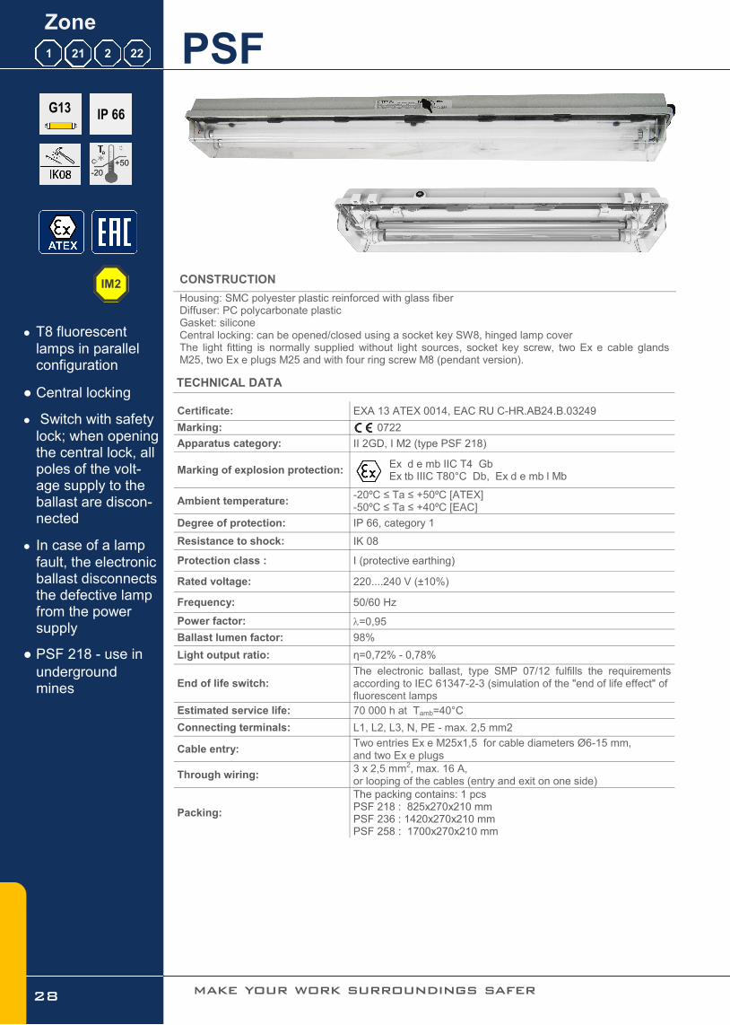
Housing: SMC polyester plastic reinforced with glass fiber Diffuser: PC polycarbonate plastic Gasket: silicone Central locking: can be opened/closed using a socket key SW8, hinged lamp cover The light fitting is normally supplied without light sources, socket key screw, two Ex e cable glands M25, two Ex e plugs M25 and with four ring screw M8 (pendant version).
TECHNICAL DATA
Certificate: EXA 13 ATEX 0014, EAC RU C-HR.AB24.B.03249
Marking: 0722
Apparatus category: II 2GD, I M2 (type PSF 218)
Marking of explosion protection: Ex d e mb IIC T4 Gb Ex tb IIIC T80°C Db, Ex d e mb l Mb
Ambient temperature: -20ºC ≤ Ta ≤ +50ºC [ATEX] -50ºC ≤ Ta ≤ +40ºC [EAC]
Degree of protection: IP 66, category 1
Resistance to shock: IK 08
Protection class : I (protective earthing)
Rated voltage: 220....240 V (±10%)
Frequency: 50/60 Hz
Power factor: =0,95
Ballast lumen factor: 98%
Light output ratio: η=0,72% - 0,78%
End of life switch: The electronic ballast, type SMP 07/12 fulfills the requirements according to IEC 61347-2-3 (simulation of the "end of life effect" of fluorescent lamps
Estimated service life: 70 000 h at Tamb=40°C
Connecting terminals: L1, L2, L3, N, PE - max. 2,5 mm2
Cable entry: Two entries Ex e M25x1,5 for cable diameters Ø6-15 mm, and two Ex e plugs
Through wiring: 3 x 2,5 mm2, max. 16 A, or looping of the cables (entry and exit on one side)
Packing:
The packing contains: 1 pcs PSF 218 : 825x270x210 mm PSF 236 : 1420x270x210 mm PSF 258 : 1700x270x210 mm
28
● T8 fluorescent
lamps in parallel configuration
● Central locking
● Switch with safety
lock; when opening the central lock, all poles of the volt-age supply to the ballast are discon-nected
● In case of a lamp
fault, the electronic ballast disconnects the defective lamp from the power supply
● PSF 218 - use in
underground mines
make your work surroundings safer
G13
IM2

Fluorescent light fitting
www.tepex.hr
MODEL CODE
POLAR CURVE MOUNTING
DIMENSION DRAWING (all dimensions in mm)
Model code Max.
Wattage Lamp type
Nominal voltage
Luminous flux [lm]
Lamp holder
Nominal operational
current Weight
PSF 218 2x18 W
T8 220 - 240 V
2 x 1350
G13
0,18 A 7,5 kg
PSF 236 2x36 W 2 x 3350 0,33 A 10 kg
PSF 258 2x58W 2x 5200 0,5 A 12 kg
Pendant, on pipe, wall, ceiling
200
130
L1
L2
M8
M25
L1 [mm] L2 [mm]
PSF 218 750 400
PSF 236 1370 800
PSF 258 1665 800
SPARE PARTS AND ACCESSORIES
Sketch Description Code Sketch Description Code
Diffuser PSF PSF218 10-120 PSF236 20-120
Ex e cable gland
SPU 25 SPU 25
Gasket PSF PSF218 10-130 PSF236 20-130
Ex e plug M25 SPC 25
Internal reflector with
lamp holder PSF
PSF218 10-140 PSF236 20-140
PSF
Ceiling mounting set
PSF 30-110
El. ballast SMP SMP 07/12
SMP 08 (PSF 258)
PSF Pipe mounting set
PSF 30-120
Terminals 5x2,5mm2 PSF236 20-150 PSF
Wall mounting set PSF 30-130
Socket key SW8 PSF236 20-160 Ring bolt M8 PSF 30-140
29
All technical data is relevant at the time of print.

PSF E Zone
1 21 2 22
IP 66
+40
-20
C
CONSTRUCTION
Housing: SMC polyester plastic reinforced with glass fiber Diffuser: PC polycarbonate plastic Gasket: EPDM formed gasket Central locking: can be opened/closed using a socket key SW8, hinged lamp cover The light fitting is normally supplied without light sources, with socket key, two Ex e cable glands M25, two Ex e plugs M25 and with four ring screw M8 (pendant version).
TECHNICAL DATA
Certificate: EXA 13 ATEX 0014/3
Marking: 0722
Apparatus category: II 2GD
Marking of explosion protection: Ex db eb mb IIC T4 Gb Ex tb IIIC T80°C Db
Ambient temperature: -20ºC ≤ Ta ≤ +40ºC
Degree of protection: IP 66, category 1
Resistance to shock: IK 08
Protection class : I (protective earthing)
Rated voltage: 220....240 V (±10%)
Frequency: 50/60 Hz
Power factor: =0,95
Ballast lumen factor: 98%
Light output ratio: η=0,78%
Battery: Nominal autonomy:
PSF 218E - Ni-Mh Saft VHT D, 4,8V 6Ah PSF 236E - Ni-Mh Saft VHT F, 4,8V 10Ah 1,5 / 3 hours
Connecting terminals: L1, L2, L3, N, PE - max. 2,5 mm2
Cable entry: Two entries Ex e M25x1,5 for cable diameters Ø6-15 mm, and two Ex e plugs
Piktogram: 300x150mm
Packing: The packing contains: 1 pcs PSF 236 : 1420x270x210 mm PSF 218 : 825x270x210 mm
● 1,5 or 3h autono-
my
● Maintained / Non
maintained opera-tion
● Ni-Mh battery
30 make your work surroundings safer
G13

Emergency fluorescent light fitting
www.tepex.hr
MODEL CODE
POLAR CURVE MOUNTING
DIMENSION DRAWING (all dimensions in mm)
Model code Max.
Wattage Lamp type
Nominal voltage
Luminous flux [lm]
Lamp holder
Nominal operational
current Weight
Luminos flux bat. mod [lm]
PSF 218 2x18 W T8
220 - 240 V
2 x 1350 G13
0,18 A 9,0 kg 1,5h 60% (800lm) 3h 40% (550lm)
PSF 236 2x36 W 2 x 3350 0,33 A 12,5 kg 1,5h 60% (2000lm) 3h 30% (1000lm)
Pendant, on pipe, wall, ceiling
200
130
L1
L2
M8
M25
L1 [mm] L2 [mm]
PSF 218 E 750 400
PSF 236 E 1370 800
SPARE PARTS AND ACCESSORIES
31
All technical data is relevant at the time of print.

FLX Zone
1 21 2 22
IP 66
+50
-50
C
CONSTRUCTION
Housing: aluminium, corrosion resistant grey polyurethanes painted Diffuser: borosilicate glass tube Gasket: silicon The light fitting is normally supplied with two light sources, two entries M20 and wall/sealing mounting set.
TECHNICAL DATA
Certificate: CESI 06 ATEX 051-01/09, EAC RU C-HR.AB24.B.03253
Marking: 0722
Apparatus category: II 2GD
Marking of explosion protection: Ex de IIC T5/T6 Gb Ex tD A21 IP66 T95°C/T80°C
Ambient temperature: -20ºC ≤ Ta ≤ +50ºC [ATEX] -50ºC ≤ Ta ≤ +50ºC [EAC]
Degree of protection: IP 66, category 1
Resistance to shock: IK 08
Protection class : I (protective earthing)
Rated voltage: 100 V ÷ 280 V AC/DC
Frequency: 0-60 Hz
Rated power: See model code table
Ballast lumen factor: 98%
Light output ratio: η=0,73%
Connecting terminals: L1, L2, L3, N, PE - max. 2,5 mm2 PE for outside earthing max. 2 x 6 mm2
Cable entry:
2 x M20 2 x 3/4"NPT 2 x M20, with one Ex d plugs and one adapter type ADP 03/24,
for cable 6-15 mm
Through wiring: With two Ex de adapter ADP 03/24 - 4 x 2,5 mm2, max. 16 A,
Energy classification EEI: A2
Electromagnetic compatibility:
in conformity with the EMC Directive 2004/108 EC and harmonized standards EN 55015+A1+A2, EN 61547 , EN 61000-3-2+A1, EN 61000-3-3
32
● TC-L fluorescent
compact lamps
● 100÷280V AC/DC
● 0-60 Hz
make your work surroundings safer
2G11

Fluorescent light fitting
www.tepex.hr
MODEL CODE
POLAR CURVE DIMENSION DRAWING (all dimensions in mm)
MOUNTING
Model code Max.
Wattage Lamp type
Nominal voltage
Luminous flux [lm]
Lamp holder
A B Weight
FLX 218 2x18 W
TC-L 100-280 V
2 x 1200
2G11
330 215 3,3 kg
FLX 236 2x36 W 2 x 2900 520 405 5,8 kg
645 530 FLX 255 2x55 W 2 x 4700 8,4 kg
12
B
12
15
13
177
140 80 A
Pendant, on pipe, wall, ceiling mounting. Operates in any position.
33
All technical data is relevant at the time of print.

FLX 1 2 22
SPARE PARTS AND ACCESSORIES
Sketch Description Code Sketch Description Code
Cover gasket FLX FLX 10-120 Ex d cable gland
SPU 20 SPU 20
Base plate FLX/... FLX 10-130 Ex d plug M20 SPC 20
Protective grid FLX
set FLX 20-140
FLX Wall / ceiling mounting set
FLX 20-170
External reflector
FLX FLX 20-150
FLX Pipe mounting set
FLX 20-180
Adapter ADP 23 FLX 10-160
Zone
1 21 2 22
34 make your work surroundings safer

Fluorescent light fitting
www.tepex.hr 35

Certificate: EXA 15 ATEX 0001X EAC RU C-HR.AB24.B.03252
Marking: 0722
Apparatus category: II 2G II 2D
Marking of explosion protection: Ex d e IIC T6 Gb Ex tb IIIC T80°C Db
Ambient temperature: -20ºC ≤ Ta ≤ +40ºC /+50ºC
Degree of protection: IP 66 category 1
Resistance to shock: IK 08
Protection class : I (protective earthing)
Rated voltage: 220-240 V 110V on request
Frequency: 50Hz / 60Hz
Rated power: 2x 1,2W
Connecting terminals: L1, L2, L3, N; max. 2 x 2,5 mm2 PE terminal ; max 2x6mm2 External PA terminal -PA; max 2x6mm2
Cable entry: 2 x M20 or 2 x 3/4"NPT or 2 x M20, with one Ex d plugs and one
adapter type ADP 03/24 for cable 6-15 mm
Weight: 4kg
Housing: aluminium powder painted casting Diffuser: borosilicate glass tube, Gasket: silicon The light fitting is normally supplied with two entries M20 and wall/sealing mounting set
36
FLXE 118 LED
CONSTRUCTION
TECHNICAL DATA
● Used for marking
escape routes and exits in potentially explosive atmos-pheres.
● Self-test, monitor-
ing and diagnostics reduce costly maintenance checks.
● >3h autonomy
● Maintained / Non
maintained opera-tion
● Possibility of sup-
plies with DALI compatible ballast
● Ni-MH 3,6V/2.2Ah,
build in light fitting, microprocessor controlled charg-ing, discharging and control of bat-tery
Zone
1 21 2 22
MOUNTING
IP 66
+50
-20
C
Pendant, on pipe, wall, ceiling mounting . Operates in any position.
make your work surroundings safer

www.tepex.hr 37
SKETCH DESCRIPTION CODE SKETCH DESCRIPTION CODE
Cover gasket FLX FLX 10-120 External reflector
FLX
FLX LED 20-150
Base plate FLXE FLXE 10-130
FLX Wall / ceiling mounting set
FLX 20-170
Protective grid
FLXE set
FLXE 20-140 FLX
Pipe mounting set FLX 20-180
MODEL CODE
SPARE PARTS AND ACCESSORIES
ISOCANDELA CURVE [l/cd] DIMENSION DRAWING
Emergency LED light fitting
180±0,5
160±0,512240±1 220±1
O13
330
The lamp can operate with two types of connection: a) Maintained (Dauerschaltung) The light fitting can be used for gen-eral and orientation lighting with mains power supply via L' (installation switch). In case of voltage drop or an interruption in the mains power supply L, the light fitting will continue to oper-ate in battery-powered mode, regard-less of the status of installation switch L' (ON/OFF). b) Non maintained (Bereitschaftschaltung) In case of voltage drop or an interrup-tion in the mains power supply L, the light fitting will operate only in battery-powered mode. In both types of the connection in the presence of continuous phase L, it is possible to verify the correctness of the emergency system by turning on the switch in the TEST circuit.
All technical data is relevant at the time of print.

SIF Zone
1 21 2 22
IP 66
+50
-30
C
CONSTRUCTION
Housing: Epoxi/polyester powder-coated sheet steel Diffuser: flat borosilicate glass with a high thermal and mechanical stability Gasket: EPDM formed gasket All-pole are disconnected via NC switch when glass cover is opened. The light fitting is normally supplied without light sources, two Ex e cable glands M25, one Ex e plug M25 and with two ring screw M8 (pendant version). TECHNICAL DATA
Certificate: EXA 13 ATEX 0015
Marking: 0722
Apparatus category: II 2GD
Marking of explosion protection: Ex d e mb IIC T4 Gb Ex tb IIIC T80°C Db
Ambient temperature: -30ºC ≤ Ta ≤ +50ºC
Degree of protection: IP 66, category 1
Resistance to shock: IK 08
Protection class : I (protective earthing)
Rated voltage: 220....240 V (±10%)
Frequency: 50/60 Hz
Power factor: =0,95
Ballast lumen factor: 98%
Light output ratio: η=0,72%
End of life switch: The electronic ballast, type SMP 07/12 fulfills the requirements according to IEC 61347-2-3 (simulation of the "end of life effect" of fluorescent lamps
Estimated service life: 70 000 h at Tamb=40°C
Connecting terminals: L1, L2, L3, N, PE - max. 2,5 mm2
Cable entry: Two entries Ex e M25x1,5 for cable diameters Ø6-15 mm, and two Ex e plugs
Through wiring: 5x terminals 4x4 mm2, max. 16 A, or looping of the cables (entry and exit on one side)
Disconnection of the light:
Switch with safety lock; when opening the central lock, all poles of the voltage supply to the ballast are disconnected; contacts of the switching element are NC contacts, they can only be switched on again when the lamp cover are closed. In case of a lamp fault, the electronic ballast disconnects the defective lamp from the power supply.
Packing: The packing contains: 1 pcs 142X415X140 mm
38
● T8 fluorescent
lamps in parallel configuration
● Switch with safety
lock; when opening the central lock, all poles of the volt-age supply to the ballast are discon-nected
● In case of a lamp
fault, the electronic ballast disconnects the defective lamp from the power supply
● Recessed mount-
ing set for clear rooms
make your work surroundings safer
G13

Fluorescent light fitting
www.tepex.hr
MODEL CODE
POLAR CURVE RECESSED LIGHT FITTING
MOUNTING (Pendant, wall/ceiling mounting, recessed )
SPARE PARTS AND ACCESSORIES
Sketch Description Code Sketch Description Code
Gasket SIF SIF 10-130 Ex e cable gland
SPU 25 SPU 25
El. ballast SMP
07/12 SMP 06/12 Ex e plug M25 SPC 25
Ring bolt M8 -
Model code Max.
Wattage Lamp type
Nominal voltage
Luminous flux [lm]
Lamp holder
Nominal operational
current Weight
SIF 236 2x36 W T8 220 - 240 V
2 x 3350 G13
0,18 A 25 kg
SIF 436 4x36 W 4 x 3350 0,33 A 27 kg
MOUNTING (Pendant, wall/ceiling mounting, recessed )
39
All technical data is relevant at the time of print.

Certificate: EXA 16 ATEX 0015
Marking: 0722
Apparatus category: II 2G II 2D
Marking of explosion protection: Ex eb mb IIC T6 Gb
Ex tb IIIC T80C Db
Ambient temperature: -30ºC ≤ Ta ≤ +50ºC
Degree of protection: IP 66 category 1
Resistance to shock: IK 08
Protection class : I (protective earthing)
Rated voltage: 230 V
Frequency: 50Hz (60Hz on request)
Rated power: 20 W
Connecting terminals: terminals L1 + N for 2 x 4 mm² terminals PE for 2 x 4 mm²
Cable entry: 2x M25 (1x M25 Exe cable gland, 1x Exe M25 plug)
Weight: 4 kg
Packing: The packing contains: 1 pcs 360x240x205 mm
Housing: aluminium powder painted casting Diffuser: borosilicate glass, silicone gasket Protected grid: AISI 316 Standard version without protected grid
0403.24 LED20
CONSTRUCTION
TECHNICAL DATA
● Application in con-
fined or restricted spaces
● Robust light alloy
enclosure weighs only 4 kg
● Allowing the user
to mount in areas where the availa-ble space is re-stricted
● Fast and easy in-
stallation
● Estimated service
life 70 000 hours
Zone
1 21 2 22
MOUNTING
IP 66
+50
-30
C
Two brackets with two screws M6
40 make your work surroundings safer

MODEL CODE LED power [W] VOLTAGE [V] LUMINOUS FLUX
[lm]
LIGHT OUTPUT
RATIO
0403.24 LED 20-1 20W 230V 2000 0,80
SKETCH DESCRIPTION CODE SKETCH DESCRIPTION CODE
LEDEx 01 modul 0403.24 LED 10-
110
Ex e cable gland M25
SPU 25
Gasket 0403.24 LED 0403.24 LED
10-120
Ex e plug M25 SPC 25
Glass cover 0403.24 LED
10-130 Bracket for wall
0403.24 LED
10-160
Protective grid 0403.24 LED
20-120
Bracket for pipe R2”
0403.24 LED
10-170
MODEL CODE
SPARE PARTS AND ACCESSORIES
POLAR CURVE DIMENSION DRAWING (all dimensions in mm)
Bulkhead LED light fitting
www.tepex.hr
LED A - incandescent light bulb
0403.24 LED 20 20W
100 lm/W
0403.24/10
100W 15 lm/W
Example of equivalent "traditional" light sources with Ex LED
The given information is for rough orientation only. In each individual case a lighting calculation is necessary.
41
All technical data is relevant at the time of print.

Certificate: EXA 14 ATEX 0056X
Marking: 0722
Apparatus category: II 2G II 2D
Marking of explosion protection: Ex d e IIC T6 Gb
Ex tb IIIC T80C Db
Ambient temperature: -20ºC ≤ Ta ≤ +40ºC
Degree of protection: IP 66 category 1
Resistance to shock: IK 08
Protection class : I (protective earthing)
Rated voltage: 230 V
Frequency: 50Hz (60Hz on request)
Rated power: 12W, 20 W
Connecting terminals: terminals L1 + N for 2 x 4 mm² terminals PE for 2 x 4 mm²
Cable entry: 2x M20 (1x M20 Ex de adapter ADP 23/1 for cable 7-15mm, 1x Exd M20 plug)
Weight: 3,5 kg
Packing: The packing contains: 2 pcs 440x260x170mm
Housing: aluminium powder painted casting Diffuser: borosilicate glass Accessories: protected galvanized steel gird (INOX on request), assembly kit for wall, pipe and ceiling mounting Standard version without protected grid
PLFM LED
CONSTRUCTION
TECHNICAL DATA
● Robust light alloy
enclosure weighs only 3,5 kg
● Fast and easy in-
stallation
● PLFM 100/3 with
E27 lampholder for LED bulb
● Estimated service
life for LED module 20W ~ 70 000 h
● LED module with
100lm/W
Zone
1 21 2 22
MOUNTING
IP 66
+40
-20
C
Pendant, on pipe, wall, ceiling
42 make your work surroundings safer

MODEL CODE LED power [W] VOLTAGE [V] LUMINOUS FLUX
[lm]
LIGHT OUTPUT
RATIO
PLFM 100/3-. 12 W Osram 13 W Philips
810 1055
0,80 230V
PLFM 20 LED LED module 2000
SKETCH DESCRIPTION CODE SKETCH DESCRIPTION CODE
Replacement glass
PLFM PLFM 10-120
Ex d metal plug M20
SPC 20
Wire guard PLFM PLFM 10-130 LED bulb E27 prema tablici
izvedbi
Gasket PLFM PLFM 10-140
PLFM mounting bracket for pipe
R2” PLFM 20-120
PLFM LED modul,
set PLFM 10-170
PLFM mounting bracket (ceiling)
PLFM 20-130
Adapter ADP 23/1 PLFM 20-110 PLFM mounting
bracket (wall) PLFM 20-140
MODEL CODE
SPARE PARTS AND ACCESSORIES
POLAR CURVE DIMENSION DRAWING
Pendant LED light fitting
www.tepex.hr
Example of equivalent "traditional" light sources with Ex LED
LED module 20W, 2000 lm
Master LEDbulb Osram 12W, 810 lm
The given information is for rough orientation only. In each individual case a lighting calculation is necessary.
LED QT (halogen) CFL (compact fluo)
PLFM 20 LED
17W 100 lm/W
PLFM 100 QT
100W 18 lm/W
PLFM 100/2
23W
65 lm/W
43
All technical data is relevant at the time of print.

Certificate: In progress
Marking: 0722
Apparatus category: II 2G II 2D
Marking of explosion protection: Ex d e IIC T6 Gb Ex tb IIIC T80°C Db
Ambient temperature: -20ºC ≤ Ta ≤ +40ºC
Degree of protection: IP 66 category 1
Resistance to shock: IK 08
Protection class : I (protective earthing)
Rated voltage: 230 V
Frequency: 50Hz (60Hz on request)
Rated power: 30 W
Connecting terminals: terminals L1 + N for 2 x 4 mm² terminals PE for 2 x 4 mm²
Cable entry: 2x M25 (1x M25 Ex e cable gland for cable 7-15mm, 1x Exe M25 plug)
Weight: 3,8 kg
Housing: aluminium powder painted casting Diffuser: borosilicate glass, Accessories: assembly kit for wall, pipe and ceiling mounting
0401.35 LED 30
CONSTRUCTION
TECHNICAL DATA
● Robust light alloy
enclosure weighs only 3,8 kg
● Estimated service
life 70 000 hours
● LED module with
100lm/W
Zone
1 21 2 22
MOUNTING
IP 66
+40
-20
C
Pendant, on pipe, wall, ceiling
44 make your work surroundings safer

MODEL CODE LED power [W] VOLTAGE [V] LUMINOUS FLUX
[lm]
LIGHT OUTPUT
RATIO
0401.35 LED 30 30 W 230V 2850 0,84
SKETCH DESCRIPTION CODE SKETCH DESCRIPTION CODE
Replacement glass 0401.35
LED
0401.35 LED 10-130 Ex e cable gland
M25 SPU 25
LED module 30W 0401.35 LED 10-110 Gasket 0401.35 0401.35 LED
10-120
MODEL CODE
SPARE PARTS AND ACCESSORIES
POLAR CURVE DIMENSION DRAWING
Pendant LED light fitting
www.tepex.hr
Example of equivalent "traditional" light sources with Ex LED
LED module 30W, 2850 lm
The given information is for rough orientation only. In each individual case a lighting calculation is necessary.
LED HME (mercury) HIE (metal halide) QT (halogen)
0401.35 LED 30 30W
95 lm/W
PLFS-T
80W 50 lm/W
PLFS-T 100
70W
80 lm/W
PLFS-T 200
230W
18 lm/W
45
All technical data is relevant at the time of print.
248±1
246±1
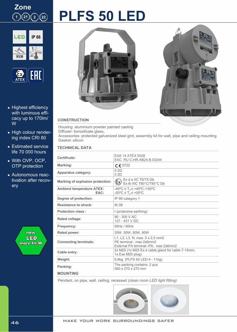
Certificate: EXA 14 ATEX 0028 EAC RU C-HR.AB24.B.03244
Marking: 0722
Apparatus category: II 2G II 2D
Marking of explosion protection: Ex d e IIC T6/T5 Gb Ex tb IIIC T80°C/T85°C Db
Ambient temperature ATEX: EAC:
-40ºC ≤ Ta ≤ +40ºC /+50ºC -50ºC ≤ Ta ≤ +50ºC
Degree of protection: IP 66 category 1
Resistance to shock: IK 08
Protection class : I (protective earthing)
Rated voltage: 90 - 305 V AC 127 - 431 V DC
Frequency: 50Hz / 60Hz
Rated power: 35W, 50W, 60W, 80W
Connecting terminals: L1, L2, L3, N; max. 2 x 2,5 mm2 PE terminal ; max 2x6mm2 External PA terminal -PA; max 2x6mm2
Cable entry: 2x M25 (1x M25 Ex e cable gland for cable 7-15mm, 1x Exe M25 plug)
Weight: 6,8kg (PLFS 50 LED-4 - 11kg)
Packing: The packing contains: 2 pcs 560 x 270 x 270 mm
Housing: aluminium powder painted casting Diffuser: borosilicate glass, Accessories: protected galvanized steel gird, assembly kit for wall, pipe and ceiling mounting Gasket: silicon
PLFS 50 LED
CONSTRUCTION
TECHNICAL DATA
● Highest efficiency
with luminous effi-cacy up to 170lm/W
● High colour render-
ing index CRI 80
● Estimated service
life 70 000 hours
● With OVP, OCP,
OTP protection
● Autonomous reac-
tivation after recov-ery
Zone
1 21 2 22
MOUNTING
IP 66
+50
-40
C
Pendant, on pipe, wall, ceiling, recessed (clean room LED light fitting)
46 make your work surroundings safer

MODEL CODE LED power [W] VOLTAGE [V] LUMINOUS FLUX [lm]
LIGHT OUTPUT
RATIO AMBIENT TEMP.
PLFS 50 LED-1 35 W
90-305 V AC 127-431 V DC
5950 -40C ÷ +50C
0,80 PLFS 50 LED-2 50 W 8500
PLFS 50 LED-3 60 W 10 200 40C ÷ +40°C
PLFS 50 LED-4 80 W 13 600
SKETCH DESCRIPTION CODE SKETCH DESCRIPTION CODE
Replacement
glass PLFS LED PLFS LED
10-120
PLFS-T fixing bracket for tube
R 1 1/2“ PLFS 20-120
Wire guard PLFS
LED
PLFS LED 10-130
PLFS-T mounting bracket (ceiling and
wall mounting) PLFS 20-130
MODEL CODE
SPARE PARTS AND ACCESSORIES
POLAR CURVE DIMENSION DRAWING
Pendant LED light fitting
www.tepex.hr
Example of equivalent "traditional" light sources with Ex LED
The given information is for rough orientation only. In each individual case a lighting calculation is necessary.
WARNING - DO NOT OPEN WHEN ENERGIZED
P - AZ -
HR - 10090 ZAGREB
II 2G Ex de IIC T6 Gb -20°ta +50°C
II 2D Ex tb IIIC T80°C Db IP 66
PLFS-T/LED HREx ATEX T 13.099
90-305 VAC, 127-431 VDC 50 W max.
xxx
PLFS 50 LED-1, -2, -3 PLFS 50 LED-4
LED HME (mercury)) HIE (metal halide) QT (halogen) / A
PLFS 50 LED-1
35W 170 lm/W
PLFS-T 125
125W 50 lm/W
PLFS-T 100
100W
80 lm/W
PLFS-T 200
230W QT
18 lm/W
PLFS 50 LED-3
60W 170 lm/W
PLFL 250 HME
250W 52 lm/W
PLFS-T 150 HIE
150W
80 lm/W
PLFL 500
500W A
15 lm/W
PLFS 50 LED-4
80W 170 lm/W
PLFL 400 HME
400W 50 lm/W
PLFL 250 HIE
250W
80 lm/W
47
All technical data is relevant at the time of print.

Certificate: EXA 15 ATEX 0050X
Marking: 0722
Apparatus category: II 2G II 2D
Marking of explosion protection: Ex d e IIC T6 Gb Ex tb IIIC T80°C Db
Ambient temperature: -20ºC ≤ Ta ≤ +40ºC /+50ºC
Degree of protection: IP 66 category 1
Resistance to shock: IK 08
Protection class : I (protective earthing)
Rated voltage: 220-240 V 110V on request
Frequency: 50Hz / 60Hz
Rated power: 3x 12W
Connecting terminals: L1, L2, L3, N; max. 2 x 2,5 mm2 PE terminal ; max 2x6mm2 External PA terminal -PA; max 2x6mm2
Cable entry: 2 x M20 or 2 x 3/4"NPT or 2 x M20, with one Ex d plugs and one
adapter type ADP 03/24 for cable 6-15 mm
Weight: 7kg
Packing: The packing contains: 1 pcs 540x230x200 mm
Housing: aluminium powder painted casting Diffuser: borosilicate glass tube, Gasket: silicon The light fitting is normally supplied with three LED linear sources, two entries M20 and wall/sealing mounting set
FLX 310 LED
CONSTRUCTION
TECHNICAL DATA
● High colour render-
ing index CRI >80
● Estimated service
life ≥50 000 work-ing hours at tamb = 40°C
● LED 3 x 12W chip
-on-board technol-ogy with OVP, OCP, OTP protec-tion
● Autonomous acti-
vation after recov-ery
● Suitable for linear
lighting up to 20 modules
Zone
1 21 2 22
MOUNTING
IP 66
+50
-20
C
Pendant, on pipe, wall, ceiling mounting . Operates in any position.
48 make your work surroundings safer

MODEL CODE LED power [W] VOLTAGE [V] LUMINOUS FLUX [lm]
LIGHT OUTPUT
RATIO AMBIENT TEMP.
FLX 310 LED 36W 220-240V 3600 0,85 -20C ÷ +40C
SKETCH DESCRIPTION CODE SKETCH DESCRIPTION CODE
Cover gasket FLX FLX1 0-120 External reflector
FLX
FLX LED 20-150
LED module FLX
310 FLX LED10-310
FLX Wall / ceiling mounting set
FLX 20-170
Protective grid
FLX set
FLX LED 20-140 FLX
Pipe mounting set FLX 20-180
MODEL CODE
SPARE PARTS AND ACCESSORIES
POLAR CURVE DIMENSION DRAWING
Linear LED light fitting
www.tepex.hr 49
All technical data is relevant at the time of print.

Certificate: In progress
Marking: 0722
Apparatus category: II 2G II 2D
Marking of explosion protection: Ex db eb mb IIC T6 Gb
Ex tb IIIC T80C Db
Ambient temperature: -20ºC ≤ Ta ≤ +55ºC -20ºC ≤ Ta ≤ +40ºC
Degree of protection: IP 66 category 1
Resistance to shock: IK 08
Protection class : I (protective earthing)
Rated voltage: 100-240 VAC 220-250VDC
Frequency: 50-60 Hz
Rated power: See model code table
Estimated service life: PSF 28 LED-1, PSF 52 LED-1 ..... 60 000 hours PSF 28 LED-2, PSF 52 LED-2 ..... 70 000 hours
Connecting terminals: L1, L2, L3, N, PE - max. 2,5 mm2
Cable entry: Two entries Ex e M25x1,5 for cable diameters Ø6-15 mm, and two Ex e plugs
Disconnection of the light:
Switch with safety lock; when opening the central lock, all poles of the voltage supply to the ballast are disconnected; contacts of the switching element are NC contacts, they can only be switched on again when the lamp cover and the central locking system are closed. In case of a lamp fault, the electronic ballast disconnects the defective lamp from the power supply.
Packing: The packing contains: 1 pcs PSF 52 LED: 1420x270x210 mm PSF 28 LED: 825x270x210 mm
Housing: SMC polyester plastic reinforced with glass fiber, color RAL 7038 Diffuser: PC polycarbonate plastic Gasket: silicone Central locking: can be opened/closed using a socket key SW8, hinged lamp cover The light fitting is normally supplied with socket key, two Ex e cable glands M25, two Ex e plugs M25 and with mounting set PSF 30-110
PSF LED
CONSTRUCTION
TECHNICAL DATA
● Central locking
with internal switch
● Through-wiring
possible
● LED modules with
innovative encap-sulation
● Estimated service
life up to 70 000 hours
● High color render-
ing index CRI 80
● Luminous efficacy
154lm/W
● With OVP, OCP,
OTP protection
● Autonomous reac-
tivation after recov-ery
Zone
1 21 2 22
MOUNTING
Pendant, on pipe, wall, ceiling
50 make your work surroundings safer
IP 66
+50
-20
C

MODEL CODE LED power [W] VOLTAGE
[V] LUMINOUS FLUX [lm]
LIGHT OUT-PUT
RATIO AMBIENT TEMP. WEIGHT
PSF 28 LED-1 26 W 110-240VAC 220-250VDC
4700 lm
0,84 -20ºC ≤ Ta ≤ +55ºC 7,0 kg
PSF 52 LED-1 48 W 7400 lm 10,0 kg
MODEL CODE
SPARE PARTS AND ACCESSORIES
POLAR CURVE DIMENSION DRAWING (all dimensions in mm)
Linear LED light fitting
www.tepex.hr
200
130
L1
L2
M8
M25
TYPE L1
[mm] L2
[mm]
PSF LED 28-1 PSF LED 28-2
750 400
PSF LED 52-1 PSF LED 52-2
1370 800
SKETCH DESCRIPTION CODE SKETCH DESCRIPTION CODE
Diffuser PSF PSF LED 28 10-120 PSF LED 52 20-120
Ex e cable gland
SPU 25 SPU 25
Gasket PSF PSF LED 28 10-130 PSF LED 52 20-130
Ex e plug M25 SPC 25
Internal reflector with LED module
PSF LED 28 10-140 PSF LED 52 20-140
PSF
Ceiling mounting set
PSF 30-110
LED driver PSF LED 28 drive PSF LED 52 drive
PSF
Pipe mounting set PSF 30-120
Terminals 5x2,5mm2 PSF236 20-150
PSF Wall mounting set
PSF 30-130
Socket key SW8 PSF236 20-160 Ring bolt M8 PSF 30-140
PSF 28 LED-2 34 W 110-240VAC 220-250VDC
5650 lm
0,84 7,0 kg
-20ºC ≤ Ta ≤ +40ºC PSF 52 LED-2
64 W 9150 lm 10,0 kg
Special types for the ambient temperature -20ºC ≤ Ta ≤ +40ºC and higher LED power .
51
λ = 84%
All technical data is relevant at the time of print.

NOTES

Installation equipment

Certificate: EXA 15 ATEX 0006X
Marking: 0722
Apparatus category: II 2G
Marking of explosion protection: Ex d e IIC T6 Gb
Ambient temperature ATEX: -20ºC ≤ Ta ≤ +40/+50ºC
Degree of protection: IP 66 category 1
Resistance to shock: IK 08
Protection class : I (protective earthing)
Rated isolating voltage: 690 V
Thermal current Ithe : 16 A for -20°C ≤ Ta ≤ +40°C 15 A for -20°C ≤ Ta ≤ +50°C
PE terminals (inside of the enclosure):
max. 2x4 mm2+2x2,5 mm2 , 3x4 mm2 , 2x6 mm2
Weight: App. 0,6kg
Enclosure: polyester plastic reinforced with glass fiber, color - black Cover: with integrated thermoplastic elastomer gasket, closes with four M5 stainless steel screws.
SKX SW
CONSTRUCTION
TECHNICAL DATA
● Enclosure made of
glass-fibre rein-forced polyester resin
● 2 pole OFF switch
or changeover switch
Zone
IP 66
+50
-20
C
1 2
54 make your work surroundings safer

MODEL CODE
Installation switch
www.tepex.hr
DIMENSION MOUNTING
100
75
75
100
128±2
81
111±1
75
50
8
6
6
8
6
WIRING DIAGRAM
ON-OFF switch 1 pole
ON-OFF switch 2 pole
Changeover switch
Installation switches SKX - SW / .
basic type code
type of switches 1 - on-off switch 1 pole 2 - on-off switch 2 pole 6 - changeover switch
Switching capacity Rated operating voltage Ue Rated operating current Ie
AC 5a 230 V 16 A for -20°C ≤ Ta ≤ +40°C 15 A for -20°C ≤ Ta ≤ +50°C
AC 5b 230 V 16 A for -20°C ≤ Ta ≤ +40°C 15 A for -20°C ≤ Ta ≤ +50°C
AC 1 500 V 16 A for -20°C ≤ Ta ≤ +40°C 15 A for -20°C ≤ Ta ≤ +50°C
AC 15 250 V 500 V
6 A for -20°C ≤ Ta ≤ +50°C 4 A for -20°C ≤ Ta ≤ +50°C
DC 13 24 V 60 V
110 V
6 A for -20°C ≤ Ta ≤ +50°C 0,8 A for -20°C ≤ Ta ≤ +50°C 0,5 A for -20°C ≤ Ta ≤ +50°C
55
All technical data is relevant at the time of print.

Certificate: CESI 10 ATEX 040 , RU C-HR.AB24.B.03290
Marking: 0722
Apparatus category: II 2G II 2D
Marking of explosion protection: Ex e II T6 Ex ia/ib IIC T6 Ex tD A21 T80°C
Ambient temperature ATEX: EAC:
-20ºC ≤ Ta ≤ +50ºC, -20ºC ≤ Ta ≤ +70ºC for Exi -50ºC ≤ Ta ≤ +50ºC
Degree of protection: IP 66 category 1
Resistance to shock: IK 08
Protection class : I (protective earthing)
Rated voltage: 630 V
Maximum voltage for Ex i: 60 V
Maximum current of terminals :
Cable entries, cable glands and screw plugs:
6 x M25 for cable 6-15 mm (13-19 mm available on request)
6 x M32 for cable 12-21 mm (17-25 mm available on request)
4 x M25 for cable 6-15 mm (13-19 mm available on request)
4 x M32 for cable 12-21 mm (17-25 mm available on request)
PE terminals (inside of the enclosure):
max. 2x4 mm2+2x2,5 mm2 , 3x4 mm2 , 2x6 mm2
Weight: 0,55 kg
Packing: The packing contains: 14 pcs 435x260x220 mm
Enclosure: PA glass fiber reinforced polyamide, color - black Cover: PA glass fiber reinforced polyamide with integrated thermoplastic elastomer gasket, closes with four M5 stainless steel screws.
RK
CONSTRUCTION
TECHNICAL DATA
● Enclosures made
of PA glass fiber reinforced polyam-ide
● The cover screws
and all other exter-nal metal parts are made of stainless steel (AISI 316L)
● Equipped with ter-
minals up to 6mm2
● Pillar (mantle) ter-
minals
Zone
IP 66
+50
-40
C
1 21 2 22
MOUNTING
With two screws through the housing holes 6 mm at the peaks the rectangle: 100 x 75 mm
56 make your work surroundings safer

MODEL CODE
Junction box
www.tepex.hr
DIMENSION
TYPE DESIGN CABLE GLANDS NUMBER
OF TERMINALS MAX. CAPACITY PER TERMINAL
RK 01/514
cable glands 4xM25 for cable
6-15mm, 2xM25
screw plug
5 - 1 x 4mm2
(L1, L2, L3, N, PE)
1x0,5....4mm2 2x0,5....2,5mm2
RK01/514 Ex i
5 - 1 x 4mm2
(Blue 1-5)
RK 01/516 5 - 1 x 6mm2
(L1, L2, L3, N, PE) 1x1,5....6mm2 2x1,5....4mm2
RK 01/544
cable glands 4xM25 for cable
6-15mm
5 - 4 x 4mm2
4x4mm2
6x2,5mm2
1x4mm2 + 2x2,5mm2+
+3x1,5mm2
1x4mm2 + 5x1,5mm2
2x4mm2 + 3x2,5mm2
RK 01/744 7 - 4 x 4mm2
cable glands 6xM25 for cable
6-15mm
RK 01/544-E
2 x M32 cable glands for armoured cable Øv23-
32mm 4 x M25 cable glands for
armoured cable Øv17-23mm
5 - 4x 4mm2
Other configuration available on request
115
115
180
185
43
O6
75
100
64
II 2D Ex A21 IP66 T80°CII 2G Ex e II T6
WARNINGDO NOT OPEN WHEN ENERGIZED
HR - 10090 Zagreb 0722
RK/054 Ui=690V CESI 09 ATEX ...
P- AZ-
57
All technical data is relevant at the time of print.

Certificate: EXA 13 ATEX 0003U/1, lECEx EXA 16.0002U
Marking: 0722
Apparatus category: II 2G II 2D
Marking of explosion protection: Ex d IIC Gb Ex tb IIIC Db
Ambient temperature: -20ºC ≤ Ta ≤ +60ºC
Service temperature: -20ºC ≤ Ta ≤ +80ºC
Degree of protection: IP 66 category 1
Resistance to shock: IK 08
Protection class : I (protective earthing)
External earthing terminal: max. 2 x 6 mm2
Weight: 0,95 kg
Enclosure: corrosion resistant grey polyurethanes painted aluminium color RAL 7000 Gasket: Silicon
JBX
CONSTRUCTION
TECHNICAL DATA
● Ex d enclosure
made of saltwater-resistant, copper-free aluminium cast alloy
● In terminal box ver-
sions standard ca-ble glands without compund can be used
Zone
IP 66
+50
-40
C
1 21 2 22
MOUNTING
With two screws M6 x 20mm on distance 123 mm
58 make your work surroundings safer

MODEL CODE
Junction box
www.tepex.hr
DIMENSION
TYPE No. of entries/side Entries
JBX 01/11 2 / B-D
M20x1,5 - ISO 261 JBX 01/12 3 / B-C-D
JBX 01/13 4 / A-B-C-D
JBX 01/31 2 / B-D 3/4” - NPT -
ANSI ASME B1.20.1 JBX 01/32 3 / B-C-D
JBX 01/33 4 / A-B-C-D
JBX 01/41 2 / B-D 1/2” - NPT -
ANSI ASME B1.20.1 JBX 01/42 3 / B-C-D
JBX 01/43 4 / A-B-C-D
118
87
87
7
98
59
All technical data is relevant at the time of print.

Certificate: EXA 15 ATEX 0044, EXA 16 ATEX 0047 EAC RU C-HR.AB24.B.03292
Marking: 0722
Apparatus category: II 2G II 2D
Marking of explosion protection:
Ex eb llC TG Gb Ex ia/ib llC TO Gb Ex eb ia/ib llC T6 cb Ex tb lllC T80'C Db
Ambient temperature ATEX: EAC:
-20ºC ≤ Ta ≤ +50ºC -50ºC ≤ Ta ≤ +50ºC
Degree of protection: IP 66 category 1
Resistance to shock: IK 08
Protection class : I (protective earthing)
Rated voltage: 630 V
Nominal current: Up to 125 A (depend on size and number of terminals)
Maximum safe voltage Um for intrinsically safe circuits Exi:
60 V
Cable entries, cable glands and screw plugs:
6 x M25 for cable f6-15 mm (f13-19 mm available on request) 6 x M32 for cable f12-21 mm (f17-25 mm available on request) 4 x M25 for cable f6-15 mm (f13-19 mm available on request) 4 x M32 for cable f12-21 mm (f17-25 mm available on request)
PE terminals (inside of the enclosure):
max. 2x4 mm2+2x2,5 mm2 , 3x4 mm2 , 2x6 mm2
N/PE rails inside the enclosure: 2 pcs, 11 terminals 2x4mm2 max.
Weight (without cable glands):
SKX 12/E ..... 0.5kg SKX 13/E ..... 0,7kg SKX 14/E ..... 1.0kg SKX 15/E ..... 1.0 - 1,5kg SKX 16/E ..... 3,5kg SKX 18/E ..... 4,5kg SKX 20/E ..... 7,0kg
Enclosure: SMC glass fiber reinforced polyamide, color - black Cover: SMC glass fiber reinforced polyamide with integrated thermoplastic elastomer gas-ket, closes with four M5/M6 stainless steel screws.
SKX ../E
CONSTRUCTION
TECHNICAL DATA
● Enclosures in
shock-resistant glass fibre rein-forced polyester resin
● 7 basic enclosure
sizes
● Fitted according to
the customer's re-quirements
Zone
IP 66
+50
-20
C
1 21 2 22
MOUNTING
With two/four screws through the housing holes 6 mm at the peaks the rectangle: SKX 12: 75 x 50 mm SKX 13: 75 x 100 mm SKX 14: 75 x 150 mm SKX 15: 125 x 150 mm
SKX 16: 235 x 200 mm SKX 18: 380 x 200 mm SKX 20: 580 x 200 mm
60 make your work surroundings safer

Terminal box SKX 12/E
Terminal box
www.tepex.hr
Max. number of mounted cable entries:
Side
Cable gland
M16 M20 M25
A-C 2 2 1
B-D 1 1 1
D
Terminal box SKX 13/E
Max. number of mounted cable entries:
Side
Cable gland
M16 M20 M25
A-C 2 2 1
B-D 4 3 2
A
B
C
D
Terminal box SKX 14/E
Max. number of mounted cable entries:
Side
Cable gland
M16 M20 M25 M32
A-C 2 2 1 1
B-D 6 4 3 2
A
B
C
D
A
B
C
61
All technical data is relevant at the time of print.
Nominal cross-section of conductor / terminal [mm2]
Max. number of terminals
Max.ambient
temp Ta C Imax [A]
4/4
40 20
5 50 18
55 17
Nominal cross-section of conductor / terminal [mm2]
Max. number of terminals
Max.ambient
temp Ta C Imax [A]
4/4 8
40 19
50 17
55 16
6/6
40 25
8 50 17
55 16
Nominal cross-section of conductor / terminal [mm2]
Max. number of terminals
Max.ambient
temp Ta C Imax [A]
4/4 16
40 20
50 18
55 16
6/6
40 25
16 50 22
55 19

SKX ../E Zone
1 21 2 22
Terminal box SKX 15/E
Table of permitted combinations of conductors on the principle of maximum rated losses (ambient temperature Ta 40°C)
The maximum number of terminals specified by the
measures of the terminal boxes
24 + busbar 22PE
24 16 14 12 8 4
Width of terminal [mm] 5 6 7 10 12 12 15
Allowed number of conductors per terminal
1x2.5-1.5 mm2
1 x4-1.5 mm2
1 x6-1.5 mm2
1 x10-2.5 mm2
1 x16-2.5 mm2
1 x 25-6 mm2
1 x 35-6 mm2
Width of PE terminal [mm] 6 6 8 10 12 16 16
Width of final terminal [mm] 9
Space for a terminal on DIN rail without end terminals
max. 140 mm
1) Two conductors are connected on one terminal 2) PE conductors and jumpers are not taken in the calculation
It is possible to connect on one terminal smaller nominal cross-section conductors, but the maximum number of conductors and maximum current for the nominal wire size must be respected according to “Table of permitted installation”. Combination of many different nominal cross-section terminals and conductors in one terminal box is allowed. Possible combinations are calculated on the basis of the “Table of permitted installation” so that the total maximum losses and the possibility of a physical installation is possible.
Nominal cross-section of conductor / terminal [mm2]
Maximum number of terminals
Imax [A]
2,5/2,5 28 12
4/4 24 16
6/6 16 20
10/10 12 33
16/16 12 50
25/25 8 60
35/35 4 80
62 make your work surroundings safer
Terminal box
www.tepex.hr
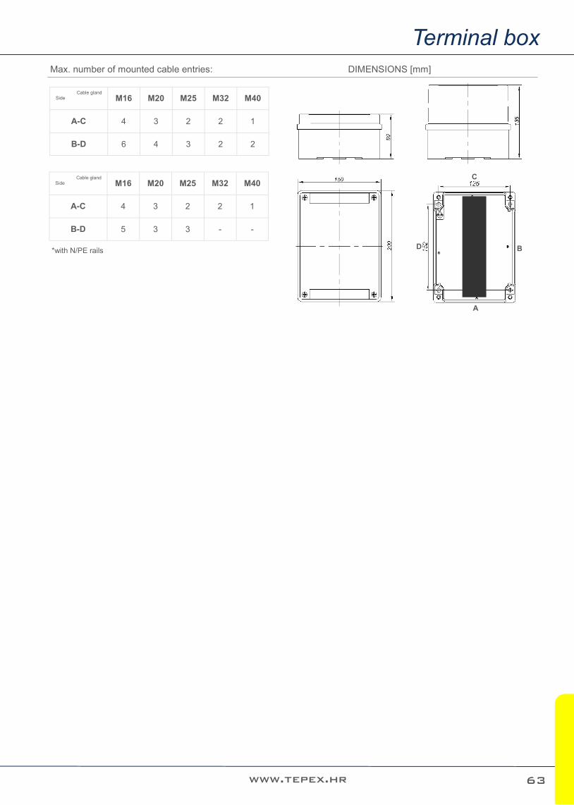
Max. number of mounted cable entries: DIMENSIONS [mm]
Side Cable gland
M16 M20 M25 M32 M40
A-C 4 3 2 2 1
B-D 6 4 3 2 2
Side Cable gland
M16 M20 M25 M32 M40
A-C 4 3 2 2 1
B-D 5 3 3 - -
*with N/PE rails
A
B
C
D
63

SKX ../E Zone
1 21 2 22
Terminal box SKX 16/E
Table of allowed number of terminals
Nominal cross section of conductors / terminals (mm2)
Maximum number of termi-nals Ambient temperature Ta[°C] Imax [A]
2,5 / 2,5 70
-20°C do +40 °C
9
2,5 / 2,5 36 13
2,5 / 2,5 4 18
2,5 / 2,5 70
-20°C do +50 °C
8
2,5 / 2,5 36 11
2,5 / 2,5 4 16
4 /4 61
-20°C do +40 °C
13
4 /4 30 18
4 /4 4 26
4 /4 61
-20°C do +50 °C
11
4 /4 30 16
4 /4 4 22
6 / 6 40
-20°C do +40 °C
18
6 / 6 22 26
6 / 6 4 35
6 / 6 40
-20°C do +50 °C
16
6 / 6 22 22
6 / 6 4 31
10 /10 37
-20°C do +40 °C
26
10 /10 17 40
10 /10 4 48
10 /10 37
-20°C do +50 °C
22
10 /10 17 34
10 /10 4 40
16 / 16 27
-20°C do +40 °C
38
16 / 16 15 52
16 / 16 4 65
16 / 16 27
-20°C do +50 °C
32
16 / 16 15 45
16 / 16 4 56
25 / 25 24
-20°C do +40 °C
52
25 / 25 15 65
25 / 25 4 86
25 / 25 24
-20°C do +50 °C
45
25 / 25 15 56
25 / 25 4 74
35 / 35 16
-20°C do +40 °C
65
35 / 35 10 90
35 / 35 4 105
35 / 35 16
-20°C do +50 °C
56
35 / 35 10 80
35 / 35 4 90
50 /50 14 -20°C do +40 °C
90
50 /50 4 120
50 /50 11 -20°C do +50 °C
80
50 /50 4 105
64 make your work surroundings safer

Terminal box
www.tepex.hr
Max. number of mounted cable entries: DIMENSIONS [mm]
Side Cable
gland M20 M25 M32 M40 M50 M63
B-D 9 9 5 3 3 2
A-C 7 5 3 3 1 1
25
5
250
12
0
16
2
235
200
65

SKX ../E Zone
1 21 2 22
Terminal box SKX 18/E
Table of allowed number of terminals
Nominal cross section of conductors / terminals
(mm2)
Maximum number of termi-nals
Ambient temperature Ta[°C]
Imax [A]
2,5 / 2,5 180
-20°C do +40 °C
9
2,5 / 2,5 64 12
2,5 / 2,5 4 16
2,5 / 2,5 108
-20°C do +50 °C
8
2,5 / 2,5 64 10
2,5 / 2,5 4 14
4 /4 103
-20°C do +40 °C
12
4 /4 54 16
4 /4 4 23
4 /4 103
-20°C do +50 °C
10
4 /4 54 14
4 /4 4 20
6 / 6 83
-20°C do +40 °C
16
6 / 6 40 23
6 / 6 4 34
6 / 6 83
-20°C do +50 °C
14
6 / 6 40 20
6 / 6 4 30
10 /10 68
-20°C do +40 °C
23
10 /10 32 34
10 /10 4 48
10 /10 68
-20°C do +50 °C
20
10 /10 32 30
10 /10 4 42
16 / 16 48
-20°C do +40 °C
34
16 / 16 26 48
16 / 16 4 60
16 / 16 48
-20°C do +50 °C
30
16 / 16 26 42
16 / 16 4 50
25 / 25 40
-20°C do +40 °C
48
25 / 25 26 60
25 / 25 4 80
25 / 25 40
-20°C do +50 °C
42
25 / 25 26 50
25 / 25 4 70
35 / 35 36
-20°C do +40 °C
60
35 / 35 20 80
35 / 35 4 105
35 / 35 36
-20°C do +50 °C
50
35 / 35 20 70
35 / 35 4 90
50 /50 26
-20°C do +40 °C
80
50 /50 16 110
50 /50 4 125
50 /50 26
-20°C do +50 °C
70
50 /50 16 95
50 /50 4 100
66 make your work surroundings safer

Terminal box
www.tepex.hr
Max. number of mounted cable entries: DIMENSIONS [mm]
Side Cable
gland M20 M25 M32 M40 M50 M63
B-D 15 15 9 6 5 4
A-C 7 5 3 3 1 1
250
12
0
40
0
16
2
380
200
67

SKX ../E Zone
1 21 2 22
Terminal box SKX 20/E
Table of allowed number of terminals
Nominal cross section of conduc-tors / terminals (mm2)
Maximum number of ter-minals
Ambient temperature Ta[°C] Imax [A]
2,5 / 2,5 200
-20°C do +40 °C
6
2,5 / 2,5 126 9
2,5 / 2,5 78 12
2,5 / 2,5 4 16
2,5 / 2,5 126
-20°C do +50 °C
8
2,5 / 2,5 78 10
2,5 / 2,5 4 14
4 /4 180
-20°C do +40 °C
9
4 /4 122 12
4 /4 66 16
4 /4 4 23
4 /4 122
-20°C do +50 °C
10
4 /4 66 14
4 /4 4 20
6 / 6 98
-20°C do +40 °C
16
6 / 6 48 23
6 / 6 4 34
6 / 6 98
-20°C do +50 °C
14
6 / 6 48 20
6 / 6 4 30
10 /10 80
-20°C do +40 °C
23
10 /10 36 34
10 /10 4 48
10 /10 80
-20°C do +50 °C
20
10 /10 36 30
10 /10 4 42
16 / 16 58
-20°C do +40 °C
34
16 / 16 29 48
16 / 16 4 60
16 / 16 58
-20°C do +50 °C
30
16 / 16 29 42
16 / 16 4 50
25 / 25 46
-20°C do +40 °C
48
25 / 25 30 60
25 / 25 4 80
25 / 25 46
-20°C do +50 °C
42
25 / 25 30 50
25 / 25 4 70
35 / 35 41
-20°C do +40 °C
60
35 / 35 23 80
35 / 35 4 105
35 / 35 41
-20°C do +50 °C
50
35 / 35 23 70
35 / 35 4 90
50 /50 33
-20°C do +40 °C
80
50 /50 18 110
50 /50 4 125
50 /50 33
-20°C do +50 °C
70
50 /50 18 95
50 /50 4 100
68 make your work surroundings safer

Terminal box
www.tepex.hr
Max. number of mounted cable entries: DIMENSIONS [mm]
Side Cable
gland M20 M25 M32 M40 M50 M63
B-D 22 22 12 8 6 6
A-C 7 5 3 3 1 1
60
0
250
12
0 16
2
58
0
200
69

Certificate: EXA 16 ATEX 0047 EAC RU C-HR.AB24.B.03296
Marking: 0722
Apparatus category: II 2G II 2D
Marking of explosion protection:
Ex eb llC TG Gb Ex ia/ib llC TO Gb Ex eb ia/ib llC T6 cb Ex tb lllC T80'C Db
Ambient temperature ATEX: EAC:
-20ºC ≤ Ta ≤ +50ºC -50ºC ≤ Ta ≤ +50ºC
Degree of protection: IP 66 category 1
Resistance to shock: IK 08
Protection class : I (protective earthing)
Rated voltage: 630 V
Nominal current: Up to 125 A (depend on size and number of terminals)
Maximum safe voltage Um for intrinsically safe circuits Exi:
60 V
Cable entries, cable glands and screw plugs:
6 x M25 for cable f6-15 mm (f13-19 mm available on request) 6 x M32 for cable f12-21 mm (f17-25 mm available on request) 4 x M25 for cable f6-15 mm (f13-19 mm available on request) 4 x M32 for cable f12-21 mm (f17-25 mm available on request)
PE terminals (inside of the enclosure):
max. 2x4 mm2+2x2,5 mm2 , 3x4 mm2 , 2x6 mm2
N/PE rails inside the enclosure: 2 pcs, 11 terminals 2x4mm2 max.
Weight (without cable glands):
SKX 16I/E ……… 3,1 kg SKX 18I/E-1……. 4,8 kg SKX 18I/E-2 …… 5,4 kg SKX 20I/E ……… 5,6 kg
Enclosure: Stainless steel AISI 316L, brush finished, thickness 1.5mm Cover: with integrated thermoplastic elastomer gasket, closes with four M5 stainless steel screws.
SKX ..I/E
CONSTRUCTION
TECHNICAL DATA
● Enclosures in
stainless steel AISI 316L
● 3 basic enclosure
sizes
● Fitted according to
the customer's re-quirements
Zone
IP 66
+50
-20
C
1 21 2 22
MOUNTING
With four screws through the housing holes 8 mm at the peaks the rectangle:
70 make your work surroundings safer

Stainless steel terminal box SKX 16I/E, SKX 18I/E-1, SKX 18I/E-2, SKX 20 I
Terminal box
www.tepex.hr
Max. number of mounted cable entries:
Type A[mm] B[mm] C[mm] SKX 16I/E 300 200 120 SKX 18I/E-1 400 200 120 SKX 18I/E-2 400 300 120 SKX 20I/E 600 200 120
MOUNTING
Type D[mm] E[mm] F[mm] G[mm]
SKX 16I/E 255 225 330 152
SKX 18I/E-1 355 225 430 152
SKX 18I/E-2 355 325 430 252
SKX 20I/E 555 625 630 152
A
B
C
D
TYPE Dimension
SKX 16I/E 300X200X120
SKX 18I/E-1 400X200X120
SKX 18I/E-2 400X300X120
SKX 20I/E 600X200X120
Cable gland
A-C B-D A-C B-D A-C B-D A-C B-D
M20x1.5 9 12 9 18 9 18 6 24
M25x1.5 4 10 4 16 4 18 4 20
M32x1.5 3 7 3 10 3 9 3 14
M40x1.5 2 4 2 6 2 6 2 8
M50x1.5 2 3 2 5 2 4 2 6
M60x1.5 1 2 1 3 1 3 2 5
71
All technical data is relevant at the time of print.

SKX ..I/E Zone
1 21 2 22
Terminal box SKX 16I/E (300x200x120 mm)
Table of allowed number of terminals
Nominal cross section of conductors / terminals (mm2)
Maximum number of termi-nals Ambient temperature Ta[°C] Imax [A]
2,5 / 2,5 60
-20°C do +40 °C
9
2,5 / 2,5 30 13
2,5 / 2,5 4 18
2,5 / 2,5 60
-20°C do +50 °C
8
2,5 / 2,5 30 11
2,5 / 2,5 4 16
4 /4 48
-20°C do +40 °C
13
4 /4 24 18
4 /4 4 26
4 /4 48
-20°C do +50 °C
11
4 /4 24 16
4 /4 4 22
6 / 6 36
-20°C do +40 °C
18
6 / 6 18 26
6 / 6 4 35
6 / 6 36
-20°C do +50 °C
16
6 / 6 18 22
6 / 6 4 31
10 /10 30
-20°C do +40 °C
26
10 /10 14 40
10 /10 4 48
10 /10 30
-20°C do +50 °C
22
10 /10 14 34
10 /10 4 40
16 / 16 22
-20°C do +40 °C
38
16 / 16 11 52
16 / 16 4 63
16 / 16 22
-20°C do +50 °C
32
16 / 16 11 45
16 / 16 4 54
25 / 25 18
-20°C do +40 °C
52
25 / 25 11 65
25 / 25 4 80
25 / 25 18
-20°C do +50 °C
45
25 / 25 11 56
25 / 25 4 69
35 / 35 14
-20°C do +40 °C
65
35 / 35 8 90
35 / 35 4 94
35 / 35 14
-20°C do +50 °C
56
35 / 35 8 80
35 / 35 4 82
50 /50 10 -20°C do +40 °C
90
50 /50 3 12
50 /50 10 -20°C do +50 °C
80
50 /50 3 105
72 make your work surroundings safer

Terminal box
www.tepex.hr
Maximum possible number of terminals definite by enclosure dimensions
Maximum possible number of terminals definite by enclosure
dimensions 36 30 22 18 15 15 10
8
Width of single terminal [mm] 5 6 7 10 12 12 15
18,5
Allowed cross-section of con-ductor for single terminal
1x2.5-1 .5 mm2
1 x4-1.5 mm2
1 x6-1.5 mm2
1 x10-2.5 mm2
1 x16-2.5 mm2
1 x 25-6 mm2
1 x 35-6 mm2
1 x 50-10 mm2
Width of PE terminal [mm] 5 6 7 10 12 12 15 18.5
Width of end holder 9
Space for terminals on DIN rail without end holders
max. 214 mm
73

SKX ..I/E Zone
1 21 2 22
Terminal box SKX 18I/E-1 (400x200x120 mm), SKX 18I/E-2 (400x300x120 mm)
Table of allowed number of terminals
Nominal cross section of conductors / terminals (mm2)
Maximum number of termi-nals
Ambient temperature Ta[°C] Imax [A]
2,5 / 2,5 95
-20°C do +40 °C
9
2,5 / 2,5 55 12
2,5 / 2,5 4 16
2,5 / 2,5 95
-20°C do +50 °C
8
2,5 / 2,5 55 10
2,5 / 2,5 4 14
4 /4 88
-20°C do +40 °C
12
4 /4 50 16
4 /4 4 23
4 /4 88
-20°C do +50 °C
10
4 /4 50 14
4 /4 4 20
6 / 6 75
-20°C do +40 °C
16
6 / 6 36 23
6 / 6 4 34
6 / 6 75
-20°C do +50 °C
14
6 / 6 36 20
6 / 6 4 30
10 /10 60
-20°C do +40 °C
23
10 /10 27 34
10 /10 4 48
10 /10 60
-20°C do +50 °C
20
10 /10 27 30
10 /10 4 42
16 / 16 44
-20°C do +40 °C
34
16 / 16 22 48
16 / 16 4 60
16 / 16 44
-20°C do +50 °C
30
16 / 16 22 42
16 / 16 4 50
25 / 25 34
-20°C do +40 °C
48
25 / 25 21 60
25 / 25 4 80
25 / 25 34
-20°C do +50 °C
42
25 / 25 21 50
25 / 25 4 70
35 / 35 31
-20°C do +40 °C
60
35 / 35 17 80
35 / 35 4 105
35 / 35 31
-20°C do +50 °C
50
35 / 35 17 70
35 / 35 4 90
50 /50 25 -20°C do +40 °C
80
50 /50 13 110
50 /50 4
-20°C do +40 °C
125
50 /50 25 70
50 /50 13 95
50 /50 4 100
74 make your work surroundings safer

Ex terminal box SKX 18I/E-1
Terminal box
www.tepex.hr
Maximum possible number of terminals definite by enclosure dimensions
Maximum possible number of terminals definite by enclosure
dimensions 64 54 40 32 26 26 20 16
Width of single terminal [mm] 5 6 7 10 12 12 15
18,5
Allowed cross-section of con-ductor for single terminal
1x2.5-1 .5 mm2
1 x4-1.5 mm2
1 x6-1.5 mm2
1 x10-2.5 mm2
1 x16-2.5 mm2
1 x 25-6 mm2
1 x 35-6 mm2
1 x 50-10 mm2
Width of PE terminal [mm] 5 6 7 10 12 12 15
18.5
Width of end holder 9
Space for terminals on DIN rail without end holders
max. 300 mm
Ex terminal box SKX 18I/E-2
75

SKX ..I/E Zone
1 21 2 22
Terminal box SKX 18I/E-1 (400x200x120 mm)
Table of allowed number of terminals
Nominal cross section of conductors / terminals (mm2)
Maximum number of termi-nals
Ambient temperature Ta[°C] Imax [A]
2,5 / 2,5 200
-20°C do +40 °C
6
2,5 / 2,5 102 9
2,5 / 2,5 60 12
2,5 / 2,5 4
-20°C do +40 °C
16
2,5 / 2,5 102 8
2,5 / 2,5 60 10
2,5 / 2,5 4
-20°C do +50 °C
14
4 /4 180 9
4 /4 96 12
4 /4 53
-20°C do +40 °C
16
4 /4 4 23
4 /4 96 10
4 /4 53
-20°C do +50 °C
14
4 /4 4 20
6 / 6 80 16
6 / 6 38
-20°C do +40 °C
23
6 / 6 4 34
6 / 6 80 14
6 / 6 38
-20°C do +50 °C
20
6 / 6 4 30
10 /10 65 23
10 /10 29
-20°C do +40 °C
34
10 /10 4 48
10 /10 65 20
10 /10 29
-20°C do +50 °C
30
10 /10 4 42
16 / 16 47 34
16 / 16 24
-20°C do +40 °C
48
16 / 16 4 60
16 / 16 47 30
16 / 16 24
-20°C do +50 °C
42
16 / 16 4 50
25 / 25 37 48
25 / 25 23
-20°C do +40 °C
60
25 / 25 4 80
25 / 25 37 42
25 / 25 23
-20°C do +50 °C
50
25 / 25 4 70
35 / 35 33 60
35 / 35 18
-20°C do +40 °C
80
35 / 35 4 105
35 / 35 33 50
35 / 35 15 -20°C do +50 °C
70
35 / 35 4 90
50 /50 26
-20°C do +40 °C
80
50 /50 14 110
50 /50 4 125
50 /50 26 70
50 /50 14 95
50 /50 4 100
76 make your work surroundings safer

Terminal box
www.tepex.hr
Maximum possible number of terminals definite by enclosure dimensions
Maximum possible number of terminals definite by enclosure
dimensions 100 86 66 50 40 40 30 26
Width of single terminal [mm] 5 6 7 10 12 12 15 18,5
Allowed cross-section of con-ductor for single terminal
1x2.5-1 .5 mm2
1 x4-1.5 mm2
1 x6-1.5 mm2
1 x10-2.5 mm2
1 x16-2.5 mm2
1 x 25-6 mm2
1 x 35-6 mm2
1 x 50-10 mm2
Width of PE terminal [mm] 5 6 7 10 12 12 15 18,5
Width of end holder 9
Space for terminals on DIN rail without end holders
max. 500 mm
Ex terminal box SKX 20I/E
77
All technical data is relevant at the time of print.

NOTES

Control units

Certificate: CESI 12 ATEX 017X, EXA 13 ATEX 0029, , EAC RU C-HR.AB24.B.03291
Marking: 0722
Apparatus category: II 2GD
Marking of explosion protection:
II 2G Ex d e IIC T6 Gb II 2G Ex d e mb IIC T6 Gb II 2G Ex e IIC T6 Gb II 2G Ex ia/ib IIC T6 Gb
II 2D Ex tb IIIC T80C Db
Ambient temperature ATEX: EAC:
-20ºC ≤ Ta ≤ +50ºC -50ºC ≤ Ta ≤ +50ºC
Degree of protection: IP 66 category 1
Resistance to shock: IK 08
Protection class : I (protective earthing)
Rated voltage: 630 V AC (with mantle terminals block SL5, SL8 Ui = 400V AC)
Thermal current Ithe : 16 A max. at Tamb -20°C ÷ +40°C 10 A max. at Tamb -20°C ÷ +50°C
PE terminals (inside of the enclosure):
max. 2x4 mm2+2x2,5 mm2 , 3x4 mm2 , 2x6 mm2
Weight (only GRP boxes):
SKX 12 ..... 0.5 kg SKX 13 ..... 0,7 kg SKX 14 ..... 1.0 kg SKX 15 ..... 1.0 kg
Enclosure: polyester plastic reinforced with glass fiber, color - black Cover: with integrated thermoplastic elastomer gasket, closes with four M5/M6 stainless steel screws.
SKX 12 … SKX 15
CONSTRUCTION
TECHNICAL DATA
● Enclosures made
of glass-fibre rein-forced polyester resin
● 4 basic enclosure
sizes
● Alone or in various
combinations of merged set
● Equipped with built
-in devices
Control devices
Indicating lamps
Pushbuttons
Control switches
Ammeters
Zone
MOUNTING
IP 66
+50
-20
C
With screw kit through the housing holes 6 mm at the peaks the rectangle: SKX 12: 75 x 50 mm SKX 13: 75 x 100 mm SKX 14: 75 x 150 mm SKX 15/15H: 125 x 150 mm
1 21 2 22
make your work surroundings safer 80

Possible combinations and layout of indicators and actuators components
Control units
www.tepex.hr
Enclosure type SKX 12
SKX 12
SKX 13
SKX 14 SKX 15
* mounting proposals and dimensions
Switch actuator SMO 17/. Switch mounting
Pushbutton actuator SPO 01/. Front element of signal lamp SPO 02/.
Pushbutton, signal lamp and potentiometer mounting
Front element of measuring instrument (AM, VM) SAM 72
Measuring instrument mounting AM, VM
Max. No. of cable glands
side
cable gland
M16 M20 M25
A-C 2 2 1
B-D 1 1 1
10
0
100
10
0
50
75
80
81
All technical data is relevant at the time of print.

Zone
1 21 2 22
Enclosure type SKX 13
Max. No. of cable glands
side
cable gland
M16 M20 M25
A-C 2 2 1
B-D 4 3 2
0
11
7
15
0
50
Control unit SKX 13/10Switch SMS 03/1, switch actuator SMO 17/1,
cable gland SPU 25
10
0
75
80
100
Enclosure type SKX 14
Max. No. of cable glands
side
cable gland
M16 M20 M25 M32
A-C 2 2 1 1
B-D 6 4 3 2
EMERG
EN
CY
S
TOP
20
01
10
50
Control unit SKX 14/MSRU ....2x pushbutton PBT 01, pushbutton actuator SPO 01/1,
mushroom-head pushbutton actuator,
1x signal lamp SLP 01, front element SPO 02/02
cable gland SPU 25
75
15
2
82
SKX 12 … SKX 15
make your work surroundings safer

Control units
www.tepex.hr
Enclosure type SKX 15
Max. No. of cable glands
side
cable gland
M16 M20 M25 M32 M40
A-C 4 3 2 2 1
B-D 6 4 3 2 2
side
cable gland
M16 M20 M25 M32 M40
A-C 4 3 2 2 1
B-D 5 3 3 - -
* with built-in N/PE busbar
20
095 Control unit SKX 15/11-11
2x pushbutton PBT 01, pushbutton actuator SPO 01/1, SPO 01/2,
ammeter AM 72 100/1A, front element of
measuring instruments SAM 72, 2x cable gland SPU 25
150
126
15
2
Various combinations of merged set (combination) of SKX enclosures
83

MODEL CODE
The program consists of serial control units and control units according to customer's request.
Zone
1 21 2 22
Type Build-in components and actuator / indicator Overview
SKX 12/1 Signal lamp SLP - red SPO 02/1
- cable gland SPU 25
SKX 12/2 Signal lamp SLP - green SPO 02/2
- cable gland SPU 25
SKX 12/3 Signal lamp SLP - white SPO 02/4
- cable gland SPU 25 -
SKX 12/21 Control switch SMS 03/1 - switch actuator SMO 17/1
- cable gland SPU 25
SKX 12/22 Serial switch SMS 03/8 - switch actuator SMO 17/5
- cable gland SPU 25 0 - I - II - III
SKX 12/23 Control switch SMS 03/6 - switch actuator SMO 17/2
- cable gland SPU 25
SKX 12/31 Pushbutton PBT 01 - Key-operated mushroom-head pushbutton
actuator GHG 410 1906 R0005 - cable gland SPU 25 -
SKX 12/32 Pushbutton PBT 01 - pushbutton actuator SPO 01/1
- cable gland SPU 25
SKX 12/33 Pushbutton PBT 01 - pushbutton actuator SPO 01/2
- cable gland SPU 25
SKX 12/34 Pushbutton PBT 01 - Mushroom-head pushbutton actuator
GHG 410 1905 R0005 - cable gland SPU 25 -
SKX 12/35 Pushbutton PBT 01 - Mushroom-head pushbutton actuator
GHG 410 1906 R0005 with protector - 2x cable gland SPU 20
-
SKX 12/36 Pushbutton PBT 011
- Key-operated pushbutton GHG 410 1906 R0005 - 2x cable gland SPU 20
-
SKX 12/37 Potentiometer GHG 4101901 R0193 - GHG 410 1944 R0010
- cable gland SPU 25 -
SKX 12/62 5x4 mm2 EURO 4/35 grey on rail TH 35-7,5 - 2x SPU 25 -
SKX 12/63 5x4 mm2 EURO 4/35 blue on rail TH 35-7,5 - 2x SPU 25 blue -
I
0
SKX 12/..
84
SKX 12 … SKX 15
make your work surroundings safer

Control units
www.tepex.hr
Type Build-in components and actuator / indicator Overview
SKX 13/1 2x pushbutton PBT 01 - SPO 01/1 - SPO 01/2
- cable gland SPU 25
SKX 13/11 Pushbutton PBT 01 - SPO 01/1 - Signal lamp SLP
- Front element of signal lamp SPO 02/2 - cable gland SPU 25
SKX 13/21 Mantle terminals SL8 - 6x cable gland SPU 25 -
SKX 13/71 Switch GHG 23. ...R.... (Ex 23 4 024)
- switch actuator SMO 17/2 - cable gland SPU 25
-
SKX 13/72 Switch GHG 23. ...R.... (Ex 23 8 067)
- switch actuator SMO 17/1 - cable gland SPU 25
-
SKX 13/10 Switch SMS 03/1 - switch actuator SMO 17/1
- cable gland SPU 25
SKX 13/20 SMS 03/4 - SMO 17/2 - SPU 25
SKX 13/30 SMS 03/5 - SMO 17/2 - SPU 25
SKX 13/40 SMS 03/6 - SMO 17/2 - SPU 25
SKX 13/60 SMS 03/3 - SMO 17/3 - SPU 25
SKX 13/70 SMS 03/2 - SMO 17/1 - SPU 25
SKX 13/80 SMS 03/7 - SMO 17/1 - SPU 25
SKX 13/100 SMS 03/8 - SMO 17/5 - SPU 25
SKX 13/110 SMS 03/9 - SMO 17/1 - SPU 25
SKX 13/120 SMS 03/11 - SMO 17/2 - SPU 25
Type Build-in components and actuator / indicator Overview
SKX 14/1 2x pushbutton PBT 01 - SPO 01/1 - SPO 01/2 -
Signal lamp SLP - SPO 02/2 - cable gland SPU 25
SKX 14/11 3x pushbutton PBT 01
- pushbutton actuator SPO 01/1 - SPO 01/2 - SPO 01/3 - cable gland SPU 25
SKX 14/21 Mantle terminals SL 8 - 8x cable gland SPU 25 -
SKX 14/22
3x signal lamp SLP front element of signal lamp
SPO 02/1 - SPO 02/2 - SPO 02/3 - cable gland SPU 25
SKX 14/31
3x pushbutton PBT 01 - pushbutton actuator SPO 01/1 - SPO 01/2
Mushroom-head pushbutton actuator GHG 410 1906 R0005
- cable gland SPU 25
-
SKX 13/..
SKX 14/..
85

Zone
1 21 2 22
Type Build-in components and actuator / indicator Overview
SKX 15/1 2x pushbutton PBT 01 - SPO 01/1 - SPO 01/2
- 2x signal lamp SLP - 02/1 - SPO 02/2 - 2x cable gland SPU 25
SKX 15/11-11
2x pushbutton PBT 01 - pushbutton actuator SPO 01/1 - SPO 01/2
- ammeter AM 72 100/1A - 2x cable gland SPU 25
- - - SKX 15/11-12 2xPBT 01 - SPO 01/1 - SPO 01/2 - AM 72 50/1 A - 2xSPU 25
SKX 15/11-21 2xPBT 01 - SPO 01/1 - SPO 01/2 - AM 72 100/5 A - 2xSPU 25
SKX 15/11-22 2xPBT 01 - SPO 01/1 - SPO 01/2 - AM 72 50/1 A - 2xSPU 25
SKX 15/21-11
Switch GHG 23. .R.. - switch actuator SMO 17/1 - ammeter AM 72 100/1 A
- 2x uvodnica SPU 25
- - -
SKX 15/21-12
Switch GHG 23. ...R… - switch actuator SMO 17/1 - ammeter AM 72 100/1 A
- 2x uvodnicaSPU 25
SKX 15/21-21
Switch GHG 23. ...R.... - Switch actuator SMO 17/1 - ammeter AM 72 100/5 A
- 2x uvodnica SPU 25
SKX 15/21-22
Switch GHG 23. ...R.... - switch actuator SMO 17/1 - ammeter AM 72 50/5 A - 2x cable gland SPU 25
SKX 15/34 4x pushbutton PBT/1 - 2xSPO 01/1 - 2xSPO 01/2
- 2x cable gland SPU 25 -
SKX 15/41 Switch SMS 03/1
- 2x terminal EURO E16-25 - 2x cable gland SPU 25
-
SKX 15/50 Switch SMS 03/12 - SMO 17/2
- cable gland SPU 25 -
SKX 15/90 Switch SMS 03/10 - SMO 17/3
- cable gland SPU 25 -
SKX 15/51 Switch SMS 03/9 - SMO 17/1
- 2x pushbutton PBT/1 - SPO 01/1 - SPO01/2 - 2x cable gland SPU 25
-
SKX 15/61 Switch GHG 23. ...R.... (Ex 23 4 024) - SMO 17/2
- 5x terminal EURO E4 - cable gland SPU 25
-
SKX 15/62 Switch GHG 23. ...R.... (Ex 23 8 067) - SMO 17/1
- 5x terminal EURO E4 - cable gland SPU 25
-
SKX 15/65 4x mantle terminals SL5 - 8x cable gland SPU 25
-
SKX 15/..
86
SKX 12 … SKX 15
make your work surroundings safer

Control units
www.tepex.hr
BUILD-IN COMPONENTS
Description, type Schema / type Overview
Control switch SMS 03/. II 2G I M2 Ex de I/IIC Gb Mb
Rated voltage: 630 V AC
Rated current: 16 A
Terminals: 2,5 mm2
87

Zone
1 21 2 22
BUILD-IN COMPONENTS
Description, type Schema Overview
Control switch GHG 23. II 2GD Ex de IIC
Rated voltage: 690 V AC
Rated current : 10 A
Terminals: 2,5 mm2
88
SKX 12 … SKX 15
make your work surroundings safer

Control units
www.tepex.hr
BUILD-IN COMPONENTS
Description, type Schema Overview
Pushbutton PBT/.
Rated voltage: 630V AC
Rated current: 16A
Terminals: 2,5 mm2
Signal lamp SLP
Rated voltage: 12-250 V AC/DC
Max. current: 20-8 mA
Terminals: 2,5 mm2
Potentionmeter PBT/POT
Rated voltage: 315 V AC/DC
Rated power: 1W
Scale: 0-100% / 270
Tolerance: ±20%
Characteristic: linear
Terminals: 2,5 mm2
Resistance R:
1,0 k
2,2 k
4,7 k
10 k
470 k
Measuring instruments AM 72, VM 72
Measuring range:
AM: n/1 A, 0-20 mA, 0-25 A direct 4-20 mA VM: n/1A, 6-415V, 6-660 V
Scale: according to customer
demand
Terminals: 1,5 - 4 mm2
-
Mantle terminals SL5 , SL8
Rated voltage: 400 V
Rated current: 16 A AC
Terminals: 4 mm2
Max. No. of wire under one
clamp: 2x4mm2 + 2x2,5mm2, 3x4mm2
-
Terminals TH 35-7.5
5 terminals 4mm2
2 terminals 16mm2
Rated voltage: 690 V AC
Rated current: 16 A
-
N/PE busbar (only for SKX 15)
11x max. 2x4mm2 -
89

Zone
1 21 2 22
ACTUATORS AND INDICATORS
Description, type Mounting Overview
Switch actuator SMO 17/.
II 2G II 2D I M2 Ex e I/IIC Gb Mb
Ex t IIIC Db
Front element of measuring instruments SAM 72
II 2G II 2D I M2 Ex e I/IIC Gb Mb
Ex t IIIC Db
Puschbitton actuator SPO 01/.
II 2G II 2D I M2 Ex e I/IIC Gb Mb
Ex t IIIC Db
Front element of signal lamp SPO 02/.
II 2G II 2D I M2 Ex e I/IIC Gb Mb
Ex t IIIC Db
Key-operated pushbutton actuator
GHG 410 1904 R0012
II 2GD Ex e II IP66
I0 I II I 0 II
I
0
III
II
I II III
1 2
3
4
1 2
3
45
1 2
3
456
1 2
3
SMO 17/1 SMO 17/2 SMO 17/3 SMO 17/4
SMO 17/5 SMO 17/6 SMO 17/7 SMO 17/8 SMO 17/9
Type SPO 01/.
SPO 01/01 0
SPO 01/02 I
SPO 01/03 II
SPO 01/04 RED
SPO 01/05 GREEN
SPO 01/06 WHITE
SPO 01/07 START
SPO 01/08 STOP
SPO 01/09 ON
SPO 01/10 OFF
Type SPO 02/.
SPO 02/01 RED
SPO 02/02 GREEN
SPO 02/03 YELLOW
SPO 02/04 TRANSPARENT
90
SKX 12 … SKX 15
make your work surroundings safer

Control units
www.tepex.hr
BUILD-IN COMPONENTS
Description, type Mounting Overview
Mushroom-head pushbutton actuator
GHG 418 815 ..R ..(EMERGENCY-STOP)
II 2GD
Ex e II IP66
Key-operated mushroom-head pushbutton actuator GHG 418 815 ..R..
(EMERGENCY-STOP)
II 2GD Ex e II IP66
Potentiometer acuator GHG 410 1944 R0010
II 2GD
Ex e II IP66
Cable gland SPU ISO 16 - ISO 40
II 2G II 2D
Ex e I/IIC Gb Ex t IIIC Db
Cable gland for armourd cable SPU A
ISO 16 - ISO 40
II 2G II 2D Ex e I/IIC Gb Ex t IIIC Db
Plug SPC .. ISO 16 - ISO M40
II 2G II 2D
Ex e I/IIC Gb Ex t IIIC Db
Connection part SKX
91

Certificate: EXA 13 ATEX 0029, EXA 15 ATEX 0036 RU C-HR.AB24.B.03291, RU C-HR.AB24.B.03294
Marking: 0722
Apparatus category: II 2GD
Marking of explosion protection: Ex d e mb ia/ib IIC T4...T6 Gb Ex tb IIIC T80°C Db
Ambient temperature ATEX: EAC:
-20ºC ≤ Ta ≤ +50ºC -50ºC ≤ Ta ≤ +50ºC
Degree of protection: IP 66 category 1
Resistance to shock: IK 08
Protection class : I (protective earthing)
Rated voltage: 690 V AC (with mantle terminals block SL5, SL8 Ui = 400V AC)
Nominal current: Up to 80 A
PE terminals (inside of the enclosure):
max. 2x4 mm2+2x2,5 mm2 , 3x4 mm2 , 2x6 mm2
Connection:
Depending on order requirements at the built-in components or at the terminal blocks. The rated operational voltage, the rated operational current and the rated cross-section depend on the terminal type used and the explosion protected components.
Enclosure: polyester plastic reinforced with glass fiber, color - black Stainless steel AISI 316L, brush finished, thickness 1.5mm Cover: with integrated thermoplastic elastomer gasket, closes with four/six M5/M6 stainless steel screws.
SKX 16, 18, 20
CONSTRUCTION
TECHNICAL DATA
● Enclosures made
of glass-fibre rein-forced polyester resin or stainless
steel AISI 316L
● 3 basic enclosure
sizes in GRP
● 3 basic enclosure
sizes in stainless steel
● Alone or in various
combinations of merged set
● Equipped with built
-in components
Control devices
Indicating lamps
Pushbuttons
Switches
Ammeters
Version with hinged doors
Zone
IP 66
+50
-20
C
1 21 2 22
Control units SKX 16, SKX 18, SKX 20 are Ex combinations configured according to customer demand. Type designation consists of a basic type designation - SKX 16, SKX 18, SKX 20, “I” for enclosure made of SS AISI 316L and SRU number that represents the number of production and assigns to the increment. Example: SKX 18 I / SRU -1280
managing the combination of the housing MMK 403016
I - stainless steel enclosure AISI 316L
performed by production number 1280
make your work surroundings safer 92

GRP enclosure SKX 16
Control units
www.tepex.hr
Side Cable
gland M20 M25 M32 M40 M50 M63
B-D 9 9 5 3 3 2
A-C 7 5 3 3 - -
GRP enclosure SKX 18
Side Cable
gland M20 M25 M32 M40 M50 M63
B-D 15 15 9 6 5 4
A-C 7 5 3 3 - -
93
All technical data is relevant at the time of print.

GRP enclosure SKX 20
Zone
1 21 2 22 SKX 16, 18, 20
Side Cable
gland M20 M25 M32 M40 M50 M63
B-D 22 22 12 8 6 6
A-C 7 5 3 3 - -
Example: Ex control units with GRP enclosures
make your work surroundings safer 94

Control units
www.tepex.hr
Stainless steel AISI 316L enclosure SKX 16 I, SKX 18 I, SKX 20 I
MOUNTING
A[mm] B[mm] C[mm] SKX 16 I 300 200 120 SKX 18 I 400 300 160
SKX 20 I 600 400 160
D[mm] E[mm] F[mm] G[mm] SKX 16 I 255 227 330 152 SKX 18 I 355 327 430 252
SKX 20 I 555 427 630 352
Example: Ex control units with stainless steel AISI 316L enclosures
95

Zone
1 21 2 22
BUILD-IN COMPONENTS
Description, type Schema Overview
Control switch SMS 03/. II 2G I M2 Ex de I/IIC Gb Mb
Rated voltage: 630 V AC
Rated current: 16 A
Terminals: 2,5 mm2
Main curent switch GHG 260
Rated voltage: 690 V AC
Rated current : 40 - 80 A
Terminals: 16 - 25 mm2
SKX 16, 18, 20
make your work surroundings safer 96

Control units
www.tepex.hr
BUILD-IN COMPONENTS
Description, type Schema Overview
Control switch GHG 23. II 2GD Ex de IIC
Rated voltage: 690 V AC
Rated current : 10 A
Terminals: 2,5 mm2
97

Zone
1 21 2 22
BUILD-IN COMPONENTS
Description, type Schema Overview
Pushbutton PBT/.
Rated voltage: 630V AC
Rated current: 16A
Terminals: 2,5 mm2
Signal lamp SLP
Rated voltage: 12-250 V AC/DC
Max. current: 20-8 mA
Terminals: 2,5 mm2
Potentionmeter PBT/POT
Rated voltage: 315 V AC/DC
Rated power: 1W
Scale: 0-100% / 270
Tolerance: ±20%
Characteristic: linear
Terminals: 2,5 mm2
Resistance R:
1,0 k
2,2 k
4,7 k
10 k
470 k
Measuring instruments AM 72, VM 72
Measuring range:
AM: n/1 A, 0-20 mA, 0-25 A direct 4-20 mA VM: n/1A, 6-415V, 6-660 V
Scale: according to customer
demand
Terminals: 1,5 - 4 mm2
-
Mantle terminals SL5 , SL8
Rated voltage: 400 V
Rated current: 16 A AC
Terminals: 4 mm2
Max. No. of wire under one
clamp: 2x4mm2 + 2x2,5mm2, 3x4mm2
-
Terminals TH 35-7.5
5 terminals 4mm2
2 terminals 16mm2
Rated voltage: 690 V AC
Rated current: 16 A
-
N/PE busbar (only for SKX 15)
11x max. 2x4mm2 -
SKX 16, 18, 20
make your work surroundings safer 98

Control units
www.tepex.hr
ACTUATORS AND INDICATORS
Description, type Mounting Overview
Switch actuator SMO 17/.
II 2G II 2D I M2 Ex e I/IIC Gb Mb
Ex t IIIC Db
Switch actuator GHG 260 1006
Front element of measuring instruments SAM 72
II 2G II 2D I M2 Ex e I/IIC Gb Mb
Ex t IIIC Db
Puschbitton actuator SPO 01/.
II 2G II 2D I M2 Ex e I/IIC Gb Mb
Ex t IIIC Db
Front element of signal lamp SPO 02/.
II 2G II 2D I M2 Ex e I/IIC Gb Mb
Ex t IIIC Db
Key-operated pushbutton actuator
GHG 410 1904 R0012
II 2GD Ex e II IP66
I0 I II I 0 II
I
0
III
II
I II III
1 2
3
4
1 2
3
45
1 2
3
456
1 2
3
SMO 17/1 SMO 17/2 SMO 17/3 SMO 17/4
SMO 17/5 SMO 17/6 SMO 17/7 SMO 17/8 SMO 17/9
Type SPO 01/.
SPO 01/01 0
SPO 01/02 I
SPO 01/03 II
SPO 01/04 RED
SPO 01/05 GREEN
SPO 01/06 WHITE
SPO 01/07 START
SPO 01/08 STOP
SPO 01/09 ON
SPO 01/10 OFF
Type SPO 02/.
SPO 02/01 RED
SPO 02/02 GREEN
SPO 02/03 YELLOW
SPO 02/04 TRANSPARENT
Ø13
Ø87,5
60°Ø5x6
99

Zone
1 21 2 22
ACTUATORS AND INDICATORS
Description, type Mounting Overview
Mushroom-head pushbutton actuator
GHG 418 815 ..R ..(EMERGENCY-STOP)
II 2GD
Ex e II IP66
Key-operated mushroom-head pushbutton actuator GHG 418 815 ..R..
(EMERGENCY-STOP)
II 2GD Ex e II IP66
Potentiometer acuator GHG 410 1944 R0010
II 2GD
Ex e II IP66
Cable gland SPU ISO 16 - ISO 40
II 2G II 2D
Ex e I/IIC Gb Ex t IIIC Db
Cable gland for armourd cable SPU A
ISO 16 - ISO 40
II 2G II 2D Ex e I/IIC Gb Ex t IIIC Db
Plug SPC .. ISO 16 - ISO M40
II 2G II 2D
Ex e I/IIC Gb Ex t IIIC Db
Connection part SKX
SKX 16, 18, 20
100 make your work surroundings safer

Control units
www.tepex.hr
BUILD-IN COMPONENTS
Description, type Schema Overview
Main fuse NH0 300XX, NH0, 301XX
-
BUILD IN SOCKET 16 A (3p/5p), 32A (4p) II 2G Ex de IIC II 2D Ex tD A21 IP66 T80°C
-
RESIDUAL CURRENT CIRCUIT BREAKERS 2p/4p 25/40/63 A, 30 mA, 10 kA with or without auxiliary contact II 2G Ex d e IIC Gb
-
DIGITAL INDIKATOR VEGADIS 175 Ex II 1G EEx ia IIC T6
-
HRC FUSE, Ex d HOUSING 3p NH00C the base and fuse II 2G Ex de IIC I M2 Ex de I
-
101

Certificate: CESI 11 ATEX 041, EAC RU C-HR.AB24.B.03293
Marking: 0722
Apparatus category: II 2G
Marking of explosion protection: Ex d e [ib] mb IIC T5 Gb
Ambient temperature ATEX: EAC:
-20ºC ≤ Ta ≤ +50ºC -50ºC ≤ Ta ≤ +50ºC
Degree of protection: IP 66 category 1
Resistance to shock: IK 08
Protection class : I (protective earthing)
Rated voltage: 230 V± 10%
Rated current: 50 mA
Frequency: 50Hz
Output circuit: 2 NO/NC Un=250VAC, In=8A / 230V, 4A at cos=0.4
Cable entry: 3 x M25 - power supply, two output circuit 4 x M25 - 2x connection clamp , 2x wire to equipotential busbar or grounding
Weight: 6 kg (without clamp and cable) weight of clamps with 10 m cable ca. 2,5 kg
Packing: The packing contains: 1 pcs 430x350x230 mm
Enclosure: polyester plastic reinforced with glass fiber, color - black Cover: with integrated Thermoplastic elastomer gasket, closes with four M6 stainless steel screws.
GGCD
CONSTRUCTION
TECHNICAL DATA
● Active grounding
system for static grounding and per-manent monitoring
● Permanent remov-
al of electrostatic charge during fill-ing or emptying tanks (road tracks, railcar tanks, bar-rels)
● Two output con-
tacts
Zone
1 2
MOUNTING
IP 66
+50
-30
C
Wall bracket with four screws
295O8
200
102 make your work surroundings safer

MODEL CODE DESCRIPTION
GGCD-01/K1 Type with one a clamp K1 with 10m
spiral cable
GGCD-01/K2 Type with two clamps K1 with 2x10m
spiral cable
MODEL CODE DIMENSION DRAWING (all dimensions in mm)
Principle of work for GGCD-01/..
Grounding and grounding control device
www.tepex.hr
28
0
255 190
103
All technical data is relevant at the time of print.

NOTES

Distribution cabinets Busbar enclosures

Certificate: EXA 14 ATEX 0050X, RU C-HR.AB24.B.03297
Marking: 0722
Apparatus category: II 2G II 2D I M2
Marking of explosion protection: Ex de I/IIC T6 Gb Mb Ex tb IIIC Db
Ambient temperature ATEX: EAC:
-20ºC ≤ Ta ≤ +50ºC -50ºC ≤ Ta ≤ +50ºC
Degree of protection: IP 66 category 1
Resistance to shock: IK 09
Protection class : I (protective earthing)
Rated voltage: Up to 690 V AC
Rated current: Up to 500 A (depends upon built-in device)
Terminal cross-section: 240 mm2
Weight: - Enclosure R3002 - Enclosure R3003 - Enclosure R3004 - Enclosure R3005 - Enclosure R3006
70 kg 18 kg 47 kg 15 kg 9 kg
Color: Yellow, RAL1016 (other color on request)
Enclosure: sheet steel (Exd enclosure 12mm thickness, Exe enclosure 3mm thickness Gasket: EPDM formed gasket
CONSTRUCTION
TECHNICAL DATA
● Enclosure in sheet
steel
● 5 basic enclosure
sizes
● Enclosures can be
combined (modular system)
● Available as empty
enclosures or as completely fitted and wired control and distribution units
● For use in under-
ground mines
● Cable entries avail-
able:
Direct : cable glands,
Indirect : via Ex e en-closure multiwire bushing, conductor insulator
Zone
1
IP 66
+50
-20
C
R3002...R3006
IK 08
21 2 22
106 make your work surroundings safer
IM2

Distribution cabinets
www.tepex.hr
Free-standing modular system with protection canopy
DIMENSION DRAWING (all dimensions in mm)
R3002
R3003
R3003 R3003 R3005
R3002
R3006
R3004
R3005R3005
R3006
R3004
470
315
470
315
315
455 315 315 300 157
315
2220
840 1880
107
All technical data is relevant at the time of print.

Data required for the layout of control and distribution boards
R3002...R3006 Zone
1 21 2 22
A distribution cabinets type R3002 and R3004 is made of steel with Ex d flameproof protection type. Closing of the cabinet is of threaded type and is protected against opening by lock switch, so that it can be opened only when it is not under voltage. The units is protected against corrosion by its painting inside and outside. Ex d steel enclosures (type R3002 and R3004) and Ex e sheet steel enclosures (type R3003, R3005, R3006) can be used as single enclosures and combinations. The dimensions of the enclosures are so designed that they can be combined into a large modular unit. A large number of components, such as contactors, switches, instruments and PLCs can be built into these enclosures. Naturally, customer-supplied equipment can also be incorporated into the layout. The equipment layout is designed by us to customer's requirements. Cable entry is either direct (cable glands or conduit entries) or indirect via an Ex e enclosures type R3003, R3005, R3006. The "flameproof" type protection 'Ex d' is based on the principle that electrical components which may cause sparks or arcing in normal operation (switches, contactors etc.) are in an enclosure constructed so that it will contain an explosion of flammable gas or vapor and will not permit ignition of a surrounding explosive atmosphere. Further, the temperature of the outside surface of the enclosures must not exceed the prescribed temperature limit for the appropriate temperature class. That means, the heat loss from the components fitted must not exceed a specified value.
We produce distribution cabinets accordint to customer requirements and basis to the project data:
the required minimum type of protection
as appropriate, details of the hazardous atmosphere for which the equipment must be suitable
single line or wiring diagram
schematic for control systems
operating, auxiliary and control voltages
frequency
power and current ratings of connected loads
quantities and types of components required, e.g. contactors, switches, circuit-breakers, fuses, thermal relays,
instruments, terminals etc
quantity and types of cables
number and size of conductors
quantity and location of entries (from top, bottom, side, centre)
environmental conditions
method of installation
TYPE OF INSTALLATION
A) temporary B) wall-mounted C) free-standing With or without protection canopy
C) Direct on line start of tree phase motor D) Light fittings control panel
108 make your work surroundings safer

Distribution cabinets
www.tepex.hr
Examples of wiring diagram for distribution cabinets
31
-Q11
5
42 6
M
3
L1 L2 L3
97 95
98 96
Pe
U V W
-F1
31
-Q12
5
42 6
-F2
42 6
SPOJ ZA DIRKTNO POKRETANJE TROFAZNOG
MOTORA I DVA SMJERA VRTNJE
31
-Q11
5
42 6
M
3
L1 L2 L3
97 95
98 96
Pe
-F1
31
-Q15
5
42 6
31
-Q13
5
42 6
31 5 13
14
21
22
U1
V1
W1
V2
W2
U2
-F2
42 6
I
42 6
I I
-Q1
SPOJ ZA POKRETANJE TROFAZNOG MOTORA U
SPOJU ZVIJEZDA - TROKUT
A) Direct on line start of tree phase motor; B) STAR-DELTA switching of three phase motor two directions of rotation
31
-Q11
5
42 6
M
3
L1 L2 L3
97 95
98 96
Pe
U V W
-F1
-F2
42 6
SPOJ ZA DIRKTNO POKRETANJE
TROFAZNOG MOTORA
C) Direct on line start of tree phase motor D) Light fittings control panel
EXIT
109

Certificate: EXA 14 ATEX 0002
Marking: 0722
Apparatus category: II 2G II 2D
Marking of explosion protection: Ex e IIC T6 Gb Ex tb IIIC T80°C Db
Ambient temperature ATEX: -20ºC ≤ Ta ≤ +50ºC
Degree of protection: IP 66 category 1
Resistance to shock: IK 09
Protection class : I (protective earthing)
Nominal voltage Un: 690 V ±10%
Enclosure: Stainless steel AISI 316L, 1.5mm Gasket: EPDM formed gasket
CONSTRUCTION
TECHNICAL DATA
● For terminals from
50... 300 mm2
● Rated operational
current up to max. 450 A depending on enclosure ver-sion and size
Zone
1
Table of maximum currents:
IP 66
+50
-40
C
SKX busbar
IK 09
Terminal Cross section tamb –40°C do +40°C tamb –40°C do +50°C
240 mm2 450 A 425 A
300mm2 185 mm2 440 A 390 A
150 mm2 400 A 350 A
120 mm2 350 A 300 A
120 mm2
95 mm2 300 A 250 A
70 mm2 220 A 185 A
50 mm2 160 A 130 A
35 mm2 100 A 80 A
21 2 22
110 make your work surroundings safer

MODEL CODE
Busbar enclosure
www.tepex.hr
Type A [mm] B [mm] C [mm] D [mm] E [mm] F [mm]
SKX 604016 800 600 555 622 422 355
SKX 10008020 1000 800 955 1022 822 755
DIMENSION DRAWING (all dimensions in mm)
A
C
D
F
B
E
SKETCH DESCRIPTION CODE SKETCH DESCRIPTION CODE
Cover SKX 604016/
10-100 Terminal 35 mm
2
SKX 604016/ 10-170
Gasket SKX 604016/
10-110 Terminal 120 mm
2
SKX 604016/ 10-180
Cover screw
M5x25 SKX 604016/
10-120 Terminal 300 mm
2 SKX 604016/
10-190
Mounting set SKX 604016/
10-130 Strain relief set 3/4" SKX 604016/
10-200
Busbar holder PE SKX 604016/
10-140 Strain relief set 1" SKX 604016/
10-210
Busbar holder
SKX 604016/
10-150 Strain relief set 5/4" SKX 604016/
10-220
Busbar
Cu 30x10 SKX 604016/
10-160 Strain relief set 6/4" SKX 604016/
10-230
SPARE PARTS AND ACCESSORIES
SKX xxxxxxxx- . / ...
type and design of enclosure SKX 604016 (600x400x160 mm) SKX 1008020 (1000x800x160 mm)
number of cable entries
number and size of terminals
111
All technical data is relevant at the time of print.

NOTES
Signalling devices Plugs and sockets Accessories

● Loud signal horn
with typical horn tone
● Lower weight, ro-
bust and corrosion proof design
● Insulation class II,
no equipotential bonding required
Zone
IP 66
dHH, mHPT
+75
-20
C
TECHNICAL DATA type dHH
Certificate: PBT 01 ATEX 1133
Marking: 0102
Apparatus category: II 2G II 2D
Marking of explosion protection: Ex de IIC T5, T6 Gb Ex tb IIIC T95 °C, T80 °C Db
Ambient temperature: -25 °C ≤ Ta ≤ +75 °C
Degree of protection: IP 66
Rated voltage: 6V AC/DC ÷ 220V AC/DC
Terminals: 2,5mm2
Cable entries: 1 x cable gland M20x1,5 , 1 x plug M20 x1,5
Weight: 5,5 kg
1 21 2 22
Glassfibre reinforced polyester
CONSTRUCTION
DIMENSION
make your work surroundings safer 114

Signal devices
www.tepex.hr
TECHNICAL DATA type mHPT
Certificate: PBT 01 ATEX 1133
Marking: 0102
Apparatus category: II 2G
Marking of explosion protection: Ex e mb IIC T5
Ambient temperature: -20 °C ≤ Ta ≤ +70 °C
Degree of protection: IP 54
Rated voltage: 24V DC, 115 V AC, 230 V AC
Terminals: 2,5mm2
Cable entries: 1 x cable gland M20x1,5
Weight: 1,5 kg
DIMENSION
115
All technical data is relevant at the time of print.

● Loud signal bell
with typical bell tone
● Insulation class II,
no equipotential bonding required
Zone
IP 66
dHW
+40
-20
C
TECHNICAL DATA type dHW
Certificate: PBT 01 ATEX 1134
Marking: 0102
Apparatus category: II 2G II 2D
Marking of explosion protection: Ex de IIC T6 Ex tD A21 IP66 T80 °C
Ambient temperature: -20 °C ≤ Ta ≤ +40 °C
Degree of protection: IP 66
Rated voltage: 6V AC/DC ÷ 220V AC/DC
Terminals: 2,5mm2
Cable entries: 1 x cable gland M20x1,5 , 1 x plug M20 x1,5
Weight: 6 kg
1 21 2 22
Glassfibre reinforced polyester
CONSTRUCTION
DIMENSION
116 make your work surroundings safer

Signal devices
www.tepex.hr 117
All technical data is relevant at the time of print.

● Explosion-proof
telephone for uni-versal applications in the industry (onshore and off-shore)
● Resistant against
high temperature differences, humid-ity,seawater, acids, alkalis etc.
● 10 ringing tone
melodies se-lectable
●
Zone
IP 66
dST1
+40 -20
C
TECHNICAL DATA type dST1
Certificate: DMT 03 ATEX E 034
Marking: 0158
Apparatus category: II 2G II 2D
Marking of explosion protection: Ex e mb [ib] IIC T5 Gb Ex tb [ib] IIIC T100°C Db
Ambient temperature: -25 °C ≤ Ta ≤ +60°C
Degree of protection: IP 66
Rated voltage: 24 V DC-66 V DC
Terminals: 4 mm2
Cable entries: 1 x M20x1,5 2 x blind plug M20x1,5
Weight: 5,5 kg
1 21 2 22
Glassfibre reinforced polyester
CONSTRUCTION
DIMENSION
IK 09
make your work surroundings safer 118

Telephone
www.tepex.hr 119
All technical data is relevant at the time of print.

● For inspection and
maintenance work
Zone
IP 68
DF1013 / DF104 / DS-14
+40
-20
C
1 0 2
TECHNICAL DATA type DF1013
Apparatus category: II 1G
Marking of explosion protection: Ex ia IIC T4 Ga
Ambient temperature: -20 ºC ≤ Tamb ≤ +40ºC
Degree of protection: IP 68
Luminous flux: 60 lm
Lenght of light beam: 130 m
Batterry: 4x AA type
Autonomy: app. 14 hours
Weight: 100 g (without batterry)
Dimension: 175x45x45 mm
LED Push Button
make your work surroundings safer 120

TECHNICAL DATA type DF104
Apparatus category: II 1G
Marking of explosion protection: Ex ia IIC T4 Ga
Ambient temperature: -20 ºC ≤ Tamb ≤ +40ºC
Degree of protection: IP 68
Luminous flux: 43 lm
Lenght of light beam: 32 m
Batterry: 3x C type
Autonomy: app. 70 hours
Weight: 190 g (without batterry)
Dimension: 220x60x85 mm
Torchlights / headlamp
www.tepex.hr
12 Ø5 LEDs Push Button
TECHNICAL DATA type DS-14 (headlamp)
Apparatus category: II 1G
Marking of explosion protection: Ex ia IIC T4 Ga
Ambient temperature: -20 ºC ≤ Tamb ≤ +40ºC
Degree of protection: IP 67
Luminous flux: 75lm / low mode , 150lm / High mode
Lenght of light beam: 75m / 100m
Batterry: 3x AAA type
Autonomy: app. 4 hours
Weight: 145 g (without batterry)
Dimension: 80x50x45 mm
HELMET MOUNTABLE RUBBERISED BUTTON
LOCKING BATTERY COMPARTMENT
SMOOTH REFLECTION
121
All technical data is relevant at the time of print.

● Plugs and sockets
receptacles 16A to 63A, 12V to 690V
● All sockets incor-
porate switching technology that prevents removal of the plug under electrical load and does not disturb the potentially ex-plosive atmos-pheres
Zone
IP 66
PRE
+55
-40
C
TECHNICAL DATA
Certificate: LCIE 02 ATEX 6068, LCIE 02 ATEX 0001U
Marking: 50228
Apparatus category: II 2G II 2D
Marking of explosion protection: Ex de IIC T6 Ex tD A21 T68ºC
Ambient temperature: -40 ºC ≤ Tamb ≤ +55ºC
Degree of protection: IP 66
Impact resistance: IK09
Plug
Wall socket
Mobile socket
Flush socket
1 21 2 22
IK 09
Socket/ 2P - 2P+E - 3P: polycarbonate Socket / 3P+E - 3P+N+E: SMC Plug, mobile socket, flush socket: polyamide
CONSTRUCTION
make your work surroundings safer 122

MODEL CODE / 16A
Plugs and sockets
www.tepex.hr 123
All technical data is relevant at the time of print.

PRE Zone
1 21 2 22
MODEL CODE / 32A
make your work surroundings safer 124

Plugs and sockets
www.tepex.hr
MODEL CODE / 63A
125

PRE Zone
1 21 2 22
DIMENSION / 16A
make your work surroundings safer 125

Plugs and sockets
www.tepex.hr
DIMENSION / 32A
DIMENSION / 63A
126

Certificate: EXA 14 ATEX 0043U
Marking: 0722
Apparatus category: II 2G II 2D
Marking of explosion protection: Ex d e IIC Gb Ex tb IIIC Db
Service temperature: -20 ºC ≤ Tservice ≤ +60 ºC
Degree of protection: IP 66 category 1
Resistance to shock: IK 08
Protection class : I (protective earthing)
Rated voltage: 400V
Rated current: 16 A
Connection terminal : L1, L2, L3, N, PE , 2 x max.2,5 mm2
Cable gland: For cable 6-15 mm
Enclosure: PA cover Multi-core bushing: brass nickel plated (SS AISI 316 on special request)
CONSTRUCTION
TECHNICAL DATA
● For electrical con-
nection between Exd and Exe en-closure without us-age of the special Ex d cable glands
● Multi-core bushing
with external thread M 20 or ½ " NPT and mounted connection termi-nals designed in type of protection increased safety "e".
Zone
1
IP 66
ADP
IK 08
21 2 22
Ex d side
Ex e side
make your work surroundings safer 128

Adapter
www.tepex.hr
All technical data is relevant at the time of print.
DIMENSION DRAWING (all dimensions in mm) OVERVIEW OF APPLICATIONS 85
Ø52
200
M20
5MODEL CODE
TYPE WIRING WIRE LENGHT
(Ex d side)
ADP 22 2x1.5mm2 ;black, black
200 mm ADP 23 3x1.5mm2 ; brown, blue, yellow-green
ADP 24 4x1.5mm2 ; black, brown, blue, yellow-green
Other configurations available on request
129
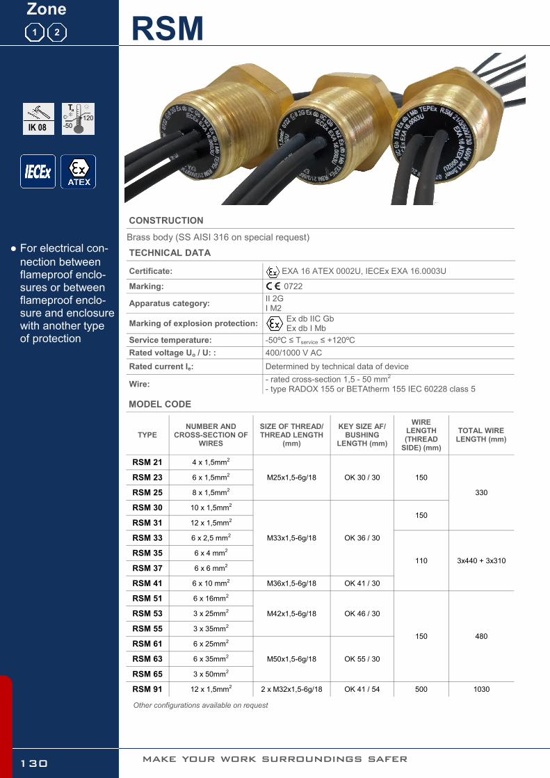
Certificate: EXA 16 ATEX 0002U, IECEx EXA 16.0003U
Marking: 0722
Apparatus category: II 2G I M2
Marking of explosion protection: Ex db IIC Gb Ex db I Mb
Service temperature: -50ºC ≤ Tservice ≤ +120ºC
Rated voltage Uo / U: : 400/1000 V AC
Rated current Ie: Determined by technical data of device
Wire: - rated cross-section 1,5 - 50 mm2 - type RADOX 155 or BETAtherm 155 IEC 60228 class 5
Brass body (SS AISI 316 on special request)
CONSTRUCTION
TECHNICAL DATA ● For electrical con-
nection between flameproof enclo-sures or between flameproof enclo-sure and enclosure with another type of protection
Zone
1
+120
-50
C
RSM
IK 08
2
MODEL CODE
Other configurations available on request
TYPE NUMBER AND
CROSS-SECTION OF WIRES
SIZE OF THREAD/THREAD LENGTH
(mm)
KEY SIZE AF/ BUSHING
LENGTH (mm)
WIRE LENGTH (THREAD
SIDE) (mm)
TOTAL WIRE LENGTH (mm)
RSM 21 4 x 1,5mm2
M25x1,5-6g/18 OK 30 / 30 150
330
RSM 23 6 x 1,5mm2
RSM 25 8 x 1,5mm2
RSM 30 10 x 1,5mm2
M33x1,5-6g/18 OK 36 / 30
150 RSM 31 12 x 1,5mm2
RSM 33 6 x 2,5 mm2
110 3x440 + 3x310 RSM 35 6 x 4 mm2
RSM 37 6 x 6 mm2
RSM 41 6 x 10 mm2 M36x1,5-6g/18 OK 41 / 30
RSM 51 6 x 16mm2
M42x1,5-6g/18 OK 46 / 30
480 150
RSM 53 3 x 25mm2
RSM 55 3 x 35mm2
RSM 61 6 x 25mm2
M50x1,5-6g/18 OK 55 / 30 RSM 63 6 x 35mm2
RSM 65 3 x 50mm2
RSM 91 12 x 1,5mm2 2 x M32x1,5-6g/18 OK 41 / 54 500 1030
make your work surroundings safer 130

Multicore bushing
www.tepex.hr 131
All technical data is relevant at the time of print.

SMP enclosure: plastic PA6
CONSTRUCTION
TECHNICAL DATA
● Ex electronica bal-
last for T8 fluores-cent tube 18, 36 and 58 W
● 18W and 36W in
parallel configura-tion
● With overcurrent,
overvoltage and over temperature protection
Zone
1
IP 20
Certificate: EXA 13 ATEX 0016U
Marking: 0722
Apparatus category: II 2G
Marking of explosion protection: Ex db IIC Gb Ex db I Mb
Ambient temperature: -25 ºC ≤ Tamb ≤ +70ºC
Degree of protection: IP 20
Frequency: 50-60 Hz
Protection class : I (protective earthing)
Lamps type: Fluo lamps T8 1-2 x 18/36/58 W
Power factor: ~0.95
BLF - Ballast lumen factor: ~ 97 %
Estimated service life: 100 000 hours at Tamb=65°C 60 000 hours at Tamb=70°C
Connection terminal: 1,0-2.5mm2, PE terminal
SMP 2
+70
-25
C
make your work surroundings safer 132

Electronic ballast
www.tepex.hr
DIMENSION DRAWING (all dimensions in mm)
MODEL CODE
TYPE LAMP TYPE
SMP 07/11 1 x 18/36W T8 Parallel configura-tion / double channel SMP 07/12 2 x 18/36W T8
SMP 08 2 x 58W T8 Single channel
SMP 07
WIRING DIAGRAM
55
201
90
222
102SMP 08 230V 50Hz 500mA
2 x 58 W T8
II 2G Ex eb mb IIC Gb
-20°C<Tservice<+80°C MA - . . .
EXA 16 ATEX . . . . U DAT - . . .
PE
N
L
L2
LL
L1
5
Medarska 69, Zagreb, Croatia
Made in Croatia0722
PE
N
L
L2
LL
L1
55
201
90
222
102SMP 08 230V 50Hz 500mA
2 x 58 W T8
II 2G Ex eb mb IIC Gb
-20°C<Tservice<+80°C MA - . . .
EXA 16 ATEX . . . . U DAT - . . .
PE
N
L
L2
LL
L1
5
Medarska 69, Zagreb, Croatia
Made in Croatia0722
PE
N
L
L2
LL
L1
133
All technical data is relevant at the time of print.

Polyamide body / neoprene gasket
PLASTIC CABLE GLANDS Exe
TECHNICAL DATA
● Ex e plastic cable
glands
● Ex d metal cable
glands for armored cable
Zone
IP 68
Apparatus category: II 2GD
Marking of explosion protection: Ex e
Ambient temperature: -35 ºC ≤ Tamb ≤ +95ºC
Degree of protection: IP 68
SPU/SPC
+90
-35
C
1 21 2 22
MODEL CODE
THREADS CLAMPING
RANGE RAL 5012 RAL 9005 H (mm) E (mm) L (mm)
M12 4,0 - 6,0 F7431200E F8031200E 15 15 39
M16 6,0 - 10,0 F7431600E F8031600E 22 15 44
M20 7,0 - 12,0 F7432050E F8032050E 24 15 45
M25 10,0 - 18,0 F7432500E F8032500E 33 15 53
M25 6,00 - 15,0 33 15 53 SPU 25 B SPU 25
M32 17,0 - 24,0 42 15 57 F7433200E F8033200E
M40 17,0 - 31,0 53 16 68 F7434000E F8034000E
M50 24,5 - 37,0 50 16 71 F7435000E F8035000E
M63 34,0 - 47,0 70 16 72 F7436300E F8036300E
134 make your work surroundings safer
H L
E
ISO

Cable glands, plugs, adapters, reducers, locknuts
www.tepex.hr
OTHER ACCESSORIES
Brass nickel plated (AISI 316 on special request)
METAL Ex d/e CABLE GLANDS (double sealing, for armoured cable) type 4F
TECHNICAL DATA
Apparatus category: II 2GD
Marking of explosion protection: Ex d/e
Ambient temperature: -40 ºC ≤ Tamb ≤ +95ºC
Degree of protection: IP 68
MODEL CODE
THREADS CLAMPING RANGE H (mm) E (mm) CODE
M16 7,0 - 12,0 20 16 4114169
M20 9,0 - 16,0 24 16 4114219
M20 13,0 - 21,0 28 16 4114229
M25 13,0 - 21,0 30 16 4114279
M25 17,0 - 27,5 36 16 4114279
M32 22,0 - 34,0 44 16 4114339
M40 28,0 - 41,0 50 16 4114419
M50 34,0 - 48,0 64 16 4114519
M63 39,0 - 54,0 70 16 4114639
M63 48,0 - 65,0 80 16 4114649
M75 55,0 - 74,0 90 18 4114769
E
Other accessories (Exd metal plugs, Exe plastic plugs, adapters, reducers, locknuts, earth tags) are available according to customer request.
135
All technical data is relevant at the time of print.

NOTES

Availability, design and specifi cations are subject to change without notice.
All rights reserved.
Printed in the Republic of Croatia, april 2017, TEPEx d.o.o.

Prilaz dr.F.Tuđmana 6, 49210 ZABOK, CROATIA
Tel: +385 49 222 900, +385 49 426 451
Fax: +385 49 426 450
@: [email protected] [email protected]
Web: www.tepex.hr