EpoxyPlus EX - Helifix
10
Applications Features and benefits • Structural steel to cracked and non-cracked concrete • Threaded bars and reinforcing bars • Rebar and starter bars • Safety barriers, fences, racking, brackets • Suitable for applications prone to dynamic loads and vibrations and in external environments • Seismically-qualified • Fixings close to free edges • Anchoring without expansion pressure • High load capacities • Fire resistant with the use of reinforcing bars up to F240 classification EpoxyPlus EX Seismically-qualified, high-performance pure epoxy resin for bonding steel bars in concrete, solid masonry, hard natural stone and solid rock Scan the QR Code for full Product Information, Case Studies and downloadable Repair Details EpoxyPlus EX has been tested in accordance with US standard AC308 for recognition under the IBC / IRC codes to resist seismic actions in Seismic Design Categories A – F. Packaging 600ml side-by-side cartridge Shelf life 24 months in original unopened containers Storage conditions Store in cool conditions (5 – 25°C) out of direct sunlight Colour Grey Mixing ratio 1:1 by volume Component A : Component B 1 PRODUCT SHEET – PS/EPEX01
-
Upload
khangminh22 -
Category
Documents
-
view
1 -
download
0
Transcript of EpoxyPlus EX - Helifix

Appl icat ions
Features and benef i ts
• Structural steel to cracked and non-cracked concrete
•Threaded bars and reinforcing bars
• Rebar and starter bars
• Safety barriers, fences, racking, brackets
• Suitable for applications prone to dynamic loads and vibrationsand in external environments
• Seismically-qualified
• Fixings close to free edges
•Anchoring without expansion pressure
• High load capacities
• Fire resistant with the use of reinforcing bars up to F240 classification
EpoxyPlus EXSeismically-qualified, high-performancepure epoxy resin for bonding steelbars in concrete, solid masonry, hardnatural stone and solid rock
Scan the QR Code for full Product Information,Case Studies and downloadable Repair Details
EpoxyPlus EX has been tested in accordance with US standard AC308 for recognitionunder the IBC / IRC codes to resist seismic actions in Seismic Design Categories A – F.
Packaging 600ml side-by-side cartridge
Shelf life 24 months in original unopened containers
Storage conditions Store in cool conditions (5 – 25°C) out of direct sunlight
Colour Grey
Mixing ratio 1:1 by volume Component A : Component B
1
PRODUCT SHEET – PS/EPEX01

Phys ical Propert iesProperty Unit Value Test Standard
4 hours N/mm2 – 1.7 ASTM D 1875 @ 20°C
Compressive Strength 24 hours N/mm2 59 ASTM D 695 @ 20°C7 days N/mm2 85 ASTM D 695 @ 20°C
Tensile Strength 24 hours N/mm2 18 ASTM D 638 @ 20°C7 days N/mm2 23 ASTM D 638 @ 20°C
Elongation at Break 24 hours % 6.6 ASTM D 638 @ 20°C7 days % 5.9 ASTM D 638 @ 20°C
Tensile Modulus 24 hours psi 827000 ASTM D 638 @ 20°C7 days psi 798000 ASTM D 638 @ 20°C
Flexural Strength 24 hours N/mm2 45 ASTM D 790 @ 20°C
HDT 7 days °C 49 ASTM D 648 @ 20°C
ASTM C 881 Test ing
According to ASTM Class CC 881-2010 Test Method (For use above 15°C)
Consistency (ASTM C 881) 0.014 in.
Gel Time (ASTM C 881) 10 minutes
Bond Strength, 2 day cure (ASTM C 882) 2656 psi
Compressive Yield Strength (ASTM D 695) 13 810 psi
Compressive Modulus (ASTM D 695) 421 293 psi
Water Absorption (ASTM D 570) 0.08%
Heat Deflection Temperature (ASTM D 468) 46°C
Linear Coefficient of Shrinkage (ASTM D 2566) 0.0003 in/in
Working and Load T imesResin Cartridge Temp. T Work Base Material Temp. T Load
10 to 15°C 20 minutes 5 to 10°C 24 hours
10 to 15°C 20 minutes 10 to 15°C 12 hours
15 to 20°C 15 minutes 15 to 20°C 8 hours
20 to 25°C 11 minutes 20 to 25°C 7 hours
25 to 30°C 8 minutes 25 to 30°C 6 hours
30 to 35°C 6 minutes 30 to 35°C 5 hours
35 to 40°C 4 minutes 35 to 40°C 4 hours
40°C 3 minutes 40°C 3 hours
NOTE: T Work is the typical time to gel at the highest temperature in the range. T Load is the typical time to reach maximum load.
2
PRODUCT SHEET – PS/EPEX01
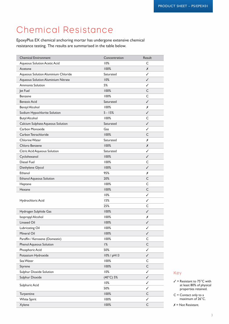
Chemical Resistance
Chemical Environment Concentration Result
Aqueous Solution Acetic Acid 10% C
Acetone 100% �
Aqueous Solution Aluminium Chloride Saturated �
Aqueous Solution Aluminium Nitrate 10% �
Ammonia Solution 5% �
Jet Fuel 100% C
Benzene 100% C
Benzoic Acid Saturated �
Benzyl Alcohol 100% �
Sodium Hypochlorite Solution 5 - 15% �
Butyl Alcohol 100% C
Calcium Sulphate Aqueous Solution Saturated �
Carbon Monoxide Gas �
Carbon Tetrachloride 100% C
Chlorine Water Saturated �
Chloro Benzene 100% �
Citric Acid Aqueous Solution Saturated �
Cyclohexanol 100% �
Diesel Fuel 100% C
Diethylene Glycol 100% �
Ethanol 95% �
Ethanol Aqueous Solution 20% C
Heptane 100% C
Hexane 100% C
10% �
Hydrochloric Acid 15% �
25% C
Hydrogen Sulphide Gas 100% �
Isopropyl Alcohol 100% �
Linseed Oil 100% �
Lubricating Oil 100% �
Mineral Oil 100% �
Paraffin / Kerosene (Domestic) 100% C
Phenol Aqueous Solution 1% C
Phosphoric Acid 50% �
Potassium Hydroxide 10% / pH13 �
Sea Water 100% C
Styrene 100% C
Sulphur Dioxide Solution 10% �
Sulphur Dioxide (40°C) 5% �
Sulphuric Acid10% �
50% �
Turpentine 100% C
White Spirit 100% �
Xylene 100% C
EpoxyPlus EX chemical anchoring mortar has undergone extensive chemicalresistance testing. The results are summarised in the table below.
� = Resistant to 75°C withat least 80% of physicalproperties retained.
C = Contact only to amaximum of 26°C.
� = Not Resistant.
Key
3
PRODUCT SHEET – PS/EPEX01

Insta l lat ion Instruct ions
1. Using the SDS Hammer Drill with acarbide tipped drill bit of theappropriate size, drill the hole to suitthe anchor.
2. a) Select the correct Air Lance, insertto the bottom of the hole anddepress the trigger for 2 seconds. Thecompressed air must be clean – freefrom water and oil – and at aminimum pressure of 90psi (6bar).
Blow Clean x 2.
b) If a Manual Pump is to be used,complete the blowing operation asabove using the full stroke of thepump and Blow Clean x 2.NOTE A Manual Pump may only be used onsizes M10-M16 and to a maximum depth<200mm.
3. Select the correct size Hole CleaningBrush. Ensure that the brush is ingood condition and the correctdiameter. Insert the brush to thebottom of the hole and withdrawwith a twisting motion. There shouldbe positive interaction between thesteel bristles of the brush and thesides of the drilled hole.
Brush Clean x 2.
4. Repeat 2 (a) or (b)
5. Repeat 3
6. Repeat 2 (a) or (b)
7. Select the appropriate static mixernozzle and attach to the cartridge.Check the Applicator is in goodworking order. Insert the cartridgeinto the dispensing tool.
NOTE: The QH nozzle is in two sections. Onesection contains the mixing elements and theother section is an extension piece. Connectthe extension piece to the mixing section bypushing the two sections firmly together until apositive engagement is felt.
8. Extrude some resin to waste until aneven- colored mixture is extruded,The cartridge is now ready for use.
9. As specified in the InstallationAccessories Table, attach anextension tube with resin stopper (ifrequired) to the end of the mixingnozzle with a push fit. (The extensiontubes may be pushed into the resinstoppers and are held in place with acoarse internal thread).
10. Insert the mixing nozzle to thebottom of the hole. Extrude theresin and slowly withdraw thenozzle from the hole. Ensure noair voids are created as thenozzle is withdrawn. Inject resin untilthe hole is approximately 3/4 full andremove the nozzle from the hole.
11. Select the steel anchor elementensuring it is free from oil or othercontaminants. Insert the steelelement into the hole using a back-and-forth twisting motion to ensurecomplete cover, until it reaches thebottom of the hole. Excess resin willbe expelled from the hole evenlyaround the steel element.
12. Clean any excess resin from aroundthe mouth of the hole.
13.Do not disturb the anchor untilthe minimum cure time has elapsed.Refer to the Working & LoadingTimes table on page 2.
14. Position the fixture and tighten theanchor to the appropriateinstallation torque.Do not over-torque the anchoras this could adversely affect itsperformance.
4
Solid Substrate Installation Method
PRODUCT SHEET – PS/EPEX01

Insta l lat ion Instruct ions (cont . )Overhead Substrate Installation Method
1. Using the SDS Hammer Drill with a carbide tipped drill bit of the appropriate size,drill the hole to suit the anchor.
2. a) Select the correct Air Lance, insert to the bottom of the hole and depress thetrigger for 2 seconds. The compressed air must be clean – free from water and oil– and at a minimum pressure of 90psi (6bar).
Blow Clean x2.
b) If a Manual Pump is to be used, complete the blowing operation as above usingthe full stroke of the pump and Blow Clean x2.
Note. A Manual Pump may only be used on sizes M10-M16 and to a maximumdepth <200mm.
3. Select the correct size Hole Cleaning Brush. Ensure that the brush is in goodcondition and the correct diameter. Insert the brush to the bottom of the holeand withdraw with a twisting motion. There should be positive interactionbetween the steel bristles of the brush and the sides of the drilled hole.
Brush Clean x2.
4. Repeat 2 (a) or (b)
5. Repeat 3
6. Repeat 2 (a) or (b)
7. Select the appropriate static mixer nozzle and attach to the cartridge. Check theApplicator is in good working order. Insert the cartridge into the dispensing tool.
Note: The QH nozzle is in two sections. One section contains the mixingelements and the other section is an extension piece. Connect the extensionpiece to the mixing section by pushing the two sections firmly together until apositive engagement is felt.
8. Extrude some resin to waste until an even-colored mixture is extruded, Thecartridge is now ready for use.
9. As specified in the Installation Accessories Table, attach an extension tube withresin stopper (if required) to the end of the mixing nozzle with a push fit. (Theextension tubes may be pushed into the resin stoppers and are held in place witha coarse internal thread).
10. Insert the mixing nozzle to the bottom of the hole. Extrude the resin and slowlywithdraw the nozzle from the hole. Ensure no air voids are created as the nozzleis withdrawn. Inject resin until the hole is approximately 3/4 full and remove thenozzle from the hole.
11. Select the steel anchor element ensuring it is free from oil or othercontaminants. Insert the steel element into the hole using a back- and-forthtwisting motion to ensure complete cover, until it reaches the bottom of thehole. Excess resin will be expelled from the hole evenly around the steel element.
12. Clean any excess resin from around the mouth of the hole.
13. Do not disturb the anchor until at least the minimum cure time has elapsed.Refer to the Working & Loading Times table on page 2.
14. Position the fixture and tighten the anchor to the appropriate installation torque.
Do not over-torque the anchor as this could adversely affect itsperformance.
Note: The use of wedges to secure the anchor during loading time isnot required.
5
PRODUCT SHEET – PS/EPEX01

Anchor Drilled Hole Brush Nozzle Extension Tube Resin Stopper NotesSize Diameter Size Type Required Required
M10 12 S14H Q Y1 > 90mm hef N
M12 14 S16H Q Y1 > 90mm hef N
M16 18 S22H Q Y2 > 250mm hef RS18 > 250mm hef QH nozzle required atQH hef > 200mm
M20 22 S24H QH Y2 > 250mm hef RS18 > 250mm hefM22 25 S27H QH Y2 > 250mm hef RS22 > 200mm hef SF27F brush required
S27F QH at hef >380mm
M24 26 S31H QH Y2 > 250mm hef RS22 > 200mm hef SF31F brush requiredS31F QH at hef>380mm
M30 35 S38H QH Y2 > 250mm hef RS30 > 200mm hef SF38F brush requiredS38F QH at hef >380mm
Insta l lat ion Accessor ies - Threaded Bar
Anchor Drilled Hole Brush Nozzle Type Tube Resin Stopper NotesSize Diameter Size Extension Required Required
T10 14 S16H Q Y1 > 90mm hef N
T12 16 S18H QH Y1 > 90mm hef N QH nozzle required atQ hef >90mm
T16 20 S22H QH Y2 > 250mm hef RS18 > 250mm hef QH nozzle required atQ hef >200mm
T20 25 S27H QH Y2 > 250mm hef RS18 > 250mm hefS27F
T25 32 S35H QH Y2 > 250mm hef RS22 >200mm hef SF31F brush requiredS35F at hef >380mm
T32 40 S43H QH Y2 > 250mm hef RS30 > 200mm hef SF38F brush requiredS43F at hef 380mm
Insta l lat ion Accessor ies - Rein forcing Bar
Extension Tubes:Y1 Required: 3/8 diameter fitted to QY2 Required: 9/16 diameter fitted to QHN Not required
Resin Stoppers:N Not requiredRS16 Use 18mm dia resin stopperRS22 Use 22mm dia resin stopperRS30 Use 30mm dia resin stopper
Key
C
S
C
C
h
hef ho
do
d anchor nominal diameterdo drilled hole diameterho hole depthhef effective bond lengthC close edge distanceS anchor spacingh concrete member thickness
Glossar y
6
PRODUCT SHEET – PS/EPEX01

Using EX wi th Threaded Bars
Characteristic Symbol Units Nominal Rod Diameter, doNominal Size do mm M10 M12 M16 M18 M20 M24 M30
Stress Area Ase mm2 58 84 157 192 245 353 561
Effectiveness Factor for Uncracked Concrete, Breakout kuncr 10.0
Effectiveness Factor for Cracked Concrete, Breakout kcr 7.1
kuncr / kcr Ycr,N 1.41
Strength Reduction Factor for Concrete Breakout Failure in Tension f 0.65
Strength Reduction Factor for Tension, Steel Failure f 0.75
Strength Reduction Factor for Concrete Breakout Failure in Shear f 0.70
Strength Reduction Factor for Concrete Pryout Failure in Shear f 0.70
Strength Reduction Factor for Shear, Steel Failure f 0.65
Additional Factor for Seismic Tension �N,seis 1.00
Reduction for Seismic Shear, Carbon Steel, ASTM F 1554 Grade 36 (A 307 C) �V,seis 1.00
Reduction for Seismic Shear, Carbon Steel, ASTM A 193 B7 �V,seis 1.00
Reduction for Seismic Shear, Stainless Steel, ASTM F 593 �V,seis 1.00
Reduction for Seismic Shear, Carbon Steel, ASTM A615, Reinforcement Bar �V,seis 1.00
Reduction for Seismic Shear, Carbon Steel, ISO 898-1 �V,seis 1.00
Reduction for Seismic Shear, Stainless Steel, ISO 3506-1 �V,seis 1.00
Reduction for Seismic Shear, Carbon Steel, DIN 488 Reinforcement Bar �V,seis 1.00
Reduction for Seismic Shear, Carbon Steel, CAN/ CSA-G30.18 Gr. 400, �V,seis 1.00Reinforcement Bar
Steel Design In format ion for Threaded Rod - General
Characteristic Symbol Units Nominal Rod Diameter, doNominal Size do mm M10 M12 M16 M18 M20 M24 M30
Stress Area1 Ase mm2 58 84 157 192 245 353 561
Tension Resistance of Carbon Steel ISO 898-1 Class 5.8 Nsa kN 29.0 42.2 78.5 96.0 122.5 176.5 280.5
Tension Resistance of Carbon Steel ISO 898-1 Class 8.8 Nsa kN 46.4 67.4 125.6 153.6 196.0 282.4 448.8
Tension Resistance of Carbon Steel ISO 898-1 Class 12.9 Nsa kN 50.0 72.7 135.3 165.5 211.2 304.3 483.6
Tension Resistance of Stainless Steel ISO 3506-1 A4-70 Nsa kN 40.6 59.0 109.9 134.4 171.5 247.1 392.7
Tension Resistance of Stainless Steel ISO 3506-1 A4-80 Nsa kN 46.4 67.4 125.6 153.6 196.0 282.4 448.8
Shear Resistance of Carbon Steel ISO 898-1 Class 5.8 Vsa kN 17.4 25.3 47.1 57.6 73.5 105.9 168.3
Shear Resistance of Carbon Steel ISO 898-1 Class 8.8 Vsa kN 27.8 40.5 75.4 92.2 117.6 169.4 269.3
Shear Resistance of Carbon Steel ISO 898-1 Class 12.9 Vsa kN 30.0 43.6 81.2 99.3 127.6 182.6 290.1
Shear Resistance of Stainless Steel ISO 3506-1 A4-70 Vsa kN 24.4 35.4 65.9 80.6 102.9 148.3 235.6
Shear Resistance of Stainless Steel ISO 3506-1 A4-80 Vsa kN 27.8 40.5 75.4 92.2 117.6 169.4 269.31Stress Area is minimum area for either tension or shear.
Steel Design In format ion for Threaded Rod - SI
7
PRODUCT SHEET – PS/EPEX01

Design Information Units Nominal Threaded Rod Diameter
M10 M12 M16 M20 M22 M24 M30
Minimum Effective Installation Depth hef,min mm 60 70 79 89 102 102 127
Maximum Effective Installation Depth hef,max mm 191 254 318 381 445 508 635
Temperature Characteristic Bond Strength in �k,uncr N/mm2 11.92Range A1 Uncracked Concrete
Characteristic Bond Strength in �k,cr N/mm2 10.06 9.72 9.03 8.67 8.33 7.64 6.60Cracked Concrete
Temperature Characteristic Bond Strength in �k,uncr N/mm2 5.15Range B2 Uncracked Concrete
Characteristic Bond Strength in �k,cr N/mm2 4.34 4.20 3.90 3.75 3.60 3.30 2.85Cracked Concrete
Temperature Characteristic Bond Strength in �k,uncr N/mm2 4.08Range C3 Uncracked Concrete
Characteristic Bond Strength in �k,cr N/mm2 3.45 3.33 3.09 2.97 2.85 2.62 2.26Cracked Concrete
Permissible Dry Concrete �d 0.65Installation Kd 1.00Conditions4, 5
Water-Saturated Concrete �ws 0.45
Kws 0.84 1.00
Water-filled Hole �wf 0.45
Kwf 0.95 1.00 0.46
Dry Concrete �d 0.65
Kd 1.00
Water-Saturated Concrete �ws 0.45 0.55
Kws 1.00
Water-filled Hole �wf 0.45 0.55 0.45
Kwf 1.00 0.54
Bond Strength Design In format ion - Threaded Rod
Perio
dic
inspectio
nCon
tinuu
ous
inspectio
n
1. Temperature Range A = 20C (Max Long Term); 43C (Max Short Term)2. Temperature Range B = 43C (Max Long Term); 72C (Max Short Term)3. Temperature Range C = 43C (Max Long Term); 80C (Max Short Term)4. � factors corresponding to Condition B according to ACI 318 - 11 for post-installed anchors5. Additional Factor for installation condition
Flow chart to establ ish design bond strength
Uncracked Concrete
SDS Hammer Drilled Holes
DryConcrete
WS- WaterSaturated
WF- WaterFilled Holes
�d �ws * Kws �wf * Kwf
�k,uncr
Cracked Concrete
SDS Hammer Drilled Holes
DryConcrete
WS- WaterSaturated
WF- WaterFilled Holes
�d �ws * Kws �wf * Kwf
�k,cr
8
PRODUCT SHEET – PS/EPEX01

Using EX wi th Rein forcing Bar
Characteristic Symbol Units Reinforcement Bar Reference
Nominal Size do mm T10 T12 T16 T20 T25 T32
Stress Area Ase mm2 78.5 113 201 314 491 804
Effectiveness Factor for Uncracked Concrete, Breakout kuncr 10.0
Effectiveness Factor for Cracked Concrete, Breakout kcr 7.1
kuncr / kcr Ycr,N 1.41
Strength Reduction Factor for Concrete Breakout Failure in Tension f 0.65
Strength Reduction Factor for Tension, Steel Failure f 0.75
Strength Reduction Factor for Concrete Breakout Failure in Shear f 0.70
Strength Reduction Factor for Concrete Pryout Failure in Shear f 0.70
Strength Reduction Factor for Shear, Steel Failure f 0.65
Additional Factor for Seismic Tension �N,seis 1.00
Reduction for Seismic Shear, Carbon Steel, ASTM F 1554 Grade 36 (A 307 C) �V,seis 1.00
Reduction for Seismic Shear, Carbon Steel, ASTM A 193 B7 �V,seis 1.00
Reduction for Seismic Shear, Stainless Steel, ASTM F 593 �V,seis 1.00
Reduction for Seismic Shear, Carbon Steel, ASTM A615, Reinforcement Bar �V,seis 1.00
Reduction for Seismic Shear, Carbon Steel, ISO 898-1 �V,seis 1.00
Reduction for Seismic Shear, Stainless Steel, ISO 3506-1 �V,seis 1.00
Reduction for Seismic Shear, Carbon Steel, DIN 488 Reinforcement Bar �V,seis 1.00
Reduction for Seismic Shear, Carbon Steel, CAN/ CSA-G30.18 Gr. 400, �V,seis 1.00Reinforcement Bar
Steel Design In format ion for Rein forcing Bar - General
Characteristic Symbol Units Nominal Rod Diameter, doNominal Size do mm T10 T12 T16 T20 T25 T32
Stress Area1 Ase mm2 78.5 113 201 314 491 804
Tension Resistance of Reinforcing Bar DIN 488 BSt 500 Nsa kN 43.2 62.2 110.6 172.7 270.1 442.2
Tension Resistance of Reinforcing Bar CAN/ CSA-G30.18 Gr. 400 Nsa kN 42.4 61.0 108.5 169.6 265.1 434.2
Shear Resistance of Reinforcing Bar DIN 488 BSt 500 Vsa kN 25.9 37.3 66.3 103.6 162.0 265.3
Shear Resistance of Reinforcing Bar CAN/ CSA-G30.18 Gr. 400 Vsa kN 25.4 36.3 65.1 101.7 159.1 260.51Stress Area is minimum area for either tension or shear.
Steel Design In format ion for Rein forcing Bar - SI
9
PRODUCT SHEET – PS/EPEX01

Tel: 020 8735 5200 l Email: [email protected] November 2020The Mille l 1000 Great West Road l Brentford l London l TW8 9DWHelif ix.co.uk l Leviat.com
Design Information Units Reinforcement Bar Reference
T10 T12 T16 T18 T20 T25 T32
Minimum Effective Installation Depth hef,min mm 60 70 79 89 102 102 127
Maximum Effective Installation Depth hef,max mm 191 254 318 381 445 508 635
Temperature Characteristic Bond Strength in �k,uncr N/mm2 11.92Range A1 Uncracked Concrete
Characteristic Bond Strength in �k,cr N/mm2 10.06 9.72 9.03 8.67 8.33 7.47 6.25Cracked Concrete
Temperature Characteristic Bond Strength in �k,uncr N/mm2 5.15Range B2 Uncracked Concrete
Characteristic Bond Strength in �k,cr N/mm2 4.34 4.20 3.90 3.75 3.60 3.23 2.70Cracked Concrete
Temperature Characteristic Bond Strength in �k,uncr N/mm2 4.08Range C3 Uncracked Concrete
Characteristic Bond Strength in �k,cr N/mm2 3.45 3.33 3.09 2.97 2.85 2.56 2.14Cracked Concrete
Permissible Dry Concrete �d 0.65Installation Kd 1.00Conditions4, 5
Water-Saturated Concrete �ws 0.45
Kws 0.84 1.00
Water-filled Hole �wf 0.45
Kwf 0.95 1.00 0.46
Dry Concrete �d 0.65
Kd 1.00
Water-Saturated Concrete �ws 0.45 0.55
Kws 1.00
Water-filled Hole �wf 0.45 0.55 0.45
Kwf 1.00 0.54
Bond Strength Design In format ion - Rein forcing Bar
Flow chart to establ ish design bond strength Heal th & Safety
Perio
dic
inspectio
nCon
tinuu
ous
inspectio
n
1. Temperature Range A = 20C (Max Long Term); 43C (Max Short Term)2. Temperature Range B = 43C (Max Long Term); 72C (Max Short Term)3. Temperature Range C = 43C (Max Long Term); 80C (Max Short Term)4. � factors corresponding to Condition B according to ACI 318 - 11 for post-installed anchors5. Additional Factor for installation condition
Uncracked Concrete
SDS Hammer Drilled Holes
DryConcrete
WS- WaterSaturated
WF- WaterFilled Holes
�d �ws * Kws �wf * Kwf
�k,uncr
Cracked Concrete
SDS Hammer Drilled Holes
DryConcrete
WS- WaterSaturated
WF- WaterFilled Holes
�d �ws * Kws �wf * Kwf
�k,cr
EpoxyPlus EX consists ofepoxy resins and hardenersystems, which are currentlyclassified as hazardousmaterials.
Wear suitable protectiveclothing, eye/face protectionand gloves, and ensureadequate ventilation.
An EpoxyPlus EX Safety DataSheet is available to downloadat www.helifix.co.uk
10
PRODUCT SHEET – PS/EPEX01