Temperature Hand Book - Tempsens
180
r Thermocouples r RTDs r Thermowells & Protection Tubes r Glass Thermocouples r Compensating Cables r Instruments Cables r Connection Heads & Accessories r Calibration Equipments r Calibration Services r Industrial Heaters r Non Contact Pyrometers r Furnace Monitoring Cameras r Industrial Furnaces www.tempsens.com Temperature Hand Book
-
Upload
khangminh22 -
Category
Documents
-
view
5 -
download
0
Transcript of Temperature Hand Book - Tempsens

r Thermocouples
r RTDs
r Thermowells & Protection Tubes
r Glass Thermocouples
r Compensating Cables
r Instruments Cables
r Connection Heads & Accessories
r Calibration Equipments
r Calibration Services
r Industrial Heaters
r Non Contact Pyrometers
r Furnace Monitoring Cameras
r Industrial Furnaces
www.tempsens.com
Temperature Hand Book

TEMPSENS Instruments (I) Pvt. Ltd is a part of Pyrotech group which was established by four
technocrats in 1976 at Udaipur, with its first product as Thermocouples and RTDs.
Today Tempsens is one of the largest manufacturer of temperature sensors with world class
manufacturing facilities in India, Germany and China.
Tempsens is an ISO 9001:2008 certified company with NABL Accredited Laboratory.
The company is involved into manufacturing of Thermocouples, RTDs, Thermowells, Cables, Non
contact Pyrometers, Heaters and Calibration Equipments etc. with Covered Area of 2,70 ,000 Sq. Ft.
Tempsens is proud of its technical solution, quick
delivery, high technical standards and outstanding
quality which have been appreciated and highly valued
by its customers worldwide.
Tempsens exports to more than 50 countries.
Tempsens success is driven by its people and their
unrelenting focus on delivering results the right way - by
operating responsibly, executing with excellence,
applying innovative technologies and capturing new
opportunities for profitable growth.
About Us
Tempsens Instruments U# l
AST & Marathon Plant Tempsens Instruments U# ll - MI Cable Plant
Tempsens Instruments U# ll

Dear friends,
We are pleased to bring to you the sixth edition of the temperature handbook, since the first handbook
was published in 2006. We are happy with the response and demand of the handbook from industry. This
handbook provides comprehensive technical details about temperature scale, sensors, calibration, etc.
Reference tables and data about sensors have been provided in the Technical reference section. If you
have any suggestion that can further improve the quality of content, please feel free to write us at:
Tempsens will celebrate its 40th anniversary in 2016. All these years, the company has been dedicated in
the field of thermal engineering solution and cables. We are privileged, in fact blessed with the support by
our esteemed clients.
We are ready to face more demanding applications in temperature sensing, heating and cables.
Tempsens would actively pursue all possible demanding application for our scope of products in steel,
cement, power, petrochemical, glass, semi-conductor, aerospace, laboratory etc.
We invite you to visit our facilities for first hand experience of our capabilities and potential. We know the
only way to keep our business successful is to provide consistent, accurate and reliable products and
prompt services. We now have NABL accredited calibration labs in Udaipur, Bangalore and Baroda. We
shall soon be in Germany to be closer to you.
With these few words, we dedicate this publication to our valuable customers.
TEAM TEMPSENS
Foreword


1
Page No.
1. Temperature and Temperature Scales 03
2. Temperature Measurement 08
3. Thermocouple Fundamental 12
4. RTD Fundamental 26
5. Protection Tubes, Thermowell, Fittings and Terminations 41
6. Extension Leads and Compensating Cables 60
7. Pyrometer Fundamental and Infrared Thermography 66
8. Furnace Monitoring System 79
9. Inspection, Testing and Calibration 82
10. Electronic and Instrumentation for Temperature 95
CONTENTS
1
Technical References 101
Glossary 167

2

. Temperature
The temperature of a substance is the degree of hotness or coldness of the substance. A hot substance is
said to have a high temperature whereas a cold substance is said to have a low temperature. Therefore,
the temperature of a substance is an indication of the average kinetic energy of the molecules of the
substance. Heat always flow from a body at higher temperature to the body at lower temperature. So, we
can also say that temperature of a body is the property which governs the flow of heat. It can easily be
demonstrated as follows:
When two objects of the same material are placed together, the object with higher temperature cools
while the cooler object gets warmer until a point is reached after which no more changes occurs.
. . Thermal E uilibrium
Heat energy flows from a body at higher temperature to another body at lower temperature. In other
words, heat flows from a hotter to the colder body. The heat energy keeps flowing from the hotter to the
cooler body until the temperature of both the bodies become equal. At this stage, the two bodies are said
to be in thermal equilibrium. When two bodies attain the same temperature, they are said to be in thermal
equilibrium with each other because then no heat flows from one body to another. The temperature thus
reached is called as equilibrium temperature.
Therefore, now we can say that Temperature is that quantity which is same for both the system when they
are in thermal equilibrium.
. . eroth Law o Thermod namics
EROTH law of thermodynamics state that If two systems are separately in thermal equilibrium with a
third, then they must also be in thermal equilibrium with each other, and they all have the same
temperature regardless of the kind of the system they are.
This law can be restated as follows: If there are three or more than three systems which when taken
together are in thermal contact and in thermal equilibrium as well, then any of the two system taken
together are in equilibrium with one another.
. Temperature Scale
One of the first attempts to make a standard temperature scale occurred in very past, when Galen, in his
medical writings, proposed a standard neutral temperature made up of equal quantities of boiling water
and ice on either side of this temperature were four degrees of heat and four degrees of cold,
respectively.
The earliest devices used to measure the temperature were called thermoscopes.
They consisted of a glass bulb having a long tube extending downward into a container of colored water,
although Galileo in 1610 is supposed to have used wine. Some of the air in the bulb was expelled before
placing it in the liquid, causing the liquid to rise into the tube. As the remaining air in the bulb was heated or
cooled, the level of the liquid in the tube would vary reflecting the change in the air temperature.
Temperature and Temperature Scales
2 3

An engraved scale on the tube allowed for a quantitative measure of the fluctuations.
The air in the bulb is referred to as the thermometric medium, i.e. the medium whose property changes
with temperature.
In 1641, the first sealed thermometer that used liquid rather than air as the thermometric medium was
developed for Ferdinand II, Grand Duke of Tuscany. His thermometer used a sealed alcohol-in-glass
device, with 50 degree marks on its stem but no fixed point was used to ero the scale. These were
referred to as spirit thermometers.
Robert Hook, Curator of the Royal Society, in 1664 used a red dye in the alcohol.
His scale, for which every degree represented an equal increment of volume equivalent to about 1 500
part of the volume of the thermometer liquid, needed only one fixed point. He selected the free ing point
of water. By scaling it in this way, Hook showed that a standard scale could be established for
thermometers of a variety of si es. Hook s original thermometer became known as the standard of
Gresham College and was used by the Royal Society until 1709. (The first intelligible meteorological
records used this scale).
In 1702, the astronomer Ole Roemer of Copenhagen based his scale upon two fixed points: snow (or
crushed ice) and the boiling point of water, and he recorded the daily temperatures at Copenhagen in
1708 - 1709 with this thermometer.
It was in 1724 that Gabriel Fahrenheit, an instrument maker of D an ig and Amsterdam, used mercury as
the thermometric liquid. Mercury s thermal expansion is large and fairly uniform, it does not stick to the
glass, and it remains a liquid over a wide range of temperatures. Its silvery appearance makes it easy to
read.
Fahrenheit described how he calibrated the scale of his mercury thermometer:
Placing the thermometer in a mixture of salt ammoniac or sea salt, ice, and water a point on the scale will be found which is denoted as ero. A second point is obtained if the same mixture is used without salt. Denote this position as 30. A third point, designated as 96, is obtained if the thermometer is placed in the mouth so as to acquire the heat of a healthy man.
On this scale, Fahrenheit measured the boiling point of water to be 212. Later he adjusted the free ing point of water to 32 so that the interval between the boiling and free ing points of water could be represented by the more rational number 180.
Temperatures measured on this scale are designated as degrees Fahrenheit ( F). In 1745, Carolus Linnaeus of Upsula, Sweden, described a scale in which the free ing point of water was ero, and the boiling point 100, making it a centigrade (one hundred steps) scale each step was called degree . Anders Celsius (1701-1744) used the reverse scale in which 100 represented the free ing point and ero the boiling point of water, still, of course, with 100 degrees between the two fixed points.
In 1948 use of the Centigrade scale was dropped in favor of a new scale using degrees Celsius ( C).
(I) The triple point of water is defined to be 0.01 C.
(ii) A degree Celsius equals the same temperature change as a degree on the ideal-gas scale.
On the Celsius scale the boiling point of water at standard atmospheric pressure is 99.975 C in contrast to the 100 degrees defined by the Centigrade scale.
34

To convert from Celsius to Fahrenheit: multiply by 1.8 and add 32.
F 1.8 C + 32
C + 273.
In 1780, J. A. C. Charles, a French physician, showed that for the same
increase in temperature, all gases exhibited the same increase in volume.
Because the expansion coefficient of gases is nearly the same, it is possible
to establish a temperature scale based on a single fixed point rather than the
two fixed- point scales, such as the Fahrenheit and Celsius scales. This
brings us back to a thermometer that uses a gas as the thermometric
medium.
In a constant volume gas thermometer a large bulb B of gas, hydrogen for
example, under a set pressure connects with a mercury-filled manometer
by means of a tube of very small volume. (The Bulb B is the temperature-
sensing portion and should contain almost all of the hydrogen). Raising or
lowering the mercury reservoir R may
adjust the level of mercury at C. The pressure of the hydrogen gas, which is
the x variable in the linear relation with temperature, is the difference between the levels D and C plus
the pressure above D.P. Chappuis in 1887 conducted extensive studies of gas thermometers with
constant pressure or with constant volume using hydrogen, nitrogen, and carbon dioxide as the
thermometric medium. Based on his results, the Comit International des Poids et Measures adopted the
constant-volume hydrogen scale based on fixed points at the ice point (0 C) and the steam point (100 C)
as the practical scale for international meteorology.
Experiments with gas thermometers have shown that there is very little difference in the temperature
scale for different gases. Thus, it is possible to set up a temperature scale that is independent of the
thermometric medium if it is a gas at low pressure. In this case, all gases behave like an Ideal Gas and
have a very simple relation between their pressure, volume, and temperature:
p (constant) T.
This temperature is called the thermodynamic temperature and is now accepted as the fundamental
measure of temperature. Note that there is a naturally defined ero on this scale - it is the point at which
the pressure of an ideal gas is ero, making the temperature also ero. With this as one point on the scale,
only one other fixed point need be defined. In 1933, the International Committee of Weights and
Measures adopted this fixed point as the triple point of water, the temperature at which water, ice, and
water vapor coexist in equilibrium) its value is set as 273.16. The unit of temperature on this scale is
called the elvin, after Lord elvin (William Thompson),
1824-1907, and its symbol is (no degree symbol used).
To convert from Celsius to elvin, add 273
C
Thermodynamic temperature is the fundamental temperature its unit is the elvin, which is defined as
the fraction 1 273.16 of the thermodynamic temperature of the triple point of water.
Constant olumeGas Thermometer
4 5

Sir William Siemens, in 1871, proposed a thermometer whose thermometric medium is a metallic
conductor whose resistance changes with temperature.
The element platinum does not oxidi e at high temperatures and has a relatively uniform change in
resistance with temperature over a large range. The Platinum Resistance.
Thermometer is now widely used as a thermoelectric thermometer and covers the temperature range
from about -260 C to 1235 C.
. . Comparison o Di erent Temperature Scales
Note: Celsius is denoted as C
Reaumer is denoted as Re
Fahrenheit is denoted as F
elvin is denoted as
Rankine is denoted as Ra
. . Relationship Between Di erent Temperature Scales
Sometimes it is required to change or convert the value of temperature from one temperature scale to
another temperature scale, for this there is a requirement of relationship between different temperature
scales. The relationship between different temperature scales is
(C-0 100) (F-32 180) ( -273 100) (Re-0 80) (Ra-491.67 180)
Where,
C, F, , Re, Ra is denoting the different temperature scales.
0, 32, 273, 0, 491.67 is denoting the lower fixed points of different temperature scales & 100, 180, 100, 80,
180 is denoting the no. of divisions in different temperature scales.
For E ample
If you want to convert Celsius into elvin and if the value in Celsius is 37 C then we can find the value in
elvin by applying the following formulae : (C- ) ( - )
. International Temperature Scale
The first internationally recogni ed temperature scale was the international temperature scale of 1927
ITS-27. Its purpose was to define procedures by which specified, high quality yet practical thermometry
could be calibrated such that the values of temperature obtained from them would be concise and
consistent instrument-to-instrument and sensor-to-sensor, while simultaneously approximating to the
appropriate thermodynamic values within the limits of the technology available.
Scale Factor Celsius Reaumer Fahrenheit elvin Rankine
Lower Fi ed Point 0 0 32 273 491.67
Upper Fi ed Point 100 80 212 373 671.67
56

This goal remains intact today.
ITS-27 extended from just below the boiling point of oxygen, -200 C, to beyond the free ing point of gold,
1065 C. Interpolation formulae were specified for platinum resistance thermometer calibrated at 0 C & at
the boiling points of oxygen, water and sulphur (445 C). Above 660 C, the Pt-10 Rh vs. Pt
thermocouple was specified for measurement. Above the gold point optical pyrometry was employed and
the values of the fixed points were based on the best available gas thermometry data of the day.
ITS-27 was revised somewhat in 1948, and then more substantially in1968-with the adoption of the
international practical temperature scale, IPTS-68. 1975 saw realignment with thermodynamic
temperature through some numerical changes, and 1976 witnessed the introduction of the provisional
0.5 to 30 temperature scale EPT-76. The current scale, ITS-90, was adopted by the International
Committee of Weights and Measures at its meeting in 1989, in accordance with the request embodied in
Resolution 7 of the 18 General Conference of Weights and Measures of 1987. This scale supersedes the
International Practical Temperature Scale of 1968 (amended edition of 1975) and the 1976 Provisional
0.5 to 30 Temperature Scale.
Essentially ITS 90 now defines a scale of temperature in five overlapping ranges.
E ualibirium State t k t C
Triple point hydrogen 13.8033 -259.3467
Boilling point of hydrogen at pressure of 33321.3Pa 17.035 -256.115
Boilling point of hydrogen at pressure of 101292Pa 20.27 -252.88
Triple point of neon 24.5561 -248.5939
Triple point of oxygen 54.3584 -218.7916
Triple point of argon 83.8058 -189.3442
Triple point of mercury 234.3156 -38.8344
Triple point of water 273.16 0.01
Melting point of gallium 302.9146 29.7646
Free ing point of indium 429.7485 156.5985
Free ing point of tin 505.078 231.928
Free ing point of inc 692.677 419.527
Free ing point of aluminium 933.473 660.323
Free ing point of silver 1234.93 961.78
Free ing point of gold 1337.33 1064.18
Free ing point of copper 1357.77 1084.62
6
These are: 0.65 to 5 using vapour pressures of Helium 3 to 24.5561 via an interpolating constant
volume gas thermometer and 13.8033 to 273.16 (0.01 C) using ratioed resistances of qualified
platinum resistance thermometers calibrated against various triple points. Then from 0 to 961.78 PRTs
are again used calibrated at fixed free ing and melting points. Finally, above the free ing point of silver,
the Planck law of radiation is used.
ITS-90 marked the culmination of a huge amount of effort (theoretical and practical) at National Physical
Laboratory and elsewhere. It is not regarded as perfect, but is a close enough approximation to the real
world of thermodynamic temperature. The goal of an International Temperature Scale is to provide an
exact definition of a measurable and traceable continuum of the physical state we call the temperature.
7

The measurement of temperature is very important in industrial application, so therefore continuous
measurement of temperature is very much essential.
Temperature can be measured through various types of sensors all of them run on the same basic
principle that they give temperature in the output according to the changes produced in their physical
characteristics in the input.
According to the type of application, measurement of temperature can be divided into following parts:
. Contact Method
This method is used when the body (whose temperature is to be measured) and the sensor (which is
measuring the temperature) can remain in contact with each other, in other words, we can say that if the
body and the sensor can remain in contact with each other during the measurement of temperature than
contact method is used.
Contact method uses three types of thermometers (temp. inst.)
1) Expansion Thermometers
2) Filled System Thermometers
3) Electrical temperature Instruments
. . E pansion Thermometers
In expansion thermometers bimetallic devices are used, in bimetallic devices there are two different
materials whose rate of thermal expansion is also different. Therefore, in bimetallic devices there are
strips of two metals which are bonded together. When heated, one side will expand more than the other,
thus the resulting expansion is translated into temperature reading by a mechanical linkage to a pointer.
The advantage of this type of instrument is that they are portable and they do not need a power supply.
And the disadvantages of this type of instrument are that they are not as accurate as other devices and
can not be directly used for controlling or recording.
. . Filled S stem Thermometers
Filled system thermometer simply means that they are filled with any of the substitute. They generally
come in two main classifications the mercury type and the organic-liquid type. Since, mercury is
considered an environmental ha ard, so there are regulations governing the shipment of that type of
devices that contain it. Now a day, there are filled system thermometers which employ gas instead of
liquids.
The advantages of these types of devices are that they do not require any electric power, they do not pose
any explosion ha ard and they are stable even after repeated cycling. And the disadvantage of these
types of devices is that they do not generate data that are easily recorded or can be transmitted and they
do not make spot or point measurements.
Temperature Measurement
8

. . Electrical Temperature Instruments
As the name implies these types of instruments sense the temperature in the terms of electrical quantities
like voltage, resistance etc. Therefore, we can say that these types of instruments are not directing
indicating thermometers like mercury in glass devices.
In the majority of industrial and laboratory processes the measurement point is usually far from the
indicating or controlling instrument. This may be due to necessity (e.g. an adverse environment) or
convenience (e.g. centrali ed data acquisition).Therefore Devices are required which convert
temperature in to another form of signal, usually electrical quantities.
The most common devices used in these types of temperature instruments are
(a) thermocouples, (b) resistance thermometers and (c) thermistors, the similarity is, all of them require
some form of contact with the body (of whose temperature is to be measured), the mode of contact could
be immersed or it could be surface, depending on the construction of the sensor and the application
where it is used.
. . (a) Thermocouples
Thermocouples essentially comprises of a thermo element (which is a junction of two dissimilar metals)
and an appropriate two wire extension lead. A thermocouple operates on the basis of the junction located
in the process producing a small voltage, which increases with temperature. It does so on a reasonably
stable and repeatable basis.
. . (b)Resistance Thermometers
Resistance thermometer utili es a precision resistor, the resistance (Ohms) value of which increases
with temperature. RTD has had positive temperature coefficient. Such variations are very stable and
precisely repeatable.
. . ( c) Thermistors
Thermistor is a semiconductor used as a temperature sensor. It is manufactured from a mixture of metal
oxides pressed into a bead, wafer or other shape. The bead is heated under the pressure at high
temperatures and then encapsulated with epoxy or glass. Beads can be very small, less than 1 mm in
some cases.
The result of all these is a temperature sensing devices that displays a very distinct non linear resistance
versus temperature relationship. The resistance of thermistor decreases with increase in the
temperature this is called as negative temperature coefficient of thermistor.
Thermistor exhibits a very large resistance changes for a small temperature change.
This can be as large as 3 to 5 per C. This makes them very sensitive to small temperature changes.
They can detect temperature change as low as 0.1 C or smaller. A thermistor element is significant
smaller in si e compared to RTDs.
The sensitivity of thermistors to temperature change and their small si e make it ideal for use in medical
equipment.
9
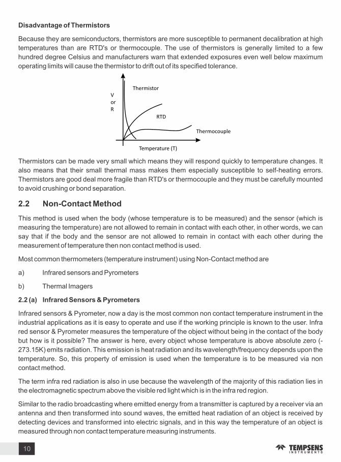
Disadvantage o Thermistors
Because they are semiconductors, thermistors are more susceptible to permanent decalibration at high
temperatures than are RTD s or thermocouple. The use of thermistors is generally limited to a few
hundred degree Celsius and manufacturers warn that extended exposures even well below maximum
operating limits will cause the thermistor to drift out of its specified tolerance.
Thermistors can be made very small which means they will respond quickly to temperature changes. It
also means that their small thermal mass makes them especially susceptible to self-heating errors.
Thermistors are good deal more fragile than RTD s or thermocouple and they must be carefully mounted
to avoid crushing or bond separation.
. Non-Contact Method
This method is used when the body (whose temperature is to be measured) and the sensor (which is
measuring the temperature) are not allowed to remain in contact with each other, in other words, we can
say that if the body and the sensor are not allowed to remain in contact with each other during the
measurement of temperature then non contact method is used.
Most common thermometers (temperature instrument) using Non-Contact method are
a) Infrared sensors and Pyrometers
b) Thermal Imagers
. (a) In rared Sensors & P rometers
Infrared sensors & Pyrometer, now a day is the most common non contact temperature instrument in the
industrial applications as it is easy to operate and use if the working principle is known to the user. Infra
red sensor & Pyrometer measures the temperature of the object without being in the contact of the body
but how is it possible The answer is here, every object whose temperature is above absolute ero (-
273.15 ) emits radiation. This emission is heat radiation and its wavelength frequency depends upon the
temperature. So, this property of emission is used when the temperature is to be measured via non
contact method.
The term infra red radiation is also in use because the wavelength of the majority of this radiation lies in
the electromagnetic spectrum above the visible red light which is in the infra red region.
Similar to the radio broadcasting where emitted energy from a transmitter is captured by a receiver via an
antenna and then transformed into sound waves, the emitted heat radiation of an object is received by
detecting devices and transformed into electric signals, and in this way the temperature of an object is
measured through non contact temperature measuring instruments.
10

Sensor Advantages Disadvantages
Thermocouple
Simple, rugged high temperature operation Low cost No resistance lead wire problems faster to temperature changes
Lease stable, least repeatable low sensitivity to small temperature changes. Extension wire must be of same T C typewire may pick up radiated electrical noise if not shielded.Lowest accuracy Cold junction compensation
RTD
More stable over timemore accurateMost repeatable temperature measurement
ery resistant to contamination corrosion of RTD element
High cost.Slowest response time.Low sensitivity to small temperature changes.Sensitivity to vibration(strains the platinum element wire)Decalibration if used beyond sensor s temperature rating. Somewhat fragile
Thermistor
High sensitivity to small temperature changesTemperature measurement become more stable with useCopper or nickel extension wires can be used
Limited temperature rangeFragilesome initial accuracy driftDecalibration if used beyond the sensor s temperature rating.Lack of standards of replacement.
In rared
No contact with the product requiredResponse times as fast or faster than thermocouplesNo corrosion or oxidation to affect sensor accuracyGood stability over timeHigh repeatability
High initial cost.More complex support electronics required.Emmisivity variations affect temperature measurement accuracy. Field of view and spot si e may restrict sensor application.Measuring accuracy affected by dust, smoke background radiation.
Heat Source
Non-Contact TSensor
emperature
Optics InfraredDetector
Temperature Controlleror Indicator
. Temperature Sensors Comparison Chart
11

. Introduction
Thermocouples are pairs of dissimilar metal wires joined at one end, which generate a net thermoelectric
voltage between the open pair according to the temperature difference between the ends.
The junction that is put into the process in which temperature is being measured is called the HOT
JUNCTION. The other junction which is at the last point of thermocouple material and which is almost
always at some kind of measuring instrument is called the COLD JUNCTION.
Thermocouples are available either as bare wire ( bead thermocouples) which offer low cost and fast
response times, or built into probes. A wide variety of probes are available, suitable for different
measuring applications (industrial, scientific, food temperature, medical research etc).
. The Seebeck E ect
In 1821 a German physicist named Seebeck discovered the thermoelectric effect, which forms the basis
of modern thermocouple technology. He observed that an electric current flows in a closed circuit of two
dissimilar metals if their two junctions are at different temperatures. The thermoelectric voltage produced
depends on the metals used and on the temperature relationship between the junctions. If the same
temperature exists at the two junctions, the voltage produced at each junction cancel each other out and
no current flows in the circuit. With different temperatures at each junction, different voltages are
produced and current flows in the circuit. A Thermocouple can therefore only measure temperature
differences between the two junctions.
It is important to designate each of the junctions for practical purposes the measuring junction (often
referred to as the hot junction) is that which is exposed to be measured temperature. The reference
junction is the other junction that is kept at a known temperature this is often referred to as the cold
junction. The term thermocouple refers to the complete system for producing thermal voltages and
generally implies an actual assembly (i.e. a sheathed device with extension leads or terminal blocks).
Thermocouple Fundamental
T T + T2 1
Current in Conductor A
Resulting
Current
T1
Current in Conductor B
Heat Flow The two conductors and associated
measuring junction constitute a thermo
element and the individual conductors are
identified as the positive or negative leg.
The change in material EMF with respect
to a change in temperature is called the
Seebeck coefficient or thermoelectric
sensitivity. This coefficient is usually a
nonlinear function of temperature.
12

Law o Successive Thermocouple
One thermocouple has its measuring point at T1 and open end at T2. The second thermocouple has its
measuring point at T2 and its open end at T3. The third thermocouple has its measuring point at T3.The
emf level for the thermocouple that is measuring T1 is e1 that for the other thermocouple is e2 and for the
last thermocouple is e3. The sum of the three EMF s e1, e2, e3, equals the EMF e that would be
generated by the combined thermocouple operating between T1 & T4.
Hence a thermocouple is a sum of many thermocouples. For eg. An EMF produced by a thermocouple
with hot junction at T1 & cold at T4 The EMF generated will be equal to many thermocouples joined
together and produced EMF would be equals to sum of these three EMF e1, e2, e3.
e e1+e2+e3
The characteristics of the thermocouple alloy should be uniform for the full length of thermocouple.
Note Thermocouple is always formed when two metals are connected together. For example, when the
Thermo element conductors are joined to copper cable or terminals, thermal voltages can be generated
at the transition. In this case, the second junction can be taken as located at the connection point
(assuming the two connections to be thermally common). The temperature of this connection point
(terminal temperature) if known, allows computation of the temperature at the measuring junction. The
thermal voltage resulting from the terminal temperature is added to the measured voltage and their sum
corresponds to the thermal voltage against a 0 C reference.
If the measuring junction is at 300 C and the terminal temperature is 25 C, the measured thermal voltage
for the type thermo element (Nickel-Chromium v Nickel-Aluminum) is 11.18 m . This corresponds to
275 C difference temperature. Therefore a positive correction of 25 C refers the temperature to 0 C
reference 300 C is thus indicated.
Important points to note at this stage are four-fold.
1. Thermocouples only generate an output in the regions where the temperature gradient exists- not
beyond.
e e1+e2+e3
e1
e2
e3
T1 T2 T3 T4
Instrument
Input
Terminals
Compensating Cable
300 C 25 C
13

2. Accuracy and stability can only be assured if the thermoelectric characteristics of the thermocouple
conductor s are uniform throughout.
3. Only a circuit comprising dissimilar materials in a temperature gradient generates an output.
4. Although the thermoelectric effects are seen at junctions, they are not due to any magic property of the
junction itself.
. Cold unction Compensation
A practical industrial or laboratory Thermocouple consists of only a single (measuring) junction the
reference is always the terminal temperature.
Possible measures are:-
a) Measures the terminal temperature accurately and compensate accordingly in calculating the
measured value.
b) Locate the terminals in a thermally controlled enclosure.
c) Terminate not in copper cable but use compensating or actual thermocouple wire to extend the
sensor termination to the associated instrumentation (compensating cable uses low cost alloys,
which have similar thermoelectric properties to the actual thermoelement). On this basis, there is no
thermal voltage at the thermocouple termination. The transition to copper then occurs only at the
instrument terminals where the ambient temperature can measure by the instrument the reference
junction can then be compensated for electronically.
Note - It is essential to use only compensating or specific extension cables (these have the correct
thermoelectric properties) appropriate to the thermocouple other wise an additional thermocouple
is formed at the connection point. The reference junction is formed where the compensating or
extension cable is connected to a difference material. The cable used must not be extended with
copper or with compensating cable of a different type.
d) Use a temperature transmitter at the termination point. This is effectively bringing instrumentation
close to the sensor where electronic reference junction techniques can be utili ed. However, this
technique is convenient and often used in plant transmitter produces an amplified corrected
signal, which can be sent to remote instruments via copper cable of any length.
Thermoelement with compensating cable
Instrumentinputterminals
Compensating Cable
Temperature Transmitter - wire
Indicator
Power
supply
12-30 dc
2-wire transmitter
4-20 mA
4-20 mA
+
14

. Method o Formation o Hot unction
To form the hot junction, a suitable method has to be adopted to obtain a good electrical contact between
the thermocouple wires.
For Chromal Alumal and other combinations, for use in high temperature measurements, welding is the
only method to obtain a suitable joint.
For this purpose Tig welding & Laser beam welding is mostly used.
Tig Welding
Gas tungsten arc welding (GTAW), also known as tungsten inert gas (TIG) welding, is an arc welding
process that uses a nonconsumable tungsten electrode to produce the weld. The weld area is protected
from atmospheric contamination by a shielding gas.
Laser Bbeam Welding
Laser beam welding (LBW) is a welding technique used to join multiple pieces of metal through the use of
a laser. The beam provides a concentrated heat source, allowing for narrow, deep welds and high welding
rates. LBW is a versatile process, capable of welding carbon steels, HSLA steels, stainless steel,
aluminum and titanium. The speed of welding is proportional to the amount of power supplied but also
depends on the type and thickness of the workpieces.
. Thermocouple Standard
ASTM E 235 : Standard Specification for Thermocouples, Sheathed, Type and Type
N for Nuclear or for other High-Reliability Applications.
. Measuring unctions
Three alternative tip configurations are usually offered:
a) An e posed (measuring) junction is recommended for the
measurement of flowing or static non-corrosive gas temperature when
the greatest sensitivity and quickest response is required.
b) An insulated junction is more suitable for corrosive media although
the thermal response is slower. In some applications where more than
one thermocouple connects to the associated instrumentation,
insulation may be essential to avoid spurious signals occurring in the
measuring circuits. If not specified, this is the standard.
c) An earthed (grounded) junction is also suitable for corrosive media
and for high pressure applications. It provides faster response than
the insulated junction and protection not offered by the exposed
junction.
B. Thermocuple elementis detached from the probe well
C. Thermocuple elementis attached to the probe well
A.Thermocuple junction
protrudes outside of the probe sheath
15

ASTM E 839 : Standard Test Methods for Sheathed Thermocouples and Sheathed
Thermocouple Materials.
ASTM E 220 : Test Methods for Calibration of Thermocouples by Comparison
Techniques
ASTM E 230 : Specification and Temperature-EMF Tables for Standardi ed
Thermocouples.
ASTM E 585 : Standard specification for compacted MI, MS, base metal thermocouple
cables.
ASTM E 608 : Standard specification for compacted MI, MS, base metal
thermocouples.
ASTM E 696 : Standard specifications for tungsten - rhenium alloy thermocouple wire.
ASTM E 1652 : Standard specification for Magnesium oxide & Alumina oxide powder &
crushable insulators used in metal sheathed PRT s, base metal
thermocouples & noble metal thermocouple.
IS 12579 : Specification for Base Metal Mineral Insulated Thermocouple Cables
and Thermocouples.
GB T 1598 - 2010 : Chinese standard for platinum thermocouples.
IEC 584 : International standard for thermocouples.
. T pes o Thermocouple
Many combinations of materials have been used to produce acceptable thermocouples, each with its
own particular application spectrum. However, the value of interchangeability and the economics of mass
production have led to standardi ation, with a few specific types now being easily available, and covering
by far the majority of the temperature and environmental applications.
These thermocouples are made to conform to an e.m.f temperature relationship specified in the form of
tabulated values of e.m.fs resolved normally to 1m against temperature in 1C intervals, and vice versa.
Internationally, these reference tables are published as IEC 584 1, 2 & 4, which is based on the
International Temperature Scale ITS-90. It is worth noting here, however, that the standards do not
address the construction or insulation of the cables themselves or other performance criteria. With the
diversity to be found, manufacturers own standards must be relied upon in this respect.
The standard covers the eight specified and most commonly used thermocouples, referring to their
internationally recogni ed alpha character type designation & providing the full reference tables for each.
These thermocouple types can be subdivided in 3 groups, base metal, noble (rare) metal & Refractory
metal thermocouple.
. . Base Metal Thermocouples
Base metal thermocouple types are composed of common, inexpensive metals such as nickel, iron and
copper. The thermocouple types E, J, , N and T are among this group and are the most commonly used
type of thermocouple.
16

Each leg of these different thermocouples is composed of a special alloy, which is usually referred to by
their common names.
T pe E The type E thermocouple is composed of a positive leg of chromel (90 nickel 10 chromium)
and a negative leg of constantan (45 nickel 55 copper). The temperature range for this thermocouple 0is -200 to 900 C (-330 to 1600 F). The type E thermocouple has the highest millivolt (EMF) output of all
established thermocouple types. Type E sensors can be used in sub- ero, oxidi ing or inert applications
but should not be used in sulphurous, vacuum or low oxygen atmospheres.
T pe Type J thermocouples have an iron positive leg and a constantan negative leg. Type J
thermocouples have a useful temperature range of 0 to 750 C (32 to 1400 F) and can be used in
vacuum, oxidi ing, reducing and inert atmospheres. Due to the oxidation (rusting) problems associated
with the iron leg, care must be takin when choosing this type for use in oxidi ing environments above 537
C.
T pe The type thermocouple has a Chromel (90 nickel 10 copper) positive leg and an Alumel
(95 nickel 5 manganese, aluminum and silicon) negative leg. The temperature range for type alloys
is -200 to 1250 C (-328 to 2282 F). Type sensors are recommended for use in oxidi ing or completely
inert environments. Type and type E should not be used in sulfurous environments. Because type has
better oxidation resistance then types E, J and T, its main area of usage is at temperatures above 600 C
but vacuum and low oxygen conditions should be avoided.
T pe N Type N thermocouples are made with a Nicrosil (74.1 nickel 14.4 chromium 1.4
silicon.0.1 magnesium) positive leg and a Nisil (95.6 nickel to 4.4 silicon) negative leg. The
temperature range for Type N is -270 to 1300 C (-450 to 2372 F). Type N is very similar to Type except
that it is less susceptible to selective oxidation. Type N should not be used in vacuum and or reducing
environments in an unsheathed design.
T pe T Type T thermocouples are made with a copper positive leg and a constantan negative leg. The
temperature range for type T is -200 to 350 C (-328 to 662 F). Type T sensors can be used in oxidi ing
(below 350 C), reducing or inert applications.
. . Noble Metal Thermocouples
Noble metal thermocouples are manufactured with wire that is made with precious or noble metals like
Platinum and Rhodium. Noble metal thermocouples can used in oxidi ing or inert applications and must
be used with a ceramic protection tube surrounding the thermocouple element. These sensors are
usually fragile and must not be used in applications that are reducing or in applications that contain
metallic vapors.
T pe R Type R thermocouples are made with a platinum 13 rhodium positive leg and a pure platinum
negative leg. The temperature range for type R is 0 to 1450 C (32 to 2642 F)
T pe S Type S thermocouples are made with a platinum 10 rhodium positive leg and a pure platinum
negative leg. The temperature range for type S is 0 to 1450 C (32 to 2642 F)
T pe B Type B thermocouples are made with a platinum 30 rhodium positive leg and a platinum 6
Rhodium negative leg. The temperature range for type B is 0 to 1700 C (32 to 3092 F)
. . Re ractor Metal Thermocouples
Refractory metal thermocouples are manufactured with wire that is made from the exotic metals tungsten
17

and Rhenium. These metals are expensive, difficult to manufacture and wire made with these metals are
very brittle. These thermocouples are intended to be used in vacuum furnaces at extremely high
temperatures and must never be used in the presence of oxygen at temperatures above 300 C. There
are several different combinations of alloys that have been used in the past but only one generally used at
this time.
T pe C- The type C thermocouple is made with a tungsten 5 rhenium positive leg and tungsten 26
rhenium negative leg and has a temperature range of 0 2320 C (32 4208 F).
T pe G- Type G thermocouple technically also known as WM26Re. The type G thermocouple has alloy
combination of tungsten (W) as positive lead and tungsten + 26 Rhenium (W-26 Re) as negative lead.
Maximum useful temperature range of this thermocouple is 0 to 2320 C.
T pe D- Type D thermocouple technically also known as W3ReM25Re. Type D thermocouple has alloy
combination of tungsten + 3 rhenium (W-3 Re) as positive lead and tungsten + 25 Rhenium (W-
56 Re) as negative lead. Maximum useful temperature range of this thermocouple is 0 to 2320 C.
Thermocouple T pe
Material & -Temperature
Range( C)Application
E
J
N
T
R
S
B
Chromel & Constantan (Ni-Cr & Cu-Ni)
Iron & Constantan (Fe & Cu-Ni)
Chromel & Alumel(Ni-Cr & Ni-Al)
Nicrosil & Nisil(Ni-Cr & Ni-Si)
Copper & Constantan(Cu & Cu-Ni)
87 Platinum 13 Rhodium & Platinum
(Pt & Pt-Rh)
90 Platinum 10 Rhodium & Platinum
(Pt & Pt-Rh)
70 Platinum 30 Rhodium & 94 Platinum 6 Rhodium
(Pt-Rh & Pt-Rh)
-200 to 900 C
0 to 750 C
-200 to 1250 C
-270 to 1300 C
-200 to 350 C
0 to 1450 C
0 to 1450 C
0 to 1700 C
Inert media, Oxidi ing media
Inert media, Oxidi ing media, Reducing media acuum
Inert media, Oxidi ing media
Inert media, Oxidi ing media
Inert media, Oxidi ing media, Reducing media acuum
Inert media, Oxidi ing media,
Inert media, Oxidi ing media,
Inert media, Oxidi ing media,
C
G
D
95 Tungsten5 Rhenium &74 Tungsten26 Rhenium
Tungsten & 74 Tungsten26 Rhenium
97 Tungsten 3 Rhenium &75 Tungsten25 Rhenium
0 to 2320 C
0 to 2320 C
0 to 2320 C
acuum inert and reducing
acuum inert and reducing
acuum inert and reducing
18
Temperature in C
EM
F in
miliv
olt
s
E
B
N
C
SRT
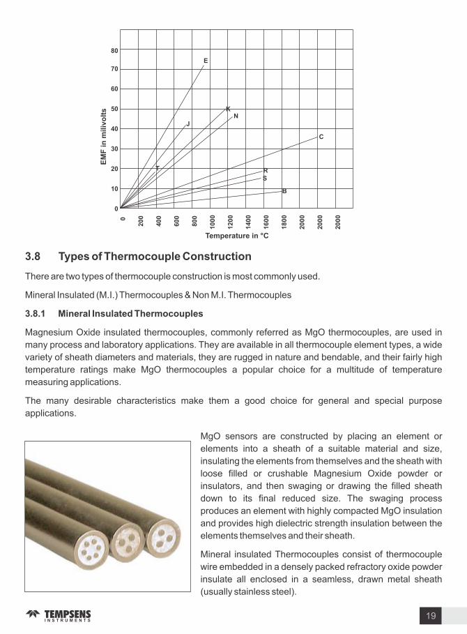
. T pes o Thermocouple Construction
There are two types of thermocouple construction is most commonly used.
Mineral Insulated (M.I.) Thermocouples & Non M.I. Thermocouples
. . Mineral Insulated Thermocouples
Magnesium Oxide insulated thermocouples, commonly referred as MgO thermocouples, are used in
many process and laboratory applications. They are available in all thermocouple element types, a wide
variety of sheath diameters and materials, they are rugged in nature and bendable, and their fairly high
temperature ratings make MgO thermocouples a popular choice for a multitude of temperature
measuring applications.
The many desirable characteristics make them a good choice for general and special purpose
applications.
MgO sensors are constructed by placing an element or
elements into a sheath of a suitable material and si e,
insulating the elements from themselves and the sheath with
loose filled or crushable Magnesium Oxide powder or
insulators, and then swaging or drawing the filled sheath
down to its final reduced si e. The swaging process
produces an element with highly compacted MgO insulation
and provides high dielectric strength insulation between the
elements themselves and their sheath.
Mineral insulated Thermocouples consist of thermocouple
wire embedded in a densely packed refractory oxide powder
insulate all enclosed in a seamless, drawn metal sheath
(usually stainless steel).
19
Effectively the thermoelement, insulation and sheath are combined as a flexible cable, which is available
in different diameters, usually from 0.25mm to 10mm.
At one end cores and sheath are welded from a hot junction. At the other end, the thermocouple is
connected to a transition of extension wires, connecting head or connector.
Advantages o mineral insulated thermocouple are
a) Small over all dimension and high flexibility, which enable temperature measurement in location
with poor accessibility.
b) Good mechanical strength.
c) Protection of the thermo element wires against oxidation, corrosion and contamination.
d) Fast thermal response.
The mineral oxides used for insulation are highly hygroscopic and open-ended cables must be effectively
sealed (usually with epoxy resins) to prevent moisture take-up. A carefully prepared mineral insulated
thermocouple will normally have a high value of insulation resistance (many hundreds of mega ohms).
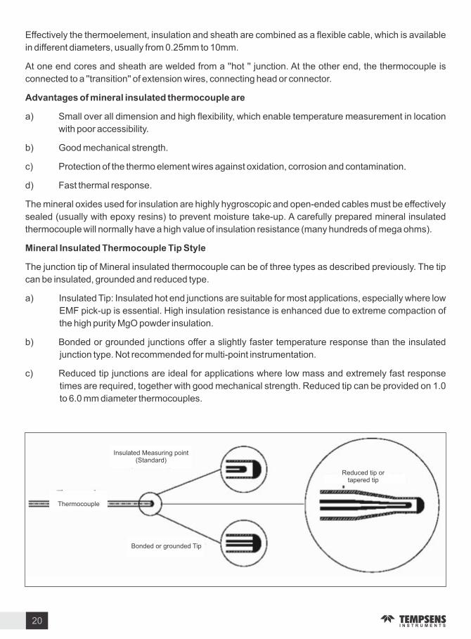
Mineral Insulated Thermocouple Tip St le
The junction tip of Mineral insulated thermocouple can be of three types as described previously. The tip
can be insulated, grounded and reduced type.
a) Insulated Tip: Insulated hot end junctions are suitable for most applications, especially where low
EMF pick-up is essential. High insulation resistance is enhanced due to extreme compaction of
the high purity MgO powder insulation.
b) Bonded or grounded junctions offer a slightly faster temperature response than the insulated
junction type. Not recommended for multi-point instrumentation.
c) Reduced tip junctions are ideal for applications where low mass and extremely fast response
times are required, together with good mechanical strength. Reduced tip can be provided on 1.0
to 6.0 mm diameter thermocouples.
Insulated Measuring point(Standard)
Thermocouple
Bonded or grounded Tip
Reduced tip or tapered tip
20

Cross Diameter (D)
Cross Section o Shell Lines
Metal Jacket (S) Thermo-wires (C)
Compact Insulation (I)
C
. . Non M.I. Thermocouples
In Non-M.I. thermocouples, thermocouple wires are either insulated with ceramic beads or after
insulation of ceramic, covered by a metal sheath (usually stainless steel) and some form of termination
(extension lead, connecting head or connector for example) is provided. In this type of construction
thermocouple wires are protected from the measuring environment when a sheath protection is provided.
The sheath material is dependent on the measuring environment usually stainless steel is used.
According to the corrosive environment sheath selection is changed.
This construction does not provide flexibility & not found in small si es. Not too good mechanical strength.
In Non M.I. construction sheath may be of ceramic or metal as per suitability.
Exposed, Grounded and Ungrounded all types of junctions are formed in both the M.I., & Non M.I.
construction.
. . Characteristics o Thermocouple
. . Tolerances on Temperature Reading
Tolerance denotes the maximum allowable value obtained by subtracting the temperature reading or the
temperature at the hot junction from the standard temperature converted from the applicable temperature
EMF table.
Cross section view o M.I. Thermocouple
In above figure of M.I. thermocouple, S, I, C represent the terms sheath
thickness, insulation, conductor respectively. These values depend
upon the outer diameter (D) of M.I. thermocouple.
T pe o thermoco-
uple Temperature range ( C)
Standard SpecialTemperature Range ( C)
Class Class
ASTM E -ANSI MC . IEC -
Tolerance Grade
B 800 to 1700 C 0.5 - - - 600 to 1700 C1100) x .0.3 )1 C or (1+(T-
1.5 C or 0.25
R & S 0 1450 Cto0.5 C or 0.25
0.6 C or 0.1
0 to 1600 C
N &
-200 to 0 C2.2 C or
2 - - -
0 to 1260 C2.2 C or 0.75
1.1 C or 0.4
-40 to 1000 C 1.5 C or 0.4 2.5 C or 0.75
1100) x .0.3 )1 C or (1+(T-
1.5 C or 0.25
21
Number o Thermoelements
Minimum Sheath Thickness 10 10 10
Minimum Thermoelement Diameter 15 12 9
Minimum Insulation Thickness 7 5.5 4

For bare wire thermocouple
T pe o Thermocouple
No. AWG . mm ( C)
Upper temperature limit or various wire si es
No. AWG . mm ( C)
No. AWG . mm ( C)
No. AWG . mm ( C)
No. AWG . mm ( C)
T
J
E
N
R, S
B
- - -
760
870
1260
1260
- - -
- - -
370
590
650
1090
1090
- - -
- - -
260
480
540
980
980
- - -
- - -
200
370
430
870
870
1480
1700
200
370
430
870
870
- - -
- - -
E
-200 0 C
0 to 870 C
to 1.7 C or 1
1.7 C or 0.5
- - -
1.0 C or 0.4
-40 to 800 C 0.41.5 C or 2.5 C or 0.75
T pe o thermoco-
uple Temperature range ( C)
Standard SpecialTemperature Range ( C)
Class Class
ASTM E -ANSI MC . IEC -
Tolerance Grade
J
T
C
0 760 Cto2.2 C or 0.75
1.1 C or 0.4
-40 to 750 C
-200 0 C
0 to 370 C
to1.0 C or
1.5
1.0 C or 0.75
- - -
0.5 C or 0.4
-40 to 350 C 0.5 C or 0.4 1 C or 0.75
0 to 2320 C4.5 C or
1.0- - - - - -
- - - - - -
0.41.5 C or 2.5 C or 0.75
. . Ma imum Operating Temperature
Operating temperature limit means the upper temperature where thermocouple can be used
continuously in air. Maximum limit means the upper temperature where thermocouple can be used
temporarily for short period of time owing to unavoidable circumstances. This graph is given as a guide
only, and not to be guaranteed.
Principal factors that affect the life of a thermocouple are:
Temperature Thermocouple life decreases by about 50 when an increase of 50 C occurs.
Diameter By doubling the diameter of the wire, the life increases by 2-3 times.
Thermic c cling When thermocouples are exposed to thermic cycling from room temperature to
above 500 C, their life decreases by about 50 compared to a thermocouple used continuously at
the same temperature.
Protection When thermocouples are covered by a protective sheath and placed into ceramic
insulators, their life is considerably extended.
22

T pe o Thermocouple
. mm( C)
Upper temperature limit or various SS sheath diameters
. mm( C)
. mm( C)
. mm( C)
. mm( C)
T
J
E
N
260
260
300
700
700
260
260
300
700
700
260
440
510
920
920
315
440
510
920
920
370
520
650
1070
1070
. mm( C)
. mm( C)
. mm( C)
370
620
730
1150
1150
370
720
820
1150
1150
370
720
820
1150
1150
For Mineral Insulated Cables
While application conditions do alter techniques, the following factors are suggested for consideration.
1. Obtain thermocouples with insulated measuring junctions.
2. Specify same metal for large installation, preferably close tolerance.
3. Thermocouple reference junction should be monitored in a reference unit with an accuracy of
+0.1 C or better.
4. Great care to be taken in running thermocouple circuitry against Pickup etc. with the minimum
number of joints in the wiring.
5. Heat-treat thermocouple to their most stable condition.
6. Calibrate thermocouples.
. . Thermocouple Response Times
The response time for a thermocouple is usually defined as the time taken for the thermal voltage (output)
to reach 63 of maximum for the step change temperature. It is dependent on several parameters
including the thermocouple dimension, construction, tip configuration and the nature of the medium in
which the sensor is located. If the thermocouple is plunged in to a medium with a high thermal capacity
and heat transfer is rapid, the effective response time will be practically the same as for the thermocouple
itself (the intrinsic response time). However, if the thermal properties of the medium are poor (e.g. still air)
the response time can be 100 times greater.
For exposed measuring junctions, divide the values shown by 10. Thermocouple with grounded junction
display response times some 20 to 30 faster than those with insulated junction. ery good sensitivity is
provided by fine gauge unsheathed thermocouples. With conductor diameter in the range 0.025mm to
0.81mm, response times in the region of 0.05 to 0.40 seconds can be reali ed.
23

. . Immersion Length
Thermocouple assemblies are tip sensing devices which lends them to both surface and immersion
applications depending on their construction. However immersion type must be used carefully to avoid
error due to stema conduction from the process which can result in a high or low reading respectively.A
general rule is to immerse into the medium to a minimum of 4 times the out side diameter of them sheath
no quantitative data applies but care must be exercised in order to obtain meaningful results.
The ideal immersion depth can be achieved in practice by moving the probe in to or out of the process
medium incrementally with each adjustment, not any apparent change in indicating temperature. The
correct depth will result in no change in indicating temperature.
. . Sur ace Temperature Measurement
Although thermocouple assemblies are primarily tip sensing devices, the use of protection tubes renders
surface sensing impractical. Physically, the probe does not lend it self to surface presentation and steam
conduction would cause reading errors. If thermocouple is to be used reliably for surface sensing, it must
be either exposed, welded junction from with very small thermal mass or be housed in a construction,
which permits true surface contact when attaching to the surface. Locating a thermocouple on a surface
can be achieved in various ways including the use of an adhesive patch, a washer and stud, a magnet for
ferrous metal and pipe clips.
. . Advantage o Thermocouple
Industrial thermocouple, in comparison with other thermometers, has the following features:
1. uick response and stable temperature measurement by direct contact with the measuring
object.
2. If the selection of a quality thermocouple is properly made, wide range of temperature can be
measured.
3. Temperature of specific spot or small space can be measured.
4. Since temperature is detected by means of EMF generated, measurement, adjustment,
amplification, control, conversion and other data processing are easy.
Sheath Outer Diameter (mm)
T pes o Measuring unction
Response Time in Seconds (in sec.)
C C C C C C
6.00
1.00
1.5
1.5
1.00
3.00
3.00
6.00
Insulated
Earthed
Insulated
Earthed
Insulated
Earthed
Insulated
Earthed
3.2
0.07
0.25
0.14
0.16
0.4
1.0
1.6
4.0
0.09
0.37
0.17
0.18
0.46
1.1
2.0
4.7
0.11
0.43
0.185
0.19
0.5
1.25
2.3
5.0
0.12
0.50
0.195
0.21
0.56
1.4
2.5
6.4
0.16
0.72
0.22
0.24
0.65
1.6
3.15
16.0
0.6
1.0
0.8
0.73
1.8
4.5
8.0
alues shown are for a closed end sheath.
24

5. Less expensive and better interchangeability in comparison with other temperature sensors.
6. The most versatile and safe for measuring environments, if a suitable protection tube is
employed.
7. Rugged construction and easy installation.
. Applications o Thermocouple
Thermocouples are suitable for measuring over a large temperature range, up to 2300 C. They are less
suitable for applications where smaller temperature differences need to be measured with high accuracy,
for example the range 0 - 100 C with 0.1 C accuracy. For such applications thermistors and resistance
temperature detectors are more suitable. Applications include temperature measurement for kilns, gas
turbine exhaust, diesel engines, and other industrial processes.
Some other applications are as follows :
1. Steel Industry
2. Cement Industry
3. Pharmaceutical Industry
4. Petrochemical Industry
5. Nuclear Industry
6. Power Industry
7. Laboratories
8. Furnace Industry
25

. Introduction
The measurement of temperature using the resistance temperature characteristics of various materials
were probably first to put use by Sir Williams Siemens in 1871, largely laid the foundations of modern
resistance thermometry.
The resistance of material can be obtained from the given formula :
R ( L) A
Where
R Resistance(ohms)
Resistivity(ohm cm)
L Length(cm)
2A Cross sectional area(cm )
. Histor Related to Resistance Temperature Detector
Sir William Siemens offered the use of platinum as the element in a resistance thermometer. His choice
proved most favorable, as platinum is used to these days as the primary element in all high-accuracy
resistance thermometers.
Platinum is especially suited to this purpose, as it can withstand high temperatures while maintaining
excellent stability. As a noble metal, it shows limited susceptibility to contamination.
The classical resistance temperature detector (RTD) construction using platinum was proposed by C.H.
Meyers in 1932. He used a helical coil of platinum on a crossed mica web and mounted the assembly
inside a glass tube. This construction minimi es strain on the wire while maximi ing resistance.
Although this construction produces a very stable element, the thermal contact between the platinum and
the measured point is quite poor. This results in a slow thermal response time. The fragility of the structure
limits its use today primarily to that of a laboratory standard.
RTD Fundamentals
MEYERS RTD CONSTRUCTION
Another laboratory standard has taken the
place of Meyers design. This is the bird-cage
element proposed by Evans and Burns. The
platinum element remains largely unsupported,
which allows it to move freely when expanded
or contracted by temperature variations.
26

Strain-induced resistance changes over time and
temperature are thus minimi ed, and the bird-cage
becomes the ultimate laboratory standard. Due to the
unsupported structure and subsequent susceptibility to
vibration, this configuration is still a bit too fragile for
industrial environment.
The platinum wire is bifilar wound on a glass or ceramic
bobbin. The bifilar winding reduces the effective
enclosed area of the coil to minimi e magnetic pickup
and its related noise. Once the wire is wound onto the
bobbin, the assembly is then sealed with a coating of
molten glass.
Insulator Disk
Bird Cage element
The sealing process assures that the RTD will maintain its integrity under extreme vibration, but it also
limits the expansion of the platinum metal at high temperatures. Unless the coefficients of expansion of
the platinum and the bobbin match perfectly, stress will be placed on the wire as the temperature
changes, resulting in a strain-induced resistance change. This may result in a permanent change in the
resistance of the wire. There are partially supported versions of the RTD which offer a compromise
between the bird-cage approach and the sealed helix. One such approach uses a platinum helix threaded
through a ceramic cylinder and affixed via glass-frit. These devices will maintain excellent stability in
moderately rugged vibrational applications.
. Resistance Temperature Detector (RTD)
. . Introduction
The RTDs resistance vs temperature characteristics are stable, reproducible, and have a near linear
positive temperature coefficient from 200 to 800 C. These attributes establish RTDs as a de-facto
industry standard. Temperature is determined by measuring resistance and then using the RTD.s .R vs T.
characteristics to extrapolate temperature. The superior sensitivity and stability of these devices, in
comparison to thermocouples, give them important advantages in low and intermediate temperature
ranges. In addition, resistive devices often simplify control and readout electronics.
Resistance thermometers may be called RTD s (resistance temperature detectors), PRT s (platinum
resistance thermometers), or SPRT s (standard platinum resistance thermometers).
The chemical stability, availability in pure form, and highly reproducible electrical properties, has made
Platinum the metal of choice for RTD s which are made of either IEC DIN-grade platinum or reference-
grade platinum. The difference lies in the purity of the platinum. The IEC DIN standard is pure platinum
that is intentionally contaminated with other platinum.
E uation o RTD
At 0 C, A platinum RTD has a resistance of 100 & a temperature co-efficient of about 0.00385 C.
These non-linearties are described in Callender- an Duesen equation. This equation consists of both a
linear portion & a non- linear portion.
2 3Range -200 to 0 C : R (t) R (1 + At + Bt + C (t 100 C) t )0
2Range 0 to 850 C : R (t) R (1 + At + Bt )0
27

With: R is resistance at 0 C0
-3 -1A 3, 9083 x 10 C
-7 -2B -5,775 x 10 C
-12 -4C -4,183 x 10 C
TEMPERATURE COEFFICIENT OF RESISTANCE ( )
Temperature Coefficient of Resistance (TCR) has many definitions. For resistance thermometers, TCR is 0normally defined as the average resistance change per C over the range 0 to 100 C, divided by R C.0
TCR values for the common elements are:
TCR ( ) ( C) (R R ) ( R )
Where,
Temperature Coefficient ( C)
R RTD resistance at 100 C100
R RTD resistance at 0 C0
TCR values for the common elements are:
Copper (12.897-9.035) (9.035) (100) 0.00427 C
Nickel- Iron (917.33 -604) 604 (100) 0.00518 C
Nickel (200.64 -120) 120 100 0.00672 C
Platinum (138.50 - 100) 100 100 0.003850 C
There are four primary curves specified for platinum:
1. 0.003926 C : Standard platinum resistance thermometers are the only PRT s that can achieve this TCR. They must have high purity platinum wire (99.999 or better) wound in a strain-free configuration.
The stresses introduced in manufacturing, lower the TCR of ordinary industrial models.
Several manufacturers offer industrial platinum thermometers with nominal TCR of 0.00392 TCR s around 0.003923 are achieved regularly.
2. 0.003911 C : This TCR is sometimes called the U.S. Industrial Standard. Ceramic elements impose strain on platinum wire. It is lower than laboratory standards as the typical construction of high temperature.
3. 0.00385 C : DIN 43760, IEC 751, and other national and international specifications mandate this TCR.
4. 0.00375 C : Elements with 0.00375 TCR, intended for low-cost applications.
There are few inherent advantages in specifying any particular TCR over another. Laboratory systems
traditionally use reference standards with the highest-grade platinum, but industrial specify may aim
instead for the greatest degree of standardi ation. In this case, 0.00385 TCR will be compatible with the
28

Re
sis
tan
ce (
Oh
ms)
Temperature C
0
100
200
300
400
500
0 100 200 300 400
Pla
tinum
(Pt)
Copper(Cu)
Nickel(Ni)
ElementMaterial
Temperature Range( C)
ResistanceRatio(R R )
Resistivit- ( .m)
Relative Cost
LinearitDeviation( - C)
Platinum
Copper
Nickel
Balco
-200 to 850
-200 to 260
-80 to 300
-200 to 230
1.3925 to 1.385
1.427
1.672
1.518
11
1.72
7.8
20
1100
1
20
15
+0.12
0
-1.61
-1.17
length number of manufacturers.
. . RTD Materials
The criterion for selecting a material to make an RTD is:
The material must be malleable so that it can be formed into small wires.
It must have a repeatable and stable slope or curve.
The material should also be resistant to corrosion.
The material should be low cost.
It is preferred that the material have a linear resistance verses temperature slope.
Some of the common RTD materials are platinum, copper, nickel, Balco (an alloy of 70 nickel and 30
iron). These metals have the advantage that they can be manufactured to a very high degree of purity and
are, consequently, available with highly reproducible temperature resistance characteristics. These
metals can also be drawn to a fine diameter wires required in resistance thermometry.
Table Characteristics o several metals used as RTD
As shown in table, although copper is
cheapest, it also has the lowest resistivity and
therefore requires inconveniently large sensing
elements. On the other hand, even as nickel
and nickel alloy have high resistivity, their
resistance versus temperature coefficients are
non-linear. They are also sensitive to strain and
their resistivities suffer from an inflexion around
the Curie point (358 C) that makes the
deviation of their resistance temperature
expressions more complicated.
29

This platinum which not only has a high resistivity (more than six times that of copper) but also a high
degree of stability and a wide temperature range. Although platinum is expensive it can be drawn into fine
wires or strips and we only require small amounts for manufacturing RTDs. As a noble metal, it has
minimum susceptibility to contamination.
The presence of impurities is undesirable since diffusion, segregation and evaporation may occur in
service, resulting in a lack of stability. The resistivity is also sensitive to internal strains. Thus, it is essential
that the platinum should remain in a fully annealed condition i.e. it should be annealed at a temperature
higher than the maximum temperature of service.
. . Temperature Rating
The maximum temperature rating for RTD s is based on two different factors. First is the element material.
Platinum RTD s can be used as high as 650 C (1202 F). Other materials are much lower in temperature
rating and vary from material to material. The other determining factor for temperature rating is probe
construction. There are construction considerations used in each of these different styles making them
ideal for use in each of those ranges. No one style is good for all ranges.
. T pes o RTD
Platinum RTDs typically are provided in two classes Class A and Class B.
Class A is considered high accuracy and has an ice point tolerance of 0.06 ohms.
Class B is standard accuracy and has an ice point tolerance of 0.12 ohms. Class B is widely used by
most industries.
The accuracy will decrease with temperature. Class A will have an accuracy of 0.43 ohms ( 1.45 C) at
600 C and class B will be 1.06 ohms ( 3.3 C) at 600 C. The chart below shows the tolerance versus
temperature (IEC 751).
Other accuracy classes like 1 3, 1 5, 1 10 of class B are available.
Table Tolerance table or t pe o RTD according to IEC
Temperature Din
( C) Din
( C) Din
( C)Class A
( C)Class B
( C)
-100 C
-50 C
0 C
50 C
100 C
150 C
200 C
250 C
300 C
350 C
400 C
0.080
0.055
0.030
0.055
0.080
0.105
0.130
0.155
0.180
0.205
0.230
1.160
0.110
0.060
0.110
0.160
0.210
0.260
0.310
0.360
0.410
0.460
0.267
0.183
0.100
0.183
0.267
0.350
0.433
0.517
0.600
0.683
0.767
0.350
0.250
0.150
0.250
0.350
0.450
0.550
0.650
0.750
0.850
0.950
0.800
0.550
0.300
0.550
0.800
1.050
1.300
1.550
1.800
2.050
2.300
30

Strain Relief Spring
Handle
External Lead
Connection JointGlass -To - Metal Seal
Glass Tubefor acuum
InsulatingDisc
Single Bore Insulating Tube
Platinum Wire
Inconel Sheath
Sensing Elements
Platinum resistance temperature sensors (PRT) They offer excellent accuracy over a wide
temperature range(from -200 to +850 C).
Other resistance value options
RTD elements are also available with resistances of 200, 500, and 1000 at 0 C. Such type of RTDs is
normally known as PT200, PT 500, and PT 1000 respectively. These RTDs have the same temperature
coefficients as previously described, but because of their higher resistances at 0 C, they provide more
resistance change per degree, allowing for greater resolution.
Other standards or Pt RTDs are shown
Standard R R Ratio
DIN 43760 1.385
U.S. Lab Spec. 1.3926
U.S. Industrial Spec. 1.3911
Canadian Spec. 1.3889
MIL - T -24388 1.3924
Japanese JIS C 1604 1.3916
Standard Platinum RTDs (SPRTs)
The ITS-90 (International Temperature Scale of 1990- used as a worldwide practical temperature scale in
national metrology labs like NIST, NPL) is made up of a number of fixed reference points with various
interpolating devices used to define the scale between points. A special set of PRTs, called SPRTs, are
used to perform the interpolation in such labs over the ranges 13.8033 (Triple point of Equilibrium
Hydrogen) to the Free ing point of silver, 971.78 C.
. RTD Standards
There are two standards for platinum RTDs: The European standard (also known as the DIN or IEC
standard) and the American standard.
The European standard, also known as the DIN or IEC standard, is considered the world-wide standard
for platinum RTDs. This standard, DIN IEC 60751 (or simply IEC751), requires the RTD to have an
electrical resistance of 100.00 at 0 C and a temperature coefficient of resistance (TCR) of 0.00385
C between 0 and 100 C. There are three resistance tolerances for Thin Film
RTDs specified in IEC60751:
Class AA (Formerly 1 3B) (0.1+0.0017 t) C or 100.00 0.04 at 0 C
31

Element Windings
Ceramic 2 Hole Insulator
Ceramic Cement Cap
Extension Leads Spot Welded to Winding
Inner coil wire wound RTD
Class A (0.15+0.002 t) C or 100.00 0.06 at 0 C
Class B (0.3+0.005 t) C or 100.00 0.12 at 0 C
Also, one special class not included in DIN IEC60751:
Class 1 10B 1 10 (0.3+0.005 t) C or 100.00 0.012 at 0 C
. Construction o RTD
The RTD elements nearly always require insulated leads attached. At temperatures below about 250 C
P C, silicon rubber or PTFE insulators are used. Above this, glass fiber or ceramic are used. The
measuring point, and usually most of the leads, requires a housing or protective sleeve, often made of a
metal alloy which is chemically inert to the process being monitored. Selecting and designing protection
sheaths can require more care than the actual sensor, as the sheath must withstand chemical or physical
attack and provide convenient attachment points.
RTD s are manufactured in 3 basic types of construction. Each of these different types has advantages
and disadvantages.
Extension Leads
Platinum Film with Resistance Path
Ceramic Base
Epoxy Dollop
Glass Coating
Platinum thin ilm RTD
. . Platinum Thin Film RTD
The thin film style of RTD is probably the most popular
design because of their rugged design and low cost. The thin
film element is manufactured by coating a small ceramic
chip with a very thin (.0001 ) film of platinum and then laser
cutting or chemical etching a resistance path in the platinum
film. The element is then coated with a thin layer of glass to
protect it from harmful chemicals and gases.
Larger extension lead wires are spot welded to the chip and
this junction is then covered with a drop of epoxy to help hold
the wires to the element.
. . Inner Coil Wire Wound RTD
This type of element is normally manufactured using
platinum wire. ery small platinum wire (0.02 mm) is coiled
and then slid into a small 2 holes ceramic insulator. Larger
extension leads are then spot welded to the ends of the
platinum wire and cemented in place. Some manufacturers
backfill the bores of the insulator with ceramic powder, once
the coils have been inserted. This keeps the coils from
moving and shorting against each other. The end opposite
the extension leads is capped with ceramic cement also.
Resistance Thermometer
Connection to leads Connection leads Sheath Insulation
RTD construction
32

Three Wire RTD
R1
R2 R3
L3
L1
OUT
Rt
(+)
(-)
L2
Two Wire RTD
R1
R2 R3
L2
L1
OUT
Rt
(+)
(-)
Extension Leads
Element Winding
Ceramic Cap
Winding andrill
Glass Coating
Outer wound RTD element
Each of the types has their advantages. The thin film is
the least expensive to manufacture and also the most
rugged. They can also be manufactured in very small
si es. The inner coil wire wound style is the most
accurate. It is however, more expensive to manufacture
and does not perform well in high vibration applications.
The outer wound element is similar in cost to the inner
coil element. It is not as accurate as the inner coil style
but is more rugged.
. Lead Wire Con igurations
RTDs are available with three different lead wire configurations. The selection of lead wire configuration is
based on desired accuracy and instrumentation to be used for the measurement.
Two Wire RTD
The two wires RTD is the simplest wire configuration. One wire is attached to each side of the element. A
measure can be taken by any device equipped to measure resistance, including basic olt Ohm Meters
( OM).
This is the least accurate way of measuring
temperature, due to the fact that the lead wire resistance
is in series with the sensing element. The lead wire is at
a different temperature than the sensing element and
also has different resistance verses temperature
characteristics. The longer the lead wire greater will be
the effect on the measurement.
. . Outer Wound RTD Element
The outer wound RTD element is made by winding the sensing element wire around a center mandrill,
which is usually made of ceramic. This winding is then coated with glass or some other insulating material
to protect and secure the windings. The winding wires are then spot welded to extension leads and
secured to the body with ceramic cement or epoxy.
Three Wire RTD
The three wires RTD is the most popular configuration
for use in industrial applications. In order to minimi e the
effects of the lead resistances, a three-wire
configuration can be used. Using this method the two
leads to the sensor are on adjoining arms. There is a
lead resistance in each arm of the bridge so that the
resistance is cancelled out, so long as the two lead
resistances are accurately the same. This configuration
allows up to 600 meters of cable.
33
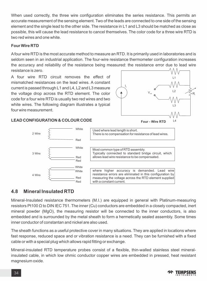
2 Wire
3 Wire
4 Wire
White
Red
White
RedRed
White
White
Red
Red
Used where lead length is short.There is no compensation for resistance of lead wires.
Most common type of RTD assembly.Typically connected to standard bridge circuit, which allows lead wire resistance to be compensated.
where higher accuracy is demanded. Lead wire resistance errors are eliminated in this configuration by measuring the voltage across the RTD element supplied with a constant current.
Is
out
L1
L2
L3
L4
Rt
Four - Wire RTD
When used correctly, the three wire configuration eliminates the series resistance. This permits an
accurate measurement of the sensing element. Two of the leads are connected to one side of the sensing
element and the single lead to the other side. The resistance in L1 and L3 should be matched as close as
possible, this will cause the lead resistance to cancel themselves. The color code for a three wire RTD is
two red wires and one white.
Four Wire RTD
A four wire RTD is the most accurate method to measure an RTD. It is primarily used in laboratories and is
seldom seen in an industrial application. The four-wire resistance thermometer configuration increases
the accuracy and reliability of the resistance being measured: the resistance error due to lead wire
resistance is ero.
A four wire RTD circuit removes the effect of
mismatched resistances on the lead wires. A constant
current is passed through L1 and L4, L2 and L3 measure
the voltage drop across the RTD element. The color
code for a four wire RTD is usually two red wires and two
white wires. The following diagram illustrates a typical
four wire measurement.
LEAD CONFIGURATION & COLOUR CODE
. Mineral Insulated RTD
Mineral-Insulated resistance thermometers (M.I.) are equipped in general with Platinum-measuring
resistors Pt100 to DIN IEC 751. The inner (Cu) conductors are embedded in a closely compacted, inert
mineral powder (MgO), the measuring resistor will be connected to the inner conductors, is also
embedded and is surrounded by the metal sheath to form a hermetically sealed assembly. Some times
inner conductor of constantan and nickel are also used.
The sheath functions as a useful protective cover in many situations. They are applied in locations where
fast response, reduced space and or vibration resistance is a need. They can be furnished with a fixed
cable or with a special plug which allows rapid fitting or exchange.
Mineral-insulated RTD temperature probes consist of a flexible, thin-walled stainless steel mineral-
insulated cable, in which low ohmic conductor copper wires are embedded in pressed, heat resistant
magnesium oxide.
34

TEMPERATURE0 C
TCR TOLERANCE
t
TOLERANCE ATTEMPERATURE t
TO
LE
RA
NC
E A
T
TE
MP
ER
AT
UR
E 0
C
Effects of R &0
slope tolerance on total tolerance
RE
SIS
TA
NC
E
The temperature probe is connected to the wires of the internal conductors and accommodated in a
stainless steel sheath. Thermowell and mineral insulated cable are welded to one another.
The good heat transition between the sheath and the temperature probe permits short response times
and high measuring accuracy. The vibration resistant (shake proof) design guarantees a long operating
life. Temperature measurements at measuring points difficult to access are possible thanks to the flexible
mineral-insulated cable. The smallest bending radius is 5 times the outer diameter.
Metal Sheathed RTD
1) It comprises of a thin-walled and flexible mineral insulated sheath cable made up of stainless steel.
2) The cable contains low resistance inner wires made of copper embedded in pressed fireproof
magnesium oxide.
3) The temperature sensor is connected to the inner wires and fitted in a protective tube.
4) Protective tube and sheathed cable are welded together hermetically.
5) Good heat transfer between protective tube and temperature sensor allows fast response time
and high measuring accuracies.
6) The flexible probe tube allows temperature measurement at locations that are not easily
accessible.
7) They are used in difficult measurement application with strong vibrations as well as at all
measuring positions where flexibility and ease of replacement are needed.
8) Areas of application are to be found in chemical plants, power stations, motors, as well as in
machine construction and building installation and in general industrial applications.
. Potential Sources o Error with Resistance Thermometers
Resistance thermometer systems are susceptible to three types of errors: The inherent tolerances built
into the thermometers, gradients between the thermometer and the medium to be sensed, and errors
introduced along the path between the sensor and readout or control instrument. Some sources of error
are electrical others result from the mechanical construction of the thermometer.
Interchangeabilit Con ormit
Conformity specifies the amount of resistance a
thermometer is allowed to deviate from a standard curve
(such as the curve produced by the Callendar- an
Dusen equation).
A tolerance at the reference temperature, usually 0 C,
and a tolerance on the slope or TCR. Below shown
figure states that a resistance thermometer conforms
most closely to its curve at the reference temperature,
while the resistance fans out above and below this
35

reference.
For example, IEC 751, Class B, requires calibration within 0.12 (0.3 C) at 0 C, but allows TCR to deviate
from nominal 0.00385 by 0.000012 C. Thus, tolerance spreads to 0.8 C at 100 C, 1.3 C at 200 C, and
on up to 3.8 C at 700 C. Interchangeability between two thermometers is no more than twice the value of
there Conformity. Commercial platinum resistance thermometer elements are available with extremely
tight tolerances, to within 0.026 C in some cases. When interchangeability is an overriding consideration,
the specified may consider other means to achieve it. For example, manufacturers may alter their
calibration procedures to fix the reference temperature and tightest tolerance at a point other than 0 C.
Sensitivit
The resistance change per degree change in temperature is a function of base resistance and TCR
(Temperature Coefficient of Resistance).
Although a thermometer with higher sensitivity is not necessarily more accurate, a larger signal simplifies
output electronics and is less susceptible to lead wire effects and electrical noise. In addition, a larger
resistance produces the same voltage output with less measuring current, which helps to limit self
heating of the thermometer element.
Insulation Resistance
If the sensing element and leads are not completely insulated from the case, a shunting effect occurs in
which the case becomes a parallel resistor and lowers apparent readings. In most industrial
thermometers, with specified insulation Resistances in the 100-M ranges, error approaches ero. The
manufacturer must take care to seal water-absorbing materials. The shunting effect decreases with low-
resistance elements, which accounts. The shunting effect decreases with low-resistance elements,
which accounts for the use of 25.5 PRT s in laboratory measurements.
Sel -Heating
A resistance thermometer is a passive resistance sensor it requires a measuring current to produce a
useful signal. Because this measuring current heats the element wire above the true ambient
temperature, errors will result unless the extra heat is dissipated.
Self-heating is most often expressed in mW C, which is the power in mill watts (1000 I2 R) required to
raise the thermometers internal temperature by 1 C. The higher the mW C figure, the lower the self-
heating. As an example, assume a 5 mA measuring current is driven through 100 platinum RTD at 100 C.
Self-heating is specified as 50 mW C in water moving at 3 ft sec. The amount of heat generated is:
mW ( . A) ( . ) . mW
The self-heating error is:
( . mW) ( mW C) . C
The generated heat increases with higher sensor element resistance (when a constant current
measurement device is used), or with increasing measuring current.
The resulting error is inversely proportional to the ability of the thermometer to shed extra heat which in
turn depends on thermometer materials, construction, and environment.
The worst self-heating occurs when a high resistance is packed into a small body. Thin film elements, with
36

little surface area to dissipate heat, are an example. Self-heating also depends on the medium in which
the thermometer is immersed. Error in still air may be over 100 times greater than in moving water.
Time Constant
A time constant indicates the responsiveness of a resistance thermometer to temperature change. A
common expression is the time it takes a thermometer to reflect 63.2 of a step temperature change in
moving water. Response speed depends on the mass of the thermometer and the rate at which heat
transfers from the outer surface to the sensing element. A rapid time constant reduces errors in a system
subject to rapid temperature changes.
Repeatabilit
The degree of accord between two successive readings with a thermometer is its repeatability. Loss of
repeatability results from permanent or temporary changes to the resistance characteristics of the
element and may be caused by exposing the thermometer to temperatures at or beyond the endpoints of
its specified range. A repeatability test cycles the thermometer between low and high temperatures any
changes to R are noted. A typical repeatability rating for 0 C industrial platinum resistance thermometers
is 0.1 C.
Stabilit
Stability is long-term drift in thermometer readings. A typical specification would limit drift to 0.1 C per
year for rated operation. Normal services at points well within the temperature rating typically cause much
less drift. Drift is a consequence of the element material, with platinum being the most stable
encapsulating materials, which could contaminate the element and mechanical stress placed on the
element by expansion of winding bobbins or other supporting structures.
Shock and ibration
Mechanical shock and vibration can alter thermometer readings or cause complete failure. In fact,
stability and ruggedness are somewhat exclusive. A laboratory thermometer designed for maximum
stability contains an unsupported element, which is far too fragile for industrial use. The elements of most
industrial resistance thermometers are fully supported by a bobbin or packing material, and therefore
stand up quite well to extreme environments. More likely to suffer are lead wire transition points, which
should be properly immobili ed. A typical RTD will meet a specification allowing shock of 100 G s of 8
milliseconds duration and vibration of 10 to 2000 H at 20 G s.
Packaging and Thermal Trans er
Sheaths and other structures surrounding resistive elements should maximi e heat transfer from the
sensed medium, minimi e heat transfer from ambient which can alter readings, and provide necessary
protection of the elements.
Proper materials and construction can dramatically improve reading accuracy. One strategy practicable
only with wire-wound resistance thermometers versus thermistors, thermocouples, and solid-state
devices are temperature averaging. An element may be wound to average temperature over lengths of
up to 100feet.
37

Sheath
Element Leads Potting Material
Insulated LeadsPacking Material
High Temperature Probe
. Industrial RTD Probes
The encased probe is the standard resistance thermometer configuration for industrial process control
and machinery protection. Most probe cases are stainless steel or Inconel to withstand high
temperatures, although other materials offer advantages at intermediate ranges.
For example, the tip-sensitive probe of Figure a copper-alloy tip which conducts heat 20 times better than
stainless steel. This design improves thermal contact with sensed surfaces and reduces errors from
conduction along the sheath.
Insulated Leads Sheath
Tip sensitive probe
Standard probe diameters range from 0.125. to 0.250. Smaller probes respond faster when directly
immersed, but larger probes may fit more snugly in standard thermowells. Probe lengths range from a
few inches to ten feet or more.
Figure shows the construction of a high temperature probe. The element fits in the tip, surrounded by high
temperature powder or cement. Extension leads, normally uninsulated, extend back from the element
and are encapsulated by powder, cement, or bored ceramic spacers. External leads, often insulated with
Teflon or glass braid, are potted with cement at the entry point to seal against moisture.
38
. Probe Assemblies
A wide variety of mounting fittings and accessories aid probe installation. Selection depends on the
nature of the medium being sensed and cost requirements. Direct immersion of a probe into a liquid
requires a fitting with a pipe thread, which may be adjustable or welded on the probe. Figure shows a
typical assembly, with one thread for mounting the probe and another for a connection head. Connection
heads provide a transition between probe leads and external signal wires.
T pical Probe Assembl
Connection Head
Fitting
Probe

Mounting in a solid material is best accomplished with a spring-loaded holder, which may be fixed or
adjustable. Spring loading provides good contact of the probe tip against the bottom of the hole and
dampens potentially damaging vibration. When liquids are particularly corrosive, under high pressure, or
fast-flowing, a thermowell may be necessary. A thermowell is a tube, closed at one end, which protects
the probe and allows its removal without breaking the liquid seal. Many materials and styles are available
to match application requirements. Thermowells drilled from solid bar stock provide the highest pressure
ratings, but welded models cost much less.
. Fle ible Resistance Thermometers
The encased probes described above do not adapt well to sensing flat surfaces. Unlike thermocouple
junctions, which can be welded directly to metal surfaces, resistance thermometers present a certain
amount of bulk and heat losses to ambient air may affect readings. Small flat elements, such as thin films,
may mount on surfaces, but fragile element and lead wire connections make installation difficult.
Figure shows a flexible resistance thermometer with a wire-wound sensing element sandwiched
between insulating layers. It conforms closely to sensed surfaces, and has thin insulation to readily
transmit heat to the sensing element. The wire element may be wound to nearly any si e to average out
temperature gradients, and the flexible construction can withstand extreme shock and vibration.
. Special Purpose Resistance Thermometers
Resistance thermometers readily adapt to
most process control and thermal
equipment designs. The user may specify
cases with axial leads for circuit board
mounting, flat packages for clamping to
surfaces, miniature cases for embedment
into metal blocks, and any sheaths and
fittings which can be produced by a machine
shop. In addition, wire windings may be
configured to sense over large areas.Fle ible resistance thermometer
39
. Where to use Resistance Thermometers
In summary, resistance thermometers offer the greatest benefits relative to other thermometer types in
these situations:
Accuracy and stability are the foremost goals of the Application
Accuracy must extend over a wide temperature range
Area, rather than point, sensing improves control
A high degree of standardi ation is desirable
. Advantages and Limitations
Advantages of platinum resistance thermometers
High accuracy

Low drift
Wide operating range
Suitable for precision applications
Limitations
RTDs in industrial applications are rarely used above 660 C. At temperatures above 660 C it
becomes increasingly difficult to prevent the platinum from becoming contaminated by impurities
from the metal sheath of the thermometer. This is why laboratory standard thermometers replace
the metal sheath with a glass construction. At very low temperatures, say below -270 C (or 3 ),
due to the fact that there are very few photons, the resistance of an RTD is mainly determined by
impurities and boundary scattering and thus basically independent of temperature. As a result,
the sensitivity of the RTD is essentially ero and therefore not useful.
Compared to thermistors, platinum RTDs are less sensitive to small temperature changes and
have a slower response time. However, thermistors have a smaller temperature range and
stability.
40

Protection Tubes Thermowell Fittings and Terminations
. Protection Tubes
Sheath material ranges from mild and stainless steel to refractory oxides (Ceramics) and a variety of
exotic material including rare metals. Sensor inserts are fabricated unit which is comprised by a sensor
and a terminal base the sensor is housed in a stainless steel insert tube, usually of 6 or 8mm diameter
and, then it is inserted into the actual protection tube. Good sheathing with physical contact between the
insert tip and sheath end is essential to ensure good heat transfer. Spring contact is used in the terminal
base to maintain this contact. This arrangement facilitates easy replacement of the sensor whenever
required. In the case of a mineral insulated thermocouple or Pt100, the sensor is designed as an integral
part with the insert tube.
. . Metallic or Non-Metallic Sheathing
Metallic tube, most commonly stainless steel, has mechanical advantage and higher thermal
conductivity they are generally immune to thermal shock. Metallic sheath can be used at temperature up
to 1150 C. Ceramics are superior when high purity is required to avoid sensor or product being
contaminated at elevated temperature.
. . Ceramic Sheath with Thermocouple Element
Ceramic sheath s main application ranges between 1000 to 1800 C. They may be in direct contact with
the medium or may be used as a gas-tight inner sheath to separate the thermocouple from the actual
metal protection tube. They should be mounted in hanging position above 1200 C to prevent distortion or
fracture due to bending stresses. Even hairline cracks can lead to contamination of the thermocouple
resulting in drift or failure. The wall thickness of the material is also important thin walled tube is
preferable to larger wall thickness. Cracks frequently developed if they are given excessively rapid
temperature changes when they are quickly removed from hot furnace.
Protection Tubes
Caution Due to high thermal conductivity of the metal tubes, minimum insertion length should be more
than twenty five times of its overall diameter to eliminate heat conduction error.
(A) Metallic Protection Tubes
Widely used as a common protection tube against heat and corrosion but not recommended for use in the presence of sulphur or reducing flame. Subject to stress and pit corrosion.
Higher corrosion resistance than 304 S.S. because of its Ti content to prevent carbon precipitation. Excellent resistance to grain boundary corrosion after welding due to less carbon precipitation.
304 S.S. 980 C
321 S.S. 980 C
1
2
FeatureSr. No. Material Ma . Operating
Temperature ( C)
41

Contains Mo and has excellent resistance to corrosives, heat, acids and alkalis.
316 S.S. 980 C3
FeatureMaterial Ma . Operating
Temperature ( C)Sr. No.
Excellent resistance to oxidi ing and reducing flames containing sulphur. Suitable for use in non-ferrous molten metals and other high temperature application, but less mechanical strength.
Excellent to high temperature oxidi ing atmosphere and thermal shock. Above 10 times longer service life than 304 S.S. against high temperature corrosion.
Less carbon content than 316 s.s. an has better resistance to grain boundary corrosion, Resistant to pit corrosion.
High Ni-Cr content and good high temperature strength with resistance to oxidation at high temperature high mechanical strength
5
316L S.S. 980 C
310 S.S. 1,000 C
4
6
Inconel 800
1000 C7
446 S.S. 1,050 C
Good resistance to high temperature oxidation but becomes brittle due to recrystalli ation. Poor mechanical strength above 850 C.
Excellent resistance to heat in corrosion, especially to HCl and H SO .2 4
superior oxidation resistance at high temperature to inconel 600, by virtue of strong bonding of metal oxide film.
Improved strength and stress rupture properties up to 980 C by MO and CB additional and immune to chloride stress corrosion cracking.
Superior Oxidation resistance to 310SS at high temperature due to formation of dense and tight oxide layer by silicon and cerium additions. can be used in the sulphurous atmospheres.
Excellent resistance to heat, corrosion and abrasion. One of the best alloy against high temperature sulphur bearing atmospheres.
Excellent resistance to oxidi ing and reducing atmospheres at high temperature. But sulphurous atmospheres should be avoided. Immune to stress and pit corrosion.
An improved version of inconel 800. All round superior alloy for high temperature applications, particularly in oil refineries against organic sulfides, hydrogen sulfide and sulphur combustion products.
15
10
11
12
13
9
8
14
Inconel 601
Inconel 625
253 MA
UMCO
Inconel 600
Inconel 825
anthal A1
Hastelloy BOxi. 500 C Red.
760 C
1,050 C
1,050 C
1000 C
Oxi. 1150 C Red. 1200 C
1,050 C
1000 C
1100 C
Excellent resistance to high temperature oxidi ing and reducing atmospheres and also Cl gases.2
16Hastelloy
C-2761000 C
42

FeatureSr. No. Material Ma . Operating
Temperature ( C)
Excellent resistance to oxidi ing and carburi ing atmospheres at high temperatures. Better machinability and weldability than other Hastelloy alloys.
Excellent resistance to water vapor and sea water at high temperature and corrosion.
Superior corrosion resistance in cryogenic temperature but at high temperatures easily oxidi ed and becomes brittle.
Excellent heat-resistant material with high resistance to all acids but apt to severe oxidation and embitterment in air at high temperature. Tantalum is outranked by tungsten for high temperature strength.
Excellent mechanical strength up to 1500 C for applications under inert, reducing and vacuum atmosphere. Resistance to metal vapours at high temperature but react with carbon or graphite. Should not be used in air or oxygen containing gases.
The platinum group metals are well suited for use at extremely high temperature under mechanical loads and simultaneous corrosive attack. They have high melting points, excellent chemical stability and are highly resistant to oxidation.Used for molten glass application as hardened PtRh alloy.
17
18
19
20
21
22
Hastelloy
Monel
Platinum
Titanium
Tantalum
Molybdenum
1100 C
Oxi. 500 C Red. 600 C
1,650 C
Oxi. 250 Red. 1000 C
Oxi. 300 Red. 2,200 C
Oxi. 400 Red. 2,000 C
(B) Non-Metallic Protection Tubes
2Silicon carbide
1500 C - max.
Good level of protection even in severe conditions. Good resistance to reasonable level of thermal shock. Mechanically strong when tick wall is specified but become brittle when aged. Unsuitable for oxidi ing atmosphere but resists fluxes.
Sr. No. Material Ma . Operating
Temperature ( C)
1
refractory oxide
recrystallised Al O -2 3
99.7 (710)
1750 C - max.Good choice for rare metal thermocouple. Good resistance to chemical attack. Mechanically strong but severe thermal shock should be avoided.
Feature
3Silicon Nitride (Si N )3 4
1,350 CExcellent thermal shock resistance. Less corrosion to acids and alkalis. High hardness. Fairly good resistance against most of molten metals.
43

FeatureSr. No. Material Ma . Operating
Temperature ( C)
Note Operating and maximum temperatures of the above tubes vary depending on the measuring
environments.
4
5
6
7
8
9
Cermet (Chrome-Alumina)
uart
60 Alumina
Self Bonded Silicon Carbide
Nitride Bonded Silicon Carbide
Tungsten Carbide
1,300 C
1,000 C
1,500 C
1,650 C
1,550 C
Below 350 C
77 Alumina -23 Chrome Excellent resistance to heat and abrasion.Recommended for temperature measurement of molten copper and other nonferrous metals.
Excellence to thermal shock but fragile. Poor resistance to alkalis but good to acids. Less gas-tightness in hydrogen and reducing gases. High thermal conductivity.
60 alumina-40 SilicaSintered alumina. Better than Pt2 but slightly less thermal shock resistance. recommended for use in heating furnace and regenerator, impervious.
99 SiC.ery low porosity. Excellent resistance to thermal shock,
corrosion and abrasion at high temperatures. recommended for use in oxidi ing and reducing atmosphere upto 1650 C but attacked by water vapor.
78 SiC+3 SiO +18 Si N (Si ON )2 3 4 2 2
Excellent performance superior to Y3 SiC but contains Si N . 3 4
Most suitable for use in molten aluminium, against most of molten metals.
Good mechanical strength and high abrasion resistance.
. . Insulation Material
Mostl used insulation materials are given below
Sr. No.
1
Insulation Material
Alumina Al O2 3
Ma . Operating Temperature ( C)
1,900 C
Feature
High-purity aluminum oxide is the standard insulation material. Alumina offers high thermal conductivity and high electrical resistivity.
44

Sr. No.
Insulation Material
Ma . Operating Temperature ( C)
Feature
2
3
5
Hafnia (HfO )2
Beryllium Oxide (BeO)
Alumina 610
Magnesium Oxide (MgO)
2,400 C
2,315 C
1,200 C
1,370 C
Refined high-purity hafnia offers a good electrical resistivity at elevated temperatures. Hafnia s resistivity is comparable to that of beryllium oxide, but hafnia does not present the potential health problems associated with beryllium oxide. Hafnia is therefore replacing beryllium oxide in many applications.
It has High electrical resistivity, toxic dust. But Beryllium Oxide needs special handling.
Good Insulation Properties.
Used primarily with compacted sheathed thermocouples,4
. Thermowell
Thermowells provide protection for temperature probes against unfavorable operating conditions such
as corrosive media, physical impact (e.g. clinker in furnaces) and high pressure gas or liquid. Their use
also permits quick and easy probe interchanging without the need to open-up the process.
It is closed-end reentrant tube designed for insertion of a temperature-sensing element, and provided
with means for a pressure-tight attachment to a vessel.
Thermowells are typically constructed of solid drilled-out bar stock and are designed to protect a
temperature sensor from flow, high pressure and harsh environments. Thermowells encase and protect
temperature sensors from the harmful effects of the processes into which they are immersed without
substantially insulating the temperature sensor (thermocouple, RTD, etc.) from the temperature of the
process.
45

I.L.
I.L. Immersion length
Taper Thread Parallel Thread
I.L.
Flange
Thermowells are hidden in pipes and are rarely seen. Thermowells are permanently placed into pipes,
tanks or sumps so that temperature measurement probes can be inserted into the pipe to measure the
contents temperature.
. . Most Common T pes o Thermowells
. . (a) According to their connection to process
The most common types of thermowells are:
(1) Threaded
(2) Socket Weld
(3) Flanged Welded
Thermowells are classified according to their connection to a process.
(I) Threaded Thermowell
A threaded Thermowell has threads at its one end and is screwed into the process. Thread can be of
tapered or parallel type. Parallel or tapered thread is made for convenient installation into a weld in fitting
directly into the process. Such a connection is suitable for smaller diameter well, which are not likely to be
changed.
(II) Socket Weld Thermowell
A socket weld Thermowell is welded into a weldalet and a weld in Thermowell is welded directly into the
process. Welded connection can be used when the process is not corrosive and routine removal is not
required. High integrity is achieved and this technique is suitable for high temperature and pressure.
(III) Flanged Thermowell
A flanged Thermowell has a flange collar which is attached to a mating flange. Flanged connection is
preferable if there is a need for more frequent well replacement such as high corrosion rates.
. . (b) According to their production method
Thermowells are also classified according to their
production method.
(I) Fabricated Thermowell
(II) Bar-stock thermowell
(III) an-stone thermowell
(I) Fabricated Thermowell
Fabricated thermowells are manufactured from tubes which are sealed by a solid welded tip at the
process. It means that the stem of thermowell is manufactured from tube and tip is made separately than
both these parts are welded by utili ing suitable welding process. The flange is also joined to this
assembly by welding process. Fabricated thermowells are generally recommended for low to medium
46

Flat
process loads. Connection to the pipe or vessel may be done by means of thread, flange or weld.
Standard threads used in fabricated thermowell are NPT, BSP (Pl), BSP (Tr), API & metric thread. The
thread si e is dependent on the application. Standard si es range from 1 8 to 2 . For applications where
a quick response to changes in temperature is required, fabricated pockets may be fitted with a reduced
tip.
(ll) Bar Stock Thermowell
Such thermowell bodies are machined and drilled from solid bar stock. This results in a non-welded water
tight unit. In this Immersion tip is also made by same material along with stem. In such type of thermowell,
no welding process is required for stem and tip production. Flange can be weld according to requirement.
Bar-Stock thermowell is also known as Solid drilled thermowell . Single piece thermowells are
manufactured from a complete element or bar stock. One-piece thermowells are suited to the highest
process loads, depending on their design. Thus internationally or in the petrochemical industry, one-
piece thermocouples are now used almost exclusively. Connection to the pipe or vessel may be done by
means of thread, flange or weld. Standard threads are NPT, BSP (P), BSP (Tr), API & metric tread. The
thread si e is dependent on the application, but 3 4 and 1 are common.
(lll) an-Stone Themowell
In van stone thermowell, stem, tip and sub part of flange all
these three prepared by using single bar or rod material. There
is no need of welding for these three parts of thermowell. The
flange sub-part serves as a gasket in such type of thermowell.
On this sub-part flange is used according to requirement.
. . Thermowell Tip Pro ile
Tapered
The outside diameter decreases gradually along the immersion length. Used for high velocity
applications.
Flat Tip
It one end has flat surface. Used in low pressure applications or where flow characteristics
around the thermowell are not important.
Domed Tip
Such thermowell has semi-spherical tip at one end of thermowell. Used in higher pressure
applications or where flow characteristics around the thermowell are important. This ensures
a high degree of mechanical strength without losing the sensitivity or accuracy of the
indicator.
Spherical Tip
For spherical tip, special drill is used with a tip angle of 118 C for production of thermowell. To
achieve a possible uniform wall thickness, the tip is ball shaped or spherical in shape. Used in
higher pressure applications or where flow characteristics around the thermowell are
important. This ensures a high degree of mechanical strength without losing the sensitivity or
accuracy of the indicator.
Domed
Spherical
47

. . Basic Construction o Thermowell
Shank Construction
(I) Dimension The thickest part of
the shank of the well on the hot side of the
process connection or flange. It is
dependent on the bore si e and the
process connection si e.
(II) Bore Si e The inside diameter of
thermowell. In other words, the diameter
of the internal cylindrical cavity of a
thermowell or protection tube Standard
bore si es are 6.5 mm, 8.5 mm.
(III) Immersion ( U ) Length The
length of a thermowell or protection tube below the mounting threads, flange, bushing, etc. extending into
the process area. The U length is measured from the bottom of the process connection to the tip of the
thermowell.
(I ) Lagging E tension ( T ) Length The length of a thermowell, in addition to the standard head
lengths, required to make the head of the thermowell accessible and this enable the probe to extend
through insulation or walls.
( ) Internal Mounting Thread The thread within the thermowell for attaching a temperature device
of the union and nipple extension for a thermowell assembly.
. . T pes o Flange Face
(a) Raised Face (RF)
The Raised Face type is the most applied flange type, and is easily to identify. It is referred to as a raised
face because the gasket surfaces are raised above the bolting circle face.
InstrumentConnection
(b) Ring-T pe oint (RT )
RTJ flanges have grooves cut into their faces which steel ring gaskets. The flanges seal when tightened
bolts compress the gasket between the flanges into the grooves, deforming (or Coining) the gasket to
make intimate contact inside the grooves, creating a metal to metal seal.
An RTJ flange may have a raised face with a ring groove machined into it. This raised face does not serve
as any part of the sealing means. For RTJ flanges that seal with ring gaskets, the raised faces of the
connected and tightened flanges may contact each other. In this case the compressed gasket will not
bear additional load beyond the bolt tension, vibration and movement cannot further crush the gasket and
lessen the connecting tension.
Ring Type Joint gaskets are metallic sealing rings, suitable for high-pressure and high-temperature
applications. They are always applied to special, accompanying flanges which ensure good, reliable
48

sealing with the correct choice of profiles and material.
Ring Type Joint gaskets are designed to seal by initial line contact or wedging action between the
mating flange and the gasket. By applying pressure on the seal interface through bolt force, the softer
metal of the gasket flows into the micro fine structure of the harder flange material, and creating a very
tight and efficient seal.
Note Gasket is a mechanical seal which ills the space between two or more mating sur aces
generall to prevent leakage rom or into the oined ob ects under compression.
( c ) Flat Face (FF)
The flat face (full face) flange has a gasket surface in the same plane as the bolting circle face.
Applications using flat face flanges are frequently those in which the mating flange or flanged fitting is
made from a casting. Flat face flanges are never to be bolted to a raised face flange.
. . Welding on Thermowells
Welding is a process of joining two metals by heating the metals to a suitable temperature. It may be done
with or without the application of pressure, and with or without filler.
T pes
Full Penetration Welding - This type of welding ensures a fully welded interface between the two parts and
is generally the strongest joint.
Partial Penetration Welding - This type consists of a partially welded interface with filler metal being laid
on the surface of the two metals.
. . Welding Procedure Speci ication (WPS) & Procedure uali ication Record (P R)
A WPS is a document that describes how welding is to be carried out in production. They are
recommended for all welding operations and many application codes and standards make them
mandatory.
The purpose of the document is to guide welders to the accepted procedures so that repeatable and
trusted welding techniques are used. A WPS is developed for each material alloy and for each welding
type used.
A WPS is supported by a Procedure ualification Record (P R or WP R). A P R is a record of a test
weld performed and tested (more rigorously) to ensure that the procedure will produce a good weld.
The variables required to be documented are typically such items as:
49

welding process used, si e, type and classification of filler alloy.
type and thickness of base material welded.
type and polarity of welding current, amps and volts recorded.
travel speed during welding, welding position, type and dimensions of joint design.
preheating temperature, interpass temperature, post weld heat treatment details, and others.
In addition to the recording of all the welding variables used during the test, in order to qualify a welding
procedure, details of the inspection and test results must also be recorded. These records must show
that the inspection and testing has proven that the weld samples have met or exceeded the specified
standard requirement.
50

SA
MP
LE
WPS FILLED FORMAT
51

SA
MP
LE
52
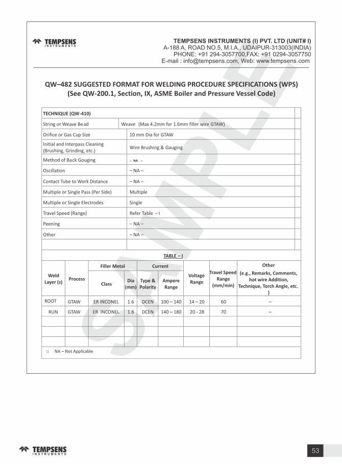
SA
MP
LE
53

. . Thermowell Special Coating
Different types of coating are carried out in thermowells. Some are as follows: Metal Thermowells with
Tungsten Carbide Ceramic PTFE P DF PFA Coatings.
2
3
4
5
6
Teflon Coated
Boron Nitride Coated
irconia Coated
Alumina
Coating
Stellite Coating
0.5-1.0mm
0.5mm
0.5-0.1mm
0.5-1.0mm
0.5-1.0mm
200 C
900 C
1800 C
1200 C
1200 C
Teflon coating provides a dry film lubricant witch provides excellent resistance against corrosion and chemicals.
Boron nitride protects surface witch comes in contact with molten metal (specially aluminum). Boron nitride inhabits corrosion and chemical attacks, and provide easier release and longer life.
irconia coating produces a hard and chemically
resistant protective layer suitable for high
temperature and corrosion.
Alumina coating provides a high temperature
abrasive protection.
Sr. No.
Coating Thickness Operating
Temperature ( C)
1Tungsten Carbide Coated
0.5-1.0mm Below 650 C
Tungsten carbide coating offers effective wear resistance coating, as it offers exceptionally high hardness level ( maximum 74 HRC hardness). It is resistance to high temperature and corrosion & high abrasive condition.
Features
Stellite coating provides very good abrasion
resistance and good chemical corrosion resistance.
. . Test on Thermowell
. Material Test
Chemical- By PMI(Positive Material Identification).
Physical -By Tensile, Elongation, Hardness, Micro & Macro examination, IGC tests.
. Dimensional Test
The Thermowell must be checked according to specified dimension given in drawing.
. H drostatic Pressure Test
A hydrostatic pressure test is a way in which leaks can be found in pressure vessels such as pipelines and
plumbing. The test involves placing water, which is often dyed for visibility, in the thermowell at the
required pressure to ensure that it will not leak or be damaged. It is the most common method employed
for testing pipes and vessels. Using this test helps maintain safety standards and durability of a vessel
54

over time. Newly manufactured pieces are initially qualified using the hydrostatic test.
. D e Penetrant Inspection
Dye penetrant inspection (DPI), also called liquid penetrant inspection (LPI) or penetrant testing (PT), is a
widely applied and low-cost inspection method used to locate surface-breaking defects in all non-porous
materials (metals, plastics, or ceramics). LPI is used to detect casting, forging and welding surface
defects such as hairline cracks, surface porosity, leaks in new products, and fatigue cracks on in-service
components.
. Radiograph
Radiographic Testing (RT), or industrial radiography, is a nondestructive testing (NDT) method of
inspecting materials for hidden flaws by using the ability of short wavelength electromagnetic radiation
(high energy photons) to penetrate various materials. irregularities and flows that can be detected witch
includes - cracks, voids, thickness, lack of fusion, lack of penetration, porosity and misalignment .
. . Selection o Thermowell
Materials the Longevit Factor
The selection of material is the most important factor for thermowell life. The material selected is based on
the temperature of the application and the process medium.
. Connection-The Installation Factor
All threaded well are made by easily welded or bra ed materials. Welding and bra ing is important for the
installation requiring seal. The pipe thread provides mechanical strength, and the weld or bra e provides
the seal.
Flanged wells (other then van stone type) consist of a bar stocks well which is solidly welded to a top
quality flange. Standard construction uses a primary J groove weld and a bevel groove clean fillet. This
double welded construction eliminates the possibility of crevice corrosion since no open joint are exposed
from either inside or outside the installation. Socket weld well are simple to install, simply weld them into
place.
. Insertion Length-The Accurac Factor
The distance from the tip of the well to the underside of the thread or other connection is defined as the
insertion length (designated as U ). For best accuracy this length should be greater enough to permit the
entire temperature sensitive part of element to project into the medium being measured. A properly
installed element: in liquid, the element should be immersed up to its sensitive length plus one inch, and in
air or gas, the element should be immersed up to its sensitive length plus three inches.
. Bore Si e-The Interchangeabilit Factor
Almost all installation uses several type of temperature measuring sensor. The selection of a standard
bore diameter can produce extreme flexibility within the plant. The same well can accommodate
thermocouple, resistance thermometer, and bimetal thermometer.
. Tapered or Straight Well- The elocit Rating Factor
Tapered shank provides greater stiffness with same sensitivity. The higher strength to weight ratio give
these wells higher natural frequency than the equivalent length straight shank well thus
55

permitting operation at higher fluid velocity.
. . PTC . Standard or Thermowell
The American Society of Mechanical Engineers (ASME) Performance Test Codes (PTC) is used to
determine the performance of specific, mechanical equipment, which are designed to meet specified
criteria for performance and operability. The results from applying Codes indicate how well the equipment
performs its intended function.
The ASME PTC 19.3 is a thermowell stress calculation, which serves as a mathematical proof that the
material chosen and the mechanical design will not fail given the effects of the operating conditions. The
calculation provides guidance for establishing a comparison between the shedding frequency and the
natural frequency of the thermowell.
PTC . - Standard or Thermocouple
In 1999, it was discovered that thermowells designed to PTC 19.3-1974 in no steam services suffer
catastrophic failure. Due to this problem, the committee decided to rewrite the entire standard. The 2010
version includes an evaluation of the forces caused by external pressure and the combination of static
and dynamic forces.
ASME PTC 19.3 TW-2010 standards main criteria s for thermowell are as follows:
a.) Criteria or Thermowells
The ASME PTC 19.3 TW-2010 standard applies to thermowells that are:
1. Machined from bar stock.
2. Straight, tapered or step-down shank.
3. Threaded, flanged, van stone or welded process connection.
4. Surface finish of 32 in. Ra or better.
b.) Not within the Scope o This Standard
1. Thermowells manufactured from pipe.
2. Specially designed surface structures, e.g. knurled, spiral.
3. Thermowells fabricated in piece construction (welding of the shank in sections).
4. Shanks that include flame spray or weld overlays.
5. Use of ball joints, spherical unions or packing glands.
6. Ceramic wells or any non-metallic or exotic metals.
c.) Selection o Thermowell Materials
The selection of thermowell material is usually governed by corrosion resistance, strength requirements,
temperature limits and welding compatibility to the process piping in the case of socket and weld-in
thermowells. Materials should be certified to meet the requirements of recogni ed codes (ASTM, ANSI or
ASME).
56

Other materials may be used, providing they conform to published specifications covering chemical,
physical and mechanical properties as required by this standard.
d.) Low Fluid elocities
At low velocities, the risk of thermowell failure is minimal and does not usually require frequency
calculations.
If the following criteria are met, the designer may elect to wave calculation requirements.
1. Maximum fluid velocity is less than 2.1 ft sec. 0.46 M s .
2. Wall thickness at A support diameter minus b bore diameter ≥ 0.376 9.55 mm .
3. L Unsupported length ≥ 24 .61 M
4. A support and B tip diameter ≥ 0.5 12.7 mm
5. Thermowell material satisfies S maximum allowable working stress ≥ 69 Mpa.
6. Sf fatigue endurance limit, in the high-cycle limit ≥ 21 Mpa.
7. Thermowell material not subject to stress corrosion or embrittlement.
e.) Fre uenc Limits
ASME PTC 19.3 TW-2010 has revised the frequency criteria based on limits set by in-line resonance and
passage of static cyclic conditions.
In low density gases with a Scruton Number (Nsc) of 2.5 Reynolds Number 105, the in-line resonance
is suppressed and therefore the acceptable ratio will be:
s 0.8 nc
If a thermowell passes cyclic stress conditions for operation at the in-line resonance condition, the
acceptable ratio will be:
s 0.8 nc
If a thermowell fails the cyclic stress condition for operation at the in-line resonance condition, the
thermowell natural frequency will be high enough to limit excitation of the in-line resonance. Therefore,
the acceptable ratio will be:
s 0.8 nc
.) Process In ormation Re uired to Run the ASME PTC . -TW- Calculation
This Software is free downloadable from our website link
http://tempsens.com/thermowell_calculator.html”.
Minimum mandatory information required
1. Maximum or operating temperature.
2. Maximum or operating pressure.
3. Fluid (gas or liquid) velocity.
57

4. Fluid density.
Additional In ormation i available (recommended)
1. Process Fluid (air, steam, water, etc.).
2. Pipe si e and schedule.
3. Fluid flow rate.
4. Fluid viscosity (will use 0.0171 centipoises if not known).
5. Shielded length (flanged Thermowell). if information is available, their will improves stress
resistance.
. . Thermowell Fitting Accessories
Installing temperature sensor assembles into thermowell or directly into the process requires the use of
some kind of brass or stainless steel fitting.
Fitting include various threaded unions, bayonet cap (and adapters) and flange.
Adjustable flange can similarly be used to sensor assembly into the process.
Bayonet caps provide a method of quick fitting into suitable adapters located in the process this
technique is widely used in plastics machinery.
Bushes and hexagon plugs are used when adjustment or removal is a lesser consideration.
The choice of fitting may be dictated by the need for pressure integrity or by physical si e constraints.
Compression fitting and threaded bushes can be supplied with tapered threads to achieve a pressure-
tight connection.
a.) Compression Fitting
Adjustable compression fitting are used directly on probe to achieve the
required insertion length in the process and to ensure the proper
sheathing of probes into thermowell. Compression fittings for attaching
tubing (piping) commonly have ferrules in them. Compression fittings
are popular because they do not require soldering, so they are
comparatively quick and easy to use.
b.) Nipple Fittings
Nipples are made up with a flange from the same family on each end of a tube section. (Fittings that are
manufactured with different flange families on each end are called hybrid adapters.) Straight nipples are
manufactured with the same si e flange on each end of straight section of tubing. Reducer nipples have
different si e flanges (from the same family) on each end.
58

The three piece unions have to be used in ha ardous areas, for the junction between conduits pipes and
boxes or various appliances. The unions are made up of three independent pieces that can be screwed
up by rotating the same pieces among them.
. . Terminations
Metallic Plugs and Socket Connections
The link between the thermoelectric wires of the thermocouple and those of the extension cable is made
by means of non - compensated male and female connectors. The metallic body and casing of these
connectors ensure the screening continuity as well as good temperature.
Standard & Miniature Thermocouple Connectors
Standard & Miniature connectors are ideal for connecting thermocouple sensors and extension or
compensating cable to each other. The pins are polari ed to avoid an incorrect connection and the
connector body is additionally marked for polarity. These connectors have color coding according to
special standard like: ANSI, IEC etc.
Standard Connector
Miniature Connector
Lemo Connector
59

E tension Leads & Compensating Cable
. Introduction
It is often desirable to connect a thermocouple probe, as a part of a very long circuit from the sensor itself
to a remote reference unit and or measuring instrument. Yet, we would avoid the expense of high
specification thermocouple cable on a long run. Connecting cheaper cable would be ideal but we need to
do so without having to take particular care that temperature where the connection is made is known and
taken in to account.
When connecting thermocouples to instruments, it is essential that a cable is used, which has the same
emf output as the thermocouple otherwise spurious emf is generated at these junctions. The best
solution is to use the same material as the thermocouple (extension cable).
A cheaper alternative is to use compensating cables, the alloys of which are different from those of the
thermocouple but have the same output over a limited temperature range.
Compensating and extension grades of wire are supplied in the bright-annealed condition.
For this to be possible, the thermo electrics properties of the additional conductor must not differ too much
from those of the thermocouple itself.
Extension and compensating cable provide convenient, economic solution-each with its pros and cons.
Extension cable uses wire of nominally the same conductor as the thermocouple itself, which thus
inherently possess similar thermo power characteristics, and with no connection problems.
Miss-match error arising from high connecting box temperature is likely to be relatively small. These cable
are less costly then thermocouple wire, although not cheap, and are usually produced in a convenient
form for carrying over long distance typically as flexible wiring or multi-core cables. They are
recommended for best accuracy.
Compensating cables, on the other hand are less precise, but cheaper. They harness quite different
relatively low cost alloy conductor materials, whose net thermocouple in question, but which not them as
faithfully as do extension cable. Thus, the combination develops similar output as those of the
thermocouple, but the operating temperature range has to be restricted to keep miss-match error
acceptably small.
. Insulation
Insulation refers to the layer of plastic, polymer or high temperature compound that is applied directly over
the conductor. Tempsens provide variety of insulation along with wide temperature range from -260 C to
1200 C. Most of the insulation materials are also used for sheathing purpose.
E
E
B
A
B
A
t
Cu
Cu
B
A
B
B
Tref
Connection o e tension or compensating cable
60

Insulation material are choose according to their electrical, Mechanical and high temperature
characteristics.
Sheathing refers to the outer most layer of the plastic, polymer or high temperature compound that is
applied to a cable. The outer sheath (or jacket as it is also commonly known) is there to provide
mechanical protection for the insulated cores & other component inside the cable.
Tempsens basically categori ed four types of insulating material
Thermoplastic Compound
. . P C (Pol vin l chloride)
Generally self extinguishing, it s used for insulation and sheath. It turns into soft over 90 C,at low
temperature (-40 C) it turns brittle. It has good mechanical properties, water resistant, flame retardant,
chemical & oil resistant & very good resistance to abrasion.
Elastomeric Compound. P C material have various type of Grade i.e. HR P C, FR P C, FRLS P C.
Temp. Range rom- C to C
PropertiesFRLS P C
(Flame Retardant) & low smoke P C
HR P C(Heat Resistant
P C)
Specific gravity 1.47 + - 0.03 1.32 + - 0.03
Hardness (Shore A) 91 + - 3 85 + - 3
Tensile Strength (Min.) Mpa
17 Mpa 20 Mpa
Elongation (min) 180 225
olume 180 225
Resistivity (ohm.cm) 8 10 13 2.6 10 13
Thermal stabilityat 200 C (min)
StandardP C
(General Purpose P C)
FR P C(Flame
Retardant P C)
ASTM-D-792 1.44 + - 0.03 1.60 + - 0.03
ASTM D2240 79 + - 3 93 + - 3
IS 10810 14 Mpa 12.5 Mpa
IS 10810 280 150
80 Min. 120 Min. 140 Min.
IS 10810 5 10 13 10 10 13
IS 5831 80 Min. 120 Min. 140 Min. 100 Min.
. . PE (Pol eth lene)
It is used for only insulation purpose. It provide a very good insulating & dielectric properties, having
excellent insulation resistance ( 5000 Mohms m).Its operating temperature is from -10 C to 70 C and
it is suitable for application where good resistance to water absorption and to abrasion is required.
. . Silicon Insulation
Silicon insulation has superior heat resistance, cold resistance, excellent resistance and flexibility.
Mechanical strength is enhanced by glass braiding having excellent electrical properties suit for high
voltage. Silicon rubber is excellent chemical resistance to acids, oil & liquid fuels. These are flame
retardant not propagating flames when exposed to fire action.
When silicon insulated cable is attacked by fire, sheath and Insulation crystalli e maintaining their
electrical properties for enough time to allow safety measure operations.
Temp. Range rom - C to C
Temp. Range rom - C to C
61

. . XLPE Insulation
nown as Cross linked Polyethylene Insulation, Generally used for insulation of medium & high voltage
cables. Its operating temperature range is -50 C to 105 C. It is used only for as insulating purpose.
. . EPR Insulation
Generally used for insulation of low voltage cables and instrument cables. Its operating temperature
range is from -40 C to 90 C.
. . PEE Insulation
Polyetheretherketone (PEE ) is considered one of the highest performance plastics today.
Polyetheretherketone, PEE , is a semi-crystalline high temperature thermoplastic insulation. PEE wire
has a durability and resistance to harsh environments that makes it extremely useful in the down hole and
deep drilling context for the oil industry. PEE wire is also used in the energy production sector, including
in the nuclear industry, due to its superior resistance to radiation. PEE can be used continuously to
250 C and in hot water or steam without permanent loss in physical properties.
Features
Excellent Resistance to Radiation.
Superior high temperature performance
Improved compressive strength
Good electrical properties
Excellent hydrolysis resistance
Excellent chemical resistance
ery low moisture absorption
Inherently good wear and abrasion resistance
Unaffected by continuous exposure to hot water or steam
Fluoro - Pol mers Compound
. . PTFE Insulation
PTFE (Poly tetra fluoroethylene) insulation is used in a wide variety of high temperature applications as
gas turbine and high voltage gas ignition wires. Due to its thin wall properties, PTFE is used in aerospace
& defense and even in vaccum.It temperature range is from -267 to 260 C.
Temp. Range rom - C to C
Temp. Range rom- C to C
Temp. Range up to C
Temp. Range rom- C to C
Properties Unit alue
Hardness Shore A 65 - 70
Density Gm Cm3 1.18 - 1.50
Elongation at break 350 - 500
Tensile Strength Mpa 5.5 - 9.5
Tear resistance N mm 20 - 45
62
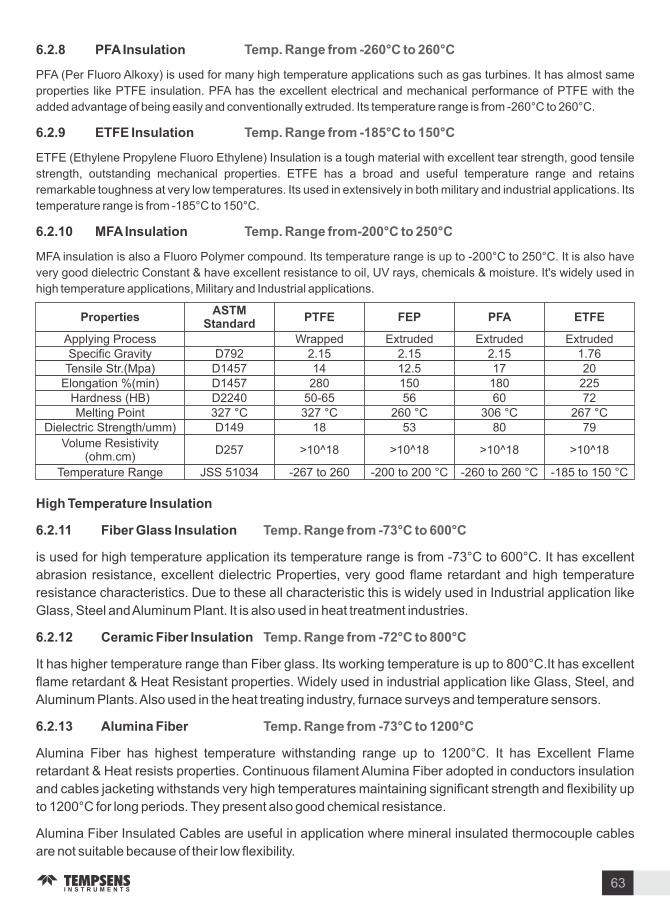
PropertiesASTM
StandardPTFE FEP PFA ETFE
Applying Process Wrapped Extruded Extruded ExtrudedSpecific Gravity D792 2.15 2.15 2.15 1.76
Tensile Str.(Mpa) D1457 14 12.5 17 20Elongation (min) D1457 280 150 180 225
Hardness (HB) D2240 50-65 56 60 72Melting Point 327 C 327 C 260 C 306 C 267 C
Dielectric Strength umm) D149 18 53 80 79
olume Resistivity (ohm.cm)
D257 10 18 10 18 10 18 10 18
Temperature Range JSS 51034 -267 to 260 -200 to 200 C -260 to 260 C -185 to 150 C
High Temperature Insulation
. . Fiber Glass Insulation
is used for high temperature application its temperature range is from -73 C to 600 C. It has excellent
abrasion resistance, excellent dielectric Properties, very good flame retardant and high temperature
resistance characteristics. Due to these all characteristic this is widely used in Industrial application like
Glass, Steel and Aluminum Plant. It is also used in heat treatment industries.
. . Ceramic Fiber Insulation
It has higher temperature range than Fiber glass. Its working temperature is up to 800 C.It has excellent
flame retardant & Heat Resistant properties. Widely used in industrial application like Glass, Steel, and
Aluminum Plants. Also used in the heat treating industry, furnace surveys and temperature sensors.
. . Alumina Fiber
Alumina Fiber has highest temperature withstanding range up to 1200 C. It has Excellent Flame
retardant & Heat resists properties. Continuous filament Alumina Fiber adopted in conductors insulation
and cables jacketing withstands very high temperatures maintaining significant strength and flexibility up
to 1200 C for long periods. They present also good chemical resistance.
Alumina Fiber Insulated Cables are useful in application where mineral insulated thermocouple cables
are not suitable because of their low flexibility.
Temp. Range rom - C to C
Temp. Range rom - C to C
Temp. Range rom - C to C
. . PFA Insulation
PFA (Per Fluoro Alkoxy) is used for many high temperature applications such as gas turbines. It has almost same
properties like PTFE insulation. PFA has the excellent electrical and mechanical performance of PTFE with the
added advantage of being easily and conventionally extruded. Its temperature range is from -260 C to 260 C.
. . ETFE Insulation
ETFE (Ethylene Propylene Fluoro Ethylene) Insulation is a tough material with excellent tear strength, good tensile
strength, outstanding mechanical properties. ETFE has a broad and useful temperature range and retains
remarkable toughness at very low temperatures. Its used in extensively in both military and industrial applications. Its
temperature range is from -185 C to 150 C.
. . MFA Insulation
MFA insulation is also a Fluoro Polymer compound. Its temperature range is up to -200 C to 250 C. It is also have
very good dielectric Constant & have excellent resistance to oil, U rays, chemicals & moisture. It s widely used in
high temperature applications, Military and Industrial applications.
Temp. Range rom - C to C
Temp. Range rom - C to C
Temp. Range rom- C to C
63
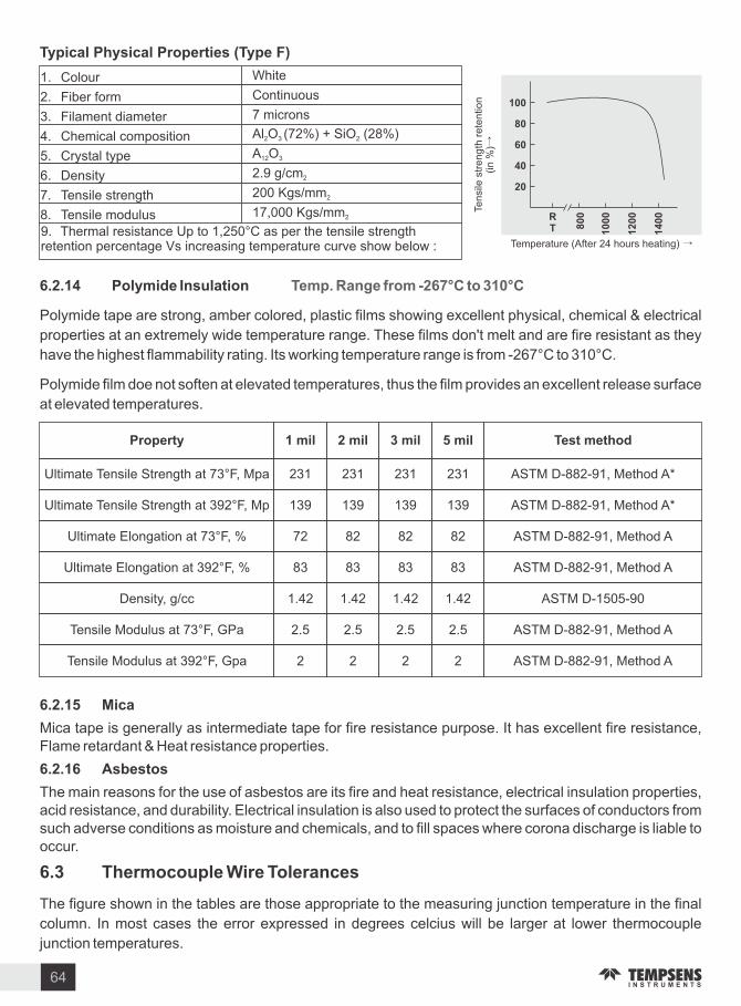
1. Colour White
2. Fiber form Continuous
3. Filament diameter 7 microns
4. Chemical composition Al O (72 ) + SiO (28 )2 3 2
5. Crystal type A O12 3
6. Density 2.9 g cm2
7. Tensile strength 200 gs mm2
8. Tensile modulus 17,000 gs mm2
9. Thermal resistance Up to 1,250 C as per the tensile strength retention percentage s increasing temperature curve show below :
T pical Ph sical Properties (T pe F)
RT
Temperature (After 24 hours heating) →
Ten
sile
str
en
gth
re
ten
tion
(in
)→
. . Pol mide Insulation
Polymide tape are strong, amber colored, plastic films showing excellent physical, chemical & electrical
properties at an extremely wide temperature range. These films don t melt and are fire resistant as they
have the highest flammability rating. Its working temperature range is from -267 C to 310 C.
Polymide film doe not soften at elevated temperatures, thus the film provides an excellent release surface
at elevated temperatures.
Temp. Range rom - C to C
. . Mica
Mica tape is generally as intermediate tape for fire resistance purpose. It has excellent fire resistance, Flame retardant & Heat resistance properties.
. . Asbestos
The main reasons for the use of asbestos are its fire and heat resistance, electrical insulation properties, acid resistance, and durability. Electrical insulation is also used to protect the surfaces of conductors from such adverse conditions as moisture and chemicals, and to fill spaces where corona discharge is liable to occur.
. Thermocouple Wire Tolerances
The figure shown in the tables are those appropriate to the measuring junction temperature in the final
column. In most cases the error expressed in degrees celcius will be larger at lower thermocouple
junction temperatures.
Propert mil mil mil mil Test method
Ultimate Tensile Strength at 73 F, Mpa 231 231 231 231 ASTM D-882-91, Method A
Ultimate Tensile Strength at 392 F, Mp 139 139 139 139 ASTM D-882-91, Method A
Ultimate Elongation at 73 F, 72 82 82 82 ASTM D-882-91, Method A
Ultimate Elongation at 392 F, 83 83 83 83 ASTM D-882-91, Method A
Density, g cc 1.42 1.42 1.42 1.42 ASTM D-1505-90
Tensile Modulus at 73 F, GPa 2.5 2.5 2.5 2.5 ASTM D-882-91, Method A
Tensile Modulus at 392 F, Gpa 2 2 2 2 ASTM D-882-91, Method A
64

NOTE
1. Cable temperature range may be restricted to figure lower then those shown in the table because of
temperature limitation imposed by the insulant.
2. A cable comprising two copper conductors may be used with type B thermocouple .The expected
maximum additional deviation within the cable temperature range 0 C to 100 C is 40 . The
equivalent in temperature is 3.5 C when the measuring junction of the thermocouple is at 1400 C.
Identification as to whether a thermocouple cable type is extension or compensating is indicated
in the example which follows however, please note that a letter A or B after the C for Compensating refers
to the Cable Temperature Range in accordance with the table of Tolerance alues set out in this standard.
1 E TENSION CLASS 1
CA 2 COMPENSATION CLASS 2, 0 to 150
J
CableTolerance Class Cable Temp.
RangeMeasuring unction
TemperatureClass
85 ( 1.5 C)
Class
140 ( 2.5 C) -25 C to +200 C 500 C
T 30 ( 0.5 C) 60 ( 1.0 C) -25 C to +100 C 300 C
E 120 ( 1.5 C) 200 ( 2.5 C) -25 C to +200 C 500 C
60 ( 1.5 C) 100 ( 2.5 C) -25 C to +200 C 900 C
CA 100 ( 2.5 C) -0 C to +150 C 900 C
CB 100 ( 2.5 C) -0 C to +100 C 900 C
N 60 ( 1.5 C) 100 ( 2.5 C) -25 C to +200 C 900 C
NC 100 ( 2.5 C) -0 C to +150 C 900 C
RCA 30 ( 2.5 C) -0 C to +100 C 1000 C
RCB 60 ( 5.0 C) -0 C to +200 C 1000 C
SCA 30 ( 2.5 C) -0 C to +100 C 1000 C
SCB 60 ( 5.0 C) -0 C to +200 C 1000 C
65

P rometer Fundamental and In rared Thermograph
. Basic Concepts
What we see with our eyes is only the small part (visible region) of a broad spectrum of electromagnetic
radiation. On the immediate high energy side of the visible spectrum lies the ultraviolet, and on the low
energy side is the infrared (IR) (see Figure ). This invisible portion of light carries various supplementary
informations.
The IR region can be divided into three different categories: near-IR (NIR Short wave), mid-IR radiation
(MIR Medium wave) and far-IR radiation (FIR Long wave). Also, this region is responsible for the heating
effect of the sun. Understanding the physical basics like blackbody, Planck, Stefan, Bolt mann, Wien and
irchhoff laws, etc. is crucial before proceeding to the next section.
Table
Electromagnetic spectrum
Regions Wavelength ( m)
Near Infrared (NIR) 0.78 - 3
Mid Infrared (MIR) 3 - 50
Far Infrared (FIR) 50 - 1000
. . Black Bod
A black body is a hypothetical object that absorbs the entire radiation incident upon it. Such body doesn t
reflect any radiation and appears perfectly black. The perfect black body is the most efficient thermal
absorber and emitter because any object at thermal equilibrium will emit the same amount of light as it
absorbs at every wavelength. The radiation spectrum of a black body is determined only by the
temperature and not by the properties, material, and structure. These features, as an ideal source to emit
or absorb radiation, make the black body valuable for many applications. For an ideal black body
absorbtivity and emissivity is one.
66

. . Gra Bod
The body which emits less thermal radiation than a perfect blackbody or its surface emissivity ( ) is less
than one but is constant over all frequencies. It s a useful approximation to some real world materials over
some frequency ranges. The spectral emission of gray body is shown in Figure.
. . Black Bod to real ob ects
A perfect blackbody is only a physical abstraction which does not exist in real world. Each body radiates
electromagnetic radiation at a temperature above ero (-273.15 C 0 ). This radiation is nothing but the
body s thermal energy which is being converted into electromagnetic energy and therefore termed as
thermal radiation. Real materials show slightly different behaviour as compared to an ideal black body.
The radiative property of the real objects always deviates from those of an ideal blackbody. The radiation
incident on the real body may undergo following physical phenomenon like reflection, absorption and
transmission (permeability) (see Figure).
(a) Absorptivit ( )
The fraction of the irradiation absorbed by a surface is called the absorptivity of a material. It can be
characteri ed by both a directional and spectral distribution. It is understood that surfaces may exhibit
selective absorption with respect to wavelength and direction of the incident radiation. However, for most
engineering applications, it is desirable to work with surface properties that represent directional
averages.
(b) Re lectivit ( )
The reflectivity of a surface describes the fraction of incident radiation reflected by a surface. If the
intensity of the reflected radiation is independent of the direction of the incident radiation and the direction
of the reflected radiation, the surface is said to be diffuse emitter. In contrast, if the incident angle is
equivalent to the reflected angle, the surface is a specular reflector. Although no surface is perfectly
diffuse or specular, specular behavior can be approximated by polished or mirror-like surfaces. Diffuse
Specific Emission of Gray body
Figure Annihilation of radiation in real type
67

behavior is closely approximated by rough surfaces and is likely to be encountered in industrial
applications.
( c) Transmissivit ( )
The remaining part of the radiation is transmitted out and the amount of radiation transmitted through a
surface is transmissivity. This process too may be selective depending on the nature of the material and
the incident radiation.
(d) Emissivit ( )
Emissivity is the ratio of energy radiated from an object to the exterior and energy radiate from blackbody.
The emissivity varies with the surface condition of the object and also with temperature variation and
wavelength. If this value is not accurate, then the true temperature cannot be measured. In other words, a
variation or change in emissivity will cause a change in the indications.
By the irchhoff s law of thermal radiation At thermal equilibrium, the emissivity ( ) of a body (or surface)
equals its absorptivity ( ) . So, for a perfect black body, is 1 while any real object would have less than
1. Also the transmissivity ( ) and reflectivity ( ) is ero. The sum of absorptivity, reflectivity and
transmissivity is always 1.
+ + 1.
Metals
Non-metals
Transparent material
. Radiation Principles Governing the Black Bod
The average or bulk properties of electromagnetic radiation interacting with matter are systemati ed in a
simple set of rules called radiation laws. These laws are applied when the radiating body is a blackbody
radiator. Usually, blackbody conditions apply when the body (radiator) has very weak interaction with the
surrounding environment and the state of equilibrium is considered. Some of these laws are discussed
below:
Planck s law Planck s law states that the intensity of electromagnetic radiation emitted by a blackbody
is a function of frequency (or wavelength). Black body will radiate energy at all frequencies. The Planck s
law gives a distribution that peaks at a certain wavelength, the peak shifts to shorter wavelengths for
higher temperatures, and the area under the curve raise rapidly with increasing temperature (see Figure).
Wien s displacement and Ste an Bolt mann law Wien s displacement law states that the
wavelength at which the blackbody emission spectrum varies inversely with the blackbody s temperature
or we can say hotter an object is, the shorter the wavelength at which it will emit most of the radiation.
Stefan Bolt mann law states that the total energy radiated per unit surface area of a black body per unit
time is inversely proportional to the fourth power of the temperature of the black body.
The Wien law provides the wavelength of the peak of the radiation distribution, whereas the Stefan-
Bolt mann law gives the total energy emitted by the blackbody at all wavelengths (i.e., the area under the
curve of Planck Law (see Figure)
By the emissivity factor materials can be categori ed as:
68

Also, the Wien law gives explanation to the peak shift to shorter wavelengths with increase in
temperature, whilst the Stefan-Bolt mann law explains the growth in the height of the curve with increase
in temperature. Both these radiation law can be derived from the Plank s law.
. P rometr
A Pyrometer is a non-Contacting device that intercepts and measures thermal radiation. Without making
any contact with the radiating body and the process is known as pyrometry. This device is useful for
determining the temperature of an object s surface.
Pyrometer is derived from the greek root pyro which means fire. The term pyrometer means a device
capable of measuring temperature of objects above incandescence. Early pyrometers (Filament
Pyrometer 1917) were restricted to visual measuring method only (i.e., the object becomes red hot, it
starts emitting radiation). So, only high temperature measurement is possible with early pyrometers. But
now days such pyrometers are also available that can measure temperatures far below the free ing point
from a distance and without making contact with the object to be measured.
Temperature is the most frequently measured physical quantity which predicts the condition of a product
or part of apparatus, both in manufacturing and in quality control.
Pyrometer strictly works on the principles of black body radiation. Here emissivity of the target plays an
important role, as it govern how bright the target appears to the pyrometer. Due to its high accuracy,
speed, economy and specific advantages, it is widely being used as a standard procedure in many
industrial applications.
There are some critical considerations which have to be included for any infrared pyrometer like
emissivity field of view (si e of the target and distance), spectral response and temperature range and
mounting. Some of the advantages of non-contact pyrometry are discussed below:
It records temperature within fractions of seconds (fast response time).
It does not influence the temperature and material of the target.
Requires less maintenance and hence the longer life time.
It can measure the temperature of the moving object.
Measurements can be taken for ha ardous or physically inaccessible object(e.g. high-voltage parts
and the great measurement distance).
Blackbody spectrum
69

As it not in direct contact with target so high temperature can be measured.
Being non-contact techniques, it will not tamper the target mechanically.
. Choosing the Spectral Range
As discussed earlier, emission coefficient plays a major role for temperature measurement by
pyrometers. So it is mandatory to establish accurate emission coefficient for a given material or target.
Metals
The emissivity of metal strongly gets influenced by the wavelength and temperature. For lustrous
(smooth) metal surfaces, emissivity is high at short wavelengths and decreases with increasing
wavelengths. Moreover wear and tear, oxidation or soiling, rust, etc may also affect the emissivity of
metals. So, it is essential to select an instrument which measures the infrared radiation at a particular
wavelength and within a particular temperature range at which the metals have the highest possible
emissivity.
The optimal wavelength for high temperatures in the case of metals is, at around 0.8 to 1.0 m, at the limit
to the visible range. Wavelengths of 1.6, 2.2, and 3.9 m are also possible. Good results can be achieved
using ratio pyrometers in cases (e.g. heating processes) where measurement is to take place across a
relatively wide temperature range and the emissivity changes with the temperature.
Plastics
The transmittance of a plastic altered with the wavelength and thickness of the material. So optimal
temperature measurement is accomplished with the wavelengths where the transmittance is almost
ero. Polyethylene, polypropylene, nylon and polystyrene are some of the plastics which are non-
transmissive at 3.43 m while polyester, polyurethane, Teflon FEP, and polyamide non-transmissive at
7.9 m. The optimal spectral bandwidth for measurement can be determined by the manufacture of the
infrared device.
Glass
For temperature measurement of the glass with an infrared thermometer, reflectance together with the
transmittance has to be considered. Only a careful selection of the wavelength facilitates measurements
of the glass surface as well as of the deeper layers of the glass. For measuring deeper layers
wavelengths of 1.0 m, 2.2 m or 3.9 m are appropriate while for surface measurements 5 m is
recommended. At low temperatures, 8.14 m should be used with the emissivity set to 0.85, to
compensate for reflectance. As glass is a bad heat conductor can change its surface temperature quickly,
so a thermometer with short response time is recommended.
Bright Flames
To measure the temperature of flames is really a tough job. For exact measurement of temperature of
flames, only the radiation coming from the glowing soot or other burning particles should reach the
pyrometer. This can be done by flame pyrometers by adjusting the soot factor n on the pyrometer.
Non-Luminous Flames
To measure the temperature of non-luminous flames (e.g. gas burners) spectral pyrometers can be used.
This pyrometer measure the radiation of hot carbon dioxide in a very narrow spectral area (4.5 & 4.65
m).
70

Ambient Conditions
The transmission behavior of the transmission path (usually the ambient air) should also be considered
before setting any IR thermometer (spectral radiation pyrometer). There are certain components in the
atmosphere (like vapor, carbon dioxide, etc.) which absorb infrared radiations at particular wavelengths
due to which transmission is attenuated. So for accurate temperature measurements, these absorption
media should be taken in account. There are windows in the infrared spectrum which do not contain
these absorption bands (see Figure). Typical measuring windows are 1.1-1.7 m, 2 - 2.5 m, 3.5 m and
8.14 m. So the infrared measuring device has to be designed with proper atmospheric correction filters.
In Table 2, the various atmospheric windows are listed for different compounds.
Table
. Methods or Determining the Emissivit
There are several ways to determine the emissivity of the material to ensure accurate temperature
measurements, some of which are discussed below:
1. The temperature of the object is first determined (measured) with a contact thermometer. Then aim
the pyrometer to the object. Now adjust the emissivity until the same temperature is achieved in
both the devices. This method can only be applied for sufficiently large and accessible objects.
2. Coat the material or the portion of it with a special coating whose emissivity approximately equals to
1, accurately known and is stable up to the temperature to be measured. When pyrometer is aimed
to the object it first measures the temperature of the coated surface and then it measures the un
coated part of the surface. Simultaneously, adjust the emissivity so as to force the indicator to
display the correct temperature.
71
Atmospheric windows and transmission of air
100
Tra
nsm
issi
vity
500 2 4 8 106 12 14
Wavelength in m
T pe o Detector (Material)
Silicon
Germanium
Indium-Gallium-Arsenide
Lead Sulphide
Lead selenide
Thermopile
Pyroelectric Detector
Thermopile
Pyroelectric Detector
Thermopile
Pyroelectric Detector
Window
I
II
III
I
I

3. For measuring high temperatures, a hole can be drilled (drilling depth should be ≤ 1 3) to the object
which acts a blackbody with emissivity of 1.0. The temperature of the drill hole is measured first,
then the pyrometer measure surface temperature. Now emissivity is so adjusted such that the
correct temperature of the material is displayed on the indicator.
4. The emissivity of a sample object can be determined by spectrometer analysis.
5. Standardi ed emissivity values for most materials are available. These can be entered into the
instrument to estimate the material s emissivity value.
. Basic Design Construction and Operation o P rometer
This section describes the basic construction of a pyrometer and its functioning. Pyrometer is any
temperature-measuring device that includes a sensor and a read out. An optical system gathers the
visible and infrared energy from an object and focuses it to the detector. The detector receives the photon
energy from the optical system and converts.
it to an electric signal to drive a temperature display or control unit. The block diagram of infrared
thermometer is shown in Figure.
Infrared thermometers have various configurations and designs, which differ in optics, electronics,
technology, si e and housing. However, the method of signal processing is same (i.e., it always starts
with an infrared signal and ends with an electronic temperature output signal). The working mechanism of
the pyrometer is shown in the flow chart (see Figure)
. . Optical s stem protection windows spot si e and measuring distance
The detector and optical system are the major components in the pyrometer. So, they should be carefully
selected to yield the optimum compromise based upon the conflicting parameters of price, accuracy,
speed of response, and usable temperature range.
Optical s stem and protection windows
An optical system mostly consists of windows, lenses and filters. A lens system can be used for particular
wavelength ranges due to their material wavelength ranges. Usually for fixed focus optical instruments
mirror system is used while for varying the focus instrument requires moving parts, which is less
complicated in a lens system. So lens system is preferably used.
The characteristics (transmission values) of the lens, filters and protection window material should be in
accordance with spectral sensitivity of the sensor. At high temperatures quart glass is commonly used.
At low temperatures (in the range 8.14 m) special IR transmissive materials (i.e., Ge and nSe) are
required.
Pre-Ampli ier ADC
DAC
Digital Inter ace
- mA
Block Diagram of Infrared thermometer
Processor
72

With the help of filters the transmission properties can be modified so that the unwanted wavelengths can
be prevented from reaching the detector. They are placed in front of the detectors.
The optics of a pyrometer transmits the image of a section of the target area of the measured surface to
the detector. The common law of optics used in photography is that as the distance between the camera
and the target increases area covered will also increases accordingly. So the distance between the
camera and the target should be considered explicitly. The dimensions of the measured object determine
the required spot si e of the pyrometer. So the target si e should be larger than the detector spot (spot
si e).The distance ratio describes the si e of the measuring spot at a certain distance. Also, the ratio of
the distance of the measuring device from the target, and the diameter of the spot (D:S) describes the
optical resolution. Better the optical resolution of the pyrometer smaller the target can be. To avoid errors
in the measurements, the spot si e should completely fill the object otherwise the sensor will read the
other temperature radiation from the background.
Sighting techni ues
There are several techniques for the adjustment of pyrometer which assist in capturing precise radiated
temperature from the target. Some of them are described below:
Trough the lens sighting techni ue
In this technique, user looks at the object in the similar way as he looks through the camera. The centre of
the viewing area is indicated by some marks which is the target area. Here user is in direct contact with
radiations, so some filters are used for the protection of eyes.
Pilot lights Laser-pointer
LED, or laser can be used as Pilot lights. The light beam facilitates the user to aim at the measuring spot
more quickly and precisely, and hence accurate temperature can be measured in darkness.
. . Detector
Detector play the vital role in any pyrometer. They are the radiation receivers which converts the received
infrared radiation into electrical signals. These electrical signals are converted then displayed as
temperature values by the electronic system. Detectors may be classified into two different categories
vi . thermal detector and quantum detectors. the behavior of thermal detector is similar to any
thermocouple. When the photons interact with the sensitive element in the thermal detectors the
temperature of this element get varied which in turn modifiers the property of detector. This modification is
then electrically analysed which similar to the voltage generated in any thermocouple uantum detectors
works on the principle of photoelectric effect. They interact directly with the impacting photons. So they
are also known as photodiodes. uantum detectors are faster than thermal detectors. The performance
of detector is strongly affected by the variation of ambient temperature. This ambient drift should be
compensated for high accuracy measurements.
. . Electronics
The function of the electronics of the infrared thermometer is to amplify, regular, linearise and convert the
signal from the detector to electric signal (m or mA) which is proportional temperature. The output of the
pyrometer can be viewed with analog and digital devices.
Spot si e and measuring distance
73

Target Emissivit It can set the emissivity of the target.
Peak Picker It locates the maximum temperature of the target temperature value from specified
number of stored real temperature in the sensor memory. Once the peak temperature is determined,
its value will be transmitted constantly even at out of range condition till a new picker process finishes.
Switch O Level Ratio pyrometer shows true temperature even when the target is partially visible.
The user can adjust this value, so when temperature of object is below this limit, the pyrometer will
stop temperature measurement.
Response Time This function is used to set the response time of the pyrometer. It is adjustable from
20 ms to 10 seconds.
Record iew This option provides data logging. The temperature and Emissivity read by both the
pyrometer with time and date is displayed.
Spot Si e Calculation It calculates the spot si e or Actual Working Distance of the pyrometer. This
option in the software is capable of calculating the spot si e for real working distance corresponding to
the value of Actual Working Distance.
Analog Scale User can select the sub range with in the basic range of pyrometer. Analog output will
automatically adjust to the selected range.
Change Sensor T pe This parameter display pyrometer sensor type and user can also change two
color sensors to single and vice versa within the same software.
. . Calibration
To achieve a reasonable level of accuracy, new pyrometer should be properly calibrated. Initial
calibration is likely to be performed by the manufacturing. but for the most qualitative measurements
periodic recalibration is required. There are three different methods of calibration which are :
Method 1. - A commercial blackbody simulator which is an isothermally heated cavity having very small
aperture can be used as calibrator, The depth of this cavity should be at least six times as long as its
diameter and the temperature of this cavity is controlled by a temperature controller (Using a
thermocouple probe). The emissivity of a cavity type blackbody source is usually 0.98 or higher which
makes them ideal for exact calibration tasks.
Method 2. - Calibrated tungsten filament lamps are commonly used as reference at higher temperatures.
Method 3. - third option is to use a reference pyrometer whose calibration is known to be accurate. Adjust
the output of the pyrometer until it matches the value of reference pyrometer.
. Sources o Inter erence
Other than the emissivity factor there are several other interference source which hinder the accuracy of
measurement. Some of these factor are discussed below:
Additional heat source present in the surroundng of the measuring object (e.g. measuring
temperature of metals in industrial ovens, where the oven walls are hotter than the measuring object)
Strongly influence the measurement may get affected.
If the target is transparent and there is some hot body behind it then the target will let the additional
74

heat pass through modifying the original temperature.
The presence if dust, water vapor, smoke and window also reduce the strength of the infrared
radiations.
. P rometer T pes
Single color pyrometers
Ratio type pyrometers (two colour pyrometers)
Multi wavelength pyrometer
Single color p rometers
These pyrometers operate over a narrow range of wavelengths. They are also called as single color
pyrometers. They are normally used for measuring glass at 5.14 m. Metals can also be measured as
their rate of emissivity is high only in a narrow band. The spectral response of the particular device
depends on the type of the detector used. For an instance, the response of a pyrometer with a silicon cell
detector is around 0.9 - 1.1 microns. These pyrometers can work on selected wavelength range with the
help of filters. But for this more sensitive detectors and advances in signal amplifiers are required.
Ratio radiation p rometers (two colour p rometers)
This pyrometer measures the radiated energy of an object between two narrow wavelength bands and
then calculates the ratio of the two energies. This ratio is the function of the temperature of the object. This
is also called as two colour pyrometer because the two wavelengths corresponded to different colors in
the visible spectrum. Even if the object does not fully cover the spot the output signal will not change. Also
the temperature measurement is independent of emissivity, so the errors caused by the emissivity
variation, surface finish, and energy absorbing materials (e.g. smoke, smog, water vapor, etc.) between
the pyrometer and the target can be minimi ed or removed (see Figure). It is used for measuring high
temperature (e.g. molten metal).
Multi wavelength p rometers
Accurate temperature determination cannot be made without knowledge of surface emissivity since
emissivity can change with processing conditions, then clearly the only solution is to gain that knowledge
while the temperature determination is being made.
An expert system multi wavelength pyrometer has been able to overcome many well known difficulties of
pyrometry, including unknown, changing, and or spectral dependence of emissivity as well as
environmental absorption of radiation.
Working o P rometer
2 -colour pyrometer
Less energy reaches pyrometer
Interference due to smoke dustObject
IR Rays
75

In addition to a multiple filter wheel for separation of wavelength and the usual optics, the instrument
includes a software based on the data collected from numerous similar application which allows to
analy e each measurement and then calculate the temperature, using the signal strength and surface
properties.
Fiber optic radiation p rometers
Optical pyrometers can be considered a subset of narrow band devices. Fiber optic pyrometers can be
classified as wide band, narrow band, or ratio devices. These devices use an optical fiber (light guide) to
direct the radiation to the detector (see Figure). The spectral response of these fibers is extended to about
2 microns so it is useful in measuring object temperatures to as low 100 C. An optical head, a glass fiber
and a signal processing unit together forms a fiber optic pyrometer. The optical head doesn t contain any
electronics. It is basically used where the sighting path to the target is not clear (pressure chamber).
Some inherent advantages of fiber optics over other pyrometers are:
1. They are unaffected by strong electromagnetic fields therefore can be easily used where such type
of interference fields are present.
2. It can be placed in hard-to-reach fields.
3. As it does not carry any electrical current, so it is ideal for explosive and ha ardous locations.
4. Optical head and the fiber are free from any electronic components so cooling is not required and
hence can be used to measure high temperatures (near about 250 C). However pyrometer unit
requires cooling.
5. The diameter of a optical fiber is small therefore the small spot si e can be obtained.
In an optical fiber the captured radiation is transmitted by total internal reflection. The inner layer is called
core and outer layer is cladding. Therefore signal can be transmitted without any loss. Optical fiber
consists either of a single fiber (mono-fiber) of multi-fiber.
The comparison between a single fiber and multi-fiber is given
below:
Breakage in the mono fiber can be immediately detected than
in multi fiber.
No wear and tear is required for mono fiber but in multi fiber the
cladding of individual fiber may get damaged due to friction
amongst them.
Multi fiber optical fiber is relatively less expensive and also
their minimum curving radius makes them useful in many
applications.
Fiber optic Pyrometer
Mono Single Fiber Multi Fiber
76

. Accessories
Pyrometer are available with a various accessories to solve a wide range of application condition. Here
listed some of those mechanical and electrical electronic accessories.
Mechanical Accessories
.Cooling Accessories Facilitate the pyrometer to be operated at higher surrounding temperature and
maintains internal temperature of electronics in the pyrometer.
Radiation shield
Cooling plate
Cooling jacket
. Mounting Devices Used to fix pyrometer in a particular position.
Angle brackets
Adjustable Positioning devices
. Flange S stems Used to append the pyrometer to the furnaces, container or pipes.
Mounting tube
Lamination slide
Ball and socket mounting
. Sighting Accessories It is very helpful to sight on the spot si e for the measurement if moving objects
and in poor light conditions.
Sight tubes
Laser pointing devices
Scopes
. Air Purge Units It is attached to front end of sensor which protects the optics of the pyrometer from
dust, smoke, moisture and other contaminations. It is in the form of round no le which and provides
positive air pressure in front of the lens.
. Emissivit Enhancer It is used for shiny and highly reflective metal surfaces having very low
emissivity at low temperatures. It is a goal plated concave mirror, which is mounted close to the
measuring object. The incident radiation undergoes multiple internal reflection between the measuring
object and the emissivity enhancer due to which the energy of infrared energy is mechanically increased.
This mechanically increased energy is measured by the pyrometer through a small hole in the concave
mirror which improve the result of temperature measurement.
. Scanner Scanner are used to move the spot si e back and front across the target to be measured. It
is used to measure the temperature of moving objects. Maximum value strong unit is always used with
scanner. Scanner can be in built or attached to the front of the optics of pyrometer which assists them to
be used as line scanners.
77

Electrical Electronic Accessories
.Indicators and controller This unit displays the measured signal as temperature ( F or C). They are
available from a simple digital panel meter to complex multi channel processors.
. Digital Converter Converts a RS 485 signal into a RS 232 signal.
. Gatewa s permits the conversion of RS 485 signals to several bus systems.
. Calibrators These are used to check the precision of the pyrometer.
78

. Introduction
Furnace monitoring systems are essential for viewing inside conditions of the hot furnace. Traditionally
peep holes were provided in the furnace for this purpose, but with advent of better protections and
technology available for getting this picture ion the control room had provided a big advantage for the
operator and the plant management.
Furnace monitoring cameras are being used for Cement, Steel, Glass and power plants for viewing
inside the rotating kilns, clinker coolers, melting furnace, boiler burner furnace etc.
The detail of advance furnace camera is as under:
Furnace Monitoring S stem
for Cement, Steel, Glass
ision Tube
Parts Description
Lens
Camera
Inner Tube
Outer Tube
Block-type : Easy assembly disassembly by user.(Easy installation maintenance & repair, cost saving)
Ultra small high definition1 4 Sony CCD SENSOR camera installed inside the tube.(Decreased weight to enable self-powered retraction by windup -spring)
Part where block type lens is located.
Made of special material to protect inner tube from high temperature
Windup SpringDo not need to use motor or pneumatic of past.Using windup-springs. ision tube can be retracted without a power source.
Electric LockPrevents arbitrary retraction caused by spring elasticity. Receives signals from the control panel and unlock to enable automatic retraction.
Retractor
Electric Control Alarm goes off power when supply is cut.Sends signal to electric lockAutomatic, manual, semi automatic control.
Air Control
Alarm goes off when air-pressure goes below a certain level.Prevents damage to ision Tube inflicted by high temperature inside furnace caused by a cut of air supply.Cooling ision Tube by consistent provision of compressed air.
Control Panel
79
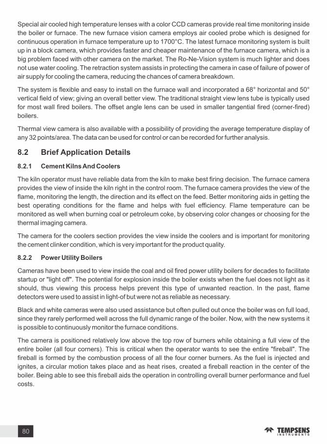
Special air cooled high temperature lenses with a color CCD cameras provide real time monitoring inside
the boiler or furnace. The new furnace vision camera employs air cooled probe which is designed for
continuous operation in furnace temperature up to 1700 C. The latest furnace monitoring system is built
up in a block camera, which provides faster and cheaper maintenance of the furnace camera, which is a
big problem faced with other camera on the market. The Ro-Ne- ision system is much lighter and does
not use water cooling. The retraction system assists in protecting the camera in case of failure of power of
air supply for cooling the camera, reducing the chances of camera breakdown.
The system is flexible and easy to install on the furnace wall and incorporated a 68 hori ontal and 50
vertical field of view giving an overall better view. The traditional straight view lens tube is typically used
for most wall fired boilers. The offset angle lens can be used in smaller tangential fired (corner-fired)
boilers.
Thermal view camera is also available with a possibility of providing the average temperature display of
any 32 points area. The data can be used for control or can be recorded for further analysis.
. Brie Application Details
. . Cement ilns And Coolers
The kiln operator must have reliable data from the kiln to make best firing decision. The furnace camera
provides the view of inside the kiln right in the control room. The furnace camera provides the view of the
flame, monitoring the length, the direction and its effect on the feed. Better monitoring aids in getting the
best operating conditions for the flame and helps with fuel efficiency. Flame temperature can be
monitored as well when burning coal or petroleum coke, by observing color changes or choosing for the
thermal imaging camera.
The camera for the coolers section provides the view inside the coolers and is important for monitoring
the cement clinker condition, which is very important for the product quality.
. . Power Utilit Boilers
Cameras have been used to view inside the coal and oil fired power utility boilers for decades to facilitate
startup or light off . The potential for explosion inside the boiler exists when the fuel does not light as it
should, thus viewing this process helps prevent this type of unwanted reaction. In the past, flame
detectors were used to assist in light-of but were not as reliable as necessary.
Black and white cameras were also used assistance but often pulled out once the boiler was on full load,
since they rarely performed well across the full dynamic range of the boiler. Now, with the new systems it
is possible to continuously monitor the furnace conditions.
The camera is positioned relatively low above the top row of burners while obtaining a full view of the
entire boiler (all four corners). This is critical when the operator wants to see the entire fireball . The
fireball is formed by the combustion process of all the four corner burners. As the fuel is injected and
ignites, a circular motion takes place and as heat rises, created a fireball reaction in the center of the
boiler. Being able to see this fireball aids the operation in controlling overall burner performance and fuel
costs.
80

. . Steel
The furnace camera provides a clear view of the steel slab progression in batch or continuous steel
reheat furnace and the burner performance. The camera is ideally mounted near the exit of the furnace on
the opposite sides above the products. The combined view of the cameras provides 360 degree view of
the furnace.
The camera is also useful when mounted just below the height where the slab travels. This aids in viewing
the level of scale deposited beneath the steel.
. . Glass
The furnace camera provides the clear view of the condition inside the glass furnace. This is used to
check the molten glass condition, refractory healthiness and the firing pattern inside the furnace.
Thermal view is employed in some cases to provide the thermal view of the furnace. Recording of the data
is possible to use for analysis of the refectory life etc.
These cameras are also used in the steel kiln applications for viewing the inside of the kiln and the burner
flame.
The furnace camera mounted at the entrance of the rolling mill assists the operator in monitoring the slab
as it enters the mill.
81

. Inspection and Testing
For the assurance of the quality of Sensor different type of testing is done they are:
(I) Type Test & (ii) Routine Test.
(I) T pe Tests The tests which are carried out to prove conformity with the requirements of the
specification are called type test. These are intended to prove the general qualities and design
of a given sample of sensor.
(ii) Routine Tests The tests which are carried out on each sensor as per sampling plan are
called routine test.
The major tests for the assurance of the quality are as follows:
(a) Appearance and Structure Check isual inspection is made to confirm that the thermocouple
assembly is in conformity with the specification, drawing and constituent materials. isual checking are
conducted on the finish of joints, junctions, welds, name tag plates and other parts to confirm that there is
no error, flaw dirt or irregularity on the surface finish. If necessary, dye penetration check, hydrostatic
pressure test and -ray inspection can be made on welded and joint parts.
(b) Dimensional Check Unless otherwise specified, dimensional check is made in accordance with
the following tables using ernier Caliper, Straight Measure and Gauges.
Non MI Unit mm Non MI Unit mm
Nominal Length Tolerance Nominal Length Tolerance
Below 1,000
1,000 - 2,000
Over 2,000
3.0
5.0
7.0
3.0
5.0
1.0
Below 250
250 - 1,000
Over 1,000
( c) Insulation Resistance Test
Insulation Resistance Test is conducted using a Super megohmeter applying steep temperature gradient
on sensor assembly immersed in a boiling water bath so as to accelerate condensation of moisture that
might be entrapped in the assembly. This enables the measurement of insulation resistance of the
assembly very precisely between terminal and sheath.
Sensor Insulation Resistanceoltage
Non MI
MI Dia - 2.0 and Below
MI Dia - 3.0 and Above
RTD
T C
at room Temperature DC 500
at room Temperature DC 1000
at room Temperature DC 500
at room Temperature DC 250
at 560 C DC 500
More Than 100MMore Than 100MMore Than 100MMore Than 100MMore Than 5M
Inspection Testing and Calibration
82

(d) Em Calibration Test
These tests can be made either by comparison method with standard thermocouples RTD or absolute
method using fixed point standards on every unit or batch at the pre-set three temperature points
depending on the types of sensor.
(e) Pressure Test (For Sealed Elements Onl )
The element shall be tested in a hydraulic test chamber containing water and ice in equilibrium and
connected electrically to an appropriate indicator. The pressure of the fluid in the chamber shall be raised
to 35kgf cm and shall be maintained for 15 minutes.
The resistance or EMF of the element shall not vary significantly from that appropriate to the equilibrium
temperature corresponding to the pressure applied and when subsequently removed from the chamber,
the element shall pass insulation resistance test and accuracy test.
( ) Identi ication Test on the Thermocouple T pe and Polarit
Either by dipping thermocouple assembly into the above boiling water bath or applying hot air-blow flame
heat on the beaded Thermocouple at its hot or cold end to have it generate EMF, which allows to indicate
specific type of thermocouple through Temperature vs. EMF Table. A high resolution D.C. circuit testing
instrument is used to identify the type of thermocouple and polarity of the thermocouple leg and terminal.
(g) Others
Loop Resistance test, voltage withstand test, -ray test, vibration test, pressure test, helium leak test, etc.
can also conducted upon request.
. Calibration
Temperature is one of the most frequently measured parameters in industrial processes. Wide varieties
of mechanical and electrical thermometers are used to sense and control process temperatures. Regular
calibration of these thermometers is critical to ensuring consistent quality of product manufactured, as
well as providing regulatory compliance for some industries.
Calibration is a comparison between measurements - one of known magnitude or correctness made or
set with one device and another measurement made in as similar a way as possible with a second device.
The device with the known or assigned correctness is called the standard. The second device is the unit
under test, test instrument, or any of several other names for the device being calibrated.
Calibration is performed to verify sensor instrument performance. Calibration is the process used to
ensure that a sensor instrument maintains specification over time and changing ambient conditions.
Calibration is the process used to maintain traceability of parameters with reference to
national international standards.
There are many definitions of calibrations as there are methods: According to ISA s The Automation,
Instruments and Systems dictionary, The word calibration is defined as A test during which a known
value of measurand are applied to transducers and corresponding output readings are recorded under
specified conditions . The definition includes the capability to adjust the instrument at ero and to set the
desired span. An interpretation of definition would say that the calibration is a comparison of measuring
instrument against a standard instrument of higher accuracy to detect, correlate, adjust, rectify and
83

Thermometer well
Water apour
Ice sheath
Thermal Contact Liquid
Water
document the accuracy of the instrument being compared.
. . T pes o Thermal Calibration
There are mainly two types of calibrations method used they are, Fixed point method and comparison
method.
a.) Fi ed Points
Fixed points are the most accurate devices available for defining a temperature scale. Fixed point
devices utili e totally pure materials enclosed in a sealed, inert environment they are usually fragile and
need to be handled with care.
The housing incorporate isothermal blocks with wells into which the probes are placed. Since fixed point
temperatures are defined by physical laws, comparison of the test probe to a reference probe is not
required.
Fixed point calibrations are used for primary temperature standards to achieve the lowest
possible uncertainties. It is a time consuming method and requires the use of expensive fixed point
cells.
The triple point of water (TPW) cell may be the most commonly used type of fixed point and is
used in ITS 90 calibrations. Water can exist as a solid, liquid, and vapor at 0.01 C and this
device creates this temperature.
Triple point of water cell
Fi ed points method
This absolute method is used for the reali ation of the International temperature scale, ITS-90. The
thermometer is calibrated by measurements at a series of temperature fixed points: e.g. free ing melting
points, triple points, vapour pressure points.
This method consists in setting up a thermometer in a fixed-point cell that provides an isothermal
environment.
The fixed point cell is a flask almost completely filled with pure material and protected by a shell. The cell
84

Pressure controller
Thermometer well
Metal
External tube
is placed in an apparatus that must provide good temperature control and
sufficient cell immersion to generate a uniform temperature in the
measurement one. The apparatus must provide for fixed-point cooling as
well as controlled heat. It may be a furnace - generally, a vertical tube
furnace with suitable insulation - or a liquid bath.
A number of fixed points are chosen. They should be as few as possible,
consistent with the need to establish a good interpolating formula. This
method gives a highly accurate calibration and is used only for highest
quality thermometry. But it is difficult to undertake because of the complexity
of the equipment and the many precautions that must be taken to reali e the
fixed points successfully.
Fixed points are reali ed using numerous pure substances. However, many
do not ensure the required stability and reproducibility and others require a
complex procedure and special laboratory facilities.
ITS i ed points include
Boiling point of Nitrogen -195.798 C
Mercury triple point 38.8344 C
Triple point of water 0.01 C
Melting point of Gallium 29.7646 C
Free ing point of Indium 156.5985 C
Free ing point of Tin 231.928 C
Free ing point of Lead 327.462 C
Free ing point of inc 419.527 C
Free ing point of Antimony 630.63 C
Free ing point of Aluminum 660.323 C
Free ing point of Silver 961.78 C
Triple Point O Water . . ( . C)
The triple-point temperature of water is assigned the value 273.16 on the elvin Thermodynamic
Temperature Scale and also on the ITS-90. It is the reference temperature for resistance ratios in
platinum resistance thermometry. The water used in preparing triple point of water cells is pure water of
naturally-occurring isotopic composition. Figure 6 shows two commonly used types of triple point of water
cells.
Triple point of water cells are usually prepared from river water that has been purified by chemical
treatment and distillation. River water is expected to have concentrations of deuterium and the heavier
isotopes of oxygen that are lower than that of ocean water. The extreme difference in the triple points of
naturally occurring water, including polar water, is given as 0.25 m . It is expected that differences among
water triple-point cells of river water would be much smaller than 0.25 m . (The isotopic composition
difference between river water and ocean water has been estimated to cause no more than a 0.050 m
85

difference in the triple-point temperature.) While the basic material is plentifully available, preparation of
water triple-point cells requires a special effort. Although the effect on the triple-point temperature is
negligible, a trace of air always remains in most sealed triple point of water cells. When a cell at room
temperature is gently inverted from one end to the other and a sharp click is produced through the water
hammer action, the amount of gas in the cell wi11 have negligible influence on the triple-point
temperature
Two types of triple point of water cells with wells for platinum resistance thermometers. The cells contain pure air-free water. The thermometer wells
are made of precision-bore tubing.
Free ing Melting Or Triple Points O Metals Hg Ga. In. Sn. n. Al. Ag Au. or Cu
The reali ation of metal fixed points requires the continuous presence of liquid-solid or liquid-solid-vapor
phases in thermal equilibrium. With SPRT s, the liquid-solid interface, i.e., the equilibrium whose
temperature is measured must surround and must be as close to the temperature sensing element as
possible. Since the first cryoscopic constants of metals are relatively low, the fixed-point metal samples
should be at least 99.9999 pure. Figure 1 shows ideali ed liquid solid equilibrium conditions inside
fixed point cells used in free ing and melting experiments.
Figure 2 shows a representative arrangement of an SPRT inserted inside a metal fixed point cell. Ideally,
and similar to the water triple-point cell, an outer liquid-solid interface, which completely surrounds the
inner interface, exists close to the container wall. This outer interface, which has a temperature very close
to that of the inner interface, thermally protects and thermally stabili es the inner interface.
T pe A T pe B
Ideali ed liquid solid equilibrium conditions inside fixed point cells used in free ing and melting experiments
Cell Hoder
Sample Cell
Sample
Liquid Sample
Solid Sample
ThermometerWell
ResistanceThermometer
86
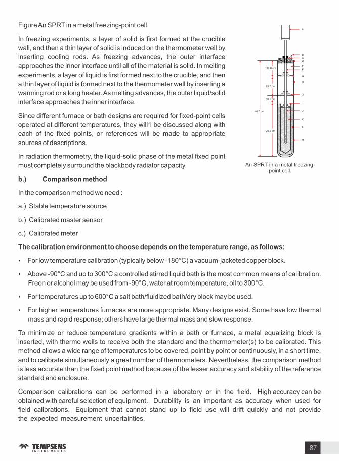
An SPRT in a metal free ing-point cell.
Figure An SPRT in a metal free ing-point cell.
In free ing experiments, a layer of solid is first formed at the crucible
wall, and then a thin layer of solid is induced on the thermometer well by
inserting cooling rods. As free ing advances, the outer interface
approaches the inner interface until all of the material is solid. In melting
experiments, a layer of liquid is first formed next to the crucible, and then
a thin layer of liquid is formed next to the thermometer well by inserting a
warming rod or a long heater. As melting advances, the outer liquid solid
interface approaches the inner interface.
Since different furnace or bath designs are required for fixed-point cells
operated at different temperatures, they will1 be discussed along with
each of the fixed points, or references will be made to appropriate
sources of descriptions.
In radiation thermometry, the liquid-solid phase of the metal fixed point
must completely surround the blackbody radiator capacity.
b.) Comparison method
In the comparison method we need :
a.) Stable temperature source
b.) Calibrated master sensor
c.) Calibrated meter
The calibration environment to choose depends on the temperature range as ollows
For low temperature calibration (typically below -180 C) a vacuum-jacketed copper block.
Above -90 C and up to 300 C a controlled stirred liquid bath is the most common means of calibration.
Freon or alcohol may be used from -90 C, water at room temperature, oil to 300 C.
For temperatures up to 600 C a salt bath fluidi ed bath dry block may be used.
For higher temperatures furnaces are more appropriate. Many designs exist. Some have low thermal
mass and rapid response others have large thermal mass and slow response.
To minimi e or reduce temperature gradients within a bath or furnace, a metal equali ing block is
inserted, with thermo wells to receive both the standard and the thermometer(s) to be calibrated. This
method allows a wide range of temperatures to be covered, point by point or continuously, in a short time,
and to calibrate simultaneously a great number of thermometers. Nevertheless, the comparison method
is less accurate than the fixed point method because of the lesser accuracy and stability of the reference
standard and enclosure.
Comparison calibrations can be performed in a laboratory or in the field. High accuracy can be
obtained with careful selection of equipment. Durability is an important as accuracy when used for
field calibrations. Equipment that cannot stand up to field use will drift quickly and not provide
the expected measurement uncertainties.
87
A
BCD
E
F
G
H
G
I
J
L
M
110.0 cm
75.0 cm
50.0 cm
40.0 cm
25.2 cm

Rt
Control PRT
Working sensors to be calibrated
Measuring Device
Liquid Calibration bath
Reference PRTwith traceable calibration Temperature
Controller
Cold unction Compensation (C C)
To make accurate measurements for thermocouples, this must be compensated for by using a technique
known as cold junction compensation (CJC). As the law of intermediate metals states that a third metal,
inserted between the two dissimilar metals of a thermocouple junction will have no effect provided that the
two junctions are at the same temperature. This law is also important in the construction of thermocouple
junctions. It is acceptable to make a thermocouple junction by soldering the two metals together as the
solder will not affect the reading. In practice, thermocouple junctions are made by welding the two metals
together (usually by capacitive discharge). This ensures that the performance is not limited by the melting
point of solder.
All standard thermocouple tables allow for this second thermocouple junction by assuming that it is kept
at exactly ero degrees centigrade. Traditionally this was done with a carefully constructed ice bath
(hence the term cold junction compensation). Maintaining an ice bath (at 0 C) is not practical for most
measurement applications, so instead the actual temperature at the point of connection of the
thermocouple wires to the measuring instrument is recorded.
Typically cold junction temperature is sensed by a precision thermometer in good thermal contact with the
input connectors of the measuring instrument. This second temperature reading, along with the reading
from the thermocouple itself is used by the measuring instrument to calculate the true temperature at the
thermocouple tip. Understanding of cold junction compensation is important any error in the
measurement of cold junction temperature will lead to the same error in the measured temperature from
the thermocouple tip.
c.) Electrical Calibration - Simulators and Sources
Indicators and controllers are calibrated by injection signals which simulate thermocouples, resistance
thermometers or thermistors. A simulator provides a very quick and convenient method for calibrating an
instrument at many points.
-
+
88

ery sophisticated and highly accurate laboratory instruments are available to permit on-site checking
and calibration with a good level of accuracy.
. . . E uipment re uired or a Calibration S stem
The equipment required to achieve thermal calibration of temperature probes is dependent on the
desired accuracy and also ease of use. The greater the required accuracy, the more demanding the
procedure becomes and of course, the greater the cost.
The re uired e uipment generall alls into one o three groups
1. General purpose system for testing industrial plant temperature sensors will usually provide
accuracies between 1.0 C and 0.1 C using comparison techniques.
2. A secondary standards system for high quality comparison and fixed point measurements will
provide accuracies generally between 0.1 C and 0.01 C.
3. A primary standards system uses the most advanced and precise equipment to provide accuracies
greater than 0.001 C.
Typical equipment used for comparison calibration is a standard or secondary PRT, several
temperature baths, and a data acquisition system.
a.) Temperature Sensor
For lower temperature calibration Platinum resistance detector is used in the form of SPRT and RTD,
these are very stable and accurate. For higher temperature calibration, Noble metal thermocouple is
used like R, S type thermocouple. These sensors must have accuracy and repeatability. The detail of
these temperature sensors is described in previous chapters and SPRT & SSPRT is discussed below:
Standard PRT s
A standard platinum resistance thermometer (SPRT) is the most accurate standard available, however, it
is the most expensive standard, and other standards are acceptable alternatives depending upon the
temperature range covered, the accuracy desired, the capabilities, or the preference of the calibration
laboratory.
SPRT is a specially constructed assembly using a close tolerance Pt100 sensing resistor or a specially
wound platinum element with a choice of Ro values. Construction is such as to eliminate the possibility of
element contamination and various techniques are utili ed to end this, such as special sheath materials,
gas filling and special coil suspension.
Standard PRT s is ery fragile. This is mainly use in laboratory environments. Highest accuracy, high
repeatability, low drift -200 C to 661 C, accurate to .001 C.
Lead wire
uart SheathElement support
Platinum Coil
89

Secondar SPRT
The secondary standard PRT s is much more user friendly and can survive mild handling mishaps.
It is less expensive than an SPRT. Metal Sheathed Semi Standard Platinum Resistance Thermometer
are widely used as references to calibrate various temperature probes, particularly in secondary
calibration laboratories.
The structure of the thermometer is similar to that of SPRTs. The differences include the applications of
certain techniques to protect the element from contamination at high temperatures and mechanical
shocks.
Basic Construction o SSPRT
SSPRT is constructed with a 6 mm outer diameter Inconel Sheath for high durability. Inside the sheath,
the sensing element is protected by a thin platinum housing that shields the sensor from contamination
from free floating metal ions found within metal environment at high temperatures. A special powder
mixture is filled into the sensor capsule to support the element wire to protect the element from
mechanical shocks. After all element parts and powder are assembled into the sensor protection capsule,
a pure mixture of gases, including oxygen, is filled into the sensor at high temperature. The sensor is
hermetically sealed under pressure. The unit is hermetically sealed using a glass to metal seal.
Strain Relief Spring
Handle
External Lead
Connection JointGlass -To - Metal Seal
Glass Tubefor acuum
InsulatingDisc
Single Bore Insulating Tube
Platinum Wire
Inconel Sheath
Sensing Elements
Improving Stabilities o SSPRT
There is a trade-off between the oxidation effect and element contamination in metal sheathed semi
standard platinum resistance thermometer. Excessively high O2 leads to sensor contamination. The
oxygen content in a thermometer may become unknown after a period of operation due to slow oxidation
of the metal sheath and consequent loss of oxygen in metal sheathed SSPRT.
A feasible solution to protect against contamination is to seal the element separately from its sheath. This
solution can resolve the conflict between the oxidation effect and element contamination and improve the
long term stability of Metal Sheathed SSPRTs.
Master thermocouple
Industrial thermometers come in a variety of forms and types, calibrating them can be quite complicated.
To calibrate industrial sensors the laboratory must compare them to standard thermometers whose
characteristics have been defined and are traceable to National Standards. Such thermometers that are
traceable to national standard are known as Master thermocouple .
Master thermocouple is use as a reference sensor in comparison type calibration process.
Master thermocouple is put in the highly stable temperature one along with sensor under calibration,
their reading is compared and error is calculated.
90

c.) Secondar Temperature source
Dr block calibrators
Dry block calibrators provide the most convenient, portable
facilities for checking industrial probes and they usually achieve
reasonably rapid heating and cooling. The units consist of a
specially designed heated block within which is located an insert
having wells for the probes. The block temperature is controlled
electronically to the desired temperature. The whole assembly is
housed in a freestanding case. Although the block temperature is
accurately controlled, any indication provided should be used for
guidance only. As with any comparison technique, a certified
sensor and indicator should be used to measure the block
temperature and used as a reference for the test probe.
Black Body furnace is also a dry bath, but used in non contact
calibration. The black body furnace has been designed to provide
stable and accurate temperature to provide stable and accurate
temperature to enable professionals to calibrate non contact
radiation pyrometer by comparison method.
Stirred li uid baths
Stirred liquid baths provide superior thermal environments for probe immersion since no air gaps exist
between the probe and medium. Thermal coupling is therefore much better than the alternatives
described, and stirring results in very even heat distribution throughout the liquid.
With the help of this bath, the comparison calibration accuracy can be considerably greater than that
which can be achieved in any metal block bath. It also has a larger calibration area, that allows more
probes to be calibrated and a greater immersion depth which provide a superior thermal environment for
probe immersion since air gaps exists between the probe and the medium. Thermal coupling is therefore
much better than the alternatives described and as a result of stirring heat distribution is very even
throughout the liquid.
Water from 0 C to +80 C and oils for up to 300 C, arious molten salts and sand baths are used for
temperatures in excess of 300 C.
Ice bath and negative bath
Ice Bath
The ice bath is made up of a mixture of melting shaved ice and water. The ice bath is a convenient and
inexpensive way to achieve an ice point it can be reproduced with ease and with exceptional accuracy.
Master thermocouple should have high accuracy, and repeatability and should be recalibrated after
certain period of time (generally time period suggested by calibration Laboratories).
b.) Temperature readout method
These instruments measures the output of the sensors, they must have high resolution and good
accuracy.
91

Junctions formed between the thermocouple materials and instrument leads can be simply immersed
into the slush mixture, or alternatively glass U tubes containing a quantity of mercury approximately 3 4
to 1 depth can be placed into the slush mixture. uick electrical connection can then be made between
thermocouple and instrument leads through the mercury.
Negative temperature bath and Ice bath is mainly used for RTD calibration which provides negative
temperature for low temperature calibration application. In this device a compressor and CFC gas is used
for cooling purpose. Methanol is used as a medium for temperature below 0 C.
Fluidi ed calibration baths
The fluidi ed calibration bath is a unique method of providing closely controlled temperatures. The bath
consists of a very fine mesh aluminum oxide, a heated chamber into which the medium is placed, and a
means for slowly agitating the bath by introducing a flow of air. By careful control of heat input and air flow,
temperatures of the bath can be controlled within close limits thereby producing isothermal conditions
between the calibration standard and the test setup. Fluidi ed beds are useful for calibrating over the
temperature range from ambient to 700 C.
. Uncertaint Factor
In earlier days, in general, the error or inaccuracy of a test instrument was a matter of concern when using
the test instruments as reference. The concept of uncertainty is very frequently used in the calibration of
precision equipments, where high degree of accuracy is required for measurement. This concept is
considered for various important parameters.
Nowadays, calibration Labs are required to calculate and affix a total or expanded uncertainty for all
measurements during calibration of a test instrument. It must be noted that error is not uncertainty .
92

SA
MP
LE
TEMPSENS CALIBRATION CENTREA Division of Tempsens instruments (l) Pvt. Ltd.
B-188A, ROAD NO.5, M.I.A., UDAIPUR-313003 INDIA
Ph.: +91-294-3057724,3057700 Fax : +91-294-2492447, 3057750
Email : [email protected], Website : www.tempsens.com
Calibration Certi icate
No. TL . .
M S XY
Address 1
Address 2
City
State
J.O. No.: 000 Y ABCD
J.O. Datet. : DD- MM-YY
Received Dt. : DD- MM-YY
Calibration Dt. : DD- MM-YY
UUC Description
One sample describes as PTRH13 -PT R TYPE THERMOCOUPLE Sr. No. TTCR-13 was received.
Calibration Re uired at C 250, 500, 750, 1000, 1200, 1500
Calibration Procedure The UUC was allowed to equiilibrate within controlled stable thermal environment, along with a standard
sensor. The reading of sensor were recorded at specified temperature point. As per work instruction no.
WI-LAB-17. The report provide the reading and deviation at the specified Point
Temperature (in C) against thermocouple reading (in ) are calculated by using ASTM E-230 IS table.
The Thermocouple has been compared with the following working standard of sensor & measuring instrument.
Standards Traceable To Certi icate No. alid Upto
MASTER RTD - Pt100
THERMOCOUPLE S TYPE
THERMOCOUPLE B TYPE
CALSYS 300
CALSYS 1200L
CALSYS 1500L
PRECISION THERMOMETER
INT. STD. (D D)
NAT. STD. (NPL)
NST. STANDARTD
3013
13153
10011555 1.03B C-91 09
YMPL 174251 27718
30-05-12
28-01-12
01-02-12
18-01-12
The result of calibration are as under :
(Reference junction calculated at 0 C)
Sr.Standard Sensor UUC Deviation E panded Uncertaint
Temp C Temp Cm Temp C C
1
2
3
4
5
6
249.77
499.84
750.03
1,000.38
1,200.29
1,498.09
1.92
4.47
7.35
10.52
13.25
17.44
250.06
500.31
750.78
1,001.41
1,201.46
1,499.53
0.29
0.47
0.75
1.03
1.17
1.44
0.10
1.07
1.30
1.30
2.20
3.70
Temperature Scale : ITS - 90 Ambient Temp. : 25 2 C Relative Humidity : 50 20
Calibrated B Checked B Certi ied B
Note (1) The calibration result reported in this certificate are valid at the time of and under the stated condition of measurement for the
particular sampl
(2) The report shall not be reproduced except in fill, without written permission of the laboratory
(3) Coverage factor 2 at 95.45 confidence level.
TEMPERATURE SENSOR TECHNOLOGY
TYPICAL CALIBRATION REPORT
93

SA
MP
LE
TEMPSENS CALIBRATION CENTREA Division of Tempsens instruments (l) Pvt. Ltd.
B-188A, ROAD NO.5, M.I.A., UDAIPUR-313003 INDIA
Ph.: +91-294-3057724,3057700 Fax : +91-294-2492447, 3057750
Email : [email protected], Website : www.tempsens.com
Calibration Certi icate
No. AB . .
TEMPSENS CALIBRATION CENTRE
A DI OF TEMPSENS INSTRUMENTS (l) P T. LTD.
B- A ROAD NO. M.I.A. UDAIPUR
(RA ) -
Calibrated B Checked B Certi ied B
TEMPERATURE SENSOR TECHNOLOGY
CALIBRATION CERTIFICATE OFSTANDARD PLATINUM RESISTANCE THERMOMETER
Certi icate No.AB . .
Date
DD MM YYYY
Recommended date or the ne t calibration Page No. O pages
. Calibration or
. Discription &
Identi ication o
instruments
. Environmental
Conditions
. Standard(s) Used
& Associated
uncertaint
. Traceable o
Standard
. Principle
Methodolog o
Calibration
. Result
XY Limited
Address
Address
Semi standard platinum resistance thermometer
Make : Tempsens Sr. No. : 1428
Range : 0 C to 660 C
: Temprature :(25 2) C
Humidity : (50 20) RH
: Fixed Point of T.P. of water, melting point of Ga, Free ing point of Sn, n, & Al.
:SPRT (25.5)
: Expanded Uncertainity at 2 & C.L. Approx. 95 ( 15 m C to 40 m C)
: The standard used for calibration are traceable to National Standards.
: The PRT110 has been calibrated by fixed point method at T.Ps of water, M.Ps of Ga
F.Ps of Tin, inc & Aluminium. The fixed point are being maintained at
Tempsens calibration centre, Udaipur as per ITS-90 (Calibration Procedures P-LAB-10)
: For the range . C to . C
W (Ga) .
W (Sn) .
W ( n) .
W (Al) .
R (Ga) .
R (Sn) .
R ( n) .
R (Al) .
A - . E-
B . E-
C - . E-
R(TPW) .
The Estimated uncertainties for k 2 & C.L. approx. 95 are as follows :
T.P. OF Water 0.015 C, M.P. OF Ga 0.029 F.P. of Sn 0.039 C,
F.P. of n 0.035 C, F.P. ofAl 0.040 C
DD MM YYYY
TYPICAL CALIBRATION REPORT FOR FIXED POINT CALIBRATION
94

. Introduction
The range requirement in instrumentation ranges from a simple display of a single temperature value to
multi sensor data acquisition and logging or from a simple controller to multi one communicating control
systems. Other requirements may include transmission and signal conditioning, analogue recording,
alarm monitoring and communications.
Fundamentally, instrumentation will be in one of the two forms, open loop or closed loop. Open loop is
where there is no system feedback and therefore no control action the measuring instrument(s) exerts
no influence over the process behavior other than possible alarm action, which may result in power-
down .
Closed loop is where there is direct or indirect feedback from the instrument to the process energy
temperature regulator resulting in control of the process temperature.
. Temperature Indicators
Temperature indicators are the basic instruments which are required either locally or required in the
control room for the process parameters monitoring.
Electronics & Instrumentation or Temperature
Open Loop S stem
Independent Energy Regulation
Process
Sensor Indicator
Sensor simpl provides temperature in ormation to the indicator.Process regulation is e ected independentl
Closed Loop S stem
Process
Sensor
ProcessEnergy Regulation
Controller
Controloutput
Sensor provides temperature eedback thus allowing automatic control
95
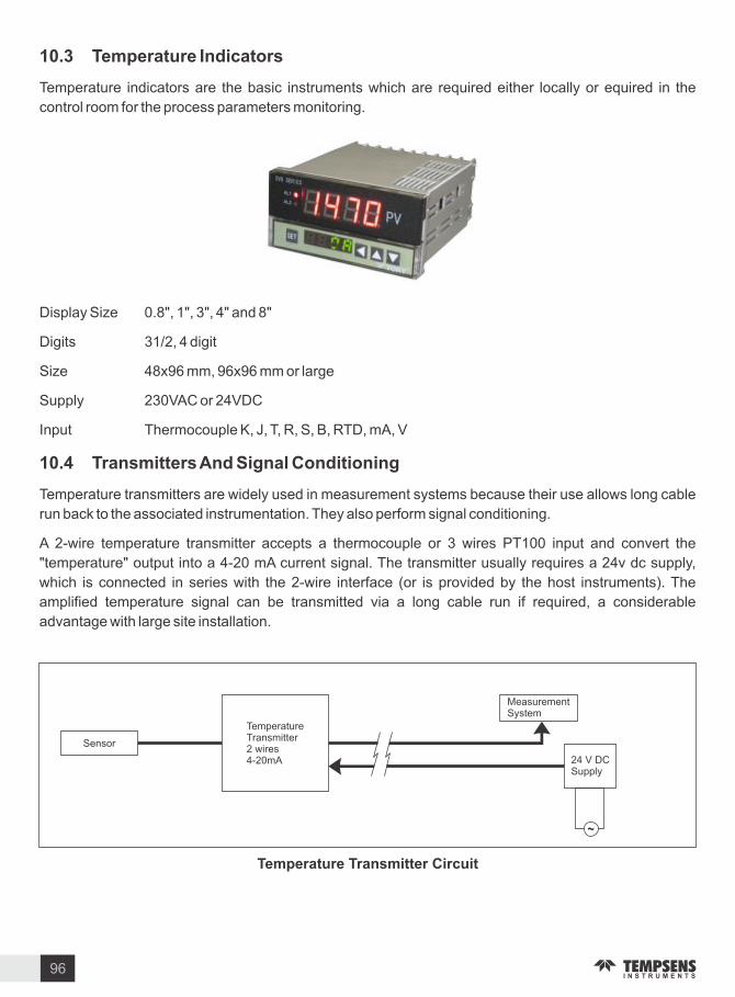
. Temperature Indicators
Temperature indicators are the basic instruments which are required either locally or equired in the
control room for the process parameters monitoring.
Display Si e 0.8 , 1 , 3 , 4 and 8
Digits 31 2, 4 digit
Si e 48x96 mm, 96x96 mm or large
Supply 230 AC or 24 DC
Input Thermocouple , J, T, R, S, B, RTD, mA,
. Transmitters And Signal Conditioning
Temperature transmitters are widely used in measurement systems because their use allows long cable
run back to the associated instrumentation. They also perform signal conditioning.
A 2-wire temperature transmitter accepts a thermocouple or 3 wires PT100 input and convert the
temperature output into a 4-20 mA current signal. The transmitter usually requires a 24v dc supply,
which is connected in series with the 2-wire interface (or is provided by the host instruments). The
amplified temperature signal can be transmitted via a long cable run if required, a considerable
advantage with large site installation.
Sensor
Temperature Transmitter2 wires4-20mA
Measurement System
24 DCSupply
Temperature Transmitter Circuit
96
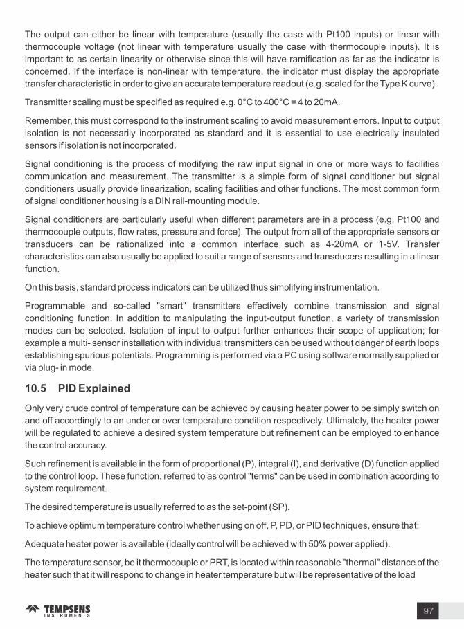
The output can either be linear with temperature (usually the case with Pt100 inputs) or linear with
thermocouple voltage (not linear with temperature usually the case with thermocouple inputs). It is
important to as certain linearity or otherwise since this will have ramification as far as the indicator is
concerned. If the interface is non-linear with temperature, the indicator must display the appropriate
transfer characteristic in order to give an accurate temperature readout (e.g. scaled for the Type curve).
Transmitter scaling must be specified as required e.g. 0 C to 400 C 4 to 20mA.
Remember, this must correspond to the instrument scaling to avoid measurement errors. Input to output
isolation is not necessarily incorporated as standard and it is essential to use electrically insulated
sensors if isolation is not incorporated.
Signal conditioning is the process of modifying the raw input signal in one or more ways to facilities
communication and measurement. The transmitter is a simple form of signal conditioner but signal
conditioners usually provide lineari ation, scaling facilities and other functions. The most common form
of signal conditioner housing is a DIN rail-mounting module.
Signal conditioners are particularly useful when different parameters are in a process (e.g. Pt100 and
thermocouple outputs, flow rates, pressure and force). The output from all of the appropriate sensors or
transducers can be rationali ed into a common interface such as 4-20mA or 1-5 . Transfer
characteristics can also usually be applied to suit a range of sensors and transducers resulting in a linear
function.
On this basis, standard process indicators can be utili ed thus simplifying instrumentation.
Programmable and so-called smart transmitters effectively combine transmission and signal
conditioning function. In addition to manipulating the input-output function, a variety of transmission
modes can be selected. Isolation of input to output further enhances their scope of application for
example a multi- sensor installation with individual transmitters can be used without danger of earth loops
establishing spurious potentials. Programming is performed via a PC using software normally supplied or
via plug- in mode.
. PID E plained
Only very crude control of temperature can be achieved by causing heater power to be simply switch on
and off accordingly to an under or over temperature condition respectively. Ultimately, the heater power
will be regulated to achieve a desired system temperature but refinement can be employed to enhance
the control accuracy.
Such refinement is available in the form of proportional (P), integral (I), and derivative (D) function applied
to the control loop. These function, referred to as control terms can be used in combination according to
system requirement.
The desired temperature is usually referred to as the set-point (SP).
To achieve optimum temperature control whether using on off, P, PD, or PID techniques, ensure that:
Adequate heater power is available (ideally control will be achieved with 50 power applied).
The temperature sensor, be it thermocouple or PRT, is located within reasonable thermal distance of the
heater such that it will respond to change in heater temperature but will be representative of the load
97

temperature (the thing being heated).
Adequate thermal mass in the system to minimi e its sensitivity to varying load or ambient condition.
Good thermal transfer between heater and load.
The controller temperature range and sensor type are suitable try to choose a range that result in a mid-
scale set point.
. . Control Function Simpl Described
10.5.1 (a) ON OFF : usually simplest and cheapest but control may be oscillatory. Best confined to alarm
function only or when thermostatic type control is all that is required, but this may be the most suitable
means of control in some application.
10.5.1 (b) Proportional (P) : a form of anticipatory action, which slows the temperature rise when
approaching set point. ariation is more smoothly corrected but an offset will occur (between set and
achieved temperature) as condition varies. Average heater power over a period of time is regulated and
applied power is proportional to the error between sensor temperature and set point. The region over
which power is thus varied is called the proportional band it is usually defined as a percentage of full scale.
Offset is the deviation of the sensor temperature from the desired value. This can be adjusted out
manually by means of a potentiometer adjustment or automatically.
10.5.1 (c) Proportional + Derivative (PD) : the derivative term when combined with proportional action
improve control by sensing change and correcting for them quickly. The proportional action is effective
intensified to achieve a quicker response.
10.5.1 (d) Proportional + Integral + Derivative (PID) : adding an integral term to Pd control can provide
automatic and continuous elimination of any offset. Integral action operates in the steady state condition
by shifting the proportional band upscale or downscale until the system temperature and set point
coincide.
. Choosing P PD or PID although superior control can be achieved in many case with PID
control action value of the PID terms inappropriate to the application can cause problem.
If an adequately powered system with good thermal response exists and the best possible control
accuracy is required, full PID control is recommend.
If somewhat less critical precision is demanded, the simpler PD action will suffice and will suit a broad
range of application.
Set Point
CA
B
Time
A Start up with out the benefit of D and non- optimi ed P.B Start up with optimi ed PD and overshoot inhibition
Set Point
Prop band (PB)
0
100
Proportional Control
98

. Proportional Plus Integral Plus Derivative Control Mode (PID)
This controller operates the same way a proportional controller does, except that the function of the trim
adjustment is performed automatically by the integral function (automatic reset). Thus, load changes are
compensated for automatically and the temperature agrees with the setpoint under all operating
conditions. Offset is eliminated.
Figure Rate unction compensates or rapid changes.
The derivative function (rate action) compensates for load changes which take place rapidly. An example
is a traveling belt oven where the product is fed intermittently. When the product enters the oven, there is a
sharp rise in the demand for heat, and when it stops, there is an excess of heat. Derivative action reduces
the undershoot and overshoot of temperature under these conditions and prevents bad product due to
over or under curing. PID control provides more accurate and stable control than on off or proportional
controller types. It is best used in systems that have a relatively small mass and which react quickly to
changes in energy added to the process. It is recommended in systems where the load changes often.
The controller is expected to automatically compensate the amount of energy available or the mass to be
controlled, due to frequent changes in setpoint. The proportional, integral and derivative terms must be
tuned, i.e., adjusted to a particular process. This is done by trial and error. Some controllers called
Autotune controllers attempt to adjust the PID parameters automatically.
. PID Controller Operation
The PID controller provides proportional with integral and derivative control. This controller combines
proportional control with two additional adjustments, which helps the unit automatically compensate for
changes in the system. These adjustments, integral and derivative, are expressed in time-based units
they are also referred to by their reciprocals, RESET and RATE, respectively.
The proportional, integral and derivative terms must be individually adjusted or tuned to a particular
system using trial and error. It provides the most accurate and stable control of the three controller types,
and is best used in systems which have a relatively small mass, those which react quickly to changes in
the energy added to the process. It is recommended in systems where the load changes often and the
controller is expected to compensate automatically due to frequent changes in setpoint, the amount of
energy available, or the mass to be controlled.
There are also other features to consider when selecting a controller. These include auto- or self-tuning,
where the instrument will automatically calculate the proper proportional band, rate and reset values for
precise control serial communications, where the unit can talk to a host computer for data storage,
Set Point
Rate Set Properly
Low RateSetting
99

analysis, and tuning alarms, that can be latching (manual reset) or non-latching (automatic reset), set to
trigger on high or low process temperatures or if a deviation from setpoint is observed timers event
indicators which can mark elapsed time or the end beginning of an event. In addition, relay or triac output
units can be used with external switches, such as SSR solid state relays or magnetic contactors, in order
to switch large loads up to 75 A.
. Solid State Rela s(SSR)
SSR Defined. A solid-state relay is an ON-OFF control device in which the load current is conducted by
one or more semiconductors - e.g., a power transistor, an SCR, or a TRIAC. (The SCR and TRIAC are
often called thyristors, a term derived by combining thyratron and transistor, since thyristors are
triggered semiconductor
switches.) Like all relays, the SSR requires relatively low control circuit energy to switch the output state
from OFF to ON, or vice versa. Since this control energy is very much lower than the output power
controllable by the relay at full load, power gain in an SSR is substantial--frequently much higher than in
an electromagnetic relay of comparable output rating. To put it another way, the sensitivity of an SSR is
often significantly higher than that of an EMR of comparable output rating.
T pes o SSR s : It is convenient to classify SSR s by the nature of the input circuit, with particular
reference to them means by which input-output isolation is achieved. Three major categories are
recogni ed:
Reed-Relay-Coupled SSR s ,in which the control signal is applied (directly, or through a preamplifier)
to the coil of a reed relay. The closure of the reed switch then activates appropriate circuitry that
triggers the thyristor switch. Clearly, the input-output isolation achieved is that of the reed relay, which
is usually excellent.
Transformer-Coupled SSR s, in which the control signal is applied (through a DC-AC converter, if it is
DC, or directly, if It is AC) to the primary of a small, low-power transformer, and the secondary voltage
that results from the primary excitation is used (with or without rectification, amplification, or other
modification) to trigger the thyristor switch. In this type, the degree of input-output isolation depends on
the design of the transformer.
Photo-coupled SSR s, in which the control signal is applied to a light or infrared source (usually, a light-
emitting diode, or LED), and the radiation from that source is detected in a photosensitive semi-
conductor (i.e., a photosensitive diode, a photo-sensitive transistor, or a photo-sensitive thyristor). The
output of the photo-sensitive device is then used to trigger (gate) the TRIAC or the SCR s that switch
the load current. Clearly, the only significant coupling path between input and output is the beam of
light or infrared radiation, and electrical isolation is excellent. These SSR s are also referred to as
optically coupled or photo-isolated .
100

Technical References
101
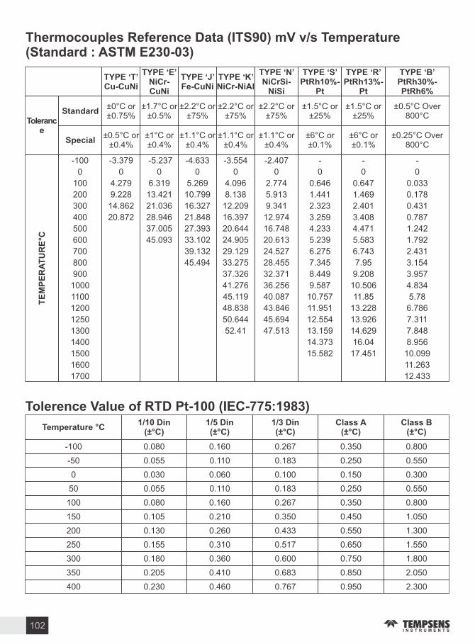
Temperature C Din
( C) Din
( C) Din
( C)Class A
( C)Class B
( C)
-100 0.080 0.160 0.267 0.350 0.800
350 0.205 0.410 0.683 0.850 2.050
0 0.030 0.060 0.100 0.150 0.300
250 0.155 0.310 0.517 0.650 1.550
100 0.080 0.160 0.267 0.350 0.800
150 0.105 0.210 0.350 0.450 1.050
200 0.130 0.260 0.433 0.550 1.300
50 0.055 0.110 0.183 0.250 0.550
300 0.180 0.360 0.600 0.750 1.800
-50 0.055 0.110 0.183 0.250 0.550
400 0.230 0.460 0.767 0.950 2.300
TE
MP
ER
AT
UR
EC
-3.379
4.279
14.862
20.872
9.228
0
-5.237
6.319
21.036
37.005
45.093
28.946
13.421
0
-4.633
5.269
16.327
27.393
39.132
45.494
33.102
21.848
10.799
0
-3.554
4.096
52.41
12.209
48.838
20.644
41.276
29.129
33.275
37.326
24.905
45.119
16.397
50.644
8.138
0
-2.407
2.774
47.513
9.341
43.846
16.748
36.256
24.527
28.455
32.371
20.613
40.087
12.974
45.694
5.913
0
-
15.582
0.646
13.159
2.323
11.951
4.233
9.587
6.275
7.345
8.449
5.239
10.757
3.259
12.554
1.441
14.373
0
-
17.451
0.647
14.629
2.401
13.228
4.471
10.506
6.743
7.95
9.208
5.583
11.85
3.408
13.926
1.469
16.04
0
-
10.099
0.033
7.848
0.431
6.786
1.242
4.834
2.431
3.154
3.957
1.792
5.78
0.787
7.311
0.178
8.956
0
11.263
12.433
-100
1500
100
1300
300
1200
500
1000
700
800
900
600
1100
400
1250
200
1400
0
1600
1700
0.25 C Over 800 C
Thermocouples Re erence Data (ITS ) m v s Temperature (Standard ASTM E - )
Tolerence alue o RTD Pt- (IEC- )
Tolerance
Standard
Special
TYPE TCu-CuNi
TYPE ENiCr-CuNi
TYPE Fe-CuNi
TYPE NiCr-NiAl
TYPE N NiCrSi-
NiSi
TYPE SPtRh -
Pt
TYPE RPtRh -
Pt
TYPE BPtRh -PtRh
0 C or 0.75
0.5 C Over 800 C
2.2 C or 75
1.5 C or 25
2.2 C or 75
2.2 C or 75
1.5 C or 25
1.7 C or 0.5
0.5 C or 0.4
1.1 C or 0.4
6 C or 0.1
1.1 C or 0.4
1.1 C or 0.4
6 C or 0.1
1 C or 0.4
102

Industrial Platinum Resistance Thermometer SensorsR( ) . OHMS
C ITS------------------ ---
.18.5222.8327.1031.3435.5439.7243.8848.0052.1156.1960.2664.3068.3372.3376.3380.3184.2788.2292.1696.09100.00
- .
22.4026.6730.9135.1239.3143.4647.5951.7055.7959.8563.9067.9271.9375.9379.9183.8787.8391.7795.6999.61
- .
21.9726.2430.4934.7038.8943.0547.1851.2955.3859.4463.4967.5271.5375.5379.5183.4887.4391.3795.3099.22
- .
21.5425.8230.0734.2838.4742.6346.7750.8854.9759.0463.0967.1271.1375.1379.1183.0887.0490.9894.9198.83
- .
21.1125.3929.6433.9638.0542.2246.3650.4754.5658.6362.6866.7270.7374.7378.7282.6986.6490.5994.5298.44
- .
20.6824.9729.2233.4437.6441.8045.9450.0654.1558.2362.2866.3170.3374.3378.3282.2986.2590.1994.1298.04
- .
20.2524.5428.8033.0237.2241.3945.5349.6553.7557.8261.8865.9169.9373.9377.9281.8985.8589.8093.7397.65
- .
19.8224.1128.3732.6036.8040.9745.1249.2453.3457.4161.4765.5169.5373.5377.5281.5085.4689.4093.3497.26
- .
19.3823.6827.9532.1836.3840.5644.7048.8352.9357.0161.0765.1169.1373.1377.1281.1085.0689.0192.9596.87
- .
18.9523.2527.5231.7635.9640.1444.2948.4252.5256.6060.6664.7068.7372.7376.7380.7084.6788.6292.5596.48
C ITS--------------------
C ITS .100.00103.90107.79111.67115.54119.40123.24127.08130.90134.71138.51142.29146.07149.83153.58157.33161.05164.77168.48172.17175.86179.53183.19186.84190.47194.10197.71210.31204.90
.100.39104.29108.18112.06115.93119.78123.63127.46131.28135.09138.88142.67146.44150.21153.96157.70161.43165.14168.85172.54176.22179.89183.55187.20190.84194.46198.07201.67205.26
.100.78104.68108.57112.45116.31120.17124.01127.84131.66135.47139.26143.05146.82150.58154.33158.07161.80165.51169.22172.91176.59180.26183.92187.56191.20194.82198.43202.03205.62
.101.17105.07108.96112.83116.70120.55124.39128.22132.04135.85139.64143.43147.20150.96154.71158.45162.17165.89169.59173.28176.96180.63184.28187.93191.56195.18198.79202.39205.98
.101.56105.46109.35113.22117.08120.94124.78128.61132.42136.23140.02143.80147.57151.33155.08158.82162.54166.26169.96173.65177.33180.99184.65188.29191.92195.55199.15202.75206.34
.101.95105.85109.73113.61117.47121.32125.16128.99132.80136.61140.40144.18147.95151.71155.46159.19162.91166.63170.33174.02177.69181.36185.01188.66192.29195.91199.51203.11206.70
.102.34106.24110.12114.00117.86121.71125.54129.37133.18136.99140.56144.56148.33152.08155.83159.56163.29167.00170.70174.38178.06181.72185.38189.02192.65196.27199.87203.47207.05
.102.73106.63110.51114.38118.24122.09125.93129.75133.57137.37141.16144.94148.70152.46156.20159.94163.66167.37171.07174.75178.43182.09185.74189.38193.01196.63200.23203.83207.41
.103.12107.02110.90114.77118.63122.47126.31130.13133.95137.75141.54145.31149.08152.83156.58160.31164.03167.74171.43175.12178.79182.46186.11189.75193.37196.99200.59204.19207.77
.103.51107.40111.29115.15119.01122.86126.69130.52134.33138.13141.91145.69149.46153.21156.95160.68164.40168.11171.80175.49179.16182.82186.47190.11193.74197.35200.95204.55208.13
C ITS
103

C ITS .208.48212.05215.61219.15222.68226.21229.72233.21236.70240.18243.64247.09250.53253.96257.38260.78264.18267.56270.93274.29277.64280.98284.30287.62290.92294.21297.49300.75304.01307.25310.49313.71316.92320.12323.30326.48329.64332.79335.93339.06342.18345.28348.38351.46354.53357.59360.64363.67366.70369.71372.71375.70378.68381.65384.60387.55390.48
.208.84212.41215.96219.51223.04226.56230.07233.56237.05240.52243.99247.44250.88254.30257.72261.12264.52267.90271.27274.63277.98281.31284.63287.63291.25294.54297.81301.08304.34307.58310.81314.03317.24320.43323.62326.79329.96333.11336.25339.37342.49345.59348.69351.77354.84357.90360.94363.98367.00370.01373.01376.00378.98381.95384.90387.84
.209.20212.76216.32219.86223.39226.91230.42233.91237.40240.87244.33247.78251.22254.65258.06261.46264.86268.24271.61274.96278.31281.64284.97288.82291.58294.86298.14301.41304.66307.90311.13314.35317.56320.75323.94327.11330.27333.42336.56339.69342.80345.90348.99352.08355.14358.20361.25364.28367.30370.31373.31376.30379.28382.24385.19388.14
.209.56213.12216.67220.21223.74227.26230.77234.26237.74241.22244.68248.13251.56254.99258.40261.80265.20268.57271.94275.30278.64281.98285.30288.61291.91295.19298.47301.73304.98308.23311.45314.67317.88321.07324.26327.43330.59333.74336.87340.00343.11346.21349.30352.38355.45358.57361.55364.58367.60370.61373.61376.60379.57382.54385.49388.43
.209.91213.48217.03220.57224.09227.61231.12234.61238.09241.56245.02248.47251.91255.33258.74262.14265.53268.91272.28275.63278.98282.31285.63288.94292.24295.52298.80302.06305.31308.55311.78314.99318.20321.39324.57327.74330.90334.05337.18340.31343.42346.52349.61352.69355.76358.81361.85364.89367.91370.91373.91376.90379.87382.83385.78388.72
.210.27213.83217.38220.92224.45227.96231.47234.96238.44241.91245.37248.81252.25255.67259.08262.48265.87269.25272.61275.97279.31282.64285.96289.27292.56295.85299.12302.38305.63308.87312.10315.31318.52321.71324.89328.06331.22334.36337.50340.62343.73346.83349.92353.00356.06359.12362.16365.19368.21371.21374.21377.19380.17383.13386.08389.02
.210.63214.19217.74221.27224.80228.31231.82235.31238.79242.26245.71249.16252.59256.01259.42262.82266.21269.59272.95276.30279.64282.97286.29289.60292.89296.18299.45302.71305.96309.20312.42315.64318.84322.03325.21328.38331.53334.68337.81340.93344.04347.14350.23353.30356.37359.42362.46365.49368.51371.51374.51377.49380.46383.42386.37389.31
.210.98214.54218.09221.63225.15228.66232.17235.66239.13242.60246.06249.50252.93256.35259.76263.16266.55269.92273.29276.64279.98283.31286.62289.93293.22296.50299.78303.03306.28309.52312.74315.96319.16322.35325.53328.69331.85334.99338.12341.24344.35347.45350.54353.61356.67359.72362.76365.79368.81371.81374.81377.79380.76383.72386.67389.60
.211.34214.90218.44221.98225.50229.02232.52236.00239.48242.95246.40249.85253.28256.70260.10263.50266.89270.26273.62276.97280.31283.64286.95290.26293.55296.83300.10303.36306.61309.84313.06316.28319.48322.67325.84329.01332.16335.31338.44341.56344.66347.76350.84353.92356.98360.03363.07366.10369.11372.11375.11378.09381.06384.01386.96389.90
.211.70215.25218.80222.33225.85229.37232.87236.35239.48243.29246.75250.19253.62257.04260.44263.84267.22270.60273.96277.31280.64283.97287.29290.59293.88297.16300.43303.69306.93310.16313.39316.60319.80322.98326.16329.32332.48335.62338.75341.87344.97348.07351.15354.22357.28360.33363.37366.40369.41372.41375.41378.39381.35384.31387.25390.19
C ITS
104
Industrial Platinum Resistance Thermometer SensorsR( ) . OHMS
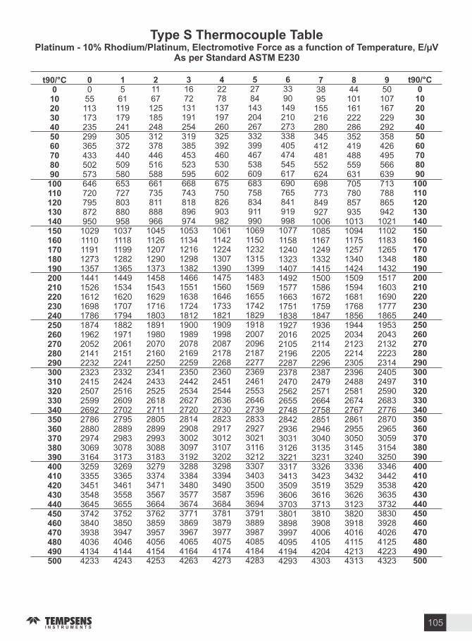
t C055113173235299365433502573646720795872950102911101191127313571441152616121698178618741962205221412232232324152507259926922786288029743069316432593355345135483645374238403938403641344233
561119179241305372440509580653727803880958103711181199128213651449153416201707179418821971206121512241233224242516260927022795288929833078317332693365346135583655375238503947404641444243
1167125185248312378446516588661735811888966104511261207129013731458154316291716180318911980207021602250234124332525261827112805289929933088318332793374347135673664376238593957405641544253
1672131191254319385453523595668743818896974105311341216129813821466155116381724181219001989207821692259235024422534262727202814290830023097319232883384348035773674377138693967406541644263
2278137197260325392460530602675750826903982106111421224130713901475156016461733182119091998208721782268236024512544263627302823291730123107320232983394349035873684378138793977407541744273
2784
143204267332399467538609683758834911990
106911501232131513991483156916551742182919182007209621872277236924612553264627392833292730213116321233073403350035963694379138893987408541844283
3390
149210273338405474545617690765841919998
107711581240132314071492157716631751183819272016210521962287237824702562265527482842293630313126322133173413350936063703380138983997409541944293
3895
155216280345412481552624698773849927
1006108511671249133214151500158616721759184719362025211422052296238724792571266427582851294630403135323133263423351936163713381039084006410542044303
44101161222286352419488559631705780857935
1013109411751257134014241509159416811768185619442034212322142305239624882581267427672861295530503145324033363432352936263123382039184016411542134313
50107167229292358426495566639713788865942
1021110211831265134814321517160316901777186519532043213222232314240524972590268327762870296530593154325033463442353836353732383039284026412542234323
t C
T pe S Thermocouple TablePlatinum - Rhodium Platinum Electromotive Force as a unction o Temperature E
As per Standard ASTM E
105

t C433244324532463247324833493450355137523953415443554656495753585759616065617062756381648665936699680669137020712872367345745475637673778378938003811482268337844985628674878789009014912892429357947295879703981999351005110168
434244424542464247424843434450455147524953515454555756605763586759716076618162866391649766036710681769247031713972477356746575747684779479048014812582378348846085738685879889129025913992549368948395999714983099461006310180
435244524552465247524853495450555157525953615464556756705774587859826056619162966402650866146720682769347042715072587367747675857695780579158026819782488360847285848697881089239037915192659380949596109726984299581007510191
436244624562466247624863496450665167526953725474557756805784588859926097620263076412651866246731683869457053716172697378748775967706781679268037814882598371848385958708882189359048916292779391950696229737985399701008610203
437244724572467247724873497450765178528053825485558856915794589860036107621263176423652966356742684969567064717272807388749776077717782779378048815982708382849486078719883289469060917492889403951896339749986599811009810215
438244824582468247824883498450865188529053925495559857015805590960136118622363286434653966466752685969677074718272917399750876187728783879488059817082818393850586188731884489579071918593009414952996459761987799931011010227
4392449245924692479348934995509651985300540255055608571258155919602461286233633864446550665667636870697770857193730274107519762977397849795980708181829384048517862987428855896990829197931194269541965697729888
100051012110238
4402450246024702480349045005510652085310541355155618572258265930603461396244634964556561666767746881698870967204731274217530764077507860797080818192830484168528864087538866898090949208932394379552966897849900
100161013310250
4412451246124712481349145015511652185320542355265629573258365940604461496254636064656571667867846892699971047215732374327541765177617871798180928203831584278539865287658878899191059219933494499564968097959911
100281014510262
4422452246224122482349245025512752285331543355365639574358465950605561606265637064766582668867956902701071177226733474437552766277727882799281038214832684388550866387768889900391179231934594609576961098079923
100401015610273
t C
106
T pe S Thermocouple TablePlatinum - Rhodium Platinum Electromotive Force as a unction o Temperature E
As per Standard ASTM E

t C10285104031052010638107571087510994111131123211351114711159011710118301195112071121911231212433125541267512796129171303813159132801340213523136441376613887140091413014251143731449414615147361485714978150991522015341154611558215702158221594216062161821630116420165391665816777
10297104141053210650107681088711006111251124411363114831160211722118421196312083122031232412445125661268712808129291305013171132921341413535136571377813899140211414214263143851450614627147481486914990151111523215353154731559415714158341595416074161941631316432165511667016789
10309104261054410662107807089911017111361125611375114951161411734118541197512095122161233612457125781269912820129411306213183133051342613547136691379013911140331415414276143971451814639147601488115002151231524415365154851560615726158461596616086162051632516444165631668216801
10320104381055610674107921091111029111481126811387115071162611746118661198712107122281234812469125901271112832129531307413195133171343813559136811380213924140451416614288144091453014651147731489415015151351525615377154971561815738158581597816098162171633716456165751669416812
10332104501056740686108041092211041111601128011399115191163811758118781199912119122401236012481126021272312844129651308613208133291345019572136931381413936140571417814300144211454214664147851490615027151481526815389155091563015750158701599016110162291634916468165871670616824
10344104611057910697108161093411053111721129111411115311165011770118901201112131122521237212493126141273512856129771309813220133411346213584137051382613948140691419114312144331455414676147971491815039151601528015401155211564215762158821600216122162411636116480165991671816836
103561047310591107091082810946110651118411303114231115421166211782119021202312143122641238412505126261274712868129891311113232133531347413596137171383913960140811420314324144451456714688148091493015051151721529215413155341565415774158941601416134162531637316492166111672916848
10367104851060310721108391095811077111961131511435115541167411794119141203512155122761239712517126381275912880130011312313244133651348713608137291385113972140941421514336144571457914700148211494215063151841530415425155461566615786159061602616146162651638516504166231674116860
10379104971061510733108511097011089112081132711447115661168611806119261204712167122881240912529126501277112892130141313513256133771349913620137421386313984141061422714348144701459114712148331495415075151961531715437155581567815798159181603816158162771639616516166341675316872
10391105091062610745108631098211101112201133911459115781169811818119391205912179123001242112542126621278312905130261314713268133901351113632137541387513996141181423914360144821460314724148451496615087152081532915449155701569015810159301605016170162891640816527166461676516883
t C
107
T pe S Thermocouple TablePlatinum - Rhodium Platinum Electromotive Force as a unction o Temperature E
As per Standard ASTM E

t C16895170131713117249173661748317600177171723217947180611817418285183951850318609
16907170251714317261173781749517612177281784417959180731818518297184061851418620
16919170371715517272173901750717623177401785517970180841819618308184171852518630
16931170491716717284174011751817635177511786717982180951820818319184281853518641
16943170611717817296174131753017647177631787817993181071821918330184391854618651
16954170721719017308174251754217658177751789018004181181823018341184491855718661
16966170841720217319174371755317670177861790118016181291824118352184601856718672
16978170961721417331174481756517682177981791318027181401825218362184711857818682
16990171081722517343174601757717693178091792418039181521826318373184821858818693
170021712017237173551747217588177051782117936180501816318274183841849318599
t C
108
T pe S Thermocouple TablePlatinum - Rhodium Platinum Electromotive Force as a unction o Temperature E
As per Standard ASTM E
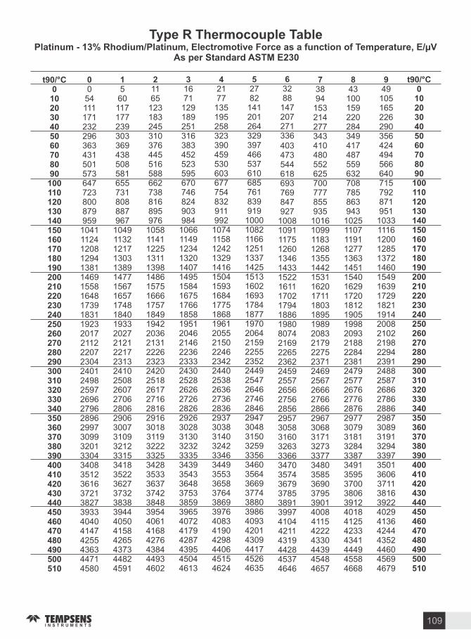
T pe R Thermocouple TablePlatinum - Rhodium Platinum Electromotive Force as a unction o Temperature E
As per Standard ASTM E
t C0541111712322963634315015736477238008799591041112412081294138114691558164817391831192320172112220723042401249825972696279628962997309932013304340835123616372138273933404041474255436344714580
5601171772393033694385085816557318088879671049113212171303138914771567165717481840193320272121221723132410250826072706280629063007310932123315341835223627373238383944405041584265437344824591
11651231832453103764455165886627388168959761058114112251311139814861575166617571849194220362131222623232420251826172716281629163018311932223325342835333637374238483954406141684276438444934602
16711291892513163834525235956707468249039841066114912341320140714951584167517661858195120462146223623332430252826262726282629263028313032323335343935433648375338593965407241794287439545044613
21771351952583233904595306036777548329119921074115812421329141615041593168417751868196120552150224623422440253826362736283629373038314032423346344935533658376438693976408341904298440645154624
2782
141201264329397466537610685761839919
10001082116612511337142515131602169317841877197020642159225523522449254726462746284629473048315032593356346035643669377438803986409342014309441745264635
3288
147207271336403473544618693769847927
10081091117512601346143315221611170217941886198080742169226523622459255726562756285629573058316032633366347035743679378538913997410442114319442845374646
3894
153214277343410480552625700777855935
10161099118312681355144215311620171118031895198920832179227523712469256726662766286629673068317132733377348035853690379539014008411542224330443945484657
43100159220284349417487559632708785863943
10251107119112771363145115401629172018121905199820932188228423812479257726762776287629773079318132843387349135953700380639124018412542334341444945584668
49105165226290356424494566640715792871951
10331116120012851372146015491639172918211914200821022198229423912488258726862786288629873089319132943397350136063711381639224029413642444352446045694679
t C
109

t C46904800491050215133524553575470558356975812592660416157627363906507662567436861698071007220734074617583770578277950807381978321844685718697882389509077920593339461959097209850998010111102421037410506106381077110905110391117311307
47014811492250335144525653695481559557095823593860536169628564026519663667556873699271127232735274737595771778397962808682098334845985848710883689639090921893469474960397339863999310124102551038710519106521078510918110521118611321
471248224933504451555267538054935606572058345949606561806297641365316648676668857004712472447364748576077729785179748098822283468471859787228849897591039230935994879616974698761000610137102681040010532106651079810932110651120011334
472348334944505551665279539155045618573158465961607661926308642565426660677868977016713672567376749876197741786479878110823483598484860987358861838891159243937195009629975998891001910150102821041310546106781081110945110791121311348
473448444955506651785290540255155629574358575972608862046320643765546672679069097028714872687389751076317753787679998123824783718496862287488874900191289256938495139642977299021003210163102951042710559106921082510958110921122711361
47454855436650775189530154145527564057545869598460996215633264486566668468026921704071607280740175227644776678888011813582598384850986348760888790149141926993979526965597859915
1004610177103081044010572107051083810972111061124011375
47564866497750885200531254255538565257665880599561116227634364606578669568146933705271727292741375347656777879018024814782728396852186478773889990269154928294109539966897989928
1005910190103211045310585107181085110985111191125311388
47674877498850995211532354365549566357775892600761226238635564726589670768266945706471847304742575467668779079138036816082848409853486598785891290399167929494239552968198119941
1007210203103341046610599107311086510998111321126711402
47784888499951115222533554485561567457895903601861346250636764846601671968386956707671967316743775587680780279258048817282968421854686728798892590529179930794369565969498249954
1008510216103471048010612107451087811012111461128011415
47894899501051225234534654595572568658005915603061466262637864956613673168496968708872087928744975707692781579388061818583098434855986858811893790659192932094499578970798379967
1009810229103611049310625107581089111025111591129411429
t C
110
T pe R Thermocouple TablePlatinum - Rhodium Platinum Electromotive Force as a unction o Temperature E
As per Standard ASTM E

t C11442115781171411850119861212312260123971253512673128121295013089132281336713507136461378613926140661420714347144881462914770149111505215193153341547515616157581589916040161811632316464166051674616887170281716917310174511759117732178721801218152182921843118571187101884918988
11456115911172711863120001213712274124111254912687128251296413103132421338113521136601380013940140811422114361145021464314784149251506615207153481548915630157721591316054161961633716478166191676016901170421718317324174651760517746178861802618166183061844518585187241886319002
11469116051174111877120131215012288124251256312701128391297813117132561339513535136741381413954140951423514375145161465714798149391508015221153621550315645157861592716068162101635116492166331677416915170561719717338174791761917760179001804018180183201845918599187381887719015
11483116181175411891120271216412301124391257712715128531299213131132701340913549136881382813968141091424914390145301467114812149531509415235153761551715659158001594116082162241636516506166471678916930170711721117352174931763317774179141805418194183341847318613187521889119029
11496116321176811904120411217812315124531259012729128671300613145132841342313563137021384213982141231426314404145441468514826149671510815249153901553115673158141595516097162381637916520166621680316944170851722517366175071764717788179281806818208183481848718627187661890419043
11510116461178211918120541219112329124661260412742128811301913158132981343713577137161385613996141371427714418145581469914840149811512215263154041554615687158281596916111162521639316534166761681716958170991724017380175211766117802179421808218222183621850118640187791891819057
11524116591179511931120681220512342124801261812756128951303313172133111345113590137301387014010140101415114291144321457214713148541499515136152771541915560157011584216125162661640716549166901683116972171131725417394175951767617816179561809618236183761851518654187931893219071
11537116731180911945120821221912356124941263212770129091304713186133251346513604137441388414024141651430514446145861472714868150091515015291154331557415715158561599816139162801642216563167041684516986171271726817408175491769017830179701811818250183901852918668188071894619085
11551116861182211959120961223312370125081264612784129221306113200133391347913618137581389814038141791431914460146011474114882150231516415306154471558815729158711601216153162941643616577167181685917000171411728217423175631770417844179841812418264184041854318682188211896019098
11564117001183611972121091224612384125211265912798129361307513214133531349313632137721391214052141931433314474146151475514896150371517915320154611560215743158851602616167163091645016591167321687317014171551729617437175771771817858179981813818278184171855718696188351897419112
t C
111
T pe R Thermocouple TablePlatinum - Rhodium Platinum Electromotive Force as a unction o Temperature E
As per Standard ASTM E
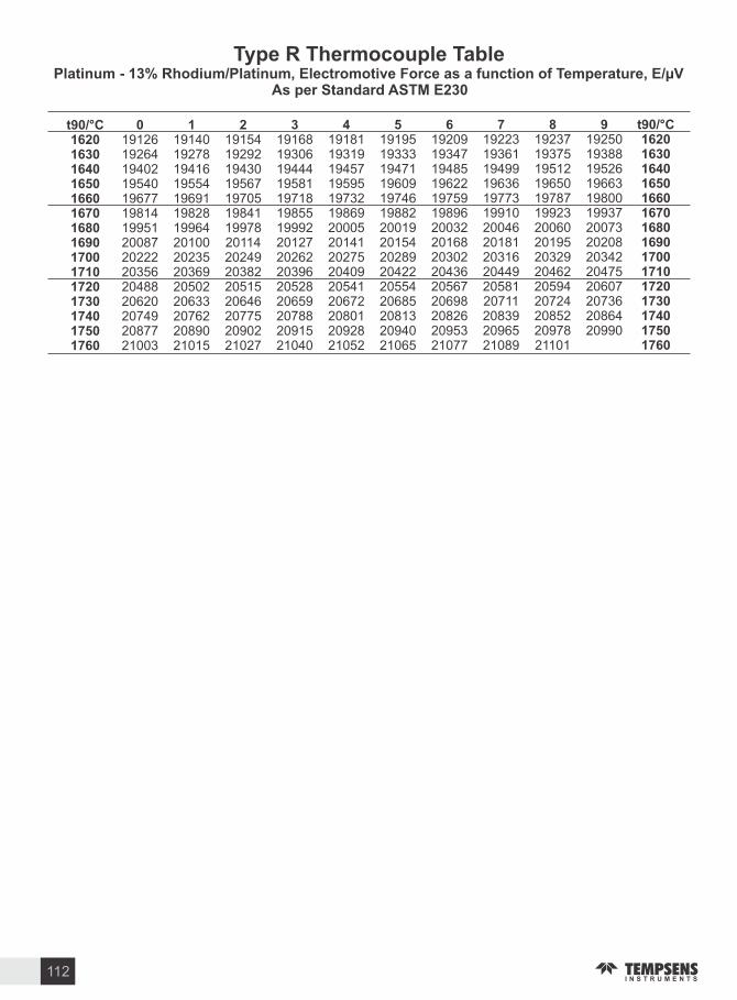
t C191261926419402195401967719814199512008720222203562048820620207492087721003
191401927819416195541969119828199642010020235203692050220633207622089021015
191541929219430195671970519841199782011420249203822051520646207752090221027
191681930619444195811971819855199922012720262203962052820659207882091521040
191811931919457195951973219869200052014120275204092054120672208012092821052
191951933319471196091974619882200192015420289204222055420685208132094021065
192091934719485196221975919896200322016820302204362056720698208262095321077
192231936119499196361977319910200462018120316204492058120711208392096521089
192371937519512196501978719923200602019520329204622059420724208522097821101
1925019388195261966319800199372007320208203422047520607207362086420990
t C
112
T pe R Thermocouple TablePlatinum - Rhodium Platinum Electromotive Force as a unction o Temperature E
As per Standard ASTM E

T pe B Thermocouple TablePlatinum - Rhodium Platinum - Rhodium EMF as a unction o temperature E
As per Standard ASTM E
t C0-2-3-20261117253343536578921071231411591781992202432672913173443724014314624945275615966326697077467878288709139571002104810951143119212421293
0-2-3-20371218263444556679941091251421611802012222452692943203473754044344654975305645996366737117507918328749179611007105311001148119712471298
0-2-3-20371219263545566881951101271441631822032252482712963223493774074374685005335686036396777157547958368789229661011105711051153120212521303
-1-2-3-20381320273646576982961121281461651842052272502742993253523804104404715035375716076436807197587998408839269701016106211091158120712571308
-1-2-3-20481420283747587084981131301481661862072292522763013283553834134434745075405756106476847237628038448879309751020106711141163121212621313
-1-2-2-1149
142129384859728599115132150168188209231255279304330358386416446478510544578614650688727766807849891935979
1025107111191167121712671318
-1-2-2-1149
1522303949607386
101117134151170190212234257281307333360389419449481513547582617654692731770811853896939984
1030107611241172122212721324
-1-2-2-115
101522314050627488
102118135153172192214236259284309336363392422452484517550585621658696735774815857900944988
1034108111291177122712771329
-2-3-2-125
101623314151637589
104120137155174195216238262286312338366395425455487520554589625662700738778819861904948993
1039108611331182123212821334
-2-3-2-126111724324252647791
106122139157176197218241264289314341369398428458490523557592628665703742782824866909953997
1043109011381187123712881339
t C
113

t C13441397145115051561161716751733179218521913197520372101216522302296236324312499256926392710278228542928300230783154323033083386346635463626370837903873395740414127421342994387447545644653474348344926501851115205529953945489
13501402145615111566162316801739179818581919198120432107217122372303237024372506257626462717278928622935301030853161323833163394347435543634371637983882396540504135422143084396448445734662475348434935502751205214530854035499
13551408146215161572162916861745180418641925198720502113217822432309237624442513258326532724279628692943301730933169324633243402348235623643372438073890397440584144423043174404449345824671476248534944503751305223531854135508
13601413146715221578163416921750181018701931199320562120218422502316238324512520259026602731280328762950302531003177325433313410349035703651373238153898398240674152423943264413450145914680477148624954504651395233532754225518
13651418147215271583164016981756181618761937199920622126219122562323239024582527259726672738281128842958303231083184326133393418349835783659374138233907399140754161424743344422451045994689478048714963505551485242533754325528
13711424147815331589164617041762182218821944200620692133219722632329239724652534260426742746281828912965304031163192326933473426350635863667374938323915399940844170425643434431451946084698478948804972506551585252534654415537
13761429148315391595165217091768182818881950201220752139220422702336240324722541261126812753282528982973304731233200327733553434351435943675375738403923400840934178426543524440452846174707479848894981507451675261535654515547
13811435148915441600165717151774183418941956201820822146221022762343241024792548261826882760283329062980305531313207328533633442352236023683376538483932401641014187427343604448453746264716480748984990508351765270536554605556
13871440149415501606166317211780184019011962202520882152221722832350241724852555262526962767284029132987306231383215329233713450353036103692377438573940402441104195428243694457454646354725481649085000509251865280537554705566
13921445150015551612166917271786184619071968203120942158222422892356242424922562263227032775284729212995307031463223330033793458353836183700378238653949403341184204429143784466455546444734482549175009510251955289538454805576
t C
114
T pe B Thermocouple TablePlatinum - Rhodium Platinum - Rhodium EMF as a unction o temperature E
As per Standard ASTM E

t C5585568257805878597660756175627663776478658066836786689069957100720573117417752476327740784879578066817682868397850886208731884489569069918292969410952496399753986899841009910215103311044710563106791079610913110291114611263113801149711614
5595569257895887598660856185628663876488659166936797690170057110721673227428753576437751785979688077818782988408851986318743885589679080919493079421953696509765988099951011110226103421045810575106911080810924110411115811275113921150911626
56055702579958975996609561956296639764996601670468076911701671217226733274397546765377617870797980888198830984198530864287548866897990929205931994339547966297769891100071012210238103541047010586107031081910936110531116911286114031152011637
56145711580959076006610562056306640765096611671468186922702971317237734374497557766477727881799080998209832084308542865387658877899091039216933094449558967397889903100181013410249103651048210598107141083110948110641118111298114151153211649
56245721581959176016611562156316641765196621672468286932703771427247735374607567767577837892800181108220833184418553866487768889900191149228934294569570968497999914100301014510261103771049310609107261084310959110761119311310114271154411661
56345731582859276026612562256326642765296632673568386942704771527258736474717578768677947903801281218231839284548564867587878900901391269239935394679581969698119926
100411015710273103891050510621107381085410971110881120511321114381155511673
56435740583859376036613562356336643865396642674568496953705871637269737574827589769778057914202381328242835384648575868787998911902491379251936494789593970798229937
100531016810284104001051610633107491086610983110991121611333114501156711684
56535750584859476046614562456346644865506652675568596963706871737279738574927600770778167924803481438253836484758586869888108922903591489262937694909604971998349949
100641018010296104121052810644107611087710994111111122811345114621157911696
56635760585859566055615562566356645865606663676668696974707971847290739675037610771878277935804581548264837584868597870988218934904791609273938795019616973098459961
100761019210307104231054010656107731088911006111231124011357114741159111708
56725770586859666065616562666367646865706673677668806984708971947300740775147621772978377946805681658275838684978608872088328945905891719285939895139627974298579972
100881020310319104351055110668107841090111018111341125111368114851160211719
t C
115
T pe B Thermocouple TablePlatinum - Rhodium Platinum - Rhodium EMF as a unction o temperature E
As per Standard ASTM E

t C11731118481196512082121991231612433125491266612782128981301413130132461336113476135911370613820
117431186011977120941221112327124441256112677127941291013026131421325713373134881360313717
117541187111988121051222212339124561257212689128051292113037131531326913384134991361413729
117661188312000121171223412351124681258412701128171293313049131651328013396135111362613740
117781189512012121291224612363124791259612712128291294513061131761329213407135221363713752
117901190712024121411225712374124911260712724128401295613072131881330413419135941364913763
118011191812035121521226912386125031261912736128521296813084132001331513430135451366013775
118131193012047121641228112398125141263112747128631298013095132111332713442135571367213786
118251194212059121761229212409125261264212759128751299113107132231333813453135681368313797
118361195312070121871230412421125381265412770128871300313119132341335013465135801369413809
t C
116
T pe B Thermocouple TablePlatinum - Rhodium Platinum - Rhodium EMF as a unction o temperature E
As per Standard ASTM E

T pe Thermocouple TableNickel-Chromium Nickel-Aluminium Electromotive Force as a unction o temperature E
As per Standard ASTM E
t C---------------------------
t C
-6458-6441-6404-6344-6262-6158-6035-5891-5730-5550-5354-5141-4913-4669-4411-4138-3852-3554-3243-2920-2587-2243-1889-1527-1156-778-392
0
0397798120316122023243628513267368240964509492053285735613865406941734077398138853989409343
-
-6444-6408-6351-6271-6170-6048-5907-5747-5569-5374-5163-4936-4694-4437-4166-3882-3584-3274-2953-2620-2278-1925-1564-1194-816-431-39
39437838124416532064247828933308372341384550496153695775617965806981738077798178857989809383
-
-6446-6413-6358-6280-6181-6061-5922-5763-5588-5395-5185-4960-47194463-4194-3911-3614-3306-2986-2654-2312-1961-1600-1231-854-470-79
79477879128516942106251929343350376541794561500254105815621966206620702174207819821886199020
-
-6448-6417-6364-6289-6192-6074-5936-5780-5606-5415-5207-4983-4744-4490-4221-3939-3645-3337-3018-2688-2347-1996-1637-1268-892-508-118
119517919132617352147256129763391380642204633504354505856625966607060746078598258865990619464
-
-6450-6421-6370-6297-6202-6087-5951-5797-5624-5435-5228-5006-4768-4516-4249-3968-3675-3368-3050-2721-2382-2032-1673-1305-930-547-157
158557960136617762188260230173433384842624674508454915896629967017100750078998298869991019504
-
-5452-5425-6377-6306-6213-6099-5965-5813-5642-5454-5250-5029-4793-4542-4276-3997-3705-3400-3083-2755-2416-2067-1709-1343-968-586-197
198597
1000140718172230264430593474388943034715512455325937633967417140754079398338873991419545
-
-6453-6429-6382-6314-6223-6111-5980-5829-5660-5474-5271-5052-4817-4567-4303-4025-3734-3431-3115-2788-2450-2103-1745-1380-1006-624-236
238637
1041144818582271268531003516393143444756516555725977638067817180757979798378877991819585
-
-6455-6432-6388-6322-6233-6123-5994-5845-5678-5493-5292-5074-4841-4593-4330-4054-3764-3462-3147-2821-2485-2138-1782-1417-1043-663-275
277677
1081148918992312272731423557397243854797520656136017642068217220761980198418881992229626
-
-6456-6435-6393-6329-6243-6135-6007-5861-5695-5512-5313-5097-4865-4618-4357-4082-3794-3492-3179-2854-2519-2173-1818-1453-1081-701-314
3177181122153019412354276831843599401344274838524756536058646068617260765980598458886092629666
-
-6457-6438-6399-6337-6252-6147-6021-5876-5713-5531-5333-5119-4889-4644-4384-4110-3823-3523-3211-2887-2553-2208-1854-1490-1119-739-353
3577581163157119822397281032253640405544684879528856946098650069017300769980998499890093029707
t C---------------------------
t C
117
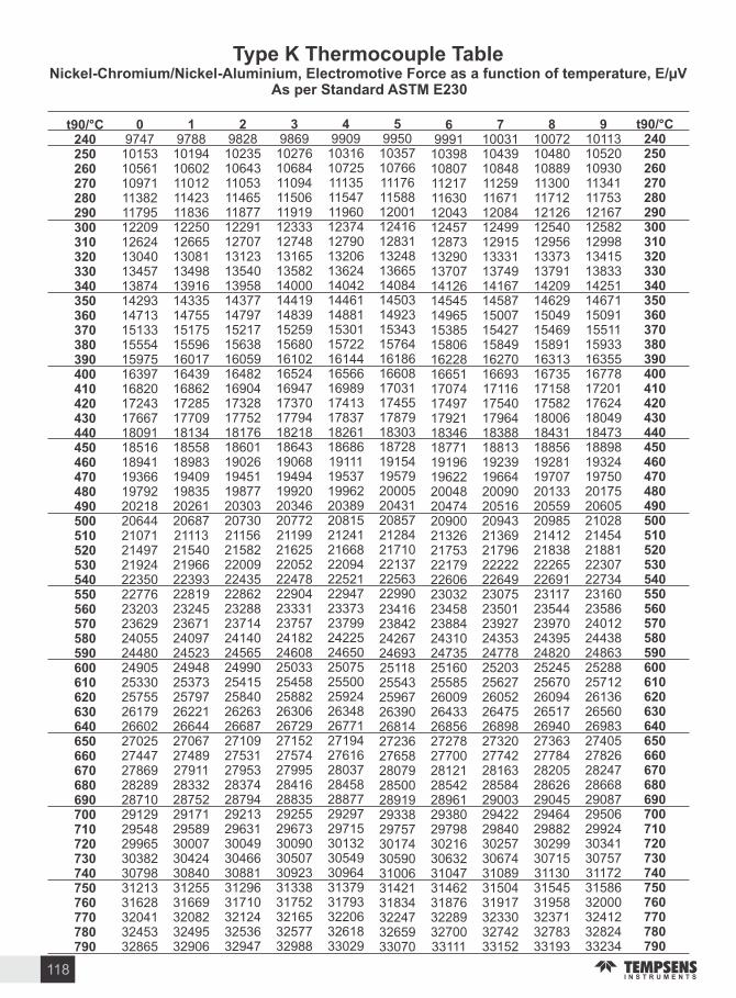
t C974710153105611097111382117951220912624130401345713874142931471315133155541597516397168201724317667180911851618941193661979220218206442107121497219242235022776232032362924055244802490525330257552617926602270252744727869282892871029129295482996530382307983121331628320413245332865
978810194106021101211423118361225012665130811349813916143351475515175155961601716439168621728517709181341855818983194091983520261206872111321540219662239322819232452367124097245232494825373257972622126644270672748927911283322875229171295893000730424308403125531669320823249532906
982810235106431105311465118771229112707131231354013958143771479715217156381605916482169041732817752181761860119026194511987720303207302115621582220092243522862232882371424140245652499025415258402626326687271092753127953283742879429213296313004930466308813129631710321243253632947
986910276106841109411506119191233312748131651358214000144191483915259156801610216524169471737017794182181864319068194941992020346207722119921625220522247822904233312375724182246082503325458258822630626729271522757427995284162883529255296733009030507309233133831752321653257732988
990910316107251113511547119601237412790132061362414042144611488115301157221614416566169891741317837182611868619111195371996220389208152124121668220942252122947233732379924225246502507525500259242634826771271942761628037284582887729297297153013230549309643137931793322063261833029
995010357107661117611588120011241612831132481366514084145031492315343157641618616608170311745517879183031872819154195792000520431208572128421710221372256322990234162384224267246932511825543259672639026814272362765828079285002891929338297573017430590310063142131834322473265933070
999110398108071121711630120431245712873132901370714126145451496515385158061622816651170741749717921183461877119196196222004820474209002132621753221792260623032234582388424310247352516025585260092643326856272782770028121285422896129380297983021630632310473146231876322893270033111
1003110439108481125911671120841249912915133311374914167145871500715427158491627016693171161754017964183881881319239196642009020516209432136921796222222264923075235012392724353247782520325627260522647526898273202774228163285842900329422298403025730674310893150431917323303274233152
1007210480108891130011712121261254012956133731379114209146291504915469158911631316735171581758218006184311885619281197072013320559209852141221838222652269123117235442397024395248202524525670260942651726940273632778428205286262904529464298823029930715311303154531958323713278333193
1011310520109301134111753121671258212998134151383314251146711509115511159331635516778172011762418049184731889819324197502017520605210282145421881223072273423160235862401224438248632528825712261362656026983274052782628247286682908729506299243034130757311723158632000324123282433234
t C
118
T pe Thermocouple TableNickel-Chromium Nickel-Aluminium Electromotive Force as a unction o temperature E
As per Standard ASTM E
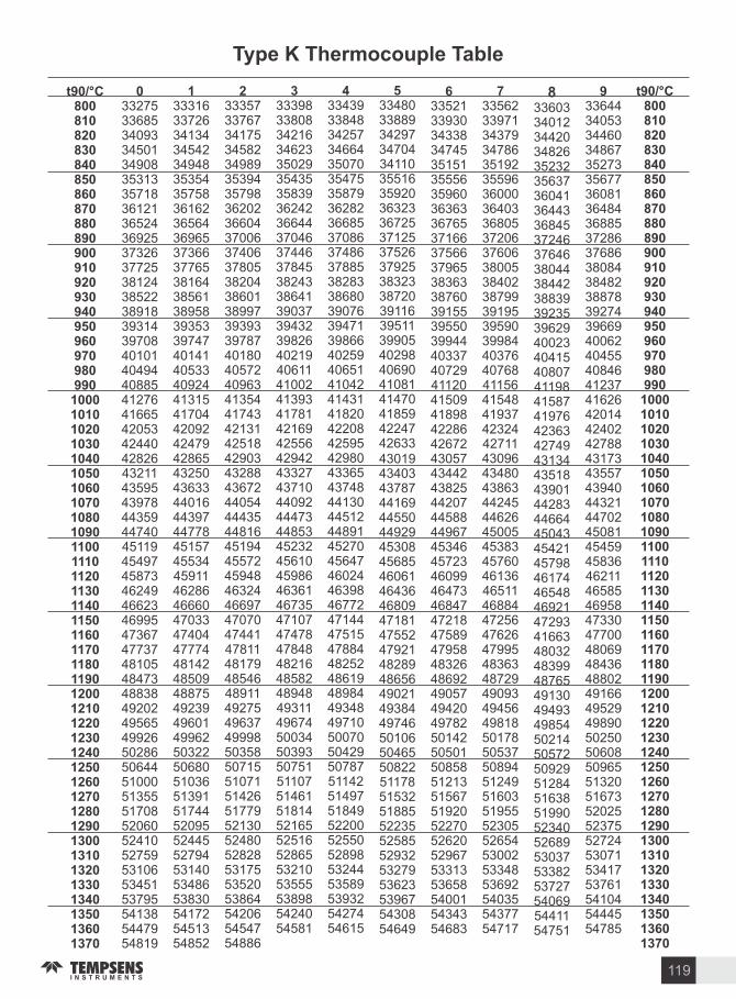
t C33275336853409334501349083531335718361213652436925373263772538124385223891839314397084010140494408854127641665420534244042826432114359543978443594474045119454974587346249466234699547367477374810548473488384920249565499265028650644510005135551708520605241052759531065345153795541385447954819
33316337263413434542349483535435758361623656436965373663776538164385613895839353397474014140533409244131541704420924247942865432504363344016443974477845157455344591146286466604703347404477744814248509488754923949601499625032250680510365139151744520955244552794531405348653830541725451354852
33357337673417534582349893539435798362023660437006374063780538204386013899739393397874018040572409634135441743421314251842903432884367244054444354481645194455724594846324466974707047441478114817948546489114927549637499985035850715510715142651779521305248052828531755352053864542065454754886
333983380834216346233502935435358393624236644370463744637845382433864139037394323982640219406114100241393417814216942556429424332743710440924447344853452324561045986463614673547107474784784848216485824894849311496745003450393507515110751461518145216552516528655321053555538985424054581
334393384834257346643507035475358793628236685370863748637885382833868039076394713986640259406514104241431418204220842595429804336543748441304451244891452704564746024463984677247144475154788448252486194898449348497105007050429507875114251497518495220052550528985324453589539325427454615
334803388934297347043411035516359203632336725371253752637925383233872039116395113990540298406904108141470418594224742633430194340343787441694455044929453084568546061464364680947181475524792148289486564902149384497465010650465508225117851532518855223552585529325327953623539675430854649
335213393034338347453515135556359603636336765371663756637965383633876039155395503994440337407294112041509418984228642672430574344243825442074458844967453464572346099464734684747218475894795848326486924905749420497825014250501508585121351567519205227052620529675331353658540015434354683
335623397134379347863519235596360003640336805372063760638005384023879939195395903998440376407684115641548419374232442711430964348043863442454462645005453834576046136465114688447256476264799548363487294909349456498185017850537508945124951603519555230552654530025334853692540355437754717
336033401234420348263523235637360413644336845372463764638044384423883939235396294002340415408074119841587419764236342749431344351843901442834466445043454214579846174465484692147293416634803248399487654913049493498545021450572509295128451638519905234052689530375338253727540695441154751
336443405334460348673527335677360813648436885372863768638084384823887839274396694006240455408464123741626420144240242788431734355743940443214470245081454594583646211465854695847330477004806948436488024916649529498905025050608509655132051673520255237552724530715341753761541045444554785
t C
119
T pe Thermocouple Table

t C---------------------------
t C
-4345-4336-4313-4277-4226-4162-4083-3990-3884-3766-3634-3491-3336-3171-2994-2808-2612-2407-2193-1972-1744-1509-1269-1023-772-518-260
0
026152579310651340161919022189248027743074337436803989430246184937525955855913
-
-4337-4316-4281-4232-4169-4091-4000-3896-3778-3648-3506-3352-3188-3012-2827-2632-2428-2215-1995-1767-1533-1293-1048-798-544-286-26
2628755282010921368164719302218250928043102340537114020433346504969529256185946
-
-4339-4319-4285-4238-4176-4100-4010-3907-3790-3662-3521-3368-3205-3030-2846-2652-2448-2237-2017-1790-1557-1317-1072-823-569-312-52
5231357884711191395167519592247253828333133343537424051436546815001532456505979
-
-4340-4321-4289-4243-4183-4108-4020-3918-3803-3675-3535-3384-3221-3048-2865-2672-2469-2258-2039-1813-1580-1341-1097-848-595-338-78
7834060587411741423170319882276256828633163346637724083439647135033535756836013
-
-4341-4324-4293-4248-4189-4116-4029-3928-3815-3688-3550-3400-3238-3066-2883-2691-2490-2280-2062-1836-1604-1366-1122-873-620-364-104
10436663290111741451173220162305259728933193349638034114442847455066538957166046
-
-4342-4326-4297-4254-4196-4124-4038-3939-3827-3702-3564-3415-3255-3084-2902-2711-2510-2301-2084-1859-1627-1390-1146-898-646-390-131
130393659928
12021479176020452334262629233223352738344145445947775098542257496079
-
-4343-4328-4300-4258-4202-4132-4048-3950-3838-3715-3578-3431-3271-3101-2921-2730-2531-2322-2106-1882-1651-1414-1171-923-671-415-157
156419685955
12291507178820742363265629533253355738654176449148095130545457826112
-
-4344-4330-4304-4263-4209-4140-4057-3960-3850-3728-3593-3446-3288-3119-2939-2750-2551-2344-2128-1905-1674-1438-1195-948-696-441-183
182446712983
12571535181721022392268529833283358838964208452348415162548758156145
-
-4345-4334-4310-4273-4221-4154-4074-3980-3873-3753-3621-3476-3320-3153-2976-2789-2592-2386-2172-1950-1721-1485-1244-999-747-495-234
208472739
101012841563184521312421271530123314361939274239455448735195552058476178
-
-4345-4334-4310-4273-4221-4154-4074-3980-3873-3753-3621-3476-3320-3153-2976-2789-2592-2386-2172-1950-1721-1485-1244-998-747-492-232
235499766
103713121591187321602450274430423344364939584270458649055227555258806211
t C---------------------------
t C
As per Standard ASTM E
T pe N Thermocouple TableNickel-Chromium-Silicon Nickel-Silicon Electromotive Force as a unction o temperature E
120
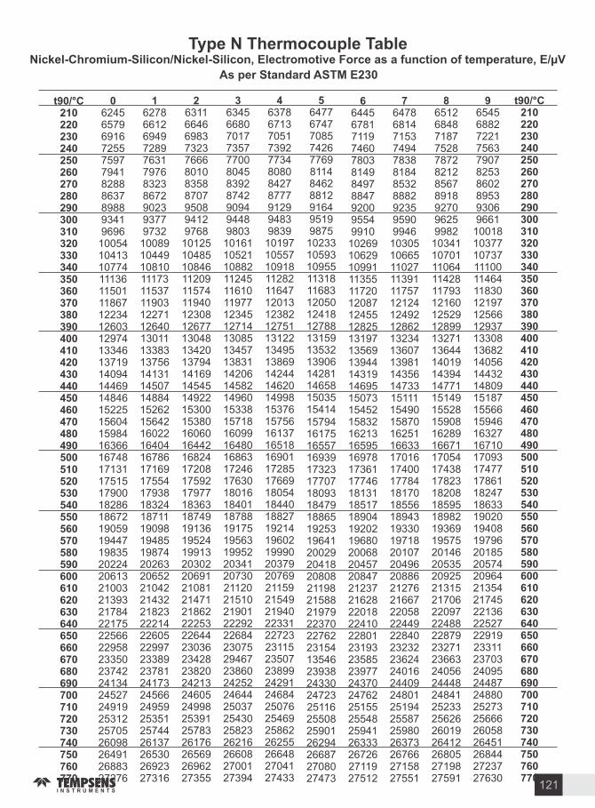
t C6245657969167255759779418288863789889341969610054104131077411136115011186712234126031297413346137191409414469148461522515604159841636616748171311751517900182861867219059194471983520224206132100321393217842217522566229582335023742241342452724919253122570526098264912688327276
6278661269497289763179768323867290239377973210089104491081011173115371190312271126401301113383137561413114507148841526215642160221640416786171691755417938183241871119098194851987420263206522104221432218232221422605229972338923781241732456624959253512574426137265302692327316
6311664669837323766680108358870795089412976810125104851084611209115741194012308126771304813420137941416914545149221530015380160601644216824172081759217977183631874919136195241991320302206912108121471218622225322644230362342823820242132460524998253912578326176265692696227355
6345668070177357770080458392874290949448980310161105211088211245116101197712345127141308513457138311420614582149601533815718160991648016863172461763018016184011878819175195631995220341207302112021510219012229222684230752946723860242522464425037254302582326216266082700127394
6378671370517392773480808427877791299483983910197105571091811282116471201312382127511312213495138691424414620149981537615756161371651816901172851766918054184401882719214196021999020379207692115921549219402233122723231152350723899242912468425076254692586226255266482704127433
64776747708574267769811484628812916495199875
10233105931095511318116831205012418127881315913532139061428114658150351541415794161751655716939173231770718093184791886519253196412002920418208082119821588219792237022762231541354623938243302472325116255082590126294266872708027473
64456781711974607803814984978847920095549910
10269106291099111355117201208712455128251319713569139441431914695150731545215832162131659516978173611774618131185171890419202196802006820457208472123721628220182241022801231932358523977243702476225155255482594126333267262711927512
64786814715374947838818485328882923595909946
10305106651102711391117571212412492128621323413607139811435614733151111549015870162511663317016174001778418170185561894319330197182010720496208862127621667220582244922840232322362424016244092480125194255872598026373267662715827551
65126848718775287872821285678918927096259982
10341107011106411428117931216012529128991327113644140191439414771151491552815908162891667117054174381782318208185951898219369195752014620535209252131521706220972248822879232712366324056244482484125233256262601926412268052719827591
6545688272217563790782538602895393069661
1001810377107371110011464118301219712566129371330813682140561443214809151871556615946163271671017093174771786118247186331902019408197962018520574209642135421745221362252722919233112370324095244872488025273256662605826451268442723727630
t C
121
As per Standard ASTM E
T pe N Thermocouple TableNickel-Chromium-Silicon Nickel-Silicon Electromotive Force as a unction o temperature E

t C2766928062284552884729239296323002430416308073119937590319813237132761331513354133930343193470735095354823586936256366413702737411377953817938562389443932639706400874046640845412234160041976423524272743101434744384644218445884495845326456944606046425467894715247513
27708281012849428886292792967130063304553084631238316293202032410328003319033580339693435834746351343552135908362943668037065374503783438217386003898239364397444012540504408834126041638420144239042764431384351143884442554462544995453634573146097464624628647188
27748281402853328926293182971030102304943086631277316683205932449328393322933619340083439634785351723556035946363333671837104374883787238256386383902039402397834016340542409204129841675420524242742802431764354943921442924466245032454004576746133464984686247224
27787281802857228965293572974930141305333092531316317073209833488328783326833658340473443534823352113559835985363713675737142375253791138294386773905939440398214020140580409584133641713420894246542839432134358643958443294469945069454374580446170465354689847260
27826282192861229004293962978930181305723096431355317463213732527329173330733697340863447434862352503563736024364103679637181375653794938332387153909739478398594023840618409964137441751421274250242877432504362343995443664473645105454744584146207465714693547296
27866282582865129043294362982830220306113100331394317853217632566329563334633736341243451334901352893567636062364493683437219376033798738370387533913539516398974027640655410344141141788421644254042914432884366044032444034477345142455104587746243466084697147333
27905282972869029083294752986730259306513104231433318243221532605329953338533774341633455234940353273571436101364873687337258376423802638409387913917339554399354031440693410724144941826422024257742951433254369844069444404481045179455474591446280466444700747369
27944283372872929122295142990630298306903108131473318633225432644330343342433813342023459134979353663575336140365263691137296376803806438447388293921139592399734035240731411094148741864422394261442989433624373544106444774484745216455844535146316466804704347405
27983283762876929161295532664530337307293112031512319033229332683330733346333852342413462935017354053579236178365643695037334377193810238485388683924939630400114039040769411474152541901422774265243026433994377244144445144488445253456214598746353467174707947441
28023284152880829200295922998530376307683116031551319423233232722331123350233891342803466835056354443583136217366033698837373377573814138524389063928739668400494042840807411854156241939423144268943064434374380944181445514492145290456574602446389467534711647477
t C
122
As per Standard ASTM E
T pe N Thermocouple TableNickel-Chromium-Silicon Nickel-Silicon Electromotive Force as a unction o temperature E

t C---------------------
t C
-8095-7890-7659-7403-7123-6831-6500-6159-5801-5426-5037-4633-4215-3786-3344-2893-2431-1961-1482-995-501
0
05071019153720592585311636504187472652695814636069097459801085629115966910224107791133411889124451300013555141101466515219157731632716881174341798618538
-
-7912-7683-7429-7152-6853-6533-6194-5838-5465-5076-4674-4257-3829-3389-2938-2478-2008-1530-1044-550-50
505581071158921112638316937034240478153235868541569647514806586189171972510279108341138911945125001305613611141661472015275158291638316936174891804118594
-
-7734-7707-7456-7181-6883-6566-6229-5824-5503-5116-4714-4300-3872-3434-2984-2524-2055-1578-1093-600-101
1016091122164121642691322237574294483553785923647070197569812086739226978010335108901144512000125561311113666142211477615330158841643816991175441809718649
-
-7955-7731-7482-7209-6914-6598-6263-5910-5541-5155-4755-4342-3916-3478-3029-2571-2103-1626-1142-650-151
1516601174169322162744327538104348488954325977652570747624817587289282983610390109451150112056126111316713722142771483115386159401649317046175991815218704
-
-7976-7755-7508-7237-6944-6631-6298-5946-5578-5194-4796-4384-3959-3522-3075-2617-2150-1674-1190-699-201
202711
1226174522692797332938644402494354876032657971297679823187839337989110446110011155612111126671322213777143321488715441159951654917102176551820718759
-
-7996-7778-7534-7265-6975-6663-6332-5982-5616-5233-4836-4425-4002-3566-3120-2663-2197-1722-1239-749-251
253762
12771797232228503382391844564997554160876634718477348286883993929947
10501110561161212167127221327813833143881494215496160501660417157177101826218814
-
-8017-1801-7559-7293-7005-6695-6366-6018-5653-5272-4877-4467-4045-3610-3165-2709-2244-1770-1288-798-301
303814
1329184923742903343639714510505255956141668972397789834188949448
1000210557111121166712222127781333313888144431499815552161061665917212177651831818870
-
-8037-7824-7585-7321-7035-6727-6400-6054-5690-5311-4917-4509-4088-3654-3210-2755-2291-1818-1336-847-351
354865
1381190224272956348940254564510656506196674472947844839689499503
1005710612111671172312278128331338913944144991505315607161611671517268178201837318925
-
-8057-7846-7610-7348-7064-6759-6433-6089-5727-5350-4957-4550-4130-3698-3255-2801-2338-1865-1385-896-401
405916
14331954248030093543407946185160570562516799734979008452900595591011310668112231177812334128891944413999145541510915663162161677017323178761842818980
-
-8076-7868-7634-7376-7094-6790-6467-6124-5764-5388-4997-4591-4173-3742-3300-2847-2385-1913-1433-946-451
456968
1485200625323062359641334672521557596306685474047955850790609614
1016810723112781183412389129441350014055146091516415718162721682517378179311848319035
t C---------------------
t C
T pe Thermocouple TableIron Copper-Nickel Electromotive Force as a unction o temperature E
As per Standard ASTM E
123

t C190901964220194207452129721848224002295229504240572461025164257202627626834273932795328516290802964730216307883136231939325193310233689342793487335470360713667537284378963851239132397554038241012416454228142919435594420344848454944614146786474314807448715493534998950622512515187752500531195373554347
191461969720249208002135221903224552300723559241122466525220257752633226889274492801028572291372970430273308453141931997325773316133748343383493235530361313673637345379583857439194398184044541045417084234442983436244426744913455594620546851474954813848779494175005250685513145194052562531815379665508
192011975320304208552140721958225102306223614241672472125275258312638726945275052806628629291942976130330309023147732055326363321933807343973499235590361913679737406380193863639256398804050841138417724240843047436884433244977456244627046915475604820248843494815011650748513775200252624532435385754469
192561980820359209112146222014225652311723670242232477625331258862644327001275612812228685292502981830387309603153532113326943327833866344573505135650352523685837467380813869839318399434057041201418354247243111437524439645042456884633446980476244826748907495445017950811514395206452686533045391954530
193111986320414209662151722069226202317223725242782483225386259422649927057276172817828741293072987430444310173159232171327523333733925345163511135710363123691837528381423876039381400054063341265418994253643175438174446145107457534639947044476884833148971496085024350874515025212752748533665398054597
193661991820469210212157222124226762322823780243332488725442259982655527113276732823428798293632993130502310743165032229328103339533984345753517135770363733697937590382043882239443400684069641328419624259943239438814452545171458184646447109477534839549034496725030650937515655218952810534275404154652
194221997320525210762162722179227312328323835243892494325497260532661027169277292829128854294202998830559311323170832287328693345434043346353523035830364333704037651382653888439505401314075941391420264266343303439454459045236458824652847173478174845949098497355036951000516275225152872534895410254713
194772002820580211312168322234227862333823891244442499825553261092666627225277852834728911294773004530616311893176632345329273351334102346943529035890364943710137712383273894639568401934082241455420904272743367440104465545301459474659347238478814852349162497995043251063516905231452934535505416454773
195322008320635211862173822289228412339323946244992505325608261652672227281278412840328967295343010230673312473182332403329853357134161347543535035950365543716237773383893900839630402564088641518421534279143431440744471945365460114665747302479464858749226498625049551126517525237652996536125422554834
195872013920690212412179322345228962344924001245552510925664262202677827337278972846029024295903015930730313043188132461330443369034220348133541036010366153722337835384503907039693403194094941581422174285543495441394478445430460764672247367480104865149290499265055951188518155243853057536735428654895
t C
124
T pe Thermocouple TableIron Copper-Nickel Electromotive Force as a unction o temperature E
As per Standard ASTM E

t C5495855561561645676357360579535854559134597216030760890614736205462634632146379264370649486552566102666796722567831684066898069553
55016556225622456823574195801358604591935978060365609496153162112626926327163850644286500665583661606673767313678886846369037
55077556825628456883574795807258663592525983860423610076758962170627506332963908644866506465641662186679467370679466852169095
55138557425634456942575385813158722593105989760482610656164762228628086338763966645446512165699662756685267428680036857869152
55198558035640457002575975819058781593695995660540611236170562286628666344564024646026517965756663336691067486680616863669209
55259558635646457062576575824958840594286001460599611826176362344629246350364081646596523765814663916696767543681196869369267
55319559235652457121577165830958899594876007360657612406182262402629826356164139647176529565872664486702567601681766875169324
55380559835658457181577765836858957595456013160715612986188062460630406361964197647756535265929665066708267658682346880869381
55440560434664357240578355842759016596046019060774613566193862518630986367764255648336541065987665646714067716682916886569439
55501561045670357300578945848659075596636024860832614156199662576631566373464313648906546866045666216719897773683486892369496
t C
125
T pe Thermocouple TableIron Copper-Nickel Electromotive Force as a unction o temperature E
As per Standard ASTM E

t C---------------------------
t C
-9835-9797-9718-9604-9455-9274-9063-8825-8561-8273-7963-7632-7279-6907-6516-6107-5681-5237-4777-4302-3811-3306-2787-2255-1709-1152-582
0
0591119218012420304836854330498556486319699876858379908197891050311224119511268413421
-
-9802-9728-9617-9471-9293-9085-8850-8588-8303-7995-7666-7315-6945-6556-6149-5724-5282-4824-4350-3861-3357-2840-2309-1765-1208-639-59
59651125218622482311137494395505157146386706677548449915198601057511297120241275713495
-
-9808-9737-9630-9487-9313-9107-8874-8616-8333-8027-7700-7351-6983-6596-6191-5767-5327-4871-4398-3911-3408-2892-2362-1820-1264-697-117
118711
131319242545317438134460511757816454713578238519922299311064711369120971283113569
-
-9813-9746-9642-9503-9331-9129-8899-8643-8362-8059-7733-7387-7021-6636-6232-5210-5372-4317-4446-3960-3459-2944-2416-1874-1320-754-176
1767701373198626073238387745265183584865227203789285899292100031071911442121701290413644
-
-9817-9754-9654-9519-9350-9151-8923-8669-8391-8090-7767-7423-7058-6675-6273-5853-5417-4963-4494-4009-3510-2996-2469-1929-1376-811-234
2358301434204726703301394245915249591565907272796286599363100741079111514122431297813718
-
-9821-6762-9666-9534-9368-9172-8947-8696-8420-8121-7800-7458-7096-6714-6314-5896-5461-5009-4542-4058-3561-3048-2523-1984-1432-868-292
294890
1495210927333365400646565315598266587341803187299434
101451086311587123171305213792
-
-9825-9770-9677-9548-9386-9193-8971-8722-8449-8152-7833-7493-7133-6753-6355-5939-5505-5055-4589-4107-3611-3100-2576-2038-1488-925-350
354950
1556217127953429407147225382604967257409810187999505
102171093511660123901312613866
-
-9828-9777-9688-9563-9404-9214-8994-8748-8477-8183-7866-7528-7170-6792-6396-5981-5549-5101-4636-4156-3661-3152-2629-2093-1543-982-408
41310101617223328583492413647885448611767947478817088699576
102881100711733124631319913941
-
-9831-9784-9698-9577-9421-9234-9017-8774-8505-8213-7899-7563-7206-6831-6436-6023-5593-5147-4684-4205-3711-3204-2682-2147-1599-1039-466
47210711678229529213556420048535514618468927547824089409647
103601108011805125371327314015
-
-9833-9790-9709-9591-9438-9254-9040-8799-8533-8243-7931-7597-7243-6869-6476-6065-5637-5192-4731-4254-3761-3255-2735-2201-1654-1095-524
53211311740235729843620426549195581625169307616830990109718
104321115211878126101334714090
t C---------------------------
t C
126
T pe E Thermocouple TableNickel-Chromium Copper-Nickel Electromotive Force as a unction o temperature E
As per Standard ASTM E

t C14164149121566416420171811794518713194842025921036218172260023386241742496425757265522734828146289462974730550313543215932965337723457935387361963700537815386243943440243410534186242671434794428645093459004670547509483134911649917507185151752315531125390854703554975628957080
14239149871573916496172571802118790195612033621114218952267823464242532504425836266312742828226290262982730630314343223933045338523466035468362443708637896387053951540324411344194342751435604436745174459804678547590483934919649997507985159752395531925398854782555765636857159
14313150621581516572173331809818867196392041421192219732275723543243322512325916267112750728306291062990830711315153232033126339333474135549363583716737977387863959640405412154202442832436404444845255460614686647670484744927650077508785167752475532725406754862556555644757238
14388151371589016648174091817518944197162049221270220512283523622244112520225995267902758728386291862998830791375953240033207340143482235630364393724838058388673967740486412964210542913437214452945335461414694647751485544935650157509585175752555533515414754941557345652657317
14463152121596616724174861825219021197942056921348221302291423701244902528126075268702766728466292663006830871316763248133287340953490235711365203732938139389783975840567413774218542994438024460945416462224702747831486344943650238510385183752634534315422655021558145660657396
14537152871604116800175621832819098198712064721426222082299323780245692536026154269502774728546293463014830952317563256233368341753498335792366013741038220390293983940648414574226643075438834469045497463024710747911487154951750318511185191652714535105430655100558935668557475
14612153621611716876176391840519175199482072521504222862307123858246482544026233270292782728626294273022931032318373264233449342563506435873366823749138300391103992040729415384234743156439634477145577463834718847992487954959750398511975199652794535905438555179559725676457554
14687154381619316952177151848219252200262080321582223652315023937247272551926313271092790728706295073030931112319173272333529343373514535954367633757238381391914000140810416194242843236440444485145658464634726848072488754967750478512775207652873536706446555259560515684357633
14762155131626917028177921855919330201032088021660224432322824016248062559826392271892798628786295873038931193319983280333610344183522636034368433765338462392724008240891417004250943317441254493245738465444734948152489554975750558513575215652953537495454455338561315692257712
14837155881634417104178681863619407201812095821739225222330724095248852567826472272682806628866296673047031273320783288433691344983530736115369243773438543393534016310972417814259043398442064501345819466244742948233490354983750638514375223653033538295462455417562105700157791
t C
127
T pe E Thermocouple TableNickel-Chromium Copper-Nickel Electromotive Force as a unction o temperature E
As per Standard ASTM E

t C57870586595944660232610176180162583633646414464922656986647367246680176878769554703197108271844726037336074115748697562176373
579495873859525603116109661879626626344564222650006577666550673236809468863696317039671159719207267873435741907494475696
580285881659604603906117461958627406352064300650776585366628674006817168940697077047271235719967275473511742667501975771
581075889559682604686125362036628186359864377651556593166705674786824869017697847054871311720727283073586743417509575847
581865897459761605476133162114628966367664455352336600866782675556832569094698607062571387721477290673662744177517075922
582655905359839606256140962192629746375464533653106608666860676326840269171699377070171463722237298173738744927524575997
583435913159918607046148862271630526383264611653886616366937677096847969247700137077771539722997305773813745677532076072
584225921059997607826156662349631306391064689654656624167014677866855669324700907085471615723757313373889746437539576147
585015928960075608606164462427632086398864766655436631867092678636863369401701667093071692724517320873964747187547176223
585805936760154609396172362505632866406664844656216639667169679406871069477702437100671768725277328474040747937554676298
t C
128
T pe E Thermocouple TableNickel-Chromium Copper-Nickel Electromotive Force as a unction o temperature E
As per Standard ASTM E

T pe T Thermocouple TableCopper Copper-Nickel Electromotive Force as a unction o temperature E
t C---------------------------
t C
-6258-6232-6180-6105-6007-5888-5753-5603-5439-5261-5070-4865-4648-4419-4177-3923-3657-3379-3089-2788-2476-2153-1819-1475-1121-757-383-0
0391790119616122036246829093358381442794750522857146206670472097720823787599288
-
-6236-6187-6114-6017-5901-5767-5619-5456-5279-5089-4886-4671-4443-4202-3949-3684-3407-3118-2818-2507-2186-1853-1510-1157-794-421-39
39431830123816542079251229533403386043254798527757636255675472607771828988129341
-
-6239-6193-6122-6028-5914-5782-5634-5473-5297-5109-4907-4693-4466-4226-3975-3711-3435-3148-2849-2539-2218-1887-1545-1192-830-459-77
78470870127916962122255629983448390743724845532558126305680573107823834188659395
-
-6242-6198-6130-6038-5926-5795-5650-5489-5316-5128-4928-4715-4489-4251-4000-3738-3463-3177-2879-2871-2251-1920-1579-1228-867-496-116
117510911
132017382165260030433494395344194893537358616355685573617874839389179448
-
-6245-6204-6138-6049-5938-5809-5665-5506-5334-5148-4949-4737-4512-4275-4026-3765-3491-3206-2910-2602-2283-1954-1614-1264-904-534-154
156549951136217802208264330873539399944664941542259106404690574127926844589709501
-
-6248-6209-6146-6059-5950-5823-5680-5523-5351-5167-4969-4759-4535-4300-4052-3791-3519-3235-2940-2633-2316-1987-1648-1299-940-571-193
195589992
140318232251268731323585404645134988547059596454695674637977849790239555
-
-6251-6214-6153-6068-5962-5836-5695-5539-5369-5186-4989-4780-4558-4324-4077-3818-3547-3264-2970-2664-2348-2021-1683-1335-976-608-231
234629
1033144518652294273231773631409245615036551960086504700675158029855090769608
-
-6253-6219-6160-6078-5973-5850-5710-5555-5387-5205-5010-4802-4581-4348-4102-3844-3574-3293-3000-2695-2380-2054-1717-1370-1013-646-269
273669
1074148619082338277632223677413846085084556760576554705775668081860291299662
-
-6255-6223-6167-6087-5985-5863-5724-5571-5404-5224-5030-4823-4604-4372-4127-3871-3602-3322-3030-2726-2412-2087-1751-1405-1049-683-307
3127091114152819502381282032673722418546555132561661076604710476178133865491829715
-
-6256-6228-6174-6096-5996-5876-5739-5587-5421-5242-5050-4844-4626-4395-4152-3897-3629-3350-3059-2757-2444-2120-1785-1440-1085-720-345
3527491155157019932425286433123768423247025180566561566654715876688185870792359769
t C---------------------------
t C
As per Standard ASTM E
129

t C98221036210907
12013125741313913709142831486215445160321662417219178191842219030196412025520875
98761041710962
120691263013196137661434114920155031609116683172791787918483190911970220317
99301047111017
121251268713253138231439914978155621615016742173391793918543191521976320378
99841052511072
121811274313310138811445615036156211620916802173991799918604192131982520440
100381058011127
122371279913366139381451415095156791626816861174581806018665192741988620502
100921063411182
122931285613423139951457315153157381632716921175181812018725193351994720563
101461068911237
123491291213480140531463015211157971638716980175781818018786193962000920625
102001074311292
124051296913537141101468815270158561644617040176381824118847194572007020687
102541079811347
124611302613595141681474615328159141650517100176981830118908195182013220748
103081085311403
125181308213652142261480415386159731656417159177591836218969195792019320810
t C
130
T pe T Thermocouple TableCopper Copper-Nickel Electromotive Force as a unction o temperature E
As per Standard ASTM E

Thermocouple W Re-W Re T pe CElectromotive Force as a unction o temperature E
As per Standard ASTM E
t C0 10 20 30 40 50 60 70 80 90 100 110 120 130 140 150 160 170 180 190 200 210 220 230 240 250 260 270 280 290 300 310 320 330 340 350 360 370 380 390 400 410 420 430 440 450 460 470 480 490 500 510 520 530 540 550
0
135 273 413 555 699 846 994 1145 1297 1451 1608 1766 1926 2087 2251 2415 2582 2750 2919 3090 3262 3436 3610 3786 3963 4141 4321 4501 4682 4865 5048 5232 5417 5603 5789 5976 6164 6353 6542 6732 6922 7113 7305 7497 7689 7882 8075 8269 8463 8657 8851 9046 9241 9436 9631
13 149 287 427 569 714 860 1009 1160 1312 1467 1624 1782 1942 2104 2267 2432 2599 2767 2936 3107 3279 3453 3628 3804 3981 4159 4339 4519 4701 4883 5066 5250 5435 5621 5808 5995 6183 6372 6561 6751 6941 7132 7324 7516 7708 7901 8095 8288 8482 8676 8871 9066 9261 9456 9651
27 163 301 441 583 728 875 1024 1175 1328 1483 1639 1798 1958 2120 2283 2449 2615 2784 2953 3124 3297 3470 3645 3821 3999 4177 4357 4537 4719 4901 5085 5269 5454 5640 5827 6014 6202 6391 6580 6770 6961 7152 7343 7535 7728 7921 8114 8308 8502 8696 8890 9085 9280 9475 9670
40 176 315 455 598 743 890 1039 1190 1343 1498 1655 1814 1974 2136 2300 2465 2632 2800 2970 3141 3314 3488 3663 3839 4017 4195 4375 4555 4737 4920 5103 5287 5473 5658 5845 6033 6221 6410 6599 6789 6980 7171 7362 7554 7747 7940 8133 8327 8521 8715 8910 9105 9300 9495 9690
54 190 329 469 612 757 905 1054 1205 1359 1514 1671 1830 1990 2152 2316 2482 2649 2817 2987 3159 3331 3505 3680 3857 4034 4213 4393 4573 4755 4938 5121 5306 5491 5677 5864 6051 6240 6429 6618 6808 6999 7190 7382 7574 7766 7959 8153 8346 8540 8735 8929 9124 9319 9514 9710
67
204 342 483 627 772 920
1069 1221 1374 1529 1687 1846 2006 2169 2333 2498 2666 2834 3004 3176 3349 3523 3698 3875 4052 4231 4411 4592 4773 4956 5140 5324 5510 5696 5883 6070 6259 6447 6637 6827 7018 7209 7401 7593 7786 7979 8172 8366 8560 8754 8949 9144 9339 9534 9729
81
218 356 498 641 787 934
1084 1236 1389 1545 1702 1862 2023 2185 2349 2515 2682 2851 3021 3193 3366 3540 3716 3892 4070 4249 4429 4610 4792 4974 5158 5343 5528 5714 5901 6089 6277 6466 6656 6846 7037 7228 7420 7612 7805 7998 8191 8385 8579 8774 8968 9163 9358 9553 9749
94
231 370 512 656 801 949
1099 1251 1405 1561 1718 1878 2039 2201 2366 2532 2699 2868 3039 3210 3383 3558 3733 3910 4088 4267 4447 4628 4810 4993 5177 5361 5547 5733 5920 6108 6296 6485 6675 6865 7056 7247 7439 7631 7824 8017 8211 8404 8599 8793 8988 9183 9378 9573 9768
108 245 385 526 670 816 964 1114 1266 1420 1576 1734 1894 2055 2218 2382 2548 2716 2885 3056 3228 3401 3575 3751 3928 4106 4285 4465 4646 4828 5011 5195 5380 5565 5752 5939 6127 6315 6504 6694 6884 7075 7267 7458 7651 7843 8037 8230 8424 8618 8812 9007 9202 9397 9592 9788
1222593995406858319791129128214361592175019102071223423992565273329023073324534183593376839454124430344834664484650305214539855845770595861456334652367136903709472867478767078638056824984438637883290279222941796129807
131

Thermocouple W Re-W Re T pe CElectromotive Force as a unction o temperature E
560 9827 9846 9866 9885 9905 9925 9944 9964 9983 10003570 10022 10042 10061 10081 10100 10120 10140 10159 10179 10198580 10218 10237 10257 10276 10296 10316 10335 10355 10374 10394590 10413 10433 10452 10472 10491 10511 10531 10550 10570 10589600 10609 10628 10648 10667 10687 10706 10726 10746 10765 10785610 10804 10824 10843 10863 10882 10902 10921 10941 10960 10980620 10999 11019 11038 11058 11077 11097 11117 11136 11156 11175630 11195 11214 11234 11253 11273 11292 11312 11331 11351 11370640 11390 11409 11429 11448 11468 11487 11507 11526 11546 11565650 11585 11604 11624 11643 11663 11682 11702 11721 11741 11760660 11780 11799 11818 11838 11857 11877 11896 11916 11935 11955670 11974 11994 12013 12033 12052 12072 12091 12111 12130 12150680 12169 12189 12208 12228 12247 12267 12286 12306 12325 12344690 12364 12383 12403 12422 12442 12461 12481 12500 12520 12539700 12559 12578 12597 12617 12636 12656 12675 12695 12714 12734710 12753 12772 12792 12811 12831 12850 12870 12889 12908 12928720 12947 12967 12986 13006 13025 13044 13064 13083 13103 13122730 13141 13161 13180 13200 13219 13238 13258 13277 13297 13316740 13335 13355 13374 13393 13413 13432 13452 13471 13490 13510750 13529 13548 13568 13587 13606 13626 13645 13665 13684 13703760 13723 13742 13761 13781 13800 13819 13839 13858 13877 13896770 13916 13935 13954 13974 13993 14012 14032 14051 14070 14089780 14109 14128 14147 14167 14186 14205 14224 14244 14263 14282790 14301 14321 14340 14359 14378 14398 14417 14436 14455 14475800 14494 14513 14532 14551 14571 14590 14609 14628 14647 14667810 14686 14705 14724 14743 14763 14782 14801 14820 14839 14858820 14878 14897 14916 14935 14954 14973 14993 15012 15031 15050830 15069 15088 15107 15126 15146 15165 15184 15203 15222 15241840 15260 15279 15298 15317 15336 15356 15375 15394 15413 15432850 15451 15470 15489 15508 15527 15546 15565 15584 15603 15622860 15641 15660 15679 15698 15717 15736 15755 15774 15793 15812870 15831 15850 15869 15888 15907 15926 15945 15964 15983 16002880 16021 16040 16058 16077 16096 16115 16134 16153 16172 16191890 16210 16229 16248 16266 16285 16304 16323 16342 16361 16380900 16398 16417 16436 16455 16474 16493 16511 16530 16549 16568910 16587 16606 16624 16643 16662 16681 16699 16718 16737 16756920 16775 16793 16812 16831 16850 16868 16887 16906 16924 16943930 16962 16981 16999 17018 17037 17055 17074 17093 17111 17130940 17149 17167 17186 17205 17223 17242 17261 17279 17298 17317950 17335 17354 17373 17391 17410 17428 17447 17465 17484 17503960 17521 17540 17558 17577 17595 17614 17633 17651 17670 17688970 17707 17725 17744 17762 17781 17799 17818 17836 17855 17873980 17892 17910 17929 17947 17966 17984 18002 18021 18039 18058990 18076 18095 18113 18131 18150 18168 18187 18205 18223 18242
1000 18260 18279 18297 18315 18334 18352 18370 18389 18407 184251010 18444 18462 18480 18499 18517 18535 18553 18572 18590 186081020 18627 18645 18663 18681 18700 18718 18736 18754 18773 187911030 18809 18827 18845 18864 18882 18900 18918 18936 18955 189731040 18991 19009 19027 19045 19064 19082 19100 19118 19136 191541050 19172 19190 19208 19227 19245 19263 19281 19299 19317 193351060 19353 19371 19389 19407 19425 19443 19461 19479 19497 195151070 19533 19551 19569 19587 19605 19623 19641 19659 19677 196951080 19713 19731 19749 19767 19785 19803 19821 19839 19856 198741090 19892 19910 19928 19946 19964 19982 19999 20017 20035 200531100 20071 20089 20106 20124 20142 20160 20178 20195 20213 202311110 20249 20267 20284 20302 20320 20338 20355 20373 20391 20409
t C
As per Standard ASTM E
132

Thermocouple W Re-W Re T pe CElectromotive Force as a unction o temperature E
t C
1120 20426 20444 20462 20479 20497 20515 20532 20550 20568 205851130 20603 20621 20638 20656 20674 20691 20709 20727 20744 207621140 20779 20797 20815 20832 20850 20867 20885 20902 20920 209381150 20955 20973 20990 21008 21025 21043 21060 21078 21095 211131160 21130 21148 21165 21183 21200 21218 21235 21253 21270 212871170 21305 21322 21340 21357 21375 21392 21409 21427 21444 214611180 21479 21496 21514 21531 21548 21566 21583 21600 21618 216351190 21652 21670 21687 21704 21721 21739 21756 21773 21790 218081200 21825 21842 21859 21877 21894 21911 21928 21946 21963 219801210 21997 22014 22032 22049 22066 22083 22100 22117 22135 221521220 22169 22186 22203 22220 22237 22254 22271 22289 22306 223231230 22340 22357 22374 22391 22408 22425 22442 22459 22476 224931240 22510 22527 22544 22561 22578 22595 22612 22629 22646 226631250 22680 22697 22714 22731 22748 22765 22782 22799 22815 228321260 22849 22866 22883 22900 22917 22934 22950 22967 22984 230011270 23018 23035 23052 23068 23085 23102 23119 23136 23152 231691280 23186 23203 23219 23236 23253 23270 23286 23303 23320 23337
23353 23370 23387 23403 23420 23437 23453 23470 23487 235031300 23520 23537 23553 23570 23587 23603 23620 23636 23653 236701310 23686 23703 23719 23736 23753 23769 23786 23802 23819 238351320 23852 23868 23885 23901 23918 23934 23951 23967 23984 240001330 24017 24033 24050 24066 24083 24099 24116 24132 24148 241651340 24181 24198 24214 24230 24247 24263 24280 24296 24312 243291350 24345 24361 24378 24394 24410 24427 24443 24459 24476 244921360 24508 24524 24541 24557 24573 24590 24606 24622 24638 246551370 24671 24687 24703 24719 24736 24752 24768 24784 24800 248171380 24833 24849 24865 24881 24897 24913 24930 24946 24962 249781390 24994 25010 25026 25042 25058 25075 25091 25107 25123 251391400 25155 25171 25187 25203 25219 25235 25251 25267 25283 252991410 25315 25331 25347 25363 25379 25395 25411 25427 25443 254591420 25475 25490 25506 25522 25538 25554 25570 25586 25602 256181430 25633 25649 25665 25681 25697 25713 25729 25744 25760 257761440 25792 25808 25823 25839 25855 25871 25886 25902 25918 259341450 25949 25965 25981 25997 26012 26028 26044 26060 26075 260911460 26107 26122 26138 26154 26169 26185 26201 26216 26232 262481470 26263 26279 26294 26310 26326 26341 26357 26372 26388 264031480 26419 26435 26450 26466 26481 26497 26512 26528 26543 265591490 26574 26590 26605 26621 26636 26652 26667 26683 26698 267141500 26729 26744 26760 26775 26791 26806 26822 26837 26852 268681510 26883 26899 26914 26929 26945 26960 26975 26991 27006 270211520 27037 27052 27067 27083 27098 27113 27128 27144 27159 271741530 27190 27205 27220 27235 27250 27266 27281 27296 27311 273271540 27342 27357 27372 27387 27403 27418 27433 27448 27463 274781550 27493 27509 27524 27539 27554 27569 27584 27599 27614 276291560 27645 27660 27675 27690 27705 27720 27735 27750 27765 277801570 27795 27810 27825 27840 27855 27870 27885 27900 27915 279301580 27945 27960 27975 27990 28005 28020 28034 28049 28064 280791590 28094 28109 28124 28139 28154 28169 28183 28198 28213 282281600 28243 28258 28272 28287 28302 28317 28332 28346 28361 283761610 28391 28406 28420 28435 28450 28465 28479 28494 28509 285241620 28538 28553 28568 28582 28597 28612 28626 28641 28656 286701630 28685 28700 28714 28729 28744 28758 28773 28787 28802 288171640 28831 28846 28860 28875 28890 28904 28919 28933 28948 289621650 28977 28991 29006 29020 29035 29049 29064 29078 29093 291071660 29122 29136 29151 29165 29180 29194 29209 29223 29237 292521670 29266 29281 29295 29309 29324 29338 29353 29367 29381 29396
1290
As per Standard ASTM E
133

t C 1680 29410 29424 29439 29453 29467 29482 29496 29510 29525 295391690 29553 29567 29582 29596 29610 29625 29639 29653 29667 296811700 29696 29710 29724 29738 29753 29767 29781 29795 29809 298231710 29838 29852 29866 29880 29894 29908 29922 29937 29951 299651720 29979 29993 30007 30021 30035 30049 30063 30077 30091 301061730 30120 30134 30148 30162 30176 30190 30204 30218 30232 302461740 30260 30274 30288 30302 30315 30329 30343 30357 30371 303851750 30399 30413 30427 30441 30455 30469 30482 30496 30510 305241760 30538 30552 30565 30579 30593 30607 30621 30635 30648 306621770 30676 30690 30704 30717 30731 30745 30759 30772 30786 308001780 30813 30827 30841 30855 30868 30882 30896 30909 30923 309371790 30950 30964 30978 30991 31005 31019 31032 31046 31059 310731800 31087 31100 31114 31127 31141 31154 31168 31182 31195 312091810 31222 31236 31249 31263 31276 31290 31303 31317 31330 313441820 31357 31371 31384 31397 31411 31424 31438 31451 31465 314781830 31491 31505 31518 31532 31545 31558 31572 31585 31598 316121840 31625 31638 31652 31665 31678 31692 31705 31718 31731 317451850 31758 31771 31784 31798 31811 31824 31837 31851 31864 318771860 31890 31903 31917 31930 31943 31956 31969 31982 31996 320091870 32022 32035 32048 32061 32074 32087 32101 32114 32127 321401880 32153 32166 32179 32192 32205 32218 32231 32244 32257 322701890 32283 32296 32309 32322 32335 32348 32361 32374 32387 324001900 32413 32426 32439 32451 32464 32477 32490 32503 32516 325291910 32542 32554 32567 32580 32593 32606 32619 32631 32644 326571920 32670 32683 32695 32708 32721 32734 32746 32759 32772 327841930 32797 32810 32823 32835 32848 32861 32873 32886 32899 329111940 32924 32937 32949 32962 32974 32987 33000 33012 33025 330371950 33050 33063 33075 33088 33100 33113 33125 33138 33150 331631960 33175 33188 33200 33213 33225 33238 33250 33263 33275 332871970 33300 33312 33325 33337 33350 33362 33374 33387 33399 334111980 33424 33436 33448 33461 33473 33485 33498 33510 33522 335351990 33547 33559 33571 33584 33596 33608 33620 33632 33645 336572000 33669 33681 33693 33706 33718 33730 33742 33754 33766 337792010 33791 33803 33815 33827 33839 33851 33863 33875 33887 338992020 33911 33923 33936 33948 33960 33972 33984 33996 34008 340192030 34031 34043 34055 34067 34079 34091 34103 34115 34127 341392040 34151 34163 34174 34186 34198 34210 34222 34234 34245 342572050 34269 34281 34293 34304 34316 34328 34340 34351 34363 343752060 34387 34398 34410 34422 34433 34445 34457 34468 34480 344922070 34503 34515 34527 34538 34550 34561 34573 34585 34596 346082080 34619 34631 34642 34654 34665 34677 34688 34700 34711 347232090 34734 34746 34757 34769 34780 34792 34803 34814 34826 348372100 34849 34860 34871 34883 34894 34905 34917 34928 34939 349512110 34962 34973 34984 34996 35007 35018 35029 35041 35052 350632120 35074 35085 35097 35108 35119 35130 35141 35152 35164 351752130 35186 35197 35208 35219 35230 35241 35252 35263 35274 352852140 35296 35307 35318 35329 35340 35351 35362 35373 35384 353952150 35406 35417 35428 35439 35450 35461 35472 35482 35493 355042160 35515 35526 35537 35547 35558 35569 35580 35591 35601 356122170 35623 35634 35644 35655 35666 35676 35687 35698 35708 357192180 35730 35740 35751 35762 35772 35783 35793 35804 35814 358252190 35836 35846 35857 35867 35878 35888 35899 35909 35920 359302200 35940 35951 35961 35972 35982 35993 36003 36013 36024 360342210 36044 36055 36065 36075 36086 36096 36106 36116 36127 361372220 36147 36157 36168 36178 36188 36198 36208 36219 36229 362392230 36249 36259 36269 36279 36289 36300 36310 36320 36330 36340
Thermocouple W Re-W Re T pe CElectromotive Force as a unction o temperature E
As per Standard ASTM E
134

Thermocouple W Re-W Re T pe CElectromotive Force as a unction o temperature E
2240 36350 36360 36370 36380 36390 36400 36410 36420 36430 364402250 36449 36459 36469 36479 36489 36499 36509 36519 36528 365382260 36548 36558 36568 36577 36587 36597 36607 36616 36626 366362270 36645 36655 36665 36675 36684 36694 36703 36713 36723 367322280 36742 36751 36761 36771 36780 36790 36799 36809 36818 368282290 36837 36846 36856 36865 36875 36884 36894 36903 36912 369222300 36931
t C
As per Standard ASTM E
135

t C 0 0 10 19 29 39 48 58 68 78 88
10 98 108 118 128 138 148 158 169 179 18920 200 210 220 231 241 252 262 273 284 29430 305 316 327 338 348 359 370 381 392 40340 414 426 437 448 459 471 482 493 505 51650 527 539 551 562 574 585 597 609 620 63260 644 656 668 680 692 704 716 728 740 75270 764 776 789 801 813 825 838 850 863 87580 888 900 913 925 938 951 963 976 989 100290 1014 1027 1040 1053 1066 1079 1092 1105 1118 1131100 1144 1157 1171 1184 1197 1210 1224 1237 1251 1264110 1277 1291 1304 1318 1331 1345 1359 1372 1386 1400120 1413 1427 1441 1455 1469 1483 1497 1511 1524 1538130 1553 1567 1581 1595 1609 1623 1637 1652 1666 1680140 1694 1709 1723 1738 1752 1766 1781 1795 1810 1824150 1839 1854 1868 1883 1898 1912 1927 1942 1957 1971160 1986 2001 2016 2031 2046 2061 2076 2091 2106 2121170 2136 2151 2166 2182 2197 2212 2227 2243 2258 2273180 2289 2304 2319 2335 2350 2366 2381 2397 2412 2428190 2443 2459 2475 2490 2506 2522 2537 2553 2569 2585200 2601 2616 2632 2648 2664 2680 2696 2712 2728 2744210 2760 2776 2792 2808 2824 2840 2857 2873 2889 2905220 2922 2938 2954 2970 2987 3003 3019 3036 3052 3069230 3085 3102 3118 3135 3151 3168 3184 3201 3218 3234240 3251 3268 3284 3301 3318 3335 3351 3368 3385 3402250 3419 3436 3452 3469 3486 3503 3520 3537 3554 3571260 3588 3605 3622 3639 3657 3674 3691 3708 3725 3742270 3760 3777 3794 3811 3829 3846 3863 3881 3898 3915280 3933 3950 3968 3985 4003 4020 4037 4055 4073 4090290 4108 4125 4143 4160 4178 4196 4213 4231 4249 4266300 4284 4302 4320 4337 4355 4373 4391 4409 4426 4444310 4462 4480 4498 4516 4534 4552 4570 4588 4606 4624320 4642 4660 4678 4696 4714 4732 4750 4768 4786 4805330 4823 4841 4859 4877 4896 4914 4932 4950 4969 4987340 5005 5023 5042 5060 5079 5097 5115 5134 5152 5171350 5189 5207 5226 5244 5263 5281 5300 5318 5337 5355360 5374 5393 5411 5430 5448 5467 5486 5504 5523 5542370 5560 5579 5598 5616 5635 5654 5673 5691 5710 5729380 5748 5767 5785 5804 5823 5842 5861 5880 5899 5917390 5936 5955 5974 5993 6012 6031 6050 6069 6088 6107400 6126 6145 6164 6183 6202 6221 6240 6260 6279 6298410 6317 6336 6355 6374 6393 6413 6432 6451 6470 6489420 6509 6528 6547 6566 6586 6605 6624 6643 6663 6682430 6701 6721 6740 6759 6779 6798 6817 6837 6856 6876440 6895 6914 6934 6953 6973 6992 7012 7031 7050 7070450 7089 7109 7128 7148 7167 7187 7206 7226 7246 7265460 7285 7304 7324 7343 7363 7383 7402 7422 7441 7461470 7481 7500 7520 7540 7559 7579 7599 7618 7638 7658480 7678 7697 7717 7737 7756 7776 7796 7816 7835 7855490 7875 7895 7915 7934 7954 7974 7994 8014 8034 8053500 8073 8093 8113 8133 8153 8172 8192 8212 8232 8252510 8272 8292 8312 8332 8352 8372 8391 8411 8431 8451520 8471 8491 8511 8531 8551 8571 8591 8611 8631 8651530 8671 8691 8711 8731 8751 8771 8791 8811 8831 8851540 8872 8892 8912 8932 8952 8972 8992 9012 9032 9052550 9072 9092 9113 9133 9153 9173 9193 9213 9233 9253
Thermocouple W Re-W Re T pe DEMF in with cool oint temperature at C
136

t C 560 9274 9294 9314 9334 9354 9374 9395 9415 9435 9455570 9475 9495 9516 9536 9556 9576 9596 9617 9637 9657580 9677 9697 9718 9738 9758 9778 9799 9819 9839 9859590 9880 9900 9920 9940 9961 9981 10001 10021 10042 10062600 10082 10102 10123 10143 10163 10183 10204 10224 10244 10265610 10285 10305 10326 10346 10366 10386 10407 10427 10447 10468620 10488 10508 10529 10549 10569 10590 10610 10630 10651 10671630 10691 10712 10732 10752 10773 10793 10813 10834 10854 10874640 10895 10915 10935 10956 10976 10996 11017 11037 11058 11078650 11098 11119 11139 11159 11180 11200 11220 11241 11261 11282660 11302 11322 11343 11363 11383 11404 11424 11445 11465 11485670 11506 11526 11547 11567 11587 11608 11628 11648 11669 11689680 11710 11730 11750 11771 11791 11812 11832 11852 11873 11893690 11914 11934 11954 11975 11995 12016 12036 12056 12077 12097700 12118 12138 12158 12179 12199 12220 12240 12260 12281 12301710 12322 12342 12363 12383 12403 12424 12444 12465 12485 12505720 12526 12546 12567 12587 12608 12628 12648 12669 12689 12710730 12730 12750 12771 12791 12812 12832 12853 12873 12893 12914740 12934 12955 12975 12996 13016 13036 13057 13077 13098 13118750 13139 13159 13180 13200 13220 13241 13261 13282 13302 13323760 13343 13364 13384 13404 13425 13445 13466 13486 13507 13527770 13548 13568 13589 13609 13630 13650 13670 13691 13711 13732780 13752 13773 13793 13814 13842 13863 13883 13904 13924 13945790 13965 13986 14006 14027 14047 14068 14088 14109 14129 14150800 14170 14191 14211 14232 14252 14273 14293 14314 14334 14355810 14375 14395 14416 14436 14457 14477 14498 14518 14539 14559820 14580 14600 14621 14641 14662 14682 14703 14723 14744 14764830 14784 14805 14825 14846 14866 14887 14907 14928 14948 14969840 14989 15009 15030 15050 15071 15091 15112 15132 15152 15173850 15193 15214 15234 15255 15275 15295 15316 15336 15357 15377860 15398 15418 15438 15459 15479 15500 15520 15540 15561 15581870 15602 15622 15642 15663 15683 15703 15724 15744 15765 15785880 15805 15826 15846 15866 15887 15907 15928 15948 15968 15989890 16009 16029 16050 16070 16090 16111 16131 16151 16172 16192900 16212 16233 16253 16273 16294 16314 16334 16354 16375 16395910 16415 16436 16456 16476 16497 16517 16537 16557 16578 16598
16618 16638 16659 16679 16699 16720 16740 16760 16780 16801930 16821 16841 16861 16881 16902 16922 16942 16962 16983 17003940 17023 17043 17063 17084 17104 17124 17144 17164 17185 17205950 17225 17245 17265 17285 17306 17326 17346 17366 17386 17406960 17427 17447 17467 17487 17507 17527 17547 17568 17588 17608970 17628 17648 17668 17688 17708 17728 17748 17769 17789 17809980 17829 17849 17869 17889 17909 17929 17949 17969 17989 18009990 18029 18049 18069 18090 18110 18130 18150 18170 18190 18210
1000 18230 18250 18270 18290 18310 18330 18350 18370 18390 184101010 18430 18450 18469 18489 18509 18529 18549 18569 18589 186091020 18629 18649 18669 18689 18709 18729 18749 18768 18788 188081030 18828 18848 18868 18888 18908 18928 18947 18967 18987 190071040 19027 19047 19067 19086 19106 19126 19146 19166 19186 192051050 19225 19245 19265 19285 19304 19324 19344 19364 19384 194031060 19423 19443 19463 19482 19502 19522 19542 19561 19581 196011070 19621 19640 19660 19680 19700 19719 19739 19759 19778 197981080 19818 19837 19857 19877 19896 19916 19936 19955 19975 199951090 20014 20034 20054 20073 20093 20113 20132 20152 20171 201911100 20211 20230 20250 20269 20289 20309 20328 20348 20367 203871110 20406 20426 20446 20465 20485 20504 20524 20543 20563 20582
920
Thermocouple W Re-W Re T pe DEMF in with cool oint temperature at C
137
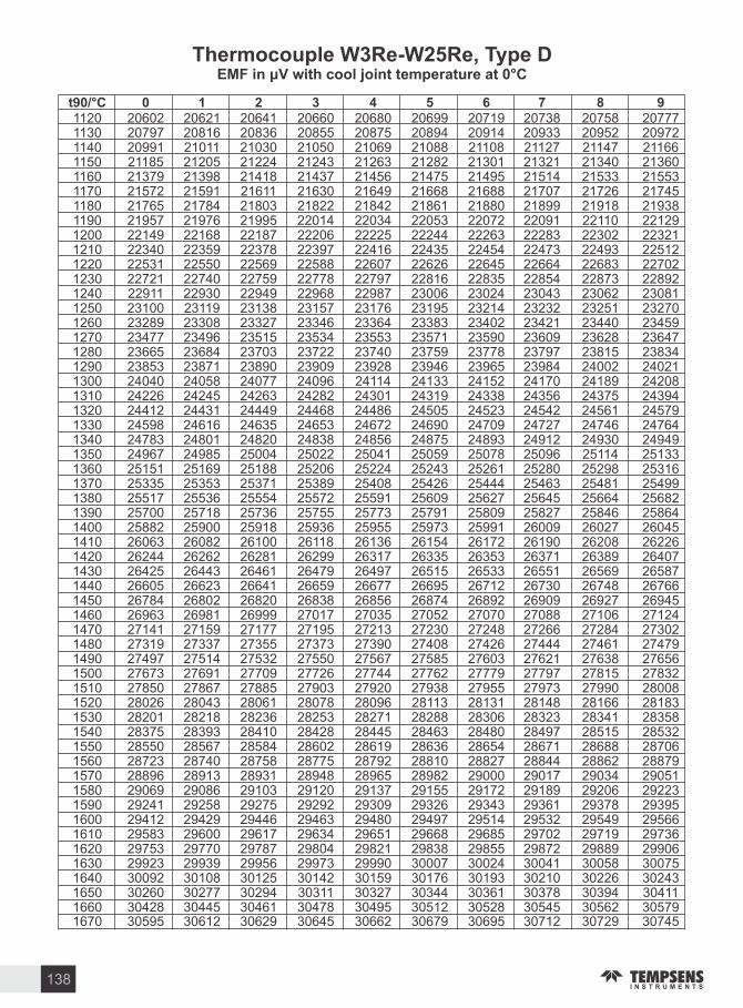
1120 20602 20621 20641 20660 20680 20699 20719 20738 20758 207771130 20797 20816 20836 20855 20875 20894 20914 20933 20952 209721140 20991 21011 21030 21050 21069 21088 21108 21127 21147 211661150 21185 21205 21224 21243 21263 21282 21301 21321 21340 213601160 21379 21398 21418 21437 21456 21475 21495 21514 21533 215531170 21572 21591 21611 21630 21649 21668 21688 21707 21726 217451180 21765 21784 21803 21822 21842 21861 21880 21899 21918 219381190 21957 21976 21995 22014 22034 22053 22072 22091 22110 221291200 22149 22168 22187 22206 22225 22244 22263 22283 22302 223211210 22340 22359 22378 22397 22416 22435 22454 22473 22493 225121220 22531 22550 22569 22588 22607 22626 22645 22664 22683 227021230 22721 22740 22759 22778 22797 22816 22835 22854 22873 228921240 22911 22930 22949 22968 22987 23006 23024 23043 23062 230811250 23100 23119 23138 23157 23176 23195 23214 23232 23251 232701260 23289 23308 23327 23346 23364 23383 23402 23421 23440 234591270 23477 23496 23515 23534 23553 23571 23590 23609 23628 236471280 23665 23684 23703 23722 23740 23759 23778 23797 23815 238341290 23853 23871 23890 23909 23928 23946 23965 23984 24002 240211300 24040 24058 24077 24096 24114 24133 24152 24170 24189 242081310 24226 24245 24263 24282 24301 24319 24338 24356 24375 243941320 24412 24431 24449 24468 24486 24505 24523 24542 24561 245791330 24598 24616 24635 24653 24672 24690 24709 24727 24746 247641340 24783 24801 24820 24838 24856 24875 24893 24912 24930 249491350 24967 24985 25004 25022 25041 25059 25078 25096 25114 251331360 25151 25169 25188 25206 25224 25243 25261 25280 25298 253161370 25335 25353 25371 25389 25408 25426 25444 25463 25481 254991380 25517 25536 25554 25572 25591 25609 25627 25645 25664 256821390 25700 25718 25736 25755 25773 25791 25809 25827 25846 258641400 25882 25900 25918 25936 25955 25973 25991 26009 26027 260451410 26063 26082 26100 26118 26136 26154 26172 26190 26208 262261420 26244 26262 26281 26299 26317 26335 26353 26371 26389 264071430 26425 26443 26461 26479 26497 26515 26533 26551 26569 265871440 26605 26623 26641 26659 26677 26695 26712 26730 26748 267661450 26784 26802 26820 26838 26856 26874 26892 26909 26927 269451460 26963 26981 26999 27017 27035 27052 27070 27088 27106 271241470 27141 27159 27177 27195 27213 27230 27248 27266 27284 273021480 27319 27337 27355 27373 27390 27408 27426 27444 27461 274791490 27497 27514 27532 27550 27567 27585 27603 27621 27638 276561500 27673 27691 27709 27726 27744 27762 27779 27797 27815 278321510 27850 27867 27885 27903 27920 27938 27955 27973 27990 280081520 28026 28043 28061 28078 28096 28113 28131 28148 28166 281831530 28201 28218 28236 28253 28271 28288 28306 28323 28341 283581540 28375 28393 28410 28428 28445 28463 28480 28497 28515 285321550 28550 28567 28584 28602 28619 28636 28654 28671 28688 287061560 28723 28740 28758 28775 28792 28810 28827 28844 28862 288791570 28896 28913 28931 28948 28965 28982 29000 29017 29034 290511580 29069 29086 29103 29120 29137 29155 29172 29189 29206 292231590 29241 29258 29275 29292 29309 29326 29343 29361 29378 293951600 29412 29429 29446 29463 29480 29497 29514 29532 29549 295661610 29583 29600 29617 29634 29651 29668 29685 29702 29719 297361620 29753 29770 29787 29804 29821 29838 29855 29872 29889 299061630 29923 29939 29956 29973 29990 30007 30024 30041 30058 300751640 30092 30108 30125 30142 30159 30176 30193 30210 30226 302431650 30260 30277 30294 30311 30327 30344 30361 30378 30394 304111660 30428 30445 30461 30478 30495 30512 30528 30545 30562 305791670 30595 30612 30629 30645 30662 30679 30695 30712 30729 30745
t C
Thermocouple W Re-W Re T pe DEMF in with cool oint temperature at C
138
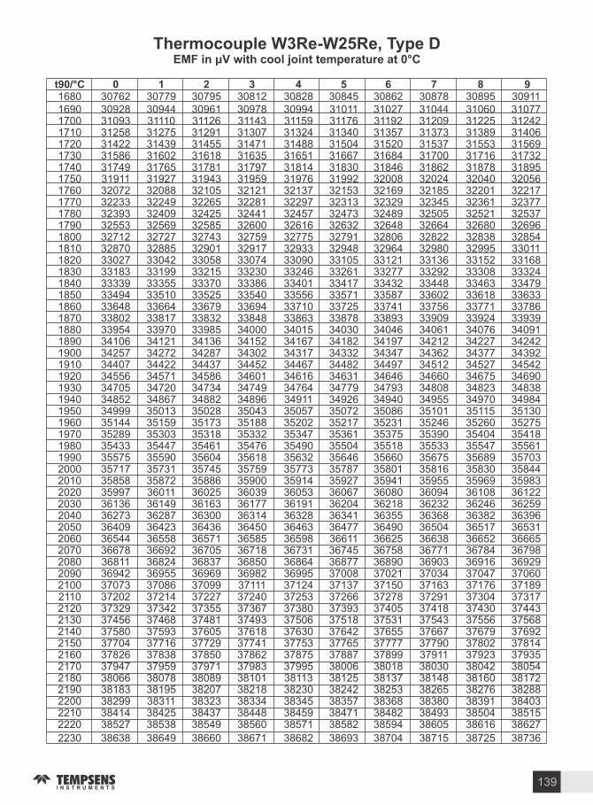
1680 30762 30779 30795 30812 30828 30845 30862 30878 30895 309111690 30928 30944 30961 30978 30994 31011 31027 31044 31060 310771700 31093 31110 31126 31143 31159 31176 31192 31209 31225 312421710 31258 31275 31291 31307 31324 31340 31357 31373 31389 314061720 31422 31439 31455 31471 31488 31504 31520 31537 31553 315691730 31586 31602 31618 31635 31651 31667 31684 31700 31716 317321740 31749 31765 31781 31797 31814 31830 31846 31862 31878 318951750 31911 31927 31943 31959 31976 31992 32008 32024 32040 320561760 32072 32088 32105 32121 32137 32153 32169 32185 32201 322171770 32233 32249 32265 32281 32297 32313 32329 32345 32361 323771780 32393 32409 32425 32441 32457 32473 32489 32505 32521 325371790 32553 32569 32585 32600 32616 32632 32648 32664 32680 326961800 32712 32727 32743 32759 32775 32791 32806 32822 32838 328541810 32870 32885 32901 32917 32933 32948 32964 32980 32995 330111820 33027 33042 33058 33074 33090 33105 33121 33136 33152 331681830 33183 33199 33215 33230 33246 33261 33277 33292 33308 333241840 33339 33355 33370 33386 33401 33417 33432 33448 33463 334791850 33494 33510 33525 33540 33556 33571 33587 33602 33618 336331860 33648 33664 33679 33694 33710 33725 33741 33756 33771 337861870 33802 33817 33832 33848 33863 33878 33893 33909 33924 339391880 33954 33970 33985 34000 34015 34030 34046 34061 34076 340911890 34106 34121 34136 34152 34167 34182 34197 34212 34227 342421900 34257 34272 34287 34302 34317 34332 34347 34362 34377 343921910 34407 34422 34437 34452 34467 34482 34497 34512 34527 345421920 34556 34571 34586 34601 34616 34631 34646 34660 34675 346901930 34705 34720 34734 34749 34764 34779 34793 34808 34823 348381940 34852 34867 34882 34896 34911 34926 34940 34955 34970 349841950 34999 35013 35028 35043 35057 35072 35086 35101 35115 351301960 35144 35159 35173 35188 35202 35217 35231 35246 35260 352751970 35289 35303 35318 35332 35347 35361 35375 35390 35404 354181980 35433 35447 35461 35476 35490 35504 35518 35533 35547 355611990 35575 35590 35604 35618 35632 35646 35660 35675 35689 357032000 35717 35731 35745 35759 35773 35787 35801 35816 35830 358442010 35858 35872 35886 35900 35914 35927 35941 35955 35969 359832020 35997 36011 36025 36039 36053 36067 36080 36094 36108 361222030 36136 36149 36163 36177 36191 36204 36218 36232 36246 362592040 36273 36287 36300 36314 36328 36341 36355 36368 36382 363962050 36409 36423 36436 36450 36463 36477 36490 36504 36517 365312060 36544 36558 36571 36585 36598 36611 36625 36638 36652 366652070 36678 36692 36705 36718 36731 36745 36758 36771 36784 367982080 36811 36824 36837 36850 36864 36877 36890 36903 36916 369292090 36942 36955 36969 36982 36995 37008 37021 37034 37047 370602100 37073 37086 37099 37111 37124 37137 37150 37163 37176 371892110 37202 37214 37227 37240 37253 37266 37278 37291 37304 373172120 37329 37342 37355 37367 37380 37393 37405 37418 37430 374432130 37456 37468 37481 37493 37506 37518 37531 37543 37556 375682140 37580 37593 37605 37618 37630 37642 37655 37667 37679 376922150 37704 37716 37729 37741 37753 37765 37777 37790 37802 378142160 37826 37838 37850 37862 37875 37887 37899 37911 37923 379352170 37947 37959 37971 37983 37995 38006 38018 38030 38042 380542180 38066 38078 38089 38101 38113 38125 38137 38148 38160 381722190 38183 38195 38207 38218 38230 38242 38253 38265 38276 382882200 38299 38311 38323 38334 38345 38357 38368 38380 38391 384032210 38414 38425 38437 38448 38459 38471 38482 38493 38504 385152220 38527 38538 38549 38560 38571 38582 38594 38605 38616 38627
2230 38638 38649 38660 38671 38682 38693 38704 38715 38725 38736
t C
Thermocouple W Re-W Re T pe DEMF in with cool oint temperature at C
139
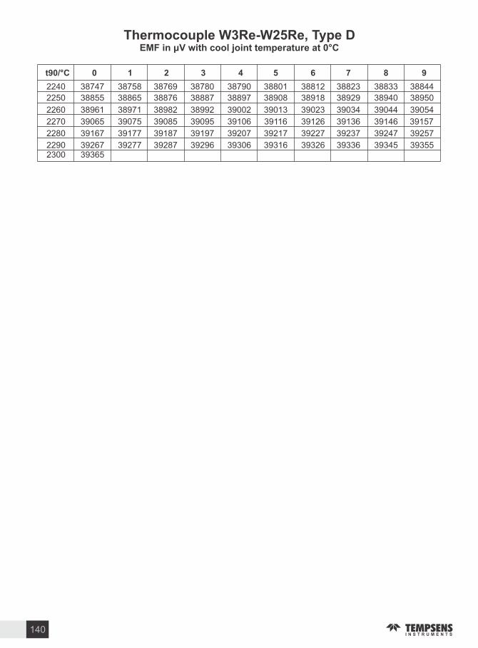
Thermocouple W Re-W Re T pe DEMF in with cool oint temperature at C
2240 38747 38758 38769 38780 38790 38801 38812 38823 38833 38844
2250 38855 38865 38876 38887 38897 38908 38918 38929 38940 38950
2260 38961 38971 38982 38992 39002 39013 39023 39034 39044 39054
2270 39065 39075 39085 39095 39106 39116 39126 39136 39146 39157
2280 39167 39177 39187 39197 39207 39217 39227 39237 39247 39257
2290 39267 39277 39287 39296 39306 39316 39326 39336 39345 393552300 39365
t C
140

Thermocouple W Re-W Re T pe AEMF in with cool oint temperature at C
0 0 13 25 37 49 61 73 85 97 11010 122 134 146 159 171 184 196 209 221 23420 246 259 271 284 297 310 322 335 348 36130 374 386 399 412 425 438 451 464 477 49140 504 517 530 543 557 570 583 596 610 62350 637 650 664 677 691 704 718 731 745 75860 772 786 799 813 827 841 855 868 882 89670 910 924 938 952 966 980 994 1008 1022 103680 1050 1064 1078 1093 1107 1121 1135 1150 1164 117890 1193 1207 1221 1236 1250 1265 1279 1293 1308 1322100 1337 1352 1366 1381 1395 1410 1425 1439 1454 1469110 1483 1498 1513 1528 1542 1557 1572 1587 1602 1617120 1632 1647 1661 1676 1691 1706 1721 1736 1751 1766130 1782 1797 1812 1827 1842 1857 1872 1887 1903 1918140 1933 1948 1964 1979 1994 2009 2025 2040 2055 2071150 2086 2102 2117 2132 2148 2163 2179 2194 2210 2225160 2241 2256 2272 2287 2303 2319 2334 2350 2365 2381170 2397 2412 2428 2444 2459 2475 2491 2507 2522 2538180 2554 2570 2585 2601 2617 2633 2649 2665 2680 2696190 2712 2728 2744 2760 2776 2792 2808 2824 2840 2856200 2872 2888 2904 2920 2936 2952 2968 2984 3000 3016210 3032 3048 3064 3081 3097 3113 3129 3145 3161 3177220 3194 3210 3226 3242 3259 3275 3291 3307 3324 3340230 3356 3372 3389 3405 3421 3438 3454 3470 3487 3503240 3519 3536 3552 3568 3585 3601 3618 3634 3650 3667250 3683 3700 3716 3733 3749 3766 3782 3799 3815 3832260 3848 3865 3881 3898 3914 3931 3947 3964 3980 3997270 4013 4030 4047 4063 4080 4096 4113 4130 4146 4163280 4179 4196 4213 4229 4246 4263 4279 4296 4313 4329290 4346 4363 4379 4396 4413 4430 4446 4463 4480 4496300 4513 4530 4547 4563 4580 4597 4614 4630 4647 4664310 4681 4697 4714 4731 4748 4765 4781 4798 4815 4832320 4849 4866 4882 4899 4916 4933 4950 4967 4983 5000330 5017 5034 5051 5068 5085 5101 5118 5135 5152 5169340 5186 5203 5220 5237 5253 5270 5287 5304 5321 5338350 5355 5372 5389 5406 5423 5440 5456 5473 5490 5507360 5524 5541 5558 5575 5592 5609 5626 5643 5660 5677370 5694 5711 5728 5745 5762 5779 5796 5813 5830 5847380 5864 5881 5898 5915 5932 5949 5966 5983 6000 6017390 6034 6051 6068 6085 6102 6119 6136 6153 6170 6187400 6204 6221 6238 6255 6272 6289 6306 6323 6340 6357410 6374 6391 6408 6425 6442 6459 6476 6493 6510 6527420 6544 6561 6579 6596 6613 6630 6647 6664 6681 6698430 6715 6732 6749 6766 6783 6800 6817 6834 6851 6868440 6885 6902 6919 6937 6954 6971 6988 7005 7022 7039450 7056 7073 7090 7107 7124 7141 7158 7175 7192 7209460 7226 7244 7261 7278 7295 7312 7329 7346 7363 7380470 7397 7414 7431 7448 7465 7482 7499 7516 7533 7551480 7568 7585 7602 7619 7636 7653 7670 7687 7704 7721490 7738 7755 7772 7789 7806 7823 7840 7857 7874 7891500 7908 7925 7943 7960 7977 7994 8011 8028 8045 8062510 8079 8096 8113 8130 8147 8164 8181 8198 8215 8232520 8249 8266 8283 8300 8317 8334 8351 8368 8385 8402530 8419 8436 8453 8470 8487 8504 8521 8538 8555 8572540 8589 8606 8623 8640 8657 8674 8691 8708 8725 8742550 8759 8776 8793 8810 8827 8844 8861 8878 8895 8912
t C
141

560 8929 8946 8963 8980 8997 9014 9031 9048 9064 9081570 9098 9115 9132 9149 9166 9183 9200 9217 9234 9251580 9268 9285 9302 9319 9336 9352 9369 9386 9403 9420590 9437 9454 9471 9488 9505 9522 9538 9555 9572 9589600 9606 9623 9640 9657 9674 9691 9707 9724 9741 9758610 9775 9792 9809 9826 9842 9859 9876 9893 9910 9927620 9944 9960 9977 9994 10011 10028 10045 10061 10078 10095630 10112 10129 10146 10162 10179 10196 10213 10230 10247 10263640 10280 10297 10314 10331 10347 10364 10381 10398 10415 10431650 10448 10465 10482 10498 10515 10532 10549 10565 10582 10599660 10616 10633 10649 10666 10683 10700 10716 10733 10750 10766670 10783 10800 10817 10833 10850 10867 10884 10900 10917 10934680 10950 10967 10984 11001 11017 11034 11051 11067 11084 11101690 11117 11134 11151 11167 11184 11201 11217 11234 11251 11267700 11284 11301 11317 11334 11351 11367 11384 11400 11417 11434710 11450 11467 11484 11500 11517 11533 11550 11567 11583 11600720 11616 11633 11650 11666 11683 11699 11716 11732 11749 11766730 11782 11799 11815 11832 11848 11865 11882 11898 11915 11931740 11948 11964 11981 11997 12014 12030 12047 12063 12080 12096750 12113 12129 12146 12162 12179 12195 12212 12228 12245 12261760 12278 12294 12311 12327 12344 12360 12376 12393 12409 12426770 12442 12459 12475 12492 12508 12524 12541 12557 12574 12590780 12606 12623 12639 12656 12672 12688 12705 12721 12738 12754790 12770 12787 12803 12819 12836 12852 12869 12885 12901 12918800 12934 12950 12967 12983 12999 13016 13032 13048 13065 13081810 13097 13113 13130 13146 13162 13179 13195 13211 13228 13244820 13260 13276 13293 13309 13325 13341 13358 13374 13390 13406830 13423 13439 13455 13471 13487 13504 13520 13536 13552 13569840 13585 13601 13617 13633 13650 13666 13682 13698 13714 13730850 13747 13763 13779 13795 13811 13827 13843 13860 13876 13892860 13908 13924 13940 13956 13973 13989 14005 14021 14037 14053870 14069 14085 14101 14117 14133 14150 14166 14182 14198 14214880 14230 14246 14262 14278 14294 14310 14326 14342 14358 14374890 14390 14406 14422 14438 14454 14470 14486 14502 14518 14534900 14550 14566 14582 14598 14614 14630 14646 14662 14678 14694910 14710 14726 14742 14757 14773 14789 14805 14821 14837 14853920 14869 14885 14901 14917 14932 14948 14964 14980 14996 15012930 15028 15043 15059 15075 15091 15107 15123 15139 15154 15170940 15186 15202 15218 15233 15249 15265 15281 15297 15312 15328950 15344 15360 15376 15391 15407 15423 15439 15454 15470 15486960 15502 15517 15533 15549 15564 15580 15596 15612 15627 15643970 15659 15674 15690 15706 15721 15737 15753 15768 15784 15800980 15815 15831 15847 15862 15878 15894 15909 15925 15940 15956990 15972 15987 16003 16019 16034 16050 16065 16081 16096 161121000 16128 16143 16159 16174 16190 16205 16221 16236 16252 162681010 16283 16299 16314 16330 16345 16361 16376 16392 16407 164231020 16438 16454 16469 16485 16500 16515 16531 16546 16562 165771030 16593 16608 16624 16639 16654 16670 16685 16701 16716 167311040 16747 16762 16778 16793 16808 16824 16839 16854 16870 168851050 16901 16916 16931 16947 16962 16977 16993 17008 17023 17038
17054 17069 17084 17100 17115 17130 17146 17161 17176 171911070 17207 17222 17237 17252 17268 17283 17298 17313 17328 173441080 17359 17374 17389 17405 17420 17435 17450 17465 17480 174961090 17511 17526 17541 17556 17571 17587 17602 17617 17632 176471100 17662 17677 17692 17708 17723 17738 17753 17768 17783 177981110 17813 17828 17843 17858 17873 17889 17904 17919 17934 17949
1060
t C
Thermocouple W Re-W Re T pe AEMF in with cool oint temperature at C
142

1120 17964 17979 17994 18009 18024 18039 18054 18069 18084 180991130 18114 18129 18144 18159 18174 18189 18203 18218 18233 182481140 18263 18278 18293 18308 18323 18338 18353 18368 18383 183971150 18412 18427 18442 18457 18472 18487 18502 18516 18531 185461160 18561 18576 18591 18605 18620 18635 18650 18665 18679 186941170 18709 18724 18739 18753 18768 18783 18798 18812 18827 188421180 18857 18871 18886 18901 18916 18930 18945 18960 18974 189891190 19004 19018 19033 19048 19062 19077 19092 19106 19121 191361200 19150 19165 19180 19194 19209 19224 19238 19253 19267 192821210 19297 19311 19326 19340 19355 19369 19384 19399 19413 194281220 19442 19457 19471 19486 19500 19515 19529 19544 19558 195731230 19587 19602 19616 19631 19645 19660 19674 19689 19703 197171240 19732 19746 19761 19775 19790 19804 19818 19833 19847 198621250 19876 19890 19905 19919 19934 19948 19962 19977 19991 200051260 20020 20034 20048 20063 20077 20091 20106 20120 20134 201491270 20163 20177 20191 20206 20220 20234 20248 20263 20277 202911280 20305 20320 20334 20348 20362 20377 20391 20405 20419 204331290 20448 20462 20476 20490 20504 20518 20533 20547 20561 205751300 20589 20603 20617 20631 20646 20660 20674 20688 20702 207161310 20730 20744 20758 20772 20786 20801 20815 20829 20843 208571320 20871 20885 20899 20913 20927 20941 20955 20969 20983 209971330 21011 21025 21039 21053 21067 21081 21095 21108 21122 211361340 21150 21164 21178 21192 21206 21220 21234 21248 21262 212751350 21289 21303 21317 21331 21345 21359 21372 21386 21400 214141360 21428 21442 21455 21469 21483 21497 21511 21524 21538 215521370 21566 21579 21593 21607 21621 21634 21648 21662 21676 216891380 21703 21717 21731 21744 21758 21772 21785 21799 21813 218261390 21840 21854 21867 21881 21895 21908 21922 21936 21949 219631400 21976 21990 22004 22017 22031 22044 22058 22072 22085 220991410 22112 22126 22139 22153 22166 22180 22194 22207 22221 222341420 22248 22261 22275 22288 22302 22315 22329 22342 22355 223691430 22382 22396 22409 22423 22436 22450 22463 22476 22490 225031440 22517 22530 22543 22557 22570 22584 22597 22610 22624 226371450 22650 22664 22677 22690 22704 22717 22730 22744 22757 227701460 22784 22797 22810 22823 22837 22850 22863 22877 22890 229031470 22916 22930 22943 22956 22969 22982 22996 23009 23022 230351480 23048 23062 23075 23088 23101 23114 23127 23141 23154 231671490 23180 23193 23206 23219 23233 23246 23259 23272 23285 232981500 23311 23324 23337 23350 23363 23376 23390 23403 23416 234291510 23442 23455 23468 23481 23494 23507 23520 23533 23546 235591520 23572 23585 23598 23611 23624 23637 23650 23662 23675 236881530 23701 23714 23727 23740 23753 23766 23779 23792 23804 238171540 23830 23843 23856 23869 23882 23895 23907 23920 23933 239461550 23959 23971 23984 23997 24010 24023 24035 24048 24061 240741560 24087 24099 24112 24125 24138 24150 24163 24176 24189 242011570 24214 24227 24239 24252 24265 24277 24290 24303 24316 243281580 24341 24353 24366 24379 24391 24404 24417 24429 24442 244551590 24467 24480 24492 24505 24518 24530 24543 24555 24568 245801600 24593 24606 24618 24631 24643 24656 24668 24681 24693 247061610 24718 24731 24743 24756 24768 24781 24793 24806 24818 248311620 24843 24855 24868 24880 24893 24905 24918 24930 24942 249551630 24967 24980 24992 25004 25017 25029 25041 25054 25066 250791640 25091 25103 25116 25128 25140 25152 25165 25177 25189 252021650 25214 25226 25239 25251 25263 25275 25288 25300 25312 253241660 25337 25349 25361 25373 25386 25398 25410 25422 25434 254471670 25459 25471 25483 25495 25507 25520 25532 25544 25556 25568
t C
Thermocouple W Re-W Re T pe AEMF in with cool oint temperature at C
143

Thermocouple W Re-W Re T pe AEMF in with cool oint temperature at C
1680 25580 25592 25605 25617 25629 25641 25653 25665 25677 256891690 25701 25713 25725 25738 25750 25762 25774 25786 25798 258101700 25822 25834 25846 25858 25870 25882 25894 25906 25918 259301710 25942 25954 25966 25978 25990 26002 26014 26025 26037 260491720 26061 26073 26085 26097 26109 26121 26133 26145 26156 261681730 26180 26192 26204 26216 26228 26239 26251 26263 26275 262871740 26299 26310 26322 26334 26346 26357 26369 26381 26393 264051750 26416 26428 26440 26452 26463 26475 26487 26499 26510 265221760 26534 26545 26557 26569 26580 26592 26604 26615 26627 266391770 26650 26662 26674 26685 26697 26709 26720 26732 26743 267551780 26767 26778 26790 26801 26813 26825 26836 26848 26859 268711790 26882 26894 26905 26917 26929 26940 26952 26963 26975 269861800 26998 27009 27021 27032 27043 27055 27066 27078 27089 271011810 27112 27124 27135 27146 27158 27169 27181 27192 27204 272151820 27226 27238 27249 27260 27272 27283 27295 27306 27317 273291830 27340 27351 27363 27374 27385 27396 27408 27419 27430 274421840 27453 27464 27475 27487 27498 27509 27520 27532 27543 275541850 27565 27577 27588 27599 27610 27621 27633 27644 27655 276661860 27677 27688 27700 27711 27722 27733 27744 27755 27766 277781870 27789 27800 27811 27822 27833 27844 27855 27866 27877 278881880 27900 27911 27922 27933 27944 27955 27966 27977 27988 279991890 28010 28021 28032 28043 28054 28065 28076 28087 28098 281091900 28120 28130 28141 28152 28163 28174 28185 28196 28207 282181910 28229 28240 28250 28261 28272 28283 28294 28305 28316 283271920 28337 28348 28359 28370 28381 28391 28402 28413 28424 284351930 28445 28456 28467 28478 28488 28499 28510 28521 28531 285421940 28553 28564 28574 28585 28596 28606 28617 28628 28639 286491950 28660 28671 28681 28692 28702 28713 28724 28734 28745 287561960 28766 28777 28787 28798 28809 28819 28830 28840 28851 288611970 28872 28883 28893 28904 28914 28925 28935 28946 28956 289671980 28977 28988 28998 29009 29019 29030 29040 29051 29061 290711990 29082 29092 29103 29113 29124 29134 29144 29155 29165 291762000 29186 29196 29207 29217 29227 29238 29248 29259 29269 292792010 29290 29300 29310 29320 29331 29341 29351 29362 29372 293822020 29392 29403 29413 29423 29433 29444 29454 29464 29474 294852030 29495 29505 29515 29525 29536 29546 29556 29566 29576 295862040 29597 29607 29617 29627 29637 29647 29657 29667 29677 296882050 29698 29708 29718 29728 29738 29748 29758 29768 29778 297882060 29798 29808 29818 29828 29838 29848 29858 29868 29878 298882070 29898 29908 29918 29928 29938 29948 29958 29968 29978 299882080 29998 30007 30017 30027 30037 30047 30057 30067 30077 300862090 30096 30106 30116 30126 30136 30145 30155 30165 30175 301852100 30194 30204 30214 30224 30234 30243 30253 30263 30273 302822110 30292 30302 30311 30321 30331 30341 30350 30360 30370 303792120 30389 30399 30408 30418 30427 30437 30447 30456 30466 304762130 30485 30495 30504 30514 30524 30533 30543 30552 30562 305712140 30581 30590 30600 30609 30619 30629 30638 30648 30657 306662150 30676 30685 30695 30704 30714 30723 30733 30742 30752 307612160 30770 30780 30789 30799 30808 30817 30827 30836 30846 308552170 30864 30874 30883 30892 30902 30911 30920 30930 30939 309482180 30957 30967 30976 30985 30995 31004 31013 31022 31032 310412190 31050 31059 31069 31078 31087 31096 31105 31115 31124 311332200 31142 31151 31160 31170 31179 31188 31197 31206 31215 312242210 31233 31243 31252 31261 31270 31279 31288 31297 31306 313152220 31324 31333 31342 31351 31360 31369 31378 31387 31396 314052230 31414 31423 31432 31441 31450 31459 31468 31477 31486 31495
t C
144

Thermocouple W Re-W Re T pe AEMF in with cool oint temperature at C
2240 31504 31513 31522 31530 31539 31548 31557 31566 31575 31584
2250 31593 31601 31610 31619 31628 31637 31646 31654 31663 31672
2260 31681 31690 31698 31707 31716 31725 31734 31742 31751 31760
2270 31769 31777 31786 31795 31803 31812 31821 31830 31838 31847
2280 31856 31864 31873 31882 31890 31899 31908 31916 31925 31933
2290 31942 31951 31959 31968 31976 31985 31994 32002 32011 32019
2300 32028 32036 32045 32054 32062 32071 32079 32088 32096 32105
2310 32113 32122 32130 32139 32147 32156 32164 32172 32181 32189
2320 32198 32206 32215 32223 32232 32240 32248 32257 32265 32274
2330 32282 32290 32299 32307 32315 32324 32332 32340 32349 32357
2340 32365 32374 32382 32390 32399 32407 32415 32424 32432 32440
2350 32448 32457 32465 32473 32482 32490 32498 32506 32515 32523
2360 32531 32539 32547 32556 32564 32572 32580 32588 32597 32605
2370 32613 32621 32629 32637 32646 32654 32662 32670 32678 32686
2380 32694 32702 32711 32719 32727 32735 32743 32751 32759 32767
2390 32775 32783 32791 32800 32808 32816 32824 32832 32840 32848
2400 32856 32864 32872 32880 32888 32896 32904 32912 32920 32928
2410 32936 32944 32952 32960 32968 32976 32984 32992 33000 33007
2420 33015 33023 33031 33039 33047 33055 33063 33071 33079 33087
2430 33095 33102 33110 33118 33126 33134 33142 33150 33158 33166
2440 33173 33181 33189 33197 33205 33213 33221 33228 33236 33244
2450 33252 33260 33268 33275 33283 33291 33299 33307 33314 33322
2460 33330 33338 33346 33353 33361 33369 33377 33385 33392 33400
2470 33408 33416 33423 33431 33439 33447 33454 33462 33470 33478
2480 33485 33493 33501 33509 33516 33524 33532 33540 33547 33555
2490 33563 33570 33578 33586 33594 33601 33609 33617 33625 33632
2500 33640
t C
145

Temperature to EMF Tables and pol nomial Coe icients o Thermocouples
The international standard IEC 584-1, in Europe EN 60 584-1, gives the relationship between the
temperature t in C and the thermal EMF E in for the mathematical calculation polynomial expression 90
of higher degree are divides in several ranges, than the coefficients a has to be substituted by the C and
D.
2E = B + ∑ B (t ) +C exp[C (t 126,9686) ]0 i 90 I 0 i 90 -
For the thermocouple type (NiCr-Ni), Following polynomial is used for the range from 0 to 1372 C:
for the daily use in calibration laboratories the inverse function is useful. The inverse function
calculates the temperature t in C from the Thermal EMF in . The inverse function is an 90
approximation of higher degree and has the uncertainty given in the coefficient tables. The inverse
function has the following common form:
iE=∑ A (t ) i 90
i
i = 0
it =∑ A * E90 i
i
i = 0
If the polynomial are divides in several ranges, Than the coefficient A has to be substituted by the
coefficients C and D.
Important Notes
For thermocouples type C (W5 Re-W26 Re) and D (W3 Re-W25 Re) the thermal EMF has the
dimension m (1 m 1000 )
The inverse functions of types A, C and D have, to the date of this booklet, no official uncertainties for
the approximations. It can be taken in account, the with quite high probability the uncertainty is
significantly below 1 .
In the appendix the polynomial coefficients for the non noble metal TC s are given first followed by the
noble metal TC s. The polynomial coefficients for the refractory (high temperature) TC s are given at
the end.
The following tables are calculated using the program MICROSOFT E CEL in the version 2007
using the coefficients given herein. No reliability will be taken for mistakes in calculation. If in doubt,
please use the official tables in the a.m. standard.
This booklet in no case substitutes the official printed version of the IEC 584-1 standard.
146

Conversion Temperature C into EMF Range C to CA(0) 0A(1) 58.665508708A(2) 0.045410977124A(3) -0.00077998048686A(4) -0.000025800160843A(5) -5.9452583057E-07A(6) -9.3214058667E-09A(7) -1.0287605534E-10A(8) -8.0370123621E-13A(9) -4.3979497391E-15A(10) -1.6414776355E-17A(11) -3.9673619516E-20A(12) -5.5827328721E-23A(13) -3.4657842013E-26
Range C to CB(0) 0B(1) 58.66550871B(2) 0.045032275582B(3) 0.000028908407212B(4) -3.3056896652E-07B(5) 6.502440327E-10B(6) -1.9197495504E-13B(7) -1.2536600497E-15B(8) 2.1489217569E-18B(9) -1.4388041782E-21B(10) 3.5960899481E-25
Conversion EMF into Temperature CRange to A(0) 0A(1) 0.01697288A(2) -0.0000004351497A(3) -1.5859697E-10A(4) -9.2502871E-14A(5) -2.608431E-17A(6) -4.1360199E-21A(7) -3.403403E-25A(8) -1.156489E-29
Range to Dim B(9) As DoubleB(0) 0B(1) 0.017057035B(2) -0.00000023301759B(3) 6.5435585E-12B(4) -7.3562749E-17B(5) -1.7896001E-21B(6) 8.4036165E-26B(7) -1.3735879E-30B(8) 1.0629823E-35B(9) -3.2447087E-41Uncertaint . - . C
Thermocouple T pe E (NiCr-CuNi)
Conversion Temperature C to EMF Range C to CA(0) 0A(1) 50.381187815A(2) 0.03047583693A(3) -0.00008568106572A(4) 1.3228195295E-07A(5) -1.7052958337E-10A(6) 2.0948090697E-13A(7) -1.2538395336E-16A(8) 1.5631725697E-20
Range C to CB(0) 296456.25681B(1) -1497.6127786B(2) 3.1787103924B(3) -0.0031847686701B(4) 1.5720819004E-06B(5) -3.0691369056E-10
Conversion EMF into Temperature CRange to A(0) 0A(1) 0.019528268A(2) -0.0000012286185A(3) -1.0752178E-09
A(4) -5.9086933E-13A(5) -1.7256713E-16A(6) -2.8131513E-20A(7) -2.396337E-24A(8) -8.3823321E-29
Range to B(0) 0B(1) 0.01978425B(2) -0.0000002001204B(3) 1.036969E-11B(4) -2.549687E-16B(5) 3.585153E-21B(6) -5.344285E-26B(7) 5.09989E-31
Range to C(0) -3113.58187C(1) 0.300543684C(2) -0.0000099477323C(3) 1.7027663E-10C(4) -1.43033468E-15C(5) 4.73886084E-21Uncertaint . - . C
Thermocouple T pe (Fe-CuNi)
147

Conversion Temperature C to EMF
Range C to CA(0) 0A(1) 51.71089598A(2) 0.02787113678A(3) -0.0001043996689A(4) 3.685483483E-07A(5) -8.751008267E-10A(6) -2.082014998E-12A(7) 2.178467727E-14A(8) -6.589869604E-17A(9) 1.036698719E-19A(10) -9.121218528E-23A(11) 4.247340152E-26A(12) -8.14181198E-30
The pol nomial coe icients orthermocouple t pe L (Fe-CuNi) are proposed b R.L.de Groot rom an Swinden Laborator ( SL) at NMI in Del t The Netherlands. The are commonl
accepted or conversion temperatur into EMF and vice versa.The primaril German standard DIN did not contain poli - nomial coe icients The standard was withdrawn in October .Conversion EMF into Temperature C
Range to A(0) 0A(1) 51.71089598A(2) 0.02787113678A(3) -0.0001043996689A(4) 3.685483483E-07A(5) -8.751008267E-10A(6) -2.082014998E-12A(7) 2.178467727E-14A(8) -6.589869604E-17A(9) 1.036698719E-19A(10) -9.121218528E-23A(11) 4.247340152E-26A(12) -8.14181198E-30Uncertaint . - . C
Conversion Temperature C into EMF Range C to CA(0) 0A(1) 39.450128025A(2) 0.023622373598A(3) -0.00032858906784A(4) -4.9904828777E-06A(5) -6.7509059173E-08A(6) -5.7410327428E-10A(7) -3.1088872894E-12A(8) -1.0451609365E-14A(9) -1.9889266878E-17A(10) -1.6322697486E-20
Range C to CB(0) -17.600413686B(1) 38.921204975B(2) 0.018558770032B(3) -0.000099457592874B(4) 3.1840945719E-07B(5) -5.6072844889E-10B(6) 5.6075059059E-13B(7) -3.2020720003E-16B(8) 9.7151147152E-20B(9) -1.2104721275E-23C(0) 118.5976C(1) -0.0001183432
Conversion EMF into Temperature CRange to A(0) 0A(1) 0.025173462
A(2) -0.0000011662878A(3) -1.0833638E-09A(4) -8.977354E-13A(5) -3.7342377E-16A(6) -8.6632643E-20A(7) -1.0450598E-23A(8) -5.1920577E-28
Range to B(0) 0B(1) 0.02508355B(2) 0.00000007860106B(3) -2.503131E-10B(4) 8.31527E-14B(5) -1.228034E-17B(6) 9.804036E-22B(7) -4.41303E-26B(8) 1.057734E-30B(9) -1.052755E-35
Range to C(0) -131.8058C(1) 0.04830222C(2) -0.000001646031C(3) 5.464731E-11C(4) -9.650715E-16C(5) 8.802193E-21C(6) -3.11081E-26Uncertaint . - . C
Thermocouple T pe (NiCr-Ni)
Thermocouple T pe L (Fe-CuNi)
148
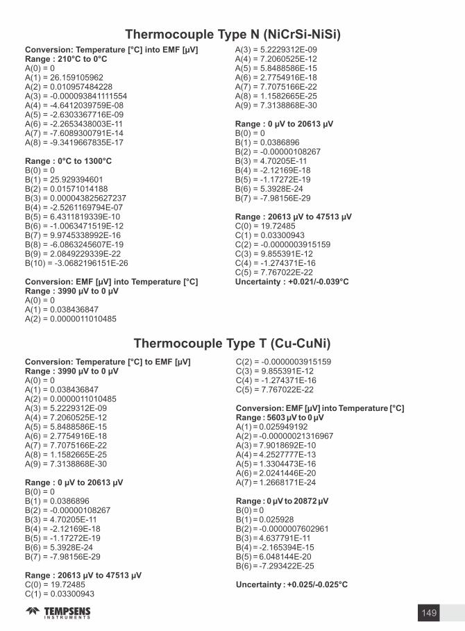
Conversion Temperature C into EMF Range C to CA(0) 0A(1) 26.159105962A(2) 0.010957484228A(3) -0.000093841111554A(4) -4.6412039759E-08A(5) -2.6303367716E-09A(6) -2.2653438003E-11A(7) -7.6089300791E-14A(8) -9.3419667835E-17
Range C to CB(0) 0B(1) 25.929394601B(2) 0.01571014188B(3) 0.000043825627237B(4) -2.5261169794E-07B(5) 6.4311819339E-10B(6) -1.0063471519E-12B(7) 9.9745338992E-16B(8) -6.0863245607E-19B(9) 2.0849229339E-22B(10) -3.0682196151E-26
Conversion EMF into Temperature CRange to A(0) 0A(1) 0.038436847A(2) 0.0000011010485
A(3) 5.2229312E-09A(4) 7.2060525E-12A(5) 5.8488586E-15A(6) 2.7754916E-18A(7) 7.7075166E-22A(8) 1.1582665E-25A(9) 7.3138868E-30
Range to B(0) 0B(1) 0.0386896B(2) -0.00000108267B(3) 4.70205E-11B(4) -2.12169E-18B(5) -1.17272E-19B(6) 5.3928E-24B(7) -7.98156E-29
Range to C(0) 19.72485C(1) 0.03300943C(2) -0.0000003915159C(3) 9.855391E-12C(4) -1.274371E-16C(5) 7.767022E-22Uncertaint . - . C
Thermocouple T pe N (NiCrSi-NiSi)
Conversion Temperature C to EMF Range to A(0) 0A(1) 0.038436847A(2) 0.0000011010485A(3) 5.2229312E-09A(4) 7.2060525E-12A(5) 5.8488586E-15A(6) 2.7754916E-18A(7) 7.7075166E-22A(8) 1.1582665E-25A(9) 7.3138868E-30
Range to B(0) 0B(1) 0.0386896B(2) -0.00000108267B(3) 4.70205E-11B(4) -2.12169E-18B(5) -1.17272E-19B(6) 5.3928E-24B(7) -7.98156E-29
Range to C(0) 19.72485C(1) 0.03300943
C(2) -0.0000003915159C(3) 9.855391E-12C(4) -1.274371E-16C(5) 7.767022E-22
Conversion EMF into Temperature CRange to A(1) 0.025949192A(2) -0.00000021316967A(3) 7.9018692E-10A(4) 4.2527777E-13A(5) 1.3304473E-16A(6) 2.0241446E-20A(7) 1.2668171E-24
Range to B(0) 0B(1) 0.025928B(2) -0.0000007602961B(3) 4.637791E-11B(4) -2.165394E-15B(5) 6.048144E-20B(6) -7.293422E-25
Uncertaint . - . C
Thermocouple T pe T (Cu-CuNi)
149
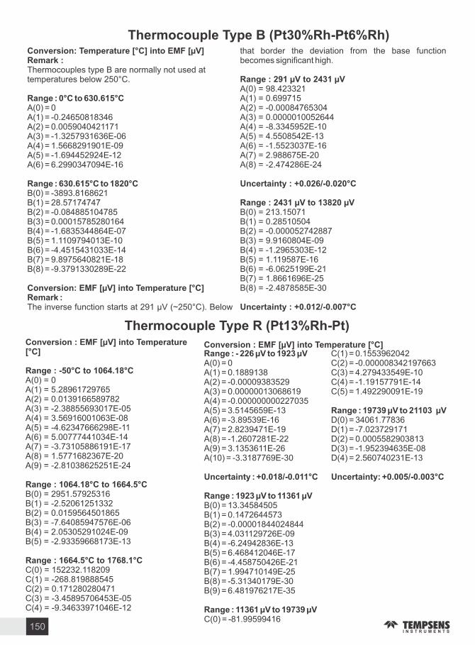
Conversion Temperature C into EMF Remark Thermocouples type B are normally not used at temperatures below 250 C.
Range C to . CA(0) 0A(1) -0.24650818346A(2) 0.0059040421171A(3) -1.3257931636E-06A(4) 1.5668291901E-09A(5) -1.694452924E-12A(6) 6.2990347094E-16
Range . C to CB(0) -3893.8168621B(1) 28.57174747B(2) -0.084885104785B(3) 0.00015785280164B(4) -1.6835344864E-07B(5) 1.1109794013E-10B(6) -4.4515431033E-14B(7) 9.8975640821E-18B(8) -9.3791330289E-22
Conversion EMF into Temperature CRemark The inverse function starts at 291 ( 250 C). Below
that border the deviation from the base function becomes significant high.
Range to A(0) 98.423321A(1) 0.699715A(2) -0.00084765304A(3) 0.0000010052644A(4) -8.3345952E-10A(5) 4.5508542E-13A(6) -1.5523037E-16A(7) 2.988675E-20A(8) -2.474286E-24
Uncertaint . - . C
Range to B(0) 213.15071B(1) 0.28510504B(2) -0.000052742887B(3) 9.9160804E-09B(4) -1.2965303E-12B(5) 1.119587E-16B(6) -6.0625199E-21B(7) 1.8661696E-25B(8) -2.4878585E-30
Uncertaint . - . C
Thermocouple T pe B (Pt Rh-Pt Rh)
Conversion EMF into Temperature C
Range - C to . CA(0) 0A(1) 5.28961729765A(2) 0.0139166589782A(3) -2.38855693017E-05A(4) 3.56916001063E-08A(5) -4.62347666298E-11A(6) 5.00777441034E-14A(7) -3.73105886191E-17A(8) 1.5771682367E-20A(9) -2.81038625251E-24
Range . C to . CB(0) 2951.57925316B(1) -2.52061251332B(2) 0.0159564501865B(3) -7.64085947576E-06B(4) 2.05305291024E-09B(5) -2.93359668173E-13
Range . C to . CC(0) 152232.118209C(1) -268.819888545C(2) 0.171280280471C(3) -3.45895706453E-05C(4) -9.34633971046E-12
Range - to C(1) 0.1553962042A(0) 0 C(2) -0.000008342197663A(1) 0.1889138 C(3) 4.279433549E-10A(2) -0.00009383529 C(4) -1.19157791E-14A(3) 0.00000013068619 C(5) 1.492290091E-19A(4) -0.000000000227035A(5) 3.5145659E-13 Range to A(6) -3.89539E-16 D(0) 34061.77836A(7) 2.8239471E-19 D(1) -7.023729171A(8) -1.2607281E-22 D(2) 0.0005582903813A(9) 3.1353611E-26 D(3) -1.952394635E-08A(10) -3.3187769E-30 D(4) 2.560740231E-13
Uncertaint . - . C Uncertaint . - . C
Range to B(0) 13.34584505B(1) 0.1472644573B(2) -0.00001844024844B(3) 4.031129726E-09B(4) -6.24942836E-13B(5) 6.468412046E-17B(6) -4.458750426E-21B(7) 1.994710149E-25B(8) -5.31340179E-30B(9) 6.481976217E-35
Range to C(0) -81.99599416
Thermocouple T pe R (Pt Rh-Pt)
Conversion EMF into Temperature C
150

Thermocouple T pe S (Pt Rh-Pt )A(6) -1.59085941E-16A(7) 8.2302788E-20A(8) -2.34181944E-23A(9) 2.7978626E-27Uncertaint . - . C
Range to B(0) 12.91507177B(1) 0.1466298863B(2) -0.00001534713402B(3) 3.145945973E-09B(4) -4.163257839E-13B(5) 3.187963771E-17B(6) -1.2916375E-21B(7) 2.183475087E-26B(8) -1.447379511E-31B(9) 8.211272125E-36
Range to C(0) -80.87801117C(1) 0.1621573104C(2) -0.000008536869453C(3) 4.719686976E-10C(4) -1.441693666E-14C(5) 2.08161889E-19
Range to D(0) 53338.75126D(1) -12.35892298D(2) 0.001092657613D(3) -4.265693686E-08D(4) 6.24720542E-13Uncertaint . - . C
Conversion Temperature C into EMF Range - C to . CA(0) 0A(1) 5.40313308631A(2) 0.012593428974A(3) -2.32477968689E-05A(4) 3.22028823036E-08A(5) -3.31465196389E-11A(6) 2.55744251786E-14A(7) -1.25068871393E-17A(8) 2.71443176145E-21
Range . C to . CB(0) 1329.00444085B(1) 3.34509311344B(2) 0.00654805192818B(3) -1.64856259209E-06B(4) 1.29989605174E-11
Range . C to . CC(0) 146628.232636C(1) -258.430516752C(2) 0.163693574641C(3) -3.30439046987E-05C(4) -9.43223690612E-12
Conversion EMF into Temperature CRange - to A(0) 0A(1) 0.18494946A(2) -0.0000800504062A(3) 0.00000010223743A(4) -1.52248592E-10A(5) 1.88821343E-13
Conversion Temperature C to EMF Result EMF in Millivolt
Remark Refractory (W-Re) thermocouples are normally not used at temperatures below 1000 C.
Range C to . CA(0) 0A(1) 13.406032A(2) 0.011924992A(3) -0.0000079806354A(4) -5.0787515E-09A(5) 1.3164197E-11A(6) -7.9197332E-15
Range . C to CB(0) 405.28823B(1) 11.509355B(2) 0.015696453B(3) -0.000013704412B(4) 5.2290873E-09B(5) -9.2082758E-13B(6) 4.5245112E-17
Conversion EMF m into Temperature CInput EMF in Millivolt
Remark Refractory (W-Re) thermocouples are normally not used at temperatures below 1000 C.
Range m to . mA(0) 0A(1) 0.0741247326A(2) -0.00000428082813A(3) 5.2113892E-10A(4) 4.57487201E-14A(5) 2.80578284E-18A(6) -1.13145137E-22A(7) 2.85489684E-27A(8) -4.07643828E-32A(9) 2.51358071E-37
Thermocouple T pe C (W Re-W Re)
151

Conversion Temperature C into EMF
Result EMF in Millivolt
Remark Refractory (W-Re) thermocouples are normally not used at tempe- ratures below 1000 C.
Range C to CA(0) 0A(1) 0.0095821929A(2) 0.000020068371A(3) -0.000000013786121A(4) -1.1620542E-11A(5) 3.98753E-14A(6) -4.2429757E-17A(7) 1.6821225E-20
Range C to CB(0) 2.2097354B(1) -0.0014500612B(2) 0.000042898234B(3) -0.000000042816409B(4) 2.4132609E-11B(5) -8.1885541E-15B(6) 1.5873209E-18B(7) -1.4320975E-22
Conversion EMF into Temperature C
Input EMF in Millivolt
Remark Refractory (W-Re) thermocouples are normally not used at temperatures below 1000 C.
Range m to . mA(0) 0A(1) 101.387139A(2) -15.1768486A(3) 3.13787524A(4) -0.446716692A(5) 0.0427451436A(6) -0.002749759A(7) 0.000118845993A(8) -0.00000339703227A(9) 6.15028058E-08A(10) -6.38332695E-10A(11) 2.89238418E-12
Thermocouple T pe D (W Re-W Re)
Conversion Temperature C into EMF
Result EMF in Millivolt
Remark Refractory (W-Re) thermocouples are normally not used at temperatures below 1000 C.
Range C to CA(0) 0.71564735A(1) 11.951905A(2) 0.016672625A(3) -0.000028287807A(4) 0.000000028397839A(5) -1.8505007E-11A(6) 7.3632123E-15A(7) -1.6148878E-18A(8) 1.4901679E-22
Conversion EMF into Temperature C
Input EMF in Millivolt
Remark Refractory (W-Re) thermocouples are normally not used at temperatures below 1000 C.
Range to A(0) 0.0009643027A(1) 0.079495086A(2) -0.000004999031A(3) 6.341776E-10A(4) -4.7440967E-14A(5) 2.1811337E-18A(6) -5.8324228E-23A(7) 8.2433725E-28A(8) -4.592848E-31
Thermocouple T pe A (W Re-W Re)
152

CORROSI E SER ICE GUIDECORROSI E AGENTAcetic Acid (Glacial)
Deg C CONC RECOMMENDED MATERIAL
Acetic Acid
Acetic Anhydride
AcetoneAcetyleneAlcohol, Ethyl
Aluminium Chloride (Aqueous)
Aluminium Nitrate (Saturated)
Aluminium Salfate (Saturated)
Ammonia (Anhydrous)Ammonia (Gas)Ammonium Chloride
Ammonium Hydroxide
Ammonium NitrateAmmonium Sulfate
Amyl AcetateAnilineBarium Chloride (Saturated)
Barium Hydroxide (Saturated)
Beer
Ben ene (Ben ol)
Ben oic Acid
Black Liquor
Bleach (Active Chlorine)Borax
Boric Acid
Brine Acid
Bromine (Liquid)
Butane
Butyl Acetate
Butyl AlcoholButyric Acid
20014020014013020020020090200140140909090902909090290703080909014090200140250902901002009010010020020024019090602002909060302909017090190200140
ALL805080ALLALLALLALLALLALLALLALLALLALLALLALLALLALLALLALL50ALLALL
SATSAT10-4010-40ALLALLALLALL50ALL
ALLALLALLALLALLALLALL12.50ALLALLALLALLALLALLALL
ALLALLALLALLALL
316 SSHast. C316 SSCarp. 20Hast. C316 SS316 SS304 SSHast. C316 SSHast. BNickel 446 SS316 SSTitanium316 SS316 SS304 SSTitaniumNickel NickelSteelSteel Carp.20Hast. B304 SSTitanium316 SS304 SS304 SSHast. CInconel Carp. 20316 SSSS 304Carp. 20304 SSTitanium304 SSTFEFEPCarp. 20 Hast. C316 SSHast CNickel Hast. CBrass TantalumAluminum SteelTitanium316 SS 316 SSCarp. 20
ALL
153

Calcium Hydroxide
Carbonic Acid
Carbonic Dioxide (Dry)
Carbonated BeveragesCarbon Disulfide
Carbon TetrachlorideChlorine (Gas)
9090290170430100902009090200
50SATALLALLALLALLALLALLALLALLALL
Hast. C304 SS Carp. 20316 SSBrass304 SSTitanium316 SS
Monel316 SS
CORROSI E AGENT Deg C CONC RECOMMENDED MATERIAL
Chlorine (Gas - Moist )Chloroform AcidChloroform
Chromic Acid
Citric Acid
Copper Cloride
Copper Nitrate 300 ALL 304 SSCopper Sulfate 200 ALL Hast. C
Corn Oil
Crude OilCyanogen Gas
EtherEthyl Acetate
Ethyl Chloride (Dry)Ethylene Glycol
Ethylene Oxide
Fatty AcidsFerric Chloride
Ferric Sulfate
Ferrous Sulfate
Formaldehyde
Formic Acid (Anhydrous)Freon (F-11)
Furfural
Gallic Acid
70180909090901309090901509020024019017090240190170909020029090902020020014030509030905050-29090200200200200240
ALLALLALLALL5050ALLALLALLALLALLALLALLALLALLALLALLALLALLALLALLALLALLALLALLALLALLALLALLALLALLALLALLALLALL5050ALLALLALL
ALLALL
Hast. CHast. BNickelCarp. 20 TitaniumHast. CHast. CCarp. 20TitaniumHast. C304 SSHast. C316 SSTFEFEP316 SS304 SSTFEFEP316 SS304 SSTitanium316 SS316 SSCarp. 20304 SSHast. C316 SS316 SSTitaniumHast. CCarp. 20316 SSTitanium304 SS304 SS304 SSCap. 20Monel316 SS
304 SSTFE
304 SS
154
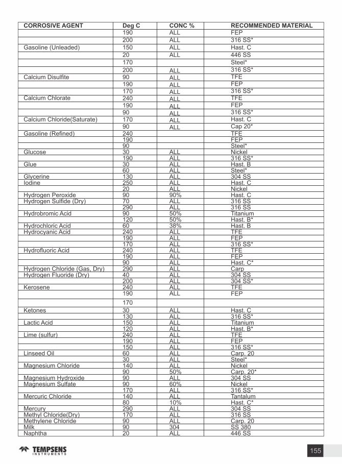
CORROSI E AGENT Deg C CONC RECOMMENDED MATERIAL
etones
Lactic Acid
Lime (sulfur)
Linseed Oil
Magnesium Chloride
Magnesium HydroxideMagnesium Sulfate
Mercuric Chloride
MercuryMethyl Chloride(Dry)Methylene ChlorideMilkNaphtha
30130150120240190150603014090909017014080290170909020
ALLALLALLALLALLALLALLALLALLALL50ALL60ALLALL10ALLALLALL304ALL
Hast. C316 SSTitanium Hast. BTFEFEP316 SSCarp. 20SteelNickelCarp. 20304 SSNickel316 SSTantalumHast. C304 SS316 SSCarp. 20SS 380446 SS
Gasoline (Refined)
Glucose
Glue
GlycerineIodine
Hydrogen PeroxideHydrogen Sulfide (Dry)
Hydrobromic Acid
Hydrochloric AcidHydrocyanic Acid
Hydrofluoric Acid
Hydrogen Chloride (Gas, Dry)Hydrogen Fluoride (Dry)
erosene
2401909030190306013025020907029090120602401901702401909029040200240190
170
ALLALLALLALLALLALLALL90ALLALL505038ALLALLALLALLALLALLALLALLALLALLALL
TFEFEPSteelNickel316 SSHast. BSteel304 SSHast. CNickelHast. C316 SS316 SSTitaniumHast. BHast. BTFEFEP316 SSTFEFEPHast. CCarp304 SS304 SSTFEFEP
Gasoline (Unleaded)
19020015020170
ALLALLALLALL
FEP316 SSHast. C446 SSSteel
Calcium Disulfite
Calcium Chlorate
Calcium Chloride(Saturate)
200901901702401909017090
ALLALLALLALLALLALLALLALLALL
316 SSTFEFEP316 SSTFEFEP316 SSHast. CCap 20
155

Natural Gas
Nickel ChlorideNickel Sulfate
Nitric Acid
Nitroben ene
Oleic AcidOleum
Oxalic Acid
120240190409080902090140170140501209090
ALL
8010ALLALL40ALLALLALL40ALLALLALL
304 SSTFEFEPSteelHast. C 3040SSTantalum304 SS304 SS304 SSCarp. 20316 SS316 SSHast. C316 SSTantalumCarp. 20
Oxygen
Palmitic Acid
Phenol (Carbolic Acid)
27020170240190200290
ALLALLALLALLALLALLALL
Tantalum446 SS316 SSTFEFEP304 SS316 SS
CORROSI E AGENT Deg C CONC RECOMMENDED MATERIAL
Sodium Fluoride
Sodium Hydroxide
Sodium Nitrate Sodium Nitrite
Sodium PeroxideSulfur
Sulfur Chloride (Dry)
Sulfur Dioxide (Dry)
708010070170909020290703029050290
MonelCarp. 20Monel316 SS316 SSTitanium304 SS446 SS304 SSAlloy 556TantalumNickelSteel316 SS
ALLALL70ALL60SAT4010ALLALLALLALLALLALL
Phosphoric Acid
Photographic SolutionsPicric Acid
Potassium Bromide
Potassium CarbonatePotassium ChloratePotassium HydroxidePotassium Nitrate
Potassium Permanganate
Potassium Sulfate Propane
Pyrogallic Acid
Salicylic Acid
Sea Water (Stagnant)Sea Water (Cavitation)Soap Solutions
Sodium Bicarbonate Sodium Bisulfite
Sodium Carbonate
Sodium Chloride
904017030202009090901709017028020170170603030170120170
(20)205017070909029030
50-8550-85ALLALLALLALL30305030508080202010ALLALLALLALLALLALL
ALLALL201010-403010-10030
Hast. CCarp. 20316 SSTitaniumAluminum316 SSTitanium446 SS304 SS316 SSNickelAluminum446 SSHast. C316 SS316 SS446 SSBrassCopper316 SSHast. C316 SSMonel 316 SS446 SSNickel316 SS316 SSCarp. 20Carp. 20Hast. BNickel
156

CORROSI E AGENT Deg C CONC RECOMMENDED MATERIALSulfur Trioxide (Dry)
Sulfuric Acid
Sulfurous Acid
Steam (Law Pressure)
(Medium Pressure)
(High Pressure)Tannic Acid
Tartaric AcidTitanium Tetrachloride
Toulene (Toluol)
Trichloroacetic Acid
TrichloroethyleneTurpentineWhiskey and Wine
ylene ( ylol)inc Chloride
inc Sulfate
2401902904012070180
90902003014017090240190907090
908029090
TFEFEB304 SSCarp. 20Hast. BTitaniumCarp. 20Inconel304 SSNickel304 SS316 SS20 Titanium304 SS304 SSCarp.TitaniumSteel304 SSTFEFEPHast. CInconel304 SS304 SS446 SSTitaniumHast. B316 SS
ALLALLALL10060ALLALL
10ALLALLALLALLALLALLALLALLALLALLALLALLALLTO 70ALLSAT
157

EMITTANCE ALUES FOR POLISHED AND OXIDI ED METALS
. - . m
SMOOTHPOLISH
SMOOTHOXIDI ED
SMOOTHPOLISH
SMOOTHOXIDI ED
SMOOTHPOLISH
SMOOTHOXIDI ED
SMOOTHPOLISH
SMOOTHOXIDI ED
SMOOTHOXIDI ED
- . m m - m
Graphite (Smootgh)
0.32 0.90
0.15 0.25
0.20 0.70
0.33 0.75
0.33 0.90
0.40 0.70
0.33 0.75
0.10 0.70
0.80 -
0.33 0.70
0.25 0.70
0.45 0.90
0.38 -
0.36 0.90
0.32 0.90
0.27 -
0.05 0.80
0.70 -
0.33 0.85
0.27 0.70
0.35 0.60
0.40 0.60
0.36 0.75
0.20 0.50
0.30 0.40
0.25 0.90
0.10 0.20
0.10 0.70
0.25 0.75
0.25 0.90
0.30 0.70
0.25 0.75
0.04 0.70
0.80 -
0.25 0.70
0.15 0.70
0.30 0.90
0.28 -
0.26 0.90
0.15 0.90
0.18 -
0.03 0.80
0.7 -
0.25 0.85
0.10 0.70
0.22 0.60
0.10 0.60
0.29 0.75
0.07 0.50
0.22 0.40
0.10 0.90
0.05 0.15
0.05 0.70
0.11 0.75
0.10 0.90
0.19 0.70
0.15 0.75
0.02 0.70
0.80 -
0.09 0.70
0.08 0.70
0.20 0.90
0.18 -
0.17 0.90
0.06 0.90
0.06 -
0.03 0.80
0.70 -
0.10 0.85
0.07 0.70
0.18 0.60
0.05 0.60
0.18 0.75
0.03 0.50
0.14 0.40
0.10 0.90
0.08 0.15
0.07 0.70
0.15 0.75
0.15 0.90
0.25 0.70
0.20 0.75
0.03 0.70
0.80 -
0.15 0.70
0.10 0.70
0.22 0.90
0.15 -
0.22 0.90
0.08 0.90
0.10 -
0.03 0.80
0.70 -
0.15 0.85
0.08 0.70
0.18 0.60
0.06 0.60
0.25 0.75
0.15 0.50
0.15 0.40
0.9
0.8
0.9
0.8
0.8
-
0.9
-
-
0.8
WA E LENGTH
MATERIAL
Alimel
Aluminium
Brass
Carbon Steel
Chromel
Chromium
Cobalt
Copper
Iron
Lead
Manganese
Molybdenum
Nichrome
Nickel
Platinum
Silver
Silicon
Stainless Steel
Tantalum
Tin
Tungusten
anadium
inc
irconium
The values listed refer to flat polished specimens and to the oxides formed on these surfaces Roughening of these Surfaces raises the emittance values. A long narrow hole or crevice in any of the above produces a blackbody with e 1.0 Electrolytically Anodi ed Not Oxidi ed
158

Temperature Conversion FROM C to F FROM F to C
C F C F F C F C
-50 -58 1750 3182 -45.56 1800 982.22
-40 -40 1800 3272 -40 1850 1010
-30 -22 1850 3362 -34.44 1900 1037.78
-20 -4 1900 3452 -28.89 1950 1065.56
-10 14 1950 3542 -23.33 2000 1093.33
-5 23 2000 3632 -20.56 2050 1121.11
-2 28.4 2050 3722 -18.56 2100 1148.89
-1 30.2 2100 3812 -18.33 2150 1176.67
0 32 -17.78 2200 1204.44
5 41 -15 2250 1232.22
10 50 -12.22 2300 1260
20 68 -6.67 2350 1287.78
30 86 -1.11 2400 1315.56
40 104 4.44 2450 1343.33
50 122 10 2500 1371.11
100 212 37.78 2550 1398.89
150 302 65.56 2600 1426.67
200 392 93.33 2650 1454.44
250 482 121.11 2700 1482.22
300 572 148.89 2750 1510
350 662 176.67 2800 1537.78
400 752 204.44 2850 1565.56
450 842 232.22 2900 1593.33
500 932 260 2950 1621.11
550 1022 287.78 3000 1648.89
600 1112 315.56 3050 1676.67
650 1202 343.33 3100 1704.44
700 1292 371.11 3150 1732.22
800
1382 398.89 3200 1760
850
1472 426.67 3250 1778.78
900
1562 454.44 3300 1815.56
950
1652 482.22 3350 1843.33
1000
1742 510 3400 1871.11
1050
1832 537.78 3450 1898.89
1100
1922 565.56 3500 1926.67
1150
2012 593.33 3550 1954.44
1200
2102 621.11 3600 1982.22
1250
2192 648.89 3650 2010
1300
2282 676.67 3700 2037.78
1350
2372 704.44 3750 2065.56
1400
2462 732.22 3800 2093.33
1450
2552 760 3850 2121.11
1500
2642 787.78 3900 2148.89
1550
2732 815.56 3950 2176.67
1600
2842 843.33 4000 2204.44
1650
2912 871.11 4050 2232.22
1700
3002 898.89 4100 2260
3092 926.67 4150 2287.78
750
-50
-40
-30
-20
-10
-5
-2
-1
0
5
10
20
30
40
50
100
150
200
250
300
350
400
450
500
550
600
650
700
800
850
900
950
1000
1050
1100
1150
1200
1250
1300
1350
1400
1450
1500
1550
1600
1650
1700
750
F . C C ( F- )
159
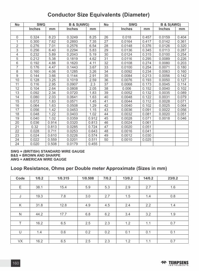
Conductor Si e E uivalents (Diameter)
SWG (BRITISH) STANDARD WIRE GAUGEB&S BROWN AND SHARPE AWG AMERICAN WIRE GAUGE
Loop Resistance Ohms per Double meter Appro imate (Si es in mm)
No SWG B & S(AWG) No SWG B & S(AWG)Inches mm Inches mm Inches mmInches mm
0 0.324 8.23 0.3249 8.25 26 0.018 0.457 0.0159 0.4041 0.300 7.62 0.2893 7.35 27 0.0164 0.417 0.0142 0.3612 0.276 7.01 0.2576 6.54 28 0.0148 0.376 0.0126 0.3203 0.256 6.40 0.2294 5.83 29 0.0136 0.345 0.0113 0.2874 0.232 5.89 0.2043 5.19 30 0.0124 0.315 0.0100 0.2545 0.212 5.38 0.1819 4.62 31 0.0116 0.295 0.0089 0.2266 0.192 4.88 0.1620 4.11 32 0.0108 0.274 0.0080 0.2037 0.176 4.47 0.1443 3.67 33 0.0100 0.254 0.0071 0.1808 0.160 4.06 0.1285 3.26 34 0.0092 0.234 0.0063 0.1609 0.144 3.66 0.1144 2.91 35 0.0084 0.213 0.0056 0.14210 0.128 3.25 0.1019 2.59 36 0.0076 0.193 0.0050 0.12711 0.116 2.95 0.0907 2.3 37 0.0068 0.173 0.0045 0.11412 0.104 2.64 0.0808 2.05 38 0.006 0.152 0.0040 0.10213 0.092 2.34 0.0720 1.83 39 0.0052 0.132 0.0035 0.08914 0.080 2.03 0.0641 1.63 40 0.0048 0.122 0.07915 0.072 1.83 0.0571 1.45 41 0.0044 0.112
0.00310.071
16 0.064 1.63 0.0508 1.29 42 0.0040 0.1020.0028
0.06417 0.056 1.42 0.0453 1.15 43 0.0036 0.091
0.00250.056
18 0.048 1.22 0.0403 1.02 44 0.0032 0.0810.0022
0.05119 0.040 1.02 0.0359 0.912 45 0.0028 0.071
0.00200.046
20 0.036 0.914 0.0320 0.813 46 0.0024 0.0610.0018
21 0.32 0.813 0.0285 0.724 47 0.0020 0.05122 0.028 0.711 0.0253 0.643 48 0.0016 0.04123 0.024 0.610 0.0226 0.574 49 0.0012 0.03024 0.022 0.559 0.0201 0.511 50 0.0010 0.02524 0.020 0.508 0.0179 0.455
Code . . . . . . .
E 38.1 15.4 5.9 5.3 2.9 2.7 1.6
J 19.3 7.8 3.0 2.7 1.5 1.4 0.8
31.8 12.8 4.9 4.5 2.4 2.2 1.4
N 44.2 17.7 6.8 6.2 3.4 3.2 1.9
T 16.2 6.5 2.5 2.3 1.2 1.1 0.7
U 1.4 0.6 0.2 0.2 0.1 0.1 0.1
16.2 6.5 2.5 2.3 1.2 1.1 0.7
160
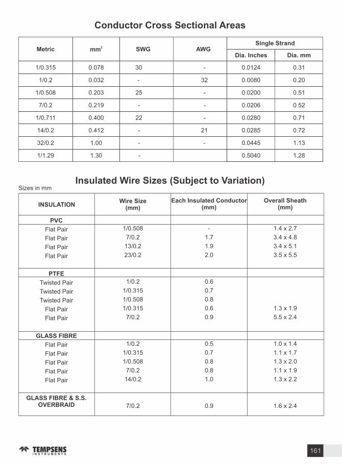
Conductor Cross Sectional Areas
Insulated Wire Si es (Sub ect to ariation)Si es in mm
INSULATIONWire Si e
(mm)Each Insulated Conductor
(mm)Overall Sheath
(mm)
P C
Flat Pair
Flat Pair
Flat Pair
Flat Pair
PTFE
Twisted Pair
Twisted Pair
Twisted Pair
Flat Pair
Flat Pair
GLASS FIBRE
Flat Pair
Flat Pair
Flat Pair
Flat Pair
Flat Pair
GLASS FIBRE & S.S. O ERBRAID
1 0.508
7 0.2
13 0.2
23 0.2
1 0.2
1 0.315
1 0.508
1 0.315
7 0.2
1 0.2
1 0.315
1 0.508
7 0.2
14 0.2
7 0.2
-
1.7
1.9
2.0
0.6
0.7
0.8
0.6
0.9
0.5
0.7
0.8
0.8
1.0
0.9
1.4 x 2.7
3.4 x 4.8
3.4 x 5.1
3.5 x 5.5
1.3 x 1.9
5.5 x 2.4
1.0 x 1.4
1.1 x 1.7
1.3 x 2.0
1.1 x 1.9
1.3 x 2.2
1.6 x 2.4
Metric mm SWG AWGSingle Strand
Dia. Inches Dia. mm
1 0.315 0.078 30 -
1 0.2 0.032 - 32
1 0.508 0.203 25 -
7 0.2 0.219 - -
1 0.711 0.400 22 -
14 0.2 0.412 - 21
32 0.2 1.00 - -
1 1.29 1.30 -
0.0124 0.31
0.0080 0.20
0.0200 0.51
0.0206 0.52
0.0280 0.71
0.0285 0.72
0.0445 1.13
0.5040 1.28
161

446 SS
253 MA
anthal 1Inconel 600Inconel 625
Inconel 825
Inconel 800
UMCo-50
Hastelloy B
Hastelloy C-276
Hastelloy
Monel 400
-
-
-
-
-
-
-
-
-
-
-
-
0.20
-
-
0.15
0.10
0.05
0.10
0.05-0.15
0.05
0.002
0.05
Monel 400
1.50
0.6
-
1.00
0.50
1.0
1.50
0.30-1.00
1.00
1.00
1.00
Monel 400
1.00
1.7
-
0.50
0.50
0.50
1.00
1.00
1.00
0.08
1.00
Monel 400
0.030
-
-
0.015
0.015
0.03
0.015
0.020
0.03
0.03
0.030
Monel 400
0.040
-
-
0.030
0.030
0.030
0.030
0.020
0.04
0.04
0.040
Monel 400
23.00-27.00
21
2214.00-17.00
21.5
19.5-23.5
19.00-23.00
26.00-30.00
-
14.5-16.5
20.50-23.00
Monel 400
-
11
-
72.00
Bal.
38-46
30.0035.00
3.00
Bal.
Bal.
Bal.
Monel 400
N: 0.25
Ce: 0.04N: 0.17Al: 5.8Trace Co
Cu:0.50Mo9 Nb+Ta: 3.7Al: 0.2,Ti:0.6-1.2,Mo:2.5-3.5
Trace Cu,Trace Co,Al, Ti
Co 50Trace MoFe: 5.0,Mo: 28,Co: 2.5,
:0.6Mo: 15-17 TraceW, Co,
Mo: 8-10.00,W0.6, Co:1.5, traceB
Monel 400
AISIASTM
ENDIN
CMa
MnMa
SiMa
SMa
PMa
CrMa
NiMa
Others
202
303
304
304L
310
316
316L
316Ti
321
347 SS
-
1.4305
1.4301
1.4306
1.4841
1.4401
1.4404
1.4571
1.4541
-
0.15
0.15
0.08
0.03
0.25
0.08
0.03
0.08
0.08
0.80
7.5-10
2.00
2.00
2.00
2.00
2.00
2.00
2.00
2.00
2.00
1.00
1.00
1.00
1.00
1.50
1.00
1.00
1.00
1.00
1.00
0.030
0.15 Min
0.030
0.030
0.030
0.030
0.030
0.030
0.030
0.030
0.060
0.20
0.045
0.045
0.045
0.045
0.045
0.045
0.045
0.045
17.00-19.0017.00-19.0018.00-20.0018.00-20.0024.00-26.0016.00-18.0016.00-18.00
16.00-18.00
17.00-19.0017.00-19.00
4.00-6.008.00-10.008.00-11.008.00-12.0019.00-22.0010.00-14.0010.00-14.00
10.00-14.00
9.00-12.009.00-13.00
-
Cu:1max
-
-
-
M0: 2.00-3.00Mo: 2.00-3.00Ti : Min(5xC ),Mo: 2.00-3.00Ti : Min(5xC )Nb : 10xC
Nominal Anal sis o Metal Protection Tubes
162

NOMINALSI E
INCH mm
O.D.
mm mm mm mm mm mm
ib s .in O.D. R.F.THIC NES
SRFT
NO. OF HOLES
HOLE DIA PCD
1 2
3 4
1.0
1-1 4
1-1 2
2
2-1 2
3.0
1 2
3 4
1.0
1-1 4
1-1 2
2
2-1 2
3.0
1 2
3 4
1.0
1-1 4
1-1 2
2
2-1 2
3.0
21.3
26.7
33.4
42.2
48.3
60.3
73
88.9
21.3
26.7
33.4
48.3
60.3
73
88.9
21.3
26.7
33.4
42.2
48.3
60.3
73
88.9
150
150
150
150
150
150
150
150
300
300
300
300
300
300
300
300
400 600
400 600
400 600
400 600
400 600
400 600
400 600
400 600
88.9
98.6
108.0
112.3
127.0
152.4
177.8
190.5
95.2
117.3
124.0
133.3
155.4
165.1
190.5
209.6
95.2
117.3
124.0
133.3
155.4
165.1
190.5
209.6
35.1
42.9
50.8
63.5
73.2
91.9
104.6
127.0
35.0
42.9
50.8
63.5
73.2
91.9
104.6
127.0
35.0
42.9
50.8
63.5
73.2
91.9
104.6
122.0
11.2
12.7
14.2
15.2
17.5
19.6
22.4
23.9
14.2
15.9
17.5
19
20.6
22.3
25.4
28.4
20.6
22.0
23.9
27.0
28.8
30.8
34.8
38.8
1.6
1.6
1.6
1.6
1.6
1.6
1.6
1.6
1.6
1.6
1.6
1.6
1.6
1.6
1.6
1.6
6.4
6.4
6.4
6.4
6.4
6.4
6.4
6.4
4
4
4
4
4
4
4
4
4
4
4
4
4
4
4
4
4
4
4
4
4
8
8
8
15.7
15.7
15.7
15.7
15.7
19.1
19.1
19.1
15.7
19.1
19.1
19.1
22.3
19.0
22.3
22.3
15.7
19.1
19.1
19.1
22.4
19.1
22.4
22.4
60.5
69.9
79.2
88.9
98.6
120.2
139.7
152.4
60.9
82.6
88.9
98.6
114.0
127.0
149.4
168.4
66.5
82.6
88.9
98.6
114.3
127.0
149.4
168.1
42.2
PIPE FLANGE
ANSI B . FLANGE DETAILS
TOLERANCEDIMENSION OPF FLANGE
0.6 mmO.D.
0.8 mmRFT - 1.6 mm
0.4 mm- 6.4 mm
1.6 mmPCD
0.8 mm4 HOLE DIA
TOLERANCE CHART (FLANGE)
3.2 mmTHIC NESS
163
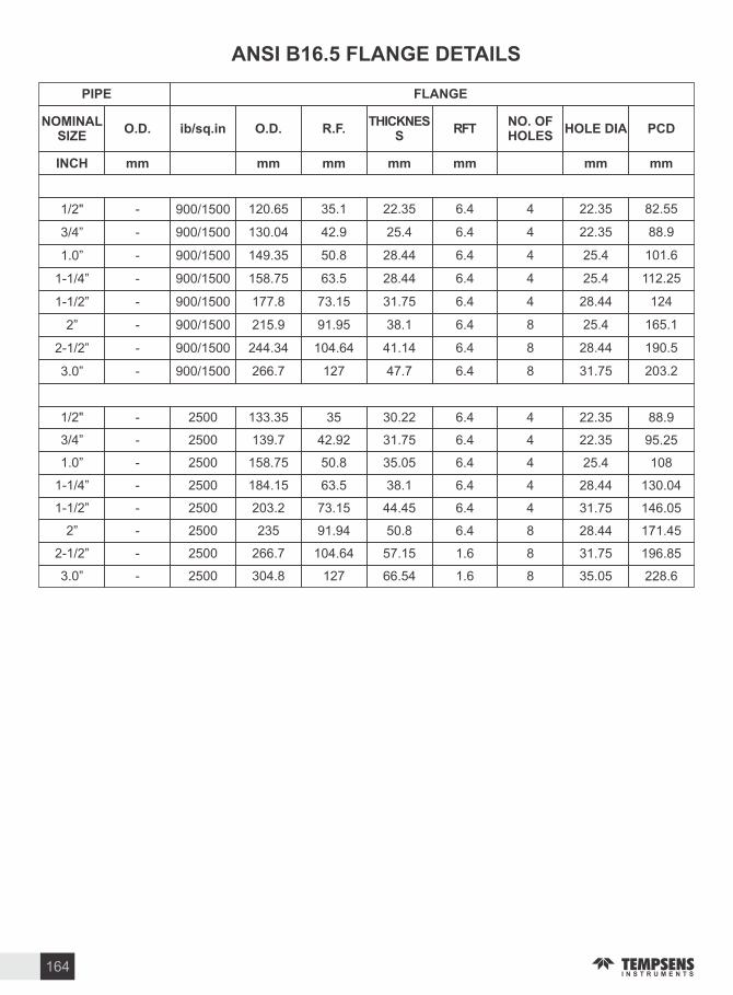
ANSI B . FLANGE DETAILS
NOMINALSI E
INCH mm
O.D.
mm mm mm mm mm mm
ib s .in O.D. R.F.THIC NES
SRFT
NO. OF HOLES
HOLE DIA PCD
1 2
3 4
1.0
1-1 4
1-1 2
2
2-1 2
3.0
-
-
-
-
-
-
-
-
900 1500
900 1500
900 1500
900 1500
900 1500
900 1500
900 1500
900 1500
120.65
130.04
149.35
158.75
177.8
215.9
244.34
266.7
35.1
42.9
50.8
63.5
73.15
91.95
104.64
127
22.35
25.4
28.44
28.44
31.75
38.1
41.14
47.7
6.4
6.4
6.4
6.4
6.4
6.4
6.4
6.4
4
4
4
4
4
8
8
8
22.35
22.35
25.4
25.4
28.44
25.4
28.44
31.75
82.55
88.9
101.6
112.25
124
165.1
190.5
203.2
PIPE FLANGE
1 2
3 4
1.0
1-1 4
1-1 2
2
2-1 2
3.0
-
-
-
-
-
-
-
-
2500
2500
2500
2500
2500
2500
2500
2500
133.35
139.7
158.75
184.15
203.2
235
266.7
304.8
35
42.92
50.8
63.5
73.15
91.94
104.64
127
30.22
31.75
35.05
38.1
44.45
50.8
57.15
66.54
6.4
6.4
6.4
6.4
6.4
6.4
1.6
1.6
4
4
4
4
4
8
8
8
22.35
22.35
25.4
28.44
31.75
28.44
31.75
35.05
88.9
95.25
108
130.04
146.05
171.45
196.85
228.6
164

NOMINAL SI E
PITCH
(INCHES) (P)
TPI INTERNAL THREADS EXTERRNAL THREADS THREADDEPTH RADIUS
MIN. MIN. MAX. MIN. MAX. MAX. MIN. MAX. MIN. MAX. MIN. (h) r
MA ORDIA(D)
PITCHDIA(D )
MINORDIA(D )
MA ORDIA(d)
PITCHDIA(d )
MINORDIA(d )
(1 16)
(1 8)
(1 4)
( )
(5 8)
(3 4)
(7 8)
(1 1)
(1-1 8)
(1-1 4)
(1-1 2)
(1-3 4)
(2 1)
0.907
0.907
1.337
1.337
1.814
1.814
1.814
1.814
2.309
2.309
2.309
2.309
2.309
2.309
28
28
19
19
14
14
14
14
11
11
11
11
11
11
7.723
9.728
13.157
16.662
20.995
22.911
26.441
30.201
33.249
37.887
41.91
47.8
53.746
59.614
7.142
9.728
12.301
15.806
19.793
21.749
25.279
29.039
31.77
36.418
40.431
46.314
52.267
58.135
7.269
9.254
12.426
15.931
19.935
21.891
25.421
29.181
31.95
36.598
40.611
46.504
52.447
58.315
6.561
8.566
11.445
14.95
18.631
22.587
24.117
27.877
30.291
34.939
38.952
44.845
50.788
56.626
6.843
8.848
11.89
15.395
19.172
21.128
24.658
28.418
30.931
35.579
39.592
45.485
51.428
57.296
7.723
9.728
13.157
16.662
20.955
22.911
26.441
30.201
33.249
37.897
41.91
47.803
53.745
59.614
7.509
9.514
12.905
16.412
20.671
22.627
26.157
29.912
32.889
37.537
41.93
47.443
53.386
59.254
7.142
9.147
12.301
15.806
19.793
21.749
25.279
29.039
31.77
36.418
40.431
46.324
52.267
7.033
9.04
12.126
15.681
19.651
21.607
25.137
28.897
31.59
36.238
40.251
46.144
52.087
57.955
6.561
8.566
11.445
14.95
18.631
20.587
24.117
27.877
30.294
34.939
38.952
44.845
50.788
56.696
6.427
8.432
11.289
14.794
18.453
20.409
23.939
27.699
30.066
34.714
38.727
44.62
50.563
56.431
0.581
0.581
0.856
0.856
1.162
1.162
1.162
1.162
1.479
1.479
1.479
1.479
1.479
1.479
0.125
0.125
0.184
0.184
0.249
0.249
0.249
0.249
0.317
0.317
0.317
0.317
0.317
0.317
(3 8)
58.135
B.S.P. THREADS DETAILS
165

WEIGHT AND THIC NESS OF S.S. GAUGE PIPE
NPT SI ETHREADS PER INCH
DIM A(IN)
DIM B(IN)
1 16 27 0.312 0.261
1 8 27 0.405 0.264
1 4 18 0.540 0.402
3 8 18 0.675 0.408
14 0.840 0.534
3 4 14 1.050 0.546
1 11 1 2 1.315 0.683
1 1 4 11 1 2 1.660 0.707
National Pipe Taper Thread Dimensions
Diameter
D Nominal
Inches
1 4
3 8
1 2
3 4
1
1 1 4
1 1 2
2
2 1 2
3
3 1 2
4
Outside
Diameter
mm
13.720
17.150
21.340
26.670
33.400
42.160
48.260
60.330
73.030
88.900
101.600
114.300
Schedule S
Thickness T
mm
1.240
1.240
1.650
1.650
1.650
1.650
1.650
1.650
2.110
2.110
2.110
3.050
Wt.
kg m
0.390
0.492
0.812
1.035
1.311
1.675
1.926
2.422
3.744
4.584
5.254
8.490
Schedule
S Thickness
T mm
1.650
1.650
2.110
2.110
2.770
2.770
2.770
2.770
3.050
3.050
3.050
6.020
Wt.
kg m
0.498
0.638
1.013
1.300
2.123
2.734
3.160
3.990
5.340
6.550
7.520
16.320
Schedule
S Thickness
T mm
2.240
2.310
2.770
2.870
3.380
3.560
3.680
3.910
5.160
5.490
5.740
8.560
Wt.
kg m
0.643
0.855
1.285
1.712
2.540
3.443
4.110
5.520
8.760
11.460
13.770
22.660
Schedule S
Thickness T
mm
3.020
3.200
3.730
3.910
4.550
4.850
5.080
5.540
7.010
7.620
8.080
13.490
Wt.
kg m
0.807
1.113
1.640
2.230
3.285
4.534
5.496
7.593
11.580
15.550
18.910
34.040
166

GLOSSARY. Abbreviations and Acron ms or Standards & Standards bodies
ANSI American National Standard Institute
ASTM American Society for Testing and Material
BS British Standard
DIN Deutche Industial Norms
IEC International Electrotechnical Commission
IPTS-68 International Practical Temperature Scale of 1968
ITS-90 International Temperature Scale 1990
IS Indian Standard
. CalibrationCalibration Checking Measuring Accuracy against an External Reference Standard
Calibrator Device used for or in calibration
Drift Change in the value of a parameter due to operational influence (e.g. temperature variation ageing)
Dry Block Calibrator A thermal device which does not use a fluid medium as a temperature source
Fixed Points(Temperature) Temperature defined by physical laws, Change of state of pure material
Fixed Point Cell A device used to provide a fixed point temperature
Primary Standards Those derived from the best available equipment. Pertaining to establishing the International Temperature Scale
Reference Probe Certified Probe used as a comparison standard
Secondary Standard Traceable to primary standard
Standard Resistance Thermometer A laboratory standard probe for the highest possible accuracy of measurement
Stirred Liquid Bath A controlled thermal reference which uses a stirred liquid medium
Temperature Calibration Point A temperature value at which calibration is performed by comparison or direct techniques
Thermal Calibration Calibration using a temperature source (I.e. not electrical)
Thermal Reference Controller Temperature Source
Tolerance Stated Uncertainties
Triple Point of Water A thermodynamic state (of water) in which the gas, Liquid and solid phases all occur in equilibrium. alue 0.01 C
Uncertainties Possible Inaccuracies
. ControlAuto-manual Selection of closed loop (Automatic) or open loop (manual) regulation
Auto-tune Automatic selection of the control terms, usually P, I & D
Calibration Checking Measuring accuracy against an external reference or standard.
Closed Loop Automatic control via feedback
Cold Junction Built in, automatic cementation for ambient temperature
Compensation(Automatic) ariations when using a thermocouple sensor
Control Output The means of controlling energy regulation in the process
D Abbreviation of Derivative
Dead-band On-Off hysteres to prevent excessively rapid power switching
Derivative Time Constant A measure of derivative term sensitivity
Hysteresis Dead-band defined in on-off switching
I Abbreviation of Integral
Integral Time Summation period for offset computation
Offset Difference between set-point and resultant control point
On-Off Power regulation by simple on-off switching (e.g. thermostat)
Open Loop System not utili ing feedback (I.e. not capable of automatic control.)
Output Control signal or communication data
Overshoot The amount by which the process temperature exceeds set- point on start up
P Abbreviation of propotional
167

Process The system being monitored or controlled
Process ariable The parameter monitored or controlled
Proportional Band The control band within power is regulated between 0 and 100 usually expressed
Set-Point Desired process temperature set by the operator
Start-Up Dynamic state of the process after switching on
Thermal Mass Heat storage effect in the process
. Instrumentation GeneralClosed Loop Facility for automatic control by means of temperature feedback from the process
to the Instrument
Control Regulation of process energy to achieve a desired temperature
Control Regulation of process energy to achieve a desired temperature
Data Acquisition Gathering data from a process, Usually electronic, Usually automatic
Indication Analogue or digital readout of data
Input The connector point for a sensor or defines type of sensor
Isolation Electrically isolation condition
Linearisation Matching the transfer characteristic of the sensor if non-linear (strictly de-linearisation)
Logging Recording data
Non-linear Not a straight line transfer characteristics
Open loop System not utili ing feedback
Process The system being monitored
Signal Conditioning Changing the electrical characteristics of a sensor signal
Stability The ability of an instrument to maintain a constant output with the application of a constant input
Temperature Coefficient Transmitter An Amount by which a parameter varies due to temperature Instrumentation. Usually converts to 4-20mA.
. Thermometere - GeneralAbsolute ero The lowest possible temperature of a body due to absence of molecular motion.
Stated as 0 elvin, equivalent to -273.15 C
Alpha The temperature coefficient of resistance of a sensing resistor. Expressed as C.
Alumina Aluminium Oxide (a refectory material)
Base Metal Thermocouple Thermocouple utili ing base metal
Boiling Point The equilibrium temperature between a liquid and its vapour
Ceramic Refractory insulating material
Coefficient ( , , ) Used in the Pt100 Characteristics polynomial they define the temperature resistance relationship.
Cold Junction Reference junction of a thermocouple
Cold Junction Compensation for thermocouple reference junction
Compensation (CJC) Temperature ariations
Colour Codes Means of cable and sensor type identification applied internationally according to appropriate standard
Compensating Cable Used for connecting thermocouple to instruments the conductor use low cost materials which have a similar ambient thermal emf relationship to that of the thermo element but at lower cost
Compression Fitting Type of threaded fitting which compresses on to the probe sheath to provided a pressure tight coupling
Cryogenic A term for very low temperatures, usually associated with liquified gases (-180 C)
Drift Change in the value of a parameter due to operational influence (e.g. temperature variation againig)
EMF Electromotive force (sometimes referred to as thermo-voltage).
Excitation Current Current supplied to an appropriate sensor or transducer to provide excitations
Exposed junction A thermo junction not protected by sheath material. Used when fast thermal response is required
168

Extension Cable Thermocouple connecting cable which uses conductors in true thermocouple alloy
Fabricated Made from component part e.g. thermocouple assembly made from tubing, wire and insulating material as opposed to one made using mineral insulated cable
Fitting Items used to secure probes into machinery e.g. compression gland threaded bushes, bayonet fittings
Fixed Points (Temperature) Temperature defined by physical laws, change of state of pure material
Flange Form of disc through which probe is installed into a process
Free ing Point The fixed temperature point of a material which occurs during the transition from a liquid to solid state. Also known as melting point for pure materials
Fundamental Intervals Thermometer resistance change over the range to 0 to 100 C
Grounded Hot Junction Thermocouple configuration in which the thermo element is electrically common to the sheath
Hot Junction Measuring junction of thermocouple
Ice Point 0 C
Immersion Placing of probe into the process medium (I.e. immersion into some medium)
Insert Replaceable probe assembly located inside outer sheath
Insulation Resistance alue of resistance measuring between the sensor wire and sheath
Interchangeability Describes how closely a sensor adheres to its defining equation
Isothermal Equal temperature
Lagging Extension Probe or pocket extension to allow for thickness of pipe or wall lagging
Leg Common term for one thermoelement wire in a thermocouple circuit
Linearity A deviation in response from straight the value of sensor
Loop Resistance the total resistance of thermocouple circuit
Measuring Junction Thermoelement measuring junction (Hot junction)
Melting Point The temperature at which a substance convert from the solid to liquid phase. This is same as the free ing point for pure material
Metallic Pertaining to presence of metal in sheath material as opposed to non-metallic
MI Abbreviation for mineral insulated as used in sensor cable
Mineral Insulated Type of cable construction used in thermometry. Conductors are insulated from sheath by compressed refractory oxide powder
Nobel Metal Rare metal, usually platinum Rhodium alloys
Noise Unwanted electrical interference picked up on a single cable
NTC Negative temperature coefficient (of resistance)
Parallel pair Wire construction where two single conductor are laid parallel
Platinum resistance Thermometer Platinum temperature sensor whose resistance varies with temperature
Polarity Determines the direction of current flow its operating environment
Protection Tube A tube (Sheath) which protect a sensor from its operating enviroment
PTC Positive temperature coefficient (of resistance)
Rare Metal Thermocouple Thermocouple made of rare metal thermoelement
Reference Junction Of the thermocouple, usually referred to the ice point
Resistance thermometer Temperature sensor, usually platinum, whose resistance varies with temperature
Response Time A measure of thermal sensitivity applied to sensors. The time required for a sensor to reach 63 of the step change temperature under particular conditions
R0 The value of thermometer resistance temperature sensors at 0 C
RTD Abbreviation for resistance temperature detector
Self-Heating Heating effect due to current flow in the sensing resistance thermometer
Sensing Resistor The sensing element of a resistance thermometer
Stability The ability of a sensor to maintain a consistent output with the application of a constant input
Stem sensing Sensing over a finite length as opposed to just the tip
Tails Connecting wires emanating from the sensor
Thermal conductivity The ability of a material to conduct heat
Thermal Gradient The distribution of different temperature in and across an object
Thermal Mass Heat storage effect in the process
Thermistor A form resistance thermometer, usually a NTC type
Thermocouple type Defines the of thermoelement e.g. J, , T, N, R, S, B etc.
169

Thermoelectric Electrical activity resulting from the generation of thermovoltage
Thermoelement The two dissimilar conductor and their junction forming a thermocouple
Thermojunction The junction formed between the dissimilar conductor of thermocouple. Usually describes the measuring junction.
Thermowell Used to protect sensor probes against aggressive media. Effectively a pocket or well into whichthe probe is inserted
The Film Sensing resistor in thin form (also flat film)
Tip Sensing Temperature sensing at the tip of a probe only as opposed to along its length
Transducer A device which converts energy from one form into another. Transducer often describes a sensor
Transfer Function Input Output characteristic of a device
Transmitter A device for amplifying a sensor signal in order to permit its transmission to remote instrumentation. Usually converts to 4-20mA
Twisted Pair Two insulated conductor twisted wires in thermocouple circuit minimise noise pick-up
Wheatstone bridge Resistance bridge for precision measurement of Pt-100 sensing resistor
Wirewound Sensing resistor in wirewound construction.
170

171

172

173

174

COLOR CODE OF COMPENSATING
CABLES & THERMOCOUPLES

CHINAWUXI Tempsens Instruments Co. Ltd.Rm 911,ShiDaijieDou, No.655, Hubin Rd.,Binhu District, Wuxi, Jiangsu, CHINAPh.:+86-510-85116563Fax.:+86-510-85116563Email: [email protected]
Tempsens Instruments (l) Pvt. Ltd. U# llA-190, Road No.5, M.I.A,.Udaipur-313003 (Rajsthan) INDIAPh.:+91-294-3052900Fax.:+91-294-3052950Email: [email protected] [email protected]
Tempsens Instruments (l) Pvt. Ltd. U# lB-188A, Road No.5, M.I.A,.Udaipur-313003 (Rajsthan) INDIAPh.:+91-294-3057700 to 800Fax.:+91-294-3057750Email: [email protected]
INDIATempsens Instruments GmbHLoehestrasse 37,53773 Hennef, GERMANYPh.:+49-2242-8703-22Fax.:+49-2242-8703-20Email: [email protected]
GERMANY
www.thermowellworld.com | www.temperaturecalibration.in | www.glassthermocouples.com | www.compensatingcables.net | www.marathonheater.in
w w w. t e m p s e n s . c o m
THERMAL ENGINEERING SOLUTIONS
CERTIFICATES