Meta-photography: A Self-critical Mirror for Photography in Digital Culture
Upload
khangminh22Category
view
0download
0
Louisiana State UniversityLSU Digital Commons
LSU Historical Dissertations and Theses Graduate School
1969
Techniques of Photography in Physical EducationResearch.Kenneth Mclellan Purdy JrLouisiana State University and Agricultural & Mechanical College
Follow this and additional works at: https://digitalcommons.lsu.edu/gradschool_disstheses
This Dissertation is brought to you for free and open access by the Graduate School at LSU Digital Commons. It has been accepted for inclusion inLSU Historical Dissertations and Theses by an authorized administrator of LSU Digital Commons. For more information, please [email protected].
Recommended CitationPurdy, Kenneth Mclellan Jr, "Techniques of Photography in Physical Education Research." (1969). LSU Historical Dissertations andTheses. 1613.https://digitalcommons.lsu.edu/gradschool_disstheses/1613

This dissertation has been microfilmed exactly as received 70-260
PURDY, Jr ., Kenneth McLellan, 1934- TECHNIQUES OF PHOTOGRAPHY IN PHYSICAL EDUCATION RESEARCH.
The Louisiana State University and Agricultural and Mechanical College, Ed.D., 1969 Education, physical
University Microfilms, Inc., Ann Arbor, Michigan

TECHNIQUES OF PHOTOGRAPHY IN PHYSICAL
EDUCATION RESEARCH
A Dissertation
Submitted to the Graduate Faculty of the Louisiana State University and
Agricultural and Mechanical College in partial fulfillment of the requirements for the degree of
Doctor of Education
in
The Department of Health, Physical, and Recreation Education
byKenneth McLellan Purdy, Jr.
B.S., Louisiana State University, 1957 M.S., Louisiana State University, 1960
May, 1969

ACKNOWLEDGMENTS
The writer wishes to take this opportunity to express his
deepest appreciation to Dr. Francis A. Drury, under whose supervision
this work was undertaken, for his incessant interest in its progress
and for his most valuable instruction. Thanks are also in order to
those individuals who aided the writer by serving as performers in
front of the cameras. The writer would like to express his gratitude
to the D. B. Milliken Company for providing a precision high-speed
camera for use in this research.

t a b l e : of c o n t e n t s
ACKNOWLEDGMENTS....................................................... 11
LIST OF T A B L E S ....................................................... vii
LIST OF ILLUSTRATIONS.......................... viii
A BSTRACT.............................................................. xi
CHAPTER PAGE
I. INTRODUCTION .................................................... 1
Background.................................................... I
The Problem................................................... 4
Statement of the p r o b l e m ............................ 4
Delimitations.......................................... 4
Definitions of Terms Used.................................... 4
Need for the S t u d y .......................................... 5
Organization of the Study.................................... 6
II. REVIEW OF THE LITERATURE...................................... 8
Historical Survey of Selected Techniques .................. 8
The Technical Application of Photography in
Physical Education Research. . . . . .................... 15
III. FACTORS IN THE SELECTION OF PHOTOGRAPHIC TECHNIQUES......... 21
Distinction Between Rapid Events . ......................... 21
Type of Event................................................. 21
Time Magnification.......................................... 22
Stopping Movement............................................. 23
Rotational and Periodic Motion ............................. 24
iii

CHAPTER PAGE
The Effects of Viewing Distance on Perspective . . . . . . 26
IV. CHARACTERISTICS OF EXPOSURE AND F I L M ......................... 27
Film Exposure................................................. 27
Film Characteristics............... '........................ 30
Film S p e e d ................................................. 32
Graininess............... 32
Resolving Power............................................. 33
Film Latitude............. 33
Film Contrast............................................... 33
Exposing and Processing F i l m ............................... 34
Calculating Shutter Speed and F. Ratio ...................... 35
V. STILL PICTURE TECHNIQUES ...................................... 39
Characteristics of 35mm Cameras............................. 39
Arresting Motion ............................................. 40
Criteria for Good Action Photography ................ 42
F. Number...................................................... 43
Depth of F i e l d ............................................... 43
Processing of F i l m ........................................... 44
Latent Grid Technique........................................ 47
Copying G r i d ............................................... 47
Photographing Posture Subject............................. 49
Combining Grid and Subject Photographically............. 52
Graphic Arts D i s p l a y ......................................... 54
Filmstrip Production ......................................... 57
iv

CHAPTER PAGE
Criteria for Production of Filmstrip.................... 57
Chronocyclography ............. 59
Photographic Procedure for Taking
Chronocyclographic Photograph................... 59
Chronocyclographic Measurement . . ...................... 63
Stroboscopic Photography . . . . . ................. . . . 63
Stroboscopic Seeing....................................... 64
Construction of Simple Stroboscope ...................... 65
Photographic Procedure for Taking
Stroboscopic Photograph................................. 66
Velocity Measurement From Stroboscopic Print ............ 69
Other Applications of Stroboscopic Photography ......... 71
Single Flash Photography ................................... 72
The Kerr Cell................................................ 72
VI. MOTION PICTURE PHOTOGRAPHY................................... 75
The 8mm Motion Picture Camera............................... 76
The Variable Shutter ........................................ 77
Measuring Framing Rate ..................................... 81
Measurement of Framing Rate by Film Exposure........... 81
Measurement of Framing Rate by Use of Strobotac.......... 82
Framing Rate and Temperature............................... 83
Types of 16mm Motion Picture Ca m e r a s ...................... 83
Lighting the Event . . . . . ............................... 87
Photographing a Golf Ball Drive............................. 87
v

CHAPTER PAGE
Quantitative and Qualitative Analysis of Film.............. 88
Processing Test Strips of F i l m ......................... 91
Calculating Exposure From Shutter Speed.................. 93
Grid Viewing Procedure . ...... 93
VII. SUMMARY AND CONCLUSIONS........... . .......................... 94
SELECTED BIBLIOGRAPHY................................................. 98
APPENDIX ........................................................ 103
V I T A ................................................................... 105
vi

LIST OF TABLES
TABLE PAGE
I. Shutter Speed Table for Taking Pictures of
Moving Objects With a Still Picture Camera........... 25
II. Comparison of Various Systems of Emulsion
Speed Values of F i l m s ...................................... 36
III. Depth of Field Table for Leitz 50mm Lens............. 46
IV. Shutter Speed Table for a Bolex 8mm Reflex
Motion Picture Camera ...................................... 79
vii

LIST OF ILLUSTRATIONS
ILLUSTRATION PAGE
1. A Reproduction of Serial Photographs of a Man Running
Originally Taken by Eadweard Muybridge................. 12
2. The Photographic Results of an Improperly Read
Light M e t e r .................................................. 29
3. The Photographic Results of a Properly Read
Light Meter ............... 29
4. The Placement of the Light Meter Close to the Subject
to Secure Proper Exposure ................................... 31
5. A Gloseup of a Light Meter Showing the F. Ratio Scale,
Shutter Speed Scale and Film Speed Scale.................... 38
6. A Photograph Taken at 1/500 of a Second of the Drive
of an Expert Golfer . . . . . . ............................. 41
7. A Photograph Taken at 1/1000 of a Second of the Drive
of an Expert G o l f e r .......................................... 41
8. A Close-up Photograph of a Leitz Lens Showing the
Depth of Field Scale on the Lens B o d y ...................... 45
9. The Leitz Boowu Auxiliary Reproduction Device Attached
to a Leica IIIG in Position to Copy Grid. ......... 48
10. A Copy of Grid Photographed by the Leitz Auxiliary
Reproduction Device . . . . . . . . . . .................... 50
11. The Tape is Attached to the Thigh of the Subject
as a Point of Reference..................................... 51
viii

ILLUSTRATION PAGE
12. A Superimposed Print of Grid and Posture Subject............... 53
13. A Superimposed Print of Gymnast and Grid...................... 55
14. A Superimposed Print of Gymnast and Grid...................... 55
15. A Photographic Copy of Foot Print Test........................ 56
16. A Contact Print of the Beginning of a 35mm
Half Frame Filmstrip. . . . . . . . ........................ 60
17. A Chronocyclograph of the Right Knee Joint of a
Subject Walking Rapidly Parallel to the Camera
Film Plane..................... 62
18. The Locations of the Camera, Strobe Unit, Subject
and Background for a Strobographic Photograph ........... . 67
19. A Strobographic Print of a Golf S w i n g .............. 70
20. A Photograph of a .45 Caliber Bullet in Flight
Taken by a Camera With a Kerr Cell Shutter................. 74
21. A Print of a Whirling Badminton Shuttlecock Photographed
at a Framing Rate of 64 Frames Per Second and a Shutter
Speed of 1/152 of a Second Taken by a Bolex H-16 Camera . . 80
22. A Print of a Whirling Badminton Shuttlecock Photographed
at a Framing Rate of 64 Frames Per Second and a Shutter
Speed of 1/304 of a Second Taken by a Bolex H-16 Camera , . 80
23. The DBM-5 16mm High-speed Motion Picture Camera .............. 86
ix

ILLUSTRATION PAGE
24. A Single Frame Print of a Golf Ball Leaving a Clubhead
at Approximately 225 Feet Per Second Taken at 400
Frames Per Second at a Shutter Speed of 1/19,000
of a Second by a D. B. Milliken 16mm High-speed
Motion Picture Camera ........................................ 90
x

ABSTRACT
The purpose of this study was to provide the physical education
researcher with a basic understanding of how the camera can be used to
aid in the study and presentation of photographic material in physical
education research. Techniques which the writer has had an opportunity
to use in physical education research applications were discussed and
explained*
Included in the study was a background for the problem under
investigation. Emphasis was placed upon the limitations of the human
eye in observing motion. The summary of related literature was divided
into two sections--literature devoted to important discoveries and
applications in photographic analysis, and a review of literature of
ways photography has been used in physical education research.
The study was limited to the discussion and explanation of tech
niques of photography with the 35mm still picture camera and the 8mm
and 16mm motion picture cameras.
Technical factors which one should consider when recording a
visual record for analysis or presentation were discussed. Attention
was given to the techniques of obtaining accurate exposure readings,
and the properties of film were discussed. Still picture techniques,
such as latent grid techniques, graphic arts display, filmstrip pro
duction, chronocyclography, stroboscopic photography, single flash
photography and the use of the Kerr cell in photography, were presented.
Motion picture techniques that were discussed include the use and
xi

limitations of the 8mm camera, filming and analytical procedures of
16mm cameras, procedures for determining framing rate, the use and
effects of the variable shutter, and development and analytical pro
cedures of cine’ film.
The following statements are a summation of the still and motion
picture techniques that were presented in this monograph:
1. To arrest motion, one must reduce the image blur on film
to a point where it cannot be seen upon enlargement.
2. Shutter speeds of 1/1,000 of a second should be used to
arrest body and limb movements with a 35mm still picture
camera.
3. Single flash exposures of extremely short duration
(1/40,000) are necessary to stop clubs or balls traveling
at velocities in excess of 100 feet per second.
4. Multiple flash strobographic photography is the proper
technique to use for multiple images on a single negative.
5. Latent grid printing is an effective way to link space
to time without the use of active background grids.
6. Copy work should be done by an auxiliary device attached
to the camera.
7. Photographs should be printed on Kodabromide Type A en
larging paper for inclusion in studies which present photo
graphs in the body of the work.
8. If positive prints are not needed, 8mm film may be used in
analytical studies.
xii

9. Chronocyclography is a useful technique in securing light
tracings of certain points on the body of the subject.
10. The 16nun camera becomes a good analytical tool if the
framing rate of the camera is established.
11. In order to get negatives for producing selected positive
prints, the shutter speed of the motion picture camera must
freeze the motion of the subject,
12. A variable shutter should be used if faster shutter speeds
than the normal open shutter are needed.
13. To study activities which involve striking actions, it is
helpful to use a cine’ camera with a framing rate of 200
frames per second.
xiii

CHAPTER I
INTRODUCTION
I. BACKGROUND
Beyond the horizon of human vision lies a whole world of
rapid motion. Man has realized the limitations of the eye in ob
serving rapid movement. He has devised techniques of recording
movement by the use of high speed photography.
The main problem in recording fast movement is the utili
zation of short exposure times. The only way of avoiding movement
in a photograph is to shorten the exposure so that the amount of
movement of the subject during exposure is insufficient to produce
a blurring of the record.
The analysis of movement cannot be fully done by taking
good still pictures. It is usually necessary to produce a series
of pictures which links time to the pictures visually.
The invention of flexible sensitized transparent film pre-
ceeded the invention of cinematography. The primary difficulty in
the use of high speed movie cameras was the lack of sufficient light.
Many researchers looked for techniques to supply enough light for
high speed motion picture photography.^"
^"George A. Jones, High Speed Photography (New York: JohnWiley and Sons, 1952), p. 3.
1

2
There are characteristics of vision that limit the effective
ness of the human eye as an optical recording instrument in the
study of motion. Human vision is not only physical but is greatly
influenced by psychological factors. Yet, the eye is the only thing
one has to interpret motion. A brief study of the visual process
is necessary for one to understand the basics of photographic motion
analysis.
The human eye is about 1 inch in diameter. Light enters
the eye, passes through the lens, the vitreous humor, and strikes
the retina. "Accommodation" or the focusing of the eye on near and
far objects is an involuntary and voluntary muscular distortion of
the lens.^
At a distance of 5 feet, the area of acute vision of the eye
is less than 1 inch in diameter. This small area of acute vision•icauses the eye to rotate constantly when studying a broad field.
This characteristic of vision greatly limits the observer's
capacity to see clearly rapidly moving objects. The muscles con
trolling the movement of the eye are involuntary and voluntary. As
the image velocity is increased, visual contact becomes hard to main
tain and the retinal image lapses into a blur.
Another important characteristic of human vision is its
capacity to interpret actions of extremely short duration. One
2William G. Hyzer, Engineering and Scientific Photography (New York: MacMillan Company, 1962), p, 6.
3Ibid., p. 7.

knows from personal experience that if an event takes place too rap
idly, only the effects before and after the event are visually
recorded. As a general rule in motion picture work, it is assumed
that the eye requires 1/4 second to record an indelible mental image
of a simple action. If the action is more complex, more time is
required to interpret it visually.^
One shortcoming of the eye in the comparative study of motion
is its lack of permanency of the visual record. The mental image
decays rapidly, and the exact detail is not retained for a very long
period. It is impossible for the eye to directly compare events
that do not occur simultaneously. Photography aids the eye in this
task, adding to the effectiveness of visual perception.
The eye can detect a minimum movement of one radian per hour,
or one mile per hour at a distance of one mile. At velocities much
slower than this, it is almost impossible for the human brain to5detect movement.
Intermittent motion has an effect on the viewer's vision.
If one looks at a television screen, one is not aware that the scan
ning rate of the tube is about 30 times per second. The viewer
sees one continuous image.
These limitations of vision establish the need for exacting
analytical methods for the study of motion. It was stated earlier
^Ibid., p . 8.
5Ibid.

that the eye takes about 1/4 second to analyze a typical action. For
example, one cannot see what happens when a golf ball is hit. The
duration of this phenomenon is too short to be visually analyzed.
By magnification or high-speed or stop-action photography, this ac
tivity's duration can be stretched to a value within the limits of
visual perception. Thus, the hitting of the golf ball can be observed
and studied.
II. THE PROBLEM
Statement of the Problem
The purpose of this study was to provide the physical educa
tion researcher with a basic understanding of how the camera can be
used to aid in the study and presentation of photographic material
in physical education research.
Delimitations
This study was limited to the discussion and explanation of
techniques of photography with the 35mm still picture camera and
the 8mm and 16mm motion picture cameras.
III. DEFINITIONS OF TERMS USED
Exposure. In terms of practical photography, this term means
the particular combination of lens aperture and shutter speed that
must be chosen to produce a good negative.
High-speed motion picture camera. As used in this monograph

any camera which can expose film at a rate of 64 frames per second or
more is classified as a high-speed motion picture camera.
Motion picture camera. Within the framework of this study,
this term refers to a camera which exposes film intermittently, thus
securing a series of individual photographs which, when projected,
simulate motion.
Still picture camera. For the purposes of this study, this
term describes a camera which exposes one film frame upon release of
the shutter and must be advanced manually before further frames can
be exposed.
Stroboscopic flash. In this study this term refers to the
repetitive production of highly actinic light of short duration.
IV. NEED FOR THE STUDY
One of physical education's unique characteristics is motion.
There has been much film exposed, but there is very little information
on securing quantitative photographic information for physical edu
cation research. There is little published information on the tech
niques of photography that are necessary to produce photography of
physical education activities for analytical purposes.
The importance of photography as a scientific and technological
tool has increased greatly during the last 25 years. In order for a
physical educator to use photography, he must search the available
related literature to gain knowledge of techniques applicable to
physical education research.

It has been the writer's experience that there are many individ
uals who would like to use photography as one of the tools in their
research, but they have no source or manual available to read to
acquire these skills.
V. ORGANIZATION OF THE STUDY
In Chapter I a background is provided for the problem under
investigation. Emphasis is placed upon the limitations of the human
eye in observing motion.
Chapter II presents a summary of related literature. The
review is divided into two sections--literature devoted to important
discoveries and applications in photographic analysis, and a review
of literature of ways photography has been used in physical education
research.
Chapter III is devoted to acquainting the reader with technical
factors which one should consider when recording a visual record for
analysis or presentation.
Exposure and film are discussed in Chapter IV. Attention is
given to the techniques of obtaining accurate exposure readings, and
the properties of film are discussed.
Chapter V is devoted to still picture techniques. Included
in this chapter are latent grid techniques, graphic arts display,
filmstrip production, chronocyclography, stroboscopic photography,
single flash photography and the use of the Kerr cell in photography.
Chapter VI is devoted to motion picture techniques. A brief
discussion of the use and limitations of the 8mm camera is presented.

7
The bulk of the chapter is devoted to filming and analytical procedures
of 16mm cameras. Procedures for determining framing rate are discussed.
The use and effects of the variable shutter are presented. Development
and analytical procedures of cine' film are discussed with special
emphasis on film taken at framing rates of 64 frames per second and
faster.
A summary of the study and concluding statements are presented
in Chapter VII.

CHAPTER II
REVIEW OF THE LITERATURE
The review of literature is divided into two sections: a
historical survey of selected techniques or inventions in analytical
photography and a review of physical education literature which
discusses the technical application of photographic techniques.
I. HISTORICAL SURVEY OF SELECTED TECHNIQUES
Aristotle noted that light entering a small hole in the wall
of a darkened room casts on the opposite wall an inverted image of
whatever lies outside the hole. Leonardo da Vinci’s manuscripts
give a clear description of the darkroom or camera obscura, as the
device was later called.
Many chemical substances are changed by exposure to light.
Among these chemical substances is silver. Johann Heinrich Schulze
observed the light sensitivity of silver in his classic experimentnof 1727. From this time forward, the recording of permanent images
on plates or film grew and the applications of photography expanded.
Fox Talbot, in 1851, used an electric spark to obtain a sharp
^Beaumont Newhall, Photography: A Short Critical History(New York: The Museum of Modern Art, 1938), p. 11.
2Ibid., p. 12.
8

93photograph of a rapidly revolving newspaper. Multiple camera serial
photography of motion analysis began in 1877 when Muybridge made a
study of the leg movements of race horses.^ These studies were ex
panded to other animals including man.
Edward James Muggeridge was born at Kingston-on-Thames in 1830
and later emigrated to America and became a professional photographer.
In 1872 he adopted the name of Eadweard Muybridge. Muybridge's work
started at Stanford in 1877 when he set up a number of cameras side
by side at a race track. The string was broken as a horse passed
and led to the release of the shutter. He used wet collodion plates,
which were very slow, and subsequently, produced weak outlines of the
limbs of the horse.®
Muybridge gave an exhibition of his photographs of animals in
motion in Paris in early 1881. The Paris showing was not the only
showing of the fantastic Muybridge photographs, for by late 1881
Muybridge had achieved an international reputation as a great7scientific photographer.
^H. F. Talbot, "On the Production of Instantaneous Photographic Images," Philosophical Magazine and Journal of Science, 3:73-77, 1852..-
^ J . D. B. Stillman, The Horse in Motion (Boston: Osgood andCompany, 1882), p. 21.
^Eadweard Muybridge, The Human Figure in Motion (New York:Dover Publications, Inc., 1955), p. 8.
6Ibid.
^Ibid., p . 9.

In 1883 Muybridge received news that the University of
Pennsylvania was willing to underwrite an ambitious new program of
photographic research on human motion. The men and women who per
formed before his battery of cameras came primarily from the univer
sity staff. The "professor of physical culture," the "champion runner,
"a well-known pugilist" and instructors at the Fencing and Sparring
Club were among the male performers. The women were chiefly profes-O
sional artists' models, since many of them appeared nude.
The technique used by Muybridge in his Pennsylvania work was
an improvement of his Palo Alto procedure. The performers passed in
front of a whitened background some 120 feet in length. This back
ground was gridded with vertical and horizontal lines five centimeters„ 9 apart.
Muybridge had 24 fixed cameras plus two portable batteries of
12 cameras each. Muybridge placed the three batteries of cameras at
right angles to each other and simultaneous exposures could be taken
by means of an ingenious electrical system. This system consisted of
a motor-driven metallic brush passing over a disc-like segmented
commutator. The speed of the brush could be controlled, thereby
controlling the interval between exposures. When the brush came in
contact with each segment of the commutator, an electric switch was
closed which actuated an extro-magnetic device which could release
up to three separate camera shutters simultaneously, depending upon
®Tbid., p . 10.
9Ibid.

11
how many cameras were connected to the system. Muybridge also connected
a tuning fork into the circuit. This fork was vibrating 100 times per
second. As each exposure was made, the fork's movement was exaggerated
and the record was made on a sheet of blackened paper. From the number
of marks on the blackened sheet of paper, the length of each exposure
and the time between exposures could be calculated and the length of
each exposure could be ascertained.^®
Muybridge estimated that his most rapid exposure at Pennsylvania
was approximately 1/6,000 of a second--an exposure which he felt was
rarely needed in his work.
Photography began on the Pennsylvania campus in the spring of
1884 and was finished during the fall of the following year. Muybridge
averaged 500 negatives a day and, in summation, over 100,000 negatives
were taken and processed.
Muybridge spent the next several years selecting and preparing
prints for publication. In 1887, the University of Pennsylvania
issued 781 plates. The price for these plates packaged in leather
portfolios was $500.^
Illustration 1 on page 12 is a reduced reproduction of one of
Muybridge's plates published in 1887.
Marey in France, during the same period of time as Muybridge's
work, made a photographic gun for taking several pictures of birds in
10Ibid., p. 11.
^ I b i d ., p. 12.

ILLUSTRATION 1
A REPRODUCTION OF SERIAL PHOTOGRAPHS OF A MAN RUNNING ORIGINALLY TAKEN BY EADWEARD MUYBRIDGE
2

13
flight. Marey's camera took 12 exposures per second at a shutter speed12of 1/720 of a second. Marey also used his photographic gun to shoot
pictures of humans. In order to obtain adequate exposure and separation
of the images, Marey clothed his human subjects in white and made them
move in front of a black background. He became quite interested in13obtaining multiple exposures on a single plate.
To obtain multiple exposures on a single plate of film, Marey
used a hand-cranked disc with a series of holes near the edge passing
in front of the lens of the camera. In using this technique, he was
successful in obtaining 1/500 second exposures at 1/10 second
intervals.^
Single-frame techniques have also had a continuous development.IS 16In 1832, Plateau and Stampfer invented the stroboscope to see
motion that was formerly unseen.
E, Mach, in 1816, devised a cechnique to study fast moving
12e . J. Marey, Movement, translated by E. Pritchard (New York: Appleton and Company, 1895), pp. 50-53.
l3Ibid.14Ibid., p. 54.
■^J. A. F. Plateau, "Des illusions d'optique sur lesquelles se fonde le petit appareil applele recemment Phenakistiscope," Annales de Chimie et de Physique, 53:304-308, 1833.
16S. Stampfer, "Ueber die optischen Tauschungs-Phanomeme, welche durch die stroboscopischen Scheiben (optischen Zauberscheiben) hervorgebracht werden," Jahrbucher k. k. Polytechnisches Institut,Wien, 18:237-258, 1834.

14
projectiles. Mach's methods are still in use today and are becoming
more popular in our space-age photography,^
In 1929 , Cranz and Schardin secured a series of high-speed
photographs by using an arrangement of box cameras, each with its1 8own triggered spark light source.
H. E. Edgerton, in 1931, pointed out that a mercury arc could
be made to give short flashes of highly actinic light, thus enabling
both shutter and optical compensator to be eliminated. Edgerton
increased the light-output efficiency by inventing the inert gas
flash tube. This development has made the strobe light a very common19camera accessory.
Another approach to short exposures was made possible by the
discovery in 1875 of the Kerr effect. It was not until 1948 that the
full use of the Kerr cell was employed. This was made possible by20brighter light sources and faster photographic emulsions.
^ E . Mach, "Ueber die Momentan-Beleuchtung bei Beobachtung der Lichtwellenschlieren," Annalen der Physik and Cheraic, 159:330-331, 1876.
Cranz and H. Schardin, "Kinematographie auf ruhendem Film und mit extrem hoher Bildrequenz,1' Zeitschrift fur Physik, 56:147-183, 1929.
^ H . E. Edgerton, "Stroboscopic and Slow-motion Moving Pictures by Means of Intermittent Light," Journal of the Society of Motion Picture and Television Engineers, 18:356-364, March, 1932.
2®A. M. Zarem, F. R. Marshall, and S. M. Hauser, "Millimicrosecond Kerr Cell Camera Shutter," Review of Scientific Instrumentation, 29:1041-1044, 1958.

15
II. THE TECHNICAL APPLICATION OF PHOTOGRAPHY
IN PHYSICAL EDUCATION RESEARCH
The technical application of photographic procedures to physi
cal education research is limited. There is little information on
the use of photographic techniques in this field.
Cureton states that:
Fairly precise analysis of the external mechanics of many acts of skill may be made by cinematography . . . Thus, athletic performance can be studied and interpreted in terms of recognizable scientific principles instead of the emperical guesses and vague suppositions which have largely characterized the coaching or sports literature up until very recently.2-̂
Cureton's article approaches the subject of photography with
the assumption that the reader knows how to secure the necessary
analytical photographs. The article is quite good on the principles
of physics used in the analysis of an activity.
A quote of Cureton1s conclusions follows:
Analytical work on films promises to contribute much to technical knowledge of athletic action. Intensive work of this type is just now beginning to be reported at an accelerated rate.The facts derived by the painfully slow process will accumulate to make possible much more scientific views of the principles employed in athletic performances. Such knowledge should contribute greatly to the improved manuals of pedagogy.22
MacEwan and Howe developed an objective method of grading
posture. A camera was used to obtain photographs of their subject.
The camera had a Gaerz Dagor 6-inch lens. The subjects were illuminated
^Thomas Kirk Cureton, "Elementary Principles and Techniques of Cinematographic Analysis," Research Quarterly, 10:4-5, May, 1939.
22Ibid.. p. 22.

16
by four 1,000 Watt lamps and an exposure of 0.1 second was used. The
camera was loaded with a roll of photostat paper 40 feet long and
2 1/4 inches wide. Sixty pictures could be taken on this roll before 23reloading.
The negative was removed and developed immediately while the
subject was still present. The final print was ready for the subject
to take into an adjoining room for a posture lesson in less than 20
minutes. The camera was fixed in a rigid crane at one end of a
4-by-20-foot room. Behind the subject was a background of CantonA I
flannel dyed a deep Turkey red.”
Before the subject entered the photography room, 11 light
aluminum pointers, 9 cms long and 4 rams wide were attached to the
skin by means of adhesive tape. These pointers were affixed to the
back along the spine. The purpose of these pointers was to indicate2Sthe real character of the anterior-posterior curve of the spine.
The authors then developed a unique method of grading these 26photographs. Considering when this work was done, it shows a
tremendous amount of imagination and an excellent procedure for
objective grading of posture.
23charlotte MacEwan and Eugene C. Howe, "An Objective Method of Grading Posture," Research Quarterly, 3:144-157, October, 1932.
24Ibid., p. 147.
25Ibid.
26Ibid.

17
Hubbard and Seng took movies of major league batters during
batting practice. The camera used was an Eyemo 35mm camera operated
at 24 and 48 frames per second. The camera and operator were pro
tected by a movable screen. Behind the batter was a mirror 2 feet
by 3 feet placed on a stand. The mirror provided a simultaneous view
of the batter and the pitcher and ball flight. This study is an
excellent example of the merging of two analytical tools, namely
electromyography and photography.^^
Lafler studied fancy diving in terms of the mechanical laws
acting on the body. Lafler suggested that in future studies the
pictures be taken at an outdoor pool and the camera be set up at
a considerable distance from the subject. She noted that the camera
should not be panned during the dive, but that the field of the28camera lens should be large enough to encompass the whole dive.
Purdy mechanically analyzed five difficult dives by means of
high-speed motion picture photography. Cameras were placed at board
height to record a lateral and front view of the diver. A motion
picture projector was used to study the film. Positive prints were29made of selected frames of the film and included in the study.
n 7Alfred W. Hubbard and Charles N. Seng, "Visual Movements of Batters," Research Quarterly, 25:26, March, 1954.
28Josephine Lafler, "A Mechanical Analysis of Diving Techniques," (unpublished Master's thesis, Department of Physical Education, University of Iowa, 1943), p. 23.
nni?K.enneth M. Purdy, Jr., "A Mechanical Analysis of Five Difficult Dives," (unpublished Master's thesis, Department of Health, Physical and Recreation Education, Louisiana State University, August, 1960), pp. 16- 20.

18
Prior and Cooper reviewed the possibilities of securing light
tracings of human movements when battery powered lights were attached
to the body parts of the subject. The authors pointed out that only
two-dimensional movements can be meaningfully interpreted by the use
of light tracings. Parallax and its effect can be reduced by exposing30the film at greater distances from the subject.
The following quote gives a summation of this technique's
effectiveness:
Finally, it must be stated that the light tracing technique has some other limitations since the movement tracings are not shown in relation to body parts. However, these light tracings may be of definite aid in the analysis of human movement because the evaluator's attention is focused on the movement patterns and not on the body parts.
Alfred W. Hubbard has a chapter on photography in the Research
Methods in Healt' 'hysical Education Recreation book. Hubbard points
out that the great abundance of photographic material about sports
seems like a gold mine of material for analytical analysis, but this
illusion generally disappears when one desires to quantify the material.
He discusses the importance of the accurate recording of spacial and32temporal relations when photographing a subject.
^Thomas Prior and John M. Cooper, "Light Tracing Used as a Tool in Analysis of Human Movement," Research Quarterly, 39:815-817, October, 1968.
3IIbid., p. 817.
•^Alfred W. Hubbard, Research Methods in Health Physical Education Recreation, ed. M. Gladys Scott (Washington, D. C.: American Association for Health, Physical Education, and Recreation, 1959), pp. 128-129.

Hubbard points out that the real problem in securing measure
ments of velocities is the determination of the interval between frames
and the frames per second. Most cameras that are used for cinemato
graphic analysis are spring driven and governor controlled. The camera
must accelerate the film to its selected operating speed. Timing of
the film transport mechanism can be obtained by photographing a freelyn 3 3falling object. The formula used for the calculation is
A fairly accurate method consists of photographing an object
dropped from a height of 9 feet. It takes the object .75 second to
reach the floor. One can get the interval between frames by dividing
the time by the number of frames between release and contact. The
frames per second is determined by taking the reciprocal of the timeQ /
divided by the number of frames exposed.
Hubbard feels that to attempt to measure for analysis from
projected negatives leads the researcher nowhere. He suggests the
making of a positive print from negative material before attempting
analysis. There is a thorough discussion of the techniques of locat-35ing the center of gravity of the body in this chapter.
The final portion of the chapter in this text is devoted to the
preparation of illustrations for thesis publication and the last sec
tion is a brief discussion of practical suggestions to aid in
photographic analysis. He points out the importance of having a

clean background to photograph. When photographing the body, close-
fitting clothing should be worn by the subject. Several suggestions
are made in regard to photographing swimmers. This chapter is a brief
introduction to photography as a research tool for obtaining data.
“̂ Ibid., p. 144.

CHAPTER III
FACTORS IN THE SELECTION OF PHOTOGRAPHIC TECHNIQUES
The rapid events which are studied in physical education re
search rarely last for more than a few seconds. In this short period
of time, it is necessary to record on film the pattern of the process
for subsequent study and analysis.
I. DISTINCTION BETWEEN RAPID EVENTS
The techniques used vary according to the type of visual record
needed. A distinction should be made between two types of rapid events--
those which move with a high translational velocity, and those which are
static but have rapid inherent changes during a given time interval.
The photographic method is used to magnify the time scale of the ac
tivity so that the eye can study and analyze the event.
II. TYPE OF EVENT
The type of event being studied dictates the type of technique
to be used for analysis. If one is studying an event which is unique
and non-recurring and is hard to repeat, it must be studied by a
series of successive photographs at a high repetition rate. In
this case, the use of a motion picture camera would be in order.^
Hj. Deryck Chesterman, The Photographic Study of Rapid Events (Oxford: Clarendon Press, 1951), p. 4.
21

22
If, on the other hand, it is an event which can be reproduced
accurately on successive occasions, single pictures may be taken by a
still picture camera in successive performances of the event, being
certain to make the exposures at different times front a zero point.^
III. TIME MAGNIFICATION
By use of time magnification, an event of short duration can
be magnified to a length which allows the observer to analyze the move
ment patterns. The speed of the event dictates the degree of time
magnification; the faster the event, the greater the time magnification
needed to record the event for later viewing.
Time magnification is achieved by recording motion pictures of
an activity at a picture repetition rate greater than the frame rate
used in projecting the film. If an activity is photographed at a
picture frequency of 64 frames per second, a sequence of 64 individual
pictures will be obtained each second with each frame depicting a dif
ferent stage of the activity being photographed.
When these pictures are projected on a screen at a projection
frequency of 16 frames per second, the entire sequence will be stretched
to 4 full seconds. The result is said to be a time magnification of 4.
Time magnification expressed symbolically,
M t=F_FP
___________________________i
2Ibid,, p. 5,

23
where M t=time magnification
F =camera picture frequency, frames per second
Fp=projector picture frequency, frames per second
IV. STOPPING MOVEMENT
Regardless of the method used to record the images of the event
on the negative material, the exposure time must be calculated to be
short enough to stop all sensible movement on the film during the
exposure of the picture.
The meaning of "stopping all sensible movement" depends on how
detailed an image is needed in the particular research. If the event
is recorded as a cine' film and projected in the conventional manner
for viewing on a screen, the researcher can tolerate visually imperfect
individual pictures and still obtain a good idea of what took place.
But if individual pictures have to be studied to obtain accurate
measurements, a much higher criterion of image sharpness must be de
manded. The criterion which should be used is arbitrary, but a good
rule to follow is that image movement across the film during exposure
should not exceed .002 inch. This figure lies within the circle of
confusion of most optical systems.^ One must remember that framing
rate is not shutter speed. The maximum subject velocity that can be
^William G. Hyzer, Engineering and Scientific Photography (New York: MacMillan Company, 1962), p. 3.
4 Ibid,, p . 24.

24
accurately analyzed is determined by the shutter speed characteristics
of the equipment and not by the available time magnification.
In photographing moving objects, one becomes concerned about
image sharpness. This image sharpness is dependent on the speed the
image crosses the film. This speed is dependent on how fast the ob
ject is traveling and the distance the object is from the camera film
plane. If the image moves a minimum amount during the time the shutter
is open, the image blur will not be detectable when the image is pro
jected or printed. Another factor affecting image sharpness is the
angle at which the subject is moving with respect to the camera.
Most moving objects fall into a few well-defined classes. Table X
on page 25 can be used to calculate shutter speeds for still picture
cameras.
If shutter speeds faster than 1/1,000 of a second are needed,
special lighting techniques can be used. This will be discussed in
the section devoted to stroboscopic photography.
V. ROTATIONAL AND PERIODIC MOTION
Motion exists in various forms, some of which are rotational,
linear, transient and periodic. The periodic and rotational forms
of motion require special consideration. Excepting periodic and
rotational motion, the maximum subject velocity determines the specific
photographic requirement. To insure an accurate photographic record of
periodic or rotational phenomena, the picture frequency or flash repe
tition rate must be greater than the frequency of the cyclic activity.

25
TABLE I
SHUTTER SPEED TABLE FOR TAKING PICTURES OF MOVING OBJECTS WITH A STILL PICTURE CAMERA
Direction of MotionFor subjects about 1 30 feet away: ’ I ^ : o
Landscape, slightly moving trees 1 or water 1 -- — 1 1/25
Person walking; city traffic ' without fast moving vehicles ' 1/25 1/50 ’ 1/100
Person hurrying; street scene 1 with moving cars ' 1/50 1/100 ' 1/200
People running; bicycles, auto- 1 mobiles at moderate speed; 1 parades; slowly moving trains; ' trotting horse; boats, ballet; ' waterfalls; bullfighting ' 1/100 1/200 ’ 1/500
Athletics; baseball games, foot- 1 ball; track events; boat races; ' diving; modern dance ' 1/200 1/500 ’ 1/1000
Fast cars and trains, airplane * take-offs; athletes in rapid 1 motion; skiers; horse races ' and steeplechase; dog races; 1 jai-alai; cockfighting 1 1/500 1/1000 '
Source: Willard D, Morgan, Leica Manual and Data Book (New York:Morgan and Morgan, Inc., 19 6 H , p. 141.

VI. THE EFFECTS OF VIEWING DISTANCE
ON PERSPECTIVE
Another factor in the choice of a technique is the distance from
which the object is going to be viewed. The proper viewing distance
from a projected image or photograph to obtain true perspective is
equal to the focal length of the taking lens times the degree of en
largement of the projected or printed image. If, for example, the
focal length of the camera lens is 4 inches and the projected negative
is enlarged 10 diameters to make a print, the correct viewing distance
for proper perspective is 4 X 10 = 40 inches. The psychophysical effect
is extremely important in analyzing photographic reproductions of motion.
The reader should keep these factors in mind as he reads the
remainder of this monograph.

CHAPTER IV
CHARACTERISTICS OF EXPOSURE AND FILM
In order to expose a film correctly, two factors must be taken
into account! the amount of light available and the sensitivity or
speed of the film. The photo-electric exposure meter is the only
reliable judge of light intensity.
I. FILM EXPOSURE
Exposure, speaking from a photographic standpoint, is defined
as the product of the image brightness and the exposure tirae.^ The
exposure time is controlled by the camera shutter and lens aperture.
The determination of the correct exposure can be one of the
most troublesome aspects of photography, especially scientific photo
graphy where very few pictures are acquired under perfect illumination.
To aid in the determination of exposure, one should use an
exposure meter. Correct exposure depends on the subject brightness,
the light intensity, stop opening, shutter speed and film speed.
Each of these five parameters must be properly evaluated to produce
good projectible negatives. The prime purpose of an exposure meter
is to measure the luminance of an object. The meter provides the
Lewis Larmore, Introduction to Photographic Principles (Englewood Cliffs, New Jersey: Prentice-Hall, Inc., 1958), p. 56,

28
the operator the information necessary to relate the object luminance
with the film speed, stop opening, and shutter speed.
Most objects are seen because of the light they reflect. There
are two basic types of exposure meters, incident and reflective light
meters. The incident exposure meter measures the light striking an
object, while the reflective meter measures the light being reflected
by an object. The reflective meter is usually more accurate when used
to calculate proper exposure.
An exposure meter which is used at the same position as the
camera reads the average light value throughout the angle of view.
This light value is satisfactory only if the subject and the surround
ings are of about the same luminance. If the subject is either more
intense or less intense than the average exposure value of the complete
angle of view, the meter does not give the correct exposure for the
subject.
Photographing a light-colored object, such as a white badminton
racket against a black background, is an example of an exposure situa
tion. If the meter is used so that the reading is primarily that
of the black background, the negative will not print properly to show
the detail of the racket. In order to correct this condition, the
meter reading should be taken up close to the racket, thus cutting
down on the amount of black area being read and increasing the amount
of racket being read. Illustrations 2 and 3 show the effect of an
improperly and properly read meter.
The exposure value for Illustration 3 was taken by placing
a meter close to the principal subject, the racket, as noted in

ILLUSTRATION 2
THE PHOTOGRAPHIC RESULTS OF AN IMPROPERLY READ LIGHT METER
ILLUSTRATION 3
THE PHOTOGRAPHIC RESULTS OF A PROPERLY READ LIGHT METER

30
Illustration 4. The reading in this illustration is a reflective light
reading.
By placing the exposure meter at this position, the meter reads
the same as if the meter were at the camera distance and the entire
field of view is filled by the badminton racket.
This technique is applicable to any photographic situation
where the subject and background have a great difference in luminance.
Examples are performers in front of black backdrops, projectiles in
front of white or black backgrounds and performers at great distances
from the camera.
Sometimes it is necessary to estimate exposure. One of the
best methods of estimating proper exposure is to work from a standard
exposure which the photographer has found from past experience to
produce a satisfactory negative. It is important to record the light
conditions and the meter readings for all photographs. When this is
done, the photographer can refer to the records and adjustments can
be made accordingly. Actually, certain conditions recur fairly fre
quently, and if the photographer does not have experience, he can
refer to the experience of others in the form of exposure tables.
Elementary exposure tables are found in most film boxes.
II. FILM CHARACTERISTICS
Almost all 35mra black and white films are panchromatic. That
is, they are sensitive to all colors of visible light. Some films are
orthochromatic and sensitive to only parts of the spectrum.

ILLUSTRATION 4
THE PLACEMENT OF THE LIGHT METER CLOSE TO THE SUBJECT TO SECURE PROPER EXPOSURE

32
Most film being used in physical education research is panchro
matic. There are important differences between the various types of
films. Film properties will be discussed in general terms from the
following points of view: (1) film speed, (2) graininess, (3) resolv
ing power, (4) latitude and (5) contrast.
Film Speed
Film speed refers to the sensitivity of a given film to light.
A film which is extremely sensitive to light is called a "fast film"2and one which is less sensitive is called a "slow film." Sometimes
the speed of a film can be modified by the type of developer used.
Graininess
If one looks at a negative under a microscope, one sees that
the image is not made up of smooth tones, but of small grains of silver.
These grains are black and vary in size and shape. To have a dark area,
there must be a lot of grains packed close together; in a light area,
there are fewer grains, more widely scattered. Unfortunately, during
development the grains tend to clump together and these clumps are
large enough many times to be visible in an enlarged print. This
clumping is referred to as "graininess. Fast films are grainier than
slow films. Graininess is affected by exposure; over-exposure produces
more grain in a given negative.
2Willard D. Morgan, Leica Manual and Data Book (New York:Morgan and Morgan, Inc., 1961), p. 84.
^Ibid., pp. 84-85.

33
Resolving Power
Resolving power is the ability of the film to separate closely
spaced points in the image. It was first thought that resolving power
was simply another form of fine grain. Recent experiments have shown
that it is an independent quality of the film. Current research has
shown that resolving power is a property of emulsion coating thick
ness.^ Many films are coated thinly to produce improved resolution;
however, thinner emulsions have less latitude in exposure and
development.
Film Latitude
Film speed ratings are chosen so that a normal exposure is
somewhere in the middle of the range of exposures which will produce
printable negatives. The amount of over-exposure or under-exposure
a given film can tolerate is referred to as the film's exposure
latitude.
Film Contrast
Film contrast is the difference between the minimum density
and maximum density characteristics of the film. The minimum density
is usually clear celluloid and the maximum density is the blackest
black a given film is capable of producing. The difference between
these extremes is called the contrast of the film. In general, the
slower films are inherently high in contrast, while the faster films
are softer in contrast.
4 Ibid.

34
II. EXPOSING AND PROCESSING FILM
There is more than one correct exposure for most films. The
criterion for a normal exposure is a technically good print. In
properly exposing film, there is a basic problem. This problem is
knowing which lens stop-shutter speed combination should be used.
One must remember that the lens stop controls the depth of field in
the image while the shutter speed is chosen mainly for action-
stopping power.
There are times when a subject has too great a range of light
values for the film's latitude. The proper thing to be done, if such
a situation presents itself, is to decide on the most important part
of the subject and read the exposure for it.
When photographing small objects or people at distances of
25 feet or more, certain exposure adjustments should be made. One
technique is to substitute some object of known reflectance and take
meter readings of that object. One such object is a gray card; such
cards are available with approximately 18 per cent reflectance. The
use of this card is very effective when one is copying line drawings
or written material.
One must remember that the photographic process contains a
number of variables. Personal ways of handling equipment, changes
in shutter speed due to wear of the camera, or different methods of
development may result in negatives which do not appear to be cor
rectly exposed. This is why it is important to record permanently
all light values for all photographs.

35
Since June I960, a new series of American Standard Exposure In
dexes for black and white negative films has been in use. There are
several systems for rating the speed of films. The system used in this
manual is the ASA exposure index. The higher the ASA speed, the faster
the film. The different systems of film speed rating use different
bases by which to rate the speed of film. Table II, page 36, is an
excerpt of ASA ratings from the Leica Manual and Data Book.
Still picture film and movie film are capable of being processed
as a negative or a positive. In order to have a positive, one should
use a reversal film. For 16mm work, the use of Eastman Kodak Tri X
Reversal film, Type 7278 is suggested. If one is interested in print
ing from a film, a negative should be made. Eastman Tri X negative,
Type 7233 or Eastman 4X negative, Type 7224 should be used if one is
interested in making selected prints. Negative films can be printed,
and thus, positive duplicates can be made.
In processing positive 35mm still picture film, a special pro
cessing kit is necessary. This kit enables one to make positive black
and white 35mm slides. This technique is referred to as direct positive
processing.
A rule of thumb in selecting a film speed is to select the
slowest film that can satisfactorily do the job.
IV. CALCULATING SHUTTER SPEED AND F. RATIO
After one notes a film's ASA rating, the exposure meter is then
set to that specific ASA rating. As long as the same film is used, the

36
TABLE II
COMPARISON OF VARIOUS SYSTEMS OF EMULSION SPEED VALUES OF FILMS
Different systems of Film Speed Ratings use different criteria to rate the "speed" of the film. There is no real numerical correlation between systems, and any such table is necessarily approximate. In the case of the H&D and Din ratings below, different sources give widely varying values for films of the same ASA or BSI speed.
Weston
ASA Exposure Index BSI
Arithmetic
ASA Additive Speed
Value
BSILog
(Scheiner) DIN2.5 3 0° 16° 63 4 0° 17° 74 5 0.5° 18° 85 6 1° 19° 96 8 1° 20° 108 10 1.5° 21° 11
10 12 2° 22° 1212 16 2° 23° 1316 20 2.5° 24° 1420 25 3° 25° 1524 32 3° 26° 1632 40 3.5° 27° 1740 50 4° 28° 1850 64 4° 29° 1964 80 4.5° 30° 2080 100 5° 31° 21
100 125 5° 32° 22125 160 5.5° 33° 23160 200 6° 34° 24200 250 6° 35° 25250 320 6.5° 36° 26320 400 7° 37° 27400 500 7° 38° 28500 640 7.5° 39° 29640 800 8° 40° 30800 1000 8 ° 41° 31
1000 1250 8.5° 42° 321250 1600 9° 43° 331600 2000 9° 44° 342000 2500 9.5° 45° 352500 3200 10° 46° 36
Source: Willard D. Morgan, Leica Manual and Data Book (New York:Morgan and Morgan, Inc,, 19611) , p. 447.

37
meter will accurately measure the luminance of a scene and the shutter
speed and lens stop or F. ratio can be calculated on the face of the
meter. Illustration 5 is a photograph of a meter and one can see the
scales for shutter speed, F. ratio and ASA index on the face of the
instrument. Most modern exposure meters operate on the same basic
principles as the pictured meter.
It is suggested that if the reader wants more technical back
ground information about exposure and film, he should refer to the
bibliography.

38
1.234 5 6 7 8 . ? 10 111
ILLUSTRATION 5
A CLOSEUP OF A LIGHT METER SHOWING THE F. RATIO SCALE, SHUTTER SPEED SCALE AND FILM SPEED SCALE

CHAPTER V
STILL PICTURE TECHNIQUES
The still picture cameras used in the development and expla
nation of the techniques presented in this chapter are Leica IIIG
35mm, Leica M3 35mm, and Heiland Pentax H-3 35mm cameras. Other
quality cameras in the 35mm format can be used equally as well.
The cameras of today are varied in both appearance and opera
tion. For the purpose of this study the types of cameras are divided
into two groups: (1) still picture cameras and (2 ) motion picture
cameras. The discussion in this chapter will be limited to 35mm still
picture cameras.
I. CHARACTERISTICS OF 35mm CAMERAS
The 35mm cameras are convenient and economical to use, and
they have an extreme quality of workmanship in the better lines of
equipment.
The high-quality 35mm cameras are extremely versatile having
ease of handling, short focal length (for greater depth of field),
interchangeable lenses, coupled rangefinders or reflex viewing systems,
a wide sampling of films and film speeds and very high quality lenses.
One must remember that a 35ram negative is quite small and requires
enlargement for the production of prints for viewing. Because of
the great degree of enlargement that is necessary, the negatives are
very susceptible to scratches, dust and other optical distractions.
39

i 40
The 35mm film format is standardized at 24 x 36mm, although there
are some cameras that differ from this norm slightly. These cameras
use 135 film in film cassets which may be purchased in two basic
magazines--20 exposure rolls and 36 exposure rolls. One can also
purchase film in bulk form, and with the use of a bulk film loader,
the individual can load from 1 frame to 50 to 60 frames into a casset.
II. ARRESTING MOTION
Since photography in physical education involves arresting
motion, the first criterion must be the stopping of movement. Move
ment takes many varied forms, such as gross body movement, limb move
ment, transverse movement, and rotational movement of the body or its
segments. The velocity of these segments varies and one must use
shutter speeds that will freeze the object being studied.
In Illustrations 6 and 7, the reader can visually see that the
blur is reduced as the shutter speed is increased. These photographs
were taken at two different shutter speeds. Illustration 6 was taken
at 1/500 second and Illustration 7 was taken at 1/1,000 second. Both
photographs were taken at the same time by a battery of two 35mm still
picture cameras. The distance the subject was from the cameras in these
photographs was 25 feet.
The distance the camera is from the performer determines what
shutter speeds are necessary to stop motion. The closer the camera
is to the subject or the use of telephoto lenses which simulates
closeness demands the use of a fast shutter speed.

ILLUSTRATION 6
A PHOTOGRAPH TAKEN AT 1/500 OF A SECOND OF THE DRIVE OF AN
EXPERT GOLFER
ILLUSTRATION 7
A PHOTOGRAPH TAKEN AT 1/1,000 OF A SECOND OF THE DRIVE OF AN
EXPERT GOLFER

42
If one is interested in taking pictures of sports activities for
later use in the classroom, the freezing of most motion is necessary.
It is extremely helpful to have a basic mechanical knowledge of an
activity before attempting to photograph the activity. In any activity
there are times when the velocity is low and the quick eye can catch
these moments and record them for later examination. In action photo
graphy one must be completely familiar with the camera so that it be
comes an extension of the eye. A high degree of nervous and muscular
co-ordination is needed along with quickness of thought, manual dex
terity and such thorough familiarity with the camera's mechanism that
its operation becomes almost automatic in response to highly discrimi
nating and willed orders from the brain and the eye.
III. CRITERIA FOR GOOD ACTION PHOTOGRAPHY
Simple technical criteria which will serve as a guide to good
action photography are listed below:
1. Get the picture sharp. A good rangefinder or reflex view
ing system will help secure sharpness.
2. When photographing fast action, one must be careful to
catch the whole figure or group.
3. For fast action, such as races, sports, or dance, use a
camera with a focal plane shutter.
4. Understand the nature of motion from its photographic
application. One must consider the speed of action, the
direction of motion, and the distance from camera to action.

43
5. Use of a "panning technique" is useful in arresting motion.
6 . In the case of groups, the shutter speed must be governed
by the fastest moving of the whole group.
IV. F. NUMBER
The use of a fast lens enables the use of fast shutter speeds.
The longer the focal length of the lens, the faster will be the shutter
speed required. The purpose of the lens is to form a sharp image on-
film. Most lenses have variable apertures. The following statement
explains what is meant by aperture or F. number: "The size of the
aperture is indicated by its F. number, i.e., the ratio of the diameter
of the opening to the focal length of the lens; a.low F. number indi
cates a large aperture."'*'
V. DEPTH OF FIELD
Each step higher in the F. number cuts the amount of light
reaching the film in half. As the F. number is increased, the depth
of field of the lens is increased. The depth of field is a zone of
sharpness in which objects will be in focus.
An application of depth of field comes into use when one is
shooting pictures in which the subject is moving at an oblique angle
or toward or away from the camera.
■*"A. S, C. Lawrence, The Scientific Photographer (New York: MacMillan Company, 1941), p. 41.

44
One can use the principle of "zone focusing” to insure that an
object will be in focus. A good technique to use is to pick a spot
that is a known distance away from the lens and focus on this spot.
When the subject enters this zone, one can be sure that the image
is in focus; thus the shutter can be released and the film can be
exposed.
On the body of most lenses there are F. numbers on either side
of a midpoint. By noting the distance an object is focused on and
observing the F. ratio number on either side on the midpoint, the depth
of field of the particular setting can be calculated. Illustration 8
is a photograph of a Leitz lens showing the depth of field scale on
the body of the lens.
There are also depth of field tables published. Table III,
page 46, is a depth of field table for a 50mm lens.
In interpreting this chart, it is assumed that the lens is
focused on 15 feet and the F. stop is F./ll. By locating 15 feet
in the column entitled "Distance Focused On," one can read across
and note that when the lens is stopped down to F./ll and focused on
15 feet, the area of sharp focus or depth of field is from 9 feet
5 inches to 37 feet 10 inches. This is a considerable safety zone
of focus.
VI. PROCESSING OF FILM
It is recommended that the film used in this type of photography
have an extremely high ASA rating. Most schools have some type of

ILLUSTRATION 8
A CLOSE-UP PHOTOGRAPH OF A LEITZ LENS SHOWING THE DEPTH OF FIELD SCALE ON THE LENS BODY

46
TABLE III
DEPTH OF FIELD TABLE FOR LEITZ 50MM LENS
OP FIELD TABLE - LB S - C irc le o f Confm lap l / 3 f _________DJalftiicc r/i.5 r/2.o tn a f/3.a 1/4 0 f/S fi tifi.0
On ntou to pnoit TO rao» TO m m TO fiiw TO FtOM TO raw TOft. in. ft. In. ft. In. ft* In. ft. in. ft. In. ft. In. ft. in. ft. In. ft. In. ft. In. |nt ft. In. ft. 1 lli ft. In.mr. IT? - inf 133 - Inf 95 - Inf 76 * inf 67 . lof 40 0 Inf 33 0 Inftoo - 64 1 213 - 57 3 390 49 11 inf 43 3 inf 40 2 Inf 32 fi inf 23 2 inf60 - 09 1 69 4 36 5 79 fi 32 11 104 6 30 4 144 0 20 a 197 0 24 fi lof 20 2 inf25 - 22 0 29 0 21 1 30 6 19 11 33 fi 18 11 ae n IB 3 39 7 10 fi 51 9 14 8 96 219 - 13 toH 16 4 13 6 16 10 13 0 17 6 13 7 la 7 13 4 IB 2 11 6 31 7 10 6 28 $10 - D 6 10 ft 9 4 10 9 9 1 11 1 fi 11 ii a II 9 11 fi A 4 12 fi 7 9 14 00 - 7 fi 6 4% 7 7 fi fi 7 5 a fi 7 a* a it 7 2 9 0 6 11 9 fi 0 e 10 47 * 6 9 7 n 6 a 7 4* C 61 7 fi 6 81 7 8 fi 4 7 9 fi 2 B 1 a to fi 96 - 6 0* 6 n 5 9 e 3 5 a fi 4l a 7 6 5H 5 61 8 61 fi 41 8 91 a a 7 25 6 9 41 5 e 5 3* a Sfe 5 2% & 9* a 2 5 tOK 5 11 a H I 4 111 fi 11 4 91 fi fi5 - 4 m $ IK 4 10 a 2 4 954 5 3 4 si a 31 4 81 a 41 4 61 a 61 4 a fi 914 6 4 4% 4 11 4 4K 4 7* 4 3% 4 aH 4 31 4 9 4 3 4 91 4 11 4 11 4 01 fi 114 a 11 4 i a 10* 4 154 3 104 4 U 3 to 4 21 3 91 4 2* 3 81 4 31 fi 71 4 si3 0 a 94 3 ft a a 3 7 3 41 3 71 3 41 3 71 a 41 3 fi 3 31 3 9 3 21 9 tttt
f/n r/iflInf 24 0 Inf 17 0 Inf
100 - 19 fl inf 14 a Inf60 * 16 6 Inf 12 8 Inf25 - 12 e Inf 10 2 Inf15 * 9 5 37 10 a 1 12S 010 * 7 2 16 fi a a 23 7e - 0 1 11 0 a e 14 fi
- 5 6 9 7 a t 10 7fi - 4 11 7 9 4 6 9 09 6 4 7 6 11 4 3 7 U5 - 4 21 0 2 3 11 fi 114 6 3 10S 5 5 3 fi a 114 * 3 fi 4 04 3 3* 5 13 0 3 u 4 0 2 m 4 31
Source: Willard D. Morgan, Leica Manual and Data Book (NewYork: Morgan and Morgan, Inc., 1961), p. 427.

47
darkroom facility in which the film can be processed. This custom pro
cessing allows much more flexibility in development and printing. By
the utilization of Diafine, a developer which increases the effective
ASA. rating, the exposure index can be increased greatly. Eastman
Kodak Tri X 35mm film is recommended for use in action photography.
Tri X film, when processed in Diafine, has an ASA rating of 2400.
With the use of this film, the shortest shutter speeds can be UBed
even in dim light.
VII. LATENT GRID TECHNIQUE
The still picture camera can be used to take posture pictures
or to analyze a frozen section of motion. The following technique'has
been developed by the investigator and is useful in securing a record
for posture analysis.
Copying Grid
The 35mm camera is set up to take a picture of a grid. It is
essential that the film plane and the grid be parallel to each other.
The writer uses a Leitz Auxilliary Reproduction device known as a
Boowu to take the picture of the grid. Illustration 9 is the Leitz
Boowu device assembled to a Leica IIIG body loaded with Eastman Kodak
Fanatomic X Film.
The legs of this accessory are adjustable to three lengths
allowing the unit to copy fixed areas of 4 1/8 x 5 3/4, 5 3/4 x 8 1/4
and 8 1/4 x 11 5/8 inches. Although there are other techniques

ILLUSTRATION 9
THE LEITZ BOOWU AUXILIARY REPRODUCTION DEVICE ATTACHED TO A LEICA IIIG IN POSITION TO COPY GRID

49
of copy, the use of the Boowu or similar pieces of equipment insures
that the film plane and subject plane are parallel. Illustration 10
is a copy of a grid photographed by this instrument. The negative of
this grid is now placed aside for later use.
Photographing Posture Subject
The next step is to photograph the posture subjects. Eastman
Panatomic X film plus electronic flash is used to secure these photo
graphs. The camera should be locked in a tripod so that the film plane
and subject are parallel to each other. The camera should be located
at least 20 feet from the subject. By maintaining this distance, the
parallax error can be kept to a minimum.
The 35mm camera is fitted with a 90mm telephoto lens. Using
a longer than normal focal length on a camera has distinct advantages.
With objects far away, the photographer obtains a larger negative image
instead of having to enlarge a small portion of a normal negative. The
perspective is greatly improved because of the increased distance from
the subject. When possible, telephoto lenses should be used, as paral
lax error is reduced to a minimum by increasing the distance between
subject and camera.
Each subject is brought to the same position in front of the
camera. Two pieces of white tape are attached to the thigh of the
subject in the manner as shown in Illustration 11, page 51. The
distance between the pieces of white Scotch Lite tape is 6 inches.
The subject is photographed with the tape attached.

ILLUSTRATION 10
A COPY OF GRID PHOTOGRAPHED BY THE LEITZ AUXILIARY REPRODUCTION DEVICE

ILLUSTRATION 11
THE TAPE IS ATTACHED TO THE THIGH OF THE SUBJECT AS A POINT OF REFERENCE

52
Combining Grid and Subject Photographically
The grid and the subject are now ready to be combined photograph
ically. Assuming one has access to a darkroom and an enlarger, the
following steps are pursued:
1. The grid negative is placed in the enlarger and the photo
graphic paper is placed in the easel. The exposure is made and the
paper now has a latent image of the grid on it. While this exposure
is being made, one must outline the grid lines by noting their distance
apart by two small pencil marks. The enlarger is turned off and the
first subject negative is placed in the enlarger. A red safety filter
is swung under the enlarging lens and the enlarger is racked up or down
to superimpose the subject's white tape marks on the two pencil marks
on the photographic paper. With the filter in place, the light does
not expose the printing paper, although one can see the grid image on
the paper. When the tape marks and pencil guide marks are aligned,
the focusing filter is swung away and the subject is exposed onto the
latently gridded enlarging paper.
2. The paper is then removed from the easel and processed
in a normal manner. The resultant print is of the posture subject
superimposed on the grid with the tape and the grid lines intersecting.
The grid lines now represent the distance between the tapes. In this
case, each grid line represents 6 inches. The photograph can then be
analyzed in any fashion suiting the researcher.
It is felt that this technique is more accurate than the con
ventional backdrop grid lines, as the subject and grid are in exactly
the same plane. Illustration 12 is what the finished superimposed

ILLUSTRATION 12
A SUPERIMPOSED PRINT OF GRID AND POSTURE SUBJECT

54
print looks like. This technique can be used on subjects who are par
ticipating in an activity in which it would be impractical to construct
a background grid. Such activities as diving or gymnastics lend them
selves effectively to this sort of treatment. Note the grid lines in
Illustrations 13 and 14.
VIII. GRAPHIC ARTS DISPLAY
There are times when one wishes to copy, for inclusion in a
research paper, line drawings or diagrams. The example used here is
the copying of a foot print test screen. The original is placed under
the Boowu or other suitable copying device and a meter reading is taken
by reflective light. The shutter speed and lens aperture are then
set on the copy camera. The picture is taken and the negative is
processed. The print can be made on Eastman Kodak Kodabromide Type
A paper. This paper comes in a size which matches the typing paper
very closely. The weight of this paper is about the same as bond
paper and it makes a very neat inclusion in a write-up of a research
study.
Illustration 15, page 56, is a copy of the foot print; this
print and all others in this monograph are printed on Eastman Kodabro
mide Type A paper. By using this paper, one does not have to use
rubber cement or dry mounting tissue in order to provide photographic
illustrations.
When photographing drawings, charts or prints, the exposure
should be noted and the object copied at the indicated exposure

ILLUSTRATION 13
A SUPERIMPOSED PRINT OF GYMNAST AND GRID
Hm
ILLUSTRATION 14
A SUPERIMPOSED PRINT OF GYMNAST AND GRID

56
ILLUSTRATION 15
A PHOTOGRAPHIC COPY OF FOOT PRINT TEST

57
setting and then the lens should be stopped oown one F. stop ana another
exposure taken. The lens should then be opened up one F. stop from the
indicated meter setting ana another exposure made. This procedure is
called "bracketing11 and should be done every time one has the oppor
tunity to make three or more exposures. By bracketing the exposures,
one is assured of getting a negative of proper printing density.
IX. FILMSTRIP PRODUCTION
In the number of uses, the medium of filmstrips may outstrip
the medium of motion pictures. The term, filmstrip, refers to a strip
of standard 35mm film upon which has been photographed a series of3single frame pictures.
A special type of 35mm camera was used for this type of produc-
tion--a Konica Autoreflex. This camera has the capacity to shoot
double frame 35mm pictures or single frame 35mm pictures. The single
frame format is 24 x 18mm. In preparing a filmstrip, there are certain
common criteria that should be adhered to.
Criteria for Production of Filmstrip
The following is a description of the format of a filmstrip as
set up by John Lord, film production advisor for the DuKane Corporation:
^Wallace Hanson (ed.), "Specifications for Single Frame Filmstrips," Photo Methods for Industry. 5:35, September, 1962.

58
1. The trimming of the leading edge of the film will be a straight cut located between the sprocket holes at 90° (+3°) with the edge of the film.
2. The first three frames of the film will have the word "START" in large white block letters appearing in each frame.
3. A white dot no less than 1/8 inch in diameter will appear in the upper left-hand corner.
4. A filmstrip produced in color will show green as the background of the three "START" frames. A black-and-white production will use black as the background color.
5. Information identifying the filmstrip should appear parallel to the film edge in the four frames following the three "START" frames.
6 . The distance from the cut leading edge of the film tothe focus frame is to be no less than nine frames or approximately 6 3/4 inches.
7. The focus frame should contain a single design so the projected picture can be accurately located; the record should also appear in this frame (i.e., ADVANCE TO BLACK FRAME AND START RECORD).
8 . It is recommended that a black frame appear between the focus frame and the title frame so that the focus frame is not kept in view and the title frame is not revealed until the presentation begins.
9. The title frame (or first information frame) will be no less than the eleventh frame from the leading edge of the film.
10. The distance from the end title or last frame of the filmstrip should be equal in length to the circumference of the can in which it is stored. Damage to the picture portion will thus be avoided.
11. The last two frames of the film before the cut edge will have the word "END" in large white block letters appearing in each frame.
12. A filmstrip produced in color will show red as the background color of the two "END" frames. A black-and-white production will show black.
^Tbid., p. 33.

59
A filmstrip can be taken directly or slides can be made out of
sequence and then collated later by the use of an extension bellows
and a slide copier. By taking the slides out of sequence, the oper
ator is not slowed down when the actual film sequence is recorded on
the filmstrip.
Each piece of equipment used in the production of filmstrips
is unique and the special operating manual for the particular piece
of equipment should be read.
Illustration 16 is a contact print of a portion of a filmstrip.
Note the basic dimensions of the beginning of the filmstrip.
For further information on this technique, the reader is
referred to the bibliography.
X. CHRONOCYCLOGRAPHY
Another technique which involves the use of a still picture
camera is chronocyclography. This involves the use of miniature lights
affixed to the limbs of a subject. The record on the film is a light
tracing of translatory and rotational movement of the subject. These
photographs are referred to as chronocyclographs and are a permanent
visual record of the light sources movement during exposure.
Photographic Procedure for Taking Chronocyclographic Photograph
The following procedures have been found to produce a very
satisfactory light record on film. The lamps used to attach to the
subject are General Electric Optically-refined High-Output Lens-end
subminiature lamps. These lamps are rated at .35 amperes at 2.5

FILMSTRIP
IDEN
TIFI
CATI
ON
FOCUS '
o
TITLE FRAME
t
THE END
60
ILLUSTRATION 16
A CONTACT PRINT OF THE BEGINNING OF A 35MM HALF FRAME FILMSTRIP

61
volts AC-DC. The lamps' physical dimensions are approximately 1/4 inch
by 1 inch. These are made to screw in a miniature base. The base is
then taped to the performer with the lens-end facing the camera. The
base receives its power from a 3-volt battery which is secured to the
performer at some location which will not interfere with the performer's
movement. Illustration 16 is a chronocyclograph of a subject walking
parallel to the film plane and the reader can note the visual record
of the light tracing of the right knee joint.
This technique should be used in semi-to-total darkness. The
use of a Wratten OC filter in a suitable holder to help in the location
of objects in darkness is very helpful. The filter is placed in a
common flashlight and then the flashlight becomes a portable
safelight.
The camera used in this type of photography is a Leica IIIG
35mm camera. The shutter is set to "Bulb," which allows the shutter
to stay open as long as the operator keeps the release button depressed.
The camera is placed in a tripod to arrest its movement and is focused
on the plane in which the subject is going to be performing. The camera
is loaded with Eastman Kodak Tri X 35mm film and the lens is stopped
down to various stops depending on the distance the subject is from the
film plane of the camera. The lens used for the photograph noted as
Illustration 17 is a 35mm Leitz Summicron. The use of the wide angle
lens allows the subject to be closer to the camera and the camera still
have a wide field of view to record the movement of the subject. The
Tri X film is custom-processed in Diafine. By doing this, the film
has an effective ASA spaed of 2400.

ILLUSTRATION 17
A CHRONOCYCLOGRAPH OF THE RIGHT KNEE JOINT OF A SUBJECT WALKING RAPIDLY PARALLEL TO THE CAMERA FILM PLANE

63
Chroncyclographic Measurement
One can note the change in velocity of the body by observing the
width of the light tracing on the print. The heavier lines denote
slower movement and, conversely, the light tracings denote faster
movement. A resistor-capacitor circuit can be employed to give inter
mittent light at known time intervals. The tracing will then exhibit
streaks of light and the distance of these streaks can be used to
measure velocities. The writer has found that it is helpful to use
a short duration flash rather than a flash bulb at the end of the
activity to place the performer. The flash duration should be about
1/40,000 of a second. This exposure will freeze the subject. Reflec
tive tape strips should be placed on the body at a known distance
apart so that the latent grid printing technique can be applied to
this type of photography. By utilizing this procedure, the live back
ground grid is eliminated.
Many other applications of chronocyclography are possible,
such as swing tracings of different racket or club sports.
XI. STROBOSCOPIC PHOTOGRAPHY
The still picture camera is also used in stroboscopic photo
graphy. "Stroboscopic flash has two main applications: analyzing
a rapid movement by photographing successive phases on one film or
plate, and arresting a rapid cyclic or other periodic movement for
64visual observation and photography."^ Stroboscopic photography has come
to mean multiple-flash photography.
Stroboscopic Seeing
Edgerton describes stroboscopic seeing by the use of a flashing
light to read letters on the blades of a revolving electric fan. If
the fan is rotating 20 times a second, one cannot read the letters
on the blades. In ordinary light, the fan looks like a -whirling blur
because the eye is not fast enough to pick out the separate blades.
By setting up a stroboscopic light flashing at the same rate (20 times
a second), the eye interprets the fan blades as standing still and the
letters on the blades can be read.^
One can also view the fan in slow motion, although its actual
speed is still 20 revolutions per second. To do this, one must regu
late the stroboscopic light to flash less than 20 times per second.
If the stroboscopic light is set to flash 19 times per second, the
fan blades will appear to make one revolution per second.
Originally the stroboscope was not a flashing light; it was
a disc with narrow slits around its perimeter, which, when revolving,
gave an intermittent view of a moving object.7 r
^Frederick Purves (ed.), The Focal Encyclopedia of Photography(New York: The Macmillan Company, 1956), p. 1127.
^Harold K. Edgerton and James R. Killian, Jr., Flash! Seeingthe Unseen by Ultra High-Speed Photography (Boston: Charles T.Branford Company, 1954), pp. 13-14.
7 Ibid.

65
Construction of Simple Stroboscope
The reader can construct a simple stroboscope by taking a large
piece of cardboard and by cutting, near its perimeter, a series of slits
spaced around the rim large enough to look through when the disc is held
close to the eye. Radial lines are drawn from the center of the disc,
extending from the center like the spokes of a bicycle wheel, one line
for each slit.
The disc should be mounted so that it may be held vertically
and revolved rapidly. One should hold the disc before a mirror so that
one can look through the slits into the mirror and see the radial lines.
By spinning the disc and looking through the slits, one will not seeOthe whirling disc, but the image of each radial line standing still.
If one recalls that the eyes have a quality known as persistence
of vision or retinal lag, one can understand this phenomenon. In look
ing through the slits, one gets a momentary glimpse of the image of
the disc in the mirror, but the view is so short that the image of
the lines does not have time to move enough to show motion, and thus,
the radial lines appear to be standing still.
Here lies the principle of the stroboscope; a moving image is
seen so briefly through the slit or shutter or by the flash of light
that it appears to stand still.
8 Ibid.

66
Photographic Procedure for Taking Stroboscopic Photograph
The technical layout of the camera for use in stroboscopic photo
graphy is similar to the technique used in chronocyclography. A 35mm
camera is locked in a tripod and the shutter is set to "Bulb."
Eastman Kodak Tri X film is used to capture the latent images. This
film is rated at ASA 2400 when processed in Diafine developer. It
is important to use a background which will reflect a minimum amount
of light from the strobe unit. Black felt is an ideal background for
use in strobographic photography. The subject should be clad in a
light colored outfit so that there can be differentiation between
the subject and the background. A distance scale of some nature should
be present in the camera field and in the same plane as the object
of principle interest. Without this scale, it is impossible to link
time to space.
The reader should note the positions of the camera, strobe unit,
subject and background as shown in Illustration 18. It is important
to place the strobe as far to the side of the subject being photographed
as possible and still get frontal illumination from the camera's position.
By placing the strobe in this position and attaching "barn doors" to
the strobe unit, one can cut down on the illumination of the background.
By utilizing this position, one can get minimum background illumination
and still get enough light on the subject to record the subject as it
traverses the film. If the light source is placed in the same position
as the camera, the background will receive too much illumination and
the multiple images will be washed out.

ILLUSTRATION 18
THE LOCATIONS OF THE CAMERA, STROBE UNIT, SUBJECT AND BACKGROUND FOR A STROBOGRAPHIC PHOTOGRAPH

68
It is suggested that one use a strobe photometer to determine
how much strobe light is striking the subject. The writer used a
Mornick Light Master Photo Meter. It is an electronic, battery-
operated instrument that is self-contained and extremely portable.
The Mornick Meter operates with an electronic circuit that holds the
needle electronically. The meter is placed in the same position as
the subject. The strobe unit is fired one flash at the meter. The
meter can then be read to determine the proper F. stop for the par
ticular situation.
A regular light meter will not record flash accurately because
of the inertia of the needle in a standard light meter. The use of
the strobe Photo Meter enables the photographer to measure the light
output of any electronic flash unit.
With the use of stroboscopic equipment, the velocity of a
golf ball can be calculated. The procedure in recording on film is
as follows:
1. Hang a black felt backdrop behind the subject. Also place
felt on the floor and under the golfer's feet to reduce
the reflection to a minimum.
2. The camera is set on "Bulb," loaded with Eastman Kodak Tri
X film and placed on a tripod.
3. A black stick is marked every 6 inches with white reflec
tive tape and placed as close to the plane of principle
interest as is feasible. The stick must be parallel to
the film plane.

69
4. The strobe unit is placed as close to the action as possible
and still maintain its safety. The angle for placement of
the strobe from the perpendicular of the camera and subject
should be greater than 45°.
5. The strobe unit should be set to fire 80 flashes per second.
6 . The golfer is instructed to start his swing after the strobe
unit commences flashing. The golfer should hit several
balls under these conditions to get used to hitting under
the effects of the strobe unit's flashes.
7. This technique requires a camera operator and a strobe
operator. The strobe is fired which is a signal to the
camera operator and the golfer. The camera operator opens
the camera shutter and records the swing and then closes
the shutter.
8 . The strobe unit is stopped as soon as the swing is completed.
9. The strobe should not be fired for periods exceeding 3 or
4 seconds, as the temperature of the flash tube might cause
permanent damage to the unit.
10. The film is processed in Diafine or some suitable developer,
following the instructions of the developer manufacturer.
11. Enlarged prints are made for analytical viewing.
Velocity Measurement From Stroboscopic Print
Illustration 19 is a print from a strobographic negative of a
golf swing. In viewing the finished print, one can see the multiple
images of the club and golf ball. To determine the velocity of the

ILLUSTRATION 19
A STROBOGRAPHIC PRINT OF A GOLF SWING £

71
clubhead and ball, one must divide the time interval (1/80 of a second)
between flashes into the distance the clubhead and ball travel between
flashes* This distance can be measured by the use of calipers. The
black stick has white markings 6 inches apart. By using this as a
point of reference, the distances between the successive clubheads
or successive balls can be measured. By dividing the distance by the
time, one gets velocity. The velocity of the clubhead before and after
contact with the ball can be measured by measuring the clubhead travel
before and after contact with the ball. The photograph reveals that
the ball velocity is approximately 130 feet per second after impact
and the clubhead velocity, approximately 110 feet per second before
impact.
Other Applications of Stroboscopic Photography
This same technique can be used to measure the velocity of many
different objects such as a tennis ball, shotput or any other thrdWn
or struck objects.
Another application of the strobographic technique is the re
cording of a multiple image of a diver on one sheet of film. The same
basic procedures are followed as were used in the golf study; however,
there are several modifications which should be noted,
1. There is no need for a felt background if there is a distance
of at least 25 feet behind the diver to the wall.
2. The camera should be located so that its field of view will
record the diver's translatory motion above and below the
springboard.

XXI. SINGLE FLASH PHOTOGRAPHY
72
Another use of the flash is to use one individual flash per
negative. This technique is used when one is interested in getting
stop action of a certain part of an activity. With the use of this
technique, an accessory triggering device must be used to fire the
flash unit. The writer has used two basic types of triggering devices--
a sound activated device and a light interception trigger. Accoustic
triggering is an effective way of firing a strobe unit at a precise
instant. The output of a microphone is used to operate a thyratron
switch or relay. This relay in turn fires the strobe unit. The dis
tance the microphone is from the source of sound serves as the time
lag factor for the firing delay. The camera is set to "Bulb" and the
shutter is opened prior to the striking of the object. When electronic
flash illumination is used, the object to be photographed must be in
the dark or the open shutter will expose the film.
XIII. THE KERR CELL
The Kerr cell can be used to get ultra-short exposures. This
cell is classified as an electro-optical shutter. It operates on the
principle that when a beam of plane polarized light is passed through
nitrobenzene and high voltage is applied to a pair of electrodes in
the liquid, the liquid becomes birefringent and the beam is circularly
polarized. The Kerr cell shutter used in this work consisted of a
glass cell or cylinder containing nitrobenzene. Placed in this cellV .
were two electrodes. At each end of the cell was a pair of crossed

polarizing filters. This cell was then attached to the camera lens so
that no light could enter the camera lens without passing through the
Kerr cell. When there was no charge on the electrodes, the system would
not pass light. On application of a high voltage pulse, the plane
polarized light became circularly polarized and some of the light
passed through the cell to the lens. Exposure times of 1/14,000 down
to 1/140,000 of a second were calculated for this instrument.
The writer has used the Kerr cell to photograph a bullet in
flight. Illustration 20 is a photograph of a .45 caliber bullet in
flight. The amount of light required for the proper exposure of the
film is quite high and the subsequent heat emitted by the light makes
the application of this technique highly specific. If the pulse
signal to the Kerr cell could be synchronized with an electronic
flash unit, further techniques might be developed to make this cell
a more useful tool.

ILLUSTRATION 20
A PHOTOGRAPH OF A .45 CALIBER BULLET IN FLIGHT TAKEN BY A CAMERA WITH A KERR CELL SHUTTER

CHAPTER VI
MOTION PICTURE PHOTOGRAPHY
The use of the motion picture camera seems to be a natural
for recording motion. The motion picture camera records on cine'
film a series of individual photographs which, when viewed continu
ally, gives the illusion of motion.
The invention of the moving picture camera is credited to
Thomas A. Edison.^ He combined Eastman's flexible film with a de
vice in which images were viewed through an ordinary magnifying
glass. Thomas Armat is credited with the principle of an intermit-9tent motion for the film. As with the still picture camera, the
development of high quality instruments has come forth as films
were developed for special purposes. The speed for projecting pic
tures in theaters is 24 frames per second. This means that 24 in
dividual photographs are projected in each second. While the
pictures are changing, the screen is not illuminated. In viewing
motion pictures, we see continuous movement because the holdover
effect of our vision does not allow us to see the intermittent motion.
The moving picture camera has a mechanism similar to that of
the projector--both instruments move the film through intermittently*
^Frederick Purves (ed.l, The Focal Encyclopedia of Photography (New York: The Macmillan Company, 1956), p. 162.
2Ibid.
75

76
Anyone who is considering serious scientific photographic work
involving physical education research should study his camera needs
carefully. The camera is no better than the technician using it.
Three types of cameras and their applications are discussed
in this chapter. An 8mm Bolex camera, a 16mm Bolex camera and a
D. B. Milliken Model DBM-5 high-speed motion picture camera were
used by the writer.
These cameras all have one common feature--they start and stop
the film for each exposure. The framing speeds were from a low of
4 frames per second to a high of 500 frames per second. Shutter
speeds ranged from 1/9 of a second to 1/24,000 of a second.
I. THE 8mm MOTION PICTURE CAMERA
Sometimes a standard visual record of an activity is needed.
The question of 8mm versus 16mm motion picture film is constantly
being discussed. One must realize that an 8mm frame area is 1/4 the
size of a 16mm frame area. This is because the 8mm frame is just
half as high and half as wide. Thus, the 8mm frame must be enlarged
four times as much as the 16mm frame to obtain the same size picture.
The use of the 8mm or Super 8mm camera should be limited to
continuous viewing and not analytical work. The picture size of ah
8mm frame is 4.2 per cent of the area of a standard 35mm still
^Dick Ham, Camera Techniques for the Color Movie Maker (San Francisco: Camera Craft Publishing Company, 1959), p. 7.

77
picture frame.^ One can see from this, that the enlarging of the 8mm
format is complex, and the sharpness of the image will suffer greatly.
The 8mm camera is ideal for photographing a subject to get a generalized
record of the performance of an activity.
Sharpness and grain can become a problem when one uses 8mm
equipment. Today there is an 8mm format which is referred to as Super
8 and the area of this frame is larger than the standard 8mm. If one
is interested in providing a class with a record of how the individuals
look swinging a golf club, the 8mm or Super 8 equipment will suffice.
Comparative costs between 8mra and 16 mm color film figure out that the
16mm film costs about three times more than 8mm.
II. THE VARIABLE SHUTTER
In order to project a sharp, clear image, the motion of the
subject must be arrested on the film. Many people think that by
taking pictures at a high framing rate, this can be accomplished.
This is only partly true. Frames per second is not shutter speed.
A short shutter speed should be used to freeze motion. The shutter
speed is a function of the frames per second, in that the higher
the framing rate, the shorter the shutter speed.
All of the cameras used in this chapter had variable shutters.
^W. Deryck Chesterman, The Photographic Study of Rapid Events (Oxford: Clarendon Press, 1951), p. 20.

78
The narrower the slit in the variable shutter, the faster the shutter
speed for a given framing rate.
Table IV on the following page is taken from the Bolex Zoom
Reflex P2 8mm Instruction Manual. This table is an expression of
filming speed and shutter speed. Note how the variable shutter cuts
the exposure time in half.
Each camera has its own particular shutter angles and, therefore,
has its own shutter speeds. It is suggested that before operation of
any equipment, the instruction manual be read and these exposure
settings be established.
Frames per second should be determined by three criteria--
the amount of light available, the speed of the activity, and the
shutter speed necessary to arrest motion.
To illustrate how shutter speed is independent of framing rate,
two pictures, Illustrations 21 and 22 on page 80, were taken at identi
cal framing rates (64 frames per second), but in one case, the shutter
speed is one-half that of the other. Note that the badminton shuttle
cock is not as blurred in the print which was made with the faster
shutter speed.
Hyzer states, "It is important in photographic work to know
the precise shutter speed or exposure duration in a camera. With
this knowledge, the photographer can determine proper exposure conditions
and the degree of image blurring caused by subject movement relative
to the camera."
^William G. Hyzer, Engineering and Scientific Photography (New York: MacMillan Company, 1962), p. 23.

TABLE IV
SHUTTER SPEED TABLE FOR A BOLEX 8MM REFLEX MOTION PICTURE CAMERA
Filming Speed 1 Variable Shutter Variable Shutter' Open Half- Closed
1 Normal Normal11
1 or Continuous Single-Frame or Continuous ' Single Frame' Running Running i
12 f.p.s. ' 1/29 sec. 1/27 sec. 1/58 sec.i
1 1/64 sec.16 ' 1/38 1/30 1/76 ' 1/7518 1/43 1/30 1/86 ' 1/7524 ' 1/58 1/30 1/116 1 1/7532 1/76 1/30 1/152 ' 1/7548 1/116 1/30 1/232 ' 1/7564 1/152 1/30 1/304 ' 1/75 1
1
Source: Bolex Zoom Reflex P2 Camera Instruction Manual (Sainte Croix,Switzerland: Paillard S. A., 1963), p. 31.

ILLUSTRATION 21
A PRINT OF A WHIRLING BADMINTON SHUTTLECOCK PHOTOGRAPHED AT A FRAMING RATE OF 64 FRAMES PER SECOND AND A SHUTTER SPEED OF 1/152 OF A SECOND TAKEN BY A BOLEX H-16 CAMERA
ILLUSTRATION 22
A PRINT OF A WHIRLING BADMINTON SHUTTLECOCK PHOTOGRAPHED AT A FRAMING RATE OF 64 FRAMES PER SECOND AND A SHUTTER SPEED OF 1/304 OF A SECOND TAKEN BY A BOLEX H-16 CAMERA

III. MEASURING FRAMING RATE
81
There are several ways to measure the framing rate of a motion
picture camera. One must be sure that when a framing speed dial is
turned to 64 frames a second, the camera actually transports 64 frames
through the film gate in one second. Any film transport mechanism has
inertia. The drive mechanism must take the film from a zero velocity
up to its operating velocity as rapidly as possible. Therefore, in
determining the transport mechanism's accuracy, the camera should be
allowed to bring the film up to operating speed. This usually requires
about 1 second.
Measurement of Framing Rate by Film Exposure
The following procedure requires the exposure of a portion of
a roll of film. The camera is loaded with the same type of film as is
going to be used in the research. A No. 6 flash lamp is set up facing
the camera. The camera is started and when it reaches operating speed,
the flash bulb is flashed. The camera continues to run and another
flash bulb is flashed again at a given time interval from the first
flash. This time interval should be at least 5 seconds in duration.
If the framing rate selected was 64 frames per second, then the distance
between the exposed frames should be 64 times 5 or 320 frames between
exposures. One notes that this is a measure of average framing rate.
This procedure is carried out for all the framing speeds on the camera
and should be repeated before any study involving framing rate is
carried out. After the film is processed in a normal manner, the
82
frames are visually examined and the distance from the beginning of
the first exposure to the beginning of the second is measured. At
64 frames per second, a 16mm camera will consume 1.6 feet of film
per second; therefore, in 5 seconds the camera should use 8 feet
of film (1.6 times 5) between the exposed frames. There are 40 frames
of 16mm film in one foot of film. One can interpolate the average
framing rate of the camera by measuring the distance between expo
sures in feet and multiplying it by the constant of 40 frames per
foot.
Measurement of Framing Rate by Use of Strobotac
Another technique for determining the framing rate of a motion
picture camera is as follows. The camera is loaded with 16mm film. A
100 foot roll should be kept for this type of timing procedure. The
film can be used over and over, as it is not exposed, to make the
calculations. The camera is set to the desired framing rate and the
lens is unscrewed from the camera body. If one looks in the lens
mount hole, one can see the rotary shutter with its slit. An instru
ment, called a strobotac (manufactured by General Radio), is then
pointed into the existing hole in the lens mount. The strobotac is
a piece of equipment which can be adjusted to fire repetitive flashes
from 2 flashes per second up to 160 flashes per second. In essence,
it is a highly accurate stroboscope with a direct read-out scale on
its face. To determine the framing rate of the loaded camera, the
camera is started with film in place and at the same time, the
strobotac is fired and is adjusted to make the rotating shutter

83
seemingly stand still. When this is done, the camera and strobotac
are stopped and a direct read-out in flashes per second is recorded.
The flashes per second has a direct translation into frames per second.
By using this technique, one does not have to process the film, as its
only function is to supply the camera mechanism with the necessary
operating load.
The writer is familiar with techniques which involve the place
ment of a clock in the field of view. This procedure is not a bad
technique, but it is felt that the two procedures discussed are very
accurate.
IV. FRAMING RATE AND TEMPERATURE
There is an environmental factor which affects the camera and
the film. This factor is temperature. The framing rate of the camera
will be slightly slower at lower temperatures. It is suggested that
the film and camera be kept in the same environment as the camera is
going to be used in for at least two hours before the actual filming
session. A few degrees temperature differential does not have a
noticeable effect on the rate of transport. Of course, the two fram
ing speed techniques should be carried out with temperature in mind.
V. TYPES OF 16mm MOTION PICTURE CAMERAS
The motion picture cameras used in this chapter ranged from
the 8mm and 16mm variable speed cameras to the highly sophisticated
16mm DBM-5 high-speed camera manufactured by the D. B. Mil liken
Company. The type of camera to be used is dictated by the type of

84
event being studied. One important factor that must be determined before
photography is commenced is an estimate of the picture frequency and
shutter speed required to record the action for later analysis.
The 16mm Bolex or similar 16mm equipment has framing speeds
from 12 frames per second to 64 frames per second. By utilization of
the variable shutter features of these cameras, they can be made into
very effective research cameras. The writer has used the 16mm Bolex
to analyze a diver performing dives of a high degree of difficulty.
The camera, when operated at 64 frames per second and with the variable
shutter half closed, does an excellent job of freezing the motion of
the diver. Activities of a similar nature can be studied with a 16mm
camera having the features of a H-16 Bolex.
The writer has used a high-speed motion picture camera to
record activities which involve extremely rapid limb movement. The
DBM-5 high-speed camera is ideal for this type of photography. This
high-speed precision motion picture camera is designed to provide motion
pictures of great clarity and detail at framing rates as high as 500
frames per second. This camera is designed to use 16mm ASA standard
perforated on two sides, black and white or color film. Only films
designated "high-speed" should be used, since the pitch holes or
perforations in these films are specially designed to function in
high-speed equipment. The cine' speeds of this camera ranged from
4 frames per second to 500 frames per second. The available shutters
for this instrument are 7^°, 10°, 18°, 36°, 60°, 120°, 140°, and 160°.
The shutter speeds range from 1/9 of a second to 1/24,000 of a second,
depending on the framing rate and shutter selection. The speed

85
stability of the DBM-5 is + 1% per cent at 400 frames per second. The
camera will operate on 28 volts DC or 115 volts AC. It is equipped with
a micro-switch which automatically stops the camera at the end of a
film run.^
Illustration 23 is a photograph of the DBM-5 high-speed motion
picture camera.
The body of the camera will accept standard "C" mount lenses..
Lenses such as the screw mount 35mm Leitz lenses perform well in the
DBM-5.
The camera is equipped with timing lights and a correlation
pulse generator which produces an output pulse at a frequency synchro
nous to the camera shutter. One receives a direct timing read-out from
the timing light marks on the perimeter of the film. Then at anyQgiven moment, one can determine framing speed. The DBM-5 must be
bore-sighted with an auxiliary sight to focus and determine what is
in the field of view. After the camera is framed and focused, the
bore-sight is removed and the camera is loaded with film. One must
realize that at a framing rate of 500 frames per second, the camera
is using more than 10 feet of film per second. A 100-foot roll of
film lasts about 8 seconds.
yOperating and Service Manual: DBM-5 (Arcadia, California:D. B, Milliken Company, 1966), pp. 1-3.
8Ibid.

ILLUSTRATION 23
THE DBM-5 16MM HIGH-SPEED MOTION PICTURE CAMERA

87
It is important to use a rigid tripod to mount this type of
camera. One must hold camera vibration to a minimum to get sharp
results on film.
VI. LIGHTING THE EVENT
As with all photography, lighting is very important in high
speed motion picture photography. Besides sunlight, which is the
primary source of light for photographic work outside, incandescent
lighting is very often used in photo instrumentation work indoors.
If one uses a battery of incandescent lamps, the amount of
light can be measured by taking a reflective meter reading of the
area to be photographed. It is here that one must take a reading of
the area of least light reflectance and set the camera to gather the
proper amount of light.
When using a camera that has a pulse generator, such as the
DBM-5, the use of electronic synchronized flash is possible. By
using stroboscopic lighting, the subject can receive a tremendous
amount of light and still remain cool. The strobe unit is synchro
nized with the camera shutter by the pulse generator. Thus, each
frame is illuminated by the stroboscope. One point of caution is
that the strobe unit should be operated for very short periods of
time to avoid over-heating of the flash tube.
VII. PHOTOGRAPHING A GOLF BALL DRIVE
The Milliken camera was used to photograph a golf ball drive
at 400 frames per second and a shutter speed of 1/19,000 of a second.

88
The following layout was used. A pair of vertical rods was located
1 foot apart. The golfer stood so that the club stroke was in the
same plane as the rods and the stroke was parallel to the film plane.
As the golfer started his backswing, the camera was started. The
stroke was recorded and the camera micro-switch was cut off. This
process was1 repeated until the film was exhausted. The film used
in this instrument was Eastman Tri X negative film Type 7233. This
type film is designed for 16mm high-speed cameras and is rated at
ASA 500. The negative film was processed in a Micro Record devel
oping tank. By custom processing the film, the writer was able to
use Diafine to get an effective ASA film speed of ASA 2,000. It is
also possible to get commercial custom processing done to the speci
fications of the researcher.
VIII. QUANTITATIVE AND QUALITATIVE
ANALYSIS OF FILM
After processing and drying the negative film, it can be viewed
by projecting it on a grid. The grid screen is moved backward or
forward until its grid lines coincide with the rods spaced 1 foot
apart. The viewer can now observe the film with a knowledge of the
distances in the field of view. From viewing this film, one can
calculate the velocity of a golf ball as it leaves the club.
By measuring the distance a golf ball travels from frame to
frame and knowing the time between frames, the velocity can be
calculated.

89
An enlarger is used to make velocity studies. The 16mm film
is aligned in a Minox negative carrier. The enlarger can be racked
up or down to coincide the rods with a grid placed on the enlarging
easel. By using the enlarger, one does not have to be concerned
about burning the film while making calculations. After making
measurements, the grid can be removed and photographic paper can be
substituted to make positive prints of the frames that the researcher
wishes to record. Illustration 24 on the following page is a print
from negative film made by using this procedure. Note that the golf
ball is frozen inflight^. At 64 frames per second', ' this freezing
action is not possible.
In photographing a subject for later quantitative measure
ments, one must have present in the picture a scale of reference.
A measuring stick or rod with strips of Scotch Lite brand reflective
sheeting is ideal, as the sheeting has the property of reflecting
the light back to the source with a brightness of more than 100
times that of a white painted strip. Scotch Lite sheeting is useful
as a stripping on limbs to outline a figure's configuration.
Time magnification of an event is achieved by taking motion
pictures at a framing rate greater than the projecting rate.
If the pictures of the golf ball drive are projected at a rate
of 18 frames per second, the time magnification is found by dividing
the projection rate into the framing rate. Thus, 18 would be divided
into 400 and it would be found that the the time has been magnified
about 22 times. By viewing the drive in this fashion, one has much
more time to visually record and analyze the movement.

ILLUSTRATION 24
A SINGLE FRAME PRINT OF A GOLF BALL LEAVING A CLUBHEAD AT APPROXIMATELY 225 FEET PER SECOND, TAKEN AT 400 FRAMES PER SECOND AT A SHUTTER SPEED OF 1/19,000 OF A SECOND
BY A D. B. MILLIKEN 16MM HIGH-SPEED MOTION PICTURE CAMERA

91
The writer has found that it is helpful, when viewing a projected
film, to not only run the film through from the start of the activity
to its end, but to reverse the projection and view the film from the
finish to the start. In viewing £he motion in this way, one does not
anticipate what is coming next and, therefore, can many times be more
objective in observation.
It is almost useless to consider a problem from a purely
photographic point of view without taking into consideration what
analysis of the subject is required. One should not set up the light
ing and camera equipment and record images in slow motion without
first predicting the probable velocities of the different components
of the subject. The researcher must consider the direction of view
and the focal length of the lens to give an image of a size that can
be analyzed. Measurements will be made from the projected film and
it is important to fill the frame when initially taking the photo
graphs. It is better to locate the camera at a distance from the
subject and use a telephoto lens to bring the subject close enough
to fill the frame. By doing this, the parallax error is reduced to
a minimum.
If the film is going to be analyzed frame by frame by enlarger
projection, it may be necessary to use a higher framing rate than is
desirable for slow motion projection viewing on a screen.
Processing Test Strips of Film
If the researcher does not have access to a cine' film process
ing unit, the following procedure can be used to run test strips of

film to determine if the cine' record is what is needed. It is hssumed
that a short strip of 16mm black and white film was exposed. The
exposed film strip is removed from the camera by cutting it loose from
the feed spool and winding it around the take-up spool. This must be
done in total darkness. The film on the take-up spool is then pulled
off of the spool into a bucket which contains the film.developer.
The film is a mass of loops and twists in the bucket; the bucket is
rocked gently to agitate the developer. The development time is vari
able, depending on the type developer and film used. The reader should
consult the film development chart and the developer tables to process
the film according to the manufacturer's suggestions. The film is
removed from the developer and placed in a second bucket which contains
a mild acetic acid solution (3 per cent). It is agitated in the same
manner as it was in the developer for about one minute. The film is
then fixed by placing it in a third bucket of fixer and hardener. The
required fixing time varies with the type fixer used. This time is
usually 3 to 4 minutes. The film is removed from the fixer and washed.
A standard bathroom shower is excellent to use in the washing of the
film. The negative film is washed about 15 minutes and is then stretched
between two points and allowed to dry. This whole process up to the
washing must be done in the dark. One should develop a definite proce
dure so that no mistakes are made in this process. The' researcher
can then examine the film and determine if he is getting the necessary
images to take the complete roll of film.

93
One must; realize that film processed in this manner is subject
to scratches and abrasions. This should not interfere with the exami
nation of the images. The remainder of the film should be exposed
and the film should be processed by a commercial processor or the
researcher can process it in a unit similar to the Micro Record
Processor.
Calculating Exposure From Shutter Speed
In determining exposure values for taking motion pictures, one
should work from shutter speed, not frames per second. By using shutter
speed, one can calculate the exact amount of light needed to properly
expose film. Most good meters have a framing rate scale on their
face. The writer disregards this scale and calculates the exposure
setting directly from the shutter speed scale. In using this method,
one must know the shutter speed for any given framing rate and vari
able shutter setting. Remember motion pictures are made up of a
series of individual pictures; therefore, the exposure is determined
in the same fashion as a still picture.
Grid Viewing Procedure
In viewing motion pictures for analysis, it is quite helpful
to project the film on a grid. One can move the grid backward or
forward until the grid lines are linked with the locating lines on
the subject. By utilizing this technique, the entire film field can
be measured with minimum error. If the distance is increased between
the camera and the subject when taking the pictures, the grid error
can be reduced to a minimum when the film is projected for viewing.

CHAPTER VII
SUMMARY AND CONCLUSIONS
The possibilities in this field of photographic research and
its application to other fields are great. High-speed photography is
an ever expanding area of knowledge. When Fox Talbot explored the
use of an electric spark to arrest motion more than 100 years ago,
he began an expansion of knowledge that even he would be shocked
by today.
The following statements are a summation of the still and
motion picture techniques presented in this paper;
1. To arrest motion, one must reduce the image blur on film
to a point where it cannot be seen upon enlargement.
2. Shutter speeds of 1/1,000 of a second should be used to
arrest body and limb movements with a 35mm still picture
camera.
3. Single flash exposures of extremely short duration
(1/40,000) are necessary to stop clubs or balls travel
ing at velocities in excess of 100 feet per second.
4. Multiple flash strobographic photography is the proper
technique to use for multiple images on a single negative.
5. Latent grid printing is an effective way to link space
to time without the use of active background grids.
6 . Copy work should be done by an auxiliary device attached
to the camera.

95
4. Photographs should be printed on Kodabromide Type A enlarg
ing paper for inclusion in studies which present photographs
in the body of the work.
8 . If positive prints are not needed, 8mm film may be used
in analytical studies.
9. Chronocyclography is a useful technique in securing light
tracings of certain points on the body of the subject.
10. The 16mm camera becomes a good analytical tool if the
framing rate of the camera is established.
11. In order to get satisfactory negatives for producing
selected positive prints, the shutter speed of the motion
picture camera must freeze the motion of the subject.
12. To study activities which involve striking actions, it
is helpful to use a cine1 camera with a framing rate of
at least 200 frames per second.
13. A variable shutter should be used if faster shutter speeds
than the normal open shutter are needed.
The use of the camera as a means of analysis can be summarized
by the following statement by Dr. Arnold Gesell:
The camera registers completely and impartially; it sees everything with instantaneous vision; and it remembers infallibly.It preserves in correlated combinations the movements of members and of the whole. It registers in their simultaneous totality the attitudes of head, trunk, arms, legs, eyes, fingers, and face. It crystallizes any given moment of behavior in its fullsynthesis and permits us to study this moment as a frozen section of a behavior pattern. By multiplying the moments, the

96
cinema reconstitutes the entire reaction event and permits us to study a whole episode of behavior manifestations.^
Photographic success today in physical education demands the
coherent working of a team of scientists from different disciplines.
This work has presented some of the problems in physical education
for which the methods of photography can be applied.
The physical educator, the physicist and the photographer all
have a major role in this search for knowledge. Progress in the future
will require the closest fusion of their different disciplines. It
is hoped that this work has contributed to this fusion.
^-Arnold L. Gesell, "Cinemanalysis: A Method of Behavior Study,"Pedagogical Seminary and Journal of Genetic Psychology, 47:4, 1935.

SELECTED BIBLIOGRAPHY

SELECTED BIBLIOGRAPHY
A. BOOKS
Barris, George. Candid Photography with Hi-Speed Flash. Greenwich* Connecticut: Fawcett Publications, Inc., 1952.
Blaker, Alfred A. Photography for Scientific Publication. San Francisco: W. H. Freeman and Company, 1965.
Bolex Zoom Reflex P2 Camera Instruction Manual. Sainte-Croix, Switzerland: Paillard S. A., 1963.
Chesterman, W. Deryck. The Photographic Study of Rapid Events.Oxford, England: Clarendon Press, 1951.
Edgerton, Harold K. and James R. Killian, Jr. Flash 1 Seeing the Unseen by Ultra High-Speed Photography. Boston: Charles T.Branford Company, 1954.
Ham, Dick. Camera Techniques for the Color Movie Maker. San Francisco: Camera Craft Publishing Company, 1959.
Hubbard, Alfred W, "Photography,” Research Methods in Health Physical Education Recreation. Edited by M. Gladys Scott. Washington,D. C.: American Association for Health, Physical Education, andRecreation, 1959.
Hyzer, William G. Engineering and Scientific High-Speed Photography. New York: Macmillan Company, 1962.
Jones, George A. High-Speed Photography. New York: John Wileyand Sons, 1952.
Larmore, Lewis. Introduction to Photographic Principles. Englewood Cliffs, New Jersey: Prentice-Hall, Inc., 1958.
Luray, Howard. Strobe--The Lively Light. San Francisco: CameraCraft Publishing Company, 1949.
Marey, E. J. Movement. New York: C. Appleton, 1895.
Morgan, Willard D. Leica Manual and Data Book. New York: Morganand Morgan, Inc., 1961.
98

(
99
Muybridge, Eadweard. The Human Figure in Motion. New York: DoverPublications, Inc., 1955.
Newhall, Beaumont. Photography: A Short Critical History. NewYork: The Museum of Modern Art, 1938.
Operating and Service Manual: DBM-5 . Arcadia, California: D. B.Milliken Company, 1966,
Purves, Frederick (ed.). The Focal Encyclopedia of Photography.New York: Macmillan Company, 1957.
Stillman, J. D. B. The Horse in Motion. Boston: Osgood and Company,1882.
Tupholme, D. H. S. Photography in Engineering. New York: ChemicalPublishing Company, 1949.
Wulff, Lee. Sports Photography. New York: A. S. Barnes and Company,1942.
B. PERIODICALS
Baylens, John A. and James N. Bumpus. "Teaching Machines: A Challenging Market for 8mm," Journal of the SMPTE, 71:569-573, August, 1962.
Cranz, C. and H. Schardin. "Kinematographie auf ruhendem Film undmit extrem hoher Bildrequenz," Zeitschrift fur Physik, 56:147-183, 1929.
Cureton, Thomas K. "Elementary Principles and Techniques of Cinemato- graphical Analysis as Aids in Athletic Research," Research Quarterly, 10:3-24, May, 1939.
Edgerton, H. E. "Stroboscopic and Slow-motion Moving Pictures by Means of Intermittent Light," Journal of the SMPTE, 18:356-364,March, 1932.
Fatora, David A. "High-speed Camera Survey," Journal of the SMPTE, 74:911-915, October, 1965.
Fayolle, P. and P. Maslin. "Simple Electronic Devices for High-speed Photography and Cinematography," Journal of the SMPTE, 60:603-626, May, 1953.
Gesell, Arnold L. "Cinemanalysis: A Method of Behavior Study," Pedagogical Seminary and Journal of Genetic Psychology, 47:3-16, 1935.
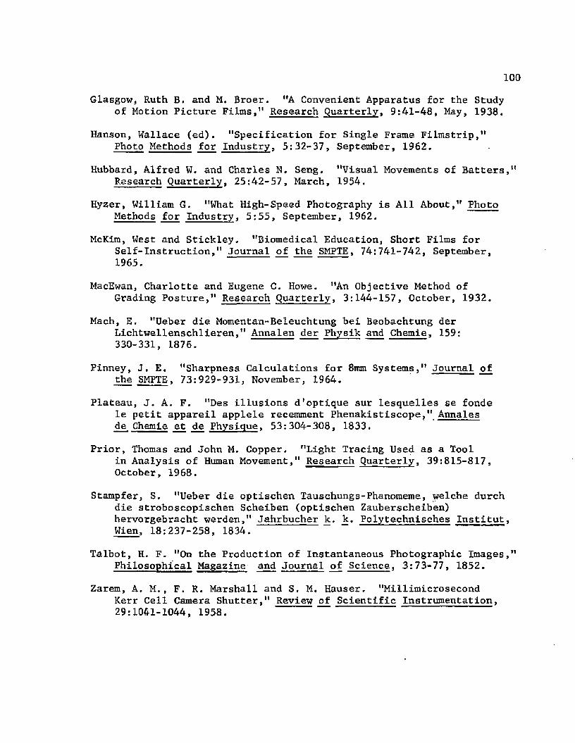
100
Glasgow, Ruth B. and M. Broer. "A Convenient Apparatus for the Study of Motion Picture Films," Research Quarterly, 9:41-48, May, 1938.
Hanson, Wallace (ed). "Specification for Single Frame Filmstrip,"Photo Methods for Industry, 5:32-37, September, 1962.
Hubbard, Alfred W. and Charles N. Seng. "Visual Movements of Batters," Research Quarterly, 25:42-57, March, 1954,
Hyzer, William G. "What High-Speed Photography is All About," Photo Methods for Industry, 5:55, September, 1962.
McKim, West and Stickley. "Biomedical Education, Short Films for Self-Instruction," Journal of the SMPTE, 74:741-742, September, 1965.
MacEwan, Charlotte and Eugene C. Howe. "An Objective Method ofGrading Posture," Research Quarterly, 3:144-157, October, 1932.
Mach, E. "Ueber die Momentan-Beleuchtung bei Beobachtung der Lichtwellenschlieren," Annalen der Physik and Chemie, 159:330-331, 1876.
Pinney, J, E. "Sharpness Calculations for 8mm Systems," Journal ofthe SMPTE, 73:929-931, November, 1964.
Plateau, J. A. F. "Des illusions d'optique sur lesquelles se fonde le petit appareil applele recemment Phenakistiscope," Annales de Chemie et de Physique, 53:304-308, 1833.
Prior, Thomas and John M, Copper. "Light Tracing Used as a Toolin Analysis of Human Movement," Research Quarterly, 39:815-817, October, 1968.
Stampfer, S. "Ueber die optischen Tauschungs-Phanomeme, welche durch die stroboscopischen Scheiben (optischen Zauberscheiben) hervorgebracht werden," Jahrbucher k. k. Polytechnisches Institut, Wien, 18:237-258, 1834.
Talbot, H. F. "On the Production of Instantaneous Photographic Images," Philosophical Magazine and Journal of Science, 3:73-77, 1852.
Zarem, A. M . , F. R. Marshall and S. M. Hauser. "MillimicrosecondKerr Cell Camera Shutter," Review of Scientific Instrumentation, 29:1041-1044, 1958.

101
C. UNPUBLISHED MATERIALS
Lafler, Josephine. "A Mechanical Analysis of Diving Techniques," Unpublished Master's thesis, University of Iowa, 1943.
Purdy, Kenneth M. , Jr. "A Mechanical Analysis of Five DifficultDives." Unpublished Master's thesis, Louisiana State University, 1960.

APPENDIX

APPENDIX
GLOSSARY
Aperture--The area of the hole in a lens available for the passage of light. The bigger the aperture, the more light the lens will pass to the film.
ASA Speed--The system of rating the speed of sensitized materials.The system was developed by the American Standards Association in 1947.
Barn doors--Flaps placed in front of a light source to control the spread of light.
Birefringent--Double refraction.
Chronocyclography— The exposure of sensitized film by light tracing in the dark. The image is the tracing of the point of light.
Cine1 Camera--A camera designed to take motion pictures.
Circle of confusion--The human eye cannot distinguish between a true point and a disc smaller than 0.01 inch. This figure fixes the standard of sharpness for a photographic print. It is usually expressed as 1/1,000 of a focal length. The circle of confusion varies with the focal length of the lens. It is the degree of sharpness of a lens.
Exposure--Photographic exposure is the product of the image bright- . ness and the exposure time.
F. number--The focal length of a lens divided by the lens diameter.
Framing rate--The number of frames a motion picture camera exposes to light in a given time period, usually expressed as frames per second.
Parallax--The apparent change in the relative position of two objects that occurs when there is a change in the viewpoint of the observer. The effect is not serious at distances beyond 6 feet.
Photographic copy— The process of making photographic reproductions of graphic art, manuscript or printed matter.
103

104
Shutter speed--The time the film plane of the camera is exposed to light, normally expressed as a fraction of a second.
Thyratron. switch— A switch incorporating a series control thyratron tube in a flash lamp circuit. The tube de-ionizes rapidly to extinguish a flash tube.
Stroboscopic photography--Multiple-flash-exposed photographs on single or multiple sheets of film.

VITA
Kenneth McLellan Purdy, Jr. was born in Baton Rouge, Louisiana,
on March 22, 1934. The first three years of his education were attained
at Highland Elementary School in Baton Rouge. At the beginning of his
fourth school year, he entered the University Laboratory School on the
campus of Louisiana State University where he graduated in May, 1952.
In June of 1952, Mr. Purdy entered Louisiana State University
and in August, 1957, received a Bachelor of Science degree with a
major in health and physical education and a minor in science. He
taught and coached at Crowley High School, Crowley, Louisiana and
at Robert E. Lee High School in Baton Rouge before joining the staff
at Louisiana State University in August of 1960. He received a Master
of Science degree in physical education in August, 1960, from Louisiana
State University. He is employed by Louisiana State University as a
counselor in the Junior Division.
He is married to Barbara Ann Bruchhaus of Elton, Louisiana
and they are the parents of three daughters, Kim Loraine, Karen Adeline
and Kris McLellan.
Mr. Purdy is presently a candidate for the degree of Doctor of
Education in Health, Physical and Recreation Education.
105


E X A M I N A T I O N A N D THESIS K E P O K T
Candidate: Kenneth McL e l l a n Purdy, Jr.
Major Field: Physical Educ ation
Title of Thesis: Techniques of Photography in Physical Education Research
Approved:
Major Professor and Chairman
Dean of the Graduate School
EXAMINING COMMITTEE:
^ C7^W~
J?] c
Date of Examination:
April 28. 1969
Copyright © 2022 FDOKUMEN