Technical Transaction 2019 iss. 4 - Repozytorium PK
160
Issue 4 Volume 2019 (116) Technical Transactions Czasopismo Techniczne
-
Upload
khangminh22 -
Category
Documents
-
view
0 -
download
0
Transcript of Technical Transaction 2019 iss. 4 - Repozytorium PK

Issue 4Volume 2019 (116)
TechnicalTransactions
Czasopismo Techniczne

Jan Błachut – University of Liverpool (UK)Wojciech Bonenberg – Poznan University of Technology (Poland)Tadeusz Burczyński – Silesian University of Technology (Poland)Massimo Corcione – Sapienza University of Rome (Italy)Leszek Demkowicz – The University of Texas at Austin (USA)Joseph El Hayek – University of Applied Sciences (Switzerland)Ameen Farooq – Technical University of Atlanta (USA)Zbigniew Florjańczyk – Warsaw University of Technology (Poland)Marian Giżejowski – Warsaw University of Technology (Poland)Sławomir Gzell – Warsaw University of Technology (Poland)Allan N. Hayhurst – University of Cambridge (UK)Maria Kušnierova – Slovak Academy of Sciences (Slovakia)Krzysztof Magnucki – Poznan University of Technology (Poland)Herbert Mang – Vienna University of Technology (Austria)Arthur E. McGarity – Swarthmore College (USA)Antonio Monestiroli – Polytechnic of Milan (Italy)Marek Pabich – Lodz University of Technology (Poland)Ivor Samuels – University of Birmingham (UK)Mirosław J. Skibniewski – University of Maryland (USA)Günter Wozny – Technical University in Berlin (Germany)Roman Zarzycki – Lodz University of Technology (Poland)
© 2019 Cracow University of Technology Basic version of each Technical Transactions magazine is its online versionPierwotną wersją każdego zeszytu Czasopisma Technicznego jest jego wersja online
Online availabilityDostępność online
www.ejournals.eu/Czasopismo-Technicznewww.biblos.suw.pk.edu.pl
www.czasopismotechniczne.pl
Section EditorSekretarz Sekcji
Dorota [email protected]
Editorial CompilationOpracowanie redakcyjne
TypesettingSkład i łamanie
MałgorzataMurat-Drożyńska
DesignProjekt graficzny
Michał Graffstein
Scientific CouncilRada Naukowa
Editorial BoardKolegium redakcyjne
ARCHITECTURE AND URBAN PLANNINGMateusz Gyurkovich [email protected]
CHEMISTRYRadomir Jasiński [email protected]
CIVIL ENGINEERINGMarek Piekarczyk [email protected]
ELECTRICAL ENGINEERINGPiotr Drozdowski [email protected]
ENVIRONMENTAL ENGINEERINGMichał Zielina [email protected]
PHYSICS, MATHEMATICS AND COMPUTER SCIENCESWłodzimierz Wójcik [email protected]
MECHANICSAndrzej Sobczyk [email protected]
Chairman of the Cracow University of Technology Press Editorial BoardPrzewodniczący Kolegium Redakcyjnego Wydawnictwa Politechniki Krakowskiej
Tadeusz Tatara
Editor-in-chiefRedaktor naczelny
Józef Gawlik [email protected]
Native SpeakersWeryfikacja językowa
Tim ChurcherRobin Gill
Aleksandra Urzę[email protected]
Creative Commons (CC BY-SA 4.0)https://creativecommons.org/licenses/by-sa/4.0/deed.pl
Technical ProofreadingKorekta techniczna
Małgorzata [email protected]
ISSN 0011-4561eISSN 2353-737X
3
Contents
ARCHITECTURE AND URBAN PLANNING Davidich Tatiana F.
The significance and stylistic features of eclectic objects in the city of Kharkov ..............................5Artur Jasiński
Colour as a tool in shaping the city image – based on the case of Mombasa ............................... 23Kazimierz Kuśnierz, Dominika Kuśnierz-Krupa
Issues with protecting medieval urban layouts from selected example towns in Lesser Poland ............................................................................................................................................... 37
Anna Mitkowska Lanckorona's market square in the context of the landscape ........................................................... 45
Marta PieczaraArchetypes in contemporary architecture .............................................................................................. 71
Monika TrojanowskaHealth-affirming landscapes and sustainable architecture of modern schools ............................ 85
CIVIL ENGINEERINGTadeusz Majcherczyk, Katarzyna Kryzia, Jerzy Majchrzak
Mining influence in the area of the Pszczynka river and the method of riverbed restoration ...................................................................................................................................103
Kamil Krzywiński, Adrian Chajec, Łukasz SadowskiThe effect of the concentration of steel fibres on the properties of industrial floors ...................115
MECHANICSDaniel Jastrzębski, Beata Niesterowicz
The reasons for hybrid light pole failures – an analytical study ....................................................133Adrian Kozień
The development and verification of a dynamic model of the Kawasaki RS010L industrial robot ..........................................................................................................................................147


5
TECHNICAL TRANSACTIONS 4/2019ARCHITECTURE AND URBAN PLANNING
DOI: 10.4467/2353737XCT.19.040.10352 submIssIOn Of The fInal versIOn: 2/04/2018
Davidich Tatiana F. orcid.org/[email protected]
Kharkov National University of Construction and Architecture
The significance and stylistic features of eclectic objects in the city of Kharkov
Znaczenie i cechy stylistyczne obiektów eklektycznych w Charkowie
AbstractThe article analyses the time periodisation of various eclectic currents in the architecture of Kharkov and the stylistic features of each flow. It shows how external factors (the administrative status of the city, political influences, trends in religious life, economic development) and various currents of eclecticism have influenced the transformation of the urban environment and characterised the specific features of the objects and the work of outstanding architects. On the basis of the analysis, architectural periods of eclectic currents in Kharkov have been identified and a list of them has been compiled.Keywords: transformation of the urban environment, Kharkov, factors of influence, periodisation of eclectic currents, objects of architecture
Streszczenieartykuł analizuje periodyzację różnych prądów eklektycznych w architekturze Charkowa i cechy stylistyczne każdego przepływu. Pokazuje, jak czynniki zewnętrzne (status administracyjny miasta, wpływy polityczne, trendy w życiu religijnym, rozwój gospodarczy) i różne nurty eklektyzmu wpłynęły na transformację środowiska miejskiego i scharakteryzowały specyficzne cechy dzieł wybitnych architektów. na podstawie analizy okresów architektonicznych eklektyczne prądy w Charkowie zostały zidentyfikowane i opracowano ich listę.Słowa kluczowe: transformacja środowiska miejskiego, Charków, czynniki wpływu, periodyzacja prądów eklektycznych, obiekty architektury
6
1. Introduction
Before the establishment of Soviet power in 1917, Kharkov was a major provincial centre of the Russian Empire; thus, architectural processes here were in line with the trends common to the whole empire. The issue of development of architecture in Kharkov from the middle of the 18th to the early 20th century is described in the works of: I.R. Akmen [1], Lizan J. [2], V.E. Novgorodov [2, 21], B.A. Bondarenko [3], I.A. Bondarenko [4], Ye.T. Cherkasova [5], T.F. Davidich [6–12], D.A. Dudukina [13], L.V. Kachemtseva [14–16], A.M. Kasianov [17], A.O. Gorshkov [18], V.T. Semenov [18], A.A. Tits [18], B.G. Klein [19], A.S. Mayak [19], I.N. Lavrentiev [19, 24], V.A. Kodin [20], E.A. Yeroshkina [20], Yu.R. Pianida [22], V.M. Lopatko [23], E.I. Remizova [23], A.Yu. Leibfreid [19, 24], A.Yu. Polyakova [24], Yu.M. Shkodovskii [24] and other authors. These works highlight the history of Kharkov’s building development and consider particular stylistic trends and architectural monuments from different historical periods and building typologies; however, there has thus far been no such work that analyses the stylistics of all directions and trends of eclecticism in Kharkov, the historical periodisation of all styles and trends, or the nature of their relationship with the stylistics of modernity, which spread during the 1910s.
The urban space was determined by, among other factors, the nature of the stylistics of building up of the main historical periods, among which it is customary to single out the following:
1) the period of transformation of the regiment city-fortress into the principal town of a governorate (1654–1765),
2) the period when Kharkоv was the centre of the Sloboda Ukraine (Slobozhanshchyna) and the main city of the Kharkov vicegerency (1765–1780, 1780–1835),
3) the period when Kharkоv was the centre of the Kharkоv Government (1835 – the middle of the 19th century),
4) the period from the beginning of the industrial revolution to the First World War and the Revolution (1860s to 1917).
2. Objects of various historical periods in the city structure
In the first period, the stone buildings that appeared in the city bore features of the Baroque style in its Russian and Ukrainian versions. Buildings from this period include the Assumption Cathedral (the first from 1685 to 1887, the second from 1771 to 1777), the Intercession Cathedral – 1689), the en route Imperial Palace of Catherine II (1769–1776), later reconstructed under the building of the university (early 19th century).
During the second period, associated with the beginning of the reign of Catherine the Great in the 1770s, the city centre reconstruction began, suggesting the creation of a single classicist ensemble. P.A. Yaroslavskii, a graduate of the Additional classes of the Kharkоv Collegium and a student of I.M. Vilyanova, became the second architect of the Governorate.
In 1780, the First City Development Plan (1768) was developed for Kharkov by the St. Petersburg and Moscow Arrangement Commission, and the position of the Gubernial

7
architect was introduced (I.M. Vilianov, a student of D.V. Ukhtomsky, sent from Moscow, held this position). It was the time of the officially prescribed style of classicism, although the architecture still preserved the features of the late Baroque.
Romantic classicism with elements of mediaeval styles, typical for the beginning of the 19th century, was evident in the building of the Prison Castle on Tiuremna (Malynovskyi) Street, built according to the model project of Joseph-Maria Charlemagne-Baudet, a Petersburg architect, in Kharkоv in the 1820s. The architectural solution of this building combined elements of classicism and Romanesque castle architecture.
During the reign of Tsar Nicholas, I (1825–1855), ideas of national revival appeared in the Russian Empire, and an alternative to the widespread classicism was sought; however, classicist solutions did not disappear. In the 1830s in Kharkоv, two-storey neoclassical buildings of a new typology appeared: the building of the post and telegraph office in Vozniesienskaia Square (now 15 Feuerbach Square), architect S. Shevtsov, 1830; the old building of the post office in Staromoskovskaia Street was reconstructed for the First Male Gymnasium building (architect N.I. Ashitkov, 1844).
In the forms of the first neo-classicism, a two-storey building was built for the post and telegraph office on Vozniesienskaia Square (architect S. Shevtsov, 1830), as well as a number of private mansions.
In 1837, Andrei Andreevich Thon, brother of the famous metropolitan architects Aleksandr Andreievich and Сonstantin Andreievich Thon, who were at the origin of stylistic transformations in the architecture of the Russian Empire, was appointed to the new position of City Architect of Kharkov. He was engaged in the completion of the bell tower of the Assumption Cathedral, the construction of which in the Empire style had been begun upon the project of the architect E.A. Vasiliev. During the reign of Tsar Nicholas I, the strengthening of patriotic moods under the slogan “Orthodoxy, Autocracy, Nationality” was favourable for the revival of artistic motifs of Byzantine and Old Russian architecture by С.A. Thon and other architects. The spread of these styles was associated with the Russian-Turkish wars. In 1844, the album of the Russian-Byzantine style projects of С.A. Thon was approved by the
Fig. 1. Church of the Beheading of St. John the Forerunner at 50 Alchevskiie Street Architect A.A. Thon, 1854–1857 years; reconstruction – architect A.I. Podiakov, 1875

8
Tsar and published with a large addition. For the first time, this album was published in 1838. By the Highest Decree of 1841, they were recommended as a model of national architecture.
The features of the Russian-Byzantine and Russian architecture styles were also manifested in the architecture of Kharkov churches built according to the designs of Andrei Andreievich Thon (The Church of the St. John the Forerunner, 1845 (Fig. 1), the Church of the Life-Giving Trinity, etc.). At the same time, the classical traditions were preserved for quite a long time in the architecture of public buildings (for example, the building of the Drama Theatre in Sumskaia Street, the authorship of the same architect).
The first attempts to deviate from the classic architecture in the direction of eclecticism began to manifest themselves in the works of architects A. Rakov, K. Tolkunov and V. Nebolsin; various directions of eclecticism then began to spread. There was no need to coordinate projects with St. Petersburg – they could be approved by local city authorities. Customers had more freedom in choosing architectural solutions. Early eclectic projects, as a rule, were low-rise mansions. They were small-scale and had a provincial character (architects Ya. Denisenkov, I. Ginsh, B. Johanson, G. Mayatskii, B. Mikhalovskii, A. Thompson, F. Nitsenko, G. Strizhevskii, etc.)
From 1858, the mandatory use of “model projects” was abolished in the Russian Empire, and the opportunity for free choice of both private and public style appeared.
This period was significantly different from the previous periods due to the drastic change in the socio-economic and cultural situation in the country. In 1869, a railway was built in Kharkov, connecting it with Moscow, St. Petersburg, and the Crimea. The construction of the railway contributed to the transformation of Kharkov into one of the largest transport hubs of the Russian Empire. The station building was in the Romanesque Revival style, to which new sections were later added in the Neo-Renaissance style. The success of economic development led to the active growth of the population of the city and the expansion of its territory. The city began to grow to the north (Sumskaia Street and Nemetskaia Street appeared and a network of streets was formed between them) and to the west (Ekaterinoslavskaia Street., Malaia Panasovka district, Aleksandrovskaia Street, and the merchant district).
In 1870, the City Regulations were adopted, and the urban economy began to develop. The City Administration and the City Duma dealt with issues of construction management – the positions of City Engineer and the Sanitary Inspector were established. In 1882, the Industrial Technical Museum was opened, in which architectural and art exhibitions were held with the participation of local and foreign authors. In 1885, Kharkov Institute of Technology began training their own civil engineers, many of whom subsequently worked as practising architects. From 1893, private architectural and construction offices and bureaus appeared.
An important role in the development of art education in Kharkov was played by M.D. Raievskaia-Ivanova, a native of Izium uyezd (district) of Kharkov Governorate. For five years, she received an art education in France, Italy and Germany. In 1868, she passed the exam at the Imperial Academy of Arts for the title of a free artist and became the first officially recognised female artist in the Russian Empire. In 1869, M.D. Raievskaia-Ivanova established the first private school of art in the Russian Empire in Kharkov. Altogether, nine-hundred students graduated from this school. Some of them became famous artists in the future:

9
S. Vasilkovskii, M. Tkachenko, P. Konchalovskii, K. Pervukhin, A. Vyiezzhev, and also the architect A.N. Beketov. In 1896, on the basis of this school, a city school of drawing and painting was created, and in 1812, the Kharkov Art College.
3. The urban space of Kharkov during the periods of economic development
The rapid development of capitalism contributed to the construction of industrial enterprises and the simultaneous rapid increase in the population of the city. In accordance with the necessities of the times, architects and civil engineers were entrusted with new tasks. Just as in all major cities of the empire, new types of buildings appeared in Kharkov; progressive design solutions were applied based on the use of metal, reinforced concrete and large-sized glass. The production of familiar materials was improved; cast steel forced out wrought iron products and the mechanised production of high-quality facade bricks appeared.
Elements of mediaeval architecture in the framework of the “brick style” appeared in Kharkov from the 1860s to the 1890s. Some examples of urban development of that period are the residential building at 5 Gogol Street, the former building of the Third Male Gymnasium at 7 Gogol Street (architect I. Ginsh, 1864); the building of the Polish Roman Catholic Church at 8 Gogol Street (architect. B. G. Mikhalovskii, 1891 (Fig. 2), the hall of which is covered with a reinforced-concrete vault with a span of 12 m); the former mansion and hospital at 52 Sumskaia Street (architect. G. Strizhevskii, 1874), heightened in 1900 upon the project of I. Zagoskin and V.G. Krichevskii in the Pseudo-Gothic style.
Fig. 2. Polish Roman Catholic Church in in honour of Our Lady of the Rosary in Gogol Street; architect B. G. Mikhalovskii, 1887–1891;
pseudo-Gothic brick
10
Orthodox churches during this period were built in Russian and Byzantine styles. From 1868 to 1886, the architect of the Kharkov and Akhtyrka eparchyes was F.I. Danilov, who graduated from the St. Petersburg Construction School in 1885. According to his projects in the Russian style with elements of classicism in Kharkov the churches of Peter and Paul (1872–1876), Joann-the-Theologian (1879) and Panteleimon-the-Healer (1885–1888) were built. The next diocesan architect V.Ch. Nemkin used the neo-Byzantine style for the churches of Nicholas-the-Wonderworker on Nikolayevskaya Square (1896) and the Cyril and Methodius Cemetery Church (1885–1897). Also in this style, the church of the Kazan Icon of the God’s Mother of on Lysaya Gora was built by V.Ch. Nemkin (now Leningradskaya Street No. 78, 1894–1912).
V.N. Pokrovsky, a graduate of the Imperial Academy of Arts, was appointed diocesan architect in 1907. Ozeryanskaya Church on the Сholodnaya Gora area, Church of Our Lady of Kazan, Three Saints (Golberg’s) were built or thoroughly rebuilt under his leadership in Kharkov. He was also one of the leaders of Neo-Byzantine and Neo-Russian styles in the church architecture of Kharkov, the author of the project of the Alexander Nevsky Church at the psychiatric hospital, and he reconstructed the St. Dmitriyevsky Church in Russia and others (Rozhdestvenskaya, Mironositskaya, Panteleymonovskaya, Svyatodukhovskaya).
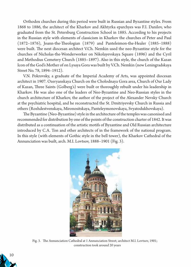
The Byzantine (Neo-Byzantine) style in the architecture of the temples was canonised and recommended for distribution by one of the points of the construction charter of 1842. It was distributed as a continuation of the artistic motifs of Byzantine and Old Russian architecture introduced by C.A. Ton and other architects of in the framework of the national program. In this style (with elements of Gothic style in the bell tower), the Kharkov Cathedral of the Annunciation was built, arch. M.I. Lovtsov, 1888–1901 (Fig. 3).
Fig. 3. The Annunciation Cathedral at 1 Annunciation Street; architect M.I. Lovtsov, 1901; construction took around 20 years

11
The period of the most active construction of civil and industrial buildings in Kharkov began in the 1890s. In 1895, a geodetic survey was carried out and a new general plan of the city was drawn up with the expansion of its borders to the north and south east. The main urban sites were identified: the squares, public shopping centres. The main streets were given a width of red lines of 20 m, the embankments were improved, bridges were built, and marshy and flooded areas of the city were drained. The first water line was laid in 1881, 12 km of the first horse tram line appeared in 1882, and the first power station was built in 1897. In 1904, the architecture and construction department of the Kharkov Technical Society was established. In 1910, a city sewage system appeared – this contributed to the emergence of multi-storey residential buildings in the central part of the city.
The active design activity of A.N. Beketov (Academician of Architecture and the author of more than 40 significant buildings in Kharkov) substantially contributed to changes in the architectural scale of the central part of Kharkov. A.N. Beketov received his education at the Faculty of Architecture of the Imperial Academy of Arts in St. Petersburg, professors D.I. Grimm and A.I. Krakau were his teachers; in 1882–1888 he trained with the famous St. Petersburg architect M.E. Mesmaher. Upon graduation, A.N. Beketov was awarded the Great Gold Medal.
The first buildings constructed according to A.N. Beketov’s projects in Kharkov gave a new scale to the main streets of the city. Mainly Neo-Greek and Neo-Renaissance styles were combined with elements of Baroque and Art Nouveau in his projects. In numerous designs for mansions, he sought to achieve the greatest possible stylistic diversity, using the forms of Neo-Greek and Moorish styles, European Renaissance and Art Nouveau, etc. (Fig. 4).
The appearance of the brick style in Kharkov dates back to the mid-1850s – by 1860s–1870s – when the production of high-quality bricks began. The buildings of the Technological Institute (architects R.R. von Henrichsen, M.I. Lovtsov, V.V. Velichko) and university clinics (now the building complex of the Regional Hospital on Trinkler Street, architect A.K. Spiegel
Fig. 4. Former building of the Volzhsko-Kamskii Bank on Nikolaevskaia Square (now at 24 Constitution Square); Architect A.N. Beketov, 1906-1908; reconstructed in 1968
under the Kharkov Puppet Theatre; Neo-Renaissance with elements of Art-Nouveau

12
(1895–1896), were built in this style. In 1901, the building of the guest house for university students was built; it was later transformed into the Museum of Nature (architect V.V. Velichko).
Technical facilities were also built in the brick style. Examples include the building of the fire tower (brick eclecticism with elements of the Romanesque style and the Renaissance), the building of a mill on Kharkovskaia Embankment, and the building of the first Kharkov power station on Kuznechnaia Street.
Buildings in the Russian style – Constantine-Yeleninskaia Church, architect M.I. Lovtsov, 1851; St. Dimitriyevskaia Church (reconstruction of the earlier classicist), architect M.I. Lovtsov, 1885–1896, the building of the School of Trade at 12/1 Marinskaia Street, architects B.N. Korneienko, V.V. Velichko – were also built from unpainted brick.
Pseudo-Romanesque and pseudo-Gothic styles were also distributed in the brick version – the building of the Non-classical secondary school on Moskovskaia Street, 1887, architect K.A. Tolkunov (Fig. 5); a number of private mansions. The Lombard building on Universitetskaia Street (architect B.N. Korneienko, 1909) was also built in a brick style with elements of Russian style.
From the 1880s, Neo-Renaissance and Beaux-Arts (architectural styles that combines elements of Renaissance and Baroque) were widely applied. The following buildings were built in the Neo-Renaissance and Beaux-Arts architectural styles: the building of the Public Library (now the library named after V.G. Korolenko), architect A.N. Beketov, 1886; the building of the Commercial School on Pushkin street (now the building of the Yaroslav Mudryi National Law University), architect A.N. Beketov, 1893; Land Bank building on Nikolaievskaia Square, architect A.N. Beketov; Karaite Kenesa at 12 Kuznechnaia Street, architect B.S. Pokrovskii, 1891–1893; the Court of Justice building at 38 Rudnev Square, architects A.N. Beketov and V.V. Khrustalov, 1899–1902; the State Bank building on Sumskaia Street (in the style of the Florentine Renaissance), architect R.P. Golenishchev, the beginning of the 1900s; the building of the People’s House on Konnaia Square, architect A.A. Vensan, (a brick version of the Beaux Arts style), a former apartment house of the insurance company “Zhizn” at 19 Sumskaia Street, architect assumptions N.A. Shtakenshneider.
Fig. 5. The building of the former Non-classical secondary school at 45 Moskovskii Prospect; now the building of the Technical University of Agriculture; architect K.A. Tolkunov, 1887

13
The following buildings were built in the style of the French Neo-Renaissance: the Drama Theatre building on Sumskaia Street (reconstruction of the architect B.G. Mikhalovskii, 1883); the building of the St. Petersburg International Bank on Nikolaevskaia Square (now 22 Constitution Square, architect V.V. Velichko); the former building of the Council of the Congress of the Mine Owners of the South of Russia at 18–20 Sumskaia Street (architects S.I. and I.I. Zagoskins with the participation of V.G. Krichevskii) 1902–1906.
Objects of the neo-baroque are: the house with a restaurant “Lux” at 3 Sumskaia Street, architect I.P. Guinsch, the1860s; former apartment house of the engineer Ivanov with the Mignon cinema on Yekaterinoslavskaia Street (Poltava Shliakh), architect A. Thompson, 1875; the former store “Lux” at 3 Constitution Square, the author is unknown, 2 storeys were added in 1954.
Exotic styles, specifically “Japanese style”, are represented by the pavilion of the water-equalising pool on Basseinaia Street (now – Petrovskaia Street), 1881 (not preserved).
Objects built in the Moorish style are: A.K. Alchevskii’s mansion at 13 Darwin Street (architect A.N. Beketov, 1896); the former mansion of the City Duma Councillor K.M. Bich-Liubenskii at 24 Artem Street, the author is unknown, the end of the 19th century (later 3 storeys were added).
The Byzantine (Neo-Byzantine) style in the architecture of the temples was canonised and recommended for distribution by one of the paragraphs of the construction charter of 1842, it was distributed as a continuation of the artistic motifs of Byzantine and Old Russian architecture introduced by С.A. Tohn and other architects in the framework of the state program. The Cathedral of the Annunciation (with elements of the Gothic style in the bell tower; architect M.I. Lovtsov, 1888–1901), was built in this style. The eparchial architect V.Kh. Nemkin used this style for the Church of St. Nicholas the Wonderworker on Nikolaievskaia Square (1896), the Church of the Cyril and Methodius Cemetery (1885–1897) and the Church of the Icon of Mother-of-God of Kazan at Lysaya Gora (78 Leningradskaia St.), arch. V.Kh. Nemkin, 1894–1912.
The Greek Revival style and eclectic blends with its use were applied in the projects of the following buildings: the former mansion of the architect A.N. Beketov (now the House of Scientists) at 10 Sovnarkomovskaia Street – architect A.N. Beketov (with the participation of V.G. Krichevskii), 1897–1900; the former mansion of the architect A.N. Beketov at 37 Darwin Street (architect A. Beketov, 1912), the former mansion of Dr. R. Frenkel at 100 Pushkinskaia Street (architects V.V. Velichko and P.V. Tolkachev, 1911–1913).
In the 1910s, new styles (Romanesque Revival, Neo-Gothic, Neo-Russian, Neo-Classicism, Neo-Renaissance, including those of Western-European type) were actively disseminated together with the Art Nouveau architectural style:
1) Romaneque Revival style: the building of the German church, architect A.F. Gergardt, 1912–1914 (demolished in 1957); a former mansion at 57 Pushkin Street,
2) Neo-Gothic style: the building of the former manufactory “Zilberman and Sons” at 9 Engels Street, architect M. Kompaniets, the 1910s,
3) Neo-Russian style: the Aleksandro-Nevskaia Church at the psychiatric hospital, architect M.I. Lovtsov, 1907, the Three Holy Hierarchs Church (Golbergovskaia),

14
architects M.I. Lovtsov and V.N. Pokrovskii, Christmas-Mother of God (Kaplunovskaya) cemetery church, arch. A.N. Beketov, 1912;
4) Neo-Renaissance, West European type: a former residential building with a store in the ground floor at 8 Kvitka-Osnovianenko Street (architect, supposedly, B.N. Korneienko, beginning of the 20th century); a former mansion of professor Somov at 11 Olminskii Street (architect. A.N. Beketov, 1899)
5) neoclassicism, which emerged as an alternative to the Art Nouveau at the beginning of the 20th century: the building of the former Consistory at 4 Universitetskaia Street, architect V.H. Nemkin, 1903; the former profitable house of the insurance company “Salamandra” at 17 Sumskaia Street, architect N.N. Verevkin, 1913–1916; the former profitable house of the insurance company “Russia” on Pavlovskaia Square, architect I.A. Pretro, 1915–1917; building of the Southern Railway Administration on Privokzalnaia Square, architects A.N. Dmitriev and D.S. Rakitin, 1912–1914.
The brick style with Gothic elements became traditional for educational institutions and the building of the University’s Chemical Building was constructed in this style according to the design of the architect V.V. Velichko in 1914.
Eclecticism as a mixture of elements of different styles manifested itself in: the building of the Theological School (Bursa) on Bursatskii Descent (this building was reconstructed by architects A.K. Tolkunov and B.S. Pokrovskii from the earlier Baroque style); Ozerianskaya Church on Kholodnaia Mountain (architect V.N. Pokrovskii); the Church of the Ozerianskaia Icon of the Mother of God in the Holy Pokrovskii Monastery (architects V.N. Pokrovsky and V.Kh. Nemkin, 1896); the building of the League of Tuberculosis Control in Voznesenskaia Square (now – 12 Feuerbach Square, architects, supposedly, I.I. Zagoskin and V.G. Krichevskii, beginning of the 20th century).
4. The urban space of Kharkov at the beginning of the twentieth century
The beginning of the 20th century in Kharkov, as well as in all major cities of the Russian Empire, was marked by the flourishing of cultural life. Ideas and trends in architecture were numerous, construction was performed very quickly and a real construction boom began. Due to the rapid economic growth and development of the system of banks and insurance companies, the country started to build multi-storey profitable residential buildings (up to 7 storeys) in Kharkov, as in one of the largest economic centres of the Russian Empire. These were equipped with elevators, rubbish chutes and internal rainwater basins, hotels workshops, railway depots and workshops, power plants, industrial mills, manufactories, shopping malls, passages, warehouses, train stations, theatre buildings, circuses, first cinemas. In these pre-revolutionary years, the most imposing buildings of our city were built, constituting the golden fund of its architecture. Among these are: the Astoria Hotel and the Merchant Bank (architects A.I. Rzhepishevskii and N.V. Vasiliev); the tenement house of the insurance company ‘Russia’ (now the Palace of Labour, the author is St. Petersburg’s architect I.A. Pretro); the building of the Russian-Asian (Northern) Bank and Women’s Medical Courses

15
(1 Sumskaia Street, architects St. Petersburg’s architect O.R. Munts, and Kharkov graduate of the Imperial Academy of Arts A.K. Shpigel); multi-storey (up to 7 floors) apartment houses, built at the expense of wealthy homeowners and insurance companies on Sumskaia Street and Yekaterinoslavskaia Street (Poltava Way).
Many of these houses were built as a result of All-Russian competitions; new building materials and structures and progressive engineering improvements of buildings according to European designs, were introduced. From 1898 to 1913 a “bank row” was formed that unfolded along the former Nikolayevskaia Square (now Constitution Square): the Land Bank (architect A.N. Beketov, sk. O.I. Jacobs), the Volga-Kamskii Commercial Bank (now the Puppet Theatre, architect A.N. Beketov); St. Petersburg International Bank (now the Savings Bank, architect V.V. Velichko); the Trade Bank (now the Technics House, the reconstruction of the architect M.F. Piskunov). In 1914, according to the competition project of Petersburg’s architects A.I. Dmitriev and D.S. Rakitin and engineer P.P. Rottert, the representative building of the Headquarters of the Southern Railway on the railway station forecourt was built in the forms of neoclassicism. In the area of Mironositskaia Street and Sadovo-Kulikovskaia Street (now Darwin Street), mansions for noblemen, merchants, industrialists, doctors, architects and cultural figures were built.
Competitive projects created for Kharkov were published in the capital’s magazine “Architect”.
Following the example of Europe and Russia, the search for national architectural identity also encompassed Russia and Ukraine. In February 1912, the Literary and Artistic Circle was created in Kharkov, bringing together leading artists, architects, theatre workers and other people interested in art. The Ukrainian architectural and art department at from was created. The university professor, historian D.I. Bagaley, architects K.N. Zhukov, A.M. Ginzburg, artists S.I. Vasilkovskii, N.S. Samokish, S.P. Timoshenko and the art school leader M.D. Raevskaya-Ivanova studied folk traditions in architecture, ornaments and decorative motifs, and organised exhibitions of Ukrainian folk art and architecture in the building of the second in the Russian Empire Industrial and Art Museum on Sergievskaia Square.
Based on the designs of architects and amateur artists of Ukrainian art from 1903 to 1909, a Ukrainian version of the Art Nouveau style was created, which was based on the stylistic features of Western Ukrainian folk architecture. An example of Ukrainian Art Nouveau is the building of the Provincial Zemstvo in Poltava, designed by the architect V.G. Krichevskii – student and employee of A.N. Beketov. In 1900, artist and ethnographer O.G. Slastion described the main morphological features of the “Ukrainian style” as: trapezoidal shapes of window and door openings; hipped roofs with creases; galleries on pillars; twisted columns; for decoration, the use of folk ornaments made in majolica and paintings were recommended. Such murals made by the artist N.S. Samokish were preserved in Kharkov in the lobby of the house at 44 Mironositskaya Street.
Examples of preserved buildings in the style of Ukrainian Art Nouveau are the Art School (now the building of the Kharkov State Academy of Design and Arts) at 8 Krasnoznamonnaia Street, architect K.N. Zhukov, 1912; the former “Peasant House” on the former Rosa Luxemburg Square, building No. 4, architect B.N. Korneienko, 1912.

16
Most professional architects who worked in Kharkov in the second half of the 19th and early 20th century were graduates of the architectural department of St. Petersburg Academy of Arts, the Construction School in St. Petersburg (from 1881 – the Institute of Civil Engineers) and the Moscow School of Painting, Sculpture and Architecture. The architecture of Kharkov developed in close connection with the architecture of the capital. The city regularly received architectural and artistic periodical publications.
5. Analysis of the periodisation of eclectic currents which determined the character of the urban environment of Kharkov and their specific features
Based on the research, the periodisation of all eclectic currents in Kharkov was performed:Romantic classicism – 1820s1st Neoclassicism – 1830s to 1896“Russian-Byzantine” style – 1854 to 1901“Brick” style – 1860s to 1914Pseudo-Roman style – 1870 to 1901Pseudo-Gothic style – 1874 to 1900sOriental pseudostils – 1881 to 1910s.“Russian” style – 1882 to 1907Neo-Renaissance – 1883 to 1928Eclecticism as a mixture of styles – 1885 to 1912Beaux Arts – the end of 1890s to 1900sNeo-baroque – late 1890s to 1900sNeo-Greek style – 1896 to 1913Eclecticism with Art Nouveau elements – 1905 to 1916Eclectic Art Nouveau – 1890s to 1910sUkrainian Art Nouveau – 1912 to 1924Neo-Russian style – 1907 to 1914Neo-Romanesque style – 1912 to 19162nd neoclassicism – 1910s to 1924Neo-Gothic style – 1913 to 1916The analysis of eclectic objects from different periods I performed enabled me to establish
that the densest time slips in the distribution of various currents of eclecticism in Kharkov were in the 1880s to the 1910s, and some of them continued in the post-revolutionary period.
Many architects of Kharkov at the turn of the 19th–20th century proved themselves to be professional masters both in various trends of eclecticism and in Art Nouveau architecture. In the 1910s, numerous buildings in the city were built according to the projects (including competitive) of Moscow and St. Petersburg architects: R.R. Heinrichsen, A.I. Dmitriev, N.N. Verevkin, I.A. Pretro, F.I. Lidval, O.R. Munts, N.V. Vasiliev, A.I. Rzhepishevskogo, A.I. von Gauguin, N.A. Shtackenshneider (son of A.I. Shtakenshneider), Ya.G. Gevirts, K.N. Zhukov, D.S. Rakitin and others.

17
Contests, exhibitions, public discussions of architectural projects, publications in magazines and books held at that time contributed to the exchange of experiences of architects throughout the empire.
As Observed by G.I. Revzin, the phenomenon of the simultaneous existence of stadially different phenomena, in particular, phenomena such as eclecticism and modernism and their interaction, as a result of which the many intermediate monuments that have arisen can equally well be attributed to different trends – Art Nouveau or eclecticism – as is vividly confirmed by the architectural examples. The residential building at 11 Gogol Street, built using the architect B.М. Hershkowitz’s project in the 1910s, can serve as an example.
It is clear that most architects continued to use proven methods of eclecticism (the choice of style from the arsenal of past eras). Therefore, in large cities, there was a huge variety of buildings, where elements of eclecticism and Art Nouveau somehow mixed together. Examples are buildings which were constructed according to the designs of A.N. Beketov in the 1900s and 1910s. In the buildings of the Kharkov Medical Society and the Pasteur Institute on Pushkin Street, elements of Art Nouveau in the solution of staircases are freely combined with elements of classicism (central rotunda) and Renaissance (main field of the facade). Elements of Art Nouveau and Neo-Renaissance are also combined in the architectural design of the building of the Volga-Kama Bank on Nikolayevskaya Square, built in 1906–1908.
Another Kharkov architect, A.M. Ginzburg, in the architectural solution of a residential building at 23 Rymarskaia Street, built in 1913, used forms of Art Nouveau, Neo-Renaissance and Neo-Baroque stylised in the spirit of modernity. Additionally, stylisation of the European variety of Neo-Baroque in the spirit of modernity can be seen in the architectural design of the former Hotel Moscow at the corner of Poltavskii Shliakh Street (formerly Yekaterinoslavskaia) and Rozhdestvenskaya Street (architect V.N. Pokrovskii, 1913). A typical example of eclectic Art Nouveau is the former apartment house with a merchant Alladin’s shop, designed by architect Yu.S. Tsaune at 44 Sumskaia Street – on its façade, elements of Art Nouveau, Neo-Renaissance and Greek Revival architectural styles are combined.
In the architectural solutions of private mansions, the method of stylisation in the spirit of the Art Nouveau of neostylistcs of Baroque, Renaissance, Romanesque, Gothic and other styles and their mixtures was often used. An example is the former mansion of the merchant V.O. Goldberg at 108 Goldbergovskaia Street (Architect V.A. Estrovich, 1913). Here, in one building, elements of the serf architecture, of the Romanesque, Renaissance and Baroque styles, stylised close to the Art-Nouveau forms are combined.
The creative practice of the Art Nouveau era did not always correspond to the purity of the theoretical statements presented in the pages of the architectural press. Therefore, the multitude and variety of directions that have emerged within the framework of Art Nouveau still cause serious difficulties in the stylistic identification of the buildings of Kharkov built during this period. Obviously, therefore, the style of buildings is not indicated in the lists of architectural monuments and protected buildings. In the Art Nouveau era, a clear formal-visual criterion for defining style for the first time in many centuries almost stopped working. Obviously, this was manifested in the “creative freedom” (“liberty”) proclaimed by the Art Nouveau, which did not recognise any formal canonisation. Some authors turned to the neo-
18
Romantic images of the architecture of the past; others, inspired by the ideas of rationalism, new designs and engineering solutions, anticipated the upcoming “technological” age by their decisions.
In the architectural solutions of the turn of the century, there is more likely a “gradual” transition from eclecticism or neostyles to Art Nouveau through proto-modern, rather than ‘anti-eclectic combat’ and the creation on its basis of some completely “new style” opposed to eclecticism. The boundaries between eclecticism, neo-stylistics and Art Nouveau are very conditional; moreover, in many buildings of the 1910s, the features of protoconstructivism were already sufficiently manifested, and such examples are several buildings of former manufactories on Rozhdestvenskaia Street, where the forms of rational Art Nouveau cleared of décor are quite logically associated with the industrial designation of buildings.
6. Architectural stages of eclectic development
The integration of the studied data showed that in the development of eclecticism in the Russian empire, several stages can be distinguished that fit into the following time periods:
1) From the 1770s to the 1830s, the elements of historical styles began to appear against the backdrop of classicism; the romantic direction of “Russian Gothic” developed. The architecture of this period, still retaining some of the features of Baroque and Rococo, was characterised by the desire to create a theatrical architectural environment using “living pictures” and spatial movement scenarios. Foreign architects were invited and features of imitation of their works appeared in the works of some Russian classical architects.
2) In the 1830s and the 1850s, there was a formation of the main directions of eclecticism and simultaneously, the spread of the first wave of neoclassicism, which continued the old tradition, but acquired the characteristics of a new era – the era of eclecticism. A rational beginning in architecture already began to manifest itself in the 1850s through the creation of rigid functional schemes for new types of public buildings (this also reflected the inheritance of the compositional techniques of classicism) and the use of metal structures for the bridging of large spans.
Furthermore, these schemes were transformed into more flexible and diverse forms. Instead of the previously typed and rigid planning solutions, nineteenth-century eclecticism proposed the principle of “drawing up” a plan from a set of local planning elements based on the creation of a basic functional scheme for the designed object;
3) In the 1860s and 1870s, there was a development of various trends and directions in eclecticism, in the process of the emergence of many new types of large public and residential buildings, the transition was made to the use of cleaner neostiles and “brick style”. In a professional architectural environment, the first critical remarks about eclecticism of stylistic mixing were made.
4) From the end of the 1870s to the 1890s, against the backdrop of the industrial revolution and new socio-economic factors, a rational beginning strengthened in the

19
architecture and new constructive solutions were introduced. This contributed to the intensification of criticism of eclecticism as a method of architectural shaping and a wider popularisation of the ideas of “rational architecture”.
5) In the 1890s and 1900s, the intermediate stylistics of “eclectic Art Nouveau” appeared, which partially spread to the 1910s. This phenomenon was especially characteristic of large provincial cities. By the turn of the 20th century there was a more active influence of the ideas of rational architecture on the scope of architectural practice. Increased attention was given to the use of technical and design innovations.
6) From 1905 to 1907, the appearance of a second wave of neoclassicism and other neo-styles was observed, their intersections with the Art Nouveau stylistics that came into fashion were noticeable, which led to the emergence of modernised stylisations of neo-styles. Moreover, all architectural trends began to fairly clearly show up the external features of rationalism; the facades were cleared of an excess of decorative elements.
7. Conclusion
The architecture of Kharkov from the middle of the 19th to the early 20th century developed in the general context of the Russian Empire architecture because Kharkov was, at that time, a major provincial centre, conveniently connected by means of communication with St. Petersburg and Moscow. The leading architects of Kharkov were graduates of the Imperial Academy of Arts, the Institute of Civil Engineers, and the Moscow School of Painting, Sculpture and Architecture. The training of its own architectural staff was facilitated by the opening of the architecture department in the Kharkov Technological Institute, founded in 1885. The free availability of professional periodicals, architectural contests, close working contacts with metropolitan architects, creation of an architectural and artistic circle was under the guidance of M.D. Raevskaia-Ivanova and the Museum of Art and Industry – all this contributed to the successful creative work of Kharkov architects.
Particularly active construction in the city began after the opening of the railway linking Kharkov with the south of the Russian Empire, Moscow and St. Petersburg. The propagation time of most eclectic trends in Kharkov falls in the period from the beginning of the 1860s to the First World War.
In the 1910s, there was a construction boom during which most high-rise residential and public buildings in the central part of the city were built. The active creative work of the academician of architecture A.N. Beketov and other graduates of the Imperial Academy of Arts, who worked in Kharkov in the 1890s–1910s was foregrounded. In the 1910s, a number of significant buildings were built in Kharkov according to competitive designs of Petersburg architects (I. Pretro, F. Lidvall, Ya.G. Gevirts, A.I. Dmitriev, N.A. Shtakenshneider, etc.) who approximated the quality of the building of the central part of the city to the capital level. In the 1910s, the trends of eclectic and constructive Art Nouveau were very characteristic of Kharkov.

20
The analysis of the stylistic trends of eclecticism in the architecture of Kharkov buildings of various functional purposes has shown that in the eclecticism of Kharkov in the middle of the 19th and the beginning of the 20th century, we can identify several main types:
▶ secondary eclecticism of European varieties of the Renaissance and the style of Beaux-Arts;
▶ the addition of the main chosen neostyle elements with elements of another; ▶ the use of neo-Russian, neo-Romanic and pseudo-Gothic forms, as well as Art Nouveau
forms in brick style; ▶ the formal stylisation of eclecticism “in the spirit of Art Nouveau” in the 1910s; ▶ the addition of the neoclassic and neo-Renaissance forms with elements of Art
Nouveau.
References
[1] Akmen I.R., Architectural enlightenment: the path of the establishment of creative associations in Kharkov in the 19th–20th centuries, I.R. Akmen, Actual scientific researches in the modern world, 2017, No. 3, pp. 14–23.
[2] Lizan J., Novgorodov V.Ye., Leibfreid A.Yu., Denisenko O.I., Holy Trinity Church in Kharkov: information, thoughts, information on history and architecture, Kharkov 1999, p. 88.
[3] Bondarenko B.A., Architectural monuments of Kharkovshchina. Essay-guide, Kharkov: Prapor, 1972, p. 124.
[4] Bondarenko I.V., Background and trends of the development of the temple architecture of Slobozhanshchina (second half of the 19th – beginning of the 20th century), Diss. Cand.of Architecture: 18.00.01, Kharkov Art and Industry Institute, Kharkov, 1999.
[5] Cherkasova Ye.T., Architectural culture of the region, Kharkov: Fort, 2010, p. 123.[6] Davidich T.F., Outstanding architects of Kharkov of 18th–mid 20th centuries, access
online: https://www.kharkov.ua/culture/architec.htm.[7] Davidich, T.F. Peculiarities of the architecture of Kharkov in the 1910s–1950s, T.F. Davidich,
Russian Academy of Architecture and Construction Sciences, 2015, No. 1, pp. 49–56.[8] Davidich T.F., Peculiarities of Kharkov Art-Nouveau. Tradycja i Innowacje w Wyższej Edukacji
Architektonicznej i Artystycznej, Collection of scientific works of higher educational institutions of art and construction profile of Ukraine and Russia, N.Ye. Tregub (ed.), Kharkiv State Academy of Design and Fine Arts, 2008, No. 4–6, pp. 133–140.
[9] Davidich T.F., The main stages of the development of the city. Formation of the urban structure access online: https://www.kharkov.ua/culture/1.html.
[10] Davidich T.F., Styles in the architecture of Kharkov, Kharkov: Litera-Nova, 2013, p. 164.[11] Davidich T.F., Styles and directions in the architecture of Kharkov, access online: https://
www.kharkov.ua/culture/architec.htm.[12] Davidich T.F., Streets and squares of the city. The most valuable buildings and ensembles,
access online: https://www.kharkov.ua/culture/architec.htm.

21
[13] Dudukina D.A. A.N. Beketov (1862–1941), Creative activity and contribution to the development of architecture of the south of Russia and Ukraine of the end of 19th – first third of the 20th centuries: author’s abstract of the dis … candidate of architecture, 2008.
[14] Kachemtseva L.V., Neo-Russian style in Kharkov architecture of the late 19th–early 20th centuries, L.V. Kachemtseva, Building Science Bulletin, 2015, No. 2, pp. 41–44.
[15] Kachemtseva L.V., Pseudo-Russian style in the cult architecture of Kharkov Lost, L.V. Kachemtseva, Building Science Bulletin, Kharkov: Kstuca Khotv ABU, 2014, Vol. 2, pp. 15–17.
[16] Kachemtseva L.V., Romance and Gothic forms in the architecture of Kharkov in the second half of the 19th–early 20th centuries, L.V. Kachemtseva, Traditions and innovations in architectural and art insights, Kharkov: Kharkov State Academy of Design and Fine Arts, 2013, No. 2, pp. 158–161.
[17] Kasianov A.M., access online: http://nua.kharkov.ua/cgibin/irbis64r_15/ cgiirbis_64.exe?LNG=&Z21ID=&I21DBN=KNIGA&P21DBN=KNIGA&S21ST N=1&S21REF= &S21FMT=fullwebr&C21COM=S&S21CNR=10&S2 1P01=0&S21 P02=0&S21P03=M=&S21STR= (Architectural and historical essay), Kharkov: Publishing House Acad. Architecture USSR, 1955, p. 66.
[18] Kharkov. Architecture, monuments, A.O. Gorshkov, V.T. Semenov, O.O. Tits (eds.), photos by B.O. Mindel et al., Kyiv: Mystetstvo, 1986, p. 207.
[19] Kharkov. Architecture, monuments. New buildings: guide, B.G. Klein, I.N. Lavrentiev, A.Yu. Leibfreid, A.S. Lighthouse, 2nd revised and corrected edition, Kharkov: Prapor, 1987, p. 151.
[20] Kodin V.A., Temples of Slobozhanshchina. Formation of architectural, artistic and urban planning traditions, Kharkov: RIP “Original”, 1998, p. 184.
[21] Novgorodov V.Ye., Elements of historical planning and development in the structure of Kharkov, Construction and Architecture 1979, No. 1, pp. 14–16.
[22] Pianida Yu.B., Compositional features of the neo-renaissance in the architecture of Kharkov in the late 19th–early 20th century, Building Science Bulletin, 2018, No. 1, pp. 67–72.
[23] Remizova E.I., Lopatko V.M., Architectural polyphony in the works of A.N. Beketov, Building Science Bulletin, 2014, No 2, pp. 34–37.
[24] Shkodovskii Yu.M., Lavrentiev I.N., Leibfreid A.Yu., Polyakova A.Yu., Kharkov yesterday, today, tomorrow, 2nd revised and corrected edition, Kharkov: Folio, 2002, p. 206.
If you want to quote this article, its proper bibliographic entry is as follow: Davidich T.F., The significance and stylistic features of eclectic objects in the city of Kharkov, Technical Transactions, Vol. 4/2019, pp. 5–22.


23
TECHNICAL TRANSACTIONS 4/2019ARCHITECTURE AND URBAN PLANNING
DOI: 10.4467/2353737XCT.19.041.10353 submIssIOn Of The fInal versIOn: 30/03/2019
Artur Jasiński orcid.org/[email protected]
Department of Architecture and Fine Arts, Andrzej Frycz Modrzewski Krakow University College
Colour as a tool in shaping the city image – based on the case of mombasa
Kolor jako narzędzie kształtowania wizerunku miasta – przykład mombasy
AbstractThe article discusses the architectural tradition of mombasa, a port city in east africa. starting from the 10th century aD, mombasa was an important trade centre of the swahili culture, which developed its own language, art, crafts and architecture, drawing on arabic, Persian and Indian influences. mombasa is currently undergoing strong urbanisation processes, which lead to its rapid expansion, spatial chaos and urban poverty. The local authorities facing these problems decided to improve the tourist appeal of the city through initiatives to make it cleaner and enhance its aesthetic values. In 2018, an administrative decree was issued that required the façades of downtown buildings to be painted blue and white. as a result, mombasa became the most frequently photographed city in africa.Keywords: Mombasa, Swahili culture, urbanisation of Africa, colour in urban planning
StreszczenieW artykule omówiona została tradycja architektoniczna mombasy, portowego miasta położonego w afryce Wschodniej. Od X w. n.e. mombasa była ważnym ośrodkiem handlowym kultury suahili, która wykształciła swój własny język, swoją sztukę, rzemiosło i architekturę, opartą o wzory pochodzące z arabii, Persji i Indii. Obecnie mombasa podlega silnym procesom urbanizacyjnym, czego skutkami jest proces gwałtownego rozrastania się miasta, chaos przestrzenny i bieda. Władze miasta, borykające się z tymi problemami, postanowiły zwiększyć jego atrakcyjność turystyczną, wdrażając inicjatywy zmierzające do poprawy stanu czystości i estetyki. W 2018 roku nakazano w trybie administracyjnym pomalowanie fasad śródmiejskich domów na biało i na niebiesko. W rezultacie mombasa stała się najczęściej fotografowanym miastem w afryce.Słowa kluczowe: Mombasa, kultura Suahili, urbanizacja Afryki, kolor w urbanistyce
24
1. Introduction
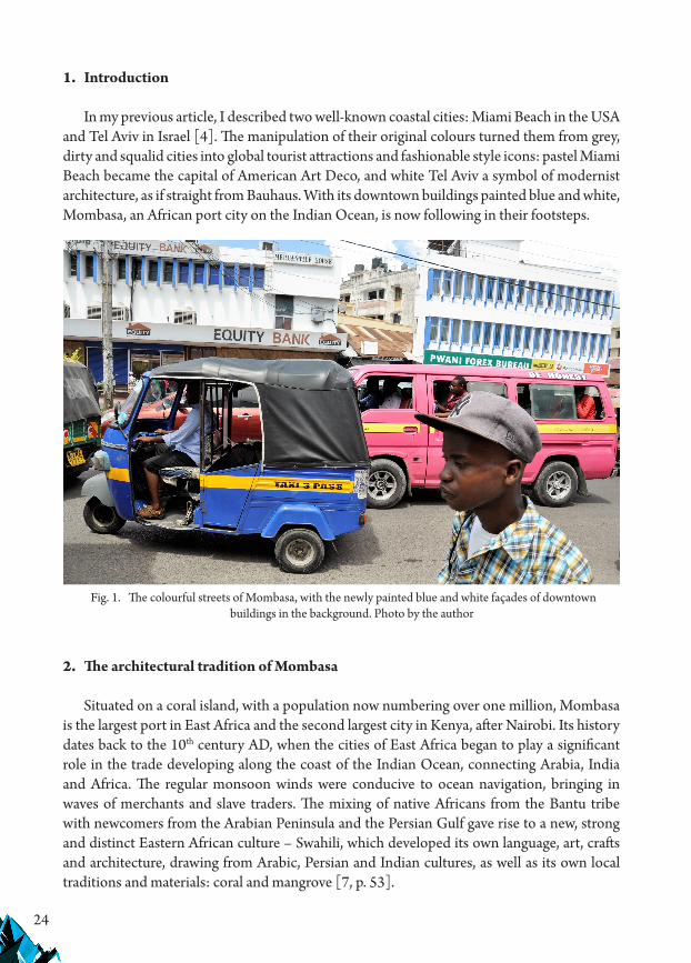
In my previous article, I described two well-known coastal cities: Miami Beach in the USA and Tel Aviv in Israel [4]. The manipulation of their original colours turned them from grey, dirty and squalid cities into global tourist attractions and fashionable style icons: pastel Miami Beach became the capital of American Art Deco, and white Tel Aviv a symbol of modernist architecture, as if straight from Bauhaus. With its downtown buildings painted blue and white, Mombasa, an African port city on the Indian Ocean, is now following in their footsteps.
2. The architectural tradition of Mombasa
Situated on a coral island, with a population now numbering over one million, Mombasa is the largest port in East Africa and the second largest city in Kenya, after Nairobi. Its history dates back to the 10th century AD, when the cities of East Africa began to play a significant role in the trade developing along the coast of the Indian Ocean, connecting Arabia, India and Africa. The regular monsoon winds were conducive to ocean navigation, bringing in waves of merchants and slave traders. The mixing of native Africans from the Bantu tribe with newcomers from the Arabian Peninsula and the Persian Gulf gave rise to a new, strong and distinct Eastern African culture – Swahili, which developed its own language, art, crafts and architecture, drawing from Arabic, Persian and Indian cultures, as well as its own local traditions and materials: coral and mangrove [7, p. 53].
Fig. 1. The colourful streets of Mombasa, with the newly painted blue and white façades of downtown buildings in the background. Photo by the author

25
At around that time, a chain of port cities developed on islands along the East African coast. They included Mombasa, Malindi, Lamu and Zanzibar, all of which still exist. These were places where people traded in ivory, wild game skins and slaves to be sent to Arabia and India – from where china, metal products, patterned fabrics and spices were brought in return. Along the narrow streets of Mombasa’s Old Town, one may still find Majengo – hip-roofed houses characteristic of coastal Swahili settlements, with an entrance hall leading to an elongated yard that separated the front residential part from the outbuilding. Other building types include the African Lamu house – a cuboidal one-level house built of coral with a yard enclosed by a wall at the front, and the Omani house – a cuboidal two- or three-storey building with window openings overlooking the internal yard. The entrance gates to these houses originally featured rich ornamentation, with wooden shutters on the window openings. Starting from the end of the 19th century, it became increasingly common to cover houses with mono-pitched roofs of corrugated metal to protect them from the sun and rain.
Vasco da Gama arrived in Mombasa in 1498, probably as the first European to see the city with his own eyes. Soon the Portuguese took Mombasa by force, and in 1593 they built Fort Jesus (which still exists) with a view to colonising East Africa. Over the following years, the city continued to change hands – it was controlled by the rulers of Oman, the British Empire and the Sultan of Zanzibar. At the end of the 19th century, during the British protectorate era, East Africa attracted a plethora of Indian settlers, mostly from Gujarat. Usually traders and craftsmen, they still remain the economic elite of Kenya. With them came the development of another type
Fig. 2. Ndia Kun Street in Mombasa: a Swahili house on the left, with an Omani house behind it and an Indian house on the right. A photograph from 1903, source: www.oldeastafricapostcards.com

26
of house in the region, known as an Indian shopfront house – a two- or three-storey masonry building with a balcony and a shop on the ground floor. Erected side by side, such houses formed whole street frontages. Many of them have characteristic four-wing folding doors, known as Gujarati doors, which make it possible to open the establishment wide to the street. The compact rows of these houses brought a certain order to the mazes of narrow streets and dead ends of traditional African cities. They mostly form shopping streets in the old port districts, and are the rock of the local economy and a tremendously popular attraction for tourists [8, pp. 69–70].
The downtown streets of Mombasa are filled with buildings dating back to the colonial period, when Kenya was a British protectorate, as well as modern buildings. These were built to touch the edge of the pavement, and followed the same principle as the Indian-type buildings, with ground floors devoted to retail and the residential part on the upper floors. After all, these houses were still being erected mostly by Indians, who monopolised the local markets of trade and services. The British usually lived in the exclusive residential districts of Tudor and Kizingo, which drew from the model of the garden city. The architecture of public utility buildings was based on British colonial motifs, with arcades and neoclassical colonnades. Newer post-war edifices usually represented the modernist style, sometimes alluding to Mendelsohn’s rounded bay windows. A British import that proved highly successful in Kenya was the veranda – a characteristic feature of the typical Anglo-Saxon bungalow, referred to by Anthony King as a “tool of the Empire” [5]. The veranda became a popular element of numerous types of buildings, providing their inhabitants with a space that protected them
Fig. 3. An Old Town street, the 16th century historical Mandhry Mosque in the foreground. Photo by the author

27
from the heat and rain but also allowed them to relax and enjoy social interactions. Another, later import to Mombasa consists of devastated and dirty blocks of flats, scattered along the main access roads into the downtown area.
The second half of the 19th century saw the railway arriving in Mombasa, with the port being modernised, new residential districts (Tudor and Kizingo) created, and the city starting to expand beyond the island, to include both port bays. As a result of its one-thousand-year history, Mombasa became a polygon of numerous architectural typologies, both native and imported, colonial and modern, mixing various building traditions and styles. This multicultural dimension of Mombasa is particularly visible in its temples. It is a place where Muslims, Hindus and Christians have long and peacefully coexisted. Islam currently prevails, and is the most dynamically developing religion in the coastal zone of East Africa. Some mosques though, such as the Mandhry Mosque in the Old Town, are almost 500 years old. Mosques are usually modest buildings, standing out only due to the minarets. The less common churches and Hindu temples feature many more embellishments.
Traditional architecture was certainly not blue and white. This is how Karen Blixen describes it: “The narrow-street town of Mombasa is all built from coral-rock, in pretty shades of buff, rose and ochre, and above the town rises the massive old Fortress, with walls and embrasures, where three hundred years ago the Portuguese and the Arabs held out against one another; it displays stronger colours than the town, as if it had, in the course of the ages, from its high site drunk in more than one stormy sunset” [1, p. 288].
Fig. 4. A downtown street in Mombasa, with house façades painted blue and white, with a Hindu temple between them. Photo by the author
28
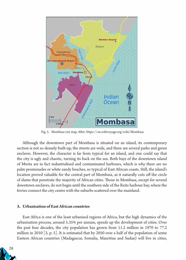
Although the downtown part of Mombasa is situated on an island, its contemporary section is not so densely built-up, the streets are wide, and there are several parks and green enclaves. However, the character is far from typical for an island, and one could say that the city is ugly and chaotic, turning its back on the sea. Both bays of the downtown island of Mwita are in fact industrialised and contaminated harbours, which is why there are no palm promenades or white sandy beaches, so typical of East African coasts. Still, the island’s location proved valuable for the central part of Mombasa, as it naturally cuts off the circle of slums that penetrate the majority of African cities. Those in Mombasa, except for several downtown enclaves, do not begin until the southern side of the Reitz harbour bay, where the ferries connect the city centre with the suburbs scattered over the mainland.
3. Urbanisation of East African countries
East Africa is one of the least urbanised regions of Africa, but the high dynamics of the urbanisation process, around 5.35% per annum, speeds up the development of cities. Over the past four decades, the city population has grown from 11.2 million in 1970 to 77.2 million in 2010 [3, p. 5]. It is estimated that by 2050 over a half of the population of some Eastern African countries (Madagascar, Somalia, Mauritius and Sudan) will live in cities,
Fig. 5. Mombasa city map. After: https://en.wikivoyage.org/wiki/Mombasa

29
while in others, such as Kenya, Ethiopia and Uganda, the rural population will still be in the majority. The urbanisation of Kenya has been progressing since colonial times, and currently centres around three regions: around the capital city of Nairobi in the western part of the country, along the railway line that connects Kenya with Uganda, and in the coastal zone, with Mombasa, Malindi and Lamu being the most populous [11, p. 8].
The rapid growth of the urban population in Kenya stems from its uneven economy, where cities generate much higher revenues and offer better job opportunities than traditional rural economies. Ever since the colonial period, cities have been home to key administrative, economic and cultural processes. Their transportation hubs, industrial plants, railway stations, ports and markets continue to attract growing numbers of people, who settle in the outskirts, in temporary housing. During the colonial period, the downtown districts inhabited by white people were separated from the local populations by open green areas, used exclusively by white people. Parks and gardens, polo fields, rugby and cricket pitches as well as golf courses – together these formed a kind of cordon sanitaire that separated the colonisers from the colonisees. After independence was restored, the white elites were replaced by local elites, and the urbanisation processes gained momentum. The main urban population growth drivers are: demography, migration from rural areas to cities, and the growing number of refugees coming from areas affected by warfare, hunger and natural disasters.
African urbanisation is sometimes referred to as the urbanisation of poverty. Paul Theroux notes that: “…as they kept expanding, African cities became more awful – more desperate and dangerous – as they grew. They did not become denser, they simply sprawled more, becoming gigantic villages. In such cities, women still lugged water from standpipes, cooked over wood
Fig. 6. Downtown buildings on Mwita Island: a tower block surrounded by slums, view from Tudor Creek. Photo by the author

30
Fig. 7. Blocks of flats in the suburbs of Mombasa
Fig. 8. Local market in the Likoni district

31
fires and washed clothes in filthy creeks, and people shat in open latrines. ‘Citified’ in Africa just meant bigger and dirtier” [8, p. 352]. As a consequence of urbanisation, a 19.9% unemployment rate was recorded in Kenyan cities in 2006. Among city youth, the unemployment rate is twice as high, at 40.6%. Over half of the people in Mombasa suffer from malnutrition, with 37.6% living below the destitution threshold [3, pp. 12–13]. According to estimates, more than half of the population of Kenyan cities live in slums (called “informal settlements”), without owning the land where they live, and without access to running water or a sewage system. Only 14% of the population has a sewage system in their homes, with just 50% of them having access to electricity. As a result, Kenyan cities, and especially their outskirts, are overpopulated and characterised by spatial chaos and pollution of the natural environment.
The effects of the automotive development are yet another significant problem. The combination of an insufficient number of roads, their very poor quality and the suicidal practices of drivers makes Kenyan streets a very dangerous place. Drivers of matatu, the minibuses that are the basic means of transport in Kenya, represent a particular hazard. Even the police ignore such conduct as overtaking into oncoming traffic, driving in the wrong direction, passing a red light and halting suddenly in the middle of the road. To enforce the speed limit in especially dangerous places, the authorities install speed bumps in the roads and streets.
African cities could be the drivers of civilisation and economic progress, but they are a hotbed of social inequalities and an epicentre of urban poverty. Still, they offer more opportunities and chances than traditional agricultural areas, which is why they continue to attract people who hope for a better life.
Fig. 9. Slums along the access roads into Mombasa – Likoni district

32
4. Initiatives to improve the appeal and aesthetics of the city
Modern day Mombasa covers an area of 229.9 km2, of which 14.8 km2 comprises the central island of Mwita and 65 km2 the area of the port bays that surround it. The majority of people live on the outskirts, while the central island is inhabited by the local elite. The average population density is 6131 people per km2. Tourism, next to the maritime economy, heavy industry and commerce, forms a crucial branch of the economy, capitalising on the presence of an international airport and the proximity of popular coastal resorts [11, p. 9]. The Mombasa authorities recognise the Old Town and Fort Jesus as the main tourist attractions, and essential economic resources. We can read in local planning documents that “there is enormous potential in the tourism and hospitality sectors, which have yet to be optimally tapped”. They also mention that spatial planning and policies are needed to “enhance the aesthetic value of Mombasa City as a beautiful tourist destination” [8, p. 74].
In their attempts to improve the aesthetics of Mombasa, the city authorities see two basic obstacles, the first being the non-regulated activity of local estate development companies, which erect tall office and residential buildings in the downtown part of the city. The architecture of such structures is based on global models, and as such they disrupt the atmosphere of the city and distort the traditional three-storey building scale. Secondly, the authorities acknowledge the squalid wharf area, whose potential is underutilised. The waterfront causeways, viewing areas, and public-access water is available only at certain points. Other reports mention the issue of bad management and the omnipresent corruption, and highlight those phenomena as significant impediments to the sustainable spatial development of Mombasa [11, p. 51].
Fig. 10. Mombasa: a downtown street near the main city market

33
The Integrated Strategic Urban Development Plan is to serve as a tool to improve the economy and the infrastructure of the city. The urban planning works financed by the United Nations are to regulate the construction requirements, develop a network of public infrastructure, improve the mobility of the inhabitants, and improve the quality of life by providing access to education, healthcare and homes as well as improving the natural environment. These are far-reaching goals, and actions have to be taken at national, regional and local levels to achieve them. Training is provided to those members of the city authorities who are in charge of developing appropriate structures and the tools to create and successfully implement local spatial development plans.
In the meantime, the most spectacular results have been yielded by two ad hoc activities undertaken by the city authorities to increase the tourist appeal of Mombasa: painting of the façades of the downtown buildings and elimination of the huge dumpsite situated beside the causeway connecting the downtown area with the Changamwe industrial district, which has not only a harbour, shipyard, cement plant, sugar factory and refinery but also an international airport. Until recently, the tourists visiting the seaside experienced a culture shock: the buses taking them from the airport, driving the crowded, bumpy roads, would first pass the refinery and smoke-enveloped factories, then they a smelly dumpsite before entering the crowded and dirty slums surrounding the city.
Ecological thinking is already noticeable at the airport: you are not allowed to bring plastic bags into Kenya, so once you arrive products are packed either in newspaper or biodegradable bags. In 2018, the downtown dumpsite was closed down, and is now being reclaimed: soil is being brought in and vegetation planted. It is planned to turn it into a public park; however,
Fig. 11. Blue and white: the new colours of Mombasa. Photo by the author

34
the situation is still out of control, and protests are multiplying. There are protests concerning the location designated for the new dumpsite from the aviation authority, as it is situated within the airport approach area and there are fears that birds looking for food at the dumpsite will pose a hazard to aircraft as they take off or land. There is also the suspicion that, as a result of corruption, the area being reclaimed has already been sold to property developers, who will use it to build skyscrapers rather than a park [2].
The façade painting project initiated by city governor Hassan Joho for the downtown buildings has yielded much better results. In March 2018, he issued a decree that ordered all the owners of the houses situated in the administrative centre of the island and in the Old Town to paint the buildings white at their own cost and to highlight window borders and architectural details in Egyptian blue, the famous lapis-lazuli – a pigment known since antiquity, with a failure to obey punishable by a fine. The owners were given two weeks to prepare and another two to implement the decree. Furthermore, no advertising signs were allowed on building walls. The statement of the grounds explained that the purpose of the initiative was to make the city more beautiful: the blue colour alluding to its heritage and cultural ties with the Indian Ocean. “The ocean is dear to our hearts”, a local clerk stated. The selected colour code is “aimed at promoting culture, preserving heritage and promoting the county as a tourism hub” [10].
This initiative was not protest-free either – at first the decree was unsuccessfully opposed by the Commissioner for Human Rights and Justice, and then a local cosmetics shop owner complained. In his application the latter claimed that his shop had been operating for 15 years, pink was his brand colour and his shops in other Kenyan cities were painted the same way. His attorneys stated that the change of colour might affect his business and that, according to the law in force, the colour of buildings could not be imposed through an arbitrary decision of the governor but only through a spatial development plan. The court shared those arguments and repealed the governor’s decree, stating that it violated the rights and limits the freedoms of real property owners [6]. However, in the meantime, the majority of the proprietors of downtown real properties followed the governor’s order and so Mombasa gained a new look. Until recently ugly and squalid, it has become the most photographed city in Africa, and the blue and white buildings form a perfect background for the colourful street life. Many people, including representatives of the tourism sector, congratulate the governor on the idea, as he made the Mombasa city centre beautiful without spending so much as a penny.

35
References
[1] Blixen K., Pożegnanie z Afryką, Wydawnictwo Graffiti, Kraków 1992.[2] Cornel E., MPs stop reclamation at Kibarani dumpsite, decry ‚massive corruption’, The
Star, 30.07.2018, https://www.the-star.co.ke/news/2018/07/30/video-mps-stop-reclamation-at-kibarani-dumpsite-decry-massive_c1794732 [accessed: 20.01.2019].
[3] Hope K.R., Urbanization in Kenya, African J. Economic and Sustainable Development, Vol. 1, No. 1, 2012.
[4] Jasiński A., Colour manipulations as a tool for creating the city image on examples of Miami Beach and Tel Aviv, Czasopismo Techniczne, z. 11-A/2017, Politechnika Krakowska.
[5] King A.D., The Bungalow: The Production of Global Culture, Oxford University Press, Oxford 1995.
[6] Mwawasi M., Mombasa County barred from painting buildings blue and white, Standard Digital, 12.07.2018, https://www.standardmedia.co.ke/article/2001287784/mombasa-county-barred-from-painting-buildings-blue-and-white [accessed: 20.01.2019].
[7] Pawełczak M., Historia Kenii, [in:] Kenia, Tanzania, Zanzibar. Praktyczny przewodnik, Pascal, Bielsko-Biała 2015.
[8] Steyn G., The Impacts of Islandness on the Urbanism and Architecture of Mombasa, Urban Island Studies, Vol. 1, No. 1, 2015.
[9] Theroux P., Safari mrocznej gwiazdy. Lądem z Kairu do Kapsztadu, Wydawnictwa Czarne, Wołowiec 2013.
[10] Tubei G., Kenya’s main tourist hub is changing before our very eyes thanks to a governor’s stroke of genius to make it the most photographed city in Africa, Business Insider, 7.03.2018, https://www.pulselive.co.ke/bi/lifestyle/hassan-joho-kenyas-main-tourist-hub-is-changing-before-our-very-eyes-thanks-to-a/rb99s85 [accessed: 20.01.2019].
[11] UN Habitat Support to Sustainable Urban Development in Kenya, Vol. 1, United Nations Human Settlements Programme 2015.
If you want to quote this article, its proper bibliographic entry is as follow: Jasiński A., Colour as a tool in shaping the city image – based on the case of Mombasa, Technical Transactions, Vol. 4/2019, pp. 23–36.


37
TECHNICAL TRANSACTIONS 4/2019ARCHITECTURE AND URBAN PLANNING
DOI: 10.4467/2353737XCT.19.042.10354 submIssIOn Of The fInal versIOn: 3/04/2019
Kazimierz Kuśnierz orcid.org/0000-0001-6703-5695Dominika Kuśnierz-Krupa orcid.org/[email protected]
Faculty of Architecture, Cracow University of Technology
Issues with protecting medieval urban layouts from selected example towns in lesser Poland
Problematyka ochrony średniowiecznych układów urbanistycznych na przykładzie wybranych miast
z terenu województwa małopolskiego
Abstractnowadays the protection of historic urban layouts poses one of the greatest challenges in the field of cultural heritage protection. even if this protection functions properly in large historic cities, it is sadly insufficient in smaller towns. The testimony to the latter claim is seen in deteriorating centres of small historic towns. such degradation is a consequence of e.g. inappropriate investments disturbing their historic urban composition, which, in turn, demonstrates insufficient conservation protection. This article presents an analysis of selected medieval towns from lesser Poland, with attention to both the state of preservation of their historic urban structure and the current form of its protection. Two towns (nowy Targ, skawina) are discussed in more detail.Keywords: medieval urban layouts, historic towns in Lesser Poland, protection of historic towns
StreszczenieObecnie jednym z największych wyzwań w zakresie ochrony dziedzictwa kulturowego jest ochrona układów urbanistycznych. O ile ochrona ta funkcjonuje prawidłowo na terenie dużych miast, o tyle na terenie mniejszych ośrodków jest ona niewystarczająca. Dowodem na słuszność takiego twierdzenia jest degradacja centrów małych miast zabytkowych. Degradacja ta związana jest m.in. z niewłaściwymi działaniami inwestycyjnymi, które powodują zaburzenie ich historycznej kompozycji urbanistycznej. To z kolei wskazuje na niewystarczającą ochronę konserwatorską. W niniejszym artykule przeanalizowano, zarówno pod kątem stanu zachowania historycznej struktury urbanistycznej, jak i bieżącej formy jej ochrony wybrane miasta zabytkowe małopolski. Dwa z nich (nowy Targ, skawina) zostaną omówione w pracy szerzej.Słowa kluczowe: średniowieczne układy urbanistyczne, zabytkowe miasta małopolski, ochrona miasta zabytkowego

38
1. Introduction
This article addresses the issue of the protection of historic urban layouts in the small medieval towns of Lesser Poland. One of the main aims of the article is to draw attention to the rapidly progressing deterioration of the discussed urban structures, as well as – or perhaps primarily – their insufficient conservation protection.
According to the authors, it seems paradoxical that whilst nowadays there is a lot of pressure to protect historic objects; invaluable urban layouts which are much more difficult to restore or recreate are neglected.
For several years, the authors of the article have been conducting research on historic towns in Lesser Poland, whose origins frequently date back to the medieval period and are associated with King Kazimierz Wielki (Casimir the Great). The monarch founded numerous towns in the area of modern-day Lesser Poland, which have survived to this day, such as Ciężkowice, Grybów, Krościenko nad Dunajcem, Lanckorona, Muszyna, Myślenice, Nowy Targ, Piwniczna, Proszowice, Skawina, Słomniki, Tylicz (former Miastko), Tymbark and Uście Solne.
As mentioned, the authors have analysed these towns regarding the state of preservation of their historic urban structure, as well as the current form of its protection. Two towns (Nowy Targ and Skawina) are discussed in greater detail.
It should also be emphasised, that the described towns with their unique cultural landscapes represent outstanding historic values, and bear testimony to the times when they were established. That observation provoked reflection on whether those towns with their historic urban layouts are properly protected, or if they are protected at all. The question arose mainly from observation of the rapidly progressing deterioration of such town layouts, and frequently incomprehensible urban planning policy which seems to completely ignore the necessity to protect cultural landscape.
2. Current conservation protection in selected historic towns
Considering the forms of monument protection listed in the currently binding Monument Protection Act from 2003 (with later amendments), the analysed towns with their urban layouts could be protected, firstly, by including them in the voivodeship monument register, or by including specific entries in local spatial development plans (or, when those are not approved, by including entries in Ordinances and Zoning Laws etc.) [1].
Moving on to the analysis of current conservation protection of selected towns, it has been found out that only 5 out of 14 discussed towns have had their medieval urban layouts entered in monument registers. This group includes Ciężkowice (urban layout entered in the monument register in 1987, no. A-313); Lanckorona (urban layout entered in the monument register in 1981, no. A-386/81 [A-896/M]); Muszyna (urban layout entered in the monument register in 1983, no. A-333); Myślenice (urban layout entered in the monument register in 1977, no. A-448 [A-633/M]) and Proszowice (urban layout entered in the monument

39
register in 1976, no. A-437 [A-628/M]). The urban layouts of the remaining 9 towns have not yet been entered in the monument register. The next step in the analysis is to find out whether these towns have currently binding local spatial development plans (further LSDP), which might enforce effective protection of those urban structures. Such plans function in 9 out of the 14 analysed towns, namely in: Grybów, Lanckorona, Muszyna, Myślenice, Nowy Targ, Piwniczna, Skawina, Słomniki and Tymbark. It should also be mentioned that some towns whose spatial layout is protected by an entry in the monument register, do not have an approved LSDP, e.g. Ciężkowice and Proszowice. Furthermore, it should be emphasised that among the 14 towns, only the urban layouts of Krościenko nad Dunajcem, Tylicz (former Miastko) and Uście Solne fail to fall under any form of protection at all, while three (Lanckorona, Muszyna and Myślenice) are very well protected since they are included in the monument register and have a LSDP approved for their historic centres.
To sum up the above research, it must be said that the current conservation protection of historic structures in selected towns is insufficient because only 3 out of 14 are protected by both the monument register and a LSDP, the combination of which is currently the most effective in the Authors’ opinion. Moreover, the majority of the mentioned towns definitely deserve to be included in the monument register, as their urban layouts are very well preserved, and the model on which they were laid out is still recognisable. In order to prove this, the urban layout of two towns (Nowy Targ and Skawina) were analysed, which, in the authors’ opinion, are of considerable historical and cultural value, whose original features have been largely preserved.
3. The urban layout of Nowy Targ – cultural values and their protection
The first town to be discussed in greater detail is Nowy Targ, the population of which currently numbers about 33,400 [2].
The cultural heritage of the town includes, first of all, the chartered urban layout, the parish church of St. Katherine with its immediate surroundings, the filial church of St. Anna, the building of the Seweryn Goszczyński Secondary School, the building of Jan Bednarski School Dormitory, numerous roadside shrines, the town hall, the building of the former “Sokół” Gymnastic Association [3], as well as many tenement houses and smaller residential buildings [4].
To briefly summarise the history of Nowy Targ, it should be mentioned that the town was founded according to the Magdeburg Law in the year 1336. Its urban layout was measured out on the land between the Biały and Czarny Dunajec Rivers, and the village of Stare Cło. It is worth mentioning, that the nearby area contained earlier settlements. According to various sources, the aforementioned Stare Cło, associated with the customs house and the church of St. Leonard, was the earliest trade settlement located in the vicinity of the later town [5]. It should also be remembered, that the town established by King Kazimierz had been preceded by an earlier town foundation initiated by the Cistercian monastery in Szczyrzyc, which might have been implemented during the 1320s, according to the Środa Śląska Law [6, p. 161].

40
The process of the second foundation of the town, which resulted in measuring out a new urban layout, was supervised by the alderman Dytryk, who was granted hereditary aldermanship by the king [7, p. 159]. The urban layout of the chartered town from 1326 can be described as a regular, orthogonal one, based on the 9-square model. Using the 45-meter-long “large cable” unit, a rectangular main market measuring 150 x 115 m was laid out in the centre, with the longer side running in the west-east direction. Single building development plots, 1.5 “cable” deep i.e. around 66 m [8, pp. 227–228], were laid out around the market.
The parish church of St. Katherine, located towards the north behind the market block, was an important object in medieval Nowy Targ. Source documents reveal that it was built from stone probably before the year 1346 [9, pp. 49–64].
Verification of available archival 18th- and 19th-century plans (First Military Photograph – 1779–1783, Second Military Photograph – 1861–1864, and the cadastral plan from the end of 1896), and subsequent comparison with current aerial photos and the orthophotomap, allow us to conclude that the medieval structure of Nowy Targ representing the 9-square model has indeed survived until today. The discussed model is clearly discernible, as well as the communications system in which two streets run from each corner of the market square.
Surprisingly, the urban layout of Nowy Targ described above is not included in the voivodeship monument register. Therefore, it is vital that the town gains a binding LSDP [10], containing regulations to protect the historic downtown and its urban layout [11].
Fig. 1. A recent orthophotomap of Nowy Targ. The yellow colour indicates the urban model upon which the town was founded. Photo: W. Gorgolewski, 2017; prep. by the authors
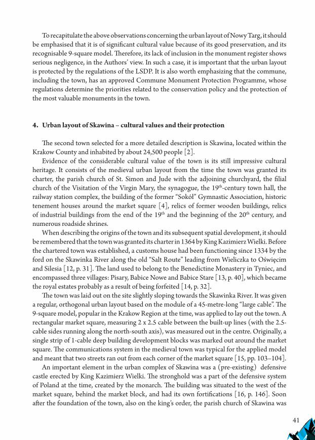
41
To recapitulate the above observations concerning the urban layout of Nowy Targ, it should be emphasised that it is of significant cultural value because of its good preservation, and its recognisable 9-square model. Therefore, its lack of inclusion in the monument register shows serious negligence, in the Authors’ view. In such a case, it is important that the urban layout is protected by the regulations of the LSDP. It is also worth emphasizing that the commune, including the town, has an approved Commune Monument Protection Programme, whose regulations determine the priorities related to the conservation policy and the protection of the most valuable monuments in the town.
4. Urban layout of Skawina – cultural values and their protection
The second town selected for a more detailed description is Skawina, located within the Krakow County and inhabited by about 24,500 people [2].
Evidence of the considerable cultural value of the town is its still impressive cultural heritage. It consists of the medieval urban layout from the time the town was granted its charter, the parish church of St. Simon and Jude with the adjoining churchyard, the filial church of the Visitation of the Virgin Mary, the synagogue, the 19th-century town hall, the railway station complex, the building of the former “Sokół” Gymnastic Association, historic tenement houses around the market square [4], relics of former wooden buildings, relics of industrial buildings from the end of the 19th and the beginning of the 20th century, and numerous roadside shrines.
When describing the origins of the town and its subsequent spatial development, it should be remembered that the town was granted its charter in 1364 by King Kazimierz Wielki. Before the chartered town was established, a customs house had been functioning since 1334 by the ford on the Skawinka River along the old “Salt Route” leading from Wieliczka to Oświęcim and Silesia [12, p. 31]. The land used to belong to the Benedictine Monastery in Tyniec, and encompassed three villages: Pisary, Babice Nowe and Babice Stare [13, p. 40], which became the royal estates probably as a result of being forfeited [14, p. 32].
The town was laid out on the site slightly sloping towards the Skawinka River. It was given a regular, orthogonal urban layout based on the module of a 45-metre-long “large cable”. The 9-square model, popular in the Krakow Region at the time, was applied to lay out the town. A rectangular market square, measuring 2 x 2.5 cable between the built-up lines (with the 2.5-cable sides running along the north-south axis), was measured out in the centre. Originally, a single strip of 1-cable deep building development blocks was marked out around the market square. The communications system in the medieval town was typical for the applied model and meant that two streets ran out from each corner of the market square [15, pp. 103–104].
An important element in the urban complex of Skawina was a (pre-existing) defensive castle erected by King Kazimierz Wielki. The stronghold was a part of the defensive system of Poland at the time, created by the monarch. The building was situated to the west of the market square, behind the market block, and had its own fortifications [16, p. 146]. Soon after the foundation of the town, also on the king’s order, the parish church of Skawina was
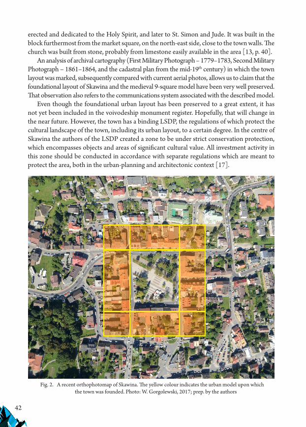
42
erected and dedicated to the Holy Spirit, and later to St. Simon and Jude. It was built in the block furthermost from the market square, on the north-east side, close to the town walls. The church was built from stone, probably from limestone easily available in the area [13, p. 40].
An analysis of archival cartography (First Military Photograph – 1779–1783, Second Military Photograph – 1861–1864, and the cadastral plan from the mid-19th century) in which the town layout was marked, subsequently compared with current aerial photos, allows us to claim that the foundational layout of Skawina and the medieval 9-square model have been very well preserved. That observation also refers to the communications system associated with the described model.
Even though the foundational urban layout has been preserved to a great extent, it has not yet been included in the voivodeship monument register. Hopefully, that will change in the near future. However, the town has a binding LSDP, the regulations of which protect the cultural landscape of the town, including its urban layout, to a certain degree. In the centre of Skawina the authors of the LSDP created a zone to be under strict conservation protection, which encompasses objects and areas of significant cultural value. All investment activity in this zone should be conducted in accordance with separate regulations which are meant to protect the area, both in the urban-planning and architectonic context [17].
Fig. 2. A recent orthophotomap of Skawina. The yellow colour indicates the urban model upon which the town was founded. Photo: W. Gorgolewski, 2017; prep. by the authors

43
To sum up the analysis of the origins and the state of preservation of the town of Skawina, it should be noted that its urban layout has been very well preserved, and its 9-square model is still recognisable. The urban layout should certainly be entered into the voivodeship monument register; even more so since Skawina does not have a current approved Commune Monument Protection Programme that would direct the current conservation policy and support the realisation of promotional and educational tasks in this field. At the moment, the LSDP is the only form of conservation protection of the analysed urban layout.
5. Conclusion
To conclude the presented research, it should be stated that the protection of historic, medieval urban layouts in Lesser Poland requires revision. Efforts should be made to register towns in the monument register which still represent significant cultural values, and remain well-preserved considering their original urban structure.
It should also be noted, that the analysed towns which are listed in the monument register, were entered in it a long time ago, namely in the 1970s and 1980s, which supports the above assumption about the necessity to update the voivodeship monument register by adding historic, well-preserved town layouts.
The Authors believe that failure to take the aforementioned steps might result in an increasing degradation of those layouts, and consequently also the degradation of culturally valuable historic towns that constitute our shared cultural heritage which ought to be protected and restored, to be enjoyed by future generations.
References
[1] Declaration of the Speaker of the Polish Sejm from 3 October 2018, on announcing the uniform text of the Monument Protection Act, J. L. 2018, pos. 2067.
[2] Rocznik Demograficzny 2018, D. Rozkrut (red.), Publ. GUS, Warszawa 2018.[3] Krupa M., Cultural landscape of Nowy Targ region – selected issues, “Wiadomości
Konserwatorskie – Journal of Heritage Conservation” 2016, 47.[4] Register of immovable monuments in Lesser Poland (division into communes and counties),
http://www.wuoz.malopolska.pl/index.php/rejestr-zabytkow, access: 23.08.2018.[5] Mateszew S., Stare Cło, [in:] Źródła i materiały do dziejów miast małopolskich, typescript,
archiwum Katedry Historii Architektury, Urbanistyki i Sztuki Powszechnej Wydziału Architektury Politechniki Krakowskiej, Kraków 1983.
[6] Krasnowolski B., Lokacyjne układy urbanistyczne na obszarze ziemi krakowskiej w XIII i XIV wieku, cz. II, Publikacje Naukowe Akademii Pedagogicznej, Kraków 2004.
[7] Kiryk F., Rozwój urbanizacji Małopolski XIII–XVI, Publikacje Naukowe Wyższej Szkoły Pedagogicznej, Kraków 1985.
44
[8] Książek M., Kuśnierz K., Rozwój przestrzenny Nowego Targu do połowy XIX wieku, [in:] Dzieje miasta Nowego Targu, M. Adamczyk (red.), Publikacje Podhalańskiego Towarzystwa Przyjaciół Nauk w Nowym Targu, Nowy Targ 1991–.
[9] Kumor B., Parafie podhalańskie (do 1550 r.), [in:] Dzieje miasta Nowego Targu, M. Adamczyk (red.), Publikacje Podhalańskiego Towarzystwa Przyjaciół Nauk w Nowym Targu, Nowy Targ 1991–.
[10] Resolution No L/550/2010 of Town Council of Nowy Targ from 8 November 2010, on: passing local spatial development plan NOWY TARG 22 (Centre) with later amendments, https://www.nowytarg.pl/jb_ud.php?zm=2010-550-000-000, access: 16.09.2018.
[11] Resolution No L/550/2010 of Town Council of Nowy Targ from 8 November 2010, Chapter 3, Principles of protecting cultural and historic heritage as well as heritage of contemporary culture, § 12, pt. 5.
[12] Mitkowski J., Najstarszy widok Skawiny, “Małopolskie Studia Historyczne” 1963, 1–2 (20–21).
[13] Skawina. Studium historyczno-urbanistyczne, t. I, S. Rusińska (red.), PKZ Cracow, PDN-H, Kraków 1978–79.
[14] Kuśnierz-Krupa D., Skawina w średniowieczu. Zagadnienia urbanistyczno-architektoniczne, Publikacje Politechniki Krakowskiej, Kraków 2012.
[15] Kuśnierz-Krupa D., History of spatial development of a “Casimir” town in Lesser Poland on the example of Skawina, “Wiadomości Konserwatorskie – Journal of Heritage Conservation” 2010, 28,.
[16] Kuśnierz-Krupa D., The castle Skawina as an example of medieval stronghold founded by King Casimir the Great, “Wiadomości Konserwatorskie – Journal of Heritage Conservation” 2010, 27,.
[17] Resolutions No XLIII/436/10 of Town Council in Skawina from 28 April 2010, on passing the local spatial development plan for the Town of Skawina within its administrative boundaries, with later amendments; http://www.gminaskawina.pl/index.php?option=34&cat_id=136&menu_id=551, access: 15.09.2018.
If you want to quote this article, its proper bibliographic entry is as follow: Kuśnierz K., Kuśnierz-Krupa D., Issues with protecting medieval urban layouts from selected example towns in Lesser Poland, Technical Transactions, Vol. 4/2019, pp. 37–44.

45
TECHNICAL TRANSACTIONS 4/2019ARCHITECTURE AND URBAN PLANNING
DOI: 10.4467/2353737XCT.19.043.10355 submIssIOn Of The fInal versIOn: 27/03/2019
Anna Mitkowska orcid.org/[email protected]
Institute of Landscape Architectre, Faculty of Architecture, Cracow University of Technology
lanckorona's market square in the context of the landscape
rynek lanckoroński w kontekście krajobrazowym
Abstract2005 saw the completion of a project featuring the restoration of the surface of the market square in lanckorona (the powiat of Wadowice, lesser Poland voivodship), funded by european union funds. The design bound the contemporary needs of residents and tourists with the tradition of the place. It is also characterised by attractive visual linkages with the hills of the beskidy mountains seen in the background. The walls of this urban interior are composed of the frontages of timber residential market-side buildings. The construction included all of the design's assumptions and the market square currently enjoys significant popularity, being often used by residents and tourists, with its surface often playing host to occasional open-air events. Keywords: sacrum, landscape of the city, landscape sacrum, identity of the place
StreszczenieW 2005 roku z dotacji unijnych zrealizowany został projekt rewaloryzacji płyty rynku w lanckoronie (pow. Wadowice, woj. małopolskie). W projekcie tym zespolono współczesne potrzeby mieszkańców i turystów z tradycją miejsca. rynek do dzisiaj zachował układ urbanistyczny właściwy średniowiecznemu XIv-wiecznemu jego kształtowi. Odznacza się on również atrakcyjnymi powiązaniami widokowymi ze wzgórzami beskidzkimi w tle. Ściany tego wnętrza urbanistycznego skonstruowane są z pierzei drewnianej mieszkaniowej zabudowy przyrynkowej. W realizacji uwzględniono wszelkie założenia projektowe i obecnie rynek ciszy się dużą popularnością, jest chętnie użytkowany przez mieszkańców i turystów, a na płycie rynku odbywają się okazjonalne imprezy plenerowe.Słowa kluczowe: sacrum, krajobraz miasta, sacrum krajobrazu, tożsamość miejsca

46
1. Introduction – definitions of terms, the goal, state and scope of research
The Market Square in Lanckorona constitutes a valuable example of Polish Medieval urban planning, which manifests creative attitudes characteristic of the period. They manifested themselves in the establishment of a town square (a market square) in the centre of the layout, considered a landscape “interior”, which on the one hand considered the utilitarian needs of residents, while on the other – was integrally bound with the landscape and topographic assets of the place (genius loci) [1, 2]. Historically confirmed advanced settlement at the site has been dated to at least the thirteenth century and the perfect urban layout of the town is considered a result of a fourteenth-century town charter grant based on the Magdeburg rights (Casimir the Great, 1362). The residential settlement was accompanied by an early gord located on Góra Lanckorońska, one of the two tallest hills in the area (along with Góra Żar, being over 600 m a.s.l. in height). Expanded during the times of Casimir the Great into a mighty fortress, it later constituted the residence of Mikołaj Zebrzydowski, who initiated the establishment of a landscape Calvary foundation in the immediate vicinity [17]. The successful development of the settlement was halted in the second half of the seventeenth century during the wars with Sweden, and later fires (in the eighteenth and nineteenth century) resulted in further destruction. The exceptional values of Lanckorona were already acknowledged by the intellectual and artistic communities of Krakow in the nineteenth century. During the first half of the twentieth century Lanckorona, possessing very good conditions for health, (water, air, a mild mountain climate) remained a holiday locality, its development based on providing services to seasonal guests, primarily as an exclusive place, eagerly visited by the cultural elite of Krakow [14].
Unfortunately, in the period after the Second World War, both the Market Square and the entirety of Lanckorona gradually fell into neglect and even ruin. At the same time, the peripheral layout of the locality left its original residents without broader employment opportunities, and as such – their livelihoods. Here, off the beaten track, to the benefit of the town’s landscape assets, no industrial development or other more intense forms of economic activity took form. The period of post-war stagnation left a tragic mark on the town. Struggling guesthouses, the impoverishment of the local population led the Medieval urban centre to a significant state of crisis [21, 23].
Although the architectural conservation community acknowledged the outstanding value of Lanckorona at the time and modest funding was being obtained for the renovation of some of the houses over the first decades of the People’s Republic of Poland, it was not possible to halt the ongoing processes of the place’s decay. In the 1960’s and 1970’s the architectural conservation services of the then-Krakow voivodship, acknowledging the rank of the locality as a heritage site and the outstanding architectural qualities of its residential buildings, took some measures towards saving them. Historical research and building surveying was performed (including, among others, at the Faculty of Architecture of the Cracow University of Technology and at the Krakow Branch of the “Pracownie Konserwacji Zabytków” State Company).
In a legal sense, through the already existing entry concerning the urban layout, some residential buildings and the Lanckorona castle in the heritage sites list (1937), an

47
administrative framework for such protection was established. In parallel, a proposal of comprehensively saving its historical assets, known as the “Lanckorona experiment”, was formulated. According to the assumptions of the proposal, the entire town was to find itself under joint, central governance and be used for tourism-related purposes as a hotel and service complex. However, at the same time, conservation activity – restrictive for the local populace, although mostly performed in good faith – gained in intensity, primarily taking on the form of numerous prohibitions and fines. They led to a deepening of serious neglect in architectural substance, as the owners of buildings were prohibited from performing maintenance work by themselves and funding was not allotted for broader conservation measures [10, 13, 15]. As a result, the residents of Lanckorona adopted a largely negative stance towards thinking and acting in the categories of protecting cultural and environmental heritage.
The political and systemic changes of 1989 that led to a resurgence of economic activity and thus to the crystallisation of positive aspirations in the local population, became a watershed moment for Lanckorona. These tendencies coincided with a general return to the memory of the most essential traditional qualities of the place. The first impulse of the genius loci awakening itself in the population was the decision to have the landscape of Kalwaria Zebrzydowska placed on the UNESCO World Heritage Sites List. Tourist traffic started to increase on a yearly basis, providing a foundation for active entrepreneurship. Despite the negligence of the second half of the twentieth century, this charming and quiet township attracts visual artists who find inspiration for their creative work here [23]. Lanckorona is also eagerly visited by groups of intellectuals, primarily from Krakow and Warsaw, who create a unique atmosphere of a specific centre of culture, comparable to Kazimierz nad Wisłą and even surpassing it in terms of its cultural and natural assets. The scientific conference entitled Ziemia Lanckorońska. Dziedzictwo przyrodniczo-kulturowe wczoraj, dziś i jutro, organised here on the 22nd of September 2012, became a confirmation of this culture-creating role. It took place on the fiftieth anniversary of the establishment of the Friends of Lanckorona Association and on the 650th anniversary of the issuing of the town’s charter, organised by the TPL with the personal involvement of professor Zbigniew Mirek.
The author of this report, following the research traditions of the scientific community of the Faculty of Architecture of the Cracow University of Technology, initiated study and design work with a broader scope, primarily associated with preparing scientific documentation for the Republic of Poland’s application to have the pilgrimage complex of Kalwaria Zebrzydowska placed on the UNESCO World Heritage Sites List [15]. These efforts led the World Heritage Committee to issue a positive decision concerning having Kalwaria Zebrzydowska placed on the list as an outstanding example of a historical composed religious landscape in the form of a mannerist-type pilgrimage park on the 1st of December 1999. The site’s area included Góra Lanckorońska and the ruins of the Casimirian castle, as the residence of Mikołaj Zebrzydowski (in the sixteenth/seventeenth century), the founder of Kalwaria. The territory of the historical Medieval urban layout of Lanckorona found itself in the “buffer” zone, gaining international fame, which constantly results in increasing tourist traffic, not only on Kalwaria’s “paths”, but in Lanckorona as well (the market square, the castle ruins). It would be good to highlight that, in the author’s initial version of the application

48
documentation, the urban layout of Medieval Lanckorona was to find itself in the landscape zone of the “paths” of Kalwaria Zebrzydowska (Mitkowska 1998, 7.2). However, the town’s state of utter neglect and the lack of a perspective of having broader conservation protection measures extended to it that had pervaded the 1990’s led to the decision to have the entirety of Lanckorona removed from the proposed territory of the UNESCO World Heritage Sites List entry proposal. This decision was associated with the criteria set by UNESCO/ICOMOS concerning the candidate site for entry being in good condition and possessing stable site protection mechanisms (Fig. 1).
However, this direct contact that Lanckorona made with the procedure of being listed on the UNESCO World Heritage Sites List led the author to more in-depth study and design work on the town. In the period between 1998 and 2009 around a dozen publications and a similar number of study and design documents and expertises were prepared, ultimately leading to performing regeneration work on Lanckorona’s Market Square. The article’s bibliography thus features a set of the most important of the author’s publications [15–21], featuring full literature on the subject, as well study and design documents and expertises.
2. The cultural and environmental rank of Lanckorona’s Market Square and its specifics
In its present administrative layout, Lanckorona is one of the municipalities of the powiat of Wadowice (the Lesser Poland Voivodship). It is located around 40 km to the south-west of Krakow, in the direct vicinity of the previously mentioned and famous Kalwaria Zebrzydowska. The locality, built in a particularly picturesque landscape on the border of Pogórze Wielickie and Beskid Średni, is placed amidst an expanse of farm fields and the forest complexes of a semi natural character that frame said fields. The territory of the municipality of Lanckorona, along with its settlement centre, constitute an interesting example of a uniform landscape area that possesses a vivid set of high-class natural and cultural values. Apart from the attractive shape of the terrain, these areas are also characterised by a wealth of flora and fauna, whilst its tree stands often feature species compositions that have been maintained in an unchanged form for several hundred years. The area, highly prized by naturalists, features protection zones for highly varied and rare specimens of local plant life (e.g. a site featuring the great horsetail). Its picturesque placement in the smoothly shaped mountainous terrain is enriched with distant views that reach even the mountain chains of Babia Góra and Polica, as well as that of the Tatra Mountains that can be seen in the distance from some areas of the locality. Lanckorona itself developed a distinct type of timber residential architecture in the past, in the form of an original “Lanckorona style”, whose elements have been largely maintained in the current market-square-side buildings and those on the nearby streets.
The market square in Lanckorona, which has remained a compositional, functional and content-related centre, both of the locality itself and of the entire municipality, constitutes an example of a Medieval town square (from the fourteenth century) unique on the European scale. It was delineated in a mountainous area, on a steep incline of the foot of the large massif of Góra

49
Lanckorońska, with wonderful landscape panoramas visible from it. Despite many unfavourable circumstances in recent decades, it has survived in its original form. Its picturesqueness and distinct compositional climate is highlighted by timber market-side hoses from the end of the nineteenth century, which were reconstructed at the time after being destroyed in a fire and given the Medieval form of the previously mentioned “Lanckorona style”. Market-side houses were designed to feature a single storey, with tall roofs and considerably protruding eaves, most often placed on quite tall masonry bases. Largely placed in a layout with gable walls facing the front, with significantly protruding eaves supported by columns, they create a specific variant of arcade sequences that surround the “interior” of the market square [20], and are divided by characteristic paths (called “miedzucha”), i.e. narrow external passages between individual houses, which are accompanied by small backyard plots, primarily used as private gardens.
The following should be highlighted in terms of the characteristic qualities of the market square in its landscape, aesthetic, functional, social and customary dimensions: 1. as integrally linked with the form of the local landscape, it co-creates the outstanding value of this landscape, 2. It is a beautiful (harmonious) landscape in its linking of natural and cultural values; 3. It also remains a region of the occurrence of local flora (the main part of the market square’s surface, front yards, backyard gardens); 4. It constitutes the material heritage of a Medieval urban layout (from the fourteenth century); 5. It operates as a centre of a locality with a Medieval, authentic planning layout; 6. It constitutes a grouping of unique, compact residential development in the form of timber “Lanckorona style” architecture. 7. It currently remains a multifunctional centre of the life of the town (and the municipality); 8. As a heritage site, it teems with life as an “urban salon”, a favourite site amongst both residents and tourists; 9. The area of the market square has also become an attractive motif of the buffer zone of the “paths” of Kalwaria Zebrzydowska (a World Heritage Site); 10. It functions as a starting (and ending) point for the local route of the “Góra Lanckorońska Forest Park” (and, further, for the Calvary “paths”).
Spontaneously landscaped front yards of houses that encroach upon the space of the market square’s “interior„ and surround it, play an important part in building the area’s local flavour. Small elements such as planters with colourful flowers (called “kwietynki”), suspended underneath the eaves of facades, planters and packets with flowers on the edges of balconies and on external windowsills appear here. They are predominantly planted with popular plant species that are easily commercially available, or feature local wild plants. It is also common for entrances to houses to be decorated with either single or multiple planters with flowers. All of the houses near the market square are accompanied by front yards. These are typically landscaped to the individual tastes of residents, featuring compositional variety, one that is nevertheless clearly subjected to local tradition, including climate conditions. Restraint and the logic of the modest yet noble plant material used here is their common trait. They formally oscillate between a smoothly trimmed lawn and an amalgam of local plants, including cover plants, creeping plants and small bushes [4, 19].
The group that co-creates the form of the local landscape is constituted by backyard gardens that stretch along the back of residential buildings, in a strict linkage between utilitarian functions and aesthetic values of plant compositions. They meticulously make use of topographic conditions (hillsides, natural earthen terraces, escarpments). An economic
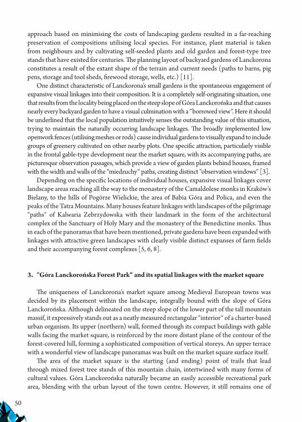
50
approach based on minimising the costs of landscaping gardens resulted in a far-reaching preservation of compositions utilising local species. For instance, plant material is taken from neighbours and by cultivating self-seeded plants and old garden and forest-type tree stands that have existed for centuries. The planning layout of backyard gardens of Lanckorona constitutes a result of the extant shape of the terrain and current needs (paths to barns, pig pens, storage and tool sheds, firewood storage, wells, etc.) [11].
One distinct characteristic of Lanckorona’s small gardens is the spontaneous engagement of expansive visual linkages into their composition. It is a completely self-originating situation, one that results from the locality being placed on the steep slope of Góra Lanckorońska and that causes nearly every backyard garden to have a visual culmination with a “borrowed view“. Here it should be underlined that the local population intuitively senses the outstanding value of this situation, trying to maintain the naturally occurring landscape linkages. The broadly implemented low openwork fences (utilising meshes or rods) cause individual gardens to visually expand to include groups of greenery cultivated on other nearby plots. One specific attraction, particularly visible in the frontal gable-type development near the market square, with its accompanying paths, are picturesque observation passages, which provide a view of garden plants behind houses, framed with the width and walls of the “miedzuchy“ paths, creating distinct “observation windows“ [3].
Depending on the specific locations of individual houses, expansive visual linkages cover landscape areas reaching all the way to the monastery of the Camaldolese monks in Kraków’s Bielany, to the hills of Pogórze Wielickie, the area of Babia Góra and Polica, and even the peaks of the Tatra Mountains. Many houses feature linkages with landscapes of the pilgrimage “paths“ of Kalwaria Zebrzydowska with their landmark in the form of the architectural complex of the Sanctuary of Holy Mary and the monastery of the Benedictine monks. Thus in each of the panoramas that have been mentioned, private gardens have been expanded with linkages with attractive green landscapes with clearly visible distinct expanses of farm fields and their accompanying forest complexes [5, 6, 8].
3. “Góra Lanckorońska Forest Park“ and its spatial linkages with the market square
The uniqueness of Lanckorona’s market square among Medieval European towns was decided by its placement within the landscape, integrally bound with the slope of Góra Lanckorońska. Although delineated on the steep slope of the lower part of the tall mountain massif, it expressively stands out as a neatly measured rectangular “interior“ of a charter-based urban organism. Its upper (northern) wall, formed through its compact buildings with gable walls facing the market square, is reinforced by the more distant plane of the contour of the forest-covered hill, forming a sophisticated composition of vertical storeys. An upper terrace with a wonderful view of landscape panoramas was built on the market square surface itself.
The area of the market square is the starting (and ending) point of trails that lead through mixed forest tree stands of this mountain chain, intertwined with many forms of cultural values. Góra Lanckorońska naturally became an easily accessible recreational park area, blending with the urban layout of the town centre. However, it still remains one of

51
Lanckorona’s rather underappreciated tourist attractions. The planning basis for the forest park avenues was provided by former farm paths, expressively delineated and climbing in spiral-like patterns up the steep slopes. At times they go through a thick forest, while at others they cross through terrain platforms that provide expansive views (“active exposure“), including those of the Calvary “paths“ and other elements of the local landscape. As a broadly accessible park, it is characterised by a considerable variety of function and forms of use. It features purely utilitarian functions, including those associated with commerce (commercial forests), water sources, pedestrian and (to a limited extent) vehicular circulation. Recreational use is the most prominent: associated with holidaymaking, rest, walking, tourism and sports (bicycles, ski running, horsemanship), as well as entertainment. A number of tourist trails link Lanckorona with areas of Beskidy and Pogórze Wielickie [2, 10, 17].
These trails also offer numerous knowledge and learning-related aspects, as well as a wealth of the semantic layer, with numerous testaments to the cultural and environmental tradition of the place. Here we can encounter examples of the microregion’s timber architecture. The local parish church, which is largely in the Gothic style, along with the nearby Calvary chapels by Paul Baudarth, allows tourists to come into contact with the values of historical architecture in its official styles (Gothic, Mannerism, Baroque). It features the miraculous painting of Mary the Mother of God of Lanckorona, which has recently become a part of the European Trail of Sanctuaries of Holy Mary. The nearby areas are also located within the borders of the actual home region of Karol Wojtyła – the blessed pope John Paul II, which is highlighted by the “Papal Oak“, planted in the lower part of the market square’s surface. The ruins of the castle and various memorial sites located all around the area remind us of Polish history, including of the period of Casimir the Great, the legacy of the Zebrzydowski and Czartoryski families in the nearby Kalwaria Zebrzydowska, about the times of the Bar Conferederation, the victims of the Second World War and the difficult times of the People’s Republic of Poland.
The Calvary complex, which encroaches upon the slope of Góra Lanckorońska in the area of Brody (the chapel of the Ascension, the Gethsemane, the Church of the Grave of the Mother of God), in a spatial and landscape sense, was separated from the broader territorial context with distinct terrain forms, such as: the massif of Góra Żar along with the buildings of the church and monastery of the monks of the Order of St. Bernard, the symbolic Góra Kalwaria (named after Mount Calvary) and the traces of a Medieval castle in Barwałd Górny on the north-western edge and Góra Lanckorońska on the south-eastern edge. It constitutes an area of a “sacrum“ of the landscape, a sort of “biblia pauperum“ that enables pilgrims and tourists to come into contact with the primary spiritual message of the Catholic Church.
When walking along the trails and paths of Góra Lanckorońska we encounter a wealth of botanical diversity with numerous field and forest plants, noble and often unique. among the forest tree stands there are weasels, hedgehogs, deer—and often boars as well. Bears have also been seen, albeit sporadically, and even grass snakes and vipers at times. Butterflies, moths and dragonflies enrich this image of the natural tradition of the place, in which distinct geological conditions also play a considerable role. In the vicinity of the compact buildings of Lanckorona, near one of the walking trails (near the “Tadeusz“ guesthouse), we can encounter the remains of an old stone quarry [22].
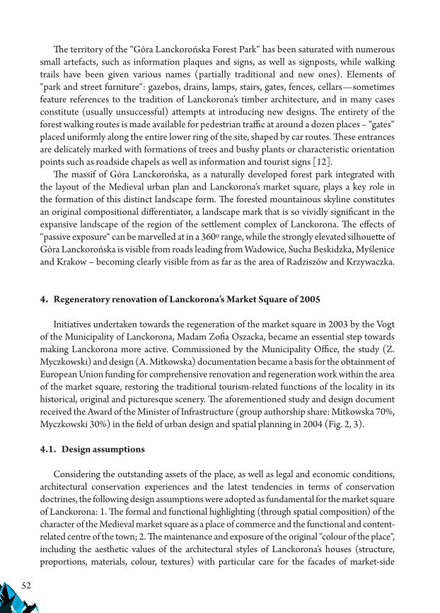
52
The territory of the “Góra Lanckorońska Forest Park“ has been saturated with numerous small artefacts, such as information plaques and signs, as well as signposts, while walking trails have been given various names (partially traditional and new ones). Elements of “park and street furniture“: gazebos, drains, lamps, stairs, gates, fences, cellars—sometimes feature references to the tradition of Lanckorona’s timber architecture, and in many cases constitute (usually unsuccessful) attempts at introducing new designs. The entirety of the forest walking routes is made available for pedestrian traffic at around a dozen places – “gates“ placed uniformly along the entire lower ring of the site, shaped by car routes. These entrances are delicately marked with formations of trees and bushy plants or characteristic orientation points such as roadside chapels as well as information and tourist signs [12].
The massif of Góra Lanckorońska, as a naturally developed forest park integrated with the layout of the Medieval urban plan and Lanckorona’s market square, plays a key role in the formation of this distinct landscape form. The forested mountainous skyline constitutes an original compositional differentiator, a landscape mark that is so vividly significant in the expansive landscape of the region of the settlement complex of Lanckorona. The effects of “passive exposure“ can be marvelled at in a 360º range, while the strongly elevated silhouette of Góra Lanckorońska is visible from roads leading from Wadowice, Sucha Beskidzka, Myślenice and Krakow – becoming clearly visible from as far as the area of Radziszów and Krzywaczka.
4. Regeneratory renovation of Lanckorona’s Market Square of 2005
Initiatives undertaken towards the regeneration of the market square in 2003 by the Vogt of the Municipality of Lanckorona, Madam Zofia Oszacka, became an essential step towards making Lanckorona more active. Commissioned by the Municipality Office, the study (Z. Myczkowski) and design (A. Mitkowska) documentation became a basis for the obtainment of European Union funding for comprehensive renovation and regeneration work within the area of the market square, restoring the traditional tourism-related functions of the locality in its historical, original and picturesque scenery. The aforementioned study and design document received the Award of the Minister of Infrastructure (group authorship share: Mitkowska 70%, Myczkowski 30%) in the field of urban design and spatial planning in 2004 (Fig. 2, 3).
4.1. Design assumptions
Considering the outstanding assets of the place, as well as legal and economic conditions, architectural conservation experiences and the latest tendencies in terms of conservation doctrines, the following design assumptions were adopted as fundamental for the market square of Lanckorona: 1. The formal and functional highlighting (through spatial composition) of the character of the Medieval market square as a place of commerce and the functional and content-related centre of the town; 2. The maintenance and exposure of the original “colour of the place“, including the aesthetic values of the architectural styles of Lanckorona’s houses (structure, proportions, materials, colour, textures) with particular care for the facades of market-side
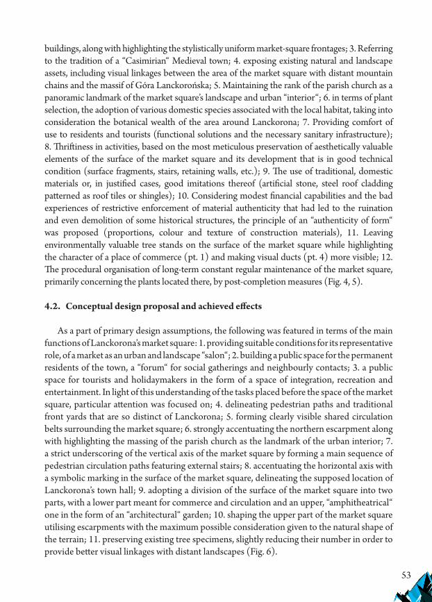
53
buildings, along with highlighting the stylistically uniform market-square frontages; 3. Referring to the tradition of a “Casimirian“ Medieval town; 4. exposing existing natural and landscape assets, including visual linkages between the area of the market square with distant mountain chains and the massif of Góra Lanckorońska; 5. Maintaining the rank of the parish church as a panoramic landmark of the market square’s landscape and urban “interior“; 6. in terms of plant selection, the adoption of various domestic species associated with the local habitat, taking into consideration the botanical wealth of the area around Lanckorona; 7. Providing comfort of use to residents and tourists (functional solutions and the necessary sanitary infrastructure); 8. Thriftiness in activities, based on the most meticulous preservation of aesthetically valuable elements of the surface of the market square and its development that is in good technical condition (surface fragments, stairs, retaining walls, etc.); 9. The use of traditional, domestic materials or, in justified cases, good imitations thereof (artificial stone, steel roof cladding patterned as roof tiles or shingles); 10. Considering modest financial capabilities and the bad experiences of restrictive enforcement of material authenticity that had led to the ruination and even demolition of some historical structures, the principle of an “authenticity of form“ was proposed (proportions, colour and texture of construction materials), 11. Leaving environmentally valuable tree stands on the surface of the market square while highlighting the character of a place of commerce (pt. 1) and making visual ducts (pt. 4) more visible; 12. The procedural organisation of long-term constant regular maintenance of the market square, primarily concerning the plants located there, by post-completion measures (Fig. 4, 5).
4.2. Conceptual design proposal and achieved effects
As a part of primary design assumptions, the following was featured in terms of the main functions of Lanckorona’s market square: 1. providing suitable conditions for its representative role, of a market as an urban and landscape “salon“; 2. building a public space for the permanent residents of the town, a “forum“ for social gatherings and neighbourly contacts; 3. a public space for tourists and holidaymakers in the form of a space of integration, recreation and entertainment. In light of this understanding of the tasks placed before the space of the market square, particular attention was focused on; 4. delineating pedestrian paths and traditional front yards that are so distinct of Lanckorona; 5. forming clearly visible shared circulation belts surrounding the market square; 6. strongly accentuating the northern escarpment along with highlighting the massing of the parish church as the landmark of the urban interior; 7. a strict underscoring of the vertical axis of the market square by forming a main sequence of pedestrian circulation paths featuring external stairs; 8. accentuating the horizontal axis with a symbolic marking in the surface of the market square, delineating the supposed location of Lanckorona’s town hall; 9. adopting a division of the surface of the market square into two parts, with a lower part meant for commerce and circulation and an upper, “amphitheatrical“ one in the form of an “architectural“ garden; 10. shaping the upper part of the market square utilising escarpments with the maximum possible consideration given to the natural shape of the terrain; 11. preserving existing tree specimens, slightly reducing their number in order to provide better visual linkages with distant landscapes (Fig. 6).

54
The leading thought behind the composition had been to highlight the motif of the tradition of the place as the factor that dictates compositional principles, which in this specific situation resulted in a proposal of exposing the natural terraced shape of the terrain of the surface of the market square and utilising topographic conditions to make the space of the market square more legible as a sort of “naturally developed amphitheatre“, which combines respect for the traditional functions of a market square with a twentieth-century layer in the form of introducing park-type greenery, along with the broadest possible meeting of the current needs of Lanckorona’s residents and of the tourists that visit it.
A set of guidelines was also prepared concerning detailed solutions for street furniture (posts, street drain framing, litter bins). The introduction of sculptural elements was also proposed to be introduced later. A monument to Casimir the Great in the upper escarpment was proposed, in a cameral, timber form, produced by local craftsmen; as well as of John Paul II in the lower part of the market square – which was introduced in the form of the “Papal Oak” planted (unfortunately, a foreign variety was used) in place of a sick willow tree that had been removed. Guidelines were prepared for colour schemes, details and advertisements for the market square’s frontages, as well as for reparatory efforts referring to modernist buildings within sequences of market-side buildings, infills in places were individual buildings were missing from the compact development of the area.
Construction work was performed in 2005, featuring a significant amount of author supervision by A. Mitkowska, usually carried out in accordance with the adopted design assumptions and construction recommendations [15]. The traditional area of public greenery in the upper (northern) part of the market square, which topographically forms a sort of naturally developed “amphitheatre“, was preserved. It was made more legible by highlighting escarpments in the terrain, formed in reference to pre-design analyses that focused on behaviour during open-air events that have been taking place at the site for many years. This part is currently maintained in the form of a meticulously landscaped lawn, enlivened by groups of dwarf shrubs, made available for all forms of recreational use. It fulfils the role of an audience for cultural events, often organised in the lower (southern) part of the market square). This solution is a reference to the well-rooted tradition of using this public space as a sophisticated landscape “salon“ for residents and tourists that dates back to the nineteenth century. Old tree plantings (primarily linden trees) in the frontages: the northern and eastern ones, have remained a supplementation of garden-type compositions in addition to individual willow trees in the lower part of the surface of the market square (a paved commercial square). They provide an impressing highlight of the course of the main compositional axis of the market square delineated along the north-south direction. In the upper part of the market square this axis was continued as a sequence of external stairs used to climb the escarpments of the “amphitheatre” which significantly highlights the skeleton of the spatial composition of the entire square [7, 9] (Fig. 7–9).
In its post-completion state, Lanckorona’s market square, featuring an “amphitheatrical“ upper part and a commercial and circulatory lower part, presently constitutes an urban framework for the day-to-day life of the town. It forms a legible landscape “interior“ that is friendly to users, foreshadowing a possibility of improving the stand of living of the town’s residents. The vividness

55
of the spatial designation and planning basis are conducive to more lively use, in which the centrally delineated sequences of walking stairs plays a leading role. Work on replacing elements of the market square’s surface was preceded by a comprehensive renovation of the storm drain system. Surface drainage gutters that had been in a state of severe neglect were formed again, generally improving the technical quality of existing technical infrastructure. A clear division into various use zones (functions of the market square) was instituted, highlighting pedestrian, vehicular and shared path sequences, as well as parking lots, places of recreation and play, occasional commerce, tourist information, transit vehicular traffic and accessways to individual buildings near the market square using different materials (Fig. 10).
It should be highlighted that the market square constitutes quite a complicated circulation “node“ with its intertwining vehicular and pedestrian traffic. The proposed traffic organisation currently works without additional prohibitive or prescriptive road signs. The selection of pavement surfaces, including the patterns of laying the various different elements, constitute a sufficient, visible and formal message concerning the functional designation of each part of the market square’s surface. The area of the market square features considerably sloping terrain, which had previously made unrestricted wheelchair movement impossible and was levelled (where technically possible) utilising individual ramps and driveways. The entirety of the market square is currently accessible to wheelchairs, both around its rim and in the lower, commercial section.
Spaces meant to be safe for small children were established in the upper, “amphitheatrical“ section of the market square, and the entirety of this zone constitutes an area of recreation (sequences of seating on low retaining walls, outlined in accordance with the elevation lines of the terrain, areas featuring freely accessible lawns). The full set of works leading to the formation of the varied surfaces was performed using local materials. Sandstone from quarries in Mucharz, Brenna, Palcza, Marwałd and Lanckorona was used, interspersed with elements from artificial stone where necessary, with careful selections of texture and colour (Brukbet) along with a small number of large-format pavement tiles from Silesian Długopole (resistance-related considerations). As a part of post-completion changes, a planned planting of shrubs meant to soften the sequences of “amphitheatrical“ escarpments in the upper part of the market square was carried out in 2006 and 2007 [19].
It should be highlighted that the shape of a Medieval commercial and circulatory town square, with an amphitheatrical section featuring a garden character, was highlighted in the terrain in complicated topographic conditions combined with often conflicting functions, all of it remaining in accordance with the conditions of the tradition of the place (genius loci). The project was carried out to provide comfort and satisfaction to the population of Lanckorona’s microregion. The design proposal that has been presented here constituted a culmination of thirty tears’ worth of studies on the assets of the landscape pilgrimage sanctuary of Kalwaria Zebrzydowska and ten years of becoming familiarised with the residents of Lanckorona, their customs, tastes and the hierarchy of values adopted by them. It should be noted that the Lanckorona Gorals are an honourable, proud, intelligent, driven and honest people, devoted to Mary the Mother of God of Kalwaria and Mary the Mother of God of Lanckorona (Fig. 11–13).

56
5. Threats to the Lanckorona market square, its state in 2012 (the author’s reflections)
In the situation of the beauty of Lanckorona’s landscape outlined over the course of this text, negative phenomena that appear here should also be noted. They primarily concern individual massings of residential buildings constructed in the final decades of the twentieth century that disregard the characteristic qualities of the “Lanckorona style“ in their proportions and detail. Two modernist massings also encroached upon market-side development at the start of the twentieth century, fortunately adhering to the traditional height of residential buildings. Furthermore, there have recently been cases of erroneous interpretations of regional forms among newly arrived plot owners (also a marginal phenomenon, featuring the regional architecture of Podhale and the area around Krakow, etc.). Some gardens started to feature forms belonging to the category of kitsch, such as garden gnomes, stork figurines and “Dutch style“ windmills, brightly coloured fence posts – often laid out in “modernist“ patterns, colourful glass elements in the facades of houses or poorly performed forming of garden plants into topiaric forms. These are, fortunately, sporadically encountered situations, ones that have started to disappear in recent years. It should be noted that, overall, the microregion of Lanckorona has maintained its distinct qualities of the tradition of the place, and in recent years we can also note a far-reaching care for the continuation of original forms of Lanckorona among both local and newly arrived plot owners, proof of which can be seen in recent renovations of private houses located in the centre of the town, as well as in the arrangement of front and backyard gardens (Mitkowska 2009, 7.1). These positive tendencies have appeared on a broader scale after the regeneration work performed in 2005 on the market square.
The market square itself has been maintained in an overall good condition after its renovation and is being subjected to regular maintenance, primarily in terms of its plant material. At the same time it is sometimes sporadically the target of acts of vandalism and intentional property damage (the tearing away of individual paving elements, damage to lighting fixtures). After performing a more in-depth analysis we can also observe certain worrying and progressively worsening negative phenomena. Some of them have started during the period of performing the main renovation and post-completion work, while others have only recently begun to manifest themselves in the area of the market square. For instance, a number of small errors were not detected during handover and their removal was not enforced as a part of warranty repairs. For instance, in the eastern edge of the main observation platform the surface was not levelled to a sufficient degree causing surface runoff to accumulate there, while insufficient surface levelling led to small cracks appearing in large-format tiles in the lower corner of the pavement on the western side.
Due to financial considerations, the design was not fully executed in some details. These include the frontal yard and entrance to a corner house in the lower part of the western frontage that have not been landscaped to this day. The work slated to be performed on the immediate vicinity of the drain in the upper part of the market square was not performed as well. The theatrical stage was not extended by constructing the proposed eastern annex. These shortcomings can be easily addressed by carrying out the planned work. However, the
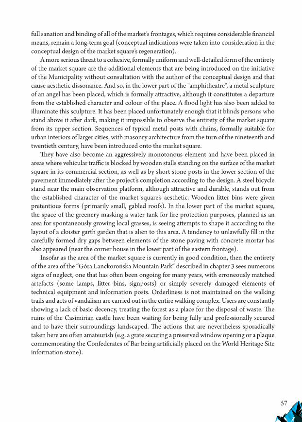
57
full sanation and binding of all of the market’s frontages, which requires considerable financial means, remain a long-term goal (conceptual indications were taken into consideration in the conceptual design of the market square’s regeneration).
A more serious threat to a cohesive, formally uniform and well-detailed form of the entirety of the market square are the additional elements that are being introduced on the initiative of the Municipality without consultation with the author of the conceptual design and that cause aesthetic dissonance. And so, in the lower part of the “amphitheatre“, a metal sculpture of an angel has been placed, which is formally attractive, although it constitutes a departure from the established character and colour of the place. A flood light has also been added to illuminate this sculpture. It has been placed unfortunately enough that it blinds persons who stand above it after dark, making it impossible to observe the entirety of the market square from its upper section. Sequences of typical metal posts with chains, formally suitable for urban interiors of larger cities, with masonry architecture from the turn of the nineteenth and twentieth century, have been introduced onto the market square.
They have also become an aggressively monotonous element and have been placed in areas where vehicular traffic is blocked by wooden stalls standing on the surface of the market square in its commercial section, as well as by short stone posts in the lower section of the pavement immediately after the project’s completion according to the design. A steel bicycle stand near the main observation platform, although attractive and durable, stands out from the established character of the market square’s aesthetic. Wooden litter bins were given pretentious forms (primarily small, gabled roofs). In the lower part of the market square, the space of the greenery masking a water tank for fire protection purposes, planned as an area for spontaneously growing local grasses, is seeing attempts to shape it according to the layout of a cloister garth garden that is alien to this area. A tendency to unlawfully fill in the carefully formed dry gaps between elements of the stone paving with concrete mortar has also appeared (near the corner house in the lower part of the eastern frontage).
Insofar as the area of the market square is currently in good condition, then the entirety of the area of the “Góra Lanckorońska Mountain Park“ described in chapter 3 sees numerous signs of neglect, one that has often been ongoing for many years, with erroneously matched artefacts (some lamps, litter bins, signposts) or simply severely damaged elements of technical equipment and information posts. Orderliness is not maintained on the walking trails and acts of vandalism are carried out in the entire walking complex. Users are constantly showing a lack of basic decency, treating the forest as a place for the disposal of waste. The ruins of the Casimirian castle have been waiting for being fully and professionally secured and to have their surroundings landscaped. The actions that are nevertheless sporadically taken here are often amateurish (e.g. a grate securing a preserved window opening or a plaque commemorating the Confederates of Bar being artificially placed on the World Heritage Site information stone).

58
6. Conclusions
The situation of Lanckorona, seen positively from the point of view of maintaining the continuity of the tradition of the place and remaining stable in the second half of the twentieth and in the beginning of the twenty-first century, has been conditioned by a fortunate combination of a number of essential factors. Paradoxically, the reality of the period of the Polish Republic of Poland. i.e. the political transformation after the Second World War, played a positive role here. On the one hand, the small scale private ownership of Lanckorona’s plot owners, who still lived according to the custom of interwar Poland, was preserved. On the other, the worsening poverty of the population, combined with a lack of economic perspectives characteristic of a communist economy, made it impossible to introduce models of post-war architecture – that departed from regional traditions – on a broader scale.
It appears that the carrying out of a comprehensive regeneration of Lanckorona’s market square has been met with a general approval of the local population. The material and formal solutions implemented in the market square, strongly accentuating traditional local conditions, have directed the thinking of the local population towards appreciating their original historical architectural forms. The simultaneous observable increase in affluence increases the capacity to perform regular maintenance work and the Office of the Municipality promotes the traditional assets of the microregion. It should be highlighted that a particularly positive role in terms of maintaining and popularising the genius loci of Lanckorona is being played by the personal involvement of the current Vogt of the Municipality, Madam Zofia Oszacka. One interesting detail that can be mentioned is that in an online poll, entitled „the seven miracles of Poland„ and organised by “National Geographic“ in September 2012, Lanckorona’s market square came 12th, competing on the scale of the entire country.
However, the popularity of Lanckorona has reached such a high level in recent years that during summer weekends the amount of occasional motorised tourists leads to an excessive density of cars being parked there. The several dozen parking spots that have been safely arranged in the surface of the square are insufficient. Vehicles, parked for the better part of a day, block circulation routes around the market square and its adjacent streets. A new task thus presents itself, concerning the control of this increased traffic and the organisational redirection of cars to a parking lot established between the parish church and the parsonage buildings. According to the author of this report, the conceptual proposals of occasional (often exceedingly noisy) open-air events (which compete with the traditional August ministries along the paths of Kalwaria Zebrzydowska, which the local populace still identifies with), including the artificial and pretentious search for “new traditions“, require particular thought, seeing as Lanckorona’s historical traditions are very rich and filled with patriotic and religious content of the highest order.

59
References
[1] Adamczewska-Wejchert H., Wejchert K., Małe miasta. Problemy urbanistyczne stale aktualne, Warszawa 1986.
[2] Böhm A., Planowanie przestrzenne dla architektów krajobrazu. O czynniku kompozycji, Kraków 2017, 145–146.
[3] Bobek W., Assessing risks caused by in historic gardens and park areas, [in:] Threats occurring in historical gardens of countries in Central Europe, (Zagrożenia występujące w ogrodach historycznych krajów Europy Środkowej), monografia 523, seria Architektura, Wydawnictwo Politechniki Krakowskiej, Kraków 2016, 53–118.
[4] Bobek W., Łakomy K., Contemporary processes and the selection of materials in historical urban greenery areas on example from Cracow and Warsaw, IOP Conference Series: Materials Science and Engineering, Vol. 471, Session 8, 2019.
[5] Dąbrowska-Budziło K., Forma i treść krajobrazowej kompozycji, Kraków 2013.[6] Fekete A., van den Toorn M., Sacred eye-catchers, Urbanity and Architecture Files
Krakow Section of Polish Academy of Sciences, Vol. XLVI, 2018, 303–311.[7] Hodor K., Rozwiązania nawierzchni przy zabytkowych zespołach sakralnych, Technical
Transactions, 2-A/1/2011, 83–89.[8] Hodor A., Fekete A., The sacred in the landscape of the city, Technical Transactions
1/2019, 11–18. [9] Hodor K., Klimek J., Attempts and methods of revitalizing the centres of small localities.
Selected examples, Journal of Sustainable Architecture And Civil, 2013.No.4(5), Technologija Knaunas 2013, 13–17.
[10] Hodor K., Sawicka M., The role of landscape architecture in the process of revitalising rural areas, (rola architektury krajobrazu w procesie rewitalizacji wsi), Technical Transactions 2-A/2016, 177–187.
[11] Hodor K., Wilkosz-Mamcarczyk M., Rola strefy sacrum w turystyce pielgrzymkowej na przykładzie wybranych obiektów powiatu wadowickiego oraz krakowskiego, [in:] „Turystyka jako rytuał”, (ed.) M.K. Leniartek, Monografie – prace zbiorowe Wyższej Szkoły Zarządzania „Edukacja” we Wrocławiu, 145–155.
[12] Hrehorowicz-Gaber H., Recreational and tourist qualities of submontane resorts within the Cracow metropolitan area, IOP Conference Series: Materials Science and Engineering, Vol. 471, 2019.
[13] Kosiński W., Aktywizacja turystyczna małych miast. Aspekty architektoniczno-krajobrazowe, Kraków 2000.
[14] Kuśnierz K., Kuśnierz-Krupa D., Funkcja turystyczna jako czynnik aktywizacji małych miast zabytkowych dawnej Ziemi Krakowskiej w drugiej dekadzie XXI wieku – wybrane problemy, Tourist function as an activating factor in small historic towns in the former Krakow region in the second decade of the 21st century – selected problems, Journal of Heritage Conservation, 42/2015, 61–70.
[15] Mitkowska A., Układy urbanistyczne uwarunkowane szczególnego typu kompozycja ogrodową lub tradycja miejsca, [in:] „Strategie rewaloryzacji miast w Polsce i w innych

60
krajach”, Ośrodek Ochrony Zabytkowego Krajobrazu „Studia i Materiały. Krajobrazy” 25 (37), Warszawa 1988, 72–78.
[16] Mitkowska A., Bogactwo kompozycyjne i krajobrazowe Kalwaryjskiego parku Pielgrzymkowego w Kalwarii Zebrzydowskiej, [in:] „Kalwaria Zebrzydowska – Polska Jerozolima skarbem kościoła i narodu polskiego” (ed. Gniecki Cz. OFM), Calvarianum, Kalwaria Zebrzydowska 2002, 183–215.
[17] Mitkowska A., Kalwaria Zebrzydowska – Światowe Dziedzictwo Kultury i Natury, [in:] „Kalwaria Zebrzydowska – Polska Jerozolima skarbem kościoła i narodu polskiego” (ed. Gniecki Cz. OFM), Calvarianum, Kalwaria Zebrzydowska 2002, 327–347.
[18] Mitkowska A., Aktywizacja turystyczna Lanckorony wobec wpisu krajobrazu komponowanego Kalwarii Zebrzydowskiej na Listę Światowego Dziedzictwa, „Folia Turistica”, wydaw. Akademii Wychowania Fizycznego w Krakowie, Kraków 2002, 49–54.
[19] Mitkowska A., Typowe materiały i technologie budowlane w kreowaniu autentyzmu formy tradycyjnego prowincjonalnego domu (na przykładzie Lanckorony), Czasopismo Techniczne, 4-A/2007, 231–236.
[20] Mitkowska A., Architektura krajobrazu w służbie ludności lokalnego mikroregionu, [in:] „Oblicza dobra”, Sympozja 2. Wydaw. Uniwersytetu Ekonomicznego w Krakowie, Kraków 2007, 79–92.
[21] Mitkowska A., Łakomy K., Ochrona obiektów krajobrazowych i ogrodowych z uwzględnieniem tradycyjnych wartości kulturowo-przyrodniczych poprzez odczytanie i eksponowanie „genius loci”, [in:] „Współczesne problemy teorii konserwatorskiej w Polsce” (ed.) B. Szmygin, ICOMOS, Politechnika Lubelska, Warszawa–Lublin 2008, 75–83.
[22] Wielgus K., Środulska-Wielgus J., Wyjątkowe i uniwersalne wartości dawnych krajobrazów warowny Chunique and universal values of former fortified landscapes, Urbanity and Architecture Files Krakow Section of Polish Academy of Sciences, Vol. XLVI, 2018, 431–447.
[23] Zabytki urbanistyki i architektury w Polsce. odbudowa i konserwacja. 1. miasta historyczne, (ed.) W. Zin, Warszawa 1986.
Unpublished study and design documentations, execution expertises
[24] Mitkowska A., Szkic uzasadnienia wpisu na Listę Światowego Dziedzictwa Kulturowego i Naturalnego UNESCO dla krajobrazu kulturowego fundacji kalwaryjskiej w Kalwarii Zebrzydowskiej, zgłoszenie wstępne, typescript in possession of the General Conservator of Historical Monuments, Kraków–Warszawa, November 1997.
[25] Mitkowska A. (et al.), Wniosek RP o wpis krajobrazu komponowanego Kalwarii Zebrzydowskiej na Listę Światowego Dziedzictwa UNESCO (V Government Programme: „Ochrona i konserwacja zabytkowego krajobrazu kulturowego”), typescript in

61
possession of the General Conservator of Historical Monuments, Kraków–Warszawa, June 1998.
[26] Mitkowska A., Projekt planu gospodarowania obiektem, dokumentacja dodatkowa do wniosku RP o wpis Kalwarii Zebrzydowskiej na Listę Światowego Dziedzictwa UNESCO, typescript with drawing sheets in possession of the General Conservator of Historical Monuments, Kraków–Warszawa, September 1999.
[27] Mitkowska A., Projekt „obelisku” – tablicy informacyjnej o strefie Światowego Dziedzictwa na zamku lanckorońskim (commissioned by the Office of the Municipality of Lanckorona), Lanckorona, June 2001.
[28] Mitkowska A., Koncepcja nawierzchni chodników dla dolnej części rynku w Lanckoronie i ul. Piłsudskiego, typescript with drawing sheets in possession of the Office of the Municipality of Lanckorona, Lanckorona, April 2003.
[29] Myczkowski Z. (et al.), Studium zagospodarowania zieleni Rynku w Lanckoronie, pre-design study documentation Kraków, typescript in possession of the Office of the Municipality of Lanckorona. April–July 2003.
[30] Mitkowska A. (et al.), Studium kompozycyjne do projektu rewaloryzacji płyty rynku w Lanckoronie. Pprojekt koncepcyjny rewaloryzacji średniowiecznego rynku w Lanckoronie, Kraków–Lanckorona; typescript with drawing sheets in possession of the Office of the Municipality of Lanckorona, October 2003.
[31] Mitkowska A., Raport z nadzoru autorskiego I etapu rewaloryzacji rynku w Lanckoronie (chodniki i wjazdy w pierzei południowej), Lanckorona, typescript with sketches in possession of the Office of the Municipality of Lanckorona, August 2004.
[32] Mitkowska A., Wytyczne szczegółowe do realizacji rewaloryzacji rynku w Lanckoronie (wskazania do ustalenia warunków przetargu na realizację projektu), Kraków–Lanckorona typescript with design sheets in possession of the Office of the Municipality of Lanckorona, February 2005.
[33] Mitkowska A., Korekta wskazań w zakresie gospodarowania drzewostanem na rynku w Lanckoronie, Lanckorona, typescript with sketches in possession of the Office of the Municipality of Lanckorona, August 2005.
[34] Mitkowska A., Lanckorona – rynek, wskazania porealizacyjne, Kraków, typescript with drawing sheets in possession of the Office of the Municipality of Lanckorona, January 2006.
[35] Mitkowska A., Rewaloryzacja rynku w Lanckoronie, folder promocyjny, Kraków–Lanckorona, typescript with illustrations in possession of the Office of the Municipality of Lanckorona, March 2006.
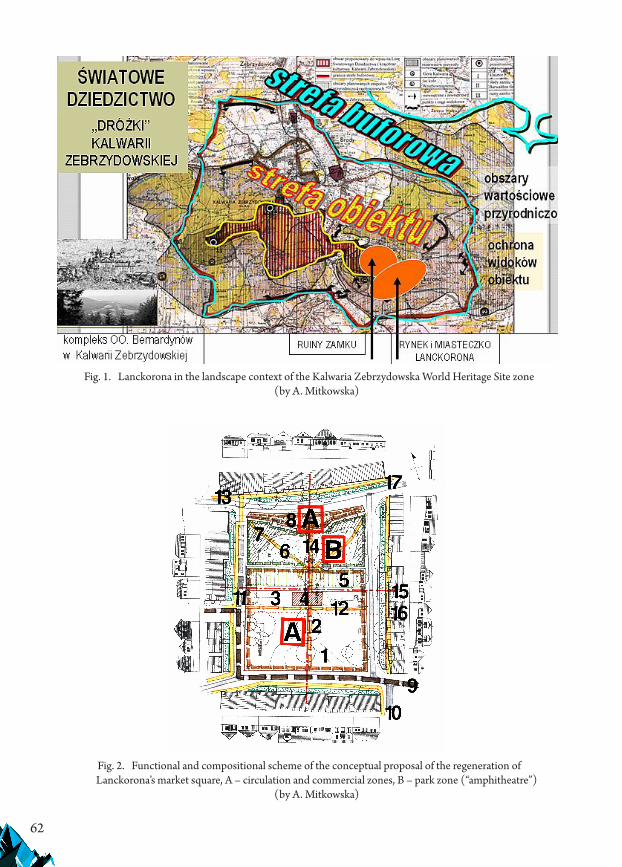
62
Fig. 1. Lanckorona in the landscape context of the Kalwaria Zebrzydowska World Heritage Site zone (by A. Mitkowska)
Fig. 2. Functional and compositional scheme of the conceptual proposal of the regeneration of Lanckorona’s market square, A – circulation and commercial zones, B – park zone (“amphitheatre”)
(by A. Mitkowska)
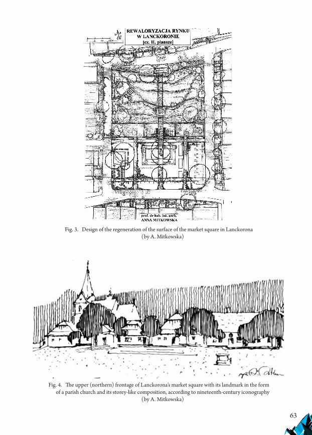
63
Fig. 3. Design of the regeneration of the surface of the market square in Lanckorona (by A. Mitkowska)
Fig. 4. The upper (northern) frontage of Lanckorona’s market square with its landmark in the form of a parish church and its storey-like composition, according to nineteenth-century iconography
(by A. Mitkowska)
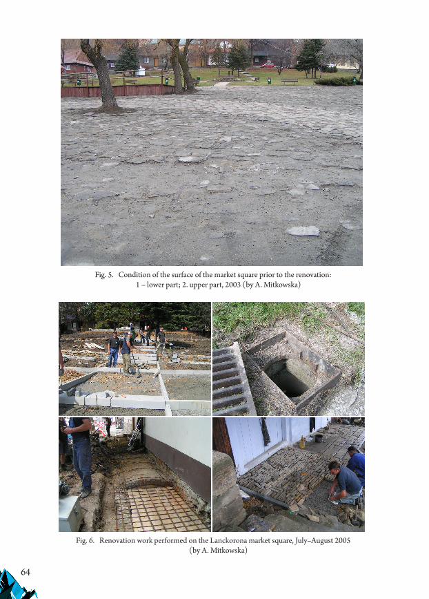
64
Fig. 5. Condition of the surface of the market square prior to the renovation: 1 – lower part; 2. upper part, 2003 (by A. Mitkowska)
Fig. 6. Renovation work performed on the Lanckorona market square, July–August 2005 (by A. Mitkowska)
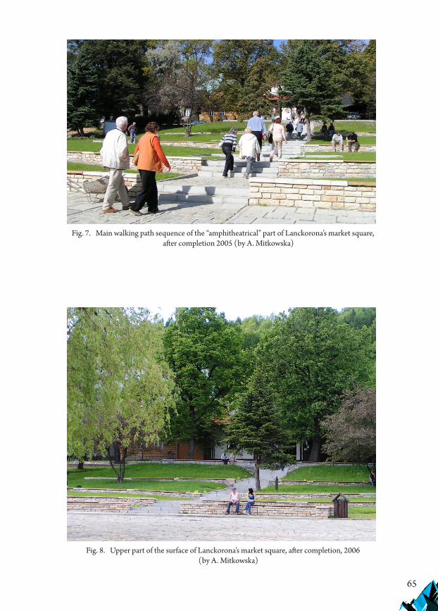
65
Fig. 7. Main walking path sequence of the “amphitheatrical” part of Lanckorona’s market square, after completion 2005 (by A. Mitkowska)
Fig. 8. Upper part of the surface of Lanckorona’s market square, after completion, 2006 (by A. Mitkowska)
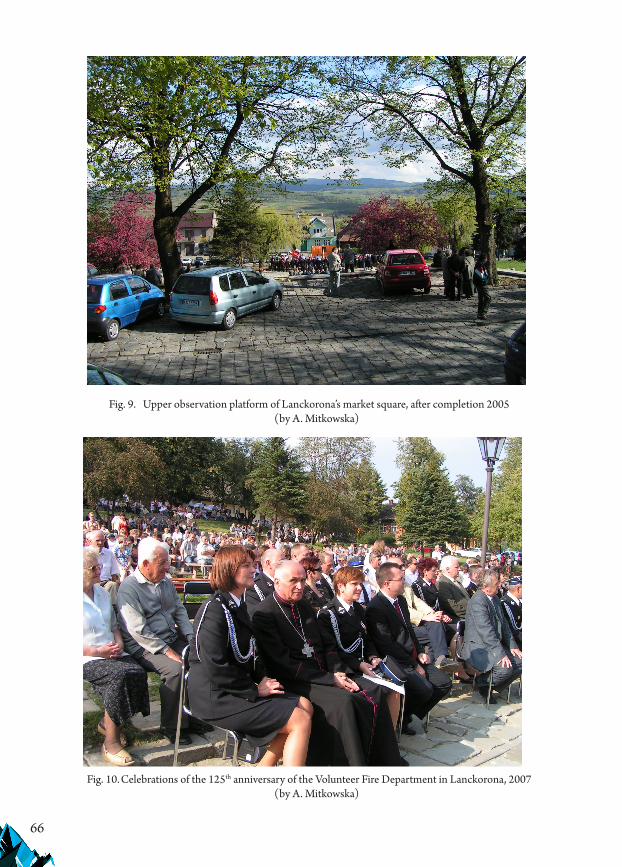
66
Fig. 9. Upper observation platform of Lanckorona’s market square, after completion 2005 (by A. Mitkowska)
Fig. 10. Celebrations of the 125th anniversary of the Volunteer Fire Department in Lanckorona, 2007 (by A. Mitkowska)
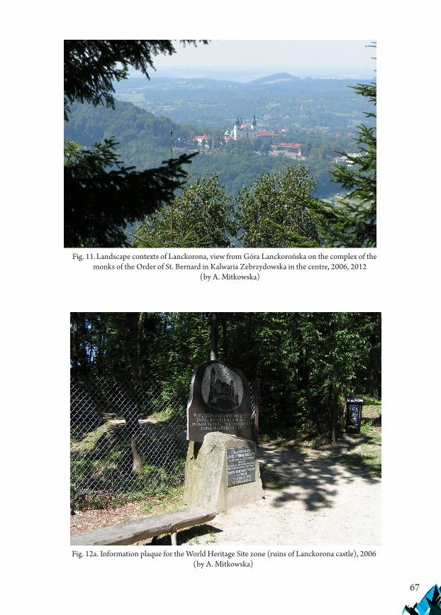
67
Fig. 11. Landscape contexts of Lanckorona, view from Góra Lanckorońska on the complex of the monks of the Order of St. Bernard in Kalwaria Zebrzydowska in the centre, 2006, 2012
(by A. Mitkowska)
Fig. 12a. Information plaque for the World Heritage Site zone (ruins of Lanckorona castle), 2006 (by A. Mitkowska)

68
Fig. 12b. Information plaque for the World Heritage Site zone with the addition of an artifact dedicated to the Confederators of Bar that was not approved by the author, 2012 (by A. Mitkowska)
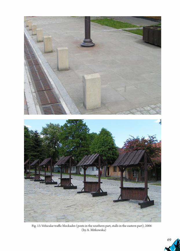
69
Fig. 13. Vehicular traffic blockades (posts in the southern part, stalls in the eastern part), 2006 (by A. Mitkowska)

If you want to quote this article, its proper bibliographic entry is as follow: Mitkowska A., Lanckorona's market square in the context of the landscape, Technical Transactions, Vol. 4/2019, pp. 45–70.
71
TECHNICAL TRANSACTIONS 4/2019ARCHITECTURE AND URBAN PLANNING
DOI: 10.4467/2353737XCT.19.044.10356 submIssIOn Of The fInal versIOn: 28/03/2019
Marta Pieczara orcid.org/[email protected]
Institute of Architecture and Physical Planning, Faculty of Architecture, Poznan University of Technology
archetypes in contemporary architecture
archetypy w architekturze współczesnej
Abstractarchitectural archetypes, which can be defined as a timeless reference of the relevant typology of buildings, are labelled as such through purely intellectual appraisals. Their conceptual qualities do nonetheless translate into the design principles which have the potential to be used as guidelines of spatial definition. The contemporary american architect louis I. Kahn, whose works are renowned for creating links with the built heritage, has adopted the notion of the archetype into his personal design philosophy. by means of studying a selection of his designs, this paper will try to explain what an archetype is and how it influences the architectural design. moreover, it aims to show that deriving inspiration from the archetype is important in terms of creating unique places.Keywords: archetype, architectural type, idea, design
Streszczeniearchetyp architektoniczny, który można zdefiniować jako ponadczasowe odniesienie dla odpowiadającej mu typologii budowli, pozostaje w sferze intelektu. Jego wartości koncepcyjne mogą jednakże zostać przeniesione na określone zasady definiowania przestrzeni. Współczesny amerykański architekt louis I. Kahn, którego prace słyną z nawiązań do dziedzictwa architektury, zaadoptował pojęcie archetypu do własnej filozofii projektowej. Poprzez analizę jego wybranych dzieł poniższy tekst ma na celu odpowiedzieć na pytania, czym jest archetyp i jak wpływa on na proces projektowania architektury. Ponadto poniższa praca dążyć będzie do pokazania, że czerpanie inspiracji z archetypu jest ważnym elementem w tworzeniu przestrzeni odbieranych jako unikalne.Słowa kluczowe: archetyp, typ architektoniczny, idea, projekt
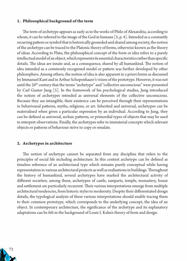
72
1. Philosophical background of the term
The term of archetype appears as early as in the works of Philo of Alexandria, according to whom, it can be referred to the image of the God in humans [5, p. 4]. Intended as a constantly recurring pattern or symbol that is historically grounded and shared among society, the notion of the archetype can be traced to the Platonic theory of forms, otherwise known as the theory of ideas. According to Plato, the philosophical concept of the form or idea refers to a purely intellectual model of an object, which represents its essential characteristics rather than specific details. The ideas are innate and, as a consequence, shared by all humankind. The notion of idea intended as a commonly recognised model or pattern was further developed by other philosophers. Among others, the notion of idea is also apparent in a priori forms as discussed by Immanuel Kant and in Arthur Schopenhauer’s vision of the prototype. However, it was not until the 20th century that the terms “archetype” and “collective unconscious” were presented by Carl Gustav Jung [5]. In the framework of his psychological studies, Jung introduced the notion of archetypes intended as universal elements of the collective unconscious. Because they are intangible, their existence can be perceived through their representations in behavioural patterns, myths, religions, or art. Inherited and universal, archetypes can be materialised when given a particular expression by an individual. According to Jung, they can be defined as universal, archaic patterns, or primordial types of objects that may be used to interpret observations. Finally, the archetypes refer to immaterial concepts which relevant objects or patterns of behaviour strive to copy or emulate.
2. Archetypes in architecture
The notion of archetype cannot be separated from any discipline that refers to the principles of social life including architecture. In this context archetype can be defined as timeless reference of an architectural type which remains purely conceptual while having representation in various architectural projects as well as realisations in buildings. Throughout the history of humankind, several archetypes have marked the architectural activity of different societies; among these, archetypes of castle, ramparts, temple, monastery, house and settlement are particularly recurrent. Their various interpretations emerge from multiple architectural tendencies, from historic styles to modernity. Despite their differentiated design details, the typological analysis of these various interpretations should enable tracing them to their common prototype, which corresponds to the underlying concept, the idea of an object. In contemporary architecture, the significance of the archetype and its explanatory adaptations can be felt in the background of Louis I. Kahn’s theory of form and design.

73
3. Form and Design1
Backed by both Plato’s theory of ideas and the Jungian vision of archetypes, Kahn’s theory of form and design makes reference to the archetypes which belong to the collective unconscious and, therefore, are intangible and purely mental. For Kahn, any architectural design starts with the form, which “belongs to the order of thought and of the unmeasurable” [11, p. 57]. Characterised by the conceptual quality, the form springs from the nature of things and includes the question “What [is it that] a thing wants to be?” [6, p. 63] (Fig. 1) Because of this, the form differentiates one existence from another, being “a sort of matrix, generating the meaning that is attributed to the content of the work” [10, p. 10]. It can also be defined as “the thought of the form” [9, p. 47], which evokes the conceptual, or mental, character of archetypes. One form can have a range of individual expressions, which Kahn calls “designs”. The architect explains his theory of form and design using the example of a spoon. The form which underlies the existence of a spoon consists of its two inseparable elements: the handle and the bowl. However, being a concept, it has neither shape nor dimension. By analysing it, different designers conceive different designs, each of which represents an individual expression of the underlying idea. The form is impersonal, while the design belongs to its creator. Kahn resumes his theory as follows: “Form is what. Design is how” [6, p. 64]. Analogically to the cited example of the spoon, the Form in architecture is an immaterial concept which specifies “a harmony of spaces good for a certain activity of man” [6, p. 64]. Various projects (designs) can express the same form differently, depending on the personal convictions of the creator as well as on a series of material conditions.
4. Archetype of the castle and the castle concept
The archetype of the castle, characterised by its inherent image of fortified walls enclosing the central meaning, was interpreted in several of Kahn’s projects. One of its first applications can be found in the design of the First Unitarian Church in Rochester, in which it is essentially expressed by the order of spatial hierarchy as well as by the building’s facade. For the first of these two elements, the archetype of the castle was associated by the architect with a functional plan of a typical medieval Scottish castle (Fig. 2) which he had analysed on the basis of literature. It served the architect to develop the design principle known as the “castle concept”, which played an important role in his individual design method. Related to his theory of servant and served spaces, the castle concept entails a spatial order in which a central space is served by minor spaces situated within the thickness of its exterior walls. Consequently, the usage relations between the central space and the periphery result in a radial distribution, which forces the selection of a central architectural type, characterised by the opposition of the central void and its servant periphery (Fig. 3).
1 The title refers to one of Kahn’s basic writings: Kahn L.I., Form and Design, 1960 [in:] Twombly R., Louis Kahn. Essential texts, W.W. Norton & Company, New York 2003, p. 63.

74
The great interest Kahn brings to the archetype of the castle also resonates in his idea of the protective wall. For Kahn, the wall symbolises the functionality of a shelter that architecture originally offered to man. The return to the solid wall is, for him, the means to oppose the lightness of the modernity and to restore the perennial value of architecture. In the project of the First Unitarian Church in Rochester, the reference to the archetype of the castle becomes externalised from the moment when the architect decided to surround the building with a crenellated wall. Although the polygonal contour of the wall emerged from attempts to manipulate the natural light falling into the building’s interior, Kahn perceived a resemblance to medieval castles which he decided to develop (Fig. 4). The following versions of the design, including the final proposal, are influenced by reference to the type of medieval castle, which prompts the architect to adopt the form of the buttress. In order to justify such a choice the architect provides it with a functionality of bay windows with benches to sit down.
Realised for the first time in the design of the First Unitarian Church, the combination of the archetype of the castle with the selection of the central architectural type is further explored in other projects, for example in the Erdman Hall located in Bryn Mawr. From the beginning, the project of the residence was marked by a conceptual duality which was due to the disintegrating cooperation between Louis Kahn and Anne Tyng. The gap between their individual visions of the building did not allow the reaching of a compromise and, therefore, its two alternative visions were elaborated simultaneously. The fundamental difference between the two proposals is related to the architectural type. While Anne Tyng focused on multiplication of the “molecular” octagonal module, Kahn studied the possibility to reuse the central type as an interpretation of the archetype of the castle. Taking into consideration the topography of the site, which was sloped, as well as the building’s functional program, which resulted in the requirement for a considerable surface area, the architect opted for a juxtaposition of a few identical central units disposed along the upper edge of the slope. After having examined different ways to put the central units together, his decision was to align three such units along their diagonals, which in effect gave long and differentiated facades (Fig. 5). The typical unit – characterised by a symmetrical square plan with a central space of double height, flanked by four towers on the corners supplying it with natural light and surrounded by a periphery of rooms – has persisted through numerous modifications that occurred during the design process. This new interpretation of the archetype of the castle also refers to the castle concept, which determines the spatial organisation of the building. In the case of the residence in Bryn Mawr, its application facilitates the resolution of the problem of the aggregation of small bedrooms to large collective spaces. As in the case of the First Unitarian Church, the reference to the archetype of the castle does equally influence the facade. Recalling medieval fortified castles, the crenellated form of the residence’s exterior wall, further complicated due to the shape of its footprint, is used to contain the periphery of bedrooms, with an emphasis placed on delivering natural light (Fig. 6).
The interest which Kahn showed in the archetype of the castle should not be considered as a purely formal inspiration. In reality, the architect focused most attention on the hierarchy of spaces and their definition. When the functional relationships between various spaces to be included within a building pointed to a central architectural type, the archetype of the

75
castle was chosen to serve as a model on which to base the building’s organisational layout. Moreover, in situations where the contextual frame of the location was suitable to make a formal reference to the castle, the architect opted to express it by means of facade design. In Bryn Mawr, for example, the silhouette of the residence corresponds with the Neo-Gothic character of the college campus, which he tried to reinterpret in a contemporary style.
Associated with the archetype of the castle, the architectural type characterised by a bidirectional symmetry, square-shaped in plan and subdivided into a cross, reappears in many other designs by Kahn, including the Exeter library (Fig. 7), the National Capitol in Dhaka (Fig. 8), and the Synagogue in Jerusalem. The common feature of these projects is their spatial organisation, founded on the relevant archetype and characterised by a major central space containing the semantic sense of the building and a surrounding servant periphery that supplies all functional requirements. On the other hand, the designs based on the functional organisation principle of the castle concept do not necessarily refer to the stylistic features of historic castles, for example, to the crenellated wall. For Kahn, reinterpretations of such elements remain limited to these situations where the existing context justifies them.
5. Archetype of the monastery and the cloister
One of the essential features that characterise the archetype of the monastery is its inherent concept of the enclosure from the exterior, which results in the consolidation of an introverted architectural type. Usually divided from the chapel, which often remains open to the public, the residential part of a monastery is typically organised around a central cloister to which the cells and other spaces open. The typical cloister is rectangular and consists of a gallery that gives protected access to all spaces, a green outdoor courtyard in the centre and a fountain. Observed from the outside, however, the spatial compactness of a typical monastery conveys information about the control this architectural form is meant to exert over its inhabitants and their contact with the rest of the society.
Such an essential architectural type, which clearly reflected the principles of the relevant archetype and has been assigned to the design of monasteries over the centuries inspired Louis I. Kahn while he worked on the design of the Salk Institute in La Jolla. His first vision of the laboratories, which was practically a copy of previously designed medical laboratories in Philadelphia, was rejected after the architect gained a better understanding of both the territory and what working conditions were preferred by the scientists. Taking into consideration their needs for solitude, quiet contemplation and for spontaneous confrontation, Kahn analyses their everyday life in the institute and seeks an architectural expression of their usual activity. Mentioned by the client during one of his meetings with the architect, the Franciscan monastery in Assisi, which he considered an inspiring environment for work, has brought the idea of founding the spatial order of the laboratories on the concept of the cloister. Transformed into a form of a courtyard surrounded by a colonnade and rows of study rooms, this basic concept has become the main principle of the spatial organisation of the two pairs of laboratory blocks, as presented in the second version of the design. Enclosed from the outside

76
by a massive belt of exhaust towers and staircases, each pair of laboratory blocks opens into a central courtyard. In essence, the principles of distribution were maintained until the final version of the project, in which the number of laboratory buildings were reduced to one pair and, more importantly, the courtyard was opened in the east-west direction so as to extend the axis of the canyon that penetrates the site (Figs. 9 & 10). Moreover, the character of the central courtyard was transformed from the original vision of a garden into a paved plaza which invites contemplation of the view of the ocean. The symmetry of the whole layout is accentuated by a water course running towards’ the coast.
Reinterpreted by Louis I. Kahn in the project of the Salk Institute, among some more of his works, the archetype of the monastery also finds a functional aspect of its application in that precise case. Namely, the compactness of the architectural form as seen from the outside and its openness towards the central courtyard refers to the essential concept of the monastery, which is the deliberate and strictly controlled separation of the inside from the outside world. This division was equally intended by Kahn in his design of the laboratories in La Jolla, where it attains a functional significance, responding to the users’ need for solitude as well as to the necessity of the limited access for visitors, who can potentially be intruders.
6. Archetype of the temple and the territory
The semantic meaning of the temple, which lies close to that of sanctuary, points to its significance for society. Although the archetype of the place of worship may be culturally diversified, the unifying feature is related to its dominant role in the public space. Both expression as well as perception of the role a temple plays for the local society is habitually underlined by the composition of its environmental setting or, in some cases, by the careful selection of its topographic situation. The importance of the territory in establishing the archetype of the temple can be justified by the fact that the first shrines of humankind were artefacts of nature.
The essential role of the territory in evoking the archetype of the temple can be observed in the example of the Salk Institute, specifically in the design of the meeting house. In La Jolla, the abundant site has initially posed a problem to the architect. The difficulty of the task to manage such an immense plot, further complicated by its unusual morphology, has shaped the design’s first stage which was out of scale. The progressing comprehension of the site quickly allowed Kahn to produce a new version of the project based on a more appropriate site plan. By means of decreasing the project’s scale, Kahn gained knowledge about the site’s tectonics and identified its most outstanding features: the cliff, the canyon and the plateau. These three significant elements inspired the architect to crystallise a concept of three separate functional identities composing the Salk Institute. The laboratories, the only realised fragment of the design, were allocated to the plateau so as to make use of a relatively flat portion of land with a moderate height difference which facilitated the development and implementation of a large-area, horizontally extended structure. The second identity resulted from the combination of the site’s privileged viewpoint overlooking the cliffs high above the Pacific coast with the representative function of the meeting house. Finally, the third unity

77
consisted of arranging the Institute’s residential dwellings along the edge of the canyon (Fig. 11). Constituting a merger between the architecture and the terrain’s topographic features, the three unique identities of the Salk Institute make reference to the spatial archetypes of the monastery (laboratories), of the temple (the meeting house) and the human settlement (housing). Despite the decreasing scale of the project’s subsequent versions, Kahn seeks to maintain the essential concept based on the three identities, which can be summarised as the allocation of the terrain’s particular features to the specific architectural objects.
With regard to the meeting house, its first formal references resulted from both the potential of its location and its functionality. Initially, the architect refers to the Greek stoa, which found expression in the form of a portico giving a view over the ocean. Afterwards, Kahn also cited the plan of Diocletian’s Palace in Split, which could serve as a model of implementation, being located at the Adriatic coast. Its square and symmetrical plan, also with a portico overlooking the coast, was interpreted by the architect so as to fit the location and the functionality of the meeting house. As the work proceeded, the architectural form of the meeting house was transformed into its final version which is a composition of different types of spaces enclosed within basic solids and arranged around a rectangular central court. In any of these design versions, the monumentality of the proposed architecture, combined with the building’s educational function as well as with the selection of a privileged topographic situation, makes a strong reference to the archetype of the temple in its essence. By means of the very elaborated use of its hilltop location, involving an outdoor amphitheater and other outdoor spaces that focused on contemplating the view, the meeting house, similar to the entire Institute, “promised to be a new Acropolis for biological science and also for architecture” [7, p. 41]. As a temple of knowledge, the meeting house points to this great classic reference by means of the perfect union of place and architecture.
7. Conclusions
As can be observed from the above examples, the contemporary interpretations of the architectural archetypes proposed by the architect Louis I. Kahn were based on a mindful and scrupulous analysis of the functional relations that are specific for each human activity. While translating his observations into a graphic diagram, the architect did not hesitate to draw on his knowledge of historic architecture in the quest for continuity. For Kahn, the great architectural types were a source to draw the design principles from. These principles were basically related to the building’s spatial organisation and definition, rather than to details or construction methods.
Another important aspect of Kahn’s approach to using the archetypes in his work is selectivity. The architect selects the archetype he refers to depending on its utility for the given purpose and its suitability with regard to the project’s contextual frame. After this, the selected archetype is transformed along the design process so as to fit the circumstances and, ultimately, the result can surpass what was originally foreseen, following a thought of Gabriella Colucci [1, p. 251]. What can also be observed in the work of Louis I. Kahn is

78
that any first transformation of an archetype into a real design tends to create an enduring link between the archetype and a specific architectural type. Reaching again for the same archetypical reference in his subsequent works, the architect will start the design process with the same architectural type and the relevant distributive order. Being a natural result of using previously gained experience, this regularity leads to certain simplifications, which can have a narrowing effect on the significance which Kahn actually attributed to the study of the architectural archetypes.
It is likely that referring to the archetypes grounded in the collective unconscious is the basis upon which Kahn’s works are considered as contemporary spaces that reflect timeless humanistic values. Reaching out for the archetypes is also not excluded nowadays. However, it ought to be remembered that an archetype is not interchangeable with an image of a historical architectural type. It has a conceptual quality and is represented by its various interpretations, while the essence remains strictly mental. Derived from the history of humankind, spatial archetypes underlie collective memory and respond to various subconscious concepts. Therein lies the source of their appeal to people, influencing them to perceive the visited places as being unique, memorable and being part of their lives.
References
[1] Barizza E., Falsetti M., Roma e l’eredità di Louis Isadore Kahn, Edizioni Franco Angeli, Milan 2014.
[2] Bloom A., The Republic of Plato, Basic Books, Harper Collins Publishers, New York 1968.
[3] Brownlee D., De Long D., Louis I. Kahn, In the Realm Of Architecture, Rizzoli, New York 1991.
[4] Johnson E.J., Lewis M.J., Drawn from the Source. The Travel Sketches of Louis I. Kahn, Williams College Museum of Art, The MIT Press, Cambridge MA 1996.
[5] Jung C.G., The archetypes and the collective unconscious, trans. by Hull R.F.C., Bollingen Series, Princeton University Press, Princeton 1969.
[6] Kahn L.I., Form and Design, 1960 [in:] Twombly R., Louis Kahn. Essential texts, W.W. Norton & Company, New York 2003.
[7] Komendant A.E., 18 years with architect Louis I. Kahn, Aloray Publisher, Englewood, NJ 1975.
[8] Kozłowski T., Archetype in Architecture, Teka Komisji Urbanistyki i Architektury Oddziału PAN w Krakowie 2016, t. XLIV, 101–111.
[9] Marchand B., Typologie des logements collectifs à Genève. Proposition de classement selon des contextes différenciés, EPFL, Lausanne 1992.
[10] Mestelan P., La portée théorique du discours [in:] Louis I.Kahn. Silence and Light. Actualité d’une pensée, Cahiers de théorie 2/3, ed. P. Mestelan, Presses Polytechniques et Universitaires Romandes, Lausanne 2000.
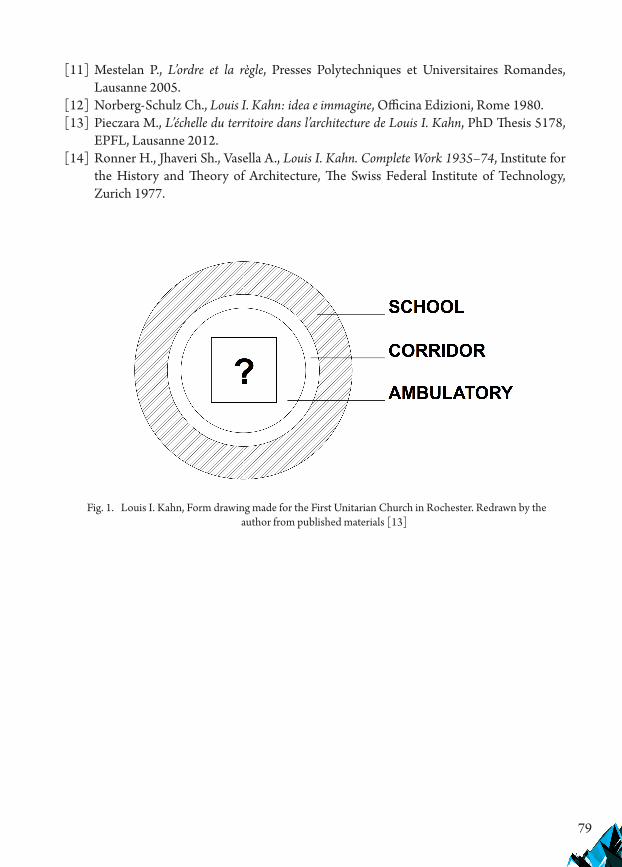
79
[11] Mestelan P., L’ordre et la règle, Presses Polytechniques et Universitaires Romandes, Lausanne 2005.
[12] Norberg-Schulz Ch., Louis I. Kahn: idea e immagine, Officina Edizioni, Rome 1980.[13] Pieczara M., L’échelle du territoire dans l’architecture de Louis I. Kahn, PhD Thesis 5178,
EPFL, Lausanne 2012.[14] Ronner H., Jhaveri Sh., Vasella A., Louis I. Kahn. Complete Work 1935–74, Institute for
the History and Theory of Architecture, The Swiss Federal Institute of Technology, Zurich 1977.
Fig. 1. Louis I. Kahn, Form drawing made for the First Unitarian Church in Rochester. Redrawn by the author from published materials [13]

80
Fig. 2. Plan of Comlongon Castle in Dumfriesshire. Public Domain
Fig. 3. Plan of the First Unitarian Church in Rochester, summer 1960. Redrawn by the author from published materials [13]

81
Fig. 4. The First Unitarian Church in Rochester, a view. Photo by the author
Fig. 5. Plan of the residence in Bryn Mawr. Redrawn by the author from published materials [13]

82
Fig. 6. A view of the residence in Bryn Mawr. Photo by the author
Fig. 7. Plan of the library in Exeter. Redrawn by the author from published materials [13]

83
Fig. 8. Plan of the National Capitol in Dhaka, Bangladesh. Redrawn by the author from published materials [13]
Fig. 9. A perspective view of the laboratories of the Salk Institute in La Jolla. A sketch based on the archival drawings from Louis I. Kahn Collection, University of Pennsylvania and Pennsylvania
Historical and Museum Commission

84
Fig. 10. Plan of the realised part of the Salk Institute in context of the site. Redrawn by the author from published materials [13]
Fig. 11. Three unities of the Salk Institute: the meeting house at the front, the laboratories on the left, the housing on the right. The Pacific coast is visible on the right. A sketch based on the archival
drawings from Louis I. Kahn Collection, University of Pennsylvania and Pennsylvania Historical and Museum Commission
If you want to quote this article, its proper bibliographic entry is as follow: Pieczara M., Archetypes in contemporary architecture, Technical Transactions, Vol. 4/2019, pp. 71–84.

85
TECHNICAL TRANSACTIONS 4/2019ARCHITECTURE AND URBAN PLANNING
DOI: 10.4467/2353737XCT.19.045.10357 submIssIOn Of The fInal versIOn: 30/03/2019
Monika Trojanowska orcid.org/[email protected]
Faculty of Civil and Environmental Engineering and Architecture, UTP University of Science and Technology
health-affirming landscapes and sustainable architecture of modern schools
Krajobrazy sprzyjające promocji zdrowia i zrównoważona architektura współczesnej szkoły
Abstractmodern schools face numerous challenges. They need to teach children about the need for sustainable development. Thus, school buildings and premises should be designed as living examples of the pursuit of sustainability. moreover, green school grounds have the potential to become health-affirming landscapes. This paper discusses the close relationship between the concept of health-affirming everyday landscapes and sustainability in modern energy-efficient school design. In the first part of the paper, a literature review concerning the concept of health-affirming landscapes for children and teenagers and sustainability in school design is presented. In the second part, selected case studies of new energy-efficient schools in Poland and france are examined.Keywords: school design, health-affirming landscapes, sustainable architecture
StreszczenieWspółczesna szkoła stoi przed licznymi wyzwaniami. uczy dzieci o potrzebie zrównoważonego rozwoju, zatem zarówno teren szkoły, jak i jej budynek powinny być żywymi przykładami rozwiązań proekologicznych. Krajobraz terenu szkoły ma potencjał do promocji zdrowia. artykuł omawia ścisły związek między koncepcją codziennych krajobrazów sprzyjających promocji zdrowia, a zrównoważonym projektowaniem nowoczesnych energooszczędnych szkół. W pierwszej części przedstawiono przegląd literatury dotyczący koncepcji krajobrazów sprzyjających promocji zdrowia dzieci i młodzieży oraz proekologicznego projektowania szkół. W drugiej części zanalizowano wybrane przykłady nowych energooszczędnych szkół w Polsce i francji.Słowa kluczowe: projektowanie szkoły, krajobrazy sprzyjające promocji zdrowia, zrównoważona architektura

86
1. Introduction – the concept of health-affirming everyday landscapes
Wilbert Gesler defined therapeutic landscapes as places where “physical and built environments, social conditions and human perceptions combine to produce an atmosphere which is conducive to healing” [1]. Numerous research projects on qualities of build and natural environment which are conducive to healing have thus far been published [2]. There are beautiful natural surroundings which for centuries have been perceived as therapeutic places, such as Epidaurus in Greece [3].
Today, the interesting question is how to use knowledge about therapeutic landscapes to convert everyday places into health affirming everyday landscapes. Urban health-affirming landscapes are everyday places which unite the qualities of therapeutic landscapes to influence people’s physical, mental and spiritual healing [4]. Modern schools may be designed and maintained to become health affirming everyday landscapes, which combine physical and built environments, social conditions and human perceptions to produce an atmosphere which is conducive to healing.
For modern architects, the interesting question is which qualities of physical and built environments should be combined. The majority of research concerning therapeutic landscapes has focussed on contact with nature.
2. Contact with nature
Nature has properties that have an impact on mood and attitude and help people disentangle the problems of life. This phenomena was explained with the concept of biophilia, which is an innate bond that humans have with nature. Contact with other living organisms has been proven to initiate and accelerate the medical healing processes [5–7]. There is a plethora of research about the impact of everyday contact with nature on longevity and general health [8–10]. Contact with nature can improve mood, reduce stress levels and aggressive behaviour across all age groups and can even help children with ADHD to concentrate better [11–14]. A green environment can also aid cognitive restoration and self-discipline [11–14]. The benefits of open green space can be divided into the following three categories [15]: physical and mental restoration, promotion of physical activity [16] and social contact. The therapeutic qualities which were studied for therapeutic parks [17, Table 1] are also relevant to the design of school premises. Put simply, the school ground should be designed as a therapeutic park.
The universal attributes of a therapeutic park are presented in Table 1. The attributes are organised into five groups which represent proposed phases of design. School children need places for psychological and physical restoration, enhancement of social contacts and opportunities for physical activities. Catering for basic needs is ensured within the school building.
Theoretically, if the school grounds are large enough, for example over 10 ha, they can accommodate the majority, if not all, of the attributes listed in the pattern. This argument can be useful when the local community is deciding about the location of a new school in order to

87
Tabl
e 1.
Uni
vers
al p
atter
n of
des
ign
for t
hera
peut
ic p
arks
; sou
rce [
17]
1. P
AR
K’S
FU
NC
TIO
NA
L PR
OG
RAM
2. O
RG
AN
ISAT
ION
O
F SP
AC
E A
ND
FU
NC
TIO
NS
3. IN
TER
IOR
DES
IGN
, A
RC
HIT
ECT
URA
L FO
RM
A
ND
DET
AIL
S
4. P
LAC
EM
AK
ING
5. P
UR
SUIT
OF
–SU
STA
INA
BLE
D
EVEL
OPM
ENT
1.1.
Psy
chol
ogic
al a
nd
phys
ical
rege
nera
tion
natu
ral l
ands
cape
sgr
een
open
spac
epl
ace t
o re
st in
the s
un an
d in
th
e sha
de
plac
e to
rest
in si
lenc
e and
so
litud
e po
ssib
ility
to o
bser
ve o
ther
pe
ople
poss
ibili
ty to
obs
erve
anim
als
1.2.
Soc
ial C
onta
cts
Enha
ncem
ent
orga
nisa
tion
of ev
ents
insid
e th
e par
kga
ther
ing
plac
e for
gro
ups
1.3.
Phy
sica
l Act
ivit
y Pr
omot
ion
spor
ts an
d re
crea
tiona
l in
frast
ruct
ure
com
mun
ity g
arde
ns1.
4. C
ater
ing
for b
asic
nee
dssa
fety
and
secu
rity
plac
es to
sit a
nd re
stsh
elte
rto
ilet f
acili
ties
drin
king
wat
erfo
od
2.1.
The
park
spat
ial
com
posi
tion
follo
ws t
he
surr
ound
ing
urba
n pa
ttern
2.2.
Arc
hite
ctur
al v
arie
ty
of u
rban
env
iron
men
t fo
cal p
oint
s and
land
mar
ksst
ruct
ure o
f int
erio
rs an
d co
nnec
tions
long
vist
as (e
xten
t)pa
thw
ays w
ith v
iew
sin
visib
le fr
agm
ents
of t
he
scen
e (vi
sta e
ngag
ing
the
imag
inat
ion)
mys
tery
, fas
cina
tion
fram
ed v
iew
shu
man
scal
e
3.1.
Opt
imal
leve
l of
com
plex
ity
3.2.
Nat
ural
surf
aces
3.3
Enga
ging
feat
ures
risk/
peril
mov
emen
t3.
4. P
rese
nce
of W
ater
3.5.
Sen
sory
stim
uli d
esig
nse
nsor
y st
imul
i: sig
htse
nsor
y st
imul
i: he
arin
gse
nsor
y st
imul
i: sm
ell
sens
ory
stim
uli:
touc
hse
nsor
y st
imul
i: ta
ste
sens
ory
path
4.1.
Wor
ks o
f Art
4.2.
Mon
umen
ts in
the
park
4.3.
His
tori
c pl
aces
cultu
re an
d co
nnec
tion
to
the p
ast
4.4.
Them
atic
gar
dens
4.5.
Per
sona
lisat
ion
4.6.
Ani
mat
ion
of p
lace
5.1.
Gre
en In
fras
truc
ture
5.2.
Sec
ond
(new
) ge
nera
tion
of p
arks
5.3.
Bio
dive
rsit
y pr
otec
tion
part
of p
ark
not-a
vaila
ble t
o vi
sitor
sha
bita
t pla
nts
natu
ral m
aint
enan
ce m
etho
dsha
bita
t ani
mal
s5.
4. D
rink
ing
wat
er
prot
ectio
nra
inw
ater
infil
tratio
nra
inw
ater
irrig
atio
nirr
igat
ion
with
non
-pot
able
w
ater
prev
entiv
e mea
sure
s if p
ark
is lo
cate
d in
a flo
od ri
sk zo
ne5.
5. U
rban
met
abol
ism
5.6.
Eco
logi
cal e
nerg
y so
urce
s
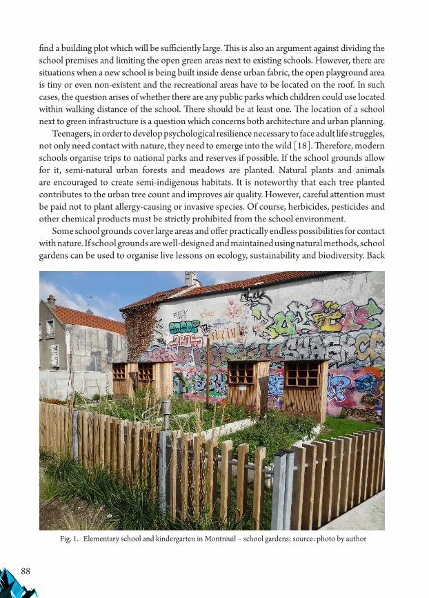
88
find a building plot which will be sufficiently large. This is also an argument against dividing the school premises and limiting the open green areas next to existing schools. However, there are situations when a new school is being built inside dense urban fabric, the open playground area is tiny or even non-existent and the recreational areas have to be located on the roof. In such cases, the question arises of whether there are any public parks which children could use located within walking distance of the school. There should be at least one. The location of a school next to green infrastructure is a question which concerns both architecture and urban planning.
Teenagers, in order to develop psychological resilience necessary to face adult life struggles, not only need contact with nature, they need to emerge into the wild [18]. Therefore, modern schools organise trips to national parks and reserves if possible. If the school grounds allow for it, semi-natural urban forests and meadows are planted. Natural plants and animals are encouraged to create semi-indigenous habitats. It is noteworthy that each tree planted contributes to the urban tree count and improves air quality. However, careful attention must be paid not to plant allergy-causing or invasive species. Of course, herbicides, pesticides and other chemical products must be strictly prohibited from the school environment.
Some school grounds cover large areas and offer practically endless possibilities for contact with nature. If school grounds are well-designed and maintained using natural methods, school gardens can be used to organise live lessons on ecology, sustainability and biodiversity. Back
Fig. 1. Elementary school and kindergarten in Montreuil – school gardens; source: photo by author

89
in the nineteenth century in Austria, official law stipulated that each school had to provide a school garden for its students. School gardens were organised in many other countries like Germany, Belgium, France, Russia, England and the USA from the late nineteenth century onwards [19]. Today, pedagogical gardens are being built to enable children to learn how food is produced and how biodiversity is promoted.
Today, there are numerous organisations which are dedicated to promote gardens for children and wild nature experiences for children. Eco-Schools is the largest global sustainable schools programme. Eco-Schools has developed from a European educational program to a global model for environmental education and sustainability on an international level [20]. The ambition of eco-school programs is to improve the environmental footprint of a school, hoping that it would lead to a more sustainable, less costly and more responsible school environment.
Nowadays, it is extremely important for school grounds to become health-affirming landscapes, because modern urban design has deprived our cities of much needed open public green spaces. Richard Louv, in his work Last child in the woods, [21] directly links the lack of nature in the lives of today’s children to some of the most disturbing trends, such as obesity, attention disorders and depression. One of the possible remedies could be the sustainable and health promoting design of schools and school premises to bring children back into contact with nature.
3. Sustainability and health promotion – the role of education
Contact with nature can be extended to contact with natural building materials such as wood, straw, hemp, stone, etc. or even further to all technologies which in the long term protect our planet, its biodiversity and natural resources.
In designing the school and school premises, we must realise that it is the best expenditure of both effort and money in the long run. The children of today will grow up to be responsible adults in the future. Our planet is our common home and we all have to take care of it simultaneously [22]. Therefore, modern schools should become showcases of the most advanced solutions. They are funded with public money. Therefore, it is possible that they may become real life living laboratories displaying the most advanced solutions to entire neighbourhoods. School facilities are predisposed for construction in a passive standard. In the summer, when the air parameters are the least comfortable, there are no lessons, so even if the school building overheats, it will not affect students’ comfort.
4. Modern energy-efficient school design
Two examples were chosen – a straw bale, hemp and wood school from France and a passive school from Poland. Both illustrate advanced ecological concepts.
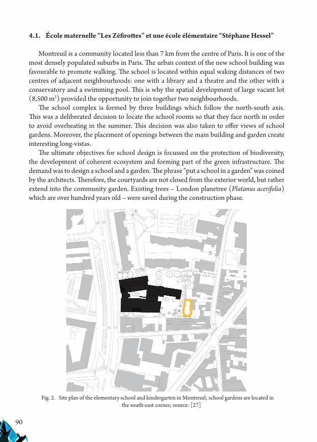
90
4.1. École maternelle “Les Zéfirottes” et une école élémentaire “Stéphane Hessel”
Montreuil is a community located less than 7 km from the centre of Paris. It is one of the most densely populated suburbs in Paris. The urban context of the new school building was favourable to promote walking. The school is located within equal waking distances of two centres of adjacent neighbourhoods: one with a library and a theatre and the other with a conservatory and a swimming pool. This is why the spatial development of large vacant lot (8,500 m2) provided the opportunity to join together two neighbourhoods.
The school complex is formed by three buildings which follow the north-south axis. This was a deliberated decision to locate the school rooms so that they face north in order to avoid overheating in the summer. This decision was also taken to offer views of school gardens. Moreover, the placement of openings between the main building and garden create interesting long-vistas.
The ultimate objectives for school design is focussed on the protection of biodiversity, the development of coherent ecosystem and forming part of the green infrastructure. The demand was to design a school and a garden. The phrase “put a school in a garden” was coined by the architects. Therefore, the courtyards are not closed from the exterior world, but rather extend into the community garden. Existing trees – London planetree (Platanus acerifolia) which are over hundred years old – were saved during the construction phase.
Fig. 2. Site plan of the elementary school and kindergarten in Montreuil; school gardens are located in the south-east corner; source: [27]

91
The elementary school has three levels with a traversing hall which directly accesses the exterior court via the courtyard and two stairways. A leisure facility shares a double-height hall with the kindergarten. The kindergarten unfolds on the floor around the playground.
The school was designed for 650 children. It houses a kindergarten (9 classes), an elementary school (15 classes), a leisure facility and a restaurant (550 meals served a day) and it occupies 5000 m2. The specialised activity rooms (computer, visual arts, video) are grouped on the second floor and are shared by the kindergarten, the elementary school and the leisure centre. The multipurpose room has a special status related to its dual use. Positioned on the Avenue de la Résistance, it is directly accessible independently of the school opening hours [23–36].
Fig. 3. Elementary school and kindergarten in Montreuil; ground floor plan; source: [27]
Fig. 4. Elementary school and kindergarten in Montreuil; section; source: [27]
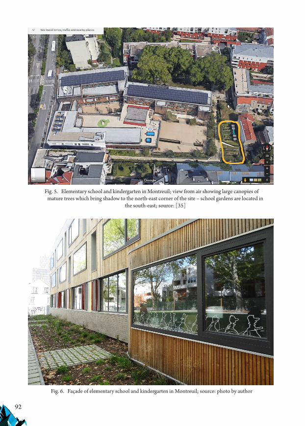
92
Fig. 5. Elementary school and kindergarten in Montreuil; view from air showing large canopies of mature trees which bring shadow to the north-east corner of the site – school gardens are located in
the south-east; source: [35]
Fig. 6. Façade of elementary school and kindergarten in Montreuil; source: photo by author

93
The school is constructed of straw bales and hemp; however, there was no question of leaving the straw bales in sight because of the risks of fire or bad weather damaging the material. Therefore, the walls came to the site prefabricated. Parts of the construction – exterior wall panels (7.20 x 3.2 m) and roof panels – were prefabricated to increase the quality and speed of implementation on site. They were constructed, stuffed with straw and covered with a rain-protection layer. They were filled with compacted straw (36 cm thick) and hermetically enclosed with two layers of 50 mm rock wool and two plates of Fermacell (fire proofed). No exotic woods were used. Douglas fir and larch, two naturally rot-proof wood species that grow in France, were used for the construction. The Douglas pine was used for the exterior (protected with larch cladding), and spruce in the interior (with decking constructed from thermo-treated ash). For educational purposes, the natural scale model of wall construction was put on display in the school building in order to familiarise all students, teachers, parents and anyone interested with the unusual construction of the school [23–36].
Rainwater is collected and used for flushing the toilets and irrigation of a large garden of 3,500 m2 with 8,000 plants. Rainwater from the roof is visibly circulating in rain gardens.
To meet the “zero energy” goal, a photovoltaic production area was needed; to meet this end, the roof houses 700 m2 of photovoltaic solar panels. In addition, 90 m2 of photovoltaic cells – monocrystalline silicon offering the best performance (12.5%) – are installed in a glass module where 60 m2 act as a sunscreen for the elementary school and 30 m2 as a sunscreen for the kindergarten.
Fig. 7. Elementary school and kindergarten in Montreuil – materials used for construction of school are being put on display for educative purposes; source: [34]

94
Fig. 8. Elementary school and kindergarten in Montreuil – lightweight timber frame construction of walls; source: [27]
Fig. 9. Wood, straw and hemp construction of walls; source: [36]

95
Vegetable oil was used to heat the building. It is not the best solution as it is foodstuff and can be consumed. Therefore, a new solution is being proposed to recuperate the oil used for frying from the restaurant [23–36].
The school and schoolyard was analysed using Table 1. The universal pattern of design for the therapeutic parks. and the results were recognised as being satisfactory. The strategy to “put a school in a garden” has brought promising results.
5. Passive school design in Budzów, Stoszowice, Poland
The school in Budzów, Stoszowice is the first educational institution in Poland to be built in accordance with the passive standard. The almost zero-energy school in Budzów sets public construction standards that will apply in the country from 2020. The construction of the facility took over a year. As part of the investment, a single-story building with an area of approx. 836 m2 was built, which provides a place of learning for about 170 students.
The primary school in Budzów is located in the middle of a flat meadow, gently sloping towards the north. The building is well connected to the surrounding landscape and greenery both from the outside and the interior. This location offers opportunities for psychological and physical restoration, enhancement of social contacts and opportunities for physical activities. Catering for basic needs is provided within the school building. This is a good starting point to create a health-affirming place next to the school.
Fig. 10. Passive school in Budzów, Stoszowice, Poland; source: [36]
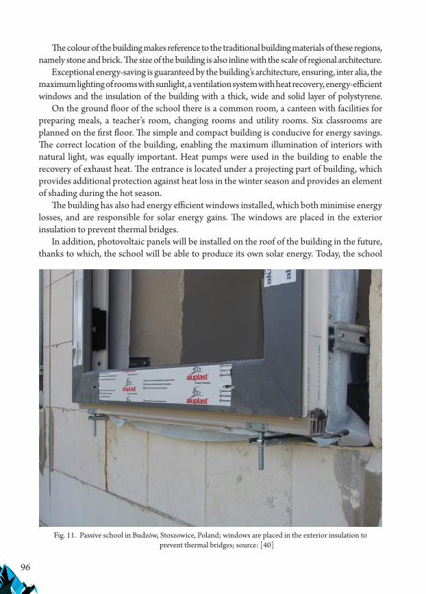
96
The colour of the building makes reference to the traditional building materials of these regions, namely stone and brick. The size of the building is also inline with the scale of regional architecture.
Exceptional energy-saving is guaranteed by the building’s architecture, ensuring, inter alia, the maximum lighting of rooms with sunlight, a ventilation system with heat recovery, energy-efficient windows and the insulation of the building with a thick, wide and solid layer of polystyrene.
On the ground floor of the school there is a common room, a canteen with facilities for preparing meals, a teacher’s room, changing rooms and utility rooms. Six classrooms are planned on the first floor. The simple and compact building is conducive for energy savings. The correct location of the building, enabling the maximum illumination of interiors with natural light, was equally important. Heat pumps were used in the building to enable the recovery of exhaust heat. The entrance is located under a projecting part of building, which provides additional protection against heat loss in the winter season and provides an element of shading during the hot season.
The building has also had energy efficient windows installed, which both minimise energy losses, and are responsible for solar energy gains. The windows are placed in the exterior insulation to prevent thermal bridges.
In addition, photovoltaic panels will be installed on the roof of the building in the future, thanks to which, the school will be able to produce its own solar energy. Today, the school
Fig. 11. Passive school in Budzów, Stoszowice, Poland; windows are placed in the exterior insulation to prevent thermal bridges; source: [40]
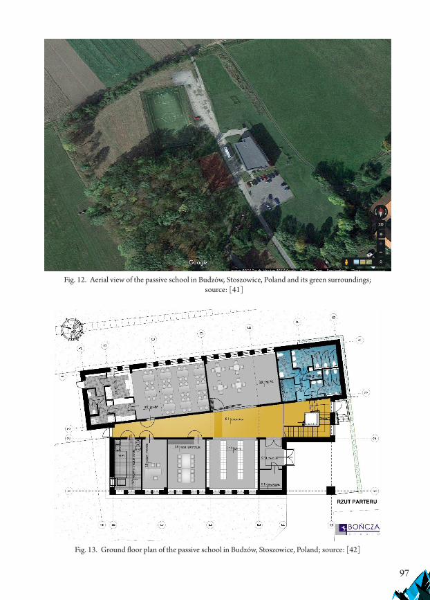
97
Fig. 12. Aerial view of the passive school in Budzów, Stoszowice, Poland and its green surroundings; source: [41]
Fig. 13. Ground floor plan of the passive school in Budzów, Stoszowice, Poland; source: [42]

98
is showing significant savings on heating and electricity expenditure. The investment cost almost 3.4 million PLN and was more expensive than a traditional building by about 10–15% of the investment’s value. The estimated cost of heating the building is approx. 1000 PLN per year. By comparison, the cost of heating a traditional building of a similar size amounts to approx. 40,000 PLN per year (including fuel costs and stoker’s remuneration). The costs of heating a passive school in Budzów are therefore around 40 times lower [37–44]. Although energy savings were envisaged, the higher cost of construction remained a major obstacle which was difficult to overcome by the small community of Stoszowice, near Budzów.
6. Conclusions
Modern school design brings new challenges to architects. The new building must not only provide a valuable learning environment for children but also become a showcase of the best available sustainable solutions. Moreover, not only is the design of energy efficient school building important but also the design of the school grounds. The school grounds should compensate for loss of everyday contact with nature that modern children are experiencing. The school gardens should fulfil a new role, that of everyday health-affirming landscapes. The two schools presented as examples of good practices demonstrate that although this is difficult, it is possible.
Fig. 14. First floor plan of the passive school in Budzów, Stoszowice, Poland; source: [43]

99
References
[1] Gesler W., Therapeutic Landscapes: An evolving theme, Health & Place 2005 Dec, 11(4), 295–7.
[2] Largo-Wight E., Cultivating healthy places and communities: evidenced-based nature contact recommendations, International Journal of Environmental Health Research 2011 Feb, ()41–61.
[3] Sternberg E.M., Healing Spaces. The Science of Place and Well-being, The Belknap Press of Harvard University Press 2010.
[4] Trojanowska M., Sas-Bojarska A., Health-affirming everyday landscapes in sustainable city. Theories and tools, Architecture Civil Engineering Environment Journal 2018, 3, 41–52.
[5] Health Council of the Netherlands and Dutch Advisory Council for Research on Spatial Planning, Nature and the Environment Nature and Health. The influence of nature on social, psychological and physical well-being. The Hague: Health Council of the Netherlands and RMNO, publication no. 2004/09E; RMNO publication nr A02ae.Cooper Marcus C., Sachs N., Therapeutic Landscapes. An Evidence-Based Approach to Designing Healing Gardens and Restorative Outdoor Spaces, John Wiley & Sons, Inc., Hoboken, New Jersey 2013.
[6] Ulrich, R. View through a window may influence recovery from surgery. Science, 1984 Apr, 224(4647), 420–421.Ulrich R., Effects of Gardens on Health Outcomes: Theory and Research [in:] Cooper Marcus C., Barnes M., Healing Gardens, John Wiley & Sons 1999.
[7] Takano T., Nakamura K., Watanabe M., Urban residential environments and senior citizens’ longevity in megacity areas: the importance of walkable green spacer, Journal of Epidemiology Community Health, 2002, 56, 913–918.
[8] Velarde M.D, Fry G., Tveit M., Health effects of viewing landscapes – Landscape types in environmental psychology, Urban Forestry & Urban Greening 2007, 6, 199–212.
[9] Harting T., Bringslimark T., Patil G.G., Restorative Environmental Design: What, When, Where, and for Whom? [in:] Biophilic design: the theory, science, and practice of bringing buildings to life, eds. S. Kellert, J. Heerwagen, M. Mador, John Wiley & Sons, Inc, Hoboken, New Jersey, 2008, 133.
[10] Faber Taylor A., Kuo F.E., Sullivan W.C, Views of nature and self-discipline: Evidence from inner city children, Journal of Environmental Psychology 2002, 22, 49–64.
[11] Faber Taylor A., Kuo F.E., Children with attention deficits concentrate better after walk in the park, Journal of Attention Disorders 2009, 12, 402–409.
[12] CABE Commission for architecture and the built environment, Community green: using local spaces to tackle inequality and improve health, London 2010.
[13] Cooper Marcus C., Barnes M., Gardens in healthcare facilities: Uses, Therapeutic benefits, and design recommendations, University of California, Berkeley 1995.
[14] NICE (National Institute for Health and Clinical Excellence), Promoting physical activity, active play and sport for pre-school and school-age children and young people in family, pre-school, school and community settings, NICE, London 2009.
[15] Trojanowska M., Parki i ogrody terapeutyczne, Wydawnictwo Naukowe PWN, Warszawa 2017.
100
[16] NECR025 (National England Commissioned Report), Wild Adventure Space: its role in teenagers’ lives, 2010, www.naturalengland.org.uk, access: 30.03.2019.
[17] Batorczyk A., Zielone podwórka – szkolne pomysły dla zrównoważonego rozwoju miast [in:] Miasto idealne-miasto zrównoważone. Planowanie przestrzenne terenów zurbanizowanych I jego wpływ na ograniczenie skutków zmian klimatu, red. A. Kalinowska, Uniwersyteckie Centrum Badań and Środowiskiem Przyrodniczym i Zrównoważonym Rozwojem, Uniwersytet Warszawski, Warszawa 2015.
[18] http://www.ecoschools.global/, access: 30.03.2019.[19] Louv R., Last Child in the Woods: Saving our Children from Nature Deficit Disorder,
updated and expanded edition, Algonquin Books, Chapel Hill, North Carolina 2008.[20] Franciszek I, papież, Encyklika Laudato Si’ Ojca Świętego Franciszka poświęcona trosce o
wspólny dom, 2015.[21] https://rfcp.fr/recensement-de-batiments-en-paille/les-batiments-en-paille-recenses/
entry/6200/?pagenum=9, access: 18.12.2018.[22] http://artisans.chefdentreprise.com/thematique/actualites-1063/Diaporamas/
une-ecole-bois-energie-positive-309982/projet-ecologique-precurseur-309997.htm, access: 18.12.2018.
[23] http://artisans.chefdentreprise.com/thematique/actualites-1063/Diaporamas/une-ecole-bois-energie-positive-309982/projet-ecologique-precurseur-309997.htm, access: 18.12.2018.
[24] https://www.bastamag.net/Des-batiments-publics-et-des-ecoles-en-paille-plus-ecologiques-et-bien-moins, access: 18.12.2018.
[25] https://www.mcub.eu/mon01, access: 18.12.2018.[26] https://alto-ingenierie.fr/articles-newsletter/l-ecole-stephane-hessel-les-zefirottes-a-
montreuil, access: 20.12.2018.[27] https://bois.fordaq.com/news/groupescolaire_St%C3%A9phaneHessel_
LesZ%C3%A9firottes_COP21_44015.html, access: 21.12.2018.[28] http://bet-gaujard.com/wp/portfolio/groupe-scolaire-de-montreuil, access:
21.12.2018.[29] https://www.batiactu.com/edito/une-ecole-isolee-en-paille-a-la-main-verte-a-
montr-40182.php, access: 21.12.2018.[30] http://www.tribu-concevoirdurable.fr/references/enseignement/ecole-a-energie-
positive-ilot-104-a-montreuil-93.html, access: 21.12.2018.[31] http://www.vegetal-e.com/fr/fiche/chantier-10/groupe-scolaire-stephane-hessel-les-
zefirottes-une-ecole-dans-un-jardin.html, access: 21.12.2018.[32] http://batirsain.org/?energie-positive-pour-montreuil-au,978.html, access:
21.12.2018.[33] https://www.google.com/maps/@48.8600457,2.4381904,131a,35y,39.48t/
data=!3m1!1e3, access: 21.12.2018.[34] http://www.echopaille.fr/p/technique-paille.html, access: 21.12.2018.[35] http://www.chronmyklimat.pl/projekty/energooszczedne-4-katy/katalog-dobrych-
przykladow/pasywna-szkola-w-budzowie, access: 22.12.2018.

101
[36] http://www.rynekinstalacyjny.pl/artykul/id3765,szkola-w-budynku-pasywnym-studium-przypadku?p=1, access: 22.12.2018.
[37] http://termomodernizacja.pl/szkola-w-standardzie-budynku-pasywnego/, access: 22.12.2018.
[38] http://oknotest.pl/okna-energooszczedne/okna-pcv-w-budynku-pasywnym, access: 22.12.2018.
[39] https://www.google.com/maps/@50.5829814,16.6903121,211m/data=!3m1!1e3, access: 22.12.2018.
[40] http://boncza-studio.pl/projekty/sp-w-budzowie/foto/4.jpg, access: 22.12.2018.[41] http://boncza-studio.pl/projekty/sp-w-budzowie/foto/5.jpg, access: 22.12.2018.[42] http://www.spbudzow.pl/o-szkole/budownictwo-pasywne, access: 22.12.2018.
If you want to quote this article, its proper bibliographic entry is as follow: Trojanowska M., Health-affirming landscapes and sustainable architecture of modern schools, Technical Transactions, Vol. 4/2019, pp. 85–102.


103
TECHNICAL TRANSACTIONS 4/2019CIVIL ENGINEERINGDOI: 10.4467/2353737XCT.19.046.10358
submIssIOn Of The fInal versIOn: 30/03/2019
Tadeusz Majcherczyk Katarzyna Kryzia orcid.org/[email protected]
AGH University of Science and Technology, Faculty of Mining and Geoengineering, Cracow, Poland
Jerzy [email protected]
Jastrzębska Spółka Węglowa S.A., Jastrzębie-Zdrój, Poland
mining influence in the area of the Pszczynka river and the method of riverbed restoration
Oddziaływanie eksploatacji górniczej w rejonie rzeki Pszczynki a metoda renaturyzacji jej koryta
AbstractThis paper investigates the influence of extraction on the surface in the area of the Pszczynka river. The mining-enhanced terrain subsidence hitherto observed has also resulted in the subsidence of the riverbed and its embankment. some geotechnical solutions are proposed, including the reconstruction and repair of damage to the existing infrastructure. such measures should facilitate a proper flow of water in the riverbed which is similar to a natural flow. Keywords: extraction influence, subsidence trough, longitudinal river profile, restoration, mining damage
StreszczenieW artykule przedstawiono wpływ dotychczasowej eksploatacji górniczej na powierzchnię terenu w rejonie rzeki Pszczynki. Występujące osiadania terenu spowodowały obniżenia koryta rzeki i jej obwałowań. Zaproponowano rozwiązania geotechniczne polegające na wykonaniu przebudowy i naprawy szkód w istniejącej infrastrukturze. Podjęte działania pozwalają na prawidłowy przepływ wody w korycie rzeki zbliżony do naturalnego.Słowa kluczowe: wpływy eksploatacji górniczej, niecka osiadań, profil podłużny rzeki, renaturyzacja, szkody górnicze

104
1. Introduction
Underground mining excavation not only results in the occurrence of both continuous and discontinuous deformations in the surface but also in the disturbance of hitherto-existing water conditions, both within the subsidence trough and beyond its edge. As a consequence, the profiles of riverbeds and other surface watercourses become seriously disturbed. Such a type of mining damage is frequently observed in the case of relatively small downslopes in surface watercourses and large mining-induced surface subsidence. As a result of such conditions, riverbed embankments are also damaged. In addition, excessive bottom erosion or silting occurs in the riverbed, which causes the water to flow to the nearby areas and create permanent bayous [1–3].
The specificity of mining damage in water objects requires the application of special protective measures. Such methods should aim to preserve the original landform in the surface or change it without constraining the free flow of surface waters (i.e. river restoration) [4].
The paper presents and discusses the results of surface subsidence caused by long-term and multi-layer mining excavation which has seriously modified water conditions in the bed of the Pszczynka river. Wide-ranging repair measures, mostly related to construction works, were undertake; this helped to eliminate occurrences of flooding and the inundation of the nearby areas whilst simultaneously restoring the previously-regulated river to its almost natural profile.
2. Geological conditions in the analyzed area
The terrain surface in the village of Krzyżowice (Silesian Voivodeship) is moderately ridged and its altitude ranges between 252.0 and 262.0 metres above sea level. The minimal altitudes occur in the Pszczynka river valley. In the nearby area, there are residential and investment buildings, as well as roads running along and across the course of the river.
The river Pszczynka flows eastbound from the west and belongs to the hydrographic network of the Vistula river basin.
In the area that is the subject of this research, there is a hard coal seam of industrial value down to a depth of approx. 1,000 m. The geological structure of the analyzed area consists of Quaternary layers (Holocene, Pleistocene), Tertiary layers (Miocene) and Carboniferous layers (Orzeskie and Rudzkie).
The Quaternary layers are represented by alluvial Holocene deposits and Pleistocene formations of water and glacier origin. The Holocene alluvia consist of fine and medium-grained sands and muds occurring in the river valleys. The thicknesses of the Quaternary formations in the area of the river Pszczynka range between approx. 24 and 51.5 m.
The Tertiary formations are deposited directly on the Carboniferous series. Their thicknesses vary, which is related to the morphological variation of Carboniferous roof, and range between approx. 200 and 440 m in the northern part of the area. It is a monotonous series of grey and grey-green marl, often with fauna inclusions and interlayers of dusty sands and thin
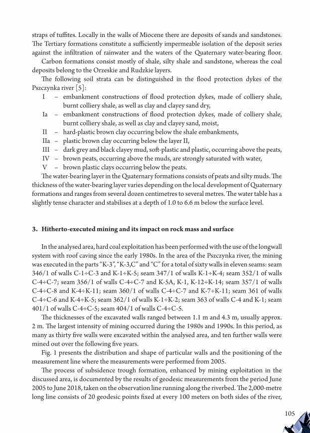
105
straps of tuffites. Locally in the walls of Miocene there are deposits of sands and sandstones. The Tertiary formations constitute a sufficiently impermeable isolation of the deposit series against the infiltration of rainwater and the waters of the Quaternary water-bearing floor.
Carbon formations consist mostly of shale, silty shale and sandstone, whereas the coal deposits belong to the Orzeskie and Rudzkie layers.
The following soil strata can be distinguished in the flood protection dykes of the Pszczynka river [5]:
I – embankment constructions of flood protection dykes, made of colliery shale, burnt colliery shale, as well as clay and clayey sand dry,
Ia – embankment constructions of flood protection dykes, made of colliery shale, burnt colliery shale, as well as clay and clayey sand, moist,
II – hard-plastic brown clay occurring below the shale embankments,IIa – plastic brown clay occurring below the layer II,III – dark grey and black clayey mud, soft-plastic and plastic, occurring above the peats,IV – brown peats, occurring above the muds, are strongly saturated with water,V – brown plastic clays occurring below the peats. The water-bearing layer in the Quaternary formations consists of peats and silty muds. The
thickness of the water-bearing layer varies depending on the local development of Quaternary formations and ranges from several dozen centimetres to several metres. The water table has a slightly tense character and stabilises at a depth of 1.0 to 6.6 m below the surface level.
3. Hitherto-executed mining and its impact on rock mass and surface
In the analysed area, hard coal exploitation has been performed with the use of the longwall system with roof caving since the early 1980s. In the area of the Pszczynka river, the mining was executed in the parts “K-3”, “K-3,C” and “C” for a total of sixty walls in eleven seams: seam 346/1 of walls C-1÷C-3 and K-1÷K-5; seam 347/1 of walls K-1÷K-4; seam 352/1 of walls C-4÷C-7; seam 356/1 of walls C-4÷C-7 and K-5A, K-1, K-12÷K-14; seam 357/1 of walls C-4÷C-8 and K-4÷K-11; seam 360/1 of walls C-4÷C-7 and K-7÷K-11; seam 361 of walls C-4÷C-6 and K-4÷K-5; seam 362/1 of walls K-1÷K-2; seam 363 of walls C-4 and K-1; seam 401/1 of walls C-4÷C-5; seam 404/1 of walls C-4÷C-5.
The thicknesses of the excavated walls ranged between 1.1 m and 4.3 m, usually approx. 2 m. The largest intensity of mining occurred during the 1980s and 1990s. In this period, as many as thirty five walls were excavated within the analysed area, and ten further walls were mined out over the following five years.
Fig. 1 presents the distribution and shape of particular walls and the positioning of the measurement line where the measurements were performed from 2005.
The process of subsidence trough formation, enhanced by mining exploitation in the discussed area, is documented by the results of geodesic measurements from the period June 2005 to June 2018, taken on the observation line running along the riverbed. The 2,000-metre long line consists of 20 geodesic points fixed at every 100 meters on both sides of the river,

106
relatively close to the riverbed. A map showing the distribution of the measurement points in the area of the bed of the Pszczynka river is presented in Fig. 2.
Altitude monitoring made it possible to interpret the process of deformation. During the period of thirteen years of measurements, the maximal surface subsidence created two subsidence troughs with maximum values of 1.79 m at point No. 8 of the measurement line and 1.79 m at point No. 18 of the line. Undoubtedly, the walls excavated directly below the measurement line exerted a crucial impact on the volume and rate of subsidence. The values of subsidence at the end points of the observation line in the western direction indicate a clearly decreased character (subsidence of only 0.23 m in point No. 1). The subsidence also decreases eastbound (0.73 m at point No. 20). In the middle of the measurement line (point No. 11), the subsidence reached the value of 0.28 m. The increase of subsidence is presented in Fig. 3.
Fig. 1. Excavation in the area of the Pszczynka river and the positioning of the observation line
Fig. 2. Map of the analysed area and positioning of the measurement line
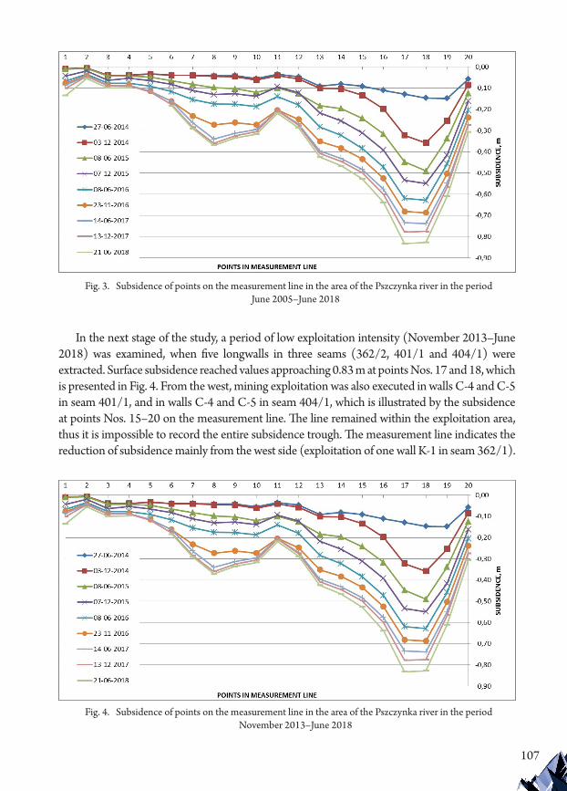
107
In the next stage of the study, a period of low exploitation intensity (November 2013–June 2018) was examined, when five longwalls in three seams (362/2, 401/1 and 404/1) were extracted. Surface subsidence reached values approaching 0.83 m at points Nos. 17 and 18, which is presented in Fig. 4. From the west, mining exploitation was also executed in walls C-4 and C-5 in seam 401/1, and in walls C-4 and C-5 in seam 404/1, which is illustrated by the subsidence at points Nos. 15–20 on the measurement line. The line remained within the exploitation area, thus it is impossible to record the entire subsidence trough. The measurement line indicates the reduction of subsidence mainly from the west side (exploitation of one wall K-1 in seam 362/1).
Fig. 3. Subsidence of points on the measurement line in the area of the Pszczynka river in the period June 2005–June 2018
Fig. 4. Subsidence of points on the measurement line in the area of the Pszczynka river in the period November 2013–June 2018

108
The mining influences on the terrain surface are characterised by the deformation indices in the measurement points in the area of Korfantego Street Bridge, Zwycięstwa Street Bridge and P-2 pump station, as presented in Table 1.
Table 1. Deformation indices in the area of the measurement line
Area Subsidencew [m]
SlopeT [mm/m]
Deformationε [mm/m]
Korfantego Str. near point No. 6 5.401 15.4 11.3
Zwycięstwa Str. near point No. 9 6.956 24.2 10.9
pump station P-2 4.96 12.6 9.4
4. Restoration of the Pszczynka river
The concept of river restoration is embedded in restoring the earlier-regulated rivers to their pre-impacted natural state, i.e. the state existing before regulation of the river or that which typically occurs in the natural environment. In actuality, a complete river restoration to its natural state is hardly ever possible, hence the restoration process is usually based on a limited range of measures taken or on some kind of a compromise [4].
As a matter of fact, in most cases it is difficult to precisely define the scope and range of measures to be taken or the ideal target state that could be assumed as being natural. This is because the rivers are subject to regular changes enhanced by various factors, including natural factors.
Restoration activities may be conducted in various zones; however, they are most frequently undertaken in the riverbed or riverbanks. Repair works in the riverbed lead to streamlining the river flow and changing the cross sections in order to obtain the optimal depth along the course of the river. Restoration of the riverbanks mostly involves the reconstruction of riverbank reinforcement and protection.
The effectiveness of restoration processes largely depends on the adequacy of the preselected and proposed concepts of supporting activities based on proper surveying of the state of the natural environment already in the conceptualisation phase. As a rule, such a survey should embrace wide-ranging aspects: hydrological, hydraulic and natural. Obviously, the range of survey undertaken for the sake of a restoration process varies depending on the particular concept and specificity of a given object [4].
As a result of mining exploitation, the bed of the Pszczynka river suffered from serious deformations. Surface subsidence caused the subsidence of the riverbed and the embankment of the river. Thus, hydraulic parameters in the riverbed changed, causing the decrease of the velocity of water streaming. The bed of the Pszczynka river began to function as a kind of sedimentation tank. In addition, the geotechnical parameters of the embankment seriously worsened, which negatively affects flood safety in the nearby areas with residential and

109
investment buildings. Therefore, particular construction works were undertaken in relation to the requirements of flood safety, proper water streaming in the riverbed and the preservation of satisfactory technical and hydraulic parameters (Fig. 5). These works involved [5]:
▶ repairing the existing flood protection dykes by raising the levee crowns and levee corpus development;
▶ raising and broadening the left and right levee corpus in the section with the largest surface subsidence;
▶ rebuilding perimeter drainage ditches colliding with the renovated flood protection dykes;
▶ rebuilding outlets of the drainage pump stations; ▶ rebuilding and protecting the hitherto-existing technical infrastructure intersecting
with the flood protection dykes and the Pszczynka river in the discussed section.
Irregular subsidence of the riverbed of the Pszczynka causing a lack of adequate gravitation slope and serious decrease of the water flow velocity resulted in the creation of the water ponding zone. Therefore, the riverbed had to be stabilised in the section of 1 km. As part of the re-profiling process, the river bottom was reinforced with stone riprap, assuming a waterbed with a maximum bottom width of 4.0 m (Fig. 6) [5].
The restoration of the river Pszczynka will help to re-establish the original width of the riverbed from before the process of subsidence. In order to make the works in the river current possible, a special steel wall will be installed at depth of 6.0 m along the riverbed and the works will be executed on both sides of the wall interchangeably (Fig. 8).
As soon as the river bottom is stabilised, the Ø 25 cm fascine bands will be laid between the rows of poles in the footing of the slopes, followed by the formation of the slopes of the embankment. Most importantly, the fascine will be made after the river bottom stabilisation and before forming the embankment slopes. The total length of the fascine bands is 4 km (Fig. 9).
Fig. 5. Fragment of topographical map: river section with inserted design solutions

110
Fig. 6. Characteristic cross section of left and right embankment of the river Pszczynka
Fig. 7. Preparing riverbed for restoration
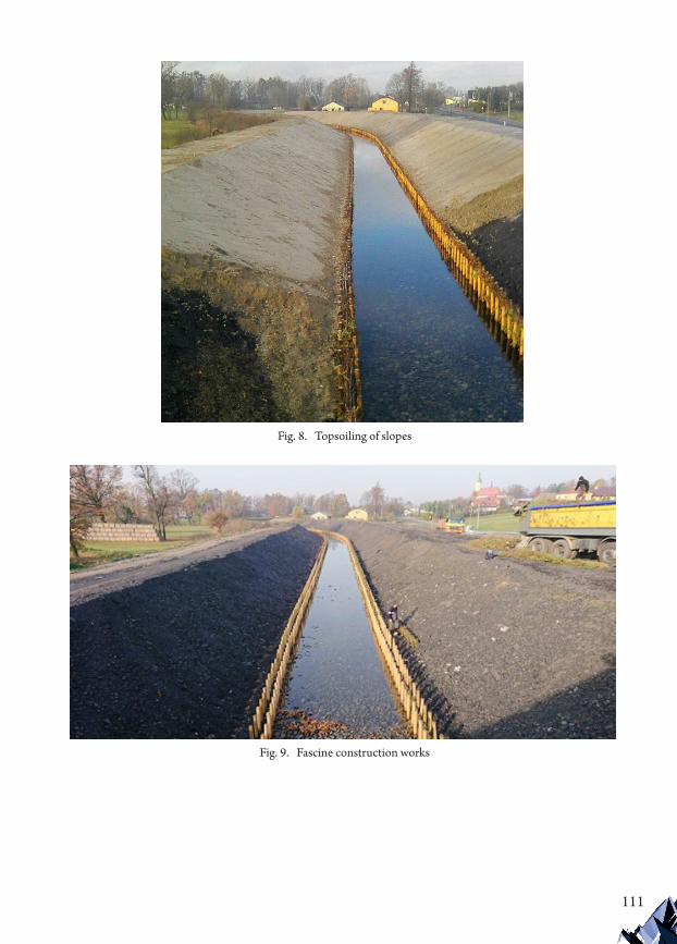
111
Fig. 8. Topsoiling of slopes
Fig. 9. Fascine construction works
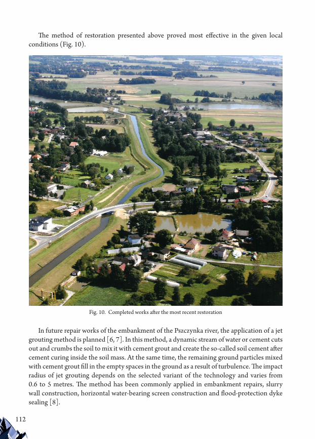
112
The method of restoration presented above proved most effective in the given local conditions (Fig. 10).
In future repair works of the embankment of the Pszczynka river, the application of a jet grouting method is planned [6, 7]. In this method, a dynamic stream of water or cement cuts out and crumbs the soil to mix it with cement grout and create the so-called soil cement after cement curing inside the soil mass. At the same time, the remaining ground particles mixed with cement grout fill in the empty spaces in the ground as a result of turbulence. The impact radius of jet grouting depends on the selected variant of the technology and varies from 0.6 to 5 metres. The method has been commonly applied in embankment repairs, slurry wall construction, horizontal water-bearing screen construction and flood-protection dyke sealing [8].
Fig. 10. Completed works after the most recent restoration

113
5. Conclusions
The concept of river restoration is embedded in a complex of efforts aimed at bringing back the degraded river sections to their pre-impacted natural state. Initially, such efforts focus on strictly technical activities, eliminating any obstacles hindering the natural river processes. In the next phase, the process of restoration is instigated and controlled by the forces of nature.
Mining exploitation causes surface subsidence and thus it also changes water conditions. This problem, to a varied degree, exists in the entire Upper Silesian Coal Basin. As a result of hard coal extraction since the 1980s, such a situation also occurs in the village of Krzyżowice, where the bed of the Pszczynka river suffered from serious deformation. The surface subsidence also affected the bottom and the embankment of the river.
The analysed area of the river Pszczynka is influenced by the hitherto executed and planned longwall mining with roof caving in the seams of the Orzeskie and Rudzkie layers. The predicted values of riverbed and embankment subsidence may maximally reach approx. 2.5 m by the year 2030.
The proposed technical solutions related to repairing the flood protection dykes of the Pszczynka river in its section affected by earlier mining allow for further exploitation as planned until 2030.
The hitherto gathered expertise, however, fails to exclude the risk of flooding in the area directly outside the embankment of the river. The coal mines try to deal with this problem by means of building local pump stations, transferring rainwater into the riverbed. As time passes and during further intensive mining, the flooded areas outside the embankments transform into excessive bayous outside the riverbed. However, the question arises here of whether keeping a gravitation streaming of water in a restored riverbed should be maintained at any cost. Keeping in mind the necessity to increase the water retentiveness of local areas and facilitate biodiversity in nature, it seems fair enough to promote and justify a totally different attitude to the issue. Areas rich in water are nature friendly and they should not always be liquidated by means of building expensive hydrotechnical systems. Maybe it would prove far more advantageous for nature if the areas endangered by the occurrence of bayous were specially prepared for filling with water.

114
References
[1] Gorol M., Poeksploatacyjne deformacje profilu rzeki Skutkujące powstaniem zawodnień terenu, Górnictwo i Geologia 2011, Vol. 6, No. 4, 19–26.
[2] Kawalec B., Problemy geotechniczne i górnicze występujące w dolinach rzek Kochłówki i Kłodnicy oraz potoku Chudowskiego, Zeszyty Naukowe Politechniki Śląskiej, Budownictwo, 1995, No. 80.
[3] Ochrona powierzchni przed szkodami górniczymi, Wydawnictwo Śląsk, Katowice 1980.[4] Żelazo J., Renaturyzacja rzek i dolin, Infrastruktura i Ekologia Terenów Wiejskich, PAN
Oddział w Krakowie 2006, No. 4/1, 11–31.[5] Naprawa obwałowań rzeki Pszczynki z tytułu szkód górniczych w km 40+906÷42+900 w
Krzyżowicach wraz z renaturyzacją jej koryta, unpublished work (in Polish).[6] Michalski T., Krzywkowski P., Techniki iniekcyjne wzmacniania podłoża, Inżynieria i
Budownictwo 2000, No. 6.[7] Pisarczyk S., Geoinżynieria. Metody modyfikacji podłoża gruntowego, Oficyna Wydawnicza
Politechniki Warszawskiej, Warszawa 2005.[8] Wanik K., Bzówka J., Przykłady zastosowania techniki iniekcji strumieniowej w pracach
geoinżynieryjnych, Budownictwo i Inżynieria Środowiska 2013, No. 4.
If you want to quote this article, its proper bibliographic entry is as follow: Majcherczyk T., Kryzia K., Majchrzak J., Mining influence in the area of the Pszczynka river and the method of riverbed restoration, Technical Transactions, Vol. 4/2019, pp. 103–114.

115
TECHNICAL TRANSACTIONS 4/2019CIVIL ENGINEERINGDOI: 10.4467/2353737XCT.19.047.10359
submIssIOn Of The fInal versIOn: 30/03/2019
Kamil Krzywiński orcid.org/[email protected] Chajec orcid.org/0000-0001-5329-9534Łukasz Sadowski orcid.org/0000-0001-9382-7709
Faculty of Civil Engineering, Wroclaw University of Science and Technology
The effect of the concentration of steel fibres on the properties of industrial floors
Wpływ zawartości włókien stalowych na właściwości posadzek przemysłowych
AbstractThis paper presents the results of a series of experiments on samples made of steel fibre reinforced concrete. The investigated samples were made with different concentrations of steel fibres ranging from 20.0 to 32.5 kg/m3. Twenty-one cubic samples (15 x 15 x 15 cm) and fourteen cuboid samples (15 x 15 x 60 cm) were used for this investigation. The article focusses on the effect of the concentration of steel fibres on the properties of industrial floors. for this purpose, both destructive and non-destructive methods were used and compared. as a result of this study, it has been proved that compressive and flexural tensile strength are lower with increasing air content and decreasing density of concrete. moreover, it was found that there is a correlation between ultrasonic pulse velocity and rebound hammer results which together can be used to estimate the compressive strength of steel fibre reinforced concrete.Keywords: steel fibres, industrial floors, non-destructive methods
StreszczenieW niniejszym artykule przedstawiono wyniki serii eksperymentów wykonanych na próbkach z betonu zbrojonego włóknami stalowymi. badane próbki zbrojone były różną zawartością włókien stalowych od 20.0 do 32.5 kg/m3. Do badań użyto 21 sześciennych (15 x 15 x 15 cm) i 14 prostopadłościennych (15 x 15 x 60 cm) próbek betonowych. W artykule skupiono się na zbadaniu wpływu zawartości włókien stalowych na właściwości posadzek przemysłowych. Do badań zastosowano i porównano metody niszczące oraz nieniszczące. W rezultacie udowodniono, że wytrzymałość na ściskanie i rozciąganie przy zginaniu zmniejsza się wraz ze wzrostem zawartości powietrza i malejącą gęstością betonu. Ponadto stwierdzono, że istnieje korelacja między wynikami ultradźwiękowymi i sklerometrycznymi, które mogą być wykorzystane do oszacowania wytrzymałości na ściskanie betonu zbrojonego włóknami stalowymi.Słowa kluczowe: włókna stalowe, posadzki przemysłowe, metody nieniszczące

116
1. Introduction
The influence of the steel fibres and the morphology of coarse aggregate on the structural concrete is well known [1; 7; 16; p. 1372]. However, steel fibre reinforced concrete has recently also become popular in industrial floors. This is mainly due to the fact that it enables a reduction in the construction time and protects the floor against shrinkage cracking. In both the design and repair stages of industrial and public structures they can be also used for better protection of concrete industrial floors against extreme loading conditions, including terrorist or mass-casualty attacks, natural hazards and disasters. This kind of reinforcement has been widely used over recent decades [11] and its use has significantly increased in industrial floors, roads, bridges, columns, parking areas, tunnels, and airport runways [10; 13, p. 551; 14; 18]. Steel fibre reinforcement is also used as a method for providing better crack development control and as a result can reduce the number of joints [2, 21]. Steel fibre reinforcement can greatly increase the energy adsorption and impact strength of concrete.
In this study, steel fibres were used as reinforcement to reduce shrinkage cracks, but there are also other materials which are used as fibres in concrete structures, for example polypropylene. In the case of polypropylene fibres, the number of fibres added to the concrete mixture is typically higher than the number of steel fibres, because both the single polypropylene fibre weight and Young’s modulus are lower than in the case of steel. Therefore, because of different properties of polypropylene and steel fibres, there are differences between the concentrations used in concrete mixtures.
Most of the research on fibre reinforcement are focused on fibre type and geometry, and some include considerations on the subject of content by volume [5, 15]. A few researchers have also investigated the effects of concrete type [2, 6, 9, 12]. However, the task of evaluating steel fibre cement in concrete used to make industrial floors is difficult. Steel fibre reinforced concrete is mostly formed horizontally when constructing industrial floors on the ground and it is assumed its mechanical strength is not identical in all directions [17]. The impact of the air content and the density of hardened concrete on the properties of this kind of industrial floor is also unknown. Considering the above, the article will focus on investigating the effect of the content of steel fibres on the properties of industrial floors. For this purpose, both destructive and non-destructive methods have been used and compared.
2. Materials and Methods
2.1. Methodology
The paper divides the experimental study into two parts. The first part concerns the properties of fresh concrete and tests for second part was performed on hardened concrete after twenty-eight days of curing. Tests in the first part of the investigation were performed on seven mixtures and thirty-five specimens were used for the second part of the study.

117
The first part of the study includes measurements of fresh concrete workability using a concrete slump test [27, 29], the temperature of the ready concrete mixture and the relative humidity in the laboratory during the study, and the density and air content [23, 30] of the fresh concrete. The second part of the study includes measurements of the density of hardened concrete, non-destructive compressive strength testing using ultrasonic pulse velocity [25] and rebound hammer [26, 28], destructive compressive strength testing using the compression-testing machine [22] and flexural tensile strength testing using loading apparatus [24, 31].
2.2. Concrete mixture
The proportions of the concrete mixture components should be suitable for the planned loads or the directed environment. The concrete was designed in such a way as to be used as the main floor layer. The components and their proportions used for this study are presented in Table 1.
Table 1. Concrete mixture recipe
Components Quantity [kg/m3] Volume [dm3]
cement (CEM III, Hranice Czech Rep.) 320 106.70
water 158 158.00
aggregate 0-2 mm (Byczeń, Poland) 700 267.20
aggregate 2-8 mm (Byczeń, Poland) 443 170.40
aggregate 8-16 mm (Byczeń, Poland) 700 269.40
superplasticiser (Pantarhit FM 1.2%) 3.84 3.34
The water-binder ratio was 0.5. The designed concrete class was C25/30. In this research, CEM III/A 42.5 N cement was used. Its properties and chemical content are summarised in Table 2.
Table 2. Selected properties of cement
Property Minimum Maximum
2-day compressive strength [MPa] 13.73 21.53
28-day compressive strength [MPa] 53.56 61.52
2-day flexural tensile strength [MPa] 3.05 4.51
28-day flexural tensile strength [MPa] 7.85 11.78
Na2O content [%] 0.230 0.410
K2O content [%] 0.550 0.860
SO3 content [%] 2.420 2.650
Cl content [%] 0.028 0.085
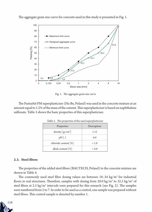
118
The aggregate grain size curve for concrete used in this study is presented in Fig. 1.
The Pantarhit FM superplasticiser (Ha-Be, Poland) was used in the concrete mixture at an amount equal to 1.2% of the mass of the cement. This superplasticizer is based on naphthalene sulfonate. Table 3 shows the basic properties of this superplasticiser.
Table 3. The properties of the used superplasticiser
Properties Description
density [g/cm3] 1.15
pH [-] 6.0
chloride content [%] < 1.0
alkali content [%] < 4.0
2.3. Steel fibres
The properties of the added steel fibres (BAUTECH, Poland) to the concrete mixture are shown in Table 4.
The commonly used steel fibre dosing values are between 18–34 kg/m3 for industrial floors in real structures. Therefore, samples with dosing from 20.0 kg/m3 to 32.5 kg/m3 of steel fibres at 2.5 kg/m3 intervals were prepared for this research (see Fig. 2). The samples were numbered from 2 to 7. In order to be used as a control, one sample was prepared without steel fibres. This control sample is denoted by number 1.
0,2 0,6 3,9
17,3
32,1
41,1
50,1
67,0
0
10
20
30
40
50
60
70
80
90
100
0 0,125 0,25 0,5 1 2 4 8 16
Pass
ing
[%]
Sieve size [mm]
Maximum limit curve
Designed aggregate curve
Minimum limit curve
Fig. 1. The aggregate grain size curve

119
Table 4. The properties of steel fibres
Property Description
length [mm] 50
diameter [mm] 1.0
average tensile strength [MPa] 1,100
Young module [GPa] 180
pieces / kg [pc/kg] 3,200
total fibre length / kg [m/kg] 160
2.4. Sample preparation
The preparation of samples began with the mixing of aggregates and steel fibres (dosing dependent on sample number) with 1/3 volume of required water for thirty seconds. The binder was then added to the rest of water and mixed for sixty seconds; during mixing, the superplasticiser was added. After mixing, the prepared fresh concrete was tested to measure its properties. The average temperature of the fresh concrete during the study was 23.3°C (± 3.2°C). The average air temperature in the laboratory was 24.6°C (± 3.6°C) together with air humidity of 47.3% (± 10%). Some of the preparation steps are shown in Fig. 3.
Cube samples measuring 15 x 15 x 15 cm were prepared in polymer forms and cuboid samples 15 x 15 x 60 cm were prepared in steel forms. After twenty-four hours of curing, the samples were placed in a special container with water inside. Before compressive and flexural tensile strength testing, the samples were tested using non-destructive tests.
0,0
20,022,5
25,027,5
30,032,5
0
5
10
15
20
25
30
35
1 2 3 4 5 6 7
Stee
l fib
ers
cont
ent [
kg/m
3 ]
Sample number [-]
Fig. 2. Steel fibre content for each sample

120
2.5. Properties of fresh concrete
2.5.1. Concrete slump test
The concrete slump test measures the workability of fresh concrete using a special cone mould which is described in [27, 29]. Before the test, the internal surface of the mould was cleaned and had oil applied. The mould was placed on a smooth horizontal non-porous steel base plate. The form was then filled with the prepared fresh concrete in three approximately equal layers. Each layer was tamped using the rounded end of the tamping rod in a uniform manner. For the subsequent layers, the tamping penetrated into the underlying layers. The excess concrete was removed, and the surface was levelled with a trowel. The mould was raised from the concrete immediately and slowly in a vertical direction without stopping. The slump was then measured as the difference between the height of the mould and that of height point of the specimen being tested (Fig. 4a).
2.5.2. Density
Fresh concrete density was calculated using the weight measuring device which is shown in Fig. 4b. The pail was filled with the fresh concrete in a few layers which were tamped using a concrete vibrator. Hardened concrete density was calculated in a similar manner but without the need for the tamping process. The samples were drawn out from the special container with water inside after twenty-eight days of curing and were then left for two hours for initial drying before being weighed.
2.5.3. Air content
To verify the air content of freshly mixed concrete, the pressure method according to [23, 30] was used. This method is preferable due to it providing relatively fast results. Initially, the fresh concrete was filled and tamped in a similar manner as described in 2.5.2. Next the top
Fig. 3. Sample preparation process

121
of the air-content test device was closed. Then, the air gap between the top of the concrete surface and the underside of the top of air meter with water was filled. The top of the air meter was then pressurised with the built-in hand pump until it zeroed out. After a stabilisation period, the pressure in the top was released and the air-void content on the dial on the top of the meter was read (Fig. 4c).
2.6. Properties of hardened concrete
2.6.1. Compressive strength2.6.1.1. Ultrasonic pulse velocity (UPV)
The UPV is an effective non-destructive testing method for the quality control of concrete materials (Fig. 4d). Using this method, it is possible to detect damage in the structural components of existing buildings. The ultrasonic pulse velocity method has recently been successfully used by Ongpeng et al. [4] for concrete reinforced with short steel fibres. In this research, tests were conducted according to [25]. In generalization travel time of ultrasonic waves reflects internal condition of tested sample. Lower wave speeds indicate that the
Fig. 4. Fig. 4. Performed tests on fresh and hardened concrete: a) the slump height measurement; b) fresh concrete weight measurements; c) pressure inside of the air-content test device;
d) scheme of ultrasonic pulse velocity direct method e) rebound hammer test; f) compressive strength test; g) flexural tensile strength test
122
concrete is of poor quality and higher wave speeds indicate that the concrete is of good quality. To measure ultrasonic pulse velocity in this study, the Proceq model was used: Pundit-lab. The ultrasonic pulse velocity measurement results were measured with one configuration of transducers – direct transmission.
2.6.1.2. Rebound hammer test The rebound hammer test is another non-destructive method which was used in this
research to define compressive strength (Fig. 4e) according to [26, 28]. This test measures the extent of rebound, which is a measure of surface hardness. This value is measured when the plunger of the rebound hammer is pressed against the surface of the concrete; a spring controlled mass with a constant energy then strikes the concrete surface and rebounds. The measured value of the rebound corresponds to concrete strength. To measure rebound value in this study, the Proceq Original Schmidt was used. The measurements were performed on samples which were constantly loaded with 0.1fck in the compression testing machine. The points where the rebound value was measured by the hammer were located at least 3 cm from the edge of the sample.
2.6.1.3. Compressive strength testThe compressive strength test is a standard test method [22] which was performed using
a compression testing machine on 15 x 15 x 15 cm dimension samples after twenty-eight days of curing. The average compressive strength was calculated on the basis of results from three tests on cube forms. The destructive compressive strength test method is presented in Fig. 4f.
2.6.1.4. Flexural tensile strength testThe flexural test indirectly evaluates the tensile strength of concrete; it tests the ability of a
concrete beam to withstand failure under bending. The tests were performed on two cuboid samples 10 x 10 x 60 cm after 28 days of curing for every concentration of steel fibres (Fig. 4g) according to [24, 31].
3. Test results and analysis
3.1. Properties of fresh concrete
3.1.1. Concrete slump test
The average slump height decreases with increases in the concentration of steel fibres (Fig. 5). All samples with steel fibres result in lower slump heights than samples without steel fibres. The water to binder ratio for each mix was constant at 0.5; thus, it is possible that water molecules could accumulate on the surface of steel fibres, which would explain the impact that the concentration of steel fibres has on slump height.

123
3.1.2. The density
The density for all of the samples is in the range of approximately 2,300–2,350 kg/m3 (Fig. 6). It appears that the steel fibres don’t have any impact on the density of fresh concrete.
0
5
10
15
20
25
0 10 20 30 40
Slum
p he
ight
[cm
]
Steel fibre concentration [kg/m3]
Fig. 5. Fresh concrete slump test results
2,100
2,150
2,200
2,250
2,300
2,350
2,400
0 10 20 30 40
Den
sity
[kg/
m3 ]
Steel fibre concentration [kg/m3]
Fig. 6. The density of fresh concrete
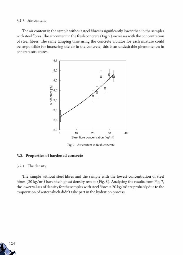
124
3.1.3. Air content
The air content in the sample without steel fibres is significantly lower than in the samples with steel fibres. The air content in the fresh concrete (Fig. 7) increases with the concentration of steel fibres. The same tamping time using the concrete vibrator for each mixture could be responsible for increasing the air in the concrete; this is an undesirable phenomenon in concrete structures.
3.2. Properties of hardened concrete
3.2.1. The density
The sample without steel fibres and the sample with the lowest concentration of steel fibres (20 kg/m3) have the highest density results (Fig. 8). Analysing the results from Fig. 7, the lower values of density for the samples with steel fibres > 20 kg/m3 are probably due to the evaporation of water which didn’t take part in the hydration process.
2,0
2,5
3,0
3,5
4,0
4,5
5,0
5,5
0 10 20 30 40
Air c
onte
nt [%
]
Steel fibre concentration [kg/m3]
Fig. 7. Air content in fresh concrete

125
3.2.2. Compressive strength
In this research, compressive strength was investigated by three different methods, one destructive and two non-destructive (Fig. 9). The ultrasonic pulse velocity method has mostly similar results. The compression test and the rebound hammer compressive strength curves have similar shapes; however, the non-destructive method records have around 20
2,100
2,150
2,200
2,250
2,300
2,350
2,400
0 10 20 30 40
Den
sity
[kg/
m3 ]
Steel fibre concentration [kg/m3]
y = -0,3327x + 47,9976
y = -0,0545x + 49,0871
y = -0,3109x + 25,4094
0
10
20
30
40
50
60
0 10 20 30 40
Com
pres
sive
stre
ngth
[MPa
]
Steel fibre concentration [kg/m3]
Compression test
Ultrasonic PulseVelocityRebound Hammer
Fig. 8. Hardened concrete density
Fig. 9. Compressive strength results for three different methods

126
MPa smaller strength values than the destructive method. The highest compressive strength was achieved for the sample with a steel fibre concentration of 20 kg/m3. Analysing Fig. 8, it can be seen that this sample had the highest density after twenty-eight days of curing. The same dependency between the density and the compressive strength can be seen for the other samples. The shape of the density curve is similar to the compressive strength curve. Thus, the final density of hardened concrete could have the largest impact on compressive strength.
3.2.3. Flexural tensile strength
From Fig. 10, it can be seen that steel fibres and their concentration doesn’t have any effect on flexural tensile strength. Little anomaly of strength decreasing has been seen for sample with 25 kg/m3 content of steel fibres. Because of the high air content in the fresh concrete mix and the lowest hardened concrete density for the sample with 25 kg/m3 steel fibre concentration, it yields the lowest flexural tensile strength result.
4. Discussion of the results
4.1. Effect of density and air content
The density decreases its value with increasing steel fibre concentration and, as a result, the air content in the concrete also increases. Small air bubbles have a negative impact on compressive and flexural tensile strength. Lower density (Fig. 11) indicates more air bubbles inside of the hardened concrete (Fig. 12) and it results in lower strength of the concrete samples.
Fig. 10. Flexural tensile strength results
y = -0,0001x + 1,2836
0,6
0,7
0,8
0,9
1,0
1,1
1,2
1,3
1,4
1,5
1,6
0 10 20 30 40
Flex
ural
tens
ile s
treng
th [M
Pa]
Steel fibre concentration [kg/m3]

127
0,5
1,0
1,5
2,0
2,5
0
10
20
30
40
50
60
2,100 2,150 2,200 2,250 2,300 2,350 2,400
Flex
ural
tens
ile s
treng
th [M
Pa]
Com
pres
sive
stre
ngth
[MPa
]
Density [kg/m3]
Compressive strengthFlexural tensile strength
Fig. 11. Comparison of compressive (destructive method) and flexural tensile strength with density of hardened concrete
0,5
1,0
1,5
2,0
2,5
0
10
20
30
40
50
60
2 3 4 5 6
Flex
ural
tens
ile s
treng
th [M
Pa]
Com
pres
sive
stre
ngth
[MPa
]
Air content [%]
Compressive strengthFlexural tensile strength
Fig. 12. Comparison of compressive (destructive method) and flexural tensile strength with air content in fresh concrete

128
4.2. Comparative analysis of the rebound hammer and ultrasonic pulse velocity results
In many pieces of research, non-destructive methods of the rebound hammer or/and ultrasonic pulse velocity have been analysed and compared [3; 8, p. 405; 19; 20]. However, the results of previous studies for these two methods are very similar and there aren’t steel fibres inside the concrete samples. In this study, the results of compressive strength testing using each method are different. It shows that standard methods are not efficient enough to identify the compressive strength of concrete with steel fibres.
Analysing the compressive strength values (Fig. 9), it was observed that ultrasonic pulse velocity method yields similar results to the real compressive strength of the sample without steel fibres; however, it doesn’t include steel fibres and their dosing. Rebound hammer method results are similar to the theoretical compressive strength 25 MPa. Moreover, this method includes the impact of steel fibres on compressive strength.
The researchers found the following relationship to calculate compressive strength using two non-destructive test results and the simplified formula:
f f f fc c UPV c RH ck� � �� �, , (1)
Where fc – estimated compressive strength of concrete; fc,UPV – ultrasonic pulse velocity compressive strength test result; fc,RH – rebound hammer compressive strength test result; fck – characteristic compressive cylinder strength of concrete at 28 days (concrete strength class).
From Fig. 13, it can be seen that by using formula (1) the real compressive strength can be estimated and calculated using results from the samples tested only by non-destructive methods (rebound hammer and ultrasonic pulse velocity). The problem of identifying the compressive strength of existing structures without their destruction can be resolved by results of this study. The calculated values are summarised with the tested values of compressive strength in Table 5.
Table 5. Summary of tested and calculated compressive strength values with errors
Tested compressive strength [MPa]
Calculated compressive strength [MPa] Error [MPa] Relative error RE
[MPa]
45.68 47.21 1.53 1.03
50.86 53.45 2.59 1.05
42.51 39.88 2.63 0.94
31.30 35.48 4.18 1.13
35.76 34.95 0.81 0.98
41.28 38.37 2.91 0.93
36.02 39.40 3.38 1.09
Mean absolute error MAE [MPa] 2.58

129
5. Conclusions
The purpose of this article was to evaluate the effect of different concentrations of steel fibres in the concrete matrix on concrete properties. In the research, properties of fresh and hardened concrete were analysed. Based on the performed tests, the following general conclusions can be drawn:
Higher steel fibre concentrations had an influence on fresh concrete workability. The slump height decreases with increasing concentrations of steel fibres. During the design of the concrete matrix, larger doses of superplasticiser should be considered.
The density results of fresh and hardened concrete shows that every matrix preparation can be executed differently. In the researcher’s opinion, the tamping process using the concrete vibrator had the most influence on the density results. It should also be considered that some of the water could evaporate after removing the samples from the special container.
Higher air content in fresh concrete has a negative influence on the strength properties. With increasing concentrations of steel fibres, the air content value in fresh concrete also increases. During designing the concrete matrix, smaller steel fibre concentrations should be considered in order to obtain more favourable strength properties.
Higher steel fibre dosing (≥ 22.5 kg/m3) decreases the compressive strength values.The results of compressive strength are not clear for three different methods. This is
because sufficient testing to compare the methods has not been performed.For concrete reinforced with steel fibres, there is the possibility to estimate compressive
strength using results from non-destructive test methods and formula (1), which was proposed by researchers.
Different concentrations of steel fibres has an impact on air content in fresh concrete and this has an impact on the density of hardened concrete. Better compressive and flexural tensile
0
10
20
30
40
50
60
0 10 20 30 40
Com
pres
sive
stre
ngth
[MPa
]
Steel fibre concentration [kg/m3]
Tested compressive strength
Calculated compressive strength
Fig. 13. Compressive strength estimation using non-destructive results

130
strength results are obtained for higher density of hardened concrete. Tested samples were tamped using a concrete vibrator for the same time for each mixture. Therefore, to obtain better strength results, it’s important to pay attention to the time of tamping, which depends on the steel fibre concentration.
Analysing this research, it was found that there exists a correlation between ultrasonic pulse velocity and rebound hammer results. In further studies, the samples should be reinforced with polymer fibres and should be tested in a similar way to verify the effectiveness of formula (1) on other types of fibres.
References
[1] Johnston C.D., Fiber-reinforced cements and concretes, CRC Press, 2014.[2] Balaguru P.N., Shah S.P., Fiber-reinforced cement composites, 1992.[3] Agunwamba J.C., Adagba T., A comparative analysis of the rebound hammer and ultrasonic
pulse velocity in testing concrete, Nigerian Journal of Technology 2012, 31(1), 31–39.[4] Ongpeng J.M., Oreta A.W., Hirose S., Characterization of Damage Using Ultrasonic
Testing on Different Types of Concrete, Materials Evaluation 2018, 76(11), 1532–1541.[5] Zhao Q., Yu J., Geng G., Jiang J., Liu X., Effect of fiber types on creep behavior of concrete,
Construction and Building Materials 2016, 105, 416–422.[6] Kırgız M.S., Fresh and hardened properties of green binder concrete containing marble
powder and brick powder, European Journal of Environmental and Civil Engineering 2016, 20(1), 64–101.
[7] Lee J.H., Influence of concrete strength combined with fiber content in the residual flexural strengths of fiber reinforced concrete, Composite Structures 2017, 168, 216–225.
[8] Ongpeng J., Oreta A., Hirose S., Investigation on the sensitivity of ultrasonic test applied to reinforced concrete beams using neural network, Applied Sciences 2018, 8(3).
[9] Wafa F.F., Ashour S.A., Mechanical properties of high-strength fiber reinforced concrete, Materials Journal 1992, 89(5), 449–455.
[10] Martí J.V., Yepes V., González-Vidosa F., Memetic algorithm approach to designing precast-prestressed concrete road bridges with steel fiber reinforcement, Journal of Structural Engineering 2014, 141(2), 04014114.
[11] Meda A., Plizzari G.A., New design approach for steel fiber-reinforced concrete slabs-on-ground based on fracture mechanics, Structural Journal 2004, 101(3), 298–303.
[12] Balaguru P., Foden A., Properties of fiber reinforced structural lightweight concrete, Structural Journal 1996, 93(1), 62–78.
[13] Sorelli L.G., Meda A., Plizzari G.A., Steel fiber concrete slabs on ground: a structural matter, ACI Structural Journal 2006, 103(4).
[14] Caratelli A., Meda A., Rinaldi Z., Romualdi P., Structural behaviour of precast tunnel segments in fiber reinforced concrete, Tunnelling and Underground Space Technology 2011, 26(2), 284–291.

131
[15] Kang S.T., Lee Y., Park Y.D., Kim J.K., Tensile fracture properties of an Ultra High Performance Fiber Reinforced Concrete (UHPFRC) with steel fiber, Composite Structures 2010, 92(1), 61–71.
[16] Ostrowski K., Sadowski Ł., Stefaniuk D., Wałach D., Gawenda T., Oleksik K., Usydus I., The Effect of the Morphology of Coarse Aggregate on the Properties of Self-Compacting High-Performance Fibre-Reinforced Concrete, Materials 2018, 11(8).
[17] Stawiski B., The heterogeneity of mechanical properties of concrete in formed constructions horizontally, Archives of Civil and Mechanical Engineering 2012, 12(1), 90–94.
[18] Ostrowski K., The influence of CFRP sheets on the strength of short columns produced from normal strength concrete and fibre reinforced concrete, Technical Transactions 2-B/2016, 145–156.
[19] Samarin A., Meynink P., Use of combined ultrasonic and rebound hammer method for determining strength of concrete structural members, Concrete International 1981, 3(03), 25–29.
[20] Abdulmajeed R., Hasan N., Amen D., Comparative Analysis of the Rebound Hammer and Ultrasonic Pulse Velocity in Testing Concrete with Multi-Variation Equation, International Review 2016, 7(6), 196–200.
[21] Di Prisco M., Felicetti R., Plizzari G.A. (eds.), PRO 39: 6th International RILEM Symposium on Fibre-Reinforced Concretes (FRC)-BEFIB 2014, vol. 1, RILEM Publications 2004.
[22] BS EN 206. (2016). BS EN 206:2016, Concrete – Specification, performance, production and conformity (includes Amendment :2016).
[23] Concrete C., Statements B. (2003). ASTM C 231:2003, Standard Test Method for Air Content of Freshly Mixed Concrete by the Pressure Method. American Society for Testing and Materials. M, 04.
[24] ASTM. (1997). C1018, Standard Test Method for Flexural Toughness and First-Crack Strength of Fiber-Reinforced Concrete (Using Beam with Third-Point Loading). ASTM International, 04 (October), 7.
[25] ASTM. (2016), Standard Test Method for Pulse Velocity Through Concrete. ASTM C597-16. ASTM International.
[26] ASTM C805-02. (2002). 1. ASTM C 805, Standard Test Method for Rebound Number of Hardened Concrete. ASTM, 2–4.
[27] ASTM C143/143M. (2010). Standard Test Method for Slump of Hydraulic-Cement Concrete. ASTM C143, (1), 1–4.
[28] BS EN 12504-2. (2012). BS EN 12504-2:2012, Testing concrete in structures – Part 2: Non-destructive testing – Determination of rebound number.
[29] BS EN 12350-2. (2009). BS EN 12350-2:2009, Testing fresh concrete. Part 2: Slump Test.[30] BS EN 12350-7. (2009). BS EN 12350-7:2009, Testing fresh concrete. Part 7: Air Content
– Pressure methods.[31] ASTM. (2002). ASTM C78/C78M – 02, Standard Test Method for Flexural Strength of
Concrete (Using Simple Beam with Third-Point Loading). ASTM International, 1–3.
If you want to quote this article, its proper bibliographic entry is as follow: Krzywiński K., Chajec A., The effect of the concentration of steel fibres on the properties of industrial floors, Technical Transactions, Vol. 4/2019, pp. 115–132.


133
TECHNICAL TRANSACTIONS 4/2019MECHANICS
DOI: 10.4467/2353737XCT.19.048.10360 submIssIOn Of The fInal versIOn: 9/04/2019
Daniel Jastrzębski orcid.org/0000-0003-0999-1763Beata Niesterowicz orcid.org/[email protected]
Faculty of Mechanical Engineering and Mechatronics, West Pomeranian University of Technology
The reasons for hybrid light pole failures – an analytical study
analityczne badania przyczyn uszkodzeń hybrydowego słupa oświetleniowego
AbstractThis paper presents the results of a durability analysis of a hybrid light pole. The developed model includes a supporting structure of a pole with photovoltaic panels, a wind turbine and a boom with a light case. Due to various operating conditions, these poles may be characterised by a different configuration of the mutual spatial distribution of individual components. This results in a large diversity in the analysis results, hence the fact that the research was performed for the selected configuration variant for which the most unfavourable operating conditions were forecasted. In order to reveal potential stress concentration areas, a series of structural analyses was applied using the finite element method. as part of the work, changes to the supporting structure of the pole were proposed and to confirm the possibility of improving the resistance of the structure, additional analyses were conducted.Keywords: finite element method, hybrid light pole, modal analysis, response spectrum analysis
StreszczenieW pracy przedstawiono wyniki modelowych badań wytrzymałościowych hybrydowego słupa oświetleniowego. W opracowanym modelu uwzględniono konstrukcję nośną słupa wraz z panelami fotowoltaicznymi, turbiną wiatrową oraz oprawą oświetleniową. Ze względu na zróżnicowane warunki eksploatacyjne słupy te mogą charakteryzować się odmienną konfiguracją wzajemnego przestrzennego rozmieszczenia poszczególnych komponentów. Powoduje to duże zróżnicowanie wyników analiz, stąd badania przeprowadzono dla wytypowanego wariantu konfiguracji, dla którego prognozowano najbardziej niekorzystne warunki eksploatacji. W celu ujawnienia potencjalnych miejsc koncentracji naprężeń zastosowano szereg analiz konstrukcji metodą elementów skończonych. W ramach pracy zaproponowano zmiany w konstrukcji nośnej słupa oraz przeprowadzono analizę potwierdzającą możliwość poprawy odporności konstrukcji.Słowa kluczowe: metoda elementów skończonych, hybrydowe słupy oświetleniowe, analiza modalna, analiza spektrum reakcji

134
1. 1. Introduction
The use of stand-alone lighting poles is particularly beneficial in places where it is difficult or unprofitable to supply electricity. These poles are often described as being hybrid due to the supply of renewable energy in the form of both solar and wind.
The inspiration for addressing the problem of hybrid poles was the suggestion of one of the manufacturers. They described a situation in which a proportion installed poles were damaged in the form of fatigue cracking of the boom arm bearing element after a short period of time (Fig. 1). The attempts made by the manufacturer to improve the structure by adding a reinforcing rib, shown on the picture presented below, did not bring the desired results.
It is interesting that this damage occurred in only a few cases. After obtaining assurance that the same production conditions were maintained for all poles, the assumption was made that the individually selected configuration of modules mounted on hybrid poles could be the cause of damage.
On the supporting constructions of such poles, in addition to the light module, photovoltaic panels and wind turbines are mounted. In reality, the configuration of these elements is different for each particular installation. Photovoltaic panels are located around the axis of the column depending on the direction of the sun’s rays. However, the setting of the lighting fixture depends on the position of the lamp relative to the illuminated road (Fig. 2). For these reasons, there is a large variety of configurations of these elements. Additionally, the element which randomly changes its position around the axis of the pole is the wind turbine as it adapts to the current wind direction.
The supporting structure of the hybrid pole may be exposed to variable loads coming from the wind [9]. These loads can vary both in terms of the values of the forces and the direction of their actions. Except the variable nature of wind forces there are load changes caused by the wind-dependent position of the wind turbine.
From the point of view of the considered problem – damage to the supporting structure of hybrid poles – the dynamic properties of the object may be relevant [2]. There is a risk of resonance vibrations being activated, as a result of which, undesirable concentrations of time-
Fig. 1. Photograph of sample damage
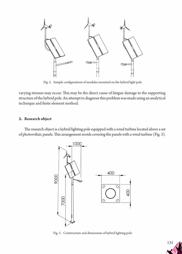
135
varying stresses may occur. This may be the direct cause of fatigue damage to the supporting structure of the hybrid pole. An attempt to diagnose this problem was made using an analytical technique and finite element method.
2. Research object
The research object is a hybrid lighting pole equipped with a wind turbine located above a set of photovoltaic panels. This arrangement avoids covering the panels with a wind turbine (Fig. 3).
Fig. 2. Sample configurations of modules mounted on the hybrid light pole
Fig. 3. Construction and dimensions of hybrid lighting pole

136
The set of considered configurations was analysed and configurations in which fatigue damage to the boom with the lamp occurred were selected. Fig. 4 presents the selected configuration in which the boom with the lamp is set in a plane perpendicular to the plane of the photovoltaic panel installation.
3. Modelling
A series of preliminary calculations were performed in the planning of the wide range of computational analysis using the finite element method (FEM). The aim of these calculations was to develop a reliable model in terms of the accepted conditions for the discretisation of the object. Due to the complex construction of the analysed object, solid elements were used for discretisation. As part of the modelling stage, analyses were conducted to examine the impact of the discretisation method on the expected results. Initially, research was conducted on the influence of the division of mesh density on the results of frequency analysis. It was decided that differences in results below 5% for individual discretisation options can be considered to be acceptable, further densification of the mesh would lead to a significant decrease in the efficiency of calculations (model with too many degrees of freedom) [5]. These conditions
Fig. 4. Selected configuration
Fig. 5. Influence of mesh density on results

137
were fulfilled for a mesh with a number of nodes above 38,000 for the supporting structure (Fig. 5a) and for more than 11,000 for solar panels (Fig. 5b).
A mesh consisting of 3,000 nodes and 10,000 elements was used to discretise the wind turbine with the use of an automatic meshing procedure in the areas of shape change.
In the next stage of modelling, a static analysis was performed under gravitational loading in order to pre-determine stress distributions. The results of this analysis were used for manual compaction of the mesh in areas of the highest stress, so that in the indicated areas, especially in weldment joints, the elements should not be larger than 2 mm.
The final stage of the model’s development was to assess the quality of the grid by determining and analysing typical mesh quality indicators, such as aspect ratio, skew angle and warpage [7]. The first of these determines the ratio of the shortest edge of the element to the longest edge. The aspect ratio for tetragonal and hexagonal elements is calculated respectively on the basis of the following formulas:
ARhl
ARllT
i
iH
i
i
�� �� �
�� �� �
32
minmax
minmax
(1)
The skew angle indicator is calculated by finding the minimum angle between the sections connecting the individual nodes and the centres of the opposite sides of each wall of the element. This coefficient is calculated on the basis of the following formulas:
SA SATi
H� ���
��
�
�� � �
��
���
�
���1
9090
190
90max max
� � (2)
The last tested indicator was warpage, which defines the deviation of the element’s walls from the planes of their best fit. This indicator is described by the following formula:
WAh
l� �
� �1
min (3)
Fig. 6. Final mesh model

138
Due to the necessity to maintain the quality of mesh in terms of meeting the abovementioned indicators [5], the grids of supporting structure elements and solar panels were compacted. As a result, a model consisting of 214,768 nodes and 247,413 elements was obtained, this model is shown in Fig. 6. With the exception of tetra- and hexagonal elements, the hexa-tetra link elements were of pyramid (5 node) and wedge (6 node) types.
The analysis of static properties performed in the first stage of research revealed two areas of intense stress concentrations. Despite low values of these stresses, their locations coincided with the indicated damage areas. Figs. 7 and 8 show areas of stress concentration revealed in the analysis of static properties.
Fig. 7. Concentration of stresses caused by the force of gravity in the area of connection between the boom of the lamp and the pole
Fig. 8. Concentration of stresses caused by the force of gravity in the area of connection of the wind turbine with the pole

139
4. Analytical and numerical research for finding the causes of damage
Due to the complex nature of the real loads on the supporting structure of hybrid poles, the search for the causes of damage to these structures was performed in several stages. In the first stage, the analysis of the impact of wind on the supporting structure of the pole was conducted. In this analysis, the distribution of pressure acting on the surfaces of all elements of the object was determined. This distribution was used as an external load in the analysis of static properties. In this analysis, appropriate stress distributions were determined. In the next step, a modal analysis was performed to determine the dynamic properties of the object. Using the results of the modal analysis, the response spectrum analysis was then conducted, which enabled obtaining the proper distribution of stresses derived from dynamic loads. Finally, an analysis of the frequency response with the load from a working wind turbine was performed.
4.1. The impact of wind
In the current regulations, the impact of wind should be taken into account on the basis of the analytical relationships contained in official specifications [4]. Conducting analyses on the basis of this standard requires knowledge of many factors concerning, for example, exposure and topography. These regulations enable the calculation of the pressure of wind depending on the height above ground and pressure resulting from a snow load. The information provided from the manufacturer shows that during the operation time when the destruction of the structure occurred, there was no snowfall. For this reason, calculations of loads resulting from snow were omitted in further analyses. The expected average pressure was approximately calculated using formulae:
q z f c z qN
me� � � � � � � �� � ����
���
� � 102
where δ is the factor relating to the column size (for h ≈ 8.5m, δ = 0.915), β ≈ 1.31 is the factor for the dynamic behaviour, f = 1 is the factor related to topography, ce(z) is the factor dependent on the terrain of the site and the height above the ground (z), q(10) is the reference wind pressure, which accounts for the geographical location of the column. Due to the fact that the pressure values determined on the basis of the standard are between 500 and 560 N/m2 at a height of up to 6 m (below solar panels) and are close to those determined on the basis of numerical analysis, load conditions on the entire column were determined using numerical simulation.
During the maintenance of hybrid poles, extreme weather conditions were not recorded. Therefore, for the purposes of this analysis, it was assumed that objects were exposed to difficult wind conditions with wind speeds of up to 26 m/s [1]. Wind analysis was performed in the Fluid Mechanics Calculation (CFD) module of the Midas NFX program [7]. In order to determine the pressure distributions acting on the surfaces of the column elements, the air flow was simulated. Fig. 9 shows the directions of wind streams acting on the object. Analyses for wind blowing in directions perpendicular (X-axis) and parallel (Z-axis) to the considered configuration of photovoltaic panel settings and the boom with the lamp were conducted.
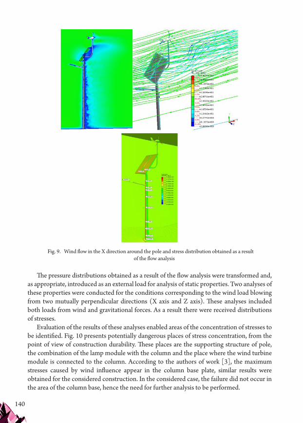
140
The pressure distributions obtained as a result of the flow analysis were transformed and, as appropriate, introduced as an external load for analysis of static properties. Two analyses of these properties were conducted for the conditions corresponding to the wind load blowing from two mutually perpendicular directions (X axis and Z axis). These analyses included both loads from wind and gravitational forces. As a result there were received distributions of stresses.
Evaluation of the results of these analyses enabled areas of the concentration of stresses to be identified. Fig. 10 presents potentially dangerous places of stress concentration, from the point of view of construction durability. These places are the supporting structure of pole, the combination of the lamp module with the column and the place where the wind turbine module is connected to the column. According to the authors of work [3], the maximum stresses caused by wind influence appear in the column base plate, similar results were obtained for the considered construction. In the considered case, the failure did not occur in the area of the column base, hence the need for further analysis to be performed.
Fig. 9. Wind flow in the X direction around the pole and stress distribution obtained as a result of the flow analysis

141
4.2. Modal analysis
In the next stage of searching for the causes of damage to the structure of the hybrid pole, modal analysis was performed. This analysis is commonly used to study the dynamic properties of mechanical structures. As a result of this analysis, it is possible to obtain a modal model describing a mechanical structure consisting of a set of figures and the natural frequency of vibrations. With knowledge of these characteristics, it is possible to predict the behaviour of the structure for any excitation frequencies. This analysis is one of the simplest tools used to analyse and then modify the structure in order to adjust its dynamic characteristics. It is often the first step for further dynamic analysis. The work involved a modal analysis of the structure taking into account the conditions for fixing the column to the ground.
The cumulative sum of effective masses should be between 80% and 90% in each direction of the response (Fig. 11) [8]; therefore, the modal analysis was performed for the first 50 natural frequencies, i.e. for the range 0–350 Hz.
In the case of the analysed object, this value is in the range of 0–30 Hz in the directions of the X axis and the Z axis. Therefore, the analysis was limited to the first ten natural frequencies (Fig. 13), from which Fig. 12 presents selected mode shapes. These mode shapes are interesting considering the column destruction areas.
Fig. 10. Stress concentration areas due to wind loads

142
Fig. 11. Graph of the cumulative mass participation
Fig. 12. Selected modes: a) mode 1 – 1.7 Hz, b) mode 4 – 9.4 Hz, c) mode 6 – 12.7 Hz, d) mode 7 – 13.2 Hz
Fig. 13. Natural frequencies

143
The largest mass ratio (about 65%) in the X direction occurs at 1.68 Hz and in the Z direction at 1.72 Hz. However, in the X direction of frequency, the largest participation of masses (11% and 19%) are much higher, amounting to 82.3 Hz and 124.2 Hz. Modal analysis, in this case, does not directly give results that can be used to indicate the reasons for the considered damage to the hybrid poles, but it is necessary for further stages of searching for the causes of damage.
4.3. Response spectrum analysis
In the next stage of the research, the spectrum of response was analysed. This analysis is used for random frequency excitation simulating variable wind, earthquake or ocean wave loads. In the studied case, the cause of such a variable load is the impact of wind. Assuming that the resonating system can be described by a harmonic oscillator with one degree of freedom characterised by parameters relating to mass, stiffness and damping. However, the response of a system with several degrees of freedom may be a combination of responses of oscillators with one degree of freedom. When the excitation frequency is equal to the resonant frequency, the system response is only controlled by a damping factor. Using this principle, a spectrum of responses can be built [6] by registering responses in the form of displacements, velocities and accelerations for individual oscillators with appropriate dynamic loads. Spectrum is created by interpolation and using several available algorithms that allow interactions between modes to be taken into account, the most common of which is the SRSS algorithm (square root of sum of squares). The spectrum thus created is available in the Midas NFX program [7] in a module designed for fatigue strength analyses. A norm is available for structures located in Europe. Using the spectrum available in the norm, the system has been loaded with X, Y and Z forces. The last element is to take into account damping in the system. It is recommended to determine the attenuation coefficient on the basis of experimental studies; however, if this
Fig. 14. Distribution of stresses for random force in the directions a) X, b) Y, c) Z

144
is not possible, a damping of 2% is suggested. As a result, stress distribution was obtained for the load in the directions indicated (Fig. 14).
Response spectrum reaction analysis indicated that, due to the purpose of the analyses, the area of stress concentration in the Y direction is particularly interesting despite the higher values of stresses determined in the X and Z directions. These stresses are concentrated at the welded joint of the boom of the luminaire with the column supporting structure (Fig. 14b) where the area of the damage occurred. This is the reason to search for additional factors that can cause damage. It can be assumed that they may be caused by external loads caused by the working wind turbine.
4.4. Analysis of the impact of a working wind turbine
According to catalogue data, the turbine operates at wind speeds between 2 m/s and 18 m/s, which means that the excitation frequencies are in the range of 8–23 Hz. Therefore, an additional dynamic analysis was performed in which the effect of rotational force at the wind turbine mounting site was simulated. For the adopted frequency range (8 to 23 Hz), maximum displacement functions were determined (Fig. 15).
In Fig. 15, it can be seen that the resonance of the system appears in the range of excitation frequencies, at a frequency of around 9 to 13 Hz. This indicated a significant displacement of the light arm boom in the X and Y direction due to the working turbine. This analysis confirms the assumption that the source of damage to the structure in the area of connection the light arm boom to the supporting structure of the pole could be the wind turbine.
The variable stress distribution revealed by dynamic analysis has a significant influence on the fatigue damages of the pole. Constant and variable small loads in a given direction cause may cause weakening of the structure in this area and as a result – its damage. This situation occurred in the considered construction. The columns were breaking at the connection point of the light arm boom with the supporting structure.
Fig. 15. Maximum displacement function for dynamic analysis with forces from wind turbine

145
5. Structural modifications
The obtained results enabled proposing a structural change consisting of strengthening the place of connecting the light arm boom to the supporting structure of the pole by means of additional reinforcing ribs (Fig. 16).
The changed construction was re-examined. The results obtained showed slightly smaller values of maximum stresses but a significantly favourable change in stress distribution (Fig. 17). This stress distribution reduces the likelihood of structural damage. Such an approach reduces the likelihood of structural failure in the considered area of the structure.
Fig. 16. Strengthening the structure in the place where the light arm boom is connected to the supporting structure of the column
Fig. 17. Distribution of stresses in the reinforced structure

146
6. Conclusions
The procedure for analysing the structure of a hybrid pole described in the article made it possible to reveal the causes of damage in the area of the connection of the light arm boom to the supporting structure of the pole. Based on the results of these analyses, a fairly simple and low-cost construction change was proposed that would significantly reduce the possibility of damage in the studied area. On the basis of information received from the manufacturer, it can be concluded that the strength of the structure under operating conditions can be increased. At the time of writing, no further damage had been found. This confirms the effectiveness of the use of structural analysis in the design of structures such as hybrid lighting poles.
References
[1] Barszczyńska E., Bedryj M., Biedroń I. i in., Wpływ zmian klimatu na środowisko, gospodarkę i społeczeństwo, t. 3, Klęski żywiołowe a bezpieczeństwo wewnętrzne kraju, Instytut Meteorologii i Gospodarki Wodnej, Państwowy Instytut Badawczy, Warszawa 2012.
[2] Caracoglia L., Jones N., Analysis of light pole failures in Illinois. Final report, Civil Engineering Studies, Structural Research Series 2004, No. 635.
[3] Dudda W., Domański J., Analiza wytrzymałościowa quasi-autonomicznego słupa oświetleniowego z wykorzystaniem systemów CAD/CAE, Mechanik 2017, nr 7.
[4] EN 40-3-1:2000, Lighting columns – Part 3–1: Design and verification – Specification for characteristic loads.
[5] Gokhale N., Bedekar S., Deshpande A., Practical Finite Element Analysis, Finite To Infinite, India 2008.
[6] Kurowski P., Vibration analysis with Solidworks Simulation 2018, SDC Publications.[7] Midas NFX User Manual, www.midasnfx.com (access: 1.08.2018).[8] Priestley M. J. N., Seible F., Calvi G. M., Seismic Design and Retrofit of Bridges, John Wiley
and Sons, New York 1996.[9] Scruton C., Wind effects on structures, John Wiley and Sons, New York 1996.
If you want to quote this article, its proper bibliographic entry is as follow: Jastrzębski D., Niesterowicz B., The reasons for hybrid light pole failures – an analytical study, Technical Transactions, Vol. 4/2019, pp. 133–146.

147
TECHNICAL TRANSACTIONS 4/2019MECHANICS
DOI: 10.4467/2353737XCT.19.049.10361 submIssIOn Of The fInal versIOn: 30/03/2019
Adrian Kozień orcid.org/[email protected]
Faculty of Mechanical Engineering, Cracow University of Technology
The development and verification of a dynamic model of the Kawasaki rs010l industrial robot
Opracowanie oraz weryfikacja modelu dynamiki robota przemysłowego Kawasaki rs010l
AbstractThis article presents an attempt to develop a simplified dynamic model of the Kawasaki rs010l industrial robot using the matlab mathematical environment. This is a six-axis robot which, due to its light weight and high movement ability, is used for a wide range of tasks, such as palletising and assembling objects. It was assumed that all links are stiff and the robot’s wrist is a concentrated mass located at the end of the third arm. In addition, the axes are controlled independently of each other in this model. essential parameters were identified using a real robot and the correctness of the developed model was verified.Keywords: robot dynamics, dynamics model of robot, Kawasaki RS010L
StreszczenieW niniejszym artykule podjęto próbę utworzenia w środowisku matematycznym matlab uproszczonego modelu dynamiki przemysłowego robota Kawasaki rs010l. Jest to 6-osiowy robot, który dzięki małej wadze oraz dużym zdolnościom ruchowym jest stosowany do szerokiego spektrum zadań, takich jak paletyzacja czy montaż obiektów. Założono, że człony są sztywne, a kiść robota jest skupioną masą na końcu trzeciego ramienia. Przyjęto również, że sterowanie osiami robota odbywa się w sposób niezależny. Ponadto, korzystając z rzeczywistego obiektu, dokonano identyfikacji niezbędnych parametrów oraz zweryfikowano poprawność utworzonego modelu. Słowa kluczowe: dynamika robotów, model dynamiki robota, Kawasaki RS010L

148
1. Introduction
Robot dynamics is a wide branch of mechanics which deals with the study of dependencies between motion and the forces and moments ττ which cause this motion. Robot motion is represented by a set of three variables in kinematic links: displacement q, velocity q and acceleration q [13]. The development of equations describing dependencies between motion and forces and moments allows us to test control strategies and motion planning techniques without using a physically available system.
Previous works on the dynamics of robots [5, 6] have typically been concerned with the determination of a mathematical model of an industrial anthropomorphic robot. More recent works focus not only on determining mathematical relations but also on the verification of received equations. The authors in [12] prepared a dynamic model of a two degrees-of-freedom (2 DOF) robot and simulated it using SIMNOM software. Furthermore, a prototype was made to assess its correctness. The total error of the trajectory for the first joint did not exceed 0.6 degrees, which can be considered to be a satisfying result. This procedure is often quite expensive and time-consuming. However, thanks to CAD program, with which the prototype was built, it is possible to identify the exact value of parameters characterising each component, such as dimensions, mass and inertia. In the case of large objects (usually complicated in assembly), the solution to this problem of identifying the exact values of these parameters is quite different. This means that many parameters can be read from specifications or CAD models provided by manufacturers. However, due to the company’s strategy to maintain secrecy, not all of the information has been published, which was challenging for many scientists. Atkeson et al. [2] performed the estimation of the dynamic parameters using the least square method. In work [4], the authors attained a dynamic model of the SCARA robot from experimental data using the weighted least squares method. It has recently been discovered that heuristic algorithms are a useful tool for identifying robot parameters. A genetic algorithm was proposed to identify the parameters of the PUMA 560 robot [15]. A few years later, an improved genetic algorithm was introduced to obtain the model of space robot [10]. However, while dealing with complex and large-scale parameter identification problems, the genetic algorithm would be stuck on the local optimum. Therefore, the artificial bee colony algorithm (ABC) was proposed by Karaboga in 2005 [6] and it was successfully applied to various kinds of problem, such as parameter identification of the aerial robot [8]. This is because previous optimisation algorithms conduct only one search operation in each iteration, while the ABC algorithm can conduct both a local search and a global search in each iteration, thus the probability of finding optimal parameters is significantly increased. The ABC algorithm was introduced to examine the missing parameters of the 6-DOF ER-16 industrial robot [10].
In this paper, a simplified dynamic model of the Kawasaki RS010L industrial robot using the Matlab mathematical environment was made. In addition, using the data from the manufacturer and the physically available robot, identification of the necessary parameters and verification of the previously created model were carried out.
149
2. Dynamic modelling
There are two basic types of dynamics tasks: direct and inverse. In the first task, forces and moments on the motors are provided and the goal is to find the course of changes in the values of the robot’s motion parameters over time. This procedure is useful in the case of robot motion simulation. The inverse dynamic task can be used to control the robot because the input value is the robot’s trajectory and the output value is the course of changes in the value of the forces and moments on the motors. Creating the model is the first step in considering tasks such as dynamic analysis, optimisation and control. Having a real object allows us to check the correctness of the built model. After verification, this model is a perfect tool to solve more complex problems [14]. The method of the building and verification of a mathematical model of an industrial robot is presented below.
Firstly, there is a need to create robot motion equations. Two methods can be used for this purpose (assuming fully rigid elements) [6, 11]:
Newton–Euler – which describes the dynamics of each link,Lagrange – which describes the dynamics of the whole robot using kinetic and potential
energy.The first of these methods considers each link separately using linear and angular motion
equations. It is obvious that if links are connected, there are linkages between them that result from forces and moments. A “forward–backward recursion” method enables the defining of expressions, which helps to obtain a complete description of the manipulator ? By contrast, the second procedure considers the robot as a whole and considers energy dependences by using generalised coordinates (in this case: q). Due to these internal links, forces of reaction are not considered. Therefore, the way to formulate equations is quite fast and yields the same result as the first method. The only disadvantage is that it doesn’t provide complete information about the examined object. The final equations can be written as follows (1): B( ) ( , ) ( )q q q q q � � �C g �� (1)
where:B – matrix of inertia,C – matrix of centrifugal and Coriolis forces,g – matrix of gravitational forces,ττ – vector of applied forces and moments.
In this research, detailed information about linkages between adjacent links is unnecessary; therefore, the second method was chosen. Fig. 1 presents the simplified version of the examined Kawasaki RS010L robot and its structural model and Table 1 presents the Denavita-Hartenberga (D-H) notation parameters.
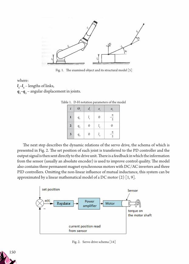
150
where:l1–l3 – lengths of links,q1–q3 – angular displacement in joints.
Table 1. D-H notation parameters of the model
i Θi di ai αi
1 q1 l1 0 –π2
2 q2 0 l2 0
3 q3 0 l3–π
2
The next step describes the dynamic relations of the servo drive, the schema of which is presented in Fig. 2. The set position of each joint is transferred to the PD controller and the output signal is then sent directly to the drive unit. There is a feedback in which the information from the sensor (usually an absolute encoder) is used to improve control quality. The model also contains three permanent magnet synchronous motors with DC/AC inverters and three PID controllers. Omitting the non-linear influence of mutual inductance, this system can be approximated by a linear mathematical model of a DC motor (2) [1, 9].
Fig. 1. The examined object and its structural model [5]
Fig. 2. Servo drive schema [14]

151
Presented equations (2) describing the DC model [14]:
didt
R iL
kL L
U
ddt
k iJ
BJ J
M
w w w
w
e s
w wz
s m w s
�� � �
�� � �
�
���
���
�
� �
1
1 (2)
where:Uz – voltage feeding the motor rotor,–iw – current in the motor windings,Rw – equivalent impedance in the motor windings,Lw – equivalent inductance in the motor windings,E – electromotive force (as linear function of the rotor speed),ωw – angular speed of rotor,B – viscous friction coefficient reduced to the motor shaft,J – moment of inertia coefficient reduced to the motor shaft,M – torque on the motor shaft,ke – electrical constant,km – torque constant.
Equation (3) describing PD controller [14]:
U t K e t Kddt
e tz p d( ) ( ) ( )� � (3)
where:Kp – proportional gain,Kd – derivative gain,e(t) – error value.
The following equations (1–3) are linked together. First of all, displacement of the joint is connected with displacement of the rotor by the gear. Thus, the values of torque M and ττ are also connected to one another with a certain ratio (ratio1–ratio3). According to Fig. 2, the output value of voltage from (3) is transferred to equation (2). The final mathematical model can be written as follows (4):

152
x �
� � � �
q
q
q
(k i -B q ) ratio -c
1
2
3
m1 1 1 1 112
q q -c q q
(k i -B q ) ratio -c q -c
1 2 113 1 3
m2 2 1 2 211 12
� � �
� � � � 2233 32
223 2 3 2
m3 3 1 3 311
q -c q q -
(k i -B q ) ratio -c q
� � �
� � � �
�
112
322 22
3
w 1 e1 1 1 w
2
-c q -
(Uz -R i -k q /ratio )/L
(Uz -
�
� �
�
1
RR i -k q /ratio )/L
(Uz -R i -k q /ratio )/L
w 2 e2 2 2 w
3 w 3 e3 3 3 w
� �
� �
��
�
��������
�
��������
(4)
where
c = -[(2 m l +0.5 m l +2 J ) sin(q ) cos(q )+
112 32
2 22
2 2 2� � � � � � �2
+m l l (cos(q ) sin(q +q )+sin(q ) cos(q +q ))+
3 3 2 2 3 2 2 3� � � � �2
+(2 J +0.5 m l ) cos(q +q ) sin(q +q )]
c = -[m l
3 32
2 3 2 3
113 3
� � � � �
�
3
22 3 2 2 3 3 3 32
2 3l cos(q ) sin(q +q )+(2 J +0.5 m l ) cos(q +q ) sin(� � � � � � � � qq +q )]
c = 0.5 m l l (sin(q ) cos(q +q )+cos(q ) sin
2 3
211 3 3 2 2 3 2� � � � � �2 ((q +q ))+
+(m l +J +0.25 m l ) sin(q ) cos(q )+(
2 3
32
2 22
2 2� � � � �2 2 JJ +0.25 m l ) sin(q +q ) cos(q +q )
c = -0.5 m l l
3 3 32
2 3 2 3
233 3 3
� � � �
� � � �2 ssin(q )
c = -m l l sin(q )
c = 0.5 m l l cos(q )
3
223 3 3 3
311 3 3 2
� � �
� � � � �
2
2 ssin(q +q )+(J +0.25 m l ) cos(q +q ) sin(q +q )
c = 0.
2 3 3 3 32
2 3 2 3
322
� � � �
55 m l l sin(q )
= (m l +0.5 m l ) cos(q )+0.5 m l
3 3 3
2 3 2 3 2 3 3
� � � �
� � � � � �
2
2� ��
� � �
cos(q +q )
= 0.5 m l cos(q +q )
2 3
3 3 3 2 3�
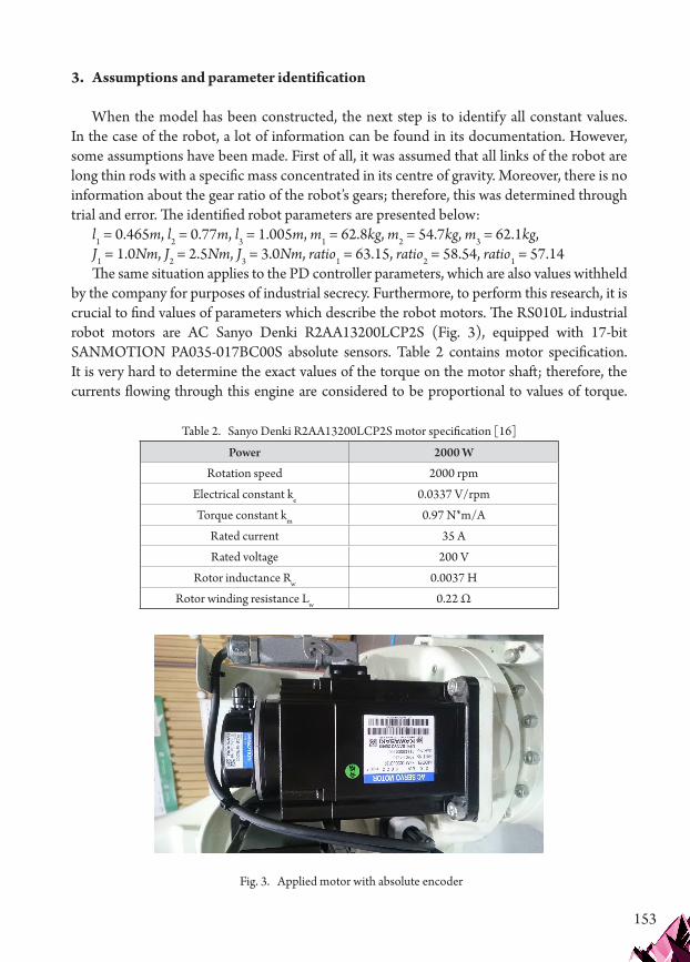
153
3. Assumptions and parameter identification
When the model has been constructed, the next step is to identify all constant values. In the case of the robot, a lot of information can be found in its documentation. However, some assumptions have been made. First of all, it was assumed that all links of the robot are long thin rods with a specific mass concentrated in its centre of gravity. Moreover, there is no information about the gear ratio of the robot’s gears; therefore, this was determined through trial and error. The identified robot parameters are presented below:
l1 = 0.465m, l2 = 0.77m, l3 = 1.005m, m1 = 62.8kg, m2 = 54.7kg, m3 = 62.1kg, J1 = 1.0Nm, J2 = 2.5Nm, J3 = 3.0Nm, ratio1 = 63.15, ratio2 = 58.54, ratio1 = 57.14The same situation applies to the PD controller parameters, which are also values withheld
by the company for purposes of industrial secrecy. Furthermore, to perform this research, it is crucial to find values of parameters which describe the robot motors. The RS010L industrial robot motors are AC Sanyo Denki R2AA13200LCP2S (Fig. 3), equipped with 17-bit SANMOTION PA035-017BC00S absolute sensors. Table 2 contains motor specification. It is very hard to determine the exact values of the torque on the motor shaft; therefore, the currents flowing through this engine are considered to be proportional to values of torque.
Table 2. Sanyo Denki R2AA13200LCP2S motor specification [16]
Power 2000 W
Rotation speed 2000 rpm
Electrical constant ke 0.0337 V/rpm
Torque constant km 0.97 N*m/A
Rated current 35 A
Rated voltage 200 V
Rotor inductance Rw 0.0037 H
Rotor winding resistance Lw 0.22 Ω
Fig. 3. Applied motor with absolute encoder
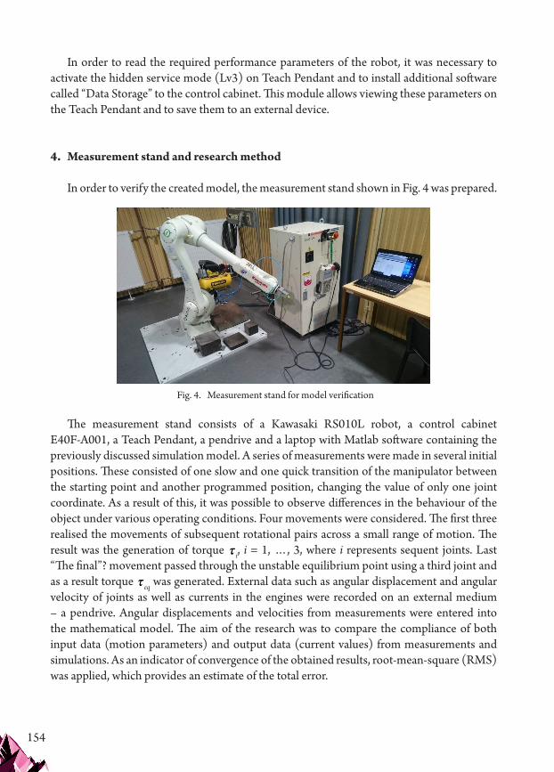
154
In order to read the required performance parameters of the robot, it was necessary to activate the hidden service mode (Lv3) on Teach Pendant and to install additional software called “Data Storage” to the control cabinet. This module allows viewing these parameters on the Teach Pendant and to save them to an external device.
4. Measurement stand and research method
In order to verify the created model, the measurement stand shown in Fig. 4 was prepared.
The measurement stand consists of a Kawasaki RS010L robot, a control cabinet E40F-A001, a Teach Pendant, a pendrive and a laptop with Matlab software containing the previously discussed simulation model. A series of measurements were made in several initial positions. These consisted of one slow and one quick transition of the manipulator between the starting point and another programmed position, changing the value of only one joint coordinate. As a result of this, it was possible to observe differences in the behaviour of the object under various operating conditions. Four movements were considered. The first three realised the movements of subsequent rotational pairs across a small range of motion. The result was the generation of torque ττ i, i = 1, …, 3, where i represents sequent joints. Last “The final”? movement passed through the unstable equilibrium point using a third joint and as a result torque ττ eq was generated. External data such as angular displacement and angular velocity of joints as well as currents in the engines were recorded on an external medium – a pendrive. Angular displacements and velocities from measurements were entered into the mathematical model. The aim of the research was to compare the compliance of both input data (motion parameters) and output data (current values) from measurements and simulations. As an indicator of convergence of the obtained results, root-mean-square (RMS) was applied, which provides an estimate of the total error.
Fig. 4. Measurement stand for model verification

155
5. Results of model verification
Fig. 5 shows the starting positions of two selected robot’s. The first of these (on the left) is specific because the link between the second and third swing pairs is arranged vertically. This also allows the robot’s behaviour to be assessed for an unstable equilibrium position, i.e. when the deflected link is also arranged vertically.
The measurement results for the first position are shown below. In this case, the first rotational pair is moved by an angle of about 90 degrees. Fig. 6 presents the course of changes of this value using the data from the measurement and simulation. Slow movement of the manipulator is visible from seconds 1 to 10 and fast movement between seconds 10 and 12. The value of RMS for the first is 0.003 degrees, and for fast movement is 0.01 degrees. Fig. 7 shows the course of changes in the angular velocity of the joint.
Fig. 5. Selected initial positions of robot (position 1 on left, position 2 on right)
Fig. 6. The course of change of angular displacement in the first joint
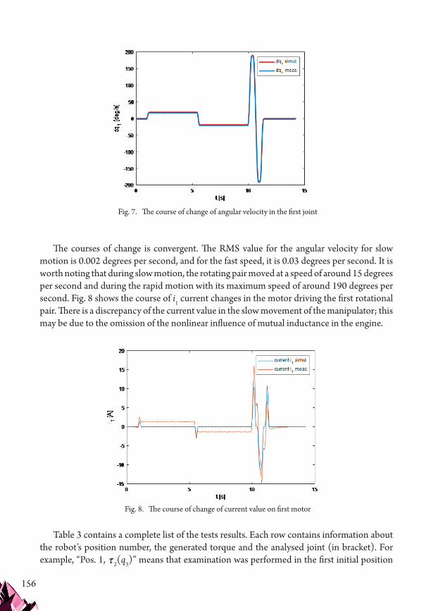
156
The courses of change is convergent. The RMS value for the angular velocity for slow motion is 0.002 degrees per second, and for the fast speed, it is 0.03 degrees per second. It is worth noting that during slow motion, the rotating pair moved at a speed of around 15 degrees per second and during the rapid motion with its maximum speed of around 190 degrees per second. Fig. 8 shows the course of i1 current changes in the motor driving the first rotational pair. There is a discrepancy of the current value in the slow movement of the manipulator; this may be due to the omission of the nonlinear influence of mutual inductance in the engine.
Table 3 contains a complete list of the tests results. Each row contains information about the robot’s position number, the generated torque and the analysed joint (in bracket). For example, “Pos. 1, ττ2(q3)” means that examination was performed in the first initial position
Fig. 7. The course of change of angular velocity in the first joint
Fig. 8. The course of change of current value on first motor

157
using the second joint and the motion parameters of the third joint and the current in its motor were analysed. The values of the RMS parameter designated separately for slow and fast motion are presented. For the second and third generated torque, two sets of solutions are shown because the second and third link are coupled. This means that if the third link moves (especially in fast movement), it will affect the second link under inertia force. It can be seen that during the fast movement, RMS values are larger by one order of magnitude. In the case of values of current, the model error is relatively large and increases with the increase of the speed of movement. This is due to the fact that the model contains simplified AC motors. A greater deviation of the measured parameters occurs in the second position, i.e. with an increased tilt of the second link of the manipulator.
Table 3. Complete list of results
Angular displacement
Slowmotion
[degrees]
Angular displacement
Fastmotion
[degrees]
Angularvelocity
Slowmotion
[degrees per second]
Angular velocity
Fastmotion
[degrees per second]
Motor current
Slow motion
[A]
Motor current
Fast motion
[A]
Pos. 1, ττ1(q1) 0.003 0.01 0.002 0.03 1.24 2.45
Pos. 1, ττ1(q2) 0.006 0.01 0.005 0.01 1.21 3.42
Pos. 1, ττ2(q3) 0.008 0.04 0.004 0.04 1.22 2.74
Pos. 1, ττ3(q3) 0.007 0.01 0.009 0.03 2.2 4.22
Pos. 1, ττ3(q2) 0.034 0.074 0.008 0.05 0.73 2.61
Pos. 1, ττ eq(q3) 0.008 0.09 0.01 0.07 2.71 4.21
Pos. 2, ττ1(q1) 0.009 0.02 0.01 0.03 1.34 4.1
Pos. 2, ττ2(q2) 0.007 0.17 0.019 0.14 2.63 4.11
Pos. 2, ττ2(q3) 0.03 0.32 0.034 0.17 1.77 3.9
Pos. 2, ττ3(q2) 0.017 0.06 0.03 0.26 1.32 1.98
Pos. 2, ττ3(q3) 0.008 0.11 0.02 0.13 3.89 4.76
6. Conclusions
The article presents a simplified dynamic model of a 6-axis industrial manipulator with a control system. It is limited to three kinematic pairs, as their size and weight significantly exceed the parameters of the gripper. In the next course of work, it would be worth to include a full-sized robot. It would also be necessary to change the form of the equations: take the integral term of the controller and create a full PID into the model. This will definitely

158
affect the quality of regulation. The values of currents from simulations and tests were not convergent. This is due to the fact that the model contains equations of DC motor dynamics and the tested object – AC motor dynamics. This is another direction that needs refinement. Another aspect is the fact that as a simplification, it is assumed that the moments of loading the motors are not considered directly. Currents value, passing through the motors, which are proportional to the value of this moment are determined. A separate measuring station should be prepared and an approximate dependence on the current value of the moment depending on the current flowing in the motor windings should be determined using the experimental method.
References
[1] Ahmad M., High Performance AC Drives. Modelling Analysis and Control, Springer 2010.[2] Atkeson Ch.G., An Ch.H. and Hollerbach J.M., Estimation of inertial parameters of
manipulator loads and links, International Journal of Robotics Research 1986, vol. 5, no. 3, 101–119.
[3] Ding L., Wu H., Yao Y., Yang Y, Dynamic Model Identification for 6-DOF Industrial Robots, Journal of Robotics Volume 2015, Article ID 471478.
[4] Gautier M. and Poignet P., Extended Kalman filtering and weighted least squares dynamic identification of robot, Control Engineering Practice, vol. 9, no. 12, pp. 1361–1372, 2001.
[5] Heimann B., Gerth W., Popp K. Mechatronik: Komponenten – Methoden – Beispielen, Hanser Verlag, Munich 2006.
[6] Jezierski E., Dynamika robotów, WNT, Warszawa 2006 (in Polish).[7] Karaboga D., An idea based on honey bee swarm for numerical optimization, Tech. Rep.
tr06, October 2005, Computer Engineering Department, Engineering Faculty, Erciyes University, 2005.
[8] Karaboga D. and Basturk B., On the performance of artificial bee colony (ABC) algorithm, Applied Soft Computing Journal 2008, vol. 8, no. 1, 687–697.
[9] Krykowski K., Piwowarczyk R., Radczuk C., Poszerzenie zakresu prędkości silnika bezszczotkowego prądu stałego z magnesami trwałymi (PM BLDC) przez zastosowanie przekształtnika podwyższającego BOOST, Materiały Krajowej Konferencji Naukowej SENE, Łódź 2007, 259–266 (in Polish).
[10] Liu Y., Li G.-X., Xia D., Xu W.-F., Identifying dynamic parameters of a space robot based on improved genetic algorithm, Journal of Harbin Institute of Technology 2010, vol. 42, no. 11, pp. 1734–1739.
[11] Morecki A., Knapczyk J., Kędzior K., Teoria mechanizmów i manipulatorów, WNT, Warszawa 2002 (in Polish).
[12] Sánchez-Sánchez P., Arteaga-Pérez M.A., Simplied Methodology for Obtaining the Dynamic Model of Robot Manipulators, International Journal of Advanced Robotic Systems, DOI: 10.5772/51305.

159
[13] Spong M.W., Hutchinson S., Vidyasagar M., Robot Dynamics and Control. Second Edition, John Wiley & Sons, Inc., Canada 2004.
[14] Szkodny T., Dynamika robotów przemysłowych, Wyd. Politechniki Śląskiej, Gliwice 2013 (in Polish).
[15] Zakharov A., Halasz S., Parameter identification of a robot arm using genetic, Periodica Polytechnica Ser. El. Eng. 2001, vol. 45, no. 3–4, 195–209.
[16] Kawasaki [online] https://robotics.kawasaki.com/en1/products/robots/small-medium-payloads/RS010L/ (access: 26.10.2018).
If you want to quote this article, its proper bibliographic entry is as follow: Kozień A., TThe development and verification of a dynamic model of the Kawasaki RS010L industrial robot, Technical Transactions, Vol. 4/2019, pp. 147–160.