Technical Supervisor - Ibiblio
161
ANALYSIS AND MECHANIZATION OF LAUNCH WINDOW AND RENDEZVOUS COMPUTATION PART I. CIRCULAR ORBITS Research & Analysis Section Tech Memo No. 175 March 1966 BY J. L. Shady Prepared for: NATIONAL AERONAUTICS AND SPACE ADMINISTRATION GEORGE C. MARSHALL SPACE FLIGHT CENTER / AERO-ASTRODYNAMICS LABORATORY Prepared under Contract NAS8-20082 Reviewed by: " D. L/Cooper Technical Supervisor Director Research & Analysis Section / NORTHROP SPACE LABORATORIES HUNTSVILLE DEPARTMENT HUNTSVILLE, ALABAMA
-
Upload
khangminh22 -
Category
Documents
-
view
0 -
download
0
Transcript of Technical Supervisor - Ibiblio

ANALYSIS AND MECHANIZATION OF
LAUNCH WINDOW AND RENDEZVOUS COMPUTATION
PART I. CIRCULAR ORBITS
R e s e a r c h & A n a l y s i s Section T e c h Memo No. 175
March 1966
BY
J. L. Shady
Prepared for:
NATIONAL AERONAUTICS AND SPACE ADMINISTRATION GEORGE C. MARSHALL SPACE FLIGHT CENTER /
AERO-ASTRODYNAMICS LABORATORY
Prepared under C o n t r a c t N A S 8 - 2 0 0 8 2
R e v i e w e d by:
" D. L / C o o p e r
Technical Supervisor
D i r e c t o r R e s e a r c h & A n a l y s i s Section
/ NORTHROP SPACE LABORATORIES HUNTSVILLE DEPARTMENT
HUNTSVILLE, ALABAMA

FOREWORD
The enclosed presents the results of work performed by Northrop Space
Laboratories, Huntsville Department, while )under contract to the Aero-
Astrodynamfcs Laboratory of Marshall Space Flight Center (NAS8-20082) *
This task was conducted in response t o the requirement of Appendix E-1,
Schedule Order No. PO. Technical coordination was provided by Mr. Jesco
van Puttkamer of the Technical and Scientific Staff (R-AERO-T)

ABS TRACT
This r e p a r t p r e s e n t s Khe r e s u l t s of an a n a l y t i c a l study t o develop t h e
logic for a d i g r t a l c3mp;lrer sclbrolrtine f o r the automatic computationof launch
oppor tun i t i e s , or t he sequence of launch times, t h a t rill allow execution of
var ious mades of g ross ~ i r c u i a r o r b i t rendezvous.
t h i s study a r e based on tho-bady orb:taf c h m r y .
The equations developed i n
The Earch has been assumed tcr ha.:e the shape of an o b l a t e spheroid. Oblateness
of t h e Earth has been accounted fo r by assuming the c i r c u l a r t a r g e t o r b i t t o be space-
f i x e d and by cos rec r ing che T a t i o n a l raLe of t h e EarKh accordingly. Gross
rendezvous between t h e r a r g e t veh ic l e and a maneuverable chaser veh ic l e , assumed
t o be a standard 3+ uprated Saturn V launched from Cape Kennedy, is i n t h i s
srudy aecomplfshed by: .x> d i r e c t ascent t o rendezvous, or 2) rendezvous v i a
a n intermediate circG1a.r parking orbit.
When operat ing, t h i s subroutine W l l k determine t h e span or sequence of
launch t i m e s i n wnich a chaser vehrcie can be iauached to accomplish a pre-
selected rendezvous m i s s L ; n . The Zaonch times w i l l be restricted by such
mission constraints as;
1:)
21
3 )
4)
Total propuls ive XreiGcity change ( A V 1 c a p a b i l i t y of t h e chaser v e h i c l e
Tocai aPZ3wabPe chaser f Light t i m e
Maximum t i m e t h a t can be spent by t h e chaser veh ic l e i n a parking o r b i t
Range s a f e t y r e s r x i c c i s n s on t h e chaser v e h i c l e ' s launch azimuth.
At t h i s pQin t rn t i m e , the subroutine 1s i n a s t a t e ready for i n i t i a l
p rog raming and L hec kaur,
1 1 1

NORTHROP SPACE LABORATORIES
TABLE OF CONTENTS
Sect ion
1
2
3
4
5
T i t l e
NOMENCLATURE . . . . . . . . . . . . . . . L I S T OF ILLUSTRATIONS . . . . . . . . . . . . . . INTRODUCTION . . . . . . . . . . . . . . . ASSUMPTIONS AND DEFINITIONS . *
2.1 E a r t h Model . . . . . . . . . . . . . . 2 .2 C o o r d i n a t e S y s t e m . . . . . . . . . . . . . 2 .3 R e f e r e n c e T i m e . . . . . . . . . . .
%
V
xxii
1-1
2-1
2-1
2 -4
2-4-
2 . 4 Pos i t ion of t h e T a r g e t O r b i t Plane a t t h e R e f e r e n c e T i m e . 2-8
2.5 Launch D e l a y T i m e Scale . . . . . . . . . . . . 2-10
2.6 Target P o s i t i o n a t G i v e n Launch D e l a y T i m e . . . , . . 2-12
2.7 R e n d e z v o u s C o m p a t i b l e O r b i t s . . . . . . . . . . 2-15
ANALYSIS. . . . . . 8 e 3-1
3.1 D i r e c t Ascent t o C i r c u l a r O r b i t R e n d e z v o u s . . * . . 3-1
3.2 R e n d e z v o u s Via an I n t e r m e d i a t e C i r c u l a r Parking O r b i t . . 3-37
RESULTS AND CONCLUSlONS. e * * 4-1
4 .1 Subroutine Logic Flow C h a r t . . . . . e . . . 4-€
4.2 R e c o m m e n d a t i o n s . . . . . 4-5
APPENDIX A DEFINITIONS. * A-1
APPENDIX B TRIGONOMETRIC EQUATIONS FOR THE ASCENT TRAJECTORY MODES * B-1
APPENDIX C ADDITIONAL EQUATIONS FOR COPLANAR ORBITAL TRANSFER MODES- - * C-1
APPENDIX D ADDITIONAL EQUATIONS FOR NON-COPLANAR ORBITAL TRANSFER MODES D-1
iv

NORTHROP SPACE LABORATORIES
NOMENCLATURE
Symbo 1 Def in i t i on
a Semi-ma j o r a x i s
Units
m
Semf-major a x i s of t r a n s f e r e l l i p s e 2 m a2
Chaser veh ic l e launch azimuth, measured
eastward from t h e launch s i te meridian
AZ
Maximum al lowable launch azimuth (*z)MAx
Minimum al lowable launch azimuth MI*
D
e
2 e
EA
EB
El
E2B0
Chord connecting p o i n t s A o r B and poin t C
of the third-stage-burn-model geometry
Eccen t r i c i ty
Eccen t r i c i ty of t r a n s f e r e l l i p s e 2
Eccent r ic anomaly of poin t A on the variable
coas t e 1 l i p se
Eccent r ic anomaly of poin t B on t h e v a r i a b l e
c o a s t el l i p s e
Eccent r ic anomaly of t he po in t of o r b i t a l
t r a n s f e r depar ture (poin t a >
Eccent r ic anomaly of t he poin t of chaser second
s t age burnout on t h e v a r i a b l e coas t e l l i p s e
deg, rad
deg, rad
deg, r ad
r ad
rad
r ad
r a d
..

NQR?HROP SPACE LABORATORIES
Symbol
NOMENCLATURE (Continued)
Definition
Eccentric anomaly of the point of orbital
transfer conic intersection with an orbit of
radius R2, ‘(point A )
E3
E4
F
go
GMT
GHAY
iT
J
K
LHA
Eccentric anomaly of the point of orbital
transfer conic intersection with an orbit of
radius R (point B) 2’
Chaser vehicle third-stage thrust
Acceleration due to gravity at the Earth’s
surface, (g = 9.8045016 m/sec ) 2 0
Greenwich mean time
Greenwich hour angle of the vernal equinox,
measured westward from the prime meridian
Target orbit inclination
3 Earth oblateness constant, (J = 1.62345 x 1 6 )
Number of completed target revolutions a t the
launch delay time, relative to the ascending
node of the target orbit
Local hour angle, measured westward from the
launch site meridian
rad
rad
kg
see
M%
M O
M2B0
M3
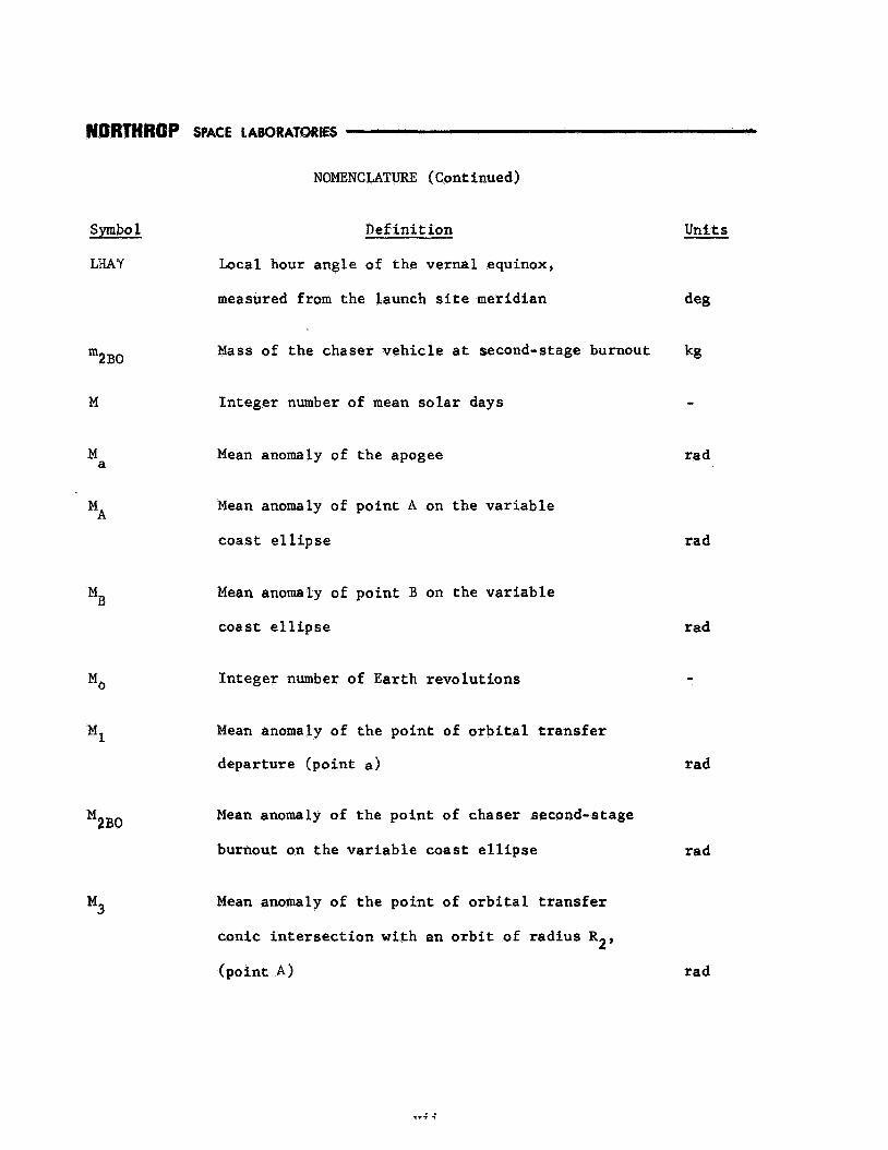
NOMENCLATURE (Continued)
Symbo 1 Def in i t i on
LHAY Local hour angle of the verna l equinox,
measured from the launch s i t e meridian
Mass of t he chaser v e h i c l e a t second-stage burnout 2B0 m
M In t ege r number of mean s o l a r days
Mean anomaly of t he apogee a M
Mean anomaly of po in t A on the v a r i a b l e
coas t e l l i p s e
MA
Mean anomaly of p o i n t B on t h e v a r i a b l e
coa s t e 1 1 i p s e
In t ege r number of Earth revolu t ions
Mean anomaly of the p o i n t of o r b i t a l t r a n s f e r
depar ture (poin t a)
Mean anomaly of t h e p o i n t of chaser second-stage
burnout on t h e v a r i a b l e coas t e l l i p s e
Mean anomaly of t h e po in t of o r b i t a l t r a n s f e r
conic i n t e r s e c t i o n wi th an o r b i t of r a d i u s RP,
(poin t A)
rad
rad
-
r ad
r a d
r ad

IYORTHROP
Symbo 1
M4
N
0 N
P
0 P
(p)LP
Q
R1
R2
R2B0
SPACE LABORATORIES
NOMENCLATURE (Continued)
Definition Units
Mean anomaly of the point of orbital transfer
conic intersection with an orbit of radius R p ,
(point B) rad
Number of target revolutions completed at the
launch delay time, relative to the target's
position at the reference time -
Number of target revolutions per Earth rotation -
Semi- latus rectum m
Target orbita 1 period sec
Limiting parabola semi-latus rectum m
Ratio of the square of the chaser second-stage
burnout velocity to the square of the circular
orbit velocity at the burnout radius
Parking orbit radius
Target orbit radius
Chaser second-stage burnout radius
viii

NOMENCLATURE (Continued)
Symbols D e f i n i t i o n
Apogee r a d i u s Ra
Units
m
Radius t o the po in t t h e chaser crossed t h e o r b i t a l
l i n e of nodes m
RCOW
Earth e q u a t o r i a l r a d i u s ,
(Re = 6.378165 x 10 m)
e R
6
R Perigee r a d i u s m P
S i d e r e a l hour angle deg SHA
tCC F l i g h t t i m e from chaser t h i rd - s t age
shutdown t o t a r g e t o r b i t i n t e r c e p t i o n
F l i g h t t i m e from chaser t h i rd - s t age
shutdown t o t a r g e t o r b i t i n t e rcep t ion ,
assuming a yaw maneuver i s performed
Launch delay t i m e
Launch delay t i m e i n t h e t r u e mean
s o l a r day
Chaser f l i g h t t i m e from second-stage burnout
t o i n t e r c e p t i o n of t h e v a r i a b l e coast e l l i p s e
with a c i r c u l a r o r b i t of r a d i u s R
(point A)
or R2, 1
s e c
s ec
sec
sec
ix

NORTHROP SPACE LABORATORIES
NOMENCLATURE (Continued)
Symbo l s Def in i t i on Uni t s
Chaser f l i g h t t i m e from second-stage .burnout
t o in t e rcep t ion of t he v a r i a b l e coas t e l l i p s e
wi th a c i r c u l a r o r b i t of r a d i u s R1 o r R2,
(po in t B)
CtEC)B
To ta l chaser ascent f l i g h t t i m e (t,)a
Maximum al lowable chaser a scen t f l i g h t t i m e [ W a ] MAX
Chaser f l i g h t time along o r b i t a l t r a n s f e r e l l i p s e 1 (%)El
Chaser f l i g h t time along o r b i t a l t r a n s f e r e l l i p s e 2 (%)E2
Chaser f l i g h t t i m e from second-stage burnout to.
itarget o r b i t i n t e rcep t ion
(tF)CC
F l i g h t time requi red f o r t h e t a r g e t t o coas t from
i t s p o s i t i o n a t t h e time of chaser Sekond-stage
( V T C
burnout t o t h e o r b i t a l l i n e of nodes, ( f o r a
non-coplanar ascent t r a j e c t o r y mode) I
F l i g h t time requi red f o r t h e t a r g e t to coas t
from i t s p o s i t i o n a t t he t i m e o f chaser second-stage
burnout t o t h e po in t of g ross rendezvous, ( f o r t h e
( t ~ ) ~ ~
sec
sec
s ec
sec
sec
s ec
sec
coplanar a scen t t r a j e c t o r y mode) sec
X

NORTHROP SPACE LABORATORIES
NOMENCLATURE (Continued)
Symbo Is Def in i t i on Units
(%)TRANS Chaser o r b i t a l t r a n s f e r time sec
tF 1
tF3
F l i g h t time from per igee t o po in t a on t h e
o r b i t a l t r a n s f e r conic
F l i g h t time from pe r igee t o po in t A on t h e
o r b i t a l t r a n s f e r conic
F l i g h t t i m e from per igee t o po in t B on t h e
o r b i t a l t r a n s f e r conic
Coast time spend i n t h e " f i c t i t i o u s f ' t~~~~
COAST t a r g e t o r b i t
To ta l chaser f l i g h t t i m e requi red t o accomplish
a given rendezvous mission
( tF 'MISS ION
Maximum alfowable mission f l i g h t t i m e [(tF )MISSION]
Chaser parking o r b i t t i m e tPARK
Maximum aflowabfe chaser parking o r b i t time (tPARK)MAx
Chaser f l i g h t time from l i f t - o f f t o second-stage
burnout
t12B
sec
s ec
s ec
sec
sec
s ec
sec
sec
sec
x i

NORT#ROP SPACE LABORATORIES
NOMENCLATURE (Continued)
Symbo 1s Def in i t i on
t 3 B Chaser third-s tage-burn t i m e
T ime requi red f o r t he launch s i t e t o r o t a t e
through the c e n t r a l angle 5
T i m e r equ i r ed fo r t h e launch s i t e t o r o t a t e
through the c e n t r a l angle $o $0
( t )
T Corrected mean s o l a r day
v a
True mean s o l a r day (To 86,164.099 sec )
Chaser v e l o c i t y a t apogee
Chaser v e l o c i t y a t t h e apogee of t r a n s f e r
e l l i p s e 1
1
(Val* Chaser v e l o c i t y a t t h e apogee of t r a n s f e r
ellipse 2
1 C i r c u l a r o r b i t v e l o c i t y a t r a d i u s R %o I1
C i rcu la r o r b i t v e l o c i t y a t t h e chaser second- (Vco)2B0
Units
sec
sec
s e c
s ec
-
m/sec
m/ sec
m/sec
mlsec
s t a g e burnout r a d i u s RaBO mlsec
xii

HORTHROP SPACE LABORATORNSS
NOMENCLATURE (Conr: inued)
Swbo Is Definit ion - Units
m/ sec 2 CfsreuZar o r b i t ve loe f ty arb radius R ' v C ~ ' 3
Cvei Chaser velocicy at poinc a on the orbi ta l
transfer conic
CVe>, Chaser v e l o c i t y a t paint A on the orbital
transfer conic
he:) 4 Chaser ve isc iky a t po in t B on the o r b i t a l
transfer C Q X Z ~ G -
Chaser ve loaf ty a t the perigee of transfer
e l l i p s e 2
%-)2
V e l o c i t y of the chaser a t the time it crosses
she orbital l i n e of nsdes
(%om
Chaser v e i s c i t y a t the pofnr: o f intersection
of %he variable coast e l l i p s e w i t h an orbi t
or radius Rl or R
%?A B
2
'2BO
X
Y
Chaser velocity at second-stage burnout
Dec ima 1
mlsec
mlsec
m / s e c
m/ see
m/sec
m/ sec
m/ sec
- -
X i i f

NOMENCLATURE (Continued)
Symbols Def in i t i on Units
a Pos i t ion of t he t a r g e t a t t h e r e fe rence time, 0
r e l a t i v e t o t h e ascending node deg, r ad
LS CY.
T a
1 Y
('SBO'MAX
The central, angle , measured i n t h e t a r g e t o r b i t
plane, from the ascending node t o t h e p o s i t i o n of
the Paunch s i t e a t t he re ference time (i > A ) r ad T
Pos i t i on of t he t a r g e t a t t h e launch delay time,
r e l a t i v e to t he ascending node rad
Chaser f l i g h t pa th angle a t t he po in t of i n t e r -
s ec t ion of t he v a r i a b l e coas t e l l i p s e wi th a
c i r c u l a r o r b i t of r ad ius R o r R measured
from the foca l ho r i zon ta l
Chaser f l i g h t p a t h angle a t po in t a on t h e
o r b i t a l t r a n s f e r conic , measured from t h e loca l
ho r i zon ta l
1 2'
Chaser f l i g h t pa th angle a t second-stage burnout,
measured from t h e l o c a l ho r i zon ta l
Chaser f l i g h t pa th angle a t second-stage burnout
t h a t produces a coas t e l l i p s e wi th a n apogee
equal t o r ad ius R1 o r R2, measured from t h e
l o c a l ho r i zon ta l
Maximum second-stage burnout f l i g h t pa th ang le
rad
rad
rad
rad
r ad

NORTHROP SPACE LABORATORIES
NOMENC MTURE (Cont hued)
Units - Symbols Definit ion
Y Chaser f i i g h t path angle a t point A on the
orbitai transfer conic, measured from the local
horizontal rad
3
Y . fb
Y
6
6'
Ay2 BO
Ln
A t
Atd
Chaser flight path angle a t point B on the
orbital transfer conic , measured from the local
hor i zont a R
Vernai equinox
Plane change angle
Plane change angle a f t er an impulsive yaw
maneuver has been performed
rad
-
rad
rad
Chaser srrond-stage b u r m u t f l i g h t path .angle
increment rad
Orbital transfer conic p o i n t of arrival increment rad
Orbital transfer major axLs arientation increment rad
Angle o f nodal regression per target orbi ta l
l e v o Zut ion
Target orbi ta l period
Launch de lay t i m e increment
rad
see
sec

Symbols
(AVIa
CTR ( AV)
( ).MISSION
TRANS ( A W
NOMENCLATURE (Continued)
Def in i t i on Units
Tota l chaser ascent impulsive v e l o c i t y increment m/ see
Maximum al lowable ehaser ascent impulsive
velocity increment
Impulsive v e l o c i t y increment required t o
c i r c u l a r i z e an o r b i t
Tota l chaser impulsive v e l o c i t y increment
required t o accomplish a given rendezvous
missi.on
Maximum allowable mission impulsive
v e l o c i t y increment MAX
1
m/sec
m/sec
m/sec
m/ sec
Chaser impulsive v e l o c i t y increment required
t o perform a plane change maneuver m/sec
Tota l chaser impulsive v e l o c i t y increment
required to perform an o r b i t a l t r a n s f e r maneuver m/sec
Chaser €mpulsfve v e l o c i t y increment requi red
t o perform a yaw maneuver m/sec
Chaser impulsive v e l o c i t y increment requi red
to change the f l i g h t path angle t o zero a t t he
po in t of i n t e r s e c t i o n of t h e v a r i a b l e coas t
e l l i p s e with an o r b i t of r a d i u s R P Or R2 m/sec

NORTHROP SPACE LABORATORIES
NOMENCLATURE (Continued)
Symbols Def i n 1 t €on
Chaser fmptnlsive ve%.ocity increment required
t o change the second-stage burnout f l i g h t path
angle
( AV) Y 2BO
Avl
Av2
Av3
llV4
rl
%c
'COLN
(e EC )A B
Chaser %mpuPai.ve v e l o c i t y increment number 1
Chaser impulsive v e l o c i t y increment number 2
Chaser impulsive v e l o c i t y increment number 3
Chaser impulsive v e l o c i t y increment number 4
Angle between poin t a and po in t A on the
o r b i t a l t r a n s f e r conic
Range angre subtended by t h e ehaser while
coas t ing from the po in t of th%rd-stage shutdown
t o carge t o x b i t or parking o r b i r i n t e rcep t ion
Range angle subtended by t h e ehaser while
coas t ing from the po in t of third-stage shutdown
t o t a r g e t o r b i t i n t e r c e p t i o n , assuming a yaw
maneuver i s performed
Units
m / s e c
m/sec
m/ sec
m/sec
m/sec
rad
rad
rad
Pos i t i on of t h e chaser a t t h e end of the requi red
parking time r e l a t i v e to t he o r b i t a l l i n e of nodes rad
Range angle from t h e p o i n t of chaser second-stage burnout
t o t h e po in t of i n t e r s e c t i o n of t h e v a r i a b l e coas t
e f $ i p s e (po in t A o r B) wi th a n o r b i t of r ad ius R1 o r R2 rad
XVii

NO'MENCLATURE (Continued)
Symbols Def in i t ion
To ta l chaser i n t e rcep t range angle
%T
'T
'TAN
Centra l angle , measured i n t h e t a r g e t o r b i t plane,
from the launch s i t e meridian, a t t he launch delay
time, t o t h e o r b i t a l l i n e o f nodes
Sum of t h e c e n t r a l angles e N and e
Central angle , measured i n t h e t a r g e t o r b i t plane,
from t h e launch s i t e meridian a t t h e r e fe rence
t i m e t o t h e launch s i t e meridian at t h e launch
delay t i m e
Pos i t ion of t h e t a r g e t , r e l a t i v e to t he t a r g e t
o r b i t ascending node, a t che t i m e t h e chaser
i n t e r c e p t s an o r b i t of rad ius R o r R2
Pos i t ion of t he t a r g e t , r e l a t i v e t o t h e t a r g e t
orbft ascending node, at the t i m e of chaser
1
' 'TAN'2BO second-stage bumout
'TO, Pos i t ion of t h e t a r g e t , r e l a t i v e t o t h e o r b i t a l
. l ine of nodes, a t t h e time t h e chaser i n t e r c e p t s
an orbit of r a d i u s K or R2
Pos i t ion of t h e t a r g e t , r e l a t i v e t o t h e o r b i t a l
l i n e of nodes, a t t h e time of chaser second-stage
3.
( e ~ ~ , > 2 ~ o
'TDN
burnout
Pos i t i on of t h e t a r g e t , r e l a t i v e to t h e descending
node, a t t h e time the chaser i n t e r c e p t s t h e t a r g e t
Units
deg , rad
rad
rad
rad
rad
rad
rad
rad
o r b i t A V A A I
rad
NOMENCLATURE (Continued)
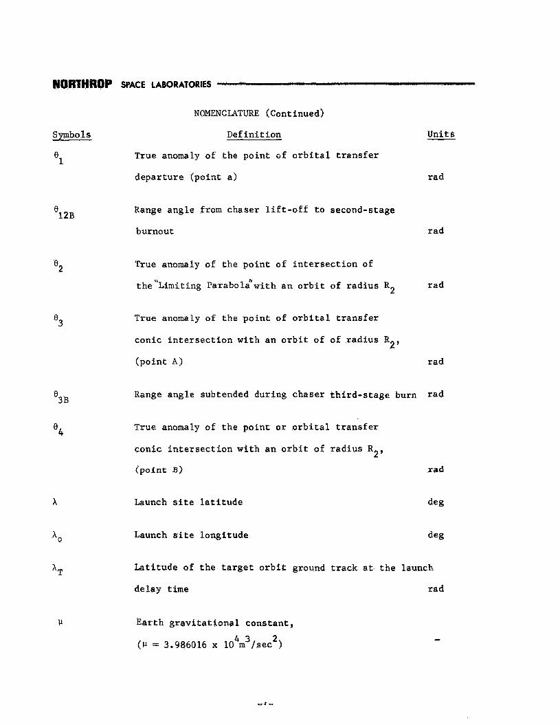
Symbols Def in i t ion Uni t s
True anomaly of t he poin t of o r b i t a l t r a n s f e r
depar ture (poin t a ) rad
'1
12B 0
'2
e3
'3 B
' 4
A
Range angle from chaser l i f t - o f f t o second-stage
burnout rad
True anomaly of t he po in t o f i n t e r s e c t i o n of
t h e ' h n i t i n g Parabolgwi th a n o r b i t of r ad ius R2 rad
True anomaly of t he po in t of o r b i t a l t r a n s f e r
conic i n t e r s e c t i o n w i t h an o r b i t of of r ad ius R
(po in t A ) rad
2'
Range angle subtended during chaser t h i rd - s t age burn rad
True anomaly of t he po in t o r o r b i t a l t r a n s f e r
conic i n t e r s e c t i o n wi th an o r b i t of r ad ius R
(po in t 3) rad
2'
Launch s i t e l a t i t u d e deg
Launch s i t e longi tude deg
Lat i tude of t h e t a r g e t o r b i t ground t r a c k a t t h e launch
de lay t fme rad
Ear th g r a v i t a t i o n a l cons tan t ,
(1-I = 3.986016 x 10 m / s ec ) 4 3 2

~ ~ ~ T H ~ O P SPACE LABORATORES
NOMENCLATURE (.Continued)
Symbols
5
U
%l
Def in i t i on
Complementary c e n t r a l angle of Ji,, measured
i n the e q u a t o r i a l plane
Cent ra l angle , measured i n t h e equa to r i a l plane,
between t h e launch s i t e meridian a t t h e re ference
t i m e and the t a r g e t o r b i t descending node
True anomaly of po in t A on t h e v a r i a b l e coas t
e l l i p s e
True anomaly of po in t B on t h e v a r i a b l e coas t
e l l i p s e
O r b i t a l t r a n s f e r phase angle !CRANS
+TRUE True phase angle
Catch-up r a t e of the chaser veh ic l e
True anomaly of the point of chaser second-stage
burnout on the v a r i a b l e coas t e l l i p s e
*BO
Centra l angle , measured i n the t a r g e t o r b i t plane,
from t h e ascending node t o t h e launch s i t e meridian
Units
rad
rad
rad
rad
rad
rad
rad /sec
rad
a t t i m e ( td) ,
xx
rad

MORTHROP SPACE LABORATORIES
NOMENCZATURE (Cone luded)
Syrnbo Is Def in i t i on Units
$0 Central angle , measured i n t h e e q u a t o r i a l plane,
+YAW
w e
C
E w
1 w
2 w
n
between t h e Paunch s i t e meridian a t t he r e fe rence
time and the launch s i t e meridian a t t he t i m e of
t h e launch s i t e ' s second passage through t h e
t a r g e t o r b i t plane
Yaw angle
Maximum yaw angle
Correeted Earth r o t a t i o n a l r a t e
rad
rad
rad
r a d l s e c
True Earth r o t a t i o n a l r a t e ,
(aE = 7.29211513 x loe5 r ad l sec )
Angular v e l o c i t y of t h e chaser i n a parking o r b i t
-
r ad l sec
Angular v e l o c i t y of t h e t a r g e t r ad l sec
Angle through which t h e t a r g e t c o a s t s during t h e
c h a s e r ' s o r b i t a l t r a n s f e r maneuver r ad
Angular d i s t a n c e through which t h e launch s i t e
r o t a t e s during a launch delay t i m e , measured i n
t h e e q u a t o r i a l plane from t h e launch s i t e meridian
a t t h e r e fe rence t i m e r ad
xx i
L I S T OF ILLUSTRATIONS
T i t le Page P
Figure
1. ORBITAL PRECESSION--MOTIGN OF A TARGET
VEHICLE AROUND AN OBLATE EARTH. e 0 e e e s e 2-2
2.
3 .
4 .
5.
6 .
7 .
a.
9,
10.
11.
12.
13.
14.
GEOCENTRIC EARTH EQUATORIAL COORDINATE SYSTEM. e 2 - 5
REFERENCE TIME GEOMETRY WHEN iT > A . . . . . 2-6
REFERENCE TIME GEOMETRY WHEN iT A
(CO-NODAL INSTANT). . a . . . , . 2-7
TARGET O R B I T Q S POSITION 1N THE GEOCENTRIC
EQUATORIAL COORDINATE SYSTEM , 8 . . . . . 2-9
TARGET VEHICLE POSITION AT THE, REFERENCE TIME* 0 ' 9 2-13
GEOMETRY FOR "TWICE-A-DAY RENDEZVOUS COMPATIBILITY" 0 2-17
THE DIRECT ASCENT TO RENDEZVOUS PROBLEM. a - 3-2
THE TWO CASES OF THE COPLANAR ASCENT TRAJECTORY MODE (i, > 1) 3-4
ASCENT TRAJECTORY MODE 1. * * 3-6
ASCENT TRAJECTORY MODE 2 . s e e s 3-7
ASCENT TRAJECTORY MODE 3 . . . ., . 0 3-8
ASCENT TRAJECTORY MODE 4 . . . . . + . . . . 3-9
ASCENT TRAJECTORY MODE 5 . . . , . . , . . 3-10
x x i i

NOR?HROP SPACE LABORATORIES
L I S T OF ILLUSTRATIONS (Continued)
Figure T i t le Page
15. ASCENT TRAJECTORY MODE 6. . 0 s 4 0 3-11
16. ASCENT TRAJECTORY MODE SEQUENCING WHEN iT > 0 0 0 3-13
27 COPLANAR ASCENT TRAJECTORY e 0 0 0 e 3-18
18.
19.
20.
21.
22.
23
24.
25.
26.
2 7 .
28.
NON-COPLANAR ASCENT TRAJECTORY, . . . . e . . e . 3-20
ASCENT TRAJECTORY PROFILE . . 0 . . . . . . . 0 3-22
THIRD-STAGE BURN GEOMETRY . . . . . . . . . 3-27
NON-COPLANAR ASCENT TRAJECTORY WITH YAW MANEUVERS . . 3-31
NON-COPLANAR ASCENT TRAJECTORY YAW MANEUVERS
GEOMETRIES ., . . . . 0 0 3-36
THE PROBLEM OF CIRCULAR ORBIT RENDEZVOUS V I A AN
INTERMEDIATE CIRCULAR PARKING ORBIT . . . . . 3-39
HOHMANN TRANSFER MODE. * 0 e e 0 3-41
MODIFIED HOHMANN TRANSFER MODE. 0 e 0 3-42
GAMMA-CHANGE TRANSFER MODE o 0 e 0 0 0 0 3-43
PARABOLIC TRANSFER MODE . . . 0 . . 0 3-44
CONCENTRIC THREE-IMI’ULSE ELLIPTIC TRANSFER MODE 0 3-45
XXlll

NORTHROP SPACE LAWRATORES
L I S T OF ILLUSTRATIONS (Continued)
Figure
29 ,
3 0 .
31.
32.
33.
3 4 .
35.
36.
37.
3 8 .
39
A-1,
A-2,
B - 1 .
T i t le r1j3g - B I - E U I P T I C THREE-IMPULSE TRANSFER MODE. e 0 0 0 0 3-46
NON-COPLANAR ORBITAL TRANSFER MANEUVER e 0 0 3-48
COPLANAR GAMMA-CHANGE TRANSFER MODE GEOmTRY e 3-52
"LIMITING PARABOLA" AND ASSOCIATED FAMILY OF
TRANSFER CONICSe . 3-54
"LIMITING PARABOLA" GEOMETRY 0 * 0 3-55
"LIMITING PARABOLA'' AND THE COPLANAR GAMMA-
CHANGE TRANSFER MODE GEOMETRY * * * - * * * - - * - 3-57
LOGIC FLOW CHART FOR THE ORBITAL TRANSFER
MODE MATRIX 0 0 e e a s 0 . 3-65
TYPICAL COPLANAR ASCENT TO PARKING ORBIT 0 e * 3-67
TYPICAL NON-COPLANAR ASCENT AND NON-COPLANAR
PARKINGORBIT. 3 a 0 a 0 0 3-70
NON-COPLANAR GAMMA-CHANGE TRANSFER MODE - * 3-72
LOGIC FLOW CHART FOR THE SUBROUTINE * 0 * 4-3
CELESTIAL SPHERE AND THE EARTH. 0 e a A-3
CELESTIAL SPHERE AS V I E m D FROM THE NORTH POLE 0 e A 0 4
COPLANAR ASCENT TRAJECTORYMODE GEOMETRY 0 0 0 B- 2
xxiv

- NOmHROP SPACE LABORATORIES
Figure
B-2
B-3.
B-4.
B - 5
B-6
B - 7
c-1.
6-2.
c-3.
c-4.
c-5.
C-6,
D-1.
LIST OF ILLUSTRATIONS (Concluded)
Tit le Page
ASCENT TRAJECTORY MODE 1 GEOMETRY. . . . . . . B-3
ASCENT TRAJECTORY MODE 2 GEOMETRY. 0 0 . 0 B-6
ASCENT TRAJECTORY MODE 3 GEOMETRY. 0 e 0 0 a * B-8
ASCENT TRAJECTORY MODE 4 GEOMETRY. 0 0 0 . 0 B - 1 0
ASCENT TRAJECTORY MODE 5 GEOMETRY. . . . . . . B-12
ASCENT TRAJECTORY MODE 6 GEOMETRY. . 0 B-13
HOHMANN TRANSFER MODE. . . . . . . . . C - 1
MODIFIED HOHMANN TRANSFER MODE . 0 . . . C-2
GAMMA-CHANGE TRANSFER MODE. . 0 . . . C-5
PARABOLIC TRANSFER MODE 0 s 0 0 e C-6
CONCENTRIC THREE-IMPULSE ELLIPTIC TRANSFER MODE . C-9
BI-ELLIPTIC THREE-IMPULSE TRANSFER MODE. 0 . . C-12
NON-COPLANAR GAMMA-CHANGE TRANSFER MODE. . . . . . D-2
xxv

CTION 1
As our n a t i o n a l space e f f o r t increases , o r b i t a l rendezvous w i l l p lay a
more predominant r o l e . E a r t h - o r b i t a l rendezvous w i l l be needed f o r such
missions as:
1. Construct ion of o r b i t a l space s t a t i o n s
2. Supply and maintenance of space s t a t i o n s
3.
4. Rescue operat ions.
Assembly of i n t e r p l a n e t a r y space v e h i c l e s
Ind ica t ions a re t h a t many of t h e s e and o the r missions w i l l r e q u i r e not j u s t
one but s eve ra l consecutive launches. Thus, a method f o r determining t h e
sequence o f Earth launch t i m e s required t o accomplish va r ious rendezvous
missions would b e a use fu l t o o l for mission planning.
This r e p o r t has been w r i t t e n t o present t h e equations and log ic required
f o r t h e development of a d i g i t a l computer subrout ine f o r determining t h e launch
oppor tun i t i e s for var ious types o f g r o s s c i rcular o r b i t rendezvous missions.
Because o f t h e E a r t h ' s ob la t eness , t r u e c i r c u l a r o r b i t s a r e i n r e a l i t y not
poss ib l e except around t h e equator.
rendezvms has
more general problem of e l l i p t i c a l o r b i t rendezvous.
However, t h e problem of c i r c u l a r o r b i t
een at tacked a s a s tepping s tone o r b u i l d i
The can be stated a s follows:
1-1

A non-maneuverable t a r g e t veh ic l e i s ed t o be o r b i t i
i n a c i r c u l a r o r b i t of known o r b i t a l
oblateness of t h e Ear th , t h e t
po la r a x i s i n a d i r e c t i o n oppos i te t o t h e d i r e c t i o n of t h e t a r g e t v e h i c l e
motion. However, t h e t a r g e t o r b i t plane can be assumed t o be f ixed i n t h e
i n e r t i a l space i f t h e E a r t h ' s r o t a t i o n a l r a t e is cor rec ted accordingly.
Rendezvous between the o r b i t i n g t a r g e t veh ic l e and an Earth-launched,
maneuverable chaser veh ic l e i s s a i d t o be accomplished when t h e two veh ic l e s
a r r i v e s imultaneously, wi th the same v e l o c i t y and f l i g h t - p a t h angle , a t some
poin t i n i n e r t i a l space. The motion of t he t a r g e t , with respec t t o a r o t a t i n g
launch s i t e , p l aces s t rong r e s t r i c t i o n s on the time during which the chaser
veh ic l e can be launched t o achieve rendezvous. Thus emerges t h e term "launch
window". A launch window is a per iod o r span of time i n which t h e t a r g e t
veh ic l e and t h e launch s i t e a r e i n favorable pos i t i ons , allowing the chaser
t o be launched t o accomplish gross rendezvous.
C i rcu la r o r b i t rendezvous can be accomplished by two genera l methods o r
modes. These modes are:
1) Di rec t a scen t t o rendezvous
2 ) Rendezvous via a n in te rmedia te parking o r b i t (which is assumed t o
i r c u l a r a
Direct a scen t t o g ross rendezvous is gene ra l ly r e s t r i c t e d t o r e l a t i v e l y small
launch t h e t a r g e t and the chaser
1-2
must be i n approximately the same pos i t i on a t t h e t i m e o f t h e c h a s e r ' s
i n j e c t i o n i n t o the t a r g e t o r b i t . Small launch delay t i m e s can be compensated
for by s l i g h t v a r i a t i o n s i n the ascent t r a j e c t o r y i t s e l f .
Gross rendezvous accomplished by use of an intermediate parking o r b i t
p e r m i t s longer launch windows. This i s s o because l a rge launch delays
can be o f f s e t by remaining i n t h e parking o r b i t u n t i l t he phase angle between
t h e t a r g e t and t h e chaser i s of t h e co r rec t magnitude t o i n i t i a t e an o r b i t a l
t r a n s f e r maneuver.
Regardless of which rendezvous mode is used, t h e a s soc ia t ed launch times
a r e r e s t r i c t e d by t h e chaser launch v e h i c l e ' s c a p a b i l i t i e s and var ious o t h e r
m i s s ion c o n s t r a i n t s
1-3


ASSUMPTIONS AND DEFINITIONS
2.1 Earth Model
The Earth model assumed is a spinning o b l a t e spheroid.
2.1.1 Oblateness E f f e c t s
Due t o t h e oblateness of the Earth, t h e elements of a t a r g e t v e h i c l e ' s
o r b i t a r e perturbed.
t a r g e t o r b i t is precession of t h e o r b i t a l plane. This plane, and thus t h e
The major e f f e c t of oblateness on an assumed c i r c u l a r
l i n e of nodes, tends t o precess about the Ea r th ' s po la r a x f s i n a d i r e c t i o n
opposi te t h e gene ra l d i r e c t i o n of motion of t h e o r b i t i n g t a r g e t veh ic l e .
Figure 1 i l l u s t r a t e s r eg res s ion of t h e l i n e of nodes f o r an eastwardly
t r a v e l l i n g t a r g e t veh fc l e
2.1.2 Earth Ro ta t iona l Rate
Regression of the l i n e of nodes can be b e s t compensated f o r , i n a
first approximation, by assuming t h e target o r b i t plane t o be f i x e d in inertial
space while t h e Earth r o t a t e s i n s i d e t h i s o r b i t a t a corrected r o t a t i o n a l
r a t e w . The corrected Earth r o t a t i o n a l r a t e can b e def ined by t he equation C
e
A 4 w = + - WE - At
where
w = Trae Earth r o t a t i o n a l r a t e - r ad / sec E
(2-1)
= Regression of the ta rge t o r b i t ! s l ine of nodes per o r b i t a l period At - r ad l sec ,
2-1
N
LAUNCH SITE
--
DIRECTION OF
Figure 1. ORBITAL PRECESSION-MOTION OF A TARGET VEHICLE AROUND AN OBLATE EARTH
2-2

The term ag has been shown by B l i t z e r ( r e f . 3) t o be expressed as
A + 2a .J(q2 cos i T
The o r b i t a l period of t he t a r g e t v e h i c l e is
(2-2)
The Earth g r a v i t a t i o n a l constant,u,can a l s o be expressed i n terms of Earth
cons tan t s as
2 o e
LI=g R
Thus,
Consequently, t he term - A' A t
can be expressed as
(2-4)
For a n eastwardly t r a v e l l i n g t a r g e t veh ic l e , t h e corrected Earth r o t a t i o n a l
r a t e becomes
w e C = w E + J (:)yF cos iT
Hence, i t c a n be seen t h a t for easter ly launches
(2-5)
E ' For westwardly t r a v e l l i n g t a r g e t v e h i c l e s w C w e
C

2.2 Coordinate System
A#geocentr ic Earth e q u a t o r i a l coordinate system w i l l be used as a r e fe rence
frame f o r f i x i n g t h e t a r g e t o r b i t p l a n e , i n i n e r t i a l space.
system has i t s o r i g i n a t t h e c e n t e r of t he Earth. The x-axis l i e s i n t h e
e q u a t o r i a l plane and po in t s toward t h e vernal equinox o r f i r s t point of
Aries. The z-axis coincides with the E a r t h ' s spin a x i s , while t h e y-axis
completes t h e right-handed coordinate system. Figure 2 i l l u s t r a t e s t h i s
coordinate system.
TRis coordinate
2.3 Reference Time
The subrout ine i s designed t o i n i t i a t e a sequen t i a l launch window computa-
t i o n a t some given r e fe rence time. Two such reference t i m e s w i l l be defined.
When t h e t a r g e t o r b i t i n c l i n a t i o n , iT9 is g r e a t e r than t h e launch s i t e
l a t i t u d e , A , t h e launch s i te passes through the t a r g e t o r b i t plane twice
pe r day. I n t h i s ca se , t h e r e fe rence t i m e i s def ined t o be t h e Greenwich
mean time, (GMT o r ZULU), on a given calendar da t e , when t h e t a r g e t o r b i t
ground-track passes through t h e launch s i t e with a n o r t h e r l y azimuth.
when i, 5 A, t he r e fe rence t i m e i s defined as t h e Greenwich mean t i m e , on a
given calendar d a t e , when t h e launch s i t e is c l o s e s t t o t h e t a r g e t o r b i t
plane. This t i m e is r e f e r r e d t o as t he co-nodal i n s t a n t because t h e launch
However,
s i t e meridian is midway between t h e ascending and descending nodes of t he
t a r g e t o r b i t . Figures 3 and 4 i l l u s t r a t e t h e s e two r e fe rence times.
The reference t i m e i s n o t on ly the t i m e a t which t h e launch window
inves t iga t ion is i n i t i a t e d , but i t a l s o r ep resen t s t h e t i m e a t which t h e
2-4

N
E 0
Y
T
VERNAL EQUINOX
Figure 2. GEOCENTRIC EARTH EQUATORIAL COORDINATE SYSTEM
2-5

N
\TARGET ORBIT PLANE
Figure 3. REFERENCE TIME GEOMETRY WHEN iT 7 X

N
LAUNCH S I T E MERIDLAN
TARGET ORBIT LAUNCH S I T E LATITUDE PLANE
DESCENDING NODE
Figure 4, REFEREHGE TIME GEOMETRY WHEN iT - <X(CO-NODAL INSTANT)
2-7

:srget orbit piane is f,xed i n 1n .e r t ia i space. Thus, t h e r e i s a need for a
nethod of d e t e r m h i n g the p o s i t m n of t he t a rge r : ' o rb i t plane, r e l a t i v e t o the
tnerciai coordinate system, at. t h e r e f e r e x e cime.
2.4 Position of t h e Target Orbi t Plane a t t h e Reference Time
!u'ith t h e reference t i m e defined rn terms of t h e Greenwich mean time (GMT o r
ZcdJ t:me), t he Greenwich hour angle of t he ve rna l equinox (GHAY!" can be found
by c o m u l t i n g an ephemeris.
eqllfnox wich reference t~ t h e Greenwich hour c i r c l e .
This angle de f ines the p o s i t i o n of t h e ve rna l
The longitude of t he launch s i t e , measured westward from the prime
meridian, 1s defined by rhe symbol A,.
equinox (LHA1.j from the 'launch s i t e hour c i rc le can be determined by t h e
expressions
The l a c a l hour angle of the vernal
LIMY = GHAY - A, when A, - c GHAY < 2n
LHAY = 271 f (GHAY - A,) when 0 GHAY < A,
Consider Figure 5. This ' igure illustrates t h e reference time when
.' A , The l o c a l hour angie of t h e ascending node of the t a r g e t orbit can iT
be found by t h e simple tr igonometric r e l a t i o n
-x Reference is made t o Appendix A for t h e d e f i n i t i o n s of t h e terms used in this sectim.

-=. LAUNCH SITE
Ffgure 5 , TARGET ORBITvS POSITION IN THE GEOCENTRIC EQUATORIAL COORDINATE SYSTEM

Hences the s i d e r e a l hour ang le !SHA) of the ascending node can be ca l cu la t ed
by one of t h e following expressions:
SHA = LHA - LHAY when Xo 2 GHAY - < ( A o + LHA) ( 2 - 8 )
Thuss t h e SHA and iT determine the pos i t i on of t h e t a r g e t o r b i t plane r e l a t i v e
to t ne ve rna l equinox a t t he reference t i m e . Ca lcu la t ion of t he SHA, for a
t a r g e t o r b i t wfth an i n c l i n a t i o n l e s s than o r equal t o the launch s i t e
l a t i t u d e , is s i m i l a r t o t h e
2.5 Launch Delay T ime Sca le
A s t he Earth r o t a t e s a t
method presented above.
a corrected r o t a t i o n a l r a t e 9 t h e launch s i te is r o t a t e d
r e l a t i v e t o i t s pos i t i on a t t h e reference time. Thus, a t i m e scale i s
needed t o determine t h e pos i t i on of the launch s i t e a t any given t i m e . This
t i m e s c a l e s h a l l be designated as the Launch Delay T ime Scale and any given
t i m e i n t h l s scale will be denoted by t h e symbol (t ) called launch delay
time where
d n
(tdInml -I- A t d (“In =
n = 1 , 2 9 3 9 . 0 0
A t d = launch delay t i m e increment.
The reference t i m e is defined as
k d I n = 0.
(2-9)
7 i n

As ( t is allowed t o inc rease , t h e pos i t i on of t he launch s i t e , r e l a t i v e
t o i t s pos i t i on a t t h e r e fe rence time, can be determined by t h e expression
d n
where
= c e n t r a l angle through which t h e launch s i t e r o t a t e s i n t h e time nLs ( t d I n .
The t r u e mean s o l a r day i s defined t o be t h e time required f o r t h e Earth
t o complete one revolut ion, o r
= - 2Ti E
(= 23*' 56m 4.099') To
Because w ; wE9 t h e corrected mean s o l a r day becomes e
C
(2-11)
(2-12)
c @e
Thus T c Toe
The launch s i t e completes one revolut ion around the E a r t h ' s po la r a x i s when
( t d I n = T
o r
The purpose of t h e launch de lay t i m e scale i s t o provide a b a s i c reference
k lock ' l i n t h e automatic determination of t he launch s i te !s pos i t i on during
t h e launch window computation. Thus, if i t i s des i r ed t o conduct an inves t iga t ion
2-11
WoMRoP SPACE LMORAlORIEs I
f o r an i n t e g e r number of t r u e mean s o l a r days, M, from t h e r e fe rence t i m e ,
t h e launch s i t e must be allowed t o r o t a t e around t h e Ea r th ' s p o l a r a x i s
f o r MT seconds o r M(2a) revolut ions.
Launch windows, fo r va r ious rendezvous modes, a r e then ca l cu la t ed by
determining if rendezvous can be accomplished a t var ious va lues of ( tdIn,
u n t i l
I f g ros s rendezvous is found t o be achievable a t any given launch delay t i m e ,
t h e va lue of (t must be co r rec t ed t o i t s a s soc ia t ed t i m e i n t h e t r u e mean
s o l a r day. This is accomplished by t h e following s i m p l e expression:
d n
we C ( t d ) n i n t h e t r u e mean s o l a r day = (tdln 7
or
(2-13) C We
= ( t ) - E d n w (t 1
n~~~~
A l l values of t h e " t r u e launch de lay time", t h a t p e r m i t gross rendezvous,
are then pieced toge the r t o g ive t h e span of permissible launch t i m e s ( launch
window) i n the t r u e mean s o l a r day.
2 . 6 Target Pos i t i on a t Given Launch Delay Time
The c e n t r a l angle measured, a t t h e r e fe rence t ime, from t h e ascending node
of the t a r g e t o r b i t t o t h e p o s i t i o n of t h e t a r g e t v e h i c l e i s defined by t h e
symbol ao, where 0 2 a0 5 2 ~ .
v e h i c l e i n the o r b i t a l plane a t t h e reference t ime (tdln = 0.
This angle d e f i n e s t h e pos i t i on of t h e t a r g e t
The angle aOy
i l l u s t r a t e d i n Figure 6 , is a n input t o t h e subroutine.
3 1 9

N
Figure 6. TARGET VEHICLE POSITION AT THE REFERENCE TIME
2- 13

I n order t o conduct a launch window i n v e s t l g a t i o n , t he pos i t i on of t h e
t a r g e t r e l a t i v e t o t h e ascending node must be known a t any launch delay
t i m e , ( td In .
The number of o r b i t a l revolut ions completed by t h e t a r g e t v e h i c l e a t any
launch delay time, ( t d jn , can be given by
where
P = 2rr - t a r g e t o r b i t a l period. 0
The t a r g e t ’ s angular d i s t ance from the ascending node a t any t i m e (t ’>
determined by
can be d n
9 01 0 i- N(2a) (2-15)
A parameter K is introduced which de f ines t h e number o f completed t a r g e t
revolut ions a t time ( t d ) n , r e l a t i v e t o the ascending node, o r
Furthermore, K i s a number composed of a whole number and a decimal. Thus,
K = X + Y (2-17)
where
X = whole number
Y = decimal.
* The nodal period of t h e t a r g e t v e h i c l e is no t used i n t h i s expression because t h e t a r g e t o r b i t i s assumed t o be space-fixed. period is t h e o r b i t a l period.
Thus, t h e nodal
2- 14

The whole number X i n d i c a t e s t h e number of f u l l r evo lu t ions completed
t h e t a r g e t a t t h e t i m e ( tdIn.
of a r evo lu t ion completed a t t i m e ( t d I n .
any launch de lay time, r e l a t i v e t o t h e ascending node, can be w r i t t e n as
, The decimal Y i nd ica t e s t h e f r a c t i o n a l port ion
Thus, t h e p o s i t i o n of the t a r g e t a t
where
0 'a 27r. T -
2.7 Rendezvous Compatible Orb i t s
The term "rendezvous compatibi l i tyr1 a p p l i e s t o t a r g e t o r b i t s having an
o r b i t a l i n c l i n a t i o n , i , g r e a t e r than o r equal t o the launch s i t e l a t i t u d e , A.
A rendezvous compatible o r b f t a l lows rendezvous t o occur n e a r l y d i r e c t l y over
t h e launch s i t e e i t h e r once o r twice per day.
* T
The a l t i t u d e o r r ad ius of a n o r b i t i n g t a r g e t v e h i c l e determines i t s
period.
appear d t r e c t l y above or i n t h e v i c i n i t y of t he launch s i t e a t t h e s a m e t i m e s
on successive days. This is known a s "once-a-day rendezvous compatibility!'
and, i n p r i n c i p l e , is f e a s i b l e f o r a l l i n c l i n a t i o n s equal t o o r g r e a t e r than A .
Thus, adjustment of a l t i t u d e is s u f f i c i e n t t o permit t h e t a r g e t t o
However, i f ( f o r iT >AI a second rendezvous p e r day is a l s o des i r ed ,
t he o r b i t a l i n c l i n a t i o n becomes of prime importancc. "Twice-a-day rendezvous
compatibi l i ty" can be achieved on ly f o r d i s c r e t e combinations of a l t i t u d e and
i n c l i n a t i o n . These combinations of o r b i t a l parameters must be such t h a t t h e
2-15

t a r g e t completes an i n t e g r a l number of revolut ions, p lus t h e a r c from P o i n t s A
t o B (Figure 71, during t h e t i m e t h e launch s i t e r o t a t e s from Point A t o
Point B .
Swanson and Peterson ( r e f s . 16 and 18) have shown t h a t t he rendezvous
compa t ib i l i t y of a target v e h i c l e , t r a v e l l i n g eastward i n a c i r c u l a r o r b i t ,
can be determined by t h e expression:
0 N
I f t h e value of - f o r a given t a r g e t o r b i t , i s an in t ege r , t h e o r b i t 5 3
is s a i d t o be "twlce-a-day rendezvous compatible". That is to say, t h e t a r g e t
w i l l be located at t h e same pos i t i on i n its o r b i t on successive days. Thus,
t h e launch t i m e s r equ i r ed t o achieve gross rendezvous with the t a r g e t will
be the same on successive days. Consequently, t h e launch t imes permit t ing
rendezvous must be determined on ly for the f i r s t day of an M-day inves t iga t ion .
These allowable launch t i m e s will
t h e inves t iga t ion . I f , however,
ing rendezvous must be determined
then be v a l i d f o r each successive day of N 0 i s not an i n t e g e r , t h e launch t i m e s allow- -
MO f o r each day of t h e inves t iga t ion .

N
Figure 7 GEOMETRY FOR "TWICE-A-DAY RENDEZVOUS COMPATIBILITY"
2- 17


RIORTHROP SPACE LMORATORW
SECTION 3
ANALYS IS
3.1 Direct Ascent t o C i r c u l a r Orb i t Rendezvous
The gene ra l problem o f d i r e c t a scen t t o c i r c u l a r o r b i t rendezvous i s
i l l u s t r a t e d i n Figure 8 , and can be s t a t e d a s follows:
A t a r g e t v e h i c l e is assumed t o be revolving around the Earth i n a space-
f ixed , c i r c u l a r o r b i t while t h e launch s i t e , on the Ea r th ' s su r f ace , r o t a t e s
beneath t h e t a r g e t o r b i t a t a corrected r o t a t i o n a l rate.
launch a chaser veRicle i s t h e i n s t a n t t h e launch s i t e passes through t h e
t a r g e t o r b i t plane. This i s sometimes c a l l e d an on-time o r coplanar launch.
The optimum time t o
A coplanar launch is advantageous from the standpoint o f f u e l consumption
because no plane change maneuver i s required. Gross rendezvous can be accomplished
only i f tRe t a r g e t i s located a t a unique point i n i t s o r b i t a t t he t i m e o f
launch of t h e chaser. However, it is u n r e a l i s t i c t o ignore poss ib l e launch
h o l d s and to assume t h a t t h e target w i l l a l w a y s be in the correct position t o
al low a coplanar d i r e c t a scen t launch. In case of a delay, t he chaser must
be launched a t some l a t e r t i m e (launch de lay t ime) v i a a non-coplanar a scen t
t r a j e c t o r y .
If a non-coplanar d i r e c t a scen t t r a j e c t o r y i s used, gross rendezvous cannot
be accomplished unless t h e t a r g e t ' s pos i t i on i s wi th in some s e c t o r of i ts
o r b i t . This s e c t o r is a funct ion of t h e t a r g e t ' s o r b i t a l parameters, t h e ascent
t r a j e c t o r y , t he launch azimuth, t he plane change angle , and t h e chaser launch
v e h f c l e ' s maneuver c a p a b i l i t i e s .
3-1

N
I TARGET ORBIT
Figure 8 , THE DIRECT ASCENT TO RENDEZVOUS PROBLEM
3 -2

3.1.1 Ascent T ra j ec to ry Modes
The reference t2me has been defined a s zero i n the Launch Delay Time
ScaSe. A t va r ious launch de lay t imes, t h e launch s i t e is located a t d i f f e r e n t
pos i t i ons r e l a t i v e t o t h e t a r g e t o r b i t plane. This f a c t gives r i se t o a number
of geometrical r e l a t i o n s h i p s t h a t occur between t h e launch s i t e and t h e t a r g e t
o r b i t plane. These r e l a t i o i s h f p s kif11 be c a l l e d Ascent T ra j ec to ry Modes.
They w i l l be categor2zed according co t h e pos i t i on of t h e launch s i t e at t h e
launch delay t i m e and t h e r a r g e t o r b i t fnc l ina t ion .
3.1.1.1 Coplanar Ascent Trajectory Mode
When r h e t a r g e t o r b i r f n c l i n a t i o n is g r e a t e r than t h e launch s i t e
l a t i t u d e , two optimum coplanar l a u x h oppor tun i t i e s w c u r d a i l y . Uie opportuni ty
occurs when the t a r g e t o r b i t ground-track passes through the launch s i t e i n
a no r the r ly d i r e c t i o n ( r e fe rence r ime) , t h e o the r when t he ground-track passes
through the launch s i t e i n a s o a t h e r l y d i r e c t i o n . The Coplanar Ascent
T ra j ec to ry Mode r e f e r s t o t h e case where the chaser veh ic l e is launched d i r e c t l y
into the t a r g e t orbit plane during one of the optgrnum launch oppor tun i t i e s .
F i g w e 9 i l l u s t r a t e s both cases of t’n’ls ascen t t r a j e c t o r y mode.
3.1.1.2 Non-Coplanar Ascent Tzaieetorg Modes
The o the r a scen t t r a j e c t o r y modes t h a t apply when t h e t a r g e t orbFt
i n c l i n a t i o n is g r e a t e r than the launch s i t e l a t i t u d e a r e def ined t o be non-
coplanar. That is t o say, t he chaser v e h i c l e 5s launched e i t h e r before o r
a f t e r the launch s i t e passes through &e t a r g e t o r b i t plane. As a r e s u l t ,
3 - 3

N
LAUNCH SITE LATITUDE
LAUNCH S I T E
COPLANAR NT TRAJECTORY
TARGET O R B I T
a , NORTHERLY COPL.AL~AR LAUNCH
N
LAUNCH SZTE
b . SOUTHERLY COPLANAR LAUNCH
Figure 9, THE TWO CASES i)F THE COPLANER ASCENT TRAJECTORY MODE ( f , > A )
i . L
NOmROP SPACE LABORATORIES
t h e ascent t r a j e c t o r y l i e s i n an ass
t h e t a r g e t o r b i t plane a t
change angle bec
chaser i n t o the g e t o r b i t . There e x i s t s fou r such non-coplanar a scen t
t r a j e c t o r y modes. These modes a r e defined and i l l u s t ed i n Figures 10 through 13.
e a plane-change u s t be performed t o i n j e c t t h e
Two o t h e r ascent t r a j e c t o r y modes apply t o t a r g e t o r b i t s with an
i n c l i n a t i o n less than o r equal t o t h e launch s i t e l a t i t u d e . Since the launch
s i t e passes through t h e t a r g e t o r b i t plane o n l y once per day,when fT A s
t h e r e e x i s t s one optimum launch t i m e t h a t does not r e q u i r e a plane-change
maneuver (due east launch).
maneuver a t t he c h a s e r ' s i n t e r c e p t i o n of t h e t a r g e t o r b i t . Plane-change
maneuvers a r e a l s o required f o r a l l ascent t r a j e c t o r i e s when iT < A.
A l l o t h e r launch times r equ i r e a plane-change
The two ascen t t r a j e c t o r y modes t h a t occur when iT 2 X are app l i cab le
t o e i t h e r launch before o r a f t e r t h e cc-nodal i n s t a n t . These two modes, &re
defined and i l l u s t r a t e d i n Figures I 4 and 15.
The t r igonometr ic r e l a t i o n s pe r t a in ing t o Ascent T ra j ec to ry Modes
1 through 6 a r e chronological ly presented i n Appendix B. These equations
r e l a t e t h e plane-change angle (6) and t h e chaser v e h i c l e ' s launch azimuth
for a v a r i a b l e t o t a l i n t e r c e p t ra
time, ( tdjn.
(e,), t o any given launch
A method will be devised for determining which ascen t t r a j e c t o r y mode is
a p p l i c a b l e f o r d i r e c t as dezvo a funct ion of t h e
launch delay t l m e . This method w i l l b e r e f e r r e d t o as Ascent T ra j ec to ry Mode
Sequencing. - -

TRAJECTORY
LAUNCH S I T E
LAUNCH S I T E LATI TUDE
LAUNCH S I T E MERIDIAN AT THE LAUNCH DELAY
INERTIALLY F I X E D
- THE CHASER VEHICLE I S LAUNCHED WITH A NORTHEASTERLY AZIMUTH, AT S
LAUNCH S I T E HAS OUGH THE TARGET O R B I T PLANE.

ASCENT TRAJECTORY MODE 2 - THE CHASER VEHICLE I S LAUNCHED WITH A SOUTHEASTERLY AZIMUTH, AT SOME LAUNCH DELAY TIME ( t d ) n 3 PRIOR TO
THE LAUNCH SITE f S SECOND PASSAGE THROUGH THE TARGET ORBIT PIANE.
N
INERTIALLY FIXED TARGET ORBIT TXED ASCENT
TRAJECTORY
LAUNCH S I T E AT LAUNCH DELAY
TRAJECTORY
H S I T E MERIDIAN AT SECOND COPLANAR LAUNCH OPPORTUNITY
Figure 11. ASCENT TRAJECTORY MODE 2

N
INERTIALLY FIXED TARGET ORBIT PLANE @e C
I
INERTIALLY FIXED ASCENT TRAJECTORY PLANE
- THE CHASER VEHICLE IS LAUNCHED WITH A SOUTHEASTERLY AZIMUTH, (td) BFTER THE LAUNCH S I T E ' S SECOND PASSAGE THROUGH
n9 THE TARGET ORBIT PLANE,
Figure 1 2 F ASCENT TRAJECTORY MODE 3

N INERTIALLY F I X E D - ASCENT TRAJECTORY
INERTIALLY F I X E D TARGET ORBIT PLANE
ASCENT TRAJECTORY MODE 4 - THE CHASER VEHICLE I S LAUNCHED WITH A NORTHEASTERLY AZIMUTH, AT SOME LAUNCH DELAY TIME (td)np PRIOR TO THE LAUNCH S I T E IS PASSAGE
THROUGH THE TARGET ORBIT PLANE NEAR THE END OF A CORRECTED DAY.
Figure 13. ASCENT TRAJECTORY MODE 4

ASCENT TRAJECTORY MODE 5 - THE CHASER VEHICLE IS LAUNCHED WITH A SOUTHEASTERLY AZIMUTH, AT SOME LAUNCH DELAY TIME (td),, AFTER THE 60-NODAL INSTANT.
N
FERENGE TIME
LAUNCH S I T E
LAUNCH S I T E AT LAUNCH DELAY
INERTIALLY FIXED ASCENT. TRAJECTORY
FNERTIALLY F I X E D TARGET ORBIT PLANE
Figure 14- ASCENT TRAJECTORY MODE 5
3-10

ASCENT TRAJECTORY MODE 6 - THE CHASER VEHICLE TS LAUNCHED TH A NORTHEASTERLY AZIMUTH, AT SOME LAUNCH DELAY TIME (td),, BEFORE THE CO-NODAL INSTANT.
N
Q C
LAUNCH S I T E AT
LAUNCH SITE
INERTIALLY FIXED r ASCENT TRAJECTORY
INERTIALLY FIXED /- (CO-NODAL INSTANT) TARGET ORBIT
/ LAUNCH SITE AT THE REFERENCE TIME
F i g u r e 1 5 . ASCENT TRAJECTORY MODE 6

F i r s t , consider t h e case of a t a r g e t o r b i t with an o r b i t a l i n c l i n a t i o n
g r e a t e r than t h e launch s i te l a t i t u d e . Figure 16 r e p r e s e n t s a sphere of t a r g e t
o r b i t r a d i u s , R2, a s viewed from the North Pole.
on the E a r t h : s su r f ace have been projected r a d i a l l y outward onto t h e su r face
o f t h e sphere. Thus, t h e Ea r th ' s equator appears as the edge of t h e c i r c l e ,
while t he launch s i t e l a t i t u d e appears as a smaller concentr ic circle.
Furthennore> because t h e t a r g e t o r b i t i s i n c l i n e d t o t h e E a r t h ' s equator , t h e
o r b i t appears as an e l l ipse .
A l l p o i n t s o f i n t e r e s t
Point A r ep resen t s tne pos i t i on of t h e launch s i t e a t the r e fe rence
d n tine (t 1 = 0 , while Point B r ep resen t s t h e p o s i t i o n of t h e launch s i t e when
t h e t a r g e t o r b i t plane passes through it i n a sou the r ly d i r e c t i o n . Po in t s C
and D r ep resen t the ascending and descending nodes of t h e t a r g e t o r b i t ,
re spec t ive 1 y . The c e n t r a l ang le measured, i n the e q u a t o r i a l plane, from t h e meridian
passing through Point A t o t h e meridian passing through Point B i s
(3-1
and the co-angle F, is
Assuming t h a t t h e t a r g e t o r b i t plane is i n e r t i a l l y f i x e d a t t h e r e fe rence time
( t 1 = 0, t h e t i m e r equ i r ed f o r t h e launch s i t e t o r o t a t e through t h e c e n t r a l
angle , $9, can b e w r i t t e n as :
d n
7 - 1 7

\ LINE OF NODES
ASCENT TRAJECTORY
ASCENT / TMJECTORY
TRAJECTORY MODE 2
ASCENT
LAUNCH SITE f LATITUDE
EQUATOR .L
Figure 16. ASCENT TRAJECTORY MODE SEQUENCING WHEN i T > X
3-13

Also t h e t ime required for t he launch s i t e t o r o t a t e through t h e c e n t r a l co-
angle , 5, i s
5 (t) =-
C 5 "'e
( 3 - 4 )
Thus, t h e t i m e r equ i r ed for t h e launch s i t e t o complete one r evo lu t ion about
t he E a r t h ' s p o l a r a x i s (one corrected mean s o l a r day) can be expressed as:
o r
I f (t
posi t ion.
= 0, and l ikewise nLs = 0,the launch s i t e i s located a t t h e reference d n
I n t h i s case, t h e coplanar ascent t r a j e c t o r y mode must be used i n
launching t h e chaser veh ic l e .
i nc reases correspondingly. Consequently, Ascent T ra j ec to ry Modes 1 through 4
However, as (td>n inc reases , t h e angle OLs
are app l i cab le under t h e following conditions:
Ascent T ra j ec to ry Mode 1,
Ascent T ra j ec to ry Mode 2,
Coplanar Ascent T ra j ec to ry Mode,
Ascent T ra j ec to ry Mode 3 ,
Ascent T ra j ec to ry Mode 4,
Coplanar Ascent T r a j e c t o r y Mode,
when
2 when (*Jb +?> < ts < 271
SS = 27T = 0. when
It should be kept i n mind t h a t t h e above sequence is v a l i d f o r one
corrected revolut ion of t h e launch s i t e around t h e Ea r th ' s po la r a x i s , o r one
co r rec t ed mean s o l a r day. I f t h e launch window inves t iga t ion i s t o be
conducted f a r s eve ra l days, t he ascent t r a j e c t o r y mode sequence is repeated
when t h e angle OLs becomes a m u l t i p l e of 2a.
I n a l i k e manner, a n a scen t t r a j e c t o r y mode sequence can be defined
f o r a t a r g e t o r b i t having an i n c l i n a t i o n less than o r equal t o t h e launch-
s i t e l a t i t u d e . I n t h i s case t h e reference t i m e i s , by d e f i n i t i o n , the t i m e
a t which t h e launch-si te meridian is midway between t h e ascending and descending
nodes. Consequently, t h e plane containing t h e launch s i t e and t h e Ea r th ' s
s p i n a x i s is perpendicular t o t h e l i n e of nodes a t t he r e fe rence time (t ) = 0.
Thus, Ascent Trajectory Modes 5 and 6 a re app l i cab le under t h e following
condi t ions:
d n
Ascent Trajectory Mode 5 , when 0 <ts < l T
Ascent T ra j ec to ry Mode 6 , when a c %s 2v.
Again, i t i s pointed out t h a t f o r launch window computations spanning seve ra l
days, t h e sequence must be repeated, f o r each day, when t h e a n g l e S2Ls becomes
a m u l t i p l e of 2 v ,
The above ascent t r a j e c t o r y modes and t h e mode sequencing procedures
w i l l a l s o be used f o r p l ac ing t h e chaser veh ic l e i n an intermediate c i r c u l a r
parking o r b i t .
3-15

3.1.3 Ascent T r a i e c t o r i e s
Regardless of whether t h e chaser v e h i c l e i s launched v i a a coplanar o r
a non-coplanar ascent t r a j e c t o r y mode, t he ascent t r a j e c t o r y i t s e l f is assumed
t o l i e i n a i n e r t i a l l y - f i x e d plane and t o be composed of var ious s t a g e s of
f l i g h t .
a r e l i s t e d i n Tables 1 and 2 , i l l u s t r a t e d i n Figures 17, 18, and 19, and
discussed i n subsec t ions 3.1.3.1 through 3.1.3.4.
These s t ages , f o r both t h e coplanar and non-coplanar t r a j e c t o r i e s ,
3.1.3.1 T r a j e c t o r i e s from L i f t -o f f t o Second-Stage Burnout
The a scen t t r a j e c t o r y t o a parking o r b i t o r t a r g e t o r b i t is assumed
t o l i e i n an i n e r t i a l l y f ixed plane. Thus, it is proposed t h a t , f o r a given
mission (launch v e h i c l e and parking o r t a r g e t o r b i t ) , t h e i t e r a t i v e guidance
mode (IGM) be used t o genera te a t a b l e of t h e following space-fixed parameters,
a t second-stage burnout , a s a funct ion of launch azimuth:
1 ) V e l o c i t y , v~~~
2B0 2 ) Flight path angle , Y
R2B0 3 ) Radius,
4 ) Range ang le ,
5 ) Fl igh t t i m e , tlZB
6) Mass of t h e chaser veh ic l e , rnZBO*
3-16

NOmROP SMCE LIUOUTOICES
Table 1. COPLANAR ASCENT TRAJECTORY
1. Continuous powered f l i g h t from l i f t - o f f t o second-stage
burnout, assuming a three-s tage launch vehic le .
2. Coast along a segment of an e l l i p s e , known a s a v a r i a b l e coas t
e l l i p s e , u n t i l t he t a r g e t o r b i t is achieved.
3 . Impulsive v e l o c i t y increment app l i ed to change t h e f l i g h t
path angle , YEc, t o zero.
4. Burning of the t h i r d s t a g e t o c i r c u l a r i z e t h e o r b i t and
e f f e c t g ross rendezvous.

3rd STAGE TARGET ORBIT 1 G N 1 T 1 0 ; ~
f A *-- J A ~e a-
1 CONTINUOUS POWERED
~
R2
4
B
3rd STAGE \b,B0 \ SHUTDOWN - VARIABLE COAST E L L I P S E
2nd STAGE BURNOUT
EARTH
Figure 17. COPLANAR ASCENT TRAJECTORY
? - 1 F t

NO#t)(WoP SPACE LIUORATORES
Table 2. NON-COPLANAR ASCENT TRAJECTORY
1, Continuous powered f l i g h t from l i f t - o f f t o second-stage burnout,
assuming a three-s tage launch veh ic l e .
2. Coast along a segment of an e l l i p s e , known as a v a r i a b l e coast e l l i p s e ,
unti.1 the t a r g e t o r b i t r ad ius i s achieved.
3 . Impulsive v e l o c i t y increment appl ied t o change the f l i g h t
path angle , YEC, t o zero.
4. Execution of an impulsive yaw maneuver, i f needed, t o a l l e v i a t e
lead o r l a g of t h e t a r g e t vehic le .
5. Burning of t he t h i r d s t age t o c i r c u l a r i z e the o r b i t .
6 e Circu la r coas t ing from third-s tage shutdown t o in t e rcep t ion
of t he t a r g e t o r b i t .
7. Impulsive v e l o c i t y increment a t i n t e rcep t ion o f t h e t a r g e t
o r b i t t o perform a plane-change maneuver and e f f e c t g ross
rendezvous.
3 - 19

IMPULSIVE
MANEWER PLANE-CHANGE
ORBITAL LINE CIRCULAR OF NODES COAST A R C 7 I
3rd STAGE I G N I T I O N 7 TARGET
ORBIT
2nd STAGE
TARGET
ORBIT PLANE 9
I
‘-3rd STAGE SHUTDOWN
CONTINUOUS ELLIPSE
TRAJECTORY GROUND TRACK
LAUNCH SITE MER1 DI AN
DIRECTION OF EARTH ROTATION
Figure 28, NON-COPLANAR ASCENT TRAJECTORY
3-20

NQRTHROP SPACE LABORAT’ORIES
This t a b l e w i l l be designated t h e Ascent T ra j ec to ry Table and w i l l be generated,
f o r a gigen launch v e h i c l e and mission, by assuming the chaser follows a f ixed
tilt program from l i f t - o f f t o f i r s t - s t a g e burnout, and a f ixed Ch i Table from
f i r s t - s t a g e burnout t o second-stage burnout. F i r s t - and second-stage burn t i m e s
w i ; l be f ixed. The Ascent T ra j ec to ry Table w i l l be placed on tape and used
as a n inp;rt t o t he subroutine. It is f e l t t h a t such a t a b l e w i l l considerably
reduce computer run t i m e .
Development of t he Ascent Trajectory Table w i l l be performed under a
f u t u r e extension of t h e present work assignment.
3.1.3.2 Variable Coast E i l i p s e
A s Tables 1 and 2 i n d i c a t e , both the coplanar and non-coplanar ascent
t r a j e c t o r i e s make use of a v a r i a b l e coas t e l l i p s e from second-stage burnout
t o th i rd - s t age i g n i t i o n . This coas t e l l i p s e is used t o increase t h e t o t a l
i n t e r c e p t range angle , el, and a t t he same t i m e achieve the t a r g e t o r b i t
radius . It i s f e l t t h a t such a v a r i a b l e coas t e l l i p s e w i l l lengthen the d i r e c t
ascenrr launch windows.
Figures 17, 18, and 19 i l l u s t r a t e t y p i c a l ascent t r a j e c t o r i e s f o r a
three-stage chase r launch veh ic l e , The ascent t r a j e c t o r y is assumed t o l i e
i r r an i n e r t i a l l y f i x e d plane passing Lhrough the cen te r of t h e Earth, the
iauncn s i t e , and t h e p o s i t i o n of t h e chaser a t second-stage burnout. This
t r a j e c t o r y may possess any launch azimuth wi th in range s a f e t y cons t r a in t s .
T h e secodd-stage burnout parameters, for a given launch azimuth (V2Bo,
and R >, determine t h e c h a r a c t e r i s t i c s of t he conic the chaser ‘‘2BO’ 2 BO

rTARGET ORBIT
IGM ASCENT TRAJECTORY FROM LIFT-OFF TO 2nd IGM ASCENT TRAJECTORY FROM LIFT-OFF TO 2nd STAGE BURNOUT
R2
R2B0
I . R = R
R2 a 2
%C)B I I s t STAGE BURNOUT \
Figure 19. ASCENT TRAJECTORY PROFILE
3-22

would fol low
al iow the chaser t o coas t t o t h e des i r ed t a r g e t orbit r ad ius before the chaser
i s i n s e r t e d i n t o c i r c u l a r o r b i t .
The una l t e red burnout parameters must be checked to determine i f they
produce a coas t e l l i p s e w i t h an apogee equal t o t h e t a r g e t o r b i t radius .
dimensionless parameter Q is introduced and i s def ined as
The
The e c c e n t r i c i t y of t h e coas t e l l i p s e can be w r i t t e n a s
2 I E - Q(2-Q) COS \d2B0 (3-7)
and the apogee
(3-9)
3-23

(3-11)
Because Ra does equal R2, t h e chaser could be in se r t ed i n t o c i r c u l a r o r b i t a t
apogee by burning t h e t h i r d s tage.
r e s t r i c t i v e because it has t h e e f f e c t of f i x i n g the ascent t r a j e c t o r y .
However, such an assumption would be very
It may
also be t h a t t he new coas t e l l i p s e i s not s a t i s f a c t o r y t o accomplish g ross
rendezvous.
f l e x i b l e by holding V2B0 cons tan t and increas ing (Y
v e l o c f t y increment
I n t h i s case , t h e a scen t t r a j e c t o r y p r o f i l e can be kept more
) by t h e impulsive 2B0 i
r 1 (3- 12)
This would produce an equal energy coas t e l l i p s e t h a t would i n t e r s e c t t h e
t a r g e t o r b i t i n two po in t s ( A and B in Figure 19) f o r a coplanar ascent
t r a j e c t o r y . However, i n t h e case of a non-coplanar ascent t r a j e c t o r y , t h e
3-24

where
The true anomaly of the second-stage burnout point i s
(3-14)
(3-15)
Hence, the central angle between the burnout point and Point A is
The f l i g h t t i m e required for the chaser to coast along the e l l i p s e from burnout
to Point A is determined from the following equations:
(1-e2>’ s in s i n E = 2B0 l+e cos +2B0
2B0 - e s i n E - M2B0 - E2B0
(l-e2>’ sin +A sin EA = l+e cos $ J
MA = EA - e s i n EA
(3-18 I
3-25

I f t h e chaser i s allowed t o coas t t o Point B, t h e requi red equat ions a re :
43 := 2a - $A
(1-e2>’ s i n +B -1 E = s i n B l+e cos $B
(3-19)
3s1,3.3 Third-Stage Burn Model
An a n a l y t i c a l approximation w i l l be used t o s imulate t h e burning of
t h e t h t r d s t age of t he launch v e h i c l e t o i n j e c t t he chaser ‘ into c i r c u l a r o r b i t .
This method i s shown i n r e fe rence 1 2 to y i e l d h ighly accura te r e s u l t s f o r a
t h i r d - s t a g e burn problem similar t o t h e one presented here in .
With r e fe rence t o Figure 20, t he approximation can be s t a t e d as
follows:
The chaser v e h i c l e follows an e l l i p t i c a l f l i g h t path u n t i l i t a r r i v e s
a t Poin t A o r B on t h e coas t e l l i p s e .
v e l o c i t y and f l i g h t path angle of t h e chaser at e i t h e r of t hese po in t s a r e :
Poin ts A and B have a r a d i u s of R2. The
3 -26

VARIABLE COAST ELLIPSE
a R2
R2
Figure 20. THIRD-STAGE BURN GEOMETRY
3-27

and
or
e s i n 4A ( YECIA= tan-’ [ J
I+e cos
l+e cos 4B
(3-22)
(3-231
A t t h e i n s t a n t of a r r i v a l of t h e chaser a t Po in t A o r B , t h e v e l o c i t y vec to r
is ro t a t ed through t h e ang le YEc by t h e impulsive v e l o c i t y increment
This causes t h e subc i r cu la r v e l o c i t y vec to r t o become o r i en ted normal to the
r ad ius vector . A t t h e i n s t a n t a t which t h e v e l o c i t y vec to r becomes perpendicular
t o the r ad ius v e c t o r t h e t h i r d - s t a g e engine i s igni ted. The engine i s allowed
t o bum f o r a period o f t i m e , t3B, u n t i l c i r c u l a r o r b i t v e l o c i t y , @-I,, i s
obtained a t Point C.
The c i r c u l a r o r b i t v e l o c i t y a t t h e t a r g e t o r b i t r a d i u s , R2, is
(3-25)
Thus9 t h e v e l o c i t y increment r equ i r ed t o i n j e c t t h e chaser i n t o c i r c u l a r o r b i t
can be w r i t t e n as
3-28

NOMHROP SPACE LAboRATORES
is assumed t h a t t he c
o r B t o Po
Thus 9
where
F
2B0 a = -
m
F = t h r u s t of t h e chaser t h i r d s t a g e
t h i r d s t a g e a t second- m = mass of t h e chaser 2Bo s t a g e burnout.
Hence,
- (Av)C*R - t3B = a
The chord D connecting Po in t s A and
( IR F’m2B0
(3-28)
C, o r B and C, can be expressed by t h e
expression
f - (:BJ t23B (3-29)
by t h e chord D can be found Consesequently, t h e c e n t r a l ang le 83B subtended
3-29

plane i n t e r s e c t s t h e t a r g e t o r b i t plane a t some angle
change angle. The i n t e r s e c t i o n of t hese two planes w i
a s t h e plane-
t h e o r b i t a l plane o f nodes.
An impulsive yaw maneuver is assumed to be performed by the chaser
veh fc l e a t t h i rd - s t age i g n i t i o n (Point A i n Figures 19 and 20) t o d e l e t e t h e
t a r g e t ’ s lead o r lag. This endows more f l e x i b i l i t y t o t h e non-coplanar
ascent t r a j e c t o r y and thus opens up t h e launch window €or a p a r t i c u l a r a scen t
mode
Figures 2 1 and 22 i l l u s t r a t e a t y p i c a l non-coplanar ascent tra-
j e c t o r y with yaw maneuvers a t t h i r d - s t a g e ign i t i on .
The t o t a l i n t e r c e p t range ang le , is defined to be a v a r i a b l e .
The equat ions i n Appendix A show t h a t as 0 i s changed a t var ious launch I delay t imes, t he launch azimuth and plane-change angles vary accordingly.
Nevertheless , for a given launch azimuth, A t a r g e t o r b i t r a d i u s , R2’ and Z
coas t e l l i p s e , t he ang le BI is

N
ARGET ORBIT NTERCEPTION
Figure 21a. NON-COPLANAR ASCENT TRAJECTORY WITH YAW MANEUVERS

CIRCULAR COAST ARC I
IMPULSIVE \ r PLANE- CHANGE
YAW LEFT MAX E 1.rvza
ORBITAL LINE OF NODES
3KU Y I A b C IGNITION \ \
\ \ I\ I
COAST ELLIPSE IGM TRAJECTORY -,
1 SHUTDOWN PLANE CHANGE MANEWER
1 S T STAGE BURNOUT
IGM TRAJECTORY
LAUNCH -
GROUND TUCK
ASCENT TRAJECTORY S I T E / GROUND TRACK x
LAUNCH SITE ME RP D I AN LAUNCH
S I TE LATI TUDE
DIRECTION OF EARTH ROTATION
Figure 21b, NON-COPLANAR ASCENT TRAJECTORY W l T H YAW MANEUVERS
3-32

The f l i g h t t i m e corresponding t o €Icc can be expressed a s
'CC tCC w,
= - (3-33) L
where
angular v e l o c i t y of a v e h i c l e i n a c i r c u l a r o r b i t of
r ad ius R2.
Thus, t h e t o t a l chaser f l i g h t t i m e from l i f t - o f f t o t a r g e t o r b i t i n t e r c e p t i o n
is
= t12B + (tEC) i) + t3B + t cC (3-341
It has been shown t h a t t h e pos i t i on o f the t a r g e t at any value of (tdIn,
relative to t h e ascending node, can be w r i t t e n as
o r
01 = Y(28) ( 2-18 I T
Thuss tRe pos i t i on of the t a r g e t , from the ascending node of the target
o r b i t , a t t h e t ime t h e chaser i n t e r c e p t s t h e t a r g e t o r b i t , is
2 8 = aT + (tFIa 0 TAN
The pos i t i on of t he t a r g e t from t h e descending node is
(3-351
(3-36)
3 -33

The following equat ions express, for each a scen t t r a j e c t o r y mode, t h e pos i t i on
of the t a r g e t r e l a t i v e t o t h e o r b i t a l l i n e of nodes a t t h e t i m e t h e chaser
i n t e r c e p t s t h e t a r g e t o r b i t :
Ascent T ra i ec to ry Mode 1
Ascent T ra j ec to ry Mode 2
Ascent T ra j ec to ry Mode 3
Ascent Tra i e c t o r y Mode 4
Ascent T ra j ec to ry Mode 5
0 = e - (eNT - T/2) TOLN TDN
Ascent T ra j ec to ry Mode 6
(3-37)
(3-38)
(3-39)
(3-41)
(3 -40)
(3-421
3-34

s i n AT x = sin-' [ s i n iT ] (3 -43 1
is p o s i t l v e , t h e t a r g e t i s s a i d t o lead t h e chaser when t h e If ~ T O L N
chaser a r r i v e s a t t h e o r b i t a l l i n e of nodes. I f eTOLN is negat ive, t h e t a r g e t
is s a i d t o l a g t h e chaser. However, lead and l a g can be compensated f o r by
assuming an impulsive yaw maneuver i s performed by the chaser a t t h e point of
t h i rd - s t age i g n i t i o n .
The sphe r i ca l t r i a n g l e s represent ing both r i g h t and l e f t yaw maneuvers
f o r Ascent T ra j ec to ry Mode 1 are shown i n Figure 22. However, t h e following
equat ions apply t o both yaw maneuvers f o r a l l ascent t r a j e c t o r y modes:
e3B
J s i n eTTOLN s i n 6
s i n $. = s i n
( 3 - 4 4 )
(3 -45 1
s i n JIyAw s i n (e3, sin e~~~~
1 6 = s i n ( 3 - 4 6 )
Equation ( 3 - 4 5 ) has been der ived i n such a way t h a t
yaw-right maneuver and negat ive f o r a yaw-left maneuver.
is p o s i t i v e f o r a
I n e i t h e r c a s e , t h e
maneuver w i l l be constrained by a subrout ine input of (J I YAW)MAx* I f
1 *YAW I 5 ($y"W'MAX' t h e yaw maneuver can be e f f ec t ed t o achieve gross rendezvous.
The incremental v e l o c i t y impulse required t o accomplish t h e yaw maneuver
can be written as
3-35

1
3rd STAGE IGNITION
a. RIGHT YAW MANEUVER
I t
TARGET OR1 _I
L -
b, LEFT YAW MANEUVER
Figure 22. NON-COPLANAR ASCENT TRAJECTORY YAW MANEUVER GEOMETRIES

The v e l o c i t y increment requi red to perform the plane-change maneuver i s
(3-47 1
( 3 - 4 8 )
The t o t a l chaser f l i g h t time from l i f t - o f f t o gross rendezvous, assuming
a yaw maneuver i s performed, can be w r i t t e n a s
where t
1 - %c - - w2
(3-491
(3-50)
3.2 Rendezvous v i a an Intermediate C i r c u l a r Parking Orbi t
The genera l problem of achieving g ross c i r c u l a r o r b i t rendezvous v i a an
intermediate c i r c u l a r parking o r b i t can be s t a t e d b r i e f l y a s follows:
A non-maneuverable target v e h i c l e isrevolving around t h e Earth i n an
i n e r t i a l l y f ixed c i r c u l a r o r b i t of known rad ius R
The maneuverable chaser veh ic l e is launched i n t o a c i r c u l a r parking o r b i t of
rad ius R1 v i a t h e a scen t t r a j e c t o r y d i c t a t e d by the launch de lay t irne,(tdln.
and i n c l i n a t i o n iT. 2
If t h e ascent t r a j e c t o r y plane i s coplanar wi th the t a r g e t o r b f t plane, the
chaser i s in j ec t ed i n t o the parking o r b i t when the th i rd - s t age engine i s
shutdown- However, if t he ascent t r a j e c t o r y mode is non-coplanar, t he ascent
t r a j e c t o r y and t a r g e t o r b i t planes intersect a t t he o r b i t a l l i n e o f nodes
3-37

and a r e inc l ined by t h e plane-change angle 6. I n t h i s case , t h e chaser is
in j ec t ed i n t o a c i r c u l a r coas t ing o r b i t of r ad ius Rl when th i rd - s t age shutdown
occurs. The chaser coas t s i n t h i s coas t ing o r b i t u n t i l it a r r i v e s a t t h e
o r b i t a l l i n e of nodes.
Upon a r r i v a l a t t h e o r b i t a l l i n e o f nodes, t he chaser has two opt ions .
These opt ions a r e :
1) Contlnue coas t ing i n a parking o r b i t t h a t l i e s i n t h e ascent
t r a j e c t o r y plane. This parking o r b i t is non-coplanar with t h e t a r g e t
o r b i t s i n c e t h e planes containing these two o r b i t s a r e inc l ined
by the angle 6.
2 ) Perform an impulsive plane change maneuver d i c t a t e d by t he magnitude
of 6 and continue coas t ing i n a parking o r b i t t h a t i s coplanar with
t h e t a r g e t o r b i t .
Regardless of t he parking o r b i t used, t he chaser is allowed t o coast i n
the parking orbit until the phase angle between the chaser and the target is
of t h e c o r r e c t magnitude t o e f f e c t a pre-determined two- o r three-impulse
t r a n s f e r maneuver. Gross rendezvous is assumed t o be accomplished when the
chaser and the t a r g e t achieve t h e same pos i t i on , v e l o c i t y , and f l i gh t -pa th
ang le i n i n e r t i a l space.
Figure 23 i l l u s t r a t e s coplanar and non-coplanar parking o r b i t s .

ASCENT TRAJECTORY
ORBITAL LINE OF
COPLANAR PARKING ORBIT
TARGET ORBIT
NON- COPLANAR PARKING ORBIT
LAUNCH S I T E
Figure 23. THE PROBLEM OF CIRCULAR ORBIT RENDEZVOUS V I A AN INTERMEDIATE CIRCULAR PARKING ORBIT
3-39

3.2.1 Orb i t a l Transfer Maneuvers
Several types of two- and three-impulse maneuvers w i l l be considered
f o r t r a n s f e r r i n g t h e chaser v e h i c l e from a circular coplanar o r non-coplanar
parking o r b i t t o a c i r c u l a r t a r g e t o r b i t . These maneuvers can be c l a s s i f i e d
a s e l l i p t i c a l and pa rabo l i c t r a n s f e r modes. Hyperbolic t r a n s f e r s were no t
considered due t o t h e extremely high v e l o c i t y increment required.
3.2.1.1 Transfer from a Coplanar Parking Orbit t o t h e Target Orbit
A l l o r b i t a l t r a n s f e r modes considered can be i n i t i a t e d a t any po in t
in t h e parking o r b i t .
parking o r b i t .
of t h e o r b i t a l t r a n s f e r maneuver.
The t r a n s f e r conic l i e s e n t i r e l y i n the plane of t h e
Gross rendezvous is assumed t o be accomplished upon completion
B r i e f l y , t h e coplanar t r a n s f e r modes used i n t h i s a n a l y s i s are as
fol lows :
a) Hohmann Transfer Mode - The chaser is given a tangential velocity impulse, AV1, at point a such that the target orbit is intercepted tangentially at point t:. A second velocity impulse,AV2, is applied at point c to circularize the chaser's orbit, (Figure 24).
Figure 24. HOHMANN TRANSFER MODE
3-41
b) Modified Hohmann Transfer Mode - A tangential velocity impulse is applied to the chaser at point a such that the transfer ellipse intersects the target orbit non-tangentially at points A and 3- A second velocity impulse,QV2, is applied at either point A or B to circularize the chaser I s orbit (Figure 25).
REFERENCE AXIS AND MAJOR AXIS OF
THE TRANSFER ELLIPSE
TARGET
\ /
"RENDE AT All
"RENDEZVOUS
Figure 25. MODIFIED HOHMANN TRANSFER MODE
3-4L

c ) Gamma-Change Transfer Mode - A non-tangential velocity impulse,AVl, is applied to the chaser at point a. The resulting transfer ellipse intersects the target orbit non-tangentially at points A and B. velocity impulse,AV2, is applied at either point A or point B to circularize the chaser's orbit (Figure 26).
A second
I I I
\
A
REFERENCE AXIS MAJOR AXIS OF
ftRENDEZVOUS THE TRANSFER
Figure 26. GAMMA-CHANGE TRANSFER MODE
3-43

d) Parabolic Transfer Mode - A non-tangential ve loc i ty impulse,AVI, i s applied t o the chaser a t point a such that the resul t ing transfer conic is a parabola. This parabola inter- sects the target orbi t a t point A. impulse,AV2, i s applied a t point A to c ircular ize the chaser's orb i t (Figure 27) .
A second ve loc i ty
REFERENCE
"RENDEZVOUS THE TRANSFER AXIS MAJOR AXIS OF
/ AT A"
Figure 27. PARABOLIC TRANSFER MODE
? - L A
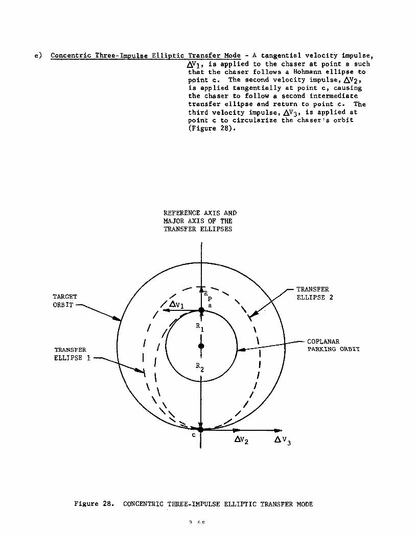
e) Concentric Three-Impulse Elliptic Transfer Mode - A tangential velocity impulse, AVl, is applied to the chaser a t point a such that the chaser follows a Hohmann ellipse to point c. The second ve loc i ty impulse,AV;!, is applied tangentially at point c, causing the chaser t o follow a second intermediate transfer ellipse and return t o point c . third velocity impulse, AV3, is applied a t point c to circularize the chaser's orbit (Figure 28).
The
REFERENCE AXIS AND MAJOR AXIS OF THE TRANSFER ELLIPSES
TRANSFER PARKING ORBIT
Figure 28. CONCENTRIC THREE-IMPULSE ELLIPTIC TRANSFER MODE
2 1. E

- This transfer is an application of either the Modified Hohmann of the Gamma - Change' Transfer Modes. Either a tangential or non-tangential velocity impulse,AV1, is applied to the chaser at point a. This causes the resulting transfer ellipse to intersect the target orbit at point A. The chaser is allowed to coast on Transfer Ellipse 1 until it arrives at the apogee, point c. A second velocity impulse,AVp, is applied tangentially at point c, causing the chaser to follow Transfer Ellipse 2 to point d. The third velocity impulse, AV3, is applied tangentially at point d to circularize the chaserfs orbit (Figure 29).
REFERENCE AXIS AND MAJOR AXIS OF THE TRANSFER ELLIPSES
I
TARGET ORBIT -
TRANSFER ELLIPSE 1
TRANSFER ELLIPSE 2
/ COPLANAR PARKING ORBIT
Figure 29. BI-ELLIPTIC THREE-IMPULSE TFUINSFER MODE . -

3.2.1.2 Transfer from a Non-Coplanar Parking Orbi t t o t h e Target Orbi t
The non-coplanar parking o r b i t p lane i n t e r s e c t s t h e t a r g e t o r b i t plane a t
t h e so-ca l led o r b i t a l l i n e of nodes.
change angle 6 . These two planes a r e inc l ined by t h e plane-
The previously discussed coplanar o r b i t a l t r a n s f e r modes can be used f o r
non-coplanar t r a n s f e r it i f is assumed t h a t t h e o r b i t a l t r a n s f e r conic l i e s in -
p a r t i n the plane of t he parking o r b i t . Thus, t h e t r a n s f e r conic i n r e r s e c t s
no t t h e t a r g e t o r b i t , but an o r b i t of r ad ius R2 ly ing i n t h e park ing-orb i t
plane. This o r b i t i s known a s the l l f i c t i t i ous ' l t a r g e t o r b i t , (Figure 30).
It has been stated above t h a t an o r b i t a l t r a n s f e r maneuver can be i n i t i a t e d
at any po in t i n the parking o r b i t .
and a r r i v a l on the " f i c t i t i o u s 1 ' t a r g e t o r b i t (po in t s a and A, r e spec t ive ly ,
in Figure 30a) l i e on the same s i d e of t he o r b i t a l l i n e of nodes, t he chaser i s
allowed t o fol low t h e t r a n s f e r conic u n t i l i t i n t e r s e c t s t h e l ' f i c t i t i ous l ' t a r g e t
o r b i t . The chaser then undergoes a change i n f l i g h t - p a t h angle and c o a s t s along
the " f i c t i t i o u s " target o r b i t u n t i l it a r r i v e s at t h e n e a r e s t node. An instantaneous
plane-change maneuver i s then performed and g r o s s rendezvous i s said to be
accomplished.
t a r g e t o r b i t (po in t B i n Figure 30b) l i e on oppos i te s i d e s of t h e o r b i t a l l ine
of nodes, t he chaser is allowed t o fol low the o r b i t a l t r a n s f e r conic u n t i l t h e
con ic i n t e r s e c t s t he o r b i t a l l i n e of nodes. A t t h i s p o i n t i n t i m e t h e chaser
performs an ins tan taneous plane-change maneuver enabl ing t h e chaser to fol low
I f t h e p o i n t s of t r a n s f e r conic departure
However, i f po in t a and t h e po in t of a r r i v a l on t h e " f i c t i t i o u s "
a por t ion of t he t r a n s f e r conic ly ing i n the t a r g e t o r b i t plane. Gross rendezvous
is accomplished upon completion of t h e o r b i t a l t r a n s f e r maneuver a t po in t B1
i n F igure 30b.
3 -47

ORBITAL LINE OF NODES
POINT OF ORBITAL TRANSFER ARRIVAL ON THE FICTITIOUS TARGET ORBIT
F I C T I T I O U S
MAJOR AXIS
TRANSFER CONIC
TRANSFER CONIC
POINT OF ORBITAL TRANSFER DEPARTURE
PARKING ORBIT
Figure 30a. NON-COPLANAR ORBITAL TRANSFER MANEUVER
3-48

PLANE -CHANGE POINT OF ORBITAL TRANSFER ARRIVAL
ON THE F I C T I T I O U S ORBITAL LINE TARGET ORBIT
POINT OF ORBITAL TRANSFER ARRIVAL ON THE TRUE TARGET
CONIC
TARGET POINT OF ORBITAL ORBIT TRANSFER DEPARTURE
ORBIT MAJOR AXIS OF THE TRANSFER CONIC
F igu re 3 0 b e NON-COPLANAR ORBITAL TRANSFER MANEUVER
3 -49

PLANE -CHANGE POINT OF ORBITAL TRANSFER ARRIVAL
ORBITAL LINE ON THE F I C T I T I O U S ARGET ORBIT
POINT OF ORBITAL TRANSFER ARRIVAL ON THE TRUE TARGET
CONIC
TARGET POINT OF ORBITAL ORBIT TRANSFER DEPARTURE
ORBIT MAJOR AXIS OF THE TRANSFER CONIC
F igure 3 0 b e NON-COPLANAR ORBITAL TRANSFER MANEUVER
3 -49

3.2.2 Orb i t a l Transfer Mode Matrix
The parameters t h a t a r e of primary i n t e r e s t f o r any o r b i t a l t r a n s f e r
maneuver a r e :
- Total impulsive v e l o c i t y increment required t o perform { Av )TRANS
t h e t r a n s f e r maneuver
- Tota l f l i g h t t i m e required t o perform t h e t r a n s f e r maneuver (t F TRANS
- The phase ang le o r t he angle between t h e chaser and t h e 'TRANS t a r g e t a t t he t i m e o f i n i t i a t i o n of t h e t r a n s f e r maneuver.
These parameters can b e generated f o r a l a r g e number of coplanar o r b i t a l
t r a n s f e r maneuvers by what w i l l be c a l l e d t h e Orb i t a l Transfer Mode Matrix.
It w a s found during t h e e a r l y development of t h e equations f o r the
va r ious modes of coplanar and non-coplanar t r a n s f e r t h a t a l l two-impulse
t r a n s f e r s were a s p e c i a l case of t he more gene ra l coplanar Gamma-Change
Transfer Mode.
were a l s o found t o be s p e c i a l a p p l i c a t i o n s of t h e two-impulse modes. A l l
non-coplanar t r a n s f e r modes d i f f e r e d from t h e coplanar t r a n s f e r modes by the
added maneuvers o u t l i n e d i n Section 3.2.1.2. Thus, i t was found t h a t a l l of
t h e above mentioned o r b i t a l parameters can b e generated f o r a l a rge number of
Both t h e coplanar and non-coplanar three-impulse t r a n s f e r s
t r a n s f e r maneuvers by solving t h e system of equations f o r t h e coplanar Gama-
Change Trans fe r Mode a s c e r t a i n "key" parameters i n t h e geometry o f t h i s mode
are varied. Additional equations are , however, required f o r a l l coplanar
three-impulse t r a n s f e r modes.
c a l l e d Orb i t a l Transfer Mode Matrix.
This method of s o l u t i o n gives rise t o the so-

The 0 . rb i ta l Transfer Mode Matrix i s an o r d e r l y a r r a y of t h e t r a n s f e r
parameters generated f o r any one, any combination, o r a l l of t h e coplanar
t r a n s f e r modes pre-selected by the use r of t h e subroutine. An example is i n
o rde r .
coplanar Gam-Change Transfer Mode with "rendezvous a t A and B". Knowing
A s s u m e t he user of t h e subrout ine wishes t o gene ra t e d a t a f o r t h e
t h e parking o r b i t r a d i u s , R1, and t h e t a r g e t o r b i t r ad ius , R2, t h e general
se t of o r b i t a l t r a n s f e r equations (and t h e a d d i t i o n a l equations f o r "rendezvous
a t BIT) a r e solved as t h e '!key'' parameters e l and rl ( t o be discussed la te r )
a r e var ied w i t h i n c e r t a i n l i m i t s . This produces a n a r r a y of t h e o r b i t a l
t r a n s f e r parameters f o r a l l of t h e t r a n s f e r modes so generated. The a r r a y o r
ma t r ix i s s t o r e d on tape and used as a n input t o t h e subrout ine.
To se t up t h e equations f o r t h e coplanar Gamma-Change Transfer Mode,
t h e geometry r e l a t e d i n Figure 31 w i l l be used.
po in t of o r b i t a l t r a n s f e r departure. This point l ies on t h e r e fe rence axis.
The angle 8
Point a i s defined as the
d e f i n e s t h e pos i t i on of t h e major a x i s of t h e t r a n s f e r conic 1
r e l a t i v e t o t h e r e fe rence ax i s . The ang le
t r a n s f e r c o n i c s s i n t e r s e c t i o n with t h e t a r g e t o r b i t (Point A ) r e l a t i v e to t h e
point of t r a n s f e r departure .
de f ines t h e l o c a t i o n o f t h e
The ang le el w i l l be defined t o have any v a l u e such t h a t
IIowever, f o r any o r i e n t a t i o n of t h e major a x i s of t h e t r a n s f e r conic (e l ) ,
t h e r e i s one and on ly one parabola t h a t h a s t h i s major a x i s o r i e n t a t i o n and
passes through po in t a. This parabola w i l l be designated t h e "Limiting Parabola",
3-51
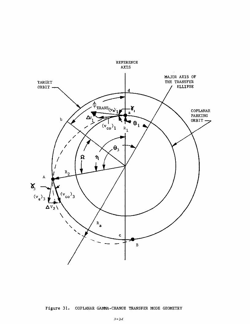
REFERENCE AX1 S
Figure 31. COPLANAR GAMMA-CHANGE TRANSFER MODE GEOMETRY
3 - 3 L

The "Limiting Parabolaf1 d e f i n e s a family of concent r ic t r a n s f e r e l l i p s e s that
have the same major a x i s and pass through poin t a.
v i t a l point .
F igure 32 i l l u s t r a t e s t h i s
R2 For given va lues of parking o r b i t rad ius , Rl, and t a r g e t o r b i t r ad ius ,
t h e "Limiting Parabola" ( i l l u s t r a t e d i n F igure 33) f o r any va lue of 0,. can be
determined as follows:
The a n g l e e l is t h e t r u e anomaly of t h e depar ture po in t ( a ) . Because
e = 1 for a parabola , t he semi- la tus rectum of the l i m i t i n g parabola can be
expressed a s
(P>, = R1 ( 1 -E cos el>
or
. (3-51)
(3-52)
where
e2 = t r u e anomaly of t h e po in t of i n t e r s e c t i o n of t h e "Limiting Parabola"
wi th an o r b i t of r a d i u s R p .
Equating expressions (3-51) and (3-52) t he a n g l e e 2 is
(3- 53
The family of t he t r a n s f e r conics , def ined by t h e l i m i t i n g parabola , i n t e r s e c t s
an o r b i t of r a d i u s R2 f n an i n f i n i t e number of poin ts . The range of i n t e r s e c t i o n s i s
where
8 = t r u e anomaly of t h e po in t of i n t e r s e c t i o n of t h e t r a n s f e r conic w i t h
t he t a r g e t o r b i t .
d - J J

REFERENCE AXIS
TARGE ORBIT
TRANSFER C

REFERENCE AXIS
TARGET ORBIT
Figure 3 3 . "LIMITING PARABOLAf1 GEOMETRY
3-55

Consider Figure 34, which i l l u s t r a t e s t h e 'ILLimiting Parabola" superimposed
upon t h e Gamma-Change Transfer Mode geometry.
conic i n t e r s e c t s t h e t a r g e t o r b i t i n two po in t s , A and B.
In most ca ses t h e t r a n s f e r
3 ' When 8 = 8
t h e i n t e r s e c t i o n i s p o i n t A and when 8 = 8 , t h e i n t e r s e c t i o n is po in t B.
This i s known as "rendezvous a t A" and tkendezvous a t B", r e spec t ive ly .
Parabol ic t r a n s f e r modes a r e app l i cab le when 8 = 02.
4
However, f o r every t r a n s f e r i n t e r s e c t i o n a t point A, when
(e, - e,) 2 ( a - e l ) ,
t h e r e is an a s soc ia t ed point of i n t e r s e c t i o n B. Thus, t o reduce computation
t i m e , t he gene ra l equat ions f o r the coplanar Gamma-Change Transfer Mode a r e
s e t up i n terms of t h e po in t of i n t e r s e c t i o n A, o r ffrendezvous a t A". An
a d d i t i o n a l se t of equat ions i s provided f o r f'rendezvous a t Bit.
The gene ra l s e t of equations f o r t h e coplanar Gamma-Change Transfer
Mode for Itrendezvous at A " , with reference t o Figure 31, are a s follows:
The po in t a t wRich t h e "Limiting Rarabola" i n t e r s e c t s t h e t a r g e t o r b i t ,
of r a d i u s R2, is determined by equation (3-53).
From t h i s equation t h e range of acceptable va lues of 8 is found t o 3
be
(3-54)

REFERENCE AXIS
Figure 34. ”LIMITING PARABOLA” AND THE GAMMA-CHANGE TRANSFER MODE GEOMETRY
J ’ J I

Since the angle
to express the range of acceptable rtfs as
has been defined as a "keyff parameter, it is advantageous
The eccentricity, e, of the orbital transfer conic can be written in terms of
BE and e3 as
P = R1 (1 + e COS 0 , )
P = R (1 f e cos e3> 2
R1 (1 + e cos 0,) = R2 (1 -I- e cos 8 ) 3
e(R COS el - R cos 8 1 = R2 - R1* 1 2 3
Thus 9
R2 - R1 e = R cos el - R COS e3 1 2
Knowing e , the semi-latus rectum can be determined
P = R1 (1 + e cos el)
As well as the semi-major axis
(3-571
(3-58)
P
1 - e 2 a = (3-59)
3-58

The above equations determine t h e geometric parameters of t h e t r a n s f e r conic.
However t h e following equations a r e t h e expressions required f o r "rendezvous
at A!':
The e c c e n t r i c anomaly of t h e point of t r a n s f e r depa r tu re (point a) ,
measured from t he major axis o f t h e t r a n s f e r con ic , is:
or
2 % (1 - e ) s i n el s i n E = 1 1 + e cos e1
The e c c e n t r i c anomaly of po in t flA1! i s
2 %
1 f e cos e3 (1 - e 1 s i n e3
s i n E = 3
2 % (1-e 1 s i n e3 1 + e cos e3 E = s i n e 1 [ ] 3
The mean anomalies of po in t s a and A a r e
M1 = El - e sin El
and
3 M = E - e s i n E 3 3
(3-60a)
( 3 -60b)
(3 -61a)
(3-61b)
The f l i g h t t i m e of a v e h i c l e traveling from t h e per igee o f t h e t r a n s f e r
con ic to p o i n t a is
( 3 - 6 2 )
(3 -63 1
3-59

The f l i g h t t i m e of a v e h i c l e t r a v e l l i n g from t h e per igee of t h e t r a n s f e r
conic to poin t A is
Thust tRe t o t a l t r a n s f e r f l i g h t from point a t o point A i s
( 3 - 6 4 )
NQW a r e l a t i o n s h i p is needed t o express the phase ang le , ( P m M s , required t o
accomplish gross rendezvous.
During che t i m e g (tFITRANs> t h e chaser v e h i c l e t r a v e l s from point a
t o p o i n t A along the t r a n s f e r conic; through a c e n t r a l angle of rl. Also
during this time t h e t a r g e r v e h i c l e t r a v e l s from point b t o point
t he t a r g e t o r b i t , of radius R 2 ; an angle of '2.
A along
Thus y
.= + +TRANS
Q = u (t 1 2 F TRANS but
where
UJ = angular v e l o c i t y of t h e t a r g e t 2
"2 =IT Hence
(3 -67 )
3-60

Solving f o r t he phase ang le $TRANS
It is now of fmportance t o exami3e t h e t o t a l v e l o c i t y increment required,
9 t o accomplish gross rendezvous. i Av )TRANS
The f l i g h t path angle a t p o i n t ar(Yl)tmeasured from t h e local hor i zon ta l
and expressed in terms of t he t r u e anomaly of point a, is :
or
e s ine l tanY = 1 1 + e cos€$
1 + e cos el
The circglar o r b i t v e l o c i t y of t h e chaser v e h i c l e i n t h e parking o r b i t is
7
%,>, =J f (3-70)
The velocity of the chaser a t point a on t h e t r a n s f e r conic can be expressed
as
Thus, t h e impulsive v e l o c i t y increment required f o r t h e chaser v e h i c l e t o
leave t‘ne parking orbit ar point a and t r a v e l along t h e t r a n s f e r conic is
The f l i g h t parh angle a t point A , i Y 3 ) ’ measured from the l o c a l ho r i zon ta l , i s
I
3-61

3 e s i n 0
1 -+ e cos e3 t aa Y3 =
or
2
3 ] I e s i n 0
Y, 3 = / t G l ~ 1 + e cos e3
The circular o r b i t v e l o c i t y of a v e h k l e %n an o r b i t of r ad ius R is
(3-749
and t h e v e l o c i t y of t h e chaser v e h t c l e a t p o i n t A 3n the t r a n s f e r e l l i p s e
(3-751
Hence, the impulsive v e l o c i t y increment required f o r t h e chaser veh ic l e t o
leave t h e t r a n s f e r conic a t point A and t r a v e l along t h e t a r g e t o r b i t Can b e
w r i t t e n as
Therefore, t h e t o t a l Pmprr1s”Le v e l o c i t y increment required t o accomplish t h e
o r b i t a l t r a n s f e r maneuver is
(3-77 9
Reference is made to Appendix C f o r rhe values of and rl t h a t d i c t a t e
which coplanar o r b i t a l t r a n s f e r mode Ls app l i cab le as t h e range of r ~ ? s is
examined. The appendix a l s o p re sen t s r h e a d d i t i o n a l equations required f o r
1) Coplanar ’’rendezvous a t B “
3-62

NORTH Rap SPACE 1 ABOR ATORlES
2) Coplanar Concentric Three-Impulse Elliptic Transfer Mode
3) Gop1ana.r Bi-Elliptic Three-Impulse Transfer Mode.
Figure 35 presents a semi-detailed logic flow chart for the Orbital
Transfer Mode Matrix, The matrix is generated for any one, any combination,
or all of the coplanar orbital transfer modes by inputting R
following concrol parameters:
and R2 and the 1
A = l
A = 2
A = 3
B = l
B = 2
B = 3
C = l
c = 3
D = l
D = 2
E = l
E = 2
F = L
F = 2
Coplanar ''rendezvous at AI1 and/or Ifrendezvous at B"
Coplanar flrendezvous at A.1' and/or ''rendezvous at B f f and
Coplanar Concentric. and/or Bi-Elliptic Three-Impulse Transfer
Mo de C s 1
Coplanar Concentric and/or Bi-Elliptic Three-Impulse Transfer
Mode 1 s)
Coplanar "rendezvous 3.t A"
Coplanar !'rendezvous at At' and/or IJrendezvous at B1'
Coplamar "rendezvous at B "
Cop lan3,r "rendezvous at A If
Coplanar "rendezvous at A and Bfl
Yes - - - Coplanar Three-Impulse Transfer Modes No - = - Coplanar Three-'Impulse Transfer Modes
Yes - - - Coplanar Coicentric Three-Impulse Elliptic Trsnsfer Mode
No - - - Coplanar Concetltric Three-Impulse Elliptic Transfer Mode
Yes - - - Coplanar Bf-Elliptic Three-Impulse Travsf.er Mode
No - - - Coplx~~r Bi-Elliptic Three-Impulse Transfer Mode,
.3 -6.3

t a r g e t o r b i t , is u t i l i z e d by t h e chaser for wait ing u n t i l the phasing r e l a t i o n -
s h i p between t h e chaser and the t a r g e t i s c o r r e c t t o i n i t i a t e an o r b i t a l
t r a n s f e r maneuver.
If t h e launch de lay t i m e , ( t d j n , i s such t h a t t h e Coplanar Ascent
T ra j ec to ry %de is app l i cab le , the chaser i s i n j e c t e d i n t o a coplanar parking
o r b i t . The t r u e phase ang le between t h e
chaser and t h e t a r g e t a t t h e t i m e of chaser o r b i t a l i n j e c t i o n is determined.
This is i l l u s t r a t e d i n Figure 3 6 .
as follows:
= s i n -1 s i n i ~ ] X Ls (3-42)
(3-35)

I
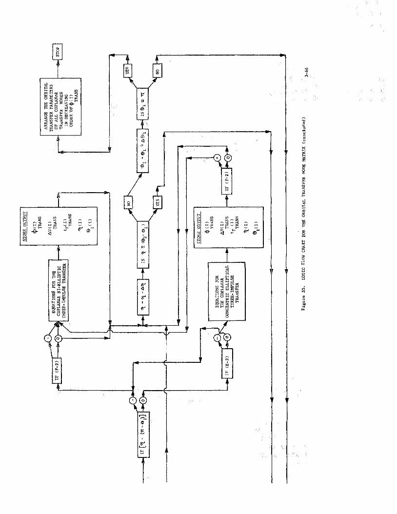
t

SCENT TRAJECTORY
LAUNCH S I T E
LAUNCH S I T E LATITUDE
ASCENDING NODE
TARGET- PARKING ORBIT GROUND
ORBIT
Figure 36, TYPICAL COPLANAR ASCENT TO PARKING ORBIT

(3-79)
Once t h e t r u e phase ang le is known, the Orb i t a l Transfer Mode Matrix
i s searched f o r a
phase angle is found, t h e o r b i t a l t r a n s f e r mode a s soc ia t ed with
be in-f t ia ted.
$ITRANs t h a t i s equal t o $ITRUE. I f a s u i t a b l e t r a n s f e r
can
However, i f a t r a n s f e r phase angle cannot be found such t h a t
- +TRANS - +TRUE?
t h e chaser must remain i n t h e parking o r b i t u n t i l t h e phasing r e l a t i o n s h i p i s
s u i t a b l e f o r i n i t i a t i o n of a t r a n s f e r maneuver.
i n t h e descending sequence of phase angles i s then examined t o determine t h e
The next t r a n s f e r phase angle
required parking time. This parking time
- - +TRUE +TRANS
i tPARK
or
i s determined by
' 'TRANS for O +Ti,, (3 -80)
for O 2 +TRUE < +TRANS
where
5 = chaser catch-up rate
2 i = w - w
1 (3-81 1
(3-82)
3-68

Thus, t h e Orb i t a l Transfer Mode Matrix i s searched f o r an o r b i t a l t r a n s f e r
mode t h a t can be accomplished wi th in c e r t a i n parking t i m e r e s t r i c t i o n s . An
acceptable t r a n s f e r maneuver is, however, r e s t r i c t e d by t h e allowable t o t a l
mission v e l o c i t y increment and t o t a l mission f l i g h t t i m e . The semi-detailed
subrout ine l o g i c flow c h a r t i n Sect ion 4 i l l u s t r a t e s t h i s approach.
If t h e launch de lay t i m e , ( t d I n , i s such t h a t a Non-Coplanar Ascent
Trajectory Mode is app l i cab le , t he chaser coas t s from t h i r d - s t a g e shutdown
t o t h e o r b i t a l l i n e of nodes. When the chaser arr ives a t t h e o r b i t a l l i n e o f
nodes, t he chaser can perform e t t h e r of t h e two opt ions o u t l i n e d i n Sect ion 3 , 2 .
If a plane change i s performed and a coplanar parking o r b i t u t i l i z e d , t he
procedure f o r f inding an acceptable t r a n s f e r mode i s t h e same as above.
However, t h e use o f a non-coplanar parking o r b i t r e q u i r e s a somewhat d i f f e r e n t
approach.
Ascent i n t o a non-coplanar parking o r b i t is accomplished by a non-
coplanar a scen t t r a j e c t o r y s imi la r t o t h e one used f o r d i r e c t ascent t o
rendezvous. Figure 37 i l l u s t r a t e s t h i s point . The t rue phase ang le exis t ing
when the chaser arrives at the orbftal line of nodes, for any a scen t t r a j e c t o r y
mode, 2s found by
o r
where
is determined by equations (3-37) through ( 3 - 4 0 ) . TOLN e
3-69
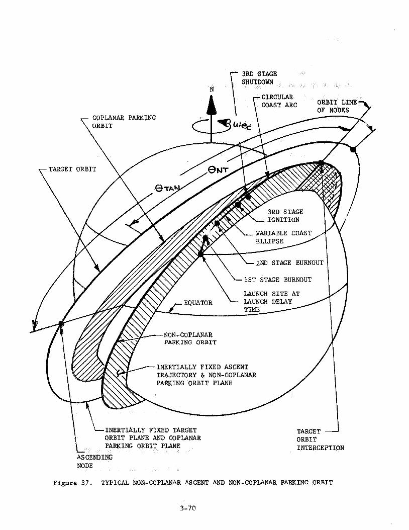
N
'-INERTIALLY FIXED TARGET TARGET ORBIT PLANE AND COPLANAR ORBIT
INTERCEPTION
Figure 3 7 , TYPICAL NON-COPLANAR ASCENT AND NON-COPLANAR PARKING ORBIT
3-7@

When +TRUE is found, t he Orb i t a l Transfer Mode Matrix i s searched f o r
a t r a n s f e r phase angle , 4
The time t h a t must be spent in t h e non-coplanar parking o r b i t is f
equation (3-80).
t h a t i s equal t o o r s l i g h t l y less
It must be remembered t h a t t h e parking o r b i t is non-coplanar with t h e
t a r g e t o r b i t and t h a t t h e s e planes i n t e r s e c t a t t he o r b i t a l l i n e of nodes
(Figure 30b) . Thus, t h e pos i t i on of t h e chaser a t t h e end o f required parking
t i m e , r e l a t i v e t o the o r b i t a l l i n e of nodes, must be determined.
Figure 38 i l l u s t r a t e s t h e Non-Csplanar Gamma-Change Transfer Mode
geometry a s v5ewed from v e r t i c a l l y above t h e parking o r b i t plane.
of t he chaser from t h e o r b i t a l l i n e of nodes f o r any parking t i m e i s
The p o s i t i o n
(3-85)
f f gross rendezvous is d e s i r e d a t point e i n Figure 38, t h e chaser
would follow t h e t r a n s f e r conic from point a t o point A'on t h e ' l f ic t i t ious l l
t a r g e t o r b i t .
u n t i l i t arrives a t t h e nea res t o r b i t a l node. A t t h e node, t he chaser would
perform a plane-change maneuver and ef f e e t rendezvous.
The chaser would then coast i n t h e l lf icti t iousll t a r g e t o r b i t
Appendix D contains t h e a d d i t i o n a l equations r equ i r ed f o r non-coplanar
o r b i t a l t r a n s f e r s i f t h e point of departure and t h e po in t of ar r iva l , on the
"fficti t ious '! target o r b i t , both l i e OR the same s i d e of t h e o r b i t a l l i n e of
nodes.
H € gross rendezvous is des i r ed a t point B f i n Figure 30b,
t h e chaser would be allowed t o fol low t h e t r a n s f e r con ic from po in t
3-71

ORBITAL LINE OF NODES MAJOR AXIS OF
THE TRANSFER ELLIPSE
\ \ \
\ I
IMPULSIVE PLANE-CHANGE
. MANEUVER
Figure 38. NON-COPLAEAR GAMMA-CXANGE TRAXSFER MODE
3-72

t h e o r b i t a l l i n e of nodes (po in t f i n Figure 38). The radius a t po in t f on
t h e o r b i t a l t r a n s f e r conic i s
The chase r i s v e l o c i t y i s
( 3 - 8 6 )
(3-87)
Thus, t h e impulsive v e l o c i t y increment requi red t o perform t h e plane-change
maneuver is
(3-88
A f t e r performing the plane change, t h e chaser cont inues coas t ing along t h e
t r a n s f e r conic , ly ing i n t h e t a r g e t o r b i t plane, u n t i l it a r r i v e s a t Point B'.
Gross rendezvous i s e f f e c t e d at t h i s point .
3-73

MORTHROP SPACE LABORATORIES
SECTION 4
RESULTS AND CONCLUSIONS
4.1 Subroutine Logic Flow Chart
Figure 39 presents a .serni-detai led log ic flow c h a r t f o r t h e e n t i r e sub-
rout ine .
Transfer Mode Matrix be input tapes .
It i s suggested t h a t t he Ascent Tra jec tory Table and the O r b i t a l
The subrout ine has t h e following inputs :
R2 a ) Target o r b i t r ad ius ,
T b) Target o r b i t i n c l i n a t i o n , i
c ) Pos i t i on of t he t a r g e t from t h e ascending node a t the re ference
time, a.
d ) Launch s i t e l a t i t u d e , X
e ) Launch s i t e longi tude, A,
f ) Local hour angle of t he verna l equinox, measured from t h e launch s i t e
hour c i r c l e a t the re ference time, LHAY
g) To ta l AV c a p a b i l i t y of the chaser launch vehic le , [(AV)MIssIoN 1
h) T o t a l alrowable chaser f l i g h t time, [(tF)MIssIoN 1 MAX
% R K ) MAX i) Tota l a l lowable parking o r b i t time,
j) Chaser launch azimuth range s a f e t y c o n s t r a i n t s , (Az& and (A Z >M I N
4- I
R1 k) Desired parking o r b i t r ad ius ,
1:) Maximm allowable yaw angle,
m ) Maximum a'FZowabPe chaser 2nd-stage burnout f l i g h t pa th angle ,
' 2 B n ~ ~
-3 n', Earth oblateness constanr , J 1,62345 X 10
6 o', Earrrh e q u a t o r i a l r ad ius , Re = 6.398156 x PO m
14 3 2 p > Earth g r a v i t a t i o n a l constant , 1-I = 3.986016 x 10 m /sec
q ) Accelerat ion due t o g r a v i t y a t t h e Ea r th ' s su r f ace , 2
= 9.8045016 m/sec go
r) Length of t h e t r u e mean solar day, To = 86,164.099 sec
-5 S) True Earth r o t a t i o n a l r a t e , uE = 9.29211513 x 10 r ad / sec
t) Reference time i n t e r n s of GMT or ZULU t i m e
u) Number of days of r equ i r ed launch window inves t iga t ion , M
v) Chaser veh ic l e t h i r d - s t a g e t h r u s t , F
w:) Maximum al lawable chaser ascent impulsive v e l o c i t y increment,
Atd x:b Launch delay t i m e Increment,
y f Chaser 2nd-stage burnout f l i g h t pa th angle increment, AY2B0

P
a" t
I - 1
NORTHROP SPACE LA~~~RATORIES
4 2 Recommendat ions
It has been assumed that the m
relatively small, roughly on the o
in a first approximation, it is assumed that the differential nodal regression
of the target and parking orbits is negligible. or longer parking
times, equationis) must be added to the subroutine to accoun for this unequal
nodal regression.
It is recommended that the subroutine be programmed and checked out in
the following steps:
1) Programing and checkout of various separate phases or parts of the
subroutine. This w i l l ensure the speed and accuracy of each independent
phase.
2) Error analysis and improvement of each phase.
3) Programming and checkout o f the entire subroutine to check the
compatibility of all separate phases.
4- 5

NORTHROP SPACE LABORATORIES
SECTION 5
RJi!FEREH
1. Berman, Arthur I., , John Wiley & Sons, Inc., 19
2. Bird, John D., and Thomas, Jr., David F., "A Two-Impulse Plan for Performing Rendezvous m a Once-a-Day Basis," NASA TN-D-437, Langley Research Center, November 1960.
3 . Blitzer, Leon, "On the Motion of a Satellite in the Gravitational Field of the Oblate Earth," GM-TM-0165-00279, Space Technology Laboratories, September 1958.
4 . Brunk, William E., and Flaherty, Richard J., Wethods and Velocity Requirements for the Rendeevous of Satellites in Circumplanetary Orbits," NASA-TN-D-81, L e w i s Research Center, October 1959.
5. Coates, G. L., flOptimization of Two-Burn Direct Ascent Trajectories for Rendezvous," TDR-269 (4550-20)-5, Aerospace Corp., February 1965.
6. Davis, H. A., and Chambers, L. H., Brief Course in Plane and Spherical - Trigonometry, American Book Co., 1933.
7. Dowlen, E. M., and Seddon, J., "Orbital Rendezvous Techniques", Journal of the British Interplanetary Society, Vol. 19, 1963-6k.
8. Ellison, Bobby, "A Parameter Study of Launch Windows for Orbit to Orbit Transfers About a Planet Keeping Required Energy Change Near a Minimum1', Aeroballistics Internal Note No. 30-63, George C. Marshall Space Flight Center, Huntsville, Alabama, 1963.
9. Ehricke, Krafft A., Space Flight, Vol I1 Dynamics, D. Van Norstrand Co., Inc., 1962.
10. Kenehan, Martin F., "Analytic Determination of Launch Windows for Orbital Rendezvous," AIAA Paper No. 64-399, Paper Presented at 1st AIAA Annual Meeting, Washington, D.C., June 29 - July 2, 1964.
11. Koelle, Hetnz H.,ed., , McGraw-Hill Book C O ~ , 1961.
12. Metzger, R. R., Kopp, R. J., and Rhodes, P., "Fortran IV Computer Program for the Determination of the Applicability of IGM to Coplanar Earth Orbital Rendezvous," , Huntsville, Alabama, (to be published) .
5-1

13. Nelson, Walter C., and Loft, Ernest E., Space Mechanics, Prentice-Hall, Inc., 1962.
14. Neilsen, Kaj J., and Vanlonkhuyzen, John H., Plane and Spherical Trigonometry, Barnes & Noble, 1964.
15. , Orbital Flight Handbook, Martin-Marietta, Space Systems Division.
16. Petersen, Norman V., and Swanson, Robert S., "Rendezvous Compatible Orbits, Astronautical Sciences Revi-ew, Oct. - Dec. 1959.
170 9 Space Navigation Handbook, Navpers 92988.
18. Swanson, Robert S . , and Petersen, Norman J., frSUmmBry Report of Rendezvous Compatible Orbits;' NSL 62-117, Northrop Space Laboratories, Hawthorne, California, July 1962.
5-2

NORTHROP SPACE LABORATORIES
APPENDIX A
DEFINITIONS
The r eade r is r e f e r r e d t o F igures A - 1 and A-2 with r e fe rence t o t h e
fol lowing d e f i n i t i o n s :
C e l e s t i a l sphere - The c e l e s t i a l sphere i s an imaginary sphere of i n f i n i t e
r a d i u s , w i th t h e Earth loca ted a t i t s center . A l l c e l e s t i a l bodies ,
inc luding the F i r s t Point of Aries , a r e considered t o l i e on t h e sur face
of t he c e l e s t i a l sphere.
c e l e s t i a l sphere ' s e q u a t o r i a l plane and t h e Earth and c e l e s t i a l po la r axes
coincide. The c e l e s t i a l sphere remains f ixed i n i n e r t i a l space while t he
Ear th r o t a t e s about i t s ax i s .
The E a r t h ' s equa to r i a l plane i s coplanar w i th t h e
Hour c i r c l e - The hour c i r c l e i s the g r e a t c i r c l e t h a t passes through the
c e l e s t i a l po le s and a po in t on the c e l e s t i a l sphere.
Vernal equinox - The verna l equinox i s t h e i n t e r s e c t i o n (ascending node) of
t h e E a r t h ' s equa to r i a l plane. This l i n e p o i n t s t o t h e assumed space-fixed
F i r s t Poin t of Aries , designated by t h e symbol Y.
S i d e r e a l hour angle (SHA) - The s i d e r e a l hour angle i s the c e n t r a l angle ,
measured i n the equa to r i a l plane, between t h e hour c i r c l e of a poin t on
t h e c e l e s t i a l sphere and t h e hour circle of Aries.
measured westward from Ar ie s through 360O.
This angle i s
A- 1

t h e hour of c i rc le of Aries.
Greenwich hour c i r c l e through 360'.
This angle is measured westward from the
Local hour angle (LHA) - The l o c a l hour angle i s t h e central angle between t h e
hour c i r c l e o f t h e launch s i t e and the hour c i r c l e of t h e t a r g e t o r b i t
ascending node.
hour angle.
This angle is measured westward from t h e launch s i t e
Y
LAUNCH SITE
HOUR CIRCLE OF THE PRIME MERIDIAN
A- 3

GREENWICH HOUR CIRCLE
HOUR CIRCLE
HOUR CIRCLE OF THE ASCENDING NODE OF THE TARGET ORBIT
OF THE LAUNCH S I T E UF 'I'HE LAUNtiH
Figure A-2. CELESTIAL SPHERE AS VIEWED FROM THE NORTH POLE
A- 4

APPENDIX B
TRlGONOMETRIC EQUATIONS FOR THE ASCENT TRAJECTORY MODES
This appendix p re sen t s t h e geometrical r e l a t i o n s h i p s f o r each ascent
t r a j e c t o r y mode and the a s s o c i a t e d equations.
assuming t h a t t h e t o t a l i n t e r c e p t range ang le 0
degrees , minimum plane-change angle occurs). Furthermore, each a scen t t r a j e c t o r y
mode i s r e s t r i c t e d by range s a f e t y c o n s t r a i n t s placed on t h e launch azimuth,
AZ, and by t h e launch v e h i c l e ' s c a p a b i l i t i e s t o perform plane-change maneuvers.
Thus, depending on these r e s t r i c t i o n s , t h e launch times f o r a given mission
can be determined by examining a l l acceptable values of 8 I
a s c e n t geometry cases, a t each t i m e po in t , ( t d ) n , a f t e r ( t d I n = 0 , f o r a
given per iod of t i m e .
These equations were developed
was a v a r i a b l e , ( f o r BI = 90 I
f o r t h e var ious
With r e fe rence t o Figure B - 1 , t h e following equat ions a re r equ i r ed fo r
determining t h e launch azimuth f o r t h e Coplanar Ascent T ra j ec to ry Mode:
o r - -1 [ AZ - T I - s i n (B-2)
With reference t o Figure B - 2 , t h e equat ions app l i cab le t o Ascent Trajectory
Mode 1 a r e as fol lows:
The c e n t r a l angle measured along the equator from t h e ascending node of
the t a r g e t o r b i t t o t h e launch s i t e meridian can be w r i t t e n as:
Lw = sin- '
B- 1
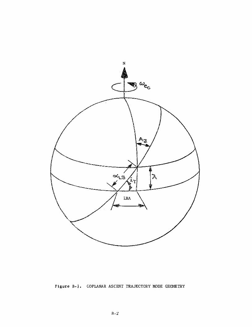
N
Figare B-I . COPLANAR ASCENT TRAJECTORY MODE GEOMETRY
H-2

N
Figure B-2, ASCENT TRAJECTORY MODE 1 GEOMETRY
B- 3
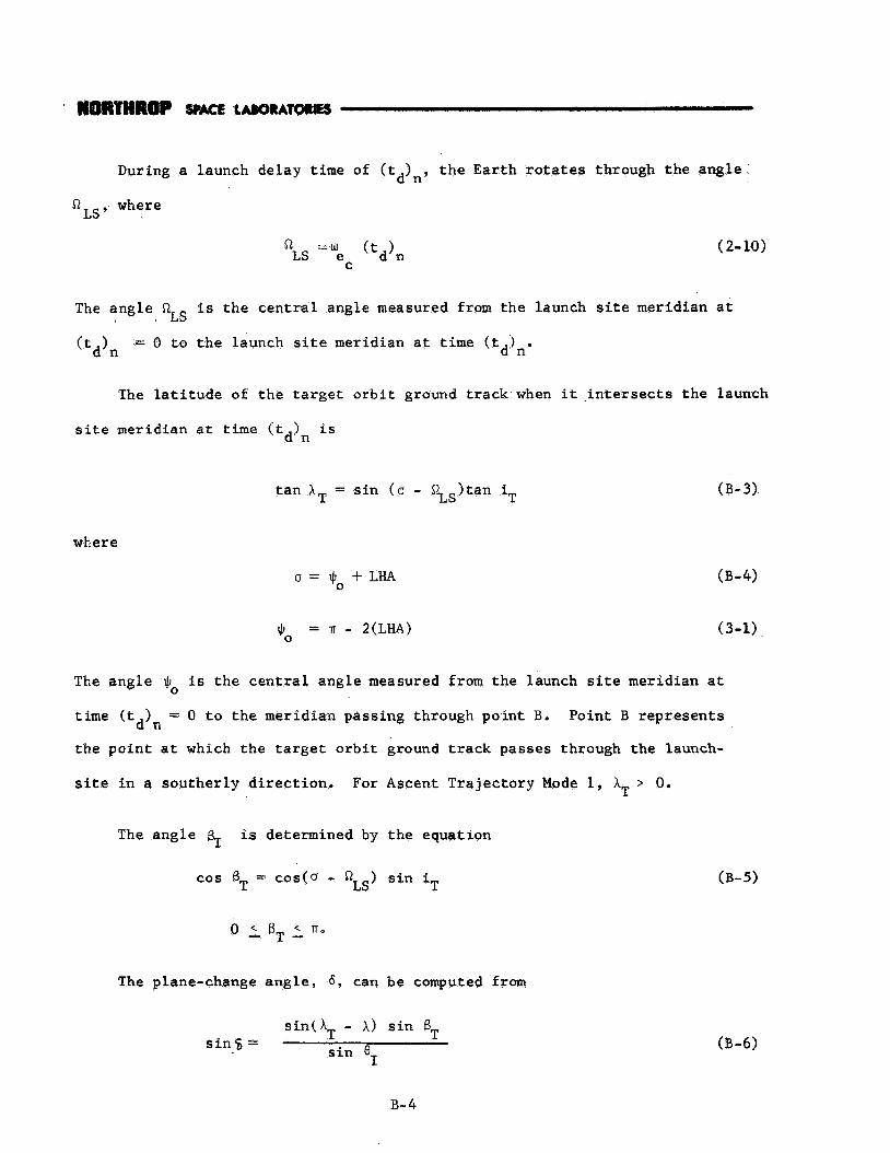
During a launch delay time of (t,),, t h e Ear th r o t a t e s through the angle
R Ls, where
LS "'e 'td)n R
C
( 2- 10)
The angle 61Zs i s t h e c e n t r a l angle measured from the launch s i te meridian a t
( t d ) n = 0 t o t h e launch s i t e meridian a t time ( t d j n .
The l a t i t u d e of t h e t a r g e t o r b i t ground t r ack when it i n t e r s e c t s t h e launch
s i t e meridian at t i m e ( t ) i s d n
t an A T = s i n ( a - Z S ) t a n iT (B-3)
where
0 = Jb + LHA
q0 = IT - 2(LHA)
The angle $ is t h e c e n t r a l angle measured from the launch s i te meridian a t
time (t 1 = 0 t o t h e meridian passing through poin t B. Point B r ep resen t s
0
d n the po in t a t which the t a r g e t o r b i t
s i t e i n a sou the r ly d i r e c t i o n . For
The angle f+ is determined by
cos BT = cos(0 - QLS)
0 2 B, 2
The plane-change ang le , 6 , can
sin(A, - A )
ground t r a c k passes through the launch-
Ascent Tra jec tory Mode 1, AT > 0.
t he equat ion
T s i n i
be computed from
s i n B,, (B-6) s i n s =
I I
I s i n 6
B- 4

1IIrnrnI8OP
The c e n t r a l angle , measured i n t h e ta
s i t e meridian a t (t,)
d by t h e equation
LS cos 8 = s i n X sinA + cosX cos X cos 62 T . T T (B-7)
The ang le eN is t h e c e n t r a l ang le measured i n t h e t a r g e t o r b i t plane from
t h e i n t e r s e c t i o n of t he t a r g e t o r b i t ground t r a c k and t h e launch s i te
meridian a t (t 1
t a r g e t o r b i t plane ( o r b i t a l l i n e of nodes).
t o t h e i n t e r s e c t i o n of t h e a scen t t r a j e c t o r y plane and t h e d n
This ang le can be found by t h e
equation
t a n & = t a n f [e, + (
The launch azimuth, A i s determined by: 2’.
With r e fe rence t o Figure B - 3 , t h e equations a p p l i c a b l e t o Ascent T ra j ec to ry
Mode 2 are:
3r = m - 2 ( 2
5 = 3 r +LHA
0
0
3- 5

Figure B-3 . ASCENT T DE 2 GEOMETRY
B- 6

sin 6 =
cos 9 = s i n h sinX + cos X (B-7) T T
cosh(@T.f 6 , tan% = + - '11 [cos%(6T - 6)] ( B - 8 )
cos4 E@, + ( AT - A ) ] cotkAZ = tan+( BT + 6 ) (B-93
With reference to Figure B - 4 , the equations applicable t o Ascent Trajectory
Mode 3 are:
LHA = sin-l I tan I tan iT
( B - 1 0 )
(B-11)
( B - 1 2 )
B- 7

N
TARGET GROUND
Figure B-4. ASCENT TRAJECTORY MODE 3 GEOMETRY
B-8

cos eT = sdn XT sinX + cos AT cos X cos p ( B - 1 3 )
With reference
Mode 4 are:
to Figure B-5, the equations applicable t o Ascent Trajectory
%S p = 2 T -
Jb = 8-2(LHA)
tan + = sin(LM - P )tan iT
T cos k$, = eos(LHA - p ) s i n i
sin(A T - A ) s i n BT s i n 8 =
sin e I
(2-10)
( B - 1 7 )
(3-1)
( B - 1 1 )
( B - 1 2 )
( B - 6 )
(B- 13)
(B-18)
(B-15)
( B - 1 6 )
B-9

N
TARGET GROUND
ASCENT TRAJECTORY GROUND TRACK
Figure B-5. ASCENT TRAJECTORY MODE 4 GEOMETRY
B-10

With reference t o Figure B-6, the equations applicable t o Ascent Trajectory
Mode 5 are:
I7 = Tr/2 (B-19)
(2-10)
tanh = s into - 52 )tan iT (B-3) T LS
cosBT = costa - QLS) s i n iT (B-5)
sin(AT -X)sinBT
sineI s i n 6 = 03-61
With reference t o Figure B-7, the equations applicable to Ascent Trajectory
Mode 6 are:
(B-19)
(2-10)
(B-17)
(B-20)
B-11

N
Figure B-6. ASCENT TRAJECTORY MODE 5 GEOMETRY

N
T4RlGET ORBIT ZiXOUND TRACK
Figure B-7. ASCENT TRAJECTORY MODE 6 GEOMETRY
B-13

cosBT = cos (0 - p)sin iT (B-21)
sin(A - A)sinBT T s in0 sin 6 =
1
coseT = sinAT sinX + c o d T cosX cosp (B-13)
B-14

APPENDIX C
ADDITTONAL EQUATIONS FOR COPLANAR ORBITAL TRANSFER MODES
This appendix presents a br ie f l i s t i n g o f the coplanar orb i ta l transfer
modes generated by the Orbital TranFfer Mode Matrix and any addit ional equations
that may be needed for the ir complete solution.
REFERENCE AXIS AND MAJOR A X I S OF THE TRMSFER ELLIPSE
I
Figure C-1. HOHMAMN TRANSFER MODE

IT
Figare C-2. MODIFIED HOHMANW TRANSFER MODE
See Coplanar Gamma-Change Transfer Mode for the equations f o r "Rendezvous a t B".
P^ 7

(C-1) 83 8 = 2 n - 4
(3-57) R2 - R1 e = R ~ C O S e - R cose4 1 2
(1 - e 2 s ) sinel (3-60a) -1 sin E = s i n 1 1 +e cosel
-1 (1 - e 2 % ) sinel El = sin 1 + e cose4 (3-60b)
2 % (1 - e ) s i n O 4 sin E = ( C - h ) 4 1 + e cose4
2 % (1 - e ) sine4
1 + e cos04 (6- 2b) -1 E 4 = s i n
c-3

I ' i
Y I =
= n - w (t ) 'TRANS 2 FTRANS
e sine
tan-1 [ 1 + e cosel ]
= F e sine
y4 1 + e cos9
AV1 + AV4
(C-5)
(3-67)
(3-68)
(3-69b)
(3-70)
(3-71)
(3-72)
(C-6)
(3-74)
(C-7)
(C-8)
(C-9)
c-4

COPLANAR PARKING ORBIT
Figure C-3. GAMMA-CHANGE TRANSFER MODE
c-5

Figure C-4. PARABOLIC TRANSFER MODE
6-6
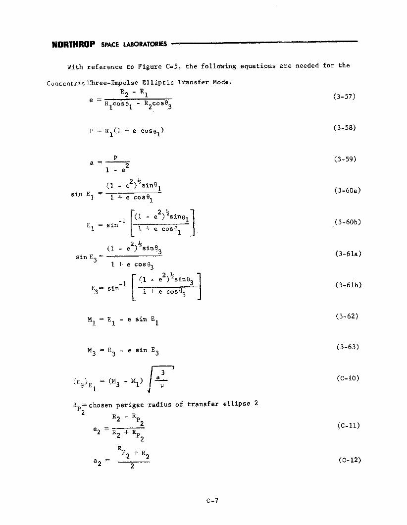
With r e fe rence t o F igure c65, t h e following equat ions a r e needed for t h e
C t .ncen t r f r ,Three -~~pu l se E l l i p t i c Transfer Mode. Re - R,
L L e = R COS^ - R COS^ I 1 2 3
P = R ~ ( I + e cosgl)
P
I - e 2 a =
2 % (1 - e ) sine, si11 E l - a,
E + e cos€$
1 -t e cos8 El = sin
1 MI = E - e sin E 1
Mg = E 3 - e s i n E 3
R =chosen per igee p2 R2 - R
- p2
- R2 + Rp2
r ad ius of t r a n s f e r e l l i p s e 2
- %2 + R2 a2 - 2
(3-57)
(3-58)
(3-59)
(3-609)
(3-60b)
( 3 - 6 l a )
(3-61b)
(3-62)
(3-63)
(c-IO)
((2-11)
(e-12)
c-9

E2 i t 5 = (t + ( $ 1
El F TRANS
w2 = $IF ((3-13)
(C- 14)
(3-67)
(C-15)
(3-70)
(3-71)
(3-69b)
(3-72)
( C - 1 6 )
(C-17)
(C-18)
(3-75)
(C-19)
(C-20)
C-8
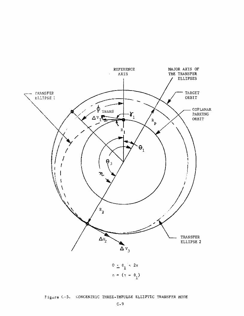
Eigirre C - 5 . CONCENTRIC THREE-IMPULSE ELLIPTIC TRANSFER MODE
C - 9
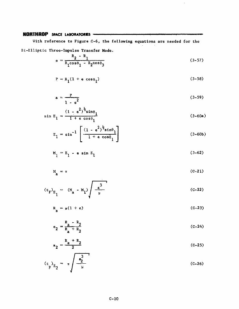
NORTHHOP SPACE LABORATORES
With reference to Figure C-6, the following equations are needed for the
B i - E l l i p t i c Three-Impulse Transfer Mode.
R2 - R1 e = R COS^^ - R2c0se3 1
P = ~ ' ( 1 + e cosel) 1
P
l - e 2 a =
sin El = 1 + e cosel
1 M = E - e s i n E 1 1
M = n a
R = a(l +- e) a
R + R2 a - a2 - 2
(t )E = F 2
(3-57)
(3-58)
(3-59)
(3-60s)
(3-60b)
(3-62)
(c-21)
(c-22)
(C-23)
(C-24)
(C-25)
(C-26)
c- 10

(v co I=/$ 1
lJ a =I R1 - -
a 1
I =J 2lJ F! - - - Ra a2
(C- 15)
(3-67)
(C-27)
(3-70)
(3-71)
(3 - 69b)
(3-72)
(C-28)
(C-29)
(C-18)
(3-75)
(C-30)
(C-31)
(c-20)

COPLANAR PARKING
/
/
0 2 . 0 1 < 2a v2
(e2 - e,) < TI < (T - 8,) Figure C-6. BI-ELLIPTIC THREE-IMPULSE TRANSFER MODE
c- 12
ORBIT

APPENDTX D
ADDTZIONAL EQUATIONS REQUIRED FOR NON-COPLANAR ORBITAL TRANSFER MODES
This appmdix p resen t s t h e z d d i t i o n a l equations r equ i r ed t o determine t h e
o r b i t a l t r a n s f e r parameters i f t h e po in t of departure and t h e po in t of arr ival
on the f i c t i t i o u s t a r g e t o r b i t (po in t s a and A , r e s p e c t i v e l y , i n Figure D-1)
lie on t h e same s i d e of t h e o r b i t a l l i n e o f nodesn
The p o s i t i o n o f t he chaser a t t h e end of required parking t i m e , r e l a t i v e
t o t h e o rb i t t i l l i n e of nodes, i s
=wet ) 'CQLN 1' PARK (3-85)
The p o i n t of orbital tracsfer departure (a) and t h e p o i n t of a r r iva l on
tbe fictitious target o r b i t ( A ) , l i e QI-I t he same s i d e of t h e o r b i t a l l i n e of
nodes when
Therefore , this method of accomplishing non-coplanar g ross rendezvous, by a
g iven t r a n s f e r mode, i s permissible only when equation (D-1) i s s a t i s f i e d .
The t i m e spent by t h e chaser i n coast ing Erom po in t A t o p o i n t e along t h e
f i c t i t i o u s t a z g s t o r b i t i s
L COAST

REFERENCE
D-2

NORTHROP SPACE LAWIAIORES
Thus, the total chaser flight time from parking orbit departure to gross
rendezvous become s
+ tFsCT -
COAST ( tF)TRANs - (tF)TRANs coplanar transfer
(D-3)
The t o t a l impulsive velocity increment required to effect rendezvous is
transfer
where
The above equations are also valid for the Non-Coplanar Three-Impulse Transfer
Modes