Technical Scope of Work
125
Technical Scope of Work 465-1-16-C47, Rev. B Page 1 of 8 Title: Swift Current Irrigation Pump Rehabilitation (Centre Farm) Source Doc. 465-1-16-C47 Rev. No.: B Project Name: Centre Farm Pump Rehabilitation Project No.: 465-1-16-C47 Customer: Agriculture and Agri-Food Canada Area No.: Important Notice UNLESS OTHERWISE AGREED IN A WRITTEN CONTRACT BETWEEN WOOD AND ITS CLIENT, THIS DOCUMENT: (I) CONTAINS INFORMATION, DATA AND DESIGN THAT IS CONFIDENTIAL AND MAY NOT BE COPIED OR DISCLOSED; AND (II) MAY BE USED BY THE CLIENT ONLY IN THE CONTEXT AND FOR THE EXPRESS PURPOSE FOR WHICH IT WAS INTENDED. ANY USE OF, OR RELIANCE ON, THIS DOCUMENT BY ANY THIRD PARTY IS AT THAT PARTY’S SOLE RISK. Rev Date Issued For Prepared Checked Approved Client A 9 March 2021 Tender D..Kidd Dale Miller AAFC B 17 June 2021 Tender S.VanEssen Dale Miller AAFC
-
Upload
khangminh22 -
Category
Documents
-
view
1 -
download
0
Transcript of Technical Scope of Work
Technical Scope of Work
465-1-16-C47, Rev. B Page 1 of 8
Title: Swift Current Irrigation Pump Rehabilitation (Centre Farm)
Source Doc. 465-1-16-C47 Rev. No.: B
Project Name: Centre Farm Pump Rehabilitation Project No.: 465-1-16-C47
Customer: Agriculture and Agri-Food Canada Area No.:
Important Notice
UNLESS OTHERWISE AGREED IN A WRITTEN CONTRACT BETWEEN WOOD AND ITS CLIENT, THIS
DOCUMENT: (I) CONTAINS INFORMATION, DATA AND DESIGN THAT IS CONFIDENTIAL AND MAY NOT
BE COPIED OR DISCLOSED; AND (II) MAY BE USED BY THE CLIENT ONLY IN THE CONTEXT AND FOR THE
EXPRESS PURPOSE FOR WHICH IT WAS INTENDED. ANY USE OF, OR RELIANCE ON, THIS DOCUMENT BY
ANY THIRD PARTY IS AT THAT PARTY’S SOLE RISK.
Rev Date Issued For Prepared Checked Approved Client
A 9 March 2021 Tender D..Kidd Dale Miller AAFC
B 17 June 2021 Tender S.VanEssen Dale Miller AAFC
Technical Scope of Work
465-1-16-C47, Rev. B Page 2 of 8
Title: Swift Current Irrigation Pump Rehabilitation (Centre Farm)
Source Doc. 465-1-16-C47 Rev. No.: B
Table of Contents
1 General ........................................................................................................................................... 3
1.1 Project Description ............................................................................................................ 3
1.2 Specifications, Standards, and Drawings ........................................................................ 4
1.3 Definition of the Work...................................................................................................... 4
2 Scope of Work ............................................................................................................................... 4
Appendices
Appendix A Wood Drawings ................................................................................................................................................. 6
Appendix B Technical Specifications ................................................................................................................................. 7

Technical Scope of Work
465-1-16-C47, Rev. B Page 3 of 8
Title: Swift Current Irrigation Pump Rehabilitation (Centre Farm)
Source Doc. 465-1-16-C47 Rev. No.: B
1 General
1.1 Project Description
Agriculture and Agri-Food Canada (AAFC) owns and operates a research centre in the City of Swift
Current, Saskatchewan. The Centre is known as the Swift Current Research and Development Centre
(SCRDC) and irrigation is an integral part of the work undertaken at the facility.
The “Centre Farm” (see Figure 1) is located on the main campus of SCRDC in land locations SE, SW and
NW 29-15-13-3 and irrigation water is sourced from the Swift Current Main Canal (SCMC). The “Centre
Farm” is currently irrigated from a 30-year-old pump station, which requires replacement.
As part of this work, the Contractor shall dispose of the existing pump station and replace it with a new
pump station, including a new intake from the SCMC Canal.
Figure 1: Location of Centre Farm Irrigation System Located on the SCRDC Campus Along the
Swift Current Main Canal
Centre Farm Pumphouse

Technical Scope of Work
465-1-16-C47, Rev. B Page 4 of 8
Title: Swift Current Irrigation Pump Rehabilitation (Centre Farm)
Source Doc. 465-1-16-C47 Rev. No.: B
1.2 Specifications, Standards, and Drawings
The Work described herein shall be performed in accordance with the Specifications, Standards, and
Engineering Drawings provided as part of the Contract Documents. These documents shall specify the
requirements of workmanship, design, demolition, and general execution of the Work. Contactor is
responsible for reviewing all documents, and in case of discrepancies between documents, Contractor
shall, before proceeding with the Work, notify the Owner in writing immediately.
1.3 Definition of the Work
.1 The General Provisions, Special Provisions, Instructions to Tenderers, Addenda, Tender Form,
and Agreement of the Contract shall be read in conjunction with these Specifications.
.2 Without limiting the Work, the work of the Contractor shall consist in general of supplying all
adequate and competent labor, supervision, tools, equipment, installed and consumable materials,
services, testing devices and warehousing and each and every item of expense necessary, and as
applicable, for the supply, fabrication, field erection, application, handling, hauling, unloading and
receiving, demolition, installation, construction, assembly, testing, evaluation, and quality assurance of
the works as shown on the Specifications, Drawings and other information issued under the Contract or
referenced in the Contract Documents and further described below.
.3 The Contractor shall be responsible for delegation and coordinating the work of all trades and
sub-contractors and supply of all materials, except those as indicated on the drawings and
specifications. Extras will not be considered based on grounds of difference in interpretation of
specifications as to which trade involved shall provide certain specialties, services or materials. The
scope of any Division or Section shall not necessarily be the limits of a Sub- contractor or trade, and
the Departmental Representative shall not be the arbiter to establish limits of contracts between
Contractor, Sub-contractor and suppliers.
.4 The Contractor shall be responsible for ensuring that all his Sub-contractors and suppliers are
familiar with the codes, by-laws, specifications and other regulations governing their work.
2 Scope of Work
The scope of work under this Contract comprises of the supply of materials, equipment, labour and
services necessary to replace the wet well and intake pipe, pump, and building of AAFC’s Centre Farm
Irrigation Pumphouse at SPARC Site. Work generally includes but not necessarily limited to the following:
.1 Remove and dispose of the existing building. Supply and Install Screw Piles, Pour new concrete
pad and erect new building. AAFC to supply bedding gravel.
.2 Dismantle existing pump and dispose of.
.3 Disconnect and dispose of existing electrical and controls not required by the replacement

Technical Scope of Work
465-1-16-C47, Rev. B Page 5 of 8
Title: Swift Current Irrigation Pump Rehabilitation (Centre Farm)
Source Doc. 465-1-16-C47 Rev. No.: B
pumps electrical and control system.
.4 Remove existing drain line and dispose of. Supply and Install new drain line including piping,
fittings, valves, and curb box.
.5 Remove and dispose of the existing wet well.
.6 Remove the existing pump discharge pipework, make modifications, and reinstall in new pump
station as per the Drawings.
.7 Supply and install new precast concrete pump well.
.8 Supply and install new irrigation pump, piping, valving, VFD, electrical and control equipment,
and transformer connection as per the Drawings.
.9 Supply and install new truck fill pump, piping, and fittings as per the Drawings.
.10 Remove and replace existing CSP intake pipe with new 400 mm PVC. Bedding sand around PVC pipe
provided by AAFC.
.11 Install new precast concrete intake structure and intake pipe c/w gate valve. Passive fish screen
provided by AAFC.
.12 Site grading and road gravel placement. Note road gravel supplied by AAFC.
.13 Small sandbagging and dewatering activities if canal is not completely drained.
.14 Certify the pumps and re-commissioning
.15 Temporary construction fencing.
.16 Quality control testing.

Technical Scope of Work
465-1-16-C47, Rev. B Page 6 of 8
Title: Swift Current Irrigation Pump Rehabilitation (Centre Farm)
Source Doc. 465-1-16-C47 Rev. No.: B
Appendix A Wood Drawings
Table A-1: Swift Current Irrigation Pump Rehabilitation (Centre Farm) Drawings
Document No. Title Rev DWG #
LW20006_DWG-01 (2021-01-05)
Cover Page & Location Plan B G-0001
Pump Site Plan And Profile B CW-1001
Turnout Structure Plan And Section B CW-1002
Pump Station Plan And Section B CW-1003
Pump Station Sections And Details B CW-1004
Pump Station Sections And Details B CW-1005
Pump Station Layout B E-5001
Pivot Pump Schematic Wiring Diagram B E-5002
Pump Station Single Line & Panel Schedule B E-5003
Technical Scope of Work
465-1-16-C47, Rev. B Page 7 of 8
Title: Swift Current Irrigation Pump Rehabilitation (Centre Farm)
Source Doc. 465-1-16-C47 Rev. No.: B
Appendix B Technical Specifications
Table B-1: Specifications
Document No. Rev. Issue Date Detail Description
465-1-16-C47 B 17 June 2021 Construction Specifications
END OF DOCUMENT

Construction Specification
465-1-16-C47, Rev. B
Page 1 of 88
Title: Swift Current Irrigation Pump
Rehabilitation (Centre Farm) Doc. No.: 465-1-16-C47 Rev. B
Project Name: Centre Farm Pump Rehabilitation Project No.: 465-1-16-C47
Customer: Agriculture and Agri-Food
Canada Plant/Area No.:
Important Notice
UNLESS OTHERWISE AGREED IN A WRITTEN CONTRACT BETWEEN WOOD AND ITS CLIENT, THIS
DOCUMENT: (I) CONTAINS INFORMATION, DATA AND DESIGN THAT IS CONFIDENTIAL AND MAY NOT
BE COPIED OR DISCLOSED; AND (II) MAY BE USED BY THE CLIENT ONLY IN THE CONTEXT AND FOR THE
EXPRESS PURPOSE FOR WHICH IT WAS INTENDED. ANY USE OF, OR RELIANCE ON, THIS DOCUMENT BY
ANY THIRD PARTY IS AT THAT PARTY’S SOLE RISK.
Rev Date Issued For Prepared Checked Approved Customer
A 9 March 2021 Tender D. Kidd Dale Miller AAFC
B 17 June 2021 Tender S.VanEssen Dale Miller AAFC

Construction Specification
465-1-16-C47, Rev. B
Page 2 of 88
Title: Swift Current Irrigation Pump
Rehabilitation (Centre Farm) Doc. No.: 465-1-16-C47 Rev. B
Table of Contents
1 General ......................................................................................................................................... 10
1.1 Purpose of Document ..................................................................................................... 10
1.2 Related Documents ......................................................................................................... 10
1.3 Language and Measurement System ............................................................................ 10
1.4 Definitions ........................................................................................................................ 10
2 Administrative ............................................................................................................................. 11
2.1 Measurement Rules ......................................................................................................... 11
Measurement System ................................................................................................................... 11
Method of Measurement............................................................................................................. 12
Measurement Computation ....................................................................................................... 13
Measurement of Work .................................................................................................................. 13
Quantities .......................................................................................................................................... 14
Scales ................................................................................................................................................... 14
Schedule of Prices .......................................................................................................................... 15
Lump Sum Items ............................................................................................................................. 15
2.2 Measurement Schedule .................................................................................................. 16
2.3 Mob & Demob ................................................................................................................. 18
Description ........................................................................................................................................ 18
Equipment & Materials................................................................................................................. 18
Special Conditions .......................................................................................................................... 19
Laydown Area And Site Access .................................................................................................. 19
2.4 Construction Progress Schedule .................................................................................... 19
Schedule ............................................................................................................................................. 19
Progress Reports ............................................................................................................................. 20
Manpower/Overtime ..................................................................................................................... 20
2.5 Contract Meetings ........................................................................................................... 20
Administrative Responsibilities .................................................................................................. 20
Administrative requirements ...................................................................................................... 20

Construction Specification
465-1-16-C47, Rev. B
Page 3 of 88
Title: Swift Current Irrigation Pump
Rehabilitation (Centre Farm) Doc. No.: 465-1-16-C47 Rev. B
Pre-Construction Meeting ........................................................................................................... 21
Construction Progress Meetings............................................................................................... 22
Workplace Orientation Meetings ............................................................................................. 23
Safety Meetings ............................................................................................................................... 23
2.6 Submittals ........................................................................................................................ 24
General ............................................................................................................................................... 24
Shop Drawings, Templates and Manuals .............................................................................. 24
Intent ................................................................................................................................................... 25
Schedules ........................................................................................................................................... 25
Manufacturers Instructions ......................................................................................................... 26
Certification of Tradesmen .......................................................................................................... 26
Warranties ......................................................................................................................................... 26
2.7 Environmental Protection .............................................................................................. 26
Fires ...................................................................................................................................................... 26
Disposal of Wastes ......................................................................................................................... 26
Drainage ............................................................................................................................................. 26
Site Clearing And Plant Protection ........................................................................................... 27
Work Adjacent To Waterways .................................................................................................... 27
Pollution Control ............................................................................................................................. 27
2.8 Health And Safety Requirements .................................................................................. 27
Work Includes .................................................................................................................................. 27
References ......................................................................................................................................... 27
Submittals .......................................................................................................................................... 28
Safety Assessment .......................................................................................................................... 29
Meetings ............................................................................................................................................ 29
General Requirements .................................................................................................................. 29
Responsibility ................................................................................................................................... 29
Compliance Requirements .......................................................................................................... 30
Unforeseen Hazards ...................................................................................................................... 30
Health And safety Coordinator .................................................................................................. 30

Construction Specification
465-1-16-C47, Rev. B
Page 4 of 88
Title: Swift Current Irrigation Pump
Rehabilitation (Centre Farm) Doc. No.: 465-1-16-C47 Rev. B
Posting Of Documents.................................................................................................................. 30
Correction Of Non-Compliance ................................................................................................ 31
Hot Work Permit ............................................................................................................................. 31
Dig Permit .......................................................................................................................................... 31
Work Stoppage ............................................................................................................................... 31
2.9 Quality Control ................................................................................................................ 31
Definitions ......................................................................................................................................... 31
Quality Control ................................................................................................................................ 32
Quality Assurance ........................................................................................................................... 33
2.10 Execution .......................................................................................................................... 33
Material Testing............................................................................................................................... 33
3 Execution Requirements ............................................................................................................. 34
3.1 Site Surveying .................................................................................................................. 34
Survey Reference Points ............................................................................................................... 34
Contractor Survey Work ............................................................................................................... 34
Owner’s Survey Requirements ..................................................................................... 35
Submittals .......................................................................................................................................... 35
Global Positions System (GPS) ................................................................................................... 35
3.2 Final Clean-up .................................................................................................................. 35
Performance Assurance ................................................................................................................ 37
Measurement and Payment........................................................................................................ 37
3.3 Contract Record Documents .......................................................................................... 37
Designation of Contract Record Documents ....................................................................... 37
Maintenance of Contract Record Documents ..................................................................... 37
Recording Information on Contract Record Documents ................................................. 38
Submittals .......................................................................................................................................... 39
4 Site Preparation ........................................................................................................................... 39
4.1 Groundwater .................................................................................................................... 39
4.2 Topsoil and Subsoil Stripping ........................................................................................ 39
Definitions ......................................................................................................................................... 39

Construction Specification
465-1-16-C47, Rev. B
Page 5 of 88
Title: Swift Current Irrigation Pump
Rehabilitation (Centre Farm) Doc. No.: 465-1-16-C47 Rev. B
References ......................................................................................................................................... 40
Submittals .......................................................................................................................................... 40
Quality Assurance ........................................................................................................................... 40
Execution ............................................................................................................................................ 40
4.3 Temporary Security Fencing ......................................................................................... 41
5 Demolition, Salvage, and Removal ............................................................................................ 42
5.1 Submittals ........................................................................................................................ 42
5.2 Work Sequencing ............................................................................................................ 42
5.3 Execution .......................................................................................................................... 42
General ............................................................................................................................................... 42
Excavation and Backfill ................................................................................................................. 42
5.4 Demolition and Removal of Structures ......................................................................... 43
5.5 Materials Salvaged by the Contractor and Retained by AAFC ................................... 43
5.6 Demolition of Concrete Structures ................................................................................ 43
5.7 Disposal and Waste Diversion ........................................................................................ 43
5.8 Clean-Up ........................................................................................................................... 43
6 Earthwork ..................................................................................................................................... 44
6.1 Excavation ........................................................................................................................ 44
Definitions ......................................................................................................................................... 44
Excavation - General ...................................................................................................................... 44
Excavation Lines .............................................................................................................................. 44
Protection .......................................................................................................................................... 45
Common Excavation ...................................................................................................................... 45
Excavation Tolerances ................................................................................................................... 45
6.2 Earthwork Materials ........................................................................................................ 46
Definitions ......................................................................................................................................... 46
References ......................................................................................................................................... 47
Submittals .......................................................................................................................................... 47
Quality Control ................................................................................................................................ 47
Quality Assurance ........................................................................................................................... 48
Materials............................................................................................................................................. 48

Construction Specification
465-1-16-C47, Rev. B
Page 6 of 88
Title: Swift Current Irrigation Pump
Rehabilitation (Centre Farm) Doc. No.: 465-1-16-C47 Rev. B
6.3 Fill Placement................................................................................................................... 49
References ......................................................................................................................................... 49
Submittals .......................................................................................................................................... 50
Quality Control ................................................................................................................................ 50
Quality Assurance ........................................................................................................................... 50
Preparation ........................................................................................................................................ 50
Protection .......................................................................................................................................... 50
Fill Placement ................................................................................................................................... 51
Moisture Control ............................................................................................................................. 52
Compaction Equipment ............................................................................................................... 52
Compaction Schedule ................................................................................................................... 53
Placement Tolerances ................................................................................................................... 53
7 Site Construction ......................................................................................................................... 54
7.1 Passive Intake Screen ...................................................................................................... 54
Materials............................................................................................................................................. 54
7.2 Inlet PVC Pipe .................................................................................................................. 54
Delivery, Storage, and Handling ............................................................................................... 54
Excavation and Preparation of the Foundation ................................................................... 54
Installation ......................................................................................................................................... 54
7.3 Process Piping.................................................................................................................. 55
Work Included.................................................................................................................................. 55
Related Work .................................................................................................................................... 55
Submissions ...................................................................................................................................... 55
Delivery and Storage ..................................................................................................................... 55
Reference Standards ...................................................................................................................... 55
Pipe Materials................................................................................................................................... 56
Flanges ................................................................................................................................................ 56
Reducers............................................................................................................................................. 56
Gaskets ............................................................................................................................................... 56
Pipe Support Systems ................................................................................................................... 57

Construction Specification
465-1-16-C47, Rev. B
Page 7 of 88
Title: Swift Current Irrigation Pump
Rehabilitation (Centre Farm) Doc. No.: 465-1-16-C47 Rev. B
Pedestal Pipe Supports ................................................................................................................. 58
Fittings ................................................................................................................................................ 58
Preparation ........................................................................................................................................ 58
Pipe Handling ................................................................................................................................... 58
Conflicts .............................................................................................................................................. 59
Trench Inspection ........................................................................................................................... 59
Alignment and Grade .................................................................................................................... 59
Bedding and Haunch Material ................................................................................................... 59
Backfilling in the Pipe Zone ........................................................................................................ 59
Pipe Laying and Jointing .............................................................................................................. 60
Flanged Joints .................................................................................................................................. 60
Testing ................................................................................................................................................ 60
Pressure Testing of Liquid Lines ................................................................................................ 60
7.4 Process Valves and Appurtenances ............................................................................... 60
Description ........................................................................................................................................ 60
References ......................................................................................................................................... 61
Submittals .......................................................................................................................................... 61
Quality Assurance ........................................................................................................................... 62
Field Testing ...................................................................................................................................... 62
8 Concrete ....................................................................................................................................... 63
8.1 Precast Concrete Pump Well & Standard Turnout Structure ..................................... 63
References ......................................................................................................................................... 63
Submittals .......................................................................................................................................... 64
Quality Control ................................................................................................................................ 64
Delivery, Storage, and Handling ............................................................................................... 64
Materials............................................................................................................................................. 64
Concrete Mix .................................................................................................................................... 65
Shop Fabrication ............................................................................................................................. 66
Excavation and Preparation of the Foundation ................................................................... 66
Construction Specification
465-1-16-C47, Rev. B
Page 8 of 88
Title: Swift Current Irrigation Pump
Rehabilitation (Centre Farm) Doc. No.: 465-1-16-C47 Rev. B
Installation ......................................................................................................................................... 67
Repair and Replacement of Damaged Concrete ................................................................ 67
9 Concrete ....................................................................................................................................... 69
9.1 Cast-in-Place Concrete Foundations ............................................................................. 69
References ......................................................................................................................................... 69
Submittals .......................................................................................................................................... 69
Quality Control ................................................................................................................................ 70
Quality Assurance ........................................................................................................................... 71
Materials............................................................................................................................................. 71
Concrete Mixes ................................................................................................................................ 72
Concrete Production ..................................................................................................................... 72
Mixing and Transporting Concrete .......................................................................................... 72
Concrete Temperature .................................................................................................................. 73
Hot Weather Requirements ........................................................................................................ 73
Cold Weather Requirements ...................................................................................................... 73
Placing of Concrete ........................................................................................................................ 74
Consolidating Concrete ................................................................................................................ 75
Construction Joints ........................................................................................................................ 75
Concrete Finishing .......................................................................................................................... 75
Curing and Protection ................................................................................................................... 77
Repair of Concrete ......................................................................................................................... 77
Environmental Requirements ..................................................................................................... 78
10 Metal ............................................................................................................................................. 79
10.1 Metal Fabrication ............................................................................................................ 79
References ......................................................................................................................................... 79
Submittals .......................................................................................................................................... 79
Delivery, Storage, and Handling ............................................................................................... 80
Materials............................................................................................................................................. 80
Shop Fabrication of Steel Components ................................................................................. 80
Installation ......................................................................................................................................... 81

Construction Specification
465-1-16-C47, Rev. B
Page 9 of 88
Title: Swift Current Irrigation Pump
Rehabilitation (Centre Farm) Doc. No.: 465-1-16-C47 Rev. B
Repair of Damaged Galvanized Coating ................................................................................ 81
11 Pre-Fabricated Building .............................................................................................................. 82
11.1 Building Specification ..................................................................................................... 82
Scope Of Work................................................................................................................................. 82
Design Loads .................................................................................................................................... 82
Dimension Requirements ............................................................................................................ 82
Structural & Painting Requirements ........................................................................................ 82
HVAC/Ventilation Requirements .............................................................................................. 83
Other Documentation ................................................................................................................... 83
12 Pump Supply & Installation ....................................................................................................... 84
12.1 Vertical Turbine Pump .................................................................................................... 84
12.2 Truck Fill Pump ................................................................................................................ 84
12.3 Contractor Requirements ............................................................................................... 84
13 Electrical ....................................................................................................................................... 85
14 Commissioning ............................................................................................................................ 86
Electrical Requirements ................................................................................................................ 86
Factory Start-Up Service .............................................................................................................. 86
Field Acceptance Tests.................................................................................................................. 86
15 Operation & Maintenance Manuals .......................................................................................... 87
16 Manufacturer’s Warranty ..................................................................................................................... 88

Construction Specification
465-1-16-C47, Rev. B
Page 10 of 88
Title: Swift Current Irrigation Pump
Rehabilitation (Centre Farm) Doc. No.: 465-1-16-C47 Rev. B
1 General
1.1 Purpose of Document
This specification describes civil, mechanical, and electrical materials and installation for the
Centre Farm Pump Rehabilitation Project for Agriculture and Agri-Food Canada (the Owner).
1.2 Related Documents
Scope of Work, and Construction Drawings, and general provisions of the contract
associated with above noted project.
1.3 Language and Measurement System
All communications shall be in English.
Use SI units (metric) for all measurements and calculations.
1.4 Definitions
Owner Agriculture and Agri-Food Canada
Contractor Party that performs the work or services for construction,
fabrication and installation of equipment and materials at the site
or other designated location.
Drawing “Issued for Tender” drawing.
Departmental
Representative
Owner’s Engineer or representative at the Project Site.
Engineer Owner’s Engineering Contractor acting through its professional
engineers, or other such employees.
Manufacturer Party responsible for manufacturing or fabricating the
materials, equipment, various system components and related
accessories.

Construction Specification
465-1-16-C47, Rev. B
Page 11 of 88
Title: Swift Current Irrigation Pump
Rehabilitation (Centre Farm) Doc. No.: 465-1-16-C47 Rev. B
2 Administrative
2.1 Measurement Rules
Measurement System
This section specifies the measurement rules that will generally be used for payment
purposes unless otherwise specified in the Contract Documents. In case of conflict between
the method of measurement specified in this section and the requirements specified in
Section 2.2 – Measurement Schedule, the latter will govern.
Work will be measured in the International System of Units (SI) in accordance with
CAN/CSA–Z234.1–89 Canadian Metric Practice Guide.
When used in the Contract, the following abbreviations and symbols have the meaning
assigned to them.
Abbreviation / Symbol Meaning
µm micrometre or micron
mm millimetre
m metre
mm2 or mm2 square millimetre
m2 or m2 square metre
ha hectare
kPa kilopascal
MPa megapascal
m3 or m3 cubic metre
L litre
L.S. lump sum
g gram
kg kilogram
N newton
kN kilonewton
t tonne
no. number (quantity)
min minute (time)
h hour
d day
wk week
% percent
> greater than
greater than or equal to
< less than
less than or equal to
$ Canadian dollars
° degree (angle)
°C degree Celsius

Construction Specification
465-1-16-C47, Rev. B
Page 12 of 88
Title: Swift Current Irrigation Pump
Rehabilitation (Centre Farm) Doc. No.: 465-1-16-C47 Rev. B
Method of Measurement
Unless otherwise indicated in the Contract Documents:
Earthwork materials will be measured net in place after compaction, with no allowance for
bulking, shrinkage, compression, foundation settlement, or waste.
Products will be measured net, with no allowance for waste.
Dimensions used in calculating quantities will be rounded to the nearest unit of dimension
as follows:
Quantity Dimension
Volume of earth centimetre
Volume of concrete millimetre
Length of pipe centimetre
Area of land decimetre
The survey station system adopted will be at minimum 5 linear metres spacing, or more
frequent as determined necessary by the Owner, for measuring earthwork quantities.
Contours may be based on aerial photograph interpretation and are approximate only.
Actual ground elevations and location co-ordinates will be determined in the field during the
course of the Work for measurement purposes.
Measurement and payment will not be made for work carried out beyond measurement and
payment lines and limits specified in the Contract Documents.
When boundaries between different items of Work are not specified in the Contract
Documents, such boundaries will be established by the Owner.
Mass:
1. Mass will be measured by weigh scale or by estimated or theoretical mass taken from
reference documents, as specified.
2. Mass will be measured to 3 decimal places.
Length:
1. Length will be measured at the item centreline or mean chord.
2. Items to be measured by linear dimension will be measured parallel to the base or
foundation upon which such items are placed.
3. Items to be measured by station will be measured horizontal to the base or foundation
upon which such items are placed.
4. Centre line for pipes, ducts, culverts, and similar items will be the line equidistant
between inside faces of pipe walls.

Construction Specification
465-1-16-C47, Rev. B
Page 13 of 88
Title: Swift Current Irrigation Pump
Rehabilitation (Centre Farm) Doc. No.: 465-1-16-C47 Rev. B
Area:
1. For rectangular and regular shaped objects, area will be measured using mean length
and width or radius.
2. For irregular objects, area will be measured by the sum of squares, triangles, and circles,
etc., as selected by the Owner.
Volume:
1. Unless otherwise indicated, volume will be measured using mean length, width, and
height or thickness.
2. Excavation and fill volumes will be computed using the average end area method or
survey data input into EMXS, LDD or CIVIL 3D software programs.
Time:
1. Construction Equipment to be paid for on a time basis will be measured in hours of
actual working time, and necessary travelling time, when under its own power to the
nearest tenth thereof.
2. Hauling equipment to be paid for on a time basis will be measured in hours of actual
working time to the nearest tenth thereof.
Number of items will be measured on a per item basis.
Lump Sum items will not be measured for payment.
When standard manufactured items are identified by their physical characteristics, such
characteristics will be considered as nominal. Unless more stringently controlled by
specified tolerances, manufacturing tolerances established by the industry involved will be
accepted.
Measurement Computation
Formulae and computer programs used for measurement computation will be as specified
or, when not specified, as selected by the Owner.
Measurement of Work
Unless otherwise specified, the Owner will measure the Work for the purpose of determining
payment to the Contractor.
The Owner will request the Contractor to attend with the Owner in making measurements.
If the Contractor does not attend measurements made or approved by the Owner will be
considered to be the correct measurement for such part of the Work.
The Owner will prepare survey records and drawings for payment purposes as the Work
progresses. The Owner will request the Contractor to attend, within 14 days, to examine and
Construction Specification
465-1-16-C47, Rev. B
Page 14 of 88
Title: Swift Current Irrigation Pump
Rehabilitation (Centre Farm) Doc. No.: 465-1-16-C47 Rev. B
verify such records and drawings. If the Contractor does not attend to examine and verify
such records and drawings, they will be considered to be correct.
If, after attending the Contractor disagrees with such measurements or records or drawings,
they will nevertheless be considered correct until the Contractor notifies the Owner of the
aspects in which they are considered incorrect. On receipt of such notice, the Owner will
review the measurements or records or drawings and either confirm or vary them.
Quantities
Unless otherwise indicated, quantities specified in the Schedule of Prices for Unit Price Work
and throughout this specification are estimated quantities and will not be considered as
actual quantities of Work to be performed. Subject to the Contract terms, unit prices stated
in the Schedule of Prices will be applied to actual quantities of Work performed as measured
in accordance with the Contract Documents.
When it is stated that the Contractor will be paid only for the quantity specified for an item
of Work, such quantity will be considered as a fixed quantity and the Contractor will be paid
for the quantity specified, regardless of the actual quantity performed. If a change in the
Work directed by the Owner results in a change in a fixed quantity, the quantity will be
adjusted in accordance with the Contract Documents and payment will be made for the
adjusted quantity.
Scales
Not Used
Construction Specification
465-1-16-C47, Rev. B
Page 15 of 88
Title: Swift Current Irrigation Pump
Rehabilitation (Centre Farm) Doc. No.: 465-1-16-C47 Rev. B
Schedule of Prices
The Schedule of Prices is divided into items for purposes of measurement and payment of
Work. Price each item in accordance with the methods of measurement specified in the
Contract.
Item names in the Schedule of Prices identify the work covered by the respective item, but
do not define the size or nature of the unit.
Read item names in the Schedule of Prices as part of the item scope, measurement, and
payment requirements to which they apply in the Measurement Schedule.
For each price specified in the Schedule of Prices include all costs and charges required to
perform the Work including overhead charges and profit, and all costs of all related Work for
which payment is not specified elsewhere.
Subject to the provisions of the Contract Documents, the total amount of the Schedule of
Prices shall cover all of the Contractor’s obligations under the Contract and all matters and
things necessary for performance of the Work in accordance with the Contract Documents.
Payment will be made only for items specified in the Schedule of Prices. Costs and charges
not directly provided for in the Schedule of Prices will be deemed to be included therein.
Work or material included in any one item will not also be measured for payment under
another item. No item will be paid for more than once.
Omissions or errors in any item including quantities in the Schedule of Prices will not
invalidate the Contract nor release the Contractor from any of his obligations or liabilities
under the Contract.
Lump Sum Items
Breakdown of Lump Sum Items:
1. If requested, submit to the Owner a breakdown of each Lump Sum item included in the
Schedule of Prices, within 21 days after the commencement date of the Contract.
2. Provide sufficient details as may be required by the Owner to identify the principal
components of the Work and to permit ready valuation of Work performed.
Lump Sum Items Paid in Accordance with a Schedule:
1. For Mobilization and Demobilization where a progress payment of the respective Lump
Sum amount will be made in accordance with a schedule as specified in Section 2.2 –
Measurement Schedule, the measurement of the Work will include the amount of work
performed for Mobilization and Demobilization.

Construction Specification
465-1-16-C47, Rev. B
Page 16 of 88
2.2 Measurement Schedule
ITEM
NO. ITEM NAME SECTION SCOPE, MEASUREMENT AND PAYMENT
GENERAL
1 Mobilization and
Demobilization
2.3 Scope:
Mobilization includes supplying and transporting to the
Site, labour, equipment, products and incidentals;
providing and maintaining temporary facilities and
controls, including buildings, utilities, contract
identification signs; the supply, installation, maintenance,
and removal of the temporary construction fencing and
warning signs and all other construction necessary for the
Contractor’s methods carried out during performance of
the Contract and which does not remain as part of the
Permanent Work; and all related work and
materials for which payment is not included elsewhere. Demobilization includes removing and transporting from
the Site, labour, equipment, products, site clean-up of the
fence and other items not required to remain upon Total
Performance of the Work; cleaning of the Site; and all
related work and materials for which payment is not
included elsewhere. Mobilization and Demobilization includes interim and
partial mobilization and demobilization activities
required to perform the Work of the Contract.
Payment:
Lump Sum paid in accordance with the following
schedule. The total amount of such payments shall not
exceed the amount bid for this item.
1. Payment of 25% of the Lump Sum amount after
completion of Work for 5% of the Contract Bid
amount.
2. Payment of another 25% of the Lump Sum amount
after completion of Work for 25% of the Contract Bid
amount.
3. Payment of another 25% of the Lump Sum amount
after completion of Work for 50% of the Contract Bid
amount.
Title: Swift Current Irrigation Pump
Rehabilitation (Centre Farm) Doc. No.: 465-1-16-C47 Rev. B

Construction Specification
465-1-16-C47, Rev. B
Page 17 of 88
Title: Swift Current Irrigation Pump
Rehabilitation (Centre Farm) Doc. No.: 465-1-16-C47 Rev. B
ITEM
NO. ITEM NAME SECTION SCOPE, MEASUREMENT AND PAYMENT
4. Payment of the remaining 25% of the Lump Sum
amount after completion of all Work of the Contract.
2 Site Works 4, 5, 6 Scope: Includes all labour, equipment, and material necessary to
complete the removal and disposal of existing building,
pump, wet well, CSP pipe and intake, and electrical
equipment as specified in the Contract Documents. Also
includes any salvage and temporary relocation required
per the Contract Documents. Sandbagging and local
dewatering of the canal, topsoil and subsoil stripping and
removal, common excavation, stockpiling, backfill of
native material previously excavated; placement of road
gravel and all related work and materials for which
payment is not included elsewhere will also be included.
Note that AAFC will supply all granular materials
including bedding sand, bedding gravel, rip rap and road
gravel.
Payment:
Lump Sum
3 Supply & Install
Irrigation Pump
System
7, 8, 9, 10,
11, 12
Scope:
Includes supplying and installing 400 mm dia PVC pipe,
fittings, and accessories; turnout structure; gate valve;
passive intake fish screen (install only, AAFC to supply
screen); pump well and accessories; irrigation pump, VFD,
and all accessories; building and Truck Tank pump (AAFC
to supply truck tank pump), pipe, fittings, and accessories;
concrete foundation pad and screwpiles as shown on the
Contract Drawings; removal and reinstallation of existing
pump discharge header; supply and installation of
concrete pad; 6 inch galvanized steel pipe, fitting,
accessories, pressure reducing valves, air valves, pressure
indicating transmission assembly, footings for discharge
pipe, drain valves, and all related work and materials for
which payment is not included elsewhere. Note AAFC
to supply the bedding sand. Commissioning of irrigation
pump and truck tank pump to be included. Payment:
Lump Sum
Construction Specification
465-1-16-C47, Rev. B
Page 18 of 88
Title: Swift Current Irrigation Pump
Rehabilitation (Centre Farm) Doc. No.: 465-1-16-C47 Rev. B
ITEM
NO. ITEM NAME SECTION SCOPE, MEASUREMENT AND PAYMENT
4
Electrical
13, 14, 15,
DWGS
E-5001,
E-5002,
E-5003
Scope:
Includes the supply, installation, and testing of electrical
systems to achieve complete operating system including
the Truck Tank Pump starter and controller and all related
work and materials for which payment is not included
elsewhere.
Payment:
Lump Sum
2.3 Mob & Demob
Description
The work shall consist of mobilization and demobilization of the Contractor’s forces and the
equipment necessary for performing the work required under the Contract. Mobilization will
not be considered as work in fulfilling the contract requirement for commencement of work.
Also included in mobilization and demobilization is Site Safety and Security; this includes all
the measures, materials and labour to ensure a safe and secure site.
Equipment & Materials
Mobilization shall include all activities and costs for transportation of personnel, equipment
and supplies/materials to the site, establishment of offices, buildings, Site Safety and
Security measures, and other necessary facilities for the Contractor’s operations at the site.
Demobilization shall include all activities and costs for transportation of personnel,
equipment and supplies/materials not used in the Contract, including the disassembly,
removal and site cleanup of any offices, Site Safety and Security measures, or other facilities
assembled on the site for the Contract.
The Contractor shall be responsible for all required permits for transportation of the
Contractor’s equipment. All equipment and materials shall be mobilized and demobilized in
accordance with all local, provincial and federal laws related to transportation and safety.
Upon completion of the work, the Contractor shall restore all access areas to the same
condition as prior to the start of the work.
The Contractor is responsible for security of the Contractor’s equipment when on site.
Construction Specification
465-1-16-C47, Rev. B
Page 19 of 88
Title: Swift Current Irrigation Pump
Rehabilitation (Centre Farm) Doc. No.: 465-1-16-C47 Rev. B
Special Conditions
The Contractor shall mobilize and demobilize all equipment by the approved access routes.
It is the Contractor’s responsibility to familiarize themselves with the project location, access
requirements and any limitations.
Laydown Area And Site Access
The Contractor will be responsible for designating the laydown areas with consultation from
the Owner. The laydown areas will be within the construction zone extents as shown on the
attached drawings.
The laydown areas consist of organization, storage and mobilization of the equipment,
stockpiles and materials for use on the site.
Site access will take place through access roads to be built by the Contractor. The layout of
the access roads are shown in the attached Drawings.
2.4 Construction Progress Schedule
Schedule
1.1 Within ten (10) days after acceptance of Tender, prepare and submit a detailed
schedule for review to the Departmental Representative.
1.2 Schedule shall show dates of commencement and completion of various parts of the
work, ordering and delivery dates of Products, phasing and timing for various
subcontracts and all other detailed information to the satisfaction of the Departmental
Representative.
1.3 All orders for materials shall be placed in ample time for adherence to the schedule.
1.4 Make special note of those times when extra work shifts are required to complete the
work.
1.5 Prepare definitive schedules for the following specific items:
.1 Product delivery.
.2 Schedule of all shop drawings required.
.3 Schedule of material deliveries.
.4 Schedule of construction phases.
.5 Requirements for special site instructions, etc.
Construction Specification
465-1-16-C47, Rev. B
Page 20 of 88
Title: Swift Current Irrigation Pump
Rehabilitation (Centre Farm) Doc. No.: 465-1-16-C47 Rev. B
Progress Reports
2.1 Maintain an accurate record of the progress of the work.
Manpower/Overtime
3.1 Should the work fail to progress according to the approved progress schedule, work
such additional time (including weekends and holidays), employ additional workers, or
both, as may be required to bring the work back on schedule, at no additional cost to
the Owner.
3.2 Night work will be permitted only with written permission of the Departmental
Representative and in accordance with existing municipal regulations. Provide
sufficient lighting to permit night work to be performed safely and satisfactorily.
3.3 If this Contractor causes delay to another Contractor or Owner, this Contractor shall bear all costs of expediting the work of such other Contractor or the Owner.
2.5 Contract Meetings
Administrative Responsibilities
The Owner will be responsible for administrative requirements for the following Contract
meetings:
Pre-construction;
Construction Progress; and
Environment.
The Contractor shall be responsible for administrative requirements for the following
Contract meetings:
Workplace Orientation; and
Safety.
The Owner or the Contractor may request additional meetings related to coordination of
multiple contracts, and environmental issues, etc. Unless otherwise specifically requested by
the Contractor, the Owner will be responsible for administrative duties related to these
meetings. The agenda for these meetings may be combined with that of the construction
progress meetings.
Administrative requirements
The administrative requirements for Contract meetings include the following:
Scheduling and administering the Contract meetings throughout the progress of the
Work.

Construction Specification
465-1-16-C47, Rev. B
Page 21 of 88
Preparing the agenda for the meetings.
Distributing to the relevant attendees written notice of each meeting and the
proposed agenda at least 2 days in advance of the meeting date.
Presiding at the meetings.
Recording the minutes including attendance, significant proceedings and decisions,
and action required by the parties.
Reproducing and distributing copies of the minutes within 5 days after each meeting
to the meeting participants and affected parties not in attendance.
Representatives of the Contractor, Subcontractors, and Suppliers shall attend
meetings as necessary and be authorized to act on behalf of the party each
represents.
Pre-Construction Meeting
Frequency: Within 15 days after award of the Contract and prior to commencement of
activities at the Site.
Purpose: To review personnel assignments, responsibilities, schedules, submissions, and
administrative and procedural requirements.
Attendees:
Contractor’s representatives: senior management, site superintendent, major
Subcontractors, and others as necessary.
Owner’s representatives: as determined by the Owner.
Agenda may include the following:
Appointment of representatives of participants in the Work.
Schedule of the Work and progress scheduling.
Schedule of submittals.
Requirements for temporary facilities, site signage, utilities, and fences.
Schedule of equipment delivery.
Site safety and security.
Change proposals, change orders, approvals required, costing and mark-up
percentages permitted, time extensions, overtime, and administrative requirements.
Products and materials provided by the Owner.
Record documents.
Operation and Maintenance manuals.
Takeover procedures, acceptance, and warranties.
Monthly progress claims, administrative procedures, and holdbacks.
Title: Swift Current Irrigation Pump
Rehabilitation (Centre Farm) Doc. No.: 465-1-16-C47 Rev. B
Construction Specification
465-1-16-C47, Rev. B
Page 22 of 88
Inspection and testing.
Insurance and transcripts of policies.
Environmental management principles.
Mobilization to the Site.
Other Business.
Construction Progress Meetings
Frequency: Bi-weekly during the course of the Work
Purpose: To monitor construction progress, to identify problems and actions required for
their solution, and to expedite the Work. Can be done via teleconference
Attendees:
Contractor’s representatives: site superintendent and, when so requested by the
Owner, Subcontractors, Suppliers, and other parties involved in the Work.
Owner’s representatives: as determined by the Owner.
Agenda may include the following:
Review and approval of minutes of the previous meeting.
Review of the Work progress since the previous meeting.
Field observations, problems, and conflicts.
Problems that impede the construction schedule.
Off-site fabrication delivery schedules.
Corrective measures and procedures to regain the Contract schedule.
Revisions to the construction schedule.
Progress and schedule for the succeeding work period.
Submittal schedules.
Adherence to quality standards.
Change proposal effects on the construction schedule and Contract Time.
Contentious items of the Work.
Contract close-out issues.
Safety and security issues.
Environmental issues.
Title: Swift Current Irrigation Pump
Rehabilitation (Centre Farm) Doc. No.: 465-1-16-C47 Rev. B

Construction Specification
465-1-16-C47, Rev. B
Page 23 of 88
Workplace Orientation Meetings
Frequency: As required for all new workers prior to commencement of Work on the Site.
Purpose: To familiarize new workers with site conditions, rules, regulations, safety, and
security requirements.
Attendees: All new Contractor and Owner personnel scheduled to work on the Site.
Agenda may include the following:
Project description including areas of work and other concurrent construction
contracts.
Hazardous areas including open excavations, construction equipment, traffic,
blasting, and chemical or explosive storage, etc.
Safety equipment to be worn by workers, including areas with special requirements.
Traffic routes on the Site.
Evacuation procedures.
First-aid procedures.
Excavation or work permit procedures.
WHMIS (Workplace Hazardous Materials Information System) requirements for
handling and storage of chemicals.
Fire safety rules and regulations.
Rules and regulations regarding wildlife, environmental concerns, drugs, alcohol, etc.
Safety Meetings
Frequency: Weekly during the course of the Work for each area of work.
Purpose: To review safety concerns and implement preventive safety measures.
Attendees: Contractor’s and Owner’s personnel for each area of work.
Agenda may include the following:
Review and discussion of safety concerns, accidents, and “near misses”.
Remedial or preventive actions to be taken.
Upcoming / future site specific safety issues.
Title: Swift Current Irrigation Pump
Rehabilitation (Centre Farm) Doc. No.: 465-1-16-C47 Rev. B

Construction Specification
465-1-16-C47, Rev. B
Page 24 of 88
2.6 Submittals
General
.1 The Contractor shall be responsible for the following:
.1 Review of all submittals prior to submission.
.2 Verify field measurements, field construction criteria, catalogue numbers and
similar data.
.3 Coordinate each submittal with requirements of the work and the Contract
Documents.
.4 Responsibility for errors and omissions in submittals is not relieved by the
Departmental Representative’s review of submittals.
.5 Notify the Departmental Representative in writing at time of submission, of
any deviation in submittals from requirements of the Contract Documents.
.2 Submit well in advance of schedule dates for fabrication, manufacture, erection, and
installation to provide adequate time for reviews, securing necessary approvals, possible
revisions and resubmittals, placing orders, securing delivery and to avoid construction
delays.
.3 Accompany each submittal with a letter of transmittal containing all pertinent
information required for identification and checking of submittals.
.4 When submittals are resubmitted for any reason, transmit under a new letter of
transmittal.
.5 Do not carry out work which requires submittals until submittals have been reviewed
by the Departmental Representative.
Shop Drawings, Templates and Manuals
.1 Prepare shop drawings, erection and setting drawings, concrete reinforcement bar lists
and structural details which the Departmental Representative considers necessary to
show details of the work to be provided in relation to adjacent work. Clearly identify
shop drawings by title and number of this Contract, and reference to applicable
Departmental Representative's drawings. Notify the Departmental Representative in
writing of changes made from the Contract Documents.
.2 Submit in accordance with the Contract Schedule not less than One (1) electronic and
One (1) hard copy of shop drawings to the Departmental Representative for their
review, One (1) electronic copy will be returned by the Departmental Representative,
stamped to indicate that the shop drawings have been reviewed, and with comments
added where applicable. If shop drawings are illegible, obscure or incomplete, they
may
Title: Swift Current Irrigation Pump
Rehabilitation (Centre Farm) Doc. No.: 465-1-16-C47 Rev. B
Construction Specification
465-1-16-C47, Rev. B
Page 25 of 88
be returned by the Departmental Representative marked "not reviewed", and such shop
drawings are to be properly redrawn and resubmitted.
.3 Make changes in shop drawings which the Departmental Representative may require
consistent with the Contract, and resubmit as before. Ensure work and units supplied
conform to final shop drawings.
.4 The Departmental Representative's review of shop drawings does not relieve the
Contractor of his responsibility for detail design inherent in shop drawings, correctness
of dimensions and details and conformity to the Contract Documents.
.5 Supply drawings, models, templates and special instructions or manuals called for in the
Specifications, or required for the proper installation of the parts shown and conform
to the intent of the Contract Documents.
Intent
.1 Before delivery of materials to the site, submit samples of materials as required by
sections of the specifications or if so requested by the Departmental Representative for
his approval.
.2 Samples must represent physical examples to illustrate materials, equipment or
workmanship and to establish standards by which completed work is judged.
.3 Ensure samples are of sufficient size and quantity, if not already specified, to illustrate.
.1 The functional characteristics of product or material, with integrally related
parts and attachment devices.
.2 Full range of colours available.
.4 After approval, samples may be used in construction of the project.
Schedules
Submit proposed construction schedules in accordance with the requirements specified
in Section 2.4.1.
Title: Swift Current Irrigation Pump
Rehabilitation (Centre Farm) Doc. No.: 465-1-16-C47 Rev. B
Construction Specification
465-1-16-C47, Rev. B
Page 26 of 88
Title: Swift Current Irrigation Pump
Rehabilitation (Centre Farm) Doc. No.: 465-1-16-C47 Rev. B
Manufacturers Instructions
.1 Submit manufacturer's instructions when required to supplement the specifications, for
the assembly and installation of specific materials or equipment. Obtain the approval of
the Departmental Representative before commencing such work.
.2 Provide copies of such approved instructions to each crew working on the items
affected.
.3 Manufacturer's instructions only apply to particular requirements relative to the
manufacturer's products and are in addition to the specifications. Do not interpret or
apply such instructions to limit the work or responsibilities, the Contract Documents
take precedence in all cases.
Certification of Tradesmen
Provide certificates, at the request of the Departmental Representative, to establish
qualifications of personnel employed on the work where such certification is required by
authorities having jurisdiction, by the Departmental Representative or by the Contract
Documents.
Warranties
Submit warranties as requested in sections of Specifications and in accordance with the
General Conditions.
2.7 Environmental Protection
Fires
Fires and burning of rubbish on site will not be permitted.
Disposal of Wastes
.1 Refer to Section 5.7.
Drainage
.1 Provide Erosion and Sediment Control Plan identifying type and location of erosion
and sediment controls provided. Ensure plan includes monitoring and reporting
requirements to assure that control measures are in compliance with applicable
regulations.
.2 Contractor required to meet Aquatic Habitat Protection Permit (AHPP)
requirements as outlined by Saskatchewan Water Security Agency. Permit will be
sought by AAFC and will be provided to Contractor prior to start of construction.

Construction Specification
465-1-16-C47, Rev. B
Page 27 of 88
Title: Swift Current Irrigation Pump
Rehabilitation (Centre Farm) Doc. No.: 465-1-16-C467 Rev. 0
Site Clearing And Plant Protection
.1 Protect trees and plants on site and adjacent properties where indicated.
.2 Minimize stripping of topsoil and vegetation.
.3 Restrict tree removal to those designated by Departmental Representative.
Work Adjacent To Waterways
.1 The Contractor's operation of construction equipment in waterways shall meet all
Provincial and Federal Regulations and meet the requirements of the AHPP.
.2 Do not use waterway beds for borrow material.
.3 Do not dump excavated fill, waste material or debris into waterways.
.4 Provide silt fence or other measures as required to prevent sediment from
excavations, embankments or stockpiles entering into waterways.
Pollution Control
.1 Maintain temporary erosion and pollution control features installed under this
Contract.
.2 Control emissions from equipment and plant to local authorities' emission
requirements.
.3 Prevent extraneous materials from contaminating air and waterways beyond
application area.
.4 Cover or wet down dry materials and rubbish to prevent blowing dust and debris.
Provide dust control for temporary roads.
2.8 Health And Safety Requirements
Work Includes
Health and safety considerations required to show due diligence towards health and safety.
References
.1 Canada Labour Code, Part 2, Canada Occupational Safety and Health Regulations.
.2 Health Canada/Workplace Hazardous Materials Information System (WHMIS).
.1 Material Safety Data Sheets (MSDS).
.3 Province of Saskatchewan

Construction Specification
465-1-16-C47, Rev. B
Page 28 of 88
Title: Swift Current Irrigation Pump
Rehabilitation (Centre Farm) Doc. No.: 465-1-16-C47 Rev. B
.1 Occupational Health and Safety Act, 1993.
.2 Occupational Health and Safety Regulations, 1996.
Submittals
.1 Submittals:
.1 Submit Company Health and Safety Plan and current COR Certificate: within 7
days after date of Notice to Proceed and prior to commencement of Work.
.2 Submit site-specific Health and Safety Plan: within 14 days after date of Notice to
Proceed and prior to commencement of Work. Health and Safety Plan must
include:
.1 Results of site specific safety hazard assessment.
.2 Results of safety and health risk or hazard analysis for site tasks and operation
found in work plan.
.3 Submit copies of reports or directions issued by Federal, Provincial and
Municipal health and safety inspectors.
.4 Submit copies of daily hazard assessments.
.5 Submit copies of regular tool box meetings.
.6 Submit copies of incident and accident reports.
.7 Submit WHMIS MSDS - Material Safety Data Sheets.
.2 Departmental Representative will review Contractor's site-specific Health and Safety
Plan and provide comments to Contractor within 7 days after receipt of plan. Revise
plan as appropriate and resubmit plan to Departmental Representative within 7 days
after receipt of comments from Departmental Representative.
.3 Departmental Representative's review of Contractor's final Health and Safety plan
should not be construed as approval and does not reduce the Contractor's overall
.4 Medical Surveillance: where prescribed by legislation, regulation or safety program,
submit certification of medical surveillance for site personnel prior to
commencement of Work, and submit additional certifications for any new site
personnel to Departmental Representative.
.5 On-site Contingency and Emergency Response Plan: address standard operating
procedures to be implemented during emergency situations including but not
limited to:
.1 Accidents
.2 Spills
.3 Fires

Construction Specification
465-1-16-C47, Rev. B
Page 29 of 88
Title: Swift Current Irrigation Pump
Rehabilitation (Centre Farm) Doc. No.: 465-1-16-C46 Rev. 0
.4 Contact Information including Safety Coordinator and Site Supervisor
Safety Assessment
Perform site specific safety hazard assessment related to project.
Meetings
Schedule and administer Health and Safety meeting with Departmental Representative and
Owner prior to commencement of Work.
General Requirements
.1 Develop written site-specific Health and Safety Plan based on hazard assessment
prior to beginning site Work and continue to implement, maintain and enforce plan
until final demobilization from site. Health and Safety Plan must address project
specifications.
.2 Departmental Representative may respond in writing where deficiencies or concerns
are noted and may request re-submission with correction of deficiencies or concerns.
.3 Contractor shall maintain on-site a sufficient number of instruments for air
monitoring including, as a minimum, oxygen level meter, H2S meter and combustible
gas meter.
.4 The Contractor shall comply with the Occupational Health and Safety Act and
Regulations. This includes preparation of a safety plan that complies with the
Occupational Health and Safety Act.
Responsibility
.1 Contractor is responsible for health and safety of all persons on work site, safety of
property on site and for protection of persons adjacent to site and environment to
the extent that they may be affected by conduct of Work.
.2 Comply with and enforce compliance by employees with safety requirements of
Contract Documents, applicable federal, provincial and local statutes, bylaws,
regulations and ordinances, and with site-specific Health and Safety Plan.
.3 Provide training for all employees, suppliers and subcontractors entering site.
.4 Maintain log of all visitors to site.
.5 Coordinate activities with the Owner’s Operational Staff.
.6 Contact local police, fire and EMS agencies to notify them of the location of the
site in the event emergency response is required.

Construction Specification
465-1-16-C47, Rev. B
Page 30 of 88
Title: Swift Current Irrigation Pump
Rehabilitation (Centre Farm) Doc. No.: 465-1-16-C47 Rev. B
Compliance Requirements
.1 Comply with Occupational Health and Safety Act, General Safety Regulation,
Saskatchewan.
.2 Comply with Canada Labour Code, Canada Occupational Safety and Health
Regulations.
Unforeseen Hazards
When unforeseen or peculiar safety-related factor, hazard or conditions occur during
performance of Work, follow procedures in place for Employee's Right to Refuse Work in
accordance with Acts and Regulations of Saskatchewan and advise Departmental
Representative verbally and in writing.
Health And safety Coordinator
.1 Employ and assign to Work a competent and authorized representative as Health
and Safety Co-coordinator. Health and Safety Co-coordinator must:
.1 Have minimum 2 years' site-related working experience specific to activities
associated with safety.
.2 Have working knowledge of occupational safety and health regulations.
.3 Be responsible for completing Contractor's Health and Safety Training Sessions
and ensuring that personnel not successfully completing required training are
not permitted to enter site to perform Work.
.4 Be responsible for implementing, enforcing daily and monitoring site-specific
Contractor's Health and Safety Plan.
.5 Be on site during execution of Work and report directly to and be under
direction of site supervisor.
Posting Of Documents
.1 Ensure applicable items, articles, notices and orders are posted in conspicuous location on
site in accordance with Acts and Regulations of Saskatchewan, and in consultation
with the Owner and the Departmental Representative.
.2 Maintain on-site copies of provincial OH&S regulations, company safety manual,
site specific safety plan, daily hazard assessments, tool box meeting, MSDS sheets
and other documentation as required by the regulations.
Construction Specification
465-1-16-C47, Rev. B
Page 31 of 88
Title: Swift Current Irrigation Pump
Rehabilitation (Centre Farm) Doc. No.: 465-1-16-C47 Rev. B
Correction Of Non-Compliance
.1 Immediately address health and safety non-compliance issues identified by
authority having jurisdiction or by Owner or by Departmental Representative.
.2 Provide Departmental Representative with written report of action taken to correct
non-compliance of health and safety issues identified.
.3 Owner or Departmental Representative may stop Work if non-compliance of health
and safety regulations is not corrected.
Hot Work Permit
If required by the Owner, obtain hot work permit prior to commencement of welding or
other activities requiring open flame.
Dig Permit
Not applicable
Work Stoppage
Give precedence to safety and health of public and site personnel and protection of
environment over cost and schedule considerations for Work.
2.9 Quality Control
Definitions
.1 Quality Control is defined as actions taken by a supplier or Contractor to provide
control over what is being done and what is being provided so that applicable
standards of good practice for the Work are followed.
.2 Quality Assurance is defined as actions taken by the Departmental Representative
to provide assurance that what is being done and what is being provided are in
accordance with the applicable standards of good practice for the Work.
.3 Witness Point is defined as any event identified by the Departmental
Representative within the construction schedule, which requires inspection or
sampling by the Departmental Representative before the Contractor continues the
Work.
.4 All of the material testing is quality control testing. All quality control testing to be
conducted and paid by Contractor. Quality assurance will be the responsibility of
the Departmental Representative.

Construction Specification
465-1-16-C47, Rev. B
Page 32 of 88
Title: Swift Current Irrigation Pump
Rehabilitation (Centre Farm) Doc. No.: 465-1-16-C47 Rev. B
Quality Control
.1 The contractor shall supply a qualified testing firm to provide Quality Control
testing as required in the specifications. The contractor shall bear any and all cost
as a result of any delays in completing the required tests as specified.
.2 Strictly adhere to the specifications and standards of quality specified within the
Contract Documents in addition to those customary in the industry where no
specific requirement is made.
.3 Prepare a quality control plan for the Work to be submitted to the Departmental
Representative within 14 calendar days of Notice of Award. The plan must state the
parties who will be performing the tests, those tests that will be included and the
sampling frequency of each of the tests.
.4 Forward copies of results of the aforementioned tests to the Departmental
Representative within forty-eight (48) hours of performing the test.
.5 The Departmental Representative, at his sole discretion, may direct the location and
timing of the sampling by the Contractor.
.6 All Work, whether or not listed within the Quality Control Plan, is subject to
surveillance that may be witnessed at the discretion of the Departmental
Representative. Provide the Departmental Representative full and free access to the
place of business of the Contractor or any designated testing agency for such
quality surveillance.
.7 Notify the Departmental Representative a minimum of two (2) working days prior
to the occurrence of scheduled witness points identified within the Contractor’s
construction schedule.
.8 Provide the Departmental Representative with safe and adequate access, assistance
and cooperation as well as all drawings, documents and samples, including
stoppage of Work, necessary to perform such examination and assure full
compliance with the requirements of this Contract.
.9 The failure to make such quality surveillance or to discover defective workmanship
in no way relieves the Contractor of its obligations under this Contract. Such failure
also does not prejudice the rights of the Departmental Representative to
subsequently reject or require the correction of defective Work in accordance with
provisions of the Contract.
.10 Bear all costs of re-inspection and/or testing of rejected Work.
.11 Collect, maintain and submit quality control data, analyses and reports along with
the record drawings and/or operating and maintenance manuals as required by the
Contract.
Construction Specification
465-1-16-C47, Rev. B
Page 33 of 88
Title: Swift Current Irrigation Pump
Rehabilitation (Centre Farm) Doc. No.: 465-1-16-C47 Rev. B
Quality Assurance
.1 The Departmental Representative may take samples and conduct laboratory tests
on materials and the finished product. Such tests are for the purpose of assuring
compliance with the specifications. If any test results indicate non- compliance, the
Departmental Representative, at his sole discretion, may instruct the Contractor to
cease all Work until corrective measures are implemented that meet the
requirements.
.2 The Departmental Representative may, at his sole discretion, make available test
results to the Contractor for information purposes. The Contractor makes use of
this information at his own discretion and cannot rely on the correctness or
accuracy of those results as a substitute for a quality control program.
.3 The Departmental Representative will identify to the Contractor any witness points
required within the construction schedule a minimum of two (2) working days
before the scheduled date.
.4 The Departmental Representative may add or delete witness points based on
changes to designs, specifications or processes, observations made during
inspection, or other conditions that could affect quality verification.
2.10 Execution
Material Testing
.1 Select an independent, material testing laboratory to carry out inspection and
testing of materials. Obtain Departmental Representative’s approval of selected
laboratory.
.2 Testing laboratory to select locations for backfill density tests in consultation with
the Departmental Representative. Submit test results to the Departmental
Representative within 24 hours of each test. Laboratory to retest immediately in all
locations where initial test results fail to meet the specified requirements.
.3 Minimum requirements for material testing to include but not be limited to:
.1 Concrete – air content, slump, and compressive strength, minimum one test
per day.
.2 Granular material for pipe zone and road base – Standard Proctor Density,
minimum one test per 25 linear metres.
.3 In situ material for compacted trench backfill – Standard Proctor
Density, minimum one test per 25 linear metres.
.4 Testing frequencies and types called for in the Contract Documents in excess of or
in addition to those listed above shall govern.

Construction Specification
465-1-16-C47, Rev. B
Page 34 of 88
Title: Swift Current Irrigation Pump
Rehabilitation (Centre Farm) Doc. No.: 465-1-16-C47 Rev. B
3 Execution Requirements
3.1 Site Surveying
Survey Reference Points
Primary horizontal and vertical survey reference points locations are shown in the Drawings.
Locate, confirm, and protect primary reference points prior to starting Work on the Site.
Preserve permanent reference points during construction.
Make no changes to or relocations of the primary survey reference points without prior
written authorization of the Owner.
Report to the Owner when a reference point is lost or damaged, or requires relocation
because of the Work.
Replace damaged reference points in accordance with the original survey control.
Contractor Survey Work
Employ qualified construction surveyors to perform survey work.
Record survey data in accordance with standard survey methods in a form acceptable to the
Owner.
Establish secondary survey reference points required for laying out and staking the Work
and for checking tolerances. Be solely responsible for the accuracy of the secondary survey
reference points and the layout, staking, and checking of the Work.
Establish lines, grades, and elevations, and locate and lay out the Work.
Provide final grade staking of each line, grade or elevation required for the Owner’s checking
of the work and for measurement for payment purposes, as defined in Section 2.2 –
Measurement Schedule, for checking by the Owner. Maintain final grade stakes in place
until the Owner has authorized their removal.
Provide such assistance as may be required by the Owner for carrying out surveys in Section
3.1.3.
Establish and maintain survey reference points in all work areas, including elevations and
locations relative to established stationing and offset systems or otherwise required by the
Owner. Provide reference points within 50 m horizontal distance and 2 m vertical distance of
all locations where testing, observations of conditions, or other similar activities are
undertaken by the Owner, such that the Owner can establish the location and elevations at
those locations.

Construction Specification
465-1-16-C47, Rev. B
Page 35 of 88
Title: Swift Current Irrigation Pump
Rehabilitation (Centre Farm) Doc. No.: 465-1-16-C47 Rev. B
Owner’s Survey Requirements
The Owner may carry out surveys, as the Owner deems necessary, to check the accuracy of
the Contractor’s layout and stakes and for determining payment as necessary.
Submittals
Provide the following submittals.
The name and address of the Contractor’s surveyor to the Owner prior to commencing the
Work at the Site.
When requested, submit a copy of reduced notes for surveys or portions of surveys to the
Owner.
Electronic survey data files in a format acceptable to the Owner.
Global Positions System (GPS)
If the Contractor chooses to utilize GPS controlled excavation and trimming equipment in
conjunction with GPS final grade checking, the Owner may waive the requirement to place
final grade stakes if the Contractor can demonstrate the accuracy and consistency of the
final grade checking.
If waived, provide a surface grade sheet in both electronic and hard copy format and the
electronic survey data in a format acceptable to the Owner.
The GPS surface grade sheet should include the following minimum information:
Station.
Offset left or right of the centre line.
Design elevation at the grade line break point.
Actual elevation at the grade line break point.
Deviation of the actual elevation from the design elevation.
Indication if deviation is within specified tolerances.
3.2 Final Clean-up
Perform final cleaning operations prior to the request for inspection for Substantial
Performance.

Construction Specification
465-1-16-C47, Rev. B
Page 36 of 88
Title: Swift Current Irrigation Pump
Rehabilitation (Centre Farm) Doc. No.: 465-1-16-C47 Rev. B
Remove surplus products, tools, construction machinery, and equipment not required for the
performance of the remaining work prior to the request for inspection for Substantial
Performance.
Remove waste products and debris resulting from the work of the Contractor, and leave the
work clean and suitable for use by the Owner.
Repair, patch, and touch-up marred surfaces to match adjacent finishes.
Leave all surfaces in a neat, levelled condition.
Excavate and dispose of contaminated soils from equipment service and maintenance areas.
Excavate and dispose of excess soils random, granular, and riprap materials.
Clean up and dispose of all foreign matter including wire, posts, rocks, refuse, and
construction debris.
All brush, fallen trees and/or logs found on the Site or removed due to work performed by
the Contractor will be piled off the access road and remain on site.
Prior to application for the Interim or Final Certificate of Completion, carefully inspect the
work and ensure it is complete, that major and minor construction deficiencies are recorded
and/or corrected. Notify the Engineer, in writing, of satisfactory completion of the work and
request an inspection. The inspection team shall consist of the Engineer’s and the Owner’s
representative.
Include the request for inspection a complete typewritten list of all remaining deficiencies
and defects identified or known at the time of request for inspection. All deficiencies and
defects noted by the Contractor, the Engineer and the Owner, shall be complied by the
Engineer and will be recognized as the Interim or Final Completion Deficiency List for the
purpose of determining and assessing the value of the deficiency retention fund.
The value of the deficiencies will be assessed by the Engineer. The total amount of this
assessment will be withheld at the time of release of holdback pending Total Completion of
the Work.
Such deficiencies shall be corrected by a date mutually agreed upon between the
Contractor, Owner and the Engineer and a reinspection by the Engineer shall be called for by
the Contractor, following his own inspection. The contractor is cautioned to avoid
unnecessary inspections to prevent undue costs to the inspection authorities. The cost of
subsequent inspections after the first reinspection will be borne by the contractor.
Notify the Engineer, in writing, of satisfactory completion and request an Engineer’s
inspection. As a result of the Engineer’s inspection, a list of apparent deficiencies will be
drawn up and signed by the Engineer. Correct all deficiencies in a satisfactory manner. The
Final Certificate of Completion will not be issued until all deficiencies have been corrected to
the satisfaction of the Owner.
Construction Specification
465-1-16-C47, Rev. B
Page 37 of 88
Title: Swift Current Irrigation Pump
Rehabilitation (Centre Farm) Doc. No.: 465-1-16-C47 Rev. B
Performance Assurance
Before application for the Final Certificate of Completion, forward to the Engineer a list
summarizing when the originals of all inspection and approval certificates, test reports,
warranties, maintenance manuals, operating instructions, as-built drawings, and other
documents specifically required by the Contract Documents were forwarded to the Engineer.
Supply any documents required but not submitted.
Measurement and Payment
Payment for all work performed under this section will be incidental to payment for work
described in other sections unless shown otherwise in the Schedule of Quantities and Prices.
3.3 Contract Record Documents
Designation of Contract Record Documents
The Contractor is responsible to maintain one record copy of the following:
Contract Specifications.
Drawings Set.
Set of all addenda issued.
Change Orders and other modifications to the Contract.
Reviewed Shop Drawings, Product Data, and Samples.
Field test records.
Inspection certificates.
Manufacturers’ certificates.
Final survey data.
Environmental Protection Work Plan.
Maintenance of Contract Record Documents
Store Contract Record Documents on site during the works.
Label each document “CONTRACT RECORD” in large, neatly printed letters.
Maintain Contract Record Documents in a clean, dry, and legible condition. Do not use
these documents for construction purposes.
Keep Contract Record Documents available for inspection by the Owner. Revise the content
of the documents as required prior to final submittal.
Construction Specification
465-1-16-C47, Rev. B
Page 38 of 88
Title: Swift Current Irrigation Pump
Rehabilitation (Centre Farm) Doc. No.: 465-1-16-C47 Rev. B
Maintain Contract Record Documents as work progresses. Record information for each area
of work within 14 days after completion.
Recording Information on Contract Record Documents
Record information on the Contract Record Documents provided by the Owner.
Use coloured erasable pencils to record information.
Use a different colour to record information pertaining to each major system.
Record changes and variations from the Drawings concurrently with construction progress.
Do not cover any work until the required information is recorded.
Legibly mark Contract Record Drawings to record actual construction, including the
following:
Measured dimensions, depths, elevations, and horizontal co-ordinates of foundation
excavations and fill surfaces, including the interfaces of fill zones.
Measured dimensions, elevations, and horizontal co-ordinates of structure
components and foundations.
Measured depths, elevations, and horizontal co-ordinates of underground utilities
and appurtenances. Reference locations to permanent surface improvements.
Measured depths, elevations, and horizontal co-ordinates of internal utilities and
appurtenances covered in construction. Reference to visible and accessible features
of construction.
Measured depths, elevations, and horizontal co-ordinates of instrumentation
installed in foundations and structures.
Field changes of dimensions and details.
Changes to equipment layout and services.
Details not on the original Drawings.
References to related Shop Drawings and modifications.
Legibly mark the Specifications to record actual construction including the following:
Manufacturer trade name and catalogue number of each product actually installed,
particularly optional and substitute items.
Changes made by addenda and Change Orders.
Maintain other documents including manufacturer’s certifications, inspection certifications,
and field test records required by individual Specification sections.

Construction Specification
465-1-16-C47, Rev. B
Page 39 of 88
Title: Swift Current Irrigation Pump
Rehabilitation (Centre Farm) Doc. No.: 465-1-16-C47 Rev. B
Submittals
Provide the following submittals.
Contract Record Drawings at finalization of the Work as the information becomes available
or the information is received. The Owner’s representative will check the Contract Record
Drawings and confirm the accuracy of the information by field notes, surveys, photographs,
or other field observation methods and return the Contract Record Drawings to the
Contractor after review for ongoing revisions.
Completed Contract Record Documents before or with the request for inspection for
Substantial Performance
4 Site Preparation
4.1 Groundwater
Contractor shall make provisions within their tender bid for the possible effects of
groundwater. Contractors shall thoroughly investigate and have knowledge of the
groundwater and the possible effects during construction of the works as contained within
the tender documents.
All excavations shall be kept in a dewatered state / condition, to the bottom of the
excavation, until all backfilling is acceptably completed.
All costs associated with maintaining the control and management of groundwater
infiltrating into the work area, including excavated areas; pumping of groundwater; and the
effects of groundwater, including changes in river elevation, rain, effects of rain and runoff,
snow, snow melt, spring runoff, and all other sources of water below or above ground will be
considered incidental to the Work, and no separate or additional payment will be made.
No additional compensation will be paid by the Owner for any delay, inconvenience or
damage sustained by the Contractor which is caused by the effects of groundwater to the
progress of work.
4.2 Topsoil and Subsoil Stripping
Definitions
“Topsoil” means the uppermost part of the soil, ordinarily moved in tillage, or its equivalent
in uncultivated soils, and normally ranging in depth from 50 mm to 450 mm. It corresponds
to the surface “A” (organo–mineral) horizon of the soil profile as defined by the Canadian
System of Soil Classification.
“Subsoil” means the portion of soil material that lies immediately beneath the Topsoil
extending to root depth. In exceptional cases, subsoil may be up to 1500 mm in depth. It
corresponds to the “B” horizon and the upper portion of the parent material as defined by
the Canadian System of Soil Classification. In some soils there is no “B” horizon.

Construction Specification
465-1-16-C47, Rev. B
Page 40 of 88
Title: Swift Current Irrigation Pump
Rehabilitation (Centre Farm) Doc. No.: 465-1-16-C47 Rev. B
“Unsuitable Organic Soils” means soils that contain organic materials and are not suitable
for use as earthwork materials or as Topsoil and Subsoil. These soils would include soils that
contain too much organic matter for earthwork materials, are contaminated, or do not meet
the requirements of Soil Quality Criteria Relative to Disturbance and Reclamation.
References
Provide Topsoil and Subsoil stripping in accordance with the following standards (latest
revision) except where specified otherwise.
Canadian Soil Survey Committee, 1998, Research Branch, Canada Department of Agriculture,
Publication 1646:
Canadian System of Soil Classification
Submittals
No submittals required – follow the lines and grades as shown on the Drawings.
Quality Assurance
Notify Owner in advance of commencing stripping operations on Site.
Execution
4.2.5.1 Protection of Existing Facilities
Locate and protect utility lines, survey reference points, instrumentation, culverts, and all
other existing facilities before commencing clearing operations.
4.2.5.2 Estimated Quantities
To be used for reference only, Estimated quantities for removal of topsoil and subsoil are: 38 m3
4.2.5.3 Clearing
Do not clear any area without prior authorization of the Owner.
Do not drive on undisturbed areas except for performance of the clearing operation. Stay
on temporary roads: including temporary access roads, haul roads, detours; construction
facilities, lay down and parking areas, and do not disturb grassed or natural areas.
Strip Topsoil from the areas where Common Excavation and fill placement is required.
Strip Topsoil and Subsoil to the depths specified in the Contract Documents or as
established by the Owner.
Remove stripped Topsoil and Subsoil from site.

Construction Specification
465-1-16-C47, Rev. B
Page 41 of 88
Sequence, stagger, and conduct stripping and excavation operations so that
undesirable mineral soil does not become mixed with Topsoil or Subsoil.
Use equipment with precise depth control, such as a grader, when stripping shallow or
variable depths of material.
Suspend stripping operations during rain, snow, wet ground conditions, high winds, or other
conditions that may result in contamination or loss of material.
Drain surface water away from the stripped areas to prevent ponding and infiltration in fill
placement areas.
4.3 Temporary Security Fence
To restrict Owner and Public access to the work area, the Contractor shall supply, install,
maintain, and remove temporary construction fence along the private-property side of the
work area and as designated by the Engineer.
Locations for the Temporary Construction Fence will be marked out prior to starting
construction by the Engineer. The Contractor shall provide 48 hours advance notice to the
Engineer to allow notification to property owners prior to installation of Temporary
Construction Fencing.
The temporary construction fence shall be a minimum 1.83 m (6 ft) high construction grade
fence. Each section of fence shall be interlocking to ensure the security fence is stable
during normal weather conditions. The fence shall be installed straight and plumb.
Temporary construction fence shall include warning signs for each property such as “Keep
Out” and “Construction Area” or any additional signs which may be necessary to warn of
conditions present.
For reference only – estimated linear meters of temporary construction fence is 35 m.
Title: Swift Current Irrigation Pump
Rehabilitation (Centre Farm) Doc. No.: 465-1-16-C47 Rev. B

Construction Specification
465-1-16-C47, Rev. B
Page 42 of 88
Title: Swift Current Irrigation Pump
Rehabilitation (Centre Farm) Doc. No.: 465-1-16-C47 Rev. B
5 Demolition, Salvage, and Removal
5.1 Submittals
Submit copies of permits or licenses for off-Site disposal of materials, equipment, and debris.
Submit copies of weigh-slips for all disposal (i.e. refuse, recycling, etc).
5.2 Work Sequencing
Commence demolition or salvage work only after the irrigation operations have ended, and
upon approval from Departmental Representative.
5.3 Execution
General
Prior to commencing demolition or salvage, inspect the Site and verify with the
Departmental Representative items designated for demolition, salvage, and removal.
Locate and protect existing utility lines, survey reference points, instrumentation and other
facilities that are to remain in place before commencing the Work.
If any Utility service lines are connected to the items to be demolished or salvaged, confirm
with the Utility that the service lines are not in operation, or make arrangements with the
Utility to shut down the service lines.
Conform with Regulatory Requirements, including safety requirements established by the
Occupational Health and Safety Act (Saskatchewan).
At the end of each shift, leave the work in a safe and stable condition, so that no part of it is
in danger of toppling, falling or sliding.
Do not use blasting to perform demolition work.
Demolish and remove the existing structures and equipment, when and as specified in the
Contract Documents.
Remove oil, fuel, and other fluids from equipment prior to demolition or salvage.
Perform work in a manner that prevents the loss or damage of materials specified for
salvage. Repair or replace damaged materials as required by the Owner.
Excavation and Backfill
Provide excavations of sufficient width and depth to permit demolition and salvage, and
subsequent placement of fill materials as specified in the Contract Documents.
Perform excavations in accordance with Section 6.1 Excavation and backfill in accordance
with Section 6.3 Fill Placement.

Construction Specification
465-1-16-C47, Rev. B
Page 43 of 88
Title: Swift Current Irrigation Pump
Rehabilitation (Centre Farm) Doc. No.: 465-1-16-C47 Rev. B
5.4 Demolition and Removal of Structures
Demolish per the contract documents (ie drawings).
5.5 Materials Salvaged by the Contractor and Retained by AAFC
Salvage for AAFC’s future use the following materials and remove to the specified storage
area.
o Electrical (Pump) control panel
5.6 Demolition of Concrete Structures
Demolish and remove the existing concrete structures as specified in the Contract
Documents.
Demolish concrete into individual pieces with a maximum size of approximately 1 m3.
Cut exposed reinforcing steel to within 25 mm of the concrete surface, and dispose of
reinforcing steel off-Site.
5.7 Disposal and Waste Diversion
AAFC is committed to minimizing environmental impact from its operations. It is aiming to
meet the Federal Sustainable Development Strategy target of diverting at least 90% (by
weight) of all construction and demolition waste from landfills.
Remove as per contract documents and dispose of at appropriate handling facilities,
providing AAFC with weigh slips. Per AAFC waste diversion policies any materials that can
be recycled shall be recycled, and weigh slips provided.
5.8 Clean-Up
Finish the demolition work areas to a leveled and neat condition.

Construction Specification
465-1-16-C47, Rev. B
Page 44 of 88
Title: Swift Current Irrigation Pump
Rehabilitation (Centre Farm) Doc. No.: 465-1-16-C47 Rev. B
6 Earthwork
6.1 Excavation
Definitions
“Common Excavation” means the excavation of on-Site soils required by the Contract
Documents, excluding Topsoil and Subsoil Stripping, and excavation for processed granular
materials.
“Topsoil and Subsoil Stripping” means the excavation of Topsoil and Subsoil defined in
Section 4.2 – Topsoil and Subsoil Stripping.
“Processed granular materials” means all processed gravel materials. Stripping, excavation,
restoration and other activities required to supply and produce processed granular materials will not
be paid for separately, but shall be included in the price bid for the granular material being
produced.
Excavation - General
Sequence, schedule and perform excavation and fill placement operations to make the best
use of all excavated material.
Locate and protect utility lines, survey reference points, instrumentation, fencing, and other
facilities.
Complete all excavation and backfill prior to onset of winter conditions.
The general goal is to reuse as much excavated material on site as fill material.
AAFC to provide supplemental backfill material to be used for common fill only.
For reference only, estimated quantity for general excavation activities is 300 m3
Excavation Lines
Excavate to the lines, grades, slopes, and elevations specified in the Contract Documents,
unless established otherwise by the Owner.
The Owner will determine if unsuitable bearing soils are encountered at the specified
foundation level. Carry the excavation deeper to remove unsuitable bearing soils and
replace excavated soil with materials as directed by the Owner.
The Owner will determine if suitable bearing conditions are found above the specified lines.
Adjust excavation lines as directed by the Owner to accommodate the raised foundation.
Fill unauthorized over-excavation to the lines, grades, slopes, and elevations specified in the
Contract Documents using materials as directed by the Owner, at no cost to the Owner.
Construction Specification
465-1-16-C47, Rev. B
Page 45 of 88
Title: Swift Current Irrigation Pump
Rehabilitation (Centre Farm) Doc. No.: 465-1-16-C47 Rev. B
Excavate frozen materials from surfaces against which fill materials, structures or pipes will
be placed as specified in the Contract Documents. Excavate frozen materials located beyond
the excavation lines, grades, slopes, and elevations specified in the Contract Documents, and
replace with fill materials as directed by the Owner, at no cost to the Owner.
Protection
Protect excavations throughout the Work by temporary shoring, bracing, or other suitable
methods, if required, to provide safe working conditions and to prevent cave-ins and loose
soil from falling into the excavations.
Remove boulders, loose rock, soil blocks, and other fragments that may slide or roll into
excavated areas, which, in the opinion of the Owner or the Contractor, are unsafe or appear
to endanger persons, work, or property.
In cold weather, protect excavated surfaces against which fill materials will be placed from
freezing, by using a temporary layer of soil or insulating materials, or other means
authorized by the Owner at no additional cost to the Owner. Remove protection only when
the Contractor is ready to place fill.
Protect excavated slopes from erosion. Sequence the placement of overlying fill materials
including granular materials, riprap bedding and riprap in a manner that provides adequate
protection against erosion.
Conduct final grade survey checks prior to materials freezing.
Common Excavation
Provide Common Excavation at the locations, and to the lines, grades, slopes, and elevations
specified in the Contract Documents.
Load, haul, and dump all Common Excavation materials at the appropriate fill placement
zones, waste disposal areas or other locations as directed by the Owner.
Do not place any Common Excavation materials in waste disposal areas that can be worked
to meet the specified requirements for Native Fill.
Sequence and schedule the Common Excavation and fill placement operations so as to
maximize the quantity of Native Fill that is incorporated within the fill zones.
If necessary, temporarily stockpile materials derived from Common Excavations that are
suitable for use in the Native Fill. Re-handle if required, and incorporate these materials in
appropriate fill zones.
Excavation Tolerances
Provide finished excavation surfaces that are smooth, regular, and uniform.

Construction Specification
465-1-16-C47, Rev. B
Page 46 of 88
Title: Swift Current Irrigation Pump
Rehabilitation (Centre Farm) Doc. No.: 465-1-16-C47 Rev. B
For finished excavation surfaces below concrete structure foundation materials, a deviation
measured normal to the excavated surface of +/-50 mm will be permitted between the
finished excavated surface and the lines, grades, slopes, and elevations specified in the
Contract Documents or as established by the Owner.
For all other finished excavation surfaces, a deviation measured normal to the excavated
surface of +/-100 mm will be permitted between the finished excavated surface and the
lines, grades, slopes, and elevations specified in the Contract Documents or as established
by the Owner.
Limit the maximum rate of change in deviation from the specified grade of any surface to a
ratio of height to length of 1:50. The height and length of the gradual irregularity will be
measured normal and parallel, respectively, to the specified grade.
6.2 Earthwork Materials
This section is a reference section specifying the quality of earthwork materials.
Requirements for the inclusion of such materials in the Work are specified elsewhere in the
Contract Documents.
Definitions
“Effective Particle Size (De)” of rock particles is calculated as follows:
De
Where De = Effective particle size measured in metres.
M = Particle mass measured in kilograms.
Gs = Specific gravity of particle = 2.60 unless otherwise measured.
“Percent Passing by Mass” means the cumulative mass of particles that are finer than a
specified size expressed as a percentage of the total mass of the sample.
“Durability Absorption Ratio” of rock particles is determined as follows:
Where: DAR = Durability Absorption Ratio of rock particles.
Durability Index of the rock particles is determined by CAL.229.
Absorption of the rock particles is determined by CAL.206 and is expressed
as a percentage.
523.6 Gs

Construction Specification
465-1-16-C47, Rev. B
Page 47 of 88
Title: Swift Current Irrigation Pump
Rehabilitation (Centre Farm) Doc. No.: 465-1-16-C47 Rev. B
References
Provide earthwork materials in accordance with the following standards (latest revision)
except where specified otherwise:
American Society for Testing and Materials (ASTM):
ASTM D422 Standard Method for Particle Size Analysis of Soils.
ASTM D1140 Standard Test Method for Amount of Material in Soils Finer than the
No. 200 (75 µm) Sieve.
ASTM D2487 Standard Classification of Soils for Engineering Purposes (Unified
Soil Classification System).
ASTM D4318 Standard Test Method for Liquid Limit, Plastic Limit and Plasticity
Index of Soils.
California Division of Highways:
CAL. 206 Test Method for Specific Gravity and Absorption of Coarse
Aggregate.
CAL. 229 Test Method for Durability Index.
Canadian General Standards Board (CGSB):
CAN/CGSB-8.2-M Sieves, Testing, Woven Wire, Metric.
Canadian Standards Association (CSA):
CAN/CSA–A23.1/A23.2 Concrete Materials and Methods of Concrete Construction.
Prairie Farm Rehabilitation Administration (PFRA):
Unified Soils Classification System as modified by PFRA.
Submittals
None.
Quality Control
General:
Provide a quality control program to ensure that the specified requirements will be
consistently attained throughout the work. Incorporate the specified testing, and any
additional testing or measures as required by the Contractor.
Engage an independent CSA certified materials engineering and testing company to
perform quality control tests of earthwork materials.

Construction Specification
465-1-16-C47, Rev. B
Page 48 of 88
Quality Assurance
The Owner may reject earthwork materials at the source, in the transport vehicle, in the
stockpile, or in place.
Samples of earthworks materials will be taken by the Owner for quality assurance testing.
The frequency of quality assurance testing will be as deemed necessary by the Owner. Co-
operate with the Owner during sampling and testing. Load and dispose of sampled
materials when no longer required by the Owner.
Materials
The following materials will be provided (stockpiled) on site for use in this contract.
Gradations for earthworks materials will be in accordance with ASTM D422 and ASTM
D1140. Specified sieve sizes are based on the nominal sieve opening sizes, in
millimetres, under the Canadian Metric Sieve Series in accordance with CAN/CGSB-
8.2-M.
400 mm Diameter IPS DR41 PVC Pipe Trench Bedding Material:
Material Gradation – 25 mm Minus Crushed Gravel
Sieve Size (mm) % Passing by Weight
25 100
20 75 to 100
10 30 to 65
5 5 to 35
2.36 0 to 20
0.315 0 to 10
0.08 0 to 8
400 mm Diameter IPS DR41 PVC Pipe Trench Fill:
Native soils obtained from required excavations, free from organic materials,
deleterious materials, and frozen materials.
Within 1000 mm of structures and 600 mm of pipes, remove stones larger than 80
mm from the Native Fill.
Title: Swift Current Irrigation Pump
Rehabilitation (Centre Farm) Doc. No.: 465-1-16-C47 Rev. B
Construction Specification
465-1-16-C47, Rev. B
Page 49 of 88
Road Gravel Zone 4B:
Reasonably well graded crushed gravel and sand with a gradation that falls
completely within the upper and lower bounds of the envelope defined by straight
lines drawn directly between the following points:
Sieve Size Percent Passing by Mass
18.0 mm 100%
5.0 mm 45% – 80%
2.0 mm 25% – 60%
400 µm 0% – 30%
At least Forty (40) percent by mass of the particles retained on the 5.0 mm and
larger sieves to have two (2) or more fractured faces.
Place at 75 mm thick with a 3% slope away from the steel shed.
6.3 Fill Placement
This section specifies placement requirements for fill materials specified in Section 6.2 –
Earthwork Materials. All fill placement to be complete prior to freeze up conditions.
References
Provide fill placement in accordance with the following standards (latest revision)
except where specified otherwise.
American Society for Testing and Materials (ASTM):
ASTM D698 Standard Test Methods for Moisture-Density Relations of Soils and
Soil Aggregate Mixtures Using 5.5 lb (2.49 kg) Rammer and 12” (305 mm) Drop.
ASTM D2216 Standard Test Method for Laboratory Determination of Water
(Moisture) Content of Soil, Rock, and Soil-Aggregate Mixtures.
ASTM D2922 Standard Test Method for Density of Soil and Soil-Aggregate in
Place by Nuclear Methods (Shallow Depth).
ASTM D3017 Standard Test Method for Water Content of Soil and Rock in Place
by Nuclear Methods (Shallow Depth).
ASTM D4253 Standard Test Methods for Maximum Index Density of Soils Using a
Vibratory Table.
Title: Swift Current Irrigation Pump
Rehabilitation (Centre Farm) Doc. No.: 465-1-16-C47 Rev. B
Construction Specification
465-1-16-C47, Rev. B
Page 50 of 88
Submittals
No submittals required
Quality Control
Perform quality control tests of fill materials as specified in Section 6.2 Earthwork Materials.
Quality Assurance
The Owner may test fill materials at any time to assure suitability for the intended uses.
The Owner will perform any testing of fill material to assure conformance with the specified
requirements after the material has been placed and compacted.
The Owner may reject fill material during excavation, in the borrow areas, in the stockpiles, in
the transport vehicle, or in-place.
Preparation
Remove debris, snow, ice, water, and loose material prior to starting fill placement. Do not
place fill material when the material, the foundation, or the surface on which it would be
placed is frozen. Moisten, if required, and scarify the foundation surface to a minimum
depth of 200 mm to obtain a good bond prior to placing the first lift of fill. Scarification of
bedrock foundation surfaces is not required. Grade and compact the scarified foundation
surface to the same density specified for the overlying fill.
Protection
Suspend fill placement operations at any time when, in the opinion of the Engineer, work
cannot be performed in accordance with the specifications on account of rain, flooding, cold
weather, or other unsatisfactory conditions. Immediately prior to any suspension in fill
operations, slope the fill surface as specified and roll with rubber tire equipment or smooth
cylindrical roller so as to leave the surface area in a smooth, even condition for drainage.
Protect compacted fill and foundation surfaces that have been prepared for receiving fill
from freezing by a using a temporary layer of soil or insulating materials, or other means
authorized by the Engineer. Remove protection only when ready to place fill, and
authorization is provided by the Engineer. If deemed necessary by the Engineer, condition,
rework, and re-compact or remove and replace any portion of the fill or foundation that has
suffered a reduction in quality due to drying, frost, rain, or any other reason to the specified
requirements before placing succeeding layers. Reroute construction traffic away from or
stabilize areas to the satisfaction of the Engineer where the fill or ground surfaces begin to
Title: Swift Current Irrigation Pump
Rehabilitation (Centre Farm) Doc. No.: 465-1-16-C47 Rev. B
Construction Specification
465-1-16-C47, Rev. B
Page 51 of 88
rut or exhibit instability. Do not allow construction traffic, including foot traffic, to cross
unless adequate measures, acceptable to the Engineer, are in place to prevent
contamination, degradation, and over compaction of these materials.
Fill Placement
Do not place fill material on any surface until the prepared surface has been inspected by
the Engineer. Rectify any defects, including any identified by the Engineer.
Construct fill zones at the locations, and to the lines, grades, slopes, and elevations specified
in the Contract Documents, or as established by the Engineer, using fill materials that are
placed, conditioned, and compacted to the specified requirements. Overbuild final fill slopes
and then trim them to the lines, grades, slopes, and elevations specified in the Contract
Documents.
Maintain the top surface of fill zones approximately horizontal. During spreading and
compaction, provide the surface of the fill zone with a gentle transverse gradient of 3% to
5% so that water from precipitation will drain freely toward the extremities of the fill zone
but away from any filter materials.
Place and spread fill materials in continuous and approximately horizontal layers of uniform
thickness in such a manner as to prevent segregation and stratification and to obtain a
homogeneous mass. Place, spread and compact fill materials in a continuous operation to
avoid freezing of the materials before the specified compaction can be achieved.
Place and spread fill for the barrier system in a direction parallel to the barrier centreline to
minimize the potential for formation of preferential seepage paths.
Prior to or during fill placement operations, Contractor to mix or blend material as required
to obtain a consistent fill material, and to scarify, blend, condition and break up fill materials
to the full depth of the uncompacted lift.
Commence placement of fill materials at the lowest elevation of the foundation, and
progress in an upslope direction
Moisten each previously placed lift, if necessary, and work with discs to a minimum depth of
50 mm to provide a bonding surface prior to placing the overlying lift of fill material except
when, in the opinion of the Engineer, such work cannot be performed because of cold
weather.
Place fill materials in layers not exceeding a loose thickness of 200 mm
Join new fill onto all natural, excavated, or fill slopes by terracing or stepping into the slopes.
Stagger fill joints to minimize the potential for preferred seepage paths in any direction
Place fill material equally on all sides of structures and pipes to minimize unbalanced
loading.
Apply compaction effort for a minimum horizontal distance of 600 mm on each side of joints
in the fill zones.
Title: Swift Current Irrigation Pump
Rehabilitation (Centre Farm) Doc. No.: 465-1-16-C47 Rev. B
Construction Specification
465-1-16-C47, Rev. B
Page 52 of 88
During placement and compaction operations, direct the movement of equipment to obtain
uniform coverage. Disc and re-compact areas of non-uniformly compacted ridges or
troughs resulting from placement or spreading equipment
Unless otherwise authorized by the Engineer, maintain no more than 1000 mm maximum
difference in elevation between adjacent fill zones, and maintain the temporary slopes within
fill zones no steeper than 5H:1V.
Moisture Control
Compact each layer of fill material within the moisture content limits specified in Section
6.3.10.
Add water to the fill material when its moisture content is below that specified. Use
methods that permit water to be added in controlled amounts and which do not cause finer
materials to be washed out. Work the water into the fill material until the specified moisture
content is uniformly obtained throughout the material.
When the moisture content of the fill material exceeds the specified limits, dry the fill
material prior to compaction by spreading, discing, and harrowing the fill material until the
specified moisture content is uniformly obtained throughout the material.
Add sufficient quantities of water to sand and gravel fill materials during compaction, even
when moisture content limits have not been specified, to achieve the required densities.
Do not add water to the fill material or perform drying operations such as spreading, discing,
and harrowing when, in the opinion of the Engineer, such work cannot be performed
because of cold weather. Mixing of suitable materials having different in situ moisture
contents to obtain the required moisture content is permitted. Use discs or other methods
to obtain a consistent material with the required uniformity of moisture content.
Compaction Equipment
Use compaction equipment of the type, size, and efficiency capable of achieving the
densities specified in Section 6.3.10.
In areas that are not accessible or which are within 1000 mm of structures and 600 mm of
pipes, or other items susceptible to compaction induced damage, reduce the lift thickness to
not exceed 100 mm loose lift thickness, remove stones larger than 60 mm, and compact fill
materials with hand operated pneumatic or mechanical tamping equipment.
Title: Swift Current Irrigation Pump
Rehabilitation (Centre Farm) Doc. No.: 465-1-16-C47 Rev. B
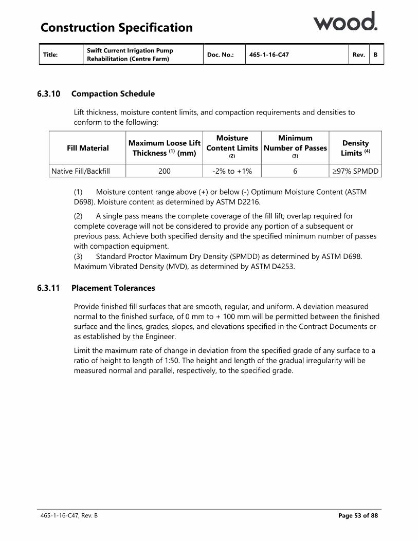
Construction Specification
465-1-16-C47, Rev. B
Page 53 of 88
Compaction Schedule
Lift thickness, moisture content limits, and compaction requirements and densities to
conform to the following:
Fill Material Maximum Loose Lift
Thickness (1) (mm)
Moisture
Content Limits (2)
Minimum
Number of Passes (3)
Density
Limits (4)
Native Fill/Backfill 200 -2% to +1% 6 97% SPMDD
(1) Moisture content range above (+) or below (-) Optimum Moisture Content (ASTM
D698). Moisture content as determined by ASTM D2216.
(2) A single pass means the complete coverage of the fill lift; overlap required for
complete coverage will not be considered to provide any portion of a subsequent or
previous pass. Achieve both specified density and the specified minimum number of passes
with compaction equipment.
(3) Standard Proctor Maximum Dry Density (SPMDD) as determined by ASTM D698.
Maximum Vibrated Density (MVD), as determined by ASTM D4253.
Placement Tolerances
Provide finished fill surfaces that are smooth, regular, and uniform. A deviation measured
normal to the finished surface, of 0 mm to + 100 mm will be permitted between the finished
surface and the lines, grades, slopes, and elevations specified in the Contract Documents or
as established by the Engineer.
Limit the maximum rate of change in deviation from the specified grade of any surface to a
ratio of height to length of 1:50. The height and length of the gradual irregularity will be
measured normal and parallel, respectively, to the specified grade.
Title: Swift Current Irrigation Pump
Rehabilitation (Centre Farm) Doc. No.: 465-1-16-C47 Rev. B

Construction Specification
465-1-16-C47, Rev. B
Page 54 of 88
Title: Swift Current Irrigation Pump
Rehabilitation (Centre Farm) Doc. No.: 465-1-16-C47 Rev. B
7 Site Construction
7.1 Intake Pipe
Materials
Provide 400 mm Diameter IPS DR41 PVC Pipe.
Passive Intake Screen to be provided by AAFC – assume to be Johnson Screens
Passive Intake Screen Model T18FME.
7.2 Inlet PVC Pipe
Delivery, Storage, and Handling
Inspect each shipment of material and timely replace any damaged material.
Unload and handle pipe by hand or using canvas slings to avoid scratching the pipe. Do not
use individual chains or single cables.
When handling pipe avoid impact blows, abrasion damage, and gouging or cutting by
abrasive surfaces or sharp objects. Replace pipe with deep scratches as required by the
Owner.
Excavation and Preparation of the Foundation
Perform as per Section 6.1
Construct pipe bedding as specified in the Contract Documents. Shape the pipe bedding to
conform to the bell joint for uniform support.
Installation
Do not install the pipe when the ambient temperature is below -5°C or above 32°C. Shield
the ends to be joined from direct sunlight prior to and during the laying operation.
Install pipes with joints close and even abutting all around, and without any deflections at
the joints unless specified otherwise.
Install the pipe at the locations, of the sizes, and to the lines, grades, slopes, and elevations
specified in the Contract Drawings. The tolerance from the specified lines, grades, slopes,
and elevations is +/-15 mm. Where departures occur that are within the specified
tolerance, return to the specified lines, grades, slopes, and elevations gradually at a rate of
not more than 5 mm per metre length of pipe. For greater departures, remove and re-
install pipe.
Provide watertight pipe joints, and install the pipes so that they are free of depressions and
are free draining.

Construction Specification
465-1-16-C47, Rev. B
Page 55 of 88
When a laser beam is used to maintain grade, use manual survey methods to check the pipe
invert at several intermediate locations and at the termination points.
7.3 Process Piping
Work Included
Supply, installation and testing of process piping, fittings, and piping supports (other than
concrete supports) for the water discharge system as shown on the drawings.
Related Work
Process Valves and Appurtenances: Section 7.4.
Submissions
Shop Drawings: Where piping locations deviate from those shown in the drawings, shop
drawings for piping systems shall be furnished prior to fabrication. Indicate in orthogonal
and/or isometric drawings as required to furnish the assembly details, the welds, flanges,
valve placement, supports, and the provisions for thrust restraint, as well as any other
pertinent details. The drawings shall be reviewed by the Owner for general compliance with
design intent.
Where specified or when directed by the Owner, provide mill test results or product samples.
Delivery and Storage
Deliver pipe to site using loading methods which do not damage pipe or coatings.
Pipe delivered to site will be clearly identified as to size, type and coatings.
Until ready for incorporation in the Work, store on site as recommended by the pipe
manufacturer to prevent damage, undue stresses, or weathering.
Store pipe at least 200 mm above ground with sufficient supports to prevent undue
bending.
Reference Standards
Refer to CSA and ASTM Standards for various sewer, drainage and water materials.
Title: Swift Current Irrigation Pump
Rehabilitation (Centre Farm) Doc. No.: 465-1-16-C47 Rev. B
Construction Specification
465-1-16-C47, Rev. B
Page 56 of 88
Title: Swift Current Irrigation Pump
Rehabilitation (Centre Farm) Doc. No.: 465-1-16-C47 Rev. B
Pipe Materials
All Pipe materials shall be new, free from defects and shall conform to the reference
standards identified in the detailed pipe specification unless otherwise stated.
Where a material or procedures standard is indicated in the specifications sheets, it is current
at the time of preparation of specifications. Where the standard has been superseded prior
to bidding, the Contractor shall comply with the new standard.
Flanges
Unless otherwise noted, flanges on steel pipe shall be Class 150 or 300, conforming to ANSI
B16.5. Flanges on HDPE pipe shall be Class 125, conforming to ANSI B16.1.
Flanges for mating to equipment or valves shall be compatible with those items.
For steel piping, use only weld neck flanges.
Reducers
Reducers in horizontal lines shall be concentric unless shown otherwise.
Reducers in vertical lines shall be eccentric, with the flat side on the bottom, unless indicated
otherwise.
Provide shop drawings of reducer components, including flanges, at least 20 days prior to
fabrication. Indicate on the shop drawings material specifications, and dimensions.
Gaskets
For flat-faced flanges, use full-face gaskets. For raised-face flanges, use ring-type gaskets.
Conform to ASTM B16.21.
Gasket materials for flanged connections shall be suitable for the temperature, pressure, and
corrosivity of the fluid conveyed in the pipeline. Generally acceptable material selections are
as follows:
Liquid Service: Service temperature less than or equal to 80oC: natural rubber, neoprene, or
SBR.
Minimum Gasket Material Thickness:
1.6 mm thick, pipe diameter 75 mm to 250 mm
3.2 mm thick, pipe diameter 300 mm to 450 mm
6.4 mm thick, pipe diameter 500 mm or greater.
Gaskets for grooved joint couplings shall be as recommended by the manufacturer for the
service conditions indicated.
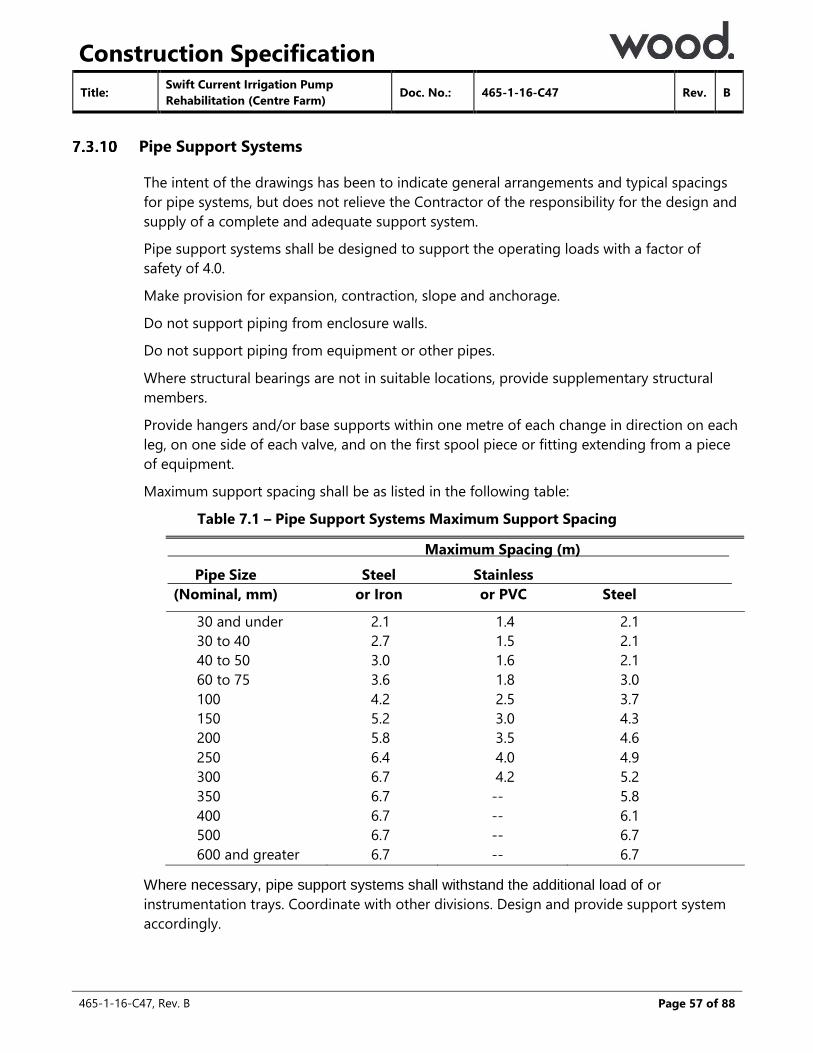
Construction Specification
465-1-16-C47, Rev. B
Page 57 of 88
Title: Swift Current Irrigation Pump
Rehabilitation (Centre Farm) Doc. No.: 465-1-16-C47 Rev. B
Pipe Support Systems
The intent of the drawings has been to indicate general arrangements and typical spacings
for pipe systems, but does not relieve the Contractor of the responsibility for the design and
supply of a complete and adequate support system.
Pipe support systems shall be designed to support the operating loads with a factor of
safety of 4.0.
Make provision for expansion, contraction, slope and anchorage.
Do not support piping from enclosure walls.
Do not support piping from equipment or other pipes.
Where structural bearings are not in suitable locations, provide supplementary structural
members.
Provide hangers and/or base supports within one metre of each change in direction on each
leg, on one side of each valve, and on the first spool piece or fitting extending from a piece
of equipment.
Maximum support spacing shall be as listed in the following table:
Table 7.1 – Pipe Support Systems Maximum Support Spacing
Maximum Spacing (m)
Pipe Size
(Nominal, mm)
Steel
or Iron
Stainless
or PVC
Steel
30 and under 2.1 1.4 2.1
30 to 40 2.7 1.5 2.1
40 to 50 3.0 1.6 2.1
60 to 75 3.6 1.8 3.0
100 4.2 2.5 3.7
150 5.2 3.0 4.3
200 5.8 3.5 4.6
250 6.4 4.0 4.9
300 6.7 4.2 5.2
350 6.7 -- 5.8
400 6.7 -- 6.1
500 6.7 -- 6.7
600 and greater 6.7 -- 6.7
Where necessary, pipe support systems shall withstand the additional load of or
instrumentation trays. Coordinate with other divisions. Design and provide support system
accordingly.

Construction Specification
465-1-16-C47, Rev. B
Page 58 of 88
Title: Swift Current Irrigation Pump
Rehabilitation (Centre Farm) Doc. No.: 465-1-16-C47 Rev. B
Pedestal Pipe Supports
Pedestal pipe supports shall be fitted with manufactured cradles and adjustment bolts, as
indicated in the drawings.
The pipe used for the pedestal shall conform to ASTM A53. The base plate shall be steel to
ASTM A36 (CAN/CSA-G40.21 Grade 300W) - galvanized as noted.
Fittings
Long radius elbows shall be provided as shown on the drawings.
Preparation
Prior to installation, inspect and field measure to ensure that previous work is not prejudicial
to the proper installation of piping.
Make all minor modifications to suit installed equipment and structural element locations
and elevations.
Piping arrangements indicated on the drawings have been established on the basis of the
"Design Standard" listed in the specific process equipment sections. At no expense to the
Owner, modify the piping arrangement as necessary to suit the equipment supplied under
this contract.
Advise the Owner of all minor modifications. Do not commence work on the related piping
until the Owner's acceptance has been received.
Include any piping modifications in the shop drawings submitted prior to fabrication or
installation.
Pipe Handling
Each pipe and fitting shall be inspected prior to installation. Damaged pipe or pipe with
damaged protective coatings shall not be installed.
Remove all foreign matter from inside of pipe prior to installation.
Repair pipe with damaged protective coatings with material similar to the original in
accordance with the manufacturer's directions and to the satisfaction of the Owner.
Use proper implements, tools, and facilities for the proper protection of the pipe. Exercise
care in the installation so as to avoid damage to pipe or coatings.

Construction Specification
465-1-16-C47, Rev. B
Page 59 of 88
Title: Swift Current Irrigation Pump
Rehabilitation (Centre Farm) Doc. No.: 465-1-16-C47 Rev. B
Conflicts
Review the drawings prior to installation of piping, conduit and fixtures. Identify any conflicts
and cooperate with the Owner to determine the amendments necessary to resolve these
conflicts.
Confirm the routing of each section of pipework with the Owner prior to commencement of
installation. Advise the Owner of any conflicts with existing services or services yet to be
installed. Where necessary, amend the routing of pipework to avoid conflict, as instructed
by the Owner. Provide shop drawings showing proposed routing.
Trench Inspection
Inspect the trench for clearance, grade and foundation for pipe. The base of the trench and
the bedding along each length of pipe shall be carefully prepared before the pipe is lowered
in to ensure each pipe is fully supported along its body.
Alignment and Grade
Lay pipes to the alignment and grade shown on the drawings.
Grades shall not deviate from design grades by more than 6 mm plus 10 mm per m of
diameter of the pipe.
The Contractor shall confirm that the bedding is on grade by taking levels 20 meters prior to
lowering in of the pipe.
Bedding and Haunch Material
The bedding material shall be placed in the bottom of the trench at a minimum depth of 100
mm. The top 50 to 75 mm shall be left uncompacted to develop a loose cushion for the
pipe.
The haunch backfill is considered to be the backfill zone from the pipe inverts to 2/3 of the
outside diameter of the pipe. Compact the haunch backfill to 90% standard proctor
maximum dry density. The haunch material shall be brought up evenly either side of the
pipe to give the required support.
Backfilling in the Pipe Zone
Backfill all pipes using Pipe Bedding and Haunch Material compacted to 95% of the
maximum density as determined by the Standard Proctor Compaction Test to 300 mm over
the pipe. The backfill shall be placed the full width of the trench. Do not use frozen
materials.

Construction Specification
465-1-16-C47, Rev. B
Page 60 of 88
Title: Swift Current Irrigation Pump
Rehabilitation (Centre Farm) Doc. No.: 465-1-16-C47 Rev. B
Pipe Laying and Jointing
Lay pipes so that there is a smooth, uniform invert.
Lay pipes so that each pipe is supported uniformly and continuously throughout its length.
Clean pipe ends and make joints in accordance with the manufacturer's recommendations.
Flanged Joints
Flanges and gaskets shall be cleaned prior to connection.
Gaskets shall be lubricated with soapy water and anti-seize compound shall be applied to
the bolts.
Bring flanges into close parallel and lateral alignment.
Bolts shall be tightened progressively. Bolt tightening shall proceed from side to side of the
flange.
Washers may not be used to take up excess bolt length.
Bolt projection beyond nuts shall be approximately two full threads.
When joining steel to cast iron flanges, take care to avoid damage to the cast iron flange.
Ensure both flanges are flat-faced and use full face gaskets.
Align flanges which connect piping to mechanical equipment to close parallel and lateral
alignment prior to tightening bolts. Do not place undue strain on the equipment.
Testing
Not used
Pressure Testing of Liquid Lines
There shall be no visual evidence of leakage.
7.4 Process Valves and Appurtenances
Description
Provide and test valves and appurtenances as indicated and specified.
Provide sizes and capacities as indicated or specified.

Construction Specification
465-1-16-C47, Rev. B
Page 61 of 88
References
American Society of Mechanical Engineers (ASME):
B1.20.7: Hose Coupling Screw Threads.
B16.1: Standard for Cast Iron Pipe Flanges and Flanged Fittings, 125 lb.
B16.4: Cast-Iron Threaded Fittings, Class 125 and 250.
B16.10: Face-to-Face and End-to-End Dimensions of Ferrous Valves.
American Society for Testing and Materials International (ASTM):
A48: Standard Specification for Gray Iron Castings.
A126: Standard Specification for Gray Iron Castings for Valves, Flanges and Pipe Fittings.
A536: Standard Specification for Ductile Iron Castings.
American Water Works Association (AWWA):
C500: Metal-Seated Gate Valves for Water Supply Service.
C504: Rubber-Seated Butterfly Valves.
C509: Standard Specifications for Resilient-Seated Gate Valves for Water and Sewage
Systems.
D102: Coating Steel Water-Storage Tanks.
NSF International (NSF):
61: Drinking water system components Health effects.
Submittals
Submit the following :
Data, regarding valve characteristics and performance including Cv.
Shop drawing data for accessory items.
Manufacturer's literature as needed to supplement certified data.
Operating and maintenance instructions and parts lists.
Listing of reference installations as specified with contact names and telephone
numbers.
Valve shop test results.
List of recommended spare parts other than those specified.
Title: Swift Current Irrigation Pump
Rehabilitation (Centre Farm) Doc. No.: 465-1-16-C47 Rev. B

Construction Specification
465-1-16-C47, Rev. B
Page 62 of 88
Special tools.
Shop and field testing procedures and equipment to be used.
Manufacturer’s product data and specifications for shop painting.
Material Certification:
o Provide certification from the equipment manufacturer that the materials of
construction specified are recommended and suitable for the service
conditions specified and indicated. If materials other than those specified are
proposed based on incompatibility with the service conditions, provide
technical data and certification that the proposed materials are recommended
and suitable for the service conditions specified and indicated including an
installation list of a minimum of five (5) installations in operation for a
minimum of five (5) years. Provide proposed materials at no additional cost
to the Owner.
o Where materials are not specified, provide technical data and certification
that the proposed materials are recommended and suitable for the service
conditions specified and indicated.
Quality Assurance
Field Testing
Make all adjustments necessary to place valves in specified working order at time of above
tests.
Remove all replace valves and appurtenances at no additional cost to the Owner with
equipment that will meet all requirements specified and indicated if unable to demonstrate
to the satisfaction of the Engineer and Owner that valves will perform the service specified,
indicated and as submitted and accepted.
Title: Swift Current Irrigation Pump
Rehabilitation (Centre Farm) Doc. No.: 465-1-16-C47 Rev. B
Construction Specification
465-1-16-C47, Rev. B
Page 63 of 88
Title: Swift Current Irrigation Pump
Rehabilitation (Centre Farm) Doc. No.: 465-1-16-C47 Rev. B
8 Concrete
8.1 Precast Concrete Pump Well & Standard Turnout Structure
References
Provide precast concrete structures in accordance with the following standards (latest
revision) except where specified otherwise.
Saskatchewan Building Code
American Concrete Institute (ACI):
ACI 211.1 Standard Practice for Selecting Proportions for Normal,
Heavyweight, and Mass Concrete.
American Society for Testing and Materials (ASTM):
ASTM A276 Specification for Stainless Steel Bars and Shapes.
ASTM A307 Specifications for Carbon Steel Bolts and Studs.
ASTM C260 Standard Specification for Air-Entraining Admixtures for Concrete.
Canadian General Standards Board (CGSB):
CAN / CGSB-1.181 Ready-Mixed Organic Zinc-Rich Coating.
Canadian Standards Association (CSA)
CAN / CSA-A3000 Cementitious Materials Compendium.
CAN / CSA-A23.1 Concrete Materials and Methods of Concrete Construction.
CAN / CSA-A23.2 Methods of Test for Concrete.
CSA-A23.3 Design of Concrete Structures.
CAN / CSA-A 23.4 Precast Concrete – Materials and Construction.
CSA-G30.5 Welded Steel Wire Fabric for Concrete Reinforcement.
CSA-G30.14 Deformed Steel Wire for Concrete Reinforcement
CSA-G30.15 Welded Deformed Steel Wire Fabric for Concrete
Reinforcement.
CAN / CSA-G30.18 Billet-Steel Bars for Concrete Reinforcement.
CSA-G40.20 General Requirements for Rolled or Welded Structural
Quality Steel.
CSA-G40.21 Structural Quality Steel.
CAN / CSA-G164 Hot-Dip Galvanizing of Irregularly Shaped Articles.

Construction Specification
465-1-16-C47, Rev. B
Page 64 of 88
Title: Swift Current Irrigation Pump
Rehabilitation (Centre Farm) Doc. No.: 465-1-16-C47 Rev. B
Submittals
Provide the following submittals:
Structural design calculations, mix designs, and shop drawings for the precast concrete
structures, stamped and signed by a Professional Engineer, at least 20 days prior to
manufacture.
Certified copies of the results of the tests specified in Section 8.1.3 prior to delivering any
structure to the Site.
Quality Control
During manufacture, perform the following tests in accordance with CAN / CSA-A23.2 for each
day concrete is placed.
Concrete compressive strength tests at 28 days after concrete placement for at least 2
cylinders obtained from a batch of concrete randomly selected from a particular day’s
pour.
Slump tests for the same batch of concrete.
Air content tests for the same batch of concrete.
Delivery, Storage, and Handling
Inspect each shipment of material and timely replace any damaged material.
Handle and transport large precast concrete panels in a vertical position.
Handle all precast concrete elements in accordance with the manufacturer’s instructions,
utilizing the lifting devices and holes provided.
Materials
Provide materials in accordance with the following.
Precast Concrete Structures:
Design precast concrete structures in accordance with CSA-A23.3 and CAN / CSA-
A23.4 to resist the governing combination of loads and other requirements as specified
below:
o Dead load: Due to the self-weight of the structure. Use a minimum load
factor of 1.25, and where required include an impact factor due to handling.
o Earth load: Saturated unit weight of backfill of 21 kN/m3 and a lateral earth
pressure coefficient at-rest of 0.5. Use a minimum load factor of 1.25.
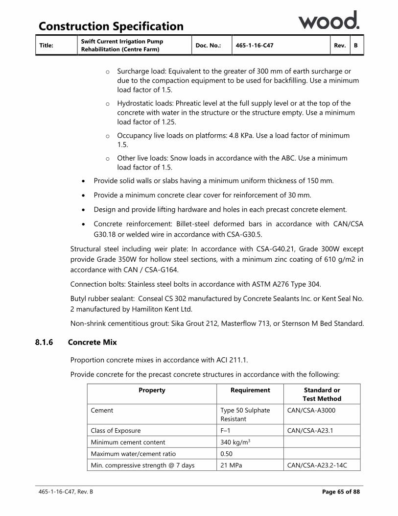
Construction Specification
465-1-16-C47, Rev. B
Page 65 of 88
Title: Swift Current Irrigation Pump
Rehabilitation (Centre Farm) Doc. No.: 465-1-16-C47 Rev. B
o Surcharge load: Equivalent to the greater of 300 mm of earth surcharge or
due to the compaction equipment to be used for backfilling. Use a minimum
load factor of 1.5.
o Hydrostatic loads: Phreatic level at the full supply level or at the top of the
concrete with water in the structure or the structure empty. Use a minimum
load factor of 1.25.
o Occupancy live loads on platforms: 4.8 KPa. Use a load factor of minimum
1.5.
o Other live loads: Snow loads in accordance with the ABC. Use a minimum
load factor of 1.5.
Provide solid walls or slabs having a minimum uniform thickness of 150 mm.
Provide a minimum concrete clear cover for reinforcement of 30 mm.
Design and provide lifting hardware and holes in each precast concrete element.
Concrete reinforcement: Billet-steel deformed bars in accordance with CAN/CSA
G30.18 or welded wire in accordance with CSA-G30.5.
Structural steel including weir plate: In accordance with CSA-G40.21, Grade 300W except
provide Grade 350W for hollow steel sections, with a minimum zinc coating of 610 g/m2 in
accordance with CAN / CSA-G164.
Connection bolts: Stainless steel bolts in accordance with ASTM A276 Type 304.
Butyl rubber sealant: Conseal CS 302 manufactured by Concrete Sealants Inc. or Kent Seal No.
2 manufactured by Hamiliton Kent Ltd.
Non-shrink cementitious grout: Sika Grout 212, Masterflow 713, or Sternson M Bed Standard.
Concrete Mix
Proportion concrete mixes in accordance with ACI 211.1.
Provide concrete for the precast concrete structures in accordance with the following:
Property Requirement Standard or
Test Method
Cement Type 50 Sulphate
Resistant
CAN/CSA-A3000
Class of Exposure F–1 CAN/CSA-A23.1
Minimum cement content 340 kg/m3
Maximum water/cement ratio 0.50
Min. compressive strength @ 7 days 21 MPa CAN/CSA-A23.2-14C
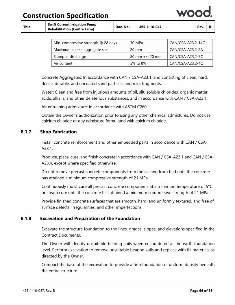
Construction Specification
465-1-16-C47, Rev. B
Page 66 of 88
Title: Swift Current Irrigation Pump
Rehabilitation (Centre Farm) Doc. No.: 465-1-16-C47 Rev. B
Min. compressive strength @ 28 days 30 MPa CAN/CSA-A23.2-14C
Maximum coarse aggregate size 20 mm CAN/CSA-A23.2-2A
Slump at discharge 80 mm +/- 20 mm CAN/CSA-A23.2-5C
Air content 5% to 8% CAN/CSA-A23.2-4C
Concrete Aggregates: In accordance with CAN / CSA-A23.1, and consisting of clean, hard,
dense, durable, and uncoated sand particles and rock fragments.
Water: Clean and free from injurious amounts of oil, silt, soluble chlorides, organic matter,
acids, alkalis, and other deleterious substances, and in accordance with CAN / CSA-A23.1.
Air entraining admixture: In accordance with ASTM C260.
Obtain the Owner’s authorization prior to using any other chemical admixtures. Do not use
calcium chloride or any admixture formulated with calcium chloride.
Shop Fabrication
Install concrete reinforcement and other embedded parts in accordance with CAN / CSA-
A23.1.
Produce, place, cure, and finish concrete in accordance with CAN / CSA-A23.1 and CAN / CSA-
A23.4, except where specified otherwise.
Do not remove precast concrete components from the casting from bed until the concrete
has attained a minimum compressive strength of 21 MPa.
Continuously moist cure all precast concrete components at a minimum temperature of 5°C
or steam cure until the concrete has attained a minimum compressive strength of 21 MPa.
Provide finished concrete surfaces that are smooth, hard, and uniformly textured, and free of
surface defects, irregularities, and other imperfections.
Excavation and Preparation of the Foundation
Excavate the structure foundation to the lines, grades, slopes, and elevations specified in the
Contract Documents.
The Owner will identify unsuitable bearing soils when encountered at the earth foundation
level. Perform excavation to remove unsuitable bearing soils and replace with fill materials as
directed by the Owner.
Compact the base of the excavation to provide a firm foundation of uniform density beneath
the entire structure.
Construction Specification
465-1-16-C47, Rev. B
Page 67 of 88
Title: Swift Current Irrigation Pump
Rehabilitation (Centre Farm) Doc. No.: 465-1-16-C47 Rev. B
Install supplied bedding material as specified in the Contract Documents.
Installation
Install the precast concrete structure at the locations, and to the lines, grades, slopes, and
elevations specified in the Contract Documents. The tolerance from the specified lines, grades,
slopes, and elevations is +/-25 mm.
Assemble the precast concrete structures in accordance with the manufacturer’s written
instructions.
Apply a 25 mm diameter bead of joint sealant between all connecting precast concrete
elements to form a watertight joint. Fill all lifting holes or unused bolt holes with non-shrink
cementitious grout.
Commence backfilling operations only after the Owner has inspected the installation. Rectify
defects, including any identified by the Owner.
Place and compact fill adjacent to the structure as specified in the Contract Documents.
Within 600 mm of the structure, remove stones larger than 80 mm from the fill material. Place
fill in lifts not exceeding 100 mm in thickness, and compact to the specified density using
pneumatic or other mechanical hand tamping equipment.
Compact each lift of fill at the moisture content and to the density specified in Section 6.3 –
Fill Placement.
Clean the structure of any accumulations of soil and debris.
Repair and Replacement of Damaged Concrete
Replace any element that suffers structural damage including cracking or other damage that
in the opinion of the Owner, compromises its strength, performance or durability.
Examine all concrete surfaces and clearly mark out spalled or other areas to be repaired.
Obtain the Owner’s authorization of the delineated repair areas and the proposed method
and equipment to be used for the repairs prior to commencing the work.
Completely remove all damaged concrete down to sound concrete. Remove microfractured
surfaces resulting from the initial concrete removal process.
Sawcut the perimeter perpendicular to the surface to a minimum depth of 25 mm. Do not use
any repair method that produces a featheredge.

Construction Specification
465-1-16-C47, Rev. B
Page 68 of 88
Title: Swift Current Irrigation Pump
Rehabilitation (Centre Farm) Doc. No.: 465-1-16-C47 Rev. B
Prior to placing repair mortar, clean and dampen the surfaces to obtain a saturated surface
dry condition except where the repair technique requires a dry surface.
Place the polymerized cementitious mortar in accordance with the manufacturer’s written
instructions. Treat the surface of the concrete to be repaired with a compatible acrylic bonding
agent as authorized by the Owner prior to mortar filling.
Construct the repair area slightly proud of the general surface and then grind it to match.
Following repairs, promptly initiate curing and protection in accordance with CAN / CSA-
A23.1.
Provide completed repair areas that are tightly bonded to the underlying concrete, and are
free of shrinkage cracks or hollow void areas.

Construction Specification
465-1-16-C47, Rev. B
Page 69 of 88
Title: Swift Current Irrigation Pump
Rehabilitation (Centre Farm) Doc. No.: 465-1-16-C47 Rev. B
9 Concrete
9.1 Cast-in-Place Concrete Foundations
References
Provide cast-in-place concrete work in accordance with the following standards (latest
revision) except where specified otherwise.
American Concrete Institute (ACI).
ACI 211.1 Standard Practice for Selecting Proportions for Normal, Heavyweight,
and Mass Concrete.
ACI 304R Guide for Measuring, Mixing, Transporting, and Placing Concrete.
American Society for Testing and Materials (ASTM).
ASTM C260 Standard Specification for Air-Entraining Admixtures for Concrete.
ASTM C309 Standard Specification for Liquid Membrane-Forming Compounds
for Curing Concrete.
ASTM C494/C494M Standard Specification for Chemical Admixtures for
Concrete.
Canadian Standards Association (CSA).
CAN/CSA-A3000 Cementitious Materials Compendium.
CAN/CSA-A23.1 Concrete Materials and Methods of Concrete Construction.
CAN/CSA-A23.2 Methods of Test for Concrete.
CSA-A23.3 Design of Concrete Structures.
Submittals
Provide the following submittals.
Cementitious Materials:
Details of the source of cement and the manufacturer’s recent test data including
total alkali content expressed as Na2O equivalent, at least 10 days prior to
placement of concrete.
Details of the source of fly ash and the manufacturer’s recent test data including
gradation, loss on ignition, specific gravity, SiO2, Al2O3, Fe2O3 contents, and total
alkali content expressed as Na2O equivalent, at least 10 days prior to placement of
concrete.
Mix Design by the Contractor: Mix designs to be provided at least 10 days prior to placement.

Construction Specification
465-1-16-C47, Rev. B
Page 70 of 88
Title: Swift Current Irrigation Pump
Rehabilitation (Centre Farm) Doc. No.: 465-1-16-C47 Rev. B
Concrete Placement:
Concrete should all be placed prior to cold weather conditions, however if cold
weather conditions are to be incurred provide details of procedures and equipment
for cold weather concreting at least 15 days prior to concrete placement.
Shop Drawings of hoarding structures for “Record Purposes Only” at least 15 days
prior to undertaking such work. Where required by Regulatory Requirements, have
the hoarding structure design Shop Drawings stamped by a Professional Engineer
registered with the Association of Professional Engineers, Geologists and
Geophysicists of Saskatchewan.
Delivery tickets to the Engineer at the point of placement as soon as the batch is
delivered.
Quality Control
Mix Designs and Testing by the Contractor:
Proportion concrete mixes in accordance with ACI 211.1. Select proportions to
provide the necessary placeability, density, strength, durability, and workability,
and to limit the heat generated during hydration. Do not allow the total alkali
content of concrete, determined by multiplying the cement content of the concrete
mix expressed as kg/m3 by the total alkali content of the cement, and from
admixtures to exceed [3] kg/m3.
Where placement by pumping is proposed, obtain a pumpable concrete mix by
using the appropriate gradations of fine and coarse aggregates, admixtures, and
properly sized pumping equipment rather than by increasing the volume of fine
aggregate as compared to an equivalent non-pumped mix proportioned in
accordance with ACI 211.1.
Submit test results for the mix design being proposed for concrete at least 10
days prior to placement of concrete. Test results are to include proportions of
ingredients, slump, unit mass, yield, air content, 7–day and 28–day compressive
strengths, and workability.
Complete Concrete Pour Release Forms specified in clause 1.1 for review by the Engineer.
Obtain the Engineer’s authorization to proceed prior to ordering concrete.
Record the following information on the delivery tickets of each batch of concrete from the
batching plant.
Slip serial number and date.
Class of concrete.

Construction Specification
465-1-16-C47, Rev. B
Page 71 of 88
Title: Swift Current Irrigation Pump
Rehabilitation (Centre Farm) Doc. No.: 465-1-16-C47 Rev. B
Specified 28–day strength.
Type of cement and a list of all admixtures.
Time of loading or first mixing of cement, fly ash, and aggregate.
Time the load arrived at the placement point.
Time the discharge of load was started.
Time the discharge of load was completed.
Concrete temperature during placing.
Quality Assurance
The Owner may also take samples of concrete throughout the work.
Materials
Provide materials in accordance with the following.
Cement: Type 50, Sulphate Resistant Portland Cement, in accordance with CAN/CSA-A3000,
with a total alkali content less than 0.65% (Na2O equivalent).
Fly Ash: Class CI or F fly ash in accordance CAN/CSA-A3000, with a total alkali content less
than 3% (Na2O equivalent) and an oxide (CaO) content less than 8%.
Admixtures:
Provide air-entraining agent, superplasticizer, and water-reducing agent from the
same manufacturer for compatibility. Provide liquid type admixtures. Provide type
WN water reducing agent when required.
Air-entraining admixture: In accordance with ASTM C260.
Chemical admixtures: In accordance with ASTM C494/C494M.
Do not use calcium chloride or any admixture formulated with calcium chloride.
Water: Clean and free from injurious amounts of oil, silt, soluble chlorides, organic matter,
acids, alkalis, and other deleterious substances, and in accordance with CAN/CSA-A23.1.
Obtain permits as required to use water from natural sources.
Aggregates:
Fine aggregates: In accordance with CAN/CSA-A23.1 Section 5 consisting of
clean, hard, dense, durable, uncoated rock fragments. Provide gradation FA1 as
specified in CAN/CSA-A23.1, Table 4.

Construction Specification
465-1-16-C47, Rev. B
Page 72 of 88
Title: Swift Current Irrigation Pump
Rehabilitation (Centre Farm) Doc. No.: 465-1-16-C47 Rev. B
Coarse Aggregates: In accordance with CAN/CSA-A23.1 consisting of natural
gravel, crushed rock, or a combination of both, and to consist of clean, hard, dense,
durable, uncoated rock fragments. [Provide 20-5 nominal size of aggregate as
specified in CAN/CSA-A23.1, Table 5, Group I.] [Provide 40–5 aggregate consisting
of a blend of 20–5 aggregate from Group I and 40–20 aggregate from Group II.]
Wash coarse aggregates during processing and stockpile separately at the batch
plant stockpile areas.
Concrete Mixes
Provide the classes of concrete as follows, at the locations specified in the Contract
Documents.
Class of
Concrete
Specified
Compressive
Strength
(MPa)
Fly Ash by
Mass of
Cementitious
Materials
(%)
Nominal
Size of
Coarse
Aggregate
(mm)
Maximum
Water/
Cementing
Materials
Ratio
Air
Content
(%)
Specified
Slump
(mm)
General
Location
Floor Slab
Concrete
30 @ 28 days [25] [40–5] 0.45 4–7 Max. 80 Between
foundation
soils and
structural
concrete.
Notes: Cementitious materials consist of cement and fly ash.
Concrete Production
Production of concrete and the batch plant to be in accordance with CAN/CSA-A23.1 unless
specified otherwise.
Mixing and Transporting Concrete
Mix and transport concrete in accordance with CAN/CSA-A23.1, clauses 18.3 and 18.4 unless
specified otherwise.
Use mixers capable of producing concrete that is thoroughly mixed, of a uniform mass, and of
discharging the concrete so that the uniformity requirements of CAN/CSA-A23.1, clause 18.3.5
are met. Replace any mixer that does not produce concrete of the specified uniformity.
Provide sufficient numbers of truck mixers and monitor and schedule their departure times
from the batch plant and their arrival times at the point of placement to avoid waiting periods
or delay in arrival. Provide equipment for direct communication between the Contractor’s

Construction Specification
465-1-16-C47, Rev. B
Page 73 of 88
Title: Swift Current Irrigation Pump
Rehabilitation (Centre Farm) Doc. No.: 465-1-16-C47 Rev. B
personnel at the job site and the batching plant during concrete placement.
Concrete Temperature
The permissible concrete temperature at the point of placement is as follows:
Thickness of
Structure Section (m)
Permissible Concrete Temperature at the Point
of Placement (C)
Minimum Maximum
< 0.3 10 30
0.3 to 1 10 30
Do not use concrete that fails to meet the permissible temperatures at the point of placement.
To avoid cracking of the concrete due to sudden temperature change, do not remove weather
protection measures until the concrete has cooled to the temperature differential specified in
CAN/CSA-A23.1, Table 18.
Hot Weather Requirements
Hot weather requirements apply when the air temperature is at or above 25C, or is forecast
to rise to 25C within 24 hours of placement.
Protect formwork, reinforcement, and concrete equipment from the direct rays of the sun, or
cool by fogging and evaporation. Dampen subgrade surfaces prior to concrete placement.
Provide adequate personnel and equipment to transport, place, consolidate, and finish the
concrete at the fastest possible rate. Obtain prior authorization from the Owner for the
proposed equipment and procedures for hot weather concreting.
Provide protection from drying in accordance with CAN/CSA-A23.1, clause 21.2.2.3.
Cold Weather Requirements
Cold weather requirements apply when the air temperature is at or below 5C, or is forecast
to fall below 5C within 24 hours of placing.
When concrete is to be placed in cold weather, have all materials and equipment needed for
adequate protection and curing on hand and ready for use before concrete placement is
started. Obtain prior authorization from the Owner for the proposed enclosures, equipment,
and procedures for cold weather concreting.
Do not place concrete against any surface that has a temperature of less than 5C. Remove all
snow and ice. Preheat such surfaces for 24 hours or as required to obtain surface temperatures
of 5C minimum, whichever is longer, prior to placing concrete.
Design and construct heating and hoarding protection measures including heated enclosures,

Construction Specification
465-1-16-C47, Rev. B
Page 74 of 88
Title: Swift Current Irrigation Pump
Rehabilitation (Centre Farm) Doc. No.: 465-1-16-C47 Rev. B
coverings, insulation, or a suitable combination of these methods in accordance with
CAN/CSA-A23.1, clause 21.2.3.4.
Inspect heating and hoarding measures at least every 4 hours and verify that enclosures,
coverings, and insulation are in place, there is adequate heater fuel, and the specified
temperatures are being maintained.
Provide a sufficient number of adequately sized and properly vented heaters. Do not place
heaters at locations that may cause rapid drying of freshly placed concrete. Use fans to
constantly circulate warm air within the enclosure. Do not use tiger torches or other open
flame burners as heaters.
Placing of Concrete
Place concrete in accordance with CAN/CSA-A23.1, clause 19 unless specified otherwise.
Do not schedule or place concrete during periods that have a high probability of rain or snow.
Provide adequate materials on Site to protect concrete from the harmful effects of rain or
snow during placement.
Convey concrete from the point of supply to its final position as rapidly as practicable, by
methods that will prevent segregation, loss of ingredients, or damage by exposure to the
elements.
Completely discharge and place concrete within the forms no later than 90 minutes after the
cement has been mixed with the water or aggregates. Reduce the time between batching and
complete discharge to 60 minutes when the ambient air temperature exceeds 25C.
Place the concrete in a continuous operation until the unit section is completed. Use a concrete
placing rate that ensures that each layer is placed while the previous layer is soft or plastic; the
two layers become monolithic by penetration of the vibrators; and cold joints are not
produced.
Do not place concrete faster than the rate for which the forms have been designed or at which
the concrete can be properly consolidated. Regulate the deposition of concrete such that it is
properly consolidated in horizontal layers 500 mm in thickness with minimum lateral
movement.
Use placing equipment of such size, design, and condition so as to steadily supply concrete at
the point of placement. Provide equipment that has devices necessary to permit the prompt
and complete discharge of concrete without segregation and with the required slump.
Limit the unrestricted drop of concrete to less than 1500 mm. If the drop of concrete is in
excess of 1500 mm, use chutes or trunks to prevent segregation of the materials.
Maintain all placing equipment free from hardened concrete and foreign materials and clean
such equipment at frequent intervals. Do not use conveying equipment made from aluminum
alloys.

Construction Specification
465-1-16-C47, Rev. B
Page 75 of 88
Title: Swift Current Irrigation Pump
Rehabilitation (Centre Farm) Doc. No.: 465-1-16-C47 Rev. B
If concrete is to be placed at night, supply a lighting system that will illuminate the inside of
the forms, and provide a safe workplace.
Whenever concrete is being placed by pumping, provide a standby concrete pump unit or
other appropriate placement equipment at the Site as authorized by the Engineer.
Consolidating Concrete
Uniformly and thoroughly compact concrete as it is being placed. Use vibrators, of the proper
size, frequency and amplitude, supplemented by hand spading and tamping when required,
to secure a dense, homogeneous concrete, a good bond with the reinforcing steel and
embedded items, and a smooth formed surface free of air pockets and surface blemishes.
Do not use concrete vibrators for moving concrete laterally. Thoroughly and systematically
vibrate concrete in the previously placed layer before placing the overlying layer.
Operate vibrators in a vertical position and allow the vibrating head to penetrate the top
portion of the underlying concrete at a uniform spacing over the entire area of placement.
Maintain the distance between insertions at approximately 12 times the radius of action of the
vibrator so that the area under vibration overlaps the just-vibrated area by several centimetres.
Do not allow segregation of the ingredients or laitance to appear on the surface.
Do not allow vibrators to disturb embedded parts.
Provide spare vibrators at the point of placement to maintain production.
Construction Joints
Prepare construction joints to provide an adequate bond between successive and adjacent
lifts of concrete. Roughen the construction joint interface to an amplitude of 5 mm. Use air-
water cutting, sandblasting, high pressure water jets, or other authorized means to remove all
laitance, unsound mortar, and inferior surface concrete, and to expose clean, sound, fine
aggregate without undercutting the edges of coarse aggregate particles.
Provide a clean concrete joint that is saturated surface dry at the time new concrete is placed
on it.
Dispose of wastewater employed in cutting, washing, and rinsing of concrete surfaces such
that the wastewater does not stain, discolour, or affect exposed surfaces of the structures, or
damage the environment.
Concrete Finishing
Provide a finished surface that is smooth, uniform in texture, and free from streaks,
discoloration, or other imperfections.
Surface Irregularities:
Construction Specification
465-1-16-C47, Rev. B
Page 76 of 88
Title: Swift Current Irrigation Pump
Rehabilitation (Centre Farm) Doc. No.: 465-1-16-C47 Rev. B
Local surface irregularities are classified as “abrupt” or “gradual.”
Abrupt irregularities mean offsets or fins caused by displaced or misplaced form
sheeting, lining, or form sections or by defective form lumber, or improper
screeding or trowelling.
Gradual irregularities mean bulges or depressions resulting in gradual changes in
the concrete surface.
Measuring Surface Irregularities:
Measure irregularities as deviations from a surface, with a 3 m long straightedge
or shaped template authorized by the Minister. Move the position of the
straightedge about the irregularity as necessary to locate the point where the
maximum height and slope exists.
For irregularities protruding above the surface, place 1 end of the straightedge
on top of the irregularity. The height of the irregularity is determined by
measuring the existing gap that is perpendicular to the straightedge. The length
of the irregularity is determined by measuring the distance along the
straightedge from the gap to the point of contact at the top of the irregularity.
The slope of the irregularity is the ratio of the height to length.
For irregularities extending below the surface, place the straightedge across the
irregularity. The height of the irregularity is determined by measuring the gap
between the straightedge and the surface. The length of the irregularity is the
distance along the straightedge from the gap to the point of contact with the
surface. The slope of the irregularity is the ratio of the height to length.
Finishes for Formed Surfaces:
F1:
F3:
o Applies to permanently concealed formed surfaces upon or against which
fill or concrete is to be placed.
o F1 surfaces require no treatment beyond the repair of defective concrete
and dry packing of tie-rod holes. Cut back form ties to a minimum depth
of 25 mm from the concrete surface.
o Applies to permanently exposed formed surfaces and formed surfaces
exposed to water.
o Limit the height of abrupt irregularities to no more than [3 mm]. Limit the
height of gradual irregularities to no more than 6 mm and the ratio of
height to length to no steeper than [1:16].
o Immediately after removing forms, dry pack tie-rod holes and surface voids
in excess of 10 mm diameter. Cut back form ties to a minimum depth of

Construction Specification
465-1-16-C47, Rev. B
Page 77 of 88
Title: Swift Current Irrigation Pump
Rehabilitation (Centre Farm) Doc. No.: 465-1-16-C47 Rev. B
25 mm from the concrete surface. Repair defective and damaged areas.
Finishes for Unformed Surfaces:
U1:
U3:
o Applies to permanently concealed unformed surfaces that will be covered
by fill or concrete. It is also the first stage for a U3 finish.
o Level and screed the concrete surface to produce a uniform surface.
o Applies to permanently exposed unformed surfaces and unformed surfaces
exposed to water.
o Limit the height of abrupt irregularities to no more than [3 mm]. Limit the
height of gradual irregularities to no more than [6 mm] and the ratio of
height to length no steeper than [1:16.]
o Level and screed the concrete surface followed by floating and applying a
steel trowel finish to produce a dense uniform surface, free of blemishes,
ripples, and trowel marks to the required lines, slopes, and elevations.
Curing and Protection
Maintain all material and equipment required for curing and protection on hand at the Site
prior to placing any concrete.
Do not commence curing until after finishing.
Commence curing of exposed surfaces as soon as the concrete has hardened sufficiently to
prevent surface damage.
Continuously moist cure all concrete for a minimum duration of 7 consecutive days at an
ambient temperature maintained above 10C.
Continuously moist cure concrete by covering with absorptive mat or fabric kept wet by using
a system of perforated pipes, mechanical sprinklers, porous hoses, or by other methods that
keep all surfaces continuously wet. Initially cure formed surfaces by leaving forms in position
and keeping such forms continuously wet.
Do not use curing water that is more than 11C cooler than the concrete temperature.
Repair of Concrete
Examine all concrete surfaces and clearly mark out defective areas to be repaired. Obtain the
Engineer’s authorization of the delineated repair areas and the proposed method and
equipment to be used for the repairs prior to commencing with the work.
Completely remove all damaged, deteriorated, loosened, or unbonded concrete down to
Construction Specification
465-1-16-C47, Rev. B
Page 78 of 88
Title: Swift Current Irrigation Pump
Rehabilitation (Centre Farm) Doc. No.: 465-1-16-C47 Rev. B
sound concrete. Remove microfractured surfaces resulting from the initial concrete removal
process.
Sawcut the perimeter of areas requiring concrete removal and replacement perpendicular to
the surface to a minimum depth of 25 mm. Do not use any repair method that produces a
featheredge.
Prior to filling, provide a repair area that is clean and saturated surface dry except where the
repair technique requires a dry surface.
Use dry-pack mortar for filling holes left by the removal of form ties, for narrow grooves cut
for repair of cracks, and for repair of small honeycombed areas where lateral restraint can be
obtained. Pre-soak the repair area, allow the area to attain a saturated surface dry condition,
and apply a cement paste bond coat prior to filling with mortar. Dry-pack mortar is to consist
of 1 part Portland Cement to 2.5 parts sand, by mass.
Mortar filling with a polymerized mortar placed under pressure by use of a mortar gun or head
box may be used for repairing defects that are too wide for dry-pack filling, too shallow for
concrete placement, and no deeper than the far side of the reinforcement that is nearest the
surface. Treat the surface of the concrete to be repaired with a compatible acrylic bonding
agent as authorized by the Engineer prior to mortar filling.
Completely remove honeycombed areas down to sound concrete or to the required depth
behind the reinforcing steel, whichever is greater. The depth required beyond the reinforcing
steel is 1.5 times the maximum aggregate size of the replacement concrete or 25 mm,
whichever is greater. Treat the surface of the concrete to be repaired with a high percentage
solids epoxy bonding agent or acrylic bonding agent as authorized by the Engiener prior to
concrete replacement. Construct the repair area slightly proud of the general surface and then
grind it to match within the specified tolerances.
Provide replacement concrete that has the same strength and durability characteristics as the
adjacent specified concrete. Use cement that provides a finish colour that matches the
surrounding concrete surfaces in areas that are permanently exposed.
Following repairs, promptly initiate curing. Provide completed repair areas that are tightly
bonded to the underlying concrete, and are free of shrinkage cracks or hollow void areas.
Environmental Requirements
Contain all wastewater including that from washing truck mixers. Do not release any
wastewater on site.
Provide disposal bins on site for collecting waste concrete and other test materials. Empty the
bins when required by the Engineer.
Place waste rejected concrete and other waste materials in waste disposal areas on-Site
as authorized by the Engineer or off-Site waste disposal facilities.
Construction Specification
465-1-16-C47, Rev. B
Page 79 of 88
Title: Swift Current Irrigation Pump
Rehabilitation (Centre Farm) Doc. No.: 465-1-16-C47 Rev. B
10 Metal
10.1 Metal Fabrication
References
Provide metal fabrications in accordance with the following standards (latest revision) except
where specified otherwise.
American Society for Testing and Materials (ASTM)
ASTM A53 Specification for Pipe, Steel, Black, and Hot-Dipped, Zinc-Coated
Welded and Seamless.
ASTM A108 Specification for Steel Bars, Carbon, Cold Finished, Standard Quality.
ASTM A276 Specification for Stainless Steel Bars and Shapes.
ASTM A307 Specification for Carbon Steel Bolts and Studs, 60,000 psi Tensile.
ASTM A320 Specification for Alloys, Steel Bolting Materials for Low-Temperature
Service.
ASTM A325M Specification for High-Strength Bolts for Structural Steel Joints
(Metric).
Canadian General Standards Board (CGSB)
CAN/CGSB-1.181 Ready-Mixed Organic Zinc-Rich Coating.
Canadian Standards Association (CSA)
CSA-G40.21 Structural Quality Steel.
CAN/CSA-G164 Hot-Dip Galvanizing of Irregularly Shaped Articles.
CAN/CSA-S16 Limit States Design of Steel Structures.
CSA-W47.1 Certification of Companies for Fusion Welding of Steel Structures.
CSA-W48 Filler Metals and Allied Materials for Metal Arc Welding.
CSA-W59M Welded Steel Construction (Metal Arc Welding) (Metric Version).
Submittals
Provide the following submittals.
Shop drawings at least 20 days prior to fabrication. Indicate material specifications,
dimensions, weights, finishes, welds, and other details.
Details of CSA welding certification of the fabricator at least 20 days prior to fabrication.

Construction Specification
465-1-16-C47, Rev. B
Page 80 of 88
Title: Swift Current Irrigation Pump
Rehabilitation (Centre Farm) Doc. No.: 465-1-16-C47 Rev. B
Delivery, Storage, and Handling
Inspect each shipment of material and timely replace any damaged materials.
Unload, handle, and store materials in accordance with the manufacturer’s written instructions.
Do not damage the metal fabrications or shop-applied coatings. Do not store metal
fabrications in direct contact with the ground.
Materials
Provide materials in accordance with the following.
Steel:
Steel sections and plates: In accordance with CSA-G40.21, Grade 300W.
Hollow structural sections: In accordance with CSA-G40.21, Grade 350W.
Welding materials: In accordance with CSA-W59. Welding electrodes: In
accordance with CSA-W48. Welding electrodes for structural steel: E480XX.
High strength steel bolts: In accordance with ASTM A325M, galvanized finish.
Steel anchor bolts: In accordance with ASTM A307, galvanized finish.
Stainless steel anchor bolts: In accordance with ASTM A276 Type 304.
Stainless steel fasteners: In accordance with ASTM A320, Grade B8 Class 2 AISI 304,
minimum yield strength 690 MPa, 321 HB hardness.
Ladders: Heavy Duty Galvanized Bilco ladder attached to Corrugated Steel pipe
independent of the concrete slab.
Shop Fabrication of Steel Components
Employ a fabricator certified by the Canadian Welding Bureau in accordance with CSA-W47.1,
Division 3, unless specified otherwise.
Fabricate in accordance with CAN/CSA-S16. Perform welding in accordance with CSA-W59
using welding electrodes in accordance with CSA-W48. Control and minimize distortion, and
include stress relief measures to minimize residual stresses.
Do not conduct welding operations when the ambient temperature is below 0°C, or when the
base metal temperature is below 0°C. Preheat and maintain the base metal at a minimum
temperature of 25°C during welding.
Accurately fabricate metal fabrications true to line and free from warps, twists, bends, and
open joints. Reject metal fabrications that have sharp kinks or bends.
Use approved dies or bending rolls for bends. When heating is required, avoid overheating
the metal and use cooling methods that do not alter the original properties of the metal.
Construction Specification
465-1-16-C47, Rev. B
Page 81 of 88
Title: Swift Current Irrigation Pump
Rehabilitation (Centre Farm) Doc. No.: 465-1-16-C47 Rev. B
Do not carry out metal fabrications with welds other than those specified in the Contract
Documents unless authorized by the Minister.
Structural steel may be gas-cut in accordance with the applicable portions of CAN/CSA-S16.
Do not flame-cut any material without the authorization of the Minister.
Provide bolted connections in accordance with the applicable clauses of CAN/CSA-S16.
Provide holes for fasteners that are not more than 2 mm larger than the nominal diameter of
bolts unless otherwise specified in the Contract Documents. Where the thickness of the
material is greater than the nominal diameter of the bolt, sub-punch and ream or sub-drill and
ream, or drill the holes for the fasteners. Poor matching of holes will be cause for rejection of
the item of work.
Hot-dip galvanize metal fabrications, except stainless steel and aluminium items and steel
items completely encased in concrete, in accordance with CAN/CSA-G164. Employ measures
to minimize distortions due to galvanizing. Locate vent holes so they are not readily visible
after the item is installed. Galvanize all items after fabrication, except parts that are bolted
together are to be galvanized before final assembly. Galvanize to provide a zinc coating of not
less than 610 g/m2.
Installation
Do not tack weld to aid fabrication or installation without authorization from the Engineer.
Perform repairs to welds or base metal by grinding or arc-air gouging followed by grinding.
Do not use flame gouging or oxygen gouging.
Shop assemble matching parts of metal fabrications to verify the correctness of fabrication
and matching of component parts. If required by the Minister, assemble the component parts
at the Site prior to installation.
Accurately align and install metalwork true to the lines, grades, slopes, and elevations specified
in the Contract Documents, and obtain proper matching of adjacent surfaces.
Install anchors and anchor bolts such that, after placement of the concrete, their position is
within 3 mm of their specified location, and within 2 mm of their specified location with respect
to other anchors and anchor bolts, which are to be subsequently connected to the same piece
of metalwork. Provide templates for proper location of anchor bolts for equipment.
Repair of Damaged Galvanized Coating
Repair damaged galvanized surfaces with a zinc-rich paint that is in accordance with
CAN/CGSB-1.181.
Construction Specification
465-1-16-C47, Rev. B
Page 82 of 88
Title: Swift Current Irrigation Pump
Rehabilitation (Centre Farm) Doc. No.: 465-1-16-C47 Rev. B
Power tool clean surfaces to be repaired to a bright metal surface. Apply multiple coats of
zinc-rich paint in accordance with the manufacturer’s written instructions to obtain a
minimum dry film thickness of 50 microns or greater where required by the paint
manufacturer.
11 Pre-Fabricated Building
11.1 Building Specification
Scope Of Work
The contractor shall furnish and install one (1) factory built, factory delivered, above ground
prefabricated building.
Design Loads
The prefabricated building is designed to withstand wind load of 5.8 Kilopascals, a roof live
load (snow load) of 1.46 Kilopascals. The enclosure shall be designed in accordance with the
applicable sections of the latest edition of the AISC "Specifications for Structural Steel
Buildings" and the AISI "Specification for Design of Cold Formed Steel Structural Members".
All combining and distributing of auxiliary equipment loads imposed on the equipment
enclosure shall be done in accordance with the applicable section of the MBMA publication
entitled "Low Rise Building Systems Manual".
Dimension Requirements and Other Features
Exterior Dimensions: 12’-0” wide x 12’-0” long x 10’’-0” eave
Gable style roof with a 4:12 slope
Roof should withstand wind load of 5.8 Kilopascals, a roof live load (snow load) of
1.46 Kilopascals
Exterior colour to be determined, for bid purposes assume standard colours
Doors & Windows:
1 - 3’ x 7’ double man door c/w handle (hasp and staple, whitcomb latch, barrel
bolts on active leaf, barrel bolts on inactive leaf, check chains, and weather-
stripping)
1 – 40” x 40” double glazed window c/w half screen and latch
Structural & Painting Requirements
The substructure shall be designed to support the building live and dead loads plus the
burden imposed by loading, transporting and unloading of this equipment. All steel
structural shapes (I-Beams, channels and angles) and plates used in the substructure shall
meet or exceed the requirements of ASTM-A36. All structural rectangular or square tubing

Construction Specification
465-1-16-C47, Rev. B
Page 83 of 88
Title: Swift Current Irrigation Pump
Rehabilitation (Centre Farm) Doc. No.: 465-1-16-C47 Rev. B
shall meet or exceed the requirements for ASTM A-500 Grade B. All welding shall be in
accordance with the Canadian Welder Bureau (CWB) Code.
The base shall be designed with such rigidity that the base, when lifted, will not deflect more
than one inch per 180 inches of length or width. The top of the base shall be flat to within
1/4 of an inch.
Painting:
o Main Skid / All Structural steel
Top and all sides of skid to be painted
Painting as per system:
o SSPC-SP6 surface preparation
o One (1) coat Cloverdale 710 (or equivalent) series primer
o One (1) coat Cloverdale 74 (or equivalent) series industrial
enamel
Provide / capable of supporting the specified electrical
components.,
HVAC/Ventilation Requirements
2 –12” x 12” operable louvers c/w screen and manual wing nut control
1 – 12” explosion-proof or general-purpose exhaust fan c/w hood
120/1/60
1150 CFM per fan
Other Documentation
Building and Skid Drawings – Issued For Construction (IFC) drawings only, to be stamped by
a Professional Engineer, registered to practice in the Province of Saskatchewan.

Construction Specification
465-1-16-C47, Rev. B
Page 84 of 88
Title: Swift Current Irrigation Pump
Rehabilitation (Centre Farm) Doc. No.: 465-1-16-C47 Rev. B
12 Pump Supply & Installation
12.1 Vertical Turbine Pump
Contractor to supply and install a vertical turbine pump (Peerless Pump Model M12LD/LC, 3
stage, rated from 100 to 760 gpm at 90 psi TDH, see attached drawings in Appendix along
with Pump Performance Datasheet) complete with 50 HP, 208 V, 3 phase, 60 Hz VFD- rated
motor as shown in attached drawing LW20006_DWG-01-CW1001.
Alternative vertical turbine pumps of similar dimensions and performance would be
considered, subject to the review and approval of the Engineer.
12.2 Truck Fill Pump
Contractor to install supplied submersible pump (Grundfos Model 62S07-2, see attached
Truck Fill Pump Details) complete with fractional HP motor, 208 V, 3 phase, 60 Hz as shown
in attached drawing LW20006_DWG-01-CW1001.
12.3 Contractor Requirements
Contractor shall provide a list of recommended spare parts for the vertical turbine
pump.
Contractor shall submit drawing red-lines detailing any installation deviations from the
intended design.
Contractor shall complete commissioning and testing of both the vertical turbine pump and
the submersible pump. The Engineer shall be notified of the testing at least 48 hours prior
to the testing.
Construction Specification
465-1-16-C47, Rev. B
Page 85 of 88
Title: Swift Current Irrigation Pump
Rehabilitation (Centre Farm) Doc. No.: 465-1-16-C47 Rev. B
13 Electrical
Contractor to ensure lock-out and complete isolation of electrical power prior to work
starting on removal of existing pumphouse.
Contractor to supply and install grounding as per drawing 245558-0000-DF00-LYD-0001.
Contractor to supply and install electrical equipment as per drawing 245558-0000-DF00-
LYD-0001
Equipment of similar ratings would be considered, subject to the review and approval of the
Engineer.
Note: Recommendation is that the VFD including control cabinet be purchased from a panel
shop and that shop drawings are submitted for review by Engineer. Contractor is also
responsible to provide or facilitate VFD setup and configuration.
Contractor to supply and install all cables, conduits, connectors, etc. for a complete
installation.
Contractor is responsible to ensure electrical installation meets the 2018 Canadian Electrical
code (CSA C22.1-18).
Contractor to bench set pressure switch setpoints, pressure transducer and flow meter
ranges per drawing 245558-0000-DF00-SCH-0001. Any changes must be authorized by the
Engineer in writing prior to startup.
The Engineer shall be notified upon completion of below grade grounding and cabling and
provided photos of the installation at least 48 hours prior to in-fill.
Contractor shall submit drawing red-lines detailing any installation deviations from the
intended design.
Construction Specification
465-1-16-C47, Rev. B
Page 86 of 88
Title: Swift Current Irrigation Pump
Rehabilitation (Centre Farm) Doc. No.: 465-1-16-C47 Rev. B
14 Commissioning
Contractor shall complete pre-commissioning and commissioning of, vertical turbine pump,
truck fill pump and pumphouse building facilities.
Commissioning will have to occur in May of 2022 when water is accessible from the canal.
Electrical Requirements
The Electrical Engineer of Record shall be notified upon substantial completion of
electrical installation and provided photos at least 48 hours prior to energization.
Factory Start-Up Service
Start-up service technician shall be a regular employee of the station manufacturer and one
technician from the electrical equipment supplier.
Start-up service to include one (1) bound O&M manuals and one (1) electronic copy (PDF version)
Start-up service report attested to by start-up technician and representative of Owner or
Engineer.
Service report distributed to:
Manufacturer’s file
Engineer’s file
Contractor’s file
Owner’s file
Field Acceptance Tests
After installation of equipment and after completion of the services of manufacturer's
representative, operate each unit to demonstrate its ability to pump without excessive
vibration, motor overloading, or overheating. Operate each pump for a sufficient period to
permit thorough observation of all pump components. Verify proper sequence and
operation of all controls.
Correct all defects or replace all defective equipment promptly, at no expense to Owner.
Make all final adjustments necessary to place equipment in satisfactory working order at
time of above tests.
After installation, test all piping for tightness under pressure to 1-1/2 times service pressure.
Should leaks be found, repair faulty joints even to extent of disassembling and remaking
joint, and remove and replace all defective pipe and fittings in a manner satisfactory to
Engineer.
Construction Specification
465-1-16-C47, Rev. B
Page 87 of 88
Title: Swift Current Irrigation Pump
Rehabilitation (Centre Farm) Doc. No.: 465-1-16-C47 Rev. B
Conduct Electrical field acceptance tests.
Remove and replace all equipment at no additional cost to the Owner with equipment that
will meet all requirements specified and indicated if unable to demonstrate to the
satisfaction of the Engineer that equipment will perform the service specified, indicated and
as submitted and approved.
15 Operation & Maintenance Manuals
The equipment supplier shall prepare an operation and maintenance manual covering:
Equipment function, normal operating characteristics and limiting conditions.
Assembly, installation, alignment, adjustment and checking instruction.
Operating instructions for start-up, routine and normal operation, regulation
and control, shutdown and emergency conditions.
Lubrication and maintenance instructions.
Guide to "troubleshooting".
Parts lists and predicted life of parts subject to wear.
Outline, cross section and assembly drawings; engineering data; and wiring
diagrams.
Test data and performance curves, where applicable.
The operation and maintenance manuals shall be in addition to any
instructions or parts lists packed with or attached to the equipment when
delivered.
Manuals shall be printed on heavy, first quality paper, 8 1/2 x 11 inch size with standard 3-
hole punching. Drawings and diagrams shall be reduced to 8 1/2 x 11 inches or 11 x 17 inches.
Where reduction is not practical, larger drawings shall be folded separately and placed in
envelopes which are bound into the manuals. Each envelope shall bear suitable identification
on the outside.
One hard copy of each manual, bound in heavy paper covers bearing suitable identification,
shall be submitted to the Engineer prior to the date of shipment of the equipment, One
electronic version (PDF format) also to be provided
Construction Specification
465-1-16-C47, Rev. B
Page 88 of 88
Title: Swift Current Irrigation Pump
Rehabilitation (Centre Farm) Doc. No.: 465-1-16-C47 Rev. B
16 Manufacturer’s Warranty
The warranty is the sole responsibility of the Contractor and that a Contractor’s warranty shall
be provided in written form for inclusion with both the submittal covering the specified
equipment and the O&M manuals provided with that equipment.
Said Contractor warranty shall at a minimum cover:
A period of one (1) year commencing upon successful start-up, after authorized
manufacturer's start-up, not to exceed eighteen (18) months from the date of
shipment.
The warranty period shall be inviolate regardless of any component manufacturer's
warranty for equipment and components within the station.
The Contractor’s warranty shall cover all equipment, components and systems provided in or
with the station by the manufacturer of the station, exclusive of those components supplied
by and/or installed by others independent of the manufacturer of record for this station.
The warranty shall provide for the station manufacturer to bear the full cost of labor and
materials for replacement and/or repair of faulty or defective components so there shall be
no cost incurred by the Owner for this work during the warranty period.
The Contractor’s warranty policy is amended only by the items considered consumables, i.e.,
light bulbs, pump seals, pump packing, lubricants and other maintenance items consumed by
usage.
No assumption of contingent liabilities for any component failure during manufacturer's
warranty is made.
It is the intent of this manufacturer's warranty to gain for the owner a single source
responsible party for all components specified herein. "Second party" or "pass through"
warranties will not be accepted.
If the submitted written manufacturer's warranty does not meet the minimum requirements
set forth above, that submittal will forthrightly be rejected.
END OF DOCUMENT

Peerless Express 20.3.1
General Arrangement Drawing
N/A
N/A 16.5 17.00
17.00 N/A 11.00
6x6x12 G
17.00 1.00
N/A 7.50
11.44
N/A 1.00 12
14.00 Notes
1. Unless otherwise specified, dimensions are in
2. Baseplate requires support on all sides.
3. Read instructions before beginning pump assembly or installation.
4. Drawing is preliminary until certified by factory.
141
APPROXIMATE DRY WEIGHT
Driver 0 lb
Discharge Head 225 lb
Column / Shaft 150 lb / 41 lb
Bowl Assembly 544 lb
Total 960 lb
6.00
147 1.00 N/A
M12LD 3
11.70
51.00
28.60 57.00
3.50 N/A
18.00 6.00
GENERAL DATA
Capacity 760 USgpm Liquid Cold Water
Head 90.00 psi Specific Gravity 1.000 SG
Pump Speed 1775 rpm
DRIVER DATA
MFGR - Shaft Type OLS
Hp 0.0 hp Enclosure / Type WP1
Volt / Ph / Hz 460 / 3 / 0 Hz Frame / Model 0
Service Factor 1.15
Customer Name Mid Continental Pump Supply
Quote No 1157497
Item No. 003
Project Swift Current Feasibility
Date 04 Aug 2020 9:01 PM
1157497-003
MID CONTINENTAL PUMP · 73 AIRPORT RD · WINNIPEG, MB R3H 0V5
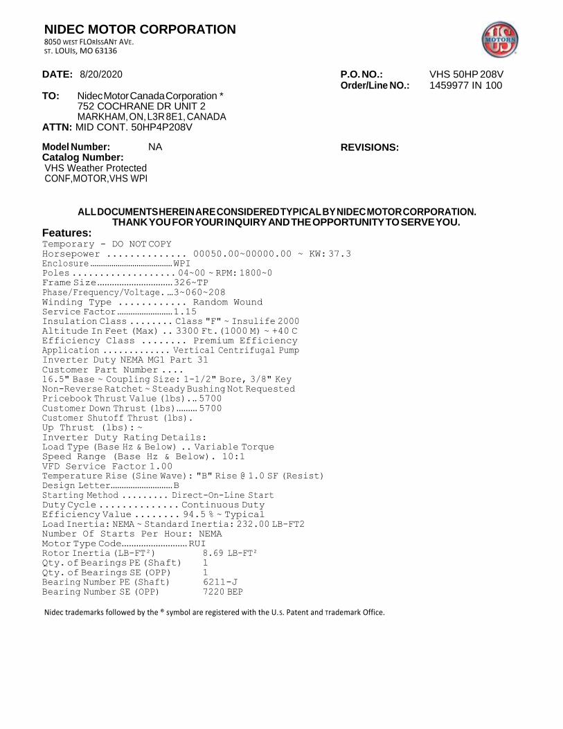
NIDEC MOTOR CORPORATION 8050 WEST FLORISSANT AVE. ST. LOUIS, MO 63136
DATE: 8/20/2020 P.O. NO.: VHS 50HP 208V Order/Line NO.: 1459977 IN 100
TO: Nidec Motor Canada Corporation * 752 COCHRANE DR UNIT 2 MARKHAM, ON, L3R 8E1, CANADA
ATTN: MID CONT. 50HP4P208V
Model Number: NA Catalog Number: VHS Weather Protected CONF,MOTOR,VHS WPI
REVISIONS:
ALL DOCUMENTS HEREIN ARE CONSIDERED TYPICAL BY NIDEC MOTOR CORPORATION. THANK YOU FOR YOUR INQUIRY AND THE OPPORTUNITY TO SERVE YOU.
Features: Temporary - DO NOT COPY
Horsepower .............. 00050.00~00000.00 ~ KW: 37.3 Enclosure ....................................... WPI Poles ................... 04~00 ~ RPM: 1800~0 Frame Size ............................... 326~TP Phase/Frequency/Voltage. ... 3~060~208 Winding Type ............ Random Wound Service Factor ......................... 1.15 Insulation Class ........ Class "F" ~ Insulife 2000 Altitude In Feet (Max) .. 3300 Ft.(1000 M) ~ +40 C Efficiency Class ........ Premium Efficiency Application ............. Vertical Centrifugal Pump Inverter Duty NEMA MG1 Part 31
Customer Part Number .... 16.5" Base ~ Coupling Size: 1-1/2" Bore, 3/8" Key Non-Reverse Ratchet ~ Steady Bushing Not Requested Pricebook Thrust Value (lbs). .. 5700 Customer Down Thrust (lbs) ......... 5700 Customer Shutoff Thrust (lbs). Up Thrust (lbs): ~
Inverter Duty Rating Details: Load Type (Base Hz & Below) .. Variable Torque Speed Range (Base Hz & Below). 10:1
VFD Service Factor 1.00 Temperature Rise (Sine Wave): "B" Rise @ 1.0 SF (Resist) Design Letter ............................ B Starting Method ......... Direct-On-Line Start Duty Cycle .............. Continuous Duty Efficiency Value ........ 94.5 % ~ Typical Load Inertia: NEMA ~ Standard Inertia: 232.00 LB-FT2 Number Of Starts Per Hour: NEMA
Motor Type Code........................... RUI Rotor Inertia (LB-FT²) 8.69 LB-FT² Qty. of Bearings PE (Shaft) 1
Qty. of Bearings SE (OPP) 1 Bearing Number PE (Shaft) 6211-J Bearing Number SE (OPP) 7220 BEP
Nidec trademarks followed by the ® symbol are registered with the U.S. Patent and Trademark Office.
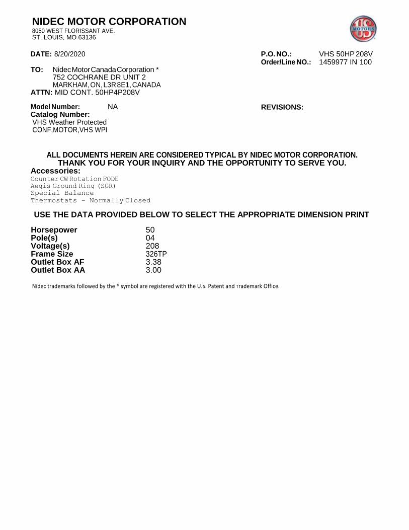
NIDEC MOTOR CORPORATION 8050 WEST FLORISSANT AVE. ST. LOUIS, MO 63136
DATE: 8/20/2020 P.O. NO.: VHS 50HP 208V Order/Line NO.: 1459977 IN 100
TO: Nidec Motor Canada Corporation * 752 COCHRANE DR UNIT 2 MARKHAM, ON, L3R 8E1, CANADA
ATTN: MID CONT. 50HP4P208V
Model Number: NA Catalog Number: VHS Weather Protected CONF,MOTOR,VHS WPI
REVISIONS:
ALL DOCUMENTS HEREIN ARE CONSIDERED TYPICAL BY NIDEC MOTOR CORPORATION. THANK YOU FOR YOUR INQUIRY AND THE OPPORTUNITY TO SERVE YOU.
Accessories: Counter CW Rotation FODE Aegis Ground Ring (SGR) Special Balance
Thermostats - Normally Closed
USE THE DATA PROVIDED BELOW TO SELECT THE APPROPRIATE DIMENSION PRINT
Horsepower 50 Pole(s) 04 Voltage(s) 208 Frame Size 326TP Outlet Box AF 3.38 Outlet Box AA 3.00
Nidec trademarks followed by the ® symbol are registered with the U.S. Patent and Trademark Office.

EFFECTIVE:
20-JUL-11 VERTICAL MOTORS
WEATHER PROTECTED TYPE 1
PRINT:
09-2291
SUPERSEDES:
22-FEB-11 FRAME: 324, 326TP, TPH
BASIC TYPE: RU
SHEET:
1 OF 1
PUMP SHAFT, ADJUSTING NUT AND LOCKING SCREWS ARE NOT FURNISHED WITH MOTOR
AB
AC
EO
AA SIZE
CONDUIT P
XO
AG
CD
AF
BF
BV 4 HOLES
BE AJ
AK
BB BD
ALL DIMENSIONS ARE IN INCHES AND MILLIMETERS
UNITS 2
P AG BE BV CD EO XO
IN 19.06 33.06 .69 11.06 28.22 4.69 21.69
MM 484 840 18 281 717 119 551
FRAME UNITS AJ AK BB
MIN BD
MAX BF
324, 326TP IN 14.750 13.500 .25 16.50 .69
MM 374.65 342.90 6 419 18
324,326TPH IN 9.125 8.250 .19 12.00 .44
MM 231.78 209.55 5 305 11
CONDUIT BOX MATERIAL
UNITS AA AB AC AF
STEEL IN
3.00 15.84 11.56 3.38
MM 402 294 86
CAST IRON IN
3 NPT 16.63 12.25 4.63
MM 422 311 118
1: ALL ROUGH DIMENSIONS MAY VARY BY .25" DUE TO CASTING AND/OR FABRICATION VARIATIONS.
2: LARGEST MOTOR WIDTH. 3: CONDUIT OPENINGS MAY BE LOCATED IN STEPS OF 90 DEGREES REGARDLESS OF LOCATION.
STANDARD AS SHOWN WITH CONDUIT OPENING DOWN.
4: TOLERANCES SHOWN ARE IN INCHES ONLY.
09-2291/C Nidec Motor Corporation St. Louis, Missouri
IHP
_D
P_N
MC
A (
MA
R-2
011)
SO
LID
ED
GE
TOLERANCES 8.250 AK 13.500 AK
FACE RUNOUT .004 T.I.R. .007 T.I.R.
PERMISSIBLE ECCENTRICITY OF MOUNTING RABBET
.004 T.I.R.
.007 T.I.R.
TOLERANCE ON AK DIMENSION +.003 +.005

INFORMATION DISCLOSED ON THIS
DOCUMENT IS CONSIDERED PROPRIETARY
AND SHALL NOT BE REPRODUCED OR
DISCLOSED WITHOUT WRITTEN
CONSENT OF NIDEC MOTOR CORPORATION
ISSUED BY
E. WENDT APPROVED BY
K. POTTER

6211-J - QTY 1
CATALOG NUMBER: NAMEPLATE PART #:
MODEL FR
SHAFT END BRG
TYPE
OPP
END BRG
PH MAX AMB
ID#
INSUL CLASS
Asm. Pos.
DUTY
HP
VOLTS
RPM HP RPM
VOLTS
FL
AMPS
FL AMPS
SF AMPS
SF
DESIGN
CODE
SF AMPS
SF DESIGN CODE
NEMA NOM EFFICIENCY
GUARANTEED EFFICIENCY
NOM PF
MAX KVAR
KiloWatt
HZ
NEMA NOM
EFFICIENCY
GUARANTEED EFFICIENCY
NOM PF
MAX HZ KVAR
HAZARDOUS LOCATION DATA (IF APPLICABLE):
DIVISION CLASS I GROUP I
TEMP CODE CLASS II GROUP II
VFD DATA (IF APPLICABLE):
VOLTS
AMPS
TORQUE 1
VFD LOAD TYPE 1
VFD HERTZ RANGE 1
VFD SPEED RANGE 1
SERVICE FACTOR
TORQUE 2
VFD LOAD TYPE 2
VFD HERTZ RANGE 2
VFD SPEED RANGE 2
FL SLIP
NO. POLES MAGNETIZING AMPS
VECTOR MAX RPM Encoder PPR
Radians / Seconds Encoder Volts
TEAO DATA (IF APPLICABLE):
HP (AIR OVER) HP (AIR OVER
RPM (AIR RPM (AIR OVER
FPM AIR VELOCITY
M/S)
FPM AIR VELOCITY M/S
OVER)
FPM AIR VELOCITY SEC
M/S)
RUI 326TP
40 C (ref: Order#: 1459977, Type: IN, Line#: 100)
CONT
144.0
93.6 60
131.3
208
1.00
1780
50
422707-005
ENCL WPI
7220 BEP - QTY 1
208
125.0
1.15
94.5
B
88.0
F
37.30
147.60LB-FT
VT/PWM
6-60
180-1800

ADDITIONAL NAMEPLATE DATA:
Decal / Plate WD=499495 Customer PN
Notes Non Rev Ratchet NRR
Max Temp Rise 80C RISE/[email protected] OPP/Upper Oil Cap 3 QT/2.8 L
Thermal (WDG) OVER TEMP PROT 2 SHAFT/Lower Oil Cap GREASE
Altitude Usable At
Regulatory Notes Regulatory Compliance
COS Marine Duty
Balance 0.08 IN/SEC Arctic Duty
3/4 Load Eff. 94.7 Inrush Limit
Motor Weight (LBS) 675 Direction of Rotation
Sound Level Special Note 1
Vertical Thrust (LBS) 5700 Special Note 2
Thrust Percentage 100% HT Special Note 3
Bearing Life Special Note 4
Starting Method Special Note 5
Number of Starts Special Note 6
200/208V 60Hz Max Amps SH Max. Temp.
190V 50 hz Max Amps SH Voltage
380V 50 Hz Max Amps SH Watts
NEMA Inertia Load Inertia
Sumpheater Voltage Sumpheater Wattage
Special Accessory Note 1 Special Accessory Note 16
Special Accessory Note 2 Special Accessory Note 17
Special Accessory Note 3 Special Accessory Note 18
Special Accessory Note 4 Special Accessory Note 19
Special Accessory Note 5 Special Accessory Note 20
Special Accessory Note 6 Special Accessory Note 21
Special Accessory Note 7 Special Accessory Note 22
Special Accessory Note 8 Special Accessory Note 23
Special Accessory Note 9 Special Accessory Note 24
Special Accessory Note 10 Special Accessory Note 25
Special Accessory Note 11 Special Accessory Note 26
Special Accessory Note 12 Special Accessory Note 27
Special Accessory Note 13 Special Accessory Note 28
Special Accessory Note 14 Special Accessory Note 29
Special Accessory Note 15 Special Accessory Note 30
Heater in C/B Voltage Heater in C/B Watts
Zone 2 Group Division 2 Service Factor
Note 1 Note 2
Note 3 Note 4
Note 5 Note 6
Note 7 Note 8
NIDEC MOTOR CORPORATION ST. LOUIS, MO
TYPICAL NAMEPLATE DATA ACTUAL MOTOR NAMEPLATE LAYOUT MAY VARY
SOME FIELDS MAY BE OMITTED
Nidec trademarks followed by the ® symbol are registered with the U.S. Patent and Trademark Office.
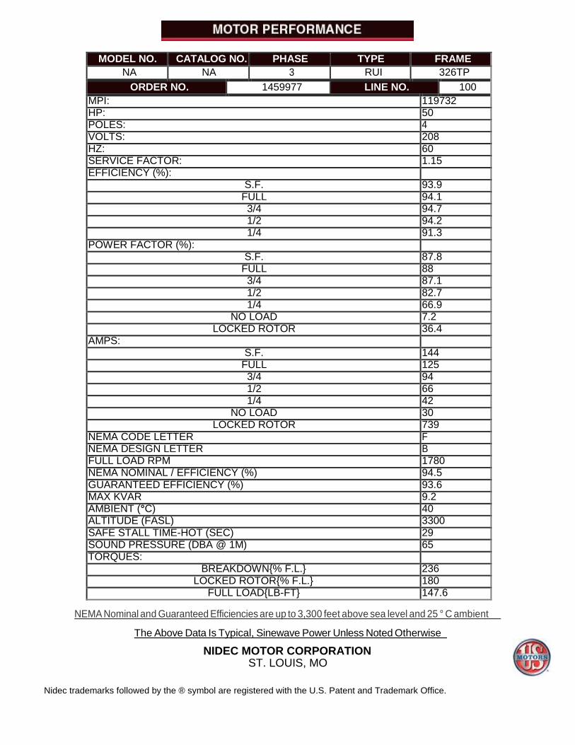
MODEL NO. CATALOG NO. PHASE TYPE FRAME
NA NA 3 RUI 326TP
ORDER NO. 1459977 LINE NO. 100
MPI: 119732 HP: 50 POLES: 4 VOLTS: 208 HZ: 60 SERVICE FACTOR: 1.15 EFFICIENCY (%):
S.F. 93.9 FULL 94.1 3/4 94.7 1/2 94.2 1/4 91.3
POWER FACTOR (%):
S.F. 87.8 FULL 88 3/4 87.1 1/2 82.7 1/4 66.9
NO LOAD 7.2 LOCKED ROTOR 36.4
AMPS:
S.F. 144 FULL 125 3/4 94 1/2 66 1/4 42
NO LOAD 30 LOCKED ROTOR 739
NEMA CODE LETTER F NEMA DESIGN LETTER B FULL LOAD RPM 1780 NEMA NOMINAL / EFFICIENCY (%) 94.5 GUARANTEED EFFICIENCY (%) 93.6 MAX KVAR 9.2 AMBIENT (°C) 40 ALTITUDE (FASL) 3300 SAFE STALL TIME-HOT (SEC) 29 SOUND PRESSURE (DBA @ 1M) 65 TORQUES:
BREAKDOWN{% F.L.} 236 LOCKED ROTOR{% F.L.} 180
FULL LOAD{LB-FT} 147.6
NEMA Nominal and Guaranteed Efficiencies are up to 3,300 feet above sea level and 25 ° C ambient
The Above Data Is Typical, Sinewave Power Unless Noted Otherwise
NIDEC MOTOR CORPORATION ST. LOUIS, MO
Nidec trademarks followed by the ® symbol are registered with the U.S. Patent and Trademark Office.

NIDEC MOTOR CORPORATION ST. LOUIS, MISSOURI
1800 75
S
K
P .
E W
E .
D
1790 60
200
C
U
R
R
E
N
T
160
P
C
T
.
100
Performance vs Horsepower
I E
I N
I F
N P
N F U
.
T
1780 45 120 75
R A
A
P M
N
M P
D S
1770 30 80 50
P
.
F
.
1760 15 40 25
1750 0 0 0
12.50
25.00
HORSEPOWER
37.50
50.00
62.50
08-20-2020
EFFICIENCY
POWER FACTOR
AMPS
INPUT POWER
RPM
50.00 Hp
208 Volts 60 Hz
40º C
MPI = 119732

NIDEC MOTOR CORPORATION ST. LOUIS, MISSOURI
1800 75
S
K
P .
E W
E .
D
1790 60
200
C
U
R
R
E
N
T
160
P
C
T
.
100
Performance vs Torque
I E
I N
I F
N P
N F U
.
T
1780 45 120 75
R A
A
P M
N
M P
D S
1770 30 80 50
P
.
F
.
1760 15 40 25
1750 0 0 0
36.00
72.00
TORQUE IN LB-FT
108.00
144.00
180.00
08-20-2020
EFFICIENCY
POWER FACTOR
AMPS
INPUT POWER
RPM
50.00 Hp
208 Volts 60 Hz
40º C
MPI = 119732

NIDEC MOTOR CORPORATION ST. LOUIS, MISSOURI
950
C
P U
O R
W R
E E
R N
T
1 760
450
T
O
R
Q
U
E
360
Torque, Current, PF vs RPM
F A
C I I
T N N
O
R
0.75 570 270
A F
M T /
P L
S B
0.5 380 180
0.25 190 90
0 0 0
300 600
TORQUE
CURRENT
POWER FACTOR
50.00 Hp
208 Volts 60 Hz
40º C
MPI = 119732

NIDEC MOTOR CORPORATION ST. LOUIS, MISSOURI
900
RPM
1200
1500
1800
08-20-
2020

499495
Motor Wiring Diagram
T1
T3 DELTA T2
Connection
LEAD CONNECTION
1 2 3
Line
Each lead may consist of one or more cables having the
same lead number.
499495
To reverse direction of rotation interchange connections L1 and L2.
Each lead may be comprised of one or more cables.
Each cable will be marked with the appropriate lead number.
EFFECTIVE: 2/27/96 SUPERCEDES: X736618, 96441, 179879, 284138 Connection Plate: 499495
Connection Decal: 912113

THERMOSTATS
1. MOTOR IS EQUIPPED WITH QTY-3 (1 PER PHASE) NORMALLY CLOSED THERMOSTATS. THERMOSTATS ARE SET TO OPEN AT HIGH TEMPERATURE.
2. CONTACT RATINGS FOR THERMOSTATS: 120-600 VAC, 720 VA
N. C. THERMOSTATS
P1
P2
NOTE: THERMOSTATS LEADS MAY BE LOCATED IN EITHER THE MAIN OUTLET BOX OR IF SO
EQUIPPED, AN AUXILIARY BOX.
ACCESSORY LISTING
QTY-3 N.C. THERMOSTATS
NIDEC CONFIDENTIAL
NIDEC MOTOR CORPORATION 24-Feb-11
REVISION DESCRIPTION FOR: MISC SCALE
NONE UNITS
IN TITLE
CUSTOMER CONNECTION DIAGRAM
NIDEC MOTOR
CORPORATION STL0211 - UPDATED FORMAT .
TOLERANCES ON DIMENSIONS (UNLESS OTHERWISE SPECIFIED)
INCHES mm MATERIAL:
--- MUST BE COMPLIANT TO RoHS DIRECTIVE EU 2002/95/IEC AND REGULATION EC 1907/2006 (REACH) AS AMENDED
ISSUED BY
R. KING APPROVED BY
C. CADE REVISION DATE
24-FEB-11 CODE DWG NO.
0834066 REV
G SHEET
NUMBER
1 OF 1
DWG SIZE
A ANGLES X°= ±1°
NMCA (JAN-2011) SOLIDEDGE

FRAMES 324 THRU 447 - OPEN DRIPPROOF MOTORS TYPES: RU, RUE, RUI, RUS, RUSI, RV, RV4, RVE, RVE4, RVI, RVI4, RVS, RVS4
HIGH THRUST - WEATHER PROTECTED TYPE 1 - P BASE HOLLOSHAFT & SOLIDSHAFT MOTORS
WARNING: Any disassembly or repair work on explosionproof motors will void the Underwriters Laboratories, Inc.label unless done by the manufacturer, or a facility approved by the Underwriters Laboratories, Inc.Refer to your nearest sales office for assistance.
BEARINGS: Refer to motor nameplate for the bearing numbers.
PRICES: Parts stocking distributors: refer to renewal parts numerical index.All Others: refer to your nearest parts distributor.
reference: Renewal Parts Section 700, Pages 149 & 150
ITEM NO.
QTY
NAME OF PART
1 1 Canopy Cap
2 3 Hex Head Cap Screws (Canopy Cap)
3 1 Upper Bracket Assembly
4 1 Oil Retaining Tube
5 4 Hex Head Cap Screw & Lockwasher (Bracket to Stator)
6 1 Special Plug
7 1 Reflector Disc
8 2 Gasket - Sight Gauge
9 1 Sight Gauge Window
10 1 Sight Gauge Housing
11 4 Oval Head Screw (Sight Gauge)
12 1 Nipple Fitting (Oil Drain)
13 1 Gasket or "O" Ring
ITEM NO.
QTY
NAME OF PART
14 1 Drain Cap
15 1 Locking Arm
16 1 Hex Head Cap Screw & Lockwasher
17 1 Dust Ring
18 1 Gasket (Dust Ring)
19 3 Hex Head Cap Screw & Lockwasher
20-25 - NOT USED THIS ASSEMBLY
26 1 Coupling (RU & RUE only)
27 1 Gib Key
28 3 Hex Head Cap Screw & Lockwasher (Bearing Mounting)
29 3 Spring Pin
30 1 Locknut / Lockwasher
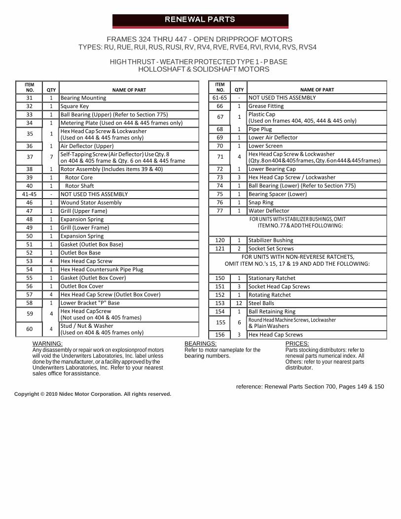
FRAMES 324 THRU 447 - OPEN DRIPPROOF MOTORS TYPES: RU, RUE, RUI, RUS, RUSI, RV, RV4, RVE, RVE4, RVI, RVI4, RVS, RVS4
HIGH THRUST - WEATHER PROTECTED TYPE 1 - P BASE HOLLOSHAFT & SOLIDSHAFT MOTORS
WARNING: Any disassembly or repair work on explosionproof motors will void the Underwriters Laboratories, Inc. label unless done by the manufacturer, or a facility approved by the Underwriters Laboratories, Inc. Refer to your nearest sales office for assistance.
BEARINGS: Refer to motor nameplate for the bearing numbers.
PRICES: Parts stocking distributors: refer to renewal parts numerical index. All Others: refer to your nearest parts distributor.
reference: Renewal Parts Section 700, Pages 149 & 150
Copyright © 2010 Nidec Motor Corporation. All rights reserved.
ITEM NO.
QTY
NAME OF PART
31 1 Bearing Mounting
32 1 Square Key
33 1 Ball Bearing (Upper) (Refer to Section 775)
34 1 Metering Plate (Used on 444 & 445 frames only)
35 1 Hex Head Cap Screw & Lockwasher (Used on 444 & 445 frames only)
36 1 Air Deflector (Upper)
37 7 Self-Tapping Screw (Air Deflector) Use Qty. 8 on 404 & 405 frame & Qty. 6 on 444 & 445 frame
38 1 Rotor Assembly (Includes items 39 & 40)
39 1 Rotor Core
40 1 Rotor Shaft
41-45 - NOT USED THIS ASSEMBLY
46 1 Wound Stator Assembly
47 1 Grill (Upper Fame)
48 1 Expansion Spring
49 1 Grill (Lower Frame)
50 1 Expansion Spring
51 1 Gasket (Outlet Box Base)
52 1 Outlet Box Base
53 4 Hex Head Cap Screw
54 1 Hex Head Countersunk Pipe Plug
55 1 Gasket (Outlet Box Cover)
56 1 Outlet Box Cover
57 4 Hex Head Cap Screw (Outlet Box Cover)
58 1 Lower Bracket "P" Base
59 4 Hex Head Cap Screw (Not used on 404 & 405 frames)
60 4 Stud / Nut & Washer (Used on 404 & 405 frames only)
ITEM NO.
QTY
NAME OF PART
61-65 - NOT USED THIS ASSEMBLY
66 1 Grease Fitting
67 1 Plastic Cap (Used on frames 404, 405, 444 & 445 only)
68 1 Pipe Plug
69 1 Lower Air Deflector
70 1 Lower Screen
71 4 Hex Head Cap Screw & Lockwasher (Qty. 8 on 404 & 405 frames, Qty. 6 on 444 & 445 frames)
72 1 Lower Bearing Cap
73 3 Hex Head Cap Screw / Lockwasher
74 1 Ball Bearing (Lower) (Refer to Section 775)
75 1 Bearing Spacer (Lower)
76 1 Snap Ring
77 1 Water Deflector
FOR UNITS WITH STABILIZER BUSHINGS, OMIT ITEM NO. 77 & ADD THE FOLLOWING:
120 1 Stabilizer Bushing
121 2 Socket Set Screws
FOR UNITS WITH NON-REVERESE RATCHETS, OMIT ITEM NO.'s 15, 17 & 19 AND ADD THE FOLLOWING:
150 1 Stationary Ratchet
151 3 Socket Head Cap Screws
152 1 Rotating Ratchet
153 12 Steel Balls
154 1 Ball Retaining Ring
155 6 Round Head Machine Screws, Lockwasher & Plain Washers
156 3 Hex Head Cap Screws
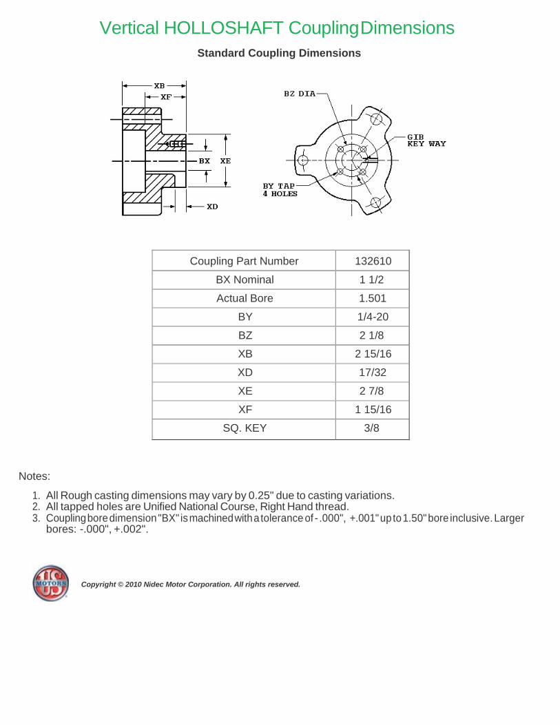
Vertical HOLLOSHAFT Coupling Dimensions
Standard Coupling Dimensions
Coupling Part Number 132610
BX Nominal 1 1/2
Actual Bore 1.501
BY 1/4-20
BZ 2 1/8
XB 2 15/16
XD 17/32
XE 2 7/8
XF 1 15/16
SQ. KEY 3/8
Notes:
1. All Rough casting dimensions may vary by 0.25" due to casting variations. 2. All tapped holes are Unified National Course, Right Hand thread. 3. Coupling bore dimension "BX" is machined with a tolerance of - .000", +.001" up to 1.50" bore inclusive. Larger
bores: -.000", +.002".
Copyright © 2010 Nidec Motor Corporation. All rights reserved.

Note: Motor RCF Test Data can be provided at time of motor shipment through special test. Please contact your Nidec Motor Corporation representative for more information.
MODEL NO: NA
CATALOG NO: NA
Frame: 326TP Type: RUI
REED CRITICAL FREQUENCY: 60 HZ
CENTER OF GRAVITY: 13 IN
DEFLECTION @ CENTER OF GRAVITY: 0.0027 IN
UNIT WEIGHT: 690 LBS
BASE DIAMETER: ALL IN
TOLERANCE ON RCF VALUE: 20%
DATE: 8/20/2020
Copyright © 2010 Nidec Motor Corporation. All rights reserved.

General Information for Integral Horsepower (IHP) Motors
on Variable Frequency Drives (VFDs)
vii www.usmotors.com
Variable Frequency Drives (VFD)
A VFD is a type of controller used to vary the speed of an electric motor.
The VFD takes a fixed AC voltage and frequency and allows it to be adjusted in order to get different speeds from the motor. Motor speed
can be varied by changing the frequency of the input power waveform.
The equation below shows how the frequency affects the speed of a three phase induction motor.
120* Fundamental Input Frequency
• VFD dv/dt - winding end turn differential in voltage
versus differential in time
• High temperatures or high humidity
• Grouding system
Wider speed ranges, higher voltages, higher switching frequencies, insufficient grounding and increased cable lengths all add to the severity
of the application and, therefore, the potential for premature motor
failure.
Speed =
Number of Motor Poles How does a VFD affect the motor? There are many things to consider when a motor is powered using a
How does a VFD work?
A VFD takes the fixed frequency and voltage sine wave from the power
grid or power station and puts it through a few steps in order to allow
the VFD user to vary the frequency and in turn control the motor speed. First it rectifies the AC power into DC Power. Because of this step, a
term commonly used instead of VFD is inverter. This only describes one
step of what the VFD does to the power waveform. Once rectified into
a DC voltage the drive sends the power through a set of transistors or
switches. These switches can take the DC waveform and by opening
and closing at certain speeds and durations can create an output waveform that mimics the sine wave that is required to drive a three
phase electric motor. The output wave form is known as a Pulse Width
Modulation (PWM) waveform because the waveform is created by multiple pulses of the switches at short intervals.
PULSE WIDTH MODULATION WAVEFORM
Line
to Neutral Voltage
Line Current
Figure 1 PWM Waveform
What variables should be considered when deciding whether to power a motor with a VFD?
VFD compatibility with motors is complex. As a result, many variables
must be considered when determining the suitability of a particular motor
for use with a VFD. These variables include:
• Torque requirements (Constant or Variable)
• Speed Range
• Line / System Voltage
• Cable length between the VFD and the motor
• Drive switching (carrier) frequency
• Motor construction
VFD or PWM power. When a motor is powered by a PWM waveform the motor windings very often see a large differential voltage, either from
phase to phase or turn to turn. When the voltage differential becomes
large enough it creates a reaction at the molecular level that converts available oxygen into O3. This phenomenon is called partial discharge or
corona. This reaction creates energy in the form of light and heat. This
energy has a corrosive effect on the varnish used to protect the motor
windings. PWM waveforms can also magnify shaft voltages which lead to arcing across the bearing and causing premature bearing failure.
Corrective action must be taken to mitigate these issues that arise when
using an electric motor with a VFD.
How do I protect the motor?
Nidec Motor Corporation (NMC) has developed specific motor designs
to decrease the harmful affects that a VFD can have on a motor.
NMC’s INVERTER GRADE® insulation system is the first line of defense against corona and phase to phase faults that can be common
when a motor is powered using a PWM waveform. The INVERTER
GRADE® insulation system is standard on all of NMC’s Inverter Duty products. Along with the INVERTER GRADE® insulation, thermostats
are installed as a minimum protection against over heating the motor.
Special consideration must also be given to bearings in motors powered by VFD’s. In order to create a low resistance path to ground for built
up shaft voltages a shaft grounding device can be used. On larger
horsepower motors an insulated bearing system should be used in
conjunction with the shaft grounding device when installed, to force the stray shaft voltages to ground. The bearing failures are more prominent
on motors with thrust handling bearings. NMC has created an Inverter
Duty vertical motor line that not only uses the INVERTER GRADE®
insulation system, but that also comes standard with a shaft grounding device. On motors that are 100 HP and greater the thrust bearing is also
insulated for additional protection.
What does "Inverter Duty" mean?
An Inverter Duty motor should describe a motor that helps mitigate potential failure modes of a motor that is powered by a VFD. Inverter
duty motor windings should be able to withstand the voltage spikes per
NEMA MG1 Part 31.4.4.2 and protect against overheating when the motor is run at slow speeds. On thrust handling bearings it is apparent
that the bearings require additional protection. Inverter Duty vertical
motors should have a shaft grounding device to protect the motor
bearings from fluting due to voltage discharge through the bearing. On larger motors (100HP and larger) the shaft should also be electrically
isolated from the frame in order to aid the shaft grounding ring in
discharging the shaft voltages to ground.

General Information for Integral Horsepower (IHP) Motors
on Variable Frequency Drives (VFDs)
vii www.usmotors.com
*This information applies only to Integral Horsepower (IHP) motors as defined on the Agency Approval page, under UL®† & CSA®† listings where indicated.

Motor / Inverter
Compatibility
www.usmotors.com viii
Thermal Overloads and Single Phase Motors
Motors with thermal overloads installed may not operate properly on a VFD. The current carrying thermal overload is designed for sine wave power. Operation on a VFD may cause nuisance tripping or potentially not protect the motor as would be expected on line power. Thermostats or thermistors installed in the motor and connected properly to the VFD may provide suitable thermal overload protection when operating on a VFD. (consult codes for installation requirements)
Single phase motors and other fractional horsepower ratings are not designed to be operated on a VFD. Within Nidec Motor Corporation standard products, all motors NEMA®† 48 frame (5.5” diameter) and smaller are not suitable for VFD applications. Three phase 56 and 143/145 frame applications should be noted on the catalog price page; or if in doubt ask an Nidec Motor Corporation technical representative for recommendations on compatibility with a VFD.
Slow Speed Motors
Motors with a base design of slower than six poles require special consideration regarding VFD sizing and minimizing harmonic distortion created at the motor terminals due to cable installation characteristics. Additional external PWM waveform filters and shielded motor cables designed for PWM power may be required to provide acceptable motor life. Harmonic distortion on the output waveform should be kept to a minimum level (less than 10%) mismatch impedence.
690V Applications
Motors that are rated for 690VAC and that will be powered by 690VAC PWM VFDs require the use of an external filter to limit peak voltage spikes and the use of an INVERTER GRADE® motor. Where available, an alternative to using an output filter is to upgrade to a 2300V insulation system.
Low Voltage TITAN® Motors
When using 449 frame and larger motors on PWM type VFDs consider the use of an external filter and shielded motor cables designed for PWM power to minimize harmonic distortion and peak voltages at the motor terminals. Harmonic distortion on the output waveform should be kept to a minimum level (less than 10%).
Bearing Currents Related to PWM Waveforms
Protection of the motor bearings from shaft currents caused by common mode voltages is becoming a standard feature on Inverter Duty motor products. Some installations may be prone to a voltage discharge condition through the motor bearings called Electrical Discharge Machining (EDM) or fluting. Vertical HOLLOSHAFT and HOSTILE DUTY World Motor come with grounding devices installed as standard. EDM damage is related to characteristics of the PWM waveform, and the VFD programming, and installations factors.
Bearing Protection on Inverter Duty Vertical Motors All U.S. MOTORS® brand “Inverter Duty” vertical products have a shaft grounding system that allows damaging shaft currents a low resistance path to ground. Bearings on vertical motors fed by VFD power without this bearing protection are not covered under any warranty. All other bearing failure is covered per NMC’s standard warranty. An electric motor repair shop approved to service U.S. MOTORS® brand motors must verify that the cause of the bearing failure was not due to EDM damage.
Multiple Motors on a Single VFD Special considerations are required when multiple motors are powered from a single VFD unit. Most VFD manufacturers can provide guidelines for proper motor thermal considerations and starting/stopping of motors. Cable runs from the VFD and each motor can create conditions that will cause extra stress on the motor winding. Filters may be required at the motor to provide maximum motor life.
Grounding and Cable Installation Guidelines Proper output winding and grounding practices can be instrumental in minimizing motor related failures caused by PWM waveform characteristics and installation factors. VFD manufacturers typically provide detailed guidelines on the proper grounding of the motor to the VFD and output cable routing. Cabling manufacturers provide recommended cable types for PWM installations and critical information concerning output wiring impedance and capacitance to ground.
Vertical Motors on VFDs Vertical motors operated on VFD power present unique conditions that may require consideration by the user or installation engineer:
• Locked rotor and drive tripping caused by non-reversing-ratchet operation at low motor speeds. It is not recommended to operate motors at less than 1/4 of synchronous speed. If slow speeds are required contact NMC engineering.
• Unexpected / unacceptable system vibration and or noise levels caused by the torque pulsation characteristics of the PWM waveform, a system critical frequency falling inside the variable speed range of the process or the added harmonic content of the PWM waveform exciting a system component
• Application related problems related to the controlled acceleration/ deceleration and torque of the motor on VFD power and the building of system pressure/ load.
• The impact the reduction of pump speed has on the down thrust reflected to the pump motor and any minimum thrust requirements of the motor bearings
• Water hammer during shutdown damaging the non-reversing ratchet
Humidity and Non-operational Conditions
The possible build-up of condensation inside the motor due to storage in an uncontrolled environment or non-operational periods in an installation, can lead to an increased rate of premature winding or bearing failures when combined with the stresses associated with PWM waveform characteristics. Moisture and condensation in and on the motor winding over time can provide tracking paths to ground, lower the resistance of the motor winding to ground, and lower the Corona Inception Voltage (CIV) level of the winding.
Proper storage and maintenance guidelines are important to minimize the potential of premature failures. Space heaters or trickle voltage heating methods are the common methods for drying out a winding that has low resistance readings. Damage caused by these factors are not covered by the limited warranty provided for the motor unless appropriate heating methods are properly utilized during non-operational periods and prior to motor start-up.
NEMA®† Application Guide for AC Adjustable Speed Drive Systems: http://www.nema.org/stds/acadjustable.cfm#download
* This information applies only to Integral Horsepower (IHP) motors as defined on the Agency Approval page, under UL®† & CSA®† listings where indicated.

Warranty Guidelines for Integral Horsepower
ix www.usmotors.com
(IHP)* Motors on Variable Frequency Drives
Warranty Guidelines
The information in the following section refers to the motor and drive application guidelines and limitations for warranty.
Hazardous Location Motors
Use of a variable frequency drive with the motors in this catalog, intended for use in hazardous locations, is only approved for Division1, Class I,
Group D hazardous location motors with a T2B temperature code, with a limitation of 2:1 constant torque or 10:1 variable torque output. No other stock hazardous location motors are inherently suitable for operation with a variable frequency drive. If other requirements are needed, including non-listed Division 2, please contact your Nidec Motor Corporation territory manager to conduct an engineering inquiry.
575 Volt Motors
575 volt motors can be applied on Inverters when output filters are used. Contact the drive manufacturer for filter selection and installation requirements.
Applying INVERTER GRADE® Insulated Motors on
Variable Frequency Drives (2, 4, 6 pole)
The products within this catalog labeled “Inverter Duty” or “Vector Duty”
are considered INVERTER GRADE® insulated motors. INVERTER GRADE® motors exceed the NEMA®† MG-1 Part 31 standard. Nidec Motor Corporation provides a three-year limited warranty on all NEMA®† frame INVERTER GRADE® insulated motors and allows long cable runs between the motor and the VFD (limited to 400 feet without output filters). Cable distance can be further limited by hot and humid environments and VFD manufacturers cable limits. These motors may be appropriate for certain severe inverter applications or when the factors relating to the end use application are undefined (such as spares).
Nidec Motor Corporation’s U.S. Motors® brand is available in the following INVERTER GRADE® insulated motors:
• Inverter Duty NEMA®† frame motors good for 20:1 Variable Torque
& 5:1 Constant Torque, including Vertical Type RUSI (10:1 V.T.)
• Inverter Duty motors rated for 20:1 Constant Torque
• ACCU-Torq® and Vector Duty Motors with full torque to 0 Speed or
5000:1
• 841 Plus® NEMA®† Frame Motors
Applying Premium Efficient motors (that do not have INVERTER GRADE® insulation) on Variable Frequency Drives (2, 4, 6 pole)
Premium efficient motors without INVERTER GRADE insulation meet
minimum NEMA®† MG-1, Section IV, Part 31.4.4.2. These motors can be used with Variable Frequency Drives (with a reduced warranty period) under the following parameters:
• On NEMA®† frame 447 and smaller motors, 20:1 speed rating on variable torque loads & 4:1 speed range on constant torque loads.
• On TITAN® 449 and larger frame motors, 10:1 speed rating on variable torque loads.
• On TITAN® frame motors, inquiry required for suitability on constant torque loads.
Cable distances are for reference only and can be further limited by hot and humid environments (refer to Table 1). Refer to specific VFD
Table 1 - Cable Distances
Maximum Cable Distance VFD to Motor
Switching Frequency 460 Volt 230 Volt 380 Volt
3 Khz 127 ft 400 ft 218 ft
6 Khz 90 ft 307 ft 154 ft
9 Khz 73 ft 251 ft 126 ft
12 Khz 64 ft 217 ft 109 ft
15 Khz 57 ft 194 ft 98 ft
20 Khz 49 ft 168 ft 85 ft
manufacturers cable limits. Refer to the Motor/ Inverter Compatibility page for special consideration of vertical motor bearings.
Warranty Period Clarifications and Exceptions
Standard Energy Efficient Exclusion Applying Standard & Energy Efficient Motors on Variable Frequency Drives is not recommended. VFD related failures on standard and energy efficient motors will not be covered under warranty.
Vertical Motor Windings Premium efficient vertical motors without INVERTER GRADE® insulation that are installed using the criteria described in this document and applied in the correct applications shall have a warranty while powered by a VFD for 12 months from date of installation or 18 months from date of manufacturing whichever comes first. See limited warranty page for horizontal motor warranty periods.
Bearing Exclusion for Thrust Handling Bearings Bearings used in premium efficienct vertical motors, and all thrust handling bearings, that are powered by VFDs without shaft grounding devices or insulated bearings (when required) will not be covered under any warranty for damages caused from being powered by a VFD. All other bearing failure is covered per NMC’s standard warranty. An electric motor repair shop approved to service U.S. MOTORS® brand motors must verify that the cause of the bearing failure was not due to Electrical Discharge Machining.
Medium Voltage and Slow Speed Considerations Motors that are rated above 700 VAC or that are eight pole and slower require special consideration and installation and are not covered under the warranty guidelines in this document. Motors that are rated above 700VAC have special cable length and voltage differential issues that are specific
to the VFD type and manufacture. The motor construction and cost may vary dramatically depending on the VFD topology and construction. Contact your NMC representative with VFD manufacturer name and model type for application and motor construction considerations. Motors that are designed eight pole and slower also require special installation and filters per the drive manufacturer.
* This information applies only to Integral Horsepower (IHP) motors as defined on the Agency Approval page, under UL®† & CSA®† listings where indicated.

Peerless Express 20.2.4
MID CONTINENTAL PUMP · 73 AIRPORT RD · WINNIPEG, MB R3H 0V5
Hea
d -
psi
NP
SH
r -
ft
Po
wer
- h
p
Pump Performance Datasheet Customer : Mid Continental Pump Supply
Customer ref. / PO :
Tag Number 003
Service :
Quantity 1
Quote Number / ID : 20-396
Peerless Model : M12LD/LC
Stages 3
Based on curve number : M12LDLC-4605509
Date last saved : 04 Aug 2020 8:53 PM
Operating Conditions Liquid
Flow, rated : 760 USgpm
Differential head / pressure, rated (requested) : 90.00 psi
Differential head / pressure, rated (actual) : 90.51 psi
Suction pressure, rated / max : 0.00 / 0.00 psi.g
NPSH available, rated : Ample
Site Supply Frequency : 60 Hz
Liquid type : Cold Water
Additional liquid description :
Solids diameter, max : 0.00 in
Solids concentration, by volume : 0.00 %
Temperature, max : 68.00 deg F
Fluid density, rated / max : 1.000 / 1.000 SG
Viscosity, rated : 1.00 cP
Vapor pressure, rated : 0.34 psi.a Performance
Speed, rated : 1775 rpm
Impeller diameter, rated : 9.72 / 8.94 in
Impeller diameter, maximum : 9.72 / 8.94 in
Impeller diameter, minimum : 8.91 / 7.88 in
Efficiency (bowl / pump) : 83.05 / 81.94 %
NPSH required / margin required : 7.4 / 0.0 ft
Ns (imp. eye flow) / Nss (imp. eye flow) : 1,940 / 11,206 US Units
MCSF : 150 USgpm
Head, maximum, rated diameter : 136.3 psi
Head rise to shutoff (bowl / pump) : 47.41 / 48.34 %
Flow, best eff. point (bowl / pump) : 739 / 734 USgpm
Flow ratio, rated / BEP (bowl / pump) : 102.85 / 103.55 %
Diameter ratio (rated / max) : 100.00 %
Head ratio (rated dia / max dia) : 99.45 %
Cq/Ch/Ce/Cn [ANSI/HI 9.6.7-2010] : 1.00 / 1.00 / 1.00 / 1.00
Selection status : Acceptable
Material
Material selected : Material Group, Standard
Pressure Data
Maximum working pressure : See the Additional Data page
Maximum allowable working pressure : See the Additional Data page
Maximum allowable suction pressure : N/A
Hydrostatic test pressure : See the Additional Data page
Driver & Power Data (@Max density)
Motor sizing specification : Rated power (based on duty
point)
Margin over specification : 0.00 %
Service factor : 1.15 (used)
Power, hydraulic : 41.0 hp
Power (bowl / pump) : 49.4 / 49.7 hp
Max power (non-overloading) : 54.9 hp
Nameplate motor rating : 50.0 hp / 37.3 kW
Pump performance. Adjusted for construction, viscosity, static lift to discharge nozzle centerline, friction and power losses of lineshaft and thrust bearings.
The duty point represents the head at the discharge nozzle centerline.
Performance based on test acceptance - Hyd Ins 14.6 Bilateral (2B)
Performance curve represents typical performance. When tested, only the design flow and head are guaranteed. Contact factory for additional requirements. 80
60
40 Power
20
0
150
135
120
105
90
75
60
45
30
15
0
60
NPSHr
30
0 0 100 200 300 400 500 600 700 800 900 1,000 1,100 1,200 1,300 1,400
Flow - USgpm
9.72 / 8.9 36
4 in 52 6 5
7 4 80
8.91 / 7.8 8 in 82 82 80
74
6 5
52
36

Peerless Express 20.2.4
MID CONTINENTAL PUMP · 73 AIRPORT RD · WINNIPEG, MB R3H 0V5
Hea
d -
psi
NP
SH
r -
ft
Po
wer
- h
p
Pump Performance Curve
Pump performance. Adjusted for construction, viscosity, static lift to discharge nozzle centerline, friction and power losses of lineshaft and thrust bearings.
The duty point represents the head at the discharge nozzle centerline.
Performance based on test acceptance - Hyd Ins 14.6 Bilateral (2B)
Performance curve represents typical performance. When tested, only the design flow and head are guaranteed. Contact factory for additional requirements. 80
60
Power 40
20
0
150
135
36
120 9.72 / 8.94 in 52
65
74
105 80
8.91 / 7.88 in 82 82
90 80
75 74
60 65
45 52
30
36 15
0
60
NPSHr
30
0
0 100 200 300 400 500 600 700 800 900 1,000 1,100 1,200 1,300 1,400
Flow - USgpm
Customer : Mid Continental Pump Supply
Customer ref. / PO :
Tag Number 003
Service :
Quantity 1
Quote Number / ID : 20-396
Date last saved : 04 Aug 2020 8:53 PM
Peerless Model : M12LD/LC
Stages 3
Speed, rated : 1775 rpm
Based on curve number : M12LDLC-4605509
Efficiency (bowl / pump) : 83.05 / 81.94 %
Power (bowl / pump) : 49.4 / 49.7 hp
NPSH required : 7.4 ft
Flow, rated : 760 USgpm
Differential head / : 90.00 psi
pressure, rated
Fluid density, rated / max : 1.000 / 1.000 SG
Viscosity : 1.00 cP
Cq/Ch/Ce/Cn [ANSI/HI 9.6.7-2010] : 1.00 / 1.00 / 1.00 / 1.00
Flow
(USgpm)
Head
(psi)
Efficiency
(%)
Power
(hp)
NPSHr
(ft)
Thrust, total
(lbf)
0
140
279
419
559
699
838
978
1,118
1,258
136.3
129.4
122.7
115.6
107.3
97.45
85.49
71.19
54.40
35.08
0.00
28.81
51.54
68.06
78.44
82.88
81.76
75.62
65.14
51.20
35.0
36.6
38.8
41.5
44.6
47.9
51.1
53.7
54.5
50.3
-
-
4.2
5.1
5.3
6.3
9.5
16.1
27.2
43.7
3,278
2,922
2,560
2,256
2,004
1,769
1,512
1,216
896
577
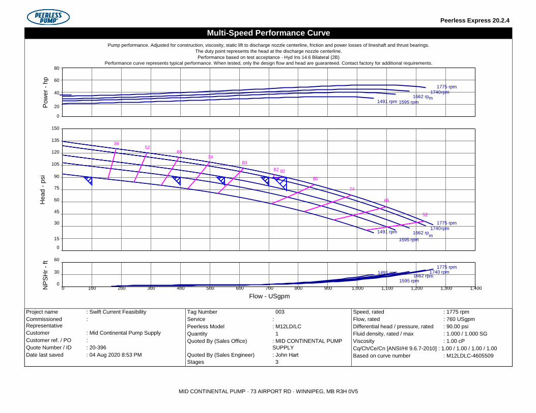
Head -
psi
NP
SH
r -
ft
Pow
er
- h
p
Peerless Express 20.2.4
Multi-Speed Performance Curve
Pump performance. Adjusted for construction, viscosity, static lift to discharge nozzle centerline, friction and power losses of lineshaft and thrust bearings.
The duty point represents the head at the discharge nozzle centerline.
Performance based on test acceptance - Hyd Ins 14.6 Bilateral (2B)
Performance curve represents typical performance. When tested, only the design flow and head are guaranteed. Contact factory for additional requirements. 80
60
1775 rpm
40 1662 rp
1740 rpm
1491 rpm 1595 rpm m
20
0
150
135
36
52 120 65
74
105 80 82 82
90 80
75 74
60 65
45 52
30 1775 rpm
1491 rpm 1662 rp 1740 rpm
15 1595 rpm m
0
60
1775 rpm 30 1491 rpm
1662 rp1740 rpm m
0 1595 rpm
0 100 200 300 400 500 600 700 800 900 1,000 1,100 1,200 1,300 1,400
Flow - USgpm
Project name : Swift Current Feasibility
Commissioned :
Representative
Customer : Mid Continental Pump Supply
Customer ref. / PO :
Quote Number / ID : 20-396
Date last saved : 04 Aug 2020 8:53 PM
Tag Number 003
Service :
Peerless Model : M12LD/LC
Quantity 1
Quoted By (Sales Office) : MID CONTINENTAL PUMP
SUPPLY
Quoted By (Sales Engineer) : John Hart
Stages 3
Speed, rated : 1775 rpm
Flow, rated : 760 USgpm
Differential head / pressure, rated : 90.00 psi
Fluid density, rated / max : 1.000 / 1.000 SG
Viscosity : 1.00 cP
Cq/Ch/Ce/Cn [ANSI/HI 9.6.7-2010] : 1.00 / 1.00 / 1.00 / 1.00
Based on curve number : M12LDLC-4605509
MID CONTINENTAL PUMP · 73 AIRPORT RD · WINNIPEG, MB R3H 0V5

Count Description
1 62S07-2
Company name: Mid Continental Pump Supply
Created by: John Hart
Phone: 2047838619
Email: [email protected]
Date: 5/4/2020
Product No.: On request
Multi-stage submersible pump for raw water supply,
groundwater lowering and pressure boosting. The
pump is suitable for pumping clean, thin, non-agressive
liquids without solid particles or fibers.
The pump is made entirely of Stainless steel
DIN W.-Nr. EN 1.4301 and suitable for
horizontal and vertical installation.
The pump is fitted with a built-in non-return valve.
The motor is a 3-phase motor of the canned
type with a sand shield, liquid-lubricated bearings
and pressure-equalizing diaphragm.
Liquid:
Pumped liquid: Water
Maximum liquid temperature: 104 °F
Selected liquid temperature: 68 °F
Density: 62.29 lb/ft³
Kinematic viscosity: 1 cSt
Technical:
Pump speed on which pump data is based: 3450 rpm
Actual calculated flow: 76.8 US gpm
Resulting head of the pump: 26.24 ft
Shaft seal for motor: LIPSEAL
Approvals on nameplate: CE,EAC,CSACOMP,UR
Curve tolerance: ISO9906:2012 3B
Motor version: T40
Materials:
Pump: Stainless steel
EN 1.4301
AISI 304
Impeller: Stainless steel
EN 1.4301
AISI 304
Motor: Stainless steel
DIN W.-Nr. 1.4301
AISI 304
Installation:
Maximum ambient pressure: 217.56 psi
Pump outlet: 2"NPT
Motor diameter: 4 inch
Electrical data:
Motor type: MS402
Rated power - P2: 0.75 HP
Main frequency: 60 Hz
Rated voltage: 3 x 460 V
Service factor: 1.50
Rated current: 2.3 A

Starting current: 460 %

Count Description
Cos phi - power factor: 0.70
Rated speed: 3450 rpm
Enclosure class (IEC 34-5): IP68
Insulation class (IEC 85): B
Built-in temperature transmitter: No
Motor Number: 96465639
Others:
ErP status: EuP Standalone/Prod.
Net weight: 26.7 lb
Gross weight: 30.4 lb
Shipping volume: 0.57 ft³
Country of origin: US
Company name: Mid Continental Pump Supply
Created by: John Hart
Phone: 2047838619
Email: [email protected]
Date: 5/4/2020
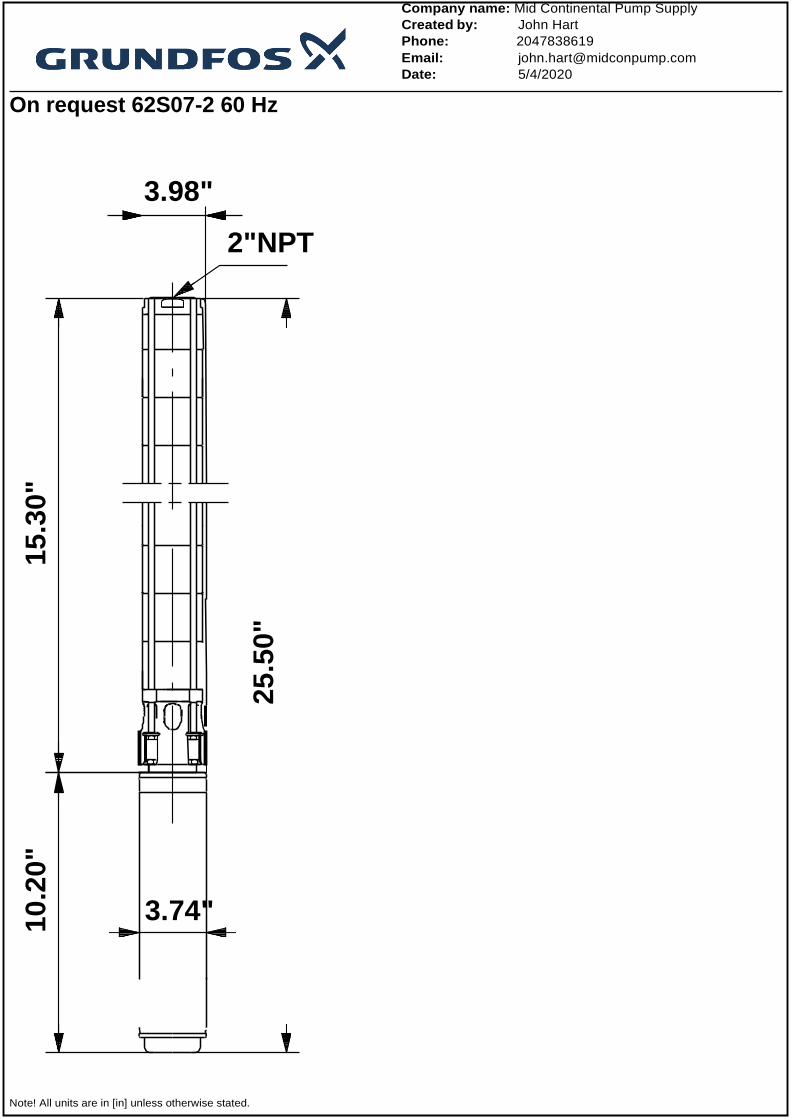
On request 62S07-2 60 Hz
Company name: Mid Continental Pump Supply
Created by: John Hart
Phone: 2047838619
Email: [email protected]
Date: 5/4/2020
3.98"
Note! All units are in [in] unless otherwise stated.
2"NPT
3.74" 10
.20"
15
.30"
25
.50"

Disclaimer: This simplified dimensional drawing does not show all details.