Technical Publications Direction 2366845 - GE Healthcare
61
GE Medical Systems Technical Publications Direction 2366845 Revision 2.1 MR VECTRA CONFORMANCE STATEMENT FOR DICOM (ID/NET v3.0) -MRVectra Series, Vectra Series, Sierra (4.10-4.13) Copyrights 2003 By General Electric Co.
-
Upload
khangminh22 -
Category
Documents
-
view
3 -
download
0
Transcript of Technical Publications Direction 2366845 - GE Healthcare

GE Medical Systems
Technical Publications
Direction 2366845 Revision 2.1
MR VECTRA CONFORMANCE STATEMENT FOR DICOM (ID/NET v3.0)
-MRVectra Series, Vectra Series, Sierra (4.10-4.13)
Copyrights 2003 By General Electric Co.

___________________________________________________________________________GE Medical System

LEGAL NOTES TRADEMARKS
All products and all their name brands are trademarks of their respective holders.
OMISSIONS & ERRORS
Customers, please contact your GE Sales or Service representatives.
GE personnel, please use the GEMS CQA Process to report all omissions, errors, and defects
in this publication.
Copyrights
All Material Copyrighted© 2003 by General Electric Company, All rights reserved.
WARNING
• THIS SERVICE MANUAL IS AVAILABLE IN ENGLISH ONLY.
• IF A CUSTOMER’S SERVICE PROVIDER REQUIRES A LANGUAGE
OTHER THAN ENGLISH, IT IS THE CUSTOMER’S RESPONSIBILITY TO
PROVIDE TRANSLATION SERVICES.
• DO NOT ATTEMPT TO SERVICE THE EQUIPMENT UNLESS THE
SERVICE MANUAL HAS BEEN CONSULTED AND UNDERSTOOD.
• FAILURE TO HEED THIS WARNING MAY RESULT IN INJURY TO THE
SERVICE PROVIDER, OPERATOR OR PATIENT FROM ELECTRIC
SHOCK, MECHANICAL OR OTHER HAZARDS.

GE Medical Systems MR VECTRA CONFORMANCE STATEMENT REV 2.1 DIRECTION 2366845
REVISION HISTORY
REV DATE REASON FOR CHANGE 1.0 Oct. 28,1994 Initial release. 2.0 June 19,1995 Add Query/Retrieve Service Class. 2.1 Dec. 12,2002 Eliminate the descriptions for Screen Save Image.
LIST OF EFFECTIVE PAGES
SECTION NUMBER SECTION NUMBER Title Page 2.1
Revision History I 2.1
Revision History II 1.0
Table of Contents i 1.0
Table of Contents ii 2.0
Introduction 1-1 2.0
Introduction 1-2 thru 1-6 1.0
Conformance Statement 2-1 thru 2-4, 2-6 2.0
Conformance Statement 2-5, 2-7, 2-8 1.0
MR Vectra Information Object Definition 3-1 thru 3-20 1.0
MR Vectra Secondary Capture Image Information Object Definition 4-1 thru 4-12 2.1
MR Vectra Query/Retrieve Information Model Definition 5-1 thru 5-5 2.0
doc ver 2.1 II

GE Medical Systems MR VECTRA CONFORMANCE STATEMENT REV 2.1 DIRECTION 2366845
THIS PAGE LEFT INTENTIONALLY BLANK
doc ver 2.1 III

GE Medical Systems MR VECTRA CONFORMANCE STATEMENT REV 2.1 DIRECTION 2366845
TABLE OF CONTENTS
SECTION 1 - INTRODUCTION 1-1 1.0 OVERVIEW 1-1 1.1 OVERALL CONFORMANCE STATEMENT DOCUMENTATION STRUCTURE 1-2 1.2 INTENDED AUDIENCE 1-4 1.3 SCOPE AND FIELD OF APPLICATION 1-4 1.4 IMPORTANT REMARKS 1-5 1.5 REFERENCES 1-6 1.6 DEFINITIONS 1-6 1.7 SYMBOLS AND ABBREVIATIONS 1-6 1.8 CONVENTIONS 1-6
SECTION A (2) - CONFORMANCE STATEMENT 2-1 A.0 INTRODUCTION 2-1 A.1 IMPLEMENTATION MODEL 2-1
A.1.1 Application Data Flow Diagram 2-1 A.1.2 Functional Definition of AE's 2-2 A.1.3 Sequencing of Real-World Activities 2-2
A.2 AE SPECIFICATIONS 2-3 A.2.1 AE1 Specification 2-3
A.2.1.1 Association Establishment Policies 2-4 A.2.1.2 Association Initiation by Real-World Activity 2-5
A.3 COMMUNICATION PROFILES 2-7 A.3.1 Supported Communication Stacks (parts 8,9) 2-7 A.3.2 OSI Stack 2-7
A.3.2.1 International Standardized Profile (ISP) 2-7 A.3.2.2 API (Application Programming Interface) 2-7 A.3.2.3 Physical Media Support 2-7
A.3.3 TCP/IP Stack 2-7 A.3.3.1 API 2-7 A.3.3.2 Physical Media Support 2-7
A.3.4 Point-to-Point Stack 2-7 A.4 EXTENSIONS / SPECIALIZATIONS / PRIVATIZATIONS 2-8
A.4.1 Standard Extended/Specialized/Private SOP's 2-8 A.5 CONFIGURATION 2-8
A.5.1 AE Title/Presentation Address Mapping 2-8 A.5.2 Configurable Parameters 2-8
A.6 SUPPORT OF EXTENDED CHARACTER SETS 2-8
doc ver 2.1 i

GE Medical Systems MR VECTRA CONFORMANCE STATEMENT REV 2.1 DIRECTION 2366845
TABLE OF CONTENTS (continued)
SECTION 3 - MR VECTRA INFORMATION OBJECT DEFINITION 3-1 3.0 MR IMAGE INTEROPERABILITY SCHEMA 3-2 3.1 ENTITY DESCRIPTIONS 3-3
3.1.1 Series Entity 3-3 3.1.2 Frame Of Reference Entity 3-3
3.2 ENTITY MODULE TABLE 3-4 3.3 ENTITY MODULE LIBRARY 3-5
3.3.1 Patient Entity Module 3-5 3.3.2 Study Entity Modules 3-6 3.3.3 Series Entity Module 3-8 3.3.4 Frame Of Reference Entity Module 3-9 3.3.5 Equipment Entity Module 3-10 3.3.6 Image Entity Modules 3-11
SECTION 4 - MR VECTRA SECONDARY CAPTURE IMAGE INFORMATION OBJECT DEFINITION 4-1
4.0 SC IMAGE INTEROPERABILITY SCHEMA 4-2 4.1 ENTITY DESCRIPTIONS 4-3 4.2 ENTITY MODULE TABLE 4-4 4.3 ENTITY MODULE LIBRARY 4-5
4.3.1 Equipment Entity Module 4-5 4.3.2 Image Entity Modules 4-6
SECTION 5 - MR VECTRA QUERY/RETRIEVE INFORMATION MODEL DEFINITION 5-1
5.0 INTEROPERABILITY SCHEMA 5-1 5.1 ENTITY DESCRIPTIONS 5-2 5.2 STUDY LEVEL 5-3
5.2.1 Study Level Keys for the Study Root Query/Retrieve Information Model 5-3
5.3 SERIES LEVEL 5-4 5.3.1 Series Level Keys for the Study Root Query/Retrieve Information Model 5-4
5.4 IMAGE LEVEL 5-5 5.4.1 Image Level Keys for the Study Root Query/Retrieve Information Model 5-5
doc ver 2.1 ii

GE Medical Systems MR VECTRA CONFORMANCE STATEMENT REV 2.1 DIRECTION 2366845
SECTION 1 - INTRODUCTION
1.0 OVERVIEW This DICOM Conformance Statement is divided into Sections as described below:
Section 1, Introduction, provides general information about the content and scope of this document.
Section A (2), Conformance Statement, is the DICOM Conformance Statement related to this product. Conformance Statements define the subset of options selected from those offered by the DICOM standard.
Section 3, MR Vectra Information Object Definition, and Section 4, Secondary Capture Image Information Object Definition, define the technical specifications required to interoperate with a GE Medical Systems (GEMS) ID/Net v3.0 network interface. They define the technical details of the Information Object Definitions (IOD's) listed in the Conformance Statement.
Section 5, MR Vectra Query/Retrieve Information Model Definition, defines the information required to interoperate using the DICOM Query/Retrieve models.
doc ver 2.1 1-1

GE Medical Systems MR VECTRA CONFORMANCE STATEMENT REV 2.1 DIRECTION 2366845
1.1 OVERALL CONFORMANCE STATEMENT DOCUMENTATION STRUCTURE
The Documentation Structure of the ID/Net v3.0 Conformance Statements and their relationship with the DICOM Conformance Statements is shown in Illustration 1-1.
ILLUSTRATION 1-1 DOCUMENTATION STRUCTURE
doc ver 2.1 1-2
DICOM Part 4
DICOM Part 3
DICOM Part 2
DICOM STANDARD
DICOM Part 1
DICOM Part 16
PRODUCT IMPLEMENTATION:
STANDARD SPECIFICATION:
Introduction tothe Integrated
DICOM/Networkv3.0
(ID/Net v3.0)Conformance
StatementDirection:2118780
CT9800DICOM v3.0(ID/Net v3.0)Direction:
269546G5
(services classes, Information objects, exchange, etc.)
APPLICATION ENTITY SPECIFICATION
..............
CT AdvantageConformance Statement forDICOM v3 0 (ID/Net v3 0)
Direction:2118781
ID/NET V3.0
MR VectraConformanceStatement forDICOM v3.0(ID/Net v3.0)
Direction:2366845

GE Medical Systems MR VECTRA CONFORMANCE STATEMENT REV 2.1 DIRECTION 2366845
The Documentation Structure given in Illustration 1-1 shows the overall documentation structure for all of the GEMS ID/Net v3.0 Conformance Statements. ID/Net v2.0 documentation is also openly available, but the two documentation structures are independent of one another.
This document specifies the DICOM implementation. It is entitled:
MR Vectra Conformance Statement for DICOM (ID/Net v3.0) Direction 2366845.
This Conformance Statement documents the DICOM Conformance Statement and Technical Specification required to interoperate with the GEMS ID/Net v3.0 network interface. Introductory information, which is applicable to all GEMS ID/Net v3.0 Conformance Statements, is described in the document:
Introduction to the Integrated DICOM/Network (ID/Net v3.0) Conformance Statement Direction: 2118780.
This Introduction familiarizes the reader with DICOM terminology and general concepts. It should be read prior to reading the individual products' ID/Net v3.0 Conformance Statements.
The ID/Net v3.0 Conformance Statement, contained in this document, also specifies the Lower Layer communications that it supports (e.g., TCP/IP, OSI, etc.). However, the Technical Specifications are defined in the DICOM Part 8 standard.
For more information including Network Architecture and basic DICOM concepts, please refer to the Introduction.
For the convenience of software developers, there is "collector" Direction available. By ordering the collector, the Introduction described above and all of the currently published ID/Net v3.0 Product Conformance Statements will be received. The collector Direction is:
ID/Net v3.0 Conformance Statements Direction: 2117016
For more information regarding DICOM, copies of the Standard may be obtained on the Internet at http://medical.nema.org. Comments on the standard may be addressed to :
DICOM Secretariat NEMA 1300 N. 17th Street, Suite 1847 Rosslyn, VA 22209 USA Phone: +1.703.841.3200
doc ver 2.1 1-3

GE Medical Systems MR VECTRA CONFORMANCE STATEMENT REV 2.1 DIRECTION 2366845
1.2 INTENDED AUDIENCE The reader of this document is concerned with software design and/or system integration issues. It is assumed that the reader of this document is familiar with the DICOM Standards and with the terminology and concepts that are used in those Standards.
If readers are unfamiliar with DICOM terminology they should first refer to the document listed below, then read the DICOM Standard itself, prior to reading this Conformance Statement document. Introduction to the Integrated DICOM/Network (ID/Net v3.0) Conformance Statement Direction: 2118780
1.3 SCOPE AND FIELD OF APPLICATION It is the intent of this document, in conjunction with the Introduction to the Integrated DICOM/Network (ID/Net v3.0) Conformance Statement, Direction: 2118780, to provide an unambiguous specification for GEMS ID/Net v3.0 implementations. This specification, called a Conformance Statement (previously an Implementation Profile), includes a DICOM Conformance Statement and is necessary to ensure proper processing and interpretation of GEMS medical image data exchanged using DICOM. The GEMS ID/Net v3.0 Conformance Statements are available to the public.
The reader of this Conformance Statement should be aware that different GEMS devices are capable of using different Information Object Definitions. For example, a GEMS CT Scanner may send images using the CT Information Object, MR Information Object, Secondary Capture Object, etc.
Included in the Technical Specification of this Conformance Statement are the Module Definitions that define all data elements used by this GEMS ID/Net v3.0 implementation. If the user encounters unspecified private data elements while parsing a GEMS Data Set, the user is well advised to ignore those data elements (per the DICOM standard). Unspecified private data element information is subject to change without notice. If, however, the device is acting as a "full fidelity storage device", it should retain and retransmit all of the private data elements that are sent by GEMS devices.
doc ver 2.1 1-4

GE Medical Systems MR VECTRA CONFORMANCE STATEMENT REV 2.1 DIRECTION 2366845
1.4 IMPORTANT REMARKS The use of these Conformance Statements, in conjunction with the DICOM Standards, is intended to facilitate communication with GE imaging equipment. However, by itself, it is not sufficient to ensure that inter-operation will be successful. The user (or user's agent) needs to proceed with caution and address at least four issues:
Integration - The integration of any device into an overall system of interconnected devices goes beyond the scope of standards (DICOM), and of this introduction and associated Conformance Statements when interoperability with non-GE equipment is desired. The responsibility to analyze the applications requirements and to design a solution that integrates GE imaging equipment with non-GE systems is the user's responsibility and should not be underestimated. The user is strongly advised to ensure that such an integration analysis is correctly performed.
•
•
•
•
Validation - Testing the complete range of possible interactions between any GE device and non-GE devices, before the connection is declared operational, should not be overlooked. Therefore, the user should ensure that any non-GE provider accepts full responsibility for all validation required for their connection with GE devices. This includes the accuracy of the image data once it has crossed the interface between the GE imaging equipment and the non-GE device and the stability of the image data for the intended applications. Such a validation is required before any clinical use (diagnosis and/or treatment) is performed. It applies when images acquired on GE imaging equipment are processed/displayed on a non-GE device, as well as when images acquired on non-GE equipment are processed/displayed on a GE console or workstation.
Future Evolution - GE understands that the DICOM Standard will evolve to meet the user's growing requirements. GE is actively involved in the development of the DICOM Standard. DICOM will incorporate new features and technologies and GE may follow the evolution of the Standard. ID/Net v3.0 is based on DICOM as specified in each ID/Net DICOM Conformance Statement. Evolution of the Standard may require changes to devices that have implemented DICOM. In addition, GE reserves the right to discontinue or make changes to the support of communications features (on its products) reflected on by these ID/Net DICOM Conformance Statements. The user should ensure that any non-GE provider, which connects with GE devices, also plans for the future evolution of the DICOM Standard. Failure to do so will likely result in the loss of function and/or connectivity as the DICOM Standard changes and GE Products are enhanced to support these changes.
Interaction - It is the sole responsibility of the non-GE provider to ensure that communication with the interfaced equipment does not cause degradation of GE imaging equipment performance and/or function.
doc ver 2.1 1-5

GE Medical Systems MR VECTRA CONFORMANCE STATEMENT REV 2.1 DIRECTION 2366845
1.5 REFERENCES A list of references which is applicable to all ID/Net v3.0 Conformance Statements is included in the Introduction to the Integrated DICOM/Network (ID/Net v3.0) Conformance Statement, Direction: 2118780.
1.6 DEFINITIONS A set of definitions which is applicable to all ID/Net v3.0 Conformance Statements is included in the Introduction to the Integrated DICOM/Network (ID/Net v3.0) Conformance Statement, Direction: 2118780.
1.7 SYMBOLS AND ABBREVIATIONS A list of symbols and abbreviations which is applicable to all ID/Net v3.0 Conformance Statements is included in the Introduction to the Integrated DICOM/Network (ID/Net v3.0) Conformance Statement, Direction: 2118780.
1.8 CONVENTIONS Please refer to DICOM Standard Part 3 (Information Object Definitions) for the Attribute Type Definitions that are used in the Module Descriptions found in sections 3 and 4 of this conformance statement.
doc ver 2.1 1-6
GE Medical Systems MR VECTRA CONFORMANCE STATEMENT REV 2.1 DIRECTION 2366845
SECTION A - CONFORMANCE STATEMENT
A.0 INTRODUCTION This Conformance Statement (CS) specifies the GE MR Vectra scanner compliance to DICOM. It details the DICOM Service Classes and roles that are supported by this product. Other sections of this document describe the Information Object data elements that are used by this implementation. Note that the format of this section strictly follows the format of DICOM Standard Part2(Conformance) Appendix A. Please refer to that part of the standard while reading this section.
A.1 IMPLEMENTATION MODEL
A.1.1 Application Data Flow Diagram The Basic and Specific Application models for this device are shown in Ill. 2-1 .
ILLUSTRATION 2-1 SPECIFIC AE APPLICATION MODEL
MANUAL TRANSMIT
AUTOTRANSFER
REMOTE STORAGE SCP
E-Link AE
ASSOCIATIONINITIATION
DICOM INTERFACESTANDARD
REMOTE QUERY/RETRIEVE
SCU
doc ver 2.1 2-1
GE Medical Systems MR VECTRA CONFORMANCE STATEMENT REV 2.1 DIRECTION 2366845
The E-Link Application Entity (AE) is an application that handles all DICOM protocol communications. E-Link AE is automatically brought up when an Operator's Console (OC) or Diagnostic Console (DC3) is powered on.
All remote DICOM AE's must be manually configured on the OC/DC3, usually at software installation time, by a GEMS Field Engineer.
There are two local real world activities, Manual Transmit (MT), and Auto Transfer (AUT), which can cause the E-Link AE to initiate a DICOM association to store an image.
MT consists of an operator selecting a Study, Series, or an Image from the Network screen of the console User Interface and choosing to send that image(s) to a selected destination.
If AUT is enabled, after the technologist prescribes a scan and begins acquiring the images, the OC will automatically (without operator intervention) initiate a DICOM association after every image is completed, and send the image to a preset destination.
There is no local real world event required for the E-Link AE to respond to a DICOM Query. The E-Link AE is always prepared to respond to a DICOM query by any remote DICOM AE that has been configured on the GEMS system. E-Link can then send (STORE) image(s) to the remote entity if requested by a retrieve (MOVE) request.
A.1.2 Functional Definition of AE's Application Entity 1, E-Link
Supports the following functions:
Has access to patient demographics and pixel data in the local database •
•
•
•
Manually (MT) or automatically (AUT) initiates a DICOM association to send images
Responds to DICOM associations containing a query request using the information in the console's local database
Moves images to any configured remote DICOM AE when requested to do so by the remote querying device
doc ver 2.1 2-2

GE Medical Systems MR VECTRA CONFORMANCE STATEMENT REV 2.1 DIRECTION 2366845
A.1.3 Sequencing of Real-World Activities Image Send:
The E-Link AE will initiate a DICOM association •
•
•
•
•
The AE will select the appropriate Abstract and Transfer Syntaxes from those accepted by the remote AE.
The AE will use the C-STORE command to send the image.
Query/Retrieve:
The E-Link AE will respond to a DICOM association initiation and accept only the Abstract and Transfer syntaxes specified in this document.
At some later point, the E-Link AE will respond to a C-MOVE request and send the image(s) to a specified remote AE when (if) requested to do so.
A.2 AE SPECIFICATIONS
A.2.1 AE1 Specification This Application Entity provides Standard Conformance to the following DICOM SOP Classes as an SCU:
SOP Class Name SOP Class UID
CT Image Information Object Storage SC 1.2.840.10008.5.1.4.1.1.2 MR Image Information Object Storage SC 1.2.840.10008.5.1.4.1.1.4 SC Image Information Object Storage SC 1.2.840.10008.5.1.4.1.1.7
This Application Entity provides Standard Conformance to the following DICOM SOP classes as an SCP:
SOP Class Name SOP Class UID
Verification (Echo) SC 1.2.840.10008.1.1 Study Root Query/Retrieve Info. model - FIND 1.2.840.10008.5.1.4.1.2.2.1 Study Root Query/Retrieve Info. model - MOVE 1.2.840.10008.5.1.4.1.2.2.2
doc ver 2.1 2-3
GE Medical Systems MR VECTRA CONFORMANCE STATEMENT REV 2.1 DIRECTION 2366845
A.2.1.1 Association Establishment Policies
A.2.1.1.1 General The DICOM Application Context Name (ACN), which is always proposed, is:
DICOM Application Context Name 1.2.840.10008.3.1.1.1
The Maximum Length PDU negotiation is included in all association establishment requests. The maximum length PDU for an association initiated by the E-Link AE is:
Maximum Length PDU 4 Kbytes
The SOP class Extended Negotiation is not supported.
The maximum number of Presentation Contexts Items that will be proposed is 3.
The user info items sent by this product are:
Maximum PDU Length and, •
• Implementation UID
A.2.1.1.2 Number of Associations The E-Link AE will initiate only one DICOM association to perform an image store at a time.
A.2.1.1.3 Asynchronous Nature Asynchronous mode is not supported. All operations will be performed synchronously.
A.2.1.1.4 Implementation Identifying Information The Implementation UID allows unique identification of a set of products that share the same implementation.
The Implementation UID for this ID/Net v3.0 Implementation is:
Storage & Q/R Implementation UID 1.2.840.113619.6.3
This Implementation UID applies only to those ID/Net v3.0 Implementations that are available on GE Vectra Consoles.
The Implementation UID is sent in the Implementation Class UID Sub-Item. The Implementation Class UID Sub-Item is defined in Annex D of DICOM Part 7: Message Exchange.
doc ver 2.1 2-4

GE Medical Systems MR VECTRA CONFORMANCE STATEMENT REV 2.1 DIRECTION 2366845
A.2.1.2 Association Initiation by Real-World Activity This AE attempts to initiate a new association due to two Real-World Activities:
A. "Manual Transmit" initiated by the operator, and
B. "Auto Transfer" where the image is sent to a single preset destination after image reconstruction with no operator intervention (this includes localizer, prospective, and retrospective image types).
A.2.1.2.1 Real-World Activity A, and B Although there are two different real world activities that can begin an image storage process, the DICOM association initiation and transfer process is identical.
A.2.1.2.1.1 Associated Real-World Activity Upon request, either manual or automatic, an image and/or overlay plane will be sent to a DICOM Storage SCP.
A.2.1.2.1.2 Proposed Presentation Contexts
Presentation Context Table - Proposed Abstract Syntax Transfer Syntax Role Expanded
Name UID Name List UID List Negotiation CT Image Info Obj.
1.2.840.10008.5.1.4.1.1.2 Little Endian Big Endian
1.2.840.10008.1.2 1.2.840.10008.1.2.2
SCU None
MR Image Info Obj.
1.2.840.10008.5.1.4.1.1.4 Little Endian Big Endian
1.2.840.10008.1.2 1.2.840.10008.1.2.2
SCU None
Secondary Capture Info Obj.
1.2.840.10008.5.1.4.1.1.7 Little Endian Big Endian
1.2.840.10008.1.2 1.2.840.10008.1.2.2
SCU None
A software implementer should be aware that E-Link may package multiple Presentation Data Values (PDV's) into a single Protocol Data Unit (PDU) as stated in the DICOM Standard Part 8, Appendix E.
A.2.1.2.1.2.1 SOP Specific Conformance Statement for Image Storage SOP Classes
This implementation can perform one C-STORE operation over a single association.
Each C-STORE operation supports a "Per Image" Store Timeout. This timeout starts once a C-STORE request has been issued and stops once a C-STORE confirmation has been received. This timeout is 90 seconds.
doc ver 2.1 2-5

GE Medical Systems MR VECTRA CONFORMANCE STATEMENT REV 2.1 DIRECTION 2366845
A.2.1.2.2 Association Acceptance Policy
A.2.1.2.2.1 Real-World Activity This AE accepts associations for the Query/Retrieve (Q/R) SC using the Study Root Query Model.
A.2.1.2.2.1.1 Associated Real-World Activity This AE is indefinitely listening for Q/R associations.
A.2.1.2.2.1.2 Accepted Presentation Context Table
Presentation Context Table - Accepted Abstract Syntax Transfer Syntax Role Expanded
Name UID Name List UID List Negotiation Study Root Query/Retrieve Info. model - FIND
1.2.840.10008.5.1.4.1.2.2.1 Implicit VR Little Endian
1.2.840.10008.1.2 SCP None
Study Root Query/Retrieve Info. model - MOVE
1.2.840.10008.5.1.4.1.2.2.2 Implicit VR Little Endian
1.2.840.10008.1.2 SCP None
Verification SCP 1.2.840.10008.1.1 Implicit VR Little Endian
1.2.840.10008.1.2 SCP None
A.2.1.2.2.1.2.1 SOP Specific Conformance for Query/Retrieve FIND SOP Class SCP The C-FIND response status values are supported as defined in DICOM Part 4.
All Required (R) and Unique (U) Study, Series, and Image Level Keys for the Study Root Query/Retrieve Information Model are supported. Some Optional (O) Keys are also supported, as described later in this document (see section 5).
A.2.1.2.2.1.2.2 SOP Specific Conformance for Query/Retrieve MOVE SOP Class SCP Prioritizations of C-FIND & C-MOVE requests are all set to normal.
All images requested in the C-MOVE will be sent over a single association (the association will not be established and torn down for each image).
A.2.1.2.2.1.3 Presentation Context Acceptance Criterion No criterion.
A.2.1.2.2.1.4 Transfer Syntax Selection Policies Storage SCU supports Explicit VR Big Endian and Implicit VR Little Endian, and priority for Explicit VR Big Endian is higher. Verification SCP and Query/Retrieve SCP supports only Implicit VR Little Endian.
doc ver 2.1 2-6

GE Medical Systems MR VECTRA CONFORMANCE STATEMENT REV 2.1 DIRECTION 2366845
A.3 COMMUNICATION PROFILES
A.3.1 Supported Communication Stacks (parts 8,9) DICOM Upper Layer (Part 8) is supported using TCP/IP over Ethernet v2.0.
A.3.2 OSI Stack OSI stack not supported.
A.3.2.1 International Standardized Profile (ISP) ISP not supported.
A.3.2.2 API (Application Programming Interface) Not applicable to this product.
A.3.2.3 Physical Media Support There are no physical media dependencies beyond ethernet v2.0 requirements.
A.3.3 TCP/IP Stack The TCP/IP stack is inherited from a UNIX Operating System.
A.3.3.1 API Not applicable to this product.
A.3.3.2 Physical Media Support Ethernet v2.0, IEEE 802.3.
A.3.4 Point-to-Point Stack A 50-pin ACR-NEMA (DICOM Part8) connection is not applicable to this product.
doc ver 2.1 2-7

GE Medical Systems MR VECTRA CONFORMANCE STATEMENT REV 2.1 DIRECTION 2366845
A.4 EXTENSIONS / SPECIALIZATIONS / PRIVATIZATIONS
A.4.1 Standard Extended/Specialized/Private SOP's A Standard Extended SOP is used when MR Vectra IOD is sent. Its UID is the same as Standard SOP's.
A.5 CONFIGURATION
A.5.1 AE Title/Presentation Address Mapping The Local AE Title is configurable. This must be configured by a GEMS Field Service Engineer during an installation.
•
•
•
•
•
•
•
•
A.5.2 Configurable Parameters The following fields are configurable for this AE (local):
Local AE Title
Local IP Address
Local IP Netmask
The following fields are configurable for every remote DICOM node:
Remote AE Title
Responding TCP/IP Port
Remote IP Address
IP Address of a Gateway for Remote Device
Note: All configuration must be performed by a GE Field Engineer.
Note: Max PDU length is not configurable at run time.
A.6 SUPPORT OF EXTENDED CHARACTER SETS No extended character sets are supported.
doc ver 2.1 2-8

GE Medical Systems MR VECTRA CONFORMANCE STATEMENT REV 2.1 DIRECTION 2366845
SECTION 3 - MR VECTRA INFORMATION OBJECT DEFINITION
This section contains the actual detailed specification of the DICOM MR Image Information Object Definition. It is specified in the following sections:
3.0 - Interoperability Schema
3.1 - Entity Descriptions
3.2 - Entity Module Table
3.3 - Entity Module Library
doc ver 2.1 3-1

GE Medical Systems MR VECTRA CONFORMANCE STATEMENT REV 2.1 DIRECTION 2366845
3.0 MR IMAGE INTEROPERABILITY SCHEMA
ILLUSTRATION 3-1 MR IMAGE ENTITY RELATIONSHIP DIAGRAM
0,99 Frame of Reference
spatiallydefines
Study
Equipment
Patient1
1,n
1
1,99
is the subject of
1,n
contains
MR Image
1
1,800
contains
1Seriescreates1
The Entity-Relationship diagram for the MR Image interoperability schema is shown in Illustration 3-1. In this figure, the following diagrammatic convention is established to represent the information organization:
each entity is represented by a rectangular box •
•
•
each relationship is represented by a diamond shaped box
the fact that a relationship exists between two entities is depicted by lines connecting the corresponding entity boxes to the relationship boxes.
The relationships are fully defined with the maximum number of possible entities in the relationship shown. In other words, the relationship between Series and Image can have up to 800 Images per Series, but the Patient to Study relationship has 1 Study for each Patient (a Patient can have more than one Study on the system, however each Study will contain all of the information pertaining to that Patient). NOTE: The relationship between Study and Image can have up to 800 Images per Study, too. For example, if each Series has 100 Images, the Study will be maximum 8 Series.
doc ver 2.1 3-2

GE Medical Systems MR VECTRA CONFORMANCE STATEMENT REV 2.1 DIRECTION 2366845
3.1 ENTITY DESCRIPTIONS Please refer to DICOM Standard Part 3 (Information Object Definitions) for a description of each of the entities contained within the MR Information Object.
3.1.1 Series Entity A Series Entity defines the attributes that identify distinct logical sets of images. One key criteria is used to group images into a Series. All Series within a Study are of the same modality type.
1. MR Image SOP Instances are sent with a Frame of Reference Identifier, all images within a particular Series are spatially related to each other. Each Series can have one, and only one, related Frame of Reference Entity. However, within a Study, each Series can be related to a different Frame of Reference. (Refer to 3.1.5.)
3.1.2 Frame Of Reference Entity The Frame of Reference Entity uniquely identifies the spatial coordinate system that has been used to produce a Series of Images. A Series is related to one, and only one, Frame of Reference Entity. However, it is possible to have multiple Series within a Study that are spatially and temporally related under the same frame of reference. For MRVectra/Vectra/Sierra System, each image in a series may have a different Frame of Reference. In case of changing LANDMARK(Positioning Light Point) in a series, all images within the series are not spatially related. So, you must check the Frame of Reference UID(0020, 0052) in order to determine that two images in the series are actually related.
CAUTION
doc ver 2.1 3-3

GE Medical Systems MR VECTRA CONFORMANCE STATEMENT REV 2.1 DIRECTION 2366845
3.2 ENTITY MODULE TABLE Within an entity of the DICOM MR Image Information Object Definition, attributes are grouped into related set of attributes. A set of related attributes is termed a module. A module facilitates the understanding of the semantics concerning the attributes and how the attributes are related with each other. A module grouping does not infer any encoding of information into datasets.
Table 3-1 identifies the defined modules within the entities that comprise the DICOM MR Image Information Object Definition. Modules are identified by Module Name.
A Reference pointer is provided which identifies the section that provides a complete definition of the module and the attributes that comprise the module.
See DICOM Part 3 for a complete definition of the entities, modules, and attributes.
TABLE 3-1 R IMAGE INFORMATION OBJECT DEFINITION (IOD) MODULE TABLE M
Entity Name Module Name Module Library Section
Patient Patient 3.3.1.1
Study General Study 3.3.2.1
Patient Study 3.3.2.2
Series General Series 3.3.3.1
Frame of Reference Frame of Reference 3.3.4.1
Equipment General Equipment 3.3.5.1
General Image 3.3.6.1
Image Plane 3.3.6.2
Image Pixel 3.3.6.3
Image Contrast/Bolus 3.3.6.4
MR Image 3.3.6.5
VOI LUT 3.3.6.6
SOP Common 3.3.6.7
Note: The following modules are included to convey Enumerated values, Defined Terms, and Optional Attributes Supported. Type 1 & Type 2 Attributes are also included for completeness but it should be noted that they are the same ones as defined in DICOM Part 3.
doc ver 2.1 3-4

GE Medical Systems MR VECTRA CONFORMANCE STATEMENT REV 2.1 DIRECTION 2366845
3.3 ENTITY MODULE LIBRARY Please refer to DICOM Standard Part 3 (Information Object Definitions) for a description of each of the entities and modules contained within the MR Information Object.
3.3.1 Patient Entity Module
3.3.1.1 Patient Module
TABLE 3-2 ATIENT MODULE ATTRIBUTES P Attribute Name Element Tag Type Notes
Revision 1:
Patient Name (0010,0010) 2
Patient ID (0010,0020) 2
Patient Birthday (0010,0030) 2
Patient Sex (0010,0040) 2
doc ver 2.1 3-5

GE Medical Systems MR VECTRA CONFORMANCE STATEMENT REV 2.1 DIRECTION 2366845
3.3.2 Study Entity Modules
3.3.2.1 General Study Module
TABLE 3-3 ENERAL STUDY ATTRIBUTES G
Attribute Name Element Tag Type Notes
Revision 1:
Study Instance UID (0020,000D) 1
Study Date (0008,0020) 2
Study Time (0008,0030) 2
Referring Physician's Name (0008,0090) 2 Sent zero length
Study ID (0020,0010) 2
Accession Number (0008,0050) 2 Sent zero length
Study Description (0008,1030) 3
doc ver 2.1 3-6
GE Medical Systems MR VECTRA CONFORMANCE STATEMENT REV 2.1 DIRECTION 2366845
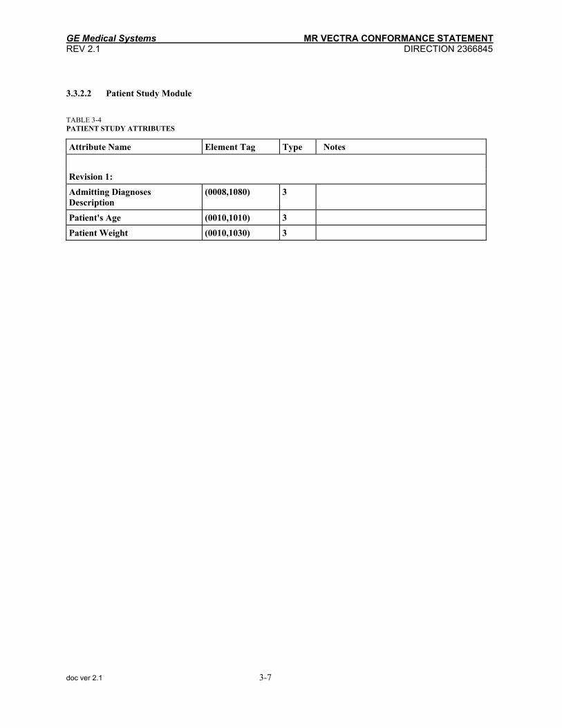
3.3.2.2 Patient Study Module
TABLE 3-4 ATIENT STUDY ATTRIBUTES P Attribute Name Element Tag Type Notes
Revision 1:
Admitting Diagnoses Description
(0008,1080) 3
Patient's Age (0010,1010) 3
Patient Weight (0010,1030) 3
doc ver 2.1 3-7

GE Medical Systems MR VECTRA CONFORMANCE STATEMENT REV 2.1 DIRECTION 2366845
3.3.3 Series Entity Module
3.3.3.1 General Series Module
TABLE 3-5 ENERAL SERIES MODULE ATTRIBUTES G
Attribute Name Element Tag Type Notes
Revision 1:
Modality (0008,0060) 1 Enumerated Value "MR" - Magnetic Resonance
Series Instance UID (0020,000E) 1
Series Number (0020,0011) 2
Laterality (0020,0060) 2C Send zero length
Series Description (0008,103E) 3
Body Part Examined (0018,0015) 3 NOTE: Sent a string of characters which Operator freely described as `Anatomic Location'
Patient Position (0018,5100) 2C (Condition is met for MR, therefore required to be sent)
doc ver 2.1 3-8

GE Medical Systems MR VECTRA CONFORMANCE STATEMENT REV 2.1 DIRECTION 2366845
3.3.4 Frame Of Reference Entity Module
3.3.4.1 Frame Of Reference Module
This module contains attributes used to identify the Frame of Reference of a Series within a Study.
TABLE 3-6 RAME OF REFERENCE IDENTIFICATION ATTRIBUTES F Attribute Name Element Tag Type Notes
Revision 1:
Frame of Reference UID (0020,0052) 1
Position Reference Indicator (0020,1040) 2 NOTE: Sent a string of characters which Operator freely described as `Anatomic Reference'
doc ver 2.1 3-9

GE Medical Systems MR VECTRA CONFORMANCE STATEMENT REV 2.1 DIRECTION 2366845
3.3.5 Equipment Entity Module
3.3.5.1 General Equipment Module TABLE 3-7
ENERAL EQUIPMENT MODULE ATTRIBUTES G Attribute Name Element Tag Type Notes
Revision 1:
Manufacturer (0008,0070) 2
Institution Name (0008,0080) 3
Station Name (0008,1010) 3
Manufacturer Model (0008,1090) 3
Device Serial Number (0018,1000) 3
Software Versions (0018,1020) 3
Pixel Padding Value (0028,0120) 3 Defined Terms: -8192
doc ver 2.1 3-10

GE Medical Systems MR VECTRA CONFORMANCE STATEMENT REV 2.1 DIRECTION 2366845
3.3.6 Image Entity Modules
3.3.6.1 General Image Module
TABLE 3-8 ENERAL IMAGE MODULE ATTRIBUTES G
Attribute Name Element Tag Type Notes
Revision 1:
Image Number (0020,0013) 2
Image Date (0008,0023) 2C
Image Time (0008,0033) 2C
Image Type (0008,0008) 3
Reference Image Sequence (0008,1140) 3
Referenced SOP Class UID (0008,1150) 1C
Reference SOP Instance UID (0008,1155) 1C
Image Comment (0020,4000) 3
doc ver 2.1 3-11

GE Medical Systems MR VECTRA CONFORMANCE STATEMENT REV 2.1 DIRECTION 2366845
3.3.6.1.1 Attribute Image Type (0008, 0008)
ILLUSTRATION 3-2 IMAGE TYPE DECISION TREE
IMAGE TYPE:
ORIGINAL
DERIVED
PRIMARY
SECONDARY PROJECTION IMAGE
T1 MAP
T2 MAP
DENSITY MAP
This information is used by applications to provide important identification characteristics. This attribute is a three valued element. Illustration 3-2 is a decision tree that provides the valid combinations of the three values that may be sent.
This attribute is multi-valued and is provided in the following manner:
Value 1: Identifies an image to be either an ORIGINAL image or a DERIVED image. An ORIGINAL image is an image whose pixel values represent original, non-transformed data. A DERIVED image is an image that has been created by combining two or more images together.
The string of either “ORIGINAL" or "DERIVED" is sent.
Value 2: Identifies the image to be created as either a PRIMARY or a SECONDARY image. A PRIMARY image is an image that has been created as part of the initial patient examination process. A SECONDARY image is an image that has been created as the result of some post processing activity.
The string of either "PRIMARY" or "SECONDARY" is sent.
Value 3: Identifies the type of processing which created the image.
One of the following strings may be sent:"T1 MAP", "T2 MAP", "DENSITY MAP", or "PROJECTION IMAGE".
doc ver 2.1 3-12

GE Medical Systems MR VECTRA CONFORMANCE STATEMENT REV 2.1 DIRECTION 2366845
3.3.6.2 Image Plane Module
TABLE 3-9 MAGE PLANE MODULE ATTRIBUTES I Attribute Name Element Tag Type Notes
Revision 1:
Pixel Spacing (0028,0030) 1
Image Orientation (patient)
(0020,0037) 1 NOTE: Be sure to read the DICOM "Image Orientation/Position with respect to the patient" definitions.
Image Position (patient)
(0020,0032) 1 NOTE: Be sure to read the DICOM "Image Orientation/Position with respect to the patient" definitions.
Slice Thickness (0018,0050) 2
Slice Location (0020,1041) 3
doc ver 2.1 3-13

GE Medical Systems MR VECTRA CONFORMANCE STATEMENT REV 2.1 DIRECTION 2366845
3.3.6.3 Image Pixel Module
TABLE 3-10 MAGE PIXEL MODULE ATTRIBUTES I Attribute Name Element Tag Type Notes
Revision 1:
Samples per Pixel (0028,0002) 1 Defined Value: 1
Photometric Interpretation (0028,0004) 1 Defined Value: ``MONOCHROME2''
Rows (0028,0010) 1
Columns (0028,0011) 1
Bits Allocated (0028,0100) 1 Enumerated Values: 16
Bits Stored (0028,0101) 1 Enumerated Value: 16
High Bit (0028,0102) 1 Enumerated Value: 15
Pixel Representation (0028,0103) 1 Enumerated Value: 1
Smallest Pixel Value (0028,0106) 3 Defined Value: -8192
Largest Pixel Value (0028,0107) 3 Defined Value: 8191
Pixel Data (7FE0,0010) 1
doc ver 2.1 3-14

GE Medical Systems MR VECTRA CONFORMANCE STATEMENT REV 2.1 DIRECTION 2366845
3.3.6.4 Contrast/Bolus Module
TABLE 3-11 ONTRAST/BOLUS MODULE ATTRIBUTES C
Attribute Name Element Tag Type
Revision 1:
Contrast/Bolus Agent (0018,0010) 2 Defined Terms: ''Contrast'' ''NONE''
Contrast/Bolus Start Time (0018,1042) 3
doc ver 2.1 3-15

GE Medical Systems MR VECTRA CONFORMANCE STATEMENT REV 2.1 DIRECTION 2366845
3.3.6.5 MR Image Module
TABLE 3-12 R IMAGE MODULE ATTRIBUTES M
Attribute Name Element Tag Type Notes
Revision 1:
Image Type (0008,0008) 1
Samples per Pixel (0028,0002) 1
Photometric Interpretation (0028,0004) 1
Bits Allocated (0028,0100) 1
Scanning Sequence (0018,0020) 1 Defined Terms: ”SE” ”IR” ”GR”
Sequence Variant (0018,0021) 1 Defined Terms: (see Standard Part 3)
Scan Options (0018,0022) 2 Defined Terms (See Standard Part 3, plus the following listed values are used by GEMS): ”CE” (ECG Cine) ”CP” (Peripheral Cine) ”NP” (No Phase Wrap) ”VB” (Variable Bandwidth) ”PM” (Pomp Scan) ”BW” (Cut Off Frequency) ”3D” (3D Scan) ”MF” (Morpho Filter) ”MT” (MTC) ”RF” (Ramped RF)
MR Acquisition Type (0018,0023) 2 Defined Terms: ”2D” ”3D”
Repetition Time (0018,0080) 2C
Echo Time (0018,0081) 2
Echo Train Length (0018,0091) 2
Inversion Time (0018,0082) 2C
Trigger Time (0018,1060) 2C
doc ver 2.1 3-16

GE Medical Systems MR VECTRA CONFORMANCE STATEMENT REV 2.1 DIRECTION 2366845
Attribute Name Element Tag Type Notes (continued from previous page)
Sequence Name (0018,0024) 3
Angio Flag (0018,0025) 3
Number of Averages (0018,0083) 3 Fractional values indicate Fractional Fourier acquisition
Imaged Nucleus (0018,0085) 3 Defined Terms: "1H"
Echo Number (0018,0086) 3
Magnetic Field Strength
(0018,0087) 3
Percent Sampling (0018,0093) 3
Pixel Bandwidth (0018,0095) 3
Nominal Interval (0018,1062) 3
Heart Rate (0018,1088) 3
Cardiac Number of Images (0018,1090) 3
Reconstruction Diameter (0018,1100) 3
Receiving Coil (0018,1250) 3
Transmitting Coil (0018,1251) 3
Phase Encoding Direction
(0018,1312) 3 Defined Terms: "ROW"
Flip Angle (0018,1314) 3
Variable Flip Angle (0018,1315) 3 Defined Terms: "N"
SAR (0018,1316) 3
doc ver 2.1 3-17

GE Medical Systems MR VECTRA CONFORMANCE STATEMENT REV 2.1 DIRECTION 2366845
3.3.6.6 VOI LUT Module
TABLE 3-13 OI LUT MODULE ATTRIBUTES V
Attribute Name Element Tag Type Notes
Revision 1:
Window Center (0028,1050) 3
Window Width (0028,1051) 1C
doc ver 2.1 3-18

GE Medical Systems MR VECTRA CONFORMANCE STATEMENT REV 2.1 DIRECTION 2366845
3.3.6.7 SOP Common Module
TABLE 3-14 OP COMMON MODULE ATTRIBUTES S Attribute Name Element Tag Type Notes
Revision 1:
SOP Class UID (0008,0016) 1
SOP Instance UID (0008,0018) 1
doc ver 2.1 3-19

GE Medical Systems MR VECTRA CONFORMANCE STATEMENT REV 2.1 DIRECTION 2366845
THIS PAGE LEFT INTENTIONALLY BLANK
doc ver 2.1 3-20

GE Medical Systems MR VECTRA CONFORMANCE STATEMENT REV 2.1 DIRECTION 2366845
SECTION 4 - MR VECTRA SECONDARY CAPTURE IMAGE INFORMATION OBJECT DEFINITION
This section specifies the subset of the DICOM Secondary Capture Image Information Object Definition used to represent the information included in Secondary Captures produced by this implementation. Corresponding attributes are conveyed using the module construct. The contents of this section are:
4.0 - Interoperability Schema 4.1 - Entity Descriptions
4.2 - Entity Module Table 4.3 - Entity Module Library
doc ver 2.1 4-1

GE Medical Systems MR VECTRA CONFORMANCE STATEMENT REV 2.1 DIRECTION 2366845
4.0 SC IMAGE INTEROPERABILITY SCHEMA
ILLUSTRATION 4-1 SC IMAGE ENTITY RELATIONSHIP DIAGRAM
Study
Patient1
1,n
1
1,99
is the subject of
contains
SecondaryCaptureImage
1
1,800
contains
Series
Equipment
1,ncreates1
The Entity-Relationship diagram for the SC Image interoperability schema is shown in Illustration 4-1. In this illustration, the following diagrammatic convention is established to represent the information organization:
each entity is represented by a rectangular box •
•
•
each relationship is represented by a diamond shaped box
the fact that a relationship exists between two entities is depicted by lines connecting the corresponding entity boxes to the relationship boxes.
doc ver 2.1 4-2

GE Medical Systems MR VECTRA CONFORMANCE STATEMENT REV 2.1 DIRECTION 2366845
4.1 ENTITY DESCRIPTIONS Please refer to DICOM Standard Part 3 (Information Object Definitions) for a description of each of the entities contained within the Secondary Capture Image Information Object Definition.
doc ver 2.1 4-3

GE Medical Systems MR VECTRA CONFORMANCE STATEMENT REV 2.1 DIRECTION 2366845
4.2 ENTITY MODULE TABLE Within an entity, attributes are grouped into related set of attributes. A set of related attributes is termed a module. A module facilitates the understanding of the semantics concerning the attributes and how the attributes are related with each other. A module does not infer any encoding of information into datasets.
Table 4-1 identifies the defined modules within the entities that comprise the DICOM Secondary Capture Information Object Definition. Modules are identified by Module Name.
A Reference pointer is provided which identifies the sections which provides a complete definition of the module and the attributes that comprise the module.
See DICOM Part 3 for a complete definition of the entities, modules, and attributes.
TABLE 4-1 SC IMAGE MODULE DEFINITION TABLE
Entity Name Module Name Module Library Section
Patient Patient (see Section 3)
Study General Study (see Section 3)
Patient Study (see Section 3)
Series General Series (see Section 3)
Equipment General Equipment (see Section 3)
SC Equipment 4.3.1.1
General Image 4.3.2.1
Image Pixel 4.3.2.2
SC Image 4.3.2.3
Image Overlay Plane 4.3.2.4
Modality LUT 4.3.2.5
VOI LUT (see Section 3)
SOP Common (see Section 3) (* Section 3, "MR Vectra Information Object Definition", uses the same modules as Secondary Capture where the note "see Section 3" appears.)
Note: The following modules are included to convey Enumerated values, Defined Terms, and Optional Attributes Supported. Type 1 & Type 2 Attributes are also included for completeness but it should be noted that they are the same ones as defined in DICOM Part 3.
doc ver 2.1 4-4

GE Medical Systems MR VECTRA CONFORMANCE STATEMENT REV 2.1 DIRECTION 2366845
4.3 ENTITY MODULE LIBRARY Please refer to DICOM Standard Part 3 (Information Object Definitions) for a description of each of the entities and modules contained within the MR Information Object.
4.3.1 Equipment Entity Module
4.3.1.1 SC Equipment Module
TABLE 4-2 C EQUIPMENT MODULE ATTRIBUTES S Attribute Name Element Tag Type Notes
Revision 1:
Conversion Type (0008,0064) 1 Defined Value: "WSD"
Modality (0008,0060) 3 Defined Value: "MR"
Secondary Capture Device ID (0018,1010) 3
Secondary Capture Device Manufacturer
(0018,1016) 3
Secondary Capture Device Manufacturer's Model Name
(0018,1018) 3
Secondary Capture Device Software Version
(0018,1019) 3
doc ver 2.1 4-5

GE Medical Systems MR VECTRA CONFORMANCE STATEMENT REV 2.1 DIRECTION 2366845
4.3.2 Image Entity Modules
4.3.2.1 General Image Module
TABLE 4-3 GENERAL IMAGE MODULE ATTRIBUTES Attribute Name Element Tag Type Notes
Revision 1:
Image Number (0020,0013) 2
Patient Orientation (0020,0020) 2C
Image Date (0008,0023) 2C
Image Time (0008,0033) 2C
Image Type (0008,0008) 3
Image Comments (0020,4000) 3
doc ver 2.1 4-6

GE Medical Systems MR VECTRA CONFORMANCE STATEMENT REV 2.1 DIRECTION 2366845
4.3.2.1.1 Attribute Image Type (0008, 0008)
ILLUSTRATION 4-2 SC GENERAL IMAGE DECISION TREE
GENERAL IMAGE TYPE:
DERIVED SECONDARY
REFORMATTED CURVED REFORMAT 3D CALCULATED
This information is used by applications to provide important identification characteristics. This attribute is a three valued element. Illustration 4-2 is a decision three which provides the valid combinations of the three values that may be sent.
This attribute is multi-valued and should be provided in the following manner:
Value 1: Basically, it identifies an image to be either an ORIGINAL image or a DERIVED image. An ORIGINAL image is an image whose pixel values represent original, non-transformed data. A DERIVED image is an image that has been created by combining two or more images together. But, MR Vectra SC Device doesn't distinguish them, therefore, the string of "DERIVED" is always sent.
Value 2: Identifies the image to be created as a SECONDARY image. A SECONDARY image is an image that has been created as the result of some post processing activity.
The string of "SECONDARY" is sent.
Value 3: Identifies the type of processing which created the image. This description is implementation specific.
One of the following strings is sent: "REFORMATTED","3D","CURVED REFORMAT" or "CALCULATED".
doc ver 2.1 4-7
GE Medical Systems MR VECTRA CONFORMANCE STATEMENT REV 2.1 DIRECTION 2366845
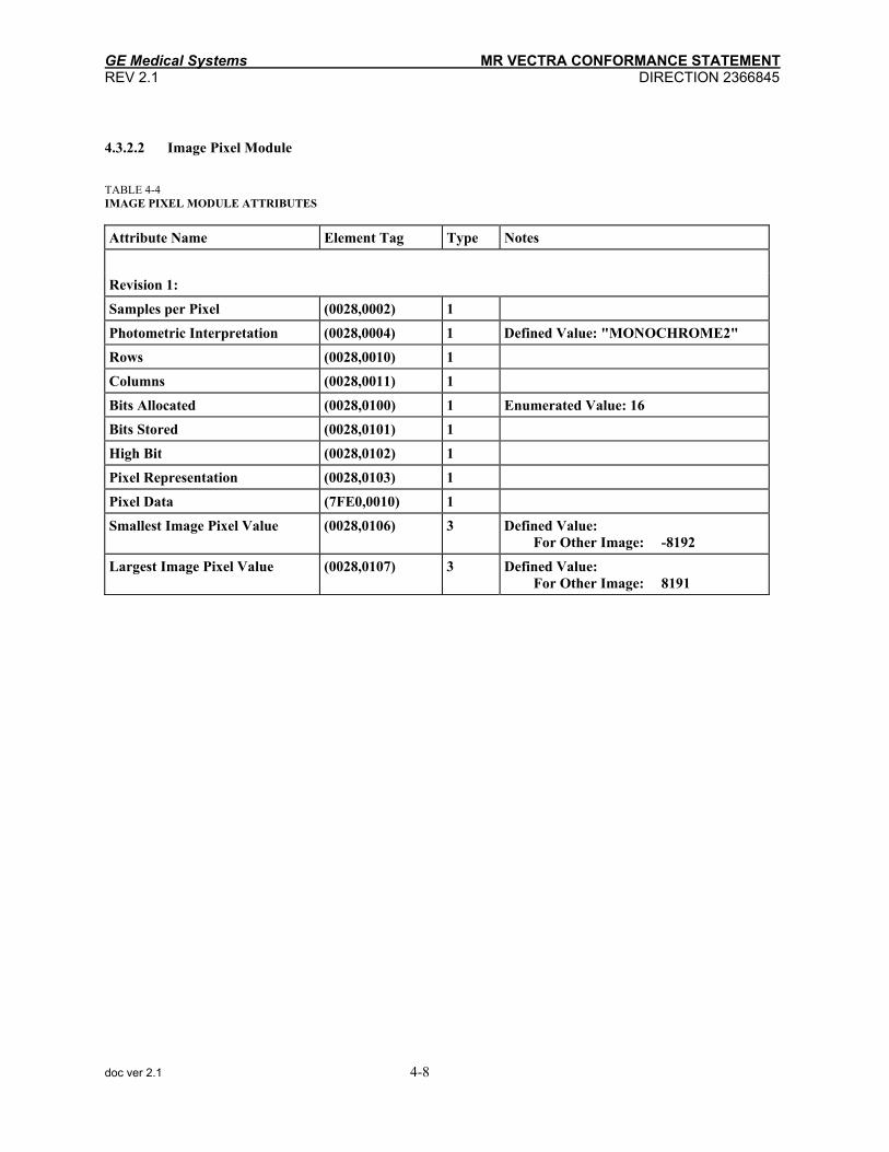
4.3.2.2 Image Pixel Module
TABLE 4-4 IMAGE PIXEL MODULE ATTRIBUTES Attribute Name Element Tag Type Notes
Revision 1:
Samples per Pixel (0028,0002) 1
Photometric Interpretation (0028,0004) 1 Defined Value: "MONOCHROME2"
Rows (0028,0010) 1
Columns (0028,0011) 1
Bits Allocated (0028,0100) 1 Enumerated Value: 16
Bits Stored (0028,0101) 1
High Bit (0028,0102) 1
Pixel Representation (0028,0103) 1
Pixel Data (7FE0,0010) 1
Smallest Image Pixel Value (0028,0106) 3 Defined Value: For Other Image: -8192
Largest Image Pixel Value (0028,0107) 3 Defined Value: For Other Image: 8191
doc ver 2.1 4-8

GE Medical Systems MR VECTRA CONFORMANCE STATEMENT REV 2.1 DIRECTION 2366845
4.3.2.3 SC Image Module
TABLE 4-5 SC IMAGE MODULE ATTRIBUTES Attribute Name Element Tag Type Notes
Revision 1:
Date of Secondary Capture (0018,1012) 3
Time of Secondary Capture (0018,1014) 3
doc ver 2.1 4-9

GE Medical Systems MR VECTRA CONFORMANCE STATEMENT REV 2.1 DIRECTION 2366845
4.3.2.4 Overlay Plane Module Conditional Descriptions:
All overlay planes are one bit overlay planes.
TABLE 4-6 VERLAY PLANE MODULE ATTRIBUTES O
Attribute Name Element Tag Type Notes
Revision 1:
Rows (60xx, 0010) 1
Columns (60xx, 0011) 1
Overlay Type (60xx, 0040) 1 Enumerated Value: "G"=Graphics
Origin (60xx, 0050) 1 Enumerated Multiple Value: 0001 0001
Bits Allocated (60xx, 0100) 1 Enumerated Value: 0001
Bit Position (60xx, 0102) 1 Enumerated Value: 0000
Overlay Data (60xx, 3000) 1C
doc ver 2.1 4-10

GE Medical Systems MR VECTRA CONFORMANCE STATEMENT REV 2.1 DIRECTION 2366845
4.3.2.5 Modality LUT Module
TABLE 4-7 ODALITY LUT MODULE ATTRIBUTES M
Attribute Name Element Tag Type Notes
Revision 1:
Rescale Intercept (0028,1052) 1C
Rescale Slope (0028,1053) 1C
Rescale Type (0028,1054) 1C
doc ver 2.1 4-11

GE Medical Systems MR VECTRA CONFORMANCE STATEMENT REV 2.1 DIRECTION 2366845
THIS PAGE LEFT INTENTIONALLY BLANK
doc ver 2.1 4-12

GE Medical Systems MR VECTRA CONFORMANCE STATEMENT REV 2.1 DIRECTION 2366845
SECTION 5 - MR VECTRA QUERY/RETRIEVE INFORMATION MODEL DEFINITION
This section specifies the subset of the DICOM Query / Retrieve Information Model Definition used to represent the information included in a Query/Retrieve produced by this implementation. Corresponding attributes are conveyed using the module construct. The contents of this section are:
5.0- Interoperability Schema 5.1 - Entity Descriptions 5.2 - Study Level 5.3 - Series Level 5.4 - Image Level
5.0 INTEROPERABILITY SCHEMA
ILLUSTRATION 5-1 STUDY ROOT QUERY/RETRIEVE ENTITY RELATIONSHIP DIAGRAM
Study1
1,99
contains
Image
1
1,800
contains
Series
doc ver 2.1 5-1

GE Medical Systems MR VECTRA CONFORMANCE STATEMENT REV 2.1 DIRECTION 2366845
The Entity-Relationship diagram for the Study Root Query/Retrieve Information Model interoperability schema is shown in Illustration 5-1. In this illustration, the following diagrammatic convention is established to represent the following information organization:
each entity is represented by a rectangular box •
•
•
each relationship is represented by a diamond shaped box
the fact that a relationship exists between two entities is depicted by lines connecting the corresponding entity boxes to the relationship boxes.
5.1 ENTITY DESCRIPTIONS Please refer to DICOM Standard Part 4 for a description of each of the entities contained within the Study Root Query/Retrieve Information Model.
doc ver 2.1 5-2

GE Medical Systems MR VECTRA CONFORMANCE STATEMENT REV 2.1 DIRECTION 2366845
5.2 Study Level
5.2.1 Study Level Keys for the Study Root Query/Retrieve Information Model Table 5-1 defines the keys supported at the Study level of the Study Root Query/Retrieve Information Model. Table 5-2 specifies the Query/Retrieve Level and AE Title that are included in a C-FIND Response.
TABLE 5-1 STUDY LEVEL KEY ATTRIBUTES (NOTE: R=Required, O=Optional, U=Unique) Attribute Name Element Tag Type Notes: R=Required, O=Optional, U=Unique
Revision 2:
Study Date (0008,0020) R
Study Time (0008,0030) R
Accession Number (0008,0050) R
Patient Name (0010,0010) R
Patient ID (0010,0020) R
Study Instance UID (0020,000D) U
Study ID (0020,0010) R
Referring Physician (0008,0090) O
Procedure Description (0008,1030) O
Patient Sex (0010,0040) O
Patient Age (0010,1010) O
Patient Weight (0010,1030) O
TABLE 5-2 Q/R LEVEL & AE TITLE SPECIFICATION - STUDY Attribute Name Element Tag Type Notes
Q/R Information Model Level (0008,0052) R Defined Value: STUDY
Retrieve AE Title (0008,0054) R Defined Value: Called AE Title
doc ver 2.1 5-3

GE Medical Systems MR VECTRA CONFORMANCE STATEMENT REV 2.1 DIRECTION 2366845
5.3 Series Level
5.3.1 Series Level Keys for the Study Root Query/Retrieve Information Model Table 5-3 defines the keys supported at the Series level of the Study Root Query/Retrieve Information Model. Table 5-4 specifies the Query/Retrieve Level and AE Title that are included in a C-FIND Response.
TABLE 5-3 SERIES LEVEL KEY ATTRIBUTES (NOTE: R=Required, O=Optional, U=Unique) Attribute Name Element Tag Type Notes: R=Required, O=Optional, U=Unique
Revision 2:
Modality (0008,0060) R
Series Instance UID (0020,000E) U
Series Number (0020,0011) R
Study Description (0008,1030) O
Series Description (0008,103E) O
Patient Position (0018,5100) O
Position Reference Indicator (0020,1040) O
TABLE 5-4 Q/R LEVEL & AE TITLE SPECIFICATION - SERIES Attribute Name Element Tag Type Notes
Q/R Information Model Level (0008,0052) R Defined Value: SERIES
Retrieve AE Title (0008,0054) R Defined Value: Called AE Title
doc ver 2.1 5-4

GE Medical Systems MR VECTRA CONFORMANCE STATEMENT REV 2.1 DIRECTION 2366845
5.4 Image Level
5.4.1 Image Level Keys for the Study Root Query/Retrieve Information Model Table 5-5 defines the keys supported at the Image level of the Study Root Query/Retrieve Information Model. Table 5-6 specifies the Query/Retrieve Level and AE Title that are included in a C-FIND Response.
TABLE 5-5 MR IMAGE LEVEL KEY ATTRIBUTES (NOTE: R=Required, O=Optional, U=Unique) Attribute Name Element Tag Type Notes
Revision 2:
SOP Instance UID (0008,0018) U
Image Number (0020,0013) R
SOP Class UID (0008,0016) O
Image Date (0008,0023) O
Image Time (0008,0033) O
Contrast/Bolus Agent (0018,0010) O
Slice Thickness (0018,0050) O
Repetition Time (0018,0080) O
Echo Time (0018,0081) O
Inversion Time (0018,0082) O
Number of Averages (0018,0083) O
Trigger Time (0018,1060) O
Reconstruction Diameter (0018,1100) O
Flip Angle (0018,1314) O
Slice Location (0020,1041) O
doc ver 2.1 5-5

GE Medical Systems MR VECTRA CONFORMANCE STATEMENT REV 2.1 DIRECTION 2366845
TABLE 5-6 Q/R LEVEL & AE TITLE SPECIFICATION - IMAGE Attribute Name Element Tag Type Notes
Q/R Information Model Level (0008,0052) R Defined Value: IMAGE
Retrieve AE Title (0008,0054) R Defined Value: Called AE Title
doc ver 2.1 5-6

GE Medical Systems MR VECTRA CONFORMANCE STATEMENT REV 2.1 DIRECTION 2366845
doc ver 2.1

GE Medical Systems MR VECTRA CONFORMANCE STATEMENT REV 2.1 DIRECTION 2366845
doc ver 2.1
____________________________________________________________________________GE Medical Systems GE Medical Systems: Telex 3797371 P.O. Box 414, Milwaukee, Wisconsin 53201 U.S.A. (Asia, Pacific, Latin America, North America) GE Medical Systems — Europe: Telex 261794
Shortlands, Hammersmith, London W6 8BX U.K.