Technical manual - Exterior venetian blinds - Labona.eu
99
TECHNICA L M A NUA L E X T E R I O R VENETIAN B L I N D S
-
Upload
khangminh22 -
Category
Documents
-
view
0 -
download
0
Transcript of Technical manual - Exterior venetian blinds - Labona.eu

Technica l m a nua l
e X T e R i O R VENETIAN B l i n D S

EXTERIOR BLINDS
All exterior blinds of ISOTRA a.s. comply with the standard ČSN EN 13659+A1:2009
European Marking of CE Compliance – marking on products
CE Product Marking
The wind resistance tests were conducted by Centrum stavebního inženýrství, a.s., Zlín, according to standard ČSN EN 13659+A1:2009.
Wind Resistance of Exterior Blinds
Cetta 50 - channelEssential characteristics Performance
Wind resistance Width of construction hole L (mm) L <= 2 000 2 000 < L <= 3 000 3 000 < L <= 4 000 4 000 < L <= 4 500Standard EN/Beaufort 13659 Beaufort 13659 Beaufort 13659 Beaufort 13659 BeaufortWind resistance class 4 7 3 6 2 5 1 4Max. wind speed vmax (km/h) 61 49 38 28Max. effective height wing Hmax = 4000mmWidth of construction hole L (mm) 4 500 < L <= 5 000 5 000 < L <= 5 500 5 500 < L <= 5 800 5 800 < L <= 6 000Wind resistance class 0 3 0 2 0 1 0 0Max. wind speed vmax (km/h) 19 11 5 1Max. effective height wing Hmax = 4000mm
Additional thermal resistance ΔR 0,08 (m2.K/W)Total solar energy transmittance gtot 0,032 - 0,094 (according to the selected slat color)*
Cetta 50 - wireEssential characteristics PerformanceWind resistance Width of construction hole L (mm) L < 2 000 2 000 < L <= 3 000 3 000 < L <= 4 000 4 000 < L <= 4 500 4 500 < L <= 4 800
Standard EN/Beaufort 13659 Beaufort 13659 Beaufort 13659 Beaufort 13659 Beaufort 13659 BeaufortWind resistance class 1 4 0 3 0 2 0 1 0 0Max. wind speed vmax (km/h) 28 19 11 5 1Max. effective height wing Hmax = 2500mmWidth of construction hole L (mm) L < 2 000 2 000 < L <= 3 000 3 000 < L <= 4 000 4 000 < L <= 4 500 4 000 < L <= 4 500Wind resistance class 0 3 0 2 0 1 0 0 0 0Max. wind speed vmax (km/h) 19 11 5 1 1Max. effective height wing Hmax = 4000mm
Additional thermal resistance ΔR 0,08 (m2.K/W)Total solar energy transmittance gtot 0,032 - 0,094 (according to the selected slat color)*
Cetta 65 - channelEssential characteristics PerformanceWind resistance Width of construction hole L (mm) L <= 2 000 2 000 < L <= 3 000 3 000 < L <= 4 000 4 000 < L <= 4 500
Standard EN/Beaufort 13659 Beaufort 13659 Beaufort 13659 Beaufort 13659 BeaufortWind resistance class 4 7 3 6 2 5 1 4Max. wind speed vmax (km/h) 61 49 38 28Max. effective height wing Hmax = 4000mmWidth of construction hole L (mm) 4 500 < L <= 5 000 5 000 < L <= 5 500 5 500 < L <= 5 800 5 800 < L <= 6 000Wind resistance class 0 3 0 2 0 1 0 0Max. wind speed vmax (km/h) 19 11 5 1Max. effective height wing Hmax = 4000mm
Additional thermal resistance ΔR
0,08 (m2.K/W)
Total solar energy tran-smittance gtot
0,032 - 0,094 (according to the selected slat color)*
Cetta 65 - wireEssential characteristics PerformanceWind resistance Width of construction hole L (mm) L <= 2 000 2 000 < L <= 3 000 3 000 < L <= 4 000 4 000 < L <= 4 500 4 500 < L <= 4 800 4 800 < L <= 5 000 5 000 < L <= 6 000
Standard EN/Beaufort 13659 Beaufort 13659 Beaufort 13659 Beaufort 13659 Beaufort 13659 Beaufort 13659 Beaufort 13659 BeaufortWind resistance class 3 6 2 5 1 4 0 3 0 2 0 1 0 0Max. wind speed vmax (km/h) 49 38 28 19 11 5 1Max. effective height wing Hmax = 2500mmWidth of construction hole L (mm) L <= 2 000 2 000 < L <= 3 000 3 000 < L <= 4 000 4 000 < L <= 4 500 4 500 < L <= 4 800 4 800 < L <= 5 000 5 000 < L <= 6 000Wind resistance class 2 5 1 4 0 3 0 2 0 1 0 0 0 0Max. wind speed vmax (km/h) 38 28 19 11 5 0 0Max. effective height wing Hmax = 4000mm
Additional thermal resistance ΔR 0,08 (m2.K/W)Total solar energy transmittance gtot 0,032 - 0,094 (according to the selected slat color)*
ISOTRA a.s.Bílovecká 2411/1, 746 01 Opava
12
EN 13659:2015ZETTA 90
CPR 008/2017Exterior sun visor
Wind resistance: 0 – 4Additional thermal resistance ΔR:0,08 m2.K/W
Total solar energy transmittance gtot: 0,032 - 0,094
Note: Pattern of CE label

Setta 65 - channelEssential characteristics PerformanceWind resistance Width of construction hole L (mm) L <= 2 000 2 000 < L <= 3 000 3 000 < L <= 4 000 4 000 < L <= 4 500
Standard EN/Beaufort 13659 Beaufort 13659 Beaufort 13659 Beaufort 13659 BeaufortWind resistance class 5 8 4 7 3 6 2 5Max. wind speed vmax (km/h) 74 61 49 38Max. effective height wing Hmax = 4000mmWidth of construction hole L (mm) 4 500 < L <= 5 000 5 000 < L <= 5 500 5 500 < L <= 5 800 5 800 < L <= 6 000Wind resistance class 1 4 0 3 0 2 0 1Max. wind speed vmax (km/h) 28 19 11 5Max. effective height wing Hmax = 4000mm
Additional thermal resistance ΔR 0,08 (m2.K/W)Total solar energy transmittance gtot 0,032 - 0,094 (according to the selected slat color)*
Setta 65 - wireEssential characteristics PerformanceWind resistance Width of construction hole L (mm) L <= 2 000 2 000 < L <= 3 000 3 000 < L <= 4 000 4 000 < L <= 4 500 4 500 < L <= 4 800 4 800 < L <= 5 000
Standard EN/Beaufort 13659 Beaufort 13659 Beaufort 13659 Beaufort 13659 Beaufort 13659 Beaufort 13659 BeaufortWind resistance class 3 6 2 5 1 4 0 3 0 2 0 1Max. wind speed vmax (km/h) 49 38 28 19 11 5Max. effective height wing Hmax = 2500mmWidth of construction hole L (mm) L <= 2 000 2 000 < L <= 3 000 3 000 < L <= 4 000 4 000 < L <= 4 500 4 500 < L <= 4 800 4 800 < L <= 5 000Wind resistance class 2 5 1 4 0 3 0 2 0 1 0 0Max. wind speed vmax (km/h) 38 28 19 11 5 1Max. effective height wing Hmax = 4000mm
Additional thermal resistance ΔR 0,08 (m2.K/W)Total solar energy transmittance gtot 0,032 - 0,094 (according to the selected slat color)*
Setta 90 - channelEssential characteristics PerformanceWind resistance Width of construction hole L (mm) L <= 2 000 2 000 < L <= 3 000 3 000 < L <= 4 000 4 000 < L <= 4 500
Standard EN/Beaufort 13659 Beaufort 13659 Beaufort 13659 Beaufort 13659 BeaufortWind resistance class 5 8 4 7 3 6 2 5Max. wind speed vmax (km/h) 74 61 49 38Max. effective height wing Hmax = 4000mmWidth of construction hole L (mm) 4 500 < L <= 5 000 5 000 < L <= 5 500 5 500 < L <= 5 800 5 800 < L <= 6 000Wind resistance class 1 4 0 3 0 2 0 1Max. wind speed vmax (km/h) 28 19 11 5Max. effective height wing Hmax = 4000mm
Additional thermal resistance ΔR 0,08 (m2.K/W)Total solar energy transmittance gtot 0,032 - 0,094 (according to the selected slat color)*
Setta 90 - wireEssential characteristics PerformanceWind resistance Width of construction hole L (mm) L <= 2 000 2 000 < L <= 3 000 3 000 < L <= 4 000 4 000 < L <= 4 500 4 500 < L <= 4 800 4 800 < L <= 5 000 5 000 < L <= 6 000
Standard EN/Beaufort 13659 Beaufort 13659 Beaufort 13659 Beaufort 13659 Beaufort 13659 Beaufort 13659 Beaufort 13659 BeaufortWind resistance class 3 6 2 5 1 4 0 3 0 2 0 1 0 0Max. wind speed vmax (km/h) 49 38 28 19 11 5 1Max. effective height wing Hmax = 2500mmWidth of construction hole L (mm) L <= 2 000 2 000 < L <= 3 000 3 000 < L <= 4 000 4 000 < L <= 4 500 4 500 < L <= 4 800 4 800 < L <= 5 000 5 000 < L <= 6 000Wind resistance class 2 5 1 4 0 3 0 2 0 1 0 0 0 0Max. wind speed vmax (km/h) 38 28 19 11 5 1 0Max. effective height wing Hmax = 4000mm
Additional thermal resistance ΔR 0,08 (m2.K/W)Total solar energy transmittance gtot 0,032 - 0,094 (according to the selected slat color)*
Zetta 70 - channelEssential characteristics PerformanceWind resistance Width of construction hole L (mm) L <= 2 000 2 000 < L <= 3 000 3 000 < L <= 4 000 4 000 < L <= 4 500
Standard EN/Beaufort 13659 Beaufort 13659 Beaufort 13659 Beaufort 13659 BeaufortWind resistance class 4 7 3 6 2 5 1 4Max. wind speed vmax (km/h) 61 49 38 28Max. effective height wing Hmax = 4000mmWidth of construction hole L (mm) 4 500 < L <= 5 000 5 000 < L <= 5 500 5 500 < L <= 5 800 5 800 < L <= 6 000Wind resistance class 0 3 0 2 0 1 0 0Max. wind speed vmax (km/h) 19 11 5 1Max. effective height wing Hmax = 4000mm
Additional thermal resistance ΔR 0,08 (m2.K/W)Total solar energy transmittance gtot 0,032 - 0,094 (according to the selected slat color)*

EXTERIOR BLINDS
4
Zetta 70 - wireEssential characteristics PerformanceWind resistance Width of construction hole L (mm) L <= 2 000 2 000 < L <= 3 000 3 000 < L <= 4 000 4 000 < L <= 4 500 4 500 < L <= 4 800 4 800 < L <= 5 000 5 000 < L <= 6 000
Standard EN/Beaufort 13659 Beaufort 13659 Beaufort 13659 Beaufort 13659 Beaufort 13659 Beaufort 13659 Beaufort 13659 BeaufortWind resistance class 3 6 2 5 1 4 0 3 0 2 0 1 0 0Max. wind speed vmax (km/h) 49 38 28 19 11 5 1Max. effective height wing Hmax = 2500mmWidth of construction hole L (mm) L <= 2 000 2 000 < L <= 3 000 3 000 < L <= 4 000 4 000 < L <= 4 500 4 500 < L <= 4 800 4 800 < L <= 5 000 5 000 < L <= 6 000Wind resistance class 2 5 1 4 0 3 0 2 0 1 0 0 0 0Max. wind speed vmax (km/h) 38 28 19 11 5 1 0Max. effective height wing Hmax = 4000mm
Additional thermal resistance ΔR 0,08 (m2.K/W)Total solar energy transmittance gtot 0,032 - 0,094 (according to the selected slat color)*
Zetta 90 - channelEssential characteristics PerformanceWind resistance Width of construction hole L (mm) L <= 1 000 1 000 < L <= 2 000 2 000 < L <= 3 000 3 000 < L <= 4 000
Standard EN/Beaufort 13659 Beaufort 13659 Beaufort 13659 Beaufort 13659 BeaufortWind resistance class 6 9 5 8 4 7 3 6Max. wind speed vmax (km/h) 88 74 61 49Max. effective height wing Hmax = 4000mmWidth of construction hole L (mm) 4 000 < L <= 4 500 4 500 < L <= 5 000 5 000 < L <= 5 500 5 500 < L <= 6 000Wind resistance class 2 5 1 4 0 3 0 2Max. wind speed vmax (km/h) 38 28 19 11Max. effective height wing Hmax = 4000mm
Additional thermal resistance ΔR 0,08 (m2.K/W)Total solar energy transmittance gtot 0,032 - 0,094 (according to the selected slat color)*
Zetta 90 - wireEssential characteristics PerformanceWind resistance Width of construction hole L (mm) L <= 2 000 2 000 < L <= 3 000 3 000 < L <= 4 000 4 000 < L <= 4 500 4 500 < L <= 4 800 4 800 < L <= 5 000 5 000 < L <= 6 000
Standard EN/Beaufort 13659 Beaufort 13659 Beaufort 13659 Beaufort 13659 Beaufort 13659 Beaufort 13659 Beaufort 13659 BeaufortWind resistance class 3 6 2 5 1 4 0 3 0 2 0 1 0 0Max. wind speed vmax (km/h) 49 38 28 19 11 5 1Max. effective height wing Hmax = 2500mmWidth of construction hole L (mm) L <= 2 000 2 000 < L <= 3 000 3 000 < L <= 4 000 4 000 < L <= 4 500 4 500 < L <= 4 800 4 800 < L <= 5 000 5 000 < L <= 6 000Wind resistance class 2 5 1 4 0 3 0 2 0 1 0 0 0 0Max. wind speed vmax (km/h) 38 28 19 11 5 1 0Max. effective height wing Hmax = 4000mm
Additional thermal resistance ΔR 0,08 (m2.K/W)Total solar energy transmittance gtot 0,032 - 0,094 (according to the selected slat color)*
Cetta 60 Flexi - wireEssential characteristics PerformanceWind resistance Width of construction hole L (mm) L <= 800 800 < L <= 2 000 2 000 < L <= 3 000 3 000 < L <= 4000 4000 < L <= 4 500 4 500 < L <= 4 800
Standard EN/Beaufort 13659 Beaufort 13659 Beaufort 13659 Beaufort 13659 Beaufort 13659 Beaufort 13659 BeaufortWind resistance class 3 6 2 5 1 4 0 3 0 2 0 1Max. wind speed vmax (km/h) 49 38 28 19 11 5Max. effective height wing Hmax = 2500mmWidth of construction hole L (mm) L <= 800 800 < L <= 2 000 2 000 < L <= 3 000 3 000 < L <= 4000 4000 < L <= 4 500 4 500 < L <= 4 800Wind resistance class 2 5 1 4 0 3 0 2 0 1 0 0Max. wind speed vmax (km/h) 38 28 19 11 5 1Max. effective height wing Hmax = 4000mm
Additional thermal resistance ΔR 0,08 (m2.K/W)Total solar energy transmittance gtot 0,032 - 0,094 (dle zvolené barvy lamely)*
Cetta 60 Flexi - channelEssential characteristics PerformanceWind resistance Width of construction hole L (mm) L <= 1 000 1 000 < L <= 2 000 2 000 < L <= 3 000 3 000 < L <= 4 000
Standard EN/Beaufort 13659 Beaufort 13659 Beaufort 13659 Beaufort 13659 BeaufortWind resistance class 4 7 3 6 2 5 1 4Max. wind speed vmax (km/h) 61 49 38 28Max. effective height wing Hmax = 4000mmWidth of construction hole L (mm) 4 000 < L <= 4 500 4 500 < L <= 5 000 5 000 < L <= 5 500 5 500 < L <= 6 000Wind resistance class 0 3 0 2 0 1 0 0Max. wind speed vmax (km/h) 19 11 5 1Max. effective height wing Hmax = 4000mm
Additional thermal resistance ΔR 0,08 (m2.K/W)Total solar energy transmittance gtot 0,032 - 0,094 (dle zvolené barvy lamely)*

Cetta 80 - wireEssential characteristics PerformanceWind resistance Width of construction hole L (mm) L <= 2 000 2 000 < L <= 3 0003 000 < L <= 4 0004 000 < L <= 4 5004 500 < L <= 4 8004 800 < L <= 5 0005 000 < L <= 6 000
Standard EN/Beaufort 13659 Beaufort 13659 Beaufort 13659 Beaufort 13659 Beaufort 13659 Beaufort 13659 Beaufort 13659 BeaufortWind resistance class 3 6 2 5 1 4 0 3 0 2 0 1 0 0Max. wind speed vmax (km/h) 49 38 28 19 11 5 1Max. effective height wing Hmax = 2500mmWidth of construction hole L (mm) L <= 2 000 2 000 < L <= 3 0003 000 < L <= 4 0004 000 < L <= 4 5004 500 < L <= 4 8004 800 < L <= 5 0005 000 < L <= 6 000Wind resistance class 2 5 1 4 0 3 0 2 0 1 0 0 0 0Max. wind speed vmax (km/h) 38 28 19 11 5 1 0Max. effective height wing Hmax = 4000mm
Additional thermal resistance ΔR 0,08 (m2.K/W)Total solar energy transmittance gtot 0,032 - 0,094 (according to the selected slat color)*
Cetta 80 - channelEssential characteristics PerformanceWind resistance Width of construction hole L (mm) L <= 1 000 1 000 < L <= 2 000 2 000 < L <= 3 000 3 000 < L <= 4 000
Standard EN/Beaufort 13659 Beaufort 13659 Beaufort 13659 Beaufort 13659 BeaufortWind resistance class 6 9 5 8 4 7 3 6Max. wind speed vmax (km/h) 88 74 61 49Max. effective height wing Hmax = 4000mmWidth of construction hole L (mm) 4 000 < L <= 4 500 4 500 < L <= 5 000 5 000 < L <= 5 500 5 500 < L <= 6 000Wind resistance class 2 5 1 4 0 3 0 2Max. wind speed vmax (km/h) 38 28 19 11Max. effective height wing Hmax = 4000mm
Additional thermal resistance ΔR 0,08 (m2.K/W)Total solar energy transmittance gtot 0,032 - 0,094 (according to the selected slat color)*
Cetta 80 Flexi - wireEssential characteristics PerformanceWind resistance Width of construction hole L (mm) L <= 2 000 2 000 < L <= 2 500 2 500 < L <= 3 000 3 000 < L <= 3 400 3 400 < L <= 3 800 3 800 < L <= 4 000
Standard EN/Beaufort 13659 Beaufort 13659 Beaufort 13659 Beaufort 13659 Beaufort 13659 Beaufort 13659 BeaufortWind resistance class 2 5 1 4 0 3 0 2 0 1 0 0Max. wind speed vmax (km/h) 38 28 19 11 5 1Max. effective height wing Hmax = 2500mmWidth of construction hole L (mm) L <= 2 000 2 000 < L <= 2 500 2 500 < L <= 3 000 3 000 < L <= 3 400 3 400 < L <= 3 800 3 800 < L <= 4 000Wind resistance class 1 4 0 3 0 2 0 1 0 0 0 0Max. wind speed vmax (km/h) 28 19 11 5 1 1Max. effective height wing Hmax = 4000mm
Additional thermal resistance ΔR 0,08 (m2.K/W)Total solar energy transmittance gtot 0,032 - 0,094 (according to the selected slat color)*
Cetta 80 Flexi - channelEssential characteristics PerformanceWind resistance Width of construction hole L (mm) L <= 2 000 2 000 < L <= 3 000 3 000 < L <= 4 000 4 000 < L <= 4 500
Standard EN/Beaufort 13659 Beaufort 13659 Beaufort 13659 Beaufort 13659 BeaufortWind resistance class 2 5 1 4 0 3 0 2Max. wind speed vmax (km/h) 38 28 19 11Max. effective height wing Hmax = 4000mmWidth of construction hole L (mm) 4 500 < L <= 5 000 5 000 < L <= 6 000Wind resistance class 0 1 0 0Max. wind speed vmax (km/h) 5 1Max. effective height wing Hmax = 4000mm
Additional thermal resistance ΔR 0,08 (m2.K/W)Total solar energy transmittance gtot 0,032 - 0,094 (according to the selected slat color)*
Cetta 100 Flexi - wireEssentialcharacteristics
Performance
Wind resistance Width of construction hole L (mm) L <= 800 800 < L <= 2 000 2 000 < L <= 3 000 3 000 < L <= 4 000 4000 < L <= 4 500 4 500 < L <= 4 800Standard EN/Beaufort 13659 Beaufort 13659 Beaufort 13659 Beaufort 13659 Beaufort 13659 Beaufort 13659 BeaufortWind resistance class 3 6 2 5 1 4 0 3 0 2 0 1Max. wind speed vmax (km/h) 49 38 28 19 11 5Max. effective height wing Hmax = 2500mmWidth of construction hole L (mm) L <= 800 800 < L <= 2 000 2 000 < L <= 3 000 3 000 < L <= 4000 4000 < L <= 4 500 4 500 < L <= 4 800Wind resistance class 2 5 1 4 0 3 0 2 0 1 0 0Max. wind speed vmax (km/h) 38 28 19 11 5 1Max. effective height wing Hmax = 4000mm
Additional thermal resistance ΔR 0,08 (m2.K/W)Total solar energy transmittance gtot 0,032 - 0,094 (according to the selected slat color)*

EXTERIOR BLINDS
6
Basic Technical SpecificationEngineering Limit Values
TypeWidth (mm) Height (mm) Area (m2)
Guidance Slat Weight (kg per m2)
Blind Weight (kg per m2)
Holder Weight
(kg per m2)
6 Nm Motor Weight (kg)min. max. max. Cord Handle Motor
Cetta 50 400/600** 3150 3000 6 8 10 wire / channel 0,76 2,1 0,087
1,84
Cetta 60 Flexi 600 4000 4000 - 8 16 wire / channel 1,31 3,30Cetta 65 600 6000* 4000 - 8 24 wire / channel 1,44 3,42
0,35
Setta 65 600 6000* 4000 - 8 24 wire / channel 1,59 3,57Cetta 80 Flexi 600 4000 4000 - 8 16 wire / channel 1,12 3,55Cetta 100 Flexi 600 4000 4000 - 8 16 wire / channel 1,36 3,55Cetta 80 Cetta 80 -Slim
600 6000* 4000
- 8 24 wire / channel 1,54 3,47
Zetta 70 - 8 18 wire / channel 1,60 3,55Zetta 90 - 8 24 wire / channel 1,56 3,53Setta 90 - 8 24 wire / channel 1,66 3,63Titan 90 600 2800 4000 - - 8 wire / channel 2,1 - -
Note: Two guidance types (wire / guiding channel) can be combined, or Venetian blind with no guidance can be chosen, for some Venetian blind types. *Note: The wider the blind, the lower its wind resistance class - see “Wind resistance of exterior blinds”, page 3-4. ** motorWarning: Inclined slat operation cannot be avoided with small width.
Titan 90Essential characteristics PerformanceWind resistance Class 6 (for all dimensions)Additional thermal resistance ΔR 0,08 (m2.K/W)Total solar energy transmittance gtot 0,032 - 0,094 (according to the selected slat color)*
Sloped blind Cetta 80F TEEssential characteristics Performance
Wind resistance Width of construction hole L (mm) L <= 2 000 2 000 < L <= 2 500Standard EN/Beaufort 13659 Beaufort 13659 BeaufortWind resistance class 2 5 1 4Max. wind speed vmax (km/h) 38 28Hmax (mm) 2 500 2 500Wind resistance class 1 4 0 3Max. wind speed vmax (km/h) 19 11Hmax (mm) 4 000 4 000
Additional thermal resistance ΔR 0,08 (m2.K/W)Total solar energy transmittance gtot 0,032 - 0,094 (according to the selected slat color)*
VIVAEssential characteristics PerformanceWind resistance Class 3,4 (according to the slat type)Additional thermal resistance ΔR 0,08 (m2.K/W)Total solar energy transmittance gtot 0,032 - 0,094 (according to the selected slat color)*
Cetta 100 Flexi - channelEssential characteristics PerformanceWind resistance Width of construction hole L (mm) L <= 1 000 1 000 < L <= 2 000 2 000 < L <= 3 000 3 000 < L <= 4 000
Standard EN/Beaufort 13659 Beaufort 13659 Beaufort 13659 Beaufort 13659 BeaufortWind resistance class 4 7 3 6 2 5 1 4Max. wind speed vmax (km/h) 61 49 38 28Max. effective height wing Hmax = 4000mmWidth of construction hole L (mm) 4 000 < L <= 4 500 4 500 < L <= 5 000 5 000 < L <= 5 500 5 500 < L <= 6 000Wind resistance class 0 3 0 2 0 1 0 0Max. wind speed vmax (km/h) 19 11 5 1Max. effective height wing Hmax = 4000mm
Additional thermal resistance ΔR 0,08 (m2.K/W)Total solar energy transmittance gtot 0,032 - 0,094 (according to the selected slat color)*
Windstabil (Z90, C80, S90)Essential characteristics PerformanceWind resistance Width of construction hole L (mm) L <= 2 000 2 000 < L <= 3 000 3 000 < L <= 4 000 4 000 < L <= 4 500 4 500 < L <= 5 000 5 000 < L <= 5 400
Standard EN/Beaufort 13659 Beaufort 13659 Beaufort 13659 Beaufort 13659 Beaufort 13659 Beaufort 13659 BeaufortWind resistance class 5 8 4 7 3 6 2 5 1 4 0 3Max. wind speed vmax (km/h) 74 61 49 38 28 19Max. effective height wing Hmax = 2500mmWidth of construction hole L (mm) L <= 2 000 2 000 < L <= 3 000 3 000 < L <= 4 000 4 000 < L <= 4 500 4 500 < L <= 5 000 5 000 < L <= 5 400Wind resistance class 4 7 3 6 2 5 1 4 0 3 0 2Max. wind speed vmax (km/h) 61 49 38 28 19 11Max. effective height wing Hmax = 4000mm
Additional thermal resistance ΔR 0,08 (m2.K/W)Total solar energy transmittance gtot 0,032 - 0,094 (according to the selected slat color)*

PRODUCT TOLERANCES
Manufacturer: ISOTRA a.s., Bílovecká 2411/1, 746 01 Opava, ID: 47679191Product: EXTERNAL BLINDS
The review should help you to recognize the permissible limits of compliance and incompliance. At the same time the sheet will help you with reasoning as regards any unjust claims of the clients.External blinds comprise of many metal and textile elements with various material features and production tolerances. Despite the optimally selected products, deviations from ideal function may occur even in case of new installation due to the product tolerances. The external blinds are permanently exposed to the effect of weather, particularly temperature, moisture content, wind, and contamination. They have a great effect on the function and appearance of external blinds. The basic function of the blinds is fulfilled when the slats are turning, and when the light is not directly focused on the glazing in closed state. The deviations from the table values can be corrected by our technicians within a specific scope. Please, be aware:The specified limit values are created based on the actual state of technology, respective technical standards, and based on many years of experience. The table values are valid only for the external blinds within the permitted production dimensions available in our actual techni-cal catalogue.
Feature Description of deviation Tolerance
1 Blind width Blind width up to 2000 mm max 3mmBlind width from 2000mm to 4000mm max 4mmBlind width over 4,000mm max 5mm
2 Blind height Blind height up to 1,500mm max 4mmBlind height from 1500 to 2500mm max 6mmBlind height over 2,500mm max 10mm
3 Packet height Packet height up to 2,500mm +/-0.5% height ELPacket is higher than 2,500mm +/-1 % height EL
4 Difference of the packet height Between individual packets of the same height max 20mm
5 The packet parallelism in the upper position
The height difference of the packets at height up to 3,500mm +/- 30mmThe height difference of the packets at height over 3,500mm +/- 40mm
6 Tolerance for lamellas
Permitted deviation for twisting and longitudinal bending – lamella width up to 1 m max 3mm
Permitted deviation for twisting and longitudinal bending – lamella width up to 2m max 4mm
Permitted deviation for twisting and longitudinal bending – lamella width up to 3m max 5mm
Permitted deviation for twisting and longitudinal bending – lamella width up to 4m max 6mm
Permitted deviation for twisting and longitudinal bending – lamella width up to 5m max 7mm
Permitted deviation for twisting and longitudinal bending – lamella width over 5m max 10mm
Permitted deviation for longitudinal bending – lamella width up to 1 m max 2mmPermitted deviation for longitudinal bending – lamella width up to 2m max 3mmPermitted deviation for longitudinal bending – lamella width up to 3m max 4mmPermitted deviation for longitudinal bending – lamella width up to 4m max 5mmPermitted deviation for longitudinal bending – lamella width up to 5m max 6mmPermitted deviation for longitudinal bending – lamella width over 5m max 10mm
7 Bottom slat flexion In the upper position at width over 800mm max 15mmIn the upper position at width under 800mm max 30mmIn the lower position +/- 15mm/m
8 Oblique operation of the lower slatDeviation from the balance up to height 3500mm +/- 10mmDeviation from the balance over height 3500mm +/-15mm
9 Oblique run of packet Ladder braiding between slats permissible10 Packet operation length Permanent length of the motor operation max 4min11 Tex During the operation, visible tex location on lamellas permissible
12 Light permeability – as per EN 14501In closed state, there is no horizontal view from outside inside. permissibleIn closed state, there is no horizontal view from inside outside. permissible
13 Acoustics The operation and disconnection sounds result from technical solutions. permissibleNoise as per the wind force and lamella position. permissible
14 Tolerance for front covers For input values a, b, c, d +/- 2 mm

EXTERIOR BLINDS
8
Calculation of solar and light transmittance
The standard CSN EN 13363-1+A1 Solar protection devices combined with glazing - Calculation of solar and light transmittance defines a simplified method of calculation of a sun protection device combined with glazing based on thermal transmittance and total solar transmittance through glazing, and on light transmittance and reflectivity of a sun protection device for the evaluation of total solar transmittance.The method is applicable to any type of sun protection devices in parallel with glazing, such as shutters or blinds. Sun protection devices can be installed inside a protected room, outside or in a gap between double glazing. The method is applicable in cases when total solar transmittance through glazing ranges between 0.15 and 0.85. It is anticipated that roller shutters have to be fastened to prevent direct solar radiation. It is presumed that in exterior sun protection devices and in-built sun protection installations the space between sun protection devices and the glazing is not ventilated, whilst it is ventilated in interior sun protection installations.
Basic concepts usedTransmittance - radiation that is transmitted through window into an interior; radiation transmittance factor τe achieves values between 0 and 100; i.e. 0 to 1.Reflection (take-off) - shine that is returned to the external area by window, coefficient of returned shine ρe acquires the values from 0 to 100 % that is 0 to 1. Absorption - radiation that is absorbed by window and increases its temperature; the radiation factor αe achieves values between 0 and 100; i.e. 0 to 1.Emissivity - ability to radiate heat εe; it applies that ε = α As result, the following equation applies: τe + ρe + αe = 100 %; or 1.
Value of factor g for the calculation is usually defined by the manufacturer of window panes or windows. gtot - total solar transmittance factor with solar protection. Fc - reduction coefficient. The value of the coefficient ranges between 0 (theoretically best protection from solar radiation) and 1 (zero protection from solar radiation; in that case it applies that: g = gtot).
Type and specification of glazing:Insulated transparent glazing (ČSN EN 14501)
Thermal transmittance Ug 2,90 W/(m2.K)
Overall solar transmittance g 0,76
Exterior shadingG=(1/Ug+1/G1+1/G2)-1
G1 5,00 W/(m2.K)
G2 10,00 W/(m2.K)
G 1,55 W/(m2.K)
Interior shadingG=(1/Ug+1/G2)-1
G2 30,00 W/(m2.K)
G 2,64 W/(m2.K)
Calculation gtot:a) Exterior shading: gt = τe*g+αe*G/G2+τe*(1-g)*G/G2b) Interior shading: gt = g(1-g*ρe-αe*G/G2)
Example of calculation n.1:Exterior blind Iostra, white aluminium colour (RAL 9006) + insulated transparent glazing
1. Measured values:
Transmittance τe 0,00
Reflectance ρe 0,55
Absorption capacity αe 0,45

Solar and light transmittance according to CSN EN 13363-1+A1 for selected products of ISOTRA a.s.
2. Values as per ČSN EN 13363-1+A1
Thermal transmittance through glass Ug 2,90 W/(m2.K)
Overall solar transmittance through glass
g 0,76
G1 5,00 W/(m2.K)
G2 10,00 W/(m2.K)
3. CalculationG = (1/Ug+1/G1+1/G2)-1 = (1/2,9+1/5+1/10)-1 = 1,55gtot = τe*g+αe*G/G2+τe*(1-g)*G/G2gtot = 0*2,9+0,45*1,55/10+0*(1-0,76)*1,55/10 = 0,070Fc = gtot/g = 0,07/0,76 = 0,092
Example of calculation n. 2:Exterior blind Isotra, white aluminium colour (RAL 9006) + insulated transparent glazing, angle 45°
1. Calculation of transmittance, reflectance and absorptance:Transmittance: τe = 0,65*τe+0,15*αe = 0,65*0+0,15*0,45 = 0,07Reflectance: ρe = ρe*(0,75+0,7*τe) = 0,55*(0,75+0,7*0) = 0,41Absorption capacity: αe = 1-τe–αe = 1-0,07-0,41= 0,52
2. Valoues as per ČSN EN 13363-1+A1
Thermal transmittance through glass Ug 2,90 W/(m2.K)
Overall solar transmittance through glass g 0,76
G1 5,00 W/(m2.K)
G2 10,00 W/(m2.K)
3. CalculationG = (1/Ug+1/G1+1/G2)-1 = (1/2,9+1/5+1/10)-1 = 1,55gtot = τe*g+αe*G/G2+τe*(1-g)*G/G2 = 0,137Fc= gtot/g = 0,137/0,76 = 0,18
Slat colour Reflection (%) Absorption (%) gtot FcRAL 7038 39 61 0,064 0,107
RAL 7048 34 66 0,069 0,114
RAL 9010 74 26 0,034 0,057
RAL 9016 76 24 0,032 0,054
RAL 9006 58 42 0,048 0,080
RAL 8014 8 92 0,091 0,152
RAL 6005 22 78 0,079 0,132
RAL 7016 17 83 0,083 0,139
RAL 9002 62 38 0,044 0,074
RAL 9007 39 61 0,064 0,107
RAL 1015 66 34 0,041 0,068
W210 31 69 0,071 0,119
DB 703 23 77 0,078 0,130
DB 702 29 71 0,073 0,122
VSR 780 22 78 0,079 0,132
RAL 3000S 42 58 0,048 0,08
RAL 3004 35 65 0,068 0,113
RAL 5002 32 68 0,070 0,117
RAL 5014 39 61 0,064 0,107
RAL 7022 18 82 0,083 0,138
RAL 7035 51 49 0,054 0,090
RAL 9005 5 95 0,094 0,156
*valid for glazing with parameters g = 0,59, Ug = 1,2 W/m2K

EXTERIOR BLINDS
10
Wound Up Venetian Blind Height Including Head Rail and Bottom Rail without Blind holder
Gap between the lower edge of the channel and the first slat when closed.Cetta 60 Flexi 32 - 92 mmCetta 65 32 - 92 mmCetta 80 35 - 103 mmCetta 80 Flexi 38 - 106 mmCetta 100 Flexi 45 - 130 mmZetta 70 44 - 104 mmZetta 90 62 - 142 mmSetta 65 44 - 104 mmSetta 90 66 - 152 mmTitan 90 60 - 150 mm
The values fall within the manufacturing tolerance of the blind height.
Blind TypeControl - Handle Coiling Height Based on Blind Height (mm)
500 600 700 800 900 1000 1100 1200 1300 1400 1500 1600 1700 1800
Cetta 50 - channel 130 135 145 160 170 180 190 200 210 220 230 240 250 265
Cetta 50 - wire 85 90 95 100 100 105 110 110 115 120 120 125 125 130
Cetta 65 135 145 155 160 165 175 185 190 195 205 215 220 230 235
Cetta 60 Flexi - channel 125 130 135 140 145 150 155 160 170 170 175 180 185 190
Cetta 60 Flexi - wire 115 120 120 125 130 135 135 140 145 145 150 150 155 160
Cetta 80 Flexi - channel 110 110 115 115 120 125 125 130 130 135 135 140 145 145
Cetta 80 Flexi - wire 110 115 115 120 120 125 130 130 135 135 140 140 145 145
Cetta 100 Flexi - channel 120 120 125 130 130 135 135 140 145 150 155 155 160 160
Cetta 100 Flexi - wire 110 110 115 115 115 120 120 120 125 130 130 130 135 135
Cetta 80 130 140 145 155 155 165 170 180 185 190 195 205 210 215
Cetta 80 Slim 125 135 135 145 150 155 160 165 170 180 180 190 195 195
Setta 65 135 145 150 160 170 175 185 190 195 205 215 220 230 240
Setta 90 125 135 140 145 150 155 165 170 170 175 185 190 195 200
Zetta 70 135 140 145 155 165 165 175 185 190 195 205 210 220 225
Zetta 90 125 135 140 145 150 160 165 170 170 180 185 190 195 205
Titan 90 (Motor control) 150 158 165 180 188 195 203 218 225 233 240 255 263 270
Blind TypeControl - Handle Coiling Height Based on Blind Height (mm)
1900 2000 2100 2200 2300 2400 2500 2600 2700 2800 2900 3000 3100 3200
Cetta 50 - channel 275 280 295 305 315 325 335 350 355 365 380 385 400 410
Cetta 50 - wire 135 140 145 145 150 155 160 170 175 180 185 195 200 205
Cetta 65 245 250 260 265 270 280 290 300 300 310 320 325 335 340
Cetta 60 Flexi - channel 195 205 210 215 220 225 230 235 240 245 250 255 260 265
Cetta 60 Flexi - wire 160 165 170 175 175 180 185 185 190 190 195 200 200 205
Cetta 80 Flexi - channel 150 155 155 160 160 165 165 170 175 175 180 185 185 190
Cetta 80 Flexi - wire 150 150 155 155 160 160 165 165 170 170 175 175 180 180
Cetta 100 Flexi - channel 165 170 170 175 180 180 185 190 195 195 200 200 205 210
Cetta 100 Flexi - wire 135 140 140 140 145 145 150 150 150 155 155 155 160 160
Cetta 80 225 230 235 240 250 255 265 265 275 280 290 295 300 305
Cetta 80 Slim 205 205 215 220 225 230 235 240 250 250 260 265 270 275
Setta 65 245 250 260 265 275 285 290 300 305 310 320 330 335 345
Setta 90 205 215 215 220 225 235 240 245 250 255 260 265 270 275
Zetta 70 230 240 245 250 260 270 270 280 290 295 300 310 315 325
Zetta 90 210 215 215 225 230 235 240 250 255 260 260 270 275 280
Titan 90 (Motor control) 278 293 300 308 315 330 338 345 353 368 375 383 390 405
Wound Up Height

Blind TypeControl - Handle Coiling Height Based on Blind Height (mm)
3300 3400 3500 3600 3700 3800 3900 4000 4100 4200 4300 4400 4500 4600
Cetta 50 - channel 420 430 440 450 460 470 485 495 - - - - - -
Cetta 50 - wire 210 215 215 220 225 230 235 235 - - - - - -
Cetta 65 350 355 365 375 380 385 395 405 415 420 430 435 445 455
Cetta 60 Flexi - channel 270 275 280 285 290 295 305 305 310 315 320 325 330 340
Cetta 60 Flexi - wire 210 210 215 220 225 225 230 230 235 240 240 245 250 250
Cetta 80 Flexi - channel 190 195 195 200 205 205 210 215 220 220 225 225 230 235
Cetta 80 Flexi - wire 185 185 190 190 195 195 200 200 205 205 210 215 215 220
Cetta 100 Flexi - channel 210 215 220 225 225 230 235 235 240 245 245 250 250 255
Cetta 100 Flexi - wire 160 165 165 170 170 175 175 175 180 180 180 185 185 185
Cetta 80 315 320 325 335 340 345 350 360 365 370 380 385 390 400
Cetta 80 Slim 280 285 290 295 300 305 310 320 315 320 330 335 340 350
Setta 65 355 360 365 375 380 390 400 405 410 415 420 430 440 445
Setta 90 285 290 295 300 305 310 315 320 320 325 330 340 345 350
Zetta 70 330 335 345 350 355 365 375 375 380 390 395 400 410 415
Zetta 90 285 295 300 305 305 315 320 325 325 330 335 345 350 355
Titan 90 (Motor control) 413 420 428 443 450 458 465 480 - - - - - -
Blind TypeControl - Handle Coiling Height Based on Blind Height (mm)
4700 4800 4900 5000 5100 5200 5300 5400 5500 5600 5700 5800 5900 6000
Cetta 50 - channel - - - - - - - - - - - - - -
Cetta 50 - wire - - - - - - - - - - - - - -
Cetta 65 460 470 480 485 490 500 510 515 525 530 540 550 555 560
Cetta 60 Flexi - channel 345 350 355 360 365 370 375 380 385 390 395 400 405 410
Cetta 60 Flexi - wire 255 260 265 265 270 275 275 280 280 285 290 290 295 300
Cetta 80 Flexi - channel 235 240 245 250 250 255 255 260 260 265 270 275 275 280
Cetta 80 Flexi - wire 225 230 235 235 240 240 245 250 250 255 255 260 265 270
Cetta 100 Flexi - channel 260 265 265 270 275 275 280 285 285 290 290 295 300 305
Cetta 100 Flexi - wire 190 190 195 195 195 200 200 200 205 205 205 210 210 215
Cetta 80 405 410 420 425 430 435 445 450 455 465 470 475 485 490
Cetta 80 Slim 355 360 370 375 380 385 395 400 405 415 420 425 425 430
Setta 65 455 465 475 480 485 495 505 510 520 525 535 545 550 555
Setta 90 360 365 370 375 380 385 390 400 405 410 415 420 425 430
Zetta 70 425 430 440 445 450 460 465 470 480 485 495 500 505 510
Zetta 90 360 370 375 380 385 390 400 405 410 415 420 425 430 435
Titan 90 (Motor control) - - - - - - - - - - - - - -
Note: For Cetta 50 (motor), the coiling height will change by +40 mm. For Cetta 65, 80, 80-Flexi and Zetta 70 a 90 (motor), the coiling height will change by +20 mm.The coiling heights are approximate values which can deviate positively or negatively for technical reasons.

EXTERIOR BLINDS
22
Bottom rail made of extruded aluminum
Higher slat rigidity
Electrical control option
Slim - low roll height - specific folding of slats
SLAT
SH
APE
Cetta 65,80,80 Slim, 60/80/100 Flexi

Head Rail Bottom Rail Slat Side Guidance
Ladder Textile Band Assembly
Steel Wire Guiding Channel Commercial Name Dimension (mm)Material
P 00156 x 58
Fe
P 001/258 x 60
Al
P 012/380 x 13
Al
P 0400,42 x 98
Al
P 036ø 3,2
Fe/PVC
See Chapter “Guid-ance” for guiding
channel alternatives
P 030/168 x 85
PES
P 531P 531/16x0,28
PES
See chapter „Assembly“
Color Standard:galvanized steel platenatural (Al profil)
Other RAL colors sprayed , DECORAL*
Standard:anodized aluminum
Other RAL colors sprayed, DECORAL*
According to current ISOTRA a.s. scheme
grey Standard: anodized
Other RAL colors sprayed, DECORAL*
greyblack
greyblack
*Maximum dimension 4000mm.
We do not make atypical designs.
Standard Dimensions Width (mm) Height (mm) Guaranteed Area (m2)
min. max. min. max. max.
600 6000* 500 4000 8 (Handle control)
Specification Cetta 65
Head Rail Bottom Rail Slat Side Guidance
Ladder Textile Band Assembly
Steel Wire Guiding Channel Commercial Name Dimension (mm)Material
P 00156 x 58
Fe
P 001/258 x 60
Al
P 012/267 x 13
Al
P 0390,42 x 83
Al
P 036ø 3,2
Fe/PVC
See Chapter “Guid-ance” for guiding
channel alternatives
P 030/258 x 70
PES
P 531P 531/16x0,28
PES
See chapter „Assembly“
Color Standard:galvanized steel platenatural (Al profil)
Other RAL colors sprayed , DECORAL*
Standard:anodized aluminum
Other RAL colors sprayed, DECORAL*
According to current ISOTRA a.s. scheme
grey Basic design – anod-izedVarnished in RAL colors, DECORAL*
greyblack
greyblack
Cetta 65, 80 - handleBasic Product Specification
* Note: The wider the blind, the lower its wind resistace class - see “Wind resistance of exterior blinds”, page 3-6.
Specification Cetta 80
CETTA 65/80 - HANDLE 2-00171-XXXX-I

EXTERIOR BLINDS
24
Cetta 65, Cetta 80 klika (2-00171-XXXX)Position Item name Business name Drawing number
10 - 18 Head rail 56x58 Fe P 001/1 3-00166-PU2210 - 18 Head rail 58x60 Al P 001/2 3-00166-PU22 10 - 18 End stop 56x58 P 041 2-00048-0000 10 - 18 Gearing P 045/9 6-010260-000010 - 18 Gearing – 6mm, hexagonal P 045/6 6-013233-000010 - 18 Gearing – 8mm, square P 045/5 6-013232-000010 - 18 Flat rod P 006 7-300198-0000 10 - 18 Bearing Stoma AX, tilting 38 st. P 025/50 6-009832-000010 - 18 Bearing C65, C80, Z70, S65 P 025/31 2-01098-900410 - 18 Gearing holder 111 510 Stoma, inbus P 046/42 6-014239-0000
20 Bottom rail C80 P 012/23 XXXX 7-302681-XXXX80 Slat C65 Al 0,42x83 O 101/XXXX 6-001072-XXXX80 Slat C80 Al 0,42x98 O 103/XXXX 6-001076-XXXX80 End guidance for slat C left + right P 033/2 XXXX 2-00047-XXXX80 End guidance - metal - right P 033/22 7-301466-PU19 80 End guidance - metal - left P 033/21 7-301467-PU19 80 End guidance flat - metal - snapping P 033/33 7-302174-PU19
100 Textile band 6x0,28 mm P 531 6-001284-XXXX100 Textile band 6x0,28 mm - black P 531/1 6-012700-XXXX100 Texband 8x0,34 mm grey/black P 028 6-001157-XXXX110 Ladder C65 60x72 grey/black P 030/3 7-301848-XXXX110 Ladder C80 68x85 grey/black P 030/1 6-001160-XXXX110 Ladder shortening comb PL 033 6-006197-0000 111 River sleeve P 076 3-02367-0000120 Texband holder P 013 2-00039-0000 130 Handle 45° / 90° square P 150/2 2-00299-0000130 Handle 45° / 90° hexagonal P 150/1 2-00298-0000130 Handle removable (90°) square P 150/4 2-00581-0000130 Handle without bushing P 150/8 2-01302-0000130 Handle with cardan (90°) square P 150/3 2-00300-0000135 Bushing 90° white/brown/grey SQ 8x250 (23x85 mm) P 056/2 XXXX 6-006684-XXXX 160 End caps lock C65 left+right P 014/5 XXXX 2-00600-xxxx160 End caps lock C80 left+right P 014/24 XXXX 2-01118-XXXX170 Guidance - wire/guiding channel + holder (56x58) left 2-00557-L001170 Guidance - wire/guiding channel + holder (56x58) right 2-00557-P001170 Upper head rail hanger - Fe PROFILE WINDSTABIL P 002/7 2-01128-0000170 Upper head rail hanger - Al PROFILE WINDSTABIL P 002/8 2-01294-0000170 Locking holder of guide rail P 023/1 3-02758-9004170 End-cap P 019/3 2-01097-9004220 Rod connector P 077 6-001198-0000221 Rod connector - articulated C65/80 and Z70/90 P 313 6-003075-0000222 Gearing corner, D-46mm P 517/46 6-017225-0000230 Blind holder 2-00649-0000
Cetta 80-Slim Visible packet saving in comparison with Cetta 80.
Blind height (mm)
Packet height Blind height (mm)
Packet height
Cetta 80 Cetta 80-Slim Cetta 80 Cetta 80-Slim
500 130 125 2300 250 225
600 140 130 2400 255 230
700 145 135 2500 265 235
800 150 145 2600 265 240
900 155 150 2700 275 250
1000 165 155 2800 280 255
1100 170 160 2900 290 260
1200 180 165 3000 295 265
1300 185 170 3100 300 270
1400 190 180 3200 305 275
1500 195 180 3300 315 280
1600 205 190 3400 320 285
1700 210 195 3500 325 290
1800 215 195 3600 335 295
1900 225 205 3700 340 300
2000 230 205 3800 345 305
2100 235 215 3900 350 310
2200 240 220 4000 360 320

Cetta 65, 80 – motorBasic Product Specification
Specification Cetta 65
Head Rail Bottom Rail SlatSide Guidance
Ladder Textile Band Assembly
Steel Wire Guiding ChannelCommercial NameDimension Material
P 001/156 x 58
Fe
P 001/258 x 60
Al
P 012/267 x 13
Al
P 0390,42 x 83
Al
P 036ø 3,2
Fe/PVC
Variants of guiding channels in Chapter
“Guides”
P 030/260 x 72
PES
P 531, P531/16 x 0,28
PES
Variants of installation in Chapter “Assembly”
Color Standard:Galvanized steel plate natural (Al profil)Other RAL colors sprayed, DECORAL*
Standard:anodized aluminium
Other RAL colors sprayed, DECORAL*
According to current ISOTRA a. s. scheme
greyblack
Basic design - anod-ized Varnished in RAL colors, DECORAL*
greyblack
greyblack
Head Rail Bottom Rail SlatSide Guidance
Ladder Textile Band Assembly
Steel Wire Guiding ChannelCommercial NameDimension Material
P 001/156 x 58
Fe
P 001/258 x 60
Al
P 012/2380 x 13
Al
P 0400,42 x 98
Al
P 036ø 3,2
Fe/PVC
Variants of guiding channels in Chapter
“Guides”
P 030/168 x 85
PES
P 531, P531/16 x 0,28
PES
Variants of installation in Chapter “Assembly”
Color Standard:Galvanized steel plate natural (Al profil)Other RAL colors sprayed, DECORAL*
Standard:anodized aluminium
Other RAL colors sprayed, DECORAL*
According to current ISOTRA a. s. scheme
greyblack
Basic design - anod-ized Varnished in RAL colors, DECORAL*
greyblack
greyblack
*Maximum dimension 4000mm.
We do not make atypical designs.
Standard dimensions Width (mm) Height (mm) Guaranteed area (m2)
min. max. min. max. max.
600 6000* 500 4000 16 (Cetta 80 Flexi)24
* Note: The wider the blind, the lower its wind resistace class - see “Wind resistance of exterior blinds”, page 3-6.
We do not make atypical designs.
Specification Cetta 80
CETTA 65/80 - MOTOR 2-00172-XXXX-G

EXTERIOR BLINDS
26
Cetta 65, Cetta 80 motor (2-00172-XXXX)Position Item name Business name Drawing number
10-18 Head rail 56x58 Fe P 001/1 3-00166-PU2210-18 Head rail 58x60 Al P 001/2 7-301180-0000 10-18 Motors (ELERO) EX. BLINDS P 096 2-00648-000010-18 Motors (SOMFY) EX. BLINDS P 073 2-00512-000010-18 Motors (GEIGER) EX. BLINDS P 093 2-00572-000010-18 Shaft P 006 7-300198-000010-18 Bearing C65, C80, Z70, S65 P 025/31 2-01098-900410-18 Bearing Stoma AX, tilting 38 st. P 025/50 6-009832-0000
20 Bottom rail profile C65 and Z70 P 012/22 7-302680-XXXX20 Bottom rail profile C80 P 012/23 XXXX 7-302681-XXXX80 Slat C65 Al 0,42x83 O 101/XXXX 6-001072-XXXX80 Slat C80 Al 0,42x98 O 103/XXXX 6-001076-XXXX
100 Textile band 6x0,28 mm P 531 6-001284-XXXX100 Textile band 6x0,28 mm - black P 531/1 6-012700-XXXX100 Textile band 8x0,34 mm grey/black P 028 6-001157-XXXX110 Ladder C65 60x72 grey/black P 030/3 7-301848-0000110 Ladder C80 60x72 grey/black P 030/1 6-001160-XXXX110 Ladder shortening comb PL 033 6-006197-0000 110 River sleeve P 076 3-02367-0000120 Textile band holder P 013 2-00039-0000 160 End caps lock C65 left+right P 014/5 XXXX 2-00600-XXXX160 End caps lock C80 left+right P 014/24 XXXX 2-01118-XXXX170 Guidance - wire/guiding channel + holder LEFT 2-00557-L001170 Guidance - wire/guiding channel + holder RIGHT 2-00557-P001170 Head rail holder - Fe profile Windstabil P 002/7 2-01128-0000170 Head rail holder - Al profile Windstabil P 002/8 2-01294-0000170 Locking holder of guide rail P 023/1 3-02758-9004
210-212 End guidance for slat "C" left+right P 033/2 XXXX 2-00047-XXXX210-212 End guidance metal for slat "C" right P 033/22 7-301466-PU19210-212 End guidance - metal, flat, snapping P 033/33 7-302174-PU19
220 Rod connector P 077 6-001198-0000221 Rod connector - articulated C65/80 and Z70/90 P 313 6-003075-0000222 Gearing corner, D-46mm P 517/46 6-017225-0000230 Blind holders 2-00649-0000
Cetta 80-Slim Visible packet saving in comparison with Cetta 80.
Blind height (mm)
Packet height Blind height (mm)
Packet height
Cetta 80 Cetta 80-Slim Cetta 80 Cetta 80-Slim
500 130 125 2300 250 225
600 140 130 2400 255 230
700 145 135 2500 265 235
800 150 145 2600 265 240
900 155 150 2700 275 250
1000 165 155 2800 280 255
1100 170 160 2900 290 260
1200 180 165 3000 295 265
1300 185 170 3100 300 270
1400 190 180 3200 305 275
1500 195 180 3300 315 280
1600 205 190 3400 320 285
1700 210 195 3500 325 290
1800 215 195 3600 335 295
1900 225 205 3700 340 300
2000 230 205 3800 345 305
2100 235 215 3900 350 310
2200 240 220 4000 360 320

Cetta 60 FlexiBasic Product Specification
FLEXI 60 - HANDLE 2-01439-XXXX-0

EXTERIOR BLINDS
28
Specification Cetta 60 Flexi
Head Rail Bottom Rail SlatSide Guidance
Ladder Textile Band Steel Wire Guiding Channel
Commercial NameDimension (mm)Material
P 001/156 x 58
Fe
P 001/258 x 60
Al
P 021/2664,5 x 12,7
Al
O 1050,40 x 60
Al
P 036ø 3,2
Fe/PVC
Variants of guidingchannels in Chapter
“Guides”
P 030/552 x 65
PES
P 531, P 531/16 x 0,28
PES
Color Standard:Galvanized steel plateOther RAL colors sprayed,
Standard:Galvanized steel plateOther RAL colors sprayed,
According to currentISOTRA a. s. scheme
grey Standard: anodizedOther RAL colors sprayed
greyblack
greyblack
We do not make atypical designs.
Standard dimensions Width (mm) Height (mm) Guaranteed area m2
min. max. min. max. max.
600 4000 500 4000 8 (handle)16 (motor)
Cetta 60 Flexi - handle, motor (2-01439-XXXX-0, 2-01440-XXXX-0)Position Item name Business name Drawing number
10-18 Head rail 56x58 Fe P 001/1 3-00166-PU2210-18 Head rail 58x60 Al P 001/2 7-301180-0000 10-18 End stop 56x58 P 041 2-00048-900410-18 Gearing P 045/9 6-010260-000010-18 Gearing plastic 6 mm hexagonal 14 mm exit, 46 mm P 045/6 6-013233-000010-18 Gearing plastic 8 mm hexagonal 14 mm exit, 46 mm P 045/5 6-013232-000010-18 Gearing holder 111 510 Stoma, inbus P 046/42 6-014239-000010-18 Bearing C65, C80, Z70, S65 P 025/31 2-01098-900410-18 Bearing Stoma AX, tilting 38 st. P 025/50 6-009832-000010-18 Shaft P 006 7-300198-000010-18 Motors (ELERO) EX. BLINDS P 096 2-00648-000010-18 Motors (SOMFY) EX. BLINDS P 073 2-00512-000010-18 Motors (GEIGER) EX. BLINDS P 093 2-00572-0000
20 Bottom rail profile C60F P 012/26 7-303193-XXXX80 Slat Al 0,40x60 O 105 6-015422-XXXX80 End guidance for slat "C" left+right P 033/2 XXXX 2-00047-XXXX80 End guidance for slat "C" right P 033/22 7-301466-PU1980 End guidance for slat "C" left P 033/21 7-301467-PU1980 End guidance - metal, flat, snapping P 033/33 7-302174-PU19
100 Textile band 6x0,28 mm P 531 6-001284-XXXX100 Textile band 6x0,28 mm - black P 531/1 6-012700-XXXX100 Textile band 8x0,34 mm grey/black P 028 6-001157-XXXX110 Ladder C60F 52x65 P 030/5 6-015600-XXXX110 Ladder shortening comb PL 033 6-006197-0000 111 River sleeve P 076 3-02367-0000120 Textile band holder P 013 2-00039-0000130 Complete handle square (45°/90°) P 150/2 2-00299-0000130 Complete handle hexagonal (45°/90°) P 150/1 2-00298-0000130 Complete handle removable square 90° P 150/4 2-00581-0000130 Complete handle with cardan square 90° P 150/3 2-00300-0000130 Complete handle without bushing P 150/8 2-01302-0000135 Bushing 90° white SQ 8x250 (23x85 mm) P 056/2 6-006684-XXXX160 End caps lock C60F left+right P 014/6 2-01434-XXXX170 Guidance - wire/guiding channel + holders see Guidance170 Head rail holder - Fe profile Windstabil P 002/7 2-01128-0000170 Head rail holder - Al profile Windstabil P 002/8 2-01294-0000170 Locking holder of guide rail P 023/1 3-02758-9004220 Rod connector P 077 6-001198-0000221 Rod connector - articulated C65/80 and Z70/90 P 313 6-003075-0000222 Gearing corner, D-46mm P 517/46 6-017225-0000

Slat guidance in guiding channel.
CETTA 80, CETTA 65 EXTERIOR BLIND DIAGRAMVERTICAL SECTION HANDLE CONTROL

CETTA 65 EXTERIOR BLIND DIAGRAMHORIzONTAL SECTION MOTOR CONTROL
DISTANCE OF GUIDING CHANNEL

EXTERIOR BLINDS
36
VERTIKÁLNŘ ŽEZ OVLÁDÁNŘ MOTOREM
CETTA 60 - FLEXI EXTERIOR BLIND DIAGRAMVERTICAL SECTION MOTOR CONTROL
min. 120

VERTIKÁLNŘ ŽEZ OVLÁDÁNŘ KLIKOU
CETTA 60 - FLEXI EXTERIOR BLIND DIAGRAMVERTICAL SECTION MOTOR CONTROL
Handle
Handle
min. 100

EXTERIOR BLINDS
38
VERTIKÁLNŘ ŽEZ OVLÁDÁNŘ MOTOR
CETTA 60 - FLEXI EXTERIOR BLIND DIAGRAMVERTICAL SECTION MOTOR CONTROL
min. 100

VERTIKÁLNŘ ŽEZ OVLÁDÁNŘ KLIKOU
CETTA 60 - FLEXI EXTERIOR BLIND DIAGRAMVERTICAL SECTION MOTOR CONTROL
Handle
Handle
min. 100

EXTERIOR BLINDS
48
Setta 65, 90SL
AT S
HA
PE
Elegant slat shape „S“
Bottom rail made of extruded aluminium
Electrical control option
Excellent thermo-regulating effect
Rubber pressed in along the entire slat width

Setta 65, 90 - HandleBasic Product Specification
65
Specification Setta 65
Head Rail Bottom Rail Slat Side Guidance
Ladder Textile Band AssemblyGuiding Channel Wire
Commercial Name Dimension (mm)Material
P 00156 x 58
Fe
P 001/258 x 60
Al
P 012/467 x 13
Al
S 0370,42 x 83
Al
See Chapter “Guid-ance” for guiding
channel alternatives
P 036Ø 3,2
Fe/PVC
P 029/260 x 9,5
PES
P 531, P531/16 x 0,28
PES
See Chapter “Assembly”
Color Standard:galvanized steel platenatural (Al profil)
Other RAL colors sprayed, DECORAL*
Standard:anodized aluminum
Other RAL colors sprayed, DECORAL*
According to current ISOTRA a.s. scheme
Standard: anodized
Other RAL colors sprayed, DECORAL*
greyblack
greyblack
greyblack
We do not make atypical designs.
Standard Dimensions Width (mm) Height (mm) Guaranteed Area (m2)
min. max. min. max. max.
600 6000* 500 4000 8 (Handle control)
90
Specification Setta 90
Head Rail Bottom Rail Slat Side Guidance
Ladder Textile Band AssemblyGuiding Channel Wire
Commercial Name Dimension (mm)Material
P 00156 x 58
Fe
P 001/258 x 60
Al
P 012/2193 x 14
Al
S 0390,42 x 113
Al
See Chapter “Guid-ance” for guiding
channel alternatives
P 036Ø 3,2
Fe/PVC
S029/186 x 9,5
PES
P 531, P531/16 x 0,28
PES
See Chapter “Assembly”
Color Standard:galvanized steel platenatural (Al profil)
Other RAL colors sprayed, DECORAL*
Standard:anodized aluminum
Other RAL colors sprayed, DECORAL*
According to current ISOTRA a.s. scheme
Standard: anodized
Other RAL colors sprayed, DECORAL*
greyblack
greyblack
greyblack
*Maximum dimension 4000mm.
* Note: The wider the blind, the lower its wind resistace class - see “Wind resistance of exterior blinds”, page 3-6.
SETTA 65/90 - HANDLE 2-00812-XXXX-C

EXTERIOR BLINDS
50
Setta 65,90 - handle (2-00812-XXXX)
Position Item name Business name Drawing number
10-18 Head rail Fe P 001/1 3-00166-PU22
10-18 Upper head rail P 001/2 7-301180-0000
10-18 Bearing C80 / C65 / S65 / Z70 P 025/31 2-01098-9004
10-18 Bearing Z90 / S90 P 025/32 2-01099-9004
10-18 Shaft P 006 7-300198-0000
10-18 End stop 56x58 P 041 2-00048-9004
10-18 Gearing P 045/9 6-010260-0000
10-18 Plastic gearing 8-mm square P 045/5 6-013232-0000
10-18 Plastic gearing 6-mm hexagonal P 045/6 6-013233-0000
20 Bottom rail profile Z 90 and S90 raw/elox P 012/21 7-302679-XXXX
20 Bottom rail profile S65 elox P 012/4 7-301895-PU52
80 Aluminium slat see Slats
80 Slat rubber Z70 - grey P 199 7-301334-XXXX
80 Slat rubber Z90 - grey P 198 7-301335-XXXX
80 Connecting hook P 200 6-001206-0000
80 Metal end guidance for slat “Z” left+right P 033/1 2-00046-XXXX
80 Metal end guidance “Z” - left P 033/31 7-301465-PU19
80 Metal end guidance “Z” - right P 033/32 7-301464-PU19
80 Metal end guidance for slat “Z” left+right P 033/33 7-302174-PU19
100 Textile band 6x0,28 mm P 531 6-001284-9006
100 Textile band 6x0,28mm-black P 531/1 6-012700-9004
110 Ladder Z70 60/9,5 - grey/black P 029/2 6-001159-XXXX
110 Ladder S90 86/9,5 - grey/black S 029/1 6-011065-XXXX
120 Textile band holder P 013 2-00039-0000
159,160 End lock S 65 left+right S 014/2 2-00697-XXXX
159,160 End lock S90 left+right S 014/21 2-01116-XXXX
170 Guidance - wire/guiding channel + holder see Guidance
170 Upper head rail hanger - Fe PROFILE WINDSTABIL P 002/7 2-01128-0000
170 Upper head rail hanger – Al PROFILE WINDSTABIL P 002/8 2-01294-0000
170 Locking hanger of guiding channel P 023/1 3-02758-9004
220 Shaft coupling P 077 6-001198-0000
221 Joint coupling of shaft C 65/80 and Z70/90 P 313 6-003075-0000
222 Gearing corner, D-46mm P 517/46 6-017225-0000
230 Holders for exterior blinds see Holders

159,160
20
80
110
230
10-18
10-1810-18
80
120
P 001/1P 001/2
P 025/31P 025/32
P 033/1P 033/31P 033/32P 033/33
P 531P 531/1
220
221, 222
P 077
P 313P 517/46
10-18
P 006
100
170
80
80
P 029/2P 029/1
170P 023/1
P 073P 093P 096
O 101O 124
P 199P 198
P 200
170P 002/7P 002/8
170
S 014/2S 014/21
P 012/21P 012/4
65
Specification Setta 65
Head Rail Bottom Rail Slat Side Guidance
Ladder Textile Band AssemblyGuiding Channel Wire
Commercial Name Dimension (mm)Material
P 00156 x 58
Fe
P 001/258 x 60
Al
P 012/467 x 13
Al
S 0390,42 x 83
Al
See Chapter “Guid-ance” for guiding
channel alternatives
P 036Ø 3,2
Fe/PVC
P 029/260 x 9,5
PES
P 531, P531/16 x 0,28
PES
See Chapter “Assembly”
Color Standard:galvanized steel platenatural (Al profil)
Other RAL colors sprayed
Standard:anodized aluminum
Other RAL colors sprayed
According to current ISOTRA a.s. scheme
Standard: anodized
Other RAL colors sprayed
greyblack
greyblack
greyblack
We do not make atypical designs.
Standard Dimensions Width (mm) Height (mm) Guaranteed Area (m2)
min. max. min. max. max.
600 6000* 500 4000 24 m2
90
Specification Setta 90
Head Rail Bottom Rail Slat Side Guidance
Ladder Textile Band AssemblyGuiding Channel Wire
Commercial Name Dimension (mm)Material
P 00156 x 58
Fe
P 001/258 x 60
Al
P 012/2193 x 14
Al
S 0370,42 x 113
Al
See Chapter “Guid-ance” for guiding
channel alternatives
P 036Ø 3,2
Fe/PVC
S029/186 x 9,5
PES
P 531, P531/16 x 0,28
PES
See Chapter “Assembly”
Color Standard:galvanized steel platenatural (Al profil)
Other RAL colors sprayed
Standard:anodized aluminum
Other RAL colors sprayed
According to current ISOTRA a.s. scheme
Standard: anodized
Other RAL colors sprayed
greyblack
greyblack
greyblack
* Note: The wider the blind, the lower its wind resistace class - see “Wind resistance of exterior blinds”, page 3-6.
Setta 65, 90 - motorBasic Product Specification
SETTA 65/90 - MOTOR 2-00813-XXXX-B

EXTERIOR BLINDS
52
Setta 65,90 - motor (2-00813-XXXX)
Position Item name Business name Drawing number
10-18 Head rail Fe P 001/1 3-00166-PU22
10-18 Upper head rail P 001/2 7-301180-000
10-18 Bearing C65, C80, Z70, S65 P 025/31 2-01098-9004
10-18 Bearing Z90/S90 P 025/32 2-01099-9004
10-18 Shaft P 006 7-300198-0000
10-18 Motors (ELERO) P 096 2-00648-0000
10-18 Motors (SOMFY) P 073 2-00512-0000
10-18 Motors (GEIGER) P 093 2-00572-0000
20 Bottom rail profile Z 90 a S90 raw/elox P 012/21 7-302679-XXXX
20 Bottom rail profile S65 elox P 012/4 7-301895-PU52
80 Aluminium slat see Slats
80 Slat rubber Z70 - grey / black P 199 7-301334-XXXX
80 Slat rubber Z90 - grey / black P 198 7-301335-XXXX
80 Connecting hook P 200 6-001206-0000
80 Metal end guidance for slat “Z” left+right P 033/1 2-00046-XXXX
80 Metal end guidance kovové “Z” - left P 033/31 7-301465-PU19
80 Metal end guidance kovové “Z” - right P 033/32 7-301464-PU19
80 Metal end guidance pro lamelu “Z” left+right P 033/33 7-302174-PU19
100 Textile band 6x0,28 mm P 531 6-001284-9006
100 Textile band 6x0,28mm-black P 531/1 6-012700-9004
110 Ladder Z70 60/9,5 - grey/black P 029/2 6-001159-XXXX
110 Ladder S90 86/9,5 - grey/black S 029/1 6-011065-XXXX
120 Textile band holder P 013 2-00039-0000
159,160 End lock S 65 left+right S 014/2 2-00697-XXXX
159,160 End lock S90 left+right S 014/21 2-01116-XXXX
170 Guidance - wire/guiding channel + holder see Guidance
170 Upper head rail hanger - Fe PROFILE WINDSTABIL P 002/7 2-01128-0000
170 Upper head rail hanger – Al PROFILE WINDSTABIL P 002/8 2-01294-0000
170 Locking hanger of guiding channel P 023/1 3-02758-9004
220 Shaft coupling P 077 6-001198-0000
221 Joint coupling of shaft C 65/80 and Z70/90 P 313 6-003075-0000
222 Gearing corner, D-46mm P 517/46 6-017225-0000
230 Holders for exterior blinds see Holders

SETTA 65,90 EXTERIOR BLIND DIAGRAMVERTICAL SECTION HANDLE CONTROL
SCHÉMA VENKOVNÍ ŽALUZIE SETTA 65,90VERTIKÁLNÍ ŘEZ OVLÁDÁNÍ KLIKOU
90° HANDLE
min. 140
45° HANDLE

EXTERIOR BLINDS
54
SETTA 65/90 EXTERIOR BLIND DIAGRAMVERTICAL SECTION HANDLE CONTROLVERTIKÁLNÍ ŘEZ OVLÁDÁNÍ KLIKOU
SCHÉMA VENKOVNÍ ŽALUZIE SETTA 65,90
90° HANDLE
min. 140
45° HANDLE

SETTA 65,90 EXTERIOR BLIND DIAGRAMVERTICAL SECTION HANDLE CONTROL
SCHÉMA VENKOVNÍ ŽALUZIE SETTA 65,90VERTIKÁLNÍ ŘEZ OVLÁDÁNÍ MOTOREM
min. 140

EXTERIOR BLINDS
56
SETTA 65/90 EXTERIOR BLIND DIAGRAMVERTICAL SECTION HANDLE CONTROLVERTIKÁLNÍ ŘEZ OVLÁDÁNÍ MOTOREM
SCHÉMA VENKOVNÍ ŽALUZIE SETTA 65,90
min. 140

DISTANCE OF GUIDING CHANNEL
SETTA 65,90 EXTERIOR BLIND DIAGRAMVERTICAL SECTION HANDLE CONTROL

EXTERIOR BLINDS
58
High degree of shading Thermo-regulating and protecting effect Outside noise level reduction Bottom rail made of extruded aluminum Electrical control option Rubber pressed in along the entire slat width
Zetta 70, 90SL
AT S
HA
PE

Specification Zetta 70
Head Rail Bottom Rail Slat Side Guidance
Ladder Textile Band AssemblyGuiding Channel Wire
Commercial Name Dimension (mm)Material
P 00156 x 58
Fe
P 001/258 x 60
Al
P 012/267 x 13
Al
P 0380,42 x 83
Al
See Chapter “Guid-ance” for guiding
channel alternatives
P 036Ø 3,2
Fe/PVC
P 029/260 x 9,5
PES
P 531, P531/16 x 0,28
PES
See Chapter “Assembly”
Color Standard:galvanized steel platenatural (Al profil)
Other RAL colors sprayed, DECORAL*
Standard:anodized aluminum
Other RAL colors sprayed, DECORAL*
According to current ISOTRA a.s. scheme
Standard: anodized
Other RAL colors sprayed, DECORAL*
greyblack
greyblack
greyblack
Zetta 70, 90 - HandleBasic Product Specification
ZeTTa 70/90 - hanDle 2-00157-XXXX-G
Head Rail Bottom Rail Slat Side Guidance
Ladder Textile Band AssemblyGuiding Channel Wire
Commercial Name Dimension (mm)Material
P 00156 x 58
Fe
P 001/258 x 60
Al
P 012/2193 x 14
Al
P 0370,42 x 113
Al
See Chapter “Guid-ance” for guiding
channel alternatives
P 036Ø 3,2
Fe/PVC
P 029/180 x 9,5
PES
P 531, P531/16 x 0,28
PES
See Chapter “Assembly”
Color Standard:galvanized steel platenatural (Al profil)
Other RAL colors sprayed, DECORAL*
Standard:anodized aluminum
Other RAL colors sprayed, DECORAL*
According to current ISOTRA a.s. scheme
Standard: anodized
Other RAL colors sprayed, DECORAL*
greyblack
greyblack
greyblack
*Maximum dimension 4000mm.
We do not make atypical designs.
Standard Dimensions Minimum Width (mm) Height (mm) Guaranteed Area (m2)
min. max. min. max. max.
600 6000* 500 4000 24
* Note: The wider the blind, the lower its wind resistace class - see “Wind resistance of exterior blinds”, page 3-6.
Specification Zetta 90

EXTERIOR BLINDS
60
Zetta 70,90 - handle (2-00157-7001/9001)
Position Item name Business name Drawing number
10-18 Head rail Fe P 001/1 3-00166-PU22
10-18 Upper head rail P 001/2 7-301180-0000
10-18 Bearing C80 / C65 / S65 / Z70 P 025/31 2-01098-9004
10-18 Bearing Z90 / S90 P 025/32 2-01099-9004
10-18 Shaft P 006 7-300198-0000
10-18 End stop 56x58 P 041 2-00048-9004
10-18 Gearing P 045/9 6-010260-0000
10-18 Plastic gearing 8-mm square P 045/5 6-013232-0000
10-18 Plastic gearing 6-mm hexagonal P 045/6 6-013233-0000
10-18 Gearing holder P 046 6-001181-0000
10-18 Gearing holder, 46 mm P 046/2 6-013234-0000
20 Bottom rail profile Z 90 and S90 raw/elox P 012/21 7-302679-XXXX
20 Bottom rail profile C65 and Z70 P 012/22 7-302680-PU52
80 Slat Al see Slats
80 Slat rubber Z70 - grey P 199 7-301334-XXXX
80 Slat rubber Z90 - grey P 198 7-301335-XXXX
80 Connecting hook P 200 6-001206-0000
80 Metal end guidance for slat “Z” left+right P 033/1 2-00046-XXXX
80 Metal end guidance “Z” - left P 033/31 7-301465-PU19
80 Metal end guidance “Z” - right P 033/32 7-301464-PU19
80 Metal end guidance for slat “Z” left+right P 033/33 7-302174-PU19
100 Textile band 6x0,28 mm P 531 6-001284-9006
100 Textile band 6x0,28mm-black P 531/1 6-012700-9004
110 Ladder Z70 60/9,5 - grey/black P 029/2 6-001159-XXXX
110 Ladder S90 86/9,5 - grey/black S 029/1 6-011065-XXXX
120 Textile band holder P 013 2-00039-0000
130 Complete handle hexagonal (45°/90°) P 150/1 2-00298-0000
130 Complete handle removable square 90° P 150/4 2-00581-0000
130 Complete handle with cardan square 90° P 150/3 2-00300-0000
130 Complete handle without bushing P 150/8 2-01302-0000
135 Bushing 90° white SQ 8x250 (23x85 mm) P 056/2 6-006684-XXXX
159,16 End lock Z70 left+right P 014/22 2-01117-XXXX
159,16 End lock S90 left+right S 014/21 2-01116-XXXX
170 Guidance - wire/guiding channel + holder see Guidance
170 Upper head rail hanger - Fe PROFILE WINDSTABIL P 002/7 2-01128-0000
170 Upper head rail hanger – Al PROFILE WINDSTABIL P 002/8 2-01294-0000
170 Locking hanger of guiding channel P 023/1 3-02758-9004
220 Shaft coupling P 077 6-001198-0000
221 Joint coupling of shaft C 65/80 and Z70/90 P 313 6-003075-0000
222 Gearing corner, D-46mm P 517/46 6-017225-0000
230 Holders for exterior blinds see Holders

Specification Zetta 70
Head Rail Bottom Rail Slat Side Guidance
Ladder Textile Band AssemblyGuiding Channel Wire
Commercial Name Dimension (mm)Material
P 00156 x 58
Fe
P 001/258 x 60
Al
P 012/267 x 13
Al
0,42 x 83Al
See Chapter “Guid-ance” for guiding
channel alternatives
P 036Ø 3,2
Fe/PVC
P 029/260 x 9,5
PES
P 531, P531/16 x 0,28
PES
See Chapter “Assembly”
Color Standard:galvanized steel platenatural (Al profil)
Other RAL colors sprayed, DECORAL*
Standard:anodized aluminum
Other RAL colors sprayed, DECORAL*
According to current ISOTRA a.s. scheme
Standard: anodized
Other RAL colors sprayed, DECORAL*
greyblack
greyblack
greyblack
Zetta 70, 90 - MotorBasic Product Specification
Head Rail Bottom Rail Slat Side Guidance
Ladder Textile Band AssemblyGuiding Channel Wire
Commercial Name Dimension (mm)Material
P 00156 x 58
Fe
P 001/258 x 60
Al
P 012/2193 x 14
Al
0,42 x 113Al
See Chapter “Guid-ance” for guiding
channel alternatives
P 036Ø 3,2
Fe/PVC
P 029/180 x 9,5
PES
P 531, P531/16 x 0,28
PES
See Chapter “Assembly”
Color Standard:galvanized steel platenatural (Al profil)
Other RAL colors sprayed, DECORAL*
Standard:anodized aluminum
Other RAL colors sprayed, DECORAL*
According to current ISOTRA a.s. scheme
Standard: anodized
Other RAL colors sprayed, DECORAL*
greyblack
greyblack
greyblack
*Maximum dimension 4000mm.
We do not make atypical designs.
Standard Dimensions Width (mm) Height (mm) Guaranteed Area (m2)
min. max. min. max. max.
600 6000* 500 4000 18 (Zetta 70)24 (Zetta 90)
* Note: The wider the blind, the lower its wind resistace class - see “Wind resistance of exterior blinds”, page 3-6.
ZETTA 70/90 - MOTOR 2-00158-XXXX-G
Specification Zetta 90

EXTERIOR BLINDS
62
Zetta 70,90 - motor (2-00158-7001/9001)
Position Item name Business name Drawing number
10-18 Head rail Fe P 001/1 3-00166-PU22
10-18 Upper head rail P 001/2 7-301180-000
10-18 Bearing C65, C80, Z70, S65 P 025/31 2-01098-9004
10-18 Bearing Z90/S90 P 025/32 2-01099-9004
10-18 Shaft P 006 7-300198-0000
10-18 Motors (ELERO) P 096 2-00648-0000
10-18 Motors (SOMFY) P 073 2-00512-0000
10-18 Motors (GEIGER) P 093 2-00572-0000
20 Bottom rail profile Z 90 a S90 raw/elox P 012/21 7-302679-XXXX
20 Bottom rail profile S65 elox P 012/22 7-302680-PU52
80 Aluminium slat see Slats
80 Slat rubber Z70 - grey / black P 199 7-301334-XXXX
80 Slat rubber Z90 - grey / black P 198 7-301335-XXXX
80 Connecting hook P 200 6-001206-0000
80 Metal end guidance for slat “Z” left+right P 033/1 2-00046-XXXX
80 Metal end guidance kovové “Z” - left P 033/31 7-301465-PU19
80 Metal end guidance kovové “Z” - right P 033/32 7-301464-PU19
80 Metal end guidance pro lamelu “Z” left+right P 033/33 7-302174-PU19
100 Textile band 6x0,28 mm P 531 6-001284-9006
100 Textile band 6x0,28mm-black P 531/1 6-012700-9004
110 Ladder Z70 60/9,5 - grey/black P 029/2 6-001159-XXXX
110 Ladder S90 86/9,5 - grey/black S 029/1 6-011065-XXXX
120 Textile band holder P 013 2-00039-0000
159, 160 End lock Z70 left+right P 014/22 2-01117-XXXX
159, 160 End lock S90 left+right S 014/21 2-01116-XXXX
170 Guidance - wire/guiding channel + holder see Guidance
170 Upper head rail hanger - Fe PROFILE WINDSTABIL P 002/7 2-01128-0000
170 Upper head rail hanger – Al PROFILE WINDSTABIL P 002/8 2-01294-0000
170 Locking hanger of guiding channel P 023/1 3-02758-9004
220 Shaft coupling P 077 6-001198-0000
221 Joint coupling of shaft C 65/80 and Z70/90 P 313 6-003075-0000
222 Gearing corner, D-46mm P 517/46 6-017225-0000
230 Holders for exterior blinds see Holders

Slat guidance in guiding channel
ZETTA 70, ZETTA 90 EXTERIOR BLIND DIAGRAMVERTICAL SECTION HANDLE CONTROL

EXTERIOR BLINDS
64
ZETTA 70, ZETTA 90 EXTERIOR BLIND DIAGRAMVERTICAL SECTION HANDLE CONTROL
Slat guidance in guiding channel
45°
41
min. 133
Ø22
Ø12
Ø25
9
Ø 12
45°
30
12
6
�5
23
7385
5
6070
5
�5
2232
54
VZ
VL
90 (70)
VP
DVL
MV
V1
75

Slat guidance using steel wire
ZETTA 70, ZETTA 90 EXTERIOR BLIND DIAGRAMVERTICAL SECTION HANDLE CONTROL

EXTERIOR BLINDS
66
ZETTA 70, ZETTA 90 EXTERIOR BLIND DIAGRAMVERTICAL SECTION HANDLE CONTROL
45°
41
min. 133
Ø22
Ø12
Ø25
9
Ø 12
45°
30
12
6
�5
23
7385
5
6070
5
�5
2232
54
VL
VZ
VP
90 (70)
DVL
MV
V1
75
Slat guidance using steel wire

DISTANCE OF GUIDING CHANNEL
ZETTA 70, ZETTA 90 EXTERIOR BLIND DIAGRAMVERTICAL SECTION HANDLE CONTROL

EXTERIOR BLINDS
68
ZETTA 70, ZETTA 90 EXTERIOR BLIND DIAGRAMVERTICAL SECTION HANDLE CONTROL
Slat guidance in double guiding channel Tec
hnic
al S
peci
ficat
ion

ZETTA 70, ZETTA 90 EXTERIOR BLIND DIAGRAMVERTICAL SECTION HANDLE CONTROL
Slat guidance using steel wire
min. 133
90(70)
75

EXTERIOR BLINDS
70
DISTANCE OF GUIDING CHANNEL
ZETTA 70, ZETTA 90 EXTERIOR BLIND DIAGRAMVERTICAL SECTION HANDLE CONTROL
Slat guidance in guiding channel

Cetta 80-Slim Visible packet saving in comparison with Cetta 80.
Shapes of exterior blind slats
Blind height (mm)
Packet height Blind height (mm)
Packet height
Cetta 80 Cetta 80-Slim Cetta 80 Cetta 80-Slim
500 130 125 2300 250 225
600 140 130 2400 255 230
700 145 135 2500 265 235
800 150 145 2600 265 240
900 155 150 2700 275 250
1000 165 155 2800 280 255
1100 170 160 2900 290 260
1200 180 165 3000 295 265
1300 185 170 3100 300 270
1400 190 180 3200 305 275
1500 195 180 3300 315 280
1600 205 190 3400 320 285
1700 210 195 3500 325 290
1800 215 195 3600 335 295
1900 225 205 3700 340 300
2000 230 205 3800 345 305
2100 235 215 3900 350 310
2200 240 220 4000 360 320
Zetta 90 Zetta 70
Setta 90 Setta 65 Cetta 80 Flexi
Titan 90
Cetta 80 + Cetta 80 Slim Cetta 65Cetta 60 FlexiCetta 50
59
1 4
A
B
C
D
31 2 4
A
D
C
B
2 3
3-03195-XXXX-0P 316LAMELA 60 FLEX
59
1 4
A
B
C
D
31 2 4
A
D
C
B
2 3
3-03195-XXXX-0P 316LAMELA 60 FLEX
Cetta 100 Flexi
98
1 4
A
B
C
D
31 2 4
A
D
C
B
2 3
3-03196-XXXX-0P 317LAMELA 100 FLEX
98
1 4
A
B
C
D
31 2 4
A
D
C
B
2 3
3-03196-XXXX-0P 317LAMELA 100 FLEX

EXTERIOR BLINDS
72
Cetta 65
Posi-tion
Item name
Business name
Drawing number
10 Al Slat O 101 2-01071-XXXX-0
30 End guidance L+R(plastic) P 033/2 2-01071-XXXX-0
30 End guidance left (metal) P 033/21 2-01071-XXXX-0
30 End guidance right (metal) P 033/22 2-01071-XXXX-0
10P 529
10
20
P 529
P 50610
30
P 529
P 033/1P 033/21P 033/22
D
C
B
A
21 5 6
652 3 41
D
C
A
B
2-01072-XXXX-0LAMELA C50 - KOMPLET
10O 101
10
30P 033/2P 033/21P 033/22
O 101
D
C
B
A
21 5 6
652 3 41
D
C
A
B
2-01071-XXXX-0LAMELA C65 - KOMPLET
Cetta 50
Posi-tion
Item name
Business name
Drawing number
10 Al Slat P 529 2-01072-XXXX-0
20 Slat insert of guide cord P 506 2-01072-XXXX-0
30 End guidance L+R(plastic) P 033/1 2-01072-XXXX-0
30 End guidance left (metal) P 033/21 2-01072-XXXX-0
30 End guidance right (metal) P 033/22 2-01072-XXXX-0
SLAT C65 - SET 2-01071-XXXX-0
SLAT C60 FLEXI - SET 2-01501-XXXX
SLAT C50 - SET 2-01072-XXXX-0
Cetta 60 Flexi
Posi-tion Item name Business
nameDrawing number
10 Al Slat O 105 2-01501-XXXX-0
30 End guidance L+R(plastic) P 033/2 2-01501-XXXX-0
30 End guidance right(metal) P 033/22 2-01501-XXXX-0
30 End guidance left(metal) P 033/21 2-01501-XXXX-0
30 End guidance flat snapping (metal) P 033/33 2-01501-XXXX-0
10
30
O 105
P 033/2P 033/22P 033/21P 033/33
10O 105
D
C
B
A
21 5 6
652 3 41
D
C
A
B
2-01501-XXXX-0 LAMELA ÚPLNÁ C60 FLEXI
10O 103
10
30P 033/2P 033/22P 033/21
O 103
D
C
B
A
21 5 6
652 3 41
D
C
A
B
2-01056-XXXX-1
Cetta 80
Posi-tion
Item name
Business name
Drawing number
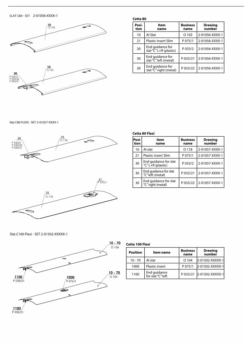
10 Al Slat O 103 2-01056-XXXX-1
21 Plastic insert Slim P 075/1 2-01056-XXXX-1
30 End guidance for slat “C” L+R (plastic) P 033/2 2-01056-XXXX-1
30 End guidance for slat “C” left (metal) P 033/21 2-01056-XXXX-1
30 End guidance for slat “C” right (metal) P 033/22 2-01056-XXXX-1
Cetta 80 Flexi
Posi-tion
Item name
Business name
Drawing number
10 Al slat O 118 2-01057-XXXX-1
21 Plastic insert Slim P 075/1 2-01057-XXXX-1
30 End guidance for slat “C” L+R (plastic) P 033/2 2-01057-XXXX-1
30 End guidance for slat “C” left (metal) P 033/21 2-01057-XXXX-1
30 End guidance for slat “C” right (metal) P 033/22 2-01057-XXXX-1
10O 118
21
1030O 118
P 033/2P 033/22P 033/21
P 075/1
Slat C80 FLEXI - SET 2-01057-XXXX-1
SLAT C80 - SET 2-01056-XXXX-1
Cetta 100 Flexi
Position Item name Business name
Drawingnumber
10 - 70 Al slat O 104 2-01502-XXXXX-1
1000 Plastic insert P 075/1 2-01502-XXXXX-1
1100 End guidance for slat “C” left P 033/21 2-01502-XXXXX-1
Slat C100 Flexi - SET 2-01502-XXXXX-1

EXTERIOR BLINDS
74
Setta 90
Posi-tion
Item name
Business name
Drawing number
10 Al slat O 124 2-00686-XXXX-B
20 Slat rubber P 198 2-00686-XXXX-B
30 Connecting hook P 200 2-00686-XXXX-B
40 End guidance for slat L+P (plastic) P 033/1 2-00686-XXXX-B
40 End guidance for slat right (metal) P 033/31 2-00686-XXXX-B
40 End guidance for slat left (metal) P 033/32 2-00686-XXXX-B
10
20
30
10
20
30
40
O 124
O 124
P 198
P 198
P 200
P 033/1P 033/31P 033/32
P 200
D
C
B
A
21 5 6
652 3 41
D
C
A
B
2-00686-XXXX-BLAMELA S90 - KOMPLET
10
20
30
10
20
30
40
O 124
O 124
P 198
P 198
P 200
P 033/1P 033/31P 033/32
P 200
D
C
B
A
21 5 6
652 3 41
D
C
A
B
2-00686-XXXX-BLAMELA S90 - KOMPLET
10
2030
40
O 101
O 101
P 199
P 199
P 200
P 200
P 033/1P 033/31P 033/32
10
20
30
D
C
B
A
21 5 6
652 3 41
D
C
A
B
2-00687-XXXX-BLAMELA S65 - KOMPLET
10
2030
40
O 101
O 101
P 199
P 199
P 200
P 200
P 033/1P 033/31P 033/32
10
20
30
D
C
B
A
21 5 6
652 3 41
D
C
A
B
2-00687-XXXX-BLAMELA S65 - KOMPLET
Setta 65
Posi-tion
Item name
Business name
Drawing number
10 Al slat O 101 2-00687-XXXX-B
20 Slat rubber P 199 2-00687-XXXX-B
30 Connecting hook P 200 2-00687-XXXX-B
40 End guidance for slat L+P (plastic) P 033/1 2-00687-XXXX-B
40 End guidance for slat right (metal) P 033/31 2-00687-XXXX-B
40 End guidance for slat left (metal) P 033/32 2-00687-XXXX-B
SLAT S65 - SET 2-00687-XXXX-B
SLAT S90 - SET 2-00686-XXXX-B
10
20
30P 200
10
20
30
40
O 101
O 101
P 199
P 199
P 033/1P 033/31P 033/32
P 200
D
C
B
A
21 5 6
652 3 41
D
C
A
B
LAMELA Z70 - KOMPLET 2-00515-XXXX-E
Zetta 70
Posi-tion
Item name
Business name
Drawing number
10 Al slat O 101 2-00515-XXXX-E
20 Slat rubber P 199 2-00515-XXXX-E
30 Connecting hook P 200 2-00515-XXXX-E
40 End guidance for slat L+P (plastic) P 033/1 2-00515-XXXX-E
40 End guidance for slat right (metal) P 033/31 2-00515-XXXX-E
40 End guidance for slat left (metal) P 033/32 2-00515-XXXX-E
SLAT Z70 - SET 2-00515-XXXX-E

Zetta 90
Posi-tion
Item name
Business name
Drawing number
10 Al slat O 124 2-00514-XXXX-C
20 Slat rubber P 198 2-00514-XXXX-C
30 Connecting hook P 200/30 2-00514-XXXX-C
40 End guidance for slat L+P (plastic) P 033/1 2-00514-XXXX-C
40 End guidance for slat right (metal) P 033/31 2-00514-XXXX-C
40 End guidance for slat left (metal) P 033/32 2-00514-XXXX-C
10
20
30
40
O 124
O 124
P 198
P 198
P 200/30
P 033/1P 033/31P 033/32
10
20
30P 200/30
D
C
B
A
21 5 6
652 3 41
D
C
A
B
2-00514-XXXX-CLAMELA Z90 - KOMPLET
SLAT Z90 - SET 2-00514-XXXX-C
“C”
“Z”
“Flat”
“C”
“Z”
Guide types for Venetian blinds with guidance using guiding channels
Metal guides Plastic guides
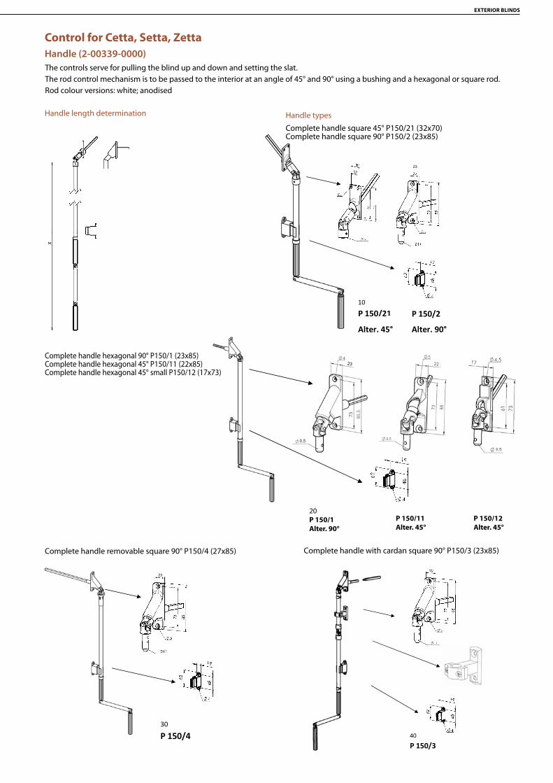
EXTERIOR BLINDS
76
10
P 150/21 20
P 150/1
30
P 150/4 40
P 150/3
KLIKY EXTERIÉRY
P 150/2 Alter. 90°
P 150/11 Alter. 45°
Alter. 90°
Alter. 45°
23
20P 150/1Alter. 90°
P 150/11Alter. 45°
P 150/12Alter. 45°
23
10
P 150/21
P 150/1
30
P 150/4
KLIKY EXTERIÉRY
P 150/2 Alter. 90°
P 150/11
P 150/12 Alter. 45°
Alter. 45°
Alter. 90° Alter. 45°
23
Handle length determination Handle types
Complete handle square 45° P150/21 (32x70)Complete handle square 90° P150/2 (23x85)
Complete handle removable square 90° P150/4 (27x85)
Complete handle hexagonal 90° P150/1 (23x85)Complete handle hexagonal 45° P150/11 (22x85)Complete handle hexagonal 45° small P150/12 (17x73)
Complete handle with cardan square 90° P150/3 (23x85)
Control for Cetta, Setta, ZettaHandle (2-00339-0000)The controls serve for pulling the blind up and down and setting the slat.The rod control mechanism is to be passed to the interior at an angle of 45° and 90° using a bushing and a hexagonal or square rod.Rod colour versions: white; anodised
10
P 150/21
20
P 150/1
30
P 150/4 40
P 150/3
KLIKY EXTERIÉRY
P 150/2 Alter. 90°
P 150/11
P 150/12 Alter. 45°
Alter. 45°
Alter. 90°
Alter. 45°
10
P 150/21 20
P 150/1
30
P 150/4 40
P 150/3
KLIKY EXTERIÉRY
P 150/2 Alter. 90°
P 150/11 Alter. 45°
Alter. 90°
Alter. 45°

Gearing Type
Gearing with square aperture045/5 (6-013232)
Gearing with hexagonal aperture, extended (STS)P045/4 (6-008115)
Gearing with hexagonal aperture for handle control(Cetta 35, Cetta 50)P228 (2-00132)
Gearing for cord control(Cetta 35, Cetta 50)P227 (2-00133)
10
22
SZ
Gearing extension
Plastic gearing with hexagonal aperture - interior(Cetta 35, Cetta 50)P 517/2 (6-001250-0002)
PROSÍM O ZASLÁNÍOBRÁZKU Převodovka P 045/9 (6-010260)
Gearing with hexagonal apertureP 045/6 (6-013233)
Gearing P 045/9 (6-010260)

EXTERIOR BLINDS
78
Gearing Shift Scheme
The gearing position (possible shift) in the head rail depends on the specific mounting of frame window, reveal. The gearing axis is the distance of the gearing center axis from the outer edge of guiding channel, or outer edge of slat in the case of the steel wire guidance.
Safety Instructions:• As soon as you reach the end stop, do not try to continue moving the handle. • Rotate the handle only in the respective direction, evenly, and without applying force.
20
"0"
- (0 - ∞)
+ (0 - 90)20

Motor controlMotor control
Motor controls serve for pulling the blind up and down and setting the slat.Motor controls allow selecting the control by the sun/wind sensor, remote control, or switch. It is possible to control several blinds at once depending on their dimensions. In this case, the motor is located in one blind in the group.
Types of motors
Item name Business name Drawing number Cable lenghtMotor J406 6/24 WT (6Nm) P 073/6J 6-002594-0000 0,5Motor J410 10/24 WT (10Nm) P 073/10J 6-002594-0001 0,5Motor J410 10/24 WT (10Nm)-PROTECT P 073/10JP 6-002594-0010P 0,5Motor J418 18/24 WT (18Nm) P 073/18J 6-002594-0004 0,5Motor J406 RTS 6/24 WT (6Nm) P 642/06 6-002593-0006 0,5Motor J410 RTS 10/24 WT (10 Nm) P 642/10 6-002593-0010 0,5Motor IO PROTECT (6 Nm) P 643/676 6-016065-0676 0,5Motor IO PROTECT (10Nm) P 643/677 6-016065-0677 0,5Motor IO PROTECT (18Nm) P 643/681 6-016065-0681 0,5Motor GJ5603 - 3Nm + buckle P 093/1 6-006880-0000 0,9Motor GJ5606 - 6Nm + buckle P 093/2 6-006880-0001 0,9Motor GJ5610 - 10Nm + buckle P 093/3 6-006880-0002 0,9Motor GJ5620 - 20Nm + buckle P 093/6 6-006880-0006 0,9Motor cable Geiger; l= 900mm P 094 6-006880-0003 1,9Motor ELERO JA 04 SFOT DC, 4Nm P 096softDC/04 6-015554-0000 0,9Motor GJ5606k F03 AIR - 6Nm + buckle PR0879/6 6-014807-0006 0,9Motor GJ5610 F03 AIR - 10Nm + buckle PR0879/10 6-014807-0010 0,9Motor GJ5620 F03 AIR - 20Nm + buckle PR0879/20 6-014807-0020 0,9Motor cable Geiger AIR with LOXON chip P094/2 6-014819-0000 1,9

EXTERIOR BLINDS
80
1 - neutral wire (N)2 - phase wire (L)3 - not connected4 - ground wire (PE)
1 - neutral wire (N)2 - phase wire (up)3 - phase wire (down)PE - ground wire
1 - Blue2 - Black3 - BrownPE - Yellow-green
Motor Wiring Diagram RTS Motor Wiring Diagram
Parameter Motor Somfy Motor Geiger
Torque 6 - 18 Nm 3 - 20 NmPower Input 90 - 210 W 90 - 190 WCurrent Consumption 0,41 - 0,7 A 0,4 - 0,85 A
Nominal Voltage 230 V / 50 Hz 230 V / 50 HzRPM 24 rpm 26 rpmEnd Switch Capacity 73 80
Motor Protection Class IP54 IP54Maximum Operation Time approx. 6 min. approx. 6 min.Weight 1,35 - 2,41 kg -
Important Instructions:
• Theelectricequipmentcanbeassembledonlybyqualifiedpersons.• Never connect more than one motor to one switch. One switch can control more drives only in the case of group control.
Note: See the manuals of Somfy, Geiger and Elero companies for detailed wiring diagrams.
Motor control
Setting of Upper and Lower End Position (end stop)
The motors applied have two integrated, freely adjustable end switches. The white button is the lower stop, the black (color) one is the upper stop.
Setting of Upper End Position:• Lower the Venetian blind using the installation cable approximately 300 mm below the required end position. • Note: the installation cable is not, however, required for setting the end stops in this case. • Press the black setting button on motor. • Lift the Venetian blind to the required upper end position. • Lower the Venetian blind for approximately 6 seconds downwards until the black setting button jumps out (clicks) audibly.
The upper end position is now set. The motors have another upper end stop integrated, the emergency one. It is the “mushroom” in the motor bodies that automatically switches the Venetian blinds off only when moving up at anytime, whenever touched by the upper blind slat.
Setting of Lower End Position:• Lift the Venetian blind approximately 300 mm above the required end position.• Press the white setting button on the motor. • Lower the Venetian blind to the required lower end position. • Lift the Venetian blind for approximately 6 seconds upwards until the white setting button jumps out (clicks) audibly.
The lower end position is now set.
The setting can be changed at any time, if required.

Setting of end stops of Somfy WT motors – using the Somfy Installation cable
The motors applied do not have visibly adjustable end switches.
Setting of Upper End Position:• Lower the Venetian blind using the installation cable approximately 300 mm below the required end position. • Press the following: button RTS on Somfy Installation cable up and down buttons simultaneously on normal installation cable. • The motor rotates for approximately 1 second. • Lift the Venetian blind to the required upper end position. • Lower the Venetian blind for approximately 3 seconds downwards.
The upper end position is now set. The motors have another upper end stop integrated, the emergency one. It is the “mushroom” in the motor bodies that automatically switch-es the Venetian blinds off only when moving up at anytime, whenever touched by the upper blind slat.
Setting of Lower End Position:• LifttheVenetianblindapproximately300mmabovetherequiredendposition.• Press the following: button RTS on Somfy Installation cable up and down buttons simultaneously on normal installation cable. • The motor rotates for approximately 1 second. • Lift the Venetian blind to the required lower end position. • Lower the Venetian blind for approximately 3 seconds downwards.
The lower end position is now set.
The setting can be changed at any time, if required.
Setting AdjustmentWhen setting the end position, the motor speed is set. If the end position is not set correctly, or if the Venetian blind behavior, and thus the bottom rail end position, has changed due to ambient effects and increased friction, the required end position must be re-set according to the above-described procedure.
Setting AdjustmentWhen setting the end position, the motor speed is set. If the end position is not set correctly, or if the Venetian blind behavior, and thus the bottom rail end position, has changed due to ambient effects and increased friction, the required end position must be re-set according to the above-described procedure.
Recommended Torque for Motor Controlled Blinds (Nm)
Blind Width (mm)
Blind height (mm)
400 1800 2400 3000 3600 4200 4800 5400 6600 7200
1000 3 3 3 3 3 3 3 3 3 32000 3 3 3 3 6 6 6 6 6 103000 3 3 6 6 6 6 10 10 10 204000 3 6 6 10 10 10 10 20 20 20

EXTERIOR BLINDS
82
24
40
139 - 160111 - 132
24
40
24
40
83 - 104
25
25
49
-
70
25
25
39 - 60
Type of wire guide Distance between wire and window frame (mm)
Corner wire guide, 25 - 46 mm P 031/6 25-46Corner wire guide, 39 - 60 mm P 031 39 - 60Corner wire guide, 49 - 70 mm P 031/1 49 - 70Corner wire guide, 83 - 104 mm P 031/2 83 - 104Corner wire guide, 111 - 132 mm P 031/3 111 - 132Corner wire guide, 139 - 160 mm P 031/4 139 - 160Corner wire guide, P 031/5 63
Guide types for wire-guided blinds(Cetta 35, Cetta 50, Cetta 65, Cetta 80, Cetta 80-Flexi)
Guidance – Wire
Corner wire guide, 49 - 70 mm P 031/1 (2-00137)
Corner wire guide, 111 - 132 mm P 031/3 (2-00559)
Corner wire guide, P 031/5 (6-009346) Stretching square P043/1 (6-011032)
Corner wire guide, 39 - 60 mm P 031 (2-00195)
Corner wire guide, 83 - 104 mm 031/2 (2-00136)
Corner wire guide, 139 - 160 mm P 031/4 (2-00560)
2
16
6
10
55
30
40 5
3,5
D
C
B
A
21 6
652 3 41
D
C
A
B
6-011032-XXXX
2
16
6
10
55
30
40 5
3,5
D
C
B
A
21 6
652 3 41
D
C
A
B
6-011032-XXXX
Corner wire guide, 25 - 46 mm P031/6 (2-00822)
Bracket for wire AF 81 P 044 (6-011063)

Wire guide - attachment methodsChannel 56 x 58
D
C
B
A
21 5 6
652 3 41
D
C
A
B
NAPÍNÁNÍ LANKA
Channel 40x40

EXTERIOR BLINDS
84
Wireholder Fe P002/7 (2-01128) Wireholder Al P002/8 (2-01294)(for head rail 56x58) (for head rail 58x60)
Clamping screw P507 (6-001229)for wire P 501 (2,2 mm) (C50)
Guide P534/1 (7-301796) GEIGER plastic gearfor negative (-) axis (-10 ≥ -32) holder with cord binding (6-017250)
Head rail section hanger Fe for cord guide (2-00685)(for Head Rail 56x58)
432F132Getriebehalter mit Seilanbindung
UNGER HANDELS- UND VERTRIEBS GMBH • Heunwiese 14 • 35759 DriedorfTel: ++49 (0)2775 9409-0 • Fax: ++49 (0)2775 9409-29 • [email protected] • www.unger-handel.de
Technische DatenMaterial Kunststoff
Außenmaß 56 x 53,5 mm
Achshöhe 29,5 mm
BestellinformationArtikel-Nr. 432F130
Kurzbeschreibung Getriebehalter mit Seilanbindung
VPE 25 Stück
Gewicht ca. 65 g
©2013 Unger Handels- und Vertriebs GmbH technische Änderungen vorbehalten
29.5
53.5
67.5
56
Ø 46432F132Getriebehalter mit Seilanbindung
UNGER HANDELS- UND VERTRIEBS GMBH • Heunwiese 14 • 35759 DriedorfTel: ++49 (0)2775 9409-0 • Fax: ++49 (0)2775 9409-29 • [email protected] • www.unger-handel.de
Technische DatenMaterial Kunststoff
Außenmaß 56 x 53,5 mm
Achshöhe 29,5 mm
BestellinformationArtikel-Nr. 432F130
Kurzbeschreibung Getriebehalter mit Seilanbindung
VPE 25 Stück
Gewicht ca. 65 g
©2013 Unger Handels- und Vertriebs GmbH technische Änderungen vorbehalten
56
Ø 46

P 018/10
P 018/2
P 016/1
P 017/1
P 018/7
P 017/7
P 018/4
P 017/5
P 018/31P 018/3
P 018/51P 018/5
RS 60P 018/2(A22)
RS 75P 018/2(A22)
D C B A
21
56 6
52
34
1
D C AB
P 018/10
P 018/2
P 016/1
P 017/1
P 018/7
P 017/7
P 018/4
P 017/5
P 018/31P 018/3
P 018/51P 018/5
RS 60P 018/2(A22)
RS 75P 018/2(A22)
D C B A
21
56 6
52
34
1
D C AB
Guidance - Guiding Channel
Guiding channels applies to: Cetta 50, Cetta 60 Flexi, Cetta 65, Cetta 80, Cetta 80-Flexi, Cetta 80-Slim, Zetta 70, Zetta 90, Setta 65, Setta 90
BLIND WIDTH

EXTERIOR BLINDS
86
Shutter P 002/41 (2-00588) for guide channel P 016/1
Self-Supporting Guiding Channel P 016/1 (7-302121)
Head rail section hanger with holder P 002/4 vodící lišty P 016/1
Single Guiding Channel P 018/2 (7-302122)for installation in lining (without use of ejector)
Single-Sided Round Channel P 018/4 (6-010533)
Double-Sided Round Guiding Channel P 017/5 (6-010532)
Double Guiding Channel P 017/1 (7-302123)for installation on frame and facade (with use of ejector)
Single Guiding Channel P 018/10 (7-302363)For installation on the frame using a guide rail holder.
18
20
22
3
5,5
6,5
5
21,
5
12
D
C
B
A
21 5 6
652 3 41
D
C
A
B
P 018/2VODÍCÍ LIŠTA
18
20
9,4
3
5,5
6,5
5
21,
5
12
D
C
B
A
21 5 6
652 3 41
D
C
A
B
P 018/2VODÍCÍ LIŠTA
3
5,5
Ø 6,5
Vedení - vodící lišta
310
P018/1
330
P 018/2
320
P 017/1
340 +
P 016/1
350
P 018/4
360
P018/51
370
P 018/5
380
P017/5
390
P018/3
400
P018/31
420
RS 60
510
P 019
500
P 022/2
Držáky pro VL: P 017/1 P 018/1
600
P 021
610
P 021/1
620
P 021/2
Držáky pro VL: P 017/1 P 017/5 P 018/1 P 018/4
630
P 021/5
640
P 021/6
530
P 023
660
P 021/4
650
P 021/3
520
2/3
342
P 016/1 drážka
55 - 74 mm
75 - 102 mm
103 - 154 mm
56 - 80 mm
81 - 125 mm
103 - 170 mm
171 - 295 mm
39,4
39,4
Ø41,2
37,6
39,4
Ø 41,2

Single-Sided Round Channel P 018/7 (7-302154) Double-Sided Round Guiding Channel P 017/7 (7-302155)
P 018/31
P 018/3
k dispozici od 08-2011
23±1
27,
6±1
35
20
26±
1
1 4
A
B
C
D
31 2 4
A
D
C
B
2 3
23+1
22
23±
1
29±1
1 4
A
B
C
D
31 2 4
A
D
C
B
2 3
84,
8
27
18
15,7
28,2
1 4
A
B
C
D
31 2 4
A
D
C
B
2 3
RS 75
Guiding Channel under Plastering P 018/3X (7-302234-PU52) with insert P 018/31 (3-01419-0000)
Guiding Channel under Plastering P 018/51 (7-301781, Al) with insert P 018/5 (7-301782, PVC)
Guiding channel - divided – RS 75 (6-011267)for installation on frame and in lining (without use of ejector)
Guiding channel under plastering is cut in 2 parts (300 mm from the top edge of the guiding channel) and is joined by the side guide chan-nel insertion (kedr) due to its fitting on the blind pin and the correct guiding into the guide rail housing. The side guide channel insertion (kedr) is the entire height of the guide rail.

EXTERIOR BLINDS
88
35 - 37,5
55 - 74
75 - 102
103 - 154
P 021
P 021/11
P 021/1
P 021/2
25
25 30
4
5,4
5,2 9,6
D
C
B
A
21 5 6
652 3 41
D
C
A
B
2-00557-XXXX-EDRŽÁKY
Telescopic guiding channel holder , P021/3 (2-00401)for guiding channel P 017/1, P 017/5, P 018/10, P 018/4
Telescopic guiding channel holder, P021/4 (2-00402)for guiding channel P 017/1, P 017/5, P 018/10, P 018/4
Telescopic guiding channel holder STS, P021/5 (2-00582)for guiding channel P 016/1, P 017/1, P 017/5, P 018/10, P 018/4
Telescopic guiding channel holder STS, P021/6 (2-00583)for guiding channel P 016/1, P 017/1, P 017/5, P 018/10, P 018/4
Guiding Channel HoldersFor guiding channel P 017/1, P 018/10

90 - 110
P 050/04
110 - 130
P 050/05
130 - 150
P 050/06
150 - 170
P 050/07
170 - 190
P 050/08
190 - 210
P 050/09
210 - 230
P 050/10D
C
B
A
21 5 6
652 3 41
D
C
A
B
DRŽÁKY VODÍCÍCH LIŠT
Telescopic guiding channel holder, P050/04 (2-01030), P050/05 (2-01031), P050/06 (2-01032), P050/07 (2-01033), P050/08 (2-01034), P050/09 (2-01035), P050/10 (2-01036) for guiding channel P017/1 a P018/10
Telescopic guiding channel holder, P050/01 (2-01027), P050/02 (2-01028), P050/03 (2-01029) for guiding channel P017/1 a P018/10
Guiding Channel Holders
50 - 60
P 050/01
60 - 70
P 050/02
70 - 90
P 050/03
D
C
B
A
21 5 6
652 3 41
D
C
A
B
DRŽÁKY VODÍCÍCH LIŠT
50 - 60
P 050/01
60 - 70
P 050/02
70 - 90
P 050/03
D
C
B
A
21 5 6
652 3 41
D
C
A
B
DRŽÁKY VODÍCÍCH LIŠT
50 - 60
P 050/01
60 - 70
P 050/02
70 - 90
P 050/03
D
C
B
A
21 5 6
652 3 41
D
C
A
B
DRŽÁKY VODÍCÍCH LIŠT
13,
3
R 2 7,2
+0,
5
62,
7
20,5
AA
7,2
+0,
5
61 + -
01,054,0
20
R0,5
R0,5
10,0
14
R2
R12 1
R28
6,5
100
°
R1,5
R2
R0,5
60,
1 + -0,
10,
3
6,0
20,5
15
20
40
1
1,2
1,2
R0,5
2°
6,5
12,5 ++
0,150,05
7,8
6
1
2
3
3
3

EXTERIOR BLINDS
90
18
20
70 - 8
0
39 - 49
ŠÍŘKA ŽALUZIE (SZ)
PRO VYSUNUTÍ 70mm JE VYMĚŘOVÁNA ŠÍŘKA ŽALUZIE (SZ) VĚTŠÍ O 39mm.S KAŽDÝM DALŠÍM VYSUNUTÍM O 1mm SE ŠÍŘKA TAKY ZVĚTŠÍ O 1mm
1 4
A
B
C
D
31 2 4
A
D
C
B
2 3
2-01150-XXXX-0DRŽÁK VODÍCÍ LIŠTYROHOVÝ VNĚJŠÍ 70-80
18
20
80 - 1
00
49 - 69
ŠÍŘKA ŽALUZIE (SZ)
PRO VYSUNUTÍ 80mm JE VYMĚŘOVÁNA ŠÍŘKA ŽALUZIE (SZ) VĚTŠÍ O 49mm.S KAŽDÝM DALŠÍM VYSUNUTÍM O 1mm SE ŠÍŘKA TAKY ZVĚTŠÍ O 1mm
1 4
A
B
C
D
31 2 4
A
D
C
B
2 3
2-01151-XXXX-0DRŽÁK VODÍCÍ LIŠTYROHOVÝ VNĚJŠÍ 80-100
Guiding Channel HoldersGuiding channel corner bracket exterior 70 -80 P 098/0 (2-01150-XXXX-0)For extension of 70mm is the measured width 39mm bigger. With each extension of 1 mm, increases also the width by 1 mm.
Guiding channel corner bracket exterior 80 – 100 P 098/1 (2-01151-XXXX-0)For extension of 80mm is the measured width 49mm bigger. With each extension of 1 mm, increases also the width by 1 mm.

18
20
100 -
140
69 - 109
ŠÍŘKA ŽALUZIE (SZ)
PRO VYSUNUTÍ 100mm JE VYMĚŘOVÁNA ŠÍŘKA ŽALUZIE (SZ) VĚTŠÍ O 69mm.S KAŽDÝM DALŠÍM VYSUNUTÍM O 1mm SE ŠÍŘKA TAKY ZVĚTŠÍ O 1mm
1 4
A
B
C
D
31 2 4
A
D
C
B
2 3
2-01152-XXXX-0DRŽÁK VODÍCÍ LIŠTYROHOVÝ VNĚJŠÍ 100-140
18
20
40
ŠÍŘKA ŽA
LUZIE
(SZ)
76 - 9
0
45 - 59
PRO VYSUNUTÍ 45mm JE VYMĚŘOVÁNA ŠÍŘKA ŽALUZIE (SZ) KRATŠÍ O 76mm.S KAŽDÝM DALŠÍM VYSUNUTÍM O 1mm SE ŠÍŘKA TAKY ZKRÁTÍ O 1mm
1 4
A
B
C
D
31 2 4
A
D
C
B
2 3
2-01154-XXXX-1DRŽÁK VODÍCÍ LIŠTYROHOVÝ VNITŘNÍ 70-80
Guiding channel corner bracket exterior 100 – 140 P 098/2 (2-01152-XXXX-0)For extension of 100mm is the measured width 69mm bigger. With each extension of 1 mm, increases also the width by 1 mm.
Guiding channel corner bracket interior 45 - 59 P 099/0 (2-01154-XXXX-0)For extension of 45mm is the measured width 39mm shorter. With each extension of 1 mm, decreases also the width by 1 mm.

EXTERIOR BLINDS
92
40
18
20
ŠÍŘKA ŽA
LUZIE
(SZ)
56 - 77
87 - 1
08
PRO VYSUNUTÍ 56mm JE VYMĚŘOVÁNA ŠÍŘKA ŽALUZIE (SZ) KRATŠÍ O 87mm.S KAŽDÝM DALŠÍM VYSUNUTÍM O 1mm SE ŠÍŘKA TAKY ZKRÁTÍ O 1mm
1 4
A
B
C
D
31 2 4
A
D
C
B
2 3
2-01155-XXXX-1DRŽÁK VODÍCÍ LIŠTYROHOVÝ VNITŘNÍ 80-100
40
18
20
ŠÍŘKA ŽA
LUZIE
(SZ)
75 - 117
106 -
148
PRO VYSUNUTÍ 75mm JE VYMĚŘOVÁNA ŠÍŘKA ŽALUZIE (SZ) KRATŠÍ O 106mm.S KAŽDÝM DALŠÍM VYSUNUTÍM O 1mm SE ŠÍŘKA TAKY ZKRÁTÍ O 1mm
1 4
A
B
C
D
31 2 4
A
D
C
B
2 3
2-01156-XXXX-1DRŽÁK VODÍCÍ LIŠTY ROHOVÝ VNITŘNÍ 100-140
For corner brackets it is necessary to order an aluminium auxiliary profile 40x40 6-013373-0000
Guiding channel corner bracket interior 56 - 77 P 099/1 (2-01155-XXXX-0)For extension of 56mm is the measured width 87mm shorter. With each extension of 1 mm, decreases also the width by 1 mm.
Guiding channel corner bracket interior 75 - 117 P 099/2 (2-01156-XXXX-0)For extension of 75mm is the measured width 106mm shorter. With each extension of 1 mm, decreases also the width by 1 mm.

40
OS+27,5
SZ=SV-(OS+27,5)
Bracket for under-plaster guiding channel
Measurement of corner bracketsMeasurement - wire
Measurement - channel
20 - 80
45 - 115
105 - 175
35
25
25
P 047/3105-175
P 047/245-115
P 047/120-80
20
(30)
25
(35)
31
(41)
4
25
9,6 5,2
5,4
25 (35)
D
C
B
A
21 5 6
652 3 41
D
C
A
B
2-00557-XXXX-GDRŽÁKY
20 - 80
45 - 115
105 - 175
35
25
25
P 047/3105-175
P 047/245-115
P 047/120-80
20
(30)
25
(35)
31
(41)
4
25
9,6 5,2
5,4
25 (35)
D
C
B
A
21 5 6
652 3 41
D
C
A
B
2-00557-XXXX-GDRŽÁKY
40
OS-27,5
SZ=SV+(OS-27,5)
40
20
18
OS-31
SZ=SV+(OS-31)
18
20
40
OS+31
SZ=SV-(OS+31)
MEASURED WIDTH (SV)
SLAT
AXI
S (O
S)
SPECIFIED WIDTH (SZ)
MEASURED WIDTH (SV)
SLAT
AXI
S (O
S)
SPECIFIED WIDTH (SZ)
MEASURED WIDTH (SV)
SLAT
AXI
S (O
S)
SPECIFIED WIDTH (SZ)
SLAT
AXI
S (O
S)
SPECIFIED WIDTH (SZ)
MEASURED WIDTH (SV)
SLAT
AXI
S (O
S)
40
OS+27,5
SZ=SV-(OS+27,5)
40
OS-27,5
SZ=SV+(OS-27,5)
40
20
18
OS-31
SZ=SV+(OS-31)
18
20
40
OS+31
SZ=SV-(OS+31)

EXTERIOR BLINDS
94
Recommended quantity of holders per one guiding channel based on blind height (mm)
Blind height ( mm) Quantity< 1801 21801 - 2800 3higher than 2800 4
Types of guiding channel holders
Distance from center of guiding channel
to the window frame (mm)
Guiding Channel
Guiding channel holder, 55 - 74 mm P021 (2-00050) 55 - 74 P 017/1, P 018/10Guiding channel holder, 75 - 102 mm P021/1 (2-00051) 75 - 102 P 017/1, P 018/10Guiding channel holder, 103 - 154 mm P021/2 (2-00052) 103 - 154 P 017/1, P 018/10Telescopic guiding channel holder, 103 - 170 mm P021/3 (2-00401) 103 - 170 P 017/1, P 017/5, P 018/10, P 018/4Telescopic guiding channel holder, 171 - 295 mm P021/4 (2-00402) 171 - 295 P 017/1, P 017/5, P 018/10, P 018/4Telescopic guiding channel holder STS, 56 - 80 mm P021/5 (2-00582) 56 - 80 P 016/1, P 017/1, P 017/5, P 018/10, P 018/4Telescopic guiding channel holder STS, 81 - 125 mm P021/6 (2-00583) 81 - 125 P 016/1, P 017/1, P 017/5, P 018/10, P 018/4Guiding channel holder, 50 - 60 mm P050/1 50 - 60 P017/1, P018/10Guiding channel holder, 60 - 70 mm P050/2 60 - 70 P017/1, P018/10Guiding channel holder, 70 - 90 mm P050/3 70 - 90 P017/1, P018/10Guiding channel holder, 90 - 110 mm P050/4 90 - 110 P017/1, P018/10Guiding channel holder, 110 - 130 mm P050/5 110 - 130 P017/1, P018/10Guiding channel holder, 130 - 150 mm P050/6 130 - 150 P017/1, P018/10Guiding channel holder, 150 - 170 mm P050/7 150 - 170 P017/1, P018/10Guiding channel holder, 170 - 190 mm P050/8 170 - 190 P017/1, P018/10Guiding channel holder, 190 - 210 mm P050/9 190 - 210 P017/1, P018/10Guiding channel holder, 210 - 230 mm P050/10 210 - 230 P017/1, P018/10

Holders for Exterior Blinds Fixed hanger for C50 Fixed hanger for C50 with front coverP 512 (2-00057) P 513 (6-001244)(for head rail 40 x 40) (for head rail 40 x 40)
72
40
45
40
86
41
87
10
42
47 22
7
43
19 49
4,6
20
7
30 4,7
40
1 4
A
B
C
D
31 2 4
A
D
C
B
2 3
VĚŠÁK P 512/6 + PODLOŽKA P 512/61
10 4
2
47 22
7
43
19 49
4,6
20
7
30 4,7
40
1 4
A
B
C
D
31 2 4
A
D
C
B
2 3
VĚŠÁK P 512/6 + PODLOŽKA P 512/61
Universal openable hanger P512/6 (6-010980)(for Head Rail 40x40)Pad P 512/61 (3-02936)

EXTERIOR BLINDS
96
Head rail hanger FeP 002 (2-00038)(for head rail 56 x 58)
Head rail hanger AlP 002/11 (2-01350)(for head rail 58 x 60)
Head rail hanger mechanic - Fe ClickP 002/31(6-002319-0000) 56x58
Head rail hanger mechanic - Fe ClickP 002/32 (6-015772-0000) 56 x 58
62
55
97
55
62
97
59
94
64

Adjustable hanger (inner hanger Fe Click) 107 - 164 mm P 009/1 (2-00404)(for head rail 56 x 58)
Adjustable hanger (inner hanger Fe Click) 164 - 225 mmP 009/2 (2-00405)(for head rail 56 x 58)
Blind bracket - short, adjustable and mechanical106-163 mmP 009/21 (2-01392)(for head rail 56 x 58)(pro horní profil 56 x 58)
120
164 - 225
56
Blind bracket - fixed, mechanical 132,5 mmP 009/20 (2-01393)(for head rail 56 x 58)
Blind bracket - long, adjustable and mechanical 165 – 223 mmP 009/22 (2-01391)
107 - 164
56
120
58116
132
115
,5
115
,5
B = 132,5 40
D
C
B
A
21 5 6
652 3 41
D
C
A
B
2-01393-XXXX-0DRŽÁK ŽALUZIE MECH. DVOJITÝ - PEVNÝ P 009/20
115
,5
B = 106 - 163
120
40
D
C
B
A
21 5 6
652 3 41
D
C
A
B
2-01392-XXXX-0DRŽÁK ŽALUZIE MECH. DVOJITÝ - NAST. KRÁTKÝ P 009/21
B = 165 - 223
120
115
,5
40
D
C
B
A
21 5 6
652 3 41
D
C
A
B
2-01391-XXXX-0DRŽÁK ŽALUZIE MECH. DVOJITÝ - NAST. DLOUHÝ P 009/22
Fixed hanger (inner hanger Fe Click) 132 mmP 009 (2-00403)(for head rail 56 x 58)

EXTERIOR BLINDS
98
Adjustable hanger (inner hanger Fe) 107 - 164 mm P 010/1 (2-00354)(for head rail 56 x 58)
Adjustable hanger (inner hanger Fe) 164 - 225 mm P 010/2 (2-00355)(for head rail 56 x 58)
120
164 - 225
56
120
107 - 164
Blind bracket - fixed 132,5 mmP 010/20 (2-01387)(for head rail 56 x 58)
116
132
Blind bracket - short, adjustable 106-163 mmP010/21 (2-01386)(for head rail 56 x 58)
Blind bracket - long, adjustable 165 – 223 mmP 010/22 (2-01385)(for head rail 56 x 58)
115
,5
120
B = 106 - 163 40
D
C
B
A
21 5 6
652 3 41
D
C
A
B
2-01386-XXXX-0P 010/21DRŽÁK ŽALUZIE DVOJITÝ - NAS. KRÁTKY
115
,5
B = 165 - 223 40
120
D
C
B
A
21 5
52 3 41
P 010/22DRŽÁK ŽALUZIE DVOJITÝ - NAS. DLOUHÝ
B = 132,5 40
115
,5
115
,5
Fixed hanger (inner hanger Fe) 132 mmP 010 (2-00353)(for head rail 56 x 58)

Adjustable hanger - mechanical 217 - 277 mm P 010/32 (2-01601-0000)
Adjustable hanger - fixed 162 - 222 mm P 010/34 (2-01603-0000)
Adjustable hanger - fixed 107 - 167 mm P 010/33 (2-01602-0000)
Adjustable hanger - fixed 217 - 277 mm P 010/35 (2-01604-0000)
Adjustable hanger - mechanical 162 - 222 mm P 010/31 (2-01600-0000)
Adjustable hanger - mechanical 107 - 167 mm P 010/30 (2-01599-0000)
30
120 B = 107 - 167 40
120
53 - 87,5
D
C
B
A
21 5 6
652 3 41
D
C
A
B
2-01599-0000P 010/30DRŽÁK NASTAVITELNÝ 107 - 167 - MECHANICKÝ
30
120 B = 217 - 277
40
120
125,5 - 197,5
D
C
B
A
21 5 6
652 3 41
D
C
A
B
2-01601-0000P 010/32DRŽÁK NASTAVITELNÝ 217 - 277 - MECHANICKÝ
30
120 B = 162 - 222 40
120
70,5 - 142,5
D
C
B
A
21 5 6
652 3 41
D
C
A
B
2-01603-0000P 010/34DRŽÁK NASTAVITELNÝ 162 - 222 - PEVNÝ
30
120 B = 162 - 222 40
120
70,5 - 142,5
D
C
B
A
21 5 6
652 3 41
D
C
A
B
2-01600-0000P 010/31DRŽÁK NASTAVITELNÝ 162 - 222 - MECHANICKÝ
120
30
120
40 B = 107-167
53 - 87,5
D
C
B
A
21 5 6
652 3 41
D
C
A
B
2-01602-0000P 010/33DRŽÁK NASTAVITELNÝ 107 - 167 - PEVNÝ
30
120 B = 217 - 277
120
40
125,5 - 197,5
D
C
B
A
21 5 6
652 3 41
D
C
A
B
2-01604-0000P 010/35DRŽÁK NASTAVITELNÝ 217 - 277 - PEVNÝ

EXTERIOR BLINDS
100
58
120
107 - 164
58
116
132
164 - 225
56
120
Blind bracket - fixed, with Al bracket 132,5 mmP 011/20 (2-01390)(for head rail 58 x 60)
Blind bracket - short, adjustable with Al bracket 106-163 mmP011/21 (2-01389) (for head rail 58 x 60)
Blind bracket - long, adjustable with Al bracket 165 – 223 mmP 011/22 (2-01388)(for head rail 58 x 60)
115
,5
B = 132.5 40
115
,5
D
C
B
A
21 5
52 3 41
DRŽÁK ŽALUZIE DVOJITÝ - PEVNÝ S AL. DRŽÁKEM P 011/20
115
,50
B = 106 - 163 40
120
D
C
B
A
21 5 6
652 3 41
D
C
A
B
2-01389-XXXX-0DRŽÁK ŽALUZIE DVOJITÝ - NAS. KRÁTKÝ S AL. DRŽÁKEM P 011/21
115
,5
B = 165 - 223 40
120
D
C
B
A
21 5
52 3 41
2-01388-XXXX-0DRŽÁK ŽALUZIE DVOJITÝ - NAS. DLOUHÝ S AL. DRŽÁKEM P 011/22
Adjustable hanger (inner hanger Al) 107 - 164 mmP 011/1 (2-00373)(for head rail 58 x 60)
Adjustable hanger (inner hanger Al) 164 - 225 mmP 011/2 (2-00374)(for head rail 58 x 60)
Fixed hanger (inner hanger Al) 132 mm P 011 (2-00384)(for head rail 58 x 60)

Holders KBT1-11
116 - 227
147
- 524
KBT3/1 (B=116-169; A=147-524)KBT3/2 (B=170-227; A=147-524)(for head rail 56 x 58)
116 - 227
147
- 524
135 - 245
177-
524
KBT4/1 (B=116-169; A=147-524)KBT4/2 (B=170-227; A=147-524)(for head rail 56 x 58)
Blind bracket - mechanical KBT01, Fe (105-180)P008_KBT1 (6-010604-0001)(for head rail 40 x 40)
Blind bracket - mechanical KBT02, Fe (130-255)P 008_KBT2 (6-010604-0002)(for head rail 56 x 58)
KBT5/1 (B=135-190;A=177-524)KBT5/2 (B=191-524;A=177-524)(for head rail 56 x 58)
115 - 140
64,5
60
130
- 25
5
D
C
B
A
21 5 6
652 3 41
D
C
A
B
6-010604-0002P 008_KBT2DRŽÁK ŽALUZIE KBT2

EXTERIOR BLINDS
102
KBT7/11 (B=116-169; A=147-524; A1=28-83)KBT7/12 (B=116-169; A=147-524; A1=84-138)KBT7/13 (B=116-169; A=147-524; A1=139-193)KBT7/21 (B=170-227; A=147-524; A1=28-83)KBT7/22 (B=170-227; A=147-524; A1=84-138)KBT7/23 (B=170-227; A=147-524; A1=139-193)(for head rail 56 x 58)
KBT8/1 (B=116-169; A=147-524)KBT8/2 (B=170-227; A=147-524)(for head rail 56 x 58)
Holders for Applications under Plastering (for atypical designs of front covers)KBT6/1 (B=116-169; A=precise)KBT6/2 (B=170-227; A=precise)(for head rail 56 x 58)
KBT11/1 (B=116-169; A=precise)KBT11/2 (B=170-227; A=precise)(for head rail 56 x 58)
116 - 227
147-
524
116 - 227
147-
524
177-
524
116 - 227
ma
x. 5
24
ma
x. 5
24
116 - 227
147-
524
116 - 227
135-245
KBT3/1 (B=116-169; A=147-524)KBT3/2 (B=170-227; A=147-524)(for head rail 56 x 58)
KBT4/1 (B=116-169; A=147-524)KBT4/2 (B=170-227; A=147-524)(for head rail 56 x 58)

KBT Holders Front coverKBT1 T2 T3 T2u T3uKBT2 T2 T3 T2u T3uKBT3 T1 T1u T2 T3 T2u T3uKBT4 T2s T3sKBT5 T2b T2r T3b T3rKBT6 atypical coverKBT7 T1cKBT8 T4 T4c T4r T4u; T4u/x T4d; T4d/xKBT9 T4sKBT10 T4bKBT11 atypical cover
164 - 223
155
107
115
,5
120
40
13,
5 35,
5
69,
5 91,
5
7
8
7,5 7
2-01347-XXXX-0NOSNÍK STAVITELNÝ DVOJITÝ - DLOUHÝ P 0031/2
132,5
115
,5
3
115
,5
25,5 7,5
8
16
38
8
7
13,
5 8
35,
5 8
40
53 68
83 90,5
8
20
27,5 8
7
7,5
2
5,5
9,5
5
5,5
3-03000-XXXX-0NOSNÍK PEVNÝ P 0031
Hanger of head rail double - adjustable, long P 003/22 2-01347-XXXX-0
Hanger of head rail - double, fixed P 003/20 3-03000-XXXX-0
Use of holders for respective front cover types

EXTERIOR BLINDS
104
Types of Front Covers
Front Covers type T2
Front Covers type T1
Note: Dimensional tolerances for input values a, b, c, d = +/- 2 mmWe recommend a minimum front cover width of 140 mm for exterior blinds Cetta 80 zig-zag, Zetta 90, Setta 90 and Cetta 100 Flexi with underplaster instal-lation.
Note: The arrows in some front cover indicate where the holes for hanging the cover sheet during painting are created.
T1
T1uz
T2
T2u
T2sz T2uz
T2z T2bz
T2n
T2b T2r
T1c T1u T1z
T2s
T2rz
a20 20
c
b
18
4,5
T4u/3
a
20
18 18
20
c
b
4,54,5
T4u/2
a
18 18
20
c
b
4,5 4,5
T4u/120
18
a
b
c
4,5
T3u
a
20
18
b
4,5
T2u
a
18
20
4,5
T1u
a
20 20
c
b
T4d/2
b
R23
a
18
4,5
T2r
a
18
b
c
4,5
T4
b
ca
18
4,5
T3
b
a
18
4,5
T2
a
18 18
c
b
4,54,5
T4c
a
1818
4,5
4,5
T1c
b
18 18
4,5 4,5
a c
5°
T4s
18
b
4,5
a
c5°
T3s
18
b
4,5
a
5°
T2s
a
18 18
b
4,5 4,5
T4r
a
18
R23
b
c
4,5
T3ra
b
20
c
T4d/1a
20
c
b
18
4,5
T4d
a
18
4,5
T1a
18
b
4,5
52
24
T2ba
18
b
c
4,5
52
24
T3b
a
18
b
c
18
4,5
4,5
52
24
T4b
a
20
T1z
a
b
a
b
c
20
a
b
24
52
T2bz 20
a
b
c 24
52
T3bz
R23
20
a
b
T2rz
R23
20
a
b
c
T3rz
20
b
a
5°
T2sz 20
b
a
5° c
T3sz
a
20
2020
20
a
b
20
20
a
b
c
a
b
cT3n/1
b
a c
T4n
20
ac
b
T3z
20
a
b
T2z
b
a
20
4,5
18
c
T4u
T1uz T2uz T3uz
T2n T3n
a
20 20
c
b
18
4,5
T4u/3
a
20
18 18
20
c
b
4,54,5
T4u/2
a
18 18
20
c
b
4,5 4,5
T4u/120
18
a
b
c
4,5
T3u
a
20
18
b
4,5
T2u
a
18
20
4,5
T1u
a
20 20
c
b
T4d/2
b
R23
a
18
4,5
T2r
a
18
b
c
4,5
T4
b
ca
18
4,5
T3
b
a
18
4,5
T2
a
18 18
c
b
4,54,5
T4ca
1818
4,5
4,5
T1c
b
18 18
4,5 4,5
a c
5°
T4s
18
b
4,5
a
5°
T3s
18
b
4,5
a
5°
T2s
a
18 18
b
4,5 4,5
T4ra
18
R23
b
c4,5
T3r
a
b
20
c
T4d/1
a
20
c
b
18
4,5
T4d
a
18
4,5
T1
a
18
b
4,5
52
24
T2b
a
18
b
c
4,5
52
24
T3b
a
18
b
c
18
4,5
4,5
52
24
T4b
a
20
T1z
a
b
a
b
c
20
a
b
24
52
T2bz 20
a
b
c 24
52
T3bz
R23
20
a
b
T2rz
R23
20
a
b
c
T3rz
20
b
a
5°
T2sz
20
b
a
5° c
T3sz
a
20
2020
20
a
b
20
20
a
b
c
a
b
cT3n/1
b
a c
T4n
20
ac
b
T3z
20
a
b
T2z
b
a
20
4,5
18
c
T4u
T1uz T2uz T3uz
T2n T3n
a
20 20
c
b
18
4,5
T4u/3
a
20
18 18
20
c
b
4,54,5
T4u/2
a
18 18
20
c
b
4,5 4,5
T4u/120
18
a
b
c
4,5
T3u
a
20
18
b
4,5
T2u
a
18
20
4,5
T1u
a
20 20
c
b
T4d/2
b
R23
a
18
4,5
T2r
a
18
b
c
4,5
T4
b
ca
18
4,5
T3
b
a
18
4,5
T2
a
18 18
c
b
4,54,5
T4c
a
1818
4,5
4,5
T1c
b
18 18
4,5 4,5
a c
5°
T4s
18
b
4,5
a
c5°
T3s
18
b
4,5
a
5°
T2s
a
18 18
b
4,5 4,5
T4r
a
18
R23
b
c
4,5
T3r
a
b
20
c
T4d/1
a
20
c
b
18
4,5
T4d
a
18
4,5
T1
a
18
b
4,5
52
24
T2b
a
18
b
c
4,5
52
24
T3b
a
18
b
c
18
4,5
4,5
52
24
T4b
a
20T1z
a
b
a
b
c
20
a
b
24
52
T2bz 20
a
b
c 24
52
T3bz
R23
20
a
b
T2rz
R23
20
a
b
c
T3rz
20
b
a
5°
T2sz
20
b
a
5° c
T3sz
a
20
2020
20
a
b
20
20
a
b
c
a
b
cT3n/1
b
a c
T4n
20
ac
b
T3z
20
a
b
T2z
b
a
20
4,5
18
c
T4u
T1uz T2uz T3uz
T2n T3n
a
20 20
c
b
18
4,5
T4u/3
a
20
18 18
20
c
b
4,54,5
T4u/2
a
18 18
20
c
b
4,5 4,5
T4u/120
18
a
b
c
4,5
T3u
a
20
18
b
4,5
T2u
a
18
20
4,5
T1u
a
20 20
c
b
T4d/2
b
R23
a
18
4,5
T2r
a
18
b
c
4,5
T4
b
ca
18
4,5
T3
b
a
18
4,5
T2
a
18 18
c
b
4,54,5
T4c
a
1818
4,5
4,5
T1c
b
18 18
4,5 4,5
a c
5°
T4s
18
b
4,5
a
c5°
T3s
18
b
4,5
a
5°
T2s
a
18 18
b
4,5 4,5
T4r
a
18
R23
b
c
4,5
T3r
a
b
20
c
T4d/1
a
20
c
b
18
4,5
T4d
a
18
4,5
T1
a
18
b
4,5
52
24
T2b
a
18
b
c
4,5
52
24
T3b
a
18
b
c
18
4,5
4,5
52
24
T4b
a
20
T1z
a
b
a
b
c
20
a
b
24
52
T2bz 20
a
b
c 24
52
T3bz
R23
20
a
b
T2rz
R23
20
a
b
c
T3rz
20
b
a
5°
T2sz
20
b
a
5° c
T3sz
a
20
2020
20
a
b
20
20
a
b
c
a
b
cT3n/1
b
a c
T4n
20
ac
b
T3z
20
a
b
T2z
b
a
20
4,5
18
c
T4u
T1uz T2uz T3uz
T2n T3n
a
20 20
c
b
18
4,5
T4u/3
a
20
18 18
20
c
b
4,54,5
T4u/2
a
18 18
20
c
b
4,5 4,5
T4u/120
18
a
b
c
4,5
T3u
a
20
18
b
4,5
T2u
a
18
20
4,5
T1u
a
20 20
c
b
T4d/2
b
R23
a
18
4,5
T2r
a
18
b
c
4,5
T4
b
ca
18
4,5
T3
b
a
18
4,5
T2
a
18 18
c
b
4,54,5
T4c
a
1818
4,5
4,5
T1c
b
18 18
4,5 4,5
a c
5°
T4s
18
b
4,5
a
c5°
T3s
18
b
4,5
a
5°
T2s
a
18 18
b
4,5 4,5
T4r
a
18
R23
b
c
4,5
T3r
a
b
20
c
T4d/1
a
20
c
b
18
4,5
T4d
a
18
4,5
T1
a
18
b
4,5
52
24
T2b
a
18
b
c
4,5
52
24
T3b
a
18
b
c
18
4,5
4,5
52
24
T4b
a
20
T1z
a
b
a
b
c
20
a
b
24
52
T2bz 20
a
b
c 24
52
T3bz
R23
20
a
b
T2rz
R23
20
a
b
c
T3rz
20
b
a
5°
T2sz
20
b
a
5° c
T3sz
a
20
2020
20
a
b
20
20
a
b
c
a
b
cT3n/1
b
a c
T4n
20
ac
b
T3z
20
a
b
T2z
b
a
20
4,5
18
c
T4u
T1uz T2uz T3uz
T2n T3n
a
20 20
c
b
18
4,5
T4u/3
a
20
18 18
20
c
b
4,54,5
T4u/2
a
18 18
20
c
b
4,5 4,5
T4u/120
18
a
b
c
4,5
T3u
a
20
18
b
4,5
T2u
a
18
20
4,5
T1u
a
20 20
c
b
T4d/2
b
R23
a
18
4,5
T2r
a
18
b
c
4,5
T4
b
ca
18
4,5
T3
b
a
18
4,5
T2
a
18
c
4,5
T4c
a
1818
4,5
4,5
T1c
b
18 18
4,5 4,5
a c
5°
T4s
18
b
4,5
a
c5°
T3s
18
b
4,5
a
5°
T2s
a
18 18
b
4,5 4,5
T4r
a
18
R23
b
c
4,5
T3r
a
b
20
c
T4d/1
a
20
c
b
18
4,5
T4d
a
18
4,5
T1
a
18
b
4,5
52
24
T2b
a
18
b
c
4,5
52
24
T3b
a
b
c4,5
4,5
52
24
T4b
a
20
T1z
a
b
a
b
c
20
a
b
24
52
T2bz 20
a
b
c 24
52
T3bz
R23
20
a
b
T2rz
R23
20
a
b
c
T3rz
20
b
a
5°
T2sz
20
b
a
5° c
T3sz
a
20
2020
20
a
b
20
20
a
b
c
a
b
cT3n/1
b
a c
T4n
20
ac
b
T3z
20
a
b
T2z
b
a
20
4,5
18
c
T4u
T1uz T2uz T3uz
T2n T3n
a
20 20
cb
18
4,5
T4u/3
a
20
18 18
20
c
b
4,54,5
T4u/2
a
18 18
20
c
b
4,5 4,5
T4u/120
18
a
b
c
4,5
T3u
a
20
18
b
4,5
T2u
a
18
20
4,5
T1u
a
20 20
c
b
T4d/2
b
R23
a
18
4,5
T2r
a
18
b
c
4,5
T4
b
ca
18
4,5
T3
b
a
18
4,5
T2
18
c
b
4,54,5
T4c
a
1818
4,5
4,5
T1c
b
18 18
4,5 4,5
a c
5°
T4s
18
b
4,5
a
c5°
T3s
18
b
4,5
a
5°
T2s
a
18 18
b
4,5 4,5
T4r
a
18
R23
b
c
4,5
T3r
a
b
20
c
T4d/1
a
20
c
b
T4d
a
18
4,5
T1
a
18
b
4,5
52
24
T2b
a
18b
c
4,5
52
24
T3b
a
18
b
c
18
4,5
4,5
52
24
T4b
a
20
T1z
a
b
a
b
c
20
a
b
24
52
T2bz 20
a
b
c 24
52
T3bz
R23
20
a
b
T2rz
R23
20
a
b
c
T3rz
20
b
a
5°
T2sz
20
b
a
5° c
T3sz
a
20
2020
20
a
b
20
20
a
b
c
a
b
cT3n/1
b
a c
T4n
20
ac
b
T3z
20
a
b
T2z
b
a
20
4,5
18
c
T4u
T1uz T2uz T3uz
T2n T3n
a
20 20
c
b
18
4,5
T4u/3
a
20
18 18
20
c
b
4,54,5
T4u/2
a
18 18
20
c
b
4,5 4,5
T4u/120
18
a
b
c
4,5
T3u
a
20
18
b
4,5
T2u
a
18
20
4,5
T1u
a
20 20
c
b
T4d/2
b
R23
a
18
4,5
T2r
a
18
b
c
4,5
T4
b
ca
18
4,5
T3
b
a
18
4,5
T2
a
18 18
c
b
4,54,5
T4c
a
1818
4,5
4,5
T1c
b
18 18
4,5 4,5
a c
5°
T4s
18b
4,5
a
c5°
T3s
18
b
4,5
a
5°
T2s
a
18 18
b
4,5 4,5
T4ra
18
R23
b
c
4,5
T3r
a
b
20
c
T4d/1
a
20
c
b
18
4,5
T4d
a
18
4,5
T1
a
18
b
4,5
52
24
T2b
a
18
b
c
4,5
52
24
T3b
a
18
b
c
18
4,5
4,5
52
24
T4b
a
20
T1z
a
b
a
b
c
20
a
b
24
52
T2bz 20
a
b
c 24
52
T3bz
R23
20
a
b
T2rz
R23
20
a
b
c
T3rz
20
b
a
5°
T2sz
20
b
a
5° c
T3sz
a
20
2020
20
a
b
20
20
a
b
c
a
b
cT3n/1
b
a c
T4n
20
ac
b
T3z
20
a
b
T2z
b
a20
4,5
18
c
T4u
T1uz T2uz T3uz
T2n T3n
a
20 20
c
b
18
4,5
T4u/3
a
20
18 18
20
c
b
4,54,5
T4u/2
a
18 18
20
c
b
4,5 4,5
T4u/120
18
a
b
c4,5
T3u
a
20
18
b
4,5
T2u
a
18
20
4,5
T1u
a
20 20
c
b
T4d/2
b
R23
a
18
4,5
T2r
a
18
b
c
4,5
T4
b
ca
18
4,5
T3
b
a
18
4,5
T2
a
18 18
c
b
4,54,5
T4c
a
1818
4,5
4,5
T1c
b
18 18
4,5 4,5
a c
5°
T4s
18
b
4,5
a
c5°
T3s18
b
4,5
a
5°
T2s
a
18 18
b
4,5 4,5
T4r
a
18
R23
b
c
4,5
T3r
a
b
20
c
T4d/1
a
20
c
b
18
4,5
T4d
a
18
4,5
T1
a
18
b
4,5
52
24
T2b
a
18
b
c
4,5
52
24
T3b
a
18
b
c
18
4,5
4,5
52
24
T4b
a
20
T1z
a
b
a
b
c
20
a
b
24
52
T2bz 20
a
b
c 24
52
T3bz
R23
20
a
b
T2rz
R23
20
a
b
c
T3rz
20
b
a
5°
T2sz
20
b
a
5° c
T3sz
a
20
2020
20
a
b
20
20
a
b
c
a
b
cT3n/1
b
a c
T4n
20
ac
b
T3z
20
a
b
T2z
b
a
20
4,5
18
c
T4u
T1uz T2uz T3uz
T2n T3n
a
20 20
c
b
18
4,5
T4u/3
a
20
18 18
20
c
b
4,54,5
T4u/2
a
18 18
20
c
b
4,5 4,5
T4u/120
18
a
b
c
4,5
T3u
a
20
18
b
4,5
T2u
a
18
20
4,5
T1u
a
20 20
c
b
T4d/2
b
R23
a
18
4,5
T2r
a
18
b
c
4,5
T4
b
ca
18
4,5
T3
b
a
18
4,5
T2
a
18 18
c
b
4,54,5
T4ca
1818
4,5
4,5
T1c
b
18 18
4,5 4,5
a c
5°
T4s
18
b
4,5
a
c5°
T3s
18
b
4,5
a
5°T2s
a
18 18
b
4,5 4,5
T4r
a
18
R23
b
c4,5
T3r
a
b
20
c
T4d/1
a
20
c
b
18
4,5
T4d
a
18
4,5
T1
a
18
b
4,5
52
24
T2b
a
18
b
c
4,5
52
24
T3b
a
18
b
c
18
4,5
4,5
52
24
T4b
a
20
T1z
a
b
a
b
c
20
a
b
24
52
T2bz 20
a
b
c 24
52
T3bz
R23
20
a
b
T2rz
R23
20
a
b
c
T3rz
20
b
a
5°
T2sz
20
b
a
5° c
T3sz
a
20
2020
20
a
b
20
20
a
b
c
a
b
cT3n/1
b
a c
T4n
20
ac
b
T3z
20
a
b
T2z
b
20
4,5
18
c
T4u
T1uz T2uz T3uz
T2n T3n
a
20 20
c
b
18
4,5
T4u/3
a
20
18 18
20
c
b
4,54,5
T4u/2
a
18 18
20
c
b
4,5 4,5
T4u/120
18
ab
c
4,5
T3u
a
20
18
b
4,5
T2u
a
18
20
4,5
T1u
a
20 20
c
b
T4d/2
b
R23
a
18
4,5
T2r
a
18
b
c
4,5
T4
b
ca
18
4,5
T3
b
a
18
4,5
T2
a
18 18
c
b
4,54,5
T4c
a
1818
4,5
4,5
T1c
b
18 18
4,5 4,5
a c
5°
T4s
18
b
4,5
a
c5°
T3s
18
b
4,5
a
5°
T2s
a
18 18
b
4,5 4,5
T4r
a
18
R23
b
c
4,5
T3r
a
b
20
c
T4d/1
a
20
c
b
18
4,5
T4d
a
18
4,5
T1
a
18
b
4,5
52
24
T2b
a
18
b
c
4,5
52
24
T3b
a
18
b
c
18
4,5
4,5
52
24
T4b
a
20
T1z
a
b
a
b
c
20
a
b
24
52
T2bz 20
a
b
c 24
52
T3bz
R23
20
a
b
T2rz
R23
20
a
b
c
T3rz
20
b
a
5°
T2sz
20
b
a
5° c
T3sz
a
20
2020
20
a
b
20
20
a
b
c
a
b
cT3n/1
b
a c
T4n
20
ac
b
T3z
20
a
b
T2z
b
a
20
4,5
18
c
T4u
T1uz T2uz T3uz
T2n T3n
a
20 20
c
b
18
4,5
T4u/3
a
20
18 18
20
c
b
4,54,5
T4u/2
a
18 18
20
c
b
4,5 4,5
T4u/120
18
a
b
c
4,5
T3ua
20
18
b
4,5
T2u
a
18
20
4,5
T1u
a
20 20
c
b
T4d/2
b
R23
a
18
4,5
T2r
a
18
b
c
4,5
T4
b
ca
18
4,5
T3
b
a
18
4,5
T2
a
18 18
c
b
4,54,5
T4c
a
1818
4,5
4,5
T1c
b
18 18
4,5 4,5
a c
5°
T4s
18
b
4,5
a
c5°
T3s
18
b
4,5
a
5°
T2s
a
18 18
b
4,5 4,5
T4r
a
18
R23
b
c
4,5
T3r
a
b
20
c
T4d/1
a
20
c
b
18
4,5
T4d
a
18
4,5
T1
a
18
b
4,5
52
24
T2b
a
18
b
c
4,5
52
24
T3b
a
18
b
c
18
4,5
4,5
52
24
T4b
a
20
T1z
a
b
a
b
c
20
a
b
24
52
T2bz 20
a
b
c 24
52
T3bz
R23
20
a
b
T2rz
R23
20
a
b
c
T3rz
20
b
a
5°
T2sz
20
b
a
5° c
T3sz
a
20
2020
20
a
b
20
20
a
b
c
a
b
cT3n/1
b
a c
T4n
20
ac
b
T3z
20
a
b
T2z
b
a
20
4,5
18
c
T4u
T1uz T2uz T3uz
T2n T3n
a
20 20
c
b
18
4,5
T4u/3
a
20
18 18
20
c
b
4,54,5
T4u/2
a
18 18
20
c
b
4,5 4,5
T4u/120
18
a
b
c
4,5
T3u
a
20
18
b
4,5
T2u
a
18
20
4,5
T1u
a
20 20
c
b
T4d/2
b
R23
a
18
4,5
T2r
a
18
b
c
4,5
T4
b
ca
18
4,5
T3
b
a
18
4,5
T2
a
18 18
c
b
4,54,5
T4c
a
1818
4,5
4,5
T1c
b
18 18
4,5 4,5
a c
5°
T4s
18
b
4,5
a
c5°
T3s
18
b
4,5
a
5°
T2s
a
18 18
b
4,5 4,5
T4r
a
18
R23
b
c
4,5
T3r
a
b
20
c
T4d/1
a
20
c
b
18
4,5
T4d
a
18
4,5
T1
a
18
b
4,5
52
24
T2b
a
18
b
c
4,5
52
24
T3b
a
18
b
c
18
4,5
4,5
52
24
T4b
a
20
T1z
a
b
a
b
c
20
a
b
24
52T2bz 20
a
b
c 24
52
T3bz
R23
20
a
b
T2rz
R23
20
a
b
cT3rz
20
b
a
5°
T2sz
20b
a
5° c
T3sz
a
20
2020
20
a
b
20
20
a
b
c
a
b
cT3n/1
b
a c
T4n
20
ac
b
T3z
20
a
b
T2z
b
a
20
4,5
18
c
T4u
T1uz T2uz T3uz
T2n T3n
a
20 20
c
b
18
4,5
T4u/3
a
20
18 18
20
c
b
4,54,5
T4u/2
a
18 18
20
c
b
4,5 4,5
T4u/120
18
a
b
c
4,5
T3u
a
20
18
b
4,5
T2u
a
18
20
4,5
T1u
a
20 20
c
b
T4d/2
b
R23
a
18
4,5
T2r
a
18
b
c
4,5
T4
b
ca
18
4,5
T3
b
a
18
4,5
T2
a
18 18
c
b
4,54,5
T4c
a
1818
4,5
4,5
T1c
b
18 18
4,5 4,5
a c
5°
T4s
18
b
4,5
a
c5°
T3s
18
b
4,5
a
5°
T2s
a
18 18
b
4,5 4,5
T4r
a
18
R23
b
c
4,5
T3r
a
b
20
c
T4d/1
a
20
c
b
18
4,5
T4d
a
18
4,5
T1
a
18
b
4,5
52
24
T2b
a
18
b
c
4,5
52
24
T3b
a
18
b
c
18
4,5
4,5
52
24
T4b
a
20
T1z
a
b
a
b
c
20
a
b
24
52
T2bz 20
a
b
c 24
52
T3bz
R23
20
a
b
T2rz
R23
20
a
b
c
T3rz
20
b
a
5°
T2sz
20
b
a
5° c
T3sz
a
20
2020
20
a
b
20
20
a
b
c
a
b
cT3n/1
b
a c
T4n
20
ac
b
T3z
20
a
b
T2z
b
a
20
4,5
18
c
T4u
T1uz T2uz T3uz
T2n T3na
20 20
c
b
18
4,5
T4u/3
a
20
18 18
20
c
b
4,54,5
T4u/2
a
18 18
20
c
b
4,5 4,5
T4u/120
18
a
b
c
4,5
T3u
a
20
18
b
4,5
T2ua
18
20
4,5
T1u
a
20 20
c
b
T4d/2
b
R23
a
18
4,5
T2r
a
18
b
c
4,5
T4
b
ca
18
4,5
T3
b
a
18
4,5
T2
a
18 18
c
b
4,54,5
T4c
a
1818
4,5
4,5
T1c
b
18 18
4,5 4,5
a c
5°T4s
18
b
4,5
a
c5°
T3s
18
b
4,5
a
5°
T2s
a
18 18
b
4,5 4,5
T4r
a
18
R23
b
c
4,5
T3r
a
b
20
c
T4d/1
a
20
c
b
18
4,5
T4d
a
18
4,5
T1
a
18
b
4,5
52
24
T2b
a
18
b
c
4,5
52
24
T3b
a
18
b
c
18
4,5
4,5
52
24
T4b
a
20
T1za
b
a
b
c
20
a
b
24
52
T2bz 20
a
b
c 24
52T3bz
R23
20
a
b
T2rz
R23
20
a
b
c
T3rz
20
b
a
5°
T2sz
20
b
a
5° c
T3sz
a
20
2020
20
a
b
20
20
a
b
c
a
b
cT3n/1
b
a c
T4n
20
ac
b
T3z20
a
b
T2z
b
a
20
4,5
18
c
T4u
T1uz T2uz T3uz
T2n T3n
a
20 20
c
b
18
4,5
T4u/3
a
20
18 18
20
c
b
4,54,5
T4u/2
a
18 18
20
c
b
4,5 4,5
T4u/120
18
a
b
c
4,5
T3u
a
20
18
b
4,5
T2u
a
18
20
4,5
T1u
a
20 20
c
b
T4d/2
b
R23
a
18
4,5
T2r
a
18
b
c
4,5
T4
b
ca
18
4,5
T3
b
a
18
4,5
T2
a
18 18
c
b
4,54,5
T4c
a
1818
4,5
4,5
T1c
b
18 18
4,5 4,5
a c
5°
T4s
18
b
4,5
a
c5°
T3s
18
b
4,5
a
5°
T2s
a
18 18
b
4,5 4,5
T4r
a
18
R23
b
c
4,5
T3r
a
b
20
c
T4d/1
a
20
c
b
18
4,5
T4d
a
18
4,5
T1
a
18
b
4,5
52
24
T2b
a
18
b
c
4,5
52
24
T3b
a
18
b
c
18
4,5
4,5
52
24
T4b
a
20
T1z
a
b
a
b
c
20
a
b
24
52
T2bz 20
a
b
c 24
52
T3bz
R23
20
a
b
T2rz
R23
20
a
b
c
T3rz
20b
a
5°
T2sz
20
b
a
5° c
T3sz
a
20
2020
20
a
b
20
20
ab
c
ab
cT3n/1
b
a c
T4n
20
ac
b
T3z
20
a
b
T2z
b
a
20
4,5
18
c
T4u
T1uz T2uz T3uz
T2n T3n
T1n
a

a
20 20c
b
184,5
T4u/3
a
20
18 18
20
c
b
4,54,5
T4u/2
a
18 18
20
c
b
4,5 4,5
T4u/120
18
a
b
c
4,5
T3u
a
20
18
b
4,5
T2u
a
18
20
4,5
T1u
a
20 20
c
b
T4d/2
b
R23
a
18
4,5
T2r
a
18
b
c
4,5
T4
b
ca
18
4,5
T3
b
a
18
4,5
T2
a
18 18
c
b
4,54,5
T4c
a
1818
4,5
4,5
T1c
b
18 18
4,5 4,5
a c
5°
T4s
18
b
4,5
a
c5°
T3s
18
b
4,5
a
5°
T2s
a
18 18
b
4,5 4,5
T4r
a
18
R23
b
c
4,5
T3r
a
b
20
c
T4d/1
a
20
c
b
184,5
T4d
a
18
4,5
T1
a
18
b
4,5
52
24
T2b
a
18
b
c
4,5
52
24
T3b
a
18
b
c
18
4,5
4,5
52
24
T4b
a
20
T1z
a
b
a
b
c
20
a
b
24
52
T2bz 20
a
b
c 24
52
T3bz
R23
20
a
b
T2rz
R23
20
a
b
c
T3rz
20
b
a
5°
T2sz
20
b
a
5° c
T3sz
a
20
2020
20
a
b
20
20
a
b
c
a
b
cT3n/1
b
a c
T4n
20
ac
b
T3z
20
a
b
T2z
b
a
20
4,5
18
c
T4u
T1uz T2uz T3uz
T2n T3n
a
20 20
c
b
18
4,5
T4u/3
a
20
18 18
20
cb
4,54,5
T4u/2
a
18 18
20
c
b
4,5 4,5
T4u/120
18
a
b
c
4,5
T3u
a
20
18
b
4,5
T2u
a
18
20
4,5
T1u
a
20 20
c
b
T4d/2
b
R23
a
18
4,5
T2r
a
18
b
c
4,5
T4
b
ca
18
4,5
T3
b
a
18
4,5
T2
a
18 18
c
b
4,54,5
T4c
a
1818
4,5
4,5
T1c
b
18 18
4,5 4,5
a c
5°
T4s
18
b
4,5
a
c5°
T3s
18
b
4,5
a
5°
T2s
a
18 18b
4,5 4,5
T4r
a
18
R23
b
c
4,5
T3r
a
b
20
c
T4d/1
a
20
c
b
18
4,5
T4d
a
18
4,5
T1
a
18
b
4,5
52
24
T2b
a
18
b
c4,5
52
24
T3b
a
18
b
c
18
4,5
4,5
52
24
T4b
a
20
T1z
a
b
a
b
c
20
a
b
24
52
T2bz 20
a
b
c 24
52
T3bz
R23
20
a
b
T2rz
R23
20
a
b
c
T3rz
20
b
a
5°
T2sz
20
b
a
5° c
T3sz
a
20
2020
20
a
b
20
20
a
b
c
a
b
cT3n/1
b
a c
T4n
20
ac
b
T3z
20
a
b
T2z
b
a
20
4,5
18
c
T4u
T1uz T2uz T3uz
T2n T3n
a
20 20
c
b
18
4,5
T4u/3
a
20
18 18
20
c
b
4,54,5
T4u/2
a
18 18
20
c
b
4,5 4,5
T4u/120
18
a
b
c
4,5
T3u
a
20
18
b
4,5
T2u
a
18
20
4,5
T1u
a
20 20
c
b
T4d/2
b
R23
a
18
4,5
T2r
a
18
b
c
4,5
T4
b
ca
18
4,5
T3
b
a
18
4,5
T2
a
18 18
c
b
4,54,5
T4c
a
1818
4,5
4,5
T1c
b
18 18
4,5 4,5
a c
5°
T4s
18b
4,5
a
c5°
T3s
18
b
4,5
a
5°
T2s
a
18 18
b
4,5 4,5
T4ra
18
R23
b
c
4,5
T3r
a
b
20
c
T4d/1
a
20
c
b
18
4,5
T4d
a
18
4,5
T1
a
18
b
4,5
52
24
T2b
a
18
b
c
4,5
52
24
T3b
a
18
b
c
18
4,5
4,5
52
24
T4b
a
20
T1z
a
b
a
b
c
20
a
b
24
52
T2bz 20
a
b
c 24
52
T3bz
R23
20
a
b
T2rz
R23
20
a
b
c
T3rz
20
b
a
5°
T2sz
20
b
a
5° c
T3sz
a
20
2020
20
a
b
20
20
a
b
c
a
b
cT3n/1
b
a c
T4n
20
ac
b
T3z
20
a
b
T2z
b
a20
4,5
18
c
T4u
T1uz T2uz T3uz
T2n T3n
Front Covers type T3
Front Covers type T4
T3
T3u
T3sz
T4
T4d/1
T3z
T3uz
T4b
T4d/2
T3bz
T3n
T4c
T4r
T3rz
T3n/1
T4d
T4s
T3b T3r T3s
a
20 20
c
b
18
4,5
T4u/3
a
20
18 18
20
c
b
4,54,5
T4u/2
a
18 18
20
c
b
4,5 4,5
T4u/120
18
a
b
c
4,5
T3u
a
20
18
b
4,5
T2u
a
18
20
4,5
T1u
a
20 20
c
b
T4d/2
bR23
a
18
4,5
T2r
a
18
b
c
4,5
T4
b
ca
18
4,5
T3
b
a
18
4,5
T2
a
18 18
c
b
4,54,5
T4c
a
1818
4,5
4,5
T1c
b
18 18
4,5 4,5
a c
5°
T4s
18
b
4,5
a
c5°
T3s
18
b
4,5
a
5°
T2s
a
18 18
b
4,5 4,5
T4r
a
18
R23
b
c
4,5
T3r
a
b
20
c
T4d/1
a
20
c
b
18
4,5
T4d
a
18
4,5
T1
a
18
b
4,5
52
24
T2b
a
18
b
c
4,5
52
24
T3ba
18
b
c
18
4,5
4,5
52
24
T4b
a
20
T1z
a
b
a
b
c
20
a
b
24
52
T2bz 20
a
b
c 24
52
T3bz
R23
20
a
b
T2rz
R23
20
a
b
c
T3rz
20
b
a
5°
T2sz
20
b
a
5° c
T3sz
a
20
2020
20
a
b
20
20
a
b
c
a
b
cT3n/1
b
a c
T4n
20
ac
b
T3z
20
a
b
T2z
b
a
20
4,5
18
c
T4u
T1uz T2uz T3uz
T2n T3n
a
20 20
c
b
18
4,5
T4u/3
a
20
18 18
20
c
b
4,54,5
T4u/2
a
18 18
20
c
b
4,5 4,5
T4u/120
18
a
b
c
4,5
T3u
a
20
18
b
4,5
T2u
a
18
20
4,5
T1u
a
20 20
c
b
T4d/2
b
R23
a
18
4,5
T2r
a
18
b
c
4,5
T4
b
ca
18
4,5
T3
b
a
18
4,5
T2
a
18 18
c
b
4,54,5
T4c
a
1818
4,5
4,5
T1c
b
18 18
4,5 4,5
a c
5°
T4s18
b
4,5a
c5°
T3s
18
b
4,5
a
5°
T2s
a
18 18
b
4,5 4,5
T4r
a
18
R23
b
c
4,5
T3r
a
b
20
c
T4d/1
a
20
c
b
18
4,5
T4da
18
4,5
T1
a
18
b
4,5
52
24
T2b
a
18
b
c
4,5
52
24
T3b
a
18
b
c
18
4,5
4,5
52
24
T4b
a
20
T1z
a
b
a
b
c
20
a
b
24
52
T2bz 20
a
b
c 24
52
T3bz
R23
20
a
b
T2rz
R23
20
a
b
c
T3rz
20
b
a
5°
T2sz
20
b
a
5° c
T3sz
a
20
2020
20
a
b
20
20
a
b
c
a
b
cT3n/1
b
a c
T4n
20
ac
b
T3z
20
a
b
T2z
b
a
20
4,5
18
c
T4u
T1uz T2uz T3uz
T2n T3n
a
20 20
c
b
18
4,5
T4u/3
a
20
18 18
20
c
b
4,54,5
T4u/2
a
18 18
20
c
b
4,5 4,5
T4u/120
18
a
b
c
4,5
T3u
a
20
18
b
4,5
T2u
a
18
20
4,5
T1u
a
20 20
c
b
T4d/2
b
R23
a
18
4,5
T2r
a
18
b
c
4,5
T4
b
ca
18
4,5
T3
b
a
18
4,5
T2
a
18 18
c
b
4,54,5
T4c
a
1818
4,5
4,5
T1c
b
18 18
4,5 4,5
a c
5°
T4s
18
b
4,5
a
c5°
T3s
18
b
4,5
a
5°
T2s
a
18 18
b
4,5 4,5
T4r
a
18
R23
b
c
4,5
T3r
a
b
20
c
T4d/1
a
20
c
b
18
4,5
T4d
a
18
4,5
T1
a
18
b
4,5
52
24
T2b
a
18
b
c
4,5
52
24
T3b
a
18
b
c
18
4,5
4,5
52
24
T4b
a
20
T1z
a
b
a
b
c
20
a
b
24
52
T2bz 20
a
b
c 24
52
T3bz
R23
20
a
b
T2rz
R23
20
a
b
c
T3rz
20
b
a
5°
T2sz
20
b
a
5° c
T3sz
a
20
2020
20
a
b
20
20
a
b
c
a
b
cT3n/1
b
a c
T4n
20
ac
b
T3z
20
a
b
T2z
b
a
20
4,5
18
c
T4u
T1uz T2uz T3uz
T2n T3n
a
20 20
c
b
18
4,5
T4u/3
a
20
18 18
20
c
b
4,54,5
T4u/2
a
18 18
20
c
b
4,5 4,5
T4u/120
18
a
b
c4,5
T3u
a
20
18
b
4,5
T2u
a
18
20
4,5
T1u
a
20 20
c
b
T4d/2
b
R23
a
18
4,5
T2r
a
18
b
c
4,5
T4
b
ca
18
4,5
T3
b
a
18
4,5
T2
a
18 18
c
b
4,54,5
T4c
a
1818
4,5
4,5
T1c
b
18 18
4,5 4,5
a c
5°T4s
18
b
4,5
a
c5°
T3s18
b
4,5
a
5°
T2s
a
18 18
b
4,5 4,5
T4r
a
18
R23
b
c
4,5
T3r
a
b
20
c
T4d/1
a
20
c
b
18
4,5
T4d
a
18
4,5
T1
a
18
b
4,5
52
24
T2b
a
18
b
c
4,5
52
24
T3b
a
18
b
c
18
4,5
4,5
52
24
T4b
a
20
T1z
a
b
a
b
c
20
a
b
24
52
T2bz 20
a
b
c 24
52
T3bz
R23
20
a
b
T2rz
R23
20
a
b
c
T3rz
20
b
a
5°
T2sz
20
b
a
5° c
T3sz
a
20
2020
20
a
b
20
20
a
b
c
a
b
cT3n/1
b
a c
T4n
20
ac
b
T3z
20
a
b
T2z
b
a
20
4,5
18
c
T4u
T1uz T2uz T3uz
T2n T3n
a
20 20
c
b
18
4,5
T4u/3
a
20
18 18
20
c
b
4,54,5
T4u/2
a
18 18
20
c
b
4,5 4,5
T4u/120
18
a
b
c
4,5
T3u
a
20
18
b
4,5
T2ua
18
20
4,5
T1u
a
20 20
c
b
T4d/2
b
R23
a
18
4,5
T2r
a
18
b
c
4,5
T4
b
ca
18
4,5
T3
b
a
18
4,5
T2
a
18 18
c
b
4,54,5
T4c
a
1818
4,5
4,5
T1c
b
18 18
4,5 4,5
a c
5°
T4s
18
b
4,5
a
c5°
T3s
18
b
4,5
a
5°
T2s
a
18 18
b
4,5 4,5
T4r
a
18
R23
b
c
4,5
T3r
a
b
20
c
T4d/1
a
20
c
b
18
4,5
T4d
a
18
4,5
T1
a
18
b
4,5
52
24
T2b
a
18
b
c
4,5
52
24
T3b
a
18
b
c
18
4,5
4,5
52
24
T4b
a
20
T1z
a
b
a
b
c
20
a
b
24
52
T2bz 20
a
b
c 24
52
T3bz
R23
20
a
b
T2rz
R23
20
a
b
c
T3rz
20
b
a
5°
T2sz
20
b
a
5° c
T3sz
a
20
2020
20
a
b
20
20
a
b
c
a
b
cT3n/1
b
a c
T4n
20
ac
b
T3z20
a
b
T2z
b
a
20
4,5
18
c
T4u
T1uz T2uz T3uz
T2n T3n
a
20 20
c
b
18
4,5
T4u/3
a
20
18 18
20
c
b
4,54,5
T4u/2
a
18 18
20
c
b
4,5 4,5
T4u/120
18
a
b
c
4,5
T3u
a
20
18
b
4,5
T2u
a
18
20
4,5
T1u
a
20 20
c
b
T4d/2
b
R23
a
18
4,5
T2r
a
18
b
c
4,5
T4
b
ca
18
4,5
T3
b
a
18
4,5
T2
a
18 18
c
b
4,54,5
T4c
a
1818
4,5
4,5
T1c
b
18 18
4,5 4,5
a c
5°
T4s
18
b
4,5
a
c5°
T3s
18
b
4,5
a
5°
T2s
a
18 18
b
4,5 4,5
T4r
a
18
R23
b
c
4,5
T3r
a
b
20
c
T4d/1
a
20
c
b
18
4,5
T4d
a
18
4,5
T1
a
18
b
4,5
52
24
T2b
a
18
b
c
4,5
52
24
T3b
a
18
b
c
18
4,5
4,5
52
24
T4b
a
20
T1z
a
b
a
b
c
20
a
b
24
52
T2bz 20
a
b
c 24
52
T3bz
R23
20
a
b
T2rz
R23
20
a
b
c
T3rz
20
b
a
5°
T2sz
20
b
a
5° c
T3sz
a
20
2020
20
a
b
20
20
a
b
c
a
b
cT3n/1
b
a c
T4n
20
ac
b
T3z
20
a
b
T2z
b
a
20
4,5
18
c
T4u
T1uz T2uz T3uz
T2n T3na
20 20
c
b
18
4,5
T4u/3
a
20
18 18
20
c
b
4,54,5
T4u/2
a
18 18
20
c
b
4,5 4,5
T4u/120
18
a
b
c
4,5
T3ua
20
18
b
4,5
T2u
a
18
20
4,5
T1u
a
20 20
c
b
T4d/2
b
R23
a
18
4,5
T2r
a
18
b
c
4,5
T4
b
ca
18
4,5
T3
b
a
18
4,5
T2
a
18 18
c
b
4,54,5
T4c
a
1818
4,5
4,5
T1c
b
18 18
4,5 4,5
a c
5°
T4s
18
b
4,5
a
c5°
T3s
18
b
4,5
a
5°
T2s
a
18 18
b
4,5 4,5
T4r
a
18
R23
b
c
4,5
T3r
a
b
20
c
T4d/1
a
20
c
b
18
4,5
T4d
a
18
4,5
T1
a
18
b
4,5
52
24
T2b
a
18
b
c
4,5
52
24
T3b
a
18
b
c
18
4,5
4,5
52
24
T4b
a
20
T1z
a
b
a
b
c
20
a
b
24
52
T2bz 20
a
b
c 24
52
T3bz
R23
20
a
b
T2rz
R23
20
a
b
c
T3rz
20
b
a
5°
T2sz
20
b
a
5° c
T3sz
a
20
2020
20
a
b
20
20
a
b
c
a
b
cT3n/1
b
a c
T4n
20
ac
b
T3z
20
a
b
T2z
b
a
20
4,5
18
c
T4u
T1uz T2uz T3uz
T2n T3n
a
20 20
c
b
18
4,5
T4u/3
a
20
18 18
20
c
b
4,54,5
T4u/2
a
18 18
20
c
b
4,5 4,5
T4u/120
18
a
b
c
4,5
T3u
a
20
18
b
4,5
T2u
a
18
20
4,5
T1u
a
20 20
c
b
T4d/2
b
R23
a
18
4,5
T2r
a
18
b
c
4,5
T4
b
ca
18
4,5
T3
b
a
18
4,5
T2
a
18 18
c
b
4,54,5
T4c
a
1818
4,5
4,5
T1c
b
18 18
4,5 4,5
a c
5°
T4s
18
b
4,5
a
c5°
T3s
18
b
4,5
a
5°
T2s
a
18 18
b
4,5 4,5
T4r
a
18
R23
b
c
4,5
T3r
a
b
20
c
T4d/1
a
20
c
b
18
4,5
T4d
a
18
4,5
T1
a
18
b
4,5
52
24
T2b
a
18
b
c
4,5
52
24
T3b
a
18
b
c
18
4,5
4,5
52
24
T4b
a
20
T1z
a
b
a
b
c
20
a
b
24
52
T2bz 20
a
b
c 24
52
T3bz
R23
20
a
b
T2rz
R23
20
a
b
c
T3rz
20
b
a
5°
T2sz
20
b
a
5° c
T3sz
a
20
2020
20
a
b
2020
a
b
c
a
b
cT3n/1
b
a c
T4n
20
ac
b
T3z
20
a
b
T2z
b
a
20
4,5
18
c
T4u
T1uz T2uz T3uz
T2n T3na
20 20
c
b
18
4,5
T4u/3
a
20
18 18
20
c
b
4,54,5
T4u/2
a
18 18
20
c
b
4,5 4,5
T4u/120
18
a
b
c
4,5
T3u
a
20
18
b
4,5
T2u
a
18
20
4,5
T1u
a
20 20
c
b
T4d/2
b
R23
a
18
4,5
T2r
a
18
b
c
4,5
T4
b
ca
18
4,5
T3
b
a
18
4,5
T2
a
18 18
c
b
4,54,5
T4c
a
1818
4,5
4,5
T1c
b
18 18
4,5 4,5
a c
5°
T4s
18
b
4,5
a
c5°
T3s
18
b
4,5
a
5°
T2s
a
18 18
b
4,5 4,5
T4r
a
18
R23
b
c
4,5
T3r
a
b
20
c
T4d/1
a
20
c
b
18
4,5
T4d
a
18
4,5
T1
a
18
b
4,5
52
24
T2b
a
18
b
c
4,5
52
24
T3b
a
18
b
c
18
4,5
4,5
52
24
T4b
a
20
T1z
a
b
a
b
c
20
a
b
24
52
T2bz 20
a
b
c 24
52
T3bz
R23
20
a
b
T2rz
R23
20
a
b
c
T3rz
20
b
a
5°
T2sz 20
b
a
5° c
T3sz
a
20
2020
20
a
b
20
20
a
b
c
a
b
cT3n/1
b
a c
T4n
20
ac
b
T3z
20
a
b
T2z
b
a
20
4,5
18
c
T4u
T1uz T2uz T3uz
T2n T3n
a
20 20
c
b
18
4,5
T4u/3
a
20
18 18
20
c
b
4,54,5
T4u/2
a
18 18
20
c
b
4,5 4,5
T4u/120
18
a
b
c
4,5
T3u
a
20
18
b
4,5
T2u
a
18
20
4,5
T1u
a
20 20
c
b
T4d/2
b
R23
a
18
4,5
T2r
a
18
b
c
4,5
T4
b
ca
18
4,5
T3
b
a
18
4,5
T2
a
18 18
c
b
4,54,5
T4c
a
1818
4,5
4,5
T1c
b
18 18
4,5 4,5
a c
5°
T4s
18
b
4,5
a
c5°
T3s
18
b
4,5
a
5°
T2s
a
18 18
b
4,5 4,5
T4r
a
18
R23
b
c
4,5
T3r
a
b
20
c
T4d/1
a
20
c
b
18
4,5
T4d
a
18
4,5
T1
a
18
b
4,5
52
24
T2b
a
18
b
c
4,5
52
24
T3b
a
18
b
c
18
4,5
4,5
52
24
T4b
a
20
T1z
a
b
a
b
c
20
a
b
24
52
T2bz 20
a
b
c 24
52
T3bz
R23
20
a
b
T2rz
R23
20
a
b
c
T3rz
20
b
a
5°
T2sz
20
b
a
5° c
T3sz
a
20
2020
20
a
b
20
20
a
b
c
a
b
cT3n/1
b
a c
T4n
20
ac
b
T3z
20
a
b
T2z
b
a
20
4,5
18
c
T4u
T1uz T2uz T3uz
T2n T3n
a
20 20
c
b
18
4,5
T4u/3
a
20
18 18
20
c
b
4,54,5
T4u/2
a
18 18
20
c
b
4,5 4,5
T4u/120
18
a
b
c
4,5
T3u
a
20
18
b
4,5
T2u
a
18
20
4,5
T1u
a
20 20
c
b
T4d/2
b
R23
a
18
4,5
T2r
a
18
b
c
4,5
T4
b
ca
18
4,5
T3
b
a
18
4,5
T2a
18 18
c
b
4,54,5
T4c
a
1818
4,5
4,5
T1c
b
18 18
4,5 4,5
a c
5°
T4s
18
b
4,5
a
c5°
T3s
18
b
4,5
a
5°
T2s
a
18 18
b
4,5 4,5
T4r
a
18
R23
b
c
4,5
T3r
a
b
20
c
T4d/1
a
20
c
b
18
4,5
T4d
a
18
4,5
T1
a
18
b
4,5
52
24
T2b
a
18
b
c
4,5
52
24
T3b
a
18b
c
18
4,5
4,5
52
24
T4b
a
20
T1z
a
b
a
b
c
20
a
b
24
52
T2bz 20
a
b
c 24
52
T3bz
R23
20
a
b
T2rz
R23
20
a
b
c
T3rz
20
b
a
5°
T2sz 20
b
a
5° c
T3sz
a
20
2020
20
a
b
20
20
a
b
c
a
b
cT3n/1
b
a c
T4n
20
ac
b
T3z
20
a
b
T2z
b
a
20
4,5
18
c
T4u
T1uz T2uz T3uz
T2n T3n
a
20 20
c
b
18
4,5
T4u/3
a
20
18 18
20
c
b
4,54,5
T4u/2
a
18 18
20
c
b
4,5 4,5
T4u/120
18
a
b
c
4,5
T3u
a
20
18
b
4,5
T2u
a
18
20
4,5
T1u
a
20 20
c
b
T4d/2
b
R23
a
18
4,5
T2r
a
18
b
c
4,5
T4
b
ca
18
4,5
T3
b
a
18
4,5
T2
a
18 18
c
b
4,54,5
T4c
a
1818
4,5
4,5
T1c
b
18 18
4,5 4,5
a c
5°
T4s
18
b
4,5
a
c5°
T3s
18
b
4,5
a
5°
T2s
a
18 18
b
4,5 4,5
T4r
a
18
R23
b
c
4,5
T3r
a
b
20
cT4d/1
a
20
c
b
18
4,5
T4d
a
18
4,5
T1
a
18
b
4,5
52
24
T2b
a
18
b
c
4,5
52
24
T3b
a
18
b
c
18
4,5
4,5
52
24
T4b
a
20
T1z
a
b
a
b
c
20
a
b
24
52
T2bz 20
a
b
c 24
52
T3bz
R23
20
a
b
T2rz
R23
20
a
b
c
T3rz
20
b
a
5°
T2sz
20
b
a
5° c
T3sz
a
20
2020
20
a
b
20
20
a
b
c
a
b
cT3n/1
b
a c
T4n
20
ac
b
T3z
20
a
b
T2z
b
a
20
4,5
18
c
T4u
T1uz T2uz T3uz
T2n T3n
a
20 20
c
b
18
4,5
T4u/3
a
20
18 18
20
c
b
4,54,5
T4u/2
a
18 18
20
c
b
4,5 4,5
T4u/120
18
a
b
c
4,5
T3u
a
20
18
b
4,5
T2u
a
18
20
4,5
T1u
a
20 20c
b
T4d/2
b
R23
a
18
4,5
T2r
a
18
b
c
4,5
T4
b
ca
18
4,5
T3
b
a
18
4,5
T2
a
18 18
c
b
4,54,5
T4c
a
1818
4,5
4,5
T1c
b
18 18
4,5 4,5
a c
5°
T4s
18
b
4,5
a
c5°
T3s
18
b
4,5
a
5°
T2s
a
18 18
b
4,5 4,5
T4r
a
18
R23
b
c
4,5
T3r
a
b
20
c
T4d/1
a
20
c
b
18
4,5
T4d
a
18
4,5
T1
a
18
b
4,5
52
24
T2b
a
18
b
c
4,5
52
24
T3b
a
18
b
c
18
4,5
4,5
52
24
T4b
a
20
T1z
a
b
a
b
c
20
a
b
24
52
T2bz 20
a
b
c 24
52
T3bz
R23
20
a
b
T2rz
R23
20
a
b
c
T3rz
20
b
a
5°
T2sz 20
b
a
5° c
T3sz
a
20
2020
20
a
b
20
20
a
b
c
a
b
cT3n/1
b
a c
T4n
20
ac
b
T3z
20
a
b
T2z
b
a
20
4,5
18
c
T4u
T1uz T2uz T3uz
T2n T3n
a
20 20
c
b
18
4,5
T4u/3
a
20
18 18
20
c
b
4,54,5
T4u/2
a
18 18
20
c
b
4,5 4,5
T4u/120
18
a
b
c
4,5
T3u
a
20
18
b
4,5
T2u
a
18
20
4,5
T1u
a
20 20
c
b
T4d/2
b
R23
a
18
4,5
T2r
a
18
b
c
4,5
T4
b
ca
18
4,5
T3
b
a
18
4,5
T2
a
18 18
c
b
4,54,5
T4c
a
1818
4,5
4,5
T1c
b
18 18
4,5 4,5
a c
5°
T4s
18
b
4,5
a
c5°
T3s
18
b
4,5
a
5°T2s
a
18 18
b
4,5 4,5
T4r
a
18
R23
b
c
4,5
T3r
a
b
20
c
T4d/1
a
20
c
b
18
4,5
T4d
a
18
4,5
T1
a
18
b
4,5
52
24
T2b
a
18
b
c
4,5
52
24
T3b
a
18
b
c
18
4,5
4,5
52
24
T4b
a
20
T1z
a
b
a
b
c
20
a
b
24
52
T2bz 20
a
b
c 24
52
T3bz
R23
20
a
b
T2rz
R23
20
a
b
c
T3rz
20
b
a
5°
T2sz
20
b
a
5° c
T3sz
a
20
2020
20
a
b
20
20
a
b
c
a
b
cT3n/1
b
a c
T4n
20
ac
b
T3z
20
a
b
T2z
b
a
20
4,5
18
c
T4u
T1uz T2uz T3uz
T2n T3n

EXTERIOR BLINDS
106
T4u
T4n
T4u/1 T4u/2 T4u/3
a
20 20
c
b
18
4,5
T4u/3
a
20
18 18
20
c
b
4,54,5
T4u/2
a
18 18
20
c
b
4,5 4,5
T4u/120
18
a
b
c
4,5
T3u
a
20
18
b
4,5
T2u
a
18
20
4,5
T1u
a
20 20
c
b
T4d/2
b
R23
a
18
4,5
T2r
a
18
b
c
4,5
T4
b
ca
18
4,5
T3
b
a
18
4,5
T2
a
18 18
c
b
4,54,5
T4c
a
1818
4,5
4,5
T1c
b
18 18
4,5 4,5
a c
5°
T4s
18
b
4,5
a
c5°
T3s
18
b
4,5
a
5°
T2s
a
18 18
b
4,5 4,5
T4r
a
18
R23
b
c
4,5
T3r
a
b
20
c
T4d/1
a
20
c
b
18
4,5
T4d
a
18
4,5
T1
a
18
b
4,5
52
24
T2b
a
18
b
c
4,5
52
24
T3b
a
18
b
c
18
4,5
4,5
52
24
T4b
a
20
T1z
a
b
a
b
c
20
a
b
24
52
T2bz 20
a
b
c 24
52
T3bz
R23
20
a
b
T2rz
R23
20
a
b
c
T3rz
20
b
a
5°
T2sz
20
b
a
5° c
T3sz
a
20
2020
20
a
b
20
20
a
b
c
a
b
cT3n/1
b
a c
T4n
20
ac
b
T3z
20
a
b
T2z
b
a
20
4,5
18
c
T4u
T1uz T2uz T3uz
T2n T3n
a
20 20
c
b
18
4,5
a
20
18 18
20
c
b
4,54,5
T4u/2a
18 18
20
c
b
4,5 4,5
T4u/120
18
a
b
c
4,5
T3u
a
20
18
b
4,5
T2u
a
18
20
4,5
T1u
a
20 20
c
b
T4d/2
b
R23
a
18
4,5
T2r
a
18
b
c
4,5
T4
b
ca
18
4,5
T3
b
a
18
4,5
T2
a
18 18
c
b
4,54,5
T4c
a
1818
4,5
4,5
T1c
b
18 18
4,5 4,5
a c
5°
T4s
18
b
4,5
a
c5°
T3s
18
b
4,5
a
5°
T2sa
18 18
b
4,5 4,5
T4r
a
18
R23
bc
4,5
T3r
a
b
20
c
T4d/1
a
20
c
b
18
4,5
T4d
a
18
4,5
T1
a
18
b
4,5
52
24
T2b
a
18
b
c
4,5
52
24
T3b
a
18
b
c
18
4,5
4,5
52
24
T4b
a
20
T1z
a
b
a
b
c
20
a
b
24
52
T2bz 20
a
b
c 24
52
T3bz
R23
20
a
b
T2rz
R23
20
a
b
c
T3rz
20
b
a
5°
T2sz
20
b
a
5° c
T3sz
a
20
2020
20
a
b
20
20
a
b
c
a
b
cT3n/1
b
a c
T4n
20
ac
b
T3z
20
a
b
T2z
ba
20
4,5
18
c
T4u
T1uz T2uz T3uz
T2n T3n
a
20 20
c
b
18
4,5
T4u/3
a
20
18 18
20
c
b
4,54,5
T4u/2a
18 18
20
c
b
4,5 4,5
T4u/120
18
a
b
c
4,5
T3u
a
20
18
b
4,5
T2u
a
18
20
4,5
T1u
a
20 20
c
b
T4d/2
b
R23
a
18
4,5
T2r
a
18
b
c
4,5
T4
b
ca
18
4,5
T3
b
a
18
4,5
T2
a
18 18
c
b
4,54,5
T4c
a
1818
4,5
4,5
T1c
b
18 18
4,5 4,5
a c
5°
T4s
18
b
4,5
a
c5°
T3s
18
b
4,5
a
5°
T2sa
18 18
b
4,5 4,5
T4r
a
18
R23
bc
4,5
T3r
a
b
20
c
T4d/1
a
20
c
b
18
4,5
T4d
a
18
4,5
T1
a
18
b
4,5
52
24
T2b
a
18
b
c
4,5
52
24
T3b
a
18
b
c
18
4,5
4,5
52
24
T4ba
20
T1z
a
b
a
b
c
20
a
b
24
52
T2bz 20
a
b
c 24
52
T3bz
R23
20
a
b
T2rz
R23
20
a
b
c
T3rz
20
b
a
5°
T2sz
20
b
a
5° c
T3sz
a
20
2020
20
a
b
20
20
a
b
c
a
b
cT3n/1
b
a c
T4n
20
ac
b
T3z
20
a
b
T2z
b
a
20
4,5
18
c
T4u
T1uz T2uz T3uz
T2n T3n
a
20 20
c
b
18
4,5
T4u/3
a
20
18 18
20
c
b
4,54,5
T4u/2a
18 18
20
c
b
4,5 4,5
T4u/120
18
a
b
c
4,5
T3u
a
20
18
b
4,5
T2u
a
18
20
4,5
T1u
a
20 20
c
b
T4d/2
b
R23
a
18
4,5
T2r
a
18
b
c
4,5
T4
b
ca
18
4,5
T3
b
a
18
4,5
T2
a
18 18
c
b
4,54,5
T4c
a
1818
4,5
4,5
T1c
b
18 18
4,5 4,5
a c
5°
T4s
18
b
4,5
a
c5°
T3s
18
b
4,5
a
5°
T2sa
18 18
b
4,5 4,5
T4r
a
18
R23
b
c
4,5
T3r
a
b
20
c
T4d/1
a
20
c
b
18
4,5
T4d
a
18
4,5
T1
a
18
b
4,5
52
24
T2b
a
18
b
c
4,5
52
24
T3b
a
18
b
c
18
4,5
4,5
52
24
T4ba
20
T1z
a
b
a
b
c
20
a
b
24
52
T2bz 20
a
b
c 24
52
T3bz
R23
20
a
b
T2rz
R23
20
a
b
c
T3rz
20
b
a
5°
T2sz
20
b
a
5° c
T3sz
a
20
2020
20
a
b
20
20
a
b
c
a
b
cT3n/1
b
a c
T4n
20
ac
b
T3z
20
a
b
T2z
b
a
20
4,5
18
c
T4u
T1uz T2uz T3uz
T2n T3n
a
20 20
c
b
18
4,5
T4u/3
a
20
18 18
20
c
b
4,54,5
T4u/2
a
18 18
20
c
b
4,5 4,5
T4u/120
18
a
b
c
4,5
T3u
a
20
18
b
4,5
T2u
a
18
20
4,5
T1u
a
20 20
c
b
T4d/2
b
R23
a
18
4,5
T2r
a
18
b
c
4,5
T4
b
ca
18
4,5
T3
b
a
18
4,5
T2
a
18 18
c
b
4,54,5
T4c
a
1818
4,5
4,5
T1c
b
18 18
4,5 4,5
a c
5°
T4s
18
b
4,5
a
c5°
T3s
18
b
4,5
a
5°
T2s
a
18 18
b
4,5 4,5
T4r
a
18
R23
b
c
4,5
T3r
a
b
20
c
T4d/1
a
20
c
b
18
4,5
T4d
a
18
4,5
T1
a
18
b
4,5
52
24
T2b
a
18
b
c
4,5
52
24
T3b
a
18
b
c
18
4,5
4,5
52
24
T4b
a
20
T1z
a
b
a
b
c
20
ab
24
52
T2bz 20
a
b
c 24
52
T3bz
R23
20
a
b
T2rz
R23
20
ab
c
T3rz
20
b
a
5°
T2sz
20
b
a
5° c
T3sz
a
20
2020
20
a
b
20
20
a
b
c
a
b
cT3n/1
b
a c
T4n
20
ac
b
T3z
20
a
b
T2z
b
a
20
4,5
18
c
T4u
T1uz T2uz T3uz
T2n T3n

Number of Exterior Blind Holders Based on Width (mm)
Blind Width (mm) (Pcs.)
to 1599 2
from 1600 to 2399 3
from 2400 to 3199 4
from 3200 to 4000 5
from 4001 to 6000 6
For arrangement of holders, consider the following: • maximum distance between two holders • motor cable outlet • symmetry of both holders (identical outer distance) and central holder
Warning: Installation of the holders must be carried out on a base without vibrations in order to minimize the transmission of produced sound.
Ordering dimension of front coverMaterial: AlThickness: 1,5 mm / 2 mm*Maximum length of front cover without joint: 4000 mmUnwound width of cover plate: L = a +b + cColor: any color according to RAL scheme
The side cover of the front cover is supplied upon customer’s request.
*recommanded thickness for width over 2500 mm
Front Cover
Extension of front cover holder
Extension Based on Front Cover Height
Type Dimension “A”P 004/100 140 - 190 mmP 004/150 191 - 240 mmP 004/200 241 - 290 mmP 004/250 291 - 340 mmP 004/300 341 - 390 mmP 004/350 391 - 440 mm
Thickness of top front cover in case width to 2,5 m: 1,5 mmThickness of top front cover in case width over 2,5 m: 2 mm
b
a
18
4,5
L
D
C
B
A
21 5 6
652 3 41
D
C
A
B
3-00943-XXXX-DT2
b
a
18
4,5
L
D
C
B
A
21 5 6
652 3 41
D
C
A
B
3-00943-XXXX-DT2
Extension cap of Top front cover (3-03083-0000)Variable holder with cap

EXTERIOR BLINDS
108
Measurement of the Standard BlindBoth width and height is always to be measured in three points. The manufacturing dimension of the exterior blind is always the smallest measured value. Always carry out measuring after the frame is fitted in the construction aperture, event. window after the internal and external reveals are completed, including parapets.
The method of measuring the exterior blinds is such a specific matter that we recommend always consulting the technical aspects on the site. There are other specific solutions available, as well.
SZ - width of the blind VZ - height of the blind DL - length of the lamella
Measurement
In the case of control by the engine, the upper profile is shortened by 5 mm. If it is controlled by handle, the length of the profile depends on the shift of the gearbox. The position of the gearbox (possible shift) in the upper profile depends on the actual fitting of the window frame, reveal. The ladder span depends on the choice of the control (it varies within the range of 50 – 200 mm).
ATTENTION! For sloped blinds always specify all possible sizes (width, bigger drop, smaller drop, hypotenuse length). Sloped blinds are produced only with motor control and wire guiding which needs specific tensioning (see amendment of this manual)
VL - length of the guiding bar V1 - height by the holder type (see page 86VL = VZ – 65 mm
VZ
max. 800mm
20
V1
DL = SZ
VYMĚŘENÍ VŽ PRO VEDENÍ LANKEM - NEKOLMÁ
VZ
25 50 - 200DLSZ
25
VL
=(V
Z-65
mm
)
max. 800mm
+ (0 - 90) - (0 - ∞)
50 - 200
V1
20
VYMĚŘENÍ VŽ PRO VEDENÍ VL - NEKOLMÁ Guidance – guiding channel - perpendicular
Guidance – wire - perpendicular
Guidance – guiding channel – non perpendicular
Guidance – wire – non perpendicular
VZ
max. 800mm
1/2
SLA
T V
1
DL = SZ
VZ
25 50 - 200DLSZ
25
VL
=(V
Z-65
mm
)
max. 800mm
+ (0 - 90) - (0 - ∞)
50 - 200
1/2
SLA
T
V1
The space between the bottom edge of head rail 56/58 and the first slat in closed position
Cetta 60 Flexi 41 - 93 mmCetta 65 32 - 92 mmCetta 80 35 - 103 mmCetta 80 Flexi 38 - 106 mmCetta 100 Flexi 85 - 169 mmZetta 70 44 - 104 mmZetta 90 62 - 142 mmSetta 65 44 - 104 mmSetta 90 66 - 152 mm

Connected Blind Measuring
L1
L1 L2
L1 L2
L1 L2
L1 L2 A3
D
C
B
A
21 5 6
652 3 41
D
C
A
B
STANDARDY ROZMÍSTĚNÍ PŘÍDAVNÉHO VODÍCÍHO LANKA
Standards for arrangement of additional guide cord

EXTERIOR BLINDS
110
1.
2. 3.
4. 5.
L
1/2 L
The assembly may only be performed by a qualified professional employee!
Construction preparedness for the assembly: · finished reveal, coloured facade, finished outside parapets
INSPECTION: · Before assembly we recommend inspecting all the parts after the delivery of the goods to prevent any problems. The manufacturer must be notified of any defects or comments concerning the assembly or blinds.
ASSEMBLY TOOLS: 1. Tape measure 2. Water gauge 3. Pencil 4. Hammer 5. Electric drill as per the source material 6. Cordless electric drill 7. Magnetic adapter 8. Bits PZ2, PH2, magnetic adapter on hexagonal head 8 and 10 9. set of Allen wrenches 10. Assembly cable 11. Small ratchet wrench and 8 nut 12. Female screw spanner No. 10 and 1313. Set of screwdrivers, insulated, electric
Standard Exterior Blind Assembly Procedure

6. 7.
8. 9.
10. 11.
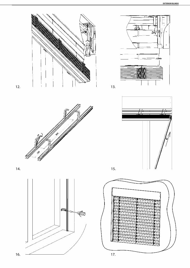
EXTERIOR BLINDS
112
12. 13.
14. 15.
16. 17.

Basic types of assembly
Assembly of the blind into the created pocket (ceiling/wall)
Assembly of the blind into the reveal on the window frame (ceiling/wall)
Assembly of the blind into the reveal on the expansion frame (ceiling/wall)
Note:For correct guiding wire tensioning follow the process below:1. After choosing the correct position of wire guiding bracket and its screwing it is necessary to release the plastic housing with female screw up to edge of the tensioning screw thread (unscrew).2. Put the wire through the tensioning screw.3. Push the whole tensioning mechanism upwards to the bracket body, hold the wire in slightly tensioned position and fix it with M4 screw with cross-point screwdriver.4. Turn the plastic housing by 3-4 turns and tension the wire. Remove the waste wire below the bracket.It is necessary to keep prestressed 2mm tolerance between upper part of wire bracket and lower part of tensioning screw.By following the above steps you will assure correct wire guiding tension.
There are two alternatives for all three basic assembly types:
a) Cover box
ASSEMBLY PROCEDURE: 1. Measure the hole and compare with already prepared blind, check the control mechanism. 2. Allocate the blind holders so they do not interfere with the cloth strips. 3. Fix the holders horizontally. 4. Insert the blind into the sleeves in the holders and secure. Do not tighten screws for the sleeves. 5. Prepare the passage for control using the handle or the cord. If there is an electric control, connect the socket. 6. From the inside passage attach the handle; if the drift is long, shorten it to the necessary length. Stretch the endless cord
through the created hole. Attach the cover for the passage of the cord. 7. Tighten the screws on the sleeves in the holders. 8. On the lamella guides attach the guiding bars which are already fitted with the holders for the guiding bars and attach them
on the window frame or into the reveal (for assembly into the reveals, the guiding bar holders are not used and the guiding bar is attached through the holes created in the body of the guiding bar). The guiding bars must be attached in the middle of the upper profile of the blind.
9. Lower the blind into the lower position (attach the holders for wires if the blind has wire guided lamellas). At the same time, check that the guiding bars or wires do not clamp the lamellas. Check the vertical position of the guiding bars.
10. When the lamellas are tilted, attach the cover box to the holders, insert the prolongation of the holder (tighten the fixation screw) into the pocket created on the cover metal sheet and secure the cover sheet using the screw through the hole in the holder for the blind .
11. The blind driven by the engine can be inspected using the assembly cable or adjust the end positions of the engine and the connection to the supply cable.
12. Fix the holders of the handle in the interior. Connect the control switch according to the connection diagram supplied.
b) The cover box incorporated into the heat-insulation system or the peripheral shell
ASSEMBLY PROCEDURE: 1. Attach the blind holders. 2. Attach the cover sheet (can also be with side parts), insert the prolongation for the holder (tighten the fixation screw) into the
pocket created in the cover sheet and secure through the hole in the holder with the screw (texem). 3. Drill the passage for control by the handle.
After heat insulation or production of the peripheral shell, the assembly of the blind is according to the previous manual.

20
30-36Z 70Z 90S 65S 90C 65C 80C 80FC 60FC 100F
D
C
B
A
21 5 6
652 3 41
D
C
A
B
2-01010-0000-BVIVASAMONOSNÁ VENKOVNÍ ŽALUZIE
C65 C80 C80 Slim F60 F80 F100 S65 S90 Z70 Z90
SELF-SUPPORTING BLIND VIVA 2-01010-0000-B
Self-Supporting Blind VIVA
Blind with self-supporting guiding channels and a possibility to integrate an insect screen.The blind’s head rail and the whole slat packet are located in the ready-made box in two versions, in a concealed or revealed finish. Sockets for connecting with the supporting rails are located on the box sides. In case of the concealed version (under plastering), the front as well as the inner side of the box can be fitted with hardened polystyrene foam of 15 mm thickness.The blind can only be installed in the version with self-supporting guiding channels.Controls: pulling the blind up and down and setting the slat by motor. The controls can be located anywhere into the box.Version suitable for all types of exterior blinds except Cetta 50.Standard height of cover box: 190mm, 220 mm, 260 mm, 300 mm.Box, guide and bottom rails possible in DECORAL and RAL version.Wide variability of pleated combined guide rails (up to 42 variants).
*If the width is bigger than 3500 mm reinforcement profile is added into the box therefore stacking height is increased by 20 mm
Blind dimensions:
Width (mm) Height (mm)min.
Guaranteed area (m2)
min. max. max.
without insect screen 600 4000* 500 12
with insect screen 720 1800 500 3
Maximum height of blind (in mm) by the type of slats for the selected dimension of box (without an insect screen)
Blind type / Height of the box in mm
190 220 260 300 300* (w. b. ↑ 3500)
Max. area [m²]
C65 900 1300 1800 2400 2100 9C80 1100 1500 2200 2800 2400 11
C80 Slim 1300 1800 2600 3300 2900 12F60 1400 1900 2700 3500 3100 14F80 1800 2500 3500 4500 4000 14
F100 2000 2900 4100 5300 4700 16S65 900 1300 1800 2300 2100 9S90 1300 1900 2600 3400 3000 12Z70 1000 1400 2000 2600 2300 10Z90 1200 1700 2500 3200 2800 12
*a reinforcing profile is installed in the box by the width of blind bigger than 3500 mm
Note: Maximum height of the self-supporting blind VIVA with insect screen is 2500 mm.

EXTERIOR BLINDS
144
Self-Supporting Blind
314SC 140
P 002275
41P 537/190PP 537/220PP 537/260PP 537/300P
180, 190PR 0303PR 0302
230PR 162/1
210PR 0465
PR 0466240
330P 097/1
35-36, 37
280P 118
303DZ 224
A 67/23302
PR 0158220 PR 0157
95 PR 0471320 PR 0151
PR 0152PR 0153
150-170
PR 0297140
PR 0464130
A 67/25
PR 046990
P 022/1
ZP0008
40313
SC 136
ZP0013
311,312 SC 138
301 450
315
438
100-107
35050-51
290
120
10-1320-2325-28
P 017/1100-107
P 021/1P 021/2
100-107P 538
P 048/2
P 537/190LP 537/220LP 537/260LP 537/300L
P 110P 111
D
C
B
A
21 5 6
652 3 41
D
C
A
B
2-01016-XXXX-D(skládané vodící lišty)
314SC 140
P 002275
41
180, 190PR 0303PR 0302
230PR 162/1
210PR 0465
PR 0466240
PR 0468/170
330P 097/135-36, 37
280P 118
303DZ 224
A 67/23302
A 67/25301
PR 0158220 PR 0157
95 PR 0471320 PR 0151
PR 0152PR 0153
150-170
PR 0297140
PR 0464130
A 67/26317
PR 046990
P 018/280
P 022/1120
P 019/3316
315
ZP0008
40
313
SC 136
290
ZP0013
311,312 SC 138
50-51
P 110P 11110-13
20-2325-28
100-107P 021/1P 021/2
100-107P 017/1
P 537/190LP 537/220LP 537/260LP 537/300L
P 537/190PP 537/220PP 537/260PP 537/300P
D
C
B
A
21 5 6
652 3 41
D
C
A
B
2-01016-XXXX-D(vodící lišta RS75)
BOX FOR SELF-SUPPORTING EXTERIOR BLIND (guiding channel RS75) 2-01016-XXXX-D
BOX FOR SELF-SUPPORTING EXTERIOR BLIND (combined guiding channel) 2-01016-XXXX-D

Box for self-supporting exterior blind (2-01016-XXXX)Position Item Business Name Drawing Number
10 - 13 Cover sheet 190/220/260/300 PS 3-02333/34/35/36-PU11
20 - 23 Cover sheet 190/220/260/300 visible 3-02337/38/39/40-PU11
25 - 28 Cover sheet 190/220/260/300 2 PS 3-02423/24/25/26-PU11
35 - 36 Foam polystyrene EPS200S 190/220/260/300 x 10 x L bm P 110/190,220,260,300 6-015901-XXXX
37 Hybrifix - 600 ml IDB (MS Unifix) - whit, glue P 111 6-012304-0000
40 Sidewall 190 left, cast - VIVA P 537/190L/220L/260L/300L 7-303226/28/30/32-0000
41 Sidewall 190 right, cast - VIVA P 537/190P/220P/260P/300P 7-303225/27/29/31-0000
50 - 51 Al Profile, L - 20x15x3 SEGMENTED ( RAL ) 3-03351-PU11
70/10 Guide rail RS 75/1 PR0468/1 7-303417-0000
80/10, 11 Guide rail profile, simple RAW / ELOX P 018/2XX 0000/PU52 7-302122-0000/PU52
90/10, 20 Guide rail A 22 COLOURLESS PR0469 6-011268-0000
95 End rail of the lower rail-I PR0157 3-01139-PU11
100 - 107 Guide rail profile, double RAW / ELOX P 017/1X 0000/PU52 7-302123-0000/PU52
100 - 107 Guide rail holder 75-102mm P 021/1 2-00051-XXXX
100 - 107 Guide rail holder 102-154mm P 021/2 2-00051-XXXX
100 - 107 Guide rails - combined see page148
120 Guide rail insert- KEDR - BLACK P 022/1 9004 7-301351-9004
130 Blackout sealing brush 9mm PR0464 6-001801-0000
140 Oblique brush - for guide rail A20 PR0297 6-006875-0000
150-170 Insect screen ISG 600x130/170/250 cm PR 151/152/153 6-001939/37/38-0000
180 Spring mechanics - up to width 720 without brake PR0303 6-010476-0000
190 Spring mechanics - from width 720 with brake PR0302 6-010475-0000
210 Lower rail brush-I at the back 12,5 mm PR0465 6-011337-0000
220 Lower rail brush-I 4,8x20mm PR0158 6-001749-0000
230 Easy-Click parts set for A 20 PR0162/1 6-001942-0000
240 Lower rail handle-I PR0466 6-011245-0000
275 Upper rail hanger - Fe PROFILE P 002 2-00038-0000
280 Screen start of EB P 118 3-02301-0000
290 Rubber cable, plastic, black 6-017078-0000
301 Screw 2,9x9,5, DIN 7504 M, Zn, semi-spherical, cross-headed A 67/25 6-011906-0000
302 Self-cutting screw with collar 4,2x13 A 67/23 6-011397-0000
303 Screw 2,9x6,5, DIN 7981 C,H, Zn, semi-spherical, cross-headed DZ 224 6-003135-0000
311, 312 Blind rivet Al 4x10 DIN 7337 A, colourless SC 136 6-002680-0000
313 Blind rivet Al 4x10, countersunk, DIN 7337 B, colourless SC 138 0000 6-003759-0000
314 Blind rivet Al 5x10 DIN 7337 A, colourless SC 140 0000 6-012369-0000
315 Cover caps 10mm, white ZP0013/XXXX 6-002066-XXXX
316 Guide rail stop - set P 019/3 9004 2-01097-9004
317 Screw 3,5x16 DIN 7982 C-H A2, countersunk, cross-headed A 67/26 6-003097-0006
320 Cord with tassel - BLACK PR0471 6-011033-0000
330 Cable Hirschmann 4000 mm P 097/1 4000 2-01037-4000
350 Cover bent plate, VIVA,10 mm 3-03283-0010
438 Insert of under-plaster rail with pocket PVC BLACK / -4m P 048/2 9017/90174 7-303507-9017/90174
450 Lower stopper P 538/9004 3-03286-9004

EXTERIOR BLINDS
146
NÁVOD NA VYMĚŘENÍ A MONTÁŽ
Platnost návodu: 1. 8. 2013 1
SAMONOSNÁ ŽALUZIE 1. VYMĚŘENÍ
Vyměřuje se šířka (Š) a výška (V) otvoru. Šířku žaluzie vyměřujte ve třech místech, nahoře, uprostřed a dole. Pro výrobu a objednávku žaluzie udáváme nejmenší naměřený rozměr.
Maximální výška žaluzie, kterou pojme schránka o velikosti 300 mm je omezena pro tyto typy lamel: Cetta 65 - 2600 mm; Setta 65 - 2600 mm; Zetta 70 - 2900 mm. Výška boxu se vyrábí ve 4 provedeních (190 mm, 220 mm, 260 mm, 300 mm). Hloubka samotného boxu je 140 mm, v provedení do zaomítání včetně polystyrénu 150 mm.
(1) - elektrický kabel
D NA VYMĚŘENÍ A MONTÁŽ
Platnost návodu: 1. 8. 2013 1
SAMONOSNÁ ŽALUZIE 1. VYMĚŘENÍ
Vyměřuje se šířka (Š) a výška (V) otvoru. Šířku žaluzie vyměřujte ve třech místech, nahoře, uprostřed a dole. Pro výrobu a objednávku žaluzie udáváme nejmenší naměřený rozm
Maximální výška žaluzie, kterou pojme schránka o velikosti 300 mm je omezena pro tyto typy lamel: Cetta 65 - 2600 mm; Setta 65 - 2600 mm; Zetta 70 - 2900 mm. Výška boxu se vyrábí ve 4 provedeních (190 mm, 220 mm, 260 mm, 300 mm). Hloubka samotného boxu je 140 mm, v provedení do zaomítání v polystyrénu 150 mm.
(1) - elektrický kabel
H H
W
W
1 – kabel
Assessment of Self-Supporting Blind Viva
Upper profile cross section
Cross section fo the visible self-supporting blind Viva
Cross section fo the built-in self-supporting blind Viva
Cross section fo the built-in self-supporting blind Viva (double polystyrene)
Cross section fo the built-in self-supporting blind Viva (expansion profiles)
Cut of under plaster self-supporting blind VIVA (ready for polystyrene on
front part)
Cut of under plaster self-supporting blind VIVA (ready for polystyrene on
both parts)
Cut of under plaster self-supporting blind VIVA (used for extension profiles -
ready for polystyrene on front part)
A
A
B
B
C
C
144
190
-300
3
9
ŘEZ A-AMĚŘÍTKO 1 : 2
39
190
-300
159
15
ŘEZ B-BMĚŘÍTKO 1 : 2
39
190
-300
174
15 15
ŘEZ C-CMĚŘÍTKO 1 : 2
G
G
169-220
39
190
-300
15 10-60
ŘEZ G-GMĚŘÍTKO 1 : 2
Řez přiznané SŽ VivaŘez vestavěné SŽ Viva
(připraveno pro polystyren z čelní strany)Řez vestavěné SŽ Viva
(Připraveno pro polystyren z obou stran)Řez vestavěné SŽ Viva
(Použité rozšiřovací profily)(Připraveno pro polystyren z čelní strany)
A
A
B
B
C
C
144
190
-300
3
9
ŘEZ A-AMĚŘÍTKO 1 : 2
39
190
-300
159
15
ŘEZ B-BMĚŘÍTKO 1 : 2
39
190
-300
174
15 15
ŘEZ C-CMĚŘÍTKO 1 : 2
G
G
169-220
39
190
-300
15 10-60
ŘEZ G-GMĚŘÍTKO 1 : 2
Řez přiznané SŽ Viva Řez vestavěné SŽ Viva Řez vestavěné SŽ Viva(Polystyren z obou stran)
Řez vestavěné SŽ Viva(Použité rozšiřovací profily)

The table of combined guide channels
Dimen-sion Business name Picture of guide channels
76 mm P 020/00
86 mm P 020/01
96 mm P 020/02
106 mm P 020/03
116 mm P 020/04
126 mm P 020/05
136 mm P 020/06
146 mm P 020/07
156 mm P 020/08
166 mm P 020/09
176 mm P 020/10
186 mm P 020/11
196 mm P 020/12
206 mm P 020/13
76 mm P 020/00
P 020/0186 mm
P 020/0296 mm
P 020/03106 mm
P 020/04116 mm
P 020/05126 mm
P 020/06136 mm
146 mm P 020/07
P 020/08156 mm
P 020/09166 mm
P 020/10176 mm
P 020/11186 mm
P 020/12196 mm
P 020/13206 mm
76 mm P 020/00
P 020/0186 mm
P 020/0296 mm
P 020/03106 mm
P 020/04116 mm
P 020/05126 mm
P 020/06136 mm
146 mm P 020/07
P 020/08156 mm
P 020/09166 mm
P 020/10176 mm
P 020/11186 mm
P 020/12196 mm
P 020/13206 mm
76 mm P 020/00
P 020/0186 mm
P 020/0296 mm
P 020/03106 mm
P 020/04116 mm
P 020/05126 mm
P 020/06136 mm
146 mm P 020/07
P 020/08156 mm
P 020/09166 mm
P 020/10176 mm
P 020/11186 mm
P 020/12196 mm
P 020/13206 mm
76 mm P 020/00
P 020/0186 mm
P 020/0296 mm
P 020/03106 mm
P 020/04116 mm
P 020/05126 mm
P 020/06136 mm
146 mm P 020/07
P 020/08156 mm
P 020/09166 mm
P 020/10176 mm
P 020/11186 mm
P 020/12196 mm
P 020/13206 mm
76 mm P 020/00
P 020/0186 mm
P 020/0296 mm
P 020/03106 mm
P 020/04116 mm
P 020/05126 mm
P 020/06136 mm
146 mm P 020/07
P 020/08156 mm
P 020/09166 mm
P 020/10176 mm
P 020/11186 mm
P 020/12196 mm
P 020/13206 mm
76 mm P 020/00
P 020/0186 mm
P 020/0296 mm
P 020/03106 mm
P 020/04116 mm
P 020/05126 mm
P 020/06136 mm
146 mm P 020/07
P 020/08156 mm
P 020/09166 mm
P 020/10176 mm
P 020/11186 mm
P 020/12196 mm
P 020/13206 mm
76 mm P 020/00
P 020/0186 mm
P 020/0296 mm
P 020/03106 mm
P 020/04116 mm
P 020/05126 mm
P 020/06136 mm
146 mm P 020/07
P 020/08156 mm
P 020/09166 mm
P 020/10176 mm
P 020/11186 mm
P 020/12196 mm
P 020/13206 mm

EXTERIOR BLINDS
148
The table of combined guide channels
Dimen-sion Business name Picture of guide channels
75 mm P 080/00
85 mm P 080/01
95 mm P 080/02
105 mm P 080/03
115 mm P 080/04
125 mm P 080/05
135 mm P 080/06
145 mm P 080/07
155 mm P 080/08
165 mm P 080/09
175 mm P 080/10
185 mm P 080/11
195 mm P 080/12
205 mm P 080/13
75 mm P 080/00
P 080/0185 mm
P 080/0295 mm
P 080/03105 mm
P 080/04115 mm
P 080/05125 mm
P 080/06135 mm
145 mm P 080/07
P 080/08155 mm
P 080/09165 mm
P 080/10175 mm
P 080/11185 mm
P 080/12195 mm
P 080/13205 mm
75 mm P 080/00
P 080/0185 mm
P 080/0295 mm
P 080/03105 mm
P 080/04115 mm
P 080/05125 mm
P 080/06135 mm
145 mm P 080/07
P 080/08155 mm
P 080/09165 mm
P 080/10175 mm
P 080/11185 mm
P 080/12195 mm
P 080/13205 mm
75 mm P 080/00
P 080/0185 mm
P 080/0295 mm
P 080/03105 mm
P 080/04115 mm
P 080/05125 mm
P 080/06135 mm
145 mm P 080/07
P 080/08155 mm
P 080/09165 mm
P 080/10175 mm
P 080/11185 mm
P 080/12195 mm
P 080/13205 mm
75 mm P 080/00
P 080/0185 mm
P 080/0295 mm
P 080/03105 mm
P 080/04115 mm
P 080/05125 mm
P 080/06135 mm
145 mm P 080/07
P 080/08155 mm
P 080/09165 mm
P 080/10175 mm
P 080/11185 mm
P 080/12195 mm
P 080/13205 mm
75 mm P 080/00
P 080/0185 mm
P 080/0295 mm
P 080/03105 mm
P 080/04115 mm
P 080/05125 mm
P 080/06135 mm
145 mm P 080/07
P 080/08155 mm
P 080/09165 mm
P 080/10175 mm
P 080/11185 mm
P 080/12195 mm
P 080/13205 mm
75 mm P 080/00
P 080/0185 mm
P 080/0295 mm
P 080/03105 mm
P 080/04115 mm
P 080/05125 mm
P 080/06135 mm
145 mm P 080/07
P 080/08155 mm
P 080/09165 mm
P 080/10175 mm
P 080/11185 mm
P 080/12195 mm
P 080/13205 mm
75 mm P 080/00
P 080/0185 mm
P 080/0295 mm
P 080/03105 mm
P 080/04115 mm
P 080/05125 mm
P 080/06135 mm
145 mm P 080/07
P 080/08155 mm
P 080/09165 mm
P 080/10175 mm
P 080/11185 mm
P 080/12195 mm
P 080/13205 mm

The table of combined guide channels
Dimen-sion Business name Picture of guide channels
76 mm P 081/00
86 mm P 081/01
96 mm P 081/02
106 mm P 081/03
116 mm P 081/04
126 mm P 081/05
136 mm P 081/06
146 mm P 081/07
156 mm P 081/08
166 mm P 081/09
176 mm P 081/10
186 mm P 081/11
196 mm P 081/12
206 mm P 081/13
76 mm P 081/00
P 081/0186 mm
P 081/0296 mm
P 081/03106 mm
P 081/04116 mm
P 081/05126 mm
P 081/06136 mm
146 mm P 081/07
P 081/08156 mm
P 081/09166 mm
P 081/10176 mm
P 081/11186 mm
P 081/12196 mm
P 081/13206 mm
76 mm P 081/00
P 081/0186 mm
P 081/0296 mm
P 081/03106 mm
P 081/04116 mm
P 081/05126 mm
P 081/06136 mm
146 mm P 081/07
P 081/08156 mm
P 081/09166 mm
P 081/10176 mm
P 081/11186 mm
P 081/12196 mm
P 081/13206 mm
76 mm P 081/00
P 081/0186 mm
P 081/0296 mm
P 081/03106 mm
P 081/04116 mm
P 081/05126 mm
P 081/06136 mm
146 mm P 081/07
P 081/08156 mm
P 081/09166 mm
P 081/10176 mm
P 081/11186 mm
P 081/12196 mm
P 081/13206 mm
76 mm P 081/00
P 081/0186 mm
P 081/0296 mm
P 081/03106 mm
P 081/04116 mm
P 081/05126 mm
P 081/06136 mm
146 mm P 081/07
P 081/08156 mm
P 081/09166 mm
P 081/10176 mm
P 081/11186 mm
P 081/12196 mm
P 081/13206 mm
76 mm P 081/00
P 081/0186 mm
P 081/0296 mm
P 081/03106 mm
P 081/04116 mm
P 081/05126 mm
P 081/06136 mm
146 mm P 081/07
P 081/08156 mm
P 081/09166 mm
P 081/10176 mm
P 081/11186 mm
P 081/12196 mm
P 081/13206 mm
76 mm P 081/00
P 081/0186 mm
P 081/0296 mm
P 081/03106 mm
P 081/04116 mm
P 081/05126 mm
P 081/06136 mm
146 mm P 081/07
P 081/08156 mm
P 081/09166 mm
P 081/10176 mm
P 081/11186 mm
P 081/12196 mm
P 081/13206 mm
76 mm P 081/00
P 081/0186 mm
P 081/0296 mm
P 081/03106 mm
P 081/04116 mm
P 081/05126 mm
P 081/06136 mm
146 mm P 081/07
P 081/08156 mm
P 081/09166 mm
P 081/10176 mm
P 081/11186 mm
P 081/12196 mm
P 081/13206 mm

EXTERIOR BLINDS
150
96
27
27
40
20
27
10
27
Základní profil Rozšiřovací profil40 mm
Rozšiřovací profil20 mm
Rozšiřovací profil10 mm
96
27
27
40
20
27
10
27
Základní profil Rozšiřovací profil40 mm
Rozšiřovací profil20 mm
Rozšiřovací profil10 mmExpansion profile 40 mm
P 048/40
96
27
27
40
20
27
10
27
Základní profil Rozšiřovací profil40 mm
Rozšiřovací profil20 mm
Rozšiřovací profil10 mmExpansion profile 20 mm
P 048/20Expansion profile 10 mm P 048/10
Basic profile P 020 Basic profile P 080 Basic profile P 081Maximum possible extension of the basic profile P 020.
Maximum possible extension of the basic profile P 080.
Maximum possible extension of the basic profile P 081.
Expansion profiles for P 020, P 080, P 081
Combined guide channels P 020The smallest dimension of the guide chan-nels is 76 mm (that is, it is only about assebly of the concealing guide channel - see pic-ture).
Combined guide channels P 080The smallest dimension of the guide chan-nels is 75 mm (that is, it is only about assebly of the concealing guide channel - see pic-ture).
Combined guide channels P 081The smallest dimension of the guide channels is 76 mm (that is, it is only about assebly of the concealing guide channel - see picture).
76
206
P 020
76
206
P 020
75
205
P 080
75
205
P 080
76
206
P 081
76
P 081
10
20
40
96
76
FASÁDA
OST
ĚNÍ
RÁM OKNA
OSA LAMELY
10
20
40
96
75
FASÁDA
OST
ĚNÍ
RÁM OKNA
OSA LAMELY
10
20
40
96
76
FASÁDA
OST
ĚNÍ
RÁM OKNA
OSA LAMELY
window frame
linin
g
lining
lining
window frame
linin
g
lining
lining
window frame
linin
g
lining
lining

12
KL1
KL2
KL3
KL4
KL5
KP1KP4
KP5
KP2
KP3
MOTOR - VÝVOD MOTORU
Control Placement
FF
76-1
46
96-1
66
27
18
59
ŘEZ F-FMĚŘÍTKO 1 : 1
OSA LAMELY
Cross section of the guide channel
Cross of the combined guide channel Cross of the guide channel RS75
slat axis
KP1
KP6
KP7KP4
KP2
KP3 KP5KL3
KL2
KL1
KL6
KL5
KL4KL7
MOTOR - MOTOR OUTLET