Target access router selection in advanced mobility scenarios
21
Target access router selection in advanced mobility scenarios D. Di Sorte * , M. Femminella, L. Piacentini, G. Reali Dipartimento di Ingegneria Elettronica e dell’Informazione (D.I.E.I.), University of Perugia, via G. Duranti 93, 06125 Perugia, Italy Received 1 April 2004; revised 27 April 2005; accepted 9 May 2005 Available online 2 June 2005 Abstract To provide nomadic users with QoS-enabled services, advanced mobility management will prove to be of fundamental importance in the future Internet. Mobile IP is the reference protocol supporting mobility at IP level. However, it has been widely recognised that it could perform poorly, especially with QoS demanding applications. In order to improve Mobile IP performance, the discovery and selection of the target access router to hand over to will play a crucial role. In this paper, we present a novel approach for Candidate Access Router Discovery and Target Access Router selection. The process is fully distributed, multicast-based, and allows timely intra and inter-access router handover, which can be either intra or inter-technology. The effectiveness of the solution to drive mobile terminal handovers has been tested by simulations. q 2005 Elsevier B.V. All rights reserved. Keywords: IP mobility; Multicast; Candidate access router discovery; Access router selection 1. Introduction IP mobility protocols (i.e. Mobile IPv4/v6, [5,6]) enable mobile nodes (MNs) to execute IP layer handover between access routers (ARs). Basic Mobile IP (MIP) protocols are well known for their poor performance and inability to support a seamless handover. In [1], the Authors define the seamless handover as ‘a handover in which there is no change in service capability, security, and quality’. A number of different approaches to improve MIP have been proposed so far: (i) micro-mobility solutions [7], which aim to limit the handover range of MIP procedures, thus reducing handover latency and signalling burden; (ii) context transfer solutions [3,4], the goal of which is to quickly re-establish information states (context) associated with the MN in the new AR upon handover, thus avoiding re-initiation of the signalling procedure to set-up the service from scratch; (iii) fast handover procedures to minimise packet losses and latency [10,11]. All the proposed enhancements assume that the new AR to hand over to is known. This is indeed the missing step in the overall seamless handover procedure. Thus, in advanced mobility scenarios, it is important to discover the set of potential target ARs and to select the most appropriate one before handing over. A candidate access router discovery (CARD) procedure collects information about the ARs which are candidates (CARs) for the MN handover [2,8,9]. It is then possible to identify the Target AR (TAR), i.e. the one that best matches the MN’s requirements and the CARs’ capabilities. The CARD requires two essential functions to be performed: † reverse address translation, which means to use layer 2 addresses to determine the coverage areas which is served through a port of an AR, thus with its IP address (layer 3 coverage). This is important to speed-up MIP handovers, and is implemented by binding the layer 2 identifier (L2 ID) of each access point (AP) with the IP address of the CAR connected to it. MNs are assumed to listen to the L2 beacons transmitted by surrounding APs periodically and to learn their L2 IDs. This information is then exchanged with the current AR. The CARD procedures can then support MNs with layer 3 information. Thus, in order to start the handover process, MNs do not have to wait for the MIP router Computer Communications 29 (2006) 337–357 www.elsevier.com/locate/comcom 0140-3664/$ - see front matter q 2005 Elsevier B.V. All rights reserved. doi:10.1016/j.comcom.2005.05.004 * Corresponding author. Tel: C39 075 585 3630; fax: C39 075 585 3654. E-mail addresses: [email protected] (D. Di Sorte), femminella@ diei.unipg.it (M. Femminella), [email protected] (L. Piacentini), [email protected] (G. Reali).
Transcript of Target access router selection in advanced mobility scenarios
Target access router selection in advanced mobility scenarios
D. Di Sorte*, M. Femminella, L. Piacentini, G. Reali
Dipartimento di Ingegneria Elettronica e dell’Informazione (D.I.E.I.), University of Perugia, via G. Duranti 93, 06125 Perugia, Italy
Received 1 April 2004; revised 27 April 2005; accepted 9 May 2005
Available online 2 June 2005
Abstract
To provide nomadic users with QoS-enabled services, advanced mobility management will prove to be of fundamental importance in the
future Internet. Mobile IP is the reference protocol supporting mobility at IP level. However, it has been widely recognised that it could
perform poorly, especially with QoS demanding applications. In order to improve Mobile IP performance, the discovery and selection of the
target access router to hand over to will play a crucial role. In this paper, we present a novel approach for Candidate Access Router Discovery
and Target Access Router selection. The process is fully distributed, multicast-based, and allows timely intra and inter-access router
handover, which can be either intra or inter-technology. The effectiveness of the solution to drive mobile terminal handovers has been tested
by simulations.
q 2005 Elsevier B.V. All rights reserved.
Keywords: IP mobility; Multicast; Candidate access router discovery; Access router selection
1. Introduction
IP mobility protocols (i.e. Mobile IPv4/v6, [5,6]) enable
mobile nodes (MNs) to execute IP layer handover between
access routers (ARs). Basic Mobile IP (MIP) protocols are
well known for their poor performance and inability to
support a seamless handover. In [1], the Authors define the
seamless handover as ‘a handover in which there is no
change in service capability, security, and quality’.
A number of different approaches to improve MIP have
been proposed so far: (i) micro-mobility solutions [7], which
aim to limit the handover range of MIP procedures, thus
reducing handover latency and signalling burden; (ii)
context transfer solutions [3,4], the goal of which is to
quickly re-establish information states (context) associated
with the MN in the new AR upon handover, thus avoiding
re-initiation of the signalling procedure to set-up the service
from scratch; (iii) fast handover procedures to minimise
packet losses and latency [10,11].
0140-3664/$ - see front matter q 2005 Elsevier B.V. All rights reserved.
doi:10.1016/j.comcom.2005.05.004
* Corresponding author. Tel: C39 075 585 3630; fax: C39 075 585
3654.
E-mail addresses: [email protected] (D. Di Sorte), femminella@
diei.unipg.it (M. Femminella), [email protected] (L. Piacentini),
[email protected] (G. Reali).
All the proposed enhancements assume that the new AR
to hand over to is known. This is indeed the missing step in
the overall seamless handover procedure. Thus, in advanced
mobility scenarios, it is important to discover the set of
potential target ARs and to select the most appropriate one
before handing over. A candidate access router discovery
(CARD) procedure collects information about the ARs
which are candidates (CARs) for the MN handover [2,8,9].
It is then possible to identify the Target AR (TAR), i.e. the
one that best matches the MN’s requirements and the CARs’
capabilities.
The CARD requires two essential functions to be
performed:
† reverse address translation, which means to use layer 2
addresses to determine the coverage areas which is
served through a port of an AR, thus with its IP address
(layer 3 coverage). This is important to speed-up MIP
handovers, and is implemented by binding the layer 2
identifier (L2 ID) of each access point (AP) with the IP
address of the CAR connected to it. MNs are assumed to
listen to the L2 beacons transmitted by surrounding APs
periodically and to learn their L2 IDs. This information
is then exchanged with the current AR. The CARD
procedures can then support MNs with layer 3
information. Thus, in order to start the handover process,
MNs do not have to wait for the MIP router
Computer Communications 29 (2006) 337–357
www.elsevier.com/locate/comcom

D. Di Sorte et al. / Computer Communications 29 (2006) 337–357338
advertisement from the new AR and fast handover
procedures may be executed ([10,11]). Note that the
capacity of performing frequency scanning is actually a
minimum requirement for all wireless technologies;
† discovery and update of service capabilities (SCs) of
CARs. In general, an SC is the set of parameters
(available bandwidth, price, security support, radio
access technology, etc.) that characterises the network
service provided to the MN. An SC includes all the most
important parameters that influence handover decisions.
Thus, the final aim is to drive the MN operation
according to specific objectives, such as (i) to balance
the traffic load on the access network, (ii) to drive the
MN towards the cheapest wireless access, (iii) to drive
the MN towards an access which guarantees the same
level of quality of service (QoS).
The first goal of this paper is to present a novel CARD
approach.
We start by assuming that the network is controlled by a
single operator (Fig. 1 shows the reference network
scenario) and that the provider of the IP connectivity
(Connection Service Provider, CSP) is also the owner of the
network infrastructure (Network Service Provider, NSP).
The result of this assumption is that, without any
commercial agreement there are no logical reasons for a
CSP to induce its mobile customers to move to other access
domains. In fact, this would imply a loss of traffic and
revenues in favour of competitors. Moreover, unless specific
agreement has been made, any CSP is usually unwilling to
give other organisations confidential information regarding
its own network (current bandwidth, security policies, etc).
Thus, we assume that our CARD procedure will be confined
Fig. 1. Reference net
within a single administrative domain. Then, we also
indicate an extension to manage the case of different
NSPs co-ordinated by a single CSP.
The proposed Push-Mode-Multicast CARD (PMM
CARD), already outlined in [22], is fully distributed and
allows each AR to dynamically self-construct a map of the
surrounding wireless coverage; the main innovation of our
approach with respect to previous proposals is the use of
push-mode multicast transmissions. We use multicast in a
push-mode in order not only to strongly reduce the latency
due to explicit queries, but also to lower the signalling
burden. The advantages in terms of signalling burden and
discovery time of the PMM CARD solutions with respect to
those proposed by the IETF within the Seamoby WG [2] are
presented in [22].
In this work, we assume that the access network is
heterogeneous and that terminals may have reconfiguration
capabilities so as to be able to access different radio access
technologies (RATs). We assume that all terminals have a
single active radio interface at a given time to save power.
This also implies the constraint of MNs not being allowed to
scan for beacons of RATs different from the one currently
being used, with the result that they cannot obtain coverage
information from them.
In homogeneous networks, handover is typically driven
by metrics which are strictly related to the received power
level [17]. In heterogeneous mobile environments, more
complex metrics combining a higher number of parameters
have to be defined (e.g. price, bandwidth, priority, power
consumption, reliability, etc.) [18–20].
In this paper, we present a novel TAR metric capable of
driving layer 2 and layer 3 handovers. Our goal is to support
intra and inter-AR handovers, which can be intra and
work scenario.
D. Di Sorte et al. / Computer Communications 29 (2006) 337–357 339
inter-technology. The metric takes into account the
bandwidth availability and received power level, together
with a statistical factor which helps to drive inter-
technology handovers by inferring about layer 2 coverage.
The paper is structured as follows. In the Section 2, we
summarise the current state of the art about CARD. In
Section 3, our PMM CARD procedure is described in detail.
In Section 4, the TAR approach is presented together with
the selection metric used. In Section 5, we describe the
simulation model and analyse the performance of the
procedure obtained from simulation trials. In particular, we
show results concerning the capability of the CARD/TAR
approach to drive inter-technology handovers. Finally,
Section 6 reports some concluding remarks.
2. Related works
In order to enable a seamless IP-layer handover, a CARD
solution must include two important tasks: (i) the reverse
address translation from L2 IDs; (ii) the discovery and
update of SCs. As mentioned the introduction, the former
function is needed to speed up the handover process,
whereas the latter function provides the TAR selection
process with the necessary information about the service
capabilities of the candidate wireless accesses in order to
drive the MN towards the most appropriate AP and AR. The
scope of the CARD process is an IP network with a number
of ARs that control a set of APs, which may be
heterogeneous. Handovers can be both inter and intra-
technology, intra and inter AR, at both layer 2 and layer 3.
We assume that each AR manages a number of APs;
consequently, the coverage area of an AR is the union of the
coverage areas of the relevant APs. Two ARs are
neighbours if their wireless coverage areas overlap.
Since MNs are generally assumed to be able to
periodically listen to the L2 beacons transmitted by the
surrounding APs, in [21] the authors propose an initial,
straightforward solution to enable the two CARD functions.
This consists of embedding the IP address, IP prefix, and
service capabilities in L2 beacons. However, this approach
has three main drawbacks. The first is strictly conceptual:
encapsulating layer 3 data within layer 2 control frames
violates the protocol layer architecture. The second is that
Fig. 2. Steady phase: message exchange for a
this approach would require some modifications to the
standard of existing technologies. Finally, to save wireless
bandwidth, it is not recommended to stuff beacons with a
large amount of additional information.
To overcome the aforementioned drawbacks, it is
necessary to define a network-assisted CARD process.
The solution presented in the framework of the IETF
Seamoby WG is as follows. When an MN remains under the
coverage of an AR (current AR), it obtains L2 IDs from the
beacons of some other APs, and passes them to its current
AR at a TAR event. The current AR is in charge of
providing the MN with either the IP addresses of CARs and
the relevant service capabilities (if the TAR algorithm is run
in the MN), or the TAR IP address (if the selection
algorithm is carried out at the current AR). This means that
not only the signalling messages to resolve L2 addresses
between an MN and its current AR, but also service
capabilities must be exchanged. Thus, a basic requirement is
that each AR is able to obtain information about the state of
the neighbouring wireless coverage (i.e. the AR–AP pairs)
and store it in a local cache. The state stored by the AR
should contain the IP address of the neighbouring ARs, the
L2 IDs of the relevant APs and the service capabilities
associated with the AR–AP pairs. This information may be
used by the current AR to offer an alternative wireless
access to an MN under its own coverage. The operations
described need a continuous, dynamic signalling exchange
between the network entities involved in the CARD process.
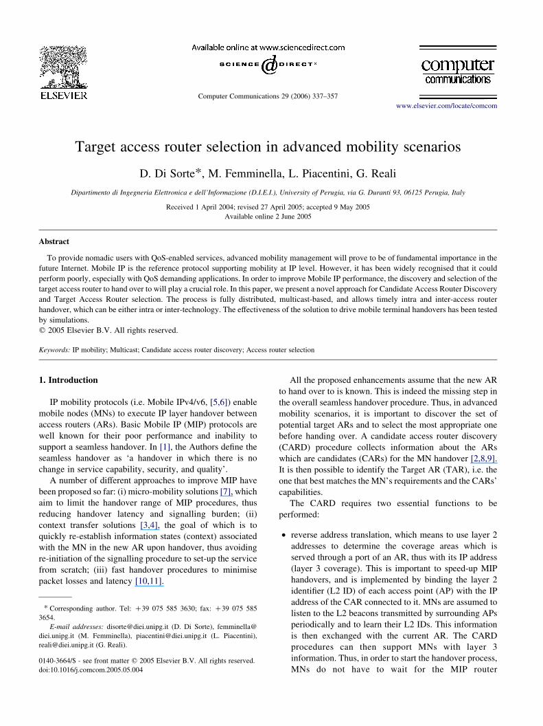
The complete message exchange between the MN, its
current AR, and a CAR is depicted in Fig. 2. This exchange
takes place during the ‘steady phase’ of the CARD process
on completion of the coverage map in the current AR. The
capability exchange between the current AR and CARs may
be performed either upon an MN request, or when the
capability lifetime expires. In Fig. 2, we have assumed that
the MN is in charge of both triggering and performing the
TAR selection. The MN communicates the current list of L2
IDs received (step 2), since they are candidate wireless
accesses for a possible handover, and must be considered for
the TAR selection.
As regards the message exchange in the steady phase,
some security considerations apply. Since the SC exchange
is the key element of any CARD process, IPsec Security
Associations (SAs) [23] among ARs is a valuable tool to
ddress mapping and capability update.
D. Di Sorte et al. / Computer Communications 29 (2006) 337–357340
protect it. Integrity check and authentication are mandatory
IPsec functions, whereas ensuring confidentiality is up to the
specific operator’s policy. As regards message exchange
between an MN and an AR, an SA is definitely needed for
an integrity check and authentication when the AR sends
CARD/TAR information to the MN, since false information
would drive the MN towards an incorrect, or bogus TAR. In
addition, if an operator wishes to hide information
exchanged on the air interface concerning network
capabilities, confidentiality also has to be supported.
An important issue of any CARD approach is the
discovery of the IP addresses of the neighbouring ARs
(‘discovery phase’), and the determination of the (L2 ID)/(IP address) mapping to be stored in the local cache.
Specifically, the discovery phase consists of discovering the
neighbouring ARs/APs, so as to build a map of the wireless
coverage of the surrounding area at both layer 2 and layer 3
for each AR. This information is clearly useful only in the
case of dense wireless coverage. This situation is realistic
for an operator offering a seamless wireless network service,
which can deploy a CARD mechanism to support TAR.
The accuracy of a CARD solution greatly depends on the
ability of an AR to obtain accurate information about
geographically neighbouring ARs, and to exchange SCs
with them. A further consideration is that a manual, address-
mapping configuration at ARs would not be a good solution
because (i) it is not feasible in large wireless networks; (ii) it
would not permit any adaptation to variable network
topologies; (iii) the coverage area of an AR (i.e. of its
APs) could not be easily and exactly determined. For these
reasons, a solution for automatically building the coverage
map at each AR is needed. Below we illustrate the solutions
proposed in literature, which can be classified in two
separate, general schemes: (i) handover-based solutions,
which use the first plain MIP handover between two ARs to
infer knowledge about the surrounding wireless coverage;
(ii) solutions which analyse and estimate the radio coverage
situation by using the information obtained by MNs from L2
beacons.
2.1. Handover-based CARD approach
The basic idea of a handover-based solution [2,9] is that
two ARs discover they are neighbours once an MN has
executed a plain MIP handover between them. Thus, an AP
connected with a neighbouring AR is discovered after a
plain MIP handover is accomplished through that particular
AP, which implies a layer 2 handover. After this handover,
the MN has to send a signalling message to the new, current
AR containing the IP address of the old AR and the L2
address of the old AP. Thus, if the association (L2 ID)/(IP
address) was unknown, the current AR can create a new
entry in its cache. Then, the new current AR is in charge of
informing the old one by means of a specific signalling
message that both of them are neighbours, so that the old AR
can update its own coverage map as well.
This message exchange can be used by the new AR to
check with the old AR to see whether the MN was indeed
attached to it during a reasonable past interval so as to trust
its information.
The handover-based approach presents some drawbacks.
Firstly, the first handover, involving an as yet undiscovered
AP by the old AR towards an AR (bootstrap handover),
cannot be driven by the CARD procedure; this could be a
weakness not only for delay-sensitive applications, but also
in a highly dynamic access network topology. In addition,
the time needed to complete the discovery phase could
increase in the case of dense wireless coverage. In fact, in
the latter case, handovers are driven by the TAR process
towards previously discovered APs, so that a non-driven
handover (discovery event) is carried out only when there is
no alternative. Finally, if an MN switches between two APs,
whose coverage areas are very close but do not overlap, then
this would result in false coverage information sent to the
network. In other words, it would imply an enlargement of
the CARD table with useless coverage data.
2.2. Centralised L2 beacon-based approach
This solution is illustrated in [2,8]. The basic idea is that
each AR must register with a centralised server, by
indicating its own IP address and the L2 IDs of the APs
associated with it. This server is a database that is
dynamically updated by ARs. Its task is to process queries
from ARs to resolve L2 IDs and to contribute to the building
of the wireless coverage map in ARs.
The process develops as follows. When an MN discovers
the L2 IDs of APs during frequency scanning, the MN
passes one or more of them to its current AR. If unknown, the
current AR sends them to the centralised server, which
returns the IP addresses of the relevant ARs. This mechanism
enables those (AR,AP) pairs with wireless coverage
overlapping with the one of the current (AR,AP) pair to be
identified. Thus, MNs can be regarded as L2 sensors used to
identify candidate wireless accesses to hand over to.
We expect an L2 beacon-based solution to speed up the
discovery phase when compared with the handover-based
approach [22], due to the higher number of events (L2
beacon listening), which trigger the discovery of new
wireless resources.
As regards security considerations, this message
exchange must establish specific SAs to guarantee integrity,
authentication and, if needed, confidentiality. In addition,
malicious MNs could communicate false information (e.g.
L2 IDs of APs that do not have a wireless coverage
overlapping with the current AR). This would cause storing
of incorrect wireless coverage information in routers.
Therefore, as highlighted in [13], if MNs cannot be trusted,
an L2 beacon-based procedure is inefficient from a security
point of view.
The server-based solution proposed by the Seamoby WG
extends the CARD protocol to support an AR-server
D. Di Sorte et al. / Computer Communications 29 (2006) 337–357 341
message exchange, whereas in [8], the Authors make use of
the SLP (Service Location Protocol) architecture with a
centralised Directory Agent. ARs act as SLP User Agents,
that is they send service requests to the Directory Agent.
A distributed SLP architecture has also been proposed
in [8].
3. The CARD approach
In this section, we present the Push-Mode-Multicast
CARD (PMM CARD), which is a proposal to perform the
CARD procedure within an administrative domain. Then we
extend the procedure towards an inter-domain scope.
The PMM CARD is network-assisted, distributed and
based on push-mode multicast transmission. Our final goal
is to define a CARD process able to provide the TAR
process with all the necessary information needed to
properly drive intra and inter-technology handovers.
We assume that MNs are either classical single-mode
terminal or adaptive terminals. The latter may be either re-
configurable terminals based on the software defined radio
paradigm or simply multi-mode terminals. In any case, we
assume that they are capable of listening to layer 2 beacons
transmitted by surrounding APs. However, in the case of
multi-mode terminals, we assume that such terminals do not
scan for beacons of RATs other than the one currently in
use. The rationale of this assumption is that, with a number
of network interfaces, scanning for beacons on all interfaces
could result in a large drain on power.
3.1. The discovery phase
As regards the discovery phase, we follow a distributed
L2 beacon-based approach. It allows us (i) to avoid the
drawbacks of a centralised solution, (ii) to avoid the
bootstrap handover, (iii) to improve the precision and
accuracy of the coverage information, and (iv) to speed up
the discovery phase [22].
Each AR organises this information in a specific table
format, the CARD table, where the notation APi,j denotes
the jth AP connected to the ith AR (ARi). An example of a
CARD table within ARh is reported in Table 1, where:
1. the upper rows of the table specify: (a) the L2 IDs and the
RAT identifier of the APs connected to the AR; (b) the
relevant service capabilities; (c) a statistic parameter
Table 1
Example of CARD table stored in ARh
IPAR APL2ID RAT SC P
ARh APh,p 0 SCh,p P
. . . .ARx APx,k 2 SCx,k P
. . . .ARy APyj 1 SCyj P
which provides some sort of coverage information at
layer 2 (e.g. with reference to Table 1, PrAP(h,s)/AP(h,p) is
an estimation of the probability of making a successful
layer 2 handover from APh,s to APh,p). This parameter is
clearly used only if the APs refer to different RATs, since
in this case it is not possible to rely on beacon listening.
In the following subsection we will describe how to
compute such a statistical parameter;
2. the other rows specify: (a) the L2 ID and the RAT
identifier of each geographically adjacent AP; (b) the
corresponding IP address of the relevant ARs; (c) the
associated service capabilities and the parameter report-
ing the probability of successfully completing an
handover towards ARh. It is worth noting that in this
case the probability of success refers to layer 3 handover.
To reduce the complexity of table management, the
entries of the CARD table are soft states, which are deleted
if they are not refreshed within a given time interval. This is
particularly helpful in the case of a dynamic network access
topology.
Part of the CARD procedure is based on the use of a
domain-wide, multicast group MGOP defined by the
network operator. MGOP includes all the ARs that provide
wireless connectivity and act as multicast hosts. MGOP is
used to resolve the IP address of the AR from the L2 ID of
any of its APs. For this purpose, when an AR starts to offer
wireless connectivity via some APs, it has to join MGOP and
to send its IP address to its multicast address, together with
the L2 IDs of the active APs under its IP scope. Thus, all
ARs in MGOP are informed of all the L2 and L3
configuration parameters of the new arrival. In turn, one
of the participants (e.g. the latest AR that has joined MGOP)
sends a unicast reply with the address mapping of all the
ARs currently active in MGOP. Below, this preliminary
phase will be referred to as the ‘initialisation phase’.
Since the coverage area of the new AR does not typically
overlap with the coverage of all ARs, only a subset of the
received information will be used to build the CARD table.
Nevertheless, we remark that the amount of address
mapping data to be exchanged during the initialisation
phase and to be managed within ARs is very limited and
simple.
Active ARs must promptly notify all ARs of all the
variations in their radio coverage (e.g. (de)activation of APs)
via MGOP. Consequently, the interested ARs can quickly
update their CARD table. Moreover, this mechanism speeds
rob APh,s Prob APh,t . Prob APh,n
rAP(h,s)/AP(h,p) PrAP(h,t)/AP(h,p) . PrAP(h,n)/AP(h,p)
. . .rAP(h,s)/AP(x,k) PrAP(h,t)/AP(x,k) . PrAP(h,n)/AP(x,k)
. . .rAP(h,t)/AP(y,j) PrAP(h,t)/AP(y,j) . PrAP(h,n)/AP(y,j)
Fig. 3. Message exchanges when a new AP is detected by an AR by means
of beacon listening by an MN.
D. Di Sorte et al. / Computer Communications 29 (2006) 337–357342
up the address resolution phase, thus avoiding the latency of
consulting a remote entity. In this sense, the mechanism is
proactive with respect to the time in which the information is
needed. This feature gives a clear advantage over the IETF
solutions, which are pull-mode based.
Once each active AR has stored the complete L2 and L3
address list, the discovery phase may take place. The reader
is invited not to mistake the address list for the CARD table,
which contains the information related to the surrounding
radio coverage at each AR.
Let us assume that an MN, located under coverage of the
sth AP connected to ARh (APh,s), enters the coverage area of
another AP connected to ARz (say, APz,k). The steps of the
discovery phase are (see Fig. 3):
1. the MN listens to the beacons of the new AP;
2. the MN notifies its current AR (ARh) of the L2 ID of the
new AP;
Fig. 4. CARD tab
3. if the detected AP does not appear in any row of its table,
ARh gets the IP address directly from the address list and
asks ARz for the SC relevant to APz,k. In addition, it
invites ARz to join its own local multicast group (namely,
MGh) and sends the SC associated with APh,s;
4. ARz sends a unicast reply, containing the SC associated
with the ARz–APz,k pair and the invitation to ARh to join
MGz;
5. the process ends when ARz and ARh join the multicast
groups MGh and MGz, respectively.
Clearly, the reciprocal invitations to join the local
multicast groups are sent only when two ARs are discovered
to be neighbours, i.e. the first time they discover each other.
As regards the second step, a question arises: when does
the MN send the list of L2 IDs to the current AR? This may
occur either (i) at a TAR event or (ii) periodically, if new L2
IDs have been received during the last Tbeacon seconds. The
latter option would result in a larger use of signalling and
would be particularly useful to better follow dynamic
network topology status.
Step No. 4 is carried out to update the CARD table
maintained in ARh (see Fig. 4), as well as the CARD table
maintained in ARz. If two ARs are discovered to be
neighbours, subsequent discovery events can also create
new entries on the CARD tables relevant to other APs.
To sum up, the procedure enables the geographical
proximity of an AR to be associated with its participation in a
given multicast group. Note that the procedure enables the
coverage map to be extended across all RATs under the
assumption that each RAT is configured as active on a subset
le update.
D. Di Sorte et al. / Computer Communications 29 (2006) 337–357 343
of the terminals moving in the relevant area. In addition, it is
worth noting that an MN can receive beacons (and send them
to the current AR) from all RATs during inter-technology
handover attempts when scanning different RATs.
3.2. The steady phase
After the transient discovery phase, the SC information
stored in CARD tables needs to be maintained. Local
multicast groups are used to manage the geographical
proximity of ARs. The generic ARh, managing the multicast
group MGh, multicasts update messages containing the SCs
associated with its APs. This event may occur both
periodically and as a result of significant variations in the
SCs. These updates are received by all the ARs included in
MGh which are neighbours of ARh. This process enables
ARs to continuously update the relevant SCs of their
neighbours stored in their CARD table. It is important to
remark that updates relevant to a given AR are sent in a
push-mode. In other words, they are controlled by the
sending AR, which decides when additional information
needs to be sent through its local multicast group. This
procedure also enables the signalling burden to be lowered
[22]. The update process can also be considered proactive,
in the sense that any AR always has all information updated
without having to issue an explicit query, as in the IETF
procedure.
Additional considerations regarding the statistical par-
ameters have to be made. Let us consider, for instance,
PrAP(h,s)/AP(x,l); such a value is simply evaluated as the
number of successful handover events between these two
APs, i.e. from APh,s to APx,l, divided by the total number of
attempts. Both the numerator (successful handovers,
NHO,SUCC) and the denominator (total number of handover
attempts, NHO,TOT) are initialised to 1 for each column in the
table stored in ARh, so that the corresponding probability is,
in turn, initialised to 1/1Z1. However, as previously said,
these fields are meaningful only for APs exploiting different
RATs.
In our approach, we consider as SC the amount of
available bandwidth of the link from the wireless interface
of an AP to the output port of the relevant AR. In a single
operator scenario other factors, such as connection price and
security associations, seem to be of less interest than the
available bandwidth, which is the basic parameter to
perform admission control for QoS-enabled services and
to execute load balancing actions.
3.3. Security considerations
As underlined in [15,16], in order to extend MIP to
support advanced network services, additional mechanisms
are needed to authenticate MNs and to authorise connec-
tivity according to local policies (e.g. pricing/accounting
strategies). RFC 2977 [15] describes an infrastructure which
enables AAA servers to authenticate MNs and authorise
them to access the network, whereas, in [16], the Authors
propose some extensions to MIP registration messages to
create Mobility SA between the MN and its home agent,
and/or between the MN and a foreign agent.
Since we propose a procedure to support advanced
network services, we assume that MNs are authenticated
when they access the network. Thus, the coverage
information provided by them and used in the network to
build wireless coverage maps is assumed reliable. False or
inexact coverage information provided by MNs may be due
to malfunction only. This unlucky event could cause an
incorrect expansion of the CARD tables and additional
signalling traffic in the network. Thus, incorrect TAR
selections might be performed, even if only for the MN
providing inexact information about its set of candidate
accesses. However, since the entries of the CARD tables
are soft states, as mentioned above, that incorrect
(and hopefully sporadic) information is not renewed, and
is deleted after a given lifetime.
To support a secure message exchange, an IPsec-based
solution has to be exploited to guarantee authentication,
integrity, and confidentiality. The extension of the
standardised point-to-point IPsec architecture towards
multicast is currently being investigated (e.g. see [14]).
3.4. An extension of the CARD solution towards
an inter-domain scenario
So far, the reference scenario of this paper is
characterised by a single NSP, which is the owner of the
network infrastructure. It is in charge of providing mobile
terminals with IP connectivity, thus acting also as a CSP.
Consequently, the scope of the CARD procedure in such a
scenario is limited to the wireless coverage provided by the
NSP/CSP, since there are no reasons that could lead the
operator to support mobile customers to change the access
domain. In fact, this would clearly mean a loss of traffic
and consequently a loss of revenue in favour of
competitors.
However, in our opinion, there is another typical
network/business model which deserves to be considered.
Such a scenario is characterised by a CSP which, under
specific contractual agreements with a number of different
NSPs, is allowed to use their network infrastructure to
provide its subscribers with wireless connectivity. This
means that the wireless coverage of the CSP spans over a
number of NSPs, and thus an MN currently handled by
that CSP may access Internet services through ARs
belonging to different administrative domains, with
possible overlapping radio coverage. Consequently, the
scope of the CARD process has to be extended to support
handovers among those NSPs which have stipulated the
agreement with the considered CSP, and allows it to use
their network infrastructure to provide a wireless
connection service.
Fig. 5. Inter-domain CARD discovery phase.
1 At this level of the hierarchy, a manual configuration of CGWs may be
envisaged.
D. Di Sorte et al. / Computer Communications 29 (2006) 337–357344
Note that the choice of using multicast transmissions in
our PMM CARD is also inspired by the intra-domain scope
of our CARD approach, since it is well known that inter-
domain multicast transmissions might imply serious
problems. Thus, in this new scenario, the original procedure
needs to be modified to overcome drawbacks due to
multicast transmission through different administrative
domains. A possible solution is briefly described below.
The first step is the introduction of a new network entity
within each NSP, named CARD gateway (CGW), the goal
of which is to manage inter-domain CARD signalling
exchange. We remark that the signalling exchange among
CARD CGWs is managed with unicast transmissions. We
assume that CGW belongs to the MGOP, so that it has
knowledge of address mappings within each NSP built up
during the initialisation phase.
As regards the discovery phase, the basic idea is that the
CGW is polled by an AR only if it has not succeeded in
resolving a specific L2 ID. Then, upon reception of the
query regarding a given L2 ID, the CGW forwards such a
request towards the CGWs of those NSPs that may have
a radio coverage overlapped by the one of the current NSP.1
If a CGW finds the requested mapping in its local address
list, it contacts the AR associated with the L2 ID to enable
the communication between the two interested peer ARs.
In more detail, all the steps of the inter-domain CARD
process are reported below (refer to Fig. 5). We assume that
ARh belongs to NSP1 and ARz belongs to NSP2.
1. When an MN managed by APh,s enters the coverage area
of APz,k, if the involved APs use the same RAT, the MN
listens to the beacons transmitted by APz,k.
2. The MN notifies ARh of the L2 ID of APz,k.
3. If ARh is not able to resolve the mapping within NSP1, it
sends a unicast request to its CGW (namely, CGW1) with
the L2 ID to be resolved. This message also contains the
invitation for CGW1 to join MGh, the mapping between
the IP address of ARh and the L2 ID of APh,s, and the
relevant service capabilities.
NSP2NSP2
NSP3NSP3
INTERNETINTERNET
Multicast
Unicast
ARh
ARi
ARj
ARk
ARl
ARzCGW1CGW3
CGW2
NSP1SC update
Fig. 6. Inter-domain CARD steady phase.
D. Di Sorte et al. / Computer Communications 29 (2006) 337–357 345
4. CGW1 forwards (in unicast) the query towards the
CGWs of those NSPs that may have a radio coverage
overlapped by that of NSP1.
5. CGW2 finds out that the L2 ID belongs to an AP
managed by ARz, which is an AR of NSP2. At this stage,
if a local multicast group associated with ARh (the one
that issued the request to CGW1) does not already exist,
CGW2 will create it in NSP2, named MGARh/NSP2; such
a group will be used for future service capability updates
from ARh within NSP2. Then, CGW2 forwards the query
to ARz, inviting it to join to MGARh/NSP2, and
communicating the service capabilities associated with
the (ARh,APh,s) pair.
6. ARz replies to CGW2 with a message containing the
mapping between the IP address and the L2 ID, the
relevant service capabilities, and the invitation for CGW2
to join its local multicast group MGz. In addition, ARz
joins MGARh/NSP2.
7. CGW2 forwards the info from ARz to CGW1 and joins
MGz.
8. If a local multicast group associated with ARz (named
MGARz/NSP1) does not already exist, CGW1 will create
one in NSP1, and then forward the message with ARz
information to ARh, inviting it to join this (new) local
multicast group (MGARz/NSP1). Then, CGW1 joins
MGh.
9. Finally, ARh joins this new local multicast group
(MGARz/NSP1).
As regards the steady phase, this is executed exploiting
inter-domain, unicast signalling among CGWs and the new
multicast groups within NSPs (MGAR/NSP).
We assume that ARi, ARj, ARk, ARl and ARz have
wireless coverage overlapping with ARh, and thus have to
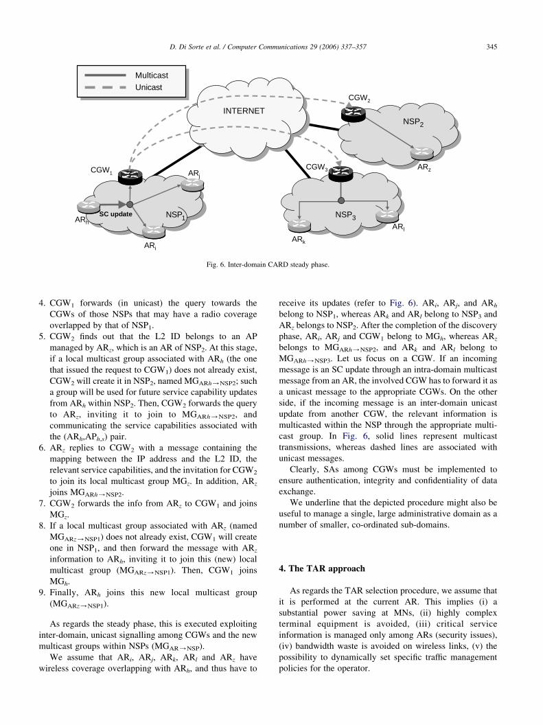
receive its updates (refer to Fig. 6). ARi, ARj, and ARh
belong to NSP1, whereas ARk and ARl belong to NSP3 and
ARz belongs to NSP2. After the completion of the discovery
phase, ARi, ARj and CGW1 belong to MGh, whereas ARz
belongs to MGARh/NSP2, and ARk and ARl belong to
MGARh/NSP3. Let us focus on a CGW. If an incoming
message is an SC update through an intra-domain multicast
message from an AR, the involved CGW has to forward it as
a unicast message to the appropriate CGWs. On the other
side, if the incoming message is an inter-domain unicast
update from another CGW, the relevant information is
multicasted within the NSP through the appropriate multi-
cast group. In Fig. 6, solid lines represent multicast
transmissions, whereas dashed lines are associated with
unicast messages.
Clearly, SAs among CGWs must be implemented to
ensure authentication, integrity and confidentiality of data
exchange.
We underline that the depicted procedure might also be
useful to manage a single, large administrative domain as a
number of smaller, co-ordinated sub-domains.
4. The TAR approach
As regards the TAR selection procedure, we assume that
it is performed at the current AR. This implies (i) a
substantial power saving at MNs, (ii) highly complex
terminal equipment is avoided, (iii) critical service
information is managed only among ARs (security issues),
(iv) bandwidth waste is avoided on wireless links, (v) the
possibility to dynamically set specific traffic management
policies for the operator.
D. Di Sorte et al. / Computer Communications 29 (2006) 337–357346
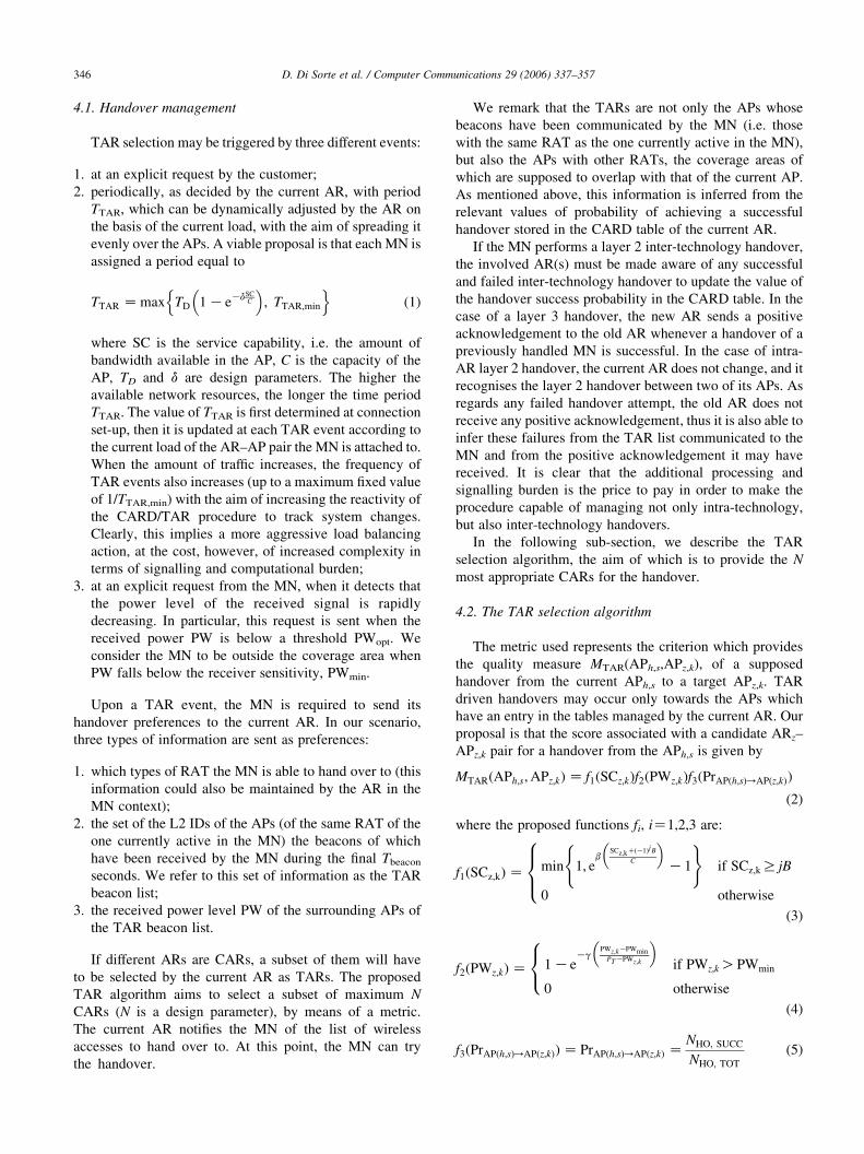
4.1. Handover management
TAR selection may be triggered by three different events:
1. at an explicit request by the customer;
2. periodically, as decided by the current AR, with period
TTAR, which can be dynamically adjusted by the AR on
the basis of the current load, with the aim of spreading it
evenly over the APs. A viable proposal is that each MN is
assigned a period equal to
TTAR Z max TD 1 KeKdSCC
� �; TTAR;min
n o(1)
where SC is the service capability, i.e. the amount of
bandwidth available in the AP, C is the capacity of the
AP, TD and d are design parameters. The higher the
available network resources, the longer the time period
TTAR. The value of TTAR is first determined at connection
set-up, then it is updated at each TAR event according to
the current load of the AR–AP pair the MN is attached to.
When the amount of traffic increases, the frequency of
TAR events also increases (up to a maximum fixed value
of 1/TTAR,min) with the aim of increasing the reactivity of
the CARD/TAR procedure to track system changes.
Clearly, this implies a more aggressive load balancing
action, at the cost, however, of increased complexity in
terms of signalling and computational burden;
3. at an explicit request from the MN, when it detects that
the power level of the received signal is rapidly
decreasing. In particular, this request is sent when the
received power PW is below a threshold PWopt. We
consider the MN to be outside the coverage area when
PW falls below the receiver sensitivity, PWmin.
Upon a TAR event, the MN is required to send its
handover preferences to the current AR. In our scenario,
three types of information are sent as preferences:
1. which types of RAT the MN is able to hand over to (this
information could also be maintained by the AR in the
MN context);
2. the set of the L2 IDs of the APs (of the same RAT of the
one currently active in the MN) the beacons of which
have been received by the MN during the final Tbeacon
seconds. We refer to this set of information as the TAR
beacon list;
3. the received power level PW of the surrounding APs of
the TAR beacon list.
If different ARs are CARs, a subset of them will have
to be selected by the current AR as TARs. The proposed
TAR algorithm aims to select a subset of maximum N
CARs (N is a design parameter), by means of a metric.
The current AR notifies the MN of the list of wireless
accesses to hand over to. At this point, the MN can try
the handover.
We remark that the TARs are not only the APs whose
beacons have been communicated by the MN (i.e. those
with the same RAT as the one currently active in the MN),
but also the APs with other RATs, the coverage areas of
which are supposed to overlap with that of the current AP.
As mentioned above, this information is inferred from the
relevant values of probability of achieving a successful
handover stored in the CARD table of the current AR.
If the MN performs a layer 2 inter-technology handover,
the involved AR(s) must be made aware of any successful
and failed inter-technology handover to update the value of
the handover success probability in the CARD table. In the
case of a layer 3 handover, the new AR sends a positive
acknowledgement to the old AR whenever a handover of a
previously handled MN is successful. In the case of intra-
AR layer 2 handover, the current AR does not change, and it
recognises the layer 2 handover between two of its APs. As
regards any failed handover attempt, the old AR does not
receive any positive acknowledgement, thus it is also able to
infer these failures from the TAR list communicated to the
MN and from the positive acknowledgement it may have
received. It is clear that the additional processing and
signalling burden is the price to pay in order to make the
procedure capable of managing not only intra-technology,
but also inter-technology handovers.
In the following sub-section, we describe the TAR
selection algorithm, the aim of which is to provide the N
most appropriate CARs for the handover.
4.2. The TAR selection algorithm
The metric used represents the criterion which provides
the quality measure MTAR(APh,s,APz,k), of a supposed
handover from the current APh,s to a target APz,k. TAR
driven handovers may occur only towards the APs which
have an entry in the tables managed by the current AR. Our
proposal is that the score associated with a candidate ARz–
APz,k pair for a handover from the APh,s is given by
MTARðAPh;s;APz;kÞ Z f1ðSCz;kÞf2ðPWz;kÞf3ðPrAPðh;sÞ/APðz;kÞÞ
(2)
where the proposed functions fi, iZ1,2,3 are:
f1ðSCz;kÞ Z min 1; eb
SCz;kCðK1ÞjB
C
� �K1
( )if SCz;k R jB
0 otherwise
8><>:
(3)
f2ðPWz;kÞ Z 1 KeKg
PWz;kKPWminPTKPWz;k
� �if PWz;k OPWmin
0 otherwise
8<:
(4)
f3ðPrAPðh;sÞ/APðz;kÞÞ Z PrAPðh;sÞ/APðz;kÞ ZNHO; SUCC
NHO; TOT
(5)
D. Di Sorte et al. / Computer Communications 29 (2006) 337–357 347
Since all the three proposed functions range between 0
and 1, the final score will also range between 0 and 1.
With reference to Eq. (3), B represents the MN
bandwidth demand to satisfactorily support the current
communication session, SCz,k is the service capability of
APz,k, C is the capacity of APz,k, and b is a design parameter.
In order to avoid ping-pong effects, the value of j is set to 1
for all but the current candidate, for which jZ0. The higher
the value of b, the higher the score associated with the
bandwidth (SCC(K1)jB) available after the hypothetical
execution of the handover, normalised by the capacity of the
AP taken into account. Moreover, if the new network access
cannot accommodate such a traffic flow with the necessary
bandwidth, its score is zero. This is a sort of admission
control function executed at the AR.
With reference to (4), PT is the standard value of the
transmission power associated with a given RAT, PWz,k is
the received power from the APz,k, and g is a design
parameter similar to b. Clearly, the higher the value of g, the
higher the sensitivity of the score function to power levels
below the optimum value PWopt.
With reference to (5), PrAP(h,s)/AP(z,k) is the estimation
of the handover success probability from APh,s to APz,k.
This probability value should approximate the percentage of
the APh,s coverage area which overlaps the APz,k coverage
area, thus a low score is given to the candidate APs with low
coverage areas overlapping with that of the current AP. This
parameter helps us in managing inter-technology handovers
without relying on coverage information from MNs. It is
worth noting that, for APs of the RAT currently used, f3 is
always set to 1 (since the overall process relies on beacon
detection), whereas, in the case of different RATs, f2 is
always set to 1 (since the MN does not estimate any power
level).
The set of handover management events includes all the
TAR executions (which may or not result in a handover
attempt) and non-assisted handovers. We define as a failure
event a handover management action that would not be
needed if the CARD/TAR functions worked properly. Thus,
at a given time, the probability, PrF, that a handover
management event fails is equal to
PrF Z PrF1 CPrF2 (6)
where PrF1 is the probability of having a non-assisted
handover (i.e. the TAR process has not been able to provide
a timely, appropriate solution), and PrF2 is the probability
that the MN does not succeed in attaching to the TARs (i.e.
the selection process forces the MN to try to connect to other
wireless accesses which are out of the coverage of the MN).
In other words, there are a couple of reasons for a non-zero
value of the failure probability of the handover management
process. Firstly, a failure may be caused by the movement of
MNs. In fact, upon a notable change of position, the wireless
accesses suggested by the TAR may be aged, so that the MN
may remain out of coverage. Then, another component of
the failure probability is due to the intrinsic characteristic of
the procedure, which, for inter-technology handovers, is
blind to the movement direction of MNs which are driven in
handing over.
In the following we will refer to PrF as the failure
probability of the CARD/TAR procedure.
Let us now illustrate the algorithm to select the list of
N TARs. In order for the selection procedure to make
sense, a CAR is selected only if its score is higher than
that of the current AR. In principle, the N candidates
with the highest score should be picked up. However, if
there are CARs of the current RAT with a score higher
than the current AR, the best of them is inserted at least
at the Nth rank of the handover list, independently of its
score. This policy enables to lower the probability of
handover failure after scanning all the N TARs provided
by the current AR. In fact, intra-technology attempts rely
on the results of previous L2 ID scanning process by the
MN.
5. Numerical results
In this section, we present some of the results obtained
from a simulation trial, the aim of which is (i) to test the
effectiveness of the proposed CARD/TAR approach in
terms of handoff success probability, and (ii) to test the
sensitivity of performance to variations of system
parameters.
We start by illustrating the main features of the
simulation model adopted. Then, we give details about the
simulation scenario, and finally we discuss the numerical
results.
5.1. Simulation model
In this sub-section, we describe the design approach and
the basic implementation choices to develop the simulator
used to evaluate the performance of the CARD/TAR
mechanism.
The simulator is flow-oriented and event-driven, where
packet transmissions are not simulated. In other words,
communications of signalling information occur instan-
taneously, and no delays are associated with information
transfer between network entities. The amount of access
network capacity is managed as a logical resource, part of
which may be allocated to an MN upon successful traffic
flow set-up.
We developed an object-oriented simulator by using the
CCC programming language. In more detail, we used the
event scheduler of the NS-2 simulator [24], and we added
our own CCC modules to manage MN mobility, CARD
functions, and TAR selection. In addition, we used the
OTcl interface of NS-2 to configure the simulation with our
own Tcl scripts. The set-up of the simulation was managed
by means of a Tcl script (typical of the NS-2 environment),
NS-2
SCHEDULERTclCL
ProprietaryTcl libraries
ProprietaryC++ libraries
INPUT FILES MATLABPOST-PROCESSING
SIMULATIONSCRIPTS
OUTPUT FILES
Fig. 7. Simulator architecture.
D. Di Sorte et al. / Computer Communications 29 (2006) 337–357348
which retrieves all the simulation parameters (relevant to
the network topology, RAT features, mobility model,
traffic load and TAR metric) by a number of input files
with a fixed structure and passes them to the CCCmodules by means of the CCC/OTcl interface. Output
files are then processed with Matlab to obtain performance
curves. The architecture of the simulator is depicted in
Fig. 7.
The events which populate the scheduler and imply the
update of the state variables are (i) the updates of the
positions of MNs, (ii) the set-up and tear-down of traffic
flows, and (iii) periodic events associated with the
CARD/TAR procedure (e.g. periodic CARD table
updates).
The coverage areas of APs are assumed to be circular
with a maximum radius denoted as rmax. The power
threshold PWopt corresponds to the one perceived at a
distance equal to 75% of the maximum coverage radius, and
it is calculated by using a quadratic attenuation law. This
simple propagation model does not invalidate the generality
of the CARD/TAR results. In fact, in order to analyse the
proposed algorithms, it is important to define the boundaries
of the coverage areas and the power threshold, regardless of
the specific propagation laws, the study of which is beyond
the scope of this paper. We implemented the coverage of an
AP as hard: so long as the received power level is higher
than PWmin, the MN is in coverage, whereas it is
disconnected when the received power level drops just
below that value.
The capacity, C, associated with an AP is considered as
net capacity, i.e. we assume ‘ideal’ layer 2 technologies,
without considering either the details relevant to trans-
mission aspects (e.g. fading and shadowing), or MAC
protocol features.
As regards the mobility model, we implemented the
Gauss–Markov model [12]. We used this model since it
avoids sharp direction changes, by allowing previous speed
and direction to influence future mobility. The equations
controlling MNs mobility are:
sn Z asnK1 C ð1 KaÞsave Cffiffiffiffiffiffiffiffiffiffiffiffiffiffiffiffiffið1 Ka2Þ
psxnK1
dn Z adnK1 C ð1 KaÞdave Cffiffiffiffiffiffiffiffiffiffiffiffiffiffiffiffiffið1 Ka2Þ
pdxnK1
8<: (7)
xn Z xnK1 CsnK1 cosðdnK1Þ
yn Z ynK1 CsnK1 sinðdnK1Þ
((8)
where sn and dn are the speed and the direction of the MN
at time n, 0%a%1 is the tuning parameter used to modify
the random nature of the motion, save and dave are constant
values representing the average values of sn and dn, sxnK1
and dxnK1are Gaussian random variables with zero mean
and variance l and, b, respectively. Clearly, xn and yn
represent the surface co-ordinates of the MN position in
the area at time n. The position of an MN is updated with
the step fixed at 1 s. The default value of the average
speed was set equal to 1.5 m/s, whereas the parameter a
was set to 0.5 and b was set to p/2. The initial value of
the direction was set to 0. However, when a MN reaches a
distance from the border of the simulation area inferior
than the 5% of the area side, this value is shifted by p (or
by Gp/4 if the MN reaches one of the corners of the
simulation area).
We assume that an MN is instantaneously aware it is
under the coverage of an AP (i.e. it immediately listens to
the relevant beacons).
The network is loaded with homogeneous CBR flows
with bandwidth equal to B. Calls are generated with a
Poisson arrival process with an average frequency l, and the
call duration is modelled as an exponentially distributed
random variable with mean 1/m. An MN can be in one of the
three following states: (i) disconnected (DISC), if it is not
under the coverage of any AP; (ii) connected (CONN), if it
is under the coverage of an AP; (iii) in communication
(COMM), if it is under the coverage of an AP and has an
active communication session, and therefore uses an amount
of the AP bandwidth equal to B.
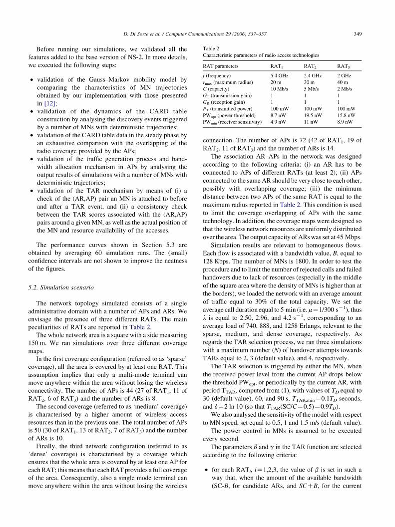
Table 2
Characteristic parameters of radio access technologies
RAT parameters RAT1 RAT2 RAT3
f (frequency) 5.4 GHz 2.4 GHz 2 GHz
rmax (maximum radius) 20 m 30 m 40 m
C (capacity) 10 Mb/s 5 Mb/s 2 Mb/s
GT (transmission gain) 1 1 1
GR (reception gain) 1 1 1
PT (transmitted power) 100 mW 100 mW 100 mW
PWopt (power threshold) 8.7 nW 19.5 nW 15.8 nW
PWmin (receiver sensitivity) 4.9 nW 11 nW 8.9 nW
D. Di Sorte et al. / Computer Communications 29 (2006) 337–357 349
Before running our simulations, we validated all the
features added to the base version of NS-2. In more details,
we executed the following steps:
† validation of the Gauss–Markov mobility model by
comparing the characteristics of MN trajectories
obtained by our implementation with those presented
in [12];
† validation of the dynamics of the CARD table
construction by analysing the discovery events triggered
by a number of MNs with deterministic trajectories;
† validation of the CARD table data in the steady phase by
an exhaustive comparison with the overlapping of the
radio coverage provided by the APs;
† validation of the traffic generation process and band-
width allocation mechanism in APs by analysing the
output results of simulations with a number of MNs with
deterministic trajectories;
† validation of the TAR mechanism by means of (i) a
check of the (AR,AP) pair an MN is attached to before
and after a TAR event, and (ii) a consistency check
between the TAR scores associated with the (AR,AP)
pairs around a given MN, as well as the actual position of
the MN and resource availability of the accesses.
The performance curves shown in Section 5.3 are
obtained by averaging 60 simulation runs. The (small)
confidence intervals are not shown to improve the neatness
of the figures.
5.2. Simulation scenario
The network topology simulated consists of a single
administrative domain with a number of APs and ARs. We
envisage the presence of three different RATs. The main
peculiarities of RATs are reported in Table 2.
The whole network area is a square with a side measuring
150 m. We ran simulations over three different coverage
maps.
In the first coverage configuration (referred to as ‘sparse’
coverage), all the area is covered by at least one RAT. This
assumption implies that only a multi-mode terminal can
move anywhere within the area without losing the wireless
connectivity. The number of APs is 44 (27 of RAT1, 11 of
RAT2, 6 of RAT3) and the number of ARs is 8.
The second coverage (referred to as ‘medium’ coverage)
is characterised by a higher amount of wireless access
resources than in the previous one. The total number of APs
is 50 (30 of RAT1, 13 of RAT2, 7 of RAT3) and the number
of ARs is 10.
Finally, the third network configuration (referred to as
‘dense’ coverage) is characterised by a coverage which
ensures that the whole area is covered by at least one AP for
each RAT; this means that each RAT provides a full coverage
of the area. Consequently, also a single mode terminal can
move anywhere within the area without losing the wireless
connection. The number of APs is 72 (42 of RAT1, 19 of
RAT2, 11 of RAT3) and the number of ARs is 14.
The association AR–APs in the network was designed
according to the following criteria: (i) an AR has to be
connected to APs of different RATs (at least 2); (ii) APs
connected to the same AR should be very close to each other,
possibly with overlapping coverage; (iii) the minimum
distance between two APs of the same RAT is equal to the
maximum radius reported in Table 2. This condition is used
to limit the coverage overlapping of APs with the same
technology. In addition, the coverage maps were designed so
that the wireless network resources are uniformly distributed
over the area. The output capacity of ARs was set at 45 Mbps.
Simulation results are relevant to homogeneous flows.
Each flow is associated with a bandwidth value, B, equal to
128 Kbps. The number of MNs is 1800. In order to test the
procedure and to limit the number of rejected calls and failed
handovers due to lack of resources (especially in the middle
of the square area where the density of MNs is higher than at
the borders), we loaded the network with an average amount
of traffic equal to 30% of the total capacity. We set the
average call duration equal to 5 min (i.e. mZ1/300 sK1), thus
l is equal to 2.50, 2.96, and 4.2 sK1, corresponding to an
average load of 740, 888, and 1258 Erlangs, relevant to the
sparse, medium, and dense coverage, respectively. As
regards the TAR selection process, we ran three simulations
with a maximum number (N) of handover attempts towards
TARs equal to 2, 3 (default value), and 4, respectively.
The TAR selection is triggered by either the MN, when
the received power level from the current AP drops below
the threshold PWopt, or periodically by the current AR, with
period TTAR, computed from (1), with values of TD equal to
30 (default value), 60, and 90 s, TTAR,minZ0.1TD seconds,
and dZ2 ln 10 (so that TTAR(SC/CZ0.5)Z0.9TD).
We also analysed the sensitivity of the model with respect
to MN speed, set equal to 0.5, 1 and 1.5 m/s (default value).
The power control in MNs is assumed to be executed
every second.
The parameters b and g in the TAR function are selected
according to the following criteria:
† for each RATi, iZ1,2,3, the value of b is set in such a
way that, when the amount of the available bandwidth
(SC-B, for candidate ARs, and SCCB, for the current
100
101
0
0.2
0.4
0.6
0.8
1
Service Capabilities (Mb/s)
f 1(SC
)
RAT1, C = 10 Mb/s
RAT2, C = 5 Mb/s
RAT3, C = 2 Mb/s
5 10 15 20 25 30
0.1
0.2
0.3
0.4
0.5
0.6
0.7
0.8
0.9
1
Received Power Level (PW) in nW
f 2(P
W)
RAT1, γ = 36 106, PW
opt = 8.7 nW
RAT2, γ = 16 106, PW
opt = 20 nW
RAT3, γ = 20 106, PW
opt = 16 nW
Fig. 8. Metric functions f1 and f2.
D. Di Sorte et al. / Computer Communications 29 (2006) 337–357350
one) is higher than, or equal to 0.8Ci, Ci being the full
capacity of RATi, then the weight associated with the
service capability is equal to 1. This implies that the
value of b is equal to bZ0.866 for all RATs. For values
of SC lower than 0.8Ci, such a weight rapidly decreases,
and consequently the importance of the load balancing
criterion increases;
† for each RATi with iZ1,2,3, the value gi is set so that the
function f2(PWopt,i)Z3/4; in other words, when the
power level is equal to the value of PWopt,i which
0 500 1000 150.9
0.95
1
Simulation tim
Han
dove
r su
cces
s pr
obab
ility
N = 3T
D = 30 s
speed = 1.5 m/
Fig. 9. Probabilities of successful ha
characterises the RATi itself, we set the weight
associated with the received power level equal to 3/4.
For values of received power lower than PWopt,i, this
weight rapidly decreases. Consequently, the power-
based criterion becomes important when the received
power level from an AP is lower than PWopt. The final
result gave values of g as g1Z36.5!106, g2Z16.2!106, and g3Z20!106, for RAT1, RAT2 and RAT3,
respectively. In this way, we take into account different
characteristics of RATs, i.e. the signal strength that, as
00 2000 2500 3000e (seconds)
P1, Dense cov
P2, Dense cov
P3, Dense cov
s
ndover: dense coverage case.
D. Di Sorte et al. / Computer Communications 29 (2006) 337–357 351
all channel specific factors, cannot be straightforwardly
compared.
The curves relevant to f1 and f2 are reported in Fig. 8.
As regards the update of the service capabilities, ARs
multicast the update of the available bandwidth, SC, to an
AP either periodically, with period equal to TSCZ60 s, and
upon variations of SC of at least 5% from the one previously
communicated.
5.3. Simulation results
Our goal is to verify the effectiveness of the
CARD/TAR procedure, in particular as regards the
capability of not only self-constructing the coverage map
of the whole area, but also of driving both inter and intra-
technology handovers.
Initially, the CARD table stored in a generic AR contains
only the information relevant to the APs connected to the
AR itself, then, as time goes by, this table self-constructs
according to the information provided by the MNs. As
regards the data collected to generate statistics, we consider
only those relevant to the MNs in the COMM state.
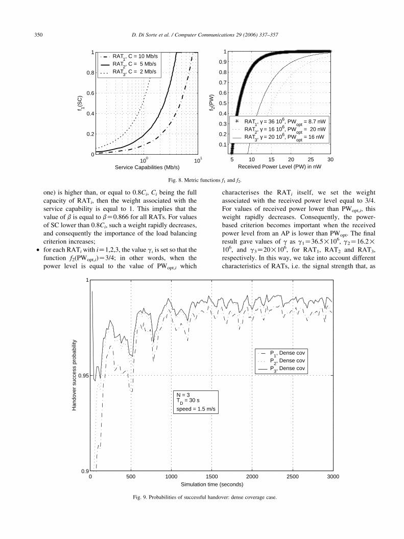
Let us first analyse the simulations in the case of dense
coverage, with TDZ30 s, MN speed equal to 1.5 m/s, and
NZ3.
0 500 1000 150
0.2
0.4
0.6
Simulation tim
Fai
lure
pro
babi
lity
N = 3T
D = 30 s
speed = 1.5 m/s
Fig. 10. Failure probabilities
Fig. 9 shows the cumulative probability of successfully
handing over within the first, second and third attempt. As
expected, we can see that after a brief transient period
needed for self-constructing the CARD tables, the prob-
ability of successfully handing over towards the best-scored
CARs rapidly converges to values close to 1. Clearly, the
successful handover probability increases with the number
of attempts.
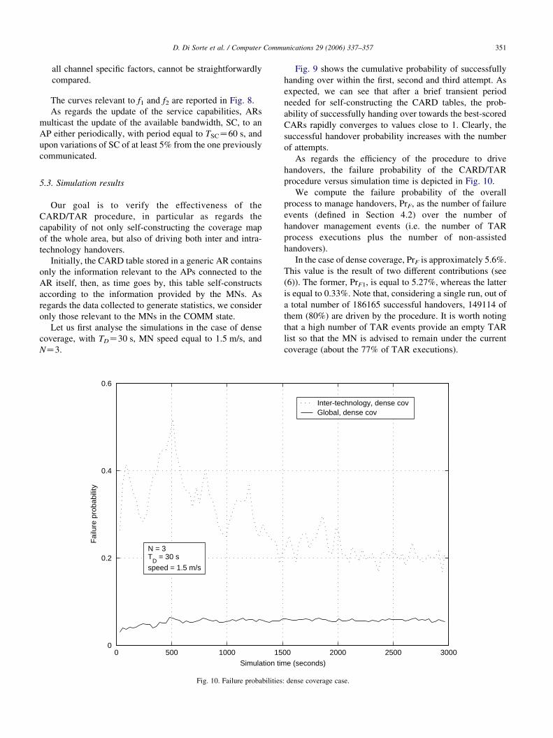
As regards the efficiency of the procedure to drive
handovers, the failure probability of the CARD/TAR
procedure versus simulation time is depicted in Fig. 10.
We compute the failure probability of the overall
process to manage handovers, PrF, as the number of failure
events (defined in Section 4.2) over the number of
handover management events (i.e. the number of TAR
process executions plus the number of non-assisted
handovers).
In the case of dense coverage, PrF is approximately 5.6%.
This value is the result of two different contributions (see
(6)). The former, PrF1, is equal to 5.27%, whereas the latter
is equal to 0.33%. Note that, considering a single run, out of
a total number of 186165 successful handovers, 149114 of
them (80%) are driven by the procedure. It is worth noting
that a high number of TAR events provide an empty TAR
list so that the MN is advised to remain under the current
coverage (about the 77% of TAR executions).
00 2000 2500 3000e (seconds)
Inter-technology, dense covGlobal, dense cov
: dense coverage case.
D. Di Sorte et al. / Computer Communications 29 (2006) 337–357352
Fig. 10 also shows that the probability of failing an inter-
technology handover is approximately 20% at the end of the
simulation, when the probability values in the CARD tables
become stable.
We note that the performance of the CARD/TAR
procedure is extremely satisfactory for dense wireless
coverage. This result is to be expected for two main reasons:
1. inter-technology handovers (the most critical ones) are
not so frequent since:
a. each RAT covers the whole area;
b. the discovery of the surrounding coverage provided
by the current RAT depends on the MN capability to
pick up the L2 beacons transmitted by the
surrounding APs. In general, we can expect the
mechanism to work better when the overlapping
area between neighbour APs belonging to the same
RAT is substantial;
c. the traffic load on offer is not heavy. This also means
that inter-technology handovers are not so often
solicited by a load-balancing action.The distribution
of successfully driven handovers, classified as intra
and inter-technology handovers, together with their
distribution over the three different RATs, is
summarised in Table 3 for a single run. Driven
intra-technology handovers are equal to 92.28% of
the total driven handovers and equal to 73.91% of
the total handovers. As expected, most handovers
occur within RAT1, which has the largest capacity.
On the other hand, driven inter-technology hand-
overs are equal to 7.72% of the total driven
handovers and equal to 6.18% of the total handovers;
2. overlapping between the coverage areas of different
RATs is high enough to keep the failure probability of
inter-technology handover attempts sufficiently low as
not to degrade the performance of the overall procedure.
Consequently, if we consider a coverage with an amount
of resources lower than those in the dense coverage, a
deterioration of the performance of the procedure is to be
expected.
Let us analyse what happens in the case of medium and
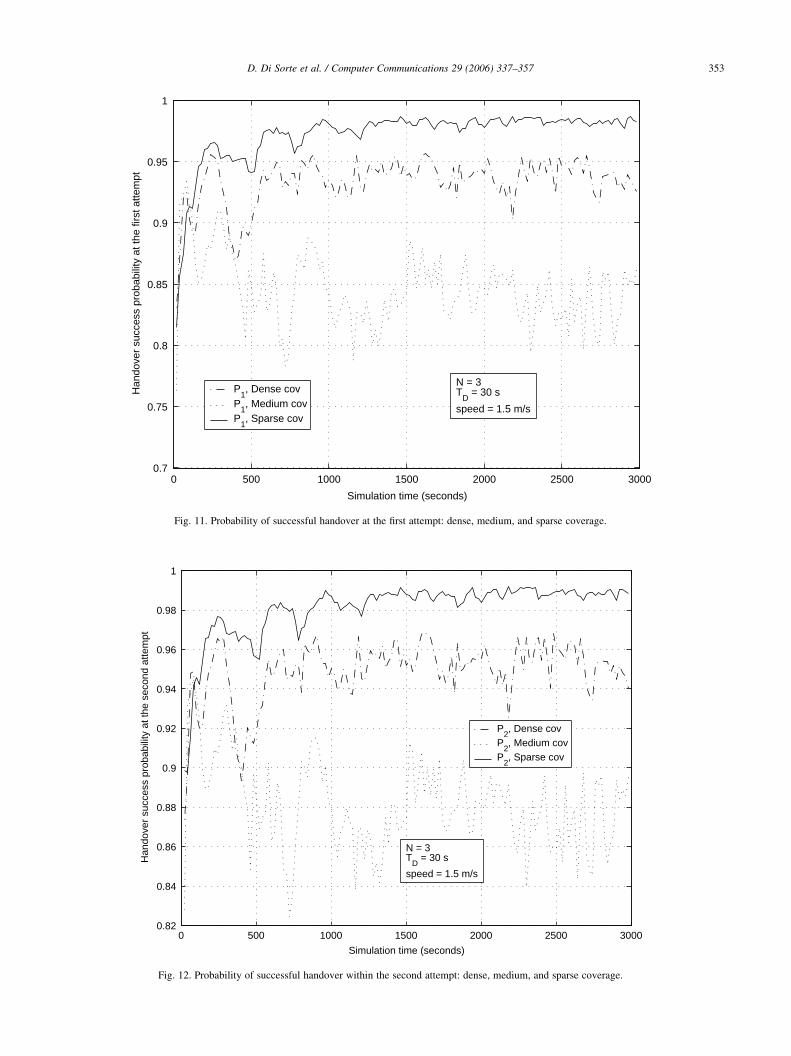
sparse coverage. Figs. 11–13 show the cumulative
Table 3
Driven Handover distribution: dense coverage case
Handover Type Involved RATS % Total %
Intra-technology RAT1/RAT1 66.43 92.28
RAT2/RAT2 20.53
RAT3/RAT3 5.32
Inter-technology RAT1/RAT2 2.31 7.72
RAT1/RAT3 0.27
RAT2/RAT1 3.1
RAT2/RAT3 0.87
RAT3/RAT1 0.24
RAT3/RAT2 0.93
probability of a successful handover within the first, second
and third attempt, respectively, in all the coverage cases. It
is clear that performance improves from sparse to medium
coverage and from medium to dense coverage. This trend is
highlighted in Fig. 14, where the probability of failure
increases when compared with the dense coverage case.
This is due to a lower amount of wireless network resources,
hence to a reduced overlapping of coverage areas of
different RATs. As a result, the percentage of driven
handovers remains nearly constant for medium coverage
(99995 out of a total of 124681, i.e. 80%) and rapidly
decreases for sparse coverage (67695 out of a total of
93005, i.e. 72.8%). Note that the number of handovers for
MNs in the COMM state is higher in the case of dense
coverage since the amount of active flows is higher than in
the other two cases. As regards the percentage of inter-
technology driven handovers, it generally rises when the
coverage area provided by a single RAT decreases; it is
equal to 11.54% in the case of sparse coverage. In addition,
the probability of failing the CARD/TAR process increases
from 5.6% for dense coverage up to approximately 6% for
medium and 7.2% for sparse coverage (PrF1 is equal to
5.5%, whereas PrF2 is equal to 1.7%). We remark that, as
expected, PrF2 has increased considerably with respect to
the dense coverage case, since inter-technology handovers
are needed more frequently.
Let us now analyse the performance of the procedure in
the case of sparse coverage when N ranges in the set {2, 3,
4}, TD in the set {30, 60, 90 s}, and the average speed of the
MNs in the set {0.5, 1, 1.5 m/s}. We expect a performance
improvement when N increases, TD decreases, and MN
speed decreases. In fact, lower values of TD imply more
frequent TAR actions, thus a better performance of the
CARD/TAR procedure, which is able to quickly track the
network changes and the MN position. Moreover, by
increasing the value of N means that the TAR list, provided
to the MNs by the current AR, includes a higher number of
CARs to try to hand over to, and this implies an
improvement in the performance of the procedure.
Furthermore, we expect the process to work better when
the speed of MNs is decreased, since the probability of
having a non-assisted handover due to large movement will
thus decrease. Note that the values of the MN speed
(walking speed) that we have chosen are typical of the
network scenario simulated, where the radius of the APs
ranges from 20 to 40 m.
Fig. 15 shows the cumulative probability of a successful
handover within the first N handover attempts for cases NZ2, NZ3, and NZ4, with TDZ30 s and MN speed equal to
1.5 m/s. The improvement is clear for each handover
attempt. We note in particular the improvement of the
successful handover probability at the last attempt. This
value varies from 0.885 for NZ2, to 0.905 for NZ3, and,
finally, to 0.91 for NZ4. This improvement induces only a
negligible decrease in the failure probability of the
CARD/TAR procedure.
0 500 1000 1500 2000 2500 30000.7
0.75
0.8
0.85
0.9
0.95
1
Simulation time (seconds)
Han
dove
r su
cces
s pr
obab
ility
at t
he fi
rst a
ttem
pt
N = 3T
D = 30 s
speed = 1.5 m/s
P1, Dense cov
P1, Medium cov
P1, Sparse cov
Fig. 11. Probability of successful handover at the first attempt: dense, medium, and sparse coverage.
0 500 1000 1500 2000 2500 30000.82
0.84
0.86
0.88
0.9
0.92
0.94
0.96
0.98
1
Simulation time (seconds)
Han
dove
r su
cces
s pr
obab
ility
at t
he s
econ
d at
tem
pt
P2, Dense cov
P2, Medium cov
P2, Sparse cov
N = 3T
D = 30 s
speed = 1.5 m/s
Fig. 12. Probability of successful handover within the second attempt: dense, medium, and sparse coverage.
D. Di Sorte et al. / Computer Communications 29 (2006) 337–357 353
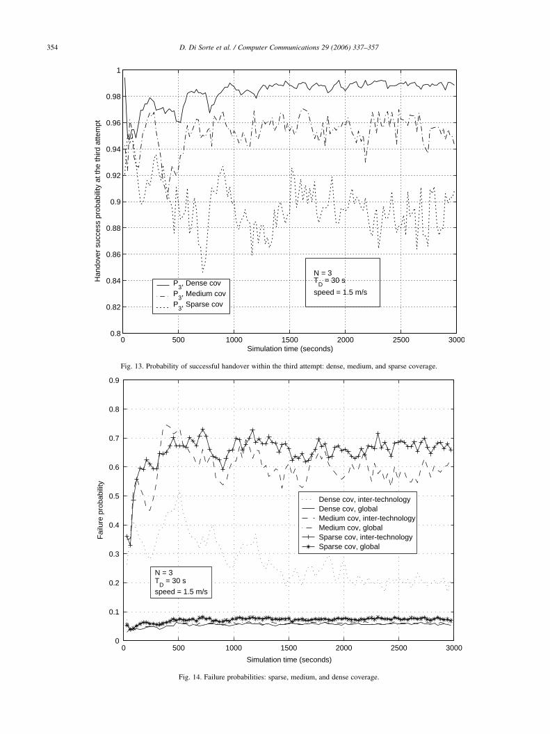
0 500 1000 1500 2000 2500 30000.8
0.82
0.84
0.86
0.88
0.9
0.92
0.94
0.96
0.98
1
Simulation time (seconds)
Han
dove
r su
cces
s pr
obab
ility
at t
he th
ird a
ttem
pt
P3, Dense cov
P3, Medium cov
P3, Sparse cov
N = 3T
D = 30 s
speed = 1.5 m/s
Fig. 13. Probability of successful handover within the third attempt: dense, medium, and sparse coverage.
0 500 1000 1500 2000 2500 30000
0.1
0.2
0.3
0.4
0.5
0.6
0.7
0.8
0.9
Simulation time (seconds)
Fai
lure
pro
babi
lity
Dense cov, inter-technologyDense cov, globalMedium cov, inter-technologyMedium cov, globalSparse cov, inter-technologySparse cov, global
N = 3T
D = 30 s
speed = 1.5 m/s
Fig. 14. Failure probabilities: sparse, medium, and dense coverage.
D. Di Sorte et al. / Computer Communications 29 (2006) 337–357354
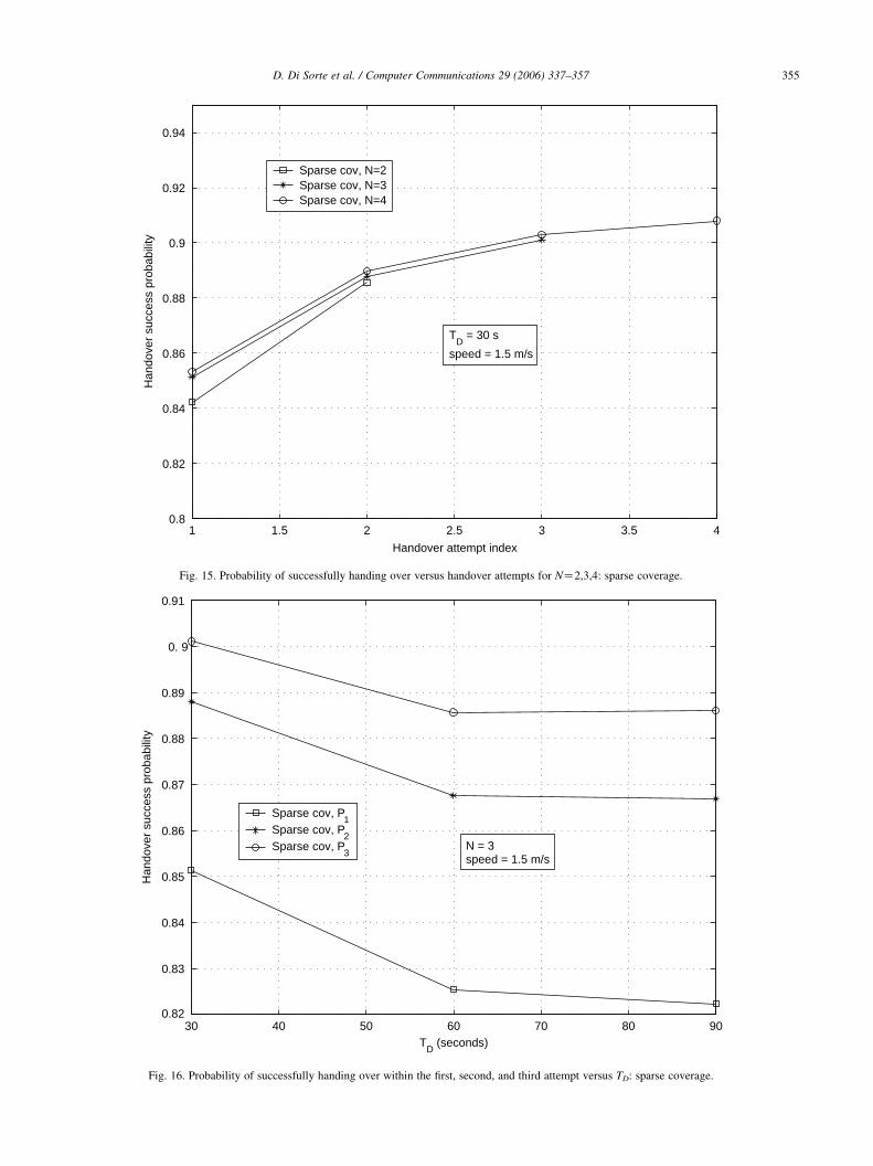
1 1.5 2 2.5 3 3.5 40.8
0.82
0.84
0.86
0.88
0.9
0.92
0.94
Handover attempt index
Han
dove
r su
cces
s pr
obab
ility
Sparse cov, N=2Sparse cov, N=3Sparse cov, N=4
TD
= 30 s
speed = 1.5 m/s
Fig. 15. Probability of successfully handing over versus handover attempts for NZ2,3,4: sparse coverage.
30 40 50 60 70 80 900.82
0.83
0.84
0.85
0.86
0.87
0.88
0.89
0. 9
0.91
TD
(seconds)
Han
dove
r su
cces
s pr
obab
ility
Sparse cov, P1
Sparse cov, P2
Sparse cov, P3
N = 3speed = 1.5 m/s
Fig. 16. Probability of successfully handing over within the first, second, and third attempt versus TD: sparse coverage.
D. Di Sorte et al. / Computer Communications 29 (2006) 337–357 355
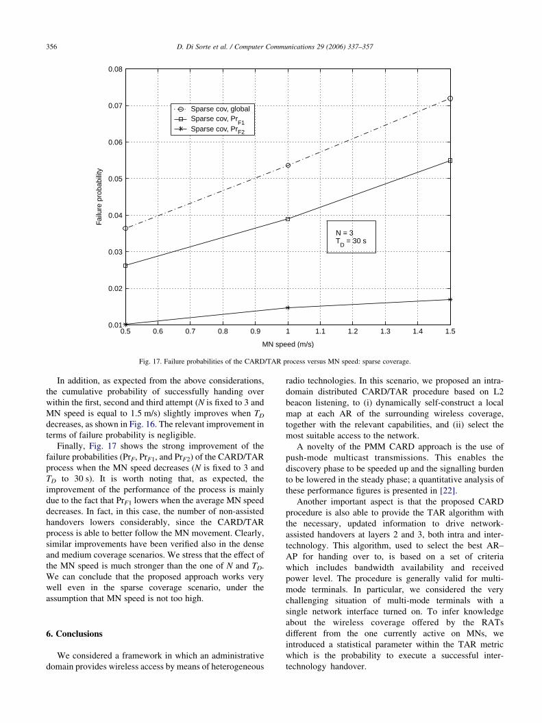
0.5 0.6 0.7 0.8 0.9 1 1.1 1.2 1.3 1.4 1.50.01
0.02
0.03
0.04
0.05
0.06
0.07
0.08
MN speed (m/s)
Failu
re p
roba
bilit
ySparse cov, globalSparse cov, Pr
F1Sparse cov, PrF2
N = 3T
D = 30 s
Fig. 17. Failure probabilities of the CARD/TAR process versus MN speed: sparse coverage.
D. Di Sorte et al. / Computer Communications 29 (2006) 337–357356
In addition, as expected from the above considerations,
the cumulative probability of successfully handing over
within the first, second and third attempt (N is fixed to 3 and
MN speed is equal to 1.5 m/s) slightly improves when TD
decreases, as shown in Fig. 16. The relevant improvement in
terms of failure probability is negligible.
Finally, Fig. 17 shows the strong improvement of the
failure probabilities (PrF, PrF1, and PrF2) of the CARD/TAR
process when the MN speed decreases (N is fixed to 3 and
TD to 30 s). It is worth noting that, as expected, the
improvement of the performance of the process is mainly
due to the fact that PrF1 lowers when the average MN speed
decreases. In fact, in this case, the number of non-assisted
handovers lowers considerably, since the CARD/TAR
process is able to better follow the MN movement. Clearly,
similar improvements have been verified also in the dense
and medium coverage scenarios. We stress that the effect of
the MN speed is much stronger than the one of N and TD.
We can conclude that the proposed approach works very
well even in the sparse coverage scenario, under the
assumption that MN speed is not too high.
6. Conclusions
We considered a framework in which an administrative
domain provides wireless access by means of heterogeneous
radio technologies. In this scenario, we proposed an intra-
domain distributed CARD/TAR procedure based on L2
beacon listening, to (i) dynamically self-construct a local
map at each AR of the surrounding wireless coverage,
together with the relevant capabilities, and (ii) select the
most suitable access to the network.
A novelty of the PMM CARD approach is the use of
push-mode multicast transmissions. This enables the
discovery phase to be speeded up and the signalling burden
to be lowered in the steady phase; a quantitative analysis of
these performance figures is presented in [22].
Another important aspect is that the proposed CARD
procedure is also able to provide the TAR algorithm with
the necessary, updated information to drive network-
assisted handovers at layers 2 and 3, both intra and inter-
technology. This algorithm, used to select the best AR–
AP for handing over to, is based on a set of criteria
which includes bandwidth availability and received
power level. The procedure is generally valid for multi-
mode terminals. In particular, we considered the very
challenging situation of multi-mode terminals with a
single network interface turned on. To infer knowledge
about the wireless coverage offered by the RATs
different from the one currently active on MNs, we
introduced a statistical parameter within the TAR metric
which is the probability to execute a successful inter-
technology handover.
D. Di Sorte et al. / Computer Communications 29 (2006) 337–357 357
We analysed the performance in terms of handover
success and failure probability of the CARD/TAR pro-
cedure by simulations. In particular, we have verified that
the procedure is very effective when the size of the
overlapping coverage areas among APs is considerable. In
this case, most of handovers are driven by our CARD/TAR
procedure, and inter-technology handovers, which are
clearly the critical ones, are not that frequent. The
probability of failure of inter-technology handover attempts
is sufficiently low and it does not significantly affect the
failure probability of the CARD/TAR process. In addition,
when the average speed of MNs is limited, we have shown
that the proposed approach works very well even in a sparse
coverage scenario.
Note that inter-technology handovers are generally
highly power consuming and potentially critical when
real-time services are supported. We stress that this
criticality is mainly due to the fact that the selection
procedure is blind and failures may occur. It is clear that, if
multi-mode terminals are allowed to simultaneously scan
for beacons on all network interfaces, the procedure is no
longer “blind”, and failures would be avoided. Note that the
intrinsic CARD/TAR characteristics (quick self-construc-
tion of coverage mapping, effective capability exchange,
load balancing) would remain unaltered. The price to pay
would be an increased complexity and power consumption
in terminals.
Acknowledgements
The authors would like to thank the anonymous referees
for their suggestions and comments that have improved the
quality of the paper. This work was performed under co-
financing by the Italian Ministry of Education, University,
and Research (MIUR) within the FIRB project PRIMO.
References
[1] J. Manner, M. Kojo, Mobility related terminology, IETF RFC 3753,
June, 2004.
[2] M. Liebsch, Candidate access router discovery, Internet draft,
September, 2004.
[3] J. Loughney, M. Nakhjiri, C. Perkins, R. Koodli, Context transfer
protocol, Internet draft, August, 2004.
[4] J. Kempf, Problem description: reasons for performing context
transfers between nodes in an IP access network, IETF RFC 3374,
September, 2002.
[5] C. Perkins, IP mobility support for IPv4, IETF RFC 3344, August,
3344, 2002.
[6] D.B. Johnson, C.E. Perkins, Mobility support in IPv6, MobiCom’96,
Rye, NY, USA, 1996.
[7] A.T. Campbell, J. Gomez, K. Sanghyo, C. Wan, Z.R. Turanyi,
A.G. Valko, Comparison of IP micromobility protocols, IEEE
Wireless Communications, February, 2002.
[8] D. Funato, X. He, C. Williams, A. Takeshita, M.D. Ali, J. Nakfour,
Geographically adjacent access router discovery protocol, Internet
draft, June, 2002.
[9] D. Trossen, G. Krishnamurthi, H. Chaskar, R.C. Chalmers, E. Shim, A
dynamic protocol for candidate access-router discovery, Internet
draft, March, 2003.
[10] R. Koodli, Fast handovers for mobile IPv6, Internet draft, October,
2004.
[11] K. El Malki, et al., Low latency handoffs in mobile IPv4, Internet
draft, June, 2004.
[12] T. Camp, J. Boleng, V. Davies, A survey of mobility models for ad
hoc network research, Wireless Communication and Mobile
Computing (WCMC) 2 (5) (2002) 483–502.
[13] E. Shim, J.P. Redlich, R.D. Gitlin, Secure candidate access router
discovery, IEEE Wireless Communications and Networking Con-
ference (IEEE WCNC), New Orleans, USA, March, 2003.
[14] IETF MSEC WG Homepage, http://www.ietf.org/html.charters/msec-
charter.html.
[15] S. Glass, T. Hiller, S. Jacobs, C. Perkins, Mobile IP authentication,
authorization, and accounting requirements, IETF RFC 2977,
October, 2000.
[16] C.E. Perkins, P.R. Calhoun, AAA registration keys for mobile IPv4,
Internet draft, October, 2003.
[17] G.P. Pollini, Trends in hand-over design, IEEE Communications
Magazine, March, 1996.
[18] P.M.L. Chan, R.E. Sheriff, Y.F. Hu, P. Conforto, C. Tocci, Mobility
management incorporating fuzzy logic for a heterogeneous IP
environment, IEEE Communications Magazine, December, 2001.
[19] K. Pahlavan, et al., Handoff in hybrid mobile data networks, IEEE
Personal Communications 7 (2) (2000).
[20] N.D. Tripathi, Generic adaptive handoff algorithms using fuzzy logic
and neural networks, PhD Thesis, Virginia Polytechnic Institute and
State University, 1997.
[21] W. Zhang, J. Jahnert, K. Dolzer, Design and evaluation of a hand-over
decision strategy for 4th generation mobile networks, IEEE Vehicular
Technology Conference, Jeju, Korea, 2003.
[22] N. Blefari-Melazzi, D. Di Sorte, M. Femminella, L. Piacentini, G.
Reali, Performance evaluation of a multicast-based solution for
wireless resources discovery, IEEE International conference on
Communications, Seoul, Korea, May 2005.
[23] R. Atkinson, S. Kent, Security Architecture for the Internet Protocol,
IETF RFC 2401, Nov, 1998.
[24] NS Web-site: http://www.isi.edu/nsnam/ns/.