
Taming heterogeneity - the Ptolemy approach
18
Taming Heterogeneity—The Ptolemy Approach JOHAN EKER, JÖRN W. JANNECK, EDWARD A. LEE, FELLOW, IEEE, JIE LIU, XIAOJUN LIU, JOZSEF LUDVIG, STEPHEN NEUENDORFFER, SONIA SACHS, AND YUHONG XIONG Invited Paper Modern embedded computing systems tend to be heterogeneous in the sense of being composed of subsystems with very different characteristics, which communicate and interact in a variety of ways—synchronous or asynchronous, buffered or unbuffered, etc. Obviously, when designing such systems, a modeling language needs to reflect this heterogeneity.Today’s modeling environments usually offer a variant of what we call amorphous heterogeneity to address this problem. This paper argues that modeling systems in this manner leads to unexpected and hard-to-analyze interac- tions between the communication mechanisms and proposes a more structured approach to heterogeneity, called hierarchical heterogeneity, to solve this problem. It proposes a model structure and semantic framework that support this form of heterogeneity, and discusses the issues arising from heterogeneous component interaction and the desire for component reuse. It introduces the notion of domain polymorphism as a way to address these issues. Keywords—component-based design, embedded systems, heterogeneous modeling, models of computation. I. INTRODUCTION Modern embedded systems are typically software enabled, interconnected, and engage the physical world. Among other things, they must be reliable, concurrent, and reactive in real time. To ensure these requirements in the face of growing complexity, designers may be able to use formal methods that allow designs to be analyzed and verified. Embedded sys- tems also tend to be heterogeneous, i.e., they include subsys- Manuscript received December 20, 2001; revised August 31, 2002. This work, as part of the Ptolemy project, was supported in part by the Defense Advanced Research Projects Agency (DARPA); in part by the Micro- electronics Advanced Research Corporation/DARPA Gigascale Silicon Research Center; in part by the State of California MICRO program; and in part by the following companies: Agilent Technologies, Cadence Design Systems, Hitachi, National Semiconductor, and Philips. J. Eker, J. W. Janneck, E. A. Lee, J. Liu, X. Liu, S. Neuendorffer, S. Sachs and Y. Xiong are with the Electrical Engineering and Computer Sciences Department, University of California at Berkeley, Berkeley, CA 94720-1770 (e-mail: [email protected]; jan- [email protected]; [email protected]; [email protected]; [email protected]; [email protected]; [email protected]; [email protected]). J. Ludvig is with Athena Semiconductors Inc., Fremont, CA 94538 (e-mail: [email protected]). Digital Object Identifier 10.1109/JPROC.2002.805829 tems with very different characteristics such as mechanical, hydraulic, analog, and digital hardware, as well as software that is oriented toward dataflow, realizes control logic, deals with resource allocation, or must provide some real-time per- formance. Much effort has been invested in creating formal models that elegantly describe each of these characteristics, and the selection of formal models and tools when designing an embedded system involves decisions that can have impor- tant consequences for a project. However, each model typically represents only one aspect of the entire system, and thus only part of its total behavior. To evaluate the behavior of the system as a whole, these models must be composed in some fashion so that their prop- erties can be considered together. This heterogeneous com- position must represent interaction and communication be- tween models while preserving the properties of each indi- vidual model. Brute-force composition of heterogeneous models may re- sult in what we call emergent behavior. Model behavior is emergent if it is caused by the interaction between character- istics of different formal models, and if it was not intended or foreseen by the author of the model. Emergent behavior is therefore always a surprise to the designer, and potentially violates properties the designer expects from the individual formal models, thereby interfering with the ability to analyze the entire model. One example of an emergent behavior is priority inver- sion between threads in a real-time operating system. In this case threads are interacting using two different communi- cation mechanisms: mutual exclusion using monitors and a fixed priority scheduling mechanism. Looking at each mech- anism in isolation, a designer naturally expects that the thread scheduler will preempt low-priority threads when a high-pri- ority thread is ready to execute. Instead, by locking a monitor, a low-priority thread may stall a high-priority thread for an unbounded amount of time. We will call a style of handling heterogeneous models that allows various interaction mechanisms to be specified be- tween a group of components at the same time amorphous, 0018-9219/03$17.00 © 2003 IEEE PROCEEDINGS OF THE IEEE, VOL. 91, NO. 1, JANUARY 2003 127
-
Upload
independent -
Category
Documents
-
view
0 -
download
0
Transcript of Taming heterogeneity - the Ptolemy approach

Taming Heterogeneity—The Ptolemy Approach
JOHAN EKER, JÖRN W. JANNECK, EDWARD A. LEE, FELLOW, IEEE, JIE LIU, XIAOJUN LIU,JOZSEF LUDVIG, STEPHEN NEUENDORFFER, SONIA SACHS,AND YUHONG XIONG
Invited Paper
Modern embedded computing systems tend to be heterogeneousin the sense of being composed of subsystems with very differentcharacteristics, which communicate and interact in a variety ofways—synchronous or asynchronous, buffered or unbuffered, etc.Obviously, when designing such systems, a modeling languageneeds to reflect this heterogeneity. Today’s modeling environmentsusually offer a variant of what we call amorphous heterogeneityto address this problem. This paper argues that modeling systemsin this manner leads to unexpected and hard-to-analyze interac-tions between the communication mechanisms and proposes amore structured approach to heterogeneity, called hierarchicalheterogeneity, to solve this problem. It proposes a model structureand semantic framework that support this form of heterogeneity,and discusses the issues arising from heterogeneous componentinteraction and the desire for component reuse. It introduces thenotion of domain polymorphism as a way to address these issues.
Keywords—component-based design, embedded systems,heterogeneous modeling, models of computation.
I. INTRODUCTION
Modern embedded systems are typically software enabled,interconnected, and engage the physical world. Among otherthings, they must be reliable, concurrent, and reactive in realtime. To ensure these requirements in the face of growingcomplexity, designers may be able to use formal methods thatallow designs to be analyzed and verified. Embedded sys-tems also tend to beheterogeneous, i.e., they include subsys-
Manuscript received December 20, 2001; revised August 31, 2002. Thiswork, as part of the Ptolemy project, was supported in part by the DefenseAdvanced Research Projects Agency (DARPA); in part by the Micro-electronics Advanced Research Corporation/DARPA Gigascale SiliconResearch Center; in part by the State of California MICRO program; andin part by the following companies: Agilent Technologies, Cadence DesignSystems, Hitachi, National Semiconductor, and Philips.
J. Eker, J. W. Janneck, E. A. Lee, J. Liu, X. Liu, S. Neuendorffer,S. Sachs and Y. Xiong are with the Electrical Engineering andComputer Sciences Department, University of California at Berkeley,Berkeley, CA 94720-1770 (e-mail: [email protected]; [email protected]; [email protected]; [email protected];[email protected]; [email protected];[email protected]; [email protected]).
J. Ludvig is with Athena Semiconductors Inc., Fremont, CA 94538(e-mail: [email protected]).
Digital Object Identifier 10.1109/JPROC.2002.805829
tems with very different characteristics such as mechanical,hydraulic, analog, and digital hardware, as well as softwarethat is oriented toward dataflow, realizes control logic, dealswith resource allocation, or must provide some real-time per-formance. Much effort has been invested in creating formalmodels that elegantly describe each of these characteristics,and the selection of formal models and tools when designingan embedded system involves decisions that can have impor-tant consequences for a project.
However, each model typically represents only one aspectof the entire system, and thus only part of its total behavior.To evaluate the behavior of the system as a whole, thesemodels must be composed in some fashion so that their prop-erties can be considered together. Thisheterogeneous com-positionmust represent interaction and communication be-tween models while preserving the properties of each indi-vidual model.
Brute-force composition of heterogeneous models may re-sult in what we callemergent behavior. Model behavior isemergent if it is caused by the interaction between character-istics of different formal models, and if it was not intendedor foreseen by the author of the model. Emergent behavioris therefore always a surprise to the designer, and potentiallyviolates properties the designer expects from the individualformal models, thereby interfering with the ability to analyzethe entire model.
One example of an emergent behavior is priority inver-sion between threads in a real-time operating system. In thiscase threads are interacting using two different communi-cation mechanisms: mutual exclusion using monitors and afixed priority scheduling mechanism. Looking at each mech-anism in isolation, a designer naturally expects that the threadscheduler will preempt low-priority threads when a high-pri-ority thread is ready to execute. Instead, by locking a monitor,a low-priority thread may stall a high-priority thread for anunbounded amount of time.
We will call a style of handling heterogeneous models thatallows various interaction mechanisms to be specified be-tween a group of components at the same timeamorphous,
0018-9219/03$17.00 © 2003 IEEE
PROCEEDINGS OF THE IEEE, VOL. 91, NO. 1, JANUARY 2003 127

since it does not constrain the applicability of different in-teraction styles by scoping or similar constructions. Con-structing complex models in an environment that supportsamorphous heterogeneity is prone to produce models thatexhibit emergent behavior such as the priority inversion de-scribed above.
This paper presents a more structured,hierarchically het-erogeneous, approach to compose different models. This ap-proach is studied in the Ptolemy project and implemented inthe Ptolemy II software environment. Using hierarchy, onecan effectively divide a complex model into a tree of nestedsubmodels, which are at each level composed to form a net-work of interacting components. Our approach constrainseach of these networks to be locally homogeneous, while al-lowing different interaction mechanisms to be specified atdifferent levels in the hierarchy.
One key concept of hierarchical heterogeneity is that theinteraction specified for a specific local network of compo-nents covers the flow of data as well as the flow of controlbetween them. We call such a framework amodel of com-putation(MoC), as it defines how computation takes placeamong a structure of computational components, effectivelygiving a semantics to such a structure.
To facilitate hierarchical composition, an MoC must becompositional in the sense that it not only aggregates a net-work of components, but also turns that network itself into acomponent that in turn may be aggregated with other models,possibly under a different MoC. We present an automata-based approach to study the compatibility and composition-ality of components with their MoC frameworks.
Because each local submodel is governed by one well-de-fined MoC, it can be understood solely in the terms of thisMoC, and it can be analyzed in the formal framework de-fined by it, while at the next higher level of the hierarchythe submodel is considered atomic for the purpose of under-standing or analyzing its containing model. This localizationof analyzability allows individual components to be refinedinto more detailed models without affecting the properties ofthe rest of the system. Thus, analysis, compilation, and codegeneration become compositional.
The remainder of this paper is structured as follows.Section II summarizes some of the related work in thisarea. Section III motivates hierarchical decomposition witha small example, while Section IV introduces the basicstructure of these models and the notion of adomain thatimplements a formal MoC. Section V describes some of theissues that arise in hierarchical heterogeneous modeling,especially concerning which models can be embedded inwhich other models, and discusses our approach. Section VIsketches the contributions of a hierarchically heterogeneousmodel structure to the task of generating code for a varietyof targets, and we conclude in Section VIII.
II. RELATED WORK
Different modeling techniques reflect different ways ofthinking by designers, and their intentions when abstractingsystem properties.
Continuous time (CT) models, such as ordinary differen-tial equations (ODEs) and differential algebraic equations,have been used for modeling mechanical dynamics, analogcircuits, chemical processes, and many other physical sys-tems. Design tools such as Spice [40], Saber (by AnalogyInc., Beaverton, OR), and early versions of Simulink (by TheMathWorks, Natick, MA) are based on these models.
Discrete-event (DE) models have a global notion of timeand time-stamped events. They are suitable for modelingtiming properties in digital circuits, network traffic, andqueuing systems. Languages and tools like Very High-SpeedIntegrated Circuit Hardware Description Language (VHDL)[41], Verilog [45], and ns [10] are primarily based onthese models. In some DE models, the time stamps of allevents are multiples of a predefined time interval. Thesediscrete-time models are used in discrete control systemsand cycle-accurate simulations.
In many system modeling methodologies, time is ab-stracted away. Synchronous/reactive (SR) models [6]abstract time into discrete “ticks,” and all events in thesystem are synchronized to them. A system reacts to theseevents, and the reaction is assumed to take zero time —the synchrony assumption. Modeling methodologies likeStatecharts [21] and languages like Esterel [7], Signal[19], Lustre [20], and Argos [36] realize examples of thesemodels.
Software systems usually have an even higher levelof abstraction, such that the ordering relation only existsamong a subset of events in the system. Synchronousmessage-passing models, like Hoare’s communicatingsequential processes (CSP) [23] and Milner’s calculusof communicating systems [37], use an atomic messageexchange mechanism to model communications amongprocesses. They clearly specify communication eventsamong processes, but not the interleaving of events insideparallel processes. Examples of languages that support thisMoC are Lotos [11] and Occam [47].
Asynchronous message-passing models of computation,such as Kahn’s process networks (PNs) [24] and dataflowmodels [31], use first-in, first-out (FIFO) queues to modelthe communication among processes. Only events within thesame communication channel are strictly ordered, while theordering among events in different channels remains unspec-ified. Various special cases of dataflow models, like syn-chronous dataflow (SDF) [30], Boolean dataflow [13], andcyclo-static dataflow (CSDF) [28], are used for specifyingsignal process algorithms, since in these models, many prop-erties like deadlock and memory requirements are staticallyanalyzable. Dataflow models have been used within toolssuch as GRAPE II [28], SPW (by Cadence, San Jose, CA),and COSSAP [27].
The models previously described usually characterize onlya single aspect of a complex system. For heterogeneous sys-tems, as seen in communication systems, electromechanicalor electrooptical systems, software enabled control systems,and hybrid systems, the modeling and design methodolo-gies and environments that can integrate semantically distinctmodels are in high demand [18], [39], [5].
128 PROCEEDINGS OF THE IEEE, VOL. 91, NO. 1, JANUARY 2003

Many languages and tools that were developed based ona single model start to embrace other models. VHDL-AMS[16] extends the DE-based VHDL language with the abilityto model and simulate analog components. Recent ver-sions of Simulink [38] have the capabilities of integratingdiscrete-time and state-transition components with a CTframework. Extensions have been made to the Esterellanguage to include asynchronous computations [42], [1].
New frameworks have also been developed to formallycharacterize heterogeneity in systems. The hybrid systemtheories integrate CT differential equations with discreteautomata [4]. The *charts (pronounced “star charts”) for-malism combines finite state machines with a variety ofconcurrent models of computation [29]. New languagesand tools emerge to support heterogeneous modeling ap-proaches. The Moses framework [17] is being developedto support various event-based models, like Petri nets,dataflow, and DE models. The El Greco system [12] (nowcalled SystemStudio) supports a generalized form of theCSDF MoC [9] and allows hierarchical combination of statemachine-based control logic and dataflow models. A lan-guage under development, Rosetta [3], provides support forspecifying multiple aspects of a system, each one belongingto a different domain. However, most of these languages andtools are based on a limited number of models and restrictthe way that they can be combined.
The Ptolemy II software environment [14] providessupport for hierarchically combining a large variety ofmodels of computation and allows hierarchical nestingof the models. Modeling, simulation, and design of largeconcurrent real-time systems can be achieved with a highlevel of confidence that emergent behavior will not occur.
III. M OTIVATING EXAMPLE
In this section, we try to illustrate some of the issuesarising in modeling a heterogeneous system by walkingthrough a small example. We represent the models asblock diagrams, since this seems to be the most readilyunderstandable representation, and because block diagramsare a very common way to present artifacts in science andengineering in general, and in Ptolemy in particular.
The model in Fig. 1 is intended to represent a system con-sisting of threecomponents(represented by blocks), , and
, connected by continuoussignals , , and (rep-resented by the arcs between the blocks). These signals havea direction, i.e., each is created by one of the components andreceived by one or several components. Since they are con-tinuous, we may think of them as having a well-defined valuefor each point in time, as they would, e.g., if they were elec-trical signals. This is a typical model of continuous systemwith a process , governed by a controller consisting of twosubcomponents and .
Abstractly, the arcs then represent functions from thereal numbers (or some appropriately chosen interval in)to some set of values, while the blocks stand for functionson these continuous functions which can be described by
Fig. 1 A model of a CT system.
equations. For example, the effect of the systemmay bewritten as
with
Similarly, the two controller blocks may be construed asequations between their input signals and output signals, i.e.,
which can be transformed into
In the context of this discussion, it is important to note thatthe model in Fig. 1 can be readily understood as unambigu-ously describing a system, and we can easily derive a formalmathematical description from it, as well as an understandingof what it means in terms of a specific application.
Now we modify this model slightly by making the con-troller discretein time, executing periodically at a given fre-quency. The controller interfaces the CT systemby a sam-pler (which transforms the continuous signal into a dis-crete sequence of values ) and a zero-order hold (whichconversely maps a sequence of values into a CT signal
), as shown in Fig. 2.The result of this is in fact aheterogeneoussystem,
consisting of continuous and discrete components. Themodel now contains more than one kind of interactionbetween components—in addition to the CT signals fromthe previous example, we also have discrete signals betweenthe components describing the controller.
Interpreting this model, however, is not quite as straight-forward as it was for the purely continuous model, becausethere are several possible interpretations of what this modeldoes, and they differ in the way they order the computa-tions performed in the blocks and . When a new sampleis generated, the new value, say , is available to both,
and . If now is executed before , it computes thevalue , which is sent to . If now ex-ecutes, it takes this value as the current one, and computes
.
EKER et al.: TAMING HETEROGENEITY—THE PTOLEMY APPROACH 129

Fig. 2 An amorphous model of a heterogeneous system.
However, if first executes, it has and the previousvalue produced by as inputs, and thus produces
, where is a unit delay, i.e.,, for any integer . This is then followed by the
execution of , computing , although thisvalue will not be used by until the next sample.
The key to this ambiguity is that while the CT portions ofthe model have a cleanly defined, Newtonian physical notionof time, the discrete portions have not been assigned a clearsemantics. What is the value ofat time ? The functionis indexed by an integer. Suppose we declare that at timehas value if . Then we get the firstexecution. On the other hand, if we declare thathas value
if , then we get the second. Theseare equally valid ways to reconcile the disparate semanticsof continuous and discrete time.
If we take the second interpretation, then we should per-haps be consistent and choose a similar interpretation for thediscrete signal . This would introduce a one-step delay be-tween the sampler and. Without this, however, we wouldhave a weirdly amorphously heterogeneous model.
The choice has implications for implementation. Forinstance, it is relatively easy to assume a specific kind ofcommunication between components (say, discrete signalsare sent asynchronously between components astokens), anddescribe itandasuitablestrategy for the flowofcontrolamongthem. Such a description could say that a data token, after ithas been received and then used in some computation, is con-sumed, and the component cannot do any more computationuntil it has a “fresh” token on each of its input lines. This rulewould disambiguate the above case, ascould not computeuntil has finished and produced a fresh result token for.
On the other hand, this rule assumes that the compo-nents we apply it to are engaged in only one kind of dataexchange—if we imagine to produce, say, a continuousoutput signal, we would need another rule to tell us whichvalue this signal has during the time that our first rule saysthat may not compute. And so on for each new kind ofsignal we care to connect to.
So the desire for a precise and unambiguous description ofthe dataflow and control flow between components, which
Fig. 3 A hierarchically heterogeneous version of the model inFig. 2.
works best in homogeneous models that have only one kindof dataflow between components, seems to oppose the use ofheterogeneous models. Clearly, arbitrarily mixing differentkinds of dataflow between components, as in Fig. 2, in anamorphously heterogeneous way leads to ambiguities thatare usually much harder to locate than in our trivial exampleabove.
The Ptolemy approach, on the other hand, reconciles thewish for a homogeneous and thus predictable model with thedesire to mix partial models of different kinds in a commonheterogeneous model by hierarchically nesting submodels ofpotentially different kinds.
The model in Fig. 3 shows how the amorphous model fromFig. 2 is disambiguated by the use of hierarchical hetero-geneity. The controller componentsand are now con-tained in a submodel embedded in a (CT) top-level model.Both the top-level model and the controller submodel arehomogeneous, and are governed by a specific set of rulesthat determine how data flows and when and how compu-tation happens—in this case, a CT top-level model and anSDF model for the discrete controller model.
In fact, the rules for SDF models say that a component con-sumes tokens upon performing a computational step, and re-quires a predefined number of tokens to be present (here, al-ways one) before being able to make this step. By placing ornot placing an initial token onto the signal between and
, we can even select unambiguously one of the two possiblebehaviors of the discrete part of this model, as shown in Fig. 4.
SDF does not have a notion of time, and it does not needone in order to interact with CT models. Reactions of the syn-chronous subsystem are instantaneous from the perspectiveof the continuous system.
IV. M ODEL STRUCTURE AND SEMANTICS
A. Actor-Oriented Modeling and Design
Ptolemy advocates anactor-orientedview of a system,where the basic building block of a system is anactor. Actors
130 PROCEEDINGS OF THE IEEE, VOL. 91, NO. 1, JANUARY 2003

Fig. 4 The two different behaviors for the discrete controller.
are concurrent components that communicate through inter-faces calledports. Relations define the interconnect betweenthese ports, and thus the communication structure betweenactors.
Actor orientation is a way of structuring and conceptual-izing a system that complements the object-oriented tech-niques that today are widely used to structure software sys-tems. Viewing a system as a structure of actors emphasizesits causal structure and its concurrent activities, along withtheir communication and data dependencies. An object-ori-ented perspective sees the state of a system as a structure ofobjects that are related by references to each other. A con-sequence of an actor-oriented view of a system is a decou-pling of the transmission of data from the transfer of control;by contrast, object orientation has come to mean that objectscan communicate only bycalling each other’s methods, ef-fectively transferring control to each other’s code.
By contrast, the communication among actors may or maynot be related to the flow of control. Ptolemy actors gener-alize those described by Agha [2] in that they are not neces-sarily associated with a thread of control. Each actor may runin its own thread, or the entire model may run sequentiallyin a single thread. It is the MoC, rather than the individualactors themselves, that defines the details of scheduling andcommunication, and whether and how these are related.
Factoring this functionality out of the actors into acommon coordinating context has two important conse-quences. First, it makes actors much more reusable, as anactor describes abstract functionality that can be run in alarge number of different ways. Second, a composition ofactors governed by some MoC can more easily be analyzedand understood, as there is no way that different actors mighthave made different assumptions about the way control flowand communication are handled.1
The structure imposed by an MoC on a collection of ac-tors may be exploited in a number of ways. The system maynow possibly be analyzed for certain properties (such as ab-sence of deadlocks, boundedness of resources, fairness ofexecution, timeliness of results), and, of course, compilerstranslating a model to a target architecture might also use theknowledge about the MoC to optimize the generated code(e.g., by computing static schedules, using buffers efficiently,or removing redundant checks for conditions that are guar-anteed by the MoC).
We will now present the structure of a Ptolemy model inmore detail, showcase some common models of computation
1Of course, not all problems concerning actor compatibility simply dis-appear, but as we will see, this framework provides promising approachesfor addressing these issues.
used in embedded systems modeling, and discuss the issuesarising from hierarchical composition of models of compu-tation.
B. Model Structure
An actor can beatomic, in which case it must be at thebottom of the hierarchy. An actor can becomposite, in whichcase it contains other actors. Note that a composite actor canbe contained by another composite actor, so hierarchies canbe arbitrarily nested.
Actors haveports, which are their communication inter-faces. A port can be an input port, an output port, or both.Communication channels are established by connectingports. A port for a composite actor can have both con-nections to the inside and to the outside, thus linking thecommunication from inside actors to outside actors.
For example, in Fig. 5, the top-level composite actor con-tains actors A1 and A2. Actor A2 is also a composite actor,as suggested by the different icon, which contains actors A3and A4. Actors A1, A3, and A4 are atomic actors. Port P2 ofA2 is an external port and connects to port P1 on the outsideand port P3 on the inside. Note that the top-level compositeactor has no external ports, implying that it completely en-capsulates the design.
C. Execution
Actors, both atomic and composite, are executable. Theexecution of a composite actor is a controlled composition ofthe execution of the actors it contains. This compositionalityof execution is the key to managing heterogeneity hierarchi-cally.
An execution in Ptolemy II has the following phases:setup, iterate, and wrapup, where each phase may havemore fine-grained phases.
The setup phase is divided intopreinitializeandinitializephases. The preinitialization subphase usually deals withstructural information, like constructing dynamically createdactors, determining the widths of ports, and creating (do-main specific) receivers. The initialization phase initializesparameters, resets local state, and produces initial tokens.Typically, the preinitialization of an actor is performedexactly once during the actor’s life of execution, and beforeany other execution of the actor. The initialization of anactor is performed once after the preinitialization and typeresolution. It may be performed again if the semanticsrequires that the actor to be reinitialized, for example, in thehybrid system formalism [33].
Actors perform atomic executions (callediterations) in theiterate phase. An iteration is a finite computation that leadsthe actor to a quiescent state. The MoC of a composite actordetermines how the iteration of one actor is related to theiterations of other actors in the same composite.
To coordinate the iterations among actors, an iteration isfurther broken down into prefire, fire, and postfire. Prefiretests the preconditions for the actor to execute, such as thepresence of sufficient inputs to complete the iteration. Thecomputation of the actor is typically performed during thefire phase. Typically, computation involves reading inputs,
EKER et al.: TAMING HETEROGENEITY—THE PTOLEMY APPROACH 131
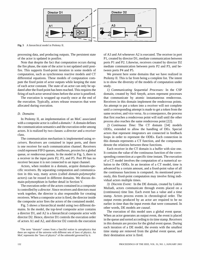
Fig. 5 A hierarchical model in Ptolemy II.
processing data, and producing outputs. The persistent stateof the actor is updated in postfire.
Note that despite the fact that computation occurs duringthe fire phase, the state of the actor is not updated until post-fire. This supports fixed-point iteration in some models ofcomputation, such as synchronous reactive models and CTdifferential equations. These models of computation com-pute the fixed point of actor outputs while keeping the stateof each actor constant. The state of an actor can only be up-dated after the fixed point has been reached. This requires thefiring of each actor several times before the actor is postfired.
The execution is wrapped up exactly once at the end ofthe execution. Typically, actors release resources that wereallocated during execution.
D. Domains
In Ptolemy II, an implementation of an MoC associatedwith a composite actor is called adomain.2 A domain definesthe communication semantics and the execution order amongactors. It is realized by two classes: adirectorand areceiverclass.
The communication mechanism is implemented usingre-ceivers. Receivers are contained in input ports, and thereis one receiver for each communication channel. Receiverscould represent FIFO queues, mailboxes, proxies for a globalqueue, or rendezvous points. In the model in Fig. 5, there isa receiver in the input ports P2, P3, and P5. Port P0 has noreceiver because it is not connected to an input channel.
Actors, when resident in a domain, acquire domain-spe-cific receivers. By separating computation and communica-tion in this way, many actors (calleddomain-polymorphicactors) can be reused in different domains. We discuss do-main-polymorphism in further detail in Section V.
The execution order of the actors contained in a compositeis controlled by adirector. Since receivers and directors mustwork together, the director is also responsible for creatingreceivers. When a composite actor is fired, the director insidethe composite actor fires the actors of the contained model.
Fig. 5 shows a hierarchical model using two different do-mains. In the model, the top-level composite actor containsa director D1, and A2 is a hierarchical composite actor withdirector D2. Hence, director D1 controls the execution orderof actors A1 and A2, and director D2 controls the execution
2The term “domain” comes from a fanciful notion in astrophysics thatthere are regions of the universe with different sets of laws of physics. AnMoC represents the “laws of physics” of the submodel governed by it.
of A3 and A4 whenever A2 is executed. The receiver in portP1, created by director D1, mediate communication betweenports P1 and P2. Likewise, receivers created by director D2mediate communication between ports P2 and P3, and be-tween ports P4 and P5.
We present here some domains that we have realized inPtolemy II. This is far from being a complete list. The intentis to show the diversity of the models of computation understudy.
1) Communicating Sequential Processes:In the CSPdomain, created by Neil Smyth, actors represent processesthat communicate by atomic instantaneous rendezvous.Receivers in this domain implement the rendezvous points.An attempt to put a token into a receiver will not completeuntil a corresponding attempt is made to get a token from thesame receiver, and vice versa. As a consequence, the processthat first reaches a rendezvous point will stall until the otherprocess also reaches the same rendezvous point [22].
2) Continuous Time:The CT domain [34] modelsODEs, extended to allow the handling of DEs. Specialactors that representintegratorsare connected in feedbackloops in order to represent the ODEs. Each connection inthis domain represents a CT function, and the componentsdenote the relations between these functions.
Each receiver in the CT domain is a buffer with size one.It contains the value of the continuous function of the corre-sponding connection at a specific time instant. The executionof a CT model involves the computation of a numerical so-lution to the ODEs. In an iteration of a CT model, time isadvanced by a certain amount, and a fixed-point value of allthe continuous functions is computed. As mentioned previ-ously, this fixed-point computation may involve firing indi-vidual actors multiple times.
3) Discrete Event:In the DE domain, created by LukitoMuliadi, actors communicate through events placed on a(continuous) time line. Each event has a value and a timestamp. Actors process events in chronological order. Theoutput events produced by an actor are required to be noearlier in time than the input events that were consumed. Inother words, DE models arecausal.
The execution of this model uses a global event queue.When an actor generates an output event, the event is placedin the queue and sorted according to its time stamp. Receiversin this domain are proxies for the global event queue. Duringeach iteration of a DE model, the events with the smallesttime stamp are removed from the global event queue, andtheir destination actor is fired.
132 PROCEEDINGS OF THE IEEE, VOL. 91, NO. 1, JANUARY 2003

4) Process Network:In the PN domain, created by TomParks, actors represent processes that communicate by (con-ceptually infinite capacity) FIFO queues [25]. Receivers inthis model implement these FIFO queues. Writing to thequeues always succeeds, while reading from an empty queueblocks the reader process. The simple blocking-read- non-blocking-write rule ensures the determinacy of the model.
5) Synchronous Dataflow:An SDF model [30] is a par-ticularly restricted special case of a PN model. When an actoris executed in this model, it consumes a fixed number of to-kens from each input port and produces a fixed number of to-kens to each output port. A valuable property of SDF modelsis that deadlock and boundedness can be statically analyzed.Receivers in this domain represent FIFO queues with fixedfinite capacity, and the execution order of components is stat-ically scheduled.
V. COMPONENT INTERACTIONS AND DOMAIN
POLYMORPHISM
A domain controls the communication between actors3 bydetermining the receivers on their input ports. Also, the di-rector of a domain may control the execution order of the ac-tors. In effect, the receiver and director decouple the idiosyn-crasies of interaction in a domain from the requirements ofthe actors embedded in it.
The concept of domain-specific receivers and directorsthat form the interface between actors and their environmentseems to suggest that any actor, including every model in anydomain, may be embedded into any other model, because allrely on a common notion of execution (atomic firing) and acommon notion of communication (receivers). Clearly, thisis most desirable, since it maximizes the reuse of componentsand models. Unfortunately, things are not so simple.
In software terms, by defining the receiver notion, we haveessentially specified aninterface, a set oflexical conven-tions for sending or receiving information to and from theenvironment of an actor. For example, all receivers have a
method, which is used to obtain a token stored in thereceiver. Since the receiver notion is generic, there are manydifferent realizations of these conventions (which is, after all,the whole point in the design of this abstraction). Unfortu-nately, any two such realizations are not necessarily compat-ible.
For instance, all the actors have a method that thedirector uses to start their execution. In this method, an actormay call the method of the receiver to obtain an inputtoken. In the SDF domain, the scheduler guarantees that anactor is fired only when there is a token in its receiver. So anSDF actor does not need to check the availability of a tokenbefore calling . By contrast, in the DE domain, the di-rector does not make the same guarantee, so the actors should
3Remember that these actors may be atomic or may, in fact, themselvesbe formulated as models in some, possibly different, domain. It is testimonyto the power of the domain framework that this distinction is irrelevant tothe following discussion.
check the availability of a token by calling be-fore calling . If an SDF actor is used in DE, it may causean exception by calling on an empty receiver.
To ensure validity of our models, however, we would liketo statically check the compatibility of an actor with a do-main it is embedded in. This suggests that we need to pre-cisely specify the behavior of the receivers and directors indifferent domains. Our approach is to define automata thatmodel the combined role of receivers and directors. Theseautomata are called domain automata, since they essentiallyspecify the communication behavior of the domains. We alsodescribe the behavior of the actors using automata and checkthe compatibility of the actor with a domain by composingthe domain automata with the actor automata. This approachis sketched later. More information can be found in [32].
Among the many variants of automata models, we chooseinterface automata [15] for their strength in the composi-tion semantics. As with other automata models, interface au-tomata consist of states and transitions4 and are usually de-picted by bubble-and-arc diagrams. There are three differentkinds of transitions in interface automata: input, output, andinternal transitions. When modeling a software component,input transitions correspond to the invocation of methods onthe component or the returning of method calls from othercomponents. Output transitions correspond to the invocationof methods on other components or the returning of methodcalls from the component being modeled. Internal transitionscorrespond to computations inside the component. For ex-ample, Fig. 6 shows the interface automaton model for anSDF actor. This figure is a screen shot of a model in thePtolemy II interface automata domain. The convention ininterface automata is to label the input transitions with anending ”?”, the output transitions with an ending “!”, and in-ternal transitions with an ending “;”. Fig. 6 does not containany internal transitions. The block arrows on the sides denotethe inputs and outputs of the automaton. They are:
1) : invocation of the method of the actor;2) : return from the method;3) : invocation of the method of the receiver at the
input port of the actor;4) : token returned by the call;5) : invocation of the method of the re-
ceiver;6) : value true returned by the call,
meaning that the receiver contains one of more tokens;7) : value false returned by the call,
meaning that the receiver does not contain any token.The initial state is state 0. When the actor is in this state,
and the method is called, it calls on the receiverto obtain a token. After receiving the token in state 3, it per-forms some computation, and returns from . Note thatthis actor does not check the availability of tokens beforecalling . By contrast, the automaton in Fig. 7 describesan actor that performs this check. We will show that this latteractor is domain polymorphic in that it can work in multipledomains.
4Transitions are called actions in [15].
EKER et al.: TAMING HETEROGENEITY—THE PTOLEMY APPROACH 133
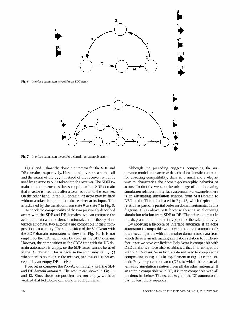
Fig. 6 Interface automaton model for an SDF actor.
Fig. 7 Interface automaton model for a domain-polymorphic actor.
Fig. 8 and 9 show the domain automata for the SDF andDE domains, respectively. Here,and represent the calland the return of the method of the receiver, which isused by an actor to put a token into the receiver. The SDFDo-main automaton encodes the assumption of the SDF domainthat an actor is fired only after a token is put into the receiver.On the other hand, in the DE domain, an actor may be firedwithout a token being put into the receiver at its input. Thisis indicated by the transition from state 0 to state 7 in Fig. 9.
To check the compatibility of the two previously describedactors with the SDF and DE domains, we can compose theactor automata with the domain automata. In the theory of in-terface automata, two automata are compatible if their com-position is not empty. The composition of the SDFActor withthe SDF domain automaton is shown in Fig. 10. It is notempty, so the SDF actor can be used in the SDF domain.However, the composition of the SDFActor with the DE do-main automaton is empty, so the SDF actor cannot be usedin the DE domain. This is because the actor may callwhen there is no token in the receiver, and this call is not ac-cepted by an empty DE receiver.
Now, let us compose the PolyActor in Fig. 7 with the SDFand DE domain automata. The results are shown in Fig. 11and 12. Since these compositions are not empty, we haveverified that PolyActor can work in both domains.
Although the preceding suggests composing the au-tomaton model of an actor with each of the domain automatafor checking compatibility, there is a much more elegantway to characterize the domain-polymorphic behavior ofactors. To do this, we can take advantage of the alternatingsimulation relation of interface automata. For example, thereis an alternating simulation relation from SDFDomain toDEDomain. This is indicated in Fig. 13, which depicts thisrelation as part of a partial order on domain automata. In thisdiagram, DE is above SDF because there is an alternatingsimulation relation from SDF to DE. The other automata inthis diagram are omitted in this paper for the sake of brevity.
By applying a theorem of interface automata, if an actorautomaton is compatible with a certain domain automaton P,it is also compatible with all the other domain automata fromwhich there is an alternating simulation relation to P. There-fore, once we have verified that PolyActor is compatible withDEDomain, we have also established that it is compatiblewith SDFDomain. So in fact, we do not need to compute thecomposition in Fig. 11 The top element in Fig. 13 is the Do-main Polymorphic automaton (DP), to which there is an al-ternating simulation relation from all the other automata. Ifan actor is compatible with DP, it is then compatible with allthe domains below. The exact design of the DP automaton ispart of our future research.
134 PROCEEDINGS OF THE IEEE, VOL. 91, NO. 1, JANUARY 2003

Fig. 8 SDF domain automaton.
VI. GENERATING CODE
A. Translating Models
Formal system models are used in several ways. At theirmost basic, formal models can be used to prototype and vali-date new designs. After the model has been created and vali-dated, it is typically translated by hand into code for a systemimplementation. This code is written in an appropriate targetarchitecture-specific language that compiles directly onto thetarget architecture. If the system being designed is an ap-plication-specific integrated circuit, then the implementationcode will often consist of a hardware description language,such as VHDL or Verilog. Similarly, if the system is a micro-processor system, then the implementation code will likelybe some flavor of C [26]. If the system is heterogeneous, thenmore than one language is usually used.
However, this translation process is complex and prone toerror, which reduces the value of any testing and verifica-tion done on the model. A more robust strategy is to followthe precepts ofmodel-based design[44], where the model isused as the specification for the system, and the realization issynthesized from the model. This is sometimes calledcodegeneration. In this case, implementation code is generateddirectly from the model by acode generator. To generate themost efficient code possible, this generator is usually writtenwith a particular type of model and target architecture inmind [46], thus following the precepts of platform-based de-sign [43]. To handle hierarchical models, either the modelcan be flattened, resulting in a large, generally amorphousmodel, or code can be recursively generated at each level ofthe hierarchy, incorporating the output of code generation atone point in the hierarchy into code generated at a higherlevel.
B. Domain Optimizations
A key part of a code generator that creates efficient codeis analyzing the model to determine how it can best betransformed into implementation code. This analysis musttake into account both the control flow and communicationbetween actors. This information is readily available ina Ptolemy domain, allowing transformations to be easilywritten.
For example, the sizes of communication queues in anSDF domain model can be statically determined, since theactors are statically scheduled. Replacing the queues withcircularly addressed arrays usually results in more efficientimplementation code [8]. Furthermore, since the order inwhich actors are fired is known during code generation, op-timizations can be made between actors to improve the gen-erated code. For a model in the PN domain, the number ofexecuting processes can often be reduced by consolidatingchains of actors together into a single process. This is oftenuseful if the system is being implemented on a micropro-cessor using expensive operating system threads.
These optimizations might be possible for an amorphousmodel, although the analysis required would be much morecomplex. Using hierarchical heterogeneity, the MoC is spec-ified by the designer as part of the design and a design toolneeds only make use of that information. In an amorphousmodel, as the complexity of a system model grows, and asthe types of communication styles allowed are increased, theanalysis necessary to determine whether a particular opti-mization is possible must also increase. On the other hand,when composing models of computation, the analysis andtransformations during code generation do not individuallyincrease in complexity, but are simply applied hierarchically.
EKER et al.: TAMING HETEROGENEITY—THE PTOLEMY APPROACH 135
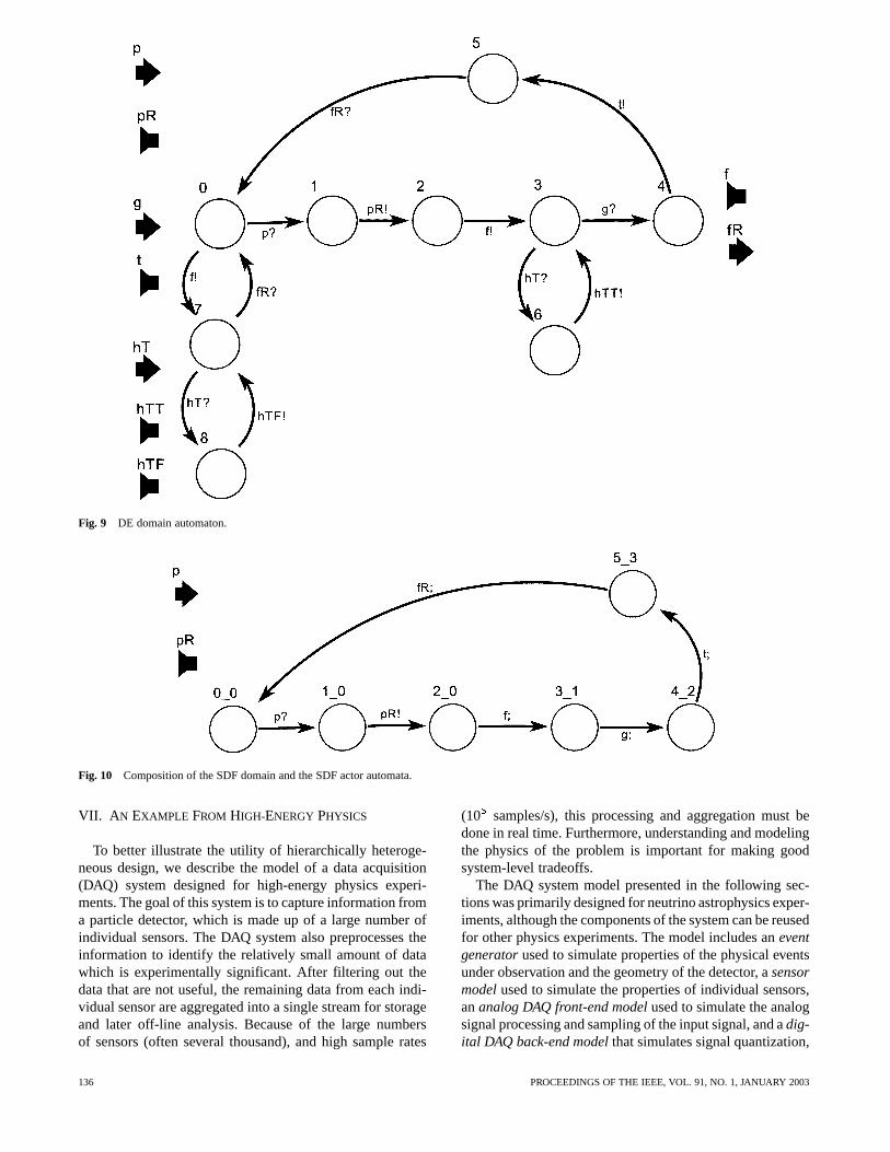
Fig. 9 DE domain automaton.
Fig. 10 Composition of the SDF domain and the SDF actor automata.
VII. A N EXAMPLE FROM HIGH-ENERGY PHYSICS
To better illustrate the utility of hierarchically heteroge-neous design, we describe the model of a data acquisition(DAQ) system designed for high-energy physics experi-ments. The goal of this system is to capture information froma particle detector, which is made up of a large number ofindividual sensors. The DAQ system also preprocesses theinformation to identify the relatively small amount of datawhich is experimentally significant. After filtering out thedata that are not useful, the remaining data from each indi-vidual sensor are aggregated into a single stream for storageand later off-line analysis. Because of the large numbersof sensors (often several thousand), and high sample rates
(10 samples/s), this processing and aggregation must bedone in real time. Furthermore, understanding and modelingthe physics of the problem is important for making goodsystem-level tradeoffs.
The DAQ system model presented in the following sec-tions was primarily designed for neutrino astrophysics exper-iments, although the components of the system can be reusedfor other physics experiments. The model includes aneventgeneratorused to simulate properties of the physical eventsunder observation and the geometry of the detector, asensormodelused to simulate the properties of individual sensors,ananalog DAQ front-end modelused to simulate the analogsignal processing and sampling of the input signal, and adig-ital DAQ back-end modelthat simulates signal quantization,
136 PROCEEDINGS OF THE IEEE, VOL. 91, NO. 1, JANUARY 2003
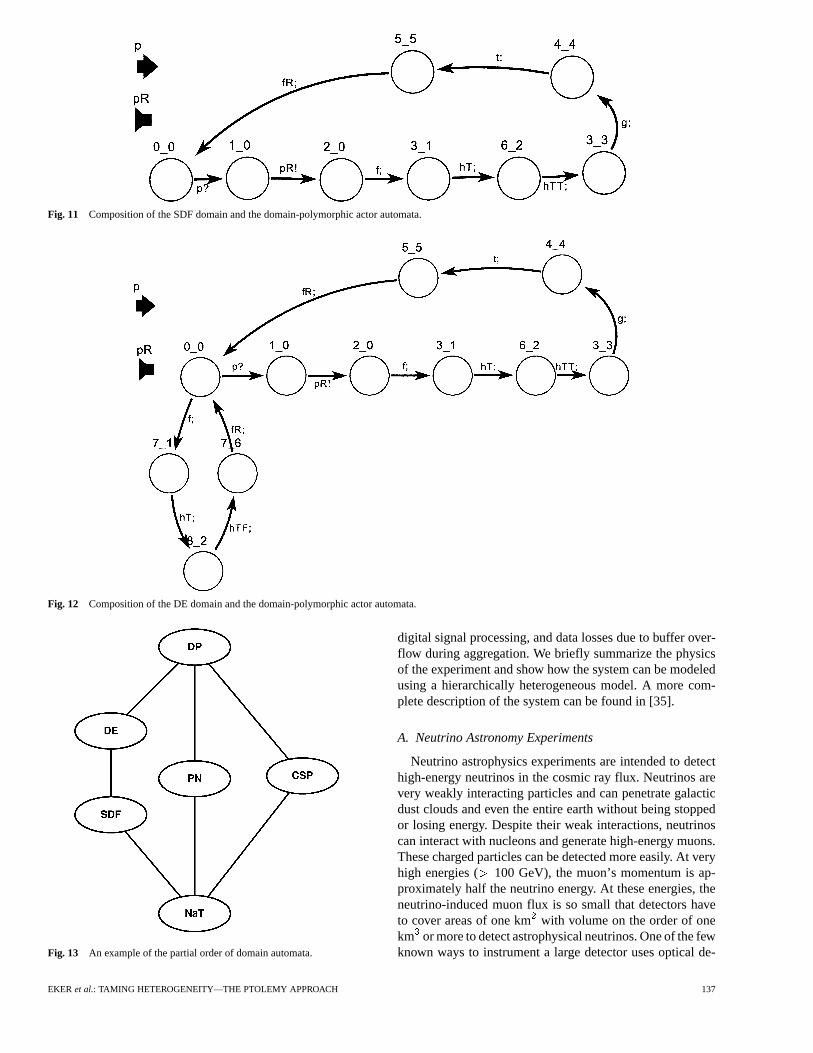
Fig. 11 Composition of the SDF domain and the domain-polymorphic actor automata.
Fig. 12 Composition of the DE domain and the domain-polymorphic actor automata.
Fig. 13 An example of the partial order of domain automata.
digital signal processing, and data losses due to buffer over-flow during aggregation. We briefly summarize the physicsof the experiment and show how the system can be modeledusing a hierarchically heterogeneous model. A more com-plete description of the system can be found in [35].
A. Neutrino Astronomy Experiments
Neutrino astrophysics experiments are intended to detecthigh-energy neutrinos in the cosmic ray flux. Neutrinos arevery weakly interacting particles and can penetrate galacticdust clouds and even the entire earth without being stoppedor losing energy. Despite their weak interactions, neutrinoscan interact with nucleons and generate high-energy muons.These charged particles can be detected more easily. At veryhigh energies ( 100 GeV), the muon’s momentum is ap-proximately half the neutrino energy. At these energies, theneutrino-induced muon flux is so small that detectors haveto cover areas of one kmwith volume on the order of onekm or more to detect astrophysical neutrinos. One of the fewknown ways to instrument a large detector uses optical de-
EKER et al.: TAMING HETEROGENEITY—THE PTOLEMY APPROACH 137

Fig. 14 Model that calculates arrival time of Cherenkov radiation.
tection of Cherenkov radiation. Cherenkov radiation is elec-tromagnetic radiation generated by charged particles (in thiscase, the muons) moving faster through a polarizing mediumthan the local speed of light in the medium. The power spec-trum of Cherenkov radiation is proportional to the frequencyof the emitted photons. The very faint Cherenkov radiationis detected by large diameter (8-12 in) photomultiplier tubes(PMTs) enclosed by pressure resistant optical module (OM)spheres. A vertical string of detector modules intercepts aCherenkov cone along a cone section, i.e., a wedge or a hy-perbola. This intersection creates a characteristic time profilealong the string: the relative timing of photons registered byOMs is a function of the position of the OM and the direc-tion of the particle track. Detecting this radiation, correlatedacross a number of sensors in the string allows extrapolationof the original path of the neutrino. Particles emit Cherenkovradiation under a fixed angle. If the distance between theparticle track and the string is called, the projection of thenearest point onto the string coordinate (here, chosen to be)is named , the angle of the track relative to the string (thezenith angle) is called, and denotes the speed of light, theequation for the hit time becomes
(1)
While this geometric model is an oversimplification of thephysics, it is sufficient for an initial exploration for systemsengineering purposes. A Ptolemy model calculating the eventarrival times is shown in Fig. 14.
Given the parameters of the neutrino path, this SDF modelcreates a sequence of coordinates for eight equidistant mod-ules along a detector string and calculates the correspondinghit times for each module. These times are used to generateevents in the top-level DE system model (shown in Fig. 15).These events simulate the arrival of Cherenkov radiation atthe PMTs at the correct times. Note that the cone2time modelitself executes in zero time, and we have simply used the SDFmodel as a convenient way of organizing the computation ofthe event times. The calculated times are converted into timedDEs by theTimedDelayactors. The times computed by thismodel for an interesting neutrino path are plotted in Fig. 16.
B. Sensor Model
PMTs are stochastic amplifiers: a photon can create asingle photoelectron at the surface of the photocathode,which is then accelerated toward an electron multiplierchain by a strong electrostatic field where it creates multiplesecondary electrons. Thepulse height distribution(PHD) isthe most important performance characteristics of a PMT.5
A DE model of the stochastic amplification properties ofa PMT is shown in Fig. 17. This model simply applies arandom amplitude and delay to the incoming event.
C. Front End
A typical DAQ front end consists of a preamplifier, a signalshaper to limit the bandwidth of the circuit and improve thesignal-to-noise ratio of detector signals, a sample/hold (S/H)circuit, and an analog-to-digital converter (ADC).6
The CT PMT waveform and preamplifier model in Fig. 18use a single fourth-order low-pass filter with 5-ns time con-stant, corresponding to 60-MHz preamplifier bandwidth.The first pole is given explicitly with an integrator and feed-back loop, while the remaining three are lumped into a simpleLaplace transfer function. The dynamics of such a system canbe specified in other ways, of course, but this representationboth naturally describes the CT dynamics of the PMT andemphasizes the lack of synchronization between input eventsand the sampling of the signal. The preamplified and shapedwaveforms are sampled at 10-ns intervals, and the samplesare discretized to the ADC resolution of 12 bit, i.e., an in-teger between 0 and 4095.
5A good PHD is nearly Gaussian with width� � 1. Individual pho-toelectrons are also delayed by a random drift time due to the inhomogeneityof the accelerating electrostatic field. The average drift time (� 20 ns) andthe time spread (� 2 ns) of the drift time distribution can be modeled witha normal distributionN(t ; � ).
6Most of the information about the path of an incoming neutrino is carriedby the arrival time of Cherenkov radiation at each PMT. The arrival time canbe extracted from a PMT pulse by sampling it with high resolution (12 bit)at a high rate [100 million samples/s (MSPS)] and fitting a parameterizedanalytical expression for the expected waveform to the sampled data. ForPMT pulses, three free parameters (amplitude, offset, and a pulse time) areused, and three samples are sufficient to calculate the pulse parameters. APMT pulse with 15–20 ns width gives 3–5 nonzero samples at 100 MSPSsampling rate. The statistical error for the time parameter of the fit is usuallyless than 20% of the sampling period, or about 2 ns.
138 PROCEEDINGS OF THE IEEE, VOL. 91, NO. 1, JANUARY 2003

Fig. 15 Complete system model.
Fig. 16 The arrival time of Cherenkov radiation (ns) versus string position for a horizontal track100 m from the string.
An important issue for mixed DE/CT simulation is effi-ciency. While a DE simulation is evaluated only at times atwhich at least one variable is changing, CT models are eval-uated continuously at time intervals that are set by the dif-ferential equation solver of the simulator. The use of a pe-riodic sampling actor as an S/H stage model also requiresthe simulator to evaluate the model every 10 ns. This is very
inefficient, since the average hit rate of a PMT is 1 kHz,and the PMT pulse is only 100 ns long. A free-running CTmodel would create an unnecessary computational overhead.By embedding it into amodal model, a finite state machine(shown in Fig. 19) determines when the CT model executes.This embedded modal model contains a state machine withtwo states, an inactive state and a state that acti-
EKER et al.: TAMING HETEROGENEITY—THE PTOLEMY APPROACH 139
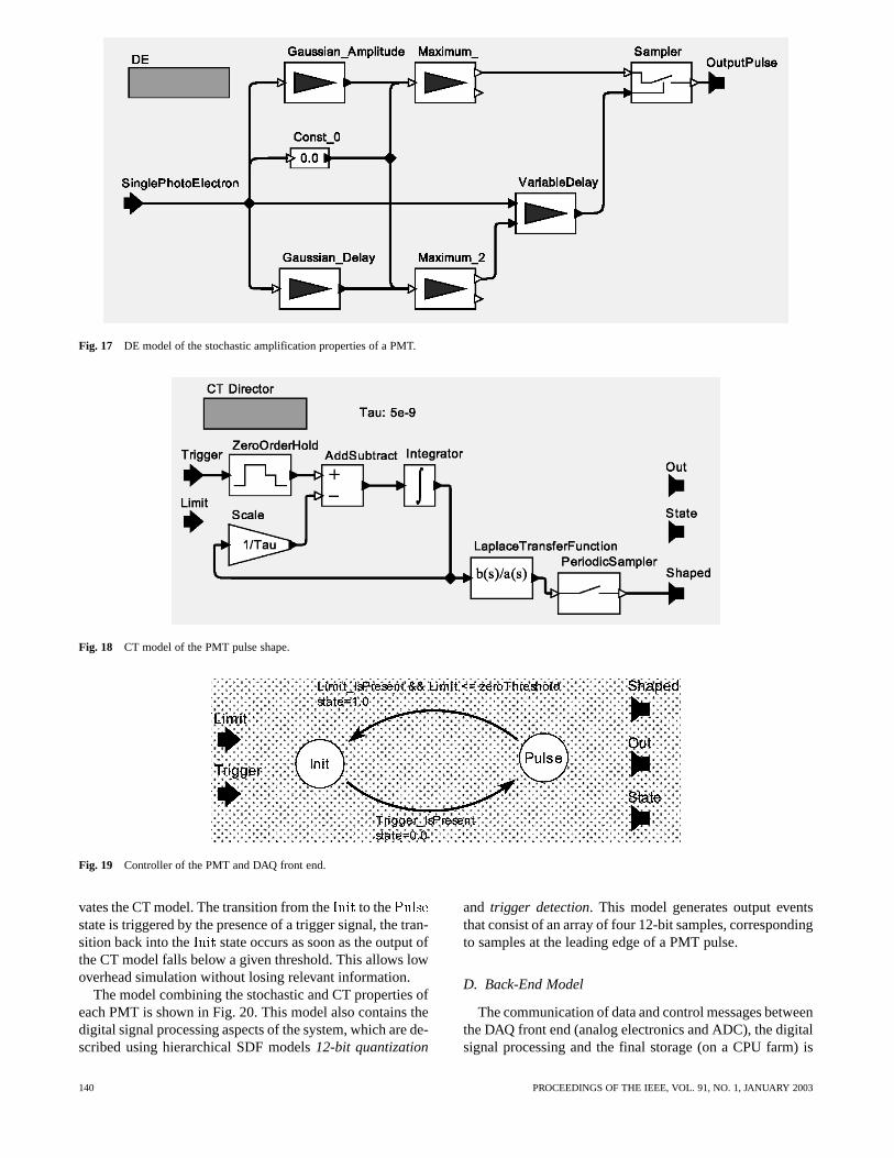
Fig. 17 DE model of the stochastic amplification properties of a PMT.
Fig. 18 CT model of the PMT pulse shape.
Fig. 19 Controller of the PMT and DAQ front end.
vates the CT model. The transition from the to thestate is triggered by the presence of a trigger signal, the tran-sition back into the state occurs as soon as the output ofthe CT model falls below a given threshold. This allows lowoverhead simulation without losing relevant information.
The model combining the stochastic and CT properties ofeach PMT is shown in Fig. 20. This model also contains thedigital signal processing aspects of the system, which are de-scribed using hierarchical SDF models12-bit quantization
and trigger detection. This model generates output eventsthat consist of an array of four 12-bit samples, correspondingto samples at the leading edge of a PMT pulse.
D. Back-End Model
The communication of data and control messages betweenthe DAQ front end (analog electronics and ADC), the digitalsignal processing and the final storage (on a CPU farm) is
140 PROCEEDINGS OF THE IEEE, VOL. 91, NO. 1, JANUARY 2003
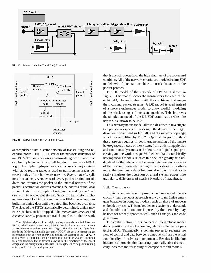
Fig. 20 Model of the PMT and DAQ front end.
Fig. 21 Network structures within an FPGA.
accomplished with a static network of transmitting and re-ceiving nodes.7 Fig. 21 illustrates the network structures ofan FPGA. This network uses a custom datagram protocol thatcan be implemented in a small fraction of available FPGAlogic. A simple, high-performance packet-routing strategywith static routing tables is used to transport messages be-tween nodes of the hardware network.Router circuitssplitnets into subnets. A router reads every packet destination ad-dress and reroutes the packet to the internal network if thepacket’s destination address matches the address of the localsubnet. Data from multiple subnets are merged bycombinercircuits into one output stream. Since the transmitter archi-tecture is nonblocking, a combiner uses FIFOs on its inputs tobuffer incoming data until the output line becomes available.The sizes of the FIFOs are statically determined, which maycause packets to be dropped. Thetransmitter circuitsandreceiver circuitspresent a parallel interface to the network
7The digitized signals from eight analog channels are fed into oneFPGA, which writes them into 27–Mbit double data rate static randomaccess memory waveform memories. Digital signal processing algorithmsinside the field programmable gate array (FPGA) are used to extract triggerinformation such as event energy and timing. Processing of theGByte=sdata stream is continuous and dead-time-free. Eight FPGAs are connectedin a ring topology that is favorable owing to the simplicity of the boarddesign and the nearly optimal electrical line length, which helps minimizingnoise problems in the analog section.
that is asynchronous from the high data rate of the router andcombiner. All of the network circuits are modeled using SDFmodels with finite state machines to track the states of thepacket protocol.
The DE model of the network of FPGAs is shown inFig. 22. This model shows the transmitters for each of theeight DAQ channels, along with the combiners that mergethe incoming packet streams. A DE model is used insteadof a more synchronous model to allow explicit modelingof the clock using a finite state machine. This improvesthe simulation speed of the DE/SDF combination when thenetwork is known to be idle.
This heterogeneous model allows a designer to investigatetwo particular aspects of the design: the design of the triggerdetection circuit used in Fig. 20, and the network topologywhich is exemplified by Fig. 22. Optimal design of both ofthese aspects requires in-depth understanding of the innateheterogeneous nature of the system, from underlying physicsand continuous dynamics of the detector to digital signal pro-cessing and network design. We believe that hierarchicallyheterogeneous models, such as this one, can greatly help un-derstanding the interactions between heterogeneous aspectsof the system, ultimately leading to better designs. Further-more, the previously described model efficiently and accu-rately simulates the operation of a real system across timegranularity differences of nearly six orders of magnitude.
VIII. C ONCLUSION
In this paper, we have proposed an actor-oriented, hierar-chically heterogeneous approach as a way to minimize emer-gent behavior in complex models, such as those of modernembedded systems. This makes designs easier to understand,and the additional structure imposed by the hierarchy maybe used for other purposes as well, such as analysis and codegeneration.
The central notion in our concept of hierarchical modeldecomposition is that of adomain, which implements a par-ticular MoC. Technically, a domain serves to separate theflow of control and data between components from the actualfunctionality of individual components. Besides facilitatinghierarchical models, this factoring potentially also dramati-cally increases the reusability of components and models.
EKER et al.: TAMING HETEROGENEITY—THE PTOLEMY APPROACH 141
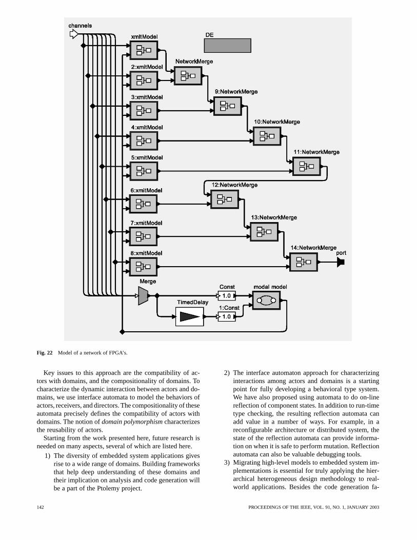
Fig. 22 Model of a network of FPGA’s.
Key issues to this approach are the compatibility of ac-tors with domains, and the compositionality of domains. Tocharacterize the dynamic interaction between actors and do-mains, we use interface automata to model the behaviors ofactors, receivers, and directors. The compositionality of theseautomata precisely defines the compatibility of actors withdomains. The notion ofdomain polymorphismcharacterizesthe reusability of actors.
Starting from the work presented here, future research isneeded on many aspects, several of which are listed here.
1) The diversity of embedded system applications givesrise to a wide range of domains. Building frameworksthat help deep understanding of these domains andtheir implication on analysis and code generation willbe a part of the Ptolemy project.
2) The interface automaton approach for characterizinginteractions among actors and domains is a startingpoint for fully developing a behavioral type system.We have also proposed using automata to do on-linereflection of component states. In addition to run-timetype checking, the resulting reflection automata canadd value in a number of ways. For example, in areconfigurable architecture or distributed system, thestate of the reflection automata can provide informa-tion on when it is safe to perform mutation. Reflectionautomata can also be valuable debugging tools.
3) Migrating high-level models to embedded system im-plementations is essential for truly applying the hier-archical heterogeneous design methodology to real-world applications. Besides the code generation fa-
142 PROCEEDINGS OF THE IEEE, VOL. 91, NO. 1, JANUARY 2003

cilities discussed in Section VI, how to characterizeembedded system architectures, and how to abstractan application platform to better support hierarchicalrun-time systems are in the critical path.
REFERENCES
[1] M. Adelantado and F. Boniol, “Controlling real-time asynchronoustasks with Esterel synchronous language,” inProc. 13th Annu. ACMSymp. Principles of Distributed Comput., 1994, p. 387.
[2] G. A. Agha,ACTORS: A Model of Concurrent Computation in Dis-tributed Systems. Cambridge, MA: MIT Press, 1986, MIT PressSeries in Artificial Intelligence.
[3] P. Alexander, C. Kong, and D. Barton. (2000) Rosetta SemanticsStrawman. [Online]. Available: http://www.sldl.org
[4] P. Antsaklis, W. Kohn, A. Nerode, and S. Sastry,Lecture Notesin Computer Science: Hybrid Systems II. Heidelberg, Germany:Springer-Verlag, 1995, vol. 999.
[5] D. Barker, “Requirements modeling technology: A vision for better,faster, and cheaper systems,” presented at the VHDL Int. UsersForum Fall Workshop (VIUF’00), Orlando, FL., Oct. 2000.
[6] A. Benveniste and G. Berry, “The synchronous approach to reactiveand realtime systems,”Proc. IEEE, vol. 79, pp. 1270–1282, Sept.1991.
[7] G. Berry and G. Gonthier, “The Esterel synchronous programminglanguage: Design, semantics, implementation,”Sci. Comput. Pro-gram., vol. 19, no. 2, pp. 87–152, 1992.
[8] S. S. Bhattacharyya, P. K. Murthy, and E. A. Lee,Software Synthesisfrom Dataflow Graphs. Norwell, MA: Kluwer, 1996.
[9] G. Bilsen, M. Engels, R. Lauwereins, and J. Peperstraete,“Cyclo-static dataflow,”IEEE Trans. Signal Processing, vol. 44,pp. 397–408, Feb. 1996.
[10] L. Breslauet al., “Advances in network simulation,”IEEE Com-puter, vol. 33, pp. 59–67, May 2000.
[11] E. Brinksma and T. Bolognesi, “Introduction to the ISO specificationlanguage LOTOS,”Computer Netw. ISDN Syst., vol. 14, no. 1, 1987.
[12] J. Buck and R. Vaidyanathan, “Heterogeneous modeling and simu-lation of embedded systems in El Greco,” inProc. 8th Int. WorkshopHardware/Software Codesign 2000, 2000, pp. 142–146.
[13] J. T. Buck, “Scheduling dynamic dataflow graphs with boundedmemory using the token flow model,” Ph.D. dissertation, Univ.California, Elec. Eng. Comput. Sci., Berkeley, 1993.
[14] J. Davis et al., “Ptolemy II—Heterogeneous Concurrent Mod-eling and Design in Java,” Univ. California, Elec. Eng. Comput.Sci., Berkeley, CA, Memo M99/40, University of California atBerkeley/Electronics Research Laboratory (UCB/ERL), 1999.
[15] L. de Alfaro and T. A. Henzinger, “Interface automata,” inProc. 9thAnnu. Symp. Found. Software Eng., 2001, pp. 109–120.
[16] A. Doboli and R. Vemuri, “The definition of a VHDL-AMS subsetfor behavioral synthesis of analog systems,” presented at theIEEE/VIUF Int. Workshop Behav. Model. Simulation (BMAS’98),Orlando, FL, 1998.
[17] R. Esser and J. W. Janneck, “Moses: A tool suite for visual modelingof discrete-event systems,” inProc. Symp. Human-Centric Comput.(HCC ’01), 2001, pp. 272–279.
[18] T. Grotker, R. Schoenen, and H. Meyr, “Pcc: A modeling techniquefor mixed control/data flow systems,” inProc. Eur. Design Test Conf.(ED&TC), 1997, pp. 482–486.
[19] P. Le Guernic, A. Benveniste, P. Bournai, and T. Gautier, “Signal:A data flow oriented language for signal processing,”IEEE Trans.Acoust., Speech, Signal Processing, vol. 34, pp. 362–374, Apr. 1986.
[20] N. Halbwachs, P. Caspi, P. Raymond, and D. Pilaud, “The syn-chronous data flow programming language Lustre,”Proc. IEEE,vol. 79, pp. 1305–1321, Sept. 1991.
[21] D. Harel, “Statecharts: A visual formalism for complex systems,”Sci. Comput. Program., vol. 8, pp. 231–274, 1987.
[22] C. A. R. Hoare, “A theory of CSP,”Commun. ACM, vol. 21, no. 8,Aug. 1978.
[23] , “Communicating sequential processes,” inComputer Sci-ence. Englewood Cliffs, NJ: Prentice-Hall, 1985.
[24] G. Kahn, “The semantics of a simple language for parallel program-ming,” in Proc. IFIP Cong. 74, 1974, pp. 471–475.
[25] G. Kahn and D. B. MacQueen, “Coroutines and networks of parallelprocesses,” inProc. IFIP Cong. 77, 1977, pp. 993–998.
[26] B. W. Kernigan and D. M. Ritchie,The C Programming Language,2nd ed. Englewood Cliffs, NJ: Prentice-Hall, 1988.
[27] J. Kunkel, “COSSAP: A stream driven simulator,” presented at theIEEE Int. Workshop Microelectrion. Commun., Interlaken, Switzer-land, Mar. 1991.
[28] R. Lauwereins, M. Engels, M. Ad, and J. A. Peperstraete, “Grape-II:A system-level prototyping environment for dsp applications,”IEEEComputer, vol. 28, pp. 35–43, Feb. 1995.
[29] B. Lee, “Specification and design of reactive systems,” Ph.D. dis-sertation, Univ. California, Elec. Eng. Comput. Sci. Dept., Berkeley,CA, 2000.
[30] E. A. Lee and D. G. Messerschmitt, “Synchronous data flow,”Proc.IEEE, vol. 75, pp. 1235–1245, Sept. 1987.
[31] E. A. Lee and T. M. Parks, “Dataflow process networks,”Proc.IEEE, vol. 83, pp. 773–798, May 1995.
[32] E. A. Lee and Y. Xiong, “System-level types for component-baseddesign,” inLecture Notes in Computer Science, Embedded Software,T. A. Henzinger and C. M. Kirsch, Eds. Heidelberg, Germany:Springer-Verlag, 2001, vol. 2211, pp. 148–165.
[33] J. Liu, X. Liu, T. J. Koo, B. Sinopoli, S. Sastry, and E. A. Lee, “Ahierarchical hybrid system model and its simulation,” inProc. 38thIEEE Conf. Decision Contr., vol. 4, 1999, pp. 3508–3513.
[34] J. Liu, “Continuous time and mixed-signal simulation in PtolemyII,” Univ. California Elec. Eng. Comput. Sci., Berkeley, CA, MemoM98/74, UCB/ERL, 1998.
[35] J. Ludvig, J. McCarthy, S. Neuendorffer, and S. R. Sachs, “Repro-grammable platforms for high-speed data acquisition,” J. Design Au-tomat. Embedded Syst., vol. 7, no. 4, pp. 341–364, Nov. 2002, to bepublished.
[36] F. Maraninchi, “The Argos language: Graphical representation ofautomata and description of reactive systems,” presented at the IEEEWorkshop Visual Lang., Kobe, Japan, 1991.
[37] R. Milner, Lecture Notes in Computer Science, A Calculus forCommunicating Systems. Heidelberg, Germany: Springer-Verlag,1980, vol. 92.
[38] M. Mokhtari and M. Marie,Engineering Applications of MATLAB5.3 and SIMULINK 3. Berlin, Germany: Springer-Verlag, 2000.
[39] P. J. Mosterman, “An overview of hybrid simulation phenomena andtheir support by simulation packages,” inLecture Notes in ComputerScience, Hybrid Systems: Computation and Control. Heidelberg,Germany: Springer-Verlag, 1999, vol. 1569, pp. 148–165.
[40] W. Nagel, “SPICE 2—A computer program to simulate semicon-ductor circuits,” Univ. California Elec. Eng. Comput. Sci., Berkeley,CA, Memo M520, UCB/ERL, 1975.
[41] Z. Navabi,VHDL Analysis and Modeling of Digital Systems. NewYork: McGraw-Hill, 1993.
[42] M. Richard and O. Roux, “An attempt to confront asynchronousreality to synchronous modelization in the Esterel language,”in Lecture Notes in Computer Science, Formal Techniques inReal-Time and Fault-Tolerant Systems. Heidelberg, Germany:Springer-Verlag, 1992, vol. 571, pp. 429–450.
[43] A. Sangiovanni-Vincentelli, “Defining platform-based design,”EEDesign, Feb. 2002.
[44] J. Sztipanovits and G. Karsai, “Model-integrated computing,”IEEEComputer, vol. 30, pp. 110–112, Apr. 1997.
[45] D. E. Thomas and P. Moorby,The Verilog Hardware DescriptionLanguage. Norwell, MA: Kluwer, 1991.
[46] P. van der Wolf, P. Lieverse, M. Goel, D. La Hei, and K. Vissers,“An MPEG-2 decoder case study as a driver for a system level de-sign methodology,” inProc. Int. Symp. Hardware/Software Code-sign (CODES), 1999, pp. 33–37.
[47] J. Wexler, Concurrent Programming in Occam 2. Chichester,U.K.: Ellis Horwood, 1989, Ellis Horwood Series in Computers andTheir Applications.
Johan Eker, photograph and biography not available at time of publication.
Jörn W. Janneck, photograph and biography not available at time of pub-lication.
Edward A. Lee (Fellow, IEEE), photograph and biography not available attime of publication.
EKER et al.: TAMING HETEROGENEITY—THE PTOLEMY APPROACH 143

Jie Liu , photograph and biography not available at time of publication.
Xiaojun Liu , photograph and biography not available at time of publication.
Jozsef Ludvig, photograph and biography not available at time of publica-tion.
Stephen Neuendorffer, photograph and biography not available at time ofpublication.
Sonia Sachs, photograph and biography not available at time of publication.
Yuhong Xiong, photograph and biography not available at time of publica-tion.
144 PROCEEDINGS OF THE IEEE, VOL. 91, NO. 1, JANUARY 2003