
Tamil Nadu Urban Flagship Investment Project (Tranche 3)
215
Initial Environmental Examination Document Stage: Draft Project Number: 49107-010 April 2022 India: Tamil Nadu Urban Flagship Investment Project (Tranche 3) – Construction of Distribution network for 3 years and Operation & Maintenance for 5 years in core city area of Madurai Corporation (Package IV – Phase III) Prepared by Madurai City Municipal Corporation for the Asian Development Bank.
-
Upload
khangminh22 -
Category
Documents
-
view
0 -
download
0
Transcript of Tamil Nadu Urban Flagship Investment Project (Tranche 3)

Initial Environmental Examination
Document Stage: Draft Project Number: 49107-010 April 2022
India: Tamil Nadu Urban Flagship Investment Project (Tranche 3) – Construction of Distribution network for 3 years and Operation & Maintenance for 5 years in core city area of Madurai Corporation (Package IV – Phase III)
Prepared by Madurai City Municipal Corporation for the Asian Development Bank.

CURRENCY EQUIVALENTS (As of 25 April 2022)
Currency Unit – Indian rupee (₹) ₹1.00 = $0.0131 $1.00 = ₹766.464
ABBREVIATIONS
AAQM - Ambient Air Quality Monitoring
ADB - Asian Development Bank
BIS - Bureau of Indian Standard
CAC - Common Air Contaminants
CIA - Cumulative Impact Assessment
CMA - Commissioner of Municipal Administration
CMSC - Construction Management and Supervision Consultant
CPCB - Central Pollution Control Board
CPHEEO - Central Public Health and Environment Engineering Organization
CRO - Complaint Receiving Officer
CTE - Consent To Establishment
CTO - Consent To Operation
CWM - Construction waste management
CWSS - Combined water supply scheme
DMA - District Metering Areas
DNI - Distribution network improvement
DPR - Detailed project report
EAC - Expert Appraisal Committee
EARF - Environmental Assessment Review Framework
EC - Environmental Clearance
EHS - Environmental Health and Safety
EIA - Environmental Impact Assessment
EMP - Environmental Management Plan
ESS - Environmental and Social Safeguards
GHG - Greenhouse Gas
GIAC - Governance Improvement and Awareness Consultant
GOTN - Government Of Tamil Nadu
GRC - Grievance Redress Cell
GRM - Grievance Redress Mechanism
IA - Implementing Agency
IEE - Initial Environmental Examination
LPCD - Litres per capita per day
MAWS - The Municipal Administration and Water Supply Department
MCFT - Million cubic feet
MCMC - Madurai City Municipal Corporation

MLD - Million litres per day
MoEF&CC - Ministry of Environment, Forests and Climate Change
NOC - No Objection Certificate
OHS - Occupational health and safety
OHT - Over Head Tank
PCC - Plain cement concrete
PIU - Program implementation Unit
PMU - Program management Unit
PPE - Personal Protective Equipment
PPTA - Project Preparatory Technical Assistance
PUC - Pollution under control
PWD - Public Works Department
QEMR - Quarterly Environmental Monitoring Report
REA - Rapid Environmental Assessment
ROW - Right-Of-Way
SEIAA - State Environmental Impact Assessment Authority
SEMP - Site Environmental Management Plan
SEMR - Semi-annual Environmental Monitoring Report
SPS - Safeguard Policy Statement
SR - Service Reservoir
SWM - Solid Wastes Management
TNPCB - Tamil Nadu Pollution Control Board
TNUFIP - Tamil Nadu Urban Flagship Investment Program
TNUIFSL - Tamil Nadu Urban Infrastructure Financial Services Limited
ToR - Terms of reference
UGT - Underground Tank
VEC - Valued environmental components
WDS - Water Distribution Station
WHO - World Health Organization
WPA - Wildlife Protection Act
WTP - Water Treatment Plant

WEIGHTS AND MEASURES
°C - Degree Celsius Km - Kilometer
lpcd - Litres Per Capita Per Day m - Meter
MCFT - Million Cubic Feet Mgd - Million Gallons Per Day MLD - Million Litres Per Day mm - Millimeter nos - Numbers Km2 - Square Kilometer
NOTE
In this report, "$" refers to United States dollars. This draft initial environmental examination is a document of the borrower. The views expressed herein do not necessarily represent those of ADB's Board of Directors, Management, or Staff, and may be preliminary in nature. Your attention is directed to the “terms of use” section on ADB’s website. In preparing any country program or strategy, financing any project, or by making any designation of or reference to a particular territory or geographic area in this document, the Asian Development Bank does not intend to make any judgments as to the legal or other status of any territory or area.


CONTENTS
I. INTRODUCTION 1
A. Background 1 B. Scope of the Sub Project 2 C. Purpose of this Initial Environmental Examination (IEE) Report 3 D. Structure of the Report 3
II. DESCRIPTION OF THE PROJECT 5
A. Project Area 5 B. Existing Administrative Zone/Water Supply System 6 E. Proposed Water Supply Distribution System 19 F. Implementation Schedule 25
III. POLICY, LEGAL AND ADMINISTRATIVE FRAMEWORK 26
A. ADB Policy 26 B. National Environmental Laws 26 C. International Treaties/Conventions/Declarations on Environment Management 34
IV. DESCRIPTION OF THE ENVIRONMENT 36
A. Methodology used for Baseline Study 36 B. Physical Environmental Component 36 C. Biological Environment 58 D. Socio-economic Environment 62
V. ANTICIPATED ENVIRONMENTAL IMPACTS AND MITIGATION MEASURES 70
A. Pre-Construction Impacts- Design and Location 70 B. Construction Impacts 73 C. Operation and Maintenance Impacts 82
VI. PUBLIC CONSULTATION AND INFORMATION DISCLOSURE 84
A. Overview 84 B. Public Consultation 84 C. Information Disclosure 85
VII. GRIEVANCE REDRESS MECHANISM 86
VIII. ENVIRONMENTAL MANAGEMENT PLAN 90
A. Implementation Arrangements 116 B. Training Needs 119 C. Monitoring and Reporting 120 D. EMP Implementation Cost 121
X. CONCLUSION AND RECOMMENDATIONS 123
LIST OF TABLES
Table 1: Ward Details 7
Table 2: Administrative Zone 1 7
Table 3: Administrative zone 2 8
Table 4: Administrative zone 3 9
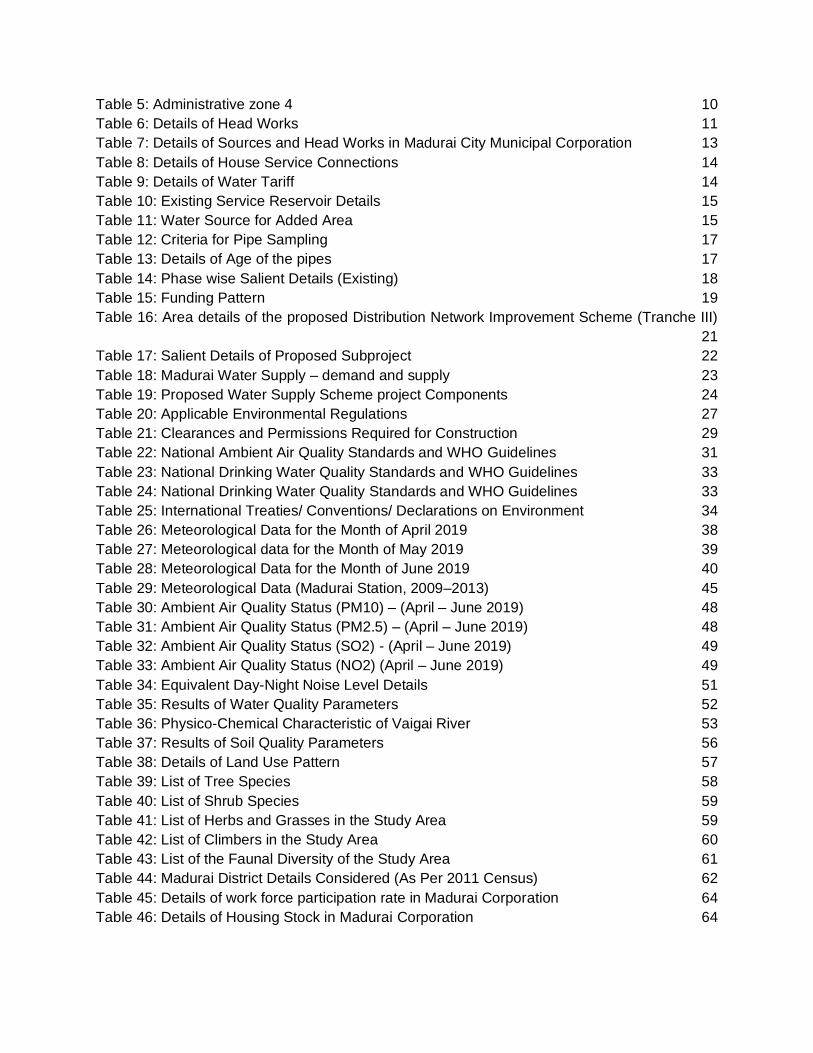
Table 5: Administrative zone 4 10
Table 6: Details of Head Works 11
Table 7: Details of Sources and Head Works in Madurai City Municipal Corporation 13
Table 8: Details of House Service Connections 14
Table 9: Details of Water Tariff 14
Table 10: Existing Service Reservoir Details 15
Table 11: Water Source for Added Area 15
Table 12: Criteria for Pipe Sampling 17
Table 13: Details of Age of the pipes 17
Table 14: Phase wise Salient Details (Existing) 18
Table 15: Funding Pattern 19
Table 16: Area details of the proposed Distribution Network Improvement Scheme (Tranche III)
21
Table 17: Salient Details of Proposed Subproject 22
Table 18: Madurai Water Supply – demand and supply 23
Table 19: Proposed Water Supply Scheme project Components 24
Table 20: Applicable Environmental Regulations 27
Table 21: Clearances and Permissions Required for Construction 29
Table 22: National Ambient Air Quality Standards and WHO Guidelines 31
Table 23: National Drinking Water Quality Standards and WHO Guidelines 33
Table 24: National Drinking Water Quality Standards and WHO Guidelines 33
Table 25: International Treaties/ Conventions/ Declarations on Environment 34
Table 26: Meteorological Data for the Month of April 2019 38
Table 27: Meteorological data for the Month of May 2019 39
Table 28: Meteorological Data for the Month of June 2019 40
Table 29: Meteorological Data (Madurai Station, 2009–2013) 45
Table 30: Ambient Air Quality Status (PM10) – (April – June 2019) 48
Table 31: Ambient Air Quality Status (PM2.5) – (April – June 2019) 48
Table 32: Ambient Air Quality Status (SO2) - (April – June 2019) 49
Table 33: Ambient Air Quality Status (NO2) (April – June 2019) 49
Table 34: Equivalent Day-Night Noise Level Details 51
Table 35: Results of Water Quality Parameters 52
Table 36: Physico-Chemical Characteristic of Vaigai River 53
Table 37: Results of Soil Quality Parameters 56
Table 38: Details of Land Use Pattern 57
Table 39: List of Tree Species 58
Table 40: List of Shrub Species 59
Table 41: List of Herbs and Grasses in the Study Area 59
Table 42: List of Climbers in the Study Area 60
Table 43: List of the Faunal Diversity of the Study Area 61
Table 44: Madurai District Details Considered (As Per 2011 Census) 62
Table 45: Details of work force participation rate in Madurai Corporation 64
Table 46: Details of Housing Stock in Madurai Corporation 64

Table 47: Archaeological Monuments, Heritage and Culturally Important Site in the surroundings
of the subproject area 65
Table 48: Subproject site Environmental Features 69
Table 49: Madurai Water Supply – demand and supply 71
Table 50: Details of the Type of Roads and its Lengths 77
Table 51: Design Stage Environmental Impacts and Mitigation Measures 91
Table 52: Pre-Construction Stage Environmental Impacts and Mitigation Measures 91
Table 53: Construction Stage Environmental Impacts and Mitigation Measures 96
Table 54: Operation Stage Environmental Impacts and Mitigation Measures 112
Table 55: Construction Stage Environmental Monitoring Plan 114
Table 56: Operation Stage Environmental Monitoring Plan 115
Table 57: Outline Capacity Building Program on EMP Implementation 120
Table 58: Cost Estimates to implement the Environmental Management Plan 121
LIST OF FIGURES
Figure 1: Madurai City Map 5
Figure 2: Water Supply Zones of Core Madurai 6
Figure 3: Administrative Zone 1 Map 7
Figure 4: Administrative Zone 2 Map 8
Figure 5: Administrative Zone 3 Map 9
Figure 6: Administrative Zone 4 Map 10
Figure 7: Map showing sub project coverage area (Green shaded -) 20
Figure 8: Wind Rose diagram for April 2019 42
Figure 9: Wind Rose diagram for May 2019 43
Figure 10: Wind Rose diagram for June 2019 44
Figure 11: Sampling Location Map (Air, Noise, Water & Soil) 50
Figure 12: Sampling Location Map (Surface Water) 54
Figure 13: Soil Sampling 56
Figure 14: Drainage map of Madurai City 57
Figure 15: Resources profile of the Madurai Corporation 63
Figure 16: Monuments, Archaeological and cultural Heritage Sites surrounding the subproject
area 67
Figure 17: Monuments, Archaeological and cultural Heritage Sites surrounding the subproject
area (Zoomed Map) 68
Figure 18: Proposed TNUFIP Grievance Redress Mechanism 88
APPENDICES
Appendix - 1 : Rapid Environmental Assessment Checklist
Appendix - 2 : Checklist for Preliminary Climate Risk Screening
Appendix - 3 : Salient Features of Major Labor Laws Applicable to Establishments
Engaged in Construction of Civil Works

Appendix - 4 : Sample Grievance Registration Form
Appendix - 5 : Sample Outline Traffic Management Plan
Appendix - 6 : Sample Outline Spoils (Construction Waste) Management Plan
Appendix - 7 : Sample Environmental Site Inspection Report
Appendix - 8 : Quarterly Reporting Format for Madurai City Municipal Corporation /
Program Implementation Unit
Appendix - 9 : Public Information Notice Template
Appendix - 10 : Public Consultation at Distribution Locations
Appendix - 11 : Public Consultation in Madurai City Municipal Corporation
Appendix - 12 : Detailed Operational Report on Safety Measures & Pre-Cautions Followed
In Site For COVID-19 (SOP)
Appendix - 13 : Zone Wise Details of Proposed DNI

EXECUTIVE SUMMARY
The Tamil Nadu Urban Flagship Investment Program (TNUFIP) will advance India’s national urban flagship programs to develop priority urban and environmental infrastructure in ten cities located within strategic industrial corridors of Tamil Nadu (the State), including those within the East Coast Economic Corridor (ECEC), to enhance environmental sustainability, climate resilience, and livability. It will also strengthen the capacity of state and local institutions and improve urban governance. TNUFIP is aligned with the following impact: urban livability and climate resilience in cities of economic importance improved. TNUFIP will have the following outcomes: smart and climate resilient urban services delivered in ten cities in priority industrial corridors.
The TNUFIP is structured under three outputs: (i) sewage collection and drainage improved and climate-friendly sewage treatment systems introduced, (ii) access to reliable and smart drinking water services improved, and (iii) Institutional capacity, public awareness, and urban governance strengthened. TNUFIP will be implemented over an 8-year period beginning in 2018 and will be funded by Asian Development Bank (ADB). via its multitranche financing facility (MFF).
Tranches. TNUFIP MFF comprises of three tranches sequenced based on readiness, absorptive capacity, and logical progression of investments. Tranche 1 (Project 1), approved in September 2018, is supporting water supply and sewerage facilities in six cities (Chennai, Coimbatore, Rajapalayam, Tiruchirappalli, Tirunelveli, and Vellore), capacity development of the DMA and ULBs and improvement in urban governance and financial management in all 135 ULBs. A transactional technical assistance approved in 2018 will strengthen capacity of the DMA to better support ULBs in preparing urban infrastructure projects and implement urban governance improvement programs. Tranche 2 (Project 2), approved in November 2019, is supporting water supply and sewerage facilities in five cities (Ambur, Madurai, Tiruchirappalli, Tiruppur, and Vellore) and facilitating reforms for improved service delivery and innovation in the program ULBs. A periodic financing request for the third last tranche under the TNUFIP MFF is submitted to ADB and is under processing. Tranche 3 (Project 3) will support water supply in Madurai, sewerage in Coimbatore and storm water drainage in Thoothukudi.
This subproject is proposed to provide water distribution network in 39 of total 81 water supply zones in Madurai City and is in continuation of water supply system improvements being undertaken in Madurai under the ongoing ADB funded TNUFIP Tranche 2.
Located in the south-central part of Tamil Nadu State, on the banks of the River Vaigai, Madurai is the third largest city in the State after Chennai and Coimbatore. Madurai City Municipal Corporation (MCMC) provides water supply in the city and is currently tapping 192 million liters per day (MLD) of water from three sources (Vaigai dam – 115 MLD, River Cauvery-30 MLD, and Vaigai river bed- 47 MLD) while the estimated demand is 268 MLD (2019 - base year), and 317 MLD (2034 – intermediate design year). MCMC has prepared a Water Supply Master Plan for to address demand and supply gap and provide water to the entire municipal area organized into 81 water supply zones. Accordingly, a comprehensive development of water supply system is undertaken under the ADB funded TNUFIP (tranche 2) to augment water source, treatment and storage capacity, transmission, and distribution system. The following works are under implementation: (i) new source (Mullai Periyar River) and raw water transmission main from Mullai periyar Lower Camp to proposed water treatment plant (WTP), (ii) new WTP (125 MLD), (iii) clear water transmission mains from WTP to service reservoirs and construction of 37 new service reservoirs (44 of required 81 are existing and in good condition), and (iv) distribution network improvement (DNI) in 34 zones. Besides TNUFIP Tranche 2, MCMC has is also implementing

ii
DNI in 8 zones under the government funded SMART City Mission. Of the 81 Zones, these cover 42 zones.
Scope of Subproject. This subproject, to be funded under Tranche 3 of TNUFIP, will improve distribution network in the remaining 39 zones, where the existing water distribution network is also mostly very old and is in poor condition. MCMC adopted 24 x 7 supply model in the entire city with creation of District Metering Areas (DMA) for proper monitoring and reducing the loss of water. Subproject will cover areas on the north (18 zones - 3, 11 to 22, 26, 29 to 32) and south
(21 zones - 33 to 36, 38 to 40, 45, 49 to 51, 54, 55, 56, 64 to 70) of River Vaigai. Subproject includes the following civil works components and will be implemented under a single ‘works type’ contract package: (i) 813.5 km length of distribution pipes (386.2 km in the north, and 427.3 in the south) of high-density polyethylene (HDPE, 110 to 200 mm diameter) and ductile iron (DI, 250 – 400 mm diameter), and (ii) 163,958 house service connections.
Project Implementation Arrangements. The MAWS of Government of Tamil Nadu acting through TNUIFSL is the state level Executing Agency (EA). A Program Management Unit (PMU) has been established in TNUIFSL headed by its Managing Director as the Project Director and the Commissioner of Municipal Administration as the Deputy Project Director. Together with them, designated full time staff from TNUIFSL and CMA constitute the PMU for overall project and financial management. The MCMC is the Project Implementing Agency (PIA) for this subproject. The Project Implementation Unit (PIU) established in MCMC for day-to-day implementation of the subproject under Tranche II of TNUIFSL shall continue to implement this subproject under Tranche III as well. The PIU will be assisted by Construction Management and Supervision Consultant (CMSC). Environmental and Social Safeguards (ESS) Managers in PMU/TNUIFSL will have overall responsibility of safeguard compliance with respect to Environmental Management Plan (EMP) and Environmental Assessment Review Framework (EARF). Environmental Specialist of the CMSC will assist PIU in implementation of subproject in compliance with EMP and EARF and will carry out all necessary tasks.
Screening and Assessment of Potential Impacts. ADB requires the consideration of environmental issues in all aspects of the bank’s operations, and the requirements for environmental assessment are described in ADB’s Safeguard Policy Statement (SPS), 2009. As per the Government of India Environmental Impact Assessment (EIA) Notification, 2006, these subprojects do not require EIA study or Environmental Clearance (EC). The potential environmental impacts of the subproject have been assessed using ADB Rapid Environmental Assessment (REA) checklist (Appendix 1) for water supply and accordingly, the potential negative impacts were identified in relation to pre-construction, construction and operation phases.
Project Categorization. Based on the outcome of the assessment and ADB safeguard Policy Statement (SPS) 2009, the subproject is classified as environmental category “B”, i.e., subproject potential adverse environmental impacts are less adverse than those of category A, and are site-specific, and in the most cases mitigation measures can be designed more readily than for category A projects. As per the ADB SPS, 2009, preparation of Initial Environmental Examination (IEE) is mandatory for category “B” projects and accordingly this IEE has been prepared.
Description of the Environment. Madurai City is located in the south-central Tamil Nadu (470 km from Chennai) and it is the third largest city in Tamil Nadu. Geographically Madurai City is located at 9˚55’ North and 78˚07’ East Longitude and 330 feet above sea level on the banks of River Vaigai. The Madurai City has an area of 51.80 km2 and experiences soaring heat in the month of May ranging about 38.2˚C and a minimum temperature of about 21.0˚C in the month of December. The city receives the highest rainfall in the month of October and the lowest in the month of January. The northeast monsoon brings a fair amount of rainfall with a maximum of

iii
254.4 mm in the month of October. The major portion of the city has red soil and black soil. The adjoining area of the city has vandal soil. The city is completely free of forest areas; there are no eco-sensitive areas and archeological monuments located within the sub-project area. Sri Meenakshi Sundareswarar temple which is of religious & cultural importance is present within the city, however it is located outside the subproject area of Tranche III (2.0 km). On the outskirts of the city, agriculture is followed predominantly. The crops cultivated includes fruits crops like mango, banana and aonla, vegetables like lady's finger, gourds, tomato, brinjal, onion and chillies, plantation crops like cashew and betel vine, and flower crops like jasmine and tuberose.
As per Census 2011, the population in Madurai City are 1,846,801; of which male and female are 925,228 and 921,573 respectively. Total literates in Madurai City are 1,485,340 of which 777,351 are males while 707,989 are females. Average literacy rate of Madurai City is 90.91%. The sex ratio of Madurai City is 999 per 1,000 males.The city is well connected by the National Highways NH7, NH 45B, NH 208 and NH 49. Madurai Junction is the major railway station serving the city, there are direct trains connecting major cities and towns across India. Madurai Airport located at Avaniyapuram offers domestic flight services to key cities in India and international services to Middle East and South Asian Countries.
Potential Environmental Impacts and Mitigation Measures. The subproject is unlikely to cause significant impacts that are irreversible, diverse or unprecedented because: (i) the components will involve straight forward construction and operation, so impacts will be mainly localized; (ii) there are no significant sensitive environmental features in the project sites although careful attention needs to be paid to minimizing disruption to local population (including controlled blasting, which will be performed (if required) after obtaining necessary permissions/ clearances from the competent authority/ PIU; and (iii) predicted impacts are site-specific and likely to be associated with the construction process and operation process.
The construction works involve laying of conveying main and distribution main. The potential impacts that might arise during construction shall be considered as significant but temporary. These impacts of construction are common in urban areas, and there are well-developed methods to mitigate the same. However, this project is expected to induce negative impacts if due care is not taken during construction and operation. In these works, the temporary negative impacts arise mainly from construction dust and noise, hauling of construction material, waste and equipment on local roads (traffic, dust, safety, etc.), occupational health and safety aspects will be done if required. Laying of pipeline will be conducted along the edge/ road shoulder. Therefore, water pipe laying works will have impacts on the movement of the traffic; safety risk to workers and impediment to public restricting their access, disposal of construction waste, etc. These are all general impacts of construction and there are well-developed methods of mitigation that are suggested in the EMP.
If hard rock is identified during work execution, various methods of excavation would be examined based on site conditions and if required controlled blasting may be carried out after getting approval from the District Collector, Madurai. All the controlled blasting shall be done by an approved and licensed Explosive contractor after submitting a blasting plan to PIU. If asbestos pipes are encountered during excavation it shall be handled as per the Hazardous Wastes Management Rules, 2016 by the contractor with consultation with PIU and CMSC, including adoption of procedures per ADB Good Practice Guidance for the Management and Control of Asbestos Protecting Workplaces and Communities from Asbestos Exposure Risks, March 2022,
Environmental Management Plan (EMP). An EMP has been developed to provide mitigation measures to reduce all negative impacts to acceptable levels, along with the delegation of

iv
responsibility to appropriate agency. As stated, various design related measures are discussed in the IEE report. During construction, the EMP includes mitigation measures in all proposed places and in socially sensitive locations including schools, hospitals and temples such as (i) proper planning of pipe laying works to minimize the public inconvenience; (ii) barricading, dust suppression and control measures; (iii) traffic management measures for works along the roads and for hauling activities; (iv) provision of walkways and planks over trenches to ensure access will not be impeded; and (v) finding beneficial use of excavated materials to extent possible to reduce the disposal quantity (vi) If asbestos pipes encountered during excavation it shall be handled as per the Hazardous Wastes Management Rules, 2016. Hence there will not be any impact. Mitigation measures to ensure safety during the implementation have been included in the EMP. Construction works near Sri Meenakshi Amman temple has been completed under the SMART City scheme. There are no construction activities proposed near Sri Meenakshi Amman temple and it is about 2.0 Km away from the proposed Distribution system network of the subproject area of the Tranche III and hence there will not be any impacts. Hard rock removal through controlled blasting if required may be carried out and measures to mitigate impacts for controlled blasting have also been included in the EMP. The EMP will guide the environmentally sound construction of the subproject. The EMP includes a monitoring program to measure the effectiveness of EMP implementation and include observations on-and off-site, document checks, and interviews with workers and beneficiaries.
The EMP will be included in the bid and contract documents to ensure compliance to the conditions set out in this document. The contractor will be required to submit to PIU, for review and approval, a Site Environmental Management Plan (SEMP) also reflecting the associated mitigation and monitoring measures including (i) proposed sites/locations for construction work camps, storage areas, hauling roads, controlled blasting activities (if required), lay down areas, disposal areas for solid and hazardous wastes; (ii) specific mitigation measures following the approved EMP; and (iii) monitoring program as per EMP. No works are allowed to commence prior to approval of SEMP. A copy of the EMP/approved SEMP will be kept on site during the construction period at all times.
Consultation, Disclosure and Grievance Redress Mechanism. The stakeholders were involved in developing the IEE through discussions on-site and public consultation workshops at Ellisnagar, Thideer nagar and Valaithoppu on 28 November, 2020 and public consultation at Ellis nagar on 10 December, 2020. Full-fledged town-level consultation meeting for the proposed distribution system was conducted on 12 August 2021. A total of 79 persons from civil society, women self-help groups, resident welfare associations, elected/public representatives, general public including women, press and media, etc. participated in the meeting. Participants welcomed the project as it is proposed to improve water supply system and will benefit everyone in the project area. People recounted the existing system with old and leaking pipes and wastage of water, inadequate and unequal supply, and hoped that project will improve this. No notable safeguard concerns are expressed by the participants, and project team explained the proposed environmental management plan to minimize/mitigate the construction phase impacts and inconveniences. Participants sought to know on the how complaints during the works can be submitted, and Project team explained the proposed grievance redress mechanism. People sought to know whether water supply system would be privatized and expressed concern on metering and likely high tariff. Some participants were of the view that metering will reduce the water wastage. Project team explained the overall project design and implementation. Thus, the views expressed during the consultation are well taken in the planning and development of the project. The IEE will be made available at public locations and will be disclosed to a wider audience via the ADB, Madurai City Municipal Corporation and TNUIFSL websites. The consultation process will be continued during project implementation as required. A Grievance

v
Redress Mechanism (GRM) is described within the IEE to ensure any public grievances are addressed quickly. GRM includes provisions for complainants to register complaints, and receive feedback, via phone, emails etc. remotely and safely, which is suitable in the current COVID-19 pandemic also.
Monitoring and Reporting. Contractor will submit a monthly EMP implementation report to PIU. PIU with the assistance of CMSC will monitor the compliance of contractor, prepare a Quarterly Environmental Monitoring Report (QEMR) and submit to PMU. The PMU will oversee the implementation and compliance and will submit environmental monitoring reports to ADB, semiannually during construction and annually during operation, until a project completion report (PCR) is issued by ADB. Per ADB’s SPS 2009 and Access to Information Policy, 2018, environmental monitoring reports will be publicly disclosed. ADB will post the environmental monitoring reports on its website. Monitoring reports will also be posted on MCMC and TNUIFSL websites.
Conclusions and Recommendations. Therefore, as per ADB SPS, 2009 the project is classified as environmental category ‘B’ and does not require further environmental impact assessment. No major environmental risks are anticipated due to the value addition works to the water supply system. This IEE shall be updated by PIU during the implementation phase to reflect any changes, amendments and will be reviewed and approved by PMU, and will be further submitted to ADB for approval and disclosure.


I. INTRODUCTION
A. Background 1. The Tamil Nadu Urban Flagship Investment Program (TNUFIP) will advance India’s National Urban Flagship Programs to develop priority urban and environmental infrastructure in ten cities located within strategic industrial corridors of Tamil Nadu (the State), including those within the East Coast Economic Corridor (ECEC), to enhance environmental sustainability, climate resilience, and livability. It will also strengthen the capacity of state and local institutions and improve urban governance.
2. TNUFIP will be implemented over an 8-year period beginning in 2018 and will be funded by Asian Development Bank (ADB) via its Multi-tranche Financing Facility (MFF). The Executing Agency is the Department of Municipal Administration and Water Supply (MAWS) of the State acting through the Tamil Nadu Urban Infrastructure Financial Services Limited (TNUIFSL) who has established a Program Management Unit (PMU). The Thoothukudi City Municipal Corporation (TCMC) will be the Project Implementing Agency (PIA) of this sub-project and a Project Implementing Unit (PIU) will be established within the TCMC for executing the sub-project.
3. Tranches. TNUFIP MFF comprises of three tranches sequenced based on readiness, absorptive capacity, and logical progression of investments. Tranche 1 (Project 1), approved in September 2018, is supporting water supply and sewerage facilities in six cities (Chennai, Coimbatore, Rajapalayam, Tiruchirappalli, Tirunelveli, and Vellore), capacity development of the DMA and ULBs and improvement in urban governance and financial management in all 135 ULBs. A transactional technical assistance approved in 2018 will strengthen capacity of the DMA to better support ULBs in preparing urban infrastructure projects and implement urban governance improvement programs. Tranche 2 (Project 2), approved in November 2019, is supporting water supply and sewerage facilities in five cities (Ambur, Madurai, Tiruchirappalli, Tiruppur, and Vellore) and facilitating reforms for improved service delivery and innovation in the program ULBs. A periodic financing request for the third last tranche under the TNUFIP MFF is submitted to ADB and is under processing. Tranche 3 (Project 3) will support water supply in Madurai, sewerage in Coimbatore and storm water drainage in Thoothukudi.
4. TNUFIP Project 3 is aligned with the following impacts: (i) universal access to basic water and sanitation services achieved; (ii) “world-class” cities and industrial corridors across the state developed; and (iii) water security, reduced vulnerability to climate change in urban areas achieved. Project 3 will have the following outcome: livability and climate resilience in selected cities in priority industrial corridors enhanced. Outputs of the Project 3 are:
(i) Output 1: Climate-resilient sewage collection and treatment, and drainage systems developed in two cities. Sewerage works in Coimbatore include: (i) two new STPs with a combined treatment capacity of 34.92 million liters per day (MLD) constructed (zone 5: 15.43 MLD, zone 7: 19.49 MLD); (ii) 529 km of new sewage collection pipelines constructed (zone 5: 230.2km, zone 7: 298.9km) with 100% households connected (Total 67,545 households - zone 5: 24,969, zone 7: 42,576); (iii) 14 pump/lift stations (combined capacity of 348 kW) constructed (zone 5: 9 and 108 kW, zone 7: 5 and 240 kW); and (iv) 14.2 km of sewage pumping mains built (zone 5: 9.8 km, zone 7: 4.4 km). Climate-resilient stormwater drainage systems (36.3 km of tertiary drains and enhancement of an existing stormwater pump station) will be established in Thoothukudi. In Coimbatore and Madurai, two all-female self-help groups (one in each city) will be trained on benefits of

2
household connection to sewage collection system, water conservation, sanitation, health and hygiene and in areas of leadership.
(ii) Output 2: Water supply system in one city improved with smart features. Works in Madurai include: (i) 813 km of new distribution pipelines commissioned with 100% households connected (163,958 households) in 115 newly established district metering areas with smart water features to reduce nonrevenue water; and (ii) 15 booster pumps (combined capacity of 70 kW) constructed.
(iii) Output 3: Institutional capacity, public awareness, and urban governance strengthened. This output includes targets to improve awareness of students, teachers and women’s groups on water conservation and hygiene and develop capacity of stakeholders on gender mainstreaming in urban governance. The governance improvement and awareness consultants engaged under Project 1 for the program will continue to support output 3 under Project 3.
B. Scope of the Sub Project 5. Madurai City Municipal Corporation (MCMC) is currently tapping 192MLD of water (115MLD (1,500mcft) from Vaigai dam (under combined water supply scheme), 30 MLD from River Cauvery (under Melur combined water supply scheme) and 47 MLD from Vaigai river bed) to meet its daily requirement. As per the detailed project report (DPR) prepared by TWAD, the total water supply demand gap for Madurai City Municipal Corporation (MCMC) in the year 2034 (intermediate stage) is estimated to be 125 MLD. Hence a dedicated water supply scheme for MCMC from the Mullai Periyar River at Lower Camp, as source of water is being implemented under TNUFIP (Tranche-II). However, the existing water distribution network is a very old system in the Madurai Core City (erst while corporation). In some areas (south of River Vaigai) the distribution network is more than 80 years old. The existing pipelines (including the PVC pipelines) are getting frequently damaged and there is a need to change the entire distribution system. For which, the MCMC intends to improve/ modify the distribution network of entire city into a 24 x 7 model with District Metering Areas (DMA) arrangements for proper monitoring of the distribution system and reducing the loss of water.
6. The distribution system is divided into 81 Water Supply Distribution Zones with 220 District Metering Areas (DMA). Out of 81 Water Supply Distribution Zones, 8 distribution zones are covered in SMART City scheme (under implementation), 34 distribution zones are covered in TNUFIP Tranche II (under implementation) and the remaining 39 distribution zones are proposed under TNUFIP Tranche III .
7. In this subproject to be implemented under the ADB funded TNUFIP (Tranche 3), it is proposed to provide (i) Water Distribution Network and (ii) House Service Connections for 39 zones (18 zones in the north of River Vaigai and 21 zones in the south). The entire subproject has one contract package for implementation
(i) Water distribution network. The subproject component includes providing water distribution system for a total length of 813.5 km, of which 386.2 km shall cover North of River Vaigai and remaining 427.3 km shall cover South of River Vaigai. Two types of pipes viz HPDE and DI pipes of varying sizes has been chosen for water distribution.
a. HDPE pipe of size 110 mm to 200 mm shall be laid for a length of 614402 m (110 mm pipe size shall be laid for a length of 16032 m, 125 mm pipe size for 12868 m, 160 mm

3
pipe size for 13514 m, 180 mm pipe size for 18909 m, and 200 mm pipe size for 56459 m) and
b. DI pipe of size 250 mm dia to 450 mm shall be laid for a length 813.889 m (250 mm pipe size shall be laid for 20637 m, 300 mm pipe size for 20315 m, 350 mm pipe size for 14480 m and 400 mm pipe size for 3764 m). The pipeline will be laid at the side of the roads
8. House Service Connections. 1,63,958 nos. of House Service Connections are proposed in this subproject
C. Purpose of this Initial Environmental Examination (IEE) Report
9. ADB requires the consideration of environmental issues in all aspects of the Bank’s operations, and the requirements for environmental assessment are described in ADB’s Safeguard Policy Statement (SPS), 2009. The potential environmental impacts of the subproject have been assessed using ADB Rapid Environmental Assessment (REA) Checklist for water supply (Appendix 1). The potential negative impacts were then identified in relation to pre-construction, construction and operation of the improved infrastructure, and results of the assessment show that the subproject is unlikely to cause significant impacts. Thus, this Initial Environmental Examination (IEE) has been prepared in accordance with ADB SPS’s requirements for Environment Category ‘B’ projects.
10. The IEE is prepared based on the Detailed Project Report (DPR),1 field reconnaissance surveys and secondary source of information. Primary environmental survey for Air quality, Noise levels, Soil quality and Water quality (surface water and groundwater) was conducted between April 2019 to June 2019, the outcome of the analysis are discussed in the Chapter VI (Description of the Environment). Though the baseline environmental monitoring has been conducted for preparation of the IEE, , the environmental monitoring program developed as part of the Environmental Management Plan (EMP) require the contractors to establish the baseline environmental conditions prior to commencement of civil works. The results will be reported as part of the environmental monitoring report and will be the basis to ensure no degradation will happen during subproject implementation. Stakeholder consultation was an integral part of the IEE.
D. Structure of the Report
11. This report contains the following sections including the Executive Summary at the beginning of the report:
(i) Introduction;
(ii) Description of the Project;
(iii) Policy, Legal and Administrative Framework;
(iv) Description of the Environment;
(v) Anticipated Environmental Impacts and Mitigation Measures;
(vi) Public Consultation and Information Disclosure;
(vii) Grievance Redress Mechanism;
(viii) Environmental Management Plan; and
1Prepared by Madurai City Municipal Corporation.

4
(ix) Conclusion and Recommendation.

5
II. DESCRIPTION OF THE PROJECT
A. Project Area
12. Madurai City, located in south central Tamil Nadu, is the third largest city after Coimbatore. The total population is around 18.47 lakh (as per 2011 census) and is the headquarters of Madurai District. The city is well connected by road and railway network to the urban centers in the state and the neighboring states. The MCMC administers the city with the administrative jurisdiction extending over an area of 147.99square kilometers (km2).
Figure 1: Madurai City Map
13. Madurai Constitution. The Municipality of Madurai was constituted on 1st November 1866 as per the Town Improvement Act of 1865.The Municipality was headed by a chairperson elected through regularly conducted elections. In 2010, the jurisdiction of the Madurai Corporation

6
was expanded from 72 wards to 100 wards covering area 147.997 Sq.Km, dividing into four regions-Zones I, II, III, IV by adding adjoining areas. The functions of the Municipality are devolved into six departments: (i) General, (ii) Engineering, (iii) Revenue, (iv) Public Health, (v) Town planning and (vi) Computer Wing. All these departments are under the control of a Municipal Commissioner who is the executive head. Legislative powers are vested in a body of 100 members, one each from the 100 wards. The legislative body is headed by an elected Mayor assisted by a Deputy Mayor.
14. Municipal Area. Madurai City Corporation is the second largest Municipal Corporation in the state of Tamil Nadu. It was upgraded as a Corporation on 1st May, 1971 in view of rapid increase in population and extension of administrative boundaries. The jurisdiction of Madurai City Corporation has been extended on 28th September 2010, to include the areas of the city Corporation, 3 Municipalities, 3 Town Panchayats and 11 Village Panchayats located around the Madurai City Corporation. Consequent to this extension, the total area of the Corporation has increased considerably from 51.82 sq.km to 147.997 sq.km. The extended Municipal Corporation had a population of 14,70,754 persons as per 2011 census.
B. Existing Administrative Zone/Water Supply System
15. The core city of MCMC consists of 100 wards (including the added area of 28 wards). The existing water supply schemes are functioning separately for core area and added area of MCMC. The details of existing water supply schemes (distribution system covering 52 km2 areas) are discussed in the following sections.
Figure 2: Water Supply Zones of Core Madurai

7
Table 1: Ward Details
Details Zone 1 Zone 2 Zone 3 Zone 4 Total
Wards (nos.) 23 26 25 26 100
Ward List 1 TO 23 24 TO 49 50 TO 74 75 TO 100 1 TO 100
Area (sq. km) 37.35 46.94 27.01 36.697 147.997
Table 2: Administrative Zone 1
Sl. No Ward No Ward Name Sl. No Ward No Ward Name
1 1 Shanthi Nagar 13 13 Azhagaradi
2 2 Koodal Nagar 14 14 Viswasapuri
3 3 Anaiyur 15 15 Melaponnagaram
4 4 Sambandhar Alangulam 16 16 Railway Colony
5 5 BB Kulam 17 17 Ellis Nagar
6 6 Meenambalpuram 18 18 S.S.Colony
7 7 Kailasapuram 19 19 Ponmeni
8 8 Vilangudi 20 20 Arasaradi Othakkadai
9 9 Thathaneri 21 21 Bethaniyapuram
10 10 Arappalayam 22 22 Kochadai
11 11 Ponnagaram 23 23 Visalakshi Nagar
12 12 Krishnapalayam Source: Madurai City Municipal Corporation.
Figure 3: Administrative Zone 1 Map

8
Table 3: Administrative zone 2
Sl No
Ward No
Ward Name Sl No
Ward No
Ward Name
1 24 Thiruppalai 14 37 Sellur
2 25 Kannanendhal 15 38 Pandhalkudi
3 26 Parasuramanpatti 16 39 Goripalayam
4 27 Karpaga Nagar 17 40 Ahimsapuram
5 28 Uthangudi 18 41 Narimedu
6 29 Masthanpatti 19 42 Chokkikulam
7 30 Melamadai 20 43 Thallakulam
8 31 Tahsildhar Nagar 21 44 K.K.Nagar
9 32 Vandiyur 22 45 Pudur
10 33 Santhamangalam 23 46 Lourdhu Nagar
11 34 Aringar Anna Nagar 24 47 Reserve Line
12 35 Madhichiyam 25 48 Aathikulam
13 36 Alwarpuram 26 49 Naganakulam Source: Madurai City Municipal Corporation.
Figure 4: Administrative Zone 2 Map

9
Table 4: Administrative zone 3
Sl No
Ward No
Ward Name Sl No
Ward No
Ward Name
1 50 Swami Sannidhi 14 63 Villapuram
2 51 Ismailpuram 15 64 Keeraidurai
3 52 Sourashtra Hr.Sec.School 16 65 Sappani Kovil
4 53 Pangajam Colonoy 17 66 South Krishnan Kovil
5 54 Mariamman Theppakulam 18 67 Manjanakara Street
6 55 Iravadhanallur 19 68 Dhrowpathi Amman Kovil
7 56 Chinna Anuppanadi 20 69 ST,Marrys
8 57 Anuppanadi 21 70 Kamarajapuram
9 58 Chinthamani 22 71 Balaranganathapuram
10 59 Meenakshi Nagar 23 72 Navarathinapuram
11 60 Avaniyapuram 24 73 Lakshmipuram
12 61 Villapuram Pudhu Nagar 25 74 Thirumalai Naicker Mahal
13 62 Kathirvel Nagar Source: Madurai City Municipal Corporation.
Figure 5: Administrative Zone 3 Map
10
Table 5: Administrative zone 4
Sl No
Ward No
Ward Name Sl No
Ward No
Ward Name
1 75 Madakkulam 14 88 Solai Alagupuram
2 76 Palanganatham 15 89 Jaihindpuram
3 77 Sundarajapuram 16 90 Veerakalai Amman Kovil
4 78 Madurai Baskaradass Nagar 17 91 Thennagaram
5 79 Perumal Theppakulam 18 92 Kovalan Nagar
6 80 Krishnarayar Theppakulam 19 93 T.V.S Nagar
7 81 Tamilsangam 20 94 Pamban Swami Nagar
8 82 Chokkanadhar Kovil 21 95 Mannar College
9 83 North Krishnan Kovil 22 96 Thiruparankundram
10 84 Meenakshi Kovil 23 97 Harveypatti
11 85 Jadamuni Kovil 24 98 Thirunagar
12 86 Kaajimar Street 25 99 Balaji Nagar
13 87 Subramaniapuram 26 100 Muthuramalingapuram Source: Madurai City Municipal Corporation.
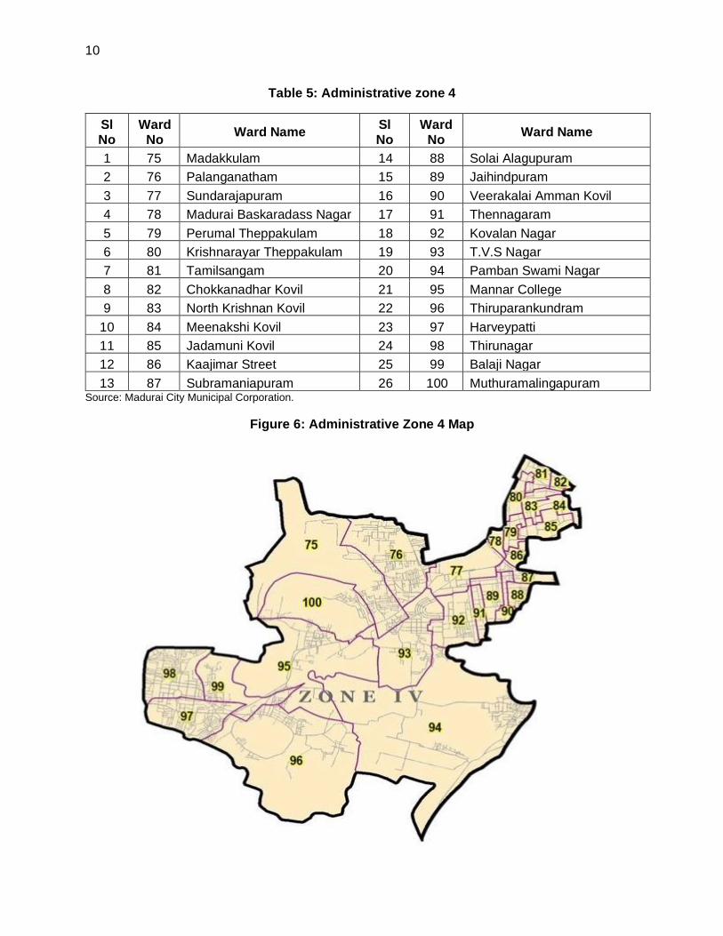
Figure 6: Administrative Zone 4 Map

11
16. Existing Water Supply Schemes in Core City of Madurai City Municipal Corporation. The first protected water supply was provided to Madurai City in the year 1892, through head works at Aarapalayam. Subsequently, considering the increasing population and additional demand, the augmentation for the city supply has been implemented in the years 1924, 1963, 1973, 1985, 1987, 1995 and 2009 respectively.
Table 6: Details of Head Works
S.No. Components Description
1
Kochadai Head works
Type Infiltration Gallery
Year of construction 1924
Year of Improvement 1940
Distance from the town 7.00 km
Motor HP 170 HP
Pump Duty Centrifugal, 3,000 GPM (13,620 lpm) at 85 ft (25.91 m) Head
Length of Infiltration Gallery 218.29 m across the river; 146.35 m u/s & 36.59 m D/S
Total length of Gallery 1348 ft (411m)
Collection point Five manhole wells, two collection wells, and one colletion well cum suction well.
Conveying main 24” dia CI pipes to D’ system for District 3,4,5 with byepass connection to Arasaradi GLSR.
Average Discharge (Capacity)
20.00 MLD
2
Collector Well Head works at Kochadai
Year of construction 1973
Distance from the town 7.50 km
Diameter of Well 4.00 m
Depth of well 17.7 m
Motor HP 135 HP (1+1)
Pump Duty Vertical Turbine, 3470 GPM (15754 lpm) at 27.43 m Head.
Length of Radial Arms Six directions in two tiers 241 m in top tier and 348 m in the bottom tier.
Conveying main 24” CI Pipes from Kochadai to GLSR at Arasaradi.
Average Discharge (Capacity)
11.50 MLD
3
Melakkal Head works
Year of construction 1963
Distance from the town 18.00 km.
Type Infiltration Gallery with four manhole wells, one suction well and one collection well.
Motor HP 55 HP (1+1)
Pump Duty 3100 GPM (14074 lpm) at 55 ft (16.77 m) Head
Length of Infiltration Gallery 304.88 m (2 rows of 18”SW pipe with cement filled joints)

12
S.No. Components Description
Length of conveying main from Melakkal to Arasaradi Pump station
14.00 m ”24" RCC) and 1,562 m ”21" RCC)
Average Discharge Capacity 16.00 MLD
4
Thatchampattu Head works
Year of Construction 1985
Distance from the town 20 km.
Infiltration wells 3 Nos.
Diameter of well 4.50–m - 2 nos. & 3.50 m -1 no.
Depth of well 9–m - 2 nos. and 10–m - 1 no.
Pump Duty (Submersible) 1,800 lpm / 13m H/ 10 –P - 2 Nos. &1,140 lpm / 14m H/ 7.5 –P - 1 no.
Motor HP 90 HP 4741 lpm X 56 m
Length of conveying main from Thatchampattu to Arasaradi Pump Station
16.70 km; 300 mm Φ
Average Discharge (Capacity)
4.50 MLD
5
Manaloor Head works
Year of Construction 1987
Distance from the town 15 km.
Diameter of Collector well 5.0 m
Diameter of pump house 6.0 m
Length of Radials 300 mm dia slotted pip–s - 210 m
Pump Duty at Manaloor Head works
25 HP Turbine - 4,741 lpm / 17m Head
Average Discharge (Capacity)
4.54 MLD
Length of Pumping main 134 m.
Thiruppuvanam Head works
Year of Construction 1987
Distance from the town 15 km
Diameter of Collector well 5.0 m
Diameter of pump house 6.0 m
Length of Radials 300 mm dia slotted pip–s - 210 m
Pump Duty at Manaloor Headworks
40 HP Turbi–e - 4,741 lpm / 27m Head
Length of Pumping main From Thiruppuvanam to Manalur
300 –m - 3830 m.
Average Discharge (Capacity)
4.54 MLD
Common Sump cum Pump house at Manalur
Capacity 100,000 liters

13
S.No. Components Description
Booster Pump Duty at Manaloor
230 HP - 9,482 lpm / 81m H
Length of Pumping main From Manalur sump to Service reservoirs at New Ramnad Road and Joseph Park
450 mm cl 15 – 7,000 m 450 mm cl 10 – 5,630 m
Pump Duty at Thiruppuvanam Head works
40 HP/ 4,741 lpm / 27m H
Booster Pump Duty at Manaloor
230 HP/ 9,482 lpm / 81m H
Length of pumping main 3.60 km; 350 mm Φ Pipe (Thiruppuvanam to Manaloor); 13.20 km.; 450 mm ΦPipe (Manaloor to Joseph Park)
6
Vaigai Scheme No 1
Year of Construction 1995
Source Vaigai Dam
Ditance from Town 66 km
Treatment Plant Capacity 71.6 MLD
Gravity Conveying main 1000 mm & 1100 mm PSC pip–s - 66 km
7
Vaigai Scheme No 2
Year of Construction 2009
Source Vaigai Dam
Ditance from Town 66 km
Treatment Plant Capacity 47 MLD
Gravity Conveying main 1,000 mm & 1,100 mm PSC pip–s - 66 km
ft = feet, GLSR = Ground Level Storage Reservoirs, GPM = gallons per minute, km = kilometer, m= meter, MLD = million liters per day, RCC = reinforced cement concrete. Source: Madurai Municipal Corporation.
17. Status of the existing water supply schemes for core city of Madurai City Municipal Corporation. The Madurai City Municipal Corporation supplies water to the Core city from Vaigai dam and sub-surface water supply schemes from Vaigai River. Water supply details are given in the Table 7.
Table 7: Details of Sources and Head Works in Madurai City Municipal Corporation
S.No. Name of
Source/Scheme Type of Source
Present Supply (MLD)
Remarks
Scheme-I
1 Kochadai Infiltration Galleries 8.46
Sub-Surface Water/Ground Water
Kochadai Collector Well Not Functioning
2 Thachampathu Melakkal WSS
Infiltration Galleries 14 Sub-Surface Water/Ground Water

14
S.No. Name of
Source/Scheme Type of Source
Present Supply (MLD)
Remarks
Scheme-II
3 Manalur and Thiruppuvanam
Collector Wells 7 Sub-Surface Water/Ground Water
Vaigai Water Supply Scheme
4 Vaigai WSS,Line-I Intake Well Vaigai Dam 68 Surface Water
5 Vaigai WSS,Line-II Intake Well Vaigai Dam 47 Surface Water
Scheme-III
6 Vaigai River bed Sources
Infiltration wells 17.54 Sub-Surface Water/Ground Water
Scheme-IV
7 Melur CWSS Collector Wells in River Cauvery
21 Sub-Surface Water/Ground Water
Total 183 -- MLD = million liters per day, WSS = water supply scheme. Source: Madurai City Municipal Corporation.
18. Water Distribution System. The potable water supply network covers about 59% of the households in the Madurai City Municipal Corporation. The existing water supply consists of about 764 km long pressurized pipe network. The distribution system in Madurai City Municipal Corporation consist of pipes with diameter varies from 63mm to 150mm and 15mm house service connections are provided to all legal connections. The condition of the existing pipes is reported to be poor and the hydraulic capacity inadequate for future demand.
19. House Service Connections: The details of the house service connection are given in the table.
Table 8: Details of House Service Connections
S.No Type of Connection No. of Connection
1 Domestic 1,45,326
2 Non-Domestic 14,980
Total 1,60,306
20. O & M of the Existing Distribution System. The O&M of Water distribution system is done by the Madurai City Municipal Corporation. Regular records for the valve operations, water levels in towers, water quality are maintained and inlet–outlet meter management are done by this department.
21. One of the major problems reported in the distribution system is un-equitable supply of water to different parts of a distribution zone. It is observed that the distribution system for a length of about 490km is more than 30 to 40 years old and these pipes are with incrustations resulting friction and reduction in pressure and flow and also they are very susceptible to damage.
22. Water Tariff Structure. The monthly water tariff for domestic house service connection, non-domestic connection as well as for commercial connections is charged on a flat rate as follows.
Table 9: Details of Water Tariff
S.No Type of
Connection
Monthly
Charges
Deposit Charges
(Rs.)
Connection Charges
(Rs.)

15
1 Domestic 75 3000 75
2 Non-Domestic 150 10000 150
23. Un-served Areas. Presently about 39 km of road length is not covered with distribution system in Core City Madurai City Municipal Corporation. People living in these areas are depending on ground water and water from public fountains/stand posts. There are about 2,850 bore wells and 3,699 public fountains maintained by Madurai City Municipal Corporation.
24. Existing Water Supply System in the added areas. The added area of Madurai Corporation includes the previous local bodies of 3 Municipalities, 3 Town Panchayats and 11 Rural Panchayats. The above local bodies were merged with the Madurai Corporation and 28 new wards were formed.
(i) Municipality: 1) Anaiyur, 2) Avaniapuram, 3) Thiruparankundram (ii) Town Panchayat: 1) Vilangudi, 2) Thirunagar, 3) Harveypatti (iii) Rural Panchayat: 1) Chinna Anuppanadi, 2) Chinthamani,3) Iravathanallur, 4)
Thiyagarajar Colony, 5) Pudhukulam Bit II, 6) Melamadai, 7) Vandiyur, 8) Thiruppalai, 9) Kannanendhal, 10) Naganakulam,11) Uthangudi.
Table 10: Existing Service Reservoir Details
S No Location Capacity Av GL LWL MWL
1 Pandian Nagar 2.00 137.060 148.630 151.630
2 Harveypatti 2.00 136.970 148.970 152.570
3 Balaji Nagar 1.00 134.300 141.300 143.800
4 Pasumalai 2.00 142.770 148.770 152.370
25. Water Source for Added Area. There are 17 Overhead Water Tank (OHTs) whose capacities are more than or equal to 2 LL. The overall storage Capacity of these 17 OHTs is estimated to be 68.6 LL. Out of these 17 OHTs, there are two OHTs whose capacity is 10 LL each. The details of existing infrastructures for the added area are furnished in Table below
TABLE 11: WATER SOURCE FOR ADDED AREA
Sl. No Project Area Ward No. Water Source
1
Anaiyur
2 Karupatti Head Works 2.57 MLD (Vaigai River)
2 3
3 4
4
Avaniyapuram
59 Sholavandan - Thatchampattu Scheme
5 60 Sholavandan - Thatchampattu Scheme
6 61 Sholavandan - Thatchampattu Scheme
7 62 Sholavandan - Thatchampattu Scheme
8 94 Sholavandan - Thatchampattu Scheme

16
Sl. No Project Area Ward No. Water Source
9 Thirupparamkundram, Thiyagarajar Colony
Pudhukulam Bit II 95
Sithargal Natham Head Works (Vaigai River)
10 Thirruparakundram
96
11 99
12 Harvepatti,
Thiruparankundram, Thirunagar
97
13 Thirunagar 98 Cauvery Combined Water Supply
14 Vilangudi
1 Cauvery Combined Water Supply
15 23 Cauvery Combined Water Supply
16 Kannanendhal
25 Cauvery Combined Water Supply
17 26 Cauvery Combined Water Supply
18 Naganakulam
48 Cauvery Combined Water Supply
19 49 Cauvery Combined Water Supply
20 Thiruppalai 24 Cauvery Combined Water Supply
21 Melamadai
30 Cauvery Combined Water Supply
22 31 Cauvery Combined Water Supply
23 Uthangudi 28 Cauvery Combined Water Supply
24 Vandiyur
29 Cauvery Combined Water Supply
25 32 Cauvery Combined Water Supply
26 Chinna Anuppanadi, Chinthamani
56 Cauvery Combined Water Supply
27 58 Cauvery Combined Water Supply
28 Iravathanallur 55 Cauvery Combined Water Supply
26. Condition Analysis of Existing Distribution Pipelines. General. Water supply distribution pipes form a major part of the capital investments in any water supply scheme. A thorough knowledge regarding the existing pipes, its condition i.e. carrying capacity and strength is required to know for the good maintenance of pipeline. This information can be correlated to arrive at logical conclusions of those pipes for future use. The present distribution networks in Madurai Corporation consists of different types of pipelines and those pipes falls in different age groups.
27. The condition analysis has been carried out by other consultant on behalf of Madurai Corporation at the year 2013. Visual observation / inspection has been carried out to check the suitability of the existing pipeline.
28. Methodology Adopted for Selection of Pipe Sample. The methodology adopted for selection of pipe samples for condition analysis are based on the study of historical performance

17
analysis (e.g. leakage or burst history, damage due to unauthorized tapings etc.) and visual inspections (witness of change in shape and size, visible damages, leakages etc). The pipe samples are to be collected with a logical understanding that these should cover representative samples of pipes laid during the last 0 to 15 years, 15 to 30 years and more than 30 to 50 years.
TABLE 12: CRITERIA FOR PIPE SAMPLING
Category
No Description of Criteria No of Pipe Samples
1 Pipes age between 30 to 50
Years and more.
01 No of Sample for each type of pipe
material
2 Pipes age between 15 to 30
Years.
02 Nos of Sample for each type of pipe
material
3 Pipe age less than 15 Years. 03 Nos of Sample for each type of pipe
material
29. Pipeline Condition in the Madurai Corporation. The pipeline condition analysis process in MCMC was carried out by the consultant with the help of Madurai Corporation officials. Pipe samples were collected as per standard format and a joint inspection by the consultant and Corporation staff was carried out. The observations were noted down in the standard format prepared by the consultant.
30. Aging Analysis. The aging analysis of the existing pipes has been done from the ward wise existing network data collected from the corporation. The analysis concludes that, the PSC, CI and GI pipes are more than 40 years old. Hence those pipelines are decided to be abandoned. Further, the pipes are decided to be abandoned and HDPE and DI Pipes are instructed to propose for the present project area.
TABLE 13: DETAILS OF AGE OF THE PIPES
Pipe Materials Sum of Length (m) Average of Age (Years)
CI 81569.5 42
GI 9496.2 41
PSC 1121 50
PVC 212592.3 14
31. Based on the above, MCMC has decided to abandon the existing old and leaking distribution pipes as it is in the ground without disturbing them, and new pipes will be laid in both Added Areas and the Core city area.
32. Water Supply Master Plan: The Water Supply Master Plan for Madurai Corporation has been prepared in Package 3 DPR for providing equitable Water Supply to the entire Area of Madurai Corporation from the all existing and the proposed water supply sources. In Madurai Corporation total number of Water Supply Zones is now proposed in this Water Supply Master Plan as 81. Among the 81 Zones, 44 Numbers are existing Zones and 37 Nos. are newly proposed with 36 Nos. of Service Reservoirs and 1 No of Sump. All this 81 numbers of Water Supply Zone are planned for equitable water supply from the all the available water supply source for Madurai Corporation.

18
33. Water Supply Improvement in Madurai Corporation. A comprehensive development of water supply system in Madurai City is planned under TNUFIP, which is proposed to be implemented under four packages. Comprehensive development of water supply system shall include augmentation of source & treatment, laying transmission and feeder mains, augmenting storage capacity and distribution network improvement (DNI).
(i) Package I. The new source and transmission of raw water from Mullai periyar Lower Camp to WTP.
(ii) Package II. New Water Treatment Plant at Pannaipatti (125 MLD).
(iii) Package III. Transmission of Clear Water from Pannaipatti WTP to the Madurai City (which includes the Feeder Mains and Construction of 37 Service Reservoirs.
34. All these packages (Packages I to III) are under implementation through ADB support from TNUFIP Tranche II. The Package IV is the distribution system, which is further divided in to 3 phases (Refer Figure 7).
• Phase I – SMART City Mission – Area Based Development (ABD) (Under Implementation). The area comprises of 8 distribution Zones (Zone Covered 37, 41 to 44, 46 to 48) located in south of River Vaigai. The Phase I of SMART City Area has been already finalized and the execution was started.
• Phase II – ADB Tranche II Funded Area (Under Implementation). The area comprises of 34 distribution Zones (Zone Covered are1, 2, 4 to 10, 23 to 25, 27, 28, 52, 53, 57 to 63, 71 to 81) located in North & South Added Area.
• PHASE III – ADB Tranche III Funded Area (this subproject scope)
o North: The area comprises of 18 distribution Zones located in North Core City
Area (Zone Covered - 3, 11 to 22, 26, 29 to 32).
o South: The area comprises of 21 distribution Zones located in South Core City
Area (Zone Covered - 33 to 36, 38 to 40, 45, 49 to 51, 54, 55, 56, 64 to 70).
Table 14: Phase wise Salient Details (Existing)
SI. No Description/Phase
Phase - I - SMART City Mission ABD (Area based development) Area - 8 Zones (Zone - 37, 41 to 44, 46 to 48)
Phase - II- ADB Funded Added Area - 34 Zones (Zone -1, 2, 4 to 10, 23 to 25, 27, 28, 52, 53, 57 to 63, 71 to 81)
1 Ward (Full) 15 28
3 Area (Sq.km) 5.81 86.09
4 Area (Acre) 1436.68 21273.09
5 Existing OHTs 6 17
6 Proposed OHTs 2 17
7 D System Zones 8 34
8 DMA 27 78
9 North of River Vaigai
(Zones) - 14

19
10 South of River Vaigai
(Zones) 8 20
11 Zones - Core Area 8 -
12 Zones - Added Area - 34
13 Households 45532 118190
14 Road Length (km) 137.12 649.02
15 Project Cost (Crores) 77.02 252.35
35. Funding. The Madurai City Municipal Corporation is receiving funds through SMART City
funds as Grant and from Asian Development Bank as Loan for Phase I and Phase II. The funding
sources will be identified for the balance requirement in Phase III area. Out of 81 Water Supply
Distribution Zones, 8 zones are in SMART city ABD area which is located in the South of River
Vaigai and 34 Zones which are located in North and South of River Vaigai (Added Areas) is
covered under the Asian Development Bank fund. The ADB Tranche III Zones in core areas of
North and south of River Vaigai.
Table 15: Funding Pattern
Sl.No. Funding Total Wards Covered Amount
1 SMART City Fund (8 Zones) 15 77.02 Crores
2 ADB Tranche II Fund (34 Zones) 28 270.00 Crores
3. ADB Tranche III Fund (39 Zones) 57 365.00 Crores
E. Proposed Water Supply Distribution System
36. Proposed Water Supply Distribution System in Madurai City Municipal Corporation
under Tranche III (Under this subproject): The Madurai City Municipal Corporation proposes
to improve existing distribution systems in 39 distribution zones (zone-3,11 to 22, 26, 29 to 32, 33
to 36, 40, 45, 49, 51, 54 to 56, 64 to 70) covering 57 wards in the core city. Estimated project
cost is INR 365.00 Crores. Under this proposal, new distribution system will be laid from 39 OHTs
(18 existing and 21 proposed under Tranche II).
(i) North: The area comprises of 18 distribution Zones located in North Core City Area (Zone
Covered - 3, 11 to 22, 26, 29 to 32).
(ii) South: The area comprises of 21 distribution Zones located in South Core City Area (Zone
Covered - 33 to 36, 38 to 40, 45, 49 to 51, 54, 55, 56, 64 to 70).

20
Figure 7: Map showing sub project coverage area (Green shaded)

21
Table 16: Area details of the proposed Distribution Network Improvement Scheme
(Tranche III)
Package III & IV – Balance Area - 39 Zones (Zone - 3, 11 to 22, 26, 29 to 32, 33 to 36, 40, 45, 49, 51, 54 to 56, 64 to 70)
Sl.no Ward no Ward Name Sl.no Ward no Ward Name
1 5 BB Kulam 30 43 Thallakulam
2 6 Meenambalpuram 31 44 K.K.Nagar
3 7 Kailasapuram 32 45 Pudur
4 8 Vilangudi 33 46 Lourdhu Nagar
5 9 Thathaneri 34 47 Reserve Line
6 10 Arappalayam 35 51 Ismailpuram
7 11 Ponnagaram 36 52 Sourashtra Hr. Sec. School
8 12 Krishnapalayam 37 53 Pangajam Colony
9 13 Azhagaradi 38 57 Anuppanadi
10 14 Viswasapuri 39 63 Villapuram
11 15 Melaponnagaram 40 64 Keeraidurai
12 17 Ellis Nagar 41 68 Dhrowpathi Amman Kovil
13 18 S.S.Colony 42 69 ST,Marrys
14 19 Ponmeni 43 70 Kamarajapuram
15 20 Arasaradi Othakkadai 44 71 Balaranganathapuram
16 21 Bethaniyapuram 45 72 Navarathinapuram
17 22 Kochadai 46 75 Madakkulam
18 27 Karpaga Nagar 47 76 Palanganatham
19 32 Vandiyur 48 77 Sundarajapuram
20 33 Santhamangalam 49 86 Kaajimar Street
21 34 Aringar Anna Nagar 50 87 Subramaniapuram
22 35 Madhichiyam 51 88 Solai Alagupuram
23 36 Alwarpuram 52 89 Jaihindpuram
24 37 Sellur 53 90 Veerakalai Amman Kovil
25 38 Pandhalkudi 54 91 Thennagaram
26 39 Goripalayam 55 92 Kovalan Nagar
27 40 Ahimsapuram 56 93 T.V.S Nagar
28 41 Narimedu 57 100 Muthuramalingapuram
29 42 Chokkikulam

22
Table 17: Salient Features of Proposed Subproject
SI.No Description/Phase Details
1 Project Cost (Crores) 365.00 Crores
2 Tender put value 312.54
3 No of Wards 57
4 Road Length in m 815.69
5 Area (Sq.km) 56.09
6 Existing SRs 21
7 Proposed SRs 18
8 D System Zones 39
9 DMA 115
10 Population:
a Base Year -2019 1048484
b Intermediate Year -2034 1219941
c Ultimate Year - 2049 1421763
11 Demand in MLD:
a Base Year -2019 167.15
b Intermediate Year -2034 193.37
c Ultimate Year - 2049 223.97
12 Demand in LPS:
a Base Year -2019 1934.63
b Intermediate Year -2034 2238.08
c Ultimate Year - 2049 2592.25
13 House Service Connection (HSC): 163958
14 Minimum Diameter - HDPE 110
15 Maximum Diameter - HDPE 200
16 Minimum Diameter - DI 250
17 Maximum Diameter - DI 450
18 Minimum Pressure - Proposed SR in m 12
19 Maximum Pressure - Proposed SR in m 22
20 Minimum Pressure - Existing SR in m 7
21 Maximum Pressure - Existing SR in m 22
22 Pressure Drop in m 5
23 No of Scour Valve -80 mm 115
24 No of Air Valve -40 mm 115
25 No of Odai Crossing 16
26 No of Sluice Valve 183
27 No of Flow Meter 183
28 No of FCV 115
29 No of PRV 10
30 Pipe Length Dia Wise- HDPE in m
31 110mm 614402
32 125mm 16032
33 140mm 12868
34 160mm 13514
35 180mm 18909
36 200mm 56459

23
37 Total (A) 732184
38 Pipe Length Dia Wise- DI in m
39 100mm
40 150mm
41 200mm
42 250mm 21041
43 300mm 20315
44 350mm 14480
45 400mm 22103
46 450mm 3764
47 500 mm 0
48 Total (B) 81703
49 Total Pipe Length in m (C = A+B) 813887
50 HSC - Water Meter
51 20mm 142110
52 25mm 16190
53 32mm 272
54 20mm for Apartments and more than 2400 Sq.ft buildings
5386
55 Total 163958
37. Water Demand Assessment: Water demand for overall city will be 374 MLD for the ultimate year (2049) and 317 MLD for intermediate year (2034). Water demand of this subproject area will be 224 MLD (2049) and 193MLD (2034). The existing water supply is 192 MLD (115MLD from Vaigai Dam schemes I and II, 30 MLD from River Cauvery Source under Melur CWSS and sub-surface water of 47 MLD from Vaigai River bed).. To meet the water demand gap of 125MLD for the intermediate design year (2034) of entire corporation, a new water supply scheme is under implementation under the ADB funded TNUFIP (Tranche II).
38. The water demand for the intermediate year is being met with the improvements. Overall city design demand and sub project area demand is enclosed below.
Table 18: Madurai Water Supply – demand and supply
Description Year Overall City
Demand (MLD)
Present Subproject
area demand (MLD)
Available water Supply
(entire corporation area) MLD
Demand supply gap
(MLD)
Base Year 2019 268 167 192 76
Intermediate year 2034 317 193 192+125 (under implementation)
Nil

24
Table 19: Proposed Water Supply Scheme Project Components
Infrastructure Function Description Location
Distribution System
Distributes clear water to houses in each zone
Providing distribution network in 39 water supply zones (18 zones in south of River Vaigai and 21 zones in North) for a length of 813,887m (814 km)
Proposed length, diameter and material of pipes are provided below
Details of Distribution system (South)
S.No Dia in mm
Material Length (m)
1 250 DI 12627
2 300 DI 15268
3 350 DI 7481
4 400 DI 5493
5 450 DI 3764
6 110 HDPE 310042
7 125 HDPE 14227
8 140 HDPE 9458
9 160 HDPE 9407
10 180 HDPE 9984
11 200 HDPE 29925
Total 427676
Details of Distribution system (North)
S.No Dia in mm
Material Length (m)
1 250 DI 8414
2 300 DI 5047
3 350 DI 6999
4 400 DI 16610
5 110 HDPE 304360
6 125 HDPE 1805
7 140 HDPE 3410
8 160 HDPE 4107
9 180 HDPE 8925
10 200 HDPE 26534
Total 386211
Distribution pipes will be laid along the roads, within the road Right of Way in 39 zones located north and south of the River vaigai falling within Madurai City Municipal Corporation Area. This subproject area covers 48 percent of total MCMC area. It does not include core town area where there are prominent religious / historical / archeological monuments/ places. The subproject area is fully urban. In each distribution zone, network will be connected to zonal OHT. Of the 39 zones, in 21 zones OHTs already exists and in 18 zones, new OHTs are in construction under TNUFIP (Tranche 2)
House Service Connections (HSC)
Individual Houses will get clear water after HSC
The 1,63,958 nos of HSC are in this distribution system. HSC in South is 89851 nos and HSC in North is 61067 nos.
In all households in areas covered by this subproject in Madurai City Municipal Corporation (MCMC).

25
F. Analysis of Alternatives
39. At present, water supply network in Madurai City Municipal Corporation covers about 59% of the households. The existing water supply distribution system consists of about 764 km long pressurized pipe network. Majority of these pipes are old (30 to 40 years) and are with incrustations resulting friction and reduction in pressure and flow and also, are very susceptible to damage. Due to frequent leaks, water losses in the system are significant, wasting the previous water resource. Besides poor condition, the existing pipes also assessed to be hydraulic capacity inadequate for future demand. One of the major problems reported in the existing distribution system is low pressure and inequitable supply of water to different parts of a distribution zone. There are also areas presently not covered with the distribution system. People living in these areas are depending on groundwater and water from public fountains/stand posts. There are 2,850 bore wells and 3,699 public fountains maintained by Madurai City Municipal Corporation. The proposed subproject intends to improve the water distribution network and will provide following benefits to the town population:
(i) increased availability of potable water at appropriate pressure to all households including urban poor; ensuring equitable and adequate supply
(ii) Increasing potable water access to currently uncovered population
(iii) Reduced water losses
(iv) Reduced time and costs in accessing alternative sources of water
(v) Better public health particularly reduction in waterborne and infectious diseases
40. The “no project” alternative will deprive the population of above benefits, and access to clean water. Under the “with project’ alternative, the people of Madurai city will be the beneficiaries of the improved water supply system, as they will be provided with a constant supply of better quality water, piped into their homes at an appropriate pressure. The project will improve the over-all health condition of the town as water borne diseases will be reduced, so people should spend less on healthcare and lose fewer working days due to illness, so their economic status should also improve, as well as their overall health. This should also improve the environment of these areas, should deliver major improvements in individual and community health and well-being. Thus, “with project” alternative preferred over “no project” alternative.
G. Implementation Schedule
41. The subproject will be Implemented under one/ single contract package. The Bids for the civil works will be invited in January 2022 and the contract will be awarded by June 2022. Construction is likely to start in July/August 2022 and will take 36 months to complete the project. The commissioning and trail run will take 6 months, and the contractor will operate and maintain (O&M) for 60 months after which it will be transferred to MCMC for operation and maintenance. A detailed implementation schedule (including design/pre-construction, construction, commissioning & trail run and operation phases) will be provided in the updated IEE.

26
III. POLICY, LEGAL AND ADMINISTRATIVE FRAMEWORK
A. ADB Policy
42. ADB requires the consideration of environmental issues in all aspects of ADB’s operations, and the requirements for environmental assessment are described in ADB SPS, 2009. This states that ADB requires environmental assessment of all ADB investments.
43. Screening and categorization. The nature of the environmental assessment required for a project depends on the significance of its environmental impacts, which related to the type and location of the project: the sensitivity, scale, nature, magnitude of its potential impacts, and the availability of cost-effective mitigation measures. Projects are screened for their expected environmental impacts, and are assigned to one of the following four categories:
(i) Category A. A proposed project is classified as category ‘A’ if it is likely to have significant adverse environmental impacts that are irreversible, diverse, or unprecedented. These impacts may affect an area larger than the sites or facilities subject to physical works. An EIA is required;
(ii) Category B. A proposed project is classified as category ‘B’ if its potential adverse environmental impacts are less adverse than those of category ‘A’ projects. These impacts are site-specific, few if any of them are irreversible, and in most cases mitigation measures can be designed more readily than for category ‘A’ projects. An IEE is required;
(iii) Category C. A proposed project is classified as category ‘C’ if it is likely to have minimal or no adverse environmental impacts. No environmental assessment is required although environmental implications need to be reviewed; and
(iv) Category FI. A proposed project is classified as category ‘FI’ if it involves investment of bank funds to or through a Financial Intermediary.
44. Environmental Management Plan. An EMP, which addresses the potential impacts and risks identified by the environmental assessment, shall be prepared. The level of detail and complexity of the EMP and the priority of the identified measures and actions will be commensurate with the project’s impact and risks.
45. Public disclosure. ADB will post the safeguard documents on its website as well as disclose relevant information in accessible manner in local communities following ADB’s SPS 2009 and Access to Information Policy 2018:
(i) final or updated IEE upon receipt; and (ii) Environmental monitoring reports submitted by the implementing agency during
project implementation upon receipt.
B. National Environmental Laws
46. Environmental Assessment. The Government of India EIA Notification of 2006 (replacing the EIA Notification of 1994), set out the requirements for Environmental Assessment in India. This states that environmental clearance is required for specified activities/projects, and this must be obtain before any construction work or land preparation (except land acquisition) may commence. Projects are categorized as A or B depending on the scale of the project and the nature of its impacts.
47. Category A projects requires environmental clearance from the central Ministry of Environment, Forests and Climate Change (MoEF&CC). The proponent is required to provide

27
preliminary details of the project in the prescribed manner with all requisite details, after which an Expert Appraisal Committee (EAC) of the MoEF&CC prepares comprehensive terms of reference (TOR) for the EIA study. On completion of the study and review of the report by the EAC, MoEF&CC considers the recommendation of the EAC and provides the environmental clearance if appropriate.
48. Category B projects require environmental clearance from the State Environment Impact Assessment Authority (SEIAA). The State level EAC categorizes the project as either B1 (requiring EIA study) or B2 (no EIA study) and prepares TOR for B1 projects within 60 days. On completion of the study and review of the report by the EAC, the SEIAA issues the environmental clearance based on the EAC recommendation. The Notification also provides that any project or activity classified as category B will be treated as category A if it is located in whole or in part within 5 km from the boundary of protected areas, notified areas or inter-state or international boundaries.
49. None of the components of this water supply scheme subproject falls under the ambit of the EIA Notification 2006, and, therefore EIA Study or environmental clearance is not required for the subproject.
50. Other applicable environmental regulations. Besides EIA Notification 2006, there are various other acts, rules, policies and regulations currently in force in India that deal with environmental issues that could apply to infrastructure development. There is no involvement of new quarries and borrow area hence EC not applicable for this subproject. The specific regulatory compliance requirements of the subproject are shown in Table 20.
Table 20: Applicable Environmental Regulations
Law Description Requirement
Environment (Protection) Act, 1986 and CPCB Environmental Standards.
Emissions and discharges from the facilities to be created or refurbished or augmented shall comply with the notified standards.
To comply with applicable notified standards.
Noise Pollution (Regulation and Control) Rules, 2000 amended up to 2010.
Rule 3 of the Act specifies ambient air quality standards in respect of noise for different areas/zones.
To comply with the noise standards.
Air (Prevention and Control of Pollution) Act, 1981, amended 1987 and it’s Rules, 1982.
Applicable for equipment and machinery’s potential to emit air pollution (including but not limited to diesel generators and vehicles); ● CTE and CTO from TNPCB; ● Compliance to conditions and emissions
standards stipulated in the CTE and CTO.
Generators will require CTE and CTO from TNPCB. Generators to comply with applicable emission standards.
Water (Prevention and Control of Pollution) Act of 1974, Rules of 1975, and amendments
Act was enacted to provide for the prevention and control of water pollution and the maintaining or restoring of wholesomeness of water. Control of water pollution is achieved through administering conditions imposed in consent issued under to this Act.
To comply with the norms as menetioned in the Act.
Tamil Nadu Minor Mineral Concession Rules, 1959
Construction activities (Sand mining, quarries and borrow Areas)
This act is not applicable for this sub project.

28
Law Description Requirement
(corrected up to 31 March 2001)
EIA Notification, 2006
Environmental Clearance required if any new quarry is proposed.
This act is not applicable for this subproject.
The Ancient Monuments and Archaeological Sites and Remains Act 1958
If any activities comes in Archaeological site the act applicable.
Construction works (distribution network) surrounding Sri Meenakshi Amman Temple has been completed under SMART city scheme. There are no other ASI or historically important monuments in the subproject area. Hence, this act is not applicable for this subproject.
Solid Wastes Management Rules, 2016
Rules to manage municipal solid waste generated; provides rules for segregation, storage, collection, processing and disposal.
Solid waste generated at proposed facilities shall be managed and disposed in accordance with the Solid Wastes Management (SWM) Rules
Tamil Nadu Timber Transit Rules, 1968 or latest.
Rules to tree cutting Tree cutting to be done as per the rules with RDO permission.
Construction and Demolition Waste Management Rules, 2016
Rules to manage construction and to waste resulting from construction, remodeling, repair and demolition of any civil structure. Rules define C and D waste as waste comprising of building materials, debris resulting from construction, re-modeling, repair and demolition of any civil structure.
Construction and demolition waste generated from the project construction shall be managed and disposed as per the rules.
Hazardous and other Wastes (Management and Transboundary Movement) Rules, 2016, as amended in 2019
Rules to ensure safe handling, generation, processing, treatment, package, storage, transportation, use reprocessing, collection, conversion, and offering for sale, destruction and disposal of Hazardous Waste. The Rules lay down corresponding duties of various authorities with wider responsibilities touching across almost every aspect of Hazardous wastes generation, handing and their disposal
Asbestos cement pipe materials if encountered during excavation shall be managed and disposed as per the provisions of the rules.
Never expose cylinders to heat, always keep the valve protection cap in place, except when the cylinder is being used, never lift a cylinder by its valve protection cap, Cylinders must be kept upright at all times when moved or stored. Secure chlorine containers with chains, chocks or appropriate equipment.
Not applicable for this subproject.
Explosives Rules, 2008
NOC for Controlled Blasting for excavation
Controlled blasting if required during execution to be carried by complying the rules

29
Law Description Requirement
The Building and Other Construction Workers (Regulation of Employment and Conditions of Service) Act, 1996 and the Cess Act of 1996 -
All the establishments who carry on any building or other construction work and employ 10 or more workers are covered under this Act. All such establishments are required to pay Cess at rate not exceeding 2% of the cost of construction as may be notified by the Government.
The employer to whom the Act applies has to obtain a registration certificate from the Registering Officer appointed by the Government. The employer is required to provide safety measures at the building or construction work and other welfare measures, such as canteens, first-aid facilities, ambulance, housing accommodation for workers near the workplace etc.
Inter-State Migrant Workmen's (Regulation of Employment and Conditions of Service) Act, 1979
The Act is applicable to an establishment which employs 5 or more inter-state migrant workmen through an intermediary (who has recruited workmen in one state for employment in the establishment situated in another state).
The employer to whom the Act applies has to obtain a registration certificate from the Registering Officer appointed by the Government. The employer is required to provide certain facilities such as housing, medical aid, displacement charges, traveling expenses from home up to the establishment and back, etc
Other Major Labor Laws,
The contractor shall not make employment decisions based upon personal characteristics unrelated to job requirements. The contractor shall base the employment relationship upon equal opportunity and fair treatment and shall not discriminate with respect to aspects of the employment relationship, including recruitment and hiring, compensation (including wages and benefits), working conditions and terms of employment or retirement, and discipline. The contractor shall provide equal wages and benefits to men and women for work of equal value or type.
Applicable labor laws including amendments issued from time to time applicable to establishments engaged in construction of civil works, which will need to be followed by the project are provided in Appendix 2.
51. Clearances / permissions to be obtained by contractor. Following table shows the list of clearances/permissions required for project construction. This list indicative and the contractor should ascertain the requirements prior to start of the construction and obtain all necessary clearances/permission prior to start of construction.
Table 21: Clearances and Permissions Required for Construction
S. No
Construction Activity
Statutory Authority
Statute under which Clearance is Required
Implementation Supervision
1 Tree Cutting
Department of Forest and
District Collector/DRO
Clearances from the authorities as per the Tamil Nadu Timber Transit Rules, 1968 or latest.
PIU PMU

30
S. No
Construction Activity
Statutory Authority
Statute under which Clearance is Required
Implementation Supervision
2
Hot mix plants, Crushers and Batching plants
TNPCB
Consent to establish and consent to operate under Air Act, 1981. If Applicable.
Contractor PIU
3
Storage, handling and transport of hazardous materials
TNPCB
Manufacturing, Storage and Import of Hazardous Chemicals Rules, 2016, as amended in 2019
Contractor PIU
4
Discharges from construction activities
TNPCB Consent To Establish and Consent To Operate under Water Act, 1974
Contractor PIU
5
Sand mining, quarries and borrow areas
Department of Geology and Mining, Govt. of Tamil. Nadu.
Not applicable Contractor to obtain material from the existing government licensed mines / quarries; Contractor will require prior approval of PIU for obtaining material from a particular source as per legislations from authorized quarries with valid clearance through the District Collector, Coimbatore. PIU to review and approve only existing licensed mines that are compliant with prevailing environmental regulations of India.
Contractor PIU
6
NOC for Controlled Blasting for excavation
District Collector, Madurai
Explosives Rules, 2008.
Contractor PIU
7 Disposal of bituminous wastes
Tamil Nadu State Pollution Control Board
Hazardous and other Wastes (Management and Transboundary Movement) Rules, 2016, as amended in 2019
Contractor
PIU
8
Temporary traffic diversion measures
Madurai Corporation
Traffic Police
MoRTH 112 SP 55of IRC codes
Contractor PIU
9 Surplus material disposal
Tamil Nadu State Pollution Control Board
Consent to establish and consent to operate under Water Act, 1974 Statutory permissions not applicable for this sub project.
Contractor PIU
10 Groundwater extraction
Public Works Department
(Groundwater)Tamil Nadu Groundwater Development and Management Act 2000
Contractor PIU

31
S. No
Construction Activity
Statutory Authority
Statute under which Clearance is Required
Implementation Supervision
11
Consent for the disposal of C&D waste from the ULB
MCMC Construction and Demolition Waste Management Rules, 2016
Contractor PIU
DRO -District Revenue Office, EIA =environmental impact assessment, PIU = program implementation unit, PMU = program management unit, TNPCB =Tamil Nadu Pollution Control Board.
52. ADB SPS Requirements. During the design, construction, and operation of the project the Program Management Unit (PMU) and Program Implementation Unit (PIU) will apply pollution prevention and control technologies and practices consistent with international good practice, as reflected in internationally recognized standards such as the World Bank Group’s Environment, Health and Safety Guidelines. These standards contain performance levels and measures that are normally acceptable and applicable to projects. When Government of India regulations differ from these levels and measures, the PMU and PIU in Madurai City Municipal Corporation will achieve whichever is more stringent. If less stringent levels or measures are appropriate in view of specific project circumstances, the PMU and PIU will provide full and detailed justification for any proposed alternatives that are consistent with the requirements presented in ADB SPS, 2009. The SPS 2009 also requires that ADB-financed sub-projects to comply with host country regulations.
53. The following IFC (World Bank Group) EHS and WHO Guidelines will be adopted in the EMP for the subprojects such as:
● WHO Guidelines on Air Emissions and Ambient Air Quality, Noise Management, Wastewater and Ambient Water Quality,
● Guidelines for Construction and Decommissioning (2007) ● Guidelines for Hazardous Material Management and Waste Management ● ADB Good Practice Guidance for the Management and Control of Asbestos Protecting
Workplaces and Communities from Asbestos Exposure Risks (March 2022)2 ● Guidance Note on Workers Accommodation: Processes and Standards, August 20063 ● Guidelines on Occupational Health and Safety and Community Health and Safety (2007)
54. Comparison of national emissions standards and International Standards / Best Practices are provided in Table 22 and Table 23. Due to different measuring conditions, the emission values are not directly comparable. However, IFC Guidelines / WHO standards are stricter than the national standards if converted to comparable values. The relevant standards applicable to this sub-project is identified in the column “applicable per ADB SPS”.
Table 22: National Ambient Air Quality Standards and WHO Guidelines
Parameter Location
National Ambient Air
Quality Standards b
WHO Air Quality Guidelines (µg/m3) Applicable Per
ADB SPS (µg/m3)
Global Updated
2005
Second Edition2000
Particulate Matter PM10
Industrial Residential, Rural and Other Areas
6/9*800 (Annual)
100 (24-hr)
20 (Annual) 50 (24-hr)
- 20 (Annual) 50 (24-hr)
2 https://www.adb.org/sites/default/files/publication/783636/good-practice-management-control-asbestos.pdf 3 IFC Guidance Note: Workers Accommodation

32
Parameter Location
National Ambient Air
Quality Standards b
WHO Air Quality Guidelines (µg/m3) Applicable Per
ADB SPS (µg/m3)
Global Updated
2005
Second Edition2000
(µg/m3) Sensitive Area
60 (Annual) 100 (24-hr)
20 (Annual) 50 (24-hr)
- 20 (Annual) 50 (24-hr)
Particulate Matter PM25
(µg/m3)
Industrial Residential, Rural and Other Areas
40 (Annual) 60 (24-hr)
10 (Annual) 25 (24-hr)
- 10 (Annual) 25 (24-hr)
Sensitive Area 40 (Annual) 60 (24-hr)
10 (Annual) 25 (24-hr)
10 (Annual) 25 (24-hr)
Sulphur Dioxide
SO2
(µg/m3)
Industrial Residential, Rural and Other Areas
50 (Annual) 80 (24-hr)
20 (24-hr) 500 (10-min)
- 20 (Annual) 800 (24-hr)
500 (10-min)
Sensitive Area 20 (Annual) 80 (24-hr)
20 (24-hr) 500 (10-min)
- 20 (Annual) 20 (24-hr)
500 (10-min)
Nitrogen Dioxide
NO2
(µg/m3)
Industrial Residential, Rural and Other Areas
40 (Annual) 80 (24-hr)
40 (Annual) 200 (1-hr)
- 40 (Annual) 80 (24-hr) 200 (1-hr)
Sensitive Area 30 (Annual) 80 (24-hr)
40 (Annual) 200 (1-hr)
- 30 (Annual) 80 (24-hr) 200 (1-hr)
Carbon Monoxide
CO (µg/m3)
Industrial Residential, Rural and Other Areas
2,000 (8-hr) 4,000 (1-hr)
- 10,000 (8-hr)
100,000 (15-min)
2,000 (8-hr) 4,000 (1-hr)
100,000 (15-min)
Sensitive Area 2,000 (8-hr) 4,000 (1-hr)
- 10,000 (8-hr)
100,000 (15-min)
2,000 (8-hr) 4,000 (1-hr)
100,000 (15-min)
Ozone (O3) (µg/m3)
Industrial Residential, Rural and Other Areas
100 (8-hr) 180 (1-hr)
100 (8-hr) - 100 (8-hr) 180 (1-hr)
Sensitive Area 100 (8-hr) 180 (1-hr)
100 (8-hr) - 100 (8-hr) 180 (1-hr)
Lead (Pb) (µg/m3)
Industrial, Residential, Rural and Other Areas
0.5 (Annual) 1.0 (24-hr)
- 0.5 (Annual) 0.5 (Annual) 1.0 (24-hr)
Sensitive Area 0.5 (Annual) 1.0 (24-hr)
- 0.5 (Annual) 0.5 (Annual) 1.0 (24-hr)
Ammonia (NH3)
(µg/m3)
Industrial Residential, Rural and Other Areas
100 (Annual) 400 (24-hr)
- 100 (Annual) 400 (24-hr)
Sensitive Area 100 (Annual) 400 (24-hr)
- - 100 (Annual) 400 (24-hr)
Benzene (C6H6) (µg/m3)
Industrial Residential, Rural and Other Areas
5 (Annual) - - 5 (Annual)
Sensitive Area 5 (Annual) - - 5 (Annual)
Benzo(o) pyrene (BaP)
(ng/m3)
Industrial Residential, Rural and Other Areas
1 (Annual) - - 1 (Annual)
Sensitive Area 1 (Annual) - - 1 (Annual)

33
Parameter Location
National Ambient Air
Quality Standards b
WHO Air Quality Guidelines (µg/m3) Applicable Per
ADB SPS (µg/m3)
Global Updated
2005
Second Edition2000
Arsenic (As)
(ng/m3)
Industrial Residential, Rural and Other Areas
6 (Annual) - - 6 (Annual)
Sensitive Area 6 (Annual) - - 6 (Annual)
Nickel (Ni) (ng/m3)
Industrial Residential, Rural and Other Areas
20 (Annual) - - 20 (Annual)
Sensitive Area 20 (Annual) - - 20 (Annual)
a. Sensitive area refers to such areas notified by the India Central Government. b. http://cpcb.nic.in/uploads/National_Ambient_Air_Quality_Standards.pdf c. World Health Organization. 2006. Air quality guidelines for particulate matter, ozone, nitrogen dioxide and sulfur
dioxide. Global update 2005. d. World Health Organization. 2000. Air Quality Guidelines for Europe Second Edition.
Table 23: National Drinking Water Quality Standards and WHO Guidelines
Receptor/ Source
Noise Level
Standardsa
(dBA)
WHO Guidelines Value For Noise Levels Measured
Out of Doorsb (One Hour LAeq in dBA)
Applicable Per ADB SPS (dBA)
Day Night 07:00 – 22:00 22:00 – 07:00 Day time Night time
Industrial area 75 70 70 70
70 70
Commercial area 65 55 65 55
Residential Area 55 45 55 45
55 45
Silent Zone 50 40 50 40
a Noise Pollution (Regulation and Control) Rules, 2002 as amended up to 2010 (http://cpcb.nic.in/displaypdf.php?id=Tm9pc2UtU3RhbmRhcmRzL25vaXNlX3J1bGVzXzIwMDAucGRm)
b. World Health Organization. 1999. Guidelines for Community Noise. c. As per ADB SPS, the project proponent shall achieve whichever of the ambient air quality standards is more stringent.
If less stringent levels or measures are appropriate in view of specific project circumstances, the project proponent will provide full and detailed justification for any proposed alternatives that are consistent with the requirements presented in ADB SPS, 2009
Table 24: National Drinking Water Quality Standards and WHO Guidelines
Group
National Standards for Drinking Waterb
WHO Guidelines for Drinking-Water Quality,
4thEdition, 2011c
Applicable
Per ADB
SPSd,e Parameter Unit Max.
Concentration Limit
Physical
Turbidity NTU 1 (5) - 1 (5)
pH 6.5 – 8.5 none 6.5 – 8.5
Color Hazen units 5 (15) none 5 (15)
Taste and Odour
Agreeable - Agreeable
TDS mg/l 500 (2,000) - 500 (2,000)
Iron mg/l 0.3 - 0.3
Manganese mg/l 0.1 (0.3) - 0.1 (0.3)
Arsenic mg/l 0.01 (0.05) 0.01 0.01
Cadmium mg/l 0.003 0.003 0.003

34
Chromium mg/l 0.05 0.05 0.05
Cyanide mg/l 0.05 none 0.05
Fluoride mg/l 1 (1.5) 1.5 1 (1.5)
Lead mg/l 0.01 0.01 0.01
Ammonia mg/l 0.5 none established 0.5
Chemical
Chloride mg/l 250 (1,000) none established 250 (1,000)
Barium mg/l 0.7 none 0.7
Sulphate mg/l 200 (400) none 200 (400)
Nitrate mg/l 45 50 45
Copper mg/l 0.05 (1.5) 2 0.05 (1.5)
Total Hardness
mg/l 200 (600) - 200 (600)
Calcium mg/l 75 (200) - 75 (200)
Zinc mg/l 5 (15) none established 5 (15)
Mercury mg/l 0.001 0.006 0.001
Aluminium mg/l 0.1 (0.3) none established 0.1 (0.3)
Anionic detergents
mg/l 0.2 (1.0) none 0.2 (1.0)
Phenolic compounds
mg/l 0.001(0.002) none 0.001(0.002)
Residual Chlorine
mg/l 0.2 5 0.2
Microbial indicator
E-coli MPN/100ml Must not be detectable in any 100 ml sample
Must not be detectable in any 100 ml sample
Must not be detectable in any 100 ml
sample Total Coliform MPN/100ml
a http://cgwb.gov.in/Documents/WQ-standards.pdf. b Bureau of India Standard 10500: 2012 (Indian Standard, Drinking Water — Specification (Second Revision). c Health-based guideline values. d As per ADB SPS, the government shall achieve whichever of the drinking quality standards is more stringent. If less
stringent levels or measures are appropriate in view of specific project circumstances, the executing agency of the government will provide full and detailed justification for any proposed alternatives that are consistent with the requirements presented in ADB SPS, 2009.
e Figures in parenthesis are maximum limits allowed in the absence of alternate source.
C. International Treaties/Conventions/Declarations on Environment Management
55. India is a signatory to the following international treaties/ conventions/ declarations on environment, social, safety and occupational issues that are relevant for the subproject. The list of international agreements is provided in Table 25.
Table 25: International Treaties/ Conventions/ Declarations on Environment
Sl. no
International Treaties/ Conventions/ Declarations
Description
1. United Nations Conference on the Human Environment - Stockholm 1972
To coordinate global efforts to promote sustainability and safeguard the natural environment
2. Convention on International Trade in Endangered Species of Wild Fauna and Flora (CITES), 1975
Its aim is to ensure that international trade in specimen of wild animals and plants does not threaten their survival

35
Sl. no
International Treaties/ Conventions/ Declarations
Description
3. Ramsar Convention, 1971, 1975 The Convention on Wetlands is the intergovernmental treaty that provides the framework for the conservation and wise use of wetlands and their resources
4. The Basel Convention on the Control of Transboundary Movements of Hazardous Wastes, 1989
The Convention aims to protect human health and the environment against the adverse effects resulting from the generation, transboundary movements and management of hazardous wastes and other wastes
5. Strategic Approach to International Chemicals Management (SAICM)
SAICM is an international non-binding policy framework to support efforts to achieve the Johannesburg Plan of Implementation (WSSD) goal for chemicals, notably “achieve by 2020 that chemicals are used & produced in ways that lead to the minimization of adverse effects on human health & the environment”
6. United Nations Conference on Environment and Development (UNCED), 1992, 2002
The conference had three objectives (Agenda – 21, Rio Declaration and Millennium Development Goals), to secure renewed political commitment for sustainable development, to assess the progress and implementation gaps in meeting previous commitments, and to address new and emerging challenges
7. United Nations Framework Convention on Climate Change (UNFCCC), 1992
● Kyoto Protocol, 1997
It operationalizes the United Nations Framework Convention on Climate Change by committing industrialized countries to limit and reduce greenhouse gases (GHG) emissions in accordance with agreed individual targets
8. The Vienna Convention, 1985 ● Montreal Protocol on Ozone
depleting substances, 1992
It sets binding progressive phase out obligations for developed and developing countries for all the major ozone depleting substances, including chlorofluorocarbons (CFCs), halons and less damaging transitional chemicals such as hydrochlorofluorocarbons (HCFCs)
9. Convention on Biological Diversity, 1992
● Cartagena Protocol on Biosafety, Ratified on 17th January, 2003
It is an international treaty governing the movement of living modified organism (LMO) resulting from modern biotechnology from one country to another
10. Convention to Combat Desertification, 1996
It is the only binding international agreement linking environment and development to sustainable soil management
11. Rotterdam Convention on Prior Informed Consent Procedure for certain Hazardous Chemicals in International Trade, 2002
It is a multilateral treaty to promote shared responsibilities in relation to importation of hazardous chemicals
12. Stockholm Convention on Persistent Organic Pollutants (POPs), 2001
It aims to eliminate or restrict the production and use of Persistent Organic Pollutants (POPs)

36
IV. DESCRIPTION OF THE ENVIRONMENT
A. Methodology used for Baseline Study
56. Data collection and stakeholder consultations. Primary Data has been collected for one complete season during the period of April 2019 – June 2019 in the subproject area. Secondary data for this study has been collected through comprehensive literature survey, discussion with stakeholder agencies and government department.
57. The literature survey broadly covered the following: (i) Project details, reports, maps, and other documents prepared by Madurai City
Municipal Corporation; (ii) Discussions with technical experts, publics and other relevant government agency. (iii) Secondary data from previous project reports and published articles; and (iv) Literature on land use, soil, geology, hydrology, climate, socioeconomic profiles, and
other planning documents collected from government agencies and websites.
58. In order to predict the anticipated impacts due to an infrastructure project implementation/ construction, it is necessary to obtain baseline information of the environment, as it exists, which would serve as a datum. The interaction of baseline environment and the anticipated impacts are the basis for the preparation of the EMP. This chapter includes existing scenario for various environmental components of the study area. Baseline data collection for each of the environmental components is based on the location of proposed project and anticipated distance of the significant impact. The baseline environmental quality status for various components of environment, viz, air, noise, water, land, biological and socio-economic is assessed through primary survey i.e field studies in the study area. The study area is defined for each of the environmental components independently taking into consideration the vulnerability of the environmental component with respect to the activity of the proposed project.
59. Ocular inspection. Several visits to the project sites were made during IEE preparation period in 2019 & 2020 to assess the existing environment (physical, chemical, biological, and socio-economic) and gather information with regard to the proposed sites and scale of the proposed project. A separate socio-economic study was conducted to determine the demographic information, existing service levels, stakeholder needs and priorities.
B. Physical Environmental Component
60. Madurai is a major city in the state of Tamil Nadu in southern India. It is the administrative headquarters of Madurai District. Madurai is the second largest corporation city by area and third largest city by population in Tamil Nadu. Located on the banks of River Vaigai, The Vaigai River is the major perennial river in Madurai that is originated in the Periyar Plateau of the Western Ghats. Situated on the Eastern slopes of the Varushanadu hills, the Vaigai River is 258 kilometres long with a drainage basin of 7,031 square kilometers. Madurai has been a major settlement for two millennia and is one of the oldest continuously inhabited cities in the world. Madurai is closely associated with the Tamil language, as all three primary congregations of Tamil scholars, the Third Tamil Sangams, were held in the city between 1780 BCE and the 3rd century CE. The recorded history of the city goes back to the 3rd century BCE, being mentioned by Megasthenes, the Greek ambassador to India, and Kautilya, a minister of the Mauryan emperor Chandragupta Maurya.
61. Location, Area and Connectivity. The geography of Madurai comprises of its location, altitude and area. This religious city falls within its namesake district, Madurai, and also acts as

37
the district headquarters. It is located between 9.93º North Longitude and 78.12º East Latitude. The city of Madurai lies on the flat and fertile plain of the River Vaigai, which runs in the northwest–southeast direction through the city, dividing it into two almost equal halves. The city lies at an altitude of 330 feet or 101 meters above sea level. 62. Major and minor bridges are constructed across River Vaigai and its tributaries for better connectivity. The National Highways NH 7, NH 45B, NH 208 and NH 49 pass through Madurai. The state highways passing through the city are SH-32, SH-33 and SH-72, which connect various parts of Madurai district. Madurai is one of the seven circles of Tamil Nadu State Highway network. Madurai is the headquarters of the Tamil Nadu State Transport Corporation (Madurai) and provides local and intercity bus transport across seven districts namely Madurai, Dindigul, Theni, Virudhunagar, Tirunelveli, Thoothukudi and Kanyakumari. Madurai has four major bus stands, namely, M.G.R Bus Stand Integrated Bus Terminus (MIBT), Arappalayam, Palanganatham and Periyar Bus stand.
63. Madurai Junction is an important railway junction in south Tamil Nadu and constitutes a separate division of the Southern Railway. There are direct trains from Madurai connecting the important cities in Tamil Nadu like Chennai, Coimbatore, Kanyakumari, Trichy, Tirunelveli, Karaikudi, Mayiladuthurai, Rameswaram, Thanjavur and Vriddhachalam. Madurai has rail connectivity with important cities and towns in India. The trains for other states are also available in Madurai Railway station.
64. Madurai International Airport is located 12 kilometers from the city. It offers domestic flight services to major cities in India and international services.
65. Geology The district is characterized by Red soil, Black clayey soil and alluvial soil. Red soil is found in all the blocks of the district while black clayey soil is also found in found in Madurai district and alluvial soil is found along the course of the river. The predominant soil type is red soil. This type of soil is found common in Madurai. The soil type in central Madurai is predominantly clay loam, while red loam and black cotton types are widely prevalent in the outer fringes of the city. 66. Seismicity. Per Bureau of Indian Standards (IS 1893: Par 1: 2002) earthquake zoning map of India, Tamil Nadu falls in Zones II & III (Low & Moderate Damage Risk Zones). Seismic hazard in the state is governed by Zone III in a few cities (for example, Chennai, Kancheepuram, Coimbatore, Cuddalore), and the rest of the state, which has few or no records of earthquakes, has been assigned to Zone II as shown in zoning map. Sub-project areas in Madurai fall under Zone II (low damage risk) based on national level classification and probabilistic seismic hazard macro-zonation at the state level.
Source: Tamil Nadu State Disaster Management Authority (TNSDMA)
Tamil Nadu Seismic Damage Risk Zone Map
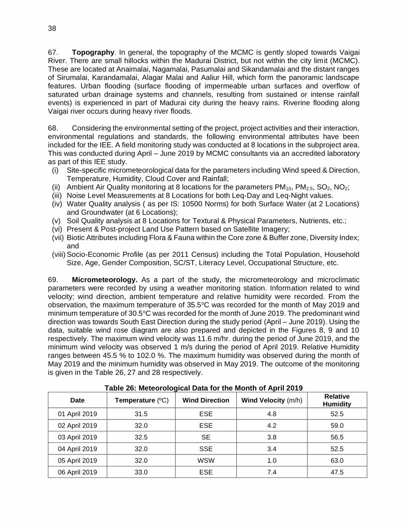
38
67. Topography. In general, the topography of the MCMC is gently sloped towards Vaigai River. There are small hillocks within the Madurai District, but not within the city limit (MCMC). These are located at Anaimalai, Nagamalai, Pasumalai and Sikandamalai and the distant ranges of Sirumalai, Karandamalai, Alagar Malai and Aaliur Hill, which form the panoramic landscape features. Urban flooding (surface flooding of impermeable urban surfaces and overflow of saturated urban drainage systems and channels, resulting from sustained or intense rainfall events) is experienced in part of Madurai city during the heavy rains. Riverine flooding along Vaigai river occurs during heavy river floods. 68. Considering the environmental setting of the project, project activities and their interaction, environmental regulations and standards, the following environmental attributes have been included for the IEE. A field monitoring study was conducted at 8 locations in the subproject area. This was conducted during April – June 2019 by MCMC consultants via an accredited laboratory as part of this IEE study. (i) Site-specific micrometeorological data for the parameters including Wind speed & Direction,
Temperature, Humidity, Cloud Cover and Rainfall; (ii) Ambient Air Quality monitoring at 8 locations for the parameters PM10, PM2.5, SO2, NO2; (iii) Noise Level Measurements at 8 Locations for both Leq-Day and Leq-Night values. (iv) Water Quality analysis ( as per IS: 10500 Norms) for both Surface Water (at 2 Locations)
and Groundwater (at 6 Locations); (v) Soil Quality analysis at 8 Locations for Textural & Physical Parameters, Nutrients, etc.; (vi) Present & Post-project Land Use Pattern based on Satellite Imagery; (vii) Biotic Attributes including Flora & Fauna within the Core zone & Buffer zone, Diversity Index;
and (viii) Socio-Economic Profile (as per 2011 Census) including the Total Population, Household
Size, Age, Gender Composition, SC/ST, Literacy Level, Occupational Structure, etc. 69. Micrometeorology. As a part of the study, the micrometeorology and microclimatic parameters were recorded by using a weather monitoring station. Information related to wind velocity; wind direction, ambient temperature and relative humidity were recorded. From the observation, the maximum temperature of 35.5oC was recorded for the month of May 2019 and minimum temperature of 30.5oC was recorded for the month of June 2019. The predominant wind direction was towards South East Direction during the study period (April – June 2019). Using the data, suitable wind rose diagram are also prepared and depicted in the Figures 8, 9 and 10 respectively. The maximum wind velocity was 11.6 m/hr. during the period of June 2019, and the minimum wind velocity was observed 1 m/s during the period of April 2019. Relative Humidity ranges between 45.5 % to 102.0 %. The maximum humidity was observed during the month of May 2019 and the minimum humidity was observed in May 2019. The outcome of the monitoring is given in the Table 26, 27 and 28 respectively.
Table 26: Meteorological Data for the Month of April 2019
Date Temperature (ºC) Wind Direction Wind Velocity (m/h) Relative Humidity
01 April 2019 31.5 ESE 4.8 52.5
02 April 2019 32.0 ESE 4.2 59.0
03 April 2019 32.5 SE 3.8 56.5
04 April 2019 32.0 SSE 3.4 52.5
05 April 2019 32.0 WSW 1.0 63.0
06 April 2019 33.0 ESE 7.4 47.5

39
Date Temperature (ºC) Wind Direction Wind Velocity (m/h) Relative Humidity
07 April 2019 33.0 SSE 4.5 57.5
08 April 2019 33.0 S 3.4 58.5
09 April 2019 33.0 SSE 3.2 57.5
10 April 2019 33.5 SE 4.7 59.0
11 April 2019 33.5 SSE 3.9 58.0
12 April 2019 33.5 SE 3.7 57.0
13 April 2019 33.0 ESE 3.6 59.0
14 April 2019 33.5 ESE 2.7 52.5
15 April 2019 33.0 SSE 3.5 59.0
16 April 2019 34.0 SSE 4.0 52.5
17 April 2019 32.5 S 4.0 60.5
18 April 2019 33.0 SSE 4.7 56.0
19 April 2019 32.5 S 5.1 61.0
20 April 2019 33.0 SSE 2.6 57.0
21 April 2019 31.5 S 3.9 65.5
22 April 2019 33.0 ESE 4.1 61.5
23 April 2019 32.0 S 4.4 52.5
24 April 2019 33.0 ESE 4.2 57.5
25 April 2019 33.5 SSE 3.6 55.0
26 April 2019 33.0 SE 4.3 59.0
27 April 2019 33.0 SE 3.9 55.0
28 April 2019 33.5 ESE 3.4 57.5
29 April 2019 32.5 NNE 4.3 58.0
30 April 2019 32.0 WNW 5.1 63.5
Source: Primary Data.
Table 27: Meteorological data for the Month of May 2019
Date Temperature
(oC) Wind Direction
Wind Velocity (m/hr)
Relative Humidity
01 May 2019 33.5 NW 6.7 59.0
02 May 2019 34.5 WNW 3.3 53.0
03 May 2019 35.0 NNW 4.5 45.5
04 May 2019 34.5 NNW 4.6 49.0
05 May 2019 34.0 NNW 4.0 51.0
06 May 2019 35.5 SE 3.1 52.0

40
Date Temperature
(oC) Wind Direction
Wind Velocity (m/hr)
Relative Humidity
07 May 2019 34.0 WSW 3.1 59.0
08 May 2019 33.0 NW 3.4 55.5
09 May 2019 34.0 WNW 3.5 58.0
10 May 2019 34.0 SSE 2.8 59.0
11 May 2019 34.0 SSE 3.2 62.5
12 May 2019 34.0 SSE 2.7 60.5
13 May 2019 34.5 ESE 4.1 61.5
14 May 2019 35.0 N 3.6 53.0
15 May 2019 35.0 NW 4.6 51.0
16 May 2019 33.0 E 3.5 101.0
17 May 2019 35.0 NW 3.3 53.0
18 May 2019 33.0 ESE 3.4 102.0
19 May 2019 34.0 ESE 4.0 61.5
20 May 2019 34.0 SSE 3.7 63.0
21 May 2019 34.5 SSE 3.4 60.5
22 May 2017 34.0 ESE 4.8 65.0
23 May 2017 33.0 SE 3.7 58.0
24 May 2017 33.5 SE 3.9 63.0
25 May 2017 32.5 SSE 3.9 66.0
26 May 2017 34.5 SE 3.7 61.5
27 May 2017 35.0 SSE 3.7 58.0
28 May 2017 35.0 E 3.4 58.0
29 May 2017 32.0 NNW 4.0 61.5
30 May 2017 33.0 SSW 4.0 58.0
31 May 2017 33.0 SW 3.8 63.0
Source: Primary Data.
Table 28: Meteorological Data for the Month of June 2019
Date Temperature
(oC) Wind Direction
Wind Velocity (m/hr)
Relative Humidity
01 June 2019 33.0 S 4.1 62.0
02 June 2019 33.0 SW 1.9 64.5
03 June 2019 33.5 NW 4.2 62.0
04 June 2019 33.0 NW 5.3 62.0

41
Date Temperature
(oC) Wind Direction
Wind Velocity (m/hr)
Relative Humidity
05 June 2019 33.0 NNW 6.2 61.5
06 June 2019 32.0 WSW 4.3 66.0
07 June 2019 32.5 WNW 3.6 66.0
08 June 2019 32.5 SW 4.4 63.0
09 June 2019 33.5 SW 11.5 56.5
10 June 2019 30.5 SW 8.7 56.0
11 June 2019 33.0 W 10.8 57.0
12 June 2019 33.5 W 9.1 52.5
13 June 2019 33.5 WNW 11.6 53.5
14 June 2019 33.0 W 8.8 59.5
15 June 2019 35.0 WNW 8.5 47.5
16 June 2019 34.5 N 4.3 51.0
17 June 2019 34.0 NW 6.5 54.0
18 June 2019 33.0 WNW 7.0 61.5
19 June 2019 34.0 WNW 7.6 50.5
20 June 2019 34.5 WNW 10.8 49.0
21 June 2019 33.5 WNW 9.7 56.5
22 June 2019 32.0 WNW 9.9 59.5
23 June 2019 33.0 WNW 9.3 53.5
24 June 2019 34.0 NNW 4.8 54.0
25 June 2019 34.0 WNW 3.8 58.0
26 June 2019 33.5 WNW 3.7 61.5
27 June 2019 34.5 WNW 5.3 46.0
28 June 2019 33.5 WNW 5.5 49.0
29 June 2019 34.0 WNW 6.7 49.5
30 June 2019 33.0 WNW 9.9 51.0
Source: Primary Data.

42
Figure 8: Wind Rose diagram for April 2019
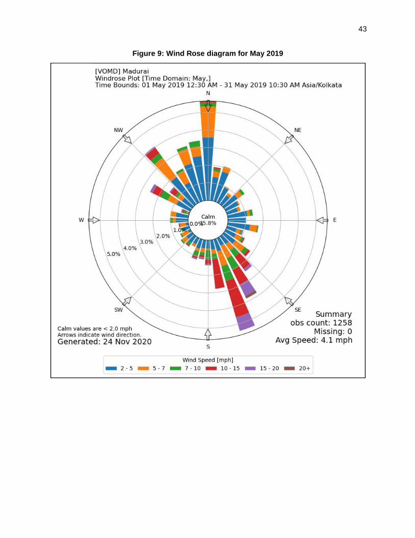
43
Figure 9: Wind Rose diagram for May 2019

44
Figure 10: Wind Rose diagram for June 2019
70. The secondary data for the period 2009-2013 collected from IMD includes temperature, relative humidity, rainfall and wind speed. The monthly maximum, minimum and average values are presented in Table 29. All these parameters are recorded twice a day viz at 8:30 a.m. and 5:30 p.m.
71. Temperature. The winter season starts from December and continues until the end of February. December and January are the coolest months. March-June is the summer season, and May is the hottest month. Mean daily maximum temperature of summer season was recorded as 40.2ºC (in the month of May 2013) and the mean daily minimum temperature of winter was recorded as 18.7ºC (in the month of January 2009). Both the night and day temperatures increase rapidly during the onset of the pre-monsoon season from March to May.
72. Relative humidity. The air is generally humid in this region during the post monsoon season. The relative humidity at 0830 hr was observed to be 98%. Similarly, at 1730 hr, the relative humidity was observed to be of 100%. In general, the weather during other seasons was observed to be dry.
73. Rainfall. Southwest monsoon sets in the month of June and continues up to September and sometime extends up to mid-October. The maximum amount of rainfall (256.3 mm) occurs in

45
the month of November during the northeast monsoon. The annual average rainfall varies from 806 mm (Sholavandan Rain Gauge Station) in the northern part to 964.1 mm (Melur Rain guage Station) in the eastern part of the Madurai district.
Table 29: Meteorological Data (Madurai Station, 2009–2013) Year Jan Feb Mar Apr May June July Aug Sept Oct Nov Dec
Monthly Mean Maximum Temperature (°C)
2009 30.2 33.4 35.2 36.1 34.5 32.5 30.3 32 31.9 32.2 29.9 29.2
2010 30.6 33.3 36.2 37.3 35.3 32.9 31.5 30.9 31.9 31.7 29.1 28.9
2011 30.8 32.3 35.3 36.2 37.7 37.6 36.7 36.0 36.1 33.7 30.4 30.3
2012 30.9 33.1 36.7 37.8 38.6 39.2 39.1 38.0 37.5 33.7 32.7 32.8
2013 33.4 33.7 36.3 40.0 40.2 37.5 38.1 36.9 35.9 36.2 32.7 31.4
Monthly Maximum Temperature (°C)
2009 32.5 37 37.7 38 37.4 37.2 35.6 33.9 35.1 34.2 33.1 32
2010 32.2 36 37.7 39.5 37.8 37 35 33.8 34.2 33.8 32.6 31.6
2011 32.0 35.0 36.8 38.4 39.4 40.0 40.0 38.4 37.0 36.4 32.8 31.6
2012 32.2 35.4 38.8 40.5 41.1 42.0 41.5 40.5 40.1 38.6 35.6 34.2
2013 34.6 36.5 39.3 41.9 42.0 40.2 40.8 39.0 38.6 39.2 34.6 34.4
Monthly Mean Minimum Temperature (°C)
2009 18.7 19.9 22.3 24.3 23.8 23.4 22.3 22.7 22.9 22.3 22.1 20.9
2010 20.3 20.8 23 25.1 25 23.5 22.6 22.4 22.6 22.5 21.7 20
2011 21.1 21.4 22.9 25.2 25.7 26.0 25.6 25.2 25.0 24.0 22.5 21.5
2012 20.3 21.5 24.5 25.7 26.4 26.4 26.2 25.4 25.3 23.9 23.0 22.4
2013 21.5 22.0 23.7 26.3 26.6 27.0 27.0 25.4 25.3 24.5 23.8 21.9
Monthly Minimum Temperature (°C)
2009 16.1 17.8 19.7 22.6 21.4 21.2 21 21.6 21.6 20.2 19 17.8
2010 17.4 17.4 19.8 23 22 21.6 21.3 21.2 20.4 20.8 19 16.6
2011 16.6 16.0 20.2 23.0 22.0 23.8 22.0 23.7 23.0 22.2 18.5 17.0
2012 16.4 18.5 20.3 22.0 22.0 24.7 24.5 23.5 23.5 22.7 20.4 19.7
2013 19.0 17.0 19.1 24.0 25.1 25.2 26.0 22.6 23.6 22.0 21.6 19.4
Monthly Mean R.H. at 0830 HRS IST (%)
2009 78 68 71 73 79 77 82 82 81 75 86 81
2010 80 77 71 73 78 80 81 83 80 82 89 86
2011 75 72 70 71 65 61 61 64 62 76 78 77
2012 75 69 68 71 64 56 58 63 63 74 73 70
2013 70 72 69 65 57 59 54 63 67 66 74 74
Monthly Highest R.H. at 0830 HRS IST (%)
2009 88 88 87 85 88 93 92 96 92 94 96 93
2010 91 86 88 81 91 95 91 98 95 96 98 96

46
2011 85 88 87 92 83 87 70 87 75 96 96 91
2012 85 82 77 87 73 66 77 79 80 91 87 86
2013 77 95 87 75 70 68 62 80 90 93 90 91
Monthly Lowest R.H. at 0830 HRS IST (%)
2009 68 50 48 61 59 64 69 75 66 49 64 72
2010 67 60 53 58 64 66 65 74 64 66 68 75
2011 64 54 59 57 51 49 52 52 54 61 58 64
2012 60 44 56 60 54 44 49 48 50 58 62 58
2013 62 51 51 52 49 49 45 45 49 49 61 62
Monthly Mean R.H. at 1730 HRS IST (%)
2009 35 23 27 37 55 61 67 63 67 51 68 57
2010 30 29 25 40 58 65 66 67 63 71 73 60
2011 56 48 37 49 45 45 49 52 52 66 69 64
2012 50 42 37 49 52 47 44 54 51 67 60 57
2013 47 46 43 41 44 50 46 55 54 54 61 54
Monthly Highest R.H. at 1730 HRS IST (%)
2009 52 37 70 60 90 91 93 83 76 91 92 97
2010 71 40 45 65 85 90 95 85 74 96 95 98
2011 77 82 47 95 88 80 84 87 93 90 96 95
2012 88 63 45 100 92 95 76 95 80 95 74 92
2013 87 72 92 75 65 63 62 95 88 92 89 80
Monthly Lowest R.H. at 1730 HRS IST (%)
2009 16 14 11 13 37 41 48 42 45 42 48 33
2010 26 15 10 21 44 47 51 46 49 45 52 37
2011 46 36 23 30 34 33 40 38 35 46 49 31
2012 33 19 24 36 40 35 33 33 38 38 47 42
2013 38 27 26 33 32 40 38 38 40 31 50 39
Monthly Total Rainfall (MM)
2009 0 0 5.8 3.1 91 8.7 42.8 55.9 68.7 51.3 227 1.3
2010 0.1 0 0 17.7 57.8 31.9 14.8 60.1 30.8 132.2 256.3 34.7
2011 7.4 42.9 0.4 52.5 68.9 28.2 70.4 65.2 74.0 219.1 189.1 15.5
2012 13.9 Trace 0.4 111.1 61.8 18.3 15.8 91.2 57.1 187.9 9.6 3.5
2013 3.9 23.1 18.2 12.8 25.2 6.9 0.1 195.5 44.3 182.2 33.7 80.5
Monthly Mean Windspeed (KMPH)
2009 3 4 4 6 9 10 11 9 9 5 3 4
2010 5 4 6 7 9 11 12 12 9 8 3 4
2011 5 6 5 4 4 4 4 4 4 3 5 5

47
2012 5 6 5 4 3 5 5 4 4 4 4 7
2013 12 6 6 5 4 6 6 4 4 3 4 5
Source: IMD.
74. Ambient air quality. The prime objective of the baseline air quality study was to assess
the existing air quality of the project area. This will also be useful for assessing the conformity to
standards of the ambient air quality during the construction and operation of the subproject. The
study area represents mostly commercial cum residential land use and some vacant/ barren land.
This section describes the selection of sampling locations, methodology adopted for sampling,
analytical techniques and frequency of sampling. The results of monitoring carried out for study
period of April 2019 to June 2019 is presented in the following sections. A total of 24 samples
were collected from the 8 locations in the sampling period from April 2019 - June 2019.
Accordingly statistical analysis was conducted and the results/ outcome of the same was
presented in the table 30 to 32.
i. Selection of Sampling Locations
75. The ambient air quality has been assessed through a scientifically designed ambient air
quality monitoring network based on the following considerations:
(i) Meteorological conditions;
(ii) Topography of the study area;
(iii) Representative of regional background air quality for obtaining baseline status; and
(iv) Representative of likely impact areas
76. Ambient Air Quality Monitoring (AAQM) stations were set up at eight locations (for 24
hours) with due consideration to the above-mentioned points. The AAQM locations are depicted
in Figure 11.
ii. Particulate Matter (PM10 & PM2.5)
77. Based on the outcome of the analysis, the maximum and minimum concentrations of
PM10 were recorded as 60 µg/m3 and 35 µg/m3 respectively. The maximum concentration was
recorded at Villapuram and minimum concentration was recorded at Kochadai. Similarly, the
arithmetic mean value was high (52.5 µg/m3) for Villapuram and low (41.5 µg/m3) for Kochadai.
The estimated standard deviation for PM10 was 10.6 µg/m3 at Villapuram and 4.9 µg/m3 at
Kochadai. All the AAQ sampling locations are residential. The results are presented in Table 30.
In comparison with the National Ambient Air Quality Standards, the recorded values are well
within the stipulated limits, however, in comparison with WHO guidelines, except Kochadai, the
PM10 values are exceeding the limit of 50 µg/m3 for all the sampling locations.
78. Based on the outcome of the analysis, the maximum and minimum concentrations of PM2.5
were recorded at Jaihindpuram (28 µg/m3) and Kochadai (16 µg/m3) respectively. The Arithmetic
mean values are estimated to be 25.5 µg/m3 at Jaihindpuram and 19.5 µg/m3 at Kochadai &
Sellur. The standard deviation for PM2.5 shows a concentration of 4.95 µg/m3 at Kochadai &
Annuppanadi and 3.54 µg/m3 at Sellur, Pudur, Villapuram and Jaihindpuram. The maximum and

48
minimum concentrations of 98th Percentile PM2.5 were recorded as 28 µg/m3 at Jaihindpuram and
22 µg/m3 at sellur. All the AAQ sampling locations are located in residential area. The results are
presented in Table 31. The recorded PM2.5 values are within the NAAQS stipulated limits,
however, in comparison with the WHO guidelines, the values recorded at Anuppanadi,
Palanganatham and Jaihindpuram exceeds the stipulated limits of 25 µg/m3.
Table 30: Ambient Air Quality Status (PM10) – (April – June 2019)
Averaging Time: 24 hrs Unit: µg/m3 Sl. No.
Sampling Station Max Min Arithmetic
Mean Standard Deviation
98th Percentile
AAQ1 BB Kulam (Zone 1, Ward 5) 51 41 46 7.1 51
AAQ2 Kochadai (Zone 1, Ward 22) 48 35 41.5 9.2 48
AAQ3 Sellur (Zone 2, Ward 37) 50 39 44.5 7.8 50
AAQ4 Pudur (Zone 2, Ward 45) 53 42 47.5 7.8 53
AAQ5 Anuppanadi (Zone 3, Ward 57) 54 43 48.5 7.8 54
AAQ6 Villapuram (Zone 3, Ward 63) 60 45 52.5 10.6 60
AAQ7 Palanganatham (Zone 4, Ward 76) 55 48 51.5 4.9 55
AAQ8 Jaihindpuram (Zone 4, Ward 89) 54 44 44.2 7.1 54
Note: PM10 Permissible limit for industrial, Residential, Rural and other area is 100 µg/m3.
Table 31: Ambient Air Quality Status (PM2.5) – (April – June 2019)
Averaging Time: 24 hrs Unit: µg/m3 Sl. No.
Sampling Station Max Min Arithmetic
Mean Standard Deviation
98th Percentile
AAQ1 BB Kulam (Zone 1, Ward 5) 24 18 21 4.24 24
AAQ2 Kochadai (Zone 1, Ward 22) 23 16 19.5 4.95 23
AAQ3 Sellur (Zone 2, Ward 37) 22 17 19.5 3.54 22
AAQ4 Pudur (Zone 2, Ward 45) 23 18 20.5 3.54 23
AAQ5 Anuppanadi (Zone 3, Ward 57) 27 20 23.5 4.95 27
AAQ6 Villapuram (Zone 3, Ward 63) 25 20 22.5 3.54 25
AAQ7 Palanganatham (Zone 4, Ward 76) 27 21 24 4.24 27
AAQ8 Jaihindpuram (Zone 4, Ward 89) 28 23 25.5 3.54 28
Note: PM2.5 Permissible limit for industrial, Residential, Rural and other area is 60 µg/m3.
iii. Sulphur Dioxide (SO2)
79. From the observation, the maximum and minimum concentrations of SO2 were recorded
as 21 µg/m3 and 9 µg/m3 respectively. The maximum concentration was recorded at Anuppanadi
and minimum concentration was recorded at Sellur & Villapuram. The maximum and minimum
concentrations of Arithmetic mean SO2 were recorded as 17.5 µg/m3 and 10.5 µg/m3 respectively.
The maximum concentration was recorded at Jaihindpuram and minimum concentration was
recorded at Villapuram. The maximum and minimum concentrations of standard deviation SO2
were recorded as 7.07 µg/m3 and 2.12 µg/m3 respectively. The maximum concentration was
recorded at Annuppanadi and minimum concentration was recorded at Villapuram. The maximum
and minimum concentrations of 98th Percentile SO2 were recorded as 21 µg/m3 and 12 µg/m3

49
respectively. The maximum concentration was recorded at Annuppanadi and minimum
concentration was recorded at Villapuram. All the samplings locations are in residential areas.
The results are shown in the Table 32.
Table 32: Ambient Air Quality Status (SO2) - (April – June 2019) Averaging time: 24 hrs. Unit: µg/m3
Sl. No.
Sampling Station Max Min Arithmetic
Mean Standard Deviation
98th Percentile
AAQ1 BB Kulam (Zone 1, Ward 5) 18 12 15 4.24 18
AAQ2 Kochadai (Zone 1, Ward 22) 19 14 16.5 3.54 19
AAQ3 Sellur (Zone 2, Ward 37) 14 09 11.5 3.54 14
AAQ4 Pudur (Zone 2, Ward 45) 17 13 15 2.83 17
AAQ5 Anuppanadi (Zone 3, Ward 57) 21 11 16 7.07 21
AAQ6 Villapuram (Zone 3, Ward 63) 12 09 10.5 2.12 12
AAQ7 Palanganatham (Zone 4, Ward 76) 15 10 12.5 3.54 15
AAQ8 Jaihindpuram (Zone 4, Ward 89) 20 15 17.5 3.54 20
Note: Permissible limit of SO2 for Industrial, Residential, Rural and other area is 80 µg/m3.
iv. Oxides of Nitrogen (NO2)
80. From the observation, the maximum and minimum concentrations of NO2 were recorded as 21 µg/m3 and 9 µg/m3 respectively. The maximum concentration was recorded at Anuppanadi and minimum concentration was recorded at Sellur & Villapuram. The maximum and minimum concentrations of Arithmetic mean NO2 were recorded as 17.5 µg/m3 and 10.5 µg/m3 respectively. The maximum concentration was recorded at Jaihindpuram and minimum concentration was recorded at Villapuram. The maximum and minimum concentrations of standard deviation NO2 were recorded as 7.07 µg/m3 and 2.12 µg/m3 respectively. The maximum concentration was recorded at Annuppanadi and minimum concentration was recorded at Villapuram. The maximum and minimum concentrations of 98th Percentile NO2 were recorded as 21 µg/m3 and 12 µg/m3 respectively. The maximum concentration was recorded at Annuppanadi and minimum concentration was recorded at Villapuram. All locations are residential. The results are shown in the Table 33.
Table 33: Ambient Air Quality Status (NO2) (April – June 2019)
Averaging Time: 24 hrs. Unit: µg/m3
Sl. No.
Sampling Station Max Min Arithmetic
Mean Standard Deviation
98th Percentile
SS 1 BB Kulam (Zone 1, Ward 5) 29 20 24.5 6.36 29
SS 2 Kochadai (Zone 1, Ward 22) 32 23 27.5 6.36 32
SS 3 Sellur (Zone 2, Ward 37) 20 16 18 2.83 20
SS 4 Pudur (Zone 2, Ward 45) 26 20 23 4.24 26
SS 5 Anuppanadi (Zone 3, Ward 57) 23 17 20 4.24 23
SS 6 Villapuram (Zone 3, Ward 63) 18 15 16.5 2.12 18
SS 7 Palanganatham (Zone 4, Ward 76) 22 19 20.5 2.12 22
SS 8 Jaihindpuram (Zone 4, Ward 89) 36 26 31 7.07 36
Note: Permissible limit of NO2 for Industrial, Residential, Rural and other area is 80 µg/m3.

50
Figure 11: Sampling Location Map (Air, Noise, Water & Soil)
Note: The area bounded by green line with hatched portion represents the project area

51
81. Noise Environment. The main objective of noise monitoring in the study area is to
establish the baseline noise levels and assess the impact of the total noise expected to be
generated during the construction and operation of the proposed activity.
(i) Identification of Sampling Locations
82. A survey has been undertaken at 8 locations to identify the major noise generating sources
in the area and accordingly sampling locations are fixed (refer Figure 11). The noise levels at
each location were recorded for 24 hours. Noise levels are recorded from the residential area.
The outcome of the monitoring is given in the Table 34.
Table 34: Equivalent Day-Night Noise Level Details
Station No.
Sampling Stations
Equivalent Levels dB(A)
Day Time Night Time
Min Max Min Max
SS 1 BB Kulam (Zone 1, Ward 5) 51.1 51.8 39.3 44.7
SS 2 Kochadai (Zone 1, Ward 22) 51.4 53.1 39.3 44.1
SS 3 Sellur (Zone 2, Ward 37) 51.4 53.6 39.7 44.5
SS 4 Pudur (Zone 2, Ward 45) 53.4 55.6 39.4 44.3
SS 5 Anuppanadi (Zone 3, Ward 57) 54.9 56.5 41.1 45
SS 6 Villapuram (Zone 3, Ward 63) 54.1 55.2 42.1 44.9
SS 7 Palanganatham (Zone 4, Ward 76) 59.4 60.8 37.5 42.8
SS 8 Jaihindpuram (Zone 4, Ward 89) 50.2 51.4 38.5 43.4
NAAQ Standards for Noise
Category of Area / Zone Limits in dB(A) Leq
Day Time Night Time
Residential Area 55 45
Source: Primary data and CPCB (for Standard Value)
83. The daytime noise levels ranges between 50.2dB(A) to 60.8 dB(A). The maximum value
60.8 dB (A) was recorded at Palanganatham and the minimum value (50.2 dB (A)) was recorded
at Jaihindpuram. The nighttime noise levels ranges between 37.5 dB (A) and 44.9 dB (A). The
maximum value (44.9 dB [A]) was recorded at Villapuram and the minimum value (37.5 dB [A])
was recorded at Palanganatham.
84. Water Quality Monitoring. The purpose of this study is to assess the water quality
characteristics in the subproject area. Understanding the water quality is essential in preparation
of report and to identify critical issues with a view to suggest appropriate mitigation measures for
implementation. The information required has been collected through primary surveys and
secondary sources.

52
85. Groundwater Quality. Water samples were collected from eight locations in June 3, 2019
and were analyzed for its physico-chemical parameters for comparing it with drinking water
standard (IS: 10500).
(i) The analysis results indicate that the pH ranges in between 7.1 to 7.9, which is well within
the specified standard (6.5 to 8.5). The maximum pH concentration of 7.9 was observed at
BB Kulam and the minimum pH concentration of 7.1 was observed at Sellur;
(ii) Total hardness (TH) was observed to be ranging from 168 to 670 mg/l. The maximum TH
was recorded at Villapuram and the minimum was recorded at Kochadai;
(iii) Chlorides were found to be in the range of 63 mg/l to 672 mg/l, the maximum concentration
of chlorides was observed at Sellur and whereas the minimum value was observed at
Kochadai;
(iv) Sulphates were found to be in the range of 26 mg/l to 316 mg/l. The maximum value
observed at Sellur whereas the minimum value observed at Kochadai;
86. The locations of groundwater samples are shown in Figure 11 and the results of ground
water samples are given in Table 35.
Table 35: Results of Water Quality Parameters
Parameters Units SS 1 SS 2 SS 3 SS 4 SS 5 SS 6 SS 7 SS 8 IS 10500
(Acceptable limit)
pH 7.9 7.3 7.1 7.3 7.5 7.3 7.8 7.2 6.5 – 8.5
Turbidity NTU < 0.5 <
0.5 <
0.5 <
0.5 < 0.5 < 0.5 < 0.5 < 0.5
1
Total Hardness as CaCO3
mg/l 576 168 581 500 368 670 415 305 -
Total Alkalinity as CaCO3
mg/l 470 293 464 573 396 587 484 498 -
Chlorides as Cl mg/l 648 63 672 259 102 264 288 337 250
Fluoride as F mg/l < 0.1 <
0.1 0.2 0.2 < 0.1 < 0.1 0.2 < 0.1
1
Sulphates as SO4 mg/l 292 26 316 112 46 129 130 146 200
Calcium as Ca mg/l 166 51 185 141 116 197 126 94 75
Magnesium as Mg mg/l 50 15 52 42 35 90 39 27 0.1
Sodium as Na mg/l 86 40 102 106 56 86 86 90 -
Potassium as K mg/l 38 16 42 45 25 32 37 41 -
Total phosphates mg/l < 0.1 <
0.1 0.4
< 0.1
< 0.1 < 0.1 < 0.1 < 0.1 -
Nitrates as NO3 mg/l 1.0 <
1.0 1.3 1.2 < 1.0 1.0 1.2 < 1.0
45
Manganese as Mn mg/l < 0.03 < 0.03 < 0.03 < 0.03 < 0.03 < 0.03 < 0.03 < 0.03 0.1
87. Surface Water Quality. The only perennial river in the subproject area is the River Vaigai. The River Vaigai is the major river in Madurai that is originated in the Periyar Plateau of the Western Ghats. Situated on the Eastern slopes of the Varushanadu hills, it initially flows northeast through the Kambam and Varushanad valleys. In its central reaches, the Vaigai flows eastward into the Vaigai reservoir at Narasingapuram. Near Sholavandan it bends to the southeast, passing Madurai on its course to its mouth on Palk Strait. The Vaigai River is 258 kilometres long with a drainage basin of 7,031 square kilometers. Some of the major tributaries of Vaigai River

53
include River Suruliyar, River Manjalaru and River Kridhumaal. Vaigai Dam, built across the river in Periyakulam in Theni district, is one of major sources of water supply to Madurai City. This dam is also source of irrigation and drinking water for other areas.
88. Water samples were collected from River Vaigai on June 3, 2019 and analysed as per the APHA methods and the results are given in table 36. Vaigai river water is used for drinking (after treatment) and for irrigation purposes. The sampling locations are given in the Figure 12. From the analysis, most tested parameters of water quality of the Vaigai River is observed to be well within the stipulated limits of IS10500 (drinking water standards), however, some parameters are exceeding the limits. Presence of BOD, though in low levels, indicated pollution. The key inferences from the analysis are as follows:
(i) The analysis results indicate that the pH ranges 7.5±0.375 - 8.1±0.64, which is well within
the specified standard (6.5 to 8.5). The maximum pH concentration observed at S4 and the
minimum pH concentration was observed at S1;
(ii) Total Dissolved Solids (TDS) was observed to be ranging from 100±6 mg/l - 112±8.96 mg/l.
The maximum TH was recorded at S4 and the minimum was recorded at S2;
(iii) Chlorides were found to be in the range of 40±2.4 mg/l to 80±6.4 mg/l, the maximum
concentration of chlorides was observed at S4 and whereas the minimum value was
observed at S2;
(iv) Sulphates were found to be in the range of 6.5±0.39 mg/l to 22±1.54 mg/l. The maximum
value observed at S3 whereas the minimum value observed at S2;
(v) Manganese concentration was high, and it is in the range between 2.7 to 10.8mg/l.
Table 36: Physico-Chemical Characteristic of Vaigai River
Parameters
Sampling Locations (within the subproject area)
S1 (Near Sellur) S2 (Near
Arapalayam) S3 (Near
Theppakulam) S4 (Near
Munisalai) IS 10500
Colour Light Green Light Green Light Gray Light Gray -
Odour Nil Nil Nil Nil -
Temperature 27±1.35 27±1.62 27±1.89 27±2.16 -
Transparency( cm) 53±2.65 48±2.88 54±3.78 52±4.16 -
EC (µs/cm) 72±3.6 70±4.2 98±6.86 115±9.2 -
pH 7.5±0.375 7.8±0.468 8.1±0.567 8.1±0.64 6.5 – 8.5
Turbidity (NUT) 4.3±0.78 4.1±0.65 4.2±0.92 4±0.96 1
DO (mg/l) 7.5±0.375 7.2±0.432 6.9±0.48 7±0.56 -
Alkalinity 10.5±0.525 11.3±0.6 25.4±1.7 22.3±1.7 -
TDS(mg/l) 105±5.25 100±6 110±7.7 112±8.96 500
BOD 1.7±0.085 1.8±0.108 2±0.14 2.1±0.168 -
Calcium(mg/l) 18±0.9 16±0.96 14±0.98 27±2.16 75
Chloride(mg/l) 45±2.25 40±2.4 52±3.64 80±6.4 250
Fluoride(mg/l) 0.26±0.013 0.21±0.012 0.22±0.015 0.21±0.016 1
Magnesium(m g/l) 8.7±0.435 8±0.48 7±0.49 15±1.2 - Manganese ( mg/l) 2.9±0.145 2.7±0.162 3.4±0.238 10.8±0.864 0.1
Nitrate(mg/l) 0.28±0.014 0.24±0.014 0.2±0.014 0.7±0.056 45
Nitrite(mg/l) 0.07±0.35 0.05±0.003 0.07±0.0049 0.09±0.007 -
Sodium(mg/l) 13.3±0.665 12±0.72 14±.98 15±1.2 -
Sulphate(mg/l) 6.9±0.345 6.5±0.39 22±1.54 20±1.6 200

54
Figure 12: Sampling Location Map (Surface Water)
Note: Sampling locations are within the subproject area. Refer Figure 11 for subproject area boundary

55
Water Quality Sampling Photos
89. Soil Quality. The study on the soil profile establishes the baseline characteristics and
identifies the incremental concentrations. The sampling locations have been identified with the
following objectives:
(i) To determine the baseline soil characteristics of the study area; and
(ii) To determine the impact on soil more importantly from agricultural productivity
point of view.
90. Eight locations in the study area were selected for soil sampling. At each location, soil
samples were collected from three different depths viz. 30 cm, 60 cm and 90 cm below the surface
and homogenized. Soil Samples were taken from residential area and barren land. The
homogenized samples were taken to identify soil conditions. The samples were collected by
ramming a core-cutter into the soil up to a depth of 90 cm. Simultaneously, in-situ infiltration test
using double ring infiltrometer was carried out at all location to determine the permeability. The
details of the sampling location are shown in Figure 11 and outcome of the results are given in
Table 37. Presence of primary nutrients in phosphorous, potassium, and secondary nutrient
calcium indicates suitability of soil for agriculture. Sandy loam soil in found in project area is
susceptible to erosion.
(i) It has been observed that the pH of the soil in the study area ranged from 6.6 to 8.5 the
maximum pH value of 8.5 was observed at Palanganatham, whereas the minimum value of
6.0 was observed at Pudur;
(ii) The phosphorus values < 0.1 kg/ha, indicating that the phosphorus content in the study
area falls in average sufficient to more than Sufficient;
(iii) The potassium values range between 140 to 174 mg/kg, with the maximum observed at
Pudur with the minimum observed at Anuppanadi.
(iv) The sodium values range between 310 to 365 mg/kg, with the maximum observed at Sellur
with the minimum observed at Pudur; and
(v) The calcium was observed to be in the range between17 to 22 Meq/L, with the maximum
observed at Kochadai & Anuppanadi with the minimum observed at BB Kulam;

56
Table 37: Results of Soil Quality Parameters
S.
no Parameters Units
Results
SA-1 SA-2 SA- 3 SA- 4 SA- 5 SA- 6 SA-7 SA-8
1 Color Brown Brown Brown Brown Brown Brown Brown Brown
2 pH (1:2) 8.3 7.7 7.4 6.6 8.3 7.2 8.5 8.4
3 Texture --- Sandy
Loam
Sandy
Loam
Sandy
Loam
Sandy
Loam
Sandy
Loam
Sandy
Loam
Sandy
Loam
Sandy
Loam
4 EC milli
mhos/ cm 0.4 0.5 0.3 0.4 0.3 0.5 0.3 0.2
5 Phosphorus as P % < 0.1 0.1 < 0.1 0.1 < 0.1 < 0.1 < 0.1 < 0.1
6 Potassium as K Mg/kg 160 154 172 140 174 165 155 162
7 Sodium as Na Mg/kg 345 320 365 310 362 346 330 335
8 Calcium as Ca Meq/L 17 22 20 20 22 18 18 21
9 Magnesium as Mg Meq/L 8 9 8 8 10 7 8 9
10 Iron as Fe mg/kg 1390 1400 1415 1340 1202 1142 1580 1264
11 Manganese as Mn mg/kg 210 210 240 260 238 224 240 224
12 Cadmium as Cd mg/kg < 1.0 < 1.0 < 1.0 < 1.0 < 1.0 < 1.0 < 1.0 < 1.0
13 Chromium as Cr mg/kg < 1.0 < 1.0 < 1.0 < 1.0 < 1.0 < 1.0 < 1.0 < 1.0
Figure 13: Soil Sampling
1. Land environment
91. Land Use Pattern. Landuse pattern for Madurai City as existed in 1994, 2001 and in 2021
is as given in the following Table 38. From the given information, it is evident that the urbanization
impact can been seen with respect to residential, commercial and industrial. There is a decrease
in the landuse patter for water bodies and agriculture.

57
Table 38: Details of Land Use Pattern
Sl.No
Type of Land Use
Area in km2 %to the Developed
Area
1994 2001 2021 1994 2001 2021
1 Residential 21.45 21.79 24.75 57.49 57.49 50.36
2 Commercial 1.94 4.14 4.7 5.32 5.32 9.57
3 Industrial 2.1 3.12 3.12 5.63 5.63 6.35
4 Education 1.72 3.62 3.62 4.61 4.61 7.36
5 Public & Semi-Public 2.65 4.66 4.66 7.1 7.1 9.49
6 Transportation/ Circulation 7.41 8.29 16.86 19.85 19.85 8.29
7 Sub-Total (Developed Area) 37.32 45.61 49.14 100 100 100
8 Water Bodies 5.03 2.07 2.07 -- -- --
9 Agriculture 9.48 4.14 0.61 -- -- --
10 Sub-Total(Un-Developed Area) 14.06 6.21 2.68 -- -- --
Total 51.82 51.96 51.96 -- -- --
92. Drainage. Vaigai, a major ephemeral river originates in Western Ghats of Theni district flow in NW-SE direction, in the central part of the district. In addition, tributaries of Vaipar and Gundar drain in south-western part of the district, while the tributaries of Pambar drained in north eastern part. The general flow direction of the drainage is NW-SE.
Figure 14: Drainage map of Madurai City

58
C. Biological Environment
93. The main objective of the study is to provide necessary information on floristic structure of the study area. The climatic and biotic variations and composition of species, which are adapted to these variations, have resulted in different vegetation covers. The tree species, shrubs, herbs, climbers and grasses were documented during the study period (April 2019 to June 2019). The tree species observed in the study area are listed in Table 39; the shrubs observed in the study area are documented in Table 40; the herbs & grasses in Table 41 and climbers in Table 42 respectively.
94. Tree species. Fifty tree species belonging to 19 families were observed in the study area (Table 42). The dominant tree species in the study area are Anacardium occidentale, Coccus nucifer, Casuarina equisetifolia, Musa paradisiaca and Ficus benghalensis. Trees may not be affected as there are very few trees (about 10 number) within the sites/alignments. There are no protected species.
Table 39: List of Tree Species
S.No Family Name Botanical Name Vernacular name IUCN Conservation Status
1 Anacardiaceae Mangifera indica Mamaram Data Deficient
Lannea coromandelica Otti Least Concern
2 Annonaceae Polyalthia longifolia Nettilingam Least Concern 3 Arecaceae Borassus flabellifer Panai Least Concern
Coccus nucifera Thennai -
Roystonea regia Arasapanai Least Concern
4 Apocynaceae Plumeria alba Perunkalli -
5 Caesalpiniaceae Cassia fistula Sarakondrai Least Concern
Cassia siamea Manjalkondrai Least Concern Peltophorum pterocarpum Perunkondrai -
Tamarindus indica Puliyamaram Least Concern
6 Caricaceae Carica papaya Pappali Data Deficient
7 Casuarinaceae Casuarina equisetifolia Savukku Least Concern
8 Combretaceae Terminalia catappa Patham Least Concern
9 Fabaceae Acacia auriculiformis Kathi savukku Least Concern Bauhinia purpurea Mantharai Least Concern
Delonix regia Semmayir kondrai Least Concern
Gliricidia sepium Seemai agathi Least Concern
Leucaena leucocephala Periyathagarai -
Pongamia glabra Pungan Least Concern
Pongamia pinnata Pungan Least Concern 10 Malvaceae Thespesia populnea Poovarasu Least Concern
11 Meliaceae Azadirachta indica Vembu Least Concern
12 Mimosaceae Acacia nilotica Karuvelai Least Concern
Albizia lebbeck Vagai Least Concern
Pithecellobium dulce Kodikai Least Concern Samanea saman Thungumunji maram Least Concern
13 Moraceae Ficus bengalensis Aalamaram -
Ficus hispida Peiaththi Least Concern
Ficus racemosa Anai athi Least Concern
Ficus religiosa Arasamaram -
14 Moringaceae Moringa oleifera Murungai Least Concern Morinda tinctoria Manjanethi Least Concern

59
S.No Family Name Botanical Name Vernacular name IUCN Conservation Status
15 Musaceae Musa paradisiaca Valai Least Concern 16 Myrtaceae Callistemon lanceolatus Bottle brush -
Eucalyptus Thailamaram Least Concern
Syzygium cumini Naval Least Concern
17 Rubiaceae Neolamarckia cadamba Cadampam -
18 Rutaceae Aegle marmelos Vilvam Least Concern
Murraya exotica - - Murraya koenigii Karuvepillai Least Concern
19 Sapotaceae Manilkara zapota Sapotta Least Concern
95. Shrub Species. During the survey a total of 18 shrub species belonging to 16 families from the study area were observed. The dominant shrubs in the study area were Calotropis gigantea, Calotropis procera, Ricinus communis, and Ipomoea carnea. The shrubs observed in the study area are given in the Table 40.
Table 40: List of Shrub Species S.No Family Name Botanical Name Vernacular name
1 Apocynaceae Nerium indicum Arali
Nerium oleander Sevvarali
2 Asclepidaceae Calotropis Gigantea Vellerukku
Calotropis procera Erukku
3 Convolvulaceae Ipomoea carnea Kulai kuchi
4
Euphorbiaceae
Ricinus communis Amanakku
5 Lythraceae Lawsonia innemis Maruthani
6 Malvaceae Hibiscus rosa-sinensis Semparuthi
7 Mimosaceae Projopis juliflora Seemai karuvelam
8 Nyctaginaceae Bougainvilla spectabilis Kakitha poo
9 Pandanaceae Pandanus parkinson Thazhai
10 Rhamnaceae Ziziphus rugosa Ilanthai
11 Rosaceae Rosa indica Rose
12 Rubiaceae Ixora coccinia Idly poo
13 Rutaceae Citrus medica Elumichai
14 Solanaceae Datura stramonium Umaththai
15 Solanaceae Xanthium strumarium Marulumaththai
16 Verbinaceae Vitex negundo Notchi
96. Herb Species. At the time of survey, the herb and grasses are observed to be dried (during summer season); however, few herbs and grass are observed in the surroundings of the riverbank and ponds/ tanks. As per the inventory, there are a total 32 herb and grass species belonging to 19 families were recorded (Table 41). Some of the common species identified are Nymphaea sp, and Nymphaea sp.
Table 41: List of Herbs and Grasses in the Study Area S.No Family Name Botanical Name Vernacular name
1 Acanthaceae Asteracantha longifolia Neermulli
2 Amaranthaceae Achyranthes aspera Nayuruvi
Celosia argentea Kozhi poo
3 Apocynaceae Catharanthus roseus Nithya kalyani
4 Araceae Colocasia esculenta Samai kilangu

60
S.No Family Name Botanical Name Vernacular name
5 Asteraceae Ageratum conyzoides Appakkoti
Eclipta alba Karisalan kanni
Tridax procumbens Thatha poochedi
Wedelia trilobata Manjal karisalankanni
6 Caesalpiniaceae Cassia tora Sirukondrai
7 Convolvulaceae Merremia emarginata Elikkadhu-keerai
8 Cyperaceae Cyperus rotundus Korai
9 Euphorbiaceae Acalypha indica kuppaimeni
Euphorbia hirta Amman pacharisi
10 Fabaceae Tephrosia purpurea Kolinchi
11 Lamiaceae
Leucas aspera Thumbai
12 Nelumbonaceae Nelumbo nucifera Thamarai
13 Nyctaginaceae Boerhavia diffusa Mukkuruttai kodi
14 Nymphaeaceae Nymphaea odorata Alli
15 Poaceae Bambusa bambos Moongil
Cynodon dactylon Arugam pul
Heteropogon contortus -
Oriza sativa Nel
16 Ponterderiaceae Eichhornia crassipes Agaya thamarai
17 Portulacaceae Portulaca oleracea Siru pasalai
18 Solanaceae Lycopersicon esculentum Thakkali
Physalis minima Sodakku thakkali
Solanum melongena kaththari
Solanum trilobatum Thuthuvalai
Solanum virginianum Kandankathiri
Solanum xanthocarpum Sundai kai
19 Zygophylacaeae Tribulus terrestris Nerunchi
97. Climbers. The climbers were observed in the riverside and ponds/ tanks of the study area. Totally 6 climber species belonging to 5 families were noted from the study area Table 42. Some of the common species identified in the project area are Solanum trilobatum, Clitoria ternatea and Luffa acutangular.
Table 42: List of Climbers in the Study Area S.No Family Name Botanical Name Vernacular name
1 Asclepidaceae Pergularia daemia Veliparuthi
2 Convolvulaceae Ipomoea digitata Nilapoosani
Ipomoea pes-caprae Aatukkal
3 Cucurbitaceae Citrullus lanatus peikumatti
4 Fabaceae Luffa acutangula Aagasaveni
5 Sapindaceae Antigonon leptopus Kodi rose
98. Fauna. Faunal survey covers the terrestrial fauna, avian fauna and aquatic fauna. The survey was based on visual observation, enquiry with local population and records available. This survey will include identification of endangered and rare species as per Red Book. Both direct and indirect observation methods were used to survey the fauna. Visual encounter (search) method was employed to record vertebrate species. Additionally, survey of relevant literature was also done to consolidate the list of vertebrate fauna distributed in the area. Since birds may be

61
considered as indicators for monitoring and understanding human impacts on ecological systems (Lawton, 1996).
99. Based on the Wildlife Protection Act, 1972 (WPA 1972, Anonymous 1991, Upadhyay 1995, Chaturvedi and Chaturvedi 1996) species were short-listed as Schedule II or I and where referred during the study. As per the study, there is no endangered / red list species in the study area.
100. Birds. The different species of birds are observed in the study area during the study period (April – June 2019) and they are given below and also enlisted in the Table 43. The common important birds species observed in the study area are Acridotheres tristicus, Alcedo atthis, Anas crecca, Ardea alba, Ardea cinerea, Bubo, Bubulcus ibis, pycnonotus jokonus, Centropus sinensis, Cinnvris lotensis, Corvus corvus, Corvus splendens, Dicrurus macrocerus, Egretta garzetta, Hierococcyx varius, Coracias benghalensis, Lalage sykesi, Megalaima merulinus, Micropterus brachyrus, Nectarinia asiatica, Passer domisticus, Pycnonotus cafer and Temenuchus pagodarum.
101. Reptiles. The common reptile’s species that are observed in the study area were Lepus nigricollis, Funabulus palmarum, Rattus norvegicus, Herpestes edwardii, and Rana hexadactyla.
Table 43: List of the Faunal Diversity of the Study Area Technical Name Common Name Distribution
Acridotheres tristicus Common myna Common
Alcedo atthis Common Kingfisher Common
Anas crecca Common teal Observed
Ardea alba Large egret Common
Ardea cinerea Grey heron Common
Bubo Indian great horned Owl Common
Bubulcus ibis Cattle Egret Common
Centropus sinensis Crow Pheasant Common
Cinnvris lotensis Loten's sunbird Common
Corvus corvus Jungle crow Common
Corvus splendens House crow Common
Dicrurus macrocerus Black Drongo Common
Egretta garzetta Little Egret Common
Hierococcyx varius Common Hawk Cuckoo Common
Coracias benghalensis Indian roller Common
Lalage Sykesi Black headed cochoo Shrike Common
Megalaima merulinus Indian Cuckoo Common
Micropterus brachyrus Rufours Wood pecker Observed
Nectarinia asiatica Purple sunbird Observed
Passer domisticus House Sparrow Common
Pycnonotus cafer Red vented bulbul Common
Temenuchus pagodarum Brahmny Myna Common
calotes versicolor Common garden lizard Rare
Bangarus spp Krait Rare
Naja Naja Indian cobra Rare
Rana hexadactyla Frog Common
Funabulus palmarum Squirrel Herbivorous
Rattus norvegicus Field mouse Herbivorous
Herpestes edwardii Common mongoose Carnivorous Source: Divisional Forest Officer.
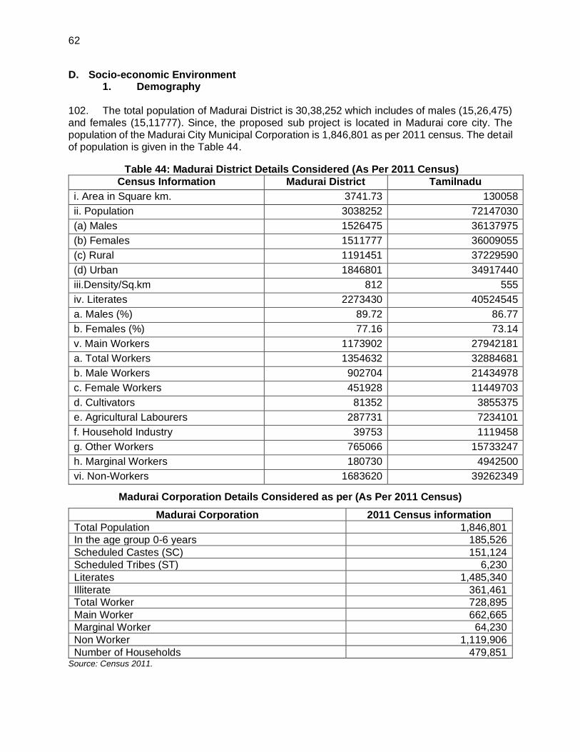
62
D. Socio-economic Environment 1. Demography
102. The total population of Madurai District is 30,38,252 which includes of males (15,26,475) and females (15,11777). Since, the proposed sub project is located in Madurai core city. The population of the Madurai City Municipal Corporation is 1,846,801 as per 2011 census. The detail of population is given in the Table 44.
Table 44: Madurai District Details Considered (As Per 2011 Census)
Census Information Madurai District Tamilnadu
i. Area in Square km. 3741.73 130058
ii. Population 3038252 72147030
(a) Males 1526475 36137975
(b) Females 1511777 36009055
(c) Rural 1191451 37229590
(d) Urban 1846801 34917440
iii.Density/Sq.km 812 555
iv. Literates 2273430 40524545
a. Males (%) 89.72 86.77
b. Females (%) 77.16 73.14
v. Main Workers 1173902 27942181
a. Total Workers 1354632 32884681
b. Male Workers 902704 21434978
c. Female Workers 451928 11449703
d. Cultivators 81352 3855375
e. Agricultural Labourers 287731 7234101
f. Household Industry 39753 1119458
g. Other Workers 765066 15733247
h. Marginal Workers 180730 4942500
vi. Non-Workers 1683620 39262349
Madurai Corporation Details Considered as per (As Per 2011 Census)
Madurai Corporation 2011 Census information
Total Population 1,846,801
In the age group 0-6 years 185,526
Scheduled Castes (SC) 151,124
Scheduled Tribes (ST) 6,230
Literates 1,485,340
Illiterate 361,461
Total Worker 728,895
Main Worker 662,665
Marginal Worker 64,230
Non Worker 1,119,906
Number of Households 479,851 Source: Census 2011.

63
2. Sex Ratio of Madurai Corporation
103. The sex ratio of 979 females per 1,000 males is higher than the national average of 944. Madurai metropolitan area constitutes the third largest metropolitan area in Tamil Nadu and the 24th in India. 8.99% of the population was under 6 years of age.
Figure 15: Resources profile of the Madurai Corporation
3. Work Force Participation
104. The details of work force participation are given in the Table 45. (i) Madurai ranks 9th with respect to the share in State GDP having 3.67%
contribution to the total state GDP; (ii) Major economic activities are trade & commerce, tourism related activities and to
some extent industrial activities; (iii) The city houses various health care facilities, automobile, rubber, chemical, and
textile manufacturing industries and has also developed as a second-tier city for information technology as well;
(iv) Increasing trend of tertiary sector with involvement of 87% population indicating major role of tourism and trade;
(v) The secondary sector comprising majorly the household handloom industry has declined from 4.06% in 2001 to 3.61% in 2011;
(vi) The Work Force Participation Rate is 39% showing an increase over the past decade; and
(vii) Share of marginal workers has grown from 4.31% in 2001 to 7.49% in 2011 indicating the high percentage of daily wages workers coming from adjacent areas to the city.

64
Table 45: Details of work force participation rate in Madurai Corporation
Sl.no Details Number Growth %
1. Primary sector 8,683 2%
2. Secondary sector 20,614 4%
3. Tertiary sector 499,264 94%
4. Total main worker 528,561 36%
5. Marginal worker 42,767 3%
6. Total non-worker 899,427 61%
7. Total population 1,470,755
8. Work participation rate 36%
4. Housing Scenario in Madurai Corporation
105. The details of house stocks are given in Table 46.
(i) Present housing stock is adequate with 80% houses under residential use and 20% under mixed area;
(ii) The growth in housing stock during the period of 2001-2011 was 27%; and (iii) There is considerable increase in number of liveable (67%) and dilapidated houses
(34%) in the city.
Table 46: Details of Housing Stock in Madurai Corporation
Parameters 2001 2011 Growth (%)
Total Census Houses 240,666 329,775 27
Vacant Houses 10,516 16,776 37
Occupied Houses 230,150 312,999 26
Residential Use 194,552 262,163 26
Residential Cum Other Purpose 35,598 50,836 30
Source: MCMC
5. Infrastructure in Madurai Corporation
106. Transport and Traffic. Road development, public transport services and suburban rail transport are recognized as essential for the efficient functioning of the urban system. The major arterial & sub-arterial road corridors and other roads are developed and maintained by National Highway (NH – 85 Cochin – Thondi via Madurai), State Highway (Bypass road, Kulamangalam road, Palamedu Road, Natham Road, Melur Road, Airport Road) and the local bodies concerned respectively. As regards traffic management and enforcement, the same is looked after by the City Traffic Police in respect of Greater City Area and District Police for the remaining City Area. The public bus transport is with State Transport Corporation.
6. Education in Madurai District
107. There are 47 approved institutions of the university in Madurai Corporation consisting of autonomous colleges, aided colleges, self-financing colleges, constituent colleges, evening colleges and other approved institutions. There are seven polytechnics and five Industrial training

65
institutes (ITIs) in Madurai, with the Government ITI and the Government Polytechnic for Women. There are a total of 399 primary, secondary and higher secondary schools in Madurai Corporation.
108. Madurai is one of the few rubber growing areas in South India, and there are rubber based industries in Madurai. Automobile manufacturers are the major consumers of rubber components produced in the city. There are numerous textiles, granite and chemical industries operating in Madurai. Madurai is promoted as a second-tier city for IT and some software companies have opened their offices in Madurai. Software Technology Parks of India, an agency of the Government of India, has authorized several such companies to receive benefits under its national information technology development program. The state government proposed two IT-based Special Economic Zones (SEZ) in Madurai, and these have been fully occupied by various IT companies.
9. Monuments, Archaeological and cultural Heritage Sites
109. There are archaeological monuments present in Madurai District such as Rock cut cave and inscriptions, Thirumalai Naicker Palace, Alagar Malai Cavern with Panchapandavar beds midway between Alagarmalai and Kidanpatti, Pathu Thungal, Samanar Hills, Brahmi Kalvettugal, Ladan Koil, Kovallan Pottal and Udayagiriswarar koil and cultural heritage site like Meenakshi Ammam Thirukovil, Some of these archeological monuments (viz., Thirumalai Naicker Palace, Cavern with Pancha Pandava beds on the western slope of the hills and similar beds behind the Sikandar mosque, and Rock-cut Cave & Inscriptions , etc and cultural heritage sites like Meenakshi Ammam Thirukovil) are present within the core Madurai City. However, these monuments are located outside the sub-project area under Tranche III. There are no such archaeological; monuments and heritage sites located in this sub-project area.
Table 47: Archaeological Monuments, Heritage and Culturally Important Site in the surroundings of the subproject area
S.no Archaeological Monuments, Heritage
and Culturally Important Site
Distance from the
subproject area
Protection Status4
1 Thiruparankundram Sree Murugan temple (Rock cut cave and inscriptions) (3 Km away from this subproject )
3 Km HR&CE under GoTN and
ASI under GoI
2 Alagar Malai Cavern with Panchapandavar beds midway between Alagarmalai and Kidanpatti
27 Km HR&CE under GoTN and
ASI under GoI
3 Cave in Sittharmalai 30 Km ASI under GoI
4 Cavern with Panchapandavar beds on western slope of the hills and similar beds behind the Sikkandar mosque on the top
10 Km ASI under GoI
5 Jain statues, rock inscriptions and Panchapandava beds on the hill
10 Km ASI under GoI
4
(i) Archeological Survey of India/GoI – ASI (ii) Department of Archeology/ GoTN – DoA (iii) Hindu Religious & Charitable Endowments/ GoTN – HR&CE

66
S.no Archaeological Monuments, Heritage
and Culturally Important Site
Distance from the
subproject area
Protection Status4
6 Panchapandavar bed, Jain statues and Brahmi and Vatteluthu inscriptions on the Panchapandavar Malai
10 Km ASI under GoI
7 Rock cut bas – relief of Jain images with inscriptions in Vatteluthu in Ammanamalai or Samanar Malai
15 Km ASI under GoI
8 Rock cut beds under natural rock shelter in Ammanamalai or Samanar Malai
15 Km ASI under GoI
9 Rock cut Jain beds – relief and beds and mutilated Jain stone image
15 Km ASI under GoI
10 Sri Meenakshi Sundareswarar Temple 2.0 Km HR&CE under GoTN
11 Thirumalai Nayakar Palace 1.5 Km DoA under GoTN
12 Madurai Fort 1.0 Km HR&CE under GoTN
110. The subproject area does not include any of the archeological monuments or heritage sites. However, Madurai being a heritage city, suitable management measures are to be followed during implementation. In case of any chance finds, any restrictions/guidance of archaeological property in/near sites shall be followed. All fossils, coins, articles of value of antiquity, structures and other remains or things of geological or archaeological interest discovered on the site shall be the property of the Government and shall be dealt with as per provisions of the relevant legislation. Wherever required, consult with local communities in advance of the work to identify and address key issues, and avoid working at sensitive times, such as religious and cultural festivals. Traffic management plan is to be prepared in consultation with the Traffic Police. Works shall be scheduled without creating any inconvenience or safely issue to tourists or visitors to the city/workers, especially in case of roads leading to temples, heritage sites and busy roads.

67
Figure 16: Monuments, Archaeological and cultural Heritage Sites surrounding the subproject area

68
Figure 17: Monuments, Archaeological and cultural Heritage Sites surrounding the subproject area (Zoomed Map)

69
Table 48: Subproject site Environmental Features
Infrastructure Location and Environmental
Features Site Photograph
Water Distribution System (HDPE pipe of size 110 mm to 200 mm, Pipe length 614402 m (16032 m – 110 mm, 12868 m – 125 mm, 13514 m – 160 mm, 18909 m – 180 mm and 56459 m – 200 mm) and DI pipe of size 250 mm dia to 450 mm Pipe length 813.889 m (20637 m – 250 mm, 20315 m – 300 mm, 14480 m – 350 mm and 3764 m – 400 mm) will be laid at the side of the roads (Where the distribution system is existing and in under operation). (Location to be covered, zone wise- 3, 11 to 22, 26, 29 to 32, 33 to 36, 40, 45, 49, 51, 54 to 56, 64 to 70).
The entire subproject area (39 zones) comes under the Urban and hence settlements and commercial activities are commonly observed in almost all the roads (proposed for laying pipeline on the sides/ shoulder). The subproject is proposed in the residential area, where there is no sensitive area, no environmental features, no agriculture land, and no water bodies The zones that are located in the south of River Vaigai are densely populated than the Zones located in the north
• Highly populated area in the proposed subproject is Jaihindpuram main road (ward no: 92, 87, 88 & 89), where 700 mm dia MS pipe for 1840 m will be laid.
• For medium density area like SMP colony (Ward no: 33), 200 mm dia DI pipe for 100 m will be laid.
• For low density area like Balaji nagar (Ward no: 99), 150 mm dia DI pipe for 800 m shall be laid
View of Jaihindpuram main road
View of roads in Balaji nagar
111. The distribution system will be laid along the edge of the streets and roads without affecting the existing infrastructures. Before commencing the pipe laying work, necessary road cut restoration charges will be paid to the concerned Department. On completion of the pipe laying work, the roads will be properly filled and consolidated with excavated earth and intimated to the concerned Department (NH and SH). The restoration of road will be carried out by the concerned Department (NH and SH).

70
V. ANTICIPATED ENVIRONMENTAL IMPACTS AND MITIGATION MEASURES
112. Potential environmental impacts of the proposed infrastructure components are presented in this section. Mitigation measures to minimize/mitigate negative impacts, if any, are recommended along with the agency responsible for implementation. Monitoring actions to be conducted during the implementation phase is also recommended to reduce the impact.
113. Screening of potential environmental impacts are categorized into four categories considering subproject phases: location impacts and design impacts (pre-construction phase), construction phase impacts and operations and maintenance phase impacts.
(i) Location impacts include impacts associated with site selection and include loss of on-site biophysical array and encroachment either directly or indirectly on adjacent environments. It also includes impacts on people who will lose their livelihood or any other structures by the development of that site;
(ii) Design impacts include impacts arising from Investment Program design, including technology used, scale of operation/throughout, waste production, and ancillary services;
(iii) Construction impacts include impacts caused by site clearing, machinery, vehicles and workers. Construction site impacts include erosion, dust, noise, traffic congestion and waste production; and
(iv) Operation and Maintenance impacts include impacts arising from the operation and maintenance activities of the infrastructure facility. These include routine management of operational waste streams, and occupational health and safety issues will be supervised by EHS supervisor.
114. Screening of environmental impacts has been based on the impact magnitude (negligible/ moderate/ severe – in the order of increasing degree) and impact duration (temporary/permanent).
115. This section of the IEE reviews possible project-related impacts, in order to identify issues requiring further attention and screen out issues of no relevance. ADB SPS, 2009 require that impacts and risks will be analyzed during pre-construction, construction, and operational stages in the context of the project’s area of influence. The ADB Rapid Environmental Assessment Checklist has been used to screen the project for environmental impacts and to determine the scope of the IEE.
116. In the case of this subproject, most of the individual elements involve simple construction and operation approach. Most of the predicted impacts are associated with the construction process, and are produced because that process is invasive, involving excavation and earth movements and being mostly located on the roadside, so will not cause direct impact on biodiversity values. The blasting proposed is “controlled blasting” following necessary precautionary measures including usage of appropriate quantities of explosives hence that the nearby structures and properties are unlikely to be affected and impacts related to controlled blasting such as dust generation, increased noise levels and vibrations would be mitigated. The subproject is proposed to be implemented in the properties owned by the government departments/ ULB and access to the project location is through public Rights-of-Way (ROW) and existing roads.
A. Pre-Construction Impacts- Design and Location
117. Design of the Proposed Components. The Central Public Health and Environment Engineering Organization (CPHEEO) manual suggests a design period of 15/30 years for water

71
supply and treatment projects. In this subproject, the water supply components were designed following the recommendations of the CPHEEO manual.
118. Impacts arise from the design of the project including the technology used, scale of operation, waste production, pollution sources and ancillary services.
119. Impacts associated with the planning mainly depend on the site selection. Location impacts include on-site biophysical array and encroachment / impact either directly or indirectly on adjacent environments. It also includes the impacts on the people who might lose their properties or livelihoods due to the development of the subproject.
120. Construction works in the MCMC area includes laying of pipelines on or along the roads (preferably on the road shoulders) and vacant/ baren land. In the narrow roads (where there is no vacant land adjoining roads), pipeline will be buried within the road Right of Way. However, considering the narrow and busy lanes, temporary impacts are likely during construction stage.
121. Associated/ Existing Facilities: This subproject includes providing distribution network and household connections in 39 of 81 water supply zones in Madurai City Municipal Corporation. Under the ongoing ADB funded TNUFIP (Tranche 2) MCMC is implementing a comprehensive water supply improvement scheme to the entire corporation area. The packages involving construction of headwork’s, raw water conveying main, Water Treatment Plant, clear water transmission main & feeder mains and construction of 37 OHTs and distribution network for 34 zones. This infrastructure will be adequate to provide treated water of drinking water quality (IS 10500-2012) to the 39 zones proposed under this subproject. SPS defines associated facilities as that are not funded by part of the project and whose viability and existence depend exclusively on the project whose goods or services are essential for successful operation of the subproject. ADB SPS requires environmental audit/ due diligence of exiting/ associated facilities as part of an IEE.
122. Since the existing/associated facilities in implementation under an ADB funded project (TNUFIP Tranche II) an IEE has already been prepared and was approved and disclosed by ADB5. Existing infrastructure facilities like headwork’s of existing schemes, 115 MLD WTP at Pannaipatti, feeder mains and 44 Nos. of OHTs are also to be retained for use. These existing facilities are in working condition and no improvements have been proposed. Environmental audit has been conducted for the existing facilities and the findings has been included in the IEE report prepared for Tranche II .
Table 49: Madurai Water Supply – demand and supply
Description Year Overall City
Demand (MLD)
Present Subproject
area demand (MLD)
Available water Supply (entire
corporation area) MLD
Demand supply gap
(MLD)
Base Year 2019 268 167 192 76
Intermediate year 2034 317 193 192+125 (under implementation)
Nil
5 Initial Environmental Examination report for the sub-project being implemented under the Tranche-II of TNUFIP
prepared following the ADB SPS was approved by ADB and is disclosed in the websites of ADB and ULB (Madurai
City Municipal Corporation) https://www.adb.org/projects/documents/ind-49107-005-iee-0.

72
123. Water supply sustainability: Water demand for overall city will be 374 MLD and water demand for this sub project area will be 224 MLD. Existing water supply available is 192 MLD (115MLD from Vaigai Dam schemes I and II, 30 MLD from River Cauvery Source under Melur CWSS and sub-surface water of 47 MLD from Vaigai River bed). The net water supply requirement for the year 2034 is 317 MLD, which shall be met through 192 MLD (existing water supply) + 125 MLD (under Tranche II). The water demand gap of 125MLD for the entire corporation for the intermediate year is being met with the improvements under Tranche II of TNUFIP.
124. Interconnection of existing and proposed schemes (As given in para 53): The following have been proposed under the Tranche II sub-project of TNUFIP.
i. The Vaigai I, Vaigai II and Mullaiperiyar Schemes are having the WTP at the same location of Pannaipatti WTP site. Hence the outlet pipes of the Clear Water Reservoirs shall be interlinked.
ii. Interconnection of the Mullaiperiyar Scheme Main feeder to the Arasaradi sump which is receiving the water from Melakkal- Thachampattu and Kochadai Schemes (from Vaigai River Bed Source).
iii. Interconnection of the Mullaiperiyar Scheme Main feeder to the two TWAD Board sumps (Cauvery CWSS – Cauvery river bed source) located at Vilangudi Sump located at North of River Vaigai and Villapuram Sump located at South of River Vaigai.
125. The interconnections being carried out linking the existing and proposed schemes for ensuring equitable distribution of water supply in the entire Madurai Corporation area.
126. Status of implementation of improvement works: The works under implementation under the SMART City scheme are expected to be completed by June 2022. Under Tranche –II, the works are ongoing and the date of completion is June-2023, & commissioning and trail run including treated water available at OHT is December 2023. The sub-project under Tranche III is proposed to be implemented in 36 months including 6 months trial-run by which all the other ongoing improvement works will be completed and be ready to use.
127. Site selection of sources of materials. Extraction of materials can disrupt natural land contours and vegetation resulting in accelerated erosion, disturbance in natural drainage patterns, ponding and water logging, and water pollution. To mitigate the potential environmental impacts, locations of quarry site/s and borrow pit/s (for loose material other than stones) would be included in the design specifications and on plan drawings. Priority would be sites already permitted by Mining Department. If other sites are necessary, these would to be located away from population centres, drinking water intakes and streams, cultivable lands, and natural drainage systems; and in structurally stable areas even if some distance from construction activities. It will be the construction contractor’s responsibility to verify the suitability of all material sources and to obtain the approval of the PIU (Madurai City Municipal Corporation). If additional quarries will be required after construction is started, then the Construction Contractor shall use the mentioned criteria to select new quarry sites, with written approval of PIU after getting recommendation from CMSC. However, it is recommended to procure construction materials from the vendors who are authorised by the Government of Tamil Nadu.
128. Tree cutting at subproject sites. The subproject area comes under the urban limit. Residential areas/ settlements and commercial activities dominates the subproject area and hence, there are no notable tree cover in the subproject area. Water supply pipeline are proposed on the sides of the roads, and therefore no major tree cutting is envisaged. However, the presence of small trees (10 no’s) may get affected during the project implementation, for which transplantation measures are suggested, accordingly budgetary provision has been included in

73
the EMP budget. The following measures needs to be implemented to minimize and/or compensate for the loss of trees.
(i) Minimize removal of trees by adopting to site condition and with appropriate design measures
(ii) Tree Transplantation should be carried out for the trees having girth size ranging from 30 to 90 cm.
(iii) Obtain prior permission for tree cutting (iv) Plant and maintain 10 trees for each tree that is removed. Planting trees should be
carried out in the vacant land available with MCMC (preferably Parks and other public places),
(v) With prior permission plantation shall be carried out in the schools and hospitals.
B. Construction Impacts
129. Impacts on Air Quality. During construction period, the impacts on air quality are mainly due to the material movement and the actual construction activities. Due to material movement air, quality over the immediate influence area will be affected though, not in significant levels. There will be increase in the dust levels. In order to reduce the dust emissions in the construction area due to material transport and construction activities, provisions should be made for sprinkling of water on all the roads in the area of improvement. It should be ensured that
(i) Construction debris are removed daily; (ii) construction requiring street closings should be performed during off-peak hours; (iii) idling of delivery trucks or other equipment should not be permitted during periods
of unloading or when they are not in active use; (iv) proper conditioned construction vehicles should be used wherever possible; and (v) As soon as construction is over the surplus earth should be utilised to fill up low-
lying areas. In no case, loose earth should be allowed to pile up in the streets.
130. Anticipated impacts during the construction phase are discussed below along with appropriate mitigation measures to avoid, minimize or mitigate those impacts to acceptable levels. 131. Sources of Materials. For the construction work, the required materials like coarse aggregate and fine aggregate will be obtained from the permitted / licensed quarries by Department of Geology & Mining, Government of Tamil Nadu. Contractor should not create/use any new borrow pits / quarries. The contractor should also make a concerted effort to re-use as much excavated material from this project as possible.
132. The construction contractor will be required to:
(i) Obtain construction materials only from government-approved quarries with prior approval PIU and CMSC;
(ii) PIU and CMSC to review, and ensure that proposed quarry sources have all necessary clearances/ permissions in place prior to approval;
(iii) Contractor to submit to PIU and CMSC on a monthly basis documentation on material obtained from each source (quarry/ borrow pit); and
(iv) Avoid creation of new borrow areas, quarries, etc., for the project; if unavoidable, contractor to obtain all clearances and permissions as required under law, including environmental clearance prior to approval by PIU after getting recommendation from CMSC.

74
133. Air Pollution during Construction work, especially from earthwork activities, coupled with dry and windy working conditions, material and debris transports, and works along the public roads carrying significant traffic, have high potential to generate dust. Significant quantities of earthwork will be conducted in the subproject, spread all over the project area. Nearly 8,13,887m3
of earthwork is anticipated from the subproject, and 90-95% of which will be reused for filling the trenches. Also, emissions from construction vehicles, equipment, and machinery used for excavation and construction will induce impacts on the air quality. Anticipated impacts include dust and increase in concentration of vehicle-related pollutants such as carbon monoxide, sulfur oxides, particulate matter, nitrous oxides, and hydrocarbons. Dust generation will be significant during pipe laying along the roads. Increase in dust/ particulate matter in ambient air is detrimental and may have adverse impacts on people and environment. To mitigate the impacts, construction contractors will be required to:
(i) For all construction works
(a) Damp down the soil and any stockpiled material on site by water sprinkling(3-4 times a day before the start of work, 1-2 times in between, and at the end of the day) when working in the roads there should permanently be one person responsible for directing when water sprinkling needs to take place to stop the dust moving;
(b) Reduce the need to sprinkle water by stabilizing surface soils where loaders, support equipment and vehicles will operate by using water and maintain surface soils in a stabilized condition;
(c) Apply water prior to levelling or any other earth moving activity to keep the soil moist throughout the process;
(d) Cover the soil stocked at the sites with tarpaulins and surround by dust screens; (e) Control access to work area, prevent unnecessary movement of vehicle, public
trespassing into work areas; limiting soil disturbance will minimize dust generation; (f) Use tarpaulins to cover the loose material (soil, sand, aggregate etc.,) when
transported by open trucks; (g) Control dust generation while unloading the loose material (particularly aggregate,
sand, soil) at the site by sprinkling water and unloading inside the barricaded area, minimize the drop height when moving the excavated soil;
(h) Clean wheels and undercarriage of haul trucks prior to leaving construction site; (i) Ensure that all the construction equipment, machinery is fitted with pollution control
devises, which are operating correctly, and have a valid pollution under control (PUC) certificate; and
(j) No vehicles or plant to be left idling at site generators to be at placed maximum distance from properties.
(ii) For pipe laying works
(a) Inform the residents likely to be affected by the works in the locality about the upcoming pipe laying works well in advance so that necessary arrangements are planned by the residents with reduced inconvenience.
(b) For sections where the controlled blasting is proposed, the residents shall provide with the schedule of blasting at least three days in advance and the residents are explained about the preventive, precautionary, mitigation and emergency response measures being taken to address their concerns.
(c) The project staff from the PIU, CMSC and contractors would undertake a survey of structures (including videography and/or photography) lying within the area of influence of blasting from the vibrations related impacts (preferably in the presence of the owners of the said structures) during pre and post-blasting situations to

75
assess and/or ascertain regarding the damages, if any, caused to the structures because of blasting activities.
(d) Barricade the construction area using hard barricades (of 2 m height) on both sides;
(e) Initiate site clearance and excavation work only after barricading of the site is done; (f) Confine all the material, excavated soil, debris, equipment, machinery (excavators,
cranes, etc.), to the barricaded area; (g) Limit the stocking of excavated material at the site; remove the excess soil from
the site immediately to the designated disposal area; (h) Undertake the work section wise a 100 m section should be demarcated and
barricaded; open up several such sections at a time, but care shall be taken to locate such sections in different zones;
(i) The section proposed for blasting shall be supervised by properly trained staff to ensure no movement of pedestrians, motorized or non-motorized vehicles, and residents takes place during blasting within the area of influence.
(j) For sections involving controlled blasting, ensure that dust curtains of adequate height are provided to the trenches to prevent emission of dust during drilling for charge holes and controlled blasting.
(k) Ensure that the excavated soil and debris along the section identified for blasting is sprinkled with adequate water prior to blasting to reduce dust emissions upon explosion of charge placed for breaking the hard rock;
(l) Ensure that adequate precautions are taken to avoid flying debris post blasting (such as covering the trench with sturdy metallic sheets having sufficient weights to absorb the blast waves);
(m) Conduct work sequentially - excavation, pipe laying, backfilling; testing section-wise (for a minimum length as possible) so that backfilling, stabilization of soil can be done;
(n) Remove the excavated soil of first section to the disposal site; as the work progresses sequentially, by the time second section is excavated, the first section will be ready for back filling, use the freshly excavated soil for back filling, this will avoid stocking of material, and minimize the dust; and
(o) Backfilled trench at any completed section after removal of barricading will be the main source of dust pollution. The traffic, pedestrian movement and wind will generate dust from backfilled section. Road restoration shall be undertaken immediately.
134. Excavation and refilling activities will disturb the topsoil, and under the influence of wind, traffic, pedestrians, and other activities etc., produces dust. There is large potential to generate significant quantities of dust after refilling the trench, and prior to road relaying. It is a common practice not to restore the road immediately after refilling the trench so as to allow sufficient time for the refilled material to stabilize naturally. Given the dry and windy conditions, and heavy traffic and other activities along the roads, the refilled trenches with loose topsoil along the roads will generate maximum dust and create very unhealthy conditions. Moreover, as the barricades / dust screens will remove after the trench is refilled, there will be absolutely nothing to control the dust generation. Dust control activities like wetting of topsoil will not be effective given the site conditions. It is therefore necessary to restore/relay the road surface immediately or take suitable steps to arrest the dust. Soil consolidation technique shall be used so that road can be restored immediately.

76
135. While obtaining permission for the proposed raw water transmission main from NH, SH & rural roads, the necessary restoration charges will be paid and accordingly the respective department will restore their roads.
136. Generation of Construction Wastes. Solid wastes generated from the construction activities are excess excavated earth (spoils), discarded construction materials, cement bags, wood, steel, oils, fuels and other similar items. Domestic solid wastes may also be generated from the workers’ camp. Improper waste management could cause odor and vermin problems, pollution and flow obstruction of nearby watercourses and could negatively impact the landscape. Earthwork excavation in the road will be reused for leveling the roadside and earth excavation from other location will be safely disposed to corporation lands.
137. The following mitigation measures to minimize impacts from waste generation shall be implemented by the contractor:
(i) Prepare and implement a Construction Waste (Spoils) Management Plan (format is given in Appendix 4);
(ii) Avoid stockpiling any excess spoils at the site for long time. Excess excavated soils should be disposed to corporation lands;
(iii) If disposal is required, the site shall be selected preferably from barren, infertile lands; sites should locate away from residential areas, forests, water bodies and any other sensitive land uses;
(iv) Domestic solid wastes should be properly segregated in biodegradable and non-biodegradable for collection and disposal to designated solid waste disposal site; create a compost pit at workers camp sites for disposal of biodegradable waste; non-biodegradable / recyclable material shall be collected separately and sold in the local recycling material market;
(v) Prohibit burning of construction and/or domestic waste; (vi) Ensure that wastes are not haphazardly thrown in and around the study area;
provide proper collection bins, and create awareness to use the dustbins; recycle waste material where possible; and
(vii) Conduct site clearance and restoration to original condition after the completion of construction work; PIU and CMSC to ensure that site is properly restored prior to issuing of construction completion certificate.
138. Surface Quality Impacts. Madurai and surrounding region receive average rainfall and there are a number of natural and man-made drainage channels crossing the city to carry the runoff safely. Runoff from the excavated areas and material and waste soil stocks likely to contain silt, and this silt runoff will deteriorate the water bodies due to silting. Large-scale silting is likely to lead to flooding. This impact will however be considered only during rainy season. These potential impacts are temporary and are of short-term duration only and to ensure these are mitigated, construction contractor will be required to:
(i) Avoid stockpiling of earth fill especially during the monsoon season unless covered by tarpaulins or plastic sheets;
(ii) Prioritize re-use of excess spoils and materials in the construction works. If spoils will be disposed, consult with PIU on designated disposal areas;
(iii) Install temporary silt traps or sedimentation basins along the drainage leading to the water bodies;
(iv) Place storage areas for fuels and lubricants away from any drainage leading to water bodies; and
(v) Dispose any wastes generated by construction activities in designated sites; and (vi) Conduct surface quality inspection according to the EMP.

77
139. Aquatic Environmental Impacts. There will not have any impact on the aquatic environment. However, care shall be taken to avoid deposition/ disposal of construction waste / accidental spillage of construction material into the surface water bodies including river, pond, lake, tank etc., and also construction works shall be restricted during the monsoon seasons.
140. Noise and Vibration Levels. The water distribution station sites are located within habitations, where there are houses, schools and hospitals, religious places and businesses. During construction stage increase in noise level may be caused by excavation, particularly breaking of cement concrete or bitumen roads and controlled blasting for removal of hard rocks in sites (if done) for the purpose of laying of pipe, operation of construction equipment, and the transportation of equipment, materials, and people. Vibration generated from construction activity, for instance from the use of pneumatic drills, will have impact on nearby buildings. The construction contractor will be required to:
(i) Plan activities in consultation with PIU and CMSC so that activities with the greatest potential to generate noise are conducted during periods of the day which will result in least disturbance, especially near schools and other sensitive receptors;
(ii) Minimize noise from construction equipment by using vehicle silencers, fitting jackhammers with noise-reducing mufflers, and use portable street barriers to minimise sound impact to surrounding sensitive receptor;
(iii) Maintain maximum sound levels within the limits as prescribed by the prevailing Indian regulations and standards;
(iv) Ensure to conduct a pre-blasting survey through videography and photography of residential properties and other structures falling along the sewerage alignment to ascertain the prevailing conditions of the structures likely to be impacted by the controlled blasting and take adequate measures to minimise such impacts.;
(v) Horns should not be used unless it is necessary to warn road users or animals of the vehicle’s approach; and
(vi) Consult local communities in advance of the work to identify and address key issues, and avoid working at sensitive times, such as religious and cultural festivals.
(vii) All the controlled blasting shall be done by an approved and licensed Explosive contractor after submitting a blasting plan to PIU and CMSC.
(viii) Noise level may be caused by excavation, particularly breaking of cement concrete or bitumen roads and operation of construction equipment, and the transportation of equipment, materials, and people. Vibration generated from construction activity, for instance from the use of pneumatic drills, will have impact on nearby buildings and utilities. This impact is negative short-term, and manageable by mitigation measures.
141. Accessibility and Traffic Disruptions. Madurai City Municipal Corporation is maintaining 1,572.38 km length of roads. 22.58 km of Stone cut & Tiles paved roads.
Table 50: Details of the Type of Roads and its Lengths
Sl.no Roads Category Length in km
1 Bus Route Roads 162.87 km
2 Ring Road 27.20 km
3 Internal Road 239.66 km
Total 532.22 km
Sl. No. Roads Category Length in km
1 B.T. Roads 947.94
2 C.C. Road 268.99

78
3 Metal Roads 125.50
4 Sand Road 207.52
5 Stone cut & Tiles paved roads 22.58
Total 1,572.38
Sl. No Road Category Length in km
1 Municipal Roads 661.81
2 Highways & Major District Roads 34.00
Total 695.81 km = kilometer.
142. The main road in the MCMC carries considerable traffic. These roads are also centers of commercial activities. Internal roads in the project area are narrow, except in the newly developing residential layout, which comparatively have wide roads. Pipes to be laid across some of the arterial roads. In other corporation maintained busy roads, work will be taken up during non-traffic hours/ night hours without much hindrance to the free flow of traffic. Potential impact is negative but short term and reversible by mitigation measures. The construction contractor will be required to:
(i) Plan transportation routes so that heavy vehicles do not use narrow local roads, except in the immediate vicinity of delivery sites;
(ii) Schedule transport and hauling activities during non-peak hours; (iii) Locate entry and exit points in areas where there is low potential for traffic congestion; (iv) Keep the site free from all unnecessary obstructions; (v) Drive vehicles in a considerate manner; (vi) Coordinate with City Traffic Office for temporary road diversions and necessary provision
of traffic aids if transportation activities cannot be avoided during peak hours; (vii) Notify affected sensitive receptors by providing sign boards informing nature and
duration of construction works and contact numbers for concerns/complaints; (viii) Provide planks across trenches in front of businesses, and ensure works are completed
quickly to avoid disruption; and (ix) Avoid full street closure.
143. Surface and Groundwater Quality. Another physical impact that is often associated with excavation is the effect on drainage and the local water table if groundwater and surface water collect in the voids. To ensure that water will not pond in pits and voids near subproject location, the construction contractor will be required to conduct excavation works on non-monsoon season.
144. Accessibility. Some of the roads in the subproject sites are narrow thus excavation and trenching works along right on the ways, hauling of construction materials and operation of equipment on- site can cause traffic problems. Potential impact is negative but short term and reversible by mitigation measures. The construction contractor will be required to:
(i) Plan transportation routes so that heavy vehicles do not use narrow local roads, except in the immediate vicinity of delivery sites;
(ii) Schedule transport and hauling activities during non-peak hours; (iii) Locate entry and exit points in areas where there is low potential for traffic congestion; (iv) Keep the site free from all unnecessary obstructions; (v) Drive vehicles in a considerate manner; (vi) Coordinate with Coimbatore Traffic Office for temporary road diversions and with for
provision of traffic aids if transportation activities cannot be avoided during peak hours; (vii) Notify affected sensitive receptors by providing sign boards informing nature and duration
of construction works and contact numbers for concerns/complaints; (viii) Provide planks across trenches in front of businesses, and ensure works are completed

79
quickly to avoid disruption; and
(ix) Avoid full street closure.
145. Socio-Economic – Income. Sites for all project components are carefully selected in government owned lands. However, few temporary shops are located in the road sides that are likely to be affected due to the proposed work. For the loss of the livelihood, compensation has been estimated and mention in the resettlement plan. During the project implementation, blocking of access to the business / livelihood activities are envisaged, especially during pipeline laying along the roads, may impact the income of households. However, given the alignment of pipeline is within the road carriage way and also the measures suggested for ensuring accessibility during pipe laying works are notable but temporary impact is envisaged. Some shops and other premises along the roads may lose business income if the access will be impeded due to excavation of trenches, the presence of heavy vehicles and machinery, etc. Access disruption to hospitals, socio cultural places etc., will cause inconvenience to the public. Implementation of the following best construction measures will avoid the disturbance reduce the inconvenience and disturbance to the public. Works near Meenakshi Temple are already completed under SMART city scheme. No activities proposed near Meenakshi Temple under this sub-project and hence there is no impact.
(i) Inform all businesses and residents about the nature and duration of any work well in advance so that they can make necessary preparations;
(ii) Do not block any access; leave spaces for access between barricades/mounds of excavated soil and other stored materials and machinery, and providing foot bridges so that people can crossover open trenches;
(iii) Barricade the construction area and regulate movement of people and vehicles in the vicinity, and maintain the surroundings safely with proper direction boards, lighting and security personnel – people should feel safe to move around
(iv) Control dust generation; (v) Immediately consolidate the backfilled soil and restore the road surface, this will also avoid
any business loss due to dust and access inconvenience of construction work; (vi) Employee best construction practices, speed up construction work with better equipment,
increase workforce, etc., in the areas with predominantly commercial, and with sensitive features like hospitals, and schools;
(vii) Consult businesses and institutions regarding operating hours and factoring this in work schedules; and
(viii) Provide sign boards for pedestrians to inform nature and duration of construction works and contact numbers for concerns/complaints.
146. Socio-Economic – Employment. Manpower will be required during the construction stage. This can result in generation of temporary employment and increase in local revenue. Thus, potential impact is positive and long-term. The construction contractor will be required to:
(i) Employ local labour force as far as possible;
(ii) If available, secure construction materials from local market;
147. Occupational Health and Safety. Workers need to be mindful of the occupational hazards which can arise from working in confined areas such as trenches, working at heights, near the heavy equipment operating areas, controlled blasting, etc. Potential impacts are negative and long-term but reversible by mitigation measures. The construction contractor will be required to:
(i) Follow all national, state and local labour laws (indicative list is in Appendix 2); (ii) Develop and implement site-specific occupational health and safety (OHS) plan, informed
by OHS risk assessment seeking to avoid, minimise and mitigate risk, including controlled

80
blasting (if required) activity which shall include measures such as: (a) safe and documented construction procedures to be followed for all site activities; (b) ensuring all workers are provided with and use personal protective equipment; (c) OHS Training for all site personnel; (d) excluding public from the work sites; and (e) documentation of work-related accidents; follow international standards such as the World Bank Group’s Environment, Health and Safety Guidelines;
(iii) Ensure that qualified first aid trained professional is deployed at all times. Equipped first-aid stations shall be easily accessible throughout the sites;
(iv) Secure all installations from unauthorized intrusion and accident risks; (v) Provide OHS orientation training to all new workers to ensure that they are appraised of the
basic site rules of work at the site, personal protective protection, and preventing injuring to fellow workers;
(vi) Provide visitor orientation if visitors to the site can gain access to areas where hazardous conditions or substances may be present. Ensure also that visitor/s do not enter hazard areas unescorted;
(vii) Ensure the visibility of workers through their use of high visibility vests and other PPEs when working in or walking through heavy equipment operating areas;
(viii) Ensure moving equipment is outfitted with audible back-up alarms; (ix) Mark and provide sign boards for hazardous areas such as energized electrical devices and
lines, service rooms housing high voltage equipment, and areas for storage and disposal. Signage shall be in accordance with international standards and be well known to, and easily understood by workers, visitors, and the general public as appropriate;
(x) Provide supplies of potable drinking water; (xi) Provide clean eating areas where workers are not exposed to hazardous or noxious
substances; and (xii) Disallow worker exposure to noise level greater than 85 dB (A) for a duration of more than
8 hours per day without hearing protection. The use of hearing protection shall be enforced actively.
(xiii) For COVID 19 all precautions and preventions will be done as per the enclosed Appendix 12.
148. Community Health and Safety. Excavations along the roads & narrow streets and hauling of equipment and vehicles have potential to create safety risks to the community. Excavations without any proper protection may endanger the close by buildings. Hazards posed to the public, specifically in high-pedestrian areas may include traffic accidents and vehicle collision with pedestrians. Potential impact is negative but short-term and reversible by mitigation measures. The construction contractor will be required to:
(i) Confine work areas; prevent public access to all areas where construction works are on-going through the use of barricading and security personnel;
(ii) Attach warning signs, blinkers to the barricading to caution the public about the hazards associated with the works, and presence of deep excavation;
(iii) Minimize the duration of time when the trench for laying pipe is left open through careful planning; plan the work properly from excavation to refilling and road relaying;
(iv) Control dust pollution – implement dust control measures as suggested under air quality section;
(v) Ensure appropriate and safe passage for pedestrians along the work sites; (vi) Provide road signs and flag persons to warn of on-going trenching activities; (vii) Restrict construction vehicle movements to defined access roads and demarcated working
areas (unless in the event of an emergency); (viii) Enforce strict speed limit (20-30 kmph) for plying on unpaved roads, construction tracks;

81
(ix) Provide temporary traffic control (e.g., flagmen) and signs where necessary to improve safety and smooth traffic flow;
(x) Where traffic is diverted around crossings, traffic control or careful selection of the exit from the working areas will be provided with the aim of ensuring that vehicles join the road in a safe manner;
(xi) At sensitive locations particularly where there are schools and markets close to the road, awareness of safety issues will be raised through neighbourhood awareness meetings;
(xii) All drivers and equipment operators will undergo safety training; and (xiii) Maintain regularly the construction equipment and vehicles; use manufacturer-approved
parts to minimize potentially serious accidents caused by equipment malfunction or premature failure.
149. Safety Measures for Controlled blasting during excavation: During excavation, alternatives like drilling and chiseling, controlled blasting (if required) etc. examined and the suitable technology will be identified depending upon the site conditions. Wherever controlled blasting is proposed, the following measures shall be carried out for execution in a safe manner.
(i) Carryout controlled blasting in consultation with PIU so that blasting activities with generating least vibration are conducted during periods of the day which will result in least disturbance; especially near schools and other sensitive receptors
(ii) The contractor shall submit a blasting plan in advance to PIU; and implement in accordance to the plan.
(iii) Permission shall be obtained from the District Collector for controlled blasting for excavation and the conditions issued shall be complied with during implementation.
(iv) Blasting shall be done through a licensed Explosive Contractor only. (v) For controlled blasting, explosives including blasting caps, shall be transported to the
blasting site only through exclusive vehicle in safe manner in accordance with the requirements of the blasting license. After blasting is over, the balance explosives shall be returned to the licensed storage.
(vi) Cost for implementation of mitigation measures and liability are the responsibility of contractor.
(vii) Proper prior notice will be issued to the residents before commencing activity works schedule
(viii) Prior information will be given to police officials (ix) Workers (Flagman) shall be stationed on both end of roads to warn people before firing any
blasts and not to permit the traffic. (x) When blasting, ample warning shall be given to all persons within the vicinity prior to
blasting. Warning signs shall be erected a minimum of 24 hours prior to the blast time. The warning signs will state the time and date of each blast.
(xi) Contractor shall ensure necessary precautions / protection (like excavated earth, sand-filled bags, etc) to reduce Ground Vibrations, Reduce noise levels, etc. Sites shall be provided with necessary shields all around.
(xii) Sites shall be provided with necessary shields all around. (xiii) Minimum Explosive will be used for Control Blasting (if required) for Residential areas. (xiv) After a blast has been fired, the Blast Control Specialist shall make a careful inspection to
determine that all charges have exploded before employees are allowed to return to the operation.
(xv) The contractor shall be responsible for any and all damage to property or injury to persons resulting from blasting or accidental or premature explosions that may occur in connection with his use of explosives. The contractor shall do the activities after obtaining the blasting permission from District Collector, Madurai.

82
(xvi) For the diversion of traffic in the blasting area, the contractor shall prepare a traffic management plan and obtain permission from Madurai Corporation and traffic police.
150. Construction Camps. Contractor may require to set up construction camps – for temporary storage of construction material (pipes, cement, steel, fixtures, fuel, lubricants, etc.), and stocking of surplus soil, and may include separate living areas for migrant workers. The contractor will however be encouraged to engage local workers as much as possible. Operation of work camps can cause temporary air, noise and water pollution, and may become a source of conflicts, and unhealthy environment if not operated properly. Potential impacts are negative but short-term and reversible by mitigation measures. The construction contractor will be required to:
(i) Select a camp site away from residential areas (at least 100 m buffer shall be maintained) or locate the camp site within the existing facilities of City Corporation;
(ii) Avoid tree cutting for setting up camp facilities; (iii) Provide a proper fencing/compound wall for camp sites; (iv) Camp site shall not be located near (100 m) water bodies, flood plains flood prone/low lying
areas, or any ecologically, socially, archeologically sensitive areas (v) Separate the workers living areas and material storage areas clearly with a fencing and
separate entry and exit; (vi) Camp shall be provided with proper drainage, there shall not be any water accumulation; (vii) Provide drinking water, water for other uses, and sanitation facilities for employees drinking
water should be regularly tested to confirm that drinking water standards are met; (viii) Prohibit employees from cutting of trees for firewood; contractor should provide cooking fuel
(cooking gas); firewood not allowed; (ix) Train employees in the storage and handling of materials which can potentially cause soil
contamination; (x) Wastewater from the camps shall be disposed properly either into sewer system, if sewer
system is not available, provide on-site sanitation with septic tank and soak pit arrangements(100 m away from surface water body or groundwater well);
(xi) Recover used oil and lubricants and reuse or remove from the site; (xii) Manage solid waste according to the following preference hierarchy: reuse, recycling and
disposal to designated areas; provide a compost pit for biodegradable waste, and non-biodegradable / recyclable waste shall be collected and sold in local market;
(xiii) Remove all wreckage, rubbish, or temporary structures which are no longer required; and (xiv) At the completion of work, camp area shall be cleaned and restored to pre-project conditions
and submit report to PIU; PIU to review and approve camp clearance and closure of work site.
C. Operation and Maintenance Impacts
151. Once the construction is over the O&M of the water distribution system will be carried out by MCMC (PIU). Prior to supply of water, it will be ensured that the newly laid pipes are properly cleaned and disinfected. In water supply distribution system project, the impacts are primarily due to construction phase activities, and are not generally associated with any significant impacts as a result of activities during operation. During the system design life (15/30 years for mechanical/civil components) it shall not require major repairs or refurbishments and should operate with little maintenance beyond routine actions required to keep the equipment in working order. The stability and integrity of the system will be monitored continuously and any problems detected will be promptly restored. Any repairs will be small-scale involving manual, temporary, and short-term works involving regular checking and recording of performance for signs of deterioration, servicing and replacement of parts.

83
152. Recurrence of pipe bursting and leakage problems can be managed by the leak detection, rectification and water auditing surveys. MCMC (PIU) will be required to ensure that the leak detection and rectification time is minimized.
153. Recurrence of blockage and leakage problems. Although impact is likely to be minimal due to new and well-designed efficient system; it should be ensured that leak detection and restoration time is minimized to the extent possible.
154. To ensure that water delivered to consumers at all times meets the drinking water standards, the following measures are suggested:
(i) Preparation and implementation of a water quality surveillance as part of the project to ensure that supplied water meets the drinking water standards; and
(ii) Surveillance program will be organized to ensure the water quality of the consumer water.
155. Disaster management and Emergency Response. The Revenue Department of the State is the Nodal Department for controlling, monitoring and directing measures for organizing rescue, relief and rehabilitation. All other concerned line departments, municipal corporations, extends cooperation to the response management of the disaster whenever it occurs. Control rooms at the State level as well as district control rooms are activated as required to deal with any disaster. At state level, Tamil Nadu State Disaster Management Authority (TNSDMA) is established to plan, coordinate and monitor the disaster management at state level. District Disaster Management Authorities (DDMA), headed by respective District Collectors, established in each district to perform similar functions at the district level in coordination with TNSDMA. District disaster management plans are prepared for each district. DDMA prepares and implements the District Disaster Management Plan and plays the role of an anchor, monitors the disaster preparedness throughout the year and particularly review non-disaster activities and preparedness of the departments to handle situations. DDMA assesses the situation and gives directions to the departments for handling of any disaster situation. It can call for outside support, if necessary, and keeps the TNSDMA informed about the handling of the situation. Meetings are held periodically during the year to ensure that alertness and preparedness levels are maintained within the district. The state and district disaster management plans follows the Sendai Frame work for Disaster Risk Reduction 2015-2020. 156. Disaster Management in Municipal Corporation Area. Madurai District disaster management plan includes the Madurai City Municipal Corporation as an integral part, and MCMC plays very important role in disaster management within its jurisdiction and works under the overall coordination of District Collector, DDMA. District disaster management plan identifies the highlights the responsibilities of urban local bodies, and MCMC is a member of district disaster management committee. The MCMC defined roles and responsibilities of all departments within its jurisdiction in disaster management.

84
VI. PUBLIC CONSULTATION AND INFORMATION DISCLOSURE
A. Overview
157. The active participation of stakeholders including local community, NGOs, etc., in all stages of project preparation and implementation is essential for successful implementation of the project. It will ensure that the subproject is designed, constructed, and operated with utmost consideration to local needs, ensures community acceptance, and will bring maximum benefits to the people. Public consultation and information disclosure is necessary as per the ADB policy.
158. Most of the main stakeholders have already been identified and consulted during preparation of this IEE, and any others that are identified during project implementation will be brought into the process in the future. Primary stakeholders of the subproject are residents, shopkeepers and business people who live and work near sites where facilities will be built (Distribution Lines), government and utility agencies responsible for provision of various services in project area. Secondary stakeholders are NGOs and CBOs working in the area, community representatives, beneficiary community in general, government agencies, TNUIFSL and Government of Tamil Nadu.
B. Public Consultation
159. The public consultation and disclosure program is a continuous process throughout the project implementation, including project planning, design and construction.
a) Consultation during Project Preparation
160. The subproject proposal is formulated by Madurai City Municipal Corporation in consultation with the public representatives in the project area to suit their requirements and as per CPHEEO norms.
161. A total of 57 wards have been identified for water distribution under the “Distribution network for 57 wards in core area of Madurai Corporation under Tranche III”. Out of 57wards, 5 wards (Arasaradi, Kochadai, Ellis Nagar, Thideer Nagar & Valaithoppu) were identified for conducting public consultations, which was held on 28, November 2020. The locations were selected based on the presence of socially important locations. Full-fledged consultation for the subproject in Madurai Corporation after being widely notified in newspapers was conducted on 12.08.21. Consultations were carried out following the COVID-19 protocols prescribed. During the consultation, various stakeholders participated and were very enthusiastic about the proposed improvement to distribution system & welcomed the subproject. A total of 79 persons from civil society, women self-help groups, resident welfare associations, elected/public representatives, general public including women, press and media, etc. participated in the meeting. Participants welcomed the project as it is proposed to improve water supply system and will benefit everyone in the project area. People recounted the existing system with old and leaking pipes and wastage of water, inadequate and unequal supply, and hoped that project will improve this. No notable safeguard concerns are expressed by the participants, and project team explained the proposed environmental management plan to minimize/mitigate the construction phase impacts and inconveniences. Participants sought to know on the how complaints during the works can be submitted, and Project team explained the proposed grievance redress mechanism. People sought to know whether water supply system would be privatized and expressed concern on metering and likely high tariff. Some participants were of the view that metering will reduce the water wastage. Project team explained the overall project design and implementation. Outcome of the consultations are enclosed as Appendix 11.

85
b) Consultation during construction
162. Prior to start of construction, PIU will conduct information dissemination sessions at various places and solicit the help of the local community, leaders/prominent for the project work. Focus group meetings, as required, will be conducted to discuss and plan construction work (mainly pipeline work) with local communities to reduce disturbance and other impacts and also regarding the project grievance redress mechanism. Project information and construction schedule will be provided to the public. A constant communication will be established with the affected communities to redress the environmental issues likely to surface during construction phase. Consultations if any during construction, will be carried out strictly following the COVID19 appropriate procedures with all safety measures prevailing at the time. Contractor will provide prior public information (in Tamil and English) about the construction work in the area, once 7 days prior to the start of work and again a day before the start of work via pamphlets (a sample public information template is provided in Appendix 8). At the work sites, public information boards will also be provided to disseminate project related information.
C. Information Disclosure
163. Executive summary of the IEE will be translated in Tamil and made available at the offices of PMU and PIU and also displayed on their notice boards. Hard copies of the IEE will be accessible to citizens as a means to disclose the document and at the same time creating wider public awareness. Electronic version of the IEE in English and executive summary in Tamil will be placed in the official website of the TNUIFSL and Madurai City Municipal Corporation after approval of the IEE by the ADB. Stakeholders will also be made aware of grievance register and redress mechanism.
164. Public information campaigns to explain the project details to a wider population will be conducted. Public disclosure meetings will be conducted at key project stages to inform the public of progress and future plans. Prior to start of construction, the PIU will issue notification on the start date of implementation in local newspapers A board showing the details of the project will be displayed at the construction sites for the information of general public.
165. Local communities will be continuously consulted regarding location of construction camps, access and hauling routes and other likely disturbances during construction. While conducting the consultations the guidelines issued by the government for the COVID – 19 have been complied; by maintaining space between publics, wearing masks and using sanitation protocols. The road closure together with the proposed detours will be communicated via advertising, pamphlets, radio broadcasts, road signage, etc.

86
VII. GRIEVANCE REDRESS MECHANISM
166. A common GRM will be in place to redress social, environmental or any other project related grievances. The GRM described below has been developed in consultation with stakeholders. Public awareness campaign will be conducted to ensure that awareness on the project and its grievance redress procedures is generated. The campaign will ensure that the poor, vulnerable and others are made aware of grievance redress procedures and entitlements per project entitlement matrix, and PMU and concerned PIU will ensure that their grievances are addressed.
167. Affected persons will have the flexibility of conveying grievances/suggestions by dropping grievance redress/suggestion forms in complaints/suggestion boxes or through telephone hotlines at accessible locations, by e-mail, by post, or by writing in a complaints register in Madurai City Municipal Corporation offices. Madurai City Municipal Corporation safeguards officer will have the responsibility for timely grievance redress on safeguards and gender issues and for registration of grievances, related disclosure and communication with the aggrieved party.
168. GRM provides an accessible, inclusive, gender-sensitive and culturally appropriate platform for receiving and facilitating resolution of affected persons' grievances related to the project. A multi-tier grievance redress mechanism is conceived, one, at project level and another, beyond project level. For the project level GRM, a Grievance Redress Cell (GRC) will be established in PIU/MCMC; safeguards officer, supported by the Deputy Construction Manager, along with Support Engineer – Construction Management Supervision Consultant (nonkey expert) and social, gender and environmental safeguards of CMSC will be responsible for creating awareness among affected communities and help them through the process of grievance redress, recording and registering grievances of non-literate affected persons.
169. GRM aims to provide a time-bound and transparent mechanism to voice and resolve social and environmental concerns linked to the project. All grievances – major or minor, will be registered. Documentation of the name of the complainant, date of receipt of the complaint, address/contact details of the person, location of the problem area, and how the problem was resolved will be undertaken. Madurai City Municipal Corporation will also be responsible for follow-through for each grievance, periodic information dissemination to complainants on the status of their grievance and recording their feedback (satisfaction/dissatisfaction and suggestions).
170. In case of grievances that are immediate and urgent in the perception of the complainant, the contractor, and supervision personnel of the CMSC and PIU will resolve the issue on site, and any issue that is not resolved at this level will be dealt at PIU head level for immediate resolution. Should the PIU fail to resolve any grievance within the stipulated time period; the unresolved grievances will be taken up at MCMC level. In the event that certain grievances cannot be resolved even at MCMC level., particularly in matters related to land purchase/acquisition, payment of compensation, environmental pollution etc., they will be referred to the Grievance Redress Committee (GRC) headed by the District Collector. Any issue which requires higher than district level inter-departmental coordination or grievance redress will be referred to the State level Steering Committee.
171. GRC will meet every month (if there are pending, registered grievances), determine the merit of each grievance, and resolve grievances within specified time upon receiving the complaint-failing which the grievance will be addressed by the state-level Steering Committee. The Steering Committee will resolve escalated/unresolved grievances received.

87
172. Composition of GRC. GRC will be headed by the District Collector, and members include PIU head, Safeguards Officer of PIU, representative of TNPCB, one elected representative / prominent citizen from the area, and a representative of affected community. GRC must have a women member.
173. State level steering committee will include Commissioner of Municipal Administration as chair, member include managing directors of TNUIFSL, Chennai Metropolitan Water Supply and Sewerage Board, TWAD Board and others as necessary.
174. Areas of Jurisdiction. The areas of jurisdiction of the GRC, headed by the District Collector will be (i) all locations or sites within the district where subproject facilities are proposed, or (ii) their areas of influence within the District. The Steering Committee will have jurisdictional authority across the state (i.e., areas of influence of subproject facilities beyond district boundaries, if any).
175. The multi-tier GRM for the project is outlined below (Figure 18), each tier having time-bound schedules and with responsible persons identified to address grievances and seek appropriate person’s advice at each stage, as required. The GRC will continue to function throughout the project duration. The implementing agencies/ULBs shall issue notifications to establish the respective PIU level grievance redress cells, with details of composition, process of grievance redress to be followed, and time limit for grievance redress at each level.

88
Figure 18: Proposed TNUFIP Grievance Redress Mechanism 232223AP = affected person, CMA = Commissionerate of Municipal Administration, CMWSSB = Chennai Metropolitan
Water Supply and Sewerage Board, CMSC = Construction, Management and Supervision Consultant, GRC =
grievance redress committee, IA = implementing agency, PIU = Project Implementation Unit, TNUIFSL = Tamil Nadu
Urban Infrastructure Financial Services Limited, TWADB = Tamil Nadu Water and Drainage Board, ULB = urban local
body.
176. Record keeping. Records of all grievances received, including contact details of complainant, date the complaint was received, nature of grievance, agreed corrective actions and the date these were effected and final outcome will be kept by PIU in Madurai City Municipal Corporation (with the support of CMSC) and submitted to PMU.
177. Information dissemination methods of the GRM. The PIU, assisted by CMSC will be responsible for information dissemination to affected persons and general public in the project area on grievance redress mechanism. Public awareness campaign will be conducted to ensure that awareness on the project and its grievance redress procedures is generated. The campaign will ensure that the poor, vulnerable and others are made aware of grievance redress procedures and entitlements per agreed entitlement matrix including. Whom to contact and when, where/ how to register grievance, various stages of grievance redress process, time likely to be taken for redress of minor and major grievances, etc. Grievances received and responses provided will be documented and reported back to the affected persons. The number of grievances recorded and resolved, and the outcomes will be displayed/disclosed in the PIU, offices, ULB notice boards and on the web, as well as reported in the semi-annual environmental and social monitoring reports to be submitted to ADB. A Sample Grievance Registration Form has been attached in Appendix 3.

89
178. Periodic review and documentation of lessons learned. The PMU will periodically review the functioning of the GRM and record information on the effectiveness of the mechanism, especially on the PIU’s ability to prevent and address grievances.
179. Costs. All costs involved in resolving the complaints (meetings, consultations, communication and reporting/information dissemination) will be borne by Madurai City Municipal Corporation. Cost estimates for grievance redress are included in resettlement cost estimates.
180. Country legal procedure. An aggrieved person shall have access to the country's legal system at any stage, and accessing the country's legal system can run parallel to accessing the GRM and is not dependent on the negative outcome of the GRM.
181. ADB’s Accountability Mechanism. In the event that the established GRM is not in a position to resolve the issue, the affected person also can use the ADB Accountability Mechanism through directly contacting (in writing) the Complaint Receiving Officer (CRO) at ADB headquarters or the ADB India Resident Mission. The complaint can be submitted in any of the official languages of ADB’s developing member countries. Before submitting a complaint to the Accountability Mechanism, it is recommended that affected people make a good faith effort to resolve their problems by working with the concerned ADB operations department (in this case, the resident mission). Only after doing that, and if they are still dissatisfied, they could approach the Accountability Mechanism. The ADB Accountability Mechanism information will be included in the project-relevant information to be distributed to the affected communities, as part of the project GRM.

90
VIII. ENVIRONMENTAL MANAGEMENT PLAN
182. An EMP has been developed to provide mitigation measures to reduce all negative impacts to acceptable levels. The EMP will guide the environmentally sound construction of the subproject and ensure efficient lines of communication between TNUIFSL/PMU, MCMC, PIU, CMSC and Contractors. The EMP will (i) ensure that the activities are undertaken in a responsible non-detrimental manner; (ii) provide a pro-active, feasible and practical working tool to enable the measurement and monitoring of environmental performance on site (iii) guide and control the implementation of findings and recommendations of the environmental assessment conducted for the subproject; (iv) detail specific actions deemed necessary to assist in mitigating the environmental impact of the subproject; and (v) ensure that safety recommendations are complied with. The EMP includes a monitoring program to measure the environmental condition and effectiveness of implementation of the mitigation measures. It will include observations on- and off-site, document checks, and interviews with workers and beneficiaries.
183. The contractor will be required to submit to PIU, for review and approval, a Site Environmental Management Plan (SEMP) including (i) proposed sites/locations for construction work camps, storage areas, hauling roads, lay down areas, disposal areas for solid and hazardous wastes; (ii) specific mitigation measures following the approved EMP; and (iii) monitoring program as per SEMP. No works are allowed to commence prior to approval of SEMP.
184. A copy of the EMP/approved SEMP will be kept on site during the construction period at all times. The EMP included in the bid and contract documents to ensure compliance to the conditions set out in this document.
185. For civil works, the contractor will be required to (i) carry out all of the mitigation and monitoring measures set forth in the approved EMP; and (ii) implement any corrective or preventative actions set out in safeguards monitoring reports that the employer will prepare from time to time to monitor implementation of this IEE, EMP and SEMP. The contractor shall allocate budget for compliance with these IEE, EMP and SEMP measures, requirements and actions. The following tables show the potential environmental impacts, proposed mitigation measures and responsible agencies for implementation and monitoring.

91
Table 51: Design Stage Environmental Impacts and Mitigation Measures
Field Anticipated
Impact Mitigation Measures Responsibility of Mitigation
Cost and Source of
Funds
Design of water supply system
Source sustainability and efficiency
(i) Gravity distribution system: designing the entire system to maintain optimal flow and terminal pressure, and optimizing the overall energy usage
(ii) Implementation of a water quality surveillance program including development of a laboratory as part of the project to ensure that supplied water meets the drinking water standards
(iii) Minimizing water losses from pipelines by perfect jointing and alignments using appropriate techniques
(iv) Reducing the incidence of water borne diseases by providing 100% population including urban poor with potable water supplies
PIU Project Costs
Trees on Project Location
Tree cutting There are no tree covers in the water distribution network. However, during construction if any need arises, the following measures shall be followed. (i) Minimize removal of trees by adopting to site condition and with appropriate
design (ii) Obtain prior permission for tree cutting (iii) Tree Transplantation should be carried out for the trees having girth size ranging from 30 to 90 cm. (iii) Plant and maintain 10 trees for each tree that is removed
PIU Project Costs
Table 52: Pre-Construction Stage Environmental Impacts and Mitigation Measures
Field Anticipated Impact Mitigation Measures Responsible for Implementation
Cost and Source of
Funds
Batching and
Crusher plant
Setting up of
Batching and
Crushers Plant,
i) Hot mix plants, crushers and ready-mix concrete batching plants shall be located at least 500 m away from the nearest habitation.
ii) Contractor shall obtain NOCs / Consent to Establishment & Operate the plants from the Tamil Nadu State Pollution Control Board (TNPCB) and submit a copy to the PIU.
iii) Specifications of hot mix plants and batching plants, other construction vehicles, equipment and machinery to be procured will comply to the relevant Bureau of Indian Standard (BIS) norms and with the requirements of the relevant current emission control legislations.
Contractor Project Costs

92
Field Anticipated Impact Mitigation Measures Responsible for Implementation
Cost and Source of
Funds
Water for construction
(i) The contractor should source the requirement of water preferentially from surface water bodies, such as rivers and tank in the project area. Boring of any tube wells is prohibited. To avoid disruption / disturbance to other water users, the contractor should extract water from fixed locations.
(ii) Only at locations where surface water sources are not available, the contractors can contemplate extraction of groundwater. Consent from the PIU engineer that no surface water resource is available in the immediate area for the project is a pre – requisite prior to extraction of groundwater. The contractor must need to comply with the requirements of the Water Resource Department, Government of Tamil Nadu / Public Works Department (PWD) and seek their approval for doing so.
(iii) The use of surface water by the contractor should be allowed only after written permission/consent of the community/corporation/ owner indicating the quantum of water allowed to be drawn.
Contractor Project cost
Sources of Materials
Extraction of materials can disrupt natural land contours and vegetation resulting in accelerated erosion, disturbance in natural drainage patterns, ponding and water logging, and water pollution.
(i) Obtain construction materials only from government approved quarries with prior approval of PIU
(ii) PIU to review, and ensure that proposed quarry sources have all necessary clearances/ permissions in place prior to approval
(iii) Contractor to submit to PIU on a monthly basis documentation on material obtained from each source (quarry/ borrow pit)
(iv) Avoid creation of new borrow areas, quarries etc., for the project; if unavoidable, contractor to obtain all clearances and permissions as required under law, including Environmental Clearance (EC) prior to approval by PIU
Contractor to prepare list of approved quarry sites and sources of materials with the approval of PIU
Project cost
Sand
Sand will be purchased through online (government portal). In case if sand is not available, as per PWD guidelines Msand will be used.
Contractor in
coordination with
PIU
Project cost
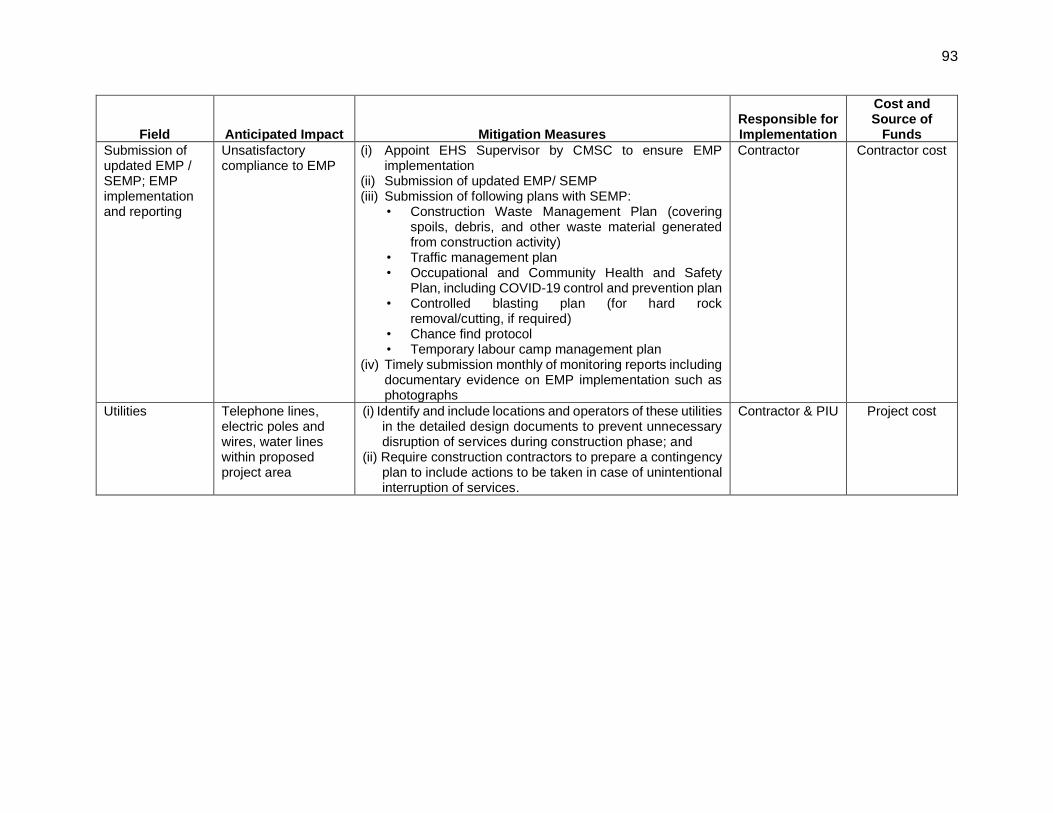
93
Field Anticipated Impact Mitigation Measures Responsible for Implementation
Cost and Source of
Funds
Submission of updated EMP / SEMP; EMP implementation and reporting
Unsatisfactory compliance to EMP
(i) Appoint EHS Supervisor by CMSC to ensure EMP implementation
(ii) Submission of updated EMP/ SEMP (iii) Submission of following plans with SEMP:
• Construction Waste Management Plan (covering spoils, debris, and other waste material generated from construction activity)
• Traffic management plan • Occupational and Community Health and Safety
Plan, including COVID-19 control and prevention plan • Controlled blasting plan (for hard rock
removal/cutting, if required) • Chance find protocol • Temporary labour camp management plan
(iv) Timely submission monthly of monitoring reports including documentary evidence on EMP implementation such as photographs
Contractor Contractor cost
Utilities Telephone lines, electric poles and wires, water lines within proposed project area
(i) Identify and include locations and operators of these utilities in the detailed design documents to prevent unnecessary disruption of services during construction phase; and
(ii) Require construction contractors to prepare a contingency plan to include actions to be taken in case of unintentional interruption of services.
Contractor & PIU Project cost

94
Field Anticipated Impact Mitigation Measures Responsible for Implementation
Cost and Source of
Funds
Construction work camps, stockpile areas, storage areas, and disposal areas.
Conflicts with local community; disruption to traffic flow and sensitive receptors
(i) Prioritize areas within or nearest possible vacant space in the project location;
(ii) If it is deemed necessary to locate elsewhere, consider sites that will not promote instability and result in destruction of property, vegetation, irrigation, and drinking water supply systems;
(iii) Do not consider residential areas; (iv) Take extreme care in selecting sites to avoid direct
disposal to water body, which will inconvenience the community.
(v) For excess spoil disposal, ensure (a) site shall be selected preferably from barren, infertile lands. In case agricultural land needs to be selected, written consent from landowners (not lessees) will be obtained; (b) debris disposal site shall be at least 200 m away from surface water bodies; (c) no residential areas shall be located within 100 m downwind side of the site; and (d) site is minimum 100 m away from sensitive locations like settlements, ponds/lakes or other water bodies.
Contractor to finalize locations in consultation and approval of PIU
Contractor cost
Consents, permits,
clearances, NOCs, etc.
Failure to obtain necessary consents, permits, NOCs, etc. can result to design
revisions and/or stoppage of works
(i) Obtain all necessary consents, permits, clearance, NOCs, etc. prior to award of civil works.
(ii) Ensure that all necessary approvals for construction to be obtained by contractor are in place before start of construction
(iii) Acknowledge in writing and provide report on compliance all obtained consents, permits, clearance, NOCs, etc.
Contractor and PIU
Cost of obtaining all consents, permits, clearance, NOCs, etc. prior to start of civil works responsibility of PIU

95
Field Anticipated Impact Mitigation Measures Responsible for Implementation
Cost and Source of
Funds
Chance finds Damage / disturbance to
artifacts
(i) Construction contractors to follow these measures in conducting any excavation work
(ii) Create awareness among the workers, supervisors and engineers about the chance finds during excavation work.
(iii) Stop work immediately to allow further investigation if any finds are suspected;
(iv) All fossils, coins, articles of value of antiquity, structures and other remains or things of geological or archaeological interest discovered on the site shall be the property of the Government and shall be dealt with as per provisions of the relevant legislation.
(v) Inform Archeological Survey of India / State Archaeological Department if a find is suspected and take any action required to ensure its removal or protection in situ.
Contractor and PIU
Contractor cost
Works in proposed area
Degradation of water quality due to entry of silt laden runoff
(i) No earthworks should be conducted during the monsoon season in general, and in particular no earth work to be conducted in subproject areas during monsoon season
(ii) Stockpiled material and earth/soil shall be properly covered with tarpaulins; bunds, silt traps/fences, etc.,
(iii) Install temporary silt traps or sedimentation basins along the drainage leading to the water bodies; it shall be ensured that no silt laden runoff or traces of fuels, lubricants or chemicals used in construction drains into any public areas.
(iv) Place storage areas for fuels and lubricants away from any drainage leading to water bodies;
(v) Store fuel, construction chemicals etc., on an impervious floor, also avoid spillage by careful handling; provide spill collection sets for effective spill management
(vi) No workers camp sites, storage areas etc., will not be located close to the wetland (< 1 km).
Contractor and PIU
Project cost
Temporary economic impacts
Disruption to vendors, hawkers on ROW during sewer
laying works
(i) Contractor is required to provide notice to the shop owners of the need to shift kiosk/wares displayed on ROW as soon as the work plan is ready, with minimum 7 working days.
(ii) No works can be commenced unless 100% shifted in sections ready for implementation.
Contractor and PIU
Project cost
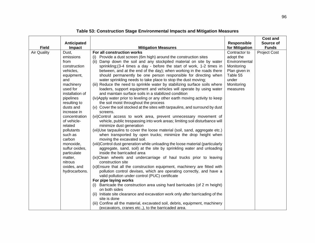
96
Table 53: Construction Stage Environmental Impacts and Mitigation Measures
Field Anticipated
Impact Mitigation Measures Responsible for Mitigation
Cost and Source of
Funds
Air Quality Dust, emissions from construction vehicles, equipment, and machinery used for installation of pipelines resulting to dusts and increase in concentration of vehicle-related pollutants such as carbon monoxide, sulfur oxides, particulate matter, nitrous oxides, and hydrocarbons.
For all construction works (i) Provide a dust screen (6m high) around the construction sites (ii) Damp down the soil and any stockpiled material on site by water
sprinkling;(3-4 times a day - before the start of work, 1-2 times in between, and at the end of the day); when working in the roads there should permanently be one person responsible for directing when water sprinkling needs to take place to stop the dust moving;
(iii) Reduce the need to sprinkle water by stabilizing surface soils where loaders, support equipment and vehicles will operate by using water and maintain surface soils in a stabilized condition
(iv)Apply water prior to leveling or any other earth moving activity to keep the soil moist throughout the process
(v) Cover the soil stocked at the sites with tarpaulins, and surround by dust screens.
(vi)Control access to work area, prevent unnecessary movement of vehicle, public trespassing into work areas; limiting soil disturbance will minimize dust generation
(vii)Use tarpaulins to cover the loose material (soil, sand, aggregate etc.) when transported by open trucks; minimize the drop height when moving the excavated soil.
(viii)Control dust generation while unloading the loose material (particularly aggregate, sand, soil) at the site by sprinkling water and unloading inside the barricaded area
(ix)Clean wheels and undercarriage of haul trucks prior to leaving construction site
(x)Ensure that all the construction equipment, machinery are fitted with pollution control devises, which are operating correctly, and have a valid pollution under control (PUC) certificate
For pipe laying works (i) Barricade the construction area using hard barricades (of 2 m height)
on both sides (ii) Initiate site clearance and excavation work only after barricading of the
site is done (iii) Confine all the material, excavated soil, debris, equipment, machinery
(excavators, cranes etc.,), to the barricaded area.
Contractor to adopt the Environmental Monitoring Plan given in Table 55 under Monitoring measures
Project Cost

97
Field Anticipated
Impact Mitigation Measures Responsible for Mitigation
Cost and Source of
Funds
(iv) Ensure that adequate cover is provided to the trenches to prevent emission of dust during controlled blasting. Limit the stocking of excavated material at the site; remove the excess soil from the site immediately to the designated disposal area
(v) Undertake the work section wise: a 500 m section should be demarcated and barricaded; open up several such sections at a time, but care shall be taken to locate such sections in different zones
(vi)Conduct work sequentially - excavation, Pipe laying, backfilling; testing section-wise (for a minimum length as possible) so that backfilling, stabilization of soil can be done.
(vii)Remove the excavated soil of first section to the disposal site; as the work progresses sequentially, by the time second section is excavated, the first section will be ready for back filling, use the freshly excavated soil for back filling, this will avoid stocking of material, and minimize the dust.
(viii)Backfilled trench at any completed section after removal of barricading will be the main source of dust pollution. The traffic, pedestrian movement and wind will generate dust from backfilled section. Road restoration shall be undertaken immediately.
(ix) Immediately consolidate the backfilled soil and restore the road surface; if immediate road restoration is not possible, provide a layer of plain cement concrete (PCC) of suitable mix on the backfilled trench so that dust generation, erosion is arrested and it will also provide a smooth riding surface for the traffic until the road is properly restored. Backfilled trench without any road restoration is a major source of dust.
(x) For sections involving controlled blasting, ensure that dust curtains of adequate height are provided to the trenches to prevent emission of dust during drilling for charge holes and controlled blasting.
(xi) Ensure that the excavated soil and debris along the section identified for blasting is sprinkled with adequate water prior to blasting to reduce dust emissions upon explosion of charge placed for breaking the hard rock;
Removal of rock during excavation works
Increase in vibration due to the controlled blasting and
(i) During excavation for works, wherever removal of rock is identified, alternatives like drilling and chiseling, controlled blasting (if required) etc will be examined and the suitable technology shall be finalised depending upon the site conditions. Following measures for ensuring safety shall be ensured during controlled blasting by EHS supervisor.
Construction Contractor
Cost for implementation of mitigation measures
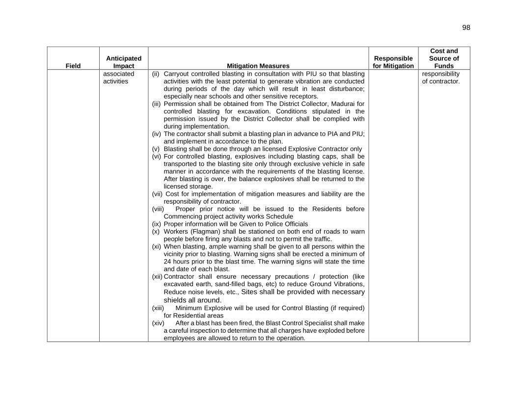
98
Field Anticipated
Impact Mitigation Measures Responsible for Mitigation
Cost and Source of
Funds
associated activities
(ii) Carryout controlled blasting in consultation with PIU so that blasting activities with the least potential to generate vibration are conducted during periods of the day which will result in least disturbance; especially near schools and other sensitive receptors.
(iii) Permission shall be obtained from The District Collector, Madurai for controlled blasting for excavation. Conditions stipulated in the permission issued by the District Collector shall be complied with during implementation.
(iv) The contractor shall submit a blasting plan in advance to PIA and PIU; and implement in accordance to the plan.
(v) Blasting shall be done through an licensed Explosive Contractor only (vi) For controlled blasting, explosives including blasting caps, shall be
transported to the blasting site only through exclusive vehicle in safe manner in accordance with the requirements of the blasting license. After blasting is over, the balance explosives shall be returned to the licensed storage.
(vii) Cost for implementation of mitigation measures and liability are the responsibility of contractor.
(viii) Proper prior notice will be issued to the Residents before Commencing project activity works Schedule
(ix) Proper information will be Given to Police Officials (x) Workers (Flagman) shall be stationed on both end of roads to warn
people before firing any blasts and not to permit the traffic. (xi) When blasting, ample warning shall be given to all persons within the
vicinity prior to blasting. Warning signs shall be erected a minimum of 24 hours prior to the blast time. The warning signs will state the time and date of each blast.
(xii) Contractor shall ensure necessary precautions / protection (like excavated earth, sand-filled bags, etc) to reduce Ground Vibrations,
Reduce noise levels, etc., Sites shall be provided with necessary shields all around.
(xiii) Minimum Explosive will be used for Control Blasting (if required) for Residential areas
(xiv) After a blast has been fired, the Blast Control Specialist shall make a careful inspection to determine that all charges have exploded before employees are allowed to return to the operation.
responsibility of contractor.

99
Field Anticipated
Impact Mitigation Measures Responsible for Mitigation
Cost and Source of
Funds
(xv) The contractor shall be responsible for any and all damage to property or injury to persons resulting from blasting or accidental or premature explosions that may occur in connection with his use of explosives.
(xvi) The contractor shall do the activities after obtaining the blasting permission from District Collector, Madurai.
(xvii) For the diversion of traffic in the blasting area, the contractor shall prepare a traffic management plan and obtain permission from Madurai Corporation and traffic police.
(xviii) Ensure to conduct a pre-blasting survey through videography and photography of residential properties and other structures falling along the alignment to ascertain the prevailing conditions of the structures likely to be impacted by the controlled blasting and take adequate measures to minimize such impacts
Asbestos cement pipes if encountered
Pollution to the environment
If asbestos cement pipes encountered during excavation it shall be handled as per the Hazardous and other Wastes (Management and Transboundary Movement) Rules 2016 as amended in 2019 by the contractor with consultation with PIU and CMSC Follow ADB’s Good Practice Guidance for the Management and Control of Asbestos Protecting Workplaces and Communities from Asbestos Exposure Risks (March 2022)6 in dealing with asbestos at work place
Construction Contractor
Cost for implementation of mitigation measures responsibility of contractor.
Surface water quality
Mobilization of settled silt materials, and chemical contamination from fuels and lubricants during construction can contaminate nearby
(i) All earthworks be conducted during the dry season to prevent the problem of soil/silt run-off during rains
(ii) Avoid stockpiling of earth fill especially during the monsoon season unless covered by tarpaulins or plastic sheets do not stock earth/material close to water bodies (at least100 m)
(iii) Prioritize re-use of excess spoils and materials in the construction works. If spoils will be disposed, only designated disposal areas shall be used;
(iv) Install temporary silt traps, oil traps, or sedimentation basins along the water leading to the water bodies; it shall be ensured that no silt laden runoff or traces of fuels, lubricants or chemicals used in construction drains into nearby water bodies.
Contractor to adopt the Environmental Monitoring Plan given in Table 55 under Monitoring measures
Project Cost
6 https://www.adb.org/sites/default/files/publication/783636/good-practice-management-control-asbestos.pdf

100
Field Anticipated
Impact Mitigation Measures Responsible for Mitigation
Cost and Source of
Funds
surface water quality.
(v) Place storage areas (with impermeable surface) for fuels and lubricants away from any drainage leading to water bodies; these should be at least 100 m away from water bodies and groundwater wells)
(vi) Store fuel, construction chemicals etc., on an impervious floor, also avoid spillage by careful handling; provide spill collection sets for effective spill management
(vii) Dispose any wastes generated by construction activities in designated sites;
Water accumulation in trenches/pits
(i) As far as possible control the entry of runoff from upper areas into the excavated pits, and work area by creation of temporary drains or bunds around the periphery of work area
(ii) Pump out the water collected in the pits / excavations to a temporary sedimentation pond; dispose off only clarified water into drainage channels/streams after sedimentation in the temporary ponds
(iii) Consider safety aspects related to pit collapse due to accumulation of water
Contractor Project Cost
Noise Levels Increase in noise level due to earth-moving and excavation equipment, and the transportation of equipment, materials, and people, and vibration
(i) Plan activities in consultation with PIU so that activities with the greatest potential to generate noise are conducted during periods of the day which will result in least disturbance especially near schools and other sensitive receptors
(ii) Minimize noise from construction equipment by using vehicle silencers, fitting jackhammers with noise-reducing mufflers, and use portable street barriers to minimise sound impact to surround sensitive receptor; and
(iii)Maintain maximum sound levels not exceeding 70 decibels (dB(A)) when measured at a distance of 10 m or more from the vehicle/s.
(iv)Identify any buildings at risk from vibration damage and avoiding any use of pneumatic drills or heavy vehicles in the vicinity; if any building at risk, structural survey be completed prior to work, to provide baseline in case any issues from vibration, and if building is structurally unsound that measures taken to avoid any further damage
(v) Horns should not be used unless it is necessary to warn other road users or animals of the vehicle’s approach; (vi)Consult local communities in advance of the work to identify and
address key issues, and avoid working at sensitive times, such as night time’s religious and cultural festivals.
Contractor to adopt the Environmental Monitoring Plan given in Table 55 under Monitoring measures
Project Cost

101
Field Anticipated
Impact Mitigation Measures Responsible for Mitigation
Cost and Source of
Funds Controlled blasting
Ground vibrations Noise (air blast) Flying debris Dust
(i) Carryout controlled blasting in consultation with PIU so that blasting activities are conducted during periods of the day which will result in least disturbance; especially near schools and other sensitive receptors.
(ii) The contractor shall submit a blasting plan in advance to PIU for approval; and implement in accordance to the plan once approved.
(iii) The controlled blasting at identified locations shall be permitted only after the requisite statutory permissions from regulatory authorities are obtained. The contractor shall comply with all terms and conditions stipulated in such permissions. The controlled blasting would be monitored by following the necessary requirements to prevent safety risk to both public and nearby structures as provisioned in the prevailing Indian regulations and standards.
(iv) Blasting shall be carried out through a licensed Explosive Contractor only.
(v) For controlled blasting, explosives including blasting caps, shall be transported to the blasting site only through exclusive vehicle in safe manner in accordance with the requirements of the blasting license. After blasting is over, the balance explosives shall be returned to the licensed storage.
(vi) Cost for implementation of mitigation measures and liability are the responsibility of contractor.
(vii) Proper prior notice will be issued to the residents before commencing blasting activity works. Inform the residents likely to be affected by the works in the locality about the upcoming blasting works well in advance so that necessary arrangements are planned by the residents with reduced inconvenience.
(viii) For sections where the controlled blasting is proposed, the residents shall be provided with the schedule of blasting at least three days in advance and the residents are explained about the preventive, precautionary, mitigation and emergency response measures being taken to address their concerns.
(ix) Prior information will be given to Police Officials (x) Workers (Flagman) shall be stationed on both end of roads to warn
people before firing any blasts and not to permit the traffic. The section proposed for blasting shall be supervised by properly trained staff to ensure no movement of pedestrians, motorized or non-
Contractor and PIU
Contractor Costs

102
Field Anticipated
Impact Mitigation Measures Responsible for Mitigation
Cost and Source of
Funds
motorized vehicles, and residents takes place during blasting within the area of influence. For the diversion of traffic in the blasting area, the contractor shall prepare a traffic management plan and obtain permission from Madurai City Municipal Corporation and traffic police.
(xi) When blasting, ample warning shall be given to all persons within the vicinity prior to blasting. Warning signs shall be erected a minimum of 24 hours prior to the blast time. The warning signs will state the time and date of each blast.
(xii) Sites shall be provided with necessary shields all around. (xiii) Minimum explosive will be used for Controlled Blasting specifically
within residential areas. (xiv) After a blast has been fired, the Blast Control Specialist shall make
a careful inspection to determine that all charges have exploded before employees are allowed to return to the operation, and subsequently the movement of residents /pedestrians and vehicles is permitted.
(xv) Ensure appropriate measures are taken to maintain maximum ambient noise levels within the limits as permitted by the prevailing Indian regulations and standards. The ambient noise levels would be monitored to ascertain the efficacy of acoustic measures thus implemented and compliance with associated regulatory permissions.
(xvi) Ensure that adequate precautions are taken to avoid flying debris post blasting (such as covering the trench with sturdy metallic sheets with sand filled bags to absorb the blast waves);
(xvii) For sections involving controlled blasting, ensure that dust curtains of adequate height are provided to the trenches to prevent emission of dust during drilling for charge holes and controlled blasting.
(xviii) Ensure that the excavated soil and debris along the section identified for blasting is sprinkled with adequate water prior to blasting to reduce dust emissions upon explosion of charge placed for breaking the hard rock.
(xix) The project staff from the PIU, CMSC and contractors would undertake a post-blasting survey of structures (including videography and/or photography) lying within the area of influence

103
Field Anticipated
Impact Mitigation Measures Responsible for Mitigation
Cost and Source of
Funds
of blasting from the vibrations related impacts (preferably in the presence of the owners of the said structures) to assess and/or ascertain regarding the damages, if any, caused to the structures because of blasting activities.
(xx) The contractor shall be responsible for any and all damages to property or injury to persons resulting from blasting or accidental or premature explosions that may occur in connection with use of explosives. The log of such events would be properly maintained. The contractor shall provide immediate support and relief measures commensurate with the damages.
(xxi) Training related to controlled blasting activity will be included in the overall safeguards training programme meant for PIU, CMSC and Contractors.
Landscape and aesthetics – waste generation
Impacts due to excess excavated earth, excess construction materials, and solid waste such as removed concrete, wood, packaging materials, empty containers, spoils, oils, lubricants, and other similar items.
(i) Prepare and implement a Construction Waste Management Plan (refer Appendix 4)
(ii) As far as possible utilize the debris and excess soil in construction purpose, for example for raising the ground level or construction of access roads etc.,
(iii)Avoid stockpiling any excess spoils at the site for long time. Excess excavated soils should be disposed off to approved designated areas immediately
(iv)If disposal is required, the site shall be selected preferably from barren, infertile lands; sites should located away from residential areas, forests, water bodies and any other sensitive land uses
(v) Domestic solid wastes should be properly segregated in biodegradable and non-biodegradable for collection and disposal to designated solid waste disposal site; create a compost pit (with impermeable bottom and sides)at workers camp sites for disposal of biodegradable waste; non-biodegradable / recyclable material shall be collected separately and sold in the local recycling material market
(vi)Residual and hazardous wastes such as oils, fuels, and lubricants shall be disposed off via licensed (by TNPCB) third parties;
(vii)Prohibit burning of construction and/or domestic waste; (viii)Ensure that wastes are not haphazardly thrown in and around the
project site; provide proper collection bins and create awareness to use the dustbins recycle waste material where possible.
Contractor Project Cost

104
Field Anticipated
Impact Mitigation Measures Responsible for Mitigation
Cost and Source of
Funds
(ix)Conduct site clearance and restoration to original condition after the completion of construction work; PIU to ensure that site is properly restored prior to issuing of construction completion certificate.
Accessibility and traffic disruptions
Traffic problems and conflicts near project locations and haul road
Pipe laying works (i) Prepare a pipe laying work implementation plan in each zone separately
and undertake the work accordingly; ensure that for each road where the work is being undertaken there is an alternative road for the traffic diversion; take up the work in sequential way so that public inconvenience is minimal; prepare traffic management plans for each section (refer sample in Appendix 5)
(ii) Plan the pipe laying work in coordination with the traffic police; provide temporary diversions, where necessary with clear signage and effectively communicate with general public
(iii)Avoiding conducting work in all roads in a colony at one go; it will render all roads unusable due to excavations at the same time, creating large scale inconvenience
(iv)Undertake the work section wise: a 100m section should be demarcated and barricaded; open up several such sections at a time, but care shall be taken to locate such sections in different zones
(v) Confine work areas in the road carriageway to the minimum possible extent; all the activities, including material and waste/surplus soil stocking should be confined to this area. Proper barricading should be provided; avoid material/surplus soil stocking in congested areas – immediately removed from site/ or brought to the as and when required
(vi)Limit the width of trench excavation as much as possible by adopting best construction practices; adopt vertical cutting approach with proper shoring and bracing; this is especially to be practiced in narrow roads and deeper excavation; if they deep trenches are excavated with slopes, the roads may render completely unusable during the construction period
(vii)Leave spaces for access between mounds of soil to maintain access to the houses / properties; access to any house or property shall not be blocked completely; alternative arrangements, at least to maintain pedestrian access at all times to be provided
Contractor Project Cost

105
Field Anticipated
Impact Mitigation Measures Responsible for Mitigation
Cost and Source of
Funds
(viii)Provide pedestrian access in all the locations; provide wooden/metal planks with safety rails over the open trenches at each house to maintain the access.
(ix)Inform the affected local population about the work schedule a week before, and a day before to start of work
(x) Plan and execute the work in such a way that the period of disturbance/ loss of access are minimum.
(xi)Keep the site free from all unnecessary obstructions; (xii)Notify affected public-by-public information notices, providing
signboards informing nature and duration of construction works and contact numbers for concerns/complaints.
(xiii)At work site, public information/caution boards shall be provided including contact for public complaints
(xiv) Wherever required, consult with local communities in advance of the work to identify and address key issues, and avoid working at sensitive times, such as religious and cultural festivals.
(xv) Works shall be scheduled without creating any inconvenience or safely issue to tourists or visitors to the city/workers, especially in case of roads leading to temples, heritage sites and busy roads.
Construction work (i) Prepare work implementation plan separately and undertake the
work accordingly; ensure that for site / each road where the work is to be undertaken there is an alternative road for the traffic diversion; take up the work in sequential way so that public inconvenience is minimal; prepare traffic management plans for each section.
(ii) Plan the Construction work in coordination with the traffic police; provide temporary diversions, where necessary with clear signage and effectively communicate with general public
(iii) Avoiding conducting work in all roads in a colony at one go; it will render all roads unusable due to excavations at the same time, creating large scale inconvenience
(iv) Confine work areas in the road carriageway to the minimum possible extent; all the activities, including material and waste/surplus soil stocking should be confined to this area. Proper barricading should be provided; avoid material/surplus soil stocking in congested areas – immediately removed from site/ or brought to the as and when required

106
Field Anticipated
Impact Mitigation Measures Responsible for Mitigation
Cost and Source of
Funds
(v) Limit the width of trench excavation as much as possible by adopting best construction practices; adopt vertical cutting approach with proper shoring and bracing; this is especially to be practiced in narrow roads and deeper sewers; if they deep trenches are excavated with slopes, the roads may render completely unusable during the construction period
(vi) Leave spaces for access between mounds of soil to maintain access to the houses / properties; access to any house or property shall not be blocked completely; alternative arrangements, at least to maintain pedestrian access at all times to be provided
(vii) Provide pedestrian access in all the locations; provide wooden/metal planks with safety rails over the open trenches at each house to maintain the access.
(viii) Inform the affected local population about the work schedule, a week before, and a day before to start of work
(ix) Plan and execute the work in such a way that the period of disturbance/ loss of access are minimum.
(x) Keep the site free from all unnecessary obstructions; (xi) Notify affected public by public information notices, providing sign
boards informing nature and duration of construction works and contact numbers for concerns/complaints. Provide information to the public through media – newspapers and local cable television (TV) services
(x) At work site, public information/caution boards shall be provided including contact for public complaints.
Controlled blasting (If required) (i) The contractor shall submit a blasting plan in advance to PIU; and
implement in accordance to the plan. (ii) Proper prior notice will be issued to the Residents before
Commencing activity works Schedule (iii) Proper information will be Given to Police Officials (iv) Workers (Flagman) shall be stationed on both end of roads to warn
people before firing any blasts and not to permit the traffic. (v) When blasting, ample warning shall be given to all persons within the
vicinity prior to blasting. Warning signs shall be erected a minimum

107
Field Anticipated
Impact Mitigation Measures Responsible for Mitigation
Cost and Source of
Funds
of 24 hours prior to the blast time. The warning signs will state the time and date of each blast.
(vi) For the diversion of traffic in the blasting area, the contractor shall prepare a traffic management plan and obtain permission from respective local bodies/ Madurai City Municipal Corporation and traffic police.
Hauling (material, waste/debris and equipment) activities (i) Plan transportation routes so that heavy vehicles do not use narrow
local roads, except in the immediate vicinity of delivery sites (ii) Schedule transport and hauling activities during non-peak hours(peak
hours 7 to 10 AM and 4 to 7 PM); (iii)Locate entry and exit points in areas where there is low potential for
traffic congestion; (iv)Drive vehicles in a considerate manner (v) Notify affected public by public-information notices, providing sign
boards informing nature and duration of construction works and contact numbers for concerns/complaints.
EMP Implementation Training
Irreversible impact to the environment, workers, and community
(i) Project manager and all key workers will be required to undergo training on EMP implementation including spoils/waste management, Standard operating procedures (SOP) for construction works; occupational health and safety (OH and S), core labor laws, applicable environmental laws, etc.
Contractor Contractor cost
Socio-Economic Loss of access to houses and business
Loss of income
(i) Inform all businesses and residents about the nature and duration of any work well in advance so that they can make necessary preparations;
(ii) Do not block any access; leave spaces for access between barricades/mounds of excavated soil and other stored materials and machinery, and providing footbridges so that people can crossover open trenches
(iii)Barricade the construction area and regulate movement of people and vehicles in the vicinity, and maintain the surroundings safely with proper direction boards, lighting and security personnel – people should feel safe to move around
(iv)Control dust generation (v) Immediately consolidate the backfilled soil and restore the road surface;
this will also avoid any business loss due to dust and access inconvenience of construction work.
Contractor Contractor cost

108
Field Anticipated
Impact Mitigation Measures Responsible for Mitigation
Cost and Source of
Funds
(vi)Employee best construction practices, speed up construction work with better equipment, increase workforce, etc., in the areas with predominantly commercial, and with sensitive features like hospitals, and schools;
(vii)Consult businesses and institutions regarding operating hours and factoring this in work schedules; and
(viii)Provide sign boards for pedestrians to inform nature and duration of construction works and contact numbers for concerns/complaints.
Socio-Economic – Employment
Generation of temporary employment and increase in local revenue
(i) Employ local labour force as far as possible (ii) Comply with labor laws
Contractor Contractor cost
Occupational Health and Safety
Occupational hazards which can arise during work
(i) Follow all national, state and local labour laws (indicative list is in Appendix 2);
(ii) Develop and implement site-specific occupational health and safety (OH and S) Plan which shall include measures such as: (a) safe and documented construction procedures to be followed for all site activities; (b) ensuring all workers are provided with and use personal protective equipment; (c) OH and S Training for all site personnel, (d) excluding public from the work sites; and (e) documentation of work-related accidents; Follow International Standards such as the World Bank Group’s Environment, Health and Safety Guidelines and For controlled blasting activity, identify the risks involved for the labourers and public and include measures in the OHS plan. Provide necessary training and PPEs to the labourers to ensure safety during implementation.
(iii) Ensure that qualified first-aider is available at all times. Equipped first-aid stations shall be easily accessible throughout the sites;
(iv) Secure all installations from unauthorized intrusion and accident risks (v) Provide H and S orientation training to all new workers to ensure that
they are apprised of the basic site rules of work at the site, personal protective protection, and preventing injuring to fellow workers;
(vi) Provide visitor orientation if visitors to the site can gain access to areas where hazardous conditions or substances may be present. Ensure also that visitor/s do not enter hazard areas unescorted;
Contractor Contractor cost

109
Field Anticipated
Impact Mitigation Measures Responsible for Mitigation
Cost and Source of
Funds
(vii) Ensure the visibility of workers through their use of high visibility vests and other PPE when working in or walking through heavy equipment operating areas;
(viii) Ensure moving equipment is outfitted with audible back-up alarms; (ix) Mark and provide sign boards for hazardous areas such as energized
electrical devices and lines, service rooms housing high voltage equipment, and areas for storage and disposal. Signage shall be in accordance with international standards and be well known to, and easily understood by workers, visitors, and the general public as appropriate; and
(x) Disallow worker exposure to noise level greater than 85 dBA for duration of more than 8 hours per day without hearing protection. The use of hearing protection shall be enforced actively.
(xi) Provide supplies of potable drinking water; (xii) Provide clean eating areas where workers are not exposed to
hazardous or noxious substances
Community Health and Safety.
Traffic accidents and vehicle collision with pedestrians during material and waste transportation
(i) Consult PIU before locating project offices, sheds, and construction plants;
(ii) Select a campsite away from residential areas (at least 100 m buffer shall be maintained) or locate the campsite within the existing facilities of City Corporation.
(iii)Avoid tree cutting for setting up camp facilities. (iv)Provide a proper fencing/compound wall for campsites. (v) Camp site shall not be located near (100 m) water bodies, flood plains
flood prone/low lying areas, or any ecologically, socially, archeologically sensitive areas.
(vi)Separate the workers living areas and material storage areas clearly with a fencing and separate entry and exit.
(vii)Ensure conditions of liveability at work camps are maintained at the highest standards possible at all times; living quarters and construction camps shall be provided with standard materials (as far as possible to use portable ready to fit-in reusable cabins with proper ventilation); thatched huts, and facilities constructed with materials like GI sheets, tarpaulins, etc., shall not be used as accommodation for workers.
(viii)Camp shall be provided with proper drainage, there shall not be any water accumulation.
Contractor Contractor cost
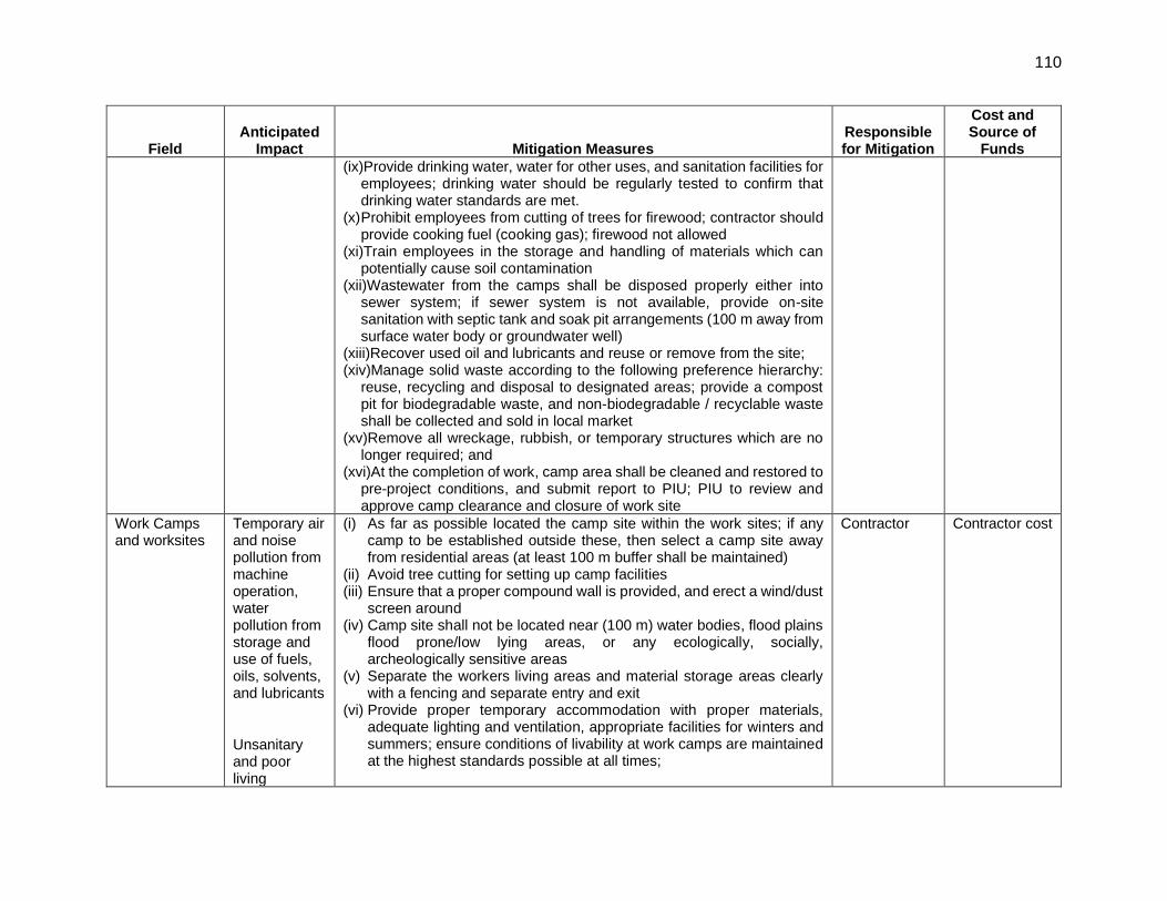
110
Field Anticipated
Impact Mitigation Measures Responsible for Mitigation
Cost and Source of
Funds
(ix)Provide drinking water, water for other uses, and sanitation facilities for employees; drinking water should be regularly tested to confirm that drinking water standards are met.
(x) Prohibit employees from cutting of trees for firewood; contractor should provide cooking fuel (cooking gas); firewood not allowed
(xi)Train employees in the storage and handling of materials which can potentially cause soil contamination
(xii)Wastewater from the camps shall be disposed properly either into sewer system; if sewer system is not available, provide on-site sanitation with septic tank and soak pit arrangements (100 m away from surface water body or groundwater well)
(xiii)Recover used oil and lubricants and reuse or remove from the site; (xiv)Manage solid waste according to the following preference hierarchy:
reuse, recycling and disposal to designated areas; provide a compost pit for biodegradable waste, and non-biodegradable / recyclable waste shall be collected and sold in local market
(xv)Remove all wreckage, rubbish, or temporary structures which are no longer required; and
(xvi)At the completion of work, camp area shall be cleaned and restored to pre-project conditions, and submit report to PIU; PIU to review and approve camp clearance and closure of work site
Work Camps and worksites
Temporary air and noise pollution from machine operation, water pollution from storage and use of fuels, oils, solvents, and lubricants
Unsanitary and poor living
(i) As far as possible located the camp site within the work sites; if any camp to be established outside these, then select a camp site away from residential areas (at least 100 m buffer shall be maintained)
(ii) Avoid tree cutting for setting up camp facilities (iii) Ensure that a proper compound wall is provided, and erect a wind/dust
screen around (iv) Camp site shall not be located near (100 m) water bodies, flood plains
flood prone/low lying areas, or any ecologically, socially, archeologically sensitive areas
(v) Separate the workers living areas and material storage areas clearly with a fencing and separate entry and exit
(vi) Provide proper temporary accommodation with proper materials, adequate lighting and ventilation, appropriate facilities for winters and summers; ensure conditions of livability at work camps are maintained at the highest standards possible at all times;
Contractor Contractor cost

111
Field Anticipated
Impact Mitigation Measures Responsible for Mitigation
Cost and Source of
Funds
conditions for workers
(vii) Consult PIU before locating project offices, sheds, and construction plants;
(viii)Minimize removal of vegetation and disallow cutting of trees (ix) Ensure conditions of livability at work camps are maintained at the
highest standards possible at all times; living quarters and construction camps shall be provided with standard materials (as far as possible to use portable ready to fit-in reusable cabins with proper ventilation); thatched huts, and facilities constructed with materials like GI sheets, tarpaulins, etc., shall not be allowed as accommodation for workers
(x) Camp shall be provided with proper drainage, there shall not be any water accumulation
(xi) Provide drinking water, water for other uses, and sanitation facilities for employees
(xii) Prohibit employees from cutting of trees for firewood; contractor should be provide proper facilities including cooking fuel (oil or gas; fire wood not allowed)
(xiii)Train employees in the storage and handling of materials which can potentially cause soil contamination
(xiv)Recover used oil and lubricants and reuse or remove from the site (xv)Manage solid waste according to the following preference hierarchy:
reuse, recycling and disposal to designated areas; provide a compost pit for biodegradable waste, and non-biodegradable / recyclable waste shall be collected and sold in local market
(xvi)Remove all wreckage, rubbish, or temporary structures which are no longer required
(xvii)At the completion of work, camp area shall be cleaned and restored to pre-project conditions and submit report to PIU; PIU to review and approve camp clearance and closure of work site.

112
Field Anticipated
Impact Mitigation Measures Responsible for Mitigation
Cost and Source of
Funds
COVID 19 control measures
Health & Safety of the labourers and community
(i) Construction sites operating during the COVID-19 pandemic need to ensure they are protecting their Workforce and minimising the risk of spread of infection. (ii) Labourer’s shall be provided trainings, orientation of COVID related regulations. (iii) COVID 19 related hygiene facilities and guidance shall be made available for the labourers in the work sites and accommodation. (iv) SOPs and guidelines issued by GOI and GoTN from time to time to prevent spread of Covid19 are adhered to in the work sites and camp area during sub-project implementation. (Details given in Appendix 12.).
Contractor Contractor cost
Post-construction clean-up
Damage due to debris, spoils, excess construction materials
(i) Remove all spoils wreckage, rubbish, or temporary structures (such as buildings, shelters, and latrines) which are no longer required; and
(ii) All excavated roads shall be reinstated to original condition. (iii) All disrupted utilities restored (iv) All affected structures compensated (v) The area that previously housed the construction camp is to be checked
for spills of substances such as oil, etc. and these shall be cleaned up. (vi) The contractor must arrange the cancellation of all temporary services. (vii) Request PIU to report in writing that worksites and camps have been
vacated and restored to pre-project conditions before acceptance of work.
Contractor Contractor cost
Table 54: Operation Stage Environmental Impacts and Mitigation Measures
Field Anticipated
Impact Mitigation Measures
Responsible for
Mitigation
Cost and Source of
Funds
Operation and maintenance of distribution system
Blocks, overflows, system malfunction, occupational health and safety
(i) Establish regular maintenance program, including: ● Regular cleaning of grit chambers and lines to remove grease, grit,
and other debris that may lead to water backups. Cleaning should be conducted more frequently for problem areas
● Inspection of the condition of distribution system and identifying areas that need repair or maintenance. Items to note may include cracked/deteriorating pipes; leaking joints or seals; frequent line blockages; lines that generally flow at or near capacity; and
● Monitoring of water flow to identify potential inflows and outflows
PIU Operating costs

113
Field Anticipated
Impact Mitigation Measures
Responsible for
Mitigation
Cost and Source of
Funds
(ii) Develop an Emergency Response System for the water system leaks, burst and overflows, etc.
(iii) Provide all necessary personnel protection equipment

114
Table 55: Construction Stage Environmental Monitoring Plan
Monitoring field
Monitoring location
Monitoring parameters Frequency Responsibility Cost and Source of
Funds
Construction disturbances, nuisances, public and worker safety,
All work sites Implementation of construction stage EMP including dust control, noise control, traffic management, and safety measures during controlled blasting. Site inspection checklist to review implementation is appended at Appendix6
Weekly during construction
Supervising staff and safeguards specialists of CMSC
Staff and consultant costs are part of incremental administration costs
Ambient air quality
(120 (10 x 12) Samples)
locations 50 m downwind direction near work sites in the sub project area;
● PM10, PM2.5 NO2, SO2, CO Once before start of work and
Quarterly (yearly 4-times) during work period
Contractor in consultation with CMSC
Cost for implementation of monitoring measures responsibility of contractor
Ambient noise
(120 (10 x 12) Samples)
locations near water distribution station;
● Day time and nighttime noise levels
Once before start of work and
Quarterly (yearly 4-times) during work period
Contractor in consultation with CMSC
Cost for implementation of monitoring measures responsibility of contractor
Soil Monitoring
(120 (10 x 12) Samples)
Near work sites ● Monitoring of Pb, SAR and Oil & Grease
Once before start of work and
Quarterly (yearly 4-times) during work period
Contractor in consultation with CMSC
Cost for implementation of monitoring measures responsibility of contractor
Water Monitoring
(120 (10 x 12) Samples)
Near work sites ● Monitoring of pH, TDS, Calcium, Chloride etc
Once before start of work and
Quarterly (yearly 4-times) during work period
Contractor in consultation with CMSC
Cost for implementation of monitoring measures responsibility of contractor

115
Table 56: Operation Stage Environmental Monitoring Plan
Monitoring field
Monitoring location
Monitoring parameters Frequency Responsibility Cost and Source of
Funds
Water quality Various locations at the OHT outlet
Turbidity Color Odor pH value @ 25ºC Total Dissolved Solids @105ºC Calcium (as Ca) Chlorides (as Cl-) Magnesium (as Mg) Sulphates (as SO4
-2) Total Alkalinity (as CaCO3) Total Hardness (as CaCO3) Iron (as Fe) Free Residual Chlorine, Total Coliform
Monthly Once Madurai City Municipal Corporation Defects liability period is one year after trial run and commissioning. Cost maintenance for next 5 years
Operating Cost
Various locations in the distribution system
Residual chlorine Daily Random sampling month
Noise level monitoring
Various locations in the distribution system
Day time and nighttime noise levels (24 hours)
Monthly Once

116
A. Implementation Arrangements
186. The Municipal and Water Supply Department (MAWS) acting through TNUIFSL will be the executing agency. A program steering committee, headed by Principal Secretary, MAWS, Government of Tamil Nadu, will provide overall guidance and strategic directions to the program. A PMU for TNUFIP, headed by the Managing Director, TNUIFSL acting as Program Director has been established within TNUIFSL for overall management, planning, implementing, monitoring, reporting, and coordinating TNUFIP. The CMA will act as the Deputy Program Director in the PMU. The MCMC will be the implementing agencies for works in cities/towns and will establish PIUs headed by a City Engineer as full-time Project Manager. PIUs will comprise of dedicated staff responsible for overseeing implementation of projects on a day-to-day basis. The PIUs will be supported by a CMSC recruited by TNUIFSL. For the institutional capacity, public awareness, and urban governance component, CMA acting through its Commissioner, will establish a PIU and appoint a Governance Improvement and Awareness Consultant (GIAC) responsible for supporting these activities. The implementing agency for this subproject is Madurai City Municipal Corporation. A PIU established in Madurai City Municipal Corporation headed by City Engineer (Madurai City Municipal Corporation) and comprising dedicated full-time staff from engineering and other departments of Madurai City Municipal Corporation. PIU under the Madurai City Municipal Corporation will be responsible for planning, implementation, monitoring and supervision, and coordination of all activities of subproject. A CMSC will be appointed to assist PIU in day-to-day implementation of the subproject.
187. Safeguards Compliance Responsibilities. ESS in the PMU in TNUIFSL will have overall responsibility of safeguard compliance with norms. ESS Managers report to Vice President in the Projects Wing. ESS Managers (TNUIFSL) will report to the Head, Projects Division. The Assistant Executive Engineer in charge of the project, will coordinate safeguard tasks at Madurai City Municipal Corporation. As expert support is available to Madurai City Municipal Corporation via CMSC, and the role of Assistant Executive Engineer will be mainly to coordination, overseeing the implementation of safeguard tasks, grievance redress and reporting.
188. PMU Safeguard Responsibilities. Key tasks and responsibilities of the ESS Manager (Environment), for this subproject include the following:
1. DPR finalization and Bidding stage: (i) Ensure that all design related measures of the EMP are included designs; (ii) Ensure that EMP is included in bidding documents and civil works contracts
including requirement for EHS supervisor with the contractor; (iii) Ensure that the bid/contract documents include specific provisions requiring
contractors to comply with all applicable labour laws and core labour standards; (iv) Ensure that staff required for implementation of EMP (EHS officer) is included in the
bid requirements; (v) Ensure that EMP cost is included in the project cost; and (vi) Prior to invitation of bids and prior to award of contract, ensure that all
clearance/permissions as required for implementation of subproject are in place to the extent possible.
2. Construction stage: (i) Prior to start of construction:
(a) Ensure that all necessary clearances/permissions/licenses, including that of contractor’s are in place prior to start of construction; and

117
(b) Provide oversight on environmental management aspects of subprojects and ensure EMPs are implemented by PIU and contractors.
(ii) Oversee and provide guidance to the PIU to properly carry out the environmental monitoring as per the EMP;
(iii) Oversee grievance redress mechanism to address any grievances brought about in a timely manner; ensure that records are properly maintained;
(iv) Consolidate quarterly environmental monitoring reports from PIU and submit semi-annual monitoring reports to TNUIFSL; and
(v) Oversee site closures to ensure that all work / facility sites are restored properly prior to issuing work completion certificate to the contractor.
3. Operation stage:
189. Ensure that the quality of the water supply from the system developed under the subproject is in compliance with all government regulations, standards and conditions.
190. PIU Safeguard Responsibilities. Key tasks and responsibilities of the PIU assisted by CMSC for this subproject include the following:
1. DPR finalization and Bidding stage: (i) Include design related measures of the EMP in the project design and DPR; (ii) Include EMP in the bidding documents and civil works contracts, including
requirement of staff (EHS supervisor) with contractor for EMP implementation; (iii) Provide necessary budget in the project as IEE for EMP Implementation; (iv) Ensure that the bid/contract documents include specific provisions requiring
contractors to comply with all applicable labour laws and core labour standards including: a. Labour welfare measures and provision of amenities; b. Prohibition of child labour as defined in national legislation for construction and
maintenance activities; c. Equal pay for equal work of equal value regardless of gender, ethnicity, or
caste; d. Elimination of forced labour; e. The requirement to disseminate information on sexually transmitted diseases,
including HIV/AIDS/ COVID 19, to employees and local communities surrounding the project sites.
(v) In the pre-bid meeting, provide insight into EMP measures, and overall compliance requirements to the bidders; and
(vi) Obtain all clearance/permissions as required for implementation of subproject, prior to invitation of bids and/or prior to award of contract / prior to construction as appropriate.

118
2. Construction stage: (i) Identify regulatory clearance requirements and obtain all necessary clearances prior
to start of construction; ensure construction work by contractor is conducted in compliance with all government rules and regulations including pollution control, labour welfare and safety etc.;
(ii) Prior to start of construction organize an induction course for the training of contractors, preparing them on EMP implementation, environmental monitoring, and on taking immediate action to remedy unexpected adverse impacts or ineffective mitigation measures found during the course of implementation;
(iii) Ensure contractor compliance with staff resources as per the IEE/EMP/Bid; (iv) Guide contractor on updating EMP / preparing Site Environmental Plan at the start
of the project; (v) Update IEE and EMP; ensure that IEE reflects the final design being implemented
by contractor; (vi) Conduct public consultation and information disclosure as necessary; (vii) Take necessary action for obtaining ROW; (viii) Supervise day-to-day EMP implementation on site by contractor, including the
environmental monitoring plan; (ix) Supervise ambient environmental monitoring by contractors; (x) Take corrective actions when necessary to ensure no environmental impacts; (xi) Submit quarterly environmental monitoring reports to PMU; (xii) Conduct continuous public consultation and awareness; (xiii) Address any grievances brought about through the grievance redress mechanism
in a timely manner as per the EMP; (xiv) Monitor Contractor’s compliance with the measures set forth in the EMP and any
corrective or preventative actions set forth in a safeguards monitoring report that the PMU will prepare from time to time;
(xv) Implement corrective or preventative actions in case of non-compliance or new/unanticipated impacts;
(xvi) Inform PMU promptly in case if any significant impacts surfaces, which were not identified in the IEE and develop necessary corrective actions as necessary and ensure implementation by the contractors; include all such impacts and suggested actions in the Quarterly Environmental Monitoring Reports;
(xvii) Implementation grievance redress system, and undertake appropriate actions to redress the complaints; ensure that complaints/grievances are addressed in a timely manner and resolutions are properly documented;
(xviii) Review and approve monthly progress reports submitted by Contractor on EMP compliance;
(xix) Prepare quarterly environmental monitoring reports and submit to PMU /TNUIFSL; and
(xx) Provide any assistance in environmental safeguard related tasks as required by PMU to ensure compliance and reporting to ADB.
3. Operation stage:
(i) Obtain all clearances as required for operation of project prior to operation; (ii) Conduct environmental management and monitoring activities as per the EMP; and (iii) Ensure that conveyance system constructed and operated with all necessary
clearances and approvals, and compliance with standards and conditions.

119
191. Contractor’s Responsibilities:
1. Bidding stage:
(i) Understand the EMP requirements and allocate necessary resources (budget, staff, etc.); and
(ii) Understand the regulatory compliance requirements related to labour welfare, safety, environment etc.
2. Construction stage:
(i) Mobilize EHS Supervisor prior to start of work; (ii) Prepare SEMP and submit to PIU in MCMC; (iii) Ensure that all regulatory clearances (both projects related and contractor related)
are in place prior start of the construction work; (iv) Confirm with PIU availability of rights of way at all project sites prior to start of work; (v) Prepare and submit:
a. Construction waste management(CWM) plan (sample is in Appendix 4); b. Traffic management plan (sample is Appendix 5).
(vi) Implement the mitigation measures as per the EMP including CWM and traffic management plans;
(vii) Follow the EMP measures/guidelines for establishment of temporary construction camps, construction waste disposal sites, and material borrow areas, etc.;
(viii) Implement EMP and ensure compliance with all the mitigation and enhancement measures;
(ix) Conduct environmental monitoring (air, noise, water, etc.), as per the EMP; (x) Undertake immediate action as suggested by PIU to remedy unexpected adverse
impacts or ineffective mitigation measures found during the course of implementation;
(xi) Submit monthly progress reports on EMP implementation to PIU; (xii) Act promptly on public complaints and grievances related to construction work and
redress in a timely manner in coordination with PIU and CMSC; and (xiii) Comply with applicable government rules and regulations.
B. Training Needs
192. Table 57 presents the outline of capacity building program to ensure EMP implementation. These capacity building and trainings will be conducted at the offices of PMU and PIU by the environmental safeguards specialist of PMU/PIU and their consultants, which are part of project implementation set-up, and therefore no separate or additional costs are envisaged. Adequate costs are already considered in project’s capacity building program. The detailed program and specific modules will be customized for the available skill set after assessing the capabilities of the target participants and the requirements of the project by the PMU.

120
Table 57: Outline Capacity Building Program on EMP Implementation
Description Target Participants
and Venue Cost and Source
of Funds
1. Introduction and Sensitization to Environmental Issues (1 day)
- ADB Safeguards Policy Statement - Government of India and Tamil Nadu
applicable safeguard laws, regulations and policies including but not limited to core labor standards, OHS, etc.
- Incorporation of EMP into the project design and contracts
- Monitoring, reporting and corrective action planning
All staff and consultants involved in the project
At PMU (combined program for all PIU)
Included in the overall program cost
2. EMP implementation (1/2 day) - EMP mitigation and monitoring measures -Roles and responsibilities - Public relations, - Consultations - Grievance redress - Monitoring and corrective action planning - Reporting and disclosure - Construction site SOP - Chance find (archeological) protocol - Traffic management plan - Waste management plan - Site clean-up and restoration - Controlled Blasting
All PIU staff, contractor staff and consultants involved in the subproject
At PIU
To be conducted by CMSC at the PIU office; part of project implementation cost
3. Contractors Orientation to Workers (1/2 day) - Environment, health and safety in project
construction Health & safety measures during coronavirus
disease (COVID-19) pandemic
Before start of work, regular briefing is done once in every month. Daily briefing on safety prior to start of work All workers (including unskilled laborers)
Contractors’ EHS supervisor to conduct program, with guidance of CMSC
ADB = Asian Development Bank, CMSC = Construction Management and Supervision Consultant, EHS = environmental Health and Safety, EMP = environmental management plan, OHS = occupational health and safety, PMU = program management unit, PIU = program implementation unit, SOP = standard operating procedures.
C. Monitoring and Reporting
193. Immediately after mobilization and prior to commencement of the works, the contractor will submit a compliance report to PIU in Madurai City Municipal Corporation that all identified pre-construction mitigation measures as detailed in the EMP are undertaken. Baseline Environmental monitoring as indicated in the construction stage environmental monitoring plan should be conducted and the analysis of the outcome should be shared in the compliance report. Contractor should confirm that the staff for EMP implementation (EHS supervisor) is mobilized. PIU will review and approve the report and permit commencement of works.

121
194. During construction, results from internal monitoring by the contractor will be reflected in their monthly EMP implementation reports to the PIU. CMSC will monitor, review and advise contractors for corrective actions if necessary. Quarterly Environmental Monitoring Report (QEMR) summarizing compliance and corrective measures, if any, taken will be prepared by CMSC team in discussion with the PIU and submitted to PMU (Report format is at Appendix 7). During operation, PIU will conduct management and monitoring actions as per the operation stage EMP, and submit to PMU annual report.
195. Based on PIU Quarterly Environmental Monitoring Reports (QEMR) and oversight visits to subproject work sites, PMU will submit Environmental Monitoring Report (EMR) to ADB, - semi-annually during construction and annually during operation, until the project completion report (PCR) is issued by ADB. Once concurrence from the ADB is received the report will be disclosed on TNUIFSL and Madurai City Municipal Corporation websites.
196. ADB will review project performance against the TNUFIP commitments as agreed in the legal documents (loan and project agreements etc.). The extent of ADB’s monitoring and supervision activities will be commensurate with the project’s risks and impacts. Monitoring and supervising of social and environmental safeguards will be integrated into the project performance management system.
D. EMP Implementation Cost
197. Most of the mitigation measures require the contractors to adopt good site/ engineering practices, which should be part of their normal procedures, so there are unlikely to be major costs associated with compliance. The costs, which are specific to EMP implementation and are not covered elsewhere in the projects, are given below.
Table 58: Cost Estimates to implement the Environmental Management Plan
S. No.
Particulars Stages Unit Total
Number Rate (₹)
Cost (₹)
Costs Covered By
A. Mitigation Measures
1 Provision for Transplantation and maintenance
Construction Per tree
10 16,247.5 1,62,475 Project costs
(PIU)
2
Provision for tree cutting and compensatory plantation measures (1:10 ratio replantation)
Construction Per tree
50 200 10,000 Project costs
(PIU)
3
Implementation of traffic management plan, waste (spoils) management plan etc.), traffic management at work sites (Pavement Markings, Channelizing Devices, Arrow Panels and Warning Lights)(packages 5)
Construction Lump sum
4 6,00,000 24,00,000 Civil works contractor

122
S. No.
Particulars Stages Unit Total
Number Rate (₹)
Cost (₹)
Costs Covered By
Subtotal (A) 25,72,475
B. Monitoring Measures
1 Air quality monitoring
Construction Per sample
120 (10 x 12)
5000 6,00,000
Civil works contractor
2 Noise levels monitoring
Construction Per sample
120 (10x 12)
2000 2,40,000
3 Water monitoring Construction Per sample
120 (10x 12)
3500 4,20,000
4 Soil Quality Monitoring
Construction Per sample
120 (10x 12)
4000 4,80,000
Subtotal (B) 17,40,000/-
C. Capacity Building
1. Training on EMP implementation
Pre-construction
-
Project costs (PIU)
2.
Contractors Orientation to Workers on EMP implementation
Prior to dispatch to
worksite -
Subtotal (C) -
Total (A+B+C) INR 43,12,475/- EMP = Environmental Management Plan, PMU = Program Management Unit, PIU = Program Implementation Unit.

123
IX. CONCLUSION AND RECOMMENDATIONS
198. The process described in this document has assessed the environmental impacts of all elements of the providing water distribution network and house service connections in 39 of 81 water distribution zones in Madurai City Municipal Corporation. This covers 48 percent of total corporation area. This subproject is proposed in continuation of improvements to Madurai water supply system undertaken comprehensively under the ongoing ADB funded TNUFIP (Tranche 2). All potential impacts were identified in relation to designing, pre-construction, construction, and operation phases. Planning principles and design considerations have been reviewed and incorporated into the site planning and design process wherever possible; thus, environmental impacts pertaining to the project design or location were not significant. Mitigation measures have been developed to reduce all negative impacts to acceptable levels. These were discussed with specialists responsible for the engineering aspects, and as a result of significant measures have already been included in the designs for the infrastructure.
199. The project will be implemented in the land/properties belonging to the local government/ ULB and the access to the project location will be made through the existing roads (Right of Way).
200. Pipe laying works and the interference with the general public and community around is minimal. There will be temporary negative impacts, arising mainly from construction dust and noise, hauling of construction material, waste and equipment on local roads (traffic, dust, safety etc.), occupation health and safety aspects. Pipeline works will be conducted along edge of public roads in an urban area congested with people, activities and traffic, subproject is likely to have significant impacts during construction. Impacts mainly arise from the construction dust and noise; from the disturbance of residents, businesses, traffic by the construction work, safety risk to workers, controlled blasting, public and nearby buildings due to trench excavations, especially in narrow roads, dust, access impediment to houses and business, disposal of large quantities of construction waste, etc. These are all general impacts of construction in urban areas, and there are well developed methods of mitigation that are suggested in the EMP.
201. Once the distribution network is in operation, the facilities will operate with routine maintenance, which should not affect the environment. Improved system operation will comply with the O&M manual and standard operating procedures to be developed for all the activities.
202. Mitigation measures will be assured by a program of environmental monitoring conducted during construction and operation to ensure that all measures are implemented, and to determine whether the environment is protected as intended. This will include observations on- and off-site, document checks, and interviews with workers and beneficiaries, and any requirements for remedial action will be reported to the PMU. Mitigation and monitoring measures, along with the project agency responsible for such actions, which would form part of the EMP.
203. Stakeholders were involved in developing the IEE through face-to-face discussions. Views expressed by the stakeholders were incorporated into the IEE and the planning and development of the project. The IEE will be made available at public locations and will be disclosed to a wider audience via Madurai City Municipal Corporation, TNUIFSL and ADB websites. The consultation process will be continued during project implementation, as required, to ensure that stakeholders are engaged in the project and have the opportunity to participate in its development and implementation.
204. The project’s grievance redress mechanism will provide the citizens with a platform to redress their grievances, and describes the informal and formal channels, time frame, and mechanisms for resolving complaints about environmental performance.
124
205. The EMP will assist the project agencies and contractor in mitigating the environmental impacts and guide them in the environmentally sound execution of the proposed project. A copy of the updated EMP/ SEMP shall be kept on-site during the construction period at all times. The EMP shall be made binding on all contractors operating on the site, to ensure compliance to the conditions set out in this document. This subproject shall have one/single contract packages for implementation,
206. The citizens of the subprojects area of Madurai City Municipal Corporation (MCMC) is the beneficiaries of this subproject. The new water supply system will provide safe drinking water of acceptable standard for the public which will improve the over-all public health in the project area. Diseases due to poor water quality, such as Cholera, diarrhea and dysentery will be prevented so people should spend less on healthcare and lose fewer working days due to illness, so their economic status should also improve, as well as their overall health.
207. The people of Madurai city will be the beneficiaries of the improved water supply system, as they will be provided with a constant supply of better quality water, piped into their homes at an appropriate pressure. The project will improve the over-all health condition of the town as water borne diseases will be reduced, so people should spend less on healthcare and lose fewer working days due to illness, so their economic status should also improve, as well as their overall health. This should also improve the environment of these areas, should deliver major improvements in individual and community health and well-being.
208. Therefore, as per ADB SPS, the project is classified as Environmental Category ‘B’ and does not require further Environmental Impact Assessment. This IEE will be updated during the implementation phase to reflect any changes in water distribution network. Updated IEE will be submitted to ADB for review, clearance and disclosure.

125 Appendix 1
RAPID ENVIRONMENTAL ASSESSMENT CHECKLIST
Instructions: ❑ This checklist is to be prepared to support the environmental classification of a project. It is to be
attached to the environmental categorization form that is to be prepared and submitted to the Chief Compliance Officer of the Regional and Sustainable Development Department.
❑ This checklist is to be completed with the assistance of an Environment Specialist in a Regional Department.
❑ This checklist focuses on environmental issues and concerns. To ensure that social dimensions are adequately considered, refer also to ADB checklists and handbooks on (i) involuntary resettlement, (ii) indigenous peoples planning, (iii) poverty reduction, (iv) participation, and (v) gender and development.
❑ Answer the questions assuming the “without mitigation” case. The purpose is to identify potential impacts. Use the “remarks” section to discuss any anticipated mitigation measures.
Country/Project Title
: India / Tamil Nadu Urban Flagship Investment Program – Distribution network for 57 wards in core area of Madurai Corporation (Package IV – Phase III)
Sector Division : Urban Development
Screening Questions Yes No Remarks
A. PROJECT SITING Is the Project Area
▪ Densely Populated? ✔ Subproject activities are proposed in the urban areas of MCMC. The central areas of the project towns are characterized by densely populated areas with narrow streets, while the outer areas are sparsely developed with wider roads. The outer areas (which are mainly recently added areas to the municipal limits) also comprise densely populated core town/village habitations surrounded by agricultural and vacant lands. Newly developing residential areas have low density and well-planned layouts.
▪ Heavy with Development Activities?
✓
▪ Adjacent to or Within any Environmentally Sensitive Areas?
▪ Cultural Heritage Site ✓ There are 413 nationally protected monuments in 27 districts of Tamil Nadu and 8 nationally protected monuments in Madurai. The water supply sub-project components’ locations are not within nor adjacent to any protected monuments. Details added in Para 124.
▪ Protected Area ✓ In Tamil Nadu State, there are 5 national parks, 15 wildlife sanctuaries (including four tiger reserves), 15 bird sanctuaries, and two conservation reserves and in madurai there is no national park, wildlife sanctuaries an bird santuries. The nearest protected area is Vettangudi bird sanctuary which is 55 Kms & grizzled squirrel wildlife sanctuary which is 105 Kms from Madurai. The sub-project location is not located in the vicinity of the protected areas.
▪ Wetland ✓ Not Applicable
▪ Mangrove ✓ Not Applicable
▪ Estuarine ✓ Not Applicable

126 Appendix 1
Screening Questions Yes No Remarks
▪ Buffer Zone of Protected Area ✓ Not Applicable
▪ Special Area for Protecting Biodiversity
✓ Not Applicable
▪ Bay ✓ Not Applicable
B. POTENTIAL ENVIRONMENTAL IMPACTS Will the Project cause…
▪ Pollution of raw water supply from upstream wastewater discharge from communities, industries, agriculture, and soil erosion runoff?
✓ Not Envisaged, this subproject is on the treated water distribution within the Madurai core areas.
▪ Impairment of historical/cultural monuments/areas and loss/damage to these sites?
✓ Not anticipated. There are protected monuments located in Madurai District and few within the city. However, Tranche III sub-project locations are not within nor adjacent to any protected historical/cultural monuments/areas.
▪ Hazard of land subsidence caused by excessive ground water pumping?
✓ Not anticipated. Groundwater will not be used as source.
▪ Social conflicts arising from displacement of communities?
✓ Not anticipated. Physical displacement is not anticipated. Temporary impacts to businesses if any during pipe laying works and will be addressed through Resettlement Plan (RP) prepared to comply with ADB SPS requirements.
▪ Conflicts in abstraction of raw water for water supply with other beneficial water uses for surface and ground waters?
✓ Not anticipated. The design engineers and project preparatory team confirmed required amount of water by subprojects is negligible. The IEEs provided lean season flows and availability to downstream users in the project description chapter.
▪ Unsatisfactory raw water supply (e.g. excessive pathogens or mineral constituents)?
✓ Not anticipated. There are no sources of pollution upstream of the intakes. Monitoring and analysis conducted on raw water sources during design phase indicate good quality water (no pathogens and heavy metals). Adequate treatment of water is included in the design and specifications of the project under Tranche II, and is already under implementation
▪ Delivery of unsafe water to distribution system?
✓ Not anticipated. The ULBs will be trained on standard operating procedures and maintenance to ensure facilities are functioning according to the designs.
▪ Inadequate protection of intake works or wells, leading to pollution of water supply?
✓ Not anticipated. Protection of intake works and adequate treatment of water are included in the design and specifications of the project under Tranche II, and is already under implementation.
▪ Over pumping of ground water, leading to salinization and ground subsidence?
✓ Not applicable.
▪ Excessive algal growth in storage reservoir?
✓ Not anticipated. The design engineers and project preparation consultants confirmed all overhead tanks and ground-level reservoirs are covered and maintained to prevent algal growth.

127 Appendix 1
Screening Questions Yes No Remarks
▪ Increase in production of sewage beyond capabilities of community facilities?
✓ Not anticipated. Existing sewerage system is there in the project area
▪ Inadequate disposal of sludge from water treatment plants?
✓ Not applicable from this subproject.
▪ Inadequate buffer zone around pumping and treatment plants to alleviate noise and other possible nuisances and protect facilities?
✓ Not anticipated from this subproject.
▪ Impairments associated with transmission lines and access roads?
✓ Anticipated during construction but temporary, site-specific and can be mitigated. Complete road blocks are not envisaged. In narrow roads, traffic may be diverted but access will be ensured for pedestrians. Works will be conducted during dry season. Contractors are required to submit traffic management plan as part of site-specific EMP.
▪ Health hazards arising from inadequate design of facilities for receiving, storing, and handling of chlorine and other hazardous chemicals.
✓ Not Anticipated.
▪ Dislocation or involuntary resettlement of people?
✓ Not Anticipated but if any can be managed through the resettlement plan.
▪ Disproportionate impacts on the poor, women and children, Indigenous Peoples or other vulnerable groups?
✓ Not anticipated. The contractor will be encouraged to hire workers from the local labor force.
▪ Noise and dust from construction activities?
✓ Anticipated during construction. All Temporary nuisance/disturbance due to construction activities will be minimized with appropriate mitigation measures as suggested in the EMP. However, for Controlled blasting (if required) it shall be done in controlled environment by the required. Necessary noise and vibration protection measures (e.g. Covered with MS sheet + Excavated earth + sand filled gunny bags) are deployed. All necessary permissions are obtained from District Collector, Madurai prior to start of the controlled blasting work.
▪ Increased road traffic due to interference of construction activities?
✓ Anticipated during construction but temporary, site-specific and can be mitigated. Complete road blocks are not envisaged. In narrow roads, traffic may be diverted but access will be ensured for pedestrians. Works will be conducted during summer season. Contractors are required to submit traffic management plan as part of site-specific EMP.
▪ Continuing soil erosion/silt runoff from construction operations?
✓ Anticipated during construction but temporary, site-specific and can be mitigated. EMPs and contract provisions include requirement for contractors to provide silt control

128 Appendix 1
Screening Questions Yes No Remarks
measures.
▪ Delivery of unsafe water due to poor O&M treatment processes (especially mud accumulations in filters) and inadequate chlorination due to lack of adequate monitoring of chlorine residuals in distribution systems?
✓ Not anticipated. O&M Manuals will be developed as part of the contracts. Necessary equipment and training to workers will be provided under TNUIFP. The ULBs will be trained on standard operating procedures and maintenance to ensure facilities are functioning according to the designs.
▪ Delivery of water to distribution system, which is corrosive due to inadequate attention to feeding of corrective chemicals?
✓ Not anticipated. Treated water will be tested prior to distribution to ensure it meets WHO Drinking Water Guideline Values. The O&M Manual, standard operating procedures, equipment, trainings and regular maintenance (which are part of the contracts) will ensure safe drinking water is supplied to the system.
▪ Accidental leakage of chlorine gas? ✓ Not applicable.
▪ Excessive abstraction of water affecting downstream water users?
✓ Not anticipated. The design engineers and project preparatory team confirmed required amount of water by subprojects is negligible compared to the volumetric flow rates and availability of the surface water source. The IEEs provided lean season flows and availability to downstream users.
▪ Competing uses of water? ✓
▪ Increased sewage flow due to increased water supply
✓ The increased sewage will be handled by the sewage management system with adequate treatment facilities taken up by Madurai City Municipal Corporation covering all the 100 wards.
▪ Increased volume of sullage (wastewater from cooking and washing) and sludge from wastewater treatment plant
✓
▪ Large population influx during project construction and operation that causes increased burden on social infrastructure and services (such as water supply and sanitation systems)?
✓ Not anticipated. Engaging local labor will be a priority in TNUFIP.
▪ Social conflicts if workers from other regions or countries are hired?
✓ Not anticipated. Engaging local labor will be a priority in TNUFIP.
▪ Risks to community health and safety due to the transport, storage, and use and/or disposal of materials such as explosives, fuel and other chemicals during operation and construction?
✓ Anticipated but can be mitigated. Controlled blasting if required shall be carried out only by licensed agency and complying with the applicable Indian regulations and standards. During operations, chlorination prior to distribution is required. The EMPs include measures and monitoring requirements conforming to IFC EHS Guidelines. O&M Manuals will include health and safety requirements for managing chemicals.
▪ Community safety risks due to both accidental and natural hazards, especially where the structural elements or components of the project are accessible to members of the affected community or where their failure could result in injury to
✓ Anticipated. Restrict the public access to the project area during construction phase through barricading of work areas and security work forces and reduce the duration when pipe line trench will be left open through appropriate planning. Arrange alternate ways to pedestrians for safe passage way along the work sites.

129 Appendix 1
Screening Questions Yes No Remarks
the community throughout project construction, operation and decommissioning?
Appropriate measures to be undertaken for dust & noise control measures

130 Appendix 2
CHECKLIST FOR PRELIMINARY CLIMATE RISK SCREENING
Screening Questions Score Remarksa
Location and Design of project
Is siting and/or routing of the project (or its components) likely to be affected by climate conditions including extreme weather-related events such as floods, droughts, storms, landslides?
1 Some project locations may experience flooding during heavy rains. No components will be sited in river flood plains, drainage channels, etc. Locations may however be in low-lying areas. Adequate measures will be included in the designs to safeguard facilities from extreme events.
Materials and Maintenance
Would weather, current and likely future climate conditions (e.g. prevailing humidity level, temperature contrast between hot summer days and cold winter days, exposure to wind and humidity hydro-meteorological parameters likely affect the selection of project inputs over the life of project outputs (e.g. construction material)?
0 No significant effect
Would weather, current and likely future climate conditions, and related extreme events likely affect the maintenance (scheduling and cost) of project output(s)?
0 No significant effect
Performance of project outputs
Would weather/climate conditions and related extreme events likely affect the performance (e.g. annual power production) of project output(s) (e.g. hydro-power generation facilities) throughout their design life time?
0 No significant effect
aIf possible, provide details on the sensitivity of project components to climate conditions, such as how climate parameters are considered in design standards for infrastructure components, how changes in key climate parameters and sea level might affect the siting/routing of project, the selection of construction material and/or scheduling, performances and/or the maintenance cost/scheduling of project outputs.
Options for answers and corresponding score are provided below:
Response Score
Not Likely 0
Likely 1
Very Likely 2
Responses when added that provide a score of 0 will be considered low risk project. If adding all responses will result to a score of 1-4 and that no score of 2 was given to any single response, the project will be assigned a medium risk category. A total score of 5 or more (which include providing a score of 1 in all responses) or a 2 in any single response will be categorized as highrisk project. Result of Initial Screening (Low, Medium, High): Low.

131 Appendix 3
Salient Features of Major Labor Laws Applicable to Establishments Engaged in Construction of Civil Works
(i) Workmen Compensation Act, 1923 - The Act provides for compensation in case of injury by accident arising out of and during the course of employment.
(ii) Payment of Gratuity Act, 1972 - Gratuity is payable to an employee under the Act on satisfaction of certain conditions on separation if an employee has completed 5 years’ service or more or on death at the rate of 15 days wages for every completed year of service. The Act is applicable to all establishments employing 10 or more employees.
(iii) Employees’ PF and Miscellaneous Provisions Act, 1952 - The Act provides for monthly contributions by the employer plus workers at 10% or 8.33%. The benefits payable under the Act are: (a) Pension or family pension on retirement or death as the case may be; (b) deposit linked insurance on the death in harness of the worker; (c) payment of PF accumulation on retirement/death etc.
(iv) Maternity Benefit Act, 1951 - The Act provides for leave and some other benefits to women employees in case of confinement or miscarriage etc.
(v) Contract Labour (Regulation and Abolition) Act, 1970 - The Act provides for certain welfare measures to be provided by the Contractor to contract labor and in case the Contractor fails to provide, the same are required to be provided by the Principal Employer by Law.The principal employer is required to take Certificate of Registration and the Contractor is required to take a License from the designated Officer. The Act is applicable to the establishments or Contractor of principal employer if they employ 20 or more contract labor.
(vi) Minimum Wages Act, 1948 - The employer is supposed to pay not less than the Minimum Wages fixed by appropriate Government as per provisions of the Act if the employment is a scheduled employment. Construction of Buildings, Roads and Runways are scheduled employment.
(vii) Payment of Wages Act, 1936 - It lays down as to by what date the wages are to be paid, when it will be paid and what deductions can be made from the wages of the workers.
(viii) Equal Remuneration Act, 1979 - The Act provides for payment of equal wages for work of equal nature to Male and Female workers and not for making discrimination against Female employees in the matters of transfers, training and promotions etc.
(ix) Payment of Bonus Act, 1965 - The Act is applicable to all establishments employing 20 or more workmen. The Act provides for payments of annual bonus subject to a minimum of 8.33 % of wages and maximum of 20 % of wages to employees drawing Rs. 3,500/- per month or less. The bonus to be paid to employees getting Rs. 2,500/- per month or above up to Rs.3,500/- per month shall be worked out by taking wages as Rs.2,500/- per month only. The Act does not apply to certain establishments. The newly set up establishments are exempted for five years in certain circumstances. Some of the State Governments have reduced the employment size from 20 to 10 for the purpose of applicability of the Act.
(x) Industrial Disputes Act, 1947 - The Act lays down the machinery and procedure for resolution of industrial disputes, in what situations a strike or lock-out becomes illegal and what are the requirements for laying off or retrenching the employees or closing down the establishment.
(xi) Industrial Employment (Standing Orders) Act, 1946 - It is applicable to all establishments employing 100 or more workmen (employment size reduced by some of the States and Central Government to 50).The Act provides for laying down rules governing the conditions of

132 Appendix 3
employment by the employer on matters provided in the Act and get the same certified by the designated Authority.
(xii) Trade Unions Act, 1926 - The Act lays down the procedure for registration of trade unions of workmen and employees. The trade unions registered under the Act have been given certain immunities from civil and criminal liabilities.
(xiii) Child Labor (Prohibition and Regulation) Act, 1986 - The Act prohibits employment of children below 14 years of age in certain occupations and processes and provides for regulation of employment of children in all other occupations and processes. Employment of child labor is prohibited in Building and Construction Industry.
(xiv) Inter-State Migrant Workmen's (Regulation of Employment and Conditions of Service) Act, 1979 - The Act is applicable to an establishment which employs 5 or more inter-state migrant workmen through an intermediary (who has recruited workmen in one state for employment in the establishment situated in another state). The inter-state migrant workmen, in an establishment to which this Act becomes applicable, are required to be provided certain facilities such as housing, medical aid, traveling expenses from home up to the establishment and back, etc
(xv) The Building and Other Construction Workers (Regulation of Employment and Conditions of Service) Act, 1996 and the Cess Act of 1996 - All the establishments who carry on any building or other construction work and employ 10 or more workers are covered under this Act. All such establishments are required to pay Cess at rate not exceeding 2% of the cost of construction as may be notified by the Government. The employer of the establishment is required to provide safety measures at the building or construction work and other welfare measures, such as canteens, first-aid facilities, ambulance, housing accommodation for workers near the workplace etc. The employer to whom the Act applies has to obtain a registration certificate from the Registering Officer appointed by the Government.
(xvi) Explosives Rules, 2008: These rules are applicable for regulating the manufacture, import, export, transport, and possession for sale or use of explosives. Under this regulation, it is required to obtain permit from the Local authority to carry out blasting activity. During execution, the licensee in-charge of blasting operations shall take all precautions against fire, accident, loss, pilferage etc., of explosives and will be personally held responsible for any contravention of the relevant provisions of the Act or Rules.

133 Appendix 4
Sample Grievance Registration Form (To be available in Tamil and English)
The _____________________________________Project welcomes complaints, suggestions, queries, and comments regarding project implementation. We encourage persons with grievance to provide their name and contact information to enable us to get in touch with you for clarification and feedback. Should you choose to include your personal details but want that information to remain confidential, please inform us by writing/typing *(CONFIDENTIAL)* above your name. Thank you. Date Place of registration Project Town
Project:
Contact information/personal details
Name Gender * Male * Female
Age 1.
Home address
Place
Phone no.
Complaint/suggestion/comment/question Please provide the details (who, what, where, and how) of your grievance below:
If included as attachment/note/letter, please tick here:
How do you want us to reach you for feedback or update on your comment/grievance?
FOR OFFICIAL USE ONLY Registered by: (Name of official registering grievance)
Mode of communication: Note/letter E-mail Verbal/telephonic
Reviewed by: (Names/positions of officials reviewing grievance)
Action taken:
Whether action taken disclosed:
Yes No
Means of disclosure:

134 Appendix 5
Sample Outline Traffic Management Plan A. Principles for TMP around the Water Supply Scheme Implementation Sites 1. One of the prime objectives of this TMP is to ensure the safety of all the road users along the work zone, and to address the following issues:
(i) The safety of pedestrians, bicyclists, and motorists travelling through the construction zone;
(ii) Protection of work crews from hazards associated with moving traffic; (iii) Mitigation of the adverse impact on road capacity and delays to the road users; (iv) Maintenance of access to adjoining properties; and (v) Addressing issues that may delay the project.
B. Operating Policies for TMP 2. The following principles will help promote safe and efficient movement for all road users (motorists, bicyclists, and pedestrians, including persons with disabilities) through and around work zones while reasonably protecting workers and equipment.
(i) Make traffic safety and temporary traffic control an integral and high-priority element of project from planning through design, construction, and maintenance;
(ii) Inhibit traffic movement as little as possible; (iii) Provide clear and positive guidance to drivers, bicyclists, and pedestrians as they
approach and travel through the temporary traffic control zone; (iv) Inspect traffic control elements routinely, both day and night, and make
modifications when necessary; (v) Pay increased attention to roadside safety in the vicinity of temporary traffic control
zones; (vi) Train all persons that select, place, and maintain temporary traffic control devices; (vii) Keep the public well informed; and (viii) Make appropriate accommodation for abutting property owners, residents,
businesses, emergency services, railroads, commercial vehicles, and transit operations.
3. Figure 1. illustrates the operating policy for TMP for the construction of water pipes along various types of roads. C. Analyze the impact due to street closure 4. Apart from the capacity analysis, a final decision to close a particular street and divert the traffic should involve the following steps:
(i) Approval from the Greater Corporation/ Highways/ Public Works Department (PWD) to use the local streets as detours;
(ii) Consultation with businesses, community members, traffic police, PWD, etc, regarding the mitigation measures necessary at the detours where the road is diverted during the construction;
(iii) Determining of the maximum number of days allowed for road closure, and incorporation of such provisions into the contract documents;
(iv) Determining if additional traffic control or temporary improvements are needed
along the detour route;

135 Appendix 5
(v) Considering how access will be provided to the worksite; (vi) Contacting emergency service, school officials, and transit authorities to determine
if there are impacts to their operations; and (vii) Developing a notification program to the public so that the closure is not a surprise.
As part of this program, the public should be advised of alternate routes that commuters can take or will have to take as result of the traffic diversion.
5. If full road-closure of certain streets within the area is not feasible due to inadequate capacity of the Detour Street or public opposition, the full closure can be restricted to weekends with the construction commencing on Saturday night and ending on Monday morning prior to the morning peak period.
Figure 1: Policy Steps for the TMP
D. Public awareness and notifications 6. As per discussions in the previous sections, there will be travel delays during the constructions, as is the case with most construction projects, albeit on a reduced scale if utilities and traffic management are properly coordinated. There are additional grounds for travel delays in the area, as most of the streets lack sufficient capacity to accommodate additional traffic from diverted traffic as a result of street closures to accommodate the works.
7. The awareness campaign and the prior notification for the public will be a continuous activity which the project will carry out to compensate for the above delays and minimize public
Review construction schedule and methods Review
Identify initial traffic recirculation and control policy Traffic Re-Circulation
Identify routes for traffic diversions
Traffic Diversions
Begin community consultation for consensus
Full Road Closures
Identify temporary parking (on and off -street )
Temporary Parking
Coordinate with theTraffic Police to enforce traffic and diversions
Police Coordination
Install traffic control devices (traffic cones, sgns, lightings, etc)
Install control devices
Conduct campaigns, publicity, and notify public about street closure
Awareness
Develop a mechanism to address public grievances regarding disruptons (traffic, utilities, and diversions)
Public Redress

136 Appendix 5
claims as result of these problems. These activities will take place sufficiently in advance of the time when the roadblocks or traffic diversions take place at the particular streets. The reason for this is to allow sufficient time for the public and residents to understand the changes to their travel plans. The project will notify the public about the roadblocks and traffic diversion through public notices ward level meetings and city level meeting with the elected representatives. 8. The PIU will also conduct an awareness campaign to educate the public about the following issues:
(i) Traffic control devices in place at the work zones (signs, traffic cones, barriers, etc.);
(ii) Defensive driving behavior along the work zones; and (iii) Reduced speeds enforced at the work zones and traffic diversions.
9. It may be necessary to conduct the awareness programs/campaigns on road safety during construction.
10. The campaign will cater to all types of target groups i.e. children, adults, and drivers. Therefore, these campaigns will be conducted in schools and community centres. In addition, the project will publish a brochure for public information. These brochures will be widely circulated around the area and will also be available at the PIU, and the contractor's site office. The text of the brochure should be concise to be effective, with a lot of graphics. It will serve the following purpose:
(i) Explain why the brochure was prepared, along with a brief description of the project;
(ii) Advise the public to expect the unexpected; (iii) Educate the public about the various traffic control devices and safety measures
adopted at the work zones; (iv) Educate the public about the safe road user behavior to emulate at the work zones; (v) Tell the public how to stay informed or where to inquire about road safety issues
at the work zones (name, telephone, mobile number of the contact person; and (vi) Indicate the office hours of relevant offices.
E. Install traffic control devices at the work zones and traffic diversion routes
11. The purpose of installing traffic control devices at the work zones is to delineate these areas to warn, inform, and direct the road users about a hazard ahead, and to protect them as well as the workers. As proper delineation is a key to achieve the above objective, it is important to install good traffic signs at the work zones. The following traffic control devices are used in work zones:
● Signs ● Pavement Markings ● Channelizing Devices ● Arrow Panels ● Warning Lights
12. Procedures for installing traffic control devices at any work zone vary, depending on road configuration, location of the work, construction activity, duration, traffic speed and volume, and pedestrian traffic. Work will take place along major roads, and the minor internal roads. As such, the traffic volume and road geometry vary. The main roads carry considerable traffic; internal roads in the new city areas are wide but in old city roads very narrow and carry considerable traffic. However, regardless of where the construction takes place, all the work zones should be cordoned off, and traffic shifted away at least with traffic cones, barricades, and temporary signs (temporary “STOP” and “GO”).

137 Appendix 5
13. Illustrates a typical set-up for installing traffic control devices at the work zone of the area, depending on the location of work on the roadway, and road geometrics:
● Work on shoulder or parking lane ● Shoulder or parking lane closed on divided road ● Work in Travel lane ● Lane closure on road with low volume ● Street closure with detour
14. The work zone should take into consideration the space required for a buffer zone between the workers and the traffic (lateral and longitudinal) and the transition space required for delineation, as applicable. For the works, a 30 cm clearance between the traffic and the temporary STOP and GO signs should be provided. In addition, at least 60 cm is necessary to install the temporary traffic signs and cones. 15. Traffic police should regulate traffic away from the work zone and enforce the traffic diversion result from full street closure in certain areas during construction. Flaggers/ personnel should be equipped with reflective jackets at all times and have traffic control batons (preferably the LED type) for regulating the traffic during nighttime. 16. In addition to the delineation devices, all the construction workers should wear fluorescent safety vests and helmets in order to be visible to the motorists at all times. There should be provision for lighting beacons and illumination for night constructions.

138 Appendix 6
Sample Outline Spoils (Construction Waste) Management Plan
● The Spoil Management Plan should be site specific and be part of the monthly Construction Management Plan.
● The contractor, in consultation with the PIU, has to find out appropriate location/s for the disposal of the excess soil generated. The spoils should be deposited only at these sites.
● Further precautions need to be taken in case of the contaminated spoils ● The vehicle carrying the spoil should be covered properly. ● The spoils generating from each site should be removed on the same day or immediately
after the work is complete. The site / road should be restored to the original condition.
I. Spoils information
The spoil information contains the details like a) the type / material, b) potential contamination by that type, c) expected volume (site / component specific), d) spoil classification etc. II. Spoils management The spoil management section gives the details of a) transportation of spoil b) disposal site details c) precautions taken d) volume of contaminated spoil, if present, d) suggested reuse of disposal of the spoil. III. Documentation The volume of spoil generated (site specific, date wise), site disposed, reuse / disposal details should be documented properly.

139 Appendix 7
Sample Environmental Site Inspection Report
Project Name: Providing comprehensive Water Supply Scheme to Madurai City Contract Number:
NAME: __________________________________ DATE: __________________________ TITLE: ___________________________________ DMA: ___________________________ LOCATION: _______________________________GROUP: ________________________ WEATHER:
Project Activity Stage
Survey
Design
Implementation
Pre-Commissioning
Guarantee Period
Monitoring Items Compliance
Compliance marked as Yes / No / Not applicable (NA) / Partially Implemented (PI)
EHS supervisor appointed by contractor and available on site
Construction site management plan (spoils, safety, schedule, equipment etc.,) prepared
Traffic management plan prepared
Dust is under control
Excavated soil properly placed within minimum space
Construction area is confined; no traffic/pedestrian entry observed
Surplus soil/debris/waste is disposed without delay
Construction material (sand/gravel/aggregate) brought to site as and when required only
Tarpaulins used to cover sand and other loose material when transported by vehicles
After unloading , wheels and undercarriage of vehicles cleaned prior to leaving the site
No AC pipes disturbed/removed during excavation
No chance finds encountered during excavation
Work is planned in consultation with traffic police
Work is not being conducted during heavy traffic
Work at a stretch is completed within a day (excavation, pipe laying and backfilling)
Pipe trenches are not kept open unduly
Road is not completely closed; work is conducted on edge; at least one line is kept open
Road is closed; alternative route provided and public informed, information board provided

140 Appendix 7
Pedestrian access to houses is not blocked due to pipe laying
Spaces left in between trenches for access
Wooden planks/metal sheets provided across trench for pedestrian
No public/unauthorized entry observed in work site
Children safety measures (barricades, security) in place at works in residential areas
Prior public information provided about the work, schedule and disturbances
Caution/warning board provided on site
Guards with red flag provided during work at busy roads
Workers using appropriate PPE (boots, gloves, helmets, ear muffs etc)
Workers conducting or near heavy noise work is provided with ear muffs
Contractor is following standard and safe construction practices
Deep excavation is conducted with land slip/protection measures
First aid facilities are available on site and workers informed
Drinking water provided at the site
Toilet facility provided at the site
Separate toilet facility is provided for women workers
Workers camps are maintained cleanly
Adequate toilet and bath facilities provided
Contractor employed local workers as far as possible
Workers camp set up with the permission of PIU
Adequate housing provided
Sufficient water provided for drinking/washing/bath
No noisy work is conducted in the nights
Local people informed of noisy work
No blasting activity conducted
Pneumatic drills or other equipment creating vibration is not used near old/risky buildings
Signature_______________________________________ Sign off _______________________________ ________________________________ Name& Position Name& Position

141 Appendix 8
Quarterly Reporting Format for Madurai City Municipal Corporation / Program Implementation Unit 1. Introduction
● Description of subproject implemented by PIU ● Environmental category of the subproject ● Details of site personnel and/or consultants responsible for environmental
monitoring ● Subproject status
No.
Subproject Name
Subproject status List of Works Progress of Works
Design□ Pre-Construction□ Construction□ Operational Phase□
2. Compliance status with National/ State/ Local statutory environmental
requirements
No.
Subproject Name Statutory Environmental Requirements
Status of Compliance
Action Required
3. Compliance status with environmental loan covenants, if any
No. (List schedule and paragraph
number of Loan Agreement)
Covenant Status of Compliance
Action Required
4. Compliance status with the environmental management and monitoring plan
● Provide the monitoring results as per the parameters outlined in the EMP. Append supporting documents where applicable, including Environmental Site Inspection Reports.
● There should be reporting on the following items which can be incorporated in the checklist of routine Environmental Site Inspection Report followed with a summary

142 Appendix 8
in the semi-annual report send to ADB. Visual assessment and review of relevant site documentation during routine site inspection needs to note and record the following:
o What are the dust suppression techniques followed for site and if any dust
was noted to escape the site boundaries; o If muddy water was escaping site boundaries or muddy tracks were seen
on adjacent roads; o Adequacy of type of erosion and sediment control measures installed on
site, condition of erosion and sediment control measures including if these were intact following heavy rain;
o Are their designated areas for concrete works, and refueling; o Are their spill kits on site and if there are site procedure for handling
emergencies; o Is there any chemical stored on site and what is the storage condition? o Is there any dewatering activities if yes, where is the water being
discharged; o How are the stockpiles being managed; o How is solid and liquid waste being handled on site; o Review of the complaint management system; and o Checking if there are any activities being under taken out of working hours
and how that is being managed.

143 Appendix 8
Summary Monitoring Table Impacts
(List from IEE)
Mitigation Measures (List from
IEE)
Parameters Monitored (As a minimum those identified in the IEE
should be monitored)
Method of Monitoring
Location of
Monitoring
Date of Monitoring Conducted
Name of Person
Who Conducted
the Monitoring
Design Phase
-
Pre-Construction Phase
Construction Phase
Operational Phase
Overall Compliance with EMP
No. Sub-Project Name
EMP Part of Contract
Documents (Y/N)
EMP Being Implemented
(Y/N)
Status of Implementation (Excellent/ Satisfactory/ Partially Satisfactory/ Below Satisfactory)
Action Proposed and Additional
Measures Required

144 Appendix 8
5. Approach and methodology for environmental monitoring of the project ● Brief description on the approach and methodology used for environmental
monitoring of each subproject. 6. Monitoring of environmental impacts on project surroundings (ambient air, water
quality and noise levels) ● Brief discussion on the basis for monitoring ● Indicate type and location of environmental parameters to be monitored ● Indicate the method of monitoring and equipment to be used ● Provide monitoring results and an analysis of results in relation to baseline data
and statutory requirements As a minimum the results should be presented as per the tables below. Air Quality Results
Site No. Date of Testing Site Location
Parameters (Government Standards)
PM10 µg/m3
SO2 µg/m3
NO2 µg/m3
Water Quality Results
Site No. Date of Sampling Site Location
Parameters (Monitoring Results)
pH Conductivit
y µS/cm BOD mg/L
TSS mg/L
TN mg/L
TP mg/L
Noise Quality Results
Site No. Date of Testing Site Location LAeq (dBA) (Government Standard)
Day Time Night Time
7. Summary of key issues and remedial actions
● Summary of follow up time-bound actions to be taken within a set timeframe. 8. Appendixes
● Photos ● Summary of consultations conducted, if any ● Copies of environmental clearances and permits ● Sample of environmental site inspection report ● Other

145 Appendix 9
PUBLIC INFORMATION NOTICE TEMPLATE
Public Announcement
Madurai City Municipal Corporation
Providing Dedicated Water Supply Scheme to Madurai City Municipal Corporation
Under this project, works are being conducted by xxxxxxxx Contractor to provide
water supply scheme for Madurai City Municipal Corporation
As part of this, works for laying pipeline network will be taken up in -------- road----/ street/ lane ………. From……………to…………… (Provide dates).
We request you to kindly co-operate for smooth implementation of the works.
We also request you to drive vehicles / pedestrians to walk carefully
Inconvenience caused is regretted.
PIU - Contact No.
Contractor – Contact no.

146 Appendix 10
Public Consultation at Distribution Locations
A total of 57 wards have been identified for water distribution under the “Distribution network for 57 wards in core area of Madurai City Municipal Corporation (Package-V) in Tranche III”. Out of 57 wards, 5 wards were identified for conducting public consultations, which was held from November 2020. The locations were selected based on the presence of socially important locations. The outcome of the consultation has been discussed in the following tables.
I. Minutes of meeting for “Distribution network for 57 wards in core area of Madurai City Municipal Corporation (Package-
V) in Tranche III” held on November 2020
S.No Participants Outcome of the Consultation and
Discussions Response from PIU Photographs
1. Arasaradi C. Murugesan, K. Ramesh kumar, A. Pandi, I. Meenakshi sundar, B.Manoj kumar, Jeni, Muthu, Meera, Eswari, Vani and Latha
Who participated in the public consultation welcomed the conversion of the old tap to the new ones
It was informed by the PIU, that the work shall be completed within two years from the date of contract
2. Kochadai
Vincent depaul, Pechiyammal, S. Jeyalakshmi, C. Sankareswari, S. Rasathi and L. Dharun Aadhithya
The women who participated in the public consultation welcomed the conversion of the old tap to the new ones. The meter to be fixed in each household seems strange to them as they have not heard about meter connection to water supply. They insisted that there should not be charge for some minimum usage like electricity. They reiterated that there is no charge for 100 units of electricity likewise they won’t be any charge for the minimum usage so as to protect the poor
It was informed by the PIU, that the work shall be completed within two years from the date of contract

147 Appendix 10
3. Ellis Nagar R. Sharmila, A. Imthiyas suthana, R. Shameem, V. Lisisheli, B. Gopika, P. Vijayalakshmi, K.S. Shraiyaa and B. Bhuvaneshwaran
The woman vendor in the ellisnagar area is selling vegetables. When she was asked what she would do if her business is temporarily affected by the project, she replied “All my customers are regular customers only, so I can directly deliver the vegetables to their door. Hence there would not be any issue for my business”
It was assured by the PIU to construct the OHT at the earliest so as to facilitate the regular water supply
4. Thideer nagar
G. Deepa, R. Kavitha, G. Sanjathai, N. Leela, R. Ramesh and S. Kaleeswari
The woman of Thideernagar was astonished, hearing the meter for the water usage. However they are very much positive as the indiscriminate usage of water always affects the poor and the rich enjoys. They posed a request that the water should be available round the clock so that they can use the water whenever they want
The PIU have accepted the request and assured that the new OHT shall be constructed near the existing one and it will be properly barricaded to prevent the children’s entering the site.
5. Valaithoppu Palaniyammal, P. Thavamurugan, U. Vijaya nandhini and T. Pandiyammal
The Valaithoppu women are delighted to know that an Over Head Tank would be constructed in their locality. They told “we will ripe double benefits, uninterrupted regular water service and the second thing is that the dump ward would be cleaned and we can escape from the foul and filthy smell. Our hygiene would be improved, if the OHT is constructed here”
The PIU have accepted the request and assured that the OHT shall be located inside the Public park

148 Appendix 10
Public Consultation at Distribution locations
A total of 57 wards have been identified for water distribution under the “Distribution network for 57 wards in core area of Madurai City Municipal Corporation (Package-5) in Tranche III”.A consultation was held at the alignment of distribution network @ ward no 17, Old
Colony, Ellis Nagar, Madurai on 10 Dec 2020. As many as 16 Women, mostly housewives from the alignment location have participated. The
participants have explained the salient details of the proposed project. The consultation was carried out. The outcome of the consultation has been discussed in the following tables.
S.No Outcome of the Consultation and
Discussions Response from PIU Photographs

149 Appendix 10
1. ● If water from the lower camp is taken for the drinking purpose of Madurai residents, then will the agriculture in the lower camp area be affected?
● Whether the three-phase power connection is required for the pressurized water service?
● If the water flowing through the new pipes would be contaminated?
● Whether the water from the lower camp will be mixed with groundwater to supply for the entire city, if there is a shortage of water particularly during the summer period
● If the old pipes are changed with the new ones, then all the residents should pay for the new pipes?
● Though all the existing residences are connected with the new pipes, what will happen, when new houses are constructed?
● Whether the amount for the new connection would be heavier than the present one?
● Many house-owners have given their houses for rent due to the shortage of water supply in this area, if round the clock water service is given, then the house owners will vacate the tenant and come back to occupy their houses?
● If the water shortage problem is solved in this area, then the rent of the area would be increased?
● Whether the water will flow up to the second-floor houses?
● The Water Utilization Committee of Government has accorded permission for drawing water after analyzing downstream impacts. Hence this will not affect the irrigation for agriculture.
● Since the water is flowing through the pressurized system, No power supply is required, hence the three-phase connection requirement is categorically ruled out.
● Since the pipe is new and without any damage, there is no possibility of drainage mixed up with the drinking water, therefore the water contamination would be there. One of the main purposes of the scheme is to provide safe and clean drinking water
● The groundwater source will not be mixed with river water in this project.
● All the existing house service connections will be transferred to the new systems without any cost. And for the new connection, charges levied by the Madurai City Municipal Corporation have to be paid.
● All the residences would be connected in the new scheme and the new residences will get a connection from the main connection as soon as they pay the new connection fee
● Now the connection fee is charged based on the distance and length of the pipe connected to the household. Since all the residences are connected in the new system, No huge cost is involved
● Since all the 100 wards would be connected in the new system, the owner will get 24*7 water at his present house itself, therefore he will not occupy his house located in this area due to water issues.
● Since the entire Madurai City Municipal Corporation region will be connected with the new system, the rent of this particular area alone will not be increased
● The water will flow through the pressurized system, hence it will flow to any number of story building

150 Appendix 11
Public Consultation in Madurai Corporation - 2
Date: August 12, 2021 Venue: MADITSSIA Hall, Madurai Madurai City Municipal Corporation has proposed to take up Water Supply Distribution system to the 57
wards. This project is proposed to be taken up under tranche 3 of ADB assisted TNUFIP. As Madurai
Corporation has already taken up Dedicated Water Supply Scheme including source development, water
treatment plant, construction of 38 Service Reservoirs and distribution system for 844 kilometers etc under
Tranche -2 of TNUFIP.
The Madurai City Municipal Corporation organized a public consultation meeting on 12.08.2021 in Maditssia
Hall. A press release was issued by the Corporation on 10.08.2021 & 11.08.2021 inviting public with a brief
about the project. Popular Tamil and English daily newspapers were published the same (Annexure - 1
News Paper Clippings).
The meeting was chaired by the Commissioner, Madurai Corporation and corporation officials. The
meeting was started at 10:00AM, the Commissioner of the Corporation welcomed the participants and
introduced the project. The project officials explained about the proposed project, its salient features,
duration of implementation etc and requested the participants for their comments and suggestions. The
meeting was attended by 79 participants representing Women Self Help Groups, civil society, resident
welfare associations, former elected representatives, women from different parts of Madurai City, press and
media among others. (Attendance sheet is enclosed as Annexure - 2). The deliberations of the meeting are
as follows:
Sl. No Queries Raised Response
1 Is the new distribution system is proposed for only 57 wards or for all the 100 wards of the Madurai Corporation?
This project is for providing D system network to 57 wards only. The remaining wards have been already covered under SMART city scheme and ongoing scheme under AMRUT part funded by ADB.
2 What is the major difference between the existing and the new system?
The new system will be a modern one providing assured minimum quantity (135 liters per person per day) pressurized water supply with a systematic online monitoring mechanism to ensure quality and quantity for a minimum of 4 hours to 24 hours per day water supply.
3 Is there any possibility for handing it over in to Private companies?
The project will be fully under the control of Madurai Corporation. It will not be handed over to a private player. However, the work execution, maintenance works, etc will be done through private contractors selected through a tender process. Various players may also be engaged by Madurai Corporation for executing the activities under the control and supervision of Madurai Corporation.
4 If private companies are not engaged, then who is the sole authorized for the project?
Madurai corporation is the sole authorized for the project
5 Whether meter will be fixed to measure the water consumption by for all the households?
The meter will be fixed for the house service connections. Due consideration on socio-economic status of the households will be given will fixing the tariff.
6 What is the average consumption of water per individual / per day
The norm of 135 LPCD is adopted as per CPHEEO guidelines.
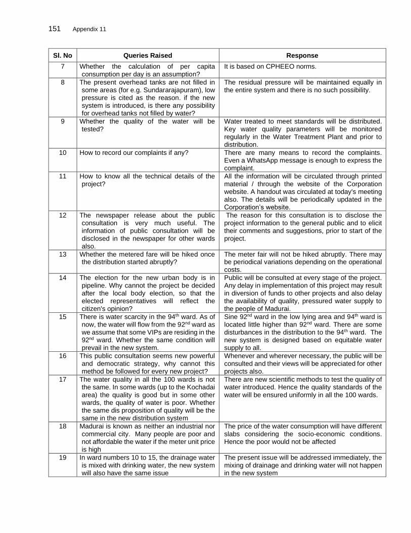
151 Appendix 11
Sl. No Queries Raised Response
7 Whether the calculation of per capita consumption per day is an assumption?
It is based on CPHEEO norms.
8 The present overhead tanks are not filled in some areas (for e.g. Sundararajapuram), low pressure is cited as the reason. if the new system is introduced, is there any possibility for overhead tanks not filled by water?
The residual pressure will be maintained equally in the entire system and there is no such possibility.
9 Whether the quality of the water will be tested?
Water treated to meet standards will be distributed. Key water quality parameters will be monitored regularly in the Water Treatment Plant and prior to distribution.
10 How to record our complaints if any? There are many means to record the complaints. Even a WhatsApp message is enough to express the complaint.
11 How to know all the technical details of the project?
All the information will be circulated through printed material / through the website of the Corporation website. A handout was circulated at today's meeting also. The details will be periodically updated in the Corporation’s website.
12 The newspaper release about the public consultation is very much useful. The information of public consultation will be disclosed in the newspaper for other wards also.
The reason for this consultation is to disclose the project information to the general public and to elicit their comments and suggestions, prior to start of the project.
13 Whether the metered fare will be hiked once the distribution started abruptly?
The meter fair will not be hiked abruptly. There may be periodical variations depending on the operational costs.
14 The election for the new urban body is in pipeline. Why cannot the project be decided after the local body election, so that the elected representatives will reflect the citizen's opinion?
Public will be consulted at every stage of the project. Any delay in implementation of this project may result in diversion of funds to other projects and also delay the availability of quality, pressured water supply to the people of Madurai.
15 There is water scarcity in the 94th ward. As of now, the water will flow from the 92nd ward as we assume that some VIPs are residing in the 92nd ward. Whether the same condition will prevail in the new system.
Sine 92nd ward in the low lying area and 94th ward is located little higher than 92nd ward. There are some disturbances in the distribution to the 94th ward. The new system is designed based on equitable water supply to all.
16 This public consultation seems new powerful and democratic strategy, why cannot this method be followed for every new project?
Whenever and wherever necessary, the public will be consulted and their views will be appreciated for other projects also.
17 The water quality in all the 100 wards is not the same. In some wards (up to the Kochadai area) the quality is good but in some other wards, the quality of water is poor. Whether the same dis proposition of quality will be the same in the new distribution system
There are new scientific methods to test the quality of water introduced. Hence the quality standards of the water will be ensured uniformly in all the 100 wards.
18 Madurai is known as neither an industrial nor commercial city. Many people are poor and not affordable the water if the meter unit price is high
The price of the water consumption will have different slabs considering the socio-economic conditions. Hence the poor would not be affected
19 In ward numbers 10 to 15, the drainage water is mixed with drinking water, the new system will also have the same issue
The present issue will be addressed immediately, the mixing of drainage and drinking water will not happen in the new system

152 Appendix 11
Sl. No Queries Raised Response
20 The pipe used now is age-old and many pipes got broken, hence the drinking water is flowing to the river and wasted, if the pressurized water will flow through the same pipes, the pipe will break and the water wastage will be enormous
Water will be distributed only through the new pipes proposed in this project, hence the wastage of the water will be arrested
21 The then opposite party DMK was against the Suez project in Coimbatore, as it was against the poor, Now the same party now evinces interest in privatizing water supply. Why is this contradictory, whether it is politically motivated?
This project is not about privatization of water supply. The water supply will be under the control of Madurai Corporation.
22 In Coimbatore, the new drinking water distribution system was handed over to the private companies, the same system will be done in Madurai
All activities will be under the control of Madurai Corporation. The Corporation, depending on the needs may engage various private players for executing various works under this project.
23 Whether any subsidy for schools, civil societies in the fare fixed?
The fare system will be finalized later
24 If the periodical payment is not made for the Telephone connection, Electricity connection, the connection will be disconnected until the payment. Will the same system be introduced in the new system?
This will be considered while finalizing the water supply charges.
25 Whether the new connection is available for residents only or commercial, apartments are also eligible for the new connection?
It is available for all consumers.
26 Though water tax is commonly fixed to all the wards of Madurai corporation, the water availability is not even in all the wards. In some wards the availability of water is not adequate; will the new system also face the same issue?
This system is designed to ensure equitable water supply.
27 We use hand pumps to suck water, and we are very much dissatisfied. Whether in the new connection also, should we use hand pumps?
This is a pressurized water supply system hence no hand pumps are required
28 After the new connection and fixing of the meter, if water does not come due to low pressure, should we pay every month for the water that does not come to our residences?
Pressurized water supply is the key in this project, However, in case of non-supply, consumers will not be charges as the water meters are proposed.
29 Now the drinking water comes only half an hour once in every three days. The same timing will be followed in the new system also?
The water will be supplied for 4 to 24 hours every day
30 Whether the new drinking water distribution system will be introduced to all the 100 wards at the same time?
This project implementation period for these 57 wards will take 3 years to complete. Similarly Madurai corporation another 28 wards is covered under Tranche II (package 4) and 15 wards in SMART City.
31 Whether the existing pipe will be used for the new system also?
The existing pipelines will be discarded. Water will be supplied only through the new system.
32 We are happy that there is no privatization in the new system. Whether it is anywhere
The responsibility of water supply and accountability will be with the Corporation. Private players may be

153 Appendix 11
Sl. No Queries Raised Response
documented that no private companies are involved in the major decision-making process
engaged for executing certain activities, but under the control of Madurai Corporation.
33 What are the conditions made by ADB to implement the project?
Water for all, quality water supply, ensuring inclusive model and sustainability are the major conditions made by ADB
34 The scheme is heart fully accepted if the income generated from the connection goes to Madurai corporation
The amount will go to Madurai corporation and will be used for meeting O&M expenses only
35 The fixation of tariffs will be done by private companies?
The fixation of tariff will be done by the Madurai corporation only
36 There are two schools in ward number 27. Whether these schools are also included in the new system?
Water supply connections will be given institutional, commercial and residential properties.
37 AMRUT ( Atal Mission for rejuvenation and urban transformation)is a private company, if it is involved, then privatization becomes inevitable
AMRUT is not a private company. It is a central government scheme to provide civic services to the urban areas. Hence the privatization is ruled out. Works like civil, construction works such as pipe laying, etc will be given to the private firms
38 If the drinking water scheme is introduced, there are some possibilities for mixing with drainage as it happens in some areas.
Adequate drainage facilities are being made through a SMART city scheme. Hence no need to be afraid of mixing of water will not happen
39 The subsidy was introduced to cooking gas, then slowly it has been removed. Will the same style be adapted to the new drinking water distribution system
Separate slabs for residential and commercial purposes will be fixed.
40 The women consumer forum from ward number 93 requested the Madurai corporation to remove the wastes blocked in the pipeline and that was immediately done by the corporation. If such type of works are done in time, meter fixing would be an issue as the system is beneficial to the poor too
All the works in Madurai corporation are done in time.
41 Information about the different slabs in the tariff should be disseminated
All the adequate information will be furnished without fail
42 The project information such as the phone number to make complaints, the project timeline, the details about the contractors should be disseminated to the public
A separate and adequate number of boards will be provided in all the important places during construction.
43 Whether a separate Grievance redressal system will be constituted?
A grievance redressal system will function to resolve the issues and the information about it will be circulated and mentioned on the boards
44 The project information boards should be in Tamil
All the information will be furnished in Tamil for the benefit of the public.

154 Appendix 11
Participants’ details
Male Participants Female Participants Total Participants
51 28 79
Information about the Consultation
The information in Tamil about the meeting was circulated, which highlighted salient details about
the project with the date and time of the meeting to all the residents through notice/news release.
Leading news papers published the information about the public consultation.
The details of the hearing were captured in all the leading News papers and brief of the same are as follows.
Newspapers’ Clippings
Public consultation news item appeared in all leading Newspapers: “The Hindu” focused that the
project ensured quality portable water with high pressure and further ensured 135 litres/day per
person. The ‘Hindu Tamil Disai’ highlighted that the project would not be handed over to private
companies. It will be done by Madurai Corporation. A central control and monitoring office will be
set up to monitoring the water distribution system. ‘Dinakaran’ illustrated that the poor should be
considered while collecting the charges and fixing the meter tariff. The Times of India mentioned
that the confirmation on the scheme not to be privatized should formally be in writing otherwise
legal suits will be filed against the Madurai Corporation. All the newspapers indicated that the
public may send their suggestions to [email protected] before 20th August.
Annexures
1. Popular Tamil and English daily newspapers were published the same (Annexure - 1 News
Paper Clippings)
2. Attendance sheet is enclosed as Annexure – 2
3. Public hearing Photos as Annexure – 3
4. Annexure - 4 Press Release.

155 Appendix 11
Annexure - 1 News Paper Clippings

156 Appendix 11
Annexure - 2 (Attendance Sheet)

157 Appendix 11
158 Appendix 11

159 Appendix 11

160 Appendix 11

161 Appendix 11

162 Appendix 11
Annexure - 3 (Public Hearing Photos)
Annexure - 4 (Press Release)

163 Appendix 11

164 Appendix 11
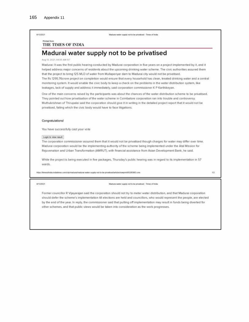
165 Appendix 11

166 Appendix 12
DETAILED OPERATIONAL REPORT ON SAFETY MEASURES & PRECAUTIONS FOLLOWED IN SITE FOR COVID-19 (SOP)
INDEX
Chapter No Description
1 Introduction
2 COVID-19
3 COVID-19 Typical symptoms
4 Basic Precautions in Workers Protection
4.1 Labour deployment best Practices
4.2. Workers Protection &Precaution
4.2.2Workers Protection
4.2.3 Workers Precaution
4.2.4 Medical attention One should seek medical attention without loosing time
4.3 General directions to be followed at Site
5 Work Site Preventions
5.1 Site Access
5.2 Construction areas
6 6.1 Material Management
6.2 Transportation to and from Site
6.3 Labour Quarters Protocol
6.4 Medical Camps
7 Registers
8 Returns
9 Training &Awareness
10 Emergency Contacts
11 Scenario Planning
12 Covid-19 Check Slip
13 Reference
1. INTRODUCTION This report gives detail instructions & norms followed in site on day to day basis followed by the guidelines issued by the Govt. of India & Tamil Nadu to eradicate and to prevent spreading of COVID -19. 2. COVID – 19 Coronavirus disease (COVID-19) is an infectious disease caused by a newly discovered coronavirus. Most people infected with the COVID-19 virus will experience mild to moderate respiratory illness and recover without requiring special treatment. Older people, and those with underlying medical problems like cardiovascular disease, diabetes, chronic respiratory disease, and cancer are more likely to develop serious illness. The COVID-19 virus spreads primarily through droplets of saliva or discharge from the nose when an infected person coughs or sneezes. At this time, there are no specific vaccines or treatments for COVID-19.7 However, precautions can be implemented to prevent and slow down the transmission of the virus. 3. COVID – 19 COMMON SYMPTOMS COVID-19 affects different people in different ways. Most infected people will develop mild to moderate illness and recover without hospitalization. Most common symptoms:
∙ Fever. ∙ Dry cough. ∙ Tiredness.
Less common symptoms:
7 World Health Organization. https://www.who.int/health-topics/coronavirus#tab=tab_1
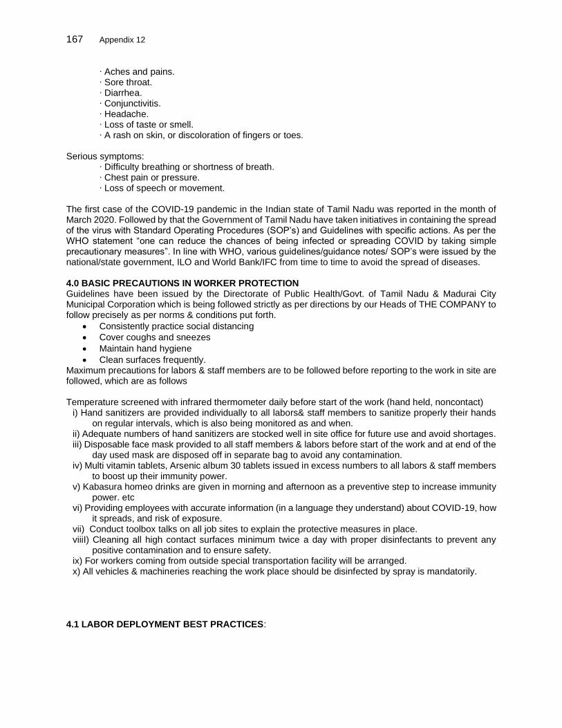
167 Appendix 12
∙ Aches and pains. ∙ Sore throat. ∙ Diarrhea. ∙ Conjunctivitis. ∙ Headache. ∙ Loss of taste or smell. ∙ A rash on skin, or discoloration of fingers or toes.
Serious symptoms:
∙ Difficulty breathing or shortness of breath. ∙ Chest pain or pressure. ∙ Loss of speech or movement.
The first case of the COVID-19 pandemic in the Indian state of Tamil Nadu was reported in the month of March 2020. Followed by that the Government of Tamil Nadu have taken initiatives in containing the spread of the virus with Standard Operating Procedures (SOP’s) and Guidelines with specific actions. As per the WHO statement “one can reduce the chances of being infected or spreading COVID by taking simple precautionary measures”. In line with WHO, various guidelines/guidance notes/ SOP’s were issued by the national/state government, ILO and World Bank/IFC from time to time to avoid the spread of diseases. 4.0 BASIC PRECAUTIONS IN WORKER PROTECTION Guidelines have been issued by the Directorate of Public Health/Govt. of Tamil Nadu & Madurai City Municipal Corporation which is being followed strictly as per directions by our Heads of THE COMPANY to follow precisely as per norms & conditions put forth.
• Consistently practice social distancing
• Cover coughs and sneezes
• Maintain hand hygiene
• Clean surfaces frequently. Maximum precautions for labors & staff members are to be followed before reporting to the work in site are followed, which are as follows Temperature screened with infrared thermometer daily before start of the work (hand held, noncontact)
i) Hand sanitizers are provided individually to all labors& staff members to sanitize properly their hands on regular intervals, which is also being monitored as and when.
ii) Adequate numbers of hand sanitizers are stocked well in site office for future use and avoid shortages. iii) Disposable face mask provided to all staff members & labors before start of the work and at end of the
day used mask are disposed off in separate bag to avoid any contamination. iv) Multi vitamin tablets, Arsenic album 30 tablets issued in excess numbers to all labors & staff members
to boost up their immunity power. v) Kabasura homeo drinks are given in morning and afternoon as a preventive step to increase immunity
power. etc vi) Providing employees with accurate information (in a language they understand) about COVID-19, how
it spreads, and risk of exposure. vii) Conduct toolbox talks on all job sites to explain the protective measures in place. viiiI) Cleaning all high contact surfaces minimum twice a day with proper disinfectants to prevent any
positive contamination and to ensure safety. ix) For workers coming from outside special transportation facility will be arranged. x) All vehicles & machineries reaching the work place should be disinfected by spray is mandatorily.
4.1 LABOR DEPLOYMENT BEST PRACTICES:

168 Appendix 12
Sl. No Description Ensure / suggestive option Responsibility
1 From Containment area Must Not Contractor
2 From Quarantine area i)Should not ii)Tested negative on completion of quarantine
Contractor
3 Containment / Quarantine Habitation i)Avoid as for as possible ii) tested negative
Contractor
4 Age of person No Child Labor < 50 as for as possible >55shouldTested negative >65 Avoid
Contractor
5 Medical Complaints: - Diabetics, B.P, Cancer etc
More vulnerable – Avoid COVID officer
6 Proof of Identity & Address Must COVID Officer
7 Providing Social Information of Family
Must COVID Officer
4.2 WORKERS PROTECTION &PRECAUTION 4,2,1 WORKERS PROTECTION The workers shall be protected from infection and subsequently likely to become carriers.
SL. NO WORKERS RESPONSIBILITY RESPONSIBILITY
1 No sign of COVID-19 Symptoms- prior to 24hrs of Entry –Any positive symptoms such workers shall be removed from the Site and sent to quarantine Centre
COVID-19 Officer
2 Self-Attestation- COVID Officer
3 Undergone for Quarantine/Isolation – Shall be Certified by registered medical practitioner at the time of Recruitment.
COVID-Officer-
4 Non-Essential area – Close Contact between workers shall be prevented
COVID Officer –
5 Close Contact area- Shall explore Automation/ or Mechanization
Contractor/covid-19 Officer
6 Social Distancing( 6 feet OR More) COVID Officer
7 (i) Washing Hands often and Use Hand Sanitizer whenever physical contact with other substances
(ii) Disinfecting the surfaces-Door Handles, Mobile, Laptop, Utensils etc
(iii) void face to face meeting
COVID Officer- (i) Arrange facilities &Consumables.
(ii) Arrange facilities &Consumables
(iii) Meeting-shall be through Video
Conferences/Mobile/Webinar
(iv) For small meetings with Social PPEs
and following Social distancing
8 (i) Drinking Water-shall be provided with individual water Bottle
(ii) Avoid touching Eyes, Nose and Mouth with your hands during works
(iii) Handle your personnel belongings your self’s
(i) COVID Officer
(ii) Self- Individual
(iii) Self- Individuals
9- (i) Labor Camp (ii) Use of Toilet – Hand wash before and
after (iii) Use Avoid common Towels and Use
Tissue Paper
(i) Contractor shall arrange to supply all consumables at Site and avoid labors leaving Site for Purchase
(ii) COVID Officer-shall arrange to provide Rubbish Bins and one of the Laborer

169 Appendix 12
shall be allocated with responsibilities for proper maintenance.
10 Take Self prepared food as for as possible and preheated where ever possible Lunch Break –staggered break to ensure Social distancing
COVID Officer
4.2.3 WORKERS PRECAUTION The Employer shall strictly adhere the guidelines and ensure no infected people/vulnerable/chronic people are employed. Entry of unauthorized Visitors shall be refused entry.
PRECAUTION RESPONSIBILITY
Stay in Home - If Sick yourself or anyone in the family Individual / COVID Officer
If found Sick on entry sent to Home Individual / COVID Officer
If Some One at Site Observed Sick, Quarantine, sent Home Report to COVID Officer for further follow up
COVID Officer-Report to Dist. Medical Officer
Temperature Screening twice in a Day @ Morning COVID Officer
Drivers /Cleaners -shall be kept away from Workplace, Ensure Wearing of Facemask, Hand washing – sanitizing
COVID-Officer
To protect self and Others - Ensure COVID-19 guidelines are strictly followed
COVID Officer
Visitors -unauthorized visitors shall be refused entry Authorized Visitors shall be monitored and ensure guidelines are strictly followed till they leave the Site.
COVID Officer/Site In charge
4.2.4 Medical attention One should seek medical attention without losing time, when
● Trouble in breathing
● Persistent pain or pressure in the chest
● New confusion
● Inability to wake or stay awake
● Bluish lips or face
4.3 GENERAL DIRECTIONS TO BE FOLLOWED IN SITE
● No handshake, only Namaste
● Work requiring physical contact should not be carried out.
● Plan all other work to avoid contact between workers to ensure social distancing
● Use of alcohol-based sanitizer
● No person should enter the work site other than the authorized persons mentioned by the
supervisors during start of work
● Everyone at work site should always practice social distancing by maintaining a minimum distance
of 6 feet from others to prevent spreading
● Avoiding face to face meeting, if necessary, situation arises requiring in person discussion we must
follow social distancing
● Brief toolbox talks where employees are asked to check for any symptoms of covid-19
● COVID -19 safety guidelines display board is placed in Tamil& English at suitable apt locations.
● All restrooms, toilet facilities are cleaned on regular basis with proper arrangements.
● All surfaces are cleaned regularly including tabletops, door handles, etc.
● All common areas and meeting places be cleaned at frequent intervals and disinfected at least
twice a day.
● Maintaining social distance during breaks and lunch

170 Appendix 12
● Cover coughing, sneezing with a tissue the throwing it in trash and wash hands
● Cleaning hands after coughing or sneezing thoroughly with soap and water
● Adequate number of sanitizer and soaps are made available at all locations including offices,
meeting rooms, corridors, washrooms, toilets etc.
● All are advised not to touch eyes, nose mouth with hands
● Work schedules shall be adjusted to provide time for proper cleaning and disinfecting
● Separate closed bins are provided at various locations in the site to dispose the used mask and
hand tissues.
● Outside persons are not allowed to enter the work site
● Labors are to be supplied with standard face mask, gloves etc.
● Gathering places on the site such as sheds shall be eliminated, and instead small break areas shall
be used with seating arrangements limited to ensure social distancing.
5 WORK SITE PREVENTIONS
5.1SITE ACCESS
● At construction site have appointed with health & safety officer, who is tasked to ensure compliance
for respective staff against set out COVID-19 safety compliance procedures on daily basis.
● Approved mitigation measures are discussed prior to start of work product cut sheets of the
sanitation products to be deployed.
● Consumption of tobacco, smoking and spitting in open place are strictly prohibited inside the
construction site.
● COVID-19 awareness signage boarding in regional language is installed at all areas including entry,
exit point, labor camps, canteens, meeting rooms, stores. etc
● As the construction staff arrives at site Operating procedures are to be followed and once the
construction staff enters the site, their movement outside of the site is strictly restricted.
● Entry to construction site is limited to 1 number and exit from the site is also restricted to 1 number
so as to monitor the movements of labors effective
● Daily orientation meetings and toolbox talks are to be conducted in open areas maintain safe
distancing norms.
● Mandatory site orientation meetings and safety toolbox for site staff prior to start of daily works are
to be conducted .and discuss COVID-19 safety procedures. Highlighting Dos & Don’t. So that
Laborers are familiar with the guidelines.
5.2 CONSTRUCTION AREAS
● Prepare daily work Schedule and organize work areas into zones to ensure safe distancing norms
are followed. Also restrict number of labors in a defined zone to the extent possible.
● Prior to start/end of the daily work, disinfection of tools, equipment’s,PPE’s to be done.
● Disinfecting the work zones periodically during the day at break hours.
● Shuffling of workers operating equipment or working in any other areas of the zones shall not be
allowed.
6.1 MATERIAL MANAGEMENT
● Loading/unloading zones are clearly identified with limited access to concerned teams only.
● All vehicles entering or exiting the site shall be disinfected properly.
● The delivery staff should go through the site access procedures as outlined in above measures.
● All documents related to delivery shall be reviewed and validated in digital formats and exchange
of physical paper works is avoided.
● Unloaded delivery to be disinfected prior to keeping in stores is done.

171 Appendix 12
● If in case the delivered item cannot be disinfected then the item shall be kept stored in separate
weather protected area for 72 hrs prior to use.
● Stores are disinfected daily.
● Construction waste shall be removed from site in covered containers.
6.2 TRANSPORTATION TO AND FROM SITE
● Vehicles being used to transport workers or construction goods shall be thoroughly disinfected
before and after.
● Every worker to undergo temperature screening before allowed to board into vehicle for travelling
is followed mandatorily.
● Adequate markings on the ground are put in place for staff waiting to be screened to comply with
safe distancing norms.
● Wearing of desirable masks, Personal Protective Equipment (PPE) as per regulatory guidelines
shall be followed at all times in site.
● Safe distancing norms shall be practiced in the vehicle to seat the workers additional trips or
vehicles are to be arranged if necessity.
● Travel times are utilized to create awareness about construction workers safety norms.
● Vehicle wash down or disinfection area is created at the site entry to ensure adequate safeguards.
● Non-essential / authorized visitors are not allowed to visit construction site.
6.3 LABOR QUARTERS PROTOCOL
● Limit labor dormitory occupancy to ensure compliance with distancing norms.
● Social gatherings shall be restricted, safe distancing and hygiene protocols are to be followed
strictly.
● Labor quarters shall be cleaned and disinfected frequently.
● Additional hand washing stations with clean water and soaps at common locations.
● Display Do’s & don’t boarding’s in local vernacular language spoken by the labors.
● Ensure compliance to the extent possible through security guards at the Entry of Site.
● Arrangements shall be made for regular supply of all essential items like food, grains, groceries,
drinking water etc.and restrict the movements of labor outside.
● Visitor entry to labor quarters are banned and restricted to possible extents to avoid any sorts of
unwanted contamination.
● Staggered lunch/break hours to reduce number of labors in room at the same time.
6.4 MEDICAL CAMPS
● Conduct medical camps calling registered medical practitioner once in a month to check and
monitor the health conditions of labors and staffs working to ensure safety.
● Display details including Name, address and Mobile No of Doctor in Site Office.
● Display Health & Revenue department contact Numbers in Site Office.
● Conduct awareness meetings weekly during Lunch breaks. Discuss the
● Nonconformance and remedies so as to ensure the Safety.
7. REGISTERS The following Registers shall be maintained. In hard and soft cop ● Measurement of Body Temperature.
● Social Information details pertaining to all workers and Staff with Contact Mobile number ,address,
Employment details of other family members
● Stock Register for Drugs & Consumables –Receipt of Supply and issues Name & Date are maintained
● Visitors Register and
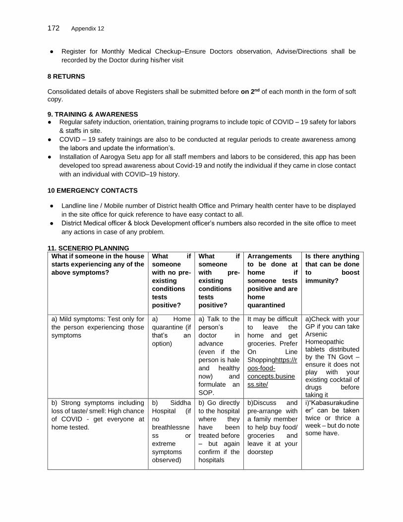
172 Appendix 12
● Register for Monthly Medical Checkup–Ensure Doctors observation, Advise/Directions shall be
recorded by the Doctor during his/her visit
8 RETURNS Consolidated details of above Registers shall be submitted before on 2nd of each month in the form of soft copy. 9. TRAINING & AWARENESS ● Regular safety induction, orientation, training programs to include topic of COVID – 19 safety for labors
& staffs in site.
● COVID – 19 safety trainings are also to be conducted at regular periods to create awareness among
the labors and update the information’s.
● Installation of Aarogya Setu app for all staff members and labors to be considered, this app has been
developed too spread awareness about Covid-19 and notify the individual if they came in close contact
with an individual with COVID–19 history.
10 EMERGENCY CONTACTS ● Landline line / Mobile number of District health Office and Primary health center have to be displayed
in the site office for quick reference to have easy contact to all.
● District Medical officer & block Development officer’s numbers also recorded in the site office to meet
any actions in case of any problem.
11. SCENERIO PLANNING
What if someone in the house
starts experiencing any of the
above symptoms?
What if
someone
with no pre-
existing
conditions
tests
positive?
What if
someone
with pre-
existing
conditions
tests
positive?
Arrangements
to be done at
home if
someone tests
positive and are
home
quarantined
Is there anything
that can be done
to boost
immunity?
a) Mild symptoms: Test only for
the person experiencing those
symptoms
a) Home
quarantine (if
that’s an
option)
a) Talk to the
person’s
doctor in
advance
(even if the
person is hale
and healthy
now) and
formulate an
SOP.
It may be difficult
to leave the
home and get
groceries. Prefer
On Line
Shoppinghttps://r
oos-food-
concepts.busine
ss.site/
a)Check with your GP if you can take Arsenic Homeopathic tablets distributed by the TN Govt – ensure it does not play with your existing cocktail of drugs before taking it
b) Strong symptoms including
loss of taste/ smell: High chance
of COVID - get everyone at
home tested.
b) Siddha
Hospital (if
no
breathlessne
ss or
extreme
symptoms
observed)
b) Go directly
to the hospital
where they
have been
treated before
– but again
confirm if the
hospitals
b)Discuss and
pre-arrange with
a family member
to help buy food/
groceries and
leave it at your
doorstep
i)“Kabasurakudineer” can be taken twice or thrice a week – but do note some have.

173 Appendix 12
admit COVID
patients.
c) Select list of labs that do
home testing:
i) Apollo Diagnostics
https://www.apollodiagnostics.i
n/for-patients/test-
booking/chennai/
ii)Lister Metropolis
c) Other
Hospitals
i) Apollo
Hospital
ii) SIMS
Hospital
Choose hospitals that you have been to before and are confident with – confirm if those are registered to treat COVID cases
c)Prepare a one-page case summary of the person and keep it handy – if possible hand it over to the paramedical personnel who bring the patient to the hospital (OR) to the doctor who has treated you previously in the hospital (OR) anyone you think can help you
c)If there is a
patient at home
and the patient
attender
contracts
COVID, plan how
you are going to
manage their
absence.
c)Steam inhalation
Note: If any one positive and likely to be quarantine/hospitalized. All Members of the family are advised to take the following at least for a week as a prevention procedure even no infections are noticed
i) Multi vitamin Tablets ii) Zinc Tablets iii) Steam Breathing iv) Antibiotic Tablet Any how take the advice of the Medical Practitioner involved in treatment of COVID-19.
12. COVID-19
CHECKSLIST Date: PACKAGE: (The COVID-19 Officer shall monitor the guidelines and report in the following Check Slip on daily Basis.)
No. Description Compliance
1 Is it ensured the labor is provided self-attested details as required Yes/No
2 Are You verified He/ She is free of Symptoms of COVID-19 Yes/No
3 Are You ensured He /She do not have Chronic diseases-Obtain Certificate from Registered Medical Practitioner
Yes/No
4 Is it ensured He / She is not from Contained/Quarantined area Yes/No
5 If from quarantined area, whether He/ She was Medically Checked for COVID-19 and found Negative
Yes/No
6 Is He / She was subjected to Temperature Screening twice as laid downing the guidelines.
Yes/No
7 Social distancing is followed strictly including in nonessential area by all labors Yes/No
8 Whether all Labors are wearing PPEs including Face Mask at all times Yes/No
9 Whether all Registers mentioned in the COVID-19 Plan are maintained at Site. Yes/No
10 Whether adequate Drugs / Consumables are stocked for a period not less than 15days.
Yes/No

174 Appendix 12
No. Description Compliance
11 Drinking Water in individual Water Bottle is provided .Otherwise whether all precautions are taken to maintain better hygiene at Water Tap
Yes/No
12 Toilets are properly cleaned and disinfected at regular intervals Yes/No
13 Sanitization is followed in Common Utility area where possible physical contact is observed
Yes/No
14 All living common area including Labor Camp, Toilets Assembling hall, Dining are disinfected morning and end of the Day
Yes/No
15 All Food waste and Spills are collected and disposed safely as prescribed in the guidelines.
Yes/No
16 Are Monthly Medical Checkup conducted and Medical Practitioners observations recorded and follow Action initiated
Yes/No
Note: In Case of noncompliance/Violations record the details of nonconformance and record the Compliance.
1. 2. 3.
Certified that information’s provided are based on facts and actual and correct to best of my knowledge. COVID-19 Officer Remarks of Contractor/Authorized Person Signature Remarks of Site Engineer Signature 17. REFERENCES
● Standard Operating Procedure for Social Distancing for offices, workplaces, Factories and other establishments (https://cms.tn.gov.in/sites/default/files/go/hfw_e_191_2020.pdf)
● Standard Operating Procedure - Infection prevention control (https://cms.tn.gov.in/sites/default/files/go/revenue_e_217_2020_0.pdf)
● MHA National Directives for Covid-19 Management (https://static.mygov.in/rest/s3fs-public/mygov_158972288555063671.pdf)
● MoHFW Guidelines on preventive measures to contain spread of COVID-19 in workplace
settings
(https://www.mohfw.gov.in/pdf/GuidelinesonpreventivemeasurestocontainspreadofCOVID19i
nworkplacesettings.pdf
● SoP GO No. 191 dated 16.04.2020.

175 Appendix 13
Zone wise Details of Proposed DNI
ZONE 3. ARULDASAPURAM – 20 .00 LL. The Distribution network in Zone 03 comprise of Ward No 5, 8 Partial, and 9 full with a total population of base year (2019) 33,387 Nos, Intermediate Year (2034) -38,144 Nos and Ultimate Year (2049) – 43,580 Nos. The Demand for the Base Year (2019) is 5.275 MLD, Intermediate Year (2035) - 6.634 MLD and Ultimate Year (2050) – 6.756 MLD. The entire network is divided in to 3 No. of DMAs. The Overall Length of Distribution System is 28,211 m.
1. SERVICE RESERVOIR (SR).The Existing SR is located at Aruldasapuram is Ward No.9.The Capacity of the SR is 20 LL and Staging Height 14.0 m.
2. DMA-01.The Total length DMA-01 is 13270 m. The Pipe in the Distribution Network ranges from 110 mm HDPE to 180 mm HDPE. The Minimum and Maximum pressure in the DMA is 8.3 m and 13.2 m respectively with a pressure drop of 4.9 m. 1 No of Air Valve , 1 No of Scour Valve , 3 No of Critical Measuring Points where the Pressure can be monitored are conclude in the DMA. Detail of flow meter and flow control valve are provided as show in the valve table. The total House Hold conclude in this DMA is 2791 Nos. and the anticipated HSC is 2791 No
3. DMA-02.The Total length DMA-02 is 8565 m. The Pipe in the Distribution Network ranges from 110 mm HDPE to 200 mm HDPE. The Minimum and Maximum pressure in the DMA is 7.1 m and 9.9 m respectively with a pressure drop of 2.8 m. 1 No of Air Valve , 1 No of Scour Valve , 3 No of Critical Measuring Points where the Pressure can be monitored are conclude in the DMA. Detail of flow meter and flow control valve are provided as show in the valve table. The total House Hold conclude in this DMA is 1801 Nos. and the anticipated HSC is 1801 Nos
4. DMA-03.The Total length DMA-03 is 4523 m. The Pipe in the Distribution Network ranges from 110mm HDPE to 200 mm HDPE. The Minimum and Maximum pressure in the DMA is 7.9 m and 11.6 m respectively with a pressure drop of 3.7 m. 1 No of Air Valve, 1 No of Scour Valve , 3 No of Critical Measuring Points where the Pressure can be monitored are conclude in the DMA. Detail of flow meter and flow control valve are provided as show in the valve table. The total House Hold conclude in this DMA is 951 Nos. and the anticipated HSC is 951 Nos
5. ZONE 11. ANAIYUR COMPOSTING YARD –I (SELLUR KANMOI) – 25.00 LL. The Distribution network in Zone 11 comprise of Ward No 4, 5 Partial with a total population of base
year (2019) 38964 Nos, Intermediate Year (2034) -46164 Nos and Ultimate Year (2049) – 54832
Nos. The Demand for the Base Year (2019) is 6.304 MLD, Intermediate Year (2035) -7.454 MLD
and Ultimate Year (2050) – 8.842 MLD. The entire network is divide in to 6 No. of DMAs. The
Overall Length of Distribution System is 33338 m.
Distribution System:
Number of DMA ( Nos ) – 3
Pipe Length ( m) – 28211
Total Number o f HSC
Nos) ( - 5543
20
LL
Melakkal
Thachampathu (24.5
MLD) – 5.852 MLD
Arasaradi
Pumping
Station

176 Appendix 13
6. SERVICE RESERVOIR (SR).The Proposed SR is located at Anaiyur Composting Yard is
Ward No 2.The Capacity of the SR is 25.0 LL and Staging Height 18.0 m.
7. DMA-01.The Total length DMA-01 is 4212 m. The Pipe in the Distribution Network ranges
from 110 mm HDPE to 140 mm HDPE. The Minimum and Maximum pressure in the DMA is 12.1
m and 16.5 m respectively with a pressure drop of 4.4 m. 1 No of Air Valve , 1 No of Scour Valve,
3 No of Critical Measuring Points where the Pressure can be monitored are conclude in the DMA. Detail of flow meter and flow control valve are provided as show in the valve table. The total
House Hold concludes in this DMA is 997 Nos. and the anticipated HSC is 997 Nos.
8. DMA-02.The Total length DMA-02 is 4813 m. The Pipe in the Distribution Network ranges
from 110 mm HDPE to 200 mm HDPE. The Minimum and Maximum pressure in the DMA is 12.2
m and 15.5 m respectively with a pressure drop of 3.3 m. 1 No of Air Valve , 1 No of Scour Valve,
3 No of Critical Measuring Points where the Pressure can be monitored are conclude in the DMA.
Detail of flow meter and flow control valve are provided as show in the valve table. The total House Hold concludes in this DMA is 1139 Nos. and the anticipated HSC is 1139 Nos.
9. DMA-03.The Total length DMA-03 is 7008 m. The Pipe in the Distribution Network ranges
from 110 mm HDPE to 200 mm HDPE. The Minimum and Maximum pressure in the DMA is 12.0
m and 15.7 m respectively with a pressure drop of 3.7 m. 1 No of Air Valve , 1 No of Scour Valve,
3 No of Critical Measuring Points where the Pressure can be monitored are conclude in the DMA.
Detail of flow meter and flow control valve are provided as show in the valve table. The total
House Hold concludes in this DMA is 1659 Nos. and the anticipated HSC is 1659 Nos.
10. DMA-04.The Total length DMA-04 is 5421 m. The Pipe in the Distribution Network ranges
from 110 mm HDPE to 200 mm HDPE. The Minimum and Maximum pressure in the DMA is 12.3
m and 16.4 m respectively with a pressure drop of 4.1 m. 1 No of Air Valve , 1 No of Scour Valve,
3 No of Critical Measuring Points where the Pressure can be monitored are conclude in the DMA.
Detail of flow meter and flow control valve are provided as show in the valve table. The total
House Hold concludes in this DMA is 1283 Nos. and the anticipated HSC is 1283 Nos.
11. DMA-05.The Total length DMA-05 is 1898 m. The Pipe in the Distribution Network ranges from 110 mm HDPE to 110 mm HDPE. The Minimum and Maximum pressure in the DMA is 13.1
m and 14.7 m respectively with a pressure drop of 1.60 m. 1 No of Air Valve , 1 No of Scour Valve,
3 No of Critical Measuring Points where the Pressure can be monitored are conclude in the DMA.
Detail of flow meter and flow control valve are provided as show in the valve table. The total
House Hold concludes in this DMA is 449 Nos. and the anticipated HSC is 449 Nos.
12. DMA-06.The Total length DMA-06 is 5823 m. The Pipe in the Distribution Network ranges
from 110 mm HDPE to 200 mm HDPE. The Minimum and Maximum pressure in the DMA is 12.3
m and 15.9 m respectively with a pressure drop of 3.6 m. 1 No of Air Valve , 1 No of Scour Valve,
Distribution System:
Number of DMA ( Nos ) – 6
Pipe Length ( m) – 33338
Total Number o f HSC ( Nos) 6906
25
LL
Mullai Periyar (125 MLD) –
5.803 MLD
Cauvery (21 MLD)
– 1.28 MLD

177 Appendix 13
3 No of Critical Measuring Points where the Pressure can be monitored are conclude in the DMA.
Detail of flow meter and flow control valve are provided as show in the valve table. The total
House Hold concludes in this DMA is 744 Nos. and the anticipated HSC is 744 Nos.
13. ZONE 12. ANAIYUR COMPOSTING YARD –II (SINGARAYAR COLONY) – 25 LL. The Distribution network in Zone 12 comprise of Ward No 6 full, 41 Partial with a total population of
base year (2019) 40791 Nos, Intermediate Year (2034) -46605 Nos and Ultimate Year (2049) –
53256 Nos. The Demand for the Base Year (2019) is 6.599 MLD, Intermediate Year (2035) -
7.525 MLD and Ultimate Year (2050) – 8.587 MLD. The entire network is divided in to 6 No. of
DMAs. The Overall Length of Distribution System is 18300 m.
14. SERVICE RESERVIOR (SR).The Proposed SR is located at Anaiyur Composting Yard is
Ward No 2.The Capacity of the SR is 25.0 LL and Staging Height 18.0 m.
15. DMA-01.The Total length DMA-01 is 2577 m. The Pipe in the Distribution Network ranges
from 110 mm HDPE to 200 mm HDPE. The Minimum and Maximum pressure in the DMA is 12.1
m and 14.7 m respectively with a pressure drop of 2.6 m. 1 No of Air Valve , 1 No of Scour Valve,
3 No of Critical Measuring Points where the Pressure can be monitored are conclude in the DMA. Detail of flow meter and flow control valve are provided as show in the valve table. The total
House Hold concludes in this DMA is 912 Nos. and the anticipated HSC is 912 Nos.
16. DMA-02.The Total length DMA-02 is 3157 m. The Pipe in the Distribution Network ranges
from 110 mm HDPE to 200 mm HDPE. The Minimum and Maximum pressure in the DMA is 12
m and 16.2 m respectively with a pressure drop of 4.2 m. 1 No of Air Valve , 1 No of Scour Valve,
3 No of Critical Measuring Points where the Pressure can be monitored are conclude in the DMA.
Detail of flow meter and flow control valve are provided as show in the valve table. The total House Hold concludes in this DMA is 1117 Nos. and the anticipated HSC is 1117 Nos.
17. DMA-03.The Total length DMA-03 is 2818 m. The Pipe in the Distribution Network ranges
from 110 mm HDPE to 200 mm HDPE. The Minimum and Maximum pressure in the DMA is 13.9
m and 15.9 m respectively with a pressure drop of 2.0 m. 1 No of Air Valve , 1 No of Scour Valve,
3 No of Critical Measuring Points where the Pressure can be monitored are conclude in the DMA.
Detail of flow meter and flow control valve are provided as show in the valve table. The total
House Hold concludes in this DMA is 997 Nos. and the anticipated HSC is 997 Nos.
18. DMA-04. The Total length DMA-04 is 1545 m. The Pipe in the Distribution Network ranges
from 110 mm HDPE to 200 mm HDPE. The Minimum and Maximum pressure in the DMA is 13.9
m and 17.2 m respectively with a pressure drop of 3.3 m. 1 No of Air Valve , 1 No of Scour Valve,
3 No of Critical Measuring Points where the Pressure can be monitored are conclude in the DMA.
Detail of flow meter and flow control valve are provided as show in the valve table. The total
House Hold concludes in this DMA is 547 Nos. and the anticipated HSC is 547 Nos.
Distribution System:
Number of DMA ( Nos ) – 6
Pipe Length ( m) – 18300
Total Number of HSC
( Nos) - 5123
25 LL
Mullaiperiyar (125 MLD) – 7.1 1 MLD

178 Appendix 13
19. DMA-05.The Total length DMA-05 is 2277 m. The Pipe in the Distribution Network ranges
from 110 mm HDPE to 200 mm HDPE. The Minimum and Maximum pressure in the DMA is 13.1
m and 16.3 m respectively with a pressure drop of 3.2 m. 1 No of Air Valve , 1 No of Scour Valve,
3 No of Critical Measuring Points where the Pressure can be monitored are conclude in the DMA. Detail of flow meter and flow control valve are provided as show in the valve table. The total
House Hold concludes in this DMA is 806 Nos. and the anticipated HSC is 806 Nos.
20. DMA-06.The Total length DMA-06 is 2101 m. The Pipe in the Distribution Network ranges
from 110 mm HDPE to 200 mm HDPE. The Minimum and Maximum pressure in the DMA is 12.3
m and 15.9 m respectively with a pressure drop of 3.6 m. 1 No of Air Valve , 1 No of Scour Valve,
3 No of Critical Measuring Points where the Pressure can be monitored are conclude in the DMA.
Detail of flow meter and flow control valve are provided as show in the valve table. The total House Hold concludes in this DMA is 744 Nos. and the anticipated HSC is 744 Nos.
21. ZONE 13. RESERVE LINE– 20.00 LL. The Distribution network in Zone 13 comprise of
Ward No 47 full, 5,42,48 Partial with a total population of base year (2019) 32760 Nos,
Intermediate Year (2034) -37811 Nos and Ultimate Year (2049) – 43684 Nos. The Demand for
the Base Year (2019) is 5.300 MLD, Intermediate Year (2035) -6.106 MLD and Ultimate Year
(2050) – 7.044 MLD. The entire network is divided in to 4 No. of DMAs. The Overall Length of
Distribution System is 33937 m.
22. SERVICE RESERVOIR (SR):The Existing SR is located at Reserve Line is Ward No
47.The Capacity of the SR is 20.0 LL and Staging Height 18.0 m.
23. DMA-01.The Total length DMA-01 is 10637 m. The Pipe in the Distribution Network
ranges from 110 mm HDPE to 250 mm DI K7. The Minimum and Maximum pressure in the DMA
is 13 m and 16.7 m respectively with a pressure drop of 3.7 m. 1 No of Air Valve , 1 No of Scour
Valve , 3 No of Critical Measuring Points where the Pressure can be monitored are conclude in
the DMA. Detail of flow meter and flow control valve are provided as show in the valve table. The
total House Hold concludes in this DMA is 1790 Nos. and the anticipated HSC is 1790 Nos.
24. DMA-02.The Total length DMA-02 is 4815 m. The Pipe in the Distribution Network ranges
from 110 mm HDPE to 200 mm HDPE. The Minimum and Maximum pressure in the DMA is 13.4
m and 16.9 m respectively with a pressure drop of 3.5 m. 1 No of Air Valve , 1 No of Scour Valve
, 3 No of Critical Measuring Points where the Pressure can be monitored are conclude in the
DMA. Detail of flow meter and flow control valve are provided as show in the valve table. The total
House Hold concludes in this DMA is 810 Nos. and the anticipated HSC is 810 Nos.
25. DMA-03. The Total length DMA-03 is 7897 m. The Pipe in the Distribution Network ranges from 110 mm HDPE to 250 mm DI K7. The Minimum and Maximum pressure in the DMA is 12.2
m and 16.4 m respectively with a pressure drop of 3.5 m. 1 No of Air Valve , 1 No of Scour Valve,
3 No of Critical Measuring Points where the Pressure can be monitored are conclude in the DMA.
Detail of flow meter and flow control valve are provided as show in the valve table. The total
House Hold concludes in this DMA is 1329 Nos. and the anticipated HSC is 1329 Nos.
26. DMA-04.The Total length DMA-04 is 8385 m. The Pipe in the Distribution Network ranges
from 110 mm HDPE to 300 mm DI K7. The Minimum and Maximum pressure in the DMA is 13 m and 17.6 m respectively with a pressure drop of 4.6 m. 1 No of Air Valve , 1 No of Scour Valve ,
3 No of Critical Measuring Points where the Pressure can be monitored are conclude in the DMA.

179 Appendix 13
Detail of flow meter and flow control valve are provided as show in the valve table. The total
House Hold concludes in this DMA is 1411 Nos. and the anticipated HSC is 1411 Nos.
27. ZONE 14: RACE COURSE ROAD – 6.80 LL. The Distribution network in Zone 14
comprises of Ward No 41, 42, 43 Partial with a total population of base year (2019) 11303 Nos, Intermediate Year (2034) -12914 Nos and Ultimate Year (2049) – 14754 Nos. The Demand for
the Base Year (2019) is 1.828 MLD, Intermediate Year (2035) -2.85 MLD and Ultimate Year
(2050) – 2.379 MLD. The entire network is divided in to 2 No. of DMAs. The Overall Length of
Distribution System is 22150 m.
28. SERVICE RESERVOIR (SR).The Existing SR is located at Race Course Road is Ward
No 42.The Capacity of the SR is 6.80 LL and Staging Height 12.0 m.
29. DMA-01.The Total length DMA-01 is 5646 m. The Pipe in the Distribution Network ranges from 110 mm HDPE to 250 mm DI K7. The Minimum and Maximum pressure in the DMA is 9.7
m and 12.4 m respectively with a pressure drop of 2.7 m. 1 No of Air Valve , 1 No of Scour Valve,
3 No of Critical Measuring Points where the Pressure can be monitored are conclude in the DMA.
Detail of flow meter and flow control valve are provided as show in the valve table. The total
House Hold concludes in this DMA is 799 Nos. and the anticipated HSC is 799 Nos.
30. DMA-02. The Total length DMA-02 is 14368 m. The Pipe in the Distribution Network
ranges from 110 mm HDPE to 300 mm DI K7. The Minimum and Maximum pressure in the DMA is 12 m and 14.7 m respectively with a pressure drop of 2.7 m. 1 No of Air Valve , 1 No of Scour
Valve , 3 No of Critical Measuring Points where the Pressure can be monitored are conclude in
the DMA. Detail of flow meter and flow control valve are provided as show in the valve table. The
total House Hold concludes in this DMA is 2033 Nos. and the anticipated HSC is 2033 Nos.
31. ZONE 15: SELLUR – 13.60 LL. The Distribution network in Zone 15 comprises of Ward
No 38 full, 40 Partial with a total population of base year (2019) 20608 Nos, Intermediate Year
(2034) -23544 Nos and Ultimate Year (2049) – 26899 Nos. The Demand for the Base Year (2019)
is 3.334 MLD, Intermediate Year (2035) -3.801 MLD and Ultimate Year (2050) – 4.338 MLD. The entire network is divided in to 2 No of DMAs. The Overall Length of Distribution System is 10114
m.
32. SERVICE RESERVOIR (SR).The Existing SR is located at Sellur is Ward No 38.The
Capacity of the SR is 13.60 LL and Staging Height 12.0 m.
33. DMA-01. The Total length DMA-01 is 4734 m. The Pipe in the Distribution Network ranges
from 110 mm HDPE to 200 mm HDPE. The Minimum and Maximum pressure in the DMA is 7.5
m and 11.7 m respectively with a pressure drop of 4.2 m. 1 No of Air Valve , 1 No of Scour Valve, 3 No of Critical Measuring Points where the Pressure can be monitored are conclude in the DMA.
Detail of flow meter and flow control valve are provided as show in the valve table. The total
House Hold concludes in this DMA is 1015 Nos. and the anticipated HSC is 1155 Nos.
34. DMA-02. The Total length DMA-02 is 4172 m. The Pipe in the Distribution Network ranges
from 110 mm HDPE to 200 mm HDPE. The Minimum and Maximum pressure in the DMA is 7.2
m and 10.8 m respectively with a pressure drop of 3.6 m. 1 No of Air Valve , 1 No of Scour Valve,
3 No of Critical Measuring Points where the Pressure can be monitored are conclude in the DMA. Detail of flow meter and flow control valve are provided as show in the valve table. The total
House Hold concludes in this DMA is 1018 Nos. and the anticipated HSC is 1018 Nos.

180 Appendix 13
35. ZONE 16. SELLUR LORRY STAND – 30.00 LL. The Distribution network in Zone 16
comprise of Ward No 7,37,39 full, 40 Partial with a total population of base year (2019) 49422
No’s, Intermediate Year (2034) -56464 Nos and Ultimate Year (2049) – 64510 Nos. The Demand
for the Base Year (2019) is 7.995 MLD, Intermediate Year (2035) -9.118 MLD and Ultimate Year (2050) – 10.403 MLD. The entire network is divided in to 6 No. of DMAs. The Overall Length of
Distribution System is 24307 m.
36. SERVICE RESERVOIR (SR). The Proposed SR is located at Sellur Lorry Stand is Ward
No 37.The Capacity of the SR is 30.0 LL and Staging Height 18.0 m.
37. DMA-01. The Total length DMA-01 is 5569 m. The Pipe in the Distribution Network ranges
from 110 mm HDPE to 200 mm DI K7. The Minimum and Maximum pressure in the DMA is 12 m
and 15 m respectively with a pressure drop of 3 m. 1 No of Air Valve , 1 No of Scour Valve , 3 No of Critical Measuring Points where the Pressure can be monitored are conclude in the DMA. Detail
of flow meter and flow control valve are provided as show in the valve table. The total House Hold
concludes in this DMA is 1691 Nos. and the anticipated HSC is 1691 Nos.
38. DMA-02. The Total length DMA-02 is 3411 m. The Pipe in the Distribution Network ranges
from 110 mm HDPE to 180 mm HDPE. The Minimum and Maximum pressure in the DMA is 12.2
m and 15.1 m respectively with a pressure drop of 2.9 m. 1 No of Air Valve , 1 No of Scour Valve
, 3 No of Critical Measuring Points where the Pressure can be monitored are conclude in the DMA. Detail of flow meter and flow control valve are provided as show in the valve table. The total
House Hold concludes in this DMA is 1036 Nos. and the anticipated HSC is 1036 Nos.
39. DMA-03.The Total length DMA-03 is 1794 m. The Pipe in the Distribution Network ranges
from 110 mm HDPE to 200 mm DI K7. The Minimum and Maximum pressure in the DMA is 12.8
m and 15.2 m respectively with a pressure drop of 2.4 m. 1 No of Air Valve , 1 No of Scour Valve
, 3 No of Critical Measuring Points where the Pressure can be monitored are conclude in the
DMA. Detail of flow meter and flow control valve are provided as show in the valve table. The total
House Hold concludes in this DMA is 545 Nos. and the anticipated HSC is 545 Nos.
40. DMA-04.The Total length DMA-04 is 4322 m. The Pipe in the Distribution Network ranges
from 110 mm HDPE to 200 mm DI K7. The Minimum and Maximum pressure in the DMA is 12.3
m and 15.5 m respectively with a pressure drop of 3.2 m. 1 No of Air Valve , 1 No of Scour Valve
, 3 No of Critical Measuring Points where the Pressure can be monitored are conclude in the
DMA. Detail of flow meter and flow control valve are provided as show in the valve table. The total
House Hold concludes in this DMA is 1313 Nos. and the anticipated HSC is 1313 Nos.
41. DMA-05.The Total length DMA-05 is 3217 m. The Pipe in the Distribution Network ranges from 110 mm HDPE to 250 mm DI K7. The Minimum and Maximum pressure in the DMA is 12.8
m and 14.5 m respectively with a pressure drop of 1.7 m. 1 No of Air Valve , 1 No of Scour Valve
, 3 No of Critical Measuring Points where the Pressure can be monitored are conclude in the
DMA. Detail of flow meter and flow control valve are provided as show in the valve table. The total
House Hold concludes in this DMA is 977 Nos. and the anticipated HSC is 977 Nos.
42. DMA-06.The Total length DMA-06 is 1785 m. The Pipe in the Distribution Network ranges
from 110 mm HDPE to 400 mm DI K7. The Minimum and Maximum pressure in the DMA is 12.2 m and 14.4 m respectively with a pressure drop of 2.2 m. 1 No of Air Valve , 1 No of Scour Valve
, 3 No of Critical Measuring Points where the Pressure can be monitored are conclude in the

181 Appendix 13
DMA. Detail of flow meter and flow control valve are provided as show in the valve table. The total
House Hold concludes in this DMA is 542 Nos. and the anticipated HSC is 542 Nos.
43. ZONE 17. RAJAJI PARK – 18.00 LL The Distribution network in Zone 17 comprise of
Ward No 35,36 full, 43 Partial with a total population of base year (2019) 29663 Nos, Intermediate Year (2034) -33889 Nos and Ultimate Year (2049) – 38719 Nos. The Demand for the Base Year
(2019) is 4.798 MLD, Intermediate Year (2035) -5.472 MLD and Ultimate Year (2050) – 6.244
MLD. The entire network is divide in to 3 No. of DMAs. The Overall Length of Distribution System
is 25471 m.
44. SERVICE RESERVOIR (SR)The Existing SR is located at Rajaji Park is Ward No 43.The
Capacity of the SR is 18.00 LL and Staging Height 12.0 m.
45. DMA-01.The Total length DMA-01 is 10498 m. The Pipe in the Distribution Network ranges from 110 mm HDPE to 200 mm DI K7. The Minimum and Maximum pressure in the DMA
is 8.5 m and 11.5 m respectively with a pressure drop of 3.0 m. 1 No of Air Valve , 1 No of Scour
Valve , 3 No of Critical Measuring Points where the Pressure can be monitored are conclude in
the DMA. Detail of flow meter and flow control valve are provided as show in the valve table. The
total House Hold conclude in this DMA is 2008 Nos. and the anticipated HSC is 2008 Nos.
46. DMA-02.The Total length DMA-02 is 6043 m. The Pipe in the Distribution Network ranges
from 110 mm HDPE to 200 mm DI K7. The Minimum and Maximum pressure in the DMA is 8.9 m and 12.5 m respectively with a pressure drop of 3.6 m. 1 No of Air Valve , 1 No of Scour Valve
, 3 No of Critical Measuring Points where the Pressure can be monitored are conclude in the
DMA. Detail of flow meter and flow control valve are provided as show in the valve table. The total
House Hold concludes in this DMA is 1156 Nos. and the anticipated HSC is 1156 Nos.
47. DMA-03.The Total length DMA-03 is 5224 m. The Pipe in the Distribution Network ranges
from 110 mm HDPE to 200 mm DI K7. The Minimum and Maximum pressure in the DMA is 9.8
m and 12.6 m respectively with a pressure drop of 2.8 m. 1 No of Air Valve , 1 No of Scour Valve
, 3 No of Critical Measuring Points where the Pressure can be monitored are conclude in the DMA. Detail of flow meter and flow control valve are provided as show in the valve table. The total
House Hold conclude in this DMA is 999 Nos. and the anticipated HSC is 999 Nos.
48. ZONE 18: KK NAGAR – 8.00 LL. The Distribution network in Zone 18 comprises of Ward
No 43, 44 Partial with a total population of base year (2019) 13243 Nos, Intermediate Year (2034)
-15130 Nos and Ultimate Year (2049) – 17286 Nos. The Demand for the Base Year (2019) is
2.143 MLD, Intermediate Year (2035) -2.443 MLD and Ultimate Year (2050) – 2.788 MLD. The
entire network is divide in to 2 No. of DMAs. The Overall Length of Distribution System is 17479 m.
49. SERVICE RESERVOIR (SR). The Existing SR is located at KK Nagar is Ward No 44.The
Capacity of the SR is 8.00 LL and Staging Height 12.0 m.
50. DMA-01. The Total length DMA-01 is 7328 m. The Pipe in the Distribution Network ranges
from 110 mm HDPE to 200 mm DI K7. The Minimum and Maximum pressure in the DMA is 7.7
m and 12.2 m respectively with a pressure drop of 4.5 m. 1 No of Air Valve , 1 No of Scour Valve
, 3 No of Critical Measuring Points where the Pressure can be monitored are conclude in the DMA. Detail of flow meter and flow control valve are provided as show in the valve table. The total
House Hold conclude in this DMA is 1222 Nos. and the anticipated HSC is 1222 Nos.

182 Appendix 13
51. DMA-02. The Total length DMA-02 is 9384 m. The Pipe in the Distribution Network ranges
from 110 mm HDPE to 200 mm HDPE. The Minimum and Maximum pressure in the DMA is 7.1
m and 9.4 m respectively with a pressure drop of 2.3 m. 1 No of Air Valve , 1 No of Scour Valve ,
3 No of Critical Measuring Points where the Pressure can be monitored are conclude in the DMA. Detail of flow meter and flow control valve are provided as show in the valve table. The total
House Hold conclude in this DMA is 1565 Nos. and the anticipated HSC is 1565 Nos.
52. ZONE 19: LOTUS TANK – 2.30 LL. The Distribution network in Zone 19 comprise of
Ward No 45 Partial with a total population of base year (2019) 3828 Nos, Intermediate Year (2034)
- 4373 Nos and Ultimate Year (2049) – 4996 Nos. The Demand for the Base Year (2019) is 0.619
MLD, Intermediate Year (2035) -0.706 MLD and Ultimate Year (2050) – 0.806 MLD. The entire
network is divide in to 1 No. of DMAs. The Overall Length of Distribution System is 5039 m.
53. SERVICE RESERVOIR (SR). The Existing SR is located at Lotus Tank is Ward No 45.The
Capacity of the SR is 2.30 LL and Staging Height 12.0 m.
54. DMA. The Total length DMA-01 is 5008 m. The Pipe in the Distribution Network ranges
from 110 mm HDPE to 180 mm HDPE. The Minimum and Maximum pressure in the DMA is 7.7
m and 12.2 m respectively with a pressure drop of 4.5 m. 1 No of Air Valve , 1 No of Scour Valve
, 3 No of Critical Measuring Points where the Pressure can be monitored are conclude in the
DMA. Detail of flow meter and flow control valve are provided as show in the valve table. The total House Hold conclude in this DMA is 583 Nos. and the anticipated HSC is 583 Nos.
55. ZONE 20: KK NAGAR MARKET – 12.00 LL. The Distribution network in Zone 20
comprises of Ward No 27, 45 Partial with a total population of base year (2019) 18788 Nos,
Intermediate Year (2034) -21465 Nos and Ultimate Year (2049) – 24524 Nos. The Demand for
the Base Year (2019) is 3.177 MLD, Intermediate Year (2035) -3.636 MLD and Ultimate Year
(2050) – 4.155 MLD. The entire network is divide in to 2 No. of DMAs. The Overall Length of
Distribution System is 31307 m.
56. SERVICE RESERVOIR (SR). The Proposed SR is located at KK Nagar Market is Ward No 27.The Capacity of the SR is 12.00 LL and Staging Height 18.0 m.
57. DMA-01. The Total length DMA-01 is 9907 m. The Pipe in the Distribution Network ranges
from 110 mm HDPE to 200 mm DI K7. The Minimum and Maximum pressure in the DMA is 12.3
m and 15.9 m respectively with a pressure drop of 3.6 m. 1 No of Air Valve , 1 No of Scour Valve
, 3 No of Critical Measuring Points where the Pressure can be monitored are conclude in the
DMA. Detail of flow meter and flow control valve are provided as show in the valve table. The total
House Hold conclude in this DMA is 1208 Nos. and the anticipated HSC is 1208 Nos.
58. DMA-02. The Total length DMA-02 is 17998 m. The Pipe in the Distribution Network
ranges from 110 mm HDPE to 350 mm DI K7. The Minimum and Maximum pressure in the DMA
is 12.0 m and 15 m respectively with a pressure drop of 3.0 m. 1 No of Air Valve , 1 No of Scour
Valve , 3 No of Critical Measuring Points where the Pressure can be monitored are conclude in
the DMA. Detail of flow meter and flow control valve are provided as show in the valve table. The
total House Hold conclude in this DMA is 2195 Nos. and the anticipated HSC is 2195 Nos.
59. ZONE 21: K PUDHUR – 15.00 LL. The Distribution network in Zone 21 comprise of Ward No 27, 45, 46 Partial with a total population of base year (2019) 23504 Nos, Intermediate Year
(2034) -26853 Nos and Ultimate Year (2049) – 30679 Nos. The Demand for the Base Year (2019)

183 Appendix 13
is 3.79 MLD, Intermediate Year (2035) -4.337 MLD and Ultimate Year (2050) – 4.958 MLD. The
entire network is divide in to 2 No. of DMAs. The Overall Length of Distribution System is 19135
m.
60. SERVICE RESERVOIR (SR). The Existing SR is located at K Puthur is Ward No 46.The Capacity of the SR is 15.00 LL and Staging Height 12.0 m.
61. DMA-01. The Total length DMA-01 is 8042 m. The Pipe in the Distribution Network ranges
from 110 mm HDPE to 200 mm HDPE. The Minimum and Maximum pressure in the DMA is 7 m
and 11.2 m respectively with a pressure drop of 4.2 m. 1 No of Air Valve, 1 No of Scour Valve , 3
No of Critical Measuring Points where the Pressure can be monitored are conclude in the DMA.
Detail of flow meter and flow control valve are provided as show in the valve table. The total
House Hold conclude in this DMA is 1787 Nos. and the anticipated HSC is 1787 Nos.
62. DMA-02. The Total length DMA-02 is 9556 m. The Pipe in the Distribution Network ranges
from 110 mm HDPE to 300 mm DI K7. The Minimum and Maximum pressure in the DMA is 7.3
m and 10.4 m respectively with a pressure drop of 3.1 m. 1 No of Air Valve , 1 No of Scour Valve
, 3 No of Critical Measuring Points where the Pressure can be monitored are conclude in the
DMA. Detail of flow meter and flow control valve are provided as show in the valve table. The total
House Hold conclude in this DMA is 2123 Nos. and the anticipated HSC is 2123 Nos.
63. ZONE 22: ISLAND NAGAR – 12.00 LL. The Distribution network in Zone 22 comprise of Ward No 27, 46, 48 Partial with a total population of base year (2019) 17786 Nos, Intermediate
Year (2034) -21850 Nos and Ultimate Year (2049) – 26905 Nos. The Demand for the Base Year
(2019) is 2.933 MLD, Intermediate Year (2035) -3.596 MLD and Ultimate Year (2050) – 4.419
MLD. The entire network is divide in to 3 No. of DMAs. The Overall Length of Distribution System
is 30486 m.
64. SERVICE RESERVOIR (SR). The Proposed SR is located at Island Nagar is Ward No
27.The Capacity of the SR is 12.00 LL and Staging Height 18.0 m.
65. DMA-01. The Total length DMA-01 is 3636 m. The Pipe in the Distribution Network ranges from 110 mm HDPE to 300 mm DI K7. The Minimum and Maximum pressure in the DMA is 13.4
m and 18.3 m respectively with a pressure drop of 4.9 m. 1 No of Air Valve , 1 No of Scour Valve
, 3 No of Critical Measuring Points where the Pressure can be monitored are conclude in the
DMA. Detail of flow meter and flow control valve are provided as show in the valve table. The total
House Hold conclude in this DMA is 1097 Nos. and the anticipated HSC is 1097 Nos.
66. DMA-02. The Total length DMA-02 is 6909 m. The Pipe in the Distribution Network ranges
from 110 mm HDPE to 200 mm DI K7. The Minimum and Maximum pressure in the DMA is 12.1 m and 16.2 m respectively with a pressure drop of 4.1 m. 1 No of Air Valve , 1 No of Scour Valve
, 3 No of Critical Measuring Points where the Pressure can be monitored are conclude in the
DMA. Detail of flow meter and flow control valve are provided as show in the valve table. The total
House Hold conclude in this DMA is 659 Nos. and the anticipated HSC is 659 Nos.
67. DMA-03. The Total length DMA-03 is 9106 m. The Pipe in the Distribution Network ranges
from 110 mm HDPE to 250 mm DI K7. The Minimum and Maximum pressure in the DMA is 12.0
m and 15.7 m respectively with a pressure drop of 3.7 m. 1 No of Air Valve , 1 No of Scour Valve , 3 No of Critical Measuring Points where the Pressure can be monitored are conclude in the
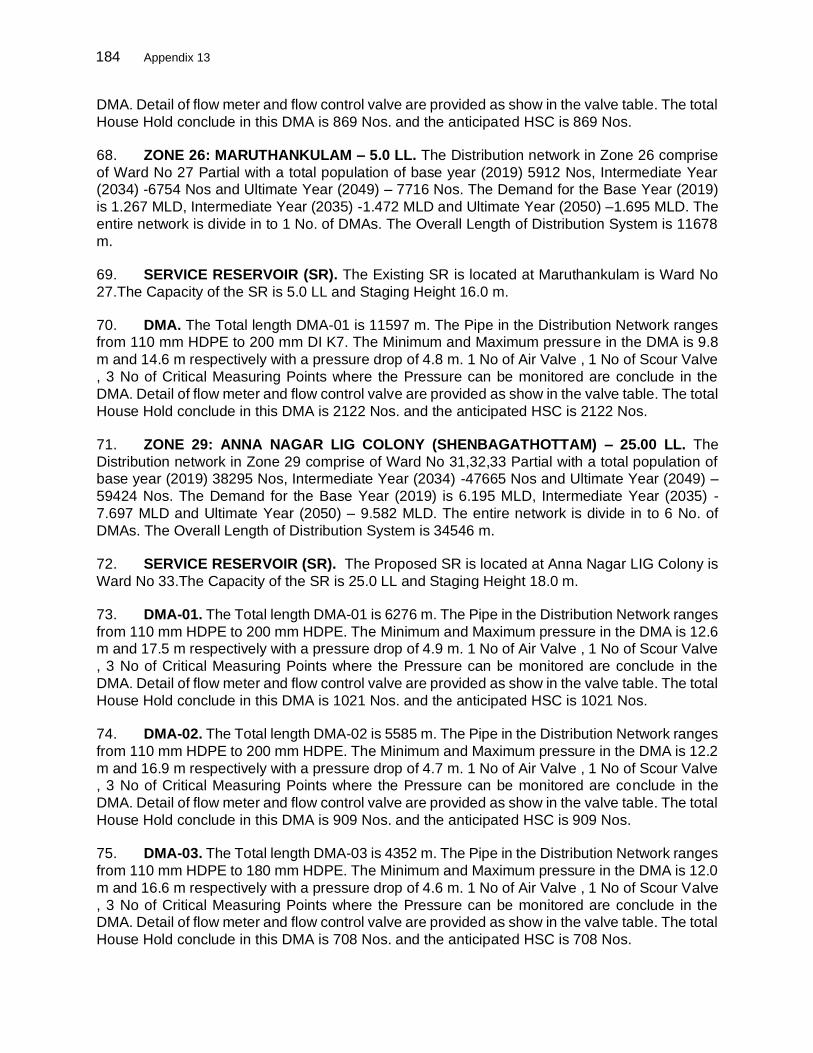
184 Appendix 13
DMA. Detail of flow meter and flow control valve are provided as show in the valve table. The total
House Hold conclude in this DMA is 869 Nos. and the anticipated HSC is 869 Nos.
68. ZONE 26: MARUTHANKULAM – 5.0 LL. The Distribution network in Zone 26 comprise
of Ward No 27 Partial with a total population of base year (2019) 5912 Nos, Intermediate Year (2034) -6754 Nos and Ultimate Year (2049) – 7716 Nos. The Demand for the Base Year (2019)
is 1.267 MLD, Intermediate Year (2035) -1.472 MLD and Ultimate Year (2050) –1.695 MLD. The
entire network is divide in to 1 No. of DMAs. The Overall Length of Distribution System is 11678
m.
69. SERVICE RESERVOIR (SR). The Existing SR is located at Maruthankulam is Ward No
27.The Capacity of the SR is 5.0 LL and Staging Height 16.0 m.
70. DMA. The Total length DMA-01 is 11597 m. The Pipe in the Distribution Network ranges from 110 mm HDPE to 200 mm DI K7. The Minimum and Maximum pressure in the DMA is 9.8
m and 14.6 m respectively with a pressure drop of 4.8 m. 1 No of Air Valve , 1 No of Scour Valve
, 3 No of Critical Measuring Points where the Pressure can be monitored are conclude in the
DMA. Detail of flow meter and flow control valve are provided as show in the valve table. The total
House Hold conclude in this DMA is 2122 Nos. and the anticipated HSC is 2122 Nos.
71. ZONE 29: ANNA NAGAR LIG COLONY (SHENBAGATHOTTAM) – 25.00 LL. The
Distribution network in Zone 29 comprise of Ward No 31,32,33 Partial with a total population of base year (2019) 38295 Nos, Intermediate Year (2034) -47665 Nos and Ultimate Year (2049) –
59424 Nos. The Demand for the Base Year (2019) is 6.195 MLD, Intermediate Year (2035) -
7.697 MLD and Ultimate Year (2050) – 9.582 MLD. The entire network is divide in to 6 No. of
DMAs. The Overall Length of Distribution System is 34546 m.
72. SERVICE RESERVOIR (SR). The Proposed SR is located at Anna Nagar LIG Colony is
Ward No 33.The Capacity of the SR is 25.0 LL and Staging Height 18.0 m.
73. DMA-01. The Total length DMA-01 is 6276 m. The Pipe in the Distribution Network ranges
from 110 mm HDPE to 200 mm HDPE. The Minimum and Maximum pressure in the DMA is 12.6 m and 17.5 m respectively with a pressure drop of 4.9 m. 1 No of Air Valve , 1 No of Scour Valve
, 3 No of Critical Measuring Points where the Pressure can be monitored are conclude in the
DMA. Detail of flow meter and flow control valve are provided as show in the valve table. The total
House Hold conclude in this DMA is 1021 Nos. and the anticipated HSC is 1021 Nos.
74. DMA-02. The Total length DMA-02 is 5585 m. The Pipe in the Distribution Network ranges
from 110 mm HDPE to 200 mm HDPE. The Minimum and Maximum pressure in the DMA is 12.2
m and 16.9 m respectively with a pressure drop of 4.7 m. 1 No of Air Valve , 1 No of Scour Valve , 3 No of Critical Measuring Points where the Pressure can be monitored are conclude in the
DMA. Detail of flow meter and flow control valve are provided as show in the valve table. The total
House Hold conclude in this DMA is 909 Nos. and the anticipated HSC is 909 Nos.
75. DMA-03. The Total length DMA-03 is 4352 m. The Pipe in the Distribution Network ranges
from 110 mm HDPE to 180 mm HDPE. The Minimum and Maximum pressure in the DMA is 12.0
m and 16.6 m respectively with a pressure drop of 4.6 m. 1 No of Air Valve , 1 No of Scour Valve
, 3 No of Critical Measuring Points where the Pressure can be monitored are conclude in the DMA. Detail of flow meter and flow control valve are provided as show in the valve table. The total
House Hold conclude in this DMA is 708 Nos. and the anticipated HSC is 708 Nos.

185 Appendix 13
76. DMA-04. The Total length DMA-04 is 5689 m. The Pipe in the Distribution Network ranges
from 110 mm HDPE to 140 mm HDPE. The Minimum and Maximum pressure in the DMA is 12
m and 14.8 m respectively with a pressure drop of 2.8 m. 1 No of Air Valve , 1 No of Scour Valve
, 3 No of Critical Measuring Points where the Pressure can be monitored are conclude in the DMA. Detail of flow meter and flow control valve are provided as show in the valve table. The total
House Hold conclude in this DMA is 926 Nos. and the anticipated HSC is 926 Nos.
77. DMA-05. The Total length DMA-05 is 3724 m. The Pipe in the Distribution Network ranges
from 110 mm HDPE to 200 mm HDPE. The Minimum and Maximum pressure in the DMA is 12.6
m and 15.5 m respectively with a pressure drop of 2.9 m. 1 No of Air Valve , 1 No of Scour Valve
, 3 No of Critical Measuring Points where the Pressure can be monitored are conclude in the
DMA. Detail of flow meter and flow control valve are provided as show in the valve table. The total House Hold conclude in this DMA is 606 Nos. and the anticipated HSC is 606 Nos.
78. DMA-06. The Total length DMA-06 is 6844 m. The Pipe in the Distribution Network ranges
from 110 mm HDPE to 200 mm HDPE. The Minimum and Maximum pressure in the DMA is 12.0
m and 14 m respectively with a pressure drop of 2.0 m. 1 No of Air Valve , 1 No of Scour Valve ,
3 No of Critical Measuring Points where the Pressure can be monitored are conclude in the DMA.
Detail of flow meter and flow control valve are provided as show in the valve table. The total
House Hold conclude in this DMA is 1114 Nos. and the anticipated HSC is 1114 Nos.
79. ZONE 30: ANNA NAGAR II – 6.0 LL. The Distribution network in Zone 30 comprise of
Ward No 33, 34, 44 Partial with a total population of base year (2019) 10059 Nos, Intermediate
Year (2034) -11492 Nos and Ultimate Year (2049) – 13130 Nos. The Demand for the Base Year
(2019) is 1.627 MLD, Intermediate Year (2035) -1.856 MLD and Ultimate Year (2050) – 2.117
MLD. The entire network is divide in to 2 No. of DMAs. The Overall Length of Distribution System
is 15391 m.
80. SERVICE RESERVOIR (SR). The Proposed SR is located at Anna Nagar II is Ward No
33.The Capacity of the SR is 6.0 LL and Staging Height 12.0 m.
81. DMA-01. The Total length DMA-01 is 5438 m. The Pipe in the Distribution Network ranges
from 110 mm HDPE to 200 mm HDPE. The Minimum and Maximum pressure in the DMA is 8.6
m and 12.1 m respectively with a pressure drop of 3.5 m. 1 No of Air Valve , 1 No of Scour Valve
, 3 No of Critical Measuring Points where the Pressure can be monitored are conclude in the
DMA. Detail of flow meter and flow control valve are provided as show in the valve table. The total
House Hold conclude in this DMA is 893 Nos. and the anticipated HSC is 893 Nos.
82. DMA-02. The Total length DMA-02 is 8741 m. The Pipe in the Distribution Network ranges from 110 mm HDPE to 200 mm HDPE. The Minimum and Maximum pressure in the DMA is 7 m
and 10 m respectively with a pressure drop of 3 m. 1 No of Air Valve , 1 No of Scour Valve , 3 No
of Critical Measuring Points where the Pressure can be monitored are conclude in the DMA. Detail
of flow meter and flow control valve are provided as show in the valve table. The total House Hold
conclude in this DMA is 1436 Nos. and the anticipated HSC is 1436 Nos.
83. ZONE 31: ANNA NAGAR I – 2.3 LL. The Distribution network in Zone 31 comprise of
Ward No 33,34 Partial with a total population of base year (2019) 3840 Nos, Intermediate Year (2034) -4386 Nos and Ultimate Year (2049) – 5012 Nos. The Demand for the Base Year (2019)
is 0.621 MLD, Intermediate Year (2035) -0.708 MLD and Ultimate Year (2050) – 0.808 MLD. The

186 Appendix 13
entire network is divide in to 1 No. of DMAs. The Overall Length of Distribution System is 5633
m.
84. SERVICE RESERVOIR (SR). The Existing SR is located at Anna Nagar I is Ward No
33.The Capacity of the SR is 2.3 LL and Staging Height 12.0 m.
85. DMA. The Total length DMA-01 is 5607 m. The Pipe in the Distribution Network ranges
from 110 mm HDPE to 180 mm HDPE. The Minimum and Maximum pressure in the DMA is 7.1
m and 11.9 m respectively with a pressure drop of 4.8 m. 1 No of Air Valve , 1 No of Scour Valve
, 3 No of Critical Measuring Points where the Pressure can be monitored are conclude in the
DMA. Detail of flow meter and flow control valve are provided as show in the valve table. The total
House Hold conclude in this DMA is 759 Nos. and the anticipated HSC is 759 Nos.
86. ZONE 32: SMP COLONY – 10.00 LL. The Distribution network in Zone 32 comprise of Ward No 32,33,34,25 Partial with a total population of base year (2019) 15315 Nos, Intermediate
Year (2034) -18612 Nos and Ultimate Year (2049) – 22677 Nos. The Demand for the Base Year
(2019) is 2.478 MLD, Intermediate Year (2035) -3.005 MLD and Ultimate Year (2050) – 3.657
MLD. The entire network is divide in to 2 No. of DMAs. The Overall Length of Distribution System
is 19689 m.
87. SERVICE RESERVOIR (SR). The Proposed SR is located at SMP Colony is Ward No
34.The Capacity of the SR is 10.0 LL and Staging Height 18.0 m.
88. DMA-01. The Total length DMA-01 is 7074 m. The Pipe in the Distribution Network ranges
from 110 mm HDPE to 250 mm DI K7. The Minimum and Maximum pressure in the DMA is 13 m
and 17.9 m respectively with a pressure drop of 4.9 m. 1 No of Air Valve , 1 No of Scour Valve ,
3 No of Critical Measuring Points where the Pressure can be monitored are conclude in the DMA.
Detail of flow meter and flow control valve are provided as show in the valve table. The total
House Hold conclude in this DMA is 1234 Nos. and the anticipated HSC is 1234 Nos.
89. DMA-02. The Total length DMA-02 is 10432 m. The Pipe in the Distribution Network
ranges from 110 mm HDPE to 250 mm DI K7. The Minimum and Maximum pressure in the DMA is 12.3 m and 17 m respectively with a pressure drop of 4.7 m. 1 No of Air Valve , 1 No of Scour
Valve , 3 No of Critical Measuring Points where the Pressure can be monitored are conclude in
the DMA. Detail of flow meter and flow control valve are provided as show in the valve table. The
total House Hold conclude in this DMA is 1820 Nos. and the anticipated HSC is 1820 Nos.
90. ZONE 33: KOCHADAI – 15.00 LL. The Distribution network in Zone 33 comprise of Ward
No 21, 22 Partial with a total population of base year (2019) 24515 Nos, Intermediate Year (2034)
-28008 Nos and Ultimate Year (2049) – 32000 Nos. The Demand for the Base Year (2019) is 3.966 MLD, Intermediate Year (2035) -4.523 MLD and Ultimate Year (2050) – 5.106 MLD. The
entire network is divide in to 2 No. of DMAs. The Overall Length of Distribution System is 22722
m.
91. SERVICE RESERVOIR (SR). The Existing SR is located at Kochadai is Ward No 22.The
Capacity of the SR is 15.0 LL and Staging Height 15.0 m.
92. DMA-01. The Total length DMA-01 is 8892 m. The Pipe in the Distribution Network ranges
from 110 mm HDPE to 350 mm DI K7. The Minimum and Maximum pressure in the DMA is 12 m and 15.6 m respectively with a pressure drop of 3.6 m. 1 No of Air Valve , 1 No of Scour Valve ,

187 Appendix 13
3 No of Critical Measuring Points where the Pressure can be monitored are conclude in the DMA.
Detail of flow meter and flow control valve are provided as show in the valve table. The total
House Hold conclude in this DMA is 2155 Nos. and the anticipated HSC is 2155 Nos.
93. DMA-02. The Total length DMA-02 is 9834 m. The Pipe in the Distribution Network ranges from 110 mm HDPE to 350 mm DI K7. The Minimum and Maximum pressure in the DMA is 12 m
and 16.3 m respectively with a pressure drop of 4.3 m. 1 No of Air Valve , 1 No of Scour Valve, 3
No of Critical Measuring Points where the Pressure can be monitored are conclude in the DMA.
Detail of flow meter and flow control valve are provided as show in the valve table. The total
House Hold conclude in this DMA is 2384 Nos. and the anticipated HSC is 2384 Nos.
94. ZONE 34: KOCHADAI– 25.00 LL. The Distribution network in Zone 34 comprise of Ward
No 20,21,22 Partial with a total population of base year (2019) 41595 Nos, Intermediate Year (2034) -47522 Nos and Ultimate Year (2049) – 54295 Nos. The Demand for the Base Year (2019)
is 6.729 MLD, Intermediate Year (2035) -7.694 MLD and Ultimate Year (2050) – 8.756 MLD. The
entire network is divide in to 6 No. of DMAs. The Overall Length of Distribution System is 36932
m.
95. SERVICE RESERVOIR (SR). The Proposed SR is located at Kochadai is Ward No 22.The
Capacity of the SR is 25.0 LL and Staging Height 18.0 m.
96. DMA-01. The Total length DMA-01 is 4304 m. The Pipe in the Distribution Network ranges from 110 mm HDPE to 250 mm DI K7. The Minimum and Maximum pressure in the DMA is 13.1
m and 17.6 m respectively with a pressure drop of 4.5 m. 1 No of Air Valve , 1 No of Scour Valve
, 3 No of Critical Measuring Points where the Pressure can be monitored are conclude in the
DMA. Detail of flow meter and flow control valve are provided as show in the valve table. The total
House Hold conclude in this DMA is 915 Nos. and the anticipated HSC is 915 Nos.
97. DMA-02. The Total length DMA-02 is 6854 m. The Pipe in the Distribution Network ranges
from 110 mm HDPE to 250 mm DI K7. The Minimum and Maximum pressure in the DMA is 12 m
and 15.3 m respectively with a pressure drop of 3.3 m. 1 No of Air Valve , 1 No of Scour Valve , 3 No of Critical Measuring Points where the Pressure can be monitored are conclude in the DMA.
Detail of flow meter and flow control valve are provided as show in the valve table. The total
House Hold conclude in this DMA is 1458 Nos. and the anticipated HSC is 1458 Nos.
98. DMA-03. The Total length DMA-03 is 4733 m. The Pipe in the Distribution Network ranges
from 110 mm HDPE to 180 mm HDPE. The Minimum and Maximum pressure in the DMA is 12.1
m and 16.3 m respectively with a pressure drop of 4.2 m. 1 No of Air Valve , 1 No of Scour Valve,
3 No of Critical Measuring Points where the Pressure can be monitored are conclude in the DMA. Detail of flow meter and flow control valve are provided as show in the valve table. The total
House Hold conclude in this DMA is 1007 Nos. and the anticipated HSC is 1007 Nos.
99. DMA-04. The Total length DMA-04 is 3638 m. The Pipe in the Distribution Network ranges
from 110 mm HDPE to 200 mm HDPE. The Minimum and Maximum pressure in the DMA is 12.3
m and 15.9 m respectively with a pressure drop of 3.6 m. 1 No of Air Valve , 1 No of Scour Valve,
3 No of Critical Measuring Points where the Pressure can be monitored are conclude in the DMA.
Detail of flow meter and flow control valve are provided as show in the valve table. The total House Hold conclude in this DMA is 774 Nos. and the anticipated HSC is 774 Nos.

188 Appendix 13
100. DMA-05. The Total length DMA-05 is 5505 m. The Pipe in the Distribution Network ranges
from 110 mm HDPE to 250 mm DI K7. The Minimum and Maximum pressure in the DMA is 12.3
m and 17 m respectively with a pressure drop of 4.7 m. 1 No of Air Valve , 1 No of Scour Valve ,
3 No of Critical Measuring Points where the Pressure can be monitored are conclude in the DMA. Detail of flow meter and flow control valve are provided as show in the valve table. The total
House Hold conclude in this DMA is 1171 Nos. and the anticipated HSC is 1171 Nos.
101. DMA-06. The Total length DMA-06 is 5745 m. The Pipe in the Distribution Network ranges
from 110 mm HDPE to 200 mm HDPE. The Minimum and Maximum pressure in the DMA is 12
m and 16.7 m respectively with a pressure drop of 4.7 m. 1 No of Air Valve , 1 No of Scour Valve,
3 No of Critical Measuring Points where the Pressure can be monitored are conclude in the DMA.
Detail of flow meter and flow control valve are provided as show in the valve table. The total House Hold conclude in this DMA is 1222 Nos. and the anticipated HSC is 1222 Nos.
102. ZONE 35: HMS COLONY– 16.00 LL. The Distribution network in Zone 35 comprise of
Ward No 19, 22 Partial with a total population of base year (2019) 26402 Nos, Intermediate Year
(2034) -30165 Nos and Ultimate Year (2049) – 34463 Nos. The Demand for the Base Year (2019)
is 4.271 MLD, Intermediate Year (2035) -4.871 MLD and Ultimate Year (2050) – 5.557 MLD. The
entire network is divide in to 2 No. of DMAs. The Overall Length of Distribution System is 24836
m.
103. SERVICE RESERVOIR (SR). The Existing SR is located at HMS Colony is Ward No
22.The Capacity of the SR is 16.0 LL and Staging Height 16.0 m.
104. DMA-01. The Total length DMA-01 is 12113 m. The Pipe in the Distribution Network
ranges from 110 mm HDPE to 250 mm DI K7. The Minimum and Maximum pressure in the DMA
is 12.8 m and 17.4 m respectively with a pressure drop of 4.6 m. 1 No of Air Valve , 1 No of Scour
Valve, 3 No of Critical Measuring Points where the Pressure can be monitored are conclude in
the DMA. Detail of flow meter and flow control valve are provided as show in the valve table. The
total House Hold conclude in this DMA is 2466 Nos. and the anticipated HSC is 2466 Nos.
105. DMA-02. The Total length DMA-02 is 12723 m. The Pipe in the Distribution Network
ranges from 110 mm HDPE to 300 mm DI K7. The Minimum and Maximum pressure in the DMA
is 12.8 m and 16.2 m respectively with a pressure drop of 3.4 m. 1 No of Air Valve , 1 No of Scour
Valve 3 No of Critical Measuring Points where the Pressure can be monitored are conclude in the
DMA. Detail of flow meter and flow control valve are provided as show in the valve table. The total
House Hold conclude in this DMA is 2591 Nos. and the anticipated HSC is 2591 Nos.
106. ZONE 36: VKP NAGAR – 20.00 LL. The Distribution network in Zone 36 comprise of Ward No 19,75,76 Partial with a total population of base year (2019) 32160 Nos, Intermediate
Year (2034) -36744 Nos and Ultimate Year (2049) – 41920 Nos. The Demand for the Base Year
(2019) is 5.203 MLD, Intermediate Year (2035) -5.933 MLD and Ultimate Year (2050) – 6.770
MLD. The entire network is divide in to 3 No. of DMAs. The Overall Length of Distribution System
is 37836 m.
107. SERVICE RESERVOIR (SR). The Proposed SR is located at VKP Nagar is Ward No
75.The Capacity of the SR is 20.0 LL and Staging Height 18.0 m.
108. DMA-01.The Total length DMA-01 is 10476 m. The Pipe in the Distribution Network
ranges from 110 mm HDPE to 250 mm DI K7. The Minimum and Maximum pressure in the DMA

189 Appendix 13
is 12.3 m and 16.6 m respectively with a pressure drop of 4.3 m. 1 No of Air Valve , 1 No of Scour
Valve, 3 No of Critical Measuring Points where the Pressure can be monitored are conclude in
the DMA. Detail of flow meter and flow control valve are provided as show in the valve table. The
total House Hold conclude in this DMA is 1826 Nos. and the anticipated HSC is 1826 Nos.
109. DMA-02. The Total length DMA-02 is 10133 m. The Pipe in the Distribution Network
ranges from 110 mm HDPE to 250 mm DI K7. The Minimum and Maximum pressure in the DMA
is 12 m and 14.5 m respectively with a pressure drop of 2.5 m. 1 No of Air Valve , 1 No of Scour
Valve, 3 No of Critical Measuring Points where the Pressure can be monitored are conclude in
the DMA. Detail of flow meter and flow control valve are provided as show in the valve table. The
total House Hold conclude in this DMA is 1767 Nos. and the anticipated HSC is 1767 Nos.
110. DMA-03. The Total length DMA-03 is 13489 m. The Pipe in the Distribution Network ranges from 110 mm HDPE to 300 mm DI K7. The Minimum and Maximum pressure in the DMA
is 12.0 m and 16.6 m respectively with a pressure drop of 4.6 m. 1 No of Air Valve , 1 No of Scour
Valve, 3 No of Critical Measuring Points where the Pressure can be monitored are conclude in
the DMA. Detail of flow meter and flow control valve are provided as show in the valve table. The
total House Hold conclude in this DMA is 2352 Nos. and the anticipated HSC is 2352 Nos.
111. ZONE 38: ARASARADI– 11.50 LL. The Distribution network in Zone 38 comprise of Ward
No 15 full, 20 Partial with a total population of base year (2019) 18975 Nos, Intermediate Year (2034) -21679 Nos and Ultimate Year (2049) – 24769 Nos. The Demand for the Base Year (2019)
is 3.070 MLD, Intermediate Year (2035) -3.501 MLD and Ultimate Year (2050) – 3.994 MLD. The
entire network is divide in to 2 No. of DMAs. The Overall Length of Distribution System is 13862
m.
112. SERVICE RESERVOIR (SR). The Existing SR is located at Arasaradi is Ward No 15.The
Capacity of the SR is 11.50 LL and Staging Height 12 m.
113. DMA-01. The Total length DMA-01 is 7073 m. The Pipe in the Distribution Network ranges
from 110 mm HDPE to 300 mm DI K7. The Minimum and Maximum pressure in the DMA is 7 m and 10.2 m respectively with a pressure drop of 3.2 m. 1 No of Air Valve , 1 No of Scour Valve ,
3 No of Critical Measuring Points where the Pressure can be monitored are conclude in the DMA.
Detail of flow meter and flow control valve are provided as show in the valve table. The total
House Hold conclude in this DMA is 1789 Nos. and the anticipated HSC is 1789 Nos.
114. DMA-02. The Total length DMA-02 is 4902 m. The Pipe in the Distribution Network ranges
from 100 mm HDPE to 250 mm DI K7. The Minimum and Maximum pressure in the DMA is 7.8
m and 9.6 m respectively with a pressure drop of 1.8 m. 1 No of Air Valve , 1 No of Scour Valve , 3 No of Critical Measuring Points where the Pressure can be monitored are conclude in the DMA.
Detail of flow meter and flow control valve are provided as show in the valve table. The total
House Hold conclude in this DMA is 1240 Nos. and the anticipated HSC is 1240 Nos.
115. ZONE 39: ARAPALAY–M -I – 30.00 LL. The Distribution network in Zone 39 comprise of
Ward No 10,11,12,14 full, with a total population of base year (201–) - 49764 Nos, Intermediate
Year (2034) -56856 Nos and Ultimate Year (2049) – 64958 Nos. The Demand for the Base Year
(2019) is 8.500 MLD, Intermediate Year (2035) -9.181 MLD and Ultimate Year (2050) – 10.476 MLD. The entire network is divide in to 5 No. of DMAs. The Overall Length of Distribution System
is 26814 m.

190 Appendix 13
116. SERVICE RESERVOIR (SR). The Existing SR is located at Arappalayam is Ward No
10.The Capacity of the SR is 30.0 LL and Staging Height 19 m.
117. DMA-01. The Total length DMA-01 is 4941 m. The Pipe in the Distribution Network ranges
from 100 mm HDPE to 200 mm HDPE. The Minimum and Maximum pressure in the DMA is 12.2 m and 16.4 m respectively with a pressure drop of 4.2 m. 1 No of Air Valve , 1 No of Scour Valve
, 3 No of Critical Measuring Points where the Pressure can be monitored are conclude in the
DMA. Detail of flow meter and flow control valve are provided as show in the valve table. The total
House Hold conclude in this DMA is 1427 Nos. and the anticipated HSC is 1427 Nos.
118. DMA-02. The Total length DMA-02 is 8250 m. The Pipe in the Distribution Network ranges
from 100 mm HDPE to 200 mm HDPE. The Minimum and Maximum pressure in the DMA is 12
m and 16.3 m respectively with a pressure drop of 4.3 m. 1 No of Air Valve , 1 No of Scour Valve , 3 No of Critical Measuring Points where the Pressure can be monitored are conclude in the
DMA. Detail of flow meter and flow control valve are provided as show in the valve table. The total
House Hold conclude in this DMA is 2383 Nos. and the anticipated HSC is 2383 Nos.
119. DMA-03. The Total length DMA-03 is 4050 m. The Pipe in the Distribution Network ranges
from 100 mm HDPE to 200 mm HDPE. The Minimum and Maximum pressure in the DMA is 12.7
m and 16.8 m respectively with a pressure drop of 4.1 m. 1 No of Air Valve , 1 No of Scour Valve
, 3 No of Critical Measuring Points where the Pressure can be monitored are conclude in the DMA. Detail of flow meter and flow control valve are provided as show in the valve table. The total
House Hold conclude in this DMA is 1170 Nos. and the anticipated HSC is 1170 Nos.
120. DMA-04. The Total length DMA-04 is 4911 m. The Pipe in the Distribution Network ranges
from 100 mm HDPE to 110 mm HDPE. The Minimum and Maximum pressure in the DMA is 12.2
m and 16.5 m respectively with a pressure drop of 4.5 m. 1 No of Air Valve , 1 No of Scour Valve
, 3 No of Critical Measuring Points where the Pressure can be monitored are conclude in the
DMA. Detail of flow meter and flow control valve are provided as show in the valve table. The total
House Hold conclude in this DMA is 1419 Nos. and the anticipated HSC is 1419 Nos.
121. DMA-05: The Total length DMA-05 is 3145 m. The Pipe in the Distribution Network ranges
from 100 mm HDPE to 200 mm HDPE. The Minimum and Maximum pressure in the DMA is 12.3
m and 16.4 m respectively with a pressure drop of 4.1 m. 1 No of Air Valve , 1 No of Scour Valve
, 3 No of Critical Measuring Points where the Pressure can be monitored are conclude in the
DMA. Detail of flow meter and flow control valve are provided as show in the valve table. The total
House Hold conclude in this DMA is 908 Nos. and the anticipated HSC is 908 Nos.
122. ZONE 40: ARAPALAY–M -II – 12.00 LL. The Distribution network in Zone 40 comprise of Ward No 13 full, and 16 Partial with a total population of base year (201–) - 19567 Nos,
Intermediate Year (2034) -22355 Nos and Ultimate Year (2049) – 25540 Nos. The Demand for
the Base Year (2019) is 3.166 MLD, Intermediate Year (2035) -3.610 MLD and Ultimate Year
(2050) – 4.118 MLD. The entire network is divide in to 2 No. of DMAs. The Overall Length of
Distribution System is 16697 m.
123. SERVICE RESERVOIR (SR). The Existing SR is located at Arappalayam is Ward No
10.The Capacity of the SR is 12.0 LL and Staging Height 18 m. The Detailed General Arrangement of the SR is show in Drawing No 15.17.

191 Appendix 13
124. DMA-01. The Total length DMA-01 is 5072 m. The Pipe in the Distribution Network ranges
from 100 mm DI K7 to 200 mm HDPE. The Minimum and Maximum pressure in the DMA is 14.2
m and 16.6 m respectively with a pressure drop of 2.4 m. 1 No of Air Valve , 1 No of Scour Valve
, 3 No of Critical Measuring Points where the Pressure can be monitored are conclude in the DMA. Detail of flow meter and flow control valve are provided as show in the valve table. The total
House Hold conclude in this DMA is 885 Nos. and the anticipated HSC is 885 Nos.
125. DMA-02. The Total length DMA-02 is 8958 m. The Pipe in the Distribution Network ranges
from 100 mm DI K7 to 250 mm DI K7. The Minimum and Maximum pressure in the DMA is 12.1
m and 15.2 m respectively with a pressure drop of 3.1 m. 1 No of Air Valve , 1 No of Scour Valve
, 3 No of Critical Measuring Points where the Pressure can be monitored are conclude in the
DMA. Detail of flow meter and flow control valve are provided as show in the valve table. The total House Hold conclude in this DMA is 1563 Nos. and the anticipated HSC is 1563 Nos.
126. ZONE 45: AVSS HOSPITAL – 20 LL. The Distribution network in Zone 45 comprise of
Ward No 51,52,73,84 partial with a total population of base year (2019) 28954 No, Intermediate
Year (2034) -33081 No and Ultimate Year (2049) – 37795 No. The Demand for the Base Year
(2019) is 5.230 MLD, Intermediate Year (2035) -6.012 MLD and Ultimate Year (2050) – 6.886
MLD. The entire network is divided in to 2 No. of DMAs. The Overall length of Distribution System
is 15173 m.
127. SERVICE RESERVOIR (SR). The Proposed SR is located at AVSS Hospital, Ward No
50.The Capacity of the SR is 20 LL and Staging Height 18 m. The Detailed General Arrangement
of the SR is show in Drawing No 15.18.
128. DMA-01. The Total length DMA-01 is 6509 m. The Pipe in the Distribution Network ranges
from 100 mm DI to 300 mm DI K7. The Minimum and Maximum pressure in the DMA is 12 m and
15.7 m respectively with a pressure drop of 3.7 m. 1 No of Air Valve , 1 No of Scour Valve , 3 No
of Critical Measuring Points where the Pressure can be monitored are conclude in the DMA. Detail
of flow meter and flow control valve are provided as show in the valve table. The total House Hold conclude in this DMA is 2196 Nos. and the anticipated HSC is 2196 Nos.
129. DMA-02. The Total length DMA-02 is 7780 m. The Pipe in the Distribution Network ranges
from 100 mm DI to 300 mm DI K7. The Minimum and Maximum pressure in the DMA is 12.1 m
and 16.8m respectively with a pressure drop of 4.7 m. 1 No of Air Valve , 1 No of Scour Valve , 3
No of Critical Measuring Points where the Pressure can be monitored are conclude in the DMA.
Detail of flow meter and flow control valve are provided as show in the valve table. The total
House Hold conclude in this DMA is 2624 Nos. and the anticipated HSC is 2624 Nos.
130. ZONE 49: JOSEPH PARK 1 – 15 LL. The Distribution network in Zone 01 comprise of
Ward No 69,70,71,72 partial with a total population of base year (2019) 24814 No, Intermediate
Year (2034) -28349 No and Ultimate Year (2049) – 32389 No. The Demand for the Base Year
(2019) is 4.014 MLD, Intermediate Year (2035) -4.578 MLD and Ultimate Year (2050) – 5.223
MLD. The entire network is divide in to 2 No. of DMAs. The Overall length of Distribution System
is 12147 m.
131. SERVICE RESERVOIR (SR). The Existing SR is located at Joseph park-1, Ward No 71.The Capacity of the SR is 15 LL and Staging Height 20 m.
192 Appendix 13
132. DMA-01. The Total length DMA-01 is 5474 m. The Pipe in the Distribution Network ranges
from 110 mm HDPE to 250 mm DI K7. The Minimum and Maximum pressure in the DMA is 15.6
m and 18.5 m respectively with a pressure drop of 2.9 m. 1 No of Air Valve , 1 No of Scour Valve
, 3 No of Critical Measuring Points where the Pressure can be monitored are conclude in the DMA. Detail of flow meter and flow control valve are provided as show in the valve table. The total
House Hold conclude in this DMA is 1632 No. and the anticipated HSC is 1632 Nos.
133. DMA-02. The Total length DMA-02 is 6008 m. The Pipe in the Distribution Network ranges
from 110 mm HDPE to 250 mm DI K7. The Minimum and Maximum pressure in the DMA is 12.5
m and 17m respectively with a pressure drop of 4.5 m. 1 No of Air Valve , 1 No of Scour Valve ,
3 No of Critical Measuring Points where the Pressure can be monitored are conclude in the DMA.
Detail of flow meter and flow control valve are provided as show in the valve table. The total House Hold conclude in this DMA is 1792 No. and the anticipated HSC is 1792 Nos.
134. ZONE 50: JOSEPH PARK 2 – 15 LL. The Distribution network in Zone 50 comprise of
Ward No 70,71,72 partial with a total population of base year (2019) 24874 No, Intermediate Year
(2034) -28418 No and Ultimate Year (2049) – 32468 No. The Demand for the Base Year (2019)
is 4.024 MLD, Intermediate Year (2035) -4.589 MLD and Ultimate Year (2050) – 5.236 MLD. The
entire network is divided in to 2 No. of DMAs. The Overall length of Distribution System is 8620
m.
135. SERVICE RESERVOIR (SR). The Existing SR is located at Joseph park-1, Ward No
71.The Capacity of the SR is 15 LL and Staging Height 19.5 m.
136. DMA-01. The Total length DMA-01 is 2544 m. The Pipe in the Distribution Network ranges
from 110 mm HDPE to 180 mm HDPE. The Minimum and Maximum pressure in the DMA is 13.6
m and 17.5 m respectively with a pressure drop of 3.9 m. 1 No of Air Valve , 1 No of Scour Valve
, 3 No of Critical Measuring Points where the Pressure can be monitored are conclude in the
DMA. Detail of flow meter and flow control valve are provided as show in the valve table. The total House Hold conclude in this DMA is 938 No. and the anticipated HSC is 938 Nos.
137. DMA-02. The Total length DMA-02 is 5527 m. The Pipe in the Distribution Network ranges
from 110 mm HDPE to 250 mm DI K7. The Minimum and Maximum pressure in the DMA is 12.3
m and 16.5m respectively with a pressure drop of 4.2 m. 1 No of Air Valve , 1 No of Scour Valve
, 3 No of Critical Measuring Points where the Pressure can be monitored are conclude in the
DMA. Detail of flow meter and flow control valve are provided as show in the valve table. The total
House Hold conclude in this DMA is 2039 No. and the anticipated HSC is 2039 Nos.
138. ZONE 51: NEW RAMNAD ROAD – 15 LL. The Distribution network in Zone 51 comprise
of Ward No 52,53,54,72 partial with a total population of base year (2019) 24911 No, Intermediate
Year (2034) -28462 No and Ultimate Year (2049) – 32517 No. The Demand for the Base Year
(2019) is 4.030 MLD, Intermediate Year (2035) -4.596 MLD and Ultimate Year (2050) – 5.244
MLD. The entire network is divided in to 2 No. of DMAs. The Overall length of Distribution System
is 21568 m.
139. SERVICE RESERVOIR (SR). The SR is located at New Ramnad Road, Ward No 71.The Capacity of the SR is 15 LL and Staging Height 14 m.

193 Appendix 13
140. DMA-01. The Total length DMA-01 is 9702 m. The Pipe in the Distribution Network ranges
from 110 mm HDPE to 300 mm DI K7. The Minimum and Maximum pressure in the DMA is 12 m
and 15.2 m respectively with a pressure drop of 3.2 m. 1 No of Air Valve , 1 No of Scour Valve ,
3 No of Critical Measuring Points where the Pressure can be monitored are conclude in the DMA. Detail of flow meter and flow control valve are provided as show in the valve table. The total
House Hold conclude in this DMA is 1840 No. and the anticipated HSC is 1840 Nos.
141. DMA-02. The Total length DMA-02 is 10896 m. The Pipe in the Distribution Network
ranges from 110 mm HDPE to 250 mm DI. The Minimum and Maximum pressure in the DMA is
7 m and 11.7 m respectively with a pressure drop of 4.7 m. 1 No of Air Valve , 1 No of Scour
Valve , 3 No of Critical Measuring Points where the Pressure can be monitored are conclude in
the DMA. Detail of flow meter and flow control valve are provided as show in the valve table. The total House Hold conclude in this DMA is 2066 No. and the anticipated HSC is 2066 Nos.
142. ZONE 54: CHINNA ANUPANANDI HOUSING – 15 LL. The Distribution network in Zone
54 comprise of Ward No 56,57 partial with a total population of base year (2019) 24352 No,
Intermediate Year (2034) -28839 No and Ultimate Year (2049) – 34241 No. The Demand for the
Base Year (2019) is 3.939 MLD, Intermediate Year (2035) -4.657 MLD and Ultimate Year (2050)
– 5.522 MLD. The entire network is divided in to 3 No. of DMAs. The Overall length of Distribution
System is 32407 m.
143. SERVICE RESERVOIR (SR). The Proposed SR is located at Chinna Anuppanandi
Housing, Ward No 56.The Capacity of the SR is 15 LL and Staging Height 18 m.
144. DMA-01. The Total length DMA-01 is 11020 m. The Pipe in the Distribution Network
ranges from 110 mm HDPE to 200 mm HDPE. The Minimum and Maximum pressure in the DMA
is 12 m and 16.7 m respectively with a pressure drop of 4.7 m. 1 No of Air Valve , 1 No of Scour
Valve , 3 No of Critical Measuring Points where the Pressure can be monitored are conclude in
the DMA. Detail of flow meter and flow control valve are provided as show in the valve table. The
total House Hold conclude in this DMA is 1819 No. and the anticipated HSC is 1819 Nos.
145. DMA-02. The Total length DMA-02 is 8458 m. The Pipe in the Distribution Network ranges
from 110 mm HDPE to 250 mm DI K7. The Minimum and Maximum pressure in the DMA is 12.2
m and 16.3m respectively with a pressure drop of 4.1 m. 1 No of Air Valve , 1 No of Scour Valve
, 3 No of Critical Measuring Points where the Pressure can be monitored are conclude in the
DMA. Detail of flow meter and flow control valve are provided as show in the valve table. The total
House Hold conclude in this DMA is 1396 No. and the anticipated HSC is 1396 Nos.
146. DMA-03. The Total length DMA-02 is 12439 m. The Pipe in the Distribution Network ranges from 110 mm HDPE to 350 mm DI K7. The Minimum and Maximum pressure in the DMA
is 14.2 m and 17.4m respectively with a pressure drop of 3.2 m. 1 No of Air Valve , 1 No of Scour
Valve , 3 No of Critical Measuring Points where the Pressure can be monitored are conclude in
the DMA. Detail of flow meter and flow control valve are provided as show in the valve table. The
total House Hold conclude in this DMA is 2054 No. and the anticipated HSC is 2054 Nos.
147. ZONE 55: KEERAI THURAI – 16 LL. The Distribution network in Zone 55 comprise of
Ward No 56,63,64 partial with a total population of base year (2019) 25743 No, Intermediate Year (2034) -30454 No and Ultimate Year (2049) – 36117 No. The Demand for the Base Year (2019)
is 4.164 MLD, Intermediate Year (2035) -4.918 MLD and Ultimate Year (2050) – 5.824 MLD. The

194 Appendix 13
entire network is divided in to 4 No. of DMAs. The Overall length of Distribution System is 15341
m.
148. Service Reservoir (SR).The Existing SR is located at Keeraithurai, Ward No 61.The
Capacity of the SR is 16 LL and Staging Height 16 m.
149. DMA-01.The Total length DMA-01 is 3822 m. The Pipe in the Distribution Network ranges
from 110 mm HDPE to 200 mm HDPE. The Minimum and Maximum pressure in the DMA is 10.4
m and 13.5 m respectively with a pressure drop of 3.1 m. 1 No of Air Valve , 1 No of Scour Valve
, 3 No of Critical Measuring Points where the Pressure can be monitored are conclude in the
DMA. Detail of flow meter and flow control valve are provided as show in the valve table. The total
House Hold conclude in this DMA is 1395 No. and the anticipated HSC is 1395 Nos
150. DMA-02. The Total length DMA-02 is 2885 m. The Pipe in the Distribution Network ranges from 110 mm HDPE to 200 mm HDPE. The Minimum and Maximum pressure in the DMA is 12
m and 15 m respectively with a pressure drop of 3 m. 1 No of Air Valve , 1 No of Scour Valve , 3
No of Critical Measuring Points where the Pressure can be monitored are conclude in the DMA.
Detail of flow meter and flow control valve are provided as show in the valve table. The total
House Hold conclude in this DMA is 1053 No. and the anticipated HSC is 1053 Nos.
151. DMA-03. The Total length DMA-02 is 4130 m. The Pipe in the Distribution Network ranges
from 110 mm HDPE to 200 mm HDPE. The Minimum and Maximum pressure in the DMA is 10.4 m and 13.4 m respectively with a pressure drop of 3.0 m. 1 No of Air Valve, 1 No of Scour Valve
, 3 No of Critical Measuring Points where the Pressure can be monitored are conclude in the
DMA. Detail of flow meter and flow control valve are provided as show in the valve table. The total
House Hold conclude in this DMA is 1507 No. and the anticipated HSC is 1507 Nos.
152. DMA-04. The Total length DMA-02 is 3232 m. The Pipe in the Distribution Network ranges
from 110 mm HDPE to 160 mm HDPE. The Minimum and Maximum pressure in the DMA is 10.6
m and 12.6m respectively with a pressure drop of 2 m. 1 No of Air Valve , 1 No of Scour Valve ,
3 No of Critical Measuring Points where the Pressure can be monitored are conclude in the DMA. Detail of flow meter and flow control valve are provided as show in the valve table. The total
House Hold conclude in this DMA is 1198 No. and the anticipated HSC is 1198 Nos.
153. ZONE 56: VILLAPURAM – 10 LL. The Distribution network in Zone 56 comprise of Ward
No 61,62,63 partial with a total population of base year (2019) 15683 No, Intermediate Year
(2034) -18988 No and Ultimate Year (2049) – 23052 No. The Demand for the Base Year (2019)
is 2.537 MLD, Intermediate Year (2035) -3.066 MLD and Ultimate Year (2050) – 3.717 MLD. The
entire network is divide in to 2 No. of DMAs. The Overall length of Distribution System is 14478 m.
154. SERVICE RESERVOIR (SR). The proposed SR is located at Villapuram, Ward No 61.The
Capacity of the SR is 10 LL and Staging Height 18 m. The Detailed General Arrangement of the
SR is show in Drawing No 15.22.
155. DMA-01. The Total length DMA-01 is 4924 m. The Pipe in the Distribution Network ranges
from 110 mm HDPE to 200 mm HDPE. The Minimum and Maximum pressure in the DMA is 12.5
m and 16.7 m respectively with a pressure drop of 4.2 m. 1 No of Air Valve , 1 No of Scour Valve , 3 No of Critical Measuring Points where the Pressure can be monitored are conclude in the

195 Appendix 13
DMA. Detail of flow meter and flow control valve are provided as show in the valve table. The total
House Hold conclude in this DMA is 1204 No. and the anticipated HSC is 1204 Nos.
156. DMA-02. The Total length DMA-02 is 8566 m. The Pipe in the Distribution Network ranges
from 110mm HDPE to 250 mm DI K7. The Minimum and Maximum pressure in the DMA is 12.5 m and 15.7 m respectively with a pressure drop of 3.2 m. 1 No of Air Valve , 1 No of Scour Valve
, 3 No of Critical Measuring Points where the Pressure can be monitored are conclude in the
DMA. Detail of flow meter and flow control valve are provided as show in the valve table. The total
House Hold conclude in this DMA is 2094 No. and the anticipated HSC is 2094 Nos.
157. ZONE 64: KAMBAR SCHOOL TVS PARK 2- 25 LL. The Distribution network in Zone 64
comprise of Ward No 61,87,88 partial with a total population of base year (2019) 40469 No,
Intermediate Year (2034) -46480No and Ultimate Year (2049) –53415 No. The Demand for the Base Year (2019) is 6.547 MLD, Intermediate Year (2035) -7.505 MLD and Ultimate Year (2050)
– 8.614 MLD. The entire network is divide in to 4 No. of DMAs. The Overall length of Distribution
System is 19112 m.
158. SERVICE RESERVOIR (SR). The proposed SR is located at Kambar School TVS Park
2, Ward No 92.The Capacity of the SR is 25 LL and Staging Height 18 m.
159. DMA-01. The Total length DMA-01 is 4162 m. The Pipe in the Distribution Network ranges
from 110 mm HDPE to 200 mm HDPE. The Minimum and Maximum pressure in the DMA is 14.7 m and 16.5 m respectively with a pressure drop of 1.8 m. 1 No of Air Valve , 1 No of Scour Valve
, 3 No of Critical Measuring Points where the Pressure can be monitored are conclude in the
DMA. Detail of flow meter and flow control valve are provided as show in the valve table. The total
House Hold conclude in this DMA is 1205 No. and the anticipated HSC is 1205 Nos.
160. DMA-02. The Total length DMA-01 is 4121 m. The Pipe in the Distribution Network ranges
from 110 mm HDPE to 200 mm HDPE. The Minimum and Maximum pressure in the DMA is 14.2
m and 16.6 m respectively with a pressure drop of 2.4 m. 1 No of Air Valve , 1 No of Scour Valve
, 3 No of Critical Measuring Points where the Pressure can be monitored are conclude in the DMA. Detail of flow meter and flow control valve are provided as show in the valve table. The total
House Hold conclude in this DMA is 1194 No. and the anticipated HSC is 1194 Nos.
161. DMA-03. The Total length DMA-01 is 3377 m. The Pipe in the Distribution Network ranges
from 110 mm HDPE to 250 mm DI K7. The Minimum and Maximum pressure in the DMA is 12.2
m and 13.9 m respectively with a pressure drop of 1.7 m. 1 No of Air Valve , 1 No of Scour Valve
, 3 No of Critical Measuring Points where the Pressure can be monitored are conclude in the
DMA. Detail of flow meter and flow DMA is 978 No. and the anticipated HSC is 978 Nos.
162. DMA-04. The Total length DMA-01 is 4281 m. The Pipe in the Distribution Network ranges
from 110 mm HDPE to 250 mm DI K7. The Minimum and Maximum pressure in the DMA is 12.1
m and 13.8 m respectively with a pressure drop of 1.7 m. 1 No of Air Valve , 1 No of Scour Valve
, 3 No of Critical Measuring Points where the Pressure can be monitored are conclude in the
DMA. Detail of flow meter and flow control valve are provided as show in the valve table. The total
House Hold conclude in this DMA is 1240 No. and the anticipated HSC is 1240 Nos.
163. ZONE 65: SUNDARARAJAPUR–M - 16 LL. The Distribution network in Zone 65 comprise of Ward No 77,89,90,91 partial with a total population of base year (2019) 23580 No,
Intermediate Year (2034) -26940No and Ultimate Year (2049) –30779 No. The Demand for the

196 Appendix 13
Base Year (2019) is 4.253 MLD, Intermediate Year (2035) -4.89 MLD and Ultimate Year (2050)
– 5.60 MLD. The entire network is divide in to 3 No. of DMAs. The Overall length of Distribution
System is 12159 m.
164. SERVICE RESERVOIR (SR). The Existing SR is located at Sundarajapuram, Ward No 77.The Capacity of the SR is 16 LL and Staging Height 16 m.
165. DMA-01. The Total length DMA-01 is 4856 m. The Pipe in the Distribution Network ranges
from 110 mm HDPE to 200 mm HDPE. The Minimum and Maximum pressure in the DMA is 10.6
m and 13.6 m respectively with a pressure drop of 3 m. 1 No of Air Valve , 1 No of Scour Valve ,
3 No of Critical Measuring Points where the Pressure can be monitored are conclude in the DMA.
Detail of flow meter and flow control valve are provided as show in the valve table. The total
House Hold conclude in this DMA is 1617 No. and the anticipated HSC is 1617 Nos.
166. DMA-02.The Total length DMA-01 is 3187 m. The Pipe in the Distribution Network ranges
from 110 mm HDPE to 200 mm HDPE. The Minimum and Maximum pressure in the DMA is 9 m
and 11.3 m respectively with a pressure drop of 2.3 m. 1 No of Air Valve , 1 No of Scour Valve ,
3 No of Critical Measuring Points where the Pressure can be monitored are conclude in the DMA.
Detail of flow meter and flow control valve are provided as show in the valve table. The total
House Hold conclude in this DMA is 1061 No. and the anticipated HSC is 1061 Nos.
167. DMA-03. The Total length DMA-01 is 3123 m. The Pipe in the Distribution Network ranges from 110 mm HDPE to 200 mm HDPE. The Minimum and Maximum pressure in the DMA is 8.9
m and 10.5 m respectively with a pressure drop of 1.6 m. 1 No of Air Valve , 1 No of Scour Valve
, 3 No of Critical Measuring Points where the Pressure can be monitored are conclude in the
DMA. Detail of flow meter and flow control valve are provided as show in the valve table. The total
House Hold conclude in this DMA is 1040 No. and the anticipated HSC is 1040 Nos.
168. ZONE 66: TVS PARK–1 - 25 LL. The Distribution network in Zone 66 comprise of Ward
No 88,89,90,91,92 partial with a total population of base year (2019) 41465 No, Intermediate Year
(2034) -47580 No and Ultimate Year (2049) –54360 No. The Demand for the Base Year (2019) is 6.737 MLD, Intermediate Year (2035) -7.682 MLD and Ultimate Year (2050) – 8.766 MLD. The
entire network is divide in to 4 No. of DMAs. The Overall length of Distribution System is 24310
m.
169. SERVICE RESERVOIR (SR). The Proposed SR is located at TVS Park-1, Ward No
92.The Capacity of the SR is 25 LL and Staging Height 18 m.
170. DMA-01. The Total length DMA-01 is 8882 m. The Pipe in the Distribution Network ranges
from 110 mm HDPE to 300 mm DI K7. The Minimum and Maximum pressure in the DMA is 12 m and 13.9 m respectively with a pressure drop of 1.9 m. 1 No of Air Valve , 1 No of Scour Valve ,
3 No of Critical Measuring Points where the Pressure can be monitored are conclude in the DMA.
Detail of flow meter and flow control valve are provided as show in the valve table. The total
House Hold conclude in this DMA is 2577 No. and the anticipated HSC is 2577 Nos.
171. DMA-02. The Total length DMA-01 is 4826 m. The Pipe in the Distribution Network ranges
from 110 mm HDPE to 200 mm HDPE. The Minimum and Maximum pressure in the DMA is 14.7
m and 16.7 m respectively with a pressure drop of 2 m. 1 No of Air Valve , 1 No of Scour Valve , 3 No of Critical Measuring Points where the Pressure can be monitored are conclude in the DMA.

197 Appendix 13
Detail of flow meter and flow control valve are provided as show in the valve table. The total
House Hold conclude in this DMA is 1400 No. and the anticipated HSC is 1400 Nos.
172. DMA-03. The Total length DMA-01 is 3394 m. The Pipe in the Distribution Network ranges
from 110 mm HDPE to 200 mm HDPE. The Minimum and Maximum pressure in the DMA is 13.7 m and 15.7 m respectively with a pressure drop of 2 m. 1 No of Air Valve , 1 No of Scour Valve ,
3 No of Critical Measuring Points where the Pressure can be monitored are conclude in the DMA.
Detail of flow meter and flow control valve are provided as show in the valve table. The total
House Hold conclude in this DMA is 985 No. and the anticipated HSC is 985 Nos.
173. DMA-04. The Total length DMA-01 is 4575 m. The Pipe in the Distribution Network ranges
from 110 mm HDPE to 200 mm HDPE. The Minimum and Maximum pressure in the DMA is 15
m and 17 m respectively with a pressure drop of 2 m. 1 No of Air Valve , 1 No of Scour Valve , 3 No of Critical Measuring Points where the Pressure can be monitored are conclude in the DMA.
Detail of flow meter and flow DMA is 1328 No. and the anticipated HSC is 1328 Nos.
174. ZONE 67: MUTHUPATTY 20 LL. The Distribution network in Zone 67 comprise of Ward
No 77,92,93,95 partial with a total population of base year (2019) 31515 No, Intermediate Year
(2034) -36974 No and Ultimate Year (2049) –43473 No. The Demand for the Base Year (2019)
is 5.208 MLD, Intermediate Year (203–) - 6.105 MLD and Ultimate Year (2050) – 7.170 MLD. The
entire network is divide in to 3 No. of DMAs. The Overall length of Distribution System is 33398 m.
175. SERVICE RESERVOIR (SR). The Proposed SR is located at Muthupatty, Ward No
93.The Capacity of the SR is 20 LL and Staging Height 18 m.
176. DMA-01. The Total length DMA-01 is 9302 m. The Pipe in the Distribution Network ranges
from 110 mm HDPE to 300 mm DI K7. The Minimum and Maximum pressure in the DMA is 12.7
m and 17 m respectively with a pressure drop of 4.3 m. 1 No of Air Valve , 1 No of Scour Valve ,
3 No of Critical Measuring Points where the Pressure can be monitored are conclude in the DMA.
Detail of flow meter and flow control valve are provided as show in the valve table. The total House Hold conclude in this DMA is 2391 No. and the anticipated HSC is 2391 Nos.
177. DMA-02. The Total length DMA-01 is 8786 m. The Pipe in the Distribution Network ranges
from 110 mm HDPE to 250 mm DI K7. The Minimum and Maximum pressure in the DMA is 13.7
m and 15.9 m respectively with a pressure drop of 2.2 m. 1 No of Air Valve , 1 No of Scour Valve
, 3 No of Critical Measuring Points where the Pressure can be monitored are conclude in the
DMA. Detail of flow meter and flow control valve are provided as show in the valve table. The total
House Hold conclude in this DMA is 2258 No. and the anticipated HSC is 2258 Nos.
178. DMA-03. The Total length DMA-01 is 9409 m. The Pipe in the Distribution Network ranges
from 110 mm HDPE to 300 mm DI K7. The Minimum and Maximum pressure in the DMA is 14 m
and 16.6 m respectively with a pressure drop of 2.6 m. 1 No of Air Valve , 1 No of Scour Valve ,
3 No of Critical Measuring Points where the Pressure can be monitored are conclude in the DMA.
Detail of flow meter and flow control valve are provided as show in the valve table. The total
House Hold conclude in this DMA is 2418 No. and the anticipated HSC is 2418 Nos
179. ZONE 68: PALANGANATH–M - 25 LL. The Distribution network in Zone 68 comprise of Ward No 75,76,77,100 partial with a total population of base year (2019) 31515 No, Intermediate
Year (2034) -36974 No and Ultimate Year (2049) –43473 No. The Demand for the Base Year

198 Appendix 13
(2019) is 6.646 MLD, Intermediate Year (2035) -7.628 MLD and Ultimate Year (2050) – 8.730
MLD. The entire network is divided in to 3 No. of DMAs. The Overall length of Distribution System
is 24251 m.
180. SERVICE RESERVOIR (SR). The Existing SR is located at Palanganatham, Ward No 26.The Capacity of the SR is 25 LL and Staging Height 15 m.
181. DMA-01. The Total length DMA-01 is 2998 m. The Pipe in the Distribution Network ranges
from 110 mm HDPE to 180mm HDPE. The Minimum and Maximum pressure in the DMA is 12.4
m and 14.6 m respectively with a pressure drop of 2.2 m. 1 No of Air Valve , 1 No of Scour Valve
, 3 No of Critical Measuring Points where the Pressure can be monitored are conclude in the
DMA. Detail of flow meter and flow control valve are provided as show in the valve table. The total
House Hold conclude in this DMA is 947 No. and the anticipated HSC is 947 Nos.
182. DMA-02. The Total length DMA-01 is 4341 m. The Pipe in the Distribution Network ranges
from 110 mm HDPE to 200 mm HDPE. The Minimum and Maximum pressure in the DMA is 10.6
m and 13.3 m respectively with a pressure drop of 2.7 m. 1 No of Air Valve , 1 No of Scour Valve
, 3 No of Critical Measuring Points where the Pressure can be monitored are conclude in the
DMA. Detail of flow meter and flow control valve are provided as show in the valve table. The total
House Hold conclude in this DMA is 1372 No. and the anticipated HSC is 1372 Nos.
183. DMA-03. The Total length DMA-01 is 3411 m. The Pipe in the Distribution Network ranges from 110 mm HDPE to 160 mm HDPE. The Minimum and Maximum pressure in the DMA is 12.1
m and 14.8 m respectively with a pressure drop of 2.7 m. 1 No of Air Valve , 1 No of Scour Valve
, 3 No of Critical Measuring Points where the Pressure can be monitored are conclude in the
DMA. Detail of flow meter and flow control valve are provided as show in the valve table. The total
House Hold conclude in this DMA is 1078 No. and the anticipated HSC is 1078 Nos.
184. DMA-04. The Total length DMA-01 is 4220 m. The Pipe in the Distribution Network ranges
from 110 mm HDPE to 200 mm HDPE. The Minimum and Maximum pressure in the DMA is 12.5
m and 14.0m respectively with a pressure drop of 1.5 m. 1 No of Air Valve , 1 No of Scour Valve , 3 No of Critical Measuring Points where the Pressure can be monitored are conclude in the
DMA. Detail of flow meter and flow control valve are provided as show in the valve table. The total
House Hold conclude in this DMA is 1334 No. and the anticipated HSC is 1334 Nos.
185. DMA-05. The Total length DMA-01 is 4733 m. The Pipe in the Distribution Network ranges
from 110 mm HDPE to 200 mm HDPE. The Minimum and Maximum pressure in the DMA is 9 m
and 13.3 m respectively with a pressure drop of 4.3 m. 1 No of Air Valve , 1 No of Scour Valve ,
3 No of Critical Measuring Points where the Pressure can be monitored are conclude in the DMA. Detail of flow meter and flow DMA is 1496 No. and the anticipated HSC is 1496 Nos.
186. DMA-06. The Total length DMA-01 is 2949 m. The Pipe in the Distribution Network ranges
from 110 mm HDPE to 250 mm DI K7. The Minimum and Maximum pressure in the DMA is 9 m
and 13.4 m respectively with a pressure drop of 4.4 m. 1 No of Air Valve , 1 No of Scour Valve ,
3 No of Critical Measuring Points where the Pressure can be monitored are conclude in the DMA.
Detail of flow meter and flow control valve are provided as show in the valve table. The total
House Hold conclude in this DMA is 926 No. and the anticipated HSC is 932 Nos.
187. ZONE 69: MUTHURAMALINGAPURAM-1- 5 LL. The Distribution network in Zone 67
comprise of Ward No 100 partial with a total population of base year (2019) 31515 No,

199 Appendix 13
Intermediate Year (2034) -36974 No and Ultimate Year (2049) –43473 No. The Demand for the
Base Year (2019) is 1.235 MLD, Intermediate Year (2035) -1.409 MLD and Ultimate Year (2050)
– 1.607 MLD. The entire network is divide in to 3 No. of DMAs. The Overall length of Distribution
System is 9223 m.
188. SERVICE RESERVOIR (SR). The Propose d SR is located at Muthuramalingapuram-1,
Ward No 100.The Capacity of the SR is 5 LL and Staging Height 18 m.
189. DMA-01. The Total length DMA-01 is 9210 m. The Pipe in the Distribution Network ranges
from 110 mm HDPE to 180mm HDPE. The Minimum and Maximum pressure in the DMA is 14.6
m and 18.5 m respectively with a pressure drop of 3.9 m. 1 No of Air Valve , 1 No of Scour Valve
, 3 No of Critical Measuring Points where the Pressure can be monitored are conclude in the
DMA. Detail of flow meter and flow control valve are provided as show in the valve table. The total House Hold conclude in this DMA is 1233 No. and the anticipated HSC is 1233 Nos.
190. ZONE 70: MUTHURAMALINGAPURAM-2- 3 LL. The Distribution network in Zone 67
comprise of Ward No 100 partial with a total population of base year (2019) 4242 No, Intermediate
Year (2034) -4846 No and Ultimate Year (2049) –5536 No. The Demand for the Base Year (2019)
is 0.686 MLD, Intermediate Year (2035) 0.783 MLD and Ultimate Year (2050) – 0.893 MLD. The
entire network is divide in to 3 No.of DMAs. The Overall length of Distribution System is 3800 m
191. . SERVICE RESERVOIR (SR). The Proposed Sump 10000litre with 3LL GLSR is located at Muthuramalingapuram-2, Ward No 100.The Capacity of the SR is 3 LL.
192. DMA-01. The Total length DMA-01 is 3800 m. The Pipe in the Distribution Network ranges
from 110 mm HDPE to 180mm HDPE. The Minimum and Maximum pressure in the DMA is 4 m
and 16 m respectively with a pressure drop of 12 m. 1 No of Air Valve , 1 No of Scour Valve , 3
No of Critical Measuring Points where the Pressure can be monitored are conclude in the DMA.
Detail of flow meter and flow control valve are provided as show in the valve table. The total
House Hold conclude in this DMA is 685 No. and the anticipated HSC is 685 Nos.
PIPE DATA – PHA–E -III
Table 1: Diameter wise – DI Pipe Abstract
Pipe Diameter DI
Total 250mm 300mm 350mm 400mm 450mm
Pha–e -III 20637 20315 14480 22103 3764 81299
Total 20637 20315 14480 22103 3764 81299
Table 2: Diameter wise – HDPE Pipe Abstract
Pipe Dia HDPE Grand
Total 110mm 125mm 140mm 160mm 180mm 200mm
Pha–e -III 614402 16032 12868 13514 18909 56459 732184
Total 614402 16032 12868 13514 18909 56459 732184

200 Appendix 13
Total Length = 8,13,483