Tailored liquid-crystal switching on ferroelectric polymer films
6
Tailored liquid-crystal switching on ferroelectric polymer films Hemang J. Shah David Delaine Adam K. Fontecchio Abstract — The development of voltage-controlled visible-wavelength progression in displays and optical data storage devices using ferroelectric polymers and liquid crystals is described. Ferroelectric polymers are materials that have a ready distribution of dipoles which can be oriented by manipulating material composition and external fields. Utilizing the charge polarization distribution, their perform- ance as an alignment layer for inducing liquid-crystal alignment is presented. The switching response of the devices was tailored by changing the material composition through copolymers and nanoclay doping. Keywords — Liquid crystals, ferroelectric polymers, voltage-controlled wavelength progression, optical spectrometry, displays. 1 Introduction Ferroelectric polymers are poised for tremendous growth for use in next-generation electronics. They are very attrac- tive for developing electronic devices for many reasons: long-term charge stability, they are light in weight, soluble in many solvents, and able to form optically clear, stable films ranging in thickness from micrometers to single mono- layers. As a result, they have been used for a wide range of applications including opto-ferroelectric memories, 1 non- volatile random-access memories based on Langmuir- Blodgett films, 2 and diodes. 3 Ferroelectricity also implies a thermodynamically stable phase with a ready distribution of dipoles whose polarity can be switched using external fields. The switching process in conventional ferroelectrics alter- nates between the “up” and “down” states, indicating the orientation of the dipoles. However, for ferroelectric poly- mers, the dipole switching can rotate to intermediate angles as opposed to the virtually 180° shift in conventional fer- roelectrics. 4 One such family of ferroelectric polymers is based on polyvinylidene fluoride (PVDF), which is con- structed of a simple chemical structure, CH 2 –CF 2 . The polarity difference between the CH and the CF bonds leads to the presence of dipoles. Additionally, the CH 2 bonds serve to dilute the CF 2 –CF 2 interactions imparting addi- tional flexibility in the polymer chains. For this reason, PVDF can attain multiple-stable-chain configurations including the all-trans TTTT chain configuration corre- sponding to the ferroelectric β phase. However, the repul- sion between the CF and the CH bonds results in a TGTG′ phase corresponding to the non-ferroelectric α phase, where the dipole assembly results in a cancellation of the charges. 4 Addition of copolymers and dopants, including nanoclay, to PVDF can also enhance the ferroelectricity in the system by forcing specific polymer-chain configura- tions. 5–8 On the other hand, liquid crystals (LCs) are materials that exhibit unique electro-optic properties, mainly due to their chemical structure, which impart birefringence and a positional order within certain temperature or solvent-con- centration ranges. The ordering of the molecules in the liq- uid-crystalline phases, the dielectric anisotropy, and excellent surface-mapping characteristics are the principal reasons for widespread usage. The nematic phase of LCs is the one that has been of most use in commercial applica- tions including displays, electro-optic switches, 9 photonic crystals, 10 and even biological applications. 11,12 Combining them with ferroelectric polymers provides an opportunity for discovering new applications. The charge in the fer- roelectric polymers can be coupled to the LCs resulting in certain preferred aligned states. On application of electric fields, the internal field due to dipoles in the ferroelectric has to be overcome before affecting any LC molecule. Even when the internal field is overcome, because of interactions with the polymer dipoles, the LC molecules will not reorient linearly with respect to the electric field. Thus, interesting switching effects are observed in the LC–ferroelectric-poly- mer system. The possibility of using a ferroelectric polymer as an alignment layer for LC-based devices is reported. Using PVDF-based polymers as an alignment layer, an analog dis- play is developed where controlling the magnitude of the applied electric field generates the desired wavelength of light. Conventional LCDs generate a desired color in a pixel through the use of three subpixels, corresponding to red (R), green (G), and blue (B) wavelengths. The R, G, and B components are added additively to generate the desired color. Through PVDF-LC devices, every pixel can be designed to generate the desired colors allowing an increase of 300% in the resolution of the commercial displays. PVDF and its copolymers exhibit a net charge polari- zation without the application of external fields. 4 The fer- roelectric charge orientation can be programmed using Revised extended version of a paper presented at the 26th International Display Research Conference held September 18–22, 2006 at Kent State University, Kent, OH, U.S.A. H. J. Shah and D. Delaine are with the Department of Electrical and Computer Engineering, Drexel University, Philadelphia, PA. A. K. Fontecchio is with the Department of Electrical and Computer Engineering and the A. J. Drexel Nanotechnology Institute, Drexel University, 3141 Chestnut St., Bossone 601, Philadelphia, PA 19104; telephone 215/895-0234, fax -1695, e-mail: [email protected]. © Copyright 2007 Society for Information Display 1071-0922/07/1508-0579$1.00 Journal of the SID 15/8, 2007 579
Transcript of Tailored liquid-crystal switching on ferroelectric polymer films

Tailored liquid-crystal switching on ferroelectric polymer films
Hemang J. ShahDavid DelaineAdam K. Fontecchio
Abstract — The development of voltage-controlled visible-wavelength progression in displays andoptical data storage devices using ferroelectric polymers and liquid crystals is described. Ferroelectricpolymers are materials that have a ready distribution of dipoles which can be oriented by manipulatingmaterial composition and external fields. Utilizing the charge polarization distribution, their perform-ance as an alignment layer for inducing liquid-crystal alignment is presented. The switching responseof the devices was tailored by changing the material composition through copolymers and nanoclaydoping.
Keywords — Liquid crystals, ferroelectric polymers, voltage-controlled wavelength progression,optical spectrometry, displays.
1 IntroductionFerroelectric polymers are poised for tremendous growthfor use in next-generation electronics. They are very attrac-tive for developing electronic devices for many reasons:long-term charge stability, they are light in weight, solublein many solvents, and able to form optically clear, stablefilms ranging in thickness from micrometers to single mono-layers. As a result, they have been used for a wide range ofapplications including opto-ferroelectric memories,1 non-volatile random-access memories based on Langmuir-Blodgett films,2 and diodes.3 Ferroelectricity also implies athermodynamically stable phase with a ready distribution ofdipoles whose polarity can be switched using external fields.The switching process in conventional ferroelectrics alter-nates between the “up” and “down” states, indicating theorientation of the dipoles. However, for ferroelectric poly-mers, the dipole switching can rotate to intermediate anglesas opposed to the virtually 180° shift in conventional fer-roelectrics.4 One such family of ferroelectric polymers isbased on polyvinylidene fluoride (PVDF), which is con-structed of a simple chemical structure, CH2–CF2. Thepolarity difference between the CH and the CF bonds leadsto the presence of dipoles. Additionally, the CH2 bondsserve to dilute the CF2–CF2 interactions imparting addi-tional flexibility in the polymer chains. For this reason,PVDF can attain multiple-stable-chain configurationsincluding the all-trans TTTT chain configuration corre-sponding to the ferroelectric β phase. However, the repul-sion between the CF and the CH bonds results in a TGTG′phase corresponding to the non-ferroelectric α phase,where the dipole assembly results in a cancellation of thecharges.4 Addition of copolymers and dopants, includingnanoclay, to PVDF can also enhance the ferroelectricity inthe system by forcing specific polymer-chain configura-tions.5–8
On the other hand, liquid crystals (LCs) are materialsthat exhibit unique electro-optic properties, mainly due totheir chemical structure, which impart birefringence and apositional order within certain temperature or solvent-con-centration ranges. The ordering of the molecules in the liq-uid-crystalline phases, the dielectric anisotropy, andexcellent surface-mapping characteristics are the principalreasons for widespread usage. The nematic phase of LCs isthe one that has been of most use in commercial applica-tions including displays, electro-optic switches,9 photoniccrystals,10 and even biological applications.11,12 Combiningthem with ferroelectric polymers provides an opportunityfor discovering new applications. The charge in the fer-roelectric polymers can be coupled to the LCs resulting incertain preferred aligned states. On application of electricfields, the internal field due to dipoles in the ferroelectrichas to be overcome before affecting any LC molecule. Evenwhen the internal field is overcome, because of interactionswith the polymer dipoles, the LC molecules will not reorientlinearly with respect to the electric field. Thus, interestingswitching effects are observed in the LC–ferroelectric-poly-mer system.
The possibility of using a ferroelectric polymer as analignment layer for LC-based devices is reported. UsingPVDF-based polymers as an alignment layer, an analog dis-play is developed where controlling the magnitude of theapplied electric field generates the desired wavelength oflight. Conventional LCDs generate a desired color in a pixelthrough the use of three subpixels, corresponding to red(R), green (G), and blue (B) wavelengths. The R, G, and Bcomponents are added additively to generate the desiredcolor. Through PVDF-LC devices, every pixel can bedesigned to generate the desired colors allowing an increaseof 300% in the resolution of the commercial displays.
PVDF and its copolymers exhibit a net charge polari-zation without the application of external fields.4 The fer-roelectric charge orientation can be programmed using
Revised extended version of a paper presented at the 26th International Display Research Conference held September 18–22, 2006 at Kent StateUniversity, Kent, OH, U.S.A.
H. J. Shah and D. Delaine are with the Department of Electrical and Computer Engineering, Drexel University, Philadelphia, PA.
A. K. Fontecchio is with the Department of Electrical and Computer Engineering and the A. J. Drexel Nanotechnology Institute, Drexel University,3141 Chestnut St., Bossone 601, Philadelphia, PA 19104; telephone 215/895-0234, fax -1695, e-mail: [email protected].
© Copyright 2007 Society for Information Display 1071-0922/07/1508-0579$1.00
Journal of the SID 15/8, 2007 579
selective poling techniques including electrical poling, elec-trostatic force microscopy,13 poling using electron beam,14
and corona discharge.15,16 Deposition of nematic LC on thischarged substrate will result in LC alignment parallel to thepolarization vector by virtue of induced dipoles in LCs. TheLC alignment will show variations that map the chargedomains in the ferroelectric polymer. This technique calledthe domain visualization technique has been used to studythe domains in ferroelectric crystalline materials includingtriglycine sulfate and lead-zirconate titanate.17 The founda-tions of this work have been laid out in previous reports ofLC alignment on rubbed films of PVDF-TrFE (70/30)formed using a dipping method13 or spin-coating.18 How-ever, the switching responses and LC alignment observed inour devices are significantly different from the ones reported.LCDs developed using rubbed P(VDF-TrFE) (75/25) filmsas the alignment layer have shown voltage-dependent colorswitching, which is uniform over an area of 1.2 × 1.2mm.19,20 One of the principal reasons for the differentresponses is the absence of polyimide beneath the ferroelec-tric polymer layer. The effects of using only PVDF polymersas the alignment layer on one side of a sandwich cell isreported here. Such cell architecture is necessary to under-stand the influence of dipoles in a single polymer layer onthe surrounding LC molecules. The switching responses ofLCs aligned on different copolymers are also discussed. Theexperimental phenomenon observed is analyzed using thepolarized optical microscope and optical spectrometry forwavelength tracking.
2 Material setThe materials used were Solef PVDF homopolymers and itscopolymers with trifluoroethylene (TrFE) in a 25% molarratio, hexafluoropropyleen (HFP) in 12% and 15% molarratios, and chlorotrifluoroethylene (CTFE) in 10% molarratio. The polymer powders were mixed in 10% by weightconcentration with either Dimethyl Formamide (DMF) or1-methyl-2-pyrrilidinone (NMP) to result in an opticallyclear solution. PVDF–nanoclay composite films wereformed by adding Nanoclay 25A (Southern Clay Products,Inc.) in 1 wt.% to the polymer solution. Nanoclay 25A con-sists of clay platelets, which average about 6 µm in width andhave a d001 spacing of 1.86 nm. The addition of the clayparticles ensured that nanoclay and polymer combined to a10% by weight concentration in the solvent (DMF).
Heating and stirring the polymer–solvent mixture at80°C formed optically clear solutions. The solutions werespin-coated on 1 × 1-in. indium tin oxide (ITO) coated glassslides (Colorado Concepts, Inc.) after which they werebaked at 180°C for at least 4 hours. Baking helps to evapo-rate the solvent and crystallize the polymer films from themelt. Glass sandwich cells were then prepared using twoITO-glass slides, coated with PVDF on either one or bothsides, separated by 5-µm cylindrical spacers (EMD Poly-sciences, Inc.). The two sides were glued using an optical
adhesive (NOA–65, Norland Optical Adhesives, Inc.). TheLC used was 5CB (K15, EM Industries), which is nematicin the temperature range of 21.5–34.5°C. The solvents, glassmicroscope slides, pipettes, and glass cover slips wereacquired from Fisher Scientific, Inc.
3 LC alignment and switchingThe homopolymer PVDF morphology has always beencharacterized by the presence of spherulites when imagedunder crossed polarizers.5,19,20 On the other hand, the mor-phologies of the copolymer films are generally featureless.Complete wetting of 5CB on each polymer film was observedusing the sessile drop method, signifying planar alignmentof the LC. A CCD camera in conjunction with a computerwas used to capture the images.
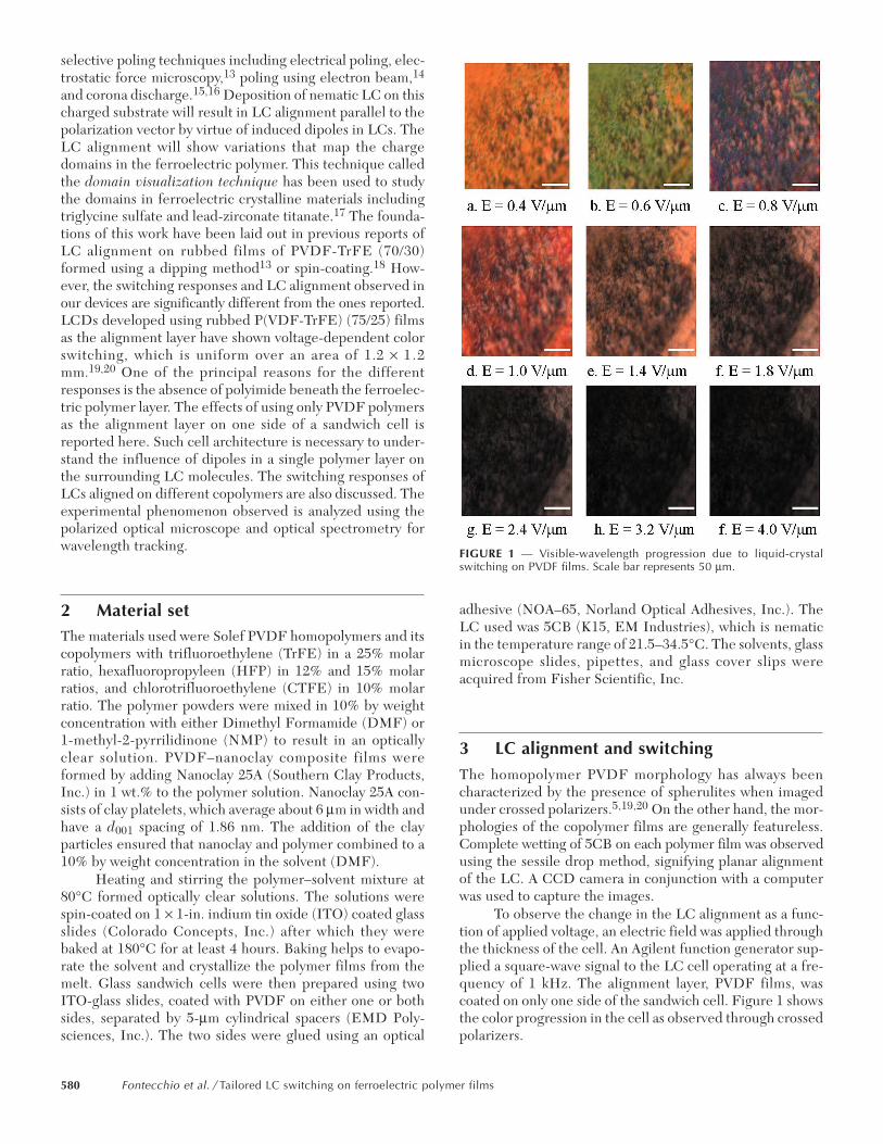
To observe the change in the LC alignment as a func-tion of applied voltage, an electric field was applied throughthe thickness of the cell. An Agilent function generator sup-plied a square-wave signal to the LC cell operating at a fre-quency of 1 kHz. The alignment layer, PVDF films, wascoated on only one side of the sandwich cell. Figure 1 showsthe color progression in the cell as observed through crossedpolarizers.
FIGURE 1 — Visible-wavelength progression due to liquid-crystalswitching on PVDF films. Scale bar represents 50 µm.
580 Fontecchio et al. / Tailored LC switching on ferroelectric polymer films

Due to the dielectric anisotropy of the LC, the exter-nal electric field exerts torques on the LC molecules, chang-ing their orientational angles, causing them to rotate in thedirection of the applied field. As the molecules rotate toalign themselves parallel to the applied field, the polarizedlight from the microscope experiences different birefrin-gence magnitudes. The physical interaction between thePVDF films and the LC can be approximated using dipole-induced dipole interaction and can be represented as21
(1)
where u1 and u2 are the respective dipole moments, θ1 andθ2 are the elevation angles of the dipoles, and φ is theazimuthal angle of the induced dipole.
The PVDF dipoles are permanent dipoles whereas theLC, being a non-polar material, leads to a freely rotating-induceddipole. Because the polymer charge is fixed, the LC willrotate in azimuthal and elevation directions until reachingan equilibrium state where the interaction energy is mini-mized. As a result, a variation in the transmitted intensitiesand colors is observed through crossed polarizers as shownin Fig. 1. The color progression has been observed for LCswitching on all films used including copolymers of PVDF.It must be also noted that most of the voltage drop is acrossthe LC layer, and there is no ferroelectric switching in thepolymer layer. The maximum voltage applied across the5 µm cell was 20 Vp–p at 1 kHz. Using the R-C equivalentcircuit for the sandwich cell schematic, the voltage dropacross the polymer layer is given by17
(2)
where |VPFE| is the voltage dropped across the ferroelectricpolymer layer, Vo is the applied voltage, εPFE and εLC arethe dielectric permittivities of the polymer and the LC layer,respectively, and tPFE and tLC are the thicknesses of therespective layers.
Using the effective value of dielectric permittivity forthe LC layer, we get
(3)
Using a value of 6 for ε⊥ and 26.1 for ε||, we obtain avalue of εLC as 12.67.22 The range of εPFE varies from 9 to12 at room temperature for the different PVDF samples.23
Using Eq. (2), we get |VPFE| to range from 0.81 to 1.35 V,implying that almost 90% of the applied voltage is droppedacross the LC layer. The electric field across the polymerlayer ranges from 4.1 to 6.75 V/µm. These magnitudes aremuch lower than the 100-V/µm minimum required toswitch the dipoles in the polymers16,24 which indicates thatthe external electric field influences only the LC molecules.
In order to map the wavelength response as a functionof the applied electric field, spectrometry measurements
were performed using a crossed-polarizer configuration onthe LC-PVDF cells. A halogen lamp source (Ocean Opticstungsten halogen lamp, λ = 300–800 nm) supplied whitelight, which was fed through an optical fiber to the cellplaced between crossed polarizers. The transmitted lightwas delivered to a 600-nm-core-diameter fiber connected toa spectrometer (Ocean Optics USB2000 spectrometer, reso-lution = 0.36 nm).
Figure 2 shows the transmission of 650 nm (red), 532nm (green), and 450 nm (blue) wavelengths transmittedthrough two LC cells with PVDF and P(VDF-HFP) films,respectively, as the alignment layer. The variations in thevisible wavelengths transmitted through the cell as a func-tion of applied electric field can be clearly observed. Figure2(c) compares the intensity progression in the two cells as afunction of electric field. The intensity was calculated usingthe following formula used for image reproduction in dis-plays:
(4)
where I is the intensity and R, G, B represent red, green,and blue wavelengths. The intensity progression can bedescribed as starting from an initial value (P1) until itreaches a certain state (P2), followed by a decrease to localminima (P3), after which it rises to the maximum intensity(P4) before dropping to the cell OFF-state. This progres-sion is true for LC switching on any of the PVDF films asthe alignment layer, and the cell switches OFF at a magni-tude of ~2 V/µm. Variations observed between the switchingtrends of LC on the different films are due to the differentsurface-charge magnitudes of the polymer in the differentPVDF formulations. The maximum rise and fall timesobserved are ~3.5 and ~1.5 msec, respectively. For dynamicdisplays, switching times less than 10 msec are ideal, indi-cating the suitability of PVDF for display-manufacturingpurposes. However, the LC alignment is not completely uni-form, and the electric field is higher by 1 V/µm compared tothat of commercial LCDs. The techniques that can be usedto overcome these disadvantages include changing thematerial composition, physical modification of the polymerfilm using rubbing, and poling the polymer film to enhancethe β phase. In the next section, we present the results ofthe result of rubbing the polymer films on LC switching.
w ru u
ro( ) cos cos sin sin cos ,= - -1 2
3 1 2 1 24
2pe
q q q q fb g
V Vt
tPFE oPFE LC
LC PFE= +
FHG
IKJ
LNMM
OQPP
1ee
,
ee e
LC =+^2
3|| .
I R G B= + +03 0 59 011. . . ,
FIGURE 2 — Spectrometry response of red (650.11 nm), green (532.11nm), and blue (455.25 nm) as a function of electric field. (a) PVDFhomopolymer is the alignment layer, (b) P(VDF–HFP) is the alignmentlayer, and (c) Intensity vs. electric fields for LC on PVDF and onP(VDF–HFP).
Journal of the SID 15/8, 2007 581

Addition of nanoclays to PVDF and its copolymers isknown to modify the arrangement of the polymer chains toresult in a stronger ferroelectric phase.5–8 The nanoclaysalso lead to an increase in the ordering of the polymerchains, which implies that the dipoles are oriented uni-formly along certain directions. LC alignment on such filmswill map the uniformity of the charge distribution, and theresulting LC textures should exhibit minimal defects. Fig-ure 3 shows the LC alignment on a P(VDF–CTFE) filmwhich was doped with nanoclay (25A). The LC alignment ismuch more uniform than previously observed (Fig. 1). If theLC alignment is uniform, a reduction in the switching elec-tric field is expected. Figure 4 compares the switching of LCon a P(VDF–CTFE) film with one which was doped withnanoclays. The color progression observed in these devicesis more controlled as opposed to that observed in the spin-coated films. Also, the switch OFF voltage in these devicesis ~3 V or an electric field of 0.6 V/µm. This is an improve-ment of approximately 300% over 2 V/µm required in theprevious devices. Thus, changing the alignment-layer mate-rial composition can have significant effects on the responseof the device.
4 Rubbed ferroelectric polymer filmsThus far, we have discussed the electro-optic performanceof the films, which did not undergo any post-baking proc-esses. In this section, we present the effects of rubbingP(VDF-TrFE) films in a 65/35 molar ratio. After baking, the
P(VDF-TrFE) films were rubbed using a cloth-based rub-bing machine. The polymer film exhibits uniform morphol-ogy with no discernible features after rubbing.20 Thesandwich cell had the rubbed films present on both ITO-glass slides.
The resulting variation in the transmitted intensitiesand colors due to LC switching is observed through crossedpolarizers as shown in Fig. 5. The wavelength of light is uni-form across a larger sample area and also encompasses thevisible spectrum, which is an ideal property for displays. Theentire visible wavelength progression occurs at a magnitudebelow 1 V/µm. At higher magnitudes, the transmitted lightreduces in intensity, indicating increased alignment of theLC molecules in the direction of the applied field (z axis).Multiple switching cycles reproduced the identical wave-length progression through the cell. This phenomenon isideal for the manufacture of displays where the requiredvisible wavelength can be generated by applying the corre-sponding voltage. Consequently, the display resolution willincrease by 300% when compared to the conventionalmethod of using three pixels to generate one color.
The variations in the colors transmitted through thecell as a function of applied electric field can be clearlyobserved. The cell switches OFF at a magnitude of ~2 V/µm.
FIGURE 3 — Polarized optical images of LC alignment on (a) PVDF film,(b) PVDF–Nanoclay film, and (c) P(VDF-CTFE)–Nanoclay film. The scalebar on all images represents 50 µm. The blue spots in (b) and (c) are theclay aggregates.
FIGURE 4 — Spectrometry response of red (650.11 nm), green (532.11nm), and blue (455.25 nm) as a function of electric field. (a) P(VDF–CTFE)is the alignment layer, (b) P(VDF-CTFE)–Nanoclay composite film is thealignment layer, and (c) Intensity vs. electric fields for LC onP(VDF–CTFE) and on P(VDF–CTFE)–Nanoclay composite film. Theintensity for the PVDF–CTFE–NC film goes to minimum just after 0.5V/µm, indicating the improvement in switching response due tonanoclay inclusion.
FIGURE 5 — Visible-wavelength progression due to liquid-crystal switchingon rubbed P(VDF–TrFE) films. Scale bar represents 200 µm.
582 Fontecchio et al. / Tailored LC switching on ferroelectric polymer films

Variations observed between the switching trends of LCs ondifferent films are due to the different surface charge mag-nitudes of the polymer in the different PVDF formulations.
From Fig. 6, it is evident that the electro-optic re-sponse is more linear compared to the ones observed inFigs. 2 and 4, highlighting the suitability of these polymerfilms for developing displays and color filters.
5 ConclusionsUsing ferroelectric films as alignment layers for liquid crys-tals provides an approach to develop displays and optical-data-storage devices. Due to the interactions between thedipoles in the polymer and liquid crystal region, the displaysexhibit a visible-wavelength progression as a function of theapplied electric field. As a result, simply varying the magni-tude of the applied field can generate the desired color.Additionally, the transmitted wavelengths encompass thevisible spectrum, an ideal property for this application. ThePVDF–LC system can increase the display resolution by afactor of 3 when compared to the conventional method ofusing three pixels to generate one color. From a materialsperspective, nanoclay doped PVDF films have shown thebest response due to the switching efficiency. However, theaggregates of clay as observed through LC alignment couldcause a problem in the generation of defects in a workingdevice. The film, which is most applicable for use in thedisplay industry is P(VDF–TrFE) films in a 75/25 ratio.These films have shown very uniform LC alignment, wave-length progression response, and switching efficiency.20
The development of optical-data-storage devices is depend-ent on orienting the charge orientation within the polymerregions. Deposition of LCs on this substrate will map theunderlying dipole orientation providing an optical readoutfor the ferroelectric charge. Thus, the polymer can be usedto record charges (data) with the LC layer providing theoptical readout.
References1 M Date, T Furukawa, T Yamaguchi, A Kojima, and I Shibata, “Opto-
ferroelectric memories using vinylidene fluoride and trifluoroethylenecopolymers,” 1988 6th International Symposium on Electrets 24, 537(1989).
2 T J Reece, S Ducharme, A V Sorokin, and M Poulsen, “Nonvolatilememory element based on a ferroelectric polymer Langmuir-Blodgettfilm,” Appl Phys Lett 82, 142 (2003).
3 B Xu, Y Ovchenkov, M Bai, A N Caruso, A V Sorokin, S Ducharme, BDoudin, and P A Dowben, “Heterojunction diode fabrication frompolyaniline and a ferroelectric polymer,” Appl Phys Lett 81, 4281(2002).
4 H S Nalwa, Ferroelectric Polymers: Chemistry, Physics, and Applica-tions (Marcel-Dekker, 1995).
5 D R Dillon, K K Tenneti, C Y Li, F K Ko, I Sics, and B S Hsiao, “Onthe structure and morphology of polyvinylidene fluoride–nanoclaycomposites,” Polymer 47, 1678–1688 (2006).
6 L Priya and J P Jog, “Poly(vinylidene fluoride)/clay nanocompositesprepared by melt intercalation: Crystallization and dynamic mechani-cal behavior studies,” J Polym Sci, Part B (Polym Phys) 40, 1682 (2002).
7 L Priya and J P Jog, “Polymorphism in intercalated poly(vinylidenefluoride)/clay nanocomposites,” J Appl Polym Sci 89, 2036 (2003).
8 L Priya and J P Jog, “Intercalated poly(vinylidene flouride)/clay nano-composites: structure and properties,” J Polym Sci, Part B (Polym Phys)41, 31 (2003).
9 Q-H Wang, T X Wu, X Zhu, and S-T Wu, “Achromatic polarizationswitch using a film-compensated twisted nematic liquid crystal cell,”Liquid Crystals 31, 535 (2004).
10 M J Escuti, J Qi, and G P Crawford, “Two-dimensional tunable pho-tonic crystal formed in a liquid crystal/polymer composite: Thresholdbehavior and morphology,” Appl Phys Lett 83, 1331 (2003).
11 J Fang, W Ma, J V Selinger, and R Shashidhar, “Imaging biological cellsusing liquid crystals,” Langmuir 19, 2865–2869 (2003).
12 E H Lay, A Kirakosian, J L Lin, D Y Petrovykh, J N Crain, F J Himpsel,R R Shah, and N L Abbott, “Alignment of liquid crystals on steppedand passivated silicon templates prepared in ultrahigh vacuum,” Lang-muir 16, 6731–6738 (2000).
13 L M Blinov, R Barberi, S P Palto, M P De Santo, and S G Yudin,“Switching of a ferroelectric polymer Langmuir–Blodgett film studiedby electrostatic force microscopy,” J Appl Phys 89, 3960 (2001).
14 R Danz, M Pinnow, A Buchtemann, and A Wedel, “Electron beampoling of thin fluoropolymer layers,” IEEE Trans Dielectrics ElectricalInsulation 5, 16 (1998).
15 L M Blinov, S P Palto, S V Yakovlev, and D G Sikharulidze, “Asymmet-ric electro-optical switching of a nematic cell controlled by a coronapoled ferroelectric polymer layer,” Appl Phys Lett 72, 3377–3379(1998).
16 M Wegener and R Gerhard-Multhaupt, “Electric poling and electro-mechanical characterization of 0.1-mm-thick sensor films and 0.2-mm-thick cable layers from poly(Vinylidene Fluoride-Trifluroethylene),”IEEE Trans Ultrasonics, Ferroelectrics and Frequency Control 50, 921(2003).
17 J F Hubbard, H F Gleeson, R W Whatmore, C P Shaw, and Q Zhang,“Coupling of the remanent polarisation in thin film oxide ferroelectricswith nematic liquid crystals,” J Mater Chem 9, 375–380 (1999).
18 A R Geivandov and S P Palto, “The influence of ferroelectric polymeralignment layer on electrooptical properties of nematic LC cell,” Mo-lecular Crystals and Liquid Crystals 433, 155–164 (2005).
19 H J Shah and A K Fontecchio, “Influence of ferroelectric polymerlayers on liquid crystal alignment,” Abstracts of Papers of the AmericanChemical Society 230, U3504–U3504 (2005).
20 H J Shah and A K Fontecchio, “Low-voltage color switching in liquidcrystal displays,” Conf Record of 26th IDRC, 315–317 (2006).
21 J N Israelachvili, Intermolecular and Surface Forces: With Applicationsto Colloidal and Biological Systems, 2nd edition (Academic Press,London, 1991).
22 E C Inc., “Technical Data Sheet, LCG K15, Product No. 058300.”23 S Solexis, SOLEF (R) Technical Manual for Polyvinylidene Fluoride.24 A V Bune, V M Fridkin, S Ducharme, L M Blinov, S P Palto, A V
Sorokin, S G Yudin, and A Zlatkin, “Two-dimensional ferroelectricfilms,” Nature 391, 874 (1998).
FIGURE 6 — Transmission of 650-nm (red), 532-nm (green), and 450-nm(blue) wavelengths transmitted through the sandwich cell as observedwith a spectrometer.
Journal of the SID 15/8, 2007 583

Hemang J. Shah received his B.E. degree in elec-tronics and telecommunications engineering fromthe University of Mumbai in 1996 and his M.S.degree in electrical/telecom engineering in 2005from Drexel University, Philadelphia. He is currentlyworking towards the Ph.D. degree in electricalengineering with Adam Fontecchio at Drexel Uni-versity, Philadelphia. His current research inter-ests include liquid-crystal displays, ferroelectricpolymers, carbon nanotubes, ink-jet printing and
plasma treatment of surfaces. He is a student member of IEEE, the Soci-ety for Information Display, the American Physical Society, and theAmerican Chemical Society.
David A. Delaine received his B.S. degree in elec-trical engineering in 2005 from Northeastern Uni-versity, Boston, MA. He is currently workingtoward his Ph.D. in the Department of Electricaland Computer Engineering with Adam Fontec-chio at Drexel University, Philadelphia. His cur-rent research includes the development of novelpower-generation techniques through powerscavenging, and the electrical poling of polymers.He is a member of IEEE, the National Society ofBlack Engineers (NSBE), and the Society of His-panic Professional Engineers.
Adam K. Fontecchio received his B.A. degree inphysics in 1996, his M.Sc. in physics in 1998, andhis Ph.D. in physics in 2002, all from Brown Uni-versity. He is currently Assistant Professor in theDepartment of Electrical and Computer Engineeringand an Affiliated Faculty member in the Depart-ment of Materials Engineering at Drexel Univer-sity. He also serves as the Director of Fabricationfor the A. J. Drexel Nanotechnology Institute. Heis the recipient of a NASA New Investigator
award, the International Liquid Crystal Society Multimedia Prize, andthe Drexel ECE Outstanding Research Award. He has authored over 35peer-review publications on electro-optics and condensed matter phys-ics, holds two patents, and has five additional patents pending. His cur-rent research projects include developing liquid-crystal polymertechnology for optical film applications, including electro-optic virtualfocusing optics, reflective displays, flexible displays, power-generatingMEMS arrays, and photonic crystal structures with tunable defects. Heis a member of IEEE, the Society for Information Display, the AmericanPhysical Society, and the American Chemical Society.
584 Fontecchio et al. / Tailored LC switching on ferroelectric polymer films