Table 11a. Summary of Area Warning Signs
177
AMERICAN NATIONAL STANDARD Z136.1-2007 82 Table 11a. Summary of Area Warning Signs Clause Title Classification Required Statement or Comment 2 3R 3B 4 3.5.1 Personnel X X X X Some individuals may be unable to read or understand signs 4.3.9.1 Warning Sign Posting - X X X Specifies which sign required Caution, Danger, Notice 4.3.9.2 Laser Warning Sign Purpose - X X X States the four purposes of warning signs 4.3.9.3 Warning Sign Non- Beam Hazard X X X X Must follow requirements of other appropriate documents 4.3.9.4.1 Audible Warning Devices - - X X Audible warning should be required for Class 3B and shall for Class 4 4.3.9.4.2 Visible Warning Devices - - X X Visible warning should be required for Class 3B and shall for Class 4 4.7.1 Design of Signs X X X Per ANSI Z535 requirements 4.7.2.1.1 Laser Symbol X X X Laser sun burst required on all signs per ANSI 4.7.2.1.2 International Laser Symbol International symbol as specified in IEC 60825-1 is acceptable 4.7.2.2 Safety Alert Symbol X X X The alert symbol is required on all Caution & Danger Signs 4.7.3.1 Signal Word “Danger” X X X Specifies when to use “Danger” word and format 4.7.3.2 Signal Word “Caution” X Specifies when to use “Caution” word and format 4.7.3.3 Signal Word “Notice” X X X Specifies when to use “Notice” word and format 4.7.4 Pertinent Sign Information X X X Specifies the location of words on signs 4.7.4.3 Location of Signs X X X Specifies location of signs Note: Signs and labels prepared in accordance with previous revisions of this standard are considered to fulfill the requirement of the standard. Licensed to David Patterson. ANSI order X_51518. Downloaded 3/25/2008 10:53 AM. Single user license only. Copying and networking prohibited.
-
Upload
khangminh22 -
Category
Documents
-
view
3 -
download
0
Transcript of Table 11a. Summary of Area Warning Signs

AMERICAN NATIONAL STANDARD Z136.1-2007
82
Table 11a. Summary of Area Warning Signs Clause Title Classification Required Statement or Comment
2 3R 3B 4 3.5.1 Personnel X X X X Some individuals may be unable
to read or understand signs 4.3.9.1 Warning Sign
Posting - X X X Specifies which sign required
Caution, Danger, Notice 4.3.9.2 Laser Warning Sign
Purpose - X X X States the four purposes of
warning signs 4.3.9.3 Warning Sign Non-
Beam Hazard X X X X Must follow requirements of
other appropriate documents 4.3.9.4.1 Audible Warning
Devices - - X X Audible warning should be
required for Class 3B and shall for Class 4
4.3.9.4.2 Visible Warning Devices
- - X X Visible warning should be required for Class 3B and shall for Class 4
4.7.1 Design of Signs X X X Per ANSI Z535 requirements 4.7.2.1.1 Laser Symbol X X X Laser sun burst required on all
signs per ANSI 4.7.2.1.2 International Laser
Symbol International symbol as
specified in IEC 60825-1 is acceptable
4.7.2.2 Safety Alert Symbol X X X The alert symbol is required on all Caution & Danger Signs
4.7.3.1 Signal Word “Danger”
X X X Specifies when to use “Danger” word and format
4.7.3.2 Signal Word “Caution”
X Specifies when to use “Caution” word and format
4.7.3.3 Signal Word “Notice”
X X X Specifies when to use “Notice” word and format
4.7.4 Pertinent Sign Information
X X X Specifies the location of words on signs
4.7.4.3 Location of Signs X X X Specifies location of signs
Note: Signs and labels prepared in accordance with previous revisions of this standard are considered to fulfill the requirement of the standard.
Licensed to David Patterson. ANSI order X_51518. Downloaded 3/25/2008 10:53 AM. Single user license only. Copying and networking prohibited.

AMERICAN NATIONAL STANDARD Z136.1-2007
83
Table 11b. Summary of Labeling Requirements
Clause Title Classification Required Statement or Comment
1 2 3R 3B 4 3.5.1 Personnel X X X X X Some individuals may be
unable to read or understand labels
4.3.14.1 Warning Label - X X X X Class label with symbols & specific words
4.3.14.2 Protective Housing X X X X X Specific word depending on internal laser (see Section 4.7.5 for suggested words)
4.3.14.3 Conduit Label X X X X 4.3.3 Service Access Panel X X X X X Label required if removal
permits access to laser 4.5.2 Optical Fiber
Transmission X X X Words required if
disconnect not in a laser controlled area
4.7.5 Equipment Label Information
X X X X X Specifies specific wording by class
Note1: Labeling of laser equipment in accordance with the Federal Laser Product Performance Standard
(FLPPS) or IEC 60825-1 (or latest revision thereof) may be used to satisfy the equipment labeling requirements in this standard.
Note 2: Signs and labels prepared in accordance with previous revisions of this standard are considered to fulfill the requirement of the standard.
Table 11c. Summary of Protective Equipment Labeling
Clause Title Summary 4.6.5.1 Protective Eyewear OD and wavelength marking required 4.6.5.2 Protective Windows OD, wavelength and exposure time marking
required 4.6.5.3 Collecting Optics
Filters OD, wavelength and threshold limit marking required
4.6.5.4 Protective Barrier Threshold limit and exposure time marking required, see Appendix C2.4.
Note 1: Signs and labels prepared in accordance with previous revisions of this standard are considered to fulfill the requirement of the standard.
Note 2: Marking is only required when windows, filters or barriers are not sold as an integral part of the product.
Licensed to David Patterson. ANSI order X_51518. Downloaded 3/25/2008 10:53 AM. Single user license only. Copying and networking prohibited.

AMERICAN NATIONAL STANDARD Z136.1-2007
84
(YELLOW)POSITION 1
BOLD BLACK LETTERING( )
POSITION 2BOLD BLACK LETTERING( )
POSITION 3BOLD BLACK LETTERING( )
(BLACK SYMBOL)
(YELLOW)(BORDER AND
LINE OPTIONAL) (BLACK) (YELLOW)
Figure 1a. Sample Warning Sign for Class 2 and Class 2M Lasers
Licensed to David Patterson. ANSI order X_51518. Downloaded 3/25/2008 10:53 AM. Single user license only. Copying and networking prohibited.

AMERICAN NATIONAL STANDARD Z136.1-2007
85
(WHITE)POSITION 1
BOLD BLACK LETTERING( )
POSITION 2BOLD BLACK LETTERING( )
POSITION 3BOLD BLACK LETTERING( )
(RED SYMBOL)
(RED) (WHITE) (RED)
Figure 1b. Sample Warning Sign for Class 3R, Class 3B, and Class 4 Lasers
Licensed to David Patterson. ANSI order X_51518. Downloaded 3/25/2008 10:53 AM. Single user license only. Copying and networking prohibited.

AMERICAN NATIONAL STANDARD Z136.1-2007
86
SPACE FOR LEGEND
LEGEND AND BORDER:BACKGROUND:
BLACKYELLOW
Figure 1c. IEC Warning Logo and Information Label
Licensed to David Patterson. ANSI order X_51518. Downloaded 3/25/2008 10:53 AM. Single user license only. Copying and networking prohibited.

AMERICAN NATIONAL STANDARD Z136.1-2007
87
(WHITE)POSITION 1
BOLD BLACK LETTERING( )
POSITION 2BOLD BLACK LETTERING( )
POSITION 3BOLD BLACK LETTERING( )
(RED SYMBOL)
(WHITE) (BLUE)
Figure 1d. Sample Warning Sign for Facility Policy, for example, Outside a Temporary Laser Controlled Area During Periods of Service
Licensed to David Patterson. ANSI order X_51518. Downloaded 3/25/2008 10:53 AM. Single user license only. Copying and networking prohibited.

AMERICAN NATIONAL STANDARD Z136.1-2007
88
Class 4 NHZ
Floormat Sensor
Laser ProtectiveEyewear Storage
Interlocks(nondefeatableor defeatable)
Figure 2a. Area/Entryway Safety Controls for Class 4 Lasers Utilizing Entryway Interlocks
Licensed to David Patterson. ANSI order X_51518. Downloaded 3/25/2008 10:53 AM. Single user license only. Copying and networking prohibited.

AMERICAN NATIONAL STANDARD Z136.1-2007
89
Class 4 NHZ
Entryway WarningLight Assembly orAudible Signal
EmergencyOverride
Emergency Override
Laser Barrier,Screen, Curtain
Exposure < MPE @ Entryway
Figure 2b. Entryway Safety Controls for Class 4 Lasers without Entryway Interlocks
Licensed to David Patterson. ANSI order X_51518. Downloaded 3/25/2008 10:53 AM. Single user license only. Copying and networking prohibited.

AMERICAN NATIONAL STANDARD Z136.1-2007
90
< 6 METERS
≥ 6 METERS
2.5METERS
CLASS 3b or 4
CLASS 3b or 4
AUDIENCECLASS 1
BARRIER
Figure 2c. Unsupervised Laser Installation for Demonstration Laser
Licensed to David Patterson. ANSI order X_51518. Downloaded 3/25/2008 10:53 AM. Single user license only. Copying and networking prohibited.

AMERICAN NATIONAL STANDARD Z136.1-2007
91
≥ 3 METERS
AUDIENCECLASS 1
(FLOOR AREA)
CLASS 3b or 4
Figure 2d. Supervised Laser Installation for Demonstration Laser
Licensed to David Patterson. ANSI order X_51518. Downloaded 3/25/2008 10:53 AM. Single user license only. Copying and networking prohibited.

AMERICAN NATIONAL STANDARD Z136.1-2007
92
2.5 METERS
2.5 METERS
BARRIER
BARRIER
CLASS 3B or 4 (< 3 METERS HIGH) AUDIENCE
CLASS 1
Figure 2e. Supervised Laser Installation for Demonstration Laser
Licensed to David Patterson. ANSI order X_51518. Downloaded 3/25/2008 10:53 AM. Single user license only. Copying and networking prohibited.

AMERICAN NATIONAL STANDARD Z136.1-2007
93
Figure 3. Limiting Cone Angle γ, Photochemical MPEs
100
101
102
103
101 102 103 104 105
Exposure Duration (s)
Lim
iting
Con
e A
ngle
�(m
illira
dian
s)
Licensed to David Patterson. ANSI order X_51518. Downloaded 3/25/2008 10:53 AM. Single user license only. Copying and networking prohibited.

AMERICAN NATIONAL STANDARD Z136.1-2007
94
Figure 4. Point Source MPEs for Visible and Near Infrared Pulsed Sources (Wavelengths from 0.400 to 1.400 μm)
See Table 5a.
Licensed to David Patterson. ANSI order X_51518. Downloaded 3/25/2008 10:53 AM. Single user license only. Copying and networking prohibited.

AMERICAN NATIONAL STANDARD Z136.1-2007
95
Figure 5. MPE for Ultraviolet Radiation (Small and Extended Sources) for Exposure Duration from 10-9 to 3 × 10⁴ s for Ocular Exposure
and 10-9 to 103 s for Skin Exposure*
* Unless 0.56 t 0.25 is exceeded (possible for exposure durations < 10 s at wavelengths from 0.305 to 0.315 μm).
Licensed to David Patterson. ANSI order X_51518. Downloaded 3/25/2008 10:53 AM. Single user license only. Copying and networking prohibited.

AMERICAN NATIONAL STANDARD Z136.1-2007
96
Figure 6. MPE for Ultraviolet (Wavelengths from 0.315 to 0.400 μm) and Infrared Radiation (Wavelengths from 1.400 μm to 1mm)
for Single Pulses or Continuous Exposure (Small or Extended Sources) See Figure 5 for Wavelengths less than 0.315 μm.
Licensed to David Patterson. ANSI order X_51518. Downloaded 3/25/2008 10:53 AM. Single user license only. Copying and networking prohibited.

AMERICAN NATIONAL STANDARD Z136.1-2007
97
Figure 7. MPE for Ocular Exposure to Visible Laser Radiation (Wavelengths from 0.400 to 0.700 μm) for Single Pulses or Continuous Exposure (Small or Extended Sources)
See Tables 5a and 5b.
Licensed to David Patterson. ANSI order X_51518. Downloaded 3/25/2008 10:53 AM. Single user license only. Copying and networking prohibited.

AMERICAN NATIONAL STANDARD Z136.1-2007
98
Note: CA = 1 for λ = 0.400 to 0.7.00 μm CA = 102(λ-0.700) for λ = 0.700 to 1.050 μm CA = 5.0 for λ = 1.050 to 1.400 μm
Figure 8a. Correction Factor CA used to Determine the MPE for Wavelengths from 0.400 to 1.400 μm
See Table 6.
Licensed to David Patterson. ANSI order X_51518. Downloaded 3/25/2008 10:53 AM. Single user license only. Copying and networking prohibited.

AMERICAN NATIONAL STANDARD Z136.1-2007
99
Note: CC = 1.0 for λ = 1.050 to 1.150 μm CC = 1018(λ-1.150) for λ = 1.150 to 1.200 μm CC = 8 for λ = 1.200 to 1.400 μm
Figure 8b. Correction Factor CC used to Determine the MPE for Wavelengths from 1.050 to 1.400 μm
See Table 6.
Licensed to David Patterson. ANSI order X_51518. Downloaded 3/25/2008 10:53 AM. Single user license only. Copying and networking prohibited.

AMERICAN NATIONAL STANDARD Z136.1-2007
100
Figure 8c. Correction Factor CB used to Determine the MPE for Wavelengths from 0.400 to 0.600 μm
See Table 6.
Licensed to David Patterson. ANSI order X_51518. Downloaded 3/25/2008 10:53 AM. Single user license only. Copying and networking prohibited.

AMERICAN NATIONAL STANDARD Z136.1-2007
101
Note: T1 = 10 × 1020(λ-0.450) for wavelengths from 0.450 to 0.500 μm
Figure 9a. Correction Factor T1 Beyond which Photochemical (Rather than Thermal) Effects Determine the MPE for Point Sources for
Wavelengths from 0.450 to 0.500 μm See Tables 5a and 6.
Licensed to David Patterson. ANSI order X_51518. Downloaded 3/25/2008 10:53 AM. Single user license only. Copying and networking prohibited.

AMERICAN NATIONAL STANDARD Z136.1-2007
102
Note: T2 = 10 × 10(α-1.5)/ 98.5 for wavelengths from 0.400 to 1.400 μm (α is in milliradians) T2 = 10 s for point sources T2 = 100 s for sources equal to or exceeding 100 mrad
Figure 9b. Correction Factor T2 used to Determine the Extended Source MPE based on Thermal Effects for Exposure Durations Greater than T2
See Table 6.
Licensed to David Patterson. ANSI order X_51518. Downloaded 3/25/2008 10:53 AM. Single user license only. Copying and networking prohibited.

AMERICAN NATIONAL STANDARD Z136.1-2007
103
Note: Solid lines indicate the MPE based on Thermal Effects. Dashed lines indicate the MPE based on Photochemical Effects.
Figure 10a. Ocular Point Source MPE (α ≤ 1.5 mrad) for Visible and Near Infrared Laser Radiation (Wavelengths from 0.400 to 1.400 μm)
See Table 5a.
Licensed to David Patterson. ANSI order X_51518. Downloaded 3/25/2008 10:53 AM. Single user license only. Copying and networking prohibited.

AMERICAN NATIONAL STANDARD Z136.1-2007
104
Note: Solid lines indicate the MPE based on Thermal Effects. Dashed lines indicate the MPE based on Photochemical Effects.
Figure 10b. Ocular Extended Source MPE (α = 3.0 mrad) for Visible and Near Infrared Laser Radiation (Wavelengths from 0.400 to 1.400 μm)
See Table 5b.
Licensed to David Patterson. ANSI order X_51518. Downloaded 3/25/2008 10:53 AM. Single user license only. Copying and networking prohibited.

AMERICAN NATIONAL STANDARD Z136.1-2007
105
Note: Solid lines indicate the MPE based on Thermal Effects. Dashed lines indicate the MPE based on Photochemical Effects.
Figure 10c. Ocular Extended Source MPE (α ≤ 11 mrad) for Visible and Near Infrared Laser Radiation (Wavelengths from 0.400 to 1.400 μm)
See Table 5b.
Licensed to David Patterson. ANSI order X_51518. Downloaded 3/25/2008 10:53 AM. Single user license only. Copying and networking prohibited.

AMERICAN NATIONAL STANDARD Z136.1-2007
106
Note: Solid lines indicate the MPE based on Thermal Effects. Dashed lines indicate the MPE based on Photochemical Effects.
Figure 10d. Ocular Extended Source MPE (α = 25 mrad) for Visible and Near Infrared Laser Radiation (Wavelengths from 0.400 to 1.400 μm)
See Table 5b.
Licensed to David Patterson. ANSI order X_51518. Downloaded 3/25/2008 10:53 AM. Single user license only. Copying and networking prohibited.

AMERICAN NATIONAL STANDARD Z136.1-2007
107
Note: Solid lines indicate the MPE based on Thermal Effects. Dashed lines indicate the MPE based on Photochemical Effects.
Figure 10e. Ocular Extended Source MPE (α = 50 mrad) for Visible and Near Infrared Laser Radiation (Wavelengths from 0.400 to 1.400 μm)
See Table 5b.
Licensed to David Patterson. ANSI order X_51518. Downloaded 3/25/2008 10:53 AM. Single user license only. Copying and networking prohibited.

AMERICAN NATIONAL STANDARD Z136.1-2007
108
Note: Solid lines indicate the MPE based on Thermal Effects. Dashed lines indicate the MPE based on Photochemical Effects.
Figure 11. Ocular Extended Source MPE (α ≥ 110 mrad) for Visible and Near Infrared Laser Radiation (Wavelengths from 0.400 to 1.400 μm)
See Table 5b.
Licensed to David Patterson. ANSI order X_51518. Downloaded 3/25/2008 10:53 AM. Single user license only. Copying and networking prohibited.

AMERICAN NATIONAL STANDARD Z136.1-2007
109
Figure 12. Ocular Extended Source Radiance MPE (α ≥ 100 mrad) for Visible and Near Infrared Laser Radiation (Wavelengths from 0.400 to
1.400 μm) for Pulsed or Continuous Exposures less than 1 s See Table 5b.
Licensed to David Patterson. ANSI order X_51518. Downloaded 3/25/2008 10:53 AM. Single user license only. Copying and networking prohibited.

AMERICAN NATIONAL STANDARD Z136.1-2007
110
Figure 13. MPE Reduction Factor (CP) for Repetitive-Pulse Lasers and Multiple Exposures from Scanning Lasers
Licensed to David Patterson. ANSI order X_51518. Downloaded 3/25/2008 10:53 AM. Single user license only. Copying and networking prohibited.

This appendix is presented as a normative appendix, and as such is part of the American National Standard Z136.1-2007.
APPENDIX
111
Appendix A Supplement to Section 1 – Laser Safety Programs
Note: The following material is an extension of 1.3 and, as a normative Appendix, is an integral part of the standard.
A1. Laser Safety Officer (LSO) A1.1 General. The LSO is an individual designated by the employer with the authority and responsibility to effect the knowledgeable evaluation and control of laser hazards, and to monitor and enforce the control of such hazards. The LSO shall have authority to suspend, restrict, or terminate the operation of a laser system if he/she deems that laser hazard controls are inadequate. For the laser safety program to be effective, the LSO must have sufficient authority to accompany the responsibility. In organizations that do not permit authority to reside with non-management personnel and the LSO is a non-management position; the management shall provide protocols and reporting structure to assure adequate enforcement authority.
The LSO may be designated from among such personnel as the radiation safety officer, industrial hygienist, safety engineer, laser specialist, laser operator or user, etc. The LSO may be a part-time position when the workload for an LSO does not require a full-time effort. In some instances, the designation of an LSO may not be required. Operation and maintenance of Class 1, Class 1M, Class 2, Class 2M and Class 3R lasers and laser systems normally do not require the designation of an LSO. However, under some circumstances it may be desirable to designate an LSO, for example, if service is performed on a laser system having an embedded Class 3B, or Class 4 laser or laser system. In such instances, management may designate the service person requiring access to the embedded laser as the LSO. In any case, there shall be a designated LSO for all circumstances of operation, maintenance, and service of a Class 3B or Class 4 laser or laser system.
If necessary, a Deputy Laser Safety Officer (DLSO) shall be appointed by management or the LSO. The DLSO shall perform the functions of the LSO when the latter is not available. For institutions with multiple divisions or plant locations, a system of DLSOs may be required.
A1.2 LSO Specific Duties and Responsibilities.
(1) Safety Program. The LSO shall establish and maintain adequate policies and procedures for the control of laser hazards. These policies and procedures shall comply with applicable requirements, including federal, state and local regulations.
(2) Classification. The LSO shall classify, or verify classifications of, lasers and laser systems used under the LSO’s jurisdiction. Classifications shall be consistent with classifications listed in Section 3 of this standard.
(3) Hazard Evaluation. The LSO shall be responsible for hazard evaluation of laser work areas. Hazard evaluation shall be conducted in accordance with Section 3 of this standard.
Licensed to David Patterson. ANSI order X_51518. Downloaded 3/25/2008 10:53 AM. Single user license only. Copying and networking prohibited.

APPENDIX This appendix is presented as a normative appendix, and as such is part of the American National Standard Z136.1-2007.
112
(4) Control Measures. The LSO shall be responsible for assuring that the prescribed control measures are implemented and maintained in effect. This includes avoiding unnecessary or duplicate controls, and recommending or approving substitute or alternate control measures when the primary ones are not feasible or practical.
(5) Procedure Approvals. The LSO shall approve Class 3B and Class 4 standard operating procedures (SOPs), and other procedures that may be part of the requirements for administrative and procedural controls.
(6) Protective Equipment. The LSO shall recommend or approve protective equipment, i.e., eyewear, clothing, barriers, screens, etc. as may be required to assure personnel safety. The LSO shall assure that protective equipment is audited periodically to assure proper working order.
(7) Signs and Labels. The LSO shall review the wording on area signs and equipment labels.
(8) Facility and Equipment. The LSO shall review Class 3B and Class 4 laser installations, facilities and laser equipment prior to use. This also applies to modification of existing facilities or equipment.
(9) Training. The LSO shall assure that adequate safety education and training are provided to laser personnel. The frequency of refresher training shall be considered on the basis of the total hazard evaluation criteria presented in Section 3.
(10) Medical Surveillance. The LSO shall determine the personnel categories for medical surveillance (see Section 6).
(11) Records. The LSO shall assure that the necessary records required by applicable government regulations are maintained. The LSO shall also submit to the appropriate medical officer the individuals’ names that are obtained in accordance with A3.1(3) and A3.1(4), and shall assure that the appropriate records are maintained indicating that applicable medical examinations have been scheduled and performed. Other records documenting the maintenance of the safety program, such as training records, audits, SOP approvals, etc., shall be maintained.
(12) Audits, Surveys and Inspections. The LSO shall periodically audit or survey by inspection for the presence and functionality of the laser safety features and control measures required for each Class 3B and Class 4 laser or laser system in the laser facilities. The LSO shall accompany regulatory agency inspectors (such as OSHA, FDA/CDRH, state or local agencies) reviewing the laser safety program or investigating an incident and document any discrepancies or issues noted. The LSO shall assure that corrective action is taken, where required.
(13) Accidents. The LSO should develop a plan to respond to notifications of incidents of actual or suspected exposure to potentially harmful laser radiation. The plan should include the provision of medical assistance for the potentially exposed individual, investigation of the incident and the documentation and reporting of the investigation results.
(14) Approval of Laser Systems Operations. Approval of a Class 3B or Class 4 laser or laser system for operation shall be given only if the LSO is satisfied that laser hazard
Licensed to David Patterson. ANSI order X_51518. Downloaded 3/25/2008 10:53 AM. Single user license only. Copying and networking prohibited.

This appendix is presented as a normative appendix, and as such is part of the American National Standard Z136.1-2007.
APPENDIX
113
control measures are adequate. These include SOPs (standard operating procedures) for maintenance and service operations within enclosed systems and operation procedures for Class 3B and 4 laser systems. The procedures should include adequate consideration of safety from non-beam hazards.
A2. Laser Safety Committee A Laser Safety Committee may be created.
A2.1 Membership of Laser Safety Committee. The membership of the Laser Safety Committee may include members with expertise in laser technology or in the assessment of laser hazards. Management may be included in the membership. Examples of members include, but are not limited to, technical management, LSO and/or representatives of the safety/industrial hygiene organization, physician, education department member, engineer/scientist and user representative.
A2.2 Policies and Practices. The committee shall establish and maintain adequate policies and practices for the evaluation and control of laser hazards, including the recommending of appropriate laser safety training programs and materials.
A2.3 Standards. The committee shall maintain an awareness of all applicable new or revised laser safety standards.
A3. Other Personnel Responsibilities A3.1 Laser Supervisor. The supervisor of individuals working with or having the potential for exposure to greater than Class 1 laser radiation, should have a basic overall knowledge of laser safety requirements for the lasers under the supervisor’s authority.
The following responsibilities should be considered as a minimal set of responsibilities for the Laser Supervisor.
(1) The supervisor shall be responsible for the issuance of appropriate instructions and training materials on laser hazards and their control to all personnel who may work with lasers that are operated within the supervisor’s jurisdiction.
(2) The supervisor shall not permit the operation of a laser unless there is adequate control of laser hazards to employees, visitors, and the general public.
(3) The supervisor shall submit the names of individuals scheduled to work with lasers to the LSO and shall submit information as requested by the LSO for medical surveillance scheduling and training completion.
(4) When the supervisor knows of, or suspects, an accident resulting from a laser operated under his or her authority, the supervisor shall immediately upon becoming aware of a suspected laser incident implement the institution’s accident responsible plan and ensure it includes notification of the LSO.
(5) If necessary, the supervisor shall assist in obtaining appropriate medical attention for any employee involved in a laser accident.
Licensed to David Patterson. ANSI order X_51518. Downloaded 3/25/2008 10:53 AM. Single user license only. Copying and networking prohibited.

APPENDIX This appendix is presented as a normative appendix, and as such is part of the American National Standard Z136.1-2007.
114
(6) The supervisor shall not permit operation of a new or modified Class 3B or Class 4 laser under his or her authority without the approval of the LSO.
(7) The supervisor shall submit plans for Class 3B and Class 4 laser installations or modifications of installations to the LSO for review.
(8) For Class 3B or Class 4 lasers and laser systems, the supervisor shall be familiar with the standard operating procedures and ensure that they are provided to users of such lasers.
A3.2 Responsibility of Employees Working with Lasers. Employees working with lasers or laser systems shall have, where applicable, the following minimal responsibilities.
(1) An employee shall not energize or work with or near a laser unless authorized to do so by the supervisor for that laser.
(2) An employee shall comply with safety rules and procedures prescribed by the supervisor and the LSO. The employee shall be familiar with all applicable operating procedures.
(3) When an employee operating a laser knows or suspects that an accident has occurred involving that laser, or a laser operated by any other employee, and that such accident has caused an injury or could potentially have caused an injury, he or she shall immediately inform the supervisor. If the supervisor is not available, the employee shall notify the LSO.
A3.3 Other Personnel. Anyone involved in purchasing a laser or laser system should contact the LSO. Such personnel may also include but is not limited to purchasing, accounting, building management, etc. as may be applicable.
Licensed to David Patterson. ANSI order X_51518. Downloaded 3/25/2008 10:53 AM. Single user license only. Copying and networking prohibited.

This appendix is not a normative appendix, but is intended for information only.
APPENDIX
115
Appendix B Calculations for Hazard Evaluation and Classification
B1. General Calculations are not necessary for hazard evaluation and classification in many applications; however, in outdoor applications and other specialized uses where eye exposure is contemplated, several types of calculations permit the important quantitative study of potential hazards.
Mathematical symbols used here are defined in B2. MPE determination may require the use of formulae in B3. Hazard classification methods are discussed in B4. Formulae for computing beam irradiance and radiant exposure are contained in B5. Formulae useful in hazard evaluation and calculating nominal ocular hazard distance and nominal hazard zone are listed in B6. Methods for determining MPEs based on retinal hazards from both photochemical and thermal effects for extended visible laser sources are discussed in B7. Formulae useful in determining adequate protective eyewear or laser barriers are listed in B8. Determination of extended source sizes is discussed in B9. Applicable references are contained in B10.
Figures B1 through B9 illustrate conditions of ocular exposure to laser radiation.
B2. Symbols The following symbols are used in the formulae of this Appendix.
a = Diameter of emergent laser beam (cm).
α = Apparent angle subtended by a source at the location of the viewer (rad).
αmax = Apparent angle subtended by a source above which the thermal hazard is proportional to the radiance of the source (100 mrad).
αmin = Apparent angle subtended by a source above which extended source MPEs apply (1.5 mrad).
b0 = Diameter of laser beam incident on a focusing lens (cm).
bl = Width of rectangular beam (cm).
b = Major axis of elliptical cross-section beam (cm).
c = Minor axis of elliptical cross-section beam (cm).
cl = Height of rectangular beam (cm).
CA = Wavelength correction factor (0.700 μm <λ < 1.050 μm).
CB = Wavelength correction factor (0.400 μm <λ < 0.600 μm).
CC = Wavelength correction factor (1.150 μm <λ < 1.400 μm).
Licensed to David Patterson. ANSI order X_51518. Downloaded 3/25/2008 10:53 AM. Single user license only. Copying and networking prohibited.

APPENDIX This appendix is not a normative appendix, but is intended for information only.
116
CE = Extended source correction factor (=α/αmin for source angles less than 100 mrad).
CP = Repetitive-pulse correction factor1 (= n-0.25).
de = Diameter of the pupil of the eye (varies from appropriately 0.2 to 0.7 cm).
D = Barrier separation distance from the focal point of final focusing lens (cm).
DC = Diameter of collecting aperture of optical system (cm).
De = Diameter of the exit pupil of an optical system (cm).
Dexit = Exit port diameter of a laser (cm).
Df = Limiting aperture from Tables 8a and 8b (cm).
DL = Diameter of laser beam at range r (cm).
Dm = Diameter of measurement aperture from Table 9 used for classification (cm).
D0 = Diameter of objective of an optical system (cm).
Dρ = Diameter of a reflected laser beam at the reflecting surface (cm).
Dλ = Optical density at a particular wavelength (λ).
Ds = Barrier separation distance (direct beam) (cm).
DSD = Barrier diffuse reflection separation distance (cm).
Dw = Diameter of a beam waist which occurs in front of the laser exit port (cm).
e = Base of natural logarithms (2.71828).
f = Effective focal length of the eye (1.7 cm).
f0 = Focal length of a lens (cm).
F = Pulse-repetition frequency, PRF(s-1).
Feff = Effective (average) PRF (s-1).
γ = Limiting cone angle (field of view) for MPEs based on photochemical hazards (11 mrad for t<100 s).
G = Ratio of corneal irradiance or radiant exposure through magnifying optics to that received by the unaided eye.
Geff = Ratio of ocular hazard from optically aided viewing to that for unaided viewing.
H, E = Radiant exposure (H) or irradiance (E) at range r, measured in J⋅cm-2 for pulsed lasers and W⋅cm-2 for CW lasers.
H0, E0 = Emergent beam radiant exposure (H0) or irradiance (E0) at the minimum measurement distance (10 cm) (units as for E, H).
Hgroup = Radiant exposure for the summation of all the energies in a group of pulses.
Hp = The potential eye exposure, in the appropriate units, utilized in the determination of the optical density of protective eyewear.
1 For pulse repetition frequencies less than the critical frequency.
Licensed to David Patterson. ANSI order X_51518. Downloaded 3/25/2008 10:53 AM. Single user license only. Copying and networking prohibited.

This appendix is not a normative appendix, but is intended for information only.
APPENDIX
117
λ = Wavelength of source (μm).
Le = Radiance of an extended source (W⋅cm-2⋅sr-1).
Lp = Integrated radiance of an extended source (J⋅cm-2⋅sr-1).
MPE = Maximum permissible exposure.
MPE:E = MPE expressed as irradiance. For exposure to single pulses, the MPE is for peak power, and for a group of pulses, the MPE is for the average power (W⋅cm-2).
MPE:H = MPE expressed as radiant exposure for a single pulse or exposure (J⋅cm-2).
MPE:Hgroup = MPE expressed as radiant exposure for the summation of all the energy in a group of pulses (J⋅cm-2).
MPElarge = MPE for an extended source.
MPE:Le = MPE expressed as radiance (W⋅cm-2⋅sr-1).
MPE:LP = MPE expressed as integrated radiance (J⋅cm-2⋅sr-1).
MPE/Pulse = MPE expressed as radiant exposure for each pulse in a pulse train (J⋅cm-2).
MPEpoint = MPE for a point source.
MPEskin = MPE for skin exposure.
MPESP = MPE expressed as radiant exposure (J⋅cm-2) for exposure to a single pulse in a pulse train (without exposure to any other pulses).
n = number of pulses within total exposure duration T.
NA = Numerical aperture of optical fiber. For emission from an optical fiber, the numerical aperture is the half-angle beam divergence measured at 1/e3 of peak irradiance.
P = Magnifying power of an optical instrument.
φ = Emergent beam divergence measured at the 1/e peak of irradiance points (rad).
φ1 = Emergent beam divergence of the major cross-sectional dimension of a rectangular or elliptical beam (rad).
φ2 = Emergent beam divergence of the minor cross-sectional dimension of a rectangular or elliptical beam (rad).
Φ = Radiant power (W).
Φ0 = Total radiant power output of a CW laser, or average radiant power of a repetitive-pulse laser (W).
Φd = Radiant power transmitted by an aperture (W).
Φeff = Power transmitted by the measurement aperture from Table 9 (W).
Q = Radiant energy (J).
Q0 = Total radiant energy output of a pulsed laser (J).
Qd = Radiant energy transmitted by an aperture (J).
Licensed to David Patterson. ANSI order X_51518. Downloaded 3/25/2008 10:53 AM. Single user license only. Copying and networking prohibited.

APPENDIX This appendix is not a normative appendix, but is intended for information only.
118
Qeff = Energy transmitted by the measurement aperture from Table 9 (J).
r = Distance from the viewer to the laser (cm).
rNHZ = Nominal hazard zone.
rNOHD = The distance along the axis of the unobstructed beam from the laser beyond which the irradiance or radiant exposure is not expected to exceed the appropriate ocular MPE (cm).
r0 = Distance from exit port to a beam waist formed in front of the laser (cm).
rl = Distance from laser target to the viewer (cm).
R = Radius of curvature of a specular surface (cm).
ρλ = Spectral reflectance of a diffuse or specular object at wavelength λ.
S = Scan rate of a scanning laser (number of scans across eye per second).
t = Duration of single pulse or exposure (s).
τλ = Transmission of magnifying optics.
tmin = Maximum duration for which the MPE is the same as for 1 ns.
T = Total exposure duration (in seconds) of a train of pulses.
T1 = Exposure duration depending on wavelength, beyond which the MPE for a point source is based on photochemical effects rather than thermal.
T2 = Exposure duration beyond which the thermal MPE for an extended source is constant in terms of irradiance.
TL = Barrier threshold limit.
Tmax = Total expected exposure duration (see Section 8.2.2).
θs = Maximum angular sweep of a scanning beam (rad).
θν = Viewing angle from the normal to a reflecting surface (see Figure B4).
ω0 = Mode field diameter of single mode optical fiber (μm). Note that the mode field diameter is similar to the beam waist radius at 1/e2 peak of irradiance points (also designated ω0) discussed in many optics text books, but is twice the value.
B3. Examples of MPE Determination Powerful or energetic lasers can easily damage a person’s vision since the cornea and lens focus the laser energy onto the retina. Direct point source exposure to a collimated visible or near infrared laser results in a small image on the retina no more than about 25 μm in diameter. The MPEs expressed as corneal exposure, are very low in order to account for this natural focusing effect of the human eye. For retinal effects, the true hazard is related to the amount of laser power or energy that enters the pupil, and is focused on the retina.
Although infrared lasers (1.400 μm to 1 mm) and ultraviolet lasers (0.180 μm to 0.400 μm) do not present a retinal hazard, these lasers can still damage the eye with sufficient power or energy. Since the cornea and lens of the eye do not focus laser energy at these wavelengths,
Licensed to David Patterson. ANSI order X_51518. Downloaded 3/25/2008 10:53 AM. Single user license only. Copying and networking prohibited.

This appendix is not a normative appendix, but is intended for information only.
APPENDIX
119
the MPE will generally be much larger for these lasers. However, for ultraviolet exposure, photochemical effects are additive over a full day of exposure, and for some wavelengths on subsequent days, also.
The MPE may be expressed in several different ways. In Tables 5a and 5b, the MPE is provided in either J⋅cm-2 or in W⋅cm-2. Usually, the MPE provided in Tables 5a and 5b are expressed as radiant exposure (J⋅cm-2) for exposures lasting less than 10 s.
The MPEs for exposure durations exceeding 0.7 s to extended visible laser sources require concepts of radiance and integrated radiance. Techniques for determining these MPEs are provided in B7.
B3.1 Continuous-Wave Laser MPEs. For a CW laser or for an exposure lasting several milliseconds, it is natural to express the MPE as irradiance (MPE:E) in W⋅cm-2.
Example 1. Determine the maximum irradiance permitted for a 0.25 s exposure to a visible laser (λ = 400 nm to 700 nm).
Solution. The MPE for visible lasers from Table 5a for wavelengths between 0.4 and 0.7 μm (400 and 700 nm) for exposure durations from 18 μs to 10 s is:
MPE:H = 1.8 t 3/4 mJ⋅cm-2. Eq B1
For a 0.25 s exposure, the MPE is 1.8 × 0.250.75 mJ ⋅ cm-2 = (1.8 × 0.354) mJ ⋅ cm-2 = 0.636 mJ⋅cm-2. For a single exposure, the irradiance may be found by dividing the radiant exposure, H, by the exposure duration, t:
tHE = . Eq B2
For a radiant exposure (H) of 0.636 mJ⋅cm-2 for 0.25 s, the irradiance (E) is:
s0.25cmmJ 0.636:MPE :MPE
-2⋅==
tHE
= 2.55 mW⋅cm-2.
Therefore the MPE may be represented either as radiant exposure when it is provided in J⋅cm-2 or as irradiance when it is provided in W⋅cm-2.
Example 2. A helium-cadmium (HeCd) laser operating at 325 nm is used in a laboratory. Laser exposure can occur at all locations within the laboratory. A laboratory technician is required to perform tests in the laboratory which last
Licensed to David Patterson. ANSI order X_51518. Downloaded 3/25/2008 10:53 AM. Single user license only. Copying and networking prohibited.

APPENDIX This appendix is not a normative appendix, but is intended for information only.
120
10 minutes every hour. The rest of the day, the technician works elsewhere. What is the MPE for this laser for these exposure conditions?
Solution. Since the technician is only in the lab for part of the day, his total exposure time is 10 minutes (600 s) per hour multiplied by 8 hours in a day, which equals 4800 s. The MPE for 325 nm radiation is 1.0 J⋅cm-2 for exposures lasting from 10 s to 8 hours. Therefore, the MPE is 1.0 J⋅cm-2 accumulated exposure, whether the exposure is for 4800 s or 30,000 s. The MPE can also be calculated based on average power. The MPE in terms of irradiance is the MPE in terms of radiant exposure divided by the exposure duration. In this case, the MPE is:
tHE :MPE:MPE = .
.cmmW21.0
cmW101.2s4800
cmJ1
2
242
−
−−−
⋅=
⋅×=⋅
=
Example 3. A 3 mW laser operates at a wavelength of 1.55 μm with a beam diameter of 1.1 cm. What is the MPE for a 10 s exposure?
Solution. From Table 5a,, the MPE for a 10 s exposure at 1550 nm is 1 J⋅cm-2. The MPE in terms of irradiance is then 1 J⋅cm-2/10 s = 0.1 W⋅cm-2.
B3.2 Single-Pulse Laser MPEs. MPEs for a single-pulse laser may be calculated from the information provided in Tables 5, 6 and 7 or one may extrapolate a good approximate value from Figures 4, 5, 6, 7, and 8.
Example 4. Single-Pulse Visible Laser. Determine the MPE for a 694.3 nm, ruby laser pulse, having a pulse duration of 8 × 10⁻⁴ s (0.8 ms).
Solution. The appropriate MPE is given in Table 5a, see Eq B1. Substituting the values for t in the equation yields:
MPE:H = 1.8 × 10⁻³ t 0.75 J⋅cm-2
= 1.8 × 10⁻³ (8 × 10⁻⁴)0.75
= 8.6 × 10⁻⁶ J⋅cm-2.
Since E × t = H, the MPE may also be expressed as peak irradiance,
s10 8cmJ10 8.6:MPE :MPE 4-
-2-6
×⋅×
==t
HE
= 1.1 × 10⁻² W⋅cm-2.
Licensed to David Patterson. ANSI order X_51518. Downloaded 3/25/2008 10:53 AM. Single user license only. Copying and networking prohibited.

This appendix is not a normative appendix, but is intended for information only.
APPENDIX
121
Example 5. Extremely-Short-Pulsed Laser. Find the MPE for a single 100 fs (100 × 10-15 s) pulse at 580 nm (0.58 μm).
Solution. The MPE for a single 100 fs (100 × 10-15 s) pulse at 580 nm can be found using Table 5a.
MPE:H = 1.5 × 10⁻⁸ J⋅cm-2.
Example 6. Near infrared Laser. A GaAs laser operating at room temperature has a peak wavelength of 0.904 μm. What is the MPE for a single pulse of 200 ns duration?
Solution. The MPE can be calculated from the information in Figures 4 and 8. From Figure 4, the MPE for exposure durations between 1 ns and 18 μs is 5×10⁻⁷ J⋅cm-2. This MPE may be corrected for 0.9 μm by the use of CA which is about 2.5 as read from Figure 8a. The product is 1.25 × 10⁻⁶ J⋅cm-2.
Tables 5a and 6 can also be used to determine the MPE. From Table 5a, under “visible and near infrared,” 0.700–1.05 μm, 10-9 to 18 × 10-6 s, the
MPE:H = 0.5 × CA × CE × 10-6 J⋅cm-2. Eq B3
Since no information was provided on source size, CE is assumed to be 1.0 (see Section B3.5). From Table 6, the value of CA for the wavelength band of 0.7 to 1.05 μm can be calculated from the formula:
CA = 102(λ-0.7 μm)= 2.56. Eq B4
The MPE is then,
2-6-
-7
cmJ 10 1.28 )10 (2.56)(5 :MPE
⋅×=
×=H
Example 7. Single-Pulse Near infrared Laser. Determine the MPE for a 1.064 μm (Nd:YAG) laser having a pulse duration of 8 × 10⁻⁴ s.
Solution. The MPE as given in Table 5a is:
MPE:H = 9 × t 0.75 × 10⁻³ J⋅cm-2 Eq B5 = 9 × (8 × 10-4)0.75 × 10⁻³ J⋅cm-2
= 4.3 × 10⁻⁵ J⋅cm-2.
Licensed to David Patterson. ANSI order X_51518. Downloaded 3/25/2008 10:53 AM. Single user license only. Copying and networking prohibited.

APPENDIX This appendix is not a normative appendix, but is intended for information only.
122
Another way to approach this problem is to note that in Figure 8a, the MPE for this laser is five times that for a visible laser having the same exposure duration (as calculated in Example 4). Therefore, the MPE for this exposure is:
)cmJ106.8(5:MPE 26 −− ⋅××=H = 25 cmJ103.4 ⋅× − .
In terms of peak irradiance,
s108cmJ103.4
:MPE:MPE
4
25
−
−−
×⋅×
=
tH=E
= 22 cmW105.4 −− ⋅× .
Example 8. Extremely-Short Near infrared Laser. Find the MPE for a single 20 ps (2 × 10-11 s) laser pulse at 1060 nm.
Solution. The MPE is found using Table 5a. For exposure durations between 10 ps and 1 ns is:
MPE:H = 27 Cc t 0.75 J⋅cm-2, Eq B6
where t is measured in seconds. For 1060 nm (1.06 μm), CC is 1.0. Therefore,
MPE:H = 27 (1.0) (2 × 10-11)0.75 J⋅cm-2
= 2.6 × 10⁻⁷ J⋅cm-2.
Example 9. Middle Infrared Laser. What is the MPE for a single–pulse laser rangefinder operating at a wavelength of 1540 nm? The pulse width is 20 ns.
Solution. From Table 5a, the MPE for 1540 nm (1.54 μm) is 1 J⋅cm-2 for all exposure durations from 1 ns to 10 s. Therefore the MPE for this laser is 1 J⋅cm-2.
B3.3 Repetitive-Pulse Laser MPE. For exposure to n pulses in a pulse train or a group of pulses, the MPE (MPE:Hgroup) is expressed in radiant exposure for the sum of all the pulses. MPE:Egroup represents the MPE expressed in average irradiance. The average irradiance is computed from the sum of the radiant exposures, for all the pulses in the group (Hgroup), divided by the length of the pulse train, T. Therefore,
Licensed to David Patterson. ANSI order X_51518. Downloaded 3/25/2008 10:53 AM. Single user license only. Copying and networking prohibited.

This appendix is not a normative appendix, but is intended for information only.
APPENDIX
123
TH
E groupgroup
:MPE:MPE = . Eq B7
The MPE for a group of pulses may be expressed in a variety of ways. Generally, several computations are necessary to determine the MPE/Pulse expressed in J⋅cm-2. Usually, the first computation involves computing the MPE if a person were exposed to only one pulse, or the pulse with maximum energy, in a pulse train (MPESP). Another computation involves the MPE for the combined energy in a group of pulses or an entire pulse train (MPE:Hgroup).
To determine the applicable MPE for an exposure to a repetitive-pulse laser, the wavelength, pulse repetition frequency (F), duration of a single pulse (t), duration of any pulse groups (T), and the duration of a complete exposure must be known (Tmax). The appropriate MPE/pulse is the one that indicates the greatest hazard from testing the three rules:
Rule 1. Single-pulse limit. The MPE is limited by the MPESP for any single pulse during the exposure (assuming exposure to only one pulse).
Rule 2. Average-power limit. The MPE is limited to the MPE for the duration of all pulse trains, T, divided by the number of pulses, n, during T, for all exposure durations up to Tmax.
Rule 3. Repetitive-pulse limit2. The MPE is limited to MPESP multiplied by a correction factor CP, i.e., n-0.25, where n is the number of pulses that occur during the exposure duration Tmax. Note that MPESP for this rule may be different than that used for Rule 1. For pulse widths less than 1 ns, MPESP must be recalculated for a width of at least 1 ns (same MPE is used for t = tmin). For this rule, all pulses that occur within a time tmin are considered a single pulse. If there are no spaces between pulses of a width at least as large as tmin, this rule need not be applied since it can be assumed that the critical frequency has been exceeded. For groups of pulses with a group width either shorter or longer than tmin, the time period where interpulse spacing is less than tmin becomes the exposure duration used to compute MPESP and all the pulses contained within that time period are counted as a single pulse.
The critical frequency is the PRF above which the MPE from Rule 2 yields the smallest MPE. For the retinal hazard region, the critical frequency 3 is generally 55 kHz for wavelengths between 0.4 to 1.05 μm and 22 kHz for wavelengths between 1.05 and 1.4 μm4.
Example 10. Repetitive-Pulse Visible Laser with Very High PRF. Determine the MPE for a 0.514 μm (514.5 nm) argon laser operating at a PRF of 10 MHz and a pulse width t of 10 ns (10-8 s). Assume an exposure duration Tmax of 0.25 s.
2 For Rule 3, pulses that occur within tmin are considered a single pulse. Rule 3 does not apply for wavelengths shorter than 0.4 μm, except for the thermal limit expressed as 0.56 × t0.25 J⋅cm-2. 3 When subnanosecond pulses are involved, the critical frequency could be higher. When the wavelength is outside the retinal hazard region, or the duration of the pulse train exceeds 10 s, the critical frequency is lower. 4 For exposure durations exceeding 10 s, only those pulses contained within a time equal to T2 are considered when computing CP. The value of T2 is 10 s for point sources. See Eq B88 in B7.2 for computation of T2 for extended sources.
Licensed to David Patterson. ANSI order X_51518. Downloaded 3/25/2008 10:53 AM. Single user license only. Copying and networking prohibited.

APPENDIX This appendix is not a normative appendix, but is intended for information only.
124
Solution. Since the PRF is greater than 55 kHz the average irradiance limitation from Rule 2 applies. In this case, t is actually Tmax. From Table 5a,
MPE:Hgroup = 1.8 × t 0.75 × 10⁻³ J⋅cm-2 Eq B8 = 1.8 × (0.25 s)0.75 × 10⁻³ J⋅cm-2
= 6.36 × 10⁻⁴ J⋅cm-2.
This MPE is the same as for a CW laser and may be expressed in terms of average irradiance:
s0.25cmJ10 6.36:MPE
:MPE-2-4
group ⋅×==
TH
E
= 2.55 × 10⁻³ W⋅cm-2.
Example 11. Repetitive-Pulse, Near infrared Laser with Moderate PRF. Determine the MPE for a 0.905 μm (905 nm) (GaAs) laser which has a pulse width, t, of 100 ns (1×10⁻⁷ s) and a PRF of 1 kHz.
Solution. Since the PRF of this laser is less than the critical frequency, all three rules must be tested. Since the 905 nm wavelength will not provide a natural aversion response such as a visible wavelength laser would, assume a 10 s exposure duration (Tmax) for this particular laser application. The total number of pulses (n) in a 10 s interval is determined from the product of the exposure duration (T) and the PRF (F), i.e.,
n = F × T = 1 × 10⁴ pulses. Eq B9
From Figure 13, the reduction factor n-0.25 is found to be 0.1. From Table 6 or Figure 8a, the wavelength correction factor is 2.57 at 905 nm. The MPE/pulse is the most conservative (i.e., lowest value) MPE from testing the three rules. The MPE from Table 5a for a single 100 ns pulse is:
Rule 1. Single Pulse Limit:
MPESP = 0.5 CA × 10-6 J⋅cm-2
= 1.29 × 10⁻⁶ J⋅cm-2.
Rule 2. Average Power Limit: The MPE for a 10 s exposure is:
275.0A
-3group cmJ101.8 :MPE −⋅×= tCH .
The MPE/pulse based on a 10 s exposure (T) is:
Licensed to David Patterson. ANSI order X_51518. Downloaded 3/25/2008 10:53 AM. Single user license only. Copying and networking prohibited.

This appendix is not a normative appendix, but is intended for information only.
APPENDIX
125
pulses10cmJ10 1.8
4
275.0A
-3 −⋅×=
tCMPE/pulse
= 2.6 × 10⁻⁶ J⋅cm-2 .
Rule 3. Repetitive Pulse Limit: The MPE/pulse is the MPESP reduced by a repetitive-pulse reduction factor CP is:
MPE/pulse = n-0.25 MPESP Eq B10 = 10,000-0.25 (1.29 × 10⁻⁶) J⋅cm-2
= 0.1 × 1.29 × 10-6 J⋅cm-2
= 1.3 × 10⁻⁷ J⋅cm-2.
Resultant MPE (Example 11): Rule 3 provides the MPE/pulse since it is the most conservative (i.e., lowest value) calculation.
Hence, the MPE expressed as a cumulative exposure for the duration of the entire pulse train is:
MPE:Hgroup =T × F × MPE/pulse Eq B11 = (10 s)(103 Hz)(1.3 × 10⁻⁷ J⋅cm-2) = 1.3 × 10⁻³ J⋅cm-2.
This may also be expressed in terms of average irradiance,
s10cmJ 10 1.3:MPE
:MPE-2-3
group ⋅×==
TH
E
= 1.3 × 10⁻⁴ W⋅cm-2.
Example 12. Low-PRF, Long-Pulse, Repetitive-Pulse Visible Laser. Determine the MPE for a 0.632 μm (632.8 nm) (HeNe) laser where Tmax = 0.25 s, pulse width, t = 10-3 s, and F = 100 Hz.
Solution. Since the PRF is much less than 55 kHz, the exposure duration is 0.25 s, pulses are evenly spaced, and the pulse width exceeds 1 ns, Rule 3 from paragraph 8.2.3 is the appropriate method to follow. However, all three rules will be tested.
The total number of pulses in the 0.25 s exposure is n = F × T equals 25. From Table 5a or Figure 4, the MPE for a single 1 ms pulse is:
Rule 1. Single-Pulse Limit:
Licensed to David Patterson. ANSI order X_51518. Downloaded 3/25/2008 10:53 AM. Single user license only. Copying and networking prohibited.

APPENDIX This appendix is not a normative appendix, but is intended for information only.
126
MPESP = 1.8 t 0.75 × 10⁻³ J⋅cm-2
= 1.8 × 5.62 × 10-3 × 10-3 J⋅cm-2
= 1.01 × 10⁻⁵ J⋅cm-2.
This MPE in terms of average power for Rule 1 is:
MPE:E = MPE/pulse × F =1.01 × 10⁻⁵ J⋅cm-2 × 100 Hz = 1 mW⋅cm-2.
Rule 2. Average-Power Limit: The MPE found using Rule 2 is:
MPE:Hgroup = 1.8 t 0.75 × 10⁻³ J⋅cm-2
= 1.8 (0.250.75) × 10-3
= 6.4 × 10⁻⁴ J⋅cm-2, for all the pulses in the train.
In terms of average irradiance, the MPE is:
2-3
-2-4
cmW10 2.55s 0.25
cmJ 10 6.4 :MPE
⋅×=
⋅×=
−
E
Rule 3. Repetitive Pulse limit: The MPE/pulse is given by the product of n-0.25 and MPESP. From Figure 13 (or using Eq B10), the corresponding value of n-0.25 is 0.45.
The MPE/pulse for a 0.25 s exposure using CP is:
MPE/Pulse = (n-0.25) × MPESP J⋅cm-2
= (0.45) (1.01 × 10⁻⁵) J⋅cm-2
= 4.55 × 10⁻⁶ J⋅cm-2.
This MPE in terms of average power for Rule 3 is:
MPE:E = MPE/Pulse × F W⋅cm-2
= (4.55 × 10⁻⁶ J⋅cm-2) × (100 Hz) = 4.55 × 10⁻⁴ W⋅cm-2.
This MPE is then compared with the average irradiance of the laser. The effective duty factor may be used to compare the average power to the peak power. The duty factor is defined as the ratio of the pulse width t to the period (1/F), and can be expressed as:
duty factor = t × F. Eq B12
Licensed to David Patterson. ANSI order X_51518. Downloaded 3/25/2008 10:53 AM. Single user license only. Copying and networking prohibited.

This appendix is not a normative appendix, but is intended for information only.
APPENDIX
127
In this example the effective duty factor is 1 ms × 100 Hz = 0.1, and, hence, the peak irradiance is 10 times the average irradiance.
Resultant MPE (Example 12): The MPE found using Rule 3 is the correct MPE to apply, since it is the smallest.
Example 13. A xenon chloride excimer laser operating at 308 nm is used in a medical facility. The laser emits pulses that are 20 ns in length at a PRF of 200 Hz. What is the lowest MPE for this laser, considering all three rules, for a 10 s exposure duration.
Solution. The MPE for ultraviolet lasers is based on a dual limit of photochemical effects and thermal effects. The MPE for 308 nm is 40 mJ⋅cm-2 for exposure durations from 1 ns to 30 ks. This MPE is based on photochemical effects on the eye or skin. In addition, the MPE of 0.56 t0.25 also cannot be exceeded. This latter MPE is based on thermal effects. In fact it is the same MPE that is used for middle and far infrared wavelengths for exposures lasting more than a few ns. The MPE can be computed by applying the three rules listed above; however, both thermal and photochemical effects must be determined for each rule.
Rule 1. Single-Pulse Limit: For this laser, the thermal MPE limit for a single pulse is:
MPESP = 0.56 × (20 × 10-9)0.25 J⋅cm-2 = 0.56 × 1.19 × 10-2 J⋅cm-2 = 6.66 mJ⋅cm-2.
For the photochemical limit, the MPE for a single pulse is the same as for the entire exposure (40 mJ⋅cm-2). Therefore, the MPE for Rule 1 is based on the thermal limit.
MPESP (Rule 1) = 6.66 mJ⋅cm-2.
Rule 2. Average Power Limit: For thermal effects, the MPE is 0.56 t 0.25 J⋅cm-2, where t is now the total duration of the exposure, Tmax, which is 10 s.
Thermal MPE (Rule 2) = 0.56 × (10)0.25 J⋅cm-2 = 0.56 × 1.78 J⋅cm-2 = 1.0 J⋅cm-2.
In a 10 s exposure, an individual could be exposed to 200 × 10 = 2000 pulses. The thermal MPE for each pulse is then
1.0 J⋅cm-2/2000 = 0.5 mJ⋅cm-2.
Licensed to David Patterson. ANSI order X_51518. Downloaded 3/25/2008 10:53 AM. Single user license only. Copying and networking prohibited.

APPENDIX This appendix is not a normative appendix, but is intended for information only.
128
The MPE based on photochemical effects for an accumulated exposure over a 10 s duration is 40 mJ⋅cm-2. Therefore, the MPE/pulse based on photochemical effects is:
Photochemical MPE/pulse (Rule 2) = 40 mJ⋅cm-2/2000 = 20 μJ⋅cm-2.
Since the photochemical MPE is much less than the thermal MPE for Rule 2, the MPE for Rule 2 is:
MPE/pulse (Rule 2) = 20 μJ⋅cm-2.
Rule 3. Repetitive-Pulse Limit: To compute the MPE according to Rule 3, the repetitive-pulse correction factor is applied to the thermal MPESP for a single pulse, but not to the photochemical limit of 40 mJ⋅cm-2. The thermal MPESP is 6.66 mJ⋅cm-2. During the exposure, exposure to 2000 pulses is possible. The value of CP is n-0.25 = 0.15.
Therefore the MPE/pulse for Rule 3 is:
MPE/pulse (Rule 3) = 6.66 mJ⋅cm-2 × 0.15 = 1 mJ⋅cm-2.
Resultant MPE (Example 13): Comparing the MPE computed according to all three rules, Rule 2 has the lowest MPE/pulse of 20 μJ⋅cm-2 or an average irradiance of 4 mW⋅cm-2.
B3.4 MPEs for Repetitive-Pulse, Pulse Groups.
Example 14. Pulse Group for Short-Pulse Laser. Find the MPE of a Q-switched ruby laser 0.6943 μm (694.3 nm) which has an output of three 200 ps pulses, each separated by 100 ns.
Solution. This is not a repetitive-pulse laser in the usual sense (that is, one having a continuous train of pulses lasting of the order of 0.25 s or more with the pulses being reasonably equally spaced).
Rule 1. Single Pulse Limit: From Table 5a, the MPE for a single pulse is:
MPESP = 2.7 × t 0.75 J⋅cm-2
= 1.44 × 10⁻⁷ J⋅cm-2.
Rule 2. Average Power Limit:
Licensed to David Patterson. ANSI order X_51518. Downloaded 3/25/2008 10:53 AM. Single user license only. Copying and networking prohibited.

This appendix is not a normative appendix, but is intended for information only.
APPENDIX
129
The duration of the pulse train is 200 ns (which is still less than tmin of 18 μs). The MPE:Hgroup is therefore 5 × 10⁻⁷ J⋅cm-2 for the three pulses:
.cm·J101.67
pulses3cm·J105
2-7-
-2-7
×=
×=MPE/pulse
Rule 3. Repetitive-Pulse Limit: Since T is less than tmin, all the pulses are considered the same as 1 pulse, and the energies from all three pulses are summed. Therefore, CP is 1.0. The MPE based on tmin is 5 × 10⁻⁷ J⋅cm-2 for the sum of the energies of all three pulses. Therefore, for this Example the MPE/pulse based on Rule 3 is the same as for Rule 2 (i.e., 1.67 × 10⁻⁷ J⋅cm-2).
Resultant MPE (Example 14): Rule 1 provides the lowest MPE. Therefore, the MPE/pulse for this laser is 1.44 ×10⁻⁷ J⋅cm-2.
Example 15. Repetitive-Pulse, Pulse Groups. Find the MPE for a mode-locked Nd:YAG, frequency-doubled laser 0.532 μm (532 nm) used in a pulse-code-modulated (PCM) communications link. The laser presents 104 “words” per second (that is, 104 pulse groups per second) and each word consists of five hundred, 2 ps pulses, spaced at coded intervals such that the average pulse separation is 100 ns. The laser is a point source when viewed from within the beam. Compute the MPE for a 0.25 s exposure.
Solution. Since this laser involves pulses shorter than 1 ns, all three rules from paragraph 8.2.3 should be tested.
Rule 1. Single Pulse Limit: The MPESP for a pulse less than 10 ps from Table 5a is:
MPESP = 1.5 × 10⁻⁸ J⋅cm-2. Eq B13
Rule 2. Average Power Limit: Several iterations are required for this method since the pulses are in groups.
First, consider the pulses contained within tmin, which is 18 μs. Since a single word of pulses (50 μs) is longer than tmin, the number of pulses contained within tmin is:
pulses180pulses500s1050s1018
6
6
=×××
= −
−
k
For tmin, the MPE is the same as it is for 1 ns.
Licensed to David Patterson. ANSI order X_51518. Downloaded 3/25/2008 10:53 AM. Single user license only. Copying and networking prohibited.

APPENDIX This appendix is not a normative appendix, but is intended for information only.
130
MPE:H(1 ns) = 5 × 10⁻⁷ J⋅cm-2.
The MPE for each pulse is then,
2927
cmJ102.78180
cmJ105 −−−−
⋅×=⋅×
=MPE/pulse
Second, consider one word, a group of 500 pulses, which lasts 50 μs.
MPE:Hgroup = 1.8 × 10⁻³ t 0.75 J⋅cm-2 = 1.07 μJ⋅cm-2.
The MPE/pulse is then:
29-6
cmJ1014.2500
1007.1 −− ⋅×=×
=MPE/pulse .
Third, consider a 0.25 s exposure. The MPE:Hgroup for 0.25 s (momentary exposure), from Table 5a is:
MPE:Hgroup = 1.8 t 0.75 × 10⁻³ J⋅cm-2
= 6.36×10⁻⁴ J⋅cm-2.
This MPE is for all the pulses contained within 0.25 s. The effective PRF, Feff, of the pulse train is equal to the product of the number of words per second and the number of pulses per word, or 5.0 MHz. The number of pulses contained is:
pulses.1025.1 6eff ×=×= TFn
The MPE/pulse is then:
210
6
24
cmJ101.5pulses10 1.25
cm J1036.6/
−−
−−
⋅×=
×⋅×
=pulseMPE
Since the latter result is less than the previous two, the MPE/pulse for Rule 2 is 5.1 × 10⁻¹⁰ J⋅cm-2.
Rule 3. Repetitive-Pulse Limit: Since the pulses contained within a word occur at a rate such that the separation between individual pulses is less than tmin, a word lasting 50 μs can be considered a pulse for this rule.
The MPE for a word based on 50 μs (from Rule 2 above) is:
MPE:Hword = 1.07 × 10⁻⁶ J⋅cm-2
Licensed to David Patterson. ANSI order X_51518. Downloaded 3/25/2008 10:53 AM. Single user license only. Copying and networking prohibited.

This appendix is not a normative appendix, but is intended for information only.
APPENDIX
131
The number of pulses (words) separated by a time at least as long as tmin for a 0.25 s exposure duration is:
n(words) = 10,000 words/s × 0.25 s = 2.5 × 10³, and therefore CP is then 0.141.
The MPE per word is:
MPE/word = 1.07 × 10⁻⁶ × CP J⋅cm-2
= 1.5 × 10⁻⁷ J⋅cm-2.
Since there are 500 pulses in each word, the MPE/pulse is then:
pulses500cmJ101.5
///
27 −− ⋅×=
=wordpulses
wordMPEpulseMPE
= 3.0 × 10⁻¹⁰ J⋅cm-2.
Note: Another way to look at the same problem would be to consider the pulses that occur in 18 μs as a group and there would then be 3 groups/word. The value of CP would be 0.107 and the MPE(18 μs) is 5 × 10⁻⁷ J⋅cm-2. For each pulse:
2107
cmJ10 3.0180
10 5 0.107 −−−
⋅×=××
=MPE/pulse
However, the more logical method is to consider the entire pulse group as a single pulse for Rule 3 since the inter-pulse spacing is less than tmin.
Resultant MPE (Example 15): Rule 3 provides the most conservative of the three rules, considering three sub-methods for Rule 2. Therefore, since the limiting aperture is constant among the three rules, the overall MPE/pulse for this laser is simply equal to 3 × 10⁻¹⁰ J⋅cm-2.
The MPE for the entire 0.25 s train of pulses is:
MPE:Hgroup = 3.0 × 10⁻¹⁰ J⋅cm-2 × 1.25 × 106 pulses = 3.75 × 10⁻⁴ J⋅cm-2.
This MPE can be expressed as average irradiance by dividing by the duration of the pulse train.
2
24
cmmW5.1s0.25
cmJ1075.3:MPE
−
−−
⋅=
⋅×=E
Licensed to David Patterson. ANSI order X_51518. Downloaded 3/25/2008 10:53 AM. Single user license only. Copying and networking prohibited.

APPENDIX This appendix is not a normative appendix, but is intended for information only.
132
B3.5 Determining the MPE for Extended Sources. Although most types of lasers have a point source, lasers that are formed by re-collimating diffused laser energy or from a laser diode and a collimating lens can have a source size larger than αmin when viewed at a close distance. For these lasers, the angular source size cannot be larger than the beam divergence. In addition, the physical source size cannot exceed the laser exit port diameter.
For determining the extended source MPE for a diffuse reflection, refer to Sections B6.6 and B7. For determining the extended source angular subtense, refer to Section B9.
Example 16. Find the extended source MPE for a GaAs, diode laser5 (0.904 μm), with a pulse width of 200 ns and operating at a PRF of 2.73 kHz. The laser was made by focusing the diode into a fiber optic cable, and placing the tip of the fiber optic cable at the focal point of a short focal length lens.
The beam is circular and has a diameter at the laser exit port of 1.5 cm. The collimating lens is 2 cm in diameter. The source size is a nearly constant 3 mrad within a distance of 667 cm, and then the exit port limits the source size to 2 cm for all viewing distances after that. Find the MPE for this laser, at a distance of 20 cm from the laser exit port.
Solution. The point source MPE for this laser is calculated from MPESP from Example 6 and Rule 3.
(MPE/pulse)point = MPESP × CP J⋅cm-2.
The number of pulses that determines the value of CP is determined from T2, which is based on the source size. The equation for T2 is contained in Table 6.
T2 = 10 × 10(α-1.5)/98.5 = 10 × 10(3-1.5)/98.5
= 10.35 s.
The MPESP from Example 6 is 1.28 × 10⁻⁶ J⋅cm-2. For a 10.35 s exposure duration, 28,300 pulses would be emitted. The value of CP is then 0.077. The MPE is then:
MPE/pulse = 1.28 × 10⁻⁶ J⋅cm-2×CP = 1.28 × 10-6 × 0.077 J⋅cm-2
= 9.9 × 10⁻⁸ J⋅cm-2.
The extended source MPE for this laser is obtained from the angular source size and the point source MPE. If this source subtends an angle greater than 1.5 mrad, the point source MPE is multiplied by CE. For sources smaller than 100 mrad, CE is the ratio of the angular subtense
5 Unlike gas or solid-state lasers, some semiconductor diode lasers or laser arrays are extended sources when viewed at a close distance. The emitting stripe of the diode, or the array, may be magnified by a projection lens or a microscope.
Licensed to David Patterson. ANSI order X_51518. Downloaded 3/25/2008 10:53 AM. Single user license only. Copying and networking prohibited.

This appendix is not a normative appendix, but is intended for information only.
APPENDIX
133
to 1.5 mrad. Since the evaluation distance is less than 667 cm and the beam has not expanded much at this distance, the source subtends an angle of 3 mrad for this laser.
2mrad1.5
mrad3
minE ==C
αα
= . Eq B14
A comparison of Table 5a and Table 5b for this wavelength and exposure duration shows that the corresponding extended source MPE is:
(MPE/pulse)extended = (MPE/pulse)point × CE = 2 × 9.9 × 10-8 J⋅cm-2 = 2.0 × 10⁻⁷ J⋅cm-2.
B4. Laser Classification Laser classification is based on the potential for a laser to exceed the MPE for unaided viewing and optically aided viewing, for standard viewing conditions (when the potential use of optics exists). Example 17 through Example 24 show methods for calculating parameters necessary for classifying lasers in accordance with Section 3 of this standard. The hazard class of a laser depends on the effective output energy or effective output power of the laser and the corresponding accessible emission limit (AEL) for each class.
The effective output power or effective energy per pulse is the power or energy per pulse that is transmitted by the measurement aperture listed in Table 9. The Class 1 AEL is the product of the MPE and the area of the limiting aperture specified in Table 8b. Those lasers meeting the Class 1 AEL for power (or energy for pulsed lasers) measured through the apertures contained in Tables 8a and 8b but exceed the Class 1 AEL when the power or energy is measured through the apertures of Table 9 are Class 1M, as long as this measured power or energy does not exceed the Class 3B AEL, as discussed below.
The Class 2 AEL is based on the MPE for 0.25 s viewing of a visible laser. The Class 2 AEL is 1 mW for wavelengths between 0.4 and 0.7 μm. Those lasers meeting the Class 2 AEL for power (or energy for pulsed lasers) measured through the apertures contained in Tables 8a and 8b but exceed the Class 2 AEL when the power or energy is measured through the apertures of Table 9 are Class 2M, as long as this measured power or energy does not exceed the Class 3B AEL, as discussed below.
The Class 3 AEL is based on an acute hazard from the direct beam of the laser. The Class 3 AEL is the lesser of 0.03⋅CA J in a single pulse, or an average power of 0.5 W during a 0.25 s exposure (125 mJ). Class 3R (formerly Class 3a) is a subset of the Class 3. The Class 3R AEL is defined as 5 times the Class 1 AEL for invisible lasers and 5 mW (5 times the Class 2 AEL) for visible lasers (λ = 0.4 to 0.7 μm). Other Class 3 lasers are classified as Class 3B.
The Class 4 AEL is based on indirect hazards of the laser such as producing a hazard from diffuse reflections, hazards to the skin, or the capacity for starting a fire, although precise values for these different effects may be difficult to determine. Class 4 lasers are those that do not meet the AELs for lesser classes.
Licensed to David Patterson. ANSI order X_51518. Downloaded 3/25/2008 10:53 AM. Single user license only. Copying and networking prohibited.

APPENDIX This appendix is not a normative appendix, but is intended for information only.
134
Laser hazard classification is based on energy transmitted by the limiting aperture for either unaided viewing or optically aided viewing. This limiting aperture Df can be 1 mm, 3.5 mm, 7 mm, or somewhere in between. When a laser beam diameter is very close to the limiting aperture or measurement aperture, the conservative approach to hazard analysis may not offer the precision desired to determine if the Class 1 AEL is exceeded near the output of the laser for classification purposes. For a Gaussian shaped beam, the fraction of the total power or energy transmitted by a measurement aperture, Dm may be determined from the following relationships:
2
L
m
10
d ⎟⎟⎠
⎞⎜⎜⎝
⎛−
−=ΦΦ D
D
e , Eq B15
or
2
L
m
10
d ⎟⎟⎠
⎞⎜⎜⎝
⎛−
−= DD
eQQ
. Eq B16
B4.1 Classification Based on Unaided Viewing. Lasers that are used only indoors or lasers with a small beam diameter often only need to be classified for unaided viewing.
Example 17. Classify a single-pulse (PRF < 1 Hz) Q-switched ruby laser having an output peak power specified by the manufacturer as 20 MW, a pulse duration of 25 ns, and a laser rod diameter of 5/8 inch.
Solution. The output energy per pulse is:
t=Q ⋅Φ Eq B17
J.0.5=s)10W)(2.510(2 87 −××=
where Φ represents the peak power for this laser. From Table 6, CA is equal to 1.0 at 694.3 nm (0.69 μm). The Class 3B limit of 0.03⋅CA J is, thus, 30 mJ. The laser is 17 times this limit, and, is therefore, Class 4 (see Section 3.3.4).
Example 18. Classify a rhodamine 6G dye laser that has a peak output at a wavelength of 0.590 μm. The energy output is 10 mJ in a 5 mm beam for a duration of 1 μs.
Licensed to David Patterson. ANSI order X_51518. Downloaded 3/25/2008 10:53 AM. Single user license only. Copying and networking prohibited.

This appendix is not a normative appendix, but is intended for information only.
APPENDIX
135
Solution. The MPE for this laser is 5 × 10⁻⁷ J⋅cm-2, since the pulse width is less than 18 μs and the value of CA is 1.0 at 0.590 μm (see Table 6). The Class 1 AEL is the product of the MPE and the area of the limiting aperture specified in Table 8b. At 0.590 μm, the limiting aperture diameter is 7 mm and the area of this aperture is 0.385 cm2. The Class 1 AEL is:
4
π MPEAEL
2f
⎟⎟⎠
⎞⎜⎜⎝
⎛×=
D Eq B18
J.101.9cm0.385cmJ105
7
227
−
−−
×=
×⋅×=
The Class 3R AEL is 5 times the Class 1 AEL or 9.6 × 10⁻⁷ J, and the Class 3B limit is 0.03⋅CA J = 30 mJ/pulse.
The output energy of 10 mJ is between the limits of 0.96 μJ and 30 mJ; the laser is, therefore, Class 3B.
Example 19. Classify a tunable laser that can emit at wavelengths between 0.7 μm and 2 μm. The device has been altered to operate only at wavelengths of 0.75 μm, and 0.7 μm. The radiant energy output is 10 mJ at 0.75 μm and 1 mJ at 0.7 μm (total in 1 pulse). The beam diameter is 5 mm and the pulse duration is 1 μs. The laser is single- pulsed.
Solution. From Figure 8a, CA is 1.26 for 0.75 μm, and 1.0 for 0.70 μm. The MPE is:
MPESP = 5 × 10⁻⁷ CA J⋅cm-2.
For 0.75 μm, the MPE is 6.3 × 10⁻⁷ J⋅cm-2 and for 0.7 μm, the MPE is 5.0 × 10⁻⁷ J⋅cm-2. The laser output is well over the Class 1 or 3R AELs (see Example 18).
The Class 3B AEL (0.03⋅CA J/pulse) is 38 mJ for 0.75 μm, but only 30 mJ for 0.7 μm. Even if all the energy were emitted at the most hazardous wavelength, the Class 3B AEL of 30 mJ/pulse is not exceeded. Further, since the laser is single pulsed, the 11 mJ per pulse is less than the Class 3B AEL of 125 mJ total effective energy emitted within 0.25 s.
In terms of average power, the maximum average power is:
mW44s0.25
mJ11===Φ
tQ
,
which is less than the 500 mW Class 3B AEL for 0.25 s.
Licensed to David Patterson. ANSI order X_51518. Downloaded 3/25/2008 10:53 AM. Single user license only. Copying and networking prohibited.

APPENDIX This appendix is not a normative appendix, but is intended for information only.
136
Example 20. Classify a 1 W argon laser.
Solution. The laser could fall into one of several possible classifications. The laser would be Class 1 if the entire laser beam path were enclosed, as in a sealed optical pipe. The laser is Class 4, if more than 0.5 W is emitted from the laser system as an unenclosed beam that could be collected by the measurement aperture from Table 9. The laser would be Class 3B, if after passing through beam-forming optics, the total effective optical power in the beam were greater than 5 mW but less than 0.5 W (see Section 3.3).
Example 21. Classify a 0.6328 μm visible laser (HeNe) used as a remote control switch. The laser is electronically pulsed with 1 mW peak-power output, a pulse duration of 0.1 s (hence an energy of 1 × 10⁻⁴ J/pulse). The beam diameter is 1 cm. The recycle time of the laser is 5 s (maximum PRF = 0.2 Hz).
Solution. Since the pulse duration of the device is 0.1 s, the exposure duration also is 0.1 s. The applicable MPE (from Table 5a or Figure 4) is 3.2 × 10⁻⁴ J⋅cm-2 or 3.2 × 10⁻³ W⋅cm-2 peak power. The Class 1 AEL is the product of the MPE and the area of the 7 mm limiting aperture (0.385 cm2). Thus, the Class 1 AEL is 1.23 mW based on a single pulse.
The MPE for 5 or 10 s to a visible point source laser from Eq B1 is:
MPE:H = 1.8 × t 0.75 × 10⁻³ J⋅cm-2
= 6.0 × 10⁻³ J⋅cm-2 for 5 s, and = 1.0 × 10⁻³ J⋅cm-2 for 10 s.
In terms of irradiance,
MPE:E = t
H:MPE
= 1.2 mW⋅cm-2 for a 5 s exposure, and = 1.0 mW⋅cm-2 for a 10 s or longer exposure.
The Class 1 AEL based on an MPE of 1 mW⋅cm-2 is 0.385 mW.
Since the average power of 0.1 mW is less than the Class 1 AEL based on 5 or 10 s, the laser is Class 1. Exposure durations longer than 10 s would not yield a smaller Class 1 AEL for this laser.
B4.2 Classification Based on any Viewing Condition. Optically aided viewing must be considered when it is likely to occur. The transmission of ordinary viewing optics6 is also included in the computations. Therefore, the transmission would not be expected to exceed
6 Outside of the visible spectrum, reflection losses within the optics would reduce the transmission to 70% or less for a simple optic system, such as a pair of binoculars. For more complicated systems, less transmission would be expected. However, optics designed for human observers are antireflection coated to reduce these reflection losses.
Licensed to David Patterson. ANSI order X_51518. Downloaded 3/25/2008 10:53 AM. Single user license only. Copying and networking prohibited.

This appendix is not a normative appendix, but is intended for information only.
APPENDIX
137
90% throughout the visible portion of the spectrum (0.4 to 0.700 μm), and 70% in the IR (0.700 to 4.0 μm) and UV (0.302 to 0.4 μm). For other wavelengths, the transmission is assumed to be less than 2%, and therefore, would not increase the hazard over unaided viewing conditions. The larger source size and the transmission loss of the optics reduce somewhat the additional hazard associated with the use of optics.
If the laser in Example 21 were used in a locale where optically aided viewing was likely, a 50 mm measurement aperture would not increase the output energy. The internal reflection losses within the optical system would negate any increase in optical hazard. The laser is Class 1 based on any viewing condition since the peak power is 1 mW.
Extended source criteria must often be considered for optically aided viewing at close distances. In this case, a perfect 50 mm optical system is used for computations. The value of CE is determined from the angular subtense of the magnified source.
Example 22. A 0.905 μm, 30 W peak power, GaAs laser is used as a laser training device. The laser emits a series of coded pulses of 200 ns duration. No more than 1600 pulses occur in any 10 s interval. The intended use of the device would preclude exposure durations longer than 10 s. Optically aided viewing is possible since the device will be used outdoors. Determine the hazard class based on unaided viewing and optically aided viewing.
The laser has a 3 cm beam diameter, which exits from a projection system that has a 4 cm lens at the exit port. The energy is emitted from a diode stack consisting of 5 diodes in an array. The divergence of the laser is 3 mrad in a somewhat square beam. The beams from each of the diodes can be separated visually with an infrared viewer, either looking at the beam striking a matte surface, or by intrabeam viewing of the actual diodes. Each diode has a divergence of 3 mrad in length, but only 0.5 mrad in width. The source size of each individual diode and also the entire diode array matches the divergence. The diode array source size is 3 mrad square.7
Solution. Since the PRF of the laser is much less than 55 kHz and the exposure duration is only 10 s, the MPE/pulse using Rule 3 of Section 8.2.3 applies. Since the peak power is 30 W and the pulse duration is 200 ns, the energy per pulse is 6.0 μJ.
The value of αmin is 1.5 mrad. The apparent source size is 3 mrad. Therefore, this laser may be an extended source for both unaided viewing (Condition 2) and for optically aided viewing (Condition 1). However, since the output consists of a 5-diode stack, classification, based on the worst case of either a single diode or the whole stack, determines the actual classification. A conservative solution is just to assume the laser is a point source.
Case 1 (the whole stack): The point source MPESP is 1.28 × 10⁻⁶ J ⋅ cm-2 (see Example 6). The repetitive-pulse correction factor CP (n-1/4) is 0.16 based on a 1600-pulse exposure. The Class 1 AEL is the
7 For this example, the source size and beam divergence are the same, since the diode array is located at the focal point of the lens to achieve the best collimation. The source size and beam divergence are not necessarily the same value.
Licensed to David Patterson. ANSI order X_51518. Downloaded 3/25/2008 10:53 AM. Single user license only. Copying and networking prohibited.

APPENDIX This appendix is not a normative appendix, but is intended for information only.
138
product of the point source MPESP, CP, CE, and the area of a 7 mm aperture (0.385 cm2). The angular subtense (3 mrad) is twice αmin; thus, CE = 2.0. Hence, the Class 1 AEL is:
AEL = 1.28 × 10⁻⁶ J⋅cm-2 × CP × CE × 0.385 cm2 = 1.28 × 10-6× 0.16 × 2 × 0.385 = 1.6 × 10⁻⁷ J.
The Class 3R AEL is 5 times the Class 1 AEL (7.9×10⁻⁷ J).
Unaided viewing (for Case 1). Table 9 refers to Table 8 for the measurement aperture, Dm for unaided viewing, which is 7 mm in this case. At a 10 cm measurement distance, the energy passing through this aperture (assuming a flat-top beam profile) is:
Lm2L
2m
0d for DDDD
QQ ≤×= Eq B19
( )( )
J0.33cm3cm0.7Jμ6 2
2
μ=×= .
Thus, the energy through a 7 mm aperture is less than the Class 3R AEL for unaided viewing, but exceeds the Class 1 AEL by a small amount. If the Class 1 AEL were not exceeded for unaided viewing, this laser would be Class 1M.
Optically aided viewing (for Case 1). A 50 mm measurement aperture must be considered, simulating 7 × 50 binoculars with a 7 mm exit aperture and 70% transmission at this wavelength. All the emitted energy would be transmitted by a 50 mm aperture placed at 2 m from the laser exit port, except for transmission losses. The source will appear larger if it is not clipped by the laser exit port. The angular subtense of the laser exit port at a 2 m measurement distance is found from:
rDexit
port =α Eq B20
mrad20cm200
cm4== ,
where Dexit represents the laser exit port diameter and r represents the measurement distance. Since the laser exit port subtends an angle that is much greater than the 3 mrad source size, the source is not clipped at the edges.
Licensed to David Patterson. ANSI order X_51518. Downloaded 3/25/2008 10:53 AM. Single user license only. Copying and networking prohibited.

This appendix is not a normative appendix, but is intended for information only.
APPENDIX
139
The optical power of the standard optical device is:
14.7mm7mm50
e
0 ===DDP . Eq B21
However, the source size would be decreased slightly (2%) at a 2 m distance from the laser due to beam expansion (see Eq. B39 and Example 34). Therefore, the source would appear 7 times larger since it is not clipped by the exit port. The extended source correction factor CE is based on the original source size multiplied by the magnifying power of the optics. CE is then 14 instead of 2 (7 times larger). Thus,
Class 1 AEL = 1.6 × 10-7 × 7 = 1.12 μJ,
and the Class 3R AEL is 5.6 μJ. The energy per pulse emitted from the laser is 6 μJ per pulse, but the optics would not be expected to transmit more than 70% of this energy. Thus, the laser is Class 3R based on optically aided viewing also.
Case 2 (a single diode): For a single diode, the source size is 3 mrad by 0.5 mrad. Since the source is rectangular, each dimension must be equal to at least αmin before the two dimensions are averaged. Thus, the effective source size is:
mrad2.252
mrad1.5mrad32αα
α 21eff
=
+=
+= Eq B22
The value of CE is then 1.5 instead of 2.0 as in Case 1. The Class 1 AEL is then 1.2 × 10⁻⁷ J and the Class 3R AEL is 6 × 10⁻⁷ J.
Since there are 5 diodes, the energy emitted by each diode is used for comparison to the Class 1 AEL for Case 2. The energy per diode passing through a 7 mm measurement aperture Dm is 1/5 that found in Case 1 (0.33 μJ/5=6.6 × 10-8 J). Thus, the energy per diode is less than the Class 1 AEL for Case 2.
The Class 1 AEL for Case 2 is slightly less than the Class 1 AEL for Case 1; however, the emitted energy per pulse for each diode is used for comparison to the AEL for Case 2, but the total emitted energy per pulse is compared with the AEL for Case 1. Thus, Case 1 indicates more of a hazard. An analysis of optically aided viewing produces a similar result.
The laser is Class 3R since the Class 3R AEL is not exceeded for the worst case, considering both Case 1 and Case 2 for the two viewing conditions: unaided and optically aided viewing.
Licensed to David Patterson. ANSI order X_51518. Downloaded 3/25/2008 10:53 AM. Single user license only. Copying and networking prohibited.

APPENDIX This appendix is not a normative appendix, but is intended for information only.
140
It should be noted when evaluating hazards at various exposure distances for similar laser systems consisting of stacked arrays, the MPE that indicates the greater hazard may change with evaluation distance. For a more complicated system of a two dimensional array of sources, each possible grouping of sources must be tested in order to determine which grouping indicates the greatest hazard.
Example 23. A 3 mW laser operates at a wavelength of 1.55 μm with a beam diameter of 1.1 cm. Determine the hazard classification, assuming that 7 × 50 binoculars are used.
Solution. Since the laser wavelength is invisible, a 100 s exposure duration is used for classification. For exposures lasting more than 10 s, the MPE is 0.1 W⋅cm-2. The limiting aperture for this wavelength is 3.5 mm for exposure durations greater than 10 s. The Class 1 AEL is then:
4MPEAEL 1 Class
2fD π
×= Eq B23
( ) mW.9.640.35 πcmW0.1
22 =
××⋅= −
Since the possibility of optics exists, the measurement aperture listed in Table 9 must be used. For this wavelength, a 25 mm (2.5 cm) measurement aperture is used, which would contain the emitted power of the entire laser beam. In addition, 7 × 50 binoculars would transmit about 70% of the laser energy at this wavelength. In the case of either unaided viewing or optically aided viewing, 3 mW is less than the Class 1 AEL of 9.6 mW, and the laser is Class 1.
Example 24. What is the hazard class of a single–pulse laser rangefinder operating at a wavelength of 1540 nm? The exit beam diameter is 2 mm and the output energy per pulse is 12 mJ. The pulse width is 20 ns.
Solution. From Table 5a, the MPE for 1540 nm is 1 J⋅cm-2 for all exposure durations from 1 ns to 10 s. Therefore the MPE for this laser is 1 J⋅cm-2. The Class 1 AEL is the MPE multiplied by the area of the limiting aperture. From Table 8b, the limiting aperture for this laser is 1 mm. The area of a 1 mm aperture is π × (0.1)2/4 = 7.85 × 10⁻³ cm2. The Class 1 AEL is then 1 J⋅cm-2 × 7.85 × 10-3 cm2 = 7.85 × 10⁻³ J = 7.85 mJ.
For unaided viewing (Condition 2), about ¼ of the output energy per pulse would be transmitted by the limiting aperture (from Eq B15). However, for optically aided viewing (Condition 1) all the energy would be collected by the 7 mm measurement aperture. Although 30% of the energy would not be transmitted through the optics due to reflection losses within the optics, 0.7 × 12 mJ = 8.4 mJ would exceed the Class 1 limit of 7.9 mJ, and the laser would, therefore, be Class 1M, since the Class 3B AEL for this wavelength is 125 mJ.
Licensed to David Patterson. ANSI order X_51518. Downloaded 3/25/2008 10:53 AM. Single user license only. Copying and networking prohibited.

This appendix is not a normative appendix, but is intended for information only.
APPENDIX
141
Example 25. What is the hazard class of a multiple–pulse laser rangefinder operating at a wavelength of 1540 nm? The exposure duration for this device will not exceed 100 s. The exit beam diameter is 3 mm and approximately Gaussian in shape. The output energy per pulse is 10 mJ. The pulse width is 20 ns and the pulse repetition frequency is 10 Hz.
Solution. All three rules must be tested since the device is repetitive-pulse. Since different limiting apertures are involved, the lowest MPE will not necessarily determine the hazard class. Rather the rule that indicates the greatest hazard determines the classification of the laser.
Rule 1. Single Pulse Limit:
Unaided Viewing. From Example 24, the MPESP:H is 1 J⋅cm-2 and the Class 1 AEL is 7.9 mJ based on a limiting aperture of 1 mm. The energy transmitted by Df is (from Eq B15):
Φd = Φ0 ⎟⎟⎟
⎠
⎞
⎜⎜⎜
⎝
⎛−
⎟⎟⎠
⎞⎜⎜⎝
⎛−
2
L
f
1 DD
e
= Φ0 × ⎟⎟⎟
⎠
⎞
⎜⎜⎜
⎝
⎛−
⎟⎟⎠
⎞⎜⎜⎝
⎛−
2
mm3mm1
1 e = 10 mJ × 0.105
= 1.05 mJ.
Thus, based on a single pulse exposure for unaided viewing, the laser is Class 1 since the energy transmitted by the aperture is less than the Class 1 AEL.
Optically Aided Viewing. For optically aided viewing, the same Class 1 AEL is used but optical energy is collected through a 7 mm measurement aperture, Dm. Transmission of the optics is assumed to be 70%. From Eq B15:
Φd = Φ0 × τλ × ⎟⎟⎟
⎠
⎞
⎜⎜⎜
⎝
⎛−
⎟⎟⎠
⎞⎜⎜⎝
⎛−
2
L
m
1 DD
e
= Φ0 × 0.7 × ⎟⎟⎟
⎠
⎞
⎜⎜⎜
⎝
⎛−
⎟⎟⎠
⎞⎜⎜⎝
⎛−
2
mm3mm7
1 e
= 10 mJ × 0.7 × 0.996 = 6.97 mJ.
Therefore, for optically aided viewing the laser classification based on a single pulse, is also Class 1.
Licensed to David Patterson. ANSI order X_51518. Downloaded 3/25/2008 10:53 AM. Single user license only. Copying and networking prohibited.

APPENDIX This appendix is not a normative appendix, but is intended for information only.
142
Rule 2. Average Power Limit: The MPE for a 100 s exposure duration is 100 mW⋅cm-2. For a 10 s exposure, the MPE is 1 J⋅cm-2, the same as it is for a single pulse; however, the limiting aperture is 3.5 mm. The Class 1 AEL is the MPE multiplied by the area of a 3.5 mm aperture (9.6 × 10⁻² cm2) = 96 mJ for 10 s, or 9.6 mW. For the average power limit, the classification is the same for 10 s or for 100 s. The sum of all the pulse energies within 10 s transmitted by the measurement aperture must be summed for comparison to this MPE of 96 mJ. In 10 s, 100 pulses are emitted.
Unaided Viewing. The measurement aperture for unaided viewing for a 10 s (or longer) exposure duration is 3.5 mm for this wavelength.
Φd = n × Φ0/pulse × ⎟⎟⎟
⎠
⎞
⎜⎜⎜
⎝
⎛−
⎟⎟⎠
⎞⎜⎜⎝
⎛−
2
L
m
1 DD
e
= 100 × 10 mJ × ⎟⎟⎟
⎠
⎞
⎜⎜⎜
⎝
⎛−
⎟⎟⎠
⎞⎜⎜⎝
⎛−
2
mm3mm3.5
1 e
= 1.0 J × 0.744 = 0.744 J = 744 mJ.
Therefore, the Class 1 AEL, based on average power of 96 mJ total energy in 10 s, is exceeded. The Class 3R AEL is 5 × 96 mJ = 480 mJ. The Class 3R AEL is also exceeded. However, a maximum of 30 mJ is emitted within 0.25 s, which is less than the 125 mJ Class 3B AEL. Therefore, the laser is Class 3B based on unaided viewing and the average power limit for a 100 s exposure duration.
Optically Aided Viewing. The measurement aperture for optically aided viewing is 25 mm for this wavelength for a 10 s exposure duration.
Φd = n × Φ0/pulse × τλ × ⎟⎟⎟
⎠
⎞
⎜⎜⎜
⎝
⎛−
⎟⎟⎠
⎞⎜⎜⎝
⎛−
2
L
m
1 DD
e
= 100 × 10 mJ × 0.7 × ⎟⎟⎟
⎠
⎞
⎜⎜⎜
⎝
⎛−
⎟⎟⎠
⎞⎜⎜⎝
⎛−
2
mm3mm52
1 e
= 100 × 10 mJ × 0.7 = 700 mJ.
Therefore, the Class 1 AEL based on average power of 96 mJ is exceeded. The Class 3R AEL is 5 × 96 mJ = 480 mJ. The Class 3R AEL is also exceeded. However, a maximum of 30 mJ is emitted within 0.25 s, which is less than the 125 mJ Class 3B AEL. Therefore, the laser is Class 3B based on both unaided viewing and optically aided viewing, and the average power limit for a 100 s exposure duration.
Licensed to David Patterson. ANSI order X_51518. Downloaded 3/25/2008 10:53 AM. Single user license only. Copying and networking prohibited.

This appendix is not a normative appendix, but is intended for information only.
APPENDIX
143
Rule 3. Repetitive-Pulse Limit: The MPE for Rule 3 is based on MPESP × CP. However, all pulses contained within tmin are considered one pulse. The value of tmin for this wavelength is 10 s. Therefore for this rule, the laser is considered to only emit one pulse in 10 s. Since there are no pauses in emission lasting at least 10 s during the 100 s exposure duration, CP need not be applied since the critical frequency has been exceeded, and the laser can be considered the same as if it were CW.
Resultant MPE (Example 25): The laser is Class 3B based on the Class 1 AEL and MPE from Rule 2 (the average power limit) and a limiting aperture of 3.5 mm. For this example the MPE is 1 J⋅cm-2 for all 100 pulses in a 10 s exposure duration, or 10 mJ⋅cm-2/pulse. The Class 1 AEL is 96 mJ for all 100 pulses or 0.96 mJ/pulse.
B5. Central-Beam Irradiance or Radiant Exposure The beam irradiance or radiant exposure at the cornea is compared with the MPE (see Figure B1). Often the beam irradiance or radiant exposure is not provided in a laser's specification. Although most laser beams have a circular shape, some beams have a rectangular or elliptical shape as they leave the laser exit port. These beams then usually maintain a similar shape at a distance from the laser.
B5.1 Circular Beams. In addition to the laser beam having either a circular shape or a shape with x and y dimensions, the profile of the laser from the beam center to the edges may be different. The profile of the laser beam may be Gaussian or have a nearly top-hat profile if the laser operates multimode, uses fiber optics, or beam forming optics (see Figure B2). The Gaussian profile may also be truncated on the edges to produce a nearly top-hat appearance.
When a laser beam has a top-hat profile, the irradiance or radiant exposure are easily calculated by dividing the power or energy in the laser beam by the area of the beam. The diameter is well defined and may be determined by a variety of methods since the edges are sharp. The area is simply π × r2, where r is the radius of the beam. Usually the dimensions of a laser beam are provided as the full width, rather than the half-width. Therefore the area of a laser beam is π × a2/4, where a is the beam diameter near the laser exit port. The irradiance or radiant exposure of the laser beam is then given below:
a=
a=E 220
1.274 Φπ
Φ Eq B24
and
aQ=
aQ=H 220
1.274π
Eq B25
Licensed to David Patterson. ANSI order X_51518. Downloaded 3/25/2008 10:53 AM. Single user license only. Copying and networking prohibited.

APPENDIX This appendix is not a normative appendix, but is intended for information only.
144
For safety evaluations, the center beam irradiance or radiant exposure are not used when the beam diameter is close to the limiting aperture. For visible and near infrared lasers, the limiting aperture is 7 mm, representing the pupil.
Instead of center beam values of E0 and H0, values of E and H averaged over the correct limiting aperture are necessary. For retinal hazards, the degree of hazard depends on the total energy reaching the retina. Rather than the actual maximum corneal irradiance, the irradiance averaged over a 7 mm pupil is more applicable to assessing retinal hazards. For wavelengths outside the retinal hazard region, a similar argument may be made for averaging the energy over a limiting aperture Df. A reasonable approach is to calculate E and H by the following formulae:
),max(4
f aDE Φ
= Eq B26
and
),max(4
f aDQH = Eq B27
where max(Df, a) represents the maximum of the beam diameter (specified at 1/e of peak irradiance points) and the limiting aperture.
Example 26. Determine whether a laser beam exceeds the MPE. A HeNe laser (632.8 nm) has a 1 mm exit beam diameter, and has a specified, maximum output power of 0.95 mW. Does this laser exceed the MPE for a 0.25 s exposure near the laser exit port?
Solution. The MPE for a visible laser for a 0.25 s exposure is 2.55 × 10⁻³ W⋅cm-2 (see Example 1).
The laser beam will not increase in diameter near the laser exit port. However, for the retinal hazard region, Df is 7 mm (0.7 cm), simulating a large pupillary diameter. The irradiance of the laser from Eq B26 is:
( )[ ]( )
2-3
2
3
2f
cm W10 x 2.46
7.010 0.9527.1
,max1.27
⋅=
×=
Φ=
−
−
DaE
Since 2.46 mW⋅cm-2 is less than 2.55 mW⋅cm-2, this laser does not exceed the MPE.
Licensed to David Patterson. ANSI order X_51518. Downloaded 3/25/2008 10:53 AM. Single user license only. Copying and networking prohibited.

This appendix is not a normative appendix, but is intended for information only.
APPENDIX
145
Example 27. A 1 W Ar laser operating at 0.5145 μm is to be used in a communications link. Determine under what conditions the emergent beam would not be considered a skin hazard.
Solution. The MPE for skin for exposure durations greater than 10 s is found in Table 7:
MPEskin = 0.2 × CA W⋅cm-2. Eq B28
The limiting aperture for the skin from Table 8a is 3.5 mm. For an Argon laser, CA, is 1.0 and MPEskin is 0.2 W⋅cm-2. Since the total output power is greater than 0.5 W, the beam would have to be sufficiently large to reduce the irradiance below 200 mW⋅cm-2. Thus,
20skin4 E a
MPEπ
Φ== , Eq B29
assuming that a will be larger than 3.5 mm. Therefore,
MPE 4
πΦ
=a Eq B30
( )( )( ) cm 25.2
2.014
=π
= .
Therefore, the beam diameter must be greater than 2.5 cm to preclude a skin hazard.
A cross-section of a Gaussian beam has an irradiance distribution similar to a normal probability curve. The beam diameter used for safety analysis is the diameter at 1/e of the peak irradiance, rather than the often specified beam diameter at 1/e2 of peak irradiance. Therefore, an aperture that is the same size as the beam diameter would collect only 63% of the laser beam power or energy when placed in the center of the beam, rather than 87.5% or 100% as would normally be thought. This difference in measured power or energy may be significant for particular laser applications.
If the laser is single mode and has a Gaussian beam profile, the central-beam irradiance, E0, or radiant exposure, H0, may be obtained from the beam diameter specified at the 1/e points and the emitted radiant power or energy from Eqs B26 and B27. For beam divergence or diameter values specified at 1/e2 points rather than at the 1/e points, the divergence or diameter specified at the 1/e2 points is divided by 2 to obtain the corresponding 1/e value.
Example 28. Find the appropriate beam diameter to use for calculations in this standard if a laser beam diameter is specified as 3 mm as measured at 1/e2 of peak-irradiance points. The beam is further specified to be single-mode and Gaussian.
Licensed to David Patterson. ANSI order X_51518. Downloaded 3/25/2008 10:53 AM. Single user license only. Copying and networking prohibited.

APPENDIX This appendix is not a normative appendix, but is intended for information only.
146
Solution. Since the beam is Gaussian, the beam diameter measured at the 1/e2 points is greater by a factor of 2 = 1.41 than the diameter measured at the 1/e points. Hence
cm 0.212cm 0.3 ==a
.
This exercise was purely academic since the laser is in the retinal hazard region. Beam diameters less than 7 mm do not increase the retinal hazard. The value of a could, however, be used in the laser range equations (see Section B6.3).
When the laser beam diameter is nearly the same as the limiting or measurement apertures, the calculated values of H0 or E0, may not be relevant. The irradiance or radiant exposure must be averaged over the limiting aperture in Table 8b, before comparison to the MPE. The power or energy transmitted by various sized measurement apertures may be computed from Eqs B15 and B16. The average corneal irradiance or radiant exposure may then be determined by dividing the transmitted power or energy by the area of the limiting aperture.
Example 29. Compare the center-beam irradiance to the beam irradiance averaged over a 0.7 cm diameter aperture for a Gaussian beam from a 5 mW laser with a 0.8 cm beam diameter.
Solution. The center-beam irradiance is:
( )2-3-
2
-3
2
cm W10 x 9.90.8
10 527.11.27
⋅=
×=
Φ=
aE
The fraction of the laser power that would be transmitted by the aperture from Eq B15 is:
535.01
2
8.0
7.0
0
d =−=ΦΦ ⎟⎟
⎟⎟
⎠
⎞
⎜⎜⎜⎜
⎝
⎛
−
e .
The area of a 7 mm limiting aperture is 0.385 cm2. The beam irradiance averaged over a 0.7 cm diameter aperture is:
22 cmmW95.6
cm385.0535.0mW5
⋅=×
=E.
Although the maximum beam irradiance provides a conservative value, the latter calculation closely matches the actual exposure for a Gaussian-shaped beam.
Licensed to David Patterson. ANSI order X_51518. Downloaded 3/25/2008 10:53 AM. Single user license only. Copying and networking prohibited.

This appendix is not a normative appendix, but is intended for information only.
APPENDIX
147
Hazard analysis may also be accomplished through direct measurement of applicable beam parameters.
Example 30. Find the approximate beam diameter of a Gaussian laser beam having a total output power of 5 mW and a measured power of 1 mW through a 0.7 cm diameter aperture.
Solution. To calculate the beam diameter DL from a measured fraction of the total power through an aperture of diameter Df for a Gaussian beam, the following relation may be derived from Eq B15:
21
0
d
2f
L
1ln ⎥⎥⎥⎥
⎦
⎤
⎢⎢⎢⎢
⎣
⎡
⎟⎠
⎞⎜⎝
⎛
ΦΦ−
−= DD . Eq B31
Hence,
cm48.1
mW5mW11ln
cm)7.0(
21
2
L =
⎥⎥⎥⎥⎥
⎦
⎤
⎢⎢⎢⎢⎢
⎣
⎡
⎟⎟⎠
⎞⎜⎜⎝
⎛−
−=D .
Example 31. For a HeNe laser with a total output power Φ0 of 3 mW, find the power that will pass through the limiting aperture (7 mm) if the beam diameter specified at 1/e2 of the peak irradiance points is 1.6 cm.
Solution. Since the beam diameter is specified at 1/e2 points, the beam diameter used for laser safety calculations (1/e points) is 1.6 cm/ 2 = 1.1 cm.
The power which passes through an aperture of diameter Df (from Eq B15) is given by:
=⎥⎥⎥
⎦
⎤
⎢⎢⎢
⎣
⎡
−Φ=Φ⎟⎟
⎠
⎞
⎜⎜
⎝
⎛−
2
L
f
10dDD
e Eq B32
mW.11mW3
2
cm1.1
cm0.7
=
⎥⎥⎥⎥⎥
⎦
⎤
⎢⎢⎢⎢⎢
⎣
⎡
−×=⎟⎟⎟⎟
⎠
⎞
⎜⎜⎜⎜
⎝
⎛
−
e
Licensed to David Patterson. ANSI order X_51518. Downloaded 3/25/2008 10:53 AM. Single user license only. Copying and networking prohibited.

APPENDIX This appendix is not a normative appendix, but is intended for information only.
148
B5.2 Axial Beam Radiant Exposure for Elliptical and Rectangular Beams. The radiant exposure for a rectangular or elliptical beam can be calculated using modifications of Eqs B26 and B27. For an elliptical beam,
( )[ ] ( )[ ]ff ,max ,max1.27Φ
DcDbE = , Eq B33
and
)],[max()],[max(1.27
ff DcDbQ=H . Eq B34
For a rectangular beam, similar equations may be written as:
( )[ ] ( )[ ]flfl ,max ,maxΦ
DcDbE = , Eq B35
and
)],[max()],[max( f1f1 DcDbQ=H . Eq B36
Example 32. Find the beam irradiance at 20 cm from a GaAs laser illuminator with a rectangular beam shape and the following parameters:
Φ = 2 W, bl = 2 cm, and cl = 3 cm.
Solution. Using Eq B35,
( )[ ] ( )[ ]
( ) ( )2-
flfl
cm W.330cm 3 x cm 2
W2,max ,max
Φ
⋅=
==DcDb
E
In addition to the basic shape of an elliptical or a rectangular beam, the profile in each dimension can resemble either a top-hat or a Gaussian profile. The beam dimensions for these beams should be measured at 1/e of peak irradiance points, also.
Licensed to David Patterson. ANSI order X_51518. Downloaded 3/25/2008 10:53 AM. Single user license only. Copying and networking prohibited.

This appendix is not a normative appendix, but is intended for information only.
APPENDIX
149
Example 33. Find the radiant exposure of a visible–wavelength laser emitting energy of 5 μJ/pulse with an elliptical shape, having dimensions of 1 mm × 6 cm.
Solution. The irradiance used for safety evaluation is:
( )[ ] ( )[ ]
( ) ( )2-
ff
cmμJ 5.1cm 6 cm 0.7
μJ 5 x 1.27 ,max ,max
1.27
⋅=×
==DcDb
QH
When one dimension is much smaller than the limiting aperture, an elliptical beam pattern should be assumed rather than a rectangular one, to produce a conservative estimate of irradiance or radiant exposure.
B6. Formulas and Examples Useful in Evaluation of Various Laser Applications8 Normally, exposure to the direct beam presents the greatest hazard from any type laser system. The direct beam of a collimated laser may extend for tens or hundreds of kilometers from the laser source when used outdoors. Generally diffuse or specular reflections present less hazard, and the hazard is somewhat localized to the laser target (see Figures B3 and B4).
B6.1 Correction for Atmospheric Attenuation. Beam irradiance E or radiant exposure H, at range r, for a non-diverging beam which is attenuated by the atmosphere9, is given by:
E = E0e-μr, Eq B37
and
H = H0e-μr. Eq B38
B6.2 Beam Diameter versus Distance. The beam diameter of a Gaussian beam changes with distance according to a hyperbolic function, rather than linearly as is often thought (see Figure B2). When the beam waist occurs at or near the exit port of the laser, a good approximation for beam diameter as a function of distance is:10
222L φ+= raD . Eq B39
8 Adapted from Control of Hazards to Health from Laser Radiation, US Department of the Army Technical Bulletin TB-MED-524 (1985). 9 The attenuation coefficient μ varies from 10-4 cm-1 in thick fog to 10-7 cm-1 in air of very good visibility. The Rayleigh scatter coefficient at 0.6943 μm is 4.8 × 10⁻⁸ cm-1, and 1.8 × 10⁻⁸ cm-1 at 0.500 μm. The effect of aerosols in even the cleanest atmospheres usually raises μ at 0.6943 μm to at least 10-7 cm-1. 10 These formulas are accurate only for small values of φ; the accuracy is better than 1% for angles less than 0.17 rad (10°) and better than 5% for angles less than 0.37 rad (2l°).
Licensed to David Patterson. ANSI order X_51518. Downloaded 3/25/2008 10:53 AM. Single user license only. Copying and networking prohibited.

APPENDIX This appendix is not a normative appendix, but is intended for information only.
150
The initial beam diameter is generally only necessary for computing irradiance or radiant exposure at distances close to the exit port of the laser. For distances where considerable beam expansion has occurred, the initial beam diameter may be omitted without loss of accuracy.
Example 34. Find the diameter of a Gaussian laser beam at 1 km where the emergent beam diameter is 10 cm and the beam divergence is 0.1 mrad.
Solution. From Eq B39,
( ) ( )cm.1.14
cm101010 25242
222L
=
+=
φ+=
−
raD
However, in some cases, the laser beam waist is located behind the laser exit port. In these cases, the beam diameter at the laser exit port is not the waist diameter and beam expansion has already occurred. The continuing beam spread is then often more linear than hyperbolic, and the best approximation is:
φ+= raDL . Eq B40
In other cases, the beam waist is located in front of the laser exit port (see Figure B5). The beam diameter then diminishes with distance until the location of the beam waist has been reached, and then the beam again begins to expand. The equation for this type of beam expansion for a Gaussian beam is:
( ) 220
2wL φ−+= rrDD , Eq B41
where Dw is the diameter of the beam at the waist, and r0 is the distance from the laser exit port to the beam waist, and r is the distance from the laser to the point where the beam diameter is DL.
For rectangular or elliptical beams, each dimension may expand independently in accordance with any of the previous methods.
B6.3 The Laser Range Equation. B6.3.1 Circular beams. Average irradiance in the direct beam at range r (for a circular beam) is the total power in the beam at r, divided by the area of the beam at r. Likewise, the radiant exposure in a non-turbulent medium is the total energy in the beam at r divided by its total area.
Licensed to David Patterson. ANSI order X_51518. Downloaded 3/25/2008 10:53 AM. Single user license only. Copying and networking prohibited.

This appendix is not a normative appendix, but is intended for information only.
APPENDIX
151
When the formulae for irradiance E, and radiant exposure H,11 are combined with the beam expansion and atmospheric attenuation equations, formulae12 that compute the irradiance or radiant exposure at any viewer distance are formed (see Figure B6). For circular beams:13
222
μ
2222
μ 27.1
2
φ+Φ
=
⎥⎥⎦
⎤
⎢⎢⎣
⎡ φ+π
Φ=
−−
rae
ra
eErr , Eq B42
and
222
μ
2222
μ 27.1
2π
φ+=
⎥⎥⎦
⎤
⎢⎢⎣
⎡ φ+=
−−
raQe
ra
QeHrr . Eq B43
Example 35. Find the radiant exposure for a 0.1 J, Q-switched ruby laser at 1 km (105 cm). The laser has a pulse length of 20 ns, and a beam divergence of 1 mrad (10-3 rad) and an emergent beam diameter of 0.7 cm. Assume atmospheric attenuation coefficient equal to 1×10⁻⁷ cm-1.
Solution. Use Eq B43 with μ = 10-7 cm-1 to provide a worst case estimate. Thus,
2222
μ
cmJ27.1 −−
⋅φ+
=ra
QeHr
( )( ) ( )( )
( ) ( )[ ]2352
cm10cm10
rad10cm10cm0.7
J0.11.27517
−
−
×+=
−−
e
( )( )( )( ) ( )[ ] 222 cm1000.7
0.99J0.11.27
+=
= 1.25 × 10⁻⁵ J⋅cm-2.
A person located at or near the target would then be exposed in excess of the MPE of 5 × 10⁻⁷ J⋅cm-2.
B6.3.2 Focused Beams. Sometimes the waist of a laser beam is located downrange from the laser exit port (see Figure B5). In this case, the location of the beam waist, r0, and the minimum diameter of the laser beam, Dw, are of more concern than the exit beam diameter, 11 The value of E is in W⋅cm-2 and the value of H is in J⋅cm-2. All dimensions of beam diameter or distance are in cm, all angles are in radians, power is in W and energy is in J. 12 For focused beams see B6.3.2. For rectangular or elliptical beams, see B6.3.3. 13 The above equations assume that the smallest beam diameter (the beam waist) occurs at the exit port of the laser, and that a and φ are defined at the 1/e points of maximum irradiance.
Licensed to David Patterson. ANSI order X_51518. Downloaded 3/25/2008 10:53 AM. Single user license only. Copying and networking prohibited.

APPENDIX This appendix is not a normative appendix, but is intended for information only.
152
a. When the beam is nearly collimated, only a rough approximation of the location and size of the beam waist is necessary for safety calculations. When the beam is focused, the following equations (similar to Eqs B42 and B43) may be used to determine the irradiance or radiant exposure.
( ) 220
2w
μ27.1φ−+
Φ=
−
rrD
eEr
, Eq B44
and
( ) 220
2w
μ27.1φ−+
=−
rrD
QeHr
. Eq B45
Example 36. Find the radiant exposure at 50 m from a low-energy Nd:YAG laser rangefinder (λ=1.064 μm) with an output radiant energy of 40 μJ, an exit beam diameter of 9 mm, a beam waist of 7 mm located 10 m in front of the laser, and a beam divergence of 0.6 mrad.
Solution. The exit beam diameter does not appear in Eqs B44 and B45, and the atmospheric term may be neglected at short distances. The corneal radiant exposure is:
( ) 220
2w
μ27.1φ−+
=−
rrD
QeHr
( )( ) ( ) ( ) 22322
6
cm100.6100050000.7
J10401.27
⎥⎦⎤
⎢⎣⎡ ×−+
×=
−
−
( ) .cmJ101.8cm5.760.49J1050.8 26
2
6−−
−
⋅×=+
×=
Since the MPE for a single-pulse Nd:YAG laser at 1064 nm is 5 × 10⁻⁶ J⋅cm-2, the beam radiant exposure exceeds the MPE at 50 m.
B6.3.3 Rectangular and Elliptical Beams. The radiant exposure for a rectangular or elliptical beam can be computed in a similar fashion as for a circular beam. Any of the beam expansion equations may apply to the beam expansion in each dimension.
If the beam waist is located at some distance behind the exit port of the laser, the values of b and c are not measured close to the beam waist. For this situation, the equations for the irradiance and radiant exposure for an elliptical beam are:
Licensed to David Patterson. ANSI order X_51518. Downloaded 3/25/2008 10:53 AM. Single user license only. Copying and networking prohibited.

This appendix is not a normative appendix, but is intended for information only.
APPENDIX
153
][][1.27
21
-μ
φ+φ+Φ
=rcrb
eEr
, Eq B46
and
][][1.27
21
μ
φ+φ+
−
rcrbQe=H
r. Eq B47
For a rectangular beam, similar equations may be written as:
][][ 2111
μ
φ+φ+Φ
=−
rcrbeE
r
, Eq B48
and
][][ 2111
μ
φ+φ+
−
rcrbQe=H
r. Eq B49
However, for many laser beams the expansion equation of the laser beam in any two orthogonal axis is different. The beam may be focused in front of the laser in one axis, while the beam is constantly expanding in the other axis.
Example 37. Find the beam irradiance at 20 m from a GaAs laser illuminator with a rectangular beam and the following parameters: Φ = 2 W; bl = 2 cm; cl = 1.3 cm; φ1 = 51 mrad; φ2 = 17 mrad.
Solution. Using Eq B48, the initial beam dimensions or atmospheric absorption contribute little to the final irradiance. Therefore, the equation can be simplified to:
][][ 21 φφΦ
rr=E
( )[ ] ( )[ ]
( )( )24 cmW1077.5
cm34cm102W2
cm0.0172000cm0.0512000W2
−− ⋅×==
××=
.
Example 38. Find the radiant exposure at 50 m from a long-range, 904 nm, infrared illuminator with a rectangular beam focused in one dimension. The laser has the following parameters: Φ = 30 mW; bl = 2.5 cm; cl = 0.8 cm ; φ1 = 5 mrad; φ2 = -1.7 mrad
Licensed to David Patterson. ANSI order X_51518. Downloaded 3/25/2008 10:53 AM. Single user license only. Copying and networking prohibited.

APPENDIX This appendix is not a normative appendix, but is intended for information only.
154
(focused beam); no external waist in b dimension; Dw(cl dimension) = 0.4 cm; r0 (cl dimension) = 4 m.
Solution. The beam expansion equations need to be modified since the beam is focused in one axis, but not the other.
DL1 = b1 + rφ1 = 2.5 + (5000 × 5 × 10-3) = 27.5 cm.
( )
( ) ( ) ( )cm.7.83cm2.6116.0
101.7cm400cm50000.4 2322
220
2W2L
=+=
×−−+=
φ−+=
−
rrDD
( )( )L2L1
μ
DDe=E
r−Φ
( )( ) .cmmW14.0cm83.7cm27.5
W1030 23
−−
⋅=×
=
B6.4 Nominal Ocular Hazard Distance (NOHD). B6.4.1 Unaided Viewing. If Eqs B42 or B43 is solved for r, and H or E is replaced with the MPE, the corresponding value of r is the rNOHD. Thus, if the atmospheric attenuation coefficient is neglected, a worst case estimate of the rNOHD is (see Figure B6):
2NOHD MPE
1.27Φ1 ar −φ
= Eq B50
for CW lasers, or
2NOHD MPE
27.11 aQr −φ
= Eq B51
for pulsed lasers. These equations apply mainly to large beams where the beam size is larger than the limiting or measurement aperture.
Example 39. Find the rNOHD (neglecting atmospheric effects) for the laser in Example 35.
Licensed to David Patterson. ANSI order X_51518. Downloaded 3/25/2008 10:53 AM. Single user license only. Copying and networking prohibited.

This appendix is not a normative appendix, but is intended for information only.
APPENDIX
155
Solution. The MPE is 0.5 μJ⋅cm-2.
( ) ( )
km.04.5
7.0105
1.027.11011 2
73NOHD
=
−××
= −−r
When the rNOHD is very short, the beam diameter may be nearly the same size as the limiting aperture. A better equation for computing rNOHD is based on the energy or power transmitted through the limiting aperture, compared with the Class 1 AEL:
From Eq B29,
⎥⎥⎥
⎦
⎤
⎢⎢⎢
⎣
⎡
−Φ=Φ⎟⎟
⎠
⎞
⎜⎜
⎝
⎛−
2
L
f
10dDD
e . Eq B52
The beam diameter, DL may be written as a function of the distance from the laser according to Eqs B39, B40 or B41. When Φd is set equal to the Class 1 AEL (AEL), r becomes the distance from the laser to the point where the laser beam irradiance or radiant exposure is equal to the MPE (rNOHD). For a Gaussian beam, the equation becomes:
⎥⎥⎥⎥⎥
⎦
⎤
⎢⎢⎢⎢⎢
⎣
⎡
φ+−Φ=
⎟⎟⎟⎟
⎠
⎞
⎜⎜⎜⎜
⎝
⎛
−22
NOHD2
0
2f
1AEL raD
e .
When this equation is solved for rNOHD, the result is:
2
0
2f
NOHDAEL1ln
1 aD
r −
⎟⎟⎠
⎞⎜⎜⎝
⎛Φ
−
−φ
= . Eq B53
The equation for a pulsed laser may be achieved in the same manner from Eq B30, using the energy per pulse, Q0:
2
0
2f
NOHDAEL1ln
1 a
Q
Dr −
⎟⎟⎠
⎞⎜⎜⎝
⎛−
−φ
= . Eq B54
Licensed to David Patterson. ANSI order X_51518. Downloaded 3/25/2008 10:53 AM. Single user license only. Copying and networking prohibited.

APPENDIX This appendix is not a normative appendix, but is intended for information only.
156
Example 40. A low-power, visible laser has an output energy per pulse of 5 mW, an exit beam diameter of 5 mm, and a beam divergence of 1 mrad. What is the rNOHD for a 0.25 s exposure?
Solution. The MPE for a 0.25 s exposure is 2.55 mW⋅cm-2 (see Example 1). The Class 2 AEL is then about 1 mW. The limiting aperture is 7 mm for visible lasers. The rNOHD from Eq B53 is therefore:
( )
m.9.13cm1039.1
cm5.0
W105W101
1ln
cm49.01
3
2
3
3
2
NOHD
=×=
−
⎟⎟⎠
⎞⎜⎜⎝
⎛
××
−
−φ
=
−
−r
B6.4.2 Range Nomogram. The range nomogram 14 in Figure B8 (which includes two different attenuation coefficients) can also be used to determine rNOHD.
Example 41. Find the rNOHD for a Q-switched ruby laser with an output of 0.1 J and a beam divergence of 1 mrad.
Solution. The MPE from Table 5a is 0.5 μJ⋅cm-2 for a single pulse from a visible Q-switched laser. A line drawn between 100 mJ and 1.0 mrad (shown as a dotted line in Figure B8) intercepts the “Integrated Radiant Intensity” scale at approximately 0.13 MJ sr-1. A line from this point to 0.5 μJ⋅cm-2 on the “Radiant Exposure” scale intersects the “Range” scale at 4.9 km for a clear day, and 4 km for a hazy day.
B6.4.3 Optically Aided Viewing. When optical viewing aids are used to view the laser from within the beam (intrabeam viewing), the hazard is increased by as much as the square of the magnifying power.
Laser hazard classification is based on the characteristics of a pair of standard 7 × 50 binoculars. However, viewing with other types of magnifying optics results in various degrees of increased hazard over unaided viewing. Viewing with a Jeweler’s loupe or other simple magnifying devices would usually not be more hazardous than viewing with 7 × 50 binoculars at a close distance. For evaluating the effects of binoculars or telescopes, a minimum evaluation distance of 2 m is used, since these types of magnifying devices cannot be focused at closer distances.
B6.4.3.1 Optical Gain. When a laser beam is transmitted by viewing optics, the beam diameter is reduced by the magnifying power of the optics. The gain, G, is the ratio of the radiant exposure or irradiance at the cornea when viewing is aided by an optical system, to that received by the unaided eye. It is defined below:
22e
20 P
DDG == , Eq B55
14 The rNOHD for either pulsed or CW lasers may be calculated from the nomogram. The units for CW lasers are provided at the bottom of the scales and the units for pulsed lasers are provided at the top of the scales.
Licensed to David Patterson. ANSI order X_51518. Downloaded 3/25/2008 10:53 AM. Single user license only. Copying and networking prohibited.

This appendix is not a normative appendix, but is intended for information only.
APPENDIX
157
where D0 is the entrance aperture of the optics and De is the exit aperture and optics transmission is 100%.
Many 7 × 50 binoculars have a power of 7.0 and an exit port diameter slightly larger than 7 mm (the limiting aperture diameter for lasers in the retinal hazard region). The gain would be 49 for these optics. For laser hazard analysis, the gain factor represents the maximum increased hazard from a laser beam due to the concentration of laser power on the cornea. However, this degree of increased hazard is usually encountered for intrabeam viewing of large-diameter, collimated laser beams. This situation would most likely occur when viewing a powerful laser beam at a long distance from the laser output port.
However, the gain factor does not account for the internal transmission losses in the optical system. All optical viewing systems transmit less than 100% of the power or energy entering the entrance aperture of the optics. For the visible portion of the spectrum (0.4 to 0.7 μm), a maximum transmission τλ, of 90% is assumed. For other wavelengths in the spectral region from 0.302 μm to 4.0 μm, the transmission is assumed to be about 70%, due to reflection losses within the optics (since antireflection coatings are tuned to visible wavelengths). The actual gain is then G × τλ for large collimated beams.
Example 42. An individual is viewing the laser source within a specularly reflected beam from a 50 mJ, visible laser rangefinder, at a distant point where the beam radiant exposure is 2 × 10⁻⁹ J⋅cm-2. If the individual were to view the target from within the beam through a pair of 7 × 50 binoculars, (the beam diameter is larger than the objective diameter), what would be the relative hazard compared with unaided viewing?
Solution. The magnifying power P of the binoculars is 7 and any reasonable size source would appear small at this distance, even through magnifying optics, Eq B55 provides the simplest solution when τλ is added:
G = τλ× P 2 =0.9 × 7 2 = 44.
Thus, the operator would be viewing an exposure 44 times greater than with the unaided eye, which is equal to a corneal radiant exposure, H, of nearly 1 × 10⁻⁷ J⋅cm-2.
B6.4.3.2 Effective Gain. When viewing laser sources at closer distances, the hazard is usually less than that calculated from the above equation. The collecting aperture, DC, is often the same as the measurement aperture, Dm listed in Table 9. For the retinal hazard region, this aperture diameter is 5 cm, which is much larger than most laser beams near the laser exit port.
Optical devices with a higher power than 7 usually have an exit port diameter less than 7 mm. The collecting aperture, DC is, therefore, the minimum of the entrance diameter of the optics, D0, and the optical power, P, multiplied by the limiting aperture diameter, Df:
( )f0C ,min DPDD ×= . Eq B56
Licensed to David Patterson. ANSI order X_51518. Downloaded 3/25/2008 10:53 AM. Single user license only. Copying and networking prohibited.

APPENDIX This appendix is not a normative appendix, but is intended for information only.
158
Therefore, for 7 × 50 binoculars with 7 power and a 7.14 cm exit aperture, the collecting aperture is 7 × 0.7 cm = 4.9 cm, since 4.9 cm is less than 5 cm.
The calculated irradiance or radiant exposure, for beam diameters less than the limiting aperture, is based on the area of the limiting aperture rather than the actual beam area. For higher-power optics, such as 10 × 50 binoculars, or for beam diameters less than DC, the exit beam diameter from the optics will be smaller than 7 mm.
Therefore,15
2f
2L
2C
eff),min(
DDDG ×λτ= . Eq B57
Example 43. An individual is viewing a near infrared laser source from within the beam at a distance where the beam diameter is 1 m. The person has two viewing devices available: one is a 20-power optic with an 11.4 cm entrance aperture, and the other is 7 × 50 binoculars that has a 50 mm entrance aperture and an exit aperture of 7.14 mm. Determine the effective gain of each optic.
Solution. Since the beam diameter is so large at the viewer’s location, Eq B57 may be simplified:
2f
2C
eff DDG ×λτ= .
The transmission of the optics in the near infrared is about 0.7. The measurement aperture is the product of the limiting aperture diameter and the magnifying power or the actual aperture if that is smaller. For the 1st optic, the measurement aperture is 11.4 cm since 20 × 0.7 is 14 cm. The effective gain is, therefore, 0.7 × 11.42/0.49=186.
For the 2nd optic, the collecting aperture, DC is 4.9 cm. The effective gain is 0.7 × 4.92/0.49 = 34.3.
The effective gain is useful for calculating the hazards for lasers with wavelengths outside the retinal hazard region. Viewing optics are considered to transmit the laser wavelength, if the wavelength is between 0.302 μm and 2.8 μm. However, the hazard is to the cornea of the eye rather than to the retina. The optics will reduce the beam diameter by the magnifying power. Outside the visible portion of the spectrum, the transmission of the optics will be about 70% or less.
The limiting aperture for these wavelengths is either 1 mm or 3.5 mm. However, for a very large beam, all the energy collected by a 50 mm objective lens, D0, would not be reduced to the size of a 1 mm aperture by a normal pair of 7 × 50 binoculars.
15 The effective gain will not exceed the actual gain (τλ × P 2).
Licensed to David Patterson. ANSI order X_51518. Downloaded 3/25/2008 10:53 AM. Single user license only. Copying and networking prohibited.

This appendix is not a normative appendix, but is intended for information only.
APPENDIX
159
Therefore, assuming 7-power optics, the measurement aperture is about 7 times as large as the limiting aperture. For a 1 mm limiting aperture, the measurement aperture, Dm listed in Table 9 is 7 mm, and for a 3.5 mm limiting aperture, the measurement aperture is 25 mm (based on 7.14 power). For other optical systems, the collecting aperture, DC may not match the measurement aperture.
Example 44. An individual looks into a 1.54 μ m, single-pulse, Q-switched, laser rangefinder at a distance where the beam is 1 cm in diameter. The output energy per pulse is 12 mJ and the beam profile is approximately Gaussian. Will viewing the laser through a pair of 10×50 binoculars exceed the MPE?
Solution. From Table 5a, the MPE is 1 J⋅cm-2, and from Tables 8a and 8b, the limiting aperture is 1 mm. The radiant exposure at the entrance of the optics is:
( )2
2 cmmJ2.15cm1
mJ1227.1 −⋅=×
=H
which is less than the MPE for unaided viewing.
From Eq B56, the collecting aperture, DC is 10 × 1 mm = 1 cm, since D0 is larger than 1 cm. The effective gain is:
2f
2L
2C
eff),min(
DDDG ×λτ=
( ) ( )[ ]( )
.7001.00.17.0
cm1.0cm1,cm0.1min7.0 2
22
=×=
×=
The corneal radiant exposure is then 15.2 mJ⋅cm-2 × 70 = 1.06 J⋅cm-2. Therefore, the MPE is just barely exceeded. However, this approach conservatively assumes that the radiant exposure is constant over the entire aperture diameter.
Since DC is the same as DL, the problem may be approached in a different way to get a more precise answer. Eq B16 may be adapted for use with actual telescopic optics:
λ⎟⎟⎠
⎞⎜⎜⎝
⎛− τ×⎟
⎟⎠
⎞⎜⎜⎝
⎛−=
2
L
C
10
d DD
eQQ . Eq B58
Licensed to David Patterson. ANSI order X_51518. Downloaded 3/25/2008 10:53 AM. Single user license only. Copying and networking prohibited.

APPENDIX This appendix is not a normative appendix, but is intended for information only.
160
Since DC is equal to DL in this case, 63% of the energy will be transmitted by the aperture and 30% of that will be lost due to reflection losses within the optics. Hence,
( )( )( )( )( ) mJ3.57.063.0mJ12
1 λ1
0d
==τ−= −eQQ
.
The radiant exposure averaged over the limiting aperture is then,
( ).cmJ67.0
1.0mJ3.527.127.1
2
22f
d
−⋅=
×==
DQH
Therefore, the corneal radiant exposure averaged over the limiting aperture is not exceeded, although the maximum radiant exposure, H0, transmitted by the optics indicates that the MPE would be exceeded.
B6.4.3.3 Viewing Extended Sources with Optics. Another effect of optical viewing devices that has not been taken into account so far is an increase in retinal image size for wavelengths in the retinal hazard region. The laser source appears larger when viewed through optical devices, and the apparent source size is increased by the optical power of the optics. For lasers with a large apparent source size already, the MPE is increased by the magnifying power of the optics. Lasers that have a small apparent point source size for unaided viewing may be extended sources when viewed through magnifying optics. For these types of laser beams, the effective gain is:
( )aidedE
2
f
LC
eff
),min(λ
CG
DDD
⎥⎦
⎤⎢⎣
⎡τ
= , Eq B59
for CE < 1.0. When the source is also extended without optics, Geff is multiplied by CE (unaided).
Example 45. A 1.3 μm diode laser is formed by placing the end of a fiber optic cable at the focal point of a lens, and the beam is collimated to the best achievable beam divergence without focusing, which is 2 mrad. The output of the laser is 10 mW through the lens. The beam diameter is 1.2 cm as it exits the lens.
When viewed at a distance of 10 m, the source size is about 1 cm.16 What is the hazard from intrabeam viewing of the laser at 10 m with a pair of 7 × 50 binoculars?
16 The source size cannot be larger than the beam divergence. For this example, the apparent source size is close to the same size as the beam divergence (2 mrad) near the exit port, but is only 1.0 mrad at a distance of 10 m from the laser. See section B9 for additional discussion of source size.
Licensed to David Patterson. ANSI order X_51518. Downloaded 3/25/2008 10:53 AM. Single user license only. Copying and networking prohibited.

This appendix is not a normative appendix, but is intended for information only.
APPENDIX
161
Solution. The beam diameter at 10 m will be approximately:
( )
( ) ( )cm.3.2
102cm1000cm2.1 232
22L
=
××+=
φ+=
−
raD
The irradiance at 10 m is:
( ).cmmW4.2
cm3.2mW12.727.1
2
22L
−⋅=
=Φ
=D
E
When viewing through 7 × 50 binoculars, the corneal irradiance is increased, but the source size is also increased. For unaided viewing at this distance, the source is a point source since
1
ρ
rD
=α Eq B60
mrad1cm1000
cm1==
,
and αmin is 1.5 mrad.
For optically aided viewing, the source appears 7 times larger. The extended source correction factor, CE, is:
( ) 7.4mrad1.5mrad17)aided(E =
×=C .
Therefore,
( )aidedE
2
eff
cm0.7cm)3.2cm,min(5
λC
G⎥⎦
⎤⎢⎣
⎡τ
=
( )( )
.6.17.4
1cm0.7cm3.27.0
2
=×⎥⎦
⎤⎢⎣
⎡×=
Since the effective gain is 1.6, the corneal irradiance is 3.9 mW⋅cm-2 at the exit lens of the optics. Since the point source MPE for this wavelength is about 40 mW⋅cm-2, the laser does not present a hazard with viewing optics at this viewing distance.
Licensed to David Patterson. ANSI order X_51518. Downloaded 3/25/2008 10:53 AM. Single user license only. Copying and networking prohibited.

APPENDIX This appendix is not a normative appendix, but is intended for information only.
162
B6.5 Scanning Lasers. The corneal radiant exposure for a single exposure from a scanning laser beam is given by Eqs B61 and B62. [Repetitive-pulse exposures depend upon distance, r (cm) scan rate, S (cm/s) and frame rate (Hz).]
( )sL
μ
θ27.1
rSDeH
r−Φ= for DL > de, Eq B61
and
( )se
μ
θ27.1
rSdeH
r−Φ= for DL < de. Eq B62
The applicable MPEs depend upon the repetitive nature of the exposure duration t17 of a single pulse, where
s
L
θrSDt = for DL > de, Eq B63
and
s
e
θrSdt = for DL < de. Eq B64
Example 46. Find the exposure of a scanning HeNe system having the following parameters: a = 0.1 cm; φ = 5 × 10⁻³ rad; Φ = 10 mW; θS = 0.1 rad; S = 30 s-1; and the intrabeam-viewing distance r is 200 cm.
Solution. The beam diameter DL (Eq B39) is:
( ) cm005.1101.022L =+=φ+= raD .
Hence, Eq B61 applies.
17 The maximum value of t is 1/S and the PRF is S if each scan passes over the eye.
Licensed to David Patterson. ANSI order X_51518. Downloaded 3/25/2008 10:53 AM. Single user license only. Copying and networking prohibited.

This appendix is not a normative appendix, but is intended for information only.
APPENDIX
163
The PRF at the eye is 30 pulses per second and, from Eq B63, the exposure duration for a single pulse is:
( )( )( ).s1068.1
rad0.1s30cm200cm1.005
θ3
1s
L
−
−
×=
==rSD
t
The radiant exposure per pulse, as found from Eq B61, is:
( )( )( )( )( )( )( )
.cmJ1011.2
cmJ1.030200005.1
1101027.1
25
23
−−
−−
⋅×=
⋅×
=H
This total radiant exposure is equal to the product of the single pulse exposure and the number of pulses. The number of pulses exposure during a 0.25 s exposure is 0.25 × 30 ≈ 8. Hence,
( )( )
.cmJ109.161011.28
cmJ/
25
5
2tot
−−
−
−
⋅×=
×=
⋅= PulseHnH
The applicable MPE/pulse for a 0.25 s exposure is determined by the cumulative exposure of eight pulses (Rule 3). Thus,
( )
( )( ).cmJ1089.8
cmJ105.1595.0cmJ108.18
cmJMPE/
26
25
234/34/1
24/1
−−
−−
−−−
−−
⋅×=
⋅×=
⋅×××=
⋅=
tnPulseMPE
The total radiant exposure for a 0.25 s exposure duration must be compared with the MPE for a pulse train of the same duration. Thus,
( )( )
.cmJ1011.7cmJ1089.88
cmJ//
25
26
2
−−
−−
−
⋅×=
⋅×=
⋅×= PulseMPEnTrainMPE
Since the MPE for a 0.25 s exposure duration (7.11 × 10⁻⁵ J⋅cm-2) is less than the radiant exposure for a train of pulses of the same duration (16.9 × 10⁻⁵ J⋅cm-2), the exposure is not permissible for momentary (unintentional) viewing.
Licensed to David Patterson. ANSI order X_51518. Downloaded 3/25/2008 10:53 AM. Single user license only. Copying and networking prohibited.

APPENDIX This appendix is not a normative appendix, but is intended for information only.
164
B6.6 Nominal Hazard Zone (NHZ). The NHZ includes all areas around a laser where the irradiance or radiant exposure would exceed the MPE. This area could include hazards from specular or diffuse reflections, the direct beam, or a modified laser beam with a lens, or a combination of these effects.
B6.6.1 Diffuse Reflection Hazards. Although the primary hazard from lasers is from the direct beam, viewing diffuse reflections from a matte surface can be hazardous from very powerful lasers (see Figure B4). However, these reflections are only hazardous when:
(1) The viewer’s eye is located near the reflecting surface, and
(2) The reflecting surface is near the laser exit port.18
The hazard from diffuse reflections is related to the irradiance or radiant exposure at the viewer’s location. The exposure at the viewer’s location will be composed of both specular and diffuse components. However, from a matte surface, the reflection will be primarily diffuse. The reflected irradiance and radiant exposure for a diffuse reflection (for r1 > DL) are given by Lambert’s law:
21
νλ θcosρr
Eπ
Φ= , Eq B65
and
21
νλ θcosr
QHπ
ρ= . Eq B66
Example 47. Find the corneal radiant exposure at 1 m from a diffuse reflection of a Q-switched ruby laser with 1 J of output energy per pulse.
Solution. Assume that the viewing angle is at the center of the matte surface (cos θν=1) and the reflectance is 100%. The radiant exposure is then,
252 cmJ102.3
)cm100(J1 −− ⋅×=
×π=H .
Since the MPE for a single exposure to a Q-switched visible laser is 5 × 10⁻⁷ J⋅cm-2, exposure to a diffuse reflection is probably hazardous at this distance unless the source is a very large source (see B6.6.2 for extended source MPEs).
B6.6.2 Extended source Diffuse Reflections. For very large laser beams or very close viewing distances, the hazard calculated based on a point source overstates the real hazard.
18 Once the laser beam diameter has increased substantially, or the viewer is located beyond a few meters from the reflecting surface, the diffuse reflection hazard is greatly reduced.
Licensed to David Patterson. ANSI order X_51518. Downloaded 3/25/2008 10:53 AM. Single user license only. Copying and networking prohibited.

This appendix is not a normative appendix, but is intended for information only.
APPENDIX
165
Therefore, extended source MPEs should be computed. Extended source MPEs are applied only in the retinal hazard region (0.4 to 1.4 μm).
The angle, αmin, is used to determine when the viewing distance r1 in a given situation may be sufficiently close to apply the extended source MPE. Figure B4 shows the relationship between r1, Dρ, and a. For relatively small angles (where the sine and the tangent of the angle are approximately equal to the angle expressed in radians), the angular source size is:
0.37radθforθcosv
1
vρ ≤⋅
α r
D= , Eq B67
and therefore,
rD=
1
vρmin
max
θcos⋅α
. Eq B68
Solving Eq B68 for r1max, yields:
αmin
vρ θcosmax1
D=r. Eq B69
Example 48. Find the maximum distance r1max where the extended source MPE applies for a visible laser reflection from a matte target. The illuminated spot on the target is 1 cm in diameter, and the target’s reflectance is nearly 100%.
Solution. For small viewing angles, cosθν ≈ 1. Using Eq B69 and αmin (1.5 mrad):
( ) cm667=rad101.5
1cm3
minmax1 −×α
=a=r
At distances greater than r1max, there is no correction to the MPE for the source size. For sources that subtend an angle greater than αmin, but less than αmax, the extended source correction factor, CE, is equal to α/αmin. Since α changes with distance, the correction factor would also decrease as a function of the viewer distance, r1, up to the limiting distance of r1max.
1
max1E r
rC = Eq B70
for r1 < r1max and α < αmax.
Licensed to David Patterson. ANSI order X_51518. Downloaded 3/25/2008 10:53 AM. Single user license only. Copying and networking prohibited.

APPENDIX This appendix is not a normative appendix, but is intended for information only.
166
Example 49. For the laser in Example 47, the beam diameter, Dρ, of the ruby laser beam striking the matte surface is 2 cm. Is the laser a hazard for a person standing 1 meter away?
Solution. At a distance of 1 m, the angle subtended by the source at the viewer’s eye is the diameter of the beam striking the matte target divided by the distance of the viewer from the target:
mrad20cm100
cm2α
1
ρ ===rD . Eq B71
Therefore, for values of α less than 100 mrad (see Table 6):
3.13mrad1.5mrad20
minE
==
αα
=C
.
Eq B72
The MPE for viewing this diffuse reflection at a distance of 1 m is 5 × 10-7 × 13.3 = 6.7 × 10⁻⁶ J⋅cm-2. The radiant exposure at the viewer’s location is:
( ).cmJ1018.3
cm100J1θcosρ
25
221
νλ
−− ⋅×=
π=
π=
rQH
The computed radiant exposure of 3.2 × 10⁻⁵ J⋅cm-2 at this distance is almost 5 times the MPE. Yes! It is still hazardous.
Example 50. Find the minimum energy that will produce a diffuse reflection hazard from a Q-switched alexandrite laser that has a wavelength of 0.75 μm and an exit beam diameter of 1 cm. The laser is single pulsed.
Solution. The energy that will not produce a hazardous diffuse reflection can be obtained from Table 3. For visible lasers, the value of CA is 1.0; however, for 0.75 μm, CA is 1.26. Therefore, the maximum energy that will not produce a hazardous diffuse reflection is 22 × 1.26 mJ = 28 mJ for a 20 cm viewing distance. For a 100 cm viewing distance, the minimum energy is 110 × 1.26 mJ = 140 mJ. For a 10 m viewing distance, incident beam energy greater than 1.6 × 1.26 = 2.0 J will produce a hazardous diffuse reflection for a 1 cm diameter spot. However, the source is small at this distance (rather than an extended source).
Example 51. Find the minimum energy that will produce a diffuse hazard from the laser in Example 50 at a 5-m viewing distance, for a 10 s exposure, when the PRF is 10 Hz.
Licensed to David Patterson. ANSI order X_51518. Downloaded 3/25/2008 10:53 AM. Single user license only. Copying and networking prohibited.

This appendix is not a normative appendix, but is intended for information only.
APPENDIX
167
Solution. For other distances, the general equation19 from Table 3 can be used.
θcosρ
πMPE
λ
ρ1
2
⎥⎦
⎤⎢⎣
⎡2D+r
=Q Eq B73
where Dρ is equal to DL at the point where the beam impacts the matte surface. Note that the MPE in the above equation must include the factors CA, CP, CE, and CC, where appropriate.
The viewing distance is 5 m (500 cm), and for a worst-case analysis, the viewing angle is assumed to be small (cosθν≈1), and the reflection coefficient (ρλ) is equal to 1.0. From Eq B71,
mrad, 2cm 500cm 1.0
αl
ρ
==
=rD
Eq B74
which is greater than 1.5 mrad. The corresponding value of CE is:
.33.1mrad 1.5
mrad 2αα min
E ===C Eq B75
The point source MPE for a visible Q-switched laser is 5×10⁻⁷ J⋅cm-2. For this laser, the MPE must be multiplied by the factors of CA, CP, and CE. The value of CA is 1.26 and for a 10 s exposure, CP is n-0.25 = 0.316. The extended source MPE is:
2-7-
2-7-EPA
cmJ 10 2.65 1.33 0.316 1.26 cmJ 10 5
MPE :MPE
⋅×=
×××⋅×=
=×××= CCCH Eq B76
The value of Dρ/2 is 0.5 cm in this case. From Eq B73, the energy that will just produce a hazardous diffuse reflection is:
( )
J 0.21.0
cm 0.5 500 10 x 2.65 π 2-7
=
+××=Q
19 The Dρ/2 term adds a minor correction to Lambert's law (Eqs B65 and B66) when the viewing distance is within 10 source diameters.
Licensed to David Patterson. ANSI order X_51518. Downloaded 3/25/2008 10:53 AM. Single user license only. Copying and networking prohibited.

APPENDIX This appendix is not a normative appendix, but is intended for information only.
168
Example 52. Find the energy from the same laser (Example 51) that will produce a diffuse hazard at a 1 m viewing distance.
Solution. The energy that will just produce a hazardous diffuse reflection at a distance of 1 m can also obtained from Eq B73. In this case,
,mrad10=cm100cm1.0
=α
CE = 7.651
10 =.
.
The extended source MPE is:
2-6-
2-7-EPA
cmJ 10 1.33 6.7 0.316 1.26 cmJ 10 5
MPE :MPE
⋅×=
×××⋅×=
=×××= CCCH
and from Eq B73, Q is:20
( ) ( )[ ]( )( )
J 042.00.11.0
cm 0.5 100cmJ 10 x 1.33 22-6-
=
+⋅π=Q
B6.6.3 Optically Aided Viewing of Diffuse Reflections.
Example 53. The beam from a 0.1 J, visible short-pulse laser strikes a matte target with a reflectance of 0.6 (assume θν=1). At the location of the target, the beam diameter is 1.5 cm. What is the hazard from viewing the target at 10 m with 10 × 50 binoculars (P = 10, D0 = 50 mm)?
Solution. Viewing a diffuse reflection from a visible laser striking a matte target produces an angular source size of:
mrad1.5cm1000
cm1.5==α .
20 This value could have been obtained from Table 3 by multiplying the value in the table by CA and CP.
Licensed to David Patterson. ANSI order X_51518. Downloaded 3/25/2008 10:53 AM. Single user license only. Copying and networking prohibited.

This appendix is not a normative appendix, but is intended for information only.
APPENDIX
169
Since αmin is also 1.5 mrad, CE is 1.0 for unaided viewing. For the unaided eye, the radiant exposure at 10 m is:
( )( )( )( )( )
.cmJ109.1cm10003.141J0.10.6
θcosρ
28
2
21
νλ
−− ⋅×=
=
π=
rQH
This value is less than the MPE of 5 × 10⁻⁷ J⋅cm-2 by 26 times.
For optically aided viewing, the diffusely reflected laser energy will be much larger than the viewing optics at 10 m. The reflected spot from the target will also appear 10 times larger (15 mrad); thus, increasing the MPE by CE which is 10. The effective gain is:
( )( )
.6.4101
cm0.7cm59.0
)optics(1
2
2E
2f
2C
λeff
=××
=×τ=CD
DG
The hazard with optics is therefore 4.6 times greater for optically aided viewing than for unaided viewing at that distance.
B6.6.4 Medical and Industrial Applications.
Example 54. A 50 W, CW, Nd:YAG (λ = 1.064 μm) surgical laser is used in an operating suite. It can be used either with an endoscope (where the beam is contained within the patient whenever the laser operates), or with a handpiece. The handpiece has a focal length of 10 cm, an emergent beam diameter a of 1 cm, and an F-number (f/a) of 10. Determine the NHZ, assuming a 10 s exposure duration.
Solution. When the laser is operated with the endoscope, the NHZ is limited to the endoscope. When the handpiece is used, the beam would normally be directed downward (toward the patient and blocking the direct beam), and the diffuse reflection zone from a worst-case reflection from an anodized instrument ( ρ = 0.9) could be calculated using Eq B65, by setting E equal to the MPE and r1 equal to the rNHZ. Hence,
( )2NHZ
νλ θcosρMPErπ
Φ= .
The MPE for 10 s exposure to a 1.064 μm laser is 5 mW⋅cm-2. Assuming a worst-case viewing angle, (θν = 0°), the rNHZ from a diffuse reflection is:
Licensed to David Patterson. ANSI order X_51518. Downloaded 3/25/2008 10:53 AM. Single user license only. Copying and networking prohibited.

APPENDIX This appendix is not a normative appendix, but is intended for information only.
170
MPEθcosρ νλ
NHZ πΦ
=r Eq B77
( )( )( )( )
cm.5.53864,2
cmW1051W509.0
23
==
⋅×π= −−
If the handpiece could be directed away from the patient, the rNOHD determines the extent of the NHZ. Thus,
cmMPE27.11
NOHDΦ
φ=r
cmMPE27.1 Φ
⎥⎦⎤
⎢⎣⎡=
af Eq B78
( )23 cmW105
W501.27cm1cm10
−− ⋅×=
= 1126 cm = 11.3 m.
This above value of 11.3 m is measured from the focal point of the lens. Since the rNOHD computed from Eq B78 above is measured from the focal point of the lens, 10 cm should be added to the rNOHD above to account for the distance from the laser to the focal point, making the total rNOHD equal to 11.4 m.
The rNOHD becomes the dominant value for determining the radial extent of the NHZ if the beam can be reasonably expected to be accidentally or intentionally directed toward people. In normal surgical use, such lasers are not intentionally operated except when directed at the target tissue. Hence, the 11.3 m distance should be used to define the region wherein eye protection and other control measures (e.g., area/entryway controls) are administratively required. The rNHZ during surgery is only 53 cm, and within the NHZ, stringent procedural precautions should be followed and strict enforcement of the use of eye protection is mandatory.
Example 55. A manufacturer uses a 1000 W (1 kW) CW, CO2 laser for a cutting process. The beam is routed through a beam conduit (pipe) to a final work station where the beam size has expanded to a diameter of 2.5 cm (1 inch). A 12.5 cm (5-inch) focal length lens is used to focus the beam. The lens determines the extent of the NHZ. Figure B9 shows the arrangement.
Solution. First, determine the rNOHD (i.e., the distance along the axis of the focal cone to that point where the beam irradiance is equal to the MPE). Although this system will operate almost continuously during a day, unintentional exposure to the direct beam could be reasonably expected to occur for up to 10 s. The 10 s MPE is 100 mW⋅cm-2. The F-number (f /a) of the lens is:
Licensed to David Patterson. ANSI order X_51518. Downloaded 3/25/2008 10:53 AM. Single user license only. Copying and networking prohibited.

This appendix is not a normative appendix, but is intended for information only.
APPENDIX
171
f/a = (12.5)/(2.5) = 5 Eq B79
and the divergence φ of the unterminated beam from the focal point is:
rad.2.051
number1
==
−=φ
F Eq B80
The rNOHD21 can be found from Eq B78:
cmMPE27.11
NOHDΦ
φ=r
( )
( ) m.65.5cm565cm1135cmW0.1
W1011.272.0
12
3
===
⋅×
= −
This is the value used for points along the beam axis unless the beam is always terminated.
Next, determine the diffuse reflection hazard distance rNHZ. The reflectance ρλ is probably far less than 20% and, from Eq B77 and a worst case viewing angle θν of 0°,
cmMPE
θcosρ νλNHZ π
Φ=r Eq B81
( )( )( )( )
cm.25cm637
cmW0.1π10.2W1000
2
2
==
⋅= −
Next determine the rNHZ associated with a specular reflection from the workpiece. Assume ρλ = 0.2 (worst case). The rNHZ for a specular reflection is:
cmMPE
ρ27.11 λNHZ
Φφ
=r
( )( )( )
m. 2.52cm252
cm1.0
2.0100027.12.0
1
==
=
21 The rNOHD calculated in this manner is from the location where the workpiece is usually located, and not from the laser source.
Licensed to David Patterson. ANSI order X_51518. Downloaded 3/25/2008 10:53 AM. Single user license only. Copying and networking prohibited.

APPENDIX This appendix is not a normative appendix, but is intended for information only.
172
The beam diameter at this distance is:
DL = φ × rNHZ = 0.2 × 252 = 50.4 cm.
The rNHZ is therefore well defined near the beam path.
Finally, determine the operator exposure. After defining the NHZ one should consider long-term unavoidable exposure of the skin of the operator. Since the operator is required to manually load and unload the parts to be processed, there is a finite probability of exposure to scattered energy (from diffuse reflections) to the arms and face for periods up to 8 hours. The MPE for the skin must be reduced for large-area long-term exposures as described in Section 8.4.2. Assuming that the unprotected area AS of both arms is approximately 400 cm2, the corresponding MPE (see Section 8.4) is:
.cmmW25400
000,10
000,10
2
sskin
−⋅=
==A
MPE Eq B82
This value can be used to calculate the distance along the beam axis of the focal cone to the point where the irradiance and the MPE are equal. Hence,
cmMPE27.11
NHZΦ
φ=r
( )( )
m. 3.11cm1271cmW0.025
W10001.270.21
2
==
⋅= −
Assume, however, that the beam is blocked by a diffusely reflecting surface located at a distance of 200 cm from the focal point. At this distance the beam diameter is Dρ = φ × r = 0.2(200 cm) = 40 cm. The reflection from a 100% diffusely reflecting surface can be approximated using Eq B77. Thus, the distance (rNHZ) from the reflecting surface to the point at which the irradiance is equal to the MPE can be determined.
cmMPE
θcosρ νλNHZ π
Φ=r
( )( )( )( )2cmW025.0
11W1000−⋅π
=
= 113 cm = 1.13 m.
Hence, the worst case (θν = 0°) diffuse reflection hazard distance extends 113 cm from the reflecting surface.
Licensed to David Patterson. ANSI order X_51518. Downloaded 3/25/2008 10:53 AM. Single user license only. Copying and networking prohibited.

This appendix is not a normative appendix, but is intended for information only.
APPENDIX
173
B6.6.5 Specular Reflection Hazards. Specular reflections are more hazardous than diffuse reflections since collimation of the laser beam may be maintained and the laser power or energy can proceed in a different direction (see Figure B3). Flat glass surfaces can produce hazardous reflections directed either back at the operator or into an uncontrolled area. The percentage of the beam that is reflected depends on the angle of the beam to the reflecting surface. Flat glass will generally reflect about 4% per surface at normal incidence (reflection aimed at the laser operator). However, for near grazing angles, almost the entire laser beam can be reflected. Flat mirrors can reflect nearly 100% of the incidence beam at any angle. When beam pointing is relied upon as a safety measure, and an unexpected specular reflection occurs, the beam can be directed in an unexpected direction.
Example 56. A ruby laser rangefinder is used in a controlled and restricted area (see Example 35). All personnel are located behind the laser during operation. A jeep located at 1000 m in front of the laser is used as a target and has a flat glass windshield. What is the radiant exposure at the operator’s location from a specular reflection from the flat glass target? Assume that the atmospheric attenuation coefficient is 5 × 10⁻⁷ cm-1. Would the exposure exceed the MPE?
Solution. The jeep windshield could be considered as composed of a single piece of glass with two surfaces (front and back). Therefore a reflection would contain about 8% of the incident energy. The round-trip distance of the beam to the target and then returning from the target is 2000 m. Since the beam expands with distance, exposure to the reflected beam at the laser location would be similar to exposure to the direct beam from a laser with 8% of the energy output at 2000 m.
The calculated radiant exposure is then:
( )( )( )( )( ) ( )( )[ ]
.cmJ103.2rad101cm102cm0.7
0.905J0.10.081.27
ρ27.1
27
2 352
222
μλ
−−
−
−
⋅×=
××+=
φ+=
raQe
Hr
The computed radiant exposure is less than the MPE of 5 × 10⁻⁷ J⋅cm-2. However, several factors in the equation are uncertain. Atmospheric scintillation may actually affect the beam radiant exposure at these distances more than absorption and scattering.
In addition, the assumption is that the glass target is perfectly flat; when in fact, the surface could be slightly curved, either convex or concave. Therefore, either an increase or decrease in the reflected radiant exposure would be possible. Since there is only about a factor of 2 between the calculated radiant exposure and the MPE, a prudent measure would be to use eye protectors designed for the ruby wavelength.
Licensed to David Patterson. ANSI order X_51518. Downloaded 3/25/2008 10:53 AM. Single user license only. Copying and networking prohibited.

APPENDIX This appendix is not a normative appendix, but is intended for information only.
174
B7. The Brightness (Radiance) Units The irradiance falling on a person’s eye is reduced quickly with increased viewing distance. However, the angular source size from the viewer’s perspective is also reduced, so that the radiance or luminance (brightness) remains constant with viewing distance or viewing angle. The radiometric quantities, radiance (W⋅cm-2⋅sr-1) and integrated radiance (J⋅cm-2⋅sr-1) are often useful for describing the hazards from extended sources. When the laser source exceeds an angular subtense of 0.1 rad, the MPE based on thermal effects can be written in terms of radiance or integrated radiance. The MPE for photochemical effects (Section B7.2) is expressed in terms of radiance for all source sizes.
B7.1 MPE Based on Thermal Effects.
Example 57. Determine the MPE in terms of integrated radiance, based on thermal effects, for a laser having an angular subtense greater than 100 mrad, with a wavelength between 0.4 and 0.6 μm, and an exposure duration between 18 μs and 10 s.
Solution. The MPE for an extended source, based on thermal effects is:
MPE (thermal) = MPEpoint (thermal) × CE.
For a source with an angular subtense of 100 mrad (0.1 rad),
66.7.mrad1.5mrad100
minE ==
αα
=C
Therefore, for a source with an angular subtense of exactly 100 mrad, the MPE is:
MPE (thermal) = MPEpoint (thermal) × 66.7.
The solid angle Ω of a laser source is approximately related to the angular subtense of a circular source by:22
4
2απΩ =
sr Eq B83
The unit steradian (sr) is a measure of the solid angle, in this case, the solid angle that the source subtends. For a source with an angular subtense of 100 mrad, the solid angle is:23
( ) sr. 10 .8574rad 0.1πsr
4α π 3-
22
×===Ω
22 The approximation yields reasonable results up to an angle α of about 0.5 radian 23 Although the angular subtense is often expressed as mrad, it must be expressed as radians when inserted into this equation.
Licensed to David Patterson. ANSI order X_51518. Downloaded 3/25/2008 10:53 AM. Single user license only. Copying and networking prohibited.

This appendix is not a normative appendix, but is intended for information only.
APPENDIX
175
In terms of integrated radiance, the MPE may be expressed as:
( )sr
:MPE EsmallP Ω
×=
CMPEL Eq B84
( )sr107.85
cmJ7.663
2small
−
−
×⋅×
=MPE
.srcmJ105.8 12small
3 −− ⋅⋅××= MPE
Since the MPE for sources larger than 100 mrad is related to the integrated radiance or radiance rather than the corneal radiant exposure or irradiance, Eq B84 applies to sources larger than 100 mrad in addition to sources equal to 100 mrad.
From Eq B1, the MPE for exposure duration between 18 μs and 10 s is:
MPE:H (thermal) = 1.8 × CE × t 0.75 × 10⁻³ J⋅cm-2.
For a 100 mrad source size, CE is 66.7 and the MPE is:
MPE:H (thermal) = 1.8 × 66.7 × t 0.75 × 10⁻³ J⋅cm-2
= 0.12 × t 0.75 J⋅cm-2.
The MPE in terms of integrated radiance is then:
.srcmJ15sr107.85cmJ0.12:MPE
120.75
3
20.75
P
−−
−
−
⋅⋅×=
×⋅×
=Ω
=
t
tHL
The quantities of radiance and integrated radiance describe the source directly, and do not change with distance from the source. When viewing an extended source, the source subtends an angle greater than 0.1 rad only within a distance of 10 source diameters. Thus, for a 10 cm diameter laser beam, a diffuse reflection would exceed 0.1 rad only within 1.0 m. Within this distance, the MPE in terms of radiance or integrated radiance would be constant.
Example 58. Find the maximum permitted integrated radiance for a diffuse reflection (Lambertian reflector) from a matte surface illuminated by a Q-switched, visible laser with a beam diameter of 2 cm when viewed from 20 cm away.
Solution. The maximum energy in a 2 cm diameter beam incident on a matte surface that will not exceed the MPE when viewed from a distance of 20 cm is 0.046 J (Table 3). The corresponding maximum radiant exposure at the surface is (from Eq B23):
Licensed to David Patterson. ANSI order X_51518. Downloaded 3/25/2008 10:53 AM. Single user license only. Copying and networking prohibited.

APPENDIX This appendix is not a normative appendix, but is intended for information only.
176
( )2-2-
2
L2
max
cmJ 10 64.1cm 2
J 0.046 1.27
1.27 :MPE
⋅×=×
=
=D
QH Eq B85
Since the energy reflected from a perfect Lambertian surface is radiated into π steradians, the integrated radiance LP is found from the relation:
.srcmJπρ
1-2-λP ⋅⋅
⋅=
HL Eq B86
The corresponding maximum permitted integrated radiance24 is:
.srcmJ1065.4
srcmJsr14.3
%100cmJ1046.1:MPE
123
1222
p
−−−
−−−−
⋅⋅×=
⋅⋅×⋅×
=L
At a distance of 20 cm, the angular subtense of the laser source (illuminated matte surface) is 2 cm/20 cm = 0.1 radian. For sources larger than 0.1 radian, the MPE is constant in terms of radiance or integrated radiance. Thus, the MPE:LP at 10 cm is the same as the MPE:LP at 20 cm in terms of integrated radiance since α is equal or greater than 100 mrad in both cases.
B7.2 MPE based on photochemical effects. For exposures greater than 0.7 s and for wavelengths between 0.400 μm and 0.600 μm, MPEs are based on retinal hazards consisting of both photochemical and thermal effects. Normally both effects need to be calculated to determine which effect indicates the greatest hazard, but in Table 5a, a computed time, T1 separates the two effects for point sources (α ≤ 1.5 mrad), and determines the MPE. For extended sources (α > 1.5 mrad), MPEs based on both effects are provided in Table 5b. The MPEs based on thermal effects are derived from the point source MPEs by the use of a correction factor, CE. The MPE based on photochemical effects is provided as integrated radiance (100 CB J ⋅ cm-2 sr-1) for exposure duration less than 10,000 s, and as radiance (0.01 CB W⋅cm-2 sr-1) for greater exposure duration up to 30,000 s. The photochemical MPE is averaged over a cone angle γ, which is dependent on the exposure duration as defined below:
γ = 11 mrad for t ≤ 100 s, Eq B87 γ = 1.1 × t 0.5 mrad for 100 s < t ≤ 10,000 s, γ = 110 mrad for 10,000 s < t ≤ 30,000 s.
24 Assuming 100% reflectance. The MPE calculated in this manner is slightly larger than calculated from Eq B84 due to a slight correction to Lambert’s law (Eqs B65 and B66) that was added to Table 3 (see Table 3).
Licensed to David Patterson. ANSI order X_51518. Downloaded 3/25/2008 10:53 AM. Single user license only. Copying and networking prohibited.

This appendix is not a normative appendix, but is intended for information only.
APPENDIX
177
The MPE based on photochemical effects, for sources less than 11 mrad, are provided in Table 5b as radiant exposure and irradiance, for convenience. Thus, the source size, including any hot spots (very bright areas) within the source, plays a major role in determining the hazard (see Figure B10).
Example 59. Consider a doubled Nd:YAG laser (λ=0.532 μm) using a diffuser to create an extended source. The laser spot on the diffuser has a uniform distribution over a 5 cm spot diameter. For a 50 s exposure duration (Tmax) at 1 m from the source, determine if the MPE based on the photochemical hazard is lower than the MPE based on the thermal hazard.
Solution. Part 1. Thermal MPE:
When α is greater than αmin, the equation used to compute the thermal MPE depends on T2, which, in turn, depends on the angular subtense, α. The value of α is (from Eq B71):
mrad.50rad105cm100
cm5 2
1
ρ =×===α −
rD
The value of T2 is (α is expressed in milliradians):
s.31.10110 98.55.1
2 =×=⎟⎟⎠
⎞⎜⎜⎝
⎛ −α
T Eq B88
The extended source correction factor, CE, is:
.3.33mrad1.5mrad50
minE ==
αα
=C
Since Tmax is greater than T2, and α is greater than αmin, the equation used to compute the MPE based on thermal hazards from Table 5b is:
MPE:E = 1.8 CE T2-0.25 × 10⁻³ W⋅cm-2 Eq B89
= 1.8 × 33.3 × (31.1)-0.25 × 10⁻³ W⋅cm-2
= 0.0254 W⋅cm-2 = 25.4 mW⋅cm-2.
See Figure 10e for a graphical solution for the thermal MPE.
Licensed to David Patterson. ANSI order X_51518. Downloaded 3/25/2008 10:53 AM. Single user license only. Copying and networking prohibited.

APPENDIX This appendix is not a normative appendix, but is intended for information only.
178
Part 2. Photochemical MPE:
Since Tmax is less than 100 s, γ is 11 mrad. From Table 5b, the MPE for 50 s, based on photochemical hazards, for a source greater than 11 mrad is:
MPE:H (photo) = 100 CB J⋅cm-2 sr-1. Eq B90
Since this MPE includes a solid angle term, the solid angle subtended by the source is used to express the MPE in terms of corneal radiant exposure. For this example, the source angular subtense is 50 mrad, and the solid angle at the viewer’s eye subtended by the source is (from Eq B83):
( )
.sr1096.14
rad05.04
3
22
−×=
π=
απ=Ω Eq B91
The MPE expressed as corneal radiant exposure is calculated by multiplying the MPE expressed as integrated radiance by the source solid angle:
.:MPE:MPE e Ω×= LH Eq B92
The MPE expressed as corneal irradiance for a 50 mrad source is therefore:
21B
312e
cmJ1096.1
sr1096.1srcmJ100
:MPE:MPE
−−
−−−
×=
×××=
Ω×=
C
C
LH
B Eq B93
Note: If the solid angle subtended by the source had been smaller than the cone angle γ, the solid angle used in Eq B93 would have been calculated from γ rather than from the subtended angle of the source.
The value of CB is:
CB = 1020(λ - 0.45 μm) Eq B94 = 101.64 = 43.7.
Therefore, the MPE in terms of corneal radiant exposure from Eq B93 is:
MPE:H = 8.58 J⋅cm-2
Licensed to David Patterson. ANSI order X_51518. Downloaded 3/25/2008 10:53 AM. Single user license only. Copying and networking prohibited.

This appendix is not a normative appendix, but is intended for information only.
APPENDIX
179
In terms of irradiance, the MPE for photochemical effects for this example is:
.cmmW172cmW172.0s50cmJ8.58 (photo):MPE
22
-2
−− ==
=E
Result (Example 59) The MPE based on thermal effects (25.4 mW ⋅ cm-2) is less than the MPE based on photochemical effects (172 mW ⋅cm-2) for this laser under these viewing conditions and exposure duration.
Example 60. A 30 W Argon laser with a wavelength of 514.5 nm (0.5145 μ m) continuously illuminates a reflective matte target. The beam is Gaussian and the beam diameter at 1/e of peak irradiance points striking the target is 10 cm. The target is extended enough to capture the edges of the Gaussian beam. A person is located near this target board for an entire workday, but never approaches closer than 1 m. Determine the MPE for laser exposure for 30,000 s at 1 m from the surface. Assume the reflectance is 100%.
Solution. At 1 m, the source subtends an angle of:
α = cm100cm10 = 0.1 radian.
Part 1. Thermal MPE:
The thermal MPE depends on T2, which, in turn, depends on the angular subtense, α.
The value of T2 is from Eq B88 (α expressed in milliradians):
( )
s.0010110 98.5
5.1100
2
=×=
⎟⎟⎠
⎞⎜⎜⎝
⎛ −
T
The extended source correction factor, CE, is:
.7.66mrad1.5mrad100
minE ==
αα
=C
Licensed to David Patterson. ANSI order X_51518. Downloaded 3/25/2008 10:53 AM. Single user license only. Copying and networking prohibited.

APPENDIX This appendix is not a normative appendix, but is intended for information only.
180
Since Tmax is greater than T2, and α is greater than αmin, the MPE based on thermal hazards from Table 5b and Eq B89 is:
MPE:E = 1.8 CE T2-0.25 × 10⁻³ W⋅cm-2
= 1.8 × 66.7 × (100)-0.25 × 10⁻³ W⋅cm-2
= 0.0379 W⋅cm-2 = 37.9 mW⋅cm-2.
From Eq B65, the corneal irradiance at 1 m from the source is [assuming 100% reflectance and a viewer located perpendicular (normal) to the matte surface]:
E = ( )22
1 cm100W30
π=
πΦr
= 9.55 × 10⁻⁴ W⋅cm-2.
Therefore, the corneal irradiance is about 40 times less than the thermal MPE at this distance for these exposure conditions.
Part 2. Photochemical MPE:
Since α is larger than 11 mrad, and the exposure duration is greater than 10,000 s, the MPE in terms of radiance is CB × 10-2 W⋅cm-2 sr-1 averaged over a field of view of γ. From Eq B94, the value of CB for 0.5145 μm is:
( )μm45.0λ20B 10 −=C = 19.5
The MPE is then 19.5 × 10⁻² W⋅cm-2 sr-1 averaged over a field of view of γ. Since Tmax is larger than 10,000 s, γ is 110 mrad, which is somewhat larger than the source angle.
The radiance of the source is related to the irradiance on the target. The irradiance on the matte target from Eq B24 is:
E = 2L
27.1D
Φ = 0.38 W⋅cm-2.
The radiance is then the irradiance at the target divided by the solid angle into which the power is radiated. From a matte surface, the energy is radiated into π sr. Therefore,
Le = srcmW38.0 2
π=
Ω
−E Eq B96
= 0.121 W⋅cm-2 sr-1.
The computed value is less than the MPE for 0.5145 μm of 0.195 W⋅cm-2 sr-1. Therefore, no additional computation is necessary.
Licensed to David Patterson. ANSI order X_51518. Downloaded 3/25/2008 10:53 AM. Single user license only. Copying and networking prohibited.

This appendix is not a normative appendix, but is intended for information only.
APPENDIX
181
However to be precise, the radiance from Eq B96 was not averaged over a FOV of 110 mrad. Since the source is Gaussian, not all the radiated energy will originate from a cone that is less than 110 mrad although the computed angular subtense is less than 110 mrad.
Since the illuminated target is Gaussian, 63.2% of the energy would be contained within a FOV equal to α. Since γ is slightly larger than α, slightly more radiated energy will be within a cone equal to γ.
The fraction of power, Φd/Φ0 contained within a FOV equal to γ is:
⎟⎟
⎠
⎞
⎜⎜
⎝
⎛−=
ΦΦ ⎟
⎠⎞
⎜⎝⎛−
2
αγ
0
d 1 e Eq B97
7.01
2
mrad100mrad110
=⎟⎟⎟
⎠
⎞
⎜⎜⎜
⎝
⎛−=
⎟⎟⎠
⎞⎜⎜⎝
⎛−
e
The irradiance at the cornea originating from within the cone angle of 110 mrad is the computed irradiance from Part 1 (9.55 × 10⁻⁴ W ⋅ cm-2) multiplied by 0.7, which is 6.7 × 10⁻⁴ W⋅cm-2.
The radiance Le is also calculated from Eq B96 by dividing the irradiance at the cornea by the solid angle subtended by the source. However since γ is larger than the source for this example, the radiance would be calculated by dividing the corneal irradiance originating within a cone angle of 110 mrad by the solid angle defined by a linear angle of 110 mrad (9.5 × 10⁻³ sr from Eq B91). Therefore, the radiance at a person’s cornea averaged over a FOV defined by γ is:
Le = sr109.5cmW106.7
3
24
−
−−
××
= 0.07 W⋅cm-2⋅sr-1 = 70 mW⋅cm-2 sr-1.
Result (Example 60) The average radiance of 70 mW⋅cm-2 sr-1 is, therefore, less than the photochemical MPE of 0.195 W⋅cm-2 sr-1 by a factor of about 2.8 at this distance for these exposure conditions. From Part 1, the corneal irradiance was less than the thermal MPE by a factor of about 40. Since exposure to sources with an angular subtense greater than 110 mrad is based on integrated radiance and radiance, the exposure would not exceed the MPE at distances closer than about 90 cm since the source radiance is constant.
B8. Protective Eyewear and Barriers
B8.1 Protective Eyewear. Laser eye protection may be required when administrative or engineering controls cannot eliminate potential accidental hazardous exposure. Optical
Licensed to David Patterson. ANSI order X_51518. Downloaded 3/25/2008 10:53 AM. Single user license only. Copying and networking prohibited.
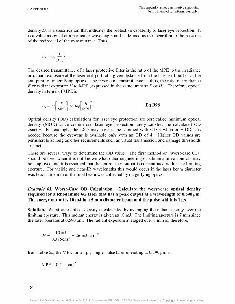
APPENDIX This appendix is not a normative appendix, but is intended for information only.
182
density Dλ is a specification that indicates the protective capability of laser eye protection. It is a value assigned at a particular wavelength and is defined as the logarithm to the base ten of the reciprocal of the transmittance. Thus,
⎥⎦
⎤⎢⎣
⎡τ
=λ
λ1logD .
The desired transmittance of a laser protective filter is the ratio of the MPE to the irradiance or radiant exposure at the laser exit port, at a given distance from the laser exit port or at the exit pupil of magnifying optics. The inverse of transmittance is, thus, the ratio of irradiance E or radiant exposure H to MPE (expressed in the same units as E or H). Therefore, optical density in terms of MPE is
⎥⎦⎤
⎢⎣⎡
⎥⎦⎤
⎢⎣⎡=
MPElogor
MPElogλ
HED . Eq B98
Optical density (OD) calculations for laser eye protection are best called minimum optical density (MOD) since commercial laser eye protection rarely satisfies the calculated OD exactly. For example, the LSO may have to be satisfied with OD 4 when only OD 2 is needed because the eyewear is available only with an OD of 4. Higher OD values are permissible as long as other requirements such as visual transmission and damage thresholds are met.
There are several ways to determine the OD value. The first method or “worst-case OD” should be used when it is not known what other engineering or administrative controls may be employed and it is assumed that the entire laser output is concentrated within the limiting aperture. For visible and near-IR wavelengths this would occur if the laser beam diameter was less than 7 mm or the total beam was collected by magnifying optics.
Example 61. Worst-Case OD Calculation. Calculate the worst-case optical density required for a Rhodamine 6G laser that has a peak output at a wavelength of 0.590 μm. The energy output is 10 mJ in a 5 mm diameter beam and the pulse width is 1 μs.
Solution. Worst-case optical density is calculated by averaging the radiant energy over the limiting aperture. This radiant energy is given as 10 mJ. The limiting aperture is 7 mm since the laser operates at 0.590 μm. The radiant exposure averaged over 7 mm is, therefore,
22 cmmJ26
cm0.385mJ10 −⋅==H .
from Table 5a, the MPE for a 1 μs, single-pulse laser operating at 0.590 μm is:
MPE = 0.5 μJ⋅cm-2.
Licensed to David Patterson. ANSI order X_51518. Downloaded 3/25/2008 10:53 AM. Single user license only. Copying and networking prohibited.

This appendix is not a normative appendix, but is intended for information only.
APPENDIX
183
The minimum worst-case optical density25 is:
⎥⎦⎤
⎢⎣⎡=MPE
logλHD Eq B99
( ) .72.4102.5log
105106.2log
4
7
2
=×=
⎥⎦
⎤⎢⎣
⎡××
= −
−
Example 62. Refer to Example 22 and determine the appropriate OD (Dλ) to protect a viewer at a distance of 10 cm from the diode array.
Solution. For the most restrictive case, the radiant exposure was found to be 0.33 μJ and the Class 1 AEL was 0.16 μJ. An attenuation of 0.33/0.16 =2.06 (Dλ = 0.3) would be required for a protective filter, if a protective filter was deemed necessary. Alternatively, the filter could be placed in the optical train of the system to reduce the laser output to Class 1.
Example 63. Optical Density at a Distance for Unaided Viewing. Calculate the minimum optical density required for unaided viewing at a distance of 1 km from a 0.1 J, Q-switched ruby laser with a pulse length of 20 ns, an exit beam diameter of 7 mm, and a divergence of 1 mrad (see Example 41).
Solution. At 1 km, the beam will be about 1 m in diameter (r × φ). When the laser beam diameter is larger than the limiting aperture and optical aids are not used, the appropriate optical density is the log of the ratio of the irradiance or radiant exposure (calculated or measured at the given distance) to the corresponding MPE. The radiant exposure at 1 km is:
( )2-
22L
cmJ7.12cm100
127.027.1⋅μ==
Φ=
DH .
and the MPE from Table 5a is 0.5 μJ⋅cm-2. The optical density is, thus26,
⎥⎦⎤
⎢⎣⎡=MPE
logλHD Eq B100
.4.1105
1025.1log 7
5
=⎥⎦
⎤⎢⎣
⎡×
×= −
−
To allow for non-uniformity in the beam caused by turbulence, etc., 1 OD unit should be added to the above. Thus, the appropriate minimum optical density for this laser at a distance of 1 km, is 2.4. (This additional safety factor is generally unnecessary for indoor laser use).
25 This method should always be used for beam diameters less than the diameter of the limiting aperture. 26 If the laser beam is smaller than the limiting aperture at the given distance, the worst-case method is used.
Licensed to David Patterson. ANSI order X_51518. Downloaded 3/25/2008 10:53 AM. Single user license only. Copying and networking prohibited.

APPENDIX This appendix is not a normative appendix, but is intended for information only.
184
In general, intrabeam viewing through magnifying optics increases the potential hazard over viewing with the unaided eye. However, this is only true at wavelengths up to approximately 4.0 μm, where common glass optics cease to transmit.
Normally it is assumed that the laser beam is larger than the entrance aperture of the optics. If the beam is smaller than the entrance aperture, the worst-case technique is used and the OD must be sufficient to reduce the radiant exposure at the cornea to a level below the MPE.
Example 64. Calculate the minimum OD for safely viewing a 50 mW HeNe laser with an initial beam diameter of 10 mm, and a divergence of 2.5 mrad. Assume 7 × 35 binoculars that transmit 85 percent at 0.633 μm are used to view the beam at a distance of 50 m.
Solution. At 50 m, the beam diameter DL is:
DL = r × φ = 5000 cm × 2.5×10-3 rad = 12.5 cm.27
The irradiance is:
( )2
2
3
cmmW4.0cm12.5
W105027.1 −−
⋅=××
=H.
This irradiance does not exceed the MPE for unaided viewing. For optically aided viewing, the effective gain of the optics must be considered. From Eq B57,
[ ]
( )( )( )
( )( )
.3.2149.0
5.385.07.0
cm5.385.0
)min(
2
2
2
2f
2L,0
λeff
=
==
×τ=D
DDG
The corneal irradiance through the optics is then 0.4 × 21.3 mW⋅cm-2 = 8.5 mW⋅cm-2.
The MPE from Table 5a is 2.5 mW⋅cm-2 and the minimum OD for an unintentional exposure of 0.25 s is:
53.0105.2105.8log
MPElog 3
3
λ =⎥⎦
⎤⎢⎣
⎡××
=⎥⎦⎤
⎢⎣⎡= −
−HD
27 The initial beam diameter is only useful for computing beam diameter at a distance when the diameter at the distance is only slightly larger than the initial beam diameter.
Licensed to David Patterson. ANSI order X_51518. Downloaded 3/25/2008 10:53 AM. Single user license only. Copying and networking prohibited.

This appendix is not a normative appendix, but is intended for information only.
APPENDIX
185
B8.2 Laser Barriers. Laser barriers needed to protect personnel may need to withstand either exposure to the direct laser beam or exposure to reflections of the laser beam from a diffuse surface.
B8.2.1 Direct Intrabeam Exposure. If the irradiance at a separation distance Ds from a laser maintained at (or below) the barrier threshold limit value TL, Ds is considered the installation criteria distance for that barrier. That is, if the barrier is installed at a separation distance Ds, the irradiance on the barrier will be below the TL for the barrier. Ds may be expressed as:
⎥⎦
⎤⎢⎣
⎡−
πΦ
φ= 2
s TL41 aD , Eq B101
where TL is the barrier threshold limit value in W⋅cm-2.
Example 65. Determine the separation distance Ds for a 300 W Class 4 (open beam) industrial Nd:YAG laser materials-processing system with a beam divergence of 2.5 mrad and an exit beam diameter of 0.4 cm.
Solution. Using Eq B101 and assuming a long term (8-hour) worst-case exposure duration and a TL of 45 W⋅cm-2, Ds is:
m.5.11
16.04514.3
3004105.2
13s
=
⎥⎦
⎤⎢⎣
⎡−
××
×= −D
Thus, one would have to locate the protective barrier at a distance greater than 11.5 meters from the laser exit for the barrier to be effective. If positioned closer, the beam could penetrate the barrier and protection would no longer be afforded.
B8.2.2 Diffuse Beam Exposures. There are some instances where it is useful to calculate the distance from a point source diffuse reflector to where a specific irradiance occurs. If the MPE is replaced by TL in Eq B77, rNHZ becomes the barrier diffuse reflection separation distance DSD. Thus,
TLθcosρ
SD πΦ
=D . Eq B102
Example 66. Assume a 5000 W CO2 laser is directed onto a target with a 100% reflectance at 10.6 μm. Determine DSD at 45 degrees for a TL of 45 W⋅cm-2.
Licensed to David Patterson. ANSI order X_51518. Downloaded 3/25/2008 10:53 AM. Single user license only. Copying and networking prohibited.

APPENDIX This appendix is not a normative appendix, but is intended for information only.
186
Solution. The value for DSD obtained from Eq B102 is:
m05.04514.3
707.050001SD =
×××
=D .
Thus, at five centimeters from the target the irradiance associated with the diffuse reflection is reduced to 45 W⋅cm-2 at 45 degrees.
B8.2.3 Laser Barriers: Lens-on-Laser Exposure. Most industrial lasers incorporate a lens as the final component in the beam path. This not only provides the increased irradiance in the focal plane of the lens to do the work intended of the laser, but it also causes the beam to spread in the space beyond the focal plane with an angle usually many times larger than the inherent laser beam divergence. Consequently, the distance D,28 beyond which the irradiance is less than TL, is less than the intrabeam distance DS, and is given by:
,TL
4
0
0
πΦ
=bfD Eq B103
where f0 is the lens focal length and b0 is the beam diameter at the lens.
Example 67. Consider a 3000 W CO2 laser with a 5-inch focal length lens in place. Assume the beam size at the lens is 1 inch. Determine D.
Solution. Assume a long-term (8-hour) worst-case TL of 45 W ⋅cm-2, substituting into Eq B103,
m.46.04514.3
3000415
=×
×=D
Thus, in the direction defined by the cone of laser energy directed through the lens, the barrier could be penetrated up to a distance of 0.46 meters, beyond which point the beam has expanded sufficiently to limit E to 45 W⋅cm-2.
B9. Determination of Extended Source Size Although most lasers are point source emitters, some lasers have an extended source. The most common example of this type of laser is the diode laser. A diode laser is usually constructed from a laser diode and a lens, producing a beam that is fairly collimated. Depending on the size of the diode and the lens, the resulting laser may have an extended source. The MPE for these types of lasers may be increased over that used for point laser sources (see Section B3.5). Some unique situations can arise, which must be considered. For example, as the distance from the laser is increased, the hazard may increase before it decreases; the MPE for optically aided viewing may be different than that for unaided
28 Dlens is measured from the focal point of the lens, not from the laser.
Licensed to David Patterson. ANSI order X_51518. Downloaded 3/25/2008 10:53 AM. Single user license only. Copying and networking prohibited.

This appendix is not a normative appendix, but is intended for information only.
APPENDIX
187
viewing; and the most hazardous distance from the laser may be farther than the standard measurement distances.
Example 68. An 850 nm laser diode, 6 thousandths of an inch long (0.15 mm) and about 1 μm wide is used with a lens that is 1 cm in diameter with a 3.5 cm focal length. The diode is positioned to provide the best collimated beam. The beam diameter is about half the lens diameter. First determine the source size and then determine the MPE for this laser for a 10 s exposure near the laser exit port.
Solution. Since this laser is well collimated, the source size near the laser exit port will be about the same dimensions as the laser divergence. Both these values will be determined from the construction characteristics of the laser. The divergence in the long dimension can be determined by,
0
diode
fD
=φ Eq B104
mrad3.4cm5.3
cm015.0
0
diode ===φf
D
The divergence in the smaller dimension will be smaller than 1.5 mrad, so 1.5 mrad may be used in calculating the extended source correction factor. The arithmetic mean of the two source dimensions is then 2.9 mrad, resulting in a CE value of 1.93. For this wavelength, CA is 2.0. The MPE for a 10 s exposure near the exit port is then,
MPE = 1.8 CA CE (10)0.75/10 mW⋅cm-2 = 3.9 mW⋅cm-2
Example 69. The construction of the laser in Example 68 is changed so that the position of the laser diode is closer to the focusing lens, producing a beam that is 6 mrad by 6 mrad. Determine the MPE at 100 cm from the laser exit port.
Solution. Near the exit port of the laser the source size would be about the same as for Example 68; however, at 100 cm from the laser exit port, the beam has increased in size to about 0.8 cm instead of 0.5 cm (See Eq B39 and Example 34). Therefore, the source size would be expected to be 5/8 of 4.3 mrad or 2.7 mrad. The arithmetic mean of the source is then 2.1 mrad, and the CE value is 1.4 instead of 1.93, resulting in an MPE of 2.8 mW⋅cm-2.
Example 70. For the laser in Example 69 (850 nm, 5 mm beam diameter, 6 mrad beam divergence), compare the MPE for optically aided viewing at 2 m and at 10 m with 7-power telescopic optics (7 × 50 binoculars). Assume that the total output power is 1 mW and compare the corneal irradiance at both distances.
Licensed to David Patterson. ANSI order X_51518. Downloaded 3/25/2008 10:53 AM. Single user license only. Copying and networking prohibited.

APPENDIX This appendix is not a normative appendix, but is intended for information only.
188
Solution. At 2 m from the laser, the beam size is approximately 1.3 cm in diameter. Therefore, the source size is 0.5/1.3 (or 0.385) times as large. The source size is then 1.66 mrad in length and very small in width. For optically aided viewing, the source appears 7 times larger or 11.6 mrad in length. The arithmetic mean of the source is then 6.56 mrad. The CE value is then 4.4 for optically aided viewing at 2 m. The MPE is then 8.8 mW⋅cm-2. Essentially all the emitted power can be collected by a 5 cm objective lens, so the corneal irradiance is,
( )( )( )
22 cmmW8.1
cm0.3857.0mW1 −⋅==E ,
assuming that the optics transmission is 70%.
At 10 m from the laser, the beam is 6 cm in diameter. The source size in the long dimension is 0.36 mrad for unaided viewing, but 2.5 mrad when viewing with 7-power optics. The arithmetic mean of the source is then 2.0 mrad and the CE factor is 1.34. The MPE is then 2.7 mW⋅cm-2, about 5.5 times less than that at 2 m. The corneal irradiance is determined from the amount of power transmitted by the 5 cm entrance aperture of the magnifying optics (see Eq B15).
( ) mW 0.5mW 10.51 2
2
65
0d ==⎟⎟
⎠
⎞
⎜⎜
⎝
⎛−Φ=Φ
−
e
( )( )( )
22 cmmW9.0
cm0.3857.0mW5.0 −⋅==E
So, for a 6 cm beam diameter, about half of the power is collected by the 5 cm lens at 10 m distance. Therefore the corneal irradiance is about half of that calculated for the 2 m distance.
Since the MPE is 5.5 times less at the 10 m distance but the corneal irradiance is only reduced by half, this laser is more hazardous when viewed with 7-power optics at 10 m from the laser than it is when viewed at 2 m. Additional computations would be necessary to determine the precise distance where the optical hazard is maximized.
B10. References Marshall, W. J. and Conner, P. W., Field Laser Hazard Calculations, Health Physics 52(l), 27-
37; 1987.
Marshall, W. J., Comparative Hazard Evaluation of Near infrared Diode Lasers, Health Physics 66(5): 532-539; 1994.
Licensed to David Patterson. ANSI order X_51518. Downloaded 3/25/2008 10:53 AM. Single user license only. Copying and networking prohibited.

This appendix is not a normative appendix, but is intended for information only.
APPENDIX
189
Marshall, W. J., Determining Hazard Distances from Non-Gaussian Lasers, Appl. Opt. 30(6), 696-698; 1991.
Marshall, W. J., Hazard Analysis on Gaussian shaped Laser Beams, AIHA Journal 41, 547-551; 1980.
Marshall, W. J., Laser Reflections from Relatively Flat Specular Surfaces, Health Physics 56(5), 753-757; 1989.
Marshall, W. J., Aldrich, R. C., and Zimmerman, S. A., Laser Hazard Evaluation Method for Middle Infrared Laser Systems, Journal of Laser Applications, Vol. 8, 211-216; 1996.
Marshall, W. J., Understanding Laser Hazard Evaluation, Journal of Laser Applications, Vol. 7, 99-105; 1995.
Marshall, W. J., Determining source size from diode laser systems, Journal of Laser Applications, Vol. 14, 252-259; 2002.
Sliney, D.H. and Wolbarsht, M. L., Safety with Lasers and other Optical Sources, New York, Plenum Press; 1980.
Thomas, R. J., Maier, D. A., Barsalou, N., McLin, L., Lambert, L. and Keppler, K., Laser Light Show Measurement Techniques, SAFE Jour 27 (2) 115-126; 1997.
Thomas R. J., Rockwell B. A., Marshall W. J., Aldrich R. C., Zimmerman S. A., Rockwell R. J. A procedure for multiple-pulse maximum permissible exposure determination under the Z136.1-2000 American National Standard for Safe Use of Lasers, Journal of Laser Applications, Vol. 13: 134-140; 2001.
Thomas R. J., Rockwell B. A., Marshall W. J., Aldrich R. C., Zimmerman S. A., Rockwell R. J. A procedure for laser hazard classification under the Z136.1-2000 American National Standard for Safe Use of Lasers, Journal of Laser Applications, Vol. 14: 57-66; 2002.
Thomas R. J., Rockwell B, A., Marshall W. J., Aldrich R. C., Gorschboth M. F., Zimmerman S. A., Rockwell R. J. A procedure for the estimation of intrabeam hazard distances and optical density requirements under the ANSI Z136.1-2000 Standard, Journal of Laser Applications, Vol. 16: 167-177; 2004.
U.S. Army Medical Technical Bulletin (TB MED) 524, Control of Hazards to Health from Laser Radiation, June 1985.
Van De Merwe, W. P. and Marshall, W. J., Hazardous Ranges of Laser Beams and their Reflections from Targets, Appl. Opt. 25(5), 605-611; 1986.
Zimmerman, S. and Aldrich, R., Comparison of Divergence Measurement Techniques for Laser Light Show Application, Proceedings of the Third International Laser Safety Conference, Laser Institute of America, 1997.
Licensed to David Patterson. ANSI order X_51518. Downloaded 3/25/2008 10:53 AM. Single user license only. Copying and networking prohibited.

APPENDIX This appendix is not a normative appendix, but is intended for information only.
190
Figure B1. Intrabeam Viewing – Direct (Primary) Beam
Flat-Top Beam
0
1
Gaussian Beam
Figure B2. Flat-Top Beam Shape Compared with Gaussian Beam Both Beams Have the Same Beam Diameter
DL
Licensed to David Patterson. ANSI order X_51518. Downloaded 3/25/2008 10:53 AM. Single user license only. Copying and networking prohibited.

This appendix is not a normative appendix, but is intended for information only.
APPENDIX
191
FLAT SURFACE REFLECTION
(Secondary Beam) CURVED SURFACE REFLECTION
Figure B3. Intrabeam Viewing – Specularly Reflected
Licensed to David Patterson. ANSI order X_51518. Downloaded 3/25/2008 10:53 AM. Single user license only. Copying and networking prohibited.

APPENDIX This appendix is not a normative appendix, but is intended for information only.
192
Figure B4. Viewing Diffuse Reflections
LASER α DL
r
Figure B5. Beam Expansion with Distance from the Laser Inner lines in upper diagram show beam diameter according to Eq B39 and outer dashed lines show beam diameter according to Eq B40. Lower diagram illustrates beam expansion for a focused beam (beam waist in front of laser).
LASER D W
r
DL
Licensed to David Patterson. ANSI order X_51518. Downloaded 3/25/2008 10:53 AM. Single user license only. Copying and networking prohibited.

This appendix is not a normative appendix, but is intended for information only.
APPENDIX
193
2/1
0
0NOHD πMPE
4⎟⎠⎞
⎜⎝⎛ Φ
⎟⎟⎠
⎞⎜⎜⎝
⎛=
bfr
rNOHD b0
LASER
f0
2/1
NOHD πMPE7.1
⎟⎠⎞
⎜⎝⎛ Φ
=NA
r (multimode)
2/1
oNOHD MPE2
πλ
⎟⎠⎞
⎜⎝⎛ Φ
=ω
r (single mode)rNOHD
LASER
Figure B6. Examples of Use of Laser Range Equations for Determining Nominal Hazard Distances
Licensed to David Patterson. ANSI order X_51518. Downloaded 3/25/2008 10:53 AM. Single user license only. Copying and networking prohibited.

APPENDIX This appendix is not a normative appendix, but is intended for information only.
194
2/1
NHZ MPEπθcosρ
⎟⎟⎠
⎞⎜⎜⎝
⎛ Φ=r
LASER
θ rNHZ
Figure B7. Nominal Hazard Zone for a Diffuse Reflection
Licensed to David Patterson. ANSI order X_51518. Downloaded 3/25/2008 10:53 AM. Single user license only. Copying and networking prohibited.

This appendix is not a normative appendix, but is intended for information only.
APPENDIX
195
ENERGY OUTPUT
(mJ)
BEAM DIVERGENCE
(mr)
INTEGRATED RADIENT
INTENSITY (MJ/sr) RANGE
(km)
RADIANT EXPOSURE
(μJ/cm2)
POWER OUTPUT
(mW)
RADIENT INTENSITY
(MW/sr) IRRADIANCE (μW/cm2)
CLEAR HAZE
1000
100
10
1.0
0.1
10
1.0
0.1
0.01
0.001
0.01
0.1
1.0
10
100
100
10
1.0
0.1
0.01
0.1
1.0
10
100
200
30
10
1.0
Figure B8. Laser Range Equation Nomogram See Section B6.4.2 and Example 41.
Licensed to David Patterson. ANSI order X_51518. Downloaded 3/25/2008 10:53 AM. Single user license only. Copying and networking prohibited.

APPENDIX This appendix is not a normative appendix, but is intended for information only.
196
Figure B9. Diagram of the Laser Arrangement for Example 55 See Section B6.6.4.
���� �
��� ���� �
��� �������
�����������
���������
����
�������� �! �
��� �� "�
��� �������
�����������
��#�� ����
����� ���� ��� "� ���������
��� ����
�� �����������
����������
���� �������� � �! "�
���� ����� ���#��
���� "��
�������
� �
Licensed to David Patterson. ANSI order X_51518. Downloaded 3/25/2008 10:53 AM. Single user license only. Copying and networking prohibited.

This appendix is not a normative appendix, but is intended for information only.
APPENDIX
197
Figure B10. Determination of Limiting Cone Angle, γ Illustration of optical sources where the source is fairly uniform and the source size, α, is less than the field or view, γ (upper). The lower figure illustrates an optical source with hot spots and the source size is larger than γ.
Licensed to David Patterson. ANSI order X_51518. Downloaded 3/25/2008 10:53 AM. Single user license only. Copying and networking prohibited.

APPENDIX This appendix is not a normative appendix, but is intended for information only.
198
Appendix C Hazard Evaluation, Classification and Control Measures
C1. Alternate Labeling Some laser equipment manufactured outside of the USA may conform to requirements of the IEC Publication 60825, Radiation Safety of Laser Products, Equipment Classification, Requirements and User's Guide (or latest revision thereof). The IEC 60825 label style (shown in Figure 1c) is different from that required by this standard and those specified in the Federal Laser Product Performance Standard.
C2. Laser Protection Damage Threshold Evaluation C2.1 Laser Protective Eyewear. A wide variety of commercially available optical absorbing filter materials (glass and plastics) and various coated reflecting “filters” (dielectric and holographic) are available for laser eye protection. Some are available with spectacle lenses ground to prescription specifications. Protection for multiple laser wavelengths is becoming more common as more applications involve several simultaneous wavelengths.
Each filter material has some limitations. For example, it should be noted that not all absorbing glass filters used for laser protection are easily annealed (thermally hardened) and, consequently, do not provide adequate impact resistance. In some goggles, however, impact resistant plastic filters (polycarbonate) can be used together with non-hardened glass filters in a design where the plastic is placed in front and behind of the non-hardened laser filter glass.
In some tests, glass filter plates have cracked and shattered following intense Q-switched, pulsed laser exposures. In some instances, the shattering occurred after one-quarter to one-half hour had elapsed following the exposure. Also, several glass filter types have displayed photobleaching when exposed to Q-switched laser pulses.
The advantage of using reflective coatings is that they can be designed to selectively reflect a given wavelength while transmitting as much of the remaining visible spectrum as possible. Note that some angular dependence of the spectral attenuation factor may be present in dielectric coatings.
The advantages of using absorbing plastic filter materials are greater impact resistance, lighter weight, and convenience of molding the eye protection into comfortable shapes. The disadvantages are that, unless specially coated, they are more readily scratched and the filters often age poorly as the organic dyes used as absorbers are more readily affected by heat and/or ultraviolet radiation, which eventually causes the filter to significantly darken.
It should be stressed that there are few known materials that can withstand laser exposures which exceed 105 W⋅cm-2 since the electric fields associated with the beam will exceed the bonding forces of matter. However, most materials will begin to degrade at levels far below these field strength levels due to thermal or shock effects.
Licensed to David Patterson. ANSI order X_51518. Downloaded 3/25/2008 10:53 AM. Single user license only. Copying and networking prohibited.

This appendix is not a normative appendix, but is intended for information only.
APPENDIX
199
C2.2 Laser Eyewear Filter Damage Level. At some specific beam intensity, the filter material which absorbs the laser radiation can be damaged. Plastic materials have damage thresholds much lower than glass filters and glass (by itself) is lower than glass coated with a reflective dielectric coating.
The damage threshold is especially important for those who work close to the beam interaction site where there is a much higher probability of receiving a direct exposure. Typical damage thresholds for CW lasers fall between 500 and 1000 W⋅cm-2 for dielectric coated glass, 100 to 500 W⋅cm-2 for uncoated glass and 1 to 100 W⋅cm-2 for plastics.
A 1979 FDA study, Evaluation of Commercially Available Laser Protective Eyewear [HEW Publication (FDA) 79-8086], reported limited testing of laser protective eyewear available at that time. For example, tests were reported for Q-switched ruby laser exposures (0.694 μm) on various manufacturers’ protective eyewear. The plastic laser protective eyewear displayed damage thresholds (surface pitting) for Q-switched pulses ranging from 3.8 to 18 J⋅cm-2 while glass filters required a radiant exposure ranging from 93 to 1620 J⋅cm-2.
More recent analysis of polycarbonate protectors with CO2 lasers indicated that a level of 60 W⋅cm -2 for 10 seconds was just below the penetration level. A level of 112 W⋅cm-2 for 4 s just produced penetration and 10 seconds produced significant penetration. Additional detailed damage threshold data for protective eyewear of more recent vintage is not readily available, although at least one comprehensive study is currently underway to examine these factors.
While direct intrabeam exposure of eyewear is certainly not recommended under any normal condition, it can and does occur. At least one intrabeam eye accident with thermal decomposition of plastic (non-polycarbonate) laser eyewear has been reported with a Nd:YAG laser in a research laboratory.
C2.3 Protective Viewing Windows. All viewing portals, optics, windows or display screens included as a part of the laser or laser installation shall incorporate some means to attenuate the laser radiation transmitted through the windows to levels below the appropriate MPE. This would include, for example, a viewing window into the laser facility. The filtration requirements would be based upon the level of laser radiation that would occur at the window in a typical worst-case condition in a manner identical to the eyewear evaluations discussed above.
C2.4 Laser Barriers and Protective Curtains. Area control can be effected in some cases using special barriers which have been specifically designed to withstand either direct and/or diffusely scattered beams. In this case, the barrier will exhibit a barrier threshold limit for beam penetration through the barrier during a specified exposure time (typically 60 seconds). The barrier is located at a distance from the laser source so that the threshold limit is not exceeded in the worst-case exposure scenario.
Currently available laser barriers exhibit threshold limits ranging from 10 W⋅cm-2 to 350 W⋅cm-2 for different laser wavelengths and power levels. A hazard analysis can be performed in a manner similar to the NHZ evaluations that establishes the recommended barrier type and installation separation distances between the barrier and a given laser.
Licensed to David Patterson. ANSI order X_51518. Downloaded 3/25/2008 10:53 AM. Single user license only. Copying and networking prohibited.

APPENDIX This appendix is not a normative appendix, but is intended for information only.
200
Note that the factor of flammability is important in the design of a protective barrier. It is essential that the material not support combustion or be consumed by flames following the termination of the beam. Also important is the factor that decomposition products resulting from the laser interaction not be a respiratory hazard.
The purpose of a threshold limit evaluation is to define that point or distance at which the barrier must be placed so as to withstand a worst-case exposure from the laser.
C3. Examples of Typical Lasers or Laser System Classification and MPEs for Selected Lasers Since the laser classification was designed to include all types of lasers operating at essentially any wavelength or pulse duration, the rules of classification (see Section 3.2) may appear complicated. To assist in the classification of commonly available lasers, Tables C1 and C2 have been prepared to aid the user in rapidly determining the required radiometric parameters needed to classify a laser and its applicable class once the required output parameters are known. Table C1 applies to CW lasers (potential exposure time ≥ 0.25 s), and Table C2 applies to pulsed lasers. To classify a repetitive-pulse laser, the values in Tables C1 and C2 are not generally applicable but may be used as a first step in estimating into what class the laser will fall.
In all cases the user should apply the rules given in Section 3 of the standard.
Licensed to David Patterson. ANSI order X_51518. Downloaded 3/25/2008 10:53 AM. Single user license only. Copying and networking prohibited.

This appendix is not a normative appendix, but is intended for information only.
APPENDIX
201
Table C1. Typical Laser Classification – Continuous Wave (CW) Point Source Lasers
Wavelength (μm)
Laser Type Wavelength (μm)
Class 1 * (W)
Class 2 (W)
Class 3 ** (W)
Class 4 (W)
Ultraviolet 0.180 to 0.280
Neodymium: YAG
(Quadrupled) Argon
0.266 0.275
≤ 9.6 × 10⁻⁹ for 8 hours
None
> Class 1 but ≤ 0.5
> 0.5
Ultraviolet 0.315 to 0.400 Visible 0.400 to 0.700 Near Infrared 0.700 to 1.400 Far Infrared 1.400 to 103
Helium-Cadmium Argon Krypton
Helium-Cadmium Argon (Visible)
Krypton Neodymium: YAG
(Doubled) Helium-Neon Dye Helium-Selenium Dye Helium-Neon InGaAlP Ti:Sapphire Krypton GaAlAs GaAlAs GaAs Neodymium: YAG Helium-Neon InGaAsP InGaAsP Holmium Erbium Hydrogen Fluoride Helium-Neon Carbon Monoxide Carbon Dioxide Water Vapor Hydrogen Cyanide
0.325 0.351, 0.363, 0.3507, 0.3564 0.4416 only 0.457 0.476 0.488 0.514 0.530 0.532 0.543 0.400 - 0.500 0.460 - 0.500 0.550 - 0.700 0.632 0.670 0.350 – 0.500 0.6471, 0.6764 0.780 0.850 0.905 1.064 1.080 1.152 1.310 1.550 2.100 2.940 2.600 - 3.00 3.390 only 5.000 - 5.500 10.6 118 337
≤ 3.2 × 10⁻⁶ ≤ 4 × 10⁻⁵ ≤ 5 × 10⁻⁵
≤ 1 × 10⁻⁴
≤ 2 × 10⁻⁴
≤ 4 × 10⁻⁴ ≤ 0.4 CB × 10-4 ≤ 4 × 10⁻⁴
≤ 5.6 × 10⁻⁴
≤ 7.7 × 10⁻⁴ ≤ 9.9 × 10⁻⁴ ≤ 1.9 × 10⁻³ ≤ 1.9 × 10⁻³ ≤ 2.1 × 10⁻³ ≤ 1.5 × 10⁻² ≤ 9.6 × 10⁻³ ≤ 9.5 × 10⁻²
None
> Class 1 but ≤ 1 × 10⁻³
None
> Class 1 but ≤ 0.5
> Class 2 but ≤ 0.5
> Class 1 but ≤ 0.5
> 0.5
> 0.5
> 0.5
* Assumes no mechanical or electrical design incorporated into laser system to prevent exposures from lasting up to
Tmax = 8 hours (one workday); otherwise the Class 1 AEL could be larger than tabulated. ** See 3.3.3.1 for definition of Class 3R.
Licensed to David Patterson. ANSI order X_51518. Downloaded 3/25/2008 10:53 AM. Single user license only. Copying and networking prohibited.

APPENDIX This appendix is not a normative appendix, but is intended for information only.
202
Table C2. Typical Laser Classification – Single-Pulse Point Source Lasers
Wavelength (μm)
Laser Type Wavelength (μm)
Pulse Duration (s)
Class 1 (J)
Class 3B (J)
Class 4 (J)
Ultraviolet 0.180 to 0.400
Excimer (ArF) Excimer (KrF) Neodymium: YAG Q-switched
(Quadrupled) Excimer (XeCl) Nitrogen Excimer (XeF)
0.193 0.248 0.266 0.308 0.337 0.351
20 × 10-9 20 × 10-9 20 × 10-9 20 × 10-9
20 × 10-9
20 × 10-9
≤ 2.4 × 10⁻⁵ ≤ 2.4 × 10⁻⁵ ≤ 2.4 × 10⁻⁵
≤ 5.3 × 10⁻⁵ ≤ 5.3 × 10⁻⁵ ≤ 5.3 × 10⁻⁵
> Class 1 but ≤ 0.125
> 0.125
Visible 0.400 to 0.700 Near Infrared 0.700 to 1.4 Far Infrared 1.400 to 103
Rhodamine 6G (Dye Laser) Copper Vapor Neodymium: YAG (Doubled) (Q-
switched) Ruby (Q-switched) Ruby (Long Pulse) Ti: Sapphire Alexandrite Neodymium: YAG (Q-switched) Erbium: Glass Co: Magnesium- Fluoride Holmium Hydrogen Fluoride Erbium Carbon Dioxide Carbon Dioxide
0.450-0.650 0.510, 0.578 0.532 0.6943 0.6943 0.700-1.000 0.720-0.800 1.064 1.540 1.8-2.5 2.100 2.600-3.000 2.940 10.6 10.6
1 × 10⁻⁶
2.5 × 10⁻⁹ 20 × 10-9 20 × 10-9 1 × 10⁻³ 6 × 10⁻⁶ 1 × 10⁻⁴ 20 × 10-9 10 × 10-9 80 × 10-6 250 × 10-6 0.4 × 10⁻⁶ 250 × 10-6 100 × 10-9 1 × 10⁻³
≤ 1.9 × 10⁻⁷
≤ 3.9 × 10⁻⁶
≤ 1.9 × 10⁻⁷ ≤ 7.6 × 10⁻⁷ ≤ 1.9 × 10⁻⁶
≤ 7.9 × 10⁻³ ≤ 7.9 × 10⁻⁴
≤ 7.9 × 10⁻⁴ ≤ 1.1 × 10⁻⁴ ≤ 5.6 × 10⁻⁴ ≤ 7.9 × 10⁻⁵ ≤ 7.9 × 10⁻⁴
> Class 1 but ≤ 0.03
> Class 1 but ≤ 0.033** >Class 1 but ≤ 0.125
> Class 1 but ≤ 0.125
> 0.03
> 0.033** > 0.125
> 0.125
* Assuming that both eye and skin may be exposed, i.e., 1.0 mm beam (area of limiting aperture = 7.9 × 10⁻³ cm2). ** Class 3B AEL varies from 0.033 to 0.480 J corresponding to wavelengths that vary from 0.720 to 0.800 μm.
Licensed to David Patterson. ANSI order X_51518. Downloaded 3/25/2008 10:53 AM. Single user license only. Copying and networking prohibited.

This appendix is not a normative appendix, but is intended for information only.
APPENDIX
203
Table C3a. Point Source MPE for the Eye for Selected CW Lasers
Laser Type Wavelength Exposure Duration Maximum Permissible Exposure
(μm) (s) (J·cm-2) (W·cm-2)
Argon Helium-Cadmium Argon Helium-Cadmium Argon Helium-Neon Helium-Neon Krypton Krypton InGaAlP GaAs Neodymium: YAG InGaAsP InGaAsP Carbon-Dioxide
0.275 0.325 0.351 0.4416 0.488 0.488 0.488 0.5145 0.632 0.632 0.647 0.647 0.670 0.905 1.064 1.310 1.550
10.600
10 to 3 × 10⁴ 10 to 3 × 10⁴ 10 to 3 × 10⁴
0.25 10 to 58 58 to 102
> 102 10 to 3 × 10⁴
0.25 10 to 3 × 10⁴
0.25 10 to 3 × 10⁴
0.25 10 to 3 × 10⁴ 10 to 3 × 10⁴ 10 to 3 × 10⁴ 10 to 3 × 10⁴ 10 to 3 × 10⁴
3 × 10⁻³ 1 1 − −
5.8 × 10⁻² − − − − − − − - - - - -
− − −
2.5 × 10⁻³ 1 × 10⁻³
5.8 × 10⁻⁴ 1 × 10⁻³ 2.5 × 10⁻³ 1 × 10⁻³ 2.5 × 10⁻³ 1 × 10⁻³ 2.5 × 10⁻³ 2.6 × 10⁻³ 5 × 10⁻³ 4 × 10⁻²
0.1 0.1
Table C3b. Point Source MPE for the Skin for Selected CW Lasers
Laser Type Wavelength Exposure Duration Maximum Permissible Exposure
(μm) (s) (J·cm-2) (W·cm-2)
Argon Helium-Cadmium Argon Helium-Cadmium Argon Argon Helium-Neon Krypton GaAs Neodymium: YAG Carbon-Dioxide
0.275 0.325 0.325 0.351 0.351 0.4416 0.488 0.5145 0.6328 0.647 0.905 1.064
10.600
3 × 10⁴ 10 to 1000
> 1000 10 to 1000
> 1000 > 10 >10 >10 >10 >10 >10 >10 >10
3 × 10⁻³ 1 1 − − − − − − − − −
− −
1 × 10⁻³ −
1 × 10⁻³ 0.2 0.2 0.2 0.2 0.2 0.5 1.0 0.1
Licensed to David Patterson. ANSI order X_51518. Downloaded 3/25/2008 10:53 AM. Single user license only. Copying and networking prohibited.

APPENDIX This appendix is not a normative appendix, but is intended for information only.
204
Table C4. Point Source MPE for the Eye and MPE for the Skin for Selected Single-Pulse Lasers
Laser Type Wavelength Pulse Duration
Maximum Permissible Exposure (J⋅cm-2)
(μm) (s) Eye Skin
Excimer (ArF) Excimer (KrF) Excimer (XeCl) Excimer (XeF) Ruby (Normal-Pulsed) Ruby (Q-switched) Rhodamine 6G dye laser Nd:YAG (Normal Pulse) Nd:YAG (Q-switched) Carbon Dioxide
0.193 0.248 0.308 0.351 0.6943 0.6943 0.500 - 0.700 1.064 1.064
10.6
2 × 10⁻⁸
2 × 10⁻⁸
2 × 10⁻⁸
2 × 10⁻⁸
1 × 10⁻³
5 - 100 × 10-9 0.5 - 18 × 10-6
1 × 10⁻³ 5 - 100 × 10-9
1 × 10⁻³
3 × 10⁻³
3 × 10⁻³
6.7 × 10⁻³
6.7 × 10⁻³
1 × 10⁻⁵
5 × 10⁻⁷
5 × 10⁻⁷
5 × 10⁻⁵
5 × 10⁻⁶
0.1
3 × 10⁻³
3 × 10⁻³
6.7 × 10⁻³
6.7 × 10⁻³
0.2
0.02 0.03 to 0.07
1.0
0.1
0.1
Licensed to David Patterson. ANSI order X_51518. Downloaded 3/25/2008 10:53 AM. Single user license only. Copying and networking prohibited.

This appendix is not a normative appendix, but is intended for information only.
APPENDIX
205
C4. References Conference of Radiation Control Program Directors: Model State Laser Standard,
Lexington, KY.
Doyle, D. and Kokosa, J.M., Laser Processing of Kevlar. Hazardous Chemical By-products, Proceedings of ICALEO, Laser Institute of America, Orlando, FL, 1986.
Doyle, D. J., and Kokosa, J. M., Hazardous By-Products of Plastics Processing with Carbon Dioxide Lasers. In: Laser Welding, Machining and Materials Processing, C. Albright, Editor. IFS LTD., Bedford, United Kingdom, pp. 201-203; 1985.
Electronic Product Radiation and the Health Physicist, Proceedings of the Fourth Annual Midyear Topical symposium; 1970. Washington: U.S. Department of Health, Education, and Welfare; Bureau of Radiological Health, Division of Electronic Products; 70-26. Available from National Technical Information Service, Springfield, VA 22161.
Envall, K. R. and Murray, R., Evaluation of Commercially Available Laser Protective Eyewear, DHEW Publication (FDA) 79-8086, May 1979.
Goldman, L., Rockwell, R. J., Jr. Lasers in Medicine. 1971, chapter II; New York: Gordon and Breach Science Publishers, 1971.
Goldman, L., Rockwell, R. J., Jr., Homby, P. Laser Laboratory Design and Personnel Protection from High Energy Lasers. In: Handbook of Laboratory Safety. N.V. Steere, ed; 2nd ed. Cleveland: The Chemical Rubber Company: 381-389; 1971.
Guide for the Selection of Laser Eye Protection. Laser Institute of America, Orlando, FL; 1996.
International Electrotechnical Commission Standard Radiation Safety of Laser Products, Equipment Classification, Requirements and Users Guide, IEC Publication 825: Geneva Switzerland; 1990.
Laser Health Hazards Control. U.S. Department of the Air Force Manual AFM-161-32, 1973 (or latest revision thereof). Available from National Technical Information Service, Springfield, VA. 22161.
Laser Institute of America, Safety Information on Electrical Hazards, Laser News, Laser Institute of America, Vol. 6, No. 5, pp. 8-14; Sept., 1984.
Laser Product Performance Standard. Code of Federal Regulations, Title 21, Subchapter J, Part 1040, 1979.
Laser Products; Amendments to Performance Standard; Final Rule. Code of Federal Regulations, Title 21, Parts 1000 and 1040, Federal Register, Aug. 20,1985.
Marshall, W. J., Hazard analysis on Gaussian shaped laser beams. Journal of the American Industrial Hygiene Association. 41(8): 547-551; Aug 1980.
Rockstroh, T. J., and Mazumder, J., Spectroscopic Studies of Plasma, During CW Laser Materials Interaction. J. Appl. Phys., Vol. 61, No. 3, pp. 917-923; 1987.
Licensed to David Patterson. ANSI order X_51518. Downloaded 3/25/2008 10:53 AM. Single user license only. Copying and networking prohibited.

APPENDIX This appendix is not a normative appendix, but is intended for information only.
206
Rockwell, R. J., Jr. and Moss, C. E., Optical radiation hazards in laser welding processes Part 1: Neodymium - YAG Laser. The Journal of the American Industrial Hygiene Association. 44(8); 572-579; Aug 1983.
Rockwell, R. J., Jr., Ensuring safety in laser robotics. Lasers and Applications. 3(l1); 65-69; Nov 1984.
Rockwell, R. J, Jr., Fundamentals of Industrial Laser Safety. In: Industrial Laser Annual Handbook, edited by M. Levitt and D. Belforte, Penn Well Books, Tulsa, OK., pp. 131-148; 1986.
Rockwell, R. J. Jr. and Moss, C. E., Optical Radiation Hazards of Laser Welding Processes Part H: Carbon Dioxide Laser, The Journal of the American Industrial Hygiene Association, Vol. 50, No. 8. pp. 419-427; August, 1989.
Rockwell, R. J. Jr., Laser Accidents: Are They All Reported and What Can Be Learned From Them?. Journal of Laser Applications, Laser Institute of America, Orlando, FL, pp. 53-57; 1989.
Rockwell, R. J. Jr., Analyzing Laser Hazards, Lasers and Applications, Vol. 5. No. 5. pp. 97-103; May, 1986.
Rockwell, R. J. Jr., Controlling Laser Hazards, Lasers and Applications, Vol. 5, No. 9, pp. 93-99; Sept., 1986.
Rockwell, R. J. Jr., Selecting Laser Eyewear, Medical Laser Buyer's Guide, Penn Well Books, Tulsa, OK., pp. 84-92; January, 1989.
Rockwell, R. J. Jr., Utilization of the Nominal Hazard Zone in Control Measure Selection, Proceedings of the International Laser Safety Conference, Laser Institute of America, Orlando, FL, 1991.
Sliney, D. H., Evaluating health hazards from military lasers. Journal of the American Medical Association. 214(6): 1047-1054; Nov., 1970.
Sliney, D. H., Laser Protective Eyewear. In: M. L. Wolbarsht, ed. Laser Applications in Medicine and Biology. New York. Plenum Press; v. 2, chapter 7, pp. 223-240; 1974.
Sliney, D. H., Sparks, S.D. and Wood, R.L. Jr., The Protective Characteristics of Polycarbonate Lenses Against CO2, Laser Radiation, Journal of Laser Applications, Laser Institute of America, Orlando, FL, pp 49-52; Apr. 1993.
Sliney, D. H. and Wolbarsht, M. L., Safety with Lasers and other Optical Sources. New York.- Plenum Publishing Co; 1980.
Swope, C. H., The Eye - Protection. Archives of Environmental Health. 18(3): 428-433; 1969.
U.S. Department of the Army, Control of Hazards to Health from Laser Radiation. U.S. Department of the Army Technical Bulletin TB-MED-524; June 1985. Available from National Technical Information Service, Springfield, VA. 22161.
U.S. Army Regulation 11-9, the Army Radiation Safety Program, Headquarters, Department of the Army, Washington DC, 28 May 1999.
Licensed to David Patterson. ANSI order X_51518. Downloaded 3/25/2008 10:53 AM. Single user license only. Copying and networking prohibited.

This appendix is not a normative appendix, but is intended for information only.
APPENDIX
207
Appendix D Guide for Organization and Implementation of
Employee Laser Safety Training Programs The extent to which the various parts of the following guide are applicable to a specific organization depends on the magnitude of the potential laser hazards within that organization. However, it is essential that each laser safety program include sufficient education of personnel in laser safety.
D1. Employee Training D1.1 General. Education may be provided to users of Class 1M, Class 2, Class 2M or Class 3R lasers. Laser safety training must be provided to users of class 3B or class 4 lasers (see section 1.3.1). Training programs may be developed by the employer. Short courses and other training programs on laser safety are also commercially available.
Employers should consider awareness level training for employees operating laser systems that enclose higher power lasers. This training may be used to communicate the safety or potential hazards under conditions other than those of normal operations. An explanation of the differences of potential hazard between the classes of lasers is beneficial to the user. The employer should consider when this effort would be beneficial to the operator.
The LSO determines what, if any, training is commensurate with the laser hazards accessible at the employer’s facility.
D1.2 Laser Safety Training Program Topics. Topics for a laser safety training program for Class 3B and Class 4 laser use may include, but are not necessarily limited to, the following:
(1) For user personnel routinely working with or potentially exposed to Class 3B or Class 4 laser radiation:
(a) Fundamentals of laser operation (physical principles, construction, etc.)
(b) Bioeffects of laser radiation on the eye and skin
(c) Significance of specular and diffuse reflections
(d) Non-beam hazards of lasers (see Section 7)
(e) Laser and laser system classifications
(f) Control measures
(g) Overall responsibilities of management and employee
(h) Medical surveillance practices (if applicable)
(i) CPR for personnel servicing or working on lasers with exposed high voltages and/or the capability of producing potentially lethal electrical currents
Licensed to David Patterson. ANSI order X_51518. Downloaded 3/25/2008 10:53 AM. Single user license only. Copying and networking prohibited.

APPENDIX This appendix is not a normative appendix, but is intended for information only.
208
(2) For the LSO or other individual responsible for the laser safety program, evaluation of hazards, and implementation of control measures, or any others if directed by management to obtain a thorough knowledge of laser safety:
(a) The topics in D1.2 (1)
(b) Laser terminology
(c) Types of lasers, wavelengths, pulse shapes, modes, power/energy
(d) Basic radiometric units and measurement devices
(e) MPEs
(f) Laser hazard evaluations and other calculations
D1.2.1 Class 2 and Class 2M Awareness Training. For optional Class 2 and Class 2M education, simple, brief programs may be developed that are designed for easy implementation by persons other than LSOs or education instructors, such as first line supervisors. Potential topics include:
(1) Simple explanation of a laser
(2) Compare difference of laser light from ordinary light
(3) Explain a Class 2 laser with the concept that it is harmless for exposure duration less than the human aversion response time of 0.25 s
(4) Explain the differences between a Class 2 and a Class 2M lasers
(5) Provide statement cautioning against intentional overcoming of the human aversion and staring into a Class 2 and Class 2M laser beam
(6) General explanation of the differences in the various laser classifications
D1.2.2 Class 1M and Class 3R Awareness Training. For optional Class 1M and Class 3R education, simple brief programs may be developed that are designed for easy implementation by persons other than LSOs or education instructors, such as first line supervisors. Potential topics include:
(1) Simple explanation of a laser
(2) Compare difference of laser light from ordinary light
(3) Describe nature of near IR beams where applicable
(4) Explanation of Class 1M and 3R lasers, and the relative potential hazard of each
(5) Explanation of the potential for collecting and focusing optics to increase the hazard
D1.2.3 Laser Pointer Awareness. If laser pointer awareness education is determined to be desirable, suggested topics can include:
(1) Simple explanation of a laser
(2) Compare difference of laser light from ordinary light
(3) Precautions for use
(4) Effects of exposures
Licensed to David Patterson. ANSI order X_51518. Downloaded 3/25/2008 10:53 AM. Single user license only. Copying and networking prohibited.

This appendix is not a normative appendix, but is intended for information only.
APPENDIX
209
(5) Misuse/FDA warning on misuse of pointers
(6) FDA limit of 5 mW
(7) Local ordinance limitations
D2. References American Conference of Government Industrial Hygienists, A Guide for Control of Laser
Hazards, ACGIH, PO Box 1937, Cincinnati, OH 45201; 1990.
Hartwig, P. A., Medical Laser Safety Programs: Management and Training. Proceedings of the International Laser Safety Conference, Laser Institute of America, Orlando, FL, pp. 8-31 to 8-35; 1991.
Hoffman, P., A Technical Training Approach to the Safe Operation, Maintenance and Service of Lasers in Manufacturing. Proceedings of the International Laser Safety Conference, Laser Institute of America, 1910.134, Respiratory Protection. Orlando, FL, pp. 7-65 to 7-74; 1991.
Johnson, J. R., Safety Audits of Industrial Laser Facilities. Proceedings of the International Laser Safety Conference, Laser Institute of America, Orlando, FL, pp. 5-1 to 5-4; 1991.
Kestenbaum, A. and Coyle, J., Laser System Design for Safety Manufacturing. Proceedings of the International Laser Safety Conference, Laser Institute of America, Orlando, FL, pp. 5-53 to 5-64; 1991.
LIA Laser Safety Guide, Laser Institute of America, Orlando, FL; 1993.
Manufacturer's accident reporting requirements are detailed in the Code of Federal Regulations, 21 CFR Subchapter J Part 1002.20.
OSHA, Guidelines for Laser Safety and Hazard Assessment, Instruction PUB 8-1.7. Chapter IX Laser Training.
Skillern, C. P., Management of a Laser Safety Program in the Research Environment. Proceedings of the International Laser Safety Conference, Laser Institute of America, Orlando, FL, pp. 7-1 to 7-8; 1991.
Smith, J. F., Safety Programs and Formal Training. In: Sliney and Wolbarsht. Safety with Lasers and Other Optical Sources. New York: Plenum Press; 1980: chapter 25.
Smith, J. F., Class 2 Laser Safety Training Programs. Proceedings of the International Laser Safety Conference, Laser Institute of America, Orlando, FL., pp. 7-83 to 7-86; 1991.
Smith, J. F., Murphy, J. J., Eberle, W. J., Industrial Laser Safety Program Management. Poughkeepsie, NY: IBM Corp., System Products Division.
Smith, J.F. and Jones, J.E., Laser Safety Training Operation Options for Industrial and Laboratory Environments. Proceedings of the International Laser Safety Conference, Laser Institute of America, Orlando, FL, 1997.
US Code of Federal Regulations: 29CFR Part 1910.132, General Requirements for Protective Equipment.
Licensed to David Patterson. ANSI order X_51518. Downloaded 3/25/2008 10:53 AM. Single user license only. Copying and networking prohibited.

APPENDIX This appendix is not a normative appendix, but is intended for information only.
210
US Code of Federal Regulations: 29CFR Part 1910.133, Eye and Face Protection.
US Code of Federal Regulations: 29CFR Part 1910.134, Respiratory Protection.
US Code of Federal Regulations: 29CFR Part 1910.147, Control of Hazardous Energy (Lockout/Tagout).
US Code of Federal Regulations: 29CFR Part 1910.331, Safety Related Work Practices, Training.
US Code of Federal Regulations: 29CFR Part 1910.1200, Hazard Communication (Right to Know).
US Code of Federal Regulations: 29CFR Part 1910.1405, Occupational Exposures to Hazardous Chemicals in Laboratories.
US Code of Federal Regulations: 29CFR Part 1926.54, Nonionizing Radiation.
US Code of Federal Regulations: 29CFR Part 1926.102, Eye and Face Protection.
Licensed to David Patterson. ANSI order X_51518. Downloaded 3/25/2008 10:53 AM. Single user license only. Copying and networking prohibited.

This appendix is not a normative appendix, but is intended for information only.
APPENDIX
211
Appendix E Medical Examinations
E1. Medical Referral Following Suspected or Known Laser Injury Any employee with an actual or suspected laser-induced injury should be evaluated by a medical professional as soon as possible after the exposure. Referral for medical examinations shall be consistent with the medical symptoms and the anticipated biological effect (see Appendix G)based upon the laser system in use at the time of the incident. For laser-induced injury to the retina, the medical evaluation shall be performed by an ophthalmologist. Employees with skin injuries should be seen by a physician.
E1.1 Medical Examinations for Exposure Incidents. Recommended medical examinations for actual or suspected exposure include but are not limited to those specified in Section E3.
E2. Medical Surveillance Examinations E2.1 Rational for Surveillance Examinations. The basic reasons for performing medical surveillance of personnel working in a laser environment are the same as for other potential health hazards. Medical surveillance examinations may include assessment of physical fitness to safely perform assigned duties, biological monitoring of exposure to a specific agent, and early detection of biological damage or effect.
Physical fitness assessments are used to determine whether an employee would be at increased or unusual risk in a particular environment. For workers using laser devices, the need for this type of assessment is most likely to be determined by factors other than laser radiation per se. Specific information on medical surveillance requirements that might exist because of other potential exposures, such as toxic gases, noise, ionizing radiation, etc., are outside the scope of this appendix.
Direct biological monitoring of laser radiation is impossible, and practical indirect monitoring through the use of personal dosimeters is not available.
Early detection of biological change or damage presupposes that chronic or subacute effects may result from exposure to a particular agent at levels below that required to produce acute injury. Active intervention must then be possible to arrest further biological damage or to allow recovery from biological effects. Although chronic injury from laser radiation in the ultraviolet, near ultraviolet, blue portion of the visible, and near infrared regions appears to be theoretically possible, risks to workers using laser devices are primarily from accidental acute injuries. Based on risks involved with current uses of laser devices, medical surveillance requirements that should be incorporated into a formal standard appear to be minimal.
Other arguments in favor of performing extensive medical surveillance have been based on the fear that repeated accidents might occur and the workers would not report minimal acute injuries. The limited number of laser injuries that have been reported in the past 30 years and the excellent safety records with laser devices do not provide support to this argument.
Licensed to David Patterson. ANSI order X_51518. Downloaded 3/25/2008 10:53 AM. Single user license only. Copying and networking prohibited.

APPENDIX This appendix is not a normative appendix, but is intended for information only.
212
E3. Medical Examinations E3.1 Rationale for Examinations. Past experience has shown that pre-incident examinations would normally not be as extensive as a post incident examination. Therefore, the medical-legal value of pre-examination has been shown to be of limited value with litigation tending to be driven by biophysical measurements of the accident site and the exposure geometry. Individual institutions may provide pre-exposure screening and even continuing surveillance; however, that surveillance was not deemed to be a requirement for safe laser usage.
E3.1.1 Preassignment Medical Examinations. Except for examination following suspected injury, these are the only examinations required by this standard. One purpose is to establish a baseline against which damage (primarily ocular) can be measured in the event of an accidental injury. A second purpose is to identify certain workers who might be at special risk from chronic exposure to selected continuous wave lasers. For incidental workers (e.g., custodial, military personnel on maneuvers, clerical and supervisory personnel not working directly with lasers) only visual acuity measurement is required. For laser workers' medical histories, visual acuity measurement, and selected examination protocols are required. The wavelength of laser radiation is the determinant of which specific protocols are required (see Section E3.2). Examinations should be performed by, or under the supervision of, an ophthalmologist or optometrist or other qualified physician. Certain examination protocols may be performed by other qualified practitioners or technicians under the supervision of a physician. Although skin damage from chronic exposure to laser radiation has not been reported, and indeed seems unlikely, this area has not been adequately studied. Limited skin examinations are suggested to serve as a baseline until future epidemiologic studies indicate whether they are needed or not.
E3.1.2 Periodic Medical Examinations. Periodic examinations are not required by this standard. At present, no chronic health problems have been linked to working with lasers. Also, most uses of lasers do not result in chronic exposure of employees even to low levels of radiation. A large number of these examinations have been performed in the past, and no indication of any detectable biological change was noted. Employers may wish to offer their employees periodic eye examinations or other medical examinations as a health benefit. However, there does not appear to be any valid reason to require such examinations as part of a medical surveillance program.
E3.1.3 Termination Medical Examinations. The primary purpose of termination examinations is for the legal protection of the employer against unwarranted claims for damage that might occur after an employee leaves a particular job. The decision on whether to offer or require such examinations is left to individual employers.
E3.2 Examination Protocols. E3.2.1 Ocular History. The past eye history and family history are reviewed. Any current complaints concerned with the eyes are noted. Inquiry should be made into the general health status with a special emphasis upon systemic diseases which might produce ocular problems in regard to the performance cited in Section 6.1. The current refraction prescription and the date of the most recent examination should be recorded.
Certain medical conditions may cause the laser worker to be at an increased risk for chronic exposure. Use of photosensitizing medications, such as phenothiazines and psoralens, lower
Licensed to David Patterson. ANSI order X_51518. Downloaded 3/25/2008 10:53 AM. Single user license only. Copying and networking prohibited.

This appendix is not a normative appendix, but is intended for information only.
APPENDIX
213
the threshold for biological effects in the skin, cornea, lens and retina of experimental animals exposed to ultraviolet and near ultraviolet radiation. Aphakic individuals would be subject to additional retinal exposure from blue light and near ultraviolet and ultraviolet radiation. Unless chronic viewing of these wavelengths is required, there should be no reason to deny employment to these individuals.
E3.2.2 Visual Acuity. Visual acuity for far and near vision should be measured with some standardized and reproducible method. Refraction corrections should be made if required for both distant and near test targets. If refractive corrections are not sufficient to change acuity to 20/20 (6/6) for distance and near vision, a more extensive examination is indicated as defined in Section 6.3.
E3.2.3 Macular Function. An Amsler grid or similar pattern is used to test macular function for distortions and scotomas. The test should be administered in a fashion to minimize malingering and false negatives. If any distortions or missing portions of the grid pattern are present, the test is not normal.
E3.2.4 Color Vision. Color vision discrimination can be documented by Ishihara or similar color vision tests.
E3.2.5 Examination of the Ocular Fundus with an Ophthalmoscope or Appropriate Fundus Lens at a Slit Lamp. This portion of the examination is to be administered to individuals whose ocular function in any of Section E.3.2.1 through E.3.2.4 is not normal. The points to be covered are: the presence or absence of opacities in the media; the sharpness of outline of the optic disc; the color of the optic disc; the depth of the physiological cup, if present; the ratio of the size of the retinal veins to that of the retinal arteries, the presence or absence of a well defined macula and the presence or absence of a foveal reflex; and any retinal pathology that can be seen with an ophthalmoscope (hyper-pigmentation, depigmentation, retinal degeneration, exudate, as well as any induced pathology associated with changes in macular function). Even small deviations from normal should be described and carefully localized. Dilation of the pupil is required.
E3.2.6 Skin Examination. Not required for preplacement examinations of laser workers; however, it is suggested for employees with history of photosensitivity or working with ultraviolet lasers. Any previous dermatological abnormalities and family history are reviewed. Any current complaints concerned with the skin are noted as well as the history of medication usage, particularly concentrating on those drugs which are potentially photosensitizing.
Further examination should be based on the type of laser radiation, above the appropriate MPEs, present in the individual's work environment.
E3.2.7 Other Examinations. Further examinations should be done as deemed necessary by the examiner.
E4. Records and Record Retention Complete and accurate records of all medical examinations (including specific test results) should be maintained for all personnel included in the medical surveillance program. Records should be retained for at least 30 years.
Licensed to David Patterson. ANSI order X_51518. Downloaded 3/25/2008 10:53 AM. Single user license only. Copying and networking prohibited.

APPENDIX This appendix is not a normative appendix, but is intended for information only.
214
E5. Access to Records The results of medical surveillance examinations should be discussed with the employee.
All non-personally identifiable records of the medical surveillance examinations acquired in Section E.4 of these guidelines should be made available on written request to authorized physicians and medical consultants for epidemiological purposes. The record of individuals will, as is usual, be furnished upon request to their private physician.
E6. Epidemiologic Studies Past use of lasers has generally been stringently controlled. Actual exposure of laser workers has been minimal or even nonexistent. It is not surprising that acute accidental injury has been rare and that the few reports of repeated eye examinations have not noted any chronic eye changes. For these reasons, the examination requirements of this standard are minimal. However, animal experiments with both laser and narrow-band radiation indicate the potential for chronic damage from both subacute and chronic exposure to radiation at certain wavelengths. Lens opacities have been produced by radiation in the 0.295 to 0.45 µm range and are also theoretically possible from 0.75 to 1.4 µm.
Photochemical retinitis appears to be inducible by exposure to 0.35 to 0.5 µm radiation. If laser systems are developed that require chronic exposure of laser workers to even low levels of radiation at these wavelengths, it is recommended that such workers be included in the long-term epidemiologic studies and have periodic examinations of the appropriate eye structures.
Epidemiologic studies of workers with chronic skin exposure to laser radiation (particularly ultraviolet) are suggested.
E7. References Friedman, A. L. The ophthalmic screening of laser workers. Ann Occup Hyg. 21: 277-279;
1978.
Hathaway, J. A., Stern, N., Soles, E. M., Leighton, E. Ocular medical surveillance on microwave and laser workers. J. Occup Med. 19: 683-688; 1977.
Hathaway, J. A. The Need for Medical Surveillance of Laser and Microwave Workers. Current Concepts in Ergophthalmology. Societas Ergophthalmologica Internationalis. Sweden: 139-160; 1978.
Wolbarsht, M. L., and Landers, M. B., Testing visual capabilities for medical surveillance or to ensure job fitness. J. Occup Med. 27: 897-901; 1985.
Mainster, M.A., Sliney, D.H., Marshall, J., Warren, K.A., Timberlake, G.T., Trokel, S.L . But Is It Really Light Damage? Ophthalmol. 104(2): 179-180; 1997.
Mainster, M.A., Timberlake, G.T., Sliney, D.H., Pointers on Laser Pointers. Ophthalmol. 104(8): 1213-1214;1997.
Mainster, M.A., Stuck, B.E., Brown J., Assessment of Alleged Retinal laser Injuries, Arch. of Ophthalmol. 122: 1210-1217; Aug 2004.
Licensed to David Patterson. ANSI order X_51518. Downloaded 3/25/2008 10:53 AM. Single user license only. Copying and networking prohibited.

This appendix is not a normative appendix, but is intended for information only.
APPENDIX
215
Green, R.P., Cartledge, R.M., Cheney, F.E., Menendez, A.R. Medical Management of Combat Laser Eye Injuries. USAFSAM-TR-88-21, Brooks Air Force Base, TX. October 1988
Department of the Army Field Manual 8-50. Prevention and Medical Management of Laser Injuries, Headquarters, Department of the Army, Washington, D.C. August 1990.
http://www.adtdl.army.mil/cgibin/atdl.dll/fm/8-50/toc.htm
Licensed to David Patterson. ANSI order X_51518. Downloaded 3/25/2008 10:53 AM. Single user license only. Copying and networking prohibited.

APPENDIX This appendix is not a normative appendix, but is intended for information only.
216
Appendix F Non-Beam Hazards
Non-beam hazards may be categorized into physical, chemical, or biological agents. Physical agents include, but are not limited to electrical hazards, collateral and plasma radiation, noise, and mechanical hazards. Chemical agents may be subdivided into laser generated airborne contaminants (LGAC), compressed gases, dyes, and solvents. Biological agents include blood borne materials such as blood components and microorganisms.
F1. Physical Agents F1.1 Electrical Hazards. F1.1.1 Grounding. The frames, enclosures and other accessible non-current-carrying metallic parts of laser equipment should be grounded. Grounding should be accomplished by providing a reliable, continuous metallic connection between the part or parts to be grounded and the grounding conductor of the power wiring system.
F1.1.2 Electrical Fire Hazards. Components in electrical circuits should be evaluated with respect to potential fire hazards. Enclosures, barriers or baffles of nonmetallic material should comply with Underwriters Laboratory Standard, UL 746C, Polymeric Materials - Use in Electrical Equipment Evaluations.
F1.1.3 Electrical Hazards from Explosion. Gas laser tubes and flash lamps should be supported to ensure that their terminals cannot make any contact which will result in a shock or fire hazard in the event of a tube or lamp failure. Components such as electrolytic capacitors may explode if subjected to voltages higher than their ratings, with the result that ejected metallic material may bridge live electrical parts. Such capacitors should be rated to withstand the highest probable voltage should other circuit components fail, unless the capacitors are adequately contained so as not to create a hazard.
F1.1.4 Marking. The user should ensure that each laser or laser system is permanently marked with its primary electrical rating in volts, frequency, and power or current. The user should also determine if the system has electrical components that operate at other frequencies, such as radio frequencies. This is important because the threshold for current-induced biological effects will vary with frequency. If the laser is intended for use by the public or by personnel untrained in laser safety, and is provided with electrical safety interlocks, warning notices instructing the user not to defeat the interlock should be applied to the device.
F1.1.5 Other. Where applicable, the user should comply with provisions of OSHA Standards for Electrical Safety-Related Work Practices (29 CFR 1910 Subpart S) and the Control of Hazardous Energy (lockout/tagout; 29 CFR 1910.147).
F1.2 Plasma and Collateral Radiation. Plasma radiation is produced when the output from an energetic laser beam interacts with target materials. This has been demonstrated most often for pulsed emissions from carbon dioxide lasers when welding, drilling or otherwise treating metallic materials. Such plasma radiation is rich in actinic UV (UV-C and UV-B)
Licensed to David Patterson. ANSI order X_51518. Downloaded 3/25/2008 10:53 AM. Single user license only. Copying and networking prohibited.

This appendix is not a normative appendix, but is intended for information only.
APPENDIX
217
and contains UV-A and visible wavelengths. Of greatest concern for visible wavelengths is the blue-light component and the total luminance (photometric brightness) of the plasma. Some studies have demonstrated potential overexposures to actinic radiation and blue light at distances around 1 meter from the beam-material interaction site. Luminance may exceed exposure criteria at this distance, too. The acceptable exposure duration for actinic radiation during some evaluations has been shown to be less than a minute, but this depends on a number of factors including beam power, shield gas, and base material. Other lasers used in material processing may also produce plasma radiation and should be evaluated to determine exposure. Hence, when specifying control measures for material processing lasers, plasma radiation must be a consideration.
Collateral radiation includes those wavelengths emitted by the laser or laser system other than laser radiation. An example of this is x-radiation emitted by a high-energy switch, such as a thyratron, in a pulsed laser. Collateral x-radiation is produced by the process known as bremsstrahlung, or braking radiation. This occurs when electrons, under a high difference in electric potential, are sharply accelerated resulting in the emission of x-rays. Broadband optical radiation may be produced by lamps used to energize (optically-pumped) solid-state lasers. Radio-frequency radiation may be generated from energy-pumping components in some gas lasers, such as sealed plasma-tube CO2 lasers, or from pulse-forming components in pulsed lasers. Power-frequency electric and magnetic fields (50 or 60 Hz and harmonics) are produced by electrical power supplies, wiring, and circuit components, for all alternating current lasers. As with plasma radiation, collateral radiation should be evaluated to determine the potential for overexposure, and appropriate control measures utilized as necessary.
F1.2.1 Control Measures. These include distance, shielding, and personal protective equipment. The intensity of the electromagnetic energy decreases with distance, usually decreasing with the second or third power of distance, which can effectively decrease exposure. Shielding is effective for optical, microwave, RF radiation and power-frequency electric fields. Much of the optical radiation band may be shielded with plastics such as polycarbonate and poly(methyl methacrylate)-type plastics, although additives (dyes) may be necessary for visible and some IR wavelengths. Microwaves and electric fields may be shielded with conductive materials (e.g., metals such as aluminum or copper). Shielding is more difficult for low-frequency RF and power-frequency magnetic fields, which may require the use of special shielding materials, such as ferrous alloys containing nickel or cobalt. Personal protective equipment, for the eyes and skin, is useful for optical radiation. In general, personal protective equipment is not useful for RF and power-frequency fields.
F1.3 Noise. Some pulsed lasers may present a potential noise hazard. This has occurred with certain excimer lasers and transversely-excited atmospheric (TEA) carbon dioxide lasers. The LSO should request information on potential noise exposure or equipment sound levels from the laser product manufacturer. In many cases, sound levels will not result in overexposure to noise, but may be a nuisance that must be addressed.
F2. Chemical Agents F2.1 Laser Generated Airborne Contaminants (LGAC). LGAC may be aerosols, gases or vapors. Factors important in the generation of LGAC include the base material, shield gas, and beam irradiance. In general, if the beam irradiance exceeds 107 W/cm2, the intensity is
Licensed to David Patterson. ANSI order X_51518. Downloaded 3/25/2008 10:53 AM. Single user license only. Copying and networking prohibited.

APPENDIX This appendix is not a normative appendix, but is intended for information only.
218
sufficiently high to produce LGAC from most target materials, as shown in Table F1(a), although beam irradiance values as low as hundreds of W/cm2 have been reported to produce LGAC (see Table F1(b)).
Aerosols, generated by absorption of laser radiation, will vary in their size distribution, composition, morphology and toxicity. For the most part, the size distribution is usually weighted towards aerosols that are small in size, and are, therefore, respirable. An important type of LGAC aerosol, metallic oxide fumes, comes from laser processing of metals. If the metal is mild steel, the major aerosol will be iron oxides. If the metal is certain stainless steels, the aerosol will include oxides of iron, nickel, and chromium.
Gases and vapors that form during laser beam interaction may be representative of the base material, such as the monomer from which a polymer is synthesized. In other cases, the base material may dissociate and reactions may produce new compounds. Some of the compounds from various materials include: polycyclic aromatic hydrocarbons (PAH) from mode burns on poly (methyl methacrylate)-type polymers; hydrogen cyanide and benzene from cutting of aromatic polyamide fibers; fused silica from cutting quartz; and hydrogen chloride and benzene from cutting polyvinyl chloride. A more complete list is included in Table F1(b). Possible biological effects and control measures are in Table F1(c).
F2.1.1 Control Measures. Engineering control measures should be given priority for LGAC control measures. Foremost among these are isolation, the use of local exhaust ventilation, and the substitution of substances that produce less toxic by-products (see Section 7.3.1).
F2.2 Compressed Gases. Common laser gases may be inert (helium-neon, argon), flammable (hydrogen), toxic (chlorine, fluorine), corrosive (hydrogen chloride), or oxidizing (oxygen). The potential hazard(s) associated with a specific gas or gas mixture must be addressed, and some potential hazards may not be obvious. For example, toxic gases may be diluted (typically less than a few percent) in biologically inert gases. However, if released to the atmosphere, the dilute concentration may result in airborne concentrations that are immediately dangerous to life and health (IDLH). Consider that a gas mixture for some carbon dioxide lasers includes 2% carbon monoxide, which equals 20,000 parts per million (ppm). If released to the atmosphere, this would be well above the IDLH level for CO, which is 1200 ppm. Also, in sufficient quantity, the inert gases may produce an adverse biologic effect, simple asphyxiation by displacement of the available oxygen.
F.2.2.1 Control Measures. Prior to installation of a gas system, the LSO should consider elements of design and control. This includes, but is not limited to, cylinder location, cylinder security, regulator selection, purge system, ventilation requirements, remote operation including emergency shutoff, personal protective equipment, labeling, and employee training.
F2.3 Laser Dyes and Solvents. In general, there is potential exposure to dyes during weighing and mixing, and during decontamination of the system. There is potential exposure to solvents during transfer processes. The potential for exposure to both dyes and solvents exists during mixing, spill clean up, and disposal.
Laser dyes include xanthenes, polymethines, coumarins, and stilbenes. Acute toxicity studies have demonstrated that a number of these dyes are poisons, where the dose lethal to 50% of the test animals (LD50) was less than 50 mg/kg. Additionally, bioassays have shown that
Licensed to David Patterson. ANSI order X_51518. Downloaded 3/25/2008 10:53 AM. Single user license only. Copying and networking prohibited.

This appendix is not a normative appendix, but is intended for information only.
APPENDIX
219
some dyes are mutagenic. The solvents used with dyes are organic compounds that are relatively common in industry and research. These solvents may pose a wide variety of possible health hazards, including those of both a chemical (e.g., toxicity) and physical (e.g., fire) nature.
F.2.3.1 Control Measures. If more than one solvent can be used for a given application, the solvents should be compared with ensure that the safest is selected. The information necessary to aid in this determination is often contained in the material safety data sheet (MSDS). For example, the user should compare acute toxicity data (often in the form of the LD50), exposure limits (e.g., threshold limit values = ACGIH TLVs; or permissible exposure limits = OSHA PELs), volatility (vapor pressure), and flammability (flash point).
The LSO must address control measures appropriate for mixing and use of dyes and solvents, too. This includes, but is not limited to, methods of solvent transfer, adequate ventilation, personal protective equipment, process isolation, provision of secondary containment, path and construction of tubing or piping, labeling and employee training. Some useful information on control measures for dye/solvent systems has been developed by Lawrence Livermore National Laboratory and is included in the reference section, below.
F3. Biological Agents Lasers may be used in surgery in the medical, dental and veterinary environments. This creates the potential for the generation of LGAC and airborne infectious materials, when the laser beam interacts with tissues.
F3.1 LGAC. As discussed above, LGAC in the laser plume may be aerosols, gases or vapors. Gaseous materials generated by laser-tissue interaction may be numerous, but of special interest are benzene, formaldehyde, and hydrogen cyanide. The condensable phase may include PAHs such as benzo(a)pyrene. Additionally, LGAC may be generated if the laser beam contacts articles in the health care environment, such as tubing or swabs.
F3.2 Infectious Materials. The laser plume may contain aerosolized blood (plasma and blood cells or fragments of cells) and blood borne pathogens. Blood borne pathogens may include bacteria and viruses. Viral organisms that have been found include a bacteriophage and human papillomavirus. In vitro studies of bacterial targets demonstrated viable Escherichia coli and Staphylococcus aureus in the laser plume.
F3.3 Control Measures. The primary control measure is exhaust ventilation; specifically smoke evacuation. Most smoke evacuation units are movable units that include a small, high-velocity nozzle (hood) that can be located very near the laser-tissue interaction site. The collected effluent is conveyed to the filtration system which includes an activated carbon bed for organic LGACs and a HEPA (high efficiency particulate air-) or ULPA (ultra-low particulate air-) filter for aerosols. In some cases, the source of exhaust ventilation may be a house vacuum system. Regardless of the type of system, the LSO should ensure that the filtration system is on a preventative maintenance schedule so that filter penetration does not occur.
Licensed to David Patterson. ANSI order X_51518. Downloaded 3/25/2008 10:53 AM. Single user license only. Copying and networking prohibited.

APPENDIX This appendix is not a normative appendix, but is intended for information only.
220
F4. References F4.1 Electrical Hazards.
Dalziel, C.F.: Effects of electric shock on man. IRE Trans. Med. Elec. PGME-5: 44-62; 1956.
Dalziel, C.F.: Electric shock hazard. IEEE Spectrum 9(2): 41-50; 1972.
Larkin, W.D., J.P. Reilly, and L.B. Kittler: Individual differences in sensitivity to transient electrocutaneous stimulation. IEEE Trans. Biomed. Eng. BME-33: 495-504; 1986.
Lee, R.H.: Electrical safety in industrial plants. IEEE Spectrum 8(6): 51-55; 1971.
Thomas, D.K.: Often overlooked electrical hazards common in many lasers. In Proceedings of the 1992 International Laser Safety Conference. Orlando, FL: Laser Institute of America, 4I-41 - 4I-44; 1993.
Sliney, D.H. and M.L. Wolbarsht: Safety with Lasers and Other Optical Sources. New York: Plenum Publishing, (chapter 28); 1985.
Varanelli, A.G.: Electrical hazards associated with lasers. Journal of Laser Applications 7: 62-64; 1995.
F4.2 Plasma and Collateral Radiation.
F4.2.1 X-radiation. Carroll, F.E.: Generation of “soft x-rays” by using the free electron laser as a proposed means
of diagnosing and treating breast cancer. Lasers Surg. Med. 11: 72-78; 1991.
Chen, H. et al.: Study of x-ray emission from picosecond laser-plasma interaction. SPIE 1413: 112-119; 1991.
Kuhnle, G. et al.: X-ray production by irradiation of solid targets with sub-picosecond excimer laser pulses. Appl. Phys. B 47: 361-366; 1988.
Shmaenok, L.A., et al.: Soft x-rays emitted by a laser plasma created by two consecutive laser pulses. Tech. Phys. Lett. 21: 920-922; 1995.
F4.2.2 Optical Radiation. Abbott, D.H. and C.E. Albright: CO2 shielding gas effects in laser welding mild steel.
Journal of Laser Applications 6(2): 69-80 (1994).
Bos, A.J.J. and M.P. de Haas: On the safe use of a high power ultraviolet laser. In Human Exposure to Ultraviolet Radiation: Risks and Regulations, edited by W.F. Passchier and B.F.M. Bosnjakovic. New York: Elsevier Science Publishers, pp. 377-382; 1987.
Hietanen, M. and P. Von Nandelstadh: Scattered and plasma-related optical radiations associated with industrial laser processes. In Proceedings of the International Laser Safety Conference. Orlando, FL: Laser Institute of America, pp. 3-105 - 3-108; 1991.
Hietanen, M., et al.: Evaluation of hazards in CO2 laser welding and related processes. Ann. Occup. Hyg. 36:183-188; 1992.
Hitchcock, R.T.: Ultraviolet Radiation (Nonionizing Radiation Guide Series). Akron, OH: American Industrial Hygiene Association, 49 pp; 2001.
Licensed to David Patterson. ANSI order X_51518. Downloaded 3/25/2008 10:53 AM. Single user license only. Copying and networking prohibited.

This appendix is not a normative appendix, but is intended for information only.
APPENDIX
221
Rockwell, R.J., Jr. and C.E. Moss: Optical radiation assessment of laser welding. In Proceedings of the Medicine and Biology Symposium. Laser Institute of America: ICALEO (vol 32), pp. 100-108; 1982.
Rockwell, R.J., Jr.. and C.E. Moss: Optical radiation hazards of laser welding processes part 1: neodymium-YAG laser. Am. Ind. Hyg. Assoc. J. 44: 572-579; 1983.
Rockwell, R.J., Jr. and C.E. Moss: Optical radiation hazards of laser welding processes part 2: CO2 laser. Am. Ind. Hyg. Assoc. J. 50: 419-427; 1989.
Schulmeister, K., et al.: Hazardous ultraviolet and blue-light emissions of CO2 laser beam welding. In Proceedings of the International Laser Safety Conference. Orlando, FL: Laser Institute of America, pp. 229-232; 1997.
F4.2.3 Radio-frequency Radiation. Bioelectromagnetics, Supplement 6, Wiley-Liss, 2003
Hitchcock, R.T.: Radio-Frequency and Microwave Radiation (Nonionizing Radiation Guide Series). Fairfax, VA: American Industrial Hygiene Association, 33 pp; 2004.
Seitz, T.A. and C.E. Moss: RF-excited carbon dioxide lasers: concerns of RF occupational exposures. In Proceedings of the International Laser Safety Conference. Orlando, FL: Laser Institute of America, pp. 3-35 - 3-40; 1991.
F4.2.4 Power-frequency (Extremely low frequency, ELF) Fields. Bowman, J.D. et al.: Exposures to extremely low frequency (ELF) electromagnetic fields in
occupations with elevated leukemia rates. Appl. Ind. Hyg. 3: 189-194; 1988.
Hitchcock, R.T., S. McMahan, and G.C. Miller: Extremely Low Frequency (ELF) Electric and Magnetic Fields (Nonionizing Radiation Guide Series). Fairfax, VA: American Industrial Hygiene Association, 59 pp; 1995.
Reilly J. P. Applied Bioelectricity: From Electrical Stimulation To Electropathology, Springer, NY, 1998.
F4.3 Fires and Explosions. Bos, A.J.J. and M.P. de Haas: On the safe use of a high power ultraviolet laser. In Human
Exposure to Ultraviolet Radiation: Risks and Regulations, edited by W.F. Passchier and B.F.M. Bosnjakovic. New York: Elsevier Science Publishers, pp. 377-382; 1987.
Caldwell, C.: Laser fire protection. In Proceedings of the 1992 International Laser Safety Conference. Orlando, FL: Laser Institute of America, 4I-1 - 4I-8; 1993.
Cozine, K. et al.: Laser-induced endotracheal tube fire. Anesthesiology 55: 583-585; 1981.
Domin, M.A.: Ignition potential of surgical appliances and materials. In Proceedings of the 1992 International Laser Safety Conference. Orlando, FL: Laser Institute of America, 4M-5 - 4M-12; 1993.
Dubaniewicz, T.H., et al.: Laser ignition of flammable gas. In Proceedings of the International Laser Safety Conference ILSC 1999. Orlando, FL: Laser Institute of America, pp. 309-318; 2003.
Licensed to David Patterson. ANSI order X_51518. Downloaded 3/25/2008 10:53 AM. Single user license only. Copying and networking prohibited.

APPENDIX This appendix is not a normative appendix, but is intended for information only.
222
Engel, D.: Laser generated metal dust explosive potential. In Proceedings of the 1992 International Laser Safety Conference. Orlando, FL: Laser Institute of America, 4I-21 - 4I-24; 1993.
Fried, M.P. et al.: Laser resistant stainless steel endotracheal tube: experimental and clinical evaluation. Lasers Surg. Med. 11: 301-306; 1991.
Hirshman, C.A. and D. Leon: Ignition of an endotracheal tube during laser microsurgery. Anesthesiology 53: 177; 1980.
Hughes, R.: Fire in the hole: an endotracheal tube fire. In ILSC 2003 Conference Proceedings & Program. Orlando, FL: Laser Institute of America, pp. 307-314; 2003.
Kashiwagi, T.: Ignition of a liquid fuel under high intensity radiation. Combustion Sci. Technol. 21: 131-139; 1980.
Lavid, M., S.K. Gulati, and W.R. Lempert: Laser ignition of ball power (nitrocellulose base). Proc. SPIE 2122: 129-143; 1994.
Lavid, M. and J.G. Stevens: Photochemical ignition of premixed hydrogen/oxidizer mixtures with excimer lasers. Combust. Flame 60: 195-202; 1985.
Pashayan, A.G. and J.S. Gravenstein: Airway fires during surgery with the carbon dioxide laser. Anesthesiology 71L: 478; 1989.
Sosis, M.: Polyvinylchloride endotracheal tubes are hazardous for CO2 laser surgery (letter); Pashayan, A.G. et al. (reply). Anesthesiology 69: 801-802; 1988.
Sosis, M.B. and F.X. Dillon: Comparison of CO2 laser ignition of the Xomed plastic and rubber tracheal tubes. In Proceedings of the 1992 International Laser Safety Conference. Orlando, FL: Laser Institute of America, 4M-13 - 4M-16; 1993.
F4.4 Chemical Agents.
F4.4.1 LGAC.
Busch, H. et al.: Aerosol formation during laser cutting of fibre reinforced plastics. J. Aerosol Sci. 20: 1473-1476 (1989).
Dahmen, M., et al.: Degradation of optical components in laser machines for manufacturing. In Proceedings of SPIE 2428: 248-254; 1995.
Doyle, D.J.: Spectroscopic evaluation of toxic by-products produced during industrial laser processing. In Proceedings of the International Laser Safety Conference. Orlando, FL: Laser institute of America, pp. 3-109 - 3-114; 1991.
Doyle, D.J. and J.M. Kokosa: Chemical by-products of laser cutting of Kevlar. Polymer Preprints 27: 206-207; 1986.
Fleeger, A. and C.E. Moss: Airborne emissions produced by the interaction of a carbon dioxide laser with glass, metals, and plastics. In Proceedings of the International Laser Safety Conference. Orlando, FL: Laser Institute of America, pp. 3-23 - 3-33; 1991.
Haferkamp. H., et al.: Hazardous emissions: characterization of CO2 laser material processing. Journal of Laser Applications 7: 83-88; 1988.
Licensed to David Patterson. ANSI order X_51518. Downloaded 3/25/2008 10:53 AM. Single user license only. Copying and networking prohibited.

This appendix is not a normative appendix, but is intended for information only.
APPENDIX
223
Haferkamp, H., et al.: Air contaminants generated during laser processing of organic materials and protective measures. In Proceedings of the International Laser Safety Conference. Orlando, FL: Laser Institute of America, pp. 209-218; 1997.
Hietanen, M., et al.: Evaluation of hazards in CO2 laser welding and related processes. Ann. Occup. Hyg. 36:183-188; 1992.
Kiefer, M. and C.E. Moss: Laser generated air contaminants released during laser cutting of fabrics and polymers. Journal of Laser Applications 9: 7-13; 1997.
Klein, R.M., et al.: Workplace exposure during laser-machining. In Proceedings of the International Laser Safety Conference. Orlando, FL: Laser Institute of America, pp. 252-261; 1997.
Kokosa, J.M.: Hazardous chemicals produced by laser materials processing. Journal of Laser Applications 6(4): 195-201; 1994.
Kokosa, J.M. and D.J. Doyle: Condensed phase pyrolysates produced by CO2 laser processing of polymers I: polycyclic aromatic hydrocarbons obtained from polyvinyl chloride. Polymer Preprints 26: 255-256; 1985.
Kwan, J.K.: Toxicological characterization of chemicals produced from laser irradiation of graphite composite materials. In Proceedings of the International Laser Safety Conference. Orlando, FL: Laser Institute of America, pp. 3-69 - 3-96; 1991.
Moss, C.E. and T. Seitz: Hazard evaluation and technical assistance report No. HETA-90-102-L2075, Ebtec East, Agawam, Massachusetts. Springfield, VA: National Technical Information Service, 1990.
Pena, A.C., J.G. Soler, and G.R. Caicedo : The characterization of aerosols generated during the cutting of metallic materials with lasers. Environ. Technol. 19:83-90; 1998.
Powell, J., A. Ivarson, and C. Magnusson: Laser cutting of steels: a physical and chemical analysis of the particles ejected during cutting. Journal of Laser Applications 5(1): 25-31; 1993.
Rockwell, R.J., Jr., et al.: Occupational hazards of laser material processing (Final Report Prepared for NIOSH). Springfield, VA: National Technical Information Service (Order No. PB89-186-530); 1976.
Schroder, K. et al.: UV-radiation induced ozone and nitrogen oxide emission during CO2 laser welding. In Proceedings of the 3rd EUREKA Industrial Laser Safety Forum, pp. 317-322; 1995.
Steiner, H., D. Windelberg, and B. Georgi: Aerosol generation during cutting of various materials with plasma, laser and consumable electrode. J. Aerosol Sci. 19: 1381-1384; 1988.
Tarroni, G., et al.: Characterization of aerosols produced in cutting steel components and concrete structures by means of a laser beam. J. Aerosol Sci. 17: 587-591; 1986.
Thomas, D.W. and M. Scott: Assessment of material particle sizes generated during excimer laser processing. In Proceedings of the 3rd EUREKA Industrial Laser Safety Forum, pp. 173-181; 1995.
Licensed to David Patterson. ANSI order X_51518. Downloaded 3/25/2008 10:53 AM. Single user license only. Copying and networking prohibited.

APPENDIX This appendix is not a normative appendix, but is intended for information only.
224
Tonshoff, H.K., R. Egger, and F. Klocke: Environmental and safety aspects of electrophysical and electrochemical processes. CIRP Annals - Manufacturing Techno. 45(2): 553-568; 1996.
Troutman, K.R. and R.A. Froehlich: Case studies of laser generated air pollution. In Proceedings of the 1992 International Laser Safety Conference. Orlando, FL: Laser Institute of America, 4I-25 - 4I-32; 1993.
F4.4.2 Compressed Gases. Benoit, H., J. Clark, and W.J. Keon: Installation of a commercial excimer laser in the
operating room. Journal of Laser Applications 1(3): 45-50; 1989.
Bos, A.J.J. and M.P. de Haas: On the safe use of a high power ultraviolet laser. In Human Exposure to Ultraviolet Radiation: Risks and Regulations, edited by W.F. Passchier and B.F.M. Bosnjakovic. New York: Elsevier Science Publishers, pp. 377-382; 1987.
Dietz, A. and E. Bradford: Safe handling of excimer gases. In The Photonics Design and Applications Handbook (Book 3). Pittsfield, MA: Laurin Publishing Co., pp. H-240 - H-243; 1991.
Lorenz, A.K.: Gas handling safety for laser makers and users. Lasers and Applications 6(3): 69-73; 1987.
Sliney, D.H. and T.N. Clapham: Safety of medical exicmer lasers with an emphasis on compressed gases. Journal of Laser Applications 3(3): 59-62; 1991.
F4.4.3 Dyes and Solvents. Austin, L. and U. Brackman: Dye lasers and laser dyes. In The Photonics Design and
Applications Handbook (Book 3). Pittsfield, MA: Laurin Publishing Co., pp. H-204 - H-207; 1991.
Chiarella, W.: Cleaning and handling of optical components. In The Photonics Design and Applications Handbook (Book 3). Pittsfield, MA: Laurin Publishing Co., pp. H-317 - H-320; 1991.
Kues, H.A. and G.A. Lutty: Dyes can be deadly. Laser Focus 11(4): 69-60; 1975.
Lawrence Livermore National Lab: Laser Dyes. Section 14.11, LLNL Environment, Safety and Health Manual http://www.llnl.gov/es_and_h/hsm/doc_14.11/doc14-11.html
Miller, G.: Industrial hygiene concerns of laser dyes. In Proceedings of the International Laser Safety Conference. Orlando, FL: Laser institute of America, pp. 3-97 - 3-103; 1991.
Miyazoe, Y. and M. Maeda: Stimulated emission from 19 polymethine dyes--laser action over the continuous range of 710-1060 mµ. Appl. Phys. Letters 12: 206-208; 1968.
Mosovsky, J.A.: Laser dye toxicity, hazards, and recommended controls (Report No. UCRL-89148). Livermore, CA: Lawrence Livermore National Laboratory; 1983.
Wuebbles, B.J.Y. and J.S. Felton: Evaluation of laser dye mutagenicity using the Ames/Salmonella microsome test. Environ. Mut. 7: 511-522; 1985.
Licensed to David Patterson. ANSI order X_51518. Downloaded 3/25/2008 10:53 AM. Single user license only. Copying and networking prohibited.

This appendix is not a normative appendix, but is intended for information only.
APPENDIX
225
F4.5 Biological.
F4.5.1 LGAC.
Albrecht, H. and W. Waesche: Evaluation of potential health hazards caused by laser and RF surgery. Proc. SPIE 2624:200-204; 1996.
Felten, R.P.: Summary of laser plume effects and safety session. Journal of Laser Applications 1(2): 4-5; 1989.
Freitag, L., et al.: Laser smoke effect on the bronchial system. Lasers Surg. Med. 7: 283-288; 1987.
Kokosa, J.M. and M.D. Benedetto: Probing plume protection problems in the health care environment. Journal of Laser Applications 4(3): 39- 43; 1992.
Kokosa, J.M. and J. Eugene: Chemical composition of laser-tissue interaction smoke plume. Journal of Laser Applications 1(3): 59-63; 1989.
Moss, C.E., et al.: NIOSH Health Hazard Evaluation Report HETA 88-101-2008, University of Utah Health Sciences Center, Salt Lake City, Utah. Springfield, VA: National Technical Information Service (PB91-107789); 1990.
Occupational Safety and Health Administration (OSHA): Laser/Electrosurgery Plume web page: http://www.osha.gov/SLTC/laserelectrosurgeryplume/index.html
Wasche, W. and H. Albrecht: Investigation of the distribution of aerosols and VOC in plume produced during laser treatment under OR conditions. Proc. SPIE 2624: 270-275; 1996.
Weber, L. and T. Meier: Concepts of risk assessment of complex chemical mixtures in laser pyrolysis fumes. Proc. SPIE 2624: 259-269; 1996.
Weigmann, H.-J., et al.: Permanent gases and highly volatile organic compounds in laser plume. Proc. SPIE 2923: 164-167; 1996.
Ziegler, B.L., et al.: Generation of infectious retrovirus aerosol through medical laser irradiation. Lasers Surg. Med. 22: 37-41; 1998.
F4.5.2 Infectious Agents. Abramson, A.L., T.P. DiLorenzo, and B.M. Steinberg: Is Papillomavirus detectable in the
plume of laser-treated laryngeal Papilloma? Arch. Otolaryngol. Head Neck Surg. 116: 604-607; 1990.
Baggish, M.S., et al.: Presence of human immunodeficiency virus DNA in laser smoke. Lasers Surg. Med. 11: 197-203; 1991.
Bellina, J.H., R.L. Stjernholm, and J.E. Kurpel: Analysis of plume emissions after Papovavirus irradiation with the carbon dioxide laser. J. Reprod. Med. 27: 268-270; 1982.
Benedetto, M.D. and J.M. Kokosa: Laser plume hazards in the healthcare environment. Proc. SPIE 1892: 188-194; 1993.
Byrne, P.O. et al.: Carbon dioxide laser irradiation of bacterial targets in vitro. J. Hosp. Infect. 9: 265-273; 1987.
Licensed to David Patterson. ANSI order X_51518. Downloaded 3/25/2008 10:53 AM. Single user license only. Copying and networking prohibited.

APPENDIX This appendix is not a normative appendix, but is intended for information only.
226
Capizzi, P.J., R.P. Clay, and M.J. Battey: Microbiologic activity in laser resurfacing plume and debris. Lasers Surg. Med. 23: 172-174; 1998.
Ediger, M.N. and L.S. Matchette: In vitro production of viable bacteriophage in a laser plume. Lasers Surg. Med. 9: 296-299; 1989.
Felten, R.P.: Summary of laser plume effects and safety session. Journal of Laser Applications 1(2): 4-5; 1989.
Ferenczy, A., C. Bergeron, and R.M. Richart: Human Papillomavirus DNA in CO2 laser generated plume of smoke and its consequences to the surgeon. Obstet. Gynecol. 75: 114-118; 1990.
Furzikov, N.P., et al.: Relative efficiency and products of atherosclerotic plaque destruction by pulsed laser radiation. Lasers Life Sci. 1(4): 265-274; 1987.
Lobraico, R.V., M.J. Schifano, and K.R. Brader: A retrospective study on the hazards of the carbon dioxide laser plume. Journal of Laser Applications 1(1): 6-8; 1988.
Matchette, L.S., et al.: In vitro production of viable bacteriophage in carbon dioxide and argon laser plumes. Lasers Surg. Med. 11: 380-384; 1991.
Matchette, L.S., T.J. Vegella, and R.W. Faaland: Viable bacteriophage in CO2 laser plume: aerodynamic size distribution. Lasers Surg. Med. 13: 18-22; 1993.
Nezhat, C., et al.: Smoke from laser surgery: is there a health hazard? Lasers Surg. Med. 7: 376-382; 1987.
Sawchuk, W.S. and R.P. Felten: Infectious potential of aerosolized particles. Arch. Dermatol. 125: 1689-1692; 1989.
Sawchuk, W.S. et al.: Infectious Papillomavirus in the vapor of warts treated with carbon dioxide laser or electrocoagulation: detection and protection. J. Am. Acad. Dermatol. 21: 41-49; 1989.
Treffler, B., et al.: Investigations of pulsed laser tissue ablation by short-time exposure video recording and image processing. Proc. SPIE 2624:226-233; 1996.
Walker, N.P.J., J. Matthews, and S.W.B. Newsom: Possible hazards from irradiation with the carbon dioxide laser. Lasers Surg. Med. 6: 84-86; 1986.
Weber, L.: Spreading of infectious materials from the laser interaction zone: viruses and bacteria. Proc. SPIE 2923: 178-181; 1996.
Ziegler, B.K., et al.: Generation of infectious retrovirus aerosol through medical irradiation. Lasers Surg. Med. 22: 37-41; 1998.
F4.6 Control Measures. American Conference of Governmental Industrial Hygienists: Industrial Ventilation--A
Manual of Recommended Practice. Cincinnati, OH: ACGIH (or latest revision thereof).
Baggish, M.S., P. Baltoyannis, and E. Sze: Protection of the rat lung from the harmful effects of laser smoke. Lasers Surg. Med. 8: 248-253; 1988.
Licensed to David Patterson. ANSI order X_51518. Downloaded 3/25/2008 10:53 AM. Single user license only. Copying and networking prohibited.

This appendix is not a normative appendix, but is intended for information only.
APPENDIX
227
Ball, R.D., B. Kulik, and S.L. Tan: The assessment and control of hazardous by-products from materials processing with CO2 lasers. In Industrial Laser Handbook. Pennwell Publishing Co., pp. 154-164; 1989.
Benoit, H., J. Clark, and W.J. Keon: Installation of a commercial excimer laser in the operating room. Journal of Laser Applications 1(3): 45-50; 1989.
Caldwell, C.: Laser fire protection. In Proceedings of the 1992 International Laser Safety Conference. Orlando, FL: Laser Institute of America, 4I-1 - 4I-9; 1993.
Council on Scientific Affairs, American Medical Association: Lasers in medicine and surgery. J. Am. Med. Assoc. 256: 900-907; 1986.
ECRI: Laser smoke evacuators. Health Devices 1: 1990.
Fleeger, A. and C.E. Moss: NIOSH Health Hazard Evaluation Report HETA 89-331-2078, Photon Dynamics Ltd., Inc., Longwood, Florida. Springfield, VA: National Technical Information Service (PB91-188946); 1990.
Fried, M.P. et al.: Laser resistant stainless steel endotracheal tube: experimental and clinical evaluation. Lasers Surg. Med. 11: 301-306; 1991.
Garner, R.K.: Research, development and future of filtration methods. In Proceedings of the 1992 International Laser Safety Conference. Orlando, FL: Laser Institute of America, 4M-21 - 4M-24; 1993.
Haferkamp, H., et al.: Air contaminants generated during laser processing of organic materials and protective measures. In Proceedings of the International Laser Safety Conference. Orlando, FL: Laser Institute of America, pp. 209-218; 1997.
Hitchcock, R.T. (ed.): LIA Guide to Non-beam Hazards Associated with Laser Use. Orlando, FL: Laser Institute of America; 1999.
Hitchcock, R.T. and R..M. Patterson: Radio-Frequency and ELF Electromagnetic Energies - A Handbook for Health Professionals. New York: Van Nostrand Reinhold; 1995.
Itoh, K.: Environmental protection in laser processing in Japan. In ICALEO ’92 Laser Materials Processing. Orlando, FL: Laser Institute of America, pp. 348-353; 1992.
Kestenbaum, A., R.J. Coyle, and P.P. Solan: Safe laser system design for production. Journal of Laser Applications 7: 31-37; 1995.
Kokosa, J.M. and M.D. Benedetto: Probing plume protection problems in the health care environment. Journal of Laser Applications 4(3): 39-43; 1992.
Kumar, A. and E. Frost: Prevention of fire hazard during laser microsurgery. Anesthesiology 54: 350; 1981.
Lawrence Livermore National Lab: Laser Dyes. Section 14.11, LLNL Environment, Safety and Health Manual http://www.llnl.gov/es_and_h/hsm/doc_14.11/doc14-11.html
Liu, B.Y.H., K.L. Rubow, and D.Y.H. Pui: Performance of HEPA and ULPA filters. Paper presented at the 31st Annual Technical Meeting of the Institute of Environmental Sciences, Las Vegas, NV; April 29-May 2, 1985.
Licensed to David Patterson. ANSI order X_51518. Downloaded 3/25/2008 10:53 AM. Single user license only. Copying and networking prohibited.

APPENDIX This appendix is not a normative appendix, but is intended for information only.
228
Lobraico, R.V.: Laser safety in health care facilities. Journal of Laser Applications 4(1): 37-41; 1992.
Lorenz, A.K.: Gas handling safety for laser makers and users. Lasers and Applications 6(3): 69-73; 1987.
Miller, R.L.: Characteristics of blood-containing aerosols generated by common powered dental instruments. Am. Ind. Hyg. Assoc. J. 56:670-676; 1995.
Milstein, H.G.: A simple solution to decreasing the hazards of carbon dioxide laser plume in the operating room (letter); Groot, D. (reply). J. Am. Acad. Dermatol. 20: 708; 1989.
Moss, C.E.: Control measures necessary for limiting occupational exposures in laser surgical procedures. In Proceedings of the International Laser Safety Conference. Orlando, FL: Laser institute of America, pp. 3-1 - 3-21; 1991.
Moss, C.E., et al.: NIOSH Health Hazard Evaluation Report HETA 88-101-2008, University of Utah Health Sciences Center, Salt Lake City, Utah. Springfield, VA: National Technical Information Service (PB91-107789); 1990.
Moss, C.E. and T. Seitz: Hazard Evaluation and Technical Assistance Report No. HETA-90-102-L2075, Ebtec East, Agawam, Massachusetts. Springfield, VA: National Technical Information Service (PB91-146233); 1990.
National Fire Protection Association: Standard for Laser Fire Protection (NFPA 115). Qunicy, MA: NFPA; 2003.
National Institute of Occupational Safety and Health (NIOSH): Control of smoke from laser/electric surgical procedures, (http://www.cdc.gov/niosh/hc11.html).
Ott, D.E.: Proposal for a standard for laser plume filter technology. Journal of Laser Applications 6(2): 108-110; 1994.
Pashayan, A.G., et al.: The helium protocol for laryngotracheal operations with CO2 laser: a retrospective review of 523 cases. Anesthesiology 68: 801-804; 1988.
Sawchuk, W.S. et al.: Infectious Papillomavirus in the vapor of warts treated with carbon dioxide laser or electrocoagulation: detection and protection. J. Am. Acad. Dermatol. 21: 41-49; 1989.
Sliney, D.H. et al.: Semitransparent curtains for control of optical radiation hazards. Appl. Opt. 20: 2352-2366; 1981.
Smith, J.P., et al.: Evaluation of a smoke evacuator used for laser surgery. Lasers Surg. Med. 9: 276-281; 1989.
Smith, J.P., J.L. Topmiller, and S. Shulman: Factors affecting emission collection by surgical smoke evacuators. Lasers Surg. Med. 10: 224-233; 1990.
Sosis, M.: Polyvinylchloride endotracheal tubes are hazardous for CO2 laser surgery (letter); Pashayan, A.G. et al. (reply). Anesthesiology 69: 801-802; 1988.
Sosis, M.B. and F.X. Dillon: Comparison of CO2 laser ignition of the Xomed plastic and rubber tracheal tubes. In Proceedings of the 1992 International Laser Safety Conference. Orlando, FL: Laser Institute of America, 4M-13 - 4M-16; 1993.
Licensed to David Patterson. ANSI order X_51518. Downloaded 3/25/2008 10:53 AM. Single user license only. Copying and networking prohibited.

This appendix is not a normative appendix, but is intended for information only.
APPENDIX
229
Streifel, A.J. and D. Akale: Evaluation of methods for limiting exposure to laser plume. In Proceedings of the 1992 International Laser Safety Conference. Orlando, FL: Laser Institute of America, 4M-25; 1993.
Troutman, K.R.: Ventilation system design for industrial laser operation. In Proceedings of the International Laser Safety Conference. Orlando, FL: Laser institute of America, pp. 3-55 - 3-67; 1991.
Willeke, K. et al.: Penetration of airborne microorganisms through a surgical mask and a dust/mist respirator. Am. Ind. Hyg. Assoc. J. 57:348-355; 1996.
Wollmer, W.: Protection measures against the influences of laser plume in medical applications. In Proceedings of the International Laser Safety Conference. Orlando, FL: Laser Institute of America, pp. 372-382; 1997.
Yeh, C.R.: New capture and collection technology - assures removal of surgical smoke. In Proceedings of the International Laser Safety Conference. Orlando, FL: Laser Institute of America, pp. 393-395; 1997.
Licensed to David Patterson. ANSI order X_51518. Downloaded 3/25/2008 10:53 AM. Single user license only. Copying and networking prohibited.

APPENDIX This appendix is not a normative appendix, but is intended for information only.
230
Table F1a. Laser Generated Air Contaminant (LGAC) Thresholds
Approximate LGAC Thresholds and Guide to the Determination of Air Monitoring
Irradiance (W⋅cm-2) Plastic Composites Metals Skin > 107 X X X X
103 to 107 X Δ Δ Δ < 103 Ο Ο Ο Ο
Notes:
X - can exist Δ - may exist Ο - probably do not exist
Table F1b. Laser Generated Airborne Contaminants
Operational Parameters
Decomposition Products
Comment Reference
Industry and Research 15 to 25 W CO2 on PVC, nylon & PMMA
PMMA: methyl methacrylate monomer; PVC: HCl, benzene, toluene, styrene, PAHs; nylon: volatile amides
Analyzed gaseous material
Rockwell et al., 1976
1.6 kW CO2 on PVC; shield gas: air or Ar
Benzo(a)pyrene, pyrene, fluoranthene, o-terphenyl pyrolsates, 1-methylpyrene, more
Condensed-phase material
Kokosa & Doyle, 1985
2.5 kW CO2 on Kevlar; shield gas: He
Benzene, styrene, pyrene, benzo(k)fluoranthene, chrysene/benz(a)anthracene, biphenyl, fluorene, other PAHs
Between 0.25 & 0.062 mg of benzene per inch of cut material
Doyle & Kokosa, 1986
10 kW CO2 on steel and concrete
Cr, Ni, Fe SS 304; evaluated aerosols
Tarroni et al., 1986
CW CO2 on PVC, polyester, Kevlar, leather, mild steel
Typically < 90% of aerosol is smaller than 1 µm; SS 347: Cr & Ni oxides; galvanized steel: Fe & Zn oxides; nonmetals: CO, benzene, toluene, others
Includes discussion of exhaust ventilation
Ball et al., 1988
1 kW CO2 on graphite composite materials; shield gases: air or Ar
Aniline, cresols, quinoline, 1,1-biphenyl, dibenzofuran, phenanthrene, many more
Base materials were epoxy & polyimide-based
Kwan, 1990
350 W CO2 on Kevlar & Kevlar-graphite
CO, HCN, NO, NO2, 1,1,1-trichloroethane, ethyl acetate; methyl isobutyl ketone
Workplace survey; no overexposures found
Moss & Seitz, 1990
Licensed to David Patterson. ANSI order X_51518. Downloaded 3/25/2008 10:53 AM. Single user license only. Copying and networking prohibited.

This appendix is not a normative appendix, but is intended for information only.
APPENDIX
231
Table F1b. Laser Generated Airborne Contaminants (cont.)
Operational Parameters
Decomposition Products
Comment Reference
600 W CO2 on fused quartz, PMMA, ABS
Fused silica from quartz; ethyl acrylate from polymers
Personal & area samples
Fleeger & Moss, 1990
2.5 kW CO2 on Al, carbon steel, SS, PMMA-plastics
C-steel: Fe oxides; SS: Cr oxides, others; plastics: benzene, pyrene, toluene, PAHs
Identified hexavalent Cr from SS
Hietanen et al., 1992
900 W CO2 on mild steel & SS
SS: Fe > Fe2O3 > Cr > Cr2O3 > Ni > NiO Diameter of projected particles ranged in size from 50 to 500 µm
Powell et al., 1993
25.9 W CO2 on felt, woven fabrics, PVC, PMMA, acrylic, Formica
Felt: formaldehyde, HCN, acrylonitrile, acetonitrile, acrolein; Fabric: formaldehyde, HCN, benzene, styrene; Formica: formaldehyde, HCN, methanol, acetonitrile, furan; others
Area air samples: CO levels low (≤ 2 ppm) for all materials
Kiefer & Moss, 1997
2.6 kW CO2 on SS; assist gas: N2 or O3
Operational parameters related to highest fume concentration: N2: speed; O2: power
2 mm thick SS Siggard & Olsen, 1997
750 W CO2 on carbon steel, galvanized steel and SS
Generally, 75-80% of particles < 3 µm in diameter
Concentration of airborne samples can exceed magnitude of exposure limits
Pena et al., 1998
280 to 300 W Nd:YAG; 2.2-5 kW CO2; both on SS & Zn-coated steel
Respirable dust concentrations 0.12-0.76 mg/m3 (Nd:YAG) & 0.22-2.30 mg/m3; airborne metals: Fe, Zn, Mn, Cr, Ni
Exposure limits not exceeded for dust or elements
Klein et al., 1998
Degradation of ZeSe infrared optical components
Possibly ZnO, SeH2, SeO3 or H2SeO3; Th compounds may be released
Laser-induced degradation & damage
Dahmen et al., 1995
2.5 kW CO2 welding on steel and Al; shield gas: Ar
Steel: 0.21 mg/s O3 & 0.88 mg/s NOx; Al: 0.72 mg/s O3 & 3.62 mg/s NOx
O3 concentration quickly increased above exposure limit
Schroder et al., 1997
Pulsed KrF excimer (248 nm) on polymer-based thin films & unfired ceramics
Polymer-based films: majority of particles < 0.1 µm; ceramic: particle diameters between 0.5 and 5 µm
Analyzed by scanning electron microscopy and shadow photography
Thomas & Scott 1995
Health Care 1 kJ Nd:glass on animal tumors
Projectile particulate matter may reach an initial velocity of 5000 feet per second
Discusses control measures
Wilkinson, 1969
Licensed to David Patterson. ANSI order X_51518. Downloaded 3/25/2008 10:53 AM. Single user license only. Copying and networking prohibited.

APPENDIX This appendix is not a normative appendix, but is intended for information only.
232
Table F1b. Laser Generated Airborne Contaminants (cont.)
Operational Parameters
Decomposition Products
Comment Reference
KrF, XeCl & CO2 on atherosclerotic plaque
Liquid or fibrous plaques: lipids, proteins, diene & triene hydroperoxides of fatty acids, water: main product for UV lasers
In vitro experiment Furzikov et al., 1987
5 to 30 W CW Nd:YAG & 10 to20 W CO2 (pulsed) on pig tissue
Aerosol concentration highest 20 cm above surgical site; VOCs: toluene, styrene, ethylbenzene, benzaldehyde, 2-butanone, pyrrole/pyridine, others
VOC concentrations relatively low; aerosol concentration relatively high
Wasche & Albrecht, 1988
300 W CO2 on beef liver 30 W Nd:YAG
Benzene, smoke, acrolein, formaldehyde, PAHs Composition similar to CO2 laser, above
Irradiance as low as 380 W/cm2 produce LGAC
Kokosa & Eugene, 1989
30 W CO2 on pork chop 38 to 74 W Nd:YAG on pork chop 4 W CO2, 2.5 W Ar laser
Acetone, isopropanol, toluene, cyclohexane, alkanes, formaldehyde, HCN, Ethanol, isopropanol, cyclohexane, toluene, alkanes, methyl isobutyl ketone, formaldehyde Formaldehyde
Laboratory evaluation Laboratory evaluation Procedure on patient
Moss et al. 1990
CO2 & XeCl on pig tissues
Ethene, propene, benzene, methyl-1-propene, toluene, cis-2-butene, acetonitrile, 2-propenenitrile, others
In vitro experiment Weigmann et al., 1996
200 mJ Er:YAG, 40 mJ XeCl, 10 W CO2 & 20 W Nd:YAG on dental materials, pig tissue, and agar gels
Particle velocities on the order of hundreds of m/s for pulsed ablation; some m/s for CW ablation
Size distribution & morphology depend on laser type & material
Treffler et al., 1996
6-45 W CO2 on agar targets seeded with 2 bacteria
Viable Escherichia coli & Staphylococcus aureus
In vitro experiment found S. aureus to be more resistant to laser thermal effects
Byrne et al., 1987
Er:YAG on agar target Viable bacteriophage ΦΧ174 transported in the plume
In vitro experiment Ediger & Matchette, 1989
Licensed to David Patterson. ANSI order X_51518. Downloaded 3/25/2008 10:53 AM. Single user license only. Copying and networking prohibited.

This appendix is not a normative appendix, but is intended for information only.
APPENDIX
233
Table F1b. Laser Generated Airborne Contaminants (cont.)
Operational Parameters
Decomposition Products
Comment Reference
10 W CO2 on (HPV) plantar warts on patients & bovine warts (BVP)
Viral DNA found in plume but infectivity not ascertained
Procedure on patient (HPV); in vitro experiment (BPV)
Sawchuk et al., 1989
CO2 on genital HPV infections
Viral DNA dispersed by laser therapy Procedure on patients
Ferenczy et al., 1990
20 W CO2 on HIV-infected cells in Petri dish
HIV pro-viral DNA In vitro experiment Baggish et al., 1991
4.3 W CO2 & 1.2-6.8 W Ar laser on agar bacteriophage substrate
Dispersion of viable bacteriophage ΦΧ174 with airborne particles that settle within 100 mm of beam interaction site
In vitro experiment Matchette et al., 1991
5 W CO2 on agar-bacteriophage substrate
Viable bacteriophage ΦΧ174 contained in the plume
In vitro experiment Matchette et al., 1993
0.5 J/cm2 CO2 laser on skin (resurfacing)
5 of 13 cultures were positive for Staphylococcus; 1/5 had growth of Corynebacterium & 1/5 had growth of Neisseria
Plume & debris from 13 patients receiving laser resurfacing
Capizzi et al., 1998
60 mJ, pulsed Er:YAG on supernatants from a cell line producing retroviruses carrying a marker gene
Viral marker gene detected in 16% of samples at distances of 5.0-6.3 cm and 59% of samples 0.5-1.6 cm from laser impact
In vitro experiment Ziegler et al., 1998
Abbreviations: ABS – acrylonitrile-butadiene-styrene; Al – aluminum; Ar – argon; BVP – bovine papillomavirus; Fe – iron; CO – carbon monoxide; CO2– carbon dioxide; Cr – chromium; DNA – deoxyribonucleic acid; Er:YAG – erbium:YAG; He – helium; HCN – hydrogen cyanide; HIV – human immunodeficiency virus; HPV – human papillomavirus; KrF – krypton fluoride; mg – milligrams; Mn – manganese; N2 – nitrogen; Nd:YAG – neodymium:YAG; Ni – nickel – NO – nitric oxide; NO2 – nitrogen dioxide; O3 – ozone; PAHs- polycyclic aromatic hydrocarbons; PMMA – poly(methyl methacrylate); ppm – parts per million; PVC – poly(vinyl chloride); SS – stainless steel; Th – thorium; VOCs – volatile organic compounds; XeCl – xenon chloride; Zn – zinc; ZeSe - zinc selenide.
Licensed to David Patterson. ANSI order X_51518. Downloaded 3/25/2008 10:53 AM. Single user license only. Copying and networking prohibited.

APPENDIX This appendix is not a normative appendix, but is intended for information only.
234
Table F1c. Control Measures for Laser Generated Air Contaminants (LGAC)
IRRADIANCE (W⋅cm-2)
POTENTIAL BIOLOGICAL EFFECTS
POSSIBLE CONTROL MEASURES
> 107 Air contaminants assoc. with chronic effects
Process isolation Local exhaust ventilation Training and education Limit worker access Robotic/manipulators Housekeeping Preventive maintenance
103 to 107 Air contaminants assoc. with acute effects; noxious odors; visibility concerns
Local exhaust ventilation Respiratory protection Personal protective equip Preventive maintenance Training and education
< 103 Potential for light odors
Adequate building ventilation Information
Licensed to David Patterson. ANSI order X_51518. Downloaded 3/25/2008 10:53 AM. Single user license only. Copying and networking prohibited.

This appendix is not a normative appendix, but is intended for information only.
APPENDIX
235
Appendix G Biological Effects of the Eye and Skin
G1. Minimal Biological Effects of Laser Radiation on the Eye G1.1 General. The majority of the work in arriving at the MPEs in Section 8 of this standard has been concerned with how to compare and weigh the data or damage thresholds from various laboratories. Among different laboratories, some differences in standardization and calibration probably exist. This has introduced a certain spread among the data. Where regression lines were available, they indicate that a factor of 10 below the 50% damage level gave a negligible probability of damage. Whenever possible, these regression lines formed the basis for the level selected for any particular MPE. If the data indicated a steeper regression line, a factor less than 10 was used.
G1.2 Corneal Damage. For the purposes of this standard, a minimal corneal lesion is a small white area involving only the epithelium and whose surface is not elevated or swollen. It appears within 10 minutes after the exposure. Very little or no staining results from fluorescein application. A minimal lesion will heal within 48 hours without visible scarring.
G1.2.1 Infrared (1.4 to 1000 μm). Excessive infrared exposure causes a loss of transparency or produces a surface irregularity in the cornea. The MPE is well below the energy or power required to produce a minimal lesion. These observations are based on experiments with CO2 lasers; extrapolation to wavelengths other than 10.6 μm must be made with care.
Damage results from heating resulting from absorption of the incident energy by tears and tissue water in the cornea. The absorption is diffuse, and simple heat flow models appear to be valid. The identity of the sensitive material or protein in the cornea is not known. Although the exact critical temperature threshold value has not been found, it does not appear to be much above normal body temperature, and there are many indications that it is a variable function of exposure duration.
G.1.2.2 Ultraviolet (0.18 to 0.4 μm). Excessive ultraviolet exposure produces photophobia accompanied by surface redness, tearing conjunctival discharge, and corneal surface exfoliation and stromal haze. The MPE is well below the energy required to produce any of the changes named. The adverse effects are usually delayed for several hours after the exposure but will occur within 24 hours.
Damage to the epithelium by absorption of ultraviolet light probably results from photochemical denaturation of proteins or other molecules in the cells. Some of the most important molecules are the deoyribonucleic acids (DNA) and ribonucleic acids (RNA). The absorption is probably by selective sensitive portion of single cells. The action of the ultraviolet radiation is photochemical rather than thermal, since the temperature rise calculated for experimental exposure is negligible.
G1.3 Retinal Damage (0.4 to 1.4 μm). In the visible and near infrared region, 0.4 to 1.4 μm, the MPE is well below the exposure required to produce a minimal (or threshold)
Licensed to David Patterson. ANSI order X_51518. Downloaded 3/25/2008 10:53 AM. Single user license only. Copying and networking prohibited.

APPENDIX This appendix is not a normative appendix, but is intended for information only.
236
lesion. For the purposes of this standard, a minimal retinal lesion is the smallest ophthalmoscopically visible change in the retina. This change is a small white patch (apparently coagulation which occurs within 24 hours of the time of exposure). At threshold, the lesion is probably the result of local heating of the retina subsequent to absorption of the light and its conversion to heat by the melanin granules in the pigment epithelium. The most serious effects on vision will occur for damage in the central portion of the retina, the macula, and especially in the fovea.
Extended exposure lasting several minutes for a retinal image that is very small is difficult to accomplish, except by stabilized image optics. Thus, there exists no experimental data for long exposures and small spot sizes. However, accidental retinal exposures which combine long periods of time and small spot sizes are very unlikely.
G1.4 Other Ocular Damage. There are two transition zones between corneal hazard and retinal hazard spectral regions. These are located at the wavelength bands separating the ultraviolet and visible regions and separating near infrared and infrared. The transition wavelengths are not precise, and in these transition regions, there may be both corneal and retinal damage. Also, damage to intermediate structures, such as the lens and iris, can occur.
Gl.5 References. The most important references are cited in this section. They cover the major portion of the data used in deriving this standard. Several of the references are review articles; their bibliographies should be used as a source of additional references. The most comprehensive and up-to-date bibliography of laser effects on the eye and skin is Laser Hazards, Bibliography published by the U.S. Army Environmental Hygiene Agency, Aberdeen Proving Ground, MD 21010-5422, and the latest version should be consulted.
Adams, D.O., Beatrice, E.S., and Bedell, R.B. Retinal Ultrastructural Alterations Produced by Extremely Low Levels of Coherent Radiation, Science, 177(4043):58-60; 1972.
Allen, R.G., Thomas, SJ., Harrison, R.F., Zuclich, J.A., and Blankenstein, M.F. Ocular Effects of Pulsed Nd Laser Radiation: Variation of Threshold with Pulse Width, Health Physics, 49(5):685-692; 1985.
Bimgruber, R., Hillenkamp, F., and Gabel, V.P. Theoretical Investigations of Laser Thermal Retinal Injury, Health Physics, 48(6):781-796; 1985.
Birngruber, R., Puliafito, C.A., Gawande, A., Lin, W., Schoenlein, R.T., and Fujimoto, J.G. Femtosecond Laser Tissue Interactions: Retinal Injury Studies, IEEE Journal of Quantum Electronics, QE-23(10):1836-1844; 1987.
Cain, C.P., Toth, C.A., DiCarlo, C.D., Stein, C.D., Noojin, G.D., Stolarski, D.J., Roach, W.P., “Visible Retinal Lesions from Ultrashort Laser Pulses in the Primate Eye”, Investigative Ophthalmology and Visual Science 36: 879-888; 1995.
Cain, C.P., Toth, C.A., Noojin, G.D., Carothers, V., Stolarski, D.J., and Rockwell, B.A., “Thresholds for Visible Lesions in the Primate Eye Produced by Ultrashort Near infrared Laser Pulses”, Invest. Ophthal. and Visual Science 40: 2343-2349; 1999.
Clark, A.M. Ocular Hazards From Lasers and Other Optical Sources, Critical Review in Environmental Control, (3):307-339; November, 1970.
Courant, D., Court, L., Abadie, B., and Brouillet, B. Retinal Damage Thresholds from Single-Pulse Laser Exposures in the Visible Spectrum, Health Physics., 56(5):637-642; 1989.
Licensed to David Patterson. ANSI order X_51518. Downloaded 3/25/2008 10:53 AM. Single user license only. Copying and networking prohibited.

This appendix is not a normative appendix, but is intended for information only.
APPENDIX
237
Docchio, F., and Sacchi, C.A. Shielding Properties of Laser Induced Plasmas in Ocular Media Irradiated by Single Nd:YAG Pulses of Different Durations, Invest. Ophthalmol. Vis. Sci., 29(3):437-443; 1988.
Farrer, D.N., Graham, E.S., Ham, W.T. Jr., Geeraets, W.J., Williams, R.C., Mueller, H.A., Cleary, S.F., and Clarke, A.M. The Effect of Threshold Macular Lesions and Subthreshold Macular Exposures on Visual Acuity in the Rhesus Monkey, Am. Ind. Flyg. Assn. J., 31(2):198-295; 1970.
Gabel, V.P. and Birngruber, R.A. Comparative Study of Threshold Laser Lesions in the Retina of Human Volunteers and Rabbits, Health Physics. 40:238-240; 1981.
Ham, W.T. and Mueller, H.A. Photopathology and Nature of Blue Light and Near UV Retinal Lesions Produced by Lasers and Other Optical Sources. pp. 191-246. In: Laser Applications in Medicine and Biology, M.L. Wolbarshi4 ed., Plenum Publ. Corp., New York; 1989.
Hansen, W.P. and Fine, S. Melanin Granule Models for Pulsed Laser Induced Retinal Injury, Applied Optics, 7(l):155-159; 1968.
Hayes, J.R. and Wolbarsht, M.L. Thermal Model for Retinal Damage Induced by Pulsed Lasers, Aerospace Medicine, 39(5):474-480; 1968.
Laser Health Hazards Control, U.S. Department of the Air Force Manual AFM-161-32; April 20, 1973. Available from National Technical Information Service, Springfield, VA 22161.
Lund, D. and Beatrice, E.S. Near Infrared Laser Ocular Bioeffects, Health Physics., 56(5):631-636; 1989.
Marshall, J., Trokel, S., Rothery, S., and Schubert, H. An Ultrastructural Study of Corneal Incisions Induced by Excimer Laser at 193 nm, Ophth., 92(6):749-758; 1985.
Ness, J.W., Zwick, H, Stuck, B.E., Lund, D.J., Lund, B.J., Molchany, J.W. and Sliney, D.H. “Retinal Image Motion during Deliberate Fixation: Implications to Laser Safety for Long Duration Viewing”, Health Physics 78(2): 131-142; 2000.
Roach, W.P., Johnson, T.E., and Rockwell B.A., “Proposed Maximum Permissible Exposure Limits for Ultrashort Laser Pulses”, Health Physics 76: 349-354; 1999.
Rockwell, B.A., Hammer, D.X., Hopkins, R.A., Payne, D.J., Toth, C.A., Roach, W.P., Druessel, J.J., Kennedy, P.K., Amnotte, R. E., Eilert, B.G., Philips, S., Noojin, G.D., Stolarski, D.J., and Cain, C.P., “Ultrashort laser pulse bioeffects and safety,” Journal of Laser Applications 11: 42-44; 1999.
Rockwell, R.J. Jr., Marshall, W.J., Wolbarsht, M.L., and Sliney, D.H. An Overview of the Proposed Changes to the American National Standard Institute Z-136.1 for the Safe Use of Lasers, Journal of Laser Applications; 1992.
Sliney, D. H., Aron-Rosa, D., DeLori, F., Fankhauser, F., Landry, R., Mainster, M., Marshall, J., Rassow, B., Stuck, B., Trokel, S., West, T. M., and Wolffe, M. “Adjustment of guidelines for exposure of the eye to optical radiation from ocular instruments: statement from a task group of the International Commission on Non-Ionizing Radiation Protection (ICNIRP)”, Applied Optics 44(11): 2162 – 2176(2005).
Licensed to David Patterson. ANSI order X_51518. Downloaded 3/25/2008 10:53 AM. Single user license only. Copying and networking prohibited.

APPENDIX This appendix is not a normative appendix, but is intended for information only.
238
Sliney, D.H. and Wolbarsht, M.L. Safety with Lasers and Other Optical Sources, New York, Plenum Publishing Company; 1980.
Sliney, D.H., Doich, B.R., Rosen, A., and DeJacma, F.W. Jr. Intraocular Lens Damage from ND:YAG Laser Pulses Focused in the Vitreous. Part 11: ModeLocked Lasers, J. Cataract Refract. Surg..14(5):530-532; 1988.
Sliney, D.H. Interaction Mechanisms of Laser Radiation with Ocular Tissues, pp. 64-83. In: Lasers et Normes de Protection, First International Symposium on Laser Biological Effects and Exposure Limits, Court, L.A.,
Sliney, D.H. Development of Laser Safety Criteria. In: Laser Applications in Medicine and Biology, M.L. Wolbarsht ed., vol. 1, New York, Plenum Press, pp. 153-238; 1971.
Stuck, B.E., Lund, D.J., and Beatrice, E.S. Ocular Effects of Holmium (2.06 μm) and Erbium (1.54 μm) Laser Radiation, Health Physics., 40:835-846; 1981.
Taboada, J., Mikesell. G.W., and Reid, R.D. Response of the Comeal Epithelium to KrF Excimer Laser Pulses, Health Physics. 40(5):677-683; 1981.
Threshold Limit Values for Chemical Substances and Physical Agents in the Workroom Environment with Intended Changes for 1992, American Conference of Governmental Industrial Hygienists; Cincinnati, 1991-92.
Toth, C.A., Narayan, D.G., Cain, C.P., Noojin, G.D., Winter, K.P., Rockwell, B.A., and Roach, W.P., “Pathology of Macular Lesions from Subnanosecond Pulses of Visible Laser Energy” Invest. Ophthal. And Visual Science 38(11): 2204-2213, 1997.
Vassiliadis, A. Ocular Damage From Laser Radiation, pp. 125-162. In: Laser Applications in Medicine and Biology, M.L. Wolbarsht, ed., vol. 1, Plenum Press, New York; 1977.
Vos, JJ. A Theory of Retinal Burns, Bulletin of Mathematical Biophysics, 24:115-128; 1962.
White, TJ., Mainster, M.A., Tips, I.A., and Wilson, P.W. Chorioretinal Therffial Behavior, Bulletin of Mathematical Biophysics, 32(9):315-322; 1970.
Wolbarsht, M.L. Cataract from Infrared Lasers: Evidence for Photochemical Mechanisms, Lasers Light Ophthamol. 4:91-96; 1992.
Wolbarsht, M.L. and Sliney, D.H. Historical Development of the ANSI Laser Safety Standard, Journal of Laser Applications, 3(5):5-11; 1991.
Zuclich, J.A. Ultraviolet Laser Radiation Injury to the Ocular Tissues, pp. 256-275. In: Lasers et Nornes de Protection, First International Symposium on Laser Biological Effects and Exposure Limits, Court L.A., Duchene, A., and Courant, D., eds., Fontenay-aux-Roses: Commissariat al'Energic Atomique, Departement de Protection Sanitaire. Service de Documentation; 1988.
G2. Biological Effects of Laser Radiation on the Skin G2.1 General. The large skin surface makes this body tissue readily available to accidental and repeated exposures to laser radiation. The biological significance of irradiation of the skin by lasers operating in the visible and infrared regions is considerably less than exposure of the eye, as skin damage is usually reparable or reversible. Effects may vary from a mild
Licensed to David Patterson. ANSI order X_51518. Downloaded 3/25/2008 10:53 AM. Single user license only. Copying and networking prohibited.

This appendix is not a normative appendix, but is intended for information only.
APPENDIX
239
reddening (erythema) to blisters and charring. Depigmentation, ulceration, and scarring of the skin and damage to underlying organs may occur from extremely high-power laser radiation.
Outside of the UV region, latent and cumulative effects of laser radiation to the skin are not known at this time. The possibility of such effects occurring, however, should not be ignored in planning for personnel safety in laser installations.
Little or no data is available describing the reaction of skin exposed to laser radiation in the 0.2 to 0.4 μm spectral region, but chronic exposure to ultraviolet wavelengths in this range can have a carcinogenic action on skin as well as eliciting an erythematous response.
On the basis of studies with noncoherent ultraviolet radiation, exposure to wavelengths in the 0.25 to 0.32 μm spectral region is most injurious to skin. Exposure to the shorter (0.2 to 0.25 μm) and longer (0.32 to 0.4 μm) ultraviolet wavelengths is considered less harmful to normal human skin. The shorter wavelengths are absorbed in the outer dead layer of the epidermis (stratum corneum), and exposure to the longer wavelengths has a pigment darkening effect. However, the sensitivity of skin to the longer wavelengths may be increased by known or inadvertent usage of photosensitizers.
G2.2 References. The most comprehensive and up-to-date bibliography of laser effects on the eye and skin is Laser Hazards Bibliography published by the U.S. Army Center for Health Promotion and Preventative Medicine, Aberdeen Proving Ground, MD 21010-5422, and the latest version should be consulted.
Anderson, R.R. and Parrish, J.A. The Optics of Human Skin, J. Invest. Dermatol., 77:13-18; 1981.
Buchanan, A.R., Heim, H.G., and Stilson, D.W. Biomedical Effects of Exposure to Electromagnetic Radiation - Part I: Ultraviolet. Air Development Center Technical Report 60-376, AD 244 786; May, 1960. Available from National Technical Information Service, Springfield, VA 22161.
Goldman, L. and Rockwell, R.J. Jr. Lasers in Medicine, New York: Gordon and Breach Science Publishers; 1971.
Kochevar, I.E. Photoallergic to Chemicals, Photochem. Photobiol, 30:437-442; 1979.
Lane, RJ. Linskcr, R., Wynne, JJ., Torms, A., and Geronemus, R.G. Ultraviolet - Laser Ablation of Skin, Archives of Dermatology, 121:(609-617); 1985.
Laor, Y., Simpson, C., Klein, E., and Fine, S. Pathology of Internal Viscera Following Laser Radiation, American Journal of the Medical Sciences, 257(4):242-252; 1969.
Parr. W.H. Skin Lesion Threshold Values for Laser Radiation as Compared with Safety Standards, U.S. Army Medical Research Laboratory Report 813, AD 688 871; 1969. Available from National Technical Information Service, Springfield. VA 22161.
Parrish, J.A., Zaynoun, S., and Anderson, R.R. Cumulative Effects of Repeated Sub-Threshold Doses of Ultraviolet Radiations. J. Invest. Dermatol., 76(5):356-8; 1981.
Svaasand, L.O, On the Propagation of Thermal Waves in Blood Perfused Tissues, Lasers in the Life Sciences, 2(4):289-311; 1988.
Licensed to David Patterson. ANSI order X_51518. Downloaded 3/25/2008 10:53 AM. Single user license only. Copying and networking prohibited.

APPENDIX This appendix is not a normative appendix, but is intended for information only.
240
Tan, O.T., Motemedi, M., Welch, A.J., and Kurban, A.K. Spotsize Effects on Guinea Pig Skin Following Pulsed Irradiation, J. Invest. Dermatol., 90(6):877-878; 1988.
Threshold Limit Values for Chemical Substances and Physical Agents in the Workroom Environments with Intended Changes for 1992, Cincinnati: American Conference of Governmental Industrial Hygienists; 1991-92.
Tong, A.K., Tan, O.T., Boll, J.J., Parrish, J.A., and Murphy, G.F. Ultrastructure: Effects of Melanin Pigment on Target Specificity Using a Pulsed Dye Laser (577 run), J. Invest. Dermatol., 88(6):747-752; 1987.
Urbach, F., ed. The Biological Effects of Ultraviolet Radiation (with Emphasis on the Skin), Proceedings of the First International Conference, 1966, New York, Pergamon Press; 1969.
Urbach, F. and Wolbarsht, M.L. Occupational Skin Hazards from UV Exposure, pp. 21-35. In: Ocular Effects of Non-Ionizing Radiation (M.L. Wolbarsht and D.H. Stiney, eds.), Proc. Soc. Photo. Inst. Eng. (SPIE), vol. 229, Bellingham, WA; 1980.
Van der Leun, J.C. Interactions of Different Wavelengths in Effects of UV Radiation on Skin, Photodermatology, 4:257-264; 1986.
Van Gemert, M.J.C., de Kelijn, WJ.A., and Hulsbcrgcn Henning, J.P. Temperature Behavior of a Model PoTt-Wine Stain During Argon Laser Coagulation. Phys. Med. Biol.. vol. 27, no. 9:10891104; 1982.
Watanabe, S., Flotte, TJ., McAuliffe, DJ. and Jacques. S.L. Putative Photoacoustic Damage in Skin Induced by Pulsed ArF Excimcr Laser, J. Invest. Dermatol., 90(5):761-766; 1988.
Zhac-Zhang, L., Jin-Nu, W., Kang, G., and Yan, Z. Ultraviolet Erythema of laser Radiation, Lasers in the Life Sciences, 2(2):91-101; 1988.
Licensed to David Patterson. ANSI order X_51518. Downloaded 3/25/2008 10:53 AM. Single user license only. Copying and networking prohibited.

This appendix is not a normative appendix, but is intended for information only.
APPENDIX
241
Appendix H Laser Products Classified Under Previous Standards
The earlier standards differed slightly from the criteria currently in use in this and other current laser safety standards. However, the impact upon safe use is normally minimal. Products most likely affected are 1-5 mW laser pointers, expanded beam laser products (e.g., as used in optical communications) and those with highly diverging beams (e.g., some diode laser products). Any laser product previously labeled as a Class 3a product can safely be treated as Class 3R if the beam diameter is less than 7 mm. This appendix provides background information for the laser user on these changes.
The ANSI Z136 committee has always strived to have classification guidelines and requirements identical, or as closely harmonized as possible, with the Federal Laser Product Performance Standard (FLPPS) and the international standards for laser safety issued by the International Electrotechnical Commission (IEC 60825 series). On July 26, 2001 the FLPPS issued Laser Notice No. 50, which provides guidance to laser product manufacturers on the conditions under which IEC 60825-1 can be used as an alternate to the FLPPS.
In the past, the FLPPS issued by CDRH and the ANSI standards did not always consider optically aided viewing of a highly diverging beam--as from a diode laser or fiber pigtail source. Such a highly diverging beam could be collected by an eye loupe and rendered more hazardous. This concern was not previously considered in the development of earlier ANSI standards except in ANSI Z136.2-1997, Safe Use of Optical Fiber Communications Systems (OFCS). Laser products previously classified as Class 3a are now Class 3R unless the emergent beam diameter exceeded 7 mm, in which case they could be Class 1M or 2M if reassessed. There is no requirement to reassess lasers that were previously classified. However, a laser product with a highly diverging or greatly expanded beam that may have been “over-classified” by the old system can be reclassified in accordance with this updated classification scheme. Products that were previously in Class 1 remain in Class 1. A few products previously in Class 3B or 3a could now be Class 1M. In some current standards, Class 1 has been termed “eye safe”29 and this applies even under worst-case conditions with optically aided viewing. Likewise, Class 1M has been referred to as “eye safe” except with optical aids. All lasers of low risk emitting visible (0.4 to 0.7 μm) radiation are in Class 2 or 2M, due to the aversion response. In all previous standards, Class 2 referred to those lasers emitting visible radiation that were safe for momentary viewing under all conditions; but some of these laser products emitting less than 0.4 mW may now be Class 1. Class 2M did not previously exist, but some lasers that were safe for momentary viewing only without optical aids were in Class 3a and had a Caution label; these would now be Class 2M.
29 Note: The term “eye safe” in reference to laser use and application is used by the IEC to connote Class 1. Because this term has frequently been misused in the US to refer to “eye-safe” laser wavelengths in the middle infrared spectrum and not solely to Class 1, the ANSI Z136 committee avoids the use of this term when discussing lasers and potential laser hazards at this time.
Licensed to David Patterson. ANSI order X_51518. Downloaded 3/25/2008 10:53 AM. Single user license only. Copying and networking prohibited.

APPENDIX This appendix is not a normative appendix, but is intended for information only.
242
The transitional-zone Class 3R (“R” for Reduced Requirements) is largely composed of lasers formerly in ANSI 3a, CDRH Class IIIa, and IEC Class 3B emitting less than 5 mW. Although these differences appear to be substantial, very few laser products actually have different control measures. Virtually all class 2 lasers (i.e., with small beam diameters) remain Class 2 and virtually all Class 1 products remain Class 1. Almost all current Class 3a lasers become 3R. Only products with highly diverging beams or greatly expanded beams are affected.
The advantages of the IEC revision in 2001 were that the same classification time base is now used within each group, and the revised classification scheme became more versatile for application (vertical) standards where controls may differ based upon risk. Additionally common risk concepts are applied for each class, and the revised scheme became easier to teach in laser safety classes. It is re-emphasized that the impact of the new laser safety classification scheme was minimal. Despite the appearance of major changes, the actual impact on existing products will be minimal:
All former Class 1 are now Classes 1 and 1M. Most former Class 2 are now Class 2 (or 2M if a highly diverging beam, e.g., a diode
laser). All former products labeled as ANSI Class 3a (IEC 3B) with a “Danger” logo, such
as most laser pointers were renamed Class 3R. Class 3a expanded-beam lasers were rare outside military applications and are now
Classes 1M and 2M.
Licensed to David Patterson. ANSI order X_51518. Downloaded 3/25/2008 10:53 AM. Single user license only. Copying and networking prohibited.

This appendix is not a normative appendix, but is intended for information only.
APPENDIX
243
Table H1. Diameters of the Measurement Apertures and Minimum Distance from Apparent Source Used in IEC 60825-1: 2001
Wavelength
(μm) For values expressed in power (W) or
energy (J) For irradiance (W/m²)
or radiant exposure (J/m²)
Condition 1 Condition 2 Aperture
(mm) Distance
(mm) Aperture
(mm) Distance
(mm) Aperture
(mm) Distance
(mm) < 0.302 μm - - 7 14 1 0 ≥ 0.302 μm to 0.4 μm
25 2000 7 14 1 100
≥ 0.4 μm to 1.4 μm
50 2000 7 14-100 depending on source
size
7 100
≥ 1.4 μm to 4 μm
25 2000 7 14 * 100
≥ 4 μm to 102 μm
- - 7 14 * 0
≥ 102 μm to 103 μm
- - 7 14 11 0
* 1 mm for t ≤ 0.3 s 1.5 t3/8 for 0.3 s < t < 10 s 3.5 mm for t ≥ 10 s.
Note 1: In cases where the apparent source is not accessible by virtue of engineering
design (e.g., recessed) the minimum measurement distance would be at the closest point of human access but not less than the specified distance.
Note 2: The measurement distances referring to the apparent source are measured from
the apparent source irrespective of any optical element placed between the source and the measurement aperture.
Licensed to David Patterson. ANSI order X_51518. Downloaded 3/25/2008 10:53 AM. Single user license only. Copying and networking prohibited.

APPENDIX This appendix is not a normative appendix, but is intended for information only.
244
Table H2a. Comparison of National and International Standards for Classification
Class IEC 60825
(Amend. 2) U.S.: FDA/CDRH ANSI-Z136.1
Class 1
Any laser or laser system containing a laser that cannot emit laser radiation at levels that are known to cause eye or skin injury during normal operation. This does not apply to service periods requiring access to Class 1 enclosures containing higher-class lasers.
Class 1M
Not known to cause eye or skin damage unless collecting optics are used.
N/A Considered incapable of producing hazardous exposure unless viewed with collecting optics
Class 2a
N/A Visible lasers that are not intended for viewing and cannot produce any known eye or skin injury during operation based on a maximum exposure time of 1000 seconds.
N/A
Class 2
Visible lasers considered incapable of emitting laser radiation at levels that are known to cause skin or eye injury within the time period of the human eye aversion response (0.25 seconds).
Class 2M
Not known to cause eye or skin damage within the aversion response time unless collecting optics are used.
N/A
Emits in the visible portion of the spectrum, and is potentially hazardous if viewed with collecting optics.
Licensed to David Patterson. ANSI order X_51518. Downloaded 3/25/2008 10:53 AM. Single user license only. Copying and networking prohibited.

This appendix is not a normative appendix, but is intended for information only.
APPENDIX
245
Table H2a. Comparison of National and International Standards for Classification (cont.)
Class IEC 60825
(Amend. 2) U.S.: FDA/CDRH ANSI-Z136.1
Class 3a
N/A Lasers similar to Class 2 with the exception that collecting optics cannot be used to directly view the beam
Visible Only
N/A
Class 3R Replaces Class 3a and has different limits. Up to 5 times the Class 2 limit for visible and 5 times the Class 1 limits for some invisible.
N/A A laser system that is potentially hazardous under some direct and specular reflection viewing condition if the eye is appropriately focused and stable.
Class 3B Medium-powered lasers (visible or invisible regions) that present a potential eye hazard for intrabeam (direct) or specular (mirror-like) conditions. Class 3B lasers do not present a diffuse (scatter) hazard or significant skin hazard except for higher powered 3B lasers operating at certain wavelength regions.
Class 4 High-powered lasers (visible or invisible) considered to present potential acute hazard to the eye and skin for both direct (intrabeam) and scatter (diffused) conditions. Also have potential hazard considerations for fire (ignition) and byproduct emissions from target or process materials.
Licensed to David Patterson. ANSI order X_51518. Downloaded 3/25/2008 10:53 AM. Single user license only. Copying and networking prohibited.

INDEX
246
Index
A αmax 5, 62, 67, 76, 116, 166 αmin 5-6, 10-12, 45, 62, 66-67, 76, 116-
117, 133, 138, 140, 162, 166, 170, 178, 181
access panel 29 accessible emission limit 5, 10, 16-21,
26, 67-68, 78, 134-144, 156-157, 184, 202-203
AEL see accessible emission limit aided viewing 1, 7, 11, 17-18, 117, 134-
135, 137-143, 162, 170, 185, 187-189, 242
alignment procedures 37-38, 45, 201 alpha max see αmax alpha min see αmin alternate control measures 27, 113 authorized personnel 4, 6, 28, 34, 37 aversion response 1, 2, 6, 18, 64, 125,
209, 242, 245
B barrier 9, 27, 34, 47-48, 55, 186-187,
200-201 beam conduit 36, 171 beam diameter 6, 14, 18, 44, 121, 135-
138, 141-142, 144-148, 150-153, 156-159, 161-163, 165, 167, 169, 170, 173, 176, 180, 183-189, 193, 242-243
beam termination 29, 42
C CA 6, 20, 72, 74-77, 99, 116, 122, 135-
136, 146, 167-169, 188, 225 Caution 49-50, 63, 82, 242 CB 6, 65-66, 74-76, 101, 116, 177, 179,
181, 202 CC 6, 72, 74-76, 100, 116, 123, 168 CE 6, 18, 62, 72, 74-76, 117, 122, 133-
134, 138-140, 161-162, 166, 168-170, 175-178, 180-181, 188-189
Class 1 1, 3-4, 8-9, 17-19, 21, 25, 28, 30, 36-38, 50-53, 112, 114, 134-144, 156, 184, 201-203, 208-209, 242-243, 245-246
Class 1M 1, 3, 9, 17-19, 25, 37, 51-53, 112, 134, 139, 141, 208-209, 242, 245
Class 2 1-3, 9, 18-19, 25, 37, 39, 42, 48-53, 85, 112, 134, 157, 202, 208-210, 242-243, 245-246
Class 2M 1, 2, 9, 19, 25, 37, 48-49, 51-53, 112, 134, 208-209, 242, 245
Class 3a 134, 242-243, 246 Class 3B 2-5, 9, 17, 19-21, 25-33, 36-40,
42-43, 45, 47-53, 57-58, 68, 80-82, 86, 112-113, 115, 134-137, 141, 143-144, 201, 203, 208, 242-243, 246
Class 3R 2, 9, 19-20, 25-26, 31, 37, 39, 42, 48-53, 85-86, 112, 134, 136, 139-140, 143, 202, 208-209, 242-243, 246
Class 4 2-4, 9, 20, 25-26, 28-43, 45, 47-53, 57-58, 68, 80-82, 86, 89-90, 112-113, 115, 134-135, 137, 186, 201-203, 208, 246
collecting optics 7, 29, 47, 245-246 confined work space see limited
workspace continuous wave see CW control measures 1-4, 15-16, 20, 22-28,
30, 32, 38-39, 41-42, 52-54, 58-59, 67, 113-114, 171, 209, 218-220, 232, 243
correction factors 16, 63, 68, 72, 74-75 CP 64, 72, 76, 117, 133, 169 CW 7, 17-19, 45, 57, 63-66, 71, 73, 78,
117-118, 120, 125, 144, 155, 157, 170-171, 200-202, 204, 206, 213, 231, 233
D danger 50 diffuse reflection 2, 3, 7, 21-22, 37, 45,
62, 72, 117, 133-134, 165, 167-170, 172-174, 176, 186-187, 208
Licensed to David Patterson. ANSI order X_51518. Downloaded 3/25/2008 10:53 AM. Single user license only. Copying and networking prohibited.

INDEX
247
divergence 5-7, 9, 63, 67, 118, 133, 138, 146, 151-153, 157, 161, 172, 184-188, 190
dual limit 65, 128 dyes 54, 58-59, 61, 199, 217-220, 225
E education 26, 38, 52, 113-114, 208-209,
235 engineering controls 9, 24, 27, 36, 41, 48,
54, 59, 182 exhaust 48, 59-61, 219-220, 231, 235 exposure duration 9-10, 14, 17-19, 46,
62-66, 72, 77-79, 96, 119-126, 128, 132-133, 137-138, 141-144, 146, 163-164, 170, 175-178, 180-181, 186, 209, 218, 236, see also Table 4a
extended source see large source, see large source
eye protection 23-24, 31, 33, 42, 44-46, 73, 171, 182-183, 199
F federal laser product performance standard
1, 26-27, 36, 51, 61, 67, 69, 83, 242 field of view 8, 67-68, 117, 181 FLPPS see federal laser product
performance standard
G γ see limiting cone angle
H hazard evaluation 3-4, 10, 15-16, 20-22,
30, 47, 51-53, 63, 78-79, 112-113, 116, 209
I infrared 6-8, 13, 19-20, 34, 45, 58, 63,
65-66, 68, 119, 122, 128, 138, 145, 154, 159, 212, 232, 236-237, 239, 242
interlock 8, 28, 30, 36, 58, 217 intrabeam 3, 9, 138, 157-158, 161, 163,
185, 187, 190, 200, 246 invisible laser 37, 134, 201
L large source 3, 8, 18, 20, 45, 62-63, 66-
68, 74, 116, 118-119, 124, 133, 138, 161-162, 165, 167, 175-178, 187, 188
laser classification 9, 16, 20, 67-68, 79, 142, 201, 209
laser controlled area 20, 25, 27, 31-35, 38, 41, 50, 80, 83, 88
laser installation 29, 39, 41, 55, 113, 115, 200, 240
laser operation 21, 39, 53, 57, 208, 230 laser personnel 9, 33, 54 laser pointer 9, 26, 31, 209, 242-243 laser protective barrier 38, 48, 201 laser safety officer 2-5, 9, 16, 19-20, 23,
25-41, 46-47, 51-53, 55, 57-58, 60-61, 80-81, 112-115, 183, 208-209, 218-220
laser generated air contaminants 2, 24, 29, 58-60, 217-220, 223, 226, 231, 233, 235
LGAC see laser generated air contaminants
limited work space 17, 61 limiting aperture 10, 17, 44, 62, 65, 68,
74-75, 77-78, 132, 134-137, 141-148, 150, 156-161, 183-184, 203
limiting cone angle (γ) 10, 18, 62, 75 limiting exposure duration see Tmax LSO see laser safety officer
M magnifier viewing see aided viewing maximum permissible exposure see MPE measurement 2, 7, 10, 13, 17, 19-20, 65,
67-68, 74, 78-79, 117-119, 134-135, 137-143, 147-148, 155, 158-160, 188, 209, 213, 244
medical surveillance 4, 52-53, 113-114, 212-215
MPE 6, 8, 10-12, 14, 17-18, 20, 25, 28-31, 33-37, 39-47, 49-51, 62-68, 72, 74-75, 77-78, 80-81, 96-111, 116, 118-134, 136-138, 141-147, 152-153, 155-157, 160-162, 164-171, 173-190, 200, 204-205, 236
Licensed to David Patterson. ANSI order X_51518. Downloaded 3/25/2008 10:53 AM. Single user license only. Copying and networking prohibited.

INDEX
248
multiple pulse 13, 16, 65, see also repetitive pulse
N Navigable Airspace 35, 80 NHZ 11, 20-22, 30- 31, 34-35, 42, 47,
49, 67, 80-81, 165, 170-171, 173, 200 NOHD see nominal ocular hazard
distance nominal hazard zone 11, 116 nominal ocular hazard distance 11, 116,
155 non-beam hazard 11, 23-24, 32, 51-55,
114
O ocular exposure 6, 43, 63, 116 open beam path 30 optical density 11, 44-48, 117, 183-184,
190
P photochemical 5-6, 10-11, 14, 18, 24, 62-
65, 67, 72, 74-75, 77, 116-117, 119-120, 128-129, 175, 177-180, 182, 236, see also CB, T1 , and �
plasma radiation 2, 11, 59, 217-218 point source 3, 5-6, 8, 11-12, 17-18, 21,
45, 62, 66-67, 73-74, 95, 102-104, 118-119, 130, 133, 137-138, 161-162, 165, 168, 177, 186-187, 202-205
protective equipment 23-24, 33-36, 42, 47, 60, 113, 218-220
protective eyewear 14, 32, 37, 42-44, 46-47, 49, 116-117, 200-201
protective housing 8, 12, 27-28, 30, 35-36, 38, 57
pulsed 7-8, 12, 14, 17-18, 56, 58, 63, 65, 68, 72, 74-75, 78, 117-118, 134, 136-137, 155-157, 199, 201, 217-218, 227, 233-234
R repetitive pulse 13, see also multiple
pulse
retinal hazard region 3, 13, 19, 53, 62, 64, 74, 124, 145, 147, 158-159, 161, 166
robotics 61, 207
S scanning 13, 119, 163, 232 signs and labels 48-50 single pulse 12, 64-65, 71, 73, 78, 118-
119, 122, 124, 128-129, 132, 134, 136-137, 142-143, 157, 163-164, 167
skin 1-2, 5-6, 8, 10, 23-24, 43-44, 48, 53-54, 59, 62, 66, 73, 118, 128, 134, 146, 173, 203, 208, 212-215, 218, 234, 237, 239, 240, 245-246
spectator 14
T T1 14, 62, 74-76, 102, 119, 177 T2 14, 65, 74-76, 103, 119, 124, 133,
178, 180-181 telescopic viewing see aided viewing or
collecting optics temporary laser controlled area 31, 35,
41, 50, 80, 88 Tmax or TMAX (limiting exposure duration)
10, 14, 17, 19, 63-65, 78, 119, 124-126, 128, 178-179, 181, 202
tmin 14, 20, 64-66, 78, 119, 124, 130-132, 144
training 3-4, 14, 16, 22, 24-27, 35, 37-39, 51-53, 55-56, 113-114, 138, 201, 208, 219-220
U ultraviolet 7, 13, 15, 46, 48, 63, 68, 119,
128, 199, 212, 214-215, 221-222, 225, 236-237, 240
V visible laser 21, 22, 34, 37, 45, 66, 75,
116, 120, 123, 134, 137, 145, 157, 158, 165, 166, 167, 169, 176, 201, 242
Licensed to David Patterson. ANSI order X_51518. Downloaded 3/25/2008 10:53 AM. Single user license only. Copying and networking prohibited.

INDEX
249
W warning 22, 25, 26, 28, 31, 32, 33, 34,
36, 38, 41, 49, 50, 51, 56, 82, 201, 210, 217
Licensed to David Patterson. ANSI order X_51518. Downloaded 3/25/2008 10:53 AM. Single user license only. Copying and networking prohibited.

NOTES
Licensed to David Patterson. ANSI order X_51518. Downloaded 3/25/2008 10:53 AM. Single user license only. Copying and networking prohibited.

NOTES
Licensed to David Patterson. ANSI order X_51518. Downloaded 3/25/2008 10:53 AM. Single user license only. Copying and networking prohibited.

NOTES
Licensed to David Patterson. ANSI order X_51518. Downloaded 3/25/2008 10:53 AM. Single user license only. Copying and networking prohibited.

NOTES
Licensed to David Patterson. ANSI order X_51518. Downloaded 3/25/2008 10:53 AM. Single user license only. Copying and networking prohibited.

NOTES
Licensed to David Patterson. ANSI order X_51518. Downloaded 3/25/2008 10:53 AM. Single user license only. Copying and networking prohibited.

NOTES
Licensed to David Patterson. ANSI order X_51518. Downloaded 3/25/2008 10:53 AM. Single user license only. Copying and networking prohibited.

NOTES
Licensed to David Patterson. ANSI order X_51518. Downloaded 3/25/2008 10:53 AM. Single user license only. Copying and networking prohibited.

Founded in 1968, the Laser Institute of America (LIA) is the professional membership society dedicated to fostering lasers, laser applications, and laser safety worldwide. Serving the industrial, medical, research and government communities, LIA offers technical information and networking opportunities to laser users around the globe. The LIA is the secretariat and publisher of the American National Standards Institute (ANSI) Z136 series of the laser safety standards. These documents provide a thorough set of guidelines for implementing a safe laser program. The ANSI Z136 series is recognized by OSHA, and is the authoritative series of laser safety documents in the United States. LIA also offers a wide array of products and services including safety and application publications, training videos, signs and labels, laser safety officer training, and conferences. Laser Institute of America members receive the Journal of Laser Applications® and the LIA Today newsletter throughout the year. Furthermore, every member receives a membership card, an annual Membership Directory, and substantial discounts on all LIA courses, publications, and conferences. For more information or to receive a free catalog, contact the LIA.
CONTACT INFORMATION
Publications
[email protected] Membership
[email protected] Conferences
[email protected] Education/Training
[email protected] Journal of Laser Applications
[email protected] General
Laser Institute of America 13501 Ingenuity Drive, Suite 128
Orlando, FL 32826 Phone: (407) 380-1553 · Fax: (407) 380-5588 [email protected] · www.laserinstitute.org
Licensed to David Patterson. ANSI order X_51518. Downloaded 3/25/2008 10:53 AM. Single user license only. Copying and networking prohibited.

American National Standard The standard in this booklet is one of more than 10,000 standards approved to date by the American National Standard Institute. The Standards Institute provides the machinery for creating voluntary standards. It serves to eliminate duplication of standards activities and to weld conflicting standards into single, nationally accepted standards under the designation “American National Standards.” Each standard represents general agreement among maker, seller, and user groups as to the best current practices with regard to some specific problem. Thus the completed standards cut across the whole fabric of production, distribution, and consumption of goods and services. American National Standards, by reason of Institute procedures, reflect a national consensus of manufacturers, consumers, and scientific, technical, and professional organizations, and government agencies. The completed standards are used widely by industry as well as commerce and often by municipal, state, and federal governments. The Standards Institute, under whose auspices this work is being done, is the United States clearinghouse and coordinating body for voluntary standards activity on the national level. It is a federation of trade associations, technical societies, professional groups, and consumer organizations. Some 1000 companies are affiliated with the Institute as company members. The American National Standards Institute is the United States member of the International Organization for Standardization (ISO) and International Electro-technical Commission (IEC). Through these channels U.S. standards interests make their position felt on the international level. American National Standards are on file in the libraries of the national standard bodies of more than 60 countries.
Secretariat & Publisher
13501 Ingenuity Drive, Suite 128 Orlando, FL 32826
407.380.1553 Fax: 407.380.5588
www.laserinstitute.org
Licensed to David Patterson. ANSI order X_51518. Downloaded 3/25/2008 10:53 AM. Single user license only. Copying and networking prohibited.