Traffic Signs Manual – Chapter 3 - Regulatory Signs - GOV.UK
258
Traffic Signs Manual Regulatory Signs 2019 3 CHAPTER
-
Upload
khangminh22 -
Category
Documents
-
view
1 -
download
0
Transcript of Traffic Signs Manual – Chapter 3 - Regulatory Signs - GOV.UK
TrafficSignsManual
Regulatory Signs
2019
3CHAPTER


Traffic Signs Manual
Chapter 3
Regulatory Signs
Department for Transport
Department for Infrastructure (Northern Ireland)
Scottish Government
Welsh Government
London: TSO
Designers should consult the Department for Transport’s website www.gov.uk for confirmation of current publication dates.
Published for The Department for Transport under licence from the Controller of Her Majesty’s Stationery Office
© Crown copyright 2019
All rights reserved
Copyright in the typographical arrangement rests with the Crown.
This publication, excluding logos, may be reproduced free of charge in any format or medium for non‑commercial research, private study or for internal circulation within an organisation. This is subject to it being reproduced accurately and not used in a misleading context. The copyright source of the material must be acknowledged and the title of the publication specified.
First published 2019First edition Crown Copyright 1986
ISBN 978 0 11 553223 8
Printed in the United Kingdom for TSO (The Stationery Office)J003526296 c2 02/19
Traffic Signs ManualContents of Chapters 1–8CHAPTER 1 Introduction
CHAPTER 2 Informatory Signs*
CHAPTER 3 Regulatory Signs
CHAPTER 4 Warning Signs
CHAPTER 5 Road Markings
CHAPTER 6 Traffic Control
CHAPTER 7 The Design of Traffic Signs
CHAPTER 8 Traffic Safety Measures and Signs for Road Works and Temporary Situations
* To be published at a later date

3
CONTENTS
1 INTRODUCTION 71.1 General 71.2 Legal 71.3 Definitions 91.4 References 91.5 Format 91.6 Types of upright regulatory sign 101.7 Upright sign sizes 111.8 Siting of upright signs 111.9 Mounting of upright signs 121.10 Mounting more than one sign on a post 121.11 Backing boards 131.12 Illumination of upright signs 141.13 Road markings 141.14 Maintenance 151.15 Working drawings 16
2 STOP SIGNS 172.1 General 172.2 Visibility criteria 182.3 Road markings 182.4 Size and siting of stop signs 192.5 Railway and tramway crossings 20
3 GIVE WAY SIGNS 213.1 General 213.2 Road markings 223.3 Upright signs 243.4 Size and siting of upright signs 253.5 Railway and tramway crossings 26
4 COMPULSORY AND PROHIBITED MOVEMENTS 274.1 General 274.2 Limited movements through junctions 274.3 Supplementary exception plates 334.4 Supplementary time plates 334.5 Siting of signs at junctions 344.6 Roundabouts 354.7 Keep left, keep right, pass either side 364.8 Priority signs 374.9 One‑way roads 384.10 No entry signs (other than one‑way roads) 404.11 No U‑turns 414.12 No overtaking 42

4
5 PROHIBITION OF TRAFFIC 445.1 General 445.2 All vehicles prohibited and Play Street 455.3 Prohibition of motor vehicles 475.4 Prohibition of buses 485.5 Prohibition of goods vehicles (other than structural weight limit) 495.6 Prohibition of articulated or track laying vehicles 505.7 Prohibition of horse‑drawn vehicles and accompanied horses 505.8 Prohibition of towed caravans 515.9 Prohibition of vehicles carrying explosives 515.10 Vehicles carrying dangerous goods prohibited from tunnels 525.11 Prohibition of cycling 525.12 Prohibition of pedestrians 535.13 Prohibition of traffic on mown verge 535.14 Structural weight limit 535.15 Width and length limits 545.16 Height limit 565.17 Siting of signs 56
6 PEDESTRIAN ZONES 576.1 General 576.2 Zone entry and exit signs 576.3 Signs within the zone 60
7 CLEARWAYS 647.1 General 647.2 24‑hour rural clearway 647.3 Urban clearway 657.4 Red route clearway 66
8 SPEED LIMITS 688.1 General 688.2 Terminal signs indicating maximum and national speed limits 688.3 Repeater signs indicating maximum and national speed limits 748.4 40 mph zones 758.5 All‑purpose dual carriageway roads with a speed limit of 60 mph 768.6 Motorways 778.7 20 mph zones 788.8 Extending the length of an existing 30 mph speed limit 798.9 Minimum speed limits 818.10 Informatory signs for speed cameras 838.11 Temporary speed limits 858.12 Maximum speed advised 858.13 Speed limits for tramcars 858.14 Backing boards 858.15 Illumination of signs 868.16 Sign design 878.17 Sign mounting 878.18 Road markings 88

5
9 BUS LANES AND GATES 899.1 General 899.2 Waiting and loading restrictions 899.3 With‑flow bus lanes 909.4 Contraflow bus lanes 969.5 Signs for pedestrians 1029.6 Bus lanes at pedestrian crossings 1049.7 Bus‑only streets and bus gates 104
10 TRAM SIGNS 10810.1 General 10810.2 Upright signs and road markings for tram‑only routes 10810.3 Pedestrian signs 11510.4 Road junctions 11510.5 Tram stops 11510.6 Swept path markings 116
11 CYCLE FACILITIES 11711.1 General 11711.2 Waiting and loading restrictions 11811.3 Mandatory with‑flow cycle lanes 11811.4 Advisory with‑flow cycle lanes 12111.5 Mandatory contraflow cycle lanes 12311.6 Advisory contraflow cycle lanes 12711.7 Signs for pedestrians 13011.8 Cycle lanes at pedestrian crossings 13011.9 False one‑way streets 13111.10 Cycle bypasses 13111.11 Cycle tracks and routes shared with pedestrians 13211.12 Cycle tracks crossing roads 13411.13 Worded markings and arrows 13611.14 Parking places for pedal cycles 137
12 CONGESTION CHARGING ZONES 13812.1 General 138
13 CONTROL OF ON‑STREET PARKING 14113.1 General 14113.2 Signs prescribed by Schedule 4 14113.3 Time periods 14413.4 Prohibition of waiting and loading 14413.5 Prohibition of waiting, stopping or parking on verge or footway 15213.6 On‑street parking places 15413.7 General parking places without time limit or payment 15613.8 General parking places without payment but with time controls 15813.9 Permit parking (other than permit parking areas) 15913.10 Permit parking areas 16113.11 Disabled badge holder parking 16213.12 Pay and display parking 16313.13 Voucher parking 165
6
13.14 Parking places for large or slow vehicles 16613.15 Loading bays 16613.16 Electric vehicle recharging point 16713.17 Shared‑use parking bays 16813.18 Parking and loading bays with prohibition of waiting and loading at certain times 17113.19 Parking places on verges or footways 17213.20 Other parking arrangements 17813.21 Parking bay upright sign design, size and siting 17913.22 Suspension of a parking or loading bay 18013.23 No waiting or stopping except taxis, ambulances or police vehicles 18013.24 Bus stop clearways 18413.25 Prohibition of waiting by goods vehicles and buses 18613.26 Prohibition of waiting in off‑road loading and loading only areas 18813.27 No stopping except in emergency 18913.28 No stopping on entrance markings 19013.29 Temporary prohibition of waiting and loading 19213.30 Temporary prohibition of stopping 193
14 CONTROLLED PARKING ZONES 19414.1 General 19414.2 Prohibition of waiting by goods vehicles and buses 19814.3 Sign design, size and siting 199
15 RESTRICTED PARKING ZONES 20015.1 General 20015.2 Zone entry and exit signs 20015.3 Signs within the zone 202
16 RED ROUTES 20416.1 General 20416.2 Design, siting and size of upright signs for red routes 208
Appendix A Sizes of signs 211
Appendix B Northern Ireland variations 217
LIST OF FIGURES 221
LIST OF TABLES 231
INDEX 232

7
1 INTRODUCTION
1.1 General1.1.1. The Traffic Signs Manual (the Manual) offers advice to traffic authorities and their contractors, designers and managing agents in the United Kingdom, on the use of traffic signs and road markings on the highway network. Mandatory requirements are set out in the Traffic Signs Regulations and General Directions 2016 (as amended) (TSRGD). In Northern Ireland the relevant legislation is the Traffic Signs Regulations (Northern Ireland) 1997 (as amended). Whilst the Manual can assist with complying with the mandatory requirements, it cannot provide a definitive legal interpretation, nor can it override them. This remains the prerogative of the courts or parking adjudicators in relation to the appearance and use of specific traffic signs, road markings etc. at specific locations.
1.1.2. The advice is given to assist authorities in the discharge of their duties under section 122 of the Road Traffic Regulation Act 1984 and Part 2 of the Traffic Management Act 2004 in England and under Part 1 of the Roads (Scotland) Act 1984. Subject to compliance with the Directions, which are mandatory (see 1.4.2 and 1.4.3), it is for traffic authorities to determine what signing is necessary to meet those duties.
1.1.3. The Manual applies to the United Kingdom. References to “the national authority” should therefore be interpreted as referring to the Secretary of State for Transport, the Department for Infrastructure (Northern Ireland), the Scottish Government or the Welsh Government as appropriate. Any reference to the “Department” is a reference to the Department for Transport or the appropriate national authority for Northern Ireland, Scotland or Wales as described above.
1.1.4. This chapter of the Manual explains the correct use of regulatory signs prescribed by TSRGD. These include STOP, GIVE WAY, prohibited turns, waiting and loading restrictions and bus and cycle lanes. There is also a comprehensive section dealing with the signing of speed limits. This chapter also deals with certain regulatory road markings but only those that are associated with upright traffic signs. It enables the correct sign to be used, and advises on the appropriate size and siting to ensure visibility and conspicuity. Where markings are used to supplement upright signs or placed in connection with traffic signals and pedestrian crossings, guidance on these can be found in the following chapters:
a) Stop and Give Way markings: Chapter 3b) Signal controlled junctions: Chapter 6c) Pedestrian crossings: Chapter 6d) Cycle markings: Chapter 3e) Bus markings: Chapter 3f) Tram markings: Chapter 3g) Control of on‑street parking: Chapter 3h) Markings associated with regulatory signs: Chapter 3
1.2 Legal1.2.1. All traffic signs placed on a highway or on a road to which the public has access (right of passage in Scotland), as defined in section 142 of the Road Traffic Regulation Act 1984 and amended by the New Roads and Street Works Act 1991, must be either prescribed by Regulations or authorised by the Secretary of State for Transport (for installations in England),
INTRODUCTION
8
the Department for Infrastructure (Northern Ireland), the Scottish Government or the Welsh Government as appropriate.
1.2.2. Care should be taken to ensure that traffic signs are used only as prescribed in the Regulations, and in accordance with any relevant directions, and that no non‑prescribed sign is used unless it has been formally authorised in writing. Failure to do so may leave an authority open to litigation, or make a traffic regulation order (TRO) unenforceable.
1.2.3. There could be circumstances where it might be appropriate to use prescribed signs and markings in a manner that is not strictly in accordance with the General Directions or the Schedule‑specific Directions. In such cases, a special direction (not an authorisation), given in writing, should be sought from the national authority. Except in the case of certain signs to indicate temporary obstructions or placed by the police in an emergency, signs may be placed only by, or with the permission of, the traffic authority.
1.2.4. Occasionally a sign that is not prescribed by the Regulations may be authorised by the national authority for placing on a public highway.
1.2.5. Most regulatory signs are the means of putting into practical effect an Act, order, regulation, byelaw or notice. For example, such orders may impose restrictions on speed, on the turning of traffic in a particular direction at a junction, or on waiting. Most regulatory signs are therefore used to give effect to a TRO. Restrictions, and the supporting traffic orders, particularly those for parking controls, should be kept as simple as possible in order to avoid complex traffic signs that might be difficult for drivers to understand. The practicalities of placing a sign on site should be considered when determining the extent of such orders.
1.2.6. Where an order is not required, this is indicated in the relevant section of this chapter. Regulatory signs which do not require an order are mostly subject to section 36 of the Road Traffic Act 1988 (meaning that it is an offence not to comply with these signs) and are listed below. Other regulatory signs without an underlying traffic order are enforced under civil or decriminalised powers:
• 601.1 (S9‑2‑1)• 602 (S9‑2‑2)• 606 (S3‑2‑1) when used on the central island of a roundabout or at a junction with a dual
carriageway road• 609 (S3‑2‑2) when used on the approach to a dual carriageway road• 610 (S3‑2‑3)• 611.1 (S9‑2‑6)• 615 (S3‑2‑9)• 616 (S3‑2‑10)• 629.2A (S2‑4‑5) when used on a road where headroom is limited by a structure (see 5.16.1)• 1003A (S9‑6‑3)• 1003B (S9‑6‑9)• 1025.1 (S7‑4‑9)• 1027.1 (S7‑4‑10) when used in conjunction with an upright sign• 1049B (S9‑6‑7) when indicating the boundary of a mandatory with‑flow cycle lane.
1.2.7. In the case of diagram 1027.1 (no stopping on entrance markings), it should be noted that civil enforcement outside London is only possible by making an order.

INTRODUCTION
9
1.3 Definitions1.3.1. In the Manual, the word “must” is used to indicate a legal requirement of the Traffic Signs Regulations and General Directions (or other legislation) that must be complied with. The word “should” indicates a course of action that is recommended and represents good practice. The word “may” generally indicates a permissible action, or an option that requires consideration depending on the circumstances.
1.3.2. Section 64 of the Road Traffic Regulation Act 1984 defines a traffic sign as “any object or device (whether fixed or portable) for conveying to traffic on roads or any specified class of traffic, warnings, information, requirements, restrictions or prohibitions of any description … and any line or mark on the road for so conveying such warnings, information, requirements, restrictions or prohibitions” and stipulates that these signs be “specified by regulations made by the national authority, or authorised by the national authority”. The types of signs and carriageway markings and their appropriate use are prescribed in TSRGD.
1.3.3. “Signing” includes not only traffic signs mounted on supports (and other structures such as gantries, bridges, railings etc.) but also carriageway markings, beacons, studs, bollards, traffic signals, matrix signals and other devices prescribed in TSRGD.
1.3.4. The words “exception” and “excepted” are used where there are aspects of an order that need to be indicated on traffic signs, and “exempt” and “exempted” to indicate those that do not. When drawing up the TRO, the authority can allow for particular classes of vehicles to be excepted but these need to be signed and this is usually done with a plate below the sign (e.g. “except buses”). However, other vehicles may be exempted from the TRO; e.g. emergency vehicles, refuse collectors, mobile libraries. These exemptions are not signed, as they can be communicated in other ways to the small number of affected organisations.
1.4 References1.4.1. Any reference to the “Regulations” or the “Directions” is a reference to the Traffic Signs Regulations and General Directions 2016 (as amended), applicable to England, Scotland and Wales. Reference to a diagram number or to a Schedule is a reference to a diagram or Schedule in those Regulations.
1.4.2. In Northern Ireland, the relevant legislation is the Traffic Signs Regulations (Northern Ireland) 1997 as amended. Diagram numbering occasionally differs in these Regulations and references to Schedules do not apply to Northern Ireland. The design of road markings, meanings and permitted variants are generally similar but can vary; where the Northern Ireland Regulations apply, the designer is advised to read them in conjunction with the Manual.
1.4.3. Not all road markings referred to in the text are included in the Northern Ireland Regulations. References to directions are not applicable in Northern Ireland; where these are referred to, advice should be sought from the Department for Infrastructure’s Headquarters.
1.5 Format1.5.1. Any reference to a “Chapter” is a reference to a Chapter of the Traffic Signs Manual, and any reference to a “section”, unless otherwise stated, is a reference to a section within a chapter of the Manual. Where more detailed background information might be helpful, reference is made to Standards and Advice Notes in the Design Manual for Roads and Bridges (DMRB), published by TSO and available on the Department’s website at:
www.standardsforhighways.co.uk
INTRODUCTION
10
1.5.2. References to Schedules, Parts, items and paragraphs within TSRGD are shown in an abbreviated format. In this system, “Schedule” is shortened to “S” and “Part” is indicated by the second number without a prefix. The final element, variously “item” or “paragraph” is also denoted by a number without a prefix. This is illustrated in the following examples:
• “Schedule 9, Part 6, item 25” becomes “S9‑6‑25”• “Schedule 11, Part 6, paragraph 3” becomes “S11‑6‑3”• “Schedule 12, Part 2” becomes “S12‑2”.
1.5.3. The numbering system contained in the Manual utilises three levels comprising sections, sub‑headings and numbered paragraphs. Internal references are in bold blue.
1.6 Types of upright regulatory sign1.6.1. Regulatory signs indicate requirements, restrictions and prohibitions. Most are provided to give effect to a TRO or other statutory provision (see 1.2.5). There are certain signs where the legal requirements are specified in the Regulations; these include “STOP”, “GIVE WAY”, “keep left” (or “keep right”) and mini‑roundabout signs.
1.6.2. Regulatory signs either give positive instructions or indicate a prohibition. Positive upright signs are generally circular with a white border and symbol on a blue background. They usually indicate something all drivers must do (e.g. keep left) or a facility available to certain classes of traffic (e.g. buses only). The exceptions are the octagonal red STOP sign and the triangular GIVE WAY sign. Prohibitory upright signs, which generally tell drivers what they must not do, are mostly circular with a red border. The red ring indicates prohibition; diagonal red bars are used only on signs which prohibit a specific manoeuvre, i.e. banned left or right turn or U‑turn. Other regulatory upright signs give details of waiting and loading restrictions and the use of on‑street parking places. These signs are rectangular and generally mounted parallel to the edge of the carriageway. A further category of regulatory sign is rectangular with a blue background to indicate a bus, cycle or other lane restricted to particular vehicle types.
1.6.3. Many regulatory upright signs are accompanied by supplementary plates. There are specific plate legends which may be used with individual signs and these are described along with each sign. Working drawings showing the correct layouts for most permitted variants have been produced by the Department for Transport. Where a working drawing does not exist, the principles of sign design outlined in Chapter 7 should be followed (see 1.15).
1.6.4. Signs to give advance warning of regulatory restrictions are sometimes needed; most of these are dealt with in Chapter 4, e.g. STOP and GIVE WAY ahead (diagram 501; S2‑6‑1) and warning of a low bridge (diagram 818.5; S12‑28‑23).
1.6.5. Where upright regulatory signs are accompanied by road markings, details of the markings are given in this chapter.
1.6.6. The regulatory signs indicated in S12‑20 may be incorporated as symbols into directional signs to give advance warning of a restriction; for design details see Chapter 7. Such additional guidance is purely informatory; the normal regulatory signs must still be provided to make the restriction enforceable.
1.6.7. Guidance on the use of regulatory signs at road works and temporary situations is given in Chapter 8.
INTRODUCTION
11
1.7 Upright sign sizes1.7.1. It is important that upright signs giving effect to TROs, and intended to be read from a moving vehicle, are of sufficient size to enable drivers to recognise them and assimilate the information in time. They therefore need to be of a size appropriate to the prevailing traffic speed on the road on which they are used (see Appendix A). All sign sizes, generally based on the 85th percentile approach speed, are in millimetres unless stated otherwise.
1.8 Siting of upright signs1.8.1. It is essential that drivers have an unobstructed view of upright signs. The distance which should be kept clear of obstructions to the sight line, whether caused by vegetation, other signs or street furniture, is known as the clear visibility distance. The higher the prevailing traffic speeds, the greater this distance needs to be.
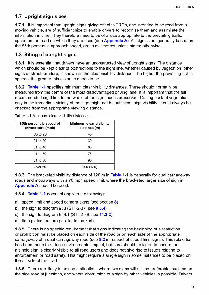
1.8.2. Table 1‑1 specifies minimum clear visibility distances. These should normally be measured from the centre of the most disadvantaged driving lane. It is important that the full recommended sight line to the whole of the sign face is preserved. Cutting back of vegetation only in the immediate vicinity of the sign might not be sufficient; sign visibility should always be checked from the appropriate viewing distance.
Table 1‑1 Minimum clear visibility distances
85th percentile speed of private cars (mph)
Minimum clear visibility distance (m)
Up to 20 45
21 to 30 60
31 to 40 60
41 to 50 75
51 to 60 90
Over 60 105 (120)
1.8.3. The bracketed visibility distance of 120 m in Table 1‑1 is generally for dual carriageway roads and motorways with a 70 mph speed limit, where the bracketed larger size of sign in Appendix A should be used.
1.8.4. Table 1‑1 does not apply to the following:
a) speed limit and speed camera signs (see section 8)b) the sign to diagram 958 (S11‑2‑37; see 9.3.4)c) the sign to diagram 958.1 (S11‑2‑38; see 11.3.2)d) time plates that are parallel to the kerb.
1.8.5. There is no specific requirement that signs indicating the beginning of a restriction or prohibition must be placed on each side of the road or on each side of the appropriate carriageway of a dual carriageway road (see 8.2 in respect of speed limit signs). This relaxation has been made to reduce environmental impact, but care should be taken to ensure that a single sign is clearly visible to all road users and does not give rise to issues relating to enforcement or road safety. This might require a single sign in some instances to be placed on the off side of the road.
1.8.6. There are likely to be some situations where two signs will still be preferable, such as on the side road at junctions, and where obstruction of a sign by other vehicles is possible. Drivers
INTRODUCTION
12
should not be placed in the situation where they might not see the sign before starting to turn at a road junction.
1.8.7. Time plates indicating the effects of No Stopping orders (see section 13) should, whenever possible, be mounted to face traffic. A driver does not then have to stop to read the sign, possibly resulting in an offence.
1.9 Mounting of upright signs1.9.1. The normal mounting height measured to the lower edge of a sign or backing board (or any supplementary plate) is between 900 mm and 1500 mm above the adjacent carriageway. The greater height should be used where vehicle spray is likely to soil the sign, or above planted areas. Careful consideration should be given to any proposal to mount signs at a low height, such as on railings or bollards, as there is a risk of drivers not noticing them, especially at night or when they could be obscured by parked vehicles or pedestrians. Where signs facing moving traffic are erected above footways, or in areas likely or intended to be used by pedestrians (e.g. pedestrian refuges), a headroom of 2300 mm is recommended, with 2100 mm as an absolute minimum. A clearance of at least 2300 mm should be maintained over a cycle track or a shared cycle / pedestrian facility.
1.9.2. Supplementary plates should be separated from the sign or another plate by a vertical space not exceeding the x‑height of the legend, and ideally half the x‑height (but see 1.10.4). When mounted on a backing board, this space should be 0.05 times the roundel diameter.
1.9.3. Except where they support a luminaire, posts should not project above the top of the sign. This practice is unsightly, and needlessly increases visual intrusion and clutter.
1.9.4. Where posts are erected on footways, there should be a preferred minimum of 1500 mm and an absolute minimum of 1000 mm of unobstructed width to allow the passage of wheelchairs, double buggies etc. Posts not readily visible to pedestrians or cyclists may be provided with a yellow or white band in accordance with the requirements of direction 8(2).
1.10 Mounting more than one sign on a post1.10.1. Research has shown that the greater the number of signs which drivers are presented with simultaneously, the greater the difficulty they are likely to have in assimilating the information. This problem in dealing with information overload increases with age, so that older drivers suffer disproportionately. Generally, therefore, not more than two signs should be erected on any one post when intended to be read from an approaching vehicle. This also applies to signs mounted at the same location on separate posts. Where a sign requires a supplementary plate, the sign and plate is generally regarded as one sign. Exceptionally, three signs for each approach direction may be mounted on one post, or at the same location, provided none requires a supplementary plate.
1.10.2. STOP or GIVE WAY signs or signs indicating the start of a speed limit (terminal signs) should not be mounted on the same post as a warning sign. Speed limit terminal signs should wherever possible be mounted alone. For further guidance on mounting speed limit signs, including repeater signs, see 8.17. Sign combinations, excluding speed limit terminal signs, which may be mounted together should be placed in the following order from top to bottom:
a) STOP or GIVE WAY or any triangular warning signb) speed limit repeater signsc) other circular signsd) rectangular signs.

INTRODUCTION
13
1.10.3. All proposed assemblies should be critically examined to ensure that the intended messages are clear. Ambiguity may result in difficulty enforcing a TRO. Where a supplementary plate with the legend “End” is used to indicate the termination of a prohibition or restriction, particular care is necessary to ensure that it is clear which sign it applies to when there is more than one.
1.10.4. Where a speed limit sign is erected on the same post as a clearway sign accompanied by an “End” plate, the plate should be butted directly up to the lower edge of the clearway sign. The speed limit sign should be mounted at the top of the assembly with a space equal to twice the width of the red border between the roundels to ensure there is no ambiguity.
1.10.5. Generally, no assembly of multiple signs should be taller than 4 metres above ground level, but this may be exceeded to obtain visibility of the signs at particularly difficult sites. However, account should always be taken of the potential environmental impact of tall and cluttered sign assemblies (see also Chapter 1).
1.10.6. It should also be borne in mind that high‑mounted signs may receive little light from car headlamps, particularly on dipped beam. Where such signs are not directly lit but rely on reflectorisation to be seen at night, they are likely to be less conspicuous and less legible.
1.11 Backing boards1.11.1. To improve conspicuity against a complex or dark background, an upright regulatory sign may be mounted on a grey or yellow backing board (direction 9). A backing board can also make for a neater assembly, e.g. when a sign requires a supplementary plate, and also eliminates the risk of the plate becoming misaligned. A yellow backing board must be rectangular in shape (except when a speed limit terminal sign is mounted with a town or village boundary sign; see 8.14.2), but a grey board may be non‑rectangular, e.g. to enable a circular sign to be bracketed off a supporting structure (see Chapter 1). A backing board must not itself be provided with a border, nor give the impression of being an additional border. Where it seems that a sign is not being noticed by drivers, it should be checked to ensure that it is well‑sited, not obscured by vegetation or other obstructions, and is of the appropriate size and in good condition. Only then should the use of a yellow backing board be considered.
1.11.2. A yellow backing board may be reflectorised to increase its conspicuity at night, although this is not usually necessary for regulatory signs. In most cases these are lit when placed on lit roads, or are mounted parallel to the kerb, and on unlit roads reflectorisation of the sign is usually sufficient to ensure night‑time conspicuity. A yellow backing board may also be fluorescent; this greatly increases conspicuity in dull weather and at dusk. Fluorescence can also be particularly effective in drawing attention to signs mounted in deep shadow, e.g. below overhanging trees. However, fluorescence is visually intrusive and should be used with discretion.
1.11.3. There are potential disadvantages to the use of backing boards. The larger overall size of the assembly can sometimes obstruct sight lines. A backing board can deprive non‑rectangular signs of a primary recognition aid: their distinctive silhouette. Yellow backing boards can be especially environmentally intrusive, and their over‑use could eventually devalue their attention‑attracting benefits. A less garish way of increasing a sign’s conspicuity is simply to provide a standard sign of larger size. Not only will this be more noticeable than a smaller sign, but it will also improve legibility and hence reading distance, which a yellow backing board cannot. Detailed guidance on the correct design and use of backing boards can be found in Chapter 7. Guidance on the use of backing boards for speed limit signs is given in this chapter (see 8.14).

INTRODUCTION
14
1.12 Illumination of upright signs1.12.1. Illumination requirements for upright traffic signs are set out in regulation 8 and, where appropriate, in individual Schedules. Many regulatory signs must be illuminated throughout the hours of darkness by internal or external lighting if they are sited within 50 m of a street lamp forming part of a system of street lighting where the speed limit is greater than 20 mph. In the case of the “one‑way traffic” sign shown in diagram 652 (S9‑4‑5), this applies only when sited within 50 m of a junction. See 8.15 for the illumination of speed limit signs. Where a sign is required to be illuminated by internal or external lighting, a means of lighting should be provided specifically to illuminate it. That light source could be mounted on the same structure, or be a remote source, such as a spot light, dedicated to the sign in question.
1.12.2. Some signs, such as those for bus lanes, may be either directly lit or reflectorised (or both), whether or not the road is lit. It is not a regulatory requirement to directly light these signs within a system of street lighting. However, some signs that need only be reflectorised might be sited where they will not receive adequate illumination from headlamps, and it might be prudent to provide direct lighting regardless of the regulatory requirements. Examples include signs mounted unusually high above the level of the carriageway, on the off side of the road or at the entrance to a side road. Retroreflection is also less effective where the sign is presented at a large angle to the direction of oncoming traffic. Modern microprismatic materials can achieve high luminances for many drivers in defined situations, but not for all drivers in all circumstances. However, some are designed to produce luminances little better than that of traditional beaded materials. Where regulatory signs on lit roads are exempted from the requirement to be directly lit, high‑performance microprismatic sheeting with a European Technical Assessment verifying that it meets class R3B (UK) or above is recommended.
1.12.3. Some regulatory signs, including time plates indicating parking controls and those intended for pedestrians, need not be directly illuminated or reflectorised.
1.13 Road markings1.13.1. This chapter includes full details of those road markings that are used in conjunction with upright regulatory signs; otherwise road markings can be found in Chapter 5, except for signal controlled junctions and pedestrian crossings which can be found in Chapter 6. Although double white lines and yellow box markings are regulatory, as they are not used in conjunction with upright signs, they are covered in Chapter 5.
1.13.2. Road markings serve a very important function in conveying to road users information and requirements, supplementing upright signs and, in the case of longitudinal markings, providing a continuing message. Some road markings described in this chapter may be used without an upright sign (e.g. the Give Way lines, parking bays etc.). However, road markings alone have their limitations. They can be completely obliterated by snow. Their conspicuity is impaired when wet or dirty, and their effective life is reduced if they are subjected to heavy trafficking. Therefore, it is important that road markings are well maintained (see Chapter 5).
1.13.3. Although road markings may be reflectorised (regulation 9), individual Schedules within the Regulations require that certain markings must be reflectorised; those included in this chapter are shown in Table 1‑2. Retroreflectivity is achieved through the addition of glass beads applied directly to the surface of the road marking during the application process and, in the case of thermoplastic, through the presence of glass beads incorporated within the material itself. This makes the marking much brighter at night than non‑reflectorised materials. The British Standard for road markings (BS EN 1436) specifies several different classes for night‑time brightness. Brighter markings are visible at greater distances, and may provide an

INTRODUCTION
15
acceptable level of performance for a longer time before renewal becomes necessary (see Chapter 5 for further details).
Table 1‑2 Markings required to be reflectorised
Diagram Number TSRGD reference Diagram Number TSRGD reference
1002.1 S9‑6‑1 1036.1 S9‑6‑19
1003A S9‑6‑3 1036.2 S9‑6‑20
1003.3 S9‑6‑6 1037.1 S9‑6‑21
1003.4 S9‑6‑5 1042 S9‑6‑22
1009A S11‑4‑8 1046 S9‑6‑17
1013.1 S9‑6‑23 1046.1 S9‑6‑18
1013.5 S9‑6‑24 1049A S9‑6‑11
1022 S9‑6‑2 1049B S9‑6‑7
1023A S9‑6‑4 1065 S10‑2‑9
NOTE: Diagram 1049B must be reflectorised only where indicating the boundary of a mandatory cycle lane (S9‑8‑9), otherwise it may be reflectorised.
1.13.4. Road markings are prescribed in the colours white, yellow and red. Further details on the specification of colours for road marking materials can be found in Chapter 5.
1.13.5. Dimensions shown for road markings in the figures in this chapter are in millimetres unless stated otherwise. Many markings are fully dimensioned in the Regulations. Detailed working drawings are available for the more complex markings. In addition to indicating overall dimensions, the Regulations prescribe maximum heights for road markings above the road surface (regulation 10).
1.14 Maintenance1.14.1. Over a period of years, signs gradually become faded and their retroreflective properties diminish. This will reduce both conspicuity and legibility, by day and by night. Excessively discoloured or faded signs (e.g. white backgrounds which have become grey or brown, or red borders faded to pink) and signs where the legend or graphic is peeling cannot be fully effective and need to be replaced. Guidance can be found in TD 25, in Volume 8 of DMRB (see 1.5.1).
1.14.2. Signs should be cleaned at intervals appropriate to the site conditions. Signs located where they are subject to heavy soiling from passing traffic, or algae growth (a common problem with signs beneath tree canopies) will need more frequent cleaning. Neglect reduces the external contrast between the sign and its surroundings, making it less likely to be noticed by drivers. It also reduces the internal contrast between legend and sign background, making the sign more difficult to read. Moreover, it seriously reduces light transmission through the retroreflective medium. Dirty signs are far less effective at night. Older drivers are particularly disadvantaged; the ageing process of the eye means that progressively more light is required to maintain the same legibility performance. Dimmer signs take longer to recognise and to read, reducing the time available for drivers to take appropriate action.
1.14.3. Regular inspection, particularly in summer when the rapid growth of foliage and other vegetation is most likely to cause obscuration, will ensure early detection of any problems.
1.14.4. A reference number may be placed on the back of a sign in a contrasting colour in characters not exceeding 25 mm in height, or embossed in the same colour in characters not

INTRODUCTION
16
exceeding 50 mm in height (direction 9). It is unlawful, as well as distracting and unsightly, to place reference numbers on the sign face or on the front of a backing board.
1.15 Working drawings1.15.1. Dimensions on the figures are in millimetres unless stated otherwise. Many signs and markings are fully dimensioned in the Regulations. Detailed working drawings of the more complex ones are available at:
www.gov.uk/government/collections/traffic‑signs‑signals‑and‑road‑markings
1.15.2. Workings drawings for Welsh and English bilingual signs are available at
www.traffic‑wales.com/traffic_signs.aspx

17
2 STOP SIGNS
2.1 General2.1.1. The STOP sign to diagram 601.1 (S9‑2‑1, see Figure 2‑1) imposes mandatory requirements on drivers entering a major road or crossing a railway or tramway (see S9‑7‑1 & 2). When the sign is to be installed in conjunction with railway level crossings or tramway crossings, the railway or tramway infrastructure manager and the Office of Rail and Road should be consulted beforehand.
2.1.2. The sign is subject to section 36 of the Road Traffic Act 1988. As an order is not required to install the sign, where an offence is committed it is one of failing to obey a traffic sign. A STOP sign does not require site approval from the national authority.
2.1.3. It is expected that most junctions that satisfy the criteria for STOP signs already have signs in place. New junctions should not be constructed with very poor visibility, so the provision of new STOP signs should be exceptional. Consultation with the police for their support on enforcement is recommended.
2.1.4. Schedule 9 General Direction 3 prohibits the use of STOP signs on all approaches to a junction, as this would cause uncertainty as to which vehicles had priority.
2.1.5. Advance warning of the requirement to stop may be given using the sign to diagram 501 (S2‑6‑1; see Chapter 4). This may be accompanied by the worded marking “SLOW” to diagram 1024 (S11‑4‑15, see Chapter 5) on the carriageway.
2.1.6. The “Dual carriageway” plate to diagram 608 (S9‑2‑3, see Figure 2‑2) may be mounted below the STOP sign on the minor road approaching a dual carriageway where there is a gap in the central reservation. This warns drivers from the minor road that, if turning right, they should turn after the central reservation.
2.1.7. Schedule 9 General Direction 4 requires that the STOP sign and its associated road markings to diagrams 1002.1 and 1022 (S9‑6‑1 and 2 respectively, see Figure 2‑3 and Figure 2‑4) must always be used together; the road markings must not be used on their own.
Figure 2‑1 Diagram Figure 2‑2 Diagram Figure 2‑3 Diagram Figure 2‑4 Diagram 601.1 (S9‑2‑1) 608 (S9‑2‑3) 1002.1 (S9‑6‑1) 1022 (S9‑6‑2)
2.1.8. Where a STOP sign (diagram 601.1) has been provided, S9‑7‑1 requires that:
a) every vehicle must stop before crossing the transverse line shown in diagram 1002.1 (S9‑6‑1), or if that line is not clearly visible, before entering the major road in respect of which the stop sign has been provided; and
b) no vehicle must cross the transverse line, or if that line is not clearly visible, enter the major road in respect of which the stop sign has been provided, so as to be likely to endanger any person, or to cause the driver of another vehicle to change its speed or course in order to avoid an accident.

STOP SIGNS
18
Similar requirements apply at railway and tramway crossings where a STOP sign has been provided.
2.2 Visibility criteria2.2.1. STOP signs, other than at junctions with tramways, should be provided only where visibility is so restricted that it is essential for drivers to stop before entering the major road (see 2.5 for railway and tram crossings). The sign will be well respected only if drivers can see the need for it. The possibility of making a visibility improvement at a junction should always be investigated before considering a STOP sign. Restriction of visibility caused, for example, by a hedge that can be reduced in height or removed will not normally justify a STOP sign, particularly as highway authorities have powers under section 79 of the Highways Act 1980 to remove such obstructions.
2.2.2. Visibility distances below which a STOP sign might be considered are specified in Table 2‑1. Other factors which should be taken into account include traffic volumes on both the major and minor roads, gradient of the minor road, accident record, poor alignment or any other factors which cause unusual difficulty. It does not automatically follow that STOP signs should always be provided at sites where the criteria are met. If any changes take place at a junction that already has a STOP sign, it will be necessary to check if the criteria are still met, and if not the junction should be assessed for the appropriate level of give way signing (see section 3).
Table 2‑1 Visibility criteria for STOP sign
85th percentile speed of private cars on major road (mph)
Visibility distance along major road (m)
20 15
30 30
40 45
50 70
60 90
70 120
2.2.3. The visibility distance in Table 2‑1 is measured along the nearer edge of the major road from a point 1.05 m above the centre line of the minor road (representing the driver’s eye position). The distances in the table should be interpolated for intermediate speeds (e.g. 37.5 m for a speed of 35 mph). Where the minor road is lightly trafficked, this visibility should be available from a point 3 m back from the edge of the major road carriageway along the centre line of the minor road. This distance should be increased to 4.5 m where the minor road has some through‑traffic value. Visibility from the side road along the major road is important to the left as well as to the right, especially where there is the likelihood of vehicles from the left overtaking or the major road is one way from left to right.
2.3 Road markings2.3.1. Figure 2‑5 shows a typical road marking layout at a junction controlled by a STOP sign. The Stop line to diagram 1002.1 is normally positioned so that the edge of the marking nearest to the major road continues the line of the edge of that road or any longitudinal edge line. This applies even when the minor road enters at an angle other than 90°. A Stop line should never be set back from the major road in an attempt to give pedestrians crossing the mouth of the side road a greater degree of priority over exiting traffic. Not only would this confuse drivers approaching the line, but it would also reduce their visibility along the major road and put pedestrians at risk.

STOP SIGNS
19
2.3.2. On two‑way minor roads, the Stop line normally extends to the centre of the carriageway, the remaining width being marked with diagram 1009A (S11‑4‑8) to delineate the edge of the major road. Where this would result in a Stop line less than 2.75 m long, the marking to diagram 1009A and the centre line should be omitted; the Stop line is then extended across the full width of the minor road carriageway. The width of the diagram 1009A marking should normally be 100 mm, except where the major road has a continuous edge line marking to diagram 1012.1 (S11‑4‑11, see 3.2.6) with a width of 150 mm or 200 mm. In this case, the width of diagram 1009A should be the same as that of diagram 1012.1 (see Chapter 5).
600
100150200
STOP sign(Diagram 601.1)
2050
Diagram 1002.1
Diagram 1009A
300
Diagram1022
2100 - 2750(15000 max)
1500(6000 max)
Figure 2‑5 Road markings at a junction controlled by a STOP sign
2.3.3. Where a one‑way street enters a major road, the Stop marking should always extend across the whole width of the minor road.
2.3.4. The word STOP is normally located so that the top edge of the legend is not more than 2.75 m or less than 2.1 m from the nearest part of the Stop line. Exceptionally this may be increased to a maximum of 15 m, e.g. where the vertical curvature or a sharp bend prevents it being seen from a distance. For details of the formation of worded markings, see Chapter 5.
2.3.5. For details of longitudinal lines forming centre lines at road junctions, see Chapter 5.
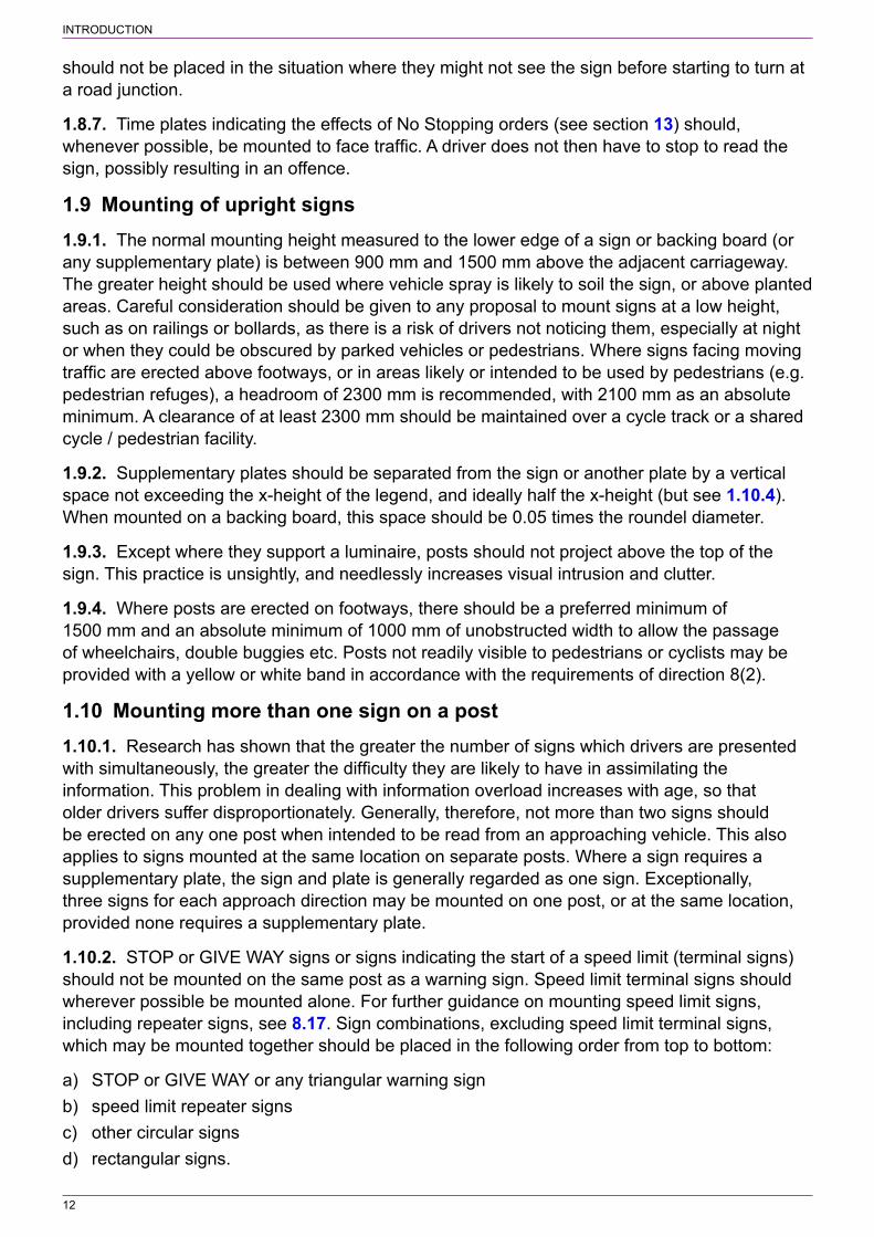
2.4 Size and siting of stop signs2.4.1. The appropriate size for the STOP sign and the worded STOP road marking is indicated in Table 2‑2. The 85th percentile speed should be measured at a point prior to traffic slowing down for the junction.
2.4.2. The upright STOP sign should be sited as close as possible to the Stop line, but not in such a position as to impair visibility along the major road. Normally the sign will be about 1.5 m before the marking (see Figure 2‑5). If conditions prevent a sign from being easily seen, it should be placed at a greater distance, but no more than 6 m from the line.
2.4.3. Normally, a single sign should be provided, sited on the left hand side of the road. Where visibility of the sign would be restricted, consideration should be given to siting the sign on the right hand side of the road (but see 2.4.2). There might be some situations where a pair of signs might be considered appropriate, e.g. on a wide one‑way road or where there is a refuge in the
STOP SIGNS
20
mouth of the minor road and there are two or more lanes at the Stop line. Signs should be sited where they are not obscured by parked vehicles.
Table 2‑2 Size of STOP sign and road marking
85th percentile speed of private cars approaching on minor road (mph)
Size of STOP sign (mm)
Size of STOP road marking (mm)
Up to 30 750 1600
31 to 40 900 (750) 1600 (2800)
41 to 50 1200 (900) 2800
Over 50 1200 2800
NOTE: The smaller sign sizes shown in brackets may be used where an advance STOP sign is provided. The 2800 mm road marking in brackets should be used where required by site conditions or where the accident record calls for greater emphasis.
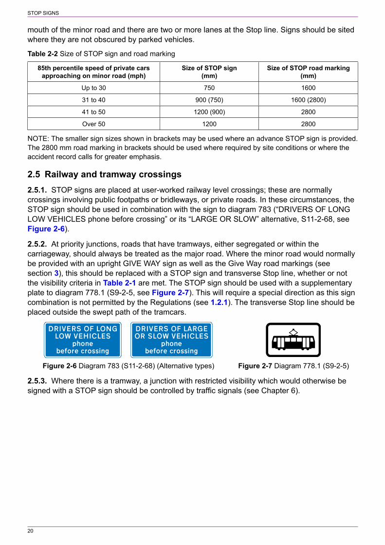
2.5 Railway and tramway crossings2.5.1. STOP signs are placed at user‑worked railway level crossings; these are normally crossings involving public footpaths or bridleways, or private roads. In these circumstances, the STOP sign should be used in combination with the sign to diagram 783 (“DRIVERS OF LONG LOW VEHICLES phone before crossing” or its “LARGE OR SLOW” alternative, S11‑2‑68, see Figure 2‑6).
2.5.2. At priority junctions, roads that have tramways, either segregated or within the carriageway, should always be treated as the major road. Where the minor road would normally be provided with an upright GIVE WAY sign as well as the Give Way road markings (see section 3), this should be replaced with a STOP sign and transverse Stop line, whether or not the visibility criteria in Table 2‑1 are met. The STOP sign should be used with a supplementary plate to diagram 778.1 (S9‑2‑5, see Figure 2‑7). This will require a special direction as this sign combination is not permitted by the Regulations (see 1.2.1). The transverse Stop line should be placed outside the swept path of the tramcars.
Figure 2‑6 Diagram 783 (S11‑2‑68) (Alternative types) Figure 2‑7 Diagram 778.1 (S9‑2‑5)
2.5.3. Where there is a tramway, a junction with restricted visibility which would otherwise be signed with a STOP sign should be controlled by traffic signals (see Chapter 6).
21
3 GIVE WAY SIGNS
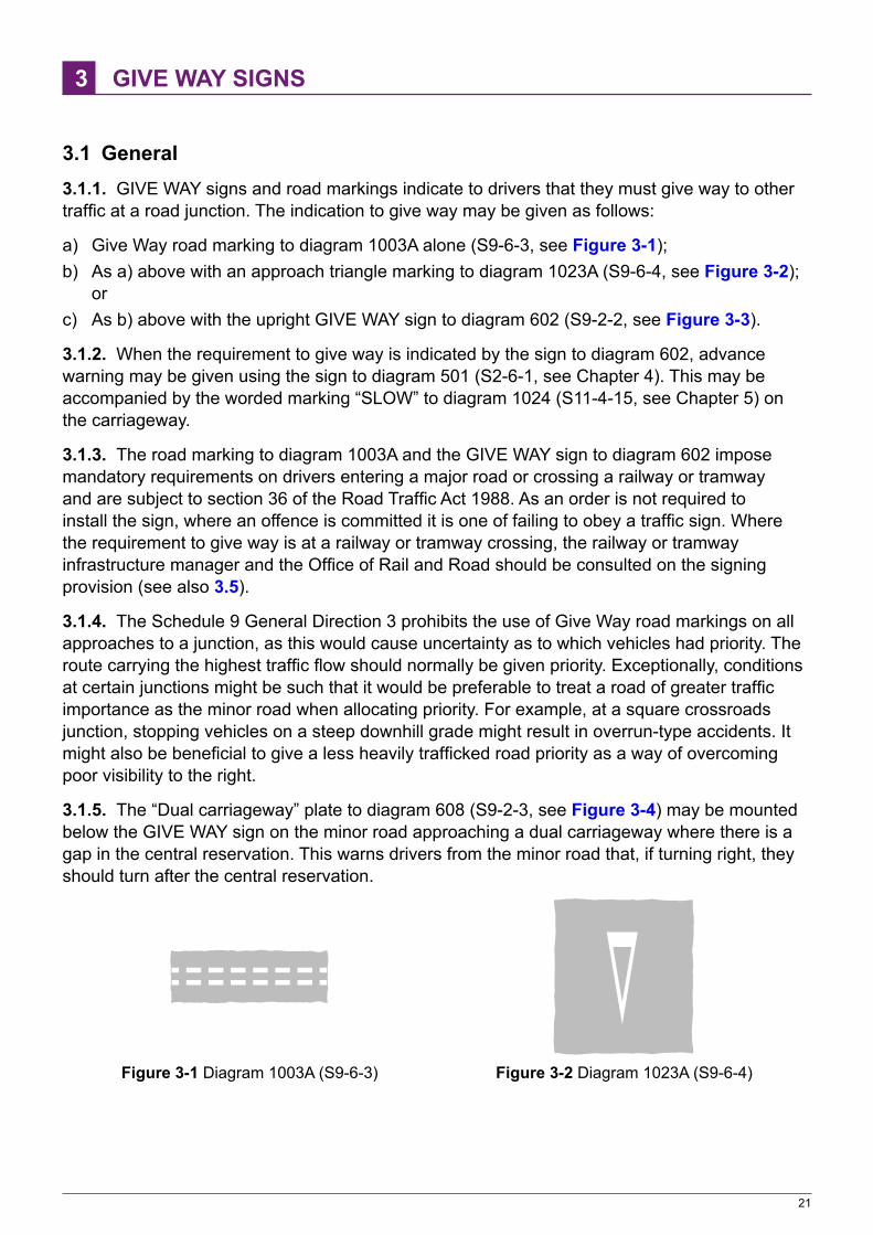
3.1 General3.1.1. GIVE WAY signs and road markings indicate to drivers that they must give way to other traffic at a road junction. The indication to give way may be given as follows:
a) Give Way road marking to diagram 1003A alone (S9‑6‑3, see Figure 3‑1);b) As a) above with an approach triangle marking to diagram 1023A (S9‑6‑4, see Figure 3‑2);
orc) As b) above with the upright GIVE WAY sign to diagram 602 (S9‑2‑2, see Figure 3‑3).
3.1.2. When the requirement to give way is indicated by the sign to diagram 602, advance warning may be given using the sign to diagram 501 (S2‑6‑1, see Chapter 4). This may be accompanied by the worded marking “SLOW” to diagram 1024 (S11‑4‑15, see Chapter 5) on the carriageway.
3.1.3. The road marking to diagram 1003A and the GIVE WAY sign to diagram 602 impose mandatory requirements on drivers entering a major road or crossing a railway or tramway and are subject to section 36 of the Road Traffic Act 1988. As an order is not required to install the sign, where an offence is committed it is one of failing to obey a traffic sign. Where the requirement to give way is at a railway or tramway crossing, the railway or tramway infrastructure manager and the Office of Rail and Road should be consulted on the signing provision (see also 3.5).
3.1.4. The Schedule 9 General Direction 3 prohibits the use of Give Way road markings on all approaches to a junction, as this would cause uncertainty as to which vehicles had priority. The route carrying the highest traffic flow should normally be given priority. Exceptionally, conditions at certain junctions might be such that it would be preferable to treat a road of greater traffic importance as the minor road when allocating priority. For example, at a square crossroads junction, stopping vehicles on a steep downhill grade might result in overrun‑type accidents. It might also be beneficial to give a less heavily trafficked road priority as a way of overcoming poor visibility to the right.
3.1.5. The “Dual carriageway” plate to diagram 608 (S9‑2‑3, see Figure 3‑4) may be mounted below the GIVE WAY sign on the minor road approaching a dual carriageway where there is a gap in the central reservation. This warns drivers from the minor road that, if turning right, they should turn after the central reservation.
Figure 3‑1 Diagram 1003A (S9‑6‑3) Figure 3‑2 Diagram 1023A (S9‑6‑4)

GIVE WAY SIGNS
22
Figure 3‑3 Diagram 602 (S9‑2‑2) Figure 3‑4 Diagram 608 (S9‑2‑3)
3.1.6. The Give Way marking is not normally used at private accesses, or on minor residential roads where traffic speeds and flows are low and visibility is good.
3.2 Road markings3.2.1. Where a Give Way marking (diagram 1003A) has been provided, S9‑7‑7 requires that:
“no vehicle may proceed past the transverse line which is the nearer to the major road into that road in a manner or at a time likely to endanger the driver of, or any passenger in, a vehicle on the major road or to cause the driver of such a vehicle to change its speed or course in order to avoid an accident.”Similar requirements apply where vehicles give way to railway vehicles or tramcars, where the marking is used in conjunction with a road narrowing (see 4.8.5) and where the marking is used in conjunction with a cycle crossing (see 11.12.6).
3.2.2. Figure 3‑5 shows a typical road marking layout at a junction where vehicles are required to give way. The Give Way line shown in Figure 3‑1 is normally positioned so that the edge of the marking nearest to the major road continues the line of the edge of that road or any longitudinal edge line, except where an edge line delineates a hard strip. This applies even when the minor road enters at an angle other than 90°. A Give Way line should not be set back from the major road in an attempt to give pedestrians crossing the mouth of the side road a greater degree of priority over exiting traffic. Not only would this confuse drivers approaching the line, but it would also reduce their visibility along the major road and put pedestrians at risk.
3.2.3. On two‑way minor roads, the Give Way line normally extends to the centre of the carriageway, the remaining width being marked with diagram 1009A (S11‑4‑8) to delineate the edge of the major road. Where this would result in a Give Way line less than 2.75 m long, the marking to diagram 1009A and the centre line should be omitted; the Give Way line is then extended across the full width of the minor road carriageway. The width of the diagram 1009A marking should normally be 100 mm, except where the major road has a continuous edge line marking (diagram 1012.1; S11‑4‑11) with a width of 150 mm or 200 mm. In this case, the width of diagram 1009A should be the same as that of diagram 1012.1 (see Chapter 5).
3.2.4. Where a one‑way street enters a major road, the Give Way marking is always carried across the whole width of the minor road.
3.2.5. The triangular marking to diagram 1023A may be used only when a transverse Give Way line to diagram 1003A is provided. It is normally located with its leading edge between 2100 mm and 2750 mm from the transverse marking (see Figure 3‑5). This distance may be increased to a maximum of 15 m where the vertical curvature or a sharp bend prevents it being seen from a distance, or where a vertical sign has been provided and this is sited further from the junction in order to ensure adequate visibility (see 3.4.2). The triangular marking should be positioned approximately in the centre of the traffic lane. Where the approach to the junction comprises more than one lane, the marking should be provided in each lane.

GIVE WAY SIGNS
23
600 300
Diagram 1009A
Diagram 1003A
Diagram 1023A
100150200
2100 - 2750(15000 max)
Figure 3‑5 Road markings at a junction where vehicles give way
3.2.6. On roads where a hard strip is provided, demarcated with the edge of carriageway marking to diagram 1012.1 or 1012.3 (S11‑4‑11 and 13 respectively), the Give Way marking (diagram 1003A) should be aligned with the back of the hard strip and not with the edge line (see Figure 3‑6).
Diagram 1003A Diagram 1009A
Diagram 1023A
Diagram 1012.1 or 1012.3
Figure 3‑6 Layout used where a 1 m hard strip is provided on the main carriageway
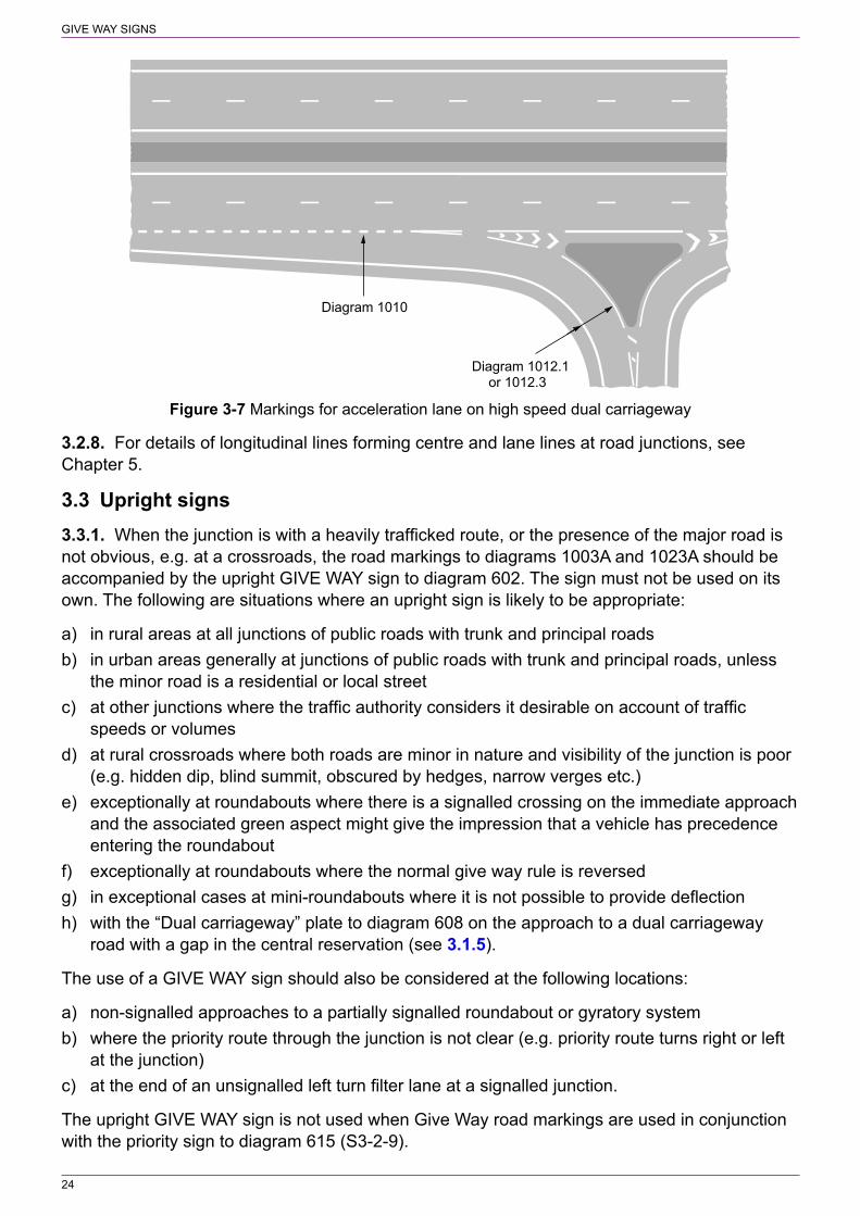
3.2.7. Diagram 1003A should not be used on high‑speed dual carriageway roads where traffic either joins from a slip road (at a grade separated junction) or there is a merging taper. At such sites the marking to diagram 1010 (S11‑4‑10) should be used (see Figure 3‑7 and Chapter 5).
GIVE WAY SIGNS
24
Diagram 1010
Diagram 1012.1or 1012.3
Figure 3‑7 Markings for acceleration lane on high speed dual carriageway
3.2.8. For details of longitudinal lines forming centre and lane lines at road junctions, see Chapter 5.
3.3 Upright signs3.3.1. When the junction is with a heavily trafficked route, or the presence of the major road is not obvious, e.g. at a crossroads, the road markings to diagrams 1003A and 1023A should be accompanied by the upright GIVE WAY sign to diagram 602. The sign must not be used on its own. The following are situations where an upright sign is likely to be appropriate:
a) in rural areas at all junctions of public roads with trunk and principal roadsb) in urban areas generally at junctions of public roads with trunk and principal roads, unless
the minor road is a residential or local streetc) at other junctions where the traffic authority considers it desirable on account of traffic
speeds or volumesd) at rural crossroads where both roads are minor in nature and visibility of the junction is poor
(e.g. hidden dip, blind summit, obscured by hedges, narrow verges etc.)e) exceptionally at roundabouts where there is a signalled crossing on the immediate approach
and the associated green aspect might give the impression that a vehicle has precedence entering the roundabout
f) exceptionally at roundabouts where the normal give way rule is reversedg) in exceptional cases at mini‑roundabouts where it is not possible to provide deflectionh) with the “Dual carriageway” plate to diagram 608 on the approach to a dual carriageway
road with a gap in the central reservation (see 3.1.5).
The use of a GIVE WAY sign should also be considered at the following locations:
a) non‑signalled approaches to a partially signalled roundabout or gyratory systemb) where the priority route through the junction is not clear (e.g. priority route turns right or left
at the junction)c) at the end of an unsignalled left turn filter lane at a signalled junction.
The upright GIVE WAY sign is not used when Give Way road markings are used in conjunction with the priority sign to diagram 615 (S3‑2‑9).

GIVE WAY SIGNS
25
3.3.2. Where a GIVE WAY sign (diagram 602) has been provided, S9‑7‑3 requires that:
“no vehicle is to cross the transverse line shown in diagram 1003A nearer to the major road at the side of which that line is placed, or if that line is not clearly visible, enter that major road, so as to be likely to endanger any person, or cause the driver of another vehicle to change its speed or course in order to avoid an accident.”
This supplements the requirements for the road markings. When the GIVE WAY sign is used in combination with diagram 778 or 778.1 (S9‑2‑4 and 5 respectively), the requirement is for vehicles to give way to railway vehicles or tramcars.
3.4 Size and siting of upright signs3.4.1. The appropriate size for the GIVE WAY sign is indicated in Table 3‑1. The smaller sizes shown in brackets may be used where an advance warning sign is provided. The larger size for approach speeds over 60 mph might be helpful where there is a history of accidents caused by a failure to give way. The 85th percentile speed should be measured at a point prior to traffic slowing down for the junction.
Table 3‑1 Size of upright GIVE WAY sign
85th percentile speed of private cars approaching on minor road (mph)
Size of GIVE WAY sign (mm)
Up to 30 600
31 to 40 750 (600)
41 to 50 900 (750)
51 to 60 1200 (900)
Over 60 1200 (1500)
3.4.2. The upright sign should be sited as close as possible to the Give Way line (diagram 1003A), but not in such a position as to impair visibility along the major road. Normally the sign will be about 1.5 m before the marking (see Figure 3‑8). If conditions prevent a sign from being easily seen, it should be placed at a greater distance, but no more than 12 m from the line.
1500(12000 max)
Figure 3‑8 Siting of GIVE WAY sign
3.4.3. Normally, a single sign should be provided, sited on the left hand side of the road. Where visibility of the sign would be restricted, consideration should be given to siting the sign on the right hand side of the road. There might be some situations where a pair of signs might be considered appropriate, e.g. on a wide one‑way road or where there is a refuge in the mouth of the minor road and there are two or more lanes at the Give Way line. Signs should be sited where they are not obscured by parked vehicles. The sign should normally be duplicated on roundabouts where drivers on the circulatory carriageway are required to give way to traffic entering the junction (see Chapter 5).

GIVE WAY SIGNS
26
3.5 Railway and tramway crossings3.5.1. At open railway level crossings and tramway crossings (i.e. those with no barriers and without signals) the upright GIVE WAY sign should be used in combination with diagram 774 (S2‑6‑4, see Figure 3‑9) and either diagram 778 or 778.1 (S9‑2‑4 and 5 respectively, see Figure 3‑10 and Figure 3‑11) as appropriate. Diagram 774 is mounted uppermost, with the plate to diagram 778 or 778.1 below diagram 602.
Figure 3‑9 Diagram 774 (S2‑6‑4) Location of railway or tramway without gate or barrier
Figure 3‑10 Diagram 778 (S9‑2‑4) Open Figure 3‑11 Diagram 778.1 (S9‑2‑5) Open railway level crossing without light signals tramway crossing without light signals
3.5.2. At priority junctions, roads that have tramways, either segregated or within the carriageway, should always be treated as the major road. Where the minor road would normally be provided with an upright GIVE WAY sign as well as the Give Way road markings, this should be replaced with a STOP sign and transverse Stop line (see section 2), whether or not the visibility criteria in Table 2‑1 are met. At all other junctions with a road carrying a tramway, the minor road should have the transverse Give Way line, the triangular marking and an upright GIVE WAY sign. The transverse Give Way line should be placed outside the swept path of the tramcars.
3.5.3. Junctions with heavy traffic flows or restricted visibility should be controlled by traffic signals where there is a tramway (see Chapter 6).

27
4 COMPULSORY AND PROHIBITED MOVEMENTS
4.1 General4.1.1. The signs in this section generally give instructions regarding manoeuvres that must or must not be made. Positive signs tell drivers what must be done; prohibitory signs indicate a forbidden manoeuvre. They cover both junctions and the sections of road between junctions. The choice of sign or signs for a particular junction will depend on the road layout, the permitted movements and whether there are traffic signals.
4.2 Limited movements through junctions4.2.1. The sign to diagram 606 (S3‑2‑1, see Figure 4‑1) is used to indicate the only route that may lawfully be taken through a junction. It may point horizontally to the left or to the right, or vertically upwards. The sign to diagram 609 (S3‑2‑2, see Figure 4‑2) is an advance sign indicating a compulsory left or right turn.
Figure 4‑1 Diagram 606 (S3‑2‑1) Figure 4‑2 Diagram 609 (S3‑2‑2) Figure 4‑3 One‑way Vehicular traffic must proceed in Vehicular traffic must turn ahead supplementary plate the direction indicated by the arrow in the direction indicated by the (S3‑3‑1) (Alternative types) arrow (Alternative types)
4.2.2. Diagrams 606 and 609 may include supplementary plates with the prescribed legends set out at S3‑3‑1 to 3. These are “One way” (S3‑3‑1, see Figure 4‑3), “Dual carriageway” (see Figure 3‑4) and, as described in 4.3, exceptions for various classes of vehicle.
4.2.3. Figure 4‑4 shows the correct signing arrangement at an unsignalled junction where a side road forms a T‑junction with a one‑way road and traffic is required to turn in one direction only from the side road. Where the major road is a dual carriageway without a gap in the central reservation (see Figure 4‑5) a TRO is not required (see Schedule 3 General Direction 1(3)). In both instances, the use of the advance sign to diagram 609 together with the “One way” plate is optional. Where the dual carriageway has a gap in the central reservation and an order is made to prohibit the right turn, “no entry” signs to diagram 616 (S3‑2‑10, see Figure 4‑32) should be erected on each side of the gap, as shown in Figure 4‑7. The sign to diagram 606 with a plate legend “Dual carriageway” should be located to the left of the gap.
4.2.4. Signs to diagrams 606 and 609 are not required where traffic joins a dual carriageway via a slip road and an acceleration lane, and the Give Way line is replaced by the marking to diagram 1010 (S11‑4‑10, see Chapter 5). However, an advance sign to diagram 609 with a plate legend “Dual carriageway” might be helpful where it is not apparent to drivers that they are on a slip road, e.g. a former main road through a village joining a by‑pass. Where a traffic merge warning sign is provided on the slip road (see Chapter 4), this should be located in advance of the sign to diagram 609.
4.2.5. At an unsignalled junction where a side road forms a T‑junction with a two‑way road (see Figure 4‑6) and traffic is required to turn in one direction only, the use of a sign to diagram 606, even without a “One way” plate, could be misleading as drivers might think they are turning into a one‑way road. A sign to diagram 612 or 613 (S3‑2‑7 and 8 respectively, see Figure 4‑8

COMPULSORY AND PROHIBITED MOVEMENTS
28
and Figure 4‑9) should therefore be used at the junction, indicating the prohibited turn. Where a map‑type advance direction sign is provided in the side road, this should incorporate the “no right turn” or “no left turn” symbol (S12‑20‑19). Where appropriate, a sign to diagram 609 without a supplementary plate may be used in advance of the junction; this should not be necessary where there is an advance direction sign.
one way
Sited approx50 m fromjunction
(see 4.5.2)
Sited approx50 m fromjunction
(see 4.5.2)
Figure 4‑4 Signing arrangement at unsignalled Figure 4‑5 Signing arrangement at unsignalled junction where side road meets one‑way road junction where side road meets dual carriageway
4.2.6. The road marking to diagram 1036.1 (“TURN LEFT”) or 1037.1 (“TURN RIGHT”) (S9‑6‑19 and 21 respectively, see Figure 4‑10 and Figure 4‑11) may be used to supplement the upright sign. The word “ONLY” must not be used with “TURN LEFT” or “TURN RIGHT” as this is not prescribed. The arrows must not be omitted from these markings. The legend may be laid in a single line or in two lines, as shown in Figure 4‑10 and Figure 4‑11, depending on the carriageway or lane width available. Two sizes are prescribed; the smaller size will be appropriate for most situations. The larger size might be used where greater emphasis is required.
4.2.7. Where the side road is one way and the main road is a single carriageway with two‑way traffic, a warning sign to diagram 522 (two‑way traffic) (S2‑2‑17) may be provided (see Chapter 4). This should be mounted above the “no right turn” or “no left turn” sign.
4.2.8. Where a major road at a crossroads is one way, the use of signs to diagrams 606 and 609 is not appropriate, as traffic can normally proceed ahead from the side road. In this situation, a “no right turn” sign to diagram 612 or a “no left turn” sign to diagram 613 should be used as appropriate. “One‑way traffic” signs to diagram 652 (S9‑4‑5) should be provided in the major road within 50 m of the junction (see 4.9.3).

COMPULSORY AND PROHIBITED MOVEMENTS
29
two way
Sited approx50 m fromjunction
(see 4.5.2)
Sited approx50 m fromjunction
(see 4.5.2)
Figure 4‑6 Signing arrangement at unsignalled Figure 4‑7 Signing arrangement at unsignalled junction where side road meets two‑way road junction where side road meets a dual carriageway and there is a banned right turn
Figure 4‑8 Diagram 612 (S3‑2‑7) Figure 4‑9 Diagram 613 (S3‑2‑8) No right turn for vehicular traffic No left turn for vehicular traffic
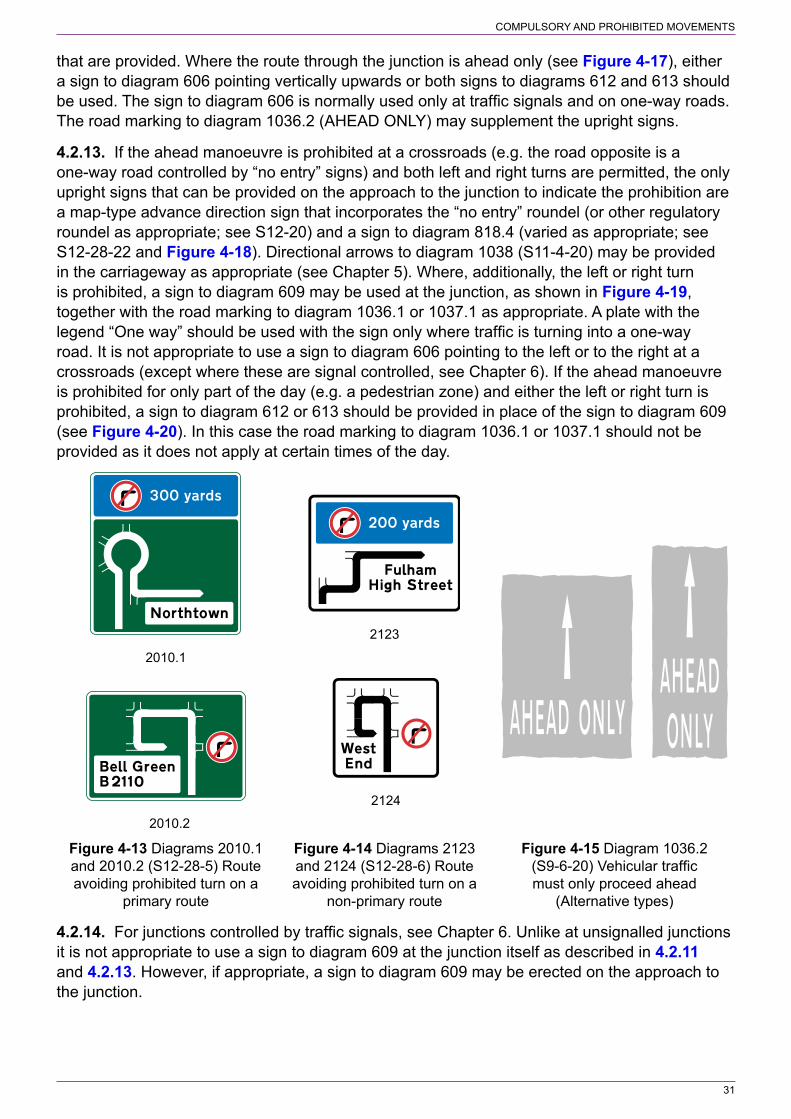
4.2.9. Where traffic is prohibited from turning into a side road at an unsignalled T‑junction (see Figure 4‑12), a sign to diagram 612 or 613 as appropriate should be provided at the junction. A map‑type advance direction sign, if provided, should indicate the prohibited turn by incorporating a diagram 612 or 613 roundel. This sign could be of the type shown in diagram 2010.1, 2010.2, 2123 or 2124 (S12‑28‑5 and 6, see Figure 4‑13 and Figure 4‑14), each showing an alternative route. The road marking to diagram 1036.2 (“AHEAD ONLY”, S9‑6‑20, see Figure 4‑15) may be used to supplement the upright signs. Two sizes are prescribed; the smaller size will be appropriate where the speed limit is 40 mph or less. For higher speed limits, where traffic approaching the junction must proceed ahead only, the larger size should be used, except where traffic speeds are low and diagram 1004 (S11‑4‑2) is used for centre and lane lines (see Chapter 5).
4.2.10. Where the turn into the side road is prohibited because it is a one‑way road controlled by “no entry” signs, it might not be necessary to provide signs to diagram 612 or 613. Situations where the “no right turn” and “no left turn” signs might be omitted are where the side road is

COMPULSORY AND PROHIBITED MOVEMENTS
30
narrow and of minor importance or where the “no entry” signs can be clearly seen from the main road when approaching the junction. Any map‑type advance direction sign should incorporate the “no entry” roundel to diagram 616 (S12‑20‑21), in which case a sign to diagram 612 or 613 should not be necessary.
4.2.11. If traffic has to turn left or right at an unsignalled junction, as shown in Figure 4‑16, because the ahead manoeuvre is prohibited, a sign to diagram 609 with or without the road marking to diagram 1036.1 or 1037.1 may be provided as appropriate. Depending on the nature of the junction, the road marking alone might be sufficient. Where, on the approach to the junction, it is clear that all traffic must turn left (or right as appropriate), then it might not be necessary to provide a sign to diagram 609 or the road marking arrow. The “no entry” sign opposite the junction and any centre or lane line guiding traffic through the junction should be sufficient. A plate with the legend “One way” should be used with the sign to diagram 609 only where traffic is turning into a one‑way road. Any map‑type advance direction sign should incorporate the appropriate regulatory roundel (e.g. “no entry” or “no vehicles”). For this type of junction arrangement, it is not appropriate to provide a sign to diagram 606 pointing to the left or to the right.
Figure 4‑10 Diagram 1036.1 (S9‑6‑19) Vehicular Figure 4‑11 Diagram 1037.1 (S8‑6‑21) Vehicular traffic must turn left (Alternative types) traffic must turn right (Alternative types)
two wayor
one way
Figure 4‑12 Signing arrangement where traffic is prohibited from turning into side road at unsignalled T‑junction
4.2.12. Where the junction is a priority crossroads controlled by STOP or GIVE WAY signs, any prohibited turn should be indicated by signs to diagram 612 or 613 located at the junction. The diagram 612 or 613 roundel should be incorporated in any map‑type advance direction signs
COMPULSORY AND PROHIBITED MOVEMENTS
31
that are provided. Where the route through the junction is ahead only (see Figure 4‑17), either a sign to diagram 606 pointing vertically upwards or both signs to diagrams 612 and 613 should be used. The sign to diagram 606 is normally used only at traffic signals and on one‑way roads. The road marking to diagram 1036.2 (AHEAD ONLY) may supplement the upright signs.
4.2.13. If the ahead manoeuvre is prohibited at a crossroads (e.g. the road opposite is a one‑way road controlled by “no entry” signs) and both left and right turns are permitted, the only upright signs that can be provided on the approach to the junction to indicate the prohibition are a map‑type advance direction sign that incorporates the “no entry” roundel (or other regulatory roundel as appropriate; see S12‑20) and a sign to diagram 818.4 (varied as appropriate; see S12‑28‑22 and Figure 4‑18). Directional arrows to diagram 1038 (S11‑4‑20) may be provided in the carriageway as appropriate (see Chapter 5). Where, additionally, the left or right turn is prohibited, a sign to diagram 609 may be used at the junction, as shown in Figure 4‑19, together with the road marking to diagram 1036.1 or 1037.1 as appropriate. A plate with the legend “One way” should be used with the sign only where traffic is turning into a one‑way road. It is not appropriate to use a sign to diagram 606 pointing to the left or to the right at a crossroads (except where these are signal controlled, see Chapter 6). If the ahead manoeuvre is prohibited for only part of the day (e.g. a pedestrian zone) and either the left or right turn is prohibited, a sign to diagram 612 or 613 should be provided in place of the sign to diagram 609 (see Figure 4‑20). In this case the road marking to diagram 1036.1 or 1037.1 should not be provided as it does not apply at certain times of the day.
2010.2
2010.1
2123
2124
Figure 4‑13 Diagrams 2010.1 Figure 4‑14 Diagrams 2123 Figure 4‑15 Diagram 1036.2 and 2010.2 (S12‑28‑5) Route and 2124 (S12‑28‑6) Route (S9‑6‑20) Vehicular traffic avoiding prohibited turn on a avoiding prohibited turn on a must only proceed ahead primary route non‑primary route (Alternative types)
4.2.14. For junctions controlled by traffic signals, see Chapter 6. Unlike at unsignalled junctions it is not appropriate to use a sign to diagram 609 at the junction itself as described in 4.2.11 and 4.2.13. However, if appropriate, a sign to diagram 609 may be erected on the approach to the junction.

COMPULSORY AND PROHIBITED MOVEMENTS
32
or
Figure 4‑16 Signing arrangement at unsignalled Figure 4‑17 Signing arrangement at unsignalled junction where ahead manoeuvre is prohibited junction where left and right turns are prohibited
Figure 4‑18 Diagram 818.4 (S12‑28‑22) Indication of a restriction ahead (permitted variant)
Right turnprohibited
Right turnprohibited
Figure 4‑19 Signing arrangement at crossroads Figure 4‑20 Signing arrangement at crossroads where ahead and right‑turn manoeuvres are where ahead manoeuvre is prohibited prohibited 10 am ‑ 4 pm and right turn is prohibited
COMPULSORY AND PROHIBITED MOVEMENTS
33
4.3 Supplementary exception plates4.3.1. A TRO restricting the movement of vehicles through a junction may provide exceptions for buses, taxis, cycles and authorised vehicles. In such cases the signs to diagrams 606, 609, 612 and 613 may have supplementary plate legends prescribed by S3‑3‑3 as follows:
“Except” and—
a) “buses” or “local buses”;b) “taxis”;c) “cycles”;d) “authorised vehicles”; ore) any appropriate combination of a) to d) above with “and” or “&” inserted before the last
legend.
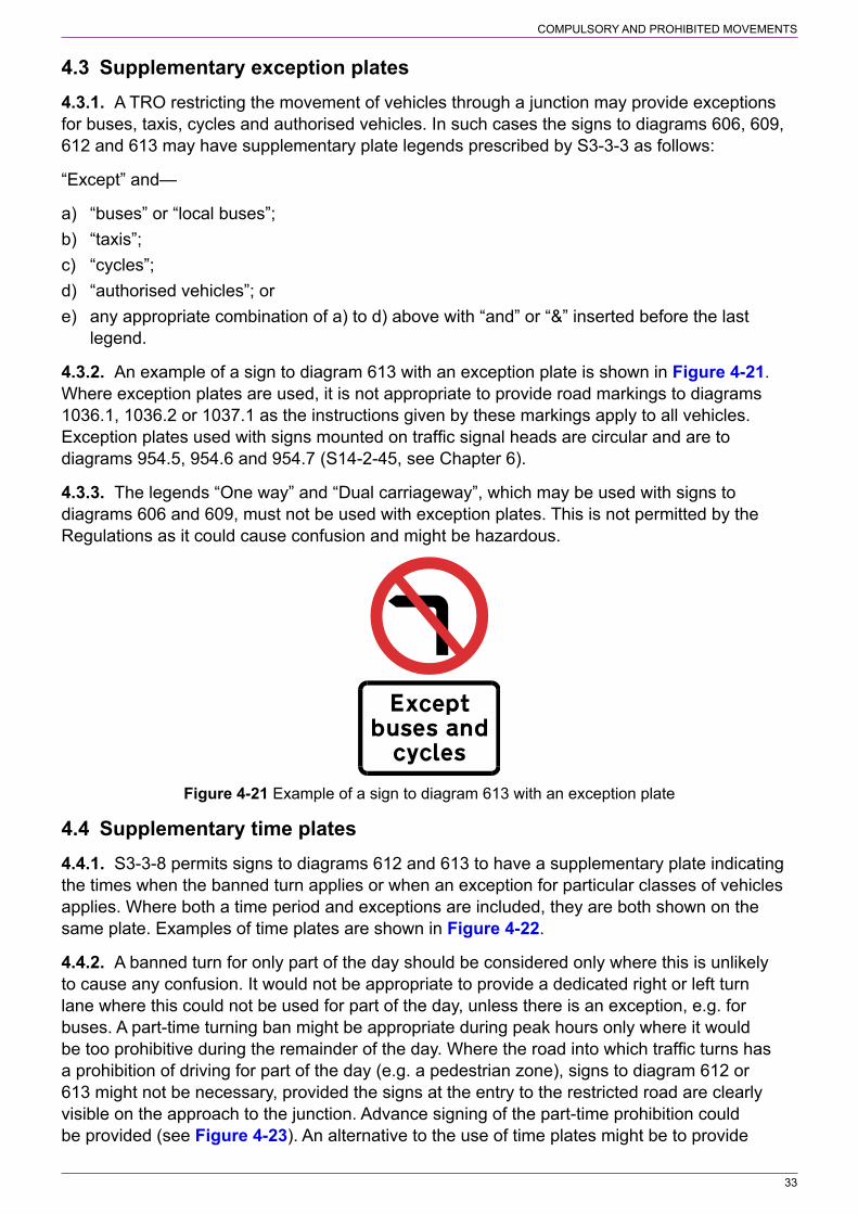
4.3.2. An example of a sign to diagram 613 with an exception plate is shown in Figure 4‑21. Where exception plates are used, it is not appropriate to provide road markings to diagrams 1036.1, 1036.2 or 1037.1 as the instructions given by these markings apply to all vehicles. Exception plates used with signs mounted on traffic signal heads are circular and are to diagrams 954.5, 954.6 and 954.7 (S14‑2‑45, see Chapter 6).
4.3.3. The legends “One way” and “Dual carriageway”, which may be used with signs to diagrams 606 and 609, must not be used with exception plates. This is not permitted by the Regulations as it could cause confusion and might be hazardous.
Figure 4‑21 Example of a sign to diagram 613 with an exception plate
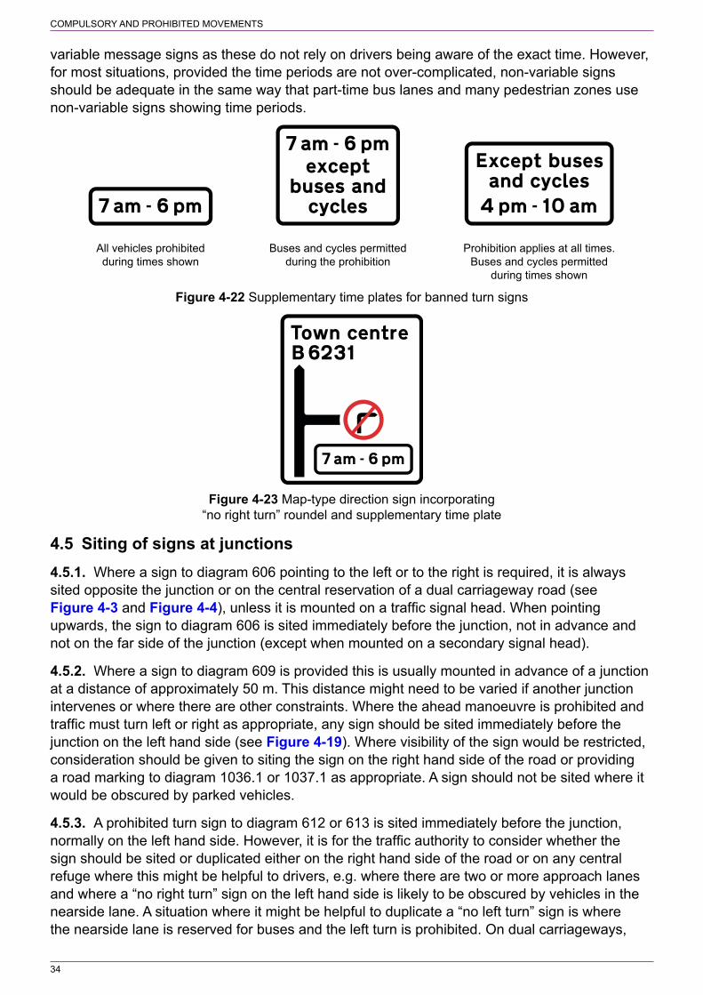
4.4 Supplementary time plates4.4.1. S3‑3‑8 permits signs to diagrams 612 and 613 to have a supplementary plate indicating the times when the banned turn applies or when an exception for particular classes of vehicles applies. Where both a time period and exceptions are included, they are both shown on the same plate. Examples of time plates are shown in Figure 4‑22.
4.4.2. A banned turn for only part of the day should be considered only where this is unlikely to cause any confusion. It would not be appropriate to provide a dedicated right or left turn lane where this could not be used for part of the day, unless there is an exception, e.g. for buses. A part‑time turning ban might be appropriate during peak hours only where it would be too prohibitive during the remainder of the day. Where the road into which traffic turns has a prohibition of driving for part of the day (e.g. a pedestrian zone), signs to diagram 612 or 613 might not be necessary, provided the signs at the entry to the restricted road are clearly visible on the approach to the junction. Advance signing of the part‑time prohibition could be provided (see Figure 4‑23). An alternative to the use of time plates might be to provide
COMPULSORY AND PROHIBITED MOVEMENTS
34
variable message signs as these do not rely on drivers being aware of the exact time. However, for most situations, provided the time periods are not over‑complicated, non‑variable signs should be adequate in the same way that part‑time bus lanes and many pedestrian zones use non‑variable signs showing time periods.
Buses and cycles permittedduring the prohibition
Prohibition applies at all times.Buses and cycles permitted
during times shown
All vehicles prohibitedduring times shown
Figure 4‑22 Supplementary time plates for banned turn signs
Figure 4‑23 Map‑type direction sign incorporating “no right turn” roundel and supplementary time plate
4.5 Siting of signs at junctions4.5.1. Where a sign to diagram 606 pointing to the left or to the right is required, it is always sited opposite the junction or on the central reservation of a dual carriageway road (see Figure 4‑3 and Figure 4‑4), unless it is mounted on a traffic signal head. When pointing upwards, the sign to diagram 606 is sited immediately before the junction, not in advance and not on the far side of the junction (except when mounted on a secondary signal head).
4.5.2. Where a sign to diagram 609 is provided this is usually mounted in advance of a junction at a distance of approximately 50 m. This distance might need to be varied if another junction intervenes or where there are other constraints. Where the ahead manoeuvre is prohibited and traffic must turn left or right as appropriate, any sign should be sited immediately before the junction on the left hand side (see Figure 4‑19). Where visibility of the sign would be restricted, consideration should be given to siting the sign on the right hand side of the road or providing a road marking to diagram 1036.1 or 1037.1 as appropriate. A sign should not be sited where it would be obscured by parked vehicles.
4.5.3. A prohibited turn sign to diagram 612 or 613 is sited immediately before the junction, normally on the left hand side. However, it is for the traffic authority to consider whether the sign should be sited or duplicated either on the right hand side of the road or on any central refuge where this might be helpful to drivers, e.g. where there are two or more approach lanes and where a “no right turn” sign on the left hand side is likely to be obscured by vehicles in the nearside lane. A situation where it might be helpful to duplicate a “no left turn” sign is where the nearside lane is reserved for buses and the left turn is prohibited. On dual carriageways,

COMPULSORY AND PROHIBITED MOVEMENTS
35
consideration could be given to mounting signs on both the left hand side and the central reservation. Generally, duplication of signs should be avoided where this would provide unnecessary sign clutter with little benefit to road users. A single sign at the junction will normally be adequate where the banned turn is indicated on an advance direction sign. At a signal‑controlled junction the sign should be mounted on the primary and secondary signal heads (see Chapter 6).
4.5.4. The prescribed sign sizes of 270 and 300 mm for diagrams 606, 612 and 613 in S3‑2 are intended for use in traffic bollards. Signs for use on traffic signal heads are prescribed in Schedule 14 (see Chapter 6). A sign mounted on a bollard might be suitable where traffic calming has been introduced or in a pedestrian zone where vehicles are permitted to enter (see section 6), with the aim of reducing sign clutter in environmentally sensitive areas. Where bollards are used, they should be sited so that they can be clearly seen and drivers are fully aware of the mandatory requirements. Where supplementary plates are required, the larger post‑mounted signs should be used.
4.6 Roundabouts4.6.1. The sign to diagram 606 pointing to the left may be used without a TRO on central islands of roundabouts, where it is normally accompanied by the deviation of route sign to diagram 515 (S2‑6‑3, see Chapter 4). There is no requirement to place diagram 515 on a roundabout only in combination with diagram 606. Traffic authorities therefore need to consider the appropriate level of signing. However, should diagram 515 be used on its own, section 36 of the Road Traffic Act 1988 would not apply to a driver navigating the roundabout in an anti‑clockwise direction (see 1.2.6). On very small roundabouts, other than mini‑roundabouts, the sign to diagram 606 may be mounted in a traffic bollard, in which case it will normally have a diameter of 270 or 300 mm.
4.6.2. A sign to diagram 611.1 (S9‑2‑6, see Figure 4‑24) is used at mini‑roundabouts and requires that vehicles entering a junction marked with diagram 1003.4 (S9‑6‑5) must give priority to vehicles from the right at the transverse broken line to diagram 1003.3 (S9‑6‑6, see also 4.6.5). If the transverse line is temporarily not visible, e.g. because of road works, priority must be given to traffic from the right at the road junction. The provision of this sign does not require a TRO. “Turn left” signs to diagram 606 are not used at mini‑roundabouts.
Figure 4‑24 Diagram 611.1 (S9‑2‑6) Mini‑roundabout
4.6.3. The sign to diagram 611.1 should be placed on the left hand side of each approach to a mini‑roundabout junction, in the correct orientation as shown in the diagram, at a distance of approximately 1.5 m before the transverse line. This might have to be increased if the sign would not otherwise be clearly visible, but to no more than 12 m. The sign may be duplicated on a traffic island in the middle of the road where the traffic authority considers that this would be helpful to drivers without adding to unnecessary sign clutter. To avoid misleading drivers, care should be taken when siting signs at a double mini‑roundabout to ensure that the signs for each roundabout are not too close to each other. Advance warning of the roundabout may be given by the sign to diagram 510 (S2‑2‑7, see Chapter 4) or by an advance direction sign incorporating the route symbol shown in S12‑7‑4.
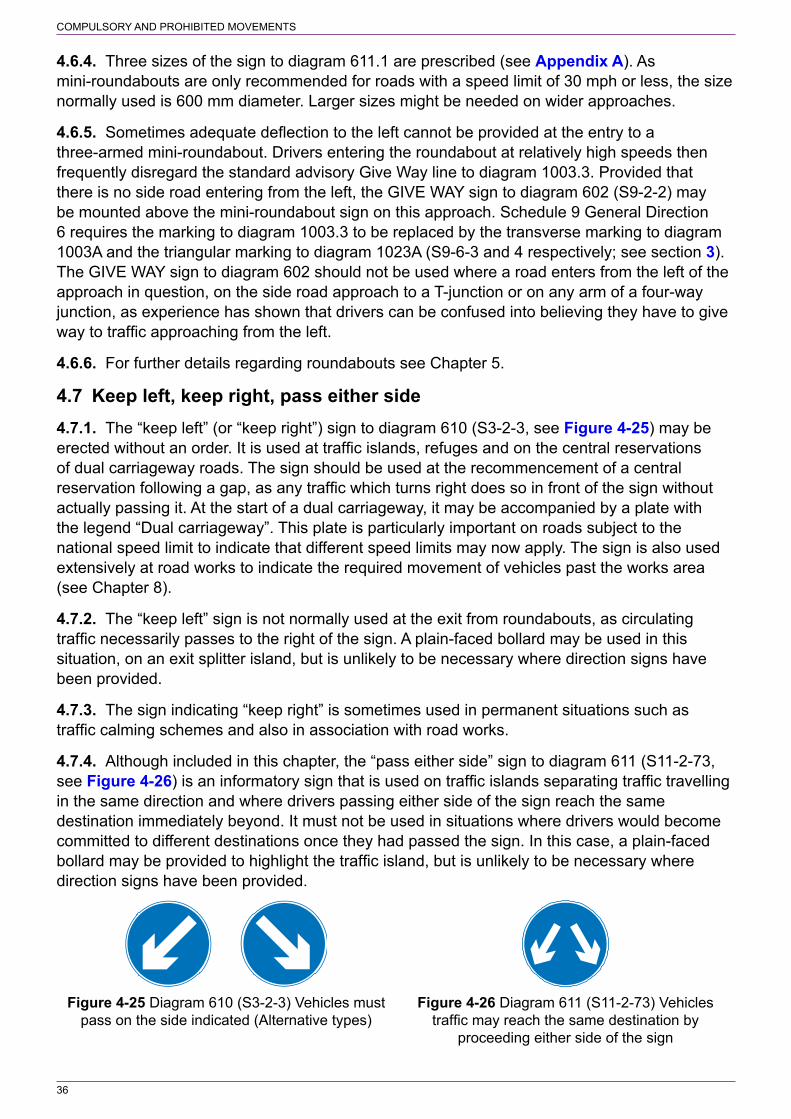
COMPULSORY AND PROHIBITED MOVEMENTS
36
4.6.4. Three sizes of the sign to diagram 611.1 are prescribed (see Appendix A). As mini‑roundabouts are only recommended for roads with a speed limit of 30 mph or less, the size normally used is 600 mm diameter. Larger sizes might be needed on wider approaches.
4.6.5. Sometimes adequate deflection to the left cannot be provided at the entry to a three‑armed mini‑roundabout. Drivers entering the roundabout at relatively high speeds then frequently disregard the standard advisory Give Way line to diagram 1003.3. Provided that there is no side road entering from the left, the GIVE WAY sign to diagram 602 (S9‑2‑2) may be mounted above the mini‑roundabout sign on this approach. Schedule 9 General Direction 6 requires the marking to diagram 1003.3 to be replaced by the transverse marking to diagram 1003A and the triangular marking to diagram 1023A (S9‑6‑3 and 4 respectively; see section 3). The GIVE WAY sign to diagram 602 should not be used where a road enters from the left of the approach in question, on the side road approach to a T‑junction or on any arm of a four‑way junction, as experience has shown that drivers can be confused into believing they have to give way to traffic approaching from the left.
4.6.6. For further details regarding roundabouts see Chapter 5.
4.7 Keep left, keep right, pass either side4.7.1. The “keep left” (or “keep right”) sign to diagram 610 (S3‑2‑3, see Figure 4‑25) may be erected without an order. It is used at traffic islands, refuges and on the central reservations of dual carriageway roads. The sign should be used at the recommencement of a central reservation following a gap, as any traffic which turns right does so in front of the sign without actually passing it. At the start of a dual carriageway, it may be accompanied by a plate with the legend “Dual carriageway”. This plate is particularly important on roads subject to the national speed limit to indicate that different speed limits may now apply. The sign is also used extensively at road works to indicate the required movement of vehicles past the works area (see Chapter 8).
4.7.2. The “keep left” sign is not normally used at the exit from roundabouts, as circulating traffic necessarily passes to the right of the sign. A plain‑faced bollard may be used in this situation, on an exit splitter island, but is unlikely to be necessary where direction signs have been provided.
4.7.3. The sign indicating “keep right” is sometimes used in permanent situations such as traffic calming schemes and also in association with road works.
4.7.4. Although included in this chapter, the “pass either side” sign to diagram 611 (S11‑2‑73, see Figure 4‑26) is an informatory sign that is used on traffic islands separating traffic travelling in the same direction and where drivers passing either side of the sign reach the same destination immediately beyond. It must not be used in situations where drivers would become committed to different destinations once they had passed the sign. In this case, a plain‑faced bollard may be provided to highlight the traffic island, but is unlikely to be necessary where direction signs have been provided.
Figure 4‑25 Diagram 610 (S3‑2‑3) Vehicles must Figure 4‑26 Diagram 611 (S11‑2‑73) Vehicles pass on the side indicated (Alternative types) traffic may reach the same destination by proceeding either side of the sign
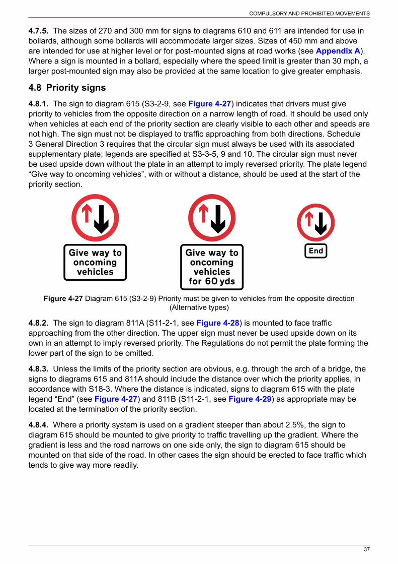
COMPULSORY AND PROHIBITED MOVEMENTS
37
4.7.5. The sizes of 270 and 300 mm for signs to diagrams 610 and 611 are intended for use in bollards, although some bollards will accommodate larger sizes. Sizes of 450 mm and above are intended for use at higher level or for post‑mounted signs at road works (see Appendix A). Where a sign is mounted in a bollard, especially where the speed limit is greater than 30 mph, a larger post‑mounted sign may also be provided at the same location to give greater emphasis.
4.8 Priority signs4.8.1. The sign to diagram 615 (S3‑2‑9, see Figure 4‑27) indicates that drivers must give priority to vehicles from the opposite direction on a narrow length of road. It should be used only when vehicles at each end of the priority section are clearly visible to each other and speeds are not high. The sign must not be displayed to traffic approaching from both directions. Schedule 3 General Direction 3 requires that the circular sign must always be used with its associated supplementary plate; legends are specified at S3‑3‑5, 9 and 10. The circular sign must never be used upside down without the plate in an attempt to imply reversed priority. The plate legend “Give way to oncoming vehicles”, with or without a distance, should be used at the start of the priority section.
Figure 4‑27 Diagram 615 (S3‑2‑9) Priority must be given to vehicles from the opposite direction (Alternative types)
4.8.2. The sign to diagram 811A (S11‑2‑1, see Figure 4‑28) is mounted to face traffic approaching from the other direction. The upper sign must never be used upside down on its own in an attempt to imply reversed priority. The Regulations do not permit the plate forming the lower part of the sign to be omitted.
4.8.3. Unless the limits of the priority section are obvious, e.g. through the arch of a bridge, the signs to diagrams 615 and 811A should include the distance over which the priority applies, in accordance with S18‑3. Where the distance is indicated, signs to diagram 615 with the plate legend “End” (see Figure 4‑27) and 811B (S11‑2‑1, see Figure 4‑29) as appropriate may be located at the termination of the priority section.
4.8.4. Where a priority system is used on a gradient steeper than about 2.5%, the sign to diagram 615 should be mounted to give priority to traffic travelling up the gradient. Where the gradient is less and the road narrows on one side only, the sign to diagram 615 should be mounted on that side of the road. In other cases the sign should be erected to face traffic which tends to give way more readily.

COMPULSORY AND PROHIBITED MOVEMENTS
38
Figure 4‑28 Diagram 811A (S11‑2‑1) Beginning of Figure 4‑29 Diagram 811B (S11‑2‑1) End section of road where traffic has priority over vehicles of section of road where traffic has priority from the opposite direction (Alternative types) over vehicles from the opposite direction
4.8.5. To give greater emphasis to the sign to diagram 615 and to indicate the place at which vehicles should wait, the Give Way line to diagram 1003A (S9‑6‑3) may be used. The marking to diagram 1023A (S9‑6‑4) may also be provided, but not the upright sign to diagram 602 (S9‑2‑2), which is prescribed for use only at junctions or level crossings. When used in conjunction with a Give Way line, the sign to diagram 615 should normally be sited about 1.5 m before the marking. A longitudinal warning line to diagram 1004 or 1004.1 (S11‑4‑2 and 3 respectively; see Chapter 5) should be used on the approach to the narrow section as far as the Give Way line, discontinued through the hazard and recommenced where an adequate two‑way width is regained. Under no circumstances should a Give Way line be provided at the opposite end of the narrow section where traffic has priority.
4.8.6. Where the width of the priority section is not greater than 4.5 m at its narrowest point, a yellow box to diagram 1043 (S9‑6‑25) may be used to prevent vehicles from queuing back into the section and obstructing the flow from the opposite direction (see Chapter 5). This is appropriate only where queues are likely to form, for example near a junction, beyond the priority section.
4.9 One‑way roads4.9.1. The “one‑way traffic” sign to diagram 652 (S9‑4‑5, see Figure 4‑30) may be used only to indicate the effect of a TRO which requires vehicles to proceed in one direction only. It should not be used to sign traffic along one carriageway of a dual carriageway road. However, where a rural dual carriageway comprises two one‑way roads (i.e. where there is non‑highway land between the two carriageways) each carriageway should be subject to a one‑way traffic order and signs to diagram 652 provided accordingly. The ahead arrow road marking to diagram 1038 (S11‑4‑20, see Chapter 5) may be used in conjunction with the “one‑way traffic” sign.
4.9.2. A sign to diagram 652 should normally be erected on either the left or right hand side of the carriageway at the point of entry to a one‑way road. The sign should be carefully sited to avoid possible confusion over which road it applies to. When the one‑way road forms a junction with the side of another road, the sign should be sited in line with the backline of the major road, although it may be placed a short distance into the one‑way road if this enables advantage to be taken of a convenient mounting point such as a lighting column. It may be desirable to orientate the sign to suit the direction of approaching traffic. It is for the traffic authority to determine whether a duplicate sign on the opposite side of the road would be beneficial without adding to unnecessary sign clutter. Note that if a sign is mounted within 50 m of a junction from which

COMPULSORY AND PROHIBITED MOVEMENTS
39
traffic may turn and approach that sign, it must be illuminated by internal or external lighting if the road is lit and the speed limit is greater than 20 mph (S9‑8‑7). This also applies to junctions within the one‑way road. Direct lighting of the signs in these circumstances ensures that drivers can see the signs at night where the headlamps of turning vehicles are unlikely to provide sufficient illumination from retroreflection.
4.9.3. Repeater signs to diagram 652 should be erected so that signs are generally placed alternately on each side of the road. The distance between consecutive signs on alternate sides of the road should not normally exceed 100 m. When a side road enables traffic to enter a one‑way road, a repeater sign should be erected on the main road to face traffic within 50 m of the entry point, unless a sign to diagram 606 with a “One way” plate (S3‑2‑1) has been provided. Where the signs are used on a rural dual carriageway comprising two one‑way roads, it is recommended that signs are normally mounted in pairs, with consecutive pairs being approximately 400 m apart. This reminds drivers that, with care, it should be safe to overtake on a road that otherwise takes on the appearance of a single two‑way road.
4.9.4. The ONE WAY sign to diagram 810 (S11‑2‑2, see Figure 4‑31) is an informatory sign for pedestrians. It should be used at locations where pedestrians regularly cross the road, particularly where traffic is approaching from the left. It must never be used in place of diagram 606 (S3‑2‑1) when aimed at vehicular traffic. At pedestrian crossing points the LOOK LEFT or LOOK RIGHT road marking to diagram 1029 (S11‑4‑18) may be used (see Chapter 5).
Figure 4‑30 Diagram 652 (S9‑4‑5) Figure 4‑31 Diagram 810 (S11‑2‑2) One‑way traffic One‑way traffic in direction indicated (Sign for pedestrians) (Alternative types)
4.9.5. The point where entry is prohibited into a one‑way road is indicated by the “no entry” sign to diagram 616 (S3‑2‑10, see Figure 4‑32). There is no specific requirement to provide two signs. However, the traffic authority should take care to ensure that a single sign is clearly visible to road users and does not give rise to issues relating to road safety or enforcement. There might be situations where a pair of signs might be preferable, particularly where there is the possibility of drivers misunderstanding which road a single sign applies to. When the one‑way road forms a junction with the side of another road, the “no entry” sign or signs should be sited in line with the backline of the major road. A sign should be clearly visible at all times to traffic approaching from any permitted direction; this might require it to be angled slightly.
4.9.6. A pair of signs is unlikely to be necessary where the carriageway of the one‑way road is relatively narrow, e.g. less than 5 m wide. A single sign, sited no more than 2 m from the carriageway edge, should be sufficient provided that it can be readily seen by all drivers who might otherwise attempt to enter the prohibited road. A single sign might also be sufficient where the main route through the junction is one‑way, regardless of the width of the side road to which the “no entry” prohibition applies. In this case the sign should be placed on the far side of the prohibited road when viewed from the direction of travel on the main route.
4.9.7. The upright “no entry” sign may be supplemented by the “NO ENTRY” road marking to diagram 1046 (S9‑6‑17, see Figure 4‑33). The legend may be laid in a single line or in two lines depending on the carriageway or lane width available. Two sizes are prescribed; the

COMPULSORY AND PROHIBITED MOVEMENTS
40
smaller size will be appropriate for most situations. The larger size might be used where greater emphasis is required. Circumstances in which the marking might be helpful include junctions where:
a) the ahead movement is prohibited. The marking should be placed on the main carriageway side of the Give Way or Stop line.
b) it may be difficult to see the upright signs, e.g. because of obscuration by stationary vehicles. The supplementary carriageway markings should help alert drivers before they become committed to the manoeuvre.
c) to supplement a single upright “no entry” sign, particularly where there is a contraflow cycle lane (see section 11).
Marking “NO ENTRY” on the carriageway should help to reduce the risk of inadvertent non‑compliance.
Figure 4‑32 Diagram 616 (S3‑2‑10) Figure 4‑33 Diagram 1046 (S9‑6‑17) No entry No entry for vehicular traffic for vehicular traffic (Alternative types)
4.9.8. Where a one‑way street order has an exception for buses or cycles, e.g. to introduce a contraflow bus or cycle lane, the sign to diagram 616 may be used with a supplementary plate. Prescribed legends are:
“Except” and—a) “buses” or “local buses”;b) “cycles”;c) “buses and cycles” or “buses & cycles”; ord) “local buses and cycles” or “local buses & cycles”.
For further details on contraflow bus lanes and contraflow cycle facilities see sections 9 and 11. In addition to the above, the plate legend “Except trams” is prescribed. This is for use where the route is for the exclusive use of tramcars. It might be a contraflow tramway in a one‑way road, a section of two‑way tram‑only road or the entrance to an off‑road tramway. For further details see section 10.
4.9.9. Where a traffic bollard is situated at the exit from a one‑way road, it may be fitted with a 270 or 300 mm diameter “no entry” sign to stop vehicles entering from the opposite direction. This sign should normally be used in addition to the larger signs, but might be suitable on its own, e.g. where roads are narrow, vehicle speeds are low or where traffic calming has been introduced. The “no entry” symbol (S12‑20‑21) may also be incorporated into map‑type advance direction signs.
4.10 No entry signs (other than one‑way roads)4.10.1. “No entry” signs now require a traffic order in all circumstances when erected for the first time (see S3‑5‑1). However, any such signs erected without an order, but with national authority approval under previous regulations, continue to be enforceable. Signs might be useful in guiding drivers at channelising traffic islands when approaching a roundabout or turning

COMPULSORY AND PROHIBITED MOVEMENTS
41
right into a side road, although in most situations a “keep left” sign to diagram 610 (S3‑2‑3) should be sufficient. “No entry” signs might also be considered where there is likely to be the risk of traffic entering the wrong carriageway of a dual carriageway road or travelling in the wrong direction along a slip road, but only where there is a genuine risk of confusion. “No entry” signs are unlikely to be justified where an acceleration lane is provided for traffic joining a dual carriageway road. Superfluous signing is not only unnecessary, it is unsightly and can distract or confuse drivers on the opposite carriageway.
4.10.2. At a junction with a dual carriageway where there is no gap in the central reservation (i.e. all traffic from the side road turns left), diagram 606 (S3‑2‑1) should be sufficient without the need for “no entry” signs (see Figure 4‑5 and 4.2.3). Where there is a gap in the central reservation and traffic can turn right into the dual carriageway from the side road, “no entry” signs might be beneficial to deter drivers from turning into the wrong carriageway, particularly in areas prone to adverse weather conditions such as fog. Where the junction is controlled by traffic signals, the signs would usually not be necessary. See 4.2.3 in respect of “no entry” signs preventing vehicles from entering the gap in the central reservation of a dual carriageway.
4.10.3. The “NO ENTRY” road marking to diagram 1046 may be used in the situations described above, with or without associated upright “no entry” signs, subject to the requirement that it is backed by a TRO.
4.10.4. “No entry” signs may also be used to indicate two‑way bus‑only roads and be used in conjunction with the road marking “BUS GATE” (diagram 1048.5). For further details see section 9.
4.11 No U‑turns4.11.1. The “no U‑turn” sign to diagram 614 (S3‑2‑6, see Figure 4‑34) is used to give effect to an order which may apply to a junction or a length of road. At junctions not controlled by signals, the sign should be mounted on the central refuge or reservation as close as practicable to the junction to face traffic approaching from the direction the prohibition applies to. Where there is no central island, the sign should normally be mounted on the left hand side of the road. However, where the sign might be obscured and to ensure that drivers are aware of the prohibition, the traffic authority should consider whether the sign should be sited or duplicated on the right hand side of the road. For signalled junctions see Chapter 6. Advance warning of the prohibition may be given on a sign to diagram 2010.1 or 2123 (S12‑28‑5 and 6 respectively, see Figure 4‑13 and Figure 4‑14), with the “no right turn” symbol varied to the “no U‑turn” symbol (S12‑20‑20).
Figure 4‑34 Diagram 614 (S3‑2‑6) No U‑turns for vehicular traffic (Alternative types)
4.11.2. Where the prohibition applies to a gap in the central reservation on a dual carriageway road, it is recommended that a sign of the size appropriate to the speed of traffic is erected on both sides of the carriageway just before the gap (see Appendix A). Where traffic speeds are low, a single sign on the central reservation should be sufficient.

COMPULSORY AND PROHIBITED MOVEMENTS
42
4.11.3. Where the prohibition applies to a length of single carriageway road, the start should be signed using a sign to diagram 614 with a supplementary plate indicating the distance over which the prohibition applies (see Figure 4‑34). A sign and distance plate should also be erected within 50 m of each point of entry from a side road so that drivers turning into the major road are aware of the restriction. Although there is no specific requirement to provide repeater signs, they might be needed, without a distance plate, to ensure that drivers are reminded of the U‑turning prohibition. It is recommended that, where practicable, repeater signs are provided at intervals of about 100 m. Unlike speed limit and rural clearway signs, the repeater signs should be the full size appropriate to the speed of traffic (see Appendix A). At the end of the restriction, the sign to diagram 614 and a supplementary plate with the legend “End” should be provided (see Figure 4‑34). Depending on the local traffic conditions and road layout, a single sign or a pair of signs should be provided at the start and end of the restriction, making use of any central refuge; it is for the traffic authority to determine the appropriate level of signing for a particular road. On dual carriageway roads it is likely to be more appropriate to sign each individual gap rather than a length of road with start, end and repeater signs.
4.11.4. Where a traffic bollard is situated on a central refuge or reservation, it may be fitted with a 270 or 300 mm diameter “no U‑turn” sign as an alternative to using the larger post‑mounted sign. This might be suitable where roads are narrow, vehicle speeds are low, where traffic calming has been introduced or in a pedestrian zone where vehicles are permitted to enter (see section 6).
4.12 No overtaking4.12.1. The sign to diagram 632 (S3‑2‑5, see Figure 4‑35) is used to give effect to an order which prohibits overtaking. Such orders will be exceptional as situations where forward visibility makes overtaking hazardous can normally be dealt with by double white lines (see Chapter 5). “No overtaking” signs must not be used along the same length of road as double white lines. Situations where an order might be appropriate include:
a) roads which are less than 6.1 m wide, thereby making double white lines impracticable (see Chapter 5), and
b) roads along which the stopping restrictions imposed by double white lines would not be acceptable.
4.12.2. “No overtaking” signs might also be used at road works, where a temporary order will be required (see Chapter 8). Where a road is prone to ice or snowdrifts during most winters, an order can be made to prohibit overtaking when traffic signs are displayed. In this case the sign to diagram 632 should include a plate legend “Ice”, “Ice for” and a distance, “Snowdrifts” or “Snowdrifts” and a distance (see Chapter 4).
Figure 4‑35 Diagram 632 (S3‑2‑5) No overtaking (Alternative types)
4.12.3. At the start of the affected length, it is recommended that a “no overtaking” sign with a plate legend “For” and a distance should normally be erected on each side of the road (the off side sign should be located on a central refuge where one is provided). However, there is no

COMPULSORY AND PROHIBITED MOVEMENTS
43
specific requirement to provide two signs. Where a single sign is provided, care should be taken to ensure that it is sited where it can clearly be seen by approaching drivers. At least one sign to diagram 632 with a plate legend “End” should be placed where the restriction ends. Appropriate sign and plate sizes are specified in Appendix A.
4.12.4. Although there is no specific requirement to provide repeater signs, they might be needed, without a distance plate, to ensure that drivers are reminded of the overtaking prohibition. In order that road safety is not compromised, it is recommended that, where practicable, repeater signs are provided at intervals of about 400 m. Where a side road enables traffic to enter part way along a section of road where overtaking is prohibited, it is recommended that signs and plates are erected on both sides of the major road within 50 m either side of the junction so that they can be seen by drivers turning right or left from the side road. Unlike speed limit and rural clearway signs, the repeater signs should be the full size appropriate to the speed of traffic (see Appendix A).

44
5 PROHIBITION OF TRAFFIC
5.1 General5.1.1. This section describes the group of signs that prohibit traffic or categories of traffic (including pedestrians) from certain roads. It includes signs that prohibit vehicles because of their weight or size. Except where stated otherwise, the signs may be used only to give effect to a TRO etc. Signs relating to pedestrian zones are in section 6. See Appendix A for sizes of signs and supplementary plates and 5.17.1 for the siting of signs.
5.1.2. It is important to address the directional signing changes needed when a regulatory measure prevents some or all traffic from following the previously signed route. This could apply to pedestrian zones or bus gates, as well as to the restrictions covered in this section. When width, height, length or weight limit signs are used, it is important that the alternative route is clearly signed not only at the start of the diversion but also at the last place where a vehicle can divert, even though this might not be the preferred diversion route. Signing should be continued at junctions along its entire length, using directional signs including where appropriate “avoiding” or “alternative route for” legends in accordance with S12‑3‑2 as shown in Figure 5‑1 (see also Chapter 7). In some cases it might be more appropriate to sign advisory lorry routes using signs, also prescribed by Schedule 12 as shown in Figure 5‑2.
Figure 5‑1 Example of an advance direction sign Figure 5‑2 Example of an advance indicating a height restriction ahead with an direction sign indicating a route advised alternative route to the left (Sign on a primary route) for goods vehicles
5.1.3. Advance warning of certain restrictions may be given by incorporating the prohibitory sign into direction signs or advance direction signs as shown in Figure 5‑1 (see also Chapter 7). These are not a substitute for the terminal signs that indicate the start of the restriction. Unless the restriction begins at the junction, either on the main road or on the side road, a distance plate should be included so that drivers can judge whether they can reach a particular property or destination before reaching the restriction. Exception plates may be included on these signs in accordance with S12‑20‑45. The restrictions that may be signed in this way are shown in S12‑20 and are:
a) Item 22; No vehicles (diagram 617, S3‑2‑11, see Figure 5‑5)b) Item 23; No motor vehicles (diagram 619, S3‑2‑12, see Figure 5‑8)c) Item 24; Environmental weight limit (diagram 622.1A, S3‑2‑13, see Figure 5‑13)d) Item 25; Structural weight limit (roundel only from diagram 626.2A, S9‑4‑2, see Figure 5‑25)e) Item 26; No vehicles carrying explosives (diagram 622.8, S3‑2‑16, see Figure 5‑19)

PROHIBITION OF TRAFFIC
45
f) Item 27; Vehicles carrying dangerous goods prohibited from proceeding through tunnel (diagram 622.10, S9‑4‑3, see Figure 5‑20)
g) Item 28; No buses (diagram 952, S3‑2‑17, see Figure 5‑12)h) Item 29; No motor vehicles except solo motor cycles (diagram 619.1, S3‑2‑18, see
Figure 5‑9)i) Item 30; No towed caravans (diagram 622.7, S3‑2‑19, see Figure 5‑18)j) Item 31; No solo motor cycles (diagram 619.2, S3‑2‑20, see Figure 5‑10)k) Item 32; No horse‑drawn vehicles (diagram 622.5, S3‑2‑23, see Figure 5‑16)l) Item 33; Length limit (diagram 629.1, S3‑2‑25, see Figure 5‑27)m) Item 34; Width limit (diagram 629A, S3‑2‑26, see Figure 5‑26)n) Item 35; Height limit (diagram 629.2A, S3‑2‑27, see Figure 5‑28).
5.1.4. An alternative to incorporating a prohibitory roundel into a conventional directional sign is to use a sign to diagram 818.4 (S12‑28‑22, see Figure 5‑3). In many cases this can reduce the overall size of an advance direction sign as shown in Figure 5‑4 and should be considered where sign overload is likely to occur. The sign may or may not indicate an alternative route. The working drawing for diagram 818.4 shows many of the variations, including the addition of distance and arrow.
Figure 5‑3 Diagram 818.4 (S12‑28‑22) Nature and location of a prohibition (Alternative types)
Simple sign: This can be very large andmight be difficult to site where there is
limited verge width
Two signs: These can provide a more compactarrangement. The sign to diagram 818.4 should be sitedupstream of the advance direction sign for the junction
Figure 5‑4 Alternative methods of indicating a restriction on a road at a junction ahead
5.2 All vehicles prohibited and Play Street5.2.1. The sign to diagram 617 (S3‑2‑11, see Figure 5‑5) prohibits all vehicles including ridden pedal cycles and horse‑drawn vehicles. Normally it is used either for Play Streets (where vehicles are admitted only for access) or for shopping streets closed to vehicles and
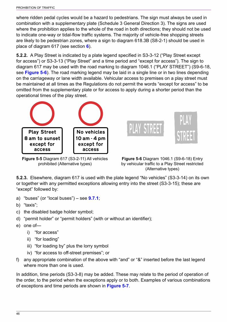
PROHIBITION OF TRAFFIC
46
where ridden pedal cycles would be a hazard to pedestrians. The sign must always be used in combination with a supplementary plate (Schedule 3 General Direction 3). The signs are used where the prohibition applies to the whole of the road in both directions; they should not be used to indicate one‑way or tidal‑flow traffic systems. The majority of vehicle‑free shopping streets are likely to be pedestrian zones, where a sign to diagram 618.3B (S8‑2‑1) should be used in place of diagram 617 (see section 6).
5.2.2. A Play Street is indicated by a plate legend specified in S3‑3‑12 (“Play Street except for access”) or S3‑3‑13 (“Play Street” and a time period and “except for access”). The sign to diagram 617 may be used with the road marking to diagram 1046.1 (“PLAY STREET”) (S9‑6‑18, see Figure 5‑6). The road marking legend may be laid in a single line or in two lines depending on the carriageway or lane width available. Vehicular access to premises on a play street must be maintained at all times as the Regulations do not permit the words “except for access” to be omitted from the supplementary plate or for access to apply during a shorter period than the operational times of the play street.
Figure 5‑5 Diagram 617 (S3‑2‑11) All vehicles Figure 5‑6 Diagram 1046.1 (S9‑6‑18) Entry prohibited (Alternative types) by vehicular traffic to a Play Street restricted (Alternative types)
5.2.3. Elsewhere, diagram 617 is used with the plate legend “No vehicles” (S3‑3‑14) on its own or together with any permitted exceptions allowing entry into the street (S3‑3‑15); these are “except” followed by:
a) “buses” (or “local buses”) – see 9.7.1;b) “taxis”;c) the disabled badge holder symbol;d) “permit holder” or “permit holders” (with or without an identifier);e) one of—
i) “for access”ii) “for loading”iii) “for loading by” plus the lorry symboliv) “for access to off‑street premises”; or
f) any appropriate combination of the above with “and” or “&” inserted before the last legend where more than one is used.
In addition, time periods (S3‑3‑8) may be added. These may relate to the period of operation of the order, to the period when the exceptions apply or to both. Examples of various combinations of exceptions and time periods are shown in Figure 5‑7.

PROHIBITION OF TRAFFIC
47
Disabled badge holdersand loading permittedduring the prohibition
All vehicles prohibitedduring times shown
Prohibition applies at alltimes. Access permitted
during times shown
Figure 5‑7 Examples of diagram 617 plate legends
5.2.4. It is unusual for the sign to diagram 617 to show only the plate legend “No vehicles”. This would be appropriate only where vehicles (including ridden cycles) are prohibited at all times and access is not permitted. Example of such roads might be a public footpath or a wide footbridge (with a level approach or ramp) that has been constructed to allow the passage of emergency or maintenance vehicles. There would need to be alternative access to any premises situated along the road. The length of road affected might be very short where a through route is stopped up part way along its length, effectively creating two culs‑de‑sac to prevent rat running. In such situations it might be possible to construct a physical barrier. A sign to diagram 617 might then not be required. If the total ban on vehicles applies during part of the day only, a time period is added to the “No vehicles” plate. Alternatively, a variable message sign could be used and the plate need only display “No vehicles”. The disadvantage of using a variable message sign is that drivers lawfully entering and parking within the street, and unfamiliar with the restrictions, might not know that they cannot drive within that street at certain times.
5.3 Prohibition of motor vehicles5.3.1. The sign to diagram 619 (S3‑2‑12, see Figure 5‑8) gives effect to an order which prohibits the use of a road by motor vehicles. Diagram 619.1 (S3‑2‑18, see Figure 5‑9) prohibits motor vehicles other than solo motor cycles, scooters or mopeds, and diagram 619.2 (S3‑2‑20, see Figure 5‑10) prohibits solo motor cycles.
5.3.2. The sign to diagram 619 is the most commonly used of the three. It is likely to be used to keep motor vehicles out of certain roads or a length of road for environmental reasons and where cyclists would not be a hazard to pedestrians. The sign should not be used to indicate one‑way or tidal‑flow traffic systems. Whilst it may be used to indicate the start of an advisory contraflow cycle lane where it is not possible to provide a traffic island, this is no longer recommended (see 11.6.4). A “no motor vehicle” restriction might be appropriate for narrow streets in villages and for shopping streets in towns and cities where full pedestrianisation is not appropriate. Where there is a need to reduce the level of unnecessary traffic in a residential street, a prohibition of motor vehicles except for access might sometimes be preferable to stopping up the road and creating a cul‑de‑sac.

PROHIBITION OF TRAFFIC
48
Figure 5‑8 Diagram 619 Figure 5‑9 Diagram 619.1 Figure 5‑10 Diagram 619.2 (S3‑2‑12) Motor vehicles (S3‑2‑18) Motor vehicles except (S3‑2‑20) Solo motor cycles prohibited solo motor cycles prohibited prohibited
5.3.3. Diagram 619.1 would be used where it was acceptable to permit solo motor cycles (i.e. without side cars) to use the road where other motor traffic is prohibited. Diagram 619.2 might be used where it is required to emphasise that solo motor cycles are not permitted to use a route that has been provided for pedestrians and cyclists.
5.3.4. A sign to diagram 619, 619.1 or 619.2, unlike the sign to diagram 617, does not have to be used with a supplementary plate. However, it is rarely desirable to deny access to premises or land adjacent to a road, so a plate legend such as “Except for access” should be used with these signs if the traffic order permits. The prescribed legends for exceptions are the same as those for diagram 617 (S3‑3‑15, see 5.2.3). The plate may indicate time periods (S3‑3‑8) where the order does not apply continuously or where the exceptions apply only at certain times. Some exceptions are not appropriate for the plate used with the sign to diagram 619.2. Examples of plate legends are shown in Figure 5‑11.
Permit holders permittedduring the prohibition
Prohibition applies at all times. Disabledbadge holders permitted at all times
and loading during times shown
All vehicles prohibitedduring times shown
Figure 5‑11 Examples of plate legends for diagrams 619, 619.1 and 619.2
5.4 Prohibition of buses5.4.1. The sign to diagram 952 (S3‑2‑17, see Figure 5‑12) is used to give effect to a prohibition of buses. For this purpose, a bus is defined in Schedule 1 as:
a) a motor vehicle constructed or adapted to carry more than 8 passengers (exclusive of the driver); or
b) a local bus.
A local bus is defined in Schedule 1 as a public service vehicle used for the provision of a local service not being an excursion or tour, where “local service” has the meaning given in section 2 of the Transport Act 1985. Note that a local bus may be designed to carry fewer than 8 passengers.
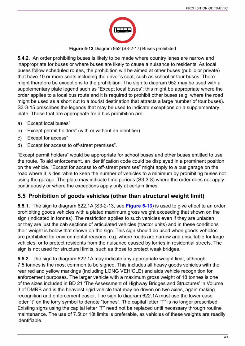
PROHIBITION OF TRAFFIC
49
Figure 5‑12 Diagram 952 (S3‑2‑17) Buses prohibited
5.4.2. An order prohibiting buses is likely to be made where country lanes are narrow and inappropriate for buses or where buses are likely to cause a nuisance to residents. As local buses follow scheduled routes, the prohibition will be aimed at other buses (public or private) that have 10 or more seats including the driver’s seat, such as school or tour buses. There might therefore be exceptions to the prohibition. The sign to diagram 952 may be used with a supplementary plate legend such as “Except local buses”; this might be appropriate where the order applies to a local bus route and it is required to prohibit other buses (e.g. where the road might be used as a short cut to a tourist destination that attracts a large number of tour buses). S3‑3‑15 prescribes the legends that may be used to indicate exceptions on a supplementary plate. Those that are appropriate for a bus prohibition are:
a) “Except local buses”b) “Except permit holders” (with or without an identifier)c) “Except for access”d) “Except for access to off‑street premises”.
“Except permit holders” would be appropriate for school buses and other buses entitled to use the route. To aid enforcement, an identification code could be displayed in a prominent position on the vehicle. “Except for access to off‑street premises” might apply to a bus garage on the road where it is desirable to keep the number of vehicles to a minimum by prohibiting buses not using the garage. The plate may indicate time periods (S3‑3‑8) where the order does not apply continuously or where the exceptions apply only at certain times.
5.5 Prohibition of goods vehicles (other than structural weight limit)5.5.1. The sign to diagram 622.1A (S3‑2‑13, see Figure 5‑13) is used to give effect to an order prohibiting goods vehicles with a plated maximum gross weight exceeding that shown on the sign (indicated in tonnes). The restriction applies to such vehicles even if they are unladen or they are just the cab sections of articulated vehicles (tractor units) and in these conditions their weight is below that shown on the sign. This sign should be used when goods vehicles are prohibited for environmental reasons, e.g. where roads are narrow and unsuitable for large vehicles, or to protect residents from the nuisance caused by lorries in residential streets. The sign is not used for structural limits, such as those to protect weak bridges.
5.5.2. The sign to diagram 622.1A may indicate any appropriate weight limit, although 7.5 tonnes is the most common to be signed. This includes all heavy goods vehicles with the rear red and yellow markings (including LONG VEHICLE) and aids vehicle recognition for enforcement purposes. The larger vehicle with a maximum gross weight of 18 tonnes is one of the sizes included in BD 21 ‘The Assessment of Highway Bridges and Structures’ in Volume 3 of DMRB and is the heaviest rigid vehicle that may be driven on two axles, again making recognition and enforcement easier. The sign to diagram 622.1A must use the lower case letter “t” on the lorry symbol to denote “tonnes”. The capital letter “T” is no longer prescribed. Existing signs using the capital letter “T” need not be replaced until necessary through routine maintenance. The use of 7.5t or 18t limits is preferable, as vehicles of these weights are readily identifiable.
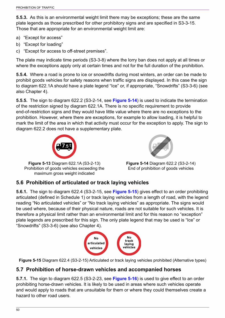
PROHIBITION OF TRAFFIC
50
5.5.3. As this is an environmental weight limit there may be exceptions; these are the same plate legends as those prescribed for other prohibitory signs and are specified in S3‑3‑15. Those that are appropriate for an environmental weight limit are:
a) “Except for access”b) “Except for loading”c) “Except for access to off‑street premises”.
The plate may indicate time periods (S3‑3‑8) where the lorry ban does not apply at all times or where the exceptions apply only at certain times and not for the full duration of the prohibition.
5.5.4. Where a road is prone to ice or snowdrifts during most winters, an order can be made to prohibit goods vehicles for safety reasons when traffic signs are displayed. In this case the sign to diagram 622.1A should have a plate legend “Ice” or, if appropriate, “Snowdrifts” (S3‑3‑6) (see also Chapter 4).
5.5.5. The sign to diagram 622.2 (S3‑2‑14, see Figure 5‑14) is used to indicate the termination of the restriction signed by diagram 622.1A. There is no specific requirement to provide end‑of‑restriction signs and they would have little value where there are no exceptions to the prohibition. However, where there are exceptions, for example to allow loading, it is helpful to mark the limit of the area in which that activity must occur for the exception to apply. The sign to diagram 622.2 does not have a supplementary plate.
Figure 5‑13 Diagram 622.1A (S3‑2‑13) Figure 5‑14 Diagram 622.2 (S3‑2‑14) Prohibition of goods vehicles exceeding the End of prohibition of goods vehicles maximum gross weight indicated
5.6 Prohibition of articulated or track laying vehicles5.6.1. The sign to diagram 622.4 (S3‑2‑15, see Figure 5‑15) gives effect to an order prohibiting articulated (defined in Schedule 1) or track laying vehicles from a length of road, with the legend reading “No articulated vehicles” or “No track laying vehicles” as appropriate. The signs would be used where, because of their physical nature, roads are not suitable for such vehicles. It is therefore a physical limit rather than an environmental limit and for this reason no “exception” plate legends are prescribed for this sign. The only plate legend that may be used is “Ice” or “Snowdrifts” (S3‑3‑6) (see also Chapter 4).
Figure 5‑15 Diagram 622.4 (S3‑2‑15) Articulated or track laying vehicles prohibited (Alternative types)
5.7 Prohibition of horse‑drawn vehicles and accompanied horses5.7.1. The sign to diagram 622.5 (S3‑2‑23, see Figure 5‑16) is used to give effect to an order prohibiting horse‑drawn vehicles. It is likely to be used in areas where such vehicles operate and would apply to roads that are unsuitable for them or where they could themselves create a hazard to other road users.
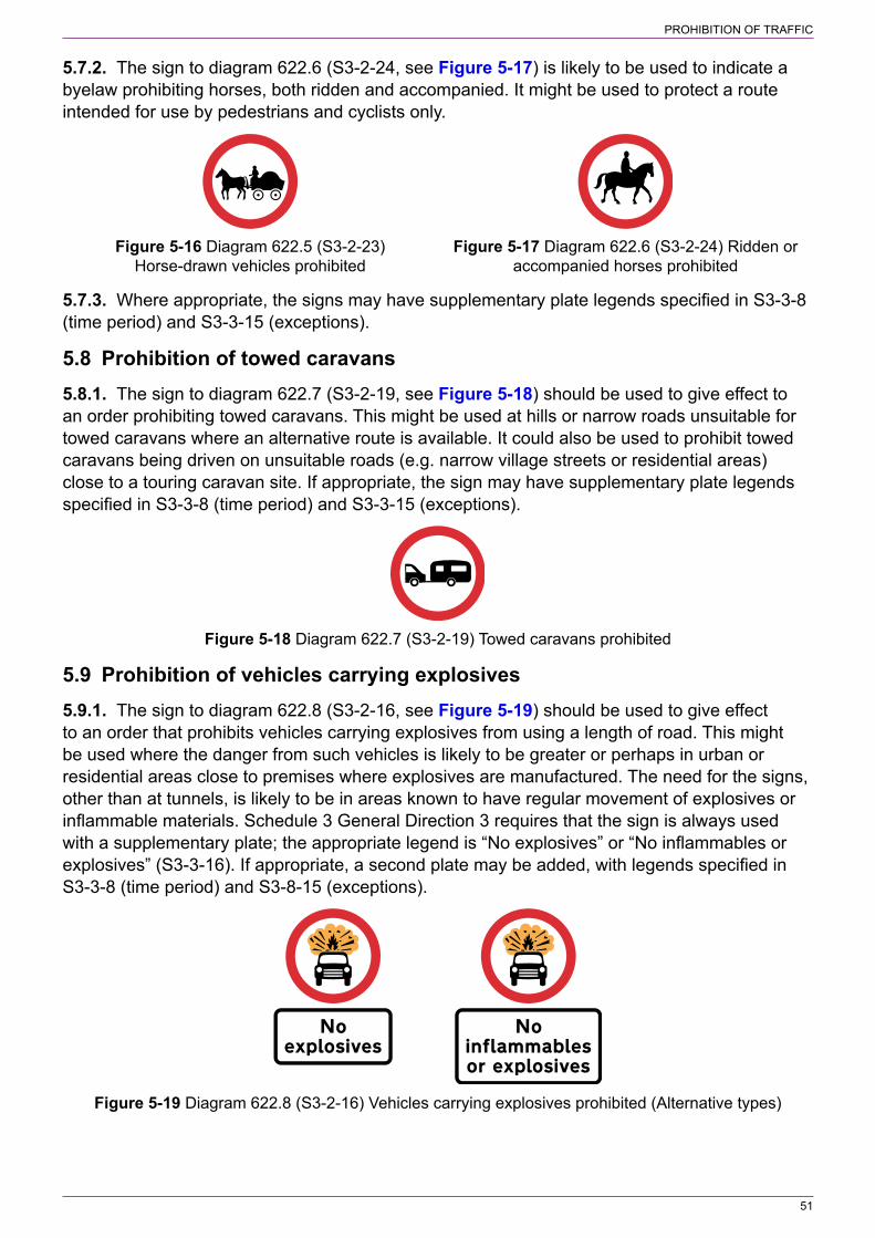
PROHIBITION OF TRAFFIC
51
5.7.2. The sign to diagram 622.6 (S3‑2‑24, see Figure 5‑17) is likely to be used to indicate a byelaw prohibiting horses, both ridden and accompanied. It might be used to protect a route intended for use by pedestrians and cyclists only.
Figure 5‑16 Diagram 622.5 (S3‑2‑23) Figure 5‑17 Diagram 622.6 (S3‑2‑24) Ridden or Horse‑drawn vehicles prohibited accompanied horses prohibited
5.7.3. Where appropriate, the signs may have supplementary plate legends specified in S3‑3‑8 (time period) and S3‑3‑15 (exceptions).
5.8 Prohibition of towed caravans5.8.1. The sign to diagram 622.7 (S3‑2‑19, see Figure 5‑18) should be used to give effect to an order prohibiting towed caravans. This might be used at hills or narrow roads unsuitable for towed caravans where an alternative route is available. It could also be used to prohibit towed caravans being driven on unsuitable roads (e.g. narrow village streets or residential areas) close to a touring caravan site. If appropriate, the sign may have supplementary plate legends specified in S3‑3‑8 (time period) and S3‑3‑15 (exceptions).
Figure 5‑18 Diagram 622.7 (S3‑2‑19) Towed caravans prohibited
5.9 Prohibition of vehicles carrying explosives5.9.1. The sign to diagram 622.8 (S3‑2‑16, see Figure 5‑19) should be used to give effect to an order that prohibits vehicles carrying explosives from using a length of road. This might be used where the danger from such vehicles is likely to be greater or perhaps in urban or residential areas close to premises where explosives are manufactured. The need for the signs, other than at tunnels, is likely to be in areas known to have regular movement of explosives or inflammable materials. Schedule 3 General Direction 3 requires that the sign is always used with a supplementary plate; the appropriate legend is “No explosives” or “No inflammables or explosives” (S3‑3‑16). If appropriate, a second plate may be added, with legends specified in S3‑3‑8 (time period) and S3‑8‑15 (exceptions).
Figure 5‑19 Diagram 622.8 (S3‑2‑16) Vehicles carrying explosives prohibited (Alternative types)

PROHIBITION OF TRAFFIC
52
5.10 Vehicles carrying dangerous goods prohibited from tunnels5.10.1. The sign to diagram 622.10 (S9‑4‑3, see Figure 5‑20) should be used to indicate a tunnel restriction code as defined in Schedule 1. The code indicates the restrictions on the carriage of dangerous goods through tunnels. The roundel and the code letter must always be used together. Codes that have been assigned to tunnels in Great Britain can be found at:
www.gov.uk/government/publications/adr
5.10.2. The code letter shown on the plate alongside the roundel may be varied as appropriate. Code letter “A” is not prescribed as it applies to tunnels with no restrictions and hence no signs are required. Signs should be erected at a suitable location on the approach to the tunnel. Advance warning of the prohibition, together with an alternative route, may be given by a variant of diagram 818.4 (S12‑28‑22) incorporating the symbol in S12‑20‑27 (see Figure 5‑21). As an alternative, the symbol, with a distance plate (S12‑20‑45), may be incorporated in a directional sign (see 5.1.3), but see 5.1.4 and Figure 5‑3.
Figure 5‑20 Diagram 622.10 (S9‑4‑3) Vehicles Figure 5‑21 Diagram 818.4 (permitted variant) carrying dangerous goods within the tunnel (S12‑28‑22) Tunnel restriction ahead for vehicles restriction code indicated by the sign prohibited carrying dangerous goods with indication of alternative route
5.11 Prohibition of cycling5.11.1. The sign to diagram 951 (S3‑2‑21, see Figure 5‑22) should be used to give effect to a prohibition of cycling made under an order or, more often, imposed by a byelaw. It is mainly used where there are pedestrian routes through housing estates which are not suitable for cycling because either their width or the visibility along them is not sufficient. In order to make such areas more accessible, traffic authorities are encouraged to provide suitable facilities for cyclists (see section 11 for the signing of cycle facilities). The sign to diagram 951 should not be used to indicate the end of a shared pedestrian and cycle facility (see 11.11.8). Another use for the sign is where pedal cycles are prohibited from major roads such as a dual carriageways subject to the national speed limit. The sign does not have a supplementary plate.
Figure 5‑22 Diagram 951 (S3‑2‑21) Riding of pedal cycles prohibited

PROHIBITION OF TRAFFIC
53
5.12 Prohibition of pedestrians5.12.1. The sign to diagram 625.1 (S3‑2‑22, see Figure 5‑23) should be used to give effect to an order to prohibit pedestrians. It is likely to be used in urban areas where inner ring roads etc. do not have any frontage development or footways, especially where such roads include flyovers and underpasses. The sign might also be appropriate where pedestrians are able to gain access to a tram‑only route. The sign does not have a supplementary plate.
Figure 5‑23 Diagram 625.1 (S3‑2‑22) Pedestrians prohibited
5.12.2. The sign to diagram 625.1 should not be used to indicate that pedestrians are prohibited from motorways as the sign to diagram 2901 (S9‑4‑13) signifies that the Motorway Traffic Regulations 1982, which include the prohibition of pedestrians, apply.
5.13 Prohibition of traffic on mown verge5.13.1. Traffic, including pedestrians and animals, may be prohibited from using verges that are maintained in mown or ornamental condition. The sign to diagram 651 (S9‑4‑1, see Figure 5‑24) will always indicate that motor vehicles and cycles are prohibited. It may indicate that animals or pedestrians or both are also prohibited. The various layouts are shown on working drawing P 651.
5.13.2. A sign, without the arrow, facing oncoming traffic should be provided at the start of the mown verge and after every road junction. Signs should also be provided where traffic can enter from a junction on the opposite side of the road. For very long verges it may be desirable to provide repeater signs. Signs may be placed parallel to the carriageway; the sign with the arrow, pointing in the appropriate direction, indicating the start and end of the prohibition. The prescribed size of sign varies from 20 mm minimum to 40 mm maximum x‑height. It is recommended that the largest size is used on roads where the 85th percentile speed is in excess of 40 mph. Intermediate signs may have a smaller x‑height. For roads where the 85th percentile speed is less than 30 mph, a 20 mm x‑height should be sufficient for all signs.
Figure 5‑24 Diagram 651 (S9‑4‑1) Prohibition of traffic on mown verge
5.14 Structural weight limit5.14.1. Details of signs used to prohibit goods vehicles for environmental reasons are shown in 5.5. The weight limit prohibition sign to diagram 626.2A (S9‑4‑2, see Figure 5‑25) indicates a structural limit and applies to all types of vehicle, including buses. The sign should be used

PROHIBITION OF TRAFFIC
54
to give effect to an order prohibiting a vehicle above the maximum gross weight specified on the sign from driving on a weak bridge. When the legend in the upper panel is varied to read “WEAK ROAD”, it should be used where an order has been made because the condition of a road is such that its use by heavy vehicles is liable to damage it.
Figure 5‑25 Diagram 626.2A (S9‑4‑2) Maximum weight of vehicle on bridge with an exception for empty vehicles
5.14.2. The sign may indicate weights of 3t, 7.5t, 10t, 13t, 18t, 26t and 33t; these correlate to the classification divisions in BD 21 ‘The Assessment of Highway Bridges and Structures’ in Volume 3 of DMRB. The lower case letter “t” must be used on the sign to denote “tonnes”. The capital letter “T” is no longer prescribed. Existing signs using the capital letter “T” need not be replaced until necessary through routine maintenance.
5.14.3. Specifying gross vehicle weights makes enforcement simpler as it is necessary only to check the vehicle’s plated weight against that on the sign, eliminating the need for a vehicle to be taken to a weighbridge for checking. Unless an assessment shows that a structure can carry any unladen vehicle, and this has been allowed for in the order, the bottom panel (“Except empty vehicles”) should be omitted.
5.15 Width and length limits5.15.1. The sign to diagram 629A (S3‑2‑26, see Figure 5‑26) should be used to give effect to an order prohibiting all vehicles exceeding the indicated width from being driven along a road. The order may be imposed to prevent entry to roads physically incapable of accommodating larger vehicles or to protect the environment by preventing unnecessary intrusion by large vehicles. In the latter case a physical feature might need to be installed to enforce it. Provision might be needed to permit buses to use the road and also to permit access. Where buses are excluded from an environmental width or length limit, it might sometimes be preferable to impose a lorry ban with signs to diagram 622.1A (S3‑2‑13) unless there are other large vehicles that are to be prohibited from using the road.
5.15.2. The maximum width permitted, in imperial units, should be 6 inches less than the narrowest part of the road, rounded to the nearest 6 inches downwards. If this narrow part is long and not straight it might be necessary to increase the clearance to allow for long vehicle overhang at bends. If the limit is introduced for environmental reasons, a width of 6′‑6″ is frequently used, as this excludes most lorries.
5.15.3. The metric dimension should be obtained by measuring the narrowest part of the road in metres to two decimal places, subtracting 0.15 metres and deleting the second decimal digit. The imperial‑only sign is no longer prescribed, but existing signs may remain in use until they need to be replaced.

PROHIBITION OF TRAFFIC
55
5.15.4. The sign to diagram 629.1 (S3‑2‑25, see Figure 5‑27) is used to give effect to an order prohibiting vehicles exceeding the indicated length from being driven along a road. The order may be imposed to prevent entry to roads that are unsuitable for long vehicles or to protect the environment. In the latter case, a length limit might be preferable to a weight limit as this might be more flexible in targeting a specific group of vehicles. The length limit sign applies to all long vehicles, not only goods vehicles. The sign must comprise the two roundels (Schedule 3 General Direction 4). The single imperial‑only version of diagram 629.1 is no longer prescribed, but existing signs may remain in use until they need to be replaced or can be converted to the prescribed version by the addition of the metric roundel.
Figure 5‑26 Diagram 629A (S3‑2‑26) Width Figure 5‑27 Diagram 629.1 (S3‑2‑25) Length restriction in metric and imperial units restriction in imperial and metric units
5.15.5. The vehicle length to be shown on the sign to diagram 629.1 will depend on any physical constraints along the road, particularly sharp bends, or, in the case of an environmental limit, the size of vehicle to be prohibited. The metric dimension is obtained by converting the imperial dimension to metres and deleting the second and any subsequent decimal digit.
5.15.6. Where a width or length limit has been imposed for environmental reasons, the order may provide an exception for access to premises and land adjacent to the road. Exceptions may also be made for buses or local buses. In these circumstances, the sign will include a supplementary plate with a legend specified in S3‑3‑15. The legends that might be appropriate for an environmental width or length restriction are “Except” and:
a) “buses”;b) “local buses”;c) “permit holder” or “permit holders” (with or without an identifier); or one of—
i) “for access”ii) “for loading”iii) “for access to off‑street premises”.
The above exceptions may be combined as appropriate with “and” or “&” inserted before the last legend where more than one is used. The plate may indicate time periods (S3‑3‑8) where the order does not apply continuously or where the exceptions apply only at certain times.
5.15.7. Where the exceptions described in 5.15.6 apply only to one section of the road and it is not physically possible to accommodate wide or long vehicles beyond the point where access is permitted, additional signs to diagram 629A or 629.1 (without exception plates) should be provided. These should be located in accordance with the order. This would normally be immediately after the last available access point to premises or the last place where vehicles are able to turn round.
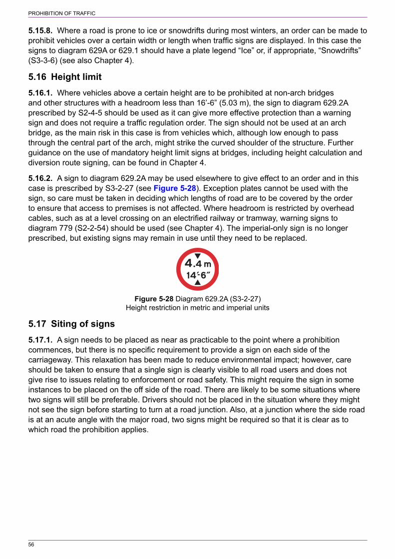
PROHIBITION OF TRAFFIC
56
5.15.8. Where a road is prone to ice or snowdrifts during most winters, an order can be made to prohibit vehicles over a certain width or length when traffic signs are displayed. In this case the signs to diagram 629A or 629.1 should have a plate legend “Ice” or, if appropriate, “Snowdrifts” (S3‑3‑6) (see also Chapter 4).
5.16 Height limit5.16.1. Where vehicles above a certain height are to be prohibited at non‑arch bridges and other structures with a headroom less than 16’‑6” (5.03 m), the sign to diagram 629.2A prescribed by S2‑4‑5 should be used as it can give more effective protection than a warning sign and does not require a traffic regulation order. The sign should not be used at an arch bridge, as the main risk in this case is from vehicles which, although low enough to pass through the central part of the arch, might strike the curved shoulder of the structure. Further guidance on the use of mandatory height limit signs at bridges, including height calculation and diversion route signing, can be found in Chapter 4.
5.16.2. A sign to diagram 629.2A may be used elsewhere to give effect to an order and in this case is prescribed by S3‑2‑27 (see Figure 5‑28). Exception plates cannot be used with the sign, so care must be taken in deciding which lengths of road are to be covered by the order to ensure that access to premises is not affected. Where headroom is restricted by overhead cables, such as at a level crossing on an electrified railway or tramway, warning signs to diagram 779 (S2‑2‑54) should be used (see Chapter 4). The imperial‑only sign is no longer prescribed, but existing signs may remain in use until they need to be replaced.
Figure 5‑28 Diagram 629.2A (S3‑2‑27) Height restriction in metric and imperial units
5.17 Siting of signs5.17.1. A sign needs to be placed as near as practicable to the point where a prohibition commences, but there is no specific requirement to provide a sign on each side of the carriageway. This relaxation has been made to reduce environmental impact; however, care should be taken to ensure that a single sign is clearly visible to all road users and does not give rise to issues relating to enforcement or road safety. This might require the sign in some instances to be placed on the off side of the road. There are likely to be some situations where two signs will still be preferable. Drivers should not be placed in the situation where they might not see the sign before starting to turn at a road junction. Also, at a junction where the side road is at an acute angle with the major road, two signs might be required so that it is clear as to which road the prohibition applies.

57
6 PEDESTRIAN ZONES
6.1 General6.1.1. Details of signs for roads, other than pedestrian zones, where either motor vehicles or all vehicles are prohibited can be found in section 5. Pedestrian zones are generally areas such as shopping streets where pedestrians will normally predominate and have full use of the width of the road, either at all times or at certain times of day. The roads may be fully paved for pedestrians or comprise a carriageway with separate footways. If a pedestrian zone is introduced on a road that was previously a signed route or was used by significant through traffic, consideration should be given to providing or changing directional signing to guide prohibited traffic to use the preferred alternative route, as described in 5.1.2.
6.1.2. Where alternative access to premises is available, it might be possible to prohibit all vehicles from a pedestrian zone without any exceptions. However, in most cases some form of access will be required. This might be for deliveries, disabled badge holders, buses etc. The pedestrian zone might operate for part of the day with or without exceptions, e.g. from 10 am to 4 pm, with unlimited access at other times. Alternatively, the zone might operate for a longer period, perhaps for 24 hours, with exceptions for access at certain times or at all times. Depending on the access requirements, a pedestrian zone might or might not need parking controls. It might be desirable to impose a prohibition of waiting and, possibly, loading during the hours when entry into the zone is prohibited. This would provide a means of enforcement where a vehicle has legally entered the zone and parked there but does not leave when the zone becomes operational. For details of signing waiting and loading restrictions within the zone see 6.3.
6.1.3. Emergency vehicles, security cash delivery vehicles, road works vehicles, statutory undertakers’ vehicles, domestic removals, funerals etc. are not usually signed as exceptions as it is common for them to be exempted from the requirements of the traffic regulation order.
6.2 Zone entry and exit signs6.2.1. There are two types of entry sign depending on whether ridden pedal cycles are permitted within the zone. Diagram 618.3B (S8‑2‑1, see Figure 6‑1) includes the “no vehicles” roundel and should be used where ridden pedal cycles are prohibited. Diagram 618.3C (S8‑2‑2, see Figure 6‑2) includes the “no motor vehicles” roundel and should be used where ridden pedal cycles are permitted. To clarify this, the legend at the top of the sign is “PEDESTRIAN and CYCLE ZONE”. If ridden pedal cycles are to be prohibited for only part of the time that the zone is operational, the entry sign will need special authorisation. The signs, which may be variable message signs, offer flexibility in the use of the bottom “no waiting” panel. Existing signs, with the legend “PEDESTRIAN ZONE” and the “no motor vehicles” roundel, need not be replaced with the new sign with the legend “PEDESTRIAN and CYCLE ZONE” until necessary through routine maintenance.
6.2.2. Where the zone is operational for 24 hours on every day of the week, no times are shown on the sign other than those relating to the exceptions. If the zone is part‑time, the operational period is shown in the upper panel below the legend “No vehicles” or below the “no motor vehicles” roundel as appropriate. Where the zone operates only on certain days of the week and for 24 hours on those days, the days only are shown on the sign; the expression “At any time” is not used. Examples of the top panel for zone entry signs are shown in Figure 6‑3. The operational period is not normally shown where a variable message sign is used.

PEDESTRIAN ZONES
58
Figure 6‑1 Diagram 618.3B (S8‑2‑1) Entry to, Figure 6‑2 Diagram 618.3C (S8‑2‑2) Entry to, and and waiting in, pedestrian zone restricted waiting in, pedestrian and cycle zone restricted
Zone operates at all times Zone operates for part of the day at thesame times on every day of the week
Zone operates for part of the day at thesame times on certain days of the week
Zone operates for 24 hours on certain daysof the week
Figure 6‑3 Examples of different times of operation for a pedestrian zone
6.2.3. The exceptions to the prohibition of entry that may be shown in the middle panel of the zone entry signs are “Except” followed by:
a) “buses” or “local buses”;b) “taxis”;

PEDESTRIAN ZONES
59
c) “for access”, “for loading” or “for loading by” and the goods vehicle symbol;d) “permit holders” or “permit holder”, without or without a permit identifier or identifiers;e) the disabled badge holder symbol; orf) any appropriate combination of the above with “and” or “&” inserted before the last legend
where more than one is used.
A time period indicating when the exceptions apply (if different from the zone operational period) may be included in the middle panel. It is recommended that where more than one exception is shown on the sign, each applies for the same time period, otherwise the sign becomes complex and difficult for a driver to assimilate. If different time periods are required for each exception, it is likely to be more appropriate to use the variable message sign. The use of the permitted variant “Except for access”, on its own or combined with another exception, should be given careful consideration. This could attract too many vehicles and compromise pedestrian safety. It could also make parking enforcement difficult in fully paved roads where yellow lines are not provided. General access should be permitted only at times when it is deemed essential or where it is likely to attract a low number of vehicles, e.g. where the zone is a cul‑de‑sac. Where access is required at all times, consideration should be given to signing the road in accordance with section 5 and not as a pedestrian zone. Where there are no exceptions, both the middle and lower panels are omitted. The design of the exception panel is shown on the appropriate working drawings. Note that the panel dividers are always the same width as the sign border.
6.2.4. The yellow “no waiting” panel is intended mainly for pedestrian zones that have waiting restrictions but no yellow lines, similar to the restricted zones described in section 15. The restrictions should be consistent throughout the zone; otherwise conventional signing with upright signs and road markings should be provided in accordance with section 13 and the yellow panel on the entry sign omitted. Where the yellow panel is used, this may indicate a time period different to that shown in the upper panel and may be for a longer period as shown in Figure 6‑1 and Figure 6‑2. Where there is also a prohibition of loading within the zone, this is not shown on the entry sign.
6.2.5. If the entry restrictions change during the day or on different days of the week, a variable message sign is recommended to avoid a complex legend that can be confusing and difficult to read. In this case, the upper panel should not include a time period. The sign should show a complete blank grey or black face, as defined in Schedule 1, during the times when the zone is not operational. The lower yellow panel can be displayed on the variable message sign only during the operational period of the zone (i.e. when the upper and middle panels are displayed). Where waiting restrictions apply at other times, all restrictions should be indicated by signs and markings within the zone in accordance with section 13.
6.2.6. During the period that entry into the zone is prohibited, the centre panel of a variable message sign may be varied at different times of day to show the appropriate exceptions. This panel has a fixed size which is determined by the tallest legend to be shown. When there are no exceptions during part of the zone operational period, the sign should be varied to show only the upper panel; the middle and lower panels should be replaced by a grey background. In these circumstances, any waiting restrictions within the zone should be signed in accordance with section 13. A disadvantage of using a variable message sign is that it does not inform drivers when the period during which access is permitted comes to an end.
6.2.7. Only one size of zone entry sign is prescribed, although the overall height will vary according to the time periods and exceptions shown. In order to reduce environmental impact, there is no requirement to provide an entry sign on each side of the road. A single sign might be sufficient depending on the width of the road, the nature of the paving, the presence of any

PEDESTRIAN ZONES
60
obstacles such as planters and trees, and whether a single sign can be clearly seen from all approaches to the zone.
6.2.8. Where the pedestrian zone comprises a one‑way road, it should be signed in accordance with 4.9. Signs to diagram 618.3B or 618.3C should be provided only at the entry to the zone in the direction of travel; they should not be used with or in place of the “no entry” signs to diagram 616 (S3‑2‑10) at the other end of the one‑way road.
6.2.9. Where all motor vehicles are prohibited from a pedestrian zone and there are no exceptions, an alternative to the provision of zone entry signs is to physically prevent vehicles from entering. This can be achieved by the placing of barriers, bollards, street furniture, planters etc. Where it is necessary to maintain access for emergency vehicles or where the total prohibition of vehicles does not apply at all times, any physical obstruction should be removable. Signs to diagram 606, 617 or 619 (S3‑2‑1, 11 and 12 respectively) may be used to supplement any barriers, but “no entry” signs to diagram 616 should not be used; these are appropriate only where traffic is prohibited in one direction. It might be possible to permanently close one end of a pedestrian zone so that it is no longer available to through traffic. Places where emergency vehicles may enter a 24‑hour zone without having to open a barrier should be sited so as to discourage other vehicles from entering.
6.2.10. The zone end signs to diagrams 618.4A (S8‑2‑3, “End of pedestrian zone”, see Figure 6‑4) and 618.4B (S8‑2‑4, “End of pedestrian and cycle zone”, see Figure 6‑5), which are prescribed in one size only, should be sited as close as practicable to the point where the prohibition ends. Although there is no specific requirement to provide the sign, it is helpful to both pedestrians and drivers, particularly where the pedestrian zone has a carriageway and separate footways, as it indicates that normal traffic conditions resume. Where it is clear that a fully paved road has come to an end, and there are very few exceptions to the prohibition of vehicles, it might not be necessary to provide an end sign. However, it might be desirable to provide an end sign to indicate where waiting restrictions end in zones that have no yellow lines. Existing signs, with the legend “Pedestrian Zone ENDS” and the “no motor vehicles” roundel, need not be replaced with the new sign with the legend “Pedestrian and cycle Zone ENDS” until necessary through routine maintenance.
Figure 6‑4 Diagram 618.4A (S8‑2‑3) End of Figure 6‑5 Diagram 618.4B (S8‑2‑4) End of restrictions associated with a pedestrian zone restrictions associated with a pedestrian and cycle zone
6.3 Signs within the zone6.3.1. Where there is a prohibition of waiting within a pedestrian zone, this may be signed as described in section 13. However, as an alternative, the sign prescribed by S4‑3‑4 may be used to draw attention to the waiting or loading restrictions in the absence of yellow line or kerb markings. Where a prohibition of loading is required, this may be indicated by a sign prescribed by S4‑4‑1. Extracts from the two tables are shown in Figure 6‑6. Complete signs are shown in
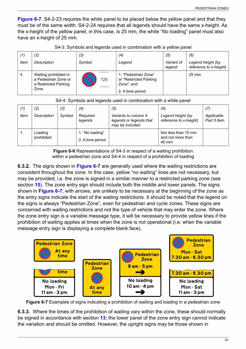
PEDESTRIAN ZONES
61
Figure 6‑7. S4‑2‑23 requires the white panel to be placed below the yellow panel and that they must be of the same width. S4‑2‑24 requires that all legends should have the same x‑height. As the x‑height of the yellow panel, in this case, is 25 mm, the white “No loading” panel must also have an x‑height of 25 mm.
S4‑3: Symbols and legends used in combination with a yellow panel
(1)
Item
(2)
Description
(3)
Symbol
(4)
Legend
(5)
Variant of legend
(6)
Legend height (by reference to x‑height)
4. Waiting prohibited in a Pedestrian Zone or a Restricted Parking Zone
1251. “Pedestrian Zone” or “Restricted Parking Zone”; and
2. A time period
25 mm
S4‑4: Symbols and legends used in combination with a white panel
(1)
Item
(2)
Description
(3)
Symbol
(4)
Required legends
(5)
Variants to column 4 legends or legends that may be included
(6)
Legend height (by reference to x‑height)
(7)
Applicable Part 5 item
1. Loading prohibited
1. “No loading”
2. A time period
Not less than 15 mm and not more than 40 mm
Figure 6‑6 Representations of S4‑3 in respect of a waiting prohibition within a pedestrian zone and S4‑4 in respect of a prohibition of loading
6.3.2. The signs shown in Figure 6‑7 are generally used where the waiting restrictions are consistent throughout the zone. In this case, yellow “no waiting” lines are not necessary, but may be provided; i.e. the zone is signed in a similar manner to a restricted parking zone (see section 15). The zone entry sign should include both the middle and lower panels. The signs shown in Figure 6‑7, with arrows, are unlikely to be necessary at the beginning of the zone as the entry signs indicate the start of the waiting restrictions. It should be noted that the legend on the signs is always “Pedestrian Zone”, even for pedestrian and cycle zones. These signs are concerned with waiting restrictions and not the type of vehicle that may enter the zone. Where the zone entry sign is a variable message type, it will be necessary to provide yellow lines if the prohibition of waiting applies at times when the zone is not operational (i.e. when the variable message entry sign is displaying a complete blank face).
Figure 6‑7 Examples of signs indicating a prohibition of waiting and loading in a pedestrian zone
6.3.3. Where the times of the prohibition of waiting vary within the zone, these should normally be signed in accordance with section 13; the lower panel of the zone entry sign cannot indicate the variation and should be omitted. However, the upright signs may be those shown in
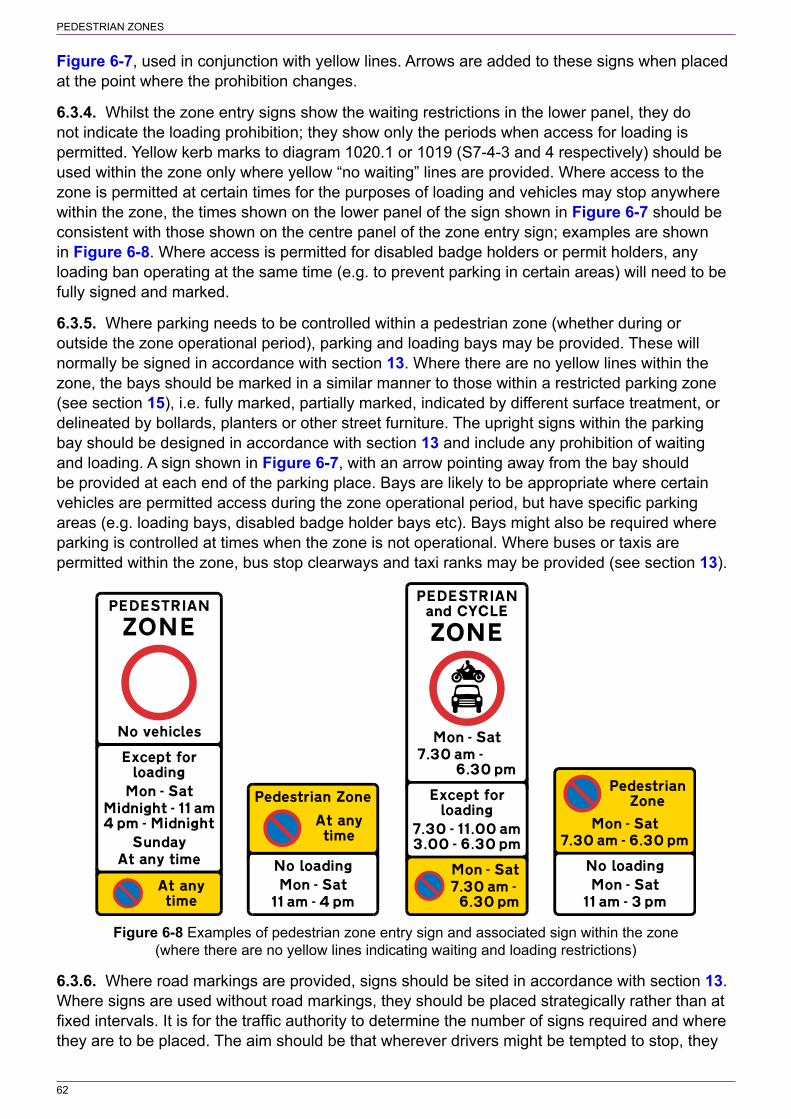
PEDESTRIAN ZONES
62
Figure 6‑7, used in conjunction with yellow lines. Arrows are added to these signs when placed at the point where the prohibition changes.
6.3.4. Whilst the zone entry signs show the waiting restrictions in the lower panel, they do not indicate the loading prohibition; they show only the periods when access for loading is permitted. Yellow kerb marks to diagram 1020.1 or 1019 (S7‑4‑3 and 4 respectively) should be used within the zone only where yellow “no waiting” lines are provided. Where access to the zone is permitted at certain times for the purposes of loading and vehicles may stop anywhere within the zone, the times shown on the lower panel of the sign shown in Figure 6‑7 should be consistent with those shown on the centre panel of the zone entry sign; examples are shown in Figure 6‑8. Where access is permitted for disabled badge holders or permit holders, any loading ban operating at the same time (e.g. to prevent parking in certain areas) will need to be fully signed and marked.
6.3.5. Where parking needs to be controlled within a pedestrian zone (whether during or outside the zone operational period), parking and loading bays may be provided. These will normally be signed in accordance with section 13. Where there are no yellow lines within the zone, the bays should be marked in a similar manner to those within a restricted parking zone (see section 15), i.e. fully marked, partially marked, indicated by different surface treatment, or delineated by bollards, planters or other street furniture. The upright signs within the parking bay should be designed in accordance with section 13 and include any prohibition of waiting and loading. A sign shown in Figure 6‑7, with an arrow pointing away from the bay should be provided at each end of the parking place. Bays are likely to be appropriate where certain vehicles are permitted access during the zone operational period, but have specific parking areas (e.g. loading bays, disabled badge holder bays etc). Bays might also be required where parking is controlled at times when the zone is not operational. Where buses or taxis are permitted within the zone, bus stop clearways and taxi ranks may be provided (see section 13).
Figure 6‑8 Examples of pedestrian zone entry sign and associated sign within the zone (where there are no yellow lines indicating waiting and loading restrictions)
6.3.6. Where road markings are provided, signs should be sited in accordance with section 13. Where signs are used without road markings, they should be placed strategically rather than at fixed intervals. It is for the traffic authority to determine the number of signs required and where they are to be placed. The aim should be that wherever drivers might be tempted to stop, they
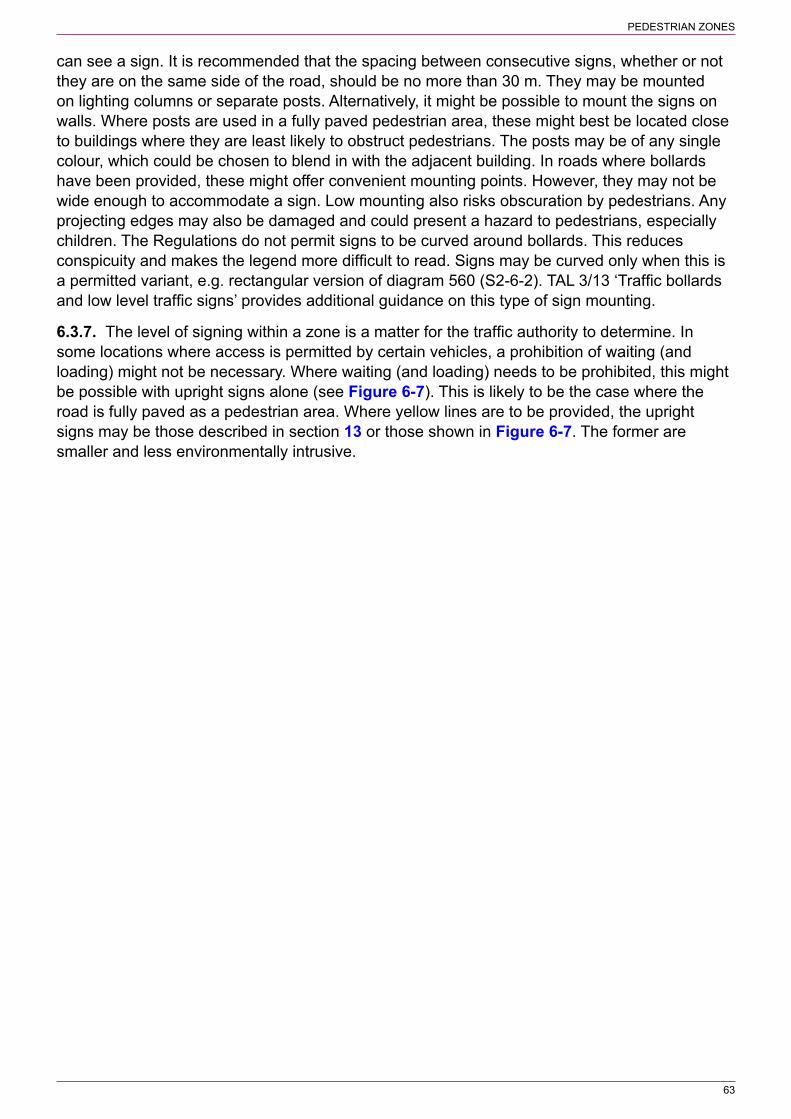
PEDESTRIAN ZONES
63
can see a sign. It is recommended that the spacing between consecutive signs, whether or not they are on the same side of the road, should be no more than 30 m. They may be mounted on lighting columns or separate posts. Alternatively, it might be possible to mount the signs on walls. Where posts are used in a fully paved pedestrian area, these might best be located close to buildings where they are least likely to obstruct pedestrians. The posts may be of any single colour, which could be chosen to blend in with the adjacent building. In roads where bollards have been provided, these might offer convenient mounting points. However, they may not be wide enough to accommodate a sign. Low mounting also risks obscuration by pedestrians. Any projecting edges may also be damaged and could present a hazard to pedestrians, especially children. The Regulations do not permit signs to be curved around bollards. This reduces conspicuity and makes the legend more difficult to read. Signs may be curved only when this is a permitted variant, e.g. rectangular version of diagram 560 (S2‑6‑2). TAL 3/13 ‘Traffic bollards and low level traffic signs’ provides additional guidance on this type of sign mounting.
6.3.7. The level of signing within a zone is a matter for the traffic authority to determine. In some locations where access is permitted by certain vehicles, a prohibition of waiting (and loading) might not be necessary. Where waiting (and loading) needs to be prohibited, this might be possible with upright signs alone (see Figure 6‑7). This is likely to be the case where the road is fully paved as a pedestrian area. Where yellow lines are to be provided, the upright signs may be those described in section 13 or those shown in Figure 6‑7. The former are smaller and less environmentally intrusive.

64
7 CLEARWAYS
7.1 General7.1.1. This section deals with clearways which limit stopping along a length of road, indicated by upright signs without any road markings. There are three types of clearway:
a) 24‑hour rural clearway;b) Urban clearway; andc) Red route clearway.
7.1.2. See section 16 for details of red routes that use both upright signs and road markings.
7.2 24‑hour rural clearway7.2.1. A 24‑hour clearway order prohibits stopping on the main carriageway for any purpose at all times. It is suitable for use only on semi‑urban or rural roads where there are very few premises requiring access from the main carriageway. Its main purpose is to ensure the free flow of traffic on major inter‑urban routes, especially dual carriageway roads and single carriageway primary routes. The restriction applies to the main running carriageway, slip roads and any acceleration and deceleration splays included in the order. It does not apply to verges, footways, lay‑bys and other highway areas. To enable drivers to stop for a break, there should be lay‑bys at frequent intervals. They should also be provided for isolated properties on the route where no off‑carriageway area is available for parking and loading.
7.2.2. The clearway would not normally continue through a village or small settlement. Where there is a need to keep the main carriageway clear of stationary vehicles, a 24‑hour prohibition of waiting is more appropriate as this allows the picking up and setting down of passengers and, where not also prohibited, loading and unloading.
7.2.3. There might sometimes be a need to prevent parking on the verge where the ground is soft or newly seeded, or for road safety or security reasons, such as near an airfield. This can be achieved by making an order prohibiting either waiting or stopping on the verge and using the sign prescribed by S4‑3‑5 (see section 13). An alternative is to replace the 24‑hour rural clearway with a red route clearway.
7.2.4. The start of the clearway is indicated by a sign to diagram 642 (S3‑2‑4, see Figure 7‑1) with a supplementary plate indicating the restricted length in miles; this must be to the nearest whole mile if the distance is greater than three miles (see S18‑3‑4). In order to reduce environmental impact, there is no requirement to provide two signs, one on each side of the road. However, as such clearways generally apply to high‑speed roads, a driver who fails to observe the sign and stops on the main carriageway will be a hazard to other drivers. It is possible that a sign on the nearside of a dual carriageway road might be obscured by a large commercial vehicle and this must be taken into consideration when deciding whether a second sign should be placed on the opposite side of the carriageway. The end of the clearway is indicated by a sign to diagram 642 with an “End” plate as shown in Figure 7‑1. Only one sign is required, but a second sign should be considered, particularly where the likelihood of parked vehicles on the road ahead presents a possible hazard; e.g. on a dual carriageway where a single sign on the nearside might be obscured by vehicles in the nearside lane. Where start and end signs are erected on each side of the carriageway, they should be mounted back to back. Traffic authorities should determine whether repeater signs are required and where they are

CLEARWAYS
65
placed. However, to ensure that drivers are reminded of the restriction, it is recommended that repeater signs, which may alternate from one side of the carriageway to the other, are placed along the length of the road such that the distance between successive signs is equivalent to a travel time of approximately 60 seconds. As a guide, where the speed limit is 60 mph or more, it is recommended that repeater signs are placed at intervals of approximately 1600 m in each direction. Where the speed limit is 30, 40 or 50 mph, the recommended spacing is 800 m, 1100 m and 1350 m respectively. Where the length of road subject to the prohibition on stopping is less than these distances, in respect of each speed limit (including 60 mph or more), repeater signs are unlikely to be necessary. Where street lighting is provided, it is recommended that repeater signs are mounted on the lighting columns (see Chapter 1).
Figure 7‑1 Diagram 642 (S3‑2‑4) No stopping on main carriageway (Alternative types)
7.2.5. Where a road joins or crosses a clearway, a commencement sign to diagram 642 should be erected on that road to face traffic approaching the junction. A second sign on the opposite side of the carriageway may be provided if considered necessary. A distance plate is not used as in most cases traffic can turn either left or right into the clearway. However, distance plates should be provided if the road is a slip road leading to a dual carriageway. For traffic turning into the side road and leaving the clearway it will normally be sufficient to provide a single sign to diagram 642 with an “End” plate on the left hand side of the minor road. Complex junctions with splitter islands, link roads or slip roads might require additional signs.
7.2.6. Appropriate circular sign and plate sizes are specified in Appendix A.
7.3 Urban clearway7.3.1. The urban clearway, indicated by the sign to diagram 646 (S7‑2‑6, see Figure 7‑2), limits stopping during peak periods, but is effectively a prohibition of waiting and loading as drivers may stop to pick up and set down passengers. It applies to both sides of the carriageway and includes footways and verges. Road markings are not used, so signs should face oncoming traffic, but need only be erected on one side of the road in each direction. A second sign may be placed on the opposite side of the road where the traffic authority considers that this would aid enforcement. The sign indicates two time periods representing the morning and evening peak periods; it cannot be varied to show a single time period such as 8 am to 6 pm. Signs should be provided at the start of the clearway and in both directions just after each side road junction. They should be sited a sufficient distance from the junction to enable them to be read by drivers turning into the clearway, but generally no more than 45 m measured from the backline of the side road. Care will need to be taken when siting signs at a staggered crossroads or where junctions are very close together. Where junctions are more than 400 m apart, it is recommended that additional signs should be provided to maintain a spacing of not more than 400 m. The end of the clearway is indicated by the sign to diagram 647 (S7‑2‑7, see Figure 7‑3). Signs to diagrams 646 and 647 are not normally provided on side roads that join or cross an urban clearway.

CLEARWAYS
66
Figure 7‑2 Diagram 646 (S7‑2‑6) No stopping for Figure 7‑3 Diagram 647 (S7‑2‑7) End of the periods indicated, except to pick up or to set restriction on stopping down passengers
7.3.2. The Regulations prescribe two sizes for the sign to diagram 646. The larger size would normally be used on roads with a speed limit of 40 mph or more. Only one size is prescribed for diagram 647.
7.3.3. An urban clearway should be introduced only where there are no other on‑street parking controls, as described in section 13, even if they operate at a different time of day. The provision of a prohibition of waiting with time plates could be confusing to drivers as could a time‑limited parking bay that operates off‑peak, implying that outside those times (during peak periods) the bay can be used without limit. The only additional restriction that could sensibly be applied would be a 24‑hour prohibition of waiting to protect junctions. Where other controls are required, the urban clearway should be replaced by a prohibition of waiting and loading and signed accordingly (see section 13).
7.4 Red route clearway7.4.1. A red route clearway is similar to the 24‑hour rural clearway except that it applies also to the verge and footway, not just to the main carriageway. No vehicle is permitted to stop at any time for any purpose, except in signed lay‑bys or elsewhere in an emergency. The traffic order should provide an exemption to allow licensed taxis to stop to pick up or set down passengers, and to allow the driver of a vehicle displaying a blue badge to stop to pick up or set down a disabled person. Where bus stops are required, they should generally be provided within lay‑bys (see section 13 for details of bus stop clearways). Red route clearways are likely to be appropriate in urban or semi‑urban areas where off‑road parking is available or where roads, such as dual carriageways, are segregated from service roads alongside.
7.4.2. The start of the red route clearway is indicated by the sign to diagram 642.4 (S7‑2‑8, see Figure 7‑4). Normally a single sign will be sufficient, placed on the left hand side of the carriageway. However, as with the 24‑hour rural clearway, a second sign on the opposite side of the carriageway might be required to ensure that drivers are aware of the restriction, particularly as there are no road markings. Diagram 642.4 is also used as a repeater sign. As red route clearways are likely to be provided in an urban or semi‑urban environments, the recommended spacing is the same as that for urban clearways, i.e. after each road junction and with additional signs as necessary so that two signs are generally no further apart than 400 m. This spacing is appropriate for roads with a 30 mph speed limit. For higher speed limits the spacing should be increased proportionally so that drivers pass a sign approximately every 30 seconds (e.g. 800 m spacing at 60 mph). The end of the red route clearway is indicated by the sign to diagram 642.5 (S7‑2‑9, see Figure 7‑5). Appropriate sign sizes are specified in Appendix A.
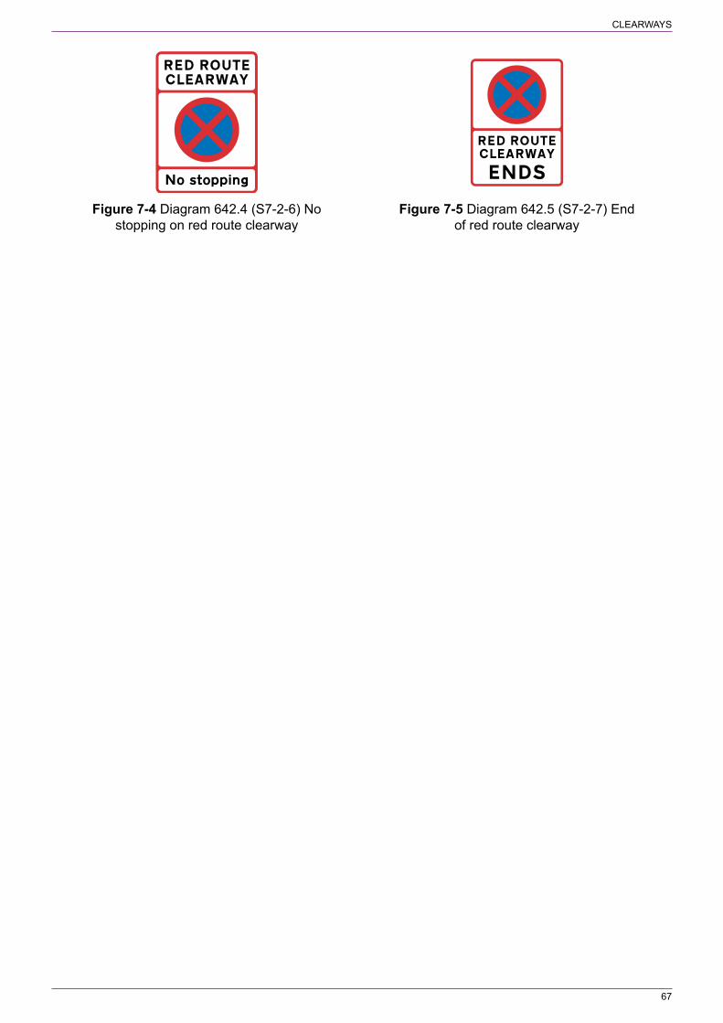
CLEARWAYS
67
Figure 7‑4 Diagram 642.4 (S7‑2‑6) No Figure 7‑5 Diagram 642.5 (S7‑2‑7) End stopping on red route clearway of red route clearway

68
8 SPEED LIMITS
8.1 General8.1.1. Traffic authorities have a duty under section 85 of the Road Traffic Regulation Act 1984 to erect and maintain prescribed speed limit signs on their roads in accordance with the Secretary of State’s directions; i.e. the signs must be prescribed by and provided in accordance with TSRGD unless they have been specially authorised. Signs that do not strictly follow TSRGD (see 1.1.4 in respect of Northern Ireland), or have not been specially authorised are not lawfully placed and the speed limit might be unenforceable. To avoid the risk of failed prosecutions, it is of the greatest importance that speed limits are adequately signed so that at no time will drivers be in any doubt about the prevailing limit.
8.1.2. “Speed limit” and “National speed limit” are defined separately in Schedule 1 and are referred to in this section as follows:
a) National speed limit, being 70 mph on motorways and dual carriageway roads and 60 mph on single carriageway roads (see definition of “national speed limit”)
b) Maximum speed limit, being an upper limit (see definition of “speed limit”). This includes restricted roads (sections 81 and 82 of the Road Traffic Regulation Act 1984), which are those roads with a speed limit of 30 mph by virtue of the presence of a system of street lighting (carriageway lighting in Scotland) where lamps are placed not more than 200 yards (183 metres) apart (185 metres in Scotland)
c) Minimum speed limit, being a speed below which vehicles must not be driven (see definition of “speed limit”).
8.1.3. Any maximum speed limit below 30 mph (other than a temporary limit made under section 14 of the Road Traffic Regulation Act 1984, or a 20 mph limit or a 20 mph zone) requires the consent of the national authority (paragraphs 13 and 14 of Schedule 9 to the Act as amended by the Road Traffic Regulation Act (Amendment) Order 1999); such limits are unlikely to be agreed. References in this section to street lighting should be taken in Scotland to be references to carriageway lighting.
8.1.4. The Schedule 10 Directions set out certain requirements for the placing of signs to indicate speed limits. These are described in detail in the following paragraphs (see 1.1.4 in respect of Northern Ireland).
8.2 Terminal signs indicating maximum and national speed limits8.2.1. A terminal sign to diagram 670 (S10‑2‑1, see Figure 8‑1) should be used to indicate the beginning of a maximum speed limit (except for 20 and 40 mph zones). Diagram 670 is not used to indicate the national speed limit; the appropriate sign is diagram 671 (S10‑2‑2, see Figure 8‑2). All speed limits, except those for tramcars, are signed in miles per hour.
8.2.2. Schedule 10 General Direction 4 requires the placing of a terminal sign as near as practicable to the point where the speed limit begins or ends. The sign to diagram 671 should be used where a speed limit ends and the national speed limit applies, otherwise the end of one speed limit is indicated by the start of another by diagram 670. There is no specific requirement to provide two terminal signs, one on each side of the carriageway, where the speed limit changes along a length of road. However, in most situations it is recommended that two signs are provided, particularly on motorways and rural dual carriageway roads. Drivers need to be

SPEED LIMITS
69
fully aware of the speed limit both for reasons of road safety and enforcement, particularly where the sign indicates a reduction in the speed limit. There is always the possibility that a single sign might become damaged or obscured by vegetation and require a more rigorous maintenance regime. A single sign could also be obscured by high‑sided vehicles, particularly on roads with more than one traffic lane in the same direction. Any decision by the traffic authority to use a single sign should be underpinned by robust risk analysis. Where a single sign is to be used this could be supplemented by a speed limit road marking (see 8.18.1). Where the speed limit changes to the national limit, two signs are likely to be required as there is no appropriate road marking and repeater signs are not used where there is no street lighting. A driver not aware of the higher limit might be a hazard to other road users and encourage dangerous overtaking. A single sign is likely to be appropriate on narrow roads, particularly in rural locations and in urban areas where a 20 mph speed limit is introduced. Where a single carriageway road has a central traffic island, a terminal sign may be erected on that island rather than on the opposite side of the road. Figure 8‑3 shows examples of siting terminal signs.
Figure 8‑1 Diagram 670 (S10‑2‑1) Figure 8‑2 Diagram 671 (S10‑2‑2) Maximum speed limit in miles per hour National speed limits apply
8.2.3. On a road with a 30 mph speed limit by virtue of street lighting (i.e. a restricted road), where the adjacent length of road is unlit and is subject to the national speed limit, the 30 mph speed limit will begin at the first lighting column. The terminal sign or signs should be placed on, or in line with, that column as appropriate. To ensure that drivers are aware of the commencement of the 30 mph limit, it is essential that the terminal signs are correctly placed and clearly visible. If the 30 mph limit is to start at some other point (before or after the street lighting begins), it will be necessary to make a speed limit order and locate the terminal signs accordingly. Where a 30 mph limit commences on an unlit section of road and continues as a restricted road on the lit section, additional terminal signs must not be placed, in either direction, at the point where the street lighting begins, i.e. where the 30 mph speed limit order ends and the restricted road begins (but see 8.3.2).
8.2.4. Where traffic enters or leaves a side road that has a different speed limit to that on the main road, a single terminal sign should normally be provided in each direction on the side road. The sign for drivers turning into the side road should be sited in such a manner that it can be easily seen, but generally no more than 20 m from the edge of the carriageway of the main road. It is for the traffic authority to determine whether a speed limit order is required to cover the length of road from the junction to the terminal sign. The siting of this sign will then determine the location of the sign for traffic leaving the side road. For certain junction layouts it might be preferable to provide two terminal signs in one or both directions; an example is shown in Figure 8‑4. Although only one sign to indicate the speed limit in the side road would normally be sufficient, drivers could mistakenly think that the sign applies to the main road; the additional sign overcomes this problem. Alternatively, a single sign on the off side might be sufficient. Traffic authorities should determine the level of speed limit signing that is appropriate for a particular road junction.
8.2.5. The placing of terminal signs at junctions as described in 8.2.4 applies generally to simple priority junctions, including crossroads. For other types of junction, such as roundabouts and those controlled by signals, drivers are likely to require more guidance on the speed

SPEED LIMITS
70
limits in force; it is recommended that full signing is provided. An example showing speed limit terminal signs at a roundabout junction is shown in Figure 8‑5.
30 mph
40 mph
30 mph
40 mph
30 mph
40 mph
30 mph
40 mph
30 mph
40 mph
On wide dual carriageways with wide central reservations, the two off side signs should be mountedseparately, closer to each other
Figure 8‑3 Examples of siting terminal signs where two signs are used on each approach

SPEED LIMITS
71
Lower lim
it (e.g. 30 mph)
H
ighe
r lim
it
Additionalsign
Figure 8‑4 Road junction where the side road makes an acute angle with the main road (Signs for drivers entering the side road)
30 mph
40 mph 40 mph
30 mph
30 mph
30 mph
Figure 8‑5 Example of a roundabout junction
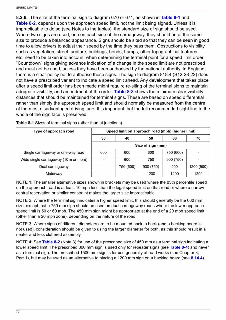
SPEED LIMITS
72
8.2.6. The size of the terminal sign to diagram 670 or 671, as shown in Table 8‑1 and Table 8‑2, depends upon the approach speed limit, not the limit being signed. Unless it is impracticable to do so (see Notes to the tables), the standard size of sign should be used. Where two signs are used, one on each side of the carriageway, they should be of the same size to produce a balanced appearance. Signs should be sited so that they can be seen in good time to allow drivers to adjust their speed by the time they pass them. Obstructions to visibility such as vegetation, street furniture, buildings, bends, humps, other topographical features etc. need to be taken into account when determining the terminal point for a speed limit order. “Countdown” signs giving advance indication of a change in the speed limit are not prescribed and must not be used, unless they have been authorised by the national authority. In England, there is a clear policy not to authorise these signs. The sign to diagram 818.4 (S12‑28‑22) does not have a prescribed variant to indicate a speed limit ahead. Any development that takes place after a speed limit order has been made might require re‑siting of the terminal signs to maintain adequate visibility, and amendment of the order. Table 8‑3 shows the minimum clear visibility distances that should be maintained for terminal signs. These are based on speed differential rather than simply the approach speed limit and should normally be measured from the centre of the most disadvantaged driving lane. It is important that the full recommended sight line to the whole of the sign face is preserved.
Table 8‑1 Sizes of terminal signs (other than at junctions)
Type of approach road Speed limit on approach road (mph) (higher limit)
30 40 50 60 70
Size of sign (mm)
Single carriageway or one‑way road 600 600 600 750 (600) ‑
Wide single carriageway (10 m or more) ‑ 600 750 900 (750) ‑
Dual carriageway ‑ 750 (600) 900 (750) 900 1200 (900)
Motorway ‑ ‑ 1200 1200 1200
NOTE 1: The smaller alternative sizes shown in brackets may be used where the 85th percentile speed on the approach road is at least 10 mph less than the legal speed limit on that road or where a narrow central reservation or similar constraint makes the larger size impracticable.
NOTE 2: Where the terminal sign indicates a higher speed limit, this should generally be the 600 mm size, except that a 750 mm sign should be used on dual carriageway roads where the lower approach speed limit is 50 or 60 mph. The 450 mm sign might be appropriate at the end of a 20 mph speed limit (other than a 20 mph zone), depending on the nature of the road.
NOTE 3: Where signs of different diameters are to be mounted back to back (and a backing board is not used), consideration should be given to using the larger diameter for both, as this should result in a neater and less cluttered assembly.
NOTE 4: See Table 8‑2 (Note 3) for use of the prescribed size of 450 mm as a terminal sign indicating a lower speed limit. The prescribed 300 mm sign is used only for repeater signs (see Table 8‑4) and never as a terminal sign. The prescribed 1500 mm sign is for use generally at road works (see Chapter 8, Part 1), but may be used as an alternative to placing a 1200 mm sign on a backing board (see 8.14.4).

SPEED LIMITS
73
Table 8‑2 Sizes of terminal signs at junctions
Type of junction and location of sign Speed limit on approach road (mph) (higher limit)
30 40 50 60 70
Size of sign (mm)
Signal‑controlled junction (signs viewed only from turning vehicles)
600 600 600 600 (750) 600 (750)
Signal‑controlled junction (other signs) 600 600 750 750 900
Side road approach to a priority junction 600 600 600 600 750
Entry into side road at a priority junction 600 600 600 600 (750) 600 (750)
Approach to a roundabout 600 600 600 750 (600) 900
Exit from a roundabout 600 600 600 600 (750) 600 (750)
NOTE 1: The larger alternative sizes shown in brackets might be appropriate where there are high‑speed flow conditions such as a diverge lane at a priority junction or spiral markings on a large roundabout. The smaller alternative size of 600 mm shown in brackets for the approach to a roundabout may be used where the 85th percentile speed is less than 50 mph.
NOTE 2: Where the terminal sign indicates a higher speed limit, this should generally be the 600 mm size. The 450 mm sign might be appropriate at the end of a 20 mph speed limit (other than a 20 mph zone), depending on the nature of the road.
NOTE 3: Where the width of the verge is insufficient to allow the provision of a 600 mm sign shown in the table or referred to in Note 2, a 450 mm sign might have to be used. A 450 mm sign might also be appropriate where traffic turns from a road with a 30 mph speed limit into a road with a 20 mph speed limit (other than a 20 mph zone), depending on the nature of the junction.
NOTE 4: Where signs of different diameters are to be mounted back to back (and a backing board is not used), consideration should be given to using the larger diameter for both, as this should result in a neater and less cluttered assembly.
NOTE 5: The prescribed size of 300 mm is used only for repeater signs (see Table 8‑4) and never as a terminal sign. The prescribed 1500 mm sign is for use only at road works (see Chapter 8, Part 1).
Table 8‑3 Minimum clear visibility distances for terminal signs (other than entering a side road)
Approach road speed limit for
private cars (mph)
Speed limit sign (mph)
20 30 40 50 60
Visibility distance of sign (m)
70 ‑ 165 140 110 75
60 ‑ 115 95 65 ‑
50 ‑ 75 50 ‑ ‑
40 ‑ 40 ‑ ‑ ‑
30 30 ‑ ‑ ‑ ‑
NOTE 1: On the side road approach to a priority junction or on any road where the speed limit increases, the visibility distance for each approach speed should be not less than the lowest value shown for that speed (e.g. 50 m for an approach speed limit of 50 mph). Where the approach speed limit is 20 mph, the minimum visibility distance is 20 m.
NOTE 2: Where the 85th percentile speed on the approach road is at least 10 mph less than the legal speed limit on that road, the clear visibility distance may be reduced to that appropriate to the actual speed (e.g. on a country lane subject to the national limit, where the 85th percentile speed is 50 mph the

SPEED LIMITS
74
clear visibility distance should not be less than 75 m when approaching a 30 mph speed limit, and not less than 50 m when approaching a 40 mph or 50 mph speed limit).
NOTE 3: The minimum clear visibility distance indicated should be provided for both terminal signs, where two are provided.
8.2.7. Guidance on the illumination of speed limit terminal signs can be found in 8.15, and on their mounting and co‑location with other signs in 8.17.
8.3 Repeater signs indicating maximum and national speed limits8.3.1. Whilst there is no specific requirement to provide repeater signs, it is for the traffic authority to determine how many are required and where they are placed. However, to ensure that drivers are fully aware of the speed limit in force it is recommended that repeater signs are provided at the intervals shown in Table 8‑4 (see 8.3.4). Schedule 10 General Direction 2 prohibits the use of 30 mph repeater signs where a road has a system of carriageway lighting. Section 82 of the Road Traffic Regulation Act 1984 defines a lit road as being a “restricted road” (see 8.1.2). Section 81 specifies that the speed limit along such a road is 30 mph unless an order has been made to impose another limit and remove the restricted road status. The presence of carriageway lighting therefore means that a road automatically has a speed limit of 30 mph with the lamps taking the place of repeater signs. It is therefore important that, when lit roads have a speed limit other than 30 mph, repeater signs are provided at adequate intervals along the road as recommended in Table 8‑4. Failure to do so could undermine confidence in the signing of all speed limits, as drivers have only the repeaters to tell them that the limit is not 30 mph. Where a speed limit, other than 30 mph, applies before and after the point where the carriageway lighting begins, a repeater sign should be placed in line with the first lamp; in most cases the sign would be mounted on the lighting column.
8.3.2. Where a 30 mph speed limit is imposed on an unlit road, it is necessary to make an order. In this case it is recommended that 30 mph repeater signs are provided (see 8.3.1). (see 8.3.4). Where a road subject to a 30 mph limit is lit for only part of its length, it is recommended that a repeater sign for the unlit section when leaving the lit section should be placed at a distance of not more than 100 m from the last street lamp. Where two consecutive street lamps on a lit road are more than 183 m apart (185 m in Scotland and Northern Ireland) a speed limit order is required as it is not a “restricted road” with repeater signs provided where considered to be appropriate. Where the two lamps are less than 200 m apart it is unlikely that a repeater sign will be necessary.
8.3.3. Schedule 10 General Direction 3 prohibits the use of repeater signs on an unlit road subject to the national speed limit. Where a lit road is subject to the national limit, repeater signs should normally be provided to remind drivers that the road is not a restricted road with a speed limit of 30 mph (see 8.3.1). At the point where carriageway lighting commences on a road subject to the national speed limit, it is recommended that a repeater sign is placed in line with the first lamp; in most cases the sign would be mounted on the lighting column. This sign should be the appropriate size for a repeater sign (see Table 8‑4) and not the larger terminal sign. Repeater signs indicating the national speed limit are to diagram 671 (S10‑2‑2) and not diagram 670. National speed limit repeater signs are not permitted on motorways.
8.3.4. Sizes, recommended maximum spacing and minimum clear visibility distances (CVD) for repeater signs are shown in Table 8‑4. Repeater signs should normally be staggered on alternate sides of a single carriageway road, or on alternate sides of each carriageway of a dual carriageway road. However, where site constraints preclude this, adjacent signs may be placed on the same side of the road. Guidance on the mounting of repeater signs, and co‑location with other signs, can be found in 8.17. The road marking roundel to diagram 1065 (S10‑2‑9,

SPEED LIMITS
75
see 8.18.1) may be used as a repeater, either on its own as an alternative to the upright sign or together with the upright sign.
Table 8‑4 Size, recommended spacing and minimum clear visibility distances (CVD) for repeater signs
Speed limit and type of road1, 2 Size of sign (mm)
Maximum distance (m) between CVD (m)
Each repeater sign
Terminal sign and first repeater3
20 mph zone 300 See 8.7.1 See 8.7.1 ‑
20 mph 300 200 200 20
30 mph (lit road) ‑ No repeaters No repeaters ‑
30 mph (unlit road) 300 250 200 30
40 mph 300 350 250 40
50 mph 450 450 350 50
60 mph (dual carriageway) 600 500 400 60
National speed limit (lit single) carriageway) 450 500 400 60
National speed limit (lit dual) carriageway) 600 600 450 70
National speed limit (unlit road) ‑ No repeaters No repeaters ‑
NOTE 1: A lit road or carriageway refers to street lamps placed not more than 183 metres apart in England and Wales or not more than 185 metres apart in Scotland and Northern Ireland. Where a road is not lit throughout and requires repeater signs for both the lit and unlit sections, a repeater sign should be provided at the point where the carriageway lighting commences.
NOTE 2: Sign size, spacing and clear visibility distance for motorways, including link roads, will be the same as shown for 40 mph, 50 mph and 60 mph, as appropriate. Repeater signs must not be used on lit or unlit motorways to indicate the national speed limit.
NOTE 3: Repeater signs are unlikely to be needed where the length of the speed limit is less than the distance shown in this column.
8.4 40 mph zones8.4.1. The sign to diagram 676 (S10‑2‑8, see Figure 8‑6) indicates the entrance to a zone where a maximum speed limit of 40 mph is in force. It must not be varied to indicate another speed limit. The sign is an alternative to diagram 670 and is intended for areas where the provision of upright repeater signs on minor roads would be environmentally intrusive, e.g. within recreational areas such as National Parks. It might be more appropriate to provide the road marking roundel to diagram 1065 (S10‑2‑9, see 8.18.1) as a repeater sign, to remind drivers of the speed limit. There is no requirement for the road marking to be used in conjunction with an upright repeater sign. It is for the traffic authority to determine the appropriate level of signing within the zone. Whether one or two zone entry signs are provided might depend not only on the character of the road but also on the level of repeater signing within the zone. There is no “zone end” sign; a standard terminal sign indicating the adjacent speed limit should be used.

SPEED LIMITS
76
Figure 8‑6 Diagram 676 (S10‑2‑8) Entrance to a zone where a maximum speed limit of 40 mph is in force
8.5 All‑purpose dual carriageway roads with a speed limit of 60 mph8.5.1. Where a road is part dual carriageway and part single carriageway and has a speed limit of 60 mph throughout, terminal signs must be provided at the point where the central reservation begins or ends. The speed limit on the dual carriageway will be signed as a 60 mph speed limit with terminal and repeater signs to diagram 670, varied to show “60”. An order will be required to impose a 60 mph limit on the dual carriageway section. The single carriageway road subject to the national speed limit should be signed with signs to diagram 671. Repeater signs on the single carriageway should be provided only if the road is lit.
8.5.2. Where a two‑way single carriageway road subject to the national speed limit of 60 mph has a junction with a dual carriageway road on which is imposed a speed limit of 60 mph, at least one terminal sign to diagram 670, facing traffic approaching the dual carriageway, should be provided as shown in Figure 8‑7. Although the actual speed limit is the same on both roads (i.e. 60 mph), at least one terminal sign to diagram 670 should be placed facing traffic leaving the side road. This is to ensure that drivers, when turning into the dual carriageway road, do not assume that the national speed limit of 70 mph applies. The repeater signs alone would not be sufficient for this purpose. A second terminal sign to diagram 670 may be provided on the opposite side of the road if considered appropriate by the traffic authority. Only one sign to diagram 671 is likely to be needed on entering the side road. The traffic authority should consider whether a second sign on the opposite side of the carriageway would be helpful.
8.5.3. In the opposite direction, only one sign, to diagram 671, is likely to be needed. If the side road forms a short link to another road at a grade separated junction and this other road has a speed limit other than the national limit, it might be preferable to apply this limit to the link road also, to eliminate the short length of national speed limit and hence the number of signs (see Figure 8‑8). This would not be appropriate, however, where the speed limit on the link road would be unrealistically low for the prevailing conditions.
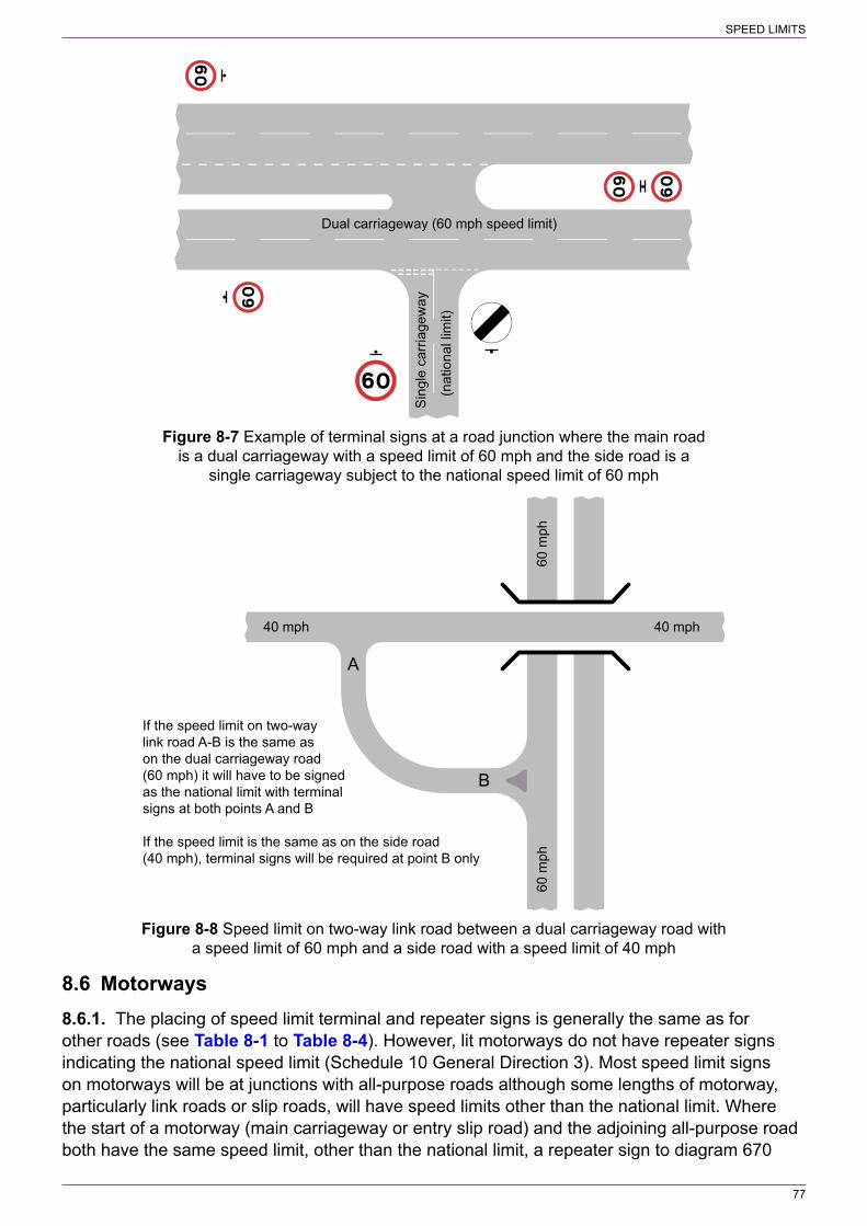
SPEED LIMITS
77
Sin
gle
carri
agew
ay
Dual carriageway (60 mph speed limit)
(nat
iona
l lim
it)Figure 8‑7 Example of terminal signs at a road junction where the main road
is a dual carriageway with a speed limit of 60 mph and the side road is a single carriageway subject to the national speed limit of 60 mph
40 mph40 mph
60 m
ph60
mph
A
B
If the speed limit on two-waylink road A-B is the same ason the dual carriageway road(60 mph) it will have to be signedas the national limit with terminalsigns at both points A and B
If the speed limit is the same as on the side road(40 mph), terminal signs will be required at point B only
Figure 8‑8 Speed limit on two‑way link road between a dual carriageway road with a speed limit of 60 mph and a side road with a speed limit of 40 mph
8.6 Motorways8.6.1. The placing of speed limit terminal and repeater signs is generally the same as for other roads (see Table 8‑1 to Table 8‑4). However, lit motorways do not have repeater signs indicating the national speed limit (Schedule 10 General Direction 3). Most speed limit signs on motorways will be at junctions with all‑purpose roads although some lengths of motorway, particularly link roads or slip roads, will have speed limits other than the national limit. Where the start of a motorway (main carriageway or entry slip road) and the adjoining all‑purpose road both have the same speed limit, other than the national limit, a repeater sign to diagram 670

SPEED LIMITS
78
should be co‑located with the sign to diagram 2901 (S9‑4‑13) that indicates the start of the motorway. This ensures that drivers are aware that the national motorway speed limit of 70 mph does not apply at this point. Where the speed limit on a motorway ends and becomes the national limit, terminal signs to diagram 671 must be erected.
8.6.2. Where a motorway subject to the national speed limit has a junction with an all‑purpose road that has a different limit, terminal signs to diagram 670 must be provided on the exit slip road to indicate the speed limit on the all‑purpose road. The requirement under section 85 of the Road Traffic Regulation Act 1984 to provide prescribed speed limit signs does not apply to motorways subject to the national speed limit. Signs to diagram 671 are not needed, therefore, on the entry slip road. The sign to diagram 2901, indicating the start of motorway regulations, also indicates that the national speed limit applies. There will be situations where the all‑purpose road and the motorway are both subject to the national speed limit, and the all‑purpose road or both roads have street lamps. A repeater sign to diagram 671, to be viewed by drivers leaving the motorway, should then be placed on the first lighting column beyond the point where the motorway regulations end (indicated by the sign to diagram 2931; S9‑4‑15). If the all‑purpose road is subject to the national speed limit and is unlit, no signs are required. The signing principles in this paragraph apply also where the main carriageway of a motorway terminates at a roundabout.
8.6.3. Where a motorway terminates at a grade separated junction and the main carriageway becomes an all‑purpose road, the motorway regulations usually continue through the junction to the point where the entry slip road joins. If the all‑purpose road has a lower speed limit than the motorway, this will be signed as described in 8.6.2. However, this speed limit might sometimes commence some distance before the slip road joins and the motorway regulations end. A short section of the motorway will then be subject to a speed limit other than the national limit. The motorway and all‑purpose road should be treated as a single entity in respect of the provision of terminal and repeater signs, although a repeater sign indicating the lower limit should be placed at the point where the motorway starts. The size of the repeater signs is the same on motorways and all‑purpose dual carriageway roads subject to the same speed limit (see Table 8‑4).
8.7 20 mph zones8.7.1. A 20 mph speed limit is indicated by terminal and repeater signs to diagram 670 in exactly the same manner as any other speed limit (other than a 30 mph limit on a lit road where repeater signs are not permitted). However, a 20 mph zone, indicated by the sign shown in diagram 674 (S10‑2‑5, see Figure 8‑9), may be introduced instead, but only if it complies with Schedule 10 General Direction 1. This specifies that the sign to diagram 674 may be used only if no part of a road (not being a cul‑de‑sac less than 80 metres long) within the zone is more than 50 metres (measured along the road) from a traffic calming feature; i.e. the features must be no further apart than 100 m. A traffic calming feature is defined as:
a) a road hump constructed pursuant to section 90A of the Highways Act 1980 or section 36 of the Roads (Scotland) Act 1984 and in accordance with the Highways (Road Humps) Regulations 1999 or the Road Humps (Scotland) Regulations 1998;
b) traffic calming works constructed in accordance with section 90G of the 1980 Act or section 39A of the 1984 Act and in accordance with the Highways (Traffic Calming) Regulations 1999 or the Roads (Traffic Calming) (Scotland) Regulations 1994;
c) a refuge for pedestrians which was constructed pursuant to section 68 of the 1980 Act, or section 27(c) of the 1984 Act, after 15th June 1999 and is constructed so as to encourage a reduction in the speed of traffic using the carriageway;

SPEED LIMITS
79
d) a variation of the relative widths of the carriageway or of any footway pursuant to section 75 of the 1980 Act or section 1(1) or 2(1) of the 1984 Act which ‑
i) was carried out after 15th June 1999 for the purpose of encouraging a reduction in the speed of traffic using the carriageway; and
ii) had the effect of reducing the width of the carriageway;e) a horizontal bend in the carriageway through which all vehicular traffic has to change
direction by no less than 70 degrees within a distance of 32 metres as measured at the inner kerb radius;
f) a sign to diagram 670 (S10‑2‑1) varied to “20”; org) a road marking to diagram 1065 (S10‑2‑9) varied to “20”.
Schedule 10 General Direction 1 requires that the 20 mph zone includes at least one of the physical features listed in (a) to (e) above. The speed limit repeater sign and road marking are now included as traffic calming features and need not be used together. This allows traffic authorities to reduce the number of physical features. In doing so, they will need to carefully consider the implications for the self‑enforcing nature of the 20 mph zone. Traffic authorities will also need to consider whether a 20 mph speed limit or a 20 mph zone is the most appropriate for particular roads in their area.
8.7.2. Signs to diagram 674 must be provided at each entrance to the zone, even where the adjacent speed limit is 20 mph (without traffic calming features). Generally only one terminal sign will be needed, particularly where the zone commences in a side road at a junction. Only one size of sign is prescribed. The lower panel may be varied or omitted, but the speed limit roundel in the upper panel must not be varied to any other speed limit.
8.7.3. The end of the zone is indicated by a sign showing the adjacent speed limit. This is to diagram 675A (S10‑2‑6, see Figure 8‑10) or, where the adjacent speed limit is the national limit, diagram 675B (S10‑2‑7, see Figure 8‑11). Normally only one sign is likely to be needed. Where the adjacent speed limit is 20 mph (without traffic calming features), the sign to diagram 675A is replaced by a 20 mph terminal sign to diagram 670.
Figure 8‑9 Diagram 674 Figure 8‑10 Diagram 675A Figure 8‑11 Diagram 675B (S10‑2‑5) Entrance to a zone (S10‑2‑6) End of 20 mph speed (S10‑2‑7) End of 20 mph speed where a maximum speed limit limit zone with indication of limit zone with indication that of 20 mph is in force maximum speed limit in mph national speed limits apply
8.8 Extending the length of an existing 30 mph speed limit8.8.1. Schedule 10 General Direction 2 does not permit a 30 mph speed limit to have repeater signs where a road has carriageway lighting. Any adjacent length of road which is also lit and subject to a different speed limit, including the national limit, will normally have repeater signs. Should an order be made to extend the 30 mph limit into this adjacent length of road, the

SPEED LIMITS
80
terminal signs will be moved to the new speed limit changeover point and the repeater signs removed entirely. Regular drivers might not at first realise that the speed limit has changed and might not notice that the speed limit signs have been removed. A sign to diagram 7032 (S13‑6‑38, see Figure 8‑12 and Figure 8‑13) should therefore be erected to advise drivers that a new 30 mph speed limit is in force.
Figure 8‑12 Diagram 7032 (S13‑6‑38) New 30 mph speed limit in force
8.8.2. Schedule 13 General Direction 13 sets out the conditions, all of which must be met, for the use of the sign to diagram 7032; they are:
a) The sign must indicate only a 30 mph speed limit (it must not be used to indicate any other speed limit);
b) The road must be lit;c) The road must have been subject to a higher speed limit (i.e. a sign to diagram 7032 is not
used where the previous speed limit was 20 mph);d) The sign must be located as near as practicable to the point where the original 30 mph limit
ended (i.e. where the previous terminal signs have been removed);e) The sign must not be used at the point where the new 30 mph limit ends and changes to
another limit (i.e. the point where new terminal signs are placed); andf) The sign must be removed not later than six months after the day on which the new speed
limit comes into force.
8.8.3. The x‑height of the sign will depend on the location. In most cases the smallest size of 50 mm should be sufficient. A larger size might be required where the conspicuity of the sign needs to be increased, such as on a dual carriageway road. Only one sign, mounted on the nearside, will normally be needed although a second sign on the off side should be provided where a nearside sign is liable to be obscured (e.g. on a dual carriageway road). In accordance with S13‑7‑8, the sign must have, on its reverse, a date by which the person placing the sign reasonably believes the sign will have been removed.
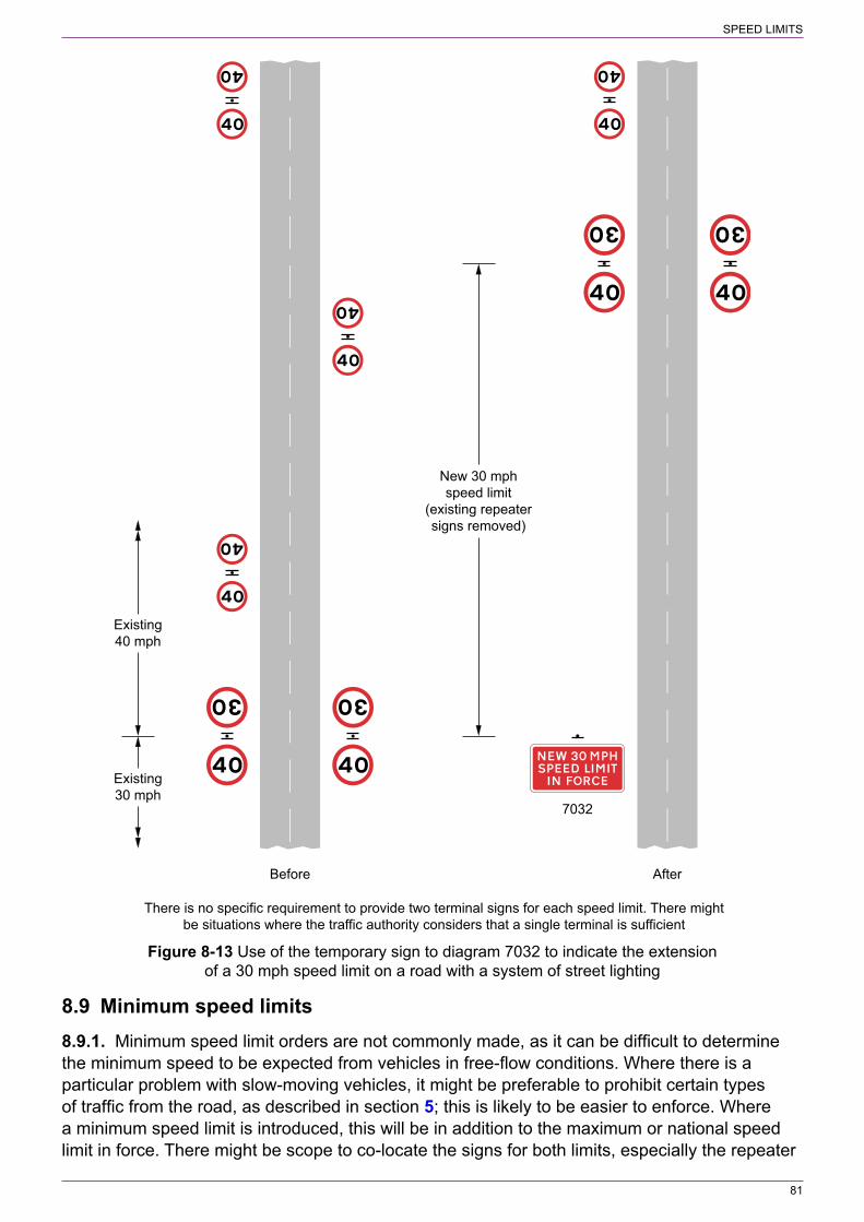
SPEED LIMITS
81
Existing30 mph
Before
Existing40 mph
New 30 mphspeed limit
(existing repeatersigns removed)
After
7032
There is no specific requirement to provide two terminal signs for each speed limit. There mightbe situations where the traffic authority considers that a single terminal is sufficient
Figure 8‑13 Use of the temporary sign to diagram 7032 to indicate the extension of a 30 mph speed limit on a road with a system of street lighting
8.9 Minimum speed limits8.9.1. Minimum speed limit orders are not commonly made, as it can be difficult to determine the minimum speed to be expected from vehicles in free‑flow conditions. Where there is a particular problem with slow‑moving vehicles, it might be preferable to prohibit certain types of traffic from the road, as described in section 5; this is likely to be easier to enforce. Where a minimum speed limit is introduced, this will be in addition to the maximum or national speed limit in force. There might be scope to co‑locate the signs for both limits, especially the repeater

SPEED LIMITS
82
signs; minimum speed limit signs should be mounted below the maximum or national speed limit signs.
8.9.2. The start of a minimum speed limit is indicated by a terminal sign to diagram 672 (S10‑2‑3, see Figure 8‑14). A smaller size is used as a repeater sign. The end of the limit is indicated by a terminal sign to diagram 673 (S10‑2‑4, see Figure 8‑15). The sizes of minimum speed limit terminal and repeater signs are shown in Table 8‑5 and the minimum clear visibility distance in Table 8‑6. A terminal sign must be placed at or as near as practicable to the point where the speed limit begins and ends. There is no specific requirement to provide a sign on each side of the carriageway, although this should be considered where a single sign might be obscured, for example by high‑sided vehicles on a road with two or more lanes in the same direction.
Figure 8‑14 Diagram 672 (S10‑2‑3) Figure 8‑15 Diagram 673 (S10‑2‑4) Minimum speed limit in mph End of minimum speed limit
Table 8‑5 Size of minimum speed limit signs
Maximum speed limit Size of sign (mm)
Terminal Repeater
40 mph and below 600 300
50 mph 600 300
60 mph (dual carriageway) 600 450
National limit (single carriageway) 600 450
National limit (dual carriageway) 900 450
NOTE: For terminal signs, the maximum speed limit is that on the approach.
Table 8‑6 Minimum clear visibility distances in metres for minimum speed limit terminal signs
Dual carriageway road subject to the national speed limit 75
Dual carriageway road subject to a maximum speed limit of 60 mph or a single carriageway road subject to the national speed limit
65
Any other road 50
NOTE: Where terminal signs are provided on each side of the carriageway, the minimum clear visibility distance indicated should be applied to both signs.
Although there is no specific requirement to provide repeater signs, it is for the traffic authority to determine how many are required and where they are placed. However, to ensure that drivers are fully aware of the minimum speed limit in force it is recommended that repeater signs are provided at the intervals shown in Table 8‑7.
Table 8‑7 Recommended spacing of minimum speed limit repeater signs (metres)
Maximum distance between a terminal sign and first repeater 250
Maximum distance between consecutive signs 350
NOTE 1: The recommended spacing of repeaters is the same for all minimum speed limits and types of road.

SPEED LIMITS
83
NOTE 2: The recommended maximum spacing of 350 m applies whether the two adjacent repeater signs are on the same side or on opposite sides of the road.
NOTE 3: Where the signs alternate from one side of the road to another, it is recommended that two signs on the same side of the road are no further apart than 500 m.
NOTE 4: Repeater signs are unlikely to be needed where the length of the speed limit is less than 250 m.
8.10 Informatory signs for speed cameras8.10.1. Signs prescribed by the Regulations for indicating speed cameras are diagrams 878, 880 and 880.1 (S11‑2‑63, 64 and 65 respectively, see Figures 8‑16, 8‑17 and 8‑18). The sign to diagram 878, with the legend “Speed cameras”, is used to indicate the boundary of an area where camera enforcement is taking place. When placed within such an area to act as a reminder to drivers that cameras are being used, the legend may be omitted, with the sign often co‑located with a speed limit repeater sign (see Figure 8‑19). Where camera enforcement utilises two or more cameras to measure the average speed of a vehicle over a set distance, the legend on diagram 878 is varied to “Average speed check”.
Figure 8‑16 Diagram 878 (S11‑2‑63) Area in which cameras are used to enforce speed limits (Alternative types)
Figure 8‑17 Diagram 880 (S11‑2‑64) Speed Figure 8‑18 Diagram 880.1 (S11‑2‑65) Speed camera ahead on a lit road and reminder of camera ahead on an unlit road and reminder that 30 mph speed limit a national speed limit applies
8.10.2. The size of the sign to diagram 878, when including a legend, is related to the speed of traffic and is specified in Appendix A. The size of the sign without any legend will depend on whether or not it is co‑located with a speed limit sign to either diagram 670 or 671. Where it is mounted on its own, the height of the sign should not be less than the size of the speed limit repeater signs as specified in Table 8‑4. On lit 30 mph roads, the 300 mm size should be used. Where the sign is co‑located with diagram 670 or 671, the size of the sign should be as shown in Figure 8‑19.

SPEED LIMITS
84
Diameter of speed limit roundelequal to 300 mm
300 mm
50 mm
30 mm
300 mm
30 mm
200 mm
30 mm
Diameter of speed limit roundelgreater than 300 mm
0.125 D
0.75 D
0.075 D
D
0.5 D
0.1 D
0.1 D
The backing board must not have any kind of border. The colour may be varied to grey. In street‑lit areas only, the roundel may be varied to diagram 671 (national speed limit)
Figure 8‑19 Co‑located speed limit sign to diagram 670 and camera reminder sign to diagram 878 without any legend
8.10.3. On a lit road with a 30 mph speed limit, 30 mph repeater signs are not permitted. However, the sign to diagram 880 (see Figure 8‑17) may be used to advise drivers that a 30 mph speed limit is being enforced by cameras on roads that do not have repeater signs. This sign must not be used as a substitute for repeater or terminal signs, or to indicate any other limit. The sign should normally be placed on the approach to an enforcement camera. For other speed limits or a 30 mph limit on an unlit road, a repeater sign to diagram 670 may be co‑located with the camera sign to diagram 878 without any legend as shown in Figure 8‑19, especially on the approach to an enforcement camera.
8.10.4. Where a camera is used to enforce the national speed limit on an unlit road, the sign to diagram 880.1 (see Figure 8‑18) may be used, normally on the approach to an enforcement camera. The sign must not be used where there is a system of carriageway lighting: repeater signs to diagram 671 should be used, co‑located with diagram 878 without any legend as appropriate (see Figure 8‑7).
8.10.5. Only one size of sign is prescribed for diagram 880, as it is only ever used on a road with a 30 mph speed limit. Similarly, the sign to diagram 880.1 has only one size as it is used only on roads subject to the national speed limit.
8.10.6. Speed enforcement should be highly visible, with drivers made fully aware of the presence of cameras and of the prevailing speed limit. The camera and speed limit signs should always be clearly visible to drivers, and not obscured by other street furniture or vegetation. The minimum clear visibility distance for the signs should be at least that shown in Table 8‑4. Speed limit repeaters and camera signs should be co‑located where permitted and practicable. For fixed cameras, the speed limit and camera signs should normally be visible to the driver in the same view as the camera. This might require speed limit repeater signs to be spaced at different intervals to those recommended in Table 8‑4 where the signs would not otherwise coincide with camera locations.
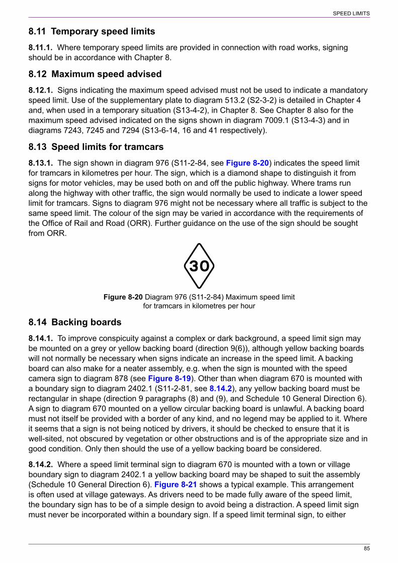
SPEED LIMITS
85
8.11 Temporary speed limits8.11.1. Where temporary speed limits are provided in connection with road works, signing should be in accordance with Chapter 8.
8.12 Maximum speed advised8.12.1. Signs indicating the maximum speed advised must not be used to indicate a mandatory speed limit. Use of the supplementary plate to diagram 513.2 (S2‑3‑2) is detailed in Chapter 4 and, when used in a temporary situation (S13‑4‑2), in Chapter 8. See Chapter 8 also for the maximum speed advised indicated on the signs shown in diagram 7009.1 (S13‑4‑3) and in diagrams 7243, 7245 and 7294 (S13‑6‑14, 16 and 41 respectively).
8.13 Speed limits for tramcars8.13.1. The sign shown in diagram 976 (S11‑2‑84, see Figure 8‑20) indicates the speed limit for tramcars in kilometres per hour. The sign, which is a diamond shape to distinguish it from signs for motor vehicles, may be used both on and off the public highway. Where trams run along the highway with other traffic, the sign would normally be used to indicate a lower speed limit for tramcars. Signs to diagram 976 might not be necessary where all traffic is subject to the same speed limit. The colour of the sign may be varied in accordance with the requirements of the Office of Rail and Road (ORR). Further guidance on the use of the sign should be sought from ORR.
Figure 8‑20 Diagram 976 (S11‑2‑84) Maximum speed limit for tramcars in kilometres per hour
8.14 Backing boards8.14.1. To improve conspicuity against a complex or dark background, a speed limit sign may be mounted on a grey or yellow backing board (direction 9(6)), although yellow backing boards will not normally be necessary when signs indicate an increase in the speed limit. A backing board can also make for a neater assembly, e.g. when the sign is mounted with the speed camera sign to diagram 878 (see Figure 8‑19). Other than when diagram 670 is mounted with a boundary sign to diagram 2402.1 (S11‑2‑81, see 8.14.2), any yellow backing board must be rectangular in shape (direction 9 paragraphs (8) and (9), and Schedule 10 General Direction 6). A sign to diagram 670 mounted on a yellow circular backing board is unlawful. A backing board must not itself be provided with a border of any kind, and no legend may be applied to it. Where it seems that a sign is not being noticed by drivers, it should be checked to ensure that it is well‑sited, not obscured by vegetation or other obstructions and is of the appropriate size and in good condition. Only then should the use of a yellow backing board be considered.
8.14.2. Where a speed limit terminal sign to diagram 670 is mounted with a town or village boundary sign to diagram 2402.1 a yellow backing board may be shaped to suit the assembly (Schedule 10 General Direction 6). Figure 8‑21 shows a typical example. This arrangement is often used at village gateways. As drivers need to be made fully aware of the speed limit, the boundary sign has to be of a simple design to avoid being a distraction. A speed limit sign must never be incorporated within a boundary sign. If a speed limit terminal sign, to either
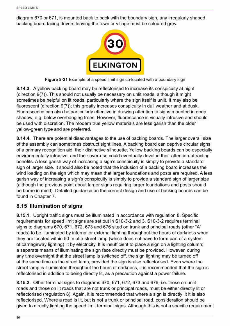
SPEED LIMITS
86
diagram 670 or 671, is mounted back to back with the boundary sign, any irregularly shaped backing board facing drivers leaving the town or village must be coloured grey.
Figure 8‑21 Example of a speed limit sign co‑located with a boundary sign
8.14.3. A yellow backing board may be reflectorised to increase its conspicuity at night (direction 9(7)). This should not usually be necessary on unlit roads, although it might sometimes be helpful on lit roads, particularly where the sign itself is unlit. It may also be fluorescent (direction 9(7)); this greatly increases conspicuity in dull weather and at dusk. Fluorescence can also be particularly effective in drawing attention to signs mounted in deep shadow, e.g. below overhanging trees. However, fluorescence is visually intrusive and should be used with discretion. The modern true yellow materials are less garish than the older yellow‑green type and are preferred.
8.14.4. There are potential disadvantages to the use of backing boards. The larger overall size of the assembly can sometimes obstruct sight lines. A backing board can deprive circular signs of a primary recognition aid: their distinctive silhouette. Yellow backing boards can be especially environmentally intrusive, and their over‑use could eventually devalue their attention‑attracting benefits. A less garish way of increasing a sign’s conspicuity is simply to provide a standard sign of larger size. It should also be noted that the inclusion of a backing board increases the wind loading on the sign which may mean that larger foundations and posts are required. A less garish way of increasing a sign’s conspicuity is simply to provide a standard sign of larger size (although the previous point about larger signs requiring larger foundations and posts should be borne in mind). Detailed guidance on the correct design and use of backing boards can be found in Chapter 7.
8.15 Illumination of signs8.15.1. Upright traffic signs must be illuminated in accordance with regulation 8. Specific requirements for speed limit signs are set out in S10‑3‑2 and 3. S10‑3‑2 requires terminal signs to diagrams 670, 671, 672, 673 and 676 sited on trunk and principal roads (other “A” roads) to be illuminated by internal or external lighting throughout the hours of darkness when they are located within 50 m of a street lamp (which does not have to form part of a system of carriageway lighting) lit by electricity. It is insufficient to place a sign on a lighting column; a separate means of illuminating the sign face directly must be provided. However, during any time overnight that the street lamp is switched off, the sign lighting may be turned off at the same time as the street lamp, provided the sign is also reflectorised. Even where the street lamp is illuminated throughout the hours of darkness, it is recommended that the sign is reflectorised in addition to being directly lit, as a precaution against a power failure.
8.15.2. Other terminal signs to diagrams 670, 671, 672, 673 and 676, i.e. those on unlit roads and those on lit roads that are not trunk or principal roads, must be either directly lit or reflectorised (regulation 8). Again, it is recommended that where a sign is directly lit it is also reflectorised. Where a road is lit, but is not a trunk or principal road, consideration should be given to directly lighting the speed limit terminal signs. Although this is not a specific requirement

SPEED LIMITS
87
of the Regulations, it would minimise the risk of drivers failing to see them. Repeater signs may be either directly lit or reflectorised, although it is unusual for such signs to be directly lit.
8.15.3. 20 mph zone signs to diagrams 674, 675A and 675B may be either directly lit or reflectorised. It is recommended that where the signs are directly lit, they are also reflectorised.
8.15.4. Where two terminal speed limit signs are provided, one on each side of the road, S10‑3‑3 requires they must be illuminated by the same means (i.e. internal illumination, external illumination or reflectorisation).
8.15.5. Where a sign is reflectorised, reflecting material must be applied to the whole sign face except those parts which are coloured black (regulation 8(10)). The optional reflectorisation of yellow backing boards is dealt with in 8.14.3.
8.16 Sign design8.16.1. Speed limit signs must conform in appearance to the diagrams prescribed by the Regulations. The numerals in diagram 670 must be in Transport Heavy alphabet (S17‑2) and be of the correct size, as specified on the working drawing P 670, and be positioned within the roundel as shown on that drawing. The numerals in diagrams 672 and 673 must be in the Transport Medium alphabet (S17‑1).
8.17 Sign mounting8.17.1. Research has shown that drivers have difficulty assimilating information when presented with too many signs (see 1.10.1). Terminal speed limit signs should not therefore normally be co‑located with other signs, except for simple boundary signs to diagram 2402.1 (see Figure 8‑21). At junctions where signs are needed to indicate the start or end of zonal restrictions or a requirement to stop or give way, these may be co‑located with terminal speed limit signs to avoid sign clutter and where separate mounting would cause one sign to obstruct the driver’s view of another. In such cases signs should be placed in the following order from top to bottom:
a) STOP or GIVE WAY signb) terminal speed limit signc) other circular signd) rectangular zonal sign.
8.17.2. Not more than one other sign should normally be erected on the same post as a terminal speed limit sign. Where a clearway sign to diagram 642 (S3‑2‑4) accompanied by either a distance plate or an “End” plate is mounted below a speed limit sign, the plate should be butted up against the lower edge of the clearway sign. There should be a space equal to twice the width of the red border between the roundels to ensure that there is no ambiguity.
8.17.3. The most cost‑effective arrangement for placing speed limit repeater signs as recommended in Table 8‑4 is to mount the signs back to back on alternate sides of the carriageway as illustrated in the left hand part of Figure 8‑13. Repeater signs may be co‑located with other signs such as warning signs. The repeater sign will be mounted below the warning sign. They should not normally be co‑located with directional signs, as drivers searching for a destination are likely to overlook the repeater sign.
8.17.4. Speed limit signs should always be mounted at heights that ensure drivers can easily see them, and where they will be free from obscuration by vegetation or other street furniture. The normal mounting height for a traffic sign, measured to its lower edge, is between 900 mm
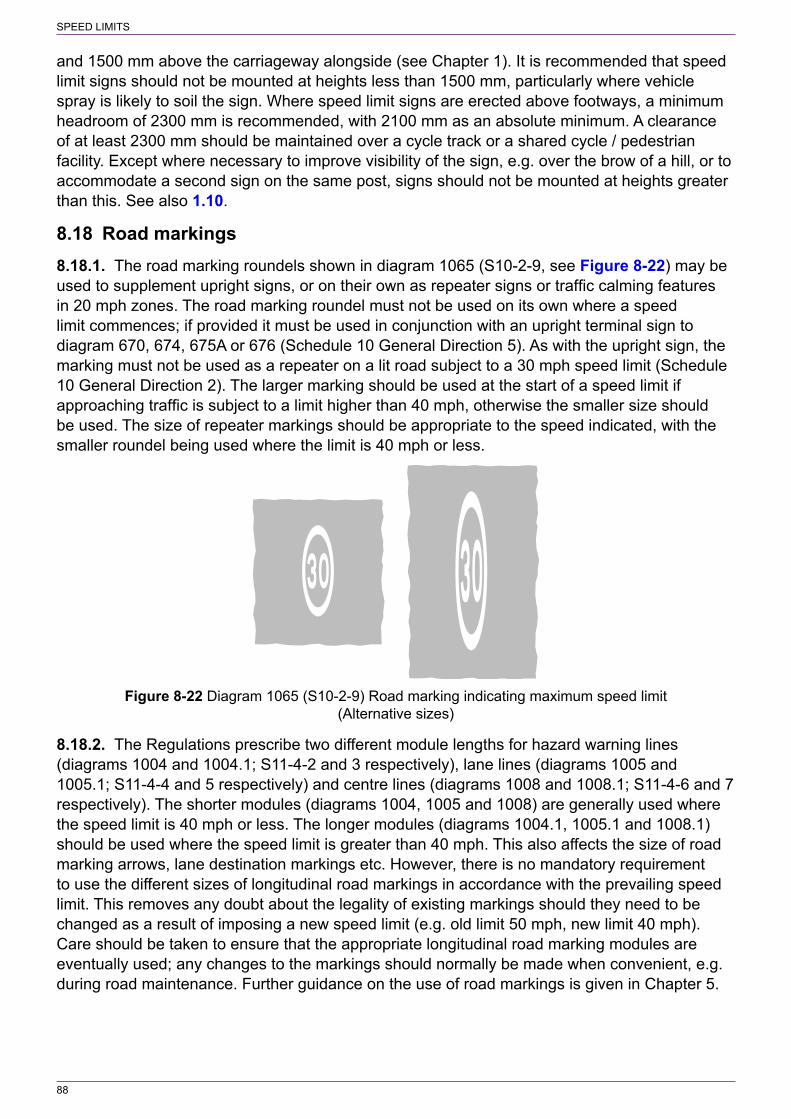
SPEED LIMITS
88
and 1500 mm above the carriageway alongside (see Chapter 1). It is recommended that speed limit signs should not be mounted at heights less than 1500 mm, particularly where vehicle spray is likely to soil the sign. Where speed limit signs are erected above footways, a minimum headroom of 2300 mm is recommended, with 2100 mm as an absolute minimum. A clearance of at least 2300 mm should be maintained over a cycle track or a shared cycle / pedestrian facility. Except where necessary to improve visibility of the sign, e.g. over the brow of a hill, or to accommodate a second sign on the same post, signs should not be mounted at heights greater than this. See also 1.10.
8.18 Road markings8.18.1. The road marking roundels shown in diagram 1065 (S10‑2‑9, see Figure 8‑22) may be used to supplement upright signs, or on their own as repeater signs or traffic calming features in 20 mph zones. The road marking roundel must not be used on its own where a speed limit commences; if provided it must be used in conjunction with an upright terminal sign to diagram 670, 674, 675A or 676 (Schedule 10 General Direction 5). As with the upright sign, the marking must not be used as a repeater on a lit road subject to a 30 mph speed limit (Schedule 10 General Direction 2). The larger marking should be used at the start of a speed limit if approaching traffic is subject to a limit higher than 40 mph, otherwise the smaller size should be used. The size of repeater markings should be appropriate to the speed indicated, with the smaller roundel being used where the limit is 40 mph or less.
Figure 8‑22 Diagram 1065 (S10‑2‑9) Road marking indicating maximum speed limit (Alternative sizes)
8.18.2. The Regulations prescribe two different module lengths for hazard warning lines (diagrams 1004 and 1004.1; S11‑4‑2 and 3 respectively), lane lines (diagrams 1005 and 1005.1; S11‑4‑4 and 5 respectively) and centre lines (diagrams 1008 and 1008.1; S11‑4‑6 and 7 respectively). The shorter modules (diagrams 1004, 1005 and 1008) are generally used where the speed limit is 40 mph or less. The longer modules (diagrams 1004.1, 1005.1 and 1008.1) should be used where the speed limit is greater than 40 mph. This also affects the size of road marking arrows, lane destination markings etc. However, there is no mandatory requirement to use the different sizes of longitudinal road markings in accordance with the prevailing speed limit. This removes any doubt about the legality of existing markings should they need to be changed as a result of imposing a new speed limit (e.g. old limit 50 mph, new limit 40 mph). Care should be taken to ensure that the appropriate longitudinal road marking modules are eventually used; any changes to the markings should normally be made when convenient, e.g. during road maintenance. Further guidance on the use of road markings is given in Chapter 5.

89
9 BUS LANES AND GATES
9.1 General9.1.1. This section describes bus lanes and gates that use prescribed signs, i.e. facilities for buses, cyclists, taxis and solo motor cycles. Where certain vehicles, such as private hire vehicles (minicabs), are permitted to use a facility, this is indicated by the legend “authorised vehicles”. Where other vehicles such as heavy goods vehicles are to be admitted, the signs will require authorisation and guidance should be sought from the national authority. Working drawings for some non‑prescribed signs, including those for bus lanes that may be used by heavy goods vehicles, and those for high‑occupancy vehicle lanes, are available on request from the Department.
9.1.2. A bus lane is mandatory and requires an order which prohibits other vehicles from using that part of the carriageway while the lane is in operation. It may be either a with‑flow lane or, in a one‑way road, a contraflow lane. The latter must be operational at all times, but a with‑flow bus lane may operate for only part of the day. With‑flow bus lanes on the left hand side of the carriageway are usually available to both buses and pedal cycles; it is not considered safe to force cyclists to use the general traffic lane where they would be confined between two streams of motor traffic. There might, however, be situations where a with‑flow lane leads directly to a bus‑only facility that is not available to pedal cycles (e.g. a bus‑only gate or the entrance to a bus station). In these circumstances, where the bus lane excludes cyclists, the regulatory upright traffic sign will need authorisation by the national authority. Where permitted by the order, taxis (hackney carriages), solo motor cycles and authorised vehicles may use a with‑flow bus lane as appropriate. A contraflow bus lane is generally used by buses only, but pedal cycles may also use the lane where permitted by the order.
9.1.3. The Regulations permit signs to be varied to indicate centre or off side with‑flow lanes. Where these are not appropriate for use by pedal cycles, as with nearside lanes the upright regulatory sign will need to be authorised. Centre or off side with‑flow lanes are likely to be used as a lead‑in to a bus gate at junction ahead (see 9.3.9). Where an off‑side lane is provided in a two‑way road, it should generally be separated from the opposing flow of traffic by a solid island or hatch markings to diagram 1040 (S11‑4‑23) where the boundary line is formed by the marking to diagram 1049A (S9‑6‑11, see 9.3.2 and Chapter 5). Contraflow lanes, in the direction of travel along the lane, should always be on the nearside.
9.1.4. Bus‑only streets and bus gates are lengths of road or parts of a road where access is restricted to buses, although sometimes other vehicles such as pedal cycles, solo motor cycles, taxis and trams are also admitted.
9.1.5. Bus lanes and bus gates may be surfaced in coloured material in order to demarcate them more emphatically and to discourage encroachment by motor vehicles. However, coloured surfacing has no legal significance; it is the prescribed traffic signs and road markings that establish the legal status of a bus facility.
9.2 Waiting and loading restrictions9.2.1. Waiting should always be prohibited within a bus lane during its operational period. Signs and markings should be provided in accordance with section 13 and these will indicate the duration of the prohibition which may be the same as that for the bus lane or longer. Where waiting is prohibited at all times and the bus lane operates for a shorter period, the road marking

BUS LANES AND GATES
90
will be the double yellow line to diagram 1018.1 (S7‑4‑1). Upright “no waiting” signs are not used in this case.
9.2.2. Loading will also normally be prohibited during the operational hours, although there may occasionally be reasons why it needs to be allowed, such as off‑peak loading in a 24‑hour bus lane. Any prohibition of loading, whether during or outside the hours when the lane is in force, should be indicated with signs and markings in accordance with section 13.
9.2.3. A bus lane may include bus stop clearways; these should be signed in accordance with section 13.
9.3 With‑flow bus lanes9.3.1. Figure 9‑1 shows a typical layout for a nearside with‑flow lane. Where roads are wide enough, the bus lane should be 4.25 m wide, certainly at least 4 m (see LTN 1/97 ‘Keeping Buses Moving’). This allows buses to overtake cycles safely and reduces the likelihood of interference from general traffic in the adjacent lane. The minimum recommended width is 3 m.
9.3.2. The bus lane is separated from the rest of the carriageway by a continuous line to diagram 1049A (S9‑6‑11). The width of the line is 250 or 300 mm depending upon site conditions, particularly the width of road available. The wider line might be appropriate where the speed limit is 40 mph or greater. Road studs are not prescribed for use with the boundary marking to diagram 1049A, and must not be used.
9.3.3. The start of the lane is marked with a broken line to diagram 1010 (S11‑4‑10), the same width as the 1049A marking, and normally laid at a taper no sharper than 1:10. There may be situations where it is not practicable to provide a taper of 1:10 and a sharper taper is necessary. In such circumstances, care should be taken to ensure that traffic is directed away from the start of the bus lane in a safe manner. Where the road widens to allow a bus lane to develop on the left (or on the right in the case of an off side bus lane), the line to diagram 1010 will be parallel to the flow of traffic rather than laid diagonally. The bus lane should not start in such a position that the marking to diagram 1010 would extend across a side road junction. Deflection arrows to diagram 1014 (S11‑4‑14, see Chapter 5) 4.5 m in length should be placed 15 m and 30 m upstream of the start of any taper where general traffic is required to deflect but certain vehicles are not. Longer arrows and greater spacing should be used where the speed limit is more than 40 mph (see also 9.3.8). The arrow length should be 6 m for 50 or 60 mph, and 9 m for 70 mph.
9.3.4. Advance indication of a with‑flow bus lane is provided by the sign to diagram 958 (S11‑2‑37, see Figure 9‑2) varied as appropriate. Where the speed limit is 20 mph or 30 mph, the sign should be sited 30 m in advance of the lead‑in taper formed by the road marking to diagram 1010 (see 9.3.3), with a minimum clear visibility distance of 45 m. Where the speed limit is 40 mph, the sign should be sited 45 m in advance of the taper with a minimum clear visibility distance of 60 m. For a speed limit of 50 mph the sign should be sited 90 m in advance of the taper with a minimum clear visibility distance of 75 m.
9.3.5. The sign to diagram 959B (S9‑4‑10, see Figure 9‑3) is a regulatory sign and should be placed as near as practicable to the start of the lane, i.e. where the continuous line to diagram 1049A begins. Although there is no specific requirement to provide repeater signs, it is for the traffic authority to determine how many are required and where they are placed. However, to ensure that drivers, whether entering from a side road or proceeding alongside the bus lane, are informed or reminded of the restriction, a sign should normally be placed just beyond each side road. This applies to road junctions on the same side of the road as the bus lane and to those on the opposite side where traffic can turn right to enter the major road alongside the bus lane. Additional repeater signs should be considered where the distance between them would

BUS LANES AND GATES
91
otherwise exceed 300 m. Repeater signs are unlikely to be needed where the overall length of the bus lane is less than 300 m and there are no junctions along its length.
one way
Diagram 958
Diagram 959B
Diagram 959B
Diagram 959B
one way
10 mapprox
Diagram 1010
Diagram 1048
Diagram1049A
NOT TOSCALE
Diagram 959B
Diagram 877
30 mapprox
Diagram 964
Signal-controlledjunction
Diagram1050
Diagram1010
Diagram 1010
Diagram1014
Figure 9‑1 Typical layout for a with‑flow bus lane
9.3.6. The signs to diagrams 958 and 959B should indicate the type of vehicles that are allowed to use the lane, i.e. they must show the bus symbol, with or without the legend “local”, the cycle symbol and, optionally, any combination of the legend “taxi”, the legend “authorised

BUS LANES AND GATES
92
vehicles” and the solo motor cycle symbol. The legend “local” on the bus symbol indicates that the lane may be used only by those buses operating a local service as defined in Schedule 1. The bus symbol without the legend “local” means that any bus, as defined in Schedule 1, may use the lane. The signs to diagrams 958 and 959B may be varied to indicate centre or off side bus lanes. The detailed design of the signs, including their variants, is shown on the working drawings.
9.3.7. The times during which the bus lane operates are shown in the bottom panel of the signs to diagrams 958 and 959B. Where there is more than one bus lane along a particular length of road or within the same geographical area, the times of operation should be consistent, where possible, to avoid driver confusion. The working drawings show how time periods are accommodated within the fixed width of the signs. Time periods must be expressed in the manner described in S18‑1 (see also Chapter 7). The time may be varied to “At all times”, but this should be used only to avoid possible confusion where a 24‑hour bus lane is introduced in the vicinity of another bus lane that does not operate at all times; otherwise the bottom panel should be omitted (indicating that the lane operates for 24 hours on every day of the week).
Figure 9‑2 Diagram 958 (S11‑2‑37) With‑flow Figure 9‑3 Diagram 959B (S9‑4‑10) With‑flow bus lane ahead (Alternative types) bus lane (Alternative types)
9.3.8. The road marking “BUS LANE” to diagram 1048 (S9‑6‑14, see Figure 9‑4) is used to indicate all types of with‑flow bus lanes, including those where other vehicles are allowed. The marking should normally be placed at the beginning of the lane, i.e. where the line to diagram 1049A commences. Where the speed limit is greater than 40 mph (e.g. a commuter route with little frontage development and a speed limit of 50 mph), the larger marking with 2800 mm high letters should be used, otherwise the smaller marking with 1600 mm high letters is appropriate. There is no specific requirement to use the road marking in conjunction with diagram 959B which means that they need not be placed together at particular locations. It is for the traffic authority to determine the number of upright signs and road markings that are required and where they are placed. However, the marking must not be used as a substitute for diagram 959B, relying only on diagram 958 to indicate the vehicles permitted to use the lane; the Regulations prescribe the marking as being a bus lane that may be used by vehicles indicated on the sign to diagram 959B.
9.3.9. The end of a with‑flow bus lane will usually be obvious through the termination of the diagram 1049A marking. If considered necessary due to observed driver behaviour, an upright sign to diagram 964 (S9‑4‑11, see Figure 9‑5) may be sited as shown in Figure 9‑1. The lane should normally be stopped short of the Stop line at traffic signal controlled junctions.

BUS LANES AND GATES
93
Figure 9‑4 Diagram 1048 (S9‑6‑14) Traffic Figure 9‑5 Diagram 964 (S9‑4‑11) lane reserved for buses and other vehicles as indicated on the sign to diagram 959B
9.3.10. Where the bus lane is on the nearside, the carriageway is marked with the double arrow to diagram 1050 (S9‑6‑12, see Figure 9‑6) indicating ahead in both lanes for all traffic (see Figure 9‑1). The permitted variant of diagram 1050, showing a left‑turn arrow, is appropriate where non‑bus lane traffic should move only into the left‑hand lane if turning left at the junction, the appropriate double arrow is to diagram 1050.1 (S9‑6‑13, see Figure 9‑7). Detailed dimensions of the arrow markings are shown on the working drawings. The purpose of the “set‑back” is to ensure that full saturation flow can be sustained throughout the green period at traffic signals, thus minimising the delays to other traffic. It also facilitates, and makes safer, left or right turns (as appropriate) at the junction. As a general guide, the length of the set‑back (in metres) should normally be twice the minimum green time (in seconds), although it may be necessary to adjust this if there are special local site conditions or to take account of the variations in green time in active‑response UTC systems. A with‑flow bus lane should be brought up to the Stop line at a traffic signal only—
a) if a reduction in capacity of the junction is acceptable;b) if safe provision can be made for any turning traffic;c) if right‑turning traffic alongside a nearside bus lane can be accommodated in such a way
that it does not restrict flow in the ahead lanes; ord) where the bus lane continues beyond the junction and there is no turning movement across
that lane for other traffic.
9.3.11. At roundabouts, a set‑back for a nearside bus lane should be provided to allow left‑turning traffic to take the nearside lane, and to ensure that the full width of the roundabout entry is available to all traffic at peak periods. The set‑back distance should be determined on site, unless the roundabout is controlled by traffic signals in which case it should accord with the guidance for signal controlled junctions given above.
9.3.12. The signs to diagrams 958, 959B and 964 are prescribed in three sizes. The smallest size should be used on roads with a speed limit of 20 mph or 30 mph. The next size is for use on roads with a 40 mph speed limit. The largest size is for use where a bus lane is introduced on a road with a higher speed limit.
9.3.13. Where a nearside bus lane passes a junction with a major left‑turning flow into the side road, the line to diagram 1049A should be replaced with a broken line to diagram 1010 (see Figure 9‑1). The broken line should commence 30 m in advance of the junction, and have the same width as the line to diagram 1049A. It should be accompanied by the arrow to diagram 1050 indicating a left turn (see Figure 9‑6). At other junctions, the diagram 1049A marking should be terminated approximately 10 m before the junction (or at the junction if the minor road is one‑way towards the major road). In each case the bus lane recommences beyond the junction in combination with a marking to diagram 1010 (see Figure 9‑1). It is important to ensure that the marking to diagram 1049A is terminated correctly, so that drivers turning left can move across to do so safely without needing to cross the continuous line.

BUS LANES AND GATES
94
Figure 9‑6 Diagram 1050 (S9‑6‑12) Indication of traffic movements at end of nearside bus lane or intermediate junction (Alternative types)
Figure 9‑7 Diagram 1050.1 (S9‑6‑13) Indication of traffic movements at end of off‑side bus lane or intermediate junction (Alternative types)
9.3.14. The sign to diagram 877 (S11‑2‑22, see Figure 9‑8) may be used at an intermediate junction as shown in Figure 9‑1. The legend on the sign, above the red block, may be “Bus lane”, “Except buses” or “Except buses & cycles”. The legend “Bus lane” is likely to be appropriate in most cases, particularly where other vehicles such as taxis are permitted to use the lane. This legend also indicates that the bus lane continues beyond the junction. “Except buses” and “Except buses & cycles” would be used where the road ahead is for buses only or buses and cycles. In this case, other lanes indicated on the sign are likely to be turn left or turn right (e.g. the right hand arrow in Figure 9‑8 would be a right turn arrow and not an ahead arrow). When used on a primary route, the colour of the sign is varied to a green background with white arrows, legend and border. Four sizes are prescribed; the smallest should be used on roads with a speed limit of 20 mph or 30 mph. The next size is appropriate for roads with a 40 mph speed limit. The two largest sizes are intended for use on roads with a speed limit greater than 40 mph. The “End of bus lane” sign to diagram 964 is not used at intermittent breaks in the bus lane.
Figure 9‑8 Diagram 877 (S11‑2‑22) Appropriate traffic lanes for manoeuvres at junction ahead (variant)
9.3.15. The sign to diagram 962 (S11‑2‑34, see Figure 9‑9) may be provided on side roads to warn emerging drivers of the presence of a with‑flow bus lane on the major road. The only

BUS LANES AND GATES
95
symbol shown on the sign is the bus symbol (not the local bus symbol) even though the bus lane might be used by other vehicles. The placing of a sign to diagram 959B alongside the bus lane will indicate to drivers turning from the side road which vehicles may use the lane. The sign to diagram 962 should not be necessary where a bus lane commences downstream of the junction, provided that a driver turning into the major road would see a sign to diagram 958 in good time to react to it. The arrow on the sign indicates the direction of travel within the bus lane. The time period should be omitted where the bus lane operates at all times.
9.3.16. The sign to diagram 962 is most likely to be used where a nearside bus lane is on the same side of the major road as the side road; in this case the arrow will point to the left. It will not normally be necessary to provide a sign where the bus lane is on the opposite side of the major road; in most cases the presence of the continuous line to diagram 1049A and a sign to diagram 959B should give adequate warning to drivers as they turn right at the junction. Drivers turning left at the junction do not need to be told that there is a bus lane on the opposite side of the road. Where there is a banned turn from the side road and this prevents traffic from turning into the major one in the direction of travel of the bus lane, a sign to diagram 962 should not be used.
Figure 9‑9 Diagram 962 (variant) (S11‑2‑34) Bus lane on road at junction ahead with indication of times of operation (Alternative types)
9.3.17. Where there are nearside with‑flow bus lanes on both sides of the major road and there are no banned turns, the sign to diagram 962 with the legend “Bus lanes” and without an arrow should be used. If the two lanes operate at different times, a time period should not be shown on the sign; drivers will be informed of the period of operation by the sign to diagram 959B after turning into the major road. Where there are two bus lanes in the major road and the right turn from the side road is prohibited, the sign to diagram 962 should indicate only the bus lane to the left (i.e. the sign with a left turn arrow and legend “Bus lane” should be used). Figure 9‑10 shows examples of the use of diagram 962.
9.3.18. Two sizes are prescribed for the sign to diagram 962; in most cases the smaller size will be sufficient. The sign should be mounted below any GIVE WAY or STOP sign or, if the junction is controlled by traffic signals, mounted a sufficient distance in advance of the junction so as not to obstruct the view of the signal head.
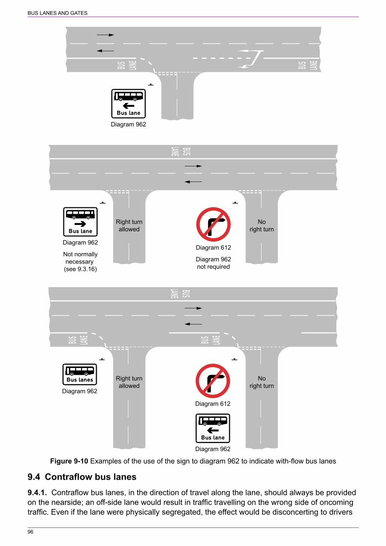
BUS LANES AND GATES
96
Diagram 962
Diagram 612
Diagram 962
Diagram 962
Right turnallowed
Noright turn
Diagram 612
Diagram 962not required
Diagram 962
Not normallynecessary (see 9.3.16)
Noright turn
Right turnallowed
Figure 9‑10 Examples of the use of the sign to diagram 962 to indicate with‑flow bus lanes
9.4 Contraflow bus lanes9.4.1. Contraflow bus lanes, in the direction of travel along the lane, should always be provided on the nearside; an off‑side lane would result in traffic travelling on the wrong side of oncoming traffic. Even if the lane were physically segregated, the effect would be disconcerting to drivers
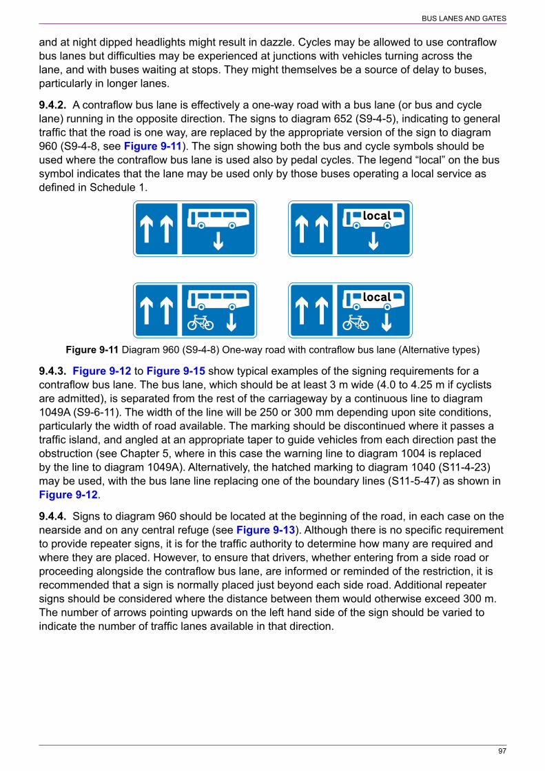
BUS LANES AND GATES
97
and at night dipped headlights might result in dazzle. Cycles may be allowed to use contraflow bus lanes but difficulties may be experienced at junctions with vehicles turning across the lane, and with buses waiting at stops. They might themselves be a source of delay to buses, particularly in longer lanes.
9.4.2. A contraflow bus lane is effectively a one‑way road with a bus lane (or bus and cycle lane) running in the opposite direction. The signs to diagram 652 (S9‑4‑5), indicating to general traffic that the road is one way, are replaced by the appropriate version of the sign to diagram 960 (S9‑4‑8, see Figure 9‑11). The sign showing both the bus and cycle symbols should be used where the contraflow bus lane is used also by pedal cycles. The legend “local” on the bus symbol indicates that the lane may be used only by those buses operating a local service as defined in Schedule 1.
Figure 9‑11 Diagram 960 (S9‑4‑8) One‑way road with contraflow bus lane (Alternative types)
9.4.3. Figure 9‑12 to Figure 9‑15 show typical examples of the signing requirements for a contraflow bus lane. The bus lane, which should be at least 3 m wide (4.0 to 4.25 m if cyclists are admitted), is separated from the rest of the carriageway by a continuous line to diagram 1049A (S9‑6‑11). The width of the line will be 250 or 300 mm depending upon site conditions, particularly the width of road available. The marking should be discontinued where it passes a traffic island, and angled at an appropriate taper to guide vehicles from each direction past the obstruction (see Chapter 5, where in this case the warning line to diagram 1004 is replaced by the line to diagram 1049A). Alternatively, the hatched marking to diagram 1040 (S11‑4‑23) may be used, with the bus lane line replacing one of the boundary lines (S11‑5‑47) as shown in Figure 9‑12.
9.4.4. Signs to diagram 960 should be located at the beginning of the road, in each case on the nearside and on any central refuge (see Figure 9‑13). Although there is no specific requirement to provide repeater signs, it is for the traffic authority to determine how many are required and where they are placed. However, to ensure that drivers, whether entering from a side road or proceeding alongside the contraflow bus lane, are informed or reminded of the restriction, it is recommended that a sign is normally placed just beyond each side road. Additional repeater signs should be considered where the distance between them would otherwise exceed 300 m. The number of arrows pointing upwards on the left hand side of the sign should be varied to indicate the number of traffic lanes available in that direction.
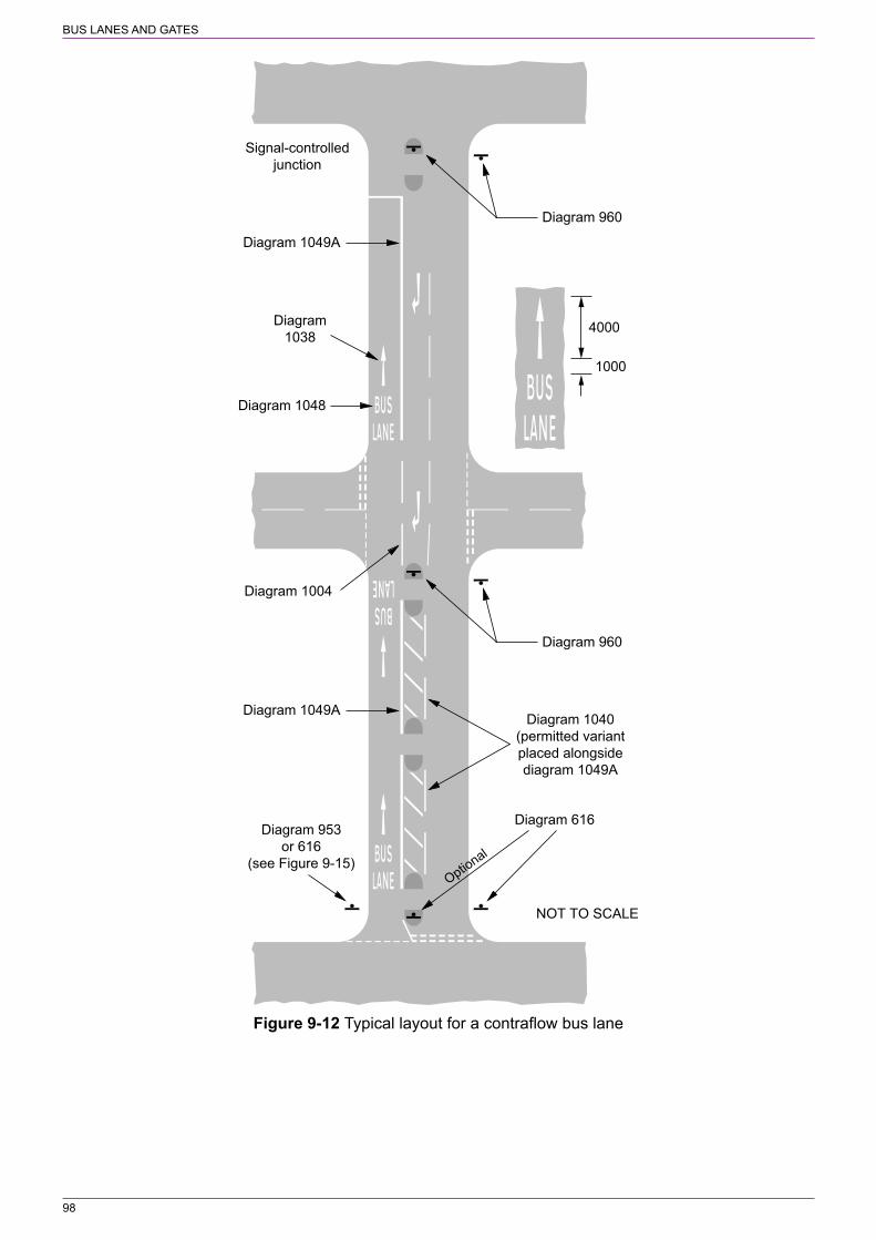
BUS LANES AND GATES
98
NOT TO SCALE
Signal-controlledjunction
Diagram 1049A
Diagram 616
Diagram 1040(permitted variantplaced alongsidediagram 1049A
Diagram1038
4000
1000
Diagram 1004
Diagram 953or 616
(see Figure 9-15)
Diagram 960
Diagram 1048
Diagram 1049A
Diagram 960
Optional
Figure 9‑12 Typical layout for a contraflow bus lane

BUS LANES AND GATES
99
Diagram 960
Diagram 960
Figure 9‑13 Example of signs indicating contraflow bus lane to other drivers
Diagram 616
Diagram 953
Optional
Diagram 616 Diagram 616
Optional
Figure 9‑14 Start of contraflow bus‑only lane Figure 9‑15 Start of contraflow bus‑only lane indicated by a sign to diagram 953 indicated by signs to diagram 616

BUS LANES AND GATES
100
9.4.5. The start of the contraflow lane should be separated from opposing traffic by a refuge in the centre of the road. The exit side of the road, used by all traffic, should be protected by “no entry” signs to diagram 616 (S3‑2‑10) as for ordinary one‑way roads. Where a bollard is provided on the refuge, this may include a “no entry” sign, but a full‑size sign should also be provided. A contraflow bus lane may be signed by either the appropriate version of diagram 953 (S3‑2‑33, see Figure 9‑16) as shown in Figure 9‑14 or the “no entry” sign to diagram 616 as shown in Figure 9‑15. Where diagram 953 is used, the variant showing both the bus and cycle symbols should be used where pedal cycles are permitted to use the lane. The legend “local” on the bus symbol indicates that the lane may be used only by those buses operating a local service as defined in Schedule 1. In Figure 9‑14, one “no entry” sign may be used instead of two. Where the “no entry” sign is used as shown in Figure 9‑15, two “no entry” signs may be used instead of three. Only the sign on the left hand side of the road has a supplementary plate; this will have one of the following legends as appropriate:
“Except” and—a) “buses” or “local buses”;b) “buses and cycles” or “buses & cycles”; orc) “local buses and cycles” or “local buses & cycles”.
Figure 9‑16 Diagram 953 (variant) (S3‑2‑33) Route for use only by buses and, where indicated, pedal cycles (Alternative types)
9.4.6. It is for the traffic authority to determine whether to use diagram 953 or the “no entry” sign, bearing in mind that the aim should be to provide consistent signing within a particular area. The “no entry” sign is likely to be appropriate where a central refuge cannot be provided at the start of the bus lane. In this case, the “Except buses” plate or its appropriate variant, should be used only with the sign on the left hand side of the road (similar to a road with a central refuge as shown in Figure 9‑15). It should be noted that the “Only” plate, previously used with diagram 953, is no longer prescribed by the Regulations. “End of bus lane” signs to diagram 964 (S9‑4‑11) are not used with contraflow lanes, nor are time plates, as these lanes operate continuously.
9.4.7. Two sizes are prescribed for the sign to diagram 960. The smaller size will usually be adequate. The larger size might be more appropriate where there are more than two lanes for general traffic or where there is a particular conspicuity problem. The “no entry” sign to diagram 616 should be 750 mm in diameter with the supplementary plate having an x‑height of 62.5 mm. Where the sign to diagram 953 is used, this should normally be 750 mm in diameter.
9.4.8. At junctions on the nearside, the contraflow lane should be discontinued, but unlike with‑flow lanes a broken line is not necessary on the approach since there will be no left‑turning traffic (except possibly buses, and cycles where they are permitted within the lane). “BUS LANE” road markings to diagram 1048 (S9‑6‑14, see Figure 9‑4) with 1600 mm high letters, together with 4 m long direction arrows to diagram 1038 (S11‑4‑20, see Chapter 5), should be placed on each side of the junction, as shown in Figure 9‑12 and Figure 9‑13, so that they can be read by drivers approaching from the side road. These markings should also be provided at the start of the contraflow lane and may be repeated along the road at locations in addition to road junctions. However, there is no specific requirement to use the road marking in conjunction with diagram 960, which means that they need not be placed at the same frequency. It is for the

BUS LANES AND GATES
101
traffic authority to determine the number of upright signs and road markings that are required and where they are placed. It should be noted that the marking to diagram 1048.1 (contraflow bus and cycle lane) is no longer prescribed; contraflow lanes are now treated in the same way as with‑flow lanes, i.e. diagram 1048 should be used whether or not pedal cycles are permitted to use the lane.
9.4.9. Where central islands are provided along the lane, these should have “keep left” signs to diagram 610 (S3‑2‑3) in both directions, as they would on any two‑way road.
9.4.10. The sign to diagram 962 (S11‑2‑34, see Figure 9‑9), without any time period, should be provided on side roads to warn emerging drivers of the presence of a contraflow bus‑only lane on the major road. If cycles are also permitted to use the lane, the sign to diagram 962.2 (S11‑2‑36, see Figure 9‑17) should be used. For a bus lane on the same side of the major road as the side road, the arrow will point to the left. The sign should be accompanied by the “no left turn” sign to diagram 613 (S3‑2‑8). Where buses and, if appropriate, cycles are permitted to turn left into the bus lane, the “no left turn” sign should have a supplementary plate “Except buses”, “Except local buses”, “Except buses and cycles” or “Except local buses and cycles”. Where the bus lane is on the opposite side of the major road, the arrow on the sign to diagram 962 or 962.2 will point to the right. A “no right turn” sign to diagram 612 (S3‑2‑7) should be provided and, where buses and cycles are permitted to turn right to enter the lane, used with an appropriate supplementary plate (as for the “no left turn” sign above). Examples of the use of diagrams 962 and 962.2 are shown in Figure 9‑18. It should be noted that the “local bus” symbol is not used on these signs, the supplementary plate to diagram 612 or 613 will indicate which type of bus (if any) may turn at the junction to use the contraflow lane.
9.4.11. Two sizes are prescribed for the signs to diagram 962 and 962.2; in most cases the smaller size will be sufficient. The sign should be mounted below any GIVE WAY or STOP sign or, if the junction is controlled by traffic signals, mounted a sufficient distance in advance of the junction so as not to obstruct the view of the signal head.
Figure 9‑17 Diagram 962.2 (S11‑2‑36) Contraflow bus and cycle lane on road at junction ahead (Alternative types)
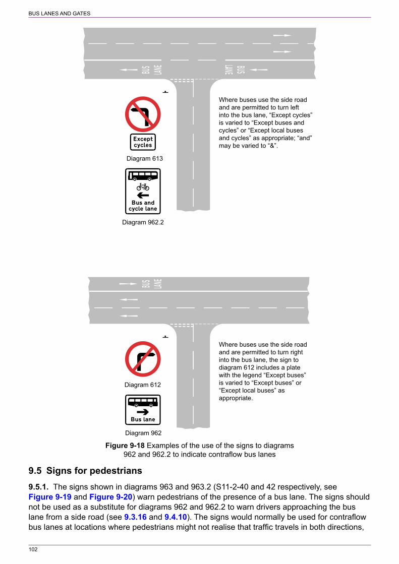
BUS LANES AND GATES
102
Diagram 612
Diagram 962
Diagram 613
Diagram 962.2
Where buses use the side roadand are permitted to turn leftinto the bus lane, “Except cycles”is varied to “Except buses andcycles” or “Except local busesand cycles” as appropriate; “and”may be varied to “&”.
Where buses use the side roadand are permitted to turn rightinto the bus lane, the sign todiagram 612 includes a platewith the legend “Except buses”is varied to “Except buses” or“Except local buses” asappropriate.
Figure 9‑18 Examples of the use of the signs to diagrams 962 and 962.2 to indicate contraflow bus lanes
9.5 Signs for pedestrians9.5.1. The signs shown in diagrams 963 and 963.2 (S11‑2‑40 and 42 respectively, see Figure 9‑19 and Figure 9‑20) warn pedestrians of the presence of a bus lane. The signs should not be used as a substitute for diagrams 962 and 962.2 to warn drivers approaching the bus lane from a side road (see 9.3.16 and 9.4.10). The signs would normally be used for contraflow bus lanes at locations where pedestrians might not realise that traffic travels in both directions,
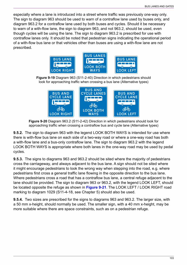
BUS LANES AND GATES
103
especially where a lane is introduced into a street where traffic was previously one‑way only. The sign to diagram 963 should be used to warn of a contraflow lane used by buses only, and diagram 963.2 for a contraflow lane used by both buses and cycles. Should it be necessary to warn of a with‑flow lane, the sign to diagram 963, and not 963.2, should be used, even though cycles will be using the lane. The sign to diagram 963.2 is prescribed for use with contraflow lanes only. It should be noted that pedestrian signs indicating the operational period of a with‑flow bus lane or that vehicles other than buses are using a with‑flow lane are not prescribed.
Figure 9‑19 Diagram 963 (S11‑2‑40) Direction in which pedestrians should look for approaching traffic when crossing a bus lane (Alternative types)
Figure 9‑20 Diagram 963.2 (S11‑2‑42) Direction in which pedestrians should look for approaching traffic when crossing a contraflow bus and cycle lane (Alternative types)
9.5.2. The sign to diagram 963 with the legend LOOK BOTH WAYS is intended for use where there is with‑flow bus lane on each side of a two‑way road or where a one‑way road has both a with‑flow lane and a bus‑only contraflow lane. The sign to diagram 963.2 with the legend LOOK BOTH WAYS is appropriate where both lanes in the one‑way road may be used by pedal cycles.
9.5.3. The signs to diagrams 963 and 963.2 should be sited where the majority of pedestrians cross the carriageway, and always adjacent to the bus lane. A sign should not be sited where it might encourage pedestrians to look the wrong way when stepping into the road, e.g. where pedestrians first cross a general traffic lane flowing in the opposite direction to the bus lane. Where pedestrians cross a road that has a contraflow bus lane, a central refuge adjacent to the lane should be provided. The sign to diagram 963 or 963.2, with the legend LOOK LEFT, should be located opposite the refuge as shown in Figure 9‑21. The LOOK LEFT / LOOK RIGHT road marking to diagram 1029 (S11‑4‑18, see Chapter 5) should also be used.
9.5.4. Two sizes are prescribed for the signs to diagrams 963 and 963.2. The larger size, with a 50 mm x‑height, should normally be used. The smaller sign, with a 40 mm x‑height, may be more suitable where there are space constraints, such as on a pedestrian refuge.

BUS LANES AND GATES
104
Diagram 963Diagram 963
(optional)
All other traffic
Diagram 963
Figure 9‑21 Example of the use of pedestrian signs to diagram 963 to indicate a contraflow bus lane
9.6 Bus lanes at pedestrian crossings9.6.1. Bus lane markings must not be continued through the controlled area of a pedestrian crossing indicated by zig‑zag lines (see Chapter 6). The marking to diagram 1049A bounding the with‑flow or contraflow lane is not prescribed for use in such situations (see Schedule 1); it should be replaced with a zig‑zag line over the length of the controlled area on both sides of the crossing. If a coloured surface has been used for a bus lane (whether with‑flow or contraflow, see 9.1.5), this may be continued through the controlled area (although not through the crossing point itself).
9.7 Bus‑only streets and bus gates9.7.1. Where a one‑way or two‑way road is reserved for buses and any other permitted vehicles, the entry points may be indicated by upright signs in following ways:
a) The “bus only” sign to diagram 953, 953A or 953B (S3‑2‑33 to 35 respectively, see Figure 9‑22, Figure 9‑23 and Figure 9‑24) (note that these signs are no longer used with the “Only” supplementary plate). Diagram 953 may be varied to omit the word “taxi”, the cycle symbol or both as appropriate (S3‑4‑7 and 8). The signs may have a supplementary plate that includes a time period, the legend “and authorised vehicles” or both. Diagrams 953A and 953B are the only signs that can be used where the solo motor cycles are permitted to use the road; these two signs do not have permitted variants.
b) The “no entry” sign to diagram 616 with an appropriate exception plate (S3‑2‑10). This sign may be used where buses or both buses and cycles are the only vehicles permitted to use the road at all times; a time plate must not be used with the “no entry” sign. The prescribed legends for the exception plate are:
“Except” and—i) “buses” or “local buses”;ii) “cycles”;iii) “buses and cycles” or “buses & cycles”; oriv) “local buses and cycles” or “local buses & cycles”.
c) The “no motor vehicles” sign to diagram 619 with an appropriate supplementary plate (S3‑2‑12). This sign should be used where vehicles other than buses, cycles, and taxis

BUS LANES AND GATES
105
are permitted to use the road (e.g. permit holders, for access, for loading etc.). The supplementary plate may include time periods where the restriction does not apply continuously or where the exceptions apply only at certain times.
d) Diagram 617 with an appropriate exception plate (S3‑2‑11). This sign is an alternative to diagram 619 where pedal cycles are prohibited.
The other end of a one‑way road must have “no entry” signs to diagram 616 in accordance with 4.9.5 to 4.9.7.
Figure 9‑22 Diagram 953 Figure 9‑23 Diagram 953A Figure 9‑24 Diagram 953B (S3‑2‑33) Route for use by (S3‑2‑34) Route for use by buses, (S3‑2‑35) Route for use by buses, buses, pedal cycles and taxis pedal cycles and solo motor pedal cycles, solo motor cycles only (Alternative types) cycles only (Alternative types) and taxis only (Alternative types)
9.7.2. The upright signs need to be placed as near as practicable to the point where the restriction commences, but there is no specific requirement to provide a sign on each side of the carriageway. This relaxation has been made to reduce environmental impact, but care should be taken to ensure that a single sign is clearly visible to all road users and does not give rise to issues relating to enforcement or road safety. This might require the sign in some instances to be placed on the off side of the road. There are likely to be some situations where two signs will still be preferable. Drivers should not be placed in the situation where they might not see the sign before starting to turn at a road junction. Also, at a junction where the side road is at an acute angle with the major road, two signs might be required so that it is clear as to which road the prohibition applies.
9.7.3. A bus gate is a short length of bus‑only street. On a two‑way road, access may be restricted to buses in one direction only, with all traffic permitted in the opposite direction, i.e. similar to a contraflow lane, but too short to be signed as such. In this case, that part of the carriageway reserved for buses should be separated from the opposing flow of traffic by a traffic island and not by a continuous line marking to diagram 1049A (see Figure 9‑25). Bus gates are often used to remove through traffic from a road but allow full access. They effectively create a “no through road” for all traffic other than buses. The bus gate may be located either at a junction or part way along a road, and may be used by other vehicles where permitted by the order. If a bus gate is placed on a road that was previously a signed route or was used by significant through traffic, consideration should be given to providing or changing directional signing to guide prohibited traffic to use the preferred alternative route, as described in 5.1.2. An example is shown in Figure 9‑26.
9.7.4. A bus gate is signed in a similar manner to a bus‑only street as described in 9.7.1. Where the bus gate is a short length of one‑way road which leads to a two‑way road used by all traffic, the opposite end of the gate must have “no entry” signs to diagram 616.
9.7.5. Appropriate sizes for upright signs and supplementary plates indicating bus‑only roads and bus gates are specified in Appendix A. It should be noted that diagram 953B is larger than diagrams 953 and 953A because the symbols on the sign are smaller. A bus‑only street or bus gate may be indicated on an advance direction sign, as shown in Figure 9‑26, incorporating an appropriate symbol prescribed by S12‑20.
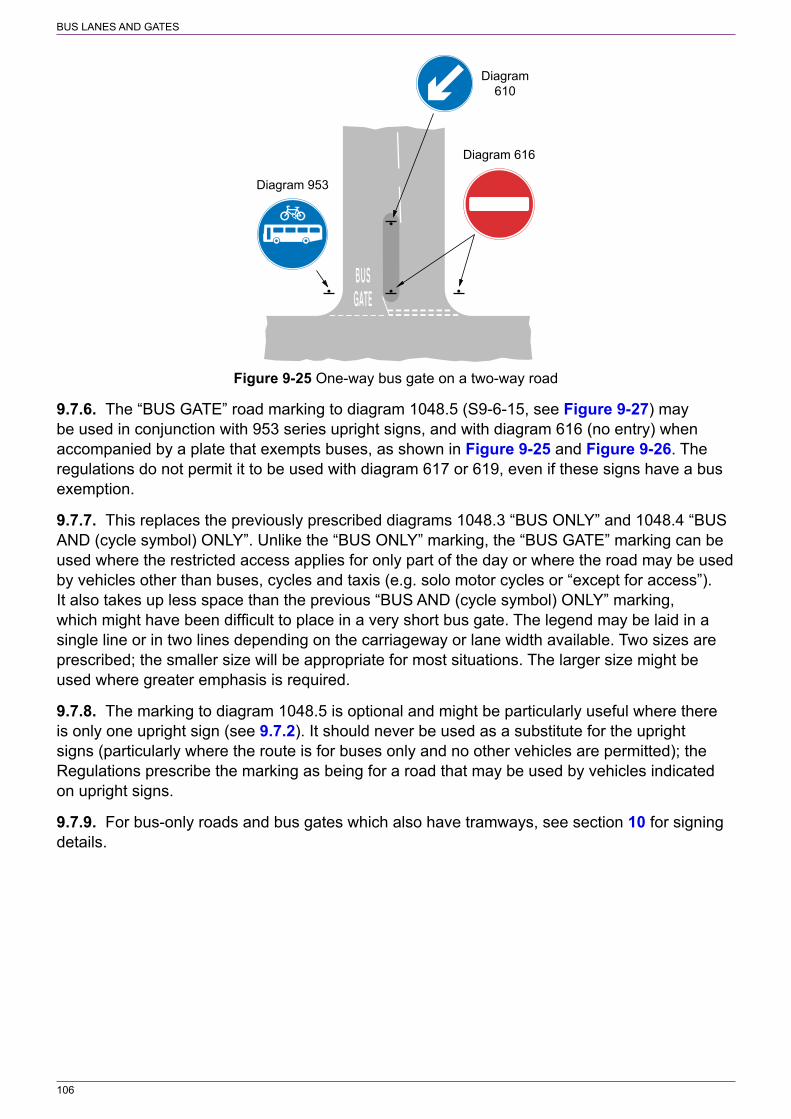
BUS LANES AND GATES
106
Diagram 616
Diagram 953
Diagram610
Figure 9‑25 One‑way bus gate on a two‑way road
9.7.6. The “BUS GATE” road marking to diagram 1048.5 (S9‑6‑15, see Figure 9‑27) may be used in conjunction with 953 series upright signs, and with diagram 616 (no entry) when accompanied by a plate that exempts buses, as shown in Figure 9‑25 and Figure 9‑26. The regulations do not permit it to be used with diagram 617 or 619, even if these signs have a bus exemption.
9.7.7. This replaces the previously prescribed diagrams 1048.3 “BUS ONLY” and 1048.4 “BUS AND (cycle symbol) ONLY”. Unlike the “BUS ONLY” marking, the “BUS GATE” marking can be used where the restricted access applies for only part of the day or where the road may be used by vehicles other than buses, cycles and taxis (e.g. solo motor cycles or “except for access”). It also takes up less space than the previous “BUS AND (cycle symbol) ONLY” marking, which might have been difficult to place in a very short bus gate. The legend may be laid in a single line or in two lines depending on the carriageway or lane width available. Two sizes are prescribed; the smaller size will be appropriate for most situations. The larger size might be used where greater emphasis is required.
9.7.8. The marking to diagram 1048.5 is optional and might be particularly useful where there is only one upright sign (see 9.7.2). It should never be used as a substitute for the upright signs (particularly where the route is for buses only and no other vehicles are permitted); the Regulations prescribe the marking as being for a road that may be used by vehicles indicated on upright signs.
9.7.9. For bus‑only roads and bus gates which also have tramways, see section 10 for signing details.

BUS LANES AND GATES
107
Diagram 953Diagram 953
Diagram 613
Figure 9‑26 Example of a two‑way bus gate
Figure 9‑27 Diagram 1048.5 (S9‑6‑15) Road or part of road with access permitted only for buses and other vehicles as indicated on upright signs (Alternative types)

108
10 TRAM SIGNS
10.1 General10.1.1. The general principles for signing and marking tramways, including the use of variants of the speed limit sign to diagram 976 (S11‑2‑84), are set out in the Office of Rail and Road (ORR) ‘Railway Safety Publication 2, Guidance on Tramways’ published on the ORR website. Early contact should be made with ORR to discuss requirements. Warning signs for tramway crossings are covered in Chapter 4. The following paragraphs give more detailed guidance on the use of traffic signs for street‑running tramways.
10.1.2. The following terms are used to describe tramways:
a) integrated on‑street tramway where the part of the highway occupied by the rails may be used by other vehicles or by pedestrians;
b) segregated on‑street tramway or tram‑only street where the part of the highway occupied by rails may be crossed by pedestrians, but is not normally shared with other road users;
c) tram gate, where only trams (and specific vehicles where permitted) travel along a short length of road that precedes an integrated on‑street system; and
d) off‑street tramway where the alignment of the track is wholly separate from the highway.
10.2 Upright signs and road markings for tram‑only routes10.2.1. Where an integrated on‑street tramway leaves the general traffic route to enter a tram gate, a segregated on‑street tramway (or tram‑only road) or an off‑street tramway, upright signs to either diagram 616 (“no entry”) with an “Except trams” plate (S3‑2‑10, see Figure 10‑1) or diagram 953.1 (S3‑2‑36, see Figure 10‑2) are provided. It should be noted that the “Only” plate, previously used with diagram 953.1, is no longer prescribed by the Regulations. The “no entry” sign is most likely to be appropriate where drivers might be tempted to or accidentally follow a tramway that becomes off‑street, resulting in vehicles becoming stranded on the tram tracks.
10.2.2. A tram gate is similar to a bus‑only street or bus gate described in 9.7. Buses and other permitted vehicles may share a tram gate, in which case a sign to diagram 953.1 (variant), 953.1A, 953.1B or 953.1C should be used as appropriate (S3‑2‑37 to 40 respectively, see Figure 10‑3 to Figure 10‑6). These signs, along with diagram 953.1 may include a supplementary plate with a time period, the legend “and authorised vehicles” or both. A time period is appropriate where the route may be used by all vehicles at certain times of the day or days of the week. The “no entry” sign to diagram 616 may be used as an alternative, but only where buses, cycles or both are permitted to use the route and a time plate is not required. In this case, the “exception” plate must not include the legend “trams” as this is not prescribed; the route is treated as being a bus gate that is also used by trams, indicated by the tramway tracks.
10.2.3. The upright signs should to be placed as near as practicable to the point where the restriction commences, but there is no specific requirement to provide a sign on each side of the carriageway. This relaxation has been made to reduce environmental impact, however care should be taken to ensure that a single sign is clearly visible to all road users and does not give rise to issues relating to enforcement or road safety. There are likely to be many situations where two signs are required to ensure the safe operation of the tramway.

109
TRAM SIGNS
Figure 10‑1 Diagram 616 (S3‑2‑10) Figure 10‑2 Diagram 953.1 (S3‑2‑36) No entry except trams Route for use by tramcars only
Figure 10‑3 Diagram 953.1 (variant) (S3‑2‑37) Figure 10‑4 Diagram 953.1A (S3‑2‑38) Route for use by tramcars and buses only Route for use by tramcars, buses and (Alternative types) pedal cycles only (Alternative types)
Figure 10‑5 Diagram 953.1B (S3‑2‑39) Route for use by tramcars, buses, pedal cycles and taxis only (Alternative types)
Figure 10‑6 Diagram 953.1C (S3‑2‑39) Route for use by tramcars, buses, pedal cycles and solo motor cycles (taxis may also be permitted where shown) (Alternative types)
10.2.4. The sign to diagram 953.1 (including the variant with the bus symbol) should normally be 750 mm in diameter and for diagrams 953.1A, 953.1B and 953.1C, 900 mm as they include smaller symbols that need to be recognised by drivers. The largest sign size of 900 mm for diagram 953.1 (Figure 10‑2) is likely to be appropriate where a tramway leaves the public highway to enter an off‑street route. The largest size for all of the signs might be appropriate at locations where greater emphasis is required to ensure that drivers follow the correct route through a complex junction. The smaller sizes might be appropriate where traffic speeds are low, where two signs are provided (see 10.2.3) and where access to traffic is generally restricted (e.g. where a tramway crosses a pedestrian zone). Where a “no entry” sign is used, the diameter should normally be 750 mm. The appropriate x‑height of any supplementary plate used with these signs is shown in Table 10‑1.
10.2.5. Where a particular route is for tramcars only at all times, the upright sign should normally be supplemented by the “TRAM ONLY” road marking to diagram 1048.2A (S9‑6‑16, see Figure 10‑7). Two sizes are prescribed; the smaller size will be appropriate for most situations. The larger size might be used where greater emphasis is required, particularly at the beginning of an off‑street tramway. The marking should be laid so that no part of the lettering is on the running or check rails of the tram track (see Figure 10‑7). It should be arranged so that the words “TRAM” and “ONLY” are centred on the tracks with the first and last letters

110
TRAM SIGNS
outside the running rails. Where other vehicles, including buses, are permitted to use the tram route, the appropriate road marking is “BUS GATE” to diagram 1048.5 (S9‑6‑15; see 9.7.6 and Figure 9‑27). The “TRAM & BUS ONLY” marking (previously diagram 1048.2) is no longer prescribed. Where the sign shown in Figure 10‑2 has a supplementary plate, the road marking to diagram 1048.2A is not appropriate as it indicates that the route is for tramcars only (and not “authorised vehicles”) at all times.
Table 10‑1 “x‑height” of supplementary plates in millimetres
Diagram No. x‑height of plate legend appropriate to roundel heights shown (mm)
450 600 750 900 1200
616 50 62.5 62.5 75 n/a
953.1 50 62.5 62.5 75 ‑
953.1 (variant) 50 62.5 62.5 75 ‑
953.1A ‑ 50 62.5 62.5 75
953.1B ‑ 50 62.5 62.5 75
953.1C ‑ 50 62.5 62.5 75
Figure 10‑7 Diagram 1048.2A (S9‑6‑16) Road or part of road with access permitted only for tramcars
10.2.6. A segregated on‑street tramway is similar to a bus lane except that physical separation is provided between the tramway and that part of the road used by other traffic. No other traffic should be allowed to use the tramway, although it may be crossed by pedestrians. Figure 10‑8 shows an example of each end of a one‑way road used by all traffic, including trams, with a contraflow segregated tramway.
10.2.7. Figure 10‑9 and Figure 10‑10 show an examples of a tramway leaving the public highway to enter an off‑street route. The situations shown in Figure 10‑10 will normally be controlled by traffic signals and for simplicity these are not shown in the figure.
10.2.8. Where the tramway diverges from an integrated system at a shallow angle onto a reserved length of track or to a tram stop, particular care needs to be taken to ensure that other drivers do not follow the tracks; this is particularly hazardous where it is the road that deviates leaving the tracks to carry straight on. Road markings are essential, in addition to appropriate vertical signing. Typical layouts are shown in Figure 10‑10.
10.2.9. An edge line to diagram 1012.1 (S11‑4‑11, see Chapter 5) should be provided, following the edge of the main carriageway at an angle across the tram tracks. The line should be discontinued where it crosses the running and check rails, but resumed in the space between the rails. This line should be supplemented by reflecting road studs of the appropriate colour (see Chapter 5). Any stud laid within 2 m of the running rail should be of plastic construction. Physical measures to dissuade other vehicles from being driven along the tram track are

111
TRAM SIGNS
recommended, e.g. the edge line may be supplemented by a low kerb painted alternately black and white, or by hostile paving.
Diagram 616Diagram652
Diagram610
Diagram 616
Tramsonly
Alltraffic
Diagram 953.1
All trafficTramsonly
Alltraffic
All traffic
This sign may be replaced bydiagram 616 with an “Excepttrams” plate, with the advancedirection sign below modifiedaccordiningly. Where diagram953.1 is used, a second signto diagram 953.1 may be placedon the central island where thiscan be accommodated on aseparate post from the sign todiagram 616.
The two layouts showthe opposite ends of aone-way road with acontraflow segregatedtramway
Figure 10‑8 Example of a one‑way road used by all traffic with a contraflow segregated tramway

112
TRAM SIGNS
Diagram 610(see para 10.2.12)
NOT TO SCALE
The two signs to diagram616 may be replaced bysigns to diagram 953.1, withthe advance direction signbelow modified accordiningly
Diagram 616
Figure 10‑9 Example of a tramway leading from a public highway to an off‑street route showing appropriate upright signs
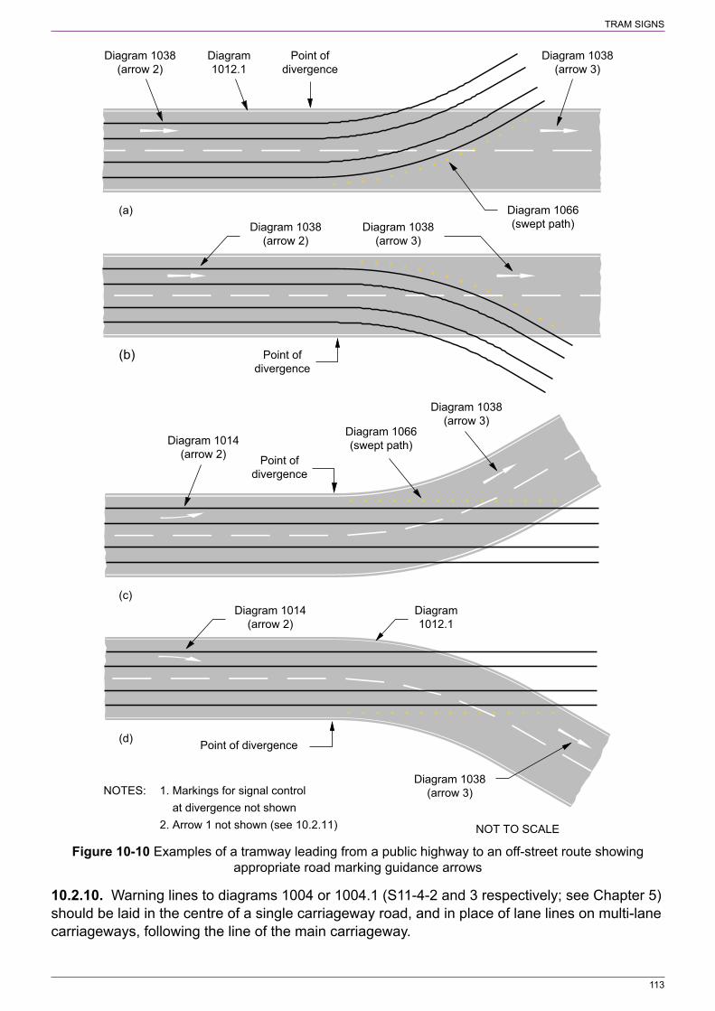
113
TRAM SIGNS
(b)
Diagram 1038(arrow 3)
Point ofdivergence
Diagram 1038(arrow 2)
(c)
Diagram 1014(arrow 2)
Diagram 1038(arrow 3)
Diagram 1066(swept path)
Diagram 1038(arrow 3)
Diagram 1066(swept path)
(a)
Point ofdivergence
Diagram1012.1
Diagram 1038(arrow 2)
1. Markings for signal control at divergence not shown2. Arrow 1 not shown (see 10.2.11)
(d)
Diagram 1014(arrow 2)
Diagram 1038(arrow 3)
Diagram1012.1
Point ofdivergence
Point of divergence
NOTES:
NOT TO SCALE
Figure 10‑10 Examples of a tramway leading from a public highway to an off‑street route showing appropriate road marking guidance arrows
10.2.10. Warning lines to diagrams 1004 or 1004.1 (S11‑4‑2 and 3 respectively; see Chapter 5) should be laid in the centre of a single carriageway road, and in place of lane lines on multi‑lane carriageways, following the line of the main carriageway.

114
TRAM SIGNS
10.2.11. A minimum of three arrows should be used to guide road vehicles past the divergence. The final arrow (3) should be positioned immediately after the point of divergence. The second and first arrows (2) and (1) should be placed before the point of divergence at distances equivalent to 1 and 3 seconds of travel respectively. These distances and the size of arrows that should be used are indicated in Table 10‑2. The appropriate type of arrow, diagram 1014 or 1038 (S11‑4‑14 and 20 respectively, see Figure 10‑11 and Figure 10‑12, and Chapter 5), depends upon the nature of the divergence, and is indicated in Table 10‑3 and Figure 10‑10. If the layout of the road is such that drivers might mistake arrow (1) or (2) as an indication to move to the next lane, then it should be omitted.
Figure 10‑11 Diagram 1014 (S11‑4‑14) Deflection Figure 10‑12 Diagram 1038 (S11‑4‑20) arrow (Longitudinal marking) (Alternative types) (Version with single arrow indicating ahead) (Longitudinal marking)
Table 10‑2 Arrow size and location
Speed limit (mph) Length of arrow (m) Distance from point of divergence (m)
First arrow (1) Second arrow (2) Third arrow (3)
30 4.5 (4) 40.5 13.5 See Figure 10‑10
40 4.5 (4) 54.0 18.0
50 6 67.5 22.5
60 6 81.0 27.0
70 9 94.5 31.5
NOTE: The smallest arrows to diagram 1014 and 1038 are 4.5 m and 4 m long respectively.
Table 10‑3 Arrow type
Description of divergence Figure 10‑10 reference
Arrow type (diagram number)
First arrow (1) Second arrow (2) Third arrow (3)
Tracks diverge from road a & b 1038 1038 1038
Road diverges to the left c 1014 1014 1038
Road diverges to the right d 1014 1014 1038
10.2.12. In certain situations it might be appropriate to provide a “keep left” or “keep right” sign to diagram 610 (S3‑2‑3) to guide other traffic away from a route used exclusively by trams, whether this is on‑street or off‑street (see Figure 10‑9). S3‑4‑3(5) exempts trams from the requirement to comply with such a sign.
10.2.13. An advance direction sign may indicate a route for trams only (and any other permitted vehicles), as shown in Figure 10‑1 and Figure 10‑2, incorporating an appropriate symbol prescribed by S12‑20.

115
TRAM SIGNS
10.2.14. There are no prescribed signs for a with‑flow bus lane that is used also by trams. Where such provision is required, standard bus lane upright signs and road markings should be used.
10.3 Pedestrian signs10.3.1. The sign shown in diagram 963.3 (S11‑2‑43, see Figure 10‑13) warns pedestrians of the presence of a tramway. The legend LOOK LEFT or LOOK RIGHT is appropriate where trams travelling in opposite directions are separated by a pedestrian refuge or where the tramway is one way. The LOOK BOTH WAYS sign should always be used where a pedestrian route crosses a two‑way off‑street tramway.
Figure 10‑13 Diagram 963.3 (S11‑2‑43) Direction in which pedestrians should look for approaching tramcars when crossing a tramway (Alternative types)
10.3.2. Two sizes are prescribed for the sign to diagram 963.3. The larger size, with a 50 mm x‑height, should normally be used. The smaller sign, with a 40 mm x‑height, may be more suitable where there are space constraints, such as on a pedestrian refuge.
10.4 Road junctions10.4.1. Where a road is crossed by a segregated or off‑street tramway, this should be treated as a level crossing and controlled by traffic signals. Junctions along an integrated tramway with heavy traffic flows or restricted visibility (including those where the minor road would normally be signed with the diagram 601.1 STOP sign; see section 2) should also be controlled by traffic signals.
10.4.2. At priority junctions, roads carrying tramways should always be treated as the major road. Junctions with restricted visibility which would normally be signed with the upright STOP sign in accordance with section 2 should be controlled by traffic signals. Otherwise, upright signs and markings on the minor road should be provided in accordance with 2.5.2 and 3.5.2.
10.4.3. Guidance on marking yellow boxes to diagram 1043 (S9‑6‑25) at junctions with tramways can be found in Chapter 5.
10.5 Tram stops10.5.1. On modern tramways, tramcars stop at purpose‑built platforms to help passengers to board. These are readily recognisable by other traffic and the raised platform makes it unattractive for other vehicles to park there, so there should be no need for clearway markings of the kind used at bus stops.
10.5.2. Where a tram stop platform is located on a length of road shared with other traffic, it is sometimes necessary for the raised platform to project into the carriageway to ensure that it is close enough to the tramcar for passengers to board. The end of the platform facing approaching traffic should be protected by kerbing or surface treatment, or by hatched road markings to diagram 1040.4 (S11‑4‑25, see Chapter 5) to guide other traffic away from the end of the platform. Hazard reflectors to diagram 560 (S2‑6‑2, see Chapter 4) might also be necessary. Care should be taken to ensure that cyclists are not guided into the wheel flange
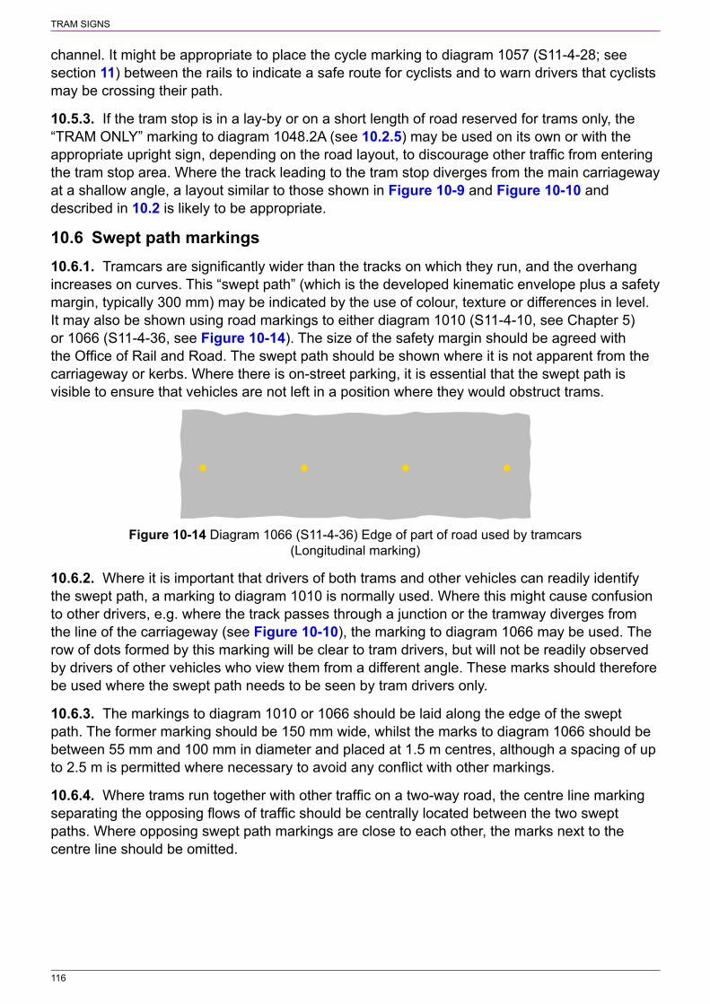
116
TRAM SIGNS
channel. It might be appropriate to place the cycle marking to diagram 1057 (S11‑4‑28; see section 11) between the rails to indicate a safe route for cyclists and to warn drivers that cyclists may be crossing their path.
10.5.3. If the tram stop is in a lay‑by or on a short length of road reserved for trams only, the “TRAM ONLY” marking to diagram 1048.2A (see 10.2.5) may be used on its own or with the appropriate upright sign, depending on the road layout, to discourage other traffic from entering the tram stop area. Where the track leading to the tram stop diverges from the main carriageway at a shallow angle, a layout similar to those shown in Figure 10‑9 and Figure 10‑10 and described in 10.2 is likely to be appropriate.
10.6 Swept path markings10.6.1. Tramcars are significantly wider than the tracks on which they run, and the overhang increases on curves. This “swept path” (which is the developed kinematic envelope plus a safety margin, typically 300 mm) may be indicated by the use of colour, texture or differences in level. It may also be shown using road markings to either diagram 1010 (S11‑4‑10, see Chapter 5) or 1066 (S11‑4‑36, see Figure 10‑14). The size of the safety margin should be agreed with the Office of Rail and Road. The swept path should be shown where it is not apparent from the carriageway or kerbs. Where there is on‑street parking, it is essential that the swept path is visible to ensure that vehicles are not left in a position where they would obstruct trams.
Figure 10‑14 Diagram 1066 (S11‑4‑36) Edge of part of road used by tramcars (Longitudinal marking)
10.6.2. Where it is important that drivers of both trams and other vehicles can readily identify the swept path, a marking to diagram 1010 is normally used. Where this might cause confusion to other drivers, e.g. where the track passes through a junction or the tramway diverges from the line of the carriageway (see Figure 10‑10), the marking to diagram 1066 may be used. The row of dots formed by this marking will be clear to tram drivers, but will not be readily observed by drivers of other vehicles who view them from a different angle. These marks should therefore be used where the swept path needs to be seen by tram drivers only.
10.6.3. The markings to diagram 1010 or 1066 should be laid along the edge of the swept path. The former marking should be 150 mm wide, whilst the marks to diagram 1066 should be between 55 mm and 100 mm in diameter and placed at 1.5 m centres, although a spacing of up to 2.5 m is permitted where necessary to avoid any conflict with other markings.
10.6.4. Where trams run together with other traffic on a two‑way road, the centre line marking separating the opposing flows of traffic should be centrally located between the two swept paths. Where opposing swept path markings are close to each other, the marks next to the centre line should be omitted.

117
11 CYCLE FACILITIES
11.1 General11.1.1. This section deals with the signing of cycle facilities, including cycle lanes and tracks, cycle routes shared with pedestrians and cycle parking places. For signal‑controlled cycle crossings and advanced cycle stop lines see Chapter 6. Guidance on the design of cycle facilities can be found in LTN 2/08 ‘Cycle Infrastructure Design’ available at:
www.gov.uk/government/publications/cycle‑infrastructure‑design‑ltn‑208
11.1.2. Cycle facilities may take the form of cycle lanes which run along the road and form part of the carriageway, and cycle tracks which are separate from the carriageway and meet up with it only to cross or join it. Cycle tracks alongside carriageways have an advantage over cycle lanes in that they provide full segregation from parallel traffic flows. However, it is often difficult to provide priority for cycles over turning traffic where tracks cross side roads, whereas cyclists using lanes on the carriageway have automatic priority over traffic entering or leaving a side road.
11.1.3. Cycle lanes may be mandatory, where other vehicles are excluded for at least part of the day, or advisory, where other vehicles may enter if necessary and when it is safe to do so. A mandatory cycle lane requires an order only when it is a contraflow lane. The Regulations now (S9‑9‑1(2)) permit a mandatory with‑flow lane that has the meaning set out in S9‑7‑12 to be provided without an order. A with‑flow lane may operate for only part of the day, but a contraflow lane must be operational at all times. Advisory with‑flow lanes, which do not require an order, may be used in situations where mandatory lanes would be too restrictive, typically where road width is restricted and motor vehicles might occasionally need to encroach on the lane. They may be used at junctions controlled by traffic signals as lead‑in lanes to the advanced cycle stop lines shown in diagram 1001.2 (S14‑2‑50, see Chapter 6) where it is not practicable to introduce a mandatory lane. They may also be used to by‑pass parking bays as shown in Figure 11‑6. Contraflow cycle facilities may be introduced in one‑way streets, without the provision of a mandatory lane, but these will require a one‑way street order that includes an exemption for cyclists. The facility, referred to as an advisory contraflow cycle lane, may have a lane marked in a similar manner to an advisory with‑flow lane or no lane at all (see 11.6). Such a facility enables motor vehicles to encroach on the area used by contraflow cycles.
11.1.4. Cycle lanes should be a minimum of 1.5 m wide. Widths less than this give cyclists very little room to manoeuvre around debris, surface defects or gulley gratings. Slightly narrower widths might nevertheless sometimes be helpful over short lengths, e.g. on the immediate approach to a junction. Where cycle flows are heavy, there might be advantages in increasing the width to 2.0 m, but lanes wider than this are likely to be abused by other traffic.
11.1.5. Cycle lanes may be surfaced in coloured material in order to demarcate them more emphatically, to discourage encroachment by motor vehicles or to highlight the existence of cycle facilities to motorists turning across them. However, coloured surfacing has no legal significance; it is the prescribed traffic signs and road markings that establish the legal status of a cycle lane.
11.1.6. The road marking cycle symbol to diagram 1057 (S11‑4‑28, see Figure 11‑1) is prescribed with alternative dimensions. The width of cycle lane or track available and the required conspicuity of the marking will determine the appropriate size; the largest (1700 mm) is

118
CYCLE FACILITIES
used within the reservoir of the advanced stop line marking (see Chapter 6). The symbol should normally face left; the right facing symbol is generally used in combination with a road marking arrow to diagram 1059 (S11‑4‑32) indicating a right turn.
Figure 11‑1 Diagram 1057 (S11‑4‑28) Road marking indicating a cycle lane, track or route (Alternative types)
11.2 Waiting and loading restrictions11.2.1. Waiting should be prohibited during the operational periods of a mandatory cycle lane as it is an offence for motor vehicles to be driven or ridden in the lane. Signs and markings should be provided in accordance with section 13 and these will indicate the duration of the prohibition which may be the same as that for the cycle lane or longer.
11.2.2. Loading should also be banned in a mandatory cycle lane, although there may occasionally be reasons why it needs to be allowed, such as off‑peak loading in a 24‑hour with‑flow cycle lane. Any prohibition of loading, whether during or outside the hours when the lane is in force, should always be indicated with signs and markings in accordance with section 13.
11.2.3. Waiting and loading restrictions should be implemented to cover the times when an advisory with‑flow lane is most heavily used and should be indicated by the use of yellow lines, kerb markings and appropriate upright signs (see section 13). Advisory contraflow lanes are provided where it might not practicable to prohibit waiting or loading at all times within the lane. Waiting and loading restrictions should at least be considered for those times when the road is most heavily used, whether by cycles in the contraflow lane, opposing traffic or both.
11.3 Mandatory with‑flow cycle lanes11.3.1. Mandatory with‑flow cycle lanes may be provided in both one‑way and two‑way roads; a typical layout is shown in Figure 11‑2. The lane is bounded by a 150 mm continuous white line to diagram 1049B (S9‑6‑7). The prescribed line widths of 200 and 250 mm are intended for use with cycle lanes that have a width of 2 m or more. Road studs are not prescribed for use with diagram 1049B, and must not be used. The marking should be interrupted for the length of any bus stop marked by diagram 1025.1 (S7‑4‑9, see section 13). At side road junctions the mandatory lane should change to an advisory one bordered by a 150 mm wide line to diagram 1004 or 1004.1 (S11‑4‑2 and 3 respectively, see Chapter 5). Where the line to diagram 1049B is 200 or 250 mm wide, the marking to diagram 1004 or 1004.1 is replaced by a marking to diagram 1010 (S11‑4‑10, see Chapter 5) with the same width as diagram 1049B. The marking to diagram 1049B may be continued across private driveways; S9‑7‑12 provides an exemption for access.
11.3.2. The cycle lane normally commences with a road marking to diagram 1009A (S11‑4‑8). This is laid diagonally across the carriageway, at a recommended taper no sharper than 1:10, to guide motor vehicles away from the lane. If the speed limit is 40 mph or less, the 150 mm wide line is used, otherwise it should be 200 mm wide. If necessary, because it is not clear that there is a cycle lane ahead, warning of the cycle lane should be given in advance of this taper by an

119
CYCLE FACILITIES
upright sign to diagram 958.1 (S11‑2‑38, see Figure 11‑3). A road marking deflection arrow to diagram 1014 (S11‑4‑14, see Chapter 5) should be placed where there is significant deflection to the vehicle path. The sign and the marking need not necessarily be co‑located. Where the speed limit is 20 or 30 mph, the sign to diagram 958.1 should be sited 20 m in advance of the taper, with a minimum clear visibility distance of 45 m. Where the speed limit is 40 mph or greater, the sign should be sited 40 m in advance of the taper with a minimum clear visibility distance of 60 m. Where siting of the sign is likely to be difficult and where the cycle lane is clearly visible to drivers, the sign to diagram 958.1 may be omitted. However, in the interests of road safety, the sign should be provided wherever possible. It is not appropriate to use the sign at intermediate junctions along the cycle lane. The deflection arrow to diagram 1014 should be 4.5 m long where the speed limit is 40 mph or less. For speed limits greater than 40 mph, the arrow length should be 6 m.
11.3.3. The sign to diagram 959.1 (S9‑4‑9, see Figure 11‑4) is a regulatory sign and should be placed as near as practicable to the start of the lane, i.e. where the continuous line to diagram 1049B begins. Although there is no specific requirement to provide repeater signs, it is for the traffic authority to determine how many are required and where they are placed. However, to ensure that drivers, whether entering from a side road or proceeding along the major road, are informed or reminded of the restriction, a sign should normally be placed just beyond each side road. This applies to road junctions on the same side of the road as the cycle lane and to those on the opposite side where traffic can turn right to enter the major road alongside the cycle lane. Additional repeater signs should be considered where the distance between them would otherwise exceed 300 m.
11.3.4. The times during which the cycle lane operates are shown in the panel at the bottom of the signs to diagrams 958.1 and 959.1. The working drawings show how time periods are accommodated within the fixed width of the signs. Time periods must be expressed in the manner described in S18‑1 (see also Chapter 7). Although the time may be varied to “At all times”, this would not normally apply to cycle lanes. The legend “At all times” is intended for bus lanes to avoid possible confusion where a 24‑hour bus lane is introduced in the vicinity of another bus lane that does not operate at all times (see 9.3.7). A sign to diagram 958.1 or 959.1, when the bottom panel is omitted, means that the cycle lane operates for 24 hours on every day of the week.
11.3.5. The signs to diagrams 958.1 and 959.1 are prescribed in two sizes. The smaller size should be used on roads with a speed limit of 20 mph or 30 mph. The larger size is for use on roads with higher speed limits.
11.3.6. Cycle symbol markings to diagram 1057 (see Figure 11‑1), usually 1100 mm wide, are provided within the lane, although there is no specific requirement to use them in conjunction with upright signs. The marking should be placed at the beginning of the lane, i.e. where the line to diagram 1049B commences. Additional markings may be placed at intervals along the lane, where considered appropriate, but they need not be co‑located with the upright signs to diagram 959.1. Markings are likely to be useful to warn drivers of the presence of the lane when emerging from a side road as shown in Figure 11‑2.
11.3.7. The sign to diagram 962.1 (S11‑2‑35, see Figure 11‑5) is intended mainly for use in conjunction with contraflow cycle lanes. However, it may be provided on side roads, as shown in Figure 11‑2, to warn emerging drivers of the presence of a with‑flow cycle lane on the major road, although this is not essential. The arrow on the sign indicates the direction of travel within the cycle lane and will normally point to the left, as a sign is not required to indicate a lane on the opposite side of the road. However, where there are with‑flow cycle lanes on both sides of the major road and there are no banned turns, the arrow on diagram 962.1 is omitted, the

120
CYCLE FACILITIES
symbol faces left and the word “lane” is varied to “lanes”. Where there are two cycle lanes in the major road and the right turn from the side road is prohibited, the sign to diagram 962.1 should indicate only the cycle lane to the left. A time period should not be shown on the sign where the cycle lane operates at all times or where the legend is “Cycle lanes” and the two lanes operate at different times. In the case of the latter, a sign to diagram 959.1 should be provided to inform drivers of the period of operation after turning into the major road.
Diagram 958.1
Diagram 959.1
Diagram 959.1
Diagram 962.1
Diagram1014
Diagram1009A
Diagram1049B
Diagram1057
Diagram1004
Diagram1049B
Diagram1057
Figure 11‑2 Example of a mandatory with‑flow cycle lane

121
CYCLE FACILITIES
Figure 11‑3 Diagram 958.1 (S11‑4‑38) Mandatory Figure 11‑4 Diagram 959.1 (S9‑4‑9) Mandatory with‑flow cycle lane ahead (Alternative types) with‑flow cycle lane (Alternative types)
Figure 11‑5 Diagram 962.1 (S11‑2‑35) Cycle lane on road at junction ahead (Alternative types)
11.3.8. Two sizes are prescribed for the sign to diagram 962.1; in most cases the smaller size will be sufficient. The sign should be mounted below any GIVE WAY or STOP sign or, if the junction is controlled by traffic signals, mounted a sufficient distance in advance of the junction so as not to obstruct the view of the signal head.
11.3.9. The end of the cycle lane is normally indicated by the termination of the continuous white line to diagram 1049B, although the road markings to diagram 1057 (cycle symbol) and diagram 1058 (“END”, S11‑4‑30) may also be used. The “end of cycle route” sign to diagram 965 (S11‑2‑45) is not intended to indicate the end of a cycle lane, although it might be helpful if a lane ends at a hazardous location where cyclists would need to take extra care.
11.4 Advisory with‑flow cycle lanes11.4.1. Advisory with‑flow cycle lanes are available at all times and may be provided in both one‑way and two‑way roads; a typical layout is shown in Figure 11‑6. The lane is bounded by a 100 mm wide hazard warning line to either diagram 1004 or 1004.1 (S11‑4‑2 and 3 respectively; see Chapter 5) depending on the speed limit. Where this is 40 mph or less, a boundary line to diagram 1004 is appropriate. Where the speed limit is greater than 40 mph, a line to diagram 1004.1 should normally be used. The line to diagram 1004 or 1004.1 may be widened to 150 mm for greater emphasis, but in a two‑way road it should never be wider than the centre line (see Chapter 5). Road studs should not be used with the boundary line, as this could be misleading to drivers of motor vehicles. The marking should be interrupted for the length of any bus stop marked by diagram 1025.1 (S7‑4‑9, see section 13), but should be continued across any side road or private driveway. An advisory cycle lane may be continued on the off side of a parking bay. In this situation, which is shown in Figure 11‑6, adequate clearance should be provided to allow for carelessly opened car doors.
11.4.2. The lane normally commences with diagram 1009A (S11‑4‑8) laid diagonally across the carriageway. If the speed limit is 40 mph or less, the 150 mm wide line should be used, otherwise it should be 200 mm wide. As the lane is advisory, it is not essential for other vehicles to be deflected in advance of it. Angles between the line and the kerb of 30º to 45º are therefore
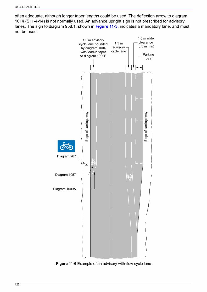
122
CYCLE FACILITIES
often adequate, although longer taper lengths could be used. The deflection arrow to diagram 1014 (S11‑4‑14) is not normally used. An advance upright sign is not prescribed for advisory lanes. The sign to diagram 958.1, shown in Figure 11‑3, indicates a mandatory lane, and must not be used.
1.5 m advisorycycle lane bounded
by diagram 1004with lead-in taperto diagram 1009B
1.5 madvisory
cycle lane
1.0 m wideclearance
(0.5 m min)
Parkingbay
Edg
e of
car
riage
way
Edg
e of
car
riage
way
Diagram 967
Diagram 1057
Diagram 1009A
Figure 11‑6 Example of an advisory with‑flow cycle lane

123
CYCLE FACILITIES
11.4.3. The sign to diagram 967 (S11‑2‑44, see Figure 11‑7) is used to indicate an advisory with‑flow cycle lane and may be provided at the start of the lane immediately after the taper. Although there is no specific requirement to provide repeater signs, the traffic authority should determine how many signs might be needed along the length of the advisory lane to act as reminders. It is recommended that the sign to diagram 967 is treated in a similar manner to the sign to diagram 959.1 and placed after each road junction with additional signs considered where the distance between them would otherwise exceed 300 m. As advisory with‑flow lanes are available at all times, time plates are not used with the sign to diagram 967.
Figure 11‑7 Diagram 967 (S11‑2‑44) Route recommended for pedal cycles on the main carriageway of a road
11.4.4. The sign to diagram 967 is prescribed in two sizes. The smaller size should be used on roads with a speed limit of 20 mph or 30 mph. The larger size is for use on roads with higher limits.
11.4.5. Cycle symbol markings to diagram 1057 (see Figure 11‑1), usually 1100 mm wide, are provided within the lane, although there is no specific requirement to use them in conjunction with upright signs. The marking should be placed at the beginning of the lane, i.e. where the line to diagram 1004 or 1004.1 commences. Additional markings may be placed at intervals along the lane, where considered appropriate, but they need not be co‑located with the upright signs to diagram 967. Markings are likely to be useful to warn drivers of the presence of the lane when emerging from a side road as with mandatory lanes (see Figure 11‑2). Where an advisory lane is provided as a short approach to an advanced stop line, an upright sign is not required; the cycle symbol marking to diagram 1057 within the lane will be sufficient. Where such a lane is in the centre of the carriageway, it is not practicable to provide an upright sign.
11.4.6. The sign shown in diagram 962.1 (see Figure 11‑5) may be provided on side roads to warn emerging drivers of the presence of an advisory with‑flow cycle lane on the major road, although this is not essential. Where provided, it should be used, with the time period omitted, in a similar manner to that for mandatory with‑flow cycle lanes.
11.4.7. The end of the cycle lane is normally indicated by the termination of the boundary line to diagram 1004 or 1004.1, although the road markings to diagram 1057 (cycle symbol) and diagram 1058 (“END”, S11‑4‑30) may also be used. The “end of cycle route” sign to diagram 965 is not intended to indicate the end of a cycle lane, although it might be helpful if a lane ends at a hazardous location where cyclists would need to take extra care.
11.5 Mandatory contraflow cycle lanes11.5.1. As with mandatory with‑flow lanes, a mandatory contraflow cycle lane is bounded by a continuous white line to diagram 1049B and all other traffic is prohibited from entering that part of the carriageway. An order is required and this should establish a one‑way street for all traffic, with a contraflow lane for cyclists. The width of diagram 1049B is generally 150 mm, but the larger widths of 200 and 250 mm may be used where the lane width is 2 m or more, or where greater emphasis is required to ensure that drivers are fully aware of the contraflow lane. At side road junctions the mandatory lane should change to an advisory one bordered by a 150 mm wide line to diagram 1004 or 1004.1 (S11‑4‑2 and 3 respectively; see Chapter 5). Where the line to diagram 1049B is 200 or 250 mm wide, the marking to diagram 1004 or 1004.1 is replaced by a marking to diagram 1010 (S11‑4‑10, see Chapter 5) with the same width as diagram 1049B.
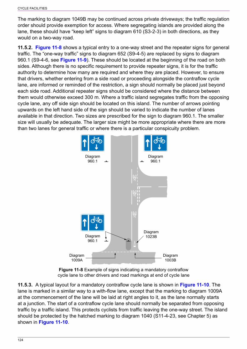
124
CYCLE FACILITIES
The marking to diagram 1049B may be continued across private driveways; the traffic regulation order should provide exemption for access. Where segregating islands are provided along the lane, these should have “keep left” signs to diagram 610 (S3‑2‑3) in both directions, as they would on a two‑way road.
11.5.2. Figure 11‑8 shows a typical entry to a one‑way street and the repeater signs for general traffic. The “one‑way traffic” signs to diagram 652 (S9‑4‑5) are replaced by signs to diagram 960.1 (S9‑4‑6, see Figure 11‑9). These should be located at the beginning of the road on both sides. Although there is no specific requirement to provide repeater signs, it is for the traffic authority to determine how many are required and where they are placed. However, to ensure that drivers, whether entering from a side road or proceeding alongside the contraflow cycle lane, are informed or reminded of the restriction, a sign should normally be placed just beyond each side road. Additional repeater signs should be considered where the distance between them would otherwise exceed 300 m. Where a traffic island segregates traffic from the opposing cycle lane, any off side sign should be located on this island. The number of arrows pointing upwards on the left hand side of the sign should be varied to indicate the number of lanes available in that direction. Two sizes are prescribed for the sign to diagram 960.1. The smaller size will usually be adequate. The larger size might be more appropriate where there are more than two lanes for general traffic or where there is a particular conspicuity problem.
Diagram960.1
Diagram960.1
Diagram960.1
Diagram1023B
Diagram1003B
Diagram1009A
Figure 11‑8 Example of signs indicating a mandatory contraflow cycle lane to other drivers and road markings at end of cycle lane
11.5.3. A typical layout for a mandatory contraflow cycle lane is shown in Figure 11‑10. The lane is marked in a similar way to a with‑flow lane, except that the marking to diagram 1009A at the commencement of the lane will be laid at right angles to it, as the lane normally starts at a junction. The start of a contraflow cycle lane should normally be separated from opposing traffic by a traffic island. This protects cyclists from traffic leaving the one‑way street. The island should be protected by the hatched marking to diagram 1040 (S11‑4‑23, see Chapter 5) as shown in Figure 11‑10.

125
CYCLE FACILITIES
1000approx
Diagram 955
Diagram 616
Diagram 955on bollard
Diagram1009A
Diagram1003A
Diagram1059
Diagram1057
Figure 11‑9 Diagram 960.1 (S9‑4‑6) Figure 11‑10 Start of a mandatory One‑way road with a mandatory contraflow cycle lane contraflow cycle lane
11.5.4. The exit side of the road used by all traffic should be signed with “no entry” signs in accordance with 4.9.5 to 4.9.9. In this case, the “no entry” signs to diagram 616, including the sign placed on the traffic island, do not have supplementary plates. It is for the traffic authority to consider whether one or two “no entry” signs should be provided. A sign to diagram 955 (S3‑2‑28, see Figure 11‑11), with a diameter of 450 mm, should be provided on the left hand side of the road at the entrance to the contraflow cycle lane. A second, smaller sign may be provided in a bollard on the traffic island. In some locations (e.g. in a traffic calmed area), it might be appropriate to reduce the size of the sign on the left hand side to 300 mm diameter or to remove it altogether, with the sign on the bollard being sufficient. In this case the cycle symbol road marking to diagram 1057 (see Figure 11‑1), usually 1100 mm wide, together with the ahead arrow to diagram 1059 (S11‑4‑32, see 11.13.3 and Figure 11‑30), should be placed on the carriageway at the start of the contraflow lane to clearly identify the route for cyclists. It is recommended that these markings are also provided where the sign to diagram 955 is used on the left hand side as shown in Figure 11‑10.
11.5.5. Where it is not physically possible to provide a traffic island, the sign to diagram 955 is not used. In this case, a “no entry” sign to diagram 616 and a supplementary plate with the legend “Except cycles” should be placed on the left hand side of the road. The traffic authority should consider whether an additional sign is required on the right hand side of the road. A plate should not be used with this additional sign as this might encourage cyclists to use the “wrong” side of the road, particularly where there is very little oncoming traffic. The “NO ENTRY” road marking to diagram 1046 (S9‑6‑17) may be used to supplement the upright signs, but it must not encroach on the area where cyclists enter the contraflow lane. The road marking to diagram 1057, together with an ahead arrow to diagram 1059, should be provided at the beginning of the lane.
11.5.6. Cycle symbol markings to diagram 1057 may be placed at intervals along the lane, where considered appropriate, but there is no specific requirement to use them in conjunction with upright signs, in this case diagram 960.1. Markings are likely to be useful to warn drivers of the presence of the lane when emerging from a side road as shown in Figure 11‑8.

126
CYCLE FACILITIES
Figure 11‑11 Diagram 955 (S3‑2‑28) Route for use by pedal cycles only
11.5.7. The end of the lane will normally be at a road junction where the cyclist Give Way markings to diagrams 1003B and 1023B (S9‑6‑9 and 10 respectively) should be provided as shown in Figure 11‑8. The edge of carriageway marking across the end of the one‑way road, where all vehicles enter, is marked with diagram 1009A (S11‑4‑8). The cycle lane should be segregated from traffic entering the street in the opposite direction by a traffic island as shown in Figure 11‑10. The road marking to diagram 1057 (cycle symbol), diagram 1058 (“END”; S11‑4‑30), and the “end of cycle route” sign to diagram 965 should not normally be used to indicate the end of the cycle lane because this will be self‑evident (see LTN 2/08).
11.5.8. A sign to diagram 962.1 (see Figure 11‑5), without a time period, should be provided on side roads to warn emerging drivers of the presence of a contraflow cycle lane on the major road, as shown in Figure 11‑12. For a cycle lane on the same side of the major road as the side road, the arrow will point to the left. The sign should be accompanied by the “no left turn” sign to diagram 613 (S3‑2‑8) with a supplementary plate “Except cycles”. Where the cycle lane is on the opposite side of the major road, the arrow on the sign to diagram 962.1 will point to the right. A “no right turn” sign to diagram 612 (S3‑2‑7) should be provided, again with an “Except cycles” plate. If, for road safety reasons, the right turn ban also applies to cycles, the “Except cycles” plate and the sign to diagram 962.1 should be omitted. The presence of a sign to diagram 962.1 in this case might encourage cyclists to turn right into the cycle lane. A convenient alternative route should be provided for cyclists wanting to turn right at the junction. If possible, the cycle lane should be segregated from the major road at the junction by a traffic island. A sign to diagram 960.1, if placed immediately after the junction in the major road, will warn drivers of the presence of the contraflow lane. Where the road layout is such that traffic may turn only into the major road (e.g. the junction is not a crossroads), a sign to diagram 606 (S3‑2‑1), with an “Except cycles” plate as appropriate, should be provided opposite the side road as shown in Figure 11‑12. Where a one‑way road has both mandatory with‑flow and contraflow lanes, the legend on the sign to diagram 962.1 is varied to “Cycle lanes”, with the cycle symbol facing left and the arrow and time period omitted (even where the with‑flow lane does not operate at all times).
11.5.9. Of the two sizes that are prescribed for the sign to diagram 962.1, the smaller size will be sufficient in most cases. The sign should be mounted below any GIVE WAY or STOP sign or, if the junction is controlled by traffic signals, mounted a sufficient distance in advance of the junction so as not to obstruct the view of the signal head.

127
CYCLE FACILITIES
Diagram 606
Diagram 613
Diagram 962.1
Figure 11‑12 Example of the use of the sign to diagram 962.1 to indicate a mandatory contraflow cycle lane
11.6 Advisory contraflow cycle lanes11.6.1. Where it is not practicable to provide a mandatory contraflow cycle lane (prohibiting other traffic from using that part of the carriageway reserved for cycles), an advisory contraflow lane might be considered. This is likely to occur where (a) oncoming vehicles need occasionally to encroach into the cycle lane, for example to pass parked vehicles on the opposite side or to pass cyclists travelling in the with‑flow direction, (b) occasional loading and unloading needs to be allowed for within the lane, or (c) it is not possible to prohibit waiting in the lane at all times. Each of these situations will limit the benefit of the lane for cyclists, and the traffic authority will need to be satisfied that this form of provision will not unduly compromise their safety. Advisory contraflow lanes should normally be considered only where either the 85th percentile speed of traffic is less than 25 mph, or vehicle flows are less than 1000 vehicles per day. The order required for the one‑way street should permit cyclists to travel in the opposite direction without formally designating a lane for use by cycles only. The advisory lane is marked on the carriageway in a similar manner to an advisory with‑flow lane, i.e. the boundary is indicated by a hazard warning line to diagram 1004 (S11‑4‑2). Where the two conditions referred above are both met, or where the road is within a 20 mph zone, the boundary line may be omitted, although it should normally be provided at the start and end of the lane to segregate contraflow cyclists from other traffic leaving and entering the road respectively.
11.6.2. Figure 11‑13 shows a typical entry to a one‑way street and the repeater signs for general traffic. The “one‑way traffic” signs to diagram 652 (S9‑4‑5, see 4.9) are replaced by signs to diagram 960.2 (S9‑4‑7, see Figure 11‑14), whether or not an actual cycle lane is

128
CYCLE FACILITIES
marked on the carriageway (see 11.6.1). Where the lane is not marked throughout its length, the warning line should comprise at least two marks before the traffic island. Where it is not possible to provide an island, the warning line should still comprise at least two marks. The signs to diagram 960.2 should be located at the beginning of the road on both sides. Although there is no specific requirement to provide repeater signs, it is for the traffic authority to determine how many are required and where they are placed. However, to ensure that drivers, whether entering from a side road or proceeding along the one‑way road, are informed or reminded of the advisory contraflow cycle lane, a sign should normally be placed just beyond each side road. Additional repeater signs should be considered where the distance between them would otherwise exceed 300 m. This is particularly important where the lane is not marked on the carriageway throughout its length (see also 11.6.6). Where a traffic island segregates traffic from the opposing cycle lane, any off side sign should be located on this island. As an advisory contraflow lane should be introduced only where the road is narrow and comprises only one lane for general traffic, the sign to diagram 960.2, unlike diagram 960.1, must show only one arrow indicating the flow of general traffic. Two sizes are prescribed for the sign to diagram 960.2. The smaller size should normally be used, but the larger size might be more appropriate where cycle lane markings have not been provided.
Diagram960.2
Diagram960.2
Diagram960.2
Diagram960.2
Diagram1009A
Diagram1003B
Figure 11‑13 Example of signs indicating an Figure 11‑14 Diagram 960.2 (S9‑4‑7) advisory contraflow cycle lane to other drivers Contraflow cycles with or without an advisory lane marked on the carriageway
11.6.3. Where it is possible to provide a traffic island at the start of the contraflow lane, upright signs should be the same as those shown in Figure 11‑10 and described in 11.5.4. A “keep left” sign to diagram 610 (S3‑2‑3) should be provided on the island, facing oncoming traffic approaching the end of the one‑way street. The island should also be protected by hatched markings as shown in Figure 11‑10. The continuous line denoting the edge of the cycle lane is replaced by a hazard warning line to diagram 1004. Where the lane is not marked along the

129
CYCLE FACILITIES
whole length of the road (see 11.6.1), it is recommended that the warning line should comprise at least two marks beyond the hatched marking to help indicate the presence of the contraflow cycle facility. The cycle symbol to diagram 1057, together with an ahead arrow to diagram 1059, may be provided at the beginning of the lane. The marking to diagram 1057 could also be provided adjacent to the last mark of the warning line.
11.6.4. Figure 11‑15 shows the start of an advisory contraflow lane where it is not possible to provide a traffic island. A “no entry” sign to diagram 616 and a supplementary plate with the legend “Except cycles” should be placed on the left hand side of the road. The traffic authority should consider whether an additional sign is required on the right hand side of the road. A plate should not be used with this additional sign as this might encourage cyclists to use the wrong side of the road. Although signs to diagram 619 (S3‑2‑12) could be used as an alternative to the “no entry” signs, it is recommended that they are not used for contraflow cycle lanes but reserved for roads with restricted access. The “NO ENTRY” road marking to diagram 1046 (S9‑6‑17) may be used to supplement the upright signs in the position shown in Figure 11‑15, but it must not encroach on the area where cyclists enter the contraflow lane. The start of the contraflow lane has a boundary line to diagram 1004 which should normally be continued for the whole length of the lane. However, where the advisory lane is not marked on the carriageway throughout its length, the line to diagram 1004 should comprise at least two marks. In this case, the short length of cycle lane could include coloured surfacing. These measures are to ensure that vehicles emerging from the one‑way street and turning right at the junction do not encroach on that part of the carriageway used by cyclists travelling in the opposite direction. The start of the lane should also include the road marking to diagram 1057, together with an ahead arrow to diagram 1059. In order to reduce environmental impact, particularly in traffic calmed areas and where traffic flows are low, it might be possible to dispense with the “no entry” sign on the right hand side of the road, provided this does not compromise road safety. Where only one upright sign is provided, it is recommended that it is used in conjunction with the road marking to diagram 1046.
11.6.5. Cycle symbol markings to diagram 1057 may be placed at intervals along the lane, where considered appropriate, but there is no specific requirement to use them in conjunction with upright signs, in this case diagram 960.2. Markings are likely to be useful to warn drivers of the presence of the lane when emerging from a side road as shown in Figure 11‑13. The markings may also be placed along that part of the road used by cyclists where the boundary line to diagram 1004 has not been provided.
11.6.6. Where a side road joins the one‑way street, signs should be provided in accordance with 11.5.8. The advisory contraflow lane should be marked with a boundary line to diagram 1004 on the carriageway of the major road through the junction, together with the cycle symbol road marking to diagram 1057.
11.6.7. The end of the advisory contraflow lane should be marked in a similar manner to the end of a mandatory contraflow lane, except that the line to diagram 1049 is replaced by the warning line to diagram 1004. Where the lane is not marked throughout its length the warning line should comprise at least two marks before the traffic island. Where it is not possible to provide an island, the warning line should comprise at least two marks. Coloured surfacing might be helpful where there is no traffic island, whether or not the contraflow cycle lane is marked throughout its length. This would highlight the cycle facility to cyclists turning out of the road and to drivers turning into the road.

130
CYCLE FACILITIES
Diagram 616Diagram 616
Diagram1046
Diagram1004
Figure 11‑15 Start of an advisory contraflow cycle lane without a traffic island
11.7 Signs for pedestrians11.7.1. The sign shown in diagram 963.1 (S11‑2‑41, see Figure 11‑16) warns pedestrians of the presence of a cycle lane; it should not be used as a substitute for diagram 962.1 to warn drivers approaching the cycle lane from a side road. The sign is normally used for contraflow lanes where cycles will be approaching from the opposite direction to the flow of traffic. The signs should be sited where the majority of pedestrians cross the carriageway. Where pedestrians first cross a general traffic lane, the sign with the legend “LOOK LEFT” and the cycle symbol facing right should be located on the opposite side of the road, adjacent to the cycle lane. Signs may be located on a pedestrian refuge adjacent to the cycle lane. Two sizes are prescribed for diagram 963.1. The larger size, with a 50 mm x‑height, should normally be used. The smaller sign, with a 40 mm x‑height, may be more suitable where there are space constraints, such as on a pedestrian refuge. The sign may also be used for cycle tracks.
Figure 11‑16 Diagram 963.1 (S11‑2‑41) Direction in which pedestrians should look for approaching pedal cycles when crossing a cycle lane (Alternative types)
11.8 Cycle lanes at pedestrian crossings11.8.1. Cycle lane markings must not be continued through the controlled area of a pedestrian crossing indicated by zig‑zag lines (see Chapter 6). Apart from the potentially confusing effect, they would affect the legality of the marking of the crossing. However, coloured surfacing, which has no legal significance, may be used for the cycle lane, and continued through the controlled area (although not through the crossing place itself). The zig‑zag marking may be placed up to 2 m from the edge of the carriageway to allow space for cycling behind the marking. Cycle symbols to diagram 1057 may be placed within the controlled area to indicate a cycle route if desired.
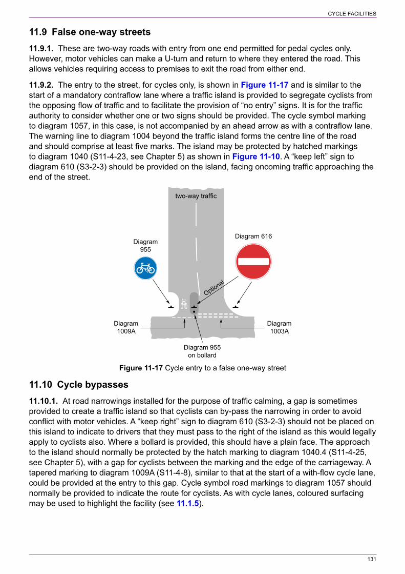
131
CYCLE FACILITIES
11.9 False one‑way streets11.9.1. These are two‑way roads with entry from one end permitted for pedal cycles only. However, motor vehicles can make a U‑turn and return to where they entered the road. This allows vehicles requiring access to premises to exit the road from either end.
11.9.2. The entry to the street, for cycles only, is shown in Figure 11‑17 and is similar to the start of a mandatory contraflow lane where a traffic island is provided to segregate cyclists from the opposing flow of traffic and to facilitate the provision of “no entry” signs. It is for the traffic authority to consider whether one or two signs should be provided. The cycle symbol marking to diagram 1057, in this case, is not accompanied by an ahead arrow as with a contraflow lane. The warning line to diagram 1004 beyond the traffic island forms the centre line of the road and should comprise at least five marks. The island may be protected by hatched markings to diagram 1040 (S11‑4‑23, see Chapter 5) as shown in Figure 11‑10. A “keep left” sign to diagram 610 (S3‑2‑3) should be provided on the island, facing oncoming traffic approaching the end of the street.
two-way traffic
Diagram 616Diagram
955
Diagram 955on bollard
Diagram1009A
Diagram1003A
Optional
Figure 11‑17 Cycle entry to a false one‑way street
11.10 Cycle bypasses11.10.1. At road narrowings installed for the purpose of traffic calming, a gap is sometimes provided to create a traffic island so that cyclists can by‑pass the narrowing in order to avoid conflict with motor vehicles. A “keep right” sign to diagram 610 (S3‑2‑3) should not be placed on this island to indicate to drivers that they must pass to the right of the island as this would legally apply to cyclists also. Where a bollard is provided, this should have a plain face. The approach to the island should normally be protected by the hatch marking to diagram 1040.4 (S11‑4‑25, see Chapter 5), with a gap for cyclists between the marking and the edge of the carriageway. A tapered marking to diagram 1009A (S11‑4‑8), similar to that at the start of a with‑flow cycle lane, could be provided at the entry to this gap. Cycle symbol road markings to diagram 1057 should normally be provided to indicate the route for cyclists. As with cycle lanes, coloured surfacing may be used to highlight the facility (see 11.1.5).

132
CYCLE FACILITIES
11.11 Cycle tracks and routes shared with pedestrians11.11.1. A cycle track may be a physically segregated part of a road, or form a separate route entirely distinct from the road system. It may form a route for cycles only, a segregated route shared with pedestrians where cyclists and pedestrians use separate parts of the track, or an unsegregated route where both cyclists and pedestrians use the full width of the track.
11.11.2. An off‑road cycle track is indicated by the sign to diagram 955 (S3‑2‑28, see Figure 11‑11), which means that the route is for cycles only and all other vehicular traffic is prohibited. As the route is not intended for pedestrians, there should be a convenient footway or footpath nearby. The sign should be provided at the start of the cycle track and where the track crosses roads used by other traffic. The signs may also be used as repeaters along the route. The sign to diagram 967 (S11‑2‑44, see Figure 11‑7) is not appropriate for off‑road cycle tracks as it is prescribed for use only on the main carriageway of a road. Where a pedestrian route crosses a cycle track the sign to diagram 963.1 (S11‑2‑41, see Figure 11‑16) may be used to alert pedestrians to the presence of cycles. The sign should be varied to “CYCLE TRACK”, with the legend “LOOK RIGHT” or “LOOK LEFT” as appropriate for a one‑way track, or “LOOK BOTH WAYS”, where the cycle track is two way.
11.11.3. Where a footway (forming part of a road) or footpath (e.g. through a park) has been converted to an unsegregated route shared by pedestrians and cyclists, this is indicated by the sign diagram 956 (S3‑2‑29, see Figure 11‑18). This prohibits the use of the route by any other vehicles and should be located where the shared route begins. Repeater signs may be placed along the route in order to remind both pedestrians and cyclists that pedal cycles can be legally ridden on the footway or footpath. Where ridden horses are permitted to use an unsegregated cycle and pedestrian route, the sign to diagram 956.1 (S3‑2‑30, see Figure 11‑19) should be used, and where horse‑drawn vehicles are also permitted, the appropriate sign is diagram 956.2 (S3‑2‑31, see Figure 11‑20).
Figure 11‑18 Diagram 956 Figure 11‑19 Diagram 956.1 Figure 11‑20 Diagram 956.2 (S3‑2‑29) Route for use by pedal (S3‑2‑30) Route for use by (S3‑2‑31) As diagram 956.1 cycles and pedestrians only pedal cycles, horses and but permitting horse‑drawn pedestrians only vehicles also
11.11.4. The cycle symbol marking to diagram 1057 may be used with the signs to diagram 955 and 956. This would be particularly useful on unsegregated footways and footpaths to remind pedestrians that the route is also used by cyclists, and to reassure cyclists that they are legally riding on the footway. The marking may be repeated more often than the upright sign and may be provided as an alternative, i.e. where no upright repeater signs are provided along the track or route. There is no requirement to use the marking in conjunction with an upright sign.
11.11.5. Where a route is divided into separate parts for the use of cyclists and of pedestrians, segregation may be achieved using the continuous marking to diagram 1049B (S9‑6‑7), normally with a width of 150 mm, or by the raised profile marking to diagram 1049.1 (S9‑6‑8, see Figure 11‑21). The latter is more easily detected by blind and partially sighted pedestrians. Alternatively, separation may be effected by the use of kerbs, a difference in level, or by the use of contrasting coloured surfaces. See Chapter 5 in respect of drainage issues associated with road markings. The segregated route is indicated by the sign to diagram 957 (S3‑2‑32, see Figure 11‑22). This is placed at the start of the route as it prohibits motor vehicles. It may

133
CYCLE FACILITIES
also be used as a repeater sign to remind pedestrians and cyclists which side of the track they should be using. The sign is generally used in conjunction with the cycle symbol marking to diagram 1057 which emphasises that part of the track used by cyclists. If this is to the right of the pedestrian part of the track (in the direction of travel) the cycle symbol on the upright sign faces right. The marking to diagram 1057 should, therefore, also face to the right. To reduce the number of upright repeater signs or to have none at all, the marking to diagram 1057 may be used on its own to indicate the part of the segregated route to be used by cyclists. The pedestrian symbol is not prescribed for use as a road marking, so must not be used on the pedestrian part of a segregated track or footway.
cross section A – A
6 max
12 min20 max
50
50
50
A
A
Figure 11‑21 Diagram 1049.1 (S9‑6‑8) Division Figure 11‑22 Diagram 957 (S3‑2‑38) Route of route into that part reserved for pedal cycles comprising two ways for use by pedal cycles and that part reserved for pedestrians only and by pedestrians only indicated by (Longitudinal marking) diagram 1049B or 1049.1, or by physical means (Alternative types)
11.11.6. Several sizes are prescribed for the signs to diagrams 955, 956, 956.1, 956.2 and 957. As these signs prohibit motor vehicles, the 600 mm and 450 mm diameter signs should normally be used for diagrams 955, 956 and 957 where they control entry from the main carriageway of a road and where motor vehicles, especially solo motor cycles, are not physically prevented from entering the cycle track or shared cycle / pedestrian route. For diagrams 956.1 and 956.2, the equivalent sizes are 750 mm and 600 mm as the symbols are smaller. The smaller sizes for all signs may be used as repeater signs and on bollards.
11.11.7. Where the cycle track or shared pedestrian route forms part of a numbered cycle route, the supplementary plate to diagram 2602.3 (S9‑4‑12, see Figure 11‑23) may be used with the circular signs. The plate, which must not be used on its own (Schedule 9 General Direction 7), has a red background for a national route, a blue background for a regional route and any appropriate colour for other routes. Table 11‑1 shows recommended x‑heights, depending on the size of sign the plate is used with. The cycle route number may be indicated by the road marking to diagram 1057.1 (S11‑4‑29, see Figure 11‑24), particularly where there are no upright signs. This marking should generally be used with the cycle symbol marking to diagram 1057; otherwise it might not be apparent that the number relates to a cycle route. Where the number comprises both capital letters and numerals it may be on one or two lines as shown in Figure 11‑24, depending on the track width available. There are three alternative heights for the route number characters; these generally relate to the size of the cycle symbol marking to diagram 1057.
11.11.8. The “END” road marking to diagram 1058, together with the cycle symbol marking to diagram 1057, may be used to indicate the end of a cycle track, although this might not always be necessary. It might be helpful where cyclists rejoin the main carriageway of a road at the end of a shared footway or where a numbered route terminates. It should not be used at an intermittent break in a cycle track or shared route, such as at a road crossing. The upright sign to diagram 965 (S11‑2‑45, see Figure 11‑25) may be used with the markings or as an
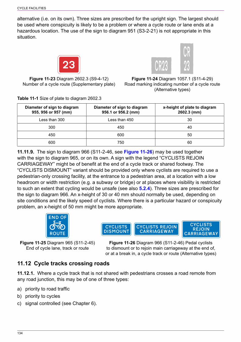
134
CYCLE FACILITIES
alternative (i.e. on its own). Three sizes are prescribed for the upright sign. The largest should be used where conspicuity is likely to be a problem or where a cycle route or lane ends at a hazardous location. The use of the sign to diagram 951 (S3‑2‑21) is not appropriate in this situation.
Figure 11‑23 Diagram 2602.3 (S9‑4‑12) Figure 11‑24 Diagram 1057.1 (S11‑4‑29) Number of a cycle route (Supplementary plate) Road marking indicating number of a cycle route (Alternative types)
Table 11‑1 Size of plate to diagram 2602.3
Diameter of sign to diagram 955, 956 or 957 (mm)
Diameter of sign to diagram 956.1 or 956.2 (mm)
x‑height of plate to diagram 2602.3 (mm)
Less than 300 Less than 450 30
300 450 40
450 600 50
600 750 60
11.11.9. The sign to diagram 966 (S11‑2‑46, see Figure 11‑26) may be used together with the sign to diagram 965, or on its own. A sign with the legend “CYCLISTS REJOIN CARRIAGEWAY” might be of benefit at the end of a cycle track or shared footway. The “CYCLISTS DISMOUNT” variant should be provided only where cyclists are required to use a pedestrian‑only crossing facility, at the entrance to a pedestrian area, at a location with a low headroom or width restriction (e.g. a subway or bridge) or at places where visibility is restricted to such an extent that cycling would be unsafe (see also 5.2.4). Three sizes are prescribed for the sign to diagram 966. An x‑height of 30 or 40 mm should normally be used, depending on site conditions and the likely speed of cyclists. Where there is a particular hazard or conspicuity problem, an x‑height of 50 mm might be more appropriate.
Figure 11‑25 Diagram 965 (S11‑2‑45) Figure 11‑26 Diagram 966 (S11‑2‑46) Pedal cyclists End of cycle lane, track or route to dismount or to rejoin main carriageway at the end of, or at a break in, a cycle track or route (Alternative types)
11.12 Cycle tracks crossing roads11.12.1. Where a cycle track that is not shared with pedestrians crosses a road remote from any road junction, this may be of one of three types:
a) priority to road trafficb) priority to cyclesc) signal controlled (see Chapter 6).
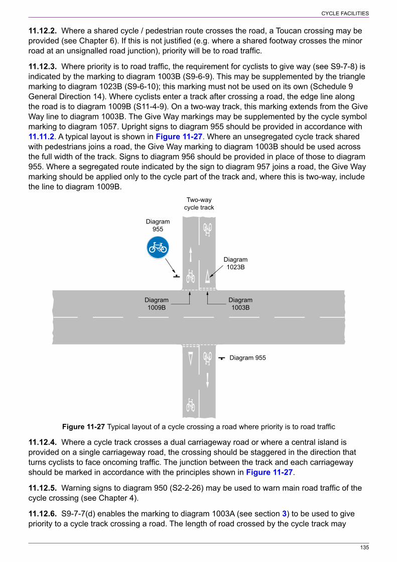
135
CYCLE FACILITIES
11.12.2. Where a shared cycle / pedestrian route crosses the road, a Toucan crossing may be provided (see Chapter 6). If this is not justified (e.g. where a shared footway crosses the minor road at an unsignalled road junction), priority will be to road traffic.
11.12.3. Where priority is to road traffic, the requirement for cyclists to give way (see S9‑7‑8) is indicated by the marking to diagram 1003B (S9‑6‑9). This may be supplemented by the triangle marking to diagram 1023B (S9‑6‑10); this marking must not be used on its own (Schedule 9 General Direction 14). Where cyclists enter a track after crossing a road, the edge line along the road is to diagram 1009B (S11‑4‑9). On a two‑way track, this marking extends from the Give Way line to diagram 1003B. The Give Way markings may be supplemented by the cycle symbol marking to diagram 1057. Upright signs to diagram 955 should be provided in accordance with 11.11.2. A typical layout is shown in Figure 11‑27. Where an unsegregated cycle track shared with pedestrians joins a road, the Give Way marking to diagram 1003B should be used across the full width of the track. Signs to diagram 956 should be provided in place of those to diagram 955. Where a segregated route indicated by the sign to diagram 957 joins a road, the Give Way marking should be applied only to the cycle part of the track and, where this is two‑way, include the line to diagram 1009B.
Two-waycycle track
Diagram955
Diagram1003B
Diagram1009B
Diagram1023B
Diagram 955
Figure 11‑27 Typical layout of a cycle crossing a road where priority is to road traffic
11.12.4. Where a cycle track crosses a dual carriageway road or where a central island is provided on a single carriageway road, the crossing should be staggered in the direction that turns cyclists to face oncoming traffic. The junction between the track and each carriageway should be marked in accordance with the principles shown in Figure 11‑27.
11.12.5. Warning signs to diagram 950 (S2‑2‑26) may be used to warn main road traffic of the cycle crossing (see Chapter 4).
11.12.6. S9‑7‑7(d) enables the marking to diagram 1003A (see section 3) to be used to give priority to a cycle track crossing a road. The length of road crossed by the cycle track may

136
CYCLE FACILITIES
consist of a flat‑topped road hump that extends across the full width of the carriageway. The marking to diagram 1023A (see section 3) should be provided, together with a longitudinal warning line to diagram 1004 on each approach. Where a hump is provided, this should be marked with diagram 1062 (see Chapter 5). The Give Way marking should be placed on the carriageway of the road, not on any part of the hump.
11.13 Worded markings and arrows11.13.1. Figure 11‑28 shows the reduced size “SLOW” road marking to diagram 1058.1 (S11‑4‑31). The available lane or track width will determine the appropriate size. The marking should be used where cyclists need to take extra care, particularly where they are likely to come into conflict with pedestrians or road traffic. The marking need not be used with the cycle symbol to diagram 1057 nor with any upright sign.
11.13.2. The “END” road marking to diagram 1058 (S11‑4‑30, see Figure 11‑29) is generally used at the end of a route or track (see 11.11.8). It is not intended to be used at short breaks, nor where cycle facilities continue in another form. It is prescribed in three sizes; the width of track available and the required conspicuity of the marking will generally determine the appropriate size. The marking is normally used with the cycle symbol marking to diagram 1057, in which case both markings should be the same width. The markings may also be used at the end of a with‑flow cycle lane.
750, 1100, 1700
70510351600
1100
500
Diagram 1058
Diagram 1057
NOTE: The distance between END and the cyclesymbol (diagram 1057) is approximate and adjustedproportionally for other sizes of marking
Figure 11‑28 Diagram 1058.1 (S11‑4‑31) Figure 11‑29 Diagram 1058 (S11‑4‑30) Pedal cycles should proceed with caution End of a cycle lane, track or route because of potential danger ahead
11.13.3. Figure 11‑30 shows reduced size arrow road markings to diagram 1059 (S11‑4‑32) for use with cycle facilities. The arrow should be used with the cycle symbol marking to diagram 1057, with 1000 mm arrow being used with the 750 mm wide cycle symbol. The arrow must indicate only one direction. Where the arrow points to the right, the cycle symbol should face right. The distance between the arrow and cycle symbol should be approximately 1 m, as shown in Figure 11‑10, although this can be reduced where the smaller arrow is used.

137
CYCLE FACILITIES
Figure 11‑30 Diagram 1059 (S11‑4‑32) Directions in which pedal cycles should travel along a cycle lane, track or route (Alternative types)
11.13.4. See 11.11.7 for more information on cycle route number markings.
11.14 Parking places for pedal cycles11.14.1. Figure 11‑31 shows the upright signs to diagrams 968 and 968.1 (S11‑2‑47) prescribed for cycle parking places. These have no permitted variants, are not used with road markings and do not require an order. They are generally associated with cycle racks and storage facilities. The choice of sign will depend on the location and mounting arrangements.
Figure 11‑31 Diagrams 968 and 968.1 (S11‑2‑47) Parking place for pedal cycles
138
12 CONGESTION CHARGING ZONES
12.1 General12.1.1. Upright signs and road markings for congestion charging zones prescribed in S8‑4 are intended for roads where a road‑charging scheme is applied and not for tolled roads and tolled crossings. They may be used where congestion charging is by number plate recognition or where payment is made on entry or exit.
12.1.2. The entrance to the zone is indicated by an upright sign to either diagram 677 or 678 (S8‑4‑1 and 2 respectively, see Figure 12‑1). Diagram 677 may include a top panel with the name and logo of the traffic authority. The middle panel of diagram 677 and the upper panel of diagram 678 differ with regard to the positioning of the “C” symbol. In diagram 677, the legend “Congestion charging” is always used above the symbol, with the name of the zone below the symbol. In diagram 678, the name of the zone, in the format [place name] and “charging ZONE” is located above the symbol; the place name may be replaced by “Congestion” (i.e. the legend is “Congestion charging ZONE”). The zone operational period is shown in the lower panel on each of the two signs, in accordance with S18‑1. Where the zone operates at all times, the legend is “At all times”; the Regulations do not permit the time period to be omitted in this case. Details of the method of payment and the amount of charge may be shown in the lower panel above the time period. The prescribed legends are:
a) “Pay on entry” or “Pay on exit”;b) “£2 Pay on entry” or “£2 Pay on exit” with “£2” varied as appropriate; andc) “£2 per day” or “£2 per vehicle” with “£2” varied as appropriate.
12.1.3. The zone entry signs are prescribed in three sizes. The smallest size will be appropriate in most situations, particularly where the zone boundary is at a junction on a minor route with low traffic speeds. The larger sizes should be considered where the entrance to the zone is at a complex road junction and drivers might mistakenly commit themselves to turning into the zone. Normally a single zone entry sign will be sufficient, sited either on the left or right hand side of the road depending which provides the better visibility distance on the approach. The sign may be supplemented by the road marking to diagram 1068 (S8‑4‑7, see Figure 12‑2). The red elongated circle indicates that the marking is regulatory and once it has been crossed the vehicle has entered the zone. The marking is prescribed in two sizes; the larger should be used where greater emphasis is required. The marking must not be used as a repeater within the zone as it is not prescribed for this purpose.
12.1.4. The repeater sign to diagram 894 (S8‑4‑5, see Figure 12‑3) may be used as appropriate to remind drivers that there are number plate recognition cameras within the zone. The sign may include the name and logo of the enforcement authority. The appropriate sign size is generally related to the speed of traffic and is specified in Appendix A.
12.1.5. The end of the zone is indicated by the sign to diagram 679 (S8‑4‑6, see Figure 12‑4). A single sign should be sufficient in most situations. A second sign might be required at more complex junctions, particularly if a route leading from the junction is still within the zone and the exit from the zone needs to be clearly identified. As with the zone entry signs, the “zone end” sign is prescribed in three sizes. For most situations the intermediate size is likely to be appropriate. The largest size should be considered where conspicuity is a problem or the road junction is complex. The smallest size might be appropriate on narrow roads, where traffic speeds are low and within traffic calmed areas. It should also be considered where payment is

139
CONGESTION CHARGING ZONES
on exit and all vehicles have to stop. In this case, if it is clear that the payment point is at the exit, the “zone end” sign might not be needed.
Figure 12‑1 Diagrams 677 (S8‑4‑1) and 678 Figure 12‑2 Diagram 1068 (S8‑4‑7) (S8‑4‑2) Entrance to a congestion charging zone Road marking indicating the commencement of a congestion charging zone
Figure 12‑3 Diagram 894 (S8‑4‑5) Reminder to Figure 12‑4 Diagram 679 (S8‑4‑6) drivers within a congestion charging zone in which End of congestion charging zone cameras are used to enforce traffic regulations (Alternative types)
12.1.6. The signs to diagrams 818.6 and 818.7 (S8‑4‑3 and 4 respectively, see Figure 12‑5 and Figure 12‑6) give advance information about a congestion charging zone ahead so that drivers can decide whether to enter the zone or take an alternative route. Diagram 818.6 is normally placed the furthest from the zone and indicates only the times of operation. Diagram 818.7 normally follows diagram 818.6 and indicates both the amount of charge and the times of operation. Unlike diagram 818.6, this sign does not include the legend “Congestion charging zone”. Where it is not appropriate to indicate the amount of charge on the advance to the zone, diagram 818.7 may be replaced by a second sign to diagram 818.6. Advance signs should be provided where considered appropriate (e.g. after each major road junction within one mile of the zone). The distance in the lower panel on each sign is varied in accordance with S18‑3, as appropriate.

140
CONGESTION CHARGING ZONES
Figure 12‑5 Diagram 818.6 (S8‑4‑3) Advance Figure 12‑6 Diagram 818.7 (S8‑4‑4) Advance indication of a congestion charging zone indication of a congestion charging zone indicating the amount of charge
12.1.7. The “C” symbol prescribed by S12‑11‑19 may be used on directional signs to indicate the entrance to a congestion charging zone. The symbol is used without any legend. Where a traffic lane on the approach to a junction leads directly to the zone, the road marking to diagram 1069 (S8‑4‑8, see Figure 12‑7) may be provided. This should be used to give advance warning to drivers where it is still possible to make a safe manoeuvre (e.g. change lanes) in order to avoid entering the zone. This marking, which has a white elongated circle, is informatory and not regulatory. Two sizes of marking are prescribed, the larger being used where greater emphasis is required (e.g. where the entrance to the zone is at a junction on a heavily traffic road such as a dual carriageway).
Figure 12‑7 Diagram 1069 (S8‑4‑8) Road marking giving advance warning
of a congestion charging zone
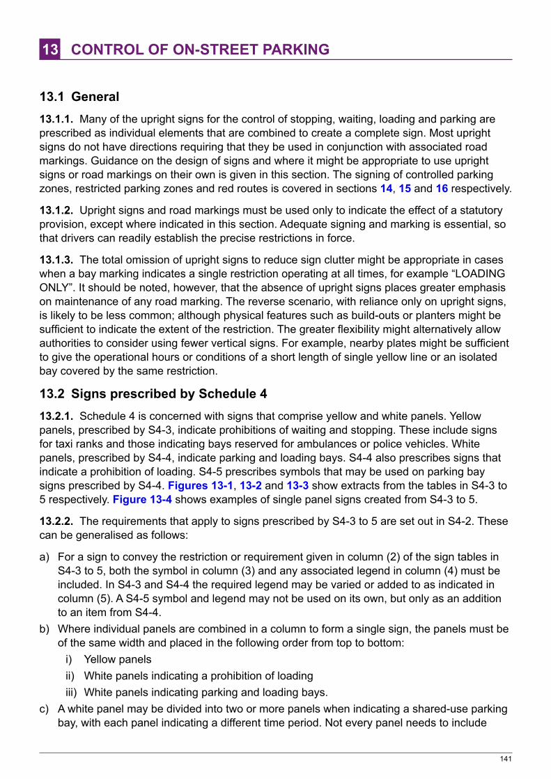
141
13 CONTROL OF ON‑STREET PARKING
13.1 General13.1.1. Many of the upright signs for the control of stopping, waiting, loading and parking are prescribed as individual elements that are combined to create a complete sign. Most upright signs do not have directions requiring that they be used in conjunction with associated road markings. Guidance on the design of signs and where it might be appropriate to use upright signs or road markings on their own is given in this section. The signing of controlled parking zones, restricted parking zones and red routes is covered in sections 14, 15 and 16 respectively.
13.1.2. Upright signs and road markings must be used only to indicate the effect of a statutory provision, except where indicated in this section. Adequate signing and marking is essential, so that drivers can readily establish the precise restrictions in force.
13.1.3. The total omission of upright signs to reduce sign clutter might be appropriate in cases when a bay marking indicates a single restriction operating at all times, for example “LOADING ONLY”. It should be noted, however, that the absence of upright signs places greater emphasis on maintenance of any road marking. The reverse scenario, with reliance only on upright signs, is likely to be less common; although physical features such as build‑outs or planters might be sufficient to indicate the extent of the restriction. The greater flexibility might alternatively allow authorities to consider using fewer vertical signs. For example, nearby plates might be sufficient to give the operational hours or conditions of a short length of single yellow line or an isolated bay covered by the same restriction.
13.2 Signs prescribed by Schedule 413.2.1. Schedule 4 is concerned with signs that comprise yellow and white panels. Yellow panels, prescribed by S4‑3, indicate prohibitions of waiting and stopping. These include signs for taxi ranks and those indicating bays reserved for ambulances or police vehicles. White panels, prescribed by S4‑4, indicate parking and loading bays. S4‑4 also prescribes signs that indicate a prohibition of loading. S4‑5 prescribes symbols that may be used on parking bay signs prescribed by S4‑4. Figures 13‑1, 13‑2 and 13‑3 show extracts from the tables in S4‑3 to 5 respectively. Figure 13‑4 shows examples of single panel signs created from S4‑3 to 5.
13.2.2. The requirements that apply to signs prescribed by S4‑3 to 5 are set out in S4‑2. These can be generalised as follows:
a) For a sign to convey the restriction or requirement given in column (2) of the sign tables in S4‑3 to 5, both the symbol in column (3) and any associated legend in column (4) must be included. In S4‑3 and S4‑4 the required legend may be varied or added to as indicated in column (5). A S4‑5 symbol and legend may not be used on its own, but only as an addition to an item from S4‑4.
b) Where individual panels are combined in a column to form a single sign, the panels must be of the same width and placed in the following order from top to bottom:
i) Yellow panelsii) White panels indicating a prohibition of loadingiii) White panels indicating parking and loading bays.
c) A white panel may be divided into two or more panels when indicating a shared‑use parking bay, with each panel indicating a different time period. Not every panel needs to include

142
CONTROL OF ON‑STREET PARKING
the associated symbol where this is the same, allowing the top panel to be a header that may also contain times or an arrow applicable to the whole sign. Further details are given in 13.17.
d) A sign may be formed by placing no more than two panels side by side; they need not be of the same height. Two columns of sign panels may be placed side by side. A single panel may be placed centrally above or below panels that are side by side.
e) Where a sign is placed to indicate the beginning of, or a change in, a restriction or prohibition, it must include an arrow pointing to the left or to the right as appropriate.
f) Certain signs may comprise only a single panel. These are:i) No waiting, or no stopping, on a verge or footwayii) Signs indicating an off‑road loading areaiii) No stopping in a lay‑by except in an emergencyiv) No stopping on entrance markingsv) “Have you paid and displayed?” sign.
13.2.3. Examples of multi‑panel signs are shown in Figure 13‑5.
Symbols and legends used in combination with a yellow panel
(1)
Item
(2)
Description
(3)
Symbol
(4)
Legend
(5)
Variant of legend
(6)
Legend height (by reference to x‑height)
1. Waiting prohibited for a time that is not continuous throughout the year
30 min80 max
A time period
The legend may include either or both—
(a) “No waiting”; and
(b) “except” followed by one or more of “taxis”, “ambulances”, “police vehicles”
Not less than 15 mm and not more than 40 mm
Figure 13‑1 Extract from S4‑3
Symbols and legends used in combination with a white panel
(1)
Item
(2)
Description
(3)
Symbol
(4)
Required legends
(5)
Variants to column 4 legends or legends that may be included
(6)
Legend height (by reference to x‑height)
(7)
Applicable Part 5 item
1. Loading prohibited
1. “No loading”
2. A time period
Not less than 15 mm and not more than 40 mm
2. Parking place 75 min
200 max
1. A time period may be included
2. A permitted parking expression may be included
3. etc.
Not less than 15 mm and not more than 40 mm
1, 2, 3, 4, 5, 6, 7, 8
Figure 13‑2 Extract from S4‑4
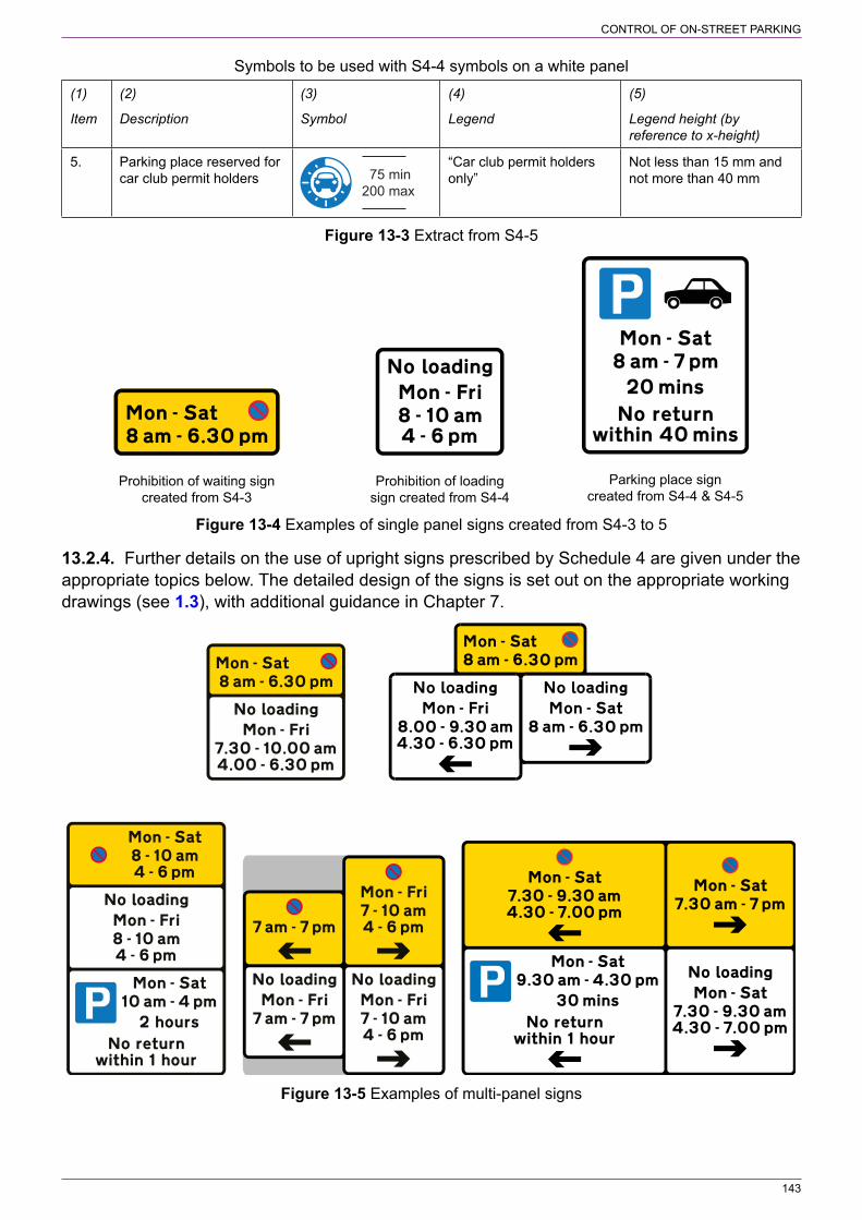
143
CONTROL OF ON‑STREET PARKING
Symbols to be used with S4‑4 symbols on a white panel
(1)
Item
(2)
Description
(3)
Symbol
(4)
Legend
(5)
Legend height (by reference to x‑height)
5. Parking place reserved for car club permit holders 75 min
200 max
“Car club permit holders only”
Not less than 15 mm and not more than 40 mm
Figure 13‑3 Extract from S4‑5
Prohibition of waiting signcreated from S4-3
Prohibition of loadingsign created from S4-4
Parking place signcreated from S4-4 & S4-5
Figure 13‑4 Examples of single panel signs created from S4‑3 to 5
13.2.4. Further details on the use of upright signs prescribed by Schedule 4 are given under the appropriate topics below. The detailed design of the signs is set out on the appropriate working drawings (see 1.3), with additional guidance in Chapter 7.
Figure 13‑5 Examples of multi‑panel signs

144
CONTROL OF ON‑STREET PARKING
13.3 Time periods13.3.1. Upright signs indicating a prohibition of stopping, waiting and loading and those indicating parking controls will, in most cases, indicate the times when the various elements of the traffic order apply. Permitted expressions of time periods, days and dates are set out in S18‑1 (see regulation 6 and Chapter 7). Where the prohibitions or parking controls are continuous throughout the year, the expression “at any time” or “at all times” should be used as appropriate. This is not necessary for certain signs, as described in the topics below, where the absence of a time period means 24 hours a day throughout the year.
13.3.2. A time period may comprise the time of day, the day of the week and, where not applicable throughout the year, the appropriate dates. The expressions “Match days”, “Event days” and “Market days” may also be used (S18‑1‑5). The time of day must always be shown in the 12‑hour clock format (S18‑1‑1(2)). Where time periods are the same on every day of the week, the days of the week are not shown on the sign; an expression such as “Mon ‑ Sun” should not be used. This makes the sign larger than necessary and could lead to inconsistent signing or cause confusion. Where public holidays are excluded from the order, this should be indicated on the signs; otherwise drivers will not know that the parking controls do not apply on these days. Where dates are shown they may be abbreviated and expressed in the manner “1 May – 30 Sept”. Where a prohibition applies overnight, but not on every day of the week, signing is simplified by using the expression “next day”; for example, “Mon – Sat 10 pm – 6 am next day”. Where the overnight prohibition applies every day, it is signed in the manner “10 pm – 6 am”. Regulation 6(2) permits more than one time period to be included on a sign (e.g. the morning peak period and the evening peak period).
13.3.3. Where new traffic regulation orders are to be introduced, restrictions should be kept as simple as possible to avoid complex traffic signs that might be difficult for drivers to understand.
13.4 Prohibition of waiting and loading13.4.1. Waiting and loading prohibitions on the side of a road generally apply from the carriageway centre line to the highway boundary. The prohibition therefore applies to any verge, footway or cycle track as well as to the carriageway.
13.4.2. Standard exemptions to a waiting prohibition are not shown on the signs. These exemptions include stopping to pick up or set down passengers, and causing a vehicle to be stationary for the purposes of loading or unloading goods from that vehicle. Loading generally refers to commercial loading or to objects that are too heavy or bulky to be carried very far by hand, but does not include time for purchasing the goods. Where loading is not permitted, this is indicated on the upright sign. Loading restriction signs have a white background, to contrast with the yellow “no waiting” signs. Disabled badge holders may park on single or double yellow lines for up to three hours (or in Scotland for an indefinite period) but in general not where there are restrictions on loading or unloading – indicated by yellow kerb dashes and/or signs on plates. Where a length of road is not suitable for parking by disabled badge holders, a prohibition of loading should be considered. However, if a loading provision is necessary, a loading bay should be provided for this specific purpose. A prohibition of loading still permits drivers to pick up and set down passengers.
13.4.3. The double yellow line to diagram 1018.1 (S7‑4‑1, see Figure 13‑6) applies at all times. It is not used for a seasonal 24‑hour prohibition of waiting; the single yellow line to diagram 1017 (S7‑4‑2, see Figure 13‑7) is used for this purpose. There is no time limit in replacing any seasonal double yellow line with a single yellow line; this should normally be done under routine maintenance or when the road is resurfaced. Upright signs are not used to indicate a continuous
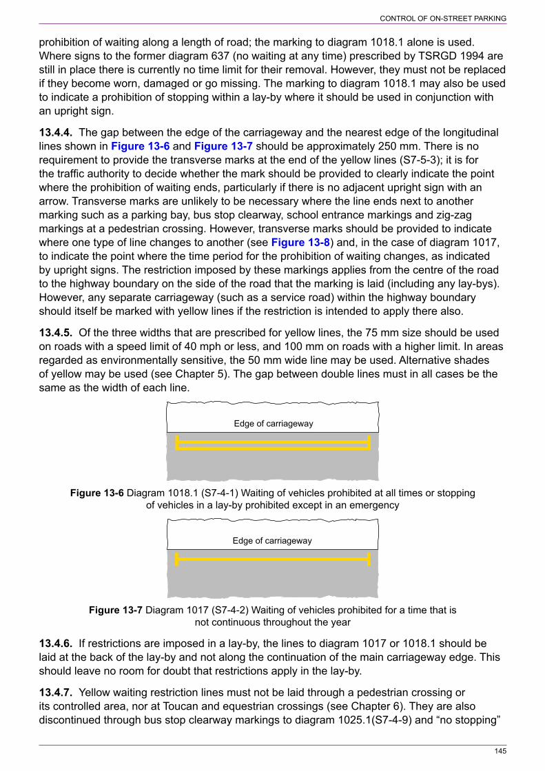
145
CONTROL OF ON‑STREET PARKING
prohibition of waiting along a length of road; the marking to diagram 1018.1 alone is used. Where signs to the former diagram 637 (no waiting at any time) prescribed by TSRGD 1994 are still in place there is currently no time limit for their removal. However, they must not be replaced if they become worn, damaged or go missing. The marking to diagram 1018.1 may also be used to indicate a prohibition of stopping within a lay‑by where it should be used in conjunction with an upright sign.
13.4.4. The gap between the edge of the carriageway and the nearest edge of the longitudinal lines shown in Figure 13‑6 and Figure 13‑7 should be approximately 250 mm. There is no requirement to provide the transverse marks at the end of the yellow lines (S7‑5‑3); it is for the traffic authority to decide whether the mark should be provided to clearly indicate the point where the prohibition of waiting ends, particularly if there is no adjacent upright sign with an arrow. Transverse marks are unlikely to be necessary where the line ends next to another marking such as a parking bay, bus stop clearway, school entrance markings and zig‑zag markings at a pedestrian crossing. However, transverse marks should be provided to indicate where one type of line changes to another (see Figure 13‑8) and, in the case of diagram 1017, to indicate the point where the time period for the prohibition of waiting changes, as indicated by upright signs. The restriction imposed by these markings applies from the centre of the road to the highway boundary on the side of the road that the marking is laid (including any lay‑bys). However, any separate carriageway (such as a service road) within the highway boundary should itself be marked with yellow lines if the restriction is intended to apply there also.
13.4.5. Of the three widths that are prescribed for yellow lines, the 75 mm size should be used on roads with a speed limit of 40 mph or less, and 100 mm on roads with a higher limit. In areas regarded as environmentally sensitive, the 50 mm wide line may be used. Alternative shades of yellow may be used (see Chapter 5). The gap between double lines must in all cases be the same as the width of each line.
Edge of carriageway
Figure 13‑6 Diagram 1018.1 (S7‑4‑1) Waiting of vehicles prohibited at all times or stopping of vehicles in a lay‑by prohibited except in an emergency
Edge of carriageway
Figure 13‑7 Diagram 1017 (S7‑4‑2) Waiting of vehicles prohibited for a time that is not continuous throughout the year
13.4.6. If restrictions are imposed in a lay‑by, the lines to diagram 1017 or 1018.1 should be laid at the back of the lay‑by and not along the continuation of the main carriageway edge. This should leave no room for doubt that restrictions apply in the lay‑by.
13.4.7. Yellow waiting restriction lines must not be laid through a pedestrian crossing or its controlled area, nor at Toucan and equestrian crossings (see Chapter 6). They are also discontinued through bus stop clearway markings to diagram 1025.1(S7‑4‑9) and “no stopping”
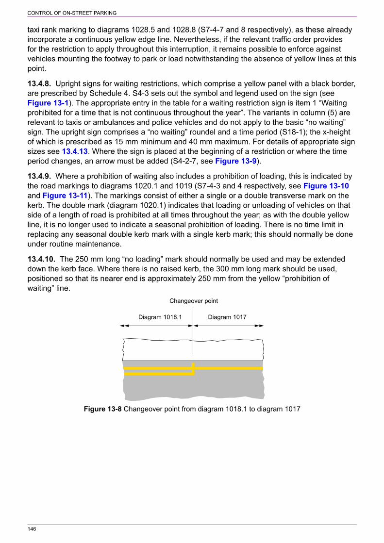
146
CONTROL OF ON‑STREET PARKING
taxi rank marking to diagrams 1028.5 and 1028.8 (S7‑4‑7 and 8 respectively), as these already incorporate a continuous yellow edge line. Nevertheless, if the relevant traffic order provides for the restriction to apply throughout this interruption, it remains possible to enforce against vehicles mounting the footway to park or load notwithstanding the absence of yellow lines at this point.
13.4.8. Upright signs for waiting restrictions, which comprise a yellow panel with a black border, are prescribed by Schedule 4. S4‑3 sets out the symbol and legend used on the sign (see Figure 13‑1). The appropriate entry in the table for a waiting restriction sign is item 1 “Waiting prohibited for a time that is not continuous throughout the year”. The variants in column (5) are relevant to taxis or ambulances and police vehicles and do not apply to the basic “no waiting” sign. The upright sign comprises a “no waiting” roundel and a time period (S18‑1); the x‑height of which is prescribed as 15 mm minimum and 40 mm maximum. For details of appropriate sign sizes see 13.4.13. Where the sign is placed at the beginning of a restriction or where the time period changes, an arrow must be added (S4‑2‑7, see Figure 13‑9).
13.4.9. Where a prohibition of waiting also includes a prohibition of loading, this is indicated by the road markings to diagrams 1020.1 and 1019 (S7‑4‑3 and 4 respectively, see Figure 13‑10 and Figure 13‑11). The markings consist of either a single or a double transverse mark on the kerb. The double mark (diagram 1020.1) indicates that loading or unloading of vehicles on that side of a length of road is prohibited at all times throughout the year; as with the double yellow line, it is no longer used to indicate a seasonal prohibition of loading. There is no time limit in replacing any seasonal double kerb mark with a single kerb mark; this should normally be done under routine maintenance.
13.4.10. The 250 mm long “no loading” mark should normally be used and may be extended down the kerb face. Where there is no raised kerb, the 300 mm long mark should be used, positioned so that its nearer end is approximately 250 mm from the yellow “prohibition of waiting” line.
Diagram 1018.1 Diagram 1017
Changeover point
Figure 13‑8 Changeover point from diagram 1018.1 to diagram 1017
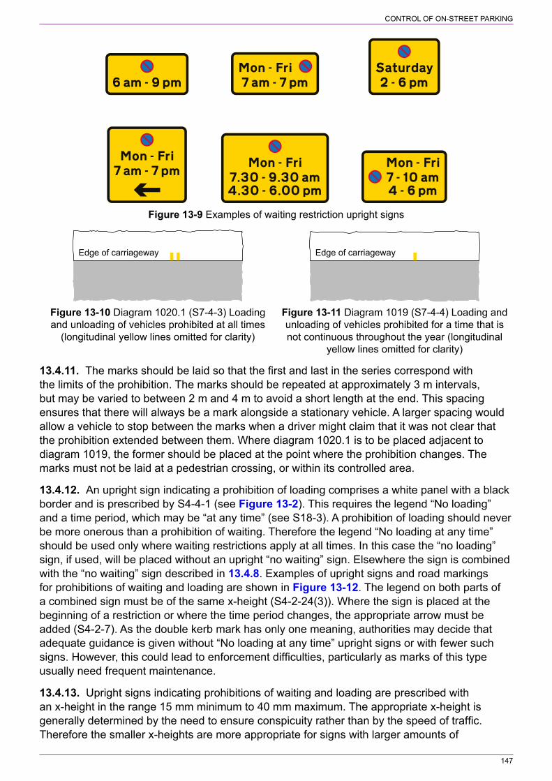
147
CONTROL OF ON‑STREET PARKING
Figure 13‑9 Examples of waiting restriction upright signs
Edge of carriageway
Edge of carriageway
Figure 13‑10 Diagram 1020.1 (S7‑4‑3) Loading Figure 13‑11 Diagram 1019 (S7‑4‑4) Loading and and unloading of vehicles prohibited at all times unloading of vehicles prohibited for a time that is (longitudinal yellow lines omitted for clarity) not continuous throughout the year (longitudinal yellow lines omitted for clarity)
13.4.11. The marks should be laid so that the first and last in the series correspond with the limits of the prohibition. The marks should be repeated at approximately 3 m intervals, but may be varied to between 2 m and 4 m to avoid a short length at the end. This spacing ensures that there will always be a mark alongside a stationary vehicle. A larger spacing would allow a vehicle to stop between the marks when a driver might claim that it was not clear that the prohibition extended between them. Where diagram 1020.1 is to be placed adjacent to diagram 1019, the former should be placed at the point where the prohibition changes. The marks must not be laid at a pedestrian crossing, or within its controlled area.
13.4.12. An upright sign indicating a prohibition of loading comprises a white panel with a black border and is prescribed by S4‑4‑1 (see Figure 13‑2). This requires the legend “No loading” and a time period, which may be “at any time” (see S18‑3). A prohibition of loading should never be more onerous than a prohibition of waiting. Therefore the legend “No loading at any time” should be used only where waiting restrictions apply at all times. In this case the “no loading” sign, if used, will be placed without an upright “no waiting” sign. Elsewhere the sign is combined with the “no waiting” sign described in 13.4.8. Examples of upright signs and road markings for prohibitions of waiting and loading are shown in Figure 13‑12. The legend on both parts of a combined sign must be of the same x‑height (S4‑2‑24(3)). Where the sign is placed at the beginning of a restriction or where the time period changes, the appropriate arrow must be added (S4‑2‑7). As the double kerb mark has only one meaning, authorities may decide that adequate guidance is given without “No loading at any time” upright signs or with fewer such signs. However, this could lead to enforcement difficulties, particularly as marks of this type usually need frequent maintenance.
13.4.13. Upright signs indicating prohibitions of waiting and loading are prescribed with an x‑height in the range 15 mm minimum to 40 mm maximum. The appropriate x‑height is generally determined by the need to ensure conspicuity rather than by the speed of traffic. Therefore the smaller x‑heights are more appropriate for signs with larger amounts of

148
CONTROL OF ON‑STREET PARKING
information (e.g. a sign comprising more than one panel). Choice of x‑height will depend on prevailing conditions and the design of the sign. In a quiet narrow residential street, a 15 mm x‑height is likely to be adequate even for the smallest signs (e.g. a sign a “no waiting” sign with the legend “8 am ‑ 6 pm”). However, in a busy high street or a wide suburban road, a larger x‑height such as 20 or 25 mm is likely to be appropriate, particularly if the sign does not have high target value. The largest size of 40 mm x‑height is likely to be appropriate on urban dual carriageways or on other roads with a speed limit of 50 mph or more.
13.4.14. The signs should be erected parallel to the kerb, facing the carriageway. There is no specific requirement to provide repeater signs; it is for the traffic authority to determine whether additional signs are required and where they are to be placed. However, to ensure that drivers are adequately informed of the times when a particular restriction applies, it is recommended that signs are sited at approximately 60 m intervals (and on each side of the road where the restriction applies to both sides). This will normally be achieved by fixing the signs on lighting columns within the restricted length of road. Where there are no lighting columns or other suitable mounting points, posts will need to be erected. Providing conspicuity is not compromised, signs may be mounted at the back of the footway on posts, walls, railings or other street furniture. This is likely to be preferable where the footway is narrow. In environmentally sensitive areas where a post is sited at the back of the footway, consideration might be given to painting the post in a similar colour to the adjacent building (direction 8 allows a post to be any single colour, including its natural colour). Where practicable, consideration should also be given to siting the post on the boundary between adjacent properties.
13.4.15. A sign should normally be erected within 15 m of the start and end of the prohibition. Where there is a change in the prohibition, signs for each prohibition are normally mounted either side by side or one above the other at the changeover point. Each sign should include an arrow indicating the direction in which the prohibition extends. Where a sign indicates both a prohibition of waiting and loading and only one of those prohibitions changes, the arrows should be applied only to the prohibition that changes. It is not necessary to duplicate the prohibition that does not change with an arrow pointing in each direction. Figures 13‑13, 13‑14, 13‑15, 13‑16, 13‑17, 13‑18 and 13‑19 give examples of signing changeover points, together with the appropriate road markings. Where the prohibition of loading changes, but not the prohibition of waiting, the yellow “no waiting” line at the changeover point does not have a transverse mark. Upright signs at the changeover point may be combined into a single sign or mounted separately. Where the resulting sign or combination of signs is not rectangular, a grey backing board may be used. This need not extend beyond the top and bottom of the assembly, or beyond the sides of the widest sign.
13.4.16. Figure 13‑19 shows an arrangement where a single yellow “no waiting” sign is placed above two “no loading” signs. Note that the width of the “no waiting” sign should not be increased to that of the two “no loading” signs.

149
CONTROL OF ON‑STREET PARKING
Waiting and loading prohibitedduring the times indicated
No waiting at any time; loadingprohibited during the times indicated
No waiting at any time No waiting at any time;no loading at any time
Figure 13‑12 Examples of upright signs and road markings for prohibitions of waiting and loading
Figure 13‑13 Change from daytime prohibition of waiting to both “no waiting” and “no loading at any time”

150
CONTROL OF ON‑STREET PARKING
Figure 13‑14 Start of a loading prohibition with no change to a prohibition of waiting at any time
Figure 13‑15 Start of peak‑hour prohibition of loading with no change to daytime prohibition of waiting
Figure 13‑16 Change from peak‑hour prohibition of waiting to daytime prohibition of waiting with no change to peak‑hour prohibition of loading
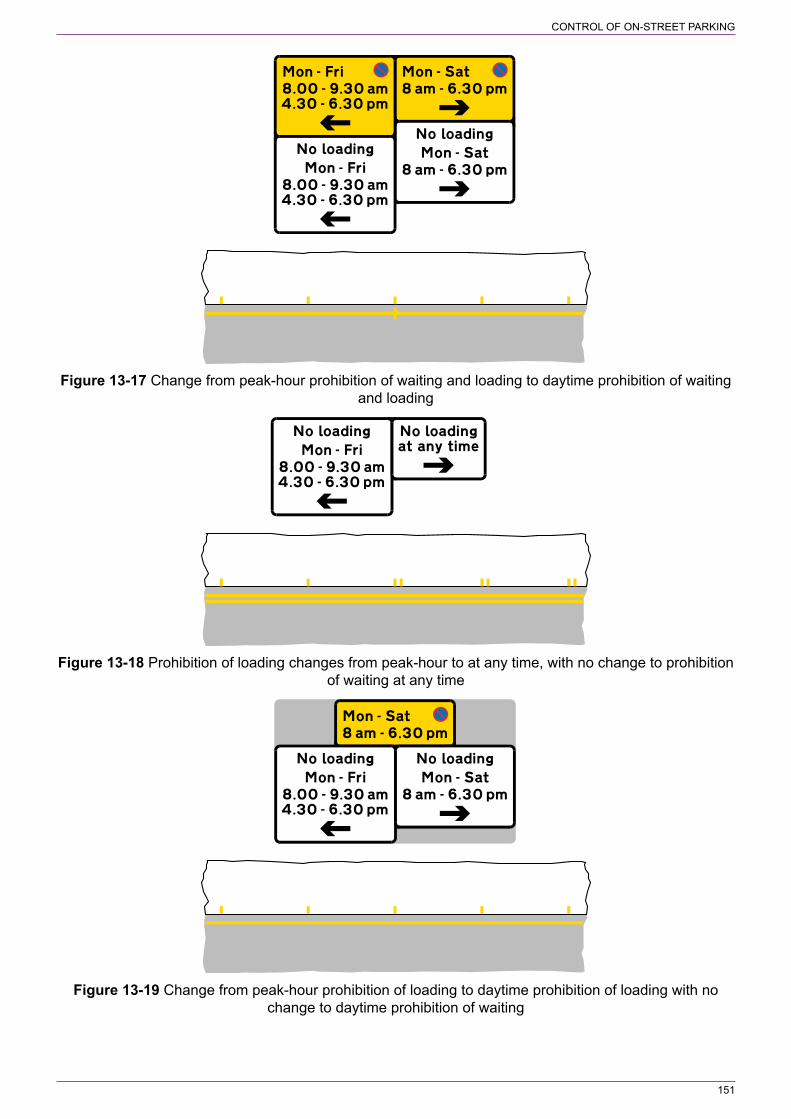
151
CONTROL OF ON‑STREET PARKING
Figure 13‑17 Change from peak‑hour prohibition of waiting and loading to daytime prohibition of waiting and loading
Figure 13‑18 Prohibition of loading changes from peak‑hour to at any time, with no change to prohibition of waiting at any time
Figure 13‑19 Change from peak‑hour prohibition of loading to daytime prohibition of loading with no change to daytime prohibition of waiting

152
CONTROL OF ON‑STREET PARKING
13.5 Prohibition of waiting, stopping or parking on verge or footway13.5.1. A prohibition of waiting extends from the centre of the road to the highway boundary. However, there might be certain situations where it is required to prohibit waiting on the verge or footway, but not on the main carriageway. This is most likely on rural roads subject to an order that prohibits stopping on the main carriageway (i.e. a 24‑hour rural clearway, see section 7). It might be desirable to prevent waiting on a verge because the ground is soft or newly seeded, or perhaps for road safety or security reasons, such as near an airfield. In this case, the sign prescribed by S4‑3‑5 should be used, with no road markings. The mandatory legend is “At any time on” followed by “verge or footway”, “footway” or “verge”. The prohibition applies at all times; the time period must not be varied. Where the order prohibits stopping, rather than waiting, the sign at item 6 should be used; i.e. to additionally prohibit loading. The legend is the same as that for the “no waiting” sign, the only difference being the symbol. The signs at items 5 and 6 must not be used with any other sign panel (S4‑2‑19). Examples of complete signs are shown in Figure 13‑20. The signs are mounted parallel to the edge of the carriageway.
No waiting No stopping No stopping
Figure 13‑20 Examples of upright signs indicating a prohibition of waiting or stopping on verge or footway
13.5.2. As the signs shown in Figure 13‑20 are used without a road marking, the first and last signs indicating where the prohibition starts and finishes should normally include an arrow. In village locations where a verge is being protected from parked vehicles, the start and end might be obvious and arrows might not be necessary. It is for the traffic authority to determine whether any repeater signs are required and where they are to be placed. However, to ensure that drivers are reminded of the restriction, it is recommended that repeater signs are, in most cases, including along rural roads subject to the national speed limit, provided at approximately 30 m intervals. This spacing is the same as that recommended for waiting restriction signs in pedestrian zones and restricted parking zones where there are no yellow lines to draw attention to the prohibition.
13.5.3. The signs are prescribed with an x‑height in the range 20 mm minimum to 40 mm maximum. Note that the minimum x‑height of 15 mm is not prescribed for these signs as they are not used in conjunction with a road marking and therefore need to be more conspicuous. The choice of x‑height will depend on prevailing conditions. In a quiet narrow village setting, a 20 mm x‑height is likely to be adequate. The largest size of 40 mm x‑height is likely to be appropriate on rural dual carriageways or on other roads subject to the national speed limit.
13.5.4. The signs shown in Figure 13‑20 are generally not appropriate for urban areas and could add to sign clutter. On roads that do not have waiting restrictions, but where it is desirable to prohibit parking on footways and verges, new zonal signing has been prescribed. Signs will not be necessary in places, such as London, where it is already unlawful to park on footways and verges. Elsewhere an order and upright signs will be required. The order for the prohibition of parking on the verge or footway should cover both sides of the road. This is because a single entry sign is normally used to reduce environmental impact and there should not be any

153
CONTROL OF ON‑STREET PARKING
confusion as to whether it applies to one side or both sides of the road. The general principle is that the prohibition of verge and footway parking applies to the whole road.
13.5.5. The entrance to an area (i.e. zone or road) where footway and verge parking is prohibited is indicated by a sign prescribed by Schedule 5. The sign comprises two elements, an upper panel at S‑3‑7 and a lower panel at S‑4‑4. Extracts from the two are shown in Figure 13‑21 and examples of complete signs are shown in Figure 13‑22.
S5‑3 – The upper panel and provision of the lower panel
(1)
Item
(2)
Description
(3)
Symbol
(4)
Legend
(5)
Height and location of legend
(6)
Permitted variants
(7)
Inclusion of a lower panel
7. Entrance to an area where parking on the verge or footway is prohibited
600 The name of a zone, city, town, village area or road
x‑height: 50 mm
Location: Above the symbol
1. The symbol may be reversed
2. The legend may be omitted
A lower panel must be included showing the legend specified in the Part 4 sign table at item 4
S5‑4 – Legends and symbols in the lower panel
(1)
Item
(2)
Legend
(3)
Height of legend or symbol
(4)
Permitted variants
4. “No motor vehicle parking on verge or footway except where signed”
x‑height: 50 mm 1. “motor vehicle” or “except where signed”, or both may be omitted
2. “verge or footway” may be varied to “verge” or “footway”
Figure 13‑21 Extracts from S5‑3 and S5‑4 in respect of the entrance to an area where parking on the verge or footway is prohibited
13.5.6. The prohibition of parking should always apply to both the footway and verge where they are present, even if they do not occur at the same place. This should be reflected by the legend in the lower panel of the entry sign. The legend “on footway” should be used only where there is no verge at any point within the zone or road and likewise the legend “on verge” should be used where there is no footway. Elsewhere the legend “on verge or footway” should be used. The legend “except where signed” in the lower panel should be used where verge or footway parking has been provided in certain places within the zone or road. The reference to “parking” in the lower panel may or may not include the words “motor vehicle” as considered appropriate. The entry sign may include the name of the road or zone above the symbol in the upper panel to indicate to drivers the extent of the prohibition. This may be the name of a city, town or village where the prohibition covers the entire urban area.
13.5.7. Depending on the road layout, the entry sign may be mounted on either the left hand or right hand side. If the latter, the symbol in the upper panel is reversed. Only one size of sign is prescribed. Repeater signs to diagram 663.4 (S7‑2‑10, see Figure 13‑23) should be provided within the zone or along a road as considered necessary by the traffic authority to remind drivers of the prohibition. These might be placed at road junctions within a zone and where drivers might be tempted to park. Where a single entry sign has been provided, it is recommended that a repeater sign is provided on the opposite side of the road where it can be clearly seen by drivers passing the entry sign. This avoids any doubt about the prohibition applying to both sides of the road. There are two types of repeater sign; the one on the left in Figure 13‑23 is always placed on the left hand side of the road as viewed by drivers, and the sign on the right is always placed on the right hand side of the road. The end of the prohibition is

154
CONTROL OF ON‑STREET PARKING
indicated by the sign to diagram 664.3 (S7‑2‑11, see Figure 13‑24). Again there are two types, one for the left hand side of the road and one for the right hand side. It is for the traffic authority to determine whether to use a pair of signs or a single sign, and if a single sign, on which side of the road it is placed.
Figure 13‑22 Examples of complete signs indicating the entrance to an area where parking on the verge or footway is prohibited
Figure 13‑23 Diagram 663.4 (S7‑2‑10) Figure 13‑24 Diagram 663.3 (S7‑2‑11) Reminder to drivers that parking on the verge End of area where parking on verge or footway or footway is prohibited is prohibited
13.6 On‑street parking places13.6.1. An on‑street parking place is that part of the highway set aside for parked vehicles. This might be an uncontrolled lay‑by or parking area at the side of the main carriageway, or it might be part of a road (including a lay‑by) subject to controls imposed by a traffic regulation order etc. A controlled parking place is usually indicated by a parking bay which is a defined area marked on the carriageway where vehicles should be parked. An exception might be where an entire road is designated as a parking place and entry signs indicate the restrictions that apply.
13.6.2. A standard parking bay is prescribed as diagram 1028.4 (S7‑4‑6, see Figure 13‑25). The design of the bay is flexible in that the marks and gaps forming the boundary may vary in length and number; the boundary line may also be continuous (see Appendix B for Northern Ireland). The permitted variants allow the size of the bay to meet the requirements for it to be used by disabled badge holders, thus replacing diagram 1028.3 prescribed by the 2002 Regulations. The bay may also be divided into individual parking spaces for single vehicles; these may be echelon format, thus replacing diagrams 1032 and 1033 prescribed by the 2002 Regulations, except that the transverse marking at each end of the bay is now a single line and not a double line. The required or permitted variants applying to the size and layout of the white bay marking are set out in S7‑5‑2 and summarised below:
a) A bay reserved for disabled badge holders (whether or not reserved for other users) must have a length of at least 6600 mm. The width of the bay must be at least 2700 mm (or at least 3000 mm when placed in the centre of the carriageway) except in a case where,

155
CONTROL OF ON‑STREET PARKING
on account of the nature of traffic using the road, the overall width of the carriageway is insufficient to accommodate a bay of that width.
b) The bay may be divided into individual spaces by either a broken or continuous white line with a minimum width of 50 mm. These spaces may be within a bay that is parallel to the edge of the carriageway (see Figure 13‑26) or they may be inclined at any angle (including 90°) to form an overall bay in echelon pattern, in which case the boundary furthest from the edge of the carriageway may be parallel to the carriageway (see Figure 13‑27).
c) Individual spaces parallel to the carriageway must have a minimum length of 6600 mm when reserved for disabled badge holders and a minimum length of 4500 mm in any other case. There is no maximum length. This will be determined by the type of user and size of vehicle.
d) The length of the largest rectangle that can be accommodated within an echelon space must not be less than 4200 mm. The width of each space must not be less than 3600 mm when reserved for disabled badge holders and not less than 2000 mm in any other case.
13.6.3. As an alternative to the white road marking, contrasting bays may be used (see Appendix B for Northern Ireland). The area available for parking is indicated by either block paving or coloured road surface, varied in pattern or colour. The bays must stand out from the surrounding parts of the road and any adjoining bays, so that drivers are clear about where to park and which restrictions, if any, apply. Block paving is unlikely to be suitable for bays with legends, unless it is only the bay itself and not the whole road that is block paved. In such cases, legends that are outside the bays will be applied to that part of the road surface that is not block paved.
13.6.4. The normal width of the lines outlining parking bays is 50 mm. A width of 75 mm might be considered to give greater emphasis or to reduce maintenance, or to 100 mm to accommodate the use of paving blocks in block‑paved areas. The transverse line may be omitted where the marking is placed in a lay‑by or where the end of the bay is delineated by a raised kerb (S7‑5‑7).
13.6.5. Where the parking or loading restriction applies at all times and is fully described by the road marking legend, the upright sign may be omitted.
13.6.6. Depending on the use of the bay, the legend shown in diagram 1028.4 may be varied or omitted (S7‑5‑1). The legend is marked outside the bay so that it can be read by a passing driver and not obscured by parked vehicles. The letter height may be any size between 350 mm and 700 mm. It should be consistent for any particular bay and ideally the same size for a run of bays within the same street. The 350 mm height is likely to be suitable for most situations, particularly for individual spaces in echelon pattern (see Figure 13‑27). A larger size might be more appropriate where greater emphasis is required, such as on a wide road or where the speed limit is 40 mph or above. The legend may be repeated along the length of the bay as appropriate (S7‑5‑10). It is recommended that the legend is repeated at intervals of about 12 m (on both sides of a bay that is in the centre of the carriageway). A bay to diagram 1028.4 without any legend and which is not in a controlled parking zone does not require an order (Schedule 7 General Direction 1); in this case any order will be associated with an upright sign. The use of legends is dealt with under the various topics below.
13.6.7. A bay laid adjacent to the road edge should be designed so that neither it nor any associated legend overlaps the centre line road marking. A centre line should not be interrupted alongside bay markings. If conditions allow, it may be moved away from the geometric centre of the carriageway to permit traffic to pass a row of parked vehicles without crossing the centre line. Lane lines should not be interrupted but may also be realigned if practicable.
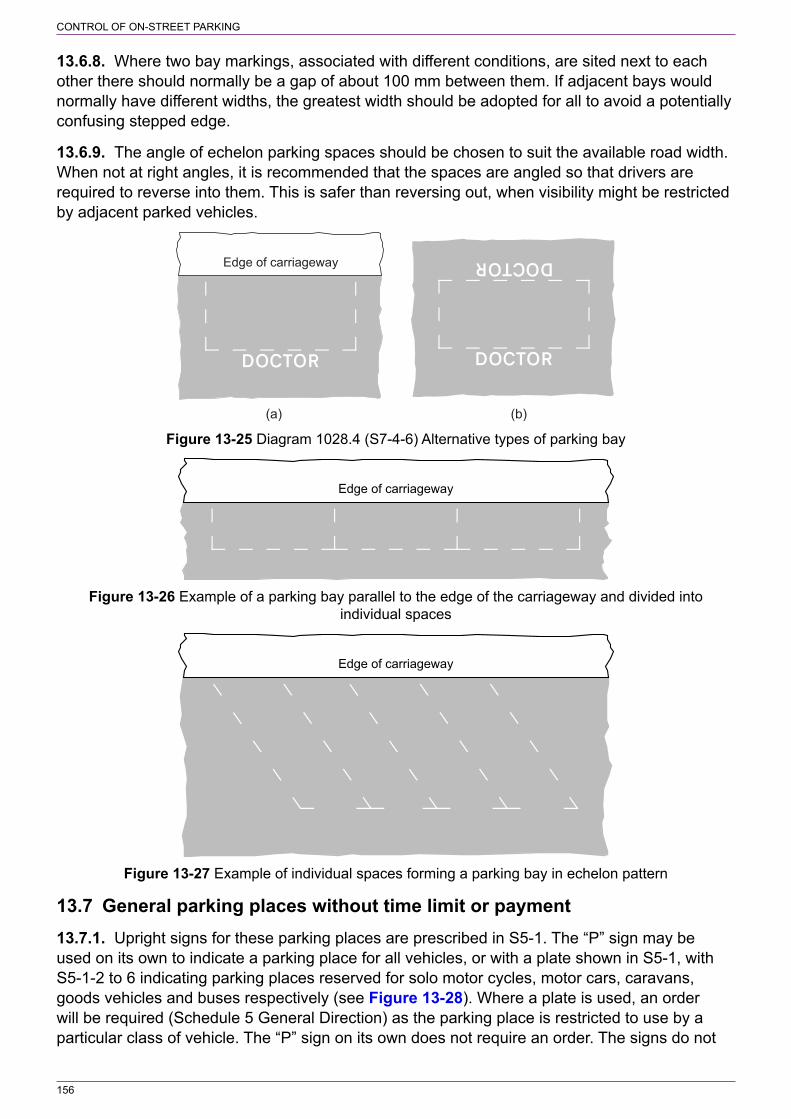
156
CONTROL OF ON‑STREET PARKING
13.6.8. Where two bay markings, associated with different conditions, are sited next to each other there should normally be a gap of about 100 mm between them. If adjacent bays would normally have different widths, the greatest width should be adopted for all to avoid a potentially confusing stepped edge.
13.6.9. The angle of echelon parking spaces should be chosen to suit the available road width. When not at right angles, it is recommended that the spaces are angled so that drivers are required to reverse into them. This is safer than reversing out, when visibility might be restricted by adjacent parked vehicles.
(b)(a)
Edge of carriageway
Figure 13‑25 Diagram 1028.4 (S7‑4‑6) Alternative types of parking bay
Edge of carriageway
Figure 13‑26 Example of a parking bay parallel to the edge of the carriageway and divided into individual spaces
Edge of carriageway
Figure 13‑27 Example of individual spaces forming a parking bay in echelon pattern
13.7 General parking places without time limit or payment13.7.1. Upright signs for these parking places are prescribed in S5‑1. The “P” sign may be used on its own to indicate a parking place for all vehicles, or with a plate shown in S5‑1, with S5‑1‑2 to 6 indicating parking places reserved for solo motor cycles, motor cars, caravans, goods vehicles and buses respectively (see Figure 13‑28). Where a plate is used, an order will be required (Schedule 5 General Direction) as the parking place is restricted to use by a particular class of vehicle. The “P” sign on its own does not require an order. The signs do not

157
CONTROL OF ON‑STREET PARKING
have permitted variants and therefore they can be used only where the reserved parking place operates at all times.
All vehicles Solo motor cycles Motor cars
Motorised caravansor caravans drawnby motor vehicles
Goods vehicles Buses
Figure 13‑28 Upright signs prescribed by S5‑1 for parking places without time limit or payment
13.7.2. The size of the signs shown in Figure 13‑28 will depend on location and the amount of background distraction. In narrow roads the smallest size should be adequate, but for wide roads or where signs are mounted at the back of the footway a larger sign might be required. Larger signs might also be appropriate where parking is provided in an area separate from the main carriageway, such as in the centre of a town square.
13.7.3. The sign to diagram 801 (S11‑2‑56, see Figure 13‑29), which has larger sizes than the “P” sign prescribed by S5‑1, is used as an informatory sign, generally on a rural road, when indicating a lay‑by or off‑road parking area that has no restrictions and does not require the provision of a bay marking. A sign to diagram 2501 (S11‑2‑55, see Figure 13‑30) is normally used in advance of the lay‑by or parking area.
Figure 13‑29 Diagram 801 (S11‑2‑56) Figure 13‑30 Diagram 2501 (S11‑2‑55) Parking place Distance to a parking place ahead
13.7.4. Bay markings to diagram 1028.4 are normally used with the signs shown in Figure 13‑28, although there might be circumstances where such markings are not required, e.g. within a lay‑by. The “P” sign on its own may be used with a bay marking that has no legend. In this case an order is not required (Schedule 5 General Direction 1 and Schedule 7 General Direction 1), except where the parking place is within a controlled parking zone. It is unusual to provide such an arrangement along the side of a road, as although it would indicate an area suitable for parking, it would otherwise have no more effect than if no signs or markings were provided at all. Situations where it would, however, be appropriate to use a “P” sign without a plate and a bay marking are:

158
CONTROL OF ON‑STREET PARKING
a) where echelon parking along the side of a road is required.b) in the centre of the carriageway.c) in a controlled parking zone to indicate areas where there are no parking restrictions (see
section 14). An order will be required in this case.
13.7.5. Where the “P” sign is used with a plate indicating motorcars, caravans or goods vehicles, any associated parking bay will have no legend. Where the plate indicates solo motor cycles or buses, the associated bay may have an appropriate legend, although this is not a specific requirement. Where the bay has a legend, the upright signs may be omitted or reduced in number in order to reduce environmental impact. However, care should be taken to ensure that the road markings are well‑maintained and do not become obscured in adverse weather; the legend must be clearly seen by drivers at all times. Where contrasting bays are provided, it is likely to be more appropriate to provide an upright sign and a bay without a legend. The prescribed legends for a bus bay are “BUSES” or “BUSES ONLY”. The prescribed legends for solo motor cycle bays are as follows:
a) “SOLO MOTORCYCLES” or “SOLO MOTORCYCLES ONLY”b) “SOLO M/CYCLES” or “SOLO M/CYCLES ONLY”c) “SOLO M/CS” or “SOLO M/CS ONLY”.
The choice of legend is a matter for the traffic authority and is likely to depend on the space available.
13.8 General parking places without payment but with time controls13.8.1. Signs indicating a free parking place where time controls apply are prescribed by S4‑4 and 5. The sign may include the times of operation, a particular class of vehicle (car, solo motor cycle or bus), and a limited waiting period, together with the time period during which a vehicle may not return. Examples are shown in Figure 13‑31. Outside the times of operation there are no restrictions on parking unless there are signs and markings to indicate otherwise. Where no class of vehicle is shown, the parking place may be used by any vehicle. The limited waiting period is omitted where there is unlimited parking for a particular class of vehicle and times of operation are shown. Where the parking place operates at all times and there is no limit on waiting, the signs prescribed by S5‑1 should be used as appropriate.
13.8.2. The signs shown in Figure 13‑31 are prescribed by Schedule 4 as follows:
a) The “P” symbol is in the S4‑4‑2, column 3.b) The times of operation (time periods) are a permitted variant in S4‑4‑2, column 5, entry 1.
These are set out in S18‑1. Regulation 6(2) allows more than one time period.c) The limited waiting period and the time period during which a vehicle may not return are
permitted parking expressions, referred to in S4‑4‑2, column 5, entry 2. These are set out in S18‑2 (see regulation 6(3). In the case of the signs in Figure 13‑31, the limited waiting periods “1 hour” and “20 mins” are prescribed by S18‑2‑1(a) and the legend “No return within 2 hours” and its variants by S18‑2‑1(e).
d) The vehicle symbol is permitted by the entries in the S4‑4‑2, column 7. This refers to the symbols in S4‑5.
e) The arrow is required by S4‑2‑17 when the sign is placed at the end of the parking bay.

159
CONTROL OF ON‑STREET PARKING
The motor cycle, car and bus symbols face to the left, except where the signincludes an arrow pointing to the right, in which case the symbols face to the right
Figure 13‑31 Examples of upright signs prescribed by S4‑4 and 5 for free parking places with time controls
13.8.3. The signs should normally be used with the bay marking to diagram 1028.4. The legends for solo motor cycles and for buses may be used, but only if the associated upright sign includes the vehicle symbol. Echelon parking bays at 90° might be appropriate, particularly where these are set back from the main carriageway in the form of a lay‑by. The parking place may be within a lay‑by where a standard parking bay might not be required; there is no requirement to use the upright sign with a prescribed parking bay marking. However, where a lay‑by is wide, echelon parking bays at 90° might be appropriate. Elsewhere there might be some locations where upright signs may be provided without a parking bay, but only where it is clear to which part of the road or parking area the signs apply.
13.9 Permit parking (other than permit parking areas)13.9.1. Permit parking is provided where residents could have difficulty in parking close to their homes because road space would otherwise be taken up by commuters, shoppers etc. The use of the word “Resident” is optional; however, it might help to identify the users of a permit scheme, particularly where the permit identifiers described in 13.9.3 are not used. Permits may also be issued for other purposes, such as doctor permits to allow doctors to park close to a surgery where off‑street parking is not available, and business permits to allow owners, managers or other permit holders to park close to their business premises, particularly if loading and unloading of vehicles is required.
13.9.2. Upright signs that indicate a parking place reserved for permit holders (other than car club permit holders, recharging points for electric vehicles and voucher parking) no longer have specific legends. The legend used with the “P” symbol prescribed by S4‑4‑2 may include a type of user and, where the user is a type of permit holder, a permit identifier may be included. This allows the use of legends, such as “Market traders only”, which previously would have required authorisation. This provides traffic authorities with more flexibility when providing parking places for specific users. However, previously prescribed legends should be used where appropriate. These are:
a) “Permit holders only”b) “Resident permit holders only”
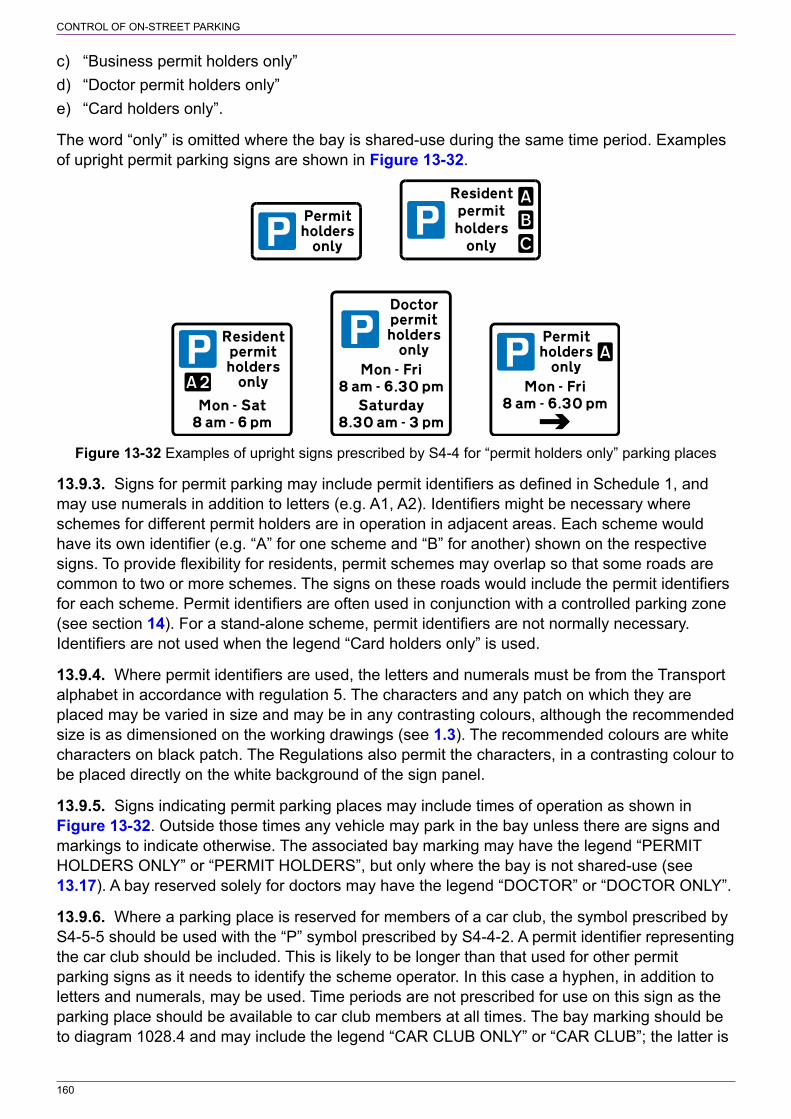
160
CONTROL OF ON‑STREET PARKING
c) “Business permit holders only”d) “Doctor permit holders only”e) “Card holders only”.
The word “only” is omitted where the bay is shared‑use during the same time period. Examples of upright permit parking signs are shown in Figure 13‑32.
Figure 13‑32 Examples of upright signs prescribed by S4‑4 for “permit holders only” parking places
13.9.3. Signs for permit parking may include permit identifiers as defined in Schedule 1, and may use numerals in addition to letters (e.g. A1, A2). Identifiers might be necessary where schemes for different permit holders are in operation in adjacent areas. Each scheme would have its own identifier (e.g. “A” for one scheme and “B” for another) shown on the respective signs. To provide flexibility for residents, permit schemes may overlap so that some roads are common to two or more schemes. The signs on these roads would include the permit identifiers for each scheme. Permit identifiers are often used in conjunction with a controlled parking zone (see section 14). For a stand‑alone scheme, permit identifiers are not normally necessary. Identifiers are not used when the legend “Card holders only” is used.
13.9.4. Where permit identifiers are used, the letters and numerals must be from the Transport alphabet in accordance with regulation 5. The characters and any patch on which they are placed may be varied in size and may be in any contrasting colours, although the recommended size is as dimensioned on the working drawings (see 1.3). The recommended colours are white characters on black patch. The Regulations also permit the characters, in a contrasting colour to be placed directly on the white background of the sign panel.
13.9.5. Signs indicating permit parking places may include times of operation as shown in Figure 13‑32. Outside those times any vehicle may park in the bay unless there are signs and markings to indicate otherwise. The associated bay marking may have the legend “PERMIT HOLDERS ONLY” or “PERMIT HOLDERS”, but only where the bay is not shared‑use (see 13.17). A bay reserved solely for doctors may have the legend “DOCTOR” or “DOCTOR ONLY”.
13.9.6. Where a parking place is reserved for members of a car club, the symbol prescribed by S4‑5‑5 should be used with the “P” symbol prescribed by S4‑4‑2. A permit identifier representing the car club should be included. This is likely to be longer than that used for other permit parking signs as it needs to identify the scheme operator. In this case a hyphen, in addition to letters and numerals, may be used. Time periods are not prescribed for use on this sign as the parking place should be available to car club members at all times. The bay marking should be to diagram 1028.4 and may include the legend “CAR CLUB ONLY” or “CAR CLUB”; the latter is
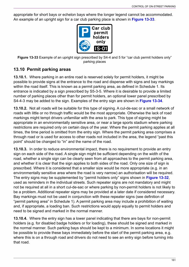
161
CONTROL OF ON‑STREET PARKING
appropriate for short bays or echelon bays where the longer legend cannot be accommodated. An example of an upright sign for a car club parking place is shown in Figure 13‑33.
Figure 13‑33 Example of an upright sign prescribed by S4‑4 and 5 for “car club permit holders only” parking places
13.10 Permit parking areas13.10.1. Where parking in an entire road is reserved solely for permit holders, it might be possible to provide signs at the entrance to the road and dispense with signs and bay markings within the road itself. This is known as a permit parking area, as defined in Schedule 1. Its entrance is indicated by a sign prescribed by S5‑3‑5. Where it is desirable to provide a limited number of parking places other than for permit holders, an optional lower panel prescribed by S4‑4‑3 may be added to the sign. Examples of the entry sign are shown in Figure 13‑34.
13.10.2. Not all roads will be suitable for this type of signing. A cul‑de‑sac or a small network of roads with little or no through traffic would be the most appropriate. Otherwise the lack of road markings might tempt drivers unfamiliar with the area to park. This type of signing might be appropriate in an environmentally sensitive area, or near a large sports stadium where parking restrictions are required only on certain days of the year. Where the permit parking applies at all times, the time period is omitted from the entry sign. Where the permit parking area comprises a through road or is used for access to other roads not included in the area, the legend “past this point” should be changed to “in” and the name of the road.
13.10.3. In order to reduce environmental impact, there is no requirement to provide an entry sign on each side of the road. A single sign might be sufficient depending on the width of the road, whether a single sign can be clearly seen from all approaches to the permit parking area, and whether it is clear that the sign applies to both sides of the road. Only one size of sign is prescribed. Where it is considered that a smaller size would be more appropriate (e.g. in an environmentally sensitive area where the road is very narrow) an authorisation will be required. The entry signs may be supplemented by “permit holders only” signs shown in Figure 13‑32, used as reminders in the individual streets. Such repeater signs are not mandatory and might not be required at all in a short cul‑de‑sac or where parking by non‑permit holders is not likely to be a problem. Additional repeater signs may be provided at a later date if considered necessary. Bay markings must not be used in conjunction with these repeater signs (see definition of “permit parking area” in Schedule 1). A permit parking area may include a prohibition of waiting and, if appropriate, a loading ban. Such restrictions would apply equally to permit holders and need to be signed and marked in the normal manner.
13.10.4. Where the entry sign has a lower panel indicating that there are bays for non‑permit holders (e.g. for disabled badge holders or for loading), these should be signed and marked in the normal manner. Such parking bays should be kept to a minimum. In some locations it might be possible to provide these bays immediately before the start of the permit parking area, e.g. where this is on a through road and drivers do not need to see an entry sign before turning into that road.

162
CONTROL OF ON‑STREET PARKING
13.10.5. A sign to diagram 664.1 (S7‑2‑3, see Figure 13‑35) indicating the end of the permit holder parking area will be needed, unless it is a cul‑de‑sac. Normally, only one sign is required. Two signs might be useful on a wide road adjacent to an area that has no prohibition of waiting or on‑street parking controls (i.e. where there are no upright signs or markings).
Figure 13‑34 Examples of upright signs Figure 13‑35 Diagram 664.1 (S7‑2‑3) End of prescribed by S4‑4 and 5 indicating the entrance permit parking area to a permit parking area
13.11 Disabled badge holder parking13.11.1. Disabled badge holders may usually park on single or double yellow lines for up to three hours in England and Wales; in Scotland there is no time limit. In Northern Ireland, although the three‑hour limit applies, parking is not permitted on yellow lines within 15 m of a junction. Disabled badge holders may not wait where there is a ban on loading or in a few areas where local schemes apply. They might also be exempt from limits on parking times or parking charges imposed on other users. Where there is a high demand for parking or where vehicles regularly load and unload on yellow lines, the provision of parking bays for disabled badge holders might be advantageous. Such bays are generally wider than ordinary parking bays, are not normally time limited and encourage disabled badge holders to park in the most appropriate locations. However, a maximum length of stay may be imposed where it is necessary to ensure the availability of parking for disabled badge holders at popular locations. The time limit should not be less than 3 hours where this might encourage disabled badge holders to park on an adjacent length of road with a prohibition of waiting (but not loading).
13.11.2. The upright sign indicating parking places reserved only for disabled badge holders includes the “P” symbol prescribed by S4‑4‑2, together with the blue badge symbol and legend prescribed by S4‑5‑4. The blue badge symbol always faces to the right, even when the sign incorporates an arrow pointing to the left. Where the bay is for the exclusive use of disabled badge holders, the appropriate legend is “Disabled badge holders only”. The times of operation may be included on the sign; outside these times any vehicle may park in the bay unless signs and markings indicate otherwise. Examples of upright signs are shown in Figure 13‑36.
13.11.3. Disabled badge holder bays are often provided near facilities such as shops, doctors’ surgeries and railway stations. However, there might be a need to provide bays that enable disabled people to park close to their homes in areas that either have parking bay provision for other road users (permit or otherwise) or where there are no parking controls but kerb space is often fully occupied by parked vehicles. Where other disabled badge holders are likely to deprive a resident of the use of the space, a resident permit holder bay should be considered, with the permit issued only to the designated person. In this case the legend on the upright sign is “Disabled badge holder only” and a permit identifier as described in 13.9.3 and 13.9.4. An example sign is shown in Figure 13‑37 (note that the disabled badge identifier may alternatively come after the word “only”).

163
CONTROL OF ON‑STREET PARKING
Edge of carriageway
Figure 13‑36 Examples of upright signs Figure 13‑37 Example of an upright sign prescribed by S4‑4 and 5 indicating a parking prescribed by S4‑4 and 5, together with the bay place reserved only for disabled badge holders marking, indicating a parking place reserved only for a specific disabled badge holder with a permit
13.11.4. The bay marking to diagram 1028.4, when provided for disabled badge holders, must have the minimum dimension set out in 13.6.2. The marking may include the legend “DISABLED” or “DISABLED ONLY”. Where the bay is reserved for a designated person, an alphanumeric identifier (same as that on the upright sign) may be added after “DISABLED”, e.g. “DISABLED D123” or “DISABLED D123 ONLY”.
13.12 Pay and display parking13.12.1. Upright signs used in association with on‑street pay and display schemes are prescribed by S4‑4‑7. The required legend is “Pay at machine”, but this may be varied in accordance with the entries in column 5 in S4‑4. Newly prescribed legends allow for payment by mobile phone and where parking is free for a short period. The sign may include an arrow indicating the direction to the nearest ticket machine. A second arrow may be added pointing in the opposite direction when the sign is sited between two machines. Where the ticket machine is on the other side of the road, the legend is “Pay at machine across road” or “Pay at machine opposite”. Other permitted variants are “Pay at machine” and a location (e.g. “Pay at machine on Green Street”) and the use of coloured legend to identify a machine (e.g. “Pay at red machine” where “red machine” is in red letters). The legend “Pay here at machine” should be used when the sign is sited close to the ticket machine. “Pay and display” signs may include the symbols in S4‑5 where parking is of a specific type. Examples of upright signs are shown in Figure 13‑38.

164
CONTROL OF ON‑STREET PARKING
Figure 13‑38 Examples of upright signs prescribed by S4‑4 indicating a pay and display
13.12.2. The times of operation may be included on the signs. Outside these times any vehicle may park in the bay without payment unless signs and markings indicate otherwise (e.g. a prohibition of waiting). A time limit on the duration of parking may also be shown on the signs. Where the period during which a vehicle may not return is not specified, the limited parking period is expressed as “Max stay 2 hours” where the time shown represents the maximum period for which a ticket may be purchased.
13.12.3. Except where the parking place is in a lay‑by and not divided into individual spaces, a bay marking to diagram 1028.4 without any legend should be used; this may be a contrasting bay.
13.12.4. A parking place identifier, as defined in Schedule 1, may be added to pay and display signs. This may be any symbol, logo, letter, numeral or name (or in combination) of any size in a colour that contrasts with the background on which they are placed; i.e. the background may be a patch or the white background of the sign panel. An identifier may be necessary where two pay and display schemes operate in adjacent roads and a ticket purchased from a machine in one road is not valid for parking in the other. To avoid driver confusion, it is recommended that wherever possible two or more different schemes (such as long stay and short stay parking) should not be introduced in the same road. However, where it is necessary to provide adjacent bays that belong to two different schemes, two separate “pay and display” signs should be erected side by side on the boundary. Each sign should have its own parking place identifier with an arrow pointing towards the appropriate ticket machine. There should also be separate bay markings for each scheme, set apart by a distance of at least 100 mm. When a pay and display parking bay is adjacent to a different type of bay such as a “permit holders only” bay, care should be taken in siting signs so that drivers are not misled into purchasing a ticket and parking in the wrong bay. Ticket machines need to be sited carefully, for the same reason.
13.12.5. The sign with the legend “Have you paid and displayed?”, which is a reminder to drivers and is optional, is prescribed by S4‑4‑8, see Figure 13‑39. This sign must always be used on its own and never combined with any other sign panel (see S4‑2‑19).

165
CONTROL OF ON‑STREET PARKING
Figure 13‑39 Upright sign prescribed by S4‑4 indicating that drivers must obtain and display parking tickets (Alternative types)
13.13 Voucher parking13.13.1. Voucher parking involves the purchase of a voucher from a local outlet, e.g. a nearby shop. It has the advantage that money is not kept in machines on site, there is reduced capital cost and less on‑street clutter. The disadvantage is that vouchers are available only when the shops are open, which might reduce the times of operation of a scheme. Voucher parking is often more convenient for local people than for those making the occasional journey into a town. This tends to gives priority for on‑street parking to local people, encouraging others to use off‑street car parks where available.
13.13.2. The upright sign indicating a voucher parking place includes the “P” symbol prescribed by S4‑4‑2, together with the voucher symbol and legend prescribed by S4‑5‑8. The symbol should be varied to correspond with the design on the applicable approved voucher, but the size must not varied from that shown in S4‑5 (see S4‑2‑16(4)). Information about the voucher scheme, such as charges and where vouchers may be purchased, may be shown on a white panel of the sign (see S4‑2‑21); this should be placed below the main sign panel. If this information is given elsewhere, the additional panel is not necessary. The times of operation may be included on the sign; outside these times any vehicle may park in the bay without displaying a voucher unless signs and markings indicate otherwise. A voucher parking place may be shared with permit holders with the appropriate legend being shown on the sign. Voucher parking may also be implemented as a controlled parking zone (see section 14). An example of an upright voucher parking sign is shown in Figure 13‑40. The prescribed legends for the voucher parking sign, one of which must be used, are:
a) “Voucher parking only”b) “Voucher parking and permits only” with or without a permit identifierc) “Voucher parking and resident permits only” with or without a permit identifierd) “Voucher parking and business permits only” with or without a permit identifier.
13.13.3. The bay marking to diagram 1028.4, in this case, does not have any legend. Where the bay is shared with permit holders, it is not appropriate to add the legend “PERMIT HOLDERS” or “PERMIT HOLDERS ONLY”.

166
CONTROL OF ON‑STREET PARKING
The lower panel is for information about the voucherparking scheme. The lower panel may be omitted.
Figure 13‑40 Example of an upright sign prescribed by S4‑4 and S4‑5 for a voucher parking place
13.14 Parking places for large or slow vehicles13.14.1. The bay marking to diagram 1028.4 with the legend “LARGE OR SLOW VEHICLES” or “LARGE OR SLOW VEHICLES ONLY”, and of a suitable width, may be used to designate places for large vehicles, either for general parking or awaiting police escort. The upright sign has the “P” symbol prescribed by S4‑4‑2 with the legend “Large or slow vehicles only” (type of user referred to in column (5)). An example of the upright sign is shown in Figure 13‑41. At level crossings where drivers of large, slow or long vehicles are required to stop and telephone before crossing, the bay marking, without any legend, may be used in conjunction with the sign to diagram 786 (S11‑2‑70). In this case a traffic regulation order is not required.
Figure 13‑41 Example of an upright sign prescribed by S4‑4 indicating a parking place for large or slow vehicles
13.15 Loading bays13.15.1. A parking place may be reserved for loading only, either by any class of vehicle or by goods vehicles. The provision of a loading bay reserves space for deliveries or for customers collecting goods where it might otherwise be taken up by lawfully parked vehicles, including those of disabled badge holders parked on yellow lines where loading is not prohibited. Disabled badge holders may use loading bays, other than those reserved for goods vehicles, but only for as long as is necessary for the purposes of loading or unloading.
13.15.2. The upright sign indicating a loading bay is prescribed by S4‑4‑5 (see Figure 13‑42). The loading symbol on the sign generally faces to the left unless an arrow pointing to the right is added; the symbol would then be reversed. Times of operation may be included on the sign; outside these times any vehicle may park in the bay unless signs and markings indicate otherwise (e.g. a prohibition of waiting and loading during peak periods). The order may include a time limit (a permitted parking expression in the table), which should be shown on the sign, but it needs to be sufficient to accommodate the most time‑consuming loading operation likely to take place. This will depend on the nature of the business conducted in adjacent premises. Unless there is a large demand for loading or a possibility that drivers might abuse the bay by combining loading with ordinary parking, a time limit should be avoided, so that the loading

167
CONTROL OF ON‑STREET PARKING
operation is allowed to take as long as is necessary. The bay may be used for loading by any vehicle unless the legend on the upright sign refers to a goods vehicle. It should be noted that the “P” symbol prescribed by S4‑4‑2 and the symbols prescribed by S4‑5 are not used on this sign. Examples of upright signs are shown in Figure 13‑43.
Symbols and legends used in combination with a white panel
(1)
Item
(2)
Description
(3)
Symbol
(4)
Required legends
(5)
Variants to column 4 legends or legends that may be included
(6)
Legend height (by reference to x‑height)
(7)
Applicable Part 5 item
5. Parking place reserved for loading and unloading
75 min200 max
“Loading only”
[see below] Not less than 15 mm and not more than 40 mm
Entries in column (5) are:1. “Loading only” may be varied to “Loading”, “Goods vehicle loading” or “Goods vehicle loading only”2. The legend may be varied to include— (a) a time period; (b) a permitted parking expression; or (c) both3. The name of the traffic authority may be included4. A parking place identifier may be included
Figure 13‑42 Extract from S4‑4 in respect of a parking place reserved for loading and unloading
Figure 13‑43 Examples of upright signs prescribed by S4‑4 indicating a parking place reserved for loading and unloading
13.15.3. The bay marking to diagram 1028.4, when used for a loading bay, may have no legend or either the legend “LOADING” or “LOADING ONLY”. The width of the bay should be appropriate to the type of vehicle it is to be used by.
13.15.4. Where a loading bay operates at all times the upright sign may be omitted.
13.16 Electric vehicle recharging point13.16.1. An on‑street parking place with facilities for recharging electric vehicles may be reserved for all electric vehicles or for electric solo motor cycles. The upright signs comprise the “P” symbol prescribed by S4‑4‑2 and either the electric vehicle or electric solo motor cycle symbol prescribed by S4‑5‑7 and 6 respectively. The prescribed legend is “Electric vehicle recharging point only” or “Electric solo motor cycle recharging point only” as appropriate. The parking place may be provided for permit holders only, in which case the word “only” is omitted and the legend “Permit holders only”, with or without a permit identifier, added on a separate line. Time periods may be added to the sign to indicate when the parking place is available (i.e. where it does not operate at all times). Examples of upright signs for all types of electric vehicles and for electric solo motor cycles only are shown in Figure 13‑44 and Figure 13‑45 respectively.

168
CONTROL OF ON‑STREET PARKING
Figure 13‑44 Examples of upright signs prescribed by S4‑4 and 5 indicating a parking place reserved for the recharging of all types of electric vehicles
Figure 13‑45 Examples of upright signs prescribed by S4‑4 and 5 indicating a parking place reserved for the recharging of electric solo motor cycles
13.16.2. The bay marking to diagram 1028.4, when used for an electric vehicle recharging bay, may have no legend or one of the following legends as appropriate:
a) “ELECTRIC VEHICLES” or “ELECTRIC VEHICLES ONLY”b) “ELECTRIC VEHS” or “ELECTRIC VEHS ONLY”c) “ELECTRIC MOTORCYCLES” or “ELECTRIC MOTORCYCLES ONLY”d) “ELECTRIC M/CYCLES” or “ELECTRIC M/CYCLES ONLY”e) “ELECTRIC M/CS” or “ELECTRIC M/CS ONLY”.
The choice of legend (or no legend) is likely to depend on the size of the parking bay.
13.17 Shared‑use parking bays13.17.1. It might be appropriate, in some locations, for a parking place to have different uses at different times of day or to be used for different types of parking at the same time. These are known as shared‑use parking bays. For example, a parking bay provided for permit holders may also be used as a pay and display parking place for non‑permit holders. Figure 13‑46 shows an example of an upright sign for each type of shared use.

169
CONTROL OF ON‑STREET PARKING
Different types of parkingat the same time
Different types of parkingat different times of day
Figure 13‑46 Examples of upright signs for shared use parking places
13.17.2. A sign with separate panels showing different uses for different times of day may comprise a combination of separate parking signs, each self‑contained. However, where the same symbol or symbols (e.g. the “P” symbol and the motorcar symbol) are used to indicate the different types of parking, these may be shown only in a top white panel, together with any days of the week and if appropriate, any date which are common to all of the panels. This uppermost white panel therefore becomes a header to the remainder of the sign (see Figure 13‑47). These arrangements are permitted by S4‑2‑19 and 20. This header panel should include an arrow pointing to the left or to the right as appropriate when the sign is located at the beginning of a parking place. The “P” or other symbol should be repeated in a panel that is intended to over‑ride the indications of the first header, for example by referring to different days of the week, as shown in Figure 13‑50. Panels indicating a time of day should generally be in chronological order from top to bottom.
13.17.3. Where two types of parking occur at the same time, they are shown in a single panel separated by the word “or” (S4‑2‑18).Where the symbol is the same for both types of parking (e.g. the “P” symbol indicating parking for both permit holders and pay and display for non‑permit holders), it need only be shown once. As the two types of parking occur at the same time, the legend should not include the word “only”, e.g. “Permit holders” not “Permit holders only”. This type of panel may be incorporated in a sign that has multiple panels as described in 13.17.2. An example of this is shown in Figure 13‑48. Where the sign has only a single panel indicating the parking requirements and is located at the beginning of a parking place, an arrow pointing to the left or to the right, as appropriate, should be included in that panel.
13.17.4. Where a shared‑use bay is provided for permit holders they are likely to be able to park throughout the day without any further restrictions. However, it might be desirable to reserve the bays for permit holders at certain times of the day only, such as early morning and early evening. At other times, the conditions that apply to other users would also apply to permit holders. The panel on the sign covering this period would show only the parking conditions, such as limited waiting or pay and display, with no reference to permit holders (see Figure 13‑49).
13.17.5. The time periods shown on the signs indicating when certain parking controls apply can be varied as appropriate. However, as the signs can be quite complex and hence large, it is recommended that the time periods and conditions shown apply for each day of the week that

170
CONTROL OF ON‑STREET PARKING
the parking place is operational (e.g. Monday to Saturday or every day of the week). To have different conditions applying on different days will result in complicated signs and might confuse drivers. Where different conditions do apply, it might be necessary to use separate signs, for example where parking conditions on Sundays differ from those for the other days of the week. However, it might be possible to simplify the sign by using the prescribed legend “At other times” (S18‑1‑1(1)(b)). An example is shown in Figure 13‑50.
Between 10 am and 4 pm, the parking conditions apply equally to permit holdersand other road users. The sign on the right is placed at the beginning of the
parking bay with the arrow in the top panel pointing towards the bay.
Figure 13‑47 Arrangement of sign panels showing different uses at different times of day
Figure 13‑48 Example of a sign that has Figure 13‑49 Example of a sign that is reserved shared use at the same time for part of day for permit holders for only part of the day; at other and single use at other times times the parking conditions apply to all users including permit holders
13.17.6. As the parking place has more than one type of use, it is not appropriate for the bay marking to diagram 1028.4 to have any legend.

171
CONTROL OF ON‑STREET PARKING
The sign above is a simplifiedversion of the sign on the left
Figure 13‑50 Use of the expression “At other times” to reduce sign size
13.18 Parking and loading bays with prohibition of waiting and loading at certain times13.18.1. Where a parking or loading bay does not operate continuously, and there is a prohibition of waiting at certain times (e.g. during peak hours), a multi‑panel sign (see Figure 13‑51 and Figure 13‑52) should be used. This generally comprises either two or three panels depending on whether there is a prohibition of loading. The upper panel is yellow and gives details of the waiting restrictions. It is based on the sign described in 13.4.8. The centre panel, if any, will include details of the loading prohibition as described in 13.4.12. The lower panel gives details of the parking or loading conditions. It may indicate limited waiting, permit parking, an electric vehicle recharging point, disabled badge holder parking, pay and display parking, voucher parking, a loading bay, shared‑use parking or disc zone parking. It has the same design as one of the signs described previously in this section and therefore may include a multi‑panel shared‑use bay. Examples of parking place signs that also indicate waiting and loading prohibitions are shown in Figure 13‑51. The time periods for parking and for the prohibition of waiting should not overlap.
13.18.2. The sign should be used with a parking bay appropriate to the lower panel, together with a single yellow line running through the bay to indicate the prohibition of waiting and, if appropriate, single kerb marks to indicate a prohibition of loading. Where the single yellow line continues beyond the bay, and the upright signs indicate different waiting restrictions, a transverse mark referred to in 13.4.4 is not required. The end of the bay is sufficient to indicate a change in the restrictions. Examples of upright signs and road markings are shown in Figure 13‑52.
13.18.3. A double yellow line must not be used within a loading bay as the reserved use of the bay prohibits waiting. The single yellow line within the bay denotes a prohibition during a period when the loading bay is not operational. Where the loading bay operates at all times, no yellow line is used.
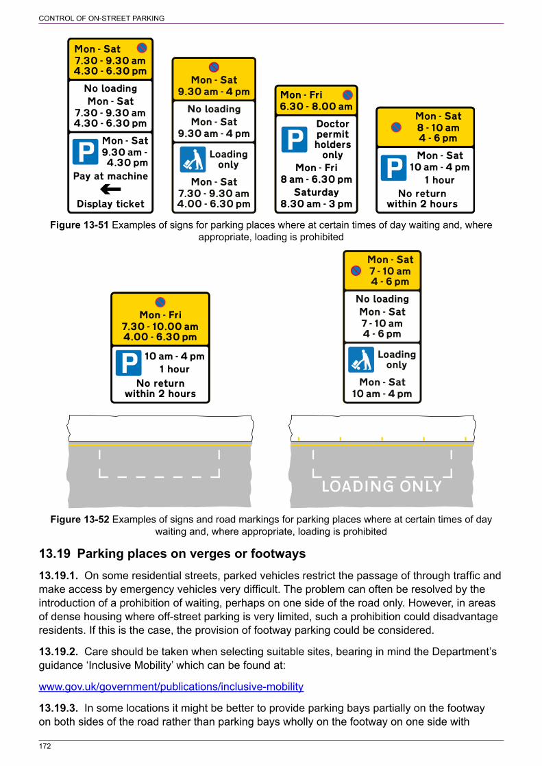
172
CONTROL OF ON‑STREET PARKING
Figure 13‑51 Examples of signs for parking places where at certain times of day waiting and, where appropriate, loading is prohibited
Figure 13‑52 Examples of signs and road markings for parking places where at certain times of day waiting and, where appropriate, loading is prohibited
13.19 Parking places on verges or footways13.19.1. On some residential streets, parked vehicles restrict the passage of through traffic and make access by emergency vehicles very difficult. The problem can often be resolved by the introduction of a prohibition of waiting, perhaps on one side of the road only. However, in areas of dense housing where off‑street parking is very limited, such a prohibition could disadvantage residents. If this is the case, the provision of footway parking could be considered.
13.19.2. Care should be taken when selecting suitable sites, bearing in mind the Department’s guidance ‘Inclusive Mobility’ which can be found at:
www.gov.uk/government/publications/inclusive‑mobility
13.19.3. In some locations it might be better to provide parking bays partially on the footway on both sides of the road rather than parking bays wholly on the footway on one side with

173
CONTROL OF ON‑STREET PARKING
carriageway parking on the other. This would evenly distribute available footway width on both sides of the road, although it would not be practicable if one footway is very narrow or non‑existent. In some roads, the provision of parking bays partially on the footway on one side only might be sufficient to allow safe passage of through traffic. The footway should also be of suitable construction to allow vehicle parking. Where there is a scheme to improve a road, the opportunity should be taken to consider the provision of lay‑bys as an alternative to footway parking.
13.19.4. The prohibition of parking on the footway or verge in an urban area is covered by 13.5. Where an order is made to prohibit parking on the footway or verge this may designate certain sections of footway as parking places. In London, parking is not permitted on the footway or verge unless a resolution of the local authority under section 15(4) of the Greater London Council (General Powers) Act 1974 authorises the provision of parking places, either partially or wholly on the footway. Elsewhere, vehicles under 7.5t are not specifically prohibited from parking on the footway or verge (although it is unlawful to drive on the footway). Outside London, vehicles over 7.5t are prohibited from parking on the footway or verge under section 19 of the Road Traffic Act 1988.
13.19.5. Parking bays provided on the footway should normally operate at all times. Drivers should not be expected to park on the footway for part of the day and wholly on the carriageway at other times. This would be inconvenient and confusing, particularly where a bay has been marked partially on the footway and partially on the carriageway. Where there is a specific need to keep the footway clear and, in the case of bays partially on the footway, to keep the carriageway clear at certain times of the day, there should be a prohibition of waiting at the appropriate times. Where, in exceptional circumstances, parking is permitted on the footway for only part of the day and on the carriageway at other times, bay markings should not be provided.
13.19.6. Signs to diagrams 667, 667.1 and 667.2 (S7‑2‑12, 14 and 16 respectively, see Figures 13‑53, 13‑54 and 13‑55) are used to indicate the extent of parking that may take place partially on the footway. Signs to diagrams 668, 668.1 and 668.2 (S7‑2‑13, 15 and 17 respectively, see Figures 13‑56, 13‑57 and 13‑58) indicate the extent that parking is permitted wholly on the footway. These six diagrams are intended to face oncoming traffic and include a symbol which shows the footway either to the left or to the right of the carriageway from the driver’s point of view. However, the signs may be mounted parallel to the kerb and where they include an arrow, the symbol should show the footway to the right of the carriageway when the arrow points to the left and vice versa. The symbol then represents the true situation when looking in the direction of the arrow. Sign design details are set out on the appropriate working drawings.
13.19.7. The upright signs may be used with or without parking bays to diagram 1028.4. Where marked bays are used, Figure 13‑59 shows how they are set out. A bay situated partially on the footway is to S7‑4‑6, pattern (b), and for a bay wholly on the footway, the marking is to pattern (a). Where the bay is wholly on the footway it must be adjacent to the kerb; the Regulations do not prescribe the four‑sided bay to pattern (b) to be used wholly on the footway (i.e. remote from the kerb). Upright signs on their own are appropriate where parking is allowed on a verge unsuitable for road markings or where there is no requirement to indicate specific parts of a footway where parking is permitted.
13.19.8. Where the upright signs are mounted to face oncoming traffic, the commencement of footway parking, whether or not a marked bay is provided, should normally be indicated by diagram 667 or 668 as appropriate. The same sign is then used as a repeater along the road. The sign to diagram 667.2 or 668.2 is provided where footway parking ends. Where used,

174
CONTROL OF ON‑STREET PARKING
repeater signs do not have to be erected at any specific intervals. Their siting will depend on the need to remind drivers that footway parking is permitted, particularly where there are no bay markings. On a two‑way road, signs should be mounted to face traffic travelling in both directions as drivers may wish to park on the opposite side of the road, particularly where parking places are provided only on one side of the road. Signs for each direction should normally be mounted back to back. Repeater signs may be mounted parallel to the kerb to reduce the number required. See 13.19.10 for signs mounted parallel to the kerb.
Figure 13‑53 Diagram 667 (S7‑2‑12) Figure 13‑54 Diagram 667.1 (S7‑2‑14) Vehicles may be parked partially on the verge Vehicles may be parked partially on the or footway (Alternative types) verge or footway during the period indicated (Alternative types)
Figure 13‑55 Diagram 667.2 (S7‑2‑16) End Figure 13‑56 Diagram 668 (S7‑2‑13) Vehicles of area where vehicles may be parked partially may be parked wholly on the verge or footway on the verge or footway (Alternative types) (Alternative types)
Figure 13‑57 Diagram 668.1 (S7‑2‑15) Figure 13‑58 Diagram 668.2 (S7‑2‑17) End Vehicles may be parked wholly on the verge of area where vehicles may be wholly on the or footway during the period indicated verge or footway (Alternative types) (Alternative types)

175
CONTROL OF ON‑STREET PARKING
CarriagewayCarriageway
Figure 13‑59 Bay markings indicating a parking place partially or wholly on the footway
13.19.9. Where footway parking along a length of road is interrupted by features such as private accesses, trees, street furniture and grass verges not suitable for parking, individually marked bays can be provided and each signed as described in 13.19.8. In this case, depending on the length of each bay, repeater signs might not be needed. If the bay is relatively short, start and end signs might not be necessary; a single sign, parallel to the kerb and mounted at or near to the centre of the bay, might be sufficient. To further reduce the number of signs required, a sign to diagram 667.1 or 668.1, as appropriate, with the legend “In marked bays” in the lower panel and facing oncoming traffic may be provided at the beginning of footway parking. This need not be at the commencement of the first marked bay, but at a suitable location in advance of it where it can be clearly seen by drivers. This should remove the need to provide upright signs at intermediate bays, as shown in Figure 13‑60, although this is a matter for the traffic authority to determine. However, additional signing should be provided where the run of bays is interrupted by a road junction or a kerbed private access, or where a section of the road between the bays is subject to a prohibition of waiting. Additional signs might also be required where there is a road junction opposite the parking bays and drivers entering from that road need to be made aware of the parking requirements.
13.19.10. Although upright signs indicating the beginning and end of a parking place on a footway are normally mounted to face oncoming traffic, there might be situations where it is more practical to mount signs parallel to the kerb, similar to other parking signs. Where footway parking with no bay markings commences part way along a road and is not preceded by a yellow “no waiting” line or other road marking, a start sign facing oncoming traffic could be mistaken for a repeater sign, tempting drivers to park in advance of it where footway parking should not take place. This might not be a problem where an order has been made to prohibit footway parking and a repeater sign to diagram 663.4 has been provided in advance of the footway parking place. An end sign is not required when signs are mounted parallel to the edge of carriageway. A start sign is located at each end of the parking bay and should include an arrow as described in 13.19.6, pointing in the direction of footway parking. The arrow should not be used to indicate that there is footway parking along another road, to the left or to the right. As the end signs to diagrams 667.2 and 668.2 should always face oncoming traffic, there is no permitted variant to allow an arrow to be shown on these signs.
13.19.11. Where the parking place operates for only part of the day, the sign to diagram 667.1 or 668.1 should be used with the appropriate times being shown in the lower panel. The legend “In marked bays” should be included and shown above the time period when the signs are used as described in 13.19.9. Where signs are located at the start and end of an individual marked bay, whether or not in a run of bays, the legend in the lower panel should only indicate the time period. An arrow should be added when the signs are parallel to the kerb. During the times when footway parking is not permitted there should be a prohibition of waiting, with upright signs located so as not to obstruct the parking bay or the footway. Where possible waiting prohibition signs may be co‑located with the footway parking signs. A yellow line to diagram 1017 (S7‑4‑2) should be provided along the edge of the carriageway. This will run through the middle of a

176
CONTROL OF ON‑STREET PARKING
marked bay where this is partially on the footway. Where parking is wholly on the footway, double yellow lines to diagram 1018.1 (no waiting at any time) (S7‑4‑1) should not be provided as a means to prevent parking on the carriageway, as the restriction would apply equally to the footway. Any repeater signs indicating parking on the footway should be to diagram 667.1 or 668.1, showing the appropriate time periods; it is not necessary for repeater signs to include the legend “In marked bays” where the road marking to diagram 1028.4 has been provided.
13.19.12. Where repeater signs to diagrams 667, 667.1, 668 and 668.1 have been mounted parallel to the kerb, the symbol should show the footway relevant to the direction of travel. On a two‑way road the footway part of the symbol will always be on left. On a one‑way road, the sign on the nearside will show the footway part of the symbol on the left and the sign on the off side will show the footway on the right.
13.19.13. Where conditions apply to the parking place, such as permit parking, limited waiting or pay and display, signs should be provided as prescribed by Schedule 4. In this case, the “P” symbol at S4‑4‑2 is replaced by the symbol at item 3 or 4 as appropriate. The footway part of the symbol will generally be to the left of the carriageway; the symbol with the footway to the right of the carriageway should be used on the off side of a one‑way road. The upright sign should be parallel to the kerb and may incorporate panels indicating prohibitions of waiting and loading as appropriate. Any legend associated with the marking to diagram 1028.4 should be placed on the carriageway side of the bay and not on the footway. Examples of upright signs and bay markings are shown in Figure 13‑61. A sign to diagram 667.1 or 668.1, with the legend “In marked bays”, may be provided at the start of the bay or run of bays, with a sign to diagram 667.2 or 668.2 at the end. However, the parking bay signs with the footway parking symbol may be sufficient in most situations. Repeater signs to diagram 667 or 668, indicating footway parking, will not be necessary.
13.19.14. The signs for footway parking, other than the parking bay signs described in 13.19.13, are prescribed with an x‑height in the range 20 mm minimum to 50 mm maximum. For signs that have no legend, the size is prescribed by reference to the height of the “P” symbol, which is equal to four times the x‑height. Where the sign faces oncoming traffic and is intended to be read from a moving vehicle, its size needs to be appropriate to the circumstances. Signs need to be larger when the 85th percentile speed is higher, where there is a time plate that drivers need to read, and where there are no bay markings to make the footway parking more conspicuous. Appropriate sizes are shown in Table 13‑1. Where signs are parallel to the kerb, the smaller sizes are likely to be appropriate. Intermediate sizes might be required to increase conspicuity where signs are mounted at the back of the footway or where bay markings have not been provided.
13.19.15. The size of upright signs that are provided to indicate waiting restrictions or parking controls, as shown in Figure 13‑61, are prescribed with an x‑height in the range 15 mm minimum to 40 mm maximum; the appropriate size being that as recommended for parking places wholly on the carriageway.
13.19.16. Placing upright signs at the back of a parking bay might not be practicable where posts would be in the middle of the footway and be a hazard to pedestrians. However, existing lighting columns might be suitable for mounting the signs parallel to the kerb; signs to diagram 667 or 668 may also be mounted back to back facing oncoming traffic. Elsewhere, it might be necessary to mount the signs at the back of the footway on posts, walls, railings or other street furniture, but care must be taken to ensure that conspicuity is not compromised. It is important that signs indicating parking controls can be clearly seen.

177
CONTROL OF ON‑STREET PARKING
Diagram1028.4
(partially onfootway)
Diagram668.1
Diagram668.2
Privateaccess
A
B
Diagram667.1
Diagram667.2
Diagram1028.4
(wholly onfootway)
NOTE: The signs shownface oncoming traffic andare seen when driving fromA to B. Appropriate signsare provided in the oppositedirection on a two-way road
Figure 13‑60 Example of individually marked footway parking bays along a length of road
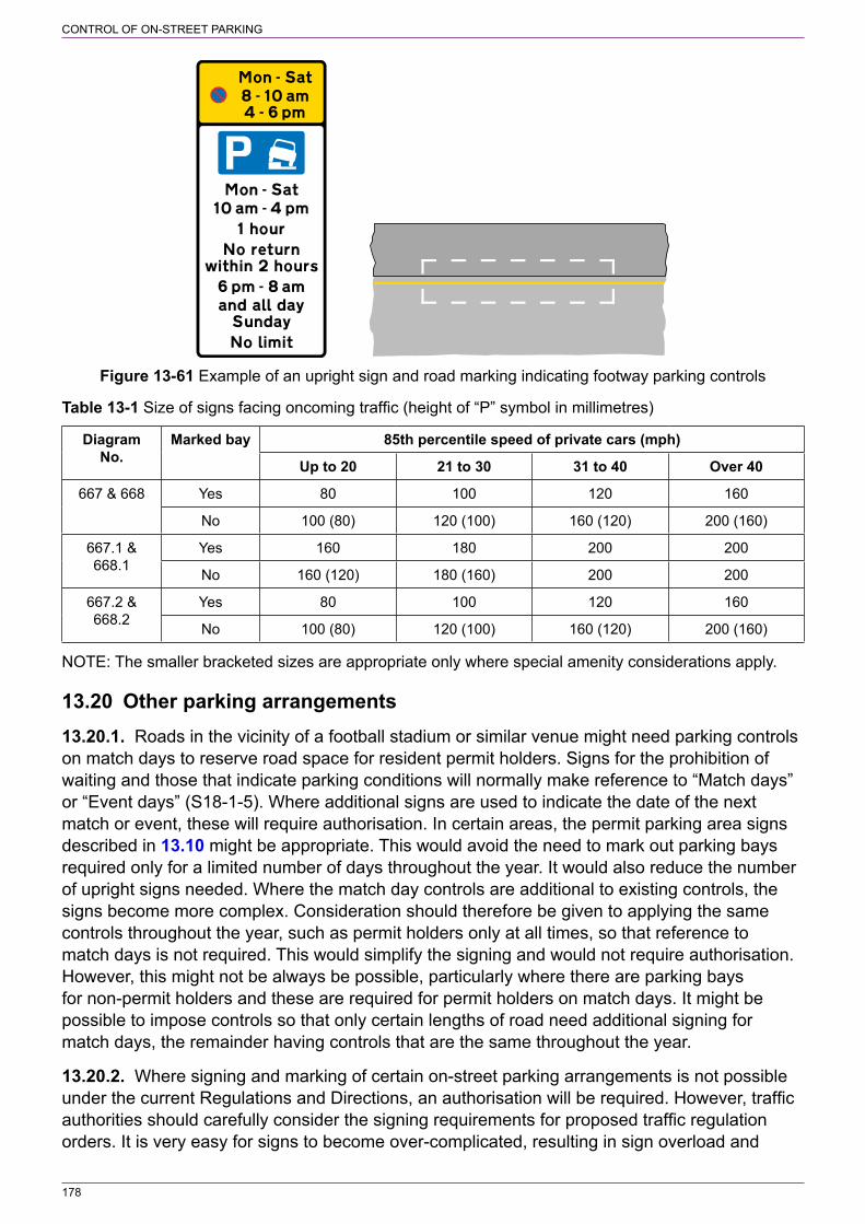
178
CONTROL OF ON‑STREET PARKING
Figure 13‑61 Example of an upright sign and road marking indicating footway parking controls
Table 13‑1 Size of signs facing oncoming traffic (height of “P” symbol in millimetres)
Diagram No.
Marked bay 85th percentile speed of private cars (mph)
Up to 20 21 to 30 31 to 40 Over 40
667 & 668 Yes 80 100 120 160
No 100 (80) 120 (100) 160 (120) 200 (160)
667.1 & 668.1
Yes 160 180 200 200
No 160 (120) 180 (160) 200 200
667.2 & 668.2
Yes 80 100 120 160
No 100 (80) 120 (100) 160 (120) 200 (160)
NOTE: The smaller bracketed sizes are appropriate only where special amenity considerations apply.
13.20 Other parking arrangements13.20.1. Roads in the vicinity of a football stadium or similar venue might need parking controls on match days to reserve road space for resident permit holders. Signs for the prohibition of waiting and those that indicate parking conditions will normally make reference to “Match days” or “Event days” (S18‑1‑5). Where additional signs are used to indicate the date of the next match or event, these will require authorisation. In certain areas, the permit parking area signs described in 13.10 might be appropriate. This would avoid the need to mark out parking bays required only for a limited number of days throughout the year. It would also reduce the number of upright signs needed. Where the match day controls are additional to existing controls, the signs become more complex. Consideration should therefore be given to applying the same controls throughout the year, such as permit holders only at all times, so that reference to match days is not required. This would simplify the signing and would not require authorisation. However, this might not be always be possible, particularly where there are parking bays for non‑permit holders and these are required for permit holders on match days. It might be possible to impose controls so that only certain lengths of road need additional signing for match days, the remainder having controls that are the same throughout the year.
13.20.2. Where signing and marking of certain on‑street parking arrangements is not possible under the current Regulations and Directions, an authorisation will be required. However, traffic authorities should carefully consider the signing requirements for proposed traffic regulation orders. It is very easy for signs to become over‑complicated, resulting in sign overload and

179
CONTROL OF ON‑STREET PARKING
clutter. Not only can this make comprehension by road users difficult but it is likely to be detrimental to environmentally sensitive areas, and can lead to enforcement difficulties.
13.21 Parking bay upright sign design, size and siting13.21.1. Signs for parking and loading bays are prescribed with an x‑height in the range 15 minimum to 40 mm maximum. The appropriate x‑height for such signs is determined by the need to ensure that the sign is conspicuous rather than by the speed of traffic. Therefore the smaller x‑heights are more appropriate for signs displaying larger amounts of information. Selection of x‑height will depend on prevailing conditions and the design of the sign. In a quiet, narrow residential street the smallest prescribed size is likely to be adequate for any sign. However, in a busy high street or a wide suburban road, a larger x‑height, such as 20 or 25 mm, is likely to be required unless the sign has high target value. The largest size of 40 mm x‑height should be used where a sign needs to be made more conspicuous in areas where there are background distractions and perhaps where the sign is mounted at the back of the footway.
13.21.2. On‑street parking and loading signs are normally erected parallel to the kerb, facing the carriageway. Where conspicuity is not compromised, signs may be mounted at the back of the footway on posts, walls, railings or other street furniture to minimise street clutter. This is also likely to be preferable where the footway is narrow. In environmentally sensitive areas where a post is sited at the back of the footway, consideration might be given to painting the post in a similar colour to the adjacent building (direction 8 allows a post to be any single colour, including its natural colour). Where practicable, consideration should also be given to siting the post on the boundary between adjacent properties.
13.21.3. There is no specific requirement to provide repeater signs; it is for the traffic authority to determine whether additional signs are required and where they are to be placed. However, to ensure that drivers are fully aware of the parking conditions, it is recommended that signs are sited at approximately 30 m intervals, i.e. half the distance recommended for signs indicating a prohibition of waiting. As bay markings denote a place where a driver might be able to park, information about the permitted parking is required at more frequent intervals, particularly where the bay marking does not have any legend to indicate the type of user. All signs should be within the extent of the bay and the first sign should generally be no more than 15 m from the end of the bay. Where the length of the bay is less than 30 m, a sign mounted at the mid‑point should therefore be sufficient (but see 13.21.4). Where the road marking is divided into individual spaces, it is not necessary to provide a sign for each space. The whole run of parking spaces should be treated as a single bay for the purposes of signing (i.e. signs should be placed at approximately 30 m intervals). To minimise the possibility of driver confusion, wherever practicable the intermediate signs should be sited in line with the transverse lines separating the individual spaces to emphasise that a particular sign does not apply to a single parking space.
13.21.4. Where two different parking bays are side by side (e.g. a loading bay adjacent to a disabled badge holder bay), consideration should be given to mounting two signs side by side, preferably on a grey backing board, or as a combined sign at the changeover point, with arrows pointing in the direction of the respective bays (see 13.4). This should minimise the risk of drivers parking in the wrong bay by mistake. A single “one column” sign could be used where this would not be too tall. The panel with the left‑pointing arrow should be uppermost. Where two separate signs are mounted together, they should both have the same x‑height.

180
CONTROL OF ON‑STREET PARKING
Figure 13‑62 Signing arrangement for different parking bays side by side (Alternative types)
13.21.5. Where a footway has vehicle crossovers serving private accesses, it is preferable to terminate parking bays at each crossover to avoid the possibility of parked vehicles blocking vehicular access to adjacent property. To avoid a proliferation of parking place signs where each individual property has a crossover, there is no longer a requirement to provide each bay with an upright sign. Signs should be strategically placed, at a spacing of approximately 30 m, so that it is clear that they apply to the run of bays. Where parking is for permit holders only, a permit parking area as described in 13.10 should be considered as an alternative.
13.22 Suspension of a parking or loading bay13.22.1. Where it is required to suspend a parking or loading bay, e.g. to enable works to be carried out, a temporary sign should be provided. These are not prescribed by the Regulations, other than for parking meters where a temporary sign to diagram 640.1 (S13‑6‑22) should be provided. Guidance should therefore be sought from the Department who will consider applications for special authorisation. There should be sufficient signs to ensure that it is clear that parking is not permitted. Signs should be erected in advance of when the suspension applies so that motorists are made aware of changes to the restrictions in force. The sign typically includes a white space within which information about the parking suspension may be written. The text in this section does not have to be written in Transport alphabet.
13.23 No waiting or stopping except taxis, ambulances or police vehicles13.23.1. At a taxi rank, other vehicles may be prohibited from either waiting or stopping; the latter is appropriate where loading is also to be prohibited. Where the prohibition is “no waiting”, this may apply during the operation of the taxi rank or for a longer period. The period of operation for the taxi rank and an additional prohibition of waiting need not be continuous, e.g. where the taxi rank operates overnight from 11 pm to 5 am and the waiting prohibition applies from 8 am to 6 pm. The upright signs for a taxi rank with a prohibition of waiting are prescribed by S4‑3‑1; examples are shown in Figure 13‑63. The signs may have white panels to indicate a prohibition of loading and where the rank, outside the operational period, is used as a controlled parking place.
Figure 13‑63 Examples of upright signs for a “no waiting” taxi rank
13.23.2. The road marking for a “no waiting” taxi rank, which is not used as a controlled parking or loading bay at other times, is the yellow marking to diagram 1028.2 (S7‑4‑5, see

181
CONTROL OF ON‑STREET PARKING
Figure 13‑64). It is laid either at the road edge or in the centre of the carriageway and may be extended to any length to accord with the traffic order. The legend should be repeated at intervals of about 12 m and marked on both sides when used in the centre of the road. In Northern Ireland the bay marking may be coloured white. Where a prohibition of waiting applies outside the hours of operation of the taxi rank, this is indicated by a single yellow line to diagram 1017 within the bay. Where there is a prohibition of loading, single or double kerb marks to diagram 1019 or 1020.1 may be provided as appropriate. As the taxi rank marking defines the area to which the upright sign applies, “no loading” kerb marks might not be necessary.
13.23.3. Where a part‑time “no waiting” taxi rank is used as a controlled parking or loading bay at other times, the marking to diagram 1028.2 is not appropriate. In this case, the marking to diagram 1028.4 should be used without any legend as this would conflict with the use of the bay by taxis. This is supplemented by a single yellow line, representing “no waiting” during the operational period of the rank. Where unlimited free parking is permitted outside the operational period of the rank, this does not need to be indicated by upright signs and road markings. The standard “no waiting” taxi rank upright sign and the marking to diagram 1028.2 (without the yellow line to diagram 1017) is sufficient. Figure 13‑65 shows various examples of signing and marking “no waiting” taxi ranks.
13.23.4. Where vehicles are prohibited from stopping in a taxi rank, the symbol shown in S4‑3‑2 should be used on the upright sign. The road marking is the yellow bay to diagram 1028.5 (S7‑4‑7, see Figure 13‑66) which includes a broad continuous yellow line similar to denote “no stopping”. The purpose of a “no stopping” taxi rank is to keep it clear of other vehicles during the operational period, i.e. loading is prohibited as is the picking up and setting down of passengers in respect of vehicles other than taxis.
13.23.5. The Regulations allow the legend “taxis” on the upright sign to be varied to “ambulances” or “police vehicles”. Likewise the legend “TAXIS” forming part of the bay marking to diagrams 1028.2 and 1028.5 may be varied to “AMBULANCES” or “POLICE”.
Edge of carriageway
Figure 13‑64 Diagram 1028.2 (S7‑4‑5) Alternative types of taxi rank markings where waiting by other vehicles is prohibited
13.23.6. Where a “no stopping” taxi rank does not operate at all times, a prohibition of waiting might be required at other times. As it is not practicable to provide a yellow line to diagram 1017 within the road marking, the prohibition of waiting is indicated by an upright sign alone. This may be a separate sign or an additional yellow panel on the “no stopping” taxi rank sign. The two time periods showing the stopping and waiting prohibitions should not overlap. If a loading ban is also required, this may be indicated by upright signs alone as there is no requirement to provide the associated road marking to diagram 1019. However, the use of such markings might be desirable. Examples of upright signs for a “no stopping” taxi rank are shown in Figure 13‑67.
13.23.7. Where a part‑time “no stopping” taxi rank is used as a controlled parking or loading bay at other times, the marking to diagram 1028.5 is not appropriate. A new shared‑use bay marking has been prescribed as diagram 1028.6 (S7‑4‑8, see Figure 13‑68). This is effectively the parking bay marking to diagram 1028.4 (without any legend) together with a broad

182
CONTROL OF ON‑STREET PARKING
continuous yellow line representing “no stopping” during the operational period of the rank. As with diagram 1028.4, the bay may be divided into individual spaces. Where the bay is used by disabled badge holders outside the operational period of the of the taxi rank, it must be at least 6600 mm in length and 2700 mm in width (S7‑5‑2). The design of the bay marking (other than the yellow line) may be varied in a similar manner to diagram 1028.4. Where unlimited free parking is permitted outside the operational period of the rank, this does not need to be indicated by an upright signs and road markings. The standard “no stopping” taxi rank upright sign and the marking to diagram 1028.5 is sufficient. Figure 13‑69 shows examples of signing and marking for part‑time “no stopping” taxi ranks that are used as controlled parking or loading bays at other times.
Figure 13‑65 Examples of “no waiting” taxi rank signing and marking
Edge of carriageway
Figure 13‑66 Diagram 1028.5 (S7‑4‑7) Taxi rank marking where stopping by other vehicles is prohibited (Note: the legend may be varied to indicate a bay reserved for ambulances or police vehicles)
13.23.8. The time period shown on upright signs for “no waiting” and “no stopping” taxi ranks may be varied as appropriate, or omitted when the rank operates at all times. Where a taxi rank operates overnight, but not on every day of the week, signing is simplified by using the expression “next day”; for example, “Mon – Sat 11 pm – 5 am next day”. Where the operational period is the same on every day, it is signed in the manner “11 pm – 5 am”.
Figure 13‑67 Examples of upright signs for a “no stopping” taxi rank
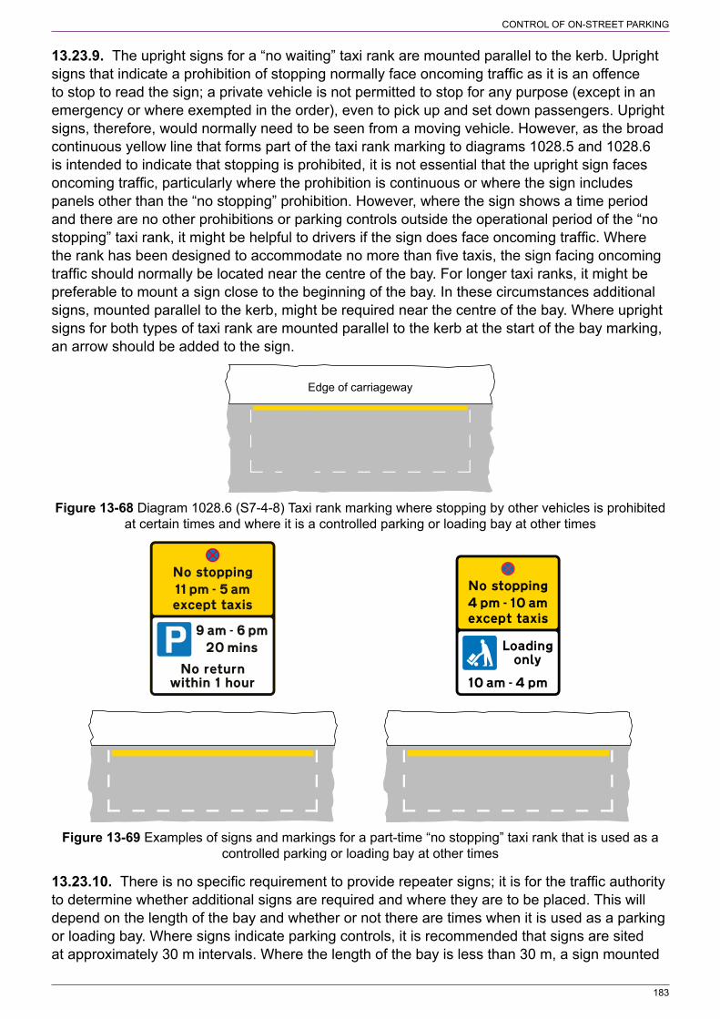
183
CONTROL OF ON‑STREET PARKING
13.23.9. The upright signs for a “no waiting” taxi rank are mounted parallel to the kerb. Upright signs that indicate a prohibition of stopping normally face oncoming traffic as it is an offence to stop to read the sign; a private vehicle is not permitted to stop for any purpose (except in an emergency or where exempted in the order), even to pick up and set down passengers. Upright signs, therefore, would normally need to be seen from a moving vehicle. However, as the broad continuous yellow line that forms part of the taxi rank marking to diagrams 1028.5 and 1028.6 is intended to indicate that stopping is prohibited, it is not essential that the upright sign faces oncoming traffic, particularly where the prohibition is continuous or where the sign includes panels other than the “no stopping” prohibition. However, where the sign shows a time period and there are no other prohibitions or parking controls outside the operational period of the “no stopping” taxi rank, it might be helpful to drivers if the sign does face oncoming traffic. Where the rank has been designed to accommodate no more than five taxis, the sign facing oncoming traffic should normally be located near the centre of the bay. For longer taxi ranks, it might be preferable to mount a sign close to the beginning of the bay. In these circumstances additional signs, mounted parallel to the kerb, might be required near the centre of the bay. Where upright signs for both types of taxi rank are mounted parallel to the kerb at the start of the bay marking, an arrow should be added to the sign.
Edge of carriageway
Figure 13‑68 Diagram 1028.6 (S7‑4‑8) Taxi rank marking where stopping by other vehicles is prohibited at certain times and where it is a controlled parking or loading bay at other times
Figure 13‑69 Examples of signs and markings for a part‑time “no stopping” taxi rank that is used as a controlled parking or loading bay at other times
13.23.10. There is no specific requirement to provide repeater signs; it is for the traffic authority to determine whether additional signs are required and where they are to be placed. This will depend on the length of the bay and whether or not there are times when it is used as a parking or loading bay. Where signs indicate parking controls, it is recommended that signs are sited at approximately 30 m intervals. Where the length of the bay is less than 30 m, a sign mounted

184
CONTROL OF ON‑STREET PARKING
at the mid‑point should therefore be sufficient, unless the rank is adjacent to another type of parking bay where a sign (with an arrow) at each end of the bay is preferable.
13.23.11. The upright signs are prescribed with an x‑height in the range of 15 mm minimum to 40 mm maximum. The smallest size is only appropriate where the sign is parallel to the kerb, as the x‑height is too small for the sign to be read from a moving vehicle. Where a “no stopping” sign faces oncoming traffic, the x‑height should be 40 mm. Where two or more individual signs are mounted together, they should have the same x‑height.
13.23.12. The informatory sign to diagram 857.1 (S11‑2‑48, see Figure 13‑70) may be used to display fare tables and any additional information such as the number of taxis allowed to wait in the stand and the conditions of hire. The letter height of the information must not exceed 25 mm (S11‑5‑16). The white space may be omitted so that the sign shows only the number of taxis that can be accommodated within the rank. As the sign is mainly for the information of customers, it should normally face onto the footway. Other mounting positions may be adopted, e.g. it may face the carriageway if the information relates to the way in which taxis may use the stand or if the white space is omitted.
Figure 13‑70 Diagram 857.1 (S11‑2‑48) Information relating to a taxi rank for the number of taxis specified
13.24 Bus stop clearways13.24.1. The significance of the bus stop clearway marking shown in diagram 1025.1 (S7‑4‑9, see Figure 13‑71) is specified in S7‑6‑1. Although there is no requirement for a traffic regulation order, S7‑3‑3 makes it an offence to fail to comply with the indication given by these markings. There is no specific requirement (under the Road Traffic Regulation Act 1984) to consult on the introduction of a new bus stop clearway, but it is strongly recommended that those likely to be affected should be consulted over the location and times of operation of the proposed restrictions. It should be noted that taxis are permitted to stop in a bus stop clearway to pick up or set down passengers. In Northern Ireland, the Roads (Restriction of Waiting) Order (Northern Ireland) 1982 prohibits waiting at any time over the length of these markings. This would be effective (in Northern Ireland only) at times when the prohibition of stopping did not apply.
Edge of carriageway
Figure 13‑71 Diagram 1025.1 (S7‑4‑9) Bus stop clearway road marking
13.24.2. The Regulations prescribe the wording “BUS STAND” as an alternative to “BUS STOP”. The definition of a “clearway” includes both bus stops and bus stands, whereas the definition of a “bus stop clearway” relates only to bus stops and not to bus stands. The requirement is that a bus may stop in a “clearway” for as long as it is necessary to maintain a scheduled service, but in the case of a “bus stop clearway” there is a time limit of two minutes.

185
CONTROL OF ON‑STREET PARKING
Therefore, if buses are expected to stop for longer than two minutes, other than to pick up and set down passengers or for a change of crew, the clearway should be marked and signed as a bus stand.
13.24.3. The Regulations allow the clearway marking to be placed within a lay‑by where part is used by buses and part is used by other vehicles, or within a lay‑by provided solely for buses, thus replacing the markings previously prescribed by the 2002 Regulations as diagrams 1025.3 and 1025.4. In each case green road studs may be provided in the gaps in the broken edge line along the boundary between the lay‑by and the main carriageway (S7‑3‑2). Further details on road studs can be found in Chapter 5.
13.24.4. Both the worded marking and the broken line delineating the stopping area must be coloured yellow (except in Northern Ireland where it may be white). When the bus stop is in a part of a lay‑by, the longitudinal broken edge line within the length of the bus stop is coloured yellow, whilst that beyond it is coloured white (denoting the edge of the lay‑by used by all vehicles; see Chapter 5).
13.24.5. Where a bus stop serves frequent or multiple services, or vehicles with different entrance positions, the length of the bay may be increased in increments of 2 m. The legend “BUS STOP” should be used once for every complete length of 12 m. Under‑used stops of excessive length could result in enforcement difficulties.
13.24.6. Schedule 7 General Direction 3 requires that the road marking must be used in conjunction with an associated upright sign which is prescribed by Schedule 4 and includes the symbol shown in S4‑3‑2. The time period shown on the sign may be varied or omitted as appropriate, but should not be changed to the expression “at any time”. Where the bus stop is for use only by buses operating a local service, the upright sign must be varied to “except local buses”. The words “BUS STAND” must be included when indicating a bus stand where buses may stop for more than 2 minutes; this is a permitted variant shown in S4‑3‑2(5).
13.24.7. Where the bus stop clearway does not operate at all times, a prohibition of waiting might be required at other times. As it is not practicable to provide a yellow line to diagram 1017 within a bus stop clearway marking, the prohibition of waiting is indicated by an upright sign alone. This may be a separate sign or an additional yellow panel on the bus stop clearway sign. The two time periods showing the stopping and waiting prohibitions should not overlap. If a loading ban is also required, this may be indicated by upright signs alone as there is no requirement to provide the associated road marking to diagram 1019. The loading prohibition may be indicated by a separate sign or by a white panel on the bus stop clearway sign. A daytime bus stop clearway may be used as a “no stopping” taxi rank overnight. This is indicated on a sign comprising a single panel; the “taxi” legend and associated time period being a permitted variant of S4‑3‑2. In this case the road marking is to diagram 1025.1. Examples of upright signs are shown in Figure 13‑72.
Figure 13‑72 Examples of upright signs indicating places where only buses may stop during the period indicated, for the purpose of picking up and setting down passengers and where a bus stop is used
overnight as a “no stopping” taxi rank

186
CONTROL OF ON‑STREET PARKING
13.24.8. A bus stop clearway that operates for only part of the day may be used as a controlled parking place at other times, e.g. a bus stop during the daytime and a loading bay overnight. A white panel is added to the upright sign to indicate the parking controls or alternatively a separate sign provided. The road marking to diagram 1025.1 is still used in this situation. An example of an upright sign is shown in Figure 13‑73. Where unlimited free parking is permitted outside the operational period of the bus stop clearway, this does not need to be indicated by an upright sign.
Figure 13‑73 Signing arrangement for a bus stop during the daytime and a loading bay overnight
13.24.9. Upright signs that indicate a prohibition of stopping normally face oncoming traffic as it is an offence to stop to read the sign. The signs, therefore, would normally need to be seen from a moving vehicle. However, as the broad continuous yellow line that forms part of the bus stop clearway marking is intended to indicate that stopping is prohibited, it is not essential that the upright signs face oncoming traffic, particularly where the prohibition is continuous or where the sign includes panels other than the “no stopping” prohibition. However, where the sign shows a time period it will be helpful to drivers if the sign does face oncoming traffic. The sign should normally be located near the centre of the bay or mounted on the post that supports the bus stop sign to diagram 970, 973.2 or 973.3 (S11‑2‑76 and 77). Where the bus stop marking has been extended to accommodate two or more buses, it might be preferable to mount the sign close to the beginning of the bay. In these circumstances an additional sign, mounted parallel to the kerb, might be required near the centre of the bay.
13.24.10. The upright signs are prescribed with an x‑height in the range of 15 mm minimum to 40 mm maximum. The smallest size is only appropriate where the sign is parallel to the kerb, as the x‑height is too small for the sign to be read from a moving vehicle. Where the sign faces oncoming traffic, the x‑height should be 40 mm. Where two or more individual signs are mounted together, they should have the same x‑height.
13.25 Prohibition of waiting by goods vehicles and buses13.25.1. A sign prescribed by S4‑3‑3 (see Figure 13‑74) gives effect to an order prohibiting waiting by any goods vehicle with a maximum gross weight as indicated on the sign. The lower case letter “t” must now be used on the lorry symbol to denote “tonnes”. The capital letter “T” is no longer prescribed. Existing signs using the capital letter “T” need not be replaced until necessary through routine maintenance. The order may also refer to buses, either in addition to, or in place of goods vehicles. S4‑2‑3 requires the lorry symbol, the bus symbol or both to be used with the “no waiting” roundel. The right facing vehicle symbols are used when a right pointing arrow is included on the sign, otherwise the symbols should face left. Restrictions are normally applied overnight and at weekends as an environmental measure. Column (4) of S4‑3 requires that a time period is always included on the sign. Examples of complete signs are shown in Figure 13‑75.

187
CONTROL OF ON‑STREET PARKING
Symbols and legends used in combination with a yellow panel
(1)
Item
(2)
Description
(3)
Symbol
(4)
Legend
(5)
Variant of legend
(6)
Legend height (by reference to x‑height)
3. Waiting of goods vehicles over a maximum gross weight shown or buses (or both) prohibited
The lorry symbols are alternative types
The bus symbols are alternative types
75 min200 max
112.5 min300 max
127.5 min340 max
A time period Not less than 15 mm and not more than 40 mm
Figure 13‑74 Extract from S4‑3 in respect of a prohibition of waiting by goods vehicles and buses
Figure 13‑75 Examples of upright signs indicating prohibitions of waiting by goods vehicles and buses
13.25.2. The signs described in Figure 13‑74 and illustrated in Figure 13‑75 are used either as repeater signs within a controlled parking zone that applies only to commercial vehicles or on roads not forming part of a zone. In both cases, road markings are not used and enforcement depends on the upright signs only. At the start or end of any restriction that is not within a zone, the sign should include an arrow indicating the length of road to which the restriction applies. On other signs the arrow is omitted. In a zone, the Regulations require that at least one sign is provided on each side of every road (Schedule 1 definition). For roads not within a zone, additional signs might be required as there is no zone entry sign. In this case, the aim should be to provide signs at approximately 60 m intervals on each side of the road, although it is for the traffic authority to determine how many signs are required and where they should be placed.
13.25.3. Care must be taken to ensure that drivers do not associate the upright sign with any yellow lines that relate to other waiting restrictions that might be imposed, particularly as these are likely to apply at different times. It is therefore recommended that the sign be co‑located with the upright sign that indicates the waiting restrictions associated with the yellow line. The two signs may be combined into a single sign; the panel indicating the prohibition of waiting in respect of goods vehicles and buses may be placed to the left or right of the other part of the sign. This might produce a neater arrangement than a tall single column where the sign includes white panels.

188
CONTROL OF ON‑STREET PARKING
13.25.4. The upright signs are prescribed with an x‑height in the range of 15 mm minimum to 40 mm maximum. The appropriate x‑height is determined by the need to ensure conspicuity rather than by the speed of traffic, particularly as the sign is used without road markings. This is the reason that a larger than normal “no waiting” roundel is used. The smaller x‑heights are likely to be appropriate for signs with large amounts of information (e.g. a sign with both the goods vehicle and bus symbol or where the sign is combined with another sign). The choice of x‑height will also depend on prevailing conditions. For example, a small x‑height might be appropriate in a quiet residential street. Where two or more individual signs are mounted together, they should have the same x‑height.
13.26 Prohibition of waiting in off‑road loading and loading only areas13.26.1. The Regulations prescribe signs that are used to give effect to an order made under section 61 of the Road Traffic Regulation Act 1984 to control parking in off‑road goods vehicle loading areas. The consent of the owners and occupiers of the loading area must be obtained before commencing the order‑making procedure. It is also likely that the order will need to be enforced by the local authority and not the police. The loading area is signed by upright signs alone and it is therefore preferable that orders are applied only to areas which have clearly defined boundaries.
13.26.2. Upright signs indicating the entrances to off‑road loading areas and repeaters signs which may be used in larger areas as considered necessary are prescribed by S4‑3‑7 and 8 respectively (see Figure 13‑76). These include a “no waiting” roundel and the mandatory legend shown in column (4) of S4‑3. Examples of completed signs are shown in Figure 13‑77.
Symbols and legends used in combination with a yellow panel
(1)
Item
(2)
Description
(3)
Symbol
(4)
Legend
(5)
Variant of legend
(6)
Legend height (by reference to x‑height)
7. Entrance to a designated off‑road loading area
2001. “Loading area”;
2. “Except by permitted vehicles”; and
3. A time period
1. 50 mm for “Loading area”
2. 40 mm for “Except by permitted vehicles”
3. 40 mm for the time period
8. Waiting prohibited in a designated off‑road loading area
2001. “Except by permitted vehicles”; and
2. A time period
40 mm
Figure 13‑76 Extract from S4‑3 in respect of signs for off‑road loading areas
13.26.3. A sign to diagram 640.5 (S7‑2‑5, see Figure 13‑78) should be erected at each exit from the area, but if the area is small with a combined entrance and exit directly onto a public highway, this sign is unlikely to be needed.
Entrance to loading area Repeater sign Figure 13‑77 Examples of upright signs prescribed Figure 13‑78 Diagram 640.5 (S7‑2‑5) by Schedule 4 for off‑road loading areas End of designated off‑road loading area
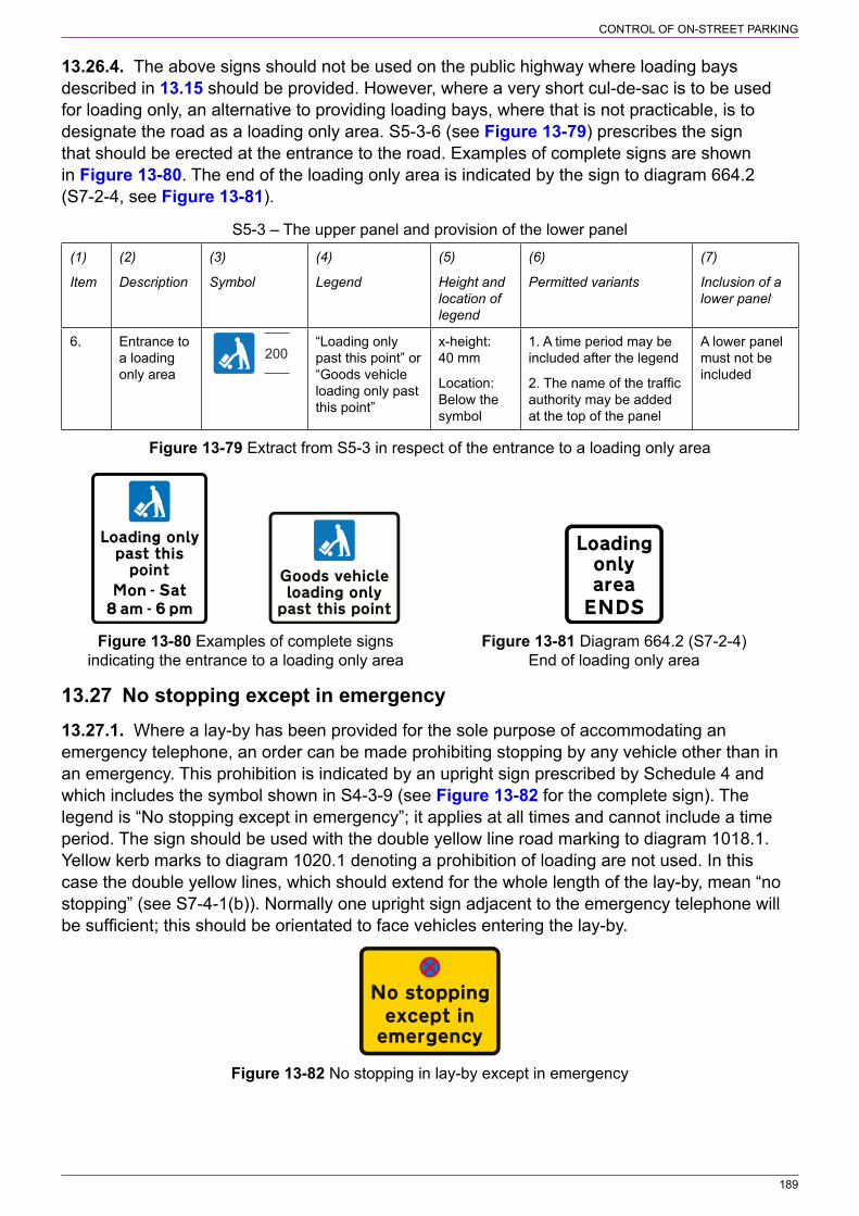
189
CONTROL OF ON‑STREET PARKING
13.26.4. The above signs should not be used on the public highway where loading bays described in 13.15 should be provided. However, where a very short cul‑de‑sac is to be used for loading only, an alternative to providing loading bays, where that is not practicable, is to designate the road as a loading only area. S5‑3‑6 (see Figure 13‑79) prescribes the sign that should be erected at the entrance to the road. Examples of complete signs are shown in Figure 13‑80. The end of the loading only area is indicated by the sign to diagram 664.2 (S7‑2‑4, see Figure 13‑81).
S5‑3 – The upper panel and provision of the lower panel
(1)
Item
(2)
Description
(3)
Symbol
(4)
Legend
(5)
Height and location of legend
(6)
Permitted variants
(7)
Inclusion of a lower panel
6. Entrance to a loading only area
200“Loading only past this point” or “Goods vehicle loading only past this point”
x‑height: 40 mm
Location: Below the symbol
1. A time period may be included after the legend
2. The name of the traffic authority may be added at the top of the panel
A lower panel must not be included
Figure 13‑79 Extract from S5‑3 in respect of the entrance to a loading only area
Figure 13‑80 Examples of complete signs Figure 13‑81 Diagram 664.2 (S7‑2‑4) indicating the entrance to a loading only area End of loading only area
13.27 No stopping except in emergency13.27.1. Where a lay‑by has been provided for the sole purpose of accommodating an emergency telephone, an order can be made prohibiting stopping by any vehicle other than in an emergency. This prohibition is indicated by an upright sign prescribed by Schedule 4 and which includes the symbol shown in S4‑3‑9 (see Figure 13‑82 for the complete sign). The legend is “No stopping except in emergency”; it applies at all times and cannot include a time period. The sign should be used with the double yellow line road marking to diagram 1018.1. Yellow kerb marks to diagram 1020.1 denoting a prohibition of loading are not used. In this case the double yellow lines, which should extend for the whole length of the lay‑by, mean “no stopping” (see S7‑4‑1(b)). Normally one upright sign adjacent to the emergency telephone will be sufficient; this should be orientated to face vehicles entering the lay‑by.
Figure 13‑82 No stopping in lay‑by except in emergency
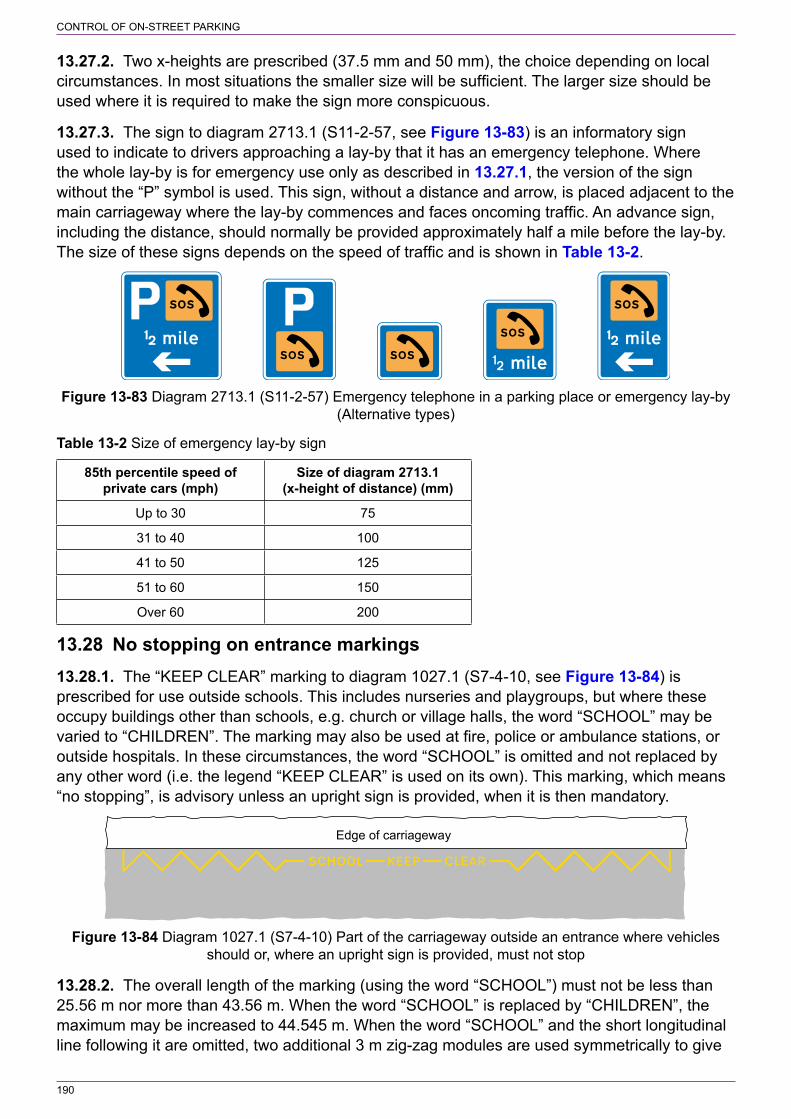
190
CONTROL OF ON‑STREET PARKING
13.27.2. Two x‑heights are prescribed (37.5 mm and 50 mm), the choice depending on local circumstances. In most situations the smaller size will be sufficient. The larger size should be used where it is required to make the sign more conspicuous.
13.27.3. The sign to diagram 2713.1 (S11‑2‑57, see Figure 13‑83) is an informatory sign used to indicate to drivers approaching a lay‑by that it has an emergency telephone. Where the whole lay‑by is for emergency use only as described in 13.27.1, the version of the sign without the “P” symbol is used. This sign, without a distance and arrow, is placed adjacent to the main carriageway where the lay‑by commences and faces oncoming traffic. An advance sign, including the distance, should normally be provided approximately half a mile before the lay‑by. The size of these signs depends on the speed of traffic and is shown in Table 13‑2.
Figure 13‑83 Diagram 2713.1 (S11‑2‑57) Emergency telephone in a parking place or emergency lay‑by (Alternative types)
Table 13‑2 Size of emergency lay‑by sign
85th percentile speed of private cars (mph)
Size of diagram 2713.1 (x‑height of distance) (mm)
Up to 30 75
31 to 40 100
41 to 50 125
51 to 60 150
Over 60 200
13.28 No stopping on entrance markings13.28.1. The “KEEP CLEAR” marking to diagram 1027.1 (S7‑4‑10, see Figure 13‑84) is prescribed for use outside schools. This includes nurseries and playgroups, but where these occupy buildings other than schools, e.g. church or village halls, the word “SCHOOL” may be varied to “CHILDREN”. The marking may also be used at fire, police or ambulance stations, or outside hospitals. In these circumstances, the word “SCHOOL” is omitted and not replaced by any other word (i.e. the legend “KEEP CLEAR” is used on its own). This marking, which means “no stopping”, is advisory unless an upright sign is provided, when it is then mandatory.
Edge of carriageway
Figure 13‑84 Diagram 1027.1 (S7‑4‑10) Part of the carriageway outside an entrance where vehicles should or, where an upright sign is provided, must not stop
13.28.2. The overall length of the marking (using the word “SCHOOL”) must not be less than 25.56 m nor more than 43.56 m. When the word “SCHOOL” is replaced by “CHILDREN”, the maximum may be increased to 44.545 m. When the word “SCHOOL” and the short longitudinal line following it are omitted, two additional 3 m zig‑zag modules are used symmetrically to give
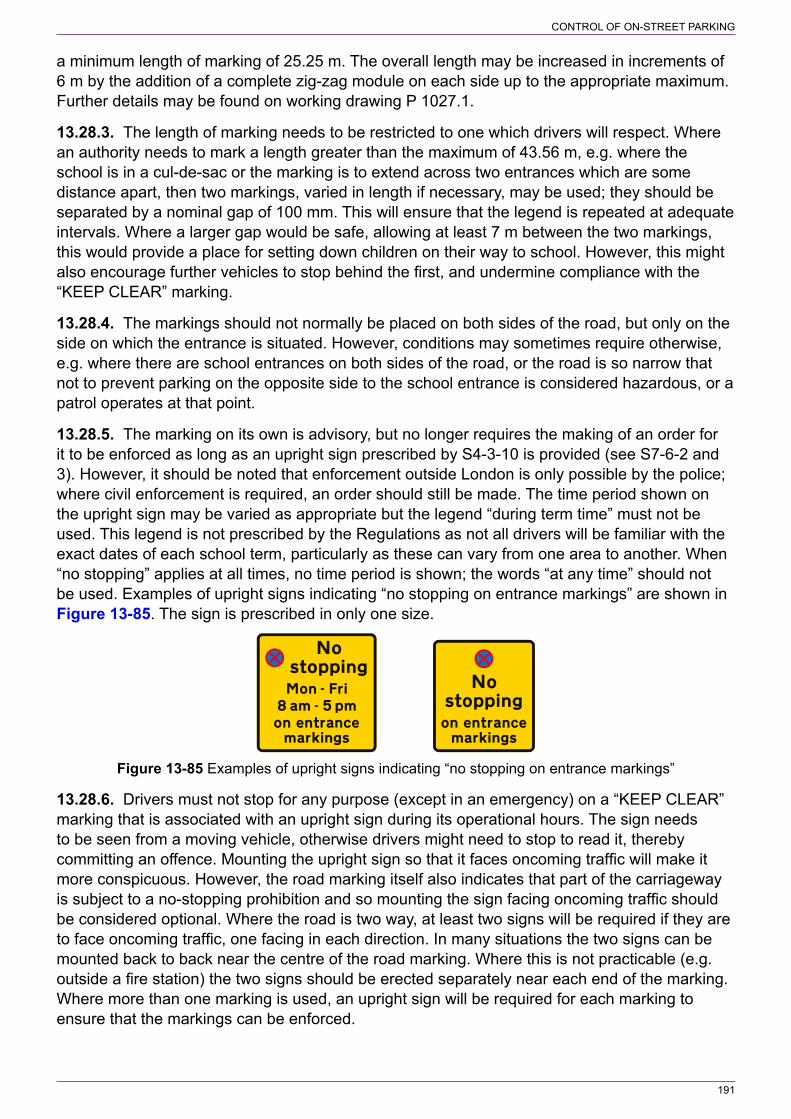
191
CONTROL OF ON‑STREET PARKING
a minimum length of marking of 25.25 m. The overall length may be increased in increments of 6 m by the addition of a complete zig‑zag module on each side up to the appropriate maximum. Further details may be found on working drawing P 1027.1.
13.28.3. The length of marking needs to be restricted to one which drivers will respect. Where an authority needs to mark a length greater than the maximum of 43.56 m, e.g. where the school is in a cul‑de‑sac or the marking is to extend across two entrances which are some distance apart, then two markings, varied in length if necessary, may be used; they should be separated by a nominal gap of 100 mm. This will ensure that the legend is repeated at adequate intervals. Where a larger gap would be safe, allowing at least 7 m between the two markings, this would provide a place for setting down children on their way to school. However, this might also encourage further vehicles to stop behind the first, and undermine compliance with the “KEEP CLEAR” marking.
13.28.4. The markings should not normally be placed on both sides of the road, but only on the side on which the entrance is situated. However, conditions may sometimes require otherwise, e.g. where there are school entrances on both sides of the road, or the road is so narrow that not to prevent parking on the opposite side to the school entrance is considered hazardous, or a patrol operates at that point.
13.28.5. The marking on its own is advisory, but no longer requires the making of an order for it to be enforced as long as an upright sign prescribed by S4‑3‑10 is provided (see S7‑6‑2 and 3). However, it should be noted that enforcement outside London is only possible by the police; where civil enforcement is required, an order should still be made. The time period shown on the upright sign may be varied as appropriate but the legend “during term time” must not be used. This legend is not prescribed by the Regulations as not all drivers will be familiar with the exact dates of each school term, particularly as these can vary from one area to another. When “no stopping” applies at all times, no time period is shown; the words “at any time” should not be used. Examples of upright signs indicating “no stopping on entrance markings” are shown in Figure 13‑85. The sign is prescribed in only one size.
Figure 13‑85 Examples of upright signs indicating “no stopping on entrance markings”
13.28.6. Drivers must not stop for any purpose (except in an emergency) on a “KEEP CLEAR” marking that is associated with an upright sign during its operational hours. The sign needs to be seen from a moving vehicle, otherwise drivers might need to stop to read it, thereby committing an offence. Mounting the upright sign so that it faces oncoming traffic will make it more conspicuous. However, the road marking itself also indicates that part of the carriageway is subject to a no‑stopping prohibition and so mounting the sign facing oncoming traffic should be considered optional. Where the road is two way, at least two signs will be required if they are to face oncoming traffic, one facing in each direction. In many situations the two signs can be mounted back to back near the centre of the road marking. Where this is not practicable (e.g. outside a fire station) the two signs should be erected separately near each end of the marking. Where more than one marking is used, an upright sign will be required for each marking to ensure that the markings can be enforced.
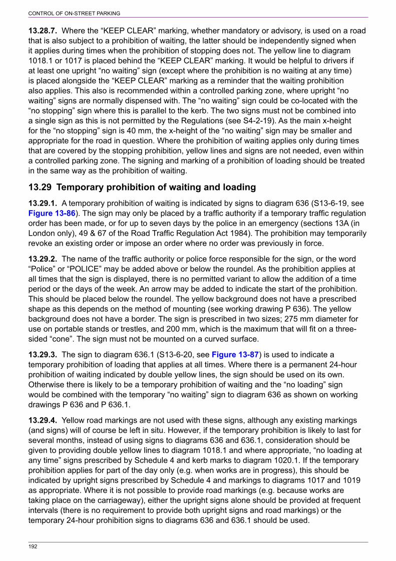
192
CONTROL OF ON‑STREET PARKING
13.28.7. Where the “KEEP CLEAR” marking, whether mandatory or advisory, is used on a road that is also subject to a prohibition of waiting, the latter should be independently signed when it applies during times when the prohibition of stopping does not. The yellow line to diagram 1018.1 or 1017 is placed behind the “KEEP CLEAR” marking. It would be helpful to drivers if at least one upright “no waiting” sign (except where the prohibition is no waiting at any time) is placed alongside the “KEEP CLEAR” marking as a reminder that the waiting prohibition also applies. This also is recommended within a controlled parking zone, where upright “no waiting” signs are normally dispensed with. The “no waiting” sign could be co‑located with the “no stopping” sign where this is parallel to the kerb. The two signs must not be combined into a single sign as this is not permitted by the Regulations (see S4‑2‑19). As the main x‑height for the “no stopping” sign is 40 mm, the x‑height of the “no waiting” sign may be smaller and appropriate for the road in question. Where the prohibition of waiting applies only during times that are covered by the stopping prohibition, yellow lines and signs are not needed, even within a controlled parking zone. The signing and marking of a prohibition of loading should be treated in the same way as the prohibition of waiting.
13.29 Temporary prohibition of waiting and loading13.29.1. A temporary prohibition of waiting is indicated by signs to diagram 636 (S13‑6‑19, see Figure 13‑86). The sign may only be placed by a traffic authority if a temporary traffic regulation order has been made, or for up to seven days by the police in an emergency (sections 13A (in London only), 49 & 67 of the Road Traffic Regulation Act 1984). The prohibition may temporarily revoke an existing order or impose an order where no order was previously in force.
13.29.2. The name of the traffic authority or police force responsible for the sign, or the word “Police” or “POLICE” may be added above or below the roundel. As the prohibition applies at all times that the sign is displayed, there is no permitted variant to allow the addition of a time period or the days of the week. An arrow may be added to indicate the start of the prohibition. This should be placed below the roundel. The yellow background does not have a prescribed shape as this depends on the method of mounting (see working drawing P 636). The yellow background does not have a border. The sign is prescribed in two sizes; 275 mm diameter for use on portable stands or trestles, and 200 mm, which is the maximum that will fit on a three‑ sided “cone”. The sign must not be mounted on a curved surface.
13.29.3. The sign to diagram 636.1 (S13‑6‑20, see Figure 13‑87) is used to indicate a temporary prohibition of loading that applies at all times. Where there is a permanent 24‑hour prohibition of waiting indicated by double yellow lines, the sign should be used on its own. Otherwise there is likely to be a temporary prohibition of waiting and the “no loading” sign would be combined with the temporary “no waiting” sign to diagram 636 as shown on working drawings P 636 and P 636.1.
13.29.4. Yellow road markings are not used with these signs, although any existing markings (and signs) will of course be left in situ. However, if the temporary prohibition is likely to last for several months, instead of using signs to diagrams 636 and 636.1, consideration should be given to providing double yellow lines to diagram 1018.1 and where appropriate, “no loading at any time” signs prescribed by Schedule 4 and kerb marks to diagram 1020.1. If the temporary prohibition applies for part of the day only (e.g. when works are in progress), this should be indicated by upright signs prescribed by Schedule 4 and markings to diagrams 1017 and 1019 as appropriate. Where it is not possible to provide road markings (e.g. because works are taking place on the carriageway), either the upright signs alone should be provided at frequent intervals (there is no requirement to provide both upright signs and road markings) or the temporary 24‑hour prohibition signs to diagrams 636 and 636.1 should be used.

193
CONTROL OF ON‑STREET PARKING
13.29.5. Where a parking bay is suspended, a temporary sign to diagram 640.1 (S13‑6‑22, see Figure 13‑88) should be used to cover the parking place upright sign. It may have more than one side and be used as a parking meter or ticket machine cover. The temporary sign may indicate a prohibition of waiting or a prohibition of both waiting and loading. Where the temporary prohibition applies only during the hours of operation of the parking meters within a meter zone, the legend “during meter control” is added. The words “No waiting” or “No unloading” are not prescribed and must not be used.
Figure 13‑86 Diagram 636 Figure 13‑87 Diagram 636.1 Figure 13‑88 Diagram 640.1 (S13‑6‑19) Temporary (S13‑6‑20) Temporary prohibition (S13‑6‑22) Waiting, loading prohibition of waiting except for of loading and unloading and unloading prohibited at a loading and unloading parking place where parking is temporarily suspended
13.30 Temporary prohibition of stopping13.30.1. The sign to diagram 636.2 (S13‑6‑21, see Figure 13‑89) indicates a temporary prohibition of stopping and is used mainly by the police in an emergency. If the sign is used by a traffic authority to indicate the effect of a temporary order, the name of the authority must be shown on the sign, replacing the name of the police authority (see Schedule 13 General Direction 10). In most cases where a road needs to be kept clear for planned works, a temporary prohibition of waiting and loading will be adequate.
Figure 13‑89 Diagram 636.2 (S13‑6‑21) Temporary prohibition of stopping during the periods indicated
13.30.2. The time period shown may be varied or omitted; the expression “At any time” is not used. The sign, which is prescribed in one size only, should normally face oncoming traffic, but may be placed parallel to the kerb. Repeater signs should be placed along the section of the road to indicate where the restriction applies. As there is no “End” sign or associated road marking and an arrow cannot be included on the sign, consideration should be given to placing signs fairly close together so that it is clear where the restriction ends.
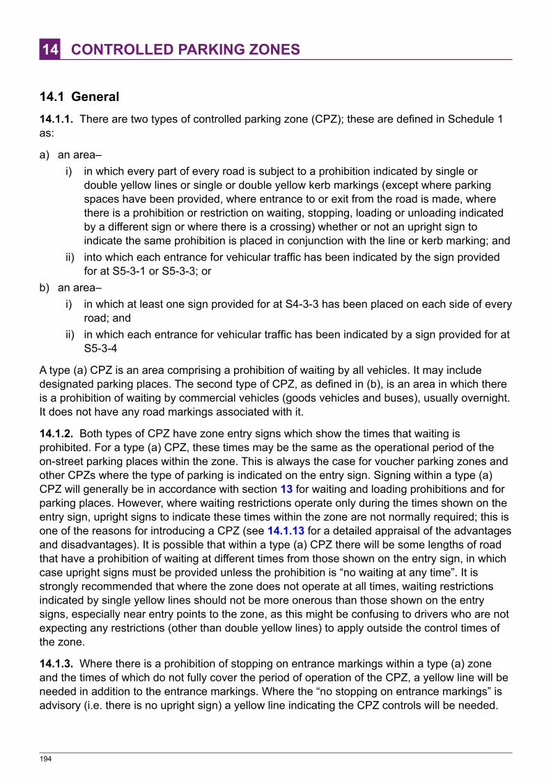
194
14 CONTROLLED PARKING ZONES
14.1 General14.1.1. There are two types of controlled parking zone (CPZ); these are defined in Schedule 1 as:
a) an area–i) in which every part of every road is subject to a prohibition indicated by single or
double yellow lines or single or double yellow kerb markings (except where parking spaces have been provided, where entrance to or exit from the road is made, where there is a prohibition or restriction on waiting, stopping, loading or unloading indicated by a different sign or where there is a crossing) whether or not an upright sign to indicate the same prohibition is placed in conjunction with the line or kerb marking; and
ii) into which each entrance for vehicular traffic has been indicated by the sign provided for at S5‑3‑1 or S5‑3‑3; or
b) an area–i) in which at least one sign provided for at S4‑3‑3 has been placed on each side of every
road; andii) in which each entrance for vehicular traffic has been indicated by a sign provided for at
S5‑3‑4
A type (a) CPZ is an area comprising a prohibition of waiting by all vehicles. It may include designated parking places. The second type of CPZ, as defined in (b), is an area in which there is a prohibition of waiting by commercial vehicles (goods vehicles and buses), usually overnight. It does not have any road markings associated with it.
14.1.2. Both types of CPZ have zone entry signs which show the times that waiting is prohibited. For a type (a) CPZ, these times may be the same as the operational period of the on‑street parking places within the zone. This is always the case for voucher parking zones and other CPZs where the type of parking is indicated on the entry sign. Signing within a type (a) CPZ will generally be in accordance with section 13 for waiting and loading prohibitions and for parking places. However, where waiting restrictions operate only during the times shown on the entry sign, upright signs to indicate these times within the zone are not normally required; this is one of the reasons for introducing a CPZ (see 14.1.13 for a detailed appraisal of the advantages and disadvantages). It is possible that within a type (a) CPZ there will be some lengths of road that have a prohibition of waiting at different times from those shown on the entry sign, in which case upright signs must be provided unless the prohibition is “no waiting at any time”. It is strongly recommended that where the zone does not operate at all times, waiting restrictions indicated by single yellow lines should not be more onerous than those shown on the entry signs, especially near entry points to the zone, as this might be confusing to drivers who are not expecting any restrictions (other than double yellow lines) to apply outside the control times of the zone.
14.1.3. Where there is a prohibition of stopping on entrance markings within a type (a) zone and the times of which do not fully cover the period of operation of the CPZ, a yellow line will be needed in addition to the entrance markings. Where the “no stopping on entrance markings” is advisory (i.e. there is no upright sign) a yellow line indicating the CPZ controls will be needed.

195
CONTROLLED PARKING ZONES
14.1.4. Where bus stop clearways and “no stopping” taxi ranks are provided within a type (a) zone, yellow lines to diagram 1017 are not provided as these cannot be accommodated within the road markings. Any waiting restrictions that apply outside the operational periods of a bus stop clearway or taxi rank are indicated by upright signs only. Kerb marks to diagram 1019 should be provided only where a prohibition of loading applies during times when the bus stop clearway or taxi rank is not operational.
14.1.5. Where loading is prohibited within a type (a) CPZ, this may be indicated on the entry sign, but only if the times are the same as those for the prohibition of waiting. If the loading prohibition operates at different times, it must be signed within the zone. Where an area has roads that are predominantly “no waiting at any time” and loading is not prohibited at all times, there may be little advantage in designating the area as a CPZ and providing zone entry signs.
14.1.6. All designated parking places and loading bays within a type (a) CPZ, other than parking meter bays, need to be signed in accordance with section 13. The times of operation, where not continuous, are always shown on the sign, even where they are the same as those shown on the zone entry sign. To omit times from the sign indicates that a parking place or loading bay operates at all times. Where the parking bays operate for a shorter period than the CPZ (e.g. the CPZ operates from 8 am to 6 pm, and the parking bays from 10 am to 4 pm), the upright sign should indicate both the parking controls and the waiting restrictions, together with any loading prohibition. This is because the waiting restrictions are different from those shown on the entry sign, i.e. they do not apply when the parking bay is operational. The sign also ensures that drivers are aware of all the restrictions.
14.1.7. Within a type (a) zone, yellow lines indicating the waiting restrictions and, where appropriate, kerb marks indicating loading prohibitions must always be provided within a bus or cycle lane.
14.1.8. The entry sign for a type (a) CPZ is prescribed by S5‑3‑1, except for a voucher parking zone where the appropriate sign is S5‑3‑3. Both signs may have a bottom panel prescribed by S5‑4‑1. The legend at the top of the sign in S5‑3‑1 can be varied to indicate the type of parking within the zone. In most cases this will be “Controlled ZONE”, as it covers all types of parking other than disc and ticket parking. It is also used for those zones that have no on‑street parking places. Where on‑street parking is of the same type throughout the zone, whether or not permit parking is also provided, and where the operational time of the parking places is the same as the times shown on the entry sign, the legend on the sign may be one of the following:
a) “Meter ZONE” (where parking meters are used)b) “Pay and Display ZONE” (on‑street ticket machines)c) “Ticket ZONE” (purchase of ticket other than from an on‑street machine)d) “Disc ZONE” (limited waiting requiring the display of a parking disc to indicate the time of
arrival)e) “Disc and Meter ZONE”f) “Ticket and Meter ZONE”.
14.1.9. Examples of zone entry signs are shown in Figure 14‑1. If the CPZ includes disc or ticket parking, the upright signs within the zone indicating the parking places should include the legend “Disc Zone” or “Ticket Zone” respectively. The entry sign must show “Disc ZONE”, “Ticket ZONE”, “Disc and Meter ZONE” or “Ticket and Meter ZONE”. It is therefore not appropriate to mix disc or ticket parking with any other type of parking that is available to non‑permit holders (e.g. pay and display). A zone signed with any of the permitted legends may include parking bays for permit holders and for disabled badge holders.
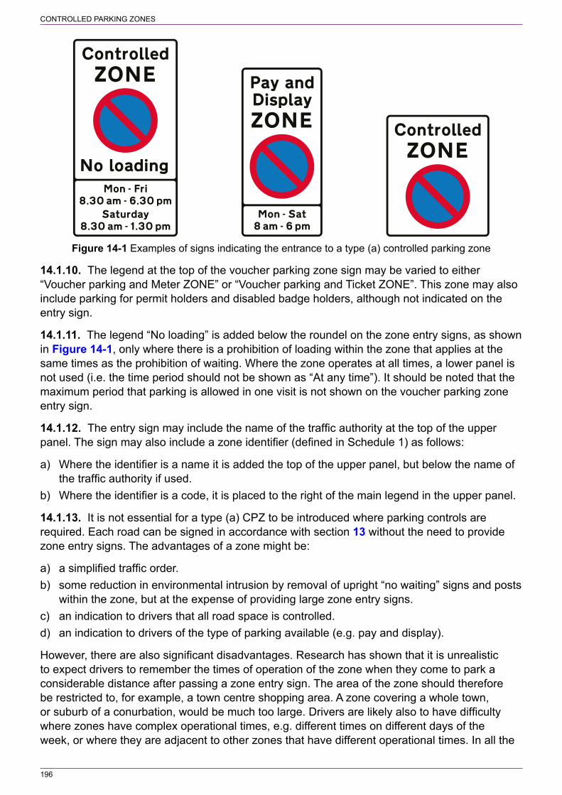
196
CONTROLLED PARKING ZONES
Figure 14‑1 Examples of signs indicating the entrance to a type (a) controlled parking zone
14.1.10. The legend at the top of the voucher parking zone sign may be varied to either “Voucher parking and Meter ZONE” or “Voucher parking and Ticket ZONE”. This zone may also include parking for permit holders and disabled badge holders, although not indicated on the entry sign.
14.1.11. The legend “No loading” is added below the roundel on the zone entry signs, as shown in Figure 14‑1, only where there is a prohibition of loading within the zone that applies at the same times as the prohibition of waiting. Where the zone operates at all times, a lower panel is not used (i.e. the time period should not be shown as “At any time”). It should be noted that the maximum period that parking is allowed in one visit is not shown on the voucher parking zone entry sign.
14.1.12. The entry sign may include the name of the traffic authority at the top of the upper panel. The sign may also include a zone identifier (defined in Schedule 1) as follows:
a) Where the identifier is a name it is added the top of the upper panel, but below the name of the traffic authority if used.
b) Where the identifier is a code, it is placed to the right of the main legend in the upper panel.
14.1.13. It is not essential for a type (a) CPZ to be introduced where parking controls are required. Each road can be signed in accordance with section 13 without the need to provide zone entry signs. The advantages of a zone might be:
a) a simplified traffic order.b) some reduction in environmental intrusion by removal of upright “no waiting” signs and posts
within the zone, but at the expense of providing large zone entry signs.c) an indication to drivers that all road space is controlled.d) an indication to drivers of the type of parking available (e.g. pay and display).
However, there are also significant disadvantages. Research has shown that it is unrealistic to expect drivers to remember the times of operation of the zone when they come to park a considerable distance after passing a zone entry sign. The area of the zone should therefore be restricted to, for example, a town centre shopping area. A zone covering a whole town, or suburb of a conurbation, would be much too large. Drivers are likely also to have difficulty where zones have complex operational times, e.g. different times on different days of the week, or where they are adjacent to other zones that have different operational times. In all the

197
CONTROLLED PARKING ZONES
above cases, consideration should be given to replacing the zone with conventional signing as described in section 13, dividing the zone into several smaller ones or reducing the size of the zone and signing other roads individually.
14.1.14. As the times shown on the entry signs generally coincide with those applying to parking places as well as to the yellow line waiting restrictions, drivers might take signs at on‑street parking places as a reminder of the times when waiting is prohibited. This would be confusing where parking places operate at different times (e.g. 24‑hour permit parking in a zone that does not operate for 24 hours). In such cases, conventional signing might be preferable to the introduction of a zone.
14.1.15. Where there are breaks in a run of parking bays to allow for vehicle crossovers at private accesses, the Regulations no longer require that these gaps be marked with a yellow line. A yellow line at a vehicle crossover would prevent the owner of a property from parking there when the waiting restriction is in force. To discourage inconsiderate parking, the vehicle crossovers could be treated as described in 13.21.5. Where the road is a cul‑de‑sac and all parking is for permit holders only, a permit parking area as described in 13.10 might be appropriate. In this case there would be no bay markings within the road concerned, but as it would be designated as a parking place for permit holders, it would still meet the requirements of a type (a) CPZ as defined by the Regulations. Any waiting and loading restrictions within the permit parking area would need to be indicated by road markings; upright signs would be required only if the times were different to those shown on the CPZ entry sign.
14.1.16. Where a length of road within a type (a) CPZ has both a prohibition of waiting that would normally be indicated by a single yellow line without upright signs and a prohibition of waiting by commercial vehicles indicated by the sign prescribed by S4‑3‑3, drivers might associate that sign with the road marking. As the two restrictions are likely to apply at different times, it is recommended that the sign be co‑located with an upright sign that indicates the waiting restrictions associated with the yellow line. The two signs may be combined into a single sign; the panel indicating the prohibition of waiting in respect of goods vehicles and buses may be placed to the left or right of the other part of the sign. This might produce a neater arrangement than a tall single column where the sign includes white panels.
14.1.17. The end of a type (a) CPZ is indicated by the sign to diagram 664 (S7‑2‑1, see Figure 14‑2). Where one zone ends and another commences, the zone end sign is replaced by the zone entry sign for the second zone. Where a road forms the boundary between two zones, it should be within one or the other zone, or excluded from both; one side of the road should not be within one zone and the other side within the other zone, as this would result in signing that is likely to be confusing to drivers. Where a type (a) CPZ is adjacent to a restricted parking zone (see section 15), the zone end sign is replaced by the restricted zone entry sign. Likewise, the zone end sign for the restricted parking zone is replaced by the CPZ entry sign.
14.1.18. The extent of a type (a) CPZ will be determined by specific characteristics. For example, the zone could be an area where a specific parking permit is valid. It might be an area where the type of parking, such as pay and display (possibly with uniform charges), is the same throughout. Where the parking is time‑limited with no charge, the prohibition on return to the parking place might be applied to the whole zone. This would be appropriate only for small zones, as it would be unreasonable to expect drivers not to return to any part of a large area; enforcement would also be difficult. The signs located at the parking bays in this type of zone would include the legend “No return to Zone A within 2 hours” (or similar), as prescribed by S18‑2 (permitted expressions for parking restriction signs). In this case the zone identifier would be shown on the entry sign and would also apply to any permit parking within the zone. In an

198
CONTROLLED PARKING ZONES
area with a mix of different types of parking, a zone could represent a small geographical area, the name of which may be added to the entry sign as a zone identifier.
14.1.19. A type (a) CPZ may be introduced to control parking within the vicinity of a sports stadium or similar facility. This might be an independent zone that operates only when an event is taking place; on other days there are no zonal controls. An existing zone that operates throughout the year could have additional controls on event days; this makes the zone entry sign very complicated and should be avoided where possible. In such circumstances, all yellow line waiting restrictions within the zone should have upright signs showing times when waiting is prohibited, both on event days and on non‑event days. The lower panel of the zone entry sign may include the legend “Event days” and times the prohibition applies, together with the legend “Next event” and a date (S18‑1‑5). An example is shown in Figure 14‑3. An alternative to including the date of the next event on the zone entry sign, requiring the sign to be variable message, is to provide additional signs which should normally be provided on the approach to the zone. These additional signs are not prescribed and require authorisation.
Figure 14‑2 Diagram 664 (S7‑2‑1) End of a Figure 14‑3 Example of a lower panel on a type controlled, voucher or restricted parking zone (a) CPZ entry sign indicating “Event days”
14.2 Prohibition of waiting by goods vehicles and buses14.2.1. The entry sign for a type (b) CPZ is prescribed by S5‑3‑4 (upper panel) and by S5‑4‑1 (lower panel). The times shown on the sign usually indicate an overnight period. The sign can therefore be simplified if the prohibition applies at the same times on every day of the week, e.g. 7 pm ‑ 8 am, without the need to refer to midnight. Where waiting is to be prohibited at all times, the lower panel is not used (i.e. the time period should not be shown as “At any time”). As this type of zone can be used only to prohibit waiting by large vehicles, the entry signs cannot be varied to include a prohibition of loading. Examples of zone entry signs are shown in Figure 14‑4.
14.2.2. A type (b) CPZ can apply to goods vehicles, buses or both as indicated by the appropriate symbols on the signs. The lorry symbol may show an appropriate maximum gross weight. The lower case letter “t” must now be used on the lorry symbol to denote “tonnes”. The capital letter “T” is no longer prescribed. Existing signs using the capital letter “T” need not be replaced until necessary through routine maintenance.
14.2.3. Signs prescribed by S4‑3‑3 are provided within the zone. There should be at least one sign on each side of every road. Road markings are not used. Where there are other waiting restrictions within the zone indicated by the single yellow line to diagram 1017, it is recommended that the upright signs for these are co‑located or combined with the sign shown in S4‑3‑3 to avoid driver confusion.

199
CONTROLLED PARKING ZONES
14.2.4. The exit from the zone is indicated by the sign shown in diagram 666 (S7‑2‑2, see Figure 14‑5). The symbols shown in the lower panel must be the same as those shown on the entry sign.
Figure 14‑4 Examples of signs indicating the Figure 14‑5 Diagram 666 (S7‑2‑2) End entrance to a type (b) CPZ of a controlled parking zone applying to goods vehicles, buses or both
14.3 Sign design, size and siting14.3.1. The detailed design of zone entry and exit signs for both types of CPZ is set out on the appropriate working drawings. Note that the panel divider is always the same width as the sign border. The voucher symbol on the voucher parking zone entry sign must be the same as that shown on the signs within the zone, and correspond to the design shown on the vouchers themselves. The symbol must be within the size shown in S5‑3‑3.
14.3.2. There are two sizes of entry and exit signs. The smaller size would normally be used where the zone boundary is in a side road at a junction or on a minor through‑route with low traffic speed. The larger size entry sign is appropriate where the zone boundary is on a main road with a speed limit of 30 mph or more. It might also be used where there is a need to give drivers more time to assimilate the information, e.g. where the time period shown is complex (although this should be avoided wherever possible).
14.3.3. In order to reduce environmental impact, there is no requirement to provide an entry sign on each side of the road. A single sign might be sufficient depending on the width of the road, whether a single sign can be clearly seen from all approaches to the zone, and whether it is clear that the sign applies to both sides of the road. The boundary of a zone, particularly on a main through road, should be carefully chosen so that the entry sign is not in conflict with other traffic signs, traffic signals, pedestrian crossings etc. which demand a driver’s attention. Locations where the zone entry signs are likely to be obscured by large vehicles (e.g. delivery vans, or buses at bus stops) should be avoided.
14.3.4. The choice of x‑height, the siting of signs and the provision of road markings for waiting and loading restrictions and parking bays within a type (a) CPZ should be in accordance with section 13. Signs indicating a prohibition of waiting or a prohibition of loading may be omitted where these prohibitions operate at the same times as shown on the zone entry sign. The choice of x‑height for signs within a type (b) CPZ should be in accordance with section 13.

200
15 RESTRICTED PARKING ZONES
15.1 General15.1.1. Restricted parking zones were originally developed for historic areas or where very narrow roads resulted in conventional yellow lines being visually intrusive. Zones are now also used in urban areas and town centres where it is desired to enhance the environment, for example by improved road surface treatment. They have also been used in some residential areas. They might also be considered where the road surface, such as cobble stones, is not conducive to the application of yellow lines.
15.1.2. Waiting and loading restrictions, which must be uniform throughout the zone, are indicated by zone entry signs and time plates within the zone, but without yellow lines or kerb marks (see 15.2). Restricted parking zones are therefore suitable only for single streets or clearly defined small areas. They are not suitable for through routes with heavy traffic or facilities which create a demand for parking greater than can be accommodated in on‑street bays and any convenient off‑street parking. Unlike a pedestrian zone, there is no restriction on entry into a restricted parking zone.
15.1.3. Provision may be made for parking and loading within a zone, with bays being delineated either by white road markings or by physical features such as block paving, planters, bollards etc. (see 15.3). Upright signs for such bays will generally be in accordance with the signs described in section 13. However, where uncontrolled parking is provided this will need to be indicated by different signs. For example, in a 24‑hour zone (no waiting at any time) a parking bay might be pay and display during the day, with free (uncontrolled) parking overnight.
15.2 Zone entry and exit signs15.2.1. The entry sign for a restricted parking zone is prescribed by S5‑3‑2 (upper panel) and by S5‑4‑2 (lower panel); examples of complete signs are shown in Figure 15‑1. Where the zone operates for part of the day, no prohibition of waiting or loading is to be imposed outside the time period indicated in the lower panel. The lower panel is not used where the controls apply at all times and there is no provision for parking within the zone; the expression “At any time” is not used on this sign. Where loading is prohibited during the same period that waiting is prohibited, the sign is varied to include the legend “No loading”; otherwise any loading prohibition is signed only within the zone. Where there is some provision of on‑street parking or loading within the zone, this is indicated on the lower panel of the entry sign by the legend “except in signed bays” following a time period or “Except in signed bays” where there is no time period (i.e. the restricted zones operates at all times). Where there is a single parking or loading bay within the zone, the legend “signed bays” is varied to “signed bay”.
15.2.2. The entry sign may include the name of the traffic authority at the top of the upper panel. The sign may also include a zone identifier (defined in Schedule 1) as follows:
a) Where the identifier is a name it is added at the top of the upper panel, but below the name of the traffic authority if used.
b) Where the identifier is a code, it is placed to the right of the main legend in the upper panel.
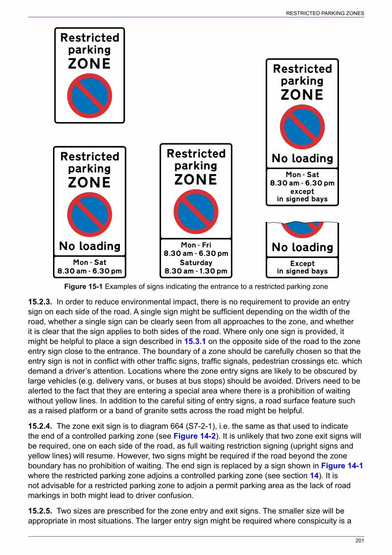
201
RESTRICTED PARKING ZONES
Figure 15‑1 Examples of signs indicating the entrance to a restricted parking zone
15.2.3. In order to reduce environmental impact, there is no requirement to provide an entry sign on each side of the road. A single sign might be sufficient depending on the width of the road, whether a single sign can be clearly seen from all approaches to the zone, and whether it is clear that the sign applies to both sides of the road. Where only one sign is provided, it might be helpful to place a sign described in 15.3.1 on the opposite side of the road to the zone entry sign close to the entrance. The boundary of a zone should be carefully chosen so that the entry sign is not in conflict with other traffic signs, traffic signals, pedestrian crossings etc. which demand a driver’s attention. Locations where the zone entry signs are likely to be obscured by large vehicles (e.g. delivery vans, or buses at bus stops) should be avoided. Drivers need to be alerted to the fact that they are entering a special area where there is a prohibition of waiting without yellow lines. In addition to the careful siting of entry signs, a road surface feature such as a raised platform or a band of granite setts across the road might be helpful.
15.2.4. The zone exit sign is to diagram 664 (S7‑2‑1), i.e. the same as that used to indicate the end of a controlled parking zone (see Figure 14‑2). It is unlikely that two zone exit signs will be required, one on each side of the road, as full waiting restriction signing (upright signs and yellow lines) will resume. However, two signs might be required if the road beyond the zone boundary has no prohibition of waiting. The end sign is replaced by a sign shown in Figure 14‑1 where the restricted parking zone adjoins a controlled parking zone (see section 14). It is not advisable for a restricted parking zone to adjoin a permit parking area as the lack of road markings in both might lead to driver confusion.
15.2.5. Two sizes are prescribed for the zone entry and exit signs. The smaller size will be appropriate in most situations. The larger entry sign might be required where conspicuity is a
202
RESTRICTED PARKING ZONES
problem. The larger exit sign might be appropriate where the restricted parking zone is adjacent to an area that has no yellow lines. Detailed design of the signs is set out on the appropriate working drawings.
15.2.6. Previously authorised entry and exit signs, displaying the legends “Restricted ZONE” and “Restricted Zone ENDS” respectively, may remain in place until life‑expired or replaced, at which point the prescribed signs should be used.
15.3 Signs within the zone15.3.1. Signs within the zone indicating the prohibition of waiting and, where applicable, the prohibition of loading are prescribed by S4‑3‑4 and S4‑4‑1 respectively; examples are shown in Figure 15‑2. Unlike the zone entry sign, the time period in the “no waiting” panel is varied to “At any time” when the prohibition of waiting applies at all times. “At any time” signs are needed as there are no double yellow lines within the zone (unlike conventional signing, described in 13.4.3, where time plates for a “no waiting at any time” prohibition are not provided). Where the entry sign indicates “No loading” (see Figure 15‑1), the time periods shown in both the upper and lower panels of the sign shown in Figure 15‑2 will be the same. Where the lower panel shows a shorter time period, the zone entry sign will not display the legend “No loading”. In this case, a sign shown in Figure 15‑2 should be clearly visible when entering the zone; otherwise a driver might not be aware that loading is not permitted at that time. It is for the traffic authority to determine how many signs are required within the zone and where they are to be placed. The aim should be to place signs strategically so that where drivers might be tempted to stop, they can see a sign. It is recommended that the spacing between consecutive signs, whether or not they are on the same side of the road, should be no more than about 30 m. The signs may be mounted on lighting columns or separate posts. Alternatively, it might be possible to mount them on walls. They should not be mounted where they might be obscured by pedestrians or by vehicles that are legally parked (e.g. where loading is not prohibited). Only one size is prescribed for the sign shown in Figure 15‑2 and the detailed design is set out on the appropriate working drawing. Note that the white “no loading” panel prescribed by S4‑4‑1 has an x‑height in the range 15 to 40 mm. However, the x‑height must be the same as that in the yellow “no waiting” panel (S4‑2‑24(3)) which has a single size of 25 mm. Previously authorised signs displaying the legend “Restricted Zone” may remain in place until life‑expired or replaced, at which point the prescribed signs should be used.
15.3.2. Where parking places or loading bays are provided within the zone they will be indicated by upright signs as described in section 13. Where the bays are delineated by surface treatment rather than by road markings, to ensure that they are clearly identified, the parking and loading signs should be located at the end of the bay and include an arrow pointing in the appropriate direction. This is very important where two different types of bay are next to each other. A sign shown in Figure 15‑2 should be placed at the point or close to the point where permitted parking or loading ends as a reminder of the general restrictions that apply within the zone. When placed at the end of a parking or loading bay, the sign should include an arrow pointing in the appropriate direction. This is particularly important where there are waiting restrictions at certain times within the bay and these are different to the main zonal restrictions.

203
RESTRICTED PARKING ZONES
Figure 15‑2 Examples of signs indicating a prohibition of waiting and loading in a restricted parking zone
15.3.3. The upright signs indicating the use of each parking or loading bay must include the times of operation, even if these are the same as indicated on the zone entry signs. Where parking controls operate for a shorter period than the waiting restrictions and unlimited parking is permitted at other times, this should be indicated on the signs. For example, if the general restriction is “no waiting at any time” and a limited waiting bay, as described in 13.8.1, is provided from 8 am to 6 pm, the implication is that the zonal prohibition of waiting applies from 6 pm to 8 am unless the parking sign indicates that parking is available at all times. Where a loading bay operates for part of the day and is used for general parking at other times, the upright sign needs to indicate this. Examples of these signs are shown in Figure 15‑3. If waiting is prohibited within a bay for part of the day, the “no waiting” panel on the sign may either be S4‑3‑1 or the yellow panel of the restricted parking zone sign shown in Figure 15‑2. Examples of these signs are shown in Figure 13‑51. The latter has a fixed x‑height of 25 mm which applies to the whole sign and may be too large. A standard “no waiting” panel (S4‑3‑1) allows a smaller x‑height to be used which is likely to be more appropriate for the parking bay. The sign should indicate the time periods during which waiting and loading is prohibited within the bay and not those shown on the zone entry sign.
Figure 15‑3 Examples of upright signs indicating loading and parking bays where controls do not apply throughout the operational period of the restricted parking zone
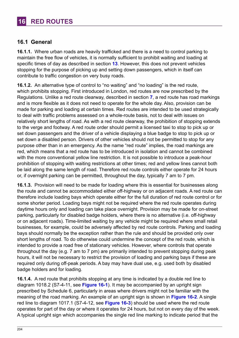
204
16 RED ROUTES
16.1 General16.1.1. Where urban roads are heavily trafficked and there is a need to control parking to maintain the free flow of vehicles, it is normally sufficient to prohibit waiting and loading at specific times of day as described in section 13. However, this does not prevent vehicles stopping for the purpose of picking up and setting down passengers, which in itself can contribute to traffic congestion on very busy roads.
16.1.2. An alternative type of control to “no waiting” and “no loading” is the red route, which prohibits stopping. First introduced in London, red routes are now prescribed by the Regulations. Unlike a red route clearway, described in section 7, a red route has road markings and is more flexible as it does not need to operate for the whole day. Also, provision can be made for parking and loading at certain times. Red routes are intended to be used strategically to deal with traffic problems assessed on a whole‑route basis, not to deal with issues on relatively short lengths of road. As with a red route clearway, the prohibition of stopping extends to the verge and footway. A red route order should permit a licensed taxi to stop to pick up or set down passengers and the driver of a vehicle displaying a blue badge to stop to pick up or set down a disabled person. Drivers of other vehicles should not be permitted to stop for any purpose other than in an emergency. As the name “red route” implies, the road markings are red, which means that a red route has to be introduced in isolation and cannot be combined with the more conventional yellow line restriction. It is not possible to introduce a peak‑hour prohibition of stopping with waiting restrictions at other times; red and yellow lines cannot both be laid along the same length of road. Therefore red route controls either operate for 24 hours or, if overnight parking can be permitted, throughout the day, typically 7 am to 7 pm.
16.1.3. Provision will need to be made for loading where this is essential for businesses along the route and cannot be accommodated either off‑highway or on adjacent roads. A red route can therefore include loading bays which operate either for the full duration of red route control or for some shorter period. Loading bays might not be required where the red route operates during daytime hours only and loading can take place overnight. Provision may be made for on‑street parking, particularly for disabled badge holders, where there is no alternative (i.e. off‑highway or on adjacent roads). Time‑limited waiting by any vehicle might be required where small retail businesses, for example, could be adversely affected by red route controls. Parking and loading bays should normally be the exception rather than the rule and should be provided only over short lengths of road. To do otherwise could undermine the concept of the red route, which is intended to provide a road free of stationary vehicles. However, where controls that operate throughout the day (e.g. 7 am to 7 pm) are primarily intended to prevent stopping during peak hours, it will not be necessary to restrict the provision of loading and parking bays if these are required only during off‑peak periods. A bay may have dual use, e.g. used both by disabled badge holders and for loading.
16.1.4. A red route that prohibits stopping at any time is indicated by a double red line to diagram 1018.2 (S7‑4‑11, see Figure 16‑1). It may be accompanied by an upright sign prescribed by Schedule 6, particularly in areas where drivers might not be familiar with the meaning of the road marking. An example of an upright sign is shown in Figure 16‑2. A single red line to diagram 1017.1 (S7‑4‑12, see Figure 16‑3) should be used where the red route operates for part of the day or where it operates for 24 hours, but not on every day of the week. A typical upright sign which accompanies the single red line marking to indicate period that the
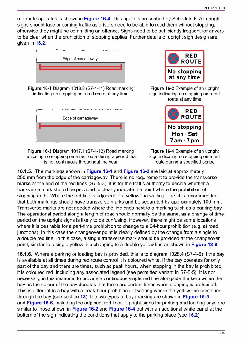
205
RED ROUTES
red route operates is shown in Figure 16‑4. This again is prescribed by Schedule 6. All upright signs should face oncoming traffic as drivers need to be able to read them without stopping, otherwise they might be committing an offence. Signs need to be sufficiently frequent for drivers to be clear when the prohibition of stopping applies. Further details of upright sign design are given in 16.2.
Edge of carriageway
Figure 16‑1 Diagram 1018.2 (S7‑4‑11) Road marking Figure 16‑2 Example of an upright indicating no stopping on a red route at any time sign indicating no stopping on a red route at any time
Edge of carriageway
Figure 16‑3 Diagram 1017.1 (S7‑4‑12) Road marking Figure 16‑4 Example of an upright indicating no stopping on a red route during a period that sign indicating no stopping on a red is not continuous throughout the year route during a specified period
16.1.5. The markings shown in Figure 16‑1 and Figure 16‑3 are laid at approximately 250 mm from the edge of the carriageway. There is no requirement to provide the transverse marks at the end of the red lines (S7‑5‑3); it is for the traffic authority to decide whether a transverse mark should be provided to clearly indicate the point where the prohibition of stopping ends. Where the red line is adjacent to a yellow “no waiting” line, it is recommended that both markings should have transverse marks and be separated by approximately 100 mm. Transverse marks are not needed where the line ends next to a marking such as a parking bay. The operational period along a length of road should normally be the same, as a change of time period on the upright signs is likely to be confusing. However, there might be some locations where it is desirable for a part‑time prohibition to change to a 24‑hour prohibition (e.g. at road junctions). In this case the changeover point is clearly defined by the change from a single to a double red line. In this case, a single transverse mark should be provided at the changeover point, similar to a single yellow line changing to a double yellow line as shown in Figure 13‑8.
16.1.6. Where a parking or loading bay is provided, this is to diagram 1028.4 (S7‑4‑6) If the bay is available at all times during red route control it is coloured white. If the bay operates for only part of the day and there are times, such as peak hours, when stopping in the bay is prohibited, it is coloured red, including any associated legend (see permitted variant in S7‑5‑5). It is not necessary, in this instance, to provide a continuous single red line alongside the kerb within the bay as the colour of the bay denotes that there are certain times when stopping is prohibited. This is different to a bay with a peak‑hour prohibition of waiting where the yellow line continues through the bay (see section 13).The two types of bay marking are shown in Figure 16‑5 and Figure 16‑6, including the adjacent red lines. Upright signs for parking and loading bays are similar to those shown in Figure 16‑2 and Figure 16‑4 but with an additional white panel at the bottom of the sign indicating the conditions that apply to the parking place (see 16.2).
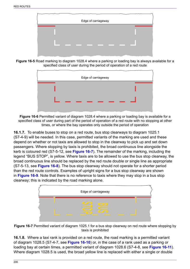
206
RED ROUTES
Edge of carriageway
Figure 16‑5 Road marking to diagram 1028.4 where a parking or loading bay is always available for a specified class of user during the period of operation of a red route
Edge of carriageway
Figure 16‑6 Permitted variant of diagram 1028.4 where a parking or loading bay is available for a specified class of user during part of the period of operation of a red route with no stopping at other
times, or where the bay operates only outside the period of operation
16.1.7. To enable buses to stop on a red route, bus stop clearways to diagram 1025.1 (S7‑4‑9) will be needed. In this case, permitted variants of the marking are used and these depend on whether or not taxis are allowed to stop in the clearway to pick up and set down passengers. Where stopping by taxis is prohibited, the broad continuous line alongside the kerb is coloured red (S7‑5‑12, see Figure 16‑7). The remainder of the marking, including the legend “BUS STOP”, is yellow. Where taxis are to be allowed to use the bus stop clearway, the broad continuous line should be replaced by the red route double or single line as appropriate (S7‑5‑13, see Figure 16‑8). The bus stop clearway should not operate for a shorter period than the red route controls. Examples of upright signs for a bus stop clearway are shown in Figure 16‑9. Note that there is no reference to taxis where they may stop in a bus stop clearway; this is indicated by the road marking alone.
Edge of carriageway
Figure 16‑7 Permitted variant of diagram 1025.1 for a bus stop clearway on red route where stopping by taxis is prohibited
16.1.8. Where a taxi rank is provided on a red route, the road marking is a permitted variant of diagram 1028.5 (S7‑4‑7, see Figure 16‑10) or, in the case of a rank used as a parking or loading bay at certain times, a permitted variant of diagram 1028.6 (S7‑4‑8, see Figure 16‑11). Where diagram 1028.5 is used, the broad yellow line is replaced with either a single or double

207
RED ROUTES
red line as appropriate. This also applies to diagram 1028.6, except that the white boundary lines are replaced by red lines, but only where parking or loading by vehicles other than taxis is not allowed to take place during any part of the operational period of the red route. An example of where the white lines would be retained is where both the red route and parking bay operate from 7 am to 7 pm and the taxi rank operates from 7 pm to 7 am.
Edge of carriageway
Figure 16‑8 Permitted variant of diagram 1025.1 for a bus stop clearway on red route where taxis may stop to pick up and set down passengers
Figure 16‑9 Examples of upright signs for bus stop clearways
Edge of carriageway
Figure 16‑10 Permitted variant of diagram 1028.5 for a taxi rank on red route
Edge of carriageway
Figure 16‑11 Permitted variant of diagram 1025.6 for a shared use taxi rank and parking or loading bay on red route
16.1.9. Paragraph 16.1.8 applies also where diagrams 1028.5 and 1028.6 used to indicate a parking place for ambulances or police vehicles. In the case of diagram 1028.5, the legend

208
RED ROUTES
“TAXIS” is varied to “AMBULANCES” or “POLICE” as appropriate. Figure 16‑12 shows examples of signs indicating taxi ranks and parking places for ambulances or police vehicles.
Figure 16‑12 Examples of upright signs for taxi ranks and parking places
16.2 Design, siting and size of upright signs for red routes16.2.1. The basic upright sign for red routes, before any detailed information is added, is prescribed by S6‑1. This comprises three panels and is shown in Figure 16‑13. The legends shown on this sign must always be used, but S6‑1‑3 permits “RED ROUTE” in the top panel to be on a single line. The bottom panel is used only to indicate details of any parking place (including loading bays) that may be provided on the red route; otherwise this panel is omitted.
Figure 16‑13 Basic upright sign for red routes before detailed information is added
16.2.2. The middle panel is completed by adding the following legends:
a) A time period as prescribed by S18‑1. This may include days of the week, but if so there cannot be any waiting restrictions on other days. The legend “at any time” is used for a red route that operates continuous throughout the year (see Figure 16‑2). In this case an upright sign is not essential where drivers are familiar with the meaning of the double red line.
b) “except” followed by–i) “buses” or “local buses”;ii) “in signed bays” or “in signed bay”; oriii) one or more of “taxis”, “ambulances”, and “police vehicles”, and where more than one
of those exceptions is provided for “and” or “&” must precede the final exception.c) “BUS STAND” if displayed above “No stopping” and in combination with “except buses” or
“except local buses”.
Where legends (i) or (ii) under (b) above are used, the bottom panel is not used. A sign with the legend “except in sign bays” or “except in signed bay”, as shown in Figure 16‑14, should be used remotely from the parking place to indicate to drivers that there are locations along the red route where they will be permitted to stop. As there is no indication of the type of parking place, this legend should be used only where there is at least one bay where any type of vehicle
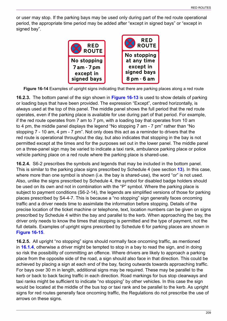
209
RED ROUTES
or user may stop. If the parking bays may be used only during part of the red route operational period, the appropriate time period may be added after “except in signed bays” or “except in signed bay”.
Figure 16‑14 Examples of upright signs indicating that there are parking places along a red route
16.2.3. The bottom panel of the sign shown in Figure 16‑13 is used to show details of parking or loading bays that have been provided. The expression “Except”, centred horizontally, is always used at the top of this panel. The middle panel shows the full period that the red route operates, even if the parking place is available for use during part of that period. For example, if the red route operates from 7 am to 7 pm, with a loading bay that operates from 10 am to 4 pm, the middle panel displays the legend “No stopping 7 am ‑ 7 pm” rather than “No stopping 7 ‑ 10 am, 4 pm ‑ 7 pm”. Not only does this act as a reminder to drivers that the red route is operational throughout the day, but also indicates that stopping in the bay is not permitted except at the times and for the purposes set out in the lower panel. The middle panel on a three‑panel sign may be varied to indicate a taxi rank, ambulance parking place or police vehicle parking place on a red route where the parking place is shared‑use.
16.2.4. S6‑2 prescribes the symbols and legends that may be included in the bottom panel. This is similar to the parking place signs prescribed by Schedule 4 (see section 13). In this case, where more than one symbol is shown (i.e. the bay is shared‑use), the word “or” is not used. Also, unlike the signs prescribed by Schedule 4, the symbol for disabled badge holders should be used on its own and not in combination with the “P” symbol. Where the parking place is subject to payment conditions (S6‑2‑14), the legends are simplified versions of those for parking places prescribed by S4‑4‑7. This is because a “no stopping” sign generally faces oncoming traffic and a driver needs time to assimilate the information before stopping. Details of the precise location of the ticket machine or telephone, text, location numbers can be given on signs prescribed by Schedule 4 within the bay and parallel to the kerb. When approaching the bay, the driver only needs to know the times that stopping is permitted and the type of payment, not the full details. Examples of upright signs prescribed by Schedule 6 for parking places are shown in Figure 16‑15.
16.2.5. All upright “no stopping” signs should normally face oncoming traffic, as mentioned in 16.1.4, otherwise a driver might be tempted to stop in a bay to read the sign, and in doing so risk the possibility of committing an offence. Where drivers are likely to approach a parking place from the opposite side of the road, a sign should also face in that direction. This could be achieved by placing a sign at each end of the bay, facing outwards towards approaching traffic. For bays over 30 m in length, additional signs may be required. These may be parallel to the kerb or back to back facing traffic in each direction. Road markings for bus stop clearways and taxi ranks might be sufficient to indicate “no stopping” by other vehicles. In this case the sign would be located at the middle of the bus top or taxi rank and be parallel to the kerb. As upright signs for red routes generally face oncoming traffic, the Regulations do not prescribe the use of arrows on these signs.

210
RED ROUTES
Figure 16‑15 Examples of upright signs indicating a parking place on a red route
16.2.6. As it is an offence to stop on a red route, the smallest prescribed x‑height is 30 mm (see Figure 16‑13). Drivers need to be able to assimilate the information on the sign in good time and without stopping. The largest x‑height of 40 mm, is likely to be appropriate on roads where traffic speeds are high (e.g. on a road with a 40 mph speed limit) or where signs need to be more conspicuous (e.g. on a busy high street where there are distractions). The minimum x‑height for signs on red route clearways is 50 mm (see 7.4).

211
APPENDIX A SIZES OF SIGNS
Table A‑1 Sign dimensions (in mm)
Diagram number
(TSRGD ref)
Dimension 85th percentile speed of private cars (mph)1
Up to 20 21 to 30 31 to 40 41 to 50 51 to 60 Over 60
Extent of restriction (S18‑3)
x‑height ‑ 62.5 62.5 (75) 75 (100) 100 (125) 125 (150)
601.1 (S9‑2‑1) See Table 2‑2
602 (S9‑2‑2) See Table 3‑1
606 (S3‑2‑1, S14‑2‑42)5
Diameter 450 (450) 600 (600) 750 (750) 900 (900) 1200 1200 (1500)
607 (S3‑3‑1) x‑height 50 (50) 62.5 (62.5) 75 (75) 100 (100) 125 125
608 (S3‑3‑3, S9‑2‑3)
x‑height 50 (50) 62.5 (62.5) 75 (75) 100 (100) 125 125
609 (S3‑2‑2) Diameter 450 (450) 600 (600) 750 (750) 900 (900) 1200 1200
610 (S3‑2‑3, S13‑6‑11)6
Diameter 450 (450) 600 (600) 750 (750) 900 (900) 1200 1200 (1500)
611 (S11‑2‑73)6 Diameter 450 (450) 600 (600) 750 (750) 900 (900) 1200 1200
611.1 (S9‑2‑6)7 Diameter 600 600 (750) 750 (900) ‑ ‑ ‑
612 (S3‑2‑7, S14‑2‑43)5
Diameter 450 (450) 600 (600) 750 (750) 900 (900) 1200 1200
613 (S3‑2‑8, S14‑2‑43)5
Diameter 450 (450) 600 (600) 750 (750) 900 (900) 1200 1200
614 (S3‑2‑6, S14‑2‑43)5
Diameter 450 600 600 (750) 750 (900) 900 (1200) 1200
615 (S3‑2‑9) Diameter 600 750 (750) 900 (900) 1200 1200 ‑
615.1 (S3‑3‑9, S3‑3‑10)
x‑height 62.5 75 (75) 100 (100) 125 125 ‑
616 (S3‑2‑10, S14‑2‑44)5, 11
Diameter (450) 600 (600) 750 750 (750) 900 (900) 1200 1200
617 (S3‑2‑11) Diameter 450 (450) 600 (600) 750 (750) 900 (900) 1200 1200
618 (S3‑3‑12, S3‑3‑13)
x‑height (37.5) 50 (50) 62.5 ‑ ‑ ‑ ‑
618.1 (S3‑3‑14) x‑height (37.5) 50 (50) 62.5 (62.5) 75 (75) 100 100 ‑
618.3B (S8‑2‑2) One size only
618.3C (S8‑2‑2) One size only
618.4A/B (S8‑2‑3/4)
One size only
619 (S3‑2‑12)12 Diameter 450 (450) 600 (600) 750 (750) 900 (900) 1200 1200
619.1 (S3‑2‑18) Diameter 450 (450) 600 (600) 750 (750) 900 (900) 1200 1200
619.2 (S3‑2‑20) Diameter 450 (450) 600 (600) 750 (750) 900 (900) 1200 1200
620 (S3‑3‑15)13 x‑height (37.5) 50 (50) 62.5 (62.5) 75 (75) 100 (100) 125 125

212
APPENDIX
Diagram number
(TSRGD ref)
Dimension 85th percentile speed of private cars (mph)1
Up to 20 21 to 30 31 to 40 41 to 50 51 to 60 Over 60
620.1 (S3‑3‑15) x‑height (37.5) 50 (50) 62.5 (62.5) 75 (75) 100 (100) 125 125
622.1A (S3‑2‑15) Diameter 450 (450) 600 (600) 750 (750) 900 (900) 1200 1200 (1500)
622.2 (S3‑2‑14) Diameter 450 (450) 600 600 750 (750) 900 900
622.4 (S3‑2‑15) Diameter 600 600 (600) 750 (750) 900 900 ‑
622.5 (S3‑2‑23) The size of this sign is not related to traffic speed8
622.6 (S3‑2‑24) The size of this sign is not related to traffic speed8
622.7 (S3‑2‑19) Diameter 450 (450) 600 (600) 750 (750) 900 (900) 1200 ‑
622.8 (S3‑2‑16) Diameter 450 600 750 900 1200 1200
Plate for 622.8 (S3‑3‑16)
x‑height (37.5) 50 62.5 75 100 125 125
622.10 (S9‑4‑3) Diameter 600 600 750 900 1200 1200
Code panel height
440 440 550 660 880 880
625.1 (S3‑2‑22) The size of this sign is not related to traffic speed8
626.2A (S9‑4‑2) x‑height 60 (60) 80 (80) 100 (100) 120 120 ‑
627.1 (S9‑4‑2) x‑height 37.5 (37.5) 50 (50) 62.5 (62.5) 75 75 ‑
629A (S3‑2‑26) Diameter 750 750 (750) 900 (900) 1200 1200 ‑
629.1 (S3‑2‑25) Diameter 600 600 (600) 750 (750) 900 900 ‑
629.2A (S3‑2‑27, S2‑4‑5)
Diameter 750 750 900 1200 1500 1500
632 (S3‑2‑5) Diameter ‑ 600 600 (750) 750 (900) 900 (1200) ‑
633 (S13‑6‑17) Diameter 450 (the larger size of 540 can be used at the discretion of the police)
636 (S13‑6‑19) See working drawing P 636
636.1 (S13‑6‑20) See working drawing P 636.1
636.2 (S13‑6‑21) One size only (see working drawing P 636.2)
640.1 (S13‑6‑22) To suit size of parking meter cover and legend used – see working drawing P 640.1
640.5 (S7‑2‑5) One size only (see working drawing P 640.5)
642 (Terminal) (S3‑2‑4)
Diameter 450 600 600 (750) 750 (900) 900 900 (1200)
642 (Repeater) (S3‑2‑4)
Diameter ‑ 300 300 450 450 600
642.2A (S4‑3‑10) One size only (see working drawing P 642.2A)
642.4 (S7‑2‑8) x‑height 50 50 60 60 80 80
642.5 (S7‑2‑9) x‑height 50 50 60 60 80 80
645 (S3‑3‑5, S11‑2‑1, S13‑2‑9)
x‑height 50 62.5 75 (100) 100 (125) 125 (150) 150 (200)
646 (S7‑2‑6) See 7.3.2 and working drawing P 646
647 (S7‑2‑7) See 7.3.2 and working drawing P 647

213
APPENDIX
Diagram number
(TSRGD ref)
Dimension 85th percentile speed of private cars (mph)1
Up to 20 21 to 30 31 to 40 41 to 50 51 to 60 Over 60
651 (S9‑4‑1) See 5.13 and working drawing P 651
652 (S9‑4‑5) Height 450 450 450 675 675 675
663.4 (S7‑2‑10) Diameter One size only (300)
664 (S7‑2‑1) See working drawing P 664
664.3 (S7‑2‑11) x‑height One size only (50)
666 (S7‑2‑2) See working drawing P 666
667 (S7‑2‑12) See working drawing P 667, 13.19 and Table 13‑1
667.1 (S7‑2‑14) See working drawing P 667.1, 13.19 and Table 13‑1
667.2 (S7‑2‑16) See working drawing P 667.2, 13.19 and Table 13‑1
668 (S7‑2‑13) See working drawing 668, 13.19 and Table 13‑1
668.1 (S7‑2‑15) See working drawing 668.1, 13.19 and Table 13‑1
668.2 (S7‑2‑17) See working drawing 668.2, 13.19 and Table 13‑1
670 (S10‑2‑1) See Table 8‑1, Table 8‑2 and Table 8‑4
671 (S10‑2‑2) See Table 8‑1, Table 8‑2 and Table 8‑4
672 (S10‑2‑3) See Table 8‑5
673 (S10‑2‑4) See Table 8‑5
674 (S10‑2‑5) One size only (see working drawing P 674)
675 (S10‑2‑7) One size only (see working drawing P 675)
675A One size only (see 8.7)
675B One size only (see 8.7)
774 (S2‑6‑4) Width 900 900 900 (900) 1200 1200 ‑
778 (S9‑2‑4) Height 420 420 (420) 525 (525) 630 630 ‑
778.1 (S9‑2‑5) Height 300 370 (300) 375 (375) 450 450 ‑
783 (S11‑2‑68)9 x‑height 50 60 75 100 100 ‑
801 (S5‑1‑1, S11‑2‑56)
See 13.7.3 ‑ the size of this sign is not related to traffic speed
810 (S11‑2‑2) The size of this sign is not related to traffic speed8
811A (S2‑11‑2) x‑height 37.5 37.5 (50) 50 (62.5) 62.5 (70) 75 (100)
811B (S2‑11‑2) x‑height 62.5 62.5 (75) 75 (100) 100 (125) 125 (150)
818.4 (S12‑28‑22)9
x‑height 60 75 100 125 150 200 (300)
857.1 (S11‑2‑48) The size of this sign is not related to traffic speed10
877 (S11‑2‑22) See 9.3.13
878 (S11‑2‑63)9 x‑height 50 60 75 100 125 150 (250)
880 (S11‑2‑64) One size only (see 8.10.5)
880.1 (S11‑2‑65) One size only (see 8.10.5)
951 (S3‑2‑21) The size of this sign is not related to traffic speed8
952 (S3‑2‑17)13 Diameter 450 (450) 600 (600) 750 (750) 900 (900) 1200 1200
953 (S3‑2‑33) Diameter (450) 600 (600) 750 750 (750) 900 ‑ ‑

214
APPENDIX
Diagram number
(TSRGD ref)
Dimension 85th percentile speed of private cars (mph)1
Up to 20 21 to 30 31 to 40 41 to 50 51 to 60 Over 60
953A See 9.7.1 and 9.7.5
953B See 9.7.1 and 9.7.5
953.1 (S3‑2‑36, S3‑2‑37)
Diameter As diagram 953, but see 10.2.4
951.1A (S3‑2‑38),
953.1B (S3‑2‑39),
953.1C (S3‑2‑40)
Diameter See 10.2.2, 10.2.4 and Table 10‑1
954.5 (S14‑2‑45) One size only (see Chapter 6)
954.6 (S14‑2‑45) One size only (see Chapter 6)
954.7 (S14‑2‑45) One size only (see Chapter 6)
955 (S3‑2‑28) See 11.11.6
956 (S3‑2‑29) See 11.11.6
956.1 (S3‑2‑30) See 11.11.6
956.2 (S3‑2‑31) See 11.11.6
957 (S3‑2‑32) See 11.11.6
958 (S11‑2‑37) See 9.3.12
958.1 (S11‑2‑38) See 11.3.5
959B (S9‑4‑10) See 9.3.12
959.1 (S9‑4‑9) See 11.3.5
960 (S9‑4‑8) See 9.4.7
960.1(S9‑4‑6) See 11.5.2
962 (S11‑2‑34) See 9.3.18 and 9.4.11
962.1 (S11‑2‑35) See 11.3.8
962.2 (S11‑2‑36) See 9.4.11
963 (S11‑2‑40) See 9.5.4
963.1 (S11‑2‑41) See 11.7.1
963.2 (S11‑2‑42) See 9.5.4
963.3 (S11‑2‑43) See 10.3.2
964 (S9‑4‑11) See 9.3.12
965 (S11‑2‑45) See 11.11.8
966 (S11‑2‑46) See 11.11.9
967 (S11‑2‑44) See 11.4.4
968 (S11‑2‑47) One size only
968.1 (S11‑2‑47) One size only
976 (S11‑2‑84) Seek advice from the Office of Rail and Road
2010.1 (S12‑28‑5)
See Chapter 7 Appendix E
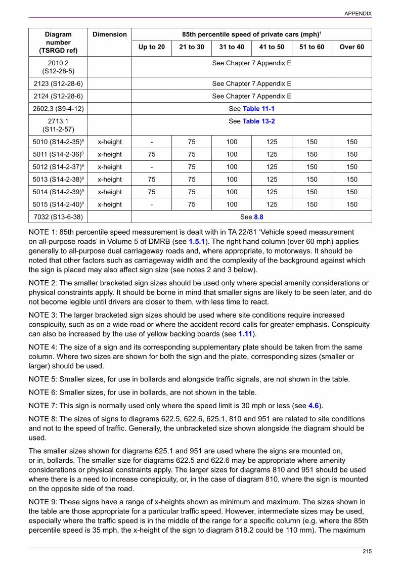
215
APPENDIX
Diagram number
(TSRGD ref)
Dimension 85th percentile speed of private cars (mph)1
Up to 20 21 to 30 31 to 40 41 to 50 51 to 60 Over 60
2010.2 (S12‑28‑5)
See Chapter 7 Appendix E
2123 (S12‑28‑6) See Chapter 7 Appendix E
2124 (S12‑28‑6) See Chapter 7 Appendix E
2602.3 (S9‑4‑12) See Table 11‑1
2713.1 (S11‑2‑57)
See Table 13‑2
5010 (S14‑2‑35)9 x‑height ‑ 75 100 125 150 150
5011 (S14‑2‑36)9 x‑height 75 75 100 125 150 150
5012 (S14‑2‑37)9 x‑height ‑ 75 100 125 150 150
5013 (S14‑2‑38)9 x‑height 75 75 100 125 150 150
5014 (S14‑2‑39)9 x‑height 75 75 100 125 150 150
5015 (S14‑2‑40)9 x‑height ‑ 75 100 125 150 150
7032 (S13‑6‑38) See 8.8
NOTE 1: 85th percentile speed measurement is dealt with in TA 22/81 ‘Vehicle speed measurement on all‑purpose roads’ in Volume 5 of DMRB (see 1.5.1). The right hand column (over 60 mph) applies generally to all‑purpose dual carriageway roads and, where appropriate, to motorways. It should be noted that other factors such as carriageway width and the complexity of the background against which the sign is placed may also affect sign size (see notes 2 and 3 below).
NOTE 2: The smaller bracketed sign sizes should be used only where special amenity considerations or physical constraints apply. It should be borne in mind that smaller signs are likely to be seen later, and do not become legible until drivers are closer to them, with less time to react.
NOTE 3: The larger bracketed sign sizes should be used where site conditions require increased conspicuity, such as on a wide road or where the accident record calls for greater emphasis. Conspicuity can also be increased by the use of yellow backing boards (see 1.11).
NOTE 4: The size of a sign and its corresponding supplementary plate should be taken from the same column. Where two sizes are shown for both the sign and the plate, corresponding sizes (smaller or larger) should be used.
NOTE 5: Smaller sizes, for use in bollards and alongside traffic signals, are not shown in the table.
NOTE 6: Smaller sizes, for use in bollards, are not shown in the table.
NOTE 7: This sign is normally used only where the speed limit is 30 mph or less (see 4.6).
NOTE 8: The sizes of signs to diagrams 622.5, 622.6, 625.1, 810 and 951 are related to site conditions and not to the speed of traffic. Generally, the unbracketed size shown alongside the diagram should be used.
The smaller sizes shown for diagrams 625.1 and 951 are used where the signs are mounted on, or in, bollards. The smaller size for diagrams 622.5 and 622.6 may be appropriate where amenity considerations or physical constraints apply. The larger sizes for diagrams 810 and 951 should be used where there is a need to increase conspicuity, or, in the case of diagram 810, where the sign is mounted on the opposite side of the road.
NOTE 9: These signs have a range of x‑heights shown as minimum and maximum. The sizes shown in the table are those appropriate for a particular traffic speed. However, intermediate sizes may be used, especially where the traffic speed is in the middle of the range for a specific column (e.g. where the 85th percentile speed is 35 mph, the x‑height of the sign to diagram 818.2 could be 110 mm). The maximum

216
APPENDIX
x‑height of 250 mm for the sign to diagram 878 is not shown as this size is unlikely to be used, but might be considered for motorways with four or more lanes.
NOTE 10: The smallest size (20 mm x‑height) is likely to be appropriate when the sign faces the footway (see 13.23.12).
NOTE 11: Where the “no entry” sign to diagram 616 is used with a supplementary plate, see para 9.4.7. Where the “no entry” sign is used in connection with a contraflow cycle lane, see 11.5.3 and 11.5.4.
NOTE 12: Where the sign to diagram 619 is used in connection with an advisory contraflow cycle lane, see 11.6.4.
NOTE 13: Where an “Except local buses” supplementary plate is required with a 1200 mm diameter sign to diagram 952, this should have an x‑height of 125 mm.
NOTE 14: The table below shows the appropriate x‑height of “Except cycles” plate when used with the “no through road” sign to diagram 816.
Table A‑2 x‑height of “Except cycles” for diagram 816
Height of diagram 816 (mm) x‑height of plate (mm)
400 37.5
480 50
560 62.5
217
APPENDIX B NORTHERN IRELAND VARIATIONS
BackgroundThe Traffic Signs Regulations and General Directions 2016 apply to England, Wales and Scotland. In Northern Ireland, the equivalent legislation is the Traffic Signs Regulations (Northern Ireland) 1997 (“NI Regulations”) and subsequent amendments. In Northern Ireland, references to “Directions” are not applicable (see 1.4.3); where these are referred to, advice should be sought from the Department for Infrastructure’s headquarters in Belfast.
BusesIn Northern Ireland the term “local bus” is not defined and should therefore not be used. The term “buses” may be varied to “permitted buses”.
Seasonal waiting restrictionsIn Northern Ireland, any 24/7 waiting restriction that applies for only part of the year would be marked with diagram 1018.1 double yellow lines.
On‑street parkingIn Northern Ireland, dimensions are still prescribed for bay markings to diagrams 1028.3, 1028.4, 1032 and 1033. There is no option in the NI Regulations to mark them with a distinctive surfacing material as an alternative to normal painted markings.
Clearway and no stopping signsIn Northern Ireland, where diagram 1025 (NI Regulations only) is used to delineate the limits of a bus stop, an accompanying vertical sign is not required to prohibit waiting. Further details can be found in 13.24.1.
IlluminationDifferent illumination requirements apply in Northern Ireland. Schedule 17 of the NI Regulations should be referred to.
TaxisIn Northern Ireland, the term “permitted taxi” is prescribed for use on traffic signs for bus lanes as an alternative to the more general term “taxi”. Advice on the meaning of “permitted taxi” can be obtained from the Department for Infrastructure’s headquarters.
Legislative variationsTable B‑1 indicates differences in regulation numbers between the two sets of Regulations where these are relevant to this chapter of the Manual. The notes below the table indicate other differences of legislation or practice between Northern Ireland and the rest of the UK.
Directional signsReference is made in this chapter to the use of directional signs to give advance indication of restrictions and to show alternative routes. Although such signs are not yet prescribed in the NI regulations, they may be used in Northern Ireland. Further advice should be sought from the Department for Infrastructure’s headquarters.

218
APPENDIX
Table B‑1 Northern Ireland legislation references
TSM3 ref1 Subject of regulation referred to in paragraph TSRGD 2016 ref2
NI Regulations ref
1.2.6, 2.1.2, 3.1.3, 4.6.1
Signs subject to s 36 of the Road Traffic Act 1988 S2, 3, 7, 9, 13, 14 & 15
8
8.15, 8.15.5 Reflectorisation of traffic signs R8 & other schedules
17
2.1.8 Significance of a STOP sign S9‑7 14
3.3.2 Significance of a GIVE WAY sign S9‑7 14
5.4.1 Definition of “local bus” S1 Not used
5.5.1 Definition of “articulated vehicle” S1 2
13.9.4 Style of lettering other than Transport alphabet not permitted R5 11(4)
13.24.1 Significance of a bus stop clearway marking S7‑6‑1 & 4 None3
6.2.5 Definition of “variable message sign” S16 & other schedules
48(1)
14.1.1 Definition of “controlled parking zone” S1 2
8.1.2 Definition of “speed limit” S1 3
8.1.2 Definition of “national speed limit” S1 3(2)
8.1.2 Definition of “maximum speed limit” S1 3(1)
8.1.2 Definition of “minimum speed limit” S1 3(1)
8.15 Illumination of signs R8 & individual schedules
16
5.4.1 Definition of “local bus service” S1 Not applicable
10.2.12 Tramcars exempt from the sign to diagram 610 S3‑4‑3 13(3)
NOTES
1. Paragraph numbers refer to this edition of Chapter 3 of the Traffic Signs Manual.
2. “R” and “S” denote regulations and schedules respectively in TSRGD.
3. See the Roads (Restriction of Waiting) Order (Northern Ireland) 1982.
NOTES ON PARAGRAPHS
1.1.1 In Northern Ireland, there is no direct equivalent to section 122 of the Road Traffic Regulation Act 1984 or Part 2 of the Traffic Management Act 2004, as these relate to the duties of local authorities.
1.2.1 In Northern Ireland, “section 142 of the Road Traffic Regulation Act 1984 as amended by the New Roads and Street Works Act 1991” should be replaced with “article 2(2) of the Road Traffic Regulation (Northern Ireland) Order 1997”.
1.2.6, 2.1.2, 3.1.3, 4.6.1 In Northern Ireland, “section 36 of the Road Traffic Act 1988” should be replaced with “article 50 of the Road Traffic (Northern Ireland) Order 1995”.
2.1.1, 8.13.1, 10.1.1 In Northern Ireland, advice on the use of these signs with railways and tramways should be sought from the Department for Infrastructure’s Headquarters in Belfast and from Northern Ireland Railways.
2.2.1 In Northern Ireland, “section 79 of the Highways Act 1980” should be replaced with “articles 49 and 50 of the Roads (Northern Ireland) Order 1993”.
5.4.1 In Northern Ireland, there is no equivalent to the Transport Act 1985.
13.26.1 In Northern Ireland, there is no equivalent to section 61 of the Road Traffic Regulation Act 1984.
219
APPENDIX
8.1.1, 8.6.2 In Northern Ireland, “section 85 of the Road Traffic Regulation Act 1984” should be replaced with “articles 41 and 43 of the Road Traffic Regulation (Northern Ireland) Order 1997”.
8.1.2 In Northern Ireland, there is no equivalent to section 14 of the Road Traffic Regulation Act 1984 or Schedule 9 to the Act as amended by the Road Traffic Regulation Act (Amendment) Order 1999. In Northern Ireland, 20 mph speed limits are made under article 38 of the Road Traffic Regulation (Northern Ireland) Order 1997.
8.1.2 In Northern Ireland, “sections 81 and 82 of the Road Traffic Regulation Act 1984” should be replaced with “articles 36(1) and 37 of the Road Traffic Regulation (Northern Ireland) Order 1997”.
8.3.1 In Northern Ireland, “Section 82 of the Road Traffic Regulation Act 1984” should be replaced with “Article 37 of the Road Traffic Regulation (Northern Ireland) Order 1997”, and “Section 81” with “Article 36(1)”.
8.7.1 In Northern Ireland, “section 90A of the Highways Act 1980 (“the 1980 Act”)” should be replaced with “article 65 of the Roads (Northern Ireland) Order 1993 (“the 1993 Order”)”.
8.7.1 In Northern Ireland, “Highways (Road Humps) Regulations 1999” should be replaced with “Road Humps Regulations (Northern Ireland) 1999”.
8.7.1 In Northern Ireland, “section 90G of the 1980 Act” should be replaced with “article 65 of the 1993 Order”.
8.7.1 In Northern Ireland, “Highways (Traffic Calming) Regulations 1999” should be replaced with “Traffic Calming Regulations (Northern Ireland) 1995”.
8.7.1 In Northern Ireland, there is no direct equivalent to section 68 of the Highways Act 1980. However, for construction of new roads it may be interpreted as referring to article 3 of the Roads (Northern Ireland) Order 1993 and on existing roads to article 43 of the Roads (Northern Ireland) Order 1993.
8.7.1 In Northern Ireland, “section 75 of the 1980 Act” should be replaced with “article 43 of the 1993 Order”.
13.6.2 and 13.6.3 In Northern Ireland, markings of bays shall be in accordance with Schedule 6 of the Traffic Signs Regulations (Northern Ireland) 1997.
The following table lists the main instances where diagram numbers in the NI Regulations differ from those in TSRGD 2016, or where there is no longer a TSRGD diagram number. The page numbers refer to this edition of Chapter 3 of the Traffic Signs Manual. The position with equivalent diagram numbers may change over time, and designers in Northern Ireland should contact the Department for Infrastructure’s headquarters to ascertain the current position.

220
APPENDIX
Table B‑2 Northern Ireland diagram number variations
Page number
Description TSRGD 2016 ref
TSRGD 2016 diagram no.
NI Regulations diagram no.
32 Route avoiding prohibited turn S12‑28‑6 2010.1, 2010.2, 2123 and 2124
None1
20 Indication of restriction ahead S12‑28‑22 818.2 669
21 “Except local buses” plate S3‑3‑3, S3‑3‑11, S3‑3‑15
Not used
22 Circular exception plates S14‑2‑45 954.5, 954.6, 954.7
None
46 Lorry route advance direction sign S12‑2‑7A None1
46 Advance direction sign indicating a restriction S12‑2‑2A None1
31 Mandatory height limit ahead / alternative route
S12‑28‑22 818.4 None
32 Play street (supplementary plate) S3‑3‑12 None
37 No explosives (supplementary plate) S3‑3‑16 622.9 Plate not used
39 Weak bridge S9‑4‑2 626.2A 626.2
60–66 Entrance signs for pedestrian zones S8‑2 618.3, 618.3A
121 New 30 mph speed limit in force S13‑6‑38 7032 None
126 Speed camera and reminder of national limit S11‑2‑65 880.1 None
138 Number of national or regional cycle route S9‑4‑12 2602.3 None1
146–201 Signs for on‑street parking control S4 Various2
202–212 Entrance signs for parking zones S5 663, 663.5, 665
NOTES
1. Directional signs in Northern Ireland are covered by a Department for Infrastructure policy document.
2. Yellow plates for waiting and stopping restrictions in S4‑3 are covered by NI Regulations diagrams 637.1 to 637.3, 639 to 640.4, 642.2 to 642.3 and 650.1 to 650.2. Plates for loading restrictions and permitted parking or loading in S4‑4 are covered by NI Regulations diagrams 638, 638.1 and 660 to 662. NI Regulations diagrams 637.2, 639.1A and 640 are equivalent to signs constructed using both parts 3 and 4 of TSRGD 2016 Schedule 4.
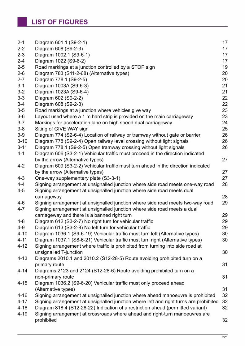
221
LIST OF FIGURES
2‑1 Diagram 601.1 (S9‑2‑1) 172‑2 Diagram 608 (S9‑2‑3) 172‑3 Diagram 1002.1 (S9‑6‑1) 172‑4 Diagram 1022 (S9‑6‑2) 172‑5 Road markings at a junction controlled by a STOP sign 192‑6 Diagram 783 (S11‑2‑68) (Alternative types) 202‑7 Diagram 778.1 (S9‑2‑5) 203‑1 Diagram 1003A (S9‑6‑3) 213‑2 Diagram 1023A (S9‑6‑4) 213‑3 Diagram 602 (S9‑2‑2) 223‑4 Diagram 608 (S9‑2‑3) 223‑5 Road markings at a junction where vehicles give way 233‑6 Layout used where a 1 m hard strip is provided on the main carriageway 233‑7 Markings for acceleration lane on high speed dual carriageway 243‑8 Siting of GIVE WAY sign 253‑9 Diagram 774 (S2‑6‑4) Location of railway or tramway without gate or barrier 263‑10 Diagram 778 (S9‑2‑4) Open railway level crossing without light signals 263‑11 Diagram 778.1 (S9‑2‑5) Open tramway crossing without light signals 264‑1 Diagram 606 (S3‑2‑1) Vehicular traffic must proceed in the direction indicated
by the arrow (Alternative types) 274‑2 Diagram 609 (S3‑2‑2) Vehicular traffic must turn ahead in the direction indicated
by the arrow (Alternative types) 274‑3 One‑way supplementary plate (S3‑3‑1) 274‑4 Signing arrangement at unsignalled junction where side road meets one‑way road 284‑5 Signing arrangement at unsignalled junction where side road meets dual
carriageway 284‑6 Signing arrangement at unsignalled junction where side road meets two‑way road 294‑7 Signing arrangement at unsignalled junction where side road meets a dual
carriageway and there is a banned right turn 294‑8 Diagram 612 (S3‑2‑7) No right turn for vehicular traffic 294‑9 Diagram 613 (S3‑2‑8) No left turn for vehicular traffic 294‑10 Diagram 1036.1 (S9‑6‑19) Vehicular traffic must turn left (Alternative types) 304‑11 Diagram 1037.1 (S8‑6‑21) Vehicular traffic must turn right (Alternative types) 304‑12 Signing arrangement where traffic is prohibited from turning into side road at
unsignalled T‑junction 304‑13 Diagrams 2010.1 and 2010.2 (S12‑28‑5) Route avoiding prohibited turn on a
primary route 314‑14 Diagrams 2123 and 2124 (S12‑28‑6) Route avoiding prohibited turn on a
non‑primary route 314‑15 Diagram 1036.2 (S9‑6‑20) Vehicular traffic must only proceed ahead
(Alternative types) 314‑16 Signing arrangement at unsignalled junction where ahead manoeuvre is prohibited 324‑17 Signing arrangement at unsignalled junction where left and right turns are prohibited 324‑18 Diagram 818.4 (S12‑28‑22) Indication of a restriction ahead (permitted variant) 324‑19 Signing arrangement at crossroads where ahead and right‑turn manoeuvres are
prohibited 32

222
LIST OF FIGURES
4‑20 Signing arrangement at crossroads where ahead manoeuvre is prohibited 10 am ‑ 4 pm and right turn is prohibited 32
4‑21 Example of a sign to diagram 613 with an exception plate 334‑22 Supplementary time plates for banned turn signs 344‑23 Map‑type direction sign incorporating “no right turn” roundel and supplementary
time plate 344‑24 Diagram 611.1 (S9‑2‑6) Mini‑roundabout 354‑25 Diagram 610 (S3‑2‑3) Vehicles must pass on the side indicated (Alternative types) 364‑26 Diagram 611 (S11‑2‑73) Vehicles traffic may reach the same destination by
proceeding either side of the sign 364‑27 Diagram 615 (S3‑2‑9) Priority must be given to vehicles from the opposite
direction (Alternative types) 374‑28 Diagram 811A (S11‑2‑1) Beginning of section of road where traffic has priority
over vehicles from the opposite direction (Alternative types) 384‑29 Diagram 811B (S11‑2‑1) End of section of road where traffic has priority over
vehicles from the opposite direction 384‑30 Diagram 652 (S9‑4‑5) One‑way traffic 394‑31 Diagram 810 (S11‑2‑2) One‑way traffic in direction indicated (Sign for
pedestrians) (Alternative types) 394‑32 Diagram 616 (S3‑2‑10) No entry for vehicular traffic 404‑33 Diagram 1046 (S9‑6‑17) No entry for vehicular traffic (Alternative types) 404‑34 Diagram 614 (S3‑2‑6) No U‑turns for vehicular traffic (Alternative types) 414‑35 Diagram 632 (S3‑2‑5) No overtaking (Alternative types) 435‑1 Example of an advance direction sign indicating a height restriction ahead with
an alternative route to the left (Sign on a primary route) 445‑2 Example of an advance direction sign indicating a route advised for goods vehicles 445‑3 Diagram 818.4 (S12‑28‑22) Nature and location of a prohibition (Alternative types) 455‑4 Alternative methods of indicating a restriction on a road at a junction ahead 455‑5 Diagram 617 (S3‑2‑11) All vehicles prohibited (Alternative types) 465‑6 Diagram 1046.1 (S9‑6‑18) Entry by vehicular traffic to a Play Street restricted
(Alternative types) 465‑7 Examples of diagram 617 plate legends 475‑8 Diagram 619 (S3‑2‑12) Motor vehicles prohibited 485‑9 Diagram 619.1 (S3‑2‑18) Motor vehicles except solo motor cycles prohibited 485‑10 Diagram 619.2 (S3‑2‑20) Solo motor cycles prohibited 485‑11 Examples of plate legends for diagrams 619, 619.1 and 619.2 485‑12 Diagram 952 (S3‑2‑17) Buses prohibited 495‑13 Diagram 622.1A (S3‑2‑13) Prohibition of goods vehicles exceeding the
maximum gross weight indicated 505‑14 Diagram 622.2 (S3‑2‑14) End of prohibition of goods vehicles 505‑15 Diagram 622.4 (S3‑2‑15) Articulated or track laying vehicles prohibited
(Alternative types) 505‑16 Diagram 622.5 (S3‑2‑23) Horse‑drawn vehicles prohibited 515‑17 Diagram 622.6 (S3‑2‑24) Ridden or accompanied horses prohibited 515‑18 Diagram 622.7 (S3‑2‑19) Towed caravans prohibited 515‑19 Diagram 622.8 (S3‑2‑16) Vehicles carrying explosives prohibited (Alternative types) 515‑20 Diagram 622.10 (S9‑4‑3) Vehicles carrying dangerous goods within the tunnel
restriction code indicated by the sign prohibited 525‑21 Diagram 818.4 (permitted variant) (S12‑28‑22) Tunnel restriction ahead for
vehicles carrying dangerous goods with indication of alternative route 52

223
LIST OF FIGURES
5‑22 Diagram 951 (S3‑2‑21) Riding of pedal cycles prohibited 525‑23 Diagram 625.1 (S3‑2‑22) Pedestrians prohibited 535‑24 Diagram 651 (S9‑4‑1) Prohibition of traffic on mown verge 535‑25 Diagram 626.2A (S9‑4‑2) Maximum weight of vehicle on bridge with an
exception for empty vehicles 545‑26 Diagram 629A (S3 2 26) Width restriction in metric and imperial units 555‑27 Diagram 629.1 (S3‑2‑25) Length restriction in imperial and metric units 555‑28 Diagram 629.2A (S3 2 27) Height restriction in metric and imperial units 566‑1 Diagram 618.3B (S8‑2‑1) Entry to, and waiting in, pedestrian zone restricted 586‑2 Diagram 618.3C (S8‑2‑2) Entry to, and waiting in, pedestrian and cycle zone
restricted 586‑3 Examples of different times of operation for a pedestrian zone 586‑4 Diagram 618.4A (S8‑2‑3) End of restrictions associated with a pedestrian zone 606‑5 Diagram 618.4B (S8‑2‑4) End of restrictions associated with a pedestrian and
cycle zone 606‑6 Representations of S4‑3 in respect of a waiting prohibition within a pedestrian
zone and S4‑4 in respect of a prohibition of loading 616‑7 Examples of signs indicating a prohibition of waiting and loading in a pedestrian
zone 616‑8 Examples of pedestrian zone entry sign and associated sign within the zone
(where there are no yellow lines indicating waiting and loading restrictions) 627‑1 Diagram 642 (S3‑2‑4) No stopping on main carriageway (Alternative types) 657‑2 Diagram 646 (S7‑2‑6) No stopping for the periods indicated, except to pick up
or to set down passengers 667‑3 Diagram 647 (S7‑2‑7) End of restriction on stopping 667‑4 Diagram 642.4 (S7‑2‑6) No stopping on red route clearway 677‑5 Diagram 642.5 (S7‑2‑7) End of red route clearway 678‑1 Diagram 670 (S10‑2‑1) Maximum speed limit in miles per hour 698‑2 Diagram 671 (S10‑2‑2) National speed limits apply 698‑3 Examples of siting terminal signs where two signs are used on each approach 708‑4 Road junction where the side road makes an acute angle with the main road
(Signs for drivers entering the side road) 718‑5 Example of a roundabout junction 718‑6 Diagram 676 (S10‑2‑8) Entrance to a zone where a maximum speed limit of
40 mph is in force 768‑7 Example of terminal signs at a road junction where the main road is a dual
carriageway with a speed limit of 60 mph and the side road is a single carriageway subject to the national speed limit of 60 mph 77
8‑8 Speed limit on two‑way link road between a dual carriageway road with a speed limit of 60 mph and a side road with a speed limit of 40 mph 77
8‑9 Diagram 674 (S10‑2‑5) Entrance to a zone where a maximum speed limit of 20 mph is in force 79
8‑10 Diagram 675A (S10‑2‑6) End of 20 mph speed limit zone with indication of maximum speed limit in mph 79
8‑11 Diagram 675B (S10‑2‑7) End of 20 mph speed limit zone with indication that national speed limits apply 79
8‑12 Diagram 7032 (S13‑6‑38) New 30 mph speed limit in force 808‑13 Use of the temporary sign to diagram 7032 to indicate the extension of a
30 mph speed limit on a road with a system of street lighting 818‑14 Diagram 672 (S10‑2‑3) Minimum speed limit in mph 82

224
LIST OF FIGURES
8‑15 Diagram 673 (S10‑2‑4) End of minimum speed limit 828‑16 Diagram 878 (S11‑2‑63) Area in which cameras are used to enforce speed
limits (Alternative types) 838‑17 Diagram 880 (S11‑2‑64) Speed camera ahead on a lit road and reminder of
30 mph speed limit 838‑18 Diagram 880.1 (S11‑2‑65) Speed camera ahead on an unlit road and reminder
that a national speed limit applies 838‑19 Co‑located speed limit sign to diagram 670 and camera reminder sign to
diagram 878 without any legend 848‑20 Diagram 976 (S11‑2‑84) Maximum speed limit for tramcars in kilometres per hour 858‑21 Example of a speed limit sign co‑located with a boundary sign 868‑22 Diagram 1065 (S10‑2‑9) Road marking indicating maximum speed limit
(Alternative sizes) 889‑1 Typical layout for a with‑flow bus lane 919‑2 Diagram 958 (S11‑2‑37) With‑flow bus lane ahead (Alternative types) 929‑3 Diagram 959B (S9‑4‑10) With‑flow bus lane (Alternative types) 929‑4 Diagram 1048 (S9‑6‑14) Traffic lane reserved for buses and other vehicles as
indicated on the sign to diagram 959B 939‑5 Diagram 964 (S9‑4‑11) 939‑6 Diagram 1050 (S9‑6‑12) Indication of traffic movements at end of nearside bus
lane or intermediate junction (Alternative types) 949‑7 Diagram 1050.1 (S9‑6‑13) Indication of traffic movements at end of off‑side bus
lane or intermediate junction (Alternative types) 949‑8 Diagram 877 (S11‑2‑22) Appropriate traffic lanes for manoeuvres at junction
ahead (variant) 949‑9 Diagram 962 (variant) (S11‑2‑34) Bus lane on road at junction ahead with
indication of times of operation (Alternative types) 959‑10 Examples of the use of the sign to diagram 962 to indicate with‑flow bus lanes 969‑11 Diagram 960 (S9‑4‑8) One‑way road with contraflow bus lane (Alternative types) 979‑12 Typical layout for a contraflow bus lane 989‑13 Example of signs indicating contraflow bus lane to other drivers 999‑14 Start of contraflow bus‑only lane indicated by a sign to diagram 953 999‑15 Start of contraflow bus‑only lane indicated by signs to diagram 616 999‑16 Diagram 953 (variant) (S3‑2‑33) Route for use only by buses and, where
indicated, pedal cycles (Alternative types) 1009‑17 Diagram 962.2 (S11‑2‑36) Contraflow bus and cycle lane on road at junction
ahead (Alternative types) 1019‑18 Examples of the use of the signs to diagrams 962 and 962.2 to indicate
contraflow bus lanes 1029‑19 Diagram 963 (S11‑2‑40) Direction in which pedestrians should look for
approaching traffic when crossing a bus lane (Alternative types) 1039‑20 Diagram 963.2 (S11‑2‑42) Direction in which pedestrians should look for
approaching traffic when crossing a contraflow bus and cycle lane (Alternative types) 103
9‑21 Example of the use of pedestrian signs to diagram 963 to indicate a contraflow bus lane 104
9‑22 Diagram 953 (S3‑2‑33) Route for use by buses, pedal cycles and taxis only (Alternative types) 105
9‑23 Diagram 953A (S3‑2‑34) Route for use by buses, pedal cycles and solo motor cycles only (Alternative types) 105

225
LIST OF FIGURES
9‑24 Diagram 953B (S3‑2‑35) Route for use by buses, pedal cycles, solo motor cycles and taxis only (Alternative types) 105
9‑25 One‑way bus gate on a two‑way road 1069‑26 Example of a two‑way bus gate 1079‑27 Diagram 1048.5 (S9‑6‑15) Road or part of road with access permitted only for
buses and other vehicles as indicated on upright signs (Alternative types) 10710‑1 Diagram 616 (S3‑2‑10) No entry except trams 10910‑2 Diagram 953.1 (S3‑2‑36) Route for use by tramcars only 10910‑3 Diagram 953.1 (variant) (S3‑2‑37) Route for use by tramcars and buses only
(Alternative types) 10910‑4 Diagram 953.1A (S3‑2‑38) Route for use by tramcars, buses and pedal cycles
only (Alternative types) 10910‑5 Diagram 953.1B (S3‑2‑39) Route for use by tramcars, buses, pedal cycles and
taxis only (Alternative types) 10910‑6 Diagram 953.1C (S3‑2‑39) Route for use by tramcars, buses, pedal cycles and
solo motor cycles (taxis may also be permitted where shown) (Alternative types) 10910‑7 Diagram 1048.2A (S9‑6‑16) Road or part of road with access permitted only for
tramcars 11010‑8 Example of a one‑way road used by all traffic with a contraflow segregated tramway 11110‑9 Example of a tramway leading from a public highway to an off‑street route
showing appropriate upright signs 11210‑10 Examples of a tramway leading from a public highway to an off‑street route
showing appropriate road marking guidance arrows 11310‑11 Diagram 1014 (S11‑4‑14) Deflection arrow (Longitudinal marking)
(Alternative types) 11410‑12 Diagram 1038 (S11‑4‑20) (Version with single arrow indicating ahead)
(Longitudinal marking) 11410‑13 Diagram 963.3 (S11‑2‑43) Direction in which pedestrians should look for
approaching tramcars when crossing a tramway (Alternative types) 11510‑14 Diagram 1066 (S11‑4‑36) Edge of part of road used by tramcars (Longitudinal
marking) 11611‑1 Diagram 1057 (S11‑4‑28) Road marking indicating a cycle lane, track or route
(Alternative types) 11811‑2 Example of a mandatory with‑flow cycle lane 12011‑3 Diagram 958.1 (S11‑4‑38) Mandatory with‑flow cycle lane ahead (Alternative types) 12111‑4 Diagram 959.1 (S9‑4‑9) Mandatory with‑flow cycle lane (Alternative types) 12111‑5 Diagram 962.1 (S11‑2‑35) Cycle lane on road at junction ahead (Alternative types) 12111‑6 Example of an advisory with‑flow cycle lane 12211‑7 Diagram 967 (S11‑2‑44) Route recommended for pedal cycles on the main
carriageway of a road 12311‑8 Example of signs indicating a mandatory contraflow cycle lane to other drivers
and road markings at end of cycle lane 12411‑9 Diagram 960.1 (S9‑4‑6) One‑way road with a mandatory contraflow cycle lane 12511‑10 Start of a mandatory contraflow cycle lane 12511‑11 Diagram 955 (S3‑2‑28) Route for use by pedal cycles only 12611‑12 Example of the use of the sign to diagram 962.1 to indicate a mandatory
contraflow cycle lane 12711‑13 Example of signs indicating an advisory contraflow cycle lane to other drivers 12811‑14 Diagram 960.2 (S9‑4‑7) Contraflow cycles with or without an advisory lane
marked on the carriageway 128

226
LIST OF FIGURES
11‑15 Start of an advisory contraflow cycle lane without a traffic island 13011‑16 Diagram 963.1 (S11‑2‑41) Direction in which pedestrians should look for
approaching pedal cycles when crossing a cycle lane (Alternative types) 13011‑17 Cycle entry to a false one‑way street 13111‑18 Diagram 956 (S3‑2‑29) Route for use by pedal cycles and pedestrians only 13211‑19 Diagram 956.1 (S3‑2‑30) Route for use by pedal cycles, horses and pedestrians
only 13211‑20 Diagram 956.2 (S3‑2‑31) As diagram 956.1 but permitting horse‑drawn vehicles
also 13211‑21 Diagram 1049.1 (S9‑6‑8) Division of route into that part reserved for pedal
cycles and that part reserved for pedestrians (Longitudinal marking) 13311‑22 Diagram 957 (S3‑2‑38) Route comprising two ways for use by pedal cycles only
and by pedestrians only indicated by diagram 1049B or 1049.1, or by physical means (Alternative types) 133
11‑23 Diagram 2602.3 (S9‑4‑12) Number of a cycle route (Supplementary plate) 13411‑24 Diagram 1057.1 (S11‑4‑29) Road marking indicating number of a cycle route
(Alternative types) 13411‑25 Diagram 965 (S11‑2‑45) End of cycle lane, track or route 13411‑26 Diagram 966 (S11‑2‑46) Pedal cyclists to dismount or to rejoin main
carriageway at the end of, or at a break in, a cycle track or route (Alternative types) 13411‑27 Typical layout of a cycle crossing a road where priority is to road traffic 13511‑28 Diagram 1058.1 (S11‑4‑31) Pedal cycles should proceed with caution because
of potential danger ahead 13611‑29 Diagram 1058 (S11‑4‑30) End of a cycle lane, track or route 13611‑30 Diagram 1059 (S11‑4‑32) Directions in which pedal cycles should travel along a
cycle lane, track or route (Alternative types) 13711‑31 Diagrams 968 and 968.1 (S11‑2‑47) Parking place for pedal cycles 13712‑1 Diagrams 677 (S8‑4‑1) and 678 (S8‑4‑2) Entrance to a congestion charging zone 13912‑2 Diagram 1068 (S8‑4‑7) Road marking indicating the commencement of a
congestion charging zone 13912‑3 Diagram 894 (S8‑4‑5) Reminder to drivers within a congestion charging zone in
which cameras are used to enforce traffic regulations (Alternative types) 13912‑4 Diagram 679 (S8‑4‑6) End of congestion charging zone 13912‑5 Diagram 818.6 (S8‑4‑3) Advance indication of a congestion charging zone 14012‑6 Diagram 818.7 (S8‑4‑4) Advance indication of a congestion charging zone
indicating the amount of charge 14012‑7 Diagram 1069 (S8‑4‑8) Road marking giving advance warning of a congestion
charging zone 14013‑1 Extract from S4‑3 14213‑2 Extract from S4‑4 14213‑3 Extract from S4‑5 14313‑4 Examples of single panel signs created from S4‑3 to 5 14313‑5 Examples of multi‑panel signs 14313‑6 Diagram 1018.1 (S7‑4‑1) Waiting of vehicles prohibited at all times or stopping
of vehicles in a lay‑by prohibited except in an emergency 14513‑7 Diagram 1017 (S7‑4‑2) Waiting of vehicles prohibited for a time that is not
continuous throughout the year 14513‑8 Changeover point from diagram 1018.1 to diagram 1017 14613‑9 Examples of waiting restriction upright signs 147
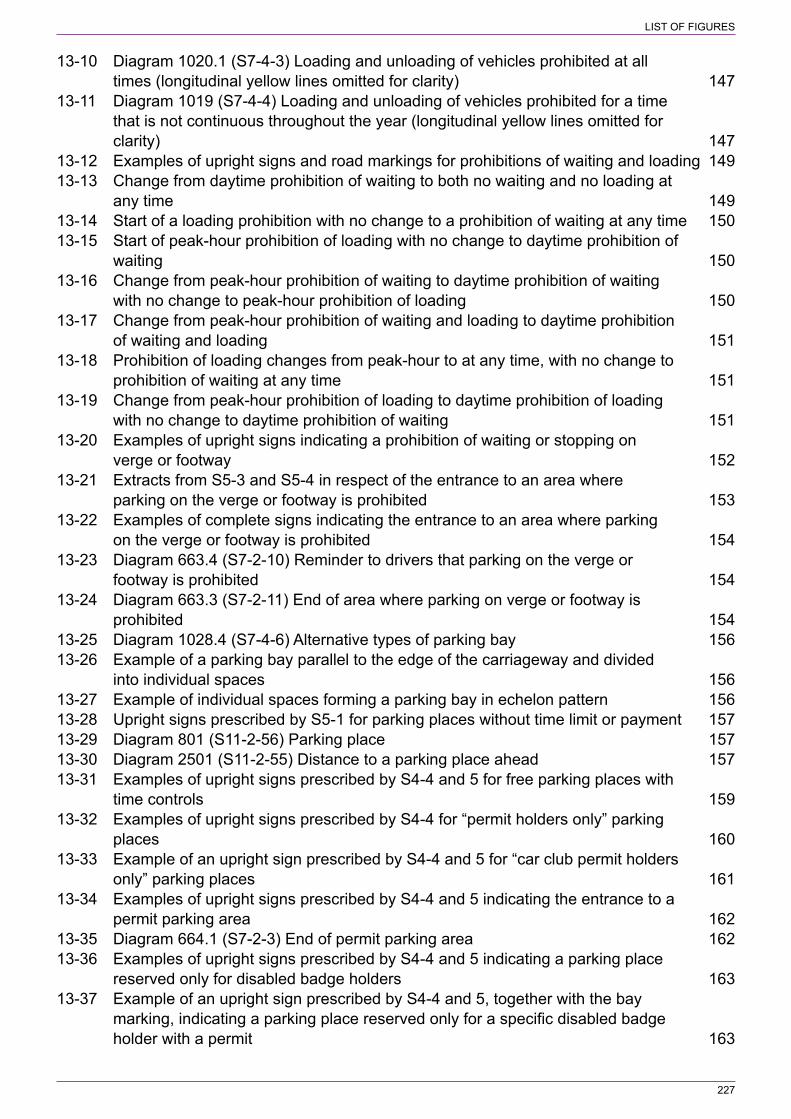
227
LIST OF FIGURES
13‑10 Diagram 1020.1 (S7‑4‑3) Loading and unloading of vehicles prohibited at all times (longitudinal yellow lines omitted for clarity) 147
13‑11 Diagram 1019 (S7‑4‑4) Loading and unloading of vehicles prohibited for a time that is not continuous throughout the year (longitudinal yellow lines omitted for clarity) 147
13‑12 Examples of upright signs and road markings for prohibitions of waiting and loading 14913‑13 Change from daytime prohibition of waiting to both no waiting and no loading at
any time 14913‑14 Start of a loading prohibition with no change to a prohibition of waiting at any time 15013‑15 Start of peak‑hour prohibition of loading with no change to daytime prohibition of
waiting 15013‑16 Change from peak‑hour prohibition of waiting to daytime prohibition of waiting
with no change to peak‑hour prohibition of loading 15013‑17 Change from peak‑hour prohibition of waiting and loading to daytime prohibition
of waiting and loading 15113‑18 Prohibition of loading changes from peak‑hour to at any time, with no change to
prohibition of waiting at any time 15113‑19 Change from peak‑hour prohibition of loading to daytime prohibition of loading
with no change to daytime prohibition of waiting 15113‑20 Examples of upright signs indicating a prohibition of waiting or stopping on
verge or footway 15213‑21 Extracts from S5‑3 and S5‑4 in respect of the entrance to an area where
parking on the verge or footway is prohibited 15313‑22 Examples of complete signs indicating the entrance to an area where parking
on the verge or footway is prohibited 15413‑23 Diagram 663.4 (S7‑2‑10) Reminder to drivers that parking on the verge or
footway is prohibited 15413‑24 Diagram 663.3 (S7‑2‑11) End of area where parking on verge or footway is
prohibited 15413‑25 Diagram 1028.4 (S7‑4‑6) Alternative types of parking bay 15613‑26 Example of a parking bay parallel to the edge of the carriageway and divided
into individual spaces 15613‑27 Example of individual spaces forming a parking bay in echelon pattern 15613‑28 Upright signs prescribed by S5‑1 for parking places without time limit or payment 15713‑29 Diagram 801 (S11‑2‑56) Parking place 15713‑30 Diagram 2501 (S11‑2‑55) Distance to a parking place ahead 15713‑31 Examples of upright signs prescribed by S4‑4 and 5 for free parking places with
time controls 15913‑32 Examples of upright signs prescribed by S4‑4 for “permit holders only” parking
places 16013‑33 Example of an upright sign prescribed by S4‑4 and 5 for “car club permit holders
only” parking places 16113‑34 Examples of upright signs prescribed by S4‑4 and 5 indicating the entrance to a
permit parking area 16213‑35 Diagram 664.1 (S7‑2‑3) End of permit parking area 16213‑36 Examples of upright signs prescribed by S4‑4 and 5 indicating a parking place
reserved only for disabled badge holders 16313‑37 Example of an upright sign prescribed by S4‑4 and 5, together with the bay
marking, indicating a parking place reserved only for a specific disabled badge holder with a permit 163

228
LIST OF FIGURES
13‑38 Examples of upright signs prescribed by S4‑4 indicating a pay and display 16413‑39 Upright sign prescribed by S4‑4 indicating that drivers must obtain and display
parking tickets (Alternative types) 16513‑40 Example of an upright sign prescribed by S4‑4 and S4‑5 for a voucher parking
place 16613‑41 Example of an upright sign prescribed by S4 4 indicating a parking place for
large or slow vehicles 16613‑42 Extract from S4‑4 in respect of a parking place reserved for loading and unloading 16713‑43 Examples of upright signs prescribed by S4‑4 indicating a parking place
reserved for loading and unloading 16713‑44 Examples of upright signs prescribed by S4‑4 and 5 indicating a parking place
reserved for the recharging of all types of electric vehicles 16813‑45 Examples of upright signs prescribed by S4‑4 and 5 indicating a parking place
reserved for the recharging of electric solo motor cycles 16813‑46 Examples of upright signs for shared use parking places 16913‑47 Arrangement of sign panels showing different uses at different times of day 17013‑48 Example of a sign that has shared use at the same time for part of day and
single use at other times 17013‑49 Example of a sign that is reserved for permit holders for only part of the day; at
other times the parking conditions apply to all users including permit holders 17013‑50 Use of the expression “At other times” to reduce sign size 17113‑51 Examples of signs for parking places where at certain times of day waiting and,
where appropriate, loading is prohibited 17213‑52 Examples of signs and road markings for parking places where at certain times
of day waiting and, where appropriate, loading is prohibited 17213‑53 Diagram 667 (S7‑2‑12) Vehicles may be parked partially on the verge or
footway (Alternative types) 17413‑54 Diagram 667.1 (S7‑2‑14) Vehicles may be parked partially on the verge or
footway during the period indicated (Alternative types) 17413‑55 Diagram 667.2 (S7‑2‑16) End of area where vehicles may be parked partially on
the verge or footway (Alternative types) 17413‑56 Diagram 668 (S7‑2‑13) Vehicles may be parked wholly on the verge or footway
(Alternative types) 17413‑57 Diagram 668.1 (S7‑2‑15) Vehicles may be parked wholly on the verge or
footway during the period indicated (Alternative types) 17413‑58 Diagram 668.2 (S7‑2‑17) End of area where vehicles may be wholly on the
verge or footway (Alternative types) 17413‑59 Bay markings indicating a parking place partially or wholly on the footway 17513‑60 Example of individually marked footway parking bays along a length of road 17713‑61 Example of an upright sign and road marking indicating footway parking controls 17813‑62 Signing arrangement for different parking bays side by side (Alternative types) 18013‑63 Examples of upright signs for a “no waiting” taxi rank 18013‑64 Diagram 1028.2 (S7‑4‑5) Alternative types of taxi rank markings where waiting
by other vehicles is prohibited 18113‑65 Examples of “no waiting” taxi rank signing and marking 18213‑66 Diagram 1028.5 (S7‑4‑7) Taxi rank marking where stopping by other vehicles
is prohibited (Note: the legend may be varied to indicate a bay reserved for ambulances or police vehicles) 182
13‑67 Examples of upright signs for a “no stopping” taxi rank 182
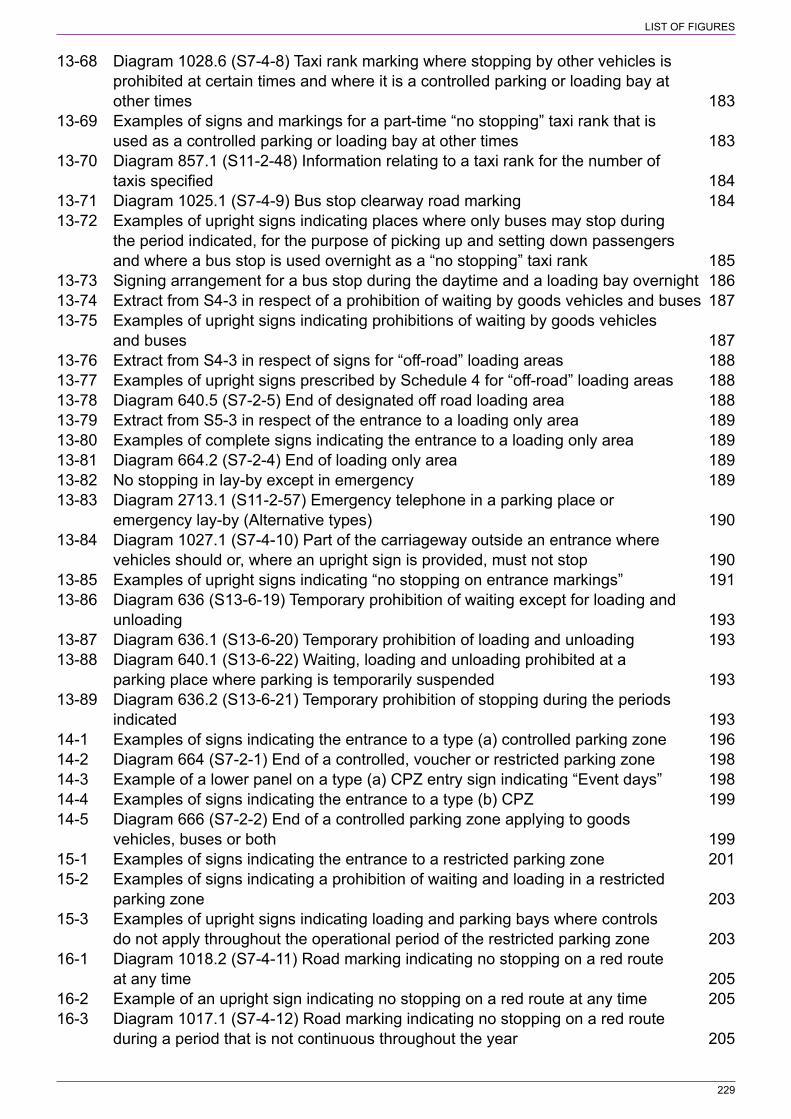
229
LIST OF FIGURES
13‑68 Diagram 1028.6 (S7‑4‑8) Taxi rank marking where stopping by other vehicles is prohibited at certain times and where it is a controlled parking or loading bay at other times 183
13‑69 Examples of signs and markings for a part‑time “no stopping” taxi rank that is used as a controlled parking or loading bay at other times 183
13‑70 Diagram 857.1 (S11‑2‑48) Information relating to a taxi rank for the number of taxis specified 184
13‑71 Diagram 1025.1 (S7‑4‑9) Bus stop clearway road marking 18413‑72 Examples of upright signs indicating places where only buses may stop during
the period indicated, for the purpose of picking up and setting down passengers and where a bus stop is used overnight as a “no stopping” taxi rank 185
13‑73 Signing arrangement for a bus stop during the daytime and a loading bay overnight 18613‑74 Extract from S4‑3 in respect of a prohibition of waiting by goods vehicles and buses 18713‑75 Examples of upright signs indicating prohibitions of waiting by goods vehicles
and buses 18713‑76 Extract from S4‑3 in respect of signs for “off‑road” loading areas 18813‑77 Examples of upright signs prescribed by Schedule 4 for “off‑road” loading areas 18813‑78 Diagram 640.5 (S7‑2‑5) End of designated off road loading area 18813‑79 Extract from S5‑3 in respect of the entrance to a loading only area 18913‑80 Examples of complete signs indicating the entrance to a loading only area 18913‑81 Diagram 664.2 (S7‑2‑4) End of loading only area 18913‑82 No stopping in lay‑by except in emergency 18913‑83 Diagram 2713.1 (S11‑2‑57) Emergency telephone in a parking place or
emergency lay‑by (Alternative types) 19013‑84 Diagram 1027.1 (S7‑4‑10) Part of the carriageway outside an entrance where
vehicles should or, where an upright sign is provided, must not stop 19013‑85 Examples of upright signs indicating “no stopping on entrance markings” 19113‑86 Diagram 636 (S13‑6‑19) Temporary prohibition of waiting except for loading and
unloading 19313‑87 Diagram 636.1 (S13‑6‑20) Temporary prohibition of loading and unloading 19313‑88 Diagram 640.1 (S13‑6‑22) Waiting, loading and unloading prohibited at a
parking place where parking is temporarily suspended 19313‑89 Diagram 636.2 (S13‑6‑21) Temporary prohibition of stopping during the periods
indicated 19314‑1 Examples of signs indicating the entrance to a type (a) controlled parking zone 19614‑2 Diagram 664 (S7‑2‑1) End of a controlled, voucher or restricted parking zone 19814‑3 Example of a lower panel on a type (a) CPZ entry sign indicating “Event days” 19814‑4 Examples of signs indicating the entrance to a type (b) CPZ 19914‑5 Diagram 666 (S7‑2‑2) End of a controlled parking zone applying to goods
vehicles, buses or both 19915‑1 Examples of signs indicating the entrance to a restricted parking zone 20115‑2 Examples of signs indicating a prohibition of waiting and loading in a restricted
parking zone 20315‑3 Examples of upright signs indicating loading and parking bays where controls
do not apply throughout the operational period of the restricted parking zone 20316‑1 Diagram 1018.2 (S7‑4‑11) Road marking indicating no stopping on a red route
at any time 20516‑2 Example of an upright sign indicating no stopping on a red route at any time 20516‑3 Diagram 1017.1 (S7‑4‑12) Road marking indicating no stopping on a red route
during a period that is not continuous throughout the year 205
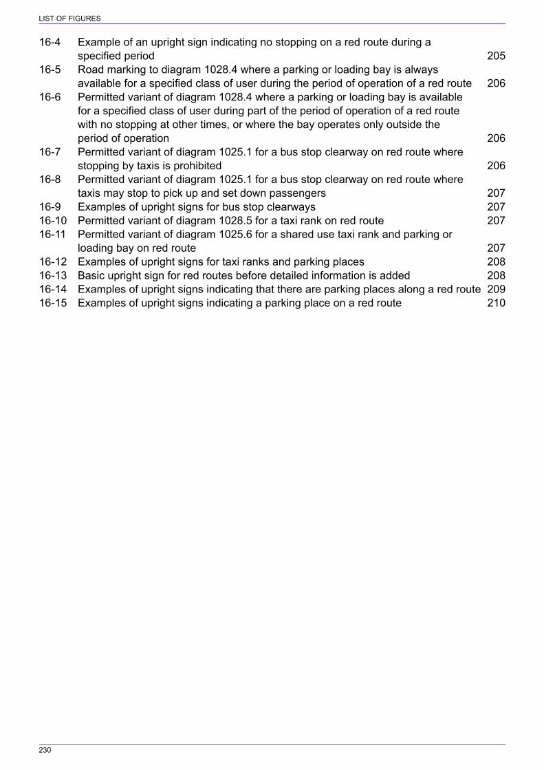
230
LIST OF FIGURES
16‑4 Example of an upright sign indicating no stopping on a red route during a specified period 205
16‑5 Road marking to diagram 1028.4 where a parking or loading bay is always available for a specified class of user during the period of operation of a red route 206
16‑6 Permitted variant of diagram 1028.4 where a parking or loading bay is available for a specified class of user during part of the period of operation of a red route with no stopping at other times, or where the bay operates only outside the period of operation 206
16‑7 Permitted variant of diagram 1025.1 for a bus stop clearway on red route where stopping by taxis is prohibited 206
16‑8 Permitted variant of diagram 1025.1 for a bus stop clearway on red route where taxis may stop to pick up and set down passengers 207
16‑9 Examples of upright signs for bus stop clearways 20716‑10 Permitted variant of diagram 1028.5 for a taxi rank on red route 20716‑11 Permitted variant of diagram 1025.6 for a shared use taxi rank and parking or
loading bay on red route 20716‑12 Examples of upright signs for taxi ranks and parking places 20816‑13 Basic upright sign for red routes before detailed information is added 20816‑14 Examples of upright signs indicating that there are parking places along a red route 20916‑15 Examples of upright signs indicating a parking place on a red route 210
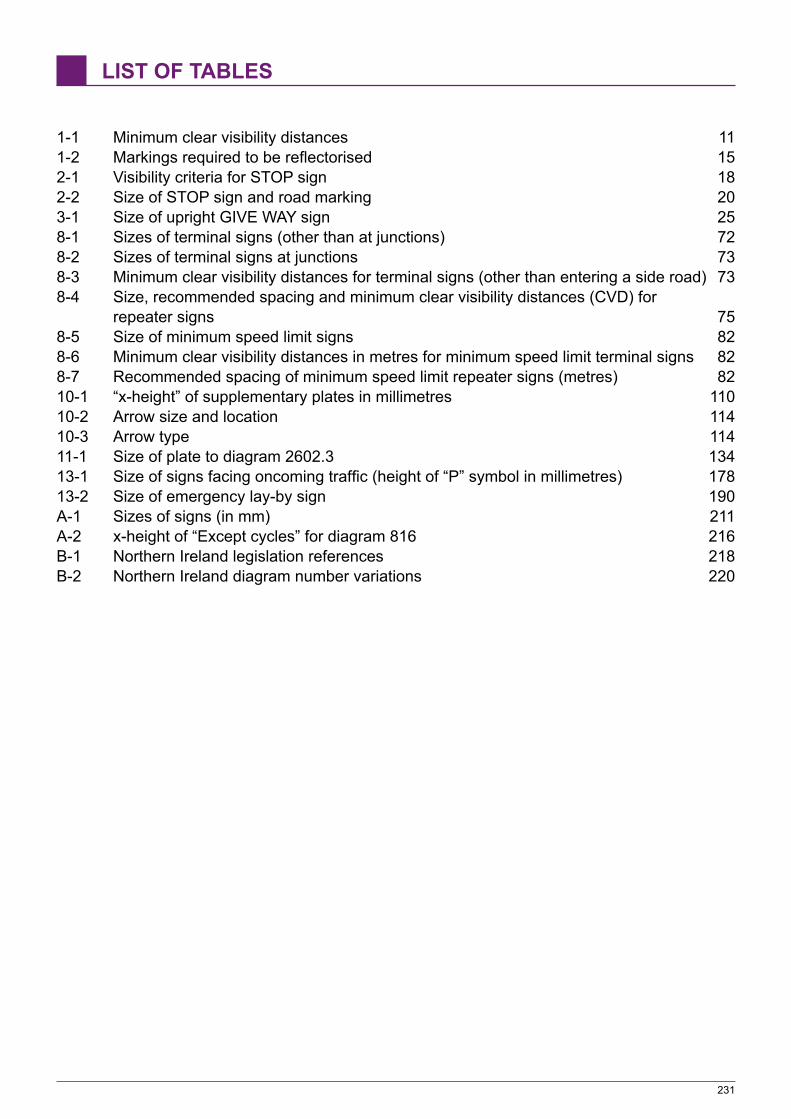
231
LIST OF TABLES
1‑1 Minimum clear visibility distances 111‑2 Markings required to be reflectorised 152‑1 Visibility criteria for STOP sign 182‑2 Size of STOP sign and road marking 203‑1 Size of upright GIVE WAY sign 258‑1 Sizes of terminal signs (other than at junctions) 728‑2 Sizes of terminal signs at junctions 738‑3 Minimum clear visibility distances for terminal signs (other than entering a side road) 738‑4 Size, recommended spacing and minimum clear visibility distances (CVD) for
repeater signs 758‑5 Size of minimum speed limit signs 828‑6 Minimum clear visibility distances in metres for minimum speed limit terminal signs 828‑7 Recommended spacing of minimum speed limit repeater signs (metres) 8210‑1 “x‑height” of supplementary plates in millimetres 11010‑2 Arrow size and location 11410‑3 Arrow type 11411‑1 Size of plate to diagram 2602.3 13413‑1 Size of signs facing oncoming traffic (height of “P” symbol in millimetres) 17813‑2 Size of emergency lay‑by sign 190A‑1 Sizes of signs (in mm) 211A‑2 x‑height of “Except cycles” for diagram 816 216B‑1 Northern Ireland legislation references 218B‑2 Northern Ireland diagram number variations 220
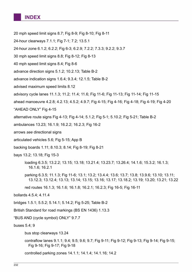
232
INDEX
20 mph speed limit signs 8.7; Fig 8‑9; Fig 8‑10; Fig 8‑11
24‑hour clearways 7.1.1; Fig 7‑1; 7.2; 13.5.1
24‑hour zone 6.1.2; 6.2.2; Fig 6‑3; 6.2.9; 7.2.2; 7.3.3; 9.2.2; 9.3.7
30 mph speed limit signs 8.8; Fig 8‑12; Fig 8‑13
40 mph speed limit signs 8.4; Fig 8‑6
advance direction signs 5.1.2; 10.2.13; Table B‑2
advance indication signs 1.6.4; 9.3.4; 12.1.5; Table B‑2
advised maximum speed limits 8.12
advisory cycle lanes 11.1.3; 11.2; 11.4; 11.6; Fig 11‑6; Fig 11‑13; Fig 11‑14; Fig 11‑15
ahead manoeuvre 4.2.8; 4.2.13; 4.5.2; 4.9.7; Fig 4‑15; Fig 4‑16; Fig 4‑18; Fig 4‑19; Fig 4‑20
“AHEAD ONLY” Fig 4‑15
alternative route signs Fig 4‑13; Fig 4‑14; 5.1.2; Fig 5‑1; 5.10.2; Fig 5‑21; Table B‑2
ambulances 13.23; 16.1.9; 16.2.2; 16.2.3; Fig 16‑2
arrows see directional signs
articulated vehicles 5.6; Fig 5‑15; App B
backing boards 1.11; 8.10.3; 8.14; Fig 8‑19; Fig 8‑21
bays 13.2; 13.18; Fig 15‑3
loading 6.3.5; 13.2.2; 13.15; 13.18; 13.21.4; 13.23.7; 13.26.4; 14.1.6; 15.3.2; 16.1.3; 16.1.6; 16.2.1
parking 6.3.5; 11.1.3; Fig 11‑6; 13.1; 13.2; 13.4.4; 13.6; 13.7; 13.8; 13.9.6; 13.10; 13.11; 13.12.3; 13.12.4; 13.13; 13.14; 13.15; 13.16; 13.17; 13.18.2; 13.19; 13.20; 13.21; 13.22
red routes 16.1.3; 16.1.6; 16.1.8; 16.2.1; 16.2.3; Fig 16‑5; Fig 16‑11
bollards 4.5.4; 4.11.4
bridges 1.5.1; 5.5.2; 5.14.1; 5.14.2; Fig 5‑25; Table B‑2
British Standard for road markings (BS EN 1436) 1.13.3
“BUS AND (cycle symbol) ONLY” 9.7.7
buses 5.4; 9
bus stop clearways 13.24
contraflow lanes 9.1.1; 9.4; 9.5; 9.6; 9.7; Fig 9‑11; Fig 9‑12; Fig 9‑13; Fig 9‑14; Fig 9‑15; Fig 9‑16; Fig 9‑17; Fig 9‑18
controlled parking zones 14.1.1; 14.1.4; 14.1.16; 14.2
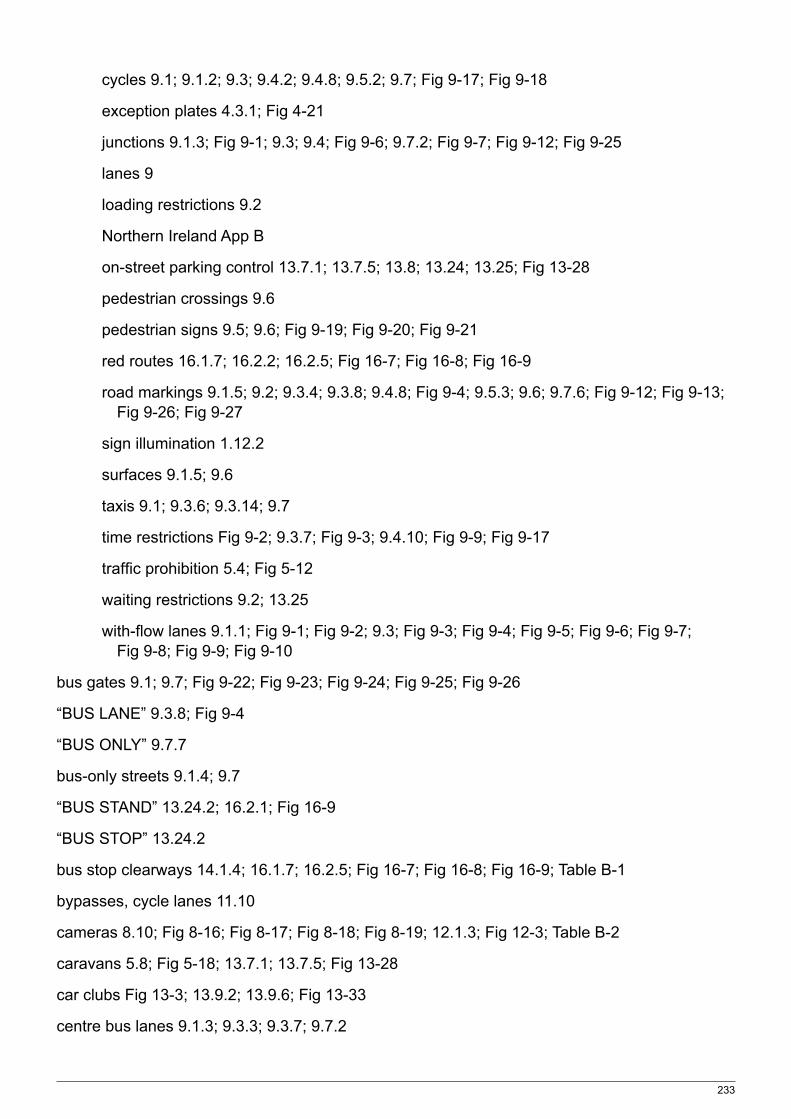
233
cycles 9.1; 9.1.2; 9.3; 9.4.2; 9.4.8; 9.5.2; 9.7; Fig 9‑17; Fig 9‑18
exception plates 4.3.1; Fig 4‑21
junctions 9.1.3; Fig 9‑1; 9.3; 9.4; Fig 9‑6; 9.7.2; Fig 9‑7; Fig 9‑12; Fig 9‑25
lanes 9
loading restrictions 9.2
Northern Ireland App B
on‑street parking control 13.7.1; 13.7.5; 13.8; 13.24; 13.25; Fig 13‑28
pedestrian crossings 9.6
pedestrian signs 9.5; 9.6; Fig 9‑19; Fig 9‑20; Fig 9‑21
red routes 16.1.7; 16.2.2; 16.2.5; Fig 16‑7; Fig 16‑8; Fig 16‑9
road markings 9.1.5; 9.2; 9.3.4; 9.3.8; 9.4.8; Fig 9‑4; 9.5.3; 9.6; 9.7.6; Fig 9‑12; Fig 9‑13; Fig 9‑26; Fig 9‑27
sign illumination 1.12.2
surfaces 9.1.5; 9.6
taxis 9.1; 9.3.6; 9.3.14; 9.7
time restrictions Fig 9‑2; 9.3.7; Fig 9‑3; 9.4.10; Fig 9‑9; Fig 9‑17
traffic prohibition 5.4; Fig 5‑12
waiting restrictions 9.2; 13.25
with‑flow lanes 9.1.1; Fig 9‑1; Fig 9‑2; 9.3; Fig 9‑3; Fig 9‑4; Fig 9‑5; Fig 9‑6; Fig 9‑7; Fig 9‑8; Fig 9‑9; Fig 9‑10
bus gates 9.1; 9.7; Fig 9‑22; Fig 9‑23; Fig 9‑24; Fig 9‑25; Fig 9‑26
“BUS LANE” 9.3.8; Fig 9‑4
“BUS ONLY” 9.7.7
bus‑only streets 9.1.4; 9.7
“BUS STAND” 13.24.2; 16.2.1; Fig 16‑9
“BUS STOP” 13.24.2
bus stop clearways 14.1.4; 16.1.7; 16.2.5; Fig 16‑7; Fig 16‑8; Fig 16‑9; Table B‑1
bypasses, cycle lanes 11.10
cameras 8.10; Fig 8‑16; Fig 8‑17; Fig 8‑18; Fig 8‑19; 12.1.3; Fig 12‑3; Table B‑2
caravans 5.8; Fig 5‑18; 13.7.1; 13.7.5; Fig 13‑28
car clubs Fig 13‑3; 13.9.2; 13.9.6; Fig 13‑33
centre bus lanes 9.1.3; 9.3.3; 9.3.7; 9.7.2

234
INDEX
“CHILDREN” 13.28.2
circular sign mounting 1.9; 1.10.2; 1.10.4
cleaning signs 1.14.2
clear visibility distances (CVD) Table 1‑1; 1.8.2; 1.8.4
buses 9.3.4
cycles 11.3.2
speed limit signs 8.2.6; 8.3.4; Table 8‑3; Table 8‑4; Table 8‑6
clearways 7
24‑hour 7.2
bus stop 13.24; 14.1.4; 16.1.7; 16.2.5; Fig 16‑7; Fig 16‑8; Fig 16‑9; Table B‑1
Northern Ireland App B
red routes 7.4; Fig 7‑4; Fig 7‑5; 16.1.2; 16.1.7; 16.2.5; 16.2.6; Fig 16‑8; Fig 16‑9
road markings 7.1.1
upright signs 1.10.4; 7.2.4; Fig 7‑1
urban 7.3; Fig 7‑2; Fig 7‑3
coloured surfacing, bus lanes 9.1.5; 9.6
colour specifications, road markings 1.13.4
compulsory and prohibited movements 4.1
ahead manoeuvre 4.2.8; 4.2.13; 4.5.2; 4.9.7; Fig 4‑15; Fig 4‑16; Fig 4‑18; Fig 4‑19; Fig 4‑20
dual carriageways 4.2.3; 4.2.4; 4.5; Fig 4‑7
exception plates 4.3; Fig 4‑21
give way signs 4.2.4; 4.2.12; 4.8.1; Fig 4‑27
junctions 4.2; 4.5
“keep left”/“keep right” signs 4.7; Fig 4‑25
“no overtaking” signs 4.12; Fig 4‑35
“no U‑turn” signs 4.11; Fig 4‑34
one‑way roads 4.2.8; Fig 4‑3; Fig 4‑4; 4.9; Fig 4‑30; Fig 4‑31; Fig 4‑32; Fig 4‑33
“pass either side” signs 4.7; Fig 4‑26
priority signs 4.8; Fig 4‑27; Fig 4‑28; Fig 4‑29
roundabouts 4.6
siting signs 4.5
supplementary plates 4.2.2; 4.2.6; 4.3; Fig 4‑3; 4.4; Fig 4‑4; 4.9.8; 4.11.3

235
INDEX
time plates 4.4; Fig 4‑22; Fig 4‑23
T‑junctions 4.2; Fig 4‑4; Fig 4‑5; Fig 4‑6; Fig 4‑7; Fig 4‑12
congestion charging zones 12
contraflow lanes 4.9.8; 9; 11
bus lanes 9.1.1–9.1.3; 9.4; 9.5; 9.6; 9.7; Fig 9‑11; Fig 9‑12; Fig 9‑13; Fig 9‑14; Fig 9‑15; Fig 9‑16; Fig 9‑17; Fig 9‑18
cycle lanes 5.3.2; 11.1.3; 11.2.3; 11.5; 11.6; Fig 11‑8; 11.9; Fig 11‑9; Fig 11‑10; Fig 11‑12; Fig 11‑13; Fig 11‑14; Fig 11‑15
controlled parking zones (CPZ) 14; Fig 14‑1; Fig 14‑2; Fig 14‑4; Fig 14‑5; Table B‑1
“Controlled ZONE” 14.1.8
CPZ see controlled parking zones
crossroad movement control 4.2.8; 4.2.12; 4.2.13; Fig 4‑17; Fig 4‑18; Fig 4‑19; Fig 4‑20
“C” symbol 12.1.7; Fig 12‑7
CVD see clear visibility distances
cycle lanes 11; see also cycles
advisory lanes 11.1.3; 11.2; 11.4; 11.6; Fig 11‑6; Fig 11‑13; Fig 11‑14; Fig 11‑15
bypasses 11.10
controlled parking zones 14.1.7
junctions 11.1.3; 11.3; 11.4.3; 11.5; Fig 11‑5; 11.6.4; 11.12
loading restrictions 11.2
mandatory lanes 11.1.3; 11.2; Fig 11‑2; 11.3; Fig 11‑3; Fig 11‑4; 11.5; Fig 11‑5; Fig 11‑6; Fig 11‑8; Fig 11‑10; Fig 11‑12
one‑way streets 11.9; Fig 11‑17
pedestrians 11.1.1; 11.7; 11.8; 11.11; 11.13; Fig 11‑16
waiting restrictions 11.2
worded markings 11.13
Cycle Infrastructure Design see Local Transport Note 2/08 Cycle Infrastructure Design
cycles 6.2; 11; see also cycle lanes
bus lanes 9.1; 9.1.2; 9.3; 9.4.2; 9.4.8; 9.5.2; 9.7; Fig 9‑17; Fig 9‑18
cycle routes 11.1; 11.3.9; 11.4.7; 11.5.7; Fig 11‑7; 11.8; 11.10; 11.11; Fig 11‑11; 11.12; 11.13; Fig 11‑18; Fig 11‑22; Fig 11‑25; Table B‑2
cycle tracks 11.1; 11.7; 11.11; 11.12; 11.13
exception plates 4.3.1; Fig 4‑21
facilities for 11
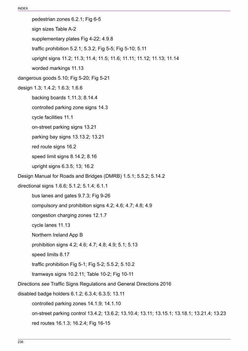
236
INDEX
pedestrian zones 6.2.1; Fig 6‑5
sign sizes Table A‑2
supplementary plates Fig 4‑22; 4.9.8
traffic prohibition 5.2.1; 5.3.2; Fig 5‑5; Fig 5‑10; 5.11
upright signs 11.2; 11.3; 11.4; 11.5; 11.6; 11.11; 11.12; 11.13; 11.14
worded markings 11.13
dangerous goods 5.10; Fig 5‑20; Fig 5‑21
design 1.3; 1.4.2; 1.6.3; 1.6.6
backing boards 1.11.3; 8.14.4
controlled parking zone signs 14.3
cycle facilities 11.1
on‑street parking signs 13.21
parking bay signs 13.13.2; 13.21
red route signs 16.2
speed limit signs 8.14.2; 8.16
upright signs 6.3.5; 13; 16.2
Design Manual for Roads and Bridges (DMRB) 1.5.1; 5.5.2; 5.14.2
directional signs 1.6.6; 5.1.2; 5.1.4; 6.1.1
bus lanes and gates 9.7.3; Fig 9‑26
compulsory and prohibition signs 4.2; 4.6; 4.7; 4.8; 4.9
congestion charging zones 12.1.7
cycle lanes 11.13
Northern Ireland App B
prohibition signs 4.2; 4.6; 4.7; 4.8; 4.9; 5.1; 5.13
speed limits 8.17
traffic prohibition Fig 5‑1; Fig 5‑2; 5.5.2; 5.10.2
tramways signs 10.2.11; Table 10‑2; Fig 10‑11
Directions see Traffic Signs Regulations and General Directions 2016
disabled badge holders 6.1.2; 6.3.4; 6.3.5; 13.11
controlled parking zones 14.1.9; 14.1.10
on‑street parking control 13.4.2; 13.6.2; 13.10.4; 13.11; 13.15.1; 13.18.1; 13.21.4; 13.23
red routes 16.1.3; 16.2.4; Fig 16‑15

237
INDEX
“Disc ZONE” 14.1.8
DMRB see Design Manual for Roads and Bridges
double white lines 1.13.1
drawings 1.6.3; 1.15
“Dual carriageway” 2.1.6; 3.1.5; Fig 3‑4; 3.3.1; 4.2.2; 4.2.3
compulsory and prohibited movements 4.2.4
give way signs 3.1.5; 3.3.1; Fig 3‑4
stop signs 2.1.6; Fig 2‑2
dual carriageways 1.2.6; 1.8.5; 8.5
compulsory and prohibited movements 4.2.3; 4.2.4; 4.5; Fig 4‑7
cycle tracks 11.12.4
give way signs 3.1.5; 3.2.7; 3.3.1; Fig 3‑4; Fig 3‑7
sign siting 1.8.5
speed limit signs 8.1.2; 8.2.2; 8.5; Fig 8‑7; Fig 8‑8
echelon parking spaces 13.6.2; 13.6.6; 13.6.9; 13.7.4; 13.8.3; Fig 13‑27
electric vehicle recharging points 13.16; Fig 13‑44; Fig 13‑45
emergency vehicles 13.23; 16.1.9; 16.2.2; 16.2.3; Fig 16‑2
“End” 1.10.4; 7.2.4; 7.2.5; 8.17.2; Fig 4‑27; Fig 4‑29
end plates/signs 6.2.10
bus lanes 9.3.9; Fig 9‑5
clearways Fig 7‑1; 7.2.4; 7.2.5; 7.3.1; Fig 7‑3
compulsory and prohibited movements 1.10.3; 4.8.3; 4.11.3; Fig 4‑27; Fig 4‑29; 4.12.3; 5.5.5; Fig 5‑14
controlled parking zones 14.1.17; Fig 14‑2
cycle lanes 11.3.9; 11.4.7; 11.5.4; 11.5.7; 11.6.7; 11.11.8
mounting 1.10.4
red route clearways 7.4.2; Fig 7‑5
speed limit zones 8.7.3; Fig 8‑10; Fig 8‑11; 8.9.2; Fig 8‑15; 8.11
urban clearways Fig 7‑2; 7.3.1; Fig 7‑3
entry signs 6.2; 15.2
congestion charging zones 12.1
controlled parking zones 14; Fig 14‑1; Fig 14‑2; Fig 14‑3; Fig 14‑4; Fig 14‑5
Northern Ireland Table B‑2

238
INDEX
no stopping on 13.28
pedestrian zones Fig 6‑1; 6.2; Fig 6‑2; 6.3.4; Fig 6‑7; Table B‑2
restricted parking zones 15; Fig 15‑1
equestrians 5.7.2; Fig 5‑17
“Event days” 13.20; 14.1.19; Fig 14‑2
“exception” and “excepted”, definitions 1.3.4
exception plates/signs 4.3; Fig 4‑21
bus lanes Fig 9‑2; 9.3.7; Fig 9‑3; 9.4.5; 9.4.10; 9.7.1; Fig 9‑9; Fig 9‑16; Fig 9‑17; Fig 9‑18
compulsory and prohibited movements 4.3; 4.9.8; Fig 4‑21
cycle sign sizes Table A‑2
Northern Ireland Table B‑2
pedestrian zone entry 6.2.3
red routes 16.1.9; 16.2; Fig 16‑9; Fig 16‑12; Fig 16‑13; Fig 16‑14; Fig 16‑15
traffic prohibition 5.1.3; 5.2.3; 5.4.2; 5.5.3; Fig 5‑7; 5.15.6
exemption, waiting and loading prohibition 13.4.2
exit signs 6.2; 15.2
congestion charging zones 12.1
controlled parking zones 14.1.1; 14.2.4; 14.3
pedestrian zones 6.2
restricted parking zones 15.1; 15.2
explosives 5.9; Fig 5‑19; Table B‑2
false one‑way streets 11.9; Fig 11‑17
footways/footpaths 1.9.4; 11.11; 13.5; 13.19
free parking 13.7; 13.8
gates 9
bus lanes 9.1; 9.7; Fig 9‑22; Fig 9‑23; Fig 9‑24; Fig 9‑25; Fig 9‑26
trams 10.1; 10.2.2; Fig 10‑3
“GIVE WAY” 1.10.2; Table B‑1
give way signs 3.1
compulsory and prohibited movements 4.2.4; 4.2.12; 4.8.1; Fig 4‑27
cycle tracks 11.12.3
dual carriageways 3.1.5; 3.2.7; 3.3.1; Fig 3‑4; Fig 3‑7
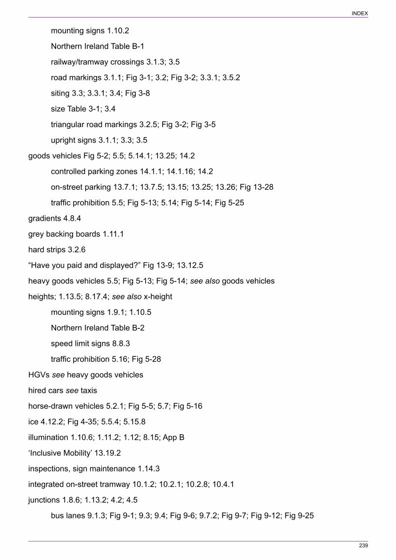
239
INDEX
mounting signs 1.10.2
Northern Ireland Table B‑1
railway/tramway crossings 3.1.3; 3.5
road markings 3.1.1; Fig 3‑1; 3.2; Fig 3‑2; 3.3.1; 3.5.2
siting 3.3; 3.3.1; 3.4; Fig 3‑8
size Table 3‑1; 3.4
triangular road markings 3.2.5; Fig 3‑2; Fig 3‑5
upright signs 3.1.1; 3.3; 3.5
goods vehicles Fig 5‑2; 5.5; 5.14.1; 13.25; 14.2
controlled parking zones 14.1.1; 14.1.16; 14.2
on‑street parking 13.7.1; 13.7.5; 13.15; 13.25; 13.26; Fig 13‑28
traffic prohibition 5.5; Fig 5‑13; 5.14; Fig 5‑14; Fig 5‑25
gradients 4.8.4
grey backing boards 1.11.1
hard strips 3.2.6
“Have you paid and displayed?” Fig 13‑9; 13.12.5
heavy goods vehicles 5.5; Fig 5‑13; Fig 5‑14; see also goods vehicles
heights; 1.13.5; 8.17.4; see also x‑height
mounting signs 1.9.1; 1.10.5
Northern Ireland Table B‑2
speed limit signs 8.8.3
traffic prohibition 5.16; Fig 5‑28
HGVs see heavy goods vehicles
hired cars see taxis
horse‑drawn vehicles 5.2.1; Fig 5‑5; 5.7; Fig 5‑16
ice 4.12.2; Fig 4‑35; 5.5.4; 5.15.8
illumination 1.10.6; 1.11.2; 1.12; 8.15; App B
‘Inclusive Mobility’ 13.19.2
inspections, sign maintenance 1.14.3
integrated on‑street tramway 10.1.2; 10.2.1; 10.2.8; 10.4.1
junctions 1.8.6; 1.13.2; 4.2; 4.5
bus lanes 9.1.3; Fig 9‑1; 9.3; 9.4; Fig 9‑6; 9.7.2; Fig 9‑7; Fig 9‑12; Fig 9‑25
240
INDEX
compulsory and prohibited movements 4.2; 4.5
cycle lanes 11.1.3; 11.3; 11.4.3; 11.5; Fig 11‑5; 11.6.4; 11.12
give way signs 3.3
limited movements Fig 4‑1; 4.2; Fig 4‑2; Fig 4‑3; Fig 4‑5; Fig 4‑6; Fig 4‑7
speed limit signs 8.2.4; Fig 8‑4; 8.5.2; 8.5.3; Fig 8‑5; Fig 8‑7
stop signs 2.1.3
traffic prohibition 5.1.4; Fig 5‑4
tramways 10.4
“KEEP CLEAR” 13.28
“keep left”/“keep right” signs 4.7; Fig 4‑25; 10.2.12
large vehicles, on‑street parking 13.14; Fig 13‑41
legal framework 1.2
legal interpretation 1.1.1; Table B‑1
length limits 5.15; Fig 5‑26; Fig 5‑27
lettering styles Table B‑1
level crossings 2.5; Fig 2‑6; Fig 2‑7; 3.5; Fig 3‑10
limited movements, junctions Fig 4‑1; 4.2; Fig 4‑2; Fig 4‑3; Fig 4‑4; Fig 4‑5; Fig 4‑6; Fig 4‑7
loading areas/bays 13.4; 13.15; 13.18; 13.22; 13.26
controlled parking zones 14
on‑street parking 13.2.2; 13.4.2; 13.15; 13.18; 13.21; 13.22; 13.23; 13.26.4
red routes 16.1.3; 16.1.6; 16.1.8; 16.2.1; 16.2.3; Fig 16‑5; Fig 16‑11
restricted parking zones 15.3.2; Fig 15‑3
waiting prohibition 13.4; 13.18; 13.26
“LOADING ONLY” 13.1; 13.15.3
loading restrictions 1.1.4; 1.6.2; 6.3
bus lanes 9.2
cycle lanes 11.2
on‑street parking 13.1; 13.2; 13.3; 13.4; 13.5; 13.6.5; 13.9; 13.10; 13.11; 13.15; 13.18; 13.19.13; 13.21; 13.22; 13.23; 13.24.7; 13.26; 13.27; 13.29; 13.30; Fig 13‑73
pedestrian zones 6.3; Fig 6‑6; Fig 6‑7; Fig 6‑8
red routes 16.1; 16.2
restricted parking zones 15; Fig 15‑3
Local Transport Note 2/08 Cycle Infrastructure Design (LTN 2/08) 11.1.1
241
INDEX
“LOOK BOTH WAYS”/”LOOK LEFT”/”LOOK RIGHT” markings 9.5.2; 9.5.3; Fig 9‑21
lorry route advance direction signs Table B‑2
LTN 2/08 see Local Transport Note 2/08 Cycle Infrastructure Design (LTN 2/08)
maintenance, upright signs 1.14
mandatory cycle lanes 11.1.3; 11.2; Fig 11‑2; 11.3; Fig 11‑3; Fig 11‑4; 11.5; Fig 11‑5; Fig 11‑6; Fig 11‑8; Fig 11‑9; Fig 11‑10; Fig 11‑12
“Match days” 13.20
maximum speed limits 8.1.2; 8.2; 8.3; 8.12
Northern Ireland Table B‑1
repeater signs 8.3; Table 8‑4
terminal signs Fig 8‑1; Table 8‑1; 8.2; Fig 8‑2; Table 8‑2; Fig 8‑3; Table 8‑3; Fig 8‑4; Fig 8‑5
meter bays 14.1.6; 14.1.8
minimum speed limits 8.1.2; Table 8‑5; Table 8‑6; Table 8‑7; 8.9; Fig 8‑14; Fig 8‑15; Table B‑1
mini‑roundabouts 1.6.1; 3.3.1; 4.6; Fig 4‑24; see also roundabouts
motor cycles 5.3.1; 9.1.1
bus lanes 9.1; 9.3.6; 9.7.1; 9.7.7; Fig 9‑24
on‑street parking 13.7.1; 13.7.5; 13.8.3; 13.16; Fig 13‑28; Fig 13‑31
traffic prohibition 5.3.2; Fig 5‑10
motor vehicle prohibition 5.3; Fig 5‑8; Fig 5‑9; Fig 5‑10; Fig 5‑11
motorways 1.8.3; 5.12.2; 8.1.2; 8.2.2; 8.6
mounting signs 1.9; 1.10; 8.2.2; Fig 8‑3; 8.17
mown verges 5.13; Fig 5‑24
multiple signs 1.10.5; 13.2.3; Fig 13‑5; 13.17.3; 13.18.1
‘must’ 1.3.1
national authority, definitions 1.1.3; 1.3.2
national speed limits 8.1.2; 8.2; 8.3
Northern Ireland Table B‑1; Table B‑2
repeater signs 8.2.6; 8.3; Table 8‑4
terminal signs Fig 8‑1; Table 8‑1; 8.2; Fig 8‑2; Table 8‑2; Fig 8‑3; Table 8‑3; Fig 8‑4; Fig 8‑5
nature and location of prohibition 5.1.4; Fig 5‑3
nearside bus lanes 9.1.3; 9.3.1; 9.3.10; 9.3.16; 9.4; Fig 9‑6

242
INDEX
new 30 mph speed limit in force Fig 8‑12; Fig 8‑13
“no entry” signs
compulsory and prohibited movements 4.2.3; 4.2.10; Fig 4‑7; 4.9.5; 4.10; Fig 4‑19; Fig 4‑32; Fig 4‑33
cycle lanes 11.5.5
“no left turn” signs 4.2.8; 4.2.10; 4.5.3; Fig 4‑9; Fig 4‑17
“no loading” 6.3.1; Fig 6‑6; Fig 13‑2; 13.4.10; 13.4.12; 13.4.16; Fig 13‑13; 13.23.2; 13.29.3; 13.29.4; 14.1.11; 15.2.1; 15.3.1; 16.1.2
“no motor vehicles” 6.2.1; 6.2.9; 9.7.1
“no overtaking” signs 4.12; Fig 4‑35
“no right turn” signs 4.2.8; 4.2.10; 4.5.3; Fig 4‑8; Fig 4‑9; Fig 4‑17; Fig 4‑20
Northern Ireland App B
“no stopping on entrance markings” 13.28; 14.1.3
“no stopping except in emergency” 13.27
no stopping signs 1.2.7; 1.8.7; Fig 7‑1; 13.2.2; Fig 13‑20; 13.23.11; 13.27; Fig 13‑82; 13.28; Fig 13‑84; Fig 13‑85; 14.1.3
Northern Ireland App B
red routes 16.1; 16.2
road markings 1.2.7; 13.23.4
siting of signs 1.8.7; 13.24.9
taxi ranks 13.4.7; 13.23.4; 13.23.6; 13.23.7; 13.23.8; Fig 13‑67; 13.23.9; Fig 13‑69; 13.24.7; Fig 13‑72; 14.1.4
“no U‑turn” signs 4.11; Fig 4‑34
“no vehicle” signs 6.2.1
“no waiting” 6.3.2; Fig 6‑7; 15.3.1; 16.1.2
“no waiting at any time” 14.1.5
Office of Rail and Road (ORR) 10.1.1
off‑road cycle tracks 11.11.2
off‑road loading 13.26
off‑side bus lanes 9.1.3; 9.3.3; 9.3.7; 9.7.2
off‑street tramways 10.1; 10.2; 10.3; 10.4; Fig 10‑9; Fig 10‑10
one‑way roads 4.2.2
bus lanes 9.4.2; 9.7.2; Fig 9‑11

243
INDEX
compulsory and prohibited movement 4.2.8; Fig 4‑3; Fig 4‑4; 4.9; Fig 4‑30; Fig 4‑31; Fig 4‑32; Fig 4‑33
cycle lanes 11.9; Fig 11‑17
give way signs 3.2.4
supplementary plates Fig 4‑3; Fig 4‑4
“ONLY” 4.2.6
on‑street parking control 13
bays 13.1; 13.2; 13.4.4; 13.6; 13.7; 13.8; 13.9.6; 13.10; 13.11; 13.12.3; 13.12.4; 13.13; 13.14; 13.15; 13.16; 13.17; 13.18.2; 13.19; 13.20; 13.21; 13.22
buses 13.7.1; 13.7.5; 13.8; 13.24; 13.25; Fig 13‑28
design of signs 13.21
disabled badge holders 13.4.2; 13.6.2; 13.10.4; 13.11; 13.15.1; 13.18.1; 13.21.4; 13.23
electric vehicle recharging points 13.16; Fig 13‑44; Fig 13‑45
emergency vehicles 13.23
footways 13.5; 13.19
free parking 13.7; 13.8
goods vehicles 13.7.1; 13.7.5; 13.15; 13.25; 13.26; Fig 13‑28
large vehicles 13.14; Fig 13‑41
loading 13.1; 13.2; 13.3; 13.4; 13.5; 13.6.5; 13.9; 13.10; 13.11; 13.15; 13.18; 13.19.13; 13.21; 13.22; 13.23; 13.24.7; 13.26; 13.27; 13.29; 13.30; Fig 13‑73
Northern Ireland App B
no stopping 13.27; 13.28
parking bays 13.2; 13.4.4; 13.6; 13.7.5; 13.8; 13.10.4; 13.11; 13.12.4; 13.17; 13.18.2; 13.19; 13.20; 13.21; 13.22; 13.23.7; 13.29.5
pay and display parking 13.12; 13.13; 13.17; Fig 13‑38; Fig 13‑39
payment 13.7; 13.8
permit parking 13.9; 13.10; 13.13.3; 13.17; Fig 13‑31; Fig 13‑32; Fig 13‑33; Fig 13‑34; Fig 13‑35
places 13.6; 13.7; 13.8; 13.14; 13.15
prohibitions 13.4; 13.5; 13.18; 13.19.4; 13.20; 13.25; 13.26; 13.27; 13.29; 13.30
road markings 13.1; 13.4; 13.5; 13.6; 13.7; 13.8; 13.9.6; 13.10; 13.11; 13.12; 13.13; 13.14; 13.15; 13.18; 13.19; 13.20; 13.21; 13.23; 13.24; 13.25; 13.27; 13.28; 13.29; 13.30
Schedule 4 13.2; 13.4.8; 13.4.12; 13.5.1; 13.8; 13.9; 13.10.1; 13.11; 13.12; 13.13; 13.14; 13.15; 13.16; 13.17; 13.19.13; 13.23; 13.24.6; 13.25; 13.26; 13.27; 13.28.5; 13.29.4; Fig 13‑34

244
INDEX
shared‑use parking bays 13.17; Fig 13‑46; Fig 13‑47; Fig 13‑48; Fig 13‑49; Fig 13‑50
sign sizes Table 13‑1; Table 13‑2; 13.4.5; 13.4.8; 13.5.2; 13.5.7; 13.6; 13.7.2; 13.9.4; 13.10.3; 13.12.4; 13.13.2; 13.19.14; 13.21; 13.23.11; 13.24.10; 13.29.2; Fig 13‑61
siting signs 13.4.14; 13.5.7; 13.19.16; 13.21
slow vehicles 13.14; Fig 13‑41
stopping restrictions 13.1; 13.2; 13.3; 13.4; 13.5; 13.14; 13.23; 13.24; 13.27; 13.28; 13.30
suspensions 13.22; 13.29.5; Fig 13‑88
taxis 13.23
temporary signs 13.29; 13.30
time restrictions 13.3; 13.7; 13.8; 13.9.5; 13.17; 13.18; 13.19.5; 13.23; 13.25; 13.30; Fig 13‑31; Fig 13‑54; Fig 13‑72; Fig 13‑73
verges 13.5; 13.19
voucher parking 13.13; Fig 13‑40
waiting 13.1; 13.2; 13.3; 13.4; 13.5; 13.8; 13.10; 13.11; 13.15; 13.17.4; 13.18; 13.19.7; 13.20; 13.21; 13.23; 13.24; 13.25; 13.26; 13.28.7; 13.29; 13.30
yellow lines 13.1; 13.4; 13.6.1; 13.15.1; 13.18; 13.19.11; 13.23; 13.24; 13.25.3; 13.27; 13.28.7; 13.29
on‑street tramways 10
orders not required 1.2.6
ORR see Office of Rail and Road
parking 13
controlled parking zones 14
cycles 11.14; Fig 11‑31
Northern Ireland App B
on‑street parking control 13
red routes 16
restricted parking zones 15
parking bays
on‑street parking control 13.2; 13.4.4; 13.6; 13.7.5; 13.8; 13.10.4; 13.11; 13.12.4; 13.17; 13.18.2; 13.19; 13.20; 13.21; 13.22; 13.23.7; 13.29.5
red routes 16.1.3; 16.1.6; 16.1.8; 16.2.1; 16.2.3; Fig 16‑5; Fig 16‑11
parking places 1.6.2; 11.14; 13.6; 13.7; 13.8; 13.14; 13.19
on‑street parking control 13.6; 13.7; 13.8; 13.14; 13.15
red routes 16.1.6; 16.1.9; 16.2; Fig 16‑12
245
INDEX
restricted parking zones 15.3.2; Fig 15‑3
“pass either side” signs 4.7; Fig 4‑26
“Pay at machine” 13.12.1; Fig 13‑38
pay and display 13.12
controlled parking zones 14.1.8
on‑street parking 13.12; 13.13; 13.17; Fig 13‑38; Fig 13‑39
restricted parking zones Fig 15‑3
payment, on‑street parking 13.7; 13.8
pedestrians; see also pedestrian zones
bus lanes 9.5; 9.6; Fig 9‑19; Fig 9‑20; Fig 9‑21
crossings for 1.13.1; 9.6; 11.8
cycle lanes 11.1.1; 11.7; 11.8; 11.11; 11.13; Fig 11‑16
one‑way road signs 4.9.4
prohibition 5.12; Fig 5‑23
tramways 10.3; Fig 10‑13
pedestrian zones 6
entrance/entry signs Fig 6‑1; 6.2; Fig 6‑2; 6.3.4; Fig 6‑7; Table B‑2
exit signs 6.2
loading restrictions 6.3; Fig 6‑6; Fig 6‑7; Fig 6‑8
Northern Ireland Table B‑2
prohibition signs Fig 6‑1; 6.2.4; Fig 6‑2; 6.3; Fig 6‑6; Fig 6‑7; Fig 6‑8
signs within the zone 6.3; Fig 6‑6; Fig 6‑7; Fig 6‑8
temporary signs 6.2.2; 6.2.5; Fig 6‑3
waiting restrictions Fig 6‑1; 6.2.4; Fig 6‑2; 6.3; Fig 6‑6; Fig 6‑7; Fig 6‑8
permit holder parking 5.2.3; Fig 5‑11; 5.4.2; 5.15.6; 6.2.3; 6.3.4; 13.9
controlled parking zones 14.1.9; 14.1.10; 14.1.14
on‑street parking 13.9; 13.10; 13.13.3; 13.17; Fig 13‑31; Fig 13‑32; Fig 13‑33; Fig 13‑34; Fig 13‑35
places see parking places
Play Streets 5.2; Fig 5‑5; Fig 5‑6; Fig 5‑7; Table B‑2
police vehicles 13.23; 16.1.9; 16.2.2; 16.2.3; Fig 16‑2
positive instructions 1.6.2
priority signs 4.8; Fig 4‑27; Fig 4‑28; Fig 4‑29
246
INDEX
prohibition 1.6.2; see also compulsory and prohibition
clearways 7
controlled parking zones 14
movement signs 4
Northern Ireland Table B‑2
on‑street parking control 13.4; 13.5; 13.18; 13.19.4; 13.20; 13.25; 13.26; 13.27; 13.29; 13.30
pedestrians 5.12; Fig 5‑23
pedestrian zones Fig 6‑1; 6.2.4; Fig 6‑2; 6.3; Fig 6‑6; Fig 6‑7; Fig 6‑8
red routes 16.1
restricted parking zones 15.2; 15.3
of traffic 5
“P” sign/symbol 13.7.1; 13.7.3; Fig 13‑29; Fig 13‑30; 13.7.4; 13.7.5
on‑street parking Table 13‑1; 13.7; 13.8; 13.9; 13.11; 13.13; 13.14; 13.15.2; 13.16; 13.17.2; 13.19.13; 13.27.3
red routes 16.2.4
railway crossings 2.5; Fig 2‑6; Fig 2‑7; 3.1.3; 3.5
Railway Safety Publication 2, Guidance on Tramways 10.1.1
recharging points 13.16; Fig 13‑44; Fig 13‑45
rectangular sign mounting 1.10.2
“RED ROUTE” 16.2.1
red routes 16
clearways 7.4; Fig 7‑4; Fig 7‑5; 16.1.2; 16.1.7; 16.2.5; 16.2.6; Fig 16‑8; Fig 16‑9
design of signs 16.2
loading restrictions 16.1; 16.2
prohibitions 16.1
road markings 16.1; 16.2
sign sizes 16.2
siting signs 16.1.5; 16.2
time restrictions 16.1; 16.2
upright signs 16.1; 16.2
waiting restrictions 16.1; 16.2
reference numbers, sign maintenance 1.14.4

247
INDEX
reflectorisation Table 1‑2; 1.11.2; 1.12.2; 1.13.3; Table B‑1
repeater signs 1.10.2; 4.9.3; 4.11.3; 4.12.4; 5.13.2; 7.2.4; 7.4.2; 8.2.2; Table 8‑2; 8.3; Table 8‑4; 8.4.1; 8.5.1; 8.17; 9.3.5; 9.4.4; 13.5.2; Fig 13‑20; 13.26.2
cameras 8.10.1; 8.10.2; Fig 8‑19; 8.10.3; 8.10.4; 8.10.6; 12.1.4
cycles 11.3.3; 11.4.3; 11.5.2; 11.6.2; 11.11.2; 11.11.4; 11.11.5; 11.11.6
motorways 8.6.1; 8.6.2; 8.6.3
mounting 1.10.2
“no overtaking” signs 4.12.4
one‑way roads 4.9.3
parking 13.4.14; 13.5.7; 13.10.3; 13.19.8; 13.19.9; 13.21.3; 13.25.2
road markings 8.18.1; 12.1.3; 13.19.10; 13.19.11; 13.23.10
speed limit signs 8.2.6; 8.3; Table 8‑4; 8.7.1; 8.8.1; Fig 8‑13; 8.9.1; 8.9.2; Table 8‑7; 8.10.3; 8.17.3
resident permit parking 13.9.1
restricted parking zones 15
signs within the zone 15.3
restrictions, see also individual restrictions; traffic prohibition
retroreflection see reflectorisation
road markings 1.13
bus lanes 9.1.5; 9.2; 9.3.4; 9.3.8; 9.4.8; Fig 9‑4; 9.5.3; 9.6; 9.7.6; Fig 9‑12; Fig 9‑13; Fig 9‑26; Fig 9‑27
clearways 7.1.1
colour specifications 1.13.4
compulsory and prohibited movements 4.2.6
congestion charging zones 12.1
controlled parking zones 14
cycle lanes 11.11; Fig 11‑11
double white lines 1.13.1
give way signs 3.1.1; Fig 3‑1; 3.2; Fig 3‑2; 3.3.1; 3.5.2
on‑street parking control 13.1; 13.4; 13.5; 13.6; 13.7; 13.8; 13.9.6; 13.10; 13.11; 13.12; 13.13; 13.14; 13.15; 13.18; 13.19; 13.20; 13.21; 13.23; 13.24; 13.25; 13.27; 13.28; 13.29; 13.30
pedestrian crossings 1.13.1
red routes 16.1; 16.2

248
INDEX
restricted parking zones 15
signal controlled junctions 1.13.1
speed limit signs 8.18; Fig 8‑22
stop signs 2.1.7; Table 2‑2; 2.3; Fig 2‑3; Fig 2‑4; Fig 2‑5
tramways Fig 10‑1; Table 10‑1; 10.2; Fig 10‑2; Table 10‑2; Fig 10‑3; Table 10‑3; 10.6; Fig 10‑7; Fig 10‑8; Fig 10‑9; Fig 10‑10; Fig 10‑11
upright signs 1.6.5; 1.13
yellow box markings 1.13.1
Road Traffic Act 1988, stop signs 2.1.2
road works 1.6.7; 8.11
roundabouts 3.3.1; 3.4.3; 4.6; 4.7.2; 4.10.1; 8.2.5; Fig 8‑5; Table 8‑2; 8.6.2; 9.3.11; see also mini‑roundabouts
Schedule 4 on‑street parking signs 13.2; 13.4.8; 13.4.12; 13.5.1; 13.8; 13.9; 13.10.1; 13.11; 13.12; 13.13; 13.14; 13.15; 13.16; 13.17; 13.19.13; 13.23; 13.24.6; 13.25; 13.26; 13.27; 13.28.5; 13.29.4; Fig 13‑34
“SCHOOL” 13.28.2
seasonal waiting restrictions App B; 13.4.3; 13.4.9; Fig 13‑7
Secretary of State for Transport see national authority
segregated cycle route/tracks 11.11
segregated on‑street tramways 10.1.2; 10.2.1; 10.2.6; 10.4.1; Fig 10‑8
shared use 13.17; Fig 13‑46; Fig 13‑47; Fig 13‑48; Fig 13‑49; Fig 13‑50; 16.2.3; Fig 16‑11
sight lines see clear visibility distances
signal controlled junctions 1.13.1
“Signing”, definitions 1.3.3
sign mounting 1.9; 1.10; 8.2.2; Fig 8‑3; 8.17
sign sizes 1.7; App A
bus lanes 9.3.12; 9.4.7; 9.4.11; 9.5.4; 9.7.5; Fig 9‑26
compulsory and prohibited movement 4.5.4
congestion charging zones 12.1.4
controlled parking zones 14.3
cycle lanes 11.1.4; 11.1.6; Table 11‑1; 11.3.5; 11.4.4; 11.5.1; 11.5.9; 11.11.6
cycles Table A‑2
give way Table 3‑1; 3.4
249
INDEX
on‑street parking Table 13‑1; Table 13‑2; 13.4.5; 13.4.8; 13.5.2; 13.5.7; 13.6; 13.7.2; 13.9.4; 13.10.3; 13.12.4; 13.13.2; 13.19.14; 13.21; 13.23.11; 13.24.10; 13.29.2; Fig 13‑61
parking bays 13.21
pedestrian zones 6.2.7
red routes 16.2
restricted parking zones 15.2.5
road markings 1.13.5
speed limit signs Table 8‑1; 8.2.6; Table 8‑2; 8.3.4; Table 8‑4; Table 8‑5; 8.10.2; Fig 8‑19; Table A‑1
stop signs Table 2‑2; 2.4
tramways 10.2.4; 10.2.5
signs within pedestrian zones 6.3; Fig 6‑6; Fig 6‑7; Fig 6‑8
siting signs 1.8
bus lanes 9.3.4; Fig 9‑3; 9.4.4; Fig 9‑13
compulsory and prohibited movements 4.5
controlled parking zone signs 14.3
cycle lanes 11.3.3;11.4.6; 11.5.6
give way signs 3.3; 3.3.1; 3.4; Fig 3‑8
junctions 4.5
on‑street parking 13.4.14; 13.5.7; 13.19.16; 13.21
pedestrian zones 6.3.7
red routes 16.1.5; 16.2
speed limit signs 8.2.2; Fig 8‑3; 8.17
stop signs 2.4; Fig 2‑5
traffic prohibition 5.17
tramways 10.2.3
sizes of signs see sign sizes
“SLOW” 3.1.2
slow vehicles 13.14; Fig 13‑41
snow/snowdrifts 4.12.2; Fig 4‑35; 5.5.4; 5.15.8
solo motor cycles see motor cycles
special directions 1.2.3
250
INDEX
speed cameras 8.10; Fig 8‑16; Fig 8‑17; Fig 8‑18; Fig 8‑19; Table B‑2
speed limit signs 8
20 mph zones 8.7; Fig 8‑9; Fig 8‑10; Fig 8‑11
40 mph zones 8.4; Fig 8‑6
backing boards 1.11.3; 8.10.3; 8.14; Fig 8‑19; Fig 8‑21
cameras 8.10; Fig 8‑16; Fig 8‑17; Fig 8‑18; Fig 8‑19
design 8.16
dual carriageways 8.1.2; 8.2.2; 8.5; Fig 8‑7; Fig 8‑8
extending length of 8.8; Fig 8‑12; Fig 8‑13
illumination 1.12.1; 8.15
junctions 8.2.4; Fig 8‑4; 8.5.2; 8.5.3; Fig 8‑5; Fig 8‑7
motorways 1.8.3; 8.1.2; 8.2.2; 8.6
mounting signs 1.10.2; 8.17
Northern Ireland Table B‑1; Table B‑2
repeater signs 8.2.6; 8.3; Table 8‑4; Table 8‑7; 8.10.3
road markings 8.18; Fig 8‑22
roadworks 8.11
sign siting 1.8.5; 8.2.2; Fig 8‑3; 8.17
sizes Table 8‑1; 8.2.6; Table 8‑2; 8.3.4; Table 8‑4; Table 8‑5; 8.10.2; Fig 8‑19; Table A‑1
temporary signs 8.8; Fig 8‑12; Fig 8‑13
terminal signs Fig 8‑1; Table 8‑1; 8.2; Fig 8‑2; Table 8‑2; Fig 8‑3; Table 8‑3; Fig 8‑4; 8.5; Fig 8‑5; Fig 8‑8; Fig 8‑8; Fig 8‑9; 8.9.2
tramways 8.13; Fig 8‑20; 10.1.1; Table 10‑2
visibility distances 8.2.6; 8.3.4; Table 8‑3; Table 8‑4; Table 8‑6
start plates/signs Fig 7‑1; Fig 7‑2; 7.2.4; 7.3.1; 7.4.2; Fig 7‑4; 9.4.5; 11.3.2; 11.4.2; 11.4.3; 11.5.2; 11.6.2; 11.6.4
stop lines 2.3.1; 2.3.2
stop platforms 10.5
STOP sign 1.10.2; Table B‑1
stop signs 2.1; 2.2
compulsory and prohibited movements 4.2.12
level crossings 2.5; Fig 2‑6; Fig 2‑7
mandatory requirements 2.1.1; Fig 2‑1

251
INDEX
railway/tramway crossings 2.5; Fig 2‑6; Fig 2‑7
road markings 2.1.7; Table 2‑2; 2.3; Fig 2‑3; Fig 2‑4; Fig 2‑5
siting 2.4; Fig 2‑5
sizes Table 2‑2; 2.4
visibility criteria Table 2‑1; 2.2
stopping restrictions 14; 16
on‑street parking control 13.1; 13.2; 13.3; 13.4; 13.5; 13.14; 13.23; 13.24; 13.27; 13.28; 13.30
street‑running tramways 10
structural weight limits 5.14; Fig 5‑25
supplementary plates 1.6.3; see also exception plates/signs; time plates/signs
backing boards 1.11.1
bus lanes Fig 9‑2; 9.3.7; Fig 9‑3; 9.4.5; 9.4.10; 9.7.1; Fig 9‑9; Fig 9‑16; Fig 9‑17; Fig 9‑18
compulsory and prohibited movements 4.2.2; 4.2.6; 4.3; Fig 4‑3; 4.4; Fig 4‑4; 4.9.8; 4.11.3; Fig 4‑21; Fig 4‑22; Fig 4‑23
cycle lanes 11.5.5; 11.11.7
mounting signs 1.9.2; 1.10.1; 1.10.3
one‑way roads Fig 4‑3; Fig 4‑4
traffic prohibition 5.1.3; 5.2.3; 5.3.4; 5.4.2; 5.5.3; Fig 5‑7; Fig 5‑11; 5.15.6
suspensions 13.22; 13.29.5; Fig 13‑88
swept path markings 10.6; Fig 10‑14
taxis 4.3.1; 5.2.3; 6.2.3; 6.3.5
bus lanes 9.1; 9.3.6; 9.3.14; 9.7
controlled parking zones 14.1.4
Northern Ireland App B
on‑street parking control 13.23
red routes 7.4.1; 16.1.2; 16.1.8; 16.2.2; 16.2.3; Fig 16‑8; Fig 16‑10; Fig 16‑11; Fig 16‑12
temporary signs 1.6.7
on‑street parking control 13.29; 13.30
pedestrian zones 6.2.2; 6.2.5; Fig 6‑3
speed limit signs 8.8; Fig 8‑12; Fig 8‑13
time plates 4.4.2; Fig 4‑23
temporary speed limits 8.11
252
INDEX
terminal speed limit signs Fig 8‑1; Table 8‑1; 8.2; Fig 8‑2; Table 8‑2; Fig 8‑3; Table 8‑3; Fig 8‑4; 8.5; Fig 8‑5; Fig 8‑8–Fig 8‑9; 8.9.2
30 mph speed limit 8.8; Fig 8‑12; Fig 8‑13
“Ticket ZONE” 14.1.8
time plates/signs 4.4; see also time restrictions
bus lanes Fig 9‑2; 9.3.7; Fig 9‑3; 9.4.10; Fig 9‑9; Fig 9‑17
compulsory and prohibited movements 4.4; Fig 4‑22; Fig 4‑23
congestion charging zones 12.1.3; Fig 12‑2
cycle lanes 11.3.4; 11.4.1; 11.5.8
illumination 1.12.3
on‑street parking 13.3; 13.7; 13.8; 13.9.5; 13.17; 13.18; 13.19.5; 13.23; 13.25; 13.30; Fig 13‑31; Fig 13‑54; Fig 13‑72
red routes 16.1; 16.2
restricted parking zones 15; Fig 15‑1; Fig 15‑2; Fig 15‑3
siting 1.8.4; 1.8.7
traffic prohibition 5.3.4; Fig 5‑11
T‑junctions 4.2; Fig 4‑4; Fig 4‑5; Fig 4‑6; Fig 4‑7; Fig 4‑12
towed caravans 5.8; Fig 5‑18
track laying vehicles 5.6; Fig 5‑15
traffic bollards 4.5.4; 4.11.4
traffic calming features 8.7.1; 8.18.1
traffic islands, cycle lanes 11.5; 11.6; 11.9; 11.10; 11.12.4
traffic prohibition 5
articulated vehicles 5.6; Fig 5‑15
buses 5.4; Fig 5‑12
cycles 5.2.1; 5.3.2; Fig 5‑5; Fig 5‑10; 5.11
dangerous goods prohibited from tunnels 5.10; Fig 5‑20; Fig 5‑21
exception plates 5.1.3; 5.2.3; 5.4.2; 5.5.3; Fig 5‑7; 5.15.6
explosives 5.9; Fig 5‑19
goods vehicles 5.5; Fig 5‑13; 5.14; Fig 5‑14; Fig 5‑25
height limits 5.16; Fig 5‑28
horse‑drawn vehicles 5.2.1; Fig 5‑5; 5.7; Fig 5‑16
motor vehicles 5.3; Fig 5‑8; Fig 5‑9; Fig 5‑10; Fig 5‑11

253
INDEX
mown verges 5.13; Fig 5‑24
Play Streets 5.2; Fig 5‑5; Fig 5‑6; Fig 5‑7
siting signs 5.17; 5.17.1
structural weight limits 5.14; Fig 5‑25
supplementary plates 5.1.3; 5.2.3; 5.3.4; 5.4.2; 5.5.3; Fig 5‑7; Fig 5‑11; 5.15.6
time plates 5.3.4; Fig 5‑11
towed caravans 5.8; Fig 5‑18
track laying vehicles 5.6; Fig 5‑15
width and length limits 5.15; Fig 5‑26; Fig 5‑27
Traffic Regulation Order (TRO) 1.2.2
traffic signals 4.2.14; 9.3.10
traffic signs, definitions 1.3
Traffic Signs Regulations and General Directions 2016 (TSRGD) Table 1‑2; 1.1; 1.3; 1.5.2; 8.1; Table A‑1; Table B‑2
Traffic Signs Regulations (Northern Ireland) 1997 1.1; 1.4; App B
tramcars 8.13; Fig 8‑20
tram gates 10.1; 10.2.2; Fig 10‑3
tramways 10
crossings 2.5; Fig 2‑6; Fig 2‑7; 3.1.3; 3.5
junctions 10.4
Northern Ireland Table B‑1
pedestrian signs 10.3; Fig 10‑13
road markings Fig 10‑1; Table 10‑1; 10.2; Fig 10‑2; Table 10‑2; Fig 10‑3; Table 10‑3; 10.6; Fig 10‑7; Fig 10‑8; Fig 10‑9; Fig 10‑10; Fig 10‑11
speed limit signs 8.13; Fig 8‑20; 10.1.1; Table 10‑2
stop platforms 10.5
swept path markings 10.6; Fig 10‑14
upright signs Fig 10‑1; Table 10‑1; 10.2; Fig 10‑2; Table 10‑2; Fig 10‑3; Table 10‑3; Fig 10‑7; Fig 10‑8; Fig 10‑9; Fig 10‑10; Fig 10‑11
triangular road markings 3.2.5; Fig 3‑2; Fig 3‑5
TRO see Traffic Regulation Order
TSRGD see Traffic Signs Regulations and General Directions 2016
tunnels, dangerous goods 5.10; Fig 5‑20; Fig 5‑21

254
INDEX
“TURN LEFT”/“TURN RIGHT” signs Fig 4‑10; Fig 4‑11
two‑way roads, bus gates 9.7; Fig 9‑25
unsignalled junctions 4.2; Fig 4‑4; Fig 4‑5; Fig 4‑6; Fig 4‑7; Fig 4‑12; Fig 4‑16
upright signs 1.1.4; 1.6
backing boards 1.11
clearways 7
compulsory and prohibited movements 4.2.6; 4.2.9
congestion charging zones 12.1
controlled parking zones 14
cycles 11.2; 11.3; 11.4; 11.5; 11.6; 11.11; 11.12; 11.13; 11.14
give way 2.5.2; 3.1.1; 3.3; 3.4; Table 3‑1; 3.4.2; 3.5
illumination 1.10.6; 1.12
maintenance 1.14
mounting 1.9; 1.10
on‑street parking control 13
parking bay design, size and siting 13.21
pedestrian zones 6.3.6; 6.3.7; Fig 6‑7
railway crossings 3.5.1
red routes 7.4; Fig 7‑4; Fig 7‑5; 16.1; 16.2
restricted parking zones 15
road markings 1.6.5; 1.13.1–1.13.2
siting of 1.8; 3.4
sizes 1.7; 3.4
tramway crossings 3.5.2; Fig 10‑1; Table 10‑1; 10.2; Fig 10‑2; Table 10‑2; Fig 10‑3; Table 10‑3; Fig 10‑7; Fig 10‑8; Fig 10‑9; Fig 10‑10; Fig 10‑11
types 1.6
urban clearways Fig 7‑2; 7.3; Fig 7‑3
U‑turn see “no U‑turn” signs
“variable message signs” Table B‑1
verges 5.13; Fig 5‑24; 13.5; 13.19
visibility criteria Table 2‑1; 2.2; see also clear visibility distances
voucher parking 13.13; Fig 13‑40; 14.1.8
waiting restrictions 13.4; 13.5; 13.18; 13.23; 13.25; 13.26

255
INDEX
buses 13.25
bus lanes 9.2
controlled parking zones 14
cycle lanes 11.2
goods vehicles 13.25
loading areas 13.4; 13.18; 13.26
Northern Ireland App B
on‑street parking control 13.1; 13.2; 13.3; 13.4; 13.5; 13.8; 13.10; 13.11; 13.15; 13.17.4; 13.18; 13.19.7; 13.20; 13.21; 13.23; 13.24; 13.25; 13.26; 13.28.7; 13.29; 13.30
pedestrian zones Fig 6‑1; 6.2.4; Fig 6‑2; 6.3; Fig 6‑6; Fig 6‑7; Fig 6‑8
red routes 16.1; 16.2
restricted parking zones 15
temporary signs 13.29
warning lines, tramways 10.2.10
weak bridges Table B‑2
white panel on‑street parking signs 13.2
width and length limits 5.15; Fig 5‑26; Fig 5‑27
with‑flow lanes Fig 9‑2; Fig 9‑3
bus lanes 9.1.1; Fig 9‑1; Fig 9‑2; 9.3; Fig 9‑3; Fig 9‑4; Fig 9‑5; Fig 9‑6; Fig 9‑7; Fig 9‑8; Fig 9‑9; Fig 9‑10
cycle lanes 11.1.3; Fig 11‑2; 11.3; Fig 11‑3; 11.4; Fig 11‑4; 11.5; Fig 11‑6; Fig 11‑15
worded markings, cycle lanes 11.13
working drawings 1.3; 1.6.3; 1.13.5; 1.15; 9.1.1; 9.3.6; 9.3.7; 9.3.10; 11.3.4; 13.2.4; 13.9.4; 13.19.16; 13.29.3; 14.3.1; 15.2.5
x‑height 1.9.2
bus lanes and gates 9.4.7; 9.5.4
controlled parking zones 14.3.4
cycles 1.9.2; Table 11‑1; 11.7.1; 11.11.9; Table A‑2
on‑street parking control Fig 13‑1; Fig 13‑2; Table 13‑2; Fig 13‑3; 13.4.13; 13.5.2; 13.19.14; 13.21.1; Fig 13‑21; 13.23.11; 13.24.10; Fig 13‑42; Fig 13‑74; Fig 13‑76; Fig 13‑79
pedestrian zones 6.3.1; Fig 6‑6
red routes 16.2.6
restricted parking zones 15.3

256
INDEX
speed limit signs 8.8.3; Table A‑1
traffic prohibitions 5.13.2
tramway signs Table 10‑1; 10.3.2
yellow backing boards 1.11.1; 1.11.2; 8.14; Fig 8‑21
yellow box markings 1.13.1
yellow lines 14.1; 14.2
on‑street parking control 13.1; 13.2; 13.6.1; 13.15.1; 13.18; 13.19.11; 13.23; 13.24; 13.25.3; 13.27; 13.28.7; 13.29
yellow panels Fig 6‑1; 6.2.4; Fig 6‑2; 6.3.2; Fig 6‑7; 13.2
zig‑zag lines 9.6.1; 11.8.1; 13.4.4
zig‑zag modules 13.28.2