sz-ka.pdf - IK INDUSTRY
16
Safety Laser Scanner SZ Series NEW Maximum safety standard for scanners SIL2 Type3 PLd Category3 Multi-function (SZ-04M) Simple function (SZ-01S) Multi-zone sets (banks) (SZ-16V) Select from 3 different models for your application TYPE 3 SAFETY LASER SCANNER World's Smallest Up to 48 Zones
-
Upload
khangminh22 -
Category
Documents
-
view
0 -
download
0
Transcript of sz-ka.pdf - IK INDUSTRY

Safety Laser ScannerSZ Series
NEW
Maximum safety standard for scanners
SIL2Type3 PLdCategory3
Multi-function (SZ-04M)Simple function (SZ-01S) Multi-zone sets (banks) (SZ-16V)
Select from 3 different models for your application
TYPE 3 SAFETY LASER SCANNER
World's Smallest
Up to 48 Zones

2
* Model: SZ-16V only
Incredibly small, versatile, and affordable
16 protection zones & 32 warning zones(48 total) can be configured.*
Maximum protection zone
World'ssmallest
Die-castbody
4.2m (13.77')
Industry’s First

3
SZ SeriesSafety Laser ScannerNEW
3 models available according to the application
Simple function type SZ-01S Multi-function type SZ-04M Multi-zone sets (banks) type SZ-16V
A safety laser scanner allows users to configure protection zones anywhere, even in complex-shaped zones.
Area ProtectionSee P.4
A safety laser scanner is easy to install. Side-mounted installation significantly reduces labor related to beam axis adjustment and wiring.
Access ProtectionSee P.6
A safety laser scanner can be mounted on an automated guide vehicle. The following three area settings are available: slow area, stop area, and emergency stop area. SZ-16V users can configure up to 16 different zone sets, each consisting of unique slow, stop, and emergency stop area settings for a total of 48 zones.
Collision PreventionSee P.8

❙ A safety mat may break if something heavy or sharp drops on it❙ Having to stock different sized mats can be cumbersome❙ Change in the facility layout can make safety mats unusable❙ Not easy to move due to its heavy weight❙ Only rectangular shapes can be covered in the protection zone
❙ Non-contact detection is free from damage caused by falling objects or vehicle traffic❙ No need to stock different size mats❙ Protection zones easily modified for workspace layout changes ❙ Easy to move due to its compact body and light weight❙ Complex-shaped zones can be configured
Safety Mat SZ Series
4
A type 3 safety laser scanner allows users to easily configure protection zones.
Area ProtectionSZ series
AREA PROTECTION - CONVENTIONAL METHOD VS. SZ SERIES METHOD
Configure zones anywhere and save space

5
Easily configure zones with a safety laser scanner
A laser scanner can be installed anywhere since protection zones and/or warning zones can be easily configured for dangerous areas. Despite its compact body, the SZ Series has a maximum protection zone of 13.77' 4.2m and a maximum warning zone of 32.80' 10 m.
ZONE CONFIGURATION
PC CONFIGURATION
Zones can be easily configured with a PC.*Simple rectangular shaped protection zones can be configured via the front operator buttons.
Multiple protection zones/warning zones can be switched
Multiple zones (protection zones/warning zones) can be selected via remote input. For example, in the image on the right, the zone set is selected via feedback on the robot's position. * SZ-04M: 4 zone sets (banks) SZ-16V: 16 zone sets (banks)
Zone set (bank) 1
Zone set (bank) 2
Detection angle
2.8m
7m
The maximum warning zone
The maximumprotection zone
USB cable
SZ-16VSZ-04MSZ-01S
SZ-16VSZ-04M
(9.19')
(22.97')
4.2m(13.77')
270°
10 m (32.80')
Configure the protective zone
SZ Series
Complex protection zones can be automatically configured around obstacles.

6
A type 3 safety laser scanner is easy to install.
Access ProtectionSZ series
ACCESS PROTECTION - CONVENTIONAL METHOD VS. THE SZ SERIES METHOD
Simple installation covers complex-shaped zones
TARGET TARGET
Light curtain SZ Series Light curtain SZ Series
❙ Installation was difficult due to the clearance of a complex shape.
❙ The transmitter and receiver required it beinstalled on both sides.
❙ The SZ Series can be freely configured to protect clearances of any shape.
❙ The Muting function could nullify an area that requires protection.
❙ Safety is increased by minimizing the deadzone caused by the Muting function.
The SZ-16V (Multi-zone set type) is not equipped with the Reference Point Monitoring function.

7
SZ Series
Similar to KEYENCE SL-V Series safety light curtains, muting sensors signal the scanner to ignore certain areas of the protection zone to allow passage of a target. However, unlike light curtains, muting the scanner results in a much tighter protection zone, minimizing dead zones around the passing target.
Maintain safe conditions even after unexpected misalignment Reference Point Monitoring function
For vertical guarding (access protection), reference points are required to prevent changes from creating an unsafe condition (e.g. removal of a door or hard guard, unintended or even deliberate misalignment of the scanner). Configuring reference points with our user-friendly software can be done in seconds. If the reference points are breached, a stop signal is sent, preventing a potentially unsafe situation. (Reference Point Monitoring function) Dead zone generated
Misaligned
SZ-04MSZ-01S
SZ-04M
Can be easily installed anywhere due to its light-weight and super-compact body
The SZ Series installs easily for vertical guarding or access protection applications. Compared to conventional scanning devices, the SZ offers smaller overall footprint and lighter weight, enabling simple installation. A variety of mounting brackets are available to help reduce installation time for any application, vertical or horizontal.
Protection from any direction
Can be placed in almost any position to guard the desired area
Configuring zones with conventional scanners is unforgiving and inflexible. The simple, intuitive drawing tools of the SZ Configurator software make it easy to create protection zones to the left, right or directly along the scanner's centerline. This allows the user to choose the most convenient location to mount the scanner.
SZ-04MSZ-01S
SZ-04MSZ-01S
(For details, see P. 11)
First laser scanner with a built-inMuting function Industry’s First

8
A type 3 safety laser scanner can be mounted on an automated guide vehicle.
Collision PreventionSZ series
Up to 16 zone sets (banks) with 3 zonesfor a total of 48 zones can be configured
One protection zone (emergency stop) and two warning zones (stop/slow), 3 zones in total, can be configured per zone set (bank) and up to 16 zone sets (banks) can be configured. External inputs enable simple switching between the 16 zone sets accord-ing to the speed, direction, and environment.
SZ-16V
Distance based detection detects even matte black targets
Conventional obstacle detection could fail due to something as simple as wearing a dark pair of pants. The SZ Series ensures reliable detection by limiting the influence of color and surface finish.
SZ-16VSZ-04MSZ-01S
Low-speed High-speed Wide Narrow
When turningoff (right/left)
Slow zone
Stop zone
Emergency stop zone
Long-reach
Short-reach
3 zones for 1 zone set (bank) Example of zone set (bank) switching pattern
Speed Direction Environment
No need to worry about dark colored work clothes.
9
Outputs to anexternal device
Error occurred, external device is damaged
Lens is soiled.
Zone set (bank) changed
Muting
SZ SeriesDisplay
PLC
Revolvingscanner
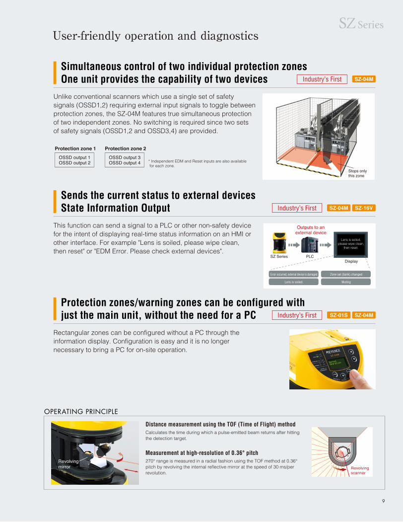
OPERATING PRINCIPLE
Calculates the time during which a pulse-emitted beam returns after hitting the detection target.
Distance measurement using the TOF (Time of Flight) method
270° range is measured in a radial fashion using the TOF method at 0.36° pitch by revolving the internal reflective mirror at the speed of 30 ms/per revolution.
Measurement at high-resolution of 0.36° pitchRevolvingmirror
Sends the current status to external devicesState Information Output
This function can send a signal to a PLC or other non-safety device for the intent of displaying real-time status information on an HMI or other interface. For example "Lens is soiled, please wipe clean, then reset" or "EDM Error. Please check external devices".
SZ-16VSZ-04M
SZ SeriesUser-friendly operation and diagnostics
Industry’s First
Simultaneous control of two individual protection zonesOne unit provides the capability of two devices
Unlike conventional scanners which use a single set of safety signals (OSSD1,2) requiring external input signals to toggle between protection zones, the SZ-04M features true simultaneous protection of two independent zones. No switching is required since two sets of safety signals (OSSD1,2 and OSSD3,4) are provided.
SZ-04MIndustry’s First
Protection zone 1
OSSD output 1OSSD output 2 * Independent EDM and Reset inputs are also available
for each zone.Stops only this zone
Protection zones/warning zones can be configured with just the main unit, without the need for a PC
Rectangular zones can be configured without a PC through the information display. Configuration is easy and it is no longer necessary to bring a PC for on-site operation.
SZ-04MSZ-01SIndustry’s First
Protection zone 2
OSSD output 3OSSD output 4
Lens is soiled,please wipe clean,
then reset.

Guides the user through a step-by-step setup of functions.
Setup navigation function
For the ultimate in ease of use, simply mount the SZ in the desired location, clear the area, and click the "Auto-matic Drawing" tool. Immediately the SZ draws a zone around existing obstacles.
Automatic -Drawing function
USB Port
OTHER FUNCTIONS
The easiest, most intuitive, step-by-step scanner configuration software you will ever use
Suspension in Teaching modeThis function temporarily overrides safety functions during the robot's "teach" mode. It can only be activated when the SZ receives the teach mode signal from the robot.
Industry first
SZ-H1S configuration software is fast, easy,and loaded with useful, time-saving tools SZ-16VSZ-04MSZ-01S
Output connectable to either NPN/PNPRegardless of the OSSD output type (NPN, PNP) being used, all non-safety outputs can be wired for either NPN or PNP operation depending on input device polarity.
Industry first
Interference reduction functionThe SZ Series has two scanning cycles, which makes it possible to reduce mutual interference between the SZs installed face-to-face.
Industry first
10
USB cable

11
Product LineupMain Unit * Cables and brackets are not included. Select separately.
Brackets (Appearance when mounted)
PC Software (Standard accessory)
USB Cable (Optional)
Appearance
Name
SZ Series Configuration Software
Appearance Name ModelLength
USB cable5m OP-86941
5m
Weight
Model
SZ-H1S
Weight
Mounting bracket (Optional)
Appearance Type Model Weight
Horizontal mounting bracket
Horizontal mounting bracket with
angle alignment
Approx. 690g
Approx. 850g
Approx. 960g
Vertical mountingbracket with
angle alignment
L-shaped mountingbracket with
angle alignment
OP-86935
OP-86936
OP-86935 Horizontal mount OP-86936 Vertical mount OP-86937 Horizontal mount OP-86938 Vertical mount OP-86939 L-shaped mount
Approx. 250g
Approx. 180g
Appearance Type Model Weight
OP-86937
OP-86938
OP-86939
Cable
Appearance CompatibleWith
Model
SZ-P5PS
SZ-P5NS
SZ-P10PS
SZ-P10NS
SZ-P20PS
SZ-P20NS
SZ-P5PM
SZ-P5NM
SZ-P10PM
SZ-P10NM
SZ-P20PM
SZ-P20NM
SZ-01S
SZ-04MSZ-16V
Length
5m
10m
20m
5m
10m
20m
16.4'
32.81'
65.62'
16.4'
32.81'
65.62'
Output
PNP
NPN
PNP
NPN
PNP
NPN
PNP
NPN
PNP
NPN
PNP
NPN
* Connector colors; PNP:Black, NPN:Gray
Approx. 80g
Approx. 200g
Type
Simple function type
Multi-function type
Multi-zone sets (banks) type
Model
SZ-01S
SZ-04M
SZ-16V
# of zone sets (# of banks)
1
4
16
Approx. 1.6 kg
Approx. 280g
Approx. 530g
Approx. 1,040g
Approx. 360g
Approx. 720g
Approx. 1,400g
Weight Weight
Standard mounting bracket Mounting bracket with angle alignment
Standard mounting bracket Mounting bracket with angle alignment
16.4'16.4'
Vertical mountingbracket
SZ Series

12
Specifications
SZ-04MModel
Type
Detectioncapability
Light source
Rating
OSSD output
Input (safety-related)
Non safety-related output(AUX output)
Muting lamp output
Environmental resistance
Material
Cable length
Approvedstandards
Minimum detectable object size
Detectable angle
Response time(ON to OFF)
Response time(OFF to ON)
Max. protectionzone
Max. warning zone(non safetyrelated)*1
Additional safety distance
Type, wavelength
Laser class
Power voltage
Power consumption
Output
Max. load current
Residual voltage (during ON)
OFF-state voltage
Leakage current
Max. capacitive load
Load wiring resistance
Input resistance
Output
Max. load current
Residual voltage (during ON)
(AUX6 output can be assigned for themuting lamp output)
Enclosure protection
Operating ambient temperature
Storage ambient temperature
Operating relative humidity
Storage relative humidity
Surrounding light
Vibration
Shock
Main unit case
Window
EMC
Safety
General scan cycle (Scan cycle A)
Specific scan cycle (Scan cycle B)
General scan cycle (Scan cycle A)
Specific scan cycle (Scan cycle B)
Minimum detectable object size: 2.76" 70 mm/5.91" 150 mm
Minimum detectable object size: 1.97" 50 mm
Minimum detectable object size: 1.58" 40 mm
Minimum detectable object size: 1.18" 30 mm
Minimum detectable object size: 2.76" 70 mm/5.91" 150 mm
Minimum detectable object size: 1.97" 50 mm
Minimum detectable object size: 1.58" 40 mm
Minimum detectable object size: 1.18" 30 mm
Multi-function type
Diameter 1.18" 30 mm/1.58" 40 mm, 1.97" 50 mm, 2.56" 70 mm, 5.91" 150 mm (depends on the setting)Reflectance 1.8% min., Speed 5.25 ft/s 1.6 m/s max.
270° (-45° to 225°)
60 ms (2 scanning) to 480 ms (16 scanning)
66 ms (2 scanning) to 528 ms (16 scanning)
Response time of ON to OFF + 125 ms
13.78' 4.2 m (-5° to 185°), 9.19' 2.8 m (-45° to -5°, 185° to 225°)
9.84' 3.0 m (-5° to 185°), 6.56' 2.0 m (-45° to -5°, 185° to 225°)
7.87' 2.4 m (-5° to 185°), 5.25' 1.6 m (-45° to -5°, 185° to 225°)
5.91' 1.8 m (-5° to 185°), 3.94' 1.2 m (-45° to -5°, 185° to 225°)
32.18' 10.0 m (-5° to 185°), 22.97' 7.0 m (-45° to -5°, 185° to 225°)
24.61' 7.5 m (-45° to -5°, 185° to 225°), 16.4' 5.0 m (-45° to -5°, 185° to 225°)
19.69' 6.0 m (-45° to -5°, 185° to 225°), 13.12' 4.0 m (-45° to -5°, 185° to 225°)
14.76' 4.5 m (-45° to -5°, 185° to 225°), 9.84' 3.0 m (-45° to -5°, 185° to 225°)
3.94" 100 mm *2
Infrared laser diode, 905 nm
Class 1 IEC / EN 60825-1: 2007Class 1 CFR 21 1040.10, 1040.11 (Laser Notice No.50)
Class 1 JIS C6802: 2005
24 V DC ±10% (Ripple P-P 10% or less): When using a converter power supply24 V DC +20%/-30%: When using a battery
Max. 9.5 W (without load)Max. 50W (with load)
PNP or NPN (Selectable according to the connector cable)
4 outputs
500mA*3
Max. 2.5 V (with a cable length of 16.4' 5 m)
Max. 2.0 V (with a cable length of 16.4' 5 m)
Max. 1 mA *4
2.2 μF (with a load resistance of 100Ω)
Max. 2.5Ω *5
4.4 kΩ (for Input 1,3, 4, and 5)2.2 kΩ (for Input 2 and 6)
PNP/NPN totem pole output
6 outputs
50mA
Max. 2.5 V (with a cable length of 16.4' 5 m)
IP65(IEC60529)
–10 to +55°C (No freezing) 14 to 131°F
–25 to +60°C (No freezing) –13 to 140°F
35 to 85% RH (No condensation)
35 to 95% RH
Incandescent lamp: 1500 lx or less *6
10 to 55 Hz, 0.7 mm compound amplitude, 20 sweeps each in X, Y, and Z directions
100 m/s2 (Approx. 10 G), 16 ms pulse in X, Y, Z directions, 1,000 times each axis
Aluminum die casting, SPHC (Bottom)
Polycarbonate
65.62' 20 m or less * 7
IEC61496-1, EN61496-1, UL 61496-1
EN55011 Class A, FCC Part15B Class A
IEC61496-1, EN61496-1, UL 61496-1 (Type 3 ESPE)
IEC61496-3, EN61496-3 (Type 3 AOPDDR)
IEC61508, EN61508, IEC62061, EN62061 (SIL2)
EN ISO13849-1:2006 (PL d, Category 3)
UL508, UL1998
SZ-16V
Multi-zone sets (banks) type
Max. 10.5 W (without load)Max. 43W (with load)
2 outputs
4.4 kΩ (for Input 1 and 3 to 10)2.2 kΩ (for Input 2)
4 outputs
SZ-01S
Simple function type
Max. 9.5 W (without load)Max. 39W (with load)
2 outputs
4.4 kΩ (for Input 1)2.2 kΩ (for Input 2)
2 outputs
*1 20% or more reflectance is necessary for the minimum detectable object in the warning zone.*2 If there is a high reflective background within 49.21’ 1.5 m from the boundary of the protection zone, 7.87” 200 mm must be added as supplementary necessary distance to the protection zone in case of calculation of the minimum safety distance.*3 The total load current of the OSSD output and the AUX output must be 1.5 A or less in case of the converting equipment for power supply, while it must be 1.0 A (0.5 A with 16.4’ 5m of cable length) or less in case of the battery.*4 This also takes into account the situations when power is either off or disconnected.*5 The wiring resistance between the OSSD output and the connected equipment (excluding the resistance of the cable) must be 2.5 Ω or less to ensure operation. However, it must be 1.0 Ω or less if the load current is 300 mA or more.*6 The SZ should not be installed so as to have light interference within ±5° to the detection plane.*7 It must be 32.81’ 10 m or less if the power is supplied by the battery.
PLdCategory3SIL2Type3
Can be connected to the incandescent lamp(24V DC, 1 to 5.5W) and LED lamp (load
current 10 to 230 mA)
EMS
EMI

13
Example of wiring
For the PNP output type cable
• In case of "Manual/Automatic" on the configuration of start/restart, the switch with N.C. type (S1)should be used for reset operation.
• In case of "Automatic/Automatic" on the configuration of start/restart, yellow wire should be short-circuited to +24 V.
• When "Not use" is applied as the operation mode for OSSD3/4, the gray and gray/black wire mustbe insulated (open-circuit)
• In case of NOT applying the EDM function, both red wire and red/black must be insulated (open-circuit).
• In case of NOT applying the AUX output, the wire for AUX must be insulated (open-circuit).• K5, K6 and PLC are NON SAFETY-RELATED systems.
K1, K2, K3, K4: External device (Safety relay, magnet contactor, etc.)K5, K6: Solid state contactorS1: Switch for reset operation (N.O.)S2: Switch for override (N.O.)PLC: Used for monitoring, not for control systems related to safety.P1, P2: Muting devices (ex. PZ series with PNP output, Keyence Corp.)M: 3-phase motorL: Muting lamp
Example of wiring for simple function type (SZ-01S) Configuration of start/restart mode: Manual/Manual
For the NPN output type cable
For the PNP output type cable
Example of wiring for multi-function type (SZ-04M)Multi-OSSD function: Mode A, B, C and Not use, configuration of start/restart mode: Manual/Manual in case of applying the muting function
For the NPN output type cable
(AU
X1)
Ora
nge
(AU
X2)
Ora
nge/
Bla
ck
(AU
X3)
Pin
k
(AU
X4)
Pin
k/B
lack
(0V
) B
lue
(OS
SD
1) B
lack
(OS
SD
2) W
hite
(OS
SD
3) G
ray
(ED
M 1
/2)
Red
(ED
M 3
/4)
Red
/Bla
ck
(Mut
ing
inp
ut2)
Lig
ht B
lue/
Bla
ck
Shi
eld
S1
K3K1
K2 K4
K5 K6K2K1
M
L
K4K3
M
IN
PLC
OUT
S2
P2
P1BlackBlue
BlackBlue
(AU
X5)
Gre
en
(AU
X6
outp
ut)
Gre
en/B
lack
(+24
V)
Bro
wn
(OS
SD
4) G
ray/
Bla
ck
(Res
et in
put
) Ye
llow
(Mut
ing
inpu
t1) L
ight
Blu
e
Ove
rrid
e in
put
Yel
low
/Bla
ck
Brown
Brown
M
(AU
X1)
Ora
nge
(AU
X2)
Ora
nge/
Bla
ck
(AU
X3)
Pin
k
(AU
X4)
Pin
k/B
lack
(0V
) B
lue
(OS
SD
1) B
lack
(OS
SD
2) W
hite
(OS
SD
3) G
ray
(OS
SD
4) G
ray/
Bla
ck
(ED
M 1
/2)
Red
(ED
M 3
/4)
Red
/Bla
ck
Shi
eld
L
K5 K6K2K1
M
K1 K2 K3 K4
K4K3IN
PLC
OUT
K3K1
S1K2 K4 S2
P1BlackBlue
BlackBlue P2
Brown
Brown
(AU
X5)
Gre
en
(AU
X6
outp
ut)
Gre
en/B
lack
(+24
V)
Bro
wn
(Res
et in
put
) Ye
llow
(Tea
chin
g re
ady
inpu
t2) L
ight
Blu
e/B
lack
(Tea
chin
g m
ode
inp
ut1)
Lig
ht B
lue
Ove
rrid
e in
put
Yel
low
/Bla
ck
• In case of "Manual/Automatic" on the configuration of start/restart, the switch with N.C. type (S1)should be used for reset operation.
• In case of "Automatic/Automatic" on the configuration of start/restart, yellow wire should be short-circuited to 0 V.
• When "Not use" is applied as the operation mode for OSSD3/4, the gray and gray/black wire mustbe insulated (open-circuit)
• In case of NOT applying the EDM function, both red wire and red/black must be insulated(open-circuit).• In case of NOT applying the AUX output, the wire for AUX must be insulated (open-circuit).• K5, K6 and PLC are NON SAFETY-RELATED systems.
K1, K2, K3, K4: External device (Safety relay, magnet contactor, etc.)K5, K6: Solid state contactorS1: Switch for reset operation (N.O.)S2: Switch for override (N.O.)PLC: Used for monitoring, not for control systems related to safety.P1, P2: Muting devices (ex. PZ series with NPN output, Keyence Corp.)M: 3-phase motorL: Muting lamp
K1 K2 K3 K4
SZ Series
PLC
S1
M
K1K2
K2
K3K2K1
K1
(AU
X1)
Ora
nge
Shi
eld
(AU
X2) O
rang
e/B
lack
(0V
) B
lue
(OS
SD
1) B
lack
(OS
SD
2) W
hite
(ED
M in
put
) R
ed
(+24
V)
Bro
wn
(Res
et in
put
) Ye
llow
Shi
eld
(AU
X1)
Ora
nge
(AU
X2) O
rang
e/B
lack
(0V
) B
lue
(OS
SD
1) B
lack
(OS
SD
2) W
hite
(ED
M in
put
) R
ed
S1
K2K1
K2
IN OUT
PLC
K3K2K1
M
K1
(+24
DC
) B
row
n
(Res
et in
put
) Ye
llow
IN OUT
K1, K2: External device (Safety relay, magnet contactor, etc.)K3: Solid state contactorS1: Switch for reset operation (N.O.)PLC: Used for monitoring, not for control systems related to safety.
• In case of "Manual/Automatic" on the configuration of start/restart, the switch with N.C. type (S1) should be used for reset operation.
• In case of "Automatic/Automatic" on the configuration of start/restart, the yellow wire should be short-circuited to +24 V.
• In case of NOT applying the EDM function, the red wire must be insulated (open-circuit).
• In case of NOT applying the AUX output, the wire for AUX must be insulated (open-circuit).
• K3 and PLC are NON SAFETY-RELATED systems.
• In case of "Manual/Automatic" on the configuration of start/restart, the switch with N.C. type (S1) should be used for reset operation.
• In case of "Automatic/Automatic" on the configuration of start/restart, the yellow wire should be short-circuited to 0 V.
• In case of NOT applying the EDM function, the red wire must be insulated (open-circuit).
• In case of NOT applying the AUX output, the wire for AUX must be insulated (open-circuit).
• K3 and PLC are NON SAFETY-RELATED systems.
K1, K2: External device (Safety relay, magnet contactor, etc.)K3: Solid state contactorS1: Switch for reset operation (N.O.)PLC: Used for monitoring, not for control systems related to safety.

14
Maincircuit
Maincircuit Main
circuitMaincircuit
Maincircuit
Maincircuit
+24V
Input
0V
+24V
Input
0V
+24V
Output
0V
+24V
Output
0V
+24V
Output
0V
+24V
Output
0V
• For the PNP output type cable • For the NPN output type cable • For the PNP output type cable • For the NPN output type cable
• Common for the PNP output type cable / NPN output type cable • Common for the PNP output type cable / NPN output type cable
Input circuit OSSD output circuit (Safety output)
AUX output circuit (Non-safety output) Muting lamp output
A : approx. 20 µs (If a capacitive load is connected, max. 200 µs can apply.)B : approx. 30 ms
The devices connected to the OSSD, such as safety relay or contactor, should not respond to these temporary, self-diagnostic OFF-signals.
A
B B B B
A A A
OSSD1ON
OFF
B
A
B
A
OSSD2ON
OFF
B
A
B
A
OSSD3ON
OFF
B
Approx. 780 ms
A A
OSSD4ON
OFF
NOTE
For the PNP output type cable
Example of wiring for multi-zone sets (banks) type (SZ-16V) Configuration of start/restart mode: Manual/Manual
For the NPN output type cable
M
(AU
X1)
Ora
nge
(AU
X2)
Ora
nge/
Bla
ck
(AU
X4)
Red
/Bla
ck
(Ban
k in
put
A)
Lig
ht B
lue
(Ban
k in
put
B)
Gra
y
(Ban
k in
put
C)
Pin
k
(Ban
k in
put
a)
Lig
ht B
lue/
Bla
ck
(Ban
k in
put
b)
Gra
y/B
lack
(Ban
k in
put
c)
Pin
k/B
lack
(ED
M)
Red
(0V
) B
lue
(OS
SD
1) B
lack
(OS
SD
2) W
hite
Shi
eld
K3K2K1
K1
S1K2
K1 K2
IN OUT
(AU
X3)
Yel
low
/Bla
ck
(Ban
k in
put
D)
Gre
en
(Ban
k in
put
d)
Gre
en/B
lack
(Res
et in
put
) Ye
llow
(+24
V)
Bro
wn
AGV control unit
(AU
X1)
Ora
nge
(AU
X2)
Ora
nge/
Bla
ck
(AU
X4)
Red
/Bla
ck
(Ban
k in
put
A)
Lig
ht B
lue
(Ban
k in
put
B)
Gra
y
(Ban
k in
put
C)
Pin
k
(Ban
k in
put
a)
Lig
ht B
lue/
Bla
ck
(Ban
k in
put
b)
Gra
y/B
lack
(Ban
k in
put
c)
Pin
k/B
lack
ED
M R
ed
(0V
) B
lue
(OS
SD
1) B
lack
(OS
SD
2) W
hite
Shi
eld
K3K2K1
M
K1
S1K2
K1 K2
IN OUT
(AU
X3)
Yel
low
/Bla
ck
(Ban
k in
put
D)
Gre
en
(Ban
k in
put
d)
Gre
en/B
lack
Res
et in
put
Yel
low
(+24
V)
Bro
wn
AGV control unit
• In case of "Manual/Automatic" on the configuration of start/restart, the switch with N.C. type (S1)should be used for reset operation.
• In case of "Automatic/Automatic" on the configuration of start/restart, yellow wire should be short-circuited to +24 V.
• In case of NOT applying the EDM function, red wire must be insulated (open-circuit).• In case of NOT applying the AUX output, the wire for AUX must be insulated (open-circuit).• K3 is NON SAFETY-RELATED system.
K1, K2: External device (Safety relay, magnet contactor, etc.)K3: Solid state contactorS1: Switch for reset operation (N.O.)
When the SZ detects an object (someone or something) in the protection zone, the OSSD goes to the OFF-state.The OSSD is a safety output for safety-related part of a machine control system.OSSD 1/2 is a pair of safety outputs that performs the output of same state. Similarly, OSSD 3/4 is also a pair of safety outputs that performs the output of same state.The SZ generates self-diagnosis signals on its internal control circuit to perform diagnostics on the OSSD. These signals periodically force the OSSD into a temporary OFF-state when the OSSD is in the ON-state (when the SZ detects no object in the protection zone.).The internal control circuit receives a feed-back signal (OFF-signal) based on the self-diagnosis, the SZ determines that its OSSD is in the normal operation. If the OFF-signal is not returned to the internal control circuit, the SZ determines that there is a problem in its OSSD or wiring and goes to the error state.
OSSD Time chart for self-diagnosis pulse
Input / output circuit
• In case of "Manual/Automatic" on the configuration of start/restart, the switch with N.C. type (S1)should be used for reset operation.
• In case of "Automatic/Automatic" on the configuration of start/restart, yellow wire should be short-circuited to 0 V.
• In case of NOT applying the EDM function, red wire must be insulated (open-circuit).• In case of NOT applying the AUX output, the wire for AUX must be insulated (open-circuit).• K3 is NON SAFETY-RELATED system.
K1, K2: External device (Safety relay, magnet contactor, etc.)K3: Solid state contactorS1: Switch for reset operation (N.O.)

15
SZ SeriesDimensions
270°
15°
78
270°
19
3.07”
0.75”
14 0.55”φ6.3
15 0.59”
174150
6.85”5.91”
120 8014
26
0.55”
4.72”3.15”
1.02”
15°
SZ Main unit Horizontal mounting bracket (Model: OP-86935)
Vertical mounting bracket (Model: OP-86936)
Horizontal mounting bracket with angle alignment
Vertical mounting bracket with angle alignment (Model:OP-86938)
L-shaped mounting bracket with angle alignment(Model: OP-86939)
10
56 59
22
40.2
Detectable angle
Original ofdetection area
270°
9
29.2
100.8
12104
64.5
104
30
110
24
M5 x 4 (Pitch: 0.8)Depth: 9
73
144
120
36
110
135
78
13460
194.6
170
14
161.2
140
60
4
84
70
Unit: mm inch
45°
4-φ6.3
270°
270° 270°
78
4-φ6.3
14
25
25
19
φ6.3
71.3
19
14
15°
14
15°
100
91
100
60
149151.2
Detectingsurface
(60)(15)
160
1.58” 0.39”
3.94”
3.94”
3.58”
2.36”
2.36”
0.59”
4.09”
1.18”
4.09”
0.47”0.35”
3.97”
4.33”
0.98”
4.33”
5.31”
0.98”1.42”
0.94”
0.35”
0.55”
2.87”
5.67”4.72”
1.15”
2.54”
5.87”5.95”
3.31”2.36”
2.36”
5.28”
6.69”
7.66”
2.81”
0.15”
2.76”
6.35”
2.20”2.32”
0.87”
3.07”
0.75”6.30”
5.51”
0.55”0.55”0.55”
3.07”
0.75”
73
14
0.55”
2.87”
66
170
190
2-φ6.3
6.69”
7.48”
2.60”

KA1-0049
Specifications are subject to change without notice.
CALL TOLL FREE
TO CONTACT YOUR LOCAL OFFICE
1 - 8 8 8 - 5 3 9 - 3 6 2 3
Corporate Office 50 Tice Blvd., Woodcliff Lake, NJ 07677 Phone: 201-930-0100 Fax: 201-930-0099 E-mail: [email protected]
■ Regional offices COFLGAIL
DenverTampaAtlantaChicago
ALCACA
BirminghamN.CaliforniaLos Angeles
VAWA
RichmondSeattle
SCTNTNTX
GreenvilleNashvilleKnoxvilleDallas
Fax: 201-930-0099www.keyence.com
KEYENCE CORPORATION OF AMERICA
KEYENCE CANADA INC.
Head Office Phone: 905-696-9970 Fax: 905-696-8340 E-mail: [email protected] Phone: 514-694-4740 Fax: 514-694-3206
KEYENCE MEXICO S.A. DE C.V.
Phone: +52-81-8220-7900 Fax: +52-81-8220-9097 E-mail: [email protected]
INKSKYMA
IndianapolisKansas CityLouisvilleBoston
MIMIMNMO
DetroitGrand RapidsMinneapolisSt. Louis
NJNYNCNC
Woodcliff LakeRochesterCharlotteRaleigh
OHOHORPA
CincinnatiClevelandPortlandPhiladelphia
Copyright (c) 2009 KEYENCE CORPORATION. All rights reserved. SZ-KA-C-E 0089-4 611216 Printed in Japan
* 6 1 1 2 1 6 *
With the new functions, it is no longer necessary to purchase an additional control unit. Functions like muting and beam axis intensity monitoring that used to be difficult or impossible, are now easy to setup using the software. As a result, on-site installation time will be greatly reduced.
Fixed Blanking functionFor Stationary Objects
Floating Blanking functionFor Moving Objects
Clearance height 1 Clearance height 2
Programmable Muting functionIncrease safety by muting specific beams according to target height
Safety Light Curtain SL-V Series
Super Slim Line-up
Additional EquipmentSL-VF series
Minimum detectable objectφ0.55”φ14mm
SL-VH series
Minimum detectable objectφ0.98”φ25mm
SL-VHM series
Minimum detectable objectφ0.98”φ25mm
SL-VFM series
Minimum detectable objectφ0.55”φ14mm
Super Heavy Duty Line-up
NEW NEW
Safety Controller
SC-S11
Safety Relay Terminal
SL-T11R
NEWNEW
NEWPC Configuration Software
SL-VH1SUSB Cable (2m 6.56’)
OP-51580Interface Unit
SL-V1UB
NEW