
IBM System x3650 M3 1 ® IBM System x3650 M3 IBM Redbooks Product Guide
Upload
khangminh22Category
view
1download
0
Systems Reference Library
IBM System/360 Operating System Oueued Telecommunications Access Method Message Control Program
File No. S360-30 Form C30-2005-2 OS
This punlication contains specifications on the use of the Queued Telecommunications Access Method (QTAM) and the IBM System/360 operating System to support telecommunications applications.. Information in this publication will facilitate the construction of a QTA~ message control program by the problem programmer. Complete descriptions of QTAM macro instructions are included.
For detailed information on the services provided by QTAM to support a message processing program, refer to IBM System/360 Operating system: QTAM Message Processing Program Services, Form C30-2003.

PREFACE
This publication contains information about use of the facilities of the Queued Telecommunications Access Method (QTAM) to construct a message control program to support a telecommunications application. A companion publication, IBM System/360 Operating System: QTAM Message Processing Program Services~ Form C30-2003, provides information about constructing message processing programs that may be required in addition to the message control program.
The reader should be familiar with the programming concepts and terminology introduced in the following publications:
IBM System/360 Operating System:
Introduction, Form C28-6534
Concepts and Facilities" Form C28-6535
Job Control Language, ForIT C28-6539
Assembler Language, Form C28-6514
supervisor and Data Management services, Form C28-6646
Supervisor and Data Management MacroInstructions, Form C28-6647
The reader should also be familiar with those of the following publications that apply to equipment in his system configuration:
Direct Access Storage Devices:
IBM System/360 Component Description: 2314 Direct Access Storage Facility and 2844 Auxiliary storage Contrel, Form A26-3599
IBM System/360 Component Descriptions: 2841 Storage Control,
Third Edition, November 1968
This publication corresponds to OS Release 17. It is a major revision of, and renders obsolete, Form C30-2005-1 and associated Technical Newsletters. Changes not documented in Technical Newsletters to the previous edition are indicated in the following manner: changes to the text are indicated by a vertical line to the left of the change; in the case of a page which contains all new information, a bullet (.) is placed next to the page number; similarly, changed or added illustrations are denoted by a bullet tc the left of the caption.
Significant changes or additions to the specifications contained in this publication are continually being made. When using this publication in connection with the use of IBM equipment, check the latest SRL Newsletter for revisions or contact the local IBM branch office.
Requests for copies of IBM publications should be made to your IBM representative or to the IBM branch office serving your locality.
A form is provided at the back cf this publication for reader's comments. If the form has been removed. comments may be addressed to IBM corporation, Programming Documentation, P.O. Box 12275, Research Triangle Park" North Carolina, 27709.
lc)Copyright International Business Machines Corporation 1966.1967, 1~6B
2302 Disk Storage Models 3 and 4£ 2311 Disk storage Drive'l Model 11 2321 Data Cell Drive! 2303 Drum Storage_ Form A26-5988
Telecommunications Control Units:
IBM 2701 Data Adapter Unit, Principles of Operation~ Form A22-6864
IBM System/360 Component Descriotion: IBM 2702 ~ransmission Control. Form A22-6846
IBM Svstem/360 Component Description: IBM 2703 ~ransmission Control~ Form A27-2703
Terminal Equipment:
IBM 1030 Data Collection system/l Form A24-3018
IBM 1050 Data Communication System: Principles of Operation, Form A24-3474
IBM 1060 Data Communication System, Form A24-3034
IBM Systero/360 Component Description: IBM 2260 Display Station, IBM 2848 Display Control, Form A27-2700
IBM 2740 Communications Terminal, Form A24-3403
Model 20 Functional Characteristicsu
Form A26-5847
Users lacking a background in data communications concepts should read:
Data Communications Primer,! Form C20-1668
IBM System/360 Introduction to Teleprocessing, ForIT C30-2007

INTRODUCTION • • • • ,. • • • • • • 7 Terminal Types Supported ,. • • • • 7 Machine and Device Requirements .. • ... 8 General Requirements and Capabilities 9 Operating System Considerations • • •• 9 Macro Instruction Formats .••• 9
QTAM-CONTROLLED TELECOMMUNICATIONS SYSTEMS: CONCEPTS AND TERMINOLOGY Telecommunications Networks Message Control Message Processing • '. • •• •
OS QTAM CONCEPTS AND FACILITIES General Concepts • . .. • . .. The Operating Environment • • • . QTAM Facilities '. . '.. • '. '. . ..
Data set Definition and Control Information • • • '. . ,. ••
Message Formats • . • • • • .. Message Flow Within the System
Calls From the Computer to an IBM 2740 Model 2 .. . .. • • . ..
Management of switched Lines. Calls From the Computer to a Terminal on a Switched Line
Calls From the computer to a Switched IBM 1050 • • • .. Calls From the Computer to a TWX Terminal • • • . • • • • • • • • •
Calls From a Switched Terminal to the Computer . • • • '. • • • '. • •
Relative Priority of Receiving Versus Sending Operations . •• • .•
Switched Networks .. • . • • Management of WTTA Lines. • .. System Generation Considerations .. Preparing and Entering Telecommunications Jobs •• '. '. '.
TELECOMMUNICATIONS APPLICATIONS Message Control Applications .. .. ..
Message switching • • • •• • .. Data Collection ... • .. • .. • ..
Message Processing Applications Processing Collected Data Inquiry Processing • •
QTAM System Modification •
• 11 '. 12 • 12 • 16
'. 17 '. 17 • 18 • 18
• 19 • 19 • 21
• 25 • 25
• 25
• 26
• 26
• 27
• 27 '. 28 • 28 • 29
• 29
• 31 • 31 • 31 • 31 '. 31 • 32 '. 32 • 32
MESSAGE CONTROL PROGRAM • 33 Parameter Registers • • • • • 33 Data Set Definition • 34 Direct Access Message Queues Data Set 34 Communication Line Group Data ~ets ... 34 Message Log Data Set • .. • • • 34 Checkpoint Data Set. 35 Data Set Definition Macro Instructions • • . .. • •
DCB Macro Instruction • • • • Control Information
Terminal Table. • • • • Single Terminal Entry. • ••
• 35 • 35 • 43 • 43 • 44
CONTENTS
Group Code Entry • '. • • Distribution List Entry Process Prograrr. Entry
• ,. 44
Terminal Table (TERMTBL) Macro Instruction • • • • • • Terminal Table Optional Field (OPTION) Macro Instruction ,. • Terminal Table Entry (TERM) Macro Instruction • • • • . •• .. '. .. • Terminal Table List (DLIST) Macro Instruction '. • • .. • • .. .. .. .. .. Terminal Table Precess (PROCESS)
• 45 45
'. 45
• 46
.. 47
• 50
50 Macro Instruction '. • • .. Example -- Terminal Table Definition .. .. .. • .. • • ..
Polling Lists • • • .. • • • .. .. • 50
• 52 Polling List Definition (POLL) Macro Instruction .... • .. .. • .. •
Buffer Definition and Use Buffer Request Blccks Buffers • ,. .. • .• • • '. BUFFER Macro Instruction
Data Set Initialization and Activation .. .. .. .. • .. .. .. •
OPEN Macro Instruction .. '. .. .. .. .. ENDREADY Macro Instruction .. .. ,. ,.
Line Procedure Specification (LPS) Components of the LPS _ • • .. De'limiter Macro Instructions .. Functional Macro Instructions The Scan Pointer • • ,. • • • .. Error Handling Functional Macro Instructions .. • .. .. .. • • Arrangement of LPS Macro Instruction Descriptions '. '. .. '. ... '. .. .. ,. .. .. Delimiter Macro Instruction Descriptions ,.. • .. .• ..
End Receive (ENDRCV) Macro Instruct ion '. • • • • • AI ..
End Send (ENDSEND) Macro Instruction '. .. • .. ,. • ,. Line Procedure Specification Start
'. 53 • 55 • 55 • 56 • 57
.. 58 • 59 • 60 • 61 • 61 • 62
62 .. 63
• 64
'. 66
66
.. 66
• 66
(LPSTART) Macro Instruction •• 68 Post Receive (POSTRCV) Macro Instruction ,. • • .. • • • '. Post Send (POSTSEND) Macro
• 69
Instruction • • • .. • • .. .. .. .. • '. 69 Receive Header (RCVHDR) Macro Instruction .. .. • .. • • Receive Segment (RCVSEG) Macro Instruct ion • ,. • • • .. .. .. Send Header (SENDHDR) Macro Instruction • .. • .. • Send Segment (SENDSEG) Macro Instruction '. • •• ,. ,. ..
Functional Macro Instruction Descriptions '. • .. • .. .. .. '.
Halt Receive (BREAKOFF) Macro Instruction .. .. .. .. .. • Cancel Message (CANCELM) Macro Instruction .. • • • .. • ..
69
'. • 70
'. 70
'. .. 70
• 70
.. .. .. 70
• 71 COUNTER Macro Instruction ~ • • • • 71
3
Date stamp (DATESTMP) Macro Instruction '. • •• • • .. DIRECT Macro Instruction • End-of-Address (EOA) Macro Instruction .• • •• '. • .. Hardware Error Checking End-of-Block ,(EOB) Macro Instruction • . • • • • End-of-Block and Line Correction (EOBLC) Macro Instruction Error Message (ERRMSG) Macro Instruction • . • • Intercept (INTERCP~) Macro
• 72 '. 72
• 73 • 73
• 74
.. 75
• 75
Instruction '. . • '. .. • .. • 77 Logging (LOGSEG) Macro Instruction • 78 Message Mode (MODE) Macro Instruction • . ... '. '. • ,. • .. Message Type (MSGTYPE) Macrc Instruction • .. • • Operator Control (OPCTL) Macro Instruction • . • • • • PAUSE Macro Instruction Polling Limit (POLLIMIT) Macro
.. 78
.. 80
.. 81 • 82
Instruction • • ,,. • • • • 8 4 REROUTE Macro Instruction • 84 Routing (ROUTE) Macro Instruction • 85 Sequence In (SEQIN) Macro Instruction • • • . • • .. • • Sequence Out (SEQOUT) Macro Instruction • . •• •• • SKIP Macro Instruction • • • .. SOURCE Macro Instruction. • • Time Stamp (TIMESTMP) Macro Instruction • • • • '. •• • '. Translate (TRANS) Macro Instruction WRU Macro Instruction • • • .. .. •
Modifying WTTA Translation Tables RCVEIAT2 and RCVEZSC3 Macro Instructions '. . • • • ••• .. SENDITA2 and SENDZSC3 Macro Instructions '. . • •• • .. • •
Including a User-Written Subroutine Within the LPS •.• • • • • • • Methods of Including the Subroutine The SCAN Subroutine
NETWORK CONTROL FACILI~IES Examining and Modifiying the Telecommunications System
Activating a stopped Line Start Line (STARTLN) Macro
• 86
.. 86
.. 87
.. 87
.. 88 88
• 90 90
• 90
• 91
• 92 92
• 93
• 98
• 98 • 98
Instruction '. . • • • . .. • 98 Examining and Modifying the Terminal Table .... • • • . • . • • .. .. .. .. .. • 99
Copy Terminal Table Entry (COPYT) Macro Instruction • . • • .. • • 99 Change Terminal Table Entry <CHclGT) Macro Instruction • 99
Examining and Modifying Polling Lists 100 Copy Polling List (COPYP) Macro Instruction ............... 100 Change Polling List (CHNGP) Macro Instruction ............. 101
Examining Queue Control Blocks.. • .. .101 Copy Queue Control Block (COPYQ) Macro Instruction • • • '. .101
QTAM SERVICE FACILI~'IES .103
Operator Control Facility _103 Copy Error Counters '....... .. .. 103 Copy Terminal Table Entry .104 Change Terminal Table Entry ,.104 Intercept Messages. .. .. ...... 104 Interval stop • • .. • .. .105 Release Messages • .. .105 stop Line ••••• 105 Start Line.. • .. • • .106 Switch Primary Terminal .106 Invalid Operator Control Messages .106
Error Recovery Procedures .107 Operator Awareness Messages .108 Checkpointing and Restarting the ~essage Control Program
Checkpointing the Message Control • .109
Program • • • .. • .. .. • • .. • .109 Allocating Space on the DASD Q ••• 109 Defining the Checkpoint Data Set •• 110 Opening and Closing the Checkpoint Data Set '... '. '. • .. • '.
Restarting the Message Control Program •• • • '. . • .. • • System Design Considerations ..
Dial Line Considerations • • Dea cti vating the TeLecommunica tions
.110
••• 110 .111
' ... 111
System.. • .. .. .. .. .. • • .. .. .. • .111 CLOSE Macro Instruction .. Q • ~ •• 112
APPENDIX A: DATA AND CONTROL FORMATS USED BY QTAM ' .... 113
APPENDIX B: SUMMARIES OF QTAM MACRO INSTRUCTIONS • '. .. .. • .. .. • ... •• .. .122
APPENDIX C: CONTROL CARD SEQUENCES FOR TELECOMMUNICATIONS JOBS .127
APPENDIX D: QTAM REGISTER USAGE .129 Register 1 -- QTAM Parameter Register. .. • • • • • • • • • .129 Register 2 -- QTAM Parameter Register. .. • • • • • • •• • .. 129 Register 4 LCB Address Register .129 Register 5 -- Scan Pointer Register 129 Register 6 -- Buffer Address Reqister • • • .. • • • • ........ 129 Register 7 -- LPS Routine Base Register. .. .. .. • .. • • .. 129 Register 8 -- Terminal Table Source Entry • co • • • G. • .. 129 Register 11 -- End-of-Segment Address Register • • .. • .. .. • .129 Register 14 -- Return Register for First-Level Routines .. .. .. .. .. .129
APPENDIX E: SUMMARY OF OPERATOR CONTROL MESSAGES • ..... 130
APPENDIX F: FORMAT AND SUMMARY OF MACRO INSTRUCTIONS .............. 131
APPENDIX G: QTAM TERMINAL CODES • .. 135 QTAM Character Set and Code Correspondence Chart • Q • .. • .. • .. ... 135
..... 135 .135
Arrangement of Chart • • Terminal Character Sets Transmission Codes .. .. • •.. '. • • .. 135

Representation of Characters and Bit Patterns • • • • • • ~ Nonequivalent Characters • Substitutions General Notes .• • • • • Control Characters • • • •
Terminal Code Translation Chart
APPENDIX H: EXCHANGING MESSAGES
.136
.136
.136
.137
.138 .. 148
BETWEEN IBM AND NON-IBM TERMINALS .153 End-of-Address • .. • • • • .. .. .153 Carriage Return, Line Feed, New Line, and End-of-Block • .. .. • .153 End-of-Transmission and WRU .154 End-of-Message., End-of-Transmission~ and WRU for WTTA Terminals • .. • .• '. .• .. .. .154
APPENDIX I: QTAM CHECKPOINT DATA RECORD 156
APPENDIX J: RETURN CODES FOR MACRO INSTRUCTIONS USED TO MODIFY AND EXAMINE SYSTEM ~ . .. . . . . .. .. · .157
APPENDIX K: DISK QUEUING RULES .. · .. 158
APPENDIX L: QTAM SAMPLE PROGRAM A ... .. .. 159
APPENDIX M: QTAM SAMPLE PROGRAM B .. .. .. 162
APPENDIX N: ON-LINE TERMINAL TESTING ... 166 Format of Test Request Messages .. 166 Types of Tests Available ......... 168 Terminal Test Rules .............. 169
APPENDIX 0: CPU USAGE METER CONTROL ... 171
GLOSSARY • .174
INDEX • .175
5

FIGURES
Figure 1. Line and station Configuration: Nonswitched Network 13 Figure 2. Line and Station Configuration: switched Network • • 14 Figure 3. Sample Format for an Incoming Message • • • • .. • .. • 20 Figure 4. Sample Format for an outgoing Message Figure 5. QTAJ.l Message Flow (Part 1 of 2) • • • ... Figure 6. Keyword operands for the Direct Access Message Queues DCB Macro Instruction Figure 7. Keyword operands for the Checkpoint DCB Macro Instruction • • • • • • • • Figure 8. Keyword operands for the Communications Line Group DCB
• 21
• 22
.. • 36
• 36
Macro Instruction (Part 1 of 6) •• 37 Figure 9. Addressing and Polling Characters for the TERM Macro Instruction • • .. • • • • • Figure 10. Example: Coding Sequence for Creation of a Terminal Table • • • • • Figure 11. Aids in Specifying BRBs and Buff ers • • .. '. ..
• 49
• 51
• 56 Figure 12. Line Procedure Specification Macro Instructions • 63 Figure 13. Scan Pointer Movement • 65 Figure 14. Communication Line Error Halfword (Part 1 of 2) Figure 15. Line Address ASCII and EBCDIC Equivalents for IBM 2260 Figure 16. Use of MSGTYPE Macro Instruction in an LPS •••• Figure 17. Idle Characters Figure 18. Names of Code Translation Tables Provided by
• 67
80
• 82 • 84
QT AM • '. • • • ,. • • • .. • • • 0 • 91
6
Figure 19. Register Assignments Figure 20. Activation of a User-written Subrcutine through
• 94
MODE '............. '. .. • .. 95 Figure 21. Activation of a Closed, User-Written Subroutine In~ependent of MODE •• 4 • • • • 96 Figure 22. Inclusion of an Open, User-written Subrcutine in the LPS Figure 23. Use of SCAN by a User-Written Subrcutine Activated by MODE • • • .. • .. • .. _ ..
96
• 97 Figure 24. Format of Queue Control Block (QCB> ...... Figure 25. Terminal Table Entry
• .102
Formats (Part 1 of 5) ••• 113 Figure 26. Example of the Terminal Table ...... • .118
.119 Figure 27. Polling List Formats Figure 28. Auto Poll Polling List Format ............. 0 ••• 120 Figure 29. Formats of Filled Buffers ..................... 121 Figure 30. Surrmary of Data Set Definition, Initialization, and Deactivation Macro Instructions •• 122 Figure 31. Surrmary of Control Information Macro Instruction .... 123 Figure 32. Surrmary of Line Frocedure Specification Functional Macro Instructions (Part 1 of 2) Figure 33. Surrmary of Line Procedure Specification Delimiter Macro Instructions ...... Figure 34. Summary of Macro Instructions Used to Examine and Modify the Telecommunications
.. 124
.126
System Status .. • .. • .. • .. .. .. .. .. 126 Figure 35. Surrmary of Operator Control Messages • .. ... • • ... '. , .. 130 Figure 36. EOA and EOT Characters and Sequences • • .. • • • .. .. • '. .155

In the IBM System/360 Operating System, an access method is a procedure for transferring data between main storage and an input/output device. A variety of access methods is available to the user of the operating system (OS). One of these. the Queued Telecommunications Access Method (QTAM), controls data transfer between main storage and remote terminals connected to an IBM 2701, 2702 or 2703 control unit that is attached to the multiplexer channel.
QTAM is a generalized input/output control system that extends the techniques of data management to ·the telecommunications environment. Data sets accessed by the problem programmer are queues of messages coming in from" or going out to" remote terminals via communication lines. Even though the time and order of the arrival and departure of messages to and from the Central Processing unit (CPU) are unpredictable, the programmer can handle the messages as if they were sequentially prganized.
Unlike other commonly used access methods, QTAM furnishes more than just the mechanics for input/output operations,. In addition to the standard GET/PUT macro instruction support for message processing programs" QTAM prDvides a high-level., flexible message control language. QTAMsupplied macro instructions can be used to construct a complete message control program that controls the flow of message traffic from one remote terminal to another (message switching application), and between remote terminals and any message processing programs (message processing applications). An installation-oriented message control program can thus be written in a shorter time than was previously possible ..
A QTAM message control program is generated from a number of assembler macro instructions coded by the programmer. Although the assembler macro-generator is used, the process followed is similar to that used by a high-level corrpiler. A QTAM message control program is open-ended. The user can include functions not provided through the QTAM language by employing OS control program macro instructions" and assembler language instructions and macro instructions.
A message control program is completely device dependent, with all communication lines and terminals identified to the system. Through data set definition and
INTRODUCTION
control-information macro instructionsw the user specifies his equipment configuration and the areas in main storage (buffers) required for his applications. These macros generate the tables and lists of control information that define the environment of the system for the QTAM logic,. Buffers are one of the primary resources in the telecommunications system. The number and size of the buffers required for an application are specified by the user,. The buffers are allocated to a common buffer pool from which QTAM automatically and dynamically obtains them in accordance with immediate requirements,.
QTAM logic modules are also provided for many procedural functions., such as message code translating " routing of messages" and error checking. By selecting the appropriate macro instructions, the user specifies which QTAM logic modules are to be incorporated into his message control program~ In this way., the system can be tailored to the exact requirements of the applications being supported.
The message processing ?rogram services of QTAM enable a programmer to process messages from a telecommunications network with the same easy-to-use macro instructions that he uses for his local input/ output devices. When a QTAM message control program performs the input/output operations., a device-independent message processing program can be written. The applications programmer is shielded from the time and device-dependent aspects o£ the telecommunications environment.
This publication is devoted primarily to the QTAM facilities provided for the construction of a message control program. Message processing programs are discussed in general terms and cnly when necessary to give a complete picture of a QTAMcontrolled telecomrrunications system. For detailed information on message processing programs and the services QTAM provides in supporting them., refer to IBM system/360 Operating System: QTAM Message Processing Program Services,.
TERMINAL TYPES SUPPORTED
OS QTAM supports. the following types of terminals attached to a System/360 multiplexer channel through a telecommunications control unit (IBM 2701 Data Adapter
Introduction 7

Unit or 2702 or 2703 Transmission Control Unit) :
• IBM 1030 Data Collection system on a nonswitched network (1031~1033 only).
• IBM 1050 Data Communication System on a switched network or a nonswitched network.
• IBM 1060 Data Communication System on a nonswitched network.
• IBM 2260-2848 Display Corrplex (remote) on a nonswitched network (2701 only) (1053 is not supported when attached to a 2848).
• IBM 2740 Communications Terminal on a nonswitched network -- four types: Type I: Basic 2740 Type III: Basic 2740 with Station
Type IV:
Type VI:
Control Basic 2740 with Station Control and Checking Basic 2740 with Checking
• IBM 2740 Communications Terminal on a switched network -- four types: Type II: Basic 2740 Type V: Basic 2740 with Transmit
Control and Checking Type VII: Basic 2740 with Checking Type VIII: Basic 2740 wi~h Transmit
Control.
• IBM 2740 Model 2 Communication Terminal on a nonswitched network when equipped with Station Control, with cr without Checking, with or without Buffer Receive ..
• AT&T 83B3 Selective Calling Stations on a nonswitched network.
• western Union Plan 115A outstations on a nonswitched network.
• Common Carrier (8-level code) TWX Stations on a switched network (for example t, AT&T Model 33 or 35 Teletypewriter Terminal, dial service)
• World Trade telegraph terminals (WTTA terminals) on a nonswi tched network, attached through a 2701" 2702., or 2703 that contains a World Trade Telegraph Adapter.
Note: ;rhroughout this publication u "World Trade telegraph (WTTA) terminal" refers to a terminal as defined on page 28, connected through a 2701, 2702 or 2703 Transmission Control Unit that incorporates a World Trade Telegraph Adapter. A "World Trade (WTTA) line" is a line connected in the same manner to a World Trade terminal.
8
MACHINE AND DEVICE REQUIREMENTS
A QTAM message control program can be coded to operate in a minimum size partition of main storage (for estimates of core storage required for QTAM functions, see the publication IBM System/360 Operating System: Storage Estimates, Form C28-6551,.) ~essage queues may be maintained on multiple volumes on either 2311 direct access storage devicesg or on 2314 direct access storage devices. The only additions to the minimum requirements of the IBM System/360 Operating System are:
• All telecommunications terminals must be attached to an IBM 2701 Data Adapter Unit or a 2702 or 2703 Transmission Control. They cannot be attached directly to a channel.
• All IBM 2701" 2702~1 and 2703 control units operating under QTAM control must be attached to the System/360 via the multiplexer channel.
• The hardware timer feature must be present.. At system generation time'l1 the user must specify that the timer facilities are to be included.
• The 1033 output station requires the insertion of three idle characters (hexadecimal 'DF DF DF') prior to each character transmitted to it. The user may insert them either in his LPS or in a message processing task.
• No device may be cperated in burst mode on the multiplexer channel concurrently with QTAM operaticn .•
• All switched lines that are to allow computer-initiated transmissions must have the Auto Call feature, that is:
IBM 1050 on a switched line network# IBM 2740 Type II"V"VII, and VIII on a switched network. Common carrier (8-level code) TWX station on a switched network.
• The user must understand that the high rate of data transfer between the CPU and the 2260 display station can cause the display screen to fill up several times before the terminal operator has had time to read the initial display. Alson a message being entered from a
1A switch on the CE panel on a 2702 can be used to place a given line in CE mode for equipment checking. Care must be taken to insure that no lines are in CE mode when using QTAM since no ending status would be returned to a SIO command.

2260 display station may be destroyed if a message being sent from another terminal comes in before his unit has been polled and the message sent.
The following additional features may be required if certain optional functions provided by QTAM are desired:
• The line correction feature on IBM 1050 terminals, if automatic retry of ~sages from a card reader or tape reader is desired when a transmlsslon error occurs.
• The automatic polling feature (Auto Poll) on the IBM 2703 Transmission Control Unit" if automatic polling of the following terminal types (attached to the multiplexer channel through a 2703) is desired:
IBM 1030. IBM 1050. IBM 1060. IBM 2740 with station Control. IBM 2740 with station Control
and Checking.
The Auto Poll feature is standard on the 2703 Transmission Control .•
GENERAL REQUIREMENTS AND CAPABILITIES
To construct a telecommunications system that will operate under control of QTAM (in the operating system environrrent) the user must write:
1. A message control program, 2. Any message processing programs
required by his application.
A telecommunications control system created through the use of the QTAM message control language can:
• Establish contact and control message traffic between computer and remote terminals.
• Dynamically allocate main storage for buffering.
• Perform editing of incoming and outgoing messages (i.e,. , code translation., insertion of new fields in message headers) •
• Forward messages to destination terminals and message processing programs.
• Take corrective action and provide special handling for messages containing errors.
• Maintain statistical information about message traffic.
OPERATING SYSTEM CONSIDERATIONS
QTAM is designed to operate in either Option 2 (Multiprogramming With a Fixed Number of Tasks) or Option 4 (Multiprogramming with a Variable Number of Tasks) of the IBM System/360 Operating System,. Discussions in this publication assume that Option 2 is being used; however" all information applies equally to Option 4, •
Under Option 2" it is suggested that the message control program reside in partition 0" while any message processing programs are in lower priority partitions,. In Option 4~ it is suggested that the message control program be the highest priority job in the system.
~ACRO INSTRUCTION FORMATS
A coding format illustration accompanies each macro instruction description in this publication. The illustrations indicate which operands must be coded exactly as shown" which are variable" which are required", which are optional" etc. The following system of representation is used to describe the macro instruction operands.
1. Both positional and keyword operands are described by a 3-part structure. Positional operands are described by a lowercase name fcllowed by a hyphen and a value mnemonic or a coded value.
Example: t.ermname-chars,. The lowercase name, termname" is merely a convenient ref erence to the operand and" along with the hyphen and value mnemonicw is never coded' by the programmer,. The programmer replaces the positional operand in his coding by an allowable expression defined by the value mnemonic.
For keyword operands# the 3-part structure consists of the keyword", followed by an equal sign (both of which must be coded as shown), followed by a value mnemonic or coded value that describes what to code on the right side of the equal sign. Keyword operands are coded with separating commas.
Example: CALL=integer
2. Coded values are written in the format description as uppercase characters
Introduction 9
3.
10
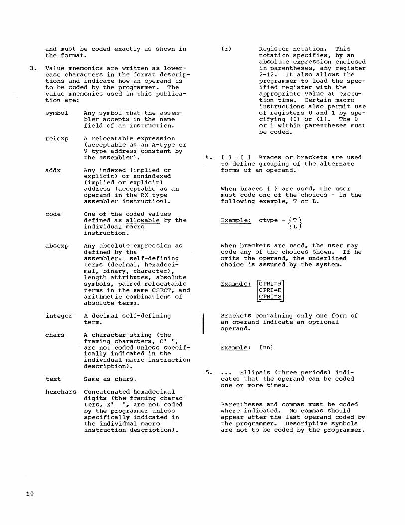
and must be coded exactly as shown in the format,.
Value mnemonics are written as lowercase characters in the format descriptions and indicate how an operand is to be coded by the programmer. The value mnemonics used in this publica-tion are: .
symbol
relexp
addx
code
absexp
integer
chars
text
Any symbol that the assembler accepts in the name field of an instruction.
A relocatable expression (acceptable as an A-type or V-type address constant by the assembler).
Any indexed (implied or explicit) or nonindexed (implied or explicit) address (acceptable as an operand in the RX type assembler instruction).
One of the coded values defined as allowable by the individual macro instruction.
Any absolute expression as defined by the assembler: self-defining terms (decimal. hexadecimal. binary~ character)~ length attributes. absolute symbols. paired relocatable terms in the same CSECT. and arithmetic corrbinations of absolute terms,.
A decimal self-defining term.
A character string (the framing characters. C· .,
, are not coded unless specifically indicated in the individual macro instruction description) •
Same as chars.
hexchars Concatenated hexadecimal digits (the framing characters, X~ .~ are not coded by the prograrrmer unless specifically indicated in the individual macro instruction description).
(r) Register notation. This notaticn specifies, by an absolute express~on enclosed in parentheses, any register 2-12. It also allows the programmer to load the specified register with the appropriate value at execution time.. Certain macro instructions also permit use of registers 0 and 1 by specifying (O) or (1). The 0 or 1 within parentheses must be coded.
4. {} [] Braces or brackets are used to define grouping of the alternate forms of an operand.
When braces { } are used. the user must code one of the choices - in the following exarrple,,, T or L.
Example: qtype - {~}
When brackets are used. the user may code any of the choices shown. If he omits the operandn the underlined choice is assumed by the system4
Example:
~PRI=RU CPRI=E CPRI=S
Brackets containing only one form of an operand indicate an optional operand,.
Example: [nn]
5. Ellipsis (three periods) indi-cates that the operand can be coded one or more times.
Parentheses and commas must be coded where indicated. No commas should appear after the last operand coded by the programmer,. Descripti ve symbols are not to be coded by the programmer.

QTAM-CONTROLLED TELECOMMUNICATIONS SYSTEMS: CONCEPTS AND TERMINOLOGY
This section describes the characteristics and operating concepts of a computer-based" QTAM-controlled telecommunications system: what it is" how its parts are connected, how communication proceeds" and how control is maintained. A number of terms that are used throughout the publication are defined. For ease of reference, many of these terms also appear in the glossary of this publication.
Telecommunications systems vary considerably from one another in terms of the uses to which they are put, the component parts of which they consist., the nature of the message traffic accommodated~ the means of controlling the system, etc. Many of the techniques and terms explained are characteristic of telecommunications systems, either specifically or in general,. Certain def~nitions may be at a slight variance with the reader's previous experience. This arises because. over the years, technical literature has contributed a number of conflicting or arrbiguous definitions and because it is desirable to make certain generalizations to avoid a level of detail inappropriate to the needs of the QTAM programmer. Theref ere" the techniques and terms explained in the following discussion should be understood 'as applying specifically to a computer-based telecommunications system that operates under the control of the QTAM facility of the IBM System/360 Operating System.
A telecommunications system (or network) consists of a number of input" output" or combined input/output devices., usually in geographically dispersed locations~ connected by one or more communications lines. A telecommunications system operating under OS QTAM may be specifically defined as a network of terminals connected to a central computer by one or more half-duplex communication lines. (A half-duplex line is a line over which data can flow in either direction, but in only one direction at a time. )
In communications terminology. the following terms are used to represent the medium that connects the physical components of a system: communication line, data link~ data path, circuit, and channel. In this publication the term communication line (or line) is used to refer to any medium, whether it is a telegraph circuit l1
a telephone circuit, a private circuit~ etc.
A terminal is the unit or units of equipment that accepts keyed or punched data as input for sending to the computer and/or produces printed. punched_ or visually displayed data as output received from the computer. All messages from one terminal to another pass through the computer. In addition,,, the computer can receive and originate messages for the terminals.
A terminal con~ists of a control unit and one or more input/output devices. Each such device is called a component. Each input and output device is considered a separate component, regardless of whether they are physically combined. For e~ample, an IBM 1050 is refer,red to as a terminal; its constituent devices, or components, include the IBM 1053 Printer. the 1054 Paper-Tape Reader, the keyboard section of the 1052 Printer-Keyboard" the printer section of the 1052 Printer-Keyboard. etc.
Terminal is used as a general term to represent the equipment at the remote location. Component is used, where necessary, to distinguish between the individual devices and the terminal as a whole. Station is used to represent the remote location at which a terminal is situated.
Terminals in a telecommunications system operating under OS QTAM control are usually separated from the computer by a distance sufficient to require common-carrier facilities and transmission techniques in order to accomplish communication with the computer. The system, however,., may include terminals on the same premises as the computerw attached to it by local cables. Regardless of the location of the terminal., all supported terminals are classified as "remote" since they must be attached to the computer channel via a Telecommunications Control Unit (TCU) '. The TCU may be an IBM 2701 Data Adapter Unito or a 2702 or 2703 Transmission Control Unit. OS QTAM does not support "local" terminals that are directly connected to a Systern/360 channel.
Each remote terrrinal and TCU is connected to the communications line by a type of data set., modem (modulator/demodulator), line adapter, subset~ etc., depending on the kind of communication line and type of terminal involved.. (Terminals connected to the TCU by local cables do not require data sets.) The precise functions of these units vary, but the overall purpose is the same: to provide an electrical interface between terminal and line,. This publication uses the more common term data set to
Telecommunications Concepts and Terminology 11

represent any of these units (not to be confused with a program data set) ,. The programmer need not concern himself with these data sets. They are mentioned only to provide a complete picture of the line and terminal configuration.
In this publication" computer is used as a general term for the equiprrent and programs at the central processing location (CPU, TCU, etc.), when reference to a specific unit of equipment or programming is not necessary,.
TELECOMMUNICATIONS NETWORKS
A telecommunications system rray consist of a nonswi tched network II a switched network" or a combination of the two.
A nonswitched network consists of a number of private (or leased) lines that connect the computer to one or.rrore remote terminals. The computer and the terminals are physically connected; that is;, the circuits making up the communications lines are continuously established for predetermined time periods during which data transmission may proceed between the computer and the terminals,. Under certain conditions in this type of system" the computer can send messages to more than one terminal on the same line at the same time. The lines that comprise a nonswitched network are known variously as private, leased" or dedicated lines. These lines usually are furnished by a common carrier on a contract basis, between specified locations for a continuous period or regularly recurring periods at stated hours, for the exclusive use of one customer. See Figure 1.
A switched network consists cf a number of remote terminals with which the computer can communicate. The computer and the several terminals are connected by access lines to the common-carrier exchanges serving their respective locations. A complete and continuous data path is established between computer and terminal only for.the period of time in which transmission takes place. The connection is established by dialing the telephorie number of the unit (either terminal or CPU) at the other end4 In this type of system, communication can be established between the computer and only one terminal at a time on each line,.
12
In this case~ line refers to a discrete data path between the telecommunications control unit and the common-carrier exchange. The service provided by the common carrier is typically on a time-used basis. See Figure 2.
In a nonswitched network" the physical circuit connections determine which terminals are associated with each line into the computer. In a switched network. the user specifies which terminals can communicate with the computer over each line.
Some communication networks have characteristics typical of both switched and nonswitched networks. In this publication, the term switched network refers to any network in which a direct phySical connection between computer and terminal must be established by dialing in order for data transmission to occur. The term nonswitched network refers to a network in which the communication lines linking computer and terminals are continuously established, thus requiring no dialing.
~ESSAGE CONTROL
The QTAM message control facilities accomplish efficient, systematic supervision of message traffic. In some respects u the functions performed by QTAM message control procedures parallel those performed in telecommunications. systems that are not computer-or ien ted ...
This section provides a general description of telecommunications systems followed by a discussion of the main functions performed in a computer-based system operated under QTAM control,. Subseql,lent sections of this publication explain how these fUnctions are implemented.
Generally" in any telecommunications system, contact between terminals must be established before a message is sent. In some systems C1 terminals attempting to send a message contend with one another for use of the line. The first terminal to initiate contact on a line that is not currently in use seizes the line and prevents its use by other terminals until it has concluded its message transmissionG A system operated in this manner is called a contention system ..

r------, I I I I I I Terminal I I 1---- I L _______ J
Station
r-------, I I I I I I Terminal I I I '----..... I L _______ J
Station
r--------, I I I I I I Terminal I I I ""'"----- I L _______ J
Station
DS = Data Set
r---
r-------, I I I I
I Terminal I
I I
I '-----.... 1 L _______ .J
Station
Ded i co ted Li nes
Telecommunications Control Unit
Multiplexer Channel
CPU
r-------, I I I I
I Terminal I
I I
I I L _______ J
Station
r-------.., I I I I
I Terminal I
I I
I '-----..... 1 L _______ ..l
Station
r-------, I I I I
I Terminal I
I
I I L _______ ...J Station
Terminal
Terminal
L __________________ _
Central Processing Location
Figure 1,. Line and Station Configuration: Nonswi tched Network
Telecommunications Concepts and Terminology 13

r--------, I I
: Terminal I I I
----,
Terminal Terminal
I I I I I I I I
I I I __ ..J
\ \: I /
, \ I I / I I L ____ _
I I I
Station
r---------, I I I I I I I I
Terminal
I I L _______ .J
Station
Terminal
L _______ _
Station
DS = Data Set X = Common - carrier exchange
, \ L ________ J / L _______ --l
, \ Station / Station
\ \ / \ \ / ',\ / ,\ / '\ / '\ / " '\ / //
" \\ \ /;' " ,\ / / / , ,\ / /
" '\ / / " '\ / ;'
" ~V/ Access Line
,---------, I
Terminal
I I I I I L _______ ...J
Station
r--------l I I
I I I
~--------------~DS Terminal
r---
T elecommun ications Control Unit
Multiplexer Channel
CPU
I I I I L ________ J
Station
----------,
Terminal
Terminal
L ______________________ ~
Central Processing Location
Figure 2. Line and station Configuration: switched Network
In other systems, one of the terminals is specified as the control station. This terminal initiates all contacts for all other terminals on the line, using a procedure known as polling. Polling is a flexible, systematic, centrally controlled
14
method of permitting terminals on a multiterminal line to transmit without contending for use of the line. The control station periodically contacts the other terminals and invites them to send any messages they have ready. In addition~ the
control station itself may elect to send a message. A system operated in this manner is called a polling system.
Polling is accomplished by sending one or more polling addresses on the line, each of which consists of one or more polling characters. Typically, two characters are used; the first selects the terminal, the second selects the specific component of that terminal.. The terminal identified by these characters then sends a response to the control station - a positive response if it has a message to send, a negative response if it does not. The control station may poll a number of terminals and components in turn until one is found that has a message ready.
Similarly, when the control station terminal (or any other terminal) has a message to send, it transmits one or more addressing or call-directing characters on the line. As in polling, two characters are usually used: the first selects the terminal, the second selects the component. The terminal identified by these characters returns a response. A positive response is returned if the terminal is able to accept the message; a negative response is returned if the terminal cannot accept the message.
A QTAM-controlled telecomrrunications system is basically a polling system in which the computer acts as the control station (although certain types of the IBM 2740 Communication Terminal employ techniques similar to those used by a contention system). ~oreover, it is a centralized system in that terminals send their messages to the computer instead of to other terminals,. The computer then relays the messages to the appropriate destination terminals (or to a message processing program) .•
With minor variations~ the polling and addressin~ functions are performed in both switched and nonswitched systems.
In a switched network, the line connection must be completed between computer and terminal before message transmission can proceed. The connection may be established by either the computer or a terminal.
In order to establish the connection, the computer dials the telephone number of the terminal,. (The user provides QTAM with the telephone number of each terminal in the switched network.) The connection is established when the terminal responds. The function performed by the ccmputer in this case is known as calling. Polling or
addressing may then take place. Ordinarily., the computer calls a terminal only to address the terminal (to send it a message), rather than to poll it (to solicit messages).
When a terminal is to establish the connection" the operator at the terminal dials the telephone number of one of the computer's access lines. The connection is established when the computer responds. The function performed by the computer~ in this case, is known as answering. Polling or addressing may then take place. Ordinarily~ a terminal calls the computer only when the terminal is to be polled for a message it has ready for the computer or another terminal.. Regardless of whether the computer or the terminal establishes the line connection g message flow from the terminal to the computer is achieved by polling the terminal. Message flow from the computer to a terminal is achieved by addressing the terrrinal.
Although terminals are permitted to call the computer at any time", the computer,,, in order to fulfill its function as control station. must be able to accept or reject incoming calls. Therefore, the computer performs a function known as enabling the linen which is the process of conditioning the telecommunications control unit to accept incoming calls on a line. The user determines which lines are to be enabled", at a given moment, and which are not. If a terminal calls in on a line that is currently enabled and that is not in contact with another terminal, the line connection is completed and message transmission (preceded by pollin'g or addressing) can occur. If a terminal calls in on a line that is enabled but is occupied with another terminal, the calling terminal receives a busy signal, and contact is not established~ If a terminal calls in on a line that is not currently enabledu the TCU cannot answer the call. Ringing continues until the operator hangs up. In either of the latter two cases, the terminal must wait and call again later.
In a nonswitched network, the line connections between computer and terminals are continuously established; hence" the calling, answering'D and enabling functions are not required. Only the computer can initiate contact with remote terminals (e~cept for Types Iu IIu VI. and VII of IBM 2740 Communications Terminals, which can bid for the computer's attention). Even in this instance" however" QTAM must previously have issued a command that permits the TCU to respond to a bid from the 2740.
Telecommunications Concepts ann Terminology 15

MESSAGE PROCESSING
Message processing is the most variable of all telecommunications functions. The nature of each user's processing routines depends on the individual application.
QTAM provides macro instructions enabling the user's problem program to obtain messages queued for processing and to place
16
response messages on destination queues. These macro instructicns,,, GET and PUT .. together with associated OPEN and CLOSE macros" are presented in the publication Operating System QTAM Message Processing Program Services. QTAM also provides a set of macro instructions for examining and modifying control information used by the access method. These macros are presented in a later section of this publication and in the above publication.

GENERAL CONCEPTS
The function of programs constituting support for a telecommunications system is to systematically and efficiently control the flow of data in a computer-based telecommunications system, and to perform concurrently any required processing af the data. Data enters the s~stem randomly in the form of message blocks from terminals and/or from programs that generate messages. The messages entered at the terminals consist of two principal parts: the message header, containing only control information, and the message text or data. Data is ultimately delivered to one or more terminals and/or programs that process messages.
For a number of reasons, the support is logically divided into two categories:
1. Programming required to identify the telecommunications system to the IBM System/360 Operating System, to establish the line control disciplines required for the various types of terminals and modes of connection, and to control the routing of messages in accordance with the user's requirements.
2. Programming required to process the contents of the messages.
The first category is implemented by routines collectively known as the message control program, which is primarily concerned with the message header. The second category is implemented by one or more ~ sage processing programs, which are primarily concerned with the message text or data.
The paramount reason for dividing telecommunications support into these two types of programs is that message flow in the system is random and proceeds at relatively slow speeds {owing to the operating speeds of the terminals> while the messages, once delivered to the computer, can be processed at computer speeds,. To fully utilize the computing system capabilities, message traffic must proceed asynchronously with message processing. Another reason for having separate message control and message processing programs is that while many device-dependent considerations govern the design of a message control program, they do not a£fect the design of a message processing program. The programmer writing a
as QTAM CONCEPTS AND FACILITIES
message processing program need know only the format of the messages and the characteristics of the data they contain to be able to proceed with the program design.
A message control program serves as an intermediary between the remote terminals and any message processing programso The device-dependent input/output operations are performed by QTAM routines that support the message control program, and are based on the terminal and line configuration of the user's system as specified in the operands of QTAM macro instructions,. To provide maximum efficiency, QTAM uses the operating technique of placing messages on queues on a direct access storage device (DASD), when necessary, and subsequently retrieving these messages for processing.
The message control program can perform limite1 processing of the message, in addition to that performed by a message processing program. Some of these processing operations may be required in order for the message control program to perform its function; for example, scanning the header to determine routing information~ and message code translating. Other optional processing operations are provided by QTAM as a convenience to the user. For example, the message control program can insert the \L... time of day in message headers, obviating ~ the need for a message processing routine to do this.
Every telecommunications system operated
I under QTAM requires one and only one message control program. Depending on the application., one or more message processing programs may be required g or none at all (except that a message processing program is always necessary tc deactivate the telecommunicat1ons system). An example of an application requiring no concurrently running message processing program is a message-switching application. The sole function of its telecommunications support is to receive messages from terminals and forward them unaltered (except for such processing as the message control program may perform) to one or more terminals.
A telecommunications system may include several different terminal types n and both line types (switched and nonswitched). For each combination of line and terminal type, the user must specify a sequence of QTAM message control macro instructions. In general, a separate sequence must be written for each communications line group. A communications line group consists of one
as QTAM Concepts and Facilities 17

or more communication lines of the same type, over which the same type of terminal can communicate with the computer. Each
CiSeqUence of message control macro instructions is called a line procedure specification (LPS); the several LPSs collectively constitute the heart of the message control program.
Example: Assume that a telecommunications system is to consist of four nonswitched lines to which IBM 1050 terminals are connected" one switched line over which contact with IBM 1050s can be made, three nonswitched lines to which IBM 2260s are connected, and two switched lines over which contact with TWX terminals can be made. The system would then have four line groups:
1. A nonswitched 1050 group,. 2. A switched 1050 group. 3. A nonswitched 2260 group. 4. A switched TWX group.
A separate LPS would be required for each group.
Each LPS consists of user-selected macro instructions in two groups: a 'receive group,' which defines the routines required to operate on messages coming in from any line in the line group, and a 'send group,' which defines routines required to operate on messages going out to any line in the line group.
THE OPEKATING ENVIRONMENT
When QTAM is operating under supervision of Option 2 (Multiprogramming with a Fixed Number of Tasks) of the system/360 operating System, the message control program and each of the message processing programs are executed as separate jobs. The message control program must be executed as the highest-priority job and hence must be loaded into partition O. The message processing programs may be located in any of the remaining partitions. If the message control job and the message processing jobs do not require the use of all available p~rtitions, the remaining partitions may be used for batch processing jobs. The batch job(s) should be loaded into the lowestpriority partition(s).
QTAM FACILITIES
The QTAN facilities include a comprehensive set of input/output, message control# translating, and editing routines that
18
relieve the programmer of the detailed and specialized prograrrming usually required in writing a message control program for a telecommunications system. Macro instructions are provided that allow t'he programmer to assemble and linkage edit these routines into an integral message control program designed to meet the exact requirements of an installation.
The primary capabilities of the telecommunication programs that can be created through the use of QTAM macro instructions are:
• Polling terminals.
• Receiving messages from terminals.
• Addressing terrrinalsu
• Sending messages to terminals.
• Dynamically allocating main storage for buffering.
• Performing message editing functions for incoming messages such as: translating from the appropriate transmission code to extended binary coded decimal interchange code (EBCDIC); inserting time-received and datereceived information in the header; recording (logging) the message on a secondary storage medium such as magnetic tape; and maintaining a count of the number of messages received from each terminal.
• Routing messages to appropriate queues, determined by either the destination code specified in the header of the message; or the source from which the message entered the system.
• Queuing messages on a direct access storage device.
• Initiating corrective action when an error or unusual condition is detected.
• Intercepting transmission of messages in error.
• Cancelling messages containing errors.
• Rerouting messages .•
• Transmitting error messages.
• Routing messages with erroneous header information to a special queue.
• Providing message data, in the work unit specified (message, message segment, or record)H to a message processing program.

• Placing response messages generated by message processing programs on queues for subsequent transmission.
• Retrieving messages already queued for transmission to terminals,.
• Performing message editing functions for outgoing messages such as: placing time-sent and date-sent information in the header" placing an output sequence number in the header, logging the outgoing message on a secondary storage device~ maintaining a count of the number of messages sent to each terminal, and translating the message from EBCDIC code to the appropriate transmission code.
• Checkpointing QTAM message control program for subsequent restart after system interruption.
• Providing operator control to system communication through a telecommunications system control terminal.
Providing on-line terminal testing for IBM 1030" 1050" 1060, 2740, and 2260-2848 remote terminals.
DATA SET DEFINITION AND CONTROL INFORMATION
A data control block must be defined for each data set referred to by the message control and message processing programs. This is accomplished by means of DCB macro instructions. A DCB macro instruction must be provided for each of the following types of QTAM data sets:
• Each communication line group (message control program).
• Direct access message queues (message control program).
• Checkpoint (message control program) '. • Each main storage process queue (mes
sage processing program). • Main storage destination queue (message
processing program).
Similarly·, an appropriate DCB macro instruction must be provided for each message log data set used by the message control program. The actual DCB used is a function of the storage medium used for the message log.
The data control blocks in a message control program serve as logical connectors between the message control program and the associated line group" DASD message queues, and message log data sets.. (These data sets are explained in detail in later sections of this publication.) ~he data con-
trol blocks defined in a message processing program are not associated with data sets themselves. They are used to provide control informatiop to QTAM for the transfer of data to and from a message processing program,. The main storage process and destination queues are the principal connectors between a message control program and a message process ing program .•
In addition to the data set definitions, the user must supply control information in the form of macro instructions that are used by the message centrol program to control the sending and receiving of messages. The control informatien consists of:
• The name and address of each terminal" along with related information such as any special distribution lists for sending a message to more than one terminal .•
• The name of each DASD process queue associated with a message processing program to which incoming messages are to be sent ..
• A polling list for each line that indicates the order in which the terminals are to be polled.
• The size and number of main storage buffers that are to be used for messages being sent to and from the terminals. In order to compensate for the differences in the rates of information flow. QTAM automatically and dynamically uses available buffers in accordance with immediate needs.
MESSAGE FORMATS
A message usually consists of two parts: header and text. The message header contains control information for the message such as:
1. One or more destination codes. 2,. The code name for the originating
terminal. 3. The number of ,the message relative to
the numbers of previous messages received from that terminal (input sequence nuffiber).
4. A message~type indicator .• 5. Various other fields containing con
trol data.
Operations on the fields in the header are a primary function of the LPS-defined routines in the message control program. The length and format of the header and the information it contains depends solely on the requir.ements of the application and the user's preferences. The length may be a few characters or rrany characters. In some instances, it is possible to omit headers
OS QTAM Concepts and Facilities 19

entirely. Generally, however" some kind of header is provided. The text portion of a message consists of the information of concern to the party ultimately receiving the message. This party can be either a terminal, or a program that processes the text (message processing program).
The format of the message header dictates the arrangement of the message control program to a great extent. For this reason, the control characters used and the sequence of the fields within the header must be predetermined so that the message control program for the telecommunications system can be properly coded.
The destination code in the message header identifies the terminal or processing program to which the message is to be routed. The message-type indicator can be used to identify a header that is to be processed in a special manner. By inserting certain macro instructions in the message control program, the user can insert in the header such data as the date and time the message is received, the date and time it is sent, and the number of the message in relation to other messages sent to a particular terminal (output sequence number) .
Depending on the type of work unit (message, segment, or record) with which he is dealing~ the user must specify appropriate characters for control purposes.
• A message is that unit of text that is terminated by an end-of-transmission (EOT) character.
• A segment is that portion of a message contained in a single buffer, the size of which is specified by the user.
• A record is that portion of a message terminated by any of the following characters: end-of-block (EOB), endof-text (ETX), carriage-return (CR), line-feed (LF)u or new-line (NL).
• A message block is that portion of the message terminated by EOB.
There are many possible variations for the format of a message header. The sample
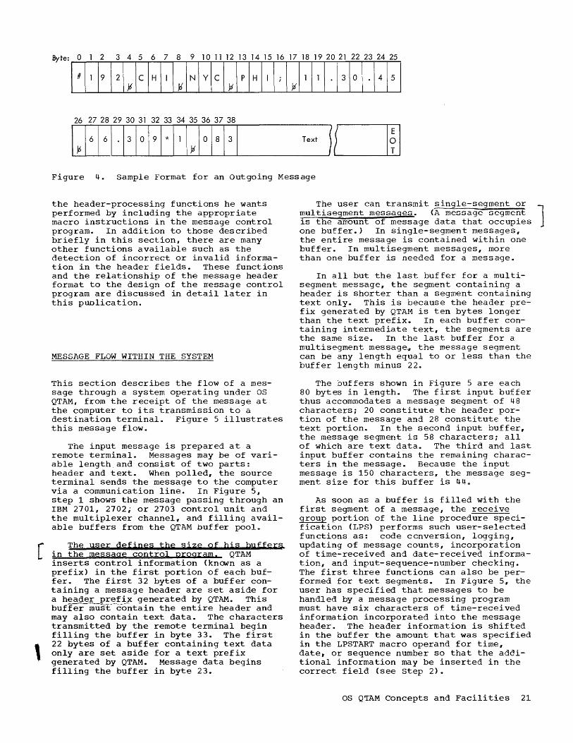
formats shown in Figures 3 and 4 are included simply for illustrative purposes.
The format shown in Figure 3 could be used in a message switching application. Byte 0 contains a machine end-of-address (EOA) character. When the message is transmitted, this character signals the end of nonrecorded machine control characters (such as addressing characters and the machine EOA itself) and the beginning of data characters. The 192 in bytes 1 through 3 is the input sequence number,. Bytes 5 through 7 contain the code for the terminal that originated the message. Bytes 9 through 11 and 13 through 15 contain destination codes specifying the terminals to which the message is to be sent,. In this example, the semicolon in byte 16 has been designated by the user as the program EOA character. Since some of the messages in this application contain multiple destination codes, this control character must follow the last destination code. Bytes 17 and 18 contain characters specifying the priority of the message. The remaining portion of the message is text and is followed by the EOT character.
After the message control program has operated on the message header and before the message header is transmitted to the destination terminals, the format of the message could be as shown in Figure 4. When the message comes into main storage, the message control program inserts timereceived and date-received information in the header. The time-received information in bytes 18 through 25 indicates that the message was received at 11 hours'll 30 minutes, and 45 seconds of the date specified in bytes 27 through 32, which is November 5, 1966. Insertion of this information moves the priority data to bytes 33 and 34. The message is then queued by priority on the direct access storage device. When tbe message reenters main storage prior to transmission to the destination terminals, the message control program places the output sequence number in bytes 36, 37, and 38 of the header. The original text and the EOT character follow the output sequence number.
QTAM,I with its complete set of headerprocessing routines and associated macro instructions g allows the user to indicate
Byte: a 2 3 4 5 6 7 8 9 10 11 12 13 14 15 16 17 18
I~# 11 19~121 ~ ~I c H ~I I ~ I N~I Y I C I----'-----I..-.~ I p}~11 I; 1----,----,--* 11 I_TEXT -----JtCJJ Figure 3. Sample Format for an Incoming Message
20 .
26 27 28 29 30 31 32 33 34 35 36 37 38
T ext ~ fL-----1...-..J1 f I
Figure 4. Sample Format for an outgoing Message
the header-processing functions he wants performed by including the appropriate macro instructions in the message control program. In addition to those described briefly in this section, there are many other functions available such as the detection of incorrect or invalid information in the header fields. These functions and the relationship of the message header format to the design of the rressage control program are discussed in detail later in this puolication.
MESSAGE FLOW WITHIN THE SYSTEM
This section describes the flow of a message through a system operating under OS QTAM, from the receipt of the message at the computer to its transmission to a destination terminal. Figure 5 illustrates this message flow.
The input message is prepared at a remote terminal. Messages may be of variable length and consist of two parts: header and text. When polled., the source terminal sends the message to the computer via a communication line. In Figure 5, step 1 shows the message passing through an IBM 2701, 2702; or 2703 control unit and the multiplexer channel~ and filling available buffers from the QTAM buffer pool.
[ The user defines the sjze gf hjs buffers
in the message control program. QTAM inserts control information (known as a prefix) in the first portion of each buf-fer. The first 32 bytes of a buffer containing a message header are set aside for a header prefix generated by QTAM. This buf~~c:c>ntain the entire header and may also contain text data. The characters transmitted by the remote terminal begin filling the buffer in byte 33. The first
, 22 bytes of a buffer containing text data only are set aside for a text prefix generated by QTAM. Message data begins filling the buffer in byte 23 .•
The user can transmit single-segment or multisegment messages. (A message segment l is the amount of message data that occupies one buffer.) In single-segment messages, the entire message is contained within one buffer. In multisegment messages, more than one buffer is needed for a message.
In all but the last buffer for a multisegment message, the segment containing a header is shorter than a segment containing text only. This is because the header prefix generated by QTAM is ten bytes longer than the text prefix. In each buffer containing intermediate text, the segments are the same size. In the last buffer for a multisegment message~ the message segment can be any length equal to or less than the buffer length minus 22.
The buffers shown in Figure 5 are each 80 bytes in length. The first input buffer thus accommodates a message segment of 48 characters; 20 constitute the header portion of the message and 28 constitute the text portion. In the second input buffer, the message segment is 58 characters; all of which are text data. The third and last input buffer contains the remaining characters in the message. Because the input message is 150 characters, the message segment size for this buffer is 44Q
As soon as a buffer is filled with the first segment of a message, the receive group portion of the li-ne procedure specification (LPS) performs such user-selected functions as: code ccnversion, logging, updating of message counts, incorporation of time-received and date-received information, and input-sequence-number checking. The first three functions can also be performed for text segments. In Figure 5, the user has specified that messages to be handled by a message processing program must have six characters of time-received information incorporated into the message header. The header information is shifted in the buffer the amount that was specified in the LPSTART macro operand for time, date. or sequence number so that the additional information may be inserted in the correct field (see Step 2).
OS Q~AM Concepts and Facilities 21

In performing its function" the LPS scans and processes header fields in accordance with the order indicated by the relative positions of the individual LPS macro
0 e:
'E Q; l-
e: ,2 "0 .~ ,~
Qi 0 0 I-
Figure
22
5.
Telecommunications Control Unit
Header
Multiplexor Channel
Text
QTAM Message Flow (Part 1 of 2)
instructions; the operations are performed in the buffer containing the message segment .•
Message Control Program
(Buffer Pool) I- - - - - - - - - - - - - - - ---1 I I I : First Input Buffer
Header
I
Receive Group of LPS
I I r- - - - - - - - - - - - - - - - --"1
Send Group of LPS
I- - - - - - - - - - - - - - - ---I I I
I I
: First Output Buffer :
1 4 8

DASD Message Queues
Message Contral Program
(Buffer Pool) 1-------------------1 I I I I I I
I I
I I 22 Bytes I I
r------------------~ "11f
MS Process Queue
MS Destination Queue
t- - - - - - - -~ - - - - - ---1 I I I I
I
t-----------------~ (Buffer Pool)
GET
Message Processing Program
Message Charocters
4 Bytes
PUT
Figure 5. QTAM Message Flow (Part 2 of 2)
After performing these functions, the receive group of the LPS routes the prefix (minus the first eight bytes~) and the seg-
~The first eight bytes of a header or text prefix contain control inforrration used only in main storage buffer handling. Therefore these bytes are not placed on the direct access device.
ment to one of two types of queues: DASD destination queues or QASD process queues.
Each DASD destination queue contain~ message segments that are to be transmitted via a certain line, or message segments that are to be transmitted to a certain terminal,. A DASD process queue contains message segments that are to be routed to a message processing prcgram.
OS Q~AM Concepts and Facilities 23

The receive group of the LPS can check the validity of the name of the originating terminal and the destination code before routing the message to a DASD process queue or to a DASD destination queue. Each type of queue is maintained on a direct access storage device~ and all such queues are regarded as one data set, the DASD message queues data set.
Each DASD process queue is associated with a message proctssing program. Messages requiring text processing should be routed to the DASD process queue associated with the message processing program that processes that type of message. The user controls this routing either via the message header (the destination code is the name of the DASD process queue) or by LPS macro instructions that direct messages of a particular type to a particular queue. In Figure 5, step 2 shows the LPS routing a message to a DASD process queue. The receive group of the LPS can place messages that do not require text processing (e.g., switched messages) directly on the appropriate DASD desEfhation queues.
For each DASD process queue, QTAM maintains a corresponding queue in main storage. Each main storage (MS) process queue is maintained in buffers from the QTAM buffer pool defined in the message control program. The number of buffers allocated to a MS process queue is specified in a data control block defined in the same message processing program. After the data control block for the MS process queue has been opened by the message processing program, a QTAM routine autorratically passes the message segment from the DASD process queue to a buffer in the MS process queue (see step 3). In moving the prefix and segment to the buffer, the eight bytes that were deleted when the prefix and segment were placed on the DASD process queue are restored, so that the prefix length is again 32 (header prefix) or 22 (text prefix) •
Each time the message processing program gains control and issues a GET (step 4)~ QTAM passes message data frorr the MS process queue to a user-specified work area in the message processing program. Message data is provided in the work unit specified by the user in the data control block. The work unit may be a complete rressage, a message segment, or a record. Before moving the message data to the work area, QTAM strips the header and text prefixes from the message segments, and places a 4-byte prefix in the first four bytes cf the work area. This prefix indicates the size and type of work unit on which the processing program is to operate. After receiving the message data, the message processing pro-
24
gram processes it as required by the application,.
A message processing program generating a response message must define and open a data control block (DeB) governing message transfer before attempting to place the message on a DASD destination queue. This data control block contains information needed by QTAM to establish an MS destination queue. When a PUT macro instruction is issued by a message processing program (step 5), QTAM moves the message data from the user-specified work area into this MS destination queue. The header or te~t prefixes are attached to' the message segments in the buffer areas that make up the MS destination queue. As the message data fills the buffers, QTAM inserts chaining addresses and other necessary control information into the prefix fields. The response message generated by a message processing program can be of any size (the one shown in Figure 5 is 120 characters).
After the header or text prefixes have been added in the MS destination queue u
QTAM places the segment into the appropriate DASD destination queue on the DASD message queues data set (step 6).
QTAM retrieves message segments from the DASD destination queues on a first-in first-out (FIFO) basis within priority groups. The message segments are brought in from the direct access device and placed in available buffers (step 7). The send group of the LPS then performs such userselected functions as: converting the code of the message to the transmission code of the terminal, incorporating time-sent and date-sent information in the header, mes~age logging" and updating of message counts. These operations are performed in the buffers that receive the message segments from the direct access device. QTAM then strips the header and text prefixes from the message segments and transmits the message to the appropriate terminal (step 8) •
The header and text prefixes described in this section are generated automatically and used by QTAM routines. No programming considerations are required by the user for the manipulation of the buffers and their prefixes as messages flow through the system.
A QTAM-provided macro instruction allows the user to retrieve messages from a queue on the DASD message queues data set. When this macro instruction is used to retrieve the segment containing the message header of a multisegment rressage q the user can access the chain-address field in the header or text prefix to retrieve succeeding segments of the message. The formats of

the header and text prefixes are shown in Appendix A.
Calls From the Computer to an IBM 2740 Model 2
The IBM 2740 Model 2 is a single message block terminal. If the checking feature is installed, the terminal expects to receive an EOB at the end of the message block transmission. The terminal then sends a positive response to the Transmission Control Unit and resets the terrrinal buffer address register to zero. The terminal then expects to receive an EOT, which initiates printing. Therefore, if a multiblock message is sent to the terminal, only the last block is printed and no error condition is returned.
If a message sent to the IBM 2740 Model 2 exceeds the, size of the terminal buffer, the terminal returns an EOT response indicating a buffer overflow condition. The transmitted message is not printed at the terminal and an error message indicating Unit Exception appears on the IBM 1052 Printer-Keyboard.or at the operator control terminal. The error halfword for the line has the "should not occur" bit set on,.,
In order to avoid the situation in which the terminal is addressed during printing of a previous message" a time delay is entered at the end of a message transmitted to an IBM 2740 Model 2. The length of the delay depends on the buffer size of the terminal: the delay is 8 seconds for a 120-character buffer, 15 seconds for a 220-character buffer, and 30 seconds for a 440~ character buffer. Messages sent during the delay are transmitted to the terminal at the expiration of the delay.
MANAGEMENT OF SWITCHED LINES
Insofar as possible, QTAM management of switched lines parallels the management of nonswitched lines. A number of differences should be understood, however.
In a switched network, terminals are not attached to the computer by specific lines. Rather a line connection between the computer and a terminal is established over any available access line included in the line group. An available line is a line over which message traffic is not currently in progress .•
The management of switched lines by QTAM allows all current message traffic (both
from CPU to terminal and from terminal to CPU) to be transmitted during one call. That is, once a line connection is established by either party~ all messages queued for sending to the terminal are sent, and the terminal is allowed to send to the computer all messages it may have ready. rhe priority scheme implemented for switched lines is similar to the sending priority later described for nonswitched lines. That is,,, each time a message is received from a terminal" any messages on the destination queue for the terminal are·sent before accepting another message from the terminal. This is true regardless of whether the line connection is caused by a computer initiated call or by a terminal initiated call. The primary reason for handling switched lines in this manner (rather than requiring separate calls for incoming and outgoing messages) is in the interest of economy since the rates for a switched network are frequently on a per call basis,.
CALLS FROM THE COMPUTER TO A TERMINAL ON A SWITCHED LINE
The Auto Call feature is required for computer initiated calls to a terminal on a switched network. This discussion assumes that this feature is included and that computer-initiated calls are desired.
When messages appear on a destination queue for any type of terminal on a swi tched network., the computer first determines if the destination terminal is connected. If the terminal is connected." the message is scheduled for transmission using the existing connection. If the terminal is not connected, the computer attempts to find ah uvailable access line starting with the relative line defined in the terminal table entry for that terminal.. If that access line is busy and additional lines are defined in the line group" the computer attempts to initiate the call using one of those lines whose relative line number is greater than that defined for the terminal. If all the defined lines are busy, the attempt to call the terminal is deferred until a line becomes available. When an available access line is found" the computer disables the line and dials the terminal using the dial digits specified in the terminal table entry. If the dialing procedure is completed successfully and if the terminal is ready to receive" the queued messages are sent.. {If the dialing procedure is not completed or if the computer receives a negative response to addressing. the messages are not sent unless the user includes INTERCPT and RELEASEM macro instructions to cause later sending
OS QTAM Concepts and Facilities 25

of the messages. See the descriptions of these macro instructions.)
After all messages are sent to the terminal, the computer turns the line around and accepts any incoming messages the terminal may be ready to send. If more messages arrive on the destination queue for the terminal while the computer is accepting an incoming message, those messages are sent to the terminal before another message is accepted from the terminal. When the last incoming message is received and no more messages appear on the destination queue., the computer breaks the line connection. It then reenables the line" making that line available again.
Calls From the computer to a Switched IBM 1050
After the computer establishes contact with an IBM 1050 on a switched line, QTAM sends the addressing characters specified in the terminal table entry for that terminal,. When the terminal returns a positive response, QTAM sends all the messages in the queue for that terminal. QTAM then sends the polling characters specified in the polling list for that line and accepts an incoming message from the terminal if it has one ready.
By turning the line around in this manner, QTAM allows the terminal to send during this connection all messages it may have ready. After each incorring message terminated by an EOT (not to be confused wi th the EOT in a null message., which is described below), QTAM sends any other messages that may have arrived on the destination queue for the terminal and then polls the terminal again,. The procedure of accepting a message from the terminal and then sending any messages that arrive on the destination queue continues until:
1. The computer receives a negative response to the poll; or
2. The terminal sends a null message. That is, a single EOT is sent following the positive response to the poll.
QTAM recognizes either of these as an indication that the terminal has sent its last message (or has no message to send). Note that one terminal is being repeatedly polled instead of a list of terminals being polled in turn.
After all incoming messages have been received from the terminal, QTAM makes a final check to determine if more messages have arrived on the destination queue for
26
the terminal. If so, the procedures for sending the messages and then polling the terminal for incoming messages are repeated during thi~ line connection. When no further messages have arrived on the destination queue, QTAM breaks the line connection and reenables the line for its next use.
Calls From the Computer to a TWX Terminal
After the computer establishes contact with a TWX terminal by dialing its telephone number, the terminal sends its identification sequence.. QT AM checks this sequence against the sequence specified in the terminal table entry for the terminal.. If they do not match, QTAM sets the "message not sent" bit (bit 12) in the error halfword for the line to indicate an addressing error" and breaks the line connection to the terminal (evidently., a wrong number was reached> •
If the two sequences do match, QTAM sends all messages currently on the destination queue for that terminal,. then sends the CPU identification sequence (defined in the polling list for that line) to the terminal. The terminal then sends to the compmter any messages it may have ready. Each of these messages should end with a transmitter off (X-off) character. ~ Each time a message terminated by this character is received" any further messages that have arrived on the destination queue for the terminal are sent. After these messages are sent (or if no further mes-sages have arrived on the destination queue), QTAM again sends the CPU identification sequence and receives another mes-sage from the terminal. When the terminal has sent its last message~ it should send an X-off character in response to the CPU identification sequence. When this character is the only character received from the terminal after sending the CPU identification sequence, QTAM recognizes it as an indication that the terminal has no more messages to send. QTAM then makes a final check to determine if more messages have arrived on the destination queue for the terminal.. If so, the procedures for sending these messages and then accepting incoming messages are repeated during this line connection. If the X-off character is not sent when there are no messages to send" the terminal will time-out.. It is therefore recommended t~ror mes-sages be sent for a time-out indication~ because this will cause a repoll" time-out, '-.. and message sequence to be continually repeated.o When no further messages have arrived on the destination queueD QTAM breaks the connection and reenables the line for its next use.

RESTRICTION: There is a possibility that some message on the destination queue for a TWX terminal will not be sent if the line connection between the computer and the terminal is terminated by the computer. To avoid this possibility, an EOT (or any other character that causes the connection to be broken prematurely) should not be sent by the terminal nor appear in a message being sent to the TWX terminal.
CALLS FROM A SWITCHED TERMINAL TO THE COMPUTER
When QTAM is not sending messages to or receiving messages from a switched terminal over a particular access line~ that line is enabled to permit switched terminals to call the computer. A terminal that wishes to send a message causes a line connection to be established by dialing the computer over an enabled line. After answering the call, QTAM receives the first incoming message from the terminal and then sends any messages on the destination queue for the terminal. From this point, the transmission of further messages between the terminal and the CPU proceed in the same sequence described for computer-initiated calls. When the terminal indicates that it has no more messages, and no further messages appear on the destination queue for the terminal, QTAM breaks the line connection and reenables the line.
Except that the first message is sent by the terminal, the receiving and sending procedures for a call initiated from either an IBM 1050, IBM 2740" or a TWX terminal are identical to those described in Calls from the Computer to a switched TermInal:
RELATIVE PRIORITY OF RECEIVING VERSUS SENDING OPERATIONS
Message traffic can proceed in only one direction at a time over each of the halfduplex lines that comprise a QTAMcontrolled telecommunications network..
The user has the option of specifying., for each line group made up of nonswitched lines" one of three relative priorities of receiving versus sending operations on each line in the group. He may specify that receiving has priority over sending, the two have equal priority, or sending has priority over receiving. The significance of each of these options is as follows.
If receiving has priority over sending" polling of terminals and receipt of incom-
ing message traffic proceed continuously except during the user-specified polling interval at the end of each polling pass. A polling pass is one complete cycle through a single polling list. Outgoing messages, (if any are present on the destination queue for the terminal or line)" are sent only during this interval" and only until the interval expires. Upon expiration of the interval, outgoing message transmission ends after the current message is sent, regardless of whether any messages still remain queued. Polling and incoming message transmission then resume. It is important to note that if no polling interval is specified, outgoing message transmission cannot occur. Assuming that the us er speci fies a polling interval" he must also make it long enough to accommodate any expected density of outgoing message traffic,. In other words" too short an interval will cause outgoing messages to "back up" on the destination queue for that terminal or line.
If receiving and sending have equal priority. polling and incoming message traffic proceed continuously until all terminals on the line have been polled (i,.e." until the end of one polling pass). Then outgoing messages (if any are present on the destination queue for the terminal or line) are sent.. Once outgoing message transmission begins" it continues until all m~ssages on the queue have been sent" regardless of whether the user has specified a polling interval,. When the destination queue is depleted# polling and incoming message traffic resume. Note that, in contrast to the case where receiving has priority, outgoing message transmission occurs whether or not a polling interval is specified and regardless of the length of t.he interval.
If sending has priority over receiving" outgoing messages (if any are present on the destination queue) are sent:
1. Each time a negative response or timeout to polling is received from a terminal.
2. Each time an EOT is received from a terminal, indicating that a complete message has been sent.
Once outgoing message transmission begins. it continues until all messages on the queue have been sent.. Note that when sending has priority, outgoing transmission can occur after each terminal is polledw rather than only after a complete polling pass.
The significance of these options differs for those lines polled under control of the Auto Poll feature. For such lines~ if receiving has priority over sending.,
OS QTAM Concepts and Facilities 27

messages can not be sent to a terminal over that line. These lines are for input only. If sending and receiving have equal priority, the significance is the same as for nonswitched lines except that the polling interval may not be specified. If sending has priority over receiving, outgoing messages (if any are present on the destination queue) are sent:
1. Each time a message ending in an EaT is received by a terminal, or
2. At the end of the polling list.
SWITCHED NETWORKS
switched networks do not employ the same scheme of receiving-sending priorities as the nonswitched networks. Terminals are not attached to specific lines in the computer. The computer establishes a line connection with a terminal over any available access line. An available line is a line over which message traffic is not currently in progress" even though the line is enabled to receive incoming calls. When messages appear on the destination queue for a terminal, the computer finds an available line, disables it, dials the terminal~ and sends the queued messages. The computer then polls the terminal (or sends the CPU's identification sequence for TWX terminals) for any incoming rressages that may be ready; the terminal is repolled after each message. When the last message is received (i.e., after a negative response to polling or an EOT), the computer breaks the line connection. It then reenables the line, making that line available again,.
When a terminal has a message to send" it dials the computer over an enabled line. The computer then performs the same action as it does after it dials the terminal and sends the queued messages: it repeatedly polls the terminal until a negative response to polling or an EOT is received. Then, it breaks the line connection and reenables the line.
MANAGEMENT OF WTTA LINES
The name World Trade telegraph terminal (WTTA terminal) refers to any of various European teletypewriters using a start-stop 5-level code with two shifts (letters shift and figures shift) to transfer data over leased point-to-point telegraph lines (referred to as WTTA I ines) at 50" 75" or 100 baud (bits per second). The codes used
28
are either the International Telegraph Alphabet No. 2 (referred to as ITA2) or the Figure Protected Code ZSC3 (referred to as ZSC3). These two codes are illustrated in Appendix G.
WTTA lines operate in a contention system. The message control program is always ready to handle messages from WTTA terminals since, as soon as traffic ceases, a Read operation is initiated so that the line is prepared to receive the next message. Therefore" only one WTTA terminal can be connected to a given WTTA line.
A message sent to a WTTA terminal (output message) or sent by a WTTA terminal (input message) must always start with twelve LTRS characters. For an input message, these twelve characters are sent by the terminal operator, but they do not enter main storage. For an output message, they are automatically sent by QTAM.
Normally, the motor of a WTTA terminal is off and the first LTRS character sent or received by the terminal starts the motor. The motor needs 1.5 seconds to reach nominal speed. During this interval~ the terminal cannot correctly send or receive a character. The motor stops when no character has been transmitted during a period of from 10 to 30 seconds. The terminal is said to be operating in Motor-Off mode,. Optionally" the terminal can be equipped with a heavy-duty motor which is never switched off; in this case~ the terminal is said to be operating in Motor-On mode.
When a WTTA terminal is operating in Motor-off mode" the MONDLY operand of the DCB macro instruction (refer to the section DCB Macro Instruction) enables the user to specify the number of Mark characters corresponding to the 1.5-second interval mentioned above,. When QTAM builds a Write channel program, it recognizes the motor mode of the terminal (motor-on or motoroff) and generates a LTRS character (that can be followed by a user-specified number of Mark characters) that precedes the data to be sent over the WTTA line.
Most WTTA terminals can be equipped with another optional feature called the Automatic Answerback unit. This feature enables a string of up to 20 identification characters, generated by a mechanical drum, to be sent over the WTTA line by either pressing the lAM key of the terminal or receiving the character FIGS D (combination no. 4 in figures shift). For terminals connected to a 2703 centrol unit, the character string must be a multiple of four significant characters (i.e.~ excluding FIGS and LTRS) '.

The user can specify that receiving has priority over sending" that sending has priority over receiving, or that the two have equal priority. If receiving has priority over sending, (or if the two have equal priority), and if there is no traffic over the line, the corresponding Prepare command is interrupted and an output message is sent to the WTTA terrrinal. If an input message is being received, the output message will be sent only after an EOT character has been received or after a time-out has occurred. If sending has priority over receiving, the same procedure is followed, except when an input message is being received; in this case, the output message will be sent as soon as an EOM or EOT character is received or a time-out occurs.
If the first character of an input message is received at the same time as the computer sends a character to the terminal, contention occurs and is resolved as follows:
1A If contention occurs during the 1.5 second interval required by the terminal to reach nominal speed, the terminal is given priority.
2. If contention occurs on a significant character of an output rressage, the computer is given priority.
Either the CPU or the WTTA terminal can ask for the identification sequence of the other,. When an identification exchange is performed, the CPU sends its identification sequence to the terminal (IAM=YES must be specified in the DCB macro instruction), and the terminal sends its identification sequence to the CPU (WRU=YES must be specified in the DCB macro instruction). An identification exchange can be performed during either:
1. Receiving operations, each time the terminal operator sends the WRU signal to the CPU; or
2. Sending operations" at the beginning of an output message (if the WRU macro instruction is in the Send Header subgroup of the LPS) or at the end of an output message (if the WRU macro instruction is in the End Send subgroup of the LPS).
When the CPU receives the terminal identification sequence, QTAM compares this sequence with that specified in the TERM macro instruction (refer to the section on the TERM Macro Instruction).
SYSTEM GENERATION CONSIDERATIONS
To incorporate QTAM facilities into an operating system,; the user must perform an operating system generation, as explained in the System Generation publication, Form C28-6554.
In his system generation macro instructions~ the user specifies the line and terminal configuration of the telecommunications system being supported. and any optional features required. In addition, he specifies QTAM as an option in the ACSMETH operand of the DATAMGT macro instruction. Specifying QTAM causes:
1. Modules for the SYS1.TELCMLIB library to be moved from the SYS1.MODLIB library (SYS1.TELCMLIB must be a preallocated data set).
2. Get., Put, Open" Close, and QTAM Implementation modules to be transferred from the SYS1.MODLIB library to the generated SYS1.SVCLIB.
3. The QTAM control program (consisting of the SVC 65 (Qwait) and SVC 67 (Qpost) module and associated routines) to be incorporated into the Supervisor Nucleus.
In each IODEVICE macro instruction that represents a line adapter for a switched line" the FEATURE operand must specify:
1. AUTOCALL (if the line is to be used for CPU-initiated transmission).
2. AUTOANSR (if the line is to be used for terminal-initiated transmission).
3. AUTOCALL and AUTOANSR (if the line is to be used for either terminal- or CPU-initiated transmission).
If the message control program includes the DATESTMPqTIMESTMP11 polling interval" or checkpoint/restart facilities, the SUPRVSOR macro must include the TIMER=INTERVAL operand.
PREPARING AND ENTERING TELECOMMUNICATIONS JOBS
The message control program and each message processing program must be assembled separately" us ing the operating system macro facilities. Each resulting object program must then be linkage edited,. using the SYS1.TELCMLIB library as the SYSLIB for inclusion of the macro-introduced routines. The load modules may be placed on any library such as the SYS1.JOBLIB library.
OS QTAM Concepts and Facilities 29

In order to execute a telecommunications system containing processing programs, the message control job should first be loaded into the highest priority partition. The message processing jobs should then be loaded into any of the other partitions.
30
The organization of a message control program and the job control cards required for executing the job are illustrated in Appendix C of this publication. Similar info~ation for message processing programs is provided in the publication QTAM ~essaqe Processing Program Services,.

A telecommunications system operating under OS QTAM can be designed for a wide variety of applications including message switching, data collection, collected data processing, inquiry processing, and system modification. Each of these is described briefly below.
MESSAGE CONTROL APPLICATIONS
Two applications particularly suited to handling by a message control program are message switching and data collection.
MESSAGE SWITCHING
Message switching can be accomplished entirely within the message control program except that a message processing program must be loaded and initiated to terminate the execution of the message control program.
In a message switching application, remote terminals transmit messages to the central processing unit, which relays the messages to one or more other remote terminals. The application does net prevent a remote terminal from sending a message to be processed. QTAM places these messages on a DA3Q process queue for handling by a message processing program (either concurrently or at a later time).
When an incoming message is to be switched, the LPS section of the message control program routes the message to the DASD destination queue for the terminal to which the message is to be forwarded. If desired, the LPS can place information such as the time and date of receipt in the message head'er. Validating the codes of the originating and destination terminals and checking the input sequence number in the header can also be performed. Before a message is transmitted to its destination, the LPS can record in the header the date and time the message is sent, and the number of the message in relation to other messages sent to that terminal. The LPS can also log the segments sequentially on a storage device for subsequent reference by the user with a different access method.
~ELECOMMUNICATIONS APPLICATIONS
DATA COLLECTION
Data collect~on. like message switching, can be accomplished entirely within the ) message control program except that a mes- I, sage processing program must be loaded and . initiated to terminate the execution of the message control program.
In a data collection application" remote terminals send data in the form of messages to the CPU.. The messages are accumulated and stored by the computer, and subsequently processed as a batch.
The message control program can accumulate data in two ways:
1. It stores the data on DASD process queues .•
2. It stores the data on any secondary storage medium .•
If the first method is used~ the messages can be obtained at any time (immediately or later) by a message processing program (see Processing Collected Data). The messages are routed to DASD process queues in the same manner as any other messages that have a rressage processing program as their destination. The messages remain on these DASD process queues until the activation of a message processing program that issues a series of GET macro instructions to obtain and process the messages.
In the second method" the LOGSEG macro instruction in the LPS section of the message control program causes the segments to be recorded sequentially on a secondary storage device selected by the user. An access method other than QTAM must be used to retrieve the messages for processing.
MESSAGE PROCESSING APPLICATIONS
A wide variety of telecommunications applications can be processed by a message processing program. Two of these applications are:
1. Processing collected data .•
2. Inquiry processing4
Telecommunications Applications 31

PROCESSING COLLECTED DATA
The processing of collected data is the second part of a 2-step application; the first step is the actual collection of the data by a message control program (see the preceding section, Data Collection).
If messages are collected on a DASD process queue, they remain on the queue until a message processing program issues GET macro instructions to obtain and process them. The message processing program that processes the collected data can either:
1. Operate concurrently with the collection of the data by the message control program" or
2. Be loaded and initiated at a later time (for example, to process data at the end of the day after all message traffic has ceased).
In the latter case!, if the user wishes to have QTAM retrieve the messages from the DASD process queue, the message control program must remain operational. If termination of the message control program is desired so that its partition is available for another program, the message proceSSing program must implement another access method to perform the input operations.
If the data is collected on a userselected secondary storage device by a LOGSEG macro instruction, the data must be obtained for processing by an access method other than QTAM.
INQUIRY PROCESSING
An inquiry application involves receiving messages from remote terminals (performed by the message control program), processing the data contained in the messages (performed by the message processing program), and sending replies to the originating terminals (message control progr<tm) ,. The routine(s} called by the message processing program to process the messages need not reside in main storage. For example, in an inquiry processing application that requires processing of many different types of inquiries, it may not be economical to
32
have all of the required processing routines in main storage. The message processing program can contain an analysis routine that determines the type of message and causes the routine required to process it to be loaded from a library,.
An optional feature of the inquiry application is operation in a conversational mode. In this mode, a terminal transmitting a message into the system is held on the line by the message control program until the message processing program generates a response message for transmission back to the inquiring terminal. The response message is transmitted immediately. Conversational mode is specified through the CONVERSE operand of the MODE macro instruction in the LPS section of the message control program. Another optional function particularly suited for a high volume inquiry application is specified by the EXPEDITE operand ef the PROCESS macro instruction in the message control program. The EXPEDITE operand causes messages to be routed directly to the main storage process queue associated with the message processing programo bypassing the normal intermediate step of placing the messages on a DASD process queue. Both ef these optional functions decrease the time required to return an answer to the inquiring terminal.
QTAM SYSTEM MODIFICATION
There are three methods for transferring input control messages to a message processing task to modify the system. This allows the message precessing task to ini tiate QTAM control functions,.
1. A dedicated terminal on the site of the computer rray be reserved for this purpose.
2,. A dedicated partition may be reserved whose function is to issue WTOR, await operator messages" and then issue QTAM control macros.
3,. A message processing task may be used to periodically process messages n
request an interrupt at a specified time, and then "poll" the console operator for control messages with a WTOR.

In every QTAM-controlled telecommunications system, there must be one message control program. It is executed as the highestpriority job.
Message control includes those functions that:
1. Govern the flow of messages between the computer and remote terminals.
2. Prepare the messages for processing and route them to their destinations (other terminals or message processing programs) •
3. Provide the user with statistical information relating to message traffic,.
4. Provide the user with copies of messages received from or sent to remote terminals.
The message control program includes both device handling and message handling routines of QTAM. Messages arriving at the computer from terminals are coded in the transmission code of the particular terminal type. QTAM provides facilities to convert these transmission codes to the extended binary-coded decimal interchange code (EBCDIC), which simplifies message analysis. Similarly, messages being sent from the computer to a terminal are converted from EBCDIC to the transmission code of the terminal.
Messages received from terminals can be routed to one or more destinations. QTAM routines check the validity of the destination codes and place messages in DASD queues according to their destinations. From these DASD queues, the rressages are usually sent to their destinations on a first-in first-out basis. However, a message priority scheme may be included to expedite the handling of selected messages. Priority processing of messages is particularly useful in an application such as inquiry processing, which requires rapid response to inquiries.
To construct his message control program, the user must select, place in order, and assemble macro instructions provided by QT&~. There are four major sections in the message control program and each can be wholly defined by QTAM macro instructions,. The four major sections, in the order in which they will be discussed, are:
MESSAGE CONTROL PROGRAM
1. Data Set Definition.
2. Control Information.
3. Data Set Initialization and Activation.
4. Line Procedure Specification.
Data set definition and control information macro instructions generate the tables, lists, and buffer areas needed in the system. Initialization and activation macro instructions ready the system for operation.
The line procedure specification (LPS) section is the heart of the message control program. It is here that the user specifies, through LPS macro instructions, the manner in which he wishes message traffic in his system to be handled. The LPS macro instructions establish the linkage to QTAM routines that perform the message code translating. editing, error checking, logging, and routing functions. The parameters used by these routines originate either in the message header or in the LPS macro instructions supplied by the user. The information specified in the data set definition and control information sections is also used by the LPS routines in performing their functions.. There must be one LPS for each communication line group that requires different message handling functions.
Note: The user must insure that the operating system subrcutine error trace scheme can function. This may be done by making a SAVE macro the first instruction in the message control program and in each message processing program. For detailed information'l1 see the IBM System/360 Operating System: Superviscr and Data Management Services publication., Form C28-6646.
PARAMETER REGISTERS
QTAM control routines use general registers 1 and 2 as parameter registers, in contrast to the general operating system practice of using registers O·and 1 as parameter registers.
Message Control Program 33

DATA SET DEFINITION
A data set definition macro instruction must be specified'for each data set referred to by the message control program. Four types of data sets are normally used:
• Direct access message queues data set. • 'Checkpoint data set. • Communication line group data sets. • Message log dpta set.
DIRECT ACCESS MESSAGE QUEUES DATA SET
One direct access message queues data set is required. Message segments awaiting transmission to destination terminals" and message segments awaiting processing by a message processing program are placed on queues on a direct access storage device (DASD). To establish these queues (called DASD destination queues and DASD process queues, respectively) " one DCB macro instruction must be issued to define the data control block for the message queues data set.
The DASD data set must first be allocated and then preformatted by writing dummy records on the entire data set. The records must have a fixed length equal to the size of a buffer minus 8 (as defined by the BUFEER macro instruction). This formatting process is necessary only once when the disk is initialized~ not each time the message control job is executed. The direct access method (DAM) or sequential access method (SAM) may be used to format this volume. The characteristics of this data set are:
• Sequential organization. • Fixed length records (record format
F) •
• Unblocked records. • No secondary track allocation.
The DO statement associated with the direct access message queues data set must allot space for these queues on the direct access device used. The space allotted must accommodate any messages that go through the LPS, including messages placed on the queues by ROUTE" DIRECT, ERRMSG, and REROUTE macro instructions. The space allotted must also hold any rressages placed on the queues by a message processing program issuing a PUT.
COMMUNICATION LINE GROUP DATA SETS
A communication line group data set consists of messages transmitted via communi-
34
cation lines. One ,or more data sets of this type are required. The user must specify one DCB macro instruction to define a data control block for each line group in the system,. A line group can consist of any number of lines that have the following common characteristics:
• All lines in the group are either swi tched or nonswitched,.
• Association with the same type of terminal devices (e.g.~ all the lines connect IBM 1050s to the systemw or all the lines connect IBM 1030s to the system). Each type cf IBM 2740 (types I through VIII) is considered a separate terminal type.
• Requirement for the same number of buffers to be requested in advance for each transmission of data from a terminal to the computera
• Operation under the same relative priority specification.
• Use of the same polling interval.
• All lines in the group either do or do not use Auto Poll.
Two additional requirements are:
1. The relative position of the device access area in a terminal table entry must be the same for all terminal table entries associated with the lines in the line group (see the section on The Terminal Table).
2. No line within the line group can be defined as part of another line group.
MESSAGE LOG DATA SET
A message log data set consists of messages that are stored and maintained sequentially on secondary storage for accounting purposes. Message logs can be produced as a by-product of normal message handling. For each message log required, the user must specify the appropriate DCB macro instruction. The specific DCB used depends on the secondary storage rredium employed; magnetic tape is the medium generally used.
In the DCB defining the log data set, the user should specify:
• DSORG=PS to indicate a sequential access method.
• MACRF=(PM) to indicate the PUT macro with move mode.

• RECFM=V to indicate var iable records,.
• BFTEK=S to indicate simple buffering.
Note: RECFM=V is restricted. The user must save and restore the first word of the buffer if V is to be used. It is better to use F or FB.
Information for supplying other required parameters for the DCB may be found in the QSAM DCB section of the IBM System/360 operating System: Supervisor and Data Management Macro Instructions publication,. Form C28-6647.
The entire contents of the buffers beginning with byte 8 (MSEGSZE) will be recorded in the log device. (In addition to the buffer contents, the log device needs 4 bytes for the access method doing the logging. Thus,. the buffer size specified in the log DCB should be 4 bytes less than the QTAM buf f er size.) Appendix A illustrates the fields of both header segments and text segments.. The QTAM message control program employs the Queued Sequential Access Method (QSAM) to record messages on the log-
CHECKPOINT DATA SET
A checkpoint data set consists of checkpoint records that are maintained and stored on a direct access storage device (DASD). A DCB macro instruction must be issued to define the data control block for the checkpoint data set. The DD statement associated with the checkpoint data set must allot space for these records on the direct access device used.
In the DCB defining the checkpoint data set, the user must specify:
• DSORG=CQ • MACRF= (G'l P) • DDNAME=TPCHKPNT
DATA SET DEFINITION MACRO INSTRUCTIONS
DCB Macro Instruction
One DCB macro instruction must be specified for the DASD message queues data set" the checkpoint data set, and for each communication line group data set. At assembly
time, DCB causes the allocation of main storage for a data control block.. Parameters based on the keyword operands specified in the macro instruction are included in the data control block. This macro generates no executable code.
r----T---------T--------------------------, 1 Name I operation I Operand I r----+---------+--------------------------i Jdcb I DCB Ikeyword operands I l ____ ~ _________ ~ __________________________ J
dcb the name of the macro instruction; it is also the name of the data control block generated by the expansion of the macro instruction. The name must be specified and may be from one to eight nonblank characters.. The first character must be numeric4
keyword operands the operands The operands ing commas. data set are 7"and 8.
that can be included. are written with separatOperands for each type of described in Figures 6~
When a parameter can be provided by an alternate source" one or more symbols appear opposite the operand associated wi th that parameter.. When there is no al ternate -source (i .• e., the parameter must be specified by the operand)* no symbol is shown. The symbols have the following meanings:
Symbol Meaning
DD The value of the operand can be provided at execution time by the Data Definition (DO) card for the data set.
PP
OE
CE
The value of the operand can be provided by the user's problem program any time before the data control block exit at Open time.
The value of the operand can be provided by the problem program any time up to and including the data control block exit at Open time.
The value of the operand can be provided by the problem program any time up to and including the data control block exit at Close time.
Message Control Program 35

r---------------T---------T-------------------------------.... -----------------------------, I Keyword I Alternate I I
I Operand I Source I Value Description I
r---------------+---------+-------------------------------------------------------------i I DSORG=CQ I I CQ I I I I identifies the data set organization as that of the I I I I direct access message queue or the checkpoint for ames-I I I I sage control program (Note 1) • I r---------------+---------+-------------------------------------------------------------i IrJI-ACRF=(G,P) I I (G.,P) I I I I specifies that access to the queue is to be gained with I I I I the GET and PUT macro instructions (Note 1). I r---------------+---------+-------------------------------------------------------------i I [DDNAME=ddname] I PP I ddname I I I I the name that appears in the DD statement associated I
I I I with the direct access message queues data control block I I I I (The name may not be TPCHKPNT) (Note 2). I r---------------~---------~-------------------------------------------------------------~ INote 1: If this operand is omitted, the telecommunications joh, when executed, is I I terminated. I INote 2: If this operand is omitted, and the value is not provided through the alter- I I nate source, the telecommunications job, when executed" is terminated. I L _______________________________________________________________________________________ J
Figure 6. Keyword Operands for the Direct Access Message Queues DeB Macro Instruction
r---------------T---------T-------------------------------------------------------------, I Keyword I Alternate I I I Operand I Source I Value Description I r---------------+---------+-------------------------------------------------------------i I DSORG=CQ I I CQ I I I I identifies the data set organization as that of either I I I I the direct access message queue or the checkpoint for a I I I I message control program. I
r---------------+---------f-------------------------------------------------------------~ I MACRF= ( G , P) I I (G , P) I I I I specifies that access to the records is to be gained I I I I with the GET and PUT macro instructions. I r---------------+---------+-------------------------------------------------------------~ I DDNAME= I I TPCHKPNT I I TPCHKPNT I I is the name that appears in the DD statement associated I I I I with the data control block and that distinguishes the I I I I checkpoint DCB from the DASD message queues DCB. I L _______________ ~ _________ ~ _____________________________________________________________ J
Figure 7,. Keyword Operands for the Checkpoint DCB Macro Instruction
36

r---------------------T---------T-------------------------------------------------------, I Keyword IAlternatel I I Operand I Source I Value Description I ~---------------------+---------+-------------------------------------------------------i I DSORG=CX I I CX , , I I identifies the data set organization as that of a , I " communication line group (Note 1). , ~---------------------+---------+-------------------------------------------------------~ I MACRF= (G" P) , I (G, P) , , I' specifies that access to the line group is to be , I I I gained with a queued access methcd (Note 1). I ~---------------------+---------+-------------------------------------------------------i I [DDNru~E=ddname] IPP I ddname I I I I the name that appears in the DD statement associated I I " with the data control block (Note 2). I ~---------------------+---------+-------------------------------------------------------i
CPOLL=(relexp1, ••. ) relexp1 , is the name of the polling list for the first line in, the line group. There must be one value (a polling I list name) in the sublist for each line in the line I group. Each polling list name must be identical to , the name specified in the POLL macro instruction used to define the list for that line. If a line is used for output onlyu the name of a pclling list with no terminal entries must be specified. Any number of output-only lines may refer to this name (Note 1).
Example: Assume this statement is used at system generation to define the communication lines:
UNITNAME UNIT=(021 g 022,024,025) NAME=GROUPONE
(The line addresses must be specified in ascending order.) Assume also the CPOLL parameter is written
CPOLL=(POLL1wOUTPUT2,POLL3,OUTPUT4) t
then POLLl corresponds to the communication line with' relative line number 1~ OUTPUT2 corresponds to the , communication line with relative line number 2 and so on. Either of the two following schemes may be used to assign relative line numbers to the lines in the line group.
1. //ddname DD UNIT=(GROUPONE,l)
The relative line numbers are assigned to the lines in the same order as they appear in the UNIT keyword parameter in the above UNITNAME macro instruction. The "1" in the DD statement indicates that only the first line is to be allocated. In this scheme, the first line in the UNITNAME sublist, line 0210 will be polled according to the polling list labeled POLL1. If "2" is specified, then the first two lines, 021 and 022~ are allocated and if 4 is stated. all four lines are allocated and will be polled according to the correspOnding lists in the CPCLLI statement. ,
~---------------------~---------~------------------------------------------------~------~ 11If this operand is omitted, the telecommunications job" when executed, is terminated. I 12If this operand is omitted, and no value is provided through an alternate source" the I , telecommunications job, when executed, is terminated. I l _______________________________________________________________________________________ J
Figure 8. Keyword Operands for the Communications Line Group DCB Macro Instruction (Part 1 of 6)
Message Control Program 37

r---------------------T---------T--------------------~----------------------------------, , Keyword ,Alternate\ \ , Operand 'Source ,Value Description , ~---------------------+---------+-------------------------------------------------------~
I 2. /Iddname DD UNIT=024 , /1 DD UNIT=022 J II DD UNIT=021 I II DD UNIT=025 , , I I , I , I I I I I I
In this scheme" the relative line numbers are assigned to the lines in the order they appear in the concatenated DD statements and all specified lines are allocated to the job. The first line specified" line 024, will have relative line number 1, and will be polled according to the polling list labeled POLL1. Note that the lines need not be in ascending order, and that any line can be dynamically allocated by itselfw or in any combination. If the following statements were used,
Ilddname DD II ,)D
UNIT=024 UNIT=025
then lines 024 and 025 would be the only ones polled and would be polled according to the polling lists labeled POLLl and OUTPUT2. The UNITNAME macro instruction is not used to determine the relative line number in this case.
QTAM allows for the capability to search for the most economical dial or WATS line. QTAM begins at the beginning of a dial list and searches upward until it finds a non-busy WATS or dial line.
By placing WATS lines in the dial list such that the lowest area coverage lines are first, and increasing area coverage lines following q with ordinary dial lines last, QTAM will now search for the most economical line possible. For those messages destined for locations beyond a given WATS . area coverage, QTAM may now be told where in the list to begin its search. This same technique in telling QTAM where to start in the list can be used to avoid saturating the shorter range WATS lines.
Previously, QTAM upon finding all dial lines busy, would requeue the message and await dial-in from a given terminal before transmission. Current QTAM overcomes this restriction and eliminates the necessity for queue "priming" in order
, to initiate transmission of these messages. I _____________________ ~ ________ ~ _______________________________________________________ J
Figure 8,. Keyword Operands for the Communication Line Group DCB Macro Instruction (Part 2 of 6)
38

r---------------------T---------T-------------------------------------------------------, I Keyword IAlternatel I I Operand I Source I Value Description I ~---------------------+---------+-------------------------------------------------------~
[BUFRQ=absexp] OE, DD absexp I BUFRQ=2 is the number of buffers to be requested for each I
transmission of data from the terminal to the com-J puter. The requests are made well in advance of I the message transmission~ and actual assignment ofl all buffers after the first is made as they are I needed. The "absexp" should be equal to or great-\ er than 2, and must not be greater than 255 or the I number of buffers specified in the BUFFER macro I instruction., which ever is less. The primary fac-I tors to be considered in determining the value of I "absexp" are: the line speed, the size of the I buffer pool as compared with the averag~ number ofl buffers that are active at anyone time, the size I of each buffer as compared with the average size I of a transmitted message. and the total system I loading.. If no value is provided either through I the DCB macro instruction or an alternate source.. I or if a value of less than 2 is specified" 2 is I assumed. I The following method of calculating BUFRQ for eachl line group may be used. Assume that the slowest- I speed lines in the system have a value of one. I Assign to each of the remaining line groups in the system a value whose ratio to one is the same as the ratio of that line group's speed to the slowest line group's speed. The value of the BUFRQ operand for each line group is equal to the calculated value plus one. Example:
• Line Group A has the slowest lines, 60 characters per second (cps). Its value is therefore 1. BUFRQ= 1 + 1 = 2.
• Line Group B has 120-cps lines; therefore, its value is 120 divided by 60 or 2. BUFRQ for this line group is therefore 2 + 1 = 3.
• Line Group C has 150-cps lines; 150 divided by 60 and rounded off is 3. BUFRQ = 3 + 1 = 4.
• Line Group D has 180-cps lines; 180 divided by 60 is 3. BUFRQ = 3 + 1 = 4.
~------------~--------+---------+-------------------------------------------------------~ rINTVL=absexp] CE., DD absexp I ~NTVL=O the polling interval (that is, the number of \
seconds of intentional delay between passes \ through a polling list) for the lines in this linel group. After all the terminals in a polling list I for a given line have been polled (beginning to I end), a delay equal to the number of seconds spec-I ified in this operand occurs before polling is I restarted at the beginning of the list. The I "absexp" must not be greater than 255. If this I operand is omitted, INTVL=O is assumed. This I operand must be omitted if the line group consists I of switched lines, WTTA lines, or if the Auto Poll I feature is used. I ______ ~ ______________ ~ ________ ~ _______________________________________________________ J
Figure 8. Keyword Operands for the communication Line Group DCB Macro Instruction (Part 3 of 6)
Message Control Program 39

r---------------------T---------T-------------------------------------------------------, I Keyword I Al terna te I I I Operand I Source I Value Description I ~---------------------+---------+-------------------------------------------------------~
~CPRI=RU OE., DD R, E, or S CPRI=E CPRI=S indicates the relative priority to be given to
sending and receiving operations, as follows: R-- Receiving has priority over sending. An output
message is sent on a given line only during a poll ing interval .•
E-- Receiving and sending have equal priority.. After each full polling sequence on a given line. all output messages queued for that line are transmitted.
S-- Sending has priority over receiving. For nonswitched lines after QTAM polls a terminal on a line, the line is made available for outgoing messages, and the next terminal is polled only when there are no output messages in the queue for that line. For Auto Poll lines, the line 'is made available for outgoing messages after a message ending in an EOT is received by a terminal on the line, or when the end of the polling list is reached. If this operand is omitted, and no value is provided through an alternate source" CPRI=S is assumed. CPRI=S must be specified for IBM 2740 Communications Terminals, Types I and VI. If the line group incl udes IBM 2740 Model 2 terminals., CPRI=S must be specified.
For WTTA lines, the relative priority is as follows:
R or E--output messages are sent when there is no traffic over the line_ after an EOT character has been received" or after a time-out has occurred.
S-- output messages are sent when there is no traffic over the line" after an EOT or EOM character has been received" or after a time-out has occurred.
This operand must be pmitted if this line group
I I I I I I I
consists of switched lines. I ~---------------------+---------+-----~-------------------------------------------------~ I I I ACLOC parameter deleted.. I ~---------------------+---------+-------------------------------------------------------~ I CLPS= relexp IOE I relexp I I t I I the symbolic address of the line procedure speci- I
I I fication for the line group represented by this I I I DCB macro. It must be identical to the name spec-I
I I I ified in the name field of the LPSTART macro I I I I ins truct ion.. I ~---------------------+---------+-------------------------------------------------------~ I [EXLST= relexp] IPP I relexp I I I I is the symbolic address of the exit list (see the I I II IBM System/360 Operating System: Supervisor and I I I I Data Management Services publication). I L _____________________ ~ _________ ~ _______________________________________________________ J
Figure 8. Keyword Operands for the Communication Line Group DCB Macro Instruction (Part 4 of 6)
40

r---------------------T---------T-------------------------------------------------------, , Keyword , Al terna te, , , Operand 'Source I Value Description , ~---------------------+---------+-------------------------------------------------------~
~THRESH=(abSexp1,J This operand the threshold values to be used in absexp2, absexp3', determining excessive number of errors (both tem-absexp~ ) porary and permanent) for a specified number of THRESH= (255,10" transmissions for each line of this line group .. ~)
absexp1 is the threshold value for the number of transmissions; less than or equal to 255. If the number of transmissions on any line in this line group reaches this threshold before any of the error counters reach their thresholds, the four threshold counters for this line will be added to the four cumulative counters for this line and the threshold counters will be reset.
absexp2 is the number of contention situations on WTTA lines or the threshold value for the number of data checks on other lines; the value specified must be less than or equal to 255. If the number of data checks on any line in this line group reaches this threshold before the number of transmissions reaches its threshold value" a message is provided. (to the 1052 system console or the telecommunication system control terminal if the OPCTL' macro instruction is included), the four threshold, counters for this line are added to the four cumu-' lative counters for this line and the threshold , counters will be reset. ,
absexp3 is the threshold value for the number of intervention required errors less than or equal to 255. Same action is taken as in description of absexp2 above.
absexp'f is the threshold value for the number of time-outs (except text time-outs) less than or equal to 255. Same act~on is taken as in description of absexp2 above.
If this operand is omitted, the threshold values 255"10.,5,, 5 will be assumed.
~---------------------+---------+-------------------------------------------------------~ I [DEVD=WT] I I specifies that WTTA terminals are to be used and I , I' causes a 4-byte field to be generated in the DeB , I I I (DCB+16). This field contains information on lAM' , 'I and WRU feature, EOM and EOT, and the number of I I I I pad characters to be used. , ~---------------------+---------+-------------------------------------------------------~ , [MON=YESJ ' , , , MON=NO I , YES I I I I specifies that each terminal in the line group is I I " equipped with the Motor-On feature. If this , I I' operand is omitted, MON=NO is assumed. , L _____________________ ~ ________ ~ _______________________________________________________ J
Figure 8. Keyword operands for the Communications Line Group DCB Macro Instruction (Part 5 of 6)
Message Control Program 41

r------------------T------------T------------------------~------------------------------, I Keyword I Alternatel I I Operand I Source I Value Description I
~------------------+------------+-------------------------------------------------------~ I [MONDLY=integer1 I I integer I I MONDLY=15 J I I specifies the number of, Mark characters corre- I I I I sponding to a 1.5-second interval when the termi- I I I I nal is not equipped with the Motor-On feature. I I I I MONDLY=10 corresponds to 50-baud service. MONDLY= I I I I 15 corresponds to 75-baud service" and MONDLY=20 I I I I corresponds to 100-baud service,. When this I I I I operand is omitted or exceeds 20" MONDLY=15 is I I I I assumed. I ~------------------+------------+-------------------------~-----------------------------~ I r IAM=YESJ I I ' YES I I LIAM=NO I I indicates that the terminal can ask for the com- I I I I puter identification sequence by sending FIGS D. I I I I If this operand is omitted, IAM=NO is assumed. I ~------------------+------------+-------------------------------------------------------~ I [WRU=YESJ I I YES I I WRU=NO I I specifies that by sending FIGS D, either the com- I I 1 I puter or the terminal can ask for the identifica- I I I I tion sequence of the other.. When WRU=YES is spec-I I I I ified, IAM=YES is assumed.. If this operand is I I I I omitted, WRU=NO is assumed. I
~~~~~~~~;~:~-----r------------+-----::::-:::::::-::::::::::-:::-:::-::-:-:::::::~-----i I WRU ~ specifies that the WR'U signal (FIGS D) is the end
of-message signal. FIGS x is set as FIGS D in the adapter (see Note 1,.) ..
X·' hh' specifies that FIGS x is used as the EOM signal. hh is the hexadecimal representation of FIGS x set in the adapter (see Note 1.>.
x' hhlF' specifies that FIGS y LTRS is used as the EO~ signal, where hh is the hexadecimal representation I of FIGS y set in the adapter (See Note 1·) '. I
I WRU is assumed if this operand is omitted. I
~------------------+------------+-------------------------------------------------------~
[EOT= 2EOM 1 I EOT=X' hhlFj 2EOM I
specifies that two consecutive EOM signals will bel recognized by QTAM as end-of-transmission" except I when IAM=YES and EOM=WRU are specified. I
I X'hhlF' I
specifies that FIGSy LTRS is used a$ the EOT I signal (see Note 1), and consequently, EOM=X"hhlF'1 cannot be used for the EOM signal.. I
I Note: A time-out is also recognized as EOT. I
~------------------+-----------_+-------------------------------------------------------i I I I I I I I Note 1: In the above description of the EOM and I I I I EOT operands, x and yare the values aSSigned by I I I I the user and set in the adapter at the time of I I I I installation of the equipment. I L __________________ ~ ____________ ~ _______________________________________________________ J
• Figure 8.. Keyword Operands for the Communications Line Group DCB Macro Instruction (Part 6 of 6).
42
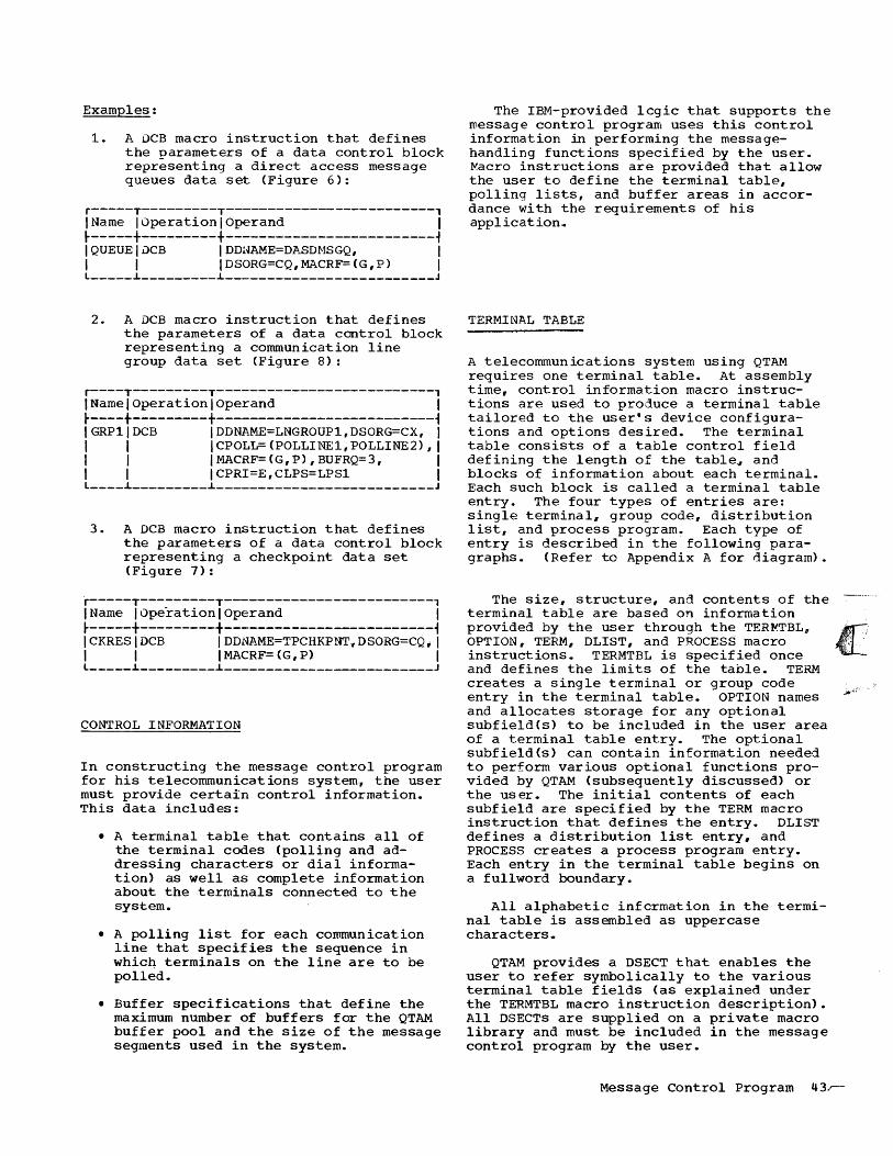
Examples:
1. A DCB macro instruction that defines the parameters of a data control block representing a direct access message queues data set (Figure 6):
r-----T---------T-------------------------, IName IOperationlOperand I ~-----+---------+-------------------------i I QUEUE I DCB I DD1-lAME=D]I._SDNSGQ, I I I I DSORG=CQ,MACRF=(G,P) I L _____ ~ _________ ~ _________________________ J
2. A DCB macro instruction that defines the parameters of a data control block representing a communication line group data set (Figure 8):
r----T---------T--------------------------, INamelOperationlOperand I ~----+---------+--------------------------i IGRP11DCB IDDNAME=LNGROUP1,DSORG=CX, I I I ICPOLL=(POLLINE1,POLLINE2), I I I IMACRF=(G,P),BUFRQ=3, I I I ICPRI=E,CLPS=LPSl I L ____ ~ _________ ~ __________________________ J
3. A DCB macro instruction that defines the parameters of a data control block representing a checkpoint data set (Figure 7):
r-----T---------T-------------------------, IName IOperationlOperand I ~-----+---------+-------------------------i ICKRESIDCB IDDNAME=TPCHKPNT,DSORG=CQ;I I I IMACRF=(G,P) I L _____ ~ _________ ~ _________________________ J
CONTROL INFORMATION
In constructing the message control program for his telecommunications system., the user must provide certain control information. This data includes:
• A terminal table that contains all of the terminal codes (polling and addressing characters or dial information) as well as complete information about the terminals connected to the system.
• A polling list for each communication line that specifies the sequence in whicQ terminals on the line are to be polled.
• Buffer specifications that define the maximum number of buffers for the QTAM buffer pool and the size of the message segments used in the system.
The IBM-provided lcgic that supports the message control program uses this control information in performing the messagehandling functions specified by the user. ~acro instructions are provided that allow the user to define the terminal table, polling lists, and buffer areas in accordance with the requirements of his application .•
TERMINAL TABLE
A telecommunications system using QTAM requires one terminal table. At assembly time, control information macro instructions are used to produce a terminal table tailored to the user·s device configurations and options desired. The terminal table consists of a table control field defining the length of the tablea and blocks of information about each terminal. Each such block is called a terminal table entry. The four types of entries are: single terminal, group code, distribution list, and process program~ Each type of entry is described in the following paragraphs. (Refer to Appendix A for diagram).
The size, structure, and contents of the -_ ..... terminal table are based on information provided by the user through the TER~TBL, OPTION, TERM, DLIST, and PROCESS macro instructions. TERMTBL is specified once and defines the limits of the table. TERM creates a single terminal or group code entry in the terminal table. OPTION names and allocates storage for any optional subfield(s) to be included in the user area of a terminal table entry. The optional subfield(s) can contain information needed to perform various optional functions pro-vided by QTAM (subsequently discussed) or the user. The initial contents of each subfield are specified by the TERM macro instruction that defines the entry. DLIST defines a distribution list entry, and PROCESS creates a process program entry. Each entry in the terminal table begins on a fullword boundary.
All alphabetic infcrmation in the terminal table is assembled as uppercase characters .•
QTAM provides a DSECT that enables the user to refer symbolically to the various terminal table fields (as explained under the TERMTBL macro instruction description). All DSECTs are supplied on a private macro library and must be included in the message control program by the user.
Message Control Program 43r-

Single Terminal Entry
The terminal table must contain a single terminal entry for each terminal that can only send, only receive, or both send and receive messages (except for a terminal in a group code entry., discussed in the following text). If a terminal component is indi vidually polled or addressed" the component must have a separate single terminal entry.
Each single terminal entry contains a minimum of seven fields. The names of the first six fields are provided in a private dummy section, which can be included by specifying TERMTBLD. No parameters are required in this macro. The first five fields in each entry are of standard length and are described as follows:
TNTRYSZE
TQCBADDR
TSEQUIN
TSEQOUT
TSTATUS
Description
Size of the entry.
Address of the queue control block for the DASD destination queue associated with the terminal.
Sequence number for messages incoming from this terminal.
Sequence number for messages outgoing to this terminal.
status information indicating whether messages to the terminal are to be suppressed, whether messages can be sent to the terminal, and whether messages can be received from the terminal.
The sixth field (TERMID), containing the name assigned to the terminal by the user, appears in each single terminal entry. This name can also appear in the source or destination code field of the message header. The length of this field is the same in each entry and is based on information provided by the user. If the number of characters in each terminal name varies, the nUffiDer of bytes in this field is equivalent to the number of characters in the longest terminal name. The user must specify this number in the TERMTBL macro instruction. If the number of characters in each terminal name does not vary, the number of bytes in this field is equivalent to the fixed number of characters. The TERMID field length can be a maximum of eight bytes.
Inclusion of the seventh field is optional. This field~ called the user area, can contain one or more optional sub-
fields. The name" length, and boundary alignment of each such subfield. if any~ are specified by an OPTION macro instruction.. The data content of the subf ields is specified by TERM macros. Optional macro instructions such as COUNTER" DIRECT, ERRMSG, INTERCPT, POLLIMIT., and REROUTE introduce routines that either obtain information from or place information into these subfields in order to perform their functions. The user can also store information in this area. Each single terminal and each group code entry associated with the same line group must contain the same optional subfields.
The eighth field~ called the device access areaw is required4 This area contains the polling and/or addressing characters for the terminal and, if it is a switched terminal~ its telephone number and
I
the number of dial digits. For WTTA terminals~ this area contains the terminal identification sequence. The size of the area depends on the requirements for the particular deviceo This field immediately follows the TERMID field if no optional subfields are included in the user area. If optional subfields are included, the device access field follows the last subfield. The total size of the terminal name area~ optional user area" and device access area must not exceed 252 bytes.
The TERM macro instruction provides the initial contents for all fields in the single terminal entry. Detailed information on this entry is contained in Appendix A.
Group Code Entry
The terminal name in a group code entry represents a prespecified group of terminals on a line with special equipment that provides the group code feature. The feature permits simUltaneous transmission of a message to a group of terminals through the specification of a single set of unique address characters. Several combinations of prespecified terminals can be grouped for this purpcse. Each group has a group terminal name and a corresponding group code entry in the terminal table,.
A group code entry is identical in structure with the single terminal entry. However, three fields are either not used or used in a different manner. QTAM increments the sequence number for outgoing messages (TSEQOUT field) by one when the group is simultaneously sent a message. If any terminal in the group is also represented by a single terminal entry, the output sequence number for that entry is not changed. \

The sequence number for incoming messages (TSEQUIN field in the single terminal entry) is not applicable to the group code entry because the terminal group cannot collecti vely send a message to the system,. For the same reason, there are no polling characters in the device access area of the group code entry. The total size of the terminal name area, optional user area, and device access area cannot exceed 252 bytes.
The TERM macro instruction provides the initial contents for all fields in the group code entry. Detailed information on this entry can be found in Appendix A,.
Distribution List Entry
A distribution list entry contains a list of addresses\of single terminal entries. These addresses are grouped under the list name. When a message contains the list name as a destination code, QTAM sends the message via separate transmissions to all terminals indicated by the list,. Each terminal on the list mu~t have a corresponding single terminal entry in the terminal table.
Each distribution list entry contains five active fields and the list area. The first four active fields in each entry are of standard length. A description of the five active fields follows:
TNTRYSZE
TDSTRQCB
TLISTKEY
TSTATUS
TERMID
Description
Size of the entry.
Address of the queue control block for the distribution list queue.
An access key to the start of the list of addresses.
Status information. This field functions in the same way as the corresponding field for a single terminal entry with the following exception: the "receive" bit in this field is never used because terminals in the list cannot collectively send a message to the system.
Contains the distribution list name. This name serves the same purpose as the terminal name in a single terminal entry and is subject to the same'restrictions,
The list of addresses of single terminal entries follows the fifth active field. This list contains, in each of its subfields (reladdr through reladdrn), a relative address that locates the corresponding single terminal entry in the terminal table. These addresses are relative to the base address of the table. The high-order bit of the last subfield is 1, indicating the end of the distribution list entry. The total size of the distribution list name area and the list area cannot exceed 243 bytes.
The DLIST macro instruction provides the initial contents for all fields in the distribution list entry.
Process Program Entry
The terminal table must include one process program entry for each DASD process queue. A DASD process queue contains those message segments that are to be routed to a message processing program.
The structure of this entry is the same as that of the single terminal entry, with the following exceptions:
1. The TSEQUIN field used in the single terminal entry is not used for the process program entry.
2,. The "receive" bit in the TSTATUS field is not used for the process program entry,.
3,. The TERMID field in the process program entry contains the name of a DASD process queue rather than a terminal name.
4. There is no opticnal area or device access area in the process program entry ..
The PROCESS macro instruction provides the initial contents for all fields in the process program entry. Detailed information on this entry can be found in Appendix A.
Terminal Table (TERMTBL) Macro Instruction
The TERMTBL macro instruction causes a table control field to be created for the terminal table and defines the length of the table. Two private DSECTs exist that provide for symbolic reference to control fields used by QTAM. One private DSECT, TERMTBLD, provides names for the fields in each terminal table entry. The other private DSECT" LCBD; supplies names for the
Message Control Program 45

fields in a line control block (LCB). QTAM maintains an LCB for each communication line attached to the system; each LCB contains control information about the line with which it is associated.
One TERMTBL macro instruction is required, and it must precede all other macro instructions used in creating the terminal table.
r----T---------T--------------------------, I Name I Operation I Operand I ~----+---------+--------------------------~ I ITERMTBL lentry [,(n)] [,OPCTL=charsll I I I [.,CPINTV=integerl I I I I [" CKPART=integer] I L ____ ~ _________ ~ __________ ~ _______________ J
entry
(n)
the name of the last entry in the terminal table.
the number of characters in the longest terminal name. This operand is not necessary if the lengths of all terminal names are the same,. The maximum number of characters is eight since "symbol" in the TERM macro has a maximum of eight .•
OPCTL=chars specifies the label on the OPCTL macro instruction.
If this operand is included., the error diagnostic messages are sent to the telecommunications control terminal. If this operand is not included, the error diagnostic messages wi'll be sent to the system console.
If this operand is included~, the OPCTL macro instruction must also be specified.
CPINTV=integer the number of 15 second intervals between checkpoints; "integer" must be a value from 1 to 60. Each integer represents 15 seconds.
CKPART=integer the number of partitions that must issue a CKREQ macro before a checkpoint will be taken (see discussion of CKREQ macro in IBM System/360 Operating System: QTAM Message Processing Program Services). This number may range from one to fifteen. If CPINTV is also stated, the CPINTV value will take precedence.
Note: The name field must be left blank.. TERMTBL is the name generated fer the terminal table by the macro instruction expansion.
46
Terminal Table Optional Field (OPTION) Macro Instruction
At assembly time. the OPTION macro instruction names and allocates a specified amount of main storage in selected Single terminal and group code entries in the terminal table. The storage allocated constitutes the optional-area field of the entries .• One OPTION macro instruction is required for each optional-area subfield desired. The order of the subfields within the optional area is determined by the order of the OPTION macro instructions.
Data values inserted into each optionalarea subfield are specified by the "opdata" operands of the TERM macro instruction that creates the entry.
The OPTION macro instruction (s) " if used, must immediately follow the TERMTBL macro instruction.. The relative order of the specified subfields must correspond to the order in which the contents for the subfields are specified in the TERM macro instructions,.
Six LPS macro instructions link to IBMprovided routines that use fields allocated by OPTION macros in performing their functions. These optional LPS macros are COUNTER, DIRECT, ERRMSG, INTERCPT" POLLIMIT u and REROUTE. The functions provided by these macro instructions are discussed under the individual macro instruction descriptions.. User-written routines can also store information in a subfield defined by an OPTION macro. QTAM defines a dummy control section for the option field in the message control program for symbolic references to the OPTION fields .•
For switched lines and for lines polled with the Auto PQll feature, a SOURCE macro instruction must appear in the LPS preceding any references to fields specified by OPTION macros. Reference must not be made to the fields for source errors,.
r--------T---------T----------------------, I Name IOperationlOperand I ~--------+---------t--------~-------------~ IsubfieldlOP~ION Itypelength I L ________ ~ _________ ~ ______________________ J
subfield the name of the optional-area subfield.
type length the type and length of the subfield in the standard assembler language format (e,. g. " H, CL8" AL3). When the subfield is used in conjunction with the DIRECT., ERRMSG', or REROUTE macro instruction, CLn must be specified
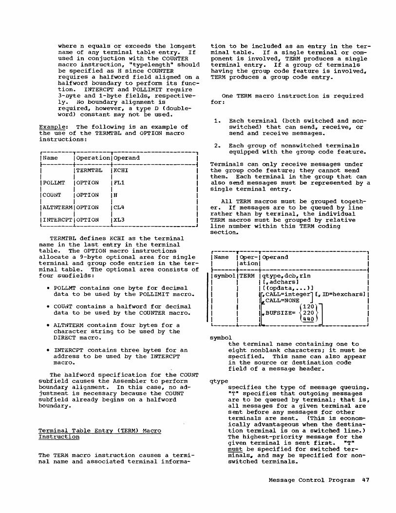
where n equals or exceeds the longest name of any terminal table entry.. If used in conjuction with the COUNTER macro instruction, "typelength" should be specified as H since COUNTER requires a halfword field aligned on a halfword boundary to perform its function. INTERCPT and POLLIMIT require 3-byte and 1-byte fields" respectively. No boundary alignment is required:, however, a type D (doubleword) constant may not be used.
Example: The following is an example of the use of the TERMTBL and OPTION macro instructions:
r--------T---------T----------------------, I Name I Operation I Operand I ~--------+---------+----------------------~ I I TERMTBL I KCHI I I I I I lPOLLMT I OPTION IFL1 I I I I I I COUNT I OPTION IH I I I I I I ALT NT ERM I OPTION ICL4 I I I I I \INTERCPTIOPTION IXL3 I l ________ ~ _________ ~ ______________________ J
TERMTBL defines KCHI as the terminal name in the last entry in the terminal table. The OPTION macro instructions allocate a 9-byte optional area for single terminal and group code entries in the terminal table. The optional area consists of four suofields:
• POLLMT contains one byte for decimal data to be used by the POLLIMIT macro.
• COU~T contains a halfword for decimal data to be used by the COUNTER macro .•
• ALTNTERM contains four bytes for a character string to be used by the DIRECT macro.
• INTERCPT contains three bytes for an address to be used by the INTERCPT macro.
The halfword specification for the COUNT subfield causes the Assembler to perform boundary alignment. In this case, no adjustment is necessary because the COUNT subfield already begins on a halfword boundary.
Terminal Table Entry (~ERM) Macro Instruction
The TERM macro instruction causes a terminal name and associated terminal informa-
tion to be included as an entry in the terminal table. If a single terminal or component is involved, TERM produces a single terminal entry. If a group of terminals having the group code feature is involved" TERM produces a group code entry.
On~ TERM macro instruction is required for:
1. Each terminal (beth switched and nonswitched) that can send., receive" or send and receive messages.
2,. Each grdup of nonswitched terminals equipped with the group code feature.
Terminals can only receive messages under the group code feature; they cannot send them. Each terminal in the group that can also send messages must be represented by a single terminal entry.
All TERM macros must be grouped together. If messages are to be queued by line rather than by terrrinal, the individual TERM macros must be grouped by relative line number within this TERM coding section ..
r------T-----T----------------------------, IName IOper-IOperand I I lationl I ~------+-----+----------------------------~ I symbol I TERM I qtype" dcb., rln I I I I [" adchars] I I I I [(opdata, .••• )] I I 11r. CALL=integerJ [,I m=hexchars] I : : fll• CALL
=NONE{120}] : I I I.BUFSIZE= 220 I I I I 440 I L ______ ~_____ _ __________________________ J
symbol
qtype
the terminal name containing one to eight nonblank characters; it must be specified.. This name can also appear in the source or destination code field of a message header.
s?,ecifies the type of message queuing. "T" specifies that outgoing messages are to be queued by terminal; that is, all messages for a given terminal are sent before any messages .for other terminals are sent,. (This is economically advantageous when the destination terminal is on a switched line.) The highest-priority message for the given terminal is sent first. "T" must be specified for switched terminals. and may be specified for nonswitched terminals .•
Message Control Program 41
dcb
rln
"L" specifies that outgoing messages are to be queued by communication line; messages for all terminals on the line are sent on a first-in firstout basis wi thin priority groups,. If "L" is specified, all TERM macros for each line must be grouped together. "L"must be specified for terminals using the Auto Poll feature .•
the name of the data control block for the line group in which the terminal is included.
the relative line number, within the group, of the access line over which the computer and the terminal communicate. For a switched terminal, any value up to the total number of lines in the group may be specified. When the computer calls a terminal, it attempts to make the call using the line whose relative number is specified. If that line is unavailable, the next highest numbered line is examined, and so on until a free li'ne is found. If all remaining lines in the line group are unavailable, the remote terminal is not dialed at this time.
adchars the addressing and/or polling characters for the terminal. The TERM macro expansion places these characters in the device access area of the terminal table entry,. Refer to Figure 9 for the number and kind of characters to be specified for each type of terminal and line. The characters are specified by writing the hexadecimal equivalent of the appropriate transmission code representation. In most systems the polling and addressing characters for the IBM 2260-2848 will be written just as they are given to the user by the customer engineer. This operand must be omitted for TWX and WTTA terminals, and for IBM 2740 terminals~ types I~ II, V, VI, VII and VIII. Its omission must be indicated by a comma. No polling characters are specified for a switched 1050 terminal. If polling is required for a switched 1050 terminal, the polling characters are specified in a POLL macro instruction.
Examples:
1. If the addressing and polling characters for a nonswitched IBM 1050 are R9 and RO, "adchars" is written 02130215 (0213 and 0215 are the hexadecimal equivalents of the transmission code representation of R9 and RO).
48
2. If the polling characters of a nonswitched IBM 1050 that is only to be polled (not addressed) are KG, "adchars" is written as xxxxC515., where "xxxx" represents the hexadecimal equivalent of any two characters (fill characters>. These two characters will be ignored.
3. If the addressing and polling characters of a nonswitched IBM 1030 that is to be polled and addressed are K and L, "adchars" is written as 45xx4601 where "xx" represents the hexadecimal equivalent of any character (fill character). This character will be ignored.
4. If the same IBM 1030 is to be addressed only~ "adchars" would be wri tten as C5,.
opdata
CALL
the actual data to be inserted into the optional-area subfield(s) of the terminal table entry for this terminal. This operand allows flexibility because data can be specified for different subfields depending on the optional functions required for messages sent to or received from the terminal. However, all entries representing terminals included in the same line group must have data specified for the same optional subfie1ds. (Figure 10 shows an example of data specified for different subfields in entries not associated with the same line group .• ) The maximum length and type of data specified for each subfield must correspond to the length and type specified by the OPTION macro instruction that allocates the additional storage required for the subfield. A comffa is used to:
1. Oelimit the data for each subfield,.
2,. Indicate that no data is specified for an intermediate subfield.
The user must specify either data or a comma for each subfield specified by an OPTION macro. The framing characters (X or C) and quotes are not coded ..
is the telephone number of the terminal,. This operand must be specif ied for switched terminals only. NONE must be specified if the line(s) over which contact with the terminal is to be established does not have the Auto Call feature. NONE must be specified for WTTA terminals4

ID=hexchars the TWX terminal identification sequence for the TWX terminal represented by the terminal table entry created by this TERM macro instruction. This operand is specified only when the computer is to call TWX terminals. It is specified by writing the hexadecimal equivalent of the 8-level TWX code for the following characters:
CR LF 11 1,2 • '. • In CR LF X-on
where CR represents Carriage Return" LF represents Line Feed, X-on represents Transmitter On, and 11 1,2 ••• In is a sequence of characters identifying the TWX terminal. When the computer calls the terminal" the terminal automatically sends an identification sequence.
For WTTA terminals" this operand is specified only when WRU=YES is specified in the DCB for the line. This operand is specified by writing the hexidecimal equivalent of the 5-level code used by the terminal. The terminal sends its identification sequence
each time the terminal sends the WRU signal. After the computer has received the identification sequence of a TWX or WTTA terminal" QTAM compares the sequence with the sequence specified by this operand. as a check that the intended terminal has in fact been reached,. An equal compare permits messag€ transmission to proceed. An unequal corrpare is treated as an addressing error; the message is not sent.
BUFSIZE specifies the size of the buffer on the IBM 2740 Model 2 terminal. If this operand is emitted. QTAM assumes that the terminal is not an IBM 2740 Model 2. If an invalid buffer size is specified, BUFSlZE=440 is assumed.
Examples:
TWXONE TERM T. DCB1, 1,,, (1,0) " CALL=51 08287317, ID=B15193 .. '. '. (etc)
TTYA TERM T,DCBA,l.(O), CALL=NONE, ID= 02080C04 '.... (etc)
r----------------T-----------T--------------------~-------------------------------------, ITerminal Type ILine Type I Specify: I ~----------------+-----------+----------------------------------------------------------~ I I IAAPP (if polling and addressing I
II IBM 1050, 1060, I I are required; for a 2260-2848 AA=PP) I I 2260-2848 I Nonswitchedl I IAT&T 83B3 I IffPP (if only polling is required) (See Note 1).. I IWU 115A I I I I I IAA (if only addressing is required) I ~----------------+-----------+----------------------------------------------------------~ I I IAfPS (if polling and addressing are required) 1 I IBM 1030, I I 1 I 2740 types I Nonswitchedl I I III and IV I IffPS (if only polling is required) I 1 I IA (if only addressing is required) 1 ~----------------+-----------+----------------------------------------------------------~ IIBM 2740, types INonswitchedlNo polling or addressing characters are to be specified. I I I and VI I I I ~----------------+-----------+----------------------------------------------------------~ IIBM 1050 I Switched IAA (if addressing is required) (See Ncte 2). I ~----------------+-----------+----------------------------------------------------------~ IIBM 2740, types ISwitched INC polling or addressing characters I I II, V, VII, VIlli I are to be specif ied I ~----------------~-----------~----------------------------------------------------------~ ILegend= I I A = one addressing character I I P = one polling character I I f = one fill character I I S one space character I I I INote 1: The second "PH must be specified as hexadecimal FF if a general poll of all I 12260s attached to a 2848 is desired. I INote 2: If polling is required, the polling characters are specified in a POLL macro I I ins truction. I L _______________________________________________________________________________________ J
Figure 9,. Addressing and Polling Characters for the TERM Macro Instruction
Message Control Program 49

Here, the .. extra comma following the relative line number indicates omission of the addressing and polling characters (which are not required for a TWX terminal).
Terminal Table List (DLIST) Macro Instruction
The DLIST macro instruction causes the name of a list of terminals~ relative terminal table addresses of the entries for the terminals on the list" and associated information on the list to be included as an entry in the terminal table. The list of terminals is called a distribution list i, and the entry produced is a distribution list entry,.
One DLIST macro instruction must be provided for each such distribution list to be created. Terminals can only receive messages through the distribution list transmission method (they cannot send messages).
r------T---------T------------------------, I Name I Operation I Operand . I ~------+---------+------------------------~ It~:~~:l~~~~: ____ l~=~~:::::::~ ____________ J symbol
the name of the list. This must be specified, and may be from one to eight nonblank characters.
entrY3..lr ••• the names of the terminals that are to be in the distribution list.
Restriction: A name representing another distribution list must not be included as an operand of the DLIST macro instruction. All names in the list must be defined by either a TERM or a PROCESS macro instruction. However" no terminal table entry defined by a PROCESS macro specifying the EXPEDITE operand can be included in a distribution list.
Terminal Table Process (PROCESS> Macro Instruction
The PROCESS macro instruction causes the name and associated information of a DASD process queue to be included as an entry in the terminal table. The entry produced is a process program entry. It differs from other terminal table entries in that it does not have an optional area or device access area, and the TSEQUIN field is not
50
used. A message processing program~ like a terminal" can be a destination for a message~ However", unlike a terminal. the processing program is not associated with a communication line and does not need addressing and polling characters.
One PROCESS macro instruction must be included for each DASD process queue.
The EXPEDITE operand permits the user to speed the processing cf messages by the message processing program associated with the process program entry. This function is valuable for an application such as inquiry processing. where rapid response to inquiries ~s required.
r------T---------y------------------------1 I Name I Operation I Operand I ~------+---------+------------------------~ I symbol I PROCESS llEXPEDITE] I L ______ ~ _________ ~ ________________________ J
~yrnbol the name of the process program entry in the terminal table.. The name must be specified, and must be the same as the DDNAME specified in the MS process queue DCB macro instruction defined in a message processing program. The name can contain from one to eight nonblank characters.
EXPEDITE specifies that message segments are to be routed directly to the message procesSing program" s MS process queue" thus bypassing the normal intermediate step of placing them on a DASD process queue. EXPEDITE should not be specified if multisegment messages are expected" because segments from different messages may be intermixed as they are delivered to the queue,. If EXPEDITE is specified, the MS process queue DCB must specify RECFM=S (see the OS QTAM Message Processing Program Services publication. The RETRIEVE macro instruction cannot be used to retrieve messages from a process queue when the EXPEDITE operand is used. Al SOi' the CANCELM" EOA, EOBLC, ERRMSG, and REROUTE macrcs cannot be used for any message whose destination is a processing program queue identified by a terminal table entry defined by PROCESS EXPEDITE.
Example -- Terminal Table Definition
Figure 10 shows a coding sequence used to create a terminal table,. The terminals are

r-----T-------T-----------T-------------------------------------------------------------, I No. I Name I Operation I Operand I ~-----+-------+-----------+-------------------------------------------------------------~
1 TERMTBL CPU
2 COUNT OPTION FL2
3 LIMIT OPTION FLl
4 DEST OPTION CL3
5 NYC TERM L, GROUP1" 1, E407E40D, (0,8, BOW)
6 BOS TERM L" GROUP1, 1,E207E20D" (0. 3.,NYC)
7 WAS TERM L, GROUP1., 2" E407E40D" (0.,1" NYC) I I 8 PHI TERM L" GROUP 2 , 1" E407E40D" (0'11" NYC) I I 9 PIT TERM L"GROUP3,1,E407E40D., (0) I I 10 RAL TERM L"GROUP4"1,,E407E40D I I 11 BOW DLIST (BOS,WAS) I I 12 CPU PROCESS I L _____ ~ _______ ~ ___________ ~ ____________________________________________________________ _
Figure 10,. Example: Coding Sequence for Creation of a Terminal Table
IBM 1050s attached to the computer by nonswitched lines .•
Instruction 1 (TERMTBL): Identifies the last entry in the terminal table,. Omission of the second operand indicates that all terminal names are of equal length,.
Instructions 2 through 4 (OPTION)·: Def ine the names and sizes of three optional-area subfields used for functions specified by the COUNTER, POLLIMIT" and DIRECI' macro instructions, respectively (refer to the section Line Procedure Specifications for a detailed discussion of the functions performed by these macro instructions). The single terminal entries in which these subfields are included and used depends on whether the optional functions are specified in the LPS that handles the line group associated with the entry.
Instructions 5 through 10 (TERM): Define the single terminal entries for the terminals in four line groups,. The operands of each TERM macro instruction provide information for the fields of the respective entries. In this example, outgoing messages are queued by line; therefore, the first operand is an L in each case.
The second operand of each TERM speci.fies the name of the data control block for the line group in which the terminal is included. In this case" there are four
line groups (therefore. four data control blocks) '.
The third operand of each TERM is the relative line number cf the line to which the terminal is attached.. The user establishes the relative line number of each line at system generation via the IODEVICE macro.. In the line group associated with the data control block named GROUP1. the New York and Boston terminals are attached to one line (relative line number 1) and the Washington terrrinal is attached to another line (relative line number 2). Since the messages are queued by line., the individual TERM macro instructions must be grouped by relative line number. For examplew it would be incorrect if the TERM macro instructions in this line group were in the order NYC, WAS, BOS.
The fourth operand of each TERM contains the addressing and polling characters for the terminal. These characters are specified in the hexadecimal equivalent of the transmission code. In instruction 5" E407 is the hexadecimal equivalent of B3 and E40D is the hexadecimal equivalent of B6 in IBM 1050 code. B3 constitutes the addressing characters; for IBM 1050s, the first addressing character identifies the terminal, and the second identifies the component (the number 3 indicates the component addressed is a card punch). B6 constitutes the polling characters (6 is the identification of a card reader). Translation of the addressing-polling character representations in instruction 6 is A3A6;
Message Control Program 51
translations of instructions 7 through 10 are all B3B6. If all these terminals were on the same line, and all were to be addressed or polled individually" a unique set of addressing and polling characters would have to be aSSigned to each terminal.
The fifth operand of each TERM contains the data to be inserted in the subfields defined by the OPTION macro instructions. Instructions 5 through 7 specify data for all three optional .subfields because the LPS that operates on messages for this line group (GROUP1) includes the COUNTER" POLLIMIT, and DIRECT macro instructions. COUNTER uses the COUNT subfield to keep a count of all messages received by the New York, Boston, and WaslIington terminals" respectively. The count is set initially to zero in all entries.
POLLIMIT uses the value in the LIMIT subfield to restrict the number of messages that can be sent by a terminal during one polling pass; the New York (NYC), Boston (BOS), and Washington (WAS) terminals can send a maximum of 8, 3, and 1 messages, respectively, during each polling pass. The DIRECT macro instruction uses the name specified in the DEST subfield to determine where to send the messages originated by each terminal. All messages sent by the New York terminal are directed to the Boston and Washington terminals because the distribution list entry" BOW, is specif ied. Messages sent by the Boston and Washington terminals are directed to the New York terminal.
Instruction 8 specifies data for only the COUNT and DEST subfields; a POLLIMIT macro instruction requiring information from the LIMIT subfield is not included in the LPS that operates on messages for this line group (GROUP2). It should be noted that an additional comma is required to specify that no data is inserted in the LIMIT subfield. Instruction 9 specifies data only for the COUNT subfield because neither the POLLIMIT nor DIRECT macro instruction is in the LPS for the line group (GROUP3). In this case, no additional commas are required because no subfield following the COUNT subfield is used. storage is not allocated for the LIMIT and DEST subfields in the terminal table entry for the Pittsburgh (PI~) terrrinal. Instruction 10 does not specify data for any of the optional subfields since none of the optional functions are specified in the LPS for the line group (GROUP4). No storage is allocated for the optional-area field in the entry for the Raleigh (RAL) terminal.
Instruction 11 (DLIST): Creates a distribution list entry in the terrrinal table. When BOW (the name of the list) is found as
52
a destination code in a message header. or in the DEST subfield of the terminal sending the message., the message is routed to the Boston and Washington terminals.
Instruction 12 (PROCESS): Creates a process program entry in the terminal table,. When CPU is specified as the destination code for a message" the message is routed to the message process~ng program represented by this process program entry,.
POLLING LISTS
Polling is a centrally controlled method of permitting each terminal on a multiterminal nonswitched line to send messages without contending for use of the line. QTAM contacts the terminals in the order established by a user-specified polling list. The polling list consists of control information followed by a series of pointers to those terminal table entries representing terminals to be polled.. In operation. QTAM steps through the pointers one by one. For each painter QTAM finds the polling address in the indicated terminal table entry and sends that address on the line.. As each terrr.inal recognizes its unique address; it either sends a message if one is ready for transmission. or it sends a negative response if no message is ready. It should be noted that for a system without the Auto Poll feature., the negative response is handled by the QTAM system; thus requiring CPU time.
After a message is received from a terminal, the same terminal is again polled" and it again sends a message if one is ready. This process is repeated until the terminal has no more messages to send or until the user-established polling limit for that terminal is reached. whichever occurs first. (The POLLIMIT macro instruction is used to set the limit.)
Each time a negative response is received by the computer or the polling limit is reached. QTAM repeats the polling process using the next pointer in the list. This operation is repeated Until the terminal represented by the last pointer in the polling list has sent a negative response or has sent its last message,. When this occurs" the polling process is rescheduled;, starting at the beginning of the list. If the user has specified a polling interval in the DCB macro instruction for the line group, the next pass through the polling list is deferred for the time specified.
A polling list must be specified for each line in the system. In defining a list for a nonswitched line" the user may

enter terminal names as many times as he wants to, and in any order. A list can include terminals on one line only. If a line is used for output only, the user must specify a polling list with no terminal entries .•
The polling process has a different meaning for switched I ines.. For nonswitched lines, the computer generally initiates contact with the terminals .• However" for swit'ched lines" the terminal normally initiates the contact. The polling function in this case consists only of sending the polling address to the terminal that initiates the contact. The terminal responds by sending one or more messages. The polling address is sent by the computer after each message is received. The polling list for a switched line does not contain pointers to terminal table entries. Rather" it contains a single polling address (except for switched IBM 274,0 and TWX terminals) in addition to control information. When a terminal dials the telephone number associated with the line represented by this polling list" QTAM sends the polling address on the line,.
In the case of TWX terminals" the polling function consists of sending a character sequence on the line rather than a polling address. otherwise" the polling function is identical. In the case of switched IBM 2740s (types II" V, VI!., and VIII), the polling list is specified as pollname POLL FFFF. Incoming message transmission begins when the computer answers a call from the terminal.
For WTTA terminals, the polling function is not used because the message control program is always ready to receive input messages.. However" the polling list contains the computer identifi9ation sequence to be sent to a WTTA terminal each time an identification exchange is performed.
The polling process has a different meaning for Auto Poll lines. Instead of causing a CPU interruption on receiving a negative response, as the regular poll does, the hardware itself initiates polling of the next terminal in the polling list .• The polling list for an Auto Poll line does not contain pointers to terminal table entries. Rather, it contains (after open DASD time) a series of polling characters and index characters in addition to control information. When a message is read into a buffer, the index character" associated with the polling characters of the responding terminal, replaces the machine EOA character as the first data character in the header. (This index may be used to iden tify the responding terminal,.)
To use QTAM more efficiently. the programmer should be aware of the processing done by QTAM in polling. To poll ~ terminal or line. QTAM forms a ring of buffer request blocks (for BRBs see section Buffer Definition and Use) with one associated buffer for each terminal in the polling list. There are three times when this ring is broken down by QTAM,.
1. On a negative response if sending has priority over receiving and there is a message to send. The ring is then rebuilt to send an outgoing message.
2. At the end of a message transmission to free the buffers and the line for another transmission.
3,. At the end of a polling list to wait for the interval of time d~lay.
Since this manipulation of the BRBs requires additional CPU time. the user must adjust the polling list to suit his application.. To increase the performance" the user may change the interval of time delay at certain periods of the day. Refer to Appendix 0 for an example of this capability .•
The POLL macro instruction is used to define polling lists for both switched and nonswitched lines.. QTAM also provides routines for examining and modifying polling lists. The macro instructions for implementing these routines are described in the section Examining and Modifying the Telecommunications System. The structure of polling lists is shown in Appendix A.
Polling List Definition (POLL) Macro Instruction
POLL generates a polling list for a specific line attached to the telecommunications control unit (TCU). For a nonswitched line, it defines the order in which terminals on the line .. are to be polled. For a switched line, it specifies the polling address or identification sequence to be sent to any terminal that calls the computer on the line represented by the list. One POLL macro instruction must be written for each switched and each nonswitched line in the system.
r--------T---------T----------------------, I Name I Operation I Operand I ~--------+---------+----------------------~ I pollname I POLL I ~ (entry" .... ) I I \ I I ["AUTOPOL={l}l' I I I I 2 ,. I I I \ Jpolladdr ( I I I ]~ nid 'I L ________ ~ _________ .1. ________________ · ______ J
Message Control Program 53

pollname the name of the polling list to be created for the line.. The name must be specified and must be identical with a name specified in the sublist of the CPOLL keyword operand in the DCB macro instruction for the line group. In addit'ion, the polling list defined must be the list for the line indicated by the relative position of the name in the CPOLL sublist.
entry" ••• the names of the terminals on a non~ switched line or on an Auto Poll line in the order in which the terminals are to be polled. All the terminals specified must be on the same line. Each name specified must be the name of a TERM macro instruction defining a single terminal entry. If the line is used for output only, the.entry operands must be omitted. This operand is to be specified only for nonswitched lines and Auto Poll lines. This operand must be enclosed in parentheses even if only one terminal name is specified,. This operand must be omitted for WT~ lines.
polladdr
nid
54
the polling address to be sent to any switched IBM terminal that dials the computer on the line represented by this polling list. All such terminals that can dial the computer on this line must recognize the same polling address. This operand must be specified in the hexadecimal representation. of the transmission code appropriate to the type of terminal on this line. This operand is to be specified only for switched lines on which IBM terminals can dial the computer. For a line on which an IBM 2740, type II, V~ VII, or VIII can call the computer~ an operand of FFFF must be specified,. If the line is used for output only., this operand must be omitted.
the number of characters in the identification sequence of the computer to be sent to any TWX terminal that dials the computer on the line represented by this polling list, followed by the characters themselves. Both must be written as one continuous character string in hexadecimal notation. The ID characters must be written in hexadecimal notation of 8-level TWX code. This operand is to be specified only for switched lines on which TWX terminals can call the computer. If the line is used for output only" this operand must be omitted.
For WTTA lines" nid is the number of characters of the computer identification sequence, followed by the characters themselves. Both must be written as one continuous character string in hexadecimal notation., that is, the number of characters is in hexadecimal notation, and the characters themselves are in the hexadecimal representation of the 5-level code used by the terminal,.
AUTOPOL Specifies that the terminals are on an Auto Poll line.
"1" specifies that the terminals are IBM 1030 terminals. From 1 to 123 of these terminals may be specified for one line,.
"2" specifies that the terminals are either IBM 1050# 1060, 2740 Type III, or 2740 Type IV terminals. From 1 to 82 of these terminals may be specified for one line ..
Example: The following POLL macro instructions create the required polling lists for two nonswitched input lines" one nonswitched output line. one switched line on which IBM 1050s can dial the computer, two switched lines on which TWX terminals can dial the computer, one line polled using
Ithe Auto Poll feature, and one nonswitched WTTA line.
r--T--------T---------T-------------------, J I Name I Operation I Operand I ~--+--------+---------+-------------------~ 11. I POLLINEll POLL I (CHI" BOS) I 12. I POLLINE21 POLL I (NYC., PHI, NYC, WAS> I 13. 1 OUTLINE31 POLL I I 14,. I POLLINE4] POLL 1 E215 I 15.IPOLLINE5 IpOLL IOCB150FF72A3EB824 I ] I I I BD2B15088 I 16,. 1 POLLINE6] POLL 103884DC9 I 17,.1 POLLINE 7 1 POLL I (NYC, PHI, NYC, WAS> " I 1 I ] 1 AUTOPOL=2 I
I 18. 1 POLLINE81 POLL 108020830352D38122D I 1 1 J 10208 ' 1 L __ ~ ________ ~ _________ ~ ___________________ J
These macro instructions create polling lists used to:
1.. Poll the Chicago and Boston terminals in that order.
2. Poll the New York, Philadelphia, New York" and WaShington terminals in that order.
3. Represent the output-only line.
4. Poll an IBM 1050 whose polling address is AO (E215 is the 1050 transmission

code representation of AO, in hexadecimal notation).
5. Send the computer" s identification sequence
" preceded and followed by
control characters, to any TWX terminal that calls the computer on this line. The operand for the next POLL macro is the transmission code representation of CR LF DELETE NEW ARK CR LF X-on, in hexadecimal notation. The X-on character will turn on the tape transmitter of the calling TWX.
6. Send a Wturnaround- sequence to any answering TWX that the CPU has dialed to turn on the tape transmitter of the TWX. The operand of this POLL macro instruction is the transmission code =epresentation of X-on 2 X-off, in hexadecimal format.
7. Auto Poll the terminals NYC.. PHIl, NYC" WAS in that order.. Associate the index characters 1" 2 1, 3 1, and 4 with their terminal entries.
8. Send the computer identification sequence (preceded and followed by control characters) to any WTTA terminal with which an identification exchange is to be performed~ The operand for this POLL macro instruction is the device code representat-ion of:
10 CR LF 3 6 0 - 5 0 CR LF
in hexadecimal notation.
"\BUFFER DEFINITION AND USE
The user must specify the size and number of the main storage areas required by QTAM for input and output buffering. This information is specified by including one., and only one, BUFFER macro instruction in the message control program. These main storage areas collectively form a buffer pool that is allocated to and used dynamically by QTAM to handle the transter of message segments from and to all communication lines" direct access queuing devices
" and
processing queues.
All buffers in the buffer pool have the same length. Since the entire header portion of a message must fit in the buffer that receives the first message segment" the length specified must be equal to or greater than the size of the message header used, plus 32 (the size of the header prefix generated and used by QTAM routines) .•
Buffer request blocks (BRBs) are QTAM control blocks used to dynamically request buffers prior to their actual allocation from the buffer pool.o The user should determine the number of BRBs required by the QTAM system.
Management of data buffers for incoming and outgoing messages is an important factor in running a QTAM system at optimal efficiency. There are three factors that a programmer must consider in weighing the balance betweentirr.e and main storage .•
i.. The user must specify the correct number of' buffers to assure no loss of or undue delay of data.
2.. The user must select the size of the buffer to accommodate his message.
3. The user must decide on the number of BRBs needed for a reliable system.
Figure 11 is provided to aid in deciding the eff ect of these f actors,. The figure shows the advantages in specifying more or less of the quantity with other considerations equal.
Buffer Reguest BlockS
The number of BRBs required in the system is a function of a number of variable factors. The most important factor is the number of lines that are to be polled at the same time.. The user should initially specify a value that represents the maximum number of BRBs that could be in use,. If the user has specified a reasonable value in the BUFRQ operand of the DCB macro instruction for each communication line groupl, the maximum number of BRBs he may need to specify in the BUFFER macro instruction may be calculated as follows:
• For each line group .. multiply the number of buffers specified in the BUFRQ operand by the number of lines in the group; add the prcducts obtained for each line group. To this figure. add the number of buffers specified in the BUFRQ operand of each concurrently used MS process queue.
• To this figure, add one buffer for each concurrently used MS destination queue defined by message processing programs. The sum is the maximum number of BRBs required.
Example: Assume three line groups, GPONE, GPTWO, and GPTHREE" consisting of five, twelve" and ei"ght lines, respectively. The BUFRQ operands of GPONE. GPTWOe and GPTHREE
Message Control Program 55

r--------~-----------T------------------------------------------------------------------, , QUANTITY , ADVANTAGES , ~--------------------+------------------------------------------------------------------~
I' larger buffers I 1. Requires fewer buffers for a message. resulting in less I , , manipulation of the buffers by QTAM. , I I , , I 2. Decreases the probability of losing data" since there is , I I less chance of missing a program controlled interrupt~ ,
" I I I 3. Makes better use of disk tracks if buffers are filled,. , I I , I I 4. Decreases the disk time,. since there are fewer disk , , , accesses.. , ~--------------------+------------------------------------------------------------------i , smaller buffers ,1. Requires a shorter amount of time to fill up buffers. This , I I results in more dynamic use of main storage. and hence main , , I storage is not tied up unprofitably. , I I I t I 2. Increases likelihood of filling the entire buffer, therefore I I I making better use of main storage,. If a message does not I I I fill up the buffer (as in larger buffers). main storage is I I I . wasted,. I ~--------------------+------------------------------------------------------------------i I more buffers I 1. Decreases the chance of losing data of incoming messages,. I I I I I I 2. Assures that outgoing messages are not delayed because they I I I are waiting for a buffer. I I I , I , 3. Allows more CPU time for other tasks,. I ~--------------------+------------------------------------------------------------------i I fewer buffers I 1. Uses main storage more efficiently. No more buffers than I I I the amount needed for incoming and outgoing messages are I I I used, thus speeding throughput and saving main storage. I ~--------------------+------------------------------------------------------------------i I more BRBs per line I 1. Reduces the chance of losing data due to a missed program , I I controlled interrupt. , 'I I 1 I 2. Saves main storage if inactivity allows fewer buffers than I I I BRBs to be specif ied,. I ~--------------------+------------------------------------------------------------------i I less BRBs per line I 1. Saves buffers. Since there are as many buffers used at one I I I time, when transmitting or receiving on a line" as there are I , I BRBs assigned to the line; buffers are net unnecessarily I I I tied up. (Only one buffer per line is assigned during I , I polling. ) I L ____________________ i ____________ ~ _____________________________________________________ J
Figure 11.. Aids in Specifying BRBs and Buffers
specify 3,. 3, and 5 , respectively. Also assume that there is one message processing program that defines one MS process queue with BUFRQ=l, and one MS destination queue. The maximum number of BRBs to be specified in the BUFFER macro instruction is calculated as (3x5) + (3x12) + (5x8) + 1 + 1 = 93.
The value calculated using the above formula represents the maximum number of BRBs that could be needed at one time. In actual operation, the greatest number required at one time would be somewhat lower, and the user may wish to specify a lesser value .•
An exception arises when all the lines consist of dial lines or lines polled with
56
the Auto Poll feature. In these cases the value derived above is the actual value that should be specified~ In other cases experience within the operating environment of a particular application can best demonstrate the practicality of specifying a lesser number of BRBs.
Buffers
The number of buffers specified must be equal to or greater than the number required at anyone time.. If the number of buffers needed to accommodate mes~age traffic at any time exceeds the number of buffers available" loss of message data can occur. Therefore." the user should specify

a sufficient number of buffers in the BUFFER macro instruction to prevent this problem from arising under any expected operating conditions.
Because the actual number of buffers that will be in use at any particular moment depends on several variable factors., the user should initially specify a value that represents the maximum number that could be in use.
This maximum value is related to the number of lines and the number of BRBs by the following formula:
Number of buffers = L + f(BRB - L)
where L number of lines
BRB = number of BRBs
f = a factor with a value of between a and 1.
For small systems with few lines. the factor f approaches one. For larger systems a value of 0.5 might be adequate. Experience within the operating environrrent of a particular application can best demonstrate the appropriate value.
Example: In the previous example there were 25 lines and 93 BRBs. A reasonable number of buffers for most applications would be
number of buffers = 25 + 0.5(93 - 25) = 59.
BUFFER Macro Instruction
BUFFER specifies the main storage buffer areas required by QTAM. The buffers are allocated to QTAM as a block of main storage called the buffer pool. This macro instruction produces no executable code.
r----T---------T--------------------------, I Name I Operation I Operand I· ~----+---------+--------------------------~ Il ____ l~~~~~ ___ l~~~~:=~::~~~~~:~:~~~: ____ J
nnn the number of buffers to be reserved (see the sample calculation in the pr~ceding example).
length the length, in bytes, of each buffer. All buffers in the buffer pool have the same length. The length specified must equal or exceed the length of the longest message header used in the system (including any fields inserted
mmm
by the LPS). plus 32 (the size of the QTAM-generated header prefix).. The length of the message segment size used in the system is based on the buffer length. The minimum buffer length is ,56 bytes (80 bytes if the Operator Control Facility is included) and the maximum is 278 bytes. The minimum does not include bytes reserved by the LPSTART macro for fields to be inserted into the header. For instance" if 7 bytes were reserved by LPSTART for the date. then the minimum buffer size would be 63 rather than 56,. Length should be d~fined so that each buffer starts on a fullword boundary. The length of the records in the DASD message queues should be 8 bytes less than the size specified in this parameter.
the number of channel command words QTAM must generate for sending the idle characters specified by the PAUSE macro instructions in the LPS sections of the message control program. The number of CCWs required depends on a number of variables whose cumulative effect changes during system operation (The principal factors are the number of appearances in messages of each control character that requires insertion of characters. and the number of lines over which outgoing messages are being sent at the moment .• ) Because determining the actual number of CCWs that could be needed at any given moment is impractical., the user should initially specify a "worst-case" value. (i..e., a value representing the maximum number of CCws that could be required under any operating condition) I. This value maybe calculated as follows:
mmm = 2(L1.(I1.) +L2 (I 2 ) + ...... Ln(In» where L = the number of lines in the line group and I = the expected number of appearances of control characters per outgoing message buffer for which insertion of idle characters is required; L(I) to be calculated for each of the line groups 1 through n.
Example: Assume that the LPS for the first line group includes PAUSE macro instructions that cause insertion of idle characters each time a NL (new line) or an HT (horizontal tab) character is encountered in an outgoing message buffer. AI~o assume that the expected number of appearances of these control characters is two, for the NL character, and six, fer the HT character. 11. is therefore 2 + 6 = 8. If the line group consists of five lines., L1. (11.) equals
Message Control Program 57

5(8). If the system includes two other line groups for which L(I), calculated similarly, equals 3 (6) and 7 (5)" then mmm 2(5(8) + 3(6) + 7(5» = 186.
In most applications this "worst-case" value will considerably exceed the actual number of CCWs required. Therefore, the user may reduce the value during system testing. If this operand is omitted;, zero is assumed.
BRB=integer the number of buffer request blocks (BRBs) to be reserved. (See the sample calculation in a previous example,. ) This number must be greater than or equal to the nurrber of buffers specified. If this operand is omitted or the number specified is less than the number of buffers, the number of BRBs is set equal to the number of buffers.
Example: Assume a system in which:
1. 59 buffers of 100 bytes each are required.
2. The number of CCWs required for insertion of idle characters is calculated as in the preceding example.
3.. The number of BRBs required is 93.
The BUFFER macro instruction would then be written:
BUFFER 59~100#186,BRB=93
DATA SET INITIALIZATION AND ACTIVATION
The data set initialization and activation section of the message control program begins with an OPEN macro instruction and ends with the ENDREADY macro instruction. Within the message control program, this section must precede the LPS section. When the instructions in this section have been executed, the system is ready to handle message traffic.
The OPEN macro instruction completes the initialization for and activation, of the DASD message queues data set" communication line group data set, message-log data set, and checkpoint data set. The data sets used by the message control program can be opened by separate OPEN macro instructions, or they can all be opened with one OPEN. Regardless of which method is used" the user must open the DASD message queues data set before any other data set used by QTAM. I f the checkpoint option is us ed" the checkpoint data set must be opened after
58
the DASD message queues data set and before the line group data set. Opening a line group data set causes all lines in the line group to be prepared for operation; the lines are activated automatically for message reception ..
Activation of a line group data set can be deferred through use of the IDLE operand in the OPEN macro instruction.. The purpose of such a deferral is to facilitate activation of particular lines in a line group,. This is accomplished by the STARTLN macro instruction (see the section Examining and Modifying the Telecommunications System) ,.
There can be a 30-second delay for each OPEN macro instruction for line not opened idle.. During Open time" QTAM must issue commands to prepare the lines for operation. If the interrupt indicating the line is initialized has not been received~ QTAM waits 30 seconds for completion,. If the commands have not completed after 30 seconds, the following message is written to the console,.'
IEC80GI ENDING STATUS NOT RECEIVED FROM LINE XXX - ~INE UNAVAILABLE
Opening multiple data sets with one OPEN macro instruction may avoid the 3D-second delay.
The ENDREADY macro instruction must be the last instruction in the initialization and activation section,. When ENDREADY has been executed" the system is ready to handle message traffic. The expansion of this macro instruction causes a branch to the IBM-provided logic that supports the message control program. The first message procured can be either a message coming in from a terminal, or a message being sent to a terminal by a message processing program. When the first message is procured, control is returned to the LPS section of the message control program for handling of the message.
Once the LPS is initially entered via the expansion of the ENDREADY macro instruction. execution in the message control program is restricted to the LPS section; that is" the LPS is continually' reentered to handle messages entering and leaving the computer as long as the message control program is active.
The STARTLN" COPYP, CHNGP" COPYT, CHNGT, and COPYQ macro instructions may be used in the initialization and activation section of the message control program. This is useful if the user wishes to modify the status of his system at the time the message control program is initiated. For example, a COPYT macro instruction can be issued to record the system status prior to

opening the telecommunications line groups. If the above macro instructions are used in this section, they must precede the ENDREADY macro instruction. Generally" however, these macros are employed in another program so that the status of the system can be dynamically examined and modified as needed. The section Examining and Modifying the Telecommunications System contains a detailed discussion of the macros that may be issued in a message control program. Those which may be issued in a message processing program are described in the publication OS QTAM Message Processing frogram Services.
OPEN Macro Instruction
OPEN is used in the message control program to complete initialization and activation of the message-log, line group and DASD message queues data sets. All of these data sets can be opened separately or with one OPEN. However, the user must open the DASD message queues data set before any other data set used by,QTAM. The operands of the OPEN macro instruction specify the names of the data control blocks for the data sets. A sublist for each data control block name specified is used to:
1. Specify the nature of the data set (input, output, or both).
2,. Specify whether or not activation is to be deferred for communication line groups.
If the data control block for a line group is specified, the OPEN routine completes the initialization of all lines in the line group and automatically activates the lines for message transmission, unless the IDLE operand is specified in the sublist. If in the OPEN for a nonswitched line group" the user specifies INPUT or INOUT" but does not specify IDLE, the Open routine initiates polling on those lines in the group that have an active polling list wi th terminal entries.. If in the OPEN for a switched line group the user specifies INPUT or INOUT" but does not specify IDLE" the Open routine issues commands to enable each line in the line group.
rf IDLE is specified, all of the lines, or particular lines in the line group" can be subsequently activated by one or more STARTLN macro instructions. The user can also inhibit polling or enabling of a line by changing the second byte of the polling list for that line to zero (this deactivates the polling list) before issuing the OPEN for the line group, but after issuing the OPEN for the direct access message
queues. (See the CHNGP macro instruction description in the section Examining and Modifying the Telecommunications System.)
If this OPEN specifies a message-log data control block, the QTAM routines are brought into the system and prepared for placement of messages on the logging device,. OUTPUT must be specified as the first operand in the sublist for the message-log data control block name.
r------T----T-----------------------------, JName lOp I Operand I ~------+----+----------~--------~---------~ I symbol I OPEN I { [ INPUT] }I I J J ( .dcb1 ·, [ ( OUTPUT £, IDLE])], I I I] INOUT ' ••• } I I ] l [. MF=L 1 I I I I ~MF=(E.listnameU I l ______ ~ ____ ~ _____________________________ J
symbol
INPUT
either the narre cf the first instruction generated by the OPEN or the name of a parameter list created by OPEN. If the MF=L operand is specified., ~ bol must be included; it becomes the name of the parameter list. If no MF operand is specified., or. the MF= (E" listname) operand is specified. symbol is optional. If incl uded" it becomes the name of the first instruction generated by OPEN,.
the address of the data control block to be opened. If register notation is used" the register deSignated must contain the address of the data control block.
specifies an input data set,. If neither INPUT. OUTPUT, nor INOUT is specified" INPUT is assumed. Polling begins on all lines having an active polling list with terminal entries provided: (1) the data set being opened is for a nonswitched line group., (2) the INPUT (or INOUT) operand is specified (or INPUT is assumed'l, and (3) the IDLE operand is omitted. If the data set being opened is for a switched line group" and condi tions 2 and 3 apply" then all lines in the line group are enabled.
OUTPUT specifies an output data set.. If the data set being opened is for a nonswitched line grcupand OUTPUT is specified. the CPOLt operand of the DeB macro for the line group refers to a polling list with no terminal entries,. OUTPUT only cannot be specified for switched line groups.
Message Control Program 59

I NOUT
IDLE
MF=L
60
specifies a data set that can be used for both input and output. If a line group data set is being opened" some of the lines can be used for input and others for output. simultaneously.
For nonswitched line groups: If an entry in the CPOLL operand sublist in the DCB macro for the line group points to a polling list with terminal entries, the line is a polled input line; polling begins if the polling list is active and the IDLE operand is not specified in the OPEN macro. If an entry in the CPOLL operand sublist in the DCB points to a polling list with no terminal entries" the line is an output-only line.
For switched line groups: If an entry in the CPOLL operand sublist in the DCB maCEO for the line group points to a polling list that contains a polling address (or CPU' identification for TWX)" the line is an input line; it is enabled if the polling list is active and the IDLE operand is not specified in the OPEN macro,. If an entry in the CPOLL operand sublist in the DCB points to a polling list without a polling address, the line is an output line,.
pertains only to line group data sets. If the IDLE operand is included" the line group data set is initialized but the lines remain inactive until activated by a STARTLN macro instruction. If IDLE is omitted, all lines in the group are automatically activated when the OPEN is executed.
Note: If neither INOUT nor IDLE is speci~ied for a particular data set. and a sub~equent data control block address is specified in the sublist, two commas must appear between the two specified data control block addresses.
causes creation of a parameter list based on the OPEN operands. No executable code is generated. The user must specify this form of the OPEN with his program constants. The parameters in the list are not used until the problem program issues an OPEN (or CLOSE) macro with an MF= (E" listname) operand referring to the list (see example below). The name specified in the name field of the OPEN macro becomes the name assigned to the parameter list.
MF=(E" listnameJ causes execution of the open routine, using the parameter list referred to by listname,. This list was created by a macro having the MF=L operand specified" as previously described. Parameters specified through a macro ha~ing MF=(E.listname) operand override corresponding parameters in the list,. An OPEN macro with the MF=(E.listname) operand can also refer to a parameter list created by a CLOSE macro with an MF=L operand.
Examples: An OPEN macro instruction that could be used in the message control program is:
r----T----T-------------------------------, INamelOp I Operand I ~---+----+-------------------------------~ I I OPEN I (QUEUE t, fI GROUPONE, (INOUT .. IDLE), I I I I MSG LOG" (OUTPUT) ) I L ____ ~ ____ ~ _______________________________ J
In this example,. QUEUE is the name of the direct access message queues data set, GROUP ONE is the name of a line group data set" and MSGLOG is the name of the messagelog data set. If the user wished to use the MF=L form, the macro would be written:
r----y----T-------------------------------, INamelOp I Operand I ~----+----+-------------------------------~ I OLST I OPEN I (QUEUE"" GROUPONE .. (INOUT. IDLE), I I I I MSGLOG. (OUTPUT,) ) fI MF=L I L ____ ~ ____ ~ _______________________________ J
The user would place the above macro among his definition statements 50 the parameter list would be produced among the constants. The following macro, placed in the data set initialization section, could be used to 'activate the data sets:
r----T----T-------------------------------l INamelop JOperand I ~----+----f-------------------------------~ I I OPEN I (QUEUE. "GROUPONE, (INOUT,., IDLE) " I I I I MSGLOG fI (OUTPUT») II1 MF= (E" OLST) I L ____ ~ ____ ~ _______________________________ J
ENDREADY Macro Instruction
The data set initialization and activation section must be ended by an ENDREADY macro instruction~ ENDREADY is essentially a type of wait instruction. The event awaited is the procurement of the first message. Only one ENDREADY macro can be included, and it must be the last in the group of data set initialization and activation instructions.

r----T---------T--------------------------, I Name I Operationl Operand I ~----+---------+--------------------------~ I I ENDREADY I I L ____ ~ _________ ~ __________________________ J
LINE PROCEDURE SPECIFICATION (LPS)
The procedure to be followed by a message control program in operating upon messages being received from or sent to remote terminals is defined by one or more userwritten sequences of Q~M macro instructions. Each sequence is called a line procedure specification (LPS). The user must prepare an LPS for each communication line group in the system. However., more than one line group may use the same LPS if they all require identical message control procedures.
The purpose of the LPS is to define macro-introduced routines that:
1. Examine and process control information in message headers.
2,. Perform functions necessary to prepare message segments for processing by message processing programs, or for forwarding to destination terminals .•
Preparing an LPS consists of selecting certain of the QTAM macro instructions' described in this chapter and writing them in a particular sequence" according to the requirements of the installation and of the line group,. In preparing an LPS:" the user must carefully analyze such considerations as the formats of message headers passing through the line group" the type of terminal and type of line (switched or nonswitched) in the line group, and the processing requirements for various types of messages (if messages having different handling requirements are directed to the same LPS).
'Two 'major types of macro instructions are used in the LPS: functional macro instructions and delimiter macro instructions. In general" the functional macro instructions perform the specific operations required on messages directed to the LPS. Delimiter macro instructions classify and identify sequences of functional macro instructions and direct control to the appropriate sequence, according to whether the message segment is incoming or outgoing, and whether it is a header segment or a text segment,.
COMPONENTS OF THE LPS
The LPS is divided into two major groups of macro instructions: the Receive group., which handles incorring messages; and the Send group., which handles outgoing messages. In the coding of the LPS~ the Receive group must precede the Send group. Each of the major groups is further divided into three coding subgroups. The Receive Segment and Send segment subgroups contain macro instructions concerned with all portions (both'header and text) of incoming and outgoing messages, respectively. The Receive Header and Send Header subgroups contain macro instructions concerned only with the headers of incoming and outgoing messages. Macro instructions in the End Receive and End Send subgroups perform error-handling procedures for incoming and outgoing messages.
The Receive Header and Receive Segment subgroups may each be used more than once within the Receive group,. Similarly, the Send Header and Send Segment subgroups may be used more than once within the Send group,. For example, an application might require that different operations be performed for several different types of messages directed to the same LPS; each of the message types could require a different header format. In such a case" there could be a separate Receive Header subgroup to process the header of each message type. The user can include in his header formats a special message-type character for each type of message. The MSGTYPE functional macro instruction can be used to examine the message-type character and direct control to the appropriate Receive Header subgroup.
The sequence of the Receive Header and Receive Segment subgroups within the Recei ve group" and the sequence of the Send Header and S'end Segment subgroups within the Send group, may depend on which functional macro instructions are specified within the subgroups. For example. assume that the TIMESTMP rracro is included in the Receive Header subgroup'l1 and that the TRANS macro is included in the Receive Segment subgroup.. The TIMESTMP macro enters the time of day into the message header in EBCDIC form~ and the TRANS macro translates all message segments from transmission code irlto EBCDIC. It is evident that the EBCDIC time information must be inserted after the header has been translated to EBCDIC" not before. The translate routine must therefore be executed before TIMESTMP; hence, 1 the Receive segment subgroup, which contains the TRANS macro, must be executed before the Receive Header subgroup. ~
Message Control Program 61

The End Receive and End Send subgroups may each be used only once and, if used, must be the last sections within the Receive and Send g roups" respectively.
If only the IBM-provided macro instructions and associated macro-introduced routines are used in coding an LPS., the Receive Header subgroup is mandatory. The user may omit any other subgroup if it is not required for a particular application. For example, the Receive Segment and Send segment subgroups may be omitted in a message switching application if all terminals involved use the same transmission code (that is, translation of the message text is not required) and none of the other
.1 functions that require translation are desired. Any or all coding subgroups may be omitted if the user prefers to write his own routines for the functions he requires. An LPS must contain, as a minimuml the LP START , POSTRCV, and POSTSEND delimiter macro instructions to provide the linkage between the LPS and the IBM-provided logic that supports the message control program.
Figure 12 shows the various coding subgroups that can be incl uded in an LP S" the delimiter macro instructions associated with each subgroup, and the functional macro instructions (in alphabetical order) that can be used in each subgroup.
DELIMITER MACRO INSTRUCTIONS
Delimiter macro instructions group the functional macro instructions into the various subgroups. They also perform initialization and control functions within the LPS.
The LPSTART macro instruction identifies the beginning of the LPS and must be the first instruction in every LPS. The code generated by the expansion of LPSTART determines whether the message segment entering the LPS is incoming or outgoing and directs the segment to the Receive group or the Send group accordingly.. In an application that directs multisegment messages to the LPS, it is necessary that the functional macro instructions in the headerproceSSing subgroups be executed only where the message segment being handled contains the message header. The expansions of the RCVHDR and SENDHDR delimiter macro instructions cause the header-processing subgroups to be bypassed when a message segment contains text only.
POSTRCV and POSTSEND identify the ends of the ~eceive group and the Send group, respectively. These delimiters, along with LPSTART, must appear in every LPS. Each of
62
the remaining delimiters is required only if the user chooses to include in the LPS the coding subgroup associated with that delimiter.
FUNCTIONAL MACRO INSTRUCTIONS
Functional macro instructions perform the specific operations required on message segments.. These functions include:
• Message editing (code translation .and insertion of time of day_ current date, and message sequence numbers in message headers) •
• Checking validity of source and destination codes in message headers.
• Routing messages to specified destinat ions.
• Maintaining logs of messages on an auxiliary storage device,.
• Checking for errors in message transmission and taking corrective action.
Functional macro instructions that perform operations related to an entire message segment may appear at any point within the coding subgroup in which they are used. All functional macro instructions in the Receive Segment, Send Segment" End Receive" and End Send subgroups are included in this category. The majority of the functional macro instructions in the Receive Header and Send Header subgroups perform functions that concern a specific header field. ~acro instructions of this type involve either:
1. Use of a QTAM scanning routine to determine the contents of a specific header field (e .. g.,,, SEQIN and SOURCE);
2. Insertion of a new fiel~ in the message header (e.g." TIMESTMP and SEQOUT)i or
3. Making a decision at some point during header processing (e.g., MODE and MSGTYPE)
These macro instructions must appear in a specific sequence dependent on the format of the message headers,.
In planning a format for message headers, the user may arrange the various header fields in any desired order. Macro instructions involving scanning" insertion of a field~ or making a decision must be in the same relative order as the corresponding message header fields on which they operate. Figure 12 indicates the functional macro instructions that must be sequenced in this rranner.

r-------~--------------------------T--T-----------------------------------, I RECEIVE MACRO-INSTRUCTIONS I I SEND MACRO-INSTRUCTIONS I ~---------T-----------T------------+--+----------T-----------T------------i I Coding I I I I Coding I I ]
ISubgroup I Delimiter I Functional I I Subgroup I Delimiter I Functional I ~---------+-----------+------------+--+----------+-----------t------------i I I LPSTART1 I I I I SENDHDR I COUNTERG 1 ~---------+----------~+------------~ I I I DATESTMp2 J I I RCVSEG I I I Send I I LOGSEG I I Receive I I BREAKOFF I I Header I I MODE2 ] I I I COUNTER I I I ~MSGTYPE 2 'J I Segment I I LOGSEG I I I I SEQOUT~ 1 I I I TRANS I I I I SKIp2 ] ~---------+-----------+------------~ I I I TIMESTMp2 J I I RCVHDR I I I TRANS I I I COUNTER I I I WRU ] I I DATESTMP2 ~----------+-----------+------------~
I DIRECT I I SENDSEG I I I EOA2 I Send I I COUNTER ] I LOGSEG I segment I I LOGSEG ]
Receive I MODE2 I I I PAUSE I Header I MSGTYPE2 I I I TRANS ]
I OPCTL2 I I I I I POLLIMIT r----------+-----------+------------~ I ROUTE2 I I ENDSEND I I I SEQIN2 I I I EOB I I SEQOUT2 I I I EOBLC ] I SKIp2 I End I I ERRMSG ] I SOURCE 2 I Send I I INTERCPT I I TlMESTMp2 I I I REROUTE J I TRANS I I I WRU )
~---------+-----------+---------~--+--+----------+-----------+------------~ I I ENDRCV I I I I POSTSEND1 I ] I I I CANCELM I I I I I lEnd I I BOB I I I I I I Receive I I EOBLC I I I I ] I I I ERRMSG I I I I ) I I I POLL 1M IT I I I I ] I I I REROUTE I I I I '] r---------+-----------+------------1 I I I ] I I POSTRCV 1 I I I I ) ] ~---------~-----------~------------~--~----------~-----------~------------~ 11Required delimiter macro instruction. I 12 Functional macro instruction must be in the same relative order as I I the corresponding message-header field on which it operates. I l _________________________________________________________________________ J
I Figure 12. Line Procedure Specification Macro Instructions
Note: The entire header of each message must be contained within the buffer that receives the first segment of the message (see the BUFFER macro instruction description). In addition, headers, of messages that contain end-of-block characters must not extend past the first end-of-block character in the message. In no case may the header exceed 256 bytes in length.
Some functional macro instructions that use the scanning routine provide the option of specifying the length of the header field to be scanned (e.g., ROUTE and SOURCE). If the user does not specify the length, the field is assumed to be of variable length and must end with a blank character. No blank character may appear within the field because it will be mis-
taken for the end-of-field delimiter. If the field length is specified, the field to be scanned need not end with a blank character~ and may contain embedded blanks, which will be skipped.
THE SCAN POINTER
In QTAM., general register 5 is used as the scan pointer register, maintaining a pointer to the current field in the message header. From the user's standpoint" this pointer is his key to QTAM. Through the use of QTAM macro instructions, the user manipulates this pointer" examines fields in the header" and makes decisions based on
Message Control Program 63

the contents of these fields. In designing a QTAM message control program, the user must be constantly aware of the header field about to be processed.
QTAM macro instructions perform many varying functions from verifying sequence information to placing messages on destination queues. The user can design a simple message switching application using QTAM macro instructions only, and no user code (see Appendix L). More sophisticated applications may require that the user use the scan pointer in his routines.
There are basically two types of LPS macro instructions that cause the scan pointer to be moved. Examples can be found in Figure 13.
A. certain macros move the scan pointer along until a user-specified character sequence is found (SKIP X'1S"). After these macro instructions have completed, the scan pointer is positioned to the last character in the sequence.
B. other macro instructions move the scan pointer a certain number of characters. There are three ways this number is determined.
64
1,. Certain macro instructions have a fixed count of characters (DATESTMP) or an assumed count to be used if no other count is supplied (TIMESTMP). When this type of macro instruction is completed" the scan pointer points to the last character to satisfy the count. Any blank characters encountered are skipped over,.
2. With certain macro instructions" the user may specify a number of nonblank characters to be considered as the next field (ROUTE 3). When these macro instructions are completed" the scan pointer is positioned to the last character that satisfies the count. The user may send in RA L, and the field is still considered RAL. The scan pointer points to the L.
3. With some macro instructions, the field may be variable in length (SOURCE). In this situation, the field length is not specified by the user,. The scan pointer is moved forward past any blanks that might precede the field. The field is then scanned for a blank delimiter. When these macro instructions have executed, the scan pointer points to the blank delimiter which follows the field.
When a message is first received for processing by the receive portion of the LPS" the space reserved by the LPSTART macro instruction for expansion has been filled with idle characters (X'17'). The scan pointer is positioned to the last of these idle characters,. If no idle characters are specified in the LPSTART macro instruction" the scan pointer points to the last byte of the header prefix.
After the receive section of the LPS is completed" the positicn of the scan pointer is saved in the MSPTR field of the header prefix" and the message is placed on the queue for its destination. When the message comes off the destination queue to go through the send portion of the LPS" the scan pointer is restored to its former position, pointing to the last character of the last field processed. Additional status information may be inserted into the header before the rressage is finally transmi tted,.
A message processing program may generate a response message containing idle characters before the header fields. When this message is retrieved from the destination queue for transmission to the terminal, the scan pointer points to the last of these idle characters. If no idle characters are iIi the message" the scan pointer points to the last character in the header prefix. Macro instructions in the SENDHDR section of the LPS will bypass these idle characters in scanning for the beginning of the header field. .
The user may use the scan pointer in his own routines to perform header analysis not provided by QT1\M. However" he must take the responsibility of positioning the scan pointer to its proper position before executing the next QTAM macro instruction.
ERROR HANDLING FUNCTIONAL MACRO INSTRUCTIONS
Four functional macro instructions (CANCELM., IN'IERCPT, REROUTE, and ERRMSG). called error macro instructions~ permit the user to test for conditions for which he wishes appropriate action to be taken,. These macro instructions are used in conjunction with the error halfword for the communication line involved,. The error halfword consists of sixteen bits. and is located at LCB+40 (dec) or at reg4+40 (dec). Each bit (except unused bits) indicates the presence (when 1) or absence (when 0) of a specific error or condition that has affected or may affect successful transmission of a rressage. The meaning of each of the hits is explained in Figure 14.,

Before DATESTMP is issued:
Message Prefix
Position of Scan Pointer is at:
Message Text
o After LPSTART and RCVHDR have been issued.
® After SKIP X'15' has been issued.
o After SOURCE has been issued.
@ After ROUTE 3 has been issued.
After DATESTMP is issued:
Message Prefix
Message Text
The DATESTMP macro instruction causes the header contents to be shifted 9 spaces left to make room for the date. The date is inserted and the scan pointer is positioned at 0 .
• Figure 13. Scan Pointer Movement
The user specifies a halfword bit configuration (called a mask) in each errorhandling macro instruction used. Upon completion of transmission of each message (or each block of a message), the mask is compared to the error halfword. If a 1 is detected in any bit position of both the mask and the error halfword" the function specified by the macro instruction is performed. A 0 is specified in a mask bit position when the error or condition represented by the corresponding position in the error halfword is to be ignored.
The user may cause the function specified by the macro instruction to be performed unconditionally (that is" for all messages or message blocks) by specifying a mask consisting entirely of zeros.
The user must analyze the requirements of his application to determine which errors or conditions must be detected and which can reasonably be ignored without degrading the performance of his system. The four error-handling macro instructions provide varying methods by which corrective or control functions can be initiated when an error has been detected .•
The ERRMSG macro instruction is used to send an appropriate message to a designated destination when any error specified by the mask has occurred,. For example, if an in-
valid destination code is detected during receipt of a message, the ERRMSG macro instruction could be used to send a message to the originating terminal stating the nature of the error and requesting that the message be corrected and sent again. The INTERCPT macro instruction suppresses the sending of messages to a terminal when any error specified by the mask has been detected; it is normally used to withhold transmission to a terminal that has become inoperative,. The section on Functional ~acro Instruction Descriptions contains detailed discussions of these and the other error-handling macro instructions.
The user must be very careful in testing the bits in the error halfword. Each circumstance is special and there are no general rules oil when to test a certain bit,. Take the case where a user wishes to intercept all messages to a terminal when a control mode time-out occurs at that terminal,. (A control mode time-out occurs when more than the maximum allowable time elapses between polling or addressing of a terminal, ~nd receipt of a response from that terminal.) A mask of X· 4048" in the INTERCPT macro instruction will assure that the message in error and all following messages to that terminal will be intercepted. Also~ the user would like to be notified when this error occurs at the terminal. A mask of X' 4048" in the ERRMSG .macro
Message Control Program 65

instruction will cause the specified error message to be sent whenever any message for that terminal is intercepted as a result of the time-out error. The generation of the error message will continue for each message intercepted until the problem at the terminal is corrected or until a RELEASEM is issued for that terminal.
The user might not wish to be notified every time a message for that terminal is intercepted after the first one. A mask of X" 0048' in the ERRMSG macro instruction would cause the error message to be sent only after the first message fOr that terminal is intercepted after tbe time-out.
In contrast to IBM terminal, the TWX 33/35 terminal normally times out when there are no messages to send instead of sending a negative response.. It is recommended that the user not send an error message to a TWX terminal for a time-out indication, because this causes the repoll" time-out, and\message sequence to be continually repeated .•
This is only an example of a particular case, but it shows the difference in performance with different bits tested.
Note: It is particularly important to specify some action to be taken in the event that a message sent to a terminal is not received by the terminal owing to line or terminal failure. If no action is taken, there is no record of which messages have been lost because of such failure.
ARRANGEMENT OF LPS MACRO INSTRUCTION DESCRIPTIONS
There are two major types of LPS macro instructions:
1. Delimiter macro instructions.
2. Functional macro instructions.
Because the decision as to which macro instructions should be included in an LPS and how they should be sequenced depends greatly on the particular application, no attempt is made to discuss the macro instructions in any logical order. The macro instruction descriptions are arranged alphabetically by major type for easy reference.
Note: The user is cautioned against transferring control between macro instructions within the LPS. A user-written branch to a macro instruction may require that the user also perform functions (such as register saving and restorin~) normally
66
provided by the IBM-supplied coding. Since user-written branches are the exception rather than the rule, the name fields in the macro instruction formats for the LPS macro instructions (with the exception of LPSTART) have been omitted.
It is recommended that the, user not include comments on macro definition state
'ments because they may be interpreted as operands ..
DELIMITER MACRO INSTRUCTION DESCRIPTIONS
LPS delimiter macro instructions are used to group the functional macro instructions into the various coding subgroups. They also provide initialization and control functions within the LPS .•
End Receive (ENDRCV) Macro Instruction
ENDRCV identifies the beginning of the End Recei ve coding subgroup of the LPS.. The functions specified in this subgroup are performed after an entire message has been received by the corrputer.
If EOB or EOBLC is specified, the functional macro instructions preceding the EOB or EOBLC in this subgroup will be performed for each message block; the functional macro instructions following the EOB or EOBLC will be performed only after the entire message has been received.. (See the descriptions of the EOB and EOBLC macro instructions.)
If the End Receive subgroup is used., it must begin with the ENDRCV macro instruction,. It must be the last subgroup in the Receive group and can be used only once in the LPS ,. No operand is required,.
r---------y-------------------------------, I Operation I Operand I ~---------+-------------------------------~ !ENDRCV I I L _________ ~ _______________________________ J
End Send fENDSEND) Macro Instruction
ENDSEND identifies the beginning of the End Send subgroup of the LPS. The functional macro instructions included in this subgroup are executed after an entire message has be en sent by the computer" or after a message block has been sent if EOB or ECBLC is included as the last macro instruction in the subgroup~ (See the descriptions of the EOB and EOBLC roacro instructions.)

Header Analysis Byte Line Contra I Byte
4 10 II 12 13 14 15
r---------------------------------------------------------------------------------------, Bit Function and Explanation
o Invalid destination code. The ROUTE macro instruction found a destination code in the message header for which there is no corresponding destination name in the terminal table. The message for the invalid destination is placed on the dead-letter queue. (For explanation of dead-letter queue., see Appendix K.) If a CANCELM macro instruction is given for this error condition, the message is cancelled for any destinations whose codes follow the invalid one in the message header, as well as for the invalid destination.
1 Terminal inoperative. The message was not sent to its destination because the "send" bit (bit 6 of the TSTATUS field) in the terrrinal table entry for that destination is off (i..e., a zero bit) '.
2 Seq~ence number high. The SEQIN routine found a message sequence number higher than the expected number for the next message originating from that terminal. If the rressage is not cancelled by the user, the same sequence number may appear in more than one message. when this error is detected, the expected sequence number is not changed.
3 Sequence number low. The SEQIN routine found a message sequence number lower than the expected number for the next message originating from that terminal. If the message is not cancelled by the user, the same sequence number may appear in more than one message. When this error is detected" the expected' sequence number is not changed,.
4 Not used. This bit is not available to the user,.
5 Incomplete header. The incoming message header did not terminate within the first message segment (or prior to the first end-of-block character) '.
6 Invalid source code. The Source routine found that the source field in the incoming message header contained a code that: (1) did not correspond to the name of the terminal that was connected to the computer over a nonswitched line, or (2) did not correspond to any terminal name in the terminal table (applicable only to switched terminals).
7 Should not occur. Error Recovery Procedures have detected an error that is not listed.
8 Transmission error. Any error in transmission, such as a longitudinal or vertical redundancy check, time-out, intervention required, or unsuccessful identification exchange over WTTA lines., occurred during the receiving or sending of a message. If the error occurred during polling or addressing, bit 12 will also be on.. If not" bit 12 will be off.
9 Time-out exceeded. The maximum allowable time interval between reception' of successive characters of a message, or between polling/addressing of a terminal or component and receipt of a response from the terminal has been exceeded, indicating possible terminal or line failure. If the error occurred during polling or addressing, bit 12 will also be on. If not. bit 12 will be off. This bit will be on whenever a time-out or intervention required error has occurred,.
Figure 14. Communication Line Error Halfword (Part 1 of 2)
Message control Program 67
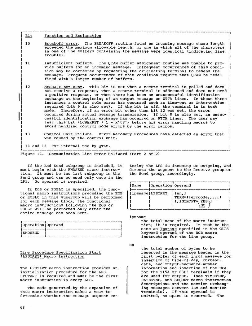
r---------------------------------------------------------------------------------------, I Bit Function and Explanation I I 10 I I I I I 11 I I I I I t 12 I
II I I
II I I I I 13 I I
Breakoff error. The BREAKOFF routine found an incoming message whose length exceeded the maximum allowable length, or one in which all of the characters in one of the buffers containing the message were i~entical (indicating line trouble).
Insufficient buffers. The QTAM buffer assignment routine was unable to provide buffers for an incoming message. Infrequent occurrences of this condition may be corrected by requesting the originating terminal to resend the message.. Frequent occurrences of this condition require that QTAM be redefined with a larger number of buffers.
Message not sent. This bit is set when a remote terminal is polled and does not receive a response" when a remote terminal is addressed and does not send a positive response, or when there has been an unsuccessful identification exchange at the beginning of an output message on WTTA lines. In these three instances a control mode error has occurred such as time-out or intervention required (bit 9 is also set). If the bit is off" the terminal is in text mode. Therefore, if an error bit other than bit 12 was set" the error occurred during actual message transmission. If bit 8 is also set, an unsuccessful identification exchange has occurred on WTTA lines. The user may test this bit (LCBERRST + 1 = X'08') before his error handling macros to avoid handling control mode errors by the error macros,.
Control Unit Failure. Error Recovery Procedures have detected an error that was caused by the control unit.
I 14 and 15 For internal use by QTAM. l ______________________________________________________________________________________ _
Figure 14. Communication Line Error Halfword (Part 2 of 2)
If the End Send subgroup is included, it must begin with the ENDSEND macro instruction. It must be the last subgroup in the Send group and can be used only once in the LPS. No operand is required.
If EOB or EOBLC is specified" the functional macro instructions preceding the EOB or EOBLC in this subgroup will be performed for each message block; the functional macro instructions following the EOB or EOBLC will be performed only after the entire message has been sent.
r---------T-------------------------------, 1 Operation I Operand I t---------+-------------------------------~ IENDSEND I I l _________ ~ _______________________________ J
Line Procedure Specification Start (LPSTART) Macro Instruction
The LPSTART macro instruction provides an initialization procedure for the LPS. LPSTART is required and must be the first macro instruction in every LPS.
The code generated by the expansion of this macro instruction makes a test to determine whether the message segment en-
68
tering the LPS is incoming or outgoing" and directs the segment tc the Receive group or the Send group, accordingly.
r-------T---------T-----------------------, I Name I Operation I Operand I ~-------+---------+-----------------------i IlpsnamelLPSTART I [nn_] I I I I TERM= (termcode1." ,. ' •• ) I I I I L" INTRCPT={YES}l I I I I NO I l _______ ~ _________ ~ _______________________ J
lpsname
nn
the total name of the macro instruction; it is required. It must be the same as lpsnarre specified in the CLPS keyword operand cf the DCB macro instruction for the line group~
the total number of bytes to be reserved in the message header in the first buffer of each input message for insertion of time-of-day, currentdate" and output-sequence-number information and insertion of the ECA for the 115A or 83B3 terminals if they are used for output. (see TIMESTMP~ DATESTMP, and SEQOUT macro instruction descriptions and the section Exchanging Messages Between IBM and non-IBM Terminals). If this operand is omi tted, no space is reserved,. The
TERM
number of bytes reserved must be included in the calculation of the buffer size (see BUFFER macro instruction description).
this parameter must be included in each LPSTART macro instruction.
Value description: (termcode1'···)
is the identifying code for the types of terminals for which terminal tests will be provided. The following values can be included in the sublist:
1. 1030 specifies IBM 1030 terminals.
2. 1050 specifies IBM 1050 terminals.
3. 1060 specifies IBM 1060 terminals.
4. 2848 specifies IBM 2848 control units (associated with remote IBM 2260 terminals).
5. 2740 specifies IBM 2740
6. 83B3 specifies AT&T 83B3 selective calling stations.
7. 115A specifies Western Union Plan 115A outstations.
8. TWX specifies common carrier TWX stations.
9. WTTA specifies World Trade telegraph terminals
Note: On-line terminal tests will not be made on Teletype terminals (numbers 6" 7.,
f8, and 9 above), but they must be specifIed if that terminal type is included in this LPS.
INTRCPT=YES this operand must be specified if the INTERCPT or RELEASEM macros are used in the LPS, or'if the operator control function is to intercept or release a terminal that uses this LPS.
INTRCPT=NO if INTRCPT=NO is specified, or if this operand is omitted" the Release and Intercept facilities must not be used.
Note: If the user wishes to use the intercept-release function in conjunction wi th checkpoint-restart., then an additional parameter must be included in the user's LPSTART macro defining the name of the intercept OPTION field in the TERM entries.
Post Receive (POSTRCV) Macro Instruction
POSTRCV identifies the end of the instruction sequence that processes incoming messages, that is~ instructions in the Receive Segment, Receive Header, and End Receive coding subgroups.
One POSTRCV macro instruction is required in each LPS6 and it must be the last instruction in the Receive group. No operand is required.
r----------T------------------------------, IOperation lOperand I r----------+------------------------------~ IPOSTRCV I I l __________ ~ ______________________________ J
Post Send (POSTS END) Macro Instruction
POSTS END identifies the end of the instruction sequence that processes outgoing messages~ that is, instructions in the Send Header, Send segment~ and End Send coding subgroups.
One POSTSEND is required in each LPS, and it must be the last instruction in the Send group. No operand is required.
r----------T------------------------------, IOperation ]Operand I t----------+------------------------------~ IPOSTSEND I I L __________ ~ ______________________________ J
Receive Header (RCVHDR) Macro Instruction
RCVHDR identifies the beginning of the Receive Header subgroup, which contains instructions concerned only with the header portions of incoming messages. The instructions generated by the expansion of this macro instruction test whether the message segment being operated on contains the message header or text only. If the segment contains text only, the functional macro instructions in the Receive Header subgroup are bypassed; if the segment contains the message header. the instructions in the Receive Header subgroup are executed.
If the Receive Header subgroup is included in the LPS, it must begin with the RCVHDR macro instructionR No operand is required.
Message Control Program 69

r----------T------------------------------, IOperation IOperand I ~----------+------------------------------1 I RCVHDR I I L _______ ---.L----------____________ . ________ J
Receive Segment (RCVSEG) Macro Instruction
RCVSEG identifies the beginning of the Receive Segment subgroup, which contains instructions concerned with both header and text portions of incoming messages.
If the Receive Segment subgroup is included in the LPS, it must begin with the RCVSEG macro instruction. No operand is required.
r----------T------------------------------, IOperation IOperand I ~----------+------------------------------1 I RCVSEG I I L __________ .L ______________________________ J
Send Header (SENDHDR) Macro Instruction
SENDHDR identifies the beginning of the Send Header subgroup, which contains instructions that process only header portions of outgoing messages. The code generated by the expansion of this macro instruction includes instructions that test whether the message segment being operated on contains the message header or text only. The functional macro instructions in the Send Header subgroup are executed if the segment contains the message header; they are bypassed if the segment contains text only.
The user must be sure that the proper EOA sequence is to be transmitted with the message. A discussion of the EOA sequences for different terminals can be found in Appendix H,.
If the Send Header subgroup is included in the LPS, it must begin with the SENDHDR macro instruction. No operand is required.
r----------T------------------------------, IOperation IOperand I ~----------+------------------------------1 ISENDHDR I I L __________ .L ______________________ ~ _______ J
70
Send Segment (SENDSEG) Macro Instruction
SENDSEG identifies the beginning of the Send Segment subgrouPr, which contains instructions concerned with both header and text portions of outgoing messages.
If the Send Segment subgroup is included in the LPS, it must begin with the SENDSEG macro instruction.. Nc operand is required.
r----------T------------------------------, IOperation JOperand I ~----------+------------------------------1 ISENDSEG ] I L __________ .L ______________________________ J
FUNCTIONAL MACRO INSTRUCTION DESCRIPTIONS
LPS functional macro instructions perform specific operations concerned with message segments. The appropriate functional macro instructions must be selected and properly sequenced to satisfy the specific handling requirements of messages directed to the LPS.
Halt Receive (BREAKOFF) Macro Instruction
BREAKOFF is used to specify a maximum length for each incoming message. If the message exceeds the maximum length. reception of the message is terminated and an error flag is set in bit ten of the error halfword for the line. This macro instruction also checks if the input buffer is filled with identical charactersG If it is, the same action is taken as described above.. (A long sequence of identical characters is usually an indication of terminal malfunction.)
Use of BREAKOFF is optional. If used~ it must appear within the Receive Segment coding subgroup.
BREAKOFF can be used only for messages from liSA and 83B3 Teletype terminals.
r----------T------------------------------, IOperation ]Operand I ~----------t------------------------------~ I BREAKOFF Innnnn I L __________ .L ______________________________ J
nnnnn the maximum number of characters for each message. The maximum value of "nnnnn" is 32767.

Cancel Message (CANCELM) Macro Instruction
CANCELM is an error-handling macro instruction that causes immediate cancellation of a message if any of the errors specified by the mask has been detected. Cancellation means that the message is not sent to the destination(s) specified in the message header (handled by the ROUTE macro). or by the DIRECT macro. If CANCELM is used to test for an invalid destination code and the error has occurred,. the message is cancelled for the invalid destination and for any destinations whose codes follow the invalid one in the message header. If a message is cancelled, any subsequent EOB or EOBLC in the subgroup that handled the message will have no effect.
If a message is not sent to its intended destination due to cancellation, it is important that some action be taken to notify a terminal operator or to perform some other corrective action. If no action is taken, there is no record of which messages have been lost because of cancellation. The ERRMSG macro instruction can be used to. send a message to a terminal notifying its operator of the error; or the REROUTE macro instruction can be used to send the message in error to a selected nerminal (see the descriptions of these macros). CANCELM must precede an ERRMSG or REROUTE macro ins~ruction used to test for the same error condition in the End Receive
I
subgroup. CANCELM cannot be used to cancel messages for a PROCESS EXPEDITE queue or multisegment messages in initiate mode (since cancelled messages must be recalled from the DASD destination queue).
The meaning of the bits in the error halfword tested is shown in Figure 14 .•
Use of CANCELM is optional.. If used" it must appear within the End Receive subgroup of the LPS~ It should not be placed after an ERRMSG or REROUTE macro instruction. Since all errors requiring message cancellation can be specified in the same error mask, only one CANCELM macro instruction is needed in the End Receive subgroup.
r----------T------------------------------, IOperation IOperand I ~----------+--------------~---------------1 ICANCELM Imask I L __________ i ______________________________ J
mask the hexadecimal representation of the bit configuration uSed to test the error halfword for the communication line involved. The frarring X and quotes must be coded.
COUNTER Macro Instruction
COUNTER enables the user to maintain four types of count:
1.. Incoming message segments from each originating terminal if EOBs are not used in the message; incoming message segments plus message blocks if EOBs are used in the message.
2. Incoming messages from each originating termmal.
3. Outgoing message segments for each destination terminal.
4. Outgoing messages for each destinatioh terminal or terminal component that has a single terminal entry in the terminal table.
The position of the COUNTER macro instruction within the LPS determines which of the four types of count will pe maintained. COUNTER must appear in the Receive Segment subgroup to count incoming message segments, in the Receive Header subgroup to count incoming messages" in the Send Segment subgroup to count outgoing message segments. and in the Send Header subgroup to count outgoing messages. Anyone or all four counts can be maintained by including the COUNTER macro instruction in the appropriate subgroups; within each subgroup, it may appear at any point .•
For each COUNTER macro instruction issued, the user must define. by means of one OPTION macro instruction. a halfword field for each entry in the terminal table defined by a TERM macro instruction.. This provides space for maintaining the messages-per-terminal or message segmentsper-terminal count. The number of COUNTER macro instructions used in the LPS, and the number of OP~ION macrc instructions for the count fields must each correspond to the number of counts being maintained. See the OPTION macro instruction description.
Use of COUNTER is optional. If it is used in the Receive Header or Receive Segment subgroup and the terminals for which it maintains counts are on a switched line, COUNTER must be preceded by a SOURCE macro instruction. If COUNTER is to be used to count segments over a switched line. there must be two Receive Segment subgroups in that LPS. one before the Receive Header subgroup containing the required SOURCE macro~ and one following it. The first Receive Segment subgroup will translate the message segment and the second will count the segments.
Message Control Program 71

Note: If COUNTER 'is used to record incoming messages from a line group to which IBM 2260s are attached, all segments received from the various 2260s during a general poll are counted as one message.
r----------T------------------------------, IOperation IOperand I ~----------+----'--------------------------~ I COUNTER Ifield I L __________ ~ ______________________________ J
field the name of a halfword field in the user's area of each single terminal entry in the terminal table, as defined by an OPTION macro instruction. The field contains a binary count up to a maximum of 32 6 767. When the maximum count has been reached" the count is reset to 1 for the next message or segment counted. The user may access the field at any time to determine and/or reset the count.
Date stamp (DATESTMP) Macro Instruction
DATESTMP causes insertion of the date in the message header. DATESTMP can be included for incoming messages, outgoing messages, or both. The date is expressed as byy.ddd, where b is a blank, yy is the year, and ddd is the day of the year (for example, b67.289).
No operand is necessary in this macro instruction because the date field has a fixed length of seven. When DATESTMP is specified, the u~er muBt include lhe length of the inserted fiel~ (seven bytes) in his calculation of the value of the operand in the LPSTART macro instruction (see the LPSTART macro instruction description).
USE: of DATESTMP is optional. Tf used, it must appear in the Receive Header or Send Header subgroup. Its position within the subgroup must correspond to the relative position within the header of the field in which the current date is to be inserted.
r----------T------------------------------, IOperation IOperand I ~----------+------------------------------~ IDATESTMP I I L __________ ~ ______________________________ J
DIRECT Macro Instruction
DIR~CT causes a message to be gueued for the destination specified by the operand. Any destination for which there is an entry
72
in the terminal table may be specified. DIRECT may be used in place of ROUTE when message headers do not contain destination codes. Either DIRECT or ROUTE must be specified to handle message routing; both cannot be used,. Only one DIRECT macro may be used for each Receive Header subgroup or for each message type used within one Receive Header subgroup.
DIRECT may be used only within the
IReceive Header subgroup. If DIRECT is used, EOA must not be specified. ,
Note: If the TERM macro instruction specifies that the IBM 2260-2848 complex is to be polled using the general poll feature" the DIRECT macro instruction must be used to send incoming messages to a message processing program. The processing program must then analyze the message" which consists of segments from different 2260s. and place each segment on the proper DASD destination or process queue.
r----------T------------------------------, IOperation ~Operand I ~----------t------------------------------~ I DIRECT 1{=CLn'dest~} I I 1 subfield I L __________ ~ ______________________________ J
dest Lhe destination code. which may be the name of any entry in the terminal table. "n" must be equal to or greater than the longest such name appearing in the terminal table; or "n" may be 8 (the maximum allowable length). "n" may be omitted if this destination name is the same length as the longest destination n~me.
subfield the name of an optional subfield in the terminal table entry for the originating terminal. This subfield contains the name of the terminal to which the message is to be sent. The name of the subfield specified by this onerand must be the same as the name assigned to the subfield by an OPTION macro instruction. The contents of the subfield are specified by the TERM macro instruction that defines the terminal table entry for the originating terminal (see the OPTION and TERM macro instruction descriptions). If the originating terminal is on a switched line, and the user wishes to use this operand~ DIRECT must be preceded by the SOURCE macro instruction.
End-of-Address (EOA) Macro Instruction
EOA is required if the user wishes to provide multiple routing of incoming messages. The instructions generated by this macro instruction determine the end of the list of destination codes in the message header. The character specified by the EOA macro instruction must appear in the header of each message after the last destination code, regardless of the number of destination codes in the header.
When used, this macro instruction must immediately follow the ROUTE macro instruction. EOA is not used if DIRECT is spec if ied,.
Restriction: EOA must not be used for any message whose destination is a processing program queue identified by a PROCESS EXPEDIT~-defined EXPEDITE terminal table entry. Messages to a PROCESS EXPEDITE queue may not be routed to more than one processing program station.
r----------T------------------------------, IOperation IOperand I ~----------+------------------------------~
IIEOA leoa I l __________ ~ ______________________________ J
eoa the EOA character that rrust appear in the message header after the last destination code. If the destination codes all have the same length, and the optional operand in the ROUTE macro instruction is specified, no blank is required between the last code and the EOA character. Otherwise, a blank must separate the two. Any nonblank character rray be specified as the EOA character. The EOA character may be specified either as the character itself, or as the hexadecimal equivalent of the character. The framing C or X and quotes must be coded.
Examples: In an EOA macro instruction that specifies a # to be used as an EOA character, the # may be written either as the character itself, or in hexadecimal representation of the EBCDIC equivalent of that character:
r----------T------------------------l IOperation IOperand I ~----------+------------------------~ I EOA I C ' # ' I (1 ) IEOA I X' 7B' I (2) l __________ ~ ________________________ J
Hardware Error Checking
Two QTAM macro instructions are provided to support the hardware error-checking and retry capabilities available with IBM terminals. The design of these macros, EOB and EOBLC, permits the use of any of the following hardware functions~
1. LRC/VRC checking only (e,.g." 1060 terminals) - Checking is provided" but no automatic (hardware) retry of errors.
2. LRC/VRC checking with automatic line correction (e.g.~ 1050) - Checking and retry of error is provided. but manual intervention is required after a permanent error is established.
3. L~C/VRC checking with automatic line correction and release (e,.g,., 1050) -Checking and retry of errors is provided without manual intervention after a permanent error.
In the case of basic terminals (e.g.~ 2740 Type I or Type III), neither the ECB or EOBLC capability is to be used. EOBLC capabil i ty is to be us,ed.
In case 1 above, the EOB macro is required following the ENDRCV and ENDSEND macros of the corresponding LPS. For read operations, a positive response will be returned to the terminal after a block has
I
been successfully read; no response will be returned after the read was unsuccessful. QTAM will assume that the message is completed and re-poll for the next message. For write operationsu QTAM will transmit the next block of a message following a successful one. It will consider an unsuccessful block as the termination of the roessage.
Manual intervention is required to reset the terminal upon occurrence of.errors.
In case 2 above, the EOBLC macro is required in place of the EOB. Its only functional difference from the EOB support is in handling of unsuccessful message blocks. Message blocks causing an error are retried twice before they are considered unsuccessful and the message is terminated. Retries are for both read and write operations. Manual intervention is required to reset the terminal upon occurrence of errors. In read operations, the operator must set his terminal to transmit the next segment of the message" or EOT, before starting his next message.
Case 3 above differs from case 2 in one instance only. The remote terminal will, without any manual intervention, continue to transmit the rerrainder of the message.
Message Control Program 73

QTAM will continue to receive and process the remainder of the message.
In both cases 2 and 3, transmission of a message from the CPU will terminate after the second retry of an unsuccessful block. Also, error indications for unsuccessful blocks in input transmissions will be saved in the error halfword. Error indications for a specific block are available in the error halfword during the LPS processing of that block (Drior to the EOBLC macro statement); error-indications for all blocks in the transmission are available in the error halfword during LPS processing following receipt of EOT (following the EOBLC macro statement).
End-of-Block (EOB) Macro Instruction
An LRC check is performed each time an endof-block (EOB) or end-of-text (ETX) character is encountered in message text. The check is made by the data adapter at the central processing location for incoming messages, and by the terminal control unit for outgoing messages. The EOB causes a positive response to be sent to the source of the message, if the data was received correctly. If the 2740 Model 2 is equipped with the checking feature, the transmission of EOB is a hardware function. Accordingly, the EOB or EOBLC macro instruction must be issued in the End Receive and End Send sections of the LPS.
The BOB macro must normally be specified, in both the End Receive and End Send subgroups of each LPS that handles messages to and from an IBM 1030, 1050, 1060, 2260, or 2740 types IV through VII. The EOB macro (or EOBLC macro" as subsequently explained) must be ,specified for a 2260-2848 for which general polls are to be performed. It may be omitted only if a,ll messages are one block long and if possible errors are to be ignored (both conditions are required). Either the EOBLC or the EOB macro instruction must be specified in both the End Receive and the End Send subgroups of each LPS that handles messages for an IBM 2740 Mode'l 2 terminal.
This macro instruction is used only for the terminal types just cited. In the case of the IBM 1050, 2260, and 2740 (types IV through VII), the EOBLC macro instruction (subsequently discussed) may be specified instead of the EOB macro.
For Incoming Messages: The EOB macro causes a positive response to be sent to the terminal if the message data was correctly received,. This permits the ter-
74
minal to send another message block. If the data was incorrectly received, no response is sent; reception of the message is terminated. The terminal must resend the message block when contact with the computer is reestablished (by polling or dialing). Either the EOBLC or the EOB macro instruction must be specified in both the End Receive and the End Send subgroups of each LPS that handles messages for an IBM 2740 Model 2 terminal.
For outgoing Messages: The EOB macro causes an EOB (or ETX), followed by an LRC character, to be sent to the terminal when an EOB (or E~X) character is encountered in message text. If the terminal receives the message data correctly, it returns a positive response. Upon recognizing this response, the computer sends the next message block. If the terminal receives the data in error, it returns a negative response. Upon receiving this response the computer terminates transmission of the message.
If the EOB macro is not specified, the first EOB (or ETX) character encountered in incoming or outgoing message text is treated as an end-of-transmission (EOT) character~ precluding transmission of any subsequent blocks of that message.
Restriction: EOA rrust not be used for any message whose destination is a processing program queue identified by a terminal table entry defined by PROCESS EXPEDITE. ~essages to a PROCESS EXPEDITE queue may not be routed to another terminal or processing program.
Note: Error-handling macros should not precede the EOB macro because if the specified error condition occurs, the EOB macro will not be executed. The EOB character will be treated as an EOT, and the source terminal will not receive a response to the EOB-LRC sequence.
Within the coding subgroup in which the EOB macro appears, all functional macro instructions that precede the EOB macro are executed for all message blocks. All functional macros that follow the EOB macro are executed only at the end of the message (an EOB is treated as an end of message if a transmission error occurred during transmission of the block).
r----------T------------------------------, IOperation IOperand I ~----------+------------------------------~ IEOB ] I L __________ ~ ______________________________ J

End-of-Block and Line Correction (EOBLC) Macro Instruction
EOBLC is an optional macro instruction used only for:
1. An IBM 1050 with automatic line correction feature.
2. An IBM 2260-2848.
3. An IBM 2140 equipped with the checking feature (types IV through VII).
4. An IBM 1030 - on read operations, the EOBLC macro must be followed by a CA1~CELM macro specify ing data check.
5. An IBM 1060 - on read operations only, the EOBLC macro must be followed by a CANCELM macro specify ing data check..
EOBLC performs the same function and is used in the same manner as the EOB macro. In addition, it returns a negative response to the message source if the data was incorrectly received, permitting the source to res end the erroneous message block~ If the 2140 Model 2 is equipped with the checking feature, the transmission of EOB is a hardware function. Accordingly, the EOB or EOBLC macro instruction must be issued in the End Receive and End Send sections of the LPS.
If EOBLC is specified.. any message block whose transmission resulted in an error is retransmitted a maximum of two times. If the error persists after the second retry .. an error flag is set in the error h~lfword for the line (see Figure 14).
Restriction: EOBLC must not be used for any message to a PROCESS EXPEDITE queue or multisegment messages in initiate mode.
r----------T------------------------------1 IOperation IOperand I r----------+------------------------------~ I EOBLe 1 I L __________ ~ ______________________________ J
Error Message (ERRMSG) Macro Instruction
ERRMSG causes a user-written error message to be sent to a designated terminal when one of the errors specified by the error mask has occurred.
By means of the ERRMSG macro6 the user specifies:
1. The bit configuration of the mask used to test the error halfword.
2. The destination to which the error message is to be sent.
3. The text that is to comprise the error For Incoming Messages: message,.
1. For an IBM 1050 not equipped with the line correction feature, resending is accomplished by rekeying the message block in error, or by repositioning the paper tape or card containing the erroneous block.
2. For an IBM 2140, resending is accomplished by rekeying the message block in error.
3. For an IBM 2260, the terminal automatically resends the message block.
4. For an IBM 1050 equipped with the line correction feature:
a. If the erroneous message block originated from the paper tape reader or card reader, the device automatically repositions the tape or card and resends the block.
b. If the erroneous message block originated from the keyboard" the operator rekeys the message block.
For Outgoing Messages: For any of the above terminal types, the corrputer automatically resends the erroneous message block.
The meaning of the bits in the error halfword tested is shewn in Figure 14. The error message includes the text written by the user and 6 optionally. the header of the message in error. The user specifies that the header is to precede the text by writi~g a period as the first character of the text. The length of the complete error message cannot exceed one segment (that is, one buffer>..
Unless the MSGTYPE macro instruction is used to distinguish between different message types, the format of the header for an error message must be identical with the header format used for other outgoing mess.ages. If the MSGTYPE macro instruction is used for this purpose, the formats of the respective message headers for the two types may differ after the message-type character. In either case, the correct EOA character for the destination terminal must be included.
If the ERRMSG macro does not specify that the message header is to be included with the error text, no LPS macros that refer to fields iQ the header may be used in the Send Header subgroup that is to pro-
Message Control Program 75

cess the error message" without some modification by the user.
For an ERRMSG macro that does not speci~y inclusion of the hea,der of the message 1n error, it is assumed that the user will place the machine EOA character or sequence in the first character position of the I er::or . text (~or the 2260 STX. is used)... . Th1s 1S requ1red by the term1nal to rece1ve the error message regardless of which LPS macros are to process the error message .. The scan pointer register, register 5# will thus be pointing to the first character of the message in error; this character will be the EOA character (or the first character of the EOA sequence). If the user chooses to have a DATESTMP, TIMESTMP, or SEQOUT macro operate on a message in error that does not contain the header of the erroneous message, he must first set the scan pointer register to point to the first character following the machine EOA.. This may be done by incrementing the register by the number of characters comprising the EOA sequence ..
If the incominq sequence number is invalid, and an error message is to be sent, ERRMSG will scan the error message. If the special character $ is encountered, the correct input sequence number is moved into the four bytes following the $, and the $ is overlayed with a blank. If a second $ is found before the end of the error message, the invalid sequence number is moved into the four bytes following the $, and this second $ is also overlayed with a blank. If this function is not desired" do not use the character $ in the error message for invalid input sequence number.. An unconditional mask (X'OOOO') may not be used in this instance. If the message with invalid sequence number was sent from a terminal on a switched line, and this function is desired, the SOURCE rracro instruction must be used in the Receive Header subgroup of this LPS. This function does not pertain to PROCESS EXPEDITE queues ..
The CANCELM macro instruction should be used prior to the ERRMSG macro instruction if the message is to be cancelled ..
This macro instruction, if used;, must appear within the End Receive and/or End Send subgroup of the LPS; it can appear more than once in either subgroup ...
Restriction: ERRMSG must not be used for any message whose destination is a processing program queue identified by a PROCESS EXPEDITE terminal table entry ..
76
r----------y------------------------------, IOperation IOperand I ~----------t------------------------------~ IERRMSG Imask, I I I {=CLn
l
' dest.'} I I I subfield I I I J SOURCE I J ~ {=C' message'} I I J msgchar I L __________ ~ ______________________________ J
mask
dest
the hexadecimal representation of the bit configuration used to test the error halfword ..
the destination code for the terminal to which the error message is sent; it may be the naree of any entry in the terminal table except a distribution list entry. nn" must be equal to or greater than the longest such name appearing in the terminal table. The maximum value for nnn is 8.. nnn may be omitted if this destination name is the same length as the longest destination name.
subfield the name of a terminal table optional subfield that is associated with the name of the terminal from which the message in error originated. The error message is sent to the destination whose name appears in the optional field ..
SOURCE specifies that the error message is to be sent to the terminal from which the message in error orig inated... For switched or Auto Poll lines.u SOURCE may not be used if this ERRMSG macro is used for an illegal source code error (that is, if the mask contains a 1 in bit position 6) ..
message the actual text of the error message.
msgchar the address of the first character of the error message text; it must be in the same CSECT as the macro instruction ..
Example: Shown in the following chart is an ERRMSG macro ins'truction used in the End Receive subgroup of an LPS to test for invalid destination codes or erroneous sequence numbers.. The first operand is the hexadecimal representation Of the configuration (1011000000000000) of the mask that tests bits 0# 2, and 3 of the error halfword.. The second operand indicates that the error message is to be sent to the terminal from which the message in error orig-
inated. The third operand is the address of the first character of the error message text.
r----------T------------------------------, IOperation IOperand I ~----------+------------------------------~ I ERRMSG I X' BOOO' ,SOURCE"ERMSG023 I L __________ ~ ______________________________ J
Example: Shown in the following chart is an ERRMSG macro instruction used in the End Send subgroup of an LPS to test for transmission errors in outgoing messages. The first operand is the hexadecimal representation of the bit configuration (0000000100000000) of the mask that tests bit S of the error halfword. The second operand is the name of the terminal to which the message in error is to be sent (all error messages are sent to the same terminal regardless of which destination terminal was to have received the erroneous message). The third operand is the text of the error message. The period as the first character causes the header of the message in error, if there is a header for that message, to precede the text. (A polling error is an example of a message in error that has no header. In this case the header cannot be included in the error message.)
In general, if the error rressage is to be sent to an IBM terminal, it may end with an end-of-block character.
r----------T------------------------------, loperation IOperand I ~----------+------------------------------~ IERRMSG IX'OOSO',=CLS'NYCSUPVR', I , I=C'.TRANSM ERROR' I L __________ ~ ______________________________ J
Intercept (INTERCPT) Macro Instruction
INTERCPT causes the suppression of all message transmission to a terminal when any of the errors specified by the mask has been detected. The untransmitted messages remain on the DASD destination queue for that terminal. If the INTERCPT macro instruction is to be used, the user must specify a 3-byte subfield named INTERCPT in the optional user area of the terminal table. (see the OPTION macro instruction description.) For each terminal for which message transmission is suppressed:
1. The disk address of the first intercepted message header is placed in the INTERCPT subfield reserved in the entry representing that terminal.
2. The intercept bit in the TSTATUS byte of that entry is set to 1.
3. The send bit in the TSTATUS byte for that entry is set to O.
No further messages are sent to the affected terminal until the user resets the intercept and send bits. This may be done by a message processing program using the RELEASEM or CHNGT rracro instruction or by issuing a RELEASEM or CHNGT operator control message. If RELEASEM is used. all suppressed messages (those on the destination queue) are sent, as are any new messages. If CHNGT is used. only the new messages (those placed on the destination queue after CHNGT has been issued) are sent. In the latter case, the suppressed messages remain on the destination queue,. and cannot be sent unless the user obtains them by a RETRIEVE macro instruction and reissues a PUT for each of them.. The meanings of the bits in the error halfword tested are shown in Figure 14.
The INTERCPT macro instruction is used to permit messages on a line that were not transmitted to be sent at a later time. Note that after the first message has been intercepted for any ccndition specified, the send bit in the terminal table for the terminal will be turned off. Therefore~ all subsequent messages for that destination will not be sent, but will be flagged as "terminal inoperative" in the error halfword. These subsequent messages will not be intercepted unless the error mask for the error halfword has terminal inoperative specified. If the terminal is equipped with the Buffer Receive option,. the user must specify the INTERCPT macro instruction in the End Send section of the LPS with a mask including the "message not sent' bit. This is necessary because the terminal may be addressed while a message is being entered at the terminal~ resulting in a negative response to addressing. If this happens, the terminal bell rings and the attention light is turned on.. The intercepted message may be released by sending a message to a message processing program to issue a RELEASEM macro instruction or by use of the Operator Control RELEASEM function. Refer to the RELEASEM macro description. noting particularly the necessity for a priming message.
If the user ever wishes to issue an INTERCPT operator control message, he must specify the INTERCPT macro instruction in the ENDSEND portion of the LPS. The mask in this macro must specify nterminal inoperative" (i. e, ... the mask must be at least a hexadecimal 4000).
The use of INTERCPT is optional. If the macro instruction is not used, messages that were unable to be transmitted are considered as transmitted, even though they did not reach their destination. If used,
Message Control Program 77
it must appear in the End Send subgroup of the LPS.
r----------T------------------------------, IOperation IOperand I ~----------+------------------------------~
IIINTERCPT I mask I L __________ ~ ______________________________ J
mask the hexadecimal representation _of the bit configuration used to test the error halfword for the communication line involved.
Logging (LOGSEG) Macro Instruction
LOGSEG enables ~he user to log message segments fplace them on an output device as a record of message traffic carried by the line group). The user may maintain any or all of four types of logs by appropriate placement of LOGSEG within the LPS. The four types of logs, and the corresponding coding subgroup in which LOGSEG must appear" are:
1. Incoming headers only (Receive Header).
2. All incoming segments if EOBs are not used in the message; incoming segments plus message blocks if EOBs are used in the message (Receive Segment) ,.
3. Outgoing headers only (Send Header) ,.
4. All outgoing segments (Send Segment).
If all segments of messages are logged" they are logged in the sequence in which they are received or sent. Theref ore" segments of different messages are intermixed on the log, not grouped together as individual messages. The last 24 bytes of a QTAM heade'r prefix, preceded by 4 bytes of information used by the access method doing the logging, are recorded on the logging device. These bytes precede the header portion (and text portion, if any) of the first segment of a message. The last 14 bytes of a QTAM text prefix, preceded by 4 bytes of information used by the access method doing the logging, are recorded on the logging device. These bytes precede the text portion of a text message segment.
LOGSEG may appear at any point in the subgroup ion which it is used. However" the results of any alteration of segments by functional macro instructions preceding LOGSEG will appear in the logged segment. For example, if LOGSEG is preceded by TIMESTMP, all logged headers will contain time-of-day information. If TIMESTMP follows LOGSEG, headers will be logged without
78
time-of-day information. (The logging effected by LOGSEG is in addition to the queuing procedure of QTAM.) Use of LOGSEG is optional.
r----------T------------------------------, IOperation ~Operand I ~----------+------------------------------~
rlLOGSEG I dcb I L __________ ~ ______________________________ J
dcb the name of the data control block for the message log data set. If register notation is used" (1) specifies that the address of the data control block is in parameter reg.ister 1. The address must be loaded into register 1 prior to execution of this macro instruction.
~essage Mode (MODE) Macro Instruction
MODE causes execution of a deSignated function, either unconditionally (the deSignated function is performed for all messages handled by this portion of the LPS) or conditionally (if the next nonblank character of the message header is the same as a character designated by the MODE macro instruct ion).
In the second case, if the characters are not the same, control returns to the next instruction in the LPS" and the scan pointer is reset to its position prior to the comparison.
MODE can cause four IBM-provi:ded written routine. IBM are discussed des cr iptions.
the execution of any of functions" or a user-The functions provided by in the following operand
The message priority scheme implemented by the MODE macro instruction with the PRIORITY operand is designed to permit a message from one of a group of lines sending to a cornmon destination to be sent ahead of the other messages in the queue for that destination. The priority routine compares the relative priority indicators of the last message sent from each line originating messages for the cornmon destination~ The highest-priority message is sent first, followed by the other ~essages, in order according to their priorities, and then non-priority messages for the line. The priority conferred on a message is valid only if that message is the last message to be sent from that source line,.. If more than one message from the

line is currently being handled by QTAM, only the message that arrived last can have valid priority.
Example: Assume that lines A" B" and Care all sending messages to line D.
Originating Line
A
B
C
Arrival of Incoming Messages Time • t
Messages sent with priority are circled: the priority is indicated by superscript. Assume that by time "t", seven messages have arrived on the destination queue for line D in the order: A1 B1 Aa C1 A3 Ba Ca. Since messages A3!, Ba, and Ca are the last messages received from their respective originating lines, only they will have priority. Thus, because priority message A3 arrived on the destination queue before priority message Aa (previously placed on the queue) was sent to D, message Aa loses its aSSigned priority and is sent on a first-in-first-out basis like all other non-priority messages. If at time "ttl, message Ca is sent, and a new priority message B3 arrives on the queue before message Ba is sent, Ba loses its priority status to B3 • Assuming no more messages arrive on the queue before all the priority messages are sent, the remaining messages on the queue are sent in the order: B3 A3 A1 B1 Aa C1 Ba.
Use of MODE is optional. If used" it must appear in the Receive Header or Send Header subgroup of the LPS. It may be used more than once in either subgroup. Its position within the subgroup must correspond to the point during header processing at which the function deSignated by its operand is to be performed.
The PRIORITY, CONVERSE, and INITIATE operands of the MODE macro instruction cannot be specified with the IBM 2740 Model 2.
r--------~-T------------------------------l IOperation I Operand 1
f---~------r--I~~~~~i-\-------------------l 1 MODE ,I MOD2260 1 I 1 userfunc 1 I I I I 1 [, condcharl 1 I I I I 1 [,WRT60=codel I L __________ ~ ___________________________ ~ __ J
PRIORITY causes scanning cf the header to locate the next nonblank character. This character is the priority value of the incoming message. It must be a letter or a digit,. The priority sequence is A •••• Z,O ••• 9 (9 is highest priority).
If MODE designates a specific character by means of the second operand, scanning of the header for a priority character occurs only when the character designated in the second operand is found. If no specific character is designated, scanning always occurs, and all messages must have a priority character as the next nonblank character.
CONVERSE causes the line. on which the originating terminal is located, to be placed in conversational mode. The line is held open until an entire message from that terminal has been received by a message processing program and that program has sent a response message to the same terminal. During this time" no incoming messages can be sent by any other terrrinal on the line, and outgoing messages that have been queued for sending to any terminal on the line will not be sent. The line will remain in ccnversational mode until a negative response is received from the terminal or until the terminal is allowed to time-out. If the message was sent from a terminal that was polled using the Auto Poll facility, that terminal will remain in conversational mode until the first reply is received from the message processing program. The second operand can be specified for conditional use of CONVERSE. Conversational mode will not be established with process queues that are not open.
INITIATE causes segments cf a message to be sent from a destination queue to the destination as soon as they are placed on the queue (normally, segments are not sent to the destination until the complete message has accumulatep on the queue). If a message has multiple destination codes specified in the header" the INITIATE function is performed only for the first destination. Sending to the remaining destinations will occur only after the complete message has been placed on the destination queue. Messages containing an EOB character in initiate mode may not be sent to a terminal attached to a 2701 Data Adapter Unit. The
Message Control Program 79

second operand can be specified for conditional use of INITIATE,.
MOD2260 causes QTAM to modify the write operation for IBM 2260s. The specific change is indicated by the WRT60 keyword operand of this macro. MOD2260 may be specified only when the mode macro is included in the Send Header LPS subgroup. If this operand is not supplied, a Write DC (Display Control) function will be executed.
userfunc the n arne of a routine provided by the user to perform a desired function. The routine must be in rrain storage and in the same control section that contains the LPS section of the message control program. (See the section entitled Including a User-written Subroutine Within the LPS.)
condchar
WRT6"0
a character that~ if found in the header before another nonblank character, causes execution of the function specified by the first operand. Rcondchar R can be any single nonblank character. If this second operand is omitted, the function is performed unconditionally for all messages. The character may be specified either as the character itself, or as the hexadecimal equivalent.
specifies the type of modification to be made to the Write operation for the 2260.
WRT60=1 Causes erasure of the 2260 screen before the next segment is displayed.
WRT60=2 Causes a write line address operation for the 2260. The user must specify the line addre~s character as the first character of the header of the message to be written out.
The user may cause the line address to be inserted by:
1. Writing assembly language instructions to perform this in his LPS.
2. Writing assembly language instructions to perform this in his message processing task.
3. Using the PAUSE macro.
The EBCDIC and ASCII-8 equivalents of each line address are given in Figure 15.
80
This operand must be specified if and only if the MOD2260 operand is specified.
r---------T------------T------------------l I Line I ASCII-8 I EBCDIC I ) I Equivalent I Equivalent I I Number I (Hex) I (Hex) I ~---------+------------+------------------~ I 1 I 50 I FO I 2 I 51 I F1 ] 3 ] 52 I F2 I 4 I 53 I F3 I 5 t 54 I F4 I 6 I 55 I F5 I 7 ) 56 I F6 I 8 I 57 I F7 I 9 I 58 I F8 I 10 I 59 I F9 I 11 I 5A I 7A I 12 I 5B I 5E l _________ ~ ____________ ~ __________________ J
Figure 15. Line Address ASCII and EBCDIC Equivalents for IBM 2260
Message Type (MSGTYPE) Macro Instruction
MSGTYPE enables the user to categorize incoming and outgoing messages into two or more message types, each of which he wishes to process in a different manner. A ~SGTYPE macro instruction encountered during processing of a message header causes the next nonblank character in the header to be compared with a character specified by the operand of the MSGTYPE macro instruction,. If the two characters are identical, the instructions between this MSGTYPE macro and the next MSGTYPE macro or the next delimiter macro instruction are executed. If the two characters are not identical, the instructions between the ~SGTYPE macro performing the test and. the next MSGTYPE macro or delimiter are' not executed4 The scan pcinter is reset to its position prior to the comparisono Instructions between a MSGTYPE macro instruction with no operand and the next delimiter are executed for messages that do not contain a message-type character. The scan pointer is not advanced in this case. These instructions are bypassed if the message was previously handled by a MSGTYPE macro instruction with a message-type character operand 0
Use of MSGTYPE is optional. Any number of MSGTYPE macro instructions may be used within a subgroup" prcvided that they all examine the same pOSition in the header for a message-type character. Only one position in a header per Receive Header subgroup may contain a message-type character. ~SGTYPE macro instructions may be used only within the Receive Header and Send Header subgroups.

r---------T-------------------------------, I Operation I Operand I
I t;~~;~;~--t--[~;~~~h~;]-------------------1 L _________ ~ _______________________________ J
typechar the message-type code. It may be any single nonblank character. If this operand is omitted (i.e." a blank is specified), the group of macro instructions that immediately follows this MSGTYPE macro instruction will process any message not handled by a preceding MSGTYPE macro instruction with a nonblank character operand. If a MSGTYPE macro with a blank operand is used, it must be the last of the series of MSGTYPE macros. The message-type character may be specified either as the character itself., or as the hexadecimal equivalent of the character.
Example: The beginning of a Line Procedure Specification section using MSGTYPE macro instructions is shown in Figure 16.
Operator Control (OPCTL) Macro Instruction
The user may find it advisable to examine control information used by QTAM and to make necessary changes from an external source. QTAM provides an operator control facility to perform this function from a terminal, in addition to the macro instructions described previously.
Operator control is specified by including an OPCTL macro instruction in the RCVHDR section of the LPS for the line group which contains the telecommunications control terminal. A local 1050 or a 2740
IWith station control and checking must be provided for this function.
Each operator control message is treated as a header segment and the complete message, including EOB and EOT characters, must fit in one buffer. If the data as transmitted from the terminal overflows the buffer, the message will be returned to the originating terminal, indicating an error. If the data to be sent to the terminal overflows the buffer, the excessive data will not be transmitted.
If the operator control facility is being used, receiving must have priority over sending on the line containing the telecommunications control terminals. If, however, the control terminals are being polled using the Auto Poll facility, then equal priority must be specified. With large systems that will have a great deal
of message traffic going to the control terminal, equal priority may make it extremely hard to enter a message from that terminal. Once a polling pass has been completed, all messages to that terminal will be sent. This may keep the terminal permanently busy, not allowing any messages to be sent in.. If this situation is conceivable, then the responsibility should be split between the control terminal and the alternate. One terminal should be used solely to receive rressages and the other solely to send them. If the control terminals are not being polled using the Auto Poll facility, then receive priority must be specified and there will be no problem in getting the messages into the system.
Note: Only one OPCTL macro may be issued in the message control program. The scan' pointer must be positioned to the character before the control message identifier characters in the message header before issuing the OPCTL macro.
If the telecommunications control terminal is to be polled using the Auto Poll facility" then the SOURCE macro instruction must precede the OPCTL macro instruction.
r------T---------T------------------------, I Name I Operation I Operand I ~------+---------+------------------------~ I name IOPCTL ICTLMSG=msgname. I ~ ~ I TERM=termname I I I I [,ALTERM=termname] I ) J I I J ) I [., INTRCPT={YES}] I I I I NO I L ______ ~ _________ ~ ________________________ J
name the name of the macro instruction. It must be the same as the OPCTL specified in the TERMTBL macro instruction.
I CTLMSG=msgname
msgname is the control message name identifier, containing one to eight nonblank characters; it must be specified. This name identifies a message as a QTAM control message.
I TERM=termname
termname is the name of the telecommunications system control terminal as it appears in the TERM entry for this terrrinal. This terminal may be a nonswitched 1050 or nonswitched 2740 with Station Control.
Message Control Program 81

r------T-----------T--------------T-----------------------------------------------------, I Name I Operation IOperand 1 Comments I
~------+-----------+--------------+-----------------------------------------------------i I LPSl 1 LPSTART 115,TERM=(1050) I Reserve 15 bytes in header I
~------+-----------+--------------+-----------------------------------------------------i I I RCVSEG 1 IDelimiter 1 ~------+-----------+--------------+-----------------------------------------------------i 1 I TRANS I RCVETl IMacro instruction executed for all segments 1 ~------+-----------+--------------+-----------------------------------------------------~ 1 I RCVHDR I IDelimiter I ~------+-----------+--------------+-----------------------------------------------------i 1 I SEQIN 14 . I 1 I I SOURCE 13 IMacro instructions executed for all header segments 1 1 I DATESTMP 1 1 1 liT IMESTMP I 8 I I I I COUNTER IMSGIN ICount number of incoming messages I ~----... -+-----------+--------------+-----------------------------------------------------1 I i MSGTYPE IC'A' ITest for type A messages I ~------+-----------+--------------+-----------------------------------------------------1 I I - I IMacro instructions executed for all type A messages I I I - I I I I I DIRECT I =CL8 'CHI' I I ~------+-----------+--------------+-----------------------------------~-----------------i 1 I MSGTYPE le'B' ITest for type B messages I ~------+-----------+--------------+-----------------------------------------------------i I I - I IMacro instructions executed for all type B messages I I I DIRECT I =CL8 ' NYC' I I ~------+-----------+--------------+-----------------------------------------------------i I I MSGTYPE I ITest for all other message types I ~------+-----------+--------------+-----------------------------------------------------i I I DIRECT I=CL8'PROCESSQ' IMacro instruction executed for all other message I I I I I types I ~------+-----------+--------------+-----------------------------------------------------i I I ENDRCV I IDelimiter I ~------+-----------+--------------+-----------------------------------------------------i I I - I I I I I - I IRemaining macro instructions of LPS I I I - I 1 1 l ______ ~ ___________ ~ ______________ ~ _____________________________________________________ J
Figure 16. Use of MSG!YPE Macro Instruction in an LPS
IALTERM=termname
termname
IINTRCPT
82
if specified, is the name of an alternate telecommunications system control terminal as it appears in the TERM entry for that terminal. Control messages may be entered froIT this terminal or the primary. This terminal may be a nonswitched 1050 or nonswitched 2740 with Station Control.
Restriction: Messages from this terminal must be processed by the same LPS that includes the OPC'I'L macro instruction.
INTRCPT=YES must be specified if INTERCPT or RELEASEM operator control messages are to be accepted from the telecommunications control terminal. In addi-
Example:
tion, there must be a 3-byte OPTION field labeled INTERCPT defined for the terminal table entries. If INTRCPT=NO is specified, or if this operand is omitted" INTERCPT and RELEASEM operator control messages will not be accepted.
r--------T---------T----------------------, I Name I Operation I Operand 1
r--------+---------+----------------------i I OPCTLNME -I OPCTL I CTLMSG=QCTL tI TERM=LOCAL 1 l ________ ~ _________ ~ ______________________ J
PAUSE Macro Instruction
PAUSE causes automatic transmisSion of a user-specified sequence of characters on the communication line each time the LPS section containing the PAUSE encounters a

user-specified character in the message segment currently being sent. The inserted characters are not placed in the outgoing message segment as contained in main storage. Rather, they become part of the segment as received at the terminal. To illustrate: If a message segment containing the characters
ABCDEF*GHI*ABCD*r1NOPQ*RSTU* *ABC
is handled by an LPS in which a PAUSE macro specifies insertion of the characte~s XY each time an asterisk is encountered, the segment as contained in main storage remains unchanged, but as received by the destination terminal becomes
ABCDEF*XYGHI*XYABCD*XYMNOPQ *XYRSTU*XY*XYABC
This facility has two main uses:
1. It permits the user to effectively modify outgoing message headers by inserting extra characters. The need for this arises when message headers received from certain terminal types are to be sent to other terminal types. In certain instances" extra control characters must be sent on the line during transmission of the header, in order for the message to be received properly.
2. It permits sending of nonprinting idle characters over the comrrunication line, where necessary to prevent loss of message data.
Characters in outgoing messages are sent continuously, even while the terminal device receiving the message is performing a mechanical positioning operation that interferes with correct recording of the incoming characters. For example" some terminal printers require more time for the carriage return operation than is available between printing of successive message characters; characters are printed during the carriage return movement.
To avoid partial loss of a message from this cause, one or more nonprinting characters must be inserted into the message after each device control character (such as carriage return) that performs an operation otherwise resulting in ldss of message characters. These nonprinting characters are referred to as idle characters, although the specific character to be used depends on the type of terminal that receives the message. The idle characters used by each type of device are shown in Figure 17.
The PAUSE macro' can be used to cause insertion of idle characters each time a
designated device control character appears in the message. (Device control characters can be inserted by a user-provided subroutine or by the terrrinal that originates the message.) The specific control characters for which insertion is required. and the number of idle characters required for each, vary among terminal device types. For these requirements, see the reference manuals for the various te:rrminail types.
The PAUSE macro instruction specifies:
1. The character that is to cause insertion.
2. The number of character sequences to be inserted.
3. The transmission code bit configuration of the characters to be inserted.
A separate PAUSE macro instruction must be specified for each control character for which insertion is required.
PAUSE cannot be used to cause the EOB character to be transmitted.
PAUSE" if usedw must appear within the Send Header or Send Segment subgroups.
r---------T-------------------------------, I Operation I Operand I ~---------+-------------------------------~ ) PAUSE Ictlchar.insertchar I L _________ ~ _______________________________ J
ctlchar the actual transmission code bit configuration of the character for which insertion is required if TRANS precedes PAUSE, and the EBCDIC code bit configuration if PAUSE precedes TRANS. It must be wrttten in hexadecimal notation. This cannot be the EOB character.
insertchar the actual transmission code bit configuration of the character (or characters) to be inserted. It must be written in hexadecimal notation, in the form nX'hexchars', where "nil is the number of character sequences to be inserted. (For example, 5X'E2E4' specifies that the sequence AB [in 1050 code] is to be sent five times.)
Example: A PAUSE rracro instruction to cause inserti.on of six idle characters into an outgoing message to an IBM 1050 each time a new line (NL) character is detected in that message by the message control program (5B and 5E are hexadecimal equivalents of 1050 transmission code new line and idle characters, respectively):
Message Control Program 83

r---------T-------------------------------, \ Operation I Operand \ ~---------+-------------------------------~ \ PAUSE IX'5B',6X'5E' \ l _________ ~ _______________________________ J
r---------------T-------------------------, \Terminal Type \Idle Character and Code \ ~---------------+-------------------------~ \IBM 1030, 1060 Idle (5E) \ \IBM 1050, 2740 Idle (5E) or delete (7F) \ \AT&T 33, 35 \ (TWX) Rubout (FF) \ \AT&T 83B3, Figures shift (lB) IWU 115A or letters shift (IF) \
I
\WTTA Figures shift (lB or 3B)~ \ Letters shift (IF or 3F), \ or Mark (OF) l _______________ ~ ________________________ _
Figure 17. Idle Characters
Polling Limit (POLLIMI~) Macro Instruction
POLLIMIT is an optional macro instruction specifying a maximum number of messages to be accepted from a nonswitched terminal during one polling pass. When this limit is reached, the next terminal is polled. If no polling limit is set (that is, the POLLIMIT macro instruction is not used), each terminal is polled until it has no more messages to send during that polling pass.
The POLLIMIT macro instruction has no effect when used with a switched line, and is not applicable to WTTA lines.
If used" POLLIMIT must appear at some point within the Receive Header or End Receive subgroup.
Note: For an IBM 2260, the LPS must include POLLIMIT, a macro that specifies a polling limit of 1.
r---------T-------------------------------, I Operation I Operand I ~---------+-------------------------------~
I
IPOLLIMIT I {nnn } I \ I subfield I L _________ ~ _______________________________ J
nnn
84
the maximum number of messages the user wishes to allow for each terminal in the line group. This option may be used only when the number of consecutive polls is to be the same for all terminals in the communication line group. The maximum value of "nnn" is
255Q Leading zeros may not be specified in this operand.
subfield the name of an optional subfield in a terminal table entry. It must be the same as the name assigned to the subfield by an OPTION macro instruction. This subfield contains the limit of consecutive polls to be allowed for the originating terminal~ as specified by a TERM macro instruction. This method of specifying the polling limit allows a different limit to be set for each terminal.
REROUTE Macro Instruction
REROUTE causes a message to be queued for an alternate destination (in addition to the destinations specified by the message header) when any of the errors specified by the mask has been detected.
The meaning of the bits in the error halfword tested is shewn in Figure 14.
If the destinations specified by the message header are switched terminals, the SOURCE macro instruction must appear in the LPS prior to REROUTE, in order for the "subfield" operand to be specified. A distribution list entry cannot be specified as the alternate destination.
Use of REROUTE is optional. If used, it must appear in the End Receive or End Send subgroup.
Re'striction: REROUTE must not be used for any message whose destination is a processing program queue identified by a PROCESS EXPEDITE terminal table entry.
r---------T-------------------------------, • I Operation \ Operand \ ~---------+-------------------------------~ I REROUTE I mask, \ \ I \ I \ {=CLn' dest ' } \ I I subfield I I I SOURCE I l _________ ~ _______________________________ J
mask
dest
the hexadecimal representation of the bit configuration used to test the error halfword in the line control block (LCB).
the destination code for the alternate destinationQ The code may be the name of any entry that appears in the ter-

minal table. If this optian is selected" all messages from any line in the line group with errors detected by REROUTE are sent to the same destination. "n" must be equal to or greater than the longest destination name appearing in the terminal table; the maximum value for "n" is 8.
subfield the name of an optional subiield in the terminal table that contains the name of the alternate destination. The name must be the same as the name assigned to the subfield by an OPTION macro instruction,.. If this option is selected, the alternate destination is the terminal specified in the option field of either
1. the terminal table entry for the originating terminal, if REROUTE is used in the ENDRCV section of the LPS, or
2. the terminal table entry for the destination terminal, if REROUTE is used in the ENDSEND section of the LPS.
For example, in Figure 10, alternate destinations are specified in the third OPTION field in the terminal table entries. If a message was received from WAS and
REROUTE DEST
was coded in the ENDRCV portion of the LPS, then the message would be sent to NYC also.
SOURCE specifies that the error message containing the error is to be sent to the terminal from which it originated {in addition to the destinations specified by the message header}.
Routing (ROUTE) Macro Instructicn
ROUTE causes scanning of the destination code field in the header of each incoming message. If the destination code is valid, ROUTE causes the message to be queued for the specified destinations. If an invalid destination code {i. e .• , one not appearing in the terminal table} is detected:
1. Bit 0 of the error halfword for the line containing the originating terminal is set to 1.
2. The message is placed on the deadletter queue. {The dead-letter queue is generated by QTAM on the direct access device.}
If further processing of messages placed on the dead-letter queue is required, a REROUTE or ERRMSG macro instruction must be specified in the End Receive subgroup to notify a terminal operator of the destination error.
Messages may be routed to multiple destinations in any of three ways:
1. More than one destination code may be included in the message header. It is not necessary to indicate in the header the number of destination codes included. When this method of routing to multiple terminals is used" the user must:
a. Include an end-of-address (EOA) character after the last destination code in the header of each incoming message (see EOA macro).
b. Specify an EOA macro instruction immediately following ROUTE in the LPS.
2. The message header may contain a single destination code that identifies a distribution list entry in the terminal table. Each destination in the distribution list receives the message.
3. Where special machine features are available. "group code" transmission may be used. Under this method, unique address characters cause the sending of single messages simultaneously to a prespecified group of terminals on the same line.
Either the ROUTE or the DIRECT macro instruction must be specified to handle message routing. Both cannot be used for the same message type. Only one ROUTE macro may be used for each LPS or for each message type used within one LPS (see the ~SGTYPE macro instruction description). ROUTE may be used only within the Receive Header subgroup.
Note: If the POLL macro instruction specifies that the IBM 2260-2848 complex is to be polled using the general poll feature, the DIRECT macro instruction must be used. ROUTE cannot be specified.
r---------T-------------------------------, I Operation] Operand I ~---------+-------------------------------~ I ROUTE I [n] I l _________ ~ _______________________________ J
n the number of characters in each destination code in the message header. "nn is specified only if the user
Message Control Program 85

choo$es to make all destination codes the same length. The maximum value of "n" is 8.. If this operand is omittedll
destination codes are assumed to have varying lengths and a blank is required:
1. After a single destination code.
2. Between multiple destination codes .•
3. Between the last destination· code and the EOA character ..
If "n" is specified, the blanks are not required ..
Sequence In (SEQIN) Macro Instruction
SEQIN causes scanning of the input sequence number field in the header of each incoming message. If the sequence nurrber is not one higher than the sequence number of the last mess~age received from the sending terminal,. an error flag is set in bit 2 or bit 3 (depending on whether the number is high or low)" of the error halfword for the line.
The first message from a terminal must contain the same input sequence number as the TSEQUIN field of the terminal table entry for that terminal. QTAM initially sets TSEQUIN to 1.. The user may at any time reset (by means of the STOPLN and CHNGT macro instructions) the contents of TSEQUIN. If TSEQUIN is reset before the maximum number (9999) is reached" the next incoming message must have the same number as TSEQUIN. If TSEQUIN is not reset before the maximum number is reachedj, the next incoming message after 9999 !rUst be numbered 0000.
In general, SEQ IN causes the input s.equence number field in the terminal table entry to be incremented for each message having a correct input sequence number in the header.. If, however., CANCELM causes a message in error to be cancelled, or if an EOBLC macro causes retransmission of the first block of a message, the input sequence number is not incremented.. In the latter case, the number is incremented when the first block is successfully retransmitted.
Use of SEQIN is optional. For switched terminals, the SEQIN macro instruction, if used, must be preceded by a SOURCE macro instruction. SEQIN may be used only within the Receive Header subgroup. Its position must correspond to the pOSition of the sequence number field relative to other header fields .•
86
r---------T-------------------------------, I Operation I Operand I ~---------+-------------------------------i
I J SEQIN 1 [n] I 'L _________ ~ _______________________________ J
n the number of character positions in the header field for the input-message sequence number.. The maximum value of Un" is 4. If this operand is omitted, a variable-length field is assumed. In this case~ the input-message sequence number must be followed by a blank used as a field delimiter.. The value Un" does not include any blanks preceding or following the sequence number digits.
Seguence Out (SEQOUT) Macro Instruction
SEQ OUT is used to place an output sequence number in the header of each outgoing message.. The LPS maintains a separate sequence count for each terminal and each terminal group (where group code addressing is used). Each message for the terminal or terminal group is given a sequence number one greater than that of the preceding message for the same terminal or group.
A message in error rerouted via a REROUTE macro or resent by the EOBLC macro retains the output sequence number originally placed in it by the LPS.
Use of SEQOUT is optional.. If used" it may appear within the Receive Header or Send Header subgroup... Its position must correspond to the relative pOSition, within the header. of the field into which the sequence number is inserted.
If SEQOUT is used in the RCVHDR section of the LPS6 it must appear following a ROUTE or DIRECT macro specifying a process queue. If SEQOUT is used with either the time stamp or date stamp facility, SEQOUT must be specified after the TIMESTMP and/or DATESTMP macro instructions.. When used in the RCVHDR section, all incoming header segments routed to a message processing program will be assigned an output sequence number. This sequence number is two bytes long and will be inserted wherever the scan pointer is pointing when SEQOUT is issued. By inserting the output sequence number in messages sent to queues for message processing programs. the capability is included to allow these programs to check for lost messages. For example, if there are three message processing programs_ in a telecommunications system, three separate counters will be kept, one for messages for each processing program queue. If message

processing program A receives the message with output sequence number 4, followed by the message with output sequence 6, then that program has the capability to tell that message 5 is missing. The message control will not check this field in any way. However, this sequence number must be removed by the processing program before the message is put to a terminal destination. otherwise, invalid characters may appear in a message header.
When SEQOUT is specified, the user includes the value of "n" in his calculation of the operand value of the LPSTART macro instruction (see the LPSTART macro instruction description).
r---------T--------------------------~----, ,Operationl Operand , ~---------+-------------------------------1 'SEQOUT I [nl I l _________ ~ _______________________________ J
n the number of characters to be inserted in the header for the output sequence number. The first character is always a blank. Therefore "n" must be specified as the number of sequence-number digits plus 1. The maximum value of "n'" is 5 (that is, the maximum field size is five characters, allowing for a sequence number range between 0001 and 9999). When the last available sequence number (99, 999, or 9999) has been issued to a message, the numbering cycle is repeated. The next message is numbered 0000.
SKIP Macro Instruction
SKIP causes skipping of either a designated number of nonblank characters, or all characters up to and including a designated sequence of characters. The sequence may consist of 1 to 8 nonblank characters. This permits the user to skip fields in the message header during processing. One SKIP macro instruction is specified for each field to be skipped. SKIP macro instructions must appear among other functional macro instructions in the sarre relative order as fields to be skipped appear among other header fields.
Use of SKIP is optional. It may be used only within the Receive Header and Send Header subgroups.
r---------T-------------------------------, I Operation I Operand , ~~--------+-------------------------------1 ISKIP , skipchars , L _________ ~ _______________________________ J
skipchars designates the number of nonblank characters to be skipped" or the a ctual character~ in the sequence that is to terminate the skip operation. The number of characters to be skipped is specified as "n", and cannot exceed the number of characters remaining in the header. The character sequence may be specified as the characters themselves or as the hexadecimal equivalent. The sequence may be 1 to 8 nonblank characters. The framing C or X and quotes must be coded.
Example: A SKIP macro instruction to cause skipping of five characters:
r---------T-------------------------------, IOperation~ Operand I ~---------+-------------------------------1 'SKIP J 5 I l _________ ~ _______________________________ J
Example: A SKIP macro instruction to skip characters up to and including #= may specify the characters themselves, or the hexadecimal representation of the characters.
r---------T------------------------~ I Operation I Operand I t---------t------------------------~ ISKIP , C'#=' I (1) I SKIP 1 x' 7B7E' 1 (2) l _________ ~ ________________________ J
SOURCE Macro Instruction
The SOURCE macro instruction causes scanning of the source terminal code field in the header of each incoming message to determine if the source code is valid. The validity check performed varies" depending on whether the source terminal is on a nonswitched or a switched line.
If the source terminal is on a nonswitched line, SOURCE verifies that the header contains the symbolic name of the same terminal that was invited to send a message (that is" the source code field in the header is compared with the name of the terminal table entry for the terminal that was polled). If the names are not equal" an error flag is set in bit 6 of the error halfword for the line. (See Figure 14.)
If the source terminal is on a switched line or an Auto Poll line, SOURCE can only verify that the source code field in the header contains a valid name (the name of an entry in the terminal tablet but not necessarily the name of the entry for the terminal that was polled). If a name that does not appear in the terminal table is
Message Control Program 87

detected, an error flag is set in bit 6 of the error halfword.
1 ..
2.
3.
4,.
Use of SOURCE is required if:
It is desired to transmit messages queued for a switched terminal whenever that terminal initiates contact with the CPU. This capability requires no new connection.
It is desired to use the SOURCE operand in an ERRMSG macro instruction in an LPS for switched lines.
The SEQIN or COUNTER macro instruction is used in the Receive Group of the LPS for switched terminals or for terminals on an Auto Poll line/ or
The DIRECT, ERRMSG, POLLIMIT, or REROUTE macro instruction containing the "subfield" operand is used in the Receive Group of the LPS for switched terminals or for terminals on an Auto Poll line.
In either case, SOURCE rrust precede the above macros in the LPS,.
The Auto Poll facility or switched line groups are used and the TRMAD parameter is used in the DCB for the main storage process queue in the message processing program. The use of SOURCE is required to get the symbolic name of the source terminal. When a GET is executed to get a record from the MS process queue, this source name is placed at the address specified in Tru~AD. (See the discussion of the DCB for Main Storage Process Queue in the QTAM Message Processing Program Services publication.)
The terminal does not have the Auto Answer facility or CALL=NONE in the TERM macro.
SOURCE may be used only within the Receive Header subgroup. Its position within the subgroup must correspond to the position of the source terminal code field relative to other header fields.
r---------T--~----------------------------, I Operation I Operand I ~---------+-------------------------------i
II SOURCE I [n] I l _______ ~_~ ______________________ ~ ________ J
n
88
the number of characters in the source terminal code field of the message header. The maximum value of "n" is 8. If this operand is omitted., a field of variable length is assumed.
In this case~ the source terminal code must be followed by a blank used as a field delimiter.
Time Stamp (TIMESTMP) Macro Instruction
TIMESTMP causes insertion of the time of day into the header portion of a messageu This function can be specified for incoming messages, outgoing messages, or both. The time is expressed in the form bhh.mm.ss" where b is a blank, hh is the hours, mm the minutes w and ss the seconds. Nine character positions are required for the complete time information. However, the user may provide a shortened form (for example, omit the seconds) by reserving fewer than nine positions in the message header.
Use of TIMESTMP is optional. .If used" it must appear in the Receive Header or Send Header subgroup_ Its position within the subgroup must correspond to the relative position~ within the headern of the field into which the time of day is inserted.
When TIMESTMP is specified" the user includes the value of ftnft in his calculation of the value of the operand of the LPSTART macro instruction (see the LPSTART macro instruction description).
Restriction: TIMESTMP may be used only when the operating system includes the timer capability (option 6A).
r---------T-------------------------------, IOperationl Operand I ~---------+-------------------------------~ IITIMESTMP I n I l _________ ~ _______________________________ J
n the number of characters of time-ofday information to be inserted in the header portion of each message. The maximum value of "n" is 9, and the value specified reflects the presence of the leading blank in the time information.
Translate (TRANS> Macro Instruction
TRANS causes the characters of an incoming or outgoing message to be translated from one code to another,. Incoming messages from a terminal are translated from the transmission code for that terminal type to EBCDIC. Outgoing messages are translated from EBCDIC to the transmission code for that terminal type. Translation is done

character for character. TRANS specifies the transmission code from which or into which the message is to be translated.
TRANS is normally required in an LPS. TRANS may be used in the Receive Header and/or Send Header subgroups to translate only the headers of incoming and outgoing messages, respectively (message switching to same terminal type). TRANS may be used in the Receive Segment and/or Send Segment subgroups to translate all segments including header segments, of incoming and outgoing messages, respectively (inquiry processing and collection of data that is to be processed at a later time).
TRANS must not be used in the Receive Header subgroup if EOB or EOBLC is used in the End Receive subgroup. Similarly" TRANS must not be used in the Send Header subgroup if EOB or EOBLC is used in the End send sUDgroup.
TRANS is not required in a message switching application in which no analysis of the header is required of QTAM. provided that:
1. The originating and the destination terminals are of the same type.
2,. The DIRECT macro, rather than the ROUTE macro, is used to send messages to destination terminals.
Code translation is normally accomplished through tables provided by QTAM" although the user may prepare and use his own tables:, if desired. For each terminal type, QTAM provides two tables: one to translate from transmission code to EBCDIC, and one to translate from EBCDIC to transmission code.
All of the characters in the character sets of each of the types of terminals capable of communicating with the System/360 CPU can be represented within the computer. However" some characters valid for one type of terminal device may not be valid for another type of terminal device. In a message switching application in which messages are exchanged between dissimilar terminal devices, the user should either:
1. Avoid placing in the message any characters that are not recognized by the destination terminal.
2. Employ a user-written translation table that converts such characters to other characters that are acceptable to the destination terminal.
The character sets of the IBM 1050 and IBM 2740 contain lowercase as well as uppercase alphabetic characters. When mes-
sages from an IBM 1050 or 2740 are sent to terminal devices or processing programs that do not recognize codes for lowercase characters, the user should either:
1. Use only the uppercase form of alphabetic characters.
2. Employ the RCVF1050 (or RCVF2740) translation table (or the user's equivalent>. The RCVF1050 and RCVF2740 tables translate each incoming lowercase letter to the EBCDIC representation of that letter's uppercase equivalent. Messages sent by an IBM 1050 or 2740 may contain lowercase and uppercase letters. However. messages received by an IBM 1050 or 2740 from a device or a processing program incapable of sending lowercase characters will contain only the uppercase form of alphabetic characters.
Note: All terminal table entry names are assembled into the terminal table as uppercase EBCDIC characters~ In order for source and destination code information in message headers to be recognized by the LPS as valid, such information must also appear to the LPS in uppercase EBCDIC form. For this reason., source and destination codes entered into message headers at an IBM 1050 or 2740 must be entered in uppercase form, if the RCVE1050 or RCVE2740 translate tables are used. They may be entered in uppercase or lowercase, if the RCVF105.0 and RCVF2740 tables are used.
There are two types of TWX terminals that may be used with QTAM. The first type will accept parity data from the CPU. For this type of TWX, the SENDT2 translation table is provided. The second type will accept only nonparity data from the CPU (the parity bit must be 1 in all characters). The SENDT3 translation table is provided for translation of data sent to these TWX terminals.. The user may wish to have both types of TWX terminals in the same line group, in which case he must provide both the SENDT2 and SENDT3 forms of the TRANS macro in the same LPS. It is the user" s responsibility to execute the appropriate TRANS macro and branch around the inappropriate one. depending upon the type of TWX terminal he is sending the message to. QTAM will not perform this function.
The SEND2260 translate table converts lowercase alphabetic characters to uppercase so that the terminal receives only uppercase 'characters.
r---------y-------------------------------, I Operation I Operand I ~---------+-------------------------------i I I TRANS 1 table I L _________ ~ _______________________________ J
Message Control Program 89

For WTTA terminals r, two codes can be used with QTAM: International Telegraph Alphabet no. 2 (ITA2), and Figure Protected Code ZSC3 (ZSC3). Four translation tables are provided (two per 5-level code used). The user can modify these tables by using the four WTTA macro instructions RCVEITA2, RCVEZSC3, SENDITA2, and SENDZSC3.
table the name of the code translation table. Names of tables provided by QTAM are given in Figure 1~.
Example: A TRANS macro instruction to translate messages sent from an IBM 1030 to the computer: r---------T-------------------------------, I Operation I Operand I ~---------+-------------------------------~ I TRANS I RCVE1030 I L _________ ~ ______________ -----------------J Example: A TRANS macro instruction to translate messages from the computer to an AT&T 8383 terminal:
r---------T-------------------------------, I Operation I Operand I ~---------+-------------------------------~ I TRANS ISENDTl I L _________ ~ _______________________________ J
WRU Macro Instruction
To request an identification exchange during transmission of an output message, a WRU macro instruction must be written in the Send Header and/or the End Send subgroups of the LPS. If the identification sent by the terminal is not the same as that specified by the ID parameter in the corresponding TERM macro instruction, the transmission error bit (bit 8) and the message-not-sent bit (bit 12) of the error halfword are set as follows:
• Bit 8 is always set on.
• Bit 12 is set on only when an identification exchange has been requested by a WRU macro instruction written in the Send Header subgroup of the LPS.
The WRU macro instruction requires no operands and is effective provided either WRU=YES or IAM=YES is specified in the corresponding DCB macro instruction.
r---------T-------------------------------, I Operation I Operand I ~---------+-------------------------------~ IWRU I I L _________ ~ _______________________________ J
90
MODIFYING WTTA TRANSLATION TABLES
Because the International Telegraph Alphabet No. 2 and the Figure Protected Code ZSC3· vary with countries., tables RCVEIAT2" RCVEZSC3.. SENDITA2, and SENDZSC3 may not fit a particular application. Therefore. four macro instructions are provided to modify these tables" when necessary., and thus produce new tables (WTTA translation tables) which can be used by the TRANS macro instruction. These four macro instructions are applicable to WTTA terminals only. They have the same names as the translation tables mentioned above, and they can be placed anywhere in the message control program.
RCVEIAT2 and RCVEZSC3 Macro Instructions
r---------T-----------T-------------------, ) Name I Operation I Operand I r---------t-----------t-------------------~ J symbol I RCVEITA2 I {Fx=hexchar .. }. •• I L _________ ~ ___________ ~-____ ~ _____________ J
r---------T-----------T-------------------, 1 Name I Operation I Operand I r---------t-----------t-------------------i ) symbol I RCVEZSC3 I {Fx=hexchar" }.. • I L _________ ~ ___________ ~ ___________________ J
where:
symbol is the name of the translation table used in the TRANS macro instruction..
RCVEITA2 specifies that table RCVEITA2 is to be modified and assembled.
RCVEZSC3 specifies a modification to the table concerned •
Fx=hexchar "F" means figure shift.
"x" is the nurrber of the code combination to be translated.
"hexchar" is the hexadecimal representation of this character in EBCDIC.
The permissible values of "x" are:
For RCVEITA2: 1, 2" 3, 6, 7, 8, 10 through 14, 19, 24~ 26~ and 32.
For RCVEZSC3: 1, 5." 8, 9, 11., 12., 14, 15, 17 through 20~ 22, 24. 26. and 32.

r-----------------y-------------~--------------------T----------------------------------, I Table Name 'Type of Conversion I Type of Terminal I ~-----------------+----------------------------------t----------------------------------~
For incoming , , messages: , l RCVE1030 I 1030 code to EBCDIC J IBM 1030 RCVE1050 I 1050 code to EBCDIC J IBM 1050 RCVF1050 1050 code to EBCDIC (converts ~ IBM 1050
RCVE1060 RCVE2260 RCVE2740 RCVF2740
lowercase alphabetic J characters to uppercase) J
1060 code to EBCDIC 1 IBM 1060 2260 code to EBCDIC ~ IBM 2260 2740 code to EBCDIC BCD code I IBM 2740 2740 code to EBCDIC ,
only 1 IBM 2740 (converts lowercase I alphabetic characters to ~ uppercase) J
RCVET1 5-level (Baudot) code to ~ AT&T 83B3 6 WU 115A EBCDIC I
RCVET2 RCVEITA2
8-level TWX code to EBCDIC I AT&T 33/35 (TWX) 5-level International Telegraph I WTTA Alphabet No,. 2 to EBCDIC ,
RCVEZSC3 5-LEVEL Figure Protected Code I WTTA ZSC3 to EBCDIC ~
~-----------------+----------------------------------t----------------------------------~ For outgoing I messages: ~ SEND1030 EBCDIC to 1030 code I IBM 1030
IBM 1050 IBM 1060 IBM 2260 IBM 2740 AT&T 83B3 o
SEND1050 EBCDIC to 1050 code J SEND1060 EBCDIC to 1060 code I SEND2260 EBCDIC to 2260 code I SEND2740 EBCDIC to 2740 code l SENDTl EBCDIC to 5-level (Baudot) I WU 115A
code , SENDT2 EBCDIC to 8-level TWX code I AT&T 33/35 TWX (parity) SENDT3 EBCDIC to 8-level TWX cdde ~ AT&T 33/35 TWX (nonparity)
I SENDITA2 EBCDIC to 5-level International I WTTA
Telegraph Alphabet No. 2 I I, SENDZSC3 EBCDIC to 5-level Figure Pro- ~ WTTA I tected Code ZSC3 I L _________________ ~ __________________________________ ~ __________________________________ J
Figure 18. Names of Code Translation Tables Provided by Q~AM
Example: If a terminal operates in 5-bit International Telegraph Alphabet No.2, combination no. 6 in figure shift representing the % character does not exist in ~able RCVEITA2. The user must create the required WTTA translation table (TBL) by writing:
TBL RCVEITA2 F6=6C
where 6C is the hexadecimal representation of the I character in EBCDIC.
SENDITA2 and SENDZSC3 Macro Instructions
r---------T-----------T-------------------, I Name I Operation I operand I ~---------+-----------+-------------------i ,symbol ISENDITA2 I {Xyy=Fx.}... I L _________ ~ ___________ ~ _______ ~--------__ J
r---------T-----------y-------------------, 'Name I Operation I Operand , }---------+-----------+-------------------1 J symbol I SENDZSC3 j{Xyy=Fxf/} ..... I L _________ ~ ___________ ~ ___________________ J
where:
symbol is the name of the translation table used in the TRANS macro instruction.
SENDITA2 specifies that table SENDITA2 is to be modified and assembleda
SENDZSC3 specifies that table SENDZSC3 is to be modified and assembled,o
Xyy=Fx Specifies a modification to the table concerned.
Message Control Program 91

"X" is coded as shown.
"yy" is the hexidecimal representation in EBCDIC of the character to be translated.
"F" means figure shift.
"x" is the number of the code combination to be translated.
The permissible values of "yy" are:
2A, 3F, 4A through 50, SA through 61, 6A through 6F, 7A through 7F.
Example: If a terminal operates in 5-bit International Telegraph Alphabet No. 2 and if the user wishes to assign the hexadecimal value X'6C' (% character in EBCDIC) to combination no. 6 in figure shift (% character to be sent by the terminal), the required WTTA translation table (TBL) will be produced by writing:
TBL SENDITA2 XbC=F6
In the same way, the user can decide that the asterisk character (X'5C' in EBCDIC) is to be sent as a % character. The required WTTA translation table (TBL) will be produced by writing:
TBL SENDITA2 XSC=F6
And if the user decides that both the % and the asterisk characters (X'6C' and X'5C' in EBCDIC, are to be sent as a % character, he will write:
TBL SENDITA2 XbC=F6,X5C=F6
Note: One of these four macro instructions can be used to create several translation tables in the same program, provided that these tables are given different names. This enables several terminals, using the same codes but with differences in their graphic arrangements, to operate in the same installation.
INCLUDING A USER-WRITTEN SUBROUTINE WITHIN THE LPS
QTAM provides for the serial execution of a user-written subroutine within an LPS line group routine. The user-written code can be included as either an open or closed subroutine.
There are several reasons why the user might include such a subroutine. There may be no IBM-provided LPS subroutine to process particular information he wishes included in his message headers. Or, he
92
may wish to expand the scope of an IBMprovided LPS subroutine (for example, to execute error correction routines after the ERRMSG macro generated subroutine indicates an error). A third case might be processing a header field in a manner entirely different from the way the IBM-provided LPS subroutine handles fields of this type. An example of this is inserting a date in a format different from the one used by the DATESTMP macro generated subroutine.
Issuance of a Supervisor WAIT or STlMER macro instruction from the user-written subroutine halts all processing of LPS macro instructions. They, therefore, should either not be used in the userwritten subroutine. or be used with extreme care.
METHODS OF INCLUDING THE SUBROUTINE
There are three ways of including a userwritten subroutine in the LPS:
1. As a closed subroutine activated by the MODE macro instruction .•
2.. As a closed subroutine independent of the MODE macro instruction .•
3. As an open, or in-line" subroutine
In all three cases" the user can employ the SCAN second level subroutine to locate the desired portion of the message header.
In writing open or closed subroutines, the user may find useful the information on QTAM register assignments contained in Appendix D .•
Figure 19 indicates which registers are available and which are not available to user-wri tten subroutines.. A register designated as available is one that need not have its original contents restored by the user-written subroutine prior to the return to the LPS.. Therefore, in the "Subroutine Activated by MODE" column, registers required for linkage are listed as "not available." In the LPS section., the contents of the registers available to the user are not preserved by the QTAM macro instructions.
ACTIVATION OF A CLOSED SUBROUTINE THROUGH MODE: The MODE macro instruction can be used to provide the necessary linkages for a user-written subroutineu and to activate the subroutine. The method of coding this macro instruction is described under the ~ODE macro instruction description..

If MODE is used, register 1 must be the base register for the closed subroutine; a USING statement referencing this register should be included in the subroutine. MODE uses register 14 to return from the userwritten subroutine to the next statement in the LPS. The last instruction in the userwritten subroutine must be a branch to 4 plus the contents of register 14.
If the user executes a non-QTAM macro instruction in the routine activated by MODE, it is possible that the contents of registers 0, 1, 14, and 15 might be destroyed upon return from that macro instruction. The user is therefore advised to save and to restore these registers as needed.
If messages from two or more communication lines are being processed simultaneously by an LPS from which a user routine is activated, the user routine need be serially reusable only on a segment basis.
Figure 20 shows control flow between an LPS containing the MODE macro instruction and the user-written subroutine activated by MODE.
INDEPENDENT ACTIVATION OF A CLOSED SUBROUTINE: If the user elects to activate a closed subroutine without using MODE, he must provide his own linkages; the linkage restrictions described under Activation of a Closed Subroutine through MODE are not applicaDle. Figure 21 shows control flow between an LPS and a closed user-written subroutine not activated by MODE.
USING AN OPEN SUBROUTINE: The user can include his subroutine as an open" or inline, subroutine. No linkage restrictions are imposed. Figure 22 illustrates this method of program modification.
THE SCAN SUBROUTINE
The user-written subroutine can take advantage of the SCAN facility to locate a portion of the message header. SCAN is available to the user as a second level subroutine; that is, the user-written routine can transfer control to the SCAN subroutine.
The following instructions effect the transfer:
r----T---------T---------T----------------, I Nameloperationl Operand I Comments I ~----+---------+---------+----------------~ ] IL 115,4(O,7)IGet address I I I I lof SCAN I 1 I 1 I subroutine I l IBALR 13,15 I Branch and I l I I I link to SCAN I L ____ L _________ ~ _________ ~ ________________ J
The size of the field to be located by SCAN must be contained in a halfword; register 14 must point to this halfword to enable the SCAN subroutine te obtain the field size specification. The size may be from one to eight characters. If the userwritten subroutine is activated through the MODE macro instruction, register 14 is set to point to a halfword indicating a field size of 1. If the user changes the contents of register 14 (that is, has register 14 point to a halfword containing a different size specification), he must restore the original contents of register 14 before returning from his subroutine. This is necessary because under MODE register 14 also provides the return linkage to the LPS.
Figure 23 shows control flow between an LPS containing the MODE macro instruction~ a closed user-written subroutine activated by MODE, and the LPS SCAN subroutine branched to by the user-written code.
If the user-written subroutine is employing SCAN and is net entered through the MODE instruction, the user must set a field size pointer in register 14. In this case, the previous contents of register 14 need not be preserved.
The SCAN subroutine operates on either a fixed-length or a variable-length field format. In the case ef fixed-length fields, the size indicated by the halfword referred to by register 14 can be from one to eight; this value indicates the e~tent of the scan.. To determine the starting point of the field to be scanned, SCAN searches for the first nonblank character. From this point, SCAN moves the number of characters specified by the field length halfword into a work area whose address is contained in register 2. Any blanks within the field are skipped and not counted in the field length. Register 5 points to the last character in the field at the termination of the fixed-length scan.
Message Control Program 93

r---T-------------------------------T-------------------------------, I I I Available to Subroutine I I I I Not Activated by MODE --, J
I I I J I I \ ~--------------------------1 V I I I IAvailable to Subroutine I I I I I Acti va ted by MODE --, I I I I I I I 1 ~---+-------------------------------+----------------------, V I I INo·1 Function IInitialized By I I I ~---+-------------------------------+----------------------~ I ] o IParameter Register I Yes IYesl
I I I 1 1 IParameter Register, IMode Subroutine No IYesl
Mode Subroutine Base Register III I I
2 Scan Work Word Address Register\Scan Subroutine Yes Yes] I I
3 Return Register (Second level) IBALR Instruction Yes Yesl
4
5
6
7
8
9
LCB Address Register
Scan Pointer Register
Buffer Address Register
LPS Routine Base Register
Terminal Table Source Entry Register
Work Register
10 Work Register
I I I Startup Subroutine., No No I ISend Scheduler I I J IStartup Subroutine No No I I J IQWAIT Subroutine I IStartup Subroutine I IStartup Subroutine I I I
No No
No No
No No
Yes Yes
Yes Yes
11 ~End of Segment Address Register Startup Subroutine No No I
12 IScan Increment Register Scan Subroutine I
13 IReserved for Save Area Address I
\14 IReturn Register (First level) BALR Instruction I I
Yes
No
No
Yes
No 1 I
Yesl I
115 ISubroutine Base Register BALR Instruction Yes Yes] L ___ ~ _______________________________ ~ ______________________ ~ ____ ~ ___ J
Figure 19. Register Assignments
94

LPS1
• • •
(Data Set Initial ization Macro Instructions)
LPSTART
• • •
• • •
Identifies the beginning of the I ine group routine
(Other LPS Macro Instructions) • • •
MODE USERRTN--r--+" (Next LPS Macro Instructions)
• • •
4USERRTN BALR 1,0 USING *,1
(First Executable Instruction in the User - Written Subroutine)
L-------------------------------------------T--------------------- B END
• • •
4(0,14) Branch back to LPS
Figure 20. Activation of a User-Written Subroutine through MODE
Message Control Program 95

• • •
{Data Set Initialization Macro Instructions} • • • Identifies the beginning LPSl LPSTART • of the I ine group routine
• •
{Other LPS Macro Instructions} • • •
BAL 14, USERRTN-~ {Next LPS Macro Instructions}
• • •
'-~ USERRTN BALR 1,0 USING * ,1
{Other executable I nstructions in the User - Written Subroutine} • • •
BR 14 END
Figure 21. Activation of a Closed, User-Written Subroutine Independent of MODE
LPSI
USERRTN
• • •
{Data Set Initialization Macro Instructions}
LPSTART
• • •
• • •
{Other LPS Macro Instructions} • • •
{First Instruction in the User -Written Subroutine} • • •
{Last I nstruction in the User - Written Subroutine} • • •
(Other LPS Macro Instructions) • • •
Identifies the beginning of the I ine group subroutine
Figure 22. Inclusion of an Open, User-Written Subroutine in the LPS
96

• • •
(Data Set Initial ization Macro Instructions) • •
LPS1 LPSTART •
• •
Identifies the beginning of the I ine group routine
• (Other LPS Macro Instructions)
• • •
MODE USERRTN -..---t--------'., (Next LPS Macro Instructions)
• • •
-~USERRTN BALR 1,0 USING *,1
(First Executable Instruction in User -Written Subroutine) • • Get address of Scan • subroutine Branch
L 15,4 (0,7) and link to SCAN Lc-- IECKSCAN (First Instruction of SCAN Subroutine)
~r-------- BALR 3,15 r--r--------t~ (Next Instruction in User-Written Subroutine)
• •
3 -------t---'
• • • BR
END .--~-------B
END 4(0,14)
Figure 23. Use of SCAN by a User-written Subroutine Activated by MODE
If the field size in the halfword referred to by register 14 is FFFF (hexadecimal), SCAN operates on a variablelength field format. SCAN searches for the start of the next field; the start of a field occurs at the next nonblank character. From this point, SCAN begins moving characters into a work area whose address is contained in register 2. The movement of characters terminates either with the character immediately preceding the next blank, or with the eighth character in the field" whichever comes first. {Intervening blanks terminate the scan, causing an error that is not recorded.> At the termination
of the scan" register 5 points to either the blank character following the field or to the eighth character in the field" depending on which came first.
CONSIDERATIONS FOR REGISTER ASSIGNMENT: The SCAN subroutine uses and destroys regist@rs 2. 5. 9. 10, and 12. The user must specify registers 3 and 15 in the Branch and Link instruction to the SCAN subroutine. SCAN uses register 3 for return to the user's routine. A USING statement in SCAN defines register 15 as the base register.
Message Control Program 97

NETWORK CONTROL FACILITIES
EXAMINING AND MODI FlYING THE TELECOMMUNICATIONS SYSTEM
Examination and modification of the status of the telecommunications system is principally done in the message processing program. For a complete discussion refer to the QTAM Message Processing Program Services publication.
Macro instructions are provided by QTAM to examine and modify the status of the system at the time the message control program initiates and activates the system. Execution of these macro instructions must occur between that of the OPEN and ENDREADY macro instructions.
Macro instructions that may be used to examine and modify the statu~ of a system enable the user to:
• Activate a stopped line ;'(STARTLN macro instruction).
• Add the four threshold counters for a line to the four cumulative counters for that line, examine the cumulative counters, and reset the threshold counters (COPYC macro instruction).
• Examine and modify the terminal table entries (COPYT and CHNGT macro instructions).
• Examine queue control blocks for DASD destination and process queues (COPYQ macro instruction).. When these macro instructions are used in the LPS, QTAM ensures that register 13 contains the address of an 18-word save area.
ACTIVATING A STOPPED LINE
QTAM provides means of activating a stopped line through the STARTLN macro instruction.
start Line (STARTLN) Macro Instruction
STARTLN can be used to:
1. Allow message transmission to resume on a particular line in a communication line group.
2. Allow message transmission to resume on all lines in a communication line
98
group.. The user must have previously opened the line group in the message control program~
If a line is deactivated by a STOPLN macro instruction issued in the message processing program. or .if the line was opened idle, STARTLN must be issued before message transmission on that particular line can resume.
In all the preceding cases, if polling is used, the presence of an active polling list is a prerequisite for message transmission. (An active polling list is one in which the second byte of the list is a non zero character -- this character is initialized as a 1 and can be changed by the CHNGP macro instruction.) If STARTLN is used. polling or enabling of input lines begins after the execution of that macro instruction. Initial polling or enabling of input lines in a line group begins when the line group is opened in the message control program. If activation of a line group was deferred by inclusion of the IDLE operand in the OPEN macro for the line group, a STARTLN macrc must be issued to activate the lines.
An attempt to initiate input/output operations on a line with a control unit that is not operational will result in the following sequence of system error messages:
IEC804I CONTROL UNIT NOT OPERATIONAL IEC804A REPLY CONT OR POST
If CONT is replied. the operation will be retried. If the action taken is not successful. the series of messages will be issued again. If POST is replied, the line will be ignored until a STARTLN macro is issued to that line, or a STARTLN control message for that line is sent.. If the control unit is still not operational, the entire sequence will be repeated. As with any WTOR message. the control program is in the wait state until the reply is received.
r--------T---------T----------------------, ] Name I OperationJ Operand I ~--------+---------+----------------------~ I [symbolJISTARTLN I termname,{rln} I 1 I ] ALL I L ________ ~ _________ ~ ______________________ J
symbol the name of the macro instruction.

termname
rln
ALL
the name of any terminal in the line group, but not necessarily the name of a terminal on the line being started. If register notation is used~ the register must contain the address of the data control block for the line group,. It cannot contain the terminal name. If an invalid terminal name is specified, an error code of hex '20', right-adjusted, is set in register 15. If the DCB for the line group has not been opened, an error code of hex '01' is set in register 15. In either case, the STARTLN has no effect.
line group, of the line to be reactivated. If register notation is used, the general register specified must contain the relative line number in binary form. If an invalid relative line number is specified, a hexadecimal code of '08', right-adjusted, is set in register 15.
specifies that all lines in the line group are to be activated.
If no errors were detected in the STARTLN macro, register 15 contains all zeros.
EXAMINING AND MODIFYING THE TERMINAL TABLE
QTAM provides macro instructions that enable the user to examine and to change dynamically the control information contained in a terminal table entry.
The COPYT macro instruction causes the contents of a specified terminal table entry to be copied into a work area. This macro instruction can be used in conjunction with the CHNGT macro instruction, which substitutes a new terminal table entry for a superseded one. The user issues a COPYT, examines the information, changes it if necessary, and issues a CHNGT.
The user can also change terminal table information via a RELEASEM macro instruc-
Ition issued in the message processing program.
Copy Terminal Table Entry (COPYT) Macro Instruction
COPYT moves the information contained in a specified terminal table entry into a designated work area. The terminal table entry can be either a single terminal, group code, distribution list., or process
program entry. Formats for each of these entries are shown in Appendix A .•
r--------T---------T----------------------, I Name I Operation I Operand I ~--------+---------+----------------------i I [symbolJICOPYT I termname,workarea I L-_______ ~ _________ ~ ______________________ J
symbol the name of the macro instruction.
termname the name of the terminal whose terminal table entry is to be copied. If register notation is used, the general register designated must contain the a1dress of a location containing the name of the terminal. The terminal whose address is in the register must be padded with blanks to the length of the maximum size TERM entry in the terminal table. If an invalid terminal name is specified, no data movement takes place; the routine linked by the COPYT macro instruction returns an error code of hex '20' rightadjusted, in register 15. If no error is detected u register 15 contains zero.
workarea the address of the area into which the information is placed. The first byte of the work area receives the first byte of data from the terminal table entry. The maximum size of the work area 1S 252 bytes (the maximum size of a terminal table entry).. If register notation is used, the general register deSignated must contain the address of the work area.
Change Terminal Table Entry (CHNGT) Macro Instruction
CHNGT moves the information for a terminal table entry from a designated work area to the terminal table area allocated for that entry. In order to change the entire contents, including TSEQUIN and TSEQOUT, the user must precede the CHNGT macro with a STOPLN macro for the line on which the affected terminal is located~ A STOPLN macro should be issued before a COPYT-CHNGT sequence so that the fields of the terminal table are not changed between the time the entry is copied and the time it is changed.
CHNGT is normally preceded by the COPYT macro instruction and instructions to examine and modify the contents of the copied terminal table entry. The user must be certain that the new terminal table entry contains all the information required
Network Control Facilities 99

for proper execution of QTAM. The format of the terminal table entries and the information contained in each field are contained in Appendix A.
·r--------T---------T----------------------, I Name I Operationl Operand I ~--------+---------+----------------------i II [symbol] ICHNGT I termname.,workarea I L ________ ~ _________ i ____________________ --J
symbol the name of the macro instruction.
termname the name of the terminal whose terminal table entry is to be replaced,. It must be the same as a name that appears in the name field of a TERM., PROCESS, or DLIST macro instruction. If register notation is used" the address of a location containing the name must be in the general register designated. The terminal name whose address is in register rrust be padded with blanks to the length of the maximum size TERM entry in the terminal table.
If an invalid name is specified, the routine generated by CHNGT returns an error code of hex '20', rightadjusted, in register 15,. QTAM subsequently disregards the new terminal taole entry and continues to use the old.
workarea the address of the area from which the information is moved. If register notation is used# the general register specified must contain the address of the work area~ If the new entry does not equal the size of the old entry,. no data movement takes place. An error code of hex '10' is returned in register 15, and QTAM continues to use the old entry.
If no errors were detected in the CHNGT macro, register 15 contains all zeros.
EXAMINING AND MODIFYING POLLING LISTS
QTAM provides macro instructions that enable the user to examine and modify the contents of the polling list for a line.
The COPYP macro instruction causes the contents of a specified polling list to be copied into a work area. This macro instruction can be used in conjunction with the CHNGP macro instruction, which can substitute a new polling list for a superseded one (the new list must be the same size as the old one). The user issues a COPYF,
100
examines the information, changes it if necessary" and issues a CHNGP. CHNGP can also be used to stop or restart polling of the terminals on a line.
copy Polling List (COPYP) Macro Instruction
COPYP causes the polling list for a specified ,line to be copied into a userdesignated work area. The format of the polling list is shown in Appendix A,.
r-------T------T-----·---------------------, J Name lOper-I Operand I I I ationl I ~--------+-----+--------------------------i II [symboIJICOPYPI termname,rln,workarea I L ________ i _____ ~ __________________________ J
symbol the name of the macro instruction~
termname
rln
the name of any terminal in the line group" but not necessarily the name of a terminal in the polling list being copied. If register notation is used" the register must contain the address of the data control block for the line group. It cannot contain the terminal name.
If an invalid terminal name is specified, an error code of hex ,. 20" " right-adjusted" is set in register 15. If the DCB for the line group has not been opened" an error code of hex • 01 ,. is set in register 15. In either case, the COPYP has no effect.
the relative line number" within the line group" of the lin~ whose polling list is to be copied~ If register notation is used, the user previously must have placed the relative line number (in binary form) in the general register designated. If the rln specified is invalid, a hexadecimal code of ,U 08', right-adjusted" will be set in register 15.
workarea the address of the work area into which the polling list is to be copied.. The first byte of the work area receives the first byte of data in the polling list. The size of the area necessary can be determined from the polling list format shown in Appendix A. If register notation is used, the general register specified must contain the address of the work area.
•

If no errors were detected in the COPYP macro, register 15 contains all zeros.
Change Polling List (CHNGP) Macro Instruction
CHNGP can either:
1. Place a new polling list in the polling list area for a specified line.
2. Change the status of a polling list for a specified line.
r--------T------T-------------------------, I Name IOper- IOperand I I lation I I ~--------+------+-------------------------~ I [symbol] ICHNGP I termname.,rln, I I I I {WOrkarea} I I I I =C'O· I I I I =C' 1 a I l ________ ~ ______ ~ _________________________ J
symbol the name of the macro instruction.
termname
rln
the name of any terminal in the line group, but not necessarily the name of a terminal in the polling list that is being changed. If register notation is used, the register must contain the address of the data control block for the line group. It cannot contain the terminal name.
If an invalid terminal name is specified, an error code of hex '20', right-adjusted, is set in register 15. If the DCB for the line group has not been opened, an error code of hex '01' is set in register 15. In either case, the CHNGP has no effect.
the relative line numberw within the line group, of the line whose polling list is to be modified. If register notation is used, the user previously must have placed the relative line number (in binary form) in the general register specified. If the relative line number is invalid (the· line group has no such line number) an error code of hex '08', right-adjusted, is set in register 15.
workarea the address of the area that contains the new polling list. The first byte of the polling list area receives the first byte of data in the work area. takes place. An error code of hex '10' is set in register 15. QTAM subsequently disregards the new polling list and continues to use the old.
=C'O'
=C'l'
causes the second byte of the polling list be changed to a zero. This results in the deactivation of the polling list. Ne further messages are received until the list is reactivated.
causes the second byte of the polling list to be changed to a one. This results in the activation of the polling list. QTAM begins polling the terminals on the line and accepting incoming messages.
If no errors were detected in the CHNGP macro, register 15 contains all zeros.
EXAMINING QUEUE CONTROL BLOCKS
Each terminal table entry defined by a TERM or PROCESS macro instruction contains the address of the queue control block (QCB) for the DASD destination or DASD process queue on which outgoing messages to the destinations are placed. QTAM uses the QCB for:
1. Placing each message on its appropriate DASD queue.
2. Maintaining information on the status of the queue.
The COPYQ macro instruction enables the user to examine a QCB to ascertain the status of the DASD destination or DASD process queue associated with the QCB,.
Figure 24 shows the contents and relative displacement of each field in the QCB that is of interest to the user. After issuing a COPYQ macro instruction to copy the QCB into a user-specified work area, the user can deterrrine the contents of the fields from which he needs information. For example~ the user can determine the number of messages in the queue q or can use the address of the queue on the disk to retrieve a message (see the RETRIEVE macro instruction description).
copy Queue Control Bleck (COPYQ) Macro Instruction
COPYQ places the contents of a QCB into a specified -work area. The user indicates the QCB desired by specifying the name of a terminal or the narre of a DASD process queue. If the name of a terminal is specified. COPYQ places into the work a,.rea the
Network Control Facilities 101

r---------------------------------------------------------------------------------------, , 0 1 2 3 4 15
1 r----T-------T------------------------------------------, I, I IQFAC I ,I , L ____ ~ _______ ~ __________________________________________ J , I 16 17 18 19 20 21 22 23 24 25 29 30 31 1 r----T-------T--------T---------T-------------T---------, I IQRLNIQDCB 1 QSIZE I QNASEG I IQBACK I 1 L ____ ~ _______ ~~ _______ ~ _________ ~ _____________ ~ _________ J
I ILegend: I IQFAC I I I IQRLN I 1 I IQDCB 1 I 1 IQSIZE
the relative record address of the next message to be read from this DASD queue; that is" the next message to be processed or transmitt.ed.
the relative line number of the line associated with this queue. for a DASD destination queue.)
the address of the data centrol block associated with this QCB. for a DASD destination queue.)
(Field used only
(Field used only
I the number of complete messages on this queue. I IQNASEG t the relative record address on the DASD message queue data set where the header I segment of the next message for this queue will be placed. 1 IQBACK I the relative record address of the last message placed on this DASD queue. L ___________________________________________________ ~ ___________________________________ J
Figure 24. Format of Queue Control Block (QCB)
QCB for the DASD destination queue associated with that terminal. If the name of a DASD process queue is specified, the QCB for the DASD process queue is placed into the work area. In both cases6 the entire contents of the 32-byte QCB are provided. However" certain fields are used internally by QTAM routines and are not of interest to the user (see Figure 24).
r---------T---------T----------------------, 1 Name I Operation I Operand I ~--------+~--------+----------------------i I' [symbol] ICOPYQ I termname,,,workarea I L ________ ~ _________ ~ ______________________ J
symbol the name of the macro instruction.
termname
102
the name of the terminal or DASD process queue whose associated QCB is to be copied. Only the name of a single terminal or process program terminal table entry can be specified, that is,
the name specified in a TERM or PROCESS macro instruction. If specified, no data movement takes place. If register notation is used" the address of a location containing the name must be in the designated general register. The terminal name whose address is in the register must be padded with blanks to the length of the maximum size TERM entry in the terminal table. If an invalid termname is specified, a hexadecimal code of '20 J
• rightadjusted, is set in register 15.
workarea the address of the area into which the contents of the QCB are placed. The area must be 32 bytes long (the size of the QCB). If register notation is used. the general register specified must contain -the address of the work area.
If no errors were detected in the COPYQ macro, register 15 contains all zeros.

This section describes the following services that QTAM provides to aid the user in network control, error recovery., operator awareness, system failure and system closedown:
• Operator Control Facility
• Error Recovery Procedures
• Operator Awareness Messages
• Checkpoint/Restart Facility
• Deactivating the Telecommunications System
OPERATOR CONTROL FACILITY
This section outlines the control messages that may be entered from the primary or alternate control terminal/, and the functions they serve. For these messages to be considered control messages, the OPCTL macro must appear in the Receive Header portion of the LPS for messages from this type terminal l, and the identifier characters must be the first in the header .•
With Operator Control, the user has the capability of selecting one terminal in the system as the telecommunications control terminal, and another as the alternate control terminal. Each of these control terminals must be nonswitched and may be either a 1050 or 2740 with station control. Messages received from either of these terminals, with the designated identifier characters/, will be considered control mes.sages.
Control messages may be sent, in order to dynamically:
• Copy the cumulative error counters (COPYC) •
• Copy a particular terminal table entry (COPYT).
• Insert the given data into a given terminal table entry (CHNGT).
• Intercept messages to a given terminal (INTERCPT).
• Release intercepted messages for a given terminal (RELEASEM).
QTAM SERVICE FACILITIES
• stop message transmission on a line for two minutes, then resume transmission on that line (INTREL).
• Start a line (STARTLN).
• Stop a line <STOPLN).
• Switch the primary and alternate control ~erminals (SWITCH).
The operator control capability provides dynamic investigation and modification of the control information used by QTAM. Many of these same capabilities are available with the system modification macros. With operator control, only the terminals deSignated as primary or alternate control terminals are afforded the use of all the following functions. (For further discussion of system modification macros. see the section on Examining and Modifying the Telecommunications System.)
It should be noted that blank characters must follow all fields in the header of all operator control messages.
Copy Error Counters
COPYC causes the four threshold counters of the line specified to be added to the four cumUlative counters for that line and the result to be printed on the primary or alternate telecommunications system terminal originating the request. Threshold counters are reset. The information is printed in hexadecimal format.
r-----------------------------------------, Il~~:~:~:_=~~:=_~::~~:~: ___________________ J
msgname is the sequence of characters specified in the CTLMSG parameter of the OPCTL macro instruction.
termname is the name of a terminal on the line desired. This may not be the name of a DLIST or PROCESS entry in the terminal table. If a DLIST or PROCESS entry is specified, the message will be returned to the originating terminal, indicating an error.
Note: The message will be returned to the originating terminal if the line is not open.
QTAM Service Facilities 103

Copy Terminal Table Entry
COPYT causes the terminal table entry specified (starting at the TSEQUIN field) to be printed on the telecommunications system control (or alternate) terminal originating the request. The information is printed in hexadecimal format. Only the data that will fit into one buffer will be transmitted.
An LPS that inserts time, date" and sequence information into the message header leaves little room in the buffer for text information. A terminal table entry" after conversion to printable hexadecimal format, may require more roorr than is left in the buffer. For this reason the user should be aware that a separate LPS, which does no header manipulation, may be used for the operator control terrrinals '.
Ir----------------------------------.-------' \msgname COPYT termname I L ______ · ___________________________________ J
msgname is the sequence of control characters specified in the CTLMSG parameter of the OPCTL macro instruction .•
termname is the name of the terminal whose entry is to be copied.
Change Terminal Table Entry
CHNGT causes the data in the text portion of the message to replace the entry in the terminal table for the terminal specified. The data must be entered in hexadecimal format.
I r--------------------·---------------------, Imsgname CHNGT termname data \ L _________________________________________ J
msgname is the series of control characters specified in the CTLMSG parameter of the OPCTL macro instruction..
termname
data
104
is the name of the terminal whose entry is to be changed.
is the information in hexadecimal format to replace the terminal table entry. The data will be placed in the terminal table entry beginning with the TSEQUIN field. Valid characters for this data are 0 - 9 and A-F. If an invalid character is specified in this field or if there is an odd number of data characters, the message"
up to and including the termname" will be returned to the originating terminal" indicating an error in the data sent.
Intercept Messages
INTERCPT causes the suppression of all message transmission to the terminal specified by termname. The untransmitted messages remain on the DASD destination queue for that terminal.
I r~~;~~~~-~;;;;~~;-~~;~~~~~----------------1 L _________________________________________ J
msgname is the series of control characters specified in the CTLMSG parameter of the OPCTL macro instruction.
termname is the name of the terminal whose messages are to be intercepted. This may not be the name of DLIST or PROCESS entry in the terminal table,. If a DLIST or PROCESS entry is specified" the message will be returned to the originating terminal, indicating an error.
If the INTERCPT control message is to be used g the user must specify a 3-byte area of the terminal table (see OPTION macro instruction description). For each terminal for which message transmission is suppressed:
1. The relative record number of the header of the first suppressed message is placed in the INTERCPT optional field of tne entry representing that terminal.
2. The intercept bit in the TSTATUS byte of the entry is set to 1.
3. The send bit in the TSTATUS byte for that entry is set to o.
No further messages are sent to the effected terminal until the user resets the intercept and send bits. This may be done by sending a RELEASEM or CHNGT control message.. If RELEASEM is used, all suppressed messages (those on 'the destination queue) are sent g as are any new messages. If CHNGT is used, only the new messages (those placed on the destination queue after CHNGT has been issued) are sent. In the latter case,. the suppressed messages remain on the destination queue" and cannot be sent unless the user obtains them by a RETRIEVE macro instruction and reissues a PUT for each of them.

If the user ever wishes to issue an INTERCPT operator control message, he must specify the INTERCPT macro instruction in the ENDSEND portion of the LPS. The mask in this macro must specify "terminal inoperative" (i.e., the mask must be at least a hexadecimal 4000). If the INTRCPT parameter is not specified in the OPCTL macro~ this message will be returned to the originating terminal, indicating an error.
Interval stop
INTREL causes the interruption of all message transmission on the line containing the terminal specified,. The function is the same as for STOPLN except that all transmission on the deSignated line is halted for two minutes following the reception of this message. After the two minutes of no transmission the line is started again and message transmission resumes until an irrecoverable error occurs. When an irrecoverable error does occur, message transmission is stopped for another two minute interval. If no irrecoverable error occurs, message transmission continues normally. INTREL will continue until a STARTLN control message is received or until a STARTLN macro is encountered.
Ir-----------------------------------------' Imsgname INTREL termname I L _________________________________________ J
msgname is the series of control characters specified in the CTLMSG parameter of the OPCTL macro instruction..
termname is the name of any terminal on the line to be effected by this interruption o£ message transmission. This may not be the name of a DLIST or PROCESS entry in the terminal table. If a DLIST or PROCESS entry is specified~ the message will be returned to the originating terminal, indicating an error.
Release Messages
RELEASEM causes intercepted rressages for a terminal to be released. This is achieved by setting to zero the intercept bit in the TSTATUS byte in the terminal table entry for the specified terminal.
It should be noted that messages for this terminal that were intercepted and later released will not be transmitted immediately. The queue of messages for'
this terminal must be "primed" by having another message put on that queue. The presence of this message on the queue causes QTAM to attempt to contact the terminal. If the terminal is free" the messages on the queue are transmitted by priority. If the terminal is busy, the messages will not be transmitted at that time.
If RELEASEM operator control messages are to be accepted fram the telecommunications control terminals" the INTRCPT=YES operand must be coded in the OPCTL macro instruction and a 3-byte OPTION field labeled INTERCPT must be defined for the terminal table entries.
msgname is the series of control characters specified in the CTLMSG parameter of the OPCTL macro.
termname is the name of the terminal whose mes-' sages are to be released. Messages for this terminal must have been previously intercepted by having an INTERCPT macro fer this terminal in the LPS, or by issuing an INTERCPT operator control message for this terminal.
Note: If INTRCPT=YES is not specified in the OPTCL macro instruction and a RELEASEM operator control message is received, the message will be returned to the originating terminal" indicating an error.
stop Line
The STOPLN control message removes a communication line" or lines, from active use. Operations on the deSignated line or lines are stopped.
msgname is the series of control characters specified in the CTLMSG parameter of the OPCTL macro.
termname is the name of a terminal on the line to be stopped. If all the lines in the line group are to be stopped. this may be the name of any terminal in that line group,. This field may not be the name of a DLIST or PROCESS
QTAM Service Facilities 105

ALL
entry in the terminal table" or the name of the source terminal. If any of these is specified,. the message will be returned to the originating terminal, indicating an error.
It must be remembered that the control terminal or alternate terminal cannot be stopped by a message from itself. There would be no way of restarting the terminal.
specifies that all the lines in a line group are to be stopped. The line group is determined by the termname. If this operand is omitted, only the line containing the terrrinal mentioned in termname will be stopped.
If the DCB for the line involved has not been opened, the message will be returned to the originating terminal, indicating an error.
Start Line
STARTLN can be used to:
1. Allow message transmission to resume on a particular line in a communication line group.
2. Allow message transmission to resume on all lines in a communication line group .•
The user must have previously opened the line group in the message control program .• If the DCB is not open, the rressage will be returned to the originating terminal, indicating an error.
If a line is deactivated by a STOPLN control message, STARTLN must be issued before message transmission on that particular line can resume. This control message will also reset the Interval step (INTREL) condition.
Ir-----------------------------------------' Imsgname STARTLN termname [ALL] I L _________________________________________ J
msgname is the series of characters specified in the CTLMSG parameter of the OPCTL macro ..
termname
106
is the name of the terminal on the line to be started. If all lines in a line group are to be started, then this may be any terminal in that line group. This may not be the name of a DLIST or PROCESS entry. If a LIST or
ALL
PROCESS entry is specified, the message will be returned to the originating terminal, indicating an error.
when used* this signifies that all the lines in the line group are to be started. If omitted, only the line with the terminal specified by termname will be started.
In all of the above cases, if polling is used, the presence of an active polling list is a prerequisite for message transmission. (An active polling list is one in which the second byte of the list is a nonzero character -- this character is initialized as a one and can be changed by the CHNGP macro instructicn.) If STARTLN is used, polling of input lines begins after the execution of that control message.
switch Primary Terminal
SWITCH causes the alternate telecommunications control terminal to receive error messages. If the alternate terminal is presently set to receive error messages, this message causes the primary terminal to receive messages.
If no alternate terminal has been specified in the OPCTL rracro instruction, the message will be returned to the originating terminal~ indicating an error.
Ir-----------------------------------------' Imsgname SWITCH I L _________________________________________ J
msgname is the series of characters specified in the CTLMSG parameter of the OPCTL macro instruction.
Invalid Operator Control Messages
It must be noted that the console commands are completely analogcus to the message processing macros of the same name, and can therefore be nullified by later occurrence of the macros. For instance., if the operator issues a STOPLN and the message processing program encounters a STARTLN., the line will be started.
In addition to the situations mentioned in the discussiens of the individual control messages" the control message will be returned to the originating terminal whenever:

1. The input message is longer than one buffer, including EOB and EOT characters.
2. The operation cannot be identified.
3. The terminal name is invalid.
If an operator has his message returned immediatelY/' he should first check the termname for validity, and then check the operation name he has specified. After this, he may check the length of the message against the length of the buf fer,. Next, he should check the discussion of the control message he has just sent for individual circumstances that might cause the message to be returned.
Example: Assume that the user wishes to stop all lines in a particular line group,. TERMl is the name of a terminal on a line in the line group to be stopped. CTL are the control characters for an operator control message. The lines in the line group can be stopped by issuing
NCTL STOPLN TERMl ALL EE L 00
BT
N L
E o B
E o T
is the New Line character
is the End-of-Block character
is the End-of-Transmission character
Blank characters must follow all fields in the header, including the last.
If the terminal that issued the message is on the line or in the line group to be stopped, the message will be returned to that terminal, indicating an error. This is to protect the user from permanently stopping the line that his control terminal is on.
ERROR RECOVERY PROCEDURES
The error recovery procedures are a comprehensive set of routines for dealing with all kinds of input/output errors that may occur within the telecommunications system.
When an I/O error occurs, the error recovery procedures examine the sense bits
and csw status bits to det·ermine which type of error has occurred. Depending upon the type of error. the following functions may be performed:
1. the failing action is retried two times, and on the third occurrence of the error an operator message is provided;
2. an operator message is immediately provided;
3. the type of failing action is recorded in a threshold counter, statistical data recorder, or outboard :t:"ecorder, depending upon the type of error;
4,. a combination of 1, 2, and 3., depending upon the type of error detected.
Note: If the error is counted in a threshold counter, it is counted every time that it occurs, including both of the retry attempts. Messages tc the operator are normally sent to the 1052 system console .• However" if the OPCTL operand is specified in the TERMTBL macro instruction q the messages are sent to the telecommunications control terminal. For further information" refer to the section on the TERMTBL macro instruction and the section on Operator control.
Eight counters are provided for each line in the system: four threshold counters and four cumulative counters. Each cumulative counter corresponds to one of the threshold counters.
The threshold counters keep a count of the number of (1) transmissions, (2) data checks, (3) intervention required errors, and (4) nontext tirre-cuts.
Whenever one of the three error threshold counters (but not the transmission threshold counter) reaches a spedified threshold value, the following action is performed:
• each threshold counter is added to the corresponding cumulative counter;
• a message is provided to the operator showing the value in each threshold counter at this time; and
• the threshold counters are reset to zero.
Whenever the transmissions threshold counter reaches its threshold value, the cumulative counters are incremented and the threshold counters are reset to ~ero, but no message is provided .•
QTAM Service Facilities 107

The threshold values represent the number of three types of errors considered excessive within a certain number of total transmissions. These values are specified in the THRESH operand of the DCB macro instruction for the line group in which the line is located. The threshold value·for any of the four threshold counters must not be more than 255. However, the threshold v~lues specified for any of the three error counters should be enough less than that specified for the number of transmissions to allow an error message to be provided. If the THRESH operand is omitted from the DeB for the line group. the following values are assumed:
Number of transmissions = 255
Number of data checks = 10
Number of intervention required errors = 5
Number \of non text time-outs = 5
OPERATOR AWARENESS MESSAGES
This section describes those messages sent by QTAM to notify the user of error conditions that could af~ect normal operations. These messages will be written on the systemconsole unless the operator control facility is included and the OPCTL operand is coded in the TERMTBL. macro instruction. In this casel, .these messages (except for the message identification number) will be sent to the telecommunications control terminal.
The following message results when a permanent or irrecoverable I/O error has occurred on the line: .
IEAOOOI I/O ER~,aaa,bb.cccc,ddee.ffgghhhh
aaa
bb
cccc
dd
108
is the line address in hexadecimal format.
is the command code as specified in the failing channel program in hexadecimal format.
is the status bytes of the channel status word (CSW) as specified in the input/output block (lOB) in hexadecimal format.
is the first sense byte as specified in the input/output block (lOB) in hexadecimal format.
ee
ff
gg
hhhh
is the sense information resulting from the issuance of a diagnostic write/read" write/break,,, or read/skip sequence if it resulted in a unit check (in hexadecimal format).
is the TP Op code as specified in the failing caw in the channel program (in hexadecimal format).
always zero.
is the terminal ID (polling or addressing characters> in hexadecimal format.. If only one polling character is used it will be left-justified in this field. If this is a dial line~ this field is the last four digits.
The following message results when the system detects excessive temporary errors as determined by the line error threshold counters:
IEC801! THRESHOLD aaa TRANS=bbb DC=ccc IR=ddd TO=eee
THRESHOLD
aaa
identifies this as an error threshold message .•
is the line address in hexadecimal format ..
TRANS=bbb bbb is the nurrber of transmissions attempted up to the time an error threshold was reached. This information is in decimal format.
DC=ccc ccc is the nurrber of data checks that occurred, in decimal format u in the past bbb transmissions.
IR=ddd ddd is the number of intervention required errors that occurredu in decimal format, in the past bbb transmiss ions.
TO=eee eee is the number of nontext time-out errors that occurred., in decimal format. in the past bbb transmissions.

CHECKPOINTING AND RESTARTING THE MESSAGE CONTROL PROGRAM
QTAM provides the facility for writing checkpoint records on a data set ~nder conditions specified by the user,. Checkpoint records contain the information necessary to record the status of the queues and of the telecommunications network. Restart provides the facility of restoring the queues and the network to its status just prior to the last checkpoint record taken. These facilities enable the user to reestablish the system if a system failure shouid occur, without loss of messages already entered in the system.
CHECKPOINTING THE MESSAGE CONTROL PROGRAM
The user may specify that checkpoint records are to be taken either at specified intervals of time or at desired points in one or more message processing programs.
Checkpoint causes records to be written as specified on a checkpoint data set maintained on a direct access storage device. Specifically, the checkpoint records include the polling lists, tpe terminal table, disk pointers, and status information associated with each queue~ and di~k pointers and status information associated with each line. Note that the data in the buffers is not included in the checkpoint record. The format of the checkpoint records is shown in Appendix I. Two such checkpoint records are maintained 'in the checkpoint data set along with a pointer to the most recent record. At user specified intervals a new checkpoint record is written over the, oldest existing record and the pointer is updated to reflect the most recent record. Should a system failure occur during checkpoint itself" restart may still be accomplished using the alternate checkpoint record.
Checkpointing is initiated by:
1. Allocating space on the DASD for the checkpoint data set.
2. Defining the checkpoint data set.
3. Opening and closing the checkpoint data set.
4,. Either using the CPINTV keyword operand in the TERMTBL rracro instruc~ tion (if checkpoint records are to be taken at specified intervals of time) or using the CKPART operand in the TERMTBL macro instruction (if the records are to be taken at certain points
in the processing programs). If the CKPART operand is used~ the CKREQ macro instruction must be issued in each processing program to be used in determining when to take the checkpoint records (see the publication IBM the publicationIBM System/360 Operating System: QTAM Message Processing Program Services.
Note: If checkpointing is specified at time intervals (CPINTV operand in the TERMTBL macro instruction) I' no additional instructions are necessary in the processing programs (i.e. checkpointing is independent of the processing programs).
Restart allows the user to re-establish the queues and the telecommunications network to its status just prior to the last checkpoint.
Allocating Space on the DASD
The checkpoint data set should be maintained on a permanently resident DASD. Space must be allocated on the DASD the first time the data set is used. The number of tracks required may be calculated from the formula:
T= [ 288 + 2 ( s,. + 11 N DO + 14 N PO + 11 N l + S P 1 + Sp2 + •••• + ~n »)/ 3625
Where: T
s,.
Number of tracks; must be rounded to the next higher integer. Size in bytes of the terrrinal table. Number of destination queues. Number of process queues.
= Number of lines.
= Sum of the sizes of the polling lists,.
For example:
Consider a telecomrrunications system conSisting of nonswitched IBM 1050s in the following configuration:
3 lines with 3 terminals each, queued by line
2 lines with 2 terminals each~ queued by terminal
1 processing entry in the terminal table
All terminal names are 5 characters. No optional fields are used in the terminal table.
QTAM Service Facilities 109
From Appendix A, the terminal table size is ~ = 248. There is one destination queue for each line queued by line, one destination queue for each terminal queued by terminal and one process queue. Thus Noa=7 and NpQ=l. For the 5 1 ines" NL =5,.
From the polling list formats in Appendix A, three lines have polling lists of 12 bytes each and two lines have polling lists of 10 bytes each. Thus Sp1.+Sp 2+'.' •• Sps =56
Therefore T = [288 + 2(248 + 11(7) + 14 (1) + 11(5) +56)]/ 3625 = .33
A. value of T allocation.
1 must then be used in SPACE
A DD card is used to allocate space for the checkpoint data set. 'Ihe name of the DD statement must be TPCHKPNT,. Secondary space allocation is not used in the TRK parameter.
A typical DD card used for initial allocation is:
//TPCHKPNT DO // // //
DSNAME=CPOS,UNIT=SYSDA, VOLUME=SER=111111, SPACE=(TRK, (1», DISP=(NEW,KEEP)
A typical DO card used for the same checkpoint data set after initial allocation is:
//TPCHKPNT DO OSNAME=CPDS, UNIT=SYSOA" DISP=OLD
Defining the Checkpoint Data Set
The checkpoint data set must be specified by a DCB macro instruction. The format of this instruction is found in a previous section entitled Data Set Definition. The DCB macro instruction will be written as follows:
DCB DSORG=CQ, MACRF= (G r, P) , DDNAME=TCHKPNT
Opening and Closing the Checkpoint Data Set
The checkpoint data set must be opened after the DASD message queues data set and before the communication line group data sets. The checkpoint data set must be closed after the communication line group data sets and before the DASD message queues data set.
110
RESTARTING THE MESSAGE CONTROL PROGRAM
When operating with the checkpoint/ restart option, the user may restart the message control program at any time. Restart reestablishes the queues and the telecommunications network to the status it had just prior to the most recent checkpoint. Restart is accomplished by reloading the
I
program after changing the DISP parameter in the DD card for the checkpoint data set to a DISP=OLD. The checkpoint data set is then examined. If this data set had been properly closed, normal operation takes place; no special action is necessary for normal startup.. If this data set had not been properly closed, a restart operation is performed. If space is being allocated for a new checkpoint data set (i .• e., DISP=(NEW,~EEP) on the DD card) a new startup is assumed and no restart is possible.
Restart of the message control program will normally require no more than five minutes longer than a regular start,. Incoming activity on nonswitched lines that does not contain normal EOB (or ETX) or EOT characters may delay restart.
If an abend occurs and the user does not wish to restart., but merely to startup" he must scratch the checkpoint data set.
After the restart procedure has been accomplished, the terminals should be notified of the delay and instructed to retransmit messages that might have been sent during this interval. This leads to the possibility that a message may be duplicated on the message queue.
At restart time, QTAM has available for each terminal the input sequence number of the last message successfully received, processed by the LPS, and placed on the message queue. Messages received after the restart will have their input sequence number checked against the last valid input sequence number from the last checkpoint record. If the sequence number is valid., processing proceeds as normal. If the sequence number is invalid, the message control program should take action to notify the operator of the terminal that that message has already been received and processed by the LPS (see ERRMSG macro instruction discussion).
For example" if, at the last checkpoint, the input sequence number of the last message successfully received and processed by the LPS for terminal Z is 25, and after the restart terminal 'z resends message 24., the operator should be notified that this message has already been processed by the LPS. If he would also resend message 25, he would receive a sirrilar notification. When

message 26 is sent" processing of messages from this terminal proceeds as if there had never been an interruption.
SYSTEM DESIGN CONSIDERATIONS
Checkpoint does not terminate incoming activity at the CPU before taking the checkpoint record. Some of the messages checkpointed will therefore be partially received. These partially received messages as well as the messages received after checkpoint time must be retransmitted by the user after restart.
Messages on the DASD at restart that have not been completely sent to their respective terminals or process queues will be sent starting with the header segment whether or not the header segment had been sent before the checkpoint.
Lines in initiate or conversational mode at checkpoint time will be in normal mode upon restart .•
Lines stopped at checkpoint time will remain stopped upon restart.
Dial Line Considerations
If a line group has more than one dial line, there must be at least one TERM entry in the terminal table for every line in the line group. That is, there must be an entry for each line in the line group each specifying a different relative line number. These may be dummy entries specifying the DCB and relat.i ve line nurrber.. If this is not done, checkpoint/restart will not function properly.
DEACTIVATING THE TELECOMMUNICATIONS SYSTEM
In order to terminate operation of the telecommunications system, the communication line group, checkpoint" and direct access message queues data sets must be closed. Before they may be closed., all message traffic in the systerr must cease. To accomplish this, the user issues a CLOSEMC macro instruction in a user-written
Itermination routine which is contained in a processing program. CLOSEMC controls and monitors line activity and checks the status of all data sets opened in the message processing programs. When all data sets opened in the message processing programs are closed" and line activity has ceased,
the routine returns control to the user to permit him to close the line group and message queues data sets. Deactivation of the system proceeds in the following manner.
When the system is to be deactivated" a CLOSEMC macro instruction must be issued in a program other than the message control program,. A recommended procedure is to send a special message to a process queue from which a message processing program containing a user-written termination routine may obtain the message.
I Note: The CLOSEMC macro instruction may not be issued in the message control program under any circumstances.
This termination routine should do the following:
1.. Be sure all other message processing programs and all their QTAM data sets are closed.
2. Issue the CLOSEMC macro instruction (only one CLOSEMC is required to deactivate the entire system).
3. Close the MS destination and MS process queues data sets and any other data sets opened in that message processing program. If the processing program does not require a main storage queue data set, a dummy one must be supplied and opened. When this data set is closed. the message processing program requests the message control program to close down.
4. Issue a RETURN macro instruction in order to end the message processing job..
When the QTAM termination routine that is called by the CLOSEMC macro is entered., the following action occurs. Outgoing message traffic continues on any lines that are not currently receiving messages. Meanwhile" incoming message traffic on each line is limited to the message currently being received over that line. When the last block of the current message is received, no more incoming messages are accepted (i.e • ., the line is not repolled or reenabled).. As each such line becomes free" any outgoing messages that have been queued for that line are sent. In this manner, incoming message traffic declines to nothing., while outgoing message traffic continues until all messages have been sent.
QTAM $ervice Facilities 111

The QTAM termination routine monitors the closing of the QTAM data sets opened in the message processing programs. When it finds that all of these data sets have been closed" and all outgoing message traffic has ended, the routine issues a STOPLN macro instruction for each line in the system. When all lines have been stopped, control returns to the first instruction following the ENDREADY macro instruction in the message control program. This instruction must begin a user-written routine (or branch to a routine) that deactivates the message control program. This deactivation routine must issue CLOSE macro instructions for each of the data sets opened in the message control program (i.e., the line group, checkpoint, and direct access message queues data sets).
The last QTAM data set to be closed must be the direct access message queues data set. This is important, because closing this data set constitutes deactivation of the telecommunications systen. After the message queues data set has been closed r, no further references can be made to queues, ,control blocks r terminal table, polling lists, etc.
The deactivation routine should end with a RETURN macro instruction in order to end the message control job. Each of the message processing programs should also end wi th a RETURN.
112
CLOSE Macro Instru9tion
CLOSE is used in the message control program to deactivate any message log data set{, communicSition line groups dat.a sets" checkpoint data set" and DASD message queues data set the user has included in the telecommunications system.
If used. this macro instruction must appear in a section of code following ENDREADY or be branched to from instructions following ENDREADY.
r--------T---------T--------------------~-, I Name I Operation I Operand I ~--------+---------+----------------------~
Il~~:~~:~l:~~~~ ____ l_~~:~::::::: __________ J
symbol
dcb
the name of the macro instruction.
specifies the symbolic address of the data control b~ock for the data sets being closed. All message control data sets can be closed with one CLOSE macro instruction by including the addresses of their data control blocks as operands. If register notation is used!, the addresses of the data control blocks must have been loaded previously into the general registers specified.

Entry Type
Single Terminal
Group Code
Distribution List
Process Program
APPENDIX A: DA.TA AND CONTROL FORMATS USED BY QTAM
TER~ID I 0"",, I u~, D;red :<~" I Area Area I
* Unused Field of One Byte
r----------T------------------------y--------T-------~T--------y---------T------T-------, I I I I I I Val ue I I 1 I I I Start I Field I IProvided IValue I Initial I IField Name I Function I Locationl Length I Form I By: I Range I Value I ~----------+------------------------+--------+--------+--------+---------+------+-------~ ITNTRYSZE All entry types: Ibyte 0 11 byte Ibinary Imacro 10-2.521-- I , Specifies entry size (inl I number I I 1 I bytes) and provides I I I I I access to the next high-I I I I I er terminal table entry. I I I I I I I I I TQCBADDR Single-terminal, group byte 1 13 bytes binary Irracro 1--
. code, process program , address I • entries: Contains the J I 'I address of the QCB for t J , the queue on which out- I going messages are placed. Using this address identification" the queuing routine places each message on its appropriate qu.eue.
ITDSTRQCB I
Distribution List entries: Same function as for TQCBADDR, except
byte 1 3 bytes binary address
macro
I I I I I I I TSEQUIN
that this address iden-tifies the QCB for a queue on which outgoing
Imessages for a distribu-Ition list are placed. , iSingle-terminal entries: byte 4 ,Stores and maintains a I sequence number for lincoming messages from Ithe terminal represented I Iby this entry. Th~ I ISEQJN macro instruction, luses this value as a I Icheck against the I Isequ~nce number appear~ I ling in the· incoming mes-J
2 bytes binary count
I sage header,,! I 1
QTAM I
0-9999 1
____ < _____ ~ ________________________ ~ ______ ~ ________ ~ ________ ~ _________ 4 ______ ~ _______ J
Figure 25. Terminal Table Entry. Formats (Part 1 of 5)
Appendix A 113

r----------T------------------------T--------y--------T--------y---------T------T-------, 1 I I 1 I I Val ue 1 I 1 1 1 I Start IField I IProvided IValue 1 Initial 1 IField NamelFunction I Location I Length IForm IBy IRange IValue 1 ~----------+------------------------+--------+--------+--------+---------+------+-~-----1 TSEQOUT 1 Single-terminal, group Ibyte 6 12 bytes Ibinary QTAM 0-9999 1 I
TLISTKEY
TSTATUS
Icode, process program I I Jcount 1 I entries: Provides and I I I I maintains a sequence I , 1 I number for outgoing mes-I 1 I sages to the destina-·I I I tions represented by I I I this entry. SEQOUT I I ,I obtains the current 1 I I val ue from TSEQOUT and I I I places it in the outgo- I I I ing message header. Thel I sequence number is I I incremented by 1 each I 1 time the number is 1 I placed in a message_ If I a terminal is repre- I sented by both a single I terminal entry and a l group code entry, only the TSEQOUT field in the group code entry is incremented when a message is transmitted via group code addressing.
Distribution list entry: Contains the starting address of the terminal list portion of this entry, relative to the address of byte 0 of the entry. The terminal list portion consists of subfields reladdr1 ,_._
reladdrn.
byte 6
I I I I I I
1 byte 1 binary IrelaItive 'address I I I I I I I
macro
IAII entry typ~s: byte 8 1 byte I binary macro see I Indicates var10US I status specif-Icommunication condi- I lic bits Itions associated with I I Ithe terminal(s) rep- 1 I I resented by this entry.. I I I IBits 0 through 3: Not I lused at present. 1 I I IBit 4: Interval stop I Ibit; initially set to o. I IWill remain 0 for pro~ 1 Icess or list entries. 1 IThis bit is set to 1 1 Iwhen this line is in I IINTREL mode. It 1S I Ireset to 0 when a I ISTARTLN is issued for I I that line. 1 1 __________ ~ ________________________ ~ ________ ~ ________ ~ ________ ~ _________ ~ ______ ~ _______ J
Figure 25.. Terminal Table Entry Formats (Part 2 of 5)
114

r----------T------------------------T--------T--------T--------T---------T------T-------1 I I I I J I Value I I I I I I Start I Field I IProvided IValue I Initial I IField Name I Function I Locationl Length IForm IBy: IRange IValue I ~----------+------------------------+--------+--------+--------+---------+------+-------i
TERMID
Bit 5: Intercept bit; I I I initially set to O. I I I This bit is set to 1 I I I upon issuing of an I] I INTERCPT macro instruc- I I I tion to indicate that a I I I message on the queue wasl I I not transmitted. It may 1·1 I be reset to 0 by a CHNGTI I or RELEASEM macro I instruction when trans- I mission can be resumed.. I
I Bit 6: Send bit; ini- I tially set to 1. This I bit is set to 0 upon I issuing of an INTER-CPT I indicating that messages I on the queue for the I destination are withheld from transmission. It may be reset to 1 by a CHGNT or RELEASEM macro instruction when transmission can be resumed.
Bit 7: Receive bit; initially set to 1 to indicate that the terminal represented by this entry is being polled. It may be set to 0 to prevent polling of the terminal. Setting to 0 or 1 is achieved by means of the CHGNT macro instruction. Note: Bit 7 is not applicable to, and is not used by, group code, distribution list and process program entries.
All entry types: Contains the name of the terminal that this entry represents, in the form of a terminal code (or code for the process program). This code is the same code that can appear in the source or destination code field
byte 9 1 to 8 bytes
EBCDIC char-acters (upper case)
User J-I I I 1 I I I I I I
of the message header. I I L __________ ~ ______ . __________________ ~ ________ ~ ________ ~--------~---------~------~-------
Figure 25,. Terminal Table Entry Formats (Part 3 of 5)
Appendix A 115

r----------T------------------------T--------y--------T--------T---------T------T-------, I I I I I I Val ue I I I I I I start I Field 1 I Provided I Value 1 Ini tiall IField NamelFunction ILocationlLength IForm IBy: IRange ,Value I ~----------+------------------------+--------+--------+--------+---------+------+-------~ Offset Dial Terminal: Offset I Irnrnedi- 1 byte 11 binary macro I--
User area
Device access area
from the beginning of lately I integer 1 the entry to the code I follow- I I for the number of dial ling I digits~ TERMID I
Nondial Terminal: Offset from the beginning of the entry to the device access field.
I 1 ] I 1 1
Single-terminal and group code entries: Contains such data as the particular application may require, e.g. alternate destination codes, polling limit parameters and diagnostic information. The user area consists of a contiguous series of subfields whose form, length, and contents are specified by means of OPTION and TERM (see the descriptions of these macro instructions).
(see Note 1)
Cumulative length of all sub-
i]AS spec- User lified by 1 OPTION 1 macros 'J
fields 1 in entry]
1 ] I ] I ] ) ] I I )
Single-terminal and Immedi- Cumula- ITrans-group code entries: lately tive I mission Nonswitched lines - I follow- length I code Contains the polling andling userlof all ] addressing characters larea I sub- I for the terminal(s) rep-I I fields 1 resented by this entry,. I r in entry] Thes e characters are I 1 specified by the "ad- I I dressing" operand of thel J TERM macro instruction. I ]
Switched lines - The first byte contains the number o£ dial digits: the next bytes contain the dial digits. These are specified in the operand of the TERM macro instruction. The following bytes contain the addressing characters as specified in the
I J I 1 1 1 1 1 1 1 J ] 1
TERM macro instruction. ]
User
J 1 I I I I I I I 1 I 1 I--I I i , I , , I I I , 1
__________ ~ _____________________ ~ __ ~ ________ ~ ________ ~ ________ ~ _________ ~_--___ ~ _______ J
Figure 25,. Terminal Table Entry Formats (Part 4 of 5)
116

r----------T------------------------y--------T--------T--------T---------T------T-------, 'I I I J ,Value I I I 'I I start I Field I ,Provided I Val ue 1 Ini tiall I Field Name I Function I Loca tion I Length ~ Form I By: I Range IV al ue I ~----------+------------------------+--------+--------+--------+---------+------f-------i I 'TWX terminal - the first I J t I I byte contains the number I l I I lof dial digits~ and the I 1 I I next bytes contain the , I , Idial digits, followed byl 1 , I a byte containing the I I I Inumber of ID characters. I 1 I I Next are the 1D charac- I I I ,ters that were specified I ') I I in the operand of the I I ITERM macro instruction. I
Ifollowed by a nurrber of I Ireserved bytes equal to I
re1addr
Ithe number of ID I I characters.. I I I WTTA terminals - the J first byte contains zero and the next byte contains the number of ID characters followed by the characters themselves, followed by a number of reserved bytes equal to the number of ID characters.
Distribution list entr- 1mmediies, contains the add- at ely
lress of a single-termin- f0110wlal entry relative to the ing laddress of the terminal ITERMID Itable (i.e., TERMTBL). Isubfieldl I A halfword of zero f01- I I Ilows the last nreladdr n I I lin the distribution I I I list, indicating the endl I
] 2 bytes IBinary per Irela-subfieldltive
Jaddress I 1 1 ] I J
User
lof that list. I I ~ I ~----------J.~-----------------------J.--------J.--.------J. ________ J. _________ J. ______ J. _______ ~ INote 1: Start location immediately follows the TERMID subfield. Symbolic references I I may be made to the optional subfields named by OPTION rracro instructions. I L _____________ ~---------------------------------------__________________________________ J
Figure 25. Terminal Table Entry Formats (Part 5 of 5)
Appendix A 117
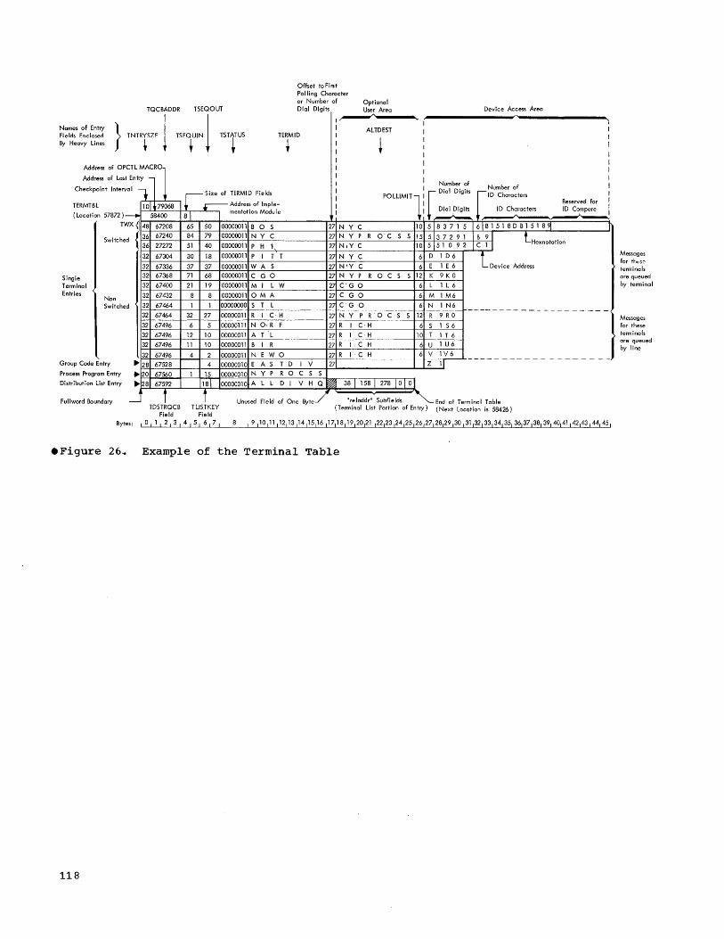
TQCBADDR TSEQOUT
Offset toFirst Po II i ng Character or Number of Dial Digits
Optional User Area
Names of Entry Fi e Ids Ene losed By Heavy Lines } TNT!,ZE 1 ~E1"'N j TSTT
US
I~ I ALTDEST
TERMID I
t I ~ I
Address of OP
Address of Las
Checkpoint Inter
CTLMAC'l t Entry rl val t
TERMTBL
(Location 57B72)
T
101,79068 --WX{ 148
Single Terminal Entries
Switche
Non Switche
Group Code Entry
Process Program Entry
Distribution List Entry
d { 36
36
32
32
32
32
32
d 32
32
32
32
32
32
~ 28
~20
~28
-
58400
67208
67240
27272
67304
67336
67368
67400
67432
67464
67464
67496
67496
67496
67496
67528
67560
67592
f
r-,Size of TERMID Fields
.-Address of Imple-81 mentation Module
65 50 00000011 B a S 84 79 00000011 NY C
51 40 00000011 P H 1-
30 18 00000011 P I T T
37 37 00000011 WA S
71 68 00000011 C GO
21 19 00000011 MI L W
8 8 00000011 OMA
1 1 00000000 S T L
32 27 00000011 R I C H
6 5 00000111 N 0, R F
12 10 00000011 A T L
11 10 00000011 B I R
4 2 00000011 N E W a 4 00000010 E A S T D I V
1 15 00000010 N Y P R a C S
181 00000010 A L L D I V H
f Unused Field of One B te
I I I I I I POLLlM'Tl I I
27 N Y C 10
27 N Y P R OC S S 15
27 NIY C 10
27 NYC 6
27N'Y'C 6 27 N Y P ROC S S 12
27 C' GO 6
27 C GO 6
27 C G a 6
27 NIY P R a C S S 12
27 R I C H 6
27 R I C H 10
27 R I C H 6
27 R I 'C H 6
27
S
Q ~ 38 I 158 I 278 I 0 I 0
"reladdr" Subfields
Device Access Area
N.umbe~ ?f Number of
[ 0,0' 0",. ['0 Chorod". Reserved for
==-~ 5183715161B1518DB151891 r 5137291 IB 91
lHexnotation 51510921C1I
D 1 D 6 t Device Address E 1 E 6
K 9 K 0
L 1 L 6
M 1 M6
N 1 N6 ------------R 9 R 0
S 1 S 6
T 1 T 6
U 1 U6
V 1 V6
Z 11 - - - - - - - - - - - - - - - - - -)
End of Terminal Table Fullword Boundary TDSTRQCB TLlSTKEY
Field Field (Terminal List Portion of Entry) (Next Location is 58426)
Bytes: I 0 I 1 I 2 I 3 I 4 I 5 I 6 I 7 I
.Figure 26 .• Example of the Terminal Table
118
Messages for tht,!s:: terminals are gueued by terminal
Messages for these terminals are gueued by line

Polling List for Nonswitched Lines:
0 2 3 n n+1 n+2 n+3
Size Status Pointer 1
I : : I Pointer Null n
v Omitted for Output-only Lines.
Poll ing List for Switched IBM 1050:
o 2 3 4
Size Status Null PC PC
~--------------~v~----------------w Omitted for Output-only Lines
Polling List for TWX (AT &T 33/35) Lines:
o 2 3 n
Size Status Null Computer I D Sequence
~------------------~v~--------------------~ Omitted for Output-only Lines
Poll ing I ist for WTT A lines:
Size Status Null m Computer ID Sequence
LEGEND:
Size: Indicates total length of polling list.
Status: Indicates current status of the polling list: if nonzero, the list is active (the line can be polled [nonswitched line] or enabled [switched line]). The status byte is initialized to X 1011 (active) when the POLL macro instruction is assembled.
Pointer 1 through Pointer n : Represent the addresses, relative to the terminal table elddress, of the first byte of the terminal table entries associated with this list.
Null: Identifies the end of the polling list (nonswitched lines) or identifies the list as being for a switched line. Null is a full byte of binary zeros.
PC: Is a polling character to be sent to an IBM 1050 terminal that calls the computer on the line represented by this polling list.
Computer ID Sequence: Is the sequence of characters to be sent to any TWX terminal that calls the computer on the line represented by this polling list or to be sent to a WTTA terminal during an identification exchange.
m: Is the number of characters in the computer ID sequence .
• Figure 27. Polling List Formats
Appendix A 119

Figure 28.
120
Polling List for Auto Poll Lines after open DASD time.
LEGEND
SIZE: Indicates length of polling list.
STATUS: Indicates current status of polling list: If nonzero, the list is active (the line can be polled). The status byte is initialized to X'Ol' (active) when the POLL macro instruction is assembled.
TE: Total entries in the list.
AE: Same value as in TE.
PS Bits 0-2 = 010 for IBM 1030 = 011 for IBM 1050, 1060, 2740 Types m or ISl
3-7 = 10000.
pc: Polling characters (one for IBM 1030, two for IBM 1050, 1060, 2740 Types m or ISl).
I: Index character associated with preceeding polling characters (The POLL macro generates 1 for 10 , 2 for 11, and n + 1 for In. )
X'FE': Scan stop byte used to find the end of the list.
Offset: A two-byte field used to find the heading of the list from the end of the list.
Auto Poll Polling List Format

First 8 bytes are not placed on direct access queue
Relative offset of entry from the first entry in the terminal table
o 2 3 4 5 6 7 8 9 10 11 12 13 14 15 16 17 18 19 20 21 22 23 24 25 26 27 28 29 30 31
QCB Address FQUEUE
Link Address
MSQLlNK
Source Key
TTSKEY
* Message Address
on DASD MSlCB
MSTATUS **
Next Segment
Link MSLlNK
Previous Header
Link MSHEAD
Next Header
Link MSDLlNK
Destin -ation Key
TTDKEY
I"Y FKEY
o
Buffer Scheduler
Priority MSPRI
Segment Size
MSEGSZE Stored Scan Pointer MSPTR Set to the last character of last processed field in header
Message Sequence Number (IN) MSNUMIN Message Sequence Number {OUT} MSNUMOUT
Fonnat of Buffer containing Header
First 8 bytes are not placed on direct acc;,ess queue
31
HDSTRT HEADER TEXT {Optional}
o 2 3 4 5 6 7 8 9 1 0 11 12 13 14 15 16 1 7 18 19 20 21
QCB Link Source * Message
Address Address Key Address
on DASD FQUEUE MSQLlNK TTSKEY
MSLCB
Key FKEY, Buffer MSTATUS **
I Scheduler
Priority
0 MSPRI 21
TXSTRT
Fonnat of Buffer containing Text
* or the address of the LCB associated with this buffer. ** Significance of the bits in the MSTATUS bytes is as follows:
Bit Position Bit Name Meaning
o CANCEL 0 ;;;: Send or process message 1 ;;;: Do not send or process message
REROUTE 0 ;;;: Original copy of header 1 ;;;: Duplicate copy of header
Next Segment
Link MSLlNK
TEXT
2 EOB 0 ;;;: No EOB is present in any buffer position except the last 1 ;;;: An EOB is present in some buffer position other than the last
Message Header
Link MSHEAD
{Presence or lack of an EOB in the last position does not affect setting of bit}
3 SRVCD 0 ;;;: Message was not previously serviced 1 ;;;: Message was previously servi ced Note: "Serviced" is set to indicate that a message header has been read from the disk before being transmitted
to a terminal or before being handled by a message processing task.
4 TRUNC Not used by QTAM.
5 PRIORITY 0;;;: Message sent Vo{ithout priority 1 ;;;: Message sent with priority
6 -7 SEGTYP 00 ;;;: Header segment (Not last segment) 01 ;;;: Text segment {Not last segment} 10 ;;;: Header segment (Last segment) 11 ;;;: Text segment {Last segment}
Figure 29. Formats of Filled Buffers
Appendix A 121

APPENDIX B: SUMMARIES OF QTAM MACRO INSTRUCTIONS
r--------------------------T~--------------T--------------------------------------------, I Name I Operation I Operand I ~--------------------------+---------------+--------------------------------------------~
lo~--~~~~~~~----------------+---~~~~~-------+-~~=~:::~=~::::::~ __________________________ ~ I dcb I I I I (DASD message queues) I DCB I keyword operands I ~--------------------------+---------------+--------------------------------------------i I dcb I I I I (checkpoint) I DCB I keyword operands I ~--------------------------+---------------+------------------------------~-------------i I dcb I DCB I keyword operands I I (line group) I I I ~--------------------------+---------------+--------------------------------------------i I dcb I DCB I keyword operands I I (message log) I I I ~--------------------------+---------------+--------------------------------------------i I I ENDREADY I I ~--------------------------+---------------+--------------------------------------------i I I I [INPUT J I I [symbol] I OPEN I ({dcb1. o , [( OUTPUT £" IDLE])], } ••• ) I I I I INOUT I I I I I I I I [, MF=L ] I I I I , MF= (E, listname) I L __________________________ ~ _______________ ~ ____________________________________________ J
Figure 30. Summary of Data Set Definition" Initialization,. and Deactivation Macro Instructions
122

r--------T---------T-----------------T-----------------------------------, I I I I Function of Macro Instruction: I I I I ~-----------------------------------i I I I I Buffer Assignment ---------------,1 I I I ~---------------------------------,il I I I I Polling List Definition -------,i II I I I ~-------------------------------,il I I 'Name I Operation I Operand , Terminal Table Definition --, 111'1 I I I I V IVIVI ~--------+---------+-----------------~----------------------------T--f-+-i , I I I I I I , I BUFFER Innn,length I I I I , I I [, mmm] I I' - I I I I [, BRB ] ~ "I ~--------+---------+----------------------------------------------+--+-+-i ,symbol IDLIST ,entry I- I , I ~--------+---------+----------------------------------------------+--f-+-i IsubfieldlOPTION Itypelength ,_1, , , ~--------+---------+----------------------------------------------+--+-+-i
l::::::::I::~~----_1-l~~~::::~~~~-----~~::~:~:~:::~J------------1--1:1-1 I symbol I PROCESS '[EXPEDITE] ]- I , I ~--------+---------+----------------------------------------------f--+-+-i ,symbol 'TERM ,qtype" dcb,rln I 'I' I I I L,adchars] [,(opdata" •• ,.)] ]- I , I I I I [, CALL=integer Jl, ID=hexchars] 1 I I I , I I, CALL=NONE ] I I I ~--------+---------+----------------------------------------------+--+-+-i , ITERMTBL lentry [,en)] I I' I I I I [.OPCTL=chars] [,CPINTV=integer] ]e 2 1 I I 1 I I [, CKPART=integer] I I I I ~--------~---------~----------------------------------------------~--~-~-i 11.0PTIOH must directly follow TERMTBL macro instruction. 1 12TERMTBL must be the first of the macro instructions used to create a I , terminal table. I L ________________________________________________________________________ J
• Figure 31. Summary of Control Information Macro Instruction
Appendix B 123

r---------------------------------------------------------------------------------, I Functional Macro Instructions and the Delimiters Each May Follow I ~-----------T---------------------------------------------T---T---T---T---T---T---i I I IRIR]EISJSJEI I I I C I C ) N I E lEI N I I Operation I Operand I V J V 1 DIN I N I D , I I lSIHlRID~DJSI I I I E I D 1 CIS I HIE 1 I I I G I R I V 1 E I DIN I I I I I I I G '1 RID I ~-----------+---------------------------------------------+---+---+---t---+---+---~ I BREAKOFF I nnnnn I • I I I I 1 1 I I I I I I 1 1 I I CANCELM I mask I I I· I I ~ I I I I I I J I I I I COUNTER I field ~ • I • I l· J • ~ I I I I I I I I I I I DATESTMP I I I· J J I· I J ~-----------+---------------------------------------------+---+---+---+---+---f---i I DIRECT I {=CLn'dest'} I I· I J I I , I I subfield I I I I I I I I I· I J I ~ I 1 I I EOA I eoa I I· I I I I I I I I I I I I I I I EOB I I I I· ~ I I· I I I I I I 1 I 1 1 I EOBLC I I I I - I J I - I ~-----------+---------------------------------------------+---+---+---+---+---+---i
{=CLn'dest'} ~ J I I I
ERRMSG mask, subfield , I I I· I • ,
INTERCPT
LOGSEG
MODE
SOURCE I I] ~ I
{ =C' message '} msgchar
mask
dcb
lPRIORITY\ co. NVERSE [, .condchar 1 INITIATE i"lOD2260 userfunc,
I I I I I I 1 J I I I I J I I I I 1 I - 1 I I I I • I I I I ] I 1·1-1 • -J , J ] 1 ! I I I I I' I I I I I I I· I - I I I I I J I I I ~ I I I I I I I
[,WRT60=code1 I I t I J I ___________ ~ _____________________ ---------------------___ ~ __ ~ ___ ~ ___ ~ ___ ~ ___ ~---J
• Figure 32. Summary of Line Procedure Specification Functional Macro Instructions (Part 1 of 2)
124

r-----------T---------------------------------------------T---T---T---T---T---T---' MSGTYPE typechar I • I I J.) I
OPCTL
PAUSE
POLL 1M IT
REROUTE
CTLMSG=msgname TERM=termname [, AL'I'ERM=termnaroe J [ ,1NTRCPT= {~;S} J
ctlchar,insertchar
{nnn } subfield
I ]] I I I 1 I I J ) I I • J I I I I I I I I I 1 I ] I I J I I I I I I I I I) I I I I I I I J I I I] • J I I I I] I I 1 I • I • I I I I I J] I ] J I I I I I I
mask, {=CLn ' dest' } I I I I J J subfield I I • I I I· I SOURCE I 1) I I I
~-----------+---------------------------------------------+---+---+---+---+---+---~ I ROUTE I [n] I 1· I I ] I I I I ) ] ] ] I I ) I SEQ1N I [n] I I· I I ) I I I I I I I I ) ] I I SEQOUT I n I I· I I I· I I I I I I 1 I I I I I SKIP I skipchars I I· I I I· J I ~-----------+---------------------------------------------+---+---+---+---+---+---~ I SOURCB I [nJ I I· I I ) ] I I I I I I I J I I I TIMESTMP I n I I· I I I·] I I I I 1 I I I I 1 I TRANS I table 1 • I • I I· I .] ] I I I I I I I I I I WRU I I I I ) I·]· J
.~-----------~---------------------------------------------~--~---~---~---~---~---~ I Note: Restrictions governing usage are explained in individual macro I I instruction descriptions. I L _________________________________________________________________________________ J
.Figure 32. Summary of Line Procedure Specification Functional Macrc Instructions (Part 2 of 2)
Appendix B 125

r-------~-T-----------T-----------------T----------------------------------~------, 1 Name I Operation , Operand I Restrictions . I ~---------+-----------+-----------------+-----------------------------------------i , 'ENDRCV' 1 , ~---------+-----------+-----------------+------------------------·----------------i 1 1 ENDSEND I I J ~---------+-----------+-----------------+-----------------------------------------~ 'symbol 'LPSTART I [nn,] IRequired delimiter; must be the first , I I , TERM= 'macro instruction in an LPS. I 1 , I (termname1!' 4 •• ) 1 1 1 I , ,INTRCPT={YES} 1 I 1 I 1 NO I I ~---------+-----------+-----------------+-----------------------------------------~ 1 1 POSTRCV 1 IRequired delimiter; must immediately I 1 I I 1 follow the last of the sequence of macro I 1 1 , linstructions that handle incoming ] 1 1 1 1 messages. Only one POSTRCV may appear I 1 I I I in an LPS. 1 ~---------+-----------+-----------------+-----------------------------------------~ I ,POSTSEND 1 IRequired delimiter; must immediately I 1 I I ,follow the last of the sequence of macro I I I , linstructions that handle outgoing mes- I 1 I I I sages. Only one POSTSEND may appear in I I , I I an LPS. I ~---------+-----------+-----------------+-------------------~-------------------~~ 1 I RCVHDR I I I ~---------+-----------+--------------~--+-----------------------------------------~ I 'RCVSEG" I ~---------+-----------+-----------------+-----------------------------------------i 1 1 SENDHDR I 1 I ~---------+-----------+-----------------+-----------------------------------------~ I 1 SENDSEG I I , L _________ ~ ___________ ~ ________________ ~ _________________________________________ J
Figure 33. Summary of Line Procedure Specification Delimiter Macro Instructions
r------------T-----------T-----------------------------------------------T--------------, 1 Name I operat ion 1 Operand 1 Notes I ~------------+-----------+-----------------------------------------------+--------------~ I [symbol] I CHGNP I termname, rln, {WOrkat::ea} I 3 I 1 1 1 =C" 0' I 1 1 1 1 =C' l' 1 I ~------------+-----------+-----------------------------------------------+--------------~ 1 [symbol] 1 CHNGT 1 termname,workarea I 3 1 ~------------+-----------+-----------------------------------------------+--------------~ I [symbol] 1 COPYT 1 termname,workarea I 2 I
~------------+-----------+-----------------------------------------------+--------------~ 1 [symbol] I COPYP I termname,workarea 1 2 I
~------------+-----------+-----------------------------------------------+--------------~ 1 [symbol] 1 STARTLN 1 termname,{rln} I 1 1 1 1 1 ALL I 1 ~------------~-----------~-----------------------------------------------~--------------~ INotes: I I 1 11. Line activation/deactivation. I 12. Access to terminal table, polling list, or DASD queue status contents. 1 13. Telecommunications system status modification. 1 L _______________________________________________________________________________________ J
.Figure 34. Summary of Macro Instructions Used to Examine and Modify the Telecommunications system Status
126

APPENDIX C: CONTROL CARD SEQUENCES FOR TELECOMMUNICATIONS JOBS
Assembling Message Control and Message Processing Programs
A typical control card sequence for assembling a message control or message processing program:
r----------------------------------------------------------------------, I//ASSEMBLY JOB MSGLEVEL=l I 1//STEPl EXEC ASMFC I I//SYSIN DD * I r-------------------------------------------~--------------------------i 1 Source Deck J
~----------------------------------------------------------------------i 1/* I L ________ ------------__________________________________________________ J
Linkage Editing Message Control and Message Processing Programs
A typical control card sequence for linkage editing a message controllor message processing program:
r----------------------------------------------------------------------, I//LINKEDIT JOB MSGLEVEL=l I 1,//STEPl EXEC PGM=LINKEDIT"PARM=' XREFgLET,LIST' I I//SYSPRINT DD SYSOUT=A I 1//SYSUTl DD DSNAME=SYS1 .. U,SPACE=(TRK, (30,10»,UNIT=2311 1 I//SYSLMOD DD DSNAME=SYS1. JOBLIB, DISP=OLD I I//SYSLIB DD DSNAME=SYS1.TELCMLIB,DISP=OLD I 1·/ /SYSLIN DD * I r----------------------------------------------------------------------i 1 Assembled Deck I ~----------------------------------------------------------------------~ 1 NAME MCONTROL For message control program I 1/* I I (or) I 1 NAME PROCTEST(R) For message processing program 1 1/* I L ______________________________________________________________________ J
Executing Message Control and Message Processing Jobs
A typical control card sequence for executing a message control job:
r----------------------------------------------------------------------, 1 I//MSGCNTRL
II//JOBLIB 1//STEPl I//SYSQUEUE 1// I//OLINE I//BLINE I//XLINE 1//wLINE I//LINES I//SYSP~INT I//SYSABEND 1/*
JOB DO EXEC DO
DD DO DO DO DO DO DO
MSGLEVEL=l DSNAME=SYS1.JOBLIB,DISP=OLD PGM=MCONTROL OSNAME=FDISO., UNIT=2311 g VOLUME=SER=222222, DISP=OLO,OCB=(_BLKSIZE=84) UNIT=031 1050 DIAL LINE UNIT=032 1060 LINE UNIT=033 TWX LINE UNIT=034 WU 115A LINE UNIT=041 1050 LINE SYSOUT=A UNIT=24·00, LABEL= (, NL)
L _____________________________________________________________________ _
Appendix C 127

A typical IODEVICE macro instruction for system generation cf QTAM:
Macro Operands
IODEVICE UNIT=115A"ADDRESS=034" ADAPTER=TELE1,SETADDR=2
Subparameter Explanation
UNIT=115A western Union Polling station
ADDRESS=034 IODEVICE is a communica-tion line (line 034)
ADAPTER=TELEl Telegraph adapter (Type I) SETADDR=2 set Address (SADl command
2 specified for 115A
Formatting the Direct Access storage Device for Buffer-Sized Records
The following prograrr can be used to format the disk for the message queues data set. In this particular case, the records will be 112 bytes long to accommodate buffers of 120 bytes.
WRITEMSG
WRITE
CLOSE
SAVE IDCB
AREA SSS EIGHT
CSECT SAVE BALR USING ST LA OPEN WRITE ST CHECK L CL BE B CLOSE L RETURN DS DCB
DC DS DC END
(14.,12) 2,0 *,2 13,SSS+4 13,SSS (DCB, (OUTPUT» DECB, SF, DCB" AREA 15,SAVE DECB 15, SAVE 15,EIGHT CLOSE WRITE (DCB> 13,SSS+4 (14,12) F DSORG=PS,MACRF=(WL).DDNAME=MSGQUE. RECFM=F,DEVD=DA 30 OC' , 18F F' 8' WRITEMSG
Once this program is as.sembled and linkage edited.q it shculd be run with the following job control language to format the disk:
//MSGCNTRL //JOBLIB //STEPl
I //MSGQUE // // //SYSPRINT
128
JOB DD EXEC DD
DD
MSGLEVEL=l DSNAME=SYS1.JOBLIB,UNIT=2311.,DISP=OLD PGM=WRITEMSG DSNAME=FDISD, UNIT=2311, SPACE= (TRK." (25»., VOLUME=SER=111111,DISP=(NEW,CATLG), DCB=(,BLKSIZE=112) SYSOUT=A

certain of the registers used by QTAM may be of value to the user who writes open or closed subroutines to be included in an LPS. The usage of each of these registers
l
is explained in this appendix. For further information see the section Methods of Including the Subroutine.
Register 1 -- QTAM Parameter Register
Register 2 -- QTAM Parameter Register
Register 4 -- LeB Address Register
Register 4 contains the address of the line control block for the line over which the current message was received (input LPS processing) or sent (output LPS processing).
Register 5 -- Scan Pointer Register
Register 5 points to the last character of the last header field scanned, or to the first blank character following that field .•
1. Register 5 contains the address of the last character of the field if the operand of the last macro that referred to the field either does not permit any variation in the length of the field (e.g., MSGTYPE CIA'), or specifies explicitly the length of the field (e.g., SOURCE 6).
2. Register 5 contains the address of the first blank character that follows the field if the operand of the last macro that referred to the field does not explicitly specify the length of the field (e.g., SOURCE [blank operand],).
Register 6 -- Buffer Address Register
Register 6 contains the address of the buffer currently being processed by the LPS. -If the buffer contains a header segment,
APPENDIX 0: QTAM REGISTER USAGE
the first data character in the header is located 32 bytes beyond the buffer address. If the buffer contains a text segment, the first data character is located 22 bytes beyond the buffer address. Both offsets are relative to register 6 as the base register.
Register 7 -- LPS Routine Base Register
Register 7 contains the address of the beginning of the LPS currently being executed (i.e." points to the LPSTART macro expansion) .•
Register 8 -- Terminal Table Source Entry
In the Receive portion of the LPS, register 8 contains the address of the TERM entry for the terminal from which the currently processed message was received. In the Send portion of the LPS u register 8 contains the address of the TERM entry for the terminal to which the currently processed message is to be sent.
Register 11 -- End-of-Segment Address Register
Register 11 contains the addres.s of the last character positicn in the buffer currently being read intc or out of.
Register 14 -- Return Register for First-Level Routines
Register 14 contains:
1. The address of the parameter list for the preceding macro instruction (following the BALR instruction).
2. The address of the next instruction following the macro instruction, if that macro has nc parameter list.
Appendix D 129

APPENDIX E: SUMMARY OF OPERATOR CONTROL MESSAGES
WRITTEN AS
CONTROL Dec Rei Hex W/S
MESSAGE OPERANDS Dig Exp Char
CHNGT term name X
data X
COPYC* term name X
COPYT* termname X
INTERCPT termname X
INTRE'L term name X
RELEASEM termname X
STARTLN termname X
ALL X
termname X STOPLN
ALL X
SWITCH {no operands}
* A response message is returned to the operator control terminal.
Note: The Control Message ID (ctlmsg) is the same for all operator contro I messages •
• Figure 35. Summary of Operator Control Messages
130

APPENDIX F: FORMAT AND SUMMARY OF MACRO INSTRUCTIONS
A format illustration accompanies each macro instruction description in this publication. The illustrations indicate which operands must be coded exactly as shown, which are required, which are variable, etc. The conventions stated to describe the operands are as follows:
1. Keyword operands are described either as the single word that must be coded as shown or by a three-part structure that consists of the keyword operand, followed by an equal sign (both of which must be coded), followed by a value mnemonic or a coded value.
Examples: a. b.
ALL TYPB=PQ
2. Positional operands are described by a lowercase name that is merely a convenient reference to the operand and is never coded by the programmer. The programmer replaces the positional operand by an allowable expression. Expressions allowed are indicated at the left of the fold-out page. The chart shows what expressions are allowed for each operand.
3. Uppercase letters and punctuation marks (except as described in these conventions) represent information that must be coded exactly as shown.
4. Lowercase letters and terms represent information that must be supplied by the programmer. More specifically, "n" indicates a decimal number, "nn" a decima'l number with at most two digits, "nnn" with at most three digits, etc.
5. An ellipsis (a comma followed by three periods) indicates that a variable number of items may be included.
6.
7.
8.
{ } [ ]
[! ]
Options contained within braces represent alternatives, one of which rrust be chosen.
Information contained within brackets represents options, one of which may be included depending on the requirements of the program.
Underlined elements represent an assumed value in the event a parameter is omitted.
Appendix F ,1;31e

Abbreviations
DEC DIG
REGISTER
RX type
REL EXP
ABS EXP
CHAR
HEX CHAR
W/S
e132
Abbreviations used in Foldout chart
Meaning
Any decirral digits, up to the value indicated in the associated macro instruction description.
A general register, always coded within parentheses, as follows:
(2-12)-one of general registers 2 through 12" previously loaded with the right-adjusted value or address indicated in the macro instruction description. The unused high-order bits must be set to zero. The register may be designated literally or symbolically.
(i)-general register 1, previously loaded as indicated above. The register can be designated only as (1).
Any address that is valid in the RX form of instruction (e.g., LA) may be designated.
A relocatable expression (acceptable as an A-type or v-type address constant by the assembler).
An absolute expression as defined by the assembler: self-defining terms (decimal, hexadecimal~ binary" character), length attributes, absolute symbols, paired relocatable terms in the same CSECT u and arithmetic combinations of absolute terms.
A character string (the framing characters g C' " are not coded unless specifically indicated in the individual macro instruction description).
Hexdecimal characters. An X in this column indicates that no framing characters and quotes are coded. An F in this column indicates that framing characters and quotes are coded.
Written as shown.

WRITTEN AS WRITTEN AS WRITTEN AS WRITTEN AS
Register Dec
I ~~) RX Rei Abs Hex Dig (1) Type Exp Exp Char Char W/S
Register MACRO Dec (2- RX Rei Abs Hex
INSTRUCTION OPERANDS Dig 12) (1) Type Exp Exp Char Char W/S
Register --MACRO Dec (2- RX Rei Abs Hex INSTRUCTION OPERANDS Dig 12) (1) Type Exp Exp Char Char W/S
MACRO Dec ~ RX Rei Abs Hex INSTRUCTION OPERANDS Dig 12) (1) Type Exp Exp Char Char W/S
F F DIRECT dest X OPEN deb X X TERM qtype Refer to Macro Description
X subfield X INPUT X deb X
X DLIST entry X OUTPUT X rln : X
X DTFQT all operands Refer to Macro Description INOUT X adchars X
X EOA eoa F F IDLE X opdata Refer to Macro Description
X ERRMSG mask F MF=L X CAll= Refer to Macro Description
F dest X MF= Refer to Macro Description ID= X
X X subfield X listname X TERMTBL entry X
X X SOURCE X OPTION type length X n X
X X message F PAUSE ctlchar F OPCTl= X
X msgchar X insertchar F CPINTV= X
X INTERCPT mask F POLL entry X CKPART X
X X lOGSEG dcb X X AUTOPOl= Refer to Macro Description TIM ESTMP n X
X X lPSTART nn X polladdr X TRANS table Refer to Macro Description
X X TERM= X nid X WTTA
X X MODE PRIORITY X POlLiMIT nnn X MACROS Refer to Macro Descriptions
X X CONVERSE X subfield X
X X INITIATE X PROCESS Refer to Mocro Description
X X MOD2260 X REROUTE mask F
X X userfunc X dest F
X X condchar F F subfield X
X X WRT60=code Refer to Macro Description SOURCE X
X MSGTYPE typechar F F ROUTE n X
OPClL CTlMSG= X SEQIN n X
TERM= X SEQOUT n X
ALTERM= X SKIP skipchrs X F F
INTRCPT= Refer to Macro Description SOURCE n X
STARTLN term name X X
rln X X
ALL X
Appendix F 133e

This appendix contains charts that define the character sets and transrrission code bit patterns used by the various terminals supported by QTAM. Charts are also provided that facilitate reading the terminal code found in storage.
QTAM CHARACTER SET AND CODE CORRESPONDENCE CHART
This chart shows the character set and bit patterns for the Extended Binary Coded Decimal Interchange Code (EBCDIC), and the character sets and transmission code bit patterns for each of the terminal types supported by OS QTAM.
The chart may be used to determine the bit patterns, as contained in main storage bytes, for each of the various characters sent or received by a specific terminal type; and to determine the relationships, as established by the arrangement of the IBM-provided translate tables, among the character sets for the various terminal types.
For convenience in referr~ng to particular chart locations, the chart's columns and rows are given reference numbers. Combined" these numbers enable reference to a particular chart location; e.g., location 21/17, the intersection of row 21 and column 17, contains NL.
Arrangement of Chart
The chart contains a group of three columns for the EBCDIC character set and a group for each of the various terminal character sets. within the EBCDIC group, colUmn 3 contains the 256 ,bit patterns comprising the code. For those bit patterns to which characters are currently assigned, the characters appear in column 1 (graphics) and column 2 (line controls and device controls). (All currently assigned characters are shown, regardless of whether they are in the character sets of any of the terminal types represented in the remainder of the chart,.)
Each of the remaining groups (columns 4 th::o'!gh 34) contains the characters comprlslng the character set of a specific terminal type, along with the transmission
APPENDIX G: QTAM TERMINAL CODES
code bit patterns. Cclumn 34 repeats the EBCDIC code presented in column 3, for ease of reference.
In the EBCDIC groupo the bit patterns and characters are arranged in collating sequence from hexadecimal 00 to hexadecimal FF. In the remainder of the chart, the locations of bit patterns and characters are determined by the arrangement of the translate tables.
Terminal Character Sets
This chart shows only the characters comprising the commonly used character set options. The options represented in the chart are:
Terminal Option
IBM 1030 Standard and "H" options
IBM 1050 System/360 option
IBM 1060 standard option
IBM 2260 Standard option
IBM 2740 System/360 option
AT&T 83B3 "A" arid nCR options
W U 115A "A" and "C" options
AT&T TWX Standard option
WTTA Standard option
IBM 1030 graphics and AT&T 83B3/WU 115A graphics that differ for the respective options are indicated in the chart by Sand H, and A and Cn respectively. Graphics not so marked are the same in both options.
Transmission Codes
The notations in the code columns of the chart for the various terminal types rep:esent the System/360 byte bit pattern equlvalents of the applicable transmission codes. The applicable transmission codes are:
Terminal
IBM 1030 Perforated tape and transmission code
Appendix G 135.

IBM 1050
IBM lObO
IBM 2260
IBM 2740
AT&T 83B3
W U 115A
AT&T TWX
WTTA
Perforated tape and transmission code
Perforated tape and transmission code
IBM 2260 transmission code
Perforated tape and transmission code (BCD code)
5-level Baudot code
5-level Baudot code
8-level TWX code
5-level ITA2 code 5-level ZSC3 code
Representation of Characters and Bit Patterns
Appearance of a character and its associated bit pattern in a character set signifies that the appropriate IBM-provided translate tables effect either incoming translation (i. e. " translation of that character to the corresponding EBCDIC character), or outgoing translation (i.e., translation of the corresponding EBCDIC character to that character), or both. How the bit pattern appears indicates which of these cases applies:
1. Where the hexadecimal representation of the bit pattern appears in brackets, only incoming translation is performed.
2. Where the bit pattern is enclosed in parentheses, only outgoing translation is performed.
3. Where the bit pattern is not enclosed by brackets or parentheses, both incoming and outgoing translation are performed.
Because each unique bit pattern for a terminal character can be represented only once in an "incoming" translate table, the character associated with the bit pattern can be traoslated to only one EBCDIC character. The converse is not true, however; anyone transmission code bit pattern can be placed any number of times within an "outgoing" translate table. Therefore, any number of EBCDIC characters can be translated to the terminal character represented by that bit pattern.
Appearance of two bit patterns opposite a single character signifies that the character has both an upper-case and a lowercase bit pattern, and that both forms of
.136
the character are translated to the same EBCDIC character.
Example: The bit pattern of the NL character appears in location 21/9. Both the lower- and upper-case bit patterns of this character are translated to the EBCDIC NL character when they appear in an incoming message. When an EBCDIC NL character appears in an outgoing message., QTAM translates it to the lower-case form of the NL character.
Where more than one EBCDIC character requires translation to the same character in a terminal character set, the termina.1 character appears an equivalent number of times in the column (e.g., locations 0/23, 6/23, 7/23, 26/23, and 50/23 all contain the LTRS character).
Where a character appears in both the graphics and the controls columns for a terminal type, its function depends on whether it is sent when the line is in control mode or in text mode. Depending on the type of terminal and the mode, the character may perform a control function" print as a graphic" or both. For details" see the reference manuals for each of the various terminals.
Nonequivalent Characters
Designing the system to accommodate terminal types having different character sets and control functions has resulted in several instances where dissimilar characters have been "equated" in translate tables. This accounts for the appearance in certain rows of this chart qf non-equivalent characters, for example, in rows 3, 386 and 50.
In other instances, the same or similar functions have different names among the various terminal types; for example, HT and Tab in row 5 are equivalent, as are DEL and Rubout in row 7.
In a few instances, terminals using the same transmission code have different meanings assigned to the identical bit pattern; for example., bit pattern 79 in the transmission code has the meaning PF for an IBM 1050, and Subtract for an IBM 1060,.
Substitutions
Where blank pOSitions appear in the terminal character set portion of the chart, there is no equivalent character for the EBCDIC character or bit pattern at the left

of the chart.. Where these blanks appear, the SUB character is to be assumed (they were omitted to make the chart more readable). That is, in each translate table that handles incoming messages, each position representing an invalid transmission code bit pattern (that is, one not used by a character in the terminal's character set) contains the EBCDIC code (3F) for the SUB character. In each translate table that handles outgoing messages,
1. each position that represents an invalid EBCDIC bit pattern (a pattern to which no EBCDIC character has been assigned), and
2. each position that represents a bit pattern for a character having no equivalent in the destination terminal's character set
contains the transmission code bit pattern for a substitute graphic. For the IBM 1050, 2260, and 2740, and the AT&T 83B3 and WU 115A, this substitute character is a colon (: L. For the IBM 1030 and 1060, and the AT&T.TWX~ it is a slash (/).
General Notes
1. Standard abbreviations are used to represent the control characters. The full names of the characters are given. For descriptions of these characters, see the reference manuals for the various terminals.
2. "Circle" characters ( B , D , etc.) in the chart are alternate names for the characters after which they appear.
3. Notes pertaining to specific characters or bit patterns are indicated by superscript numerals next to the character or bit pattern. The notes follow, and indicate the chart locations to which they apply.
4. Most of the characters in the Sand H character set options (1030) and in the A and C character set options (83B3, liSA) are identical. Where they differ between the options, the translate tables favor the S option and the A option, as illustrated in the chart. If messages fram an H option 1030 are sent only to another H
ootion 1030, the translate table may be used as is, and similarly, for the 83B3/115A" with respect to the C option. If messages from terminals with the H or C cption are to be exchanged with other terminal types, the user may wish to modify the tables.
5. Some TWX terminals send even-parity transmission-code bit patterns; others send nonparity bit patterns. All bit patterns sent by nonparity machines have a '1' in the low-order bit position (that is, the poSition that serves as the parity bit in even parity machines). The RCVTWX translate table translates either a non-parity or an even parity bit pattern to the EBCDIC bit pattern for the corresponding character. For those characters whose even parity and nonparity bit patterns are identical, a single bit pattern appears in column 30 of the chart. For example, a single pattern, X'C3', appears in location 195/30. . For those characters whose even parity and nonparity bit patterns differ by the setting of the low-order bit, two bit patterns appear~ as for example, in location 193/30. Where two bit patterns appear, the one enclosed in brackets ([]) is the nonparity bit pattern. The brackets indicate that the nonparity bit patterns are only received from TWX terminals. In outgoing message transmission, the SNDTWXE translate table sends even parity bit patterns, while the SNDTWXO translate table sends nonparity bit patterns.
Notes:
1Left bracket translates to EBCDIC hex 79; no EBCDIC character has been assigned to this bit pattern (location 121/3. 121/28).
2No graphic prints in the A character set option (location 90/22).
3Backslash translates to EBCDIC hex El; no EBCDIC character has been assigned to this bit pattern (locations 225/3, 225/28).
4IBM 1031 sends the numeric 0 as a hex 20; 1033 receives the numeric 0 as a hex 15 (location 240/4).
5Right bracket translates to EBCDIC hex 49; no EBCDIC character has been assigned to this hit pattern (locations 73/3~ 73/28).
Appendix G 137.

control Characters
BEL
BS
BYP
©
CAN
CC
CR
@
DCl DC2 DC4
DEL
DLE
DS
EM
ENQ
EOA
EOB
EOC
EOFC
EOM
EOT
ETB
ETX
FF
FIGS
HT
138
Positive Acknowledgement
End-of-block (same as EOB)
Bell
Backspace
Bypass
End-of-transmission (same as EOT)
Cancel
Cursor control
Carriage (carrier) return
Machine end-of-address (same as EOA)
Device controls
Delete
Data link escape
Digit select
End of medi urn
Enquiry
End-of-address
End-of-block
End of card
End of first card
End-of-message
End-of-transmission
End-transmission block
End-of-text
Forms feed
Figures shift
(EBCDIC hex 22) field
Horizontal tabulate
Interchange file separator
IGS
IL
IIRS
IUS
LC
LF
LF-CR
LTRS
MZ
®
NAK
NL
NUL
PF
PN
PRE
PZ
RES
RM
SI
SM
SMI
SO
SOH
ISMM
SOS
SP
STX
SUB
SYN
Tab
Interchange group sep~rator
Idle
Interchange record separator
Interchange unit separator
Lower-case shift
Line feed
Line feed-carriage return
Letters shift
Minus zero
Negati ve response to polling .• addressing, or LRC/VRC
Negative acknowledgement
New line
Null
Punch off
Punch on
Prefix
Plus zerc
Restore
Record mark
Reader stop
Start-of-address
Shift in
Set mode
Start Manual Input
Shift out
Start-of-header
Start-manual-message
Start-of-significance
Space
Start-of-text
substitute
Synchroncus idle
Tabulate (horizontal)

ITM Tape mark WRU • Who Are You?"
TpAuxOff Tape auxiliary off X-Off TranslTi tter off
TpAuxOn Tape auxiliary on X-On Transmitter on
UC Upper-case shift ® positive response to polling"
VT Vertical tabulate addressing" or LRC/VRC
Appendix.G 139

140

Ref.
0 1 2 3
4 5 6
8 9
10
12 13 14
16 17 18 19 20 21 22
24 25 26 27
28 29 30
32 33 34
36 37 38 39
48 49 50
52 53 54
64 65 66
68 69 70
NUL SOH STX ETX
PF HT LC DEL
SMM vT FF CR SO SI
CAN EM cr CUI
SUB
SP
HT
LF-CR CR
RES * LF-CR NL CR BS
Pad IL IL
BYP LF LF LF
EOB{@) EOB EOB(@) PRE
Pad IL IL
/ SP SP SP
AT&T 83 B3
IL LTRS Rubout SOH SOH ® STX STX EOA(@) ETX ETX EOB(@) CR CR
TpAuxOff HT HT
LTRS LTRS
~ ¢
NL NL NL CR
X-On
NL NL LF LF BS IL LTRS Rubout
CAN
•
LF LF LF ETX ETX CR CR
WRU ACK ACK
IL
EOT
X-Off NAK
SP SP

Ref.
Pad IL LTRS Rubout LTRS 00 0 ® SOH SOH <S) OJ I
EOA(@) STX STX EOA(@) 02 2 EOB(@) ETX ETX EOB(@) CR CR CR CR 03 3
HT HT LTRS
Rubout LTRS
~ ¢
LF-CR NL CR NL NL NL CR CR CR BYP RES
10 16 11 17 12 18 13 19
RES * LF-CR NL CR NL NL LF LF CR BS BS
Pad IL IL IL LTRS Rubout LTRS
CAN
• Check
BYP LF LF LF LF LF LF IF LF
EOB(@) EOB EOB(@) ETX ETX EOB CR CR LF LF PRE
Be II Be II
ACK ACK
Pad IL IL IL LTRS LTRS LTRS
FIGS FI GS FI GS LTRS LTRS
APpe~diX G 141.

Ref.
72 73 74 ¢ 75
+ + I I & of & &
81 82
85 86
88 89 90 I 91 $
92 93 94 , ; ; ....., --. ....., 96 97 98
/ / / / /
100 101 102 103 104 lOS 106 EOM
108 % 109 110 > > > 111 ? ? ? ? 112 113 114
116 117 lIB
['
EOA C'l/B
CR fI
@
<: Bell I
A A B B C C D E F G
H H H I I I
140 141 142 143

/
H H I I
> ?
#
@
e V8
a A b B c: C d
AT&T 8383
[I
CR #
@ <:Bell
H I
Ref.
136 137 138 139 140 141 142 143
Appendix G 143.

Ref.
144 145 i i J J i J 146 k K k K K K k K 147 I L 1 L L L I L
148 m M m M 149 n n N N 150 0 0 0
p P P
q Q Q Q
R R R R
156 157 158 159
160 161 162 S S S 5 S 163 T T T T T
164 u U U U U U 165 v V v V V v V V 166 w W W W W W 167 x X x X X x X X
168 y Y Y Y y y y y 169 z Z z Z Z z :z Z 170
172 173 174 175
181 182 183
184 185 186 187 188 189 190 191
192 PZ: PZ 193 A A A A A A A A A 194 8 8 8 B B B B B B 195 C C C C C C C C C
196 D D 0 0 0 D D D 0 197 E E E E E E E E E 198 F F F F F F F F F 199 G G G G G G G G G
200 H H H H H H H H H 3)) I I I I I ~ I I I 202 203
204 205 206 207
208 MZ MZ 209 J J J J J J 210 K K K K K K K
L L L L L L
M M M M N N N N 0 0 0 0 P P P P
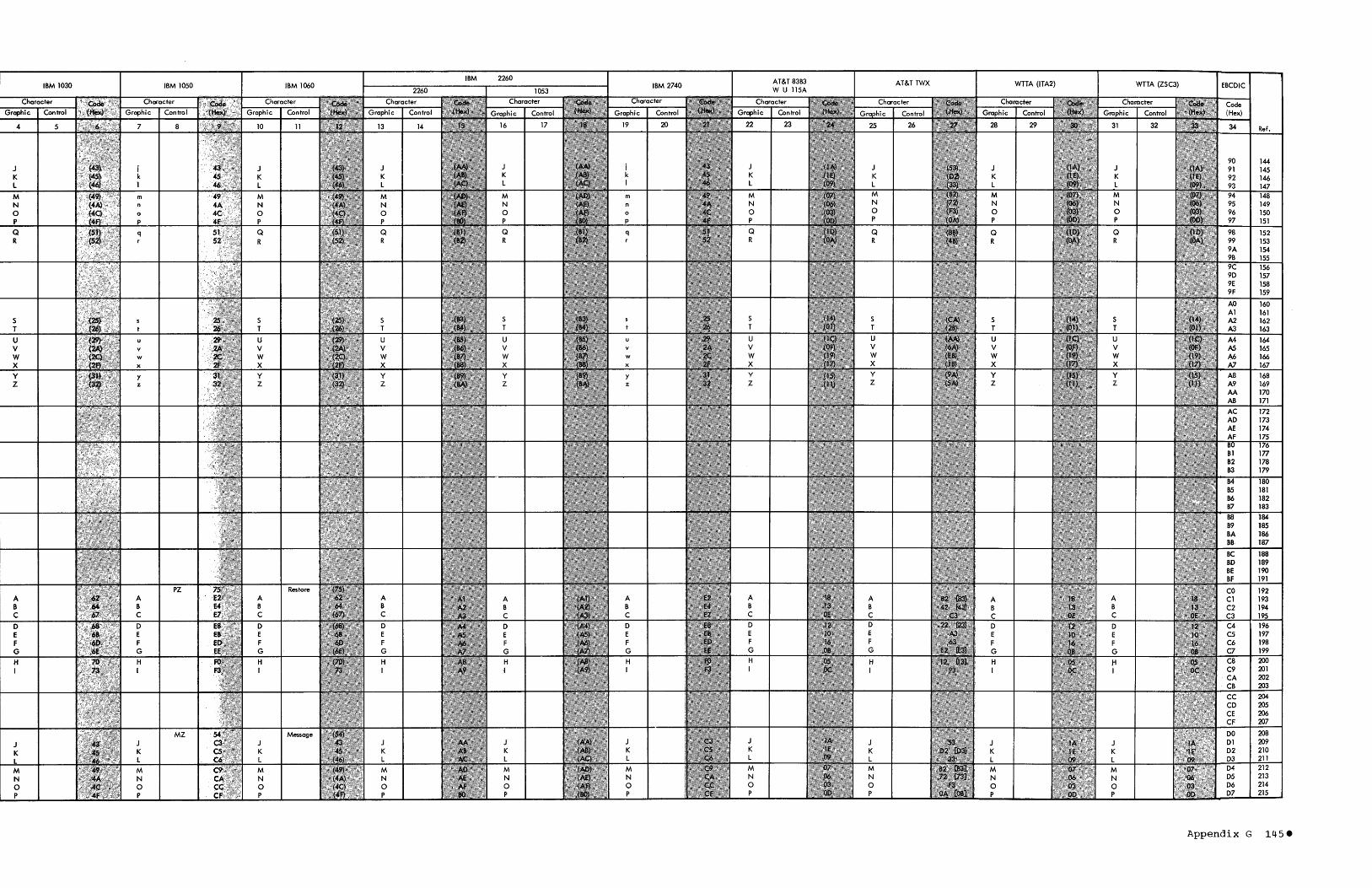
Ref.
J i J J J J J 144
J J 145 K k K K K K K K K 146 L 1 L L L L L L L 147
M m m M M M M 148 N n n N N N N 149 0 0 0 0 0 150 P p P P P 151
Q Q Q Q Q 98 152 R R R R R R 99 153
9A 154 9B 155 9C 156 9D 157 9E 158 9F 159
AO 160 Al 161
S S 5 S S A2 162 T T T T T A3 163
U u U u U U U M 164 V v V v V V V AS 165 W w W w W W W A6 166 X x X x X X X A7 167
Y y Y y Y Y Y A8 168 Z z Z z Z Z Z A9 169
AA 170 AB 171
181 182 183
184 185 186 187
188 189 190 191
PZ A A A A A A A A A B B B B B B B B B C C C C C C C C C
D D D D D D D D D 196 E E E E E E E E E 197 F F F F F F F F F 198 G G G G G G G G G 199
H H H H H H H H H H 200 I I I I ~ I I I I I 201
202 203
CC 204 CD 205 CE 206 CF 207
MZ J J J J J J J K K K K K K K K L L L L L L L L
M M M M M M M M N N N N N N N N 0 0 0 0 0 0 0 0 P P P P P P P P
Appendix G 145-

Ref.
216 Q Q Q Q Q Q Q Q Q
217 R R R R R R R R R 218 219 220 221 222
RM
S \3
S S S T T T T U U U U v v v v w w w w x x x x y y y y y Z Z Z Z Z
4 245 5 246 6 247 7 248 8 8 8 249 9 9 9 250 251 252 253 254
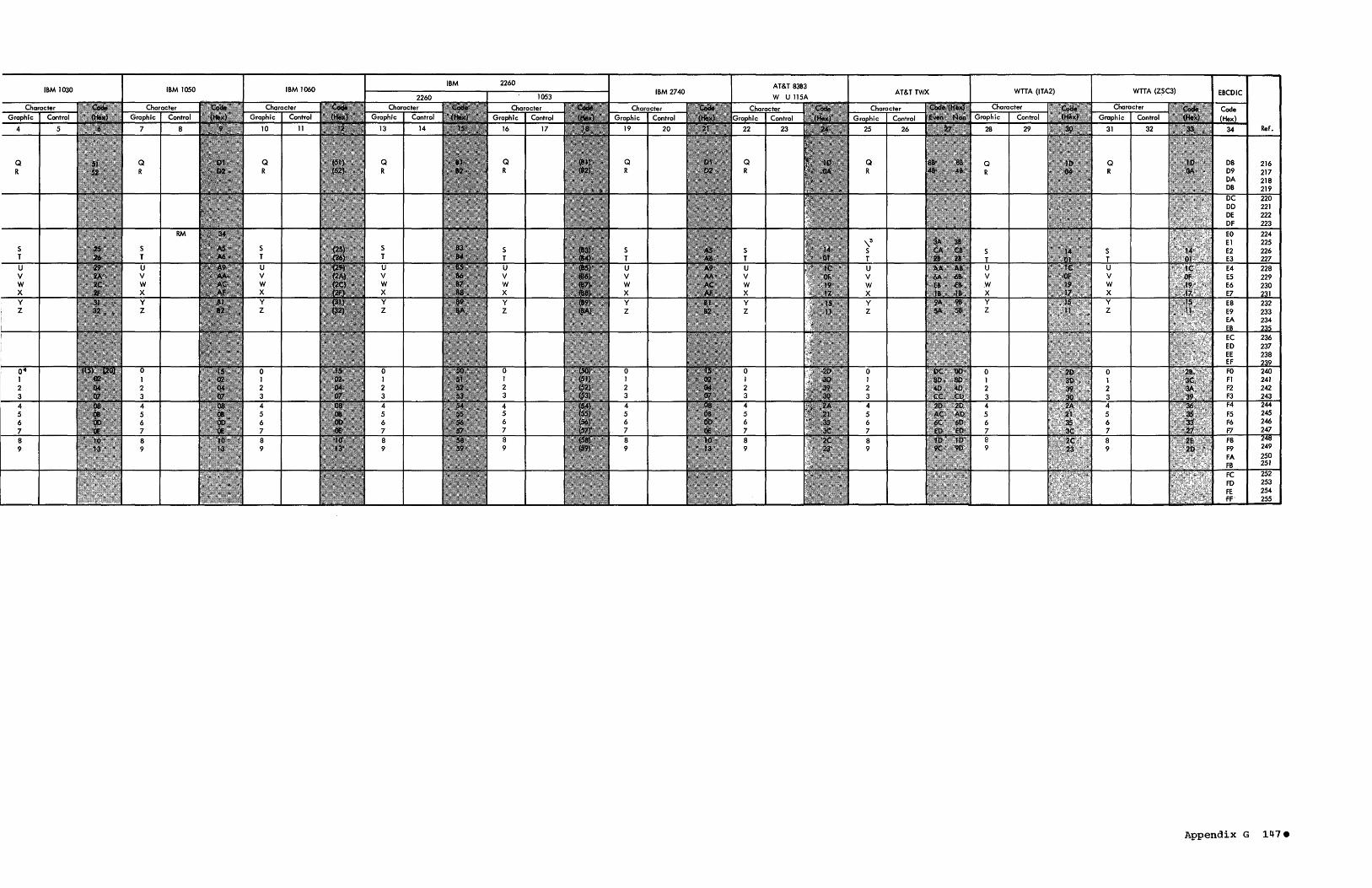
Q R
Y Z
Y Z
8 9
RM
Q
R
8 9
Q R
8 9
Q
R
Y Z
Q
R
U V W X
Y Z
Q R
S T U V W X y Z
8 9
AT&T 8383
Ref.
,\3 S T U V W X y Z
Appendix G 147.
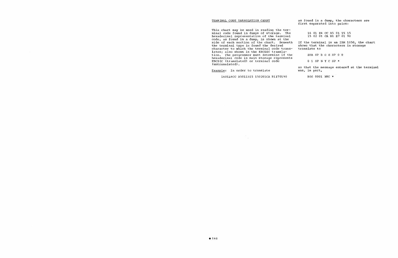
TERMINAL CODE TRANSLATION CHART
This chart may be used in reading the terminal code found in dumps of storage. The hexadecimal representation of the terminal code, as found in a dump, is shown at the side of each section of the chart. Beneath the terminal type is found the desired character to which the terminal code translates; also shown is the EBCDIC translation. The programmer must determine if the hexadecimal code in main storage represents EBCDIC <translated) or terminal code (untranslated).
Example: In order to translate
1601E4CC A5011515 150201CA B1E70190
• 148
as found in a dump, the characters are first separated into pairs:
16 01 E4 CC A5 01 15 15 15 02 01 CA B1 E7 01 90
If the terminal is an IBM 1050, the chart shows that the characters in storage translate to
EOA SP B 0 S SP 0 a
o 1 SP NYC SP * so that the message entered at the terminal was, in part,
BOS 0001 NYC *

04 05 06 07
08 09 OA 08
OC OD OE OF
10 11 12 13
14 15 16 17
18 19 lA lB
lC lD IE IF
20 21 22 23
24 25 26 27
28 29 2A 2B
2C 20 2E 2F
30 31 32 33
34 35 36 37
38 39 3A 3B
3C 3D 3E 3F
IBM 1030 IBM 1050
PF 2 HT LC DEL 3
4
5MM VT 5
FF CR 6 50 7 51
DLE 8 DCl DO TM 9
RES NL 0 8S II IL
CAN EM CC CUI
IFS IGS IRS IUS
DS ,@ SOS FS
/
S T
U SM V CU2
ENQ ACK
W
BEL X
Y SYN Z
PN RS UC EOT
CU3
DC4 NAK
SUB
SP
2
3
4
5
6 7
8
9
o EOA II
EOT
LF
EOB
@
/
u v
w
x
y
z
STX ETX
EOT
ACK
NL
NAK
CAN
NL
4
5
6 7
8
9
o II
/
u v
w
x
y z
T
o
T CR CR
o SP SP
00 01 02 03
SP H H N M
04 05 06 07
N M
R G
I P C V
E Z D 8
S Y F X
A W J
U Q K
LF L R G
I P C V
E Z o 8
S Y F X
LF 08 09 OA OS
oc OD OE OF
10 II 12 13
14 15 16 17
A 18 W 19 J lA
FIGS FIGS 18
U IC Q ID K IE
LTRS LTRS IF
EOT 5 20 21 22 23
TpAuxOff
FF FF
9
4
8 o
3 +
?
6
/
CR
SP
LF
WRU
?
7
)
/ o
9 8
6
5 4
+ 2 3 COO Bell 2
FI
7 1 (
LTRS
CR
SP
LF
24 25 26 27
28 29 2A 28
Bell 2C 2D 2E 2F
30 31
WRU 32 33
34 35 36 37
38 39 3A
FIGS 3B
3C 3D 3E
LTRS 3F
S/36O EBCDIC IBM 1030 Byte (Hex) 1----+-----;-----
40 41 42 43
44 45 46 47
48 49 4A c;:
4B
4C < 4D { 4E + 4F I
50 & 51 52 53
54 55 56 57
58 59 5A 58
5C 5D 5E SF
60 61 / 62 63
64 65 66 67
68 69 6A 68
6C % 6D 6E > 6F ?
70 71 72 73
74 75 76 77
78 79 7A 7B 1/
7C @ 70 I
7E 7F
EOM
EOA
K L
M N
o
p
Q R
C
D
F G
H
LF-CR
k I
m n
o
p
q
$
& a
b
c
d
e
9
. (2) EOFC •
HT
EOC DEL
8S IL
$ % &
( ) .. +
/
o 1 2 3
4 5 6 7
8 9
< > ?
k I
m n
o
p
q
& a
b
d
e
9
BS IL
TpAuxOn TpAuxOn
LF LF
SO
44 45 46 47
48 49 4A 48
4C 4D 4E 4F
50 51 52 53
54 55 56 57
58 59 5A 58
5C 5D 5E SF
60 61 62 63
64 65 66 67
68 69 6A 6B
6C 6D 6E 6F
70 71 72 73
74 75 76 77
78 79 7A 7B
7C 7D 7E 7F
Appendix G 14ge

5/360 EBCDIC IBM 1030 5/360 EBCDIC IBM 1030 Byte Byte Byte (Hex) (Hex) (Hex)
Gr Ctl
80 80 CO PZ CO 81 a SP 81 Cl A Cl 82 b 82 C2 B C2 83 c 83 <:3 C J J C3
84 d < < 84 C4 0 C4 85 e 85 C5 E K K C5 86 f 86 C6 F l L C6 87 9 87 Cl G Cl
88 x-On 88 C8 H C8 89 x-On 89 C9 I M M X-Off C9 8A 8A CA N N CA 8B % % 8B CB CB
8C 8C CC 0 0 CC 80 80 CD ~ CD 8E > > 8E CE CE 8F 8F CF P CF
90 .. HT 90 DO MZ DO 91 i HT 9J OJ J Q Q VT 01 92 k 92 02 K R R 02
93 I 93 03 L 03
94 m 94 D4 M 04
95 n 95 05 N 05
96 0 96 D6 0 D6
97 p 97 07 P D7
9B q 98 D8 Q D8
99 99 09 R D9
9A 9A OA DA
9B 9B DB DB
9C 9C DC DC
90 90 DO B5 BS DO
9E 9E DE Il Il DE
9F 9F OF Pad OF
AO ~ ~ WRU AO EO RM @ EO Al A WRU AJ El + + Bell El A2 B A2 E2 S A A E2 A3 ? C ? A3 E3 T E3
A4 u 0 A4 E4 U B B E4
AS v S E S AS E5 V E5 A6 w T F T A6 E6 W E6
A7 x G A7 E7 X C C E7
AS y H AS E8 Y 0 D E8 A9 z U I U A9 E9 Z E9 AA V J V AA EA EA AB K AB EB EB
AC W l W AC EC EC AD M AD ED F F ED AE N AE EE G G EE AF X 0 X AF EF EF
BO P BO FO 0 H H FO Bl Y Q Y CR Bl Fl 1 SI Fl B2 Z l Z B2 F2 2 F2 B3 S B3 F3 3 F3
54 T B4 F4 .. F4 B5 U B5 F5 5 F5 B6 V B6 F6 6 F6 B7 W B7 F7 7 F7
B8 X B8 F8 8 Fa B9 y B9 F9 9 F9 SA Z SA FA FA BB LF IF SB FB FB
BC BC FC FC BO BD FD SI FO BE BE FE FE BF BF FF
~---Rubout FF
Appendix G 151.

APPENDIX H: EXCHANGING MESSAGES BETWEEN IBM AND NON-IBM TERMINALS
Certain line and device control functions are implemented differently for IBM terminals and non-IBM terminals. Generally. no difficulties arise when messages are exchanged between IBM terminals of the same or different types, or between non-IBM terminals of the same type. For applications in which messages are to be exchanged between non-IBM terminals of dissimilar types, or between IBM and non-IBM terminals, the user should be aware of the considerations explained below, and plan his message headers accordingly. In some cases., it will be necessary to edit certain characters or character sequences out of incoming messages and edit certain characters or sequences into outgoing messages,. The functions concerned are: carriage return., new ,line, line feed, end of address, end of block, end of transmission"
'
and 'who are you?' (the latter function applies to TWX and WTTA terminals).
End-of-Address
All QTAM-supported IBM terminals employ a single machine end-of-address (EOA) character, known as a @ (for 2260 start-of-text (STX) character). Of the non-IBM terminals, the 83B3 represents EOA by the sequence CR LF LTRSi the liSA represents EOA by a single space character; and the
ITWX and WTTA terminals have no EOA sequence.
If messages are to be switched from a non- IBM terminal to an IBM terminal., the user must edit out the received EOA character or sequence and insert the proper .sequence for the receiving terminal. Figure 36 provides the code representations for the EOAs for each terminal type.
western Union liSA terminals require that an EOA (apace) be the first character in the header. AT&T 83B3 terminals~ require an EOA (CR LF LTRS) as the first three characters in the header. The QTAM user cannot have idle characters in his message header preceding the EOA. He may ensu;~,~ this by moving the EOA into the buffer.' beginning with byte 32. Space for tbe'-""'tOA should be included in the bytes reserved in the message header by the LPSTART macro. instruction. If TIMES'IAMP,DATESTAMP or SEQOUT is specified, it. should precede the movement of the EOA into the header.
For all IBM terrrinals except the 2740 Types I and VI, there may be two EOAs (two STXs for 2260) as the first two charact~rs transmitted to the terminal. The first one is sent by the access method that sends the message to the terrrinal, while the second appears in core as the first character in the buffer (following idle characters specified in the LPSTART macro instruction). This s.econd EOA was sent by the terminal as the first character in the message.
The EOA character transmitted by the access method will perform its normal function of putting the terminai in text mode. but the second EOA will print a~ a text mode character at the beginning. of the message. The user may wish to ;nsert the following code to delete this character before transmitting the message:
C~I BNE MVI LA
NO •
1(S)"X"'7B' NO 1(S)f1XII171 5,1 (0., S)
IS THIS EOA CHARACTER NO IT IS NOT YES. REPLACE WITH IDLE INCREMENT SCAN POINTER
This problem should not exist for messages generated by a message processing program. In this situation, the access method will transmit the required EOA sequence prior to writing the characters from the buffer; no other EOA should be present,.
Carriage Return, Line Feed, New Line, and End-of-Block
For non-IBM terminals, the carriage return and line feed functions are performed by two se?arate characters, CR and LF. For IBM terminals, the functions are performed by the single character new line (NL). A NL character in a rressage sent to a non-IBM terminal cannot be translated to two separate characters, that is., to both the CR and LF characters. To compensate for this, QTAM takes advantage of the usual practice of sending an EOB character at the end of each line of text printed on the printer (i.e., sending an EOB followed by a NL). Standard QTAM translate tables effect conversion of the EOB and NL characters to LF and CR, respectively. for messages sent from an IBM terminal to a non-IBM terminal. Conversely, when messages are sent from a non-IBM terminal to an IBM terminal, CR and
Appendix H lS3
LF characters are converted to EOB and NL characters. Thus, as long as any messages originating from an IBM terminal always use the BOB and NL characters in combination, the carriage return and line feed functions at the receiving terminal (non-IBM) are effected just as if the originating terminal had entered CR and LF into the message.
When messages are sent from a telegraphtype terminal (AT&T-83B3, TWX, WTTA, or Western union 115A) to an IBM 2740 Model 2 with the Buffer Receive option, LF translates to EOB when using IBM-supplied translate tables. Since (1) the contents of the buffer are printed only when EOT is received, and (2) all blocks are read into the same buffer, only the block received just prior to the EOT will be printed. (All previous blocks will have been successively overlaid in the buffer .•
End-of-Transmission and WRU
All IBM terminals employ a single endof-transmission (EOT) character called a ~ • TWX terminals also employ a single
EOT character. The 83B3 and 115A terminals represent EOT by the sequence FIGS H LTRS.
An EOT in a message sent from an IBM or TWX terminal to an 83B3 or 115A terminal is translated by QTAM to the two-character sequence FIGS H. The LTRS character is not sent, so the EOT sequence is not complete. The sequence is completed when QTAM deselects the terminal prior to polling the line or addressing a terminal on the line. When QTAM sends the EOi character that always begins a polling or addressing operation, the TCU first sends the LTRS character, completing the EOT sequence. The TCU then sends the complete EOT sequence FIGS H LTRS again. The EOT sequence thus appears on the receiving line twice, out this has no ill effect.
The EaT sequence FIGS H LTRS sent from an 83B3 or 115A terminal to an IBM or TWX terminal appears in main storage as an upshift H (transmission code X'25'). The TCU deletes the LTRS character from the incoming data stream. The upshift H is treated as an invalid character by the QTAM translate table; it is translated to a substitute character (X' 3F', in EBCDIC). ·The
154
user should edit out this substitute character from the message.. When the message is sent to the destination IBM or TWX terminal. the user should edit the appropriatE EOT character into the message. Figure 36 provides the code representations for the EOTs for each terminal type.
The user must edit out all WRU characters appearing in messages destined for TW) terminals (aS QTAM does not support the WRt functions in outgoing messages to TWX terminals). The user should also edit out EO~ characters appearing in messages destined for TWX terminals, Because EOT will cause the terminal to disconnect from the line prema turely (i. e .. " while QTAM is preparing to send additional messages to the same terminal).. io disconnect a TWX terminal from the line, the TWX operator sends an EaT from his terminal when he receives the CPU identification sequence from the computer. See the section entitled Management of Switched Lines.
End-of-Message" End-of-Transmission, and WRU for WTTA Terminals
The World Trade Telegraph Adapter recognizes two end conditions that are set in the hardware at the time the control unit is installed. These are FIGS x and FIGS y LTRS n where x and yare characters assigned by the user of a specific system.
For a terminal equipped with the Automatic .A.nswerback Unit, FIGS x must be the code combination No. 4 (FIGS D) sent by the terminal WRU key.. FIGS 0 is referred to as the WRU Signal.. For terminals not equipped with the Automatic Answerback Unit, any other code combi,nation can be selected.
Note 1: x and y must not be the same character.
Note 2: The FIGS y LTRS sequence causes a Read operation to end. Therefore, FIGS y can be sent by a terminal as data only if it is not followed by LTRS.
The above termination Signals can be used as EOM signals. Either the FIGS y LTRS sequence (if not yet used as an EOM signal) or two consecutive EOM signals can represent the signal ..

r------------------T------------------------T-------------------------, 1 I EOA Sequence I EOT Sequence 1 1 ~----------T-----~------+-----------T------T------i 1 1 1 Trans 1 1 1 Trans I J ITerminal Type ICharacterslcode I EBCDIC 1 Character I Code IEBCDIC'U 1 1 1 (hex) 1 (hex) 1 I (hex) I (hex) ~
~-------T----------+~---------+------t------+-----------+------+------1 1 IBM 12260 I STX 102 102 IEOT (©) 104 137 ~ I ~---------+----------+------t------+-----------+------+------1 I tall otherslEOA (@) 116 17B IEOT (©) 11F 137 .~ I ~----------t----------+------t------+-----------+------t------i 1 Non-IBM 1 83B3 ICR LF LTRS I 02081FI OD25061FIGS H LTRS 11BO 51FI368806'J
1 ~----------+----------+------+------+-----------t------+------~ 1 Il1SA 1 Space 104 140 IFIGS H LTRSI1B051FI3688061
I t;;~-------t---~------t_-----t------t;~~--------t21---_t37---~ 1 ~---------+----------+------t------+-----------t------t------i
Il-------l::::------l--________ ~ ___ ~ ______ ~~ _______ l~~;:_l!~ ___ -1 1 * Note : Any character assigned by the user. J L _____________________________________________________________________ J
Figure 36.. EOA and EOT Characters and Sequences
Appendix H 155

APPENDIX I: QTAM CHECKPOINT DATA RECORD
r---------------------------------------------------------------------------------------, I IRecord Format: I 11234
I I I
~--------T-----T------------T-----------T----------T-----------T-----------, I t Next It 1stiTERM ENTRIESIQCB ENTRIES I POLL LISTSjLCB ENTRIESIDEAD LETTER] IDisk Loci QCB I I I I IQcB ENTRY# I L ________ ~ _____ ~ ____________ ~ ___________ ~ __________ ~ ___________ ~ ___________ J
• L----4---~--4--J
Formats of Fields:
1. Save all terminal entries (except distribution lists).
r-----------------------------, TERl'1 ENTRY ITerminal Table Entry ]
~-----------------------------~ L---size of TERM entry + 1----J
2. Save QCB's only if current QCB is not the same as the last QCB saved.
QCB ENTRY
I PROCESS IQC~ ONLY I
r-----T-------T-----T----t---------, IQSIZEI QNASE IQBACKIQFAClt CURRENT I I I I I I MSG HDR I ~-----t-------+-----+----t---------J L--2--~---3---~--3--~--3-~-----3---J
3. sav~ polling list only if the list is not the same as the last polling list saved.
r----T------T-------------, POLLING LIST ISIZEISTATUSIVARIABLE INFO]
~----+------+-------------J L--1-~---1--~---variable--J
4. Save LCB information based on QRLM of current QCB being checkpointedo
r------T--------T--------T--------T---------, ILCBHDRILCBTTIND!LCBSTATEILCBNASEGIUNIT ADDRI ~------+--------+--------t--------+---------J L---3--~----2--~----1---~-----3--~----2---J
IControl Record: I I r-------T---------l I ISTATUS I Not Usedl I L _______ ~ _________ J
I I
status 00 Normal Close 01 Abnormal Termination Area 1 Good Info 02 Abnormal Termination Area 2 Good Info
L ______________________________________________________________________________________ _

APPENDIX J: RETURN CODES FOR MACRO INSTRUCTIONS USED TO MODIFY AND EXAMINE SYSTEM
Upon return from the message processing routine for the macro instruction, the return codes shown in the following chart
are set in the low order byte" rightadjusted" in register 15,.. All numbers in the chart appear in hexadecimal notation.
r------------------T------T------T------T------T------T------y------T------T------T-----' I I I I I I ] I R I R I I I I I I I I I I I E I E I S I I I I I I I I I I LIT I TIS I I I C I C I C I C I C I I E I R I A 1 T I I I HI HI 0 10 101 I A I I I RIC I I I N I NIP I PIP ] PIS I E I PIP I 1 I GIG I Y I Y I Y I U I E I V I L I L I I I PIT I P I Q I T 1 TIM \ E I N I N I ~------------------+------+------+------+------+------+------+------+------+------+-----~ I Normal IX'OO' IX'OO' IX'OO" IX'OO' IX'OO' JX"OO' lX'OO' \X·OO' IX'OO' IX'OO'I I Re turn I I I I I I I I I 1 I ~------------------+------+------+------+------+------+------+------+------+------+-----~ I Unopened IX'Ol' I IX'Ol" I I I I I IX'Ol" IX'Ol'l I DCB I I I I I I I I I I I ~------------------+------+------+------+------+------+------+------+------+------+-----~ I Line Not I 1 I I I I I x' 04" I I I I I INTERCPTED I I I I I J I I I I I ~------------------+------+------+------+------+------+------+------+------+------+-----~ I Invalid Relative IX'08' I IX'08' I I I I I IX'08'" IX'08' I I Line Number I I I I I ] I I I I I ~----------------~-+------+------+------+------+------+------+------+------+------+-----~ I Invalid ·IX'10' IX'10' I I I I I I I I I I Count I I I I I J I I I I I ~------------------+------+------+------+------+------+------+------+------+------+-----~ I Inva lid Disk I I I I I I I I XM 02' I I I I Address I I I , I I ] I I I I ~------------------+------+------+------+------+------+------+------+------+------+-----~ I Invalid Sequence I I I I I I I I X' 40' I 1 I I Number I I I I I I ] I I I I ~------------------+------+------+------+------+------+------+------+------+------+-----~ I Invalid Terminal IX'20' IX'20' IX'20' IX'20' IX'20' IX'20' ]X'20" IX"20· IX'20' JX'20'1 I Table Entry I I I I I I J I I I I ~------------------+------+------+------+------+------+------+------+------+------+-----1 I Work Area Larger I I I I I IX'10' ] , I J I I Than Buffer I I , I I I J I I I I ~------------------+------+------+------+------+------+------+------+------+------+-----1 I Segments Not In I I , , I IX'40' ] I I I I I Sequence , I I I I I I I I 1 I ~------------------+------+------+------+------+------+------+------+------+------+-----1
II Restart in I I I I I I 'x' 02' ] I I I I Progress; Release, I I I I I I J I I , I Not Executed I I , I I I ] I I I I L __________________ ~ ______ ~ ______ ~ ______ ~ ______ ~ ______ ~ ______ ~ ______ ~ ______ ~ ______ ~ _____ J
Appendix J 157

o
APPENDIX K: DISK QUEUING RULES
The data set defined for the DASD message queues contains one queue for each DASD process and DASD destination queue defined via the terminal table. Relative record locations 2 through n+1 each contain the first record for queues 1 through n. The ordinal indication of the queue is in bytes 2~the QCB whose address is in bytes 1 through 3 of the terminal table entry (TQCBADDR). Beginning at the record specified in bytes 2-4 of the QCB, the queue is chained through the data set. Rules for chaining are as follows:
1. The relative record address of a segment on disk is contained in bytes 5 through 7 of the disk segment MSLCB.
2. The relative record address of the next segment of a message is contained in bytes 8 through 10 of the disk segment MSLINK.
3. The relative record address of the header of the current message (if this is a text segment) or of the header of the previous message (if this is a header segment) is contained in bytes 11 through 13 of the disk segment MSHEAD.
4. The relative record address of the header for the next message is contained in bytes 14 through 16 of a header segment MSDLINK.
158
Relative record location 1 contains the first record of the dead-letter queue. This queue contains all messages whose destinations are invalid. For multiplerouted messages, the message will appear in the dead-letter queue once for each invalid destination. This is in addition to the queuing of the message in a DASD process or DASD destination queue for a valid destination.
Messages placed in a DASD queue via mul~ tiple destinations in the header, a distribution list~ REROUTE macro instruction, or an ERRMSG macro instruction follow these rules:
1. The primary destination (first DASD queue into which message is placed) contains the header segment and all text segments. The REROUTE hit in MSTATUS (bit 1 in byte 12) is set to zero in the header prefix.
2. All subsequent DASD queues used as destinations contain the header segment only. The REROUTE hit is set to one in the header prefix of each of these messages .•
3. The header segments of these secondary destinations are chained to the respective text segments, which are in the primary queues.

The following example is designed to present the basic structure of a QTAM message
Icontrol program. (See Appendix M for a more complicated sample program.) The program. is designed to receive rressages from two IBM 1050s and put them on the destination queue for any or all of the following:
• Queue for the first 1050. • Queue for the second 1050. • Queue for the process program. (The
message processing program is not included in this example.)
The program will translate each incoming message segment from 1050 transmission code to EBCDIC, count the incoming message headers received from each terminal, route the message to the proper destination queue, and check the incoming message sequence number.
Outgoing messages will be translated from EBCDIC to 1050 transmission code. The output sequence number will be inserted, and idle characters will be sent over the line when the carriage return-line feed character is recognized in the message segment.
APPENDIX L: QTAM SAMPLE PROGRAM A
The format of the incoming message is:
#NXXXXX SEQ TERMX YYYY •••
where:
# EOA
N new line character
XXXXX = name of terminal originating message
SEQ = input sequence number
TERMX = name of destination
YYYY output sequence number
= message sent
C = carriage return character
'. I .... C
Each message must be preceded by a new line character. The following statements are not meant to be card images, but aides to the user in organizing his message control program.
r---------T---------T-------------------------T-----------------------------------------, I Name I Operation I Operand I Remarks I ~---------+---------+-------------------------+-----------------------------------------i I EXAMPLE AICSECT
I . I SAVE (14,12) J I BALR 11,,0 INLINE I I USING *,11 CODE I 1ST 13,SAVEAREA+4 I fLA 13,SAVEAREA I JB OPEN
~---------+~--------+-------------------------+-----------------------------------------i I ITERMTBL IPRCSS Terminal table definition. I I I PReSS is name of last entry in table. I I I ICNTR I OPTION IH Optional field in terminal table. I I I IPLIMIT I OPTION I XLi Optional field in terminal table. I I I ITERM1 I TERM IT"LINE1,1,E213E215, (0,,1) 1050 destination entry. I I I ITERM2 I TERM IT,LINE2,1,E213E215, (0,1) 1050 destination entry,. I I I IPRCSS I PROCESS I Process Program destination entry. L _________ i _________ i _________________________ ~ ________________________________________ _
(Part 1 of 3)
Appendix L 159

r---------T---------T-------------------------T-----------------------------------------, I Name I Operation I Operand ) Remarks I .~---------+---------+-------------------------+-----------------------------------------~ I I I I I I I BUFFER 14,,92,5, BRB=4 14 (92 byte) buffers. 1 I I I I 1 I POLLINE1 I POLL I ('fERMi) J Polling list for LINE1,. I I I I I 1 IPOLLINE21pOLL I (TERM2) IPolling list for LINE2. 1
~---------+---------+--~----------------------+-----------------------------------------~ LINE1 DCB IDDNAME=LINE1DD, 1
I DSORG=CX, IDCB for first line. MACRF= (G., P) " 1 CPOLL= (POLLIN E1 ) , I BUFRQ=2, INTVL=O, I CPRI=S, I CLPS=LPS I
I LINE2 DCB DDNAME=LINE2DD, ~
DSORG=CX., IDCB for second line,. MACRF= (G" P)., I CPOLL=(POLLINE2). 1 BUFRQ=2, I INTVL=O,CPRI=S, ] CLPS=LPS I
~---------+---------+-------------------------+-----------------------------------------~ IDISK IDCB IDDNAME=DISKDD, IDCB for direct access message queue. 1 I 1 I DSORG=CQ" I I 1 I lMACRF=(G.P) I I ~---------+---------+-------------------------+-----------------------------------------~
IIECB IDC IX"40000000' ]ECB with complete bit set on. Used only I I I I I for WAITR. 1 I I 1 I I ISAVEAREA IDC 118F'0' IUser's save area. I ~---------+---------+-------------------------+-----------------------------------------~ OPEN I OPEN (DISK" (INOUT)" I Note: Disk data set must be first one
I LINE1" (INOUT) '. I opened .. I LINE2" (INOUT) ) I I I IWAITR ECB=ECB 1Causes scheduler to be associated with I Ithe next lower partition. WAITR is not I 1needed for release 16 or 17 systems. IENDREADY I I ~ I CLOSE (LINE1!, ,LlNE2""DISK) I I 1 IL 13,SAVEAREA+4 I I "J I RETURN (14,12) ]
~---------+---------+-------------------------+-----------------------------------------~ I) I
LPS LPSTART 15"TERM= (1050) t Leave 5 spaces in buffer for header 1 I 1 expansion for SEQOUT Field. I lReceive Portion of LPS. :J 1 I I I
~V~G I] I I I I
TRANS I RCVF105 0 ]Translate from 1050 code to EBCDIC. I I 1 I
RCVHDR I 1 I I J I
SKIP IX'15~ JSkip to NL character. I I ~ I
COUNTER ICNTR ~Count headers for each terminal. I I 1 I
SOURCE I J 1 l _________ ~ _________ ~ _________________________ ~ _________________________________________ J
(Part 2 of 3)
160

r---------T---------T-------------------------T-----------------------------------------, I Name I Operation I Operand ] Remarks I ~---------+---------+-------------------------+-----------------------------------------i
J SEQIN ]Check incoming sequence number for
I validity. ]
ROUTE I I
ENDRCV I J
EOBLC ]Check for correct reception oi message. J
ERRMSG x'0200' ,=CL5"TERM1', 1 =C'.INVALID SOURCE' 1
J POSTRCV 1
Send Portion of LPS. I 1
SENDHDR I 1
SEQOUT 5 lInsert output sequence number. 1
SENDSEG I 1
TRANS SEND10S0 lTranslate from EBCDIC to 1050 code. 'J
PAUSE X'5B',20X'SE' lInsert 20 idle characters. 1
ENDSEND l J
EOBLC ]Check for correct message transmission. I
POSTSEND I I ~---------+---------+-------------------------+-----------------------------------------~ I I END I EXAMPLE I I L _________ ~ _________ ~ _________________________ ~ _________________________________________ J
<Part 3 of 3)
Appendix L 161

APPENDIX M: QTAM SAMPLE PROGRAM B
The following example is an OS QTAM message control program. The purpose of the program is to switch messages between a nonswitched 1050, a switched 1050 and an 83B3. In addition, a message can be sent to a
* ***** ******* **** *** ********** ** ****** **"""****** ** *******)~** **** ** ***** * * * PROGRAM: OS QTAM MESSAGE SWITCHING * TERMINALS SUPPORTED:
SWITCHED 1050 * NONSWITCHED 1050 * NONSWITCHED 83B3 * FORMAT OF TERMINAL INPUT:
CR (FIGS H lTRS FOR 83B3) * SOURCE TERMINAL (Z PRECEDES ATl IN 83B3 FOR SKIP MACRO) *
* SPACE * * MESSAGE SEQUENCE NUMBER (3 DIGITS) * SPACe * * DESTINATION TERMINAl(S) * * SPACE * * SLASH * * SPACE *
MESSAGE * EOB (AT THE END OF EACH BLOCK) *
* EOT (AT THE END OF EACH MESSAGE) * * EE * EXAMPLE: RTP 001 ATl NYC I THIS IS THE MESSAGE 00 *
BT * * OUTPUT OF MeSSAGE ORIGINATED AT A 1050 * * SOURCE TERMINAL * SPACE * MESSAGE SEQUENCE NUMBER
SPACE * DESTINATION TERMINAl(S) * * SPACI:
SLASH SPACE >I>
* DATE (YEAR AND DAY OF YEAR) * * SPACE * * TIME (HOUR,MINUTE AND SECOND) * * SPACE * UUTPUT MESSAGE SEQUENCE NUMBER (ONLY IF 1050 TO 1050) *
SPACE * * MESSAGE * * EXAMPLE: RTP 001 ATl NYC I 68.065 10.16.33 001 THIS IS THE MESSAGE
* OUTPUT OF MESSAGE ORIGINATED AT A 83B3 * * SOURCE TERMINAL * * SPACE
MESSAGE SEQUENCE NUMBER SPACE *
* DESTINATION(S) * SPACE * SLASH
SPACE * OUTPUT MESSAGE SEQUENCE NUMBER (ONLY IF 83B3 TO 1050) * SPACE
* ME SSAGE * EXAMPLE: RTP 001 ATl NYC * THIS IS THE MESSAGE
* *********************************** ************* ************ ***** ***** OSQTAM CSECT
ECB
SAVE (14ti2)"WILLI
BAlR 12,0
USING *,12
ST 13,SAVEAREA+4
lA 13,SAVEAREA
OPEN
DC X'40000000'
SAVEAREA DC 18F '0'
OPEN OPEN (DISKDCB, (INOUT) ,CKPNTDCB, (INOUT) ,NYCDCB, (INOUT),
ATLDCB, (INOUT) ,RTPDCB, ( INOUT) )
WA ITR ECB=ECB
ENDREADY
CLOSE (NYCDCB" ATlDCB" RT PDCB" CK PNTDCB" 01 SKDCB)
13,SAVEAREA+4
RETURN (14,12)
e162
message processing program for closedown. (See IBM System 360 OS QTAM Message Processing Program Services Appendix D for the related MPP.)
Used only by WAITR
* Disk data set must be opened first and checkpoint data set must be second.
This instruction is needed only for systems prior to release 15.
Disk data set must be closed last and checkpoint data set must be next to last.

* * *** * * ********** ** * ** * *** * * * *** *** *** ********* * ** ** * * * * ** ** *** * ** ** ** * ******** TERM INA L LIST ******************************************* ***** * * *** ** ** **** ** ******* **** *** * ***** *** ** * * ** * * * * ** * * * * * * ** * * ** * * ** * ** * *
TERMTBL EOJ,CPINTV=2
COUNTl OPTION H
COUNT2 OPTION H
POLLMT OPTION Hl
RTP TERM T,RTPDCB,l,E213E21S'{0,0,9)
NYC TERM T ,NYCDCB,l, E213, (0, 0) ,C ALL=SB80
ATL TERM T,ATLDC8,l,l8131807
ALL DLIST (RTP,NYC,ATL)
EOJ PROCESS
* ***** ******* ** ** ** *** **** *** ***** * *** *** ******* ** **** * * **** ** ** ** ***** ******** BUFFER POOL FOR INPUT AND OUTPUT ***************************** ***********************************************************************
BUFFER 20,120,8
*********************************************************************** ******* POL LING LISTS ******************************************** ***** *********************************************************************** RTPPOLL POLL (RTP)
NYCPOLL POLL E21S
ATLPOLL POLL (ATLl
*********************************************************************** ******** DCB' S, ECB AND SAVE AREA ************************************** *********************************************************************** RTPDCB DCB DSORG=CX,
MACRF=( G,P),
DDNAME=RTPDD,
CPOLL=(RTPPOLL) ,
BUFRQ=S,
CPRI=E,
CLP S=LP S10 SO
NYCDCB DCB DSORG=CX,
MACRF=(G,P),
DDNAME=NYCDD,
CPOLL=(NYCPOLLl ,
BUFRQ=S,
CPRI=E,
CLPS=LPSI050
ATLDCB DCB DSORG=CX,
MACRF=(G,P),
DDNAME=ATLDD,
CPOLL=(ATLPOLLl ,
BUFRQ=S,
CPRI=E.
CLPS=LP S83B3
CKPNTDCB DCB DSORG=CQ,
MACRF=(G,P) ,
DDNAME =TCHKPNT
DISKDCB DCB DSORG=CQ,
MACRF=(G,P) ,
DDNAME=DISKDD
DC XL50'FF'
EOJ is last item in term table and checkpoint records will be taken every 30 seconds (2x15).
Storage for counting incoming messages from 1050.
Storage for counting outgoing messages for 1050.
Storage for polling limit for NS 1050.
Only addressing characters defined.for SW 1050.
Destination ALL sends the message to all terminals.
Eoa refers to a DO card in the MPP JCL (j jEOJ DO DUMMY).
20 buffers of 120 bytes each and 8 CCWs that QTAM generates for the PAUSE macro.
Polling list for NS 1050.
Polling characters for SW 1050.
Polling list for 83B3.
* Data set organization is that of a communications line group.
* A queued access method is used to access the line group.
* Name of DO card that identifies the line.
* Identifies polling list for this line.
* Buffers requested for transmission of data from terminal to computer.
* Receiving and sending have equal priority.
Identifies the line procedure specifications for this line.
* *
*
* *
*
* * *
* Data set organization is that of the direct access message queue or the checkpoint for the MCP.
* Records are to be accessed with GET and PUT macro instructions.
Name of DO card that describes the checkpoint data set.
* Data set organization is that of the direct access message queue or the checkpoint for the MCP.
* Records are to be accessed with GET and PUT macro instructions.
Name of DO card that describes the message queue data set.
Needed only for systems prior to release 15.
Appendix M 163.

*********************************************************************** ******** LINE PROCEDURE SPECIFICATIONS FOR SW 1050 AND NS 1050 ******** *********************************************************************** LPS1050 LPSTART 21,TERM=(1050)
RCVSEG
.164
TRANS RCVF1050
RCVHDR
SKIP X'15'
SOURCE 3
SEQIN 3
ROUTE 3
EOA C' /'
DATESTMP
TIMESTMP 9
COUNTER COUNTl
ENDRCV
POLLIM IT POLLMT
CANCELM X'B600'
EOBLC
ERRMSG X'0200' ,SOURCE,=C' INVALID SOURCE'
ERRMSG X'2000' ,SOURCE,=C'SEQUENCE NUMBER TOO HIGH. USE$
ERRMSG X' 1000' ,SOURCE, =C' SEQUENCE NUMBER TOO LOW. USE$
ERRMSG X' BOOO' ,SOURCE,=C' INVALID DESTINATION'
POSTRCV
SENDHDR
COUNTER COUNT2
SEQOUT 4
MVI 32 ( 6 ) , X ' 15 '
SENDSEG
TRANS SEND1050
PAUSE X'5B',20X'5E'
ENDSEND
EOBLC
ERRMSG X'0080' ,SOURCE,=C'OUTPUT TRANSMISSION ERROR'
POSTSEND
21 bytes reserved in msg hdr=9 for dates tamp + 7 for timestamp + 4 for SEQOUT + 1 for the MVI instruction.
Translates 1050 code to EBCDIC.
Move SCAN pointer to the CR character in the buffer.
Checks to see if the source code is valid.
Checks to see if the input sequence number is valid.
Checks to see if the destination code is valid.
/ will identify the end of the destination codes.
Inserts date into header after /.
Inserts time into header after date.
Counts incoming messages from the 1050.
The poll limit is found at the location POLLMT.
Cancel the message if any of the following bits are on in the errorhalfword: 1011011000000000.
Sends a positive or negative acknowledgment when EOB is received.
0200,2000,1000,8000 indicate error halfword nits. SOURCE: Error msg is sent to terminal origililating the msg
in error. causes the correct input sequence number to be included in the error msg.
Counts outgoing messages to the 1050.
Puts the correct sequence out number in all messages going to the 1050.
Insures that a NL character is the first character in the buffer.
Translates EBCDIC code to 1050 code.
Sends 20 idle characters (5E) after a NL character (5B) is transmi tted.
Performs an LRC and returns a positive or negative response.

*********************************************************************** ******** LINE PROCEDURE SPEC I F I CAT IONS FOR 83B3 *********************** *********************************************************************** LPS83B3 LPSTART 1,TERM=(8383)
RCVSEG
TRANS RCVETl
BREAKOFF 120
RCVHDR
POLLlMIT
SKIP X'E9'
SOURCE 3
SEQ IN 3
ROUTE 3
EOA C'/'
ENDRCV
CANCELM X'B600'
ERRMSG X'0200' ,SOURCE,=C'
ERRMSG X'2000' ,SOURCE ,=C'
ERRMSG X'lOOO' ,SOURCE ,=C'
ERRMSG X'8000',SOURCE,=C'
ERRMSG X '0020' , SOURCE, =C'
POSTRCV
SENDHDR
MVC 32(3,6),=X'OD2506'
SENDSEG
TRANS SENDTl
ENDSEND
INVALID SOURCE'
SEQUENCE NUMBER TOO
SEQUENCE NUM8ER TOO
INVALID DESTINATION'
MESSAGE TOO LONG'
ERRMSG X'40FC' ,SOURCE,=C' .TRANSMISSION ERROR'
POSTS END
END OSQTAM
HIGH. USE$
LOW. USE$
Causes the breakoff error bit to be posted if a message over 120 characters long is received or if a buffer is filled with the same character.
Move SCAN pointer to the Z character in the buffer.
The two spaces at the beginning of the message plus the one spaee reserved in LPSTART are needed for the EOA characters.
Inserts the 83B3 EOA characters.
The period (.) causes the header to be inserted into the buffer preceding the text.
Appendix M 165.

APPENDIX N: ON-LINE TERMINAL TESTING
The on-line terminal test facility provides tests that can be used by the terminal operator as a startup proGedure and by the IBM customer engineer for terminal checkout and diagnosis of terminal failure.
The tests operate on-line with the user's problem program and in no way affect user operation except for the line time required by the terminal tests to perform their function on the selected line.
Tests requested from a terminal can be returned to that terminal, to any other terminal on the same line, or to any other terminal in the system. The tests are: message sw~tching, comparison of incoming data to a stored pattern in core storage" all-characte~s messages sent to specified terminals, and test patterns for diagnosis of failures in the SELECTRIC. typing element of the terminal.
Requests for the various tests are entered from a remote terminal and are identified by a test activation code of 99999. The individual tests and terminal addresses are selected by secondary activation codes.
Tests are not provided for Teletype terminals.
FORMAT OF TEST REQUEST MESSAGES
All fields of the test request message are consecuti ve: tha t is" they are not separated by blanks.
The total length of the test request message should not exceed the size of a buffer as specified in the BUFFER macro instruction. Data not included in this first buffer will not be processed.
The format of the test control message is:
99999 .format-integer test- integer typeinteger Iaddr-char(s)] [unit-char(s)] [text-chars] end-char
where:
99999
166
is the primary action code used to identify this message to the system as a test request message. This field must always appear, exactly as shown" in every test request message.
format
test
type
addr
defines the test header format; it is either 0 or 1. Format 0 uses actual line addresses and can be used to address any terminal on the same line. Format 1 uses symbolic addresses and can be used to address any terminal within the system.
specifies the test to be executed. It is always one integer (1 through 9 described in the section Types of Tests Available).
specifies the type of terminal for which the test is being requested. Type codes that may be used are shown in the following table:
r-----------------------T------------, ITerminal Type IType Code I ~-----------------------+------------~ IIBM 1030 I 1 I I IIBM 1050 I 2 I I IIBM 1060 I 3 I I I IBM 2740 I 4 I I IIBM 1030 - Badge readerl 5 Jar Manual Entry I I I I IBM 2260 I 6 L ________ ~--------------~------------J
Exception: Type code 5 is used only with format O. It defines the type of terminal requesting the test (as well as the type of terminal for which the test is being requested).
is the address of (a) the terminal to which a test rressage is to be sent (tests 1., 6. and 8); (b) the terminal at which a device to be tested mechanically is located (tests 2, 3. 4, and 7); or (cl the terminal to which a respons'e message from the terminaltest facility is sent (test 5). (Test 9 does not utilize the address field .• )
~ For the IBM 1050~ 1060, and 2260-2848, two addressing characters are specified in the TERM macro instruction. For these deVices, the first of the two addressing characters is the actual address of the terminal., and is therefore the character to be

specified in the addr field. The second of the two addressing characters specifies the particular device at the terminal, and is specified in the unit field discussed below.
When used with format 0, this is a one- or two-character field depending on the type of device from which the test request message is being entered. It is a one-character field for the IBM 1030 card reader, IBM 1050 devices~ and IBM 2740 devices, and is the addressing character for the selected terminal.. Only one character is necessary because these devices are capable of transmitting the actual alphabetic terminal address character.
For the IBM 1030 badge reader or manual entry, IBM 1060 devices, and IBM 2260 devices" this field must consist of two characters. The address is selected by transmitting a predefined code as follows:
1. IBM 1060:
2.
Terminal Address
A B C
Z
IBM 1030 entry:
Terminal Address
B C D
z
Code Entered
01 02 03
26
badge reader
Code Entered
02 03 04
26
or manual
Note: If 10 is entered as the addr field, the message will be considered an invalid request, because the corresponding address (J) is not a legal IBM 1030 address.
3. IBM 2260 devices: the addr field is used to select the IBM 2848 display control unit. The address of a display control unit can be any ASCII noncontrol character; therefore there are 96 possible display control unit addresses.
unit
Terminal Address
0100000 0100001 0100010
Cede Entered
01 02 03
1111111 96
~ The predefined code applicable to a particular display control unit can be determined from a display station by utilizing the Request Address test (test 9).
When used with header format 1, this field is variable in length (from one to nine characters). The first character is a digit defining the number of following characters that constitute the symbolic address name. This symbolic address name defines a terminal in the terminal table.
Examples:
a. 4CHII (four-character symbolic name)
b. 7CHICAGO (seven-character symbolic name)
c. 0 (a zero indicates that the test is to be returned to the requesting terminal>
Note that terminal CHII could request a test for itself by using either example a or c.
specifies the particular unit at the terminal specified in the addr field. This field is used only when the format 0 is specified. When using format 1, both the terminal and the unit at the terminal are defined by the symbolic name in the addr field.
For IBM 1050 and IBM 1060 devices, one character is specified. The appropriate code can be determined from the publication describing the type of terminal being addressed.
Note: this field is not applicable to IBM 1030 and IBM 2740 devices; therefore text can start in this position.
For IBM 2848 devices, two characters are specified. IBM 2260 display stations are selected by transmitting a predefined code. The device selection
Appendix N 167

text
end
character can be any of 25 ASCII noncontrol characters.
Device Selection Character in ASCII
1000000 1000001 1000010
1011000
Code Entered
01 02 03
25
Note: The predefined code applicable to a particular display station can be determined from a display station by utilizing the Request Address test (test 9).
is the text of the message sent as a part of the terminal test. Text is included only when using the Message switching test (test 1), Stored Compare test (test 5), or Write Line Address test (test 8).
is the end character for the device from which the test request message is being transmitted.
Device End Character
IBM 1030 EOB
IBM 1050 EOT
IBi"1 1060 EOB
IBM 2740 EOT
IBM 2260 ETX
Note: The header as transmitted from an IBM 1060 device is entered by utilizing the data and transaction keys. The EOB chara~ter is entered by depressing the Teller A or Teller B key.
TYPES OF TESTS AVAILABLE
A total of nine tests are provided for IBM 1030, 1050, 1060, 27'0, and 2260 devices. The integer associated with each test description is the code to be entered in the test field to select that test for use.
1
168
Message Switching. This test will receive a message from the requesting terminal and return it to the same terminal or to any other terminal as specified in the addr field .•
2
3
4
5
Note: the nurrber of characters that can be switched is directly dependent on the buffer length that the user specifies in the BUFFER macro instruction. The total length of the test request message must not exceed this lengtho Data in subsequent buffers for this message will not be switched.
Tilt. The tilt test is sent to the terminal specified in the addr field. This test is designed to check the SELECTRIC typing element.
Rotate. The rotate test is sent to the terminal specified in the addr field. This test is designed to check the SELECTRIC typing element.
Twist. The twist test is sent to the terminal specified in the addr field. This test is designed to check the SELECTRIC typing element.
Note: ~he inability of the SELECTRIC typing element tc perform correctly the tilt, rotate, and twist tests is normally detected by observing partially printed characters within the pattern, printed during the test.
Stored Compare. The text transmitted from the requesting terminal is compared with a stored message in the cPU. The message in storage is compatible with the transmitting capabilities of the terminal(s) involved. The compare message sent from the terminal consists of the numbers 0 through 9 followed by the alphabet (A through Z). The alphabet is entered in lower case fram an IBM 1050 or an IBM 2740.
Exceptions:
1,. When transmitting from an IBM 2740 terminal with station control a space character must precede the comparison data; when transmitting from an IBM 2740 terminal without station control, two space characters must precede the comparison data.
2. The Stored Compare test for an IBM 1060 is requested by entering the following message:
TELLER A 999996534210
TELLER B
comparison is then made to this message. Response to this
request is printed only at the requesting terminal .•
6
The number of characters that can be compared is directly dependent upon the data length of the buffer that the user specifies in the BUFFER macro instruction .• The total length of the test request message must not exceed this length.
If the comparison to the stored message is valid" the following message is sent to the terminal specified in the addr field:
CMP VLD-n
where n is the last character against which a corrparison could be made. If the data length of the buffer as specified in the BUFFER macro instruction is not great enough to hold all of the message transmitted, the message is truncated after one buffer is filled and comparison is made only to the contents of that buffer. So long as the text contents of that buffer is valid, the comparison is considered valid. However" if the buffer length is so limited that no characters can be compared, n is a slash (/).
Exception: The message sent to an IBM 1060 after a valid comparison is:
CMP VLD
If the comparison to the stored message is invalid, the data received is message switched to the terminal specified in the addr field.
Note: The Stored Compare test is not applicable to the IBM 1030 badge reader or manual entry. This test is also not valid for a 1060 terminal on a line with Auto Poll.
All Characters. ~his is a standard all characters test for customer engineer terminal checkout and for a "good morning" message for the user. Special characters are not used in this test. Characters received at the terminal are:
1. For IBM 1030, 1060, and 2848 (2260 and 1053): numbers 0-9 and alphabet A-Z,.
7.
8
9
2~ For IBM 1050 and 2740: numbers 0-9~ alphabet a-z (lowercase), and alphabet A-Z (uppercase).
Carriage Mechanism Analyzer. A defined message in storage is used to exercise the terminal specified in order to analyze the capability of the typewriter carriage mechanism to perform within defined specifications. This test is not applicable to an IBM 1053 printer attached to a remote 2848 control unit.
Write Line Address (2260 only). This is a line selectivity test that uses the first two characters after the unit field (format 0) or the addr field (format 1) as a new line code. These characters can be followed by data that is to be switched to the terminal and written on the line specified on the display station screen. The following characters are used to select the line on the display station screen:
Characters
01
09 10 11 12
Line Number
#1
#9 #10 #11 #12
Request Address (2260 only). The addr and unit fields are not used in this test:--ETx can be sent immediately after the ~ field. The message returned to the requesting display station is in the following format:
DC + DV dcaddr dvaddr
where:
dcaddr is the predefinen code necessary to select this display control unit (two bytes).
dvaddr is the predefined code necessary to select this display station (two bytes).
TERMINAL TES~ RULES
1. The data length of the buffer as specified in the BUFFER macro instruction must be long enough to contain all of the test request header (that is, all
Appendix N 169

of the test request message before the text field).
2. To request a test from an IBM 1030 badge reader" the badge reader must be wired to read out the entire ten columns of the badge. (Refer to the appropriate publication on IBM 1030 devices .• )
3. The transaction code received from IBM 1030 devices is not included as part of the test request.
4. When using header format 0, all IBM 1030 tests require an IBM 1033 printer on the same line as the requesting terminal. The printer is specified in the addr field.
5. The terminal test will not test the IBM 1035 badge readers or IBM 1030 badge readers in a 1035 environment.
170
6. When switching messages from one terminal to another, the sending terminal must conform to the character set of the receiving terminal.
7. A maximum of 63 characters can be switched to an IBM 1033 printer.
8. To return a test to the requesting terminal on a dial line" format 0 must be used and EaT must be sent within the first buffer.
9. On an IBM 2740 basic terminal or terminal on a line with Auto Poll, format 1 must not be used with a zero in the addr field.
10. If the terminal requesting the online terminal test is a nonswitched terminal polled under control of the Auto Poll feature, and the message format is 0, then the EaT character must be in the first buffer.

During periods of low message traffic the user of Teleprocessing often ,desires to shut off his meter for a period of time and then resume operation. The QTAM user can do so by using the interval timer. In order to use this capability, the interval timer feature must be present and all necessary requirements for the feature must be met,.
IBM system/360 Operating System supervisor and Data Management Services" Form C28-6646, should be used to obtain necessary information about the interval timer and the use of the STIMER macro instruction. When there is no activity in the system, the STIMER macro instruction may be issued. This will cause the meter to be shut off for the specif ied period of time,. A message processing program may be entered to: (1) stop all nonswitched and noncontention line groups to ensure there is no activity, (2) set the interval of time delay, and (3) start all nonswitched and noncontention line groups when the time has elapsed.
The following example will cause the system to wait, with the meter off" for five minutes.
STOPLN TERM1,ALL (one STOPLN issued for each line group)
STIMER WAIT" DINTVL=TIME STARTLN TERM1,ALL (one STARTLN issued
for each line group)
TIME DC CL8(00050000)
An alternate method for nonswitched or noncontention lines not employing the Auto Poll feature is to change the INTVL field of the DCB. When the intervals of the
APPBNDIX 0: CPU USAGE METER CONTROL
lines overlap, the meter will be shut off. Instructions to change the INTVL field can be inserted into the LPS section of the message control program as follows:
USING IHADCB, 5
LPS LPSTART ~ERM=(1050)
set up addressability for DCB DSECT
MSGTYPE C'M' A message type f of "M" indicate
that the interval is to be changed.
LA 5~DCBl Set base address for first DCB.
MVI DCBINTVL,X'10' Move in desired
MSGTYPE
ENDRCV
DCBD
interval of time delay.
Change interval for each DCB.
DSORG=CQX)
Execute following code for all other messages.
QTAM DSECT for DCB.
In this example a "M" type of message is entered when the interval of time is to be changed. The code between the MSGTYPE macros changes the interval specified in the DCB. This will subsequently change the delay at the end of a polling list. All other messages will not execute this code.
Note: The user must determine when his message traffic is slew enough to use this method and how to inccrporate the message processing program at the proper times. It is not necessary to employ either method for dial or contention lines.
Appendix 0 171.

GLOSSARY
addressing: a procedure in which the computer transmits identifying characters to a terminal preparatory to sending a message to that terminal.
addressing characters: a set of -characters peculiar to a terminal and the addressing operation; response to the transmission of these characters indicates whether or not the terminal can receive a message.
answering: a procedure by which a called party completes a connection (for switched lines).
buffer: a storage device or area used to compensate for a difference in the rate of flow of information, or the time of occurrence of events. Buffers consist of main storage areas; size of the areas is designated by the user.
calling: a procedure by which a first party attempts to establish a connection with a second party through a central exchange. Also, dialing.
chain: the part of a queue consisting of an ordered arrangement of items. The item~ are related to each other by links.. One ot more chains may exist in each queue.
closed routine (or subroutine): a routine or subroutine that is not inserted as a block of instructions within a main routine but is entered by basic linkage from the main routine.
communication line group: a group of lines with similar characteristics (such as association with the same type of terminal device) •
component: a point in a communications network at which data can enter or leave; an input/output device. A component is always attached to a terminal control unit.
data collection: a telecommunications application in which data from several locations is accumulated at one location before processing.
data control block: an area of main storage that serves as a logical connector between the user's problem program and a data set. The data control block can also be used to provide control information for any transfer of data. Abbreviated "OCB".
172
destination code: the name of a terminal or processing program to which a message is directed.
destination queues, DASD: a group of queues in which the queue control block for each queue resides in main storage~ and the message segment chain for each queue resides on a direct access storage device.
dead-letter queue: a queue containing messages that could not be placed in the appropriate destination or process queue .• The dead-letter queue begins in relative record address 1 on the direct access storage device used.
delimiter macro instructions: LPS macro instructions that group functional macros into various coding subgroups.
direct access queues: a group of queues., or" more specifically, message segment chains of queues" residing on a direct access storage device. The group can include destination and process queues.
distribution list entry: a terminal table entry containing information on a group of terminals, each of which is to successively receive any message directed to the group. The information in the entry includes relative addresses that lccate the single terminal entries for each terminal in the group.
end-of-address character (machine): Control character(s) transmitted indicating the end of non-message-data characters (for example, addressing characters). Abbreviated, EOA.
end-of-address character (program): a QTAM character that must be placed in a message if the system is to accommodate routing of that message to several destinations; the character must immediately follow the last destination code in the message header. Abbreviated., EOA .•
exchange, common-carrier: the location of a common carrier's communication equipment for interconnecting subscribers' lines.
functional macro instructions: LPS macro instructions that operate on message segments and perform functions such as message editing. checking validity of codes used in the header" routing messages to specified destinations. maintaining logs of messages, and checking for errors in transmission or specification.

group code entry: a terminal table entry containing information on a prespecified group of terminals with the group code feature; this feature facilitates simultaneous transmission of a message to all members of the group through the specification of a single set of unique address characters.
header: a part of the first segment of a message containing information necessary for directing the message to its destination, and other control information.
line control block (LCB): an area of main storage containing control data for operations on a line. The LCB can be divided into several groups of fields; most of these groups can be identified as generalized control blocks. QTAM maintains an LCE for each line in the system.
Line Procedure Specifications: a sequence of user-selected macro instructions that:
1. Specifies the manner in which control information in the message header is to be examined and processed; and
2. specifies other functions (such as translating) to be performed.
Abbreviated, LPS.
log: a collection of messages that provides a history of message traffic.
logging: the process of recording messages on a storage medium for purposes of maintaining a history of message traffic.
LPS control routine: a QTAM routine that:
1. Performs initialization functions; and
2. Obtains the address of the LPS line group routine to be used for processing a particular message segment.
LPS line group routine: a user-defined routine comprised of subroutines necessary to prepare a message segment for processing, and examine and process the control information in the message segment. The functions performed are based on the userselected macro instructions that determine the configuration of each line group routine. Each line in the system must have an LPS to handle messages from terminals on lines in that line group. However, more than one line group may use the same LPS if they all require identical message control procedures.
message: a combination of letters" digits" and symbols whose termination point is marked by an end-of-transmission (EOT) character.
message data: transmitted characters that are recorded as part cf a message. A ~ sage data area is the area in a buffer that receives message data. In QTAM, a message data area begins with either the thirtythird byte of a buffer (if the message data includes a message header), or with the twenty-third byte of the buffer (if the message data consists of text only).
message segment: that portion of a message that fits in the message data area of a buffer.
message switching: a telecommunications application in which a message is received at a central location, stored on a direct access device until the proper outgoing line is available, and then transmitted to the ap~ropriate destination.
polling: a flexible, systematic, centrally controlled method of permitting terminals on a multiterminal line to transmit without contending for the line. The computer contacts terminals according to the order specified by the user; each terminal contacted is invited to send messages.
polling characters: a set of characters peculiar to a terminal and the polling operation; response tc these characters indicates to the computer whether or not the terminal has a message to send.
polling list: a list containing control information and narres of entries in the terminal table for a Single line; the order in which the names are specified determines the order in which the terminals are polled.
polling pass: a complete cycle through a polling list.
process program entry: a terminal table entry containing information on a processing program as the destination for a message.
process gueue, DASD: a queue in which the queue control block resides in main storage. and the message segment chain resides on a direct access storage device.
processing collected data: an application in which the data accumulated through a data collection application is processed.
processing inquiries: a telecommunications application involving receipt of a message from a remote terminal" processing of the messageu generation of a response message, and transmission of the response message to the originating terminal.
gueue: an item system consisting of:
Glossary 173

1. A queue control block.
2. One or more ordered arrangements of items (chains).
queue control block: an area in main storage containing control data for a queue. Abbreviated, QCB.
relative line numb~r: a number assigned by the user to a communications line at system generation.
resource: any facility of the computing system or operating system required by a job and including main storage, input/ output devices, the central processing unit, data sets, and control and processing programs.
single terminal entry: a terminal table entry containing information on a single terminal.
telecommunications: any transmission or reception of Signals, writing, sounds, or intelligence of any nature, by wire, radio, visual methods, or electromagnetic systems,. Often used interchangeably with "communication."
Teleprinter: a trade name used by western Union to refer to its telegraph terminal equipment.
Teletype: a trademark of the Teletype corporation. A system used for transmitting messages to remote points; the system
174
employs keyboard or paper tape sending and printed receiving.
Teletypewriter: a trade name used by AT&T to refer to its telegraph terminal equipment.
Teletypewriter Exchange Service (TWX): a switched network providing the means for interconnecting AT&T subscribers.
terminal: a point in a system at which data can enter" leave" or enter and leave,. A terminal can also be a control unit to which one or more input/output devices can be attached (see component).
terminal name: the symbolic name for a terminal~ as assigned by the user.
terminal table: an ordered collection of information conSisting of a control field for the table and blocks of information on each terminal from which a message can originate, and each terminal~ group of terminals, and processing program to which a message can be sent.
terminal table entry: a block of information on a terminal, group of terminals, or processing program; one of the units that comprise the terminal table.
text: that part of the message of con-cern-to the party ultimately receiving the message (that is" the message exclusive of the header, or control, information).

Where more than one page reference is given, the major reference appears first.
Access line 12,27 Access method 7 Activating communication lines 57,98 Activation of closed subroutines 92-93 Addressing 15
characters 43,46,47,48 terminals 15
Alternate destination 84 Answering 15 Applications 30,31 Assembling MCPs and MPPs 127 Assignment of registers 94,129 Autocall feature 29 Autoansr feature 29 Auto Poll facility 9,52,53,8,27,33,88 Auto Poll line 53
Breakoff error 67,70 BREAKOFF macro instruction 70,62,124 Buffer 7,54-57
definition 54-56 format 123 handling 21-24 insufficient 56 number 38,56 pool 54 size 54-56
BUFFER macro instruction 56-57 Buffer request block (BRB) 55-57
Calling 15 Canceling messages 70-71 CANCELM macro instruction 70-71,64,74,62,124
Capabilities, QTAM 7,8 Channel, multiplexer 8,9 Character set and code correspondence
135-138 chart 141-147
Checkpoint/Restart fa.cility 108-111,19 Checkpoint data set 34,35
allocating space for 109-110 defining 110 opening 110 closing 110 keyword operands 35
CHNGP macro instruction 101 CHNGT macro instruction 99-100 CHNGT operator control message 104 CLOSE macro instruction 112 Code
addressing 15 conversion see Code, translation correspondence 135 destination 20,44,84,85 device see Code, transmission message type 21,62 source 87.,88 translation 88-90
translation tables 90 transmission 32
Coding format, macro instruction 9-10 Communication lines 11,12.
activating 57,98-99 configuration 13,14 dedicated 12 enabling 15,58 error halfword 64-67 half-duplex 11 leased 12 private 12
Communication line grcup 17 character istics 33 data set 33,36-41
Communication network 11-16 nonswitched 12,13 switched 12g13~27-28
Component, terminal 10,43 Components of the LPS 60-61 Concepts and terminology,
telecommunications 11-16 Configuration, network 13,14 Contention system 15 Control characters 138-139 Control formats used by QTAM 113-121 Control information, QTAM 42
defining 42-50,19 macro instructions 42-50
Control station 15 Control unit failure error 67 Control unit, telecommunications (TCU) 11 Conversational mode 79,31,112 Converting transmission code ~ Code, translation
COPYC operator control message 103 COPYP macro instruction 100 COPYQ macro instruction 101-102 COPYT macro instruction 99 COPYT operator control message 104 COUNTER macro instruction 71,43,46 CPU usage meter control 171
DASD destination queue see Queue DASD process queue ~ Queue DASD volume 32 Data definition (DO) statement 33 Data formats used by QTAM 113-121 Data set
activation 57-58 checkpoint 19,24,33-34,57,156 communication-line group 33,36-42,19,57 DASDmessage queues 19,24,33",356 57,111 deactivation 111-112 definition 33-42~19 initialization 57-60 machine 11 message-log 19 n 33-34s 58
DATESTMP macro instruction 71-72,68,75 DCB macro instruction 34-42 Deactivating the telecommunications system
111,112
Index 175

Dedicated lines 12 Dead-letter queue see Queue Delay, polling see Polli.ng interval Delimiter LPS macro instructions 67-70
summary 126 Destination
alternate 84 code 44,84,85 invalid 66,,84 queue, DASD see Queue queue, main storage ~ Queue
Device-access field 43 Direct access message queues 24
data set 19,24,33-34,57,111-112 Direct access storage device (DASD), allocation 33
formatting 128 DIRECT macro instruction 72,43,81 Disk queuing rules 158 Distribution list 44~49,85 Distribution list entry 44,49 DLIST macro instruction 49,42,50-51
Editing of non-IBM terminals 153-154 carriage return, line feed, new line"
and end of block 153-154 end of address 153 end of transmission 154
Enabling of line 15,26,58 End-of-address (EOA) character
machine 20,153,155 program 20,75-76
End-of-block (EOB) character 76-78,153-154 End-of-text (ETX) character 76-78~154 End-of-transmission (EOT) character
20,154,155 End Receive subgroup 67,62 End Send subgroup 68,62 ENDRCV macro instruction 67,62 ENDREADY macro instruction 60,58 ENDSEND macro instruction 68,62 Entry, terminal table see Terminal table EOA macro instruction -r2-73 EOB macro instruction 73-74,67 EOBLC macro instruction 74-75,67, ERRMSG macro instruction 75-76,43,64-65 Error checking 64-67,73-75,85 Error conditions 64-67 Error correcting 73-75 Error halfword 66-67 Error-handling LPS macro instructions
64- 65 Error message, transmission of 75-76 Error recovery procedures 107-108 Examining and modifying control system status 58,98-102
Expedite mode 49,31 Extended BCD interchange code (EBCDIC)
18,32,88-90
Functional LPS macro instructions 61-63 summary 126
GET macro instruction 24 Glossary 172-174 Group code 43-44,86 Group code entry 43-44,86
176
Half-duplex line 11 Hardware error checking 73 Hardware timer 8 Header, message 19
field pkipping 87 format 19-20,62-63 incomplete 66 prefix 20 scanning 63-64
Header analysis error byte 66
Idle characters~ use of 82-83,63-64 Incomplete header 66 INITIATE mode 78-79" 70,,75 Initiate function 79 Input sequence number 85-86~40 Inquiry processing application 31 Inserting characters in messages 82-83 Insufficient buffers 56,67 INTERCPT macro instruction 76-77,25.,43 0 62,,64
INTERCPT operator control message 104-105 Interval, polling 27,38 Interval timer feature 8 Intervention required error 66*67 INTREL operator control message 105 Invalid destination cede 660 85 Invalid operator control messages 106-107 Invalid source code 66,87 IODEVICE macro exarrple 128
Leased line 11~12 Limiting message length 67,70 Limiting number of messages 83-84 Line. access 12_27 Line and station configuration 13,14 Line connectiono establishing 15-16 Line control block 45 Line control error byte 66-67 Line, communication see Communication line Line procedure specification (LPS)
60-63,17,18" 32 components of 60-61 delimiter macro instructions 61-63 End Receive subgroup 61 End Send subgroup 61 error-handling macro instructions 64-65 functions 61-63 functional macro instructions 61-63 header field scanning 63-64 macro instruction summary 62 Receive group 18,21,60-61 Receive Header subgroup 61 Receive segment subgroup 61 Send group 18,60 Send Header subgroup 61 Send segment subgroup 61
LOGSEG macro instruction 77-78 Logging messages 77,30 Longitudinal redundancy check (LRC) 73 LPSTART macro instruction 68-69,62,9
~achine and device requirements., QTAM 8 Machine data set 11 ~acro instructions
coding format 9-10 control information 42-60 summaries 122-126

LPS (see Line procedure specification) Main storage - destination queue see Queue Main storage - process queue see Queue Management of switched lines 25-26 Message
canceling 70-71 code translation 88-90 control 14-16 counting 71 editing 18 flow 21-24 format 19-20,62 header 19-20,62 intercepting 76-77,104-105 limiting length of 67,70 limiting number of 83-84 logging 77-78~30,33 priority 78,79 processing 16 response 31 rerouting 84-85 routing 30-31,32,85 segment 21-22 sequence number 85-87,43 switching 30 text 19 translation 88-90 type 20 work unit 20,24
Message control program 32,7.17 composition 32 functions 17,32
Message log data set 33-34 Message processing applications 30-31 Message processing program 17,7
return codes 157 \ Message switching application 30 Message type 19,61,80 Minimum buffer length 56 Mode, conversational 31,79 MODE macro instruction 78-80.92-93 Modifying system status 58,98-102 MSGTYPE macro instruction 80.61 Multiplexer channel 8,9
Negative response 15,25,26,74 Network 11-16
configuration 11-16 nonswitched 12,13 switched 12,14,27-28,25
Offset field in terminal table 116.,118 On-line terminal testing 19,166-170
test request message 166 tests available 168
OPCTL macro instruction 80-82 OPEN macro instruction 58-60 Open sunroutl.ne, use of 93,-96 Operating environment 18 Operating system considerations 9 Operator Awareness Messages 108 operator control facility 19 OPTION macro instruction 45-46,42,43,51 Optional area terminal table subfields
45,46,42,43,47 Outgoing message, sample format 21 Output sequence number 86,43
PAUSE macro instructicn 82-83,56 POLL macro instruction 52-54 POLLIMIT macro instruction 83-84,43,51 Polling 51-52,15,26.27,59
address 15,53 characters 15.44,48v 50,52 interval 27,38 limit 51
Polling list 37,52 defining 52- 54 examining and modifying 100-101 example 53 formats 120
Positive response 15,25,73-74 POSTRCV macro instruction 69,62 POSTSEND macro instruction 69,62 Prefix (header and text) 24 Priming a message queue 105 Priority
message 78 receiving and sending 27-28,39,78 system 18
Private line 12 Processing collected data 31 Processing inquiries 31 Processing program 7,17 PROCESS macro i~struction 49-51.42.51 Process program entry 44 Process queue
DASD see Queue main storage see Queue
PUT macro instruction 24
QTAM capabilities 7,8.17 facilities 17.18-19 general concepts 11-29 machine and device requirements 8 message control 14-16 operating environment 18 sample programs 159,162 terminal types supported by 8
Queue control block 101-102 DASD destination 23-24,158 DASD process 23-24,158 dead-letter 85~158 MS destination 24 MS process 24
Queue control block 101-102 Queuing
by line 47 by terminal 46-47
RCVEITA2 macro instruction 91 RCVEZSC3 macro instruction 91 RCVHDR macro instruction 69,62 RCVSEG macro instruction 69,62 Receive group of LPS 18,21-24,62 Receive Header subgroup of LPS 62 Receive segment subgroup of LPS 62 Register assignments 94.129 Register usage 129 Relative line number 36-37,47,50 Releasing intercepted messages 105 RELEASEM operator control message 105 REROUTE macro instruction 84-85.64 Response message 31
Index 177
Restarting 110 Return codes summary 157 ROUTE macro instruction 85 Routing messages 32,85
Sample programs, QTAM 159,162 . Scan pointer 63-64 Scan routine/ QTAM 93,63-64 Segment, message 21-24 Selectric typing element 167 Send group of LPS 18,60-61 SENDHDR macro instruction 69-70., 62 SENDITA2 macro instruction 91-92 Send Header subgroup of LPS 62 SENOSEG macro instruction 70 Send Segment subgroup of LPS 62 SENOZSC3 macro instruction 91-92 SEQIN macro instruction 85-86 SEQOUT macro instruction 86-87 Sequence checking 85-86 Sequence number error 85-86 Should not occur error 66 Single-terminal entry 43 SKIP macro instruction 87 Skipping of header fields 87 Source code 87
invalid 87 SOURCE macro instruction 87 STARTLN macro instruction 98-99,58,98 STARTLN operator control message 106 Station 11 STOPLN operator control message 105-106 Suppressing message transmission 76-77 SWITCH operator control message 106 Switched lines
management of 25-26 terminal table format 116
switched network 12,14,27-28 System generation 29 System modification 31
Telecommunications control unit (TCU) 11 Telecommunications system concepts 11-16 TERM macro instruction 46-49,43,50 Terminal 11
178
addressing 15 character sets 135 component 11.,43 polling 51-54.15.27.59 types supported by QTAM 7-8
Terminal table defining 42-49 device-access field 43 distribution-list entry 44~49 entry formats 113-117 examining and modifying 99-100.101-102 example 50-51,118 group code entry 43-44 optional area subfield 45-46.43.50 process program entry 44,49 single terminal entry 43
Terminal test rules 169-170 Terminal types supported by QTAM 8 TERMTBL macro instruction 44-45,.50-51 Text 19 Text prefix 21 Threshold values 40",107,,108
number of data checks 40.107.108 number of intervention requireds
40,,107,108 number of time-outs 40,107,108 number of transmissions 40.,,107,108
Time out error 67 TIMESTMP macro instruction 88,61,78 Translating transmission code 88-90 Translation tables 89 TRANS macro instruction 88- 90,,61 Transmission code 32,135
translation 88-90 Transmission error 66 TWX-terminal IoO. sequence 48
User-Written Subroutines within LPS 92-91
Vertical redundancy check (VRC) 66
Work area, message processing 24 Work unit, message 20,24 WTTA polling list 119 WTTA terminals 8


C30-200S-2
International Business Machines Corporation Data Processing Division 112 East Post Road, White Plains, N.Y.l060t [USA Only]
IBM World Trade Corporation 821 United Nations Plaza, New York, New York 10017 I International]
( u C I r-. C C (J I r-.

READER'S COMMENT FORM
IBM System/360 Operating System Queued Telecommunications Access Method Message Control Program
• How did you use this publication?
As a reference source 0 As a classroom text 0 As a self-study text 0
• Based on your own experience, rate this publication.
As a reference source: Very Good Fair
Good
As a text: Very Good Fair
Good
• What is your occupation?
Poor
Poor
Very Poor
Very
Poor
• We would appreciate your other comments; please give specific page and line references where appropriate. If you wish a reply, be sure to include your name
and address.
• Thank you for your cooperation. No postage necessary if mailed in the U. S. A.
C30-2005-2

C30-200S-2
YOUR COMMENTS, PLEASE ...
This publication is one of a series that serves as a reference source for systems analysts, programmers, and operators of IBM systems. Your answers to the questions on the back of this form, together with your comments, help us produce better publications for your use. Each reply is carefully reviewed by the persons responsible for writing and publishing this material. All comments and suggestions become the property of IBM.
Please note: Requests for copies of publications and for assistance in using your IBM system should be directed to your IBM representative or to the IBM sales office serving your locality.
Fold
Staple
Fold _____ ....... ____ ... _l'!fld .... __ .... __ -.~ ... __ ... ""'"~\~ ______________________________ ......... ------_
BUSINESS REPLY MAIL NO POSTAGE STAMP NECESSARY IF MAILED IN U. S. A.
POSTAGE WILL BE PAID BY ...
I BM Corporation P.O. Box 12275 Research Triangle Park North Carolina 27709
Attention: Programming Documentation, Dept. 844
FIRST CLASS PERMIT NO. 569 RESEARCH TRIANGLE PARK NORTH CAROLINA
.--___ ~ ____ -=- __ ~~'~...,~'l_.:I,4~~.;,."I~x...I_.-,.:..a~ .... __ ~_.....:. _____ ... _~ _________ -----------... --t
Fold
International Business Machines Corporation Data Processing Division 112 East Post Road, White Plains, N.Y.10601 [USA Only]
IBM World Trade Corporation 821 United Nations Plaza, New York, New York 10017 [ International]
Fold
Q)
c -'
0> -c 0
< ....
:; ~ u v. -0-
0-C
C v. .c ~ ~ ~ r: '"t
'"t '"i
5 ~ 0-
5 c v. 0:t: °
r: 0-c I I\: C C (J I l\.
Copyright © 2022 FDOKUMEN