IBM System Storage DS6000 Series: Architecture and ...
518
ibm.com/redbooks Front cover IBM System Storage DS6000 Series: Architecture and Implementation Bert Dufrasne Gustavo Castets Stephen Baird Werner Bauer Denise Brown Jana Jamsek Wenzel Kalabza Peter Klee Markus Oscheka Ying Thia Robert Tondini Enterprise-class storage functions in a compact and modular design New models with enhanced warranty; now supports FATA drives On demand scalability and multi-platform connectivity
-
Upload
khangminh22 -
Category
Documents
-
view
7 -
download
0
Transcript of IBM System Storage DS6000 Series: Architecture and ...

ibm.com/redbooks
Front cover
IBM System Storage DS6000 Series: Architecture and Implementation
Bert DufrasneGustavo Castets
Stephen BairdWerner BauerDenise BrownJana Jamsek
Wenzel KalabzaPeter Klee
Markus OschekaYing Thia
Robert Tondini
Enterprise-class storage functions in a compact and modular design
New models with enhanced warranty; now supports FATA drives
On demand scalability and multi-platform connectivity


International Technical Support Organization
IBM System Storage DS6000 Series: Architecture and Implementation
November 2006
SG24-6781-02

© Copyright International Business Machines Corporation 2005, 2006. All rights reserved.Note to U.S. Government Users Restricted Rights -- Use, duplication or disclosure restricted by GSA ADP ScheduleContract with IBM Corp.
Third Edition (November 2006)
This edition applies to features, microcode, GUI, and DS CLI as announced for the DS6000 in August 2006.
Note: Before using this information and the product it supports, read the information in “Notices” on page xiii.

Contents
Notices . . . . . . . . . . . . . . . . . . . . . . . . . . . . . . . . . . . . . . . . . . . . . . . . . . . . . . . . . . . . . . . . xiiiTrademarks . . . . . . . . . . . . . . . . . . . . . . . . . . . . . . . . . . . . . . . . . . . . . . . . . . . . . . . . . . . . . xiv
Preface . . . . . . . . . . . . . . . . . . . . . . . . . . . . . . . . . . . . . . . . . . . . . . . . . . . . . . . . . . . . . . . . .xvThe team that wrote this redbook. . . . . . . . . . . . . . . . . . . . . . . . . . . . . . . . . . . . . . . . . . . . . .xvSpecial thanks to: . . . . . . . . . . . . . . . . . . . . . . . . . . . . . . . . . . . . . . . . . . . . . . . . . . . . . . . . . xviiBecome a published author . . . . . . . . . . . . . . . . . . . . . . . . . . . . . . . . . . . . . . . . . . . . . . . . xviiiComments welcome. . . . . . . . . . . . . . . . . . . . . . . . . . . . . . . . . . . . . . . . . . . . . . . . . . . . . . xviii
Summary of changes . . . . . . . . . . . . . . . . . . . . . . . . . . . . . . . . . . . . . . . . . . . . . . . . . . . . . xixNovember 2006, Third Edition . . . . . . . . . . . . . . . . . . . . . . . . . . . . . . . . . . . . . . . . . . . . . . . xix
Part 1. Concepts and architecture. . . . . . . . . . . . . . . . . . . . . . . . . . . . . . . . . . . . . . . . . . . . . . . . . . . . . . . . 1
Chapter 1. Introduction to the DS6000 series. . . . . . . . . . . . . . . . . . . . . . . . . . . . . . . . . . 31.1 The DS6000, a member of the System Storage DS Family . . . . . . . . . . . . . . . . . . . . . . 4
1.1.1 Infrastructure simplification . . . . . . . . . . . . . . . . . . . . . . . . . . . . . . . . . . . . . . . . . . . 41.1.2 Business continuity . . . . . . . . . . . . . . . . . . . . . . . . . . . . . . . . . . . . . . . . . . . . . . . . . 41.1.3 Information lifecycle management . . . . . . . . . . . . . . . . . . . . . . . . . . . . . . . . . . . . . 4
1.2 Overview of the DS6000 series. . . . . . . . . . . . . . . . . . . . . . . . . . . . . . . . . . . . . . . . . . . . 51.2.1 Hardware overview . . . . . . . . . . . . . . . . . . . . . . . . . . . . . . . . . . . . . . . . . . . . . . . . . 61.2.2 Storage Management Console . . . . . . . . . . . . . . . . . . . . . . . . . . . . . . . . . . . . . . . . 91.2.3 Storage capacity . . . . . . . . . . . . . . . . . . . . . . . . . . . . . . . . . . . . . . . . . . . . . . . . . . . 91.2.4 Supported environment. . . . . . . . . . . . . . . . . . . . . . . . . . . . . . . . . . . . . . . . . . . . . 101.2.5 Copy Services functions . . . . . . . . . . . . . . . . . . . . . . . . . . . . . . . . . . . . . . . . . . . . 101.2.6 Interoperability . . . . . . . . . . . . . . . . . . . . . . . . . . . . . . . . . . . . . . . . . . . . . . . . . . . 111.2.7 Service and setup . . . . . . . . . . . . . . . . . . . . . . . . . . . . . . . . . . . . . . . . . . . . . . . . . 121.2.8 Configuration flexibility . . . . . . . . . . . . . . . . . . . . . . . . . . . . . . . . . . . . . . . . . . . . . 12
1.3 Positioning the IBM System Storage DS6000 series . . . . . . . . . . . . . . . . . . . . . . . . . . 131.3.1 Common set of functions . . . . . . . . . . . . . . . . . . . . . . . . . . . . . . . . . . . . . . . . . . . 131.3.2 Common management functions . . . . . . . . . . . . . . . . . . . . . . . . . . . . . . . . . . . . . 131.3.3 DS6000 series compared to others of the System Storage DS Family . . . . . . . . 13
1.4 Performance . . . . . . . . . . . . . . . . . . . . . . . . . . . . . . . . . . . . . . . . . . . . . . . . . . . . . . . . . 141.4.1 Tagged Command Queuing . . . . . . . . . . . . . . . . . . . . . . . . . . . . . . . . . . . . . . . . . 141.4.2 Self-learning cache algorithms - SARC. . . . . . . . . . . . . . . . . . . . . . . . . . . . . . . . . 141.4.3 IBM multipathing software. . . . . . . . . . . . . . . . . . . . . . . . . . . . . . . . . . . . . . . . . . . 151.4.4 Performance for System z. . . . . . . . . . . . . . . . . . . . . . . . . . . . . . . . . . . . . . . . . . . 15
Chapter 2. Hardware components . . . . . . . . . . . . . . . . . . . . . . . . . . . . . . . . . . . . . . . . . . 172.1 Server enclosure . . . . . . . . . . . . . . . . . . . . . . . . . . . . . . . . . . . . . . . . . . . . . . . . . . . . . . 182.2 Expansion enclosure. . . . . . . . . . . . . . . . . . . . . . . . . . . . . . . . . . . . . . . . . . . . . . . . . . . 192.3 Controller architecture. . . . . . . . . . . . . . . . . . . . . . . . . . . . . . . . . . . . . . . . . . . . . . . . . . 19
2.3.1 Server-based design. . . . . . . . . . . . . . . . . . . . . . . . . . . . . . . . . . . . . . . . . . . . . . . 222.3.2 Cache management . . . . . . . . . . . . . . . . . . . . . . . . . . . . . . . . . . . . . . . . . . . . . . . 23
2.4 Disk subsystem . . . . . . . . . . . . . . . . . . . . . . . . . . . . . . . . . . . . . . . . . . . . . . . . . . . . . . . 242.4.1 Fibre Channel ATA (FATA). . . . . . . . . . . . . . . . . . . . . . . . . . . . . . . . . . . . . . . . . . 282.4.2 Positioning FATA versus Fibre Channel disks . . . . . . . . . . . . . . . . . . . . . . . . . . . 302.4.3 FATA versus Fibre Channel drives on the DS6000 . . . . . . . . . . . . . . . . . . . . . . . 34
2.5 Server enclosure RAID controller card . . . . . . . . . . . . . . . . . . . . . . . . . . . . . . . . . . . . . 36
© Copyright IBM Corp. 2005, 2006. All rights reserved. iii

2.5.1 Technical details . . . . . . . . . . . . . . . . . . . . . . . . . . . . . . . . . . . . . . . . . . . . . . . . . . 362.5.2 Device adapter ports . . . . . . . . . . . . . . . . . . . . . . . . . . . . . . . . . . . . . . . . . . . . . . . 362.5.3 Host adapter ports . . . . . . . . . . . . . . . . . . . . . . . . . . . . . . . . . . . . . . . . . . . . . . . . 372.5.4 SFPs . . . . . . . . . . . . . . . . . . . . . . . . . . . . . . . . . . . . . . . . . . . . . . . . . . . . . . . . . . . 38
2.6 Expansion enclosure SBOD controller card . . . . . . . . . . . . . . . . . . . . . . . . . . . . . . . . . 382.7 Front Display Panel (FDP) . . . . . . . . . . . . . . . . . . . . . . . . . . . . . . . . . . . . . . . . . . . . . . 402.8 Rear Display Panel (RDP) . . . . . . . . . . . . . . . . . . . . . . . . . . . . . . . . . . . . . . . . . . . . . . 412.9 Power Subsystem (PS) . . . . . . . . . . . . . . . . . . . . . . . . . . . . . . . . . . . . . . . . . . . . . . . . . 432.10 Battery Backup Units (BBU) . . . . . . . . . . . . . . . . . . . . . . . . . . . . . . . . . . . . . . . . . . . . 442.11 System service card . . . . . . . . . . . . . . . . . . . . . . . . . . . . . . . . . . . . . . . . . . . . . . . . . . 452.12 Storage Management Console (SMC) . . . . . . . . . . . . . . . . . . . . . . . . . . . . . . . . . . . . 452.13 Cables . . . . . . . . . . . . . . . . . . . . . . . . . . . . . . . . . . . . . . . . . . . . . . . . . . . . . . . . . . . . . 452.14 Summary. . . . . . . . . . . . . . . . . . . . . . . . . . . . . . . . . . . . . . . . . . . . . . . . . . . . . . . . . . . 46
Chapter 3. RAS: reliability, availability, serviceability . . . . . . . . . . . . . . . . . . . . . . . . . . 473.1 Naming . . . . . . . . . . . . . . . . . . . . . . . . . . . . . . . . . . . . . . . . . . . . . . . . . . . . . . . . . . . . . 483.2 Controller RAS . . . . . . . . . . . . . . . . . . . . . . . . . . . . . . . . . . . . . . . . . . . . . . . . . . . . . . . 48
3.2.1 Failover and failback . . . . . . . . . . . . . . . . . . . . . . . . . . . . . . . . . . . . . . . . . . . . . . . 483.2.2 NVS recovery after complete power loss . . . . . . . . . . . . . . . . . . . . . . . . . . . . . . . 503.2.3 Metadata checks. . . . . . . . . . . . . . . . . . . . . . . . . . . . . . . . . . . . . . . . . . . . . . . . . . 51
3.3 Host connection availability . . . . . . . . . . . . . . . . . . . . . . . . . . . . . . . . . . . . . . . . . . . . . . 513.3.1 Open systems host connection. . . . . . . . . . . . . . . . . . . . . . . . . . . . . . . . . . . . . . . 533.3.2 System z host connection . . . . . . . . . . . . . . . . . . . . . . . . . . . . . . . . . . . . . . . . . . . 53
3.4 Disk subsystem RAS. . . . . . . . . . . . . . . . . . . . . . . . . . . . . . . . . . . . . . . . . . . . . . . . . . . 543.4.1 Disk path redundancy . . . . . . . . . . . . . . . . . . . . . . . . . . . . . . . . . . . . . . . . . . . . . . 543.4.2 RAID-5 overview . . . . . . . . . . . . . . . . . . . . . . . . . . . . . . . . . . . . . . . . . . . . . . . . . . 543.4.3 RAID-10 overview . . . . . . . . . . . . . . . . . . . . . . . . . . . . . . . . . . . . . . . . . . . . . . . . . 553.4.4 Spare creation. . . . . . . . . . . . . . . . . . . . . . . . . . . . . . . . . . . . . . . . . . . . . . . . . . . . 563.4.5 Predictive Failure Analysis (PFA) . . . . . . . . . . . . . . . . . . . . . . . . . . . . . . . . . . . . . 573.4.6 Disk scrubbing . . . . . . . . . . . . . . . . . . . . . . . . . . . . . . . . . . . . . . . . . . . . . . . . . . . 573.4.7 Disk path redundancy . . . . . . . . . . . . . . . . . . . . . . . . . . . . . . . . . . . . . . . . . . . . . . 58
3.5 Power subsystem RAS . . . . . . . . . . . . . . . . . . . . . . . . . . . . . . . . . . . . . . . . . . . . . . . . . 593.6 System service . . . . . . . . . . . . . . . . . . . . . . . . . . . . . . . . . . . . . . . . . . . . . . . . . . . . . . . 59
3.6.1 Example 1: Using light path indicators to replace a DDM. . . . . . . . . . . . . . . . . . . 593.6.2 Example 2: Using the GUI to replace a power supply. . . . . . . . . . . . . . . . . . . . . . 603.6.3 System indicators . . . . . . . . . . . . . . . . . . . . . . . . . . . . . . . . . . . . . . . . . . . . . . . . . 623.6.4 Parts installation and repairs. . . . . . . . . . . . . . . . . . . . . . . . . . . . . . . . . . . . . . . . . 63
3.7 Concurrent microcode updates . . . . . . . . . . . . . . . . . . . . . . . . . . . . . . . . . . . . . . . . . . . 643.8 Storage Management Console (SMC) . . . . . . . . . . . . . . . . . . . . . . . . . . . . . . . . . . . . . 64
3.8.1 SMC . . . . . . . . . . . . . . . . . . . . . . . . . . . . . . . . . . . . . . . . . . . . . . . . . . . . . . . . . . . 643.8.2 Remote support and Call Home . . . . . . . . . . . . . . . . . . . . . . . . . . . . . . . . . . . . . . 64
Chapter 4. Virtualization concepts . . . . . . . . . . . . . . . . . . . . . . . . . . . . . . . . . . . . . . . . . 674.1 Virtualization definition . . . . . . . . . . . . . . . . . . . . . . . . . . . . . . . . . . . . . . . . . . . . . . . . . 684.2 The abstraction layers for disk virtualization . . . . . . . . . . . . . . . . . . . . . . . . . . . . . . . . . 68
4.2.1 Array sites . . . . . . . . . . . . . . . . . . . . . . . . . . . . . . . . . . . . . . . . . . . . . . . . . . . . . . . 694.2.2 Arrays . . . . . . . . . . . . . . . . . . . . . . . . . . . . . . . . . . . . . . . . . . . . . . . . . . . . . . . . . . 694.2.3 Ranks . . . . . . . . . . . . . . . . . . . . . . . . . . . . . . . . . . . . . . . . . . . . . . . . . . . . . . . . . . 704.2.4 Extent pools . . . . . . . . . . . . . . . . . . . . . . . . . . . . . . . . . . . . . . . . . . . . . . . . . . . . . 714.2.5 Logical volumes . . . . . . . . . . . . . . . . . . . . . . . . . . . . . . . . . . . . . . . . . . . . . . . . . . 734.2.6 Logical subsystems (LSS). . . . . . . . . . . . . . . . . . . . . . . . . . . . . . . . . . . . . . . . . . . 764.2.7 Address groups. . . . . . . . . . . . . . . . . . . . . . . . . . . . . . . . . . . . . . . . . . . . . . . . . . . 784.2.8 Volume access . . . . . . . . . . . . . . . . . . . . . . . . . . . . . . . . . . . . . . . . . . . . . . . . . . . 79
iv DS6000 Series: Architecture and Implementation

4.2.9 Summary of the virtualization hierarchy . . . . . . . . . . . . . . . . . . . . . . . . . . . . . . . . 804.2.10 Data placement . . . . . . . . . . . . . . . . . . . . . . . . . . . . . . . . . . . . . . . . . . . . . . . . . 82
4.3 Benefits of virtualization . . . . . . . . . . . . . . . . . . . . . . . . . . . . . . . . . . . . . . . . . . . . . . . . 82
Chapter 5. Copy Services . . . . . . . . . . . . . . . . . . . . . . . . . . . . . . . . . . . . . . . . . . . . . . . . . 855.1 Introduction to Copy Services . . . . . . . . . . . . . . . . . . . . . . . . . . . . . . . . . . . . . . . . . . . . 865.2 Copy Services functions . . . . . . . . . . . . . . . . . . . . . . . . . . . . . . . . . . . . . . . . . . . . . . . . 86
5.2.1 FlashCopy. . . . . . . . . . . . . . . . . . . . . . . . . . . . . . . . . . . . . . . . . . . . . . . . . . . . . . . 865.2.2 FlashCopy options . . . . . . . . . . . . . . . . . . . . . . . . . . . . . . . . . . . . . . . . . . . . . . . . 885.2.3 Remote Mirror and Copy. . . . . . . . . . . . . . . . . . . . . . . . . . . . . . . . . . . . . . . . . . . . 935.2.4 Comparison of the Remote Mirror and Copy functions . . . . . . . . . . . . . . . . . . . . . 995.2.5 What is a Consistency Group? . . . . . . . . . . . . . . . . . . . . . . . . . . . . . . . . . . . . . . 101
5.3 Interfaces for Copy Services . . . . . . . . . . . . . . . . . . . . . . . . . . . . . . . . . . . . . . . . . . . . 1055.3.1 DS Storage Manager Web-based interface . . . . . . . . . . . . . . . . . . . . . . . . . . . . 1065.3.2 DS Command-Line Interface (CLI) . . . . . . . . . . . . . . . . . . . . . . . . . . . . . . . . . . . 1065.3.3 System z Host I/O interfaces. . . . . . . . . . . . . . . . . . . . . . . . . . . . . . . . . . . . . . . . 1065.3.4 DS open application programming interface (API) . . . . . . . . . . . . . . . . . . . . . . . 1075.3.5 TotalStorage Productivity Center for Replication . . . . . . . . . . . . . . . . . . . . . . . . 107
5.4 Interoperability with ESS . . . . . . . . . . . . . . . . . . . . . . . . . . . . . . . . . . . . . . . . . . . . . . . 108
Part 2. Planning and installation . . . . . . . . . . . . . . . . . . . . . . . . . . . . . . . . . . . . . . . . . . . . . . . . . . . . . . . 109
Chapter 6. Physical planning and installation . . . . . . . . . . . . . . . . . . . . . . . . . . . . . . . 1116.1 Considerations prior to installation . . . . . . . . . . . . . . . . . . . . . . . . . . . . . . . . . . . . . . . 112
6.1.1 Who should be involved? . . . . . . . . . . . . . . . . . . . . . . . . . . . . . . . . . . . . . . . . . . 1126.1.2 Required tasks . . . . . . . . . . . . . . . . . . . . . . . . . . . . . . . . . . . . . . . . . . . . . . . . . . 1126.1.3 What information is required? . . . . . . . . . . . . . . . . . . . . . . . . . . . . . . . . . . . . . . . 112
6.2 Physical installation overview . . . . . . . . . . . . . . . . . . . . . . . . . . . . . . . . . . . . . . . . . . . 1136.2.1 Space and power provisioning . . . . . . . . . . . . . . . . . . . . . . . . . . . . . . . . . . . . . . 1136.2.2 Suggested rack layout . . . . . . . . . . . . . . . . . . . . . . . . . . . . . . . . . . . . . . . . . . . . 1146.2.3 Connecting the storage enclosures . . . . . . . . . . . . . . . . . . . . . . . . . . . . . . . . . . 1156.2.4 Planning for environmental requirements . . . . . . . . . . . . . . . . . . . . . . . . . . . . . . 1176.2.5 SMC planning . . . . . . . . . . . . . . . . . . . . . . . . . . . . . . . . . . . . . . . . . . . . . . . . . . . 1176.2.6 SAN planning . . . . . . . . . . . . . . . . . . . . . . . . . . . . . . . . . . . . . . . . . . . . . . . . . . . 1176.2.7 Network planning . . . . . . . . . . . . . . . . . . . . . . . . . . . . . . . . . . . . . . . . . . . . . . . . 1176.2.8 Connecting Ethernet cables to the controller cards . . . . . . . . . . . . . . . . . . . . . . 1186.2.9 Power on. . . . . . . . . . . . . . . . . . . . . . . . . . . . . . . . . . . . . . . . . . . . . . . . . . . . . . . 118
6.3 Network configuration on the DS6800 . . . . . . . . . . . . . . . . . . . . . . . . . . . . . . . . . . . . 1186.4 Remote Mirror and Copy connectivity . . . . . . . . . . . . . . . . . . . . . . . . . . . . . . . . . . . . . 1196.5 Disk capacity considerations. . . . . . . . . . . . . . . . . . . . . . . . . . . . . . . . . . . . . . . . . . . . 119
6.5.1 FC disks or FATA disks. . . . . . . . . . . . . . . . . . . . . . . . . . . . . . . . . . . . . . . . . . . . 1216.5.2 Disk sparing . . . . . . . . . . . . . . . . . . . . . . . . . . . . . . . . . . . . . . . . . . . . . . . . . . . . 122
6.6 Planning for growth . . . . . . . . . . . . . . . . . . . . . . . . . . . . . . . . . . . . . . . . . . . . . . . . . . . 122
Chapter 7. SMC planning and setup . . . . . . . . . . . . . . . . . . . . . . . . . . . . . . . . . . . . . . . 1237.1 Activities for SMC planning as part of the project plan . . . . . . . . . . . . . . . . . . . . . . . . 1247.2 SMC hardware . . . . . . . . . . . . . . . . . . . . . . . . . . . . . . . . . . . . . . . . . . . . . . . . . . . . . . 1247.3 SMC software . . . . . . . . . . . . . . . . . . . . . . . . . . . . . . . . . . . . . . . . . . . . . . . . . . . . . . . 125
7.3.1 Components used in the SMC environment . . . . . . . . . . . . . . . . . . . . . . . . . . . . 1257.3.2 SMC software installation . . . . . . . . . . . . . . . . . . . . . . . . . . . . . . . . . . . . . . . . . . 1267.3.3 Logical flow of communication . . . . . . . . . . . . . . . . . . . . . . . . . . . . . . . . . . . . . . 129
7.4 Planning and setup of the SMC . . . . . . . . . . . . . . . . . . . . . . . . . . . . . . . . . . . . . . . . . 1307.4.1 Assigning the DS6800 to the SMC . . . . . . . . . . . . . . . . . . . . . . . . . . . . . . . . . . . 1307.4.2 Typical SMC environment setup . . . . . . . . . . . . . . . . . . . . . . . . . . . . . . . . . . . . . 131
Contents v

7.4.3 Using the DS SM front end . . . . . . . . . . . . . . . . . . . . . . . . . . . . . . . . . . . . . . . . . 1317.4.4 Using the DS CLI . . . . . . . . . . . . . . . . . . . . . . . . . . . . . . . . . . . . . . . . . . . . . . . . 1327.4.5 Using the DS Open API . . . . . . . . . . . . . . . . . . . . . . . . . . . . . . . . . . . . . . . . . . . 1337.4.6 Microcode upgrades . . . . . . . . . . . . . . . . . . . . . . . . . . . . . . . . . . . . . . . . . . . . . . 1357.4.7 Planning for time synchronization . . . . . . . . . . . . . . . . . . . . . . . . . . . . . . . . . . . . 1357.4.8 Monitoring with the SMC. . . . . . . . . . . . . . . . . . . . . . . . . . . . . . . . . . . . . . . . . . . 1367.4.9 Using the Call Home capability . . . . . . . . . . . . . . . . . . . . . . . . . . . . . . . . . . . . . . 136
7.5 User management. . . . . . . . . . . . . . . . . . . . . . . . . . . . . . . . . . . . . . . . . . . . . . . . . . . . 1367.5.1 User management using the DS CLI . . . . . . . . . . . . . . . . . . . . . . . . . . . . . . . . . 1377.5.2 User management using the DS GUI . . . . . . . . . . . . . . . . . . . . . . . . . . . . . . . . . 139
7.6 Installing a peer SMC . . . . . . . . . . . . . . . . . . . . . . . . . . . . . . . . . . . . . . . . . . . . . . . . . 141
Chapter 8. Features and license keys . . . . . . . . . . . . . . . . . . . . . . . . . . . . . . . . . . . . . . 1438.1 Activation of licensed functions . . . . . . . . . . . . . . . . . . . . . . . . . . . . . . . . . . . . . . . . . . 1448.2 Obtaining the machine signature . . . . . . . . . . . . . . . . . . . . . . . . . . . . . . . . . . . . . . . . 146
8.2.1 Obtaining the machine signature using the DS CLI . . . . . . . . . . . . . . . . . . . . . . 1468.2.2 Obtaining the machine signature using the DS GUI . . . . . . . . . . . . . . . . . . . . . . 147
8.3 Obtaining activation codes using the DSFA Web site . . . . . . . . . . . . . . . . . . . . . . . . . 1498.4 Applying activation codes . . . . . . . . . . . . . . . . . . . . . . . . . . . . . . . . . . . . . . . . . . . . . . 152
8.4.1 Applying activation codes using the DS CLI . . . . . . . . . . . . . . . . . . . . . . . . . . . . 1528.4.2 Applying activation codes using the DS GUI. . . . . . . . . . . . . . . . . . . . . . . . . . . . 153
8.5 Licensed scope considerations . . . . . . . . . . . . . . . . . . . . . . . . . . . . . . . . . . . . . . . . . . 155
Part 3. Storage configuration. . . . . . . . . . . . . . . . . . . . . . . . . . . . . . . . . . . . . . . . . . . . . . . . . . . . . . . . . . 161
Chapter 9. Configuration flow . . . . . . . . . . . . . . . . . . . . . . . . . . . . . . . . . . . . . . . . . . . . 1639.1 Logical configuration prerequisites . . . . . . . . . . . . . . . . . . . . . . . . . . . . . . . . . . . . . . . 1649.2 How to perform a logical configuration . . . . . . . . . . . . . . . . . . . . . . . . . . . . . . . . . . . . 164
9.2.1 Basic steps for a customized configuration. . . . . . . . . . . . . . . . . . . . . . . . . . . . . 1649.2.2 Guidelines for performing a customized configuration . . . . . . . . . . . . . . . . . . . . 165
Chapter 10. Configuration with DS Storage Manager GUI . . . . . . . . . . . . . . . . . . . . . 16910.1 Configuring the DS6000 using the DS Storage Manager . . . . . . . . . . . . . . . . . . . . . 17010.2 Examples of configuring the DS6000 . . . . . . . . . . . . . . . . . . . . . . . . . . . . . . . . . . . . 172
10.2.1 Configuring logical host systems. . . . . . . . . . . . . . . . . . . . . . . . . . . . . . . . . . . . 17310.2.2 Creating Arrays . . . . . . . . . . . . . . . . . . . . . . . . . . . . . . . . . . . . . . . . . . . . . . . . . 17710.2.3 Creating Ranks . . . . . . . . . . . . . . . . . . . . . . . . . . . . . . . . . . . . . . . . . . . . . . . . . 17910.2.4 Creating Extent Pools . . . . . . . . . . . . . . . . . . . . . . . . . . . . . . . . . . . . . . . . . . . . 18210.2.5 Creating fixed block (FB) volumes . . . . . . . . . . . . . . . . . . . . . . . . . . . . . . . . . . 18510.2.6 Creating Volume Groups . . . . . . . . . . . . . . . . . . . . . . . . . . . . . . . . . . . . . . . . . 18910.2.7 System z: Creating LCUs . . . . . . . . . . . . . . . . . . . . . . . . . . . . . . . . . . . . . . . . . 19210.2.8 System z: Creating count key data (CKD) volumes . . . . . . . . . . . . . . . . . . . . . 194
Chapter 11. Using the Express configuration wizard . . . . . . . . . . . . . . . . . . . . . . . . . 19911.1 Introducing the Express configuration wizard . . . . . . . . . . . . . . . . . . . . . . . . . . . . . . 20011.2 Express configuration wizard for open systems volumes . . . . . . . . . . . . . . . . . . . . . 20311.3 Express configuration wizard for System i volumes . . . . . . . . . . . . . . . . . . . . . . . . . 20811.4 Express configuration wizard for System z volumes. . . . . . . . . . . . . . . . . . . . . . . . . 210
Chapter 12. Using the Simulated manager . . . . . . . . . . . . . . . . . . . . . . . . . . . . . . . . . . 21312.1 DS6000 offline configurator. . . . . . . . . . . . . . . . . . . . . . . . . . . . . . . . . . . . . . . . . . . . 21412.2 The simulated configuration process . . . . . . . . . . . . . . . . . . . . . . . . . . . . . . . . . . . . 214
12.2.1 Creating a configuration file . . . . . . . . . . . . . . . . . . . . . . . . . . . . . . . . . . . . . . . 21412.2.2 Creating or importing a simulated Storage Unit . . . . . . . . . . . . . . . . . . . . . . . . 215
vi DS6000 Series: Architecture and Implementation

12.2.3 Configuring the host ports of the simulated Storage Unit . . . . . . . . . . . . . . . . . 21912.2.4 Logical configuration of the simulated Storage Unit . . . . . . . . . . . . . . . . . . . . . 220
12.3 Working with configuration files. . . . . . . . . . . . . . . . . . . . . . . . . . . . . . . . . . . . . . . . . 22012.3.1 Saving the configuration file . . . . . . . . . . . . . . . . . . . . . . . . . . . . . . . . . . . . . . . 22012.3.2 Opening and closing configuration files . . . . . . . . . . . . . . . . . . . . . . . . . . . . . . 22112.3.3 Exporting a configuration file. . . . . . . . . . . . . . . . . . . . . . . . . . . . . . . . . . . . . . . 22112.3.4 Considerations before applying the configuration. . . . . . . . . . . . . . . . . . . . . . . 222
12.4 Applying a configuration file . . . . . . . . . . . . . . . . . . . . . . . . . . . . . . . . . . . . . . . . . . . 22212.4.1 Reconfiguration after applying a simulated configuration . . . . . . . . . . . . . . . . . 22412.4.2 Removing an applied configuration. . . . . . . . . . . . . . . . . . . . . . . . . . . . . . . . . . 224
Chapter 13. Configuration with DS CLI . . . . . . . . . . . . . . . . . . . . . . . . . . . . . . . . . . . . . 22713.1 DS CLI structure . . . . . . . . . . . . . . . . . . . . . . . . . . . . . . . . . . . . . . . . . . . . . . . . . . . . 22813.2 Configuring the I/O ports . . . . . . . . . . . . . . . . . . . . . . . . . . . . . . . . . . . . . . . . . . . . . . 23113.3 Configuring the DS6000 for fixed block volumes . . . . . . . . . . . . . . . . . . . . . . . . . . . 232
13.3.1 Installing license keys . . . . . . . . . . . . . . . . . . . . . . . . . . . . . . . . . . . . . . . . . . . . 23213.3.2 Creating Arrays . . . . . . . . . . . . . . . . . . . . . . . . . . . . . . . . . . . . . . . . . . . . . . . . . 23313.3.3 Creating Ranks . . . . . . . . . . . . . . . . . . . . . . . . . . . . . . . . . . . . . . . . . . . . . . . . . 23413.3.4 Create Extent Pools . . . . . . . . . . . . . . . . . . . . . . . . . . . . . . . . . . . . . . . . . . . . . 23513.3.5 Creating fixed block volumes . . . . . . . . . . . . . . . . . . . . . . . . . . . . . . . . . . . . . . 23613.3.6 Creating volume groups . . . . . . . . . . . . . . . . . . . . . . . . . . . . . . . . . . . . . . . . . . 23713.3.7 Creating host connections . . . . . . . . . . . . . . . . . . . . . . . . . . . . . . . . . . . . . . . . 23913.3.8 Mapping open systems hosts disks to DS6000 or DS8000 volumes . . . . . . . . 241
13.4 Configuring the DS6000 for CKD volumes . . . . . . . . . . . . . . . . . . . . . . . . . . . . . . . . 24313.4.1 Array creation for CKD . . . . . . . . . . . . . . . . . . . . . . . . . . . . . . . . . . . . . . . . . . . 24313.4.2 Rank and Extent Pool creation . . . . . . . . . . . . . . . . . . . . . . . . . . . . . . . . . . . . . 24413.4.3 Logical control unit creation . . . . . . . . . . . . . . . . . . . . . . . . . . . . . . . . . . . . . . . 24413.4.4 Creating CKD volumes . . . . . . . . . . . . . . . . . . . . . . . . . . . . . . . . . . . . . . . . . . . 245
13.5 Scripting the DS CLI . . . . . . . . . . . . . . . . . . . . . . . . . . . . . . . . . . . . . . . . . . . . . . . . . 24613.5.1 Single command mode . . . . . . . . . . . . . . . . . . . . . . . . . . . . . . . . . . . . . . . . . . . 24613.5.2 Script mode. . . . . . . . . . . . . . . . . . . . . . . . . . . . . . . . . . . . . . . . . . . . . . . . . . . . 247
Chapter 14. Preferred path concept . . . . . . . . . . . . . . . . . . . . . . . . . . . . . . . . . . . . . . . 24914.1 Hardware overview . . . . . . . . . . . . . . . . . . . . . . . . . . . . . . . . . . . . . . . . . . . . . . . . . . 25014.2 Open systems host connections . . . . . . . . . . . . . . . . . . . . . . . . . . . . . . . . . . . . . . . . 250
14.2.1 Multipath Subsystem Device Driver (SDD) . . . . . . . . . . . . . . . . . . . . . . . . . . . . 25014.2.2 Operating systems supported by Subsystem Device Driver (SDD) . . . . . . . . . 251
14.3 System z host connections . . . . . . . . . . . . . . . . . . . . . . . . . . . . . . . . . . . . . . . . . . . . 25114.4 Determining the controller number by using WWPN. . . . . . . . . . . . . . . . . . . . . . . . . 254
Chapter 15. Performance considerations . . . . . . . . . . . . . . . . . . . . . . . . . . . . . . . . . . . 25715.1 How the DS6000 addresses the challenge . . . . . . . . . . . . . . . . . . . . . . . . . . . . . . . . 258
15.1.1 Fibre Channel switched disk interconnection at the back end . . . . . . . . . . . . . 25815.1.2 Fibre Channel device adapter . . . . . . . . . . . . . . . . . . . . . . . . . . . . . . . . . . . . . . 26115.1.3 Four-port host adapters . . . . . . . . . . . . . . . . . . . . . . . . . . . . . . . . . . . . . . . . . . 26215.1.4 Enterprise-class dual cluster design for the DS6800 . . . . . . . . . . . . . . . . . . . . 26215.1.5 Vertical growth and scalability. . . . . . . . . . . . . . . . . . . . . . . . . . . . . . . . . . . . . . 265
15.2 Performance and sizing considerations for open systems . . . . . . . . . . . . . . . . . . . . 26515.2.1 Workload characteristics . . . . . . . . . . . . . . . . . . . . . . . . . . . . . . . . . . . . . . . . . . 26515.2.2 Data placement in the DS6000 . . . . . . . . . . . . . . . . . . . . . . . . . . . . . . . . . . . . . 26615.2.3 Disk drive size, speed and type . . . . . . . . . . . . . . . . . . . . . . . . . . . . . . . . . . . . 26615.2.4 LVM striping . . . . . . . . . . . . . . . . . . . . . . . . . . . . . . . . . . . . . . . . . . . . . . . . . . . 26615.2.5 Determining the number of connections between the host and DS6000 . . . . . 26815.2.6 Determining the number of paths to a LUN. . . . . . . . . . . . . . . . . . . . . . . . . . . . 268
Contents vii

15.2.7 Determining where to attach the host . . . . . . . . . . . . . . . . . . . . . . . . . . . . . . . . 26915.3 Performance and sizing considerations for z/OS . . . . . . . . . . . . . . . . . . . . . . . . . . . 269
15.3.1 Connecting to System z hosts . . . . . . . . . . . . . . . . . . . . . . . . . . . . . . . . . . . . . 26915.3.2 Performance potential in z/OS environments . . . . . . . . . . . . . . . . . . . . . . . . . . 27015.3.3 An appropriate DS6000 size in z/OS environments . . . . . . . . . . . . . . . . . . . . . 27015.3.4 Configuration recommendations for z/OS. . . . . . . . . . . . . . . . . . . . . . . . . . . . . 273
15.4 Summary. . . . . . . . . . . . . . . . . . . . . . . . . . . . . . . . . . . . . . . . . . . . . . . . . . . . . . . . . . 277
Part 4. Host considerations . . . . . . . . . . . . . . . . . . . . . . . . . . . . . . . . . . . . . . . . . . . . . . . . . . . . . . . . . . . 279
Chapter 16. Considerations for open systems. . . . . . . . . . . . . . . . . . . . . . . . . . . . . . . 28116.1 General considerations . . . . . . . . . . . . . . . . . . . . . . . . . . . . . . . . . . . . . . . . . . . . . . . 282
16.1.1 Getting up-to-date information . . . . . . . . . . . . . . . . . . . . . . . . . . . . . . . . . . . . . 28216.1.2 Differences with ESS 2105 . . . . . . . . . . . . . . . . . . . . . . . . . . . . . . . . . . . . . . . . 28416.1.3 Boot support . . . . . . . . . . . . . . . . . . . . . . . . . . . . . . . . . . . . . . . . . . . . . . . . . . . 28416.1.4 Additional supported configurations (Request for Price Quotation) . . . . . . . . . 28416.1.5 Multipathing support . . . . . . . . . . . . . . . . . . . . . . . . . . . . . . . . . . . . . . . . . . . . . 284
16.2 Windows . . . . . . . . . . . . . . . . . . . . . . . . . . . . . . . . . . . . . . . . . . . . . . . . . . . . . . . . . . 28516.2.1 HBA and operating system settings . . . . . . . . . . . . . . . . . . . . . . . . . . . . . . . . . 28616.2.2 SDD for Windows . . . . . . . . . . . . . . . . . . . . . . . . . . . . . . . . . . . . . . . . . . . . . . . 28616.2.3 Windows Server 2003 VDS support . . . . . . . . . . . . . . . . . . . . . . . . . . . . . . . . . 289
16.3 AIX . . . . . . . . . . . . . . . . . . . . . . . . . . . . . . . . . . . . . . . . . . . . . . . . . . . . . . . . . . . . . . 29416.3.1 Finding the World Wide Port Names. . . . . . . . . . . . . . . . . . . . . . . . . . . . . . . . . 29416.3.2 AIX multipath support . . . . . . . . . . . . . . . . . . . . . . . . . . . . . . . . . . . . . . . . . . . . 29516.3.3 AIX multi-path I/O (MPIO) . . . . . . . . . . . . . . . . . . . . . . . . . . . . . . . . . . . . . . . . . 29716.3.4 LVM configuration . . . . . . . . . . . . . . . . . . . . . . . . . . . . . . . . . . . . . . . . . . . . . . . 30316.3.5 AIX access methods for I/O . . . . . . . . . . . . . . . . . . . . . . . . . . . . . . . . . . . . . . . 30416.3.6 Boot device support . . . . . . . . . . . . . . . . . . . . . . . . . . . . . . . . . . . . . . . . . . . . . 305
16.4 Linux . . . . . . . . . . . . . . . . . . . . . . . . . . . . . . . . . . . . . . . . . . . . . . . . . . . . . . . . . . . . . 30516.4.1 Support issues that distinguish Linux from other operating systems . . . . . . . . 30516.4.2 Existing reference material . . . . . . . . . . . . . . . . . . . . . . . . . . . . . . . . . . . . . . . . 30616.4.3 Important Linux issues . . . . . . . . . . . . . . . . . . . . . . . . . . . . . . . . . . . . . . . . . . . 30716.4.4 Troubleshooting and monitoring . . . . . . . . . . . . . . . . . . . . . . . . . . . . . . . . . . . . 313
16.5 OpenVMS . . . . . . . . . . . . . . . . . . . . . . . . . . . . . . . . . . . . . . . . . . . . . . . . . . . . . . . . . 31516.5.1 FC port configuration . . . . . . . . . . . . . . . . . . . . . . . . . . . . . . . . . . . . . . . . . . . . 31516.5.2 Volume configuration . . . . . . . . . . . . . . . . . . . . . . . . . . . . . . . . . . . . . . . . . . . . 31616.5.3 Command Console LUN . . . . . . . . . . . . . . . . . . . . . . . . . . . . . . . . . . . . . . . . . . 31716.5.4 OpenVMS volume shadowing. . . . . . . . . . . . . . . . . . . . . . . . . . . . . . . . . . . . . . 318
16.6 VMware . . . . . . . . . . . . . . . . . . . . . . . . . . . . . . . . . . . . . . . . . . . . . . . . . . . . . . . . . . . 31916.6.1 What is new in VMware ESX Server 2.5. . . . . . . . . . . . . . . . . . . . . . . . . . . . . . 32016.6.2 VMware disk architecture . . . . . . . . . . . . . . . . . . . . . . . . . . . . . . . . . . . . . . . . . 32016.6.3 VMware setup and configuration . . . . . . . . . . . . . . . . . . . . . . . . . . . . . . . . . . . 321
16.7 Sun Solaris . . . . . . . . . . . . . . . . . . . . . . . . . . . . . . . . . . . . . . . . . . . . . . . . . . . . . . . . 32416.7.1 Locating the WWPNs of your HBAs . . . . . . . . . . . . . . . . . . . . . . . . . . . . . . . . . 32516.7.2 Solaris attachment to DS6000 . . . . . . . . . . . . . . . . . . . . . . . . . . . . . . . . . . . . . 32516.7.3 Multipathing in Solaris . . . . . . . . . . . . . . . . . . . . . . . . . . . . . . . . . . . . . . . . . . . . 325
16.8 HP-UX . . . . . . . . . . . . . . . . . . . . . . . . . . . . . . . . . . . . . . . . . . . . . . . . . . . . . . . . . . . . 32916.8.1 Available documentation. . . . . . . . . . . . . . . . . . . . . . . . . . . . . . . . . . . . . . . . . . 33016.8.2 DS6000 specific software depots . . . . . . . . . . . . . . . . . . . . . . . . . . . . . . . . . . . 33016.8.3 Configuring the DS6000 on a HP-UX host . . . . . . . . . . . . . . . . . . . . . . . . . . . . 33016.8.4 Multipathing. . . . . . . . . . . . . . . . . . . . . . . . . . . . . . . . . . . . . . . . . . . . . . . . . . . . 331
Chapter 17. System z considerations . . . . . . . . . . . . . . . . . . . . . . . . . . . . . . . . . . . . . . 33317.1 Hardware connectivity . . . . . . . . . . . . . . . . . . . . . . . . . . . . . . . . . . . . . . . . . . . . . . . . 334
viii DS6000 Series: Architecture and Implementation

17.2 Operating systems prerequisites. . . . . . . . . . . . . . . . . . . . . . . . . . . . . . . . . . . . . . . . 33417.2.1 z/OS considerations . . . . . . . . . . . . . . . . . . . . . . . . . . . . . . . . . . . . . . . . . . . . . 33417.2.2 z/VM considerations . . . . . . . . . . . . . . . . . . . . . . . . . . . . . . . . . . . . . . . . . . . . . 33817.2.3 VSE/ESA and z/VSE. . . . . . . . . . . . . . . . . . . . . . . . . . . . . . . . . . . . . . . . . . . . . 338
Chapter 18. System i considerations . . . . . . . . . . . . . . . . . . . . . . . . . . . . . . . . . . . . . . 33918.1 Supported environment . . . . . . . . . . . . . . . . . . . . . . . . . . . . . . . . . . . . . . . . . . . . . . . 340
18.1.1 Hardware . . . . . . . . . . . . . . . . . . . . . . . . . . . . . . . . . . . . . . . . . . . . . . . . . . . . . 34018.1.2 Software . . . . . . . . . . . . . . . . . . . . . . . . . . . . . . . . . . . . . . . . . . . . . . . . . . . . . . 340
18.2 Logical volume sizes . . . . . . . . . . . . . . . . . . . . . . . . . . . . . . . . . . . . . . . . . . . . . . . . . 34018.3 Protected versus unprotected volumes. . . . . . . . . . . . . . . . . . . . . . . . . . . . . . . . . . . 341
18.3.1 Implications for mirroring. . . . . . . . . . . . . . . . . . . . . . . . . . . . . . . . . . . . . . . . . . 34118.3.2 Changing LUN protection . . . . . . . . . . . . . . . . . . . . . . . . . . . . . . . . . . . . . . . . . 341
18.4 Adding volumes to a System i configuration . . . . . . . . . . . . . . . . . . . . . . . . . . . . . . . 34218.4.1 Using the 5250 interface . . . . . . . . . . . . . . . . . . . . . . . . . . . . . . . . . . . . . . . . . . 34218.4.2 Adding volumes to an Independent Auxiliary Storage Pool . . . . . . . . . . . . . . . 344
18.5 Multipath . . . . . . . . . . . . . . . . . . . . . . . . . . . . . . . . . . . . . . . . . . . . . . . . . . . . . . . . . . 35118.5.1 Avoiding single points of failure . . . . . . . . . . . . . . . . . . . . . . . . . . . . . . . . . . . . 35218.5.2 Configuring multipath . . . . . . . . . . . . . . . . . . . . . . . . . . . . . . . . . . . . . . . . . . . . 35318.5.3 Adding multipath volumes to System i using 5250 interface. . . . . . . . . . . . . . . 35418.5.4 Adding multipath volumes to System i using System i Navigator . . . . . . . . . . . 35518.5.5 Managing multipath volumes using System i Navigator . . . . . . . . . . . . . . . . . . 35618.5.6 Multipath rules for multiple System i hosts or partitions . . . . . . . . . . . . . . . . . . 35918.5.7 Changing from single path to multipath. . . . . . . . . . . . . . . . . . . . . . . . . . . . . . . 36018.5.8 Preferred path for DS6000 . . . . . . . . . . . . . . . . . . . . . . . . . . . . . . . . . . . . . . . . 360
18.6 Sizing guidelines . . . . . . . . . . . . . . . . . . . . . . . . . . . . . . . . . . . . . . . . . . . . . . . . . . . . 36018.6.1 Planning for arrays and DDMs . . . . . . . . . . . . . . . . . . . . . . . . . . . . . . . . . . . . . 36118.6.2 Cache . . . . . . . . . . . . . . . . . . . . . . . . . . . . . . . . . . . . . . . . . . . . . . . . . . . . . . . . 36118.6.3 Number of System i Fibre Channel adapters . . . . . . . . . . . . . . . . . . . . . . . . . . 36218.6.4 Size and number of LUNs. . . . . . . . . . . . . . . . . . . . . . . . . . . . . . . . . . . . . . . . . 36218.6.5 Recommended number of ranks. . . . . . . . . . . . . . . . . . . . . . . . . . . . . . . . . . . . 36318.6.6 Sharing ranks between System i and other servers . . . . . . . . . . . . . . . . . . . . . 36318.6.7 Connecting via SAN switches . . . . . . . . . . . . . . . . . . . . . . . . . . . . . . . . . . . . . . 364
18.7 Migration . . . . . . . . . . . . . . . . . . . . . . . . . . . . . . . . . . . . . . . . . . . . . . . . . . . . . . . . . . 36418.7.1 OS/400 mirroring. . . . . . . . . . . . . . . . . . . . . . . . . . . . . . . . . . . . . . . . . . . . . . . . 36418.7.2 Metro Mirror and Global Copy. . . . . . . . . . . . . . . . . . . . . . . . . . . . . . . . . . . . . . 36418.7.3 OS/400 data migration . . . . . . . . . . . . . . . . . . . . . . . . . . . . . . . . . . . . . . . . . . . 365
18.8 Boot from SAN . . . . . . . . . . . . . . . . . . . . . . . . . . . . . . . . . . . . . . . . . . . . . . . . . . . . . 36718.8.1 Boot from SAN and cloning. . . . . . . . . . . . . . . . . . . . . . . . . . . . . . . . . . . . . . . . 36718.8.2 Why you should consider cloning . . . . . . . . . . . . . . . . . . . . . . . . . . . . . . . . . . . 367
18.9 AIX on IBM System i . . . . . . . . . . . . . . . . . . . . . . . . . . . . . . . . . . . . . . . . . . . . . . . . . 36718.10 Linux on IBM System i . . . . . . . . . . . . . . . . . . . . . . . . . . . . . . . . . . . . . . . . . . . . . . 368
Part 5. Management, maintenance, and upgrades . . . . . . . . . . . . . . . . . . . . . . . . . . . . . . . . . . . . . . . . 369
Chapter 19. Managing problems and repairs . . . . . . . . . . . . . . . . . . . . . . . . . . . . . . . . 37119.1 Using the IBM System Storage DS6000 Information Center . . . . . . . . . . . . . . . . . . 37219.2 DS6000 message codes . . . . . . . . . . . . . . . . . . . . . . . . . . . . . . . . . . . . . . . . . . . . . . 37319.3 Checking for open problems . . . . . . . . . . . . . . . . . . . . . . . . . . . . . . . . . . . . . . . . . . . 375
19.3.1 Using light path analysis to check for open problems. . . . . . . . . . . . . . . . . . . . 37519.3.2 Using DS CLI to check for open problems . . . . . . . . . . . . . . . . . . . . . . . . . . . . 37619.3.3 Using the DS6000 Storage Manager to check for open problems . . . . . . . . . . 378
19.4 Maintenance and repair . . . . . . . . . . . . . . . . . . . . . . . . . . . . . . . . . . . . . . . . . . . . . . 38219.4.1 Monitor system: Systems summary . . . . . . . . . . . . . . . . . . . . . . . . . . . . . . . . . 382
Contents ix

19.4.2 Monitor system: Physical summary. . . . . . . . . . . . . . . . . . . . . . . . . . . . . . . . . . 38319.4.3 Monitor system: Properties . . . . . . . . . . . . . . . . . . . . . . . . . . . . . . . . . . . . . . . . 38419.4.4 Monitor system: Logs . . . . . . . . . . . . . . . . . . . . . . . . . . . . . . . . . . . . . . . . . . . . 393
19.5 Creating a test problem to check notification methods . . . . . . . . . . . . . . . . . . . . . . . 39419.5.1 Using the DS CLI to initiate a test problem record . . . . . . . . . . . . . . . . . . . . . . 39419.5.2 Using the DS Storage Manager to initiate a test problem record . . . . . . . . . . . 395
Chapter 20. Microcode update . . . . . . . . . . . . . . . . . . . . . . . . . . . . . . . . . . . . . . . . . . . . 39720.1 DS6000 microcode release bundle . . . . . . . . . . . . . . . . . . . . . . . . . . . . . . . . . . . . . . 398
20.1.1 Obtaining the microcode from the IBM technical support Web site . . . . . . . . . 39820.1.2 Registering for the IBM My support Web site . . . . . . . . . . . . . . . . . . . . . . . . . . 398
20.2 Determining the currently installed code levels . . . . . . . . . . . . . . . . . . . . . . . . . . . . . 40020.2.1 Using the DS CLI to determine the current code levels . . . . . . . . . . . . . . . . . . 40020.2.2 Using the DS Storage Manager to determine the current code levels . . . . . . . 400
20.3 Installing a new microcode . . . . . . . . . . . . . . . . . . . . . . . . . . . . . . . . . . . . . . . . . . . . 40220.4 Performing a concurrent microcode installation . . . . . . . . . . . . . . . . . . . . . . . . . . . . 404
20.4.1 Preparing for the installation . . . . . . . . . . . . . . . . . . . . . . . . . . . . . . . . . . . . . . . 40420.4.2 Example of a concurrent microcode installation . . . . . . . . . . . . . . . . . . . . . . . . 405
20.5 Performing a non-concurrent microcode installation. . . . . . . . . . . . . . . . . . . . . . . . . 40820.5.1 Preparing for the installation . . . . . . . . . . . . . . . . . . . . . . . . . . . . . . . . . . . . . . . 40820.5.2 Example of a non-concurrent microcode installation . . . . . . . . . . . . . . . . . . . . 409
Chapter 21. Monitoring the DS6000 with SNMP . . . . . . . . . . . . . . . . . . . . . . . . . . . . . . 41121.1 Simple Network Management Protocol (SNMP) overview . . . . . . . . . . . . . . . . . . . . 412
21.1.1 SNMP agent . . . . . . . . . . . . . . . . . . . . . . . . . . . . . . . . . . . . . . . . . . . . . . . . . . . 41221.1.2 SNMP manager . . . . . . . . . . . . . . . . . . . . . . . . . . . . . . . . . . . . . . . . . . . . . . . . 41221.1.3 SNMP trap . . . . . . . . . . . . . . . . . . . . . . . . . . . . . . . . . . . . . . . . . . . . . . . . . . . . 41221.1.4 SNMP communication. . . . . . . . . . . . . . . . . . . . . . . . . . . . . . . . . . . . . . . . . . . . 41321.1.5 Generic SNMP security. . . . . . . . . . . . . . . . . . . . . . . . . . . . . . . . . . . . . . . . . . . 41421.1.6 Message Information Base (MIB) . . . . . . . . . . . . . . . . . . . . . . . . . . . . . . . . . . . 41421.1.7 SNMP trap request . . . . . . . . . . . . . . . . . . . . . . . . . . . . . . . . . . . . . . . . . . . . . . 414
21.2 DS600 SNMP configuration . . . . . . . . . . . . . . . . . . . . . . . . . . . . . . . . . . . . . . . . . . . 41521.3 DS6000 SNMP notifications . . . . . . . . . . . . . . . . . . . . . . . . . . . . . . . . . . . . . . . . . . . 415
21.3.1 Serviceable event using specific trap 3. . . . . . . . . . . . . . . . . . . . . . . . . . . . . . . 41521.3.2 Copy Services event traps . . . . . . . . . . . . . . . . . . . . . . . . . . . . . . . . . . . . . . . . 416
Chapter 22. Secure remote support . . . . . . . . . . . . . . . . . . . . . . . . . . . . . . . . . . . . . . . 42322.1 Remote support connections required for DS6000 . . . . . . . . . . . . . . . . . . . . . . . . . . 42422.2 Collecting problem data and providing it to IBM . . . . . . . . . . . . . . . . . . . . . . . . . . . . 424
22.2.1 Using the mkpe command . . . . . . . . . . . . . . . . . . . . . . . . . . . . . . . . . . . . . . . . 42522.2.2 Using the offloadss command. . . . . . . . . . . . . . . . . . . . . . . . . . . . . . . . . . . . . . 42722.2.3 Using the DS SM GUI to off-load problem data . . . . . . . . . . . . . . . . . . . . . . . . 43022.2.4 Firewall rules needed to allow FTP off-load . . . . . . . . . . . . . . . . . . . . . . . . . . . 43222.2.5 The benefits of allowing FTP off-load . . . . . . . . . . . . . . . . . . . . . . . . . . . . . . . . 432
22.3 Allowing IBM to connect to the DS6000 SMC using VPN. . . . . . . . . . . . . . . . . . . . . 43322.3.1 VPN connection via Ethernet . . . . . . . . . . . . . . . . . . . . . . . . . . . . . . . . . . . . . . 43322.3.2 VPN connection via modem . . . . . . . . . . . . . . . . . . . . . . . . . . . . . . . . . . . . . . . 43522.3.3 Starting VPN when the SM GUI is not working . . . . . . . . . . . . . . . . . . . . . . . . . 43722.3.4 Switching between Ethernet based VPN and modem . . . . . . . . . . . . . . . . . . . 43822.3.5 Traffic passing over the VPN tunnel . . . . . . . . . . . . . . . . . . . . . . . . . . . . . . . . . 43822.3.6 The benefits of allowing VPN access . . . . . . . . . . . . . . . . . . . . . . . . . . . . . . . . 438
22.4 Allowing e-mail Call Home from the DS6800 controllers. . . . . . . . . . . . . . . . . . . . . . 43822.4.1 Setting up Call Home . . . . . . . . . . . . . . . . . . . . . . . . . . . . . . . . . . . . . . . . . . . . 43922.4.2 Setting the destination e-mail address . . . . . . . . . . . . . . . . . . . . . . . . . . . . . . . 441
x DS6000 Series: Architecture and Implementation
22.4.3 Network changes needed for Call Home . . . . . . . . . . . . . . . . . . . . . . . . . . . . . 44122.4.4 The benefits of allowing Call Home. . . . . . . . . . . . . . . . . . . . . . . . . . . . . . . . . . 442
Chapter 23. Capacity upgrades . . . . . . . . . . . . . . . . . . . . . . . . . . . . . . . . . . . . . . . . . . . 44323.1 Adding disk capacity to a DS6000 . . . . . . . . . . . . . . . . . . . . . . . . . . . . . . . . . . . . . . 444
23.1.1 Things to consider before adding capacity . . . . . . . . . . . . . . . . . . . . . . . . . . . . 44423.1.2 Customer setup. . . . . . . . . . . . . . . . . . . . . . . . . . . . . . . . . . . . . . . . . . . . . . . . . 44423.1.3 Sources of information . . . . . . . . . . . . . . . . . . . . . . . . . . . . . . . . . . . . . . . . . . . 44523.1.4 Monitoring the process to add capacity. . . . . . . . . . . . . . . . . . . . . . . . . . . . . . . 445
23.2 Adding disks to a partially filled enclosure . . . . . . . . . . . . . . . . . . . . . . . . . . . . . . . . 44623.3 Adding additional storage enclosures . . . . . . . . . . . . . . . . . . . . . . . . . . . . . . . . . . . . 447
Appendix A. Data migration . . . . . . . . . . . . . . . . . . . . . . . . . . . . . . . . . . . . . . . . . . . . . . 449Data migration in open systems environments . . . . . . . . . . . . . . . . . . . . . . . . . . . . . . . . . 450
Migrating with basic copy commands . . . . . . . . . . . . . . . . . . . . . . . . . . . . . . . . . . . . . . 450Migrating using volume management software. . . . . . . . . . . . . . . . . . . . . . . . . . . . . . . 451Backup and restore. . . . . . . . . . . . . . . . . . . . . . . . . . . . . . . . . . . . . . . . . . . . . . . . . . . . 462
Data migration in System z environments . . . . . . . . . . . . . . . . . . . . . . . . . . . . . . . . . . . . . 463Data migration based on physical migration . . . . . . . . . . . . . . . . . . . . . . . . . . . . . . . . . 463Data migration based on logical migration . . . . . . . . . . . . . . . . . . . . . . . . . . . . . . . . . . 464Combination of physical and logical data migration . . . . . . . . . . . . . . . . . . . . . . . . . . . 464Hardware based migration . . . . . . . . . . . . . . . . . . . . . . . . . . . . . . . . . . . . . . . . . . . . . . 465
IBM Migration Services . . . . . . . . . . . . . . . . . . . . . . . . . . . . . . . . . . . . . . . . . . . . . . . . . . . 465Summary . . . . . . . . . . . . . . . . . . . . . . . . . . . . . . . . . . . . . . . . . . . . . . . . . . . . . . . . . . . . . . 465
Appendix B. Tools . . . . . . . . . . . . . . . . . . . . . . . . . . . . . . . . . . . . . . . . . . . . . . . . . . . . . . 467Capacity Magic. . . . . . . . . . . . . . . . . . . . . . . . . . . . . . . . . . . . . . . . . . . . . . . . . . . . . . . . . . 468Disk Magic . . . . . . . . . . . . . . . . . . . . . . . . . . . . . . . . . . . . . . . . . . . . . . . . . . . . . . . . . . . . . 468Bandwidth sizing . . . . . . . . . . . . . . . . . . . . . . . . . . . . . . . . . . . . . . . . . . . . . . . . . . . . . . . . 469Disk Storage Configuration Migrator . . . . . . . . . . . . . . . . . . . . . . . . . . . . . . . . . . . . . . . . . 470IBM TotalStorage Productivity Center for Disk. . . . . . . . . . . . . . . . . . . . . . . . . . . . . . . . . . 472
Appendix C. Project plan . . . . . . . . . . . . . . . . . . . . . . . . . . . . . . . . . . . . . . . . . . . . . . . . 473
Related publications . . . . . . . . . . . . . . . . . . . . . . . . . . . . . . . . . . . . . . . . . . . . . . . . . . . . 477IBM Redbooks . . . . . . . . . . . . . . . . . . . . . . . . . . . . . . . . . . . . . . . . . . . . . . . . . . . . . . . . . . 477Other publications . . . . . . . . . . . . . . . . . . . . . . . . . . . . . . . . . . . . . . . . . . . . . . . . . . . . . . . 478Online resources . . . . . . . . . . . . . . . . . . . . . . . . . . . . . . . . . . . . . . . . . . . . . . . . . . . . . . . . 478How to get IBM Redbooks . . . . . . . . . . . . . . . . . . . . . . . . . . . . . . . . . . . . . . . . . . . . . . . . . 483Help from IBM . . . . . . . . . . . . . . . . . . . . . . . . . . . . . . . . . . . . . . . . . . . . . . . . . . . . . . . . . . 483
Index . . . . . . . . . . . . . . . . . . . . . . . . . . . . . . . . . . . . . . . . . . . . . . . . . . . . . . . . . . . . . . . . . 485
Contents xi

xii DS6000 Series: Architecture and Implementation

Notices
This information was developed for products and services offered in the U.S.A.
IBM may not offer the products, services, or features discussed in this document in other countries. Consult your local IBM representative for information on the products and services currently available in your area. Any reference to an IBM product, program, or service is not intended to state or imply that only that IBM product, program, or service may be used. Any functionally equivalent product, program, or service that does not infringe any IBM intellectual property right may be used instead. However, it is the user's responsibility to evaluate and verify the operation of any non-IBM product, program, or service.
IBM may have patents or pending patent applications covering subject matter described in this document. The furnishing of this document does not give you any license to these patents. You can send license inquiries, in writing, to: IBM Director of Licensing, IBM Corporation, North Castle Drive, Armonk, NY 10504-1785 U.S.A.
The following paragraph does not apply to the United Kingdom or any other country where such provisions are inconsistent with local law: INTERNATIONAL BUSINESS MACHINES CORPORATION PROVIDES THIS PUBLICATION "AS IS" WITHOUT WARRANTY OF ANY KIND, EITHER EXPRESS OR IMPLIED, INCLUDING, BUT NOT LIMITED TO, THE IMPLIED WARRANTIES OF NON-INFRINGEMENT, MERCHANTABILITY OR FITNESS FOR A PARTICULAR PURPOSE. Some states do not allow disclaimer of express or implied warranties in certain transactions, therefore, this statement may not apply to you.
This information could include technical inaccuracies or typographical errors. Changes are periodically made to the information herein; these changes will be incorporated in new editions of the publication. IBM may make improvements and/or changes in the product(s) and/or the program(s) described in this publication at any time without notice.
Any references in this information to non-IBM Web sites are provided for convenience only and do not in any manner serve as an endorsement of those Web sites. The materials at those Web sites are not part of the materials for this IBM product and use of those Web sites is at your own risk.
IBM may use or distribute any of the information you supply in any way it believes appropriate without incurring any obligation to you.
Information concerning non-IBM products was obtained from the suppliers of those products, their published announcements or other publicly available sources. IBM has not tested those products and cannot confirm the accuracy of performance, compatibility or any other claims related to non-IBM products. Questions on the capabilities of non-IBM products should be addressed to the suppliers of those products.
This information contains examples of data and reports used in daily business operations. To illustrate them as completely as possible, the examples include the names of individuals, companies, brands, and products. All of these names are fictitious and any similarity to the names and addresses used by an actual business enterprise is entirely coincidental.
COPYRIGHT LICENSE:
This information contains sample application programs in source language, which illustrate programming techniques on various operating platforms. You may copy, modify, and distribute these sample programs in any form without payment to IBM, for the purposes of developing, using, marketing or distributing application programs conforming to the application programming interface for the operating platform for which the sample programs are written. These examples have not been thoroughly tested under all conditions. IBM, therefore, cannot guarantee or imply reliability, serviceability, or function of these programs.
© Copyright IBM Corp. 2005, 2006. All rights reserved. xiii

TrademarksThe following terms are trademarks of the International Business Machines Corporation in the United States, other countries, or both:
AIX®AIX 5L™AS/400®BladeCenter®CICS®DB2®DFSMSdss™DFSMShsm™DFSORT™DS4000™DS6000™DS8000™Enterprise Storage Server®ESCON®eServer™FICON®FlashCopy®GDPS®Geographically Dispersed Parallel
Sysplex™HACMP™
IBM®IMS™iSeries™i5/OS®Lotus®Multiprise®MVS™OS/2®OS/390®OS/400®Parallel Sysplex®Power PC®PowerPC®Predictive Failure Analysis®POWER™pSeries®Redbooks™Redbooks (logo) ™Resource Link™RMF™RS/6000®
S/390®System i™System i5™System p™System x™System z™System Storage™System Storage DS™Tivoli®TotalStorage®VM/ESA®VSE/ESA™WebSphere®xSeries®z/OS®z/VSE™z/VM®zSeries®1-2-3®
The following terms are trademarks of other companies:
Java, Solaris, Sun, Sun Microsystems, Ultra, and all Java-based trademarks are trademarks of Sun Microsystems, Inc. in the United States, other countries, or both.
Microsoft, Windows server, Windows, and the Windows logo are trademarks of Microsoft Corporation in the United States, other countries, or both.
Intel, Itanium, Pentium, Intel logo, Intel Inside logo, and Intel Centrino logo are trademarks or registered trademarks of Intel Corporation or its subsidiaries in the United States, other countries, or both.
UNIX is a registered trademark of The Open Group in the United States and other countries.
Linux is a trademark of Linus Torvalds in the United States, other countries, or both.
Other company, product, or service names may be trademarks or service marks of others.
xiv DS6000 Series: Architecture and Implementation

Preface
This IBM® Redbook describes the concepts, architecture, and implementation of the IBM System Storage DS6000™ storage server series.
This redbook provides reference information to help prepare the planning, installation, and configuration of the IBM DS6000 series, and it includes a summary of the architecture and components. This book will help you design and create a new installation, or migrate from an existing installation. It includes hints and tips derived from users’ experience for installation efficiency.
The DS6000 series started as a follow-on development of the Enterprise Storage Server (ESS) with new functions related to storage virtualization.
The DS6000 series is a modular storage product targeted for the midrange market, but it has all the functions and availability features that normally can be found only in high end storage systems. It is installed in a standard 19-inch rack, which may be client or IBM supplied.
IBM has announced a set of Advanced Copy Services products for the IBM DS6000, and some IBM Redbooks are available for the configuration and setup of these functions: FlashCopy®, Metro Mirror, Global Copy, and Global Mirror. The relevant redbooks are:IBM System Storage DS6000 Series: Copy Services in Open Environments, SG24-6783, and IBM System Storage DS6000 Series: Copy Services with IBM System z servers, SG24-6782.
The team that wrote this redbookThis redbook was produced by a team of specialists from around the world working for the International Technical Support Organization, San Jose Center in IBM Mainz, Germany.
Bertrand Dufrasne (Bert) is a Certified Consulting IT Specialist and Project Leader for IBM TotalStorage® and System Storage™ products at the International Technical Support Organization, San Jose Center. He has worked at IBM in various IT areas. Before joining the ITSO, he worked for IBM Global Services as an Application Architect. He holds a degree in Electrical Engineering.
Gustavo Castets is a Certified IBM IT Specialist and Project Leader working for the IBM International Technical Support Organization, San Jose Center. While in San Jose, from 2001 to 2004, Gustavo co-authored twelve redbooks and taught IBM classes worldwide in the area of disk storage systems. Before joining the ITSO, Gustavo was based in Buenos Aires where he worked in different technical sales support positions for more than 22 years. Today, in addition to his work with the ITSO, Gustavo is working for IBM Global Delivery in Argentina, as a Storage Specialist giving support to accounts from US and Europe.
Stephen Baird is an IT Specialist with IBM Global Services. He joined IBM in 1999, working in open systems server performance management and capacity planning. Since 2002, he has worked in Storage Area Network and disk storage subsystem support and has gained experience with Brocade, Cisco, and McData Fibre Channel switches and directors as well as DS8000™, DS4000™, and ESS series hardware. He holds a degree in Mechanical Engineering from the Massachusetts Institute of Technology, in Cambridge, MA.
© Copyright IBM Corp. 2005, 2006. All rights reserved. xv

Werner Bauer is a Certified Consulting IT Specialist in Germany. He has 26 years of experience in storage software and hardware, as well with S/390® and z/OS®. His areas of expertise include disaster recovery solutions in enterprises utilizing the unique capabilities and features of the IBM disk storage servers, ESS and DS6000/DS8000. He has written extensively in various redbooks including, Transactional VSAM, DS6000 / DS8000 Concepts and Architecture, and DS6000 / DS8000 Copy Services. He holds a degree in Economics from the University of Heidelberg and in Mechanical Engineering from FH Heilbronn.
Denise Brown is a Software Engineer at the IBM Open Systems Level Test Lab in Tucson, Arizona. She has been working with IBM Storage for the past four years, with experience in storage software and hardware in an open system environment, Her current areas of focus include Copy Services solutions in Metro/Global Mirror and Incremental Re-synchronization for the DS8000. She holds a degree in Engineering Mathematics.
Jana Jamsek is an IT Specialist in IBM Slovenia. She works in Storage Advanced Technical Support for Europe as a Specialist for IBM Storage Systems and i5/OS® systems. Jana has eight years of experience in the System i™ and AS/400® areas, and six years in Storage. She holds a Masters degree in Computer Science and a degree in Mathematics from the University of Ljubljana, Slovenia. She was among the authors of the IBM Redpaper, The LTO Ultrium Primer for IBM eServer™ iSeries™ Customers; the IBM Redbook, iSeries in Storage Area Networks; the IBM Redbook, iSeries and IBM TotalStorage: A Guide to Implementing External Disk on IBM eServer i5; and the IBM Redpaper, Multipath for IBM eServer iSeries.
Wenzel Kalabza is an IT Specialist in IBM Germany. He started in 1998 as a Field Quality Engineer for IBM hard disk drives and was a technical lead in HDD robustness and rotational vibration testing. He has three years of experience supporting IBM storage products. As a member of the DASD EMEA back office, he initially supported the ESS. and he is now a product field engineer for the DS6000, specializing in Copy Services.
Peter Klee is working as an IT Specialist with ATS EMEA, located in Mainz, Germany. He has ten years of experience in data centers. He worked for a large bank in Germany and was responsible for the architecture and the implementation of the disk storage environment using EMC Symmetrix, HDS Lightning, and ESS Model 800. He joined IBM in 2003, where he was working for Strategic Outsourcing. Since June 2004 he is working in the ATS System Storage team in Mainz. His main focus is Copy Services in the open systems environment with DS8000 and DS6000, especially Global Mirror and Metro/Global Mirror.
Markus Oscheka is an IT Specialist for Proof of Concepts and Benchmarks at the ATS Customer Solutions team in Mainz, Germany. His areas of expertise include setup and demonstration of IBM System Storage products and solutions in various environments, including AIX®, Linux®, Windows®, HP-UX, and Solaris™. He has worked at IBM for five years. He has performed many Proof of Concepts with Copy Services on DS6000/DS8000, as well as Performance-Benchmarks with DS4000/DS6000/DS8000.
Ying Thia is an Advisory IT Specialist based in IBM Singapore, providing storage technical support. She has 14 years of experience in the S/390 and storage environment. Before joining the IBM Singapore Storage team, she worked in IBM Global Services where her responsibilities include technical support and services delivery. Her areas of expertise include IBM high-end disk and tape storage subsystems and disaster recovery solutions using the capabilities and features of IBM storage products. She co-authored a previous redbook and workshop for zSeries® copy services.
Robert Tondini is a Senior IT Specialist based in IBM Australia, providing storage technical support. He has 12 years of experience in the S/390 and storage environment. His areas of expertise include IBM high-end disk and tape storage subsystems and disaster recovery solutions using the capabilities and features of IBM storage products. He co-authored several redbooks and workshop for zSeries copy services.
xvi DS6000 Series: Architecture and Implementation

The team: Gustavo, Robert, Wenzel, Jana, Peter, Markus, Denise, Werner, Ying, Stephen, Bertrand
Special thanks to:John Bynum, Bob Moon- Technical Support Marketing LeadsIBM US
We want to thank Michael Eggloff and Peter Klee for hosting us at the European Storage Competency Center in Mainz, Germany. They were able to supply us with the needed hardware, conference room, and all of the many things needed to run a successful residency.
Günter Schmitt, Uwe Schweikhard, Edgar Strubel (ATS - IBM Mainz) for their help in reserving and preparing the equipment we used.
Monika Baier, Susanne Balzer, Marion Barlen, Marion Hartmann, Andrea Witkowski, Gertrud Kramer - IBM Mainz, for their help with administrative tasks.
Many thanks to the authors of the previous edition of this redbook:
Peter Kimmel, Jukka Myyrlainen, Lu Nguyen, Gero Schmidt, Shin Takata, Anthony Vandewerdt, Bjoern Wesselbaum
We also would like to thank:
Selwyn Dickey, Timothy Klubertanz, Vess Natchev, James McCord and Chuck Stupca IBM Rochester - System i Client Technology Center
Guido Ihlein, Marcus Dupuis, Wilfried KleemannIBM Germany
Bob Bartfai, Jennifer Mason, James Davison, Steve Van Gundy, Richard Ripberger, Bill Raywinkle, Christopher o’Toole, Jim Sedgwick, Henry Sautter, Craig Gordon, Rosemary McCutchen, Lee La Frese, Alan McClure, Rachel Mikolajewski, Gail Spear, Leann Vaterlaus, David V Valverde, Sonny Williams.
Brian ShermanIBM Canada
Many thanks to the support staff of the International Technical Support Organization, San Jose Center, for their help in the preparation of this redbook: Emma Jacobs, Sangam Racherla, Deanna Polm, and Yvonne Lyon.
Preface xvii

Become a published authorJoin us for a two- to six-week residency program! Help write an IBM Redbook dealing with specific products or solutions, while getting hands-on experience with leading-edge technologies. You'll team with IBM technical professionals, Business Partners and/or customers.
Your efforts will help increase product acceptance and customer satisfaction. As a bonus, you'll develop a network of contacts in IBM development labs, and increase your productivity and marketability.
Find out more about the residency program, browse the residency index, and apply online at:
ibm.com/redbooks/residencies.html
Comments welcomeYour comments are important to us!
We want our Redbooks™ to be as helpful as possible. Send us your comments about this or other Redbooks in one of the following ways:
� Use the online Contact us review redbook form found at:
ibm.com/redbooks
� Send your comments in an email to:
� Mail your comments to:
IBM Corporation, International Technical Support OrganizationDept. HYTD Mail Station P0992455 South RoadPoughkeepsie, NY 12601-5400
xviii DS6000 Series: Architecture and Implementation

Summary of changes
This section describes the technical changes made in this edition of the book and in previous editions. This edition may also include minor corrections and editorial changes that are not identified.
Summary of Changesfor SG24-6781-02for DS6000 Series: Architecture and Implementationas created or updated on November 13, 2006.
November 2006, Third EditionThis revision reflects the addition, deletion, or modification of new and changed information described below.
New informationThe following new information is provided:
� New models with enhanced warranty terms� Support for Fibre Channel ATA (FATA) disk drives� Added information on spare creation� Added Call Home support via modem and telephone line� Added support for TotalStorage Productivity Center for Replication v3.1� Added System i related information
Changed informationThe following information has changed:
� The basic information and some examples and screen captures presented in this book were updated to reflect the latest available microcode bundle.
� The book includes merged contents from the IBM TotalStorage DS6000 Series: Concepts and Architecture, SG24-6471.
© Copyright IBM Corp. 2005, 2006. All rights reserved. xix

xx DS6000 Series: Architecture and Implementation

Part 1 Concepts and architecture
In this part of the book, we introduce the IBM System Storage DS6000 series concepts and architecture. The topics covered include:
� Product overview� Hardware components� Overview of the models� Reliability, availability, and serviceability (RAS)� Virtualization concepts� Management tools� Copy services
Part 1
© Copyright IBM Corp. 2005, 2006. All rights reserved. 1

2 DS6000 Series: Architecture and Implementation

Chapter 1. Introduction to the DS6000 series
This chapter provides an overview of the IBM System Storage DS6000 family. While the DS6800 is physically small, it is a highly scalable and powerfully performing storage server.
We cover the following topics:
� An overview of the DS6000 series: its features and benefits
� Positioning the DS6000 series within the IBM Disk Storage family of products
� Key performance features of the DS6000 series
1
© Copyright IBM Corp. 2005, 2006. All rights reserved. 3

1.1 The DS6000, a member of the System Storage DS FamilyIBM has a wide range of product offerings that are based on open standards and share a common set of tools, interfaces, and innovative features. The IBM System Storage DS™ Family is designed to offer high availability, multiplatform support, and simplified management tools, all to help you cost effectively adjust to an on demand world. The DS6000 series gives you the freedom to choose the right combination of technologies for your current needs and the flexibility to allow your infrastructure to evolve as your needs change.
1.1.1 Infrastructure simplificationConsolidation begins with compatibility. The IBM System Storage DS Family and the DS6000 support a broad array of IBM and non-IBM server platforms, including IBM z/OS, z/VM®, OS/400®, i5/OS, and AIX 5L™ operating systems, as well as Linux, HP-UX, Sun™ Solaris, Novell NetWare, UNIX®, and Microsoft® Windows environments. Consequently, you have the freedom to choose preferred vendors and run the applications you require to meet your enterprise’s needs while extending your previous IT investments.
Storage asset consolidation can be greatly assisted by virtualization. Virtualization software solutions are designed to logically combine separate physical storage systems into a single, virtual storage pool, thereby offering dramatic opportunities to help reduce the total cost of ownership (TCO), particularly when used in combination with the DS6000 series.
1.1.2 Business continuityThe IBM System Storage DS Family, and the DS6000 series as a member of this family, support the enterprise-class data backup and disaster recovery capabilities such as IBM Copy Services. Flashcopy allows production workloads to continue execution concurrent with data backups. Metro Mirror and Global Mirror business continuity solutions are designed to provide the advanced functionality and flexibility needed to tailor a business continuity environment for almost any recovery point or recovery time objective.
1.1.3 Information lifecycle managementBy retaining frequently accessed or high-value data in one storage server and archiving less valuable information in a less costly one, systems like the DS6000 series can help improve the management of information according to its business value — from the moment of its creation to the moment of its disposal. The policy-based management capabilities built into the IBM System Storage Open Software Family, IBM DB2® Content Manager and IBM System Storage Manager for Data Retention, are designed to help you automatically preserve critical data, while preventing deletion of that data before its scheduled expiration.
The FATA drives that are now available offer a cost effective option for lower priority data such as various fixed content, data archival, reference data, and near line applications that require large amounts of storage capacity for lighter workloads.
4 DS6000 Series: Architecture and Implementation
1.2 Overview of the DS6000 seriesIn a small 3U footprint, the DS6000 provides performance and functions for business continuity, disaster recovery, and resiliency, previously only available in expensive high-end storage servers. The DS6000 series is also Copy Services compatible with the previous Enterprise Storage Server® (ESS) Models 800 and 750, as well as the new DS8000 series. This, in combination with its competitive price, allows you to build very cost efficient and flexible storage solution. You can increase capacity with expansion enclosures, improve IO bandwidth with additional controllers, and easily transition to the DS8000 family as your storage needs grow.
Here is a summary of the DS6800 major features:
� Robust, flexible, near enterprise class, cost-effective disk storage� High storage density and low cost per GB� Capacities up to 38.4 TB with FC drives or up to 64 TB with the new 500GB FATA drives� Support for a wide variety and intermix of operating systems� Centralized and simplified management� Very small size, weight, and power consumption and standard (19-inch) rack mountable� Industry’s first four year warranty
The DS6000 series consists of the DS6800, Model 1750-522, which has dual Fibre Channel RAID controllers with up to 16 disk drives in the enclosure (see Figure 1-1). Capacity can be increased by adding up to 7 DS6000 expansion enclosures, Model 1750-EX2, each with up to 16 disk drives.
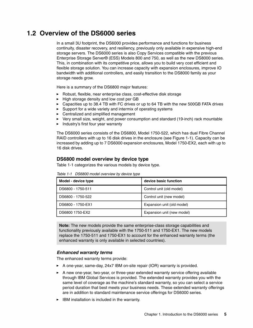
DS6800 model overview by device typeTable 1-1 categorizes the various models by device type.
Table 1-1 DS6800 model overview by device type
Enhanced warranty termsThe enhanced warranty terms provide:
� A one-year, same-day, 24x7 IBM on-site repair (IOR) warranty is provided.
� A new one-year, two-year, or three-year extended warranty service offering available through IBM Global Services is provided. The extended warranty provides you with the same level of coverage as the machine’s standard warranty, so you can select a service period duration that best meets your business needs. These extended warranty offerings are in addition to standard maintenance service offerings for DS6000 series.
� IBM installation is included in the warranty.
Model - device type device basic function
DS6800 - 1750-511 Control unit (old model)
DS6800 - 1750-522 Control unit (new model)
DS6800 - 1750-EX1 Expansion unit (old model)
DS6800 1750-EX2 Expansion unit (new model)
Note: The new models provide the same enterprise-class storage capabilities and functionality previously available with the 1750-511 and 1750-EX1. The new models replace the 1750-511 and 1750-EX1 to account for the enhanced warranty terms (the enhanced warranty is only available in selected countries).
Chapter 1. Introduction to the DS6000 series 5

1.2.1 Hardware overviewIn this section we give you a short description of the main hardware components.
DS6800 control unit 1750-5xx overviewThe 1750-511 and 1750-522 models (Figure 1-1) contain control unit functions as well as a rich set of advanced functions and hold up to 16 disk drive modules (DDMs). They provide a minimum capacity of 584 GB with 8 DDMs and 73 GB per DDM.
As of this writing, the maximum storage capacity with 16 x 500 GB FATA DDMs is 8 TB in a single control unit (1750-511/522 model).
The unit measures 5.25 inches (3U) high and is available in a 19 inch rack-mountable package.
Figure 1-1 DS6800 Model 1750-5xx and Model 1750-EXx front view
The control unit offers the following features:
� Dual active controllers to provide continuous operations and back up the other controller in case of controller maintenance or an unplanned outage of one controller
� PowerPC® 750GX 1 GHz processors architecture
� 4 GB of cache
� NVS - Battery buffered (for 3 days) cache for each controller
� Two battery backup units - one per controller card
� Two power supplies with imbedded enclosure cooling units
� Disk subsystem connectivity with eight 2 Gbps device ports.
� Front-end connectivity with two to eight Fibre Channel host ports that auto-negotiate to either 2 Gbps or 1 Gbps link speed; each port, long-wave or short-wave, can be configured for either:
– FCP to connect to open system hosts or PPRC FCP links– FICON® host connectivity
Note: Models 1750-511 and 1750-EX1 are no longer orderable.
6 DS6000 Series: Architecture and Implementation

Figure 1-2 shows a rear view of the DS6800 Model 1750-5xx.
Figure 1-2 DS6800 Model 1750-5xx rear view
The DS6000 storage system can connect to a broad range of servers through its intermix of FCP and FICON front-end I/O adapters. This support for numerous operating systems and server platforms, with the capability to partition the storage capacity among the different environments, facilitates storage consolidation.
For an up-to-date and complete interoperability matrix, refer to:
http://www.ibm.com/servers/storage/disk/ds6000/interop.html
DS6800 expansion unit 1750-EXx overviewTo configure more than 4.8 TB (enterprise DDMs) or 8 TB (FATA DDMs), up to seven DS6000 expansion enclosures (model 1750-EXx) can be attached to the DS6000 control unit to connect a maximum of 128 DDMs per storage system. This brings the maximum storage capacity to a total of 38.4 TB (enterprise only) or 64 TB (FATA only).
Each expansion enclosure contains the following features:
� Two expansion controller cards; each controller card provides the following features:
– Two 2 Gbps inbound ports– Two 2 Gbps outbound ports– One Fibre Channel switch
� A disk enclosure that holds up to 16 Fibre Channel DDMs
� Two AC/DC power supplies with imbedded enclosure cooling units
� Support for attachment to DS6800 Model 1750-5xx
The DS6800 Model 1750-EXx is also a 3U Electrical Industries Association (EIA) self-contained unit, as is the 1750-5xx, and it can also be mounted in a standard 19 inch rack.
Chapter 1. Introduction to the DS6000 series 7

Controller model 1750-522 and expansion model 1750-EX2 have the same front appearance. Figure 1-3 shows the rear view of the expansion enclosure, which is different when compared to the rear view of the control unit 1750-5xx, due to missing host ports, BBUs, and serial connectivity.
Figure 1-3 DS6800 Model 1750-EXx rear view
The processorsThe DS6800 controller unit utilizes two 64-bit PowerPC 750GX 1 GHz processors for the storage server and the host adapters, respectively, and another PowerPC 750FX 500 MHz processor for the device adapter on each controller card.
Switched FC-AL subsystemThe disk drives in the DS6800 or DS6000 expansion enclosure have a dual ported FC-AL interface. Instead of forming an FC-AL loop, each disk drive is connected to two Fibre Channel switches within each enclosure, giving the controllers four paths and a point-to-point connection to each disk drive. This allows for maximum drive side bandwidth, eliminates the bottlenecks of loop designs, and gives specific disk drive fault indication. The DS6000 series also provides preferred path I/O steering and can automatically switch the data path used to improve overall performance.
Fibre Channel drivesThe DS6800 controller unit can be equipped with up to 16 internal FC-AL disk drive modules, offering up to 4.8 TB of physical storage capacity in only 3U (5.25”) of standard 19” rack space, or up to 38.4 TB fully configured with seven expansion enclosures.
FATA drivesWith the introduction of 500 GB (7200 rpm) FATA drives, the DS6000 controller unit capacity now scales up to 8 TB and an impressive 64 TB when fully configured with seven expansion enclosures. These drives offer a cost effective option for lower priority data. Intermix with FC drives is supported with certain restrictions. See 2.4.1, “Fibre Channel ATA (FATA)” on page 28.
Dense packagingCalibrated Vectored Cooling technology used in xSeries® and BladeCenter® to achieve dense space saving packaging is also used in the DS6800. The DS6800 weighs only 49.6 kg (109 lbs.) with 16 drives. It connects to normal power outlets with its two power supplies in each DS6800 or DS6000 expansion enclosure. All this provides savings in space, cooling, and power consumption.
8 DS6000 Series: Architecture and Implementation

Host adaptersThe DS6800 has eight 2 Gbps Fibre Channel ports that can be equipped with two or up to eight shortwave or longwave Small Formfactor Plugables (SFP). You order SFPs in pairs. The 2 Gbps Fibre Channel host ports (when equipped with SFPs) can also auto-negotiate to 1 Gbps for legacy SAN components that support only 1 Gbps. Each port can be configured individually to operate in Fibre Channel or FICON mode, but you should always have pairs. Host servers should have paths to each of the two RAID controllers of the DS6800.
For more information on the components, see Chapter 2, “Hardware components” on page 17.
1.2.2 Storage Management ConsoleThe Storage Management Console (SMC) console consists of the DS Storage Manager software, shipped with every DS6000 series system, and a customer provided computer system on which the software can run. The SMC is used to configure and manage DS6000 series systems and runs on a Windows system that the client can provide.
1.2.3 Storage capacityThe DS6000 series offers outstanding scalability with physical capacities ranging from 584 GB up to 64 TB, while maintaining excellent performance. Physical capacity for the DS6800 and DS6000 expansion enclosure is purchased via disk drive sets. A disk drive set contains four identical disk drives (same capacity and revolutions per minute (RPM)). Currently, a minimum of eight drives (two disk drive sets) are required for the DS6800. You can increase the capacity of your DS6000 by adding one or more disk drive sets to the DS6800 or DS6000 expansion enclosure. Within the controller model DS6800, you can install up to four disk drive sets (16 disk drive modules (DDMs)).
The DS6800 server enclosure can have from 8 up to 16 DDMs and can connect seven expansion enclosures. Each expansion enclosure also can have 16 DDMs. Therefore, in total a DS6800 Storage Unit can have 16 + 16 x 7 = 128 DDMs.
You can select from four types of enterprise DDMs:
� 73 GB 15k RPM� 146 GB 10k RPM� 146 GB 15k RPM� 300 GB 10k RPM
And one type of FATA DDM:
� 500 GB 7.2K RPM
Therefore, a DS6800 can have from 584 GB (73 GB x 4 enterprise DDMs) up to 64TB (500 GB x 128 FATA DDMs).
Table 1-2 describes the capacity of the DS6800 with expansion enclosures.
Chapter 1. Introduction to the DS6000 series 9
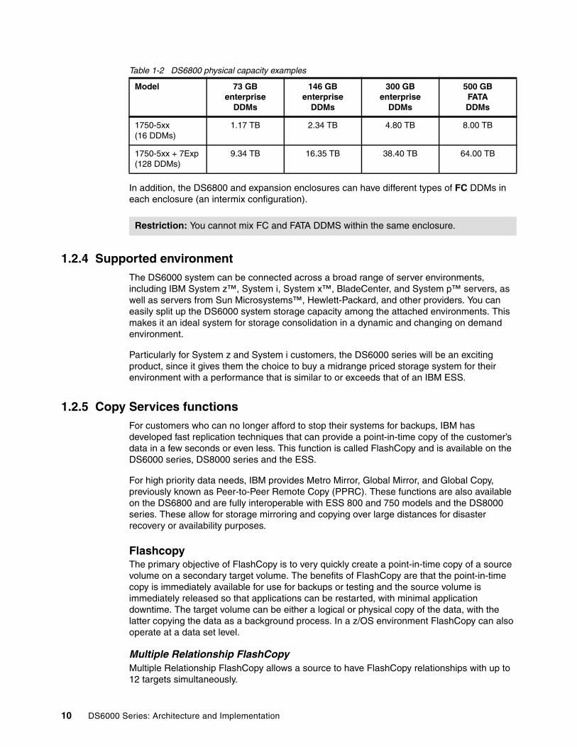
Table 1-2 DS6800 physical capacity examples
In addition, the DS6800 and expansion enclosures can have different types of FC DDMs in each enclosure (an intermix configuration).
1.2.4 Supported environmentThe DS6000 system can be connected across a broad range of server environments, including IBM System z™, System i, System x™, BladeCenter, and System p™ servers, as well as servers from Sun Microsystems™, Hewlett-Packard, and other providers. You can easily split up the DS6000 system storage capacity among the attached environments. This makes it an ideal system for storage consolidation in a dynamic and changing on demand environment.
Particularly for System z and System i customers, the DS6000 series will be an exciting product, since it gives them the choice to buy a midrange priced storage system for their environment with a performance that is similar to or exceeds that of an IBM ESS.
1.2.5 Copy Services functionsFor customers who can no longer afford to stop their systems for backups, IBM has developed fast replication techniques that can provide a point-in-time copy of the customer’s data in a few seconds or even less. This function is called FlashCopy and is available on the DS6000 series, DS8000 series and the ESS.
For high priority data needs, IBM provides Metro Mirror, Global Mirror, and Global Copy, previously known as Peer-to-Peer Remote Copy (PPRC). These functions are also available on the DS6800 and are fully interoperable with ESS 800 and 750 models and the DS8000 series. These allow for storage mirroring and copying over large distances for disaster recovery or availability purposes.
FlashcopyThe primary objective of FlashCopy is to very quickly create a point-in-time copy of a source volume on a secondary target volume. The benefits of FlashCopy are that the point-in-time copy is immediately available for use for backups or testing and the source volume is immediately released so that applications can be restarted, with minimal application downtime. The target volume can be either a logical or physical copy of the data, with the latter copying the data as a background process. In a z/OS environment FlashCopy can also operate at a data set level.
Multiple Relationship FlashCopyMultiple Relationship FlashCopy allows a source to have FlashCopy relationships with up to 12 targets simultaneously.
Model 73 GB enterprise
DDMs
146 GB enterprise
DDMs
300 GB enterprise
DDMs
500 GBFATADDMs
1750-5xx (16 DDMs)
1.17 TB 2.34 TB 4.80 TB 8.00 TB
1750-5xx + 7Exp(128 DDMs)
9.34 TB 16.35 TB 38.40 TB 64.00 TB
Restriction: You cannot mix FC and FATA DDMS within the same enclosure.
10 DS6000 Series: Architecture and Implementation

Incremental FlashCopyIncremental FlashCopy provides the capability to refresh a LUN or volume involved in a FlashCopy relationship. When a subsequent FlashCopy is initiated, only the data required to bring the target current to the source's newly established point-in-time is copied.
FlashCopy to a remote mirror primaryFlashCopy to a remote mirror primary lets you establish a FlashCopy relationship where the target is a remote mirror primary volume. This overcomes previous limitations on the ESS that especially affected z/OS clients using data set level FlashCopy for copy operations within a mirrored pool of production volumes.
Consistency GroupsConsistency Groups can be used to maintain a consistent point-in-time copy across multiple LUNs or volumes, or even multiple DS6800, DS8000, ESS 800, and ESS 750 systems.
Inband commands over remote mirror linkIn a remote mirror environment Inband FlashCopy allows commands to be issued from the local or intermediate site, and transmitted over the remote mirror Fibre Channel links for execution on the remote DS6800. This eliminates the need for a network connection to the remote site solely for the management of FlashCopy.
Remote Mirror and Copy featuresRemote Mirror and Copy features include Metro Mirror, Global Copy, and Global Mirror. As with Flashcopy, Remote Mirror and Copy functions can also be established between DS6800 and ESS 800/750 systems.
Metro MirrorMetro Mirror, previously called Synchronous Peer-to-Peer Remote Copy (PPRC), provides a synchronous copy of LUNs or volumes at a remote site within 300km.
Global CopyGlobal Copy, previously called PPRC-XD, is a non-synchronous long distance copy option for data migration and backup.
Global MirrorGlobal Mirror provides an asynchronous copy of LUNs or volumes over virtually unlimited distances. The distance is typically limited only by the capabilities of the network and channel extension technology being used.
z/OS Global Mirror z/OS Global Mirror (previously called XRC) offers a specific set of very high scalability and high performance asynchronous mirroring capabilities designed to match very demanding, large System z resiliency requirements. The DS6000 series systems can only be used as a target system in z/OS Global Mirror operations.
For more information about Copy Services see Chapter 5, “Copy Services” on page 85.
1.2.6 InteroperabilityThe DS6800 features unsurpassed enterprise interoperability for a modular storage subsystem because it uses the same software as the DS8000 series, which is an extension of the proven IBM ESS code. The DS Remote Mirror and Copy functions can interoperate between the DS8000, the DS6000, and ESS Models 750/800/800Turbo. This offers a
Chapter 1. Introduction to the DS6000 series 11

dramatically increased flexibility in developing mirroring and remote copy solutions, and also the opportunity to deploy business continuity solutions at lower costs than have been previously available.
1.2.7 Service and setupDS6000 series systems are designed to be easy to install and maintain by the customer. The DS Storage Manager’s intuitive Web-based GUI makes the configuration process easy an for most common configuration tasks, Express Configuration Wizards are available to guide you through the process.
Failure determination is made easy with Light Path Diagnostics which assists with component identification, and repair if a failure does occur. With only five types of customer replaceable units (CRU) service is easy, and Light Path Diagnostics indicators tell when a failing unit can be replaced without disruption to the whole environment. If a concurrent maintenance is not possible the DS Storage Manager’s GUI will give details on how to proceed. Customers might also want to consider a support contract with IBM or an IBM Business Partner for extended service. This, in combination with an outstanding 4 year warranty, adds to the DS6000’s low total cost of ownership (TCO).
Call Home and event notification messages for the DS6000 can be done through an Ethernet connection to the external network or an optional modem and phone line. The DS6000 uses this link to place a call to IBM or other service provider when it requires service. With encrypted, customer initiated remote access, service personnel can view logs or initiate trace and dump retrievals. Health of the Call Home process is monitored with a weekly heartbeat to remote support.
Configuration changes like adding disk drives or expansion enclosures are a non-disruptive process and most maintenance actions are non-disruptive, including downloading and activating new Licensed Internal Code.
1.2.8 Configuration flexibilityThe DS6000 series uses virtualization techniques to separate the logical view of hosts onto LUNs from the underlying physical layer. This provides high configuration flexibility (see Chapter 4, “Virtualization concepts” on page 67).
Dynamic LUN/volume creation and deletionThe DS6800 gives a high degree of flexibility in managing storage, allowing LUNs to be created and deleted non-disruptively, even within an array. Also, when a LUN is deleted, the the freed capacity can be used with other free space to form a LUN of a different size.
Large LUN and large CKD volume supportYou can configure LUNs and volumes to span arrays, allowing for larger LUN sizes up to 2 TB. The maximum CKD volume size has also been increased to 65520 cylinders (about 55.6 GB), greatly reducing the number of volumes to be managed.
Flexible LUN to LSS associationWith no predefined association of arrays to LSSs on the DS6000 series, customers are free to put LUNs or CKD volumes into LSSs and make best use of the 256 address range, overcoming previous ESS limitations, particularly for System z.
12 DS6000 Series: Architecture and Implementation

Simplified LUN maskingThe implementation of volume group based LUN masking (as opposed to the adapter based masking used on the ESS) simplifies storage management by grouping all or some WWPNs of a host into a Host Attachment. Associating the Host Attachment to a Volume Group allows all adapters within it access to all of the storage in the Volume Group.
Upper boundariesHere is a list of the current DS6000 maximum values for the major logical definitions:
� Up to 32 logical subsystems� Up to 8192 logical volumes� Up to 1040 volume groups� Up to 2 TB LUNs� Up to 65520 cylinders in a z/OS CKD volume
1.3 Positioning the IBM System Storage DS6000 series
The IBM System Storage DS6000 series is designed for the cost, performance, and high capacity requirements of today's on demand business environments. It is ideally suited for storage consolidation as it offers extensive connectivity options.
1.3.1 Common set of functionsThe DS8000 series and DS6000 share many useful features, including FlashCopy, Metro Mirror, Global Copy, and Global Mirror. In addition, the DS6000/DS8000 series mirroring solutions are also compatible with ESS 800 and ESS 750. This compatibility offers a new era in flexibility and cost effectiveness in designing business continuity solutions.
1.3.2 Common management functionsWithin the DS6000 series and DS8000 series of storage systems, the provisioning tools, such as the DS Storage Manager’s configuration GUI or CLI, are very similar. Scripts written for one series member of storage servers will also work for the other series. Given this, it is easy for a storage administrator to work with either of the products. This reduces management costs, since no training on a new product is required when adding a product of another series.
1.3.3 DS6000 series compared to others of the System Storage DS Family
Here we compare the DS6000 series to other members of the IBM System Storage DS Family.
DS6000 series compared to ESSThe ESS clients will find it very easy to replace their old systems with a DS6800. All functions (with the exception of cascading Metro/Global Copy and z/OS Global Mirror) are the same as on the ESS and are also available on a DS6800.
If you want to keep your ESS and if it is a model 800 or 750 with Fibre Channel adapters, you can use your old ESS, for example, as a secondary for remote copy. With the ESS at the appropriate LIC level, scripts or CLI commands written for Copy Services will work for both the ESS and the DS6800.
Chapter 1. Introduction to the DS6000 series 13
For most environments, the DS6800 performs much better than an ESS. You might even replace two ESS 800s with one DS6800. The sequential performance of the DS6800 is excellent. However, when you plan to replace an ESS with a large cache (let us say more than 16 GB) with a DS6800 (which comes with 4 GB cache) and you currently get the benefit of a high cache hit rate, your cache hit rate on the DS6800 will drop down. This is because of the smaller cache. z/OS benefits from large cache, so for transaction-oriented workloads with high read cache hits, careful planning is required.
DS6000 series compared to DS8000 seriesYou can think of the DS6000 series as a “little brother or sister” of the DS8000 series. All Copy Services (with the exception of z/OS Global Mirror) are available on both systems. You can do Metro Mirror, Global Mirror, and Global Copy between the two series. The CLI commands and the DS Storage Manager GUI look the same for both systems.
Obviously the DS8000 series can deliver a higher throughput and scales higher than the DS6000 series, but not all customers need this high throughput and capacity. You can choose the system that fits your needs, since both systems support the same SAN infrastructure and the same host systems.
It is very easy to have a mixed environment, using DS8000 series systems where you need them and DS6000 series systems where you need a very cost efficient solution.
Logical partitioning available with some DS8000 models is not available on the DS6000.
1.4 PerformanceWith its fast six processors on the controller cards and the switched FC-AL disk subsystem, the DS6000 series is a high-performance modular storage system.
Some of its performance relevant features are discussed in the following sections. For more on DS6000 performance, see Chapter 15, “Performance considerations” on page 257 or IBM TotalStorage DS6000 Series: Performance Monitoring and Tuning, SG24-7145,
1.4.1 Tagged Command QueuingTagged Command Queuing allows Multiple AIX/UNIX I/O commands to be queued to the DS6800, which improves performance through autonomic storage management versus the server queuing one I/O request at a time. The DS6800 can reorder the queue to optimize disk I/O.
1.4.2 Self-learning cache algorithms - SARCCache algorithms determine what data is stored in cache and what data is removed. Read ahead caching will not store recently used data in cache, but will pre-fetch data and load it into cache. This is based on the idea that the application will want the next chunks of data in addition to the data it just received.
Most vendors use a cache algorithm based on what is commonly known as Last Recently Used (LRU), which places data to cache based on server access patterns. IBM's patent pending Sequential prefetching in Adaptive Replacement Cache (SARC) places data in cache based not only on server access patterns, but also on frequency of data utilization.
14 DS6000 Series: Architecture and Implementation

1.4.3 IBM multipathing softwareIBM Multi-path Subsystem Device Driver (SDD) provides load balancing and enhanced data availability capability in configurations with more than one I/O path between the host server and the DS6800. The data path from the host to the RAID controller is pre-determined by the LUN. Below the RAID controller, load balancing algorithms are designed to direct the data to the path that will have the best throughput.
Most vendors’ priced multipathing software selects the preferred path at the time of initial request. IBM's free of charge preferred path multipathing software offers performance beyond this, by dynamically selecting the most efficient and optimum path to use at each data interchange during read and write operations.
1.4.4 Performance for System zThe features briefly presented in this section are relevant to the DS600 performance in z/OS environments.
Parallel Access Volumes (PAV)PAV is an optional feature for System z environments. This enables a single System z server to simultaneously process multiple I/O operations to the same logical volume, which can help to significantly improve throughput. This improvement is achieved by defining multiple addresses per volume. With Dynamic PAV, the assignment of addresses to volumes can be automatically managed to help the workload meet its performance objectives and reduce overall queuing. To utilize dynamic PAV, the Workload Manager must be used in Goal Mode.
Multiple AllegianceMultiple Allegiance is a standard DS6800 feature that expands simultaneous logical volume access capability across multiple System z servers. This function, along with the software function PAV, enables the DS6800 to process more I/Os in parallel, helping to dramatically improve performance and enabling greater use of large volumes.
I/O priority queuingI/O priority queuing improves performance in z/OS environments with several z/OS images. You can, for example, favor I/O from production systems compared to I/O from test systems. Due to this capability, you can manage Service Level Agreements, and storage administrator productivity can also be improved.
Chapter 1. Introduction to the DS6000 series 15

16 DS6000 Series: Architecture and Implementation

Chapter 2. Hardware components
This chapter details the DS6000 hardware platform and its components.
We cover the following topics:
� Server enclosure� Expansion enclosure� Controller architecture� Disk subsystem (FC and FATA disks)� Server enclosure RAID controller card� Expansion enclosure SBOD controller card� Front Display Panel (FDP)� Rear Display Panel (RDP)� Power Subsystem (PS)� System service card� Storage Management Console (SMC)� Cables
2
© Copyright IBM Corp. 2005, 2006. All rights reserved. 17
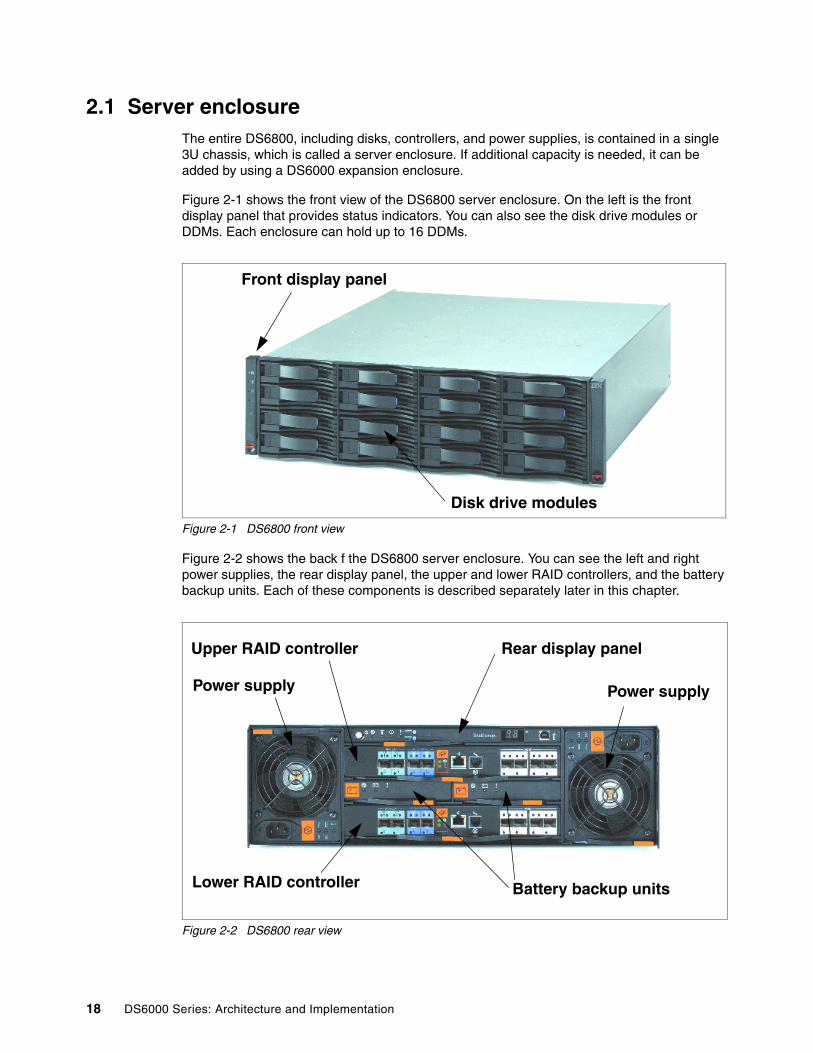
2.1 Server enclosureThe entire DS6800, including disks, controllers, and power supplies, is contained in a single 3U chassis, which is called a server enclosure. If additional capacity is needed, it can be added by using a DS6000 expansion enclosure.
Figure 2-1 shows the front view of the DS6800 server enclosure. On the left is the front display panel that provides status indicators. You can also see the disk drive modules or DDMs. Each enclosure can hold up to 16 DDMs.
Figure 2-1 DS6800 front view
Figure 2-2 shows the back f the DS6800 server enclosure. You can see the left and right power supplies, the rear display panel, the upper and lower RAID controllers, and the battery backup units. Each of these components is described separately later in this chapter.
Figure 2-2 DS6800 rear view
Front display panel
Disk drive modules
Power supply Power supply
Upper RAID controller Rear display panel
Lower RAID controller Battery backup units
18 DS6000 Series: Architecture and Implementation

2.2 Expansion enclosureThe DS6000 expansion enclosure is used to add capacity to an existing DS6800 server enclosure. Each controller unit can have a total of seven expansion enclosures added to it, three on the same loops as the controller FC switches, and four on other two loops.
From the front view, the expansion enclosure is effectively identical to the server enclosure (so it is not pictured). The rear view is shown in Figure 2-3. You can see the left and right power supplies, the rear display panel, and the upper and lower SBOD (Switched Bunch Of Disks) controllers. The power supplies and rear display panel used in the expansion enclosure are identical to the server enclosure.
The rear view shows two small but important differences. First, instead of RAID controller cards, it has two SBOD controller cards and second, there are no batteries (since there is no persistent memory in the expansion enclosure). The batteries slots are filled with blockouts to ensure correct internal airflow.
Figure 2-3 DS6000 expansion enclosure rear view
2.3 Controller architectureHaving described the enclosures themselves, in the rest of the chapter we explore the technical details of each of the components. The architecture that connects these components is pictured in Figure 2-4.
Effectively, the DS6800 consists of two controller cards. Each controller card contains an integrated four port host adapter to connect Fibre Channel and FICON hosts. For the disk subsystem, each controller card has an integrated four port FC-AL (Fibre Channel Arbitrated Loop) device adapter that connects the controller card to two separate Fibre Channel loops.
Each switched loop pair attaches to either 3 or 4 disk enclosures, each containing up to 16 disks. Each enclosure contains two 22 port Fibre Channel switches. Of these 22 ports, 16 are used to attach to the 16 disks in the enclosure and four are used to interconnect with other enclosures. The remaining two are reserved for internal use. Each disk is attached to both switches. Whenever the device adapter connects to a disk, it uses a switched connection to transfer data. This means that all data travels via the shortest possible path.
Power supply Power supply
Upper SBOD controller Rear display panel
Lower SBOD controller
Chapter 2. Hardware components 19

The attached hosts interact with controller enclosure to access data on logical volumes. The microcode running on the Power PC® chipset manages all read and write requests to the logical volumes on the disk arrays. For write I/O operations, the controllers use fast-write, whereby the data is written to volatile memory on one controller and persistent memory (also known as NVS or non-volatile storage) on the other controller. The DS6800 then reports to the host that the write is complete before it has actually been written to disk. This provides much faster write performance.
Figure 2-4 DS6000 architecture
Controller card 0
SAN fabric
Controller card 1
Power PCchipset
Power PCchipset
Persistent memory
Volatilememory
Persistent memory
Volatilememory
host adapterchipset
host adapterchipset
20 p
ort f
ibre
cha
nnel
sw
itch
20 p
ort f
ibre
cha
nnel
sw
itch
20 p
ort f
ibre
cha
nnel
sw
itch
20 p
ort f
ibre
cha
nnel
sw
itch
device adapterchipset
device adapterchipset
Server enclosure
First expansionenclosure (if present)
20 DS6000 Series: Architecture and Implementation

When a host performs a read I/O, the controllers fetch the data from the disk arrays via the high performance switched disk architecture. The data is then cached in volatile memory in case it is required again. The controllers attempt to anticipate future reads by an algorithm known as sequential prefetching in adaptive replacement cache (SARC). Data is held in cache as long as possible using this smart algorithm. If a cache hit occurs where requested data is already in cache, then the host does not have to wait for it to be read from the disks.
If you can view Figure 2-4 on page 20 in color, you can use the colors as indicators of how the DS6000 hardware is shared between the controllers (in black and white, the dark color is green and the light color is yellow). On the left side is the green controller. The green controller records its write data and caches its read data in its volatile memory area (in green). For fast-write data it has a persistent memory area on the right controller. It uses its device adapter chipset to access the disk arrays under its management. The yellow controller on the right operates in an identical fashion.
DS6800 capacity upgradeThe DS6800 has two enclosure groups for attaching expansion enclosures. One group can have a server enclosure and up to three expansion enclosures (we call this group Loop 0) and the other group can have up to four expansion enclosures (we call this group Loop 1). You can attach additional expansion enclosures to the two groups for well-balanced capacity.
Figure 2-5 illustrates the connectivity of the server and expansion enclosures. Each DS6800 controller has four FC-AL ports. Two of these ports connect to the dual redundant loops of the first group (Loop 0), and the others to the second group (Loop 1). The FC-AL port in Loop 0 is called the disk exp port, and the port in the Loop 1 is called the disk control port.
These groups are independent and there is no restriction on the connection sequence of expansion enclosures.
Figure 2-5 is an example of how to connect an expansion enclosure to each group alternately.
When you add new DDMs into an enclosure or attach additional enclosures, you don’t need disruptive maintenance. To add new DDMs into an existing enclosure, you have only to pull out the dummy carriers and replace them with the new DDMs. To attach additional enclosures, you only have to attach the new enclosures to the existing enclosures with Fibre Channel cables.
Attention: Keep in mind the spare creation rules (see 3.4.4, “Spare creation” on page 56), because you can lose capacity for unnecessary spares by mixing DDMs with different characteristics on each loop.
Chapter 2. Hardware components 21
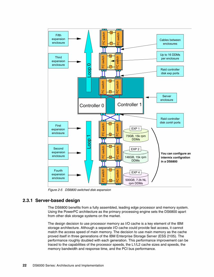
Figure 2-5 DS6800 switched disk expansion
2.3.1 Server-based designThe DS6800 benefits from a fully assembled, leading edge processor and memory system. Using the PowerPC architecture as the primary processing engine sets the DS6800 apart from other disk storage systems on the market.
The design decision to use processor memory as I/O cache is a key element of the IBM storage architecture. Although a separate I/O cache could provide fast access, it cannot match the access speed of main memory. The decision to use main memory as the cache proved itself in three generations of the IBM Enterprise Storage Server (ESS 2105). The performance roughly doubled with each generation. This performance improvement can be traced to the capabilities of the processor speeds, the L1/L2 cache sizes and speeds, the memory bandwidth and response time, and the PCI bus performance.
1
16 FC s
witc
h
FC s
witc
h
1
16 FC s
witc
h
FC s
witc
h
16
1 FC s
witc
h
FC s
witc
h
16
1 FC s
witc
h
FC s
witc
hController 0
16
1 FC s
witc
h
FC s
witc
h
1
16 FC s
witc
h
FC s
witc
hController 1
Loop
1Lo
op 0
Firstexpansionenclosure
Serverenclosure
Raid controllerdisk contrl ports
Raid controllerdisk exp ports
Cables betweenenclosures
Up to 16 DDMsper enclosure
Secondexpansionenclosure
Fourthexpansionenclosure
Thirdexpansionenclosure
Fifthexpansionenclosure
You can configure anintermix configrationin a DS6800
73GB, 15k rpm DDMs
146GB, 15k rpm DDMs
500GB, 7.2k NL rpm DDMs
EXP 1
EXP 4
EXP 2
22 DS6000 Series: Architecture and Implementation

With the DS6800, the cache access has been accelerated further by making the non-volatile storage (NVS) a part of the main memory.
2.3.2 Cache managementMost if not all high-end disk systems have internal cache integrated into the system design, and some amount of system cache is required for operation. Over time, cache sizes have dramatically increased, but the ratio of cache size to system disk capacity has remained nearly the same.
The DS6800 and DS8000 use an algorithm called Sequential Prefetching in Adaptive Replacement Cache (SARC) that was developed by IBM Storage Development in partnership with IBM Research. It is a self-tuning, self-optimizing solution for a wide range of workloads with a varying mix of sequential and random I/O streams. SARC is inspired by the Adaptive Replacement Cache (ARC) algorithm and inherits many features from it. For a detailed description of ARC, see N. Megiddo and D. S. Modha, “Outperforming LRU with an adaptive replacement cache algorithm,” IEEE Computer, vol. 37, no. 4, pp. 58–65, 2004.
SARC basically attempts to determine four things:
� When data is copied into the cache� Which data is copied into the cache� Which data is evicted when the cache becomes full� How the algorithm dynamically adapts to different workloads
The decision to copy some amount of data into the DS6000/DS8000 cache can be triggered from two policies: demand paging and prefetching. Demand paging means that disk blocks are brought in only on a cache miss. Demand paging is always active for all volumes and ensures that I/O patterns with some locality find at least some recently used data in the cache.
Prefetching means that data is copied into the cache speculatively even before it is requested. To prefetch, a prediction of likely future data accesses is needed. Because effective, sophisticated prediction schemes need extensive history of page accesses (which is not feasible in real-life systems), SARC uses prefetching for sequential workloads. Sequential access patterns naturally arise in video-on-demand, database scans, copy, backup and recovery. The goal of sequential prefetching is to detect sequential access and effectively pre-load the cache with data so as to minimize cache misses.
For prefetching, the cache management uses tracks. To detect a sequential access pattern, counters are maintained with every track, to record if a track has been accessed together with its predecessor. Sequential prefetching becomes active only when these counters suggest a sequential access pattern. In this manner, the DS6000/DS8000 monitors application read-I/O patterns and dynamically determines whether it is optimal to stage into cache one of the following:
� Just the page requested� That page requested, plus the remaining data on the disk track� An entire disk track (or a set of disk tracks) which have not yet been requested.
The decision of when and what to prefetch is essentially made on a per-application basis (rather than a system-wide basis) to be sensitive to the different data reference patterns of different applications that can be running concurrently.
To decide which pages are evicted when the cache is full, sequential and random (non-sequential) data is separated into different lists (see Figure 2-6). A page that has been brought into the cache by simple demand paging is added to the Most Recently Used (MRU)
Chapter 2. Hardware components 23
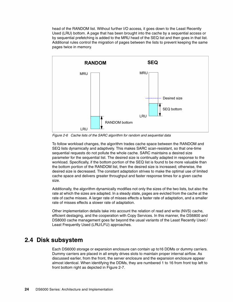
head of the RANDOM list. Without further I/O access, it goes down to the Least Recently Used (LRU) bottom. A page that has been brought into the cache by a sequential access or by sequential prefetching is added to the MRU head of the SEQ list and then goes in that list. Additional rules control the migration of pages between the lists to prevent keeping the same pages twice in memory.
Figure 2-6 Cache lists of the SARC algorithm for random and sequential data
To follow workload changes, the algorithm trades cache space between the RANDOM and SEQ lists dynamically and adaptively. This makes SARC scan-resistant, so that one-time sequential requests do not pollute the whole cache. SARC maintains a desired size parameter for the sequential list. The desired size is continually adapted in response to the workload. Specifically, if the bottom portion of the SEQ list is found to be more valuable than the bottom portion of the RANDOM list, then the desired size is increased; otherwise, the desired size is decreased. The constant adaptation strives to make the optimal use of limited cache space and delivers greater throughput and faster response times for a given cache size.
Additionally, the algorithm dynamically modifies not only the sizes of the two lists, but also the rate at which the sizes are adapted. In a steady state, pages are evicted from the cache at the rate of cache misses. A larger rate of misses effects a faster rate of adaptation, and a smaller rate of misses effects a slower rate of adaptation.
Other implementation details take into account the relation of read and write (NVS) cache, efficient destaging, and the cooperation with Copy Services. In this manner, the DS6800 and DS8000 cache management goes far beyond the usual variants of the Least Recently Used / Least Frequently Used (LRU/LFU) approaches.
2.4 Disk subsystemEach DS6000 storage or expansion enclosure can contain up to16 DDMs or dummy carriers. Dummy carriers are placed in all empty drives slots to maintain proper internal airflow. As discussed earlier, from the front, the server enclosure and the expansion enclosure appear almost identical. When identifying the DDMs, they are numbered 1 to 16 from front top left to front bottom right as depicted in Figure 2-7.
RANDOM
LRU
MRU
RANDOM bottom
SEQ
LRU
MRU
SEQ bottom
Desired size
24 DS6000 Series: Architecture and Implementation

Figure 2-7 DS6000 DDMs
Non-switched FC-AL drawbacksIn a standard FC-AL disk enclosure, all of the disks are arranged in a loop as depicted in Figure 2-8. This loop-based architecture means that data flows through all disks before arriving at either end of the RAID controller (shown here as Storage Server).
Figure 2-8 Industry standard FC-AL disk enclosure
The main problems with standard FC-AL access to DDMs are as follows:
� The full loop is required to participate in data transfer. Full discovery of the loop via loop initialization protocol (LIP) is required before any data transfer can occur. Loop stability can be affected by DDM failures.
� In the event of a disk failure, it can be difficult to identify the cause of a loop breakage, leading to complex problem determination.
� There is a performance drop off when the number of devices in the loop increases.
� To expand the loop, it is normally necessary to partially open it. If mistakes are made, a complete loop outage can result.
These problems are solved with the switched FC-AL implementation on the DS6000.
Chapter 2. Hardware components 25
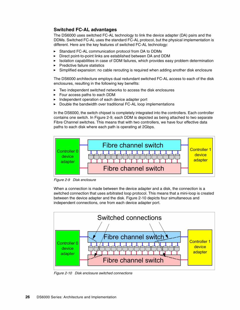
Switched FC-AL advantagesThe DS6000 uses switched FC-AL technology to link the device adapter (DA) pairs and the DDMs. Switched FC-AL uses the standard FC-AL protocol, but the physical implementation is different. Here are the key features of switched FC-AL technology:
� Standard FC-AL communication protocol from DA to DDMs� Direct point-to-point links are established between DA and DDM� Isolation capabilities in case of DDM failures, which provides easy problem determination� Predictive failure statistics� Simplified expansion: no cable rerouting is required when adding another disk enclosure
The DS6000 architecture employs dual redundant switched FC-AL access to each of the disk enclosures, resulting in the following key benefits:
� Two independent switched networks to access the disk enclosures� Four access paths to each DDM� Independent operation of each device adapter port� Double the bandwidth over traditional FC-AL loop implementations
In the DS6000, the switch chipset is completely integrated into the controllers. Each controller contains one switch. In Figure 2-9, each DDM is depicted as being attached to two separate Fibre Channel switches. This means that with two controllers, we have four effective data paths to each disk where each path is operating at 2Gbps.
Figure 2-9 Disk enclosure
When a connection is made between the device adapter and a disk, the connection is a switched connection that uses arbitrated loop protocol. This means that a mini-loop is created between the device adapter and the disk. Figure 2-10 depicts four simultaneous and independent connections, one from each device adapter port.
Figure 2-10 Disk enclosure switched connections
Controller 0deviceadapter
Fibre channel switch
Controller 1deviceadapter
Fibre channel switch
Controller 0deviceadapter
Fibre channel switchController 1
deviceadapter
Switched connections
Fibre channel switch
26 DS6000 Series: Architecture and Implementation

DS6000 switched FC-AL implementationFor a more detailed look at how the switched disk architecture expands in the DS6000, refer to Figure 2-11. This diagram depicts how the DS6000 is divided into two disk loops. The server enclosure (which contains the first 16 DDMs) is placed on loop 0. The first expansion enclosure is placed on loop 1. This allows for the best performance, because we are now using all four ports on the device adapter chipset. Expansion is achieved by adding expansion enclosures onto each loop, until each loop has four enclosures (for a total of 128 DDMs). The server enclosure is the first enclosure on loop 0, which is why we can only add a total of seven expansion enclosures.
Figure 2-11 Switched disk expansion
DDMsEach DDM is hot plugable and has two indicators. The green indicator shows disk activity. The amber indicator is used with light path diagnostics to allow the customer to identify and replace a failed DDM.
1
16 FC s
witc
h
FC s
witc
h
16
1 FC s
witc
h
FC s
witc
h
Controller 0
16
1 FC s
witc
h
FC s
witc
h
1
16 FC s
witc
h
FC s
witc
h
Controller 1
Firstexpansionenclosure
Up to 16 DDMsper enclosure
Secondexpansionenclosure
OUT ports to next enclosure
OUT ports to next enclosure
Cables betweenenclosures
Fibre channel switches
Serverenclosure
Thirdexpansionenclosure
Loop
1Fo
ur e
xpan
sion
en
clos
ures
max
imum
Loop
0Th
ree
expa
nsio
n en
clos
ures
m
axim
um
Internalconnections
through midplane
Raid controllerDISK CONTRL
ports
Raid controllerDISK EXP ports
a
Chapter 2. Hardware components 27

At the time of writing, the DS6000 allowed the choice of:
� Four different enterprise DDM types:
– 73 GB, 15K RPM drive – 146 GB, 10K RPM drive– 146 GB, 15K RPM drive– 300 GB, 10K RPM drive
� One FATA DDM drive:
– 500 GB, 7.2K RPM drive
All DDMs exist in what are called array sites. Array sites containing four DDMs are created at initial install and after enclosures/DDMs are added. During configuration, discussed in Chapter 13, “Configuration with DS CLI” on page 227, you have the choice of creating a RAID-5 or RAID-10 array by choosing one or two array sites.
2.4.1 Fibre Channel ATA (FATA)Fibre Channel ATA (FATA) is a technology that offers increased data rate performance over Parallel Advanced Technology Attachment (PATA) and improved availability over Serial Advanced Technology Attachment (SATA) drives.
Evolution of ATA technologyParallel Advanced Technology Attachment (PATA), or Integrated Drive Electronics (IDE) as it is also known, referencing the integrated controller and disk drive technology, has been the standard storage interface technology on personal computers since its introduction nearly 25 years ago. This technology has changed little over time, although there have been several developments to the specification that added performance (the original speed was just 3 MBps when the protocol was introduced).
Reliability features have been introduced, such as ATAPI, Enhanced Integrated Drive Electronics (EIDE) extensions for faster disk drive access, and multiple data-transfer modes, including Programmed Input/Output (PIO), direct memory access (DMA), and Ultra™ DMA (UDMA). However, the design limitations of the technology, coupled with faster applications and PC processor performance, meant that it was often the cause of bottlenecks in data transfer, because it has achieved its maximum data transfer rate of 133 MBps.
Serial ATA (SATA) disk drivesIn August 2001, the first version of the new ATA technology was introduced. Offering a maximum data rate of 150 MBps, Serial ATA 1.0 specifications allow for thinner, more flexible cables and lower pin counts, thus enabling easier, more flexible cable routing management and the use of smaller connectors than was possible with the existing Parallel ATA technology
SATA disks use a single serial port interface on an ATA drive and offer a low-cost disk technology to address less intensive storage operations. SATA drives for instance are used in the IBM DS4000 Storage Server (to overcome the single port drive limitation, IBM uses a MUX or interposer card to provide dual port access to the SATA drives).
Meant for capacity intensive, secondary, or near-line storage applications, SATA drive reliability is similar to Fibre Channel drives when used within their recommended duty-cycle in less I/O intensive applications.
In February 2002, a second ATA specification was launched called Serial ATA II. Second generation SATA-2 disk drives have made significant improvements in speed and functionality over the first generation SATA-1 by offering up to 3Gb/s speed and Native Tag Command Queuing like Fibre Channel disks.
28 DS6000 Series: Architecture and Implementation

Fibre Channel (FATA) disk drives A FATA disk is a combination of SATA-2 and Fibre Channel disk technologies, connecting a dual-port FC interface directly to SATA-2 disk drive hardware. This provides true dual-port drive connectivity.
Designed to meet the architectural standards of enterprise-class storage systems FATA disk drives provide high capacity at a low-cost alternative to FC disks without much sacrifice of performance, availability or functionality. Also, when used within their recommended duty-cycle, their reliability is comparable to that of the FC disks.
FATA disk drives are now available for both the IBM System Storage DS6000 series and DS8000 series, giving a lower cost alternative for large capacity, low workload environments.
Fibre Channel (FC) disk drivesFibre Channel disk drives set the standard for enterprise level performance, reliability, and availability. Mission critical applications with heavy workloads requiring high I/O performance and availability require Fibre Channel drives.
Differences between FATA, SATA, and FC disk drivesFibre Channel (FC) disk drives provide higher performance, reliability, availability, and functionality when compared to FATA and SATA disk drives. If an application requires high performance data throughput and almost continuous, intensive I/O operations, FC disk drives are the recommended option.
SATA and FATA disk drives are a cost efficient storage option for lower intensity storage workloads. By providing the same dual port FC interface as Fibre Channel disks, FATA drives offer higher availability and ensure compatibility and investment protection for existing enterprise-class storage systems.
Fibre Channel These disk drives have the following characteristics:
� Intended for heavy workloads in multi-user environments� Highest performance, availability, reliability, and functionality� Good capacity: 36–300 GB� Very high activity� Greater than 80% duty-cycle
Important: The FATA drives offer a cost effective option for lower priority data such as various fixed content, data archival, reference data, and near-line applications that require large amounts of storage capacity for lighter workloads.
These new drives are meant to complement, not compete with existing Fibre Channel drives, because they are not intended for use in applications that require drive utilization duty cycles greater than 20 percent.
Restriction: FC disk drives and FATA cannot be intermixed within the same enclosure. However, they can be intermixed within a DS6000 system: in other words, they can be intermixed on a DA pair loop.
Chapter 2. Hardware components 29

FATA These disk drives have the following characteristics:
� Intended for lower workloads in multi-user environments� High performance, availability and functionality� High reliability� More robust technology: Extensive Command Queuing� High capacity: 500 GB disk drives� Moderate activity� 20-30% duty-cycle
SATA-1 These disk drives have the following characteristics:
� Intended for lower workloads in multi-user environments� Good performance� Less availability and functionality than FATA or Fibre Channel disk drives:
Single port interface, no command queuing� High reliability� High capacity: 250–500 GB disk drives� Moderate activity� 20-30% duty-cycle
SATA-2 These disk drives have the following characteristics:
� Intended for lower workloads in multi-user environments� High performance, availability and functionality� High reliability� More robust technology: Extensive Command Queuing� High capacity: 500 GB disk drives� Moderate activity� 20-30% duty-cycle
2.4.2 Positioning FATA versus Fibre Channel disksIt is essential to understand the differences between FATA and Fibre Channel (FC) drive characteristics and mechanisms and the advantages and disadvantages of each, in order to implement FATA target applications properly.
Without any doubt, the technical characteristics and performance of FC disks remain superior to those of FATA disks. However, not all storage applications require these superior features.
When used for the appropriate enterprise applications, FATA disks offer a tremendous cost advantage over FC. First, FATA drives are cheaper to manufacture and because of their lager individual capacity, they are cheaper per gigabyte (GB) than FC disks. In large capacity systems, the drives themselves account for the vast majority of the cost of the system. Using FATA disks can substantially reduce the total cost of ownership (TCO) of the storage system.
Important: FATA is not the appropriate answer to every storage requirement. For many enterprise applications, and certainly mission-critical and production applications, Fibre Channel disks remain the best choice.
30 DS6000 Series: Architecture and Implementation

Classes of storageTo help you visualize where the benefits of FATA can best be obtained if implemented in a networked storage environment, we now describe a positioning of the types or classes of storage and the appropriate storage technology used at these levels.
Basically, storage data can reside at three different locations within the networked storage hierarchy. See Figure 2-12.
Figure 2-12 Storage data in a networked storage environment
Particular data types are suitable for storage at the various levels:
� Online (primary) storage:
This is best suited for applications that require constant instantaneous access to data, such as databases and frequently accessed user data.
Primary storage stores business-critical information, data with the highest value and importance. This data requires continuous availability and typically has high-performance requirements. Business-critical data will be stored on Fibre Channel disk implemented in enterprise-class storage solutions.
� Near-line (secondary) storage:
This is used for applications that require quicker access compared with offline storage (such as tape), but do not require the continuous, instantaneous access provided by online storage.
Secondary storage stores business-important information, but can, however, often tolerate lower performance and potentially slightly less than 24/7 availability. It can also be used to cache online storage for quicker backups to tape. Secondary storage represents a large percentage of a company’s data and is an ideal fit for FATA technology.
� Offline (archival) storage:
This is used for applications where infrequent serial access is required, such as backup for long-term storage. For this type of storage, tape remains the most economical solution.
Data storage implementations best suited to use FATA technology reside at the “near-line” or secondary location within the networked storage hierarchy and offer a cost-effective alternative to FC disks at that location. Positioned between online storage and offline storage, near-line storage or secondary storage is an optimal cost/performance solution for hosting cached backups and fixed data storage.
Table 2-1 summarizes the general characteristics for primary, secondary, and archival storage in traditional IT environments.
Network
Server
OnlineStorage
Disk
OfflineStorage
Tape
Near-lineStorage
Disk
Chapter 2. Hardware components 31

Table 2-1 Storage classes in traditional IT environments
Storage application typesNow that we have defined the storage classes, let us look at application characteristics from a storage standpoint to determine what applications are a good fit for FATA.
IOPS and throughputFrom a storage or information access perspective, applications can be classified as either having random or sequential data access patterns. Another characteristic is the access frequency. Random data access is measured in I/Os per second (IOPS) and is essential for transaction-based applications, such as OLTP and databases, with random, small-block I/O. Sequential data access, that is successive, large I/O blocks, is measured in megabytes per second (MBps) and is crucial for bandwidth-intensive applications, such as rich media streaming and seismic processing. These two very different application access patterns place unique demands on the storage system. And while the controller and firmware are critical to overall storage system performance, the disk drive plays a significant role as well.
Fibre Channel drives were designed for the highest levels of IOPS and MBps performance, integrating advanced technologies to maximize rotational velocities and data transfer rates, while lowering seek times and latency. In addition, the Fibre Channel interface provides robust functionality to process multiple I/O operations concurrently of varying sizes in both directions at once.
The slower drive mechanisms in FATA result in both lower IOPS and MBps performance compared to Fibre Channel. The FATA drive is not designed for fast access to data or handling large amounts of random I/O. However, FATA drives are a good fit for many bandwidth applications because they can provide comparable throughput for short periods of time.
Access frequencyIn addition to random and sequential access patterns, another consideration is access frequency and its relationship with secondary storage. Several secondary storage implementations identified as ideal for FATA technology generate random data access, which on the surface does not fit the FATA performance profile. But these implementations, such as fixed content and reference data, will have sporadic access activity on large quantities of data and will therefore primarily be measured by cost per gigabyte and not performance. Many non-traditional IT environments, such as high-performance computing, rich media, and energy, will significantly benefit from enterprise-class FATA solutions. These businesses are looking for high throughput performance at the lowest cost per gigabyte, which is exactly what FATA can deliver.
Class of storage Online Near-line Offline
Primary media FC disk FATA disk Tape
Price Highest Low cost-per-GB Lowest
IOPS performance Highest Minimal NA
MBps performance Highest High Lowest
Time to data Immediate ~ Immediate Mount time
Media reliability Highest Good Good - Lower
Uptime 24/7 < 24/7 < 24/7
Typical applications ERP/Oracle Fixed content Archive retrieval
32 DS6000 Series: Architecture and Implementation

The right FATA applicationBased on our discussion of storage classes and storage application types, we can identify specific applications that are prime targets for implementing FATA technology.
Backup applicationsThe secondary storage implementation that fits the FATA performance profile exceptionally well is backup, which generates sequential I/O as it streams data to the backup target. This is a performance strength of FATA.
The backup of secondary data can be achieved more efficiently when the near-line storage device acts as a caching device between Fibre Channel (FC) disks and tape, allowing the primary disk to remain online longer. Some advantages of this backup method are that it is faster and consumes less server CPU than direct backup to tape (Figure 2-13).
Figure 2-13 Near-line backup scenario
Near-line storage allows disk-to-disk backups to help achieve the following benefits:
� Shorter backup time and higher application availability:
Any IT department will tell you that its backup windows are either shrinking or already nonexistent. As a result, IT personnel are always looking for ways to improve backup times and minimize the amount of time a given application is affected by backup, either total down time or time running in a degraded mode. By using disk as the backup target, the backup runs and completes faster. After the data is safely stored on disk, the application is free of the backup overhead. In addition, the data can then be moved to tape to provide the long-term benefits of the traditional backup process.
� Faster recovery time:
In the past, tape was the only means of restoring data. This is a prolonged process, because the appropriate tape has to be located, loaded into the tape drive, and then sequentially read to locate and retrieve the desired data. Information has become increasingly vital to a company’s success, and the lengthy restoration time from tape can now be avoided. Backing up data to disk, as a disk image, enables significantly faster restoration times, because data is stored online and can be located and retrieved immediately.
� Improved backup/restore reliability:
Disk-to-disk backups create a new confidence in the ability to recover critical data by eliminating the mechanical concerns associated with tape; one bad tape can cause large restores to fail. Disk backups offer the same high level of RAID protection and redundancy as the original data.
Network
Server
OnlineStorage
Disk
OfflineStorage
Tape
Near-lineStorage
Disk
Chapter 2. Hardware components 33

� Easier backup/restore management:
Storage management software functionality can be used to create volume-level copies, or clones, of data as a source for restoration. Disk-to-disk backup packages, however, provide more intelligence and file-level information that enables simplified administration and faster restores.
Reference data applicationAnother application is fixed-content, or reference data storage, in which data has to be online and available, but is not necessarily being transacted every day. This is best suited for archiving e-mail messages, image files, and other data that must be stored safely and be readily available when needed (Figure 2-14).
Figure 2-14 Reference data storage scenario
Data retentionRecent government regulations have made it necessary to store, identify, and characterize data. The majority of this data will be unchanging and accessed infrequently, if ever. As a result, the highest possible performance is not a requirement. These implementations require the largest amount of storage for the least cost in the least amount of space. The FATA cost per gigabyte advantage over Fibre Channel and high capacity drives make it an attractive solution.
Temporary workspaceFATA is a great fit for project-based applications that need short-term, affordable capacity.
ConclusionWe have discussed when FATA is a good choice depending on the nature of an application or the type of storage required.
2.4.3 FATA versus Fibre Channel drives on the DS6000Again, we recommend that you use the new DS6000 FATA drives for applications that have a lower usage (20% or lower r/w duty cycles) than the enterprise drives (r/w duty cycles up to 80%). Also, from performance perspective, FATA drives have a lower random performance due to the lower RPM and the resulting longer seek times, than the enterprise drives.
Important: IBM recommends that FATA drives be employed strictly with applications such as those discussed in “The right FATA application” on page 33. Other types of applications, and in particular transaction processing, must be avoided.
Network
Server OnlineStorage
OfflineStorage
Tape
Reference DataStorage
Disk
Disk
34 DS6000 Series: Architecture and Implementation

An important factor to keep in mind is that the FATA drives used in the DS8000 will protect themselves by throttling IO based on the temperature registered by the internal sensors. When throttled, the performance of the drives can drop by up to 50%, resulting in much higher disk access times until the disk is able to return to its nominal temperature.
Also, to keep the FATA drives from robbing the enterprise disk traffic of DS8000 cache resources, the modified writes to Non-Volatile Storage (NVS) for the FATA arrays are limited. The customer or storage administrator is responsible for targeting appropriate workloads to the FATA drives. Table 2-2 shows some typical applications and the most suitable DS6000 drive type.
Table 2-2 Recommended drive types for common applications
Important: Due to the lower duty cycle and the potential for I/O throttling, FATA based volumes should not be mirrored with FC based volumes.
Usage Storage characteristics Storage category
Disk type recommended
Archiving and data retention Storage capacity, high density Near-line FATA
Backup and recovery (disk to disk)
Storage capacity, high density Near-line FATA
Database and data mining Mix of performance and capacity
On-line Fibre Channel
Data warehouse Storage capacity, high density, good performance
On-line Fibre Channel
Document imaging and retention
Capacity, sequential performance
Near-line FATA
E-mail Good performance, availability, capacity
On-line Fibre Channel
Enterprise eCommerce Performance, capacity, availability
On-line Fibre Channel
File serving Performance, capacity, availability
On-line Fibre Channel
Fixed content & reference data
Capacity Near-line FATA
Medical, life sciences imaging
Capacity, availability, variable performance
On-line Fibre Channel
Multi-media (audio/video) Capacity, availability, variable performance
On-line Fibre Channel
Online transaction processing (OLTP)
High performance and availability
On-line Fibre Channel
Remote data protection Good performance, availability, capacity
Near-line, Off-line
FATA
Scientific and geophysics Performance, capacity On-line Fibre Channel
Surveillance data Capacity, availability Near-line FATA
Temporary storage, spool, paging
High performance and good availability
On-line Fibre Channel
Chapter 2. Hardware components 35

2.5 Server enclosure RAID controller cardThe RAID controller cards are the key elements of the system. Each card is the equivalent of a cluster node in an ESS. IBM has leveraged its extensive development of the ESS host adapter and device adapter function to create a total repackaging. It actually uses DS8000 host adapter and device adapter logic, which allows almost complete commonality of function and code between the two series (DS6000 and DS8000).
2.5.1 Technical detailsFrom a technical point of view, the controller card is powered by an IBM PowerPC 750GX 1GHz processor. The controllers do not have an internal hard drive, but instead contain a compact flash memory card to act as a boot device and to store microcode and log data. Each controller contains 2 GB of server memory, giving the DS6800 a total of 4 GB.
A certain portion of that server memory is reserved as persistent memory or non-volatile storage (NVS). The NVS memory is not located on a separate battery protected card such as you would find in an ESS 800. Instead, it shares the same memory DIMMs with all the other functions. To protect the NVS memory area, a battery backup unit preserves the entire cache memory in the event of an unexpected power failure. If the DS6800 were to power off with un-destaged writes in NVS, then after reboot, the controller would read this reserved area and destage the writes. For more details on the batteries themselves and controller failover, see Chapter 3, “RAS: reliability, availability, serviceability” on page 47.
2.5.2 Device adapter portsThe DS6800 controller card is pictured in Figure 2-15. On the left-hand side, surrounded by light and dark blue boxes, are the disk expansion and disk control ports respectively (for readers seeing this in black and white, these boxes appear to be light and dark grey). These ports are used to attach up to a total of seven expansion enclosures to the server enclosure.
Figure 2-15 DS6800 controller card
The device adapter ports provided in each controller are effectively the chipset from one DS8000 device adapter. This provides remarkable performance thanks to a high function, high performance ASIC. To ensure maximum data integrity, it supports metadata creation and checking. Each controller provides four 2 Gbps device adapter ports, giving the machine a total of 8 device adapter ports. These ports must be short wave and use multimode cables with LC connectors.
36 DS6000 Series: Architecture and Implementation

The disks in the server enclosure are on the first disk loop (loop 0). When you attach the first expansion enclosure, you attach it to the DISK CONTRL ports to start the second disk loop (loop 1). The DISK EXP ports are used to attach the third expansion enclosure directly to the server enclosure — the second expansion enclosure will also be attached on the second disk loop (loop 1). It joins the same switched loop as the disks in the server enclosure (loop 0). The two loops are depicted in Figure 2-11 on page 27 (with loop 0 going upward and loop 1 going downward).
You add one expansion enclosure to each loop until both loops are populated with four enclosures each (remembering that the server enclosure represents the first enclosure on the first loop). Notice that while we use the term disk loops, and the disks themselves are FC-AL disks, each disk is actually attached to two separate Fibre Channel switches.
Device adapter port indicatorsFor each device adapter port, there are two indicators. The top left-hand indicator is green and is used to indicate port status. The top right-hand indicator is amber and is used to show port activity.
2.5.3 Host adapter portsFrom a host connectivity point of view, each DS6800 controller comes with four Fibre Channel/FICON host ports, giving the machine a total of eight host ports. You can see these on the right-hand side of Figure 2-15 on page 36. These host ports auto-negotiate to either 2 Gbps or 1 Gbps link speeds. These ports can be either short wave or long wave, which use multimode or single mode cables respectively, all with LC connectors.
The ports in each controller are effectively on a PCI-X 64 Bit 133 MHz card, the same card used in the DS8000. The chipset is driven by a new high function/high performance ASIC. To ensure maximum data integrity it supports metadata creation and checking.
Each port can be either FICON or Fibre Channel Protocol (FCP).The personality of the port is changeable via the DS Storage Manager GUI. A port cannot be both FICON and FCP simultaneously, but it can be changed as required.
It is important to understand that an attached host must have connectivity to both controllers. For more details, see Chapter 3, “RAS: reliability, availability, serviceability” on page 47.
Host adapter port indicatorsFor each host attachment port, there are three indicators. The top left-hand indicator is green and is used to indicate port status. The top right-hand indicator is amber and is used to show a faulty port. The bottom left-hand indicator is green and is used to indicate activity.
Fibre Channel supported serversSee this Web site for the current list of servers supported by the Fibre Channel attachment:
http://www.ibm.com/servers/storage/disk/ds6000/interop.html
Fibre Channel distancesThere are two types of SFPs you can select: long wave and/or short wave. With long-wave laser, you can connect nodes at distances of up to 10 km (non-repeated). With short wave laser, you are limited to a distance of 300 to 500 metres (non-repeated).
Chapter 2. Hardware components 37

2.5.4 SFPsThe disk expansion and host attachment ports both use SFPs (which stands for small form factor plugable). These SFPs are 2 Gbps. The RAID controller card pictured in Figure 2-15 on page 36 does not have these SFPs inserted (which is why you can’t see them there). These SFPs, which are shown in Figure 2-16 below, are hot plugable and are supplied as a priced feature of the DS6000.
Figure 2-16 SFP hot-plugable fibre port with LC connector fiber cable
Ethernet and serial portsEach controller card has a 10/100 copper Ethernet port to attach to a customer-supplied LAN. Both controllers must be attached to the same LAN and have connectivity to the SMC. This port has both a status light and an activity light. In addition, there is a serial port provided for each controller. This is not a modem port and is not intended to have a modem attached to it. Its main purpose is for maintenance by an IBM System Service Representative (SSR), and possibly for some initial setup tasks.
Health indicatorsContained in an orange box, each controller card has two status indicators located below a chip symbol. The upper indicator is green and indicates that the controller card is powered on. The lower indicator is amber and indicates that this controller requires service.
2.6 Expansion enclosure SBOD controller cardThe DS6000 SBOD controller card is only found in the expansion enclosure. Each SBOD controller card contains an independent 22 port Fibre Channel switch. Of these 22 ports, 16 are used to attach to the 16 disks in the expansion enclosure. Four more are used to interconnect with other enclosures, with the remaining two ports reserved for internal use.
Figure 2-17 shows the connectors on the SBOD controller card. The two in ports on the left are the switch ports that connect either to the server enclosure (to either the disk exp loop or the disk contrl loop) or to the out ports of a previous expansion enclosure. The two out ports on the right (in light blue boxes) are the switch ports that attach to the in ports of the next expansion enclosure. If there are no extra expansion enclosures, then they are not used.
38 DS6000 Series: Architecture and Implementation
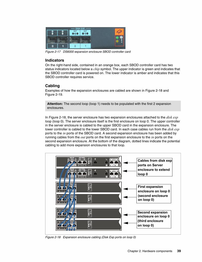
Figure 2-17 DS6000 expansion enclosure SBOD controller card
IndicatorsOn the right-hand side, contained in an orange box, each SBOD controller card has two status indicators located below a chip symbol. The upper indicator is green and indicates that the SBOD controller card is powered on. The lower indicator is amber and indicates that this SBOD controller requires service.
CablingExamples of how the expansion enclosures are cabled are shown in Figure 2-18 and Figure 2-19.
In Figure 2-18, the server enclosure has two expansion enclosures attached to the disk exp loop (loop 0). The server enclosure itself is the first enclosure on loop 0. The upper controller in the server enclosure is cabled to the upper SBOD card in the expansion enclosure. The lower controller is cabled to the lower SBOD card. In each case cables run from the disk exp ports to the in ports of the SBOD card. A second expansion enclosure has been added by running cables from the out ports on the first expansion enclosure to the in ports on the second expansion enclosure. At the bottom of the diagram, dotted lines indicate the potential cabling to add more expansion enclosures to that loop.
Figure 2-18 Expansion enclosure cabling (Disk Exp ports on loop 0)
Attention: The second loop (loop 1) needs to be populated with the first 2 expansion enclosures.
Cables from disk exp ports on Server enclosure to extend loop 0
First expansionenclosure on loop 0(second enclosure on loop 0)
Second expansion enclosure on loop 0(third enclosureon loop 0)
Chapter 2. Hardware components 39

In Figure 2-19, the server enclosure has two expansion enclosures attached to the disk contrl loop (loop 1). The first expansion enclosure plugged into the disk contrl ports is the first enclosure on loop 1. The cabling from the server enclosure to the first expansion enclosure on this loop is slightly different. Each controller attaches to both SBOD cards, so these cables are pictured in orange and green (which appear darker if viewed in black and white).
In each case, cables run from the disk contrl ports to the in ports of the SBOD card. A second expansion enclosure has been added by running cables from the out ports on the first expansion enclosure to the in ports on the second expansion enclosure. The dotted lines at the bottom indicate the potential cabling to add more expansion enclosures to that loop.
Figure 2-19 Expansion enclosure cabling (Disk Contrl ports on loop 1)
2.7 Front Display Panel (FDP)The DS6000 front display panel allows you to perform a health check with a single glance. There are seven indicators present on the panel; they are depicted in Figure 2-20.
Figure 2-20 DS6000 front display panel
Cables attach to server enclosuredisk contrl ports
First expansionenclosure on loop 1(first enclosure on loop)
Second expansion enclosure on loop 1(second enclosureon loop)
System information
System alert
Data in cache on battery
System power
System identify
CRU fault on rear
Fault in expansion enclosure
40 DS6000 Series: Architecture and Implementation

Table 2-3 summarizes the purpose of each indicator.
Table 2-3 DS6000 front panel indicators
2.8 Rear Display Panel (RDP)All of the indicators on the DS6000 front display panel are mirrored to the rear display panel. The rear display panel is pictured in Figure 2-21. The same colors and symbols are used for both the front and rear displays. The rear display panel also has several push buttons that are detailed in Table 2-4 following the figure.
Indicator Symbol Purpose
System Power (green)
Lightning bolt If this indicator is on solid, then DC power is present and the system is powered on. If it is blinking, then AC Power is present but the DS6000 is not powered on. If this indicator is off, then AC power is not present.
System Identify (blue)
Lighthouse This indicator is normally off. It can be made to blink by pressing the lightpath identify button. It is used to identify all enclosures that are grouped together in one system.
System Information (amber)
Circled letter i This indicator is normally off. If it is on solid, then an error has occurred that cannot be fixed by light path diagnostics. To turn this light off, you need to use the GUI to correct the error condition. This might be as little as to just view the error log.
System Alert (amber)
Exclamation mark This indicator is normally off. This indicator turns on solid when a fault has been detected and will remain on until the fault condition has been corrected.
Data Cache On Battery (green)
Battery This indicator is normally off. If it is blinking, then the battery is charging. If it is on solid, then AC power has been lost and the DS6000 has data in cache being protected by battery.
CRU Fault on Rear (amber)
Box with arrow pointing to rear
This indicator is normally off. If it is on solid, then a fault has occurred within a CRU in the rear of the enclosure and can be repaired using the light path indicators.
Fault in External Enclosure (amber)
Two boxes with arrow pointing to lower box.
This indicator is normally off. If it is on solid, then a fault has occurred within an attached expansion enclosure.
Chapter 2. Hardware components 41

Figure 2-21 DS6000 rear display panel
Table 2-4 DS6000 rear display panel push buttons
Enclosure ID indicatorThe rear display also has an enclosure identifier indicator. This uses two seven-segment LEDs to display the enclosure identifier number. The left-hand digit displays the device adapter switched loop the enclosure resides on. This will be 0 or 1 depending on whether the expansion enclosure is attached to the disk exp ports or the disk contrl ports respectively. On the server enclosure, it will always be 0. The right-hand digit displays the enclosure base address. It will range from 0 to 3. This address will be set automatically after the enclosure is powered on and joins the loop.
Rack identify connectorOn the far right-hand end of the rear display panel is a connector known as the rack identify connector. The intention is to allow a user to attach the enclosure to eServer rack identifier hardware. This allows you to identify in which rack a particular DS6000 storage or expansion enclosure is located.
Powercontrolswitch
Data cache onbattery
Systemidentify
Systemalert
Fault in external
enclosure
Rackidentify
connector
Systempower
Systeminformation
LightpathRemind
and Identify
switches
Fault on front CRU
Enclosureidentifier
Button Purpose
Power Control Switch (white)
This button can be seen on the left-hand side of the rear display panel. You press it once to begin the power on or power off sequence. While the button is present on the expansion enclosure, only the power button on the server enclosure can power off the entire complex.
Lightpath REMIND Switch (blue)
The upper of the two blue buttons, you push this button to re-activate the light path remind. This will allow you to identify a failed component that requires replacement.
Lightpath IDENTIFY Switch (blue)
The lower of the two blue buttons, you push this button to activate the system identify indicator.
42 DS6000 Series: Architecture and Implementation

2.9 Power Subsystem (PS)The power subsystem of the DS6800 consists of two redundant power supplies and two battery backup units (BBUs). DS6000 expansion enclosures contain power supplies but not BBUs. The power supplies convert input AC power to 3.3V, 5V, and 12V DC power. The battery units provide DC power, but only to the controller card memory cache in the event of a total loss of all AC power input. The DS6000 power supplies are hot swapable, and a single power supply is able to support the power requirements of an entire enclosure. The second power supply is supplied by default, meaning that you do not need to request redundant power as a feature.
Each power supply has two integrated fans for cooling the entire enclosure. If a power supply fails, it should not be removed from the enclosure until a replacement one is available. Both power supplies must be physically present to ensure that cooling air flows correctly through the enclosure, even if one has failed. If, during replacement of the failed supply, you take more than five minutes to install the new supply, the DS6000 could power off. Replacement, however, can be accomplished in less than 30 seconds.
Figure 2-22 DS6000 power supplies
AC power
Fault detected
DC power
Chapter 2. Hardware components 43

The DS6000 power supply has three indicators; they are defined in Table 2-5.
Table 2-5 DS6000 power supply indicators
2.10 Battery Backup Units (BBU)Each DS6800 RAID controller has a battery backup unit to provide DC power to that controller in the event of a complete loss of power. There are thus two BBUs present in the DS6800 server enclosure. If you compare their function to that of the different batteries in the ESS, they are the NVS batteries. They allow un-destaged cache writes in the NVS area of controller memory to be protected in the event of a sudden loss of AC power to both power supplies. The BBUs will protect the contents of NVS for at least 72 hours.
From the rear of the unit, the left-hand BBU supports the upper controller, while the right-hand BBU supports the lower controller.
Figure 2-23 DS6000 battery backup unit indicators
Indicator Symbol Purpose
AC Power (green) AC This indicator shows that main AC power is present. If it is off then no AC power is being supplied to the power supply, or the power supply is faulty.
DC Power (green) DC If this indicator is on solid then the power supply is producing correct DC power. If it is blinking then the DS6000 is not powered on. If it is off then either the enclosure is powered off or the power supply is faulty.
Fault detected (yellow)
Exclamation mark If this indicator is on solid then the DS6000 has identified this power supply as being faulty and it requires replacement.
Battery charging
Fault detected
DC present
44 DS6000 Series: Architecture and Implementation

The DS6000 battery units have three indicators, detailed in Table 2-6.
Table 2-6 DS6800 battery backup unit indicators
2.11 System service cardThe system service card which ships with the DS6800 can be placed in a cavity below the lower RAID controller card. It is a plastic card that contains important information on how to maintain your DS6800.
2.12 Storage Management Console (SMC)The DS6800 requires a separate PC to act as the DS Storage Management Console (SMC). This PC is a feature of the DS6800 and can be ordered separately or provided by the customer. The SMC is a requirement to install, configure and maintain the DS6800. It is connected over customers network or a private network to the DS6800 controller. If enabled, remote support and Call Home over modem are also handled through the SMC. The remote support connection is handled over the customer network or over a modem by using VPN.
The hardware and software requirements for the SMC can be found in Chapter 6, “Physical planning and installation” on page 111.
2.13 CablesThe DS6800 ships with three different sorts of cables:
� Power cords
Each DS6000 enclosure ships with six power cords. These should allow attachment to both rack power outlets and standard power outlets. The rack power outlet cords come in two lengths. The standard power cords are specified by feature code at time of purchase (based on the outlet used in your country). Only two of the six cords are used.
� Ethernet cables
Each DS6800 server enclosure ships with one Ethernet cross-over cable. This cable is used during initial configuration of the controllers to set IP addresses. After this, it is not used. You do not use it to connect the two controllers together for normal operation or during initial power on (this connectivity is supplied by an Ethernet switch).
Each DS6800 server enclosure ships with two standard Ethernet cables. These should be used in conjunction with an Ethernet hub or switch (that will need to be supplied or
Indicator Symbol Purpose
DC present (green)
Lightning bolt If this indicator is on solid then DC power is present. If this indicator is off then DC power is not available from this battery.
Battery charging (green)
Battery symbol If this indicator is on solid then the battery backup unit is fully charged. If this indicator is blinking then the battery is charging. As the battery approaches full charge the blink speed will slow. If the indicator is off then the battery is not operational.
Fault detected (yellow)
Exclamation mark If this indicator is on solid then a fault has been detected and this battery requires service.
Chapter 2. Hardware components 45

ordered separately) so that the controllers are able to communicate with each other and the DS Storage Management Console. This connectivity is for configuration and regular maintenance.
� Service cable
Each DS6800 server enclosure ships with a special service cable and DB9 converter. This cable looks very similar to a telephone cable. These components should be kept aside for use by an IBM System Service Representative and will normally be used only for problem debug.
2.14 SummaryThis chapter has described the various components that make up a DS6000. For additional information, there is documentation available on the Web at:
http://www.ibm.com/servers/storage/support/disk/index.html
46 DS6000 Series: Architecture and Implementation

Chapter 3. RAS: reliability, availability, serviceability
This chapter describes the reliability, availability, and serviceability (RAS) characteristics of the DS6000 series.
We cover the following topics:
� Naming� Host connection availability� Disk subsystem RAS� Power subsystem RAS� Light path guidance strategy� Microcode update
3
© Copyright IBM Corp. 2005, 2006. All rights reserved. 47

3.1 NamingIt is important for you to understand the naming conventions used to describe DS6000 components and constructs in order to fully appreciate the discussion of RAS concepts.
Storage complexThis term describes a group of DS6800s managed by a single Storage Management Console (SMC). A storage complex might consist of just a single DS6800 Storage Unit.
Storage unit A storage unit consists of a single DS6800 (including expansion enclosures). If your organization has one DS6800, then you have a single Storage Complex that contains a single Storage Unit.
Storage facility image In ESS 800 terms, a storage facility image (SFI) is the entire ESS 800. In a DS6800, the SFI has the same meaning — the DS6800 contains one SFI, which contains both controller or server. Sometimes an SFI might also be referred to as just a storage image.
3.2 Controller RASThe DS6800 design is built upon the IBM highly redundant storage architecture. It has the benefit of more than five years of ESS 2105 development. The DS6800, therefore, employs similar methodology to the ESS to provide data integrity when performing fast write operations and controller failover.
3.2.1 Failover and failbackTo understand the process of controller failover and failback, you have to understand the logical construction of the DS6800. For details, you might want to refer to Chapter 4, “Virtualization concepts” on page 67. Basically, in order to create logical volumes on the DS6800, we start with DDMs that are installed into pre-defined array sites. These array sites are used to form RAID-5 or RAID-10 arrays. These RAID arrays then become members of a rank. Each rank then becomes a member of an extent pool. Each extent pool has an affinity to either controller 0 or controller 1.
Within each extent pool, we create logical volumes (which, for open systems, are called LUNs, and for System z, are called 3390s). These logical volumes belong to a logical subsystem (LSS). For open systems, the LSS membership is not that important (unless you are using Copy Services), but for System z, the LSS is the logical control unit (LCU) which equates to a 3990 (a z/Series disk control unit which the DS6800 emulates). Most important, the LSSs that have an even identifying number have an affinity with controller 0, and the LSSs that have an odd identifying number have an affinity with controller 1.
When a host operating system issues a write to a logical volume, it is preferable that it is issued to the controller that owns the LSS of which that logical volume is a member. Understanding this controller affinity is important for achieving the best performance, and it is also very important when we look at host pathing. More details are provided in 3.3, “Host connection availability” on page 51.
48 DS6000 Series: Architecture and Implementation

Data flowWhen a write is issued to a volume, the write normally gets issued to the controller that owns this volume. The data flow is that the write is placed into the cache memory of the preferred controller. The write data is also placed into the NVS memory of the alternate controller. For the following discussion, refer to the diagram in Figure 3-1.
Figure 3-1 DS6800 normal data flow
Figure 3-1 illustrates how the cache memory of controller 0 is used for all logical volumes that are members of the even LSSs. Likewise, the cache memory of controller 1 supports all logical volumes that are members of odd LSSs. But for every write that gets placed into cache, another copy gets placed into the NVS memory located in the opposite controller. So the normal flow of data for a write is as follows:
1. Data is written to cache memory in the owning controller.
2. Data is written to NVS memory of the alternate controller.
3. The write is reported to the attached host as having been completed.
4. The write is destaged from the cache memory to disk.
5. The write is then discarded from the NVS memory of the alternate controller.
Under normal operation, both DS6800 controllers are actively processing I/O requests. This section describes the failover and failback procedures that occur between the DS6800 controllers when an abnormal condition has affected one of them.
FailoverIn the example depicted in Figure 3-2, controller 0 in the DS6800 has failed. The remaining controller has to take over all of its functions. The host adapters located in controller 0 are now no longer available. All the RAID arrays in the DS6800 will be accessed from the device adapter in controller 1. First, controller 1 has to process the data it is holding in NVS. It then starts operating the entire machine in single controller mode. These are the steps it takes:
1. It de-stages the contents of its NVS to disk.
2. The NVS and cache of controller 1 are divided in two, half for the odd LSSs and half for the even LSSs.
Cachememoryfor even
LSSs
NVSfor oddLSSs
NVSfor even
LSSs
Cachememoryfor oddLSSs
Controller 0 Controller 1
Chapter 3. RAS: reliability, availability, serviceability 49

3. Controller 1 now begins processing the writes (and reads) for all the LSSs.
Figure 3-2 Controller failover
This entire process is known as a failover. After failover, controller 1 now owns all the LSSs, which means all reads and writes will be serviced by controller 1. The NVS inside controller 1 is now used for both odd and even LSSs. The entire failover process should be invisible to the attached hosts, apart from the possibility of some temporary disk errors.
Failback When the failed controller has been repaired and restarted, the failback process is activated. Controller 1 starts using the NVS in controller 0 again, and the ownership of the even LSSs is transferred back to controller 0. Normal operations with both controllers active then resumes. Just like the failover process, the failback process is invisible to the attached hosts.
In general, recovery actions on the DS6800 do not impact I/O operation latency by more than 15 seconds. With certain limitations on configurations and advanced functions, this impact to latency can be limited to 8 seconds. On logical volumes that are not configured with RAID-10 storage, certain RAID-related recoveries might cause latency impacts in excess of 15 seconds. If you have real-time response requirements in this area, contact IBM to determine the latest information on how to manage your storage to meet your requirements.
3.2.2 NVS recovery after complete power lossDuring normal operation, the DS6800 preserves un-destaged write data using the NVS copy in the alternate controller. To ensure that these writes are not lost, each controller has a dedicated battery backup unit (BBU). If this BBU were to fail, the controller would lose this protection and consequently that controller would remove itself from service. If power is lost to a single power supply, this does not affect the ability of the other power supply to keep both BBUs charged, so both controllers would remain online. In other words, there is an affinity between controllers and BBUs, but not between power supplies and BBUs.
Cachememoryfor even
LSSs
NVSfor oddLSSs
Failover
NVSfor
evenLSSs
Cachefor odd
LSSs
Cachefor
evenLSSs
NVSfor odd
LSSs
Controller 0 Controller 1
50 DS6000 Series: Architecture and Implementation

The single purpose of the BBUs is to preserve the NVS area of controller memory in the event of a complete loss of input power to the DS6800. If both power supplies were to stop receiving input power, the DS6800 controller cards would detect that they were now running on batteries and immediately shut down. The BBUs are not sufficient to keep the disks spinning so there is nowhere to put the modified data. All that the BBUs will do is preserve all data in memory while input power is not available. When power becomes available again, the DS6800 controllers begin the bootup process, but leave the NVS portion of controller memory untouched. During the initialization process, the NVS data area is examined and if any un-destaged write data is found, it is destaged to disk prior to the controllers coming online.
The BBUs are capable of preserving the contents of controller memory for at least 72 hours, and possibly much longer. If the DS6800 unexpectedly powers off while processing host I/Os, and is then left without power for more than 72 hours, then any un-destaged writes in NVS could be permanently lost. Since we do not know which tracks were in NVS at the time of the power failure, all data on the DS6800 would have to be considered as suspect, and data integrity checking at the least — and data recovery at worst — could be necessary. Also, note that the DS6800 BBUs are designed to be replaced every four years.
From the rear of the server enclosure, the left-hand BBU supports the upper controller, while the right hand BBU supports the lower controller.
3.2.3 Metadata checksWhen application data enters the DS6800, special codes or metadata, also known as redundancy checks, are appended to that data. This metadata remains associated with the application data as it is transferred throughout the DS6800. The metadata is checked by various internal components to validate the integrity of the data as it moves throughout the disk system. It is also checked by the DS6800 before the data is sent to the host in response to a read I/O request. Further, the metadata also contains information used as an additional level of verification to confirm that the data being returned to the host is coming from the desired location on the disk.
3.3 Host connection availabilityEach DS6800 controller card contains four Fibre Channel ports, for connection either directly to a host or to a Fibre Channel SAN switch. This gives the DS6800 a total of eight ports for host connections.
Single and preferred pathUnlike the DS8000 or the ESS 800, the DS6800 uses the concept of preferred path, since the host adapters are integrated into the controller hardware rather than in separate I/O bays. What this means is that the attached host systems must be aware that it is preferential to direct I/O to a particular controller. If an I/O request for a particular LUN is delivered to a host adapter located in the non-owning controller, that controller will use an internal data bus to route the request to the owning controller. This re-route of the I/O request has a performance cost but does not affect the reliability or availability of the DS6800.
If a host were to only have a single path to a DS6800, as depicted in Figure 3-3, then it would still be able to access volumes belonging to all LSSs, but I/O for odd LSS volumes would use the internal data path between the controllers. However, if controller 0 were to have a hardware failure, then all connectivity would be lost. Within the figure itself, an HP is a host port (a fibre port located in the DS6800 controller card), a DA is two device adapter ports (also located on the DS6800 controller card) and an HBA is a host bus adapter (a Fibre Channel card located in the attached host).
Chapter 3. RAS: reliability, availability, serviceability 51

Figure 3-3 A host with a single path to the DS6800
For best reliability and performance, we recommend that each attached host have two connections, one to each controller, as depicted in Figure 3-4. This allows it to maintain a connection to the DS6800 throughout both controller failure and HBA or HA (host adapter) failure.
Figure 3-4 A host with two paths to the DS6800
SAN/FICON switches Because a large number of hosts can be connected to the DS6800, each using multiple paths, the eight host adapter ports that are available in the DS6800 might not be sufficient to accommodate all the connections. The solution to this problem is to use SAN switches or directors to switch logical connections from multiple hosts. In a System z environment, you will need to select a SAN switch or director that also supports FICON.
Inter-controller data path
HBA
Single pathed host
Controller 0
HP HP HP HP
DA
Even LSSLogicalVolumes
Odd LSSLogicalVolumes
Controller 1
HP HP HP HP
DA
Inter-controller data path
Controller 0
HP HP HP HP
DA
Even LSSLogicalVolumes
Odd LSSLogicalVolumes
Controller 1
HP HP HP HP
DA
HBA
Dual pathed host
HBA
52 DS6000 Series: Architecture and Implementation

A logic or power failure in a SAN switch can interrupt communication between hosts and the DS6800. We recommend that more than one SAN switch be provided to ensure continued availability. For example, four of the eight fibre ports in a DS6800 could be configured to go through each of two directors. The complete failure of either director leaves half of the paths still operating.
Multipathing softwareFor each attached host we now require a mechanism to allow the attached operating system to manage multiple paths to the same device, and to also show a preference in this routing so that I/O requests for each LUN go to the preferred controller. Also, when a controller failover occurs, attached hosts that were routing all I/O for a particular group of LUNs (LUNs on either even or odd LSSs) to a particular controller (because it was the preferred controller) must have a mechanism to allow them to detect that the preferred path is gone. It should then be able to re-route all I/O for those LUNs to the alternate, previously non-preferred controller. Finally, it should be able to detect when a controller comes back online so that I/O can now be directed back to the preferred controller on a LUN by LUN basis (determined by which LSS a LUN is a member of). The mechanism that will be used varies by the attached host operating system, as detailed in the next two sections.
3.3.1 Open systems host connectionIn the majority of open systems environments, IBM recommends the use of the Subsystem Device Driver (SDD) to manage both path failover and preferred path determination. SDD is supplied free of charge to all IBM customers who use ESS 2105, SAN Volume Controller (SVC), DS6800, or DS8000. A new version of SDD (Version 1.6) will also allow SDD to manage pathing to the DS6800 and DS8000.
SDD provides availability through automatic I/O path failover. If a failure occurs in the data path between the host and the DS6800, SDD automatically switches the I/O to another path. SDD will also set the failed path back online after a repair is made. SDD also improves performance by sharing I/O operations to a common disk over multiple active paths to distribute and balance the I/O workload. SDD also supports the concept of preferred path.
SDD is not available for all supported operating systems, so attention should be directed to the IBM System Storage DS6000 Host Systems Attachment Guide, GC26-7680, and the interoperability Web site for direction as to which multi-pathing software will be required. Some devices, such as the IBM SAN Volume Controller (SVC), do not require any multi-pathing software because the internal software in the device already supports multi- pathing and preferred path. The interoperability Web site is located at:
http://www.ibm.com/servers/storage/disk/ds6000/interop.html
3.3.2 System z host connectionIn the System z environment, the normal practice is to provide multiple paths from each host to a disk subsystem. Typically, four paths are installed. The channels in each host that can access each Logical Control Unit (LCU) in the DS6800 are defined in the HCD (or IOCDS) for that host. Dynamic Path Selection (DPS) allows the channel subsystem to select any available (non-busy) path to initiate an operation to the disk subsystem. Dynamic Path Reconnect (DPR) allows the DS6800 to select any available path to a host to reconnect and resume a disconnected operation, for example, to transfer data after disconnection due to a cache miss.
These functions are part of the System z architecture and are managed by the channel subsystem in the host and the DS6800.
Chapter 3. RAS: reliability, availability, serviceability 53
A physical FICON path is established when the DS6800 port sees light on the FICON fiber (for example, if a cable is plugged in to a DS6800 host adapter, or a processor, or the DS6800 is powered on, or a path is configured online by OS/390®). At this time, logical paths are established through the FICON port between the host and some or all of the LCUs in the DS6800, controlled by the HCD definition for that host. This happens for each physical path between a System z CPU and the DS6800. There can be multiple system images in a CPU. Logical paths are established for each system image. The DS6800 then knows which FICON paths can be used to communicate between each LCU and each host.
Provided that you have the correct maintenance level, all major System z operating systems should support preferred path (z/OS, z/VM, VSE/ESA™, TPF).
3.4 Disk subsystem RASThe DS6800 currently supports only RAID-5 and RAID-10. It does not support non-RAID configurations of disks (JBOD - just a bunch of disks).
3.4.1 Disk path redundancyEach DDM in the DS6800 is attached to two internal SAN switches. These switches are built into each enclosure controller card (in the server and the expansion enclosure).
Figure 2-4 on page 20 illustrates the redundancy features of the DS6800 switched disk architecture. Each disk has two separate connections to the backplane. This allows it to be simultaneously attached to both switches. If either enclosure controller card is removed from the enclosure, the switch that is included in that card is also removed. However, the switch in the remaining controller card retains the ability to communicate with all the disks. Equally, each DA has a path to each switch, so it also can tolerate the loss of a single path. If both paths from one DA fail, then it cannot access the switches; however, the other DA retains connection.
3.4.2 RAID-5 overviewRAID-5 is one of the most commonly used forms of RAID protection.
RAID-5 theoryThe DS6800 series supports RAID-5 arrays. RAID-5 is a method of spreading volume data plus parity data across multiple disk drives. RAID-5 provides faster performance by striping data across a defined set of DDMs. Data protection is provided by the generation of parity information for every stripe of data. If an array member fails, then its contents can be regenerated by using the parity data.
RAID-5 implementation in the DS6800In a DS6800, a RAID-5 array built on one array site will contain either three disks or four disks, depending on whether the array site chosen had a pre-allocated spare. A three disk array effectively uses 1 disk for parity, so it is referred to as a 2+P array (where the P stands for parity). The reason only three disks are available to a 2+P array is that the fourth disk in the array site used to build the array, was used as a spare. This can be referred to as a 2+P+S array site (where the S stands for spare). A four disk array also effectively uses 1 disk for parity, so it is referred to as a 3+P array.
54 DS6000 Series: Architecture and Implementation

In a DS6800, a RAID-5 array built on two array sites will contain either seven disks or eight disks, again depending on whether the array sites chosen had pre-allocated spares. A seven disk array effectively uses one disk for parity, so it is referred to as a 6+P array. The reason only 7 disks are available to a 6+P array is that the eighth disk in the two array sites used to build an array, was already a spare. This is referred to as a 6+P+S array site. An 8 disk array also effectively uses 1 disk for parity, so it is referred to as a 7+P array.
Drive failureWhen a disk drive module (DDM) fails in a RAID-5 array, the device adapter starts an operation to reconstruct the data that was on the failed drive onto one of the spare drives. The spare used is chosen based on a smart algorithm that looks at the location of the spares and the size and location of the failed DDM. The rebuild is performed by reading corresponding data and parity in each stripe from the remaining drives in the array, performing an exclusive-OR operation to recreate the data, then writing this data to the spare drive.
While this data reconstruction is going on, the device adapter can still service read and write requests to the array from the hosts. There could be some degradation in performance while the sparing operation is in progress, because some controller and switched network resources are being used to do the reconstruction. Due to the switched architecture, this effect will be minimal. Additionally, any read requests for data on the failed drive require data to be read from the other drives in the array to reconstruct the data. The remaining requests are satisfied by reading the drive containing the data in the normal way.
Performance of the RAID-5 array returns to normal when the data reconstruction onto the spare device completes. The time taken for sparing can vary, depending on the size of the failed DDM and on the workload on the array and the controller.
3.4.3 RAID-10 overviewRAID-10 is not as commonly used as RAID-5, mainly because more raw disk capacity is needed for every GB of effective capacity.
RAID-10 theoryRAID-10 provides high availability by combining features of RAID-0 and RAID-1. RAID-0 optimizes performance by striping volume data across multiple disk drives at a time. RAID-1 provides disk mirroring, which duplicates data between two disk drives. By combining the features of RAID-0 and RAID-1, RAID-10 provides a second optimization for fault tolerance. Data is striped across half of the disk drives in the RAID-10 array. The same data is also striped across the other half of the array, creating a mirror. Access to data is usually preserved, even if multiple disks fail. RAID-10 offers faster data reads and writes than RAID-5 because it does not need to manage parity. However, with half of the DDMs in the group used for data and the other half to mirror that data, RAID-10 disk groups have less capacity than RAID-5 disk groups.
RAID-10 implementation in the DS6800In the DS6800, the RAID-10 implementation is achieved by using one or two array sites (either four or eight DDMs). If a single array site array is created and that site includes one spare, then only two DDMs will be available for this array. This makes the array a 1+1 array that is effectively just RAID-1. The other two DDMs will both be spares. If an array site with no spares is selected then the array will be 2+2.
If two array sites are used to make a RAID-10 array and the array sites contain spares, then six DDMs are used to make two RAID-0 arrays which are mirrored. If spares do not exist on the array sites then eight DDMs are used to make two RAID-0 arrays which are mirrored.
Chapter 3. RAS: reliability, availability, serviceability 55

Drive failureWhen a disk drive module (DDM) fails in a RAID-10 array, the controller starts an operation to reconstruct the data from the failed drive onto one of the spare drives. The spare that is used is chosen based on a smart algorithm that looks at the location of the spares and the size and location of the failed DDM. Remember, a RAID-10 array is effectively a RAID-0 array that is mirrored. Thus, when a drive fails in one of the RAID-0 arrays, we can rebuild the failed drive by reading the data from the equivalent drive in the other RAID-0 array.
While this data reconstruction is going on, the controller can still service read and write requests to the array from the hosts. There could be some degradation in performance while the sparing operation is in progress because some controller and switched network resources are being used to do the reconstruction. Due to the switched architecture of the DS6800, this effect will be minimal. Read requests for data on the failed drive should not be affected because they can all be directed to the good RAID-0 array.
Write operations will not be affected. Performance of the RAID-10 array returns to normal when the data reconstruction onto the spare device completes. The time taken for sparing can vary, depending on the size of the failed DDM and on the workload on the array and the controller.
3.4.4 Spare creationThere are four array sites in each enclosure of the DS6800 that contains 16 DDMs. One array site contains 4 DDMs. Let us say we have a DS6800 server enclosure with three expansion enclosures attached: the first two on loop 1, and the third attached to loop 0. From the spare creation point of view, this means that in a homogeneous DDM population, two spares will be created in the server enclosure (loop 0) and two spares in the first expansion enclosure (loop 1).
Homogeneous DDM population means that, in that case, on each loop there are only DDMs with the same characteristics installed. Spares are created as the array sites are created. This happens normally when the DS6800 is initially installed or expansion enclosures/DDMs are added. After four spares have been created, no more spares are needed for this homogeneous case, up to the seventh expansion enclosure.
Consider the following examples:
� Loop 0 - 32 DDMs (server + one expansion enclosure) with 146 GB 15k RPM
� Loop 1 - 32 DDMs (two expansion enclosures) with 300 GB 10k RPM
This configuration will have two spares with 146 GB/15k on loop 0 and two spares with 300 GB/10k on loop 1.
That global spare count of 4 DDMs will also be valid for the extended capacity:
� Loop 0 - 64 DDMs (server + three expansion enclosures) with 146 GB 15k RPM
� Loop 1 - 64 DDMs (four expansion enclosures) with 300 GB 10k RPM
The spare assignment algorithm will automatically assign one spare device (S) per increment of 8 DDMs, until two spares are assigned in a span of 64 DDMs with the same characteristic on one loop.
That can lead into the following worse situation: if we mix up DDM characteristics on one loop, the algorithm will create the first spare in the first array site of each different DDM characteristic.
56 DS6000 Series: Architecture and Implementation
As a worse case from the capacity loss view, suppose loop 0 and 1 are populated each with:
� 4 x 73 GB + 4 x 146 GB 10k RPM + 4 x 146 GB 15k RPM + 4 x 300 GB + 4 x 500 GB NL = 20 DDMs on each loop containing 5 spares, from each characteristic one, on each loop. That count of 40 DDMs includes 10 spares in summary.
This count of 10 spares will also be valid by increasing the DDM count of each characteristic on both loops from 4 (one array site) to 8 (two array sites) as follows:
� 8 x 73 GB + 8 x 146 GB 10k RPM + 8 x 146 GB 15k RPM + 8 x 300 GB + 8 x 500 GB NL = 40 DDMs on each loop containing 5 spares, from each characteristic one, on each loop. That count of 80 DDMs includes also 10 spares in summary.
A further capacity upgrade with 4 DDMs (one array site) for each characteristic would lead into an additional spare for each characteristic:
� 12 x 73 GB + 12 x 146 GB 10k RPM + 12 x 146 GB 15k RPM + 12 x 300 GB + 12 x 500 GB NL = 60 DDMs on each loop containing 10 spares, from each characteristic one, on each loop. That count of 120 DDMs includes 20 spares in summary.
In some special circumstances, an extra spare can be created. This happens if you specify an array site with one spare and ask to create a RAID-10 type array from that array site. If there are no other unassigned array sites with spares that can be taken to this array site, the sparing algorithm will create one additional spare in this array site in order to satisfy the requirement that RAID-10 must have an even number of member and spare DDMs.
Copy back function after replacing failed DDMThe DS6800 implements a copy back function for taken spare DDMs. That means we will not have floating spares. The advantage is that every time, on a healthy DS6800, we have the spares on the initial location. That prevents the move of member and spare DDMs to different enclosures, which would lead to problems, for example, by moving enclosures to a different DS6800.
Hot plugable DDMsReplacement of a failed drive does not affect the operation of the DS6800 because the drives are fully hot plugable. Due to the fact that each disk plugs into a switch, there is no loop break associated with the removal or replacement of a disk. In addition, there is no potentially disruptive loop initialization process.
3.4.5 Predictive Failure Analysis (PFA)The drives used in the DS6800 incorporate Predictive Failure Analysis® (PFA) and can anticipate certain forms of failures by keeping internal statistics of read and write errors. If the error rates exceed predetermined threshold values, the drive will be nominated for replacement (interfailed state). Because the drive has not yet failed, data can be copied directly to a spare drive. This avoids using RAID-5 or RAID-10 recovery to reconstruct all of the data onto the spare drive. The DS6800 will alert you and can also send a Call Home and/or customer e-mail notification.
3.4.6 Disk scrubbing The DS6800 will periodically read all sectors on a disk. This is designed to occur without any interference to application performance. If ECC-correctable bad bits are identified, the bits are corrected immediately by the DS6800. This reduces the possibility of multiple bad bits accumulating in a sector beyond the ability of ECC to correct them.
Chapter 3. RAS: reliability, availability, serviceability 57

If a sector contains data that is beyond ECC's ability to correct, then RAID is used to regenerate the data and write a new copy onto a spare sector on the disk. The scrubbing process applies to both array members and spare DDMs.
3.4.7 Disk path redundancyEach DDM in the DS6800 is attached to two 22 port SAN switches. These switches are built into the RAID or SBOD controller cards. Figure 3-5 depicts the redundancy features of the DS6800 switched disk architecture. Each disk has two separate connections to the midplane. This allows it to be simultaneously attached to both switches. If either a RAID or SBOD controller card is removed from an enclosure, the switch that is included in that controller is also removed. However, the remaining controller retains the ability to communicate with all the disks via the remaining switch.
Figure 3-5 also shows the connection paths to the expansion enclosures. To the left and right you can see paths from the switches and Fibre Channel chipset that travel to the device adapter ports at top left and top right. These ports are depicted in Figure 2-2 on page 18. From each controller we have two paths to each expansion enclosure. This means that we can easily survive the loss of a single path (which would mean the loss of one out of four paths) due to the failure of, for instance, a cable or an optical port. We can also survive the loss of an entire RAID controller or SBOD controller (which would remove two out of four paths) since two paths to the expansion controller would be available for the remaining controller.
Figure 3-5 DS6800 switched disk connections
diskexp
diskcontrl
diskcontrl
diskexp
Midplane
RAID controller 0 RAID controller 1
device adapterchipset
device adapterchipset
loop 1 engine
loop 1 engine
loop 0 engine
loop 0 engine
Fibre channel switch
Enclosure midplane
Fibre channel switch
58 DS6000 Series: Architecture and Implementation

3.5 Power subsystem RASAs discussed in Chapter 2, “Hardware components” on page 17, the DS6800 is equipped with two BBUs and two power supplies. This provides redundancy in case of either an external power failure or an internal power subsystem failure. The DS6800 is able to control the state of the power supplies in the expansion enclosures via in-band commands sent through the device adapter Fibre Channel connections.
In the event of a BBU failure, the RAID controller that relies on that BBU for data protection will remove itself from service and go offline until its BBU is fully charged. If both BBUs were to fail, then the entire system would have to go offline until the problem is corrected. This possibility is highly unlikely.
All power components are hot plugable and can usually be replaced without employing the DS Storage Manager GUI. If more information is needed, however, the GUI could be employed, as described in “Example 2: Using the GUI to replace a power supply” on page 60.
Redundant coolingThe DS6800 gets its cooling from the two fan assemblies in each power supply. If one power supply is working and the other power supply is physically inserted, sufficient cooling will be available for that DS6800 enclosure. The DS6800 microcode can modify the speed of each fan in response to environmental conditions or the failure of a single power supply.
3.6 System serviceThe DS6800 uses a light path guidance strategy that allows you in many cases to both detect and repair a failure without using a GUI or DSCLI. However, if desired, guided maintenance in the form of a GUI with animation is also available. This is done by using the DS Storage Manager GUI. Most parts can be replaced without using this GUI, though this might not always be the case, depending on what parts have failed and the failure mode of those parts. To get an overview about the problem time line and additional informations, the recommendation is to use GUI or DSCLI.
3.6.1 Example 1: Using light path indicators to replace a DDMAn example of the use of the light path guided repair is a disk failure. You see that the System Alert Indicator is on, and that a DDM fault indicator is also lit. You refer to the Service Card shipped with the DS6800 and using the simple replacement instructions detailed there, you remove and replace the failed DDM with a new one. After replacing the DDM, the System Alert Indicator will be turned off automatically.
Important: If you install the DS6800 so that both power supplies are attached to the same power strip, or where two power strips are used but they connect to the same circuit breaker or the same switch-board, then the DS6800 will not be well protected from external power failures. This is a very common cause of unplanned outages.
Important: If any component fails, it should not be removed from the enclosure until a replacement part is available. Power supplies in particular must be physically present to ensure that cooling air flows correctly through the enclosure. You can replace a failed supply in less than 30 seconds. However, if you remove the failed power supply and do not insert a replacement within five minutes, the DS6800 could overheat and power off.
Chapter 3. RAS: reliability, availability, serviceability 59
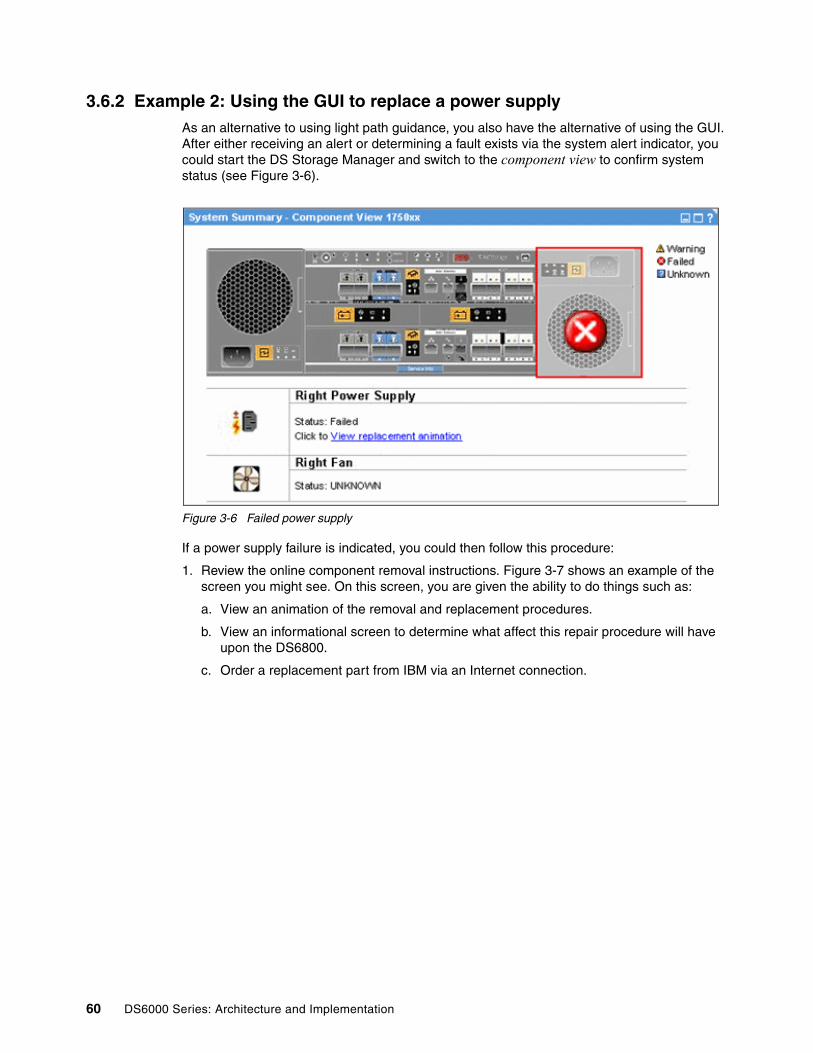
3.6.2 Example 2: Using the GUI to replace a power supplyAs an alternative to using light path guidance, you also have the alternative of using the GUI. After either receiving an alert or determining a fault exists via the system alert indicator, you could start the DS Storage Manager and switch to the component view to confirm system status (see Figure 3-6).
Figure 3-6 Failed power supply
If a power supply failure is indicated, you could then follow this procedure:
1. Review the online component removal instructions. Figure 3-7 shows an example of the screen you might see. On this screen, you are given the ability to do things such as:
a. View an animation of the removal and replacement procedures.
b. View an informational screen to determine what affect this repair procedure will have upon the DS6800.
c. Order a replacement part from IBM via an Internet connection.
60 DS6000 Series: Architecture and Implementation

Figure 3-7 Power supply replacement via the GU
2. Upon arrival of the replacement supply, you physically remove the faulty power supply and then install the replacement power supply.
3. Finally, you check the component view to review system health after the repair. An example of this is shown in Figure 3-8. In this example we can see that all the components displayed are normal.
Figure 3-8 Power supply replaced
All parts are very easy to remove and replace. There is comprehensive online documentation and help.
a
b
c
Chapter 3. RAS: reliability, availability, serviceability 61

3.6.3 System indicatorsThe DS6800 uses several simple indicators to allow a user to quickly determine the health of the DS6800. These indicators were previewed in Chapter 2, “Hardware components” on page 17.
System Identify Indicator (blue light)In addition to the light path diagnostics discussed here, the DS6800 implements a method for the person servicing the system to identify all of the enclosures associated with a given system. This is a blue LED visible on the front and rear of an enclosure. The blue light can be turned on or off by using the system identify button on the storage or any expansion enclosure.
This indicator will begin blinking when the Light Path Identify push button is pressed. At this time a request is generated to all other enclosures in the subsystem to turn their System Identify indicators on. When all enclosures have their indicators solid on, the indicator in this enclosure changes from blinking to solid on.
When the Light Path Identify button of the enclosure with its System Identify Indicator active (solid) is pressed, this indicator is changed to blinking. In turn, a request is generated to all enclosures in the subsystem to turn off their System Identify Indicators. When all other Identify indicators are turned off, the Identify indicator in this enclosure will change from blinking to solid off.
System Alert Indicator (amber light)This indicator is similar in function to the xSeries Fault Light. It is present on both the storage and expansion enclosures and is used in problem determination. This indicator will be turned on solid when a fault is detected in the system. The indicator will remain on solid until the fault condition is corrected or the Light Path Remind button is pressed and activated. If the Light Path Remind button is pressed, the Alert indicator will go from solid to a 2 second blip (a short blip on for 250 msec every 2 seconds). The System Alert Indicator and the System Information Indicator can be on at the same time, if you have two independent error conditions, one minor, one major. When the last fault is corrected, the indicator will be turned off.
System Information Indicator (amber light)This indicator is similar in function to the xSeries Information indicator. It is present on both the server and expansion enclosures and is used in problem determination. This indicator will be on solid when a minor error condition exists in the system. For example, a log entry has been written that you should look at. The indicator light will remain on solid until the fault condition is corrected (for example, by viewing the log). The System Alert Indicator and the System Information Indicator can be on at the same time if you have two independent error conditions, one minor, one major.
CRU Endpoint Indicator (amber light)A customer replaceable unit (CRU) is a part of the machine that you can replace safely and easily yourself. This indicator is present on both the controller and expansion enclosures and is used in problem determination. Each CRU has an amber indicator that, when lit, indicates to you that a fault exists and that the CRU should be replaced. If a fault indicator is on, it is not necessary to prepare that part for replacement. This means it is not necessary to quiesce a resource prior to replacement, as is the case on an ESS 2105. Any time a CRU fault light is turned on, the System Alert Indicator will also be turned on. If there are multiple CRU failures then the CRUs can be replaced in any order. The DS6800 can light more than one CRU indicator.
62 DS6000 Series: Architecture and Implementation

For example, if a power supply and a disk drive both fail, both CRU lights will be turned on and either CRU can be replaced in any order. The CRU Endpoint Indicator will be blocked from being illuminated in any case where additional guidance on the CRU replacement procedure is required. This includes a situation in which it is unclear which CRU has failed. This will prevent an incorrect maintenance procedure from taking place. After the defective CRU has been replaced, the CRU fault indicator will turn off. Pressing the Remind button will have no effect on the state of the CRU Endpoint Indicator.
3.6.4 Parts installation and repairsThe DS6800 has been designed for ease of maintenance. This allows you to perform the vast majority of service tasks.
Parts replacementWith the DS6800, an IBM Systems Service Representative (SSR) is not needed to perform the majority of service tasks required during normal operations. Using light path diagnostics it is possible for you to perform problem determination, parts ordering, and parts replacement.
CRU parts versus FRU partsWithin all IBM machines, spare parts are divided into two categories: CRU parts (customer replaceable units) and FRU parts (field replaceable units). If a part is designated a CRU, this implies that it can be safely and easily replaced by an end user with few or no tools. If a part is designated a FRU, then this implies that the spare part needs to be replaced by an IBM Service Representative. Within CRU parts, there are currently two tiers: Tier 1 CRUs are relatively easy to replace, while Tier 2 CRUs are generally more expensive parts or parts that require more skill to replace.
Tier 1 CRU partsThe tier 1 CRU parts include:
� Battery backup units� Cables: Ethernet, serial, fibre optic, and power� Disk drive modules� Operator panels - front and rear display� Power supplies� RAID controller and SBOD controller cards� SFPs (2Gbps small form factor plugable fibre optic units)
Currently the only Tier 2 CRU is the entire chassis for either the storage or expansion enclosures. There are currently no FRU parts for the DS6800.
While the DS6800 is under warranty, IBM will ship a replacement CRU to the machine location free of charge, provided the machine is located in a metro area that is serviced by IBM. You should check with your IBM sales representative or IBM Business Partner for details. Installation of Tier 1 CRUs is the customer’s responsibility.
If an IBM SSR installs a Tier 1 CRU at the customer’s request, there will be a charge for the installation. However, for machines with an on-site same-day response service agreement, IBM will replace a Tier 1 CRU at the customer’s request, at no additional charge. The customer might choose to install a Tier 2 CRU themselves, or request IBM to install it, at no additional charge. When the customer calls in for service and the problem can be fixed by a Tier 2 part, the customer is given the choice to decide at that point if they have the skills on hand to replace the part.
Chapter 3. RAS: reliability, availability, serviceability 63

3.7 Concurrent microcode updatesThe DS6800 contains several discrete redundant components. Most of these components have firmware that can be updated. This includes the controllers, device adapters, host adapters, and network adapters. Each DS6800 controller also has microcode that can be updated. All of these code releases come as a single package installed all at once. As IBM continues to develop and improve the DS6800, new releases of firmware and microcode will become available which offer improvements in both function and reliability.
The architecture of the DS6800 allows for concurrent code updates. This is achieved by using the redundant design of the DS6800. In general, redundancy is lost for a short period as each component in a redundant pair is updated. This also depends on the attached hosts having a separate path to each controller.
Each DS6800 controller card maintains a copy of the previous code version and the active code version. When a code update is performed, the new code version is written to the controller and then activated.
There is also the alternative to load code non-concurrently. This means that both controllers are unavailable for a short period of time (around 30 minutes to 1 hour for code activation). This method can be performed in a smaller window of time.
For more information on microcode updates and a detailed description of the process, refer to Chapter 20, “Microcode update” on page 397
3.8 Storage Management Console (SMC)The DS6800 management network is included in the environment network or in a private network. Here we describe the SMC as well as the remote support and Call Home features.
3.8.1 SMCThe SMC is used to perform configuration, management and maintenance activities on the DS6800. You can order it, or you can provide it yourself.
If the SMC is not operational, then it is not possible to perform guided maintenance or perform Copy Services tasks such as the establishment of FlashCopies. If TPC for Replication (TotalStorage Productivity Center for Replication) is used, copy services tasks can be managed by that tool in case of SMC unavailability. With the DS6800, it is possible and recommended to use two management consoles to act as a redundant pair. With Copy Services it is also recommended to use the same SMC for each DS6800, primary and secondary.
3.8.2 Remote support and Call Home
Call Home capability is given over two technical different ways. Call Home over SMTP (available since the initial release of the DS6000) and Call Home over modem (implemented and delivered in Release 1.9). The Call Home notification is disabled by default. The Call Home over modem is initiated from the SMC and can be configured for redundancy in a redundant SMC setup. Call Home over SMTP is initiated from the storage server itself (the master controller).
64 DS6000 Series: Architecture and Implementation

Problem notification can be enabled/disabled in any combination:
� Call Home over SMTP� Call Home over modem� Customer E-Mail notification� SNMP
Call Home Reliability:
� DS6800 can be configured with up to three Call Home paths:
– Primary SMC Modem– Secondary SMC Modem– Configured SMTP for Call Home
� Call Home will be tried on each configured path until successful:
– Modem is successful if it completes a connection to Retain.– SMTP is successful if an e-mail is sent.– IBM will receive one Call Home record.
The remote support as well as the Call Home options are described in more detail in Chapter 22, “Secure remote support” on page 423.
Chapter 3. RAS: reliability, availability, serviceability 65

66 DS6000 Series: Architecture and Implementation

Chapter 4. Virtualization concepts
This chapter describes the virtualization concepts for the DS6000 and the abstraction layers for disk virtualization.
We cover the following topics:
� Array sites� Arrays� Ranks� Extent pools� Logical volumes� Logical storage subsystems� Address groups� Volume groups� Host attachments
4
© Copyright IBM Corp. 2005, 2006. All rights reserved. 67

4.1 Virtualization definitionIn a fast changing world, to react quickly to changing business conditions, IT infrastructure must allow for on-demand changes. Virtualization is key to an on-demand infrastructure.
Our definition of virtualization is the abstraction process from the physical disk drives to a logical volume that the hosts and servers see as if it were a physical disk.
4.2 The abstraction layers for disk virtualizationIn this chapter, when we talk about virtualization, we are talking about the process of preparing a bunch of physical disk drives (DDMs) to be something that can be used from an operating system, which means we are talking about the creation of LUNs.
The DS6000 is populated with disk drives ordered in sets of 4 drives of the same capacity and RPM. The disk drives are accessed through a pair of device adapters, with four paths to the drives each. The four paths provide two FC-AL device interfaces. One device interface from each device adapter is connected to a set of FC-AL devices such that either device adapter has access to any disk drive through two independent switched fabrics (in other words, the device adapters and switches are redundant). In normal operation, however, disk drives are typically accessed by one device adapter and one server. Each path on each device adapter can be active concurrently, but the set of eight paths on the two device adapters can all be concurrently accessing independent disk drives. This avoids any contention between the two device adapters for access to the same disk, such that all eight ports on the two device adapters can be concurrently communicating with independent disk drives.
Figure 4-1 shows the physical layer on which DS8000 virtualization is based.
Figure 4-1 Physical layer as the base for virtualization
Device Adapter
Ser
ver0
Ser
ver1
Sto
rage
enc
losu
re p
air
Switched loop 1
Switches
Device Adapter
Switched loop 2
Inter-server communication
68 DS6000 Series: Architecture and Implementation

When you compare this with the ESS design, where there is a real loop, then having an 8-pack close to a device adapter as an advantage is no longer relevant for the DS6000. Because of the switched design, each drive is in close reach of the device adapter, apart from a few more hops through the Fibre Channel switches for some drives. So, it is not really a loop, but a switched FC-AL loop with the FC-AL addressing schema: Arbitrated Loop Physical Addressing (AL-PA).
4.2.1 Array sitesAn array site is a group of four DDMs. What DDMs make up an array site is pre-determined by the DS6000. However, there is no pre-determined server affinity for array sites. The DDMs selected for an array site are chosen from the same disk enclosure string (see Figure 4-2). All DDMs in an array site must be of the same type (capacity and RPM).
Figure 4-2 Array sites
Array sites are the building blocks used to define arrays.
4.2.2 ArraysArrays are created from one or two array sites. Forming an array means defining it for a specific RAID type.The supported RAID types are RAID-5 and RAID-10 (see 3.4.2, “RAID-5 overview” on page 54 and 3.4.3, “RAID-10 overview” on page 55). For each array site or for a group of two array sites, you can select a RAID type. The process of selecting the RAID type for an array is also called defining an array.
According to the DS6000 sparing algorithm, up to two spares can be taken from the array sites used to construct the array on each device interface (loop). See “DS6800 capacity upgrade” on page 21 for more details.
Figure 4-3 on page 70 shows the creation of a RAID-5 array with one spare, also called a 6+P+S array (capacity of 6 DDMs for data, capacity of one DDM for parity, and a spare drive) from two array sites. According to the RAID-5 rules, parity is distributed across all seven drives in this example.
Array Site 1Array Site 2
SwitchesLoop 1 Loop 2
Chapter 4. Virtualization concepts 69

Also referring to Figure 4-3, on the right side the terms D1, D2, D3, and so on stand for the set of data contained on one disk within a stripe on the array. If, for example, 1 GB of data is written, it is distributed across all the disks of the array.
Figure 4-3 Creation of an array
So, an array is formed using one or two array sites, and while the array could be accessed by each adapter of the device adapter pair, it is managed by one device adapter. Which adapter and which server manages this array is defined later in the configuration path.
4.2.3 RanksAnother logical construct in the DS6000 virtualization hierarchy is the rank.
The name of a rank is chosen by the DS Storage Manager at the time it is created, for example: R1, R2, or R3, and so on. You have to add an array to a rank.
The available space on each rank is divided into extents. The extents are the building blocks of the logical volumes. An extent is striped across all disks of an array as shown in Figure 4-4 on page 71 and indicated by the small squares in Figure 4-5 on page 72.
The process of forming a rank does two things:
� The array is defined for either fixed block (open systems) or CKD (System z) data. This determines the size of the set of data contained on one disk within a stripe on the array.
� The capacity of the array is subdivided into equal sized partitions, called extents. The extent size depends on the extent type, FB or CKD.
Array Site 1
RAIDArray
Spare
DataDataDataDataDataDataParity
Creation ofan array
D1 D7 D13 ...
D2 D8 D14 ...
D3 D9 D15 ...
D4 D10 D16 ...
D5 D11 P ...
D6 P D17 ...
P D12 D18 ...
Array Site 2
Spare
Note: In the current DS6000 implementation, a rank is built using just one array.
70 DS6000 Series: Architecture and Implementation
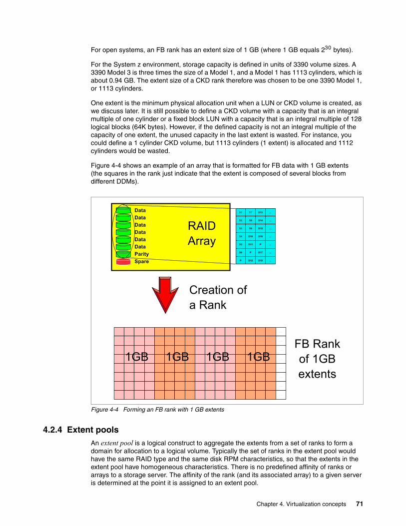
For open systems, an FB rank has an extent size of 1 GB (where 1 GB equals 230 bytes).
For the System z environment, storage capacity is defined in units of 3390 volume sizes. A 3390 Model 3 is three times the size of a Model 1, and a Model 1 has 1113 cylinders, which is about 0.94 GB. The extent size of a CKD rank therefore was chosen to be one 3390 Model 1, or 1113 cylinders.
One extent is the minimum physical allocation unit when a LUN or CKD volume is created, as we discuss later. It is still possible to define a CKD volume with a capacity that is an integral multiple of one cylinder or a fixed block LUN with a capacity that is an integral multiple of 128 logical blocks (64K bytes). However, if the defined capacity is not an integral multiple of the capacity of one extent, the unused capacity in the last extent is wasted. For instance, you could define a 1 cylinder CKD volume, but 1113 cylinders (1 extent) is allocated and 1112 cylinders would be wasted.
Figure 4-4 shows an example of an array that is formatted for FB data with 1 GB extents (the squares in the rank just indicate that the extent is composed of several blocks from different DDMs).
Figure 4-4 Forming an FB rank with 1 GB extents
4.2.4 Extent poolsAn extent pool is a logical construct to aggregate the extents from a set of ranks to form a domain for allocation to a logical volume. Typically the set of ranks in the extent pool would have the same RAID type and the same disk RPM characteristics, so that the extents in the extent pool have homogeneous characteristics. There is no predefined affinity of ranks or arrays to a storage server. The affinity of the rank (and its associated array) to a given server is determined at the point it is assigned to an extent pool.
FB Rankof 1GBextents
Creation ofa Rank
D1 D7 D13 ...
D2 D8 D14 ...
D3 D9 D15 ...
D4 D10 D16 ...
D5 D11 P ...
D6 P D17 ...
P D12 D18 ...
RAIDArray
Spare
DataDataDataDataDataDataParity
. . . .
. . . .
. . . .
. . . .
. . . .
. . . .
. . . .
. . . .
1GB 1GB 1GB 1GB
Chapter 4. Virtualization concepts 71

One or more ranks with the same extent type can be assigned to an extent pool. One rank can be assigned to only one extent pool. There can be as many extent pools as there are ranks.
The DS Storage Manager GUI guides you to use the same RAID types in an extent pool. As such, when an extent pool is defined, it must be assigned with the following attributes:
� Server affinity� Extent type� RAID type
The minimum number of extent pools is one; however, you would normally want at least two, one assigned to server 0 and the other one assigned to server 1, so that both servers are active. In an environment where FB and CKD are to go onto the DS6000 storage server, you might want to define four extent pools, one FB pool for each server, and one CKD pool for each server, to balance the capacity between the two servers. Of course, you could also define just one FB extent pool and assign it to one server, and define a CKD extent pool and assign it to the other server. Additional extent pools might be desirable to segregate ranks with different DDM types.
Ranks are organized in two rank groups:� Rank group 0 is controlled by server 0.� Rank group 1 is controlled by server 1.
Figure 4-5 is an example of a mixed environment with CKD and FB extent pools.
Figure 4-5 Extent pools
You can expand extent pools by adding more ranks to an extent pool.
Important: You should balance your capacity between the two servers for optimal performance.
1GBFB
1GBFB
1GBFB
1GBFB
Serv
er0
1113Cyl.CKD
1113Cyl.CKD
1113Cyl.CKD
1113Cyl.CKD
Serv
er1
1113Cyl.CKD
1113Cyl.CKD
1113Cyl.CKD
1113Cyl.CKD
1GBFB
1GBFB
1GBFB
1GBFB
1113Cyl.CKD
1113Cyl.CKD
1113Cyl.CKD
1113Cyl.CKD
1GBFB
1GBFB
1GBFB
1GBFB
1GBFB
1GBFB
1GBFB
1GBFB
1GBFB
1GBFB
1GBFB
1GBFB
Extent Pool CKD0 Extent Pool CKD1
Extent Pool FBtest
Extent Pool FBprod
72 DS6000 Series: Architecture and Implementation

4.2.5 Logical volumesA logical volume is composed of a set of extents from one extent pool.
On a DS6000 up to 8192 (8K) volumes can be created (8K CKD, or 8K FB volumes, or a mix of both types (4K CKD plus 4K FB).
Fixed block LUNsA logical volume composed of fixed block extents is called a LUN. A fixed block LUN is composed of one or more 1 GB (230) extents from one FB extent pool. A LUN cannot span multiple extent pools, but a LUN can have extents from different ranks within the same extent pool. You can construct LUNs up to a size of 2 TB (240) in any integral multiple of 64K bytes. The capacity allocated to a LUN is always a multiple of the 1 GB extent, so any LUN size that is not a multiple of 1 GB wastes some space in the last extent allocated to the LUN. LUNs can be allocated in binary GB (230 bytes), decimal GB (109 bytes), or 512 or 520 byte blocks. However, when you define a LUN that is not a multiple of 1 GB, the capacity up to the next multiple of 1 GB is unusable.
CKD volumesA System z CKD volume is composed of one or more extents from one CKD extent pool. CKD extents are in unit size of 3390 Model 1, which has 1113 cylinders. However, when you define a System z CKD volume, you do not specify the number of 3390 Model 1 extents but the number of cylinders you want for the volume.
You can define CKD volumes with up to 65520 cylinders, which is about 55.6 GB.
If the number of cylinders specified is not an integral multiple of 1113 cylinders, then some space in the last allocated extent is wasted. For example, if you define 1114 or 3340 cylinders, 1112 cylinders are wasted. For maximum storage efficiency, your should consider allocating volumes that are exact multiples of 1113 cylinders. In fact, integral multiples of 3339 cylinders should be consider for future compatibility.
If you want to use the maximum number of cylinders (65520), you should consider that this is not a multiple of 1113. You could go with 65520 cylinders and waste 147 cylinders for each volume (the difference to the next multiple of 1113) or you might be better off with a volume size of 64554 cylinders, which is a multiple of 1113 (factor of 58).
A CKD volume cannot span multiple extent pools, but a volume can have extents from different ranks in the same extent pool.
Chapter 4. Virtualization concepts 73

Figure 4-6 shows how a logical volume is allocated, with a CKD volume as an example.
Figure 4-6 Allocation of a CKD logical volume
1113 1113 1113 1113free
Extent Pool CKD0
Rank-x
Rank-y
3390 Mod. 3
1113free
1113free
used used Allocate 3226 cylinder volume
1113 1113 1113 1113used
Extent Pool CKD0
Rank-x
Rank-y
3390 Mod. 3
1000used
1113used
used used
Logical 3390 Mod. 3
113 cylinders unused
Volume with3226 cylinders
74 DS6000 Series: Architecture and Implementation

The allocation process for FB volumes is very similar and is shown in Figure 4-7.
Figure 4-7 Creation of an FB LUN
System i LUNsSystem i LUNs are also composed of fixed block 1 GB extents. There are, however, some special aspects with System i LUNs. LUNs created on a DS6000 are always RAID protected. LUNs are based on RAID-5 or RAID-10 arrays. However, you have the possibility to declare a LUN as not RAID protected to the host (OS/400). System i LUNs can have the attribute unprotected. This causes OS/400 to do its own mirroring.
OS/400 only supports certain fixed volume sizes, for example, model sizes of 8.5 GB, 17.5 GB, and 35.1 GB. These sizes are not multiples of 1 GB and hence, depending on the model chosen, some space is wasted. System i LUNs expose a 520 byte block to the host. The operating system uses 8 of these bytes, so the usable space is still 512 bytes like other SCSI LUNs. The capacities quoted for the System i LUNs are in terms of the 512 byte block capacity and are expressed in GB (109). These capacities should be converted to GB (230) when considering effective utilization of extents which are 1 GB (230). For more information on this topic, see Appendix 18, “System i considerations” on page 339.
Allocation and deletion of LUNs/CKD volumesAll extents of the ranks assigned to an extent pool are independently available for allocation to logical volumes. The extents for a LUN/volume are logically ordered, but they do not have to come from one rank and the extents do not have to be contiguous on a rank. The current extent allocation algorithm of the DS6000 will not distribute the extents across ranks. The algorithm will use available extents within one rank, unless there are not enough free extents available in that rank, but free extents in another rank of the same extent pool.
1 GB 1 GB 1 GB 1 GBfree
Extent Pool FBprod
Rank-a
Rank-b
3 GB LUN
1 GBfree
1 GBfree
used used Allocate a 3 GB LUN
1 GB 1 GB 1 GB 1 GBused
Extent Pool FBprod
Rank-a
Rank-b
3 GB LUN
1 GBused
1 GBused
used used
Logical 3 GB LUN
2.9 GB LUNcreated
100 MB unused
Chapter 4. Virtualization concepts 75

While this algorithm exists, you might want to consider putting one rank per extent pool to control the allocation of logical volumes across ranks to improve performance.
This construction method of using fixed extents to form a logical volume in the DS6000 allows flexibility in the management of the logical volumes. We can now delete LUNs and reuse the extents of that LUN to create another LUN, possibly of a different size. One logical volume can be removed without affecting the other logical volumes defined on the same extent pool. Compared to the ESS, where it was not possible to delete a LUN unless the whole array was reformatted, this DS6000 implementation gives you much more flexibility and allows for on demand changes according to your needs.
Since the extents are cleaned after you have deleted a LUN or CKD volume, it might take some time until these extents are available for reallocation. The reformatting of the extents is a background process.
IBM plans to further increase the flexibility of LUN/volume management. We cite from the DS6000 announcement letter the following Statement of General Direction:
Extension of IBM's dynamic provisioning technology within the DS6000 series is planned to provide LUN/volume: dynamic expansion, online data relocation, virtual capacity over provisioning, and space efficient FlashCopy requiring minimal reserved target capacity.
4.2.6 Logical subsystems (LSS)A logical subsystem (LSS) is another logical construct. It groups logical volumes, LUNs, in groups of up to 256 logical volumes.
On an ESS there was a fixed association between logical subsystems (and their associated logical volumes) and device adapters (and associated ranks). The association of an 8-pack to a device adapter determined what LSS numbers could be chosen for a volume. On an ESS, up to 16 LSSs could be defined depending on the physical configuration of device adapters and arrays.
On the DS6000, there is no fixed binding between any rank and any logical subsystem. The capacity of one or more ranks can be aggregated into an extent pool and logical volumes configured in that extent pool are not bound to any specific rank. Different logical volumes on the same logical subsystem can be configured in different extent pools. As such, the available capacity of the storage facility can be flexibly allocated across the set of defined logical subsystems and logical volumes.
This predetermined association between array and LSS is gone on the DS6000. Also, the number of LSSs has changed. You can now define up to 32 LSSs for the DS6000. You can even have more LSSs than arrays.
For each LUN or CKD volume, you can now choose an LSS. You can put up to 256 volumes into one LSS. There is, however, one restriction. We already have seen that volumes are formed from a bunch of extents from an extent pool. Extent pools, however, belong to one server, server 0 or server 1, respectively. LSSs also have an affinity to the servers. All even numbered LSSs (X’00’, X’02’, X’04’, up to X’1E’) belong to server 0 and all odd numbered LSSs (X’01’, X’03’, X’05’, up to X’1F’) belong to server 1.
System z users are familiar with a logical control unit (LCU). System z operating systems configure LCUs to create device addresses. There is a one to one relationship between an LCU and a CKD LSS (LSS X'ab' maps to LCU X'ab'). Logical volumes have a logical volume number X'abcd' where X'ab' identifies the LSS and X'cd' is one of the 256 logical volumes on the LSS. This logical volume number is assigned to a logical volume when a logical volume is
76 DS6000 Series: Architecture and Implementation

created and determines the LSS that it is associated with. The 256 possible logical volumes associated with an LSS are mapped to the 256 possible device addresses on an LCU (logical volume X'abcd' maps to device address X'cd' on LCU X'ab'). When creating CKD logical volumes and assigning their logical volume numbers, users should consider whether parallel access volumes are required on the LCU and reserve some of the addresses on the LCU for alias addresses.
For open systems, LSSs do not play an important role except in determining which server the LUN is managed by (and which extent pools it must be allocated in) and in certain aspects related to Metro Mirror, Global Mirror, or any of the other remote copy implementations.
Some management actions in Metro Mirror, Global Mirror, or Global Copy operate at the LSS level. For example, the freezing of pairs to preserve data consistency across all pairs, in case you have a problem with one of the pairs, is done at the LSS level. With the option now to put all or most of the volumes of a certain application in just one LSS, this makes the management of remote copy operations easier (see Figure 4-8).
Of course, you could have put all volumes for one application in one LSS on an ESS, too, but then all volumes of that application would also be in one or a few arrays. From a performance standpoint, this was not desirable. Now, on the DS6000, you can group your volumes in one or a few LSSs, but still have the volumes in many arrays or ranks.
Figure 4-8 Grouping of volumes in LSSs
Fixed block LSSs are created automatically when the first fixed block logical volume on the LSS is created and deleted automatically when the last fixed block logical volume on the LSS is deleted. CKD LSSs require user parameters to be specified, must be created before the first CKD logical volume can be created on the LSS, and must be deleted manually after the last CKD logical volume on the LSS is deleted.
LSS X'17'DB2
LSS X'18'DB2-test
Physical Drives Logical Volumes
Chapter 4. Virtualization concepts 77

4.2.7 Address groupsAddress groups are created automatically when the first LSS associated with the address group is created and deleted automatically when the last LSS in the address group is deleted.
LSSs are either CKD LSSs or FB LSSs. All devices in an LSS must be either CKD or FB. This restriction goes even further. LSSs are grouped into address groups of 16 LSSs. LSSs are numbered X'ab', where a is the address group and b denotes an LSS within the address group. So, for example, X'10' to X'1F' are LSSs in address group 1.
All LSSs within one address group have to be of the same type, CKD or FB. The first LSS defined in an address group fixes the type of that address group.
Figure 4-9 illustrates the concept of LSSs and address groups.
Figure 4-9 Logical subsystems
The LUN identifications X'gabb' are composed of the address group X'g', and the LSS number within the address group X'a', and the position of the LUN within the LSS X'bb'. For example LUN X'1101' denotes the second (X'01') LUN in LSS X'11' of address group 1.
Address group X'1x': FB
Address group X'0x' CKD
Extent Pool FB-2
LSS X'00'LSS X'02'LSS X'04'LSS X'06'LSS X'08'LSS X'0A'LSS X'0C'
LSS X'0E'
LSS X'10'LSS X'12'LSS X'14'LSS X'16'
LSS X'18'
LSS X'1A'LSS X'1C'LSS X'1E'
LSS X'01'LSS X'03'LSS X'05'
LSS X'07'LSS X'09'LSS X'0B'
LSS X'0D'
LSS X'11'
LSS X'0F'
LSS X'13'LSS X'15'LSS X'17'LSS X'19'LSS X'1B'
Serv
er0
Extent Pool CKD-1
Rank-a
Rank-b
Extent Pool FB-1
Rank-c
Rank-d
LSS X'1D'Se
rver
1
Extent Pool CKD-2
Rank-w
Rank-x
Extent Pool FB-2
Rank-y
Rank-z
X'0E00'
X'0E01'
X'1800'
X'0500'
X'0D00'
X'1100'
Volume ID
X'1101'
LSS X'1F'
78 DS6000 Series: Architecture and Implementation

4.2.8 Volume accessA DS6000 provides mechanisms to control host access to LUNs. In most cases a server has two or more HBAs and the server needs access to a group of LUNs. For easy management of server access to logical volumes, the DS6000 introduced the concept of host attachments and volume groups.
Host attachmentHBAs are identified to the DS6000 in a host attachment construct that specifies the HBA's World Wide Port Names (WWPNs). A set of host ports can be associated through a port group attribute that allows a set of HBAs to be managed collectively. This port group is referred to as host attachment within the GUI. A given host attachment can be associated with only one volume group. Each host attachment can be associated with a volume group to define which LUNs that HBA is allowed to access. Multiple host attachments can share the same volume group. The host attachment can also specify a port mask that controls which DS6000 I/O ports that the HBA is allowed to log in to. Whichever ports the HBA logs in on, it sees the same volume group that is defined in the host attachment associated with this HBA. The maximum number of host attachments on a DS6000 is 1024.
Volume groupA volume group is a named construct that defines a set of logical volumes. When used in conjunction with CKD hosts, there is a default volume group that contains all CKD volumes and any CKD host that logs into a FICON I/O port has access to the volumes in this volume group. CKD logical volumes are automatically added to this volume group when they are created and automatically removed from this volume group when they are deleted.
When used in conjunction with Open Systems hosts, a host attachment object that identifies the HBA is linked to a specific volume group. The user must define the volume group by indicating which fixed block logical volumes are to be placed in the volume group. Logical volumes might be added to or removed from any volume group dynamically.
There are two types of volume groups used with Open Systems hosts and the type determines how the logical volume number is converted to a host addressable LUN_ID on the Fibre Channel SCSI interface. A map volume group type is used in conjunction with FC SCSI host types that poll for LUNs by walking the address range on the SCSI interface. This type of volume group can map any FB logical volume numbers to 256 LUN_IDs that have zeroes in the last six bytes and the first two bytes in the range of X'0000' to X'00FF'.
A mask volume group type is used in conjunction with FC SCSI host types that use the Report LUNs command to determine the LUN_IDs that are accessible. This type of volume group can allow any and all FB logical volume numbers to be accessed by the host where the mask is a bit map that specifies which LUNs are accessible. For this volume group type, the logical volume number X'abcd' is mapped to LUN_ID X'40ab40cd00000'. The volume group type also controls whether 512 byte block LUNs or 520 byte block LUNs can be configured in the volume group.
When associating a host attachment with a volume group, the host attachment contains attributes that define the logical block size and the Address Discovery Method (LUN Polling or Report LUNs) that is used by the host HBA. These attributes must be consistent with the volume group type of the volume group that is assigned to the Host Attachment so that HBAs that share a volume group have a consistent interpretation of the volume group definition and have access to a consistent set of logical volume types. The GUI typically sets these values appropriately for the HBA based on the user specification of a host type. The user must consider what volume group type to create when setting up a volume group for a particular HBA.
Chapter 4. Virtualization concepts 79

FB logical volumes can be defined in one or more volume groups. This allows a LUN to be shared by host HBAs configured to different volume groups. An FB logical volume is automatically removed from all volume groups when it is deleted. The maximum number of volume groups on a DS6000 is 1040.
Figure 4-10 shows the relationships between host attachments and volume groups.
Figure 4-10 Host attachments and volume groups
In Figure 4-10, host AIXprod1 has two HBAs, which are grouped together in one host attachment, and both are granted access to volume group DB2-1. Most of the volumes in volume group DB2-1 are also in volume group DB2-2, accessed by server AIXprod2. In our example there is, however, one volume in each group that is not shared. The server in the lower left has four HBAs and they are divided into two distinct host attachments. One can access some volumes shared with AIXprod1 and AIXprod2, the other HBAs have access to a volume group called docs.
4.2.9 Summary of the virtualization hierarchyGoing through the virtualization hierarchy, we started with “just a bunch of disks” that were grouped in array sites. An array site was transformed into an array, eventually with spare disks. The array was further transformed into a rank with extents formatted for FB or CKD data. Next, the extents were added to an extent pool which determined which storage server would serve the ranks and aggregated the extents of all ranks in the extent pool for subsequent allocation to one or more logical volumes.
Next we created logical volumes within the extent pools, assigning them a logical volume number that determined which logical subsystem they would be associated with and which server would manage them. Then the LUNs could be assigned to one or more volume groups. Finally, the host HBAs were configured into a host attachment that is associated with a given volume group.
WWPN-1 WWPN-2
Host attachment: AIXprod1
Volume group: DB2-1
WWPN-3 WWPN-4
Host attachment: AIXprod2
Volume group: docs
WWPN-5 WWPN-6
WWPN-7
WWPN-8
Host att: Test
Host att: Prog
Volume group: DB2-2
Volume group: DB2-test
80 DS6000 Series: Architecture and Implementation

This new virtualization concept provides for much more flexibility. Logical volumes can dynamically be created and deleted. They can be grouped logically to simplify storage management. Large LUNs and CKD volumes reduce the total number of volumes and this also contributes to a reduction of the management efforts.
Figure 4-11 summarizes the virtualization hierarchy.
Figure 4-11 Virtualization hierarchy
Serv
er0
Array Sites
RAIDArray
Spare
DataDataDataDataDataDataParity
RankType FB
1 G
B F
B
1 G
B F
B
1 G
B F
B
1 G
B F
B
1 G
B F
B
1 G
B F
B
1 G
B F
B
1 G
B F
B
1 G
B F
B
ExtentPool
LogicalVolume
LSSFB
AddressGroup
X'0x' FB4096
addresses
LSS X'07'
X'1x' CKD4096
addresses
VolumeGroup
Host Attachment
Chapter 4. Virtualization concepts 81

4.2.10 Data placement There are several options on how to place data, including placement on extent pools owned by one server or both. You can have one extent pool per server or several and the ranks of extent pools can come from arrays on different loops or from the same loop. Figure 4-12 shows an optimal distribution of four logical volumes within a DS6000.
Figure 4-12 Optimal distribution of data
Of course, there can be more extent pools and ranks. However, to distribute data for optimal performance, it should be spread across the two servers, across the two loops, and across several ranks.
With a logical volume manager (like LVM on AIX) on the host, a host logical volume can be created from several DS6000 logical volumes (LUNs) across multiple DS6000 servers and loops as shown in Figure 4-12. Striping the host logical volume across the LUNs, will provide the best performance for this LVM volume.
4.3 Benefits of virtualizationThe DS6000 physical and logical architecture defines new standards for enterprise storage virtualization. These are the main benefits of the virtualization layers:
� Flexible LSS definition allows maximization/optimization of the number of devices per LSS.
� No strict relationship between RAID ranks and LSSs.
� No connection of LSS performance to underlying storage.
� Number of LSSs can be defined based upon device number requirements:
– With larger devices, significantly fewer LSSs could be used.
– Volumes for a particular application can be kept in a single LSS.
– Smaller LSSs can be defined if required (for systems/applications requiring less storage).
– Test systems can have their own LSSs with fewer volumes than the production systems.
Serv
er0
Serv
er1
Extent Pool FB-1aExtent Pool FB-0a
DA
pair
DA
pai
r
Host LVM volume
Extent Pool FB-1bExtent Pool FB-0b
Loop
1Lo
op 2
Loop
2Lo
op 1
LSS 00 LSS 01
82 DS6000 Series: Architecture and Implementation

� Increased number of logical volumes:
– Up to 8192 (CKD)– Up to 8192 (FB)– Up to 4096 CKD and up to 4096 FB
� Increased logical volume size:
– CKD: 55.6 GB (65520 cylinders), architected for 219 TB– FB: 2 TB, architected for 1 PB
� Flexible logical volume configuration:
– Multiple RAID types (RAID-5, RAID-10)– Storage types (CKD and FB) aggregated into extent pools– Volumes allocated from extents of extent pool– Can dynamically add/remove volumes
� Virtualization reduces storage management requirements.
Chapter 4. Virtualization concepts 83

84 DS6000 Series: Architecture and Implementation

Chapter 5. Copy Services
In this chapter, we describe the architecture and functions of Copy Services for the DS6800. Copy Services are a collection of functions that provide disaster recovery, data migration, and data duplication functions.
Copy Services run on the DS6800 server enclosure and they support open systems and System z environments. These functions are now known as FlashCopy, Metro Mirror, Global Copy, Metro/GlobalCopy, and Global Mirror. The z/OS environment supports further variants, z/OS Global Mirror and z/OS Metro/Global Mirror.
We discuss the following topics:
� Introduction to Copy Services� Copy Services functions� Interfaces for Copy Services� Interoperability with Enterprise Storage Server
For an in-depth description of the copy services functions for the DS6000, refer to the following publications:
� IBM System Storage DS6000 Series: Copy Services in Open Environments, SG24-6783� IBM System Storage DS6000 Series: Copy Services with IBM System z servers,
SG24-6782
5
© Copyright IBM Corp. 2005, 2006. All rights reserved. 85

5.1 Introduction to Copy Services
Copy Services are a collection of functions that provide disaster recovery, data migration, and data duplication functions. With the Copy Services functions, for example, you can create backup data with little or no disruption to your application, and you can back up your application data to a remote site for disaster recovery. Once you create copies, you can maintain them incrementally to keep them current, and most likely utilize them as part of the an Information Lifecycle Management process.
Copy Services run on the DS6800 server enclosure and support open systems and System z environments. These functions are also supported on the previous generation of storage systems called the Enterprise Storage Server (ESS).
Many design characteristics of the DS6800 and data copying and mirroring capabilities of the Copy Services features contribute to the protection of your data, 24 hours a day and seven days a week. The following licensed features are included in Copy Services:
� FlashCopy, which is a Point-in-Time Copy function
� Remote Mirror and Copy functions (previously known as Peer-to-Peer Remote Copy or PPRC), which include:
– IBM System Storage Metro Mirror, previously known as Synchronous PPRC – IBM System Storage Global Copy, previously known as PPRC Extended Distance – IBM System Storage Global Mirror, previously known as Asynchronous PPRC
We explain these functions in detail in the next section.
You can manage the Copy Services functions through a command-line interface (DS CLI) and a new Web-based interface (DS Storage Manager). You also can manage the Copy Services functions through the open application programming interface (DS Open API). When you manage Copy Services through these interfaces, these interfaces invoke Copy Services functions via the Ethernet network. Another graphical interface for Copy Services is also offered by the TotalStorage Productivity Center for Replication Management (TPC for RM
In System z environments, you can invoke the Copy Service functions by TSO commands, ICKDSF, the DFSMSdss™ utility, and others.
We explain these interfaces in 5.3, “Interfaces for Copy Services” on page 105.
5.2 Copy Services functionsWe describe each function and the architecture of the Copy Services in this section.
5.2.1 FlashCopyFlashCopy creates a copy of a logical volume at a specific point-in-time, which we also refer to as a Point-in-Time Copy, instantaneous copy, or t0 copy (time-zero copy).
When you set up a FlashCopy operation, a relationship is established between a source and target volumes, and a bitmap of the source volume is created. Once this relationship and bitmap are created, the target volume can be accessed as though all the data had been physically copied. While a relationship between the source and target volume exists, optionally, a background process copies the tracks from the source to the target volume.
86 DS6000 Series: Architecture and Implementation

See Figure 5-1 for an illustration of FlashCopy concepts.
Figure 5-1 FlashCopy concepts
When a FlashCopy operation is invoked, the process of establishing the FlashCopy pair and creating the necessary control bitmaps takes only a few seconds to complete. Thereafter, you have access to a point-in-time copy of the source volume. As soon as the pair has been established, you can read and write to both the source and the target volumes.
After creating the bitmaps, a background process begins to copy the real-data from the source to the target volumes. If you access the source or the target volumes during the background copy, FlashCopy manages these I/O requests as follows:
� Read from the source volume:
When you read some data from the source volume, it is simply read from the source volume.
� Read from the target volume:
When you read some data from the target volume, FlashCopy checks the bitmaps and:
– If the backup data is already copied to the target volume, it is read from the target volume.
– If the backup data is not copied yet, it is read from the source volume.
� Write to the source volume:
When you write some data to the source volume, at first the updated data is written to the data cache and persistent memory (write cache). And when the updated data is destaged to the source volume, FlashCopy checks the bitmaps and:
– If the backup data is already copied, it is simply updated on the source volume.
Note: In this section, track means a piece of data in the DS6800; the DS6800 uses the logical tracks to manage the Copy Services functions.
FlashCopy provides a point-in-time copy
FlashCopy command issued
Tim
e
Copy immediately available
Read and write to both source and copy possible
Write Read
When copy is complete,relationship betweensource and target ends
Source Target
Read
Write
T0
Chapter 5. Copy Services 87

– If the backup data is not copied yet, first the backup data is copied to the target volume, and then it is updated on the source volume.
� Write to the target volume:
When you write some data to the target volume, it is written to the data cache and persistent memory, and FlashCopy manages the bitmaps to not overwrite the latest data. FlashCopy does not overwrite the latest data by the physical copy.
The background copy could have a slight impact on your application because the real-copy needs some storage resources, but the impact is minimal because the host I/O is prior to the background copy. And if you want, you can issue FlashCopy with the no background copy option.
No background copy optionIf you invoke FlashCopy with the no background copy option, the FlashCopy relationship is established without initiating a background copy. Therefore, you can minimize the impact of the background copy. When the ESS receives an update to a source track in a FlashCopy relationship, a copy of the point-in-time data is copied to the target volume so that it is available when the data from the target volume is accessed. This option is useful for customers who don’t need to issue FlashCopy in the opposite direction.
Benefits of FlashCopyThe point-in-time copy created by FlashCopy is typically used where you need a copy of the production data to be produced with little or no application downtime (depending on the application). It can be used for online backup, testing of new applications, or for creating a database for data-mining purposes. The copy looks exactly like the original source volume and is an instantly available, binary copy.
FlashCopy function authorizationFlashCopy is an optional feature of the DS6000 and you can order it together with the DS6000. To use it, you must purchase the Point-in-Time Copy License feature code #52xx PTC (xx depends on the storage capacity) for the required DS6800 storage server machine type 1750.
Once a DS6000 is running in production, it is possible to place an additional order to increase the capacity that can be FlashCopied. This results in a new feature activation code that you need to apply.
5.2.2 FlashCopy optionsFlashCopy has many options and expanded functions to help provide data duplication. We explain these options and functions in this section.
Incremental FlashCopy (refresh target volume)Incremental FlashCopy provides the capability to refresh a FlashCopy relationship. When a subsequent FlashCopy operation is initiated, only the tracks changed on both the source and target need to be copied from the source to the target. The direction of the refresh can also be reversed.
In many cases, at most 10 to 20 percent of your entire data is changed in a day. In such a situation, if you use this function for daily backup, you can save the time for the physical copy of FlashCopy.
88 DS6000 Series: Architecture and Implementation

Figure 5-2 explains the architecture for Incremental FlashCopy.
Figure 5-2 Incremental FlashCopy
In the Incremental FlashCopy operations:
1. At first, you issue full FlashCopy with the change recording option. This option is for creating change recording bitmaps in the server enclosure. The change recording bitmaps are used for recording the tracks which are changed on the source and target volumes after the last FlashCopy.
2. After creating the change recording bitmaps, Copy Services records the information for the updated tracks to the bitmaps. The FlashCopy relationship persists even if all of the tracks have been copied from the source to the target.
3. The next time you issue Incremental FlashCopy, Copy Services checks the change recording bitmaps and copies only the changed tracks to the target volumes. If some tracks on the target volumes are updated, these tracks are overwritten by the corresponding tracks from the source volume.
If you want, you can also issue Incremental FlashCopy from the target volume to the source volumes with the reverse restore option. The reverse restore operation cannot be done unless the background copy in the original direction has finished.
Source TargetWriteRead
Write
Read
Incremental FlashCopyInitial FlashCopy relationship established with change recording and persistent copy options
Control bitmap for each volume created
Tracks changed on the target are overwritten by the corresponding tracks from the source
Possible reverse operation, the target updates the source
Incremental FlashCopy started
Tracks changed on the source are copied to the target
Chapter 5. Copy Services 89

Data Set FlashCopyData Set FlashCopy allows a FlashCopy of a data set in a System z environment (Figure 5-3).
Figure 5-3 Data Set FlashCopy
Multiple Relationship FlashCopy
Multiple Relationship FlashCopy allows a source to have FlashCopy relationships with multiple targets simultaneously. A source volume or extent can be FlashCopied to up to 12 target volumes or target extents, as illustrated in Figure 5-4.
Figure 5-4 Multiple Relationship FlashCopy
Note: If a FlashCopy source volume has more than one target, that source volume can be involved only in a single incremental FlashCopy relationship.
Dataset
Dataset
Volume level FlashCopy Dataset level FlashCopy
SourceVolume
TargetVolume
1
1’
2’
12’
Maximum 12 Target volumes from 1 Source volume
90 DS6000 Series: Architecture and Implementation

Consistency Group FlashCopyConsistency Group FlashCopy allows you to freeze (temporarily queue) I/O activity to a LUN or volume. Consistency Group FlashCopy helps you to create a consistent point-in-time copy across multiple LUNs or volumes, and even across multiple Storage Units.
What is Consistency Group FlashCopy?If a consistent point-in-time copy across many logical volumes is required, and the user does not wish to quiesce host I/O or database operations, then the user can use Consistency Group FlashCopy to create a consistent copy across multiple logical volumes in multiple Storage Units.
In order to create this consistent copy, the user issues a set of Establish FlashCopy commands with a freeze option, which will hold off host I/O to the source volumes. In other words, Consistency Group FlashCopy provides the capability to temporarily queue (at the host I/O level, not the application level) subsequent write operations to the source volumes that are part of the Consistency Group. During the temporary queueing, Establish FlashCopy is completed. The temporary queueing continues until this condition is reset by the Consistency Group Created command or the time-out value expires (the default is two minutes).
Once all of the Establish FlashCopy requests have completed, a set of Consistency Group Created commands must be issued via the same set of DS network interface servers. The Consistency Group Created commands are directed to each logical subsystem (LSS) involved in the consistency group. The Consistency Group Created command allows the write operations to resume to the source volumes.
This operation is illustrated in Figure 5-5.
Figure 5-5 Consistency Group FlashCopy
Server1
Server2 write requests
LSS11
LSS12
Wait
Wait
FlashCopy
FlashCopy
LSS11
LSS12
Wait
Wait
FlashCopy
FlashCopy
LSS11
LSS12
Wait
Wait
FlashCopy
FlashCopy
Consistency Group
Waiting write operationuntil Consistency Group Created command is invoked.
DS6000 #1, #2, #3, …
Chapter 5. Copy Services 91

A more detailed discussion of the concept of data consistency and how to manage the Consistency Group operation is given in 5.2.5, “What is a Consistency Group?” on page 101.
FlashCopy target as a Metro Mirror or Global Copy primaryWith this option, the target volume can be or becomes a primary volume for a Metro Mirror or Global Copy relationship. You might wish to use this capability to create both a remote copy and a local copy of a production volume.
Figure 5-6 illustrates this capability. In this figure, the FlashCopy target and the Metro Mirror/ Global Copy primary are the same volume. They are displayed as two separate volumes. We explain the functions of Remote Mirror and Copy in 5.2.3, “Remote Mirror and Copy” on page 93.
Figure 5-6 Establish FlashCopy on existing Remote Mirror and Copy primary
Important: Consistency Group FlashCopy can create host-based consistent copies; they are not application-based consistent copies. The copies have power-fail or crash level consistency. This means that if you suddenly power off your server without stopping your applications and without destaging the data in the file cache, the data in the file cache could be lost and you might need recovery procedures to restart your applications. To start your system with Consistency Group FlashCopy target volumes, you might need the same operations as the crash recovery.
For example, If the Consistency Group source volumes are used with a journaled file system (like AIX JFS) and the source LUNs are not unmounted before running FlashCopy, it is likely that fsck will have to be run on the target volumes.
Note: Consistency Group FlashCopy is only available through the use of CLI commands and not the DS Storage Manager GUI at the current time.
RMCPrimary Volume
RMCSecondary Volume
RMC relation
FlashCopy to RMC Primary Volume
FlashCopySource Volume
FlashCopyTarget Volume
92 DS6000 Series: Architecture and Implementation

Persistent FlashCopyPersistent FlashCopy allows the FlashCopy relationship to remain even after the copy operation completes. You must explicitly delete the relationship.
Inband commands over remote mirror linkIn a remote mirror environment, commands to manage FlashCopy at the remote site can be issued from the local or intermediate site and transmitted over the remote mirror Fibre Channel links. This eliminates the need for a network connection to the remote site solely for the management of FlashCopy.
5.2.3 Remote Mirror and CopyThe Remote Mirror and Copy feature or RMC (formerly called Peer-to-Peer Remote Copy or PPRC) is a flexible data mirroring technology that allows replication between volumes on two or more disk storage systems. You can also use this feature for data backup and Disaster Recovery.
Remote Mirror and Copy is an optional function. To use it, you must purchase the Remote Mirror and Copy function authorization code #53xx RMC for the required DS6800 storage server machine type 1750. The new Remote Mirror and Copy license authorization enables several Copy Services functions depending on the configuration and settings you use.
DS6000 Storage Units can participate in Remote Mirror and Copy solutions with another DS6000, or with the ESS Model 750, ESS Model 800, and DS8000 Storage Units. To establish an RMC (formerly PPRC) relationship between the DS6000 and the ESS, the ESS needs to have licensed internal code (LIC) Version 2.4.3.65 or later.
The Remote Mirror and Copy feature can operate in the following modes:
Metro MirrorMetro Mirror (previously known as synchronous Peer-to-Peer Remote Copy, or PPRC) provides real-time mirroring of logical volumes between two DS6800s that can be located up to 300 km apart from each other. It is a synchronous copy solution where write operations are completed on both copies (local and remote site) before they are considered to be complete. See Figure 5-7.
Metro Mirror is typically used for applications that cannot suffer any data loss in the event of a failure.
Note: You cannot FlashCopy from a source to a target, where the target is also a Global Mirror primary volume.
Note: Currently, this function is only available through the use of CLI commands and not the DS Storage Manager GUI.
Chapter 5. Copy Services 93

Figure 5-7 Metro Mirror
Global CopyGlobal Copy (previously known as PPRC Extended Distance or PPRC-XD) copies data non-synchronously and over longer distances than are possible with Metro Mirror. With Global Copy, write operations complete on the source storage system, before they are received by the target storage system. This capability is designed to prevent the local system’s performance from being affected by wait time from writes on the target system. Therefore, the source and target copies can be separated by any distance. This function is appropriate for remote data migration, off-site backups, and transmission of inactive database logs at virtually unlimited distances.
Global Copy does not keep the sequence of write operations. Therefore, the copy is normally fuzzy, but you can make a consistent copy through synchronization (called a go-to-sync operation).
After the synchronization, you can issue FlashCopy at the secondary site to make the backup copy with data consistency.
If you want to make a consistent copy with FlashCopy, you must purchase a Point-in-Time Copy function authorization for the secondary Storage Unit.
Refer to Figure 5-8 for an illustration of these concepts.
2
3
1
4
Server writeWrite to secondary
Write acknowledge
Write hitto secondary
94 DS6000 Series: Architecture and Implementation
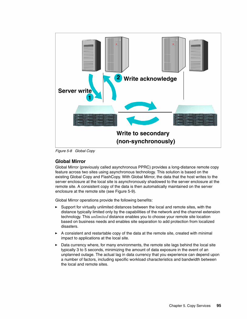
Figure 5-8 Global Copy
Global MirrorGlobal Mirror (previously called asynchronous PPRC) provides a long-distance remote copy feature across two sites using asynchronous technology. This solution is based on the existing Global Copy and FlashCopy. With Global Mirror, the data that the host writes to the server enclosure at the local site is asynchronously shadowed to the server enclosure at the remote site. A consistent copy of the data is then automatically maintained on the server enclosure at the remote site (see Figure 5-9).
Global Mirror operations provide the following benefits:
� Support for virtually unlimited distances between the local and remote sites, with the distance typically limited only by the capabilities of the network and the channel extension technology. This unlimited distance enables you to choose your remote site location based on business needs and enables site separation to add protection from localized disasters.
� A consistent and restartable copy of the data at the remote site, created with minimal impact to applications at the local site.
� Data currency where, for many environments, the remote site lags behind the local site typically 3 to 5 seconds, minimizing the amount of data exposure in the event of an unplanned outage. The actual lag in data currency that you experience can depend upon a number of factors, including specific workload characteristics and bandwidth between the local and remote sites.
2
1Server write
Write to secondary(non-synchronously)
Write acknowledge
Chapter 5. Copy Services 95

� Dynamic selection of the desired recovery point objective, based upon business requirements and optimization of available bandwidth.
� Session support whereby data consistency at the remote site is internally managed across up to eight Storage Units that are located across the local and remote sites.
� Efficient synchronization of the local and remote sites with support for failover and failback modes, helping to reduce the time that is required to switch back to the local site after a planned or unplanned outage.
Figure 5-9 Global Mirror
2
1Server write
Write to secondary(non-synchronously)
Write acknowledge
A B
C
FlashCopy(automatically)
Automatic cycle in active session
96 DS6000 Series: Architecture and Implementation

How Global Mirror worksWe explain how Global Mirror works in Figure 5-10.
Figure 5-10 How Global Mirror works
The A volumes at the local site are the production volumes; they are used as Global Copy primary volumes. The data from the A volumes is replicated to the B volumes, which are Global Copy secondary volumes. At a certain point in time, a Consistency Group is created using all of the A volumes, even if they are located in different Storage Units. This has no application impact because the creation of the Consistency Group is very quick (on the order of milliseconds).
Once the Consistency Group is created, the application writes can continue updating the A volumes. The increment of the consistent data is sent to the B volumes using the existing Global Copy relationship. Once the data reaches the B volumes, it is FlashCopied to the C volumes.
The C volumes now contain the consistent copy of data. Because the B volumes usually contain a fuzzy copy of the data from the local site, the C volumes are used to hold the last point-in-time consistent data while the B volumes are being updated by the Global Copy relationship.
Note: The copy created with Consistency Group is a power-fail consistent copy, not an application-based consistent copy. When you recover with this copy, you might need recovery operations, such as the fsck command in an AIX filesystem.
1. Create Consistency Group of volumes at local site2. Send increment of consistent data to remote site 3. FlashCopy at the remote site4. Resume Global Copy (copy out-of-sync data only)5. Repeat all the steps according to the defined time period
Global Mirror - How it works
Global Copy
Local Site Remote Site
RMC Primary RMC SecondaryFlashCopy Source
CBA
FlashCopy Target
FlashCopy
Automatic Cycle in an active Global Mirror Session
Chapter 5. Copy Services 97

The data at the remote site is current within 3 to 5 seconds, but this recovery point (RPO) depends on the workload and bandwidth available to the remote site.
In contrast to the previously mentioned Global Copy solution, Global Mirror overcomes its disadvantages and automates all of the steps that have to be done manually when using Global Copy.
If you use Global Mirror, you must adhere to the following additional rules:
� You must purchase a FlashCopy function authorization for the secondary Storage Unit.
� If Global Mirror will be used during failback on the secondary Storage Unit, you must also purchase a Point-in-Time Copy function authorization for the primary system.
Note: When you implement Global Mirror, you setup the FlashCopy between the B and C volumes with No Background copy and Start Change Recording options. It means that before the latest data is updated to the B volumes, the last consistent data in the B volume is moved to the C volumes. Therefore, at some time, a part of consistent data is in the B volume, and the other part of consistent data is in the C volume.
If a disaster occurs during the FlashCopy of the data, special procedures are needed to finalize the FlashCopy.
In the recovery phase, the consistent copy is created in the B volumes. You need some operations to check and create the consistent copy.
You need to check the status of the B volumes for the recovery operations. Generally, these check and recovery operations are complicated and difficult with the GUI or CLI in a disaster situation. Therefore, you might want to use some management tools (for example, Global Mirror Utility), or management software (for example, Multiple Device Manager Replication Manager), for Global Mirror to automate this recovery procedure.
Note: RMC can do failover and failback operations. A failover operation is the process of temporarily switching production to a backup facility (normally your recovery site) following a planned outage, such as a scheduled maintenance period, or an unplanned outage, such as a disaster. A failback operation is the process of returning production to its original location. These operations use Remote Mirror and Copy functions to help reduce the time that is required to synchronize volumes after the sites are switched during a planned or unplanned outage.
98 DS6000 Series: Architecture and Implementation

z/OS Global Mirror (XRC)z/OS Global Mirror is an asynchronous copy function for the z/Series environment. This function has a different architecture than Global Mirror. The DS6000 can only be used as a secondary system for z/OS Global Mirror (it cannot be used as primary system). See Figure 5-11.
Figure 5-11 z/OS Global Mirror (DS6000 is used as secondary system)
5.2.4 Comparison of the Remote Mirror and Copy functionsIn this section we summarize the use of and considerations for Remote Mirror and Copy functions.
Metro Mirror (Synchronous PPRC)Here is a summary of characteristics for Metro Mirror:
� Description:
Metro Mirror is a function for synchronous data copy at a distance.
� Advantages:
There is no data loss and it allows for rapid recovery for distances up to 300 km.
� Considerations:
There might be a slight performance impact for write operations.
2
1Server write
Write acknowledge Write ashynchronously
Primary server
System DataMover
Secondary server
System Data Mover is managing data consistency
DS8000 or ESS
DS6000
Chapter 5. Copy Services 99

Global CopyHere is a summary of characteristics for Global Copy:
� Description:
Global Copy is a function for continuous copy without data consistency.
� Advantages:
It can copy your data at nearly an unlimited distance, even if you are limited by the network and channel extender capabilities. It is suitable for data migration and daily backup to the remote site.
� Considerations:
The copy is normally fuzzy but can be made consistent through synchronization.
Global MirrorHere is a summary of characteristics for Global Mirror:
� Description:
Global Mirror is an asynchronous copy; you can create a consistent copy in the secondary site with an adaptable Recovery Point Objective (RPO).
Note: If you want to use RMC, you need to compare its function with OS mirroring.
Generally speaking, you will have some disruption to recover your system with RMC secondary volumes in an open systems environment because RMC secondary volumes are not online to the application servers during the RMC relationship.
You might need to do some operations before assigning RMC secondary volumes. For example, in an AIX environment, AIX assigns specific IDs to each volume (PVID). RMC secondary volumes have the same PVID as RMC primary volumes. AIX cannot manage the volumes with the same PVID as different volumes. Therefore, before using the RMC secondary volumes, you need to clear the definition of the RMC primary volumes or reassign PVIDs to the RMC secondary volumes.
Some operating systems (OS) or file systems (for example, AIX LVM) have a function for disk mirroring. OS mirroring needs some server resources, but usually can keep operating with the failure of one volume of the pair and recover from the failure non-disruptively. If you use RMC for the mirroring in the local site only, you need to consider which solution (RMC or OS mirroring) is better for your system.
Note: When you operate to create a consistent copy for Global Copy, you need the go-to-sync (synchronize the secondary volumes to the primary volumes) operation. During the go-to-sync operation, RMC changes from a non-synchronous copy to a synchronous copy. Therefore, the go-to-sync operation could cause performance impact to your application system. If the data is heavily updated and the network bandwidth for RMC is limited, the time for the go-to-sync operation becomes longer.
Note: Recovery Point Objective (RPO) specifies how much data you can afford to recreate should the system need to be recovered.
100 DS6000 Series: Architecture and Implementation

� Advantages:
Global Mirror can copy over nearly an unlimited distance. It is scalable across the server enclosures. It can realize low RPO with enough link bandwidth. Global Mirror causes little or no impact to your application system.
� Considerations:
When the link bandwidth capability is exceeded with a heavy workload, the RPO might grow.
5.2.5 What is a Consistency Group?With Copy Services, you can create Consistency Groups for FlashCopy and Remote Mirror. Consistency Group is a function to keep data consistency in the backup copy. Data consistency means that the order of dependent writes is kept in the copy.
In this section we define data consistency and dependent writes, and then we explain how Consistency Group operations keep data consistency.
What is data consistency?Many applications, such as databases, process a repository of data that has been generated over a period of time. Many of these applications require that the repository is in a consistent state in order to begin or continue processing. In general, consistency implies that the order of dependent writes is preserved in the data copy. For example, the following sequence might occur for a database operation involving a log volume and a data volume:
1. Write to log volume: Data Record #2 is being updated.
2. Update Data Record #2 on data volume.
3. Write to log volume: Data Record #2 update complete.
If the copy of the data contains any of these combinations then the data is consistent:
� Operation 1, 2, and 3� Operation 1 and 2� Operation 1
If the copy of the data contains any of these combinations, then the data is inconsistent (the order of dependent writes was not preserved):
� Operation 2 and 3� Operation 1 and 3� Operation 2� Operation 3
In the Consistency Group operations, data consistency means this sequence is always kept in the backup data.
And, the order of non-dependent writes does not necessarily need to be preserved. For example, consider the following two sequences:
1. Deposit paycheck in checking account A
2. Withdraw cash from checking account A
Note: To manage Global Mirror, you need many complicated operations. Therefore, we recommend management utilities (for example, Global Mirror Utilities) or management software (for example, IBM Multiple Device Manager) for Global Mirror.
Chapter 5. Copy Services 101

3. Deposit paycheck in checking account B
4. Withdraw cash from checking account B
In order for the data to be consistent, the deposit of the paycheck must be applied before the withdrawal of cash for each of the checking accounts. However, it does not matter whether the deposit to checking account A or checking account B occurred first, as long as the associated withdrawals are in the correct order. So for example, the data copy would be consistent if the following sequence occurred at the copy. In other words, the order of updates is not the same as it was for the source data, but the order of dependent writes is still preserved.
1. Deposit paycheck in checking account B
2. Deposit paycheck in checking account A
3. Withdraw cash from checking account B
4. WIthdraw cash from checking account A
How does Consistency Group keep data consistency?Consistency Group operations cause the Storage Units to hold I/O activity to a volume for a time period by putting the source volume into an extended long busy state. This operation can be done across multiple LUNs or volumes, and even across multiple Storage Units.
In the storage subsystem itself, each command is managed with each logical subsystem (LSS). This means that there are slight time lags until each volume in the different LSS is changed to an extended long busy state. Some people are concerned that the time lag causes you to lose data consistency, but, it is not true. We explain how to keep data consistency in the Consistency Group environments in the following section.
In this case, three write operations (first, second, and third) are dependent writes. This means that these operations must be completed sequentially.
Because of the time lag for Consistency Group operations, some volumes in some LSSs are in an extended long busy state and other volumes in the other LSSs are not.
In Figure 5-12, the volumes in LSS11 are in an extended long busy state, and the volumes in LSS12 and 13 are not. The first operation is not completed because of this extended long busy state, and the second and third operations are not completed, because the first operation has not been completed. In this case, first, second, and third updates are not included in the backup copy. Therefore, this case is consistent.
102 DS6000 Series: Architecture and Implementation

Figure 5-12 Consistency Group: Example 1
See Figure 5-13. In this case, the volumes in LSS12 are in an extended long busy state and the other volumes in LSS11 and 13 are not. The first write operation is completed because the volumes in LSS11 are not in an extended long busy state. The second write operation is not completed because of an extended long busy state. The third write operation is also not completed because the second operation is not completed. In this case, the first update is included in the backup copy, and the second and third updates are not included. Therefore, this case is consistent.
1st
2nd
3rd
dependencyfor each write operation
Servers
Wait
Wait
Wait
LSS11
LSS12
LSS13
These write operations are not completed because 1st write operation is not completed.
This write operation is not completed because of extended long busy condition.
Chapter 5. Copy Services 103

Figure 5-13 Consistency Group: Example 2
In all cases, if each write operation is dependent, Consistency Group operations can keep data consistent in the backup copy.
If each write operation is not dependent, the I/O sequence is not kept in the copy that is created by the Consistency Group operations. See Figure 5-14. In this case, the three write operations are independent. If the volumes in LSS12 are in an extended long busy state and the other volumes in LSS11 and 13 are not, the first and third operations are completed and the second operation is not completed.
1st
2nd
3rd
dependencyfor each write operation
Servers
Completed
Wait
Wait
LSS11
LSS12
LSS13
This write operation is not completed because 2nd write operation is not completed.
This write operation is completed because LSS11 is not in an extended long busy condition.
This write operation is not completed because LSS12 is in an extended long busy condition.
104 DS6000 Series: Architecture and Implementation

Figure 5-14 Consistency Group: Example 3
In this case, the copy created by Consistency Group operation reflects only the first and third write operation, not including the second operation.
If you accept this result, you can use Consistency Group operation with your applications. But, if you cannot accept it, you should consider other procedures without Consistency Group operations. For example, you could stop your applications for a slight interval for the backup operations.
5.3 Interfaces for Copy ServicesCopy Service functions can be initiated over the following interfaces:
� DS Storage Manager Web-based Interface� DS Command-Line Interface (DS CLI)� System z Host I/O interface� DS open application programming interface (DS Open API)� TotalStorage Productivity Center for RM
DS Storage Manager, DS CLI, and DS Open API commands are issued via the Ethernet network, and these commands are invoked from the DS System Management Console (SMC). When the SMC has the command requests, including those for Copy Services, from these interfaces, the SMC communicates with each server in the Storage Units via the Ethernet network. Therefore, the SMC is a key component to configure and manage the DS6800.
The client must provide a computer to use as the SMC. If they want, they can order a computer from IBM as the SMC. An additional SMC can be provided for redundancy.
1st
2nd
3rd
independentfor each write operation
Servers
Completed
Wait
LSS11
LSS12
LSS13
This write operation is completed because LSS11 is not in an extended long busy condition.
This write operation is not completed because LSS12 is in an extended long busy condition.
Completed
This write operation is completed because LSS13 is not in an extended long busy condition.(I/O sequence is not kept.)
Chapter 5. Copy Services 105

For further information about the Management Console, see Chapter 7, “SMC planning and setup” on page 123.
5.3.1 DS Storage Manager Web-based interfaceDS Storage Manager is a Web-based management interface. It is used for managing the logical configurations and invoking the Copy Services functions. The DS Storage Manager has an online mode and an offline mode; only the online mode is supported for Copy Services.
The DS Storage Manager can be installed on the SMC or other computers that are connected to the SMC through an Ethernet (IP) connection (when managing Copy Services with DS Storage Manager on a remote computer, DS Storage Manager issues its commands to the SMC over the Ethernet network).
The DS Storage Manager can be used for almost all functions for Copy Services. The following functions cannot be issued from the DS Storage Manager in the current implementation:
� Consistency Group operation (FlashCopy and RMC)
� Inband commands over RMC link
5.3.2 DS Command-Line Interface (CLI)
The IBM System Storage DS Command-Line Interface (DSCLI) provides a full-function command set that allows you to check your storage configuration and perform specific application functions when necessary.
The DSCLI also enables open systems hosts to invoke and manage FlashCopy and RMC functions through batch processes and scripts.
For further information about the DS CLI, see Chapter 13, “Configuration with DS CLI” on page 227.
5.3.3 System z Host I/O interfacesIn addition to using the DS GUI or the DS CLI, there are several possible interfaces available to System z users for managing DS6000 Copy Services relationships. These are:
� TSO� ICKDSF� DFSMSdss� The ANTRQST macro� Native TPF commands (for z/TPF only)
These interfaces have the advantage of not having to issue their commands to the DS6000 SMC. They can instead directly send commands inband over a FICON channel connection between the DS6000 and the System z operating system. Sending inband commands allows for a very quick command transfer that does not depend on any additional software stacks.
106 DS6000 Series: Architecture and Implementation

Operating system alternativesFrom an operating system point of view, these are the alternatives to the DS GUI and DS CLI:
� z/OS:
– TSO commands– ICKDSF – DSFSMSdss– ANTRQST application programming interface (API)
� z/VM:
– ICKDSF
� z/VSE™:
– ICKDSF
� z/TPF:
– ICKDSF – z/TPF itself
5.3.4 DS open application programming interface (API)
The DS open application programming interface (API) is a non-proprietary storage management client application that supports routine LUN management activities, such as LUN creation, mapping and masking, and the creation or deletion of RAID-5 and RAID-10 volume spaces. The DS Open API also enables Copy Services functions such as FlashCopy and Remote Mirror and Copy. It supports these activities through the use of the Storage Management Initiative Specification (SMIS), as defined by the Storage Networking Industry Association (SNIA).
The DS Open API helps integrate DS configuration management support into storage resource management (SRM) applications, which allow customers to benefit from existing SRM applications and infrastructures. The DS Open API also enables the automation of configuration management through customer-written applications. Either way, the DS Open API presents another option for managing the DS6800 by complementing the use of the IBM System Storage DS Storage Manager Web-based interface and the DS Command-Line Interface.
You must implement the DS Open API through the IBM System Storage Common Information Model (CIM) agent, a middleware application that provides a CIM-compliant interface. The DS Open API uses the CIM technology to manage proprietary devices such as open system devices through storage management applications. The DS Open API allows these storage management applications to communicate with a DS6800.
5.3.5 TotalStorage Productivity Center for Replication The IBM TotalStorage Productivity Center for Replication, or simply TPC for Replication, is an automated solution to provide a management front/end to Copy Services.
TPC for Replication does build on all previous experiences with storage management tools and framework proposals to organize all aspects of copy services for disaster recovery solutions.
Chapter 5. Copy Services 107

TPC for Replication also addresses the need for other solutions that involve copy services functions available with the DS6000 and DS8000. These functions could include data or volume migration, data center movements, or other projects that require the ability to copy or move data between like devices such as the DS6000, DS8000, and ESS 800.
TPC for Replication comes in the following two versions:
� TPC for Replication includes support for:
– FlashCopy– Planned failover and restart (one direction) for Metro Mirror and Global Mirror
� TPC for Replication Two Site Business Continuity (BC) includes support for:
– FlashCopy– Planned and unplanned failover and failback for Metro Mirror and Global Mirror– High availability (2 TPC Replication servers)
For an overview of TPC for Replication functions for the DS6000, refer to either of the following IBM Redbooks:
� IBM System Storage DS6000 Series: Copy Services in Open Environments, SG24-6783
� IBM System Storage DS6000 Series: Copy Services with IBM System z servers, SG24-6782
For in-depth information about TPC for Replication, refer to the following manuals:
� IBM TotalStorage Productivity Center for Replication User’s Guide, SC32-0103
� IBM TotalStorage Productivity Center for Replication Installation and Configuration Guide, SC32-0102
� IBM TotalStorage Productivity Center for Replication Command-Line Interface User’s Guide, SC32-0104.
5.4 Interoperability with ESSCopy Services also supports the IBM Enterprise Storage Server Model 800 (ESS 800) and the ESS 750. To manage the ESS models from the Copy Services for DS6000, you need to install licensed internal code Version 2.4.3.65 or later on the ESS 800.
The DS CLI supports the DS6000, DS8000, and ESS 800 at the same time. The DS Storage Manager (GUI) does not support the ESS 800.
Note: The DS6800 does not support RMC via an ESCON® link. If you want to configure an RMC relationship between a DS6800 and an ESS 800, you have to use an FCP link.
108 DS6000 Series: Architecture and Implementation

Part 2 Planning and installation
In this part of the book, we discuss various aspects of the planning process for your DS6000. The subjects covered include:
� Physical planning and installation� Preferred path concepts� Storage Management Console (SMC) planning and setup� Performance considerations� Features and license keys
Part 2
© Copyright IBM Corp. 2005, 2006. All rights reserved. 109

110 DS6000 Series: Architecture and Implementation
Chapter 6. Physical planning and installation
This chapter describes the various steps for planning and deploying a DS6000. The DS6000 is designed as a Customer Set Up unit, and this is the focus of this chapter.
We include a reference listing of the information required for setup and tell you where to find detailed technical reference material. In any case, you should review the IBM System Storage DS6000: Introduction and Planning Guide, GC26-7925 and keep it available for reference.
We cover the following topics:
� Physical planning considerations� Physical installation information� DS6800 controller network configuration
6
© Copyright IBM Corp. 2005, 2006. All rights reserved. 111

6.1 Considerations prior to installation You should develop and follow a project plan to address the many topics needed for a successful implementation. Appendix C, “Project plan” on page 473 includes a sample Gantt chart showing some suggested key activities and their timing.
In general, take the following considerations into account while planning the installation:
� Plan for system growth and minimize exposure to disruption.
� Plan the physical layout for the system (the requirements for the DS6800 controller and DS6000 Expansion Unit are the same):
– Rack/floor space– Power requirements: redundancy, uninterruptable power supply (UPS)– Environmental requirements, such as cooling
� Provision suitable workstations as system consoles.
6.1.1 Who should be involved?As indicated previously, the DS6000 Series is specified as Customer Set Up, and this redbook is designed to be used by a suitably qualified staff.
We suggest having a project manager to coordinate the many tasks necessary for a successful installation. Installation will require close cooperation with the user community, the IT support staff, and the technical resources responsible for rack space, power, and cooling.
A Storage Administrator should also coordinate requirements from the client applications and systems in order to build a storage plan for the installation. This plan will be needed to configure the storage after the initial hardware installation is complete.
6.1.2 Required tasksIn summary, the required tasks are:
� Staff training
� Planning and performing the physical installation, including the integration with the local area network and storage area network, if appropriate
� Installation and configuration Advanced Copy Services, if purchased
� Planning and implementing any application migration to the new environment
� Testing the environment before live operations
6.1.3 What information is required?There are many items needed; here are some suggestions you might find useful:
� A detailed storage plan
� A physical plan, including location coordinates, power, and cooling
� Cabling diagrams
� Network and SAN ports are assignments
� License keys for the Operating Environment License, which is a mandatory, and any Advanced Copy Services
112 DS6000 Series: Architecture and Implementation

6.2 Physical installation overviewThis section describes the elements needed to complete the physical planning process. Read and use this information to augment the detailed procedures and information in the IBM System Storage DS6000: Introduction and Planning Guide, GC26-7925. This guide can be downloaded from the Web at:
http://www.ibm.com/servers/storage/disk/ds6000/publications.html
See chapter 5, “Planning your DS6000 series” of that guide for some worksheets that you will find very useful when preparing for the installation.
Here we provide some additional information to assist you in completing your installation successfully. The physical planning process includes tasks that might require special knowledge and work by contractor services to complete (such as the validation of the cooling system capacity).
Figure 6-1 gives you an overview of how the DS6800 and the Storage Management Console (SMC) are connected to your network.
Figure 6-1 DS6800 overview
During the installation, you must do the following major operations:
� Hardware installation of the DS6800� Setting up the network configuration
6.2.1 Space and power provisioning The Physical Installation Information summary chart in Table 6-1 shows the basic requirements for quick reference. We recommend dual power sources, preferably with at least one protected by an uninterruptable power supply, because each controller and expansion unit has two power connections for redundancy.
Important: Use appropriate safety procedures and get help in installing and moving the DS600 units. Each unit weighs up to 109 lbs (49.5 kg), so a fully configured DS6000 with eight enclosures and without rack, weighs 872 lbs (396 kg).
DS6800
User provided Ethernet switch
Intranet
Internetcall home
DS Storage Manager software on user provided
DS management console
IP-1(controller 0)
IP-2(controller 1)
IP-3
Administrator accessingDS Storage Manager
Chapter 6. Physical planning and installation 113

DS6000 controllers and expansion units are individually mounted in racks conforming to Electronic Industries Association (EIA) 310-D Section 1 19-inch rack cabinet, such as the IBM System Storage 2101 Model 200 Racked Storage Solution. DS6000s can be ordered pre-mounted or can be mounted in a customer provided rack.
Any 19-inch rack complying with this standard is suitable, provided that sufficient airflow can be maintained for each unit. The distance between EIA rails, from the front to the rear of the rack, is between 69.5 cm (27.36 inches) and 76.5 cm (30.12 inches). Review the documentation that comes with your rack for safety and cabling considerations.
Table 6-1 Summary of Installation Planning information
6.2.2 Suggested rack layoutIt is beneficial for servicing purposes to install the enclosures into the rack according to loop numbering. Because each enclosure is either on loop 0 or loop 1, a suggested rack layout could be as shown in Table 6-2. In this suggested layout, loop 0 goes upward and loop 1 goes downwards. The benefit here is that when cabling the loop in 6.2.3, “Connecting the storage enclosures” on page 115, the cables only need to move either up or down one enclosure. This makes the rack neat and easy to maintain.
Tips: Remember the following recommendations:
� For safety and stability, load the rack starting at the bottom. � If you install multiple components in the rack, do not overload the power outlets. � We strongly recommend that you connect the rack power to at least two different power
circuits or sources.
Item Measure Comments
Power - Voltage 100-127 or 200-240 50 or 60 Hz AC + or - 3 Hz
Power Load -kVA 0.8
Heat Load 1880 BTU/hr Approximately 550W
Size - Height 5.25 in (13.4 cm) Per unit (3U)
Size - Width 18.8 in (47.8 cm)
Size - Depth 24 in (61 cm)
Clearance - Front 12 in (30.5 cm) See note below
Clearance - Rear 18 in (45.7 cm) See note below
Clearance - Side 2 in (5.1 cm) See note below
Weight - Max 109 lbs (49.5 Kg) With 16 DDMs
Power Outlets 2 - 28 Excludes console
Note: The clearance is for a stand-alone unit. More clearance might be needed to allow doors to be opened fully. The service clearances for adjacent units might overlap, providing minimum clearances are maintained for each unit.
114 DS6000 Series: Architecture and Implementation

Table 6-2 Rack layout suggestion
6.2.3 Connecting the storage enclosuresIf you have ordered one or more additional storage enclosures, you need to connect the storage enclosures to the DS6800. If you have no storage enclosures to connect, you can continue with the next section.
Figure 6-2 shows the connections of the DS6800 and the storage enclosure. The DS6800 provides two connections for two loops.
Figure 6-2 Rear view of DS6800 and storage enclosure
To connect the DS6800 with the storage enclosures, short wave SFPs and short wave Fibre Channel cables are used.
Rack position Enclosure type Loop Enclosure on loop
Order of installation
Enclosure number on Rear Display Panel
22-24 1750-EX2 0 4 8 03
19-21 1750-EX2 0 3 6 02
16-18 1750-EX2 0 2 4 01
13-15 1750-522 0 1 1 00
10-13 1750-EX2 1 1 2 10
7-9 1750-EX2 1 2 3 11
4-6 1750-EX2 1 3 5 12
1-3 1750-EX2 1 4 7 13
Host PortsLoop 1Loop 0
Out ports
In ports Serial PortsEthernet Ports
Systemenclosure
Expansionenclosure
Chapter 6. Physical planning and installation 115

Figure 6-3 shows how you must connect the storage enclosures to the DS6800. A maximum of three storage enclosures can be added to loop 0, and a maximum of four storage enclosures can be added to loop 1.
Figure 6-3 Storage enclosure loops
To distribute the storage enclosures equally to both storage loops, we recommend that you follow the install sequence shown in Table 6-3.
Table 6-3 Install sequence of expansion enclosures
Expansion enclosure Loop
1 1
2 1
3 0
4 1
5 0
6 1
7 0
Loop 0 Loop 1
116 DS6000 Series: Architecture and Implementation

6.2.4 Planning for environmental requirementsSee Table 6-4 for the recommended environmental specifications for the DS6000 hardware.
Table 6-4 Environment planning for DS6000 and DS6000 Expansion Unit
6.2.5 SMC planningA suitable System Management Console is required to manage the DS6000. This is required for all setup functions, including initial loading of the DS Storage Manager software, and implementation of all licensed code (this is important, as this includes the basic authorization to use any of the disk storage, Operating Environment License (OEL), and any optional Copy Services functions). This is discussed in detail in Chapter 7, “SMC planning and setup” on page 123.
6.2.6 SAN planningEnsure that sufficient ports and appropriate cables are available for the DS6000. The DS6000 can use up to eight host or SAN interfaces. Also be sure that you know what machine order was specified so your controller can be configured as intended.
6.2.7 Network planningEach controller needs to be network accessible by the System Management Console. Each of the two controller cards requires its own network connection. The DS6000 SMC requires access over a network for remote support by IBM. This can be provided as a secure link through your LAN firewall using a VPN connection, or via modem.
Item Measure and comments
Powered on temperature limit 10 - 40°C (50 - 104°F)
Powered off temperature limit 10 - 52°C (50 - 126°F)
Recommended operating point 22°C (72°F)
Recommended operating range 20 - 25°C (68 - 77°F)
Maximum wet bulb temperature 27°C (80° F)
Note:
1. The upper limit of dry bulb temperature must be de-rated (lowered) 1.0°C for every 137 meters of elevation above 915 meters.
2. The upper limit of wet bulb temperature must be derated (lowered) 1.0°C for every 274 meters of elevation above 305 meters.
Relative humidity 8 - 80 percent
Typical heat load 550 watts or 1880 BThU/hr
Electrical power 0.8 kVA
Capacity of exhaust 1.8 cubic meters per minute (64 cfm)
Leakage current 1.5 mA (100-127 V ac), 3 mA (200-240 V ac)
Maximum physical storage capacity 38.4 TB (using 128 x 300 GB DDMs) installed in one controller and seven expansion units.
Chapter 6. Physical planning and installation 117

6.2.8 Connecting Ethernet cables to the controller cardsEach controller has one Ethernet connection. After the DS6800 is mounted in a rack, you can connect the Ethernet ports from the controllers to your external Ethernet network, as shown in Figure 6-1 on page 113.
6.2.9 Power onBefore you power on the DS6800, ensure that all communication and power cables are plugged in. You can power on the DS6800 by pressing the power button at the rear of the DS6800 operator panel. The DS6800 also powers the storage enclosures on in the right sequence. This can take several minutes.
6.3 Network configuration on the DS6800To set up the TCP/IP configuration on the DS6800, you must connect with a terminal emulator, for example, HyperTerminal, to the serial port on the DS6800. The serial port on the DS6800 is on the rear side of the controller cards and marked with a wrench. You use the special serial cable that is shipped with the DS6800. Use the following settings for the terminal emulation program:
� 38400 bps� Eight Data Bits� No Parity� One Stop Bit� The flow control should be set to hardware
You have to set up the TCP/IP configuration for both controller cards. After you connect to the serial port, the ncnetconf menu appears, as shown in Figure 6-4.
Figure 6-4 ncnetconf main menu
The default user ID is guest and the password is also guest. Follow this procedure to enter the desired TCP/IP configuration. You must follow the procedure on both controller cards:
1. Select Configure network parameters.
2. Select Use static IP addresses from the network configuration menu.
3. Choose the IP address for this node from the IP address configuration menu.
4. Type in the appropriate IP address and press Enter.
5. Choose the IP address for other node from the IP address configuration menu.
118 DS6000 Series: Architecture and Implementation

6. Type in the appropriate IP address and press Enter.
7. You also have the option to change the subnet mask for both this node and the other node. Do so if required.
8. Select Back to network configuration.
9. Select Advanced configuration options.
10.From here you can set the domain name server and the gateway. It is not mandatory to do so.
11.Select Back to network configuration.
12.Select Back to main menu.
13.Select Apply changes and Exit.
14.Now connect to the other controller and repeat the above process. When viewing the IP address, subnet mask, gateway and DNS, they should already display the new settings. However, you must perform the Apply changes step on this controller as well. If you do not, then the changes will not actually be performed.
6.4 Remote Mirror and Copy connectivityThe DS6000 Remote Mirror and Copy, previously known as Peer-to-Peer Remote Copy (PPRC) connectivity, uses the high speed Fibre Channel protocol. It supports connectivity with other DS6000s, DS8000s, and the IBM Enterprise Storage Server Model 800 and Model 750.
Make sure that you have a sufficient number of FCP paths assigned for your remote mirroring between your source and target sites to address performance and redundancy issues. When you plan to use both Metro Mirror and Global Copy modes between a pair of Storage Units, IBM recommends that you use separate logical and physical paths for the Metro Mirror and another set of logical and physical paths for the Global Copy.
Plan accordingly on the distance between the primary and secondary Storage Units to properly acquire the necessary length of fiber optic cables you need, or if your Copy Services solution would require separate hardware such as channel extenders or DWDM.
6.5 Disk capacity considerationsThe effective capacity of your DS6000 unit depends on several factors:
� The size of the installed disk drives� The selected RAID configuration (RAID 5 or RAID 10)� The storage type (FB or CKD)
Important: After setting the IP addresses on one controller, when you go to set the addresses on the other controller, they appear to have already been set. However, you must always do the Apply changes step to actually set the new IP addresses on the second controller.
Note: The DS6800 Storage Unit does not support ESCON links for the Remote Mirror and Copy feature.
Chapter 6. Physical planning and installation 119

The DS6000 supports RAID 5 and RAID 10 configuration and assigns spare disks automatically. You can see the available extend count, depending on RAID type, DDM size, and data format (FB or CKD), in Figure 6-5 and Figure 6-6.
Figure 6-5 FB extend count depending on array type
Dataformat Array type Extend count
FB RAID_5 500GB DDM 2+P 877FB RAID_5 500GB DDM 3+P 1316FB RAID_5 500GB DDM 6+P 2634FB RAID_5 500GB DDM 7+P 3071FB RAID_5 300GB DDM 2+P 524FB RAID_5 300GB DDM 3+P 787FB RAID_5 300GB DDM 6+P 1576FB RAID_5 300GB DDM 7+P 1837FB RAID_5 146GB DDM 2+P 256FB RAID_5 146GB DDM 3+P 385FB RAID_5 146GB DDM 6+P 773FB RAID_5 146GB DDM 7+P 902FB RAID_5 73GB DDM 2+P 126FB RAID_5 73GB DDM 3+P 190FB RAID_5 73GB DDM 6+P 382FB RAID_5 73GB DDM 7+P 445FB RAID_10 500GB DDM 1+1 437FB RAID_10 500GB DDM 2+2 877FB RAID_10 500GB DDM 3+3 1316FB RAID_10 500GB DDM 4+4 1756FB RAID_10 300GB DDM 1+1 261FB RAID_10 300GB DDM 2+2 524FB RAID_10 300GB DDM 3+3 787FB RAID_10 300GB DDM 4+4 1050FB RAID_10 146GB DDM 1+1 127FB RAID_10 146GB DDM 2+2 256FB RAID_10 146GB DDM 3+3 385FB RAID_10 146GB DDM 4+4 515FB RAID_10 73GB DDM 1+1 62FB RAID_10 73GB DDM 2+2 126FB RAID_10 73GB DDM 3+3 190FB RAID_10 73GB DDM 4+4 254
120 DS6000 Series: Architecture and Implementation

Figure 6-6 CKD extend count depending on array type
6.5.1 FC disks or FATA disksWhen planning capacity and disk types, you can choose FC or FATA disks.
FATA drives offer a cost effective option for lower priority data such as various fixed content, data archival, reference data, and near-line applications that require large amounts of storage capacity for lighter workloads.
These new drives are meant to complement, not compete with existing Fibre Channel drives, because they are not intended for use in applications that require drive utilization duty cycles greater than 20 percent. Intermix of the two drive types within the DS6000 is supported with certain restrictions on physical placement and logical configuration.
Dataformat Array type Extend count
CKD RAID_5 500GB DDM 2+P 982CKD RAID_5 500GB DDM 3+P 1474CKD RAID_5 500GB DDM 6+P 2950CKD RAID_5 500GB DDM 7+P 3440CKD RAID_5 300GB DDM 2+P 587CKD RAID_5 300GB DDM 3+P 881CKD RAID_5 300GB DDM 6+P 1765CKD RAID_5 300GB DDM 7+P 2058CKD RAID_5 146GB DDM 2+P 287CKD RAID_5 146GB DDM 3+P 432CKD RAID_5 146GB DDM 6+P 866CKD RAID_5 146GB DDM 7+P 1010CKD RAID_5 73GB DDM 2+P 141CKD RAID_5 73GB DDM 3+P 212CKD RAID_5 73GB DDM 6+P 427CKD RAID_5 73GB DDM 7+P 499CKD RAID_10 500GB DDM 1+1 490CKD RAID_10 500GB DDM 2+2 982CKD RAID_10 500GB DDM 3+3 1474CKD RAID_10 500GB DDM 4+4 1966CKD RAID_10 300GB DDM 1+1 292CKD RAID_10 300GB DDM 2+2 587CKD RAID_10 300GB DDM 3+3 881CKD RAID_10 300GB DDM 4+4 1176CKD RAID_10 146GB DDM 1+1 142CKD RAID_10 146GB DDM 2+2 287CKD RAID_10 146GB DDM 3+3 432CKD RAID_10 146GB DDM 4+4 577CKD RAID_10 73GB DDM 1+1 69CKD RAID_10 73GB DDM 2+2 141CKD RAID_10 73GB DDM 3+3 212CKD RAID_10 73GB DDM 4+4 284
Chapter 6. Physical planning and installation 121

See Section 2.4.1, “Fibre Channel ATA (FATA)” on page 28 for a detailed discussion on when to use FATA drives.
6.5.2 Disk sparingAllocation of spare disks is performed during the hardware set up. There is always at least one spare; the number will vary depending on the mix of DDM variants. For more information on disk sparing see Section 3.4.4, “Spare creation” on page 56.
The DDMs defined as spare disks, or hot spares, are required to be immediately available to the Storage Controller if a DDM should fail. The substitution and recovery is automatic. The replacement of the DDMs, power supplies, fan units, and controllers is a client responsibility unless otherwise contracted.
6.6 Planning for growthThe DS6800 Storage Unit is a highly scalable storage solution. Features such as total storage capacity, and host ports (up to eight) can be easily increased by physically adding the necessary hardware or by changing the needed licensed key for Advanced Copy Services features (as ordered). For more information on capacity upgrades, see Section Chapter 23., “Capacity upgrades” on page 443.
Note: FC disk drives and FATA cannot be intermixed within the same enclosure. However, they can be intermixed within a DS6000 system: in other words, they can be intermixed on a DA pair loop.
122 DS6000 Series: Architecture and Implementation

Chapter 7. SMC planning and setup
This chapter describes what planning you need to do, prior to installing the DS Storage Management Console (SMC) and the DS Storage Management workstations.
We cover the following topics:
� Storage Management Console hardware requirements� SMC software� SMC software installation� SMC setup
7
© Copyright IBM Corp. 2005, 2006. All rights reserved. 123

7.1 Activities for SMC planning as part of the project planThe overall project plan in Appendix C, “Project plan” on page 473 contains the activities that are considered to be prerequisites for the SMC planning and installation. It also contains the activities that should be performed for the SMC during the planning phase. As a result of planning, the installation activities will be scheduled and responsibilities should be assigned for each resulting installation, quality assurance, and education task.
Figure 7-1 SMC planning activities
7.2 SMC hardwareThe SMC hardware can be provided by the customer or ordered separately from IBM. Before starting the installation of the management software included with the DS6800, make sure that you have a PC that meets the following requirements:
� 600 MB free disk space
� 512 MB memory
� Pentium® 4 processor 1.4 GHz
124 DS6000 Series: Architecture and Implementation
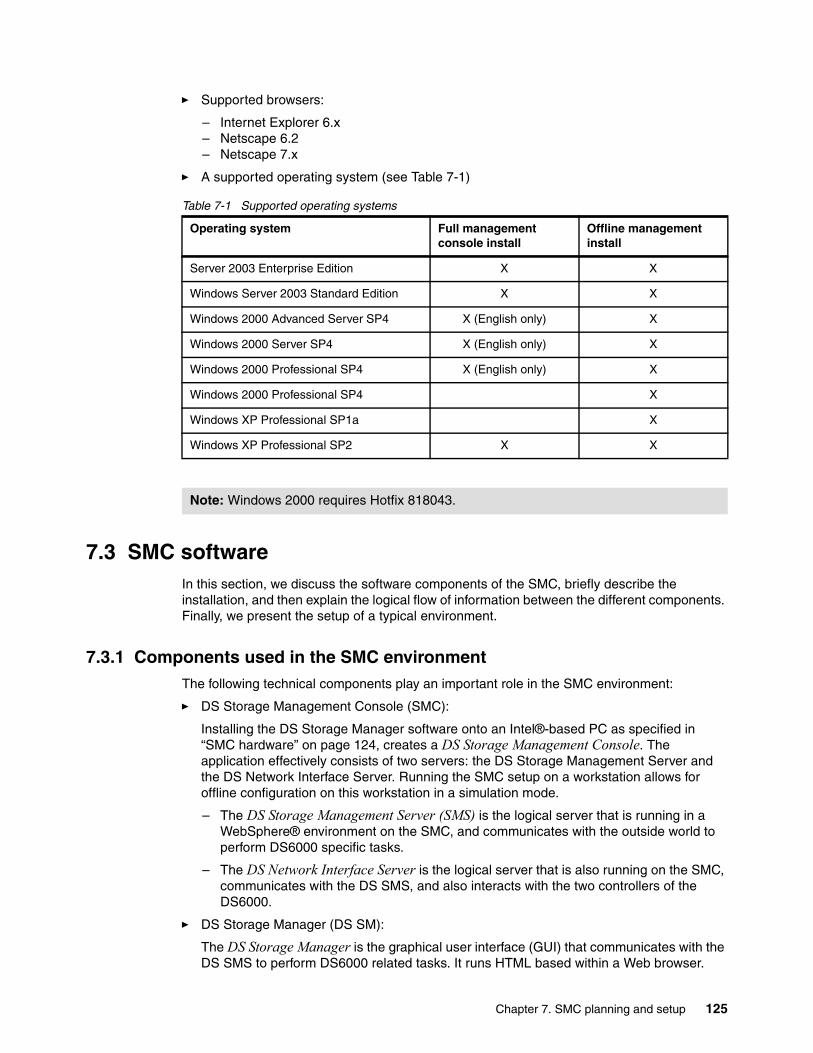
� Supported browsers:
– Internet Explorer 6.x– Netscape 6.2– Netscape 7.x
� A supported operating system (see Table 7-1)
Table 7-1 Supported operating systems
7.3 SMC softwareIn this section, we discuss the software components of the SMC, briefly describe the installation, and then explain the logical flow of information between the different components. Finally, we present the setup of a typical environment.
7.3.1 Components used in the SMC environmentThe following technical components play an important role in the SMC environment:
� DS Storage Management Console (SMC):
Installing the DS Storage Manager software onto an Intel®-based PC as specified in “SMC hardware” on page 124, creates a DS Storage Management Console. The application effectively consists of two servers: the DS Storage Management Server and the DS Network Interface Server. Running the SMC setup on a workstation allows for offline configuration on this workstation in a simulation mode.
– The DS Storage Management Server (SMS) is the logical server that is running in a WebSphere® environment on the SMC, and communicates with the outside world to perform DS6000 specific tasks.
– The DS Network Interface Server is the logical server that is also running on the SMC, communicates with the DS SMS, and also interacts with the two controllers of the DS6000.
� DS Storage Manager (DS SM):
The DS Storage Manager is the graphical user interface (GUI) that communicates with the DS SMS to perform DS6000 related tasks. It runs HTML based within a Web browser.
Operating system Full management console install
Offline management install
Server 2003 Enterprise Edition X X
Windows Server 2003 Standard Edition X X
Windows 2000 Advanced Server SP4 X (English only) X
Windows 2000 Server SP4 X (English only) X
Windows 2000 Professional SP4 X (English only) X
Windows 2000 Professional SP4 X
Windows XP Professional SP1a X
Windows XP Professional SP2 X X
Note: Windows 2000 requires Hotfix 818043.
Chapter 7. SMC planning and setup 125
� DS Command-Line Interface (DS CLI):
The DS Command-Line Interface consists of commands that can be executed in a shell environment of a server or workstation. The commands interact with the DS Network Interface Server to perform the requested tasks. It is possible to use multiple DS commands in scripts.
� DS Open Application Programming Interface (DS Open API)
The DS Open Application Programming Interface includes components that can be used within programs to interact with the DS SMS to have the requested tasks executed.
7.3.2 SMC software installationOn the SMC, install the following software:
� DS6000 Storage Manager � DS CLI (Command Line Interface)
The DS6000 Storage Manager and DS CLI software are shipped with the DS6000 or can be downloaded from the following Web site:
http://www-1.ibm.com/servers/storage/support/disk/ds6800/downloading.html
When you download the software, you have the ability to download an ISO Image to burn a CD-ROM, or you can download a zip file that must be extracted before the installation.
DS6000 Storage Manager installationThe installation of the DS6000 Storage Manager can be done in silent or graphical mode.
For a graphical mode install, insert the CD with the DS6000 Storage Manager software in the CD-ROM drive; the LaunchPad automatically starts. Select the option Installation Wizard to start the Installation of the DS6000 Storage Manager. During the installation, you have the option to install only the offline configuration or the full version. Make sure that you install the full version.
Command line interface (CLI) installationThe DS CLI can be installed on the same PC as the DS6000 Storage Manager or on any other PC or workstation. The DS CLI requires Java™ Version 1.4.1 or later. The following platforms are supported:
� AIX 5L V5.1, V5.2, and V5.3� HP-UX 11i V1 and V2� HP Tru64 Version 5.1 and Version 51A� Novell Netware 6.5� OpenVMS 7.3-1 and 7.3-2� SUN Solaris 7, 8, and 9� Windows 2000, Windows Datacenter, Windows 2003, and Windows XP
Depending on the platform you want to install the DS CLI on, the installation can be done in graphical, silent, or console mode. In this chapter, we show how to install the DS CLI on a Windows PC in graphical mode.
Attention: The DS CLI cannot be installed on the Windows 64-bit operating system.
126 DS6000 Series: Architecture and Implementation

For the installation of the DS CLI in graphical mode on a windows system, you have to start the setupwin32.exe. The Installation Wizard will be launched (see Figure 7-2).
Figure 7-2 DS CLI installation wizard
Follow the windows from the Installation Wizard to install the DS CLI.
Storage Manager post installationDuring the installation of the DS Storage Manager, two Windows services were installed:
� IBM System Storage Manager Server� IBM System Storage Network Server
The services will be started automatically after the reboot of the SMC (see Figure 7-3).
You also have the ability to stop and restart these servers manually from the Windows operating system:
1. Click Start.
2. Select Programs.
3. Click IBM System Storage DS Storage Manager or IBM System Storage DS Network Interface to stop or start the server you want. This is normally not necessary.
Important: Installation of the DS CLI will not proceed if Java is not installed. You should always check to ensure Java is already installed before beginning the DS CLI installation.
Tip: If you are installing the DS CLI onto a non-Windows based machine using a shell, then use the -console parameter when starting the installation script.
Chapter 7. SMC planning and setup 127

Figure 7-3 DS Storage Manager Services
You can now access the DS6000 Storage Manager with a Web browser from any workstation that has a network connection to the SMC or from the SMC itself. To access the DS6000 Storage Manager from the SMC:
1. Click Start.
2. Click Programs.
3. Click IBM System Storage DS6000 Storage Manager.
4. Click Open DS Storage Manager.
Here is an alternative way to access the DS6000 Storage Manager:
1. Point your browser at the URL:
https://localhost:8452/DS6000
2. From your workstation, open a Web browser and enter the following URL in the browser:
https: //<SMC IP Addresse>:8452/DS6000
or
https: //<SMC hostname>:8452/DS6000
Figure 7-4 shows the DS6000 Storage Manager Sign On window.
Figure 7-4 DS6000 Storage Manager Sign On window
128 DS6000 Series: Architecture and Implementation
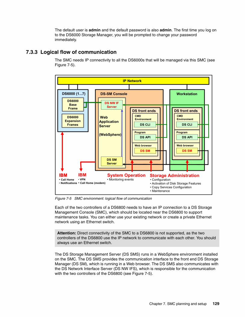
The default user is admin and the default password is also admin. The first time you log on to the DS6000 Storage Manager, you will be prompted to change your password immediately.
7.3.3 Logical flow of communicationThe SMC needs IP connectivity to all the DS6000s that will be managed via this SMC (see Figure 7-5).
Figure 7-5 SMC environment: logical flow of communication
Each of the two controllers of a DS6800 needs to have an IP connection to a DS Storage Management Console (SMC), which should be located near the DS6800 to support maintenance tasks. You can either use your existing network or create a private Ethernet network using an Ethernet switch.
The DS Storage Management Server (DS SMS) runs in a WebSphere environment installed on the SMC. The DS SMS provides the communication interface to the front end DS Storage Manager (DS SM), which is running in a Web browser. The DS SMS also communicates with the DS Network Interface Server (DS NW IFS), which is responsible for the communication with the two controllers of the DS6800 (see Figure 7-5).
Attention: Direct connectivity of the SMC to a DS6800 is not supported, as the two controllers of the DS6800 use the IP network to communicate with each other. You should always use an Ethernet switch.
1
IBM Systems Group
© 2005 IBM Corporation
DS4300
DS NW IFServer
WebApplicationServer
(WebSphere)
DS-SM Console
DS SM Server
DS6000Base
Frame
DS6000 (1...7)
DS6000Expansion
Frames
Workstation
CMDEnvironment
DS CLI
IP Network
Program
DS API
Web browser
DS SM
DS front ends
IBM• Call Home• Notifications
Storage Administration• Configuration• Activation of Disk Storage Features• Copy Services Configuration• Maintenance
System Operation• Monitoring events
CMDEnvironment
DS CLI
Program
DS API
Web browser
DS SM
DS front ends
IBM IBM• VPN• Call Home (modem)
Chapter 7. SMC planning and setup 129

7.4 Planning and setup of the SMCIt is possible to run a DS6800 implementation with one SMC or with two SMCs, where the second SMC is used for backup purposes.
7.4.1 Assigning the DS6800 to the SMCUp to two DS6800s can be managed by one SMC, but it is also possible to have one SMC for each DS6800. Each DS6800 can be administered by one SMC only or by a primary SMC and a peer SMC. The setup is very much dependent on the client’s environment. For a copy services (CS) environment, we recommend that you use two SMCs to manage a primary and secondary DS6800 in a copy services relation. We recommend that, for each DS6800 (CS primary and secondary), you use one SMC, or use one for primary and one for peer SMC.
Assume that we have an environment of a computer center service provider. Several clients served by this computer center share the same storage subsystems. Also, different types of hosts in terms of operating systems and hardware are connected to the same DS6800. This could give us an environment similar to the one in Figure 7-6.
Figure 7-6 Example of a heterogeneous environment
We offer the following questions and ideas to help you identify how to establish the relationship, using one SMC for two DS6800s or one SMC for each DS6800:
� Redundant SMC or not:
The microcode update of a DS6800 can be done in concurrent mode. The software upgrade of an SMC needs a reboot.
Tip: We recommend having a directory structure in place where all software components going to be installed for the DS environment are stored, including the latest levels from the Internet used for installation.
Important: Call Home is initiated from the DS6800 directly (and/or over modem from the SMC). Upgrade of the SMC has no impact on the Call Home functionality of the DS6800. This will still work from the DS6800 over SMTP, even if the SMC is down.
DS SMCDS6800 (1)
IP Network
DS6800 (2)
1
1
1
1
2
3
AIXLinux
WINSUN
HPUX
hostsDS Peer SMC
130 DS6000 Series: Architecture and Implementation

� Synchronized microcode:
Are we willing and in the position to keep the microcode level on both DS6800s identical or at a maximum level of one level back at all times?
� Upwards compatibility:
It is a goal of IBM to always make sure that newer versions of the SMC are able to interact with the last two versions of the microcode of the DS6800. Are we willing and in the position to keep the microcode level on all DS6800s (1 and 2), which are managed by one SMC, identical or at a maximum level of one level back at all times? Assuming this goal could not be achieved for an unforeseen reason, are we then willing and in a position to introduce new SMC hardware and software?
� Host requirements:
Let us assume that a client needs to upgrade to a newer kernel of his Linux on host Linux1 (see Figure 7-6 on page 130). Let us also assume that a new microcode is needed for the DS6800 and a new SDD is needed to support the Linux Kernel. The new microcode of the DS6800 comes along with a new SMC. Downtime is needed for the Linux1 host, but also for the other hosts like AIX1 and AIX2, because possibly, a new SDD has to be introduced to them as well, with a downtime going along with it. Would it be possible to find a maintenance window for all servers?
7.4.2 Typical SMC environment setupThe typical setup for a SMC environment assumes that the following servers and workstations exist:
� SMC (Storage Management Console) with Web browser and/or DS CLI installed� Optional workstation with Web browser only� Optional workstations with DS CLI
You also have the option to have the following workstation:
� An additional SMC workstation with SMC code for performing simulated management
7.4.3 Using the DS SM front endAll front ends for the DS6800 can be installed on the SMC or on any workstation.
The DS SM front end running in a Web browser can be used to do the whole physical and logical configuration for the DS6000. It can also be used to run Copy Services functions immediately online. During initial planning, it could be helpful to identify which tasks will be done using the DS SM front end.
According to Figure 7-7, the main areas that can be handled using the DS SM are:
� Monitor system for monitoring and administration � Manage hardware for physical configuration� Configure storage for logical configuration� Copy services for copy Services purposes� Simulated manager for simulations in offline mode
Also supported for the DS6000 environment is the option to simulate configuration tasks in an offline mode using a simulated manager.
Note: Whenever mass updates are planned to take place, the DS CLI is considered to be the preferred method.
Chapter 7. SMC planning and setup 131

Communication with the DS SMS is started by entering the HTTP address of the SMC and the port which the DS SMS is listening to in a Web browser. To connect to the DS SMS from within a Web Browser, just type in the following URL:
http://<ip-address>:8452/DS6000
Figure 7-7 Welcome page after login
7.4.4 Using the DS CLIThe DS Command Line Interface (DS CLI) can be used as another option to communicate with the SMC. Using the DS CLI for configuration and reporting purposes is preferred whenever major configuration activity (the initial configuration, for example) is needed.
Also, it is easy to integrate the CLI commands into existing scripts. This might, for example, be needed where automation for backup and disaster recovery is running based on scripts.
During the planning of the SMC, you need to identify those processes and scripts that need to be adapted to the DS6000 environment by integrating new script commands.
Once the DS CLI has been installed on a workstation or on the SMC, it can be invoked by just typing dscli in a command prompt window. Multiple DS CLI commands can be integrated into a script, which can be executed by using the dscli command with the -script parameter.
Note: The DS CLI consists of commands to interact with the DS6000. Multiple commands can be integrated into one DS CLI script. Programming logic needs to be implemented in the software that uses the DS CLI scripts or DS CLI commands.
132 DS6000 Series: Architecture and Implementation

To enter the interactive mode of the DS CLI, just type dscli in a command prompt window and follow the prompts, as shown in Example 7-1.
Example 7-1 Starting the DS CLI environment
C:\Program Files\IBM\dscli>dscliEnter the primary management console IP address: 10.0.0.1Enter the secondary management console IP address:Enter your username: adminEnter your password:xxxxxxxxDate/Time: 16 November 2005 21:28:01 IBM DSCLI Version: 5.1.0.204 DS:IBM.1750-1303461dscli>
To call a script with DS CLI commands, you could use the following syntax in a command prompt window of a Windows workstation, as shown in Example 7-2.
dscli -script <script_filename> -hmc1 <ip-address> -user <userid> -passwd <password>
Example 7-2 Running a DS CLI script
C:\Program Files\IBM\dscli>dscli -script flash101.txt -hmc1 10.0.0.1 -user admin -passwd passw0rd
For more information on the DSCLI, refer to Chapter 13, “Configuration with DS CLI” on page 227.
7.4.5 Using the DS Open APIThe IBM System Storage DS Open API is a non-proprietary storage management client application that supports routine LUN management activities, such as LUN creation, mapping and masking and the creation or deletion of RAID-5 and RAID-10 ranks. It also enables Copy Services configuration and use activities, such as FlashCopy.
The DS Open API supports these activities through the use of the Storage Management Initiative Specification (SMI-S), as defined by the Storage Networking Industry Association (SNIA).
The DS Open API presents another option for managing Storage Units by complementing the use of the IBM System Storage DS Storage Manager Web-based interface and the IBM System Storage DS Command-Line interface.
You must implement the DS Open API through the IBM System Storage Common Information Model (CIM) agent, a middleware application that provides a CIM-compliant interface. The DS Open API uses the CIM technology to manage proprietary Storage Units as open system Storage Units through storage management applications.
The DS Open API allows these storage management applications to communicate with your Storage Unit. The DS Open API supports the IBM System Storage DS8000 and the IBM System Storage DS6000, and the IBM TotalStorage Enterprise Storage Server. It is available for the AIX, Linux, and Windows operating system environments and must be used on Storage Units that have fibre-channel ports.
In some environments, there are existing backup or disaster recovery solutions based on solutions developed by the client’s development organization. For those solutions, you might need to adapt to the logic of the DS6000 by using the DS Open API. During the planning of the SMC, the program components that need to be adapted need to be identified.
Chapter 7. SMC planning and setup 133

CIMA CIM agent consists of the components shown in Figure 7-8. The main components are the CIM object manager (CIMOM), the service location protocol (SLP), and the device provider. A device can be a storage server such as your DS6000. The CIM agent registers itself with the SLP Service Agent (SLP SA) to enable discovery by the client application. The client application and the CIMOM communicate through CIM messages. The CIMOM and device provider communicate through method calls made from the CIMOM to the provider. The device provider communicates with the device through proprietary calls.
Figure 7-8 CIM Agent
The new Common Information Model (CIM) Agent (v5.2)The new CIM Agent (DS Open API v5.2) for the DS6000 is based on the Pegasus v2.5 CIMOM and is Storage Management Initiative Specification (SMI-S) 1.1 compliant. It is faster and scales better than its predecessor (DS Open API 5.1), but is not backward compatible with version 5.1.
This agent, is used by storage management applications such as TPC, TSM, VSS/VDS, and Director & Director Server Storage Provisioning. Also, with compliance to more open standards, this agent can now be accessed by software from third party vendors including Veritas/Symantec, HP/AppIQ, EMC, and many other applications.
The new agent is embedded with the SMC and does no longer require a separate server (although it is still possible to run it on a separate server and access it through a proxy as in version 5.1.)
The agent must be enabled using the Web Storage Manager GUI and configured with the dscimcli command line utility.
For more information, refer to the following Web site:
http://www.ibm.com/servers/storage/support/software/cimdsoapi/installing.html
134 DS6000 Series: Architecture and Implementation

7.4.6 Microcode upgradesConsider the following information for the microcode of the DS6800:
� Microcode on DS6800:
The DS6800 is delivered with pre-configured microcode on the controllers. At the time of installation, newer levels of microcode might be available on the IBM Internet Web site. We always recommend planning for downloading and installing the latest level of microcode. Plan for downloading the microcode at the SMC. As the microcode and the code for the SMC are closely tied together, consider the SMC to be downloaded and installed as well. If you are using the SMC for more than one DS6000, keep in mind that only the last two levels of microcode will be supported with the latest SMC. Therefore, it might also be necessary to update the microcode for other DS6000s handled by the SMC.
� Host prerequisites:
When planning for initial installation or for microcode updates, make sure that all prerequisites for the hosts are identified correctly. Sometimes a new level is required for the Subsystem Device Drive (SDD) as well. The interoperability matrix should be the primary source to identify supported operating systems, HBAs, and hardware of hosts. To prepare for the download of drivers, refer to the HBASearchTool referenced in the Interoperability matrix and make sure that the drivers are downloaded from the IBM Web site. This is to make sure that drivers are used with the settings corresponding to the DS6800 and that you do not use settings that might work with another storage subsystem but would not work or would not be optimal with the DS6800.
� Maintenance windows:
Even though the microcode update of the DS6800 is a non-disruptive action, any prerequisites identified for the hosts (for example, patches, new maintenance levels, and new drivers) could make it necessary to schedule a maintenance window. The host environments can then be upgraded to the level needed in parallel to the microcode update of the DS6000 taking place.
7.4.7 Planning for time synchronizationFor proper error analysis, it is important to have the date and time information synchronized as much as possible on all components in the DS6800 environment. This includes the DS6800, the SMC, the DS SM workstations, and also the servers connected to the DS6800. The setting of the date and time of the DS6800 is a maintenance activity that should take place directly at the SMC.
Important: The Interoperability Matrix always reflects information regarding the latest supported levels. This does not necessarily mean that former levels of HBAs or drivers are not supported any longer. If in doubt about any supported levels, contact your IBM representative.
Attention: If a DS SM workstation is used to update the date and time settings of the DS6000, then make sure that the language for the workstation and the region settings for the date and time are the same as those for the SMC. Not doing this could give unpredictable results.
Chapter 7. SMC planning and setup 135

7.4.8 Monitoring with the SMCFor monitoring purposes, the DS6800 uses SNMP traps. A Management Information Base (MIB) containing all traps can be used for integration purposes into System Management Software. The traps supported are described in more detail in the documentation that comes along with the microcode. The IP address where the traps should be sent to needs to be configured during initial installation of the DS6800.
7.4.9 Using the Call Home capabilitySpecific events happening in the DS6800 need immediate action (for example, disk damage). To do so, an e-mail could be sent to IBM. The problem is also reported in the SMC logs and can be displayed using the DS SM front end. For more details please see 3.8.2, “Remote support and Call Home” on page 64.
The details to set up the environment to report critical events immediately are described in the document VPN Security Implementation, available in the IBM Internet Techdocs library.
For the e-mail notification, the IP address of a SMTP relay is needed and/or the modem option installed and configured on the SMC.
If allowed to do so by the setup of the client’s environment, an IBM Remote Support Representative could connect to a DS6800 to perform detailed problem analysis. A detailed description about the setup for the VPN environment is contained in the document VPN Security Implementation, available in the IBM Internet Techdocs library at:
http://www-1.ibm.com/support/docview.wss?uid=ssg1S1002693&aid=1
7.5 User managementUser management can be done using the DS CLI or the DS SM. As soon as the SMC is installed, administration for user access can be performed. An administrator user ID was created automatically with the installation using the following defaults:
User ID admin
Password admin
Attention: You will need to change the password of the admin user ID before you can use that ID. The GUI will force you to change the password when you first log in. The DS CLI will allow you to log in, but will not allow you to issue any other commands until you have changed the password. To change the admin user’s password to passw0rd, for example, use the following command:
chuser-pw passw0rd admin
Once you have issued that command, you can then issue any other command.
Note: The Windows PC that is being used as the SMC has its own Windows user IDs and passwords. The user ID and password that you use to log on to Windows have nothing to do with the user ID and password that you use to manage the DS6000. They are completely separate. If you have lost or cannot recall your Windows user ID or password, you will need to follow your own local procedures to deal with this situation.
136 DS6000 Series: Architecture and Implementation

During the planning phase of the project, a worksheet or a script file was established with a list of all people who need access to the SMC. Here are the supported roles:
� Administrator has access to all services of the DS SM.
� Physical operator has access to maintain the physical configuration (Storage Complex, storage image, Array, Rank, and so on).
� Logical operator has access to maintain the logical configuration (logical volume, host, host ports, and so on).
� Copy Services operator has access to all Copy Services functions and the same access as the monitor group.
� Service operator group has access to perform maintenance tasks (like microcode upgrades) and the same access as the monitor group.
� Monitor group has access to all read-only list and show commands.
� No access could be used by the administrator to temporarily deactivate a user ID.
General password settings include the time period in days after which passwords expire, and a number that identifies how many failed logins are allowed.
Whenever a user is added, a password is entered by the administrator. During the first sign-in, the user must change this password. The user ID is deactivated if an invalid password is entered more times than as defined by the administrator for the password settings. Only a user with administrator rights can then reset the user ID with a new initial password.
If the access is denied for the administrator due to the number of invalid tries, a procedure can be obtained from your IBM representative to reset the administrator’s password.
The password for each user account is forced to adhere to the following rules:
� The length of the password must be between six and 16 characters.� It must begin and end with a letter.� It must have at least five letters. � It must contain at least one number. � It cannot be identical to the user ID.� It cannot be a previous password.
7.5.1 User management using the DS CLIThe DS CLI allows the client to manage user IDs for the DS CLI and for the DS SM. Here are the commands to support this capability:
� mkuser
This command creates a user account that can be used with both DS CLI and the DS GUI. In Example 7-3, we create a user called Pierre, who is in the op_storage group. His temporary password is tempw0rd.
Example 7-3 Using the mkuser command to create a new user
dscli> mkuser -pw tempw0rd -group op_storage PierreDate/Time: 10 November 2005 20:38:56 IBM DSCLI Version: 5.1.0.204CMUC00133I mkuser: User Pierre successfully created.
Tip: User names and passwords are both case sensitive. If you create a user name called Anthony, you cannot log on using the user name anthony. DS CLI commands, however, are not case sensitive. So the commands LSUSER or LSuser or lsuser will all work.
Chapter 7. SMC planning and setup 137

� rmuser
This command removes an existing user ID. In Example 7-4, we remove a user called Enzio.
Example 7-4 Removing a user
dscli> rmuser EnzioDate/Time: 10 November 2005 21:21:33 IBM DSCLI Version: 5.1.0.204CMUC00135W rmuser: Are you sure you want to delete user Enzio? [y/n]:yCMUC00136I rmuser: User Enzio successfully deleted.
� chuser
This command changes the password and/or group of an existing user ID. It is also used to unlock a user ID that has been locked by exceeding the allowable login retry count. You could also lock a user ID if desired. In Example 7-5, we unlock the user, change the password, and change the group membership, for a user called Sharon. A user has to use the chpass command when they use that user ID for the first time.
Example 7-5 Changing a user with chpass
dscli> chuser -unlock -pw passw0rd -group monitor SharonDate/Time: 10 November 2005 22:55:43 IBM DSCLI Version: 5.1.0.204CMUC00134I chuser: User Sharon successfully modified.
� lsuser
With this command, a list of all user IDs can be generated. In Example 7-6, we can see three users.
Example 7-6 Using the lsuser command to list users
dscli> lsuserDate/Time: 10 November 2005 21:14:18 IBM DSCLI Version: 5.1.0.204Name Group State==========================Pierre op_storage activeadmin admin activeTamara op_volume activeJuergen monitor active
� showuser
The account details of user IDs can be displayed with this command. In Example 7-7, we list the details of Tamara’s user ID.
Example 7-7 Using the show user command to list user information
dscli> showuser TamaraDate/Time: 10 November 2005 21:25:34 IBM DSCLI Version: 5.1.0.204Name TamaraGroup op_volumeState activeFailedLogin 0
� managepwfile
This command creates or adds to an encrypted password file that will be placed onto the local machine. This file can be referred to in a DS CLI profile. This allows you to run scripts without specifying a DS CLI user password in clear text. If manually starting DS CLI, you can also refer to a password file with the -pwfile parameter.
138 DS6000 Series: Architecture and Implementation

By default, the file is placed in:
– c:\Documents and settings\<Windows user name>\DSCLI\security.dat
or
– $HOME/dscli/security.dat (for non-Windows based operating systems)
In Example 7-8, we manage our password file by adding the user ID called BenColeman. The password is now saved in an encrypted file called security.dat.
Example 7-8 Using the managepwfile command
dscli> managepwfile -action add -name BenColeman -pw passw0rdDate/Time: 10 November 2005 23:40:56 IBM DSCLI Version: 5.1.0.204CMUC00206I managepwfile: Record 10.0.0.1/BenColeman successfully added to password file C:\Documents and Settings\AnthonyV\dscli\security.dat.
� chpass
This command lets you change two password rules: password expiration (days) and failed logins allowed. In Example 7-10 on page 139, we change the expiration to 365 days and 5 failed logon attempts. If you set both values to zero, then passwords never expire and unlimited logon attempts are allowed. This is not recommended.
Example 7-9 Changing rules using the chpass command
dscli> chpass -expire 365 -fail 5Date/Time: 10 November 2005 21:44:33 IBM DSCLI Version: 5.1.0.204CMUC00195I chpass: Security properties successfully set.
� showpass
This command lists the properties for passwords (Password expiration (days) and Failed logins allowed). In Example 7-10, we can see that passwords have been set to expire in 365 days and that 5 login attempts are allowed before a user ID is locked.
Example 7-10 Using the showpass command.
dscli> showpassDate/Time: 10 November 2005 21:44:45 IBM DSCLI Version: 5.1.0.204Password Expiration 365 daysFailed Logins Allowed 5
The exact syntax for any DS CLI command can be found in the IBM System Storage DS6000: Command-Line Interface User’s Guide, GC26-7922. You can also use the DS CLI help command to get further assistance.
7.5.2 User management using the DS GUITo work with user administration, sign on to the DS GUI. From the selection menu on the left, select Real-time Manager → Monitor system → User administration. This will give you a window in which you can select a Storage Complex to display all defined user IDs for it (see Figure 7-9). You would normally select localhost from the Storage Complex drop-down menu. You can then select a user ID to work with.
The administrator can perform several tasks from the Select Action drop-down menu:
� Add User (DS CLI equivalent is mkuser.)� Modify User (DS CLI equivalent is chuser.)� Lock or Unlock User; choice will toggle based on user state (DS CLI equivalent is chuser.)� Delete User (DS CLI equivalent is rmuser.)
Chapter 7. SMC planning and setup 139

� Password Settings (DS CLI equivalent is chpass.)
If you click on a user name, it will bring up the Modify User window.
Selecting Add User will display a window in which a user can be added by entering the user ID, the temporary password, and the role (see Figure 7-10). The role will decide what type of activities can be performed by this user. In this window, the user ID can also be temporarily deactivated by selecting Access none.
Figure 7-9 User administration: Overview
Figure 7-10 shows the Add User dialogue.
Figure 7-10 User Administration: Add User
Note: If a user who is not in the Administrator group logs onto the DS GUI and goes to the User Administration window, they will only be able to see their own user ID on the list. The only action they will be able to perform is to change their password.
140 DS6000 Series: Architecture and Implementation

7.6 Installing a peer SMCYou can install a peer SMC for backup proposes. This is especially important if you use DS Copy Services. On the peer SMC, you have to install the Storage Manager in the same way as on the primary SMC. Before you add the peer SMC to the primary SMC, shown in Figure 7-11, make sure that you have a user ID with the same ID and password as on your primary SMC. The attached Storage Units on the primary SMC will automatically attached to the Peer SMC (the Peer SMC should not have attached any Storage Unit before).
Figure 7-11 Define a Peer SMC on the Primary SMC
Chapter 7. SMC planning and setup 141

142 DS6000 Series: Architecture and Implementation

Chapter 8. Features and license keys
This chapter describes the activation of license keys for the DS6000.
We cover the following topics:
� Activation of licensed functions� Obtaining the machine signature� Obtaining activation codes using the DSFA Web site� Applying activation codes� Licensed scope considerations
8
© Copyright IBM Corp. 2005, 2006. All rights reserved. 143
8.1 Activation of licensed functionsWhen ordering a DS6000, the license and some optional features need activation as part of the customization of the DS6000.
Activation codes are currently needed for:
� Operation environment� Point-in-time Copy� Remote Mirror and Copy � Parallel Access Volumes (PAVs)� FICON attachment
An Internet page exists that helps you prepare for the activation of the license keys which can be used to download keyfiles that then need to be applied to the DS6000. The following information is needed for the download of the keyfile and should be prepared during planning:
� Serial number of the DS6000:
The serial number of a DS6000 can be taken from the front of the base frame (lower right corner). If several machines have been delivered, this is the only way to obtain the serial number of a machine located in a specific point in the computer center.
� Machine signature:
The machine signature can only be obtained using the DS SM or the DS CLI after installing the DS6000 and SMC.
� Order confirmation code:
The order confirmation code is printed on the DS6000 series order confirmation code document, which is sent to the client’s contact person together with the delivery of the machine or prior to delivery.
During the planning of the SMC, the capacity ordered for each of the Copy Services functions should be reviewed and after the features are activated, they should be checked to see if they match the capacity assigned in the DS6000 for Copy Services functions.
Before any configuration can be applied to your DS6000, you must activate the license activation codes (or at least the Operating Environment License code). This can be done using your designated SMC or through your DS CLI console.
Activating other license keys of the DS6000 for the advanced functions can be done thereafter. You need to create and then obtain the necessary keys from the IBM Disk Storage Feature Activation (DSFA) Web site:
http://www.ibm.com/storage/dsfa
For more details on the licensed functions for the DS6000 operation, refer to The IBM System Storage DS6000: Introduction and Planning guide, GC26-7925. You can also refer to the DS6000 Information Center Web site at:
http://publib.boulder.ibm.com/infocenter/ds6000ic/index.jsp
Note: Applying a new feature activation code which upgrades installed features or capacity is non-disruptive. Removing or lowering features or capacity is a disruptive action.
144 DS6000 Series: Architecture and Implementation

Table 8-1 shows the description for each licensed function.
Table 8-1 DS6000 licensed functions
The Operating Environment license (OEL) must be for a capacity greater than or equal to the total physical capacity of the system. If it is not, you will not be able to configure any storage for a new box or the new capacity for an upgrade. For Copy Services you need to order a license for capacity greater than or equal to the capacity of the storage format with which it will be used.
For example, suppose you have a 10 TB box with 4 TB of storage for CKD and 6 TB for FB. If you only wanted to use Copy Services for the CKD storage, you would need to order the Copy Services licenses (PTC, RMC, or RMZ) for 4 TB or higher. Another example, say you have a 15 TB box and you only want to do FlashCopy; then you need to order a PTC license for 15 TB or higher.
Before connecting to the Web site to create and obtain your feature activation codes, ensure that you have the following items:
� The IBM License Function Authorization documents (Order Confirmation Codes (OCCs)). If you are activating codes for a new Storage Unit, these documents are included in the shipment of the Storage Unit. If you are activating codes for an existing Storage Unit, IBM sends these documents to you in an envelope.
� A diskette for downloading your activation codes into a file if you cannot access the IBM System Storage DS Storage Manager from the system that you are using to access the DSFA Web site. Instead of using a diskette, you can also write down the activation codes and then go over to the system that runs the DS Storage Manager and manually enter them.
The terms FlashCopy, Point-in-Time Copy, and PTC are all interchangeable.
The terms Peer-to-Peer Remote Copy, PPRC, Remote Mirror and Copy, and RMC are all interchangeable.
1750 Feature code IBM 2244 Function Authorization License scope options
#50xx (OEL) Operating Environment License ALL
#52xx (PTC) Point in Time Copy FB, CKD, or ALL
#53xx (RMC) Remote Mirror and Copy FB, CKD, or ALL
#51xx (PAV) Parallel Access Volumes CKD
#59xx FICON attachment CKD
Important: If you order the PAV function, you must also order a server attachment license for your FICON adapters. This is feature code 5915.
Important: IBM ships order confirmation codes in a clearly marked envelope. Do not throw these codes away. They are unique for every shipment. If they are thrown away, you will need to contact IBM to organize replacements. This will create unnecessary delay and workload.
Chapter 8. Features and license keys 145

8.2 Obtaining the machine signature In this section we explain how you can obtain the machine signature.
To access the DSFA Web site where we generate the activation codes, we need the machine signature. The signature is effectively a password to log on to the DSFA site. The only way to get this signature is from the machine itself.
You can obtain the machine signature using either the DS CLI or the DS Storage Manager GUI, as described in the following sections.
8.2.1 Obtaining the machine signature using the DS CLITo obtain the machine signature using the DS CLI, proceed as follows:
1. Start the DS CLI and use the showsi command, as shown in Example 8-1.
Example 8-1 Getting the signature using the showsi -fullid command
dscli> showsi IBM.1750-1300247Date/Time: 10 November 2005 5:11:26 IBM DSCLI Version: 5.1.0.204 DS: IBM.1750-1300247Name -desc -ID IBM.1750-1300247Storage Unit IBM.1750-1300247Model 511WWNN 500507630EFFFE16Signature 1234567812345678State OnlineESSNet EnabledVolume Group IBM.1750-1300247/V0os400Serial e16
2. You will need to either write down the machine signature or copy and paste it, either into a file or directly into the DSFA Web site.
Note: You can activate the license keys all at the same time (for example, on initial activation of the Storage Unit) or activate them individually (for example, after ordering additional functions).
146 DS6000 Series: Architecture and Implementation

8.2.2 Obtaining the machine signature using the DS GUITo obtain the machine signature using the DS GUI, proceed as follows:
1. Start the DS Storage Manager application and log in using an ID with administrator access (see Figure 8-1).
Figure 8-1 DS6000 Storage Manager Sign On window
2. Select Real-time manager, then select Manage hardware, and then select Storage Units.
3. In the Storage Units main window, select the Storage Unit by clicking the box to the left of the desired Storage Unit, then selecting Properties from the Select Action drop-down menu (see Figure 8-2).
Figure 8-2 DS6000 Storage Units window
Chapter 8. Features and license keys 147

4. You should now be looking at the Attributes tab of the Storage Unit Properties window (see Figure 8-3).
Figure 8-3 DS6000 Properties window - Attributes tab
5. From this window, gather the following information about your Storage Unit:
– From the MTMS field, note the machine's serial number. The Machine Type - Model Number - Serial Number (MTMS) is a string that contains the machine type, model number, and serial number. Only the last seven characters of the string are the machine's serial number.
– From the Machine signature field, note the machine signature.
You must enter this information at the IBM DSFA Web site.
6. You can use the sample form provided in Table 8-2 to document this information.
Table 8-2 DS6000 machine information table
Property Your Storage Unit’s information
Machine’s serial number (for example, 1300247)
Machine signature (for example, 1234567812345678)
1234567812345678
148 DS6000 Series: Architecture and Implementation

8.3 Obtaining activation codes using the DSFA Web siteHere is how to obtain the activation codes:
1. At a computer with an Internet connection and a browser, connect to the IBM Disk Storage Feature Activation (DSFA) Web site at (see Figure 8-4):
http://www.ibm.com/storage/dsfa
Figure 8-4 IBM DSFA Web page
2. Click the DS6000 series link (machine type is 1750). This will bring you to the DS6000 DSFA machine information entry window. Now use this window to input the machine information you got from 8.2, “Obtaining the machine signature” on page 146 and click Submit (see Figure 8-5).
Note: The Web site examples in Figure 8-5 show the serial number and the signature with dashes. An example is 13-00247, as opposed to 1300247. There is no need to insert dashes. The serial number and the signature will input correctly whether there are dashes present in the numbers or not.
Chapter 8. Features and license keys 149

Figure 8-5 DS6000 DSFA machine information entry page
3. Now select the option to Assign order confirmation code. This should open the Assign order confirmation code window, as shown in Figure 8-6. Enter the Order Confirmation Codes (OCCs) supplied either with your new system or your upgrade. Enter them one at a time, until all of them have been entered. Make sure to follow the instructions in the window.
Figure 8-6 DS6000 assign order confirmation code window
150 DS6000 Series: Architecture and Implementation

4. When you finish entering OCCs, you should proceed to the Manage Activations window, as shown in Figure 8-7. From here you can select whether to assign Licensed functions to either FB (open systems) or CKD (System z). In some cases, you will not have any alternative in that it will only allow FB or only allow CKD.
If you change a licensed function from CKD to FB, or change the capacity, the activation code that can be downloaded will change. Be aware that increasing the capacity or changing the scope to All is always concurrent, but decreasing the scope or the capacity of a license is not concurrent. See 8.5, “Licensed scope considerations” on page 155 for more guidance if you are unsure.
Figure 8-7 Manage activations window
5. When you have finished managing your activations, you should proceed to the View Activation Codes window, as shown in Figure 8-8 on page 152. From here you can download, or highlight, then copy and paste, or write down, your activation codes. If you select Download now, you will be prompted to select a file location. The file you download will be a very small XML file.
Note: If you input an OCC for FICON, you will not get a FICON activation code. This is because the FICON activation will be part of the OEL license activation code.
Chapter 8. Features and license keys 151

Figure 8-8 View activation codes window
6. Once you have the activation codes, proceed to either 8.4.1, “Applying activation codes using the DS CLI” on page 152 or 8.4.2, “Applying activation codes using the DS GUI” on page 153.
8.4 Applying activation codes You can apply activation codes using either the DS CLI or the DS GUI.
8.4.1 Applying activation codes using the DS CLIHere is how to apply the activation codes with the DS CLI:
1. Use the DS CLI applykey command at the dscli command prompt. You can either apply the actual codes, or apply the XML file, as per the two examples below:
– You can either type in or copy and paste the activation codes. The command you use is shown in Example 8-2.
Example 8-2 Applying the key using the -key parameter
dscli> applykey -key 1234-1234-F153-10CC-01FC-DA7D-5678-5678 IBM.1750-1300247Date/Time: 2 May 2005 14:47:06 IBM DSCLI Version: 5.0.3.5 DS: IBM.1750-1300247CMUC00199I applykey: License Machine Code successfully applied to storage image IBM.1750-1300247.dscli> applykey -key ABCD-ABCD-73A1-7CED-01FC-DA7D-5678-5678 IBM.1750-1300247Date/Time: 2 May 2005 14:47:55 IBM DSCLI Version: 5.0.3.5 DS: IBM.1750-1300247CMUC00199I applykey: License Machine Code successfully applied to storage image IBM.1750-1300247.
ABCD-ABCD-73A1-7CED-01FC-DA7D-5678-5678
1234-1234-F153-10CC-01FC-DA7D-5678-5678
Note: The initial activation of any additional DS6000 licensed function is a concurrent activity.
152 DS6000 Series: Architecture and Implementation

– If you instead downloaded an XML file, and assuming the XML file is named keys and it resides on a diskette in your A: drive, use the following command:
applykey -file a:\keys.xml IBM.1750-1300247
2. Once the application of the keys is complete, verify that the keys have been activated for your Storage Unit by issuing the DS CLI lskey command, as shown in Example 8-3.
Example 8-3 Listing applied keys with lskey
dscli> lskey IBM.1750-1300819Date/Time: 11 November 2005 20:20:59 IBM DSCLI Version: 5.1.0.204 DS: IBM.1750-1300819Activation Key Capacity (TB) Storage Type=================================================Flash Copy 5 AllOperating Environment 5 AllRemote Mirror and Copy 5 All
For more details on the DS CLI, refer to the IBM System Storage DS6000: Command-Line Interface User’s Guide, GC26-7922.
8.4.2 Applying activation codes using the DS GUIIn this section we explain how to apply the activation codes with the DS CLI.
The easiest way to apply the feature activation codes is to copy and paste them from the DSFA Web site into the DS Storage Manager. You can also download the activation codes from the IBM Disk Storage Feature Activation (DSFA) Web site to your local computer and then import the file into the DS Storage Manager. You can also just write the information down and then manually type it in.
1. In the My Work navigation window on the left, select, in order, Real-time Manager, Manage Hardware, and Storage Units. In Storage Units — Main Page, select a Storage Unit. Then select Configure in the Select Action drop-down menu (see Figure 8-9).
Figure 8-9 DS6000 Storage Units select window
Attention: You cannot have both the Apply activation codes window and the Import activation codes window open at the same time. You must close one in order to access the other.
Important: Before you begin this task, you must resolve any current DS6000 problems. Refer to the IBM System Storage DS6000: Installation, Troubleshooting, and Recovery Guide, GC26-7924. If you need further assistance in resolving these problems, contact your local IBM Support.
Chapter 8. Features and license keys 153

2. The Apply activation codes window is displayed (see Figure 8-10). You can now input the codes into the boxes.
Figure 8-10 DS6000 Configure Storage Unit window (Activation code input tab)
d. If you are importing your activation codes from a file that you downloaded from the DSFA Web site, see “Importing activation codes” on page 155.
e. If you did not download your activation codes into a file, you could type the keys in. However if you have the DSFA Web site still open on the same computer, just highlight the activation code in the DSFA Web site, right-click and select Copy (or just use Ctrl-C). Then switch to the DS Storage Manager, right-click into the appropriate activation code box, and choose Paste from the menu (or just use Ctrl-V).
f. If the machine already has an activation code installed, then these values will be displayed in the fields. You can modify or overwrite them, as appropriate.
3. Click OK to complete the process.
Note: The Capacity and Storage type fields are populated based on the information contained within the activation codes.
1234567812345678
154 DS6000 Series: Architecture and Implementation

Importing activation codesAfter getting your license keys from the DSFA Web site, you need to input them to the Storage Unit for activation. Use the following procedure to import the activation code file:
1. In the Apply activation codes window (shown in Figure 8-10 on page 154), click the Import key file. You might get a warning window, informing you that the current activation keys will be over-written. If you are ready to proceed, click OK and the import window is displayed (see Figure 8-11).
2. In the Select file to import field, specify the target file. Use the Browse button to navigate to the appropriate drive and directory.
3. After you have specified the XML file, click OK to complete the process.
Figure 8-11 DS6000 Configure Storage Unit window (import key file)
4. You can now confirm the licensed features are activated by viewing the same window shown in Figure 8-10 on page 154.
8.5 Licensed scope considerationsFor the Point in Time Copy (PTC) function, and the Remote Mirror and Copy (RMC) function, you have the ability to set the scope of these functions to be FB, CKD, or ALL. After inputting the OCC to activate these functions, you then need to decide what scope to set, as shown in Figure 8-7 on page 151. In that example, the machine has 5 TB of RMC and the user has currently decided to set the scope to FB. This means that they will not be able to use RMC with any CKD volumes that they later configure. However, you can return to the DSFA Web site at any time and change the scope from CKD or FB to All, or from All to either CKD or FB. In every case, a new activation code will be generated that you can download and apply.
Why do you get a choice?Let us imagine a simple scenario where a machine has 20 TB of capacity. Of this, 15 TB is configured as FB and 5 TB is configured as CKD. If we only wish to use PTC for the CKD volumes, then we can purchase just 5 TB of PTC and set the scope of the PTC activation code to CKD. Then if we later purchase 5 TB more storage capacity but only use it for FB, then we do not need to purchase any more PTC licenses.
Note: If you do not get the choice to use CKD, it means you did not specify an OCC for FICON.
Chapter 8. Features and license keys 155

When deciding which scope to set, there are several scenarios to consider. Use Table 8-3 to guide you in your choice. This table applies to both PTC and RMC.
Table 8-3 Deciding which scope to use
Any scenario that changes from FB or CKD to All will not require an outage. If you choose to change from All to either CKD or FB, then you will need to power off and power on your machine. If you are absolutely certain that your machine will only ever be used for one storage type (for example, only CKD or only FB), then you could also quite safely just use the All scope.
Using a feature for which you are not licensedIn Example 8-4, we have a machine where the scope of the PTC license is set to FB. This means we cannot use PTC to create CKD FlashCopies. When we try, the command fails. We can, however, create CKD volumes, because the OEL key scope is All.
Example 8-4 Trying to use a feature for which we are not licensed
dscli> lskey IBM.1750-1300819Date/Time: 11 November 2005 19:01:44 IBM DSCLI Version: 5.1.0.204 DS: IBM.1750-1300819Activation Key Capacity (TB) Storage Type=================================================Flash Copy 5 FB The scope is currently set to FBOperating Environment 5 AllRemote Mirror and Copy 5 All
dscli> lsckdvolDate/Time: 11 November 2005 19:01:52 IBM DSCLI Version: 5.1.0.204 DS: IBM.1750-1300819Name ID accstate datastate configstate deviceMTM voltype orgbvols extpool cap (cyl)======================================================================================- 0000 Online Normal Normal 3390-3 CKD Base - P2 3339- 0001 Online Normal Normal 3390-3 CKD Base - P2 3339
dscli> mkflash 0000:0001 We are not able to create CKD FlashCopiesDate/Time: 11 November 2005 19:01:58 IBM DSCLI Version: 5.1.0.204 DS: IBM.1750-1300819CMUN03035E mkflash: 0000:0001: Copy Services operation failure: feature not installed
Scenario PTC or RMC usage consideration Suggested scope setting
1 This function will only ever be used by open systems hosts.
Select FB.
2 This function will only ever be used by System z hosts.
Select CKD.
3 This function will be used by both open systems and System z hosts.
Select All.
4 This function is currently only needed by open systems hosts, but we might use it for System z at some point in the future.
Select FB and change to scope All if and when the System z requirement occurs.
5 This function is currently only needed by System z hosts, but we might use it for open systems hosts at some point in the future.
Select CKD and change to scope All if and when the open systems requirement occurs.
6 This function has already been set to All. Leave the scope set to All. Changing it to CKD or FB at this point requires you to power off and then on your machine.
156 DS6000 Series: Architecture and Implementation

Changing the scope to AllAs a follow-on example to Example 8-4 on page 156, in Example 8-5 here, we have logged onto DSFA and changed the scope for the PTC license to All. We then apply this new activation code. We are now able to perform a CKD FlashCopy.
Example 8-5 Changing the scope from FB to All
dscli> lskey IBM.1750-1300819Date/Time: 11 November 2005 19:01:44 IBM DSCLI Version: 5.1.0.204 DS: IBM.1750-1300819Activation Key Capacity (TB) Storage Type=================================================Flash Copy 5 FB The scope is currently set to FBOperating Environment 5 AllRemote Mirror and Copy 5 All
dscli> applykey -key 1234-5678-9FEF-C232-51A7-429C-1234-5678 IBM.1750-1300819Date/Time: 11 November 2005 19:12:35 IBM DSCLI Version: 5.1.0.204 DS: IBM.1750-1300819CMUC00199I applykey: License Machine Code successfully applied to storage image IBM.1750-1300819.
dscli> lskey IBM.1750-1300819Date/Time: 11 November 2005 19:12:48 IBM DSCLI Version: 5.1.0.204 DS: IBM.1750-1300819Activation Key Capacity (TB) Storage Type=================================================Flash Copy 5 All The scope is now set to AllOperating Environment 5 AllRemote Mirror and Copy 5 All
dscli> lsckdvolDate/Time: 11 November 2005 19:12:52 IBM DSCLI Version: 5.1.0.204 DS: IBM.1750-1300819Name ID accstate datastate configstate deviceMTM voltype orgbvols extpool cap (cyl)======================================================================================- 0000 Online Normal Normal 3390-3 CKD Base - P2 3339- 0001 Online Normal Normal 3390-3 CKD Base - P2 3339
dscli> mkflash 0000:0001 We are now able to create CKD FlashCopiesDate/Time: 11 November 2005 19:12:55 IBM DSCLI Version: 5.1.0.204 DS: IBM.1750-1300819CMUC00137I mkflash: FlashCopy pair 0000:0001 successfully created.
Changing the scope from All to FBIn Example 8-6, we decide to increase storage capacity for the entire machine. However, we do not wish to purchase any more PTC licenses, as PTC is only being used by open systems hosts and this new capacity will only be used for CKD storage. We therefore decide to change the scope to FB. So we log on to the DSFA Web site and create a new activation code. We then apply it, but discover that because this is effectively a downward change (decreasing the scope), it does not apply until we have powered off and on the DS6000.
Example 8-6 Changing the scope for All to FB
dscli> lskey IBM.1750-1300819Date/Time: 11 November 2005 20:20:59 IBM DSCLI Version: 5.1.0.204 DS: IBM.1750-1300819Activation Key Capacity (TB) Storage Type=================================================Flash Copy 5 All The scope is currently AllOperating Environment 5 AllRemote Mirror and Copy 5 All
dscli> applykey -key ABCD-EFAB-EF9E-6B30-51A7-429C-1234-5678 IBM.1750-1300819Date/Time: 11 November 2005 20:33:59 IBM DSCLI Version: 5.1.0.204 DS: IBM.1750-1300819
Chapter 8. Features and license keys 157

CMUC00199I applykey: License Machine Code successfully applied to storage image IBM.1750-1300819.
dscli> lskey IBM.1750-1300819Date/Time: 11 November 2005 20:34:23 IBM DSCLI Version: 5.1.0.204 DS: IBM.1750-1300819Activation Key Capacity (TB) Storage Type=================================================Flash Copy 5 FB The scope is now set to FBOperating Environment 5 AllRemote Mirror and Copy 5 All
dscli> lsckdvolDate/Time: 11 November 2005 20:34:33 IBM DSCLI Version: 5.1.0.204 DS: IBM.1750-1300819Name ID accstate datastate configstate deviceMTM voltype orgbvols extpool cap (cyl)======================================================================================- 0000 Online Normal Normal 3390-3 CKD Base - P2 3339- 0001 Online Normal Normal 3390-3 CKD Base - P2 3339
dscli> mkflash 0000:0001 But we are still able to create CKD FlashCopiesDate/Time: 11 November 2005 20:34:42 IBM DSCLI Version: 5.1.0.204 DS: IBM.1750-1300819CMUC00137I mkflash: FlashCopy pair 0000:0001 successfully created.dscli>
In this scenario, we have made a downward license feature key change. We must schedule a power cycle of the Storage Unit. You should in fact only make the downward license key change immediately before doing the power cycle.
Applying the insufficient license feature keyIn this example, we have a scenario where a machine had 2 TB of OEL, FlashCopy, and RMC. We increased storage capacity and therefore increased the license key for OEL and RMC. However, we forgot to increase the license key for FlashCopy. In Example 8-7, we can see the FlashCopy license is only 2 TB. However, we are still able to create FlashCopies.
Example 8-7 Insufficient FlashCopy license
dscli> lskey IBM.1750-1300819Date/Time: 13 November 2005 21:34:25 IBM DSCLI Version: 5.1.0.204 DS: IBM.1750-1300819Activation Key Capacity (TB) Storage Type=================================================Flash Copy 2 AllOperating Environment 5 AllRemote Mirror and Copy 5 All
dscli> mkflash 1800:1801Date/Time: 13 November 2005 21:38:36 IBM DSCLI Version: 5.1.0.204 DS: IBM.1750-1300819CMUC00137I mkflash: FlashCopy pair 1800:1801 successfully created.
Restriction: Making a downward license change and then not immediately performing a reboot of the Storage Unit is not supported. Do not allow your machine to be in a position where the applied key is different than the reported key.
158 DS6000 Series: Architecture and Implementation
At this point this is still a valid configuration. This is because the configured Ranks on the machine total less than 2 TB of storage. In Example 8-8, we then try to create a new Rank that would bring the total Rank capacity above 2 TB. This command fails.
Example 8-8 Creating a Rank when we are exceeding a license key
dscli> mkrank -array A2 -stgtype fbDate/Time: 13 November 2005 21:43:52 IBM DSCLI Version: 5.1.0.204 DS: IBM.1750-1300819CMUN02403E mkrank: Unable to create rank: licensed storage amount has been exceeded
To configure the additional Ranks, we must first increase the license key capacity of every installed license. In this example, that would be the FlashCopy license.
Calculating how much capacity is used for CKD or FBTo calculate how much disk space is being used for CKD or FB storage, we need to combine the output of two commands. There are some simple rules:
� License key values are decimal numbers, so 5 TB of license is 5000 GB.
� License calculations use the disk size number shown by the lsarray command.
� License calculations include the capacity of the spare DDMs.
� Each Array Site is always four DDMs.
To make the calculation, we use the lsrank command to determine if an Array is being used for FB or CKD storage. Then we use the lsarray command to find out the disk size being used in the Array Sites for that Array. Then we multiple the disk size (73, 146, or 300) by the number of Array Sites in the Array (one or two) by four (for four DDMs in each Array Site).
In Example 8-9, lsrank tells us that Rank R0 uses Array A0 for FB storage. Then lsarray tells us that Array A0 uses one 73 GB DDM Array Site (Array Site S5). So we multiple 73 (the DDM size) by one (the number of Array Sites) by four (the number of DDMs in an Array Site). This gives us 73 x 1 x 4 = 292 GB. This means we are using 292 GB for FB storage.
Now Rank R1 in Example 8-9 is based on Array A1. Array A1 uses two 146 GB DDM Array Sites (Array Sites S6 and S7). So we multiple 146 (the DDM size) by two (the number of Array Sites) by four (the number of DDMs in an Array Site). This gives us 146 x 2 x 4 = 1168 GB. This means we are using 1168 GB for CKD storage.
So for CKD scope licenses, we are using 1168 GB. For FB scope licenses, we are using 292 GB. For licenses with a scope of All, we are using 1460 GB. Using Example 8-7 on page 158, we are within scope for all licenses.
Example 8-9 Displaying Array Site and Rank usage
dscli> lsRankDate/Time: 14 November 2005 3:15:45 IBM DSCLI Version: 5.1.0.204 DS: IBM.1750-1300819ID Group State datastate Array RAIDtype extpoolID stgtype==========================================================R0 0 Normal Normal A0 5 P0 fbR1 0 Normal Normal A1 5 P1 ckd
dscli> lsarrayDate/Time: 16 November 2005 2:38:39 IBM DSCLI Version: 5.1.0.204 DS: IBM.1750-1300819Array State Data RAIDtype arsite Rank DA Pair DDMcap (10^9B)==================================================================A0 Assigned Normal 5 (2+P+S) S5 R0 0 73.0A1 Assigned Normal 5 (6+P+S) S6,S7 R1 0 146.0A2 Assigned Normal 5 (6+P+S) S1,S2 - 0 300.0
Chapter 8. Features and license keys 159

If we combine Example 8-7 on page 158, Example 8-8 on page 159, and Example 8-9 on page 159, we can also see why the mkrank command in Example 8-8 on page 159 failed:
� In Example 8-8 on page 159, we tried to create a Rank using Array A2. Now Array A2 uses two 300 GB DDM Array Sites. This means that for FB scope and All scope licenses, we will use: 300 x 2 x 4 = 2400 GB, and therefore more license keys.
� In Example 8-7 on page 158, we had only 2 TB of FlashCopy license with a scope of All. This means that we cannot have a total configured capacity that exceeds 2,000 TB. Since we are already using 1460 GB, the attempt to use 2400 more GB will fail, since 1460 plus 2400 equals 3860 GB.
� If we increase the size of the FlashCopy license to 5 TB, then we can have 5000 GB of total configured capacity, so the Rank creation will then succeed.
160 DS6000 Series: Architecture and Implementation

Part 3 Storage configuration
In this part of the book, we discuss the configuration tasks required on your DS6000.
We cover the following topics:
� Configuration flow� Configuration using the DS Storage Manager graphical user interface (GUI)� Configuration using the DS Command-Line Interface (DS CLI)� Configuration using the Express Configuration Wizard� Configuration using the Simulated Manager� Preferred path concepts� Configuration checklist
Part 3
© Copyright IBM Corp. 2005, 2006. All rights reserved. 161

162 DS6000 Series: Architecture and Implementation

Chapter 9. Configuration flow
In this chapter, we discuss some prerequisites and guidelines that you should be aware of before actually starting with logical configuration on a DS6000 Storage Unit. The logical configuration deals with the creation of Arrays and volumes for the attached host systems.
We cover the following topics:
� Logical configuration prerequisites� How to perform a logical configuration� Guidelines for performing a customized configuration
9
© Copyright IBM Corp. 2005, 2006. All rights reserved. 163

9.1 Logical configuration prerequisitesBefore you can start with the logical configuration of a new DS6000 Storage Unit and create volumes for the attached host systems, you must have successfully completed the following steps:
� Initial physical installation of the DS6000 Storage Unit
� Setup and proper configuration of the Storage Management Console (SMC)
� Assignment of the DS6000 Storage Unit to the SMC’s Storage Complex
� Installation of the DS CLI to the SMC or additional host systems (if logical configuration is to be done using the DS CLI from these host systems)
� Activation of the license codes (operating environment and feature licenses)
Each time you install a new Storage Unit or Storage Management Console, you need to go through the above steps before you can start with the logical configuration of the new Storage Unit. Refer to the IBM System Storage DS6000 Introduction and Planning Guide, GC26-7925, and the provided customization work sheets. These will help you gather all the required information for successfully completing the initial setup and configuration steps.
9.2 How to perform a logical configurationThe logical configuration of the Storage Unit means creating Arrays, Ranks, Extent Pools, volumes, and finally assign the volumes to the attached host systems. You can either use the DS6000 Storage Manager GUI or the DS CLI to perform those tasks. Their usage is described in Chapter 10, “Configuration with DS Storage Manager GUI” on page 169 and Chapter 13, “Configuration with DS CLI” on page 227 respectively.
9.2.1 Basic steps for a customized configurationWhen configuring a DS6000 Storage Unit for attached host systems, you have to perform the following basic steps:
1. Prepare the available physical storage capacity:
a. Create Arrays from Array Sites by specifying the RAID level (RAID 5 or RAID 10) and the number of Array Sites (one or two Array Sites to build one Array).
b. Create Ranks from the Arrays by specifying the storage type (FB or CKD):
• Fixed block (FB): used for open systems hosts and System i hosts
• Count key data (CKD): used for System z hosts
c. Create Extent Pools populated with Ranks to finally provide the logical storage capacity from which the volumes for the individual host systems are created.
2. Configure the Storage Unit’s I/O ports by setting the Fibre Channel topology for the available host adapter FC ports that are used for the host attachments:
– FC-AL: The FC-AL topology setting enables the SCSI ULP (upper layer protocol) with a FC-AL topology.
Note: Be sure to apply the correct license activation keys before you start with the logical configuration of a DS6000 Storage Unit. The operating environment license (OEL) is essential for the DS6800 Storage Unit and must be activated before any logical configuration can be done.
164 DS6000 Series: Architecture and Implementation

– SCSI-FCP: The SCSI-FCP topology setting enables the SCSI ULP with a point-to-point or switched fabric topology. PPRC path I/O operations are enabled only for this setting.
– FICON: The FICON topology setting enables the FICON ULP with a point-to-point or switched fabric topology.
3. Create volumes for the attached host systems:
a. Create volumes for open systems attachments (FB volumes).
i. Create FB volumes.
ii. Create volume groups.
iii. Create host connections.
iv. Assign volume groups to host connections.
b. Create volumes for System z attachments (CKD).
i. Create LCUs (logical control units).
ii. Create CKD base volumes and alias volumes.
If you are using the DS6000 Storage Manager, you might simply follow the top-down structure of windows given in the navigation window on the left to successfully perform a logical configuration.
9.2.2 Guidelines for performing a customized configurationIf you are performing a customized configuration by manually configuring the Arrays, Ranks, Extent Pools, and volumes, review the following general guidelines that will help you plan for the best performance and capacity usage on a DS6000 Storage Unit.
� Array creation:
– Consider building Arrays from two Array Sites wherever possible. By doing so, you are using eight disks per Array, which provides a better capacity usage and offers a higher random I/O performance per Rank.
– While the DS6000 has two drive loops, it does not support Arrays across loops. The DS6000 supports creating Arrays on loops only. So when configuring 8-disk RAID arrays from two Array Sites, you have to select Array Sites that reside on the same physical drive loop. The lsddm -l or lsstgencl -l DS CLI commands, for example, will display the drive loop where an enclosure or DDM resides on.
– Spare disks are automatically determined by the system, so RAID arrays of different sizes might be created, depending on the spare drive distribution (RAID 5 with 2+P+S, 3+P or 6+P+S, and 7+P, and RAID 10 with 2x1+2S, 2x2 or 2x3+2S, 2or x4 (P=parity disk and S=spare drive)). For best capacity usage, consider creating the RAID 10 arrays first before creating the RAID 5 arrays, as the first RAID 10 arrays will most likely already reserve the two necessary spare disks per disk type and drive loop in advance. Otherwise, the number of configured spare drives might be higher than actually required.
While configuring the Arrays from the Array Sites, the spare drives are managed automatically by the system and might move among the not-yet-configured Array Sites to provide an optimum capacity usage based on the so far configured Array Sites and Arrays. You can also manually select specific Array Sites for Array creation based on the spare drive distribution (which can be displayed, for example, using the DS CLI and the lsddm command) in order to achieve a higher level of control with regard to the finally created Array types (for example, 6+P+S or 7+P) and spare drive distribution.
Chapter 9. Configuration flow 165

� Extent Pool creation:
– Create only homogenous Extent Pools populated with Ranks of the same RAID type and same disk type (RPM and capacity).
– Consider creating at least two Extent Pools per used storage type (FB and CKD). So for each storage type used (either FB or CKD), you would have at least one Extent Pool for rank group 0 and one Extent Pool for rank group 1 to balance I/O load across both DS6000 controller cards. Extent Pools belonging to rank group 0 have even numbered Extent Pool IDs (P0, P2,...) and Extent Pools belonging to rank group 1 have odd numbered Extent Pools (like P1, P3,...). Rank group 0 is owned by DS6000 controller card 0 and rank group 1 is owned by DS6000 controller card 1.
– Consider creating one Extent Pool per Rank for best granularity on managing performance and load distribution across the available disk spindles. Use only multiple Ranks within a single Extent Pool when you need to create large volumes with a capacity that would span multiple Ranks.
� Volume creation:
– Be aware that there are only two address groups, 0 and 1, available on DS6000. Each address group can only be used by a single storage type, either FB or CKD. So if you plan, for example, to create CKD volumes at a later time, make sure that the open systems volumes are created within one single address group only (check, for example, with DS CLI and the lsaddressgrp command). If the open systems volumes would be distributed across both available address groups (for example, if FB volumes exist with volume IDs 0xyz and 1xyz), no address group would be available for CKD volumes and no CKD volumes could be created.
– When creating volumes a four digit volume ID has to be specified (for example, volume ID 1101). The first digit specifies the address group, 0 or 1, of that volume. The first and second digit specify the LSS ID (logical subsystem ID) for open systems (FB) volumes or the LCU ID (logical control unit ID) for System z (CKD) volumes, 00 to 0F or 10 to 1F for a DS6000 Storage Unit providing 16 LSSs/LCUs per address group. The third and fourth digits specify the volume number within the LSS/LCU, 00-FF, providing 256 volumes per LSS/LCU. The volume ID reflects the LSS and the volume number, for example, a volume with volume ID 1101 is the volume with volume number 01 of LSS 11 belonging to address group 1.
Volumes that are created from Extent Pools with even Extent Pool IDs (for example, P0, P2, P4,...) have an affinity to DS6000 controller card 0 (rank group 0) and thus will need to belong to LSSs/LCUs with even LSS/LCU IDs only. Volumes that are created from Extent Pools with odd Extent Pool IDs (for example P1, P3, P5,...) have an affinity to DS6000 controller card 1 (rank group 1) and belong to LSSs/LCUs with odd LSS/LCU IDs.
Note: The volume allocation algorithm will be enhanced with future microcode releases to achieve a balanced distribution of allocated Extents across all available Ranks within a single multi-Rank Extent Pool. This will improve performance management and reduce the need to manually control the distribution of volumes across distinct Ranks by creating one Extent Pool per Rank. Although configuring only one Rank per Extent Pool offers the most granular control of distributing the volumes across the physical spindles, it will be obsolete with new microcode releases that inherit an improved volume allocation algorithm for multi-Rank Extent Pools.
166 DS6000 Series: Architecture and Implementation

– Consider spreading the volumes for a given host equally across at least one Extent Pool from rank group 0 and one Extent Pool from rank group 1 to balance I/O across both DS6000 controller cards, as shown in Example 9-1. For a high demand of random I/O operations for a given host system, consider spreading the volumes across as many Extent Pools and Ranks as available to utilize the maximum number of disk spindles.
– Consider using various LSS/LCU numbers for better performance and management purposes. Use at least two different LSS numbers per attached host system when creating volumes, as shown in Example 9-1. There are 16 LSSs/LCUs available per address group, LSS/LCU 00 to 0f for address group 0 and LSS/LCU 10 to 1f for address group 1 on a DS6000 Storage Unit. Even numbered LSS/LCU IDs have an affinity to rank group 0 (which is owned by DS6000 controller card 0) and odd numbered LSS/LCU IDs have an affinity to rank group 1 (which is owned by DS6000 controller card 1).
Example 9-1 Distributing the volumes of one host system evenly across two Extent Pools and two rank groups
dscli> lsfbvol -volgrp v11Date/Time: November 17, 2005 3:38:37 PM CET IBM DSCLI Version: 5.0.6.142 DS: IBM.1750-1300247Name ID accstate datastate configstate deviceMTM datatype extpool cap (2^30B) cap (10^9B) cap (blocks)===================================================================================================================idefix_1000 1000 Online Normal Normal 1750-500 FB 512 P0 - 20.0 39062528idefix_1001 1001 Online Normal Normal 1750-500 FB 512 P0 - 20.0 39062528idefix_1100 1100 Online Normal Normal 1750-500 FB 512 P1 - 20.0 39062528idefix_1101 1101 Online Normal Normal 1750-500 FB 512 P1 - 20.0 39062528
– In an open systems environment, consider creating a single volume group for each attached host system that contains all the volumes for that host. A single host connection that is specified by the WWPN of the host’s FC port can only be assigned to a single volume group. You cannot assign the same host connection to multiple volume groups, but the same volume group can be assigned to multiple host connections.
– In order to share volumes among multiple host systems, the most convenient way would be to create a separate volume group for each host system and assign the volumes that are shared to each of the host systems’ volume groups. A single volume can be assigned to multiple volume groups. Only if a group of host systems share exactly the same set of volumes and there is no need to assign additional non-shared volumes independently to particular hosts of this group can you consider using a single shared volume group for all of these host systems to simplify management.Configuring the Storage Unit’s I/O ports
– The Storage Units I/O ports used for remote mirroring need to be configured for FCP topology to support PPRC (remote mirroring) path I/O operations.
– Always use pairs of I/O ports with the same Fibre Channel topology that are spread over both DS6000 controller cards when configuring the Storage Unit’s I/O port topology.
– Remember to use at least one FC path to each DS6000 controller card when attaching a host system, giving a minimum of two physical paths per attached host system.
� System z:
– Consider using dynamic PAV for CKD volumes, if available (license key required).
Chapter 9. Configuration flow 167

168 DS6000 Series: Architecture and Implementation
Chapter 10. Configuration with DS Storage Manager GUI
This chapter shows you how to configure the DS6000 using the DS Storage Manager graphical user interface.
We provide examples of using the GUI to perform the following tasks:
� Configuring logical host systems� Creating Arrays� Creating Ranks� Creating Extent Pools� Creating fixed block (FB) volumes� Creating Volume Groups� System z: Creating LCUs� System z: Creating count key data (CKD) volumes
10
© Copyright IBM Corp. 2005, 2006. All rights reserved. 169

10.1 Configuring the DS6000 using the DS Storage ManagerThe DS Storage Manager provides you with a graphical user interface to configure the DS6000. You have two options to work with the DS Storage Manager, as shown in Figure 10-1:
� Simulated (Offline) configuration: This application allows you to create logical configurations when disconnected from the network. The Simulated manager can only be used for the initial configuration of a new or unconfigured/deconfigured Storage Unit. The whole configuration is prepared offline and applied to the Storage Unit at a later time in one single step. You can also use the Simulated manager to create a customized Storage Unit in order to practice or simply to view and evaluate the results of various logical configuration steps without applying the configuration against a real Storage Unit. You can even use the Simulated manager for evaluation purposes and perform a logical configuration on a purely virtual Storage Unit that does not even exist in a client’s environment.
� Real-time (Online) configuration: This provides real-time management support for logical configuration and Copy Services features for a network-attached Storage Unit. Configuration changes are applied to the Storage Unit as they are being made.
Figure 10-1 DS6000 Storage Manager: Logical configuration windows
To connect to the DS6000 through the browser, enter the URL of the Storage Management Console (SMC). The URL consists of the TCP/IP address, or a fully qualified name, and a specific port. The format is either:
http://<host name or IP address of SMC>:8451/DS6000
or
https://<host name or IP address of SMC>:8452/DS6000
Real-time manager (online) configuration panels
Simulated manager (offline) configuration panels
170 DS6000 Series: Architecture and Implementation

Some examples might be:
http://10.0.0.1:8451/DS6000
or
https://10.0.0.1:8452/DS6000
The default user ID is admin and the default password is also admin. The first time you log on, you will be prompted to change the password. After you log on, you will see the DS Storage Manager Welcome window (see Figure 10-2).
Figure 10-2 DS Storage Manager first window
Figure 10-2 shows the Welcome window of the DS6000 Storage Manager. It offers the following selections:
� Show all tasks: This opens the Task Manager window. Using the Task Manager window, you can end a task or switch to another task.
� Hide task list: This hides the My Work area to enlarge the main part of the window.
� Toggle Banner: This removes the banner with the IBM Total Storage Manager logo and expands the working place.
� Information Center: This launches the Information Center. The Information Center is the online help and all user information for the DS6000.
� Close Task: This closes the active task.
� Exit: This logs you off the from the DS Storage Manager.
Toggel Banner
Exit
Information Center
Close Task
Hide Task List
Show all tasksToggel Banner
Exit
Information Center
Close Task
Hide Task List
Show all tasks
Chapter 10. Configuration with DS Storage Manager GUI 171

Figure 10-3 shows an example of the Ranks window. In this window, we explain some important functions that are common to many of the other windows on the DS Storage Manager.
Figure 10-3 Example of the Ranks window
The DS Storage Manager displays the configuration of your DS6000 in tables. To make this more convenient, there are several options you can use:
� To download the information from the table, click the Download spreadsheet button. This can be useful if you want to make a documentation of your configuration. The file is in comma separated variables (CSV) format and can be opened with a spreadsheet program. This function is also useful if the table on the DS6000 Manager consist of several pages (the CSV file includes all pages).
� The Print report button opens a new window with the table in HTML format and starts the printer dialog of your PC if you want to print the table.
� The Select Action drop-down menu provides you with specific actions you can perform (for example, Create). The action you can choose depends if you have selected an item from the table or not.
� There are also buttons to set and clear filters so that only specific items are displayed in the table (for example, only FB Ranks will be shown in the table). This can be useful if you have tables with large numbers of items.
10.2 Examples of configuring the DS6000In the following sections, we show examples for the different configuration tasks when using the DS Storage Manager.
For each configuration task, we guide you through the different windows where you have to enter the necessary information. While performing a configuration task, you have the ability to go back and do modifications or cancel the process. Before completing any configuration task, the system displays a verification window where you can check the information you entered before actually submitting and completing the task.
Downloads the information from the table below in csv (comma separated values)
format. You can open this file with a spreadsheet program.
Starts the printer dialog from your PC to print the table below.
Select Action drop-down menu. From this menu you
can select a specific task you want perform.
To select / deselect all items from the
table below
.To set / unset filters for the table below. To list only specific
items.
To select / deselect all items from the
table below
To select / deselect all items from the
table below or from all tables
172 DS6000 Series: Architecture and Implementation

10.2.1 Configuring logical host systemsTo create a new host system, do the following steps:
1. From the DS Storage Manager, select Real-time Manager.
2. Select Manage hardware.
3. Click Host Systems.
4. Select the Storage Complex from the Storage Complex drop-down menu.
Figure 10-4 shows you the Host systems window. In this example, several hosts have already been defined.
Figure 10-4 Host systems window
From this window, you can select one or more hosts and then select a specific task from the Select Action drop-down menu (for example, Modify). To create a new host, select Create from the Select Action drop-down menu. This takes you to a window like that shown in Figure 10-5.
Figure 10-5 General host Information window
Chapter 10. Configuration with DS Storage Manager GUI 173

Figure 10-5 on page 173 shows the General host information window. You have to enter the following information:
� Type: The host type. In our example, we create a Series p host. The drop-down menu gives a list of types you can select.
� Nickname: Name of the host.
� Description: Optionally, you can give a description of the host. For example, its TCP/IP address or its location.
When you have entered the needed information, click Next to define the host ports. The Define host ports window displays as shown in Figure 10-6.
Figure 10-6 Define host ports window
Enter the following information:
� Quantity: The number of Fibre Channel adapters from your host from which you want to access the DS6000.
� Attachment Port Type: You have to specify if the host is attached over a FC Switch fabric (P-P) or a direct FC arbitrated loop to the DS6000.
� Group ports to share a common set of volumes: If you check this box, it means that the adapters can access the same volumes from the DS6000.
174 DS6000 Series: Architecture and Implementation

After you enter the information, click Add. The Defined host ports list is updated with the information. In this example, we defined two FC adapters in a FC switch fabric configuration and the adapters are grouped. Click Next. This displays the Define host WWPN window shown in Figure 10-7.
Figure 10-7 Define host WWPN window
There is a field for each FC adapter that was previously defined. Enter the corresponding World Wide Port Name (WWPN) for each adapter. Click OK to get to the Specify Storage Units window as shown in Figure 10-8.
Figure 10-8 Specify Storage Units window
In the Available Storage Units box, all Storage Units are listed. Highlight the Storage Units you want to access from the server and click Add. The storage image unit then appears in the Selected Storage Units box. In this example, we have Storage Units TIC-01 and 1300819 that we can choose. You must add at least one Storage Unit. When done, click Next to proceed with the Storage Units parameter window.
Chapter 10. Configuration with DS Storage Manager GUI 175

This takes you to the window shown in Figure 10-9.
Figure 10-9 Storage Unit parameters window
In Figure 10-9, you have to enter the following information:
� Select Volume Group for host attachment: You can select a Volume Group to which the host attachment should have access.
� This host attachment can log in to:
– Any valid Storage Unit I/O port: If you select this option, the host can log in to all DS6000 FC adapter ports.
– The following specific unit I/O ports: If you select this option, you can select from a list which I/O ports a host can log into.
� Click Apply assignment. The OK box will remain greyed out until you do this.
After you enter the information, click OK to get to the Verification window, as shown in Figure 10-10.
In the Verification window, you have the opportunity to check the information you entered during the process. If you want to make modifications, select Back or you can Cancel the process. After you verify the information, click Finish to create the host system.
176 DS6000 Series: Architecture and Implementation
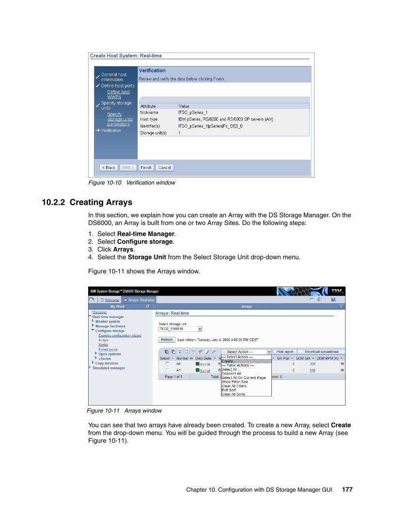
Figure 10-10 Verification window
10.2.2 Creating ArraysIn this section, we explain how you can create an Array with the DS Storage Manager. On the DS6000, an Array is built from one or two Array Sites. Do the following steps:
1. Select Real-time Manager.2. Select Configure storage.3. Click Arrays.4. Select the Storage Unit from the Select Storage Unit drop-down menu.
Figure 10-11 shows the Arrays window.
Figure 10-11 Arrays window
You can see that two arrays have already been created. To create a new Array, select Create from the drop-down menu. You will be guided through the process to build a new Array (see Figure 10-11).
Chapter 10. Configuration with DS Storage Manager GUI 177
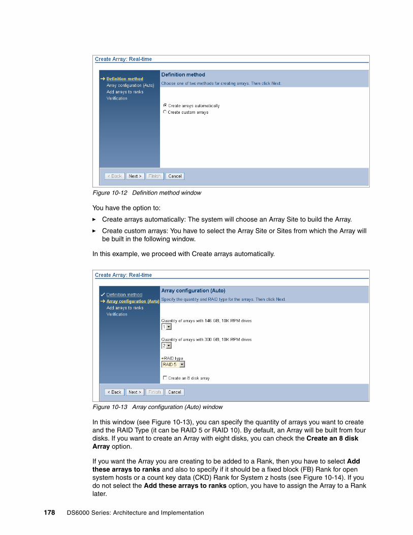
Figure 10-12 Definition method window
You have the option to:
� Create arrays automatically: The system will choose an Array Site to build the Array.
� Create custom arrays: You have to select the Array Site or Sites from which the Array will be built in the following window.
In this example, we proceed with Create arrays automatically.
Figure 10-13 Array configuration (Auto) window
In this window (see Figure 10-13), you can specify the quantity of arrays you want to create and the RAID Type (it can be RAID 5 or RAID 10). By default, an Array will be built from four disks. If you want to create an Array with eight disks, you can check the Create an 8 disk Array option.
If you want the Array you are creating to be added to a Rank, then you have to select Add these arrays to ranks and also to specify if it should be a fixed block (FB) Rank for open system hosts or a count key data (CKD) Rank for System z hosts (see Figure 10-14). If you do not select the Add these arrays to ranks option, you have to assign the Array to a Rank later.
178 DS6000 Series: Architecture and Implementation

Figure 10-14 Add arrays to ranks window
Click Next to get to the Verification window (see Figure 10-15).
Figure 10-15 Verification window
Here you can verify your specifications for the array. If everything is correct, click Finish to create the Array. In this example, we created three Arrays and choose to add them to Ranks. This means three Ranks will also be created.
10.2.3 Creating RanksIn this section, we show how to create a Rank with the DS Storage Manager:
1. Select Real-time Manager.
2. Select Configure storage.
3. Click Ranks.
4. Select the Storage Unit from the Select Storage Unit drop-down menu.
Chapter 10. Configuration with DS Storage Manager GUI 179

Figure 10-16 shows the Ranks window.
Figure 10-16 Ranks window
You can see that two Ranks are already created. To create another Rank, choose Create from the Select Action drop-down menu. This will start the process to create a Rank (see Figure 10-17).
Figure 10-17 Select Array for rank window
First, you have to select the Array from which you want to build the Rank. In our example, only one Array is available. If no Arrays are available you will have to go back to the Array window and create some. Click Next to define the Rank properties (see Figure 10-18).
180 DS6000 Series: Architecture and Implementation
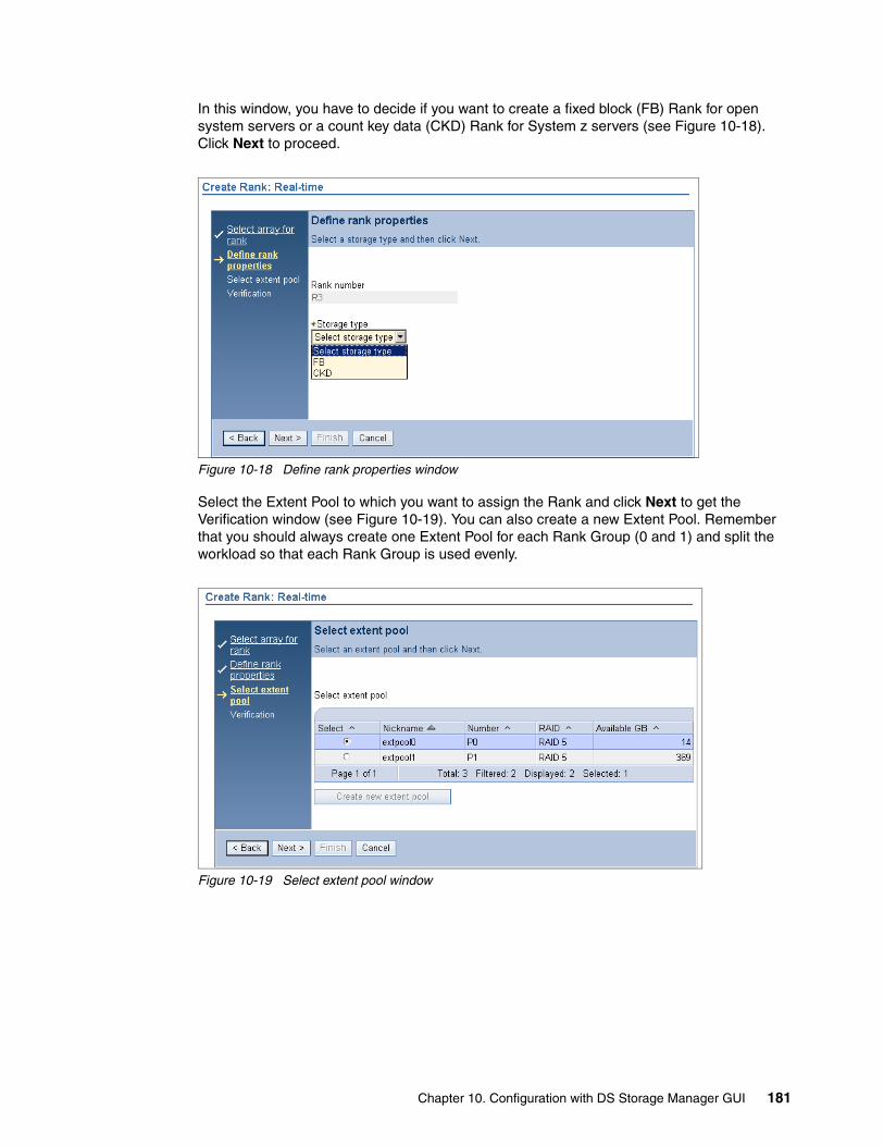
In this window, you have to decide if you want to create a fixed block (FB) Rank for open system servers or a count key data (CKD) Rank for System z servers (see Figure 10-18). Click Next to proceed.
Figure 10-18 Define rank properties window
Select the Extent Pool to which you want to assign the Rank and click Next to get the Verification window (see Figure 10-19). You can also create a new Extent Pool. Remember that you should always create one Extent Pool for each Rank Group (0 and 1) and split the workload so that each Rank Group is used evenly.
Figure 10-19 Select extent pool window
Chapter 10. Configuration with DS Storage Manager GUI 181

In the Verification window (see Figure 10-20), you can check your specifications for the Rank. If everything is correct, click Finish to add the Rank.
Figure 10-20 Verification window
10.2.4 Creating Extent PoolsTo create a new Extent Pool, follow this procedure:
1. Select Real-time Manager.
2. Select Configure storage.
3. Click Extent Pools.
4. Select the Storage Unit from the Select Storage Unit drop-down menu.
Figure 10-21 shows the Extent Pools window.
Figure 10-21 Extent pools window
182 DS6000 Series: Architecture and Implementation

To create a new Extent Pool, select Create from the Select Action drop-down menu. In the next window, you have to select the definition method, as shown in Figure 10-22.
Figure 10-22 Definition method window
In Figure 10-22, you can choose between the following options:
� Create Extent Pool automatically based on storage requirements: You have to specify the amount of storage you need and the system will automatically use unassigned Ranks and Arrays to fulfill your requirements.
� Create custom Extent Pool: You have to specify the Ranks which you want to assign to the Extent Pool.
In this example, we choose the custom option.
Important: You do not want to have a situation where you end up with only a single Extent Pool for the entire machine. If you do, the performance of the machine will not be optimal.
Chapter 10. Configuration with DS Storage Manager GUI 183

Click Next to define the requirements of the Extent Pool. This takes you to the window shown in Figure 10-23.
Figure 10-23 Define requirements window
In Figure 10-23, you have to enter the following information:
� Nickname: Name of the Extent Pool.
� Storage type: Select FB for open systems hosts or CKD for System z servers.
� RAID type: You can select RAID 5 or RAID 10.
� Server: Select the Server, 0 or 1. This is for Rank Group 0 or Rank Group 1.
Click Next, which takes us to Figure 10-24.
Figure 10-24 Select rank window
In Figure 10-24, you get the opportunity to select which Ranks to place into this Extent Pool. Remember to make sure your Ranks are evenly split between Rank Group 0 and Rank Group 1 (see how this is done in Figure 10-24). Click Next to continue.
184 DS6000 Series: Architecture and Implementation

You can choose to reserve a percentage of the Extent Pool to prevent it from being allocated. You would do this to ensure that you always have some spare capacity in the Extent Pool. If you choose to enter 0 (zero), then you can use all the storage to create volumes (see Figure 10-25). Click Next to move to the Verification window shown in Figure 10-26.
Figure 10-25 Reserve storage window
In Figure 10-26, you can verify your specifications for the Extent Pool. If everything is correct, click Finish to create the Extent Pool.
Figure 10-26 Verification window
10.2.5 Creating fixed block (FB) volumesThis section explains the creation of fixed block volumes. Perform the following steps:
1. Select Real-time manager.
2. Select Configure storage.
3. Select Open systems.
4. Click Volumes - Open system.
Chapter 10. Configuration with DS Storage Manager GUI 185

5. Select the Storage Unit from the Select Storage Unit drop-down menu.
6. If you want to display existing volumes, you can also use a secondary filter, such as LSS or Volume Group. If you want to just create new volumes, then do not worry about doing this task.
Figure 10-27 shows the Open systems window.
Figure 10-27 Volumes: Open systems window
Select Create from the Select Action drop-down menu.
Figure 10-28 shows the Select extent pool window. Choose the Extent Pool from which you want to create the volume (you can choose only one Extent Pool). Click Next to continue. The window in Figure 10-29 should appear.
Figure 10-28 Select extent pool window
186 DS6000 Series: Architecture and Implementation

Figure 10-29 Define volume characteristics window
In the window shown in Figure 10-29, define the following items:
� Volume type: You can choose between DS sized (binary), ESS sized (decimal), Blocks sized (512 byte blocks), and iSeries volumes.
� Select Volume Groups: You can select one or more Volume Groups to which you want to assign the volumes. If you do not choose a Volume Group, you can assign the volumes later.
Click Next to define the volume properties, as shown in Figure 10-30.
Figure 10-30 Define volume properties window
In Figure 10-30, you have to enter the following information:
� Quantity: The number of volumes you want to create.
� Size: The size of the volumes in either binary GB (type DS), decimal GB (type ESS), or blocks. If you are creating iSeries volumes, there will be pre-determined sizes available via a drop-down menu.
Chapter 10. Configuration with DS Storage Manager GUI 187
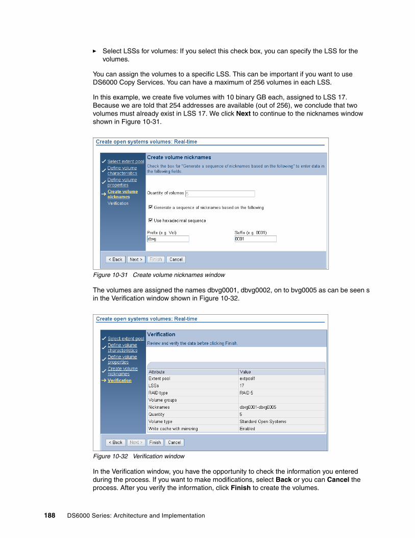
� Select LSSs for volumes: If you select this check box, you can specify the LSS for the volumes.
You can assign the volumes to a specific LSS. This can be important if you want to use DS6000 Copy Services. You can have a maximum of 256 volumes in each LSS.
In this example, we create five volumes with 10 binary GB each, assigned to LSS 17. Because we are told that 254 addresses are available (out of 256), we conclude that two volumes must already exist in LSS 17. We click Next to continue to the nicknames window shown in Figure 10-31.
Figure 10-31 Create volume nicknames window
The volumes are assigned the names dbvg0001, dbvg0002, on to bvg0005 as can be seen s in the Verification window shown in Figure 10-32.
Figure 10-32 Verification window
In the Verification window, you have the opportunity to check the information you entered during the process. If you want to make modifications, select Back or you can Cancel the process. After you verify the information, click Finish to create the volumes.
188 DS6000 Series: Architecture and Implementation

10.2.6 Creating Volume GroupsTo create a Volume Group, do the following steps:
1. Select Real-time Manager.
2. Select Configure storage.
3. Select Open Systems.
4. Click Volume Groups.
5. Select the Storage Unit from the Select Storage Unit drop-down menu.
Figure 10-33 Shows the Volume groups window.
Figure 10-33 Volume groups window
Chapter 10. Configuration with DS Storage Manager GUI 189

To create a new Volume Group, select Create from the Action drop-down menu. This takes you to Figure 10-34.
Figure 10-34 Define volume group properties window
In Figure 10-34, enter a nickname for the Volume Group and select the host type from which you want to access the Volume Group. If you select one host (for example, pSeries®), another host with the same Addressing Method will be automatically selected. Take note that there are several pages of host types. Click Next to continue, which takes you to Figure 10-35.
In Figure 10-35, we select the host attachment for your Volume Group. You can select only one host attachment.
Figure 10-35 Select host attachments window
190 DS6000 Series: Architecture and Implementation

Click Next to display the window shown in Figure 10-36. Select the volumes that should be included in the Volume Group. If you have to select a large number of volumes, you can specify a filter so that only those volumes are displayed in the list and then you can select all of them.
Figure 10-36 Select volumes for group window
Click Next to get the Verification window, as shown in Figure 10-37.
Figure 10-37 Verification window
In the Verification window, you have to check the information you entered during the process. If you want to make modifications, select Back or you can Cancel the process. After you verify the information, click Finish to create the host system attachment.
Chapter 10. Configuration with DS Storage Manager GUI 191

10.2.7 System z: Creating LCUsIn this section, we show how you can create LCUs. This is only necessary for System z. Do the following steps:
1. Select Real time Manager.
2. Select Configure storage.
3. Select System z.
4. Select LCUs.
5. Select the Storage Unit from the Select Storage Unit drop-down menu.
Figure 10-38 shows the LCUs window.
Figure 10-38 LCUs window
One LCU is already created. To create one or more new LCUs, choose Create from the Select Action drop-down menu, which takes us to Figure 10-39.
Figure 10-39 Select from available LCUs window
In Figure 10-39, you can select the LCU IDs you want to create. In this example, we create LCU 02. When finished, click Next.
192 DS6000 Series: Architecture and Implementation

In Figure 10-40, you can define the following LCU properties:
� SSID: Subsystem ID.
� LCU type: Select the LCU type you want to create (3990 Mod.3, 3990 Mod. 3 for TPF, or 3990 Mod. 6).
Figure 10-40 Define LCU properties window
The following parameter is important if you use DS6000 Copy Services:
� Concurrent copy session time-out (sec.): The time in seconds that any logical device on this LCU in a concurrent copy session stays in a long busy state before suspending a concurrent copy session.
Click Next to get to the Verification window (see Figure 10-41).
Figure 10-41 Verification window
In the Verification window, you have to check the information you entered during the process. If you want to make modifications, select Back or you can Cancel the process. After you verify the information, click Finish to create the LCU.
Chapter 10. Configuration with DS Storage Manager GUI 193

10.2.8 System z: Creating count key data (CKD) volumesIn this section, we describe how you can create and configure System z volumes. System z volumes are sized using cylinders. To create System z volumes, do the following steps:
1. Select Real-time manager.
2. Select Configure storage.
3. Select zSeries.
4. Click on Volumes - zSeries.
5. Select the Storage Unit from the Select Storage Unit drop-down menu.
6. Select the LCU you wish to work with. If no LCUs are available, then none will be listed. You will have the ability to create an LCU during the CKD volume creation process.
Figure 10-42 shows the Volumes - zSeries window.
Figure 10-42 Volumes - System z window
194 DS6000 Series: Architecture and Implementation

To create new System z volumes, select Create from the Select Action drop-down menu (see Figure 10-43).
Figure 10-43 Select extent pool window
Select the Extent Pool in which you want to create the volumes. You can select only one Extent Pool. In this example, there is only one to select from. Click Next, which takes you to the window shown in Figure 10-44.
Figure 10-44 Define base volume characteristics window
Enter the following information:
� Volume type: Select the volume model you want to create, for example, 3390 Mod. 9.
� LCU: Select the LCU in which you want to create the volumes.
Chapter 10. Configuration with DS Storage Manager GUI 195

Select Next to define the base volume properties, which takes you to the window shown in Figure 10-45.
Figure 10-45 Define base volume properties window
Enter the following information:
� Quantity: The number of base volumes you want to create.
� Base start address: The address of the first volume you want to create. Usually, this will be 0.
� Ascending / Descending: Select the addressing order for the base volumes.
Click Next to create the nicknames for the volumes. This takes you to Figure 10-46.
Figure 10-46 Create volume nicknames window
196 DS6000 Series: Architecture and Implementation

Create the base volumes VOL0002, VOL0003, and so on, up to VOL0006. Click Next. You are then taken to the window shown in Figure 10-47.
Figure 10-47 Define alias assignment window
Select the volumes for which you want to create alias volumes:
� Starting address: In this field, enter the first alias address.
� Ascending / Descending: Select the addressing order for the aliases. It is normal to start at address 255 and select descending addresses.
� Aliases / Per Volumes: In these two fields, you have to enter how many aliases you want to create for each selected base volume. In this example, we are creating two alias volumes for each base volume. Clearly if you have a large number of volumes in an LSS, the number of aliases you can create will decrease.
� Click Add aliases and click Next to go to the verification window shown in Figure 10-48.
Important: You must click Add aliases before you click Next; otherwise, the aliases will not be created. Also, if you choose to use descending addresses, do not start the alias range at 256; it must start at 255.
Chapter 10. Configuration with DS Storage Manager GUI 197

Figure 10-48 Verification window
Verify that you have entered the correct information before you select Finish.
198 DS6000 Series: Architecture and Implementation

Chapter 11. Using the Express configuration wizard
In this chapter, we introduce the Express configuration wizard, which is accessible through the DS6000 Storage Manager for both the Real-time and Simulated managers.
We cover the following topics:
� Introducing the Express configuration wizard� Express configuration wizard for open systems volumes� Express configuration wizard for System i volumes� Express configuration wizard for System z volumes
11
© Copyright IBM Corp. 2005, 2006. All rights reserved. 199

11.1 Introducing the Express configuration wizardThe Express configuration wizard is accessible through the DS6000 Storage Manager. This wizard is available for the online configuration using the Real-time manager as well as for the offline configuration using the Simulated manager, as shown in Figure 11-1.
Figure 11-1 DS6000 Storage Manager: Express configuration windows for the online and offline configurations
Express configuration provides the simplest and fastest method to configure a DS6000 Storage Unit without the need to manually create Arrays, Ranks, and Extent Pools. It requires less knowledge about the configuration of the physical storage and just concentrates on the volume needs for your host attachments. Basically, it hides all of the logical configuration objects below the volume level from the user to keep the number of required options to a minimum. Express Configuration is ideal for users with less knowledge of the underlying storage concepts who just want to quickly and easily set up and begin using volumes on a new DS6000 Storage Unit.
Select Real-time manager → Configure storage → Express configuration wizard from the navigation window of the DS6000 Storage Manager to initiate the Express Configuration in online or real-time mode, which means that the configuration is directly applied to the Storage Unit in real-time after choosing Finish on the final verification window.
200 DS6000 Series: Architecture and Implementation

Select Simulated manager → Configure storage → Express configuration wizard from the navigation window to initiate the Express Configuration in offline mode. When using the Express configuration in offline mode, you can safely prepare and review the logical configuration that has been generated by the Express configuration wizard before actually applying it to a real Storage Unit. Refer to Chapter 12, “Using the Simulated manager” on page 213 for more information on how to import, export, or apply a simulated configuration to a real Storage Unit.
On the initial Express configuration window, you need to select the Storage Unit and the Volume type to be configured from the drop-down menus, as shown in Figure 11-2.
Figure 11-2 Express configuration Real-time: Selecting the Storage Unit and the volume type to be configured
The Express configuration wizard offers three different configuration flows based on the requirements for the particular host systems:
� Creating volumes for open system hosts (standard FB volumes)� Creating volumes for System i hosts (System i specific FB volumes)� Creating volumes for System z hosts (CKD volumes)
The configuration flows for open systems and System i volumes (FB volumes) contain the following tasks:
� Configure volumes (FB)� Create volume group (optional)� Create host attachment (optional)
If you uncheck the Create host option on the initial volumes window (see Figure 11-3 on page 203 and Figure 11-12 on page 208), you can skip the tasks of creating a specific volume group and host attachment for the volumes. This is convenient if you only want to configure the physical storage capacity and create an amount of uniform volumes without the need to specify a particular host system for these volumes. Then you can customize your configuration and create appropriate volume groups from these volumes and assign them to your particular host systems using the custom configuration windows from the Storage Manager or the DS CLI.
Chapter 11. Using the Express configuration wizard 201

The configuration flow for System z contains only the following tasks, since you do not need to create volume groups or host connections for System z attachments:
� Configure volumes (CKD)� Define LCUs (logical control units) and SSIDs
The Express configuration wizard can be invoked several times (one time after another) as long as unconfigured physical storage capacity (for example, unconfigured Array Sites) is available. Each run of the Express configuration wizard will configure only the amount of unconfigured physical storage capacity that is necessary to meet the storage requirements for the specified amount of volumes. If all physical storage is already logically configured in Arrays, Ranks, and Extent Pools, you cannot use the Express configuration wizard anymore. You need to use the custom configuration windows or the DS CLI to configure additional volumes and volume groups from the available storage capacity that is available in the Extent Pools (free Extents).
The Express configuration wizard always creates new volumes from the available unconfigured physical storage capacity by configuring new Arrays, Ranks, and Extent Pools. If the Create host option is selected for open systems or System i hosts, it will also create a new volume group and a new host attachment for these volumes with each iteration.
If multiple hosts are configured using several iterations of the Express configuration wizard, it will create dedicated Arrays, Ranks, and Extent Pools for each host system. It will utilize new LSSs or LCUs (if available) with each run and distribute the Extent Pools across both controller cards in such a way as to balance the managed storage capacity per controller card.
The Express configuration wizard is very convenient to use if you quickly need to configure a homogeneous Storage Unit that is equipped with only one type of DDMs (same RPM and capacity) and want to create an amount of uniform volumes with same storage type and size for all attached host systems. As you cannot specify which DDMs to use when running the Express configuration wizard, you should not use the Express configuration if your machine is equipped with different types of DDMs. In this case, you should prefer a custom configuration.
With the current microcode release, the Express configuration wizard only creates one Extent Pool per iteration. To achieve a balanced configuration with at least two Extent Pools (one Extent Pool per rank group), you should consider running the Express configuration wizard at least twice, for example, configuring 50% of the Storage Unit’s total physical storage capacity in the first pass and configuring the remaining 50% in a second pass.
To allow the most granular configuration, the Express configuration only creates 4-disk Arrays and Ranks. If you want to configure 8-disk Arrays, you currently cannot use the Express configuration wizard. You need to use the custom configuration windows to configure 8-disk Arrays and Ranks.
Note: As the algorithms of the Express configuration wizard are enhanced with future microcode releases, you might obtain different results than described in the section above. Therefore, you should consider running the Express configuration in offline or simulated mode first and evaluate the results before applying the configuration to a real Storage Unit.
202 DS6000 Series: Architecture and Implementation
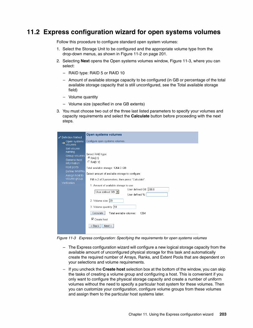
11.2 Express configuration wizard for open systems volumesFollow this procedure to configure standard open system volumes:
1. Select the Storage Unit to be configured and the appropriate volume type from the drop-down menus, as shown in Figure 11-2 on page 201.
2. Selecting Next opens the Open systems volumes window, Figure 11-3, where you can select:
– RAID type: RAID 5 or RAID 10
– Amount of available storage capacity to be configured (in GB or percentage of the total available storage capacity that is still unconfigured, see the Total available storage field)
– Volume quantity
– Volume size (specified in one GB extents)
3. You must choose two out of the three last listed parameters to specify your volumes and capacity requirements and select the Calculate button before proceeding with the next steps.
Figure 11-3 Express configuration: Specifying the requirements for open systems volumes
– The Express configuration wizard will configure a new logical storage capacity from the available amount of unconfigured physical storage for this task and automatically create the required number of Arrays, Ranks, and Extent Pools that are dependent on your selections and volume requirements.
– If you uncheck the Create host selection box at the bottom of the window, you can skip the tasks of creating a volume group and configuring a host. This is convenient if you only want to configure the physical storage capacity and create a number of uniform volumes without the need to specify a particular host system for these volumes. Then you can customize your configuration, configure volume groups from these volumes and assign them to the particular host systems later.
Chapter 11. Using the Express configuration wizard 203

4. Selecting Next opens the volume naming window, Figure 11-4, where you can specify nicknames for the volumes that are going to be created. Just check Generate a sequence of nicknames based on the following and specify an alphabetic prefix (preceding the nickname, a maximum of eight characters) and a numeric suffix (a numeric value following the nickname, which is increased sequentially, to a maximum of eight digits) to generate a sequence of nicknames for the volumes.
5. Selecting Verify nicknames are unique will also verify whether the chosen volume names are unique and not already in use on the Storage Unit, but the verification might take a considerable amount of time. Unique volume names are not required, as volumes are identified by their unique volume ID, but they might be convenient for management purposes.
Figure 11-4 Express configuration: Specifying nicknames for the open systems volumes
6. Selecting Next opens the volume group window, Figure 11-5, where you can specify a nickname (a maximum of 16 characters) for the new volume group, which will be created, and individually select the volumes for that volume group. Here you can also verify the sequence of nicknames for the created volumes that was generated based on the selections from the previous window. The volumes need to be grouped together in a volume group in order to be assigned to a host system, which will be done in a following step.
204 DS6000 Series: Architecture and Implementation

Figure 11-5 Express configuration: Creating a new volume group for the open systems volumes
7. Selecting Next opens the host type configuration window, Figure 11-6, where you have to specify the host type for your attached host system.
Figure 11-6 Express configuration: Selecting the open systems host type
A list of available host types is shown in Figure 11-7. You also have to enter a nickname (maximum 16 characters) for the new host system. An optional description (maximum 256 characters) can be entered in the description field.
Chapter 11. Using the Express configuration wizard 205

Figure 11-7 Express configuration: Available open systems host types
8. The next window, Figure 11-8, allows you to specify the quantity and type of host ports for the host attachment (either FC switched fabric for SAN attached hosts or FC arbitrated loop for direct attached hosts). You can additionally group the host ports to share a common set of volumes, so that this group of host ports is treated as a single host attachment.
Figure 11-8 Express configuration: Specifying the host ports
9. Choosing Next opens the Define WWPNs window, Figure 11-9, where you can specify the 16-digit WWPNs of the host ports for your host attachment.
Figure 11-9 Express configuration: Defining the WWPNs for the host attachment
206 DS6000 Series: Architecture and Implementation

10.The next window, Figure 11-10, allows you to map the newly created volume group to the newly defined host attachment by checking the Assign host attachment to volume group check box.
Figure 11-10 Express configuration: Assigning the volume group to the host attachment
11.The final window, Figure 11-11, is a verification window where you can verify your selections before the configuration is applied to the real-time or simulated Storage Unit by selecting Finish. The Express configuration wizard will then configure the required amount of storage from the available unconfigured storage capacity depending on your selections and create the necessary number of Arrays, Ranks, and Extent Pools as well as the volumes and host attachments.
Figure 11-11 Express configuration: Verification window for open systems configuration
Chapter 11. Using the Express configuration wizard 207

11.3 Express configuration wizard for System i volumesFollow this procedure to configure volumes for System i hosts:
1. Just select the Storage Unit to be configured and the appropriate volume type from the drop-down menus, as shown Figure 11-2 on page 201.
2. Selecting Next opens the System i volumes window, Figure 11-12, where you can select:
– RAID type: RAID 5 or RAID 10
– Volume type: Protected or Unprotected– Predefined System i Volume size: 8.56, 17.54, 35.16, 72.56, 141.12, or 282.25
(decimal GB)
– Amount of available storage capacity to be configured (in GB or percentage of the total available storage capacity that is still unconfigured, see the Total available storage field)
– Volume quantity
3. You have to choose to specify either the amount of storage or the number of volumes to be configured and select the Calculate button before proceeding with the next steps:
– The Express configuration wizard will configure new logical storage capacity from the available amount of unconfigured physical storage for this task and automatically create the required number of Arrays, Ranks, and Extent Pools dependent on your selections and volume requirements.
– If you uncheck the Create host selection box at the bottom of the window, you can skip the tasks of creating a volume group and configuring a host. This is convenient if you only want to configure the physical storage capacity and create an number of uniform volumes. Then you can customize your configuration, configure volume groups from these volumes and assign them to the particular host systems later.
Figure 11-12 Express configuration: Specifying the requirements for System i volumes
208 DS6000 Series: Architecture and Implementation

4. Selecting Next opens the volume naming window, similar to Figure 11-3 on page 203, where you can specify nicknames for the volumes that are going to be created:
– Just check Generate a sequence of nicknames based on the following and specify an alphabetic prefix (preceding the nickname, maximum of eight characters) and a numeric suffix (a numeric value following the nickname which is increased sequentially, maximum of eight digits) to generate a sequence of nicknames for the volumes.
– Selecting Verify nicknames are unique will also verify whether the chosen volume names are unique and not already in use on the Storage Unit, but the verification might take a considerable amount of time. Unique volume names are not required, as volumes are identified by their unique volume ID, but they might be convenient for management purposes.
5. Selecting Next opens the volume group window, where you can specify a nickname (maximum of 16 characters) for the new volume group, which will be created, and individually select the volumes for that volume group. Here you can also verify the sequence of nicknames for the created volumes that was generated based on the selections from the previous window. The volumes need to be grouped together in a volume group in order to be assigned to a host system, which will be done in a following step.
6. Selecting Next opens the host type configuration window, where you have to specify the host type for your attached host system. A list of available host types is shown in Figure 11-13. You also have to enter a nickname (maximum of 16 characters) for the new host system. An optional description (maximum of 256 characters) can be entered in the description field.
Figure 11-13 Express configuration: Available host types for System i
7. The next window allows you to specify the quantity and type of host ports for the host attachment (either FC switched fabric for SAN attached hosts or FC arbitrated loop for direct attached hosts). You can also group the host ports to share a common set of volumes, so that this group of host ports is treated as a single host attachment.
8. Choosing Next opens the Define WWPNs window, where you can specify the 16-digit WWPNs of the host ports for your host attachment.
9. The next window allows you to map the newly created volume group to the newly defined host attachment by checking the Assign host attachment to volume group check box.
10.The final window is a verification window where you can verify your selections before the configuration is applied to the real-time or simulated Storage Unit by selecting Finish. The Express configuration wizard will then configure the required amount of storage from the available unconfigured storage capacity dependent on your selections and create the necessary number of Arrays, Ranks, and Extent Pools, as well as the volumes and host attachments.
Chapter 11. Using the Express configuration wizard 209

11.4 Express configuration wizard for System z volumesFollow this procedure to configure volumes for System z hosts:
1. Just select the Storage Unit to be configured and the appropriate volume type from the drop-down menus, as shown in Figure 11-2 on page 201.
2. Selecting Next opens the System z volumes window, Figure 11-14 on page 210.
Figure 11-14 Express configuration: Specifying the requirements for System z volumes
Here you can select:
– RAID type: RAID 5 or RAID 10
– Volume type (see Figure 11-15 for selection of available volume types)
– Amount of available storage capacity to be configured (in GB or percentage of the total available storage capacity that is still unconfigured; see the Total available storage field)
– Volume quantity
3. You have to choose to specify either the amount of storage or the number of volumes to be configured and select the Calculate button before proceeding with the next steps.
Figure 11-15 Express configuration: Available System z volume types
The Express configuration wizard will configure new logical storage capacity from the available amount of unconfigured physical storage for this task and automatically create the required number of Arrays, Ranks, and Extent Pools dependent on your selections and volume requirements.
210 DS6000 Series: Architecture and Implementation

4. Selecting Next opens the Set LCU/SSID window, Figure 11-16, where you can set up the LCUs (logical control units) you want to configure for your Storage Unit.
Figure 11-16 Express configuration: Specifying LCUs (logical control units)
You can specify:
– Initial LCU ID to start with (from a list of all available LCUs; even numbered LCUs having an affinity to DS6000 controller card 0 and odd numbered LCUs having an affinity to DS6000 controller card 1)
– LCU type (CKD base control unit type for the LCUs; see Figure 11-17 for available types)
– Initial SSID to start with for the LCUs
5. Check Utilize all addresses in each LCU to create only as many LCUs as needed for the specified number of base volumes utilizing all 256 available addresses per LCU.
6. Check Spread volumes equally across LCU and specify the Number of LCUs to create in order to spread the base volumes equally across the specified number of LCUs. The number of new LCUs to be configured is limited to the number of available LCUs on the Storage Unit.
Figure 11-17 Express configuration: Available LCU types
7. Selecting Next opens the volume naming window where you can specify nicknames for the volumes that are going to be created:
– Just check Generate a sequence of nicknames based on the following and specify an alphabetic prefix (preceding the nickname, maximum of eight characters) and a numeric suffix (a numeric value following the nickname which is increased sequentially, maximum of eight digits) to generate a sequence of nicknames for the volumes.
– Selecting Verify nicknames are unique will also verify whether the chosen volume names are unique and not already in use on the Storage Unit, but the verification might take a considerable amount of time. Unique volume names are not required, as volumes are identified by their unique volume ID, but they might be convenient for management purposes.
Chapter 11. Using the Express configuration wizard 211

8. The final window, Figure 11-18, is a verification window where you can verify your selections before the configuration is applied to the real-time or simulated Storage Unit by selecting Finish. The Express configuration wizard will then configure the required amount of storage from the available unconfigured storage capacity depending on your selections and create the necessary number of Arrays, Ranks, and Extent Pools as well as the volumes and LCUs.
Figure 11-18 Express configuration: Verification window for System z configuration
212 DS6000 Series: Architecture and Implementation

Chapter 12. Using the Simulated manager
This chapter describes how to use the DS6000 Simulated manager, which gives you the ability to:
� Practice performing logical configuration using the GUI, without an actual machine.� Determine the ideal configuration before applying it.� Apply a pre-created configuration file at a time of your choosing.
We cover the following topics:
� The simulated configuration process� Working with configuration files� Applying a configuration file
12
© Copyright IBM Corp. 2005, 2006. All rights reserved. 213

12.1 DS6000 offline configuratorWhen it comes time to logically configure a DS6000, you have two choices:
1. Configure the box in real time using either the DS CLI or the DS Storage Manager GUI. Note that if you choose to use the GUI, you also have the opportunity to use the Express Configuration option.
2. You can also choose to create an initial logical configuration using the offline simulator and then apply the configuration onto a new or de-configured DS6000 at a later time. The offline method gives you the ability to try out different ideas and finalize a configuration without having to apply it.
If you choose to use the offline simulator, you will need to take the following steps:
1. Create a configuration file.
2. Add a simulated Storage Unit to the configuration file.
3. Configure the host ports for the simulated Storage Unit.
4. Logically configure the simulated Storage Unit, including Arrays, Ranks, Extent Pools, logical volumes, volume groups, and host connections.
5. Save the configuration file. You can also export it and then import it onto a separate SMC (unless you are using multiple SMCs, using export and import will likely be unnecessary).
6. Apply the configuration of the simulated Storage Unit to a new or de-configured DS6000.
12.2 The simulated configuration processFor the rest of this chapter, we discuss how to proceed with the offline method.
12.2.1 Creating a configuration fileHere is the procedure to follow:
1. The first step is to create a configuration file. You will need to log on to the DS Storage Manager (SM) GUI and select Simulated manager, then Manage configuration files.
When the Manage configuration files: Simulated window opens, you will see the default configuration file (see Figure 12-1).
Figure 12-1 Creating a new simulated configuration file
2. You can work with the default file or create a new one. For this example, we will create a new configuration file by choosing Create New from the Select Action menu. There is no need to highlight anything in the Select column.
214 DS6000 Series: Architecture and Implementation

3. Now because only one configuration file can be open at a time, you will get a warning message, shown in Figure 12-2. If you have been working on a configuration file and you do not wish to lose your work so far, It is very important you do not choose Continue. Instead, choose Cancel or OK.
Figure 12-2 Create new configuration warning window
4. We now have a new configuration file, as shown in Figure 12-3. The first configuration file created will be called Enterprise1, the second, Enterprise2, and so on. However, when you save the configuration file, you can name it anything you like (up to 16 characters in length).
Figure 12-3 Enterprise1 configuration has been created
The newly created configuration file does not contain any information yet. Now we must add a simulated Storage Unit.
12.2.2 Creating or importing a simulated Storage UnitWhen performing a real physical install, the process to add the Storage Unit is a vital step, and it is no different in the Simulated manager:
1. First, we need to open the Storage Units window by selecting Simulated manager, then Manage hardware and Storage Units.
2. From the Storage Units, you now need to select the drop-down menu to generate a Storage Unit, as shown in Figure 12-4.
Chapter 12. Using the Simulated manager 215

Figure 12-4 Storage Unit creation choices
There are three choices depicted in Figure 12-4:
Import Use this option to import the actual configuration from a real machine. To be able to do this, you need to be connected to the DS SMC (or using the DS SMC) that manages the actual machine you plan to configure. This is the best choice, as the configuration will be an exact match to the machine.
Import from eConfig Use this option to import an eConfig file. This would be supplied to you by your IBM Sales Representative or IBM Business Partner.
Create Use this option to actually define a machine from scratch by specifying the number of disk groups by size.
The three possible methods are detailed below.
Importing the Storage Unit from an SMCIf you choose the Import option:
1. You will be prompted for the IP address of the SMC, as shown in Figure 12-5. If you are on the same SMC that manages the real DS6000 Storage Unit, you can use the loopback IP address, 127.0.0.1.
Figure 12-5 Importing the Storage Unit: Identifying the Storage Complex
2. Once you identify the SMC IP address, you will then be prompted to select which DS6000 Storage Unit you wish to import, as shown in Figure 12-6. You will also need to choose how much of the configuration you wish to import. Unless you have a specific reason not to, select the option to import the Physical and logical configuration plus host attachments.
216 DS6000 Series: Architecture and Implementation

Figure 12-6 Importing the Storage Unit: Selecting the Storage Unit
3. You will then be prompted to name the Storage Unit and verify your choices before the import begins. When the import is complete, you will now see a new Storage Unit listed under the Storage Units tab in the Simulated manager. An example is shown in Figure 12-7.
Figure 12-7 Successfully imported Storage Unit
Considerations when importing a Storage Unit from one SMC to another SMCIf you are using two SMCs, where one is used to manage the actual DS6000s, and the other is used to create a simulated configuration, you need to ensure that the user ID and password you are using is the same on both SMCs. This is because during the import process, the target SMC uses your user ID and password to log on to the source SMC. If the user ID is not present, or has a different password, the import will fail, as shown in Figure 12-8.
Figure 12-8 Invalid password during import Storage Unit
Chapter 12. Using the Simulated manager 217
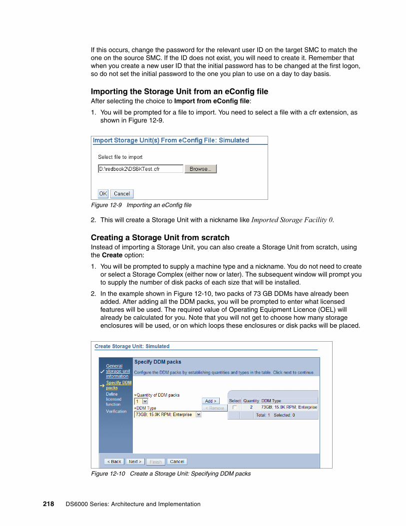
If this occurs, change the password for the relevant user ID on the target SMC to match the one on the source SMC. If the ID does not exist, you will need to create it. Remember that when you create a new user ID that the initial password has to be changed at the first logon, so do not set the initial password to the one you plan to use on a day to day basis.
Importing the Storage Unit from an eConfig fileAfter selecting the choice to Import from eConfig file:
1. You will be prompted for a file to import. You need to select a file with a cfr extension, as shown in Figure 12-9.
Figure 12-9 Importing an eConfig file
2. This will create a Storage Unit with a nickname like Imported Storage Facility 0.
Creating a Storage Unit from scratchInstead of importing a Storage Unit, you can also create a Storage Unit from scratch, using the Create option:
1. You will be prompted to supply a machine type and a nickname. You do not need to create or select a Storage Complex (either now or later). The subsequent window will prompt you to supply the number of disk packs of each size that will be installed.
2. In the example shown in Figure 12-10, two packs of 73 GB DDMs have already been added. After adding all the DDM packs, you will be prompted to enter what licensed features will be used. The required value of Operating Equipment Licence (OEL) will already be calculated for you. Note that you will not get to choose how many storage enclosures will be used, or on which loops these enclosures or disk packs will be placed.
Figure 12-10 Create a Storage Unit: Specifying DDM packs
218 DS6000 Series: Architecture and Implementation

12.2.3 Configuring the host ports of the simulated Storage UnitOnce you have added a Storage Unit using any of the three methods detailed above, the next step is to configure the host ports of the simulated Storage Unit. By default, all eight host ports on a DS6000 are either undefined or are in Fibre Channel Arbitrated Loop mode. If you wish them to be in Fibre Channel Point-to-point mode, or in FICON mode, you should make that change now:
1. Select Simulated manager.
2. Select Manage hardware.
3. Select Storage Units.
4. Check the Select check box next to your simulated Storage Unit.
5. From the Select Action drop-down menu, select Configure I/O Ports. This will open the Configure I/O Ports: Simulated window (see Figure 12-11).
Figure 12-11 Configure I/O ports
6. Either check all the boxes in the select column or use the Select Action drop-down menu to choose Select All.
7. Having selected some or all of the I/O ports, from the Select Action drop-down menu, you can set the I/O ports to your chosen topology, as shown in Figure 12-12. If you choose to use different topologies for different ports you can also do this. The topologies are:
FcSf Fibre Channel switched fabric (also called point to point)FcAl Fibre Channel arbitrated loopFICON FICON - for System z hosts only
Chapter 12. Using the Simulated manager 219

Figure 12-12 Configuring I/O ports: Making your selection
Once the simulated Storage Unit has been added and its host ports have been configured, it is time to perform the logical configuration of the simulated Storage Unit.
12.2.4 Logical configuration of the simulated Storage UnitLogical configuration of a Storage Unit in the Simulated manager is the same as in the Real-time manager including use of the Express configuration option. You will see the word Simulated as opposed to Real-time in every window, as shown in Figure 12-13 and Figure 12-14. Be careful not to accidentally stray into the Real-time manager.
Figure 12-13 Arrays in Real-time manager
Figure 12-14 Arrays in Simulated manager
For more, see Chapter 10, “Configuration with DS Storage Manager GUI” on page 169.
12.3 Working with configuration filesThere are several considerations when working with configuration files, which we now explain..
12.3.1 Saving the configuration fileAt any point after creating a configuration file, you can choose to save the file. You might want to do this on a regular basis, especially if you spend a long time creating the configuration. You also need to save the file once you have finished actually creating a configuration.
220 DS6000 Series: Architecture and Implementation

To save the configuration:
1. Select Simulated manager.
2. Select Manage configuration files.
3. By clicking in the Select column, highlight the configuration file you have been working on.
4. From the Select Action drop-down menu, choose Save or Save As.
12.3.2 Opening and closing configuration filesThe Simulated manager starts on the default configuration, not the saved one. As shown in Figure 12-15, you can check which file is open in the State column.
Figure 12-15 Opening a saved configuration file
To open a closed configuration file:
1. Select Simulated manager.
2. Select Manage configuration files.
3. In the Select column, select the configuration file you wish to open.
4. From the Select Action drop-down menu, choose Open. You will be prompted to save the open configuration file, or proceed without saving it.
You can also modify this procedure to close an open configuration by selecting Close instead of Open. If you do this, the Default configuration will be opened instead.
12.3.3 Exporting a configuration fileOnce you are satisfied with your saved configuration file, you can choose to export the file so that you can import it into another DS SMC. The file that will be created is an XML file.
To export a configuration file:
1. Select Simulated manager.
2. Select Manage configuration files.
3. In the Select column, select the configuration file you wish to open.
4. From the Select Action drop-down menu, choose Export.
5. You will be prompted to save the file into a location on a hard drive. Choose a file location and change the file name if you wish.
Chapter 12. Using the Simulated manager 221

The main reason you would export the configuration is to import it into a separate SMC. If all management tasks are being performed from a single SMC, you probably do not need to export the configuration file.
12.3.4 Considerations before applying the configurationThere are several considerations to be aware of before you apply a configuration file:
1. An offline configuration created in the Simulated manager can only be applied to a new or completely de-configured machine. Apart from installing the license keys, no form of logical configuration should have been performed to the actual machine prior to applying a configuration from the Simulated manager.
2. Do not create an offline configuration that only contains Arrays. If you do this, the application of the offline configuration will start and then fail. This is because the application process expected to create Ranks. If you have done this, you will need to delete any Arrays that might have been created on the real Storage Unit before trying another application of an offline configuration. See 12.4.2, “Removing an applied configuration” on page 224 for more details on how to do this task; otherwise, configure the rest of the machine manually.
3. Before applying a configuration, you must make sure there is sufficient OEL license on the real machine to support all the Ranks you wish to create. If the OEL license key has not been installed on the real machine, then the application will fail. So you need to check how many OEL licenses exist on the real machine:
a. Select Real-time manager.
b. Select Storage Units.
c. In the Select column, select the Storage Unit you wish to check.
d. From the Select Action drop-down menu, choose Configure.
e. Select Activation Codes and check how many OEL licenses are installed. If there are no OEL licenses, then you will need to install that key, as per Chapter 8, “Features and license keys” on page 143.
There is no way to apply the OEL key from a simulated configuration. It must be done using the Real-time manager as above, or by using the applykey command in the DS CLI.
12.4 Applying a configuration fileWhen you are ready to apply a simulated configuration onto a real machine, perform the following steps:
1. Select Simulated manager.
2. Select Manage hardware.
3. Select Storage Units.
4. Select the simulated Storage Unit you wish to activate by clicking in the select column.
5. From the Select Action drop-down menu, choose Apply Configuration.
Note: The offline configuration is applied from the Simulated manager, not the Real-time manager. You will not find an option to apply an offline configuration in the Real-time manager.
222 DS6000 Series: Architecture and Implementation

6. Unless you are creating a new Storage Complex, choose the option to Select from a list of real-time Storage Complexes.
7. Select the Storage Complex you are going to work on. If it is not listed, you will need to add it by specifying its IP address.
8. Select the Storage Unit you are going to be applying the configuration to, as shown in Figure 12-16. In this example, there are two machines. The machine TIC-01 is already configured. If it was accidentally selected, the application will not start because of that existing configuration. A visual prompt is that the Total Available GB column for TIC-01 has 0 GB while for TIC-02, the Total Raw and Total Available columns are the same.
Figure 12-16 Applying a configuration: Selecting the Storage Unit
9. Verify that the data is correct and then start the application.
10.You will initially see that the configuration file is being transferred to the target Storage Unit, as shown in Figure 12-17
Figure 12-17 Apply a simulated configuration: Progress
11.Once the transfer is complete, the configuration will be applied. This could take some time.
Chapter 12. Using the Simulated manager 223

12.4.1 Reconfiguration after applying a simulated configurationOne concern you might have with the simulated configuration process is the risk of activating a simulated configuration file onto a machine that has already been logically configured. However, if you attempt this, the application will fail, as shown in Figure 12-18.
Figure 12-18 Attempting to configure a machine that is already configured
This restriction protects you from accidentally reconfiguring a machine, but it also means that once a simulated configuration has been applied to a real machine, all further reconfiguration must be done using the Real-time manager. However, the Simulated manager can be used to try out configurations before implementing them in the Real-time manager. This allows for worry free exploration of different configurations.
12.4.2 Removing an applied configurationTo return a machine to the state where you can apply a new simulated configuration, you need to remove the existing logical configuration. You will need to remove the host connections, then the volume groups, and finally delete the Arrays. If you use the DS GUI to delete the Arrays, all other logical configuration will be deleted with them. If you use the DS CLI to remove the logical configuration, then you will need to remove the logical volumes, Ranks, and Extent Pools in separate steps.
Removing the host connectionsProceed as follows:
1. Select Real-time manager.
2. Select Manage Hardware.
3. Select Host Systems.
4. In the Select column, select the Host systems that you wish to delete.
5. From the Select Action drop-down menu, choose Delete.
6. You will get a warning message; read the warning and then click Continue.
Removing the volume groupsProceed as follows:
1. Select Real-time manager.
2. Select Open Systems.
3. Select Volume Groups.
4. In the Select Storage Unit drop-down menu, select the Storage Unit you wish to work with.
5. In the select column, click the volume groups you wish to delete to highlight them.
6. From the Select Action drop-down menu, choose Delete.
7. You will get a warning message; read the warning and then click OK.
Important: Take great care to ensure that you are working on the correct box. If you execute the steps below on the wrong DS6000, you could cause an extended outage.
224 DS6000 Series: Architecture and Implementation

Removing the logical configurationProceed as follows:
1. Select Real-time manager.
2. Select Configure Storage.
3. Select Arrays.
4. In the Select Storage Unit drop-down menu, select the Storage Unit you wish to work with.
5. In the Select column, select the Array you wish to delete.
6. From the Select Action drop-down menu, choose Delete.
7. You will receive a warning message that Arrays and associated Ranks will be deleted. Read the warning and if you agree, click OK.
Using DS CLI to take the machine to a de-configured stateTo de-configure a machine using the DS CLI, you should follow these steps:
1. Remove the host connections using rmhostconnect, then use lshostconnect to confirm that they are all gone.
2. Remove the volume groups with rmvolgrp, then use lsvolgrp to confirm. Do not remove volume groups V10, V20, and V30; they are the default volume groups.
3. Remove the fixed block volumes with rmfbvol, then use lsfbvol to confirm.
4. Remove the CKD volumes with rmckdvol, then use lsckdvol to confirm.
5. Remove the CKD control units with rmlcu, then use lslcu to confirm.
6. Remove the Ranks with rmrank, then use lsrank to confirm. Rank removal will start a format of any Arrays that were in that Rank.
7. Remove the Extent Pools with rmextpool, then use lsextpool to confirm.
8. Use lsarray to monitor the format of the Arrays. When formatting, they will be in an unavailable state. When they change to an unassigned state, you can remove them using rmarray, then use lsarray to confirm that they are all gone.
9. You have now completed the de-configuration of the machine.
Chapter 12. Using the Simulated manager 225

226 DS6000 Series: Architecture and Implementation

Chapter 13. Configuration with DS CLI
This chapter provides examples of how to configure the DS6800, as well as examples and results of the DS CLI commands that are used while configuring the DS6800. The exact sequence of screens or commands could differ slightly.
We cover the following topics:
� DS CLI structure� Configuring the I/O ports� Configuring the DS6000 for fixed block volumes� Configuring the DS6000 for CKD volumes� Scripting the DS CLI
13
© Copyright IBM Corp. 2005, 2006. All rights reserved. 227

13.1 DS CLI structureThis section gives a brief overview of the DS CLI commands and syntax. More information regarding the DS CLI can be obtained from the IBM System Storage DS6000: Command-Line Interface User’s Guide, GC26-7922. This guide has all the details you could require when creating scripts and other more demanding functions.
The DS CLI has an internal help system that can be used with each command or with the help command. Examples of these commands are shown in Example 13-1 and Example 13-2 on page 229. Example 13-1 shows the help command and Figure 13-2 shows the help for a specific command.
Example 13-1 Displaying a list of all commands in DS CLI using the help command
dscli> helpapplykey lsframe mkpprc setdialhomechckdvol lshba mkpprcpath setflashrevertiblechextpool lshostconnect mkrank setioportchfbvol lshosttype mkremoteflash setoutputchhostconnect lshostvol mksession setplexchlcu lsioport mkuser setremoteflashrevertiblechlss lskey mkvolgrp setsimchpass lslcu offloadss setsmtpchrank lslss pausegmir setsnmpchsession lsportprof pausepprc setvpnchsi lspprc quit showarraychsp lspprcpath restorevolaccess showarraysitechsu lsproblem resumegmir showckdvolchuser lsrank resumepprc showcontactinfochvolgrp lsremoteflash resyncflash showextpoolclearvol lsserver resyncremoteflash showfbvolcloseproblem lssession reverseflash showgmircommitflash lssi revertflash showgmircgcommitremoteflash lsstgencl revertremoteflash showgmiroosdscli lssu rmarray showhostconnectexit lsuser rmckdvol showioportfailbackpprc lsvolgrp rmextpool showlcufailoverpprc managehostconnect rmfbvol showlssfreezepprc managepwfile rmflash showpasshelp mkaliasvol rmgmir showplexlsaddressgrp mkarray rmhostconnect showranklsarray mkckdvol rmlcu showsilsarraysite mkesconpprcpath rmpprc showsplsavailpprcport mkextpool rmpprcpath showsulsckdvol mkfbvol rmrank showuserlsda mkflash rmremoteflash showvolgrplsddm mkgmir rmsession testcallhomelsextpool mkhostconnect rmuser unfreezeflashlsfbvol mklcu rmvolgrp unfreezepprclsflash mkpe setcontactinfo verdscli>
Note: The DS CLI is used for both DS6000 and the DS8000. In most cases, the commands operate in exactly the same way for both products. If you see a command being run on a DS8000, it will probably work in exactly the same manner on a DS6800, particularly commands used for logical configuration. There is a small number of commands that are unique to one product or the other.
228 DS6000 Series: Architecture and Implementation
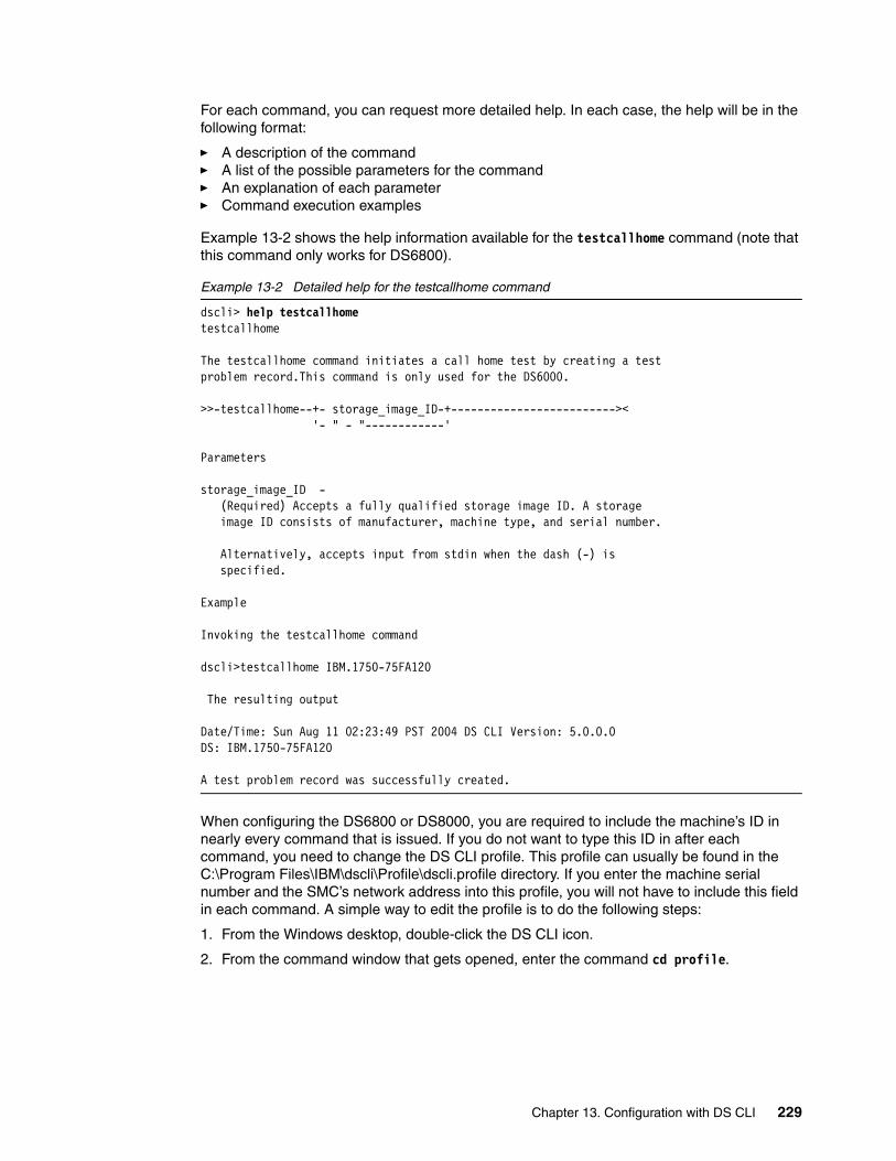
For each command, you can request more detailed help. In each case, the help will be in the following format:
� A description of the command� A list of the possible parameters for the command� An explanation of each parameter� Command execution examples
Example 13-2 shows the help information available for the testcallhome command (note that this command only works for DS6800).
Example 13-2 Detailed help for the testcallhome command
dscli> help testcallhometestcallhome
The testcallhome command initiates a call home test by creating a testproblem record.This command is only used for the DS6000.
>>-testcallhome--+- storage_image_ID-+------------------------->< '- " - "------------'
Parameters
storage_image_ID - (Required) Accepts a fully qualified storage image ID. A storage image ID consists of manufacturer, machine type, and serial number.
Alternatively, accepts input from stdin when the dash (-) is specified.
Example
Invoking the testcallhome command
dscli>testcallhome IBM.1750-75FA120
The resulting output
Date/Time: Sun Aug 11 02:23:49 PST 2004 DS CLI Version: 5.0.0.0DS: IBM.1750-75FA120
A test problem record was successfully created.
When configuring the DS6800 or DS8000, you are required to include the machine’s ID in nearly every command that is issued. If you do not want to type this ID in after each command, you need to change the DS CLI profile. This profile can usually be found in the C:\Program Files\IBM\dscli\Profile\dscli.profile directory. If you enter the machine serial number and the SMC’s network address into this profile, you will not have to include this field in each command. A simple way to edit the profile is to do the following steps:
1. From the Windows desktop, double-click the DS CLI icon.
2. From the command window that gets opened, enter the command cd profile.
Chapter 13. Configuration with DS CLI 229

3. Now from the profile directory, enter the command notepad dscli.profile, as shown in Example 13-3.
Example 13-3 Command prompt operation
C:\Program Files\ibm\dscli>cd profileC:\Program Files\IBM\dscli\profile>notepad dscli.profile
4. Now you have Notepad opened with the DS CLI profile. There are four lines you could consider adding. Examples of these are shown in bold in Example 13-4.
Example 13-4 DS CLI profile example.
## DS CLI Profile## Management Console/Node IP Address(es)# hmc1 and hmc2 are equivalent to -hmc1 and -hmc2 command options.#hmc1:127.0.0.1#hmc2:127.0.0.1
# Default target Storage Image ID# "devid" and "remotedevid" are equivalent to # "-dev storage_image_ID" and "-remotedev storeage_image_ID" command options, respectively. #devid: IBM.2107-AZ12341#remotedevid:IBM.2107-AZ12341
devid: IBM.1750-1300891hmc1: 10.0.0.250
username: adminpassword: passw0rd
5. Save the profile under a new file name, which you can then reference using the -cfg parameter.
6. Close Notepad.
Adding the serial number using the devid parameter, and SMC or HMC IP address using the hmc1 parameter, is highly recommended. Adding the username and password parameters will certainly simplify your DS CLI startup, but it is not recommended. This is because a password saved in a profile file is saved in clear text. Anyone who has access to that file can then read the password.
Attention: The default profile file created when you install DS CLI will potentially be replaced every time you install a new version of DS CLI. It is a best practice to open the default profile and then save it under a different file name. You can then create multiple profiles and reference the relevant profile file using the -cfg parameter.
Important: Take care if adding multiple devid and HMC entries. Only one should be un-commented (or more literally, un-hashed) at any one time. If you have multiple hmc1 or devid entries, the DS CLI uses the one closest to the bottom of the profile.
230 DS6000 Series: Architecture and Implementation
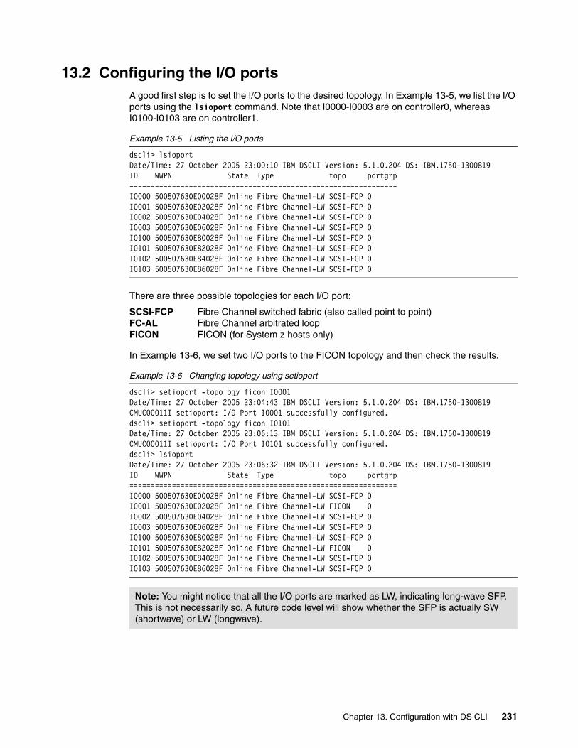
13.2 Configuring the I/O portsA good first step is to set the I/O ports to the desired topology. In Example 13-5, we list the I/O ports using the lsioport command. Note that I0000-I0003 are on controller0, whereas I0100-I0103 are on controller1.
Example 13-5 Listing the I/O ports
dscli> lsioportDate/Time: 27 October 2005 23:00:10 IBM DSCLI Version: 5.1.0.204 DS: IBM.1750-1300819ID WWPN State Type topo portgrp===============================================================I0000 500507630E00028F Online Fibre Channel-LW SCSI-FCP 0I0001 500507630E02028F Online Fibre Channel-LW SCSI-FCP 0I0002 500507630E04028F Online Fibre Channel-LW SCSI-FCP 0I0003 500507630E06028F Online Fibre Channel-LW SCSI-FCP 0I0100 500507630E80028F Online Fibre Channel-LW SCSI-FCP 0I0101 500507630E82028F Online Fibre Channel-LW SCSI-FCP 0I0102 500507630E84028F Online Fibre Channel-LW SCSI-FCP 0I0103 500507630E86028F Online Fibre Channel-LW SCSI-FCP 0
There are three possible topologies for each I/O port:
SCSI-FCP Fibre Channel switched fabric (also called point to point)FC-AL Fibre Channel arbitrated loopFICON FICON (for System z hosts only)
In Example 13-6, we set two I/O ports to the FICON topology and then check the results.
Example 13-6 Changing topology using setioport
dscli> setioport -topology ficon I0001Date/Time: 27 October 2005 23:04:43 IBM DSCLI Version: 5.1.0.204 DS: IBM.1750-1300819CMUC00011I setioport: I/O Port I0001 successfully configured.dscli> setioport -topology ficon I0101Date/Time: 27 October 2005 23:06:13 IBM DSCLI Version: 5.1.0.204 DS: IBM.1750-1300819CMUC00011I setioport: I/O Port I0101 successfully configured.dscli> lsioportDate/Time: 27 October 2005 23:06:32 IBM DSCLI Version: 5.1.0.204 DS: IBM.1750-1300819ID WWPN State Type topo portgrp===============================================================I0000 500507630E00028F Online Fibre Channel-LW SCSI-FCP 0I0001 500507630E02028F Online Fibre Channel-LW FICON 0I0002 500507630E04028F Online Fibre Channel-LW SCSI-FCP 0I0003 500507630E06028F Online Fibre Channel-LW SCSI-FCP 0I0100 500507630E80028F Online Fibre Channel-LW SCSI-FCP 0I0101 500507630E82028F Online Fibre Channel-LW FICON 0I0102 500507630E84028F Online Fibre Channel-LW SCSI-FCP 0I0103 500507630E86028F Online Fibre Channel-LW SCSI-FCP 0
Note: You might notice that all the I/O ports are marked as LW, indicating long-wave SFP. This is not necessarily so. A future code level will show whether the SFP is actually SW (shortwave) or LW (longwave).
Chapter 13. Configuration with DS CLI 231
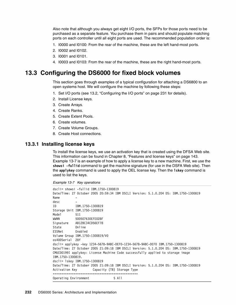
Also note that although you always get eight I/O ports, the SFPs for those ports need to be purchased as a separate feature. You purchase them in pairs and should populate matching ports on each controller until all eight ports are used. The recommended population order is:
1. I0000 and I0100: From the rear of the machine, these are the left hand-most ports.
2. I0002 and I0102.
3. I0001 and I0101.
4. I0003 and I0103: From the rear of the machine, these are the right hand-most ports.
13.3 Configuring the DS6000 for fixed block volumesThis section goes through examples of a typical configuration for attaching a DS6800 to an open systems host. We will configure the machine by following these steps:
1. Set I/O ports (see 13.2, “Configuring the I/O ports” on page 231 for details).
2. Install License keys.
3. Create Arrays.
4. Create Ranks.
5. Create Extent Pools.
6. Create volumes.
7. Create Volume Groups.
8. Create Host connections.
13.3.1 Installing license keysTo install the license keys, we use an activation key that is created using the DFSA Web site. This information can be found in Chapter 8, “Features and license keys” on page 143. Example 13-7 is an example of how to apply a license key to a new machine. First, we use the showsi -fullid command to get the machine signature (for use in the DSFA Web site). Then the applykey command is used to apply the OEL license key. Then the lskey command is used to list the keys.
Example 13-7 Key operations
dscli> showsi -fullid IBM.1750-1300819Date/Time: 27 October 2005 20:59:34 IBM DSCLI Version: 5.1.0.204 DS: IBM.1750-1300819Name -desc -ID IBM.1750-1300819Storage Unit IBM.1750-1300819Model 511WWNN 500507630EFE028FSignature AB12BC34CD56EF78State OnlineESSNet EnabledVolume Group IBM.1750-1300819/V0os400Serial 28fdscli> applykey -key 1234-5678-9ABC-DEF0-1234-5678-9ABC-DEF0 IBM.1750-1300819Date/Time: 27 October 2005 21:09:18 IBM DSCLI Version: 5.1.0.204 DS: IBM.1750-1300819CMUC00199I applykey: License Machine Code successfully applied to storage image IBM.1750-1300819.dscli> lskey IBM.1750-1300819Date/Time: 27 October 2005 21:09:18 IBM DSCLI Version: 5.1.0.204 DS: IBM.1750-1300819Activation Key Capacity (TB) Storage Type=================================================Operating Environment 5 All
232 DS6000 Series: Architecture and Implementation
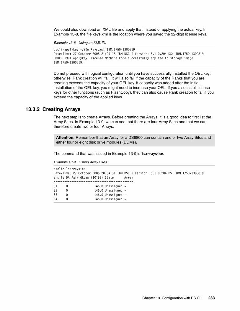
We could also download an XML file and apply that instead of applying the actual key. In Example 13-8, the file keys.xml is the location where you saved the 32-digit license keys.
Example 13-8 Using an XML file
dscli>applykey -file keys.xml IBM.1750-1300819Date/Time: 27 October 2005 21:09:18 IBM DSCLI Version: 5.1.0.204 DS: IBM.1750-1300819CMUC00199I applykey: License Machine Code successfully applied to storage image IBM.1750-1300819.
Do not proceed with logical configuration until you have successfully installed the OEL key; otherwise, Rank creation will fail. It will also fail if the capacity of the Ranks that you are creating exceeds the capacity of your OEL key. If capacity was added after the initial installation of the OEL key, you might need to increase your OEL. If you also install license keys for other functions (such as FlashCopy), they can also cause Rank creation to fail if you exceed the capacity of the applied keys.
13.3.2 Creating ArraysThe next step is to create Arrays. Before creating the Arrays, it is a good idea to first list the Array Sites. In Example 13-9, we can see that there are four Array Sites and that we can therefore create two or four Arrays.
The command that was issued in Example 13-9 is lsarraysite.
Example 13-9 Listing Array Sites
dscli> lsarraysiteDate/Time: 27 October 2005 20:54:31 IBM DSCLI Version: 5.1.0.204 DS: IBM.1750-1300819arsite DA Pair dkcap (10^9B) State Array=============================================S1 0 146.0 Unassigned -S2 0 146.0 Unassigned -S3 0 146.0 Unassigned -S4 0 146.0 Unassigned -
Attention: Remember that an Array for a DS6800 can contain one or two Array Sites and either four or eight disk drive modules (DDMs).
Chapter 13. Configuration with DS CLI 233

We can now issue the mkarray command to create Arrays, as in Example 13-10. You will notice that in this case we have used two Array Sites (in the first Array, S1 and S2) to create a single RAID 5 array. If we wished to create a RAID 10 array, we would have to change the -raidtype parameter to 10 (instead of 5). We could have also used one Array Site to create one RAID 5 or RAID 10 array.
Example 13-10 Creating Arrays with mkarray
dscli> mkarray -raidtype 5 -arsite S1,S2Date/Time: 27 October 2005 21:57:59 IBM DSCLI Version: 5.1.0.204 DS: IBM.1750-1300819CMUC00004I mkarray: Array A0 successfully created.dscli> mkarray -raidtype 5 -arsite S3,S4Date/Time: 27 October 2005 21:58:24 IBM DSCLI Version: 5.1.0.204 DS: IBM.1750-1300819CMUC00004I mkarray: Array A1 successfully created.dscli>
If we now list the Arrays, we can see what Arrays have been created by using the lsarray command. Example 13-11 shows the result of the lsarray command. We can see the type of RAID array and the number of disks that are allocated to the Array (in this example, 6+P+S, which means the usable space of the Array is 6 times the DDM size), as well as the capacity of the DDMs that are used and which Array Sites were used to create the Arrays.
Example 13-11 Listing the Arrays with lsarray
dscli> lsarrayDate/Time: 27 October 2005 21:58:27 IBM DSCLI Version: 5.1.0.204 DS: IBM.1750-1300819Array State Data RAIDtype arsite Rank DA Pair DDMcap (10^9B)=====================================================================A0 Unassigned Normal 5 (6+P+S) S1,S2 - 0 146.0A1 Unassigned Normal 5 (6+P+S) S3,S4 - 0 146.0
13.3.3 Creating RanksOnce we have created all the Arrays that are required, we then create the Ranks using the mkrank command. The format would be:
mkrank -array Ax -stgtype xxx
Where xxx will either be FB or CKD, depending on whether you are configuring for open systems or System z hosts. Once we have created all the Ranks, we can again issue an lsrank command. It will display all the Ranks that have been created, which server the Rank is attached to, the RAID type, and the format of the Rank (whether it is FIxed Block (FB) or Count Key Data (CKD)). Example 13-12 shows the result of the lsrank -l command after issuing the mkrank command.
Example 13-12 Creating and listing Ranks with mkrank and lsrank
dscli> mkrank -array A0 -stgtype fbDate/Time: 27 October 2005 21:31:16 IBM DSCLI Version: 5.1.0.204 DS: IBM.1750-1300819CMUC00007I mkrank: Rank R0 successfully created.dscli> mkrank -array A1 -stgtype fbDate/Time: 27 October 2005 21:31:16 IBM DSCLI Version: 5.1.0.204 DS: IBM.1750-1300819CMUC00007I mkrank: Rank R1 successfully created.dscli> lsrank -lDate/Time: 27 October 2005 21:32:31 IBM DSCLI Version: 5.1.0.204 DS: IBM.1750-1300819ID Group State datastate Array RAIDtype extpoolID extpoolnam stgtype exts usedexts=======================================================================================R0 - Unassigned Normal A0 5 - - fb 773 -R1 - Unassigned Normal A1 5 - - fb 773 -
234 DS6000 Series: Architecture and Implementation

13.3.4 Create Extent PoolsThe next step in the process is to create Extent Pools. Below are some points that should be remembered when creating the Extent Pools:
� The number of Extent Pools can range from one to as many ranks that exist.
� The Extent Pool has an associated Rank group (either 0 or 1, for server0 or server1).
� They have the -stgtype attribute, that is, they are either FB or CKD.
� Ideally, all Ranks within an Extent Pool should have the same characteristics in that they should have the same DDM type and same RAID type.
For ease of management, we create empty Extent Pools relating to the type of storage that is in this pool. For example, create an Extent Pool for high capacity disk, create another for high performance, and, if needed, Extent Pools for the CKD environment. For high capacity, you would consider using 300 GB 10k RPM DDMs, whereas for high performance, you might consider 73 GB 15k RPM DDMs. It is also a good idea to note to which server the Extent Pool has an affinity to. Example 13-13 shows an example of how we could divide our machine. Now in Example 13-9 on page 233, we only had four Array Sites, so clearly we would need more DDMs to support this many Extent Pools.
Example 13-13 An Extent Pool layout plan
FB Extent Pool high capacity 300gb disks assigned to server 0 (FB_LOW_0)FB Extent Pool high capacity 300gb disks assigned to server 1 (FB_LOW_1)FB Extent Pool high performance 146gb disks assigned to server 0 (FB_High_0)FB Extent Pool high performance 146gb disks assigned to server 0 (FB_High_1)CKD Extent Pool High performance 146gb disks assigned to server 0 (CKD_High_0)CKD Extent Pool High performance 146gb disks assigned to server 1 (CKD_High_1)
Note that the mkextpool command forces you to name the Extent Pools. In Example 13-14, we first create empty Extent Pools using mkextpool. We then list the Extent Pools to get their IDs. Next we attach a Rank to an empty Extent Pool using the chrank command. Then we list the Extent Pools again using lsextpool and note the change in capacity of the Extent Pool.
Example 13-14 Extent Pool creation using mkextpool, lsextpool and chrank
dscli> mkextpool -rankgrp 0 -stgtype fb FB_high_0Date/Time: 27 October 2005 21:42:04 IBM DSCLI Version: 5.1.0.204 DS: IBM.1750-1300819CMUC00000I mkextpool: Extent Pool P0 successfully created.dscli> mkextpool -rankgrp 1 -stgtype fb FB_high_1Date/Time: 27 October 2005 21:42:12 IBM DSCLI Version: 5.1.0.204 DS: IBM.1750-1300819CMUC00000I mkextpool: Extent Pool P1 successfully created.dscli> lsextpoolDate/Time: 27 October 2005 21:49:33 IBM DSCLI Version: 5.1.0.204 DS: IBM.1750-1300819Name ID stgtype rankgrp status availstor (2^30B) %allocated available reserved numvols===========================================================================================FB_high_0 P0 fb 0 below 0 0 0 0 0FB_high_1 P1 fb 1 below 0 0 0 0 0dscli> chrank -extpool P0 R0Date/Time: 27 October 2005 21:43:23 IBM DSCLI Version: 5.1.0.204 DS: IBM.1750-1300819CMUC00008I chrank: Rank R0 successfully modified.dscli> chrank -extpool P1 R1Date/Time: 27 October 2005 21:43:23 IBM DSCLI Version: 5.1.0.204 DS: IBM.1750-1300819CMUC00008I chrank: Rank R1 successfully modified.dscli> lsextpoolDate/Time: 27 October 2005 21:50:10 IBM DSCLI Version: 5.1.0.204 DS: IBM.1750-1300819Name ID stgtype rankgrp status availstor (2^30B) %allocated available reserved numvols===========================================================================================
Chapter 13. Configuration with DS CLI 235

FB_high_0 P0 fb 0 below 773 0 773 0 0FB_high_1 P1 fb 1 below 773 0 773 0 0
Now that we have assigned a Rank to an Extent Pool, we should be able to see it if we display the Ranks. In Example 13-15, we can see that Rank R0 is assigned to extpool P0.
Example 13-15 Displaying the Ranks after assigning a Rank to an Extent Pool
dscli> lsrank -lDate/Time: 27 October 2005 22:08:42 IBM DSCLI Version: 5.1.0.204 DS: IBM.1750-1300819ID Group State datastate Array RAIDtype extpoolID extpoolnam stgtype exts usedexts===================================================================================R0 0 Normal Normal A0 5 P0 FB_high_0 fb 773 0R1 1 Normal Normal A1 5 P1 FB_high_1 fb 773 0
13.3.5 Creating fixed block volumesWe are now able to create volumes and volume groups. When we create them, we should try and distribute them evenly across the two Rank groups in the machine. We should also try and create the same number of volumes in each Rank group. The format of the command that we use is:
mkfbvol -extpool pX -cap xx -name high_fb_0# 1000-1003
In Example 13-16, we create eight volumes, each with a capacity of 10 GB. The first four volumes are assigned to Rank group 0 and the second four are assigned to Rank group 1.
Example 13-16 Creating fixed block volumes using mkfbvol
dscli> lsextpoolDate/Time: 27 October 2005 21:50:10 IBM DSCLI Version: 5.1.0.204 DS: IBM.1750-1300819Name ID stgtype rankgrp status availstor (2^30B) %allocated available reserved numvols===========================================================================================FB_high_0 P0 fb 0 below 773 0 773 0 0FB_high_1 P1 fb 1 below 773 0 773 0 0dscli> mkfbvol -extpool p0 -cap 10 -name high_fb_0_#h 1000-1003Date/Time: 27 October 2005 22:24:15 IBM DSCLI Version: 5.1.0.204 DS: IBM.1750-1300819CMUC00025I mkfbvol: FB volume 1000 successfully created.CMUC00025I mkfbvol: FB volume 1001 successfully created.CMUC00025I mkfbvol: FB volume 1002 successfully created.CMUC00025I mkfbvol: FB volume 1003 successfully created.dscli> mkfbvol -extpool p1 -cap 10 -name high_fb_1_#h 1100-1103Date/Time: 27 October 2005 22:26:18 IBM DSCLI Version: 5.1.0.204 DS: IBM.1750-1300819CMUC00025I mkfbvol: FB volume 1100 successfully created.CMUC00025I mkfbvol: FB volume 1101 successfully created.CMUC00025I mkfbvol: FB volume 1102 successfully created.CMUC00025I mkfbvol: FB volume 1103 successfully created.
Looking closely at the mkfbvol command used in Example 13-16, we see that volumes 1000-1003 are in extpool P0. That Extent Pool is attached to Rank group 0, which means server 0. Now Rank group 0 can only contain even numbered LSSs, so that means volumes in that Extent Pool must belong to an even numbered LSS. The first two digits of the volume serial number are the LSS number, so in this case, volumes 1000-1003 are in LSS 10.
For volumes 1100-1003 in Example 13-16 on page 236, the first two digits of the volume serial number are 11, which is an odd number, which signifies they belong to Rank group 1. Also note that the -cap parameter determines size, but because the -type parameter was not used, the default size is a binary size. So these volumes are 10 GB binary, which equates to
236 DS6000 Series: Architecture and Implementation

10,485,760 bytes. If we used the parameter -type ess, then the volumes would be decimally sized and would be 10,000,000 bytes in size.
Finally, in Example 13-16 on page 236 we named the volumes, using the naming base high_fb_0_#h. The #h means to use the hexadecimal volume number as part of the volume name. This can be seen in Example 13-17, where we list the volumes that we have created using the lsfbvol command. We then list the Extent Pools, to see how much space we have left after the volume creation.
Example 13-17 Checking the machine after creating volumes by using lsextpool and lsfbvol
dscli> lsfbvolDate/Time: 27 October 2005 22:28:01 IBM DSCLI Version: 5.1.0.204 DS: IBM.1750-1300819Name ID accstate datastate configstate deviceMTM datatype extpool cap (2^30B) cap (10^9B) ===========================================================================================================high_fb_0_1000 1000 Online Normal Normal 1750-500 FB 512 P0 10.0 - high_fb_0_1001 1001 Online Normal Normal 1750-500 FB 512 P0 10.0 - high_fb_0_1002 1002 Online Normal Normal 1750-500 FB 512 P0 10.0 - high_fb_0_1003 1003 Online Normal Normal 1750-500 FB 512 P0 10.0 - high_fb_1_1100 1100 Online Normal Normal 1750-500 FB 512 P1 10.0 - high_fb_1_1101 1101 Online Normal Normal 1750-500 FB 512 P1 10.0 - high_fb_1_1102 1102 Online Normal Normal 1750-500 FB 512 P1 10.0 - high_fb_1_1103 1103 Online Normal Normal 1750-500 FB 512 P1 10.0 - dscli> lsextpoolDate/Time: 27 October 2005 22:27:50 IBM DSCLI Version: 5.1.0.204 DS: IBM.1750-1300819Name ID stgtype rankgrp status availstor (2^30B) %allocated available reserved numvols===========================================================================================FB_high_0 P0 fb 0 below 733 5 733 0 4FB_high_1 P1 fb 1 below 733 5 733 0 4
13.3.6 Creating volume groupsFixed block volumes get assigned to open systems hosts using volume groups (not to be confused with the term volume groups that gets used in AIX). A fixed block volume can be a member of multiple volume groups. Volumes can be added or removed from volume groups as required. Each volume group must be either SCSI MAP256 or SCSI MASK, depending on the SCSI LUN address discovery method used by the operating system to which the volume group will be attached.
Important: For the DS6800, the LSSs have to be ID 00 to ID 1F. This allows for a maximum of 8192 devices (32 LSSs times 256 volumes per LSS). The LSSs can be in one of two address groups. Address group 0 is LSS 00 to 0F, whereas address group 1 is LSS 10 to 1F. The moment you create an FB volume in an address group, then that entire address group can only be used for FB volumes. Be aware of this when planning your volume layout in a mixed FB/CKD DS6000.
Chapter 13. Configuration with DS CLI 237

Determining if an open systems host is SCSI MAP256 or SCSI MASKFirst, we determine what sort of SCSI host we are working with. Then we use the lshostype command with the -type parameter of scsimask and then scsimap256. In Example 13-18, we can see the results of each command.
Example 13-18 Listing host types with the lshostype command
dscli> lshosttype -type scsimaskDate/Time: 27 October 2005 23:13:50 IBM DSCLI Version: 5.1.0.204HostType Profile AddrDiscovery LBS==================================================Hp HP - HP/UX reportLUN 512SVC San Volume Controller reportLUN 512SanFsAIX IBM pSeries - AIX/SanFS reportLUN 512pSeries IBM pSeries - AIX reportLUN 512zLinux IBM zSeries - zLinux reportLUN 512dscli> lshosttype -type scsimap256Date/Time: 27 October 2005 23:13:58 IBM DSCLI Version: 5.1.0.204HostType Profile AddrDiscovery LBS=====================================================AMDLinuxRHEL AMD - Linux RHEL LUNPolling 512AMDLinuxSuse AMD - Linux Suse LUNPolling 512AppleOSX Apple - OSX LUNPolling 512Fujitsu Fujitsu - Solaris LUNPolling 512HpTru64 HP - Tru64 LUNPolling 512HpVms HP - Open VMS LUNPolling 512LinuxDT Intel - Linux Desktop LUNPolling 512LinuxRF Intel - Linux Red Flag LUNPolling 512LinuxRHEL Intel - Linux RHEL LUNPolling 512LinuxSuse Intel - Linux Suse LUNPolling 512Novell Novell LUNPolling 512SGI SGI - IRIX LUNPolling 512SanFsLinux - Linux/SanFS LUNPolling 512Sun SUN - Solaris LUNPolling 512VMWare VMWare LUNPolling 512Win2000 Intel - Windows 2000 LUNPolling 512Win2003 Intel - Windows 2003 LUNPolling 512iLinux IBM iSeries - iLinux LUNPolling 512pLinux IBM pSeries - pLinux LUNPolling 512
Having determined the host type, we can now make a volume group. In Example 13-19, the example host type we chose to use is AIX, and checking Example 13-18, we can see the address discovery method for AIX is scsimask. In this example, we added volumes 1000 to 1002 and 1100 to 1102 (we did this to spread the workload evenly across the two Rank groups). We then listed all available volume groups using lsvolgrp. Finally, we listed the contents of volume group V11, since this was the volume group we created.
Example 13-19 Creating a volume group using mkvolgrp and displaying it with lsvolgrp and showvolgrp
dscli> mkvolgrp -type scsimask -volume 1000-1002,1100-1102 AIX_VG_01Date/Time: 27 October 2005 23:18:07 IBM DSCLI Version: 5.1.0.204 DS: IBM.1750-1300819CMUC00030I mkvolgrp: Volume group V11 successfully created.dscli> lsvolgrpDate/Time: 27 October 2005 23:18:21 IBM DSCLI Version: 5.1.0.204 DS: IBM.1750-1300819Name ID Type=======================================ALL CKD V10 FICON/ESCON AllAIX_VG_01 V11 SCSI MaskALL Fixed Block-512 V20 SCSI AllALL Fixed Block-520 V30 OS400 All
238 DS6000 Series: Architecture and Implementation

dscli> showvolgrp V11Date/Time: 27 October 2005 23:18:15 IBM DSCLI Version: 5.1.0.204 DS: IBM.1750-1300819Name AIX_VG_01ID V11Type SCSI MaskVols 1000 1001 1002 1100 1101 1102
Clearly, we might also want to add or remove volumes to this volume group at a later time. To achieve this task, we use the chvolgrp command with the -action parameter. In Example 13-20, we added volume 1003 to the volume group V11. We display the results and then remove the volume.
Example 13-20 Changing a volume group with chvolgrp
dscli> chvolgrp -action add -volume 1003 V11Date/Time: 27 October 2005 23:22:50 IBM DSCLI Version: 5.1.0.204 DS: IBM.1750-1300819CMUC00031I chvolgrp: Volume group V11 successfully modified.dscli> showvolgrp V11Date/Time: 27 October 2005 23:22:58 IBM DSCLI Version: 5.1.0.204 DS: IBM.1750-1300819Name AIX_VG_01ID V11Type SCSI MaskVols 1000 1001 1002 1003 1100 1101 1102dscli> chvolgrp -action remove -volume 1003 V11Date/Time: 27 October 2005 23:23:08 IBM DSCLI Version: 5.1.0.204 DS: IBM.1750-1300819CMUC00031I chvolgrp: Volume group V11 successfully modified.dscli> showvolgrp V11Date/Time: 27 October 2005 23:23:13 IBM DSCLI Version: 5.1.0.204 DS: IBM.1750-1300819Name AIX_VG_01ID V11Type SCSI MaskVols 1000 1001 1002 1100 1101 1102
13.3.7 Creating host connectionsThe final step in the logical configuration process is to create host connections for your attached hosts. You will need to assign volume groups to those connections. Each host HBA can only be defined once, and each hostconnect can only have one volume group assigned to it. Remember though that a volume can be assigned to multiple volume groups.
Attention: Not all operating systems can deal with the removal of a volume. Consult your operating system documentation to determine the safest way to remove a volume from a host.
Chapter 13. Configuration with DS CLI 239

In Example 13-21, we create a single host connection that represents one HBA in our example AIX host. We use the -hosttype parameter, using the hosttype in Example 13-18 on page 238. We allocate it to volume group V11. At this point (provided the SAN zoning is correct), the host should be able to see the LUNS in volume group V11.
Example 13-21 Creating host connections using mkhostconnect and lshostconnect
dscli> mkhostconnect -wwname 100000C912345678 -hosttype pSeries -volgrp V11 AIX_Server_01Date/Time: 27 October 2005 23:28:03 IBM DSCLI Version: 5.1.0.204 DS: IBM.1750-1300819CMUC00012I mkhostconnect: Host connection 0000 successfully created.dscli> lshostconnectDate/Time: 27 October 2005 23:28:12 IBM DSCLI Version: 5.1.0.204 DS: IBM.1750-1300819Name ID WWPN HostType Profile portgrp volgrpID ESSIOport=========================================================================================AIX_Server_01 0000 100000C912345678 pSeries IBM pSeries - AIX 0 V11 alldscli>
Note that you can also use just -profile instead of -hosttype. However, this is not recommended. If you use the -hosttype parameter, it will actually invoke both parameters (-profile and -hosttype), whereas just using -profile will leave the -hosttype column unpopulated.
There is also the option in the mkhostconnect command to restrict access to only certain I/O ports. This is done with the -ioport parameter. Restricting access in this way is usually not necessary. If you wish to restrict access for certain hosts to certain I/O ports on the DS6800, do this through zoning on your SAN switch.
Managing hosts with multiple HBAsIf you have a host with multiple HBAs, you have two considerations:
� For the GUI to consider multiple host connects to be used by the same server, the host connects must have the same name. So in Figure 13-22, host connects 0003 and 0004 would appear in the GUI as a single server with two HBAs. However, host connects 0001 and 0002 would appear as two separate hosts, even though in reality they are being used by the same server. If you do not plan to use the GUI to manage host connections, then this is not a major consideration. Using more verbose hostconnect naming might make management easier.
� If you wish to use a single command to change the assigned volume group of several hostconnects at the same time, then you need to assign these hostconnects to a unique port group and then use the managehostconnect command. This command changes the assigned volume group for all hostconnects assigned to a particular port group.
When creating hosts, you can specify the -portgrp parameter. It is also possible to assign a hostconnect to a port group after you have created it. By using a unique port group number for each attached server, you can easily detect servers with multiple HBAs. In Example 13-22 on page 241, we have four host connections. By using the port group number, we can see that there are two separate hosts, each with two HBAs. Port group 0 is used for all hosts that do not have a port group number set.
240 DS6000 Series: Architecture and Implementation

Example 13-22 Using the portgrp number to separate attached hosts
dscli> lshostconnectDate/Time: 14 November 2005 4:36:18 IBM DSCLI Version: 5.1.0.204 DS: IBM.1750-1300819Name ID WWPN HostType Profile portgrp volgrpID ===========================================================================================tic2_fcs0 0001 10000000C9457555 pSeries IBM pSeries - AIX 1 V11 alltic2_fcs0 0002 10000000C9457556 pSeries IBM pSeries - AIX 1 V11 allHP1 0003 50060B000011B8B8 Hp HP - HP/UX 2 V12 allHP1 0004 50060B000011B318 Hp HP - HP/UX 2 V12 all
Changing host connectionsIf we wish to change a host connection, we can use the chhostconnect command. This command can be used to change nearly all parameters of the host connection except for the WWPN. If you need to change the WWPN, you will need to create a whole new host connection. To change the assigned volume group, use either chhostconnect to change one hostconnect at a time, or use managehostconnect to simultaneously reassign all the hostconnects in one port group.
13.3.8 Mapping open systems hosts disks to DS6000 or DS8000 volumesWhen you have assigned volumes to an open systems host, and you have then installed the DS CLI on this host, you can run the DS CLI command lshostvol on this host. This command will map assigned LUNS to open systems host volume names.
We give examples for several operating systems. In each example, we assign some volumes (either DS6000 or DS8000) to an open systems host. We install DS CLI on this host. We log onto to this host and start DS CLI. It does not matter which HMC or SMC we connect to with the DS CLI. We then issue the lshostvol command.
AIX: Mapping disks when MPIO is being usedIn Example 13-23, we have an AIX server that uses MPIO. We have two volumes assigned to this host, 1800 and 1801. Because MPIO is being used, we do not see the number of paths. In fact, from this display, it is not possible to tell if MPIO is even installed. You would need to run the pcmpath query device command to confirm the path count.
Example 13-23 lshostvol on an AIX host using MPIO
dscli> lshostvolDate/Time: November 15, 2005 7:00:15 PM CST IBM DSCLI Version: 5.1.0.204Disk Name Volume Id Vpath Name==========================================hdisk3 IBM.1750-1300819/1800 ---hdisk4 IBM.1750-1300819/1801 ---
Important: The lshostvol command communicates only with the operating system of the host on which the DS CLI is installed. You cannot run this command on one host to see the attached disks of another host.
Chapter 13. Configuration with DS CLI 241

AIX: Mapping disks when SDD is being usedIn Example 13-24, we have an AIX server that uses SDD. We have two volumes assigned to this host, 1000 and 1100. Each volume has four paths.
Example 13-24 lshostvol on an AIX host using SDD
dscli> lshostvolDate/Time: November 10, 2005 3:06:26 PM CET IBM DSCLI Version: 5.0.6.142Disk Name Volume Id Vpath Name============================================================hdisk1,hdisk3,hdisk5,hdisk7 IBM.1750-1300247/1000 vpath0hdisk2,hdisk4,hdisk6,hdisk8 IBM.1750-1300247/1100 vpath1
HP-UX: Mapping disks when SDD is not being usedIn Example 13-25 we have a HP-UX host that does not have SDD. We have two volumes assigned to this host, 1105 and 1106.
Example 13-25 lshostvol on an HP-UX host that does not use SDD
dscli> lshostvolDate/Time: November 16, 2005 4:03:25 AM GMT IBM DSCLI Version: 5.0.4.140Disk Name Volume Id Vpath Name==========================================c38t0d5 IBM.2107-7503461/1105 ---c38t0d6 IBM.2107-7503461/1106 ---
HP-UX or Solaris: Mapping disks when SDD is being usedIn Example 13-26, we have an HP-UX or Solaris host that has SDD installed. We have two volumes assigned to this host, 4205 and 4206. Each volume has two paths. With Solaris, the iostat -En command can also produce similar information. The output of lshostvol on Solaris or HP-UX with SDD looks exactly the same, with each vpath made up of disks with c-t-d numbers (controller, target, and disk).
Example 13-26 lshostvol on a Solaris host that has SDD
dscli> lshostvolDate/Time: November 10, 2005 3:54:27 PM MET IBM DSCLI Version: 5.1.0.204Disk Name Volume Id Vpath Name==================================================c2t1d0s0,c3t1d0s0 IBM.2107-7520781/4205 vpath2c2t1d1s0,c3t1d1s0 IBM.2107-7520781/4206 vpath1
Solaris: Mapping disks when SDD is not being usedIn Example 13-27, we have a Solaris host that does not have SDD installed. It instead uses an alternative multi-pathing product. We have two volumes assigned to this host, 4200 and 4201. Each volume has two paths. The iostat -En command can also produce similar information.
242 DS6000 Series: Architecture and Implementation
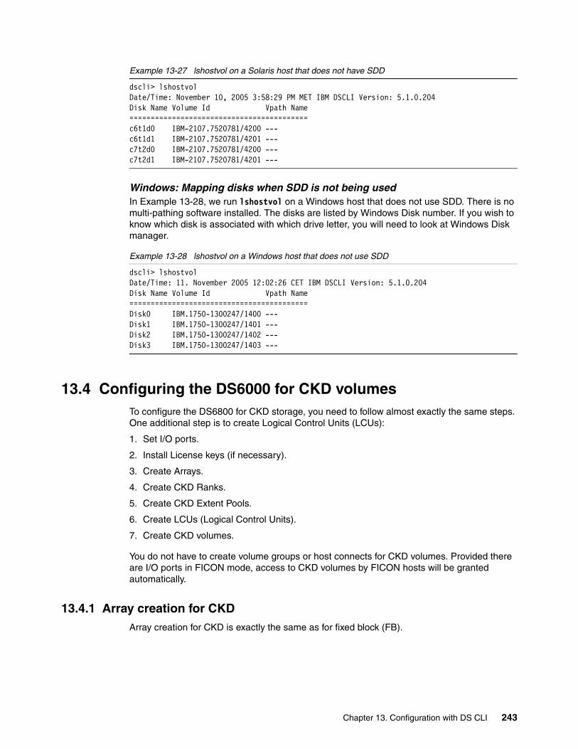
Example 13-27 lshostvol on a Solaris host that does not have SDD
dscli> lshostvolDate/Time: November 10, 2005 3:58:29 PM MET IBM DSCLI Version: 5.1.0.204Disk Name Volume Id Vpath Name==========================================c6t1d0 IBM-2107.7520781/4200 ---c6t1d1 IBM-2107.7520781/4201 ---c7t2d0 IBM-2107.7520781/4200 ---c7t2d1 IBM-2107.7520781/4201 ---
Windows: Mapping disks when SDD is not being usedIn Example 13-28, we run lshostvol on a Windows host that does not use SDD. There is no multi-pathing software installed. The disks are listed by Windows Disk number. If you wish to know which disk is associated with which drive letter, you will need to look at Windows Disk manager.
Example 13-28 lshostvol on a Windows host that does not use SDD
dscli> lshostvolDate/Time: 11. November 2005 12:02:26 CET IBM DSCLI Version: 5.1.0.204Disk Name Volume Id Vpath Name==========================================Disk0 IBM.1750-1300247/1400 ---Disk1 IBM.1750-1300247/1401 ---Disk2 IBM.1750-1300247/1402 ---Disk3 IBM.1750-1300247/1403 ---
13.4 Configuring the DS6000 for CKD volumesTo configure the DS6800 for CKD storage, you need to follow almost exactly the same steps. One additional step is to create Logical Control Units (LCUs):
1. Set I/O ports.
2. Install License keys (if necessary).
3. Create Arrays.
4. Create CKD Ranks.
5. Create CKD Extent Pools.
6. Create LCUs (Logical Control Units).
7. Create CKD volumes.
You do not have to create volume groups or host connects for CKD volumes. Provided there are I/O ports in FICON mode, access to CKD volumes by FICON hosts will be granted automatically.
13.4.1 Array creation for CKDArray creation for CKD is exactly the same as for fixed block (FB).
Chapter 13. Configuration with DS CLI 243
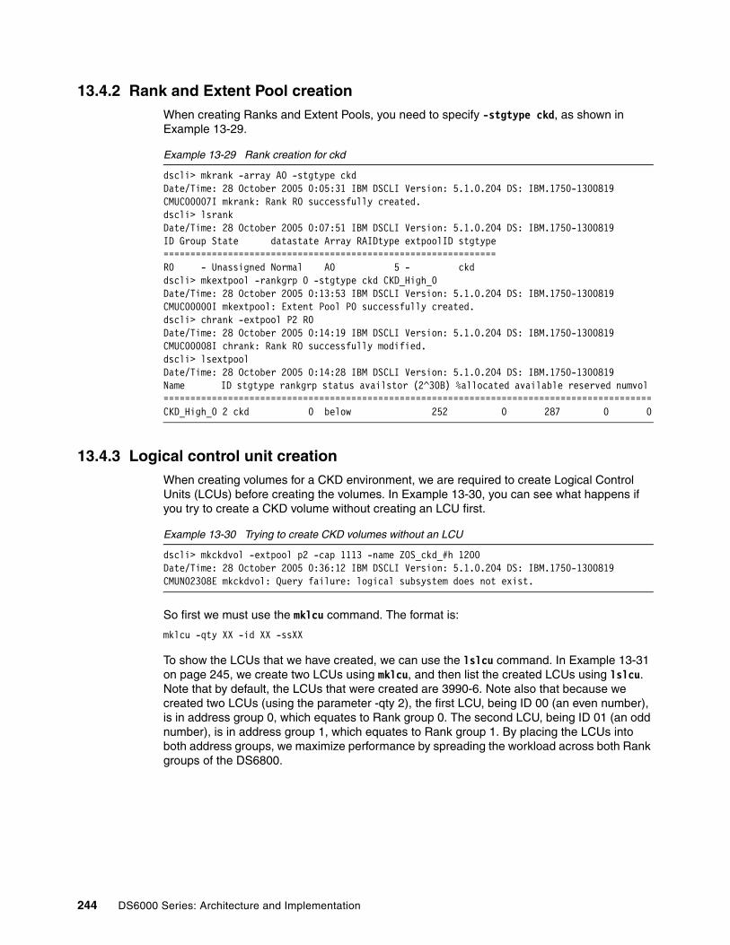
13.4.2 Rank and Extent Pool creationWhen creating Ranks and Extent Pools, you need to specify -stgtype ckd, as shown in Example 13-29.
Example 13-29 Rank creation for ckd
dscli> mkrank -array A0 -stgtype ckdDate/Time: 28 October 2005 0:05:31 IBM DSCLI Version: 5.1.0.204 DS: IBM.1750-1300819CMUC00007I mkrank: Rank R0 successfully created.dscli> lsrankDate/Time: 28 October 2005 0:07:51 IBM DSCLI Version: 5.1.0.204 DS: IBM.1750-1300819ID Group State datastate Array RAIDtype extpoolID stgtype==============================================================R0 - Unassigned Normal A0 5 - ckddscli> mkextpool -rankgrp 0 -stgtype ckd CKD_High_0Date/Time: 28 October 2005 0:13:53 IBM DSCLI Version: 5.1.0.204 DS: IBM.1750-1300819CMUC00000I mkextpool: Extent Pool P0 successfully created.dscli> chrank -extpool P2 R0Date/Time: 28 October 2005 0:14:19 IBM DSCLI Version: 5.1.0.204 DS: IBM.1750-1300819CMUC00008I chrank: Rank R0 successfully modified.dscli> lsextpoolDate/Time: 28 October 2005 0:14:28 IBM DSCLI Version: 5.1.0.204 DS: IBM.1750-1300819Name ID stgtype rankgrp status availstor (2^30B) %allocated available reserved numvol ===========================================================================================CKD_High_0 2 ckd 0 below 252 0 287 0 0
13.4.3 Logical control unit creationWhen creating volumes for a CKD environment, we are required to create Logical Control Units (LCUs) before creating the volumes. In Example 13-30, you can see what happens if you try to create a CKD volume without creating an LCU first.
Example 13-30 Trying to create CKD volumes without an LCU
dscli> mkckdvol -extpool p2 -cap 1113 -name ZOS_ckd_#h 1200Date/Time: 28 October 2005 0:36:12 IBM DSCLI Version: 5.1.0.204 DS: IBM.1750-1300819CMUN02308E mkckdvol: Query failure: logical subsystem does not exist.
So first we must use the mklcu command. The format is:
mklcu -qty XX -id XX -ssXX
To show the LCUs that we have created, we can use the lslcu command. In Example 13-31 on page 245, we create two LCUs using mklcu, and then list the created LCUs using lslcu. Note that by default, the LCUs that were created are 3990-6. Note also that because we created two LCUs (using the parameter -qty 2), the first LCU, being ID 00 (an even number), is in address group 0, which equates to Rank group 0. The second LCU, being ID 01 (an odd number), is in address group 1, which equates to Rank group 1. By placing the LCUs into both address groups, we maximize performance by spreading the workload across both Rank groups of the DS6800.
244 DS6000 Series: Architecture and Implementation

Example 13-31 Creating a logical control unit with mklcu
dscli> mklcu -qty 2 -id 00 -ss FF00Date/Time: 28 October 2005 16:53:17 IBM DSCLI Version: 5.1.0.204 DS: IBM.1750-1300819CMUC00017I mklcu: LCU 00 successfully created.CMUC00017I mklcu: LCU 01 successfully created.dscli> lslcuDate/Time: 28 October 2005 16:53:26 IBM DSCLI Version: 5.1.0.204 DS: IBM.1750-1300819ID Group addrgrp confgvols subsys conbasetype=============================================00 0 0 0 0xFF00 3990-601 1 0 0 0xFF01 3990-6
13.4.4 Creating CKD volumesHaving created an LCU, we can now create CKD volumes using the mkckdvol command. The format of the mkckdvol command is listed below:
mkckdvol -extpool pX -cap 1113 -name zOS_ckd_#h 00xx-00xx
The major difference to note here is that the capacity must be equivalent to that of a 3390 model 3 or a multiple of this capacity (3339) so that there is very little or no space wasted.
In Example 13-32, we create a single 3390-3 volume using 3339 cylinders.
Example 13-32 Creating CKD volumes using mkckdvol
dscli> mkckdvol -extpool p2 -cap 3339 -name zOS_ckd_#h 0000Date/Time: 28 October 2005 17:04:31 IBM DSCLI Version: 5.1.0.204 DS: IBM.1750-1300819CMUC00021I mkckdvol: CKD Volume 0000 successfully created.dscli> lsckdvolDate/Time: 28 October 2005 17:04:37 IBM DSCLI Version: 5.1.0.204 DS: IBM.1750-1300819Name ID accstate datastate configstate deviceMTM voltype orgbvols extpool cap (cyl)==============================================================================================zOS_ckd_0000 0000 Online Normal Normal 3390-3 CKD Base - P2 3339
Remember that we can only create CKD volumes using LCUs that we have already created. From our examples, trying, for example, to make volume 0200 will fail, with the same message as seen in Example 13-30 on page 244. This is because we only created LCU IDs 00 and 01, meaning all CKD volumes must be in the address range 00xx (LCU ID 00) and 01xx (LCU ID 01).
You also need to be aware that volumes in even numbered LCUs must be created from an Extent Pool that belongs to Rank group 0, whereas volumes in odd numbered LCUs must be created from an Extent Pool in Rank group 1.
Note: For the DS6800, the CKD LCUs have to be ID 00 to ID 1F. This allows for a maximum of 8192 devices (32 LCUs times 256 volumes per LCU). The LCUs can be in one of two address groups. Address group 0 is LCUs 00 to 0F, whereas address group 1 is LCUs 10 to 1F. If you create a CKD LCU in an address group, then that address group cannot be used for FB volumes. Likewise, if there were, for example, FB volumes in LSS 00 to 0F (address group 0), then that address group cannot be used for CKD. Be aware of this when planning the volume layout in a mixed FB/CKD DS6000.
Chapter 13. Configuration with DS CLI 245
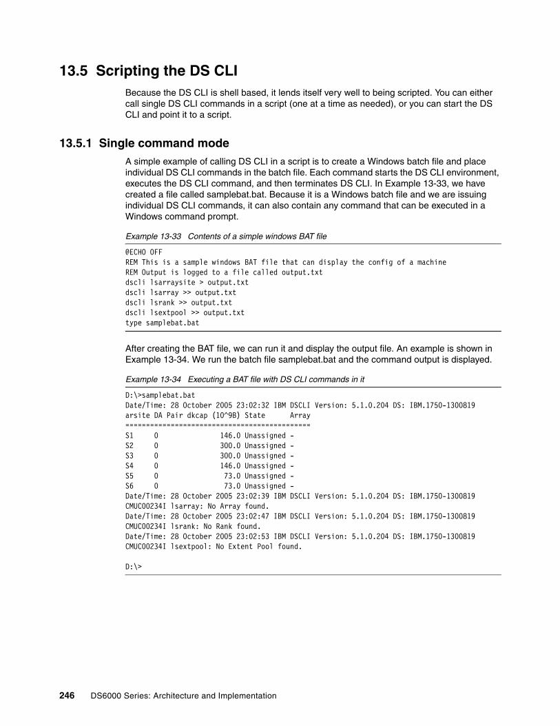
13.5 Scripting the DS CLIBecause the DS CLI is shell based, it lends itself very well to being scripted. You can either call single DS CLI commands in a script (one at a time as needed), or you can start the DS CLI and point it to a script.
13.5.1 Single command modeA simple example of calling DS CLI in a script is to create a Windows batch file and place individual DS CLI commands in the batch file. Each command starts the DS CLI environment, executes the DS CLI command, and then terminates DS CLI. In Example 13-33, we have created a file called samplebat.bat. Because it is a Windows batch file and we are issuing individual DS CLI commands, it can also contain any command that can be executed in a Windows command prompt.
Example 13-33 Contents of a simple windows BAT file
@ECHO OFFREM This is a sample windows BAT file that can display the config of a machineREM Output is logged to a file called output.txtdscli lsarraysite > output.txtdscli lsarray >> output.txtdscli lsrank >> output.txtdscli lsextpool >> output.txttype samplebat.bat
After creating the BAT file, we can run it and display the output file. An example is shown in Example 13-34. We run the batch file samplebat.bat and the command output is displayed.
Example 13-34 Executing a BAT file with DS CLI commands in it
D:\>samplebat.batDate/Time: 28 October 2005 23:02:32 IBM DSCLI Version: 5.1.0.204 DS: IBM.1750-1300819arsite DA Pair dkcap (10^9B) State Array=============================================S1 0 146.0 Unassigned -S2 0 300.0 Unassigned -S3 0 300.0 Unassigned -S4 0 146.0 Unassigned -S5 0 73.0 Unassigned -S6 0 73.0 Unassigned -Date/Time: 28 October 2005 23:02:39 IBM DSCLI Version: 5.1.0.204 DS: IBM.1750-1300819CMUC00234I lsarray: No Array found.Date/Time: 28 October 2005 23:02:47 IBM DSCLI Version: 5.1.0.204 DS: IBM.1750-1300819CMUC00234I lsrank: No Rank found.Date/Time: 28 October 2005 23:02:53 IBM DSCLI Version: 5.1.0.204 DS: IBM.1750-1300819CMUC00234I lsextpool: No Extent Pool found.
D:\>
246 DS6000 Series: Architecture and Implementation

13.5.2 Script modeIf you want to run a script that only contains DS CLI commands, then you can start DS CLI in script mode. The main thing to remember here is that the script that DS CLI executes can only contain DS CLI commands. In Example 13-35, we have the contents of a DS CLI script file. Note that it only contains DS CLI commands, though comments can be placed in the file using a hash (#). One advantage of using this method is that scripts written in this format can be used by the DS CLI on any operating system into which you can install DS CLI.
Example 13-35 Example of a DS CLI script file
# Sample ds cli script file# Comments can appear if hashedlsarraysitelsarraylsrank
In Example 13-36, we start the DS CLI using the -script parameter and specifying the name of the script that contains the commands from Example 13-35.
Example 13-36 Executing DS CLI with a script file
C:\Program Files\ibm\dscli>dscli -script sample.scriptDate/Time: 28 October 2005 23:06:47 IBM DSCLI Version: 5.1.0.204 DS: IBM.1750-1300819arsite DA Pair dkcap (10^9B) State Array=============================================S1 0 146.0 Unassigned -S2 0 300.0 Unassigned -S3 0 300.0 Unassigned -S4 0 146.0 Unassigned -S5 0 73.0 Unassigned -S6 0 73.0 Unassigned -Date/Time: 28 October 2005 23:06:52 IBM DSCLI Version: 5.1.0.204 DS: IBM.1750-1300819CMUC00234I lsarray: No Array found.Date/Time: 28 October 2005 23:06:53 IBM DSCLI Version: 5.1.0.204 DS: IBM.1750-1300819CMUC00234I lsrank: No Rank found.
C:\Program Files\ibm\dscli>
Chapter 13. Configuration with DS CLI 247

248 DS6000 Series: Architecture and Implementation

Chapter 14. Preferred path concept
In this chapter, we describe the preferred path concept of the DS6000 storage system. We discuss an internal view of the architecture and explain how the host device driver sees and works with the preferred path.
We cover the following topics:
� Hardware overview� Open systems host connections� System z host connections� Determining the controller number by using WWPN
14
© Copyright IBM Corp. 2005, 2006. All rights reserved. 249

14.1 Hardware overviewUnlike the DS8000 and the ESS 800, the DS6000 uses the concept of the preferred path, since the host adapters are integrated into the controller hardware rather than in separate I/O bays. When volumes are created, they get created from Extent Pools. The volumes will get an affinity to a certain controller through the Extent Pool affinity to a controller. This produces the concept of the preferred path. When a volume has an affinity, for example, to controller 0, and is accessed through a port in the Host Adapter (HA) of controller 0, then the I/O is locally processed. When this volume is accessed through a HA port of controller 1, then the I/O has to be routed to controller 0, since that controller owns the Extent Pool.
There is a potential performance penalty if the data from a logical volume managed by one controller is accessed from a port that is located in the other controller. The request for the logical volume and the data would have to be transferred across the bridge interface that connects the controllers. These transfers add some latency to the response time. Furthermore, this interface is also used to mirror the persistent memory and for other inter-controller communication. While this bridge is a high bandwidth, low latency, PCI-X connection, it is clearly preferable that you do not unnecessarily route traffic across it.
For these reasons, we need to consider preferred pathing when assigning host ports. We also need to use a driver that is aware of preferred paths.
14.2 Open systems host connections In this section, we discuss the available drivers that open systems servers use to manage multipathing and how these drivers handle the preferred paths provided by the DS6000 storage system.
14.2.1 Multipath Subsystem Device Driver (SDD)In the majority of open system environments, IBM recommends the use of the Multipath Subsystem Device Driver (SDD) to manage both path failover and preferred path determination. SDD is supplied free of charge to all IBM customers that use ESS 2105, SAN Volume Controller (SVC), DS6000, and DS8000. With the 1.6 Version or higher, SDD also manages pathing to the DS6000 and DS8000 systems.
SDD provides availability through automatic I/O path failover. If a failure occurs in the data path between the host and the DS6000, SDD automatically switches the I/O to another path. SDD will also set the failed path back online after a repair is made. SDD also improves performance by sharing I/O operations to a common disk over multiple active paths to distribute and balance the I/O workload.
Note that there is a difference between paths from the SDD point of view, that is, determined by the LUN affinity with controller 0 or 1, and the preferred node path-selection algorithm for DS6000. SDD will select the most efficient and optimum path to store and retrieve data from the storage system.
When SDD selects paths for I/O, preference is always given to paths to the preferred controller. Therefore, in the selection algorithm, an initial attempt is made to select a path to the preferred controller. Only if no paths to the preferred controller can be used will a path to the alternate controller be selected.
SDD will automatically fail back to the preferred controller any time a path to the preferred controller becomes available during either manual or automatic recovery. If an error occurs
250 DS6000 Series: Architecture and Implementation

and a path retry is required, retry paths are first selected to the preferred controller, then paths to the alternate controller will be selected for retry. The path selection algorithm used by SDD proceeds as follows:
1. With all paths available, I/O is only routed to paths to the preferred controller.
2. If no paths are available to the preferred controller, I/O fails over to paths to the alternate controller.
3. After failover to the alternate controller has occurred, if a path to the preferred controller becomes available, I/O will automatically fail back to the paths to the preferred controller.
14.2.2 Operating systems supported by Subsystem Device Driver (SDD)Some of the supported platforms with SDD and the DS6000 storage system include:
� AIX� HP� Linux � Novell� SUN� Windows 2000� Windows 2003
For additional info on SDD with various operating systems, refer to Chapter 16, “Considerations for open systems” on page 281.
For further information about SDD commands, refer to Multipath Subsystem Device Driver User’s Guide, SC30-4131. To check for operating system support and available releases, the SDD Web site is located at:
http://www-1.ibm.com/servers/storage/support/software/sdd/index.html
14.3 System z host connections In the DS6000, host ports have a fixed assignment to a controller card. When a path to a device is validated, the DS6000 will notify z/OS device support if the path is a preferred path for the device or not, that is, if the path is connected to the controller card that owns the device. Device support then identifies preferred paths to the IOS. The I/Os are directed to preferred paths to avoid crossing the PCI-X connection.
The only time this will not be honored is when there are no preferred paths available to the device. The software then switches over to use non-preferred paths. There will be a slight performance penalty if the I/O is not executed over the preferred path. The I/O request and the data would have to be transferred across the bridge interface that connects both controllers. These transfers add some latency to the response time. Furthermore, the bridge interface is also used to mirror the persistent memory and for other inter-controller communication. While this bridge is a high bandwidth, low latency, PCI-X connection, it is clearly preferable to not unnecessarily route traffic across it.
With the correct level of maintenance, z/OS is able to detect the preferred paths and direct I/Os onto a preferred path, if available.
New messages will inform you of the availability of preferred paths to devices. When a successful VARY PATH or CF CHP online request has occurred and the path that was just brought online is the first online preferred path to a device, z/OS issues the following message to indicate that a preferred path is now available for the device:
IOS165I DEVICE dddd. PREFERRED PATHING NOW IN USE
Chapter 14. Preferred path concept 251
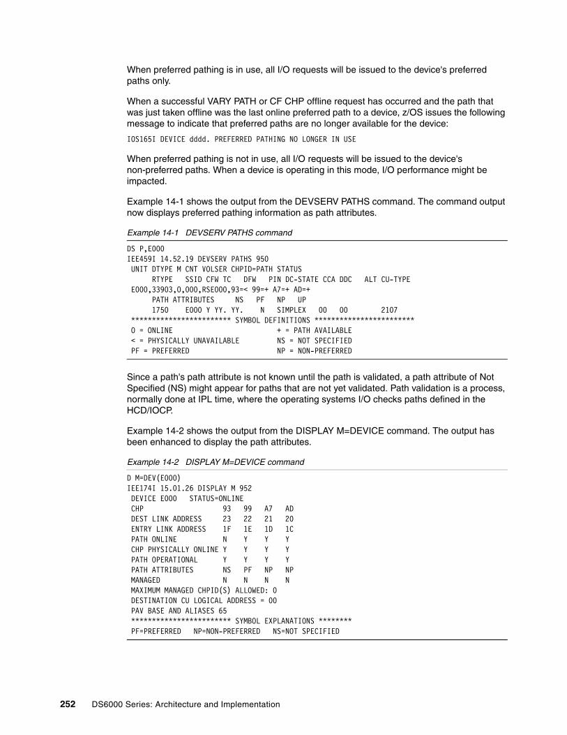
When preferred pathing is in use, all I/O requests will be issued to the device's preferred paths only.
When a successful VARY PATH or CF CHP offline request has occurred and the path that was just taken offline was the last online preferred path to a device, z/OS issues the following message to indicate that preferred paths are no longer available for the device:
IOS165I DEVICE dddd. PREFERRED PATHING NO LONGER IN USE
When preferred pathing is not in use, all I/O requests will be issued to the device's non-preferred paths. When a device is operating in this mode, I/O performance might be impacted.
Example 14-1 shows the output from the DEVSERV PATHS command. The command output now displays preferred pathing information as path attributes.
Example 14-1 DEVSERV PATHS command
DS P,E000IEE459I 14.52.19 DEVSERV PATHS 950 UNIT DTYPE M CNT VOLSER CHPID=PATH STATUS RTYPE SSID CFW TC DFW PIN DC-STATE CCA DDC ALT CU-TYPE E000,33903,O,000,RSE000,93=< 99=+ A7=+ AD=+ PATH ATTRIBUTES NS PF NP UP 1750 E000 Y YY. YY. N SIMPLEX 00 00 2107 ************************ SYMBOL DEFINITIONS ************************ O = ONLINE + = PATH AVAILABLE < = PHYSICALLY UNAVAILABLE NS = NOT SPECIFIED PF = PREFERRED NP = NON-PREFERRED
Since a path's path attribute is not known until the path is validated, a path attribute of Not Specified (NS) might appear for paths that are not yet validated. Path validation is a process, normally done at IPL time, where the operating systems I/O checks paths defined in the HCD/IOCP.
Example 14-2 shows the output from the DISPLAY M=DEVICE command. The output has been enhanced to display the path attributes.
Example 14-2 DISPLAY M=DEVICE command
D M=DEV(E000)IEE174I 15.01.26 DISPLAY M 952 DEVICE E000 STATUS=ONLINE CHP 93 99 A7 AD DEST LINK ADDRESS 23 22 21 20 ENTRY LINK ADDRESS 1F 1E 1D 1C PATH ONLINE N Y Y Y CHP PHYSICALLY ONLINE Y Y Y Y PATH OPERATIONAL Y Y Y Y PATH ATTRIBUTES NS PF NP NP MANAGED N N N N MAXIMUM MANAGED CHPID(S) ALLOWED: 0 DESTINATION CU LOGICAL ADDRESS = 00 PAV BASE AND ALIASES 65 ************************ SYMBOL EXPLANATIONS ******** PF=PREFERRED NP=NON-PREFERRED NS=NOT SPECIFIED
252 DS6000 Series: Architecture and Implementation

The Resource Management Facility (RMF™) reports and the System Management Facility (SMF) records have been updated with APAR OA09921 to provide preferred pathing information on DS6000 control units.
The following RMF reports are updated:
� Postprocessor IOQ report� Monitor II IOQUEUE report� Monitor III IOQUEUE report
The following SMF records are updated:
� SMF 78.3 (I/O queuing activity) � SMF 79.14 (Mon II IOQUEUE activity)
Example 14-3 shows an RMF Postprocessor I/O Queuing Activity report. The new channel path attributes are shown in column CHAN PATHS.
Example 14-3 RMF I/O Queuing Activity report
I/O Q U E U I N G A C T I V I T Y PAGE 1 z/OS V1R6 SYSTEM ID VSL1 DATE 10/25/2005 INTERVAL 05.00.005 RPT VERSION V1R5 RMF TIME 09.55.00 CYCLE 0.250 SECONDS
TOTAL SAMPLES = 1200 IODF = 55 CR-DATE: 10/11/2005 CR-TIME: 14.26.04 ACT: ACTIVATE
- INITIATIVE QUEUE - ------- IOP UTILIZATION ------- -- % I/O REQUESTS RETRIED -- -------- RETRIES / SSCH --------- IOP ACTIVITY AVG Q % IOP I/O START INTERRUPT CP DP CU DV CP DP CU DV RATE LNGTH BUSY RATE RATE ALL BUSY BUSY BUSY BUSY ALL BUSY BUSY BUSY BUSY
00 2094.815 0.01 5.27 2094.812 2053.716 3.6 3.6 0.0 0.0 0.0 0.04 0.04 0.00 0.00 0.00 01 175.387 0.00 0.41 175.387 165.087 0.0 0.0 0.0 0.0 0.0 0.00 0.00 0.00 0.00 0.00 02 1090.278 0.00 2.91 1090.278 1233.569 3.6 3.6 0.0 0.0 0.0 0.04 0.04 0.00 0.00 0.00 03 1043.549 0.00 2.42 1043.549 1030.129 3.6 3.6 0.0 0.0 0.0 0.04 0.04 0.00 0.00 0.00SYS 4404.027 0.00 2.75 4404.023 4482.500 3.5 3.5 0.0 0.0 0.0 0.04 0.04 0.00 0.00 0.00
AVG AVG DELAY AVG LCU CONTROL UNITS DCM GROUP CHAN CHPID % DP % CU CUB CMR CONTENTION Q CSS
MIN MAX DEF PATHS TAKEN BUSY BUSY DLY DLY RATE LNGTH DLY
010F 6100 88 69.269 0.00 0.00 90 69.266 0.00 0.00 * 138.53 0.00 0.00 0.000 0.00 0111 6500 88 0.010 0.00 0.00 90 0.010 0.00 0.00 0.000 0.00 * 0.020 0.00 0.000175 E000 93 NS 0.000 0.00 0.00
99 PF 90.265 0.00 0.00 A7 NP 0.000 0.00 0.00 AD NP 0.000 0.00 0.00 * 90.265 0.00 0.00 0.000 0.00 0176 E100 93 NS 0.000 0.00 0.00 99 NP 0.020 0.00 0.00 A7 PF 57.266 0.00 0.00 AD PF 57.256 0.00 0.00 * 114.54 0.00 0.00 0.000 0.00 0177 E200 93 NS 0.000 0.00 0.00 99 PF 99.708 0.00 0.00 A7 NP 0.000 0.00 0.00 AD NP 0.000 0.00 0.00 * 99.708 0.00 0.00 0.000 0.00 0178 E300 93 NS 0.000 0.00 0.00 99 NP 0.000 0.00 0.00 A7 PF 9.160 0.00 0.00 AD PF 9.163 0.00 0.00 * 18.323 0.00 0.00 0.000 0.00
In the example, control units E000 to E300 are on a DS6000. Notice how on each of them only the preferred paths are being used.
Chapter 14. Preferred path concept 253

14.4 Determining the controller number by using WWPNWhen a Storage Area Network (SAN) is set up, zoning decisions are normally made to ensure that the load is spread evenly across multiple host adapters and switches. With the addition of preferred path, it is vital that each host gets zoned to both controllers of the DS6000. If viewing the attached WWPNs of the DS6800 from a switch, it is advantageous to be able to determine whether a DS6000 port is located on controller 0 or controller 1. To do this, we need to examine the WWPN. You can determine the WWPNs for a DS6800 by using the DS CLI command, lsioport, as shown in Example 14-4.
Example 14-4 WWPN list by DS CLI
dscli> lsioportDate/Time: 9 November 2005 23:58:54 IBM DSCLI Version: 5.1.0.204 DS: IBM.1750-1300247ID WWPN State Type topo portgrp===============================================================I0000 500507630E01FE16 Online Fibre Channel-LW FICON 0I0001 500507630E03FE16 Online Fibre Channel-LW FICON 0I0002 500507630E05FE16 Online Fibre Channel-LW SCSI-FCP 0I0003 500507630E07FE16 Online Fibre Channel-LW SCSI-FCP 0I0100 500507630E81FE16 Online Fibre Channel-LW FICON 0I0101 500507630E83FE16 Online Fibre Channel-LW FICON 0I0102 500507630E85FE16 Online Fibre Channel-LW SCSI-FCP 0I0103 500507630E87FE16 Online Fibre Channel-LW SCSI-FCP 0
You can map the ioport numbers to the hardware (as viewed from the rear of the machine) by using the diagram shown in Figure 14-1.
Figure 14-1 Mapping lsioport to physical locations
1750 IOPORT numbers (from DS CLI lsioport)
Port 0 Port 1 Port 2 Port 3
I0000
Controller 0
I0001 I0002 I0003
Port 0 Port 1 Port 2 Port 3
I0100
Controller 1
I0101 I0102 I0103
The lsioport -l command will list all the ioportnumbers. This value is also the SAID used in FICON.
254 DS6000 Series: Architecture and Implementation

To map a WWPN to a physical location, there are two possible scenarios. Either the YY values shown in the charts will start with 00 (scenario 1) or 01 (scenario 2). The serial number of the Storage Unit will determine which scenario is used. You will not know which scenario your machine is using until you run the lsioport command. Figure 14-2 shows scenario 1 as viewed from the rear of the machine.
Figure 14-2 WWPN Determination scenario 1
Figure 14-3 shows scenario 2 as viewed from the rear of the machine.
Figure 14-3 WWPN determination scenario 2
By using the information presented in this section, you can ensure that your zoning for each server HBA will always include a port from both controller 0 and controller 1.
Scenario 1
Port 0 Port 1 Port 2 Port 3
00
Controller 0
02 04 06
Port 0 Port 1 Port 2 Port 3
80
Controller 1
82 84 86
The WWPN is:
5005 0763 xx YY xxxx
Where YY comes from the port location.
Scenario 2
Port 0 Port 1 Port 2 Port 3
01
Controller 0
03 05 07
Port 0 Port 1 Port 2 Port 3
81
Controller 1
83 85 87
The WWPN is:
5005 0763 xx YY xxxx
Where YY comes from the port location.
Chapter 14. Preferred path concept 255

256 DS6000 Series: Architecture and Implementation

Chapter 15. Performance considerations
This chapter describes the IBM DS6000 performance benefits. We go over the various considerations you should take into account regarding the physical and logical configuration.
We cover the following topics:
� DS6000 hardware performance� Performance considerations for open systems� Performance considerations for z/OS
15
© Copyright IBM Corp. 2005, 2006. All rights reserved. 257

15.1 How the DS6000 addresses the challengeThe DS6000 overcomes many of the architectural limits of the ESS. In this section we go through the different layers and discuss how they have been changed to improve the performance.
15.1.1 Fibre Channel switched disk interconnection at the back endBecause SSA connectivity has not been further enhanced to increase the connectivity speed beyond 40MBps, Fibre Channel connected disks were chosen for the DS6000 back end. This technology is commonly used to connect a group of disks in a daisy-chained fashion in a Fibre Channel Arbitrated Loop (FC-AL).
Plain FC-AL: The challengesHere are the most obvious challenges we experience with plain FC-AL:
� As the term arbitration implies, each individual disk within an FC-AL loop competes with the other disks to get on the loop because the loop supports only one operation at a time.
� Another challenge that is not adequately solved is the handling of failures within the FC-AL loop, particularly with intermittently failing components on the loops and disks.
� A third challenge with conventional FC-AL is the increasing time it takes to complete a loop operation as the number of devices increases in the loop.
For highly parallel operations, concurrent reads and writes with various transfer sizes, this impacts the total effective bandwidth of an FC-AL structure.
How DS6000 series overcomes the challenges of FC-AL The DS6000 uses the same Fibre Channel drives as used in conventional FC-AL-based storage systems. To overcome the arbitration issue within FC-AL, the architecture is enhanced by adding a switch-based approach and creating FC-AL switched loops, as shown in Figure 15-1. Actually, this architecture is called a Fibre Channel switched disk subsystem.
These switches use FC-AL protocol and attach FC-AL drives through a point-to-point connection. The arbitration message of a drive is captured in the switch, processed, and propagated back to the drive, without routing it through all the other drives in the loop.
258 DS6000 Series: Architecture and Implementation

Figure 15-1 Switched FC-AL disk subsystem
Performance is enhanced as both DAs connect to the switched Fibre Channel disk subsystem back end as displayed in Figure 15-2 on page 260. Notice that each DA port can concurrently send and receive data.
Processor
AdapterAdapter
Memory Processor
AdapterAdapter
To host servers
Stor
age
serv
er
ooo
Fibre Channel switch
Fibre Channel switch
16 DDM
Processor
AdapterAdapter
Memory Processor
To storage servers
Hos
t ser
ver
Chapter 15. Performance considerations 259

Figure 15-2 High availability and increased bandwidth connecting both DA to two logical loops
Having these two switched point-to-point loops to each drive, plus connecting both DAs to each switch, accounts for the following improvements:
� There is no arbitration competition and interference between one drive and all the other drives because there is no hardware in common for all the drives in the FC-AL loop. This leads to an increased bandwidth utilizing the full speed of a Fibre Channel for each individual drive. Notice that the external transfer rate of a Fibre Channel DDM is 200 MBps.
� This arrangement doubles the bandwidth over conventional FC-AL implementations due to two simultaneous operations from each DA to allow for two concurrent read operations and two concurrent write operations at the same time.
� Besides the superior performance, do not forget the improved RAS over conventional FC-AL. The failure of a drive is detected and reported by the switch. The switch ports distinguish between intermittent failures and permanent failures. The ports understand intermittent failures that are recoverable and collect data for predictive failure statistics. If one of the switches itself fails, a disk enclosure service processor detects the failing switch and reports the failure using the other loop. All drives can still connect through the remaining switch.
Processor
AdapterAdapter
MemoryMemory Processor
AdapterAdapter
To host servers
Stor
age
serv
er
ooo
Fibre Channel switch
Fibre Channel switch
16 DDM
To next switch
260 DS6000 Series: Architecture and Implementation

This summary just outlines the physical structure. A virtualization approach built on top of the high performance architecture contributes even further to enhanced performance. For details, see Chapter 4, “Virtualization concepts” on page 67.
15.1.2 Fibre Channel device adapterThe DS6000 still relies on eight DDMs to form a RAID-5 or a RAID-10 array. With the virtualization approach and the concept of extents, the DAs are mapping the virtualization level over the disk subsystem back end. For more details on the disk subsystem virtualization refer to Chapter 4, “Virtualization concepts” on page 67.
Figure 15-3 Fibre Channel device adapter with 2 Gbps ports
The new RAID device adapter chipset connects to four 2-Gbps Fibre Channel ports and high function, high performance ASICs. Each port provides up to five times the throughput of a previous SSA-based DA port.
Each DA chipset performs the RAID logic and frees up the processors from this task. The actual throughput and performance of a DA is not only determined by the 2-Gbps ports and hardware used, but also by the firmware efficiency.
Processor
AdapterAdapter
AdapterAdapter
To host servers
Stor
age
serv
erMemory Processor
chipsetPower PC
chipsetHost adapter
memoryProcessor
Persistent
Volatile
2 Gbps Fibre Channel ports
chipsetDevice adapter
Card 1Controller
Chapter 15. Performance considerations 261

15.1.3 Four-port host adapters Before looking into the server complex, we briefly review the more recent host adapters and their enhancements to address performance. Figure 15-4 depicts the four-port host adapters. These adapters are designed to hold four Fibre Channel ports, which can be configured to support either FCP or FICON.
Each port continues the tradition of providing industry-leading throughput and I/O rates for FICON and FCP.
Notice that a FICON channel can address up to 16,384 devices through a FICON port. The DS6000 series can hold up to 8,192 devices. So all devices within a DS6000 series can be reached through a FICON port. Whether this is desirable is a different question and is discussed further in “Configuration recommendations for z/OS” on page 273.
With two sets of HA chip sets, the DS6000 series can configure up to eight FICON or FCP ports.
Figure 15-4 Host adapter with 4 Fibre Channel ports
With eight 2 Gbps ports, the DS6000 series provides a theoretical aggregated host I/O bandwidth of 8 times 2 Gbps. Notice that besides the adapter used and port technology, throughput depends also on the firmware efficiency and how the channel protocol is implemented.
15.1.4 Enterprise-class dual cluster design for the DS6800The DS6000 series provides a dual cluster or rather a dual server design, which is also found in the ESS and DS8000 series. This offers an enterprise-class level of availability and functionality in a space efficient, modular design at a low price.
Processor
AdapterAdapter
AdapterAdapter
To host servers
Stor
age
serv
er
Memory
2 Gbps Fibre Channel ports
Processor
chipsetPower PC
memoryProcessor
Persistent
Volatile
chipsetHost adapter
2 Gbps Fibre Channel ports
chipsetDevice adapter
Card 1Controller
262 DS6000 Series: Architecture and Implementation

The DS6000 series incorporates the latest PowerPC processor technology. A simplified view is shown in Figure 15-5. The dual-processor complex approach allows for concurrent microcode loads, transparent I/O failover and failback support, and redundant, hot-swapable components.
Figure 15-5 Standard PowerPC processor complexes for DS6800-511
Next, Figure 15-6, provides a less abstract view. It outlines some details on the dual processor complex of the DS6800 enclosure and its gates to host servers through HAs, and its connections to the disk storage back end through the DAs.
Figure 15-6 DS6800 server enclosure with its Fibre Channel switched disk subsystem
Processor
AdapterAdapter
AdapterAdapter
To host servers
Stor
age
serv
er
2 Gbps Fibre Channel ports
Card 1Controller
chipsetHost adapter
chipsetPower PC
memoryProcessor
Persistent
Volatile
2 Gbps Fibre Channel ports
chipsetDevice adapter
Processor
Card 0Controller
chipset
Host adapter
chipsetPower PC
memoryProcessor
Persistent
Volatile
2 Gbps Fibre Channel ports
Processor
AdapterAdapter
AdapterAdapter
To host servers2 Gbps Fibre Channel ports
Card 1Controller
chipset
Host adapter
chipsetPower PC
memoryProcessor
Persistent
Volatile
2 Gbps Fibre Channel ports
ooo
Fibre Channel switch
Fibre Channel switch
16 DDM
2 Gbps Fibre Channel ports
Processor
chipset
Device adapter
chipset
Device adapter
Chapter 15. Performance considerations 263

Through its two processor complexes, the DS6800 controls not only one I/O enclosure as shown in Figure 15-6 on page 263, but can connect to up to seven expansion enclosures. Figure 15-7 shows a DS6800 with one DS6000 expansion enclosure.
Figure 15-7 DS6800 with one DS6000 expansion enclosure
Notice that each Fibre Channel switch in the disk subsystems from here on connects to the next pair of Fibre Channel switches through its two remaining ports. This is similar to inter-switch links between Fibre Channel switches.
Through the affinity of extent pools to servers, the DA in a server is used to drive the I/O to the disk drives in the host extent pools owned by its server.
When creating volumes in extent pools, these volumes get an affinity to a certain server through the extent pool affinity to a server (see Chapter 4, “Virtualization concepts” on page 67). This suggests even distribution of volumes across all ranks in the disk subsystems and all loops to balance the workload.
Although each HA port can reach any volume in the disk subsystem, Figure 15-7 also indicates a server affinity to its local HA and its Fibre Channel ports. This introduces the concept of a preferred path. When a volume has an affinity, for example, to server 0, and is accessed through a port in the HA of server 0, then the I/O is locally processed. When this volume is accessed through the HA of the other server, in this example from server 1, then the I/O is routed to the server which owns the extent pool, which here is server 0.
2 Gbps Fibre Channel ports
Card 1Controller
chipsetHost adapter
chipsetPower PC
memoryProcessor
Persistent
Volatile
2 Gbps Fibre Channel ports
chipsetDevice adapter
Card 0Controller
chipsetHost adapter
chipsetPower PC
memoryProcessor
Persistent
Volatile
2 Gbps Fibre Channel ports
chipsetDevice adapter
2 Gbps Fibre Channel ports
oooFibre Channel switch
Fibre Channel switch
oooFibre Channel switch
Fibre Channel switch
Server enclosure
Expansion enclosure
16 DDM
16 DDMTo next switch
Server 1Server 0
Interconnect
264 DS6000 Series: Architecture and Implementation

15.1.5 Vertical growth and scalabilityFigure 15-8 shows a simplified view of the basic DS6000 structure and how it accounts for scalability. It outlines how expansion enclosures connect through inter-switch links to the server enclosure. Notice the two Fibre Channel loops, which are evenly populated as the number of expansion enclosures grow.
Figure 15-8 DS6000 interconnects to expansion enclosures and scales very well
15.2 Performance and sizing considerations for open systemsTo determine the most optimal DS6000 layout, the I/O performance requirements of the different servers and applications should be defined up front since they will play a large part in dictating both the physical and logical configuration of the disk subsystem. Prior to designing the disk subsystem, the disk space requirements of the application should be well understood.
15.2.1 Workload characteristicsYou might have questions regarding the number of host connections or amount of cache required. The answers always depend on the workload requirements (for example, how many I/Os per second per server, I/Os per second per gigabyte of storage, and so forth).
The information you need, ideally, to conduct detailed modeling, includes:
� Number of I/Os per second� I/O density� Megabytes per second � Relative percentage of reads and writes� Random or sequential access characteristics� Cache hit ratio
Server enclosure
Expansion enclosure
oooFibre Channel switch
Fibre Channel switch
16 DDM
oooFibre Channel switch
Fibre Channel switch
16 DDM
oooFibre Channel switch
Fibre Channel switch
16 DDM
oooFibre Channel switch
Fibre Channel switch
16 DDM
Server 0 Server 1
Expansion enclosure
Expansion enclosure
Chapter 15. Performance considerations 265

15.2.2 Data placement in the DS6000Once you have determined the disk subsystem throughput, the disk space and number of disks required by your different hosts and applications, you have to make a decision regarding the data placement.
As is common for data placement and to optimize the DS6000 resources utilization, you should:
� Equally spread the LUNs across the DS6000 servers.
Spreading the LUNs equally on rank group 0 and 1 will balance the load across the DS6000 servers.
� Use as many disks as possible.
� Distribute across DA pairs and loops.
� Stripe your logical volume across several ranks.
� Consider placing specific database objects (such as logs) on different ranks.
All disks in the storage subsystem should have roughly the equivalent utilization. Any disk that is used more than the other disks will become a bottleneck to performance. A practical method is to make extensive use of volume level striping across disk drives.
15.2.3 Disk drive size, speed and typeAt the heart of disk subsystem performance is the disk itself. Anything about it that affects IO speed or throughput will have a direct impact on the performance of the subsystem as a whole. Key among these factors are the size of the disk drives, the rotational speed of the drives and the type of drive (and its intended usage).
Drive size and architecture dictate the amount of data per drive head. As the physical drive size increases, so does the potential workload for arrays and logical volumes on those drives. Keep this in mind when planning for solutions requiring high IO rates and fast response times. One way to counter this is with faster drives speeds, but for the best performance, use arrays of small, high speed drives (such as 15k rpm, 73 GB). The higher rotational speed reduces seek time, thus improving performance.
Also, keep in mind that for the new FATA 500 GB drives, they are both the largest and slowest of the drives available for the DS6000. This combined with the lower utilization recommendations and the potential for drive protection throttling means that these drives are definitely not the drive to use for high performance or heavy IO applications.
15.2.4 LVM stripingStriping is a technique for spreading the data in a logical volume across several disk drives in such a way that the I/O capacity of the disk drives can be used in parallel to access data on the logical volume. The primary objective of striping is very high performance reading and writing of large sequential files, but there are also benefits for random access.
Note: Database logging usually consists of sequences of synchronous sequential writes. Log archiving functions (copying an active log to an archived space) also tend to consist of simple sequential read and write sequences. You should consider isolating log files on separate arrays.
266 DS6000 Series: Architecture and Implementation

DS6000 logical volumes are composed of extents. An extent pool is a logical construct to manage a set of extents. One or more ranks with the same attributes can be assigned to an extent pool. One rank can be assigned to only one extent pool. To create the logical volume, extents from one extent pool are concatenated. If an extent pool is made up of several ranks, a LUN can potentially have extents on different ranks and so be spread over those ranks.
However, to be able to create very large logical volumes, you must consider having extent pools that span more than one rank. In this case, you will not control the position of the LUNs and this might lead to an unbalanced implementation, as shown in Figure 15-9.
Consider combining extent pools made up of one rank and then LVM striping over LUNs created on each extent pool. This provides a balanced method to evenly spread data across the DS6000, as shown in Figure 15-9.
Figure 15-9 Spreading data across ranks
The stripe sizeEach striped logical volume that is created by the host’s logical volume manager has a stripe size that specifies the fixed amount of data stored on each DS6000 logical volume (LUN) at one time.
Note: We recommend assigning one rank per extent pool to control the placement of the data. When creating a logical volume in an extent pool made up of several ranks, the extents for this logical volume are taken from the same rank if possible.
Note: The recommendation is to use host striping wherever possible to distribute the read and write I/O access patterns across the physical resources of the DS6000.
Extent PoolRank 5
Rank 6
Rank 7
Rank 8
8GB LUN
Extent1GB
Rank 1 Extent pool 1
Rank 3
Rank 4
2 GB LUN 1
Extent
1GB
Extent Pool 5
Rank 2
Non-balanced implementation: LUNs across ranksMore than 1 rank per extent pool
2GB LUN 2
2GB LUN 3
2GB LUN 4
Extent pool 2Extent pool 2
Extent pool 3
Extent pool 4
Balanced implementation: LVM striping1 rank per extent pool
LV stripped across 4 LUNs
Chapter 15. Performance considerations 267

15.2.5 Determining the number of connections between the host and DS6000When you have determined your workload requirements in terms of throughput, you have to choose the appropriate number of connections to put between your open systems and the DS6000 to sustain this throughput.
A Fibre Channel host port can sustain a maximum of 206 MB/s data transfer. As a general recommendation, you should at least have two FC connections between your hosts and your DS6000.
15.2.6 Determining the number of paths to a LUNWhen configuring the IBM DS6000 for an open systems host, a decision must be made regarding the number of paths to a particular LUN, because the multipath software allows (and manages) multiple paths to a LUN. There are two opposing factors to consider when deciding on the number of paths to a LUN:
� Increasing the number of paths increases availability of the data, protecting against outages.
� Increasing the number of paths increases the amount of CPU used because the multipath software must choose among all available paths each time an I/O is issued.
A good compromise is between 2 and 4 paths per LUN.
Subsystem Device Driver (SDD): Dynamic I/O load balancingThe Subsystem Device Driver is a pseudo device driver designed to support the multipath configuration environments in the IBM System Storage DS6000. It resides in a host system with the native disk device driver.
We recommend the dynamic I/O load-balancing option (default) of SDD to ensure better performance because:
� SDD automatically adjusts data routing for optimum performance. Multipath load balancing of data flow prevents a single path from becoming overloaded, causing input/output congestion that occurs when many I/O operations are directed to common devices along the same input/output path.
� The path to use for an I/O operation is chosen by estimating the load on each adapter to which each path is attached. The load is a function of the number of I/O operations currently in process. If multiple paths have the same load, a path is chosen at random from those paths.
Note: The stripe size has to be large enough to keep sequential data relatively close together, but not too large so as to keep the data located on a single array.
The recommended stripe sizes that should be defined using your host’s logical volume manager are in the range of 4MB to 64MB.
You should choose a stripe size close to 4 MB if you have a large number of applications sharing the arrays, and choose a larger size when you have very few servers or applications sharing the arrays.
268 DS6000 Series: Architecture and Implementation

15.2.7 Determining where to attach the hostWhen determining where to attach multiple paths from a single host system to I/O ports on the DS6000, the following considerations apply:
� Ensure that the host has at least two connections to the DS6000, using one host I/O port on DS6000 controller 0 and one host I/O port on controller 1.
� If you need more than two paths from a host to the DS6000, spread the attached I/O ports evenly between the two DS6000 controllers.
The DS6000 host adapters, device adapters, and ranks all have affinity to one DS6000 controller card or the other.
15.3 Performance and sizing considerations for z/OSHere we discuss some z/OS-specific topics regarding the performance potential of the DS6000. We also address what to consider when you configure and size a DS6000 to replace older storage hardware in z/OS environments.
15.3.1 Connecting to System z hostsThe diagram of a configuration fragment in Figure 15-10 shows how to connect a DS6800 to a FICON host.
Figure 15-10 DS6800 front end connectivity example - partial view
Server enclosure
oooFibre Channel switch
Fibre Channel switch
16 DDM
oooFibre Channel switch
Fibre Channel switch
16 DDM
Server 0 Server 1
Expansion enclosure
blue red
red I/Oblue I/Ored I/Oblue I/O
preferred pathpreferred path
Chapter 15. Performance considerations 269

The physical connectivity does not reveal what is important to consider when creating logical volumes and assigning these volumes to LCUs. Before considering different configuration approaches, we provide some general discussion on the potential of the DS6000 series in the following sections.
15.3.2 Performance potential in z/OS environmentsFICON channels started in the IBM 9672 G5 and G6 servers with 1 Gbps. Eventually these channels were enhanced to FICON Express channels in IBM 2064 and 2066 servers, with double the speed, so they now operate at 2 Gbps.
The DS6000 series provides only 2-Gbps FCP ports, which can be configured either as FICON to connect to System z servers, or as FCP ports to connect to Fibre Channel-attached open systems hosts. The example in Figure 15-10 shows only two FICON Express channels. But just two FICON Express channels have the potential to provide roughly a bandwidth of 2 x 175 MBps, which equals 350 MBps. This is a very conservative number. Some measurements show up to 206 MBps per 2-Gbps FICON Express channel and 406 MBps aggregated for this particular example with just two FICON Express channels.
I/O rates with 4 KB blocks are in the range of 6,800 I/Os per second or more per FICON Express channel, again a conservative number. A single FICON Express channel can actually perform up to about 9,000 read hit I/Os per second on the DS8000. The particular example with only two FICON Express channels, shown in Figure 15-10, has the potential of over 13,600 I/Os per second with conservative numbers. These numbers vary depending on the server type used.
The ESS 800 has an aggregated bandwidth of about 500 MBps for highly sequential reads and about 350 MBps for sequential writes. The DS6800 can achieve higher data rates than an ESS 800.
In a z/OS environment a typical transaction workload might perform on an ESS 800 Turbo II with a large cache configuration slightly better than with a DS6800. This is the only example where the ESS 800 outperforms the DS6800. In all open systems environments, the DS6800 performs better than the ESS 800. This is also true for sequential throughput in z/OS environments.
15.3.3 An appropriate DS6000 size in z/OS environmentsThe potential of the architecture, its implementation, and the technology utilized allow for some projections at this point (though without having the hard figures at hand). Rules of thumb have the potential to be proven wrong. Therefore, here we are offering you some recommendations on sizing that are rather conservative.
A fully configured ESS 800 Turbo with CKD volumes only and 16 FICON channels has the following capabilities:
� Over 30,000 I/Os per second � More than 500 MBps aggregated sequential read throughput� About 350 MBps sequential write throughput in mirrored cache
Without discrete DS6000 benchmark figures, a sizing approach to follow could be to propose how many ESS 800s might be consolidated into a DS6000 model. From that you can derive the number of ESS 750s, ESS F20s, and ESS E20s which can collapse into a DS6000. The older ESS models have a known relationship to the ESS 800.
270 DS6000 Series: Architecture and Implementation

Further considerations are the connection technology used, such as FICON or FICON Express channels, and the number of channels, for example.
Generally speaking, a properly configured DS6000 has the potential to provide the same or better numbers than an ESS 800, except for transaction workloads with a large cache in the ESS. Since the ESS 800 has the performance capabilities of two ESS F20s, a properly configured DS6000 can replace two ESS F20s.
Processor memory size considerations for z/OS environmentsProcessor memory or cache in the DS6000 contributes to very high I/O rates and helps to minimize I/O response time.
It is not just the pure cache size which accounts for good performance figures. Economical use of cache and smart, adaptive caching algorithms are just as important to guarantee outstanding performance. This is implemented in the DS6000 series, except for the cache segment size, which is currently 68 KB.
Processor memory is subdivided into a data in cache portion, which holds data in volatile memory, and a persistent part of the memory, which functions as NVS to hold DASD fast write (DFW) data until staged to disk.
The IBM Tucson performance evaluation lab suggests a certain ratio between cache size to backstore capacity. In general, the recommendation is:
� 0.5% cache to backstore ratio for z/OS high performance
� 0.2% cache to backstore ratio for high performance open systems
� 0.2% for z/OS for standard performance
� A ratio of 0.1% between cache size and backstore capacity for open system environments for standard performance
S/390 or System z channel consolidationThe number of channels plays a role as well when sizing DS6000 configurations and when we know from where we are coming. You can consider the total number of channels that were used where you are coming from, in the following way:
� ESCON channels are not supported for the DS6000. When coming from an ESCON environment and switching to FICON channels, a four to one ratio is very conservative. Consider, for example, replacing 16 ESCON channels with four FICON Express channels. Plan for four FICON channels as a minimum.
� When the connected host uses FICON channels with 1 Gbps technology and it will stay at this speed as determined by the host or switch ports, then keep the same number of FICON ports. So an ESS 800 with eight FICON channels each connected to IBM 9672 G5 or G6 servers, might end up in a single DS6000 also with eight FICON channels.
� When migrating not only to the DS6000 models but also from 1 Gbps FICON to FICON Express channels at 2 Gbps, you can consider consolidating the number of channels to about 2/3 of the original number of channels. Use at least four FICON channels per DS6000. (By the way, when we write about FICON channels we mean FICON ports in the disk storage servers.)
� Coming from FICON Express channels, you should then keep a minimum of four FICON ports. You might consider using 25% fewer FICON ports in the DS6000 than the aggregated number of FICON 2 Gbps ports from the source environment. For example, when you consolidate an ESS 800 with 10 FICON 2 Gbps ports to a DS6000, plan for all eight possible FICON ports on the DS6000.
Chapter 15. Performance considerations 271

Disk array sizing considerations for z/OS environmentsYou can determine the number of ranks required not only based on the needed capacity, but also depending on the workload characteristics in terms of access density, read to write ratio, and hit rates.
You can approach this from the disk side and look at some basic disk figures. Fibre Channel disks, for example, at 10k RPM, provide an average seek time of approximately 5 ms and an average latency of 3 ms. For transferring only a small block, the transfer time can be neglected. This is an average 8 ms per random disk I/O operation or 125 I/Os per second. A 15k RPM disk provides about 200 random I/Os per second for small block I/Os. A combined number of 8 disks is then good for 1,600 I/Os per second when they spin at 15k per minute. Reduce the number by 12.5% when you assume a spare drive in the 8 pack. Assume further a RAID-5 logic over the 8 packs.
Back at the host side, consider an example with 4,000 I/Os per second and a read to write ratio of 3 to 1 and 50% read cache hits. This leads to the following I/O numbers:
� There are 3,000 read I/Os per second. � There are 1,500 read I/Os must read from disk.� With 1,000 writes with RAID-5, assuming the worst case, this results in 4,000 disk I/Os.� This totals 4,500 disk I/Os.
With 15K RPM DDMs you need the equivalent of three 8-packs to satisfy the I/O load from the host for this example. Note the DS6000 can also be configured with a RAID array comprised of four DDMs.
Depending on the required capacity, you then decide the disk capacity, provided each desired disk capacity has 15k RPM. When the access density is less and you need more capacity, follow the example with higher capacity disks, which usually spin at a slower speed like 10k RPM.
In “Fibre Channel device adapter” on page 261 we stated that the disk storage subsystem DA port in a DS6000 has about five times more sequential throughput capability than an ESS 800 DA port provides. Based on the 2-Gbps Fibre Channel connectivity to a DS6000 disk array, this is approximately 200 MBps compared to the SSA port of an ESS disk array with 40 MBps. A Fibre Channel RAID array provides an external transfer rate of over 200 MBps. The sustained transfer rate varies. For a single disk drive, various disk vendors provide the following numbers:
� 146 GB DDM with 10K RPM delivers a sustained transfer rate between 38 and 68 MBps, or 53 MBps on average
� 73 GB DDM with 15K RPM transfers between 50 and 75 MBps, or 62.5 MBps on average
The 73 GB DDMs have about 18% more sequential capability than the 146 GB DDM, but 60% more random I/O potential. The I/O characteristic is another aspect to consider when deciding the disk and disk array size. Notice that this discussion takes a theoretical approach, but it is sufficient to get a first impression.
At GA the IBM internal tool, Disk Magic, helps to model configurations based on customer workload data. An IBM representative can contact support personnel who will use Disk Magic to configure a DS6000 accordingly.
Use Capacity Magic to find out about usable disk capacity. This tool is also available at an IBM internal intranet sales site.
272 DS6000 Series: Architecture and Implementation
15.3.4 Configuration recommendations for z/OSWe discuss briefly how to group ranks into extent pools and what the implications are with different grouping approaches. Note the independence of LSSs from ranks. Because an LSS is congruent with a z/OS LCU, we need to understand the implications. It is now possible to have volumes within the very same LCU, which is the very same LSS, but these volumes might reside in different ranks and the ranks might be on different loops.
A horizontal pooling approach assumes that volumes within a logical volume pool, like all DB2 volumes, are evenly spread across all ranks and loops. This is independent of how these volumes are represented in LCUs. The following sections assume horizontal volume pooling across ranks, which might be congruent with LCUs when mapping ranks accordingly to LSSs.
Configure one extent pool for each single rankFigure 15-11 shows some aspects regarding extent pools as they relate to the disk subsystem within a DS6000:
� Chapter 4, “Virtualization concepts” on page 67, introduced the construct of an extent pool. When defining an extent pool, an affinity is created between this specific extent pool and a server. Due to the virtualization of the Fibre Channel switched disk subsystem you might consider creating as many extent pools as there are RAID ranks in the DS6000. This would then work similar to what is currently in the ESS. With this approach you can control the placement of each single volume and where it ends up in the disk subsystem. For the DS6000 this would have the advantage that you can plan for proper volume placement with respect to preferred paths.
� In the example in Figure 15-11, each rank is in its own extent pool. The evenly numbered extent pools have an affinity to the left server, server 0. The odd number extent pools have an affinity to the right server, server 1. When a rank is subdivided into extents it gets assigned to its own extent pool.
� Now all volumes which are comprised of extents out of an extent pool have also a respective server affinity when scheduling I/Os to these volumes.
� This allows you to place certain volumes in specific ranks to avoid potential clustering of many high activity volumes within the same rank. You can create SMS storage groups which are congruent to these extent pools to ease the management effort of such a configuration. But you can still assign multiple storage groups when you are not concerned about the placement of less active volumes.
Chapter 15. Performance considerations 273

Figure 15-11 Extent pool affinity to processor complex with one extent pool for each rank
Figure 15-11 indicates that there is an affinity between FICON ports and certain extent pools and, therefore, an affinity between FICON ports and certain volumes within these extent pools.
In this example either one of the two HAs can address any volume in any of the ranks. which range here from rank number 1 to 12. But the HA and DA affinity to a server prefers one path over the other. Now z/OS is able to notice the preferred path and then schedule an I/O over the preferred path as long as the path is not saturated.
Server 0 Server 1
red I/Oblue I/Ored I/Oblue I/O
preferred pathpreferred path
blue red
Extent pool11
Rank
Extent pool9Extent pool7
Extent pool5Extent pool3Extent pool1
1197
531
8 1210
2 64
Extent pool10Extent pool8Extent pool6
Extent pool4Extent pool2Extent pool0
blue extent pools red extent pools
274 DS6000 Series: Architecture and Implementation

Minimize the number of extent poolsThe other extreme is to create just two extent pools when the DS6000 is configured as CKD storage only. You would then subdivide the disk subsystem evenly between both processor complexes or servers, as Figure 15-12 shows.
Figure 15-12 Extent pool affinity to processor complex with pooled ranks in two extent pools
Again, what is obvious here is the affinity between all volumes residing in extent pool 0 to the left processor complex, server 0, including its HA, and the same for the volumes residing in extent pool 1 and their affinity to the right processor complex or server 1.
When creating volumes, there is no straightforward approach to place certain volumes into certain ranks. For example, when you create the first 20 DB2 logging volumes, they would be allocated in a consecutive fashion in the first rank. The concerned RAID site would then host all these 20 logging volumes. You might want to control the placement of the most critical performance volumes and also configure for preferred paths. This might lead to a compromise between both approaches, as Figure 15-13 suggests.
Server 0 Server 1
red I/Oblue I/Ored I/Oblue I/O
preferred pathpreferred path
blue red
861210
42
Extent pool1
75119
31
Extent pool0
Rank
Chapter 15. Performance considerations 275

Plan for a reasonable number of extent poolsFigure 15-13 presents a grouping of ranks into extent pools which follows a similar pattern and discussion as for grouping volumes or volume pools into SMS storage groups.
Figure 15-13 Mix of extent pools
Create two general extent pools for all the average workload and the majority of the volumes and subdivide these pools evenly between both processor complexes or servers. These pools contain the majority of the installed ranks in the DS6000. Then you might consider two or four smaller extent pools with dedicated ranks for high performance workloads and their volumes. You could consider defining storage groups accordingly which are congruent to the smaller extent pools.
Consider grouping the two larger extent pools into a single SMS storage group. SMS will eventually spread the workload evenly across both extent pools. This allows a system-managed approach to place data sets automatically in the right extent pools. With more than one DS6000, you might consider configuring each DS6000 in a uniform fashion. We recommend grouping all volumes from all the large extent pools into one large SMS storage group. Cover the smaller, high performance extent pools through discrete SMS storage groups for each DS6000. For example, in a dual logging database environment allow assignment of extent pool0 to the first logging volume and extent pool1 for the second logging volume. Consider a respective channel path configuration which takes preferred paths into account.
Server 0 Server 1
red I/Oblue I/Ored I/Oblue I/O
preferred pathpreferred path
blue red
blue extent pools red extent pools
Rank
Extent pool5
Extent pool1Extent pool3
Extent pool4
Extent pool2Extent pool0
135
79
11
13 5
7 9
11
276 DS6000 Series: Architecture and Implementation
15.4 SummaryThe DS6000 high performance processor complex configuration is the base for a maximum of host I/O operations per second. The DS6000 can handle I/O rates of about what an ESS 800 can deliver at maximum speed. With the introduction of the smart, switch-based Fibre Channel disk back end, which overcomes the FC-AL arbitration overhead and operates at a 2-Gbps speed, the DS6000 provides a better sequential throughput than an ESS 800.
The DS6000 series is designed to deliver enterprise-class storage capabilities in a space efficient, modular design at a low price. It provides a wide capacity range from 16 DDMs up to 128DDMs. Depending on the DDM size this reaches a total of up to 67.2 TB. Just the base enclosure provides up to 4.8 TB of physical storage capacity with 16 DDMs and 300 GB per DDM.
The small and fast DS6000, with its rich functionality and compatibility with the ESS 750, ESS 800, and DS8000, in all functional respects, makes this a very attractive choice.
Chapter 15. Performance considerations 277

278 DS6000 Series: Architecture and Implementation

Part 4 Host considerations
In this part of the book, we discuss host platform specific considerations when attaching to a DS6000. We present the following host platforms and operating systems (OS):
� Open systems:
– Windows– AIX: SDD and MPIO– Linux– OpenVMS– VMware– Sun Solaris– HP-UX
� System z hosts:
– z/OS– z/VM and VM/ESA®– z/VSE and VSE/ESA– Linux for System z
� System i hosts:
– OS/400– AIX and Linux on System i
Part 4
© Copyright IBM Corp. 2005, 2006. All rights reserved. 279

280 DS6000 Series: Architecture and Implementation

Chapter 16. Considerations for open systems
This chapter describes the various considerations applying to open systems environments. We discuss the specifics of attaching the DS6000 to host systems running the following operating systems:
� Windows� AIX� Linux on various hardware platforms� HP OpenVMS� VMware� Sun Solaris� HP-UX
16
© Copyright IBM Corp. 2005, 2006. All rights reserved. 281

16.1 General considerationsThis section contains general information that is not only specific to a particular operating system. It includes available documentation, planning considerations. links to additional information, and other general topics.
16.1.1 Getting up-to-date informationIn the following sections we provide brief descriptions of the various online resources where you can find detailed and up-to-date information about supported configurations, the recommended settings, device driver versions, and so on. Due to the high innovation rate in the IT industry, the support information is updated frequently. Therefore, it is advisable to visit these resources regularly and check for updates.
The DS6000 Interoperability MatrixThe DS6000 Interoperability Matrix always provides the latest information about supported platforms, operating systems, HBAs, and SAN infrastructure solutions. It contains detailed specifications about models and versions. It also lists special support items, such as boot support and exceptions. You can find it at:
http://www-1.ibm.com/servers/storage/disk/ds6000/interop.html
The IBM HBA Search ToolFor information about supported Fibre Channel HBAs and the recommended or required firmware and device driver levels for all IBM storage systems, you can visit the IBM HBA Search Tool site, sometimes also referred to as the Fibre Channel host bus adapter firmware and driver level matrix, found at:
http://knowledge.storage.ibm.com/servers/storage/support/hbasearch/interop/hbaSearch.do
For each query, select one storage system and one operating system only; otherwise, the output of the tool will be ambiguous. You will be shown a list of all supported HBAs together with the required firmware and device driver levels for your combination. Furthermore, you can select a detailed view for each combination with more information, quick links to the HBA vendors’ Web pages and their IBM supported drivers, and a guide to the recommended HBA settings.
The DS6000 Host Systems Attachment GuideThe IBM System Storage DS6000: Host Systems Attachment Guide, GC26-7680 guides you, in detail, through all the steps that are required to attach an open system host to your DS6000 storage system. It is available at this Web site by clicking Documentation:
http://www-1.ibm.com/servers/storage/support/disk/ds6800/installing.html
The general link to installation documentation Some times links are changed. A good starting point to find documentation and troubleshooting information is available at:
http://www-1.ibm.com/servers/storage/support/disk/ds6800/installing.html
The System Storage Proven programIBM has introduced the System Storage Proven program to help clients identify storage solutions and configurations that have been pre-tested for interoperability. It builds on IBM's already extensive interoperability efforts to develop and deliver products and solutions that work together with third-party products.
282 DS6000 Series: Architecture and Implementation

The System Storage Proven Web site provides more detail on the program, as well as the list of pre-tested configurations:
http://www.ibm.com/servers/storage/proven/index.html
HBA vendor resourcesAll of the Fibre Channel HBA vendors have Web sites that provide information about their products, facts, and features, as well as support information. These sites will be useful when the IBM resources are not sufficient, for example, when troubleshooting an HBA driver. Be aware that IBM cannot be held responsible for the content of these sites.
QLogic CorporationThe Qlogic Web site can be found at:
http://www.qlogic.com
QLogic maintains a page that lists all the HBAs, drivers, and firmware versions that are supported for attachment to IBM storage systems:
http://www.qlogic.com/support/ibm_page.html
Emulex CorporationThe Emulex home page is:
http://www.emulex.com
They also have a page with content specific to IBM storage systems:
http://www.emulex.com/ts/docoem/framibm.htm
JNI / AMCCAMCC took over the former JNI, but still markets FC HBAs under the JNI brand name. JNI HBAs are supported for DS6000 attachment to SUN systems. Their home page is:
http://www.amcc.com
Their IBM storage specific support page is:
http://www.amcc.com/drivers/IBM.html
AttoAtto supplies HBAs, which IBM supports for Apple Macintosh attachment to the DS6000. Their home page is:
http://www.attotech.com
They have no IBM storage specific page. Their support page is:
http://www.attotech.com/support.html
Downloading drivers and utilities for their HBAs requires registration.
Platform and operating system vendors’ pagesThe platform and operating system vendors also provide lots of support information to their customers. Go there for general guidance about connecting their systems to SAN-attached storage. However, be aware that in some cases you will not find information that will help you with third-party products. You should always check with IBM about interoperability and support from IBM in regard to these products. It is beyond the scope of this redbook to list all the vendors’ Web sites.
Chapter 16. Considerations for open systems 283

16.1.2 Differences with ESS 2105For DS6000, the support matrix went through a cleanup process. The changes are described in this section. For details, see the resources listed in the previous section:
� There are no parallel SCSI adapters for the DS6000. Therefore, all parallel SCSI support had to be dropped. No host system can be connected to the DS6000 via parallel SCSI.
� Older HBA models, especially all 1 Gbps models, were also removed from the support matrix. Some new models were added.
� Legacy SAN infrastructure solutions, like hubs and gateways, are not supported.
� Some legacy operating systems and operating system versions were dropped from the support matrix. These are either versions that were withdrawn from marketing or support that are not marketed or supported by their vendors or are not seen as significant enough anymore to justify the testing effort necessary to support them. Some new operating systems and versions were added.
16.1.3 Boot supportFor most of the supported platforms and operating systems, you can use the DS6000 as a boot device. The DS6000 Interoperability Matrix provides detailed information about boot support.
The IBM System Storage DS6000: Host Systems Attachment Guide, GC26-7923 helps you with the procedures necessary to set up your host in order to boot from the DS6000.
The IBM System Storage Multipath Subsystem Device Driver User’s Guide, SC30-4131 also helps with identifying the optimal configuration and lists the steps required to boot from multipathing devices.
16.1.4 Additional supported configurations (Request for Price Quotation)There is a process for cases where a desired configuration is not represented in the support matrix. This process is called Request for Price Quotation (RPQ). Clients should contact their IBM storage sales specialist or IBM Business Partner for submission of an RPQ. Initiating the process does not guarantee that the desired configuration will be supported. This depends on the technical feasibility and the required test effort. A configuration that equals or is similar to one of the already approved ones is more likely to get approved than a completely different one.
16.1.5 Multipathing supportTo ensure maximum availability, most customers choose to connect their open systems hosts through more than one Fibre Channel path to their storage systems. With an intelligent SAN layout, this protects you from failures of FC HBAs, SAN components, and host ports in the storage subsystem.
Most operating systems, however, cannot deal natively with multiple paths to a single disk: They see the same disk multiple times. This puts the data integrity at risk, because multiple write requests can be issued to the same data and nothing takes care of the correct order of writes.
284 DS6000 Series: Architecture and Implementation

To utilize the redundancy and increased I/O bandwidth you get with multiple paths, you need an additional layer in the operating system’s disk subsystem to recombine the multiple disks seen by the HBAs into one logical disk. This layer manages path failover, should a path become unusable, and balancing of I/O requests across the available paths. Depending on the operating system, there could be several multipathing solutions for the DS6000.
Subsystem Device Driver (SDD)For most operating systems that are supported for DS6000 attachment, IBM makes available the IBM Subsystem Device Driver (SDD).
Refer to 14.2.1, “Multipath Subsystem Device Driver (SDD)” on page 250.
Other multipathing solutionsSome operating systems come with native multipathing software, for example:
� SUN StorEdge Traffic Manager for SUN Solaris
� HP PVLinks for HP-UX
� IBM AIX native multipathing (MPIO)
� IBM OS/400 V5R3 multipath support
� In addition, there are third-party multipathing solutions, such as Veritas DMP, which is part of Veritas Volume Manager.
Most of these solutions are also supported for DS6000 attachment, although the scope might vary. There might be limitations for certain host bus adapters or operating system versions. Always consult the DS6000 Interoperability Matrix for the latest information.
16.2 WindowsDS6000 supports Fibre Channel attachment to Microsoft Windows 2000/2003 servers. For details regarding operating system versions and HBA types, see the DS6000 Interoperability Matrix, available at:
http://www.ibm.com/servers/storage/disk/ds6000/interop.html
The support includes cluster service and acts as a boot device. Booting is supported currently with host adapters QLA23xx (32-bit or 64-bit) and LP9xxx (32_bit only). For a detailed discussion about SAN booting (advantages, disadvantages, potential difficulties, and troubleshooting) we highly recommend the Microsoft document Boot from SAN in Windows Server 2003 and Windows 2000 Server, available at:
http://www.microsoft.com/windowsserversystem/wss2003/techinfo/plandeploy/BootfromSANinWindows.mspx
Note: For concurrent maintenance and availability reasons, we recommend having, at minimum, one path to each DS6000 controller.
Attention: Only SDD Versions 1.6 and higher are supported for the DS6000.
Chapter 16. Considerations for open systems 285

16.2.1 HBA and operating system settingsDepending on the host bus adapter type, several HBA and driver settings might be required. Refer to the IBM System Storage DS6000: Host Systems Attachment Guide, GC26-7923 for the complete description of these settings. Although the volumes can be accessed with other settings too, the values recommended there have been tested for robustness.
To ensure optimum availability and recoverability when you attach a Storage Unit to a Windows 2000/2003 host system, we recommend setting the Time Out Value value associated with the host adapters to 60 seconds. The operating system uses the Time Out Value parameter to bind its recovery actions and responses to the disk subsystem.
The value is stored in the Windows registry at HKEY_LOCAL_MACHINE\SYSTEM\CurrentControlSet\Services\Disk\TimeOutValue.
The value has the data type REG-DWORD and should be set to 0x0000003c hexadecimal (60 decimal).
16.2.2 SDD for WindowsAn important task with a Windows host is the installation of the SDD multipath driver. Ensure that SDD is installed before adding additional paths to a device. Otherwise, the operating system could lose the ability to access existing data on that device. For details, refer to the IBM System Storage Multipath Subsystem Device Driver User’s Guide, SC30-4131.
In Figure 16-1, you see an example of two disks connected by four paths to the server. You see two IBM 1750500 SDD Disk Devices as real disks on Windows. The IBM 1750500 SCSI Disk Device is hidden by SDD.
Figure 16-1 SDD devices on Windows Device manager
286 DS6000 Series: Architecture and Implementation

You can see the Disk manager view in Figure 16-2.
Figure 16-2 Disk manager view
SDD datapath queryA new option, -l, was added to datapath query device to mark the non-preferred paths with an asterisk.
Example 16-1 shows a sample output of this new option.
Example 16-1 datapath query device -l
C:\Program Files\IBM\Subsystem Device Driver>datapath query device -l
Total Devices : 2
DEV#: 0 DEVICE NAME: Disk2 Part0 TYPE: 1750500 POLICY: OPTIMIZEDSERIAL: 13AAGXA1002LUN IDENTIFIER: 600507630EFFFC6F0000000000001002============================================================================Path# Adapter/Hard Disk State Mode Select Errors 0 Scsi Port2 Bus0/Disk2 Part0 OPEN NORMAL 648 0 1* Scsi Port2 Bus0/Disk2 Part0 OPEN NORMAL 0 0 2 Scsi Port3 Bus0/Disk2 Part0 OPEN NORMAL 680 0 3* Scsi Port3 Bus0/Disk2 Part0 OPEN NORMAL 0 0
Note: New assigned disks will be discovered; if not, go to the disk manager and rescan the disks or to the device manager and scan for hardware changes.
Chapter 16. Considerations for open systems 287

DEV#: 1 DEVICE NAME: Disk3 Part0 TYPE: 1750500 POLICY: OPTIMIZEDSERIAL: 13AAGXA1102LUN IDENTIFIER: 600507630EFFFC6F0000000000001102============================================================================Path# Adapter/Hard Disk State Mode Select Errors 0* Scsi Port2 Bus0/Disk3 Part0 OPEN NORMAL 0 0 1 Scsi Port2 Bus0/Disk3 Part0 OPEN NORMAL 1305 0 2* Scsi Port3 Bus0/Disk3 Part0 OPEN NORMAL 0 0 3 Scsi Port3 Bus0/Disk3 Part0 OPEN NORMAL 1302 0
The serial number of the disk is a combination of the serial number of the DS6000 and the Volume ID (last four digits). The first two digits of the Volume ID are the LSS number. In Example 16-1, device 0 serial number 13AAGXA1002 is volume 1002 on LSS 10 of DS6000 with serial number 13AAGXA. The device name is the name of the disk found in the disk manager (see Figure 16-2 on page 287).
The commands datapath query essmap and datapath query portmap are not available.
Another helpful command is datapath query wwpn (see Example 16-2). It helps you to get the World Wide Port Name (WWPN) of your Fibre Channel adapter.
Example 16-2 datapath query wwpn
C:\Program Files\IBM\Subsystem Device Driver>datapath query wwpn Adapter Name PortWWN Scsi Port2: 210000E08B037575 Scsi Port3: 210000E08B033D76
Support for Windows 2000 and Windows 2003 clustering SDD V1.5.x.x does not support I/O load balancing in a Windows Server clustering. SDD V1.6.0.0 (or later) is required to support load balancing in Windows clustering. When running Windows clustering, clustering failover might not occur when the last path is being removed from the shared resources. See Microsoft article Q294173 for additional information, found at:
http://support.microsoft.com/default.aspx?scid=kb;en-us;Q294173
Windows does not support dynamic disks in the MSCS environment.
Special considerations in the Windows 2000 / Windows 2003 clusteringenvironment There are subtle differences in the way that SDD handles path reclamation in a Windows clustering environment compared to a non-clustering environment. When the Windows server™ loses a path in a non-clustering environment, the path condition changes from open to dead and the adapter condition changes from active to degraded. The adapter and path condition will not change until the path is made operational again.
When the Windows server loses a path in a clustering environment, the path condition changes from open to dead and the adapter condition changes from active to degraded. However, after a period of time, the path condition changes back to open and the adapter condition changes back to normal, even if the path has not been made operational again.
Note: The adapter goes to DEGRAD state when there are active paths left on the adapter. It goes to FAILED state when there are no active paths.
288 DS6000 Series: Architecture and Implementation
The datapath set adapter # offline command operates differently in a clustering environment as compared to a non-clustering environment. In a clustering environment, the datapath set adapter offline command does not change the condition of the path if the path is active or being reserved. If you issue the command, the following message is displayed:
To preserve access some paths left online
Boot supportWhen booting from the FC storage systems, special restrictions apply:
� With Windows 2000, you should not use the same HBA as both the FC boot device and the clustering adapter. The reason for this is the usage of SCSI bus is reset by MSCS to break up disk reservations during quorum arbitration. Because a bus reset cancels all pending I/O operations to all FC disks visible to the host via that port, an MSCS-initiated bus reset might cause operations on the C:\ drive to fail.
� With Windows 2003, MSCS uses target resets. See the Microsoft technical article Microsoft Windows Clustering: Storage Area Networks, found at:
http://www.microsoft.com/windowsserver2003/techinfo/overview/san.mspx
� Windows Server 2003 will allow for boot disk and the cluster server disks hosted on the same bus. However, you would need to use Storport miniport HBA drivers for this functionality to work. This is not a supported configuration in combination with drivers of other types (for example, SCSI port miniport or full port drivers).
� If you reboot a system with adapters while the primary path is in a failed state, you must manually disable the BIOS on the first adapter and manually enable the BIOS on the second adapter. You cannot enable the BIOS for both adapters at the same time. If the BIOS for both adapters is enabled at the same time and there is a path failure on the primary adapter, the system will stop with an INACCESSIBLE_BOOT_DEVICE error upon reboot.
16.2.3 Windows Server 2003 VDS supportMicrosoft introduced the Virtual Disk Service (VDS) with Windows Server 2003. It unifies storage management and provides a single interface for managing block storage virtualization. This interface is vendor and technology neutral, and is independent of the layer where virtualization is done, operating system software, RAID storage hardware, or other storage virtualization engines.
VDS is a set of APIs that uses two sets of providers to manage storage devices. The built-in VDS software providers enable you to manage disks and volumes at the operating system level. VDS hardware providers supplied by the hardware vendor enable you to manage hardware RAID arrays. Windows Server 2003 components that work with VDS include the Disk Management Microsoft Management Console (MMC) snap-in, the DiskPart command-line tool, and the DiskRAID command-line tool, which is available in the Windows Server 2003 Deployment Kit.
Chapter 16. Considerations for open systems 289
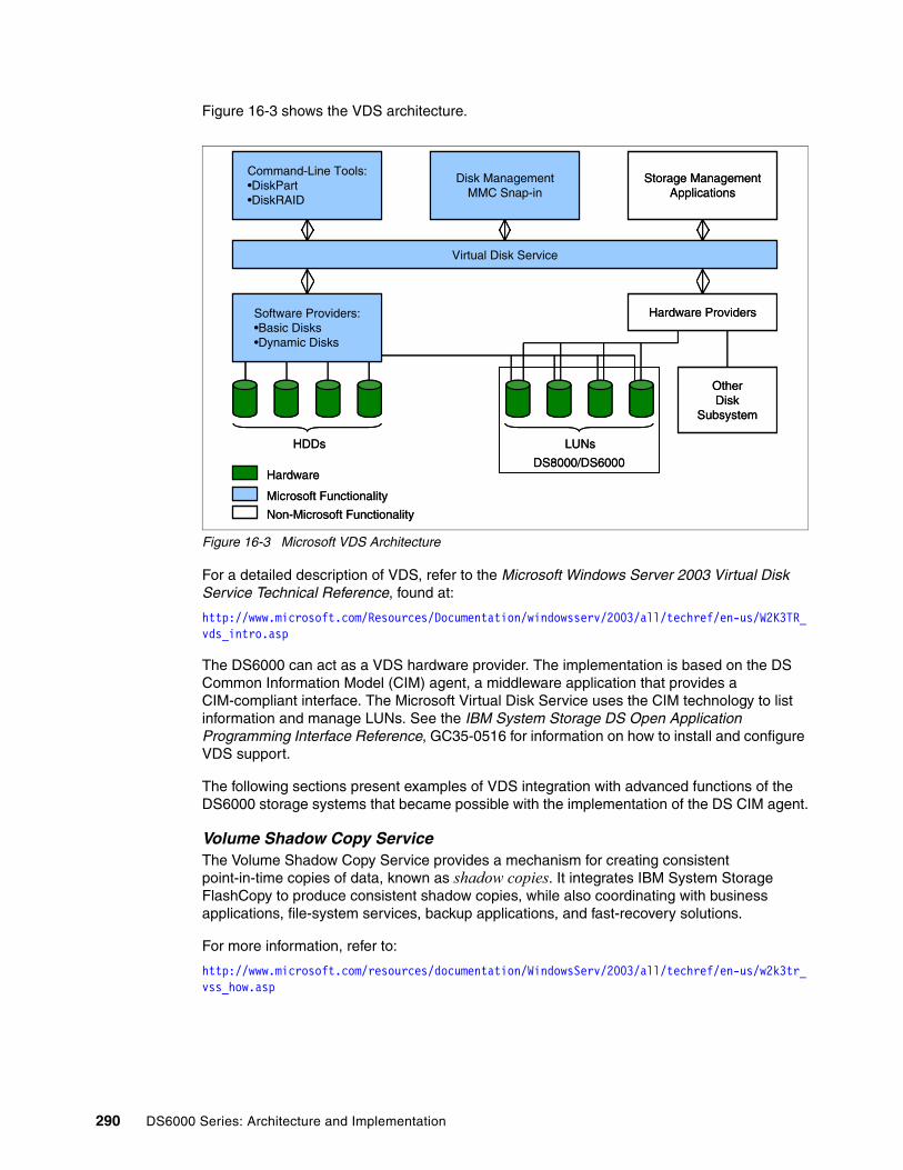
Figure 16-3 shows the VDS architecture.
Figure 16-3 Microsoft VDS Architecture
For a detailed description of VDS, refer to the Microsoft Windows Server 2003 Virtual Disk Service Technical Reference, found at:
http://www.microsoft.com/Resources/Documentation/windowsserv/2003/all/techref/en-us/W2K3TR_vds_intro.asp
The DS6000 can act as a VDS hardware provider. The implementation is based on the DS Common Information Model (CIM) agent, a middleware application that provides a CIM-compliant interface. The Microsoft Virtual Disk Service uses the CIM technology to list information and manage LUNs. See the IBM System Storage DS Open Application Programming Interface Reference, GC35-0516 for information on how to install and configure VDS support.
The following sections present examples of VDS integration with advanced functions of the DS6000 storage systems that became possible with the implementation of the DS CIM agent.
Volume Shadow Copy ServiceThe Volume Shadow Copy Service provides a mechanism for creating consistent point-in-time copies of data, known as shadow copies. It integrates IBM System Storage FlashCopy to produce consistent shadow copies, while also coordinating with business applications, file-system services, backup applications, and fast-recovery solutions.
For more information, refer to:
http://www.microsoft.com/resources/documentation/WindowsServ/2003/all/techref/en-us/w2k3tr_vss_how.asp
Software Providers:•Basic Disks•Dynamic Disks
Disk ManagementMMC Snap-in
Hardware Providers
Virtual Disk Service
Command-Line Tools:•DiskPart•DiskRAID
Storage ManagementApplications
LUNs
OtherDisk
Subsystem
DS8000/DS6000
HDDs
Non-Microsoft Functionality
Hardware
Microsoft Functionality
Software Providers:•Basic Disks•Dynamic Disks
Disk ManagementMMC Snap-in
Hardware Providers
Virtual Disk Service
Command-Line Tools:•DiskPart•DiskRAID
Storage ManagementApplications
LUNs
OtherDisk
Subsystem
DS8000/DS6000
HDDs
Non-Microsoft Functionality
Hardware
Microsoft Functionality
290 DS6000 Series: Architecture and Implementation

Basic requirements for using these functionsTo use these functions, you need an installed CIM client somewhere, such as the SMC. This CIM client requires an ESS CLI client to communicate with an ESS and DS CLI Client to communicate with DS6000 and DS8000. On each server, you need the IBM Total Storage Enterprise Storage Server API support for Microsoft Volume Shadow Copy Service (see Figure 16-4).
Figure 16-4 VSS installation infrastructure
After installation, as described in IBM System Storage DS Open Application Programming Interface Reference, GC35-0516, you have to define a VSS_FREE volume group and virtual server and a VSS_RESERVED volume group and virtual server, and assign volumes to the VSS_FREE volume group. The WWPN default for the VSS_FREE virtual server is 50000000000000; for the VSS_RESERVED virtual server, 50000000000001. These disks are available for the server as a pool of free available disks. If you want to have different pools of free disks, you can define your own WWPN for another pool (see Example 16-3 on page 292).
D S 6 0 0 0 D S 8 0 0 0 E S S
M a n a g e m e n t s e r v e r
C I M C l i e n tD S C L I
E S S C L I
W i n d o w s 2 0 0 3S e r v e r
W i n d o w s V S S
I B M A P I s u p p o r t f o r M i c r o s o f t V o l u m e S h a d o w C o p y S e r v i c e
W i n d o w s 2 0 0 3S e r v e r
W i n d o w s V S S
I B M A P I s u p p o r t f o r M i c r o s o f t V o l u m e S h a d o w C o p y S e r v i c e
S M C S H M C
Chapter 16. Considerations for open systems 291

Example 16-3 ESS Provider Configuration Tool Commands Help
C:\Program Files\IBM\ESS Hardware Provider for VSS>ibmvssconfig.exe /?
ESS Provider Configuration Tool Commands----------------------------------------ibmvssconfig.exe <command> <command arguments>
Commands:/h | /help | -? | /?showcfglistvols <all|free|vss|unassigned>add <volumeID list> (separated by spaces)rem <volumeID list> (separated by spaces)
Configuration:set targetESS <5-digit ESS Id>set user <CIMOM user name>set password <CIMOM password>set trace [0-7]set trustpassword <trustpassword>set truststore <truststore location>set usingSSL <YES | NO>set vssFreeInitiator <WWPN>set vssReservedInitiator <WWPN>set FlashCopyVer <1 | 2>set cimomPort <PORTNUM>set cimomHost <Hostname>set namespace <Namespace>
With the ibmvssconfig.exe listvols command, you can also verify what volumes are available for VSS in the VSS_FREE pool (see Example 16-4).
Example 16-4 VSS list volumes at free pool
C:\Program Files\IBM\ESS Hardware Provider for VSS>ibmvssconfig.exe listvols freeListing Volumes...
LSS Volume Size Assigned to---------------------------------------------------10 003AAGXA 5.3687091E9 bytes500000000000000011 103AAGXA 2.14748365E10 bytes5000000000000000
Also, disks that are unassigned in your disk subsystem can be assigned with the add command to the VSS_FREE pool (see Example 16-22 on page 309).
Example 16-5 VSS list volumes available for vss
C:\Program Files\IBM\ESS Hardware Provider for VSS>ibmvssconfig.exe listvols vssListing Volumes...
LSS Volume Size Assigned to---------------------------------------------------10 001AAGXA 1.00000072E10 bytesUnassigned10 003AAGXA 5.3687091E9 bytes500000000000000011 103AAGXA 2.14748365E10 bytes5000000000000000
292 DS6000 Series: Architecture and Implementation

How to use VSS and VDS for backupFigure 16-5 shows a scenario of using VSS and VDS for backup. For more detailed information, see the IBM TotalStorage Business Continuity Solutions Guide, SG24-6547.
Figure 16-5 VSS VDS example
Geographically Dispersed Sites (GDS)IBM System Storage Continuous Availability for Windows (formerly GDS for MSCS) is designed to provide high availability and a disaster recovery solution for clustered Microsoft Server environments. It integrates Microsoft Cluster Service (MSCS) and the Metro Mirror (PPRC) feature of the DS6000. It is designed to allow Microsoft Cluster installations to span geographically dispersed sites and help protect clients from site disasters or storage system failures. This solution is offered through IBM storage services. For more information on this topic, see the following Web site:
http://www-03.ibm.com/servers/storage/solutions/business_continuity/index.html
In EMEA, see this site:
http://web.mainz.de.ibm.com/ATSservices
We also discuss these solutions in The IBM System Storage DS6000 Series: Copy Services in Open Environments, SG24-6783.
For more details about GDS, refer to:
http://www.microsoft.com/windows/catalog/server/default.aspx?subID=22&xslt=search&pgn=b55095f4-71f3-4b26-98b1-05f3a9506d0d&maxrows=0&sortcol=win2003&sortdir=descending&qu=geographically&scope=1
http://www.ibm.com/servers/storage/solutions/business_continuity/pdf/IBM_TotalStorage_GDS_Whitepaper.pdf
VSS_FREEPool
TargetTarget
ProductionPool
DS8000/DS8000/DS6000DS6000
FlashCopy
RequestorRequestor
VolumeVolumeShadowShadow
CopyCopyServiceService
Win2003Production
Server
IBM VSS IBM VSS ProviderProvider Hardware
Provider
AppsApps
WritersWriters
SourceSource
Win2003Backup Server
VSS_RESERVEPool
BackupBackupAppApp
I/OI/O
IBM VDS IBM VDS ProviderProvider
CommandCommandLine Line
InterfaceInterface
StorageStorageMgtMgtAppApp
Disk MgtDisk Mgt
VirtualVirtualDiskDisk
ServiceService
Chapter 16. Considerations for open systems 293

16.3 AIXThis section covers items specific to the IBM AIX operating system. We focus here on the most important topics. For complete information, refer to IBM System Storage DS6000: Host Systems Attachment Guide, GC26-7680.
16.3.1 Finding the World Wide Port NamesIn order to allocate DS6000 disks to a System p server, the World Wide Port Name (WWPN) of each of the System p Fibre Channel adapters has to be registered in the DS6000. You can use the lscfg command to find out these names, as shown in Example 16-6.
Example 16-6 Finding Fibre Channel adapter WWN
lscfg -vl fcs0fcs0 U1.13-P1-I1/Q1 FC Adapter
Part Number.................00P4494 EC Level....................A Serial Number...............1A31005059 Manufacturer................001A Feature Code/Marketing ID...2765 FRU Number.................. 00P4495 Network Address.............10000000C93318D6 ROS Level and ID............02C03951 Device Specific.(Z0)........2002606D Device Specific.(Z1)........00000000 Device Specific.(Z2)........00000000 Device Specific.(Z3)........03000909 Device Specific.(Z4)........FF401210 Device Specific.(Z5)........02C03951 Device Specific.(Z6)........06433951 Device Specific.(Z7)........07433951 Device Specific.(Z8)........20000000C93318D6 Device Specific.(Z9)........CS3.91A1 Device Specific.(ZA)........C1D3.91A1 Device Specific.(ZB)........C2D3.91A1 Device Specific.(YL)........U1.13-P1-I1/Q1
You can also print the WWPN of an HBA directly by running:
lscfg -vl <fcs#> | grep Network
The # stands for the instance of each FC HBA you want to query.
294 DS6000 Series: Architecture and Implementation

16.3.2 AIX multipath supportThe DS6000 supports two methods of attaching AIX hosts:
� Subsystem Device Driver (SDD)
� AIX MPIO with PCM (SDDPCM)
SDD for AIXMPIO and SDD cannot coexist on the same server.
The following filesets are needed for SDD:
� devices.sdd.51.rte, devices.sdd.52.rte, devices.sdd.53.rte, or devices.sdd.433.rte, depending on the OS version
� devices.fcp.disk.ibm.rte
The following filesets should not be installed and must be removed:
� devices.fcp.disk.ibm.mpio.rte, devices.sddpcm.52.rte, or devices.sddpcm.53.rte
A new option, -l, is added to datapath query device to mark the non-preferred paths with an asterisk. This option can be used in addition to the existing datapath query device commands. In Example 16-7, you see non-preferred paths are marked with a *. You see also that only the preferred paths are used.
Example 16-7 datapath query device -l on AIX
root@sanh70:/ > datapath query device -l
Total Devices : 2
DEV#: 0 DEVICE NAME: vpath0 TYPE: 1750500 POLICY: OptimizedSERIAL: 13AAGXA1000LUN IDENTIFIER: 600507630EFFFC6F0000000000001000==========================================================================Path# Adapter/Hard Disk State Mode Select Errors 0 fscsi0/hdisk1 OPEN NORMAL 2543 0 1* fscsi0/hdisk3 OPEN NORMAL 0 0 2 fscsi1/hdisk5 OPEN NORMAL 2551 0 3* fscsi1/hdisk8 OPEN NORMAL 0 0
DEV#: 1 DEVICE NAME: vpath1 TYPE: 1750500 POLICY: OptimizedSERIAL: 13AAGXA1100LUN IDENTIFIER: 600507630EFFFC6F0000000000001100==========================================================================Path# Adapter/Hard Disk State Mode Select Errors 0* fscsi0/hdisk2 OPEN NORMAL 0 0 1 fscsi0/hdisk4 OPEN NORMAL 958 0 2* fscsi1/hdisk6 OPEN NORMAL 0 0 3 fscsi1/hdisk9 OPEN NORMAL 998 0
Also, the datapath query portmap command has changed to better see the usage of the ports. Capital letters are used for preferred paths and lower case for non-preferred paths. In Example 16-8, you can see disks that are seen by the server but not used.
Chapter 16. Considerations for open systems 295

Example 16-8 datapath query portmap on AIX seen but not used
root@sanh70:/ > datapath query portmap BAY-1(B1) BAY-2(B2) BAY-3(B3) BAY-4(B4) ESSID DISK H1 H2 H3 H4 H1 H2 H3 H4 H1 H2 H3 H4 H1 H2 H3 H4 ABCD ABCD ABCD ABCD ABCD ABCD ABCD ABCD ABCD ABCD ABCD ABCD ABCD ABCD ABCD ABCD BAY-5(B5) BAY-6(B6) BAY-7(B7) BAY-8(B8) H1 H2 H3 H4 H1 H2 H3 H4 H1 H2 H3 H4 H1 H2 H3 H4 ABCD ABCD ABCD ABCD ABCD ABCD ABCD ABCD ABCD ABCD ABCD ABCD ABCD ABCD ABCD ABCD 13AAGXA vpath0 O--- ---- ---- ---- o--- ---- ---- ---- ---- ---- ---- ---- ---- ---- ---- ---- 13AAGXA vpath1 o--- ---- ---- ---- O--- ---- ---- ---- ---- ---- ---- ---- ---- ---- ---- ----
Y = online/open y = (alternate path) online/openO = online/closed o = (alternate path) online/closedN = offline n = (alternate path) offline- = path not configuredPD = path down
Note: 2105 devices' essid has 5 digits, while 1750/2107 device's essid has 7 digits
If the disks used are like the ones in Example 16-9, you see a change from O to Y on the preferred path and a change from o to y on the non-preferred paths.
Example 16-9 datapath query portmap on AIX disks used and online
datapath query portmap BAY-1(B1) BAY-2(B2) BAY-3(B3) BAY-4(B4) ESSID DISK H1 H2 H3 H4 H1 H2 H3 H4 H1 H2 H3 H4 H1 H2 H3 H4 ABCD ABCD ABCD ABCD ABCD ABCD ABCD ABCD ABCD ABCD ABCD ABCD ABCD ABCD ABCD ABCD BAY-5(B5) BAY-6(B6) BAY-7(B7) BAY-8(B8) H1 H2 H3 H4 H1 H2 H3 H4 H1 H2 H3 H4 H1 H2 H3 H4 ABCD ABCD ABCD ABCD ABCD ABCD ABCD ABCD ABCD ABCD ABCD ABCD ABCD ABCD ABCD ABCD 13AAGXA vpath0 Y--- ---- ---- ---- y--- ---- ---- ---- ---- ---- ---- ---- ---- ---- ---- ---- 13AAGXA vpath1 y--- ---- ---- ---- Y--- ---- ---- ---- ---- ---- ---- ---- ---- ---- ---- ----
Y = online/open y = (alternate path) online/openO = online/closed o = (alternate path) online/closedN = offline n = (alternate path) offline- = path not configuredPD = path down
Note: 2105 devices' essid has 5 digits, while 1750/2107 device's essid has 7 digits.
Non-preferred paths are now shown with the datapath query essmap command, as shown in Example 16-10.
Example 16-10 datapath query essmap on AIX
root@sanh70:/ > datapath query essmap Disk Path P Location adapter LUN SN Type Size LSS Vol Rank C/A S Connection port RaidMode------- ----- - ----------- ------ ----------- ------------ ---- ---- --- ----- ---- - ----------- ---- --------vpath0 hdisk1 10-68-02[FC] fscsi0 13AAGXA1000 IBM 1750-500 10.0 16 0 0000 01 Y R1-B1-H1-ZA 0 RAID10vpath0 hdisk3 * 10-68-02[FC] fscsi0 13AAGXA1000 IBM 1750-500 10.0 16 0 0000 01 Y R1-B2-H1-ZA 100 RAID10vpath0 hdisk5 40-58-02[FC] fscsi1 13AAGXA1000 IBM 1750-500 10.0 16 0 0000 01 Y R1-B1-H1-ZA 0 RAID10vpath0 hdisk8 * 40-58-02[FC] fscsi1 13AAGXA1000 IBM 1750-500 10.0 16 0 0000 01 Y R1-B2-H1-ZA 100 RAID10vpath1 hdisk2 * 10-68-02[FC] fscsi0 13AAGXA1100 IBM 1750-500 10.0 17 0 0000 07 Y R1-B1-H1-ZA 0 RAID5vpath1 hdisk4 10-68-02[FC] fscsi0 13AAGXA1100 IBM 1750-500 10.0 17 0 0000 07 Y R1-B2-H1-ZA 100 RAID5vpath1 hdisk6 * 40-58-02[FC] fscsi1 13AAGXA1100 IBM 1750-500 10.0 17 0 0000 07 Y R1-B1-H1-ZA 0 RAID5vpath1 hdisk9 40-58-02[FC] fscsi1 13AAGXA1100 IBM 1750-500 10.0 17 0 0000 07 Y R1-B2-H1-ZA 100 RAID5
Sometimes the lsvpcfg command helps you get an overview of your configuration. You can easily count how many physical disks there are, with which serial number, and how many paths.
296 DS6000 Series: Architecture and Implementation

Example 16-11 lsvpcfg command
root@sanh70:/lpp > lsvpcfgvpath0 (Avail pv testssdvg) 13AAGXA1000 = hdisk1 (Avail ) hdisk3 (Avail ) hdisk5 (Avail ) hdisk8 (Avail )vpath1 (Avail pv testssdvg) 13AAGXA1100 = hdisk2 (Avail ) hdisk4 (Avail ) hdisk6 (Avail ) hdisk9 (Avail )
There are also some other new features in SDD Version 1.6 for AIX:
� Enhanced SDD configuration methods and migration
Starting with SDD V1.6.0.0, SDD introduces a new feature in the configuration method to read the pvid from the physical disks and convert the pvid from hdisks to vpaths during the SDD vpath configuration. With this feature, you can skip the process of converting the pvid from hdisks to vpaths after configuring SDD devices. Furthermore, SDD migration can now skip the pvid conversion process. This tremendously reduces the SDD migration time, especially with a large number of SDD devices and LVM configuration environment.
� For details of this feature, refer to “Migrating or upgrading SDD packages automatically without system restart” in the IBM System Storage Multipath Subsystem Device Driver User’s Guide, SC30-4131.
� Allow mixed volume groups with non-SDD devices in hd2vp, vp2hd, and dpovgfix.
Starting with SDD V1.6.0.0, mixed volume group is supported by three SDD LVM conversion scripts: hd2vp, vp2hd, and dpovgfix. These three SDD LVM conversion script files will allow pvid conversion even if the volume group consists of SDD supported devices and non-SDD supported devices. The Non-SDD supported devices allowed are IBM RDAC, EMC Powerpath, NEC MPO, and Hitachi Dynamic Link Manager devices.
� New migration option for large device configuration
Starting with SDD V1.6.0.0, SDD offers a new environment variable, SKIP_SDD_MIGRATION, for you to use to customize the SDD migration or upgrade to maximize performance. The SKIP_SDD_MIGRATION environment variable is an option available to permit the bypass of the SDD automated migration process backup, restoration, and recovery of LVM configurations and SDD device configurations. This variable could help to decrease the SDD upgrade time if you choose to reboot the system after upgrading SDD.
For details of this feature, refer to “Migrating or upgrading SDD packages automatically without system restart” in the IBM System Storage Multipath Subsystem Device Driver User’s Guide, SC30-4131.
16.3.3 AIX multi-path I/O (MPIO)When the disk storage system devices are configured as Multipath I/O (MPIO) devices, SDDPCM (a loadable path control module for disk storage system devices to supply path management functions and error recovery algorithms) becomes part of the AIX MPIO Fibre Channel Protocol (FCP) device driver during the configuration. The AIX MPIO-capable device driver with the disk storage system SDDPCM module enhances the data availability and I/O load balancing.
AIX MPIO-capable device drivers will automatically discover, configure, and make available every storage device path. SDDPCM manages the paths to provide:
� High availability and load balancing of storage I/O.
� Automatic path failover protection.
� Concurrent download of disk storage system licensed machine code.
� Prevention of a single point of failure caused by a host bus adapter, Fibre Channel cable, or host-interface adapter on the disk storage system.
Chapter 16. Considerations for open systems 297

You should install SDDPCM to configure disk storage system devices into MPIO-capable-devices (where only one logical device instance is created for a physical LUN). To run SDDPCM on AIX 5.2 ML07 (or later) or AIX 5.3 ML03 (or later), you must install all the latest PTFs for that OS level. You also have to install he following filesets for MPIO on AIX:
� devices.common.IBM.mpio.rte
� devices.fcp.disk.ibm.mpio.rte
� devices.sddpcm.52.rte and devices.sddpcm.53.rte, depending on the OS level
The following filesets are not needed and must be removed:
� devices.sdd.52.rte
� devices.fcp.disk.ibm.rte
Other than SDD, each disk will only be presented one time and you can use normal AIX commands (see Example 16-12). The DS6000 disk will only seen one time as IBM MPIO FC 1750.
Example 16-12 MPIO lsdev
root@san5198b:/ > lsdev -Cc diskhdisk0 Available 1S-08-00-8,0 16 Bit LVD SCSI Disk Drivehdisk1 Available 1S-08-00-9,0 16 Bit LVD SCSI Disk Drivehdisk2 Available 1p-20-02 IBM MPIOFC1750
Like SDD, MPIO with PCM supports the preferred path of the DS6000. Also, the algorithm of load leveling can be changed as in SDD (see Example 16-13).
Example 16-13 MPIO pcmpath query device
root@san5198b:/ > pcmpath query device
DEV#: 4 DEVICE NAME: hdisk4 TYPE: 1750500 ALGORITHM: Load BalanceSERIAL: 13AAGXA1101==========================================================================Path# Adapter/Path Name State Mode Select Errors 0* fscsi0/path0 OPEN NORMAL 12 0 1 fscsi0/path1 OPEN NORMAL 3787 0 2* fscsi1/path2 OPEN NORMAL 17 0 3 fscsi1/path3 OPEN NORMAL 3822 0
All other commands are as in the SDD, such as pcmpath query essmap or pcmpath query portmap. In Example 16-14, you see these commands in a mixed environment with two DS8000 disks and one DS6000 disk.
Notes:
� Default MPIO is not supported on DS6000.
� MPIO with PCM is, at the moment, not supported in a HACMP™ environment.
Restriction: SDDPCM and SDD cannot coexist on an AIX server. If a server connects to both ESS storage devices and DS family storage devices, all devices must be configured either as non-MPIO-capable devices or as MPIO-capable devices.
298 DS6000 Series: Architecture and Implementation

Example 16-14 MPIO pcmpath queries in a mixed environment
root@san5198b:/ > pcmpath query essmapDisk Path P Location adapter LUN SN Type Size LSS Vol Rank C/A S Connection port RaidMode------- ----- - ---------- -------- -------- ------------ ---- --- --- ---- --- - ----------- ---- --------hdisk2 path0 1p-20-02[FC] fscsi0 75065711100 IBM 2107-900 5.0 17 0 0000 17 Y R1-B1-H1-ZB 1 RAID5hdisk2 path1 1p-20-02[FC] fscsi0 75065711100 IBM 2107-900 5.0 17 0 0000 17 Y R1-B2-H3-ZB 131 RAID5hdisk2 path2 1p-20-02[FC] fscsi0 75065711100 IBM 2107-900 5.0 17 0 0000 17 Y R1-B3-H4-ZB 241 RAID5hdisk2 path3 1p-20-02[FC] fscsi0 75065711100 IBM 2107-900 5.0 17 0 0000 17 Y R1-B4-H2-ZB 311 RAID5hdisk3 path0 1p-20-02[FC] fscsi0 75065711101 IBM 2107-900 5.0 17 1 0000 17 Y R1-B1-H1-ZB 1 RAID5hdisk3 path1 1p-20-02[FC] fscsi0 75065711101 IBM 2107-900 5.0 17 1 0000 17 Y R1-B2-H3-ZB 131 RAID5hdisk3 path2 1p-20-02[FC] fscsi0 75065711101 IBM 2107-900 5.0 17 1 0000 17 Y R1-B3-H4-ZB 241 RAID5hdisk3 path3 1p-20-02[FC] fscsi0 75065711101 IBM 2107-900 5.0 17 1 0000 17 Y R1-B4-H2-ZB 311 RAID5hdisk4 path0 * 1p-20-02[FC] fscsi0 13AAGXA1101 IBM 1750-500 10.0 17 1 0000 07 Y R1-B1-H1-ZA 0 RAID5hdisk4 path1 1p-20-02[FC] fscsi0 13AAGXA1101 IBM 1750-500 10.0 17 1 0000 07 Y R1-B2-H1-ZA 100 RAID5hdisk4 path2 * 1p-28-02[FC] fscsi1 13AAGXA1101 IBM 1750-500 10.0 17 1 0000 07 Y R1-B1-H1-ZA 0 RAID5hdisk4 path3 1p-28-02[FC] fscsi1 13AAGXA1101 IBM 1750-500 10.0 17 1 0000 07 Y R1-B2-H1-ZA 100 RAID5
root@san5198b:/ > pcmpath query portmap BAY-1(B1) BAY-2(B2) BAY-3(B3) BAY-4(B4) ESSID DISK H1 H2 H3 H4 H1 H2 H3 H4 H1 H2 H3 H4 H1 H2 H3 H4 ABCD ABCD ABCD ABCD ABCD ABCD ABCD ABCD ABCD ABCD ABCD ABCD ABCD ABCD ABCD ABCD BAY-5(B5) BAY-6(B6) BAY-7(B7) BAY-8(B8) ESSID DISK H1 H2 H3 H4 H1 H2 H3 H4 H1 H2 H3 H4 H1 H2 H3 H4 ABCD ABCD ABCD ABCD ABCD ABCD ABCD ABCD ABCD ABCD ABCD ABCD ABCD ABCD ABCD ABCD 7506571 hdisk2 -Y-- ---- ---- ---- ---- ---- -Y-- ---- ---- ---- ---- -Y-- ---- -Y-- ---- ---- 7506571 hdisk3 -O-- ---- ---- ---- ---- ---- -O-- ---- ---- ---- ---- -O-- ---- -O-- ---- ---- 13AAGXA hdisk4 y--- ---- ---- ---- Y--- ---- ---- ---- ---- ---- ---- ---- ---- ---- ---- ----
Y = online/open y = (alternate path) online/openO = online/closed o = (alternate path) online/closedN = offline n = (alternate path) offline- = path not configured? = path information not availablePD = path down
Note: 2105 devices' essid has 5 digits, while 1750/2107 device's essid has 7 digits.
You also see that the preferred path is DS6000 only.
For detailed information about MPIO functions and commands, refer to the following Web site:
http://publib16.boulder.ibm.com/pseries/en_US/aixbman/baseadmn/manage_mpio.htm
For further information about SDDPCM commands, refer to Multipath Subsystem Device Driver User’s Guide, SC30-4131. The SDDPCM Web site is located at:
http://www-1.ibm.com/servers/storage/support/software/sdd/index.html
How preferred paths are shown through SDD and SDDPCMExample 16-15 shows the output of the SDD command datapath query device -l. Note that the path numbers followed by the sign * are the non-preferred paths. The select column shows that the I/Os are being made only on the preferred paths.
Example 16-15 SDD view of preferred paths
arielle@sanh70:/ > datapath query device -l
Total Devices: 2
DEV#: 0 DEVICE NAME: vpath0 TYPE: 1750500 POLICY: OptimizedSERIAL: 13AAGXA1000LUN IDENTIFIER: 600507630EFFFC6F0000000000001000==========================================================================Path# Adapter/Hard Disk State Mode Select Errors 0 fscsi0/hdisk1 OPEN NORMAL 2565 0 1* fscsi0/hdisk3 OPEN NORMAL 0 0 2 fscsi1/hdisk5 OPEN NORMAL 2571 0 3* fscsi1/hdisk8 OPEN NORMAL 0 0
Chapter 16. Considerations for open systems 299

DEV#: 1 DEVICE NAME: vpath1 TYPE: 1750500 POLICY: OptimizedSERIAL: 13AAGXA1100LUN IDENTIFIER: 600507630EFFFC6F0000000000001100==========================================================================Path# Adapter/Hard Disk State Mode Select Errors 0* fscsi0/hdisk2 OPEN NORMAL 0 0 1 fscsi0/hdisk4 OPEN NORMAL 975 0 2* fscsi1/hdisk6 OPEN NORMAL 0 0 3 fscsi1/hdisk9 OPEN NORMAL 1015 0root@sanh70:/ >
Example 16-16 shows the output of the SDDPCM command pcmpath query device. Note that the path number followed by the sign * are the non-preferred paths. The select column shows that the I/Os are being made only on the preferred paths.
Example 16-16 SDDPCM view of preferred paths
mitchell@san5198b:/ > pcmpath query device
DEV#: 6 DEVICE NAME: hdisk6 TYPE: 1750500 ALGORITHM: Load BalanceSERIAL: 13AAGXA1001==========================================================================Path# Adapter/Path Name State Mode Select Errors 0 fscsi0/path0 OPEN NORMAL 2312 0 1* fscsi0/path1 OPEN NORMAL 0 0 2 fscsi1/path2 OPEN NORMAL 2348 0 3* fscsi1/path3 OPEN NORMAL 0 0
DEV#: 7 DEVICE NAME: hdisk7 TYPE: 1750500 ALGORITHM: Load BalanceSERIAL: 13AAGXA1101==========================================================================Path# Adapter/Path Name State Mode Select Errors 0* fscsi0/path0 OPEN NORMAL 0 0 1 fscsi0/path1 OPEN NORMAL 893 0 2* fscsi1/path2 OPEN NORMAL 0 0 3 fscsi1/path3 OPEN NORMAL 892 0root@san5198b:/ >
Preferred path failure scenarioIn this section, we explore a preferred path failover scenario to show normal behavior. For our examples, we use a System p server running AIX. However, the examples are valid for any operating system running SDD or SDDPCM under AIX.
In Example 16-17, we have two vpaths. This means we have assigned two LUNs to this server. The first vpath (vpath0) is LUN ID 1000, which is DS6800 serial 1300247 (we get this from the serial number 13002471000). The first two digits of a LUN ID are the Logical Subsystem (LSS) number for that LUN. Because the first two digits of the LUN ID are 10, and because 10 is an even number, we know that this LUN comes from an Extent Pool served by rank group 0. Rank group 0 is owned by controller 0. The second vpath (vpath1) is LUN ID 1100, which is DS6800 serial 1300247 (we get this from the serial number 13002471100). Because the first two digits of the LUN ID are 11, and because 11 is an odd number, we know that this LUN comes from an Extent Pool served by rank group 1. Rank group 1 is owned by controller 1.
300 DS6000 Series: Architecture and Implementation

Now each vpath has four hdisks. This means that we have four separate paths to each LUN (since each hdisk represents a path through the SAN). Because two of the hdisks are marked with an *, we know these hdisks are non-preferred paths. This means these hdisks represent paths to the controller that does not own the LUN, and SDD will not use these paths unless no preferred paths remain available.
The final thing to note with Example 16-17 is that the paths are all in a state of CLOSE. This is normal if the vpath is not part of a varied on volume group in AIX. It is also valid for other operating systems when the disks have not been placed into use yet.
Example 16-17 Closed datapaths
sharon@sanh70:/ > datapath query device -l
Total Devices: 2
DEV#: 0 DEVICE NAME: vpath0 TYPE: 1750500 POLICY: OptimizedSERIAL: 13002471000LUN IDENTIFIER: 600507630EFFFE160000000000001000==========================================================================Path# Adapter/Hard Disk State Mode Select Errors 0* fscsi0/hdisk1 CLOSE NORMAL 0 0 1 fscsi0/hdisk3 CLOSE NORMAL 0 0 2* fscsi1/hdisk5 CLOSE NORMAL 0 0 3 fscsi1/hdisk7 CLOSE NORMAL 0 0
DEV#: 1 DEVICE NAME: vpath1 TYPE: 1750500 POLICY: OptimizedSERIAL: 13002471100LUN IDENTIFIER: 600507630EFFFE160000000000001100==========================================================================Path# Adapter/Hard Disk State Mode Select Errors 0 fscsi0/hdisk2 CLOSE NORMAL 0 0 1* fscsi0/hdisk4 CLOSE NORMAL 0 0 2 fscsi1/hdisk6 CLOSE NORMAL 0 0 3* fscsi1/hdisk8 CLOSE NORMAL 0 0
In Example 16-18, we have created a file system that is spread across both vpaths. We then generated some I/O to this file system. See how the select count has gone up for the preferred paths, but remains zero for the non-preferred paths.
Example 16-18 Open datapaths, situation normal
anthony@sanh70:/ > datapath query device -l
Total Devices: 2
DEV#: 0 DEVICE NAME: vpath0 TYPE: 1750500 POLICY: OptimizedSERIAL: 13002471000LUN IDENTIFIER: 600507630EFFFE160000000000001000==========================================================================Path# Adapter/Hard Disk State Mode Select Errors 0* fscsi0/hdisk1 OPEN NORMAL 0 0 1 fscsi0/hdisk3 OPEN NORMAL 6861 0 2* fscsi1/hdisk5 OPEN NORMAL 0 0 3 fscsi1/hdisk7 OPEN NORMAL 6892 0
Chapter 16. Considerations for open systems 301

DEV#: 1 DEVICE NAME: vpath1 TYPE: 1750500 POLICY: OptimizedSERIAL: 13002471100LUN IDENTIFIER: 600507630EFFFE160000000000001100==========================================================================Path# Adapter/Hard Disk State Mode Select Errors 0 fscsi0/hdisk2 OPEN NORMAL 2139 0 1* fscsi0/hdisk4 OPEN NORMAL 0 0 2 fscsi1/hdisk6 OPEN NORMAL 2160 0 3* fscsi1/hdisk8 OPEN NORMAL 0 0
In Example 16-19, we disconnected fscsi0 from the SAN by disabling the relevant switch port; fscsi0 represents a Fibre Channel HBA in the System p box. This means that the two hdisks associated with fscsi0 have gone to DEAD status. Note that the select count continues to increase slowly on the DEAD preferred paths, but only because SDD is attempting to recover these dead paths on a regular basis. All successful I/O is going to the preferred path available through fscsi1.
Example 16-19 Dead paths after fscsi0 failure
maili@sanh70:/ > datapath query device -l
Total Devices: 2
DEV#: 0 DEVICE NAME: vpath0 TYPE: 1750500 POLICY: OptimizedSERIAL: 13002471000LUN IDENTIFIER: 600507630EFFFE160000000000001000==========================================================================Path# Adapter/Hard Disk State Mode Select Errors 0* fscsi0/hdisk1 DEAD NORMAL 0 0 1 fscsi0/hdisk3 DEAD NORMAL 6947 0 2* fscsi1/hdisk5 OPEN NORMAL 0 0 3 fscsi1/hdisk7 OPEN NORMAL 18023 0
DEV#: 1 DEVICE NAME: vpath1 TYPE: 1750500 POLICY: OptimizedSERIAL: 13002471100LUN IDENTIFIER: 600507630EFFFE160000000000001100==========================================================================Path# Adapter/Hard Disk State Mode Select Errors 0 fscsi0/hdisk2 DEAD NORMAL 2222 0 1* fscsi0/hdisk4 DEAD NORMAL 0 0 2 fscsi1/hdisk6 OPEN NORMAL 5072 0 3* fscsi1/hdisk8 OPEN NORMAL 0 0
To complete Example 16-19, we re-enabled the switch port for fscsi0. We then waited for one minute for SDD to recover the paths. The paths that were DEAD changed to OPEN at that point and were automatically restored to use. No recovery action was necessary.
We then simulated loss of access to controller 0 of the DS6000 by disabling the relevant switch port. Because vpath0 is LUN ID 1000, whose preferred paths are to controller 0, Example 16-20 on page 303 shows that the result was that the preferred paths to vpath0 were marked as DEAD, while the non-preferred paths were placed into use. Thus, the select count of hdisk1 and hdisk5 began to go up. Now for vpath1, the preferred controller is controller 1. This means that both of the non-preferred paths were marked as dead, but I/O continues as per normal to controller 1.
302 DS6000 Series: Architecture and Implementation

Example 16-20 Loss of access to controller 0
malki@sanh70:/ > datapath query device -l
Total Devices: 2
DEV#: 0 DEVICE NAME: vpath0 TYPE: 1750500 POLICY: OptimizedSERIAL: 13002471000LUN IDENTIFIER: 600507630EFFFE160000000000001000==========================================================================Path# Adapter/Hard Disk State Mode Select Errors 0* fscsi0/hdisk1 OPEN NORMAL 235 0 1 fscsi0/hdisk3 DEAD NORMAL 12496 38 2* fscsi1/hdisk5 OPEN NORMAL 274 0 3 fscsi1/hdisk7 DEAD NORMAL 23748 24
DEV#: 1 DEVICE NAME: vpath1 TYPE: 1750500 POLICY: OptimizedSERIAL: 13002471100LUN IDENTIFIER: 600507630EFFFE160000000000001100==========================================================================Path# Adapter/Hard Disk State Mode Select Errors 0 fscsi0/hdisk2 OPEN NORMAL 3719 0 1* fscsi0/hdisk4 DEAD NORMAL 0 0 2 fscsi1/hdisk6 OPEN NORMAL 7029 0 3* fscsi1/hdisk8 DEAD NORMAL 0 0
To complete Example 16-20, we re-enabled the switch ports to controller 0. We then waited for one minute for SDD to recover the paths. The paths that were DEAD changed to OPEN at that point and were automatically restored to use. No recovery action was necessary. The actual recovery time will vary, but should never be more than one minute.
16.3.4 LVM configurationIn AIX all storage is managed by the AIX Logical Volume Manager (LVM). It virtualizes physical disks to be able to dynamically create, delete, resize, and move logical volumes for application use. To AIX our DS6000 logical volumes appear as physical SCSI disks. There are some considerations to take into account when configuring LVM.
LVM stripingStriping is a technique for spreading the data in a logical volume across several physical disks in such a way that all disks are used in parallel to access data on one logical volume. The primary objective of striping is to increase the performance of a logical volume beyond that of a single physical disk.
In the case of a DS6000, LVM striping can be used to distribute data across more than one array (rank).
Refer to Chapter 15, “Performance considerations” on page 257 for a more detailed discussion of methods to optimize performance.
LVM MirroringLVM has the capability to mirror logical volumes across several physical disks. This improves availability, because in case a disk fails, there will be another disk with the same data. When creating mirrored copies of logical volumes, make sure that the copies are indeed distributed across separate disks.
Chapter 16. Considerations for open systems 303

With the introduction of SAN technology, LVM mirroring can even provide protection against a site failure. Using long wave Fibre Channel connections, a mirror can be stretched up to a 10 km distance.
Another application for LVM mirroring is online (non-disruptive) data migration.
16.3.5 AIX access methods for I/OAIX provides several modes to access data in a file system. It can be important for better performance to choose the right access method.
Synchronous I/OSynchronous I/O occurs while you wait. An application’s processing cannot continue until the I/O operation is complete. This is a very secure and traditional way to handle data. It ensures consistency at all times, but can be a major performance inhibitor. It also doesn’t allow the operating system to take full advantage of functions of modern storage devices, such as queueing, command reordering, and so on.
Asynchronous I/OAsynchronous I/O operations run in the background and do not block user applications. This improves performance, because I/O and application processing run simultaneously. Many applications, such as databases and file servers, take advantage of the ability to overlap processing and I/O. They have to take measures to ensure data consistency, though. You can configure, remove, and change asynchronous I/O for each device using the chdev command or SMIT.
Direct I/OAn alternative I/O technique called Direct I/O bypasses the Virtual Memory Manager (VMM) altogether and transfers data directly from the user’s buffer to the disk and vice versa. The concept behind this is similar to raw I/O in the sense that they both bypass caching at the file system level. This reduces CPU overhead and makes more memory available to the database instance, which can make more efficient use of it for its own purposes.
Direct I/O is provided as a file system option in JFS2. It can be used either by mounting the corresponding file system with the mount –o dio option, or by opening a file with the O_DIRECT flag specified in the open() system call. When a file system is mounted with the –o dio option, all files in the file system use Direct I/O by default.
Direct I/O benefits applications that have their own caching algorithms by eliminating the overhead of copying data twice, first between the disk and the OS buffer cache, and then from the buffer cache to the application’s memory.
Tip: If the number of async I/O (AIO) requests is high, then the recommendation is to increase maxservers to approximately the number of simultaneous I/Os there might be. In most cases, it is better to leave the minservers parameter to the default value since the AIO kernel extension will generate additional servers if needed. By looking at the CPU utilization of the AIO servers, if the utilization is even across all of them, that means that they’re all being used; you might want to try increasing their number in this case. Running pstat -a will allow you to see the AIO servers by name, and running ps -k will show them to you as the name kproc.
304 DS6000 Series: Architecture and Implementation

For applications that benefit from the operating system cache, Direct I/O should not be used, because all I/O operations would be synchronous. Direct I/O also bypasses the JFS2 read-ahead. Read-ahead can provide a significant performance boost for sequentially accessed files.
Concurrent I/OIn 2003, IBM introduced a new file system feature called Concurrent I/O (CIO) for JFS2. It includes all the advantages of Direct I/O and also relieves the serialization of write accesses. It improves performance for many environments, particularly commercial relational databases. In many cases, the database performance achieved using Concurrent I/O with JFS2 is comparable to that obtained by using raw logical volumes.
A method for enabling the concurrent I/O mode is to use the mount -o cio option when mounting a file system.
16.3.6 Boot device supportThe DS6000 is supported as a boot device on RS/6000® and System p for those that support Fibre Channel boot capability. This support is also available for the IBM eServer BladeCenter. Refer to DS6000 Host Systems Attachment Guide, SC26-7680, for additional information.
16.4 LinuxLinux is an open source UNIX-like kernel, originally created by Linus Torvalds. The term Linux is often used to mean the whole operating system of GNU/Linux. The Linux kernel, along with the tools and software needed to run an operating system, are maintained by a loosely organized community of thousands of mostly volunteer programmers.
There are several organizations (distributors) that bundle the Linux kernel, tools, and applications to form a distribution, a package that can be downloaded or purchased and installed on a computer. Some of these distributions are commercial, while others are not.
16.4.1 Support issues that distinguish Linux from other operating systemsLinux is different from the other, proprietary operating systems in many ways:
� There is no one person or organization that can be held responsible or called for support.
� Depending on the target group, the distributions differ largely in the kind of support that is available.
� Linux is available for almost all computer architectures.
� Linux is rapidly changing.
All these factors make it difficult to promise and provide generic support for Linux. As a consequence, IBM has decided on a support strategy that limits the uncertainty and the amount of testing.
IBM only supports the major Linux distributions that are targeted at enterprise customers:
� Red Hat Enterprise Linux� SUSE Linux Enterprise Server� Asianux (Red Flag Linux)
Chapter 16. Considerations for open systems 305
These distributions have release cycles of about one year, are maintained for five years, and require the user to sign a support contract with the distributor. They also have a schedule for regular updates. These factors mitigate the issues listed previously. The limited number of supported distributions also allows IBM to work closely with the vendors to ensure interoperability and support. Details about the supported Linux distributions can be found in the DS6000 Interoperability Matrix at:
http://www-1.ibm.com/servers/storage/disk/ds6000/interop.html
There are exceptions to this strategy when the market demand justifies the test and support effort.
16.4.2 Existing reference materialThere is a lot of information available that helps you set up your Linux server to attach it to a DS6000 storage subsystem.
The DS6000 Host Systems Attachment GuideThe IBM System Storage DS6000: Host Systems Attachment Guide, GC26-7923 provides instructions to prepare an Intel IA-32-based machine for DS6000 attachment, including:
� How to install and configure the FC HBA� Peculiarities of the Linux SCSI subsystem� How to prepare a system that boots from the DS6000
It is not very detailed with respect to the configuration and installation of the FC HBA drivers.
Implementing Linux with IBM disk storageThe redbook, Implementing Linux with IBM Disk Storage, SG24-6261, covers several hardware platforms and storage systems. It is not yet updated with information about the DS6000. The details provided for the attachment to the IBM Enterprise Storage Server (ESS 2105) are mostly valid for the DS6000 as well. Read it for information regarding storage attachment:
� Via FCP to an IBM System z running Linux� To an IBM System p running Linux� To an IBM BladeCenter running Linux
It can be downloaded from:
http://publib-b.boulder.ibm.com/abstracts/sg246261.html
Linux with zSeries and ESS: EssentialsThe redbook, Linux with zSeries and ESS: Essentials, SG24-7025, provides much information about Linux on IBM System z and the ESS. It also describes in detail how the Fibre Channel (FCP) attachment of a storage system to zLinux works. It does not, however, describe the actual implementation. This information can be found at:
http://www.redbooks.ibm.com/redbooks/pdfs/sg247025.pdf
Getting Started with zSeries Fibre Channel ProtocolThe redpaper, Getting Started with zSeries Fibre Channel Protocol, REDP0205, is an older publication (last updated in 2003) that provides an overview of Fibre Channel (FC) topologies and terminology, and instructions to attach open systems (fixed block) storage devices via FCP to an IBM System z running Linux. It can be found at:
http://www.redbooks.ibm.com/redpapers/pdfs/redp0205.pdf
306 DS6000 Series: Architecture and Implementation
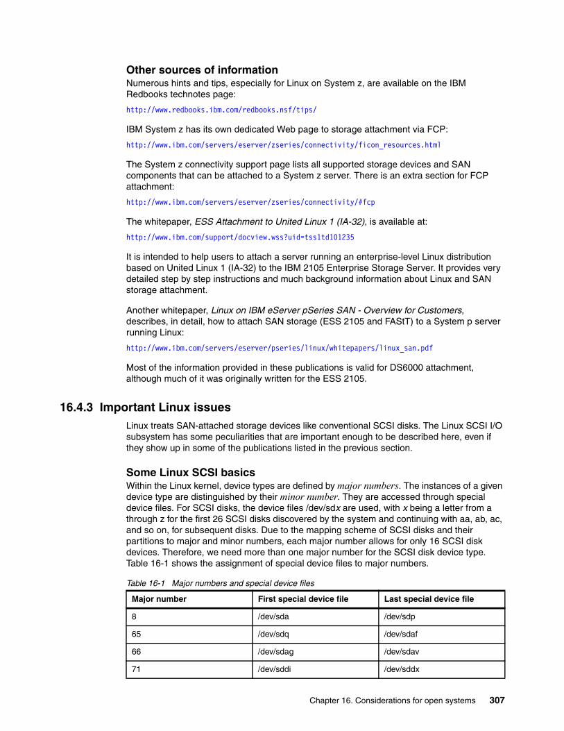
Other sources of informationNumerous hints and tips, especially for Linux on System z, are available on the IBM Redbooks technotes page:
http://www.redbooks.ibm.com/redbooks.nsf/tips/
IBM System z has its own dedicated Web page to storage attachment via FCP:
http://www.ibm.com/servers/eserver/zseries/connectivity/ficon_resources.html
The System z connectivity support page lists all supported storage devices and SAN components that can be attached to a System z server. There is an extra section for FCP attachment:
http://www.ibm.com/servers/eserver/zseries/connectivity/#fcp
The whitepaper, ESS Attachment to United Linux 1 (IA-32), is available at:
http://www.ibm.com/support/docview.wss?uid=tss1td101235
It is intended to help users to attach a server running an enterprise-level Linux distribution based on United Linux 1 (IA-32) to the IBM 2105 Enterprise Storage Server. It provides very detailed step by step instructions and much background information about Linux and SAN storage attachment.
Another whitepaper, Linux on IBM eServer pSeries SAN - Overview for Customers, describes, in detail, how to attach SAN storage (ESS 2105 and FAStT) to a System p server running Linux:
http://www.ibm.com/servers/eserver/pseries/linux/whitepapers/linux_san.pdf
Most of the information provided in these publications is valid for DS6000 attachment, although much of it was originally written for the ESS 2105.
16.4.3 Important Linux issuesLinux treats SAN-attached storage devices like conventional SCSI disks. The Linux SCSI I/O subsystem has some peculiarities that are important enough to be described here, even if they show up in some of the publications listed in the previous section.
Some Linux SCSI basicsWithin the Linux kernel, device types are defined by major numbers. The instances of a given device type are distinguished by their minor number. They are accessed through special device files. For SCSI disks, the device files /dev/sdx are used, with x being a letter from a through z for the first 26 SCSI disks discovered by the system and continuing with aa, ab, ac, and so on, for subsequent disks. Due to the mapping scheme of SCSI disks and their partitions to major and minor numbers, each major number allows for only 16 SCSI disk devices. Therefore, we need more than one major number for the SCSI disk device type. Table 16-1 shows the assignment of special device files to major numbers.
Table 16-1 Major numbers and special device files
Major number First special device file Last special device file
8 /dev/sda /dev/sdp
65 /dev/sdq /dev/sdaf
66 /dev/sdag /dev/sdav
71 /dev/sddi /dev/sddx
Chapter 16. Considerations for open systems 307
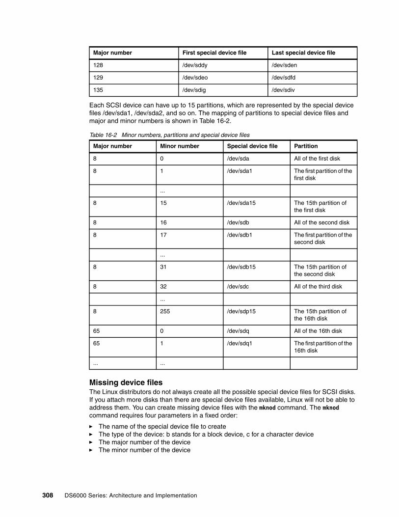
Each SCSI device can have up to 15 partitions, which are represented by the special device files /dev/sda1, /dev/sda2, and so on. The mapping of partitions to special device files and major and minor numbers is shown in Table 16-2.
Table 16-2 Minor numbers, partitions and special device files
Missing device filesThe Linux distributors do not always create all the possible special device files for SCSI disks. If you attach more disks than there are special device files available, Linux will not be able to address them. You can create missing device files with the mknod command. The mknod command requires four parameters in a fixed order:
� The name of the special device file to create� The type of the device: b stands for a block device, c for a character device� The major number of the device� The minor number of the device
128 /dev/sddy /dev/sden
129 /dev/sdeo /dev/sdfd
135 /dev/sdig /dev/sdiv
Major number Minor number Special device file Partition
8 0 /dev/sda All of the first disk
8 1 /dev/sda1 The first partition of the first disk
...
8 15 /dev/sda15 The 15th partition of the first disk
8 16 /dev/sdb All of the second disk
8 17 /dev/sdb1 The first partition of the second disk
...
8 31 /dev/sdb15 The 15th partition of the second disk
8 32 /dev/sdc All of the third disk
...
8 255 /dev/sdp15 The 15th partition of the 16th disk
65 0 /dev/sdq All of the 16th disk
65 1 /dev/sdq1 The first partition of the 16th disk
... ...
Major number First special device file Last special device file
308 DS6000 Series: Architecture and Implementation

Refer to the man page of the mknod command for more details. Example 16-21 shows the creation of special device files for the 17th SCSI disk and its first three partitions.
Example 16-21 Create new special device files for SCSI disks
mknod /dev/sdq b 65 0mknod /dev/sdq1 b 65 1mknod /dev/sdq2 b 65 2mknod /dev/sdq3 b 65 3
After creating the device files, you might have to change their owner, group, and file permission settings to be able to use them. Often, the easiest way to do this is by duplicating the settings of existing device files, as shown in Example 16-22. Be aware that after this sequence of commands, all special device files for SCSI disks have the same permissions. If an application requires different settings for certain disks, you have to correct them afterwards.
Example 16-22 Duplicating the permissions of special device files
knox:~ # ls -l /dev/sda /dev/sda1rw-rw---- 1 root disk 8, 0 2003-03-14 14:07 /dev/sdarw-rw---- 1 root disk 8, 1 2003-03-14 14:07 /dev/sda1knox:~ # chmod 660 /dev/sd*knox:~ # chown root:disk /dev/sda*
Managing multiple pathsIf you assign a DS6000 volume to a Linux system through more than one path, it will see the same volume more than once. It will also assign more than one special device file to it. To utilize the path redundancy and increased I/O bandwidth, you need an additional layer in the Linux disk subsystem to recombine the multiple disks seen by the system into one, to manage the paths, and to balance the load across them.
The IBM multipathing solution for DS6000 attachment to Linux on Intel IA-32 and Intel Itanium® architectures and IBM System p and System i is the IBM Subsystem Device Driver (SDD). SDD for Linux is available in the Linux RPM package format for all supported distributions from the SDD download site. It is proprietary and binary only. It only works with certain kernel versions with which it was tested. The README file on the SDD for Linux download page contains a list of the supported kernels. The version of the Linux Logical Volume Manager that comes with all current Linux distributions does not support its physical volumes being placed on SDD vpath devices.
What is new with SDD V1.6The following capabilities are new with SDD V1.6:
� Red Hat and Red Flag: They do not allow an rpm upgrade or removal while SDD is in use. This can be overridden with the --nopre and --nopreun flags to rpm, but since SUSE does not support these flags, the feature is not available in SUSE (--noscripts prevents required post conditions from running as well, so it is not an option).
� Tracing is now turned on by default for SDD. The SDD driver logs are saved to /var/log/sdd.log and the sddsrv daemon logs are saved to /var/log/sddsrv.log.
� As part of the new performance improvement, we separate out an optimized sequential policy from the optimized policy, and added a round robin sequential policy. The optimized sequential policy is now the default policy of Linux. Both sequential policies base the path selection on whether the I/O is sequential, and if not, fall through to use the existing optimized (load balanced) or round robin policies. Highly sequential I/O can have a significant performance improvement, and non-sequential I/O should perform the same as without the sequential policy in place.
Chapter 16. Considerations for open systems 309

� Non-root users can now open a vpath device. Before, only root users would have this privilege, but with the new capabilities in the OS, non-root users can do the same.
Limited number of SCSI devicesDue to the design of the Linux SCSI I/O subsystem in the Linux Kernel Version 2.4, the number of SCSI disk devices is limited to 256. Attaching devices through more than one path reduces this number. If, for example, all disks were attached through four paths, only up to 64 disks could be used.
SCSI device assignment changesLinux assigns special device files to SCSI disks in the order they are discovered by the system. Adding or removing disks can change this assignment. This can cause serious problems if the system configuration is based on special device names (for example, a file system that is mounted using the /dev/sda1 device name). You can avoid some of them by using:
� Disk labels instead of device names in /etc/fstab
� LVM Logical Volumes instead of /dev/sdxx devices for file systems
� SDD, which creates a persistent relationship between a DS6000 volume and a vpath device regardless of the /dev/sdxx devices
Red Hat Enterprise Linux (RH-EL) multiple LUN supportRH-EL by default is not configured for multiple LUN support. It will only discover SCSI disks addressed as LUN 0. The DS6000 provides the volumes to the host with a fixed Fibre Channel address and varying LUN. Therefore, RH-EL 3 will see only one DS6000 volume (LUN 0), even if more are assigned to it.
Multiple LUN support can be added with an option to the SCSI midlayer Kernel module scsi_mod. To have multiple LUN support added permanently at the boot time of the system, add the following line to the file /etc/modules.conf:
options scsi_mod max_scsi_luns=128
After saving the file, rebuild the module dependencies by running:
depmod -a
Now you have to rebuild the Initial RAM Disk using the command:
mkinitrd <initrd-image> <kernel-version>
Issue mkinitrd -h for more help information. A reboot is required to make the changes effective.
Note: SDD is not available for Linux on System z. SUSE Linux Enterprise Server 8 for System z comes with built-in multipathing provided by a patched Logical Volume Manager. Today, there is no multipathing support for Red Hat Enterprise Linux for System z.
Important: The latest update to the SUSE Linux Enterprise Server 8, Service Pack 3 uses a more dynamic method of assigning major numbers and allows the attachment of up to 2304 SCSI devices.
310 DS6000 Series: Architecture and Implementation

Fibre Channel disks discovered before internal SCSI disksIn some cases, when the Fibre Channel HBAs are added to a Red Hat Enterprise Linux system, they will be automatically configured in a way that they are activated at boot time, before the built-in parallel SCSI controller that drives the system disks. This will lead to shifted special device file names of the system disk and can result in the system being unable to boot properly.
To prevent the FC HBA driver from being loaded before the driver for the internal SCSI HBA, you have to change the /etc/modules.conf file:
� Locate the lines containing scsi_hostadapterx entries, where x is a number.
� Reorder these lines: First come the lines containing the name of the internal HBA driver module, then the ones with the FC HBA module entry.
� Renumber the lines: No number for the first entry, 1 for the second, 2 for the third, and so on.
After saving the file, rebuild the module dependencies by running:
depmod -a
Now you have to rebuild the Initial RAM Disk using the command:
mkinitrd <initrd-image> <kernel-version>
Issue mkinitrd -h for more help information. If you reboot now, the SCSI and FC HBA drivers will be loaded in the correct order.
Example 16-23 shows how the /etc/modules.conf file should look with two Adaptec SCSI controllers and two QLogic 2340 FC HBAs installed. It also contains the line that enables multiple LUN support. Note that the module names will be different with different SCSI and Fibre Channel adapters.
Example 16-23 Sample /etc/modules.conf
scsi_hostadapter aic7xxxscsi_hostadapter1 aic7xxxscsi_hostadapter2 qla2300scsi_hostadapter3 qla2300options scsi_mod max_scsi_luns=128
Adding FC disks dynamicallyThe commonly used way to discover newly attached DS6000 volumes is to unload and reload the Fibre Channel HBA driver. However, this action is disruptive to all applications that use Fibre Channel attached disks on this particular host.
A Linux system can recognize newly attached LUNs without unloading the FC HBA driver. The procedure slightly differs depending on the installed FC HBAs.
In the case of QLogic HBAs, issue the command:
echo "scsi-qlascan" > /proc/scsi/qla2300/<adapter-instance>
With Emulex HBAs, issue the command:
sh force_lpfc_scan.sh "lpfc<adapter-instance>"
Chapter 16. Considerations for open systems 311

This script is not part of the regular device driver package; it must be downloaded separately:
http://www.emulex.com/ts/downloads/linuxfc/rel/201g/force_lpfc_scan.sh
It requires the tool dfc to be installed under /usr/sbin/lpfc.
In both cases, the command must be issued for each installed HBA, with the <adapter-instance> being the SCSI instance number of the HBA.
After the FC HBAs rescan the fabric, you can make the new devices available to the system with the command:
echo "scsi add-single-device s c t l" > /proc/scsi/scsi
The quadruple s c t l is the physical address of the device:
� s is the SCSI instance of the FC HBA.
� c is the channel (in our case always 0).
� t is the target address (usually 0, except if a volume is seen by a HBA more than once).
� l is the LUN.
The new volumes are added after the already existing ones. The following examples illustrate this situation. Example 16-24 shows the original disk assignment as it existed since the last system start.
Example 16-24 SCSi disks attached at system start time
/dev/sda - internal SCSI disk/dev/sdb - 1st DS6000 volume, seen by HBA 0/dev/sdc - 2nd DS6000 volume, seen by HBA 0/dev/sdd - 1st DS6000 volume, seen by HBA 1/dev/sde - 2nd DS6000 volume, seen by HBA 1
Example 16-25 shows the SCSI disk assignment after one more DS6000 volume is added.
Example 16-25 SCSi disks after dynamic addition of another DS6000 volume
/dev/sda - internal SCSI disk/dev/sdb - 1st DS6000 volume, seen by HBA 0/dev/sdc - 2nd DS6000 volume, seen by HBA 0/dev/sdd - 1st DS6000 volume, seen by HBA 1/dev/sde - 2nd DS6000 volume, seen by HBA 1/dev/sdf - new DS6000 volume, seen by HBA 0/dev/sdg - new DS6000 volume, seen by HBA 1
The mapping of special device files is now different than it would have been if all three DS6000 volumes had been already present when the HBA driver was loaded. In other words, if the system is now restarted, the device ordering will change to what is shown in Example 16-26.
Example 16-26 SCSi disks after dynamic addition of another DS6000 volume and reboot
/dev/sda - internal SCSI disk/dev/sdb - 1st DS6000 volume, seen by HBA 0/dev/sdc - 2nd DS6000 volume, seen by HBA 0/dev/sdd - new DS6000 volume, seen by HBA 0/dev/sde - 1st DS6000 volume, seen by HBA 1/dev/sdf - 2nd DS6000 volume, seen by HBA 1/dev/sdg - new DS6000 volume, seen by HBA 1
312 DS6000 Series: Architecture and Implementation

Gaps in the LUN sequenceThe Qlogic HBA driver cannot deal with gaps in the LUN sequence. When it tries to discover the attached volumes, it probes for the different LUNs, starting at LUN 0 and continuing until it reaches the first LUN without a device behind it.
When assigning volumes to a Linux host with QLogic FC HBAs, make sure LUNs start at 0 and are in consecutive order. Otherwise, the LUNs after a gap will not be discovered by the host. Gaps in the sequence can occur when you assign volumes to a Linux host that are already assigned to another server.
The Emulex HBA driver behaves differently: It always scans all LUNs up to 127.
16.4.4 Troubleshooting and monitoringIn this section, we discuss some topics regarding troubleshooting and monitoring.
The /proc pseudo file systemThe /proc pseudo file system is maintained by the Linux kernel and provides dynamic information about the system. The directory /proc/scsi contains information about the installed and attached SCSI devices.
The file /proc/scsi/scsi contains a list of all attached SCSI devices, including disk, tapes, processors, and so on. Example 16-27 shows a sample /proc/scsi/scsi file.
Example 16-27 Sample /proc/scsi/scsi file
knox:~ # cat /proc/scsi/scsiAttached devices:Host: scsi0 Channel: 00 Id: 00 Lun: 00 Vendor: IBM-ESXS Model: DTN036C1UCDY10F Rev: S25J Type: Direct-Access ANSI SCSI revision: 03Host: scsi0 Channel: 00 Id: 08 Lun: 00 Vendor: IBM Model: 32P0032a S320 1 Rev: 1 Type: Processor ANSI SCSI revision: 02Host: scsi2 Channel: 00 Id: 00 Lun: 00 Vendor: IBM Model: 1750511 Rev: .545 Type: Direct-Access ANSI SCSI revision: 03Host: scsi2 Channel: 00 Id: 00 Lun: 01 Vendor: IBM Model: 1750511 Rev: .545 Type: Direct-Access ANSI SCSI revision: 03Host: scsi2 Channel: 00 Id: 00 Lun: 02 Vendor: IBM Model: 1750511 Rev: .545 Type: Direct-Access ANSI SCSI revision: 03Host: scsi3 Channel: 00 Id: 00 Lun: 00 Vendor: IBM Model: 1750511 Rev: .545 Type: Direct-Access ANSI SCSI revision: 03Host: scsi3 Channel: 00 Id: 00 Lun: 01 Vendor: IBM Model: 1750511 Rev: .545 Type: Direct-Access ANSI SCSI revision: 03Host: scsi3 Channel: 00 Id: 00 Lun: 02 Vendor: IBM Model: 1750511 Rev: .545 Type: Direct-Access ANSI SCSI revision: 03
There also is an entry in /proc for each HBA, with driver and firmware levels, error counters, and information about the attached devices. Figure 16-28 shows the condensed content of the entry for a QLogic Fibre Channel HBA.
Chapter 16. Considerations for open systems 313

Example 16-28 Sample /proc/scsi/qla2300/x
knox:~ # cat /proc/scsi/qla2300/2QLogic PCI to Fibre Channel Host Adapter for ISP23xx: Firmware version: 3.01.18, Driver version 6.05.00b9Entry address = c1e00060HBA: QLA2312 , Serial# H28468Request Queue = 0x21f8000, Response Queue = 0x21e0000Request Queue count= 128, Response Queue count= 512 . .Login retry count = 012Commands retried with dropped frame(s) = 0
SCSI Device Information:scsi-qla0-adapter-node=200000e08b0b941d;scsi-qla0-adapter-port=210000e08b0b941d;scsi-qla0-target-0=5005076300c39103;
SCSI LUN Information:(Id:Lun)( 0: 0): Total reqs 99545, Pending reqs 0, flags 0x0, 0:0:81,( 0: 1): Total reqs 9673, Pending reqs 0, flags 0x0, 0:0:81,( 0: 2): Total reqs 100914, Pending reqs 0, flags 0x0, 0:0:81,
Performance monitoring with iostatThe iostat command can be used to monitor the performance of all attached disks. It is shipped with every major Linux distribution, but not necessarily installed by default. It reads data provided by the kernel in /proc/stats and prints it in human readable format. See the man page of iostat for more details.
The generic SCSI toolsThe SUSE Linux Enterprise Server comes with a set of tools that allow low-level access to SCSI devices. They are called the sg tools. They talk to the SCSI devices through the generic SCSI layer, which is represented by special device files /dev/sg0, /dev/sg0, and so on.
By default, SLES 8 provides sg device files for up to 16 SCSI devices (/dev/sg0 through /dev/sg15). Additional sg device files can be created using the mknod command. After creating new sg devices, you should change their group setting from root to disk. Example 16-29 shows the creation of /dev/sg16, which would be the first one to create.
Example 16-29 Creation of new device files for generic SCSI devices
mknod /dev/sg16 c 21 16chgrp disk /dev/sg16
Useful sg tools are:
� sg_inq /dev/sgx prints SCSI Inquiry data, such as the volume serial number.
� sg_scan prints the /dev/sg → scsihost, channel, target, LUN mapping.
� sg_map prints the /dev/sd → /dev/sg mapping.
� sg_readcap prints the block size and capacity (in blocks) of the device.
sginfo prints SCSI inquiry and mode page data; it also allows manipulating the mode pages.
314 DS6000 Series: Architecture and Implementation

16.5 OpenVMSDS6000 supports FC attachment of OpenVMS Alpha systems with operating system Version 7.3 or newer. For details regarding operating system versions and HBA types, see the DS6000 Interoperability Matrix, found at:
http://www.ibm.com/servers/storage/disk/ds6000/interop.html
The support includes clustering and multiple paths (exploiting the OpenVMS built-in multipathing). Boot support is available via Request for Price Quotations (RPQ). The DS Open API is currently not available for OpenVMS.
16.5.1 FC port configurationIn early DS6000 codes, the OpenVMS FC driver has some limitations in handling FC error recovery. The operating system might react to some situations with MountVerify conditions, which are not recoverable. Affected processes might hang and eventually stop.
Instead of writing a special OpenVMS driver, it had been decided to handle this task in the DS6000 host adapter microcode. As a result, it became a general rule not to share DS6000 FC ports between OpenVMS and non-OpenVMS hosts.
You must dedicate storage ports for only the OpenVMS host type. Multiple OpenVMS systems can access the same port. Appropriate zoning must be enforced from the beginning. Wrong access to storage ports used by OpenVMS hosts could clear the OpenVMS-specific settings for these ports. This might remain undetected for a long time — until some failure happens, and by then I/Os might be lost. It is worth mentioning that OpenVMS is the only platform with such a restriction (usually, different open systems platforms can share the same DS6000 FC adapters).
The restrictions listed in this section apply only if your DS6000 licensed machine code has a version before 5.0.4. After these versions, the restrictions are removed. Note that you can display the versions of the DS CLI, the DS Storage Manager, and the licensed machine code by using the DS CLI command ver -l.
Important: The DS6000 FC ports used by OpenVMS hosts must not be accessed by any other operating system, not even accidentally. The OpenVMS hosts have to be defined for access to these ports only, and it must be ensured that no foreign HBA (without definition as an OpenVMS host) is seen by these ports. Conversely, an OpenVMS host must have access only to the DS6000 ports configured for OpenVMS compatibility.
Chapter 16. Considerations for open systems 315
16.5.2 Volume configurationOpenVMS Fibre Channel devices have device names according to the following schema:
$1$DGA<n>
The device name has the following elements:
� The first portion $1$ of the device name is the allocation class (a decimal number in the range 1–255). FC devices always have the allocation class 1.
� The following two letters encode the drivers where the first letter denotes the device class (D = disks, M = magnetic tapes) and the second letter the device type (K = SCSI, G = Fibre Channel). So all Fibre Channel disk names contain the code DG.
� The third letter denotes the adapter channel (from range A to Z). Fibre Channel devices always have the channel identifier A.
� The number <n> is the User-Defined ID (UDID), a number from the range 0–32767, which is provided by the storage system in response to an OpenVMS-special SCSI inquiry command (from the range of command codes reserved by the SCSI standard for vendor’s private use).
OpenVMS does not identify a Fibre Channel disk by its path or SCSI target/LUN like other operating systems. It relies on the UDID. Although OpenVMS uses the WWID to control all FC paths to a disk, a Fibre Channel disk that does not provide this additional UDID cannot be recognized by the operating system.
In the DS6000, the volume nickname acts as the UDID for OpenVMS hosts. If the character string of the volume nickname evaluates to an integer in the range 0–32767, then this integer is supplied as the answer when an OpenVMS host asks for the UDID.
The DS CLI command chfbvol -name 21 1001 assigns the OpenVMS UDID 21 to the DS6000 volume 1001 (LSS 10, volume 01). Thus the DS6000 volume 1001 will appear as OpenVMS device with the name $1$DGA21 or $1$GGA21. The DS CLI command lshostvol shows the DS6000 volumes with their corresponding OpenVMS device names.
The DS management utilities do not enforce UDID rules. They accept incorrect values that are not valid for OpenVMS. It is possible to assign the same UDID value to multiple DS6000 volumes. However, because the UDID is in fact the device ID seen by the operating system, several consistency rules have to be fulfilled. These rules are described in detail in the OpenVMS operating system documentation (see HP Guidelines for OpenVMS Cluster Configurations, found at:
http://h71000.www7.hp.com/doc/72final/6318/6318pro.html)
Here are the main rules:
� Every FC volume must have a UDID that is unique throughout the OpenVMS cluster that accesses the volume. The same UDID can be used in a different cluster or for a different stand-alone host.
� If the volume is planned for MSCP serving, then the UDID range is limited to 0–9999 (by operating system restrictions in the MSCP code).
OpenVMS system administrators tend to use elaborate schemes for assigning UDIDs, coding several hints about physical configuration into this logical ID, for example, odd/even values or reserved ranges to distinguish between multiple data centers, storage systems, or disk groups. Thus, they must be able to provide these numbers without additional restrictions imposed by the storage system. In the DS6000, UDID is implemented with full flexibility, which leaves the responsibility about restrictions to the customer.
316 DS6000 Series: Architecture and Implementation

In Example 16-30, we configure a DS6000 volume with the UDID 8275 for OpenVMS attachment. This gives the OpenVMS Fibre Channel disk device $1$DGA8275. You see the output from the OpenVMS command SHOW DEVICE/FULL $1$DGA8275. The OpenVMS host has two Fibre Channel HBAs with names PGA0 and PGB0. Because each HBA accesses two DS6000 ports, we have four I/O paths.
Example 16-30 OpenVMS volume configuration
$ show device/full $1$DGA8275:
Disk $1$DGA8275: (NFTE18), device type IBM 1750500, is online, file-oriented device, shareable, device has multiple I/O paths, served to cluster via MSCP Server, error logging is enabled.
Error count 0 Operations completed 2 Owner process "" Owner UIC [SYSTEM] Owner process ID 00000000 Dev Prot S:RWPL,O:RWPL,G:R,W Reference count 0 Default buffer size 512 Current preferred CPU Id 9 Fastpath 1 Host name "NFTE18" Host type, avail Compaq AlphaServer GS60 6/525, yes Alternate host name "NFTE17" Alt. type, avail Compaq AlphaServer GS60 6/525, yes Allocation class 1
I/O paths to device 5 Path MSCP (NFTE17), primary path. Error count 0 Operations completed 0 Path PGA0.5005-0763-0319-8324 (NFTE18), current path. Error count 0 Operations completed 1 Path PGA0.5005-0763-031B-C324 (NFTE18). Error count 0 Operations completed 1 Path PGB0.5005-0763-0310-8324 (NFTE18). Error count 0 Operations completed 0 Path PGB0.5005-0763-0314-C324 (NFTE18). Error count 0 Operations completed 0
The DS CLI command lshostvol displays the mapping of DS6000 volumes to host system device names. More details regarding this command can be found in the IBM System Storage DS6000: Command-Line Interface User’s Guide, GC26-7922.
16.5.3 Command Console LUNHP StorageWorks FC controllers use LUN 0 as Command Console LUN (CCL) for exchanging commands and information with in-band management tools. This concept is similar to the Access LUN of IBM System Storage DS4000 (FAStT) controllers.
Because the OpenVMS FC driver has been written with StorageWorks controllers in mind, OpenVMS always considers LUN 0 as CCL, never presenting this LUN as a disk device. On HP StorageWorks HSG and HSV controllers, you cannot assign LUN 0 to a volume.
The DS6000 assigns LUN numbers per host using the lowest available number. The first volume that is assigned to a host becomes this host’s LUN 0, the next volume is LUN 1, and so on.
Chapter 16. Considerations for open systems 317

Because OpenVMS considers LUN 0 as CCL, the first DS6000 volume assigned to the host cannot be used even when a correct UDID has been defined. So we recommend creating the first OpenVMS volume with a minimum size as a dummy volume for use as the CCL. Multiple OpenVMS hosts, even in different clusters, that access the same storage system, can share the same volume as LUN 0, because there will be no other activity to this volume. In large configurations with more than 256 volumes per OpenVMS host or cluster, it might be necessary to introduce another dummy volume (when LUN numbering starts again with 0).
Defining a UDID for the CCL is not required by the OpenVMS operating system. OpenVMS documentation suggests that you always define a unique UDID since this identifier causes the creation of a CCL device visible for the OpenVMS command show device or other tools. Although an OpenVMS host cannot use the LUN for any other purpose, you can display the multiple paths to the storage device, and diagnose failed paths. Fibre Channel CCL devices have the OpenVMS device type GG.
In Example 16-31, the DS6000 volume with volume ID 100E is configured as an OpenVMS device with UDID 9998. Because this was the first volume in the volume group, it became LUN 0 and thus the CCL. Note that the volume WWID, as displayed by the SHOW DEVICE/FULL command, contains the DS6000 World-Wide Node ID (6005-0763-03FF-C324) and the DS6000 volume number (100E).
Example 16-31 OpenVMS command console LUN
$ show device/full $1$GGA9998:
Device $1$GGA9998:, device type Generic SCSI device, is online, shareable, device has multiple I/O paths.
Error count 0 Operations completed 1 Owner process "" Owner UIC [SYSTEM] Owner process ID 00000000 Dev Prot S:RWPL,O:RWPL,G:RWPL,W:RWPL Reference count 0 Default buffer size 0 WWID 01000010:6005-0763-03FF-C324-0000-0000-0000-100E
I/O paths to device 4 Path PGA0.5005-0763-0319-8324 (NFTE18), primary path, current path. Error count 0 Operations completed 1 Path PGA0.5005-0763-031B-C324 (NFTE18). Error count 0 Operations completed 0 Path PGB0.5005-0763-0310-8324 (NFTE18). Error count 0 Operations completed 0 Path PGB0.5005-0763-0314-C324 (NFTE18). Error count 0 Operations completed 0
The DS CLI command chvolgrp provides the flag -lun, which can be used to control which volume becomes LUN 0.
16.5.4 OpenVMS volume shadowingOpenVMS disks can be combined in host-based mirror sets called OpenVMS shadow sets. This functionality is often used to build disaster-tolerant OpenVMS clusters.
The OpenVMS shadow driver has been designed for disks according to DEC’s Digital Storage Architecture (DSA). This architecture, forward-looking in the 1980s, includes some requirements that are handled by today’s SCSI/FC devices with other approaches. Two such things are the forced error indicator and the atomic revector operation for bad-block replacement.
318 DS6000 Series: Architecture and Implementation

When a DSA controller detects an unrecoverable media error, a spare block is revectored to this logical block number, and the contents of the block are marked with a forced error. This causes subsequent read operations to fail, which is the signal to the shadow driver to execute a repair operation using data from another copy.
However, there is no forced error indicator in the SCSI architecture, and the revector operation is nonatomic. As a substitute, the OpenVMS shadow driver exploits the SCSI commands READ LONG (READL) and WRITE LONG (WRITEL), optionally supported by some SCSI devices. These I/O functions allow data blocks to be read and written together with their disk device error correction code (ECC). If the SCSI device supports READL/WRITEL, OpenVMS shadowing emulates the DSA forced error with an intentionally incorrect ECC. For details, see Design of VMS Volume Shadowing Phase II-Host-based Shadowing, found at:
http://research.compaq.com/wrl/DECarchives/DTJ/DTJ301/DTJ301SC.TXT
The DS6000 provides volumes as SCSI-3 devices and therefore does not implement a forced error indicator. It also does not support the READL and WRITEL command set for data integrity reasons.
Usually, the OpenVMS SCSI Port Driver recognizes if a device supports READL/WRITEL, and the driver sets the NOFE (no forced error) bit in the Unit Control Block. You can verify this setting with the SDA utility: After starting the utility with the analyze/system command, enter the show device command at the SDA prompt. Then the NOFE flag should be shown in the device’s characteristics.
The OpenVMS command for mounting shadow sets provides the qualifier /override=no_forced_error to support non-DSA devices. To avoid possible problems (performance loss, unexpected error counts, or even removal of members from the shadow set), we recommend you apply this qualifier.
16.6 VMwareThe DS6000 currently supports VMware’s high-end virtualization product, the ESX Server, starting with Version 2.5. The supported guest operating systems are Windows 2000, Windows Server 2003, SUSE Linux SLES 8, and Red Hat Enterprise Linux 2.1 and 3.0. This information is likely to change, so check the Interoperability Matrix for complete, up-to-date information:
http://www.ibm.com/servers/storage/disk/ds6000/interop.html
A great deal of useful information is available in the IBM System Storage DS6000: Host Systems Attachment Guide, GC26-7923. This section is not intended to duplicate that publication, but rather it provides more information about optimizing your VMware environment as well as a step-by-step guide on setting up ESX Server with the DS6000.
VMware’s other products, such as GSX Server and Workstation, are not intended for the datacenter-class environments where the DS6000 typically is used. Certain other products, such as VMotion and VirtualCenter, can be supported on a case-by-case basis. Before using the techniques described below, check with IBM and the latest Interoperability Matrix for the support of these techniques.
Chapter 16. Considerations for open systems 319

16.6.1 What is new in VMware ESX Server 2.5The complete list of the new features in VMware ESX Server 2.5 is available from VMware’s Web site. We will instead focus on the storage-related features. One significant enhancement is related to direct SAN access (also known as raw LUN access) from the virtual machines. VMware introduced this support previously, but the capabilities have been improved with the addition of Raw Device Mappings (RDMs). Using RDMs can improve your virtual machine performance and reduce overhead.
ESX Server 2.5 also introduced support for booting directly from the SAN. This feature is not yet fully supported with the DS6000, though support could be available via RPQ. See the DS6000 Interoperability Matrix for the latest information on support for SAN boot.
16.6.2 VMware disk architectureEach of the virtual machines (VMs) can access one or more virtual disks (VM Disk0, Disk1, and so on). The virtual disks can either be virtual machine disk (.dsk) files stored on a VMFS-2 volume, or they can be raw disks from the SAN. In Figure 16-6, VM1, VM2, and VM3 use .dsk files stored on a SAN disk, while VM4 directly uses a raw SAN disk. VMs can also use the physical server’s local storage (as the Console OS does), but these disks tend to be not as fast or reliable as SAN disks. Both the virtual machine .dsk files and the raw disks represent what is seen as physical disks by the guest OS (see Figure 16-6).
Figure 16-6 The logical disk structure of ESX Server
320 DS6000 Series: Architecture and Implementation

16.6.3 VMware setup and configurationThese are the high-level steps that need to be done in order to use DS6000 disks with your virtual machines.
Assigning LUNs to the ESX Server machineAssign the LUNs that you want your virtual machines to use to your ESX Server machine’s HBAs. One method of doing this volume assignment is to use the DS CLI. When making the host connections, it is important to use the flags -addrdiscovery lunpolling, -lbs 512, and -profile VMware. Another option is to use the -hosttype VMware parameter. When making the volume groups, you should use the parameter -type scsimap256.
As with other operating systems, you should have multiple paths from your server to the DS6000 to improve availability and reliability. Normally, the LUNs would show up as multiple separate devices, but VMware contains native multipathing software that automatically conceals the redundant paths. Therefore, multipathing software might not be needed on your guest operating systems.
As with other operating systems, you should also use persistent binding. See the IBM System Storage DS6000: Host Systems Attachment Guide, GC26-7923 on why persistent binding is important and how to configure it for VMware.
After the LUNs are assigned properly, you will be able to see them from the VMware administration console by selecting Options → Storage Management → Failover Paths. You might have to tell VMware to refresh its disks by selecting Rescan SAN in the upper right hand corner.
Figure 16-7 shows the LUNs assigned to the ESX Server and the paths to each of the LUNs.
Chapter 16. Considerations for open systems 321

Figure 16-7 Storage Management Failover Paths
Assigning LUNs to the guest operating systemNow that the ESX Server machine can see the DS6000 LUNs, they can be presented to the guest operating system in one of three ways.
To select the appropriate type, select the appropriate VM, choose the Hardware tab, and then select Add Device.
� Option 1: Formatting these disks with the VMFS: This option maximizes the virtualization features that are possible, and allows the guest operating system to use the special features of VMFS volumes. However, this mode has the most overhead of the three options.
– After clicking Add Device, choose Hard Disk and then select the Blank type.
– Select the options for the new hard disk that are appropriate for your environment.
Note: The virtual machine should be powered off before adding hardware.
322 DS6000 Series: Architecture and Implementation

� Option 2: Passing the disk through to the guest OS as a raw disk in physical compatibility mode: No further virtualization occurs; the OS will write its own file system onto that disk directly, just as it would in a stand-alone environment, without an underlying VMFS structure. I/Os pass through the virtualization layer with minimal modification. This option requires the least overhead.
– After clicking Add Device, choose Hard Disk and then select the System LUN/Disk type.
– On the next window, choose the compatibility mode of Physical.
– Select the options for the new hard disk that are appropriate for your environment.
� Option 3: Passing the disk through to the guest OS as a raw disk in virtual compatibility mode: This mode allows the VM to take advantage of disk modes and other features, including redo logs. See the VMware documentation on the four different disk modes: persistent, nonpersistent, undoable, and append.
– After clicking Add Device, choose Hard Disk and then select the System LUN/Disk type.
– On the next window, choose the compatibility mode of Virtual.
– Select the options for the new hard disk that are appropriate for your environment.
In Figure 16-8, Virtual Disk (SCSI 0:1) is a VMware virtual disk, while Virtual Disk (SCSI 0:2) is a physical SAN LUN and Virtual Disk (SCSI 0:3) is a virtual SAN LUN. This VM also contains a local virtual disk, Virtual Disk (SCSI 0:0), which has the guest operating system installed.
Figure 16-8 Virtual Disk device types
Chapter 16. Considerations for open systems 323

After powering up the server, notice how in Figure 16-9 the raw disk in Physical compatibility mode shows up as an IBM 2107900 device, while the other three disks (the local disk, the SAN disk formatted with VMFS, and the SAN disk in virtual compatibility mode) all show up as VMware virtual disks.
Figure 16-9 Device Management by the guest operating system
Now the disks can be formatted and used as with any regular disks. System LUNs in physical compatibility mode have the additional advantage that SCSI commands pass down to the hardware with minimal modifications. As a result, system administrators can use the DS CLI command lshostvol to map the virtual machine disks to DS6000 disks.
16.7 Sun SolarisAs with the previous models, the IBM System Storage DS6000 series continues to provide extensive support for Sun operating systems. Currently, the DS6000 supports Solaris 8, 9, and 10, on a variety of platforms. It also supports VERITAS Cluster Server and Sun Cluster. The Interoperability Matrix provides complete information on supported configurations, including information about supported host bus adapters, SAN switches, and multipathing technologies:
http://www.ibm.com/servers/storage/disk/ds6000/interop.html
A great deal of useful information is available in the IBM System Storage DS6000: Host Systems Attachment Guide, GC26-7923. This section is not intended to duplicate that publication, but rather it provides more information about optimizing your Sun Solaris environment as well as a step-by-step guide on using Solaris with the DS6000.
324 DS6000 Series: Architecture and Implementation

16.7.1 Locating the WWPNs of your HBAsBefore you can assign LUNs to your server, you will need to locate the WWPNs of the server’s HBAs. One popular method for locating the WWPNs is to scan the /var/adm/messages file. Often, the WWPN will only show up in the file after a reboot. Also, the string to search for depends on the type of HBA that you have. Specific details are available in the IBM System Storage DS6000: Host Systems Attachment Guide, GC26-7923.
In many cases, you will also be able to use the prtconf command to list the WWPNs, as shown in Example 16-32.
Example 16-32 Listing the WWPNs
# prtconf -vp | grep port-wwn port-wwn: 21000003.ba43fdc1 port-wwn: 210000e0.8b099408 port-wwn: 210000e0.8b0995f3 port-wwn: 210000e0.8b096cf6 port-wwn: 210000e0.8b098f08
16.7.2 Solaris attachment to DS6000Solaris uses the LUN polling method in order to discover DS6000 LUNs. For this reason, each Solaris host is limited to 256 LUNs from the DS6000. LUNs can be assigned using any of the supported DS6000 user interfaces, including the DS Command Line Interface (DS CLI), the DS Storage Manager (DS SM), and the DS Open Application Programming Interface (DS Open API). When using the CLI, you should make the host connections using the flags -addrdiscovery lunpolling, -lbs 512, and -profile “SUN - Solaris”. Another option is to use the -hosttype Sun parameter. When making the volume groups, you should use the parameter -type scsimap256.
As with other operating systems, you should use persistent binding with Solaris and DS6000. If you do not use persistent binding, it is possible that Solaris will assign a different SCSI device identifier (SCSI ID) than the one it had been using previously. This can happen if a new device is added to the SAN, for example. In this case, you will have to re-configure your applications or your operating system.
The methods of enabling persistent binding differ depending on your host bus adapter. The IBM System Storage DS6000: Host Systems Attachment Guide, GC26-7923 contains the recommended HBA settings for each supported type.
16.7.3 Multipathing in SolarisAs with other operating systems, you should use multiple paths between the DS6000 and your Solaris server. Multiple paths help maximize the reliability and performance of your operating environment. The DS6000 supports three different multipathing technologies on Solaris.
First, IBM provides the System Storage Multipath Subsystem Device Driver (SDD) as a part of the DS6000 at no extra charge. Next, Sun Solaris contains native multipathing software called the StorEdge Traffic Manager Software (STMS). STMS is commonly known as MPxIO (multiplexed I/O) in the industry, and the remainder of this section will refer to this technology as MPxIO. Finally, IBM supports VERITAS Volume Manager (VxVM) Dynamic Multipathing (DMP), a part of the VERITAS Storage Foundation suite.
Chapter 16. Considerations for open systems 325

The multipathing technology that you should use depends a great deal on your operating environment and, of course, your business requirements. There are some limitations depending on your operating system version, your host bus adapters, and whether or not you use clustering. Details are available in the IBM System Storage DS6000: Host Systems Attachment Guide, GC26-7923.
One difference between the multipathing technologies is whether or not they suppress the redundant paths to the storage. MPxIO and DMP both suppress all paths to the storage except for one, and the device appears to the application as a single-path device. SDD, on the other hand, allows the original paths to be seen, but creates its own virtual device (called a vpath) for applications to use.
If you assign LUNs to your server before you install multipathing software, you can see each of the LUNs show up as two or more devices, depending on how many paths you have. In Example 16-33, the iostat -nE command shows that the volume 75207814206 appears twice: once as c2t1d1 on the first HBA, and once as c3t1d1 on the second HBA.
Example 16-33 Device listing without multipath software
# iostat -nEc2t1d1 Soft Errors: 0 Hard Errors: 0 Transport Errors: 0Vendor: IBM Product: 1750500 Revision: .212 Serial No: 75207814206Size: 10.74GB <10737418240 bytes>Media Error: 0 Device Not Ready: 0 No Device: 0 Recoverable: 0Illegal Request: 0 Predictive Failure Analysis: 0c2t1d0 Soft Errors: 0 Hard Errors: 0 Transport Errors: 0Vendor: IBM Product: 1750500 Revision: .212 Serial No: 75207814205Size: 10.74GB <10737418240 bytes>Media Error: 0 Device Not Ready: 0 No Device: 0 Recoverable: 0Illegal Request: 0 Predictive Failure Analysis: 0c3t1d1 Soft Errors: 0 Hard Errors: 0 Transport Errors: 0Vendor: IBM Product: 1750500 Revision: .212 Serial No: 75207814206Size: 10.74GB <10737418240 bytes>Media Error: 0 Device Not Ready: 0 No Device: 0 Recoverable: 0Illegal Request: 0 Predictive Failure Analysis: 0c3t1d0 Soft Errors: 0 Hard Errors: 0 Transport Errors: 0Vendor: IBM Product: 1750500 Revision: .212 Serial No: 75207814205Size: 10.74GB <10737418240 bytes>Media Error: 0 Device Not Ready: 0 No Device: 0 Recoverable: 0Illegal Request: 0 Predictive Failure Analysis: 0
IBM System Storage Multipath Subsystem Device Driver (SDD)SDD is available from your local IBM support team, or it can be downloaded from the Internet. Both the SDD software and supporting documentation are available from this IBM Web site:
http://www.ibm.com/servers/storage/support/software/sdd/index.html
After the SDD software is installed, you can see that the paths have been grouped into virtual vpath devices. Example 16-34 shows the output of the showvpath command.
326 DS6000 Series: Architecture and Implementation

Example 16-34 Output of the showvpath command
# /opt/IBMsdd/bin/showvpathvpath1: Serial Number : 75207814206 c2t1d1s0 /devices/pci@6,4000/fibre-channel@2/sd@1,1:a,raw c3t1d1s0 /devices/pci@6,2000/fibre-channel@1/sd@1,1:a,raw
vpath2: Serial Number : 75207814205 c2t1d0s0 /devices/pci@6,4000/fibre-channel@2/sd@1,0:a,raw c3t1d0s0 /devices/pci@6,2000/fibre-channel@1/sd@1,0:a,raw
For each device, the operating system creates a node in the /dev/dsk and /dev/rdsk directories. After SDD is installed, you can see these new vpaths by listing the contents of those directories. Note that with SDD, the old paths are not suppressed. Instead, new vpath devices show up as /dev/rdsk/vpath1a, for example. When creating your volumes and file systems, be sure to use the vpath device instead of the original device.
SDD also offers some parameters that you can tune for your environment. Specifically, SDD offers three different load balancing schemes:
� Failover:
– There is no load balancing.– The second path is used only if the preferred path fails.
� Round Robin:
– The paths to use are chosen at random (but different paths than the most recent I/O).– If there are only two paths, then they alternate.
� Load Balancing:
– The path is chosen based on the estimated path load.– Default policy is used.
The policy can be set through the use of the datapath set device policy command.
StorEdge Traffic Manager Software (MPxIO)On Solaris 8 and Solaris 9 systems, MPxIO is available as an operating system patch. You must install these patches in order to use MPxIO. On Solaris 10 systems, MPxIO is installed by default. In all cases, it needs to be enabled and configured before it can be used with the DS6000.
Before you enable MPxIO, you will want to configure your host bus adapters. Issue the cfgadm -la command to see the current state of your adapters. Example 16-35 shows two adapters, c3 and c4, of type fc.
Example 16-35 cfgadm -la command output
# cfgadm -laAp_Id Type Receptacle Occupant Conditionc3 fc connected unconfigured unknownc4 fc connected unconfigured unknown
Note how the command reports that both adapters are unconfigured. To configure the adapters, issue cfgadm -c configure cX (where X is the adapter number, 3 and 4 in this case). Now both adapters should show up as configured.
Note: The cfgadm -c configure command is not necessary in Solaris 10.
Chapter 16. Considerations for open systems 327

To configure your MPxIO, you will need to first enable it by editing the /kernel/drv/scsi_vhci.conf file. For Solaris 10, you will need to edit the /kernel/drv/fp.conf file instead. Find and change the mpxio-disable parameter to no:
mpxio-disable="no";
Next, add the following stanza to supply the vendor identification (VID) and product identification (PID) information to MPxIO in the /kernel/drv/scsi_vhci.conf file:
device-type-scsi-options-list ="IBM 1750500", "symmetric-option";symmetric-option = 0x1000000;
Finally, the system must be rebooted. After the reboot, MPxIO will be ready to be used.
For more information about MPxIO, including all the MPxIO commands and tuning parameters, see the Sun Web site:
http://www.sun.com/storage/software/
VERITAS Volume Manager Dynamic Multipathing (DMP)Before using VERITAS Volume Manager (VxVM) DMP, a part of the VERITAS Storage Foundation suite, you should download and install the latest Maintenance Pack. You will also need to download and install the Array Support Library (ASL) for the DS6000. Both of these packages are available from:
http://support.veritas.com/
During device discovery, the vxconfigd daemon compares the serial numbers of the different devices. If two devices have the same serial number, then they are the same LUN, and DMP will combine the paths. Listing the contents of the /dev/vx/rdmp directory will show only one set of devices.
The vxdisk path command also demonstrates DMP’s path suppression capabilities. In Example 16-36, devices c6t1d0s2 and c7t2d0s2 are combined into c6t1d0s2.
Example 16-36 vxdisk path command output
# vxdisk pathSUBPATH DANAME DMNAME GROUP STATEc6t1d0s2 c6t1d0s2 Ethan01 Ethan ENABLEDc7t2d0s2 c6t1d0s2 Ethan01 Ethan ENABLEDc6t1d1s2 c7t2d1s2 Ethan02 Ethan ENABLEDc7t2d1s2 c7t2d1s2 Ethan02 Ethan ENABLEDc6t1d2s2 c7t2d2s2 Ethan03 Ethan ENABLEDc7t2d2s2 c7t2d2s2 Ethan03 Ethan ENABLEDc6t1d3s2 c7t2d3s2 Ethan04 Ethan ENABLEDc7t2d3s2 c7t2d3s2 Ethan04 Ethan ENABLED
Note: The vendor string must be exactly eight bytes, so you must type IBM followed by five spaces.
328 DS6000 Series: Architecture and Implementation

Now, you create volumes using the device name listed under the DANAME column. In Figure 16-10, a volume is created using four disks, even though there are actually eight paths.
Figure 16-10 VERITAS DMP disk view
As with other multipathing software, DMP provides a number of parameters that you can tune in order to maximize the performance and availability in your environment. For example, it is possible to set a load balancing policy to dictate how the I/O should be shared between the different paths. It is also possible to select which paths get used in which order in case of a failure.
Complete details about the features and capabilities of DMP can be found on the VERITAS Web site:
http://www.veritas.com
16.8 HP-UXThe DS6000 attachment is supported with HP-UX Version 11i or above. For providing a fault tolerant connection to the DS6000, the HP Multipathing software PVLINKS or the IBM Multipath Subsystem Device Driver (SDD) are supported.
This section is intended to be a basic step-by-step configuration to attach a HP host to the point where the host would be capable of running I/O to the DS6000 device. It is not intended to repeat the information that is contained in other publications.
Chapter 16. Considerations for open systems 329

16.8.1 Available documentationIBM is continuously updating and adding new, supported configurations. For the latest available supported HP-UX configuration and required software patches, refer to the DS6000 Interoperability Matrix at:
http://www.ibm.com/servers/storage/disk/ds6000/interop.html
For preparing the host to attach the DS6000, refer to 16.8.3, “Configuring the DS6000 on a HP-UX host” on page 330 and the following Web site:
http://publib.boulder.ibm.com/infocenter/ds6000ic/index.jsp?topic=/com.ibm.storage.ess.console.base.help.doc/f2c_attchnghpux_1tlxvv.html
For the installation of SDD, refer to IBM System Storage Multipath Subsystem Device Driver User’s Guide, SC30-4131. The User’s Guide is available at the download page for each individual SDD Operating System Version at:
http://www.ibm.com/support/dlsearch.wss?rs=540&tc=ST52G7&dc=D430
16.8.2 DS6000 specific software depotsFor HP-UX, there are two additional DS6000 specific software depots available.
� IBM System Storage Multipath Subsystem Device Driver (SDD) � IBM System Storage DS6000 Command-Line Interface (DS CLI)
The SDD is a multipathing software with a policy based load balancing on all available paths to the DS6000.
For automation purposes of the Copy Services, storage management, and storage allocation, the DS CLI should be installed on the host.
16.8.3 Configuring the DS6000 on a HP-UX hostFor configuring the server on the DS6000, a host connection has to be defined using the DS Storage Manager GUI or the DS CLI, as the HP host is using the hosttype HP. The hosttype will automatically configure the DS6000 to present the DS6000 volumes in a HP-UX preferred method. The DS6000 volume group needs to be specified for the access mode scsimask.
After the volumes on the DS6000 have been configured, install the SDD, then connect your host to the fabric. Once the host is configured to the fabric, just discover the devices using the ioscan command. Example 16-37 does show that the DS6000 devices have been discovered successfully, but the devices cannot be used, as no special device file is available.
Tip: For the latest version of SDD and the DS CLI on your host, you can either use the version that is delivered with the DS6000 Microcode bundle or you can download the latest available SDD version from:
http://www.ibm.com/support/dlsearch.wss?rs=540&tc=ST52G7&dc=D430
The DS CLI can be downloaded along with the DS6000 microcode bundle from:
http://www.ibm.com/support/search.wss?q=ssg1*&tc=HW2A2&rs=1112&dc=D400&dtm
330 DS6000 Series: Architecture and Implementation

Example 16-37 Discovered DS6000 devices without a special device file
# ioscan -fknC disk Class I H/W Path Driver S/W State H/W Type Description===========================================================================disk 0 0/0/2/0.0.0 sdisk CLAIMED DEVICE SEAGATE ST318203LC /dev/dsk/c2t0d0 /dev/rdsk/c2t0d0disk 1 0/0/2/1.2.0 sdisk CLAIMED DEVICE HP DVD-ROM 304 /dev/dsk/c3t2d0 /dev/rdsk/c3t2d0disk 358 0/3/0/0.1.20.0.36.0.5 sdisk CLAIMED DEVICE IBM 1750500disk 360 0/3/0/0.1.20.0.36.0.6 sdisk CLAIMED DEVICE IBM 1750500disk 359 0/6/0/0.1.20.0.36.0.5 sdisk CLAIMED DEVICE IBM 1750500disk 361 0/6/0/0.1.20.0.36.0.6 sdisk CLAIMED DEVICE IBM 1750500
To create the missing special device file, there are two options. The first one is a reboot of the host, which is disruptive. The alternative to the reboot is to run the insf -eC disk command, which will reinstall the special device files for all devices of the Class disk. After creating the special device files, the ioscan output should look like Example 16-38.
Example 16-38 Discovered DS6000 devices with a special device file
# ioscan -fnC diskClass I H/W Path Driver S/W State H/W Type Description===========================================================================disk 0 0/0/2/0.0.0 sdisk CLAIMED DEVICE SEAGATE ST318203LC /dev/dsk/c2t0d0 /dev/rdsk/c2t0d0disk 1 0/0/2/1.2.0 sdisk CLAIMED DEVICE HP DVD-ROM 304 /dev/dsk/c3t2d0 /dev/rdsk/c3t2d0disk 358 0/3/0/0.1.20.0.36.0.5 sdisk CLAIMED DEVICE IBM 1750500 /dev/dsk/c42t0d5 /dev/rdsk/c42t0d5disk 360 0/3/0/0.1.20.0.36.0.6 sdisk CLAIMED DEVICE IBM 1750500 /dev/dsk/c42t0d6 /dev/rdsk/c42t0d6disk 359 0/6/0/0.1.20.0.36.0.5 sdisk CLAIMED DEVICE IBM 1750500 /dev/dsk/c41t0d5 /dev/rdsk/c41t0d5disk 361 0/6/0/0.1.20.0.36.0.6 sdisk CLAIMED DEVICE IBM 1750500 /dev/dsk/c41t0d6 /dev/rdsk/c41t0d6
Once the volumes are visible, as in Example 16-38, Volume Groups (VGs), logical volumes, and file systems can be created. If you have multiple paths to your DS6000, note that you have to use as the /dev/dsk/vpathX device for creating the VGs.
16.8.4 MultipathingThe IBM Multipath Subsystem Device Driver (SDD) is multipathing software that is capable of a policy based load balancing on all available paths to the DS6000. The load balancing is a major advantage.
PVLINKS is multipathing software that is built into the LVM of HP-UX. This software is only performing a path failover to the alternate path once the primary path is not available any more. In a poorly designed fail-over configuration, a performance bottleneck can be produced. The bottleneck can arise if all devices will only be accessed via one adapter, but the additional adapters are idle.
You have to take precautions, because from now on, the /dev/dsk/vpathX devices have to be chosen to create VGs.
Chapter 16. Considerations for open systems 331

If you have installed the SDD on an existing machine and you want to migrate your devices to become vpath devices, use the hd2vp command, which will convert your volume group to access the vpath devices instead of the /dev/dsk/cXtXdX devices.
Example 16-39 shows the output of the DS CLI command lshostvol. This command is a easy way of displaying the relationship between disk device files (paths to the DS6000), the configured DS6000 LUN serial number, and the assigned vpath device.
Example 16-39 dscli command lshostvol
dscli> lshostvolDate/Time: November 18, 2005 7:01:17 PM GMT IBM DSCLI Version: 5.0.4.140 Disk Name Volume Id Vpath Name================================================c41t0d5,c42t0d5 IBM.1750-1300819/1205 vpath15c41t0d6,c42t0d6 IBM.1750-1300819/1206 vpath14c41t0d7,c42t0d7 IBM.1750-1300819/1207 vpath13
For the support of MC/ServiceGuard with SDD, refer to the latest version of the DS6000 Interoperability Matrix.
SDD troubleshootingWhen all DS6000 volumes are visible after claiming them with ioscan, but are not configured by the SDD, you can run the cfgvpath -r command to perform a dynamic reconfiguration of all SDD devices.
Link errors handling with HP-UXIf a FC link to the DS6000 fails, the SDD will automatically take care of taking the path offline and bringing it back online once the path was established again. Example 16-40 shows the messages the SDD posts to the syslog when a link went away and comes back.
Example 16-40 Sample syslog.log entries for the SDD link failure events
Nov 18 18:49:27 dwarf vmunix: WARNING: VPATH_EVENT: device = vpath15 path = 0 offlineNov 18 18:49:27 dwarf vmunix: WARNING: VPATH_EVENT: device = vpath14 path = 0 offlineNov 18 18:50:15 dwarf vmunix: WARNING: VPATH_EVENT: device = vpath13 path = 0 offline
.....
Nov 18 18:56:12 dwarf vmunix: NOTICE: VPATH_EVENT: device = vpath15 path = 0 onlineNov 18 18:56:12 dwarf vmunix: NOTICE: VPATH_EVENT: device = vpath14 path = 0 onlineNov 18 18:56:12 dwarf vmunix: NOTICE: VPATH_EVENT: device = vpath13 path = 0 onlineNov 10 17:56:12 dwarf vmunix: NOTICE: VPATH_EVENT: device = vpath11 path = 0 online
332 DS6000 Series: Architecture and Implementation

Chapter 17. System z considerations
This chapter describes the DS6000 host considerations for a System z host.
We cover the following topics:
� Hardware connectivity� Operating system prerequisites and enhancements
17
© Copyright IBM Corp. 2005, 2006. All rights reserved. 333

17.1 Hardware connectivityThe DS6000 Storage Unit connects to System z hosts via FICON channels with the addition of Fibre Channel Protocol (FCP) for Linux for System z hosts.
Connectivity options might vary depending on the model of your processing complex. Variations could include cable adapter types and channel types.
For optimum availability, you should configure a connection to any single host across both storage clusters. For optimum performance, have at least four FICON channels on two host adapter cards in the Storage Unit.
You also need to check for dependencies in the hardware driver level and the supported feature codes for the respective server. Your IBM service representative can help you determine your current hardware driver level on your mainframe processor complex. An example of limited feature support is (FC 3319) FICON Express2 LX and (FC 3320) FICON Express2 SX, which are available only for the z890 and z990 models.
17.2 Operating systems prerequisitesThe minimum software levels required to support the DS6000 are:
� z/OS V1.4+� z/VM V4.4 or z/VM V5.1� VSE/ESA V2.7 or z/VSE V3.1� TPF V4.1� Red Hat Enterprise Linux 3.0� Linux SUSE SLES 8 for System z
Check the most recent edition of the DS6000 Interoperability Matrix to see the list of supported operating systems at:
http://www.ibm.com/servers/storage/disk/ds6000/interop.html
The PSP information can be found on the Resource Link™ Web site at:
http://www-1.ibm.com/servers/resourcelink/svc03100.nsf?OpenDatabase
17.2.1 z/OS considerationsSoftware enhancements have been introduced in the following areas:
� Scalability support:
The Input/Output subsystem (IOS) recovery is designed to support a small number of devices per control unit. Today, a unit check is presented on all devices at failover. This does not scale well with a DS6000 that has the capability to scale up to 8192 devices. With the current support, we might have CPU or spin lock contention, or exhaust storage below the 16M line at device failover.
Attention: The DS6000 storage system does not support ESCON attachment.
Important: Always review the latest edition of the Interoperability Matrix and the Preventive Service Planning (PSP) bucket of the 1750 for software updates.
334 DS6000 Series: Architecture and Implementation

Now with z/OS 1.4 and higher with the DS6000 software support, the IOS recovery has been improved by consolidating unit checks at an LSS level instead of each disconnected device. This consolidation will shorten the recovery time as a result of I/O errors. This enhancement is particularly important because the DS6000 has a much higher number of devices compared to the IBM 2105. In the IBM 2105, we have 4096 devices, and in the DS6000, we have up to 8192 devices in a storage facility. With the enhanced scalability support, the following improvements are achieved:
– Common storage (CSA) usage (above and below the 16M line) is reduced.
– IOS large block pool for error recovery processing and attention and state change interrupt processing is located above the 16M line, thus reducing storage demand below the 16M line.
– Unit control blocks (UCB) are pinned and event notification facility (ENF) signalling is done during channel path recovery.
� Large Volume Support (LVS):
Support has been enhanced to expand volumes to 65,520 cylinders, using existing 16 bit cylinder addressing. This is often referred to as 64K cylinder volumes. Components and products such as DADSM/CVAF, DFSMSdss, ICKDSF, and DFSORT™, previously shipped with 32,760 cylinders, now also support 65,520 cylinders.
Check point restart processing now supports a checkpoint data set that resides partially or wholly above the 32,760 cylinder boundary.
A new interface is implemented to return the high allocated DSCB on volumes initialized with an INDEX VTOC. DFSMSdss uses this interface to limit VTOC searches and improve performance. The VTOC has to be within the first 64K-1 tracks, while the INDEX can be anywhere on the volume
� Preferred pathing:
In the DS6000, host ports have a fixed assignment to a server (or controller card). The DS6000 will notify the host operating system, in this case DFSMS (device support), if a path is preferred or not. Device support will then identify preferred paths to the IOS, which will be directed to preferred paths to avoid crossing the PCI-X connection.
The only time this rule will not be honored is when there are no preferred paths available. The software will then switch over to use non-preferred paths. There will be a slight performance penalty if the I/O is not executed over the preferred path. The I/O request and the data would have to be transferred across the bridge interface that connects both servers. These transfers add some latency to the response time.
Furthermore, the bridge interface is also used to mirror the persistent memory and for other inter-server communication. It could become a bottleneck if too many normal I/O requests ran across it, although it is a high bandwidth, low latency, PCI-X connection. If the IOS support for preferred pathing is not implemented, sequential reads might drop by up to 50%. The response time in low stress environments might also increase by up to 10% to 20%.
Messages inform the user when all preferred or the last preferred path is varied offline. The DEVSERV PATHS command output displays preferred paths information.
The output from the DISPLAY DEV command has been enhanced to display the path attributes as preferred path (PF) or non-preferred path (NP).
� Initial Program Load (IPL) enhancement:
The channel subsystem and z/OS is enhanced to retry I/O over an alternate channel path. This will circumvent IPL failures, due to the selection of the same faulty path to read from the SYSRES device.
Chapter 17. System z considerations 335

� DS6000 device definition:
The number of LSSs is increased from 16 to 32 for the DS6000. The number of devices per LSS is still limited to 256. The number of CKD logical volumes is increased from 4096 to 8192 devices per DS6000.
The DASD Unit Information Module (UIM) is changed to define the new control unit type of 1750. The attachable device list will include 3380 and 3390 device types that include base and alias Parallel Access Volumes (PAV). HCD users have the option to select 1750 as a control unit type with 3380, 3380A, 3380B, 3390, 3390A, 3390B device types that can be defined to this control unit.
To exploit the increase in the number of LSSs that can be added in the DS6000, the unit must be defined as 1750 in the HCD/IOCP. The host supports 32 logical control units when the controller is defined as UNIT=1750. You must install the appropriate software to support this. If you do not have the required software support installed, you can define the DS6000 as UNIT=2105. In this case only 16 LCUs can be used.
� Read control unit and device recognition for the DS6000:
The host system will inform the attached DS6000 of its capabilities, such that it emulates a DS8000. This does not limit any DS6000 functions. The DS6000 will then only return information that is supported by the attached host system using the self-description data, such as read data characteristics (RDC), sense ID, and read configuration data (RCD).
The following messages and command output display DS6000 information:
– EREP messages – DEVSERV QDASD and PATHS command responses
The output from the IDCAMS LISTDATA COUNTS, DSTATUS, STATUS, and IDCAMS will display emulated DS8000s. The following DFSMS components and products are updated to recognize real control unit and real device identifiers:
– Device support - system initialization– DFSMSdss – System Data Mover (SDM) – Interactive Storage Management Facility (ISMF) – ICKDSF – DFSORT – EREP
� PAV:
Each Parallel Access Volume (PAV) alias device must have an associated alias address defined in the HCD/IOCP. Issue the ‘D M=CHP(xx)’ MVS™ command to verify that the aliases are bound where they are expected to be. PAV aliases can be dynamically moved among base addresses within the same LCU.
Wherever possible, use dynamic PAV with Workload Manager to maximize the benefit of your available aliases. The correct number of aliases for your workload can be determined from analysis of RMF data. To analyze PAV usage, you can use the PAV Tool available at:
http://www-03.ibm.com/servers/eserver/zseries/zos/unix/bpxa1ty2.html#pavanalysis
In the absence of workload data, the following rules of thumb can be applied:
– Define as many aliases as the number of FICON channels to the LSS multiplied by six times.
– Use the conservative recommendation for base:alias ratios given in Table 17-1.
336 DS6000 Series: Architecture and Implementation

Table 17-1 Base:alias ratios
More information regarding dynamic PAVs can be found on the Internet at:
http://www.ibm.com/s390/wlm/
� MIH values:
The DS6000 will supply a recommended missing interrupt interval of 30 seconds as part of the Read Configuration Data. z/OS will use this information to set its Missing Interrupt Handler (MIH) value for the base devices.
Missing Interrupt Handler times for PAV alias addresses must not be set. An alias device inherits the MIH of the base address to which it is bound and it is not possible to assign an MIH value to an alias address. Alias devices are not known externally and are only known and accessible by IOS. If an external method is used to attempt to set the MIH on an alias device address, an IOS090I message will be generated. For example, the following message will be observed for each attempt to set the MIH on an alias device:
IOS090I alias-device-number IS AN INVALID DEVICE
� RMF:
RMF will report all I/O activity against the Base PAV address, not by the Base and associated Aliases. The performance information for the Base includes all Base and Alias activity.
New reports have been designed for reporting FICON channel utilization. RMF also provides support for PPRC link utilization statistics and a new SMF 74.8 record for DS6000 statistics. This support is delivered by APAR OA04877. PTFs are available for z/OS V1R4 and above.
RMF’s cache reporting and the results of a LISTDATA STATUS command report a cache size that is half the actual size. This is because the information returned represents only the cluster to which the logical control unit is attached. Each LSS on the cluster reflects the cache and NVS size of that cluster. z/OS users will find that only the SETCACHE CFW ON | OFF command is supported, whereas other SETCACHE command options (example DEVICE, SUBSYSTEM, DFW, NVS) are not accepted.
Size of base device (number of cylinders)
Number of aliases for dynamic PAV
Number of aliases for static PAV
1 - 3339 0.33 1
3340 - 6678 0.66 2
6679 - 10,017 1 3
10,018 - 16,695 1.33 4
16,696 - 23,373 1.66 5
23,374 - 30,051 2 6
30,052 - 40,068 2.33 7
40,069 - 50,085 2.66 8
50,086 - 60,102 3 9
60,103 < 3.33 10
Tip: When setting MIH times in the IECIOSxx member of SYS1.PARMLIB, do not use device ranges that include alias device numbers.
Chapter 17. System z considerations 337

17.2.2 z/VM considerationsz/VM supports FCP attachment for Linux systems running as a guest. z/VM itself does not support FCP.
PAVz/VM does not have any support for PAV, but it allows a guest z/OS to use it. To verify that PAV aliases are bound to the correct bases use the command ‘QUERY CHPID xx’ combined with ‘QUERY PAV rdev-rdev’, where xx is the CHPID whose device addresses should be displayed showing the addresses and any aliases, and rdev is the real device address. Additional z/VM technical information for PAV support can be found on the z/VM Technical Web site at:
http://www.ibm.com/vm/techinfo/pav.html
LCUs which are not attached to an exploitation-capable z/OS guest will remain as 3990-3/6 LCU and, as such, are capable of storing any other information not associated with this guest, including VM system disks, CMS mini-disks and data belonging to other non-exploitation guests.
MIHAs the DS6000 will set MIH value to 30 seconds, z/VM will set its MIH to 40 seconds. This will allow the guest to receive the MIH 30 seconds before z/VM does.
z/VM supports FCP protocol for guest systems. z/VM itself does not support FCP.
17.2.3 VSE/ESA and z/VSEAn APAR is required for VSE 2.7 to exploit large volume support.
MIHVSE defaults MIH timer value to 180 seconds. This can be changed to the DS6000 default value of 30 seconds by using the SIR MIH command which is documented in the Hints and Tips for VSE/ESA 2.7, which can be downloaded from the VSE/ESA Web site at:
http://www.ibm.com/servers/eserver/zseries/zvse/documentation/
338 DS6000 Series: Architecture and Implementation

Chapter 18. System i considerations
This chapter describes the attachment of the DS6000 to a System i.
We cover the following topics:
� Supported environment� Logical volume sizes� Protected versus unprotected volumes� Multipath� Adding units to OS/400 configuration� Sizing guidelines� Migration� Boot from SAN� Linux and AIX support
For detailed information on these topics, refer to the redbook, iSeries and IBM TotalStorage: A Guide to Implementing External Disk on eserver i5, SG24-7120.
18
© Copyright IBM Corp. 2005, 2006. All rights reserved. 339

18.1 Supported environmentNot all hardware and software combinations for OS/400 support the DS6000. This section describes the hardware and software pre-requisites for attaching the DS6000.
18.1.1 HardwareThe DS6000 is supported on all System i models which support Fibre Channel attachment for external storage. Fibre Channel was supported on all model 8xx onwards. AS/400 models 7xx and prior only supported SCSI attachment for external storage, so they cannot support the DS6000.
There are three Fibre Channel adapters for System i. All support the DS6000:
� 2766 2 Gigabit Fibre Channel Disk Controller PCI� 2787 2 Gigabit Fibre Channel Disk Controller PCI-X� 5760 4 Gigabit Fibre Channel Disk Controller PCI-X
Each adapter requires its own dedicated I/O processor.
The System i Storage Web page provides information about current hardware requirements, including support for switches. This can be found at:
http://www.ibm.com/servers/eserver/iseries/storage/storage_hw.html
18.1.2 SoftwareThe System i must be running V5R2, V5R3 (i5/OS) or later level of OS/400. In addition, at the time of writing, the following PTFs were required:
� V5R2: MF33327, MF33301, MF33469, MF33302, SI14711, and SI14754
� V5R3: MF33328, MF33845, MF33437, MF33303, SI14690, SI14755, and SI14550
Prior to attaching the DS6000 to System i, check for the latest PTFs, which might have superseded those shown here.
18.2 Logical volume sizesOS/400 is supported on DS6000 as Fixed Block storage. Unlike other Open Systems using FB architecture, OS/400 only supports specific volume sizes and these might not be an exact number of extents. In general, these relate to the volume sizes available with internal devices, although some larger sizes are now supported for external storage only. OS/400 volumes are defined in decimal Gigabytes (109bytes).
Table 18-1 gives the number of extents required for different System i volume sizes.
Table 18-1 OS/400 logical volume sizes
Model Type OS/400 Device size (GB)
Numberof LBAs
Extents Unusable space (GiB)
Usable space%
Unprotected Protected
1750-A81 1750-A01 8.5 16,777,216 8 0.00 100.00
1750-A82 1750-A02 17.5 34,275,328 17 0.66 96.14
1750-A85 1750-A05 35.1 68,681,728 33 0.25 99.24
340 DS6000 Series: Architecture and Implementation

When creating the logical volumes for use with OS/400, you will see that in almost every case, the OS/400 device size doesn’t match a whole number of extents, and so some space will be wasted. You should also note that the #2766 and #2787 Fibre Channel Disk Adapters used by System i can only address 32 LUNs, so creating more, smaller LUNs will require more Input Output Adapters (IOAs) and their associated Input Output Processors (IOPs). For more sizing guidelines for OS/400, refer to “Sizing guidelines” on page 360.
18.3 Protected versus unprotected volumesWhen defining OS/400 logical volumes, you must decide whether these should be protected or unprotected. This is simply a notification to OS/400 – it does not mean that the volume is protected or unprotected. In reality, all DS6000 LUNs are protected, either RAID-5 or RAID-10. Defining a volume as unprotected means that it is available for OS/400 to mirror that volume to another of equal capacity – either internal or external. If you do not intend to use OS/400 (host based) mirroring, you should define your logical volumes as protected.
18.3.1 Implications for mirroringUnder some circumstances, you might want to mirror the OS/400 Load Source Unit (LSU) to a LUN in the DS6000. In this case, only one LUN should be defined as unprotected; otherwise, when mirroring is started to mirror the LSU to the DS6000 LUN, OS/400 will attempt to mirror all unprotected volumes.
18.3.2 Changing LUN protectionAlthough it is possible to change a volume from protected to unprotected (or vice versa) using the DSCLI, be extremely careful if doing this. If the volume is not assigned to any System i or is non-configured, you can change the protection. However, if it is configured, you should not change the protection. If you wish to do so, you must first delete the logical volume.
This will return the extents used for that volume into the Extent Pool. You will then be able to create a new logical volume with the correct protection after a short period of time (depending on the number of extents being returned to the extent pool). This is unlike ESS E20, F20, and 800, where the entire array containing the logical volume had to be reformatted.
1750-A84 1750-A04 70.5 137,822,208 66 0.28 99.57
1750-A86 1750-A06 141.1 275,644,416 132 0.56 99.57
1750-A87 1750-A07 282.2 551,288,832 263 0.13 99.95
Notes:
� In Table 18-1, GiB represents “Binary Gigabytes” (230 bytes) and GB represents “Decimal Gigabytes” (109 bytes).
� Logical volumes of size 8.59 and 282.2 are not supported as System i Load Source Unit (boot disk) where the Load Source Unit is to be located in the external storage server.
Model Type OS/400 Device size (GB)
Numberof LBAs
Extents Unusable space (GiB)
Usable space%
Unprotected Protected
Chapter 18. System i considerations 341

However, before deleting the logical volume on the DS6000, you must first remove it from the OS/400 configuration (assuming it was still configured). This is an OS/400 task, which is disruptive if the disk is in the System ASP or User ASPs 2-32 because it requires an IPL of OS/400 to completely remove the volume from the OS/400 configuration. This is no different than removing an internal disk from an OS/400 configuration. Indeed, deleting a logical volume on the DS6000 is similar to physically removing a disk drive from an System i. Disks can be removed from an Independent ASP with the IASP varied off without IPLing the system.
18.4 Adding volumes to a System i configurationOnce the logical volumes have been created and assigned to the host, they will appear as non-configured units to OS/400. This might be some time after being created on the DS6000. At this stage, they are used in exactly the same way as non-configured internal units. There is nothing particular to external logical volumes as far as OS/400 is concerned. You should use the same functions for adding the logical units to an Auxiliary Storage Pool (ASP) as you would for internal disks.
18.4.1 Using the 5250 interfaceAdding disk units to the configuration can be done either using the text (5250 terminal mode) interface with Dedicated Service Tools (DST) or System Service Tools (SST), or with the System i Navigator GUI. The following example shows how to add a logical volume in the DS6000 to the System ASP, using green screen SST.
1. Start System Service Tools STRSST and sign on.
2. Select Option 3, Work with disk units as shown in Figure 18-1.
Figure 18-1 System Service Tools menu
System Service Tools (SST) Select one of the following: 1. Start a service tool 2. Work with active service tools 3. Work with disk units 4. Work with diskette data recovery 5. Work with system partitions 6. Work with system capacity 7. Work with system security 8. Work with service tools user IDs Selection 3 F3=Exit F10=Command entry F12=Cancel
342 DS6000 Series: Architecture and Implementation

3. Select Option 2, Work with disk configuration as shown in Figure 18-2.
Figure 18-2 Work with Disk Units menu
4. When adding disk units to a configuration, you can add them as empty units by selecting Option 2 or you can choose to allow OS/400 to balance the data across all the disk units. Normally, we recommend balancing the data. Select Option 8, Add units to ASPs and balance data as shown in Figure 18-3.
Figure 18-3 Work with Disk Configuration menu
Work with Disk Units Select one of the following: 1. Display disk configuration 2. Work with disk configuration 3. Work with disk unit recovery
Selection 2 F3=Exit F12=Cancel
Work with Disk Configuration Select one of the following: 1. Display disk configuration 2. Add units to ASPs 3. Work with ASP threshold 4. Include unit in device parity protection 5. Enable remote load source mirroring 6. Disable remote load source mirroring 7. Start compression on non-configured units 8. Add units to ASPs and balance data 9. Start device parity protection Selection 8 F3=Exit F12=Cancel
Chapter 18. System i considerations 343

5. Figure 18-4 shows the Specify ASPs to Add Units to panel. Specify the ASP number next to the desired units. Here we have specified ASP1, the System ASP. Press Enter.
Figure 18-4 Specify ASPs to Add Units to
6. The Confirm Add Units panel will appear for review as shown in Figure 18-5. If everything is correct, press Enter to continue.
Figure 18-5 Confirm Add Units
7. Depending on the number of units you are adding, this step could take some time. When it completes, display your disk configuration to verify the capacity and data protection.
18.4.2 Adding volumes to an Independent Auxiliary Storage PoolIndependent Auxiliary Storage Pools (IASPs) can be switchable or private. Disks are added to an IASP using the System i navigator GUI. In this example, we are adding a logical volume to a private (non-switchable) IASP.
Specify ASPs to Add Units to Specify the ASP to add each unit to. Specify Serial Resource ASP Number Type Model Capacity Name 21-662C5 4326 050 35165 DD124 21-54782 4326 050 35165 DD136 1 75-1118707 1750 A85 35165 DD006 F3=Exit F5=Refresh F11=Display disk configuration capacity F12=Cancel
Confirm Add Units Add will take several minutes for each unit. The system will have the displayed protection after the unit(s) are added. Press Enter to confirm your choice for Add units. Press F9=Capacity Information to display the resulting capacity. Press F12=Cancel to return and change your choice. Serial Resource ASP Unit Number Type Model Name Protection 1 Unprotected 1 02-89058 6717 074 DD004 Device Parity 2 68-0CA4E32 6717 074 DD003 Device Parity 3 68-0C9F8CA 6717 074 DD002 Device Parity 4 68-0CA5D96 6717 074 DD001 Device Parity 5 75-1118707 1750 A85 DD006 Unprotected F9=Resulting Capacity F12=Cancel
344 DS6000 Series: Architecture and Implementation

1. Start System i Navigator. Figure 18-6 shows the initial panel.
Figure 18-6 System i Navigator initial panel
2. Expand the System i to which you wish to add the logical volume and sign on to that server as shown in Figure 18-7.
Figure 18-7 System i Navigator Signon to System i panel
Chapter 18. System i considerations 345

3. Expand Configuration and Service, Hardware, and Disk Units as shown in Figure 18-8.
Figure 18-8 System i Navigator Disk Units
4. You will be asked to sign on to SST as shown in Figure 18-9. Enter your Service tools ID and password and press OK.
Figure 18-9 SST Signon
5. Right-click on Disk Pools and select New Disk Pool
6. The New Disk Pool wizard appears. Click Next.
346 DS6000 Series: Architecture and Implementation

7. On the New Disk Pool dialog shown in Figure 18-10, select Primary from the pull-down for the Type of disk pool, give the new disk pool a name and leave Database to default to Generated by the system. Ensure the disk protection method matches the type of logical volume you are adding. If you leave it unchecked, you will see all available disks. Select OK to continue.
Figure 18-10 Defining a new disk pool
8. A confirmation panel like that shown in Figure 18-11 will appear to summarize the disk pool configuration. Select Next to continue.
Figure 18-11 Confirm disk pool configuration
Chapter 18. System i considerations 347
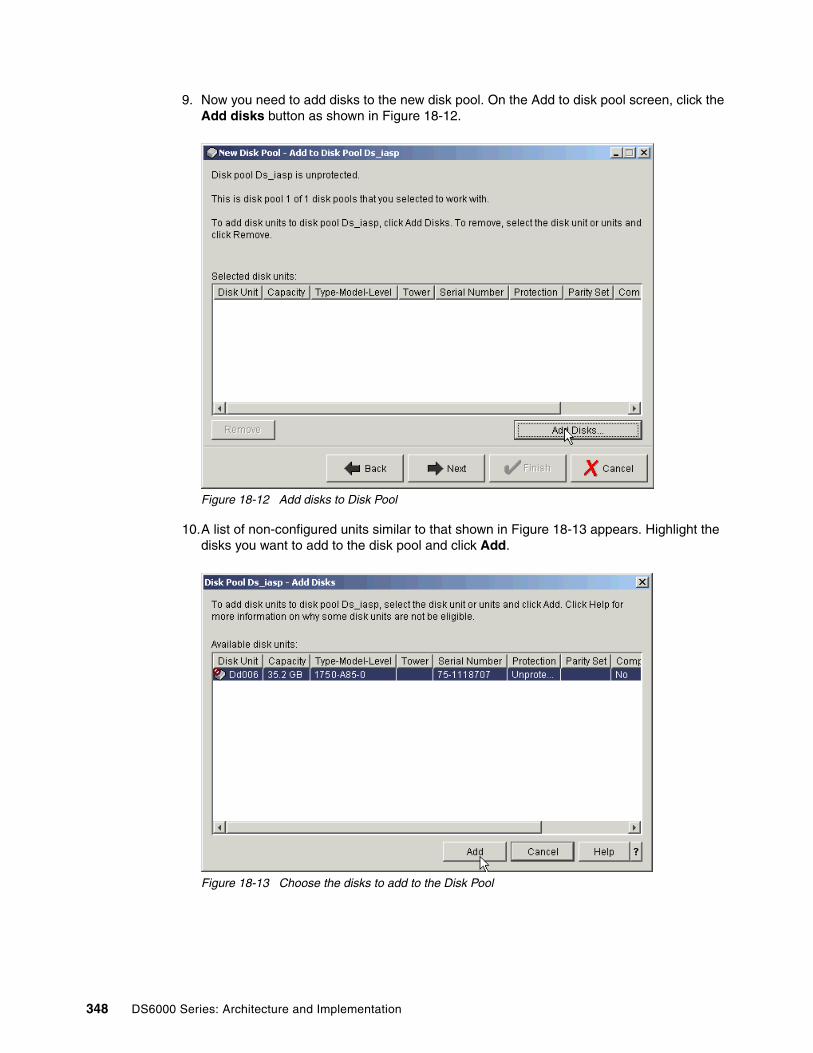
9. Now you need to add disks to the new disk pool. On the Add to disk pool screen, click the Add disks button as shown in Figure 18-12.
Figure 18-12 Add disks to Disk Pool
10.A list of non-configured units similar to that shown in Figure 18-13 appears. Highlight the disks you want to add to the disk pool and click Add.
Figure 18-13 Choose the disks to add to the Disk Pool
348 DS6000 Series: Architecture and Implementation

11.A confirmation screen appears as shown in Figure 18-14. Click Next to continue.
Figure 18-14 Confirm disks to be added to Disk Pool
12.A summary of the Disk Pool configuration similar to Figure 18-15 appears. Click Finish to add the disks to the Disk Pool.
Figure 18-15 New Disk Pool Summary
Chapter 18. System i considerations 349

13.Take note of and respond to any message dialogs which appear. After taking action on any messages, the New Disk Pool Status panel shown in Figure 18-16 displays and shows progress. This step might take some time, depending on the number and size of the logical units being added.
Figure 18-16 New Disk Pool Status
14.When complete, click OK on the information panel shown in Figure 18-17.
Figure 18-17 Disks added successfully to Disk Pool
15.The new Disk Pool can be seen on System i Navigator Disk Pools in Figure 18-18.
Figure 18-18 New Disk Pool shown on System i Navigator
350 DS6000 Series: Architecture and Implementation

16.To see the logical volume, as shown in Figure 18-19, expand Configuration and Service, Hardware, Disk Pools and click the disk pool you just created.
Figure 18-19 New logical volume shown on System i Navigator
18.5 MultipathMultipath support was added for external disks in V5R3 of i5/OS (also known as OS/400 V5R3). Unlike other platforms which have a specific software component, such as Subsystem Device Driver (SDD), multipath is part of the base operating system. At V5R3 and V5R4, up to eight connections can be defined from multiple I/O adapters on an System i server to a single logical volume in the DS6000. Each connection for a multipath disk unit functions independently. Several connections provide availability by allowing disk storage to be utilized even if a single path fails.
Multipath is important for System i because it provides greater resilience to SAN failures, which can be critical to OS/400 due to the single level storage architecture. Multipath is not available for System i internal disk units but the likelihood of path failure is much less with internal drives. This is because there are fewer interference points where problems can occur, such as long fiber cables and SAN switches, as well as the increased possibility of human error when configuring switches and external storage, and the concurrent maintenance on the DS6000 which might make some paths temporarily unavailable.
Chapter 18. System i considerations 351
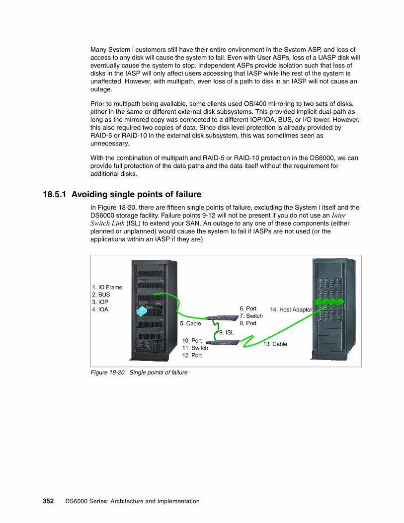
Many System i customers still have their entire environment in the System ASP, and loss of access to any disk will cause the system to fail. Even with User ASPs, loss of a UASP disk will eventually cause the system to stop. Independent ASPs provide isolation such that loss of disks in the IASP will only affect users accessing that IASP while the rest of the system is unaffected. However, with multipath, even loss of a path to disk in an IASP will not cause an outage.
Prior to multipath being available, some clients used OS/400 mirroring to two sets of disks, either in the same or different external disk subsystems. This provided implicit dual-path as long as the mirrored copy was connected to a different IOP/IOA, BUS, or I/O tower. However, this also required two copies of data. Since disk level protection is already provided by RAID-5 or RAID-10 in the external disk subsystem, this was sometimes seen as unnecessary.
With the combination of multipath and RAID-5 or RAID-10 protection in the DS6000, we can provide full protection of the data paths and the data itself without the requirement for additional disks.
18.5.1 Avoiding single points of failureIn Figure 18-20, there are fifteen single points of failure, excluding the System i itself and the DS6000 storage facility. Failure points 9-12 will not be present if you do not use an Inter Switch Link (ISL) to extend your SAN. An outage to any one of these components (either planned or unplanned) would cause the system to fail if IASPs are not used (or the applications within an IASP if they are).
Figure 18-20 Single points of failure
6. Port7. Switch8. Port
1. IO Frame2. BUS3. IOP4. IOA
5. Cable9. ISL
13. Cable10. Port11. Switch12. Port
14. Host Adapter
352 DS6000 Series: Architecture and Implementation

When implementing multipath, you should provide as much redundancy as possible. As a minimum, multipath requires two IOAs connecting the same logical volumes. Ideally, these should be on different buses and in different I/O racks in the System i. If a SAN is included, separate switches should also be used for each path. You should also use Host Adapters in different I/O drawer pairs in the DS6000. Figure 18-21 shows this situation.
Figure 18-21 Multipath removes single points of failure
Unlike other systems, which might only support two paths (dual-path), OS/400 V5R3 supports up to eight paths to the same logical volumes. As a minimum, you should use two, although some small performance benefits could be experienced with more. However, since OS/400 multipath spreads I/O across all available paths in a round-robin manner, there is no load balancing, only load sharing.
18.5.2 Configuring multipathSystem i has three I/O adapters that support DS6000:
� 2766 2 Gigabit Fibre Channel Disk Controller PCI� 2787 2 Gigabit Fibre Channel Disk Controller PCI-X� 5760 4 Gigabit Fibre Channel Disk Controller PCI-X
All can be used for multipathing and there is no requirement for all paths to use the same type of adapter. Each adapter can address up to 32 logical volumes. This does not change with multipath support. When deciding how many I/O adapters to use, your first priority should be to consider performance throughput of the IOA since this limit might be reached before the maximum number of logical units. See “Sizing guidelines” on page 360 for more information on sizing and performance guidelines.
Chapter 18. System i considerations 353

Figure 18-22 shows an example where 48 logical volumes are configured in the DS6000. The first 24 of these are assigned via a host adapter in the top controller card in the DS6000 to a Fibre Channel I/O adapter in the first System i I/O tower or rack. The next 24 logical volumes are assigned via a host adapter in the lower controller card in the DS6000 to a Fibre Channel I/O adapter on a different BUS in the first System i I/O tower or rack. This would be a valid single path configuration.
Figure 18-22 Example of multipath with System i
To implement multipath, the first group of 24 logical volumes is also assigned to a Fibre Channel I/O adapter in the second System i I/O tower or rack via a host adapter in the lower controller card in the DS6000. The second group of 24 logical volumes is also assigned to a Fibre Channel I/O adapter on a different BUS in the second System i I/O tower or rack via a host adapter in the upper controller card.
18.5.3 Adding multipath volumes to System i using 5250 interfaceIf using the 5250 interface, sign on to SST and perform the following steps as described in “Using the 5250 interface” on page 342.
1. Option 3, Work with disk units.
2. Option 2, Work with disk configuration.
3. Option 8, Add units to ASPs and balance data.
You will then be presented with a panel similar to Figure 18-23 on page 355. The values in the Resource Name column show DDxxx for single path volumes and DMPxxx for those which have more than one path. In this example, the 1750-A85 logical volume with serial number 75-1118707 is available through more than one path and reports in as DMP135.
4. Specify the ASP to which you wish to add the multipath volumes.
Volumes 25-48
Controllers and Host Adapters
Volumes 1-24
iSeries IO Towers/Racks
BUS a
BUS b
BUS x
BUS y
FC IOA
FC IOA
FC IOA
FC IOA
Logical connection
354 DS6000 Series: Architecture and Implementation

Figure 18-23 Adding multipath volumes to an ASP
5. You are presented with a confirmation screen as shown in Figure 18-24. Check the configuration details and if correct, press Enter to accept.
Figure 18-24 Confirm Add Units
18.5.4 Adding multipath volumes to System i using System i NavigatorThe System i Navigator GUI can be used to add volumes to the System, User or Independent ASPs. In this example, we are adding a multipath logical volume to a private (non-switchable) IASP. The same principles apply when adding multipath volumes to the System or User ASPs.
Follow the steps outlined in “Adding volumes to an Independent Auxiliary Storage Pool” on page 344.
Specify ASPs to Add Units to Specify the ASP to add each unit to. Specify Serial Resource ASP Number Type Model Capacity Name 21-662C5 4326 050 35165 DD124 21-54782 4326 050 35165 DD136 1 75-1118707 1750 A85 35165 DMP135 F3=Exit F5=Refresh F11=Display disk configuration capacity F12=Cancel
Note: For multipath volumes, only one path is shown. In order to see the additional paths, see “Managing multipath volumes using System i Navigator” on page 356.
Confirm Add Units Add will take several minutes for each unit. The system will have the displayed protection after the unit(s) are added. Press Enter to confirm your choice for Add units. Press F9=Capacity Information to display the resulting capacity. Press F12=Cancel to return and change your choice. Serial Resource ASP Unit Number Type Model Name Protection 1 Unprotected 1 02-89058 6717 074 DD004 Device Parity 2 68-0CA4E32 6717 074 DD003 Device Parity 3 68-0C9F8CA 6717 074 DD002 Device Parity 4 68-0CA5D96 6717 074 DD001 Device Parity 5 75-1118707 1750 A85 DMP135 Unprotected F9=Resulting Capacity F12=Cancel
Chapter 18. System i considerations 355

When you get to the point where you will select the volumes to be added, you will see a panel similar to that shown in Figure 18-25. Multipath volumes appear as DMPxxx. Highlight the disks you want to add to the disk pool and click Add.
Figure 18-25 Adding a multipath volume
The remaining steps are identical to those in “Adding volumes to an Independent Auxiliary Storage Pool” on page 344.
18.5.5 Managing multipath volumes using System i NavigatorAll units are initially created with a prefix of DD. As soon as the system detects that there is more than one path to a specific logical unit, it will automatically assign a unique resource name with a prefix of DMP for both the initial path and any additional paths.
When using the standard disk panels in System i Navigator, only a single (the initial) path is shown. The following steps show how to see the additional paths.
To see the number of paths available for a logical unit, open System i Navigator and expand Configuration and Service, Hardware, and Disk Units as shown in Figure 18-26 and click All Disk Units. The number of paths for each unit is shown in column Number of Connections visible on the right of the panel. In this example, there are 8 connections for each of the multipath units.
Note: For multipath volumes, only one path is shown. In order to see the additional paths, see “Managing multipath volumes using System i Navigator” on page 356.
356 DS6000 Series: Architecture and Implementation
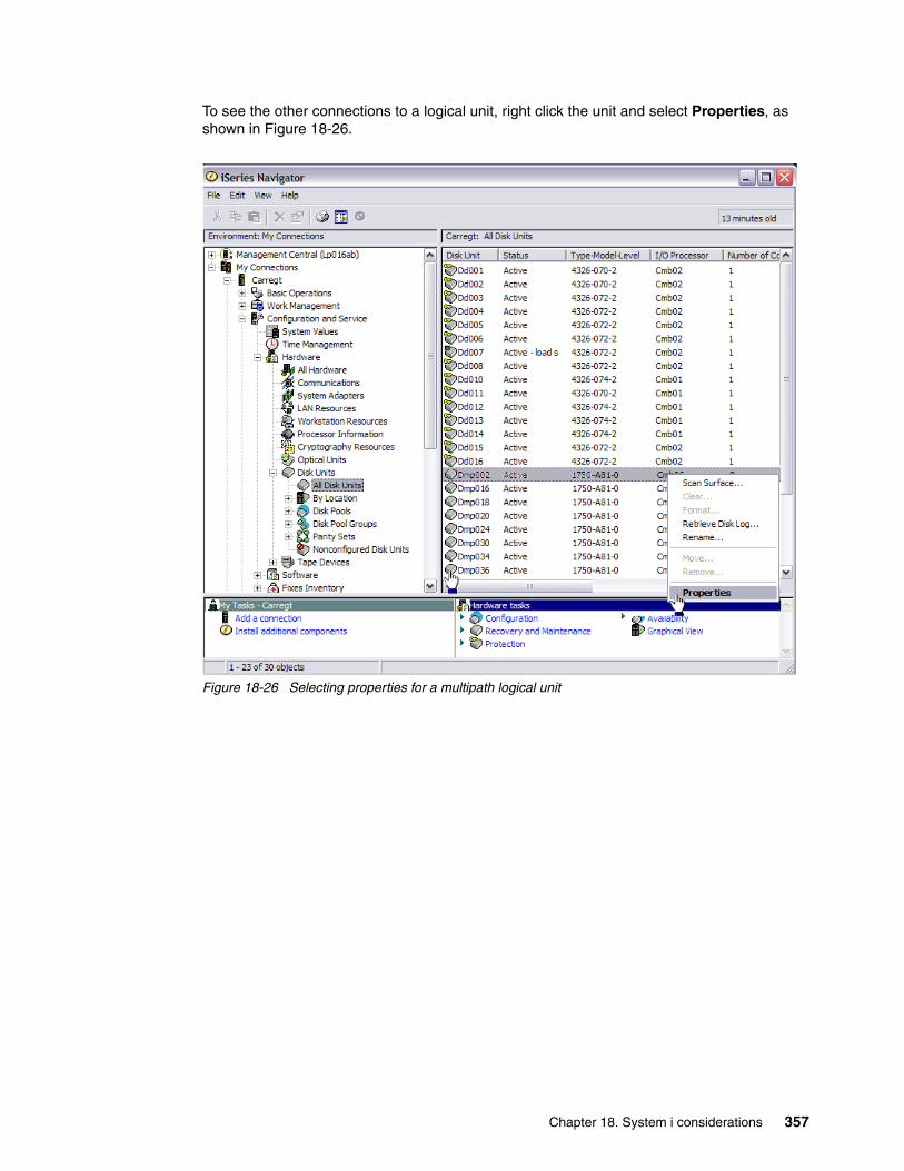
To see the other connections to a logical unit, right click the unit and select Properties, as shown in Figure 18-26.
Figure 18-26 Selecting properties for a multipath logical unit
Chapter 18. System i considerations 357

You now get the General Properties tab for the selected unit, as shown in Figure 18-27. The first path is shown as Device 1 in the box labelled Storage.
Figure 18-27 Multipath logical unit properties
358 DS6000 Series: Architecture and Implementation

To see the other paths to this unit, click the Connections tab, as shown in Figure 18-28, where you can see the other seven connections for this logical unit.
Figure 18-28 Multipath connections
18.5.6 Multipath rules for multiple System i hosts or partitionsWhen you use multipath disk units, you must consider the implications of moving IOPs and multipath connections between nodes. You must not split multipath connections between nodes, either by moving IOPs between logical partitions or by switching expansion units between systems. If two different nodes both have connections to the same LUN in the DS6000, both nodes might potentially overwrite data from the other node.
The system enforces the following rules when you use multipath disk units in a multiple-system environment:
� If you move an IOP with a multipath connection to a different logical partition, you must also move all other IOPs with connections to the same disk unit to the same logical partition.
� When you make an expansion unit switchable, make sure that all multipath connections to a disk unit will switch with the expansion unit.
� When you configure a switchable independent disk pool, make sure that all of the required IOPs for multipath disk units will switch with the independent disk pool.
If a multipath configuration rule is violated, the system issues warnings or errors to alert you of the condition. It is important to pay attention when disk unit connections are reported missing. You want to prevent a situation where a node might overwrite data on a LUN that belongs to another node.
Chapter 18. System i considerations 359

Disk unit connections might be missing for a variety of reasons, but especially if one of the preceding rules has been violated. If a connection for a multipath disk unit in any disk pool is found to be missing during an IPL or vary on, a message is sent to the QSYSOPR message queue.
If a connection is missing, and you confirm that the connection has been removed, you can update Hardware Service Manager (HSM) to remove that resource. Hardware Service Manager is a tool for displaying and working with system hardware from both a logical and a packaging viewpoint, an aid for debugging Input/Output (I/O) processors and devices, and for fixing failing and missing hardware. You can access Hardware Service Manager in System Service Tools (SST) and Dedicated Service Tools (DST) by selecting the option to start a service tool.
18.5.7 Changing from single path to multipathIf you have a configuration where the logical units were only assigned to one I/O adapter, you can easily change to multipath. Simply assign the logical units in the DS6000 to another I/O adapter and the existing DDxxx drives will change to DMPxxx and new DMPxxx resources will be created for the new path.
18.5.8 Preferred path for DS6000As discussed previously in “Avoiding single points of failure” on page 352, System i multipath can be implemented to allow a logical volume to be accessed via multiple connections. However, the Preferred Path facility for DS6000 discussed in Chapter 3, “RAS: reliability, availability, serviceability” on page 47, and also in Chapter 14, “Preferred path concept” on page 249, is currently not implemented in OS/400 and this might lead to some small performance degradation for large workloads. This is because a longer path will be used when accessing logical volumes across the midplane in the DS6000. Preferred path would access these volumes over the shortest path. However, as OS/400 does not support this, it uses a round-robin algorithm to spread I/O to a logical volume over all available paths.
18.6 Sizing guidelinesFigure 18-29 shows the process you can use to size external storage on System i. Ideally, you should have OS/400 Performance Tools reports, which can be used to model an existing workload. If these are not available, you can use workload characteristics from a similar workload to understand the I/O rate per second and the average I/O size. For example, the same application might be running at another site and its characteristics can be adjusted to match the expected workload pattern on your system.
360 DS6000 Series: Architecture and Implementation

Figure 18-29 Process for sizing external storage
18.6.1 Planning for arrays and DDMsIn general, although it is possible to use 146 GB and 300 GB 10K RPM DDMs, we recommend that you use 73 GB 15K RPM DDMs for System i production workloads. The larger, slower drives could be suitable for less I/O intensive work, or for those workloads which do not require critical response times (for example, archived data or data which is high in volume but low in use such as scanned images).
For workloads with critical response times, you might not want to use all the capacity in an array. For 73 GB DDMs you could plan to use about 300 GB capacity per 8 drive array. The remaining capacity could possibly be used for infrequently accessed data. For example, you might have archive data, or some data such as images, which is not accessed regularly, or perhaps FlashCopy target volumes which could use this capacity, but not impact on the I/O per sec on those arrays.
For very high write environments, you might also consider using RAID-10, which offers a higher I/O rate per GB than RAID-5 as shown in Figure 18-3 on page 363. However, the majority of System i workloads do not require this.
18.6.2 CacheIn general, System i workloads do not benefit from large cache. Since there is no choice for cache size on DS6000, you should ensure that your workload is not excessively cache-friendly. This can be seen in OS/400 Performance Tools System, Component and Resource Interval reports. However, in general, with large System i main memory sizes, OS/400 Expert Cache can reduce the benefit of external cache.
Modeling withDisk Magic
Rules of thumb
Proposed configuration
Requirements and expectations met ?
Finish
Other requirements:
HA, DR etc.
SAN Fabric
Workload from other servers
Yes
Adjust config based on DM
modeling
No
Workloaddescription
Workloadcharacteristics
Performance Tools Reports
Workloadstatistics
Chapter 18. System i considerations 361

18.6.3 Number of System i Fibre Channel adaptersThe most important factor to take into consideration when calculating the number of Fibre Channel adapters in the System i is the throughput capacity of the adapter and IOP combination.
Since this guideline is based only on System i adapters and Access Density (AD) of System i workload, it doesn't change when using the DS6000. (The same guidelines are valid for ESS 800).
Table 18-2 shows the approximate capacity which can be supported with various IOA/IOP combinations.
Table 18-2 Capacity per I/O Adapter
For most System i workloads, Access Density is usually below 2, so if you do not know it, the Rule of thumb column is a typical value to use.
18.6.4 Size and number of LUNsAs discussed in “Logical volume sizes” on page 340, OS/400 can only use fixed logical volume sizes. As a general rule of thumb, we recommend that you should configure more logical volumes than actual DDMs. As a minimum, we recommend 2:1. For example, with 73 GB DDMs, you should use a maximum size of 35.1GB LUNs. The reason for this is that OS/400 does not support command tag queuing. Using more, smaller LUNs can reduce I/O queues and wait times by allowing OS/400 to support more parallel I/Os.
From the values in Table 18-2, you can calculate the number of System i Fibre Channel adapters for your required System i disk capacity. As each I/O adapter can support a maximum of 32 LUNs, divide the capacity per adapter by 32 to give the approximate average size of each LUN.
For example, assume you require 2TB capacity and are using 2787 I/O adapters with 2844 I/O processors. If you know the access density, calculate the capacity per I/O adapter, or use the rule-of-thumb. Let’s assume the rule-of-thumb of 500GB per adapter. In this case, we would require four I/O adapters to support the workload. If we were able to have variable LUNs sizes, we could support 32 15.6GB LUNs per I/O adapter. However, since OS/400 only supports fixed volume sizes, we could support 28 17.5GB volumes to give us approximately 492GB per adapter.
Note: Access Density is the capacity of occupied disk space divided by the average I/O per sec. These values can be obtained from the OS/400 System, Component and Resource Interval performance reports.
I/O Adapter I/O Processor Capacity per IOA Rule of thumb
2787 2844 1022/AD 500GB
2766 2844 798/AD 400GB
2766 2843 644/AD 320GB
5760 2844 See note***
Note: ***Size the same capacity per adapter 5760 as for 2787 on 2844. For transfer sizes larger than 16KB, size about 50% more capacity than for adapter 2787.
362 DS6000 Series: Architecture and Implementation

18.6.5 Recommended number of ranksAs a general guideline, you might consider 1500 disk operations/second for an average RAID rank.
When considering the number of ranks, take into account the maximum disk operations per second per rank as shown in Table 18-3. These are measured at 100% DDM Utilization with no cache benefit and with the average I/O being 4KB. Larger transfer sizes will reduce the number of operations per second.
Based on these values you can calculate how many host I/O per second each rank can handle at the recommended utilization of 40%. This is shown for workload read-write ratios of 70% read and 50% read in Table 18-3.
Table 18-3 Disk operations per second per RAID rank
As can be seen in Table 18-3, RAID-10 can support higher host I/O rates than RAID-5. However, you must balance this against the reduced effective capacity of a RAID-10 rank when compared to RAID-5.
18.6.6 Sharing ranks between System i and other serversAs a general guideline, consider using separate extent pools for System i workload and other workloads. This will isolate the I/O for each server.
However, you might consider sharing ranks when the other servers’ workloads have a sustained low disk I/O rate compared to the System i I/O rate. Generally, System i has a relatively high I/O rate, whereas that of other servers could be lower – often below one I/O per GB per second.
As an example, a Windows file server with a large data capacity might normally have a low I/O rate with less peaks and could be shared with System i ranks. However, SQL, DB or other application servers might show higher rates with peaks, and we recommend using separate ranks for these servers.
Unlike its predecessor the ESS, capacity used for logical units on the DS6000 can be reused without reformatting the entire array. Now, the decision to mix platforms on an array is only one of performance, since the disruption previously experienced on ESS to reformat the array no longer exists.
RAID rank type Disk ops/sec Host I/O/sec (70% read)
Host I/O/sec (50% read)
RAID-5 15K RPM (7 + P) 1700 358 272
RAID-5 10K RPM (7 + P) 1100 232 176
RAID-5 15K RPM (6 + P + S) 1458 313 238
RAID-5 10K RPM (6 + P + S) 943 199 151
RAID-10 15K RPM (3 + 3 + 2S) 1275 392 340
RAID-10 10K RPM (3 + 3 + 2S) 825 254 220
RAID-10 15K RPM (4 + 4) 1700 523 453
RAID-10 15K RPM (4 + 4 1100 338 293
Chapter 18. System i considerations 363

18.6.7 Connecting via SAN switchesWhen connecting DS6000 systems to System i via switches, you should plan that I/O traffic from multiple System i adapters can go through one port on a DS6000 and zone the switches accordingly. DS6000 host adapters can be shared between System i and other platforms.
Based on available measurements and experiences with the ESS 800 we recommend you should plan no more than four System i I/O adapters to one host port in the DS6000.
For a current list of switches supported under OS/400, refer to the System i Storage Web site, located at:
http://www-1.ibm.com/servers/eserver/iseries/storage/storage_hw.html
18.7 MigrationFor many System i customers, migrating to the DS6000 will be best achieved using traditional Save/Restore techniques. However, there are some alternatives you might wish to consider.
18.7.1 OS/400 mirroringAlthough it is possible to use OS/400 to mirror the current disks (either internal or external) to a DS6000 and then remove the older disks from the System i configuration, this is not recommended because both the source and target disks must initially be unprotected. If moving from internal drives, these would normally be protected by RAID-5 and this protection would need to be removed before being able to mirror the internal drives to the DS6000 logical volumes.
Once an external logical volume has been created, it will always keep its model type and be either protected or unprotected. Therefore, once a logical volume has been defined as unprotected to allow it to be the mirror target, it cannot be converted back to a protected model and therefore will be a candidate for all future OS/400 mirroring, whether you want this or not. See Table 18-1 on page 340 for DS6000 logical volume models and types.
18.7.2 Metro Mirror and Global CopyDepending on the existing configuration, it might be possible to use Metro Mirror or Global Copy to migrate from an ESS to a DS6000 (or indeed, any combination of external Storage Units which support Metro Mirror and Global Copy). For further discussion on Metro Mirror and Global Copy, see Chapter 5, “Copy Services” on page 85 or refer to the Redbook IBM DS6000 System Storage: Copy Services in Open Environments, SG24-6783.
Consider the example shown in Figure 18-30 on page 365. Here, the System i has its internal Load Source Unit (LSU) and possibly some other internal drives. The ESS provides additional storage capacity. Using Metro Mirror or Global Copy, it is possible to create copies of the ESS logical volumes in the DS6000.
When ready to migrate from the ESS to the DS6000, you should do a complete shutdown of the System i, unassign the ESS LUNs and assign the DS6000 LUNs to the System i. After IPLing the System i, the new DS6000 LUNs will be recognized by OS/400, even though they are different models and have different serial numbers.
364 DS6000 Series: Architecture and Implementation

Figure 18-30 Using Metro Mirror to migrate from ESS to the DS6000
The same setup can also be used if the ESS LUNs are in an IASP, although the System i would not require a complete shutdown since varying off the IASP in the ESS, unassigning the ESS LUNs, assigning the DS6000 LUNs and varying on the IASP would have the same effect.
Clearly, you must also take into account the licensing implications for Metro Mirror and Global Copy.
18.7.3 OS/400 data migrationIt is also possible to use native OS/400 functions to migrate data from existing disks to the DS6000, whether the existing disks are internal or external. When you assign the new DS6000 logical volumes to the System i, initially they are non-configured (see “Adding volumes to a System i configuration” on page 342 for more details). If you add the new units and choose to spread data, OS/400 will automatically migrate data from the existing disks onto the new logical units.
Note: It is important to ensure that both the Metro Mirror or Global Copy source and target copies are not assigned to the System i at the same time because this is an invalid configuration. Careful planning and implementation is required to ensure this does not happen, otherwise unpredictable results might occur.
Note: This is a special case of using Metro Mirror or Global Copy and will only work if the same System i is used, along with the LSU to attach to both the original ESS and the new DS6000. It is not possible to use this technique to a different System i.
Metro M
irror
Chapter 18. System i considerations 365

You can then use the OS/400 command STRASPBAL TYPE(*ENDALC) to mark the units to be removed from the configuration as shown in Figure 18-31. This can reduce the down time associated with removing a disk unit. This will keep new allocations away from the marked units.
Figure 18-31 Ending allocation for existing disk units
When you subsequently run the OS/400 command STRASPBAL TYPE(*MOVDTA) all data will be moved from the marked units to other units in the same ASP, as shown in Figure 18-32. Clearly you must have sufficient new capacity to allow the data to be migrated.
Figure 18-32 Moving data from units marked *ENDALC
You can specify a time limit that the function is to run for each ASP being balanced or the balance can be set to run to completion. If the balance function needs to be ended prior to this, use the End ASP Balance (ENDASPBAL) command. A message will be sent to the system history (QHST) log when the balancing function is started for each ASP. A message will also be sent to the QHST log when the balancing function completes or is ended.
If the balance function is run for a few hours and then stopped, it will continue from where it left off when the balance function restarts. This allows the balancing to be run during off hours over several days.
In order to finally remove the old units from the configuration, you will need to use Dedicated Service Tools (DST) and re-IPL the system (or partition).
Using this method allows you to remove the existing Storage Units over a period of time. However, it does require that both the old and new units are attached to the system at the same time so it might require additional IOPs and IOAs if migrating from an ESS to a DS6000.
It might be possible in your environment to re-allocate logical volumes to other IOAs, but careful planning and implementation will be required.
Start ASP Balance (STRASPBAL) Type choices, press Enter. Balance type . . . . . . . . . . > *ENDALC *CAPACITY, *USAGE, *HSM... Storage Unit . . . . . . . . . . 1-4094 + for more values Bottom F3=Exit F4=Prompt F5=Refresh F12=Cancel F13=How to use this display F24=More keys
Start ASP Balance (STRASPBAL) Type choices, press Enter. Balance type . . . . . . . . . . > *MOVDTA *CAPACITY, *USAGE, *HSM... Time limit . . . . . . . . . . . 1-9999 minutes, *NOMAX Bottom F3=Exit F4=Prompt F5=Refresh F12=Cancel F13=How to use this display F24=More keys
366 DS6000 Series: Architecture and Implementation

18.8 Boot from SANTraditionally, System i hosts have required the use of an internal disk as a boot drive or load source unit (LSU). The new support for boot from SAN, contained in i5/OS V5R3M5 and later, removes this requirement.
18.8.1 Boot from SAN and cloningCloning is a new concept for iSeries. Previously, to create a new system image, you had to perform a full installation of the SLIC and i5/OS.
The new of boot from SAN support enables you to take advantage of some of the advanced features available with the DS6000, DS8000 series, and Copy Services functions. One of these functions is known as FlashCopy; this function allows you to perform a near instantaneous copy of the data held on a LUN or group of LUNs. Therefore, when you have a system that only has external LUNs with no internal drives, you are able to create a clone of your system.
18.8.2 Why you should consider cloningBy using the cloning capability, you can create a complete copy of your entire system in moments. You can then use this copy in any way you please. For example, you could potentially use it to minimize your backup windows, or protect yourself from a failure during an upgrade. You could perhaps even use it as a fast way to provide yourself with a backup or test system. All of these tasks can be done by cloning with minimal impact to your production operations.
18.9 AIX on IBM System iWith the announcement of the IBM System i5™ (models 520, 550, 570, and 595), it is now possible to run AIX in a partition on the i5. This can be either AIX 5L V5.2 or V5.3. All supported functions of these operating system levels are supported on i5, including HACMP for high availability and external boot from Fibre Channel devices.
The DS6000 requires the following i5 I/O adapters to attach directly to an i5 AIX partition:
� 0611 Direct Attach 2 Gigabit Fibre Channel PCI� 0625 Direct Attach 2 Gigabit Fibre Channel PCI-X
Important: When we refer to a clone, we are referring to a copy of a system that only uses external LUNs. Boot (or IPL) from SAN is therefore a prerequisite for this.
You need to have enough free storage space on your external storage server to accommodate the clone. Additionally, you should remember that any of the Copy Services functions are very resource intensive for the external storage server processor and cache. Running Copy Services tasks during the normal business operating hours could cause performance impacts.
You should not attach a clone to your network until you have resolved any potential conflicts that the clone has with the parent system.
Chapter 18. System i considerations 367

It is also possible for the AIX partition to have its storage virtualized, whereby a partition running OS/400 hosts the AIX partition's storage requirements. In this case, if using DS6000, they would be attached to the OS/400 partition using either of the following I/O adapters:
� 2766 2 Gigabit Fibre Channel Disk Controller PCI� 2787 2 Gigabit Fibre Channel Disk Controller PCI-X
For more information on running AIX in an i5 partition, refer to the i5 Information Center at:
� http://publib.boulder.ibm.com/infocenter/iseries/v1r2s/en_US/index.htm?info/iphat/iphatlparkickoff.htm
18.10 Linux on IBM System iSince OS/400 V5R1, it has been possible to run Linux in an System i partition. On System i models 270 and 8xx, the primary partition must run OS/400 V5R1 or higher and Linux is run in a secondary partition. For later i5 systems (models i520, i550, i570 and i595), Linux can run in any partition.
On both hardware platforms, the supported versions of Linux are:
� SUSE Linux Enterprise Server 9 for POWER™
(New 2.6 Kernel based distribution also supports earlier System i servers)
� RedHat Enterprise Linux AS for POWER Version 3
(Existing 2.4 Kernel based update 3 distribution also supports earlier System i servers)
The DS6000 requires the following System i I/O adapters to attach directly to an System i or i5 Linux partition.
� 0612 Linux Direct Attach PCI� 0626 Linux Direct Attach PCI-X
It is also possible for the Linux partition to have its storage virtualized, where a partition running i5/OS hosts the Linux partition's storage. This storage can be made up of any supported storage, such as a mix of internal storage and DS6000s. To use the DS6000 for this hosted storage running under the i5/OS partition, use either of the following I/O adapters:
� 2766 2 Gigabit Fibre Channel Disk Controller PCI� 2787 2 Gigabit Fibre Channel Disk Controller PCI-X
You can find more information on running Linux in an System i partition in the System i Information Center at the following sites.
For V5R2, see:
http://publib.boulder.ibm.com/iseries/v5r2/ic2924/index.htm
For V5R3, see:
http://publib.boulder.ibm.com/infocenter/iseries/v5r3/ic2924/index.htm
For running Linux in an i5 partition, check the i5 Information Center at:
http://publib.boulder.ibm.com/infocenter/iseries/v1r2s/en_US/info/iphbi/iphbi.pdf
Note: AIX will not run in a partition on earlier 8xx and prior System i hosts.
368 DS6000 Series: Architecture and Implementation

Part 5 Management, maintenance, and upgrades
In this part of the book, we discuss management and maintenance tasks for the DS6000.
We cover the following topics:
� Microcode updates� SNMP problem reporting� Managing problems and repairs� Remote support� Adding disk capacity
Part 5
© Copyright IBM Corp. 2005, 2006. All rights reserved. 369

370 DS6000 Series: Architecture and Implementation

Chapter 19. Managing problems and repairs
This chapter describes how to manage problems and repairs on a DS6000 Storage Unit.
We cover the following topics:
� Using the IBM System Storage DS6000 Information Center
� DS6000 message codes
� Checking for open problems:
– Using light path analysis to check for open problems– Using DS CLI to check for open problems– Using the DS6000 Storage Manager to check for open problems
� Maintenance and repair:
– Monitor system: Systems summary– Monitor system: Physical summary– Monitor system: Properties– Monitor system: Logs
� Creating a test problem to check notification methods:
– Using the DS CLI to initiate a test problem record– Using the DS Storage Manager to initiate a test problem record
19
© Copyright IBM Corp. 2005, 2006. All rights reserved. 371

19.1 Using the IBM System Storage DS6000 Information CenterThe IBM System Storage DS6000 Information Center provides online documentation for the DS6000. It covers a broad range of topics, helping you to plan, install, configure, manage, and maintain your DS6000 Storage Unit. With its built-in search option, it allows quick access to specific topics or to query for details of certain error message codes that were returned from the Storage Manager or the DS CLI. Especially when dealing with DS6000 maintenance or problem management issues, the DS6000 Information Center is the best place to start looking for specific information and problem handling procedures.
The DS6000 Information Center (Figure 19-1) is part of the DS6000 Storage Manager software package that is installed on the SMC and can be accessed by either starting the application locally on the SMC from the Start window using Programs → IBM System Storage DS6000 Storage Manager → Open DS Information Center or remotely using a Web browser with the following link pointing to the SMC:
http://[IP_ADDRESS_OF_SMC]:8455/help/index.jsp
It will also open if you click the “?” symbol in the upper right corner of any DS6000 Storage Manager window.
Figure 19-1 IBM System Storage DS6000 Information Center: Welcome window
There is also an online version of the DS6000 Information Center provided on the IBM technical support Web site at the following link:
http://publib.boulder.ibm.com/infocenter/ds6000ic/index.jsp
372 DS6000 Series: Architecture and Implementation

DS6000 maintenance, problem management, and problem analysis issues are especially covered under the following sections of the DS6000 Information Center:
� Maintaining:
This section provides information related to maintaining the DS6000, such as monitoring the Storage Unit and repairing failures. It covers topics like the Monitor system windows of the DS Storage Manager, taking resources online/offline and installing/removing resources.
� Troubleshooting:
This section provides troubleshooting information related to the DS6000. Topics covered include analyzing, verifying, understanding, managing, and handling various problems.
� Messages:
This section provides information related to messages of the DS Storage Manager and the DS CLI. These messages can be informational, warning, or error messages.
19.2 DS6000 message codesThree types of messages are issued from the user interfaces and supporting software when working with the DS6000 Storage Unit:
� Informational messages are identified by the letter “I” at the end of the message identifier. They provide information about activities as they take place. For example, an informational message might report that a volume was successfully created. No user action is necessary. An example of an informational message code is CMUD00008I (see Example 19-4 on page 378).
� Warning messages are identified by the letter “W” at the end of the message identifier. They warn that activities might have consequences that you do not anticipate. Warning messages normally provide the opportunity to continue an activity or to cancel it. An example of a warning message code is CMUD00009W (see Example 19-4 on page 378).
� Error messages are identified by the letter “E” at the end of the message identifier. They indicate that an error has occurred. Refer to the explanations and recommended actions in the DS6000 Information Center to resolve the problem (see Figure 19-2). An example of an error message code is CMUN02231E (see Example 19-1).
The messages are grouped by the reporting interface or software:
� Framework message identifiers are prefixed by the letters CMMC and CMUF. The framework is the basic software that supports your user interface.
� Command-line interface (DS CLI) message identifiers are prefixed by the letters CMUC and CMUD.
� DS Storage Manager message identifiers are prefixed by the letters CMUG, CMUI, CMUL, CMUR and CMUS.
� Storage Management Console server message identifiers are prefixed by the letters CMUN.
All of these message codes are listed and explained in the DS6000 Information Center or in the IBM System Storage DS6000 Messages Reference, GC26-7914.
Chapter 19. Managing problems and repairs 373

Message codes that appear in the graphical user interface of the DS Storage Manager are generally linked to the appropriate message description in the DS6000 Information Center. So clicking the message code will simply bring up the DS6000 Information Center with a detailed description of the message, providing an explanation and a recommended action plan to resolve a potential problem.
Messages that are shown in the DS CLI provide a message ID and a short description, as shown in Example 19-1. Although the short description in many cases already provides enough information about the nature of a potential problem, it might be convenient in some other cases to obtain a more detailed description with an explanation and a proposed action plan to resolve the problem. This can easily be achieved by using the DS6000 Information Center and performing a search on the given message code. Just enter the message ID into the Search field of the DS6000 Information Center with quotation marks around it, select Go, and a detailed description of the message will be shown (see Figure 19-2).
In Example 19-1, an attempt is made to create a new volume with volume ID 1142 from Extent Pool P0. This task fails because the logical subsystem group of the volume (here LSS 11 belongs to logical subsystem group 1 containing all odd numbered LSS IDs) and the rank group of the Extent Pool (here P0 belongs to rank group 0 containing all even numbered Extent Pool IDs) do not match. An error message with message code ID CMUN02231E and a short description is returned. To obtain more information about this error message and a proposal on how to resolve the problem, just enter the message ID into the Search field of the DS6000 Information Center and select Go, as shown in Figure 19-2.
Example 19-1 Obtaining an error message when using the DS CLI
dscli> mkfbvol -dev IBM.1750-1300247 -extpool P0 -cap 20 -name vol_#h 1142Date/Time: November 3, 2005 2:44:48 PM CET IBM DSCLI Version: 5.0.6.142 DS: IBM.1750-1300247CMUN02231E mkfbvol: Unable to create logical volume: rank group and logical subsystem group mismatch
Figure 19-2 Looking up a DS CLI error message using DS6000 Information Center
374 DS6000 Series: Architecture and Implementation

19.3 Checking for open problemsTo check for open problems on the DS6000 Storage Unit, you can either take a look at the light path LED indicators on the Storage Unit or at the problem log, which can be accessed through the DS6000 Storage Manager or the DS CLI.
19.3.1 Using light path analysis to check for open problemsFor problem determination, the light path LED indicators on the Storage Unit will indicate the nature of a problem condition and help to locate a resource that needs to be replaced.
Use the LED indicators located on the front display panel (Figure 19-3) and rear display panel as well as the individual resources within your server or expansion enclosure to determine if an event has occurred. Light path indicators provide indications of both fault and informational events. The Fault on rear and Fault in external enclosure LED indicators also help to easily locate the faulty resource. For more information about the light path indicators on the individual physical resources of a DS6000 Storage Unit, refer to the section Overview - DS6000 hardware resources in the DS6000 Information Center.
Figure 19-3 Light path LED indicators on front display panel for problem determination
A solid amber light on the system information LED on the front or rear display panel of the Storage Unit indicates that a noncritical event has occurred. View the problem log in the DS Storage Manager to find more information about the event. The light remains solid until the condition has been corrected or you close the log entry in the DS Storage Manager. This light is lit for minor events.
A solid amber light on the system alert LED on the front or rear display panel of the Storage Unit indicates that a fault is present on the Storage Unit. Follow the other indicator LEDs to determine the location of the faulty resource. If no other resources have solid amber error LEDs, use the DS Storage Manager to view the current log entries and determine the point of failure. This light remains solid until the required resources have been replaced, the problem log entry has been closed through the DS Storage Manager, or unless you press the Remind button on the rear operator panel. If the Remind button is pressed on the rear operator panel, the system alert LED blinks on every two seconds.
If the system alert indicator is lit at the same time as the information indicator, then two events (one minor and one major) have occurred on the resource.
Chapter 19. Managing problems and repairs 375

A solid amber light on a resource other than the front display panel or rear operator panel indicates that a fault exists on that resource. When this error LED on a resource is set to solid amber, you can remove and replace the resource without any additional action on the DS Storage Manager. If an error LED is lit on a resource, the system alert LEDs on the rear and front panels will also be set to solid amber. The lights remain solid until the resource is replaced or the log entry is closed through the DS Storage Manager.
If there are multiple resources with a fault, and those resources can be repaired in any order, the system alert lights on the front and rear panels and the error light on each of the affected resources are lit showing solid amber. If there are multiple resources with a fault, and those resources must be repaired in a specific order, the system alert lights on the front and rear panels are turned on to solid amber and the error light on the resource that must be replaced first is set to solid amber. Once that resource has been replaced and the error light is no longer turned on, the error light on the next resource that must be replaced is set to solid amber. The sequence continues in this manner until all required resources have been replaced and the system alert indicators on the front and rear panels are turned off.
For more information on how to resolve problem conditions using use the LED indicators on your Storage Unit, refer to the DS6000 Information Center, which will guide you through all the necessary steps.
19.3.2 Using DS CLI to check for open problemsTo check for open problems using the DS CLI, the lsproblem command is available. It displays all error and informational log entries from the problem log of the selected DS6000 Storage Unit. When specifying the option -state open, the command will only list the currently open problem log entries, as shown in Example 19-2. A problem log entry is marked open when a problem has occurred that requires service. The status will remain open prior to and during a repair. After the repair has successfully been completed, the status will change to closed.
Example 19-2 Using DS CLI command lsproblem
dscli> lsproblem -state open IBM.1750-1300247Date/Time: October 25, 2005 12:54:05 PM CEST IBM DSCLI Version: 5.0.6.142 DS: IBM.1750-1300247ID Node Type Sev Occur State FRUs SRN======================================================================2005-10-13-21.54.28.584879 0 H/W Problem 23 Open 1 BE876005
The standard lsproblem command will display the primary problem log information, such as:
� Problem ID
� Controller card that created the record (here referred to as node): 0 or 1
� Type of problem: H/W, S/W, Test, Heartbeat, or Data Loss
� Severity of the problem: Problem, Event, Attention, Test, or Heartbeat
� Number number of times that the problem occurred
� State of the problem: Open or Closed
� Number of FRUs (field replaceable units) that are suspended for causing the problem
� SRN (service reference number), also known as SRC, which is a 4-byte value
376 DS6000 Series: Architecture and Implementation

Specifying the -l option for the lsproblem command will display more details about the individual problem log entries, as shown in Example 19-3:
� A list of FRUs that are candidates for replacement in order to solve the problem. This list also specifies the FRUs that have been replaced and identifies those that need to be replaced. Each hardware resource in the DS6000 has a specific resource location code which is part of these FRU list entries to identify the exact physical location of the resource (see DS6000 Information Center for more information on resource location codes).
� The first timestamp of the problem.
� The last timestamp of the problem.
� The component type (Detector) that found the problem: Harvest, RAS, AH, Bering, or SES.
For further information on a specific problem log entry or for performing service actions, such as taking resources offline, the DS6000 Storage Manager needs to be used as discussed in the following sections. The internal service reference number (SRN) error code of a listed problem is translated into a comprehensive error description by selecting Real-time manager → Monitor system → Logs → View details (see Figure 19-5 on page 379). It also provides an explanation of the problem and offers a recommended action plan to finally solve the problem, as shown in Figure 19-6 on page 380.
Example 19-3 Using the DS CLI command lsproblem with long output option -l
dscli> lsproblem -l -state open IBM.1750-1300247Date/Time: October 25, 2005 12:54:34 PM CEST IBM DSCLI Version: 5.0.6.142 DS: IBM.1750-1300247ID Node Type Sev Occur State FRUs FRUList===============================================================================================================2005-10-13-21.54.28.584879 0 H/W Problem 23 Open 1 1300498-1300498-U1750EX1.1300498-P1-D15-S5AD073-0
SRN FirstTime LastTime Detector=========================================================================BE876005 10/13/2005 23:50:07 CEST 10/21/2005 04:44:16 CEST AH
In Example 19-2 on page 376 and Example 19-3 here, the problem log of the DS6000 Storage Unit (1750-511) with S/N 1300247 shows a failed device drive module (DDM) with resource location code U1750EX1.1300498-P1-D15, referring to a storage expansion unit (1750-EX1) with S/N 1300498 and a physical disk located in slot D15 (see Table 19-2 on page 380). The error code or SRN of the problem is BE876005, which is explained when looking up the details for that log entry in the DS6000 Storage Manager (see Figure 19-6 on page 380).
Chapter 19. Managing problems and repairs 377

The DS6000 resource location codes can be looked up using the DS6000 Information Center. They are presented in the following format: Uttttmmm.ppsssss-P1-L#, where tttt is the machine type, mmm is the model type, ppsssss is the machine serial number, P1 is the resource point of reference, and L# is the location for the specific resource. The resource location codes, as shown in Table 19-1, can be used to easily tell which physical resource is affected by a given problem in the Storage Unit’s problem log.
Table 19-1 DS6000 resource location codes
When the problem finally has been resolved, for example, by replacing the faulty resource, an open problem log entry can manually be closed using the DS CLI command closeproblem, as shown in Example 19-4.
Example 19-4 Using the DS CLI command closeproblem to close an open problem log entry
dscli> closeproblem -dev IBM.1750-1300247 -node 0 2005-10-13-21.54.28.584879Date/Time: November 3, 2005 10:45:59 AM CET IBM DSCLI Version: 5.0.6.142 DS: IBM.1750-1300247CMUD00009W closeproblem: Are you sure you want to close problem 2005-10-13-21.54.28.584879 ? [y/n]:yCMUD00008I closeproblem: Problem 2005-10-13-21.54.28.584879 was successfully closed.
In general, you do not need to close a problem entry log manually after successfully replacing a resource that had a solid amber error indicator light turned on. In this case, the error entry in the problem log closes automatically and the Storage Unit resumes normal operation.
19.3.3 Using the DS6000 Storage Manager to check for open problemsWhen checking for open problems on the DS6000, the most informative source is the DS6000 Storage Manager. Select Real-time Manager → Monitor System → Error Logs from the navigation window to open the Error Logs window. The log entry table initially shows all log entries, informational or error, generated in the preceding 25 hours. To view all currently open problem log entries, mark All log entries and select Open from the Status drop-down menu (see Figure 19-4).
Location code Physical resource
C1 Rear display panel
C2 Upper processor controller card
C4 Lower processor controller card
Dxx Device drive module (D1 to D16, see Table 19-2 on page 380)
E1 Power supply 0 (left-side from rear)
E2 Power supply 1 (right-side from rear)
E10 Battery backup unit (left-side from rear)
E11 Battery backup unit (right-side from rear)
E20 Front display panel
378 DS6000 Series: Architecture and Implementation

Figure 19-4 DS6000 Storage Manager displaying all open problem log entries
The problem log of the DS6000 in Figure 19-4 shows two open problems. The first log entry with error code BE8FFFFF is an informational message telling you that a heartbeat record has been generated. Heartbeat records are generated periodically once a week, indicating that the Storage Unit is healthy enough to communicate with the outside world. If the Call Home option is properly configured, a Call Home record is sent to IBM. No action is required, and you do not need to close this log entry manually, as this entry will reappear on regular basis. The second log entry shows an error message indicating a hardware problem for a disk drive module (DDM) with error code BE876005 (SRN).
To view the details of a specific log entry, just mark the entry, select View details from the Select action drop-down menu as shown in Figure 19-5. Alternatively, you can also click the Message ID of a log entry to view the details for that entry.
Figure 19-5 Selecting view details for a log entry from DS6000 Storage Manager Logs window
Chapter 19. Managing problems and repairs 379

A new window with a detailed description of the selected problem log entry will open, as shown in Figure 19-6. In addition to the information that is listed by the lsproblem command of the DS CLI (see Example 19-4 on page 378), the DS6000 Storage Manager also provides an explanation of the problem and offers a recommended action plan to finally solve the problem. The internal service reference number (SRN) or error code of the problem is translated into a comprehensive problem description.
Figure 19-6 Detailed view of a problem log entry in the DS6000 Storage Manager
In Figure 19-6, the detailed view of the problem log entry for the DS6000 Storage Unit (1750-511) shows a failed DDM with source location code U1750EX1.13ABGX-P1-D2, referring to a storage expansion unit (1750-EX1) with S/N 13ABGXand a physical disk located in slot D2 (see Table 19-2). The DS6000 resource location codes for the individual physical resources can be looked up using the DS6000 Information Center.
Table 19-2 DDM (device drive module) resource location codes
D1 D2 D3 D4
D5 D6 D7 D8
D9 D10 D11 D12
D13 D14 D15 D16
380 DS6000 Series: Architecture and Implementation

You can perform maintenance actions or view maintenance information for the resources that are associated with the log entry on the log entry details page. Select one of the resources listed in the table to request a replacement part, view maintenance instructions, take the resource offline, or bring a resource online (Figure 19-7). If more than one resource must be replaced, the resources are listed in the order in which they must be replaced. Replace the first resource in the list before the others. Next, replace the second resource in the list. Follow this method until all required resources have been replaced.
Figure 19-7 Available actions on the Log Details window for a selected resource
When the problem finally has been resolved, for example, by replacing the faulty resource, an open problem log entry can manually be closed by selecting the specific log entry, choosing Close from the drop-down menu, as shown in Figure 19-8. Before the entry will be closed, an additional warning message appears (see Figure 19-9), which needs to be confirmed by selecting Continue before the entry will finally be closed.
In general, you do not need to close a problem entry log manually after successfully replacing a resource that had a solid amber error indicator light lit. In this case, the error entry in the problem log closes automatically and the Storage Unit resumes normal operation.
Figure 19-8 Closing an open problem log entry using the DS6000 Storage Manager
Figure 19-9 Warning message before proceeding to close an open problem log entry
Important: Before you begin with any service action, you must review the effects of performing a service action on the resource you are going to repair. Use the DS6000 Information Center to check the remove and replace procedures for a resource before quiescing and removing it.
Chapter 19. Managing problems and repairs 381

19.4 Maintenance and repairTo check for the current status of a DS6000 Storage Unit or for performing maintenance and repair actions on a DS6000 Storage Unit, select Real-time Manager → Monitor system from the navigation window (see Figure 19-10) on the DS6000 Storage Manager. It contains the following sub windows:
� Systems summary� Physical summary� Properties� Logs
These windows provide easy access to DS6000 problem log entries and status information of all DS6000 resources, as well as to necessary maintenance procedures, such as taking resources offline or online in order to manage physical resources or to handle potential problems.
Before performing any maintenance or service actions on a physical resource, review the available information provided in the DS6000 Information Center on the following topics:
� Reviewing the effects of a service action� Following a light path to perform an unguided service� Performing a guided service through the problem log� Removing a resource� Installing a resource
19.4.1 Monitor system: Systems summarySelect Real-time Manager → Monitor system → Systems summary from the navigation window of the DS6000 Storage Manager to open the Systems summary window. It provides an overall systems summary of the status of all logical and physical resources from all Storage Units that belong to the selected Storage Complex. Use this window to view high-level systems status, identify failing physical components, or identify problematic logical objects. It initially displays the status for all resources of the Storage Complex. By selecting Physical or Logical from the drop-down menu under Resource type, you can limit the systems summary to show logical or physical resources only. If the status of all resources of the Storage Complex is Normal, only a short summary is given, as shown in Figure 19-10.
Figure 19-10 DS6000 Storage Manager: Systems summary: all resources normal
382 DS6000 Series: Architecture and Implementation

If any logical or physical resource of the Storage Complex has a status different from Normal it is listed in a summary table, as shown in Figure 19-11. This summary table is displayed only if a problem exists. To view a physical summary, status, or logs for a given resource that is listed in the System summary window, just select the resource and choose the appropriate action from the Select Action drop-down menu. To check for further details on a logical resource (for example, a volume) that is listed in the System summary table, just click the link in the status column or the resource column, and the status window or the properties window for that resource will open.
Figure 19-11 DS6000 Storage Manager: Systems summary listing a logical resource needing attention
19.4.2 Monitor system: Physical summarySelect Real-time Manager → Monitor system → Physical summary from the navigation window of the DS6000 Storage Manager to open the Physical summary window (see Figure 19-12). It provides a comprehensive summary of the status of all physical resources within a selected Storage Unit. It does not provide any information about logical resources or objects that have problems.
Figure 19-12 DS6000 Storage Manager: Physical summary
When selecting a row and choosing Properties from the Select Action drop-down menu or when clicking the link in the component column for a specific enclosure, the Properties window for that component will open and provide further status and maintenance information for the selected resource.
Chapter 19. Managing problems and repairs 383

19.4.3 Monitor system: PropertiesSelect Real-time Manager → Monitor system → Properties from the navigation window of the DS6000 Storage Manager to open the Properties window. This is the main window for managing the physical resources of a DS6000 Storage Unit. You can view properties and detailed status information for the available physical resources as well as helpful maintenance information about how to replace a physical resource, or see what the potential impact of a service action on that resource would be.
Select the Storage Complex, the Storage Unit, the Enclosure, and the Resource from the drop-down menus on the top of the window, as shown in Figure 19-13, to display the appropriate information for the wanted resource type. There are six types of physical resources available to choose from for management purposes or status information:
� Battery backup unit� Device drive modules� Processor controller cards� Power supplies/fans� Rear display panel� Front display panel
Figure 19-13 DS6000 Storage Manager: Monitor System: Properties window
For a selected resource type, you can choose to view general resource attributes and values (select Attributes), to view and modify resource status information (select Status), or to obtain information about maintenance instructions (select Maintenance).
384 DS6000 Series: Architecture and Implementation

AttributesThis window displays general properties information for the selected resource type. It provides resource specific information like resource attributes and values, for example, location code, part order number, serial number, firmware level, and EC (Engineering Change) level, as shown in Figure 19-14 for the processor controller cards and in Figure 19-15 for the disk drive modules (DDMs).
Figure 19-14 DS6000 Storage Manager: General properties for processor controller cards
Figure 19-15 DS6000 Storage Manager: General properties for disk drive modules (DDMs)
You can also display high level properties information for your selected Storage Unit without selecting a specific enclosure or resource in the drop-down menus on top of the Properties window, as shown in Figure 19-16. This view provides high level information related to your selected DS6000 Storage Unit, such as the number of installed DDMs (disk drive modules), the MTMS (machine type and machine serial label), the machine’s signature, the machine’s WWNN (world wide node number), and the nickname.
Chapter 19. Managing problems and repairs 385
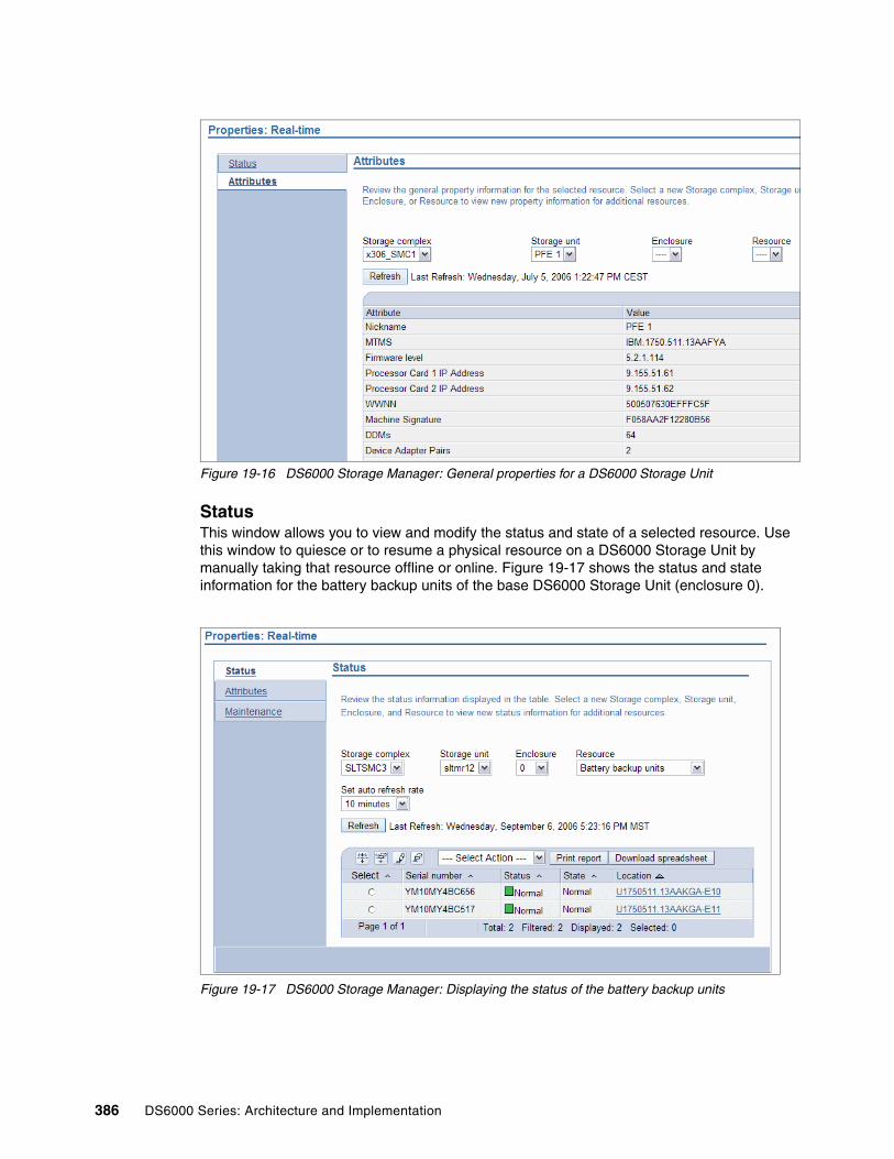
Figure 19-16 DS6000 Storage Manager: General properties for a DS6000 Storage Unit
StatusThis window allows you to view and modify the status and state of a selected resource. Use this window to quiesce or to resume a physical resource on a DS6000 Storage Unit by manually taking that resource offline or online. Figure 19-17 shows the status and state information for the battery backup units of the base DS6000 Storage Unit (enclosure 0).
Figure 19-17 DS6000 Storage Manager: Displaying the status of the battery backup units
386 DS6000 Series: Architecture and Implementation

The status of a resource is the current condition of that resource, which can be Normal, Attention, or Alert. � Normal Status:
A Normal status indicates that the hardware resource is functioning properly. The following states indicate that the hardware resource has a Normal status:
– Normal: The resource is operational and functional.
– Installing: A new resource has been recognized. It is either a replacement resource for a failed resource or it is additional capacity that you are adding.
– Verifying: The resource is made accessible to the device adapter, its characteristics are determined, cabling is checked, and diagnostics are run.
– Formatting: A verified resource requires low-level formatting and the formatting operation is in progress.
– Initializing: The resource is being initialized with all zero sectors. This is required so that the resource can be added to an Array without regenerating parity.
– Certifying: The resource is being read accessed to determine that all sectors can be read. If a bad sector is detected, an alternate sector is used to replace the bad sector.
– Rebuilding: Sparing has occurred and this formerly spare resource is being rebuilt with data from the other resources in the Array to which it now belongs.
– Migration target: DDM migration is migrating another array member resource to this spare resource.
– Migration source: DDM migration is migrating this array member resource to another spare resource.
– New: The resource is new. Integration of the resource into the system has not begun.
� Attention Status:
An Attention status indicates that the hardware resource might be missing from its slot, has been taken offline, or is faulty but still functioning. User intervention is required for this status. The following states indicate that the hardware resource has an Attention status:
– Missing: The resource is missing. The resource has been pulled out of the system and removal has not been managed.
– Missing, failed: The resource is missing and the previous state of the device was Failed before it was pulled from the enclosure.
– Removed: The resource is removed. The resource is not in the system and its removal has been managed.
– Removed, failed: The resource is removed from the system and removal has been managed. The previous state was Missing, failed.
– Inappropriate: The resource is inappropriate for the system. For example, a DDM that is of the wrong capacity or rpm, or a hardware resource that cannot be integrated in that slot. However, the resource is not failed and might be valid for other systems and locations.
– Interfailed: The resource is faulty.
Chapter 19. Managing problems and repairs 387

� Alert Status:
An Alert status indicates that the hardware resource has failed and needs to be replaced, or that there is a problem that is associated with the hardware resource. The hardware resource returns to the Normal state when the problem is resolved, for example, a power supply with a missing AC cable connection). The following states indicate that the hardware resource has an Alert status:
– Failed: The resource has failed and an immediate repair action is required. If spares are available, sparing has been initiated if this resource is an array member.
– Failed, deferred service: The resource has failed and a repair action is not immediately required. If this resource is an array member, sparing has been initiated, and there are sufficient spares at the time of this failure to allow the service action to be deferred.
You can quiesce or resume a selected physical resource for a repair or replacement procedure by manually taking that resource online or offline. The Take offline action quiesces a resource in preparation for a repair or replacement procedure. The Bring online action resumes a resource after you completed a repair or replacement procedure.
Taking a resource offline, as shown in Figure 19-18 on page 389, opens a confirmation dialogue (Figure 19-19) that asks if you are sure you want to continue taking the selected resource offline. Selecting Continue will take the resource offline. The resource is brought to a state in which its removal does not have adverse effects on the system. The status of the resource will change to Attention and the state will be shown as Prepared for service, as shown in Figure 19-20.
Important: Before you begin with any service action, you must review the effects of performing a service action on the resource you are going to repair. Use the DS6000 Information Center to check the remove and replace procedures for a resource before quiescing and removing it.
Note: If you take a hardware resource offline and decide not to remove it from the enclosure, you must bring the resource online through the DS Storage Manager before it will resume operation.
388 DS6000 Series: Architecture and Implementation

Figure 19-18 DS6000 Storage Manager: Taking a physical resource offline
Figure 19-19 DS6000 Storage Manager: Confirmation dialogue before taking a resource offline
Figure 19-20 DS6000 Storage Manager: Successfully having taken a resource offline
Chapter 19. Managing problems and repairs 389

Bringing a resource online, as shown in Figure 19-21, opens a confirmation dialog (Figure 19-22) asking if you are sure you want to continue bringing the selected resource online. Selecting Continue will bring the resource online. If the resource is successfully brought online, the status will change to Normal, as shown in Figure 19-17 on page 386. The state of the resource might vary depending on the type of resource that was brought online, for example, a new DDM might go through the states of Installing, Verifying, Formatting, Initializing and Certifying until it will be shown as Normal.
Figure 19-21 DS6000 Storage Manager: Bringing a resource online
Figure 19-22 DS6000 Storage Manager: Confirmation before bringing a resource online
390 DS6000 Series: Architecture and Implementation
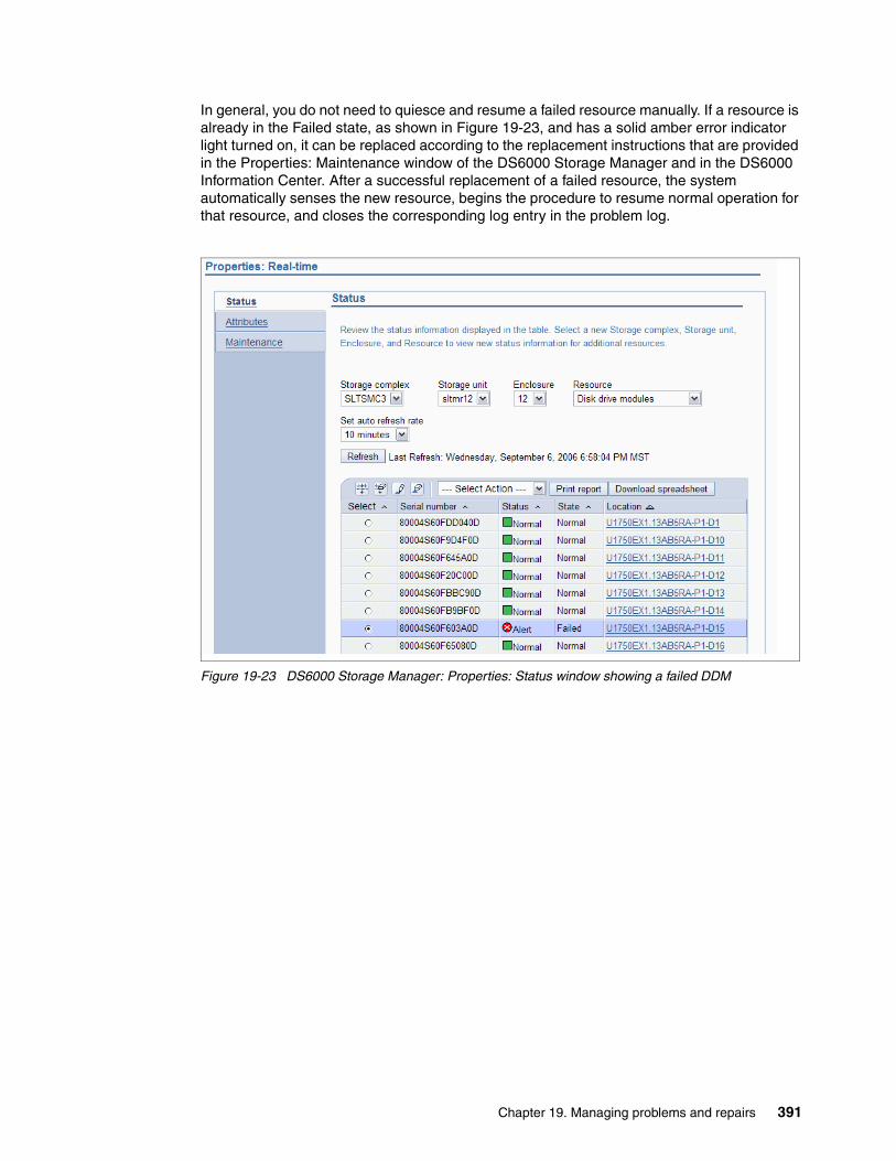
In general, you do not need to quiesce and resume a failed resource manually. If a resource is already in the Failed state, as shown in Figure 19-23, and has a solid amber error indicator light turned on, it can be replaced according to the replacement instructions that are provided in the Properties: Maintenance window of the DS6000 Storage Manager and in the DS6000 Information Center. After a successful replacement of a failed resource, the system automatically senses the new resource, begins the procedure to resume normal operation for that resource, and closes the corresponding log entry in the problem log.
Figure 19-23 DS6000 Storage Manager: Properties: Status window showing a failed DDM
Chapter 19. Managing problems and repairs 391

MaintenanceThis window allows you to view general maintenance information and procedures for a physical resource. It provides resource images, removal procedures, and installation procedures, as shown in Figure 19-24. After selecting a specific physical resource in the drop-down menus on top of the window, you can access service effect descriptions (View Service Effect) and animated examples of resource removal and installation procedures (View animated R/R sequence).
Figure 19-24 DS6000 Storage Manager: Displaying maintenance instructions for a physical resource
The View Service Effect button opens the DS6000 Information Center, which provides user information about the service effect on the specified resource. It contains the potential impacts of performing removal and replacement procedures on the resources and assists you in understanding and reviewing the effects of a service action on the selected resource.
The View animated R/R sequence (R/R = remove and replace) button opens an animated example of the remove and replace procedures for the specified resource.
The Request a replacement part button launches a new browser window that opens an IBM service request Web site where you can order the required replacement part by submitting an electronic service request to IBM using the following link:
http://www.ibm.com/support/electronic/navpage?category=2
The Electronic Service Call application (ESC+) gives IBM customers the ability to place, monitor and manage service requests electronically. It requires a user ID and password and can be accessed using the following link:
https://www.ibm.com/support/esc/signin.jsp
IBM Customer Support will then contact you. Alternatively, you might choose to place a service call by calling your local support team.
392 DS6000 Series: Architecture and Implementation

19.4.4 Monitor system: LogsSelect Real-time Manager → Monitor system → Logs from the navigation window of the DS6000 Storage Manager to view error and informational log entries for your Storage Unit. The log entry table initially shows all log entries, informational or error, generated in the preceding 25 hours. To view all currently open log entries, check All log entries and select Open from the Status drop-down menu, as shown in Figure 19-4 on page 379. Refer to 19.3, “Checking for open problems” on page 375 for more information about how to view and manage the problem log entries.
The Logs window of the DS6000 Storage Manager can be used to perform log guided service actions in order to handle or resolve problems that are logged to the problem log. Click the Message ID of a specific log entry or select View details from the Select Action drop-down menu and select Go to view the details for that entry.
On the Log Details window (Figure 19-6 on page 380) you can perform maintenance actions or view maintenance information for the resources that are associated with the log entry:
1. Select one of the resources listed in the table to request a replacement part, view maintenance instructions, take the resource offline, or bring a resource online (see Figure 19-7 on page 381).
2. If more than one resource must be replaced, the resources are listed in the order in which they must be replaced:
a. Replace the first resource in the list before the others.
b. Next, replace the second resource in the list.
3. Follow this method until all required resources have been replaced.
Before removing a physical resource from the DS6000 Storage Unit, be sure that the resource is quiesced and has the solid amber error indicator light turned on. You can quiesce a resource manually by selecting Take offline from the Select Action drop-down menu.
You must replace some resources within a specific time limit. In some cases, if you remove a resource without immediately replacing it, you must place a blank version of the resource in the empty slot to prevent overheating of the Storage Unit.
After the replacement of a resource, the resource will automatically begin the procedure to resume operation and close the corresponding log entry if the problem is solved. Review the Logs window after the replacement to determine if the log entry has been closed or if you need to perform additional actions.
Important: Before you begin with any service action, you must review the effects of performing a service action on the resource you are going to repair. Use the DS6000 Information Center to check the remove and replace procedures for a resource before quiescing and removing it.
Note: If you take a hardware resource offline and decide not to remove it from the enclosure, you must bring the resource online through the DS Storage Manager before it will resume operation.
Chapter 19. Managing problems and repairs 393
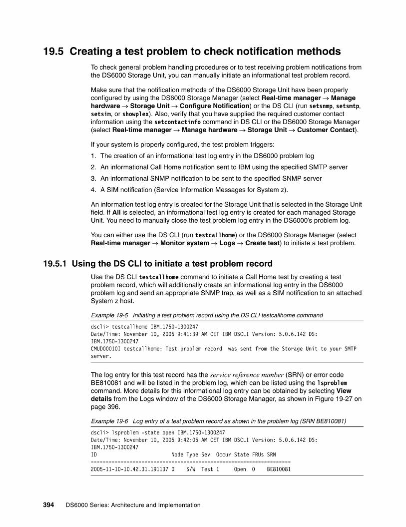
19.5 Creating a test problem to check notification methodsTo check general problem handling procedures or to test receiving problem notifications from the DS6000 Storage Unit, you can manually initiate an informational test problem record.
Make sure that the notification methods of the DS6000 Storage Unit have been properly configured by using the DS6000 Storage Manager (select Real-time manager → Manage hardware → Storage Unit → Configure Notification) or the DS CLI (run setsnmp, setsmtp, setsim, or showplex). Also, verify that you have supplied the required customer contact information using the setcontactinfo command in DS CLI or the DS6000 Storage Manager (select Real-time manager → Manage hardware → Storage Unit → Customer Contact).
If your system is properly configured, the test problem triggers:
1. The creation of an informational test log entry in the DS6000 problem log
2. An informational Call Home notification sent to IBM using the specified SMTP server
3. An informational SNMP notification to be sent to the specified SNMP server
4. A SIM notification (Service Information Messages for System z).
An information test log entry is created for the Storage Unit that is selected in the Storage Unit field. If All is selected, an informational test log entry is created for each managed Storage Unit. You need to manually close the test problem log entry in the DS6000’s problem log.
You can either use the DS CLI (run testcallhome) or the DS6000 Storage Manager (select Real-time manager → Monitor system → Logs → Create test) to initiate a test problem.
19.5.1 Using the DS CLI to initiate a test problem recordUse the DS CLI testcallhome command to initiate a Call Home test by creating a test problem record, which will additionally create an informational log entry in the DS6000 problem log and send an appropriate SNMP trap, as well as a SIM notification to an attached System z host.
Example 19-5 Initiating a test problem record using the DS CLI testcallhome command
dscli> testcallhome IBM.1750-1300247Date/Time: November 10, 2005 9:41:39 AM CET IBM DSCLI Version: 5.0.6.142 DS: IBM.1750-1300247CMUD00010I testcallhome: Test problem record was sent from the Storage Unit to your SMTP server.
The log entry for this test record has the service reference number (SRN) or error code BE810081 and will be listed in the problem log, which can be listed using the lsproblem command. More details for this informational log entry can be obtained by selecting View details from the Logs window of the DS6000 Storage Manager, as shown in Figure 19-27 on page 396.
Example 19-6 Log entry of a test problem record as shown in the problem log (SRN BE810081)
dscli> lsproblem -state open IBM.1750-1300247Date/Time: November 10, 2005 9:42:05 AM CET IBM DSCLI Version: 5.0.6.142 DS: IBM.1750-1300247ID Node Type Sev Occur State FRUs SRN===================================================================2005-11-10-10.42.31.191137 0 S/W Test 1 Open 0 BE810081
394 DS6000 Series: Architecture and Implementation

19.5.2 Using the DS Storage Manager to initiate a test problem recordHere is a procedure you can follow to accomplish this:
1. Select Real-time Manager → Monitor system → Error Logs from the navigation window of the DS6000 Storage Manager to go to the Logs window.
2. Choose the appropriate Storage Complex and the Storage Unit from the drop-down menus on the top of the window.
3. To initiate a test problem, select Create Test from the Select Action drop-down menu, as shown in Figure 19-25. A confirmation dialogue opens (Figure 19-26) asking if you are sure you want to create a test problem.
4. Select Continue and a test problem record will be initiated.
5. Verify that you received an SNMP trap or SIM notification if your system is properly configured for SNMP or SIM notifications.
Figure 19-25 Creating a test problem record using the DS6000 Storage Manager
Figure 19-26 Confirmation dialogue before creating a test problem record
Chapter 19. Managing problems and repairs 395

After the test problem record has been initiated successfully, an appropriate log entry with error code BE810011 (SRN) is added to the DS6000 problem log. Selecting View details from the DS6000 Storage Manager Logs window for that entry provides additional information and a comprehensive description (Figure 19-27). You need to manually close this problem record.
Figure 19-27 DS6000 Storage Manager: Log details for a created test problem record for SRN BE810011
396 DS6000 Series: Architecture and Implementation

Chapter 20. Microcode update
In this chapter, we discuss the installation of a newer microcode level on the DS6000 Storage Unit.
We cover the following topics:
� DS6000 microcode release bundle:
– Obtaining the microcode from the IBM technical support Web site– Registering for the IBM My support Web site
� Determining the currently installed code levels:
– Using the DS CLI to determine the current code levels– Using the DS Storage Manager to determine the current code levels
� Installing a new microcode
� Performing a concurrent microcode installation:
– Example of a concurrent microcode installation
� Performing a non-concurrent microcode installation:
– Example of a non-concurrent microcode installation
20
© Copyright IBM Corp. 2005, 2006. All rights reserved. 397

20.1 DS6000 microcode release bundleThe DS6000 operates its various components by means of an upgradeable microcode (or firmware). This microcode governs the operation of the various parts of the unit, such as the device adapters, host adapters, RAID controllers, and other advanced function features. Each DS6000 controller card maintains a copy of the previous version of microcode and the active version, so in case of an unexpected failure during a microcode update, the DS6000 Storage Unit will be able to fall back to the previous code level.
It is the responsibility of the client to ensure that their DS6000 unit is operating at the currently released version or on a version recommended by IBM. The functional microcode for the DS6000 Storage Unit is released as part of a DS6000 microcode release bundle that consists of three code packages.
The DS6000 microcode release bundle, as shown in Example 20-1, generally contains:
� DS6000 microcode (functional code of DS6000 controller cards)
� DS6000 Storage Manager (installable fileset for DS SMC)
� DS CLI (installable command-line interface fileset for DS SMC and management hosts)
Example 20-1 DS6000 microcode release bundle 6.0.600.10
Microcode Release Bundle 6.0.600.10 containing- DS6000 microcode 5.0.6-156- DS6000 Storage Manager 5.0.6.0031- DSCLI 5.0.6.142
20.1.1 Obtaining the microcode from the IBM technical support Web siteThe latest released version of the microcode bundle can be checked and downloaded from the Download section of the IBM technical support Web site for the DS6000 Storage Unit at:
http://www.ibm.com/servers/storage/support/disk/ds6800/downloading.html
You can select which downloadable files are appropriate for you. You can either download the installable files and transfer them to your DS SMC, or you can get the ISO CD-ROM image files and create the CD-ROMs for the installation. The DS6000 functional microcode file which is applied to the DS6000 controller cards using the DS Storage Manager, is named SEA.jar and is roughly 135 MB in size.
20.1.2 Registering for the IBM My support Web siteIBM also offers a My Support Web site (Figure 20-1) that provides proactive e-mail notifications when new firmware levels or product specific flashes have been released. My Support will automatically notify you of the latest DS6000 microcode updates and how to obtain them. You can register for My Support using the following Web site:
http://www.ibm.com/support/mysupport
Attention: An upgrade of your DS6000 microcode might require that you upgrade the level of your DS CLI and might also require that you upgrade your DS SMC. Check the contents of the microcode release bundle and the release notes for the required levels of all three code packages.
398 DS6000 Series: Architecture and Implementation

When registering for My Support and setting up your profile with regard to the product category of interest be sure to select System Storage DS6000 series under Storage → Computer Storage → Disk Storage Systems, as shown in Figure 20-2.
Figure 20-1 IBM My support Web site
Figure 20-2 Adding IBM System Storage DS6000 series for the notifications for the IBM My Support Web site
Chapter 20. Microcode update 399

20.2 Determining the currently installed code levelsBefore installing a new microcode, make sure to determine the current level of the functional microcode on the DS6000 Storage Unit as well as the level of the currently installed DS6000 Storage Manager on the DS SMC and the DS CLI. The new microcode release bundle might contain newer levels of these software packages and might require you to update all of them when the new functional microcode has been installed successfully on the DS6000 Storage Unit.
20.2.1 Using the DS CLI to determine the current code levelsUsing the DS CLI, the command ver -l will display the current version of the DS CLI, the Storage Manager on the DS SMC, and the functional microcode on each attached DS6000 Storage Unit, as shown in Example 20-2.
Example 20-2 Determining the current code levels using the DS CLI
dscli> ver -lDate/Time: October 28, 2005 3:03:53 PM CEST IBM DSCLI Version: 5.0.6.142DSCLI 5.0.6.142StorageManager 5.0.6.31Storage Image LMC==========================IBM.1750-1300654 5.0.6.156IBM.1750-1300819 5.0.6.156
20.2.2 Using the DS Storage Manager to determine the current code levelsThe DS6000 Storage Manager can be used to display the current code levels of the Storage Manager and the functional microcode of the attached DS6800 Storage Units.
When logging on to the DS6000 Storage Manager, the code level of the Storage Manager is displayed in the upper right corner of the Welcome window (see Figure 20-3).
Figure 20-3 Determining the code level of the DS6000 Storage Manager
400 DS6000 Series: Architecture and Implementation

The currently installed functional microcode level on the DS6800 controller cards can be displayed by selecting Real-time manager → Manage hardware → Storage Units mark the Storage Unit to review choose Properties from the drop-down menu as shown in Figure 20-4.
Figure 20-4 Selecting the Storage Unit properties
The current firmware level of the controller cards is displayed in the Attributes window as shown in Figure 20-5.
Figure 20-5 Determining the functional microcode level of the DS6800 Storage Unit
The Apply Firmware Update window, which is described in the next section and which is used to perform a new microcode installation, will also display the currently installed level of functional microcode (or firmware) on the DS6800 Storage Unit, as shown in Figure 20-7 on page 403.
Chapter 20. Microcode update 401

The DS6000 Storage Manager cannot determine the version of the DS CLI that is installed on SMC or the individual host systems. This has to be checked separately by executing, for example, the dscli -ver command from a command line with access to the installed DS CLI package, as shown in Example 20-3.
Example 20-3 Determining DS CLI version
# dscli -verIBM DSCLI Version: 5.0.6.142
20.3 Installing a new microcodeThe microcode is installed using the DS6000 Storage Manager. Select Manage hardware → Storage Units from the Real-time manager (Figure 20-6) window and select the appropriate DS6800 Storage Unit.
Figure 20-6 Selecting the DS6800 Storage Unit for the planned microcode update
402 DS6000 Series: Architecture and Implementation

Select Apply Firmware Update from the drop-down menu to be linked to the Apply Firmware Update window, Figure 20-7, from the chosen DS6800 Storage Unit.
Figure 20-7 The DS6800 Storage Manager’s Apply Firmware Update window
Starting from the Apply Firmware Update window of the DS6000 Storage Manager, the update of the functional microcode on the DS6800 controller cards involves four steps:
1. Select firmware application method: concurrent or non-concurrent:
Here you can choose whether you want to perform a disruptive (non-concurrent) or nondisruptive (concurrent) microcode installation.
2. Select the new microcode file to be installed:
The file that contains the new functional microcode has to be selected. It is called SEA.jar and should already be available on the DS6000 SMC as a locally accessible file.
3. Transfer the microcode file to DS6800 controller cards:
The microcode file is transferred from the SMC to both DS6800 controller cards. This might need some time depending on the available IP connection.
4. Activate new code:
This actually initiates the activation of the new microcode on the DS6000 controller cards. Depending on the chosen firmware application method, the DS6000 controller cards will go offline one after another (concurrent) or both simultaneously (non-concurrent) to activate the new code.
Chapter 20. Microcode update 403

The DS6800 allows two ways to perform the microcode installation:
1. Concurrent microcode update:
The concurrent code load is a nondisruptive procedure to install new firmware on a DS6800 Storage Unit. It can be used if the operation of the DS6800 must be maintained during the code load and if all prerequisites and requirements from the microcode release notes or installation instructions are met. The Storage Unit will continue to service I/O operations from the attached host systems during the code activation. The concurrent code load will take longer than the non-concurrent code load, as the code is activated on the controller cards one after the other. While one controller card is offline and activating the new microcode, the alternate controller card remains online. It takes over the ownership of the volumes and keeps servicing the attached host systems’ I/O requests.
2. Non-concurrent microcode update:
The non-concurrent code load is a disruptive procedure to install new firmware on a DS6800 Storage Unit. It can be used if the client’s environment allows an operational downtime of the DS6800 Storage Unit without servicing any I/O requests or during the initial physical installation of a DS6800 when the Storage Unit is not yet logically configured or not even attached to any host systems or other Storage Units at all. The DS6800 Storage Unit will be unavailable during the code activation, but the code activation time for this method will be shorter than for the concurrent method, as the code is activated on both controller cards simultaneously.
20.4 Performing a concurrent microcode installationIn this section we explain how to perform a concurrent microcode installation.
20.4.1 Preparing for the installationBefore performing a concurrent code load, make sure to meet all the prerequisites and requirements from the release notes or installation instructions that come with the new microcode. A concurrent upgrade of the functional microcode and thus maintaining all host I/O operations is only possible if all DS6800 volumes from each attached host system are accessed through a minimum of two physical FC connections (at least one FC connection to controller card 0 and one FC connection to controller card 1 per host system) and if appropriate multi-pathing drivers with failover capabilities are used on the attached host systems. Be sure that the environment is fully supported by IBM before doing a concurrent code load and that all current system problems on the DS6800 Storage Unit are resolved.
Note: After the successful activation of the new microcode, you need to update the SMC and DS CLI to the levels required by the new code bundle (see microcode release notes).
Attention: Before you begin to update the firmware, you must resolve any current system problems on the DS6800 Storage Unit. If you need additional assistance to resolve these problems, contact your local IBM support.
Important: When planning for a microcode update on a DS6800 Storage Unit also check for the latest or minimum required version of the available multi-pathing software on the attached host systems (for example, SDD) and also that multipathing is working well on the attached hosts before you start (specially if using the concurrent method).
404 DS6000 Series: Architecture and Implementation

Check the Concurrent Code Load Support Chart that comes with the release notes of the new microcode bundle for the latest information about necessary requirements and restrictions like, for example:
� A minimum required microcode level on the DS6800 controller cards
� Multi-pathing software requirements (SDD, AIX MPIO, Sun MPxIO, HP PV-Links, OS native multi-pathing)
� FC path requirements (multiple physical paths; direct attached or switched fabric attached)
� OS specific requirements (OS level, maintenance packages, and kernel version)
� CUIR restrictions on System z
When applying the concurrent code load, the attached host systems will experience a sequence of path failovers. When one DS6800 controller card updates its firmware, the alternate controller card takes over the ownership of the volumes and keeps servicing all I/O requests. There is a cycle of up to three DS6800 volume ownership take-overs that will occur during the concurrent code load procedure until the concurrent code load finally has finished and both controller cards are online again servicing I/O requests:
1. Controller card 0 offline / controller card 1 online2. Controller card 0 online / controller card 1 offline3. Controller card 0 offline / controller card 1 online (possibly)
Be aware that controller card 0 (upper controller card) can be taken offline twice during the concurrent code load procedure, while the controller card 1 (lower controller card) will only be taken offline once.
20.4.2 Example of a concurrent microcode installationThis section shows the steps to perform a concurrent code load with the DS6000 Storage Manager starting from the Apply Firmware Update window (see 20.3, “Installing a new microcode” on page 402 and Figure 20-7 on page 403):
1. The first step is to select the firmware application method from the drop-down menu and select Concurrent, as shown in Figure 20-7 on page 403.
2. The second step is to specify the new microcode file named SEA.jar, which is applied to the DS6800 Storage Unit by choosing Select a file. This file needs to be accessible locally on the management console. A file dialogue is opened that lets you browse for the location of the microcode file, as shown in Figure 20-8.
Note: Consider performing a concurrent microcode update during off-peak hours with only a minimum amount of I/O load on the Storage Unit. Although the microcode upgrade is nondisruptive because of the take-over of the volumes by the alternate DS6800 controller card, the maximum performance of the Storage Unit will be reduced, as only one controller card will be servicing all the I/O requests at a time during the code activation period.
Important: Before performing a concurrent code load, make sure to meet all the prerequisites and requirements in the release notes or installation instructions that come with the new microcode. Ensure that the environment is fully supported and that you are aware of the latest restrictions. Also, check for the minimum required version of the available multi-pathing software on the attached host systems (for example, SDD).
Chapter 20. Microcode update 405

Figure 20-8 Selecting the microcode file to be applied to the DS6800 Storage Unit
3. The third step is to transfer the microcode file to both DS6800 controller cards by selecting Transfer File. Before transferring the file, verify that the firmware application method is still set to concurrent, as you cannot change this setting after this step. During the ongoing transfer of the microcode to both DS6800 controller cards, an appropriate message is displayed at the top of the window, as shown in Figure 20-9.
Figure 20-9 Transferring the microcode file to the DS6800 controllers
4. When the transfer of the microcode file to both DS6800 controller cards has completed successfully, a message is displayed at the top of the window and you can proceed with the fourth step and finally activate the new code by selecting Activate, as shown in Figure 20-10.
406 DS6000 Series: Architecture and Implementation

Figure 20-10 Initiating the activation of the new functional microcode
5. Only during this final step, while the new functional microcode is actually being activated on the controller cards, will these controller cards become unavailable one after the other (when they enter the state of updating their functional microcode). While one controller card is activating the new microcode, the alternate controller card is taking over the ownership of the volumes and will service all I/O requests. The attached host systems will encounter corresponding FC path failovers, but with appropriate multi-pathing software and multiple physical FC paths to both DS6800 controller cards, the DS6800 volumes will remain available for the attached host systems and all I/O requests keep being processed by the DS6800 Storage Unit.
6. While the code activation is running, a new window will display the progress and current status of the code activation (Figure 20-11).
Figure 20-11 Activation of the new microcode being in progress
Chapter 20. Microcode update 407

7. Finally, when the microcode activation has finished successfully, a success message will be displayed (Figure 20-12).
Figure 20-12 Successful completion of a concurrent microcode installation
20.5 Performing a non-concurrent microcode installationIn this section we explain how to perform a non-concurrent microcode installation.
20.5.1 Preparing for the installationBefore performing a non-concurrent code load, make sure that you meet all the prerequisites and requirements from the release notes or installation instructions that come with the new microcode, for example, a minimum microcode level on the DS6800 Storage Unit might be required. Be sure that the environment is fully supported by IBM and that all current system problems on the DS6800 Storage Unit are resolved.
Furthermore, ensure that all I/O to the DS6800 is stopped, as this is a disruptive procedure to upgrade the functional microcode on the DS6800 controller cards. The DS6800 Storage Unit will be unavailable (that means offline to all I/O requests) during the time of the microcode activation and all host access to the volumes will be lost. Both controllers will activate the new microcode simultaneously without servicing any I/O requests during this period of time. The client needs to plan for a downtime of the DS6800 Storage Unit in order to perform a non-concurrent microcode installation.
Therefore, before initiating the activation of the new microcode (Figure 20-10), be sure to take appropriate steps to take all DS6800 volumes offline on the attached host systems (for example, cleanly unmounting file systems, taking volumes offline, stopping applications, and so on, depending on the particular operating systems) in order to prevent data corruption.
A non-concurrent microcode installation will be faster than a concurrent microcode installation. So it is an appropriate choice if sufficient downtime is available or if the functional microcode needs to be upgraded, for example, on a newly installed DS6800 Storage Unit that does not even have a logical configuration yet or is not attached to any host systems or other Storage Units at all.
Important: Before performing a non-concurrent microcode installation, plan for a period of downtime and make sure to stop all I/O to the DS6800 by taking appropriate steps to take the volumes and file systems offline on the attached host systems in order to prevent data corruption.
408 DS6000 Series: Architecture and Implementation

20.5.2 Example of a non-concurrent microcode installationThis section will show only the differences between performing a non-concurrent and concurrent code load on the DS6000 Storage Manager, starting from the Apply Firmware Update window (see 20.3, “Installing a new microcode” on page 402 and Figure 20-7 on page 403).
1. The first different step is to select the firmware application method from the drop-down menu and select Non concurrent, as shown in Figure 20-13.
Figure 20-13 Selecting the non-concurrent firmware application method
2. The remaining steps are the same as described in the concurrent procedure, starting from above Figure 20-8 on page 406 by choosing Select a file. The only differences with the non-concurrent method is that an additional warning message (Figure 20-14) appears after the successful file transfer to both DS6800 controllers and you are required to click Proceed before both DS6800 controllers will finally reboot and activate the new microcode.
Figure 20-14 Warning message before actually starting the non-concurrent code activation
Chapter 20. Microcode update 409

3. Only during this final step, when the new functional microcode is actually activated on the controller cards, will the DS6000 Storage Unit become unavailable. Both controller cards are updating their functional microcode simultaneously and no I/O requests are being processed.
Attention: All I/O access to the DS6800 volumes will be lost during the non-concurrent microcode activation.
410 DS6000 Series: Architecture and Implementation

Chapter 21. Monitoring the DS6000 with SNMP
Simple Network Management Protocol (SNMP) has become a standard for monitoring an IT environment. With SNMP, a system can be monitored and event management, based on SNMP traps, can be automated.
You can use this chapter as a reference for SNMP messages for the DS6000. It provides information on the notifications for the DS6000:
� Type of SNMP traps� SNMP configuration� DS6000 SNMP implementation
21
© Copyright IBM Corp. 2005, 2006. All rights reserved. 411

21.1 Simple Network Management Protocol (SNMP) overviewSNMP is an industry-standard set of functions for monitoring and managing TCP/IP-based networks. SNMP includes a protocol, a database specification, and a set of data objects. A set of data objects forms a Management Information Base (MIB).
SNMP provides a standard MIB that includes information such as IP addresses and the number of active TCP connections. The actual MIB definitions are encoded into the agents running on a system.
MIB-2 is the Internet standard MIB that defines over 100 TCP/IP specific objects, including configuration and statistical information such as:
� Information about interfaces� Address translation� IP, ICMP (Internet-control message protocol), TCP, and UDP
SNMP can be extended through the use of the SNMP Multiplexing protocol (the SMUX protocol) to include enterprise-specific MIBs that contain information related to a specific environment or application. A management agent (a SMUX peer daemon) retrieves and maintains information about the objects defined in its MIB, and passes this information on to a specialized network monitor or network management station (NMS).
The SNMP protocol defines two terms, agent and manager, instead of the client and server used in many other TCP/IP protocols:
21.1.1 SNMP agentAn SNMP agent is a daemon process that provides access to the MIB objects on IP hosts that the agent is running on. The agent can receive SNMP get or SNMP set requests from SNMP managers and can send SNMP trap requests to SNMP managers.
Agents send traps to the SNMP manager to indicate that a particular condition exists on the agent system, such as the occurrence of an error. In addition, the SNMP manager generates traps when it detects status changes or other unusual conditions while polling network objects.
21.1.2 SNMP managerAn SNMP manager can be implemented in two ways. An SNMP manager can be implemented as a simple command tool that can collect information from SNMP agents. An SNMP manager also can be composed of multiple daemon processes and database applications. This type of complex SNMP manager provides you with monitoring functions using SNMP. It typically has a graphical user interface for operators. The SNMP manager gathers information from SNMP agents and accepts trap requests sent by SNMP agents.
21.1.3 SNMP trapA trap is a message sent from an SNMP agent to an SNMP manager without a specific request from the SNMP manager.
412 DS6000 Series: Architecture and Implementation

SNMP defines six generic types of traps and allows definition of enterprise-specific traps. The trap structure conveys the following information to the SNMP manager:
� Agent’s object that was affected� IP address of the agent that sent the trap� Event description (either a generic trap or enterprise-specific trap, including trap number)� Time stamp� Optional enterprise-specific trap identification� List of variables describing the trap
21.1.4 SNMP communicationThe SNMP manager sends SNMP get, get-next, or set requests to SNMP agents, which listen on UDP port 161, and the agents send back a reply to the manager. The SNMP agent can be implemented on any kind of IP host, such as UNIX workstations, routers, and network appliances. In the case of the DR550, an SNMP agent can be implemented and configured on all hardware components.
You can gather various information on the specific IP hosts by sending the SNMP get and get-next request, and can update the configuration of IP hosts by sending the SNMP set request.
The SNMP agent can send SNMP trap requests to SNMP managers, which listen on UDP port 162. The SNMP trap1 requests sent from SNMP agents can be used to send warning, alert, or error notification messages2 to SNMP managers.
Note that you can configure an SNMP agent to send SNMP trap requests to multiple SNMP managers.
Figure 21-1 SNMP architecture and communication
Chapter 21. Monitoring the DS6000 with SNMP 413

21.1.5 Generic SNMP securityThe SNMP protocol uses the community name for authorization. Most SNMP implementations use the default community name public for read-only community, and private for a read-write community. In most cases, a community name is sent in a plain-text format between the SNMP agent and manager. Some SNMP implementations have additional security features, such as the restriction of the accessible IP addresses.
Therefore, you should be careful about the SNMP security. At the very least:
� Do not use the default community name (public and private).
� Do not allow access to hosts that are running the SNMP agent, from networks or IP hosts that do not necessarily require access.
You might want to physically secure the network to which you would send SNMP packets by using a firewall, because community strings are included as plain text in SNMP packets.
21.1.6 Message Information Base (MIB)The objects, which you can get or set by sending SNMP get or set requests, are defined as a set of databases called Message Information Base (MIB). The structure of MIB is defined as an Internet standard in RFC 1155, the MIB forms a tree structure.
Most hardware and software vendors provide you with extended MIB objects to support their own requirements. The SNMP standards allow this extension by using the private sub-tree, called enterprise specific MIB. Because each vendor has unique MIB sub-tree under the private sub-tree, there is no conflict among vendor original MIB extension.
21.1.7 SNMP trap requestAn SNMP agent can send SNMP trap requests to SNMP managers to inform them of the change of values or statuses on the IP host where the agent is running. There are seven predefined types of SNMP trap requests, as shown in Table 21-1.
Table 21-1 SNMP trap request types
A trap message contains pairs of an OID and a value shown in Table 21-1 to notify the cause of the trap message. You can also use type 6, the enterpriseSpecific trap type, when you have to send messages that are not fit for other predefined trap types, for example, DISK I/O error and application down. You can also set an integer value field called Specific Trap on your trap message.
Trap type Value Description
coldStart 0 Restart after a crash.
warmStart 1 Planned restart.
linkDown 2 Communication link is down.
linkUp 3 Communication link is up.
authenticationFailure 4 Invalid SNMP community string was used.
egpNeighborLoss 5 EGP neighbor is down.
enterpriseSpecific 6 Vendor specific event happened.
414 DS6000 Series: Architecture and Implementation
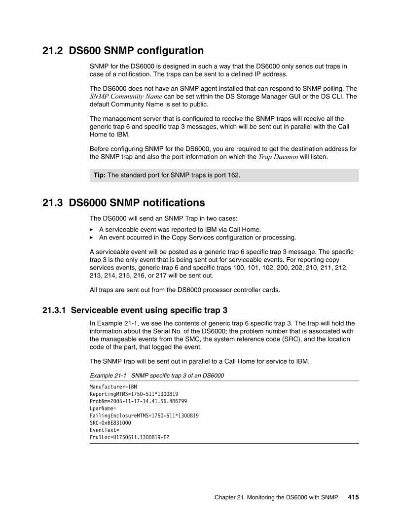
21.2 DS600 SNMP configurationSNMP for the DS6000 is designed in such a way that the DS6000 only sends out traps in case of a notification. The traps can be sent to a defined IP address.
The DS6000 does not have an SNMP agent installed that can respond to SNMP polling. The SNMP Community Name can be set within the DS Storage Manager GUI or the DS CLI. The default Community Name is set to public.
The management server that is configured to receive the SNMP traps will receive all the generic trap 6 and specific trap 3 messages, which will be sent out in parallel with the Call Home to IBM.
Before configuring SNMP for the DS6000, you are required to get the destination address for the SNMP trap and also the port information on which the Trap Daemon will listen.
21.3 DS6000 SNMP notificationsThe DS6000 will send an SNMP Trap in two cases:
� A serviceable event was reported to IBM via Call Home.� An event occurred in the Copy Services configuration or processing.
A serviceable event will be posted as a generic trap 6 specific trap 3 message. The specific trap 3 is the only event that is being sent out for serviceable events. For reporting copy services events, generic trap 6 and specific traps 100, 101, 102, 200, 202, 210, 211, 212, 213, 214, 215, 216, or 217 will be sent out.
All traps are sent out from the DS6000 processor controller cards.
21.3.1 Serviceable event using specific trap 3In Example 21-1, we see the contents of generic trap 6 specific trap 3. The trap will hold the information about the Serial No. of the DS6000; the problem number that is associated with the manageable events from the SMC, the system reference code (SRC), and the location code of the part, that logged the event.
The SNMP trap will be sent out in parallel to a Call Home for service to IBM.
Example 21-1 SNMP specific trap 3 of an DS6000
Manufacturer=IBMReportingMTMS=1750-511*1300819ProbNm=2005-11-17-14.41.56.486799LparName= FailingEnclosureMTMS=1750-511*1300819SRC=0xBE831000EventText= Fru1Loc=U1750511.1300819-E2
Tip: The standard port for SNMP traps is port 162.
Chapter 21. Monitoring the DS6000 with SNMP 415

21.3.2 Copy Services event trapsFor the state changes in a remote copy services environment, there are 13 different traps implemented. The traps 1xx are sent out for a state change of a physical link connection, the 2xx traps are sent out for state changes in the logical copy services setup. For all of these events, no Call Home will be generated and IBM will not be notified.
We only describe the messages and the circumstances when sent out by the DS6000. For detailed configuration on these functions and terms, refer to The IBM DS6000 Series: Copy Services with IBM System z, SG24-6782 and The IBM DS6000 Series: Copy Services in Open Environment, SG24-6783.
Physical connection eventsWithin the trap 1xx range, a state change of the physical links will be reported. The trap will be sent out if the physical remote copy link is interrupted. The Link trap will be sent from the primary system. The PLink and SLink columns are only used by the Enterprise Storage Server (ESS).
If one or several links (but not all links) are interrupted, a trap 100, as shown in Example 21-2 on page 416, is posted and will indicate that the redundancy is degraded. The RC column in the trap will represent the reason code for the interruption of the link. The reason codes are listed in Table 21-2 on page 417.
Example 21-2 Trap 100: PPRC links degraded
PPRC Links DegradedUNIT: Mnf Type-Mod SerialNm LSPRI: IBM 1750-511 13-00247 18SEC: IBM 1750-511 13-00819 18Path: Type PP PLink SP SLink RC1: FIBRE 0003 XXXXXX 0003 XXXXXX OK2: FIBRE 0103 XXXXXX 0002 XXXXXX 17
If all links are interrupted, a trap 101, as in Example 21-3, is posted. This event indicates that no communication between Primary and Secondary System is possible any more.
Example 21-3 Trap 101: PPRC links down
PPRC Links DownUNIT: Mnf Type-Mod SerialNm LSPRI: IBM 1750-511 13-00247 18SEC: IBM 1750-511 13-00819 18Path: Type PP PLink SP SLink RC1: FIBRE 0003 XXXXXX 0003 XXXXXX 172: FIBRE 0103 XXXXXX 0002 XXXXXX 17
Once the DS6000 can communicate again via any of the links, trap 102, as shown in Example 21-4, is sent once one or more of the interrupted links are available again.
Example 21-4 Trap 102: PPRC links up
PPRC Links UpUNIT: Mnf Type-Mod SerialNm LSPRI: IBM 1750-511 13-00247 18SEC: IBM 1750-511 13-00819 18Path: Type PP PLink SP SLink RC1: FIBRE 0003 XXXXXX 0003 XXXXXX OK2: FIBRE 0103 XXXXXX 0002 XXXXXX OK
416 DS6000 Series: Architecture and Implementation

Table 21-2 PPRC path reason codes
Reason Code Description
00 No path.
01 ESCON path established.
02 Initialization failed. ESCON link reject threshold exceeded when attempting to send ELP or RID frames.
03 Time out. No reason available.
04 No resources available at primary for the logical path establishment.
05 No resources available at secondary for the logical path establishment.
06 Secondary CU Sequence Number or Logical Subsystem number mismatch.
07 Secondary CU SS ID mismatch or failure of the I/O that collects secondary information for validation
08 ESCON link is offline. This is caused the lack of light detection coming from a host, peer, or switch.
09 Establish failed, but will retry when conditions change.
0A The primary control unit port or link cannot be converted to channel mode since a logical path is already established on the port or link. The establish paths operation will not be retried within the control unit automatically.
0B Reserved for use by StorageTek.
10 Configuration Error. The source of the error is one of the following:
1. The specification of the SA ID does not match the installed ESCON adapter cards in the primary controller.
2. For ESCON paths, the secondary control unit destination address is zero and an ESCON Director (switch) was found in the path.
3. For ESCON paths, the secondary control unit destination address is non-zero and an ESCON Director does not exist in the path, that is, the path is a direct connection.
11 Reserved.
12 Reserved.
13 / OK Fibre path established.
14 Fibre Channel Path Link Down.
15 Fibre Channel Path Retry Exceeded.
16 Fibre Channel Path Secondary Adapter not PPRC capable. This could be due to:
1. Secondary Adapter not configured properly, or does not have the correct microcode loaded.
2. The secondary adapter is already a target of 32 different ESS, DS8000, and DS6000 boxes.
17 Fibre Channel Path Secondary Adapter not available.
18 Fibre Channel Path Primary Login Exceeded.
19 Fibre Channel Path Secondary Login Exceeded.
Chapter 21. Monitoring the DS6000 with SNMP 417

Remote copy eventsIf you have configured Consistency Groups and a volume within this Consistency Group is suspended due to a write error to the secondary device, trap 200 as shown in Example 21-5 on page 418, will be sent out. One trap per LSS, which is configured with the consistency group option, will be sent. This trap could be handled by automatization software like eRCMF to freeze this Consistency Group.
Example 21-5 Trap 200: LSS-Pair Consistency Group PPRC-pair error
LSS-Pair Consistency Group PPRC-Pair ErrorUNIT: Mnf Type-Mod SerialNm LS LD SRPRI: IBM 1750-511 13-00247 18 00 07SEC: IBM 1750-511 13-00819 18 00
Trap 202, as shown in Example 21-6, will be sent out if a remote Copy Pair goes into a suspend State. The trap contains the serial number (SerialNm) of the primary and secondary machine, the LSS (LS) and the logical device (LD). To avoid SNMP trap flooding, the number of SNMP traps for the LSS will be throttled. The complete suspended pair information is represented in the summary. The last row of the trap represents the suspend state for all pairs in the reporting LSS. The suspended pair information contains a hexadecimal string of a length of 64 characters. By converting this hex string into binary, each bit will represent a single device. If the bit is 1, then the device is suspended; otherwise, the device is still in full duplex mode.
Example 21-6 Trap 202: Primary PPRC Devices on LSS Suspended Due to Error
Primary PPRC Devices on LSS Suspended Due to ErrorUNIT: Mnf Type-Mod SerialNm LS LD SRPRI: IBM 1750-511 13-00247 18 00 07SEC: IBM 1750-511 13-00819 18 00Start: 2005/11/15 19:04:10 GMTPRI Dev Flags (1 bit/Dev, 1=Suspended):8000000000000000000000000000000000000000000000000000000000000000
Trap 210, as shown in Example 21-7, is sent out when a Consistency Group in a Global Mirror environment was successfully formed.
Example 21-7 Trap 210: Asynchronous PPRC Initial Consistency Group Successfully Formed
Asynchronous PPRC Initial Consistency Group Successfully FormedUNIT: Mnf Type-Mod SerialNm IBM 1750-511 13-00247Session ID: 4001
Trap 211, as shown in Example 21-8, will be sent out if the Global Mirror setup got into an severe error state, where no attempts will be done to form a Consistency Group.
Example 21-8 Trap 211: Asynchronous PPRC Session is in a Fatal State
Asynchronous PPRC Session is in a Fatal StateUNIT: Mnf Type-Mod SerialNm
IBM 1750-511 13-00247Session ID: 4002
418 DS6000 Series: Architecture and Implementation

Trap 212, as shown in Example 21-9, is sent out when a consistency group could not be created in a Global Mirror Copy relation. Some of the reasons could include:
� Volumes have been taken out of a copy session.
� The remote copy link bandwidth might not be sufficient.
� The FC link between the PPRC primary and secondary system is not available.
Example 21-9 Trap 212: Asynchronous PPRC Consistency Group Failure: Retry will be attempted
Asynchronous PPRC Consistency Group Failure - Retry will be attemptedUNIT: Mnf Type-Mod SerialNm IBM 1750-511 13-00247Session ID: 4001
Trap 213, as shown in Example 21-10, will be sent out when a Consistency Group in a Global Mirror environment could be formed after a previous Consistency Group formation failure.
Example 21-10 Trap 213: Asynchronous PPRC Consistency Group Successful Recovery
Asynchronous PPRC Consistency Group Successful RecoveryUNIT: Mnf Type-Mod SerialNm IBM 1750-511 13-00247Session ID: 4001
Trap 214, as shown in Example 21-11, will be sent out if a Global Mirror Copy Session is terminated using the DS CLI command rmgmir or the corresponding GUI function.
Example 21-11 Trap 214: Asynchronous PPRC Master Terminated
Asynchronous PPRC Master TerminatedUNIT: Mnf Type-Mod SerialNm IBM 1750-511 13-00247Session ID: 4001
Trap 215, as shown in Example 21-12, will be sent out if, in the Global Mirror Environment, the Master has detected a failure to complete the FlashCopy commit. The trap will be sent out after a number of commit retries have failed.
Example 21-12 Trap 215: Asynchronous PPRC FlashCopy at Remote Site Unsuccessful
Asynchronous PPRC FlashCopy at Remote Site UnsuccessfulUNIT: Mnf Type-Mod SerialNm IBM 1750-511 13-00819Session ID: 4001
Trap 216, as shown in Example 21-13, will be sent out if a Global Mirror Master cannot terminate the Global Copy relationship at one of its Subordinates (slave). This might occur if the master is terminated with rmgmir, but the Master cannot terminate the copy relationship on the Subordinate. You might need to run an rmgmir against the subordinate to prevent any interference with other Global Mirror sessions.
Example 21-13 Trap 216: Asynchronous PPRC Slave Termination Unsuccessful
Asynchronous PPRC Slave Termination UnsuccessfulUNIT: Mnf Type-Mod SerialNmMaster: IBM 1750-511 13-00247Slave: IBM 1750-511 13-00260Session ID: 4002
Chapter 21. Monitoring the DS6000 with SNMP 419

Trap 217, as shown in Example 21-14, will be sent out if a Global Mirror Copy Environment was suspended by the DS CLI command pausegmir or the corresponding GUI function.
Example 21-14 Trap 217: Asynchronous PPRC Paused
Asynchronous PPRC PausedUNIT: Mnf Type-Mod SerialNm IBM 1750-511 13-00247Session ID: 4001
SNMP preparation with DS CLIThe configuration for receiving traps will be done using the DS CLI. Example 21-15 shows how SNMP will be enabled using the setsnmp command and a check of the SNMP setting with the showplex command.
Example 21-15 Configuring the SNMP using dscli
dscli> setsnmp -action enable -info 10.10.10.12:162 -comname public IBM.1750-1300819Date/Time: November 17, 2005 1:30:42 PM CET IBM DSCLI Version: 5.1.0.204 DS: IBM.1750-1300819CMUD00002I setsnmp: SNMP settings for storage image IBM.1750-1300819 successfully modified.
dscli> showplex IBM.1750-1300819Date/Time: November 17, 2005 1:30:49 PM CET IBM DSCLI Version: 5.1.0.204 DS: IBM.1750-1300819name ITSO_Plex1desc -acct 999555allowrssh Enableddialhome EnabledSNMP Enabledsnmpinfo /10.10.10.12:162snmpcomname publicsmtpserver /0.0.0.0:25simdasdlevel nonesimdasdnotify 5simmedialevel acutesimmedianotify 3simsulevel acutesimsunotify 1
420 DS6000 Series: Architecture and Implementation

SNMP preparation with the DS Storage Manager GUITo configure the SNMP Trap with the GUI, as shown in Figure 21-2, use the following procedure:
1. You can configure the IP address or the host name of the trap receiver as input.
2. Select Manage Hardware → Storage Unit, and select the Storage Unit,
3. Select Configure Notifications, and select SNMP.
Figure 21-2 GUI window to configure the SNMP destination
SNMP preparation for the management softwareFor the DS6000, you can use the ibm2100.mib file, which will be delivered with the DS CLI CD.
For download instructions, refer to 20.1, “DS6000 microcode release bundle” on page 398.
Chapter 21. Monitoring the DS6000 with SNMP 421

422 DS6000 Series: Architecture and Implementation

Chapter 22. Secure remote support
In this chapter, we discuss the remote support for the DS6000.
We cover the following topics:
� Remote support connections required for DS6000� Collecting problem data and providing it to IBM� Allowing IBM to connect to the DS6000 SMC using VPN� Allowing e-mail Call Home from the DS6800 controllers
22
© Copyright IBM Corp. 2005, 2006. All rights reserved. 423

22.1 Remote support connections required for DS6000For remote support purposes, the DS6800 effectively consists of two controllers and one or two DS Storage Management Consoles (SMCs). To ensure that your DS6800 is as reliable as possible, and that when problems do occur, they are resolved as quickly as possible, there are several implementation requirements that you should consider:
� The ability to upload log data from a DS SMC to an IBM FTP server
� Allowing a remote IBM support engineer to connect to the SMC using a Virtual Private Network (VPN) connection
� Allowing the DS6000 controllers to send alert e-mails to an IBM mail server
All of these requirements are covered in the following sections. A very detailed description of the setup for the VPN connection is contained in the document VPN Security Implementation, available at the following IBM Web site:
http://www-1.ibm.com/support/docview.wss?uid=ssg1S1002693&aid=1
Create an infrastructure where you can quickly off-load logs to IBM, and ensure that you can provide the right level of expertise required to resolve a problem in a speedy manner. This will help in resolving any issues you might have, also very quickly.
22.2 Collecting problem data and providing it to IBMIf you have a problem with your DS6800, you might need to collect and upload problem data to IBM so it can be examined to understand what the problem is (or was, if the problem has been resolved by DS6800 internal recovery). You can collect problem data via the DS CLI or the DS Storage Manager GUI (DS SM GUI). In DS CLI, the two commands are mkpe and offloadss. First, we describe the DS CLI commands.
Verifying and setting the company nameBefore creating a Product Engineer (PE) package, you should verify the contact information. If it is not correctly set, the PE package file will contain No_Company_Name instead of the real company name. To verify the correct setting, you can use the DSCLI command showcontactinfo as illustrated in Example 22-1.
Example 22-1 Verifying current contact info settings
dscli> showcontactinfo ibm.1750-1300819Date/Time: 30. Juni 2006 16:24:54 CEST IBM DSCLI Version: 5.2.0.912 DS: ibm.1750-1300819companyname IBMRedbookscompanyaddr -shipphone --shiploc IBM Street, Mainzshipcity -shipstate -shippostalcode -shipcountry DEcontactname Mitchell Holmancontactpriphone 520-555-5555contactaltphone --contactemail -
424 DS6000 Series: Architecture and Implementation
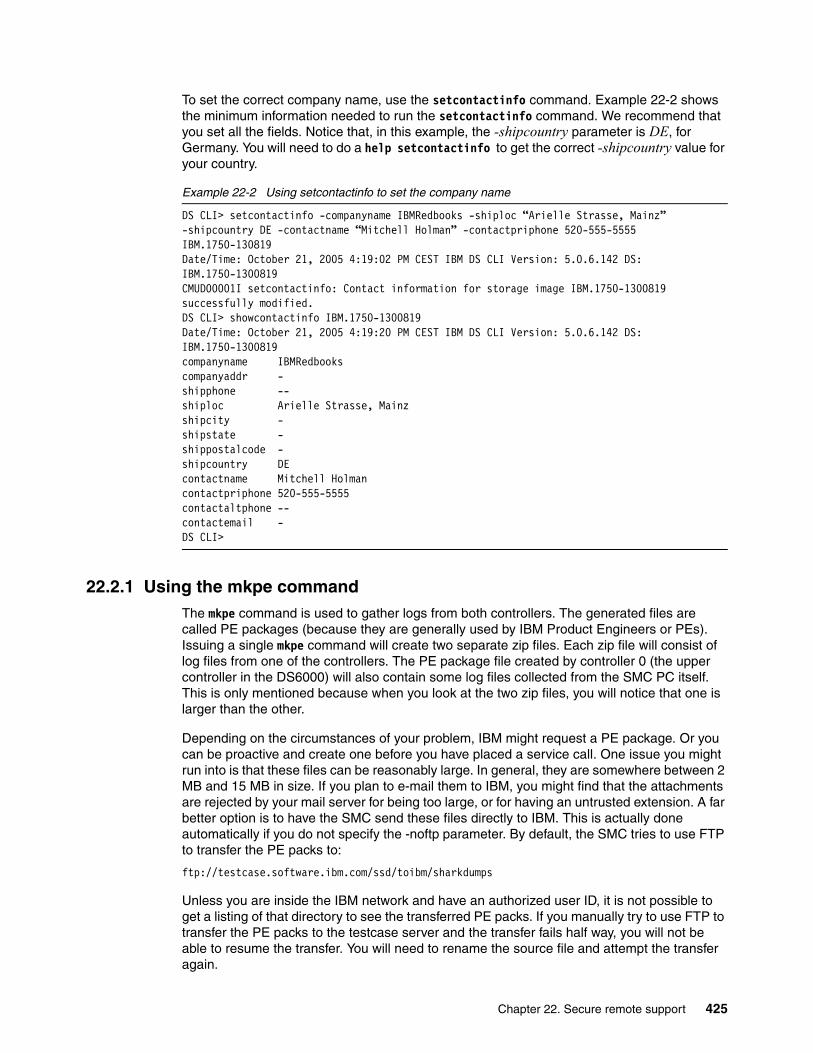
To set the correct company name, use the setcontactinfo command. Example 22-2 shows the minimum information needed to run the setcontactinfo command. We recommend that you set all the fields. Notice that, in this example, the -shipcountry parameter is DE, for Germany. You will need to do a help setcontactinfo to get the correct -shipcountry value for your country.
Example 22-2 Using setcontactinfo to set the company name
DS CLI> setcontactinfo -companyname IBMRedbooks -shiploc “Arielle Strasse, Mainz” -shipcountry DE -contactname “Mitchell Holman” -contactpriphone 520-555-5555 IBM.1750-130819Date/Time: October 21, 2005 4:19:02 PM CEST IBM DS CLI Version: 5.0.6.142 DS: IBM.1750-1300819CMUD00001I setcontactinfo: Contact information for storage image IBM.1750-1300819 successfully modified.DS CLI> showcontactinfo IBM.1750-1300819Date/Time: October 21, 2005 4:19:20 PM CEST IBM DS CLI Version: 5.0.6.142 DS: IBM.1750-1300819companyname IBMRedbookscompanyaddr -shipphone --shiploc Arielle Strasse, Mainzshipcity -shipstate -shippostalcode -shipcountry DEcontactname Mitchell Holmancontactpriphone 520-555-5555contactaltphone --contactemail -DS CLI>
22.2.1 Using the mkpe commandThe mkpe command is used to gather logs from both controllers. The generated files are called PE packages (because they are generally used by IBM Product Engineers or PEs). Issuing a single mkpe command will create two separate zip files. Each zip file will consist of log files from one of the controllers. The PE package file created by controller 0 (the upper controller in the DS6000) will also contain some log files collected from the SMC PC itself. This is only mentioned because when you look at the two zip files, you will notice that one is larger than the other.
Depending on the circumstances of your problem, IBM might request a PE package. Or you can be proactive and create one before you have placed a service call. One issue you might run into is that these files can be reasonably large. In general, they are somewhere between 2 MB and 15 MB in size. If you plan to e-mail them to IBM, you might find that the attachments are rejected by your mail server for being too large, or for having an untrusted extension. A far better option is to have the SMC send these files directly to IBM. This is actually done automatically if you do not specify the -noftp parameter. By default, the SMC tries to use FTP to transfer the PE packs to:
ftp://testcase.software.ibm.com/ssd/toibm/sharkdumps
Unless you are inside the IBM network and have an authorized user ID, it is not possible to get a listing of that directory to see the transferred PE packs. If you manually try to use FTP to transfer the PE packs to the testcase server and the transfer fails half way, you will not be able to resume the transfer. You will need to rename the source file and attempt the transfer again.
Chapter 22. Secure remote support 425

In Example 22-3, you can see how the mkpe command is executed. Because in this example the -noftp parameter was used, the PE packs were not automatically uploaded to IBM. Regardless of this, copies are always kept on the SMC in the location shown in the example.
Example 22-3 Usage of the mkpe command
dscli> mkpe -noftp ibm.1750-1300819Date/Time: 29. Juni 2006 11:32:34 CEST IBM DSCLI Version: 5.2.0.912 DS: ibm.1750-1300819CMUC00246I mkpe: The task might take more than 1 hours to complete.CMUD00018I mkpe: The following PE package was successfully generated: C:\Program Files\IBM\DS6000StorageManager\SM\send2IBM\17505111300819.IBMRedbooks.0.NOPMH.20060629113920.cl0.pe.zip C:\Program Files\IBM\DS6000StorageManager\SM\send2IBM\17505111300819.IBMRedbooks.0.NOPMH.20060629114836.cl1.pe.zip.CMUD00007I mkpe: PE packages for storage image ibm.1750-1300819 successfully generated.
You can also use the lspe command to see which PE packages are located on the SMC. The listed PE packages can have different states => ready | sending | copying | sent.
Example 22-4 Usage of the lspe command
dscli> lspeDate/Time: 29. June 2006 12:49:44 CEST IBM DSCLI Version: 5.2.0.912PE Package State==================================================================17505111300819.IBMRedbooks.0.NOPMH.20060629111716.cl0.pe.zip Ready17505111300819.IBMRedbooks.0.NOPMH.20060629113920.cl0.pe.zip Ready17505111300819.IBMRedbooks.0.NOPMH.20060629114836.cl1.pe.zip Ready
In Example 22-5, you can see what happens if you execute the mkpe command from a DS CLI session that is not on the SMC PC. In other words, if you start the DSCLI from a workstation remotely connected to the SMC PC, when the mkpe command tries to collect the SMC logs, it fails, because the local workstation is not the SMC. You need to logon locally at the SMC, then start DS CLI and execute the mkpe command. (Of course, if you can connect to the DS SMC using Remote Desktop Connection, you do not have to actually walk over to the SMC.)
Example 22-5 Usage of mkpe on a non-SMC client PC
DS CLI> mkpe -noftp IBM.1750-1300654Date/Time: 21 October 2005 22:24:07 IBM DS CLI Version: 5.1.0.204 DS: IBM.1750-1300654 NISAUtilities.readLogProperties - Failed to open FileHandler - the Exception is:java.io.IOException: Couldn't get lock for null\logs\SA.log at java.util.logging.FileHandler.openFiles(Unknown Source).....
Once the PE packages are created, you can find them in the directory C:\Program Files\IBM\DS6000StorageManager\SM\send2IBM. If there is a connection possible from the SMC to the IBM FTP site, the PE packages can be sent over one by one with the sendpe command.
Example 22-6
dscli> sendpe 17505111300819.IBMRedbooks.0.NOPMH.20060629113920.cl0.pe.zipDate/Time: 30. June 2006 16:10:36 CEST IBM DSCLI Version: 5.2.0.912CMUD00019I sendpe: PE package was successfully sent to IBM: 17505111300819.IBMRedbooks.0.NOPMH.20060629113920.cl0.pe.zip.
426 DS6000 Series: Architecture and Implementation

You have also the option to collect the logs from the directory and manually upload them to IBM either using FTP or via e-mail, as would be the case if, for security reasons, no FTP connection to IBM site is allowed.
Analyzing the PE packIBM does not expect you to analyze the PE package. Simply create it and forward it to IBM for analysis.
22.2.2 Using the offloadss commandAn offloadss command is used to off load data known as statesave data, which contains more detailed log data from the controllers. An offloadss is not a replacement for mkpe. Instead, it is a way of getting additional detailed information if a problem cannot be clearly understood from the data collected in a PE package. The DS6000 controllers take a statesave every time they shut down and will create one automatically if certain error events occur.
The first time you use the offloadss command, it will off load five statesave files from each controller. The reason you get five is that each controller can keep up to five statesaves. Each statesave is only ever off-loaded once. If you execute the offloadss command twice in a short period, the second execution of the command will not off load any new files.
Like the mkpe command, offloadss will automatically attempt to use FTP to send the statesaves to:
ftp://testcase.software.ibm.com/ssd/toibm/sharkdumps
If there is no FTP connectivity from the SMC to the IBM testcase server, then you will have to manually move the files to testcase. In this case, pay attention to the naming of the files. The time and date at which the statesave was originally created is part of the file name. In Example 22-7, the offloadss command was run and two files off-loaded. Pay attention to the portion of the name that shows the time and date, which in this case is 051020151946. The format is YYMMDDHHMMSS, which breaks out as year, month, day, hour, minute, and second. So this statesave was created on October 20, 2005 at 15:19:46 in the afternoon. If the problem that is being investigated occurred well after this date, then this statesave might be of limited value.
Example 22-7 Off loading a statesave
dscli> offloadss -noftp ibm.1750-1300819Date/Time: 3. July 2006 11:22:59 CEST IBM DSCLI Version: 5.2.0.912 DS: ibm.1750-1300819CMUD00020I offloadss: The following statesave files were successfully offloaded: 17505111300819.IBMRedbooks.0.NOPMH.060703110454.cl0.dumptrace.tgz 17505111300819.IBMRedbooks.0.NOPMH.060703110435.cl1.dumptrace.tgz.CMUD00006I offloadss: Statesave successfully offloaded from ibm.1750-1300819 to the management node.
Once you have off-loaded the available statesaves, they will be placed in C:\Program Files\IBM\DS6000StorageManager\SM\send2IBM.
If you run the offloadss command and you do not get any files, this means there are no new statesaves to off load since the last time the command was run. An example of this situation is shown in Example 22-8.
Chapter 22. Secure remote support 427

Example 22-8 Using offloadss when there are no new statesaves to perform
DS CLI> offloadss -noftp IBM.1750-1300819Date/Time: October 21, 2005 4:36:32 PM CEST IBM DS CLI Version: 5.0.6.142 DS: IBM.1750-1300819CMUD00012E offloadss: No state save can be found on storage image IBM.1750-1300819.
After using the offloadss command, use the lsss command to verify which statesaves are saved on the SMC. This option allows you to verify if there is valuable data for problem analysis generated by the microcode itself during recovery or if there is a need to manually force the creation of the statesaves. The verification is possible by comparing the statesave timestamps in the filename with the real problem occurrence timestamp. If the statesave is dated from before the problem occurrence then it is mostly of limited value. In some cases, if it is very close (in range of minutes and less than hours) to the time of the problem occurrence, it might be helpful for the problem analysis. See Example 22-9.
Example 22-9 Usage of lsss command
dscli> lsssDate/Time: 3. July 2006 11:25:26 CEST IBM DSCLI Version: 5.2.0.912Statesave State=======================================================================17505111300819.IBMRedbooks.0.NOPMH.060613152945.cl0.dumptrace.tgz Sent17505111300819.IBMRedbooks.0.NOPMH.060613155456.cl1.dumptrace.tgz Sent17505111300819.IBMRedbooks.0.NOPMH.060703110435.cl1.dumptrace.tgz Ready17505111300819.IBMRedbooks.0.NOPMH.060703110454.cl0.dumptrace.tgz Ready
The lsss command shows also the state of the statesave files, as in the case of the PE packages.
Forcing actual statesaves over DSCLI
There are several ways to force the creation of actual statesaves — for the purpose of creating additional, detailed data for problem analysis. A first method is to use the DSCLI diagsi command, as shown in Example 22-10. Note that the commands requires a confirmation to proceed.
Example 22-10 Usage of the diagsi command
dscli> diagsi -action warmstart ibm.1750-1300819Date/Time: 3. Juli 2006 11:04:57 CEST IBM DSCLI Version: 5.2.0.912 DS: ibm.1750-1300819CMUD00023W diagsi: Are you sure you want to perform diagnostic control warmstart? [y/n]:yCMUD00026I diagsi: Diagnostic control warmstart is successfully submitted. It will take some time for the system to complete the request.
A second way to create a new statesave requires you to be in direct contact with your IBM support center. This is because the procedure requires you to log on to the controllers using a secure shell (SSH) client and requires a challenge key decoded in real time.
You need to start putty (the SMC will have the putty application installed when the DS SMC application is installed) and then connect to one of the controllers using SSH. You only have to connect to one of the two controllers (it does not matter which one). Once connected, you must log on and issue the rss_warmstart command, as depicted in Example 22-11.
Important: Be aware that the manual force of statesaves should be arranged with IBM support. Actual PE packages must be provided in advance to allow IBM support to determine the state of the DS6800 and inform you of the necessity to force statesaves.
428 DS6000 Series: Architecture and Implementation

Example 22-11 Generating a statesave manually using putty and logging onto a controller
login as: [email protected]'s password: level1Last login: Fri Oct 21 14:51:49 2005 from 10.0.0.1
Enter a valid key for the following challenge "FRQ1dmEd":MI0kJVbZWELCOME!bash: SHELL: readonly variablebash: PATH: readonly variablebash: dircolors: No such file or directorybash: which: No such file or directorynoname:~ # ls. errpt ncnetconf rss_lcpssStatus rss_version.. level1 rss_displayProblem rss_quiesce rss_warmstart.bash_history ls rss_display_irccard rss_resumenoname:~ # rss_warmstartWARMSTART !!noname:~ # exit
Notice in Example 22-11 that a challenge key is used to manage logon attempts. When you log onto the controller as user ID level1, with a password of level1, you are issued a challenge key, which in this example is FRQ1dmEd. At this point, you relay this challenge key in real time to IBM support personnel. They in turn log on to a special IBM system that allows them to decode the key and generate a response. The response in this example is MI0kJVbZ.
Once the diagsi or rss_warmstart command has been issued, you should wait 10 minutes and then use the DS CLI command offloadss to collect the manual created statesaves. You only need to do this procedure on one controller.
Analyzing the statesaveIBM does not expect you to analyze a statesave. Simply create it and forward it to IBM for analysis.
Note: Both the key and the response are case sensitive.
Important: The next time you log on as level1, you will be issued a different challenge key. So do not get the key, log off, and then call IBM. The response password will not be usable when you log back on.
Chapter 22. Secure remote support 429

22.2.3 Using the DS SM GUI to off-load problem dataIt is also possible to perform the tasks of collecting problem data from the DS GUI. Proceed as follows:
1. Select Real-time manager.
2. Select Manage hardware.
3. Select Storage Units.
4. In the Select column, select the Storage Unit you wish to work with.
5. From the Select Action drop-down menu, choose Copy and Send Problem Determination Data.
6. This will open the Problem determination data menu. From here, select the option to Collect New PD Files. An example is shown in Figure 22-1.
Figure 22-1 Collecting problem determination data
7. If PE packages are required, check Traces. If statesaves are required, check Dumps.
8. Now click Collect to start the collection of the data.
9. The status of the progress will be shown in a new window (see Figure 22-2).
430 DS6000 Series: Architecture and Implementation

Figure 22-2 Example for a GUI result message after PD collection
From the Manage/Send Existing PD Files menu, it is also possible to FTP the previously collected problem determination data, or to delete older files. An example is shown in Figure 22-3. In this example, there are several statesaves (with file extension dumptrace.zip) and two PE packs (with file extension pe.zip). Because the word No appears in the sent column for every file, we know that none of these files have been sent via FTP to IBM. Note that cl0 or cl1 in the file name indicates if the file was created by controller 0 or controller 1. IBM will always need the matching PE packs and/or statesaves from each controller.
Figure 22-3 Managing problem determination data
Chapter 22. Secure remote support 431

Forcing actual statesaves over the GUI
To force statesaves from the DSGUI, proceed as follows:
1. Select Real-time manager.
2. Select Manage hardware.
3. Select Storage Units.
4. In the Select column, select the Storage Unit you wish to work with.
5. From the Select Action drop-down menu, choose Restricted Service Actions.
Figure 22-4 Statesave over GUI
6. From the pull-down menu, select Warmstart for the correct DS6800 serial number (if more than one DS6800 is attached to that SMC).
7. Login again with the correct permissions (Administrator permissions required) and click the OK button to confirm execution of a warmstart.
8. Wait for up to ten minutes and collect the newly created data as described in “Using the DS SM GUI to off-load problem data” on page 430.
22.2.4 Firewall rules needed to allow FTP off-loadAt some sites, there is a requirement to use an FTP proxy or use a logon process to allow FTP access. There is no way to do this within the DS CLI or DS GUI software. If the SMC is unable to log on to testcase.software.ibm.com using direct FTP (port 21), then discuss, with your location firewall administrator, how to allow the SMC to connect directly on port 21.
22.2.5 The benefits of allowing FTP off-loadClearly, the faster you can off load problem data, the faster a problem can be examined in closer detail and resolved. If FTP access from the SMC is not possible, then you will need to consider what is the fastest way to upload this data to IBM. This is either via an e-mail or via a manual FTP process after the files are created.
Important: Be aware that the manual force of statesaves should be arranged with IBM support. Actual PE packages must be provided in advance to allow IBM support to determine the state of the DS6800 and inform you of the necessity to force statesaves.
432 DS6000 Series: Architecture and Implementation

22.3 Allowing IBM to connect to the DS6000 SMC using VPNThere are situations when IBM will need to log on to the DS6000 controllers. Since these controllers use a UNIX-based operating system, this is achieved using the SSH protocol. The mechanics of how this is achieved are detailed in the document VPN Security Implementation, available at the following IBM Web site:
http://www-1.ibm.com/support/docview.wss?uid=ssg1S1002693&aid=1
The purpose of this section is to discuss the fundamentals of why it is desirable to allow this access and the various options available to do so.
The software required to establish and allow the VPN connection is supplied with the DS SMC software.
The VPN connection is established is as a client to server connection. The DS6000 SMC is the client in this case, and IBM’s VPN server is the server.
In terms of security, there are three fundamental points to consider here:
1. The connection can only be opened from the client side. IBM cannot initiate the creation of the VPN tunnel. This means the personnel at the machine site can control when and if the tunnel is opened.
2. The tunnel will time out and close after 10 minutes of inactivity. This is important because it means the connection cannot be accidentally left open after it is no longer needed.
3. The connection uses secure sockets and data is encrypted. In addition, no customer data can be accessed by the service personnel.
Accessing the Information Center for assistanceIn the following sections, you will see references to the Information Center. You can access the Information Center either from the version present on the SMC or by connecting to the public Web site. In the first URL, exchange the IP address for your SMC IP address (if you are not locally logged on to the SMC). The second URL is the public Web site version:
http://127.0.0.1:8455/help/index.jsp?topic=/com.ibm.storage.ssic.help.doc/f2c_ichome_23bc5o.html
or
http://publib.boulder.ibm.com/infocenter/ds6000ic/index.jsp
22.3.1 VPN connection via EthernetIn terms of implementing VPN via the SMC Ethernet interface, there are no tasks that need to be performed on the DS SMC beyond installing the DS SMC software. You would need to do this anyway as part of the normal implementation of the DS6000. Having installed the DS SMC software, you need to check whether the SMC is able to access the Internet. For some installations, the current connection to the Internet might already be suitable for the VPN software to work. All you need to do is test the connection using the DS SMC GUI.
Starting the VPN connectionProceed as follows:
1. Select Real-time manager.
2. Select Manage hardware.
3. Select Storage Units.
4. Select a Storage Unit by clicking in the select column.
Chapter 22. Secure remote support 433

5. From the Select Action drop-down menu, choose Activate Remote Support.
6. At this point, the Activate Remote Support window will open, as shown in Figure 22-5. However, nothing will happen until you click Connect on the right-hand side of the window.
Figure 22-5 Activating remote support: Prior to Connect
7. After you click Connect, you will see messages appear in the Connection status window. When you see a message saying the SMC is connected to the IBM Remote Server, then you know the VPN connection is working. An example is shown in Figure 22-6.
Figure 22-6 Successful remote connection
8. Now you can click Disconnect to end the VPN connection.
The remote support activation process is also detailed in the Information Center section by selecting Installing → Enabling Support Options → Activating remote support (Real-time only).
If the connection fails and you instead receive an error, then you have a network connectivity or, more likely, a firewall configuration issue. In these cases, you will need to work with your network support and security personnel to resolve it.
Firewall changes needed for VPNFor customers who find that the remote support connection does not work, they will need to make some firewall changes to allow the connection. These are detailed in the document VPN Security Implementation, as referenced in 22.3, “Allowing IBM to connect to the DS6000 SMC using VPN” on page 433. For completeness, the firewall rules for one possible firewall product are listed in Example 22-12 on page 435.
434 DS6000 Series: Architecture and Implementation

Example 22-12 Firewall rules for the SMC
# Assuming a Cisco PIX model 525 firewall:access-list DMZ_to_Outside permit esp host 207.25.252.196 host <IP addr for SMC>access-list DMZ_to_Outside permit esp host 129.42.160.16 host <IP addr for SMC>access-list DMZ_to_Outside permit udp host 207.25.252.196 host <IP addr for SMC> eq 500access-list DMZ_to_Outside permit udp host 129.42.160.16 host <IP addr for SMC> eq 500access-list DMZ_to_Outside permit udp host 207.25.252.196 host <IP addr for SMC> eq 4500access-list DMZ_to_Outside permit udp host 129.42.160.16 host <IP addr for SMC> eq 4500
It is important to note that only the SMCs, not the DS6000 servers themselves, must be defined for access to the IBM VPN Servers. In each case, the SMC must be able to connect to the following servers (on the Internet):
� 129.42.160.16 (IBM Rochester VPN Server)� 207.25.252.196 (IBM Boulder VPN Server)
Use the following ports:
� UDP port 500 � UDP port 4500 � ESP (which supports the VPN connection).
The details for the VPN and the firewall requirements are documented in:
http://www-1.ibm.com/support/docview.wss?&rs=1112&uid=ssg1S1002693
22.3.2 VPN connection via modemThere are situations where it is not possible to allow a connection from the SMC to the Internet via the Ethernet interface. This might be for security reasons or because corporate policy will not allow it. In these circumstances, you should purchase the modem feature, available as feature codes 1201 through 1205 (depending on which country the equipment is located in). If the modem feature is ordered, then installation will require a power outlet and a phone line for dialing out. There are several points to consider with modem access:
� When you initiate a remote support connection using the SMC, and a modem has been configured, then the modem will dial into the IBM network using the AT&T Global Dialer. This connection is usually only a local phone call (depending on your location).
� IBM cannot start the remote support connection; it has to be done from the SMC PC itself.
� IBM cannot dial into the SMC using the modem; the modem must dial out. In fact, there is no requirement for the phone line to even accept incoming calls.
� The 10 minute inactivity timer still applies to modem connections.
Configuring the modem connectionThe actual installation of the modem should be done using the procedure found in the Information Center. Select Installing → Enabling Support Options → Installing a modem on the management console to do this procedure. This procedure is no different than any modem installation on a Windows platform.
Configuring the modem using the DS SMC GUIProceed as follows:
1. Select Real-time manager.
2. Select Manage hardware.
3. Select Storage Complexes.
Chapter 22. Secure remote support 435

4. Select the Storage Complex by clicking the Select column.
5. From the Select Action drop-down menu, choose Configure Modem Remote Support.
6. You will now need to set the phone numbers that will be used to dial out. First, select the Country from the Country drop-down menu. Then from the Phone drop-down menu, select the phone number that is most suitable for your location. Then use the Populate buttons to populate the first phone number field. If you have to dial a number such as zero or nine to get an outside line, place that in the Prefix box. You can also populate the other three phone number fields, if necessary.
Figure 22-7 Configuring the modem
7. Once the phone numbers have been populated, click Test next to Phone#1 to initiate a test dial out. A successful completion message displays as shown in Figure 22-6 on page 434. If the dial out fails, you might need to check that the prefix you defined is correct (such as whether to dial zero to get an outside line) and that the modem is correctly set up.
8. Click OK at the bottom of the window to save your phone numbers and confirm that the modem will be used for VPN connections.
Information on configuring the modem and the remote support can also be found in the Information Center by selecting:
1. Installing → Enabling Support Options → Installing a modem on the management console.
Tip: Use an analog telephone handset to test the phone line prior to doing a test call with the modem
436 DS6000 Series: Architecture and Implementation

2. Installing → Enabling Support Options → Activating remote support (Real-time only). Follow the steps to Activate remote support.
22.3.3 Starting VPN when the SM GUI is not workingThere might be a situation where you want to allow IBM to remotely connect to the DS6000, but you cannot get the SM GUI to work. In this situation, it is still possible to start the VPN connection. Open a command line window and enter the command ibmremote as shown in Example 22-13.
Example 22-13 IBMremote over DOS command line
C:\>ibmremoteA subdirectory or file C:\Program Files\IBM\DS6000StorageManager\SM\logs already exists.
IBMRemote [Version 1.1.6]
Please select a machine to connect to IBM, or enter 1 to quit.
1. Quit 2. Default Parameters 3. 1750-13AAVNA (9.155.0.8, 9.155.0.9) 4. 1750-1300819 (9.155.0.1, 9.155.0.2) 5. 1750-1300654 (9.155.0.6, 9.155.0.7)>
IBMremote displays a text based menu. Select one of the system options, and the VPN for that DS6800 will be established if it’s configured correctly.
You can also use a manual method from the command line. You need to know the IP addresses of the two controllers and the serial number of the DS6000. In this example, they are:
Controller0 IP addr 192.168.0.1Controller1 IP addr 192.168.0.2DS6000 serial 1750-1300819 (note that we will not use the 1750 portion of the
serial)
Proceed as follows:
1. Open a command prompt by going to the Windows desktop and selecting Start → Run, type cmd.exe, and press Enter.
2. Once in the command window, enter:
cd %MR1750_SM_HOME%\bin
This should bring you to the c:\program files\ibm\ds6000storagemanager\sm\bin directory. This could be different depending on where you installed the SMC software.
3. Issue the following command:
ibmremote DEBUG -s < serial number> -ip1 <ip address of controller0> -ip2 <ip address of controller1>
An example of this command is:
ibmremote DEBUG -s 1300819 -ip1 192.168.0.1 -ip2 192.168.0.2
You will some messages indicating that the VPN is starting and then connected. This command works whether you use VPN over Ethernet or via modem.
Chapter 22. Secure remote support 437

22.3.4 Switching between Ethernet based VPN and modem If you have installed a modem onto the SMC, then the modem will be used by default. If you wish to switch to VPN over Ethernet (to speed up the connection, for example), you will need to de-install the modem by removing all configuration for it in the SMC GUI. You do not need to de-install or disconnect the modem from Windows.
22.3.5 Traffic passing over the VPN tunnelThe VPN tunnel is used to allow remote IBM support personnel to log on to the DS6000 controllers using SSH (usually using the Putty application). The DS SMC acts as a port forwarder, sending incoming connections for port 2222 to controller0 of the DS6000 and incoming connections for port 2223 to controller1 of the DS6000. When IBM logs on to the controller, they are given a challenge key, as shown in Example 22-11 on page 429. The IBM internal server that is used to decode this key is a restricted access server. Only highly trained and experienced IBM personnel are given access to this decode server.
IBM remote support personnel can also use the connection to log on using DS CLI or the DS GUI. However, to do this, you would need to supply a valid user ID and password. It is also possible to retrieve log data using the VPN connection. However, upload speed often means it is better to use e-mail or FTP to transfer that data back to IBM.
22.3.6 The benefits of allowing VPN accessWhile concerns about security are commonplace (and quite understandable), there is also the issue of resolution time. When a problem occurs, it can either be fixed in real time by a remote service person connecting to the machine and rectifying the fault, or it can be fixed after logs are collected and an action plan formulated for onsite personnel to execute. Nearly all customers today have a goal of high availability to meet their business needs. Unnecessary delays when trying to resolve problems are generally considered unacceptable. For this reason, you should strongly consider allowing a remote support connection.
22.4 Allowing e-mail Call Home from the DS6800 controllersMost of the requirements stated in this chapter have to do with allowing the SMC to access IBM servers on an external network (Internet). In each case, access either to or from the DS6000 controllers themselves is through the SMC. The one major exception to this is alert e-mails, which supply the Call Home function for the DS6800. When the DS6800 has an error that generates a Call Home e-mail, this e-mail is sent from one (SM leader) of the DS6800 controllers, not from the SMC. This e-mail needs to be sent to an SMTP server that will relay it to the IBM e-mail server that manages the [email protected] and [email protected] e-mail addresses. This can be an issue if the controllers do not have connectivity to a suitable e-mail server.
For some clients, their network design might involve placing two Ethernet cards into the SMC. The first card allows connectivity to the Internet, while the second card is used to access a management LAN that contains the DS6800. While this solution works fine for nearly all purposes, it will not allow the Call Home function to work. You will need to consider either placing a mail server on the management LAN or implementing some form of mail forwarding function from that LAN.
438 DS6000 Series: Architecture and Implementation

22.4.1 Setting up Call Home You can set up Call Home using either DS CLI or the DS GUI. Note that the term dialhome is used to mean sending an e-mail via SMTP. It is also possible now to set Call Home over modem.
Setting up Call Home using the DS CLIThere are four steps to follow:
1. Set the contact info for each machine.
2. Define the SMTP server.
3. Check the settings with the showplex command.
4. If necessary, enable Call Home using the setdialhome command.
5. Send a test Call Home.
Step 1 was done in Example 22-2 on page 425. In Example 22-14 on page 439, steps 2-5 are shown. First, the SMTP server is set to 10.0.0.250. Then the settings are checked with the showplex command. Then Call Home is enabled using the setdialhome command. Finally, a testcall is generated.
Example 22-14 Setting up Call Home with DS CLI
DS CLI> setsmtp -server 10.0.0.250 IBM.1750-1300819DS CLI> showplex IBM.1750-1300819Date/Time: 27 October 2005 5:25:11 IBM DS CLI Version: 5.1.0.204 DS: IBM.1750-1300819name -desc -acct -allowrssh Enableddialhome DisabledSNMP Disabledsnmpinfo /127.0.0.1:0snmpcomname Publicsmtpserver /10.0.0.250:25simdasdlevel nonesimdasdnotify 5simmedialevel acutesimmedianotify 3simsulevel acutesimsunotify 1DS CLI> setdialhome -action enable IBM.1750-1300819Date/Time: 27 October 2005 16:40:36 IBM DS CLI Version: 5.1.0.204 DS: IBM.1750-1300819CMUD00005I setdialhome: Dial Home settings for storage image IBM.1750-1300819 successfully modified.DS CLI> testcallhome IBM.1750-1300819Date/Time: 27 October 2005 16:46:04 IBM DS CLI Version: 5.1.0.204 DS: IBM.1750-1300819CMUD00010I testcallhome: Test problem record was sent from the Storage Unit to your SMTP server.DS CLI>
Chapter 22. Secure remote support 439

Setting up Call Home using the DS GUISetting up Call Home with the DS GUI has the same steps. First set the contact information (accomplished in DS CLI with the setcontactinfo and setplex commands):
1. Select Real time-manager.
2. Select Manage hardware.
3. Select Storage Units.
4. Select your Storage Unit from the table.
5. From the Select Action drop-down menu, choose Customer Contact.
6. On the next window, there are three tabs: Customer account information, Shipping information, and Contact information. Work through each tab and fill in all the details, as shown in Figure 22-8.
Figure 22-8 Setting the account information using the GUI
Once the contact details have been set, you now set the SMTP server and enable Call Home (equivalent to the setsmtp and setdialhome commands):
1. Select Real time-manager.
2. Select Manage hardware.
3. Select Storage Units.
4. Select your Storage Unit from the table.
5. From the Select Action drop-down menu, choose Configure Notifications.
6. In the next window, select the Call Home tab.
7. Check the Enable Call Home box and then in the Host name and IP address fields, enter the host name and IP address of your SMTP server, as shown in Figure 22-9.
8. After you have configured Call Home, you can send a test record using the Test Call Home connection button.
440 DS6000 Series: Architecture and Implementation

Figure 22-9 Configuring Call Home and enabling it
Call Home over modemAs you can see in Figure 22-9. it is now possible to enable Call Home over modem. From the same Define Call Home window, you can configure and test the call home over modem. If the modem was installed, configured and successfully tested before (i.e. for remote support) then there are no more configuration steps for modem call home required. If the modem needs to be configured the link “Modem configuration” will take you to the same test and configuration window as shown in Figure 22-7 on page 436.
22.4.2 Setting the destination e-mail addressNote that you do not set the destination e-mail address for Call Home e-mails. This is hard-coded to be either [email protected] for the Americas, or [email protected] for the rest of the world. The machine uses the -shipcountry parameter set using the setcontactinfo command to determine which e-mail address to use. There is no way to exchange these addresses for a different destination e-mail address.
22.4.3 Network changes needed for Call HomeNormally, no firewall changes are required for Call Home. All that is required is network connectivity between the DS6000 controllers and the SMTP server on TCP port 25. However, the DS6000 does not log on to the mail server as a client. It simply sends the e-mail to the mail server and expects the e-mail to be relayed onwards. Clearly, the SMTP server must be willing to relay these e-mails forward to the Internet. Some SMTP servers are not set up to allow this form of mail forwarding. You should check with your mail server administrator that the test e-mail you sent was actually sent to IBM. If not, work with your mail administrator to resolve the problem.
Chapter 22. Secure remote support 441

22.4.4 The benefits of allowing Call HomeClearly, the main benefit is that IBM can be automatically alerted of problems with your DS6000. Call Home has been used successfully in nearly all recent IBM disk products and has been a fundamental tool in maintaining high levels of availability and client satisfaction with the product.
442 DS6000 Series: Architecture and Implementation

Chapter 23. Capacity upgrades
This chapter describes the process involved in adding additional disk capacity to a DS6000.
We cover the following topics:
� Adding disk capacity to a DS6000� Adding disks to a partially filled enclosure� Adding additional storage enclosures
23
© Copyright IBM Corp. 2005, 2006. All rights reserved. 443

23.1 Adding disk capacity to a DS6000The DS6000 is a highly scalable storage device. Capacity can be added by both installing additional disk drive modules (DDMs) into a partially filled enclosure, or by adding additional enclosures.
23.1.1 Things to consider before adding capacityBefore adding additional capacity to a DS6000, you must consider the following points:
� If adding additional DDMs, for each disk drive set that was ordered, did you receive four identical DDMs? The four disks in each set must be the same capacity (such as 73 GB) and the same speed (such as 15k RPM). Check the label on the front of each DDM.
� FATA disks: The FATA drives that are now available offer a cost effective option for lower priority data such as various fixed content, data archival, reference data, and near line applications that require large amounts of storage capacity for lighter workloads.
� If adding enclosures, is there sufficient space in the rack? Are there sufficient power outlets in the rack? Are there any environmental considerations, such as rack cooling?
� If adding enclosures, do you have at least one other person to assist you to lift each enclosure onto its rails? If you do not remove internal components, you might need two additional people to help lift the enclosure onto the rails. Do not attempt to lift and install an enclosure by yourself. Be sure to always use safe lifting techniques.
� If adding enclosures, do you have the correct tools? You will need a flat bladed screwdriver.
� Most importantly, when adding disk capacity, you might need to apply new license keys to cover the increased capacity. For small upgrades, this might not be necessary. Regardless, you can always physically install additional capacity without the correct license keys. However, when you try and create the first Rank that would create capacity beyond what you are licensed for, the rank creation will not proceed. If additional license keys were ordered with your storage upgrade, then IBM will ship Order Confirmation Codes (OCCs). These can be used at the DSFA Web site to generate activation codes (see Chapter 8, “Features and license keys” on page 143).
23.1.2 Customer setupDS6000 capacity upgrades are intended to be performed by the client. This means that the base price of any capacity upgrade normally does not include installation by an IBM Service Representative. However, you can order an additional service (chargeable) if you would like the upgrade to be installed by an IBM engineer or IBM Business Partner service representative.
Important: IBM ships order confirmation codes in a clearly marked envelope. Do not throw these codes away. They are unique for every shipment. If they are thrown away, you will need to contact IBM to obtain replacements. This will create unnecessary delay and workload.
444 DS6000 Series: Architecture and Implementation

23.1.3 Sources of informationYour prime source for all DS6000 information is the Information Center. When you install the DS6000 Storage Manager software onto a PC, you create an Information Center that you can access with a Web browser. If you are logged onto the Windows Storage Management Console (SMC), you can access it by going to the following URL:
http://127.0.0.1:8455
If you are attempting to access your Information Center via the network, change the 127.0.0.1 IP address to the IP address of your SMC.
You can also access the public version of the DS6000 Information Center on the Internet at:
http://publib.boulder.ibm.com/infocenter/ds6000ic/index.jsp
You can also refer to the following books for more details about capacity upgrades:
� IBM System Storage DS6000 Introduction and Planning Guide, GC26-7925
� IBM System Storage DS6000: Installation, Troubleshooting, and Recovery Guide, GC26-7924
23.1.4 Monitoring the process to add capacityThere are two commands that you can use to monitor the process to add capacity. First, as we add DDMs, we can check for new DDMs and their status using the lsddm command. In Example 23-1, we have new capacity in the base enclosure. We can tell which enclosure is the base enclosure because its serial number starts with IBM.1750-511. In each case, we can see that the additional disks are available in the unconfigured state. Only one Array Site is currently being used for an Array. This is Array Site S2. DDMs in that Array Site are marked as Array members. We can also see that Array Sites have been created, and that spares have also been assigned. During Array creation, the DDM being used as a spare might be dynamically changed to a different DDM. This would occur, for example, if you chose two Array Sites that each contained a spare and tried to create a RAID 5 array. Since this would create a 5+P+S+S Array (which is not valid), the spare would be automatically moved to another unconfigured Array Site.
Example 23-1 Using lsddm to check the install state
dscli> lsddm IBM.1750-1300819Date/Time: 10 November 2005 18:35:28 IBM DSCLI Version: 5.1.0.204 DS: IBM.1750-1300819ID DA Pair dkcap (10^9B) dkuse arsite State=================================================================================IBM.1750-511-1300819/R0-P1-D1 0 300.0 spare required S1 NormalIBM.1750-511-1300819/R0-P1-D2 0 300.0 array member S1 NormalIBM.1750-511-1300819/R0-P1-D3 0 300.0 array member S1 NormalIBM.1750-511-1300819/R0-P1-D4 0 300.0 array member S1 NormalIBM.1750-511-1300819/R0-P1-D5 0 300.0 unconfigured S3 NormalIBM.1750-511-1300819/R0-P1-D6 0 300.0 unconfigured S3 NormalIBM.1750-511-1300819/R0-P1-D7 0 300.0 unconfigured S3 NormalIBM.1750-511-1300819/R0-P1-D8 0 300.0 unconfigured S3 NormalIBM.1750-511-1300819/R0-P1-D9 0 146.0 spare required S2 NormalIBM.1750-511-1300819/R0-P1-D10 0 146.0 unconfigured S2 NormalIBM.1750-511-1300819/R0-P1-D11 0 146.0 unconfigured S2 NormalIBM.1750-511-1300819/R0-P1-D12 0 146.0 unconfigured S2 NormalIBM.1750-511-1300819/R0-P1-D13 0 146.0 unconfigured S4 NormalIBM.1750-511-1300819/R0-P1-D14 0 146.0 unconfigured S4 NormalIBM.1750-511-1300819/R0-P1-D15 0 146.0 unconfigured S4 NormalIBM.1750-511-1300819/R0-P1-D16 0 146.0 unconfigured S4 NormalIBM.1750-EX1-1373950/R0-P1-D1 0 73.0 spare required S5 Normal
Chapter 23. Capacity upgrades 445

IBM.1750-EX1-1373950/R0-P1-D2 0 73.0 unconfigured S5 NormalIBM.1750-EX1-1373950/R0-P1-D3 0 73.0 unconfigured S5 NormalIBM.1750-EX1-1373950/R0-P1-D4 0 73.0 unconfigured S5 NormalIBM.1750-EX1-1373950/R0-P1-D5 0 73.0 unconfigured S6 NormalIBM.1750-EX1-1373950/R0-P1-D6 0 73.0 unconfigured S6 NormalIBM.1750-EX1-1373950/R0-P1-D7 0 73.0 unconfigured S6 NormalIBM.1750-EX1-1373950/R0-P1-D8 0 73.0 unconfigured S6 Normal
As sets of four DDMs are added (regardless of whether you installed new DDMs into an existing enclosure, or added a new enclosure), Array Sites will be created one at a time. You can use the DS CLI command, larraysite -l, to list the Array Sites. In Example 23-2, we can see six Array Sites. Unused and new Array Sites will be in the unassigned state.
Example 23-2 Using lsarraysite to check the install state
dscli> lsarraysite -lDate/Time: 10 November 2005 19:06:43 IBM DSCLI Version: 5.1.0.204 DS: IBM.1750-1300819arsite DA Pair dkcap (10^9B) diskrpm State Array=====================================================S1 0 300.0 10000 Assigned A0S2 0 146.0 10000 Unassigned -S3 0 300.0 10000 Unassigned -S4 0 146.0 10000 Unassigned -S5 0 73.0 15000 Unassigned -S6 0 73.0 15000 Unassigned -
As additional enclosures are added, we can list them using the lsstgencl -l command. Pay attention to the enclnum column. The enclosure numbers in this case are 00 and 10. This means the two digit display on the rear display panel of the relevant enclosure should match this number. The first digit is the loop number (either loop 0 or loop 1) and the second digit is the enclosure number (0, 1, 2, or 3). In this example, we have one enclosure on loop 0 (enclosure 0 on that loop) and one enclosure on loop 1 (enclosure 0 on that loop).
Example 23-3 Using the lsstgencl command to list storage enclosures
dscli> lsstgencl -l IBM.1750-1300819Date/Time: 10 November 2005 19:06:22 IBM DSCLI Version: 5.1.0.204 DS: IBM.1750-1300819ID Frame enclnum loc interadd storslot stordev cap (GB) RPM===========================================================================================================IBM.1750-511-1300819/R0-S00 - S00 U1750511.1300819-P1 0x0 16 16 300.0,146.0 10000IBM.1750-EX1-1373950/R0-S10 - S10 U1750EX1.1373950-P1 0x0 16 8 73.0 15000
23.2 Adding disks to a partially filled enclosureEach DS6000 enclosure can hold up to 16 DDMs. You can concurrently add additional disks to each enclosure until that enclosure is full. Disks are sold and must be added in groups of four identical disks (known as a disk drive set). This is because the RAID arrays in a DS6000 are based on Array Sites, and each Array Site consist of four DDMs.
Performing the upgrade is achieved by simply removing the filler module and installing a DDM in its place:
1. Remove the factory-sealed wrapping from the new disk drive module. You should do this only when you are ready to install it.
2. Before installing the disk drive module, open the disk drive module handle by pressing the blue latch and pulling the handle open.
446 DS6000 Series: Architecture and Implementation

3. Add DDMs in a row, starting with the first DDM in the far left slot and working your way across the enclosure so that the fourth DDM is in the far right slot of the same row.
4. Align the disk drive module with the groove on the disk drive module bay and push it into its slot. The drive stops before it is fully seated. Ensure that the disk drive is properly aligned in a horizontal position. Failure to do so could result in physical damage to the drive or the drive component.
5. Push the disk drive module handle inwards until it is latched closed.
6. Verify that the front of the new disk drive module is aligned with the other disk drive modules.
7. The Storage Unit will automatically begin the process to bring the DDM online and create an Array Site. You can monitor this process using the commands shown in 23.1.4, “Monitoring the process to add capacity” on page 445.
8. Once the Array Sites have all been created, you can start configuring the new storage.
23.3 Adding additional storage enclosuresAdding expansion enclosures can be done without down time. From the front of the unit, the expansion enclosure looks identical to the system enclosure. From the rear there are some noticeable differences, such as the absence of battery backup units, and the use of switch cards instead of controller cards. The front and rear view of an expansion enclosure are shown in Figure 23-1.
Figure 23-1 DS6000 expansion disk enclosure
Important: You cannot leave an empty disk drive module slot. You must insert either a new DDM or re-insert the filler module. This is to prevent overheating the storage enclosure.
Chapter 23. Capacity upgrades 447

For instructions on installing the enclosure, you should use the documentation referred to in 23.1.3, “Sources of information” on page 445.
When the additional disk enclosure is properly installed in the rack, you can start connecting the cables (see 6.2.3, “Connecting the storage enclosures” on page 115). During this process, you might need to insert SFPs into the storage expansion ports. Do not use the host adapter ports for storage enclosures.
When the cables are all connected, you can either power on the expansion enclosure using the power button on the rear display panel of the new enclosure, or simply wait for the enclosures to be automatically powered on.
During the initialization process, firmware updates might be automatically performed on the new storage enclosure. If this is the case, you might hear the fans in the enclosure speed up and slow down. This is normal. This process might take some time. The two digit indicator on the rear display panel that shows the enclosure number might not show the correct number until after this process completes.
The Storage Unit will then automatically begin the process to bring the DDMs online and create Array Sites. You can monitor this process using the commands shown in 23.1.4, “Monitoring the process to add capacity” on page 445.
Once the Array Sites have all been created, you can start configuring the new storage (provided your license keys are of a sufficient size to cover the new capacity).
Note: Screws are bagged and taped to the inside flange of the rail. Remove the bag prior to installing the storage enclosures in the rack.
Note: If you removed the resources (DDMs, power supplies, and cards), with one assistant, you should be able to lift the enclosure into the rack. If you did not remove the resources before installation, you should have at least two assistants to help you lift the unit into the rack.
Important: The SFPs used to connect the enclosure are shortwave SFPs. You might have been shipped longwave SFPs to use in the host ports. If you insert a longwave SFP into a disk expansion port, it simply will not work. Remove it and replace it with a shortwave SFP. You can normally tell longwave SFPs as they have a blue dust cap. You can also check the printed information on the SFP. Longwave SFPs are marked as 1310nm. Shortwave SFPs are marked as 850nm. The fibre cables that connect the enclosures will always be orange in color.
448 DS6000 Series: Architecture and Implementation

Appendix A. Data migration
This appendix gives you some important information to plan the methods and tools your installation will be using when doing the migration of the existing data into the IBM DS6000 storage system.
We cover the following topics:
� Data migration in open systems environments � Data migration in System z environments� IBM Migration Services
A
© Copyright IBM Corp. 2005, 2006. All rights reserved. 449

Data migration in open systems environmentsThere are numerous methods that you can use to migrate data from one storage system to another. We briefly describe the most common ones and list their advantages and disadvantages in the following sections:
� Basic copy commands� Volume management software� Backup and restore
Migrating with basic copy commandsUsing copy commands is the simplest way to move data between one storage system to another. Examples of UNIX commands are:
� cp� cpio� tar� dump� backup, restore
Examples for Windows are:
� scopy� xcopy� robocopy� Drag and drop data
These commands are available on every system supported for DS6000 attachment, but work only with data organized on file systems. Data can be copied between file systems with different sizes. Therefore, these methods can be used for consolidation of small volumes into large ones.
The most significant disadvantage of this method is disruption. To preserve data consistency, the applications writing to the data that is migrated have to be interrupted for the duration of the copy process. Furthermore, some copy commands cannot preserve advanced metadata, such as access control lists or permissions.
Copy raw devicesFor raw data, there are tools that allow you to read and write disk devices directly, such as the dd command. They copy the data and its organizational structure (metadata) without having any knowledge about it. Therefore, they cannot be used for consolidation of small volumes into large ones. Special care has to be taken when data and its metadata are kept in separate places. They both have to be copied and realigned on the target system. By themselves, they are useless.
This method also requires the disruption of the applications writing to the data for the complete process.
Important: If your storage systems are attached through multiple paths, make sure that the multipath drivers for the old storage and the new storage can coexist on the same system. If not, you have to revert the host to a single path configuration and remove the incompatible driver from the system before you attach the new storage system.
450 DS6000 Series: Architecture and Implementation

Migrating using volume management softwareLogical Volume Managers are available for open systems. For the Windows platform, it is known as Logical Disk Manager (LDM). The LVM or LDM creates a layer of virtualization within the operating system.
The basic functionality every volume management software provides is to:
� Extend logical volumes across several physical disks� Stripe data across several physical disks to improve performance � Mirror data for high availability and migration
The LUNs provided by a DS6000 appear to the LVM or LDM as physical SCSI disks.
Usually, the process is to set up a mirror of the data on the old disks to the new LUNs, wait until it is synchronized, and split it at the cut-over time. Some volume management software provides commands that automate this process.
The biggest advantage of using the volume management software for data migration is that the process can be totally non-disruptive, as long as the operating system allows you to add and remove devices dynamically. Due to the virtualization nature of volume management software, it also allows for all kinds of consolidation.
The major disadvantage of the volume management software mirroring method is that it requires a lot of system administration intervention and attention. Production data is manipulated while production is running and it requires host cycles when the synchronization of the data is running.
Mirroring volumes using AIX Logical Volume ManagerThis section shows how to mirror a Volume Group using the AIX LVM commands. We are showing the mirrorvg process in the rootvg Volume Group, but you can use this procedure for other Volume Groups in your system.
1. Install or connect the destination disk drive on the system and run the cfgmgr command that will configure the disk on the operating system. The lspv output shows our original volume as hdisk0 and the new volume where we are mirroring the data as hdisk1:
root:/ > lspvhdisk0 000007cac12a0429 rootvg activehdisk1 None None
2. Use the chdev command to set a PVID to the new volume:
root:/ > chdev -l hdisk1 -a pv=yeshdisk1 changedroot:/ > lspvhdisk0 000007cac12a0429 rootvg activehdisk1 000007ca7b577c70 None
3. Add the new volume to the same Volume Group of the original volume:
root:/ > extendvg rootvg hdisk1root:/ > lspvhdisk0 000007cac12a0429 rootvg activehdisk1 000007ca7b577c70 rootvg active
Attention: If you are planning to use volume management software functions to migrate the data, be careful with some limitations, such as total number of physical disks in the same Volume Group or volume set, and if you are consolidating volumes with different sizes, check the procedures to see if this is possible.
Appendix A. Data migration 451

The content of the Volume Group is shown with the lsvg -l command. Note that in the columns LPs and PPs the proportion is one to one, which means that we have only one physical copy of each logical data:
root:/ > lsvg -l rootvgrootvg:LV NAME TYPE LPs PPs PVs LV STATE MOUNT POINThd5 boot 1 1 1 closed/syncd N/Ahd6 paging 8 8 1 open/syncd N/Ahd8 jfs2log 1 1 1 open/syncd N/Ahd4 jfs2 1 1 1 open/syncd /hd2 jfs2 21 21 1 open/syncd /usrhd9var jfs2 1 1 1 open/syncd /varhd3 jfs2 1 1 1 open/syncd /tmphd1 jfs2 1 1 1 open/syncd /homehd10opt j fs2 1 1 1 open/syncd /optlg_dumplv sysdump 80 80 1 open/syncd N/Adownload jfs2 200 200 1 open/syncd /downloads
4. Run the mirrorvg command to create the relationship and start the copy of the data:
root:/ > mirrorvg rootvg hdisk1
After the mirroring process finishes, we have the following output for the lsvg -l command. Now you will see that the proportion between LPs and PPs columns is 1 to 2, which means one logical data in two physical volumes:
root:/ > lsvg -l rootvgrootvg:LV NAME TYPE LPs PPs PVs LV STATE MOUNT POINThd5 boot 1 2 2 closed/syncd N/Ahd6 paging 8 16 2 open/syncd N/Ahd8 jfs2log 1 2 2 open/syncd N/Ahd4 jfs2 1 2 2 open/syncd /hd2 jfs2 21 42 2 open/syncd /usrhd9var jfs2 1 2 2 open/syncd /varhd3 jfs2 1 2 2 open/syncd /tmphd1 jfs2 1 2 2 open/syncd /homehd10opt jfs2 1 2 2 open/syncd /optlg_dumplv sysdump 80 160 1 open/syncd N/Adownload jfs2 200 400 2 open/syncd /downloads
Now the Volume Group is mirrored and the data is consistent in the two volumes, as shown in the column LV STATE, which indicates the syncd status for all logical volumes.
If you want to remove the mirror, you can use the following command:
#unmirrorvg <vg_name> <hdisk#>
If you want to remove the hdisk1 and keep the hdisk0 active, run the following command:
#unmirrorvg rootvg hdisk1
If you want to remove the hdisk0 and keep the hdisk1 active, run the following command:
#unmirrorvg rootvg hdisk0
Note: You can use smit utility to perform these procedures by accessing the fast path smit mirrorvg to create a mirror or smit unmirrovg to remove a mirror.
452 DS6000 Series: Architecture and Implementation

Mirroring volumes using Windows Logical Disk ManagerDynamic disks were first introduced with Windows 2000 and provide features that the basic disks do not. One of these features is the ability to create fault-tolerant volumes. We show in this section how to create a mirror using the Logical Disk Manager with dynamic disks.
In this example, we have two volumes: Disk 8 and Disk 9. The drive letter S: is associated to Disk 8, which is the current volume running on the system. Disk 9 is the new disk that will be part of the mirror (see Figure A-1).
Figure A-1 Preparing to mirror
Note: To configure new disks on the system, after connecting it to the Windows server, run the Rescan Disks function in Disk Management.
Appendix A. Data migration 453
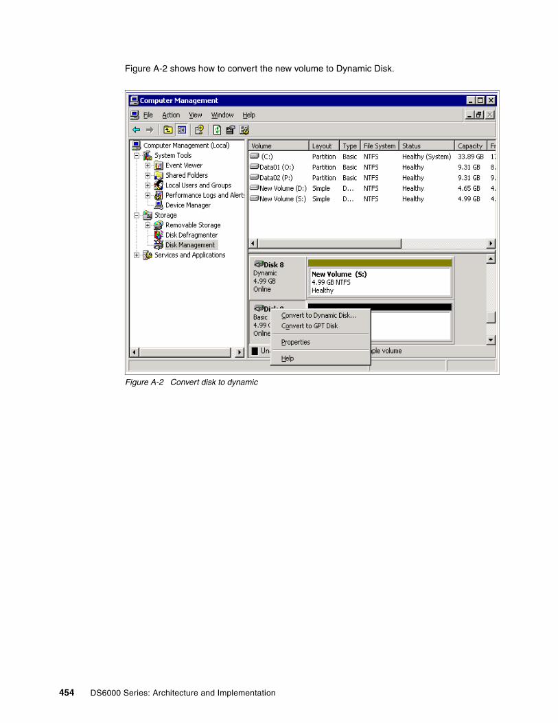
Figure A-2 shows how to convert the new volume to Dynamic Disk.
Figure A-2 Convert disk to dynamic
454 DS6000 Series: Architecture and Implementation

Now, with Disk 9 as a Dynamic Disk, the system is ready to initiate the mirroring process. Right-click the source volume (S:) and choose the Add Mirror option, as shown in Figure A-3.
Figure A-3 Accessing Add Mirror window
Appendix A. Data migration 455

The Add Mirror window will be displayed with a list of available disks. Mark the chosen disk and then click Add Mirror (see Figure A-4).
Figure A-4 Selecting disks in Add Mirror window
456 DS6000 Series: Architecture and Implementation

The synchronization process will start automatically. At this time, you are able to see that both volumes, Disk 8 and Disk 9, are assigned to the same drive letter S: (see Figure A-5).
Figure A-5 Synchronization process running
Appendix A. Data migration 457

Figure A-6 shows the volumes after the synchronization process is finished.
Figure A-6 Synchronization process finished
The next windows show you how to remove a mirror. We can access this option by right-clicking the selected volume. You have two options now:
1. Break Mirrored Volume
The select volume will keep the original drive letter and the other volume will be automatically assigned to another letter. From this point forward, the synchronization process will not occur; both drives will have different drive letters, but the data is still on it.
2. Remove Mirror
If you choose to remove the mirror, a window will be displayed asking you which volume you want to remove. The selected volume, after completing the process, will became a free disk with no drive letter and no data inside.
458 DS6000 Series: Architecture and Implementation

In Figure A-7, we select the option Break Mirrored Volume for Disk 8.
Figure A-7 Break Mirrored Volume option
Appendix A. Data migration 459

After you confirm the operation, you will see that Disk 8 was changed to drive letter E: in Figure A-8. The data is still available, but the disks will not be fault-tolerant.
Figure A-8 Break Mirrored Volume finished
460 DS6000 Series: Architecture and Implementation

The next window shows you the disks that are mirrored. We select the Remove Mirror option. A window will open; select which disk will be removed. In this case, we select Disk 8 (see Figure A-9).
Figure A-9 Remove Mirror window
Appendix A. Data migration 461

After selecting Remove Mirror, the selected volume will became available without a drive letter and no data available (see Figure A-10).
Figure A-10 Remove Mirror finished
Backup and restore Every serious IT operation will have different ways to back up and restore data. They can be used for data migration. We list this method here because it shares the common advantages and disadvantages with the methods discussed previously, although the tools will not always be provided natively by the operating system.
All open system platforms and many applications provide native backup and restore capabilities. They might not be very sophisticated sometimes, but they are often suitable in smaller environments. In large data centers, it is customary to have a common backup solution across all systems. Either can be used for data migration.
The backup and restore options allow for consolidation because the tools are aware of the data structures they handle.
One significant difference from most of the other methods discussed here is that this method does not require the source and target storage systems to be connected to the hosts at the same time.
Some of the most common software packages that provide this ability are:
� IBM Tivoli® Storage Manager (TSM)� Legato Networker � BrightStor ARCserve� VERITAS NetBackup
462 DS6000 Series: Architecture and Implementation

Data migration in System z environmentsData migration is an important activity that needs to be planned well to ensure the success of the DS6000 implementation. Because today’s business environment does not allow you to interrupt data processing services, it is crucial to make the data migration onto the new storage servers as smooth as possible. The configuration changes and the actual data migration ought to be transparent to the users and applications, with no or only minimal impact on data availability. This requires you to plan for non-disruptive migration methods and to guarantee data integrity at any time.
This section describes some methods for migrating data from existing disk storage servers onto the DS6000 disk storage server. Our intention here is to only show the possibilities that you have and not provide a detailed step-by-step migration process description:
� Data migration based on physical migration� Data migration based on logical migration� Combination of physical and logical data migration
Data migration based on physical migrationPhysical migration here refers to physical full volume operations, which in turn require the same device geometry on the source and target volume. The device geometry is defined by the track capacity and the number of tracks per cylinder. The same device geometry means that the source and target device have the same track capacity and the same number of tracks per cylinder.
Usually this is not an issue, because over time the device geometry of the IBM 3390 volume has become a quasi-standard and most installations have used this standard. For organizations still using other device geometry (for example, 3380), it might be worthwhile to consider a device geometry conversion, if possible. This requires moving the data on a logical level, which is on a data set level, and allows a reblocking during the migration from 3380 to 3390.
Utilizing physical full volume operations is possible through the following software-, microcode-, and hardware-based functions:
� Software-based:
– DFSMSdss– TDMF– FDRPAS
� Software- and hardware-based:
– System z Piper: Uses currently a System z Multiprise® server with ESCON attachment only
– z/OS Global Mirror (XRC)
� Hardware- and microcode-based:
– Global Mirror– Global Copy– FlashCopy in combination with either Global Mirror, Global Copy, or both– Metro/Global Copy
Appendix A. Data migration 463

Data migration based on logical migrationData migration based on logical migration is a data set by data set migration that maintains catalog entries according to the data movement between volumes and therefore is not a volume-based migration. This is the cleanest way to migrate data and also allows device conversion from, for example, 3380 to 3390. It also supports transparently multivolume data sets. Logical data migration is a software-only approach and does not rely on certain volume characteristics nor on device geometries.
The following software products and components support logical data migration:
� DFSMS allocation management
� Allocation management by CA-ALLOC
� DFSMSdss
� DFSMShsm™
� FDR
� System utilities like:
– IDCAMS with REPRO and EXPORT / IMPORT commands
– IEBCOPY to migrate Partitioned Data Sets (PDS) or Partitioned Data Sets Extended (PDSE)
– ICEGENER as part of DFSORT, which can handle sequential data but not VSAM data sets, which also applies to IEBGENER
� CA-Favor
� CA-DISK or ASM2
� Database utilities for data, which is managed by certain database managers, such as DB2 or IMS™. CICS® as a transaction manager usually uses VSAM data sets.
Combination of physical and logical data migrationThe following approach combines physical and logical data migration:
� Physical full volume copy to larger capacity volume when both volumes have the same device geometry (same track size and same number of tracks per cylinder).
� Use COPYVOLID to keep the original volume label and not confuse catalog management. You can still locate the data on the target volume through a standard catalog search.
� Adjust the VTOC of the target volume to make the larger volume size visible to the system with the ICKDSF REFORMAT command to refresh, REFVTOC, or expand the VTOC, EXTVTOC, which requires you to delete and rebuild the VTOC index using EXTINDEX in the REFORMAT command.
� Then perform the logical data set copy operation to the larger volumes. This allows you to use either DFSMSdss logical copy operations or the system-managed data approach.
When a level is reached where no data moves any more because the remaining data sets are in use all the time, some downtime has to be scheduled to perform the movement of the remaining data. This might require you to run DFSMSdss jobs from a system that has no active allocations on the volumes that need to be emptied.
464 DS6000 Series: Architecture and Implementation

Hardware based migration� The hardware based remote mirror and copy functions that can be used for data migration
are discussed in length in the redbook IBM System Storage DS6000 Series: Copy Services with IBM System z servers, SG24-6782. Refer to it for detailed descriptions and examples.
IBM Migration ServicesThis is the easiest way to migrate data, because IBM will assist you throughout the complete migration process. In several countries, IBM offers a Migration Service. Check with your IBM sales representative about Migration Services for your specific environment and needs. Businesses today require efficient and secure data migration. IBM provides technical specialists at your location to plan and migrate your data to your DS6000 storage system. This migration is accomplished using either native operating system mirroring, remote mirroring, or the Piper migration tool to replicate your data to the DS6000 storage system with the minimum interruption to service.
In addition, IBM will provide you documentation that specifies the activities performed during this service.
The benefits of IBM Migration Services include:
� Minimized downtime and no data loss
� Superior data protection that preserves data updates throughout the migration, allowing the process to be interrupted if needed
� Migration documentation that details the work performed
For additional information about available Migration Services, refer to the following IBM Web site:
http://www-1.ibm.com/servers/storage/services/disk.html
SummaryThis appendix shows that there are many ways to accomplish data migration. Thorough analysis of the current environment, evaluation of the requirements, and planning are necessary. Once you decide on one or more migration methods, refer to the documentation of the tools you want to use to define the exact sequence of steps to take. Special care must be exercised when data is shared between more than one host.
The migration might be used as an opportunity to consolidate volumes at the same time. After the migration and the consolidation, you will be using a disk storage server technology that will serve you with promising performance and excellent scalability combined with rich functionality and high availability.
Appendix A. Data migration 465

466 DS6000 Series: Architecture and Implementation

Appendix B. Tools
This appendix contains overview information about tools that are available for planning managing, migrating, and analyzing your DS6000.
In addition, IBM Global Services (IGS) and the IBM Systems Group can offer comprehensive assistance, including planning and design as well as implementation and migration support services. For more information on all of the following service offerings, contact your IBM representative or visit the following Web sites.
The IBM Global Services Web site can be found at:
http://www.ibm.com/services/us/index.wss/home
The IBM System Group Web site can be found at:
http://www.ibm.com/servers/storage/services/
B
© Copyright IBM Corp. 2005, 2006. All rights reserved. 467

Capacity MagicWith all this flexibility, it becomes a challenge to calculate the raw and net storage capacity of an IBM TotalStorage DS8000, DS6000, or ESS 800 storage server. The user would need an in-depth technical understanding of how spare and parity disks are assigned, taking into consideration the simultaneous use of disks with different capacities and configurations that deploy both RAID 5 and RAID 10. Capacity Magic is there to do the physical to effective capacity conversion automatically, taking all applicable rules into consideration.
Capacity Magic, a product from Intellimagic, is designed as an easy to use tool with a single main dialog. Some new functionality has been introduced into the tool to display the number of extents that are produced per Rank. The figures below show the outputs that are generated from the configuration and output windows that are produced when using Capacity Magic
Capacity Magic offers a graphical interface that allows you to enter the disk drive configuration of an IBM TotalStorage DS8000, DS6000, or ESS 800 storage server with the number of Disk Drive Modules (DDM) and RAID type. With these parameters, Capacity Magic calculates the physical and effective storage capacity.
Capacity Magic is protected by a license code. For more information, visit the following Web site:
http://www.intellimagic.net/en/
Disk MagicDisk Magic, a product from Intellimagic, is a Windows-based disk subsystem performance modeling tool. It supports disk subsystems from multiple vendors, but it offers the most detailed support for IBM subsystems.
The first release was issued as an OS/2® application in 1994 and since then Disk Magic has evolved from supporting storage control units, such as the IBM 3880 and 3990, to supporting modern, integrated, and advanced-function disk subsystems, such as the DS8000, DS6000, Enterprise Storage Server, the DS4000 Series, and the SAN Volume Controller.
A critical design objective for Disk Magic is to minimize the amount of input the user must enter, while offering a rich and meaningful modeling capability. The following list provides some examples of what Disk Magic can do, but it is by no means complete:
� Move the current I/O load to a different disk subsystem.� Merge the I/O load of multiple disk subsystems into a single one.� Insert a SAN Volume Controller in an existing disk configuration.� Increase of the current I/O load.� Storage consolidation.� Increase the disk subsystem cache size.� Change to larger capacity disk modules.� Upgrade from SCSI to 1 or 2 Gb fibre.� Use fewer or more Logical Unit Numbers (LUN).� Activate Peer-to-Peer Remote Copy.
Modeling results are presented through tabular reports and Disk Magic dialogs, and graphical output is offered by an integrated interface to Lotus® 1-2-3®.
Disk Magic is protected by a license code. For more information, visit the following Web site:
http://www.intellimagic.net/en/
468 DS6000 Series: Architecture and Implementation
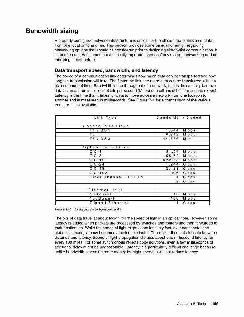
Bandwidth sizingA properly configured network infrastructure is critical for the efficient transmission of data from one location to another. This section provides some basic information regarding networking options that should be considered prior to designing site-to-site communication. It is an often underestimated but a critically important aspect of any storage networking or data mirroring infrastructure.
Data transport speed, bandwidth, and latencyThe speed of a communication link determines how much data can be transported and how long the transmission will take. The faster the link, the more data can be transferred within a given amount of time. Bandwidth is the throughput of a network, that is, its capacity to move data as measured in millions of bits per second (Mbps) or a billions of bits per second (Gbps). Latency is the time that it takes for data to move across a network from one location to another and is measured in milliseconds. See Figure B-1 for a comparison of the various transport links available.
Figure B-1 Comparison of transport links
The bits of data travel at about two-thirds the speed of light in an optical fiber. However, some latency is added when packets are processed by switches and routers and then forwarded to their destination. While the speed of light might seem infinitely fast, over continental and global distances, latency becomes a noticeable factor. There is a direct relationship between distance and latency. Speed of light propagation dictates about one millisecond latency for every 100 miles. For some synchronous remote copy solutions, even a few milliseconds of additional delay might be unacceptable. Latency is a particularly difficult challenge because, unlike bandwidth, spending more money for higher speeds will not reduce latency.
L i n k T y p e B a n d w id t h / S p e e d
C o p p e r T e l c o L i n k s T 1 / D S 1 1 . 5 4 4 M b p s T 2 6 . 3 1 2 M b p s T 3 / D S 3 4 4 . 7 3 6 M b p s
O p t i c a l T e l c o L i n k s O C - 1 5 1 . 8 4 M b p s O C - 3 1 5 5 . 5 2 M b p s O C - 1 2 6 2 2 . 0 8 M b p s O C - 2 4 1 . 2 4 4 G b p s O C - 4 8 2 . 4 8 8 G b p s O C - 1 9 2 9 . 6 G b p s F i b e r C h a n n e l / F IC O N 1 G b p s
2 G b p s
E t h e r n e t L i n k s 1 0 B a s e - T 1 0 M b p s 1 0 0 B a s e - T 1 0 0 M b p s G ig a b i t E t h e r n e t 1 G b p s
Appendix B. Tools 469

Figure B-2 presents a very generalized summary of three network technologies, the scenarios for their use, and the network provider. Network technology selection is based on distance, type of traffic, traffic volume, speed, access, cost, and other factors. While the selection might be straightforward in some cases, generally the selection process requires significant networking expertise. This is a strategic infrastructure decision for an enterprise. Selecting an inappropriate technology might prove unworkable upon implementation or could negatively impact an enterprise’s ability to expand in the future.
Figure B-2 Technology
If we are to make an informed decision on what infrastructure is to be used when designing a network for remote replication, we can see that just looking at the above is not sufficient to size the bandwidth correctly. There is, however, a quick sizing tool that can be obtained from your IBM representative that can be used to estimate the bandwidth that might be required for your replication network.
For more information on creating a replication or disaster recovery network, you should read the redbook IBM TotalStorage Business Continuity Solutions Guide, SG24-6547.
Disk Storage Configuration MigratorIBM offers a service named Disk Storage Configuration Migrator. The purpose of this service is to migrate the logical configuration of one or more customer storage subsystems to one or more IBM TotalStorage DS6000 or IBM TotalStorage DS8000 models.
Within this service, IBM will propose a possible configuration for the target storage system, which is based on the information the client provides in a questionnaire and the configuration of the currently used storage systems.
MetroMeshed / Hubbed TrafficHigh Capacity LinksOC-12, OC-48ESCON, FICON, Fibre Channel
What technology shouldbe deployed?
OC-192 OC-48 Metro DWDM
Regional Long-HaulMeshed TrafficHigh Capacity LinksOC-12, OC-48
Metro/Regional Long-HaulMeshed TrafficLow Capacity LinksDS3, OC-3
Carrier Carrier/Enterprise Enterprise
470 DS6000 Series: Architecture and Implementation

The standard CLI interfaces of the ESS and DS are used to read, modify, and write the logical and Copy Services configuration. All information is saved in a data set in the provided database on a workstation. Via the Graphical User Interface (GUI), the client information gets merged with the hardware information and it is then applied to the DS subsystem (see Figure B-3).
For additional information, contact:
mailto:[email protected]
Figure B-3 Disk storage configuration migrator
The Disk Storage Configuration Migrator toolset is provided free with keys valid for 120 continuous days to clients migrating from ESS F20 or 800 to a DS6000 or DS8000. IBM will provide free support to clients on this tool for 120 days via e-mail as well as with access to an Internet site for downloads and information materials.
The toolset deliverables include:
� ISO image of the Services tool (to be downloaded from a Web site, for supported Windows and UNIX operating systems)
� Questionnaire (to enable the support team to propose a configuration)
� Toolset users guide
� Toolset activation KEY valid for 120 days (it will be provided by e-mail)
Note: This approach could also be used to convert DS4000, HSG80, EMC, and Hitachi customers to 1750 or 2107.
Create logical configuration on DS8000 and generate 2107 copy services scripts from the available configdata.
Capture current configuration(s) to generate new 2107 configuration(s)
Linux or Windows ThinkPad with‘Disk Storage Configuration Migrator’
Appendix B. Tools 471

The free support for 120 days includes:
� Access to an Internet site for downloads and information materials
� Free support via e-mail: [email protected] or Migration Tool/Germany/IBM
� Hours of support: 8:00am to 4:00pm, Monday through Friday, except national holidays, unless otherwise specified
� Proposal of a possible configuration for the target storage system. This will be based on the information provided in response to the questionnaire (see above) and the configuration of the currently used storage system.
IBM TotalStorage Productivity Center for DiskThe IBM TotalStorage Productivity Center is the standard software package for managing complex storage environments. One subcomponent of IBM TotalStorage Productivity Center is the IBM TotalStorage Productivity Center for Disk—this is the tool for performance management. It offers monitoring, setting thresholds, alerting, and performance reporting with charts and history. Multiple storage devices can be configured from a single console to improve productivity. By monitoring and tracking the performance of all storage devices, the overall performance in the SAN can be improved. All subcomponents of a storage system, such as volumes, ports, or RAID ranks, can be monitored with a level of detail like with PDCU; however, you also have the graphical outputs, the historical database, and the thresholds/alerting capabilities when deciding for IBM TotalStorage Productivity Center for Disk.
You can find more information on these products in the Redbooks IBM TotalStorage Productivity Center V2.3: Getting Started, SG24-6490 and Managing Disk Subsystems using IBM TotalStorage Productivity Center, SG24-7097, or at this link:
http://www.ibm.com/servers/storage/software/center/index.html
472 DS6000 Series: Architecture and Implementation
Appendix C. Project plan
This appendix shows part of a skeleton for a project plan. Only the main topics are included. Further detailing could be established within each individual project.
C
© Copyright IBM Corp. 2005, 2006. All rights reserved. 473

Figure C-1 Page 1 of project plan skeleton
474 DS6000 Series: Architecture and Implementation
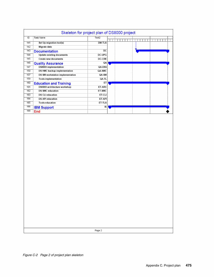
Figure C-2 Page 2 of project plan skeleton
Appendix C. Project plan 475

476 DS6000 Series: Architecture and Implementation

Related publications
The publications listed in this section are considered particularly suitable for a more detailed discussion of the topics covered in this redbook.
IBM RedbooksFor information on ordering these publications, see on page 483. Note that some of the documents referenced here might be available in soft copy only.
� IBM System Storage DS6000 Series: Copy Services in Open Environments, SG24-6783
� IBM System Storage DS6000 Series: Copy Services with IBM System z servers, SG24-6782
� IBM TotalStorage DS6000 Series: Performance Monitoring and Tuning, SG24-7145
� The IBM TotalStorage Solutions Handbook, SG24-5250
� Implementing Linux with IBM Disk Storage, SG24-6261
� iSeries and IBM TotalStorage: A Guide to Implementing External Disk on eServer i5, SG24-7120
� Fault Tolerant Storage Multipathing and Clustering Solutions for Open Systems for the IBM ESS, SG24-6295
� Getting Started with zSeries Fibre Channel Protocol, REDP-0205
� IBM TotalStorage Business Continuity Solutions Guide, SG24-6547
� Linux with zSeries and ESS: Essentials, SG24-7025
� Practical Guide for SAN with pSeries, SG24-6050
� Replication Management with IBM TotalStorage Productivity Center, SG24-7259
You might find the following redbooks related to the DS8000 and ESS useful, particularly if you are implementing a mixed systems environment with Copy Services:
� IBM System Storage DS8000 Series: Architecture and Implementation, SG24-6786
� IBM System Storage DS8000 Series: Copy Services in Open Environments, SG24-6788
� IBM System Storage DS8000 Series: Copy Services with IBM System z servers, SG24-6787
� IBM TotalStorage Enterprise Storage Server: Implementing ESS Copy Services with IBM eServer zSeries, SG24-5680
� IBM TotalStorage Enterprise Storage Server: Implementing ESS Copy Services in Open Environments, SG24-5757
© Copyright IBM Corp. 2005, 2006. All rights reserved. 477

Other publicationsThese publications are also relevant as further information sources. Note, that some of the documents referenced here might be available in soft copy only.
� IBM System Storage DS6000: Installation, Troubleshooting, and Recovery Guide, GC26-7924
� IBM System Storage DS6000 Introduction and Planning Guide, GC26-7925
� IBM System Storage DS6000: Command-Line Interface User’s Guide, GC26-7922
� IBM System Storage DS6000: Host Systems Attachment Guide, GC26-7923
� IBM System Storage Multipath Subsystem Device Driver User’s Guide, SC30-4131
� IBM System Storage DS Open Application Programming Interface Reference, GC35-0516
� IBM System Storage DS6000 Messages Reference, GC26-7914
� z/OS DFSMS Advanced Copy Services, SC35-0428
� Device Support Facilities: User’s Guide and Reference, GC35-0033
� IBM TotalStorage Productivity Center for Replication User’s Guide, SC32-0103
� IBM TotalStorage Productivity Center for Replication Installation and Configuration Guide, SC32-0102
� IBM TotalStorage Productivity Center for Replication Command-Line Interface User’s Guide, SC32-0104.
Online resourcesThese Web sites and URLs are also relevant as further information sources:
� ADVA Optical Networking
http://www.advaoptical.com/
� AMCC Corporation
http://www.amcc.com
� AMCC: Drivers and Downloads: JNI
http://www.jni.com/OEM/oem.cfm?ID=4
� ATTO Technology
http://www.attotech.com/
� ATTO Technology: Support
http://www.attotech.com/support.html
� Boot from SAN in Windows Server 2003 and Windows 2000 Server, found at:
http://www.microsoft.com/windowsserversystem/wss2003/techinfo/plandeploy/BootfromSANinWindows.mspx
� CIENA: Complete Product Listing
http://www.ciena.com/products/transport/shorthaul/cn2000/index.asp
� Cisco Systems: Introduction-Intelligent Storage Networking
http://www.cisco.com/go/ibm/storage
� Design of VMS Volume Shadowing Phase II-Host-based Shadowing, found at:
http://research.compaq.com/wrl/DECarchives/DTJ/DTJ301/DTJ301SC.TXT
478 DS6000 Series: Architecture and Implementation

� Emulex Corporation
http://www.emulex.com
� Emulex Corporation: Downloads and Manuals for IBM
http://www.emulex.com/ts/docoem/framibm.htm
� Emulex Corporation: Support
http://www.emulex.com/ts/dds.html
� FCP and System z: Additional resources
http://www.ibm.com/servers/eserver/zseries/connectivity/ficon_resources.html
� force_lpfc_scan.sh shell script
http://www.emulex.com/ts/downloads/linuxfc/rel/201g/force_lpfc_scan.sh
� How Volume Shadow Copy Service Works: Data Recovery
http://www.microsoft.com/resources/documentation/WindowsServ/2003/all/techref/en-us/w2k3tr_vss_how.asp
� IBM Business Continuity Solutions: Overview - IBM System Storage Solutions
http://www-03.ibm.com/servers/storage/solutions/business_continuity/index.html
� IBM DS6000 series: Interoperability matrix - IBM System Storage Disk Storage Systems
http://www-1.ibm.com/servers/storage/disk/ds6000/interop.html
� IBM DS6000 series: Overview - IBM System Storage Disk Storage Systems
http://www.ibm.com/servers/storage/disk/ds6000/index.html
� IBM Disk Storage Feature Activation (DSFA) Web site
http://www.ibm.com/storage/dsfahttps://www-306.ibm.com/storage/dsfa/index.jsp
� IBM: I/O connectivity on System z mainframe servers
http://www.ibm.com/servers/eserver/zseries/connectivity/#fcp
� IBM System i Technology Center
http://www-1.ibm.com/servers/eserver/iseries/service/itc
� IBM - Linux on POWER - IBM feature IBM POWER architecture
http://www-1.ibm.com/servers/eserver/linux/power/index.html
� IBM :̂ Partitioning for Linux, found at:
http://publib.boulder.ibm.com/infocenter/iseries/v1r2s/en_US/info/iphbi/iphbi.pdf
� IBM - ESS Attachment to United Linux 1 (IA-32)
http://www.ibm.com/support/docview.wss?uid=tss1td101235
� IBM GDPS business continuity solutions - Summary
http://www.ibm.com/services/us/index.wss/rs/its/a1005497
� IBM Global Services
http://www.ibm.com/services/us/index.wss/home
� IBM Global Services - Implementation Services for enterprise Remote Copy Management Facility
http://www.ibm.com/services/us/index.wss/so/its/a1000110
� IBM Global Services - Implementation Services for System Storage command line interface
http://www.ibm.com/services/us/index.wss/so/its/a1005334
Related publications 479

� IBM Global Services - Implementation Services for System Storage copy functions
http://www.ibm.com/services/us/index.wss/so/its/a1005009
� IBM Global Services - Implementation Services for System Storage disk systems
http://www.ibm.com/services/us/index.wss/so/its/a1005008
� IBM Global Services - Migration Services for IBM System z data
http://www.ibm.com/services/us/index.wss/so/its/a1005010
� IBM Global Services - Migration Services for open systems attached to System Storage disk systems
http://www.ibm.com/services/us/index.wss/so/its/a1005012
� IBM Global Services - Support Line
http://www.ibm.com/services/us/index.wss/so/its/a1000030
� IBM: Performance Data Collection Utility
https://www14.software.ibm.com/webapp/iwm/web/preLogin.do?lang=en_US&source=pdcu
� IBM Proven: Overview - IBM System Storage Proven
http://www.ibm.com/servers/storage/proven/index.html
� IBM Redbooks: Technotes
http://www.redbooks.ibm.com/redbooks.nsf/tips
� IBM Resource Link
http://www.ibm.com/servers/resourcelink
� IBM Resource Link: PSP information
http://www-1.ibm.com/servers/resourcelink/svc03100.nsf?OpenDatabase
� IBM Storage Area Network
http://www.ibm.com/storage/ibmsan/products/sanfabric.html
� IBM Storage Services: Disk storage systems - IBM System Storage
http://www-1.ibm.com/servers/storage/services/disk.html
� IBM Storage Services: Hardware-assisted data migration services - IBM System Storage
http://www.ibm.com/servers/storage/services/featured/hardware_assist.html
� IBM Storage Services: Overview - IBM System Storage
http://www.ibm.com/servers/storage/services
� IBM Storage Services: Storage solutions for the Microsoft application environment - IBM System Storage
http://www.ibm.com/servers/storage/services/featured/microsoft_application_environment.html#GDSSolution
� IBM Support & downloads - United States: SDD and Host Attachment scripts
http://www.ibm.com/support/
� IBM Support Line Supported Products List (SPL) as of September 14, 2005 (contracts on or after 8/1/03)
http://www.ibm.com/services/sl/products/java3.html
� IBM Systems Sales
http://www-1.ibm.com/partnerworld/sales/systems/http://w3-1.ibm.com/sales/systems/portal/_s.155/254?navID=f280s260&geoI
480 DS6000 Series: Architecture and Implementation

� IBM Systems Sales (IBM only)
http://w3-1.ibm.com/sales/systems/http://w3-1.ibm.com/sales/systems/portal/_s.155/253
� IBM System Storage ATS Services (IBM only)
http://web.mainz.de.ibm.com/ATSservices
� IBM System Storage DS6000 Information Center
http://publib.boulder.ibm.com/infocenter/ds6000ic/index.jsp
� IBM System Storage DS6000 Series: Interoperability Matrix, found at:
http://www-1.ibm.com/servers/storage/disk/ds6000/pdf/ds6000-interop.pdf
� IBM System Storage Support for Geographically Dispersed Sites (GDS) for Microsoft Cluster Service (GDS for MSCS), found at:
http://www.ibm.com/servers/storage/solutions/business_continuity/pdf/IBM_TotalStorage_GDS_Whitepaper.pdf
� IBM System Storage support: Business Continuance Solutions Troubleshooting
http://www-1.ibm.com/servers/storage/support/solutions/bc.html
� IBM System Storage support: SAN File System Troubleshooting
http://www-1.ibm.com/servers/storage/support/software/sanfs
� IBM System Storage support: SAN Volume Controller (2145) Troubleshooting
http://www-1.ibm.com/servers/storage/support/software/sanvc
� IBM System Storage support: Search for Fibre Channel host bus adapters, firmware and drivers
http://knowledge.storage.ibm.com/servers/storage/support/hbasearch/interop/hbaSearch.dohttp://knowledge.storage.ibm.com/HBA/HBASearchTool
� IBM System Storage support: System Storage DS6800 Downloading
http://www-1.ibm.com/servers/storage/support/disk/ds6800/downloading.html
� IBM System Storage support: System Storage DS6800 Installing
http://www-1.ibm.com/servers/storage/support/disk/ds6800/installing.html
� IBM System Storage support: System Storage DS6800 Planning
http://www.ibm.com/servers/storage/support/disk/1750.html
� IBM System Storage support: System Storage DS6800 Troubleshooting
http://www.ibm.com/servers/storage/support/disk/ds6800/
� IBM System Storage support: System Storage Multipath Subsystem Device Driver Downloading
http://www.ibm.com/servers/storage/support/software/sdd/downloading.html
� IBM System Storage support: System Storage Multipath Subsystem Device Driver Troubleshooting
http://www-1.ibm.com/servers/storage/support/software/sdd/index.htmlhttp://www-1.ibm.com/servers/storage/support/software/sdd.html
� IBM: VM ESS PAV Support
http://www.ibm.com/vm/techinfo/pav.html
� IBM Workload Manager for z/OS (WLM/SRM)
http://www.ibm.com/s390/wlm
Related publications 481

� IBM z/VSE - Documentation - Books - Product documentation
http://www-1.ibm.com/servers/eserver/zseries/os/vse/library/library.html
� System i Information Center V5R2
http://publib.boulder.ibm.com/iseries/v5r2/ic2924/index.htm
� System i Information Center V5R3
http://publib.boulder.ibm.com/infocenter/iseries/v5r3/ic2924/index.htm
� Linux on IBM ̂pSeries SAN Overview for Customers, found at:
http://www.ibm.com/servers/eserver/pseries/linux/whitepapers/linux_san.pdf
� McDATA and IBM
http://www.mcdata.com/ibm/
� McDATA - Networking the World's Business Data: CNT
http://www.cnt.com/ibm/
� Microsoft Windows Clustering: Storage Area Networks
http://www.microsoft.com/windowsserver2003/techinfo/overview/san.mspx
� Microsoft Windows Server Catalog: Search Results for geographically
http://www.microsoft.com/windows/catalog/server/default.aspx?subID=22&xslt=search&pgn=b55095f4-71f3-4b26-98b1-05f3a9506d0d&maxrows=0&sortcol=win2003&sortdir=descending&qu=geographically&scope=1
� Nortel
http://www.nortelnetworks.com/
� QLogic
http://www.qlogic.com
� QLogic Support: OEM Download driver
http://www.qlogic.com/support/ibm_page.html
� Removing the HBA cable on a server cluster
http://support.microsoft.com/default.aspx?scid=kb;en-us;Q294173
� System Management Guide: Operating System and Devices - Managing MPIO-Capable Devices
http://publib16.boulder.ibm.com/pseries/en_US/aixbman/baseadmn/manage_mpio.htm
� TotalStorage DS6000 Solution Assurance Discussion Guide, found at:
http://w3-03.ibm.com/support/assure/assur30i.nsf/WebIndex/SA684
� Technical Sales Support Request Form
http://dalnotes1.sl.dfw.ibm.com/atss/techxpress.nsf/request?OpenForm
� Virtual Disk Service Technical Reference: Storage Services
http://www.microsoft.com/Resources/Documentation/windowsserv/2003/all/techref/en-us/W2K3TR_vds_intro.asp
� VPN Security and Implementation, found at:
http://www-1.ibm.com/support/docview.wss?uid=ssg1S1002693&aid=1
482 DS6000 Series: Architecture and Implementation

How to get IBM RedbooksYou can search for, view, or download Redbooks, Redpapers, Hints and Tips, draft publications and Additional materials, as well as order hardcopy Redbooks or CD-ROMs, at this Web site:
ibm.com/redbooks
Help from IBMIBM Support and downloads
ibm.com/support
IBM Global Services
ibm.com/services
Related publications 483

484 DS6000 Series: Architecture and Implementation

Index
Symbols 42, 54, 68, 177, 265, 268, 340, 364
Aadditional supported configurations (RPQ) 284address groups 78AIX 294
access methods 304boot device support 305LVM 303MPIO 297on iSeries 367
AIX MPIO 297alert status 388applying activation codes 152–153Array 165array site 28array sites 69arrays 69ASP 342Asynchronous PPRC see Global Mirrorattention status 387
Bbackup and restore 462bandwidth sizing 469battery 18, 36battery backup unit 43battery backup unit see BBUBBU 43–44
indicators 45benefits of virtualization 82boot device support 305boot support 284business continuity 4, 10
Ccable
service 46cabling 39cache management 23call back plan 136Call Home 45, 57, 64, 130, 415
benefits 442e-mail 438network changes needed 441plan 136setting up 439setting up using the DS CLI 439setting up using the DS GUI 440
Capacity Magic 468CCL 317
© Copyright IBM Corp. 2005, 2006. All rights reserved.
challenge key 429checking for open problems 375checking for open problems with DS CLI 376checking for open problems with DS SM 376, 378CIM agent 134CIMOM 134CKD volumes 73, 75Command Console LUN see CCLcommands
mkpe 425offloadss 427setcontactinfo 425
community name 414concurrent microcode update 64configuring DS6000
examples 172configuring the DS6000 232, 243configuring using DS CLI
configuring the DS6000 232, 243connecting storage enclosures 115connector
rack identify 42Consistency Group 101Consistency Group FlashCopy 91controller
architecture 19failover and failback 48
Copy Services 85definitions 86interfaces 105
create Arrays 177create CKD volumes
zSeries 194create LCUs 192create Ranks 179create volume groups 189creating a test problem 394CRU 63CRU endpoint indicator 62customer setup 111
DDA 36
portsindicators 37
daemon 412data consistency 101data migration 449
backup and restore 462IBM Migration Services 465open systems environments 450summary 465
Data Set FlashCopy 90DDM 24, 26–27
485

hot plugable 57determining number of paths 268device adapter see DAdiagsi 428disk
raw 323DISK CONTRL 37DISK EXP 37Disk Magic 468disk scrubbing 57disk sparing 122Disk Storage Configuration Migrator 470display panel 18DS CLI 106, 125, 132
checking for open problems 376initiate test problem 394user management 137using to determine microcode levels 400using to take machine to de-configured state 225
DS GUIsetting up Call Home 440
DS management console see DS MCDS MC 9DS Network Interface Server (DS NW IFS) 129DS NW IFS 125DS Open API 107, 126, 133DS Open Application Programming Interface see DS Open APIDS SM 125
checking for open problems 376, 378create Ranks 179initiate test problem 395plan for using front end 130plan for using the front end 131time synchronization plan 135user management 139using to determine microcode levels 400
DS SMC 105call back plan 136DS CLI
plan for using 132DS Open API
plan for using 133logical flow 129time synchronization plan 135
DS SMS 125DS Storage Management Server (DS SMS) 129DS Storage Manager 106DS Storage Manager GUI
170configuring DS6000 170create Arrays 177create Extent Pools 182create FB volumes 185create LCUs 192create volume groups 189examples of configuring 172using to off load problem data 430
DS6000activation of licensed functions 144
additional supported configurations (RPQ) 284AIX 294AIX MPIO 297alert status 388allocation and deletion of LUNs/CKD volumes 75attention status 387bandwidth sizing 469boot support 284business continuity 4, 10call back plan 136Call Home 439Call Home plan 136check for open problems with DS SM 376, 378checking for open problems 375checking for open problems with DS CLI 376Command Console LUN 317Command-Line Interface 126common set of functions 13compared to DS8000 14comparison with other DS family members 13concurrent microcode installation 404configuration flexibility 12configuring 232, 243Copy Services 85–86create Extent Pools 182create FB volumes 185create LCUs 192create volume groups 189creating a test problem 394CRU versus FRU 63customer setup 111data migration back and restore 462data placement 82DDM 26–27Disk Magic 468disk path redundancy 58disk scrubbing 57DS CLI 106, 125DS NW IFS 125DS Open API 107DS SM 125DS SMC 105DS SMS 125DS Storage Manager 106, 125dynamic LUN/volume creation and deletion 12environmental requirements 117examples of configuring 172existing reference material 306expansion enclosure 19, 38Express configuration wizard 199FC Port configuration 315FlashCopy 86
options 88floating spares 57front panel 40Global Copy 86Global Mirror 86hardware components 17hardware view 250HBA and operating system settings 286
486 DS6000 Series: Architecture and Implementation

health indicators 38host attachment 79host considerations 334host considerations for zSeries 333IBM Migration Services 465Information Center 372information lifecycle management 4infrastructure simplification 4initiate test problem with DS SM 395installing new microcode 402interoperability with ESS 108iSeries 339iSeries preferred path 360large LUN and CKD volume support 12light path analysis 375Linux 305maintenance 392maintenance and repair 382maintenance windows 135managing problems and repairs 371message codes 373Metro Mirror 86microcode
updates 64microcode installation 397microcode release bundle 398Model 1750-EX1 7monitor system 382monitoring plan 136multipathing support 284network planning 117non-concurrent microcode installation 408normal status 387OELoffline configurator 214online resources 478open systems environments 450OpenVMS 315OpenVMS volume shadowing 318parts
installation and repairs 63replacement 63
PE pack 427performance considerations 257physical installation 120, 122physical planning 113plan for using DS CLI 132plan for using DS Open API 133planning for growth 117positioning 13power cords 45power subsystem 43PPRC 93preferred path 250preferred paths through SDD and SDDPCM 299prerequisites and enhancements 334project plan 112RAID-10
implementation 55RAID-5 implementation 54
rear panel 41redundant cooling 59related publications 477remote support 423RMC 93SAN planning 117SBOD controller card 38scalability 265SDD 295SDD for Windows 286series 4simplified LUN masking 13Simulated manager 213SMC 123, 125SMC setup 126SNMPSNMP configuration 415space and power provisioning 113spare creation 56storage capacity 9Storage Configuration Migrator 470Storage Manager installation 126Storage Manager post installation 127supported environment 10switched FC-AL 8switched FC-AL implementation 27system indicators 62system service 59time synchronization plan 135unique benefits 5uploading problem data to IBM 424user management using DS CLI 137vertical growth 265virtualization
concepts 67volume configuration 316VPNwindows 285z/OS Global MirrorzSeries host connections 251
DS6000 interoperability matrixboot support 284
DS6000 Storage ManagerCommand-Line Interface 126
DS6800cables 45capacity upgrade 21connect controller cards 118connect ethernet cables 118connecting storage enclosures 115controller architecture 19controller RAS 48Ethernet cables 45FICON 52host connection 51interoperability 11–12major features 5Model 1750-511 6NVS recovery 50open systems host connection 53
Index 487

power on 118preferred path 51SAN 52server based design 22server enclosure 18service cable 46system service card 45tagged command queuing 14TCP/IP configuration 118zSeries host connection 53
DS8000Capacity Magic 468planning for growth 122Remote Mirror and Copy connectivity 119sparing considerations 119
dummy carrier 24dynamic LUN/volume creation and deletion 12
Ee-mail
setting the destination address 441e-mail Call Home 438enclosure ID
indicator 42environmental requirements 117ESS
interoperability with DS6000 108ESS 800
Capacity Magic 468Ethernet
cables 45port 38
existing reference material 306expansion enclosure 19
cabling 39Express configuration wizard 199
for open systems volumes 203introducing 200iSeries volumes 208zSeries volumes 210
Extent Pool 166extent pools 71
FFATA 28FB volumes 185FC Port configuration 315FC-AL 25
non-switched 25FCP 37Fibre Attached Technology Adapted 28Fibre Channel Protocol (FCP) 37FICON 19, 37, 52firewall 432firmware 398fixed block LUNs 73FlashCopy 86, 367
benefits 88Consistency Group 91, 101
inband commands 11, 93incremental 11multiple relationship 10options 88persistent 93
floating spares 57front panel 40FRU 63FTP 432
offload 432offload benefits 432
GGDS for MSCS 293Geographically Dispersed Sites for MSCS see GDS for MSCSGlobal Copy 11, 86, 94, 100, 364Global Mirror 11, 86, 95, 100GUI
applying activation codes 152–153
HHA 37
portindicators 37
hardware components 17HBA and operating system settings 286host adapter see HAhost attachment 79
volume groups 79host connection
open systems 53zSeries 53
host considerations 279, 334host considerations for zSeries 333
prerequisites and enhancements 334
II/O priority queuing 15IASP 342, 344IBM Migration Services 465IBM Multi-path Subsystem Device Drive see SDDIBM My support Web site 398IBM Redbooks 477important issues 307inband commands 11, 93Incremental FlashCopy 11, 88Independent Auxiliary Storage Pool 344Independent Auxiliary Storage Pool see IASPindicators
CRU endpoint 62DA ports 37enclosure ID 42HA port 37health 38SBOD controller card 39system 62system alert 62
488 DS6000 Series: Architecture and Implementation

system identify 62system information 62
Information Center 372accessing 433
information lifecycle management 4infrastructure simplification 4initiate test problem with DS CLI 394initiate test problem with DS SM 395Input Output Adapter (IOA) 341Input Output Processor (IOP) 341install second SMC 141installation
Command-Line Interface 126instantaneous copy 86Inter Switch Link (ISL) 352interfaces for Copy Services 105interoperability with ESS 108IOS scalability 334iSeries 339, 367
adding multipath volumes using 5250 interface 354adding volumes 342adding volumes to IASPadding volumes using iSeries Navigator 355AIX 367avoiding single points of failure 352cache 361changing from single path to multipath 360configuring multipath 353Express configuration wizard 208Global Copy 364Linux 368logical volume sizes 340LUNs 75managing multipath volumes using iSeries Navigator 356Metro Mirror 364migration 364multipath 351multipath rules for multiple iSeries systems or parti-tions 359number of fibre channel adapters 362OS/400 data migration 365OS/400 mirroring 364preferred path for DS6000 360protected versus unprotected volumes 340recommended number of ranks 363sharing ranks 363size and number of LUNs 362sizing guidelines 360
Llarge LUN and CKD volume support 12LC connector 37license key
activation of licensed functions 144license keys
applying activation codes using GUI 152–153light path analysis 375Light Path Diagnostics 12Linux 305
important issues 307on iSeries 368
Load Source Unit (LSU) 341logical subsystems 76logical volumes 73
CKD volumes 73fixed block LUNs 73
long busy 193LSS 49lsss command 428LUN 367LUNs 75
iSeries 75masking 13
LVM 303
Mmaintenance and repair 382maintenance windows
DS6000 135Management Information Base (MIB) 412managing problems and repairs 371message codes 373
DS CLI 373DS SM 373error 373framework 373informational 373SMC 373warning 373
metadata 51Metro Mirror 11, 86, 93, 99, 364MIB 412, 414microcode
installing 402registering for IBM My support Web site 398updates 64
microcode installation 397concurrent 404non-concurrent 408
microcode update 64mkpe 424, 426modem 45, 435
configuring the connection 435monitor system 382
logs 393physical summary 383properties 384systems summary 382
MPIO 297multipath support 351
System i 351multipathing
software 53multipathing support 284Multiple Allegiance 15Multiple Relationship FlashCopy 10, 90
Index 489

Nnetwork planning 117NMS 412non-volatile storage 20non-volatile storage see NVSnormal status 387NVS 20, 36, 44, 49–50
OOEL 117offloadss 424, 427online resources 478open systems 281
additional supported configurations (RPQ) 284AIX 294AIX MPIO 297boot support 284Command Console LUN 317differences with ESS 2105 284distinguish Linux from other operating systems 305environments 450existing reference material 306Express configuration wizard 203FC Port configuration 315general considerations 282HBA and operating system settings 286host connections 250important Linux issues 307Linux 305multipathing support 284OpenVMS 315OpenVMS volume shadowing 318SDD 295SDD for Windows 286troubleshooting and monitoring 313volume configuration 316windows 285Windows Server 2003 VDS support 289
OpenVMS 315OpenVMS volume shadowing 318Operating Environment License see OELOS/400 data migration 365
Pparts installation and repairs 63PAV 15PE pack
analyzing 427PE package 424Pegasus 134performance 257
open systems 265, 268data placement 266LVM striping 266number of host connections 268workload characteristics 265
z/OS 269DS6000 size 270potential 270
Persistent FlashCopy 93PFA 57physical installation 120, 122
connect controller cards 118connect ethernet cables 118connecting storage enclosures 115disk sparing 122DS6000 Storage Manager installation 126install second SMC 141power on 118Storage Manager post installation 127TCP/IP configuration 118
physical planning 113environmental requirements 117network planning 117planning for growth 117, 122Remote Mirror and Copy connectivity 119SAN planning 117space and power provisioning 113sparing considerations 119
planning for growth 117, 122Point-in-Time Copy 86port
Ethernet 38serial 38
power cords 45power on 118power provisioning 113power subsystem 43
RAS 59power supply 18PowerPC 22, 36PPRC 93
Consistency Group 101PPRC-XD see Global Copypredictive failure analysis see PFAPreferred Path 360preferred path
concepts 249failure scenario 300hardware overview 250SDD
preferred path conceptsdetermining the controller number using WWPN 254hardware view 250preferred paths through SDD and SDDPCM 299zSeries host connections 251
preferred pathing 51problem data 424Product Engineer (PE) package 424project plan 112
information required 112who should be involved 112
putty 428
Rrack identify
connector 42RAID controller 18RAID controller card 36
490 DS6000 Series: Architecture and Implementation

RAID-10 55implementation 55theory 55
RAID-5 54implementation 54theory 54
Rank 167ranks 70RAS 47
controller 48controller failover and failback 48disk subsystem 54naming 48power subsystem 59SMC 64
raw disk 323rear panel 41Redbooks Web site 483
Contact us xviiirelated publications 477
IBM Redbooks 477reliability, availability, and serviceability see RASRemote Mirror and Copy 93, 119Remote Mirror and Copy function see RMCremote support 423
connections 424removing an applied configuration 224Request for Price Quotation see RPQRMC 11, 93
comparison of functions 99RPQ 284rss_warmstart 428
SSAN 52SAN LUNs 367SAN planning 117SARC 13–14, 21, 23SATA 28SBOD 19SBOD controller card 38
indicators 39scalability 265SDD 15, 250, 295
operating systems supported 251preferred paths 299
SDD for Windows 286SDDPCM
preferred paths 299sendpe 426Sequential prefetching in Adaptive Replacement Cache see SARCSequential prefetching in Adaptive Replacement Cache (SARC) 14serial port 38server enclosure 18
RAID controller card 36setting up Call Home 439setup
SMC 126
SFI 48SFP 38showcontactinfo 424Simple Network Management Protocol (SNMP) 411Simple Network Management Protocol see SNMPsimplified LUN masking 13simulated configurator
applying a configuration file 222configuring host ports of simulated Storage Unit 219considerations before applying the configuration 222creating a configuration file 214creating a simulated Storage Unit 215creating a Storage Unit from scratch 218exporting a configuration file 221importing a simulated Storage Unit 215importing Storage Unit from an eConfig file 218importing Storage Unit from an SMC 216logical configuration of simulated Storage Unit 220opening and closing configuration files 221process 214reconfiguration after applying a simulated configura-tion 224removing an applied configuration 224saving the configuration file 220working with configuration files 220
Simulated manager 213SM 125small form factor plugable see SFPSMC 45, 64, 123, 125
assigning the DS6000 130Call Home plan 136components 125install second 141monitoring plan 136planning activities 124planning for setup 130setup 126technical environment 125typical setup 131
SMUX 412SNMP 411–412
configuration 415Copy Services traps 416notifications 415physical connection events 416preparation for the management software 421preparation with DS CLI 420preparation with DS SM GUI 421specific trap 3 415trap 100 416trap 101 416trap 102 416trap 200 418trap 202 418trap 210 418trap 211 418trap 212 419trap 213 419trap 214 419trap 215 419
Index 491

trap 216 419trap 217 420
SNMP agent 412–413SNMP manage 412SNMP trap 412, 414SNMP trap request 412space provisioning 113sparing
spare creation 56sparing considerations 119statesave
analyzing 429creating 428
storage capacity 9Storage Complex 48Storage Facility Image 48Storage Management Server (SMS) 125Storage Manager post installation 127Storage Unit 48
configuring host ports for simulated 219creating or importing simulated 215logical configuration of simulated 220
Subsystem Device Driver see SDDswitched FC-AL 8, 26
advantages 26Synchronous PPRC see Metro Mirrorsystem alert indicator 62System i 339
logical volume size 340LUN protection 341multipath configuration rule 359multipath support 351protected volume 341supported environment 340unprotected volume 341
System i Navigator 355system identify indicator 62system information indicator 62System Management Console 105system service 59
card 45System Service Tools 342System Storage Proven 282
Ttake the machine to de-configured state 225TCP/IP configuration 118tools
bandwidth sizing 469Capacity Magic 468Disk Magic 468Disk Storage Configuration Migrator 470
TPC for Replication 64trap 412, 414troubleshooting and open systems 313
Uuploading problem data to IBM 424user management
using DS CLI 137using DS SM 139
user management using DS SM 139
VVirtual Private Network see VPNvirtualization
benefits 82concepts 67
abstraction layers 68virtualization concepts
address groups 78array sites 69arrays 69extent pools 71logical subsystems 76logical volumes 73ranks 70
VMFS 322Volume 166volume configuration 316volume groups 79VPN 117, 433
benefits of access 438firewall changes needed 434starting connection 433starting when SM GUI not working 437switching between Ethernet and modem 438tunnel traffic 438via Ethernet 433via modem 435
WWindows Server 2003 VDS support, DS6000
Windows Server 2003 VDS support 289WWPN
determining the controller number 254
XXRC see z/OS Global Mirror
Zz/OS
configuration recommendations 273IOS scalability 334
z/OS Global Mirror 11, 99zSeries
create CKD volumes 194Express configuration wizard 210host connections 251host considerations 334
492 DS6000 Series: Architecture and Implementation

(1.0” spine)0.875”<
->1.498”
460 <->
788 pages
IBM System
Storage DS6000 Series: Architecture and Implem
entation
IBM System
Storage DS6000 Series: Architecture and Im
plementation
IBM System
Storage DS6000 Series: Architecture and Im
plementation
IBM System
Storage DS6000 Series: Architecture and Implem
entation

IBM System
Storage DS6000 Series: Architecture and Im
plementation
IBM System
Storage DS6000 Series: Architecture and Im
plementation

®
SG24-6781-02 ISBN 0738496995
INTERNATIONAL TECHNICALSUPPORTORGANIZATION
BUILDING TECHNICAL INFORMATION BASED ON PRACTICAL EXPERIENCE
IBM Redbooks are developed by the IBM International Technical Support Organization. Experts from IBM, Customers and Partners from around the world create timely technical information based on realistic scenarios. Specific recommendations are provided to help you implement IT solutions more effectively in your environment.
For more information:ibm.com/redbooks
IBM System Storage DS6000 Series: Architecture and Implementation
Enterprise-class storage functions in a compact and modular design
New models with enhanced warranty; now supports FATA drives
On demand scalability and multi-platform connectivity
This IBM Redbook describes the architecture, implementation, and setup of the IBM System Storage DS6000 series of storage servers. The book itemizes the information needed to plan a successful installation, both from the client and the installer perspectives. We include a basic review of the architecture, and provide references to both printed materials and Web based information sources. The information contained in this book is useful for those preparing to install and manage IBM System Storage DS6000 storage servers.
The DS6000 series is a development of the Enterprise Storage Server, and extends the high-performance and virtualization capabilities to the mid-range customer set. The DS6000 has a modular architecture and utilizes a 19-inch rack form factor.
We describe the configuration process, using tools such as the DS Storage Manager Graphical User Interface and the DS Command Line Interface. Together with detailed planning information, these tools enable efficient configuration of the DS6000 series. Many examples are included to illustrate their use in setting up this powerful storage subsystem.
Back cover