IBM Flex System p260 and p460 Compute Nodes Installation ...
524
Power Systems IBM Flex System p260 and p460 Compute Nodes Installation and Service Guide IBM
-
Upload
khangminh22 -
Category
Documents
-
view
1 -
download
0
Transcript of IBM Flex System p260 and p460 Compute Nodes Installation ...
Power Systems
IBM Flex System p260 and p460Compute Nodes Installation andService Guide
IBM


Power Systems
IBM Flex System p260 and p460Compute Nodes Installation andService Guide
IBM
NoteBefore using this information and the product it supports, read the information in “Safety notices” on page v, “Notices,” onpage 501, the IBM Systems Safety Notices manual, G229-9054, and the IBM Environmental Notices and User Guide, Z125–5823.
This edition applies to IBM Power Systems servers that contain the POWER7 processor and to all associatedmodels.
© Copyright IBM Corporation 2012, 2015.US Government Users Restricted Rights – Use, duplication or disclosure restricted by GSA ADP Schedule Contractwith IBM Corp.
Contents
Safety notices . . . . . . . . . . .. v
Chapter 1. Introduction . . . . . . .. 1Product registration . . . . . . . . . . .. 1Related documentation . . . . . . . . . .. 3IBM documentation CD . . . . . . . . .. 4
Hardware and software requirements . . . .. 4Using the documentation browser . . . . .. 4
Notices and statements . . . . . . . . . .. 5Features and specifications. . . . . . . . .. 5
Features and specifications of the IBM Flex Systemp260 Compute Node. . . . . . . . . .. 5Features and specifications of the IBM Flex Systemp460 Compute Node. . . . . . . . . .. 7
What your compute node offers . . . . . . .. 9
Chapter 2. Power, controls, indicators,and connectors . . . . . . . . . .. 11Compute node control panel button and LEDs. .. 11Turning on the compute node . . . . . . .. 12Turning off the compute node . . . . . . .. 13System-board layouts . . . . . . . . . .. 13
System-board connectors . . . . . . . .. 14System-board LEDs. . . . . . . . . .. 17Input/output connectors and devices . . . .. 19
Chapter 3. Configuring the computenode. . . . . . . . . . . . . . .. 21Updating the firmware . . . . . . . . .. 22
Starting the TEMP image . . . . . . . .. 24Verifying the system firmware levels . . . .. 24
Using the SMS utility . . . . . . . . . .. 24Starting the SMS utility . . . . . . . .. 25SMS utility menu choices . . . . . . . .. 25
Creating a CE login. . . . . . . . . . .. 25Configuring processor cores . . . . . . . .. 26MAC addresses for integrated Ethernet controllers 27Configuring a RAID array . . . . . . . .. 28
Chapter 4. Installing the operatingsystem. . . . . . . . . . . . . .. 29Locating the installation instructions . . . . .. 29Installing service and productivity tools for Linux 31
Chapter 5. Accessing the serviceprocessor . . . . . . . . . . . .. 33
Chapter 6. Installing and removingcomponents . . . . . . . . . . .. 35Returning a device or component . . . . . .. 35Installation guidelines . . . . . . . . . .. 35
System reliability guidelines . . . . . . .. 36Handling static-sensitive devices . . . . .. 36
Removing the compute node from an IBM FlexSystem Enterprise Chassis . . . . . . . .. 37Reseating the compute node in a chassis. . . .. 38Removing and replacing tier 1 CRUs . . . . .. 39
Removing the compute node cover . . . .. 39Installing and closing the compute node cover.. 41Removing the bezel assembly . . . . . .. 43Installing the bezel assembly . . . . . .. 45Removing a SAS hard disk drive . . . . .. 46Installing a SAS hard disk drive . . . . .. 48Removing a solid-state drive carrier . . . .. 49Installing a solid-state drive carrier . . . .. 51Removing a SATA solid-state drive . . . .. 53Installing a SATA solid-state drive . . . . .. 54Removing a DIMM . . . . . . . . . .. 55Installing a DIMM . . . . . . . . . .. 58Supported DIMMs . . . . . . . . . .. 59Removing a network adapter . . . . . .. 61Installing a network adapter . . . . . . .. 63Removing the battery . . . . . . . . .. 64Installing the battery . . . . . . . . .. 65Replacing the thermal sensor on an IBM FlexSystem p460 Compute Node. . . . . . .. 67
Removing and replacing tier 2 CRUs . . . . .. 68Removing a DIMM . . . . . . . . . .. 68Installing a DIMM . . . . . . . . . .. 71Removing the management card . . . . .. 73Installing the management card . . . . .. 75Obtaining a PowerVM Virtualization Enginesystem technologies activation code . . . .. 77Removing the light path diagnostics panel . .. 81Installing the light path diagnostics panel . .. 82
Removing and replacing FRUs (trained servicetechnician only) . . . . . . . . . . . .. 83
Replacing the system-board and chassis assembly 83Completing the installation . . . . . . . .. 90
Installing and closing the compute node cover.. 91Installing the compute node in an IBM FlexSystem Enterprise Chassis . . . . . . .. 93
Chapter 7. Parts listing for IBM FlexSystem p260 and p460 Compute Nodes 97
Chapter 8. Troubleshooting . . . .. 105Introduction to problem solving . . . . . .. 105Solving problems . . . . . . . . . . .. 105Diagnostics . . . . . . . . . . . . .. 107
Diagnostic tools . . . . . . . . . .. 107Collecting dump data . . . . . . . .. 109Location codes . . . . . . . . . . .. 109Reference codes . . . . . . . . . .. 115
System reference codes (SRCs). . . . .. 1161xxxyyyy SRCs . . . . . . . . .. 1176xxxyyyy SRCs . . . . . . . . .. 128A1xxyyyy service processor SRCs . .. 134
© Copyright IBM Corp. 2012, 2015 iii
A2xxyyyy logical partition SRCs . . .. 134A6xxyyyy licensed internal code orhardware event SRCs. . . . . . .. 135A7xxyyyy licensed internal code SRCs .. 138AAxxyyyy partition firmware attentioncodes . . . . . . . . . . . .. 140B1xxyyyy service processor SRCs. . .. 143B2xxyyyy logical partition SRCs . . .. 146B6xxyyyy licensed internal code orhardware event SRCs. . . . . . .. 166B7xxyyyy licensed internal code SRCs .. 169BAxxyyyy partition firmware SRCs . .. 189
POST progress codes (checkpoints) . . .. 233C1xxyyyy service processor checkpoints 234C2xxyyyy virtual service processorcheckpoints . . . . . . . . . .. 250IPL status progress codes . . . . .. 261C7xxyyyy compute node firmware IPLstatus checkpoints . . . . . . . .. 261CAxxyyyy partition firmware checkpoints 262D1xx1yyy service processor dump statuscodes . . . . . . . . . . . .. 289D1xx3yzz service processor dump codes 297D1xx9yyy to D1xxCyyy service processorpower-off checkpoints . . . . . .. 300
Service request numbers (SRNs) . . . .. 301Using the SRN tables . . . . . . .. 301101-711 through FFC-725 SRNs . . .. 302A00-FF0 through A24-xxx SRNs . . .. 438SCSD devices SRNs (ssss-102 to ssss-640) 438Failing function codes . . . . . .. 446Controller maintenance analysisprocedures . . . . . . . . . .. 448
Error logs . . . . . . . . . . . .. 450Checkout procedure . . . . . . . . .. 451
About the checkout procedure. . . . .. 451Performing the check-out procedure . . .. 451
Verifying the partition configuration. . . .. 453Running the diagnostics program . . . .. 453
Starting AIX concurrent diagnostics . . .. 453
Starting stand-alone diagnostics . . . .. 453Starting stand-alone diagnostics from a NIMserver . . . . . . . . . . . . .. 454Using the diagnostics program . . . .. 455
Boot problem resolution . . . . . . . .. 456Troubleshooting by symptom . . . . . .. 457
Intermittent problems . . . . . . .. 457Connectivity problems . . . . . . .. 459PCI expansion card (PIOCARD) problemisolation procedure . . . . . . . .. 462Hypervisor problems . . . . . . . .. 463Service processor problems . . . . . .. 467Software problems. . . . . . . . .. 485
Light path diagnostics . . . . . . . .. 485Viewing the light path diagnostic LEDs .. 486Light path diagnostics LEDs . . . . .. 488
Isolating firmware problems . . . . . .. 492Save vfchost map data . . . . . . . .. 492Restore vfchost map data . . . . . . .. 493Recovering the system firmware . . . . .. 494
Starting the PERM image . . . . . .. 494Starting the TEMP image . . . . . .. 494Recovering the TEMP image from the PERMimage . . . . . . . . . . . . .. 495Verifying the system firmware levels . .. 495Committing the TEMP system firmwareimage . . . . . . . . . . . . .. 496
Solving shared IBM Flex System EnterpriseChassis resource problems . . . . . . .. 496
Solving shared network connection problems 497Solving shared power problems . . . .. 498
Solving undetermined problems . . . . .. 498
Appendix. Notices . . . . . . . .. 501Trademarks . . . . . . . . . . . . .. 502Electronic emission notices . . . . . . . .. 503
Class A Notices. . . . . . . . . . .. 503Class B Notices . . . . . . . . . . .. 507
Terms and conditions. . . . . . . . . .. 510
iv Power Systems: IBM Flex System p260 and p460 Compute Nodes Installation and Service Guide
Safety notices
Safety notices may be printed throughout this guide.v DANGER notices call attention to a situation that is potentially lethal or extremely hazardous to
people.v CAUTION notices call attention to a situation that is potentially hazardous to people because of some
existing condition.v Attention notices call attention to the possibility of damage to a program, device, system, or data.
World Trade safety information
Several countries require the safety information contained in product publications to be presented in theirnational languages. If this requirement applies to your country, safety information documentation isincluded in the publications package (such as in printed documentation, on DVD, or as part of theproduct) shipped with the product. The documentation contains the safety information in your nationallanguage with references to the U.S. English source. Before using a U.S. English publication to install,operate, or service this product, you must first become familiar with the related safety informationdocumentation. You should also refer to the safety information documentation any time you do notclearly understand any safety information in the U.S. English publications.
Replacement or additional copies of safety information documentation can be obtained by calling the IBMHotline at 1-800-300-8751.
German safety information
Das Produkt ist nicht für den Einsatz an Bildschirmarbeitsplätzen im Sinne § 2 derBildschirmarbeitsverordnung geeignet.
Laser safety information
The servers can use I/O cards or features that are fiber-optic based and that utilize lasers or LEDs.
Laser compliance
The servers may be installed inside or outside of an IT equipment rack.
© Copyright IBM Corp. 2012, 2015 v
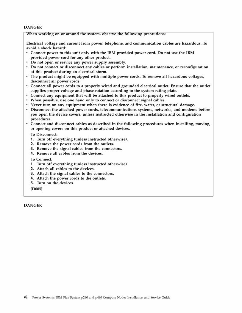
DANGER
When working on or around the system, observe the following precautions:
Electrical voltage and current from power, telephone, and communication cables are hazardous. Toavoid a shock hazard:v Connect power to this unit only with the IBM provided power cord. Do not use the IBM
provided power cord for any other product.v Do not open or service any power supply assembly.v Do not connect or disconnect any cables or perform installation, maintenance, or reconfiguration
of this product during an electrical storm.v The product might be equipped with multiple power cords. To remove all hazardous voltages,
disconnect all power cords.v Connect all power cords to a properly wired and grounded electrical outlet. Ensure that the outlet
supplies proper voltage and phase rotation according to the system rating plate.v Connect any equipment that will be attached to this product to properly wired outlets.v When possible, use one hand only to connect or disconnect signal cables.v Never turn on any equipment when there is evidence of fire, water, or structural damage.v Disconnect the attached power cords, telecommunications systems, networks, and modems before
you open the device covers, unless instructed otherwise in the installation and configurationprocedures.
v Connect and disconnect cables as described in the following procedures when installing, moving,or opening covers on this product or attached devices.
To Disconnect:1. Turn off everything (unless instructed otherwise).2. Remove the power cords from the outlets.3. Remove the signal cables from the connectors.4. Remove all cables from the devices.
To Connect:1. Turn off everything (unless instructed otherwise).2. Attach all cables to the devices.3. Attach the signal cables to the connectors.4. Attach the power cords to the outlets.5. Turn on the devices.
(D005)
DANGER
vi Power Systems: IBM Flex System p260 and p460 Compute Nodes Installation and Service Guide
Observe the following precautions when working on or around your IT rack system:
v Heavy equipment–personal injury or equipment damage might result if mishandled.
v Always lower the leveling pads on the rack cabinet.
v Always install stabilizer brackets on the rack cabinet.
v To avoid hazardous conditions due to uneven mechanical loading, always install the heaviestdevices in the bottom of the rack cabinet. Always install servers and optional devices startingfrom the bottom of the rack cabinet.
v Rack-mounted devices are not to be used as shelves or work spaces. Do not place objects on topof rack-mounted devices.
v Each rack cabinet might have more than one power cord. Be sure to disconnect all power cords inthe rack cabinet when directed to disconnect power during servicing.
v Connect all devices installed in a rack cabinet to power devices installed in the same rackcabinet. Do not plug a power cord from a device installed in one rack cabinet into a powerdevice installed in a different rack cabinet.
v An electrical outlet that is not correctly wired could place hazardous voltage on the metal parts ofthe system or the devices that attach to the system. It is the responsibility of the customer toensure that the outlet is correctly wired and grounded to prevent an electrical shock.
CAUTION
v Do not install a unit in a rack where the internal rack ambient temperatures will exceed themanufacturer's recommended ambient temperature for all your rack-mounted devices.
v Do not install a unit in a rack where the air flow is compromised. Ensure that air flow is notblocked or reduced on any side, front, or back of a unit used for air flow through the unit.
v Consideration should be given to the connection of the equipment to the supply circuit so thatoverloading of the circuits does not compromise the supply wiring or overcurrent protection. Toprovide the correct power connection to a rack, refer to the rating labels located on theequipment in the rack to determine the total power requirement of the supply circuit.
v (For sliding drawers.) Do not pull out or install any drawer or feature if the rack stabilizer bracketsare not attached to the rack. Do not pull out more than one drawer at a time. The rack mightbecome unstable if you pull out more than one drawer at a time.
v (For fixed drawers.) This drawer is a fixed drawer and must not be moved for servicing unlessspecified by the manufacturer. Attempting to move the drawer partially or completely out of therack might cause the rack to become unstable or cause the drawer to fall out of the rack.
(R001)
Safety notices vii
CAUTION:Removing components from the upper positions in the rack cabinet improves rack stability duringrelocation. Follow these general guidelines whenever you relocate a populated rack cabinet within aroom or building:
v Reduce the weight of the rack cabinet by removing equipment starting at the top of the rackcabinet. When possible, restore the rack cabinet to the configuration of the rack cabinet as youreceived it. If this configuration is not known, you must observe the following precautions:
– Remove all devices in the 32U position and above.
– Ensure that the heaviest devices are installed in the bottom of the rack cabinet.
– Ensure that there are no empty U-levels between devices installed in the rack cabinet below the32U level.
v If the rack cabinet you are relocating is part of a suite of rack cabinets, detach the rack cabinet fromthe suite.
v Inspect the route that you plan to take to eliminate potential hazards.
v Verify that the route that you choose can support the weight of the loaded rack cabinet. Refer to thedocumentation that comes with your rack cabinet for the weight of a loaded rack cabinet.
v Verify that all door openings are at least 760 x 230 mm (30 x 80 in.).
v Ensure that all devices, shelves, drawers, doors, and cables are secure.
v Ensure that the four leveling pads are raised to their highest position.
v Ensure that there is no stabilizer bracket installed on the rack cabinet during movement.
v Do not use a ramp inclined at more than 10 degrees.
v When the rack cabinet is in the new location, complete the following steps:
– Lower the four leveling pads.
– Install stabilizer brackets on the rack cabinet.
– If you removed any devices from the rack cabinet, repopulate the rack cabinet from the lowestposition to the highest position.
v If a long-distance relocation is required, restore the rack cabinet to the configuration of the rackcabinet as you received it. Pack the rack cabinet in the original packaging material, or equivalent.Also lower the leveling pads to raise the casters off of the pallet and bolt the rack cabinet to thepallet.
(R002)
(L001)
(L002)
viii Power Systems: IBM Flex System p260 and p460 Compute Nodes Installation and Service Guide
(L003)
or
All lasers are certified in the U.S. to conform to the requirements of DHHS 21 CFR Subchapter J for class1 laser products. Outside the U.S., they are certified to be in compliance with IEC 60825 as a class 1 laserproduct. Consult the label on each part for laser certification numbers and approval information.
CAUTION:This product might contain one or more of the following devices: CD-ROM drive, DVD-ROM drive,DVD-RAM drive, or laser module, which are Class 1 laser products. Note the following information:
v Do not remove the covers. Removing the covers of the laser product could result in exposure tohazardous laser radiation. There are no serviceable parts inside the device.
v Use of the controls or adjustments or performance of procedures other than those specified hereinmight result in hazardous radiation exposure.
(C026)
Safety notices ix
CAUTION:Data processing environments can contain equipment transmitting on system links with laser modulesthat operate at greater than Class 1 power levels. For this reason, never look into the end of an opticalfiber cable or open receptacle. (C027)
CAUTION:This product contains a Class 1M laser. Do not view directly with optical instruments. (C028)
CAUTION:Some laser products contain an embedded Class 3A or Class 3B laser diode. Note the followinginformation: laser radiation when open. Do not stare into the beam, do not view directly with opticalinstruments, and avoid direct exposure to the beam. (C030)
CAUTION:The battery contains lithium. To avoid possible explosion, do not burn or charge the battery.
Do Not:v ___ Throw or immerse into waterv ___ Heat to more than 100°C (212°F)v ___ Repair or disassemble
Exchange only with the IBM-approved part. Recycle or discard the battery as instructed by localregulations. In the United States, IBM has a process for the collection of this battery. For information,call 1-800-426-4333. Have the IBM part number for the battery unit available when you call. (C003)
Power and cabling information for NEBS (Network Equipment-Building System)GR-1089-CORE
The following comments apply to the servers that have been designated as conforming to NEBS(Network Equipment-Building System) GR-1089-CORE:
The equipment is suitable for installation in the following:v Network telecommunications facilitiesv Locations where the NEC (National Electrical Code) applies
The intrabuilding ports of this equipment are suitable for connection to intrabuilding or unexposedwiring or cabling only. The intrabuilding ports of this equipment must not be metallically connected to theinterfaces that connect to the OSP (outside plant) or its wiring. These interfaces are designed for use asintrabuilding interfaces only (Type 2 or Type 4 ports as described in GR-1089-CORE) and require isolationfrom the exposed OSP cabling. The addition of primary protectors is not sufficient protection to connectthese interfaces metallically to OSP wiring.
Note: All Ethernet cables must be shielded and grounded at both ends.
The ac-powered system does not require the use of an external surge protection device (SPD).
The dc-powered system employs an isolated DC return (DC-I) design. The DC battery return terminalshall not be connected to the chassis or frame ground.
x Power Systems: IBM Flex System p260 and p460 Compute Nodes Installation and Service Guide

Chapter 1. Introduction
The IBM® Flex System p260 Compute Node or IBM Flex System p460 Compute Node is based on IBMPOWER® technologies. These compute nodes run in IBM Flex System Enterprise Chassis units to providea high-density, high-performance compute-node environment with advanced processing technology.
The Installation and User's Guide includes the compute node information on the IBM Flex System EnterpriseChassis Documentation CD. All of the following information is in the document and also in the informationcenter:v Setting up the compute nodev Starting and configuring the compute nodev Installing optional hardware devicesv A reference to more information about installing supported operating systemsv Performing basic troubleshooting of the compute node
Packaged with the printed Installation and User's Guide are software CDs that help you to configurehardware, install device drivers, and install the operating system.
The compute node comes with a limited warranty. For information about the terms of the warranty andgetting service and assistance, see the information center or the Warranty and Support Informationdocument on the IBM Flex System Enterprise Chassis Documentation CD.
The compute node might have features that are not described in the documentation that comes with thecompute node. Occasionally, the documentation might be updated to include information about thosefeatures. Technical updates might also become available to provide additional information that is notincluded in the original compute node documentation. The most recent version of all IBM Flex SystemEnterprise Chassis documentation is in the IBM Flex System Information Center.
The online information for the IBM Flex System Enterprise Chassis is available in thehttp://publib.boulder.ibm.com/infocenter/flexsys/information/index.jsp.Related information:
http://www14.software.ibm.com/webapp/set2/sas/f/lopdiags/home.html
http://publib.boulder.ibm.com/infocenter/flexsys/information/index.jsp
Product registrationRecord vital data about your compute node.
© Copyright IBM Corp. 2012, 2015 1

Vital product data
Print Table 1 and use it to record information about your compute node.
You will need this information when you register the compute node with IBM. You can register thecompute node at http://www.ibm.com/support/mynotifications.
To determine the values for your compute node, use the management module and the lsvpd command. Ifyou are running the Linux operating system, download and install the service and productivity tools forthe Linux operating system to install the lsvpd command.
The model number and serial number are on the ID label that is behind the control panel door on thefront of the compute node, and on a label on the side of the compute node that is visible when thecompute node is not in the IBM Flex System Enterprise Chassis.
A set of blank labels comes with the compute node. When you install the compute node in the IBM FlexSystem Enterprise Chassis, write identifying information on a label and place the label on the bezel. Seethe documentation for your IBM Flex System Enterprise Chassis for the location of the label placement.
Important: Do not place the label where it blocks any ventilation holes on the compute node or the IBMFlex System Enterprise Chassis.
Table 1. Vital product data
Vital product data field Vital product data How to find this data
Product nameIBM Flex System p260 Compute Node andIBM Flex System p460 Compute Node
Type model number
IBM Flex System p260 Compute Node:7895-22X, 7895-23A, 7895-23X
IBM Flex System p460 Compute Node:7895-42X, 7895-43X
v For FSM:
– Chassis Manager in themanagement software webinterface of the IBM Flex SystemManager
v For Hardware Management Console(HMC):
1. In the navigation area, clickSystems Management > Servers.
2. In the content pane, select theserver you want to work with.
3. Click Tasks > Properties.
v For Integrated Virtualization Manager(IVM), see IVM lssyscfg command(http://pic.dhe.ibm.com/infocenter/powersys/v3r1m5/topic/p7hcg/lssyscfg.htm).
2 Power Systems: IBM Flex System p260 and p460 Compute Nodes Installation and Service Guide
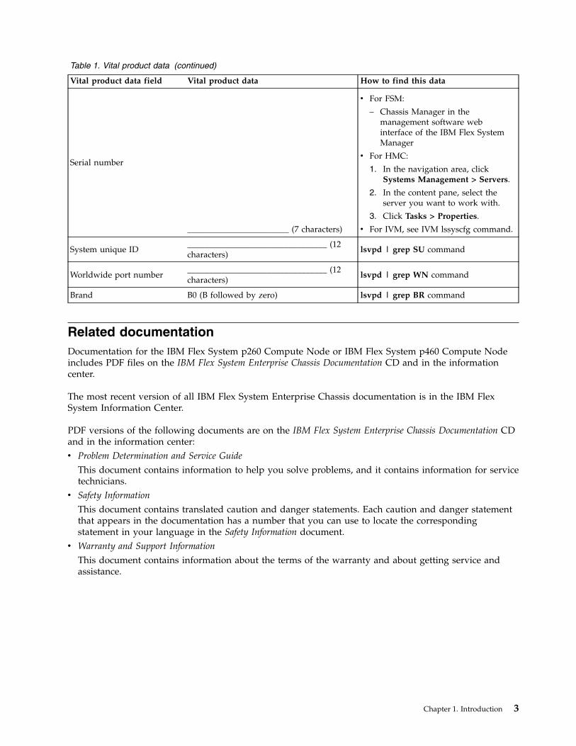
Table 1. Vital product data (continued)
Vital product data field Vital product data How to find this data
Serial number
________________________ (7 characters)
v For FSM:
– Chassis Manager in themanagement software webinterface of the IBM Flex SystemManager
v For HMC:
1. In the navigation area, clickSystems Management > Servers.
2. In the content pane, select theserver you want to work with.
3. Click Tasks > Properties.
v For IVM, see IVM lssyscfg command.
System unique ID_________________________________ (12characters)
lsvpd | grep SU command
Worldwide port number_________________________________ (12characters)
lsvpd | grep WN command
Brand B0 (B followed by zero) lsvpd | grep BR command
Related documentationDocumentation for the IBM Flex System p260 Compute Node or IBM Flex System p460 Compute Nodeincludes PDF files on the IBM Flex System Enterprise Chassis Documentation CD and in the informationcenter.
The most recent version of all IBM Flex System Enterprise Chassis documentation is in the IBM FlexSystem Information Center.
PDF versions of the following documents are on the IBM Flex System Enterprise Chassis Documentation CDand in the information center:v Problem Determination and Service Guide
This document contains information to help you solve problems, and it contains information for servicetechnicians.
v Safety Information
This document contains translated caution and danger statements. Each caution and danger statementthat appears in the documentation has a number that you can use to locate the correspondingstatement in your language in the Safety Information document.
v Warranty and Support Information
This document contains information about the terms of the warranty and about getting service andassistance.
Chapter 1. Introduction 3
The compute node might have features that are not described in the documentation that comes with thecompute node. Occasional updates to the documentation might include information about those features,or technical updates might be available to provide additional information that is not included in thedocumentation that comes with the compute node.
Review the IBM Flex System Information Center or the Planning Guide and the Installation Guide for yourIBM Flex System Enterprise Chassis. The information can help you prepare for system installation andconfiguration. The most current version of each document is available in the IBM Flex SystemInformation Center.Related information:
IBM Flex System Information Center
IBM documentation CDYou can run the IBM Flex System Enterprise Chassis Documentation CD on any personal computer thatmeets the hardware and software requirements.
The CD contains documentation for your compute node in a PDF file and includes the IBMdocumentation browser to help you find information quickly.
Hardware and software requirementsThe IBM Documentation CD requires the following minimum hardware and software levels.v Microsoft Windows XP Professional, Windows 2000, or Red Hat Enterprise Linuxv 100 MHz Microprocessorv 32 MB of RAMv Adobe Acrobat Reader 3.0 (or later) or xpdf viewer, which comes with Linux operating systems
Using the documentation browserUse the documentation browser to browse the contents of the CD, to read brief descriptions of thedocuments, and to view documents by using Adobe Acrobat Reader or xpdf viewer.
About this task
The documentation browser automatically detects the regional settings in your system and displays thedocuments in the language for that region (if available). If a document is not available in the language forthat region, the English-language version is displayed.
To start the documentation browser, use one of the following procedures:v If Autostart is enabled, insert the CD into the CD or DVD drive. The documentation browser starts
automatically.v If Autostart is disabled or is not enabled for all users, use one of the following procedures:
– If you are using a Windows operating system, insert the CD into the CD or DVD drive and clickStart > Run. In the Open field, type the following string, where e is the drive letter of the CD orDVD drive, and click OK:e:\win32.bat
– If you are using Red Hat Enterprise Linux, insert the CD into the CD or DVD drive, and then runthe following command from the /mnt/cdrom directory:sh runlinux.sh
4 Power Systems: IBM Flex System p260 and p460 Compute Nodes Installation and Service Guide
Select the compute node from the Product menu. The Available Topics list displays all the documents forthe compute node. Some documents might be in folders. A plus sign (+) indicates each folder ordocument that has additional documents under it. Click the plus sign to display the additionaldocuments.
When you select a document, a description of the document is displayed under Topic Description. Toselect more than one document, press and hold the Ctrl key while you select the documents. Click ViewBook to view the selected documents in Acrobat Reader or xpdf viewer.
To search all the documents, type a word or text string in the Search field and click Search. Thedocuments in which the word or text string occurs are listed in order of the most occurrences. Click adocument to view it, and press Ctrl+F to use the Acrobat Reader search function, or press Alt+F to usethe xpdf viewer search function within the document.
Notices and statementsThe CAUTION and DANGER statements in this document are also in the multilingual Safety Information.Each statement is numbered for reference to the corresponding statement in your language in the SafetyInformation document.
The following notices and statements are used in this document:v Note: These notices provide important tips, guidance, or advice.v Important: These notices provide information or advice that might help you avoid inconvenient or
problem situations.v Attention: These notices indicate potential damage to programs, devices, or data. An attention notice is
placed just before the instruction or situation in which damage might occur.v CAUTION: These statements indicate situations that can be potentially hazardous to you. A CAUTION
statement is placed just before the description of a potentially hazardous procedural step or situation.v DANGER: These statements indicate situations that can be potentially lethal or extremely hazardous to
you. A DANGER statement is placed just before the description of a potentially lethal or extremelyhazardous procedural step or situation.
Features and specificationsFeatures and specifications of the IBM Flex System p260 Compute Node and IBM Flex System p460Compute Node are summarized in these topics.
Features and specifications of the IBM Flex System p260 ComputeNodeFeatures and specifications of the IBM Flex System p260 Compute Node are summarized in thisoverview.
Chapter 1. Introduction 5
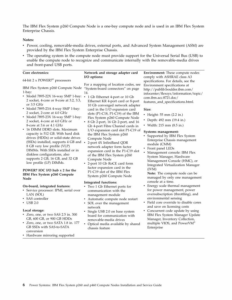
The IBM Flex System p260 Compute Node is a one-bay compute node and is used in an IBM Flex SystemEnterprise Chassis.
Notes:
v Power, cooling, removable-media drives, external ports, and Advanced System Management (ASM) areprovided by the IBM Flex System Enterprise Chassis.
v The operating system in the compute node must provide support for the Universal Serial Bus (USB) toenable the compute node to recognize and communicate internally with the removable-media drivesand front-panel USB ports.
Core electronics:
64-bit 2 x POWER7® processors
IBM Flex System p260 Compute Node1-bay:v Model 7895-22X 16-way SMP 1-bay:
2 socket, 4-core or 8-core at 3.2, 3.3,or 3.5 GHz
v Model 7895-23A 4-way SMP 1-bay:2 socket, 2-core at 4.0 GHz
v Model 7895-23X 16-way SMP 1-bay:2 socket, 4-core at 4.0 GHz or8-core at 3.6 or 4.1 GHz
v 16 DIMM DDR3 slots. Maximumcapacity is 512 GB. With hard diskdrives (HDDs) or solid-state drives(SSDs) installed, supports 4 GB and8 GB very low profile (VLP)DIMMs. With SSDs installed or indiskless configurations, alsosupports 2 GB, 16 GB, and 32 GBlow profile (LP) DIMMs.
POWER7 IOC I/O hub x 2 for theIBM Flex System p260 ComputeNode
On-board, integrated features:v Service processor: IPMI, serial over
LAN (SOL)v SAS controllerv USB 2.0
Local storage:v Zero, one, or two SAS 2.5 in. 300
GB, 600 GB, or 900 GB HDDsv Zero, one, or two SATA 1.8 in. 177
GB SSDs with SAS-to-SATAconversion
v Hardware mirroring supported
Network and storage adapter cardI/O options:
For a mapping of location codes, see“System-board connectors” on page14.v 1 Gb Ethernet 4-port or 10 Gb
Ethernet KR 4-port card or 8-port10 Gb converged network adaptercard in the I/O expansion cardslots (P1-C18, P1-C19) of the IBMFlex System p260 Compute Node
v 8 Gb 2-port, 16 Gb 2-port, and 16Gb 4-port Fibre Channel cards inI/O expansion card slot P1-C19 ofthe IBM Flex System p260Compute Node
v 2-port 4X InfiniBand QDRnetwork adapter form factorexpansion card in the P1-C19 slotof the IBM Flex System p260Compute Node
v 2-port 10 Gb RoCE card formfactor expansion card in theP1-C19 slot of the IBM FlexSystem p260 Compute Node
Integrated functions:v Two 1 Gb Ethernet ports for
communication with themanagement module
v Automatic compute node restartv SOL over the management
networkv Single USB 2.0 on base system
board for communication withremovable-media drives
v Optical media available by sharedchassis feature
Environment: These compute nodescomply with ASHRAE class A3specifications. For details, see theEnvironment specifications athttp://publib.boulder.ibm.com/infocenter/flexsys/information/topic/com.ibm.acc.8721.doc/features_and_specifications.html.
Size:
v Height: 55 mm (2.2 in.)
v Depth: 492 mm (19.4 in.)
v Width: 215 mm (8.5 in.)
Systems management:v Supported by IBM Flex System
Enterprise Chassis managementmodule (CMM)
v Front panel LEDsv Management console: IBM Flex
System Manager, HardwareManagement Console (HMC), orIntegrated Virtualization Manager(IVM)Note: The compute node can bemanaged by only one managementconsole at a time.
v Energy scale thermal managementfor power management, poweroversubscription (throttling), andenvironmental sensing
v Field core override to disable coresand save on licensing costs
v Concurrent code update by usingIBM Flex System Manager UpdateManager, Inventory Collection,multiple VIOS, and PowerVM®
Enterprise
6 Power Systems: IBM Flex System p260 and p460 Compute Nodes Installation and Service Guide
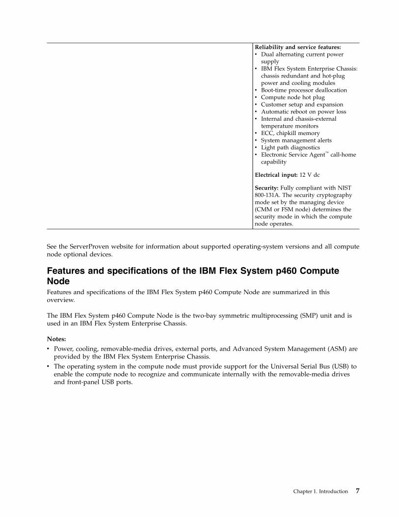
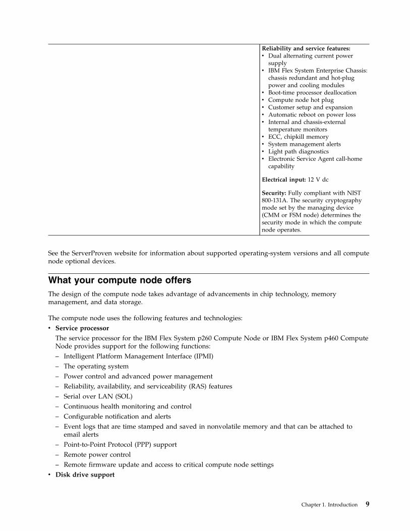
Reliability and service features:v Dual alternating current power
supplyv IBM Flex System Enterprise Chassis:
chassis redundant and hot-plugpower and cooling modules
v Boot-time processor deallocationv Compute node hot plugv Customer setup and expansionv Automatic reboot on power lossv Internal and chassis-external
temperature monitorsv ECC, chipkill memoryv System management alertsv Light path diagnosticsv Electronic Service Agent™ call-home
capability
Electrical input: 12 V dc
Security: Fully compliant with NIST800-131A. The security cryptographymode set by the managing device(CMM or FSM node) determines thesecurity mode in which the computenode operates.
See the ServerProven website for information about supported operating-system versions and all computenode optional devices.
Features and specifications of the IBM Flex System p460 ComputeNodeFeatures and specifications of the IBM Flex System p460 Compute Node are summarized in thisoverview.
The IBM Flex System p460 Compute Node is the two-bay symmetric multiprocessing (SMP) unit and isused in an IBM Flex System Enterprise Chassis.
Notes:
v Power, cooling, removable-media drives, external ports, and Advanced System Management (ASM) areprovided by the IBM Flex System Enterprise Chassis.
v The operating system in the compute node must provide support for the Universal Serial Bus (USB) toenable the compute node to recognize and communicate internally with the removable-media drivesand front-panel USB ports.
Chapter 1. Introduction 7
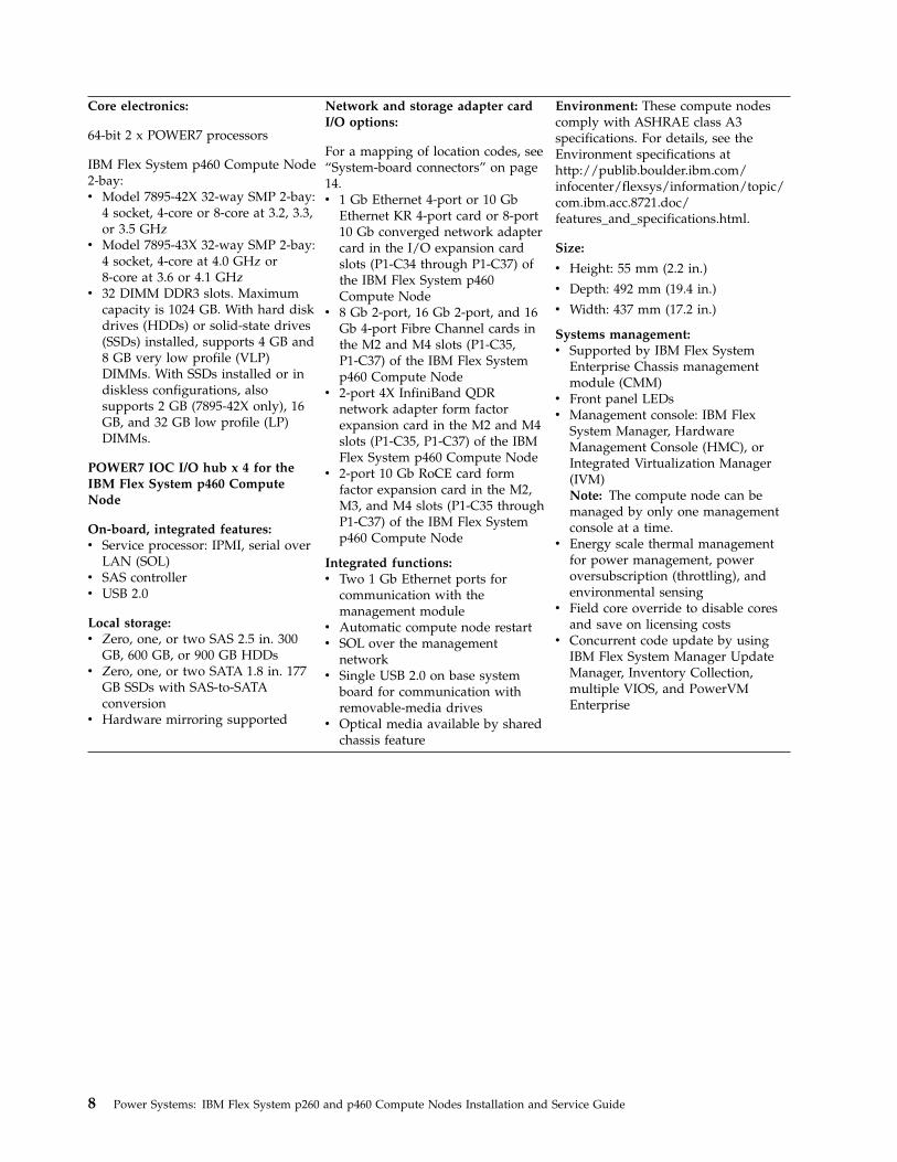
Core electronics:
64-bit 2 x POWER7 processors
IBM Flex System p460 Compute Node2-bay:v Model 7895-42X 32-way SMP 2-bay:
4 socket, 4-core or 8-core at 3.2, 3.3,or 3.5 GHz
v Model 7895-43X 32-way SMP 2-bay:4 socket, 4-core at 4.0 GHz or8-core at 3.6 or 4.1 GHz
v 32 DIMM DDR3 slots. Maximumcapacity is 1024 GB. With hard diskdrives (HDDs) or solid-state drives(SSDs) installed, supports 4 GB and8 GB very low profile (VLP)DIMMs. With SSDs installed or indiskless configurations, alsosupports 2 GB (7895-42X only), 16GB, and 32 GB low profile (LP)DIMMs.
POWER7 IOC I/O hub x 4 for theIBM Flex System p460 ComputeNode
On-board, integrated features:v Service processor: IPMI, serial over
LAN (SOL)v SAS controllerv USB 2.0
Local storage:v Zero, one, or two SAS 2.5 in. 300
GB, 600 GB, or 900 GB HDDsv Zero, one, or two SATA 1.8 in. 177
GB SSDs with SAS-to-SATAconversion
v Hardware mirroring supported
Network and storage adapter cardI/O options:
For a mapping of location codes, see“System-board connectors” on page14.v 1 Gb Ethernet 4-port or 10 Gb
Ethernet KR 4-port card or 8-port10 Gb converged network adaptercard in the I/O expansion cardslots (P1-C34 through P1-C37) ofthe IBM Flex System p460Compute Node
v 8 Gb 2-port, 16 Gb 2-port, and 16Gb 4-port Fibre Channel cards inthe M2 and M4 slots (P1-C35,P1-C37) of the IBM Flex Systemp460 Compute Node
v 2-port 4X InfiniBand QDRnetwork adapter form factorexpansion card in the M2 and M4slots (P1-C35, P1-C37) of the IBMFlex System p460 Compute Node
v 2-port 10 Gb RoCE card formfactor expansion card in the M2,M3, and M4 slots (P1-C35 throughP1-C37) of the IBM Flex Systemp460 Compute Node
Integrated functions:v Two 1 Gb Ethernet ports for
communication with themanagement module
v Automatic compute node restartv SOL over the management
networkv Single USB 2.0 on base system
board for communication withremovable-media drives
v Optical media available by sharedchassis feature
Environment: These compute nodescomply with ASHRAE class A3specifications. For details, see theEnvironment specifications athttp://publib.boulder.ibm.com/infocenter/flexsys/information/topic/com.ibm.acc.8721.doc/features_and_specifications.html.
Size:
v Height: 55 mm (2.2 in.)
v Depth: 492 mm (19.4 in.)
v Width: 437 mm (17.2 in.)
Systems management:v Supported by IBM Flex System
Enterprise Chassis managementmodule (CMM)
v Front panel LEDsv Management console: IBM Flex
System Manager, HardwareManagement Console (HMC), orIntegrated Virtualization Manager(IVM)Note: The compute node can bemanaged by only one managementconsole at a time.
v Energy scale thermal managementfor power management, poweroversubscription (throttling), andenvironmental sensing
v Field core override to disable coresand save on licensing costs
v Concurrent code update by usingIBM Flex System Manager UpdateManager, Inventory Collection,multiple VIOS, and PowerVMEnterprise
8 Power Systems: IBM Flex System p260 and p460 Compute Nodes Installation and Service Guide
Reliability and service features:v Dual alternating current power
supplyv IBM Flex System Enterprise Chassis:
chassis redundant and hot-plugpower and cooling modules
v Boot-time processor deallocationv Compute node hot plugv Customer setup and expansionv Automatic reboot on power lossv Internal and chassis-external
temperature monitorsv ECC, chipkill memoryv System management alertsv Light path diagnosticsv Electronic Service Agent call-home
capability
Electrical input: 12 V dc
Security: Fully compliant with NIST800-131A. The security cryptographymode set by the managing device(CMM or FSM node) determines thesecurity mode in which the computenode operates.
See the ServerProven website for information about supported operating-system versions and all computenode optional devices.
What your compute node offersThe design of the compute node takes advantage of advancements in chip technology, memorymanagement, and data storage.
The compute node uses the following features and technologies:v Service processor
The service processor for the IBM Flex System p260 Compute Node or IBM Flex System p460 ComputeNode provides support for the following functions:– Intelligent Platform Management Interface (IPMI)– The operating system– Power control and advanced power management– Reliability, availability, and serviceability (RAS) features– Serial over LAN (SOL)– Continuous health monitoring and control– Configurable notification and alerts– Event logs that are time stamped and saved in nonvolatile memory and that can be attached to
email alerts– Point-to-Point Protocol (PPP) support– Remote power control– Remote firmware update and access to critical compute node settings
v Disk drive support
Chapter 1. Introduction 9

The compute node supports either Serial Advanced Technology Attachment (SATA) solid-state drives(SSDs) or serial-attached SCSI (SAS) hard disk drives (HDDs) in one of the following configurations:– Up to two 1.8 in. SATA SSDs– Up to two 2.5 in. SAS HDDs
v Impressive performance using the latest microprocessor technology
The compute node comes with two POWER7 microprocessors for the IBM Flex System p260 ComputeNode and four POWER7 microprocessors for the IBM Flex System p460 Compute Node.
v I/O expansion
The compute node has connectors on the system board for optional PCI Express (PCIe) networkadapter cards for adding more network communication capabilities to the compute node.
v Large system memory capacity
The memory bus in the IBM Flex System p260 Compute Node supports up to 512 GB of systemmemory, and the IBM Flex System p460 Compute Node supports up to 1024 GB of system memory.For the official list of supported dual-inline memory modules (DIMMs), see http://www.ibm.com/systems/info/x86servers/serverproven/compat/us/ (http://www.ibm.com/systems/info/x86servers/serverproven/compat/us/).
v Light path diagnostics
Light path diagnostics provides light-emitting diodes (LEDs) to help diagnose problems. An LED onthe compute node control panel is lit if an unusual condition or a problem occurs. If this happens, youcan look at the LEDs on the system board to locate the source of the problem.
v Power throttling
If your IBM Flex System Enterprise Chassis supports power management, the power consumption ofthe compute node can be dynamically managed through the management module. For moreinformation, see http://publib.boulder.ibm.com/infocenter/flexsys/information/topic/com.ibm.acc.cmm.doc/cmm_product_page.html or the IBM support site at http://www.ibm.com/support/entry/portal/Overview.
10 Power Systems: IBM Flex System p260 and p460 Compute Nodes Installation and Service Guide
Chapter 2. Power, controls, indicators, and connectors
You can use the control panel to turn the compute nodes on or off and to view some controls andindicators. Other indicators are on the system board. The system board also has connectors for variouscomponents.
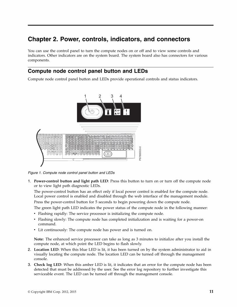
Compute node control panel button and LEDsCompute node control panel button and LEDs provide operational controls and status indicators.
1. Power-control button and light path LED: Press this button to turn on or turn off the compute nodeor to view light path diagnostic LEDs.The power-control button has an effect only if local power control is enabled for the compute node.Local power control is enabled and disabled through the web interface of the management module.Press the power-control button for 5 seconds to begin powering down the compute node.The green light path LED indicates the power status of the compute node in the following manner:v Flashing rapidly: The service processor is initializing the compute node.v Flashing slowly: The compute node has completed initialization and is waiting for a power-on
command.v Lit continuously: The compute node has power and is turned on.
Note: The enhanced service processor can take as long as 3 minutes to initialize after you install thecompute node, at which point the LED begins to flash slowly.
2. Location LED: When this blue LED is lit, it has been turned on by the system administrator to aid invisually locating the compute node. The location LED can be turned off through the managementconsole.
3. Check log LED: When this amber LED is lit, it indicates that an error for the compute node has beendetected that must be addressed by the user. See the error log repository to further investigate thisserviceable event. The LED can be turned off through the management console.
Figure 1. Compute node control panel button and LEDs
© Copyright IBM Corp. 2012, 2015 11
4. Enclosure fault LED: When this amber LED is lit, it indicates that a system error has occurred in thecompute node. The compute-node error LED will turn off after one of the following events:v Correcting the errorv Reseating the compute node in the IBM Flex System Enterprise Chassisv Cycling the IBM Flex System Enterprise Chassis power
Related tasks:“Viewing the light path diagnostic LEDs” on page 486After reading the required safety information, look at the control panel to determine whether the LEDsindicate a suboptimal condition or an error.
Turning on the compute nodeAfter you connect the compute node to power through the IBM Flex System Enterprise Chassis, you canstart the compute node after the discovery and initialization process is complete.
About this task
To start the compute node, use one of the following methods:
Procedurev Start the compute node by pressing the power-control button on the front of the compute node.
After you push the power-control button, the power-on LED continues to flash slowly for about 15seconds, and then is lit solidly when the power-on process is complete.Wait until the power-on LED on the compute node flashes slowly before you press the compute nodepower-control button. If the power-on LED is flashing rapidly, the service processor is initializing thecompute node. The power-control button does not respond during initialization.
Note: The enhanced service processor can take as long as 3 minutes to initialize after you install thecompute node, at which point the LED begins to flash slowly.
v Start the compute node automatically when power is restored after a power failure.If a power failure occurs, the IBM Flex System Enterprise Chassis and then the compute node can startautomatically when power is restored. You must configure the compute node to restart through themanagement module.
v Start the compute node remotely using the management module.After you initiate the power-on process, the power-on LED flashes slowly for about 15 seconds, andthen is lit solidly when the power-on process is complete.
12 Power Systems: IBM Flex System p260 and p460 Compute Nodes Installation and Service Guide
Turning off the compute nodeWhen you turn off the compute node, it is still connected to power through the IBM Flex SystemEnterprise Chassis. The compute node can respond to requests from the service processor, such as aremote request to turn on the compute node. To remove all power from the compute node, you mustremove it from the IBM Flex System Enterprise Chassis.
Before you begin
Shut down the operating system before you turn off the compute node. See the operating-systemdocumentation for information about shutting down the operating system.
About this task
To turn off the compute node, use one of the following methods:
Procedurev Turn off the compute node by pressing the power-control button for at least 5 seconds.
Note: The power-control LED can remain on solidly for up to 1 minute after you push thepower-control button. After you turn off the compute node, wait until the power-control LED isflashing slowly before you press the power-control button to turn on the compute node again.If the operating system stops functioning, press and hold the power-control button for more than 5seconds to force the compute node to turn off.
v Use the management module to turn off the compute node.The power-control LED can remain on solidly for up to 1 minute after you initiate the power-offprocess. After you turn off the compute node, wait until the power-control LED is flashing slowlybefore you initiate the power-on process from the Chassis Management Module (CMM) to turn on thecompute node again.Use the management-module Web interface to configure the management module to turn off thecompute node if the system is not operating correctly.For additional information, see http://publib.boulder.ibm.com/infocenter/flexsys/information/topic/com.ibm.acc.cmm.doc/cmm_product_page.html.
System-board layoutsIllustrations show the connectors and LEDs on the system board. The illustrations might differ slightlyfrom your hardware.
Chapter 2. Power, controls, indicators, and connectors 13
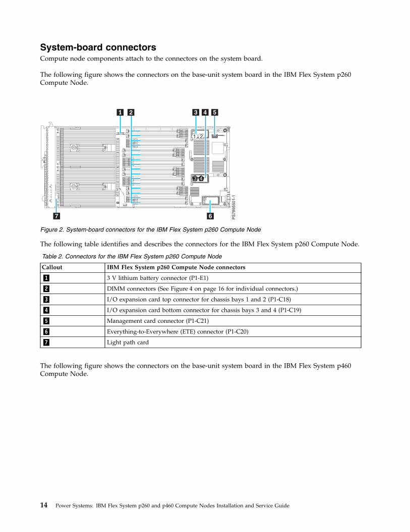
System-board connectorsCompute node components attach to the connectors on the system board.
The following figure shows the connectors on the base-unit system board in the IBM Flex System p260Compute Node.
The following table identifies and describes the connectors for the IBM Flex System p260 Compute Node.
Table 2. Connectors for the IBM Flex System p260 Compute Node
Callout IBM Flex System p260 Compute Node connectors
▌1▐ 3 V lithium battery connector (P1-E1)
▌2▐ DIMM connectors (See Figure 4 on page 16 for individual connectors.)
▌3▐ I/O expansion card top connector for chassis bays 1 and 2 (P1-C18)
▌4▐ I/O expansion card bottom connector for chassis bays 3 and 4 (P1-C19)
▌5▐ Management card connector (P1-C21)
▌6▐ Everything-to-Everywhere (ETE) connector (P1-C20)
▌7▐ Light path card
The following figure shows the connectors on the base-unit system board in the IBM Flex System p460Compute Node.
Figure 2. System-board connectors for the IBM Flex System p260 Compute Node
14 Power Systems: IBM Flex System p260 and p460 Compute Nodes Installation and Service Guide
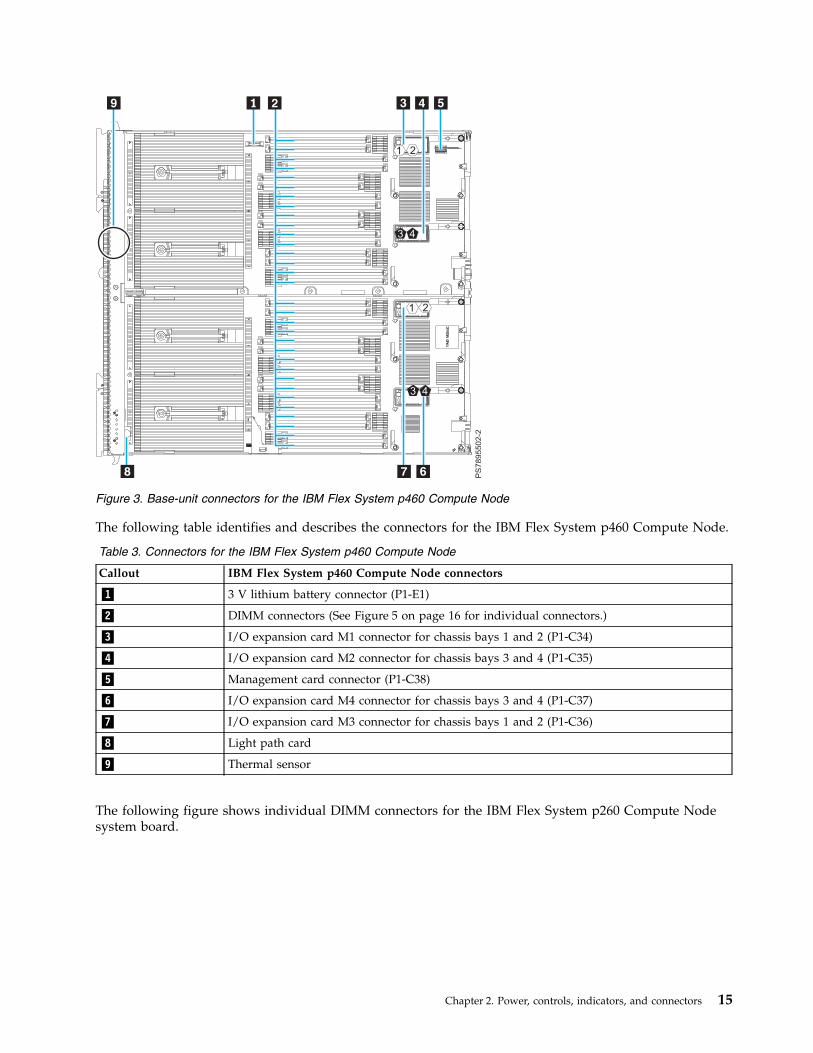
The following table identifies and describes the connectors for the IBM Flex System p460 Compute Node.
Table 3. Connectors for the IBM Flex System p460 Compute Node
Callout IBM Flex System p460 Compute Node connectors
▌1▐ 3 V lithium battery connector (P1-E1)
▌2▐ DIMM connectors (See Figure 5 on page 16 for individual connectors.)
▌3▐ I/O expansion card M1 connector for chassis bays 1 and 2 (P1-C34)
▌4▐ I/O expansion card M2 connector for chassis bays 3 and 4 (P1-C35)
▌5▐ Management card connector (P1-C38)
▌6▐ I/O expansion card M4 connector for chassis bays 3 and 4 (P1-C37)
▌7▐ I/O expansion card M3 connector for chassis bays 1 and 2 (P1-C36)
▌8▐ Light path card
▌9▐ Thermal sensor
The following figure shows individual DIMM connectors for the IBM Flex System p260 Compute Nodesystem board.
Figure 3. Base-unit connectors for the IBM Flex System p460 Compute Node
Chapter 2. Power, controls, indicators, and connectors 15
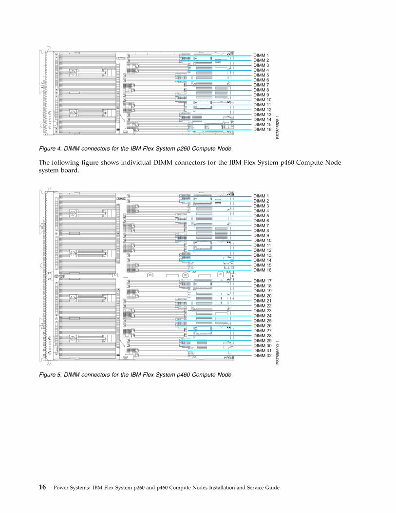
The following figure shows individual DIMM connectors for the IBM Flex System p460 Compute Nodesystem board.
Figure 4. DIMM connectors for the IBM Flex System p260 Compute Node
Figure 5. DIMM connectors for the IBM Flex System p460 Compute Node
16 Power Systems: IBM Flex System p260 and p460 Compute Nodes Installation and Service Guide
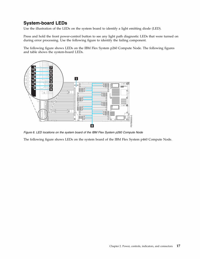
System-board LEDsUse the illustration of the LEDs on the system board to identify a light emitting diode (LED).
Press and hold the front power-control button to see any light path diagnostic LEDs that were turned onduring error processing. Use the following figure to identify the failing component.
The following figure shows LEDs on the IBM Flex System p260 Compute Node. The following figuresand table shows the system-board LEDs.
The following figure shows LEDs on the system board of the IBM Flex System p460 Compute Node.
Figure 6. LED locations on the system board of the IBM Flex System p260 Compute Node
Chapter 2. Power, controls, indicators, and connectors 17

The following table identifies the light path diagnostic LEDs.
Table 4. IBM Flex System p260 Compute Node and IBM Flex System p460 Compute Node LEDs
Callout Unit LEDs
▌1▐ 3 V lithium battery LED
▌2▐ DRV2 LED (HDD or SSD)
▌3▐ DRV1 LED (HDD or SSD)
▌4▐ Drive board LED (solid-state drive interposer, which is integrated in the cover)
▌5▐ Management card LED
▌6▐ System board LED
▌7▐ Light path power LED
▌8▐ DIMM LEDs
▌9▐ ETE connector LED
Figure 7. LED locations on the system board of the IBM Flex System p460 Compute Node
18 Power Systems: IBM Flex System p260 and p460 Compute Nodes Installation and Service Guide
Input/output connectors and devicesThe input/output connectors that are available to the compute node are supplied by the IBM Flex SystemEnterprise Chassis.
See the documentation that comes with the IBM Flex System Enterprise Chassis for information about theinput/output connectors.
The Ethernet controllers on the compute node communicate with the network through theEthernet-compatible I/O modules on the IBM Flex System Enterprise Chassis.
Chapter 2. Power, controls, indicators, and connectors 19

20 Power Systems: IBM Flex System p260 and p460 Compute Nodes Installation and Service Guide
Chapter 3. Configuring the compute node
While the firmware is running Power on System Test (POST) and before the operating system starts, aPOST menu with POST indicators is displayed. The POST indicators are the words Memory, Keyboard,Network, SCSI, and Speaker that are displayed as each component is tested. You can then selectconfiguration utilities from the POST menu.
About this task
The following configuration utilities are available from the POST menu:v System management services (SMS)
Use the system management services (SMS) utility to view information about your system or partitionand to perform tasks such as setting up remote IPL, changing self-configuring SCSI device (SCSD)settings, and selecting boot options. The SMS utility can be used for AIX® or Linux partitions.
v Default boot list
Use this utility to initiate a system boot in service mode through the default service mode boot list.This mode attempts to boot from the first device of each type that is found in the list.
Note: This is the preferred method of starting the stand-alone AIX diagnostics from CD.v Stored boot list
Use this utility to initiate a system boot in service mode by using the customized service-mode bootlist that was set up by the AIX operating system when the operating system was first booted, ormanually by using the AIX service aids.
v Open firmware prompt
This utility is for advanced users of the IEEE 1275 specifications only.v Management module
Use the management module to change the boot list to determine which firmware image to boot, andto perform other configuration tasks.
Related tasks:“Using the SMS utility” on page 24Use the System Management Services (SMS) utility to configure the IBM Flex System p260 ComputeNode or IBM Flex System p460 Compute Node.
© Copyright IBM Corp. 2012, 2015 21
Updating the firmwareIBM periodically makes firmware updates available for you to install on the compute node, on themanagement module, or on expansion cards in the compute node.
Before you begin
Attention: Installing the wrong firmware update might cause the compute node to malfunction. Beforeyou install a firmware update, read any readme and change history files that are provided with thedownloaded update. These files contain important information about the update and the procedure forinstalling the update, including any special procedure for updating from an early firmware version to thelatest version.
Important:
v To avoid problems and to maintain proper system performance, always verify that the compute nodeBIOS, service processor, and diagnostic firmware levels are consistent for all compute nodes within theIBM Flex System Enterprise Chassis.
v For a detailed summary of update procedures for all IBM Flex System components, see thehttp://www.ibm.com/support/entry/portal/docdisplay?lndocid=MIGR-5091991.
To update the firmware of the compute node, use one of the following methods.v The IBM Flex System Manager. See http://publib.boulder.ibm.com/infocenter/flexsys/information/
topic/com.ibm.acc.8731.doc/updating_firmware_and_software.html.v The Hardware Management Console (HMC). See Managed system updates.v The Integrated Virtualization Manager (IVM), see Updating the Integrated Virtualization Manager.v In-band operating system capabilities. These include the update_flash command for the Linux
operating system and the AIX operating system or the ldfware command for Virtual I/O Server.v The firmware update function of AIX diagnostics.v The firmware update function of the stand-alone diagnostics boot image.
Attention: Before the installation of the new firmware to the temporary side begins, the contents of thetemporary side are copied into the permanent side. After the firmware installation begins, the previouslevel of firmware on the permanent side is no longer available.
Notes:
v You must use the default USERID account and password in the management software to access aChassis Management Module (CMM) that is managing a chassis that contains Power Systems™
compute nodes.v Before you update the firmware for one or more Power Systems compute nodes, make sure that the
password for the default USERID account will not expire before the update is complete. If thepassword expires during a code update, then the Power Systems compute nodes might not reconnectto the management software, and each Power Systems compute node might have to be updated withthe new password.
v Firmware updates can take some time to load. To expedite the initial setup process, you can begin toinstall your operating system while you wait for the firmware updates.
22 Power Systems: IBM Flex System p260 and p460 Compute Nodes Installation and Service Guide
About this task
To install compute node firmware using an in-band method, complete the following steps:
Procedure1. Download the IBM Flex System p260 Compute Node one-bay firmware or the IBM Flex System p460
Compute Node two-bay firmware.a. Go to http://www.ibm.com/software/brandcatalog/puresystems/centre/update.b. Select the update group that matches the IBM Flex System version to which you want to update.
For example, select the Flex System 1.2.1 tab.c. Select the updates for the applicable compute node.d. Download the compute node firmware and any firmware required for installed devices, such as
adapters or drives.
Note: Ensure that you download all files in the firmware update, including .rpm, .xml, dd.xml,and pd.sdd files as well as the readme.txt file.
e. Use FTP to copy the update to a directory on the compute node (such as /tmp/fwrpms).2. Log on to the AIX or Linux system as root, or log on to the Virtual I/O Server (VIOS) as padmin.3. If you are logging on to VIOS, run the following command to obtain root access:
run oem_setup_env
4. Unpack the .rpm file.For example, if you are installing the FW773 service pack 01AF773_051_033:rpm -Uvh -ignoreos 01AF773_051_033.rpm
The output from the command should be similar to:Preparing... #################################### [100%]
1:01AF773_051_033 #################################### [100%]
The resulting .img file is now in the /tmp/fwupdate subdirectory.5. Install the firmware update with one of the following methods:v Install the firmware with the AIX update_flash command:
cd /tmp/fwupdate/usr/lpp/diagnostics/bin/update_flash -f 01AFxxx_yyy_zzz.img
v Install the firmware with the Linux update_flash command:cd /tmp/fwupdate/usr/sbin/update_flash -f 01AFxxx_yyy_zzz.img
v Return to VIOS and install the firmware with the ldfware command on VIOS:#exitcd /tmp/fwupdateldfware -file 01AFxxx_yyy_zzz.img
Where 01AFxxx_yyy_zzz.img is the name of the firmware image.
Note: You can also use the firmware update function of AIX diagnostics or the firmware updatefunction of the stand-alone diagnostics boot image. For more information, see http://publib.boulder.ibm.com/infocenter/powersys/v3r1m5/topic/p7ha5/fix_aix_diags.htm.
Chapter 3. Configuring the compute node 23
6. Restart the compute node to apply the firmware update.7. Run the following command in AIX or Linux to verify if the firmware update was successful:
lsmcode -A
Run the following command in VIOS to verify if the firmware update was successful:lsfware -all
Starting the TEMP imageThe system firmware is contained in separate temporary and permanent images in the flash memory ofthe compute node. These images are referred to as TEMP and PERM, respectively. The compute nodenormally starts from the TEMP image. Start the TEMP image before you update the firmware.
About this task
To start the TEMP image, see http://publib.boulder.ibm.com/infocenter/flexsys/information/topic/com.ibm.acc.psm.hosts.doc/dpsm_managing_hosts_power_firmware.html.
Verifying the system firmware levelsThe diagnostics program displays the current system firmware levels for the temporary (TEMP) andpermanent (PERM) images. This function also displays which image the compute node used to start.
Procedure1. Start the diagnostics program.2. From the Function Selection menu, select Task Selection and press Enter.3. From the Tasks Selection List menu, select Update and Manage System Flash and press Enter.
The top of the Update and Manage System Flash menu displays the system firmware level for thePERM and the TEMP images and the image that the compute node used to start.
Note: If the TEMP image level is more current than the PERM image, commit the TEMP image.4. When you have verified the firmware levels, press F3 until the Diagnostic Operating Instructions
window is displayed, and then press F3 again to exit the diagnostic program.
Using the SMS utilityUse the System Management Services (SMS) utility to configure the IBM Flex System p260 ComputeNode or IBM Flex System p460 Compute Node.
24 Power Systems: IBM Flex System p260 and p460 Compute Nodes Installation and Service Guide

Starting the SMS utilityStart the SMS utility to configure the compute node.
Procedure1. Turn on or restart the compute node, and establish an SOL session with it.
See the IBM Chassis Management Module Command-Line Interface Reference Guide for more information.2. When the POST menu and indicators are displayed, and after the word Keyboard is displayed and
before the word Speaker is displayed, press 1.3. Follow the instructions in the window.
SMS utility menu choicesSelect SMS tasks from the SMS utility main menu. Choices on the SMS utility main menu depend on theversion of the firmware in the compute node.
Some menu choices might differ slightly from these descriptions:v Select Language
Changes the language that is used to display the SMS menus.v Setup Remote IPL (Initial Program Load)
Enables and sets up the remote startup capability of the compute node or partition.v Change SCSI Settings
Changes the addresses of the self-configuring SCSI device (SCSD) controllers that are attached to thecompute node.
v Select Console
Selects the console on which the SMS menus are displayed.v Select Boot Options
Sets various options regarding the installation devices and boot devices.
Note: If a device that you are trying to select is not displayed in the Select Device Type menu, selectList all Devices and select the device from that menu.
v Firmware Boot Side Options
Controls the booting of firmware from the permanent or temporary side.
Creating a CE loginIf the compute node is running the AIX operating system, you can create a customer engineer (CE) login.The CE login is used to perform operating system commands that are required to service the systemwithout being logged in as a root user.
Chapter 3. Configuring the compute node 25

About this task
The CE login must have a role of Run Diagnostics and must be in a primary group of System. Thissetting enables the CE login to perform the following tasks:v Run the diagnostics, including the service aids, certification, and formatting.v Run all the operating-system commands that are run by system group users.v Configure and unconfigure devices that are not in use.
In addition, this login can enable the Shutdown Group so that use of the Update System Microcodeservice aid and the shutdown and reboot operations are available.
The preferred CE login user name is qserv.
Configuring processor coresLearn how to increase or decrease the number of active processor cores in the compute node.
You can order your IBM Flex System p260 Compute Node or IBM Flex System p460 Compute Node witha feature that instructs the factory to reduce the number of active processor cores in the compute node toreduce software licensing costs. The factory uses the field core override option to reduce the number ofprocessor cores when feature code 2319: Factory deconfiguration of one core is ordered with a new system.This option, available on the Advanced System Management Interface (ASMI), reduces the number ofprocessor cores by one.
The field core override option indicates the number of functional cores that are active in the computenode. The field core override option provides the capability to increase or decrease the number of activeprocessor cores in the compute node. The compute node firmware sets the number of active processorcores to the entered value. The value takes effect when the compute node is rebooted. The field coreoverride value can be changed only when the compute node is powered off.
You must use this option to increase the number of active processor cores due to increased workload onthe compute node.
To change the number of functional override cores in the compute node, you must access ASMI. Seehttp://publib.boulder.ibm.com/infocenter/flexsys/information/topic/com.ibm.acc.psm.hosts.doc/dpsm_managing_hosts_launch_asm.html.
For detailed information about the field core override feature, see http://publib.boulder.ibm.com/infocenter/powersys/v3r1m5/topic/p7hby/fieldcore.htm.Related information:
http://publib.boulder.ibm.com/infocenter/powersys/v3r1m5/topic/p7hby/viewprocconfig.htm
26 Power Systems: IBM Flex System p260 and p460 Compute Nodes Installation and Service Guide
MAC addresses for integrated Ethernet controllersTwo integrated Ethernet ports are used by the service processor on the IBM Flex System p260 ComputeNode or IBM Flex System p460 Compute Node. Additional Ethernet ports are provided by the featurecards plugged into the two expansion cards slots. These expansion card Ethernet ports, when used with aVirtual I/O Server (VIOS), provide virtual logical Ethernet to client logical partitions (LPARs). The VIOSsoftware uses the logical Ethernet as if they were actual physical ports.
About this task
The Media Access Control (MAC) addresses of the integrated Ethernet ports are listed on a label on thecompute node. The compute node label lists two MAC addresses. The MAC addresses of the integratedEthernet ports are displayed in the Chassis Manager in the management software web interface of theIBM Flex System Manager and in the Hardware Management Console (HMC), and in the IntegratedVirtualization Manager (IVM). The MAC addresses of the logical ports are generated by VIOS.
To view the MAC addresses of the Ethernet ports by using HMC, click HMC Management > ChangeNetwork Settings > LAN Adapters.
To view the MAC addresses of the Ethernet ports by using IVM, click View/Modify TCP/IP Settings >Properties > Connected Partitions.
Table 5 shows the relative addressing scheme.
Table 5. MAC addressing scheme for physical and logical integrated Ethernet controllers
NodeName in management
module
Relationship to the MACthat is listed on the IBM
Flex System p260 ComputeNode or IBM Flex Systemp460 Compute Node label
Example
Service processor built-inEnet0
Same as first MAC address 00:1A:64:44:0e:c4
Service processor built-inEnet1
MAC + 1 00:1A:64:44:0e:c5
Logical Ethernet ports Generated by VIOS
1. The Integrated Virtualization Manager (IVM), see Updating the Integrated Virtualization Manager.
For more information about planning, deploying, and managing the use of integrated Ethernetcontrollers, see the Configuring section of the PowerVM Information Roadmap.
Chapter 3. Configuring the compute node 27
Configuring a RAID arrayUse this information to configure a RAID array.
About this task
Configuring a RAID array applies to a compute node in which disk drives or solid-state drives areinstalled.
Note: When configuring a RAID array, the hard disk drives must use the same type of interface andmust have identical capacity and speed.
Disk drives and solid-state drives in the IBM Flex System p260 Compute Node or IBM Flex System p460Compute Node can be used to implement and manage various types of RAID arrays in operatingsystems that are on the ServerProven list. For the compute node, you must configure the RAID arraythrough the smit sasdam utility, which is the SAS RAID Disk Array Manager for the AIX operatingsystem. The AIX Disk Array Manager is packaged with the Diagnostics utilities on the diagnostics CD.Use the smit sasdam utility to configure the disk drives for use with the SAS controller. For moreinformation, see http://publib.boulder.ibm.com/infocenter/systems/scope/hw/index.jsp?topic=/p7ebj/sasusingthesasdiskarraymanager.htm.
Important: Depending on your RAID configuration, you might have to create the array before you installthe operating system in the compute node.
Before you can create a RAID array, you must reformat the drives so that the sector size of the driveschanges from 512 bytes to 528 bytes. If you later decide to remove the drives, delete the RAID arraybefore you remove the drives. If you decide to delete the RAID array and reuse the drives, you mustreformat the drives so that the sector size of the drives changes from 528 bytes to 512 bytes.Related information:
http://www.ibm.com/systems/info/x86servers/serverproven/compat/us/
http://publib.boulder.ibm.com/infocenter/systems/scope/hw/index.jsp?topic=/p7ebj/sasusingthesasdiskarraymanager.htm
28 Power Systems: IBM Flex System p260 and p460 Compute Nodes Installation and Service Guide
Chapter 4. Installing the operating system
Before you install the operating system on the compute node, verify that the compute node is installed inthe IBM Flex System Enterprise Chassis, that the management-module firmware is at the latest availablelevel, and that the compute node is turned on.
About this task
If you are not using an unattended network-installation method to install your operating system, youmust first provide a serial over LAN (SOL) connection to the compute node to install your operatingsystem. For information about starting an SOL session, see http://publib.boulder.ibm.com/infocenter/flexsys/information/topic/com.ibm.acc.cmm.doc/dw1kt_cmm_cli_book.pdf.
Important:
v After you install the operating system on the compute node, you must install any service packs orupdate packages that come with the operating system. For additional information, see the instructionsthat come with your operating-system documentation and the service packs or update packages.
v If you plan to install an Ethernet I/O expansion card, first install the operating system so that theonboard ports can be recognized and configured before the ports on the I/O expansion card. If youinstall the Ethernet I/O expansion card before you install the operating system, the I/O expansion cardports will be assigned before the onboard ports.
See the ServerProven website for information about supported operating-system versions and all computenode optional devices.
Locating the installation instructionsYou can order the IBM Flex System p260 Compute Node or IBM Flex System p460 Compute Node withVirtual I/O Server (VIOS), AIX operating-system, or IBM i operating-system already installed. If you didnot order your compute node with these operating systems installed, you can install them as a localoperating system. After installing VIOS, you can install the AIX, Linux, or IBM i operating system as aclient operating system in a logical partition (LPAR).
About this task
After you configure the compute node hardware, go to the operating-system documentation for the latestoperating-system installation instructions. See the following operating system descriptions for moreinformation:v Installing Virtual I/O Server
See the Installing section of the PowerVM Information Roadmap.If you did not order your servers with the VIOS software installed, you can use the Virtual I/O ServerDVD in the product package to install VIOS and set up a virtual environment that supports clientoperating systems in logical partitions. You can then install any of the supported operating systems asa client in an LPAR.The order of installation of VIOS and the operating systems is important. You can update the firmwarefirst with the stand-alone Diagnostics CD, but you must install the VIOS software before you install anyother software. The VIOS software creates the Integrated Virtual Manager administrator console and thefirst logical partition, which VIOS and Integrated Virtual Manager (IVM) occupy.After you install VIOS, you can use the IVM and Micro-Partitioning® features to create client partitionsfor client operating systems.
v Installing AIX
© Copyright IBM Corp. 2012, 2015 29
You can install the AIX operating system by following the installation instructions in the IBM SystemsInformation Center.See the online AIX Installation and migration topic for more information. You can find moreinformation about AIX in the IBM System p® Information Roadmap on the IBM website.
Note: After you install AIX from CD or DVD, using the keyboard and video interface, run the changeconsole command and restart the compute node to switch the AIX console to a Serial over LAN (SOL)connection. (The command does not affect the console that is used by partition firmware.) You can usethe following commands:chcons /dev/vty0shutdown -Fr
v Installing IBM i
You can install the IBM i operating system in a client partition of the VIOS.See the IBM i on a POWER Blade Read-me First document on the IBM website. Additional installationinformation and IBM i restrictions are described in i5/OS™ client partition considerations.Also, see the IBM System i® Information Roadmap.
v Installing Linux
You can install a Linux operating system by following the installation instructions in the IBM SystemsInformation Center.The online Linux installation instructions are available in the Linux on BladeCenter JS22 topic in the IBMSystems Information Center.
Notes:
1. Some optional devices have device drivers that you must install. See the documentation that comeswith the devices for information about installing any required device drivers.If your operating system does not have the required device drivers, contact your IBM marketingrepresentative or authorized reseller, or see your operating-system documentation for additionalinformation.
2. The IBM Remote Deployment Manager (RDM) program does not support the IBM Flex System p260Compute Node or IBM Flex System p460 Compute Node. However, you can use the followingprograms for remote deployment:v For AIX, Red Hat Linux or SUSE Linux operating-system deployments, you can use Cluster
Systems Management (CSM) from IBM. Go to http://www.ibm.com/systems/clusters/index.html.v For AIX operating-system deployments, you can use Network Installation Manager (NIM) from
IBM. See your AIX operating-system documentation for additional information.v For SUSE Linux operating-system deployments, you can use the AutoYast utility program from
Novell, Inc. Go to http://www.suse.com/~ug/.
30 Power Systems: IBM Flex System p260 and p460 Compute Nodes Installation and Service Guide
Results
After you install the operating system, install operating system updates, and then install any utilities thatapply to your operating system.
Installing service and productivity tools for LinuxLinux service and productivity tools include hardware diagnostic aids and productivity tools, andinstallation aids. The installation aids are provided in the IBM Installation Toolkit for the Linux operatingsystem, a set of tools that aids the installation of the Linux operating system on IBM compute nodes thatare based on IBM POWER7 Architecture technologies. You can also use the tools to update the IBM FlexSystem p260 Compute Node or IBM Flex System p460 Compute Node firmware.
About this task
The hardware diagnostic aids and productivity tools are available as downloadable Red Hat PackageManager (RPM) files for Red Hat Enterprise Linux (RHEL) and SUSE Linux Enterprise Server (SLES). TheIBM Installation Toolkit for Linux is available as an ISO compact disc (CD) image, which you can use tocreate your own CD. The Service and productivity tools for Linux systems site describes how to create aCD.
The hardware diagnostic aids and productivity tools are required for such hardware reliability,availability, and serviceability (RAS) functions as first-failure data-capture and error-log analysis. With thetools installed, problem determination and correction are greatly enhanced and the likelihood of anextended system outage is reduced.
For example, the update_flash command for installing system firmware updates can be performed only ifthe hardware diagnostic aids and productivity tools are installed.
Other tools modify various serviceability policies, manipulate system LEDs, update the bootlist, andcapture extended error data to aid analysis of intermittent errors.
Other commands and a boot-time scanning script constitute a hardware inventory system. The lsvpdcommand provides vital product data (VPD) about hardware components.
The Error Log Analysis (ELA) tool provides automatic analysis and notification of errors that are reportedby the platform firmware. ELA writes analyzed error data to /var/log/platform and to the service log. Ifa corrective action is required, a notification event sends the event to registered tools and subscribedusers.
Install the Linux operating system before you download and install the hardware diagnostic aids andproductivity tools for Linux. The Installation Toolkit for Power Systems servers running Linux isprovided as-is only. You are not entitled to IBM Software Support for the Installation Toolkit.
Install the Virtual I/O Server and the Integrated Virtualization Manager before you install your Linuxoperating system if you plan to have a virtual environment.
Chapter 4. Installing the operating system 31

32 Power Systems: IBM Flex System p260 and p460 Compute Nodes Installation and Service Guide
Chapter 5. Accessing the service processor
You can access the service processor remotely.
The management console can connect directly to the Advanced System Management Interface (ASMI) fora selected system. ASM is an interface to the service processor that you can use to manage the operationof the host, such as the automatic power restart function, and to view information about the host, such asthe error log and vital product data.
To access the ASMI by using the IBM Flex System Manager, see Launching Advanced SystemManagement (http://publib.boulder.ibm.com/infocenter/flexsys/information/topic/com.ibm.acc.psm.hosts.doc/dpsm_managing_hosts_launch_asm.html).
To access the ASMI by using the Hardware Management Console (HMC), see Accessing the ASMI usingthe HMC (http://pic.dhe.ibm.com/infocenter/powersys/v3r1m5/topic/p7hby/asmihmc.htm).
To access the ASMI by using a web browser, complete the following steps:1. Assign an IP address to the service processor of the compute node. Perform the following steps:
a. Access the Chassis Management Module (CMM) web interface. For instructions, see Ethernetconnection (http://pic.dhe.ibm.com/infocenter/flexsys/information/topic/com.ibm.acc.cmm.doc/remote_console_ethernet_connect_cmm.html).
b. From the menu bar, click Chassis Management. Then, in the drop-down menu click ComponentIP Configuration. From the Device Name list, select the compute node name to access propertytabs for the compute node. On the IPv4 property tab set the static IP address, mask, and gateway.For more information about setting the IP configuration of a compute node, see Chassismanagement options (http://pic.dhe.ibm.com/infocenter/flexsys/information/topic/com.ibm.acc.cmm.doc/cmm_ui_chassis_management.html).
2. Open a web browser on the client computer. Type https://xxx.xxx.xxx.xxx, where xxx.xxx.xxx.xxx is theIP address of the compute node service processor.
© Copyright IBM Corp. 2012, 2015 33

34 Power Systems: IBM Flex System p260 and p460 Compute Nodes Installation and Service Guide
Chapter 6. Installing and removing components
Install or remove hardware components, such as memory modules or input/output expansion cards.Some installation procedures require you to remove an installed component.
Returning a device or componentIf you are instructed to return a device or component, follow all packaging instructions, and use anypackaging materials for shipping that are supplied to you.
Installation guidelinesFollow these guidelines to remove and replace compute node components.v Read the safety information in the Safety topic and the guidelines in “Handling static-sensitive
devices” on page 36. This information will help you work safely.v When you install a new compute node, download and apply the most recent firmware updates.
Download and install updated device drivers and the compute node firmware. Go to the IBM Supportsite to download the updates. Select your product, type, model, and operating system, and then clickGo. Click the Download tab, if necessary, for device driver and firmware updates.
Note: Changes are made periodically to the IBM website. Procedures for locating firmware anddocumentation might vary slightly from what is described in this documentation.
v Observe good housekeeping in the area where you are working. Place removed covers and other partsin a safe place.
v Back up all important data before you make changes to disk drives.v Before you remove a hot-swap compute node from the IBM Flex System Enterprise Chassis, you must
shut down the operating system and turn off the compute node. You do not have to shut down theIBM Flex System Enterprise Chassis itself.
v Blue on a component indicates touchpoints, where you can grip the component to remove it from orinstall it in the compute node, open or close a latch, and so on.
v Orange on a component or an orange label on or near a component indicates that the component canbe hot-swapped, which means that if the compute node and operating system support hot-swapcapability, you can remove or install the component while the compute node is running. (Orange canalso indicate touchpoints on hot-swap components.) See the instructions for removing or installing aspecific hot-swap component for any additional procedures that you might have to perform before youremove or install the component.
v When you are finished working on the compute node, reinstall all safety shields, guards, labels, andground wires.
See the ServerProven website for information about supported operating-system versions and all computenode optional devices.
© Copyright IBM Corp. 2012, 2015 35
System reliability guidelinesFollow these guidelines to help ensure proper cooling and system reliability.v Verify that the ventilation holes on the compute node are not blocked.v Verify that you are maintaining proper system cooling in the unit.
Do not operate the IBM Flex System Enterprise Chassis without a compute node, expansion unit, orfiller node installed in each bay. See the documentation for your IBM Flex System Enterprise Chassisfor additional information.
v Verify that you have followed the reliability guidelines for the IBM Flex System Enterprise Chassis.v Verify that the compute node battery is operational. If the battery becomes defective, replace it
immediately, as described in “Removing the battery” on page 64 and “Installing the battery” on page65.
Handling static-sensitive devicesStatic electricity can damage the compute node and other electronic devices. To avoid damage, keepstatic-sensitive devices in their static-protective packages until you are ready to install them.
About this task
Attention:
To reduce the possibility of damage from electrostatic discharge, observe the following precautions:v Limit your movement. Movement can cause static electricity to build up around you.v Handle the device carefully, holding it by its edges or its frame.v Do not touch solder joints, pins, or exposed circuitry.v Do not leave the device where others can handle and damage it.v While the device is still in its static-protective package, touch it to an unpainted metal part of the IBM
Flex System Enterprise Chassis or any unpainted metal surface on any other grounded rack componentin the rack that you are installing the device in for at least 2 seconds. This drains static electricity fromthe package and from your body.
v Remove the device from its package and install it directly into the compute node without setting downthe device. If it is necessary to set down the device, put it back into its static-protective package. Donot place the device on the compute node cover or on a metal surface.
v Take additional care when handling devices during cold weather. Heating dry winter air furtherreduces its humidity and increases static electricity.
36 Power Systems: IBM Flex System p260 and p460 Compute Nodes Installation and Service Guide

Removing the compute node from an IBM Flex System EnterpriseChassisRemove the compute node from the IBM Flex System Enterprise Chassis to access options, connectors,and system-board indicators.
About this task
Attention:
v To maintain proper system cooling, do not operate the IBM Flex System Enterprise Chassis without acompute node, expansion unit, or compute node filler installed in each bay.
v When you remove the compute node, note the bay number. Reinstalling a compute node into adifferent bay from the one where it was removed might have unintended consequences. Someconfiguration information and update options are established according to bay numbers. If youreinstall the compute node into a different bay, you might have to reconfigure the compute node.
To remove the compute node, complete the following steps:
Procedure1. Read the Safety topic and the “Installation guidelines” on page 35.2. If the compute node is operating, shut down the operating system. See “Locating the installation
instructions” on page 29 for information about locating the operating system documentation for yourcompute node.
Figure 8. Removing the compute node from the IBM Flex System Enterprise Chassis
Chapter 6. Installing and removing components 37
3. Press the power-control button to turn off the compute node. See “Turning off the compute node” onpage 13.
4. Wait at least 30 seconds for the hard disk drive to stop spinning.5. Open the release handles, as shown in Figure 8 on page 37. The IBM Flex System p260 Compute
Node has one release handle. The IBM Flex System p460 Compute Nodehas two release handles. Thecompute node can be moved out of the bay approximately 0.6 cm (0.25 inch).
6. Pull the compute node out of the bay.7. Carefully lay the compute node on a flat, static-protective surface, with the cover side up.8. Place either a compute node filler or another compute node in the bay.
Reseating the compute node in a chassisReseat the compute node.
About this task
To reseat the compute node, complete the following steps:
Procedure1. Perform a virtual reseat of the compute node.
To perform a virtual reseat by using the IBM Chassis Management Module (CMM), go tohttp://pic.dhe.ibm.com/infocenter/flexsys/information/topic/com.ibm.acc.8731.doc/unmanaging_chassis.html.To perform a virtual reseat by using the IBM Flex System Manager (FSM), go to http://pic.dhe.ibm.com/infocenter/flexsys/information/topic/com.ibm.acc.8731.doc/unmanaging_chassis.html.
2. Is the problem resolved?
Yes: This ends the procedure.
No: Continue with the next step.3. Remove and replace the compute node into the IBM Flex System Enterprise Chassis.
a. Remove the compute node from the IBM Flex System Enterprise Chassis. See “Removing thecompute node from an IBM Flex System Enterprise Chassis” on page 37.
b. Install the compute node into the IBM Flex System Enterprise Chassis. See “Installing the computenode in an IBM Flex System Enterprise Chassis” on page 93.
38 Power Systems: IBM Flex System p260 and p460 Compute Nodes Installation and Service Guide
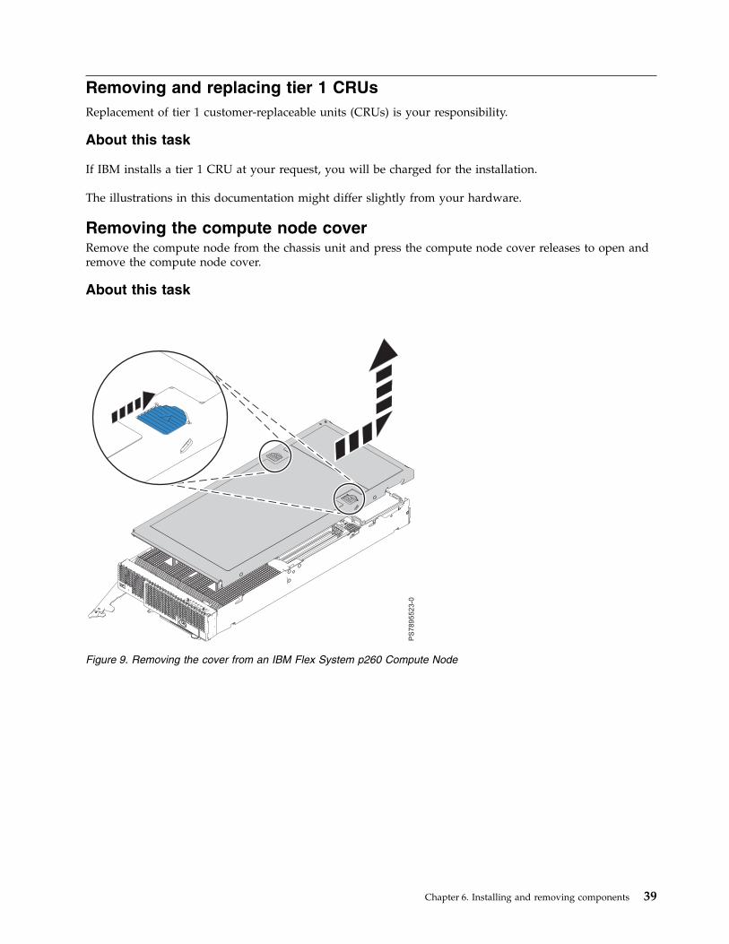
Removing and replacing tier 1 CRUsReplacement of tier 1 customer-replaceable units (CRUs) is your responsibility.
About this task
If IBM installs a tier 1 CRU at your request, you will be charged for the installation.
The illustrations in this documentation might differ slightly from your hardware.
Removing the compute node coverRemove the compute node from the chassis unit and press the compute node cover releases to open andremove the compute node cover.
About this task
Figure 9. Removing the cover from an IBM Flex System p260 Compute Node
Chapter 6. Installing and removing components 39
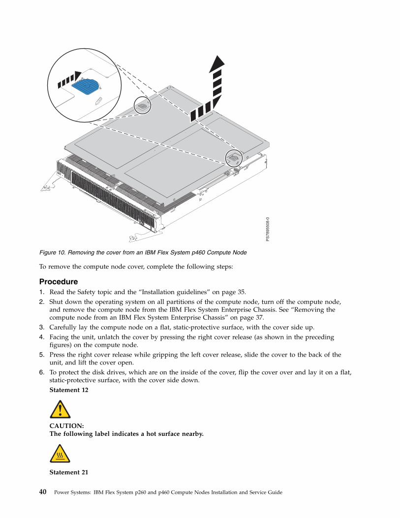
To remove the compute node cover, complete the following steps:
Procedure1. Read the Safety topic and the “Installation guidelines” on page 35.2. Shut down the operating system on all partitions of the compute node, turn off the compute node,
and remove the compute node from the IBM Flex System Enterprise Chassis. See “Removing thecompute node from an IBM Flex System Enterprise Chassis” on page 37.
3. Carefully lay the compute node on a flat, static-protective surface, with the cover side up.4. Facing the unit, unlatch the cover by pressing the right cover release (as shown in the preceding
figures) on the compute node.5. Press the right cover release while gripping the left cover release, slide the cover to the back of the
unit, and lift the cover open.6. To protect the disk drives, which are on the inside of the cover, flip the cover over and lay it on a flat,
static-protective surface, with the cover side down.Statement 12
CAUTION:The following label indicates a hot surface nearby.
Statement 21
Figure 10. Removing the cover from an IBM Flex System p460 Compute Node
40 Power Systems: IBM Flex System p260 and p460 Compute Nodes Installation and Service Guide
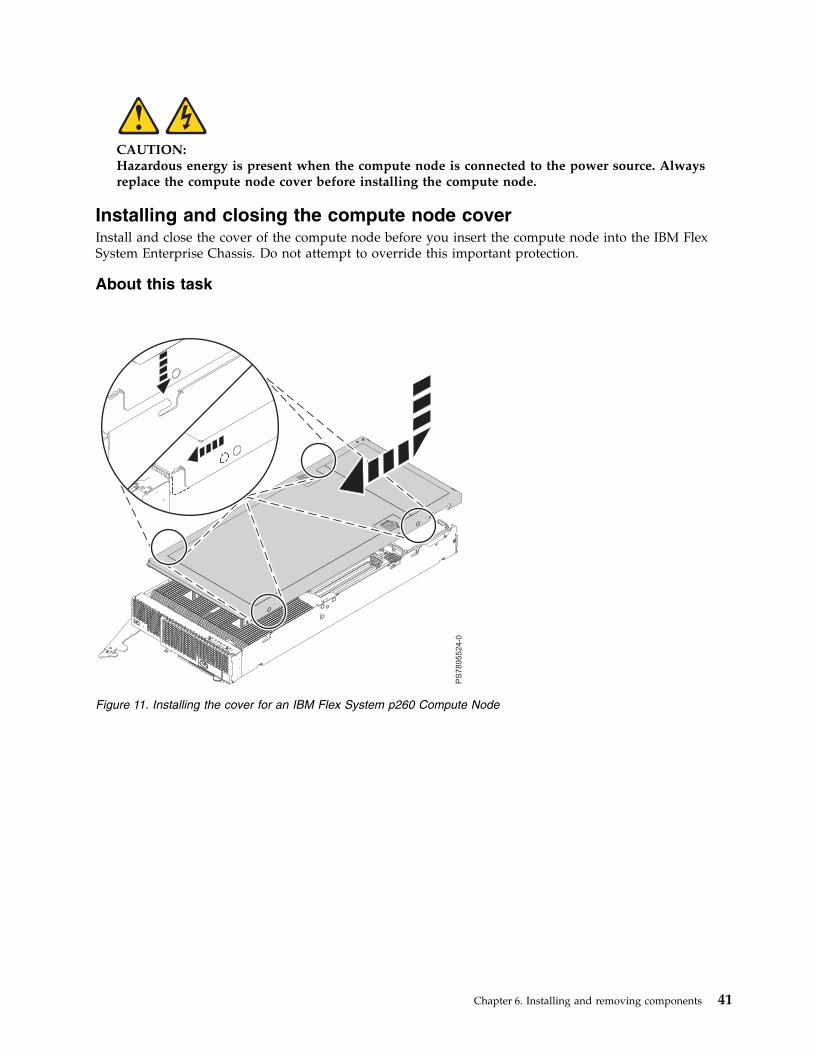
CAUTION:Hazardous energy is present when the compute node is connected to the power source. Alwaysreplace the compute node cover before installing the compute node.
Installing and closing the compute node coverInstall and close the cover of the compute node before you insert the compute node into the IBM FlexSystem Enterprise Chassis. Do not attempt to override this important protection.
About this task
Figure 11. Installing the cover for an IBM Flex System p260 Compute Node
Chapter 6. Installing and removing components 41

Statement 21
CAUTION:Hazardous energy is present when the compute node is connected to the power source. Always replacethe compute node cover before installing the compute node.
To replace and close the compute node cover, complete the following steps:
Procedure1. Read the Safety topic and the “Installation guidelines” on page 35.2. Lower the cover so that the pins on the sides of the cover slide down into the slots (as shown in the
preceding figures) at the front and rear of the compute node. Before you close the cover, verify that allcomponents are installed and seated correctly and that you have not left loose tools or parts inside thecompute node.
Figure 12. Installing the cover for an IBM Flex System p460 Compute Node
42 Power Systems: IBM Flex System p260 and p460 Compute Nodes Installation and Service Guide
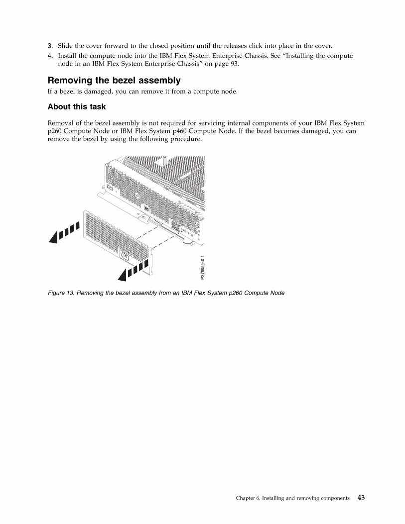
3. Slide the cover forward to the closed position until the releases click into place in the cover.4. Install the compute node into the IBM Flex System Enterprise Chassis. See “Installing the compute
node in an IBM Flex System Enterprise Chassis” on page 93.
Removing the bezel assemblyIf a bezel is damaged, you can remove it from a compute node.
About this task
Removal of the bezel assembly is not required for servicing internal components of your IBM Flex Systemp260 Compute Node or IBM Flex System p460 Compute Node. If the bezel becomes damaged, you canremove the bezel by using the following procedure.
Figure 13. Removing the bezel assembly from an IBM Flex System p260 Compute Node
Chapter 6. Installing and removing components 43
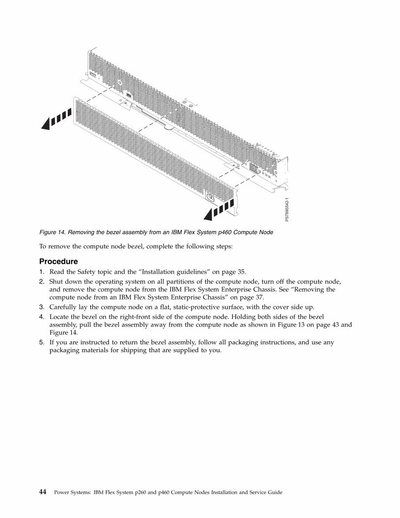
To remove the compute node bezel, complete the following steps:
Procedure1. Read the Safety topic and the “Installation guidelines” on page 35.2. Shut down the operating system on all partitions of the compute node, turn off the compute node,
and remove the compute node from the IBM Flex System Enterprise Chassis. See “Removing thecompute node from an IBM Flex System Enterprise Chassis” on page 37.
3. Carefully lay the compute node on a flat, static-protective surface, with the cover side up.4. Locate the bezel on the right-front side of the compute node. Holding both sides of the bezel
assembly, pull the bezel assembly away from the compute node as shown in Figure 13 on page 43 andFigure 14.
5. If you are instructed to return the bezel assembly, follow all packaging instructions, and use anypackaging materials for shipping that are supplied to you.
Figure 14. Removing the bezel assembly from an IBM Flex System p460 Compute Node
44 Power Systems: IBM Flex System p260 and p460 Compute Nodes Installation and Service Guide
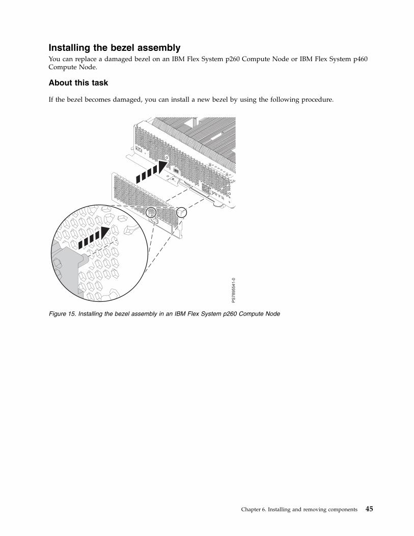
Installing the bezel assemblyYou can replace a damaged bezel on an IBM Flex System p260 Compute Node or IBM Flex System p460Compute Node.
About this task
If the bezel becomes damaged, you can install a new bezel by using the following procedure.
Figure 15. Installing the bezel assembly in an IBM Flex System p260 Compute Node
Chapter 6. Installing and removing components 45
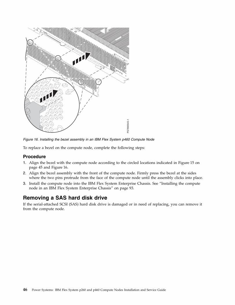
To replace a bezel on the compute node, complete the following steps:
Procedure1. Align the bezel with the compute node according to the circled locations indicated in Figure 15 on
page 45 and Figure 16.2. Align the bezel assembly with the front of the compute node. Firmly press the bezel at the sides
where the two pins protrude from the face of the compute node until the assembly clicks into place.3. Install the compute node into the IBM Flex System Enterprise Chassis. See “Installing the compute
node in an IBM Flex System Enterprise Chassis” on page 93.
Removing a SAS hard disk driveIf the serial-attached SCSI (SAS) hard disk drive is damaged or in need of replacing, you can remove itfrom the compute node.
Figure 16. Installing the bezel assembly in an IBM Flex System p460 Compute Node
46 Power Systems: IBM Flex System p260 and p460 Compute Nodes Installation and Service Guide
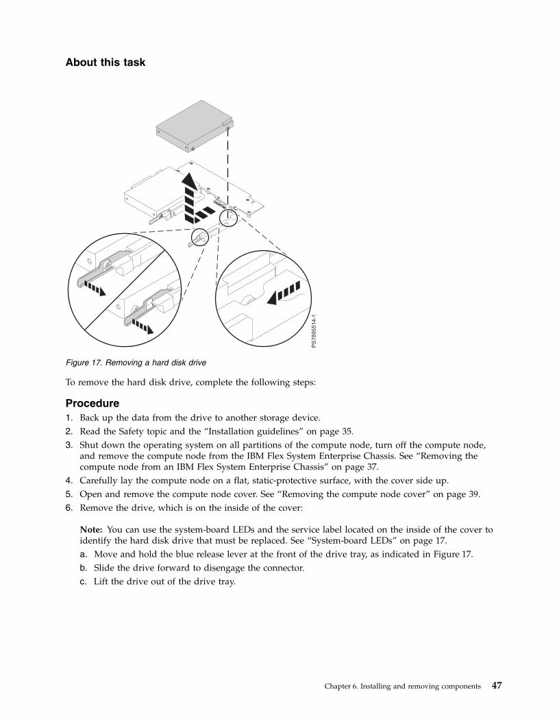
About this task
To remove the hard disk drive, complete the following steps:
Procedure1. Back up the data from the drive to another storage device.2. Read the Safety topic and the “Installation guidelines” on page 35.3. Shut down the operating system on all partitions of the compute node, turn off the compute node,
and remove the compute node from the IBM Flex System Enterprise Chassis. See “Removing thecompute node from an IBM Flex System Enterprise Chassis” on page 37.
4. Carefully lay the compute node on a flat, static-protective surface, with the cover side up.5. Open and remove the compute node cover. See “Removing the compute node cover” on page 39.6. Remove the drive, which is on the inside of the cover:
Note: You can use the system-board LEDs and the service label located on the inside of the cover toidentify the hard disk drive that must be replaced. See “System-board LEDs” on page 17.a. Move and hold the blue release lever at the front of the drive tray, as indicated in Figure 17.b. Slide the drive forward to disengage the connector.c. Lift the drive out of the drive tray.
Figure 17. Removing a hard disk drive
Chapter 6. Installing and removing components 47
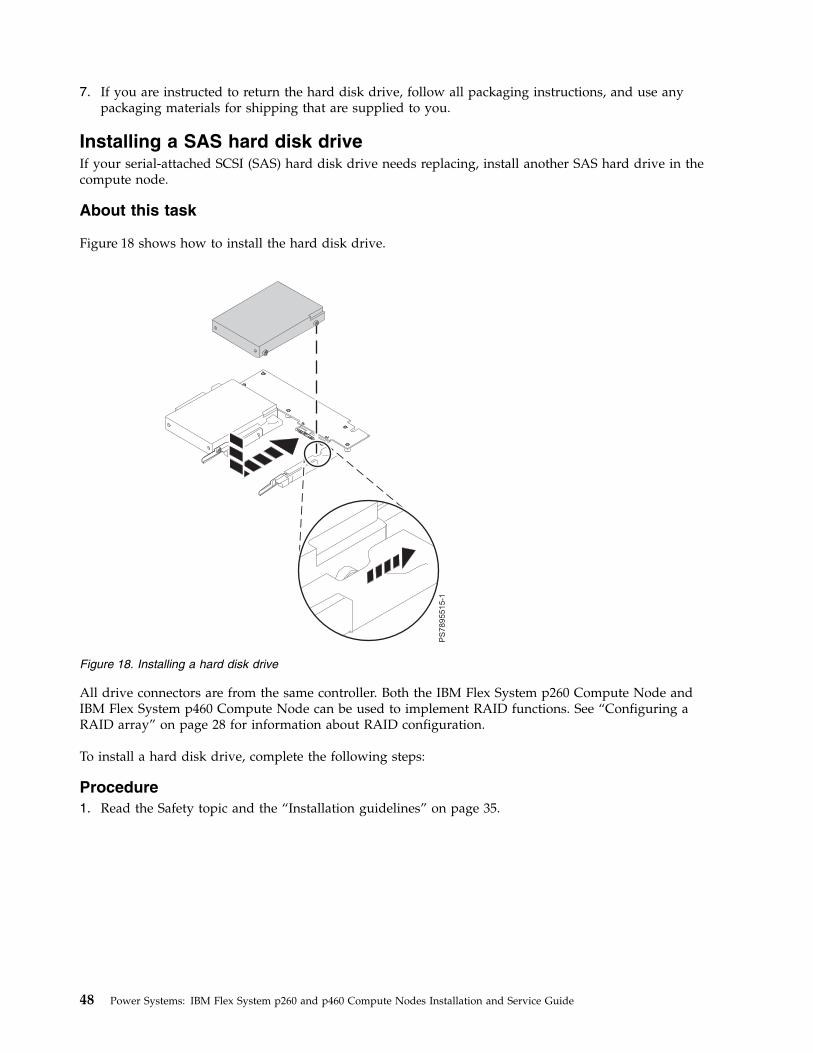
7. If you are instructed to return the hard disk drive, follow all packaging instructions, and use anypackaging materials for shipping that are supplied to you.
Installing a SAS hard disk driveIf your serial-attached SCSI (SAS) hard disk drive needs replacing, install another SAS hard drive in thecompute node.
About this task
Figure 18 shows how to install the hard disk drive.
All drive connectors are from the same controller. Both the IBM Flex System p260 Compute Node andIBM Flex System p460 Compute Node can be used to implement RAID functions. See “Configuring aRAID array” on page 28 for information about RAID configuration.
To install a hard disk drive, complete the following steps:
Procedure1. Read the Safety topic and the “Installation guidelines” on page 35.
Figure 18. Installing a hard disk drive
48 Power Systems: IBM Flex System p260 and p460 Compute Nodes Installation and Service Guide
2. Shut down the operating system on all partitions of the compute node, turn off the compute node,and remove the compute node from the IBM Flex System Enterprise Chassis. See “Removing thecompute node from an IBM Flex System Enterprise Chassis” on page 37.
3. Carefully lay the compute node on a flat, static-protective surface, with the cover side up.4. Open and remove the compute node cover. See “Removing the compute node cover” on page 39.5. Locate the connector for the drive on the inside of the cover.v If you are replacing a drive, continue to the next step.v If you are installing a new drive, remove the filler:
a. Move and hold the blue release lever at the front of the drive tray.b. Slide the filler forward and lift it out of the drive tray.
6. Place the drive into the drive tray and push it toward the rear of the compute node, as indicated inFigure 18 on page 48. When the drive moves past the lever at the front of the tray, it snaps in place.Attention: Do not press on the top of the drive. Pressing the top might damage the drive.
7. Install and close the compute node cover. See “Installing and closing the compute node cover” onpage 41.Statement 21
CAUTION:Hazardous energy is present when the compute node is connected to the power source. Alwaysreplace the compute node cover before installing the compute node.
8. Install the compute node into the IBM Flex System Enterprise Chassis. See “Installing the computenode in an IBM Flex System Enterprise Chassis” on page 93.
9. If you replaced the part because of a service action, verify the repair by checking that the amberenclosure fault LED is off. For more information, see “Compute node control panel button and LEDs”on page 11.
Removing a solid-state drive carrierIf your solid-state drive (SSD) carrier needs to be replaced, you can remove it from the compute node.
About this task
Chapter 6. Installing and removing components 49

To remove the drive, complete the following steps:
Procedure1. Back up the data from the drive to another storage device.2. Read the Safety topic and the “Installation guidelines” on page 35.3. Shut down the operating system on all partitions of the compute node, turn off the compute node,
and remove the compute node from the IBM Flex System Enterprise Chassis. See “Removing thecompute node from an IBM Flex System Enterprise Chassis” on page 37.
4. Carefully lay the compute node on a flat, static-protective surface, with the cover side up.5. Open and remove the compute node cover. See “Removing the compute node cover” on page 39.6. Remove the drive, which is on the inside of the cover:
Note: You can use the system-board LEDs and the service label located on the inside of the cover toidentify the solid-state drive that must be replaced. See “System-board LEDs” on page 17.a. Pull and hold the blue release lever at the front of the drive tray, as indicated in Figure 19.b. Slide the carrier case forward to disengage the connector.c. Lift the carrier case out of the drive tray.
Figure 19. Removing an SSD carrier
50 Power Systems: IBM Flex System p260 and p460 Compute Nodes Installation and Service Guide
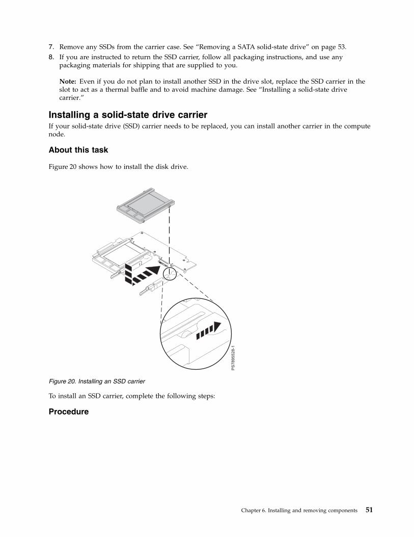
7. Remove any SSDs from the carrier case. See “Removing a SATA solid-state drive” on page 53.8. If you are instructed to return the SSD carrier, follow all packaging instructions, and use any
packaging materials for shipping that are supplied to you.
Note: Even if you do not plan to install another SSD in the drive slot, replace the SSD carrier in theslot to act as a thermal baffle and to avoid machine damage. See “Installing a solid-state drivecarrier.”
Installing a solid-state drive carrierIf your solid-state drive (SSD) carrier needs to be replaced, you can install another carrier in the computenode.
About this task
Figure 20 shows how to install the disk drive.
To install an SSD carrier, complete the following steps:
Procedure
Figure 20. Installing an SSD carrier
Chapter 6. Installing and removing components 51
1. Read the Safety topic and the “Installation guidelines” on page 35.2. Shut down the operating system on all partitions of the compute node, turn off the compute node,
and remove the compute node from the IBM Flex System Enterprise Chassis. See “Removing thecompute node from an IBM Flex System Enterprise Chassis” on page 37.
3. Carefully lay the compute node on a flat, static-protective surface, with the cover side up.4. Open and remove the compute node cover. See “Removing the compute node cover” on page 39.5. Locate the connector for the drive.
Note: Although the SSD carrier and the HDD are two separately configured cards, the SSD carriercase plugs in to the 2.5 inch SAS HDD connector.
6. If you are replacing an SSD carrier, continue to the next step. If you are installing a new SSD carrier,remove the filler to vacate the space for the new SSD carrier:a. Pull and hold the blue release lever at the front of the drive tray.b. Slide the filler forward to disengage the connector.c. Lift the filler out of the drive tray.
7. Remove the SSD carrier case that you want to replace from the drive tray. See “Removing asolid-state drive carrier” on page 49.
8. Install SSDs into the new carrier case. See “Installing a SATA solid-state drive” on page 54.9. Place the carrier case into the drive tray and push it toward the rear of the compute node, as
indicated in Figure 20 on page 51. When the SSD carrier moves past the lever at the front of the tray,it snaps in place.Attention: Do not press the top of the carrier case. Pressing the top might damage the drive.
10. Install and close the compute node cover. See “Installing and closing the compute node cover” onpage 41.Statement 21
CAUTION:Hazardous energy is present when the compute node is connected to the power source. Alwaysreplace the compute node cover before installing the compute node.
11. Install the compute node into the IBM Flex System Enterprise Chassis. See “Installing the computenode in an IBM Flex System Enterprise Chassis” on page 93.
12. If you replaced the part because of a service action, verify the repair by checking that the amberenclosure fault LED is off. For more information, see “Compute node control panel button andLEDs” on page 11.
52 Power Systems: IBM Flex System p260 and p460 Compute Nodes Installation and Service Guide
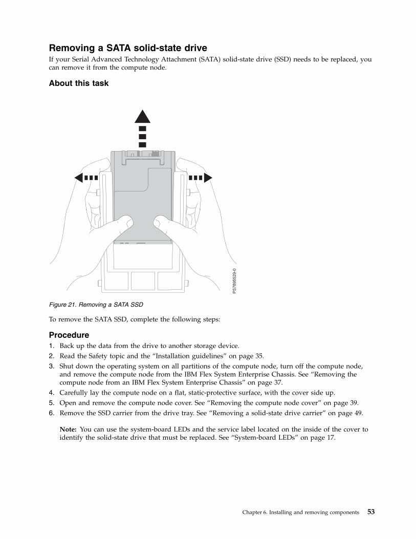
Removing a SATA solid-state driveIf your Serial Advanced Technology Attachment (SATA) solid-state drive (SSD) needs to be replaced, youcan remove it from the compute node.
About this task
To remove the SATA SSD, complete the following steps:
Procedure1. Back up the data from the drive to another storage device.2. Read the Safety topic and the “Installation guidelines” on page 35.3. Shut down the operating system on all partitions of the compute node, turn off the compute node,
and remove the compute node from the IBM Flex System Enterprise Chassis. See “Removing thecompute node from an IBM Flex System Enterprise Chassis” on page 37.
4. Carefully lay the compute node on a flat, static-protective surface, with the cover side up.5. Open and remove the compute node cover. See “Removing the compute node cover” on page 39.6. Remove the SSD carrier from the drive tray. See “Removing a solid-state drive carrier” on page 49.
Note: You can use the system-board LEDs and the service label located on the inside of the cover toidentify the solid-state drive that must be replaced. See “System-board LEDs” on page 17.
Figure 21. Removing a SATA SSD
Chapter 6. Installing and removing components 53
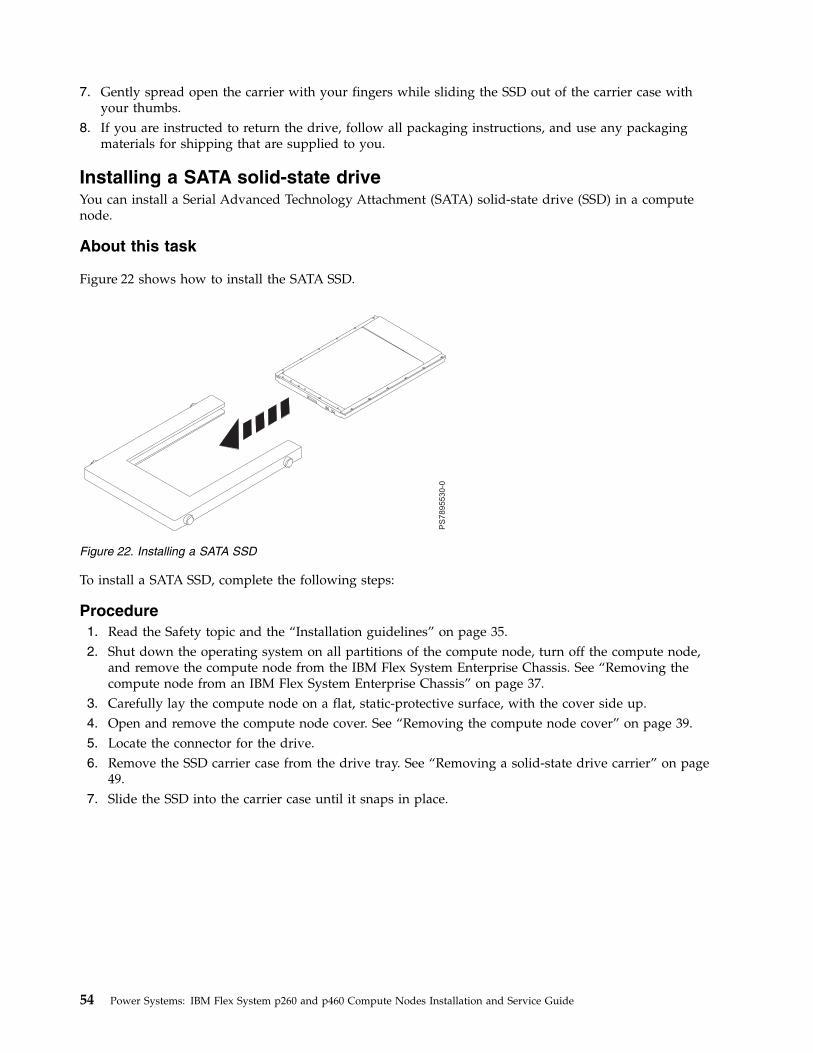
7. Gently spread open the carrier with your fingers while sliding the SSD out of the carrier case withyour thumbs.
8. If you are instructed to return the drive, follow all packaging instructions, and use any packagingmaterials for shipping that are supplied to you.
Installing a SATA solid-state driveYou can install a Serial Advanced Technology Attachment (SATA) solid-state drive (SSD) in a computenode.
About this task
Figure 22 shows how to install the SATA SSD.
To install a SATA SSD, complete the following steps:
Procedure1. Read the Safety topic and the “Installation guidelines” on page 35.2. Shut down the operating system on all partitions of the compute node, turn off the compute node,
and remove the compute node from the IBM Flex System Enterprise Chassis. See “Removing thecompute node from an IBM Flex System Enterprise Chassis” on page 37.
3. Carefully lay the compute node on a flat, static-protective surface, with the cover side up.4. Open and remove the compute node cover. See “Removing the compute node cover” on page 39.5. Locate the connector for the drive.6. Remove the SSD carrier case from the drive tray. See “Removing a solid-state drive carrier” on page
49.7. Slide the SSD into the carrier case until it snaps in place.
Figure 22. Installing a SATA SSD
54 Power Systems: IBM Flex System p260 and p460 Compute Nodes Installation and Service Guide
8. Replace the carrier case in the drive tray. See “Installing a solid-state drive carrier” on page 51.Attention: Do not press the top of the drive. Pressing the top might damage the drive.
9. Install and close the compute node cover. See “Installing and closing the compute node cover” onpage 41.Statement 21
CAUTION:Hazardous energy is present when the compute node is connected to the power source. Alwaysreplace the compute node cover before installing the compute node.
10. Install the compute node into the IBM Flex System Enterprise Chassis. See “Installing the computenode in an IBM Flex System Enterprise Chassis” on page 93.
11. If you replaced the part because of a service action, verify the repair by checking that the amberenclosure fault LED is off. For more information, see “Compute node control panel button andLEDs” on page 11.
Removing a DIMMThe very low profile (VLP) dual-inline memory module (DIMM) is a tier 1 CRU. You can remove ityourself. If IBM removes a tier 1 CRU at your request, you will be charged for the removal. The lowprofile (LP) DIMM is a tier 2 CRU. You can remove it yourself or request IBM to remove it, at noadditional charge, under the type of warranty service that is designated for the compute node.
About this task
To remove a DIMM, complete the following steps:
Procedure1. Read the Safety topic and the “Installation guidelines” on page 35.2. Shut down the operating system on all partitions of the compute node, turn off the compute node,
and remove the compute node from the IBM Flex System Enterprise Chassis. See “Removing thecompute node from an IBM Flex System Enterprise Chassis” on page 37.
3. Carefully lay the compute node on a flat, static-protective surface, with the cover side up.4. Open and remove the compute node cover. See “Removing the compute node cover” on page 39.5. Locate the DIMM connector that contains the DIMM being replaced.
Note: You can use the system-board LEDs and the service label located on the inside of the cover toidentify the DIMM that must be replaced. See “System-board LEDs” on page 17.
Chapter 6. Installing and removing components 55

Attention: To avoid breaking the DIMM retaining clips or damaging the DIMM connectors, openand close the clips gently.
Figure 23. DIMM connectors for the IBM Flex System p260 Compute Node
Figure 24. DIMM connectors for the IBM Flex System p460 Compute Node
56 Power Systems: IBM Flex System p260 and p460 Compute Nodes Installation and Service Guide
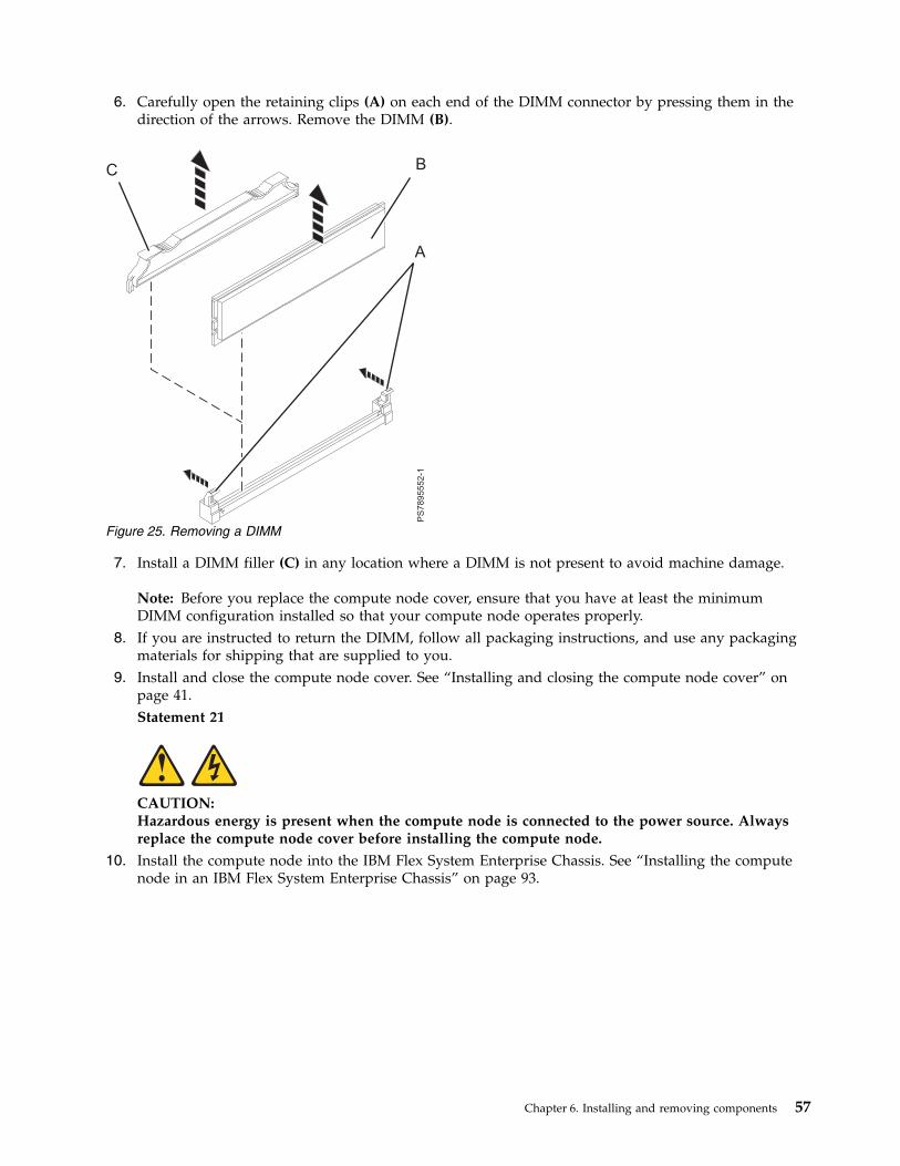
6. Carefully open the retaining clips (A) on each end of the DIMM connector by pressing them in thedirection of the arrows. Remove the DIMM (B).
7. Install a DIMM filler (C) in any location where a DIMM is not present to avoid machine damage.
Note: Before you replace the compute node cover, ensure that you have at least the minimumDIMM configuration installed so that your compute node operates properly.
8. If you are instructed to return the DIMM, follow all packaging instructions, and use any packagingmaterials for shipping that are supplied to you.
9. Install and close the compute node cover. See “Installing and closing the compute node cover” onpage 41.Statement 21
CAUTION:Hazardous energy is present when the compute node is connected to the power source. Alwaysreplace the compute node cover before installing the compute node.
10. Install the compute node into the IBM Flex System Enterprise Chassis. See “Installing the computenode in an IBM Flex System Enterprise Chassis” on page 93.
Figure 25. Removing a DIMM
Chapter 6. Installing and removing components 57
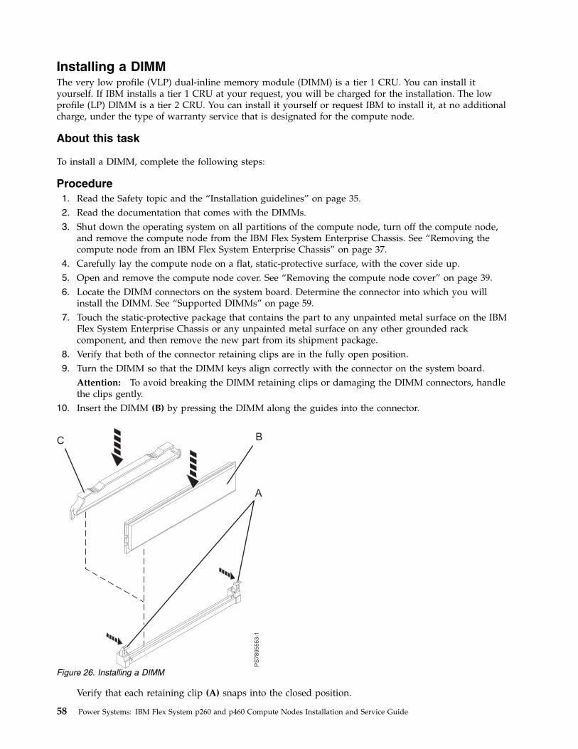
Installing a DIMMThe very low profile (VLP) dual-inline memory module (DIMM) is a tier 1 CRU. You can install ityourself. If IBM installs a tier 1 CRU at your request, you will be charged for the installation. The lowprofile (LP) DIMM is a tier 2 CRU. You can install it yourself or request IBM to install it, at no additionalcharge, under the type of warranty service that is designated for the compute node.
About this task
To install a DIMM, complete the following steps:
Procedure1. Read the Safety topic and the “Installation guidelines” on page 35.2. Read the documentation that comes with the DIMMs.3. Shut down the operating system on all partitions of the compute node, turn off the compute node,
and remove the compute node from the IBM Flex System Enterprise Chassis. See “Removing thecompute node from an IBM Flex System Enterprise Chassis” on page 37.
4. Carefully lay the compute node on a flat, static-protective surface, with the cover side up.5. Open and remove the compute node cover. See “Removing the compute node cover” on page 39.6. Locate the DIMM connectors on the system board. Determine the connector into which you will
install the DIMM. See “Supported DIMMs” on page 59.7. Touch the static-protective package that contains the part to any unpainted metal surface on the IBM
Flex System Enterprise Chassis or any unpainted metal surface on any other grounded rackcomponent, and then remove the new part from its shipment package.
8. Verify that both of the connector retaining clips are in the fully open position.9. Turn the DIMM so that the DIMM keys align correctly with the connector on the system board.
Attention: To avoid breaking the DIMM retaining clips or damaging the DIMM connectors, handlethe clips gently.
10. Insert the DIMM (B) by pressing the DIMM along the guides into the connector.
Verify that each retaining clip (A) snaps into the closed position.
Figure 26. Installing a DIMM
58 Power Systems: IBM Flex System p260 and p460 Compute Nodes Installation and Service Guide
Important: If there is a gap between the DIMM and the retaining clips, the DIMM is not correctlyinstalled. Open the retaining clips to remove and reinsert the DIMM. Install a DIMM filler (C) in anylocation where a DIMM is not present to avoid machine damage.
11. Install and close the compute node cover. See “Installing and closing the compute node cover” onpage 41.Statement 21
CAUTION:Hazardous energy is present when the compute node is connected to the power source. Alwaysreplace the compute node cover before installing the compute node.
12. Install the compute node into the IBM Flex System Enterprise Chassis. See “Installing the computenode in an IBM Flex System Enterprise Chassis” on page 93.
13. If you replaced the part because of a service action, verify the repair by checking that the amberenclosure fault LED is off. For more information, see “Compute node control panel button andLEDs” on page 11.
Related concepts:“Supported DIMMs”Your compute node contains connectors for registered dual inline memory modules (RDIMMs).
Supported DIMMsYour compute node contains connectors for registered dual inline memory modules (RDIMMs).
Each system board in the IBM Flex System p260 Compute Node contains connectors for 16 low profile(LP) or very low profile (VLP) memory DIMMs. The IBM Flex System p460 Compute Node supports upto 32 DIMMs.
The maximum size for a single DIMM is 8 GB for a VLP DIMM and 32 GB for an LP DIMM. Themaximum memory capacity for an IBM Flex System p260 Compute Node is 512 GB and for an IBM FlexSystem p460 Compute Node is 1024 GB.
Memory module rules:
v Install DIMM fillers in unused DIMM slots for proper cooling.v Install DIMMs in pairs (1 and 4, 5 and 8, 9 and 12, 13 and 16, 2 and 3, 6 and 7, 10 and 11, and 14 and
15).v Both DIMMs in a pair must be the same size, speed, type, and technology. You can mix compatible
DIMMs from different manufacturers.v Each DIMM within a processor-support group (1-4, 5-8, 9-12, 13-16) must be the same size and speed.v Install only supported DIMMs, as described on the ServerProven website.v Installing or removing DIMMs changes the configuration of the compute node. After you install or
remove a DIMM, the compute node is automatically reconfigured, and the new configurationinformation is stored.
The following table shows allowable placements of DIMM modules for the IBM Flex System p260Compute Node. Table 7 on page 60 shows allowable placements of DIMM modules for the IBM FlexSystem p460 Compute Node.
Chapter 6. Installing and removing components 59
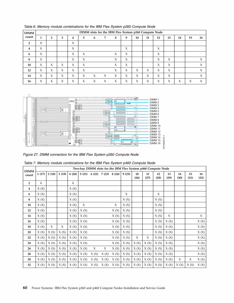
Table 6. Memory module combinations for the IBM Flex System p260 Compute Node
DIMMcount
DIMM slots for the IBM Flex System p260 Compute Node
1 2 3 4 5 6 7 8 9 10 11 12 13 14 15 16
2 X X
4 X X X X
6 X X X X X X
8 X X X X X X X X
10 X X X X X X X X X X
12 X X X X X X X X X X X X
14 X X X X X X X X X X X X X X
16 X X X X X X X X X X X X X X X X
Table 7. Memory module combinations for the IBM Flex System p460 Compute Node
DIMMcount
Two-bay DIMM slots for the IBM Flex System p460 Compute Node
1 (17) 2 (18) 3 (19) 4 (20) 5 (21) 6 (22) 7 (23) 8 (24) 9 (25) 10(26)
11(27)
12(28)
13(29)
14(30)
15(31)
16(32)
2 X X
4 X (X) X (X)
6 X (X) X (X) X X
8 X (X) X (X) X (X) X (X)
10 X (X) X (X) X X X (X) X (X)
12 X (X) X (X) X (X) X (X) X (X) X (X)
14 X (X) X (X) X (X) X (X) X (X) X (X) X X
16 X (X) X (X) X (X) X (X) X (X) X (X) X (X) X (X)
18 X (X) X X X (X) X (X) X (X) X (X) X (X) X (X) X (X)
20 X (X) X (X) X (X) X (X) X (X) X (X) X (X) X (X) X (X) X (X)
22 X (X) X (X) X (X) X (X) X (X) X (X) X (X) X X X (X) X (X) X (X)
24 X (X) X (X) X (X) X (X) X (X) X (X) X (X) X (X) X (X) X (X) X (X) X (X)
26 X (X) X (X) X (X) X (X) X (X) X X X (X) X (X) X (X) X (X) X (X) X (X) X (X)
28 X (X) X (X) X (X) X (X) X (X) X (X) X (X) X (X) X (X) X (X) X (X) X (X) X (X) X (X)
30 X (X) X (X) X (X) X (X) X (X) X (X) X (X) X (X) X (X) X (X) X (X) X (X) X (X) X X X (X)
32 X (X) X (X) X (X) X (X) X (X) X (X) X (X) X (X) X (X) X (X) X (X) X (X) X (X) X (X) X (X) X (X)
Figure 27. DIMM connectors for the IBM Flex System p260 Compute Node
60 Power Systems: IBM Flex System p260 and p460 Compute Nodes Installation and Service Guide
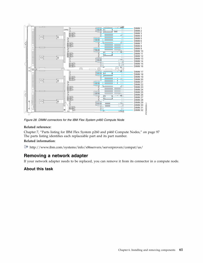
Related reference:Chapter 7, “Parts listing for IBM Flex System p260 and p460 Compute Nodes,” on page 97The parts listing identifies each replaceable part and its part number.Related information:
http://www.ibm.com/systems/info/x86servers/serverproven/compat/us/
Removing a network adapterIf your network adapter needs to be replaced, you can remove it from its connector in a compute node.
About this task
Figure 28. DIMM connectors for the IBM Flex System p460 Compute Node
Chapter 6. Installing and removing components 61
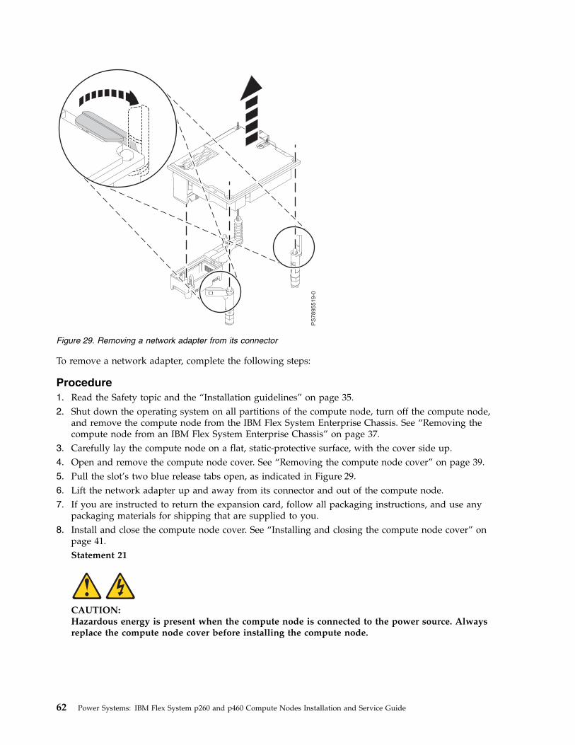
To remove a network adapter, complete the following steps:
Procedure1. Read the Safety topic and the “Installation guidelines” on page 35.2. Shut down the operating system on all partitions of the compute node, turn off the compute node,
and remove the compute node from the IBM Flex System Enterprise Chassis. See “Removing thecompute node from an IBM Flex System Enterprise Chassis” on page 37.
3. Carefully lay the compute node on a flat, static-protective surface, with the cover side up.4. Open and remove the compute node cover. See “Removing the compute node cover” on page 39.5. Pull the slot’s two blue release tabs open, as indicated in Figure 29.6. Lift the network adapter up and away from its connector and out of the compute node.7. If you are instructed to return the expansion card, follow all packaging instructions, and use any
packaging materials for shipping that are supplied to you.8. Install and close the compute node cover. See “Installing and closing the compute node cover” on
page 41.Statement 21
CAUTION:Hazardous energy is present when the compute node is connected to the power source. Alwaysreplace the compute node cover before installing the compute node.
Figure 29. Removing a network adapter from its connector
62 Power Systems: IBM Flex System p260 and p460 Compute Nodes Installation and Service Guide
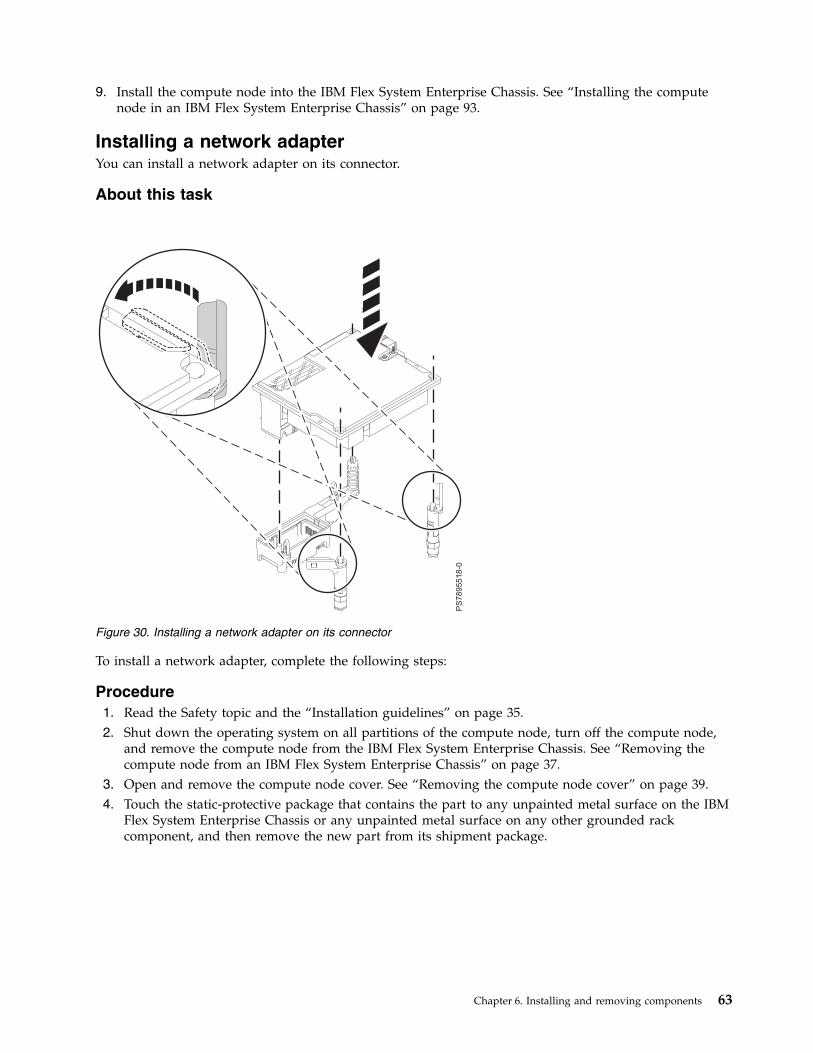
9. Install the compute node into the IBM Flex System Enterprise Chassis. See “Installing the computenode in an IBM Flex System Enterprise Chassis” on page 93.
Installing a network adapterYou can install a network adapter on its connector.
About this task
To install a network adapter, complete the following steps:
Procedure1. Read the Safety topic and the “Installation guidelines” on page 35.2. Shut down the operating system on all partitions of the compute node, turn off the compute node,
and remove the compute node from the IBM Flex System Enterprise Chassis. See “Removing thecompute node from an IBM Flex System Enterprise Chassis” on page 37.
3. Open and remove the compute node cover. See “Removing the compute node cover” on page 39.4. Touch the static-protective package that contains the part to any unpainted metal surface on the IBM
Flex System Enterprise Chassis or any unpainted metal surface on any other grounded rackcomponent, and then remove the new part from its shipment package.
Figure 30. Installing a network adapter on its connector
Chapter 6. Installing and removing components 63

5. Make sure that the slot’s two blue release tabs are in the open position, as indicated in Figure 30 onpage 63.
6. Orient the network adapter over the system board.7. Lower the card to the system board, aligning the connectors on the card with its connector on the
system board. Press down gently until the card is firmly seated.8. Lock the adapter in place by moving the slot’s two blue release tabs into the closed position.9. Install and close the compute node cover. See “Installing and closing the compute node cover” on
page 41.Statement 21
CAUTION:Hazardous energy is present when the compute node is connected to the power source. Alwaysreplace the compute node cover before installing the compute node.
10. Install the compute node into the IBM Flex System Enterprise Chassis. See “Installing the computenode in an IBM Flex System Enterprise Chassis” on page 93.
11. If you replaced the part because of a service action, verify the repair by checking that the amberenclosure fault LED is off. For more information, see “Compute node control panel button andLEDs” on page 11.
12. Use the documentation that comes with the expansion card to install device drivers and to performany configuration that the expansion card requires.
Removing the batteryYou can remove and replace the battery.
About this task
To remove the battery, complete the following steps:
Procedure1. Read the Safety topic and the “Installation guidelines” on page 35.
Figure 31. Removing the battery
64 Power Systems: IBM Flex System p260 and p460 Compute Nodes Installation and Service Guide
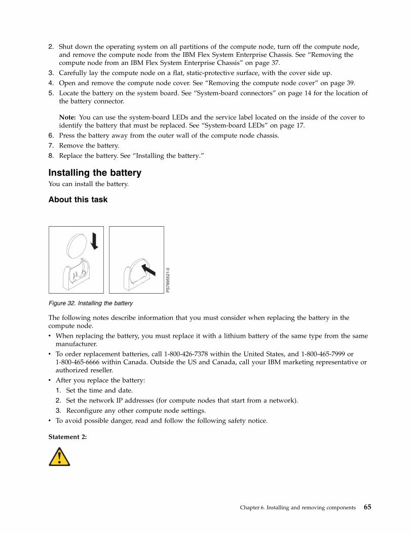
2. Shut down the operating system on all partitions of the compute node, turn off the compute node,and remove the compute node from the IBM Flex System Enterprise Chassis. See “Removing thecompute node from an IBM Flex System Enterprise Chassis” on page 37.
3. Carefully lay the compute node on a flat, static-protective surface, with the cover side up.4. Open and remove the compute node cover. See “Removing the compute node cover” on page 39.5. Locate the battery on the system board. See “System-board connectors” on page 14 for the location of
the battery connector.
Note: You can use the system-board LEDs and the service label located on the inside of the cover toidentify the battery that must be replaced. See “System-board LEDs” on page 17.
6. Press the battery away from the outer wall of the compute node chassis.7. Remove the battery.8. Replace the battery. See “Installing the battery.”
Installing the batteryYou can install the battery.
About this task
The following notes describe information that you must consider when replacing the battery in thecompute node.v When replacing the battery, you must replace it with a lithium battery of the same type from the same
manufacturer.v To order replacement batteries, call 1-800-426-7378 within the United States, and 1-800-465-7999 or
1-800-465-6666 within Canada. Outside the US and Canada, call your IBM marketing representative orauthorized reseller.
v After you replace the battery:1. Set the time and date.2. Set the network IP addresses (for compute nodes that start from a network).3. Reconfigure any other compute node settings.
v To avoid possible danger, read and follow the following safety notice.
Statement 2:
Figure 32. Installing the battery
Chapter 6. Installing and removing components 65
CAUTION:When replacing the lithium battery, use only IBM Part Number 33F8354 or an equivalent type batteryrecommended by the manufacturer. If your system has a module containing a lithium battery, replaceit only with the same module type made by the same manufacturer. The battery contains lithium andcan explode if not properly used, handled, or disposed of.
Do not:
v Throw or immerse into water
v Heat to more than 100°C (212°F)
v Repair or disassemble
Dispose of the battery as required by local ordinances or regulations.
To install the battery, complete the following steps:
Procedure1. Follow any special handling and installation instructions that come with the battery.2. Tilt the battery so that you can insert it into the socket. Make sure that the side with the positive (+)
symbol is facing the correct direction.3. Press the battery toward the outer wall of the compute node chassis until fully inserted into the
battery holder.4. Install and close the compute node cover. See “Installing and closing the compute node cover” on
page 41.Statement 21
CAUTION:Hazardous energy is present when the compute node is connected to the power source. Alwaysreplace the compute node cover before installing the compute node.
5. Install the compute node into the IBM Flex System Enterprise Chassis. See “Installing the computenode in an IBM Flex System Enterprise Chassis” on page 93.
6. Turn on the compute node and reset the system date and time through the operating system that youinstalled. For additional information, see your operating-system documentation.
7. Ensure that the system time is correct in each of the logical partitions. For additional information, seethe documentation for your operating system.
8. If you replaced the part because of a service action, verify the repair by checking that the amberenclosure fault LED is off. For more information, see “Compute node control panel button and LEDs”on page 11.
66 Power Systems: IBM Flex System p260 and p460 Compute Nodes Installation and Service Guide
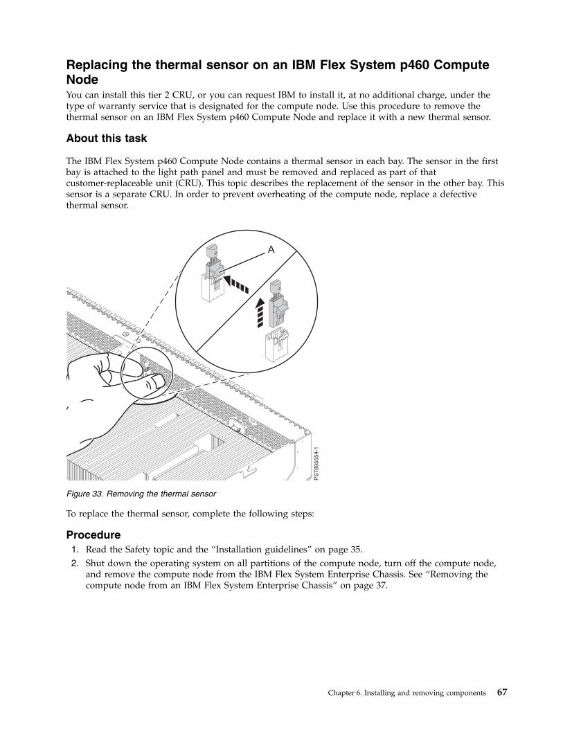
Replacing the thermal sensor on an IBM Flex System p460 ComputeNodeYou can install this tier 2 CRU, or you can request IBM to install it, at no additional charge, under thetype of warranty service that is designated for the compute node. Use this procedure to remove thethermal sensor on an IBM Flex System p460 Compute Node and replace it with a new thermal sensor.
About this task
The IBM Flex System p460 Compute Node contains a thermal sensor in each bay. The sensor in the firstbay is attached to the light path panel and must be removed and replaced as part of thatcustomer-replaceable unit (CRU). This topic describes the replacement of the sensor in the other bay. Thissensor is a separate CRU. In order to prevent overheating of the compute node, replace a defectivethermal sensor.
To replace the thermal sensor, complete the following steps:
Procedure1. Read the Safety topic and the “Installation guidelines” on page 35.2. Shut down the operating system on all partitions of the compute node, turn off the compute node,
and remove the compute node from the IBM Flex System Enterprise Chassis. See “Removing thecompute node from an IBM Flex System Enterprise Chassis” on page 37.
Figure 33. Removing the thermal sensor
Chapter 6. Installing and removing components 67
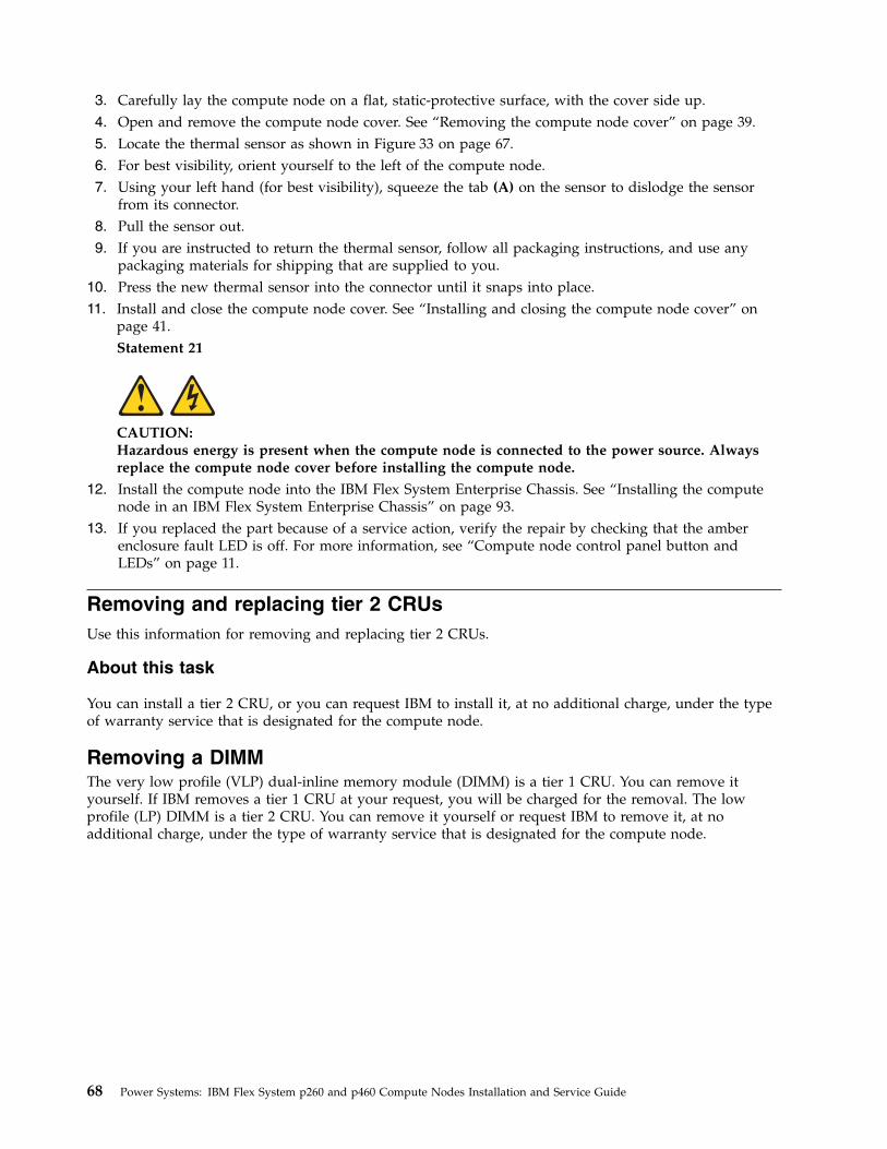
3. Carefully lay the compute node on a flat, static-protective surface, with the cover side up.4. Open and remove the compute node cover. See “Removing the compute node cover” on page 39.5. Locate the thermal sensor as shown in Figure 33 on page 67.6. For best visibility, orient yourself to the left of the compute node.7. Using your left hand (for best visibility), squeeze the tab (A) on the sensor to dislodge the sensor
from its connector.8. Pull the sensor out.9. If you are instructed to return the thermal sensor, follow all packaging instructions, and use any
packaging materials for shipping that are supplied to you.10. Press the new thermal sensor into the connector until it snaps into place.11. Install and close the compute node cover. See “Installing and closing the compute node cover” on
page 41.Statement 21
CAUTION:Hazardous energy is present when the compute node is connected to the power source. Alwaysreplace the compute node cover before installing the compute node.
12. Install the compute node into the IBM Flex System Enterprise Chassis. See “Installing the computenode in an IBM Flex System Enterprise Chassis” on page 93.
13. If you replaced the part because of a service action, verify the repair by checking that the amberenclosure fault LED is off. For more information, see “Compute node control panel button andLEDs” on page 11.
Removing and replacing tier 2 CRUsUse this information for removing and replacing tier 2 CRUs.
About this task
You can install a tier 2 CRU, or you can request IBM to install it, at no additional charge, under the typeof warranty service that is designated for the compute node.
Removing a DIMMThe very low profile (VLP) dual-inline memory module (DIMM) is a tier 1 CRU. You can remove ityourself. If IBM removes a tier 1 CRU at your request, you will be charged for the removal. The lowprofile (LP) DIMM is a tier 2 CRU. You can remove it yourself or request IBM to remove it, at noadditional charge, under the type of warranty service that is designated for the compute node.
68 Power Systems: IBM Flex System p260 and p460 Compute Nodes Installation and Service Guide
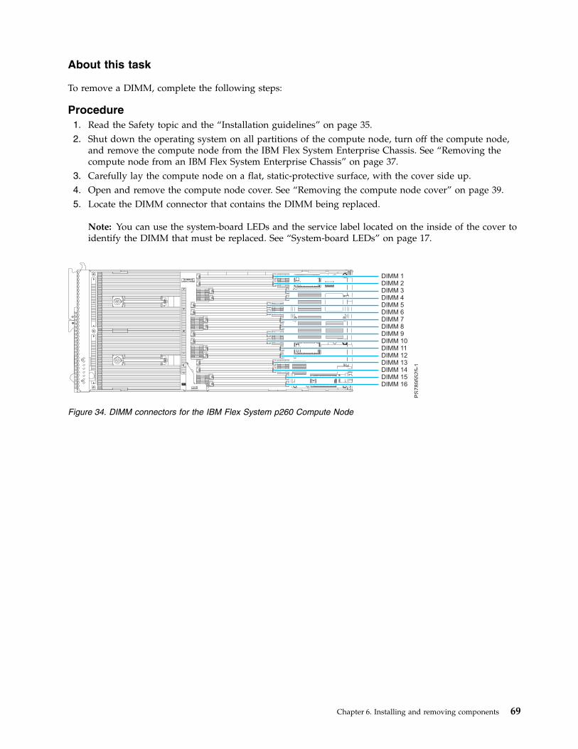
About this task
To remove a DIMM, complete the following steps:
Procedure1. Read the Safety topic and the “Installation guidelines” on page 35.2. Shut down the operating system on all partitions of the compute node, turn off the compute node,
and remove the compute node from the IBM Flex System Enterprise Chassis. See “Removing thecompute node from an IBM Flex System Enterprise Chassis” on page 37.
3. Carefully lay the compute node on a flat, static-protective surface, with the cover side up.4. Open and remove the compute node cover. See “Removing the compute node cover” on page 39.5. Locate the DIMM connector that contains the DIMM being replaced.
Note: You can use the system-board LEDs and the service label located on the inside of the cover toidentify the DIMM that must be replaced. See “System-board LEDs” on page 17.
Figure 34. DIMM connectors for the IBM Flex System p260 Compute Node
Chapter 6. Installing and removing components 69

Attention: To avoid breaking the DIMM retaining clips or damaging the DIMM connectors, openand close the clips gently.
6. Carefully open the retaining clips (A) on each end of the DIMM connector by pressing them in thedirection of the arrows. Remove the DIMM (B).
Figure 35. DIMM connectors for the IBM Flex System p460 Compute Node
Figure 36. Removing a DIMM
70 Power Systems: IBM Flex System p260 and p460 Compute Nodes Installation and Service Guide

7. Install a DIMM filler (C) in any location where a DIMM is not present to avoid machine damage.
Note: Before you replace the compute node cover, ensure that you have at least the minimumDIMM configuration installed so that your compute node operates properly.
8. If you are instructed to return the DIMM, follow all packaging instructions, and use any packagingmaterials for shipping that are supplied to you.
9. Install and close the compute node cover. See “Installing and closing the compute node cover” onpage 41.Statement 21
CAUTION:Hazardous energy is present when the compute node is connected to the power source. Alwaysreplace the compute node cover before installing the compute node.
10. Install the compute node into the IBM Flex System Enterprise Chassis. See “Installing the computenode in an IBM Flex System Enterprise Chassis” on page 93.
Installing a DIMMThe very low profile (VLP) dual-inline memory module (DIMM) is a tier 1 CRU. You can install ityourself. If IBM installs a tier 1 CRU at your request, you will be charged for the installation. The lowprofile (LP) DIMM is a tier 2 CRU. You can install it yourself or request IBM to install it, at no additionalcharge, under the type of warranty service that is designated for the compute node.
About this task
To install a DIMM, complete the following steps:
Procedure1. Read the Safety topic and the “Installation guidelines” on page 35.2. Read the documentation that comes with the DIMMs.3. Shut down the operating system on all partitions of the compute node, turn off the compute node,
and remove the compute node from the IBM Flex System Enterprise Chassis. See “Removing thecompute node from an IBM Flex System Enterprise Chassis” on page 37.
4. Carefully lay the compute node on a flat, static-protective surface, with the cover side up.5. Open and remove the compute node cover. See “Removing the compute node cover” on page 39.6. Locate the DIMM connectors on the system board. Determine the connector into which you will
install the DIMM. See “Supported DIMMs” on page 59.7. Touch the static-protective package that contains the part to any unpainted metal surface on the IBM
Flex System Enterprise Chassis or any unpainted metal surface on any other grounded rackcomponent, and then remove the new part from its shipment package.
Chapter 6. Installing and removing components 71
8. Verify that both of the connector retaining clips are in the fully open position.9. Turn the DIMM so that the DIMM keys align correctly with the connector on the system board.
Attention: To avoid breaking the DIMM retaining clips or damaging the DIMM connectors, handlethe clips gently.
10. Insert the DIMM (B) by pressing the DIMM along the guides into the connector.
Verify that each retaining clip (A) snaps into the closed position.
Important: If there is a gap between the DIMM and the retaining clips, the DIMM is not correctlyinstalled. Open the retaining clips to remove and reinsert the DIMM. Install a DIMM filler (C) in anylocation where a DIMM is not present to avoid machine damage.
11. Install and close the compute node cover. See “Installing and closing the compute node cover” onpage 41.Statement 21
CAUTION:Hazardous energy is present when the compute node is connected to the power source. Alwaysreplace the compute node cover before installing the compute node.
Figure 37. Installing a DIMM
72 Power Systems: IBM Flex System p260 and p460 Compute Nodes Installation and Service Guide
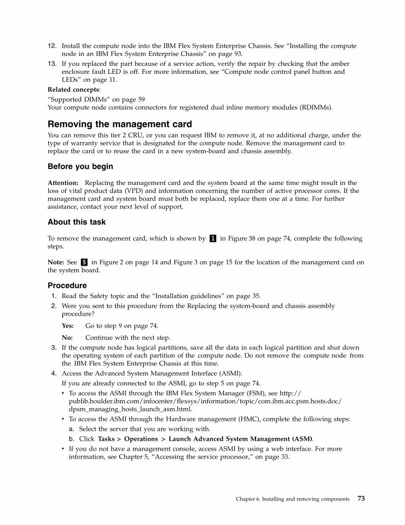
12. Install the compute node into the IBM Flex System Enterprise Chassis. See “Installing the computenode in an IBM Flex System Enterprise Chassis” on page 93.
13. If you replaced the part because of a service action, verify the repair by checking that the amberenclosure fault LED is off. For more information, see “Compute node control panel button andLEDs” on page 11.
Related concepts:“Supported DIMMs” on page 59Your compute node contains connectors for registered dual inline memory modules (RDIMMs).
Removing the management cardYou can remove this tier 2 CRU, or you can request IBM to remove it, at no additional charge, under thetype of warranty service that is designated for the compute node. Remove the management card toreplace the card or to reuse the card in a new system-board and chassis assembly.
Before you begin
Attention: Replacing the management card and the system board at the same time might result in theloss of vital product data (VPD) and information concerning the number of active processor cores. If themanagement card and system board must both be replaced, replace them one at a time. For furtherassistance, contact your next level of support.
About this task
To remove the management card, which is shown by ▌1▐ in Figure 38 on page 74, complete the followingsteps.
Note: See ▌5▐ in Figure 2 on page 14 and Figure 3 on page 15 for the location of the management card onthe system board.
Procedure1. Read the Safety topic and the “Installation guidelines” on page 35.2. Were you sent to this procedure from the Replacing the system-board and chassis assembly
procedure?
Yes: Go to step 9 on page 74.
No: Continue with the next step.3. If the compute node has logical partitions, save all the data in each logical partition and shut down
the operating system of each partition of the compute node. Do not remove the compute node fromthe IBM Flex System Enterprise Chassis at this time.
4. Access the Advanced System Management Interface (ASMI).If you are already connected to the ASMI, go to step 5 on page 74.v To access the ASMI through the IBM Flex System Manager (FSM), see http://
publib.boulder.ibm.com/infocenter/flexsys/information/topic/com.ibm.acc.psm.hosts.doc/dpsm_managing_hosts_launch_asm.html.
v To access the ASMI through the Hardware management (HMC), complete the following steps:a. Select the server that you are working with.b. Click Tasks > Operations > Launch Advanced System Management (ASM).
v If you do not have a management console, access ASMI by using a web interface. For moreinformation, see Chapter 5, “Accessing the service processor,” on page 33.
Chapter 6. Installing and removing components 73
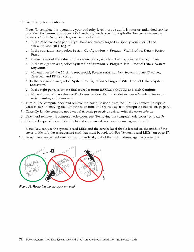
5. Save the system identifiers.
Note: To complete this operation, your authority level must be administrator or authorized serviceprovider. For information about ASMI authority levels, see http://pic.dhe.ibm.com/infocenter/powersys/v3r1m5/topic/p7hby/asmiauthority.htm.a. In the ASM Welcome pane, if you have not already logged in, specify your user ID and
password, and click Log In.b. In the navigation area, select System Configuration > Program Vital Product Data > System
Brand.c. Manually record the value for the system brand, which will is displayed in the right pane.d. In the navigation area, select System Configuration > Program Vital Product Data > System
Keywords.e. Manually record the Machine type-model, System serial number, System unique ID values,
Reserved, and RB keyword0.f. In the navigation area, select System Configuration > Program Vital Product Data > System
Enclosures.g. In the right pane, select the Enclosure location: UXXXX.YYY.ZZZZ and click Continue.h. Manually record the values of Enclosure location, Feature Code/Sequence Number, Enclosure
serial number, and Reserved.6. Turn off the compute node and remove the compute node from the IBM Flex System Enterprise
Chassis. See “Removing the compute node from an IBM Flex System Enterprise Chassis” on page 37.7. Carefully lay the compute node on a flat, static-protective surface, with the cover side up.8. Open and remove the compute node cover. See “Removing the compute node cover” on page 39.9. If an I/O expansion card is in the first slot, remove it to access the management card.
Note: You can use the system-board LEDs and the service label that is located on the inside of thecover to identify the management card that must be replaced. See “System-board LEDs” on page 17.
10. Grasp the management card and pull it vertically out of the unit to disengage the connectors.
Figure 38. Removing the management card
74 Power Systems: IBM Flex System p260 and p460 Compute Nodes Installation and Service Guide
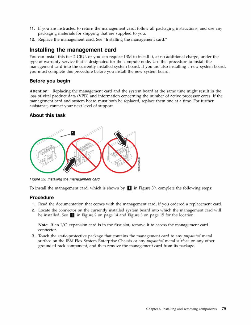
11. If you are instructed to return the management card, follow all packaging instructions, and use anypackaging materials for shipping that are supplied to you.
12. Replace the management card. See “Installing the management card.”
Installing the management cardYou can install this tier 2 CRU, or you can request IBM to install it, at no additional charge, under thetype of warranty service that is designated for the compute node. Use this procedure to install themanagement card into the currently installed system board. If you are also installing a new system board,you must complete this procedure before you install the new system board.
Before you begin
Attention: Replacing the management card and the system board at the same time might result in theloss of vital product data (VPD) and information concerning the number of active processor cores. If themanagement card and system board must both be replaced, replace them one at a time. For furtherassistance, contact your next level of support.
About this task
To install the management card, which is shown by ▌1▐ in Figure 39, complete the following steps:
Procedure1. Read the documentation that comes with the management card, if you ordered a replacement card.2. Locate the connector on the currently installed system board into which the management card will
be installed. See ▌5▐ in Figure 2 on page 14 and Figure 3 on page 15 for the location.
Note: If an I/O expansion card is in the first slot, remove it to access the management cardconnector.
3. Touch the static-protective package that contains the management card to any unpainted metalsurface on the IBM Flex System Enterprise Chassis or any unpainted metal surface on any othergrounded rack component, and then remove the management card from its package.
Figure 39. Installing the management card
Chapter 6. Installing and removing components 75
4. Insert the management card (as shown by ▌1▐ in Figure 39 on page 75) and verify that the card issecurely on the connector and pushed down all the way to the main board.
5. Were you sent to this procedure from the “Replacing the system-board and chassis assembly” onpage 83 procedure?
Yes: Return to the Return to the Replacing the system-board and chassis assembly procedure.
No: Continue with the next step.6. Install and close the compute node cover. See “Installing and closing the compute node cover” on
page 41.Statement 21
CAUTION:Hazardous energy is present when the compute node is connected to the power source. Alwaysreplace the compute node cover before installing the compute node.
7. Install the compute node into the IBM Flex System Enterprise Chassis. See “Installing the computenode in an IBM Flex System Enterprise Chassis” on page 93.
8. Power on the compute node. If a Virtual I/O Server (VIOS) partition is installed, power on only theVIOS partition. If VIOS is not installed, power on one of the partitions. If the compute node ismanaged by a management console, wait for the compute node to be discovered by the managementconsole before continuing with the next step.Attention: If the management card was not properly installed, the power-on LED flashes rapidlyand a communication error is reported to the management console. If this occurs, remove thecompute node from the IBM Flex System Enterprise Chassis, as described in “Removing themanagement card” on page 73. Reseat the management card, and then reinstall the compute node inthe IBM Flex System Enterprise Chassis.
9. A new Virtualization Engine technologies (VET) code must be generated and activated. Perform“Obtaining a PowerVM Virtualization Engine system technologies activation code” on page 77. Waitat least five minutes to ensure that the VET activation code is stored in the vital product data on themanagement card and then power off the operating system and the compute node. Continue withthe next step of this procedure.
10. Access the Advanced System Management Interface (ASMI).If you are already connected to the ASMI, go to the step 11 on page 77.v To access the ASMI through the IBM Flex System Manager (FSM), see http://
publib.boulder.ibm.com/infocenter/flexsys/information/topic/com.ibm.acc.psm.hosts.doc/dpsm_managing_hosts_launch_asm.html.
v To access the ASMI through the Hardware management (HMC), complete the following steps:a. Select the server that you are working with.b. Click Tasks > Operations > Launch Advanced System Management (ASM).
v If you do not have a management console, access ASMI by using a web interface. For moreinformation, see Chapter 5, “Accessing the service processor,” on page 33.
76 Power Systems: IBM Flex System p260 and p460 Compute Nodes Installation and Service Guide
11. Verify that the management card VPD is correct.
Note: To complete this operation, your authority level must be administrator or authorized serviceprovider. For information about ASMI authority levels, see http://pic.dhe.ibm.com/infocenter/powersys/v3r1m5/topic/p7hby/asmiauthority.htm.a. In the ASM Welcome pane, if you are not already logged in, specify your user ID and password,
and click Log In.b. In the navigation area, select System Configuration > Program Vital Product Data > System
Brand.c. Verify the system brand information matches what you recorded during the removal procedure.
Otherwise, contact your next level of support.d. In the navigation area, select System Configuration > Program Vital Product Data > System
Keywords.e. Verify the system keywords information matches what you recorded during the removal
procedure. Otherwise, contact your next level of support.f. In the navigation area, select System Configuration > Program Vital Product Data > System
Enclosures.g. In the right pane, select the Enclosure location: UXXXX.YYY.ZZZZ and click Continue.h. Verify the system enclosures information matches what you recorded during the removal
procedure. Otherwise, contact your next level of support.12. Power on the compute node and the operating system of each partition of the compute node.13. If you replaced the part because of a service action, verify the repair by checking that the amber
enclosure fault LED is off. For more information, see “Compute node control panel button andLEDs” on page 11.
Obtaining a PowerVM Virtualization Engine system technologiesactivation codeAfter you replace the management card, you must reenter the activation code for the PowerVM functionto enable virtualization.
Before you complete this procedure, install the management card, as described in Installing themanagement card.
PowerVM is one of the Capacity on Demand advanced functions. Capacity on Demand advancedfunctions are also referred to as Virtualization Engine systems technologies or Virtualization Enginetechnologies (VET).
To locate your VET code and then install the code on your compute node, complete the following steps:1. Power on the compute node. If a Virtual I/O Server (VIOS) partition is installed, power on only the
VIOS partition. If VIOS is not installed, power on one of the partitions.2. List the activation information that you must supply when the new VET activation code is ordered
through one of the following methods:v By using Advanced System Management Interface (ASMI):
a. Access the ASMI.If you are already connected to the ASMI, go to step 2c on page 78.1) To access the ASMI through the IBM Flex System Manager (FSM), see http://
publib.boulder.ibm.com/infocenter/flexsys/information/topic/com.ibm.acc.psm.hosts.doc/dpsm_managing_hosts_launch_asm.html.
2) To access the ASMI through the Hardware Management Console (HMC), complete thefollowing steps:a) Select the server that you are working with.
Chapter 6. Installing and removing components 77
b) Click Tasks > Operations > Launch Advanced System Management (ASM).3) If you do not have a management console, access ASMI by using a web interface. For more
information, see Chapter 5, “Accessing the service processor,” on page 33.b. In the ASM Welcome pane, if you have not already logged in, specify your user ID and
password, and then click Log In.c. In the navigation area, select On Demand Utilites > CoD VET Information.
The following is an example of the CoD VET information output:
Note: When you request the activation code, you must supply the information that isemphasized in the following example.CoD VET InformationSystem type: 7895System serial number: 12-34567Card type: 52EFCard serial number: 01-231S000Card ID: 30250812077C3228Resource ID: CA1FActivated Resources: 0000Sequence number: 0040Entry check: EC
Go to step 3.v By using HMC:
a. In the navigation area, expand Systems Management.b. Select Servers.c. In the contents area, select the destination compute node.d. Click Tasks > select Capacity on Demand (CoD) > PowerVM > View Code Information.
The following is an example of the PowerVM output:
Note: When you request the activation code, you must supply the information that isemphasized in the following example.CoD VET InformationSystem type: 7895System serial number: 12-34567Anchor card CCIN: 52EFAnchor card serial number: 01-231S000Anchor card unique identifier: 30250812077C3228Resource ID: CA1FActivated Resources: 0000Sequence number: 0040Entry check: EC
Go to step 3.v By using FSM:
a. On the Chassis Manager page, under Common Actions, click General Actions > ManagePower Systems Resources. The Manage Power Systems Resources page is displayed.
b. Select the destination compute node.c. Click Actions, and select System Configuration > Capacity on Demand (CoD).d. In the Capacity on Demand window, select Advanced Functions from the Select On Demand
Type list.e. In the table, select PowerVM as the Type.f. Click View Code Information.
The following is an example of the PowerVM output:
Note: When you request the activation code, you must supply the information that isemphasized in the following example.
78 Power Systems: IBM Flex System p260 and p460 Compute Nodes Installation and Service Guide
CoD VET InformationSystem type: 7895System serial number: 12-34567Anchor card CCIN: 52EFAnchor card serial number: 01-231S000Anchor card unique identifier: 30250812077C3228Resource ID: CA1FActivated Resources: 0000Sequence number: 0040Entry check: EC
Go to step 3.v By using Integrated Virtualization Manager (IVM):
a. Start the IVM, if it is not running already.b. In an IVM session, enter the lsvet -t code command.
The following is an example of the lsvet command output:
Note: When you request the activation code, you must supply the information that isemphasized in the following example.sys_type=7895,sys_serial_num=12-34567,anchor_card_ccin=52EF,anchor_card_serial_num=01-231S000, anchor_card_unique_id=30250812077C3228,resource_id=CA1F,activated_resources=0000,sequence_num=0040, entry_check=EC
Go to step 3.3. Send a request for the VET activation code for your replacement management card to the System p
Capacity on Demand mailbox at [email protected] the ASMI was used to get the VET information, include the following fields and their values:v System typev System serial numberv Card typev Card serial numberv Card IDIf the HMC or FSM was used to get the VET information, include the following fields and theirvalues:v System typev System serial numberv Anchor card CCINv Anchor card serial numberv Anchor card unique identifierIf the IVM lsvet -t code command was used to get the VET information, include the following fieldsand their values:v sys_typev sys_serial_numv anchor_card_ccinv anchor_card_serial_numv anchor_card_unique_idFollowing is an example of a statement that you can include in the email:Provide a VET activation code for the newmanagement card (anchor card) in my Flex power compute node.
The System p Capacity on Demand site then generates the code and posts the VET activation code onthe website.
4. Go to the Capacity on Demand Activation code web page to retrieve your code.
Chapter 6. Installing and removing components 79
a. Enter the system type, which is the value of the sys_type field from the IVM or the System typefield from the ASMI, HMC, or FSM.
b. Enter the serial number, which is the value of the sys_serial_num from the IVM or the Systemserial number field from the ASMI, HMC, or FSM.
If the code has not yet been assigned, then the following note is displayed:No matching activation code found.
Otherwise, look for a VET entry with a date that aligns with your request date. Then, record thecorresponding VET activation code.
5. Enter the VET activation code to activate PowerVM virtualization through one of the followingmethods:v For ASMI, HMC, or IVM graphical user interface (GUI), see http://www.ibm.com/support/entry/
portal/docdisplay?lndocid=MIGR-5091991.v For FSM, see http://www.ibm.com/support/entry/portal/docdisplay?lndocid=MIGR-5091991.v For IVM command-line interface (CLI), complete the following steps:
a. In an IVM session, enter the following command to activate the 34-character VET activationcode.chvet -o e -k <activation_code>
Where, <activation_code> is the Activation Code.For example, if the activation code is 4D8D6E7A81409365CA1F000028200041FD, enter the followingcommand:chvet -o e -k 4D8D6E7A81409365CA1F000028200041FD
b. In an IVM session, validate that the code entry is successful by using the lsvet -t histcommand.The following is an example of the command output:time_stamp=03/06/2013 16:25:08,"entry=[VIOSI05000400-0331] CoD advancedfunctions activation code entered, resource ID: CA1F, capabilities: 2820."time_stamp=03/06/2013 16:25:08,entry=[VIOSI05000403-0332] Virtual I/O servercapability enabled.time_stamp=03/06/2013 16:25:08,entry=[VIOSI05000405-0333] Micro-partitioningcapability enabled.
This ends the procedure.
The procedure does not require you to restart the compute node to activate the PowerVM virtualizationfunctions.
Note: If you intend to restart the compute node after you complete this procedure, wait at least 5minutes before you restart the compute node, or before you power off and power on the compute node.This is to ensure that the activation code is stored in the vital product data on the management card.
80 Power Systems: IBM Flex System p260 and p460 Compute Nodes Installation and Service Guide
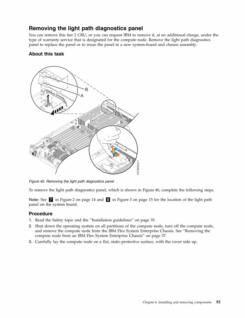
Removing the light path diagnostics panelYou can remove this tier 2 CRU, or you can request IBM to remove it, at no additional charge, under thetype of warranty service that is designated for the compute node. Remove the light path diagnosticspanel to replace the panel or to reuse the panel in a new system-board and chassis assembly.
About this task
To remove the light path diagnostics panel, which is shown in Figure 40, complete the following steps.
Note: See ▌7▐ in Figure 2 on page 14 and ▌8▐ in Figure 3 on page 15 for the location of the light pathpanel on the system board.
Procedure1. Read the Safety topic and the “Installation guidelines” on page 35.2. Shut down the operating system on all partitions of the compute node, turn off the compute node,
and remove the compute node from the IBM Flex System Enterprise Chassis. See “Removing thecompute node from an IBM Flex System Enterprise Chassis” on page 37.
3. Carefully lay the compute node on a flat, static-protective surface, with the cover side up.
Figure 40. Removing the light path diagnostics panel
Chapter 6. Installing and removing components 81
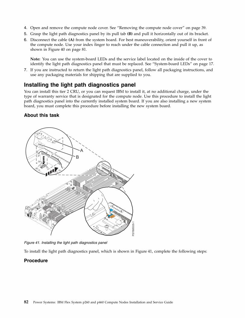
4. Open and remove the compute node cover. See “Removing the compute node cover” on page 39.5. Grasp the light path diagnostics panel by its pull tab (B) and pull it horizontally out of its bracket.6. Disconnect the cable (A) from the system board. For best maneuverability, orient yourself in front of
the compute node. Use your index finger to reach under the cable connection and pull it up, asshown in Figure 40 on page 81.
Note: You can use the system-board LEDs and the service label located on the inside of the cover toidentify the light path diagnostics panel that must be replaced. See “System-board LEDs” on page 17.
7. If you are instructed to return the light path diagnostics panel, follow all packaging instructions, anduse any packaging materials for shipping that are supplied to you.
Installing the light path diagnostics panelYou can install this tier 2 CRU, or you can request IBM to install it, at no additional charge, under thetype of warranty service that is designated for the compute node. Use this procedure to install the lightpath diagnostics panel into the currently installed system board. If you are also installing a new systemboard, you must complete this procedure before installing the new system board.
About this task
To install the light path diagnostics panel, which is shown in Figure 41, complete the following steps:
Procedure
Figure 41. Installing the light path diagnostics panel
82 Power Systems: IBM Flex System p260 and p460 Compute Nodes Installation and Service Guide

1. Read the Safety topic and the “Installation guidelines” on page 35.2. Shut down the operating system on all partitions of the compute node, turn off the compute node,
and remove the compute node from the IBM Flex System Enterprise Chassis. See “Removing thecompute node from an IBM Flex System Enterprise Chassis” on page 37.
3. Carefully lay the compute node on a flat, static-protective surface, with the cover side up.4. Open and remove the compute node cover. See “Removing the compute node cover” on page 39.5. Locate the connector on the currently installed system board into which the light path panel will be
installed. See ▌7▐ in Figure 2 on page 14 and ▌8▐ in Figure 3 on page 15 for the location of the lightpath panel on the system board.
6. For best maneuverability and visibility, orient yourself on the right side of the compute node.7. Using your right hand, connect the cable (B) on the system board by pressing it in its connector slot
by using your index finger.8. Align the light path diagnostics panel (A) with its bracket. The blue touchpoint tab faces toward the
back of the compute node.9. Press the light path diagnostics panel securely in the bracket.
10. Install and close the compute node cover. See “Installing and closing the compute node cover” onpage 41.Statement 21
CAUTION:Hazardous energy is present when the compute node is connected to the power source. Alwaysreplace the compute node cover before installing the compute node.
11. Install the compute node into the IBM Flex System Enterprise Chassis. See “Installing the computenode in an IBM Flex System Enterprise Chassis” on page 93.
12. If you replaced the part because of a service action, verify the repair by checking that the amberenclosure fault LED is off. For more information, see “Compute node control panel button andLEDs” on page 11.
Removing and replacing FRUs (trained service technician only)About this task
A FRU must be installed only by trained service technicians.
Replacing the system-board and chassis assemblyField replaceable units (FRUs) must be replaced only by trained service technicians. When replacing thesystem-board, you replace the system-board, compute node base (chassis), microprocessors, and heatsinks as a single assembly.
Chapter 6. Installing and removing components 83
Before you begin
Attention: Replacing the management card and the system-board at the same time might result in theloss of vital product data (VPD) and information about the number of active processor cores. If themanagement card and system-board must both be replaced, replace them one at a time. For furtherassistance, contact your next level of support.
About this task
Note: For more information about the locations of the connectors and LEDs on the system-board, see“System-board layouts” on page 13.
To replace the system-board and chassis assembly, complete the following steps:
Procedure1. Read the Safety topic and the “Installation guidelines” on page 35.2. Is the compute node managed by a management console?
Yes Continue with step 3.
No Continue with step 5 on page 85.3. If the compute node has Virtual I/O Server (VIOS) installed or uses more than one partition, have
the customer back up partition profile data by using one of the following methods:v If this system is managed by an IBM Flex System Manager (FSM) management console, back up
partition profile data. Using the Systems management command-line interface (SMCLI), enter thebkprofdata command. See smcli - Systems management command-line interface(http://pic.dhe.ibm.com/infocenter/flexsys/information/topic/com.ibm.acc.8731.doc/com.ibm.director.cli.helps.doc/fqm0_r_cli_smcli.html). For more information about the bkprofdatacommand, see BKPROFDATA (http://publib.boulder.ibm.com/infocenter/flexsys/information/topic/com.ibm.acc.psm.reference.doc/manpages/psm.bkprofdata.html).
Note: If the backup operation fails because the compute node is in an error state, save theconfiguration files by using the log collection tool. See Collecting pedbg on Flex System Manager(FSM) (https://www.ibm.com/support/docview.wss?uid=nas777a837116ee2fca8862578320079823c).
v If this system is managed by an Hardware Management Console (HMC), back up the partitionprofile data by using the HMC. See Backing up the partition profile data (http://pic.dhe.ibm.com/infocenter/powersys/v3r1m5/topic/p7hbm/backupprofdata.htm).
Note: If the backup fails because the compute node is in an error state, save the configuration filesby using the log collection tool. See Version 7 or 8 HMC: Collecting PEDBG from the HMC(http://www.ibm.com/support/docview.wss?uid=nas8N1018878).
v If this system is managed by an Integrated Virtualization Manager (IVM), back up the partitionprofile data. Using the IVM command line, enter the bkprofdata command. For more informationabout the bkprofdata command, see IVM bkprofdata command (http://pic.dhe.ibm.com/infocenter/powersys/v3r1m5/topic/p7hcg/bkprofdata.htm).
If no backup data is available and the back-up partition profile data operation fails, the partitiondetails cannot be restored. The partitions must be rebuilt after hardware recovery.
Note: Although the FSM and HMC management consoles automatically save partition profile data,which is used for recovery in step 28 on page 88, the manual partition profile data backup that iscompleted in step 3 is recommended as a precaution and best practice before you replace thesystem-board.
84 Power Systems: IBM Flex System p260 and p460 Compute Nodes Installation and Service Guide
4. Does the compute node have Fibre Channel adapters?
Yes If the VIOS is operational, have the customer complete “Save vfchost map data” on page492. Then, continue with the next step.
Note: If the VIOS is not operational and vfchost map data is not available from a previoussave operation, the vfchost mapping must be manually re-created (see step 31 on page 89)before powering on partitions.
No Continue with the next step.5. Have the customer record the system name of the compute as shown on the Advanced System
Management Interface (ASMI). The system name is displayed near the top of the ASMI Welcomepane (for example Server-7895-43X-SNABC1234). For information about how to access the ASMI, seeChapter 5, “Accessing the service processor,” on page 33.
6. Have the customer record the compute node IPv4 address and any static IPv6 addresses. Completethe following steps:a. Access the Chassis Management Module (CMM) web interface. For instructions, see Ethernet
connection (http://pic.dhe.ibm.com/infocenter/flexsys/information/topic/com.ibm.acc.cmm.doc/remote_console_ethernet_connect_cmm.html).
b. From the menu bar, click Chassis Management. Then, from the drop-down menu, clickComponent IP Configuration. From the Device Name list, click the compute node name toaccess the property tabs for the compute node. Record the address that is displayed in the IPv4property tab. Record any static addresses that are displayed in the IPv6 property tab. For moreinformation about displaying the IP configuration of a compute node, see Chassis managementoptions (http://pic.dhe.ibm.com/infocenter/flexsys/information/topic/com.ibm.acc.cmm.doc/cmm_ui_chassis_management.html).
7. Have the customer record Serial over LAN (SOL) setting of the chassis and Serial over LAN settingof the compute node. Complete the following steps:a. Access the Chassis Management Module (CMM) web interface. For instructions, see Ethernet
connection (http://pic.dhe.ibm.com/infocenter/flexsys/information/topic/com.ibm.acc.cmm.doc/remote_console_ethernet_connect_cmm.html).
b. To record the Serial over LAN setting of the chassis, complete the following steps:1) From the menu bar, click Chassis Management.2) From the Chassis Management list, click Compute Nodes.3) Click the Global Settings button.4) In the Global Node Settings window, click the Serial Over LAN tab.5) Record the Enable Serial Over LAN check box setting.6) Click cancel to close the Global Node Settings window.
c. To record the Serial over LAN setting of the compute node, complete the following steps:1) From the Device Name list, click the compute node name to access the property tabs for the
compute node.2) Click the General tab.3) Record the Enable Serial Over LAN check box setting.
Chapter 6. Installing and removing components 85
8. Have the customer record the VIOS boot device. If multiple devices are mapped to the VIOS, recordthe current device.
Note: Boot device information is stored in the service processor of the system-board and it must bemanually restored after the system-board is replaced with a new system-board.
Enter the following commands in the padmin shell of each VIOS partition:v oem_setup_env
v bootlist –m normal –o –v
These commands provide the device tree path. Record the output information. This information isused in step 30 on page 89 of this procedure.
9. Have the customer shut down the operating system on all partitions of the compute node, and turnoff the compute node.
10. Remove the compute node from the IBM Flex System Enterprise Chassis. See “Removing thecompute node from an IBM Flex System Enterprise Chassis” on page 37.
11. Carefully lay the compute node on a flat, static-protective surface, with the cover side up.12. Open and remove the compute node cover. See “Removing the compute node cover” on page 39.13. Remove the bezel assembly. See “Removing the bezel assembly” on page 43.14. Remove any of the following installed components from the system-board, and then place them on a
nonconductive surface or install them on the new system-board and chassis assembly:v I/O expansion card. See “Removing a network adapter” on page 61.v DIMMs. See “Removing a DIMM” on page 55.v Management card. See “Removing the management card” on page 73.
15. Touch the static-protective package that contains the system-board and chassis assembly to anyunpainted metal surface on the IBM Flex System Enterprise Chassis or any unpainted metal surface onany other grounded rack component, and then remove the assembly from its package.
16. Install any of the following components that were removed from the old system-board and chassisassembly:v Management card. See “Installing the management card” on page 75.v DIMMs. See “Installing a DIMM” on page 58.v I/O expansion card. See “Installing a network adapter” on page 63.
Note: Install a DIMM filler in any location where a DIMM is not present to avoid machine damage.17. Install the bezel assembly. See “Installing the bezel assembly” on page 45 for instructions.18. Install and close the compute node cover. See “Installing and closing the compute node cover” on
page 41.Statement 21
CAUTION:Hazardous energy is present when the compute node is connected to the power source. Alwaysreplace the compute node cover before installing the compute node.
86 Power Systems: IBM Flex System p260 and p460 Compute Nodes Installation and Service Guide

19. Write the machine type, model number, and serial number of the compute node on the repairidentification tag that is provided with the replacement system-board and chassis assembly. Thisinformation is on the identification label that is on the lower right corner of the bezel on the front ofthe compute node.
Important: Completing the information about the repair identification tag ensures future entitlementfor service.
20. Place the repair identification tag on the bottom of the compute node chassis.21. Install the compute node into the IBM Flex System Enterprise Chassis. Do not turn on the compute
node until step 26 on page 88 or 27 on page 88 of this procedure, depending upon whether thecompute node is managed by a management console. For more information about how to install thecompute node, see “Installing the compute node in an IBM Flex System Enterprise Chassis” on page93.
22. Have the customer set the compute node IPv4 address and any static IPv6 addresses. Complete thefollowing steps:a. Access the Chassis Management Module (CMM) web interface. For instructions, see Ethernet
connection (http://pic.dhe.ibm.com/infocenter/flexsys/information/topic/com.ibm.acc.cmm.doc/remote_console_ethernet_connect_cmm.html).
b. In the menu bar, click Chassis Management. Then, in the drop-down menu, click Component IPConfiguration. From the Device Name list, select the compute node name to access property tabsfor the compute node. Set the address in the IPv4 property tab by using the information that isrecorded in step 6 on page 85 of this procedure. Set any static addresses in the IPv6 property tabby using the information that is recorded in step 6 on page 85 of this procedure. For moreinformation about displaying the IP configuration of a compute node, see Chassis managementoptions (http://pic.dhe.ibm.com/infocenter/flexsys/information/topic/com.ibm.acc.cmm.doc/cmm_ui_chassis_management.html).
23. Have the customer set the chassis and compute node level Serial over LAN (SOL) settings of thecompute node. Complete the following steps:a. Access the Chassis Management Module (CMM) web interface. For instructions, see Ethernet
connection (http://pic.dhe.ibm.com/infocenter/flexsys/information/topic/com.ibm.acc.cmm.doc/remote_console_ethernet_connect_cmm.html).
b. To set the Serial over LAN setting of the chassis, complete the following steps:1) In the menu bar, click Chassis Management.2) From the Chassis Management list, click Compute Nodes.3) Click the Global Settings button.4) In the Global Node Settings window, click the Serial Over LAN tab.5) Set the Enable Serial Over LAN check box by using the information that is recorded in step 7
on page 85 of this procedure. Then, click OK to save the setting.6) In the SOL Global Configuration window, click close.
c. To set the Serial over LAN setting of the compute node, complete the following steps:1) From the Device Name list, click the compute node name to access the property tabs for the
compute node.2) Click the General tab.3) Set the Enable Serial Over LAN check box by using the information that is recorded in step 7
on page 85 of this procedure. Click apply to save the Serial Over LAN setting.4) In the Node Properties window, click close.
Chapter 6. Installing and removing components 87

24. Have the customer set the compute node system name. Complete the following steps:a. Access the ASMI. For information about how to access the ASMI, see Chapter 5, “Accessing the
service processor,” on page 33.b. The system name was recorded in step 5 on page 85 of this procedure. If the correct system name
is not displayed near the top of the ASMI Welcome pane, set the system name by clickingSystem Configuration > System Name.
25. Have the customer ensure that the Time-Of-Day setting is correct. Complete the following steps:a. Access the ASMI. For information about how to access the ASMI, see Chapter 5, “Accessing the
service processor,” on page 33.b. Click System Configuration > Time Of Day.c. Ensure that the Time-Of-Day is set to the NTP mode or that the Time-Of-Day has the correct time
in Coordinated Universal Time (UTC).
Note: If the Time-of-Day is set to the NTP mode, the ASMI center pane shows the followingmessage - Changing date/time is not allowed when the system is in NTP mode and you cannotchange the time. If the NTP mode is not set and the time is not correct in UTC, enter the correcttime and save. This operation can be completed only when the compute node is turned off.
26. Is the compute node managed by a management console?
Yes Continue with step 27.
No Have the customer turn on the compute node, then continue with step 32 on page 90.27. Have the customer complete the following steps:
a. Access the ASMI. For information about how to access the ASMI, see Chapter 5, “Accessing theservice processor,” on page 33.
b. Click Power/Restart Control > Power On/Off System.c. Record the current setting in the Server firmware start policy field.d. Change the Server firmware start policy setting to Standby (User-Initiated).e. Click Save Settings and Power on.
28. If the compute node has VIOS installed or uses more than one partition, have the customer restorepartition profile data by using one of the following methods:v If this system is managed by an FSM, ensure that the compute node is displayed on the Manage
Power Systems Resource page. If the compute node is not displayed, complete the followingactions in sequence, as needed:a. Collect inventory on the chassis and request access. See Collecting inventory
(http://pic.dhe.ibm.com/infocenter/flexsys/information/topic/com.ibm.acc.8731.doc/com.ibm.director.discovery.helps.doc/fqm0_t_collecting_inventory.html).
b. If the compute node is still not displayed, reseat the compute node. See Removing the computenode from an IBM Flex System Enterprise Chassis (http://pic.dhe.ibm.com/infocenter/flexsys/information/topic/com.ibm.acc.7895.doc/removing_the_blade_server.html). Once theFSM discovers the compute node, then collect inventory on the chassis and request accessagain. See Collecting inventory (http://pic.dhe.ibm.com/infocenter/flexsys/information/topic/com.ibm.acc.8731.doc/com.ibm.director.discovery.helps.doc/fqm0_t_collecting_inventory.html).
c. After the compute node is displayed on the Manage Power Systems Resource page, clickHosts. The compute node should have a state of Error with a detailed state of Recovery. Thisstate indicates that the profile data of the node must be recovered from the FSM. Recover thepartition profile data. For instructions, see Correcting a Recovery state for a server(http://pic.dhe.ibm.com/infocenter/flexsys/information/topic/com.ibm.acc.psm.troubleshooting.doc/dpsm_troubleshooting_managedsystemstate_recovery.html).
88 Power Systems: IBM Flex System p260 and p460 Compute Nodes Installation and Service Guide
Note: The compute node is turned on as part of the recovery process.v If this system is managed by an HMC, complete the following steps:
a. Log in to the HMC.b. Click Systems Management > Servers.c. If the compute node displays Failed Authentication in the Status column and Incorrect
password in the Reference code column, select the compute node and use the UpdatePassword task to enter the correct password for the USERID user ID. After you have entered acorrect password, the compute node displays Recovery in the Status column.
d. Recover the partition profile data. For instructions, see Correcting a Recovery state for amanaged system (http://pic.dhe.ibm.com/infocenter/powersys/v3r1m5/topic/p7eav/aremanagedsystemstate_recovery.htm).
Note: The compute node is turned on as part of the recovery process.v If this system is managed by an IVM, turn on the compute node, then restore the partition profile
data. Using the IVM command line, enter the rstprofdata command. For more information aboutthe rstprofdata command, see IVM rstprofdata command (http://www.ibm.com/support/knowledgecenter/api/content/nl/en-us/POWER7/p7hcg/rstprofdata.htm).
29. Have the customer complete the following steps:a. Access the ASMI. For information about how to access the ASMI, see Chapter 5, “Accessing the
service processor,” on page 33.b. Click Power/Restart Control > Power On/Off System.c. Change the Server firmware start policy setting to the value that was recorded in step 27 on page
88.d. Click Save Settings and continue system server firmware boot.
30. Have the customer activate a VIOS partition by using one of the following methods:v If this system is managed by an FSM, see Activating a virtual server (http://pic.dhe.ibm.com/
infocenter/flexsys/information/topic/com.ibm.acc.psm.resources.doc/vs/sdmc_vs-activating_vs.html).
v If this system is managed by an HMC, see Activate (www.ibm.com/support/knowledgecenter/POWER7/p7ha1/smpactivate.htm).
v If this system is managed by an IVM, see Activating logical partitions (http://www.ibm.com/support/knowledgecenter/POWER7/p7hch/iphchactivatelpar.htm).
Press 1 while the partition is being activated to enter the SMS menu. See Starting the SMS utility(http://pic.dhe.ibm.com/infocenter/flexsys/information/topic/com.ibm.acc.7895.doc/starting_sms.html). At the SMS main menu, click Select Boot Options and restore the boot deviceorder that is recorded in step 8 on page 86 of this procedure. Then, repeat this step for anyremaining VIOS partitions, if applicable.
31. Does the compute node have Fibre Channel adapters?
Yes Have the customer complete the steps in the “Restore vfchost map data” on page 493 topic.Then, continue with the next step.
No Continue with the next step.
Chapter 6. Installing and removing components 89

32. Have the customer reset the system date and time through the operating system that is installed.For more information, see the documentation for your operating system.
33. If the part was replaced because of a service action, verify the repair by checking that the amberenclosure fault LED is off. For more information, see “Compute node control panel button andLEDs” on page 11.
What to do next
After replacing the system-board and chassis assembly, you must either update the system with the latestfirmware or restore the pre-existing firmware.
Completing the installationTo complete the installation, you must install and close the compute node cover, install the compute nodeinto the IBM Flex System Enterprise Chassis, and turn on the compute node.
Procedure1. Install and close the compute node cover. See “Installing and closing the compute node cover” on
page 41.Statement 21
CAUTION:Hazardous energy is present when the compute node is connected to the power source. Alwaysreplace the compute node cover before installing the compute node.
2. Install the compute node into the IBM Flex System Enterprise Chassis. See “Installing the computenode in an IBM Flex System Enterprise Chassis” on page 93.
3. Turn on the compute node, as described in “Turning on the compute node” on page 12.
Note: If you have just connected the power cords of the IBM Flex System Enterprise Chassis toelectrical outlets, you must wait until the power-on LED on the compute node flashes slowly beforeyou press the power-control button.
4. If you installed an I/O expansion card, use the documentation that comes with the expansion card toinstall device drivers and to perform any configuration that the expansion card requires.
5. For certain optional devices, run the compute node SMS Utility program, as described in “Using theSMS utility” on page 24.
90 Power Systems: IBM Flex System p260 and p460 Compute Nodes Installation and Service Guide

Installing and closing the compute node coverInstall and close the cover of the compute node before you insert the compute node into the IBM FlexSystem Enterprise Chassis. Do not attempt to override this important protection.
About this task
Figure 42. Installing the cover for an IBM Flex System p260 Compute Node
Chapter 6. Installing and removing components 91
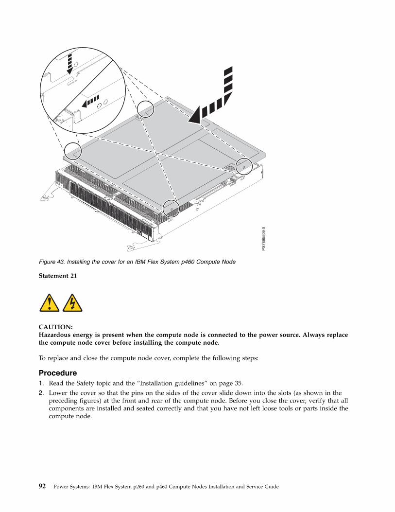
Statement 21
CAUTION:Hazardous energy is present when the compute node is connected to the power source. Always replacethe compute node cover before installing the compute node.
To replace and close the compute node cover, complete the following steps:
Procedure1. Read the Safety topic and the “Installation guidelines” on page 35.2. Lower the cover so that the pins on the sides of the cover slide down into the slots (as shown in the
preceding figures) at the front and rear of the compute node. Before you close the cover, verify that allcomponents are installed and seated correctly and that you have not left loose tools or parts inside thecompute node.
Figure 43. Installing the cover for an IBM Flex System p460 Compute Node
92 Power Systems: IBM Flex System p260 and p460 Compute Nodes Installation and Service Guide
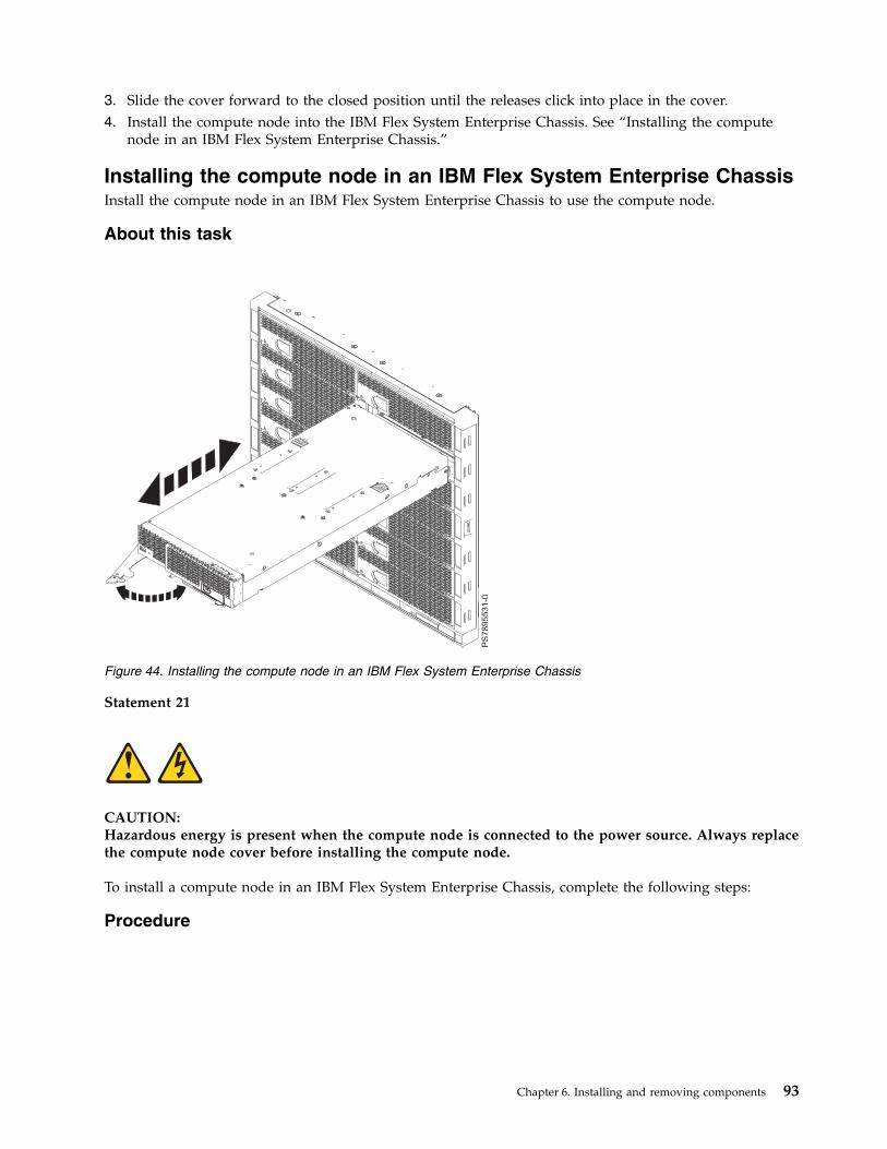
3. Slide the cover forward to the closed position until the releases click into place in the cover.4. Install the compute node into the IBM Flex System Enterprise Chassis. See “Installing the compute
node in an IBM Flex System Enterprise Chassis.”
Installing the compute node in an IBM Flex System Enterprise ChassisInstall the compute node in an IBM Flex System Enterprise Chassis to use the compute node.
About this task
Statement 21
CAUTION:Hazardous energy is present when the compute node is connected to the power source. Always replacethe compute node cover before installing the compute node.
To install a compute node in an IBM Flex System Enterprise Chassis, complete the following steps:
Procedure
Figure 44. Installing the compute node in an IBM Flex System Enterprise Chassis
Chapter 6. Installing and removing components 93

1. Go to http://www.ibm.com/support/entry/portal/Overview to download the latest firmware forthe compute node.Download the firmware so that you can use it later to update the compute node after you start it.
2. Read the Safety topic and the “Installation guidelines” on page 35.3. If you have not done so already, install any optional devices that you want, such as a SAS drive or
memory modules.4. Select the bay for the compute node:v See http://publib.boulder.ibm.com/infocenter/flexsys/information/topic/
com.ibm.acc.common.nav.doc/chassis.html that comes with your IBM Flex System EnterpriseChassis to verify that the bay you choose is powered.
v Ensure proper cooling, performance, and system reliability by installing a compute node,expansion unit, or slot filler in each bay.
v Reinstall a compute node in the same bay to preserve configuration information and updateoptions that are established by the bay. Reinstalling into a different bay can have unintendedconsequences, which might include reconfiguring the compute node.
5. Verify that the release handles on the compute node are in the open position (perpendicular to thecompute node, as shown in Figure 44 on page 93). For the IBM Flex System p260 Compute Node,there is one release handle. For the IBM Flex System p460 Compute Node, there are two releasehandles.
6. Remove any existing compute node and filler nodes from the bay in which you plan to install thecompute node.
Note: If you are installing a IBM Flex System p460 Compute Node, you might need to remove ashelf from the chassis. See http://publib.boulder.ibm.com/infocenter/flexsys/information/topic/com.ibm.acc.8721.doc/removing_the_chassis_shelves.html.
7. Slide the compute node into the bay from which you removed it until the compute node stops.8. Push the release handles on the front of the compute node to close and lock them.
The discovery and initialization process can take up to 3 minutes to complete. The discovery andinitialization process is complete when the green LED stops flashing rapidly and begins to flashslowly. At this point, you can power on the compute node.
9. Turn on the compute node. See “Turning on the compute node” on page 12.10. Verify that the power-on LED on the compute node control panel is lit continuously. The continuous
light indicates that the compute node is receiving power and is turned on.11. Optional: Write identifying information on one of the user labels that come with the compute node
and place the label on the IBM Flex System Enterprise Chassis bezel.Important: Do not place the label on the compute node or in any way block the ventilation holes onthe compute node. See the online information or the documentation that comes with your IBM FlexSystem Enterprise Chassis for information about label placement.
12. Use the SMS Utility program to configure the compute node. See “Using the SMS utility” on page24.
13. Also use the management module to configure the compute node. See the documentation for themanagement module to understand the functions that the management module provides.
94 Power Systems: IBM Flex System p260 and p460 Compute Nodes Installation and Service Guide
What to do next
If you have changed the configuration of the compute node or if this is a different compute node than theone you removed, you must configure the compute node. You might also have to install the computenode operating system.
See Chapter 4, “Installing the operating system,” on page 29 for detailed information about these tasks.
Chapter 6. Installing and removing components 95

96 Power Systems: IBM Flex System p260 and p460 Compute Nodes Installation and Service Guide
Chapter 7. Parts listing for IBM Flex System p260 and p460Compute Nodes
The parts listing identifies each replaceable part and its part number.
Figure 45 on page 98 shows replaceable components that are available for the IBM Flex System p260Compute Node.
Figure 46 on page 101 shows replaceable components that are available for the IBM Flex System p460Compute Node.
Replaceable components are of three types:v Tier 1 customer replaceable unit (CRU): Replacement of tier 1 CRUs is your responsibility. If IBM
installs a tier 1 CRU at your request, you will be charged for the installation.v Tier 2 customer replaceable unit: You can install a tier 2 CRU yourself or request IBM to install it, at
no additional charge, under the type of warranty service that is designated for your compute node.v Field replaceable unit (FRU): FRUs must be installed only by trained service technicians.
For information about the terms of the warranty and getting service and assistance, see the informationcenter or the Warranty and Support Information document on the IBM Flex System Enterprise ChassisDocumentation CD.
© Copyright IBM Corp. 2012, 2015 97
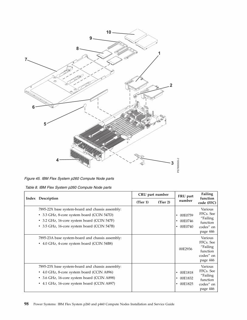
Table 8. IBM Flex System p260 Compute Node parts
Index DescriptionCRU part number FRU part
number
Failingfunction
code (FFC)(Tier 1) (Tier 2)
7895-22X base system-board and chassis assembly:
v 3.3 GHz, 8-core system board (CCIN 547D)
v 3.2 GHz, 16-core system board (CCIN 547F)
v 3.5 GHz, 16-core system board (CCIN 547B)
v 00E0759
v 00E0746
v 00E0740
VariousFFCs. See“Failingfunction
codes” onpage 446
7895-23A base system-board and chassis assembly:
v 4.0 GHz, 4-core system board (CCIN 54B8)00E2936
VariousFFCs. See“Failingfunction
codes” onpage 446
7895-23X base system-board and chassis assembly:
v 4.0 GHz, 8-core system board (CCIN A896)
v 3.6 GHz, 16-core system board (CCIN A898)
v 4.1 GHz, 16-core system board (CCIN A897)
v 00E1818
v 00E1832
v 00E1825
VariousFFCs. See“Failingfunction
codes” onpage 446
Figure 45. IBM Flex System p260 Compute Node parts
98 Power Systems: IBM Flex System p260 and p460 Compute Nodes Installation and Service Guide
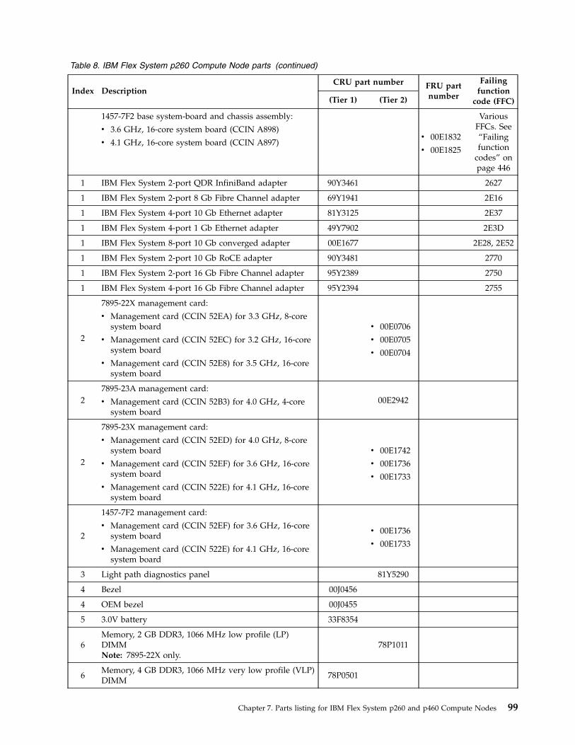
Table 8. IBM Flex System p260 Compute Node parts (continued)
Index DescriptionCRU part number FRU part
number
Failingfunction
code (FFC)(Tier 1) (Tier 2)
1457-7F2 base system-board and chassis assembly:
v 3.6 GHz, 16-core system board (CCIN A898)
v 4.1 GHz, 16-core system board (CCIN A897)v 00E1832
v 00E1825
VariousFFCs. See“Failingfunction
codes” onpage 446
1 IBM Flex System 2-port QDR InfiniBand adapter 90Y3461 2627
1 IBM Flex System 2-port 8 Gb Fibre Channel adapter 69Y1941 2E16
1 IBM Flex System 4-port 10 Gb Ethernet adapter 81Y3125 2E37
1 IBM Flex System 4-port 1 Gb Ethernet adapter 49Y7902 2E3D
1 IBM Flex System 8-port 10 Gb converged adapter 00E1677 2E28, 2E52
1 IBM Flex System 2-port 10 Gb RoCE adapter 90Y3481 2770
1 IBM Flex System 2-port 16 Gb Fibre Channel adapter 95Y2389 2750
1 IBM Flex System 4-port 16 Gb Fibre Channel adapter 95Y2394 2755
2
7895-22X management card:
v Management card (CCIN 52EA) for 3.3 GHz, 8-coresystem board
v Management card (CCIN 52EC) for 3.2 GHz, 16-coresystem board
v Management card (CCIN 52E8) for 3.5 GHz, 16-coresystem board
v 00E0706
v 00E0705
v 00E0704
27895-23A management card:
v Management card (CCIN 52B3) for 4.0 GHz, 4-coresystem board
00E2942
2
7895-23X management card:
v Management card (CCIN 52ED) for 4.0 GHz, 8-coresystem board
v Management card (CCIN 52EF) for 3.6 GHz, 16-coresystem board
v Management card (CCIN 522E) for 4.1 GHz, 16-coresystem board
v 00E1742
v 00E1736
v 00E1733
2
1457-7F2 management card:
v Management card (CCIN 52EF) for 3.6 GHz, 16-coresystem board
v Management card (CCIN 522E) for 4.1 GHz, 16-coresystem board
v 00E1736
v 00E1733
3 Light path diagnostics panel 81Y5290
4 Bezel 00J0456
4 OEM bezel 00J0455
5 3.0V battery 33F8354
6Memory, 2 GB DDR3, 1066 MHz low profile (LP)DIMMNote: 7895-22X only.
78P1011
6Memory, 4 GB DDR3, 1066 MHz very low profile (VLP)DIMM
78P0501
Chapter 7. Parts listing for IBM Flex System p260 and p460 Compute Nodes 99
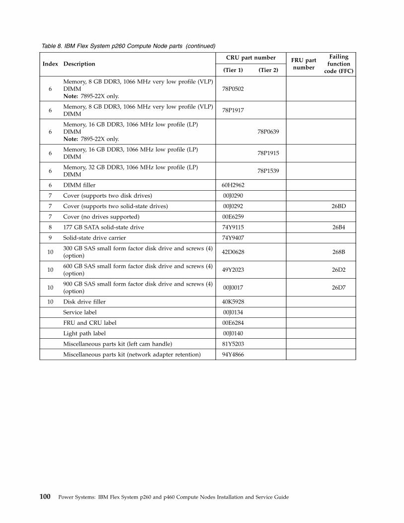
Table 8. IBM Flex System p260 Compute Node parts (continued)
Index DescriptionCRU part number FRU part
number
Failingfunction
code (FFC)(Tier 1) (Tier 2)
6Memory, 8 GB DDR3, 1066 MHz very low profile (VLP)DIMMNote: 7895-22X only.
78P0502
6Memory, 8 GB DDR3, 1066 MHz very low profile (VLP)DIMM
78P1917
6Memory, 16 GB DDR3, 1066 MHz low profile (LP)DIMMNote: 7895-22X only.
78P0639
6Memory, 16 GB DDR3, 1066 MHz low profile (LP)DIMM
78P1915
6Memory, 32 GB DDR3, 1066 MHz low profile (LP)DIMM
78P1539
6 DIMM filler 60H2962
7 Cover (supports two disk drives) 00J0290
7 Cover (supports two solid-state drives) 00J0292 26BD
7 Cover (no drives supported) 00E6259
8 177 GB SATA solid-state drive 74Y9115 26B4
9 Solid-state drive carrier 74Y9407
10300 GB SAS small form factor disk drive and screws (4)(option)
42D0628 268B
10600 GB SAS small form factor disk drive and screws (4)(option)
49Y2023 26D2
10900 GB SAS small form factor disk drive and screws (4)(option)
00J0017 26D7
10 Disk drive filler 40K5928
Service label 00J0134
FRU and CRU label 00E6284
Light path label 00J0140
Miscellaneous parts kit (left cam handle) 81Y5203
Miscellaneous parts kit (network adapter retention) 94Y4866
100 Power Systems: IBM Flex System p260 and p460 Compute Nodes Installation and Service Guide
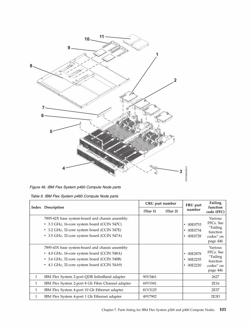
Table 9. IBM Flex System p460 Compute Node parts
Index DescriptionCRU part number FRU part
number
Failingfunction
code (FFC)(Tier 1) (Tier 2)
7895-42X base system-board and chassis assembly:
v 3.3 GHz, 16-core system board (CCIN 547C)
v 3.2 GHz, 32-core system board (CCIN 547E)
v 3.5 GHz, 32-core system board (CCIN 547A)
v 00E0753
v 00E0734
v 00E0728
VariousFFCs. See“Failingfunction
codes” onpage 446
7895-43X base system-board and chassis assembly:
v 4.0 GHz, 16-core system board (CCIN 548A)
v 3.6 GHz, 32-core system board (CCIN 548B)
v 4.1 GHz, 32-core system board (CCIN 54A9)
v 00E2878
v 00E2235
v 00E2220
VariousFFCs. See“Failingfunction
codes” onpage 446
1 IBM Flex System 2-port QDR InfiniBand adapter 90Y3461 2627
1 IBM Flex System 2-port 8 Gb Fibre Channel adapter 69Y1941 2E16
1 IBM Flex System 4-port 10 Gb Ethernet adapter 81Y3125 2E37
1 IBM Flex System 4-port 1 Gb Ethernet adapter 49Y7902 2E3D
Figure 46. IBM Flex System p460 Compute Node parts
Chapter 7. Parts listing for IBM Flex System p260 and p460 Compute Nodes 101
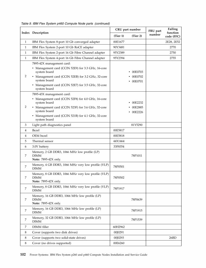
Table 9. IBM Flex System p460 Compute Node parts (continued)
Index DescriptionCRU part number FRU part
number
Failingfunction
code (FFC)(Tier 1) (Tier 2)
1 IBM Flex System 8-port 10 Gb converged adapter 00E1677 2E28, 2E52
1 IBM Flex System 2-port 10 Gb RoCE adapter 90Y3481 2770
1 IBM Flex System 2-port 16 Gb Fibre Channel adapter 95Y2389 2750
1 IBM Flex System 4-port 16 Gb Fibre Channel adapter 95Y2394 2755
2
7895-42X management card:
v Management card (CCIN 52E9) for 3.3 GHz, 16-coresystem board
v Management card (CCIN 52EB) for 3.2 GHz, 32-coresystem board
v Management card (CCIN 52E7) for 3.5 GHz, 32-coresystem board
v 00E0703
v 00E0702
v 00E0701
2
7895-43X management card:
v Management card (CCIN 52F8) for 4.0 GHz, 16-coresystem board
v Management card (CCIN 523F) for 3.6 GHz, 32-coresystem board
v Management card (CCIN 521B) for 4.1 GHz, 32-coresystem board
v 00E2232
v 00E2885
v 00E2226
3 Light path diagnostics panel 81Y5290
4 Bezel 00E5817
4 OEM bezel 00E5818
5 Thermal sensor 44X1464
6 3.0V battery 33F8354
7Memory, 2 GB DDR3, 1066 MHz low profile (LP)DIMMNote: 7895-42X only.
78P1011
7Memory, 4 GB DDR3, 1066 MHz very low profile (VLP)DIMM
78P0501
7Memory, 8 GB DDR3, 1066 MHz very low profile (VLP)DIMMNote: 7895-42X only.
78P0502
7Memory, 8 GB DDR3, 1066 MHz very low profile (VLP)DIMM
78P1917
7Memory, 16 GB DDR3, 1066 MHz low profile (LP)DIMMNote: 7895-42X only.
78P0639
7Memory, 16 GB DDR3, 1066 MHz low profile (LP)DIMM
78P1915
7Memory, 32 GB DDR3, 1066 MHz low profile (LP)DIMM
78P1539
7 DIMM filler 60H2962
8 Cover (supports two disk drives) 00J0291
8 Cover (supports two solid-state drives) 00J0293 26BD
8 Cover (no drives supported) 00E6260
102 Power Systems: IBM Flex System p260 and p460 Compute Nodes Installation and Service Guide
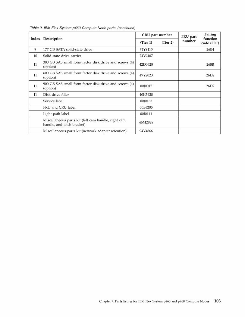
Table 9. IBM Flex System p460 Compute Node parts (continued)
Index DescriptionCRU part number FRU part
number
Failingfunction
code (FFC)(Tier 1) (Tier 2)
9 177 GB SATA solid-state drive 74Y9115 26B4
10 Solid-state drive carrier 74Y9407
11300 GB SAS small form factor disk drive and screws (4)(option)
42D0628 268B
11600 GB SAS small form factor disk drive and screws (4)(option)
49Y2023 26D2
11900 GB SAS small form factor disk drive and screws (4)(option)
00J0017 26D7
11 Disk drive filler 40K5928
Service label 00J0135
FRU and CRU label 00E6285
Light path label 00J0141
Miscellaneous parts kit (left cam handle, right camhandle, and latch bracket)
46M2828
Miscellaneous parts kit (network adapter retention) 94Y4866
Chapter 7. Parts listing for IBM Flex System p260 and p460 Compute Nodes 103

104 Power Systems: IBM Flex System p260 and p460 Compute Nodes Installation and Service Guide
Chapter 8. Troubleshooting
Use this information to diagnose and fix any problems that might occur in your compute node.
Introduction to problem solvingThis problem determination and service information helps you solve problems that might occur in yourIBM Flex System Enterprise Chassis compute node. The information describes the diagnostic tools thatcome with the compute node, error codes and suggested actions, and instructions for replacing failingcomponents.
Replaceable components are of three types:v Tier 1 customer replaceable unit (CRU): Replacement of tier 1 CRUs is your responsibility. If IBM
installs a tier 1 CRU at your request, you are charged for the installation.v Tier 2 customer replaceable unit: You can install a tier 2 CRU yourself or request IBM to install it, at
no additional charge, under the type of warranty service that is designated for your compute node.v Field replaceable unit (FRU): FRUs must be installed only by trained service technicians.
The model number and serial number for the compute node are on the ID label on the bezel on the frontof the compute node, and on a label on the bottom of the compute node that is visible when the computenode is not in the IBM Flex System Enterprise Chassis.
For information about the terms of the warranty and getting service and assistance, see the informationcenter or the Warranty and Support Information document on the IBM Flex System Enterprise ChassisDocumentation CD.
Solving problemsUse the diagnostic tools that are available to help you solve some common problems that might occurwhile you are setting up the compute node.
About this task
If you install the compute node in the IBM Flex System Enterprise Chassis and the compute node doesnot start, perform the following actions:v Make sure that the IBM Flex System Enterprise Chassis is correctly connected to a power source.v Reseat the compute node in the IBM Flex System Enterprise Chassis, as described in “Installing the
compute node in an IBM Flex System Enterprise Chassis” on page 93.v If the power-on LED is flashing slowly, turn on the compute node, as described in “Turning on the
compute node” on page 12.v If you have just added a new optional device or component, make sure that it is correctly installed and
compatible with the compute node and its components. If the device or component is not compatible,remove it from the compute node, reinstall the compute node in the IBM Flex System EnterpriseChassis, and then restart the compute node.
If the compute node does not start after you have performed the preceding actions, see the onlineinformation or the Problem Determination and Service Guide on the IBM Flex System Enterprise ChassisDocumentation CD.
© Copyright IBM Corp. 2012, 2015 105
If you cannot see the AIX console after you install AIX locally by using the keyboard/video select buttonand local media, run the change console command and restart the compute node to switch the AIXconsole to a Serial over LAN (SOL) connection:chcons /dev/vty0shutdown -Fr
The commands do not affect the console that is used by partition firmware.
The following tools are available to help you diagnose and solve hardware-related problems:v Power-on self-test (POST) firmware checkpoints and error codes
The firmware checkpoints are progress codes that your compute node writes to themanagement-module event log during POST.See the online information or the Problem Determination and Service Guide for more information.
v Firmware error codes and location codes
For detailed descriptions of the firmware error codes, see the online information or the ProblemDetermination and Service Guide.Some firmware error codes also include location codes. The location code information is required toidentify the failing component. Check the event log in the management module to determine thelocation code information that corresponds to the firmware error code.For additional information about location codes, see the online information or the Problem Determinationand Service Guide.
v Troubleshooting tables
Use the troubleshooting tables to find solutions to problems that have identifiable symptoms.See the online information or the Problem Determination and Service Guide for your compute node.
v Diagnostic utilities for the Linux operating system
Diagnostic utilities for the Linux operating system are available from IBM. To obtain these utilities andinformation about them, see http://publib.boulder.ibm.com/infocenter/powersys/v3r1m5/topic/p7ha5/obtain_service_tools.htm.
v Diagnostic utilities for the AIX operating system
An AIX operating-system diagnostic CD, also known as the stand-alone Diagnostics CD, is availablefrom IBM. You can start the CD from a CD drive or from NIM. To download the CD image, go tohttp://www14.software.ibm.com/webapp/set2/sas/f/diags/home.html.See the Problem Determination and Service Guide for instructions for using the diagnostic utilities.
v Diagnostic utilities for other operating systems
Other supported operating systems might have diagnostic tools that are available through theoperating system. See your operating-system documentation for more information.
v Light path diagnostics
Use light path diagnostics LEDs on the system board to identify system errors. If the system-error LEDon the system LED panel on the front or rear of the IBM Flex System Enterprise Chassis is lit, one ormore error LEDs on the IBM Flex System Enterprise Chassis components also might be lit. These LEDshelp identify the cause of the problem.
Notes:
v View the system event log in the IBM Flex System Enterprise Chassis management module.v Before you have the compute node serviced, verify that you provide a Serial over LAN (SOL)
connection to the compute node. To do this, you must configure the SOL feature on the compute nodeand start an SOL session as described in the IBM Chassis Management Module Command-Line InterfaceReference Guide.
v You can also configure the service processor IP address by using the management module, and set upa SOL connection to the service processor.
106 Power Systems: IBM Flex System p260 and p460 Compute Nodes Installation and Service Guide
DiagnosticsUse the available diagnostic tools to help solve any problems that might occur in the compute node.
The first and most crucial component of a solid serviceability strategy is the ability to accurately andeffectively detect errors when they occur. While not all errors are a threat to system availability, those thatgo undetected are dangerous because the system does not have the opportunity to evaluate and act ifnecessary. POWER7 processor-based systems are specifically designed with error-detection mechanismsthat extend from processor cores and memory to power supplies and hard drives.
POWER7 processor-based systems contain specialized hardware detection circuitry for detectingerroneous hardware operations. Error checking hardware ranges from parity error detection coupled withprocessor instruction retry and bus retry, to ECC correction on caches and system buses.
IBM hardware error checkers have these distinct attributes:v Continuous monitoring of system operations to detect potential calculation errorsv Attempted isolation of physical faults based on runtime detection of each unique failurev Initiation of a wide variety of recovery mechanisms designed to correct a problem
POWER7 processor-based systems include extensive hardware and firmware recovery logic.
Machine check handling
Machine checks are handled by firmware. When a machine check occurs, the firmware analyzes the errorto identify the failing device and creates an error log entry.
If the system degrades to the point that the service processor cannot reach standby state, the ability toanalyze the error does not exist. If the error occurs during hypervisor activities, the hypervisor initiates asystem reboot.
In partitioned mode, an error that occurs during partition activity is reported to the operating system inthe partition.
Diagnostic toolsTools are available to help you diagnose and solve hardware-related problems.v Power-on self-test (POST) progress codes (checkpoints), error codes, and isolation procedures
The POST checks out the hardware at system initialization. IPL diagnostic functions test some systemcomponents and interconnections. The POST generates eight-digit checkpoints to mark the progress ofpowering up the compute node.Use the management module to view progress codes.The documentation of a progress code includes recovery actions for system hangs. See “POST progresscodes (checkpoints)” on page 233 for more information.If the service processor detects a problem during POST, an error code is logged in the managementmodule event log. Error codes are also logged in the Linux syslog or AIX diagnostic log, if possible.See “System reference codes (SRCs)” on page 116.The service processor can generate codes that point to specific isolation procedures. See “Serviceprocessor problems” on page 467.
v Light path diagnostics
Use the light path diagnostic LEDs to identify failing hardware. If the enclosure fault LED on the frontor rear of the IBM Flex System Enterprise Chassis is lit, one or more fault LEDs on the compute nodewill also be lit. Use the light path diagnostic LEDs on the compute node to help identify the failingitem.
Chapter 8. Troubleshooting 107
LED locations
See “System-board LEDs” on page 17.Front panel
See “Compute node control panel button and LEDs” on page 11.v Troubleshooting tables
Use the troubleshooting tables to find solutions to problems that have identifiable symptoms.These tables are in the online information and the Problem Determination and Service Guide for yourcompute node.
v Dump data collection
In some circumstances, an error might require a dump to show more data. The IntegratedVirtualization Manager (IVM) or Hardware Management Console (HMC) sets up a dump area. SpecificIVM or HMC information is included as part of the information that can optionally be sent to IBMsupport for analysis.See “Collecting dump data” on page 109 for more information.
v Stand-alone diagnostics
The AIX-based stand-alone diagnostics CD is in the ship package and is also available from the IBMWeb site. Boot the diagnostics from a CD drive or from an AIX network installation manager (NIM)server if the compute node cannot boot to an operating system, no matter which operating system isinstalled.Functions provided by the stand-alone diagnostics include:– Analysis of errors reported by the platform, such as microprocessor and memory errors– Testing of resources, such as I/O adapters and devices– Service aids, such as firmware update, format disk, and Raid Manager
v Diagnostic utilities for the AIX operating system
Run AIX concurrent diagnostics if AIX is functioning instead of the stand-alone diagnostics. Functionsprovided by disk-based AIX diagnostics include:– Automatic error log analysis– Analysis of errors reported by the platform, such as microprocessor and memory errors– Testing of resources, such as I/O adapters and devices– Service aids, such as firmware update, format disk, and Raid Manager
v Diagnostic utilities for Linux operating systems
Linux service and productivity tools include hardware diagnostic aids and productivity tools, andinstallation aids. The installation aids are provided in the IBM Installation Toolkit for the Linuxoperating system, a set of tools that aids the installation of the Linux operating system on IBMcompute nodes that are based on IBM POWER7 Architecture technologies. You can also use the tools toupdate the IBM Flex System p260 Compute Node or IBM Flex System p460 Compute Node firmware.Diagnostic utilities for the Linux operating system are available from IBM at https://www14.software.ibm.com/webapp/set2/sas/f/lopdiags/home.html.See “Installing service and productivity tools for Linux” on page 31 for more information.
v Diagnostic utilities for other operating systems
You can use the stand-alone diagnostics CD to perform diagnostics on the IBM Flex System p260Compute Node or IBM Flex System p460 Compute Node, no matter which operating system is loadedon the compute node. However, other supported operating systems might have diagnostic tools thatare available through the operating system. See the documentation for your operating system for moreinformation.
108 Power Systems: IBM Flex System p260 and p460 Compute Nodes Installation and Service Guide

Collecting dump dataA dump might be critical for fault isolation when the built-in First Failure Data Capture (FFDC)mechanisms are not capturing sufficient fault data. Even when a fault is identified, dump data canprovide additional information that is useful in problem determination.
About this task
All hardware state information is part of the dump if a hardware checkstop occurs. When a checkstopoccurs, the service processor attempts to dump data that is necessary to analyze the error fromappropriate parts of the system.
Note: If you power off the compute node through the management module while the service processor isperforming a dump, platform dump data is lost.
You might be asked to retrieve a dump to send it to IBM Support for analysis. The location of the dumpdata varies by operating system.
Procedurev For an AIX operating system, collect the dump from the /var/adm/platform directory.v For a Linux operating system, collect the dump from the /var/log/dump directory.v For an IBM Flex System p260 Compute Node or IBM Flex System p460 Compute Node that is
managed by the Integrated Virtualization Manager (IVM), collect the dump using the Manage Dumpstask in the IVM console.
v To collect a system dump by using the Hardware Management Console (HMC), complete these steps:1. Perform a controlled shutdown of all partitions.
Note: A system dump will abnormally terminate any running partitions.2. In the navigation area, open Systems Management.3. Select the server and open it.4. Select Serviceability > Manage Dumps > Action > Initiate System Dump. The dump is
automatically saved to the HMC. For details on how to copy, report, or delete a dump after youhave completed a dump, see Managing dumps.
Location codesLocation codes identify components of the compute node. Location codes are displayed with some errorcodes to identify the compute node component that is causing the error.
Chapter 8. Troubleshooting 109

See “System-board connectors” on page 14 for component locations.
Notes:
1. Location codes do not indicate the location of the compute node within the IBM Flex SystemEnterprise Chassis. The codes identify components of the compute node only.
2. For checkpoints with no associated location code, see “Light path diagnostics” on page 485 to identifythe failing component when there is a hang condition.
3. For checkpoints with location codes, use the following table to identify the failing component whenthere is a hang condition.
4. For 8-digit codes not listed in Table 10, see the “Checkout procedure” on page 451.
Table 10. Location codes for IBM Flex System p260 Compute Node
Components Physical location code CRU LED
Un location codes are for enclosure and VPD locations.
Un = Utttt.mmm.sssssss
tttt = system machine typemmm = system model numbersssssss = system serial number
DIMM 1 Un-P1-C1 Yes
DIMM 2 Un-P1-C2 Yes
DIMM 3 Un-P1-C3 Yes
DIMM 4 Un-P1-C4 Yes
DIMM 5 Un-P1-C5 Yes
DIMM 6 Un-P1-C6 Yes
DIMM 7 Un-P1-C7 Yes
DIMM 8 Un-P1-C8 Yes
DIMM 9 Un-P1-C9 Yes
DIMM 10 Un-P1-C10 Yes
DIMM 11 Un-P1-C11 Yes
DIMM 12 Un-P1-C12 Yes
DIMM 13 Un-P1-C13 Yes
DIMM 14 Un-P1-C14 Yes
DIMM 15 Un-P1-C15 Yes
DIMM 16 Un-P1-C16 Yes
Solid-state drive interposer(integrated in cover)
Un-P1-C17 Yes
SATA solid-state drive 1 Un-P1-C17-D1 Yes
SATA solid-state drive 2 Un-P1-C17-D2 Yes
Network adapter 1 Un-P1-C18 Yes
Network adapter 2 Un-P1-C19 Yes
Management card Un-P1-C21 Yes
2.5 in. SAS disk drive 1 Un-P1-D1 Yes
2.5 in. SAS disk drive 2 Un-P1-D2 Yes
Battery Un-P1-E1 Yes
110 Power Systems: IBM Flex System p260 and p460 Compute Nodes Installation and Service Guide
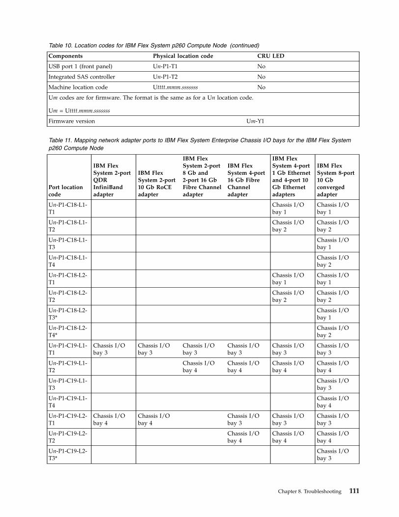
Table 10. Location codes for IBM Flex System p260 Compute Node (continued)
Components Physical location code CRU LED
USB port 1 (front panel) Un-P1-T1 No
Integrated SAS controller Un-P1-T2 No
Machine location code Utttt.mmm.sssssss No
Um codes are for firmware. The format is the same as for a Un location code.
Um = Utttt.mmm.sssssss
Firmware version Um-Y1
Table 11. Mapping network adapter ports to IBM Flex System Enterprise Chassis I/O bays for the IBM Flex Systemp260 Compute Node
Port locationcode
IBM FlexSystem 2-portQDRInfiniBandadapter
IBM FlexSystem 2-port10 Gb RoCEadapter
IBM FlexSystem 2-port8 Gb and2-port 16 GbFibre Channeladapter
IBM FlexSystem 4-port16 Gb FibreChanneladapter
IBM FlexSystem 4-port1 Gb Ethernetand 4-port 10Gb Ethernetadapters
IBM FlexSystem 8-port10 Gbconvergedadapter
Un-P1-C18-L1-T1
Chassis I/Obay 1
Chassis I/Obay 1
Un-P1-C18-L1-T2
Chassis I/Obay 2
Chassis I/Obay 2
Un-P1-C18-L1-T3
Chassis I/Obay 1
Un-P1-C18-L1-T4
Chassis I/Obay 2
Un-P1-C18-L2-T1
Chassis I/Obay 1
Chassis I/Obay 1
Un-P1-C18-L2-T2
Chassis I/Obay 2
Chassis I/Obay 2
Un-P1-C18-L2-T3*
Chassis I/Obay 1
Un-P1-C18-L2-T4*
Chassis I/Obay 2
Un-P1-C19-L1-T1
Chassis I/Obay 3
Chassis I/Obay 3
Chassis I/Obay 3
Chassis I/Obay 3
Chassis I/Obay 3
Chassis I/Obay 3
Un-P1-C19-L1-T2
Chassis I/Obay 4
Chassis I/Obay 4
Chassis I/Obay 4
Chassis I/Obay 4
Un-P1-C19-L1-T3
Chassis I/Obay 3
Un-P1-C19-L1-T4
Chassis I/Obay 4
Un-P1-C19-L2-T1
Chassis I/Obay 4
Chassis I/Obay 4
Chassis I/Obay 3
Chassis I/Obay 3
Chassis I/Obay 3
Un-P1-C19-L2-T2
Chassis I/Obay 4
Chassis I/Obay 4
Chassis I/Obay 4
Un-P1-C19-L2-T3*
Chassis I/Obay 3
Chapter 8. Troubleshooting 111

Table 11. Mapping network adapter ports to IBM Flex System Enterprise Chassis I/O bays for the IBM Flex Systemp260 Compute Node (continued)
Port locationcode
IBM FlexSystem 2-portQDRInfiniBandadapter
IBM FlexSystem 2-port10 Gb RoCEadapter
IBM FlexSystem 2-port8 Gb and2-port 16 GbFibre Channeladapter
IBM FlexSystem 4-port16 Gb FibreChanneladapter
IBM FlexSystem 4-port1 Gb Ethernetand 4-port 10Gb Ethernetadapters
IBM FlexSystem 8-port10 Gbconvergedadapter
Un-P1-C19-L2-T4*
Chassis I/Obay 4
For more information about port mapping, see http://publib.boulder.ibm.com/infocenter/flexsys/information/topic/com.ibm.acc.8721.doc/configuring_io_modules.html.
* Ports L2-T3 and L2-T4 require switches that have the capability of 56 internal ports.
Table 12. Location codes for IBM Flex System p460 Compute Node
Components Physical location code CRU LED
Un location codes are for enclosure and VPD locations.
Un = Utttt.mmm.sssssss
tttt = system machine typemmm = system model numbersssssss = system serial number
DIMM 1 Un-P1-C1 Yes
DIMM 2 Un-P1-C2 Yes
DIMM 3 Un-P1-C3 Yes
DIMM 4 Un-P1-C4 Yes
DIMM 5 Un-P1-C5 Yes
DIMM 6 Un-P1-C6 Yes
DIMM 7 Un-P1-C7 Yes
DIMM 8 Un-P1-C8 Yes
DIMM 9 Un-P1-C9 Yes
DIMM 10 Un-P1-C10 Yes
DIMM 11 Un-P1-C11 Yes
DIMM 12 Un-P1-C12 Yes
DIMM 13 Un-P1-C13 Yes
DIMM 14 Un-P1-C14 Yes
DIMM 15 Un-P1-C15 Yes
DIMM 16 Un-P1-C16 Yes
DIMM 17 Un-P1-C17 Yes
DIMM 18 Un-P1-C18 Yes
DIMM 19 Un-P1-C19 Yes
DIMM 20 Un-P1-C20 Yes
DIMM 21 Un-P1-C21 Yes
DIMM 22 Un-P1-C22 Yes
DIMM 23 Un-P1-C23 Yes
112 Power Systems: IBM Flex System p260 and p460 Compute Nodes Installation and Service Guide
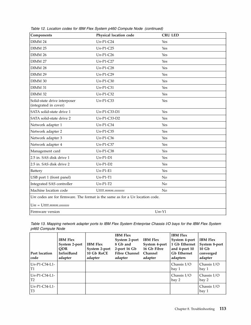
Table 12. Location codes for IBM Flex System p460 Compute Node (continued)
Components Physical location code CRU LED
DIMM 24 Un-P1-C24 Yes
DIMM 25 Un-P1-C25 Yes
DIMM 26 Un-P1-C26 Yes
DIMM 27 Un-P1-C27 Yes
DIMM 28 Un-P1-C28 Yes
DIMM 29 Un-P1-C29 Yes
DIMM 30 Un-P1-C30 Yes
DIMM 31 Un-P1-C31 Yes
DIMM 32 Un-P1-C32 Yes
Solid-state drive interposer(integrated in cover)
Un-P1-C33 Yes
SATA solid-state drive 1 Un-P1-C33-D1 Yes
SATA solid-state drive 2 Un-P1-C33-D2 Yes
Network adapter 1 Un-P1-C34 Yes
Network adapter 2 Un-P1-C35 Yes
Network adapter 3 Un-P1-C36 Yes
Network adapter 4 Un-P1-C37 Yes
Management card Un-P1-C38 Yes
2.5 in. SAS disk drive 1 Un-P1-D1 Yes
2.5 in. SAS disk drive 2 Un-P1-D2 Yes
Battery Un-P1-E1 Yes
USB port 1 (front panel) Un-P1-T1 No
Integrated SAS controller Un-P1-T2 No
Machine location code Utttt.mmm.sssssss No
Um codes are for firmware. The format is the same as for a Un location code.
Um = Utttt.mmm.sssssss
Firmware version Um-Y1
Table 13. Mapping network adapter ports to IBM Flex System Enterprise Chassis I/O bays for the IBM Flex Systemp460 Compute Node
Port locationcode
IBM FlexSystem 2-portQDRInfiniBandadapter
IBM FlexSystem 2-port10 Gb RoCEadapter
IBM FlexSystem 2-port8 Gb and2-port 16 GbFibre Channeladapter
IBM FlexSystem 4-port16 Gb FibreChanneladapter
IBM FlexSystem 4-port1 Gb Ethernetand 4-port 10Gb Ethernetadapters
IBM FlexSystem 8-port10 Gbconvergedadapter
Un-P1-C34-L1-T1
Chassis I/Obay 1
Chassis I/Obay 1
Un-P1-C34-L1-T2
Chassis I/Obay 2
Chassis I/Obay 2
Un-P1-C34-L1-T3
Chassis I/Obay 1
Chapter 8. Troubleshooting 113
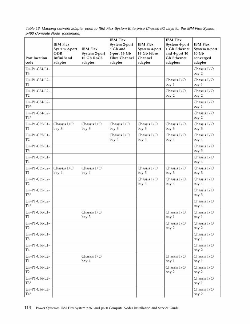
Table 13. Mapping network adapter ports to IBM Flex System Enterprise Chassis I/O bays for the IBM Flex Systemp460 Compute Node (continued)
Port locationcode
IBM FlexSystem 2-portQDRInfiniBandadapter
IBM FlexSystem 2-port10 Gb RoCEadapter
IBM FlexSystem 2-port8 Gb and2-port 16 GbFibre Channeladapter
IBM FlexSystem 4-port16 Gb FibreChanneladapter
IBM FlexSystem 4-port1 Gb Ethernetand 4-port 10Gb Ethernetadapters
IBM FlexSystem 8-port10 Gbconvergedadapter
Un-P1-C34-L1-T4
Chassis I/Obay 2
Un-P1-C34-L2-T1
Chassis I/Obay 1
Chassis I/Obay 1
Un-P1-C34-L2-T2
Chassis I/Obay 2
Chassis I/Obay 2
Un-P1-C34-L2-T3*
Chassis I/Obay 1
Un-P1-C34-L2-T4*
Chassis I/Obay 2
Un-P1-C35-L1-T1
Chassis I/Obay 3
Chassis I/Obay 3
Chassis I/Obay 3
Chassis I/Obay 3
Chassis I/Obay 3
Chassis I/Obay 3
Un-P1-C35-L1-T2
Chassis I/Obay 4
Chassis I/Obay 4
Chassis I/Obay 4
Chassis I/Obay 4
Un-P1-C35-L1-T3
Chassis I/Obay 3
Un-P1-C35-L1-T4
Chassis I/Obay 4
Un-P1-C35-L2-T1
Chassis I/Obay 4
Chassis I/Obay 4
Chassis I/Obay 3
Chassis I/Obay 3
Chassis I/Obay 3
Un-P1-C35-L2-T2
Chassis I/Obay 4
Chassis I/Obay 4
Chassis I/Obay 4
Un-P1-C35-L2-T3*
Chassis I/Obay 3
Un-P1-C35-L2-T4*
Chassis I/Obay 4
Un-P1-C36-L1-T1
Chassis I/Obay 3
Chassis I/Obay 1
Chassis I/Obay 1
Un-P1-C36-L1-T2
Chassis I/Obay 2
Chassis I/Obay 2
Un-P1-C36-L1-T3
Chassis I/Obay 1
Un-P1-C36-L1-T4
Chassis I/Obay 2
Un-P1-C36-L2-T1
Chassis I/Obay 4
Chassis I/Obay 1
Chassis I/Obay 1
Un-P1-C36-L2-T2
Chassis I/Obay 2
Chassis I/Obay 2
Un-P1-C36-L2-T3*
Chassis I/Obay 1
Un-P1-C36-L2-T4*
Chassis I/Obay 2
114 Power Systems: IBM Flex System p260 and p460 Compute Nodes Installation and Service Guide
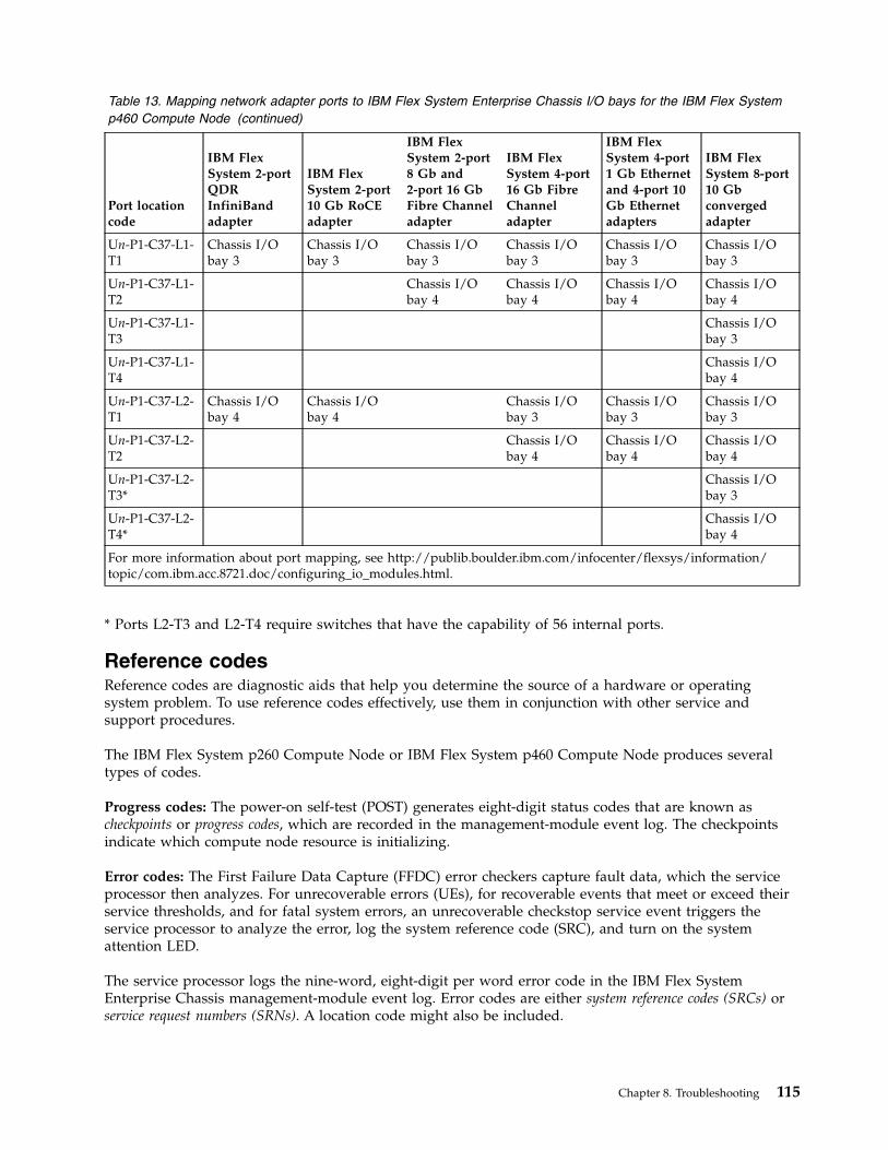
Table 13. Mapping network adapter ports to IBM Flex System Enterprise Chassis I/O bays for the IBM Flex Systemp460 Compute Node (continued)
Port locationcode
IBM FlexSystem 2-portQDRInfiniBandadapter
IBM FlexSystem 2-port10 Gb RoCEadapter
IBM FlexSystem 2-port8 Gb and2-port 16 GbFibre Channeladapter
IBM FlexSystem 4-port16 Gb FibreChanneladapter
IBM FlexSystem 4-port1 Gb Ethernetand 4-port 10Gb Ethernetadapters
IBM FlexSystem 8-port10 Gbconvergedadapter
Un-P1-C37-L1-T1
Chassis I/Obay 3
Chassis I/Obay 3
Chassis I/Obay 3
Chassis I/Obay 3
Chassis I/Obay 3
Chassis I/Obay 3
Un-P1-C37-L1-T2
Chassis I/Obay 4
Chassis I/Obay 4
Chassis I/Obay 4
Chassis I/Obay 4
Un-P1-C37-L1-T3
Chassis I/Obay 3
Un-P1-C37-L1-T4
Chassis I/Obay 4
Un-P1-C37-L2-T1
Chassis I/Obay 4
Chassis I/Obay 4
Chassis I/Obay 3
Chassis I/Obay 3
Chassis I/Obay 3
Un-P1-C37-L2-T2
Chassis I/Obay 4
Chassis I/Obay 4
Chassis I/Obay 4
Un-P1-C37-L2-T3*
Chassis I/Obay 3
Un-P1-C37-L2-T4*
Chassis I/Obay 4
For more information about port mapping, see http://publib.boulder.ibm.com/infocenter/flexsys/information/topic/com.ibm.acc.8721.doc/configuring_io_modules.html.
* Ports L2-T3 and L2-T4 require switches that have the capability of 56 internal ports.
Reference codesReference codes are diagnostic aids that help you determine the source of a hardware or operatingsystem problem. To use reference codes effectively, use them in conjunction with other service andsupport procedures.
The IBM Flex System p260 Compute Node or IBM Flex System p460 Compute Node produces severaltypes of codes.
Progress codes: The power-on self-test (POST) generates eight-digit status codes that are known ascheckpoints or progress codes, which are recorded in the management-module event log. The checkpointsindicate which compute node resource is initializing.
Error codes: The First Failure Data Capture (FFDC) error checkers capture fault data, which the serviceprocessor then analyzes. For unrecoverable errors (UEs), for recoverable events that meet or exceed theirservice thresholds, and for fatal system errors, an unrecoverable checkstop service event triggers theservice processor to analyze the error, log the system reference code (SRC), and turn on the systemattention LED.
The service processor logs the nine-word, eight-digit per word error code in the IBM Flex SystemEnterprise Chassis management-module event log. Error codes are either system reference codes (SRCs) orservice request numbers (SRNs). A location code might also be included.
Chapter 8. Troubleshooting 115
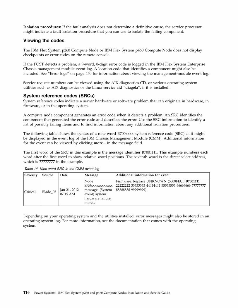
Isolation procedures: If the fault analysis does not determine a definitive cause, the service processormight indicate a fault isolation procedure that you can use to isolate the failing component.
Viewing the codes
The IBM Flex System p260 Compute Node or IBM Flex System p460 Compute Node does not displaycheckpoints or error codes on the remote console.
If the POST detects a problem, a 9-word, 8-digit error code is logged in the IBM Flex System EnterpriseChassis management-module event log. A location code that identifies a component might also beincluded. See “Error logs” on page 450 for information about viewing the management-module event log.
Service request numbers can be viewed using the AIX diagnostics CD, or various operating systemutilities such as AIX diagnostics or the Linux service aid “diagela”, if it is installed.
System reference codes (SRCs)System reference codes indicate a server hardware or software problem that can originate in hardware, infirmware, or in the operating system.
A compute node component generates an error code when it detects a problem. An SRC identifies thecomponent that generated the error code and describes the error. Use the SRC information to identify alist of possibly failing items and to find information about any additional isolation procedures.
The following table shows the syntax of a nine-word B700xxxx system reference code (SRC) as it mightbe displayed in the event log of the IBM Chassis Management Module (CMM). Additional informationfor the event can be viewed by clicking more... in the message field.
The first word of the SRC in this example is the message identifier B7001111. This example numbers eachword after the first word to show relative word positions. The seventh word is the direct select address,which is 77777777 in the example.
Table 14. Nine-word SRC in the CMM event log
Severity Source Date Message Additional information for event
Critical Blade_05Jan 21, 201207:15 AM
NodeSN#xxxxxxxxxxxxmessage: (Systemevent) systemhardware failure.more...
Firmware. Replace UNKNOWN (5008FECF B700111122222222 33333333 44444444 55555555 66666666 7777777788888888 99999999)
Depending on your operating system and the utilities installed, error messages might also be stored in anoperating system log. For more information, see the documentation that comes with the operatingsystem.
116 Power Systems: IBM Flex System p260 and p460 Compute Nodes Installation and Service Guide
Use ASMI to display the error and event logs. See Displaying error and event logs in the IBM PowerSystems Hardware Information Center.
SRC formats
SRCs are strings of either six or eight alphanumeric characters. The first two characters designate thereference code type.
The first characters indicate the type of error:v 1xxxyyyy - System power control network (SPCN) errorv 6xxxyyyy - Virtual optical device errorv A1xxyyyy - Attention required (service processor)v A2xxyyyy - Attention required (logical partition)v A6xxyyyy - Attention required (Licensed Internal Code or hardware event)v A7xxyyyy - Attention required (Licensed Internal Code)v AAxxyyyy - Attention required (Partition firmware)v B1xxyyyy - Service processor error, such as a boot problemv B2xxyyyy - Logical partition errorv B6xxyyyy - Licensed Internal Code or hardware event errorv B7xxyyyy - Licensed Internal Code errorv BAxxyyyy - Partition firmware errorv Cxxxyyyy - Checkpoint (must hang to indicate an error)v Dxxxyyyy - Dump checkpoint (must hang to indicate an error)
To find a description of an SRC that is not listed in this IBM Flex System p260 Compute Node or IBMFlex System p460 Compute Node documentation, refer to the POWER7 Reference Code Lookup page athttp://publib.boulder.ibm.com/infocenter/systems/scope/hw/index.jsp?topic=/ipha8/codefinder.htm.
1xxxyyyy SRCs:
The 1xxxyyyy system reference codes are system power control network (SPCN) reference codes.
Find the system reference code in the list below. Follow the suggested actions in the order in which theyare listed until the problem is solved. If an action solves the problem, you can stop performing theremaining actions. See Chapter 7, “Parts listing for IBM Flex System p260 and p460 Compute Nodes,” onpage 97 to determine which components are CRUs and which components are FRUs.
Chapter 8. Troubleshooting 117
110000AC
Explanation: The 110000AC SRC indicates your compute node lost ac power. This procedure will help youdetermine the source of the power loss condition that brought you here. If the system or expansion unit thatexhibited the power loss starts normally, or stays powered on after an ac power failure, replacement of parts mightnot be needed. This is likely caused by one of three scenarios: 1. If the compute node was disconnected with thepower still on, this SRC will be generated. If the check log indicator remains on, it can be turned off through themanagement console (if available). 2. Power loss to the chassis. This can be caused by a brown-out or the failure ofPDU(s). The SRC is generated by the compute node, but the problem is not local to the compute node. No computenode hardware requires replacement. 3. Power lost to the compute node slot only, but power remains on in the othercompute nodes in the chassis. In this case a legitimate hardware fail is possible. Other power-related (1100xxxx)SRC's for the compute node are expected to further diagnose and isolate the problem.
Response: No action is required.
110000AD
Explanation: Informational message: A service processor reset caused the server to power off.
Response: No action is required.
11001F02
Explanation: Informational message: The trace logs reached 1K of data.
Response: No action is required.
11001F03
Explanation: Informational message: Invalid TMS of location code.
Response: No action is required.
11002600
Explanation: Power good (pGood) master fault.
Response:
1. Search RETAIN tips and the firmware change history for the reference code to determine the recommendedactions. If a firmware update is needed, see Updating the firmware
2. Replace the system board. If there is more than one system board, use the location code in the SRC to identifywhich system board to replace.
11002610
Explanation: pGood fault.
Response:
1. Search RETAIN tips and the firmware change history for the reference code to determine the recommendedactions. If a firmware update is needed, see Updating the firmware
2. Replace the system board. If there is more than one system board, use the location code in the SRC to identifywhich system board to replace.
110000AC • 11002610
118 Power Systems: IBM Flex System p260 and p460 Compute Nodes Installation and Service Guide

11002620
Explanation: 12V dc pGood input fault.
Response:
1. Search RETAIN tips and the firmware change history for the reference code to determine the recommendedactions. If a firmware update is needed, see Updating the firmware
2. Replace the system board. If there is more than one system board, use the location code in the SRC to identifywhich system board to replace.
11002622
Explanation: Expansion_Comp_pGood_fault.
Response:
1. Search RETAIN tips and the firmware change history for the reference code to determine the recommendedactions. If a firmware update is needed, see Updating the firmware
2. Replace the system board. If there is more than one system board, use the location code in the SRC to identifywhich system board to replace.
11002629
Explanation: 1.5V reg_pgood fault.
Response:
1. Search RETAIN tips and the firmware change history for the reference code to determine the recommendedactions. If a firmware update is needed, see Updating the firmware
2. Replace the system board. If there is more than one system board, use the location code in the SRC to identifywhich system board to replace.
1100262B
Explanation: 1.8V reg_pgood fault.
Response:
1. Search RETAIN tips and the firmware change history for the reference code to determine the recommendedactions. If a firmware update is needed, see Updating the firmware
2. Replace the system board. If there is more than one system board, use the location code in the SRC to identifywhich system board to replace.
1100262C
Explanation: 5V reg_pgood fault.
Response:
1. Search RETAIN tips and the firmware change history for the reference code to determine the recommendedactions. If a firmware update is needed, see Updating the firmware
2. Replace the system board. If there is more than one system board, use the location code in the SRC to identifywhich system board to replace.
11002620 • 1100262C
Chapter 8. Troubleshooting 119
1100262D
Explanation: 3.3V reg_pgood fault.
Response:
1. Search RETAIN tips and the firmware change history for the reference code to determine the recommendedactions. If a firmware update is needed, see Updating the firmware
2. Replace the system board. If there is more than one system board, use the location code in the SRC to identifywhich system board to replace.
1100262E
Explanation: 2.5V reg_pgood fault.
Response:
1. Search RETAIN tips and the firmware change history for the reference code to determine the recommendedactions. If a firmware update is needed, see Updating the firmware
2. Replace the system board. If there is more than one system board, use the location code in the SRC to identifywhich system board to replace.
1100262F
Explanation: 1.0V power fault in the server.
Response:
1. Search RETAIN tips and the firmware change history for the reference code to determine the recommendedactions. If a firmware update is needed, see Updating the firmware
2. Replace the system board. If there is more than one system board, use the location code in the SRC to identifywhich system board to replace.
11002630
Explanation: VRM CP0 core pGood fault.
Response:
1. Search RETAIN tips and the firmware change history for the reference code to determine the recommendedactions. If a firmware update is needed, see Updating the firmware
2. Replace the system board. If there is more than one system board, use the location code in the SRC to identifywhich system board to replace.
11002632
Explanation: VRM CP0 cache pGood fault.
Response:
1. Search RETAIN tips and the firmware change history for the reference code to determine the recommendedactions. If a firmware update is needed, see Updating the firmware
2. Replace the system board. If there is more than one system board, use the location code in the SRC to identifywhich system board to replace.
1100262D • 11002632
120 Power Systems: IBM Flex System p260 and p460 Compute Nodes Installation and Service Guide
11002640
Explanation: VRM CP1 core pGood fault
Response:
1. Search RETAIN tips and the firmware change history for the reference code to determine the recommendedactions. If a firmware update is needed, see Updating the firmware
2. Replace the system board. If there is more than one system board, use the location code in the SRC to identifywhich system board to replace.
11002642
Explanation: VRM CP1 array pGood fault
Response:
1. Search RETAIN tips and the firmware change history for the reference code to determine the recommendedactions. If a firmware update is needed, see Updating the firmware
2. Replace the system board. If there is more than one system board, use the location code in the SRC to identifywhich system board to replace.
11002647
Explanation: 12V "or-ing" FET short.
Response:
1. Search RETAIN tips and the firmware change history for the reference code to determine the recommendedactions. If a firmware update is needed, see Updating the firmware
2. Replace the system board. If there is more than one system board, use the location code in the SRC to identifywhich system board to replace.
11002648
Explanation: Server power latch fault.
Response:
1. Search RETAIN tips and the firmware change history for the reference code to determine the recommendedactions. If a firmware update is needed, see Updating the firmware
2. Replace the system board. If there is more than one system board, use the location code in the SRC to identifywhich system board to replace.
11002649
Explanation: Server power fault.
Response:
1. Search RETAIN tips and the firmware change history for the reference code to determine the recommendedactions. If a firmware update is needed, see Updating the firmware
2. Replace the system board. If there is more than one system board, use the location code in the SRC to identifywhich system board to replace.
11002640 • 11002649
Chapter 8. Troubleshooting 121
1100265A
Explanation: 1.2VA pGood fault
Response:
1. Search RETAIN tips and the firmware change history for the reference code to determine the recommendedactions. If a firmware update is needed, see Updating the firmware
2. Replace the system board. If there is more than one system board, use the location code in the SRC to identifywhich system board to replace.
11002671
Explanation: 12V power fault in the server.
Response:
1. Search RETAIN tips and the firmware change history for the reference code to determine the recommendedactions. If a firmware update is needed, see Updating the firmware
2. Replace the system board. If there is more than one system board, use the location code in the SRC to identifywhich system board to replace.
11002672
Explanation: CFFh expansion card voltage alert.
Response: Perform the DTRCARD symbolic CRU isolation procedure by completing the following steps:
1. Reseat the PCIe expansion card.
2. If the problem persists, replace the expansion card.
3. If the problem persists, go to the Search RETAIN tips and the firmware change history for the reference code todetermine the recommended actions. If a firmware update is needed, see Updating the firmware.
4. If the problem persists, replace the system-board into which the expansion card was plugged.
The DTRCARD symbolic CRU isolation procedure is in Service processor problems.
11002673
Explanation: Standby power fault on one of the system-boards in the server.
Response:
1. Check the management module event log for entries that indicate a power problem with the chassis unit.
2. Resolve any problems.
3. Remove the server from the chassis, then reinsert it.
4. Power on the server.
5. Monitor the server operation to verify that the problem is solved.
6. If the chassis unit is functioning normally, but the problem persists, replace the system board specified by thelocation code that was reported with the SRC.
1100265A • 11002673
122 Power Systems: IBM Flex System p260 and p460 Compute Nodes Installation and Service Guide
11002674
Explanation: Expansion server pGood fault at standby.
Response:
1. Search RETAIN tips and the firmware change history for the reference code to determine the recommendedactions. If a firmware update is needed, see Updating the firmware
2. Replace the expansion system-board (Un-P2) assembly, as described in Removing the expansion unit.
11002675
Explanation: 1.1 Reg_CPU0_P5IO2C_Vio_pGood fault.
Response:
1. Search RETAIN tips and the firmware change history for the reference code to determine the recommendedactions. If a firmware update is needed, see Updating the firmware
2. Replace the system board. If there is more than one system board, use the location code in the SRC to identifywhich system board to replace.
11002676
Explanation: VTTA/B pGood fault.
Response:
1. Search RETAIN tips and the firmware change history for the reference code to determine the recommendedactions. If a firmware update is needed, see Updating the firmware
2. Replace the system board. If there is more than one system board, use the location code in the SRC to identifywhich system board to replace.
11002678
Explanation: PROC_Vmem_controller_pGood 1.0V. fault
Response:
1. Search RETAIN tips and the firmware change history for the reference code to determine the recommendedactions. If a firmware update is needed, see Updating the firmware
2. Replace the system board. If there is more than one system board, use the location code in the SRC to identifywhich system board to replace.
11002679
Explanation: Vmem_controller_pGood 1.5V reg. fault
Response:
1. Search RETAIN tips and the firmware change history for the reference code to determine the recommendedactions. If a firmware update is needed, see Updating the firmware
2. Replace the system board. If there is more than one system board, use the location code in the SRC to identifywhich system board to replace.
11002674 • 11002679
Chapter 8. Troubleshooting 123
1100267A
Explanation: CFFh expansion card A0_pGood fault.
Response: Perform the DTRCARD symbolic CRU isolation procedure by completing the following steps:
1. Reseat the PCIe expansion card.
2. If the problem persists, replace the expansion card.
3. If the problem persists: Search RETAIN tips and the firmware change history for the reference code to determinethe recommended actions. If a firmware update is needed, see Updating the firmware
4. Replace the system board into which the expansion card is plugged.
The DTRCARD symbolic CRU isolation procedure is in Service processor problems.
1100267B
Explanation: CFFh expansion card B0_pGood fault.
Response: Perform the DTRCARD symbolic CRU isolation procedure by completing the following steps:
1. Reseat the PCIe expansion card.
2. If the problem persists, replace the expansion card.
3. If the problem persists: Search RETAIN tips and the firmware change history for the reference code to determinethe recommended actions. If a firmware update is needed, see Updating the firmware
4. Replace the system board into which the expansion card is plugged.
The DTRCARD symbolic CRU isolation procedure is in Service processor problems.
1100267C
Explanation: REG_P5IO2C_core 1.2V pGood fault.
Response:
1. Search RETAIN tips and the firmware change history for the reference code to determine the recommendedactions. If a firmware update is needed, see Updating the firmware
2. Replace the system board. If there is more than one system board, use the location code in the SRC to identifywhich system board to replace.
1100267D
Explanation: 2.0_PLL_pGood fault.
Response:
1. Search RETAIN tips and the firmware change history for the reference code to determine the recommendedactions. If a firmware update is needed, see Updating the firmware
2. Replace the system board. If there is more than one system board, use the location code in the SRC to identifywhich system board to replace.
1100267A • 1100267D
124 Power Systems: IBM Flex System p260 and p460 Compute Nodes Installation and Service Guide
1100267F
Explanation: ETE daughter card pGood fault.
Response:
1. Search RETAIN tips and the firmware change history for the reference code to determine the recommendedactions. If a firmware update is needed, see Updating the firmware
2. Replace the ETE daughter card.
1100269C
Explanation: 1.2V A pGood fault.
Response:
1. Search RETAIN tips and the firmware change history for the reference code to determine the recommendedactions. If a firmware update is needed, see Updating the firmware
2. Replace the system board. If there is more than one system board, use the location code in the SRC to identifywhich system board to replace.
1100269D
Explanation: 1.2V B pGood fault.
Response:
1. Search RETAIN tips and the firmware change history for the reference code to determine the recommendedactions. If a firmware update is needed, see Updating the firmware
2. Replace the system board. If there is more than one system board, use the location code in the SRC to identifywhich system board to replace.
110026DA
Explanation: pGood fault on the expansion system board.
Response:
1. Search RETAIN tips and the firmware change history for the reference code to determine the recommendedactions. If a firmware update is needed, see Updating the firmware
2. Perform the following:
a. Replace the expansion system board assembly, as described in Removing the expansion unit.
11002900
Explanation: SSD drive or SSD interposer card 3.3V pGood fault on the server board.
Response:
1. On a single-wide server, replace the following, one at a time, until the failure is no longer detected:
a. The SSD interposer card
b. The first SSD drive
c. The second SSD drive
2. On a double-wide server, replace the following, one at a time, until the failure is no longer detected:
a. The SSD interposer card on the expansion planar
b. The first SSD drive on the expansion planar
c. The second SSD drive on the expansion planar
1100267F • 11002900
Chapter 8. Troubleshooting 125
11002901
Explanation: SSD interposer card pGood fault on the base system board.
Response:
1. Replace the interposer card on the base system board.
11002902
Explanation: SSD drive power-on self-test failure on the base system board
Response: Perform one of the following:
v Replace the first SSD drive on the base system board.
v Replace the second SSD drive on the base system board.
11002910
Explanation: SSD drive or SSD interposer card 3.3V pGood fault on the expansion system board.
Response:
1. Replace the following, one at a time, until the failure is no longer detected:
a. The SSD interposer card on the expansion system board
b. The first SSD drive on the expansion system board
c. The second SSD drive on the expansion system board
11002911
Explanation: SSD interposer card pGood fault on the expansion system board
Response:
1. Replace the interposer card on the expansion system board.
11002912
Explanation: SSD drive power-on self-test failure.
Response: Perform one of the following:
v Replace the first SSD drive on the expansion system board.
v Replace the second SSD drive on the expansion system board.
11003118
Explanation: Thermal sensor read error.
Response:
1. Search RETAIN tips and the firmware change history for the reference code to determine the recommendedactions. If a firmware update is needed, see Updating the firmware
2. If this is an IBM Flex System p260 or p24L compute node, replace the light path diagnostics panel. If this is anIBM Flex System p460 compute node, check word 3 of the SRC. If word 3 is 00003100, the thermal sensor in thefirst bay is failing; replace the light path diagnostics panel. If word 3 is 00003101, the thermal sensor in the secondbay is failing; replace the thermal sensor in the second bay of the compute node. For all other servers, replace thesystem board. If there is more than one system board, use the location code in the SRC to identify which systemboard to replace.
11002901 • 11003118
126 Power Systems: IBM Flex System p260 and p460 Compute Nodes Installation and Service Guide

11003134
Explanation: Fault on the hardware monitoring chip.
Response: Perform the DTRCARD symbolic CRU isolation procedure by completing the following steps:
1. Reseat the PCIe expansion card.
2. If the problem persists, replace the expansion card.
3. If the problem persists: Search RETAIN tips and the firmware change history for the reference code to determinethe recommended actions. If a firmware update is needed, see Updating the firmware
4. Replace the system board into which the PCI card is plugged.
The DTRCARD symbolic CRU isolation procedure is in Service processor problems.
11008400
Explanation: Invalid configuration decode.
Response:
1. Check for server firmware updates.
2. Apply any available updates.
3. If the problem persists:
a. Search RETAIN tips and the firmware change history for the reference code to determine the recommendedactions. If a firmware update is needed, see Updating the firmware
b. Replace the base system board, as described in Replacing the system-board and chassis assembly.
11008402
Explanation: Unable to get VPD from the concentrator.
Response:
1. Search RETAIN tips and the firmware change history for the reference code to determine the recommendedactions. If a firmware update is needed, see Updating the firmware
2. Replace the base system-board, as described in Replacing the system-board and chassis assembly.
11008413
Explanation: Invalid processor 1 VPD.
Response:
1. Search RETAIN tips and the firmware change history for the reference code to determine the recommendedactions. If a firmware update is needed, see Updating the firmware
2. Replace the system board. If there is more than one system board, use the location code in the SRC to identifywhich system board to replace.
11003134 • 11008413
Chapter 8. Troubleshooting 127
11008414
Explanation: Invalid processor 2 VPD.
Response:
1. Search RETAIN tips and the firmware change history for the reference code to determine the recommendedactions. If a firmware update is needed, see Updating the firmware
2. Replace the system board. If there is more than one system board, use the location code in the SRC to identifywhich system board to replace.
11008423
Explanation: No processor VPD was found.
Response:
1. Search RETAIN tips and the firmware change history for the reference code to determine the recommendedactions. If a firmware update is needed, see Updating the firmware
2. Replace the base system-board, as described in Replacing the system-board and chassis assembly.
11008447
Explanation: SSD interposer card pGood fault on the system board.
Response:
1. Replace the interposer card specified by the location code in the error log entry.
11008480
Explanation: Bad or missing memory controller.
Response:
1. Search RETAIN tips and the firmware change history for the reference code to determine the recommendedactions. If a firmware update is needed, see Updating the firmware
2. Replace the system board. If there is more than one system board, use the location code in the SRC to identifywhich system board to replace.
110084A0
Explanation: No backplane VPD was found.
Response:
1. Check for server firmware updates.
2. Apply any available updates.
3. Search RETAIN tips and the firmware change history for the reference code to determine the recommendedactions. If a firmware update is needed, see Updating the firmware
4. Replace the base system-board, as described in Replacing the system-board and chassis assembly.
6xxxyyyy SRCs:
The 6xxxyyyy system reference codes are virtual optical reference codes.
Find the system reference code in the list below. Follow the suggested actions in the order in which theyare listed until the problem is solved. If an action solves the problem, then you can stop performing theremaining actions. See Chapter 7, “Parts listing for IBM Flex System p260 and p460 Compute Nodes,” onpage 97 to determine which components are CRUs and which components are FRUs.
11008414 • 110084A0
128 Power Systems: IBM Flex System p260 and p460 Compute Nodes Installation and Service Guide
632BCFC1
Explanation: A virtual optical device cannot access the file containing the list of volumes.
Service action / serviceable event: Yes
Called home automatically: No
Problem determination: On this partition and on the Network File System server, verify that the proper file isspecified and that the proper authority is granted.
632BCFC2
Explanation: Virtual optical device error. A non-recoverable error was detected while reading the list of volumes.
Service action / serviceable event: Yes
Called home automatically: No
Problem determination: Resolve any errors on the Network File System server.
632BCFC3
Explanation: Virtual optical device error. The data in the list of volumes is not valid.
Service action / serviceable event: Yes
Called home automatically: No
Problem determination: On the Network File System server, verify that the proper file is specified, that all files areentered correctly, that there are no blank lines, and that the character set used is valid.
632BCFC4
Explanation: A virtual optical device cannot access the file containing the specified optical volume.
Service action / serviceable event: Yes
Called home automatically: No
Problem determination: On the Network File System server, verify that the proper file is specified in the list ofvolumes, and that the proper authority is granted.
632BCFC5
Explanation: A non-recoverable error was detected while reading a virtual optical volume.
Service action / serviceable event: Yes
Called home automatically: No
Problem determination: Resolve any errors on the Network File System server.
632BCFC1 • 632BCFC5
Chapter 8. Troubleshooting 129
632BCFC6
Explanation: Virtual optical device error. The file specified does not contain data that can be processed as a virtualoptical volume.
Service action / serviceable event: Yes
Called home automatically: No
Problem determination: On the Network File System server, verify that all the files specified in the list of opticalvolumes are correct.
632BCFC7
Explanation: A virtual optical device detected an error reported by the Network File System server that cannot berecovered.
Service action / serviceable event: Yes
Called home automatically: No
Problem determination: Resolve any errors on the Network File System server.
632BCFC8
Explanation: A virtual optical device encountered a non-recoverable error.
Service action / serviceable event: Yes
Called home automatically: Yes
Problem determination: Install any available operating system updates.
632CC000
Explanation: Informational system log entry only.
Service action / serviceable event: No
Called home automatically: No
Response: No corrective action is required.
632CC002
Explanation: Virtual optical device error. Self configuring SCSI device (SCSD) selection or reselection timeoutoccurred.
Service action / serviceable event: No
Called home automatically: No
Problem determination: Refer to the hosting partition for problem analysis.
632BCFC6 • 632CC002
130 Power Systems: IBM Flex System p260 and p460 Compute Nodes Installation and Service Guide
632CC010
Explanation: Virtual optical device error. Undefined sense key returned by device.
Service action / serviceable event: No
Called home automatically: No
Problem determination: Refer to the hosting partition for problem analysis.
632CC020
Explanation: Virtual optical device error. Configuration error.
Service action / serviceable event: No
Called home automatically: No
Problem determination: Refer to the hosting partition for problem analysis.
632CC100
Explanation: Virtual optical device error. Self configuring SCSI device (SCSD) bus error occurred.
Service action / serviceable event: No
Called home automatically: No
Problem determination: Refer to the hosting partition for problem analysis.
632CC110
Explanation: Virtual optical device error. Self configuring SCSI device (SCSD) command timeout occurred.
Service action / serviceable event: No
Called home automatically: No
Problem determination: Refer to the hosting partition for problem analysis.
632CC210
Explanation: Informational system log entry only.
Service action / serviceable event: Yes
Called home automatically: No
Response: No corrective action is required.
632CC300
Explanation: Virtual optical device error. Media or device error occurred.
Service action / serviceable event: No
Called home automatically: No
Problem determination: Refer to the hosting partition for problem analysis.
632CC010 • 632CC300
Chapter 8. Troubleshooting 131
632CC301
Explanation: Virtual optical device error. Media or device error occurred.
Service action / serviceable event: No
Called home automatically: No
Problem determination: Refer to the hosting partition for problem analysis.
632CC302
Explanation: Virtual optical device error. Media or device error occurred.
Service action / serviceable event: No
Called home automatically: No
Problem determination: Refer to the hosting partition for problem analysis.
632CC303
Explanation: Virtual optical device, media has an unknown format.
Service action / serviceable event: No
Called home automatically: No
Response: No corrective action is required. If the problem persists refer to the hosting partition for problemanalysis.
632CC333
Explanation: Virtual optical device error. Incompatible media.
Service action / serviceable event: No
Called home automatically: No
Problem determination:
1. Verify that the disk has a supported format.
2. If the format is supported, clean the disk and attempt the failing operation again.
3. If the operation fails again with the same system reference code, ask your media source for a replacement disk.
632CC400
Explanation: Virtual optical device error. Physical link error detected by device.
Service action / serviceable event: No
Called home automatically: No
Problem determination: Refer to the hosting partition for problem analysis.
632CC301 • 632CC400
132 Power Systems: IBM Flex System p260 and p460 Compute Nodes Installation and Service Guide

632CC402
Explanation: Virtual optical device driver error. An internal program error occurred.
Service action / serviceable event: Yes
Called home automatically: Yes
Problem determination: Install any available operating system updates.
632CCFF2
Explanation: Informational system log entry only.
Service action / serviceable event: No
Called home automatically: No
Response: No corrective action is required.
632CCFF4
Explanation: Internal device error occurred.
Service action / serviceable event: No
Called home automatically: No
Problem determination: Refer to the hosting partition for problem analysis.
632CCFF6
Explanation: Informational system log entry only.
Service action / serviceable event: No
Called home automatically: No
Response: No corrective action is required.
632CCFF7
Explanation: Informational system log entry only.
Service action / serviceable event: No
Called home automatically: No
Response: No corrective action is required.
632CCFFE
Explanation: Informational system log entry only.
Service action / serviceable event: No
Called home automatically: No
Response: No corrective action is required.
632CC402 • 632CCFFE
Chapter 8. Troubleshooting 133
632CFF3D
Explanation: Informational system log entry only.
Service action / serviceable event: No
Called home automatically: No
Response: No corrective action is required.
632CFF6D
Explanation: Informational system log entry only.
Service action / serviceable event: No
Called home automatically: No
Response: No corrective action is required.
A1xxyyyy service processor SRCs:
An A1xxyyyy system reference code (SRC) is an attention code that offers information about a platformor service processor dump or confirms a control panel function request. Only when you experience ahang condition should you take any of the actions described for an attention code.
If the system hangs on an attention code, follow the suggested actions in the order in which they arelisted until the problem is solved. If an action solves the problem, you can stop performing the remainingactions. See Chapter 7, “Parts listing for IBM Flex System p260 and p460 Compute Nodes,” on page 97 todetermine which components are CRUs and which components are FRUs.
A1XXYYYY
Explanation: Attention code
Response:
1. Go to Checkout procedure.
2. Replace the system board and chassis assembly, as described in Replacing the system-board and chassis assembly.
A2xxyyyy logical partition SRCs:
An A2xxyyyy SRC is a logical partition reference code that is related to logical partitioning.
A2D03000
Explanation: User-initiated immediate termination and MSD of a partition.
Response: No corrective action is required.
632CFF3D • A2D03000
134 Power Systems: IBM Flex System p260 and p460 Compute Nodes Installation and Service Guide

A2D03001
Explanation: User-initiated RSCDUMP of RPA partition's PFW content.
Response: No corrective action is required.
A2D03002
Explanation: User-initiated RSCDUMP of IBM i partition's SLIC bootloader and PFW content.
Response: No corrective action is required.
A2XXYYYY
Explanation: See the description for the B200yyyy error code with the same yyyy value.
Response: Perform the action described in the B200yyyy error code with the same yyyy value.
A6xxyyyy licensed internal code or hardware event SRCs:
An A6xxyyyy system reference code (SRC) is an error or event code that is related to licensed internalcode or hardware.
A6000255
Explanation: Contact was lost with the device indicated in the SRC. The operating system is halted waiting for theI/O function of a critical resource to return. When the I/O returns this SRC will disappear from the panel and theO/S will continue running. This problem occurs when the connection to the I/O resource or host is suspended, lostor there is a problem with I/O in the host.
The O/S cannot notify or call home in this state.
Service action / serviceable event : YES
Called home automatically: Conditional from the management console.
v If this LPAR was defined from the managent console with the option for calling home crashes and hangs then themanagement console will call this problem home.
v Otherwise this problem will not be called home.
Problem determination: Do not power off the LPAR. Look for and repair problems in the I/O host.
A6000266
Explanation: Contact was lost with the device indicated in the SRC. The operating system is halted waiting for theI/O function of a critical resource to return. When the I/O returns this SRC will disappear from the panel and theO/S will continue running. This problem occurs when the connection to the I/O resource or host is suspended, lostor there is a problem with I/O in the host.
The O/S cannot notify or call home in this state.
This SRC will continue to be refreshed in the panel periodically in the third and fourth "XX" digits (A6XX0266 orB6XX0266) while the O/S is in this state.
Service action / serviceable event : YES
Called home automatically: Conditional from the management console.
v If this LPAR was defined from the managent console with the option for calling home crashes and hangs then themanagement console will call this problem home.
v Otherwise this problem will not be called home.
Problem determination: Do not power off the LPAR. Look for and repair problems in the I/O host.
A2D03001 • A6000266
Chapter 8. Troubleshooting 135
A6xx0255
Explanation: Contact was lost with the device indicated in the SRC. The operating system is halted waiting for theI/O function of a critical resource to return. When the I/O returns this SRC will disappear from the panel and theO/S will continue running. This problem occurs when the connection to the I/O resource or host is suspended, lostor there is a problem with I/O in the host.
The O/S cannot notify or call home in this state.
Service action / serviceable event : YES
Called home automatically: Conditional from the management console.
v If this LPAR was defined from the managent console with the option for calling home crashes and hangs then themanagement console will call this problem home.
v Otherwise this problem will not be called home.
Problem determination: Do not power off the LPAR. Look for and repair problems in the I/O host.
A6xx0266
Explanation: Contact was lost with the device indicated in the SRC. The operating system is halted waiting for theI/O function of a critical resource to return. When the I/O returns this SRC will disappear from the panel and theO/S will continue running. This problem occurs when the connection to the I/O resource or host is suspended, lostor there is a problem with I/O in the host.
The O/S cannot notify or call home in this state.
This SRC will continue to be refreshed in the panel periodically in the third and fourth "XX" digits (A6XX0266 orB6XX0266) while the O/S is in this state.
Service action / serviceable event : YES
Called home automatically: Conditional from the management console.
v If this LPAR was defined from the managent console with the option for calling home crashes and hangs then themanagement console will call this problem home.
v Otherwise this problem will not be called home.
Problem determination: Do not power off the LPAR. Look for and repair problems in the I/O host.
B6000255
Explanation: Contact was lost with the device indicated in the SRC. The operating system is halted waiting for theI/O function of a critical resource to return. When the I/O returns this SRC will disappear from the panel and theO/S will continue running. This problem occurs when the connection to the I/O resource or host is suspended, lostor there is a problem with I/O in the host.
The O/S cannot notify or call home in this state.
Service action / serviceable event : YES
Called home automatically: Conditional from the management console.
v If this LPAR was defined from the managent console with the option for calling home crashes and hangs then themanagement console will call this problem home.
v Otherwise this problem will not be called home.
Problem determination: Do not power off the LPAR. Look for and repair problems in the I/O host.
A6xx0255 • B6000255
136 Power Systems: IBM Flex System p260 and p460 Compute Nodes Installation and Service Guide
B6000266
Explanation: Contact was lost with the device indicated in the SRC. The operating system is halted waiting for theI/O function of a critical resource to return. When the I/O returns this SRC will disappear from the panel and theO/S will continue running. This problem occurs when the connection to the I/O resource or host is suspended, lostor there is a problem with I/O in the host.
The O/S cannot notify or call home in this state.
This SRC will continue to be refreshed in the panel periodically in the third and fourth "XX" digits (A6XX0266 orB6XX0266) while the O/S is in this state.
Service action / serviceable event : YES
Called home automatically: Conditional from the management console.
v If this LPAR was defined from the managent console with the option for calling home crashes and hangs then themanagement console will call this problem home.
v Otherwise this problem will not be called home.
Problem determination: Do not power off the LPAR. Look for and repair problems in the I/O host.
B6xx0255
Explanation: Contact was lost with the device indicated in the SRC. The operating system is halted waiting for theI/O function of a critical resource to return. When the I/O returns this SRC will disappear from the panel and theO/S will continue running. This problem occurs when the connection to the I/O resource or host is suspended, lostor there is a problem with I/O in the host.
The O/S cannot notify or call home in this state.
Service action / serviceable event : YES
Called home automatically: Conditional from the management console.
v If this LPAR was defined from the managent console with the option for calling home crashes and hangs then themanagement console will call this problem home.
v Otherwise this problem will not be called home.
Problem determination: Do not power off the LPAR. Look for and repair problems in the I/O host.
B6xx0266
Explanation: Contact was lost with the device indicated in the SRC. The operating system is halted waiting for theI/O function of a critical resource to return. When the I/O returns this SRC will disappear from the panel and theO/S will continue running. This problem occurs when the connection to the I/O resource or host is suspended, lostor there is a problem with I/O in the host.
The O/S cannot notify or call home in this state.
This SRC will continue to be refreshed in the panel periodically in the third and fourth "XX" digits (A6XX0266 orB6XX0266) while the O/S is in this state.
Service action / serviceable event : YES
Called home automatically: Conditional from the management console.
v If this LPAR was defined from the managent console with the option for calling home crashes and hangs then themanagement console will call this problem home.
v Otherwise this problem will not be called home.
Problem determination: Do not power off the LPAR. Look for and repair problems in the I/O host.
B6000266 • B6xx0266
Chapter 8. Troubleshooting 137
A7xxyyyy licensed internal code SRCs:
An A7xxyyyy system reference code (SRC) is an error/event code that is related to licensed internal code.
A700173C
Explanation: Informational system log entry only.
Response: No corrective action is required.
A7003000
Explanation: A user-initiated platform dump occurred.
Response: No service action required.
A7004700
Explanation: Informational system log entry only.
Response: No corrective action is required.
A7004712
Explanation: A problem occurred when initializing, reading, or using system VPD.
Response: Replace the management card, as described in Removing the management card and Installing themanagement card.
A7004713
Explanation: A problem occurred when initializing, reading, or using system VPD.
Response: Replace the management card, as described in Removing the management card and Installing themanagement card.
A7004715
Explanation: A problem occurred when initializing, reading, or using system VPD.
Response: Replace the management card, as described in Removing the management card and Installing themanagement card.
A7004721
Explanation: The World Wide Port Name (WWPN) Prefix is not valid.
Response: Refer to https://www-912.ibm.com/supporthome.nsf/document/51455410
A700173C • A7004721
138 Power Systems: IBM Flex System p260 and p460 Compute Nodes Installation and Service Guide
A7004730
Explanation: Informational system log entry only.
Response: No corrective action is required.
A7004740
Explanation: Informational system log entry only.
Response: No corrective action is required.
A7004741
Explanation: Informational system log entry only.
Response: No corrective action is required.
A700474A
Explanation: System has Active Memory Mirroring (AMM) ON, but is not licensed for AMM use
Response: The management interfaces have been used to set AMM to "ON" for the system. However, at IPL time,the system does not have a valid license for AMM. The customer needs to contact IBM or a Partner Salesrepresentative to purchase and enter an Activation Code for this feature. If this is not possible, then turn off thesystem; use the management interfaces to turn AMM "OFF"; and re-IPL.
A7004788
Explanation: Informational system log entry only.
Response: No corrective action is required.
A70047FF
Explanation: Informational system log entry only.
Response: No corrective action is required.
A700YYYY
Explanation: For any other A7xxyyyy SRC not listed here, see the description for the B7xxyyyy error code with thesame xxyyyy value.
Response: Perform the action in the B7xxyyyy error code with the same xxyyyy value.
A7013003
Explanation: Partition-initiated PHYP-content RSCDUMP.
Response: No corrective action is required.
A7004730 • A7013003
Chapter 8. Troubleshooting 139
AAxxyyyy partition firmware attention codes:
AAxxyyyy attention codes provide information about the next target state for the platform firmware.These codes might indicate that you need to perform an action.
The AAxxyyyy SRCs below are the partition firmware codes that might be displayed if the POST detectsa problem. Follow the suggested actions in the order in which they are listed until the problem is solved.If an action solves the problem, then you can stop performing the remaining actions. See Chapter 7,“Parts listing for IBM Flex System p260 and p460 Compute Nodes,” on page 97 to determine whichcomponents are CRUs and which components are FRUs.
AA00E1A8
Explanation: The system is booting to the open firmware prompt.
Response: At the open firmware prompt, type dev /packages/gui obe and press Enter; then, type 1 to select SMSMenu.
AA00E1A9
Explanation: The system is booting to the System Management Services (SMS) menus.
Response:
1. If the system or partition returns to the SMS menus after a boot attempt failed, use the SMS menus to check theprogress indicator history for a BAxx xxxx error, which may indicate why the boot attempt failed. Follow theactions for that error code to resolve the boot problem.
2. Use the SMS menus to establish the boot list and restart the server.
AA00E1B0
Explanation: Waiting for the user to select the language and keyboard. The menu should be visible on the console.
Response:
1. Check for server firmware updates.
2. Apply any available updates.
3. If the problem persists:
a. Go to Checkout procedure.
b. Replace the system-board, as described in Replacing the system-board and chassis assembly.
AA00E1B1
Explanation: Waiting for the user to accept or decline the license
Response:
1. Check for server firmware updates.
2. Apply any available updates.
3. If the problem persists:
a. Go to Checkout procedure.
b. Replace the system-board, as described in Replacing the system-board and chassis assembly.
AA00E1A8 • AA00E1B1
140 Power Systems: IBM Flex System p260 and p460 Compute Nodes Installation and Service Guide
AA060007
Explanation: A keyboard was not found.
Response: Verify that a keyboard is attached to the USB port that is assigned to the partition.
AA06000B
Explanation: The system or partition was not able to find an operating system on any of the devices in the boot list.
Response:
1. Use the SMS menus to modify the boot list so that it includes devices that have a known-good operating systemand restart the server.
2. If the problem remains, go to Boot problem resolution.
AA06000C
Explanation: The media in a device in the boot list was not bootable.
Response:
1. Replace the media in the device with known-good media or modify the boot list to boot from another bootabledevice.
2. If the problem remains, go to Boot problem resolution.
AA06000D
Explanation: The media in the device in the bootlist was not found under the I/O adapter specified by the bootlist.
Response:
1. Verify that the media from which you are trying to boot is bootable or modify the boot list to boot from anotherbootable device.
2. If the problem remains, go to Boot problem resolution.
AA06000E
Explanation: The adapter specified in the boot list is not present or is not functioning.
Response:
v For an AIX operating system:
1. Try booting the server from another bootable device; then, run AIX online diagnostics against the failingadapter.
2. If AIX cannot be booted from another device, boot the server using the stand-alone diagnostics CD or a NIMserver; then, run diagnostics against the failing adapter.
v For a Linux operating system, boot the server using the stand-alone diagnostics CD or a NIM server; then, rundiagnostics against the failing adapter.
AA060007 • AA06000E
Chapter 8. Troubleshooting 141
AA060011
Explanation: The firmware did not find an operating system image and at least one hard disk in the boot list wasnot detected by the firmware. The firmware is retrying the entries in the boot list.
Response: This might occur if a disk enclosure that contains the boot disk is not fully initialized or if the boot diskbelongs to another partition. Verify that:
v The boot disk belongs to the partition from which you are trying to boot.
v The boot list in the SMS menus is correct.
AA130013
Explanation: Bootable media is missing from a USB CD-ROM
Response: Verify that a bootable CD is properly inserted in the CD or DVD drive and retry the boot operation.
AA130014
Explanation: The media in a USB CD-ROM has changed.
Response:
1. Retry the operation.
2. Check for server firmware updates; then, install the updates if available and retry the operation.
AA170210
Explanation: Setenv/$setenv parameter error - the name contains a null character.
Response:
1. Go to Checkout procedure.
2. Replace the system-board, as described in Replacing the system-board and chassis assembly.
AA170211
Explanation: Setenv/$setenv parameter error - the value contains a null character.
Response:
1. Go to Checkout procedure.
2. Replace the system-board, as described in Replacing the system-board and chassis assembly.
AA190001
Explanation: The hypervisor function to get or set the time-of-day clock reported an error.
Response:
1. Use the operating system to set the system clock.
2. If the problem persists, check for server firmware updates.
3. Install any available updates and retry the operation.
AA060011 • AA190001
142 Power Systems: IBM Flex System p260 and p460 Compute Nodes Installation and Service Guide

AA260001
Explanation: Enter the Type Model Number (Must be 8 characters)
Response: Enter the machine type and model of the server at the prompt.
AA260002
Explanation: Enter the Serial Number (Must be 7 characters)
Response: Enter the serial number of the server at the prompt.
AA260003
Explanation: Enter System Unique ID (Must be 12 characters)
Response: Enter the system unique ID number at the prompt.
AA260004
Explanation: Enter WorldWide Port Number (Must be 12 characters)
Response: Enter the worldwide port number of the server at the prompt.
AA260005
Explanation: Enter Brand (Must be 2 characters)
Response: Enter the brand number of the server at the prompt.
B1xxyyyy service processor SRCs:
A B1xxyyyy system reference code (SRC) is an error code that is related to an event or exception thatoccurred in the service processor firmware.
To find a description of an SRC that is not listed in this IBM Flex System p260 Compute Node or IBMFlex System p460 Compute Node documentation, refer to the POWER7 Reference Code Lookup page athttp://publib.boulder.ibm.com/infocenter/systems/scope/hw/index.jsp?topic=/ipha8/codefinder.htm.
Note: For problems persisting after completing the suggested actions, see “Solving undeterminedproblems” on page 498.
B15611A9
Explanation: The service processor could not communicate with the Chassis Management Module.
Response: Go to Reseating the compute node in a chassis.
AA260001 • B15611A9
Chapter 8. Troubleshooting 143
B15611B1
Explanation: The service processor could not communicate with the Chassis Management Module.
Response: Go to Reseating the compute node in a chassis.
B15611B9
Explanation: The service processor could not communicate with the Chassis Management Module.
Response: Go to Reseating the compute node in a chassis.
B15611BA
Explanation: The service processor could not communicate with the Chassis Management Module.
Response: Go to Reseating the compute node in a chassis.
B1768BBF
Explanation: During the configuration of the second interface connection, the service processor detected that theinterface is not connected to an active CMM.
Response: If a service processor reset to factory default was performed or if this is a tracking event, no serviceactions are required. Otherwise, use the FRU and procedure callouts detailed with the SRC to determine serviceactions.
B1817200
Explanation: Invalid boot request
Response: Go to Checkout procedure.
B1817201
Explanation: Service processor failure
Response: Go to Checkout procedure.
B1817202
Explanation: The permanent and temporary firmware sides are both marked invalid
Response: Go to Checkout procedure.
B1817203
Explanation: Error setting boot parameters
Response: Go to Checkout procedure.
B15611B1 • B1817203
144 Power Systems: IBM Flex System p260 and p460 Compute Nodes Installation and Service Guide

B1817204
Explanation: Error reading boot parameters
Response: Go to Checkout procedure.
B1817205
Explanation: Boot code error
Response: Go to Checkout procedure.
B1817206
Explanation: Unit check timer was reset
Response: Go to Checkout procedure.
B1817207
Explanation: Error reading from NVRAM
Response: Go to Checkout procedure.
B1817208
Explanation: Error writing to NVRAM
Response: Go to Checkout procedure.
B1817209
Explanation: The service processor boot watchdog timer expired and forced the service processor to attempt a bootfrom the other firmware image in the service processor flash memory
Response: Go to Checkout procedure.
B181720A
Explanation: Power-off reset occurred. FipsDump should be analyzed: Possible software problem
Response: Go to Checkout procedure.
B1818BC1
Explanation: The service processor reset failed to resolve a communication failure with the Chassis ManagementModule. The service processor is no longer accessible.
Response: Perform the following actions one at a time until the problem is resolved:
1. Reseat the compute node.
2. Move the compute node to a different location in the chassis.
3. Perform a firmware update. See Updating the firmware.
If these actions do not resolve the problem, contact your next level of support. Reseating the compute node in achassis
B1817204 • B1818BC1
Chapter 8. Troubleshooting 145
B1818BC2
Explanation: The service processor was reset due to a communication failure with the Chassis Management Module.
Response: If this is tracking event, no service action is required. Otherwise look for Chassis Management Moduleproblems and resolve them.
B181D548
Explanation: An informational event was generated on the service processor.
Response: This is an informational tracking event and no service action is required.
B2xxyyyy logical partition SRCs:
A B2xxyyyy SRC is a logical partition reference code that is related to logical partitioning.
The B2xxyyyy SRCs below are the system reference codes that might be displayed if system firmwaredetects a problem. Follow the suggested actions in the order in which they are listed until the problem issolved. If an action solves the problem, then you can stop performing the remaining actions. SeeChapter 7, “Parts listing for IBM Flex System p260 and p460 Compute Nodes,” on page 97 to determinewhich components are CRUs and which components are FRUs.
Note: For problems persisting after completing the suggested actions, see “Checkout procedure” on page451 and “Solving undetermined problems” on page 498.
B2001020
Explanation: Firmware for the specified function cannot be loaded
The firmware resource and all associated virtual and/or physical devices will not be available until the issue isresolved.
Response: Collect a platform dump and then go to Isolating firmware problems.
B2001130
Explanation: A problem occurred during the migration of a partition
You attempted to migrate a partition to a system that has a power or thermal problem. The migration will notcontinue.
Response: Look for and fix power or thermal problems and then retry the migration.
B2001131
Explanation: A problem occurred during the migration of a partition.
The migration of a partition did not complete.
Response: Check for server firmware updates; then, install the updates if available.
B1818BC2 • B2001131
146 Power Systems: IBM Flex System p260 and p460 Compute Nodes Installation and Service Guide
B2001132
Explanation: A problem occurred during the startup of a partition.
A platform firmware error occurred while it was trying to allocate memory. The startup will not continue.
Response: Collect a platform dump and then go to Isolating firmware problems.
B2001133
Explanation: A problem occurred during the migration of a partition.
The migration of a partition did not complete.
Response: Check for server firmware updates; then, install the updates if available.
B2001134
Explanation: A problem occurred during the migration of a partition.
The migration of a partition did not complete.
Response: Check for server firmware updates; then, install the updates if available.
B2001140
Explanation: A problem occurred during the migration of a partition.
The migration of a partition did not complete.
Response: Check for server firmware updates; then, install the updates if available.
B2001141
Explanation: A problem occurred during the migration of a partition.
The migration of a partition did not complete.
Response: Check for server firmware updates; then, install the updates if available.
B2001142
Explanation: A problem occurred during the migration of a partition.
The migration of a partition did not complete.
Response: Check for server firmware updates; then, install the updates if available.
B2001143
Explanation: A problem occurred during the migration of a partition.
The migration of a partition did not complete.
Response: Check for server firmware updates; then, install the updates if available.
B2001132 • B2001143
Chapter 8. Troubleshooting 147
B2001144
Explanation: A problem occurred during the migration of a partition.
The migration of a partition did not complete.
Response: Check for server firmware updates; then, install the updates if available.
B2001148
Explanation: A problem occurred during the migration of a partition.
The migration of a partition did not complete.
Response: Check for server firmware updates; then, install the updates if available.
B2001150
Explanation: During the startup of a partition, a partitioning configuration problem occurred.
Response: Go to Verifying the partition configuration.
B2001151
Explanation: A problem occurred during the migration of a partition.
The migration of a partition did not complete.
Response: Check for server firmware updates; then, install the updates if available.
B2001170
Explanation: During the startup of a partition, a failure occurred due to a validation error.
Response: Go to Verifying the partition configuration.
B2001225
Explanation: A problem occurred during the startup of a partition.
The partition attempted to start up prior to the platform fully initializing. Restart the partition after the platform hasfully completed and the platform is not in standby mode.
Response: Restart the partition.
B2001230
Explanation: During the startup of a partition, a partitioning configuration problem occurred; the partition is lackingthe necessary resources to start up.
Response: Go to Verifying the partition configuration.
B2001144 • B2001230
148 Power Systems: IBM Flex System p260 and p460 Compute Nodes Installation and Service Guide
B2001260
Explanation: A problem occurred during the startup of a partition.
The partition could not start at the Timed Power On setting because the partition was not set to Normal.
Response: Set the partition to Normal.
B2001265
Explanation: The partition could not start up. An operating system Main Storage Dump startup was attempted withthe startup side on D-mode, which is not a valid operating system startup scenario. The startup will be halted. ThisSRC can occur when a D-mode SLIC installation fails and attempts a Main Storage Dump.
Response: Correct the startup settings.
B2001266
Explanation: The partition could not start up. You are attempting to start up an operating system that is notsupported.
Response: Install a supported operating system and restart the partition.
B2001280
Explanation: A problem occurred during a partition Main Storage Dump. A mainstore dump startup did notcomplete due to a configuration mismatch.
Response: Go to Isolating firmware problems.
B2001281
Explanation: A partition memory error occurred. The failed memory will no longer be used.
Response: Restart the partition.
B2001282
Explanation: A problem occurred during the startup of a partition.
Response: Go to Isolating firmware problems.
B2001320
Explanation: A problem occurred during the startup of a partition.
No default load source was selected. The startup will attempt to continue, but there may not be enough informationto find the correct load source.
Response: Configure a load source for the partition. Then restart the partition.
B2001260 • B2001320
Chapter 8. Troubleshooting 149
B2001321
Explanation: A problem occurred during the startup of a partition.
Response: Verify that the correct slot is specified for the load source. Then restart the partition.
B2001322
Explanation: In the partition startup, code failed during a check of the load source path.
Response: Verify that the path for the load source is specified correctly. Then restart the partition.
B2002048
Explanation: A problem occurred during a partition Main Storage Dump. A mainstore dump startup did notcomplete due to a copy error.
Response: Go to Isolating firmware problems.
B2002054
Explanation: A problem occurred during a partition Main Storage Dump. A mainstore dump IPL did not completedue to a configuration mismatch.
Response: Go to Isolating firmware problems.
B2002058
Explanation: A problem occurred during a partition Main Storage Dump. A mainstore dump startup did notcomplete due to a copy error.
Response: Go to Isolating firmware problems.
B2002210
Explanation: Informational system log entry only.
Response: No corrective action is required.
B2002220
Explanation: Informational system log entry only.
Response: No corrective action is required.
B2002250
Explanation: During the startup of a partition, an attempt to toggle the power state of a slot has failed.
Response: Check for server firmware updates; then, install the updates if available.
B2001321 • B2002250
150 Power Systems: IBM Flex System p260 and p460 Compute Nodes Installation and Service Guide
B2002260
Explanation: During the startup of a partition, the partition firmware attempted an operation that failed.
Response: Go to Isolating firmware problems.
B2002300
Explanation: During the startup of a partition, an attempt to toggle the power state of a slot has failed.
Response: Check for server firmware updates; then, install the updates if available.
B2002310
Explanation: During the startup of a partition, the partition firmware attempted an operation that failed.
Response: Go to Isolating firmware problems.
B2002320
Explanation: During the startup of a partition, the partition firmware attempted an operation that failed.
Response: Go to Isolating firmware problems.
B2002425
Explanation: During the startup of a partition, the partition firmware attempted an operation that failed.
Response: Go to Isolating firmware problems.
B2002426
Explanation: During the startup of a partition, the partition firmware attempted an operation that failed.
Response: Go to Isolating firmware problems.
B2002475
Explanation: During the startup of a partition, a slot that was needed for the partition was either empty or thedevice in the slot has failed.
Response: Check for server firmware updates; then, install the updates if available.
B2002485
Explanation: During the startup of a partition, the partition firmware attempted an operation that failed.
Response: Go to Isolating firmware problems.
B2002260 • B2002485
Chapter 8. Troubleshooting 151
B2003000
Explanation: Informational system log entry only.
Response: No corrective action is required.
B2003081
Explanation: During the startup of a partition, the startup did not complete due to a copy error.
Response: Check for server firmware updates; then, install the updates if available.
B2003084
Explanation: A problem occurred during the startup of a partition.
The adapter type might not be supported.
Response: Verify that the adapter type is supported.
B2003088
Explanation: Informational system log entry only.
Response: No corrective action is required.
B200308C
Explanation: A problem occurred during the startup of a partition.
The adapter type cannot be determined.
Response: Verify that a valid I/O Load Source is tagged.
B2003090
Explanation: A problem occurred during the startup of a partition.
Response: Go to Isolating firmware problems.
B2003110
Explanation: A problem occurred during the startup of a partition.
Response: Go to Isolating firmware problems.
B2003113
Explanation: A problem occurred during the startup of a partition.
Response: Look for B7xx xxxx errors and resolve them.
B2003000 • B2003113
152 Power Systems: IBM Flex System p260 and p460 Compute Nodes Installation and Service Guide
B2003114
Explanation: A problem occurred during the startup of a partition.
Response: Look for other errors and resolve them.
B2003120
Explanation: Informational system log entry only.
Response: No corrective action is required.
B2003123
Explanation: Informational system log entry only.
Response: No corrective action is required.
B2003125
Explanation: During the startup of a partition, the server firmware could not obtain a segment of main storagewithin the server to use for managing the creation of a partition.
Response: Check for server firmware updates; then, install the updates if available.
B2003128
Explanation: A problem occurred during the startup of a partition. A return code for an unexpected failure wasreturned when attempting to query the load source path.
Response: Look for and resolve B700 69xx errors.
B2003130
Explanation: A problem occurred during the startup of a partition.
Response: Check for server firmware updates; then, install the updates if available.
B2003135
Explanation: A problem occurred during the startup of a partition.
Response: Check for server firmware updates; then, install the updates if available.
B2003140
Explanation: A problem occurred during the startup of a partition. This is a configuration problem in the partition.
Response: Reconfigure the partition to include the intended load source path.
B2003114 • B2003140
Chapter 8. Troubleshooting 153
B2003141
Explanation: Informational system log entry only.
Response: No corrective action is required.
B2003142
Explanation: Informational system log entry only.
Response: No corrective action is required.
B2003143
Explanation: Informational system log entry only.
Response: No corrective action is required.
B2003144
Explanation: Informational system log entry only.
Response: No corrective action is required.
B2003145
Explanation: Informational system log entry only.
Response: No corrective action is required.
B2003200
Explanation: Informational system log entry only.
Response: No corrective action is required.
B2004158
Explanation: Informational system log entry only.
Response: No corrective action is required.
B2004400
Explanation: A problem occurred during the startup of a partition.
Response: Check for server firmware updates; then, install the updates if available.
B2003141 • B2004400
154 Power Systems: IBM Flex System p260 and p460 Compute Nodes Installation and Service Guide
B2005106
Explanation: A problem occurred during the startup of a partition. There is not enough space to contain thepartition main storage dump. The startup will not continue.
Response: Verify that there is sufficient memory available to start the partition as it is configured. If there is alreadyenough memory, then go to Isolating firmware problems.
B2005109
Explanation: A problem occurred during the startup of a partition. There was a partition main storage dumpproblem. The startup will not continue.
Response: Go to Isolating firmware problems.
B2005114
Explanation: A problem occurred during the startup of a partition. There is not enough space to contain thepartition main storage dump. The startup will not continue.
Response: Go to Isolating firmware problems.
B2005115
Explanation: A problem occurred during the startup of a partition. There was an error reading the partition mainstorage dump from the partition load source into main storage. The startup will attempt to continue.
Response: If the startup does not continue, look for and resolve other errors.
B2005117
Explanation: A problem occurred during the startup of a partition. A partition main storage dump has occurred butcannot be written to the load source device because a valid dump already exists.
Response: Use the Main Storage Dump Manager to rename or copy the current main storage dump.
B2005121
Explanation: A problem occurred during the startup of a partition. There was an error writing the partition mainstorage dump to the partition load source. The startup will not continue.
Response: Look for related errors in the "Product Activity Log" and fix any problems found. Use virtual controlpanel function 34 to retry the current Main Store Dump startup while the partition is still in the failed state.
B2005122
Explanation: Informational system log entry only.
Response: No corrective action is required.
B2005106 • B2005122
Chapter 8. Troubleshooting 155
B2005123
Explanation: Informational system log entry only.
Response: No corrective action is required.
B2005127
Explanation: Timeout occurred during a main store dump IPL.
Response: There was not enough memory available for the dump to complete before the timeout occurred. Retrythe main store dump IPL, or else power on the partition normally.
B2005135
Explanation: A problem occurred during the startup of a partition. There was an error writing the partition mainstorage dump to the partition load source. The main store dump startup will continue.
Response: Look for other errors and resolve them.
B2005137
Explanation: A problem occurred during the startup of a partition. There was an error writing the partition mainstorage dump to the partition load source. The main store dump startup will continue.
Response: Look for other errors and resolve them.
B2005145
Explanation: A problem occurred during the startup of a partition. There was an error writing the partition mainstorage dump to the partition load source. The main store dump startup will continue.
Response: Look for other errors and resolve them.
B2005148
Explanation: A problem occurred during the startup of a partition. An error occurred while doing a main storagedump that would have caused another main storage dump. The startup will not continue.
Response: Go to Isolating firmware problems.
B2005149
Explanation: A problem occurred during the startup of a partition while doing a Firmware Assisted Dump thatwould have caused another Firmware Assisted Dump.
Response: Check for server firmware updates; then, install the updates if available.
B2005123 • B2005149
156 Power Systems: IBM Flex System p260 and p460 Compute Nodes Installation and Service Guide
B200514A
Explanation: A Firmware Assisted Dump did not complete due to a copy error.
Response: Check for server firmware updates; then, install the updates if available.
B200542A
Explanation: A Firmware Assisted Dump did not complete due to a read error.
Response: Check for server firmware updates; then, install the updates if available.
B200542B
Explanation: A Firmware Assisted Dump did not complete due to a copy error.
Response: Check for server firmware updates; then, install the updates if available.
B200543A
Explanation: A Firmware Assisted Dump did not complete due to a copy error.
Response: Check for server firmware updates; then, install the updates if available.
B200543B
Explanation: A Firmware Assisted Dump did not complete due to a copy error.
Response: Check for server firmware updates; then, install the updates if available.
B200543C
Explanation: Informational system log entry only.
Response: No corrective action is required.
B200543D
Explanation: A Firmware Assisted Dump did not complete due to a copy error.
Response: Check for server firmware updates; then, install the updates if available.
B2006003
Explanation: Firmware for the specified function cannot be loaded.
The firmware resource and all associated virtual and/or physical devices will not be available until the issue isresolved.
Response: Collect a platform dump and then go to Isolating firmware problems.
B200514A • B2006003
Chapter 8. Troubleshooting 157
B2006006
Explanation: During the startup of a partition, a system firmware error occurred when the partition memory wasbeing initialized; the startup will not continue.
Response: Go to Isolating firmware problems.
B2006008
Explanation: During the IPL of the partition, an error was detected while trying to setup the partition for firmwareuse.
The IPL of the partition will not continue.
Response: Contact IBM support.
B2006009
Explanation: An active memory sharing partition is attempting to use a paging space device for which it does nothave ownership.
Response: Verify that the paging space device is not in use by another CEC, and then follow the instructions belowto initialize the paging space device. 1) Power off the partition. 2) Verify that the paging device is not currently inanother CEC's Reserved Pool. 3) Clear the paging space header of the hdisk assigned to the partition. 4) Remove thepaging space from the Reserved Pool. 5) Add the just removed paging space back into the Reserved Pool. 6) Activatethe partition.
B200600A
Explanation: A problem occurred during the startup of a partition. The partition could not reserve the memoryrequired for IPL.
Response: Contact IBM support.
B2006012
Explanation: During the startup of a partition, the partition LID failed to completely load into the partition mainstorage area.
Response: Go to Isolating firmware problems.
B2006015
Explanation: A problem occurred during the startup of a partition. The load source media is corrupted or not valid.
Response: Replace the load source media.
B2006006 • B2006015
158 Power Systems: IBM Flex System p260 and p460 Compute Nodes Installation and Service Guide
B2006025
Explanation: A problem occurred during the startup of a partition. This is a problem with the load source mediabeing corrupt or not valid.
Response: Replace the load source media.
B2006027
Explanation: During the startup of a partition, a failure occurred when allocating memory for an internal objectused for firmware module load operations.
Response:
1. Make sure that enough main storage was allocated to the partition.
2. Retry the operation.
B2006110
Explanation: A problem occurred during the startup of a partition. There was an error on the load source device.The startup will attempt to continue.
Response: Look for other errors and resolve them.
B200690A
Explanation: During the startup of a partition, an error occurred while copying open firmware into the partitionload area.
Response: Go to Isolating firmware problems.
B2007200
Explanation: Informational system log entry only.
Response: No corrective action is required.
B2008080
Explanation: Informational system log entry only.
Response: No corrective action is required.
B2008081
Explanation: During the startup of a partition, an internal firmware time-out occurred; the partition might continueto start up but it can experience problems while running.
Response: Check for server firmware updates; then, install the updates if available.
B2006025 • B2008081
Chapter 8. Troubleshooting 159
B2008105
Explanation: During the startup of a partition, there was a failure loading the VPD areas of the partition; the loadsource media has been corrupted or is unsupported on this server.
Response: Check for server firmware updates; then, install the updates if available.
B2008106
Explanation: A problem occurred during the startup of a partition. The startup will not continue.
Response: Replace the load source media.
B2008107
Explanation: During the startup of a partition, there was a problem getting a segment of main storage in the servermain storage.
Response: Check for server firmware updates; then, install the updates if available.
B2008109
Explanation: During the startup of a partition, a failure occurred. The startup will not continue.
Response:
1. Make sure that there is enough memory to start up the partition.
2. Check for server firmware updates; then, install the updates if available.
B2008111
Explanation: A problem occurred during the startup of a partition.
Response: Check for server firmware updates; then, install the updates if available.
B2008112
Explanation: During the startup of a partition, a failure occurred; the startup will not continue.
Response: Check for server firmware updates; then, install the updates if available.
B2008113
Explanation: During the startup of a partition, an error occurred while mapping memory for the partition startup.
Response: Check for server firmware updates; then, install the updates if available.
B2008114
Explanation: During the startup of a partition, there was a failure verifying the VPD for the partition resourcesduring startup.
Response: Check for server firmware updates; then, install the updates if available.
B2008105 • B2008114
160 Power Systems: IBM Flex System p260 and p460 Compute Nodes Installation and Service Guide
B2008115
Explanation: During the startup of a partition, there was a low level partition-to-partition communication failure.
Response: Check for server firmware updates; then, install the updates if available.
B2008117
Explanation: During the startup of a partition, the partition did not start up due to a system firmware error.
Response: Check for server firmware updates; then, install the updates if available.
B2008121
Explanation: During the startup of a partition, the partition did not start up due to a system firmware error.
Response: Go to Isolating firmware problems.
B2008123
Explanation: During the startup of a partition, the partition did not start up due to a system firmware error.
Response: Go to Isolating firmware problems.
B2008125
Explanation: During the startup of a partition, the partition did not start up due to a system firmware error.
Response: Go to Isolating firmware problems.
B2008127
Explanation: During the startup of a partition, the partition did not start up due to a system firmware error.
Response: Go to Isolating firmware problems.
B2008129
Explanation: During the startup of a partition, the partition did not start up due to a system firmware error.
Response: Go to Isolating firmware problems.
B200813A
Explanation: There was a problem establishing a console.
Response: Go to Isolating firmware problems.
B2008115 • B200813A
Chapter 8. Troubleshooting 161
B2008140
Explanation: Informational system log entry only.
Response: No corrective action is required.
B2008141
Explanation: Informational system log entry only.
Response: No corrective action is required.
B2008142
Explanation: Informational system log entry only.
Response: No corrective action is required.
B2008143
Explanation: Informational system log entry only.
Response: No corrective action is required.
B2008144
Explanation: Informational system log entry only.
Response: No corrective action is required.
B2008145
Explanation: Informational system log entry only.
Response: No corrective action is required.
B2008150
Explanation: System firmware detected an error.
Response: Collect a platform dump and then go to Isolating firmware problems.
B2008151
Explanation: System firmware detected an error.
Response: Use the management console to increase the Logical Memory Block (LMB) size, and to reduce thenumber of virtual devices for the partition.
B2008140 • B2008151
162 Power Systems: IBM Flex System p260 and p460 Compute Nodes Installation and Service Guide

B2008152
Explanation: No active system processors.
Response: Verify that processor resources are assigned to the partition.
B2008160
Explanation: A problem occurred during the migration of a partition.
Response: Contact IBM support.
B2008161
Explanation: A problem occurred during the migration of a partition.
Response: Contact IBM support.
B200A100
Explanation: A partition ended abnormally; the partition could not stay running and shut itself down.
Response:
1. Check the error logs and take the actions for the error codes that are found.
2. Go to Isolating firmware problems.
B200A101
Explanation: A partition ended abnormally; the partition could not stay running and shut itself down.
Response:
1. Check the error logs and take the actions for the error codes that are found.
2. Go to Isolating firmware problems.
B200A140
Explanation: A lower priority partition lost a usable processor to supply it to a higher priority partition with a badprocessor.
Response: Evaluate the entire LPAR configuration. Adjust partition profiles with the new number of processorsavailable in the system.
B200B07B
Explanation: Informational system log entry only.
Response: No corrective action is required.
B2008152 • B200B07B
Chapter 8. Troubleshooting 163
B200B215
Explanation: A problem occurred after a partition ended abnormally.
There was a communications problem between this partition's service processor and the platform's service processor.
Response: Restart the platform.
B200C1F0
Explanation: An internal system firmware error occurred during a partition shutdown or a restart.
Response: Go to Isolating firmware problems.
B200D150
Explanation: A partition ended abnormally; there was a communications problem between this partition and thecode that handles resource allocation.
Response: Check for server firmware updates; then, install the updates if available.
B200E0AA
Explanation: A problem occurred during the power off of a partition.
Response: Go to Isolating firmware problems.
B200F001
Explanation: A problem occurred during the startup of a partition. An operation has timed out.
Response: Look for other errors and resolve them.
B200F003
Explanation: During the startup of a partition, the partition processor(s) did not start the firmware within thetime-out window.
Response: Collect the partition dump information; then, go to Isolating firmware problems.
B200F004
Explanation: Informational system log entry only.
Response: No corrective action is required.
B200F005
Explanation: Informational system log entry only.
Response: No corrective action is required.
B200B215 • B200F005
164 Power Systems: IBM Flex System p260 and p460 Compute Nodes Installation and Service Guide
B200F006
Explanation: During the startup of a partition, the code load operation for the partition startup timed out.
Response:
1. Check the error logs and take the actions for the error codes that are found.
2. Go to Isolating firmware problems.
B200F007
Explanation: During a shutdown of the partition, a time-out occurred while trying to stop a partition.
Response: Check for server firmware updates; then, install the updates if available.
B200F008
Explanation: Informational system log entry only.
Response: No corrective action is required.
B200F009
Explanation: Informational system log entry only.
Response: No corrective action is required.
B200F00A
Explanation: Informational system log entry only.
Response: No corrective action is required.
B200F00B
Explanation: Informational system log entry only.
Response: No corrective action is required.
B200F00C
Explanation: Informational system log entry only.
Response: No corrective action is required.
B200F00D
Explanation: Informational system log entry only.
Response: No corrective action is required.
B200F006 • B200F00D
Chapter 8. Troubleshooting 165
B2D03001
Explanation: Informational system log entry only.
Response: No corrective action is required.
B2D03002
Explanation: Informational system log entry only.
Response: No corrective action is required.
B6xxyyyy licensed internal code or hardware event SRCs:
A B6xxyyyy system reference code (SRC) is an error code or event code that is related to licensed internalcode or hardware.
The B6xxyyyy SRCs below are the system reference codes that might be displayed if system firmwaredetects a problem. Follow the suggested actions in the order in which they are listed until the problem issolved. If an action solves the problem, then you can stop performing the remaining actions. SeeChapter 7, “Parts listing for IBM Flex System p260 and p460 Compute Nodes,” on page 97 to determinewhich components are CRUs and which components are FRUs.
Note: For problems persisting after completing the suggested actions, see “Solving undeterminedproblems” on page 498.
A6000255
Explanation: Contact was lost with the device indicated in the SRC. The operating system is halted waiting for theI/O function of a critical resource to return. When the I/O returns this SRC will disappear from the panel and theO/S will continue running. This problem occurs when the connection to the I/O resource or host is suspended, lostor there is a problem with I/O in the host.
The O/S cannot notify or call home in this state.
Service action / serviceable event : YES
Called home automatically: Conditional from the management console.
v If this LPAR was defined from the managent console with the option for calling home crashes and hangs then themanagement console will call this problem home.
v Otherwise this problem will not be called home.
Problem determination: Do not power off the LPAR. Look for and repair problems in the I/O host.
A6000266
Explanation: Contact was lost with the device indicated in the SRC. The operating system is halted waiting for theI/O function of a critical resource to return. When the I/O returns this SRC will disappear from the panel and theO/S will continue running. This problem occurs when the connection to the I/O resource or host is suspended, lostor there is a problem with I/O in the host.
The O/S cannot notify or call home in this state.
This SRC will continue to be refreshed in the panel periodically in the third and fourth "XX" digits (A6XX0266 orB6XX0266) while the O/S is in this state.
Service action / serviceable event : YES
Called home automatically: Conditional from the management console.
v If this LPAR was defined from the managent console with the option for calling home crashes and hangs then themanagement console will call this problem home.
v Otherwise this problem will not be called home.
Problem determination: Do not power off the LPAR. Look for and repair problems in the I/O host.
B2D03001 • A6000266
166 Power Systems: IBM Flex System p260 and p460 Compute Nodes Installation and Service Guide
A6xx0255
Explanation: Contact was lost with the device indicated in the SRC. The operating system is halted waiting for theI/O function of a critical resource to return. When the I/O returns this SRC will disappear from the panel and theO/S will continue running. This problem occurs when the connection to the I/O resource or host is suspended, lostor there is a problem with I/O in the host.
The O/S cannot notify or call home in this state.
Service action / serviceable event : YES
Called home automatically: Conditional from the management console.
v If this LPAR was defined from the managent console with the option for calling home crashes and hangs then themanagement console will call this problem home.
v Otherwise this problem will not be called home.
Problem determination: Do not power off the LPAR. Look for and repair problems in the I/O host.
A6xx0266
Explanation: Contact was lost with the device indicated in the SRC. The operating system is halted waiting for theI/O function of a critical resource to return. When the I/O returns this SRC will disappear from the panel and theO/S will continue running. This problem occurs when the connection to the I/O resource or host is suspended, lostor there is a problem with I/O in the host.
The O/S cannot notify or call home in this state.
This SRC will continue to be refreshed in the panel periodically in the third and fourth "XX" digits (A6XX0266 orB6XX0266) while the O/S is in this state.
Service action / serviceable event : YES
Called home automatically: Conditional from the management console.
v If this LPAR was defined from the managent console with the option for calling home crashes and hangs then themanagement console will call this problem home.
v Otherwise this problem will not be called home.
Problem determination: Do not power off the LPAR. Look for and repair problems in the I/O host.
B6000255
Explanation: Contact was lost with the device indicated in the SRC. The operating system is halted waiting for theI/O function of a critical resource to return. When the I/O returns this SRC will disappear from the panel and theO/S will continue running. This problem occurs when the connection to the I/O resource or host is suspended, lostor there is a problem with I/O in the host.
The O/S cannot notify or call home in this state.
Service action / serviceable event : YES
Called home automatically: Conditional from the management console.
v If this LPAR was defined from the managent console with the option for calling home crashes and hangs then themanagement console will call this problem home.
v Otherwise this problem will not be called home.
Problem determination: Do not power off the LPAR. Look for and repair problems in the I/O host.
A6xx0255 • B6000255
Chapter 8. Troubleshooting 167
B6000266
Explanation: Contact was lost with the device indicated in the SRC. The operating system is halted waiting for theI/O function of a critical resource to return. When the I/O returns this SRC will disappear from the panel and theO/S will continue running. This problem occurs when the connection to the I/O resource or host is suspended, lostor there is a problem with I/O in the host.
The O/S cannot notify or call home in this state.
This SRC will continue to be refreshed in the panel periodically in the third and fourth "XX" digits (A6XX0266 orB6XX0266) while the O/S is in this state.
Service action / serviceable event : YES
Called home automatically: Conditional from the management console.
v If this LPAR was defined from the managent console with the option for calling home crashes and hangs then themanagement console will call this problem home.
v Otherwise this problem will not be called home.
Problem determination: Do not power off the LPAR. Look for and repair problems in the I/O host.
B6xx0255
Explanation: Contact was lost with the device indicated in the SRC. The operating system is halted waiting for theI/O function of a critical resource to return. When the I/O returns this SRC will disappear from the panel and theO/S will continue running. This problem occurs when the connection to the I/O resource or host is suspended, lostor there is a problem with I/O in the host.
The O/S cannot notify or call home in this state.
Service action / serviceable event : YES
Called home automatically: Conditional from the management console.
v If this LPAR was defined from the managent console with the option for calling home crashes and hangs then themanagement console will call this problem home.
v Otherwise this problem will not be called home.
Problem determination: Do not power off the LPAR. Look for and repair problems in the I/O host.
B6xx0266
Explanation: Contact was lost with the device indicated in the SRC. The operating system is halted waiting for theI/O function of a critical resource to return. When the I/O returns this SRC will disappear from the panel and theO/S will continue running. This problem occurs when the connection to the I/O resource or host is suspended, lostor there is a problem with I/O in the host.
The O/S cannot notify or call home in this state.
This SRC will continue to be refreshed in the panel periodically in the third and fourth "XX" digits (A6XX0266 orB6XX0266) while the O/S is in this state.
Service action / serviceable event : YES
Called home automatically: Conditional from the management console.
v If this LPAR was defined from the managent console with the option for calling home crashes and hangs then themanagement console will call this problem home.
v Otherwise this problem will not be called home.
Problem determination: Do not power off the LPAR. Look for and repair problems in the I/O host.
B6000266 • B6xx0266
168 Power Systems: IBM Flex System p260 and p460 Compute Nodes Installation and Service Guide
B7xxyyyy licensed internal code SRCs:
A B7xxyyyy system reference code (SRC) is an error code or event code that is related to licensed internalcode.
The B7xxyyyy SRCs below are the system reference codes that might be displayed if system firmwaredetects a problem. Follow the suggested actions in the order in which they are listed until the problem issolved. If an action solves the problem, then you can stop performing the remaining actions. SeeChapter 7, “Parts listing for IBM Flex System p260 and p460 Compute Nodes,” on page 97 to determinewhich components are CRUs and which components are FRUs.
Note: For problems persisting after completing the suggested actions, see “Checkout procedure” on page451 and “Solving undetermined problems” on page 498.
B7000102
Explanation: System firmware detected an error. A machine check occurred during startup.
Response:
1. Collect the event log information.
2. Go to Isolating firmware problems.
B7000103
Explanation: System firmware detected a failure
Response:
1. Collect the event log information.
2. Collect the platform dump information.
3. Go to Isolating firmware problems.
B7000104
Explanation: System firmware failure. Machine check, undefined error occurred.
Response:
1. Check for server firmware updates.
2. Update the firmware.
B7000105
Explanation: System firmware detected an error. More than one request to terminate the system was issued.
Response: Go to Isolating firmware problems.
B7000102 • B7000105
Chapter 8. Troubleshooting 169

B7000106
Explanation: System firmware failure.
Response:
1. Collect the event log information.
2. Collect the platform dump information.
3. Go to Isolating firmware problems.
B7000107
Explanation: System firmware failure. The system detected an unrecoverable machine check condition.
Response:
1. Collect the event log information.
2. Collect the platform dump information.
3. Go to Isolating firmware problems.
B7000200
Explanation: System firmware has experienced a low storage condition
Response: No immediate action is necessary.
Continue running the system normally. At the earliest convenient time or service window, work with IBM Support tocollect a platform dump and restart the system; then, go to Isolating firmware problems.
B7000201
Explanation: System firmware detected an error.
Response: No immediate action is necessary.
Continue running the system normally. At the earliest convenient time or service window, work with IBM Support tocollect a platform dump and restart the system; then, go to Isolating firmware problems.
B7000202
Explanation: Informational system log entry only.
Response: No corrective action is required.
B7000302
Explanation: System firmware failure
Response:
1. Collect the platform dump information.
2. Go to Isolating firmware problems.
B7000106 • B7000302
170 Power Systems: IBM Flex System p260 and p460 Compute Nodes Installation and Service Guide
B7000441
Explanation: Service processor failure. The platform encountered an error early in the startup or terminationprocess.
Response: Replace the system-board and chassis assembly, as described in Replacing the system-board and chassisassembly.
B7000443
Explanation: Service processor failure.
Response: Replace the system-board and chassis assembly, as described in Replacing the system-board and chassisassembly.
B7000601
Explanation: Informational system log entry only.
Response: No corrective action is required.
Note: This code and associated data can be used to determine why the time of day for a partition was lost.
B7000602
Explanation: System firmware detected an error condition.
Response:
1. Collect the event log information.
2. Go to Isolating firmware problems.
B7000611
Explanation: There is a problem with the system hardware clock; the clock time is invalid.
Response: Use the operating system to set the system clock.
B7000621
Explanation: Informational system log entry only.
Response: No corrective action is required.
B7000641
Explanation: System firmware detected an error.
Response:
1. Collect the platform dump information.
2. Go to Isolating firmware problems.
B7000441 • B7000641
Chapter 8. Troubleshooting 171

B7000650
Explanation: System firmware detected an error. Resource management was unable to allocate main storage. Aplatform dump was initiated.
Response:
1. Collect the event log.
2. Collect the platform dump data.
3. Collect the partition configuration information.
4. Go to Isolating firmware problems.
B7000651
Explanation: The system detected an error in the system clock hardware
Response: Replace the system-board and chassis assembly, as described in Replacing the system-board and chassisassembly.
B7000803
Explanation: Informational system log entry only.
Response: No corrective action is required.
B7000804
Explanation: Informational system log entry only.
Response: No corrective action is required.
B7000A00
Explanation: Informational system log entry only.
Response: No corrective action is required.
B7000A01
Explanation: Informational system log entry only.
Response: No corrective action is required.
B7000A10
Explanation: Informational system log entry only.
Response: No corrective action is required.
B7000650 • B7000A10
172 Power Systems: IBM Flex System p260 and p460 Compute Nodes Installation and Service Guide
B7001150
Explanation: Informational system log entry only.
Response: No corrective action is required.
B7001151
Explanation: Informational system log entry only.
Response: No corrective action is required.
B7001152
Explanation: Informational system log entry only.
Response: No corrective action is required.
B7001160
Explanation: Service processor failure
Response:
1. Go to Isolating firmware problems.
2. Replace the system-board, as described in Replacing the system-board and chassis assembly.
B7001161
Explanation: Informational system log entry only.
Response: No corrective action is required.
B7001730
Explanation: The VPD for the system is not what was expected at startup.
Response: Replace the management card, as described in Removing the management card and Installing themanagement card.
B7001731
Explanation: The VPD on a memory DIMM is not correct and the memory on the DIMM cannot be used, resultingin reduced memory.
Response: Replace the MEMDIMM symbolic CRU, as described in Service processor problems.
B7001732
Explanation: The VPD on a processor card is not correct and the processor card cannot be used, resulting inreduced processing power.
Response: Replace the system-board and chassis assembly, as described in Replacing the system-board and chassisassembly.
B7001150 • B7001732
Chapter 8. Troubleshooting 173
B7001733
Explanation: System firmware failure. The startup will not continue.
Response: Look for and correct B1xxxxxx errors. If there are no serviceable B1xxxxxx errors, or if correcting theerrors does not correct the problem, contact IBM support to reset the server firmware settings.
Attention: Resetting the server firmware settings results in the loss of all of the partition data that is stored on theservice processor. Before continuing with this operation, manually record all settings that you intend to preserve.
The service processor reboots after IBM Support resets the server firmware settings.
If the problem persists, Replace the system-board, as described in Replacing the system-board and chassis assembly.
B700173A
Explanation: A VPD collection overflow occurred.
Response:
1. Look for and resolve other errors.
2. If there are no other errors:
a. Update the firmware to the current level, as described in Updating the firmware.
b. You might also have to update the Management Module firmware to a compatible level.
B700173B
Explanation: A system firmware failure occurred during VPD collection.
Response: Look for and correct other B1xxxxxx errors.
B7004091
Explanation: Informational system log entry only.
Response: No corrective action is required.
B7004400
Explanation: There is a platform dump to collect
Response:
1. Collect the platform dump information.
2. Go to Isolating firmware problems.
B7004401
Explanation: System firmware failure. The system firmware detected an internal problem.
Response: Go to Isolating firmware problems.
B7001733 • B7004401
174 Power Systems: IBM Flex System p260 and p460 Compute Nodes Installation and Service Guide
B7004402
Explanation: A system firmware error occurred while attempting to allocate the memory necessary to create aplatform dump.
Response: Go to Isolating firmware problems.
B7004705
Explanation: System firmware failure. A problem occurred when initializing, reading, or using the system VPD. TheCapacity on Demand function is not available.
Response: Restart the system.
B7004710
Explanation: Informational system log entry only.
Response: No corrective action is required.
B7004714
Explanation: Informational system log entry only.
Response: No corrective action is required.
B7004715
Explanation: A problem occurred when initializing, reading, or using system VPD.
Response: Replace the management card, as described in Removing the management card and Installing themanagement card.
B7004750
Explanation: Informational system log entry only.
Response: No corrective action is required.
B7004788
Explanation: Informational system log entry only.
Response: No corrective action is required.
B70047CB
Explanation: Informational system log entry only.
Response: No corrective action is required.
B7004402 • B70047CB
Chapter 8. Troubleshooting 175
B7005120
Explanation: System firmware detected an error
Response: If the system is not exhibiting problematic behavior, you can ignore this error. Otherwise, go to Isolatingfirmware problems.
B7005121
Explanation: System firmware detected a programming problem for which a platform dump may have beeninitiated.
Response:
1. Collect the event log information.
2. Collect the platform dump information.
3. Go to Isolating firmware problems.
B7005122
Explanation: An error occurred during a search for the load source.
Response: If the partition fails to startup, go to Isolating firmware problems. Otherwise, no corrective action isrequired.
B7005123
Explanation: Informational system log entry only.
Response: No corrective action is required.
B7005190
Explanation: Operating system error. The server firmware detected a problem in an operating system.
Response: Check for error codes in the partition that is reporting the error and take the appropriate actions forthose error codes.
B7005191
Explanation: System firmware detected a virtual I/O configuration error.
Response:
1. Use the management console to verify or reconfigure the invalid virtual I/O configuration.
2. Check for server firmware updates; then, install the updates if available.
B7005120 • B7005191
176 Power Systems: IBM Flex System p260 and p460 Compute Nodes Installation and Service Guide
B7005209
Explanation: Informational system log entry only.
Response: No corrective action is required.
B7005219
Explanation: Informational system log entry only.
Response: No corrective action is required.
B7005300
Explanation: System firmware detected a failure while partitioning resources. The platform partitioning codeencountered an error.
Response: Check the Management Module event log for error codes; then, take the actions associated with thoseerror codes.
B7005301
Explanation: User intervention required. The system detected a problem with the partition configuration.
Response: Use the management console to reallocate the system resources.
B7005302
Explanation: An unsupported Preferred Operating System was detected.
The Preferred Operating System specified is not supported. The IPL will not continue.
Response: Work with IBM support to select a supported Preferred Operating System; then, re-IPL the system.
B7005303
Explanation: An unsupported Preferred Operating System was detected.
The Preferred Operating System specified is not supported. The IPL will continue.
Response: Work with IBM support to select a supported Preferred Operating System; then, re-IPL the system.
B7005304
Explanation: The number of available World Wide Port Names (WWPN) is low.
Response: Refer to https://www-912.ibm.com/supporthome.nsf/document/51455410
B7005209 • B7005304
Chapter 8. Troubleshooting 177
B7005305
Explanation: There are no remaining World Wide Port Names (WWPN).
Response: Refer to https://www-912.ibm.com/supporthome.nsf/document/51455410
B7005306
Explanation: There is insufficient licensed memory for firmware to support the manufacturing default configuration.
Response: Contact IBM support or marketing representative to obtain an activation code to license more memory inthe system.
B7005400
Explanation: System firmware detected a problem with a processor.
Response: Replace the system-board and chassis assembly, as described in Replacing the system-board and chassisassembly.
B7005442
Explanation: System firmware detected an error.
Response: Replace the system-board and chassis assembly, as described in Replacing the system-board and chassisassembly.
B70054DD
Explanation: Informational system log entry only.
Response: No corrective action is required.
B7005600
Explanation: Informational system log entry only.
Response: No corrective action is required.
B7005601
Explanation: System firmware failure. There was a problem initializing, reading, or using system location codes.
Response: Go to Isolating firmware problems.
B7005602
Explanation: The system has out-of-date VPD LIDs.
Response: Check for server firmware updates; then, install the updates if available.
B7005305 • B7005602
178 Power Systems: IBM Flex System p260 and p460 Compute Nodes Installation and Service Guide
B7005603
Explanation: Enclosure feature code and/or serial number not valid.
Response: Verify that the machine type, model, and serial number are correct for this server.
B7006900
Explanation: PCI host bridge failure
Response:
1. Replace the system-board, as described in Replacing the system-board and chassis assembly.
2. If the problem persists, use the PCI expansion card (PIOCARD) problem isolation procedure to determine thefailing component.
B7006906
Explanation: System bus error
Response: Replace the system-board and chassis assembly, as described in Replacing the system-board and chassisassembly.
B7006907
Explanation: System bus error
Response:
1. Replace the system-board, as described in Replacing the system-board and chassis assembly.
2. Go to Isolating firmware problems.
B7006908
Explanation: System bus error
Response: Replace the system-board and chassis assembly, as described in Replacing the system-board and chassisassembly.
B7006909
Explanation: System bus error
Response:
1. Replace the system-board, as described in Replacing the system-board and chassis assembly.
2. Go to Isolating firmware problems.
B7005603 • B7006909
Chapter 8. Troubleshooting 179
B7006911
Explanation: Platform LIC unable to find or retrieve VPD LID file.
Response: Check for server firmware updates; then, install the updates if available.
B7006912
Explanation: Platform LIC unable to find or retrieve VPD LID file.
Response: Check for server firmware updates; then, install the updates if available.
B7006944
Explanation: Informational system log entry only.
Response: No corrective action is required.
B7006950
Explanation: A platform dump has occurred.
Response:
1. Collect the platform dump information.
2. Go to Isolating firmware problems.
B7006951
Explanation: An error occurred because a partition needed more NVRAM than was available.
Response: Use the management console to delete one or more partitions.
B7006952
Explanation: Informational system log entry only.
Response: No corrective action is required.
B7006953
Explanation: PHYP NVRAM is unavailable after a service processor reset and reload.
Response: Go to Isolating firmware problems.
B7006954
Explanation: Informational system log entry only.
Response: No corrective action is required.
B7006911 • B7006954
180 Power Systems: IBM Flex System p260 and p460 Compute Nodes Installation and Service Guide
B7006955
Explanation: Informational system log entry only.
Response: No corrective action is required.
B7006956
Explanation: An NVRAM failure was detected.
Response: Go to Isolating firmware problems.
B7006965
Explanation: Informational system log entry only.
Response: No corrective action is required.
B7006970
Explanation: PCI host bridge failure
Response:
1. Replace the system-board, as described in Replacing the system-board and chassis assembly.
2. If the problem persists, use the PCI expansion card (PIOCARD) problem isolation procedure to determine thefailing component.
B7006971
Explanation: PCI bus failure
Response:
1. Use the PCI expansion card (PIOCARD) problem isolation procedure to determine the failing component.
2. If the problem persists, replace the system-board and chassis assembly, as described in Replacing thesystem-board and chassis assembly.
B7006972
Explanation: System bus error
Response: Replace the system-board and chassis assembly, as described in Replacing the system-board and chassisassembly.
B7006973
Explanation: System bus error
Response:
1. Use the PCI expansion card (PIOCARD) problem isolation procedure to determine the failing component.
2. If the problem persists, replace the system-board and chassis assembly, as described in Replacing thesystem-board and chassis assembly.
B7006955 • B7006973
Chapter 8. Troubleshooting 181

B7006974
Explanation: Informational system log entry only.
Response: No corrective action is required.
B7006978
Explanation: Informational system log entry only.
Response: No corrective action is required.
B7006979
Explanation: Informational system log entry only.
Response: No corrective action is required.
B700697C
Explanation: Connection from service processor to system processor failed.
Response: Replace the system-board and chassis assembly, as described in Replacing the system-board and chassisassembly.
B7006980
Explanation: RIO, HSL or 12X controller failure
Response: Replace the system-board and chassis assembly, as described in Replacing the system-board and chassisassembly.
B7006981
Explanation: System bus error.
Response: Replace the system-board and chassis assembly, as described in Replacing the system-board and chassisassembly.
B7006984
Explanation: Informational system log entry only.
Response: No corrective action is required.
B7006985
Explanation: Remote I/O (RIO), high-speed link (HSL), or 12X loop status message.
Response: Replace the system-board and chassis assembly, as described in Replacing the system-board and chassisassembly.
B7006974 • B7006985
182 Power Systems: IBM Flex System p260 and p460 Compute Nodes Installation and Service Guide
B7006987
Explanation: Remote I/O (RIO), high-speed link (HSL), or 12X connection failure.
Response: Replace the system-board and chassis assembly, as described in Replacing the system-board and chassisassembly.
B7006990
Explanation: Service processor failure.
Response: Replace the system-board and chassis assembly, as described in Replacing the system-board and chassisassembly.
B7006991
Explanation: System firmware failure
Response: Go to Isolating firmware problems.
B7006993
Explanation: Service processor failure
Response:
1. Replace the system-board, as described in Replacing the system-board and chassis assembly.
2. Go to Isolating firmware problems.
B7006994
Explanation: Service processor failure.
Response: Replace the system-board and chassis assembly, as described in Replacing the system-board and chassisassembly.
B7006995
Explanation: Informational system log entry only.
Response: No corrective action is required.
B70069C2
Explanation: Informational system log entry only.
Response: No corrective action is required.
B7006987 • B70069C2
Chapter 8. Troubleshooting 183
B70069C3
Explanation: Informational system log entry only.
Response: No corrective action is required.
B70069D9
Explanation: Host Ethernet Adapter (HEA) failure.
Response: Replace the system-board and chassis assembly, as described in Replacing the system-board and chassisassembly.
B70069DA
Explanation: Informational system log entry only.
Response: No corrective action is required.
B70069DB
Explanation: System firmware failure.
Response:
1. Collect the platform dump information.
2. Go to Isolating firmware problems.
B70069F1
Explanation: I/O Controller had a permanent unrecoverable failure.
Response: If there are any Operating System errors logged against I/O adapters, do not replace any I/O adapterhardware. This I/O Controller failure is the root cause.
1. Collect error logs and informational logs.
2. Replace the system-board and chassis assembly, as described in Replacing the system-board and chassis assembly.
3. Although the partition or application may have continued to run after the I/O adapter failures, it might need tobe restarted to recover.
B70069F2
Explanation: I/O Controller had a temporary failure which has been recovered. Do not replace any FRUs.
Response: If there are any Operating System errors logged against I/O adapters, do not replace any I/O adapterhardware. This I/O Controller failure is the root cause.
1. Collect error logs and informational logs.
2. Although the partition or application may have continued to run after the failure, it might need to be restarted torecover.
B70069C3 • B70069F2
184 Power Systems: IBM Flex System p260 and p460 Compute Nodes Installation and Service Guide
B70069F3
Explanation: I/O Controller failed.
Response: If there are any Operating System errors logged against I/O adapters, do not replace any I/O adapterhardware. This I/O Controller failure is the root cause.
1. Collect error logs and informational logs.
2. Replace the system-board and chassis assembly, as described in Replacing the system-board and chassis assembly.
3. Although the partition or application may have continued to run after the I/O adapter failures, it might need tobe restarted to recover.
B70069F4
Explanation: I/O Controller failed. The I/O Controller is not responding or is not reachable.
Response: If there are any Operating System errors logged against I/O adapters, do not replace any I/O adapterhardware. This I/O Controller failure is the root cause.
1. Collect error logs and informational logs.
2. Look in the Serviceable Event View for B130E5xx SRCs logged at about the same time. If you find any, then closethe B70069F4 SRC, and work to resolve the B130E5xx SRC.
3. Replace the system-board and chassis assembly, as described in Replacing the system-board and chassis assembly.
4. Although the partition or application may have continued to run after the I/O adapter failures, it might need tobe restarted to recover.
B70069F5
Explanation: I/O Controller failed. The I/O Controller detected an invalid firmware action.
Response: If there are any Operating System errors logged against I/O adapters, do not replace any I/O adapterhardware. This I/O Controller failure is the root cause.
1. Collect error logs and informational logs.
2. Replace the system-board and chassis assembly, as described in Replacing the system-board and chassis assembly.
3. Go to Isolating firmware problems.
4. Although the partition or application may have continued to run after the I/O adapter failures, it might need tobe restarted to recover.
B7006A21
Explanation: PCI-E switch had a permanent unrecoverable (internal) chip failure. All downstream I/O is failed.
Response:
1. Collect error logs and info logs.
2. Replace the system-board and chassis assembly, as described in Replacing the system-board and chassis assembly.Send the failed FRU and the data to IBM for fault analysis.
B70069F3 • B7006A21
Chapter 8. Troubleshooting 185
B7006A22
Explanation: PCI-E switch had a recoverable failure, however, all downstream I/O had to be failed during recovery.Recovery for the PCI-E switch failure is being attempted. If the recovery is successful, no other SRC is logged.
Response: Once the PCI-E switch is recovered, the downstream I/O adapters should recover. The partition orapplication associated with the failed downstream I/O may have to be restarted.
B7006A23
Explanation: PCI-E switch recovery failure. All downstream I/O is failed.
Response: If there are any AIX or Linux errors logged against I/O adapters on this switch, do not replace any I/Oadapter hardware. This PCI-E switch failure is the root cause.
1. Collect error logs and info logs.
2. Collect the configuration data for the IOAs downstream of the PCI-E switch.
3. Replace the system-board and chassis assembly, as described in Replacing the system-board and chassis assembly.
4. Although the partition or application may have continued to run after the I/O adapter failures, it might need tobe restarted to recover.
B7006A24
Explanation: PCI-E switch had an unrecoverable failure. All downstream I/O is failed.
Response:
1. Collect error logs and info logs.
2. Collect the configuration data for the IOAs downstream of the PCI-E switch.
3. Replace the system-board and chassis assembly, as described in Replacing the system-board and chassis assembly.Send the failed FRU and the data to IBM for fault analysis.
B7006A25
Explanation: PCI-E switch has detected a firmware action that was not valid. All downstream I/O is failed.
Response:
1. Collect error logs and info logs.
2. Collect the configuration data for the IOAs downstream of the PCI-E switch.
3. Update the firmware to the current level, as described in Updating the firmware.
4. If the problem persists, replace the system-board and chassis assembly, as described in Replacing thesystem-board and chassis assembly. Send the failed FRU and the data to IBM for fault analysis.
B7006A22 • B7006A25
186 Power Systems: IBM Flex System p260 and p460 Compute Nodes Installation and Service Guide
B7006A28
Explanation: PCI-E switch had a correctable error. Downstream I/O is not affected.
Response: No corrective action is required.
B7006A2A
Explanation: PCI-E switch downstream I/O bus had a recoverable failure. The downstream IOA might be failed.
Response: Look for and resolve other errors. If there were no other errors, then the PCI-E switch recovery wassuccessful. In either case, determine if any downstream I/O adapters are in failed states and to which partitions theybelong. The partition or application associated with the failed downstream I/O might have to be restarted.
B7006A2B
Explanation: PCI-E switch downstream bus had recoverable failure, but has reached the threshold of recoveryattempts. The downstream IOA is failed.
Response:
1. Collect error logs and info logs.
2. Collect the configuration data for the IOAs downstream of the PCI-E switch.
3. Replace the system-board and chassis assembly, as described in Replacing the system-board and chassis assembly.Send the failed FRU and the data to IBM for fault analysis.
4. After the FRU has been replaced, the partition or application associated with the failed downstream I/O mayhave to be restarted.
B7006A30
Explanation: A PCI-E bus internal connection initialized to a lower bus configuration than expected. The bus isoperational, but operating at a bandwidth below its rated capacity. This might lead to degraded I/O throughput.
Response: If this event appears in a serviceable event view, replace the system-board and chassis assembly, asdescribed in Replacing the system-board and chassis assembly. If this event does not appear in a serviceable eventview, no service action is required.
B700BA01
Explanation: During analysis of a previous serviceable error, a request to activate a FRU fault indicator was notsuccessful.
Response: Replace the system-board and chassis assembly, as described in Replacing the system-board and chassisassembly.
B700BAD1
Explanation: The platform firmware detected an error.
Response: Go to Isolating firmware problems.
B7006A28 • B700BAD1
Chapter 8. Troubleshooting 187
B700BAD2
Explanation: System firmware detected an error.
Response:
1. Collect the event log information.
2. Go to Isolating firmware problems.
B700F103
Explanation: System firmware failure
Response:
1. Collect the event log information.
2. Collect the platform dump information.
3. Go to Isolating firmware problems.
B700F104
Explanation: Operating system error. System firmware terminated a partition.
Response: Check the Management Module event log for partition firmware error codes (especially BA00F104); then,take the appropriate actions for those error codes.
B700F105
Explanation: System firmware detected an internal error
Response:
1. Collect the event log information.
2. Collect the platform dump information.
3. Go to Isolating firmware problems.
B700F106
Explanation: System firmware detected an error
Response: Replace the system-board and chassis assembly, as described in Replacing the system-board and chassisassembly.
B700F107
Explanation: System firmware detected an error.
Response:
1. Collect the event log information.
2. Go to Isolating firmware problems.
B700BAD2 • B700F107
188 Power Systems: IBM Flex System p260 and p460 Compute Nodes Installation and Service Guide
B700F108
Explanation: A firmware error caused the system to terminate.
Response:
1. Collect the event log information.
2. Go to Isolating firmware problems.
B700F10A
Explanation: System firmware detected an error
Response: Look for and correct B1xxxxxx errors.
B700F10B
Explanation: A processor resource has been disabled due to hardware problems
Response: Replace the system-board and chassis assembly, as described in Replacing the system-board and chassisassembly.
B700F10C
Explanation: The platform LIC detected an internal problem performing Partition Mobility.
Response:
1. Collect the event log information.
2. Go to Isolating firmware problems.
B700F120
Explanation: Informational system log entry only.
Response: No corrective action is required.
B700F130
Explanation: Thermal Power Management Device firmware error was detected.
Response: Check for server firmware updates; then, install the updates if available.
BAxxyyyy partition firmware SRCs:
The power-on self-test (POST) might display an error code that the partition firmware detects. Try tocorrect the problem with the suggested action.
B700F108 • B700F130
Chapter 8. Troubleshooting 189

The BAxxyyyy SRCs below are the error codes that might be displayed if POST detects a problem. Followthe suggested actions in the order in which they are listed until the problem is solved. If an action solvesthe problem, then you can stop performing the remaining actions. See Chapter 7, “Parts listing for IBMFlex System p260 and p460 Compute Nodes,” on page 97 to determine which components are CRUs andwhich components are FRUs.
Note: For problems persisting after completing the suggested actions, see “Checkout procedure” on page451 and “Solving undetermined problems” on page 498.
BA000010
Explanation: The device data structure is corrupted
Response:
1. Search RETAIN tips and the firmware change history for the reference code to determine the recommendedactions. If a firmware update is needed, see Updating the firmware
BA000020
Explanation: Incompatible firmware levels were found
Response:
1. Reboot the server.
2. If the problem persists: Search RETAIN tips and the firmware change history for the reference code to determinethe recommended actions. If a firmware update is needed, see Updating the firmware
BA000030
Explanation: An lpevent communication failure occurred
Response:
1. Search RETAIN tips and the firmware change history for the reference code to determine the recommendedactions. If a firmware update is needed, see Updating the firmware
BA000031
Explanation: An lpevent communication failure occurred
Response:
1. Search RETAIN tips and the firmware change history for the reference code to determine the recommendedactions. If a firmware update is needed, see Updating the firmware
BA000010 • BA000031
190 Power Systems: IBM Flex System p260 and p460 Compute Nodes Installation and Service Guide

BA000032
Explanation: The firmware failed to register the lpevent queues
Response:
1. Reboot the server.
2. If the problem persists, Search RETAIN tips and the firmware change history for the reference code to determinethe recommended actions. If a firmware update is needed, see Updating the firmware
BA000034
Explanation: The firmware failed to exchange capacity and allocate lpevents
Response:
1. Reboot the server.
2. If the problem persists: Search RETAIN tips and the firmware change history for the reference code to determinethe recommended actions. If a firmware update is needed, see Updating the firmware
BA000038
Explanation: The firmware failed to exchange virtual continuation events
Response:
1. Reboot the server.
2. If the problem persists: Search RETAIN tips and the firmware change history for the reference code to determinethe recommended actions. If a firmware update is needed, see Updating the firmware
BA000040
Explanation: The firmware was unable to obtain the RTAS code lid details
Response:
1. Reboot the server.
2. If the problem persists: Search RETAIN tips and the firmware change history for the reference code to determinethe recommended actions. If a firmware update is needed, see Updating the firmware
BA000050
Explanation: The firmware was unable to load the RTAS code lid
Response:
1. Reboot the server.
2. If the problem persists: Search RETAIN tips and the firmware change history for the reference code to determinethe recommended actions. If a firmware update is needed, see Updating the firmware
BA000032 • BA000050
Chapter 8. Troubleshooting 191
BA000060
Explanation: The firmware was unable to obtain the open firmware code lid details
Response:
1. Reboot the server.
2. If the problem persists: Search RETAIN tips and the firmware change history for the reference code to determinethe recommended actions. If a firmware update is needed, see Updating the firmware
BA000070
Explanation: The firmware was unable to load the open firmware code LID.
Response:
1. Reboot the server.
2. If the problem persists: Search RETAIN tips and the firmware change history for the reference code to determinethe recommended actions. If a firmware update is needed, see Updating the firmware
BA000080
Explanation: The user did not accept the license agreement
Response: Accept the license agreement and restart the server. If the problem persists: Search RETAIN tips and thefirmware change history for the reference code to determine the recommended actions. If a firmware update isneeded, see Updating the firmware
BA000081
Explanation: Failed to get the firmware license policy
Response:
1. Reboot the server.
2. If the problem persists: Search RETAIN tips and the firmware change history for the reference code to determinethe recommended actions. If a firmware update is needed, see Updating the firmware
BA000082
Explanation: Failed to set the firmware license policy
Response:
1. Reboot the server.
2. If the problem persists: Search RETAIN tips and the firmware change history for the reference code to determinethe recommended actions. If a firmware update is needed, see Updating the firmware
BA000060 • BA000082
192 Power Systems: IBM Flex System p260 and p460 Compute Nodes Installation and Service Guide
BA000091
Explanation: Unable to load a firmware code update module
Response:
1. Reboot the server.
2. If the problem persists: Search RETAIN tips and the firmware change history for the reference code to determinethe recommended actions. If a firmware update is needed, see Updating the firmware
BA00E820
Explanation: An lpevent communication failure occurred
Response:
1. Reboot the server.
2. If the problem persists: Search RETAIN tips and the firmware change history for the reference code to determinethe recommended actions. If a firmware update is needed, see Updating the firmware
BA00E830
Explanation: Failure when initializing ibm,event-scan
Response:
1. Reboot the server.
2. If the problem persists: Search RETAIN tips and the firmware change history for the reference code to determinethe recommended actions. If a firmware update is needed, see Updating the firmware
BA00E840
Explanation: Failure when initializing PCI hot-plug
Response:
1. Reboot the server.
2. If the problem persists: Search RETAIN tips and the firmware change history for the reference code to determinethe recommended actions. If a firmware update is needed, see Updating the firmware
BA00E843
Explanation: Failure when initializing the interface to AIX or Linux
Response:
1. Reboot the server.
2. If the problem persists: Search RETAIN tips and the firmware change history for the reference code to determinethe recommended actions. If a firmware update is needed, see Updating the firmware
BA000091 • BA00E843
Chapter 8. Troubleshooting 193
BA00E850
Explanation: Failure when initializing dynamic reconfiguration
Response:
1. Reboot the server.
2. If the problem persists: Search RETAIN tips and the firmware change history for the reference code to determinethe recommended actions. If a firmware update is needed, see Updating the firmware
BA00E860
Explanation: Failure when initializing sensors
Response:
1. Reboot the server.
2. If the problem persists: Search RETAIN tips and the firmware change history for the reference code to determinethe recommended actions. If a firmware update is needed, see Updating the firmware
BA010000
Explanation: There is insufficient information to boot the server
Response:
1. Reboot the server.
2. If the problem persists: Search RETAIN tips and the firmware change history for the reference code to determinethe recommended actions. If a firmware update is needed, see Updating the firmware
BA010001
Explanation: The client IP address is already in use by another network device
Response: Verify that all of the IP addresses on the network are unique; then, retry the operation.
BA010002
Explanation: Cannot get gateway IP address
Response: Perform the following actions that checkpoint CA00E174 describes:
1. Verify that:
v The bootp server is correctly configured; then, retry the operation.
v The network connections are correct; then, retry the operation.
2. If the problem persists: Search RETAIN tips and the firmware change history for the reference code to determinethe recommended actions. If a firmware update is needed, see Updating the firmware
BA00E850 • BA010002
194 Power Systems: IBM Flex System p260 and p460 Compute Nodes Installation and Service Guide
BA010003
Explanation: Cannot get server hardware address
Response: Perform the following actions that checkpoint CA00E174 describes:
1. Verify that:
v The bootp server is correctly configured; then, retry the operation.
v The network connections are correct; then, retry the operation.
2. If the problem persists: Search RETAIN tips and the firmware change history for the reference code to determinethe recommended actions. If a firmware update is needed, see Updating the firmware
BA010004
Explanation: Bootp failed
Response: Perform the following actions that checkpoint CA00E174 describes:
1. Verify that:
v The bootp server is correctly configured; then, retry the operation.
v The network connections are correct; then, retry the operation.
2. If the problem persists: Search RETAIN tips and the firmware change history for the reference code to determinethe recommended actions. If a firmware update is needed, see Updating the firmware
BA010005
Explanation: File transmission (TFTP) failed
Response: Perform the following actions that checkpoint CA00E174 describes:
1. Verify that:
v The bootp server is correctly configured; then, retry the operation.
v The network connections are correct; then, retry the operation.
2. If the problem persists: Search RETAIN tips and the firmware change history for the reference code to determinethe recommended actions. If a firmware update is needed, see Updating the firmware
BA010006
Explanation: The boot image is too large
Response: Start up from another device with a bootable image.
BA010007
Explanation: The device does not have the required device_type property.
Response:
1. Reboot the server.
2. If the problem persists: Search RETAIN tips and the firmware change history for the reference code to determinethe recommended actions. If a firmware update is needed, see Updating the firmware
BA010003 • BA010007
Chapter 8. Troubleshooting 195
BA010008
Explanation: The device_type property for this device is not supported by the iSCSI initiator configurationspecification.
Response:
1. Reboot the server.
2. If the problem persists: Search RETAIN tips and the firmware change history for the reference code to determinethe recommended actions. If a firmware update is needed, see Updating the firmware
BA010009
Explanation: The arguments specified for the ping function are invalid.
Response: The embedded host Ethernet adapters (HEAs) help provide iSCSI, which is supported by iSCSI softwaredevice drivers on either AIX or Linux. Verify that all of the iSCSI configuration arguments on the operating systemcomply with the configuration for the iSCSI Host Bus Adapter (HBA), which is the iSCSI initiator.
BA01000A
Explanation: The itname parameter string exceeds the maximum length allowed.
Response: The embedded host Ethernet adapters (HEAs) help provide iSCSI, which is supported by iSCSI softwaredevice drivers on either AIX or Linux. Verify that all of the iSCSI configuration arguments on the operating systemcomply with the configuration for the iSCSI Host Bus Adapter (HBA), which is the iSCSI initiator.
BA01000B
Explanation: The ichapid parameter string exceeds the maximum length allowed.
Response: The embedded host Ethernet adapters (HEAs) help provide iSCSI, which is supported by iSCSI softwaredevice drivers on either AIX or Linux. Verify that all of the iSCSI configuration arguments on the operating systemcomply with the configuration for the iSCSI Host Bus Adapter (HBA), which is the iSCSI initiator.
BA01000C
Explanation: The ichappw parameter string exceeds the maximum length allowed.
Response: The embedded host Ethernet adapters (HEAs) help provide iSCSI, which is supported by iSCSI softwaredevice drivers on either AIX or Linux. Verify that all of the iSCSI configuration arguments on the operating systemcomply with the configuration for the iSCSI Host Bus Adapter (HBA), which is the iSCSI initiator.
BA01000D
Explanation: The iname parameter string exceeds the maximum length allowed.
Response: The embedded host Ethernet adapters (HEAs) help provide iSCSI, which is supported by iSCSI softwaredevice drivers on either AIX or Linux. Verify that all of the iSCSI configuration arguments on the operating systemcomply with the configuration for the iSCSI Host Bus Adapter (HBA), which is the iSCSI initiator.
BA010008 • BA01000D
196 Power Systems: IBM Flex System p260 and p460 Compute Nodes Installation and Service Guide
BA01000E
Explanation: The LUN specified is not valid.
Response: The embedded host Ethernet adapters (HEAs) help provide iSCSI, which is supported by iSCSI softwaredevice drivers on either AIX or Linux. Verify that all of the iSCSI configuration arguments on the operating systemcomply with the configuration for the iSCSI Host Bus Adapter (HBA), which is the iSCSI initiator.
BA01000F
Explanation: The chapid parameter string exceeds the maximum length allowed.
Response: The embedded host Ethernet adapters (HEAs) help provide iSCSI, which is supported by iSCSI softwaredevice drivers on either AIX or Linux. Verify that all of the iSCSI configuration arguments on the operating systemcomply with the configuration for the iSCSI Host Bus Adapter (HBA), which is the iSCSI initiator.
BA010010
Explanation: The chappw parameter string exceeds the maximum length allowed.
Response: The embedded host Ethernet adapters (HEAs) help provide iSCSI, which is supported by iSCSI softwaredevice drivers on either AIX or Linux. Verify that all of the iSCSI configuration arguments on the operating systemcomply with the configuration for the iSCSI Host Bus Adapter (HBA), which is the iSCSI initiator.
BA010011
Explanation: SET-ROOT-PROP could not find the / (root) package
Response:
1. Reboot the server.
2. If the problem persists: Search RETAIN tips and the firmware change history for the reference code to determinethe recommended actions. If a firmware update is needed, see Updating the firmware
BA010013
Explanation: The information in the error log entry for this SRC provides network trace data.
Response: Informational message. No action is required.
BA010014
Explanation: The information in the error log entry for this SRC provides network trace data.
Response: Informational message. No action is required.
BA010015
Explanation: The information in the error log entry for this SRC provides network trace data.
Response: Informational message. No action is required.
BA01000E • BA010015
Chapter 8. Troubleshooting 197
BA010020
Explanation: A trace entry addition failed because of a bad trace type.
Response:
1. Reboot the server.
2. If the problem persists: Search RETAIN tips and the firmware change history for the reference code to determinethe recommended actions. If a firmware update is needed, see Updating the firmware
BA012010
Explanation: Opening the TCP node failed.
Response:
1. Reboot the server.
2. If the problem persists: Search RETAIN tips and the firmware change history for the reference code to determinethe recommended actions. If a firmware update is needed, see Updating the firmware
BA012011
Explanation: TCP failed to read from the network
Response:
1. Reboot the server.
2. If the problem persists: Search RETAIN tips and the firmware change history for the reference code to determinethe recommended actions. If a firmware update is needed, see Updating the firmware
BA012012
Explanation: TCP failed to write to the network.
Response:
1. Reboot the server.
2. If the problem persists: Search RETAIN tips and the firmware change history for the reference code to determinethe recommended actions. If a firmware update is needed, see Updating the firmware
BA012013
Explanation: Closing TCP failed.
Response:
1. Reboot the server.
2. If the problem persists: Search RETAIN tips and the firmware change history for the reference code to determinethe recommended actions. If a firmware update is needed, see Updating the firmware
BA010020 • BA012013
198 Power Systems: IBM Flex System p260 and p460 Compute Nodes Installation and Service Guide
BA017020
Explanation: Failed to open the TFTP package
Response: Verify that the Trivial File Transfer Protocol (TFTP) parameters are correct.
BA017021
Explanation: Failed to load the TFTP file
Response: Verify that the TFTP server and network connections are correct.
BA01B010
Explanation: Opening the BOOTP node failed.
Response:
1. Reboot the server.
2. If the problem persists: Search RETAIN tips and the firmware change history for the reference code to determinethe recommended actions. If a firmware update is needed, see Updating the firmware
BA01B011
Explanation: BOOTP failed to read from the network
Response: Perform the following actions that checkpoint CA00E174 describes:
1. Verify that:
v The bootp server is correctly configured; then retry the operation.
v The network connections are correct; then retry the operation.
2. If the problem persists, Search RETAIN tips and the firmware change history for the reference code to determinethe recommended actions. If a firmware update is needed, see Updating the firmware
BA01B012
Explanation: BOOTP failed to write to the network
Response: Perform the following actions that checkpoint CA00E174 describes:
1. Verify that:
v The bootp server is correctly configured; then, retry the operation.
v The network connections are correct; then, retry the operation.
2. If the problem persists, Search RETAIN tips and the firmware change history for the reference code to determinethe recommended actions. If a firmware update is needed, see Updating the firmware
BA017020 • BA01B012
Chapter 8. Troubleshooting 199
BA01B013
Explanation: The discover mode is invalid
Response:
1. Reboot the server.
2. If the problem persists: Search RETAIN tips and the firmware change history for the reference code to determinethe recommended actions. If a firmware update is needed, see Updating the firmware
BA01B014
Explanation: Closing the BOOTP node failed
Response:
1. Reboot the server.
2. If the problem persists: Search RETAIN tips and the firmware change history for the reference code to determinethe recommended actions. If a firmware update is needed, see Updating the firmware
BA01B015
Explanation: The BOOTP discover server timed out
Response: Perform the following actions that checkpoint CA00E174 describes:
1. Verify that:
v The bootp server is correctly configured; then retry the operation.
v The network connections are correct; then retry the operation.
2. If the problem persists: Search RETAIN tips and the firmware change history for the reference code to determinethe recommended actions. If a firmware update is needed, see Updating the firmware
BA01D001
Explanation: Opening the DHCP node failed
Response:
1. Reboot the server.
2. If the problem persists: Search RETAIN tips and the firmware change history for the reference code to determinethe recommended actions. If a firmware update is needed, see Updating the firmware
BA01D020
Explanation: DHCP failed to read from the network
Response:
1. Verify that the network cable is connected, and that the network is active.
2. If the problem persists: Search RETAIN tips and the firmware change history for the reference code to determinethe recommended actions. If a firmware update is needed, see Updating the firmware
BA01B013 • BA01D020
200 Power Systems: IBM Flex System p260 and p460 Compute Nodes Installation and Service Guide
BA01D030
Explanation: DHCP failed to write to the network
Response:
1. Verify that the network cable is connected, and that the network is active.
2. If the problem persists: Search RETAIN tips and the firmware change history for the reference code to determinethe recommended actions. If a firmware update is needed, see Updating the firmware
BA01D040
Explanation: The DHCP discover server timed out
Response:
1. Verify that the DHCP server has addresses available.
2. Verify that the DHCP server configuration file is not overly constrained. An over-constrained file might prevent aserver from meeting the configuration requested by the client.
3. Perform the following actions that checkpoint CA00E174 describes:
a. Verify that:
v The bootp server is correctly configured; then retry the operation.
v The network connections are correct; then retry the operation.
b. If the problem persists: Search RETAIN tips and the firmware change history for the reference code todetermine the recommended actions. If a firmware update is needed, see Updating the firmware
BA01D050
Explanation: DHCP::discover no good offer
Response: DHCP discovery did not receive any DHCP offers from the servers that meet the client requirements.
Verify that the DHCP server configuration file is not overly constrained. An over-constrained file might prevent aserver from meeting the configuration requested by the client.
BA01D051
Explanation: DHCP::discover DHCP request timed out
Response: DHCP discovery did receive a DHCP offer from a server that met the client requirements, but the serverdid not send the DHCP acknowledgement (DHCP ack) to the client DHCP request.
Another client might have used the address that was served.
Verify that the DHCP server has addresses available.
BA01D052
Explanation: DHCP::discover: 10 incapable servers were found
Response: Ten DHCP servers have sent DHCP offers, none of which met the requirements of the client. Check thecompatibility of the configuration that the client is requesting and the server DHCP configuration files.
BA01D030 • BA01D052
Chapter 8. Troubleshooting 201
BA01D053
Explanation: DHCP::discover received a reply, but without a message type
Response: Verify that the DHCP server is properly configured.
BA01D054
Explanation: DHCP::discover: DHCP nak received
Response: DHCP discovery did receive a DHCP offer from a server that meets the client requirements, but theserver sent a DHCP not acknowledged (DHCP nak) to the client DHCP request.
Another client might be using the address that was served.
This situation can occur when there are multiple DHCP servers on the same network, and server A does not knowthe subnet configuration of server B, and vice-versa.
This situation can also occur when the pool of addresses is not truly divided.
Set the DHCP server configuration file to "authoritative".
Verify that the DHCP server is functioning properly.
BA01D055
Explanation: DHCP::discover: DHCP decline
Response: DHCP discovery did receive a DHCP offer from one or more servers that meet the client requirements.However, the client performed an ARP test on the address and found that another client was using the address.
The client sent a DHCP decline to the server, but the client did not receive an additional DHCP offer from a server.The client still does not have a valid address.
Verify that the DHCP server is functioning properly.
BA01D056
Explanation: DHCP::discover: unknown DHCP message
Response: DHCP discovery received an unknown DHCP message type. Verify that the DHCP server is functioningproperly.
BA01D0FF
Explanation: Closing the DHCP node failed.
Response:
1. Reboot the server.
2. If the problem persists: Search RETAIN tips and the firmware change history for the reference code to determinethe recommended actions. If a firmware update is needed, see Updating the firmware
BA01D053 • BA01D0FF
202 Power Systems: IBM Flex System p260 and p460 Compute Nodes Installation and Service Guide
BA030011
Explanation: RTAS attempt to allocate memory failed
Response:
1. Reboot the server.
2. If the problem persists: Search RETAIN tips and the firmware change history for the reference code to determinethe recommended actions. If a firmware update is needed, see Updating the firmware
BA04000F
Explanation: Self test failed on device; no error or location code information is available
Response:
1. Reboot the server.
2. If the problem persists: Search RETAIN tips and the firmware change history for the reference code to determinethe recommended actions. If a firmware update is needed, see Updating the firmware
BA040010
Explanation: Self test failed on device; can't locate package.
Response:
1. If a location code is listed with the error, replace the device specified by the location code.
2. If a location code was not listed with the error: Search RETAIN tips and the firmware change history for thereference code to determine the recommended actions. If a firmware update is needed, see Updating the firmware
BA040020
Explanation: The machine type and model are not recognized by the server firmware.
Response:
1. Reboot the server.
2. Search RETAIN tips and the firmware change history for the reference code to determine the recommendedactions. If a firmware update is needed, see Updating the firmware
BA040030
Explanation: The firmware was not able to build the UID properly for this system. As a result, problems may occurwith the licensing of the AIX operating system.
Response:
1. Reboot the server.
2. Search RETAIN tips and the firmware change history for the reference code to determine the recommendedactions. If a firmware update is needed, see Updating the firmware
BA030011 • BA040030
Chapter 8. Troubleshooting 203
BA040035
Explanation: The firmware was unable to find the plant of manufacture in the VPD. This may cause problems withthe licensing of the AIX operating system.
Response: Verify that the machine type, model, and serial number are correct for this server. If this is a new server,check for server firmware updates; install the updates if available.
BA040040
Explanation: Setting the machine type, model, and serial number failed.
Response:
1. Reboot the server.
2. Search RETAIN tips and the firmware change history for the reference code to determine the recommendedactions. If a firmware update is needed, see Updating the firmware
BA040050
Explanation: The h-call to switch off the boot watchdog timer failed.
Response:
1. Reboot the server.
2. Search RETAIN tips and the firmware change history for the reference code to determine the recommendedactions. If a firmware update is needed, see Updating the firmware
BA040060
Explanation: Setting the firmware boot side for the next boot failed.
Response:
1. Reboot the server.
2. Search RETAIN tips and the firmware change history for the reference code to determine the recommendedactions. If a firmware update is needed, see Updating the firmware
BA050001
Explanation: Failed to reboot a partition in logical partition mode
Response:
1. Reboot the server.
2. Search RETAIN tips and the firmware change history for the reference code to determine the recommendedactions. If a firmware update is needed, see Updating the firmware
BA040035 • BA050001
204 Power Systems: IBM Flex System p260 and p460 Compute Nodes Installation and Service Guide
BA050004
Explanation: Failed to locate service processor device tree node.
Response:
1. Reboot the server.
2. Search RETAIN tips and the firmware change history for the reference code to determine the recommendedactions. If a firmware update is needed, see Updating the firmware
BA05000A
Explanation: Failed to send a boot failed message
Response:
1. Reboot the server.
2. Search RETAIN tips and the firmware change history for the reference code to determine the recommendedactions. If a firmware update is needed, see Updating the firmware
BA060008
Explanation: No configurable adapters found by the Remote IPL menu in the SMS utilities
Response: This error occurs when the firmware cannot locate any LAN adapters that are supported by the remoteIPL function. Verify that the devices in the remote IPL device list are correct using the SMS menus.
BA06000B
Explanation: The system was not able to find an operating system on the devices in the boot list.
Response: Go to Boot problem resolution.
BA06000C
Explanation: A pointer to the operating system was found in non-volatile storage.
Response:
1. Reboot the server.
2. Search RETAIN tips and the firmware change history for the reference code to determine the recommendedactions. If a firmware update is needed, see Updating the firmware
BA060020
Explanation: The environment variable boot-device exceeded the allowed character limit.
Response:
1. Reboot the server.
2. Search RETAIN tips and the firmware change history for the reference code to determine the recommendedactions. If a firmware update is needed, see Updating the firmware
BA050004 • BA060020
Chapter 8. Troubleshooting 205

BA060021
Explanation: The environment variable boot-device contained more than five entries.
Response:
1. Reboot the server.
2. Search RETAIN tips and the firmware change history for the reference code to determine the recommendedactions. If a firmware update is needed, see Updating the firmware
BA060022
Explanation: The environment variable boot-device contained an entry that exceeded 255 characters in length
Response:
1. Using the SMS menus, set the boot list to the default boot list.
2. Shut down, then restart the server.
3. Use the SMS menus to customize the boot list as required.
4. Search RETAIN tips and the firmware change history for the reference code to determine the recommendedactions. If a firmware update is needed, see Updating the firmware
BA060030
Explanation: Logical partitioning with shared processors is enabled and the operating system does not support it.
Response:
1. Install or boot a level of the operating system that supports shared processors.
2. Disable logical partitioning with shared processors in the operating system.
3. Search RETAIN tips and the firmware change history for the reference code to determine the recommendedactions. If a firmware update is needed, see Updating the firmware
BA060060
Explanation: The operating system expects an IOSP partition, but it failed to make the transition to alpha mode.
Response:
1. Verify that:
v The alpha-mode operating system image is intended for this partition.
v The configuration of the partition supports an alpha-mode operating system.
2. Search RETAIN tips and the firmware change history for the reference code to determine the recommendedactions. If a firmware update is needed, see Updating the firmware
BA060021 • BA060060
206 Power Systems: IBM Flex System p260 and p460 Compute Nodes Installation and Service Guide
BA060061
Explanation: The operating system expects a non-IOSP partition, but it failed to make the transition to MGC mode.
Response:
1. Verify that:
v The alpha-mode operating system image is intended for this partition.
v The configuration of the partition supports an alpha-mode operating system.
2. Search RETAIN tips and the firmware change history for the reference code to determine the recommendedactions. If a firmware update is needed, see Updating the firmware
BA060070
Explanation: The operating system does not support this system's processor(s)
Response: Boot a supported version of the operating system.
BA060071
Explanation: An invalid number of vectors was received from the operating system
Response: Boot a supported version of the operating system.
BA060072
Explanation: Client-arch-support hcall error
Response:
1. Reboot the server.
2. Search RETAIN tips and the firmware change history for the reference code to determine the recommendedactions. If a firmware update is needed, see Updating the firmware
BA060075
Explanation: Client-arch-support firmware error
Response:
1. Reboot the server.
2. Search RETAIN tips and the firmware change history for the reference code to determine the recommendedactions. If a firmware update is needed, see Updating the firmware
BA060200
Explanation: Failed to set the operating system boot list from the management module boot list
Response:
1. Using the SMS menus, set the boot list to the default boot list.
2. Shut down, then restart the server.
3. Use SMS menus to customize the boot list as required.
4. If the problem persists: Search RETAIN tips and the firmware change history for the reference code to determinethe recommended actions. If a firmware update is needed, see Updating the firmware
BA060061 • BA060200
Chapter 8. Troubleshooting 207
BA060201
Explanation: Failed to read the VPD "boot path" field value
Response:
1. Reboot the server.
2. Search RETAIN tips and the firmware change history for the reference code to determine the recommendedactions. If a firmware update is needed, see Updating the firmware
BA060202
Explanation: Failed to update the VPD with the new "boot path" field value
Response:
1. Reboot the server.
2. Search RETAIN tips and the firmware change history for the reference code to determine the recommendedactions. If a firmware update is needed, see Updating the firmware
BA060300
Explanation: An I/O error on the adapter from which the boot was attempted prevented the operating system frombeing booted.
Response:
1. Using the SMS menus, select another adapter from which to boot the operating system, and reboot the system.
2. Attempt to reboot the system.
3. Go to Boot problem resolution.
BA07XXXX
Explanation: self configuring SCSI device (SCSD) controller failure
Response:
1. Reboot the server.
2. Search RETAIN tips and the firmware change history for the reference code to determine the recommendedactions. If a firmware update is needed, see Updating the firmware
BA090001
Explanation: SCSD DASD: test unit ready failed; hardware error
Response:
1. Reboot the server.
2. Search RETAIN tips and the firmware change history for the reference code to determine the recommendedactions. If a firmware update is needed, see Updating the firmware
BA060201 • BA090001
208 Power Systems: IBM Flex System p260 and p460 Compute Nodes Installation and Service Guide
BA090002
Explanation: SCSD DASD: test unit ready failed; sense data available
Response:
1. Reboot the server.
2. Search RETAIN tips and the firmware change history for the reference code to determine the recommendedactions. If a firmware update is needed, see Updating the firmware
BA090003
Explanation: SCSD DASD: send diagnostic failed; sense data available
Response:
1. Reboot the server.
2. Search RETAIN tips and the firmware change history for the reference code to determine the recommendedactions. If a firmware update is needed, see Updating the firmware
BA090004
Explanation: SCSD DASD: send diagnostic failed: devofl cmd
Response:
1. Reboot the server.
2. Search RETAIN tips and the firmware change history for the reference code to determine the recommendedactions. If a firmware update is needed, see Updating the firmware
BA09000A
Explanation: There was a vendor specification error.
Response:
1. Check the vendor specification for additional information.
2. Search RETAIN tips and the firmware change history for the reference code to determine the recommendedactions. If a firmware update is needed, see Updating the firmware
BA09000B
Explanation: Generic SCSD sense error
Response:
1. Verify that the SCSD cables and devices are properly plugged.
2. Correct any problems that are found.
3. Reboot the server.
4. Search RETAIN tips and the firmware change history for the reference code to determine the recommendedactions. If a firmware update is needed, see Updating the firmware
BA090002 • BA09000B
Chapter 8. Troubleshooting 209

BA09000C
Explanation: The media is write-protected
Response:
1. Change the setting of the media to allow writing, then retry the operation.
2. Insert new media of the correct type.
3. Reboot the server.
4. Search RETAIN tips and the firmware change history for the reference code to determine the recommendedactions. If a firmware update is needed, see Updating the firmware
BA09000D
Explanation: The media is unsupported or not recognized.
Response:
1. Insert new media of the correct type.
BA09000E
Explanation: The media is not formatted correctly.
Response:
1. Insert the media.
2. Insert new media of the correct type.
3. Reboot the server.
4. Search RETAIN tips and the firmware change history for the reference code to determine the recommendedactions. If a firmware update is needed, see Updating the firmware
BA09000F
Explanation: Media is not present
Response:
1. Insert new media with the correct format.
2. Reboot the server.
3. Search RETAIN tips and the firmware change history for the reference code to determine the recommendedactions. If a firmware update is needed, see Updating the firmware
BA090010
Explanation: The request sense command failed.
Response:
1. Troubleshoot the SCSD devices.
2. Verify that the SCSD cables and devices are properly plugged. Correct any problems that are found.
3. Replace the SCSD cables and devices.
4. Reboot the server.
5. Search RETAIN tips and the firmware change history for the reference code to determine the recommendedactions. If a firmware update is needed, see Updating the firmware
BA09000C • BA090010
210 Power Systems: IBM Flex System p260 and p460 Compute Nodes Installation and Service Guide

BA090011
Explanation: The retry limit has been exceeded.
Response:
1. Troubleshoot the SCSD devices.
2. Verify that the SCSD cables and devices are properly plugged. Correct any problems that are found.
3. Replace the SCSD cables and devices.
4. Reboot the server.
5. Search RETAIN tips and the firmware change history for the reference code to determine the recommendedactions. If a firmware update is needed, see Updating the firmware
BA090012
Explanation: There is a SCSD device in the system that is not supported.
Response:
1. Replace the SCSD device that is not supported with a supported device.
2. If the problem persists:
a. Troubleshoot the SCSD devices.
b. Verify that the SCSD cables and devices are properly plugged. Correct any problems that are found.
c. Replace the SCSD cables and devices.
d. Search RETAIN tips and the firmware change history for the reference code to determine the recommendedactions. If a firmware update is needed, see Updating the firmware
BA120001
Explanation: On an undetermined SCSD device, test unit ready failed; hardware error
Response:
1. Troubleshoot the SCSD devices.
2. Verify that the SCSD cables and devices are properly plugged. Correct any problems that are found.
3. Replace the SCSD cables and devices.
4. Search RETAIN tips and the firmware change history for the reference code to determine the recommendedactions. If a firmware update is needed, see Updating the firmware
BA120002
Explanation: On an undetermined SCSD device, test unit ready failed; sense data available
Response:
1. Troubleshoot the SCSD devices.
2. Verify that the SCSD cables and devices are properly plugged. Correct any problems that are found.
3. Replace the SCSD cables and devices.
4. Search RETAIN tips and the firmware change history for the reference code to determine the recommendedactions. If a firmware update is needed, see Updating the firmware
BA090011 • BA120002
Chapter 8. Troubleshooting 211
BA120003
Explanation: On an undetermined SCSD device, send diagnostic failed; sense data available
Response:
1. Troubleshoot the SCSD devices.
2. Verify that the SCSD cables and devices are properly plugged. Correct any problems that are found.
3. Replace the SCSD cables and devices.
4. Reboot the server.
5. Search RETAIN tips and the firmware change history for the reference code to determine the recommendedactions. If a firmware update is needed, see Updating the firmware
BA120004
Explanation: On an undetermined SCSD device, send diagnostic failed; devofl command
Response:
1. Troubleshoot the SCSD devices.
2. Verify that the SCSD cables and devices are properly plugged. Correct any problems that are found.
3. Replace the SCSD cables and devices.
4. Reboot the server.
5. Search RETAIN tips and the firmware change history for the reference code to determine the recommendedactions. If a firmware update is needed, see Updating the firmware
BA120010
Explanation: Failed to generate the SAS device physical location code. The event log entry has the details.
Response:
1. Reboot the server.
2. Reboot the server.
3. Search RETAIN tips and the firmware change history for the reference code to determine the recommendedactions. If a firmware update is needed, see Updating the firmware
BA130010
Explanation: USB CD-ROM in the media tray: device remained busy longer than the time-out period
Response:
1. Retry the operation.
2. Reboot the server.
3. Troubleshoot the media tray and CD-ROM drive.
4. Replace the USB CD or DVD drive.
5. Search RETAIN tips and the firmware change history for the reference code to determine the recommendedactions. If a firmware update is needed, see Updating the firmware
BA120003 • BA130010
212 Power Systems: IBM Flex System p260 and p460 Compute Nodes Installation and Service Guide
BA130011
Explanation: USB CD-ROM in the media tray: execution of ATA/ATAPI command was not completed with theallowed time.
Response:
1. Retry the operation.
2. Reboot the server.
3. Troubleshoot the media tray and CD-ROM drive.
4. Replace the USB CD or DVD drive.
5. Search RETAIN tips and the firmware change history for the reference code to determine the recommendedactions. If a firmware update is needed, see Updating the firmware
BA130012
Explanation: USB CD-ROM in the media tray: execution of ATA/ATAPI command failed.
Response:
1. Retry the operation.
2. Reboot the server.
3. Troubleshoot the media tray and CD-ROM drive.
4. Replace the USB CD or DVD drive.
5. Search RETAIN tips and the firmware change history for the reference code to determine the recommendedactions. If a firmware update is needed, see Updating the firmware
BA130013
Explanation: USB CD-ROM in the media tray: bootable media is missing from the drive
Response:
1. Insert a bootable CD in the drive and retry the operation.
2. Retry the operation.
3. Reboot the server.
4. Troubleshoot the media tray and CD-ROM drive.
5. Replace the USB CD or DVD drive.
6. Search RETAIN tips and the firmware change history for the reference code to determine the recommendedactions. If a firmware update is needed, see Updating the firmware
BA130014
Explanation: USB CD-ROM in the media tray: the media in the USB CD-ROM drive has been changed.
Response:
1. Retry the operation.
2. Reboot the server.
3. Troubleshoot the media tray and CD-ROM drive.
4. Replace the USB CD or DVD drive.
5. Reboot the server.
6. Search RETAIN tips and the firmware change history for the reference code to determine the recommendedactions. If a firmware update is needed, see Updating the firmware
BA130011 • BA130014
Chapter 8. Troubleshooting 213
BA130015
Explanation: USB CD-ROM in the media tray: ATA/ATAPI packet command execution failed.
Response:
1. Remove the CD or DVD in the drive and replace it with a known-good disk.
2. Retry the operation.
3. Reboot the server.
4. Troubleshoot the media tray and CD-ROM drive.
5. Replace the USB CD or DVD drive.
6. Reboot the server.
7. Search RETAIN tips and the firmware change history for the reference code to determine the recommendedactions. If a firmware update is needed, see Updating the firmware
BA131010
Explanation: The USB keyboard has been removed.
Response:
1. Reseat the keyboard cable in the management module USB port.
2. Check for server firmware updates; then, install the updates if available.
BA140001
Explanation: The SCSD read/write optical test unit ready failed; hardware error.
Response:
1. Troubleshoot the SCSD devices.
2. Verify that the SCSD cables and devices are properly plugged. Correct any problems that are found.
3. Replace the SCSD cables and devices.
4. If the problem persists: Search RETAIN tips and the firmware change history for the reference code to determinethe recommended actions. If a firmware update is needed, see Updating the firmware
BA140002
Explanation: The SCSD read/write optical test unit ready failed; sense data available.
Response:
1. Troubleshoot the SCSD devices.
2. Verify that the SCSD cables and devices are properly plugged. Correct any problems that are found.
3. Replace the SCSD cables and devices.
4. If the problem persists: Search RETAIN tips and the firmware change history for the reference code to determinethe recommended actions. If a firmware update is needed, see Updating the firmware
BA130015 • BA140002
214 Power Systems: IBM Flex System p260 and p460 Compute Nodes Installation and Service Guide
BA140003
Explanation: The SCSD read/write optical send diagnostic failed; sense data available.
Response:
1. Troubleshoot the SCSD devices.
2. Verify that the SCSD cables and devices are properly plugged. Correct any problems that are found.
3. Replace the SCSD cables and devices.
4. If the problem persists: Search RETAIN tips and the firmware change history for the reference code to determinethe recommended actions. If a firmware update is needed, see Updating the firmware
BA140004
Explanation: The SCSD read/write optical send diagnostic failed; devofl command.
Response:
1. Troubleshoot the SCSD devices.
2. Verify that the SCSD cables and devices are properly plugged. Correct any problems that are found.
3. Replace the SCSD cables and devices.
4. If the problem persists: Search RETAIN tips and the firmware change history for the reference code to determinethe recommended actions. If a firmware update is needed, see Updating the firmware
BA150001
Explanation: PCI Ethernet BNC/RJ-45 or PCI Ethernet AUI/RJ-45 adapter: internal wrap test failure
Response: Replace the adapter specified by the location code.
BA151001
Explanation: 10/100 Mbps Ethernet PCI adapter: internal wrap test failure
Response: Replace the adapter specified by the location code.
BA151002
Explanation: 10/100 Mbps Ethernet card failure
Response:
1. Reboot the server.
2. Check for server firmware updates; install the updates if available.
3. Replace the adapter specified by the location code.
4. If the problem persists: Search RETAIN tips and the firmware change history for the reference code to determinethe recommended actions. If a firmware update is needed, see Updating the firmware
BA140003 • BA151002
Chapter 8. Troubleshooting 215

BA153002
Explanation: Gigabit Ethernet adapter failure
Response: Verify that the MAC address programmed in the FLASH/EEPROM is correct.
BA153003
Explanation: Gigabit Ethernet adapter failure
Response:
1. Reboot the server.
2. Check for server firmware updates; install the updates if available.
3. Replace the adapter specified by the location code.
4. If the problem persists: Search RETAIN tips and the firmware change history for the reference code to determinethe recommended actions. If a firmware update is needed, see Updating the firmware
BA154010
Explanation: HEA h-call error.
Response:
1. Reboot the server.
2. Check for server firmware updates; install the updates if available.
3. If the problem persists: Search RETAIN tips and the firmware change history for the reference code to determinethe recommended actions. If a firmware update is needed, see Updating the firmware
BA154020
Explanation: The required open firmware property was not found.
Response:
1. Reboot the server.
2. Check for server firmware updates; install the updates if available.
3. If the problem persists: Search RETAIN tips and the firmware change history for the reference code to determinethe recommended actions. If a firmware update is needed, see Updating the firmware
BA154030
Explanation: Invalid parameters were passed to the HEA device driver.
Response:
1. Reboot the server.
2. Check for server firmware updates; install the updates if available.
3. If the problem persists: Search RETAIN tips and the firmware change history for the reference code to determinethe recommended actions. If a firmware update is needed, see Updating the firmware
BA153002 • BA154030
216 Power Systems: IBM Flex System p260 and p460 Compute Nodes Installation and Service Guide
BA154040
Explanation: The TFTP package open failed
Response:
1. Reboot the server.
2. Check for server firmware updates; install the updates if available.
3. If the problem persists: Search RETAIN tips and the firmware change history for the reference code to determinethe recommended actions. If a firmware update is needed, see Updating the firmware
BA154050
Explanation: The transmit operation failed.
Response:
1. Reboot the server.
2. Check for server firmware updates; install the updates if available.
3. If the problem persists: Search RETAIN tips and the firmware change history for the reference code to determinethe recommended actions. If a firmware update is needed, see Updating the firmware
BA154060
Explanation: Failed to initialize the HEA port or queue
Response:
1. Reboot the server.
2. Check for server firmware updates; install the updates if available.
3. If the problem persists: Search RETAIN tips and the firmware change history for the reference code to determinethe recommended actions. If a firmware update is needed, see Updating the firmware
BA154070
Explanation: The receive operation failed.
Response:
1. Reboot the server.
2. Check for server firmware updates; install the updates if available.
3. If the problem persists: Search RETAIN tips and the firmware change history for the reference code to determinethe recommended actions. If a firmware update is needed, see Updating the firmware
BA15C001
Explanation: The command to retrieve the MAC address from the adapter failed.
Response:
1. Check for and apply any adapter microcode or firmware driver updates.
2. Replace adapter specified by the location code that was reported with the SRC.
BA154040 • BA15C001
Chapter 8. Troubleshooting 217

BA170000
Explanation: NVRAMRC initialization failed; device test failed
Response:
1. Reboot the server.
2. Check for server firmware updates; install the updates if available.
3. If the problem persists: Search RETAIN tips and the firmware change history for the reference code to determinethe recommended actions. If a firmware update is needed, see Updating the firmware
BA170100
Explanation: NVRAM data validation check failed
Response:
1. Reboot the server.
2. Check for server firmware updates; install the updates if available.
3. If the problem persists: Search RETAIN tips and the firmware change history for the reference code to determinethe recommended actions. If a firmware update is needed, see Updating the firmware
BA170201
Explanation: The firmware was unable to expand the target partition - saving configuration variable
Response:
1. Reboot the server.
2. Check for server firmware updates; install the updates if available.
3. If the problem persists: Search RETAIN tips and the firmware change history for the reference code to determinethe recommended actions. If a firmware update is needed, see Updating the firmware
BA170202
Explanation: The firmware was unable to expand the target partition - writing event log entry
Response:
1. Reboot the server.
2. Check for server firmware updates; install the updates if available.
3. If the problem persists: Search RETAIN tips and the firmware change history for the reference code to determinethe recommended actions. If a firmware update is needed, see Updating the firmware
BA170203
Explanation: The firmware was unable to expand the target partition - writing VPD data
Response:
1. Reboot the server.
2. Check for server firmware updates; install the updates if available.
3. If the problem persists: Search RETAIN tips and the firmware change history for the reference code to determinethe recommended actions. If a firmware update is needed, see Updating the firmware
BA170000 • BA170203
218 Power Systems: IBM Flex System p260 and p460 Compute Nodes Installation and Service Guide
BA170210
Explanation: Setenv/$Setenv parameter error - name contains a null character
Response:
1. Reboot the server.
2. Check for server firmware updates; install the updates if available.
3. If the problem persists: Search RETAIN tips and the firmware change history for the reference code to determinethe recommended actions. If a firmware update is needed, see Updating the firmware
BA170211
Explanation: Setenv/$Setenv parameter error - value contains a null character
Response:
1. Reboot the server.
2. Check for server firmware updates; install the updates if available.
3. If the problem persists: Search RETAIN tips and the firmware change history for the reference code to determinethe recommended actions. If a firmware update is needed, see Updating the firmware
BA170220
Explanation: Unable to write a variable value to NVRAM due to lack of free memory in NVRAM.
Response:
1. Reduce the number of partitions, if possible, to add more NVRAM memory to this partition.
2. Reboot the server.
3. Search RETAIN tips and the firmware change history for the reference code to determine the recommendedactions. If a firmware update is needed, see Updating the firmware
BA170221
Explanation: Setenv/$setenv had to delete stored firmware network boot settings to free memory in NVRAM.
Response: Enter the adapter and network parameters again for the network boot or network installation.
BA170998
Explanation: NVRAMRC script evaluation error - command line execution error.
Response:
1. Reboot the server.
2. Search RETAIN tips and the firmware change history for the reference code to determine the recommendedactions. If a firmware update is needed, see Updating the firmware
BA170210 • BA170998
Chapter 8. Troubleshooting 219

BA180008
Explanation: PCI device Fcode evaluation error
Response:
1. Reboot the server.
2. Search RETAIN tips and the firmware change history for the reference code to determine the recommendedactions. If a firmware update is needed, see Updating the firmware
BA180009
Explanation: The Fcode on a PCI adapter left a data stack imbalance
Response:
1. Check for adapter firmware updates; install the updates if available.
2. Check for server firmware updates; install the updates if available.
3. Replace the PCI adapter card.
4. Search RETAIN tips and the firmware change history for the reference code to determine the recommendedactions. If a firmware update is needed, see Updating the firmware
BA180010
Explanation: PCI probe error; the bridge is in a freeze state
Response:
1. Reboot the server.
2. Search RETAIN tips and the firmware change history for the reference code to determine the recommendedactions. If a firmware update is needed, see Updating the firmware
BA180011
Explanation: PCI bridge probe error; the bridge is not usable
Response:
1. Reboot the server.
2. Search RETAIN tips and the firmware change history for the reference code to determine the recommendedactions. If a firmware update is needed, see Updating the firmware
BA180012
Explanation: PCI device runtime error; the bridge is in a freeze state
Response:
1. Reboot the server.
2. Search RETAIN tips and the firmware change history for the reference code to determine the recommendedactions. If a firmware update is needed, see Updating the firmware
BA180008 • BA180012
220 Power Systems: IBM Flex System p260 and p460 Compute Nodes Installation and Service Guide
BA180014
Explanation: MSI software error
Response:
1. Reboot the server.
2. Search RETAIN tips and the firmware change history for the reference code to determine the recommendedactions. If a firmware update is needed, see Updating the firmware
BA180020
Explanation: No response was received from a slot during PCI probing.
Response:
1. Reboot the server.
2. Search RETAIN tips and the firmware change history for the reference code to determine the recommendedactions. If a firmware update is needed, see Updating the firmware
BA180099
Explanation: PCI probe error; the bridge is in a freeze state, and the slot is in a reset state
Response:
1. Reseat the PCI adapter card.
2. Check for adapter firmware updates; install the updates if available.
3. Check for server firmware updates; install the updates if available.
4. Replace the PCI adapter card.
5. Search RETAIN tips and the firmware change history for the reference code to determine the recommendedactions. If a firmware update is needed, see Updating the firmware
BA180100
Explanation: The FDDI adapter Fcode driver is not supported on this server.
Response: IBM may produce a compatible driver in the future, but does not guarantee one.
BA180101
Explanation: Stack underflow from fibre-channel adapter
Response:
1. Reboot the server.
2. Search RETAIN tips and the firmware change history for the reference code to determine the recommendedactions. If a firmware update is needed, see Updating the firmware
BA180014 • BA180101
Chapter 8. Troubleshooting 221
BA190001
Explanation: Firmware function to get/set time-of-day reported an error
Response:
1. Reboot the server.
2. Check for server firmware updates; install the updates if available.
3. Search RETAIN tips and the firmware change history for the reference code to determine the recommendedactions. If a firmware update is needed, see Updating the firmware
BA201001
Explanation: The serial interface dropped data packets
Response:
1. Reboot the server.
2. Check for server firmware updates; install the updates if available.
3. Search RETAIN tips and the firmware change history for the reference code to determine the recommendedactions. If a firmware update is needed, see Updating the firmware
BA201002
Explanation: The serial interface failed to open
Response:
1. Reboot the server.
2. Check for server firmware updates; install the updates if available.
3. Search RETAIN tips and the firmware change history for the reference code to determine the recommendedactions. If a firmware update is needed, see Updating the firmware
BA201003
Explanation: The firmware failed to handshake properly with the serial interface
Response:
1. Reboot the server.
2. Check for server firmware updates; install the updates if available.
3. Search RETAIN tips and the firmware change history for the reference code to determine the recommendedactions. If a firmware update is needed, see Updating the firmware
BA210000
Explanation: Partition firmware reports a default catch
Response:
1. Reboot the server.
2. Check for server firmware updates; install the updates if available.
3. Search RETAIN tips and the firmware change history for the reference code to determine the recommendedactions. If a firmware update is needed, see Updating the firmware
BA190001 • BA210000
222 Power Systems: IBM Flex System p260 and p460 Compute Nodes Installation and Service Guide
BA210001
Explanation: Partition firmware reports a stack underflow was caught
Response:
1. Reboot the server.
2. Check for server firmware updates; install the updates if available.
3. Search RETAIN tips and the firmware change history for the reference code to determine the recommendedactions. If a firmware update is needed, see Updating the firmware
BA210002
Explanation: Partition firmware was ready before standout was ready
Response:
1. Reboot the server.
2. Search RETAIN tips and the firmware change history for the reference code to determine the recommendedactions. If a firmware update is needed, see Updating the firmware
BA210003
Explanation: A data storage error was caught by partition firmware
Response:
1. If the location code reported with the error points to an adapter, check for adapter firmware updates.
2. Apply any available updates.
3. Check for server firmware updates.
4. Apply any available updates.
5. Search RETAIN tips and the firmware change history for the reference code to determine the recommendedactions. If a firmware update is needed, see Updating the firmware
BA210004
Explanation: An open firmware stack-depth assert failed.
Response:
1. Reboot the server.
2. Search RETAIN tips and the firmware change history for the reference code to determine the recommendedactions. If a firmware update is needed, see Updating the firmware
BA210010
Explanation: The transfer of control to the SLIC loader failed
Response:
1. Reboot the server.
2. Search RETAIN tips and the firmware change history for the reference code to determine the recommendedactions. If a firmware update is needed, see Updating the firmware
BA210001 • BA210010
Chapter 8. Troubleshooting 223
BA210011
Explanation: The transfer of control to the IO reporter failed
Response:
1. Reboot the server.
2. Search RETAIN tips and the firmware change history for the reference code to determine the recommendedactions. If a firmware update is needed, see Updating the firmware
BA210012
Explanation: There was an NVRAMRC forced-boot problem; unable to load the previous boot's operating systemimage
Response:
1. Use the SMS menus to verify that the partition firmware can still detect the operating system image.
2. Reboot the server.
3. Search RETAIN tips and the firmware change history for the reference code to determine the recommendedactions. If a firmware update is needed, see Updating the firmware
BA210013
Explanation: There was a partition firmware error when in the SMS menus.
Response:
1. Reboot the server.
2. Search RETAIN tips and the firmware change history for the reference code to determine the recommendedactions. If a firmware update is needed, see Updating the firmware
BA210020
Explanation: I/O configuration exceeded the maximum size allowed by partition firmware.
Response:
1. Increase the logical memory block size to 256 MB and restart the server.
2. Reboot the server.
3. Search RETAIN tips and the firmware change history for the reference code to determine the recommendedactions. If a firmware update is needed, see Updating the firmware
BA210100
Explanation: An error may not have been sent to the management module event log.
Response:
1. Reboot the server.
2. Search RETAIN tips and the firmware change history for the reference code to determine the recommendedactions. If a firmware update is needed, see Updating the firmware
BA210011 • BA210100
224 Power Systems: IBM Flex System p260 and p460 Compute Nodes Installation and Service Guide

BA210101
Explanation: The partition firmware event log queue is full
Response:
1. Reboot the server.
2. Search RETAIN tips and the firmware change history for the reference code to determine the recommendedactions. If a firmware update is needed, see Updating the firmware
BA210102
Explanation: There was a communication failure between partition firmware and the hypervisor. The lpevent thatwas expected from the hypervisor was not received.
Response:
1. Review the event log for errors that occurred around the time of this error.
2. Correct any errors that are found and reboot the server.
3. If the problem persists, Search RETAIN tips and the firmware change history for the reference code to determinethe recommended actions. If a firmware update is needed, see Updating the firmware
BA210103
Explanation: There was a communication failure between partition firmware and the hypervisor. There was a failingreturn code with the lpevent acknowledgement from the hypervisor.
Response:
1. Review the event log for errors that occurred around the time of this error.
2. Correct any errors that are found and reboot the server.
3. If the problem persists, Search RETAIN tips and the firmware change history for the reference code to determinethe recommended actions. If a firmware update is needed, see Updating the firmware
BA220010
Explanation: There was a partition firmware error during USB hotplug probing. USB hotplug may not workproperly on this partition.
Response:
1. Review the event log for EEH-type errors that occurred around the time of this error.
2. Correct any EEH errors that are found and reboot the server.
3. If the problem persists: Search RETAIN tips and the firmware change history for the reference code to determinethe recommended actions. If a firmware update is needed, see Updating the firmware
BA210101 • BA220010
Chapter 8. Troubleshooting 225
BA220020
Explanation: CRQ registration error; partner vslot may not be valid
Response: Verify that this client virtual slot device has a valid server virtual slot device in a hosting partition.
BA278001
Explanation: Failed to flash firmware: invalid image file
Response: Download a new firmware update image and retry the update.
BA278002
Explanation: Flash file is not designed for this platform
Response: Download a new firmware update image and retry the update.
BA278003
Explanation: Unable to lock the firmware update lid manager
Response:
1. Restart the server.
2. Verify that the operating system is authorized to update the firmware. If the system is running multiplepartitions, verify that this partition has service authority.
BA278004
Explanation: An invalid firmware update lid was requested
Response: Download a new firmware update image and retry the update.
BA278005
Explanation: Failed to flash a firmware update lid
Response: Download a new firmware update image and retry the update.
BA278006
Explanation: Unable to unlock the firmware update lid manager
Response:
1. Reboot the server.
2. Search RETAIN tips and the firmware change history for the reference code to determine the recommendedactions. If a firmware update is needed, see Updating the firmware
BA220020 • BA278006
226 Power Systems: IBM Flex System p260 and p460 Compute Nodes Installation and Service Guide
BA278007
Explanation: Failed to reboot the system after a firmware flash update
Response:
1. Reboot the server.
2. Search RETAIN tips and the firmware change history for the reference code to determine the recommendedactions. If a firmware update is needed, see Updating the firmware
BA278009
Explanation: The operating system's server firmware update management tools are incompatible with this system.
Response: Go to the IBM download site at www14.software.ibm.com/webapp/set2/sas/f/lopdiags/home.html todownload the latest version of the service aids package for Linux.
BA27800A
Explanation: The firmware installation failed due to a hardware error that was reported.
Response:
1. Look for hardware errors in the event log.
2. Resolve any hardware errors that are found.
3. Search RETAIN tips and the firmware change history for the reference code to determine the recommendedactions. If a firmware update is needed, see Updating the firmware
BA280000
Explanation: RTAS discovered an invalid operation that may cause a hardware error
Response:
1. Reboot the server.
2. Check for server firmware updates; install the updates if available.
3. Search RETAIN tips and the firmware change history for the reference code to determine the recommendedactions. If a firmware update is needed, see Updating the firmware
BA290000
Explanation: RTAS discovered an internal stack overflow
Response:
1. Reboot the server.
2. Check for server firmware updates; install the updates if available.
3. Search RETAIN tips and the firmware change history for the reference code to determine the recommendedactions. If a firmware update is needed, see Updating the firmware
BA278007 • BA290000
Chapter 8. Troubleshooting 227
BA290001
Explanation: RTAS low memory corruption was detected
Response:
1. Reboot the server.
2. Check for server firmware updates; install the updates if available.
3. Search RETAIN tips and the firmware change history for the reference code to determine the recommendedactions. If a firmware update is needed, see Updating the firmware
BA290002
Explanation: RTAS low memory corruption was detected
Response:
1. Reboot the server.
2. Check for server firmware updates; install the updates if available.
3. Search RETAIN tips and the firmware change history for the reference code to determine the recommendedactions. If a firmware update is needed, see Updating the firmware
BA310010
Explanation: Unable to obtain the SRC history
Response:
1. Reboot the server.
2. Check for server firmware updates; install the updates if available.
3. Search RETAIN tips and the firmware change history for the reference code to determine the recommendedactions. If a firmware update is needed, see Updating the firmware
BA310020
Explanation: An invalid SRC history was obtained.
Response:
1. Reboot the server.
2. Check for server firmware updates; install the updates if available.
3. Search RETAIN tips and the firmware change history for the reference code to determine the recommendedactions. If a firmware update is needed, see Updating the firmware
BA310030
Explanation: Writing the MAC address to the VPD failed.
Response:
1. Reboot the server.
2. Check for server firmware updates; install the updates if available.
3. Search RETAIN tips and the firmware change history for the reference code to determine the recommendedactions. If a firmware update is needed, see Updating the firmware
BA290001 • BA310030
228 Power Systems: IBM Flex System p260 and p460 Compute Nodes Installation and Service Guide

BA330000
Explanation: Memory allocation error.
Response:
1. Reboot the server.
2. Check for server firmware updates; install the updates if available.
3. Search RETAIN tips and the firmware change history for the reference code to determine the recommendedactions. If a firmware update is needed, see Updating the firmware
BA330001
Explanation: Memory allocation error.
Response:
1. Reboot the server.
2. Check for server firmware updates; install the updates if available.
3. Search RETAIN tips and the firmware change history for the reference code to determine the recommendedactions. If a firmware update is needed, see Updating the firmware
BA330002
Explanation: Memory allocation error.
Response:
1. Reboot the server.
2. Check for server firmware updates; install the updates if available.
3. Search RETAIN tips and the firmware change history for the reference code to determine the recommendedactions. If a firmware update is needed, see Updating the firmware
BA330003
Explanation: Memory allocation error.
Response:
1. Reboot the server.
2. Check for server firmware updates; install the updates if available.
3. Search RETAIN tips and the firmware change history for the reference code to determine the recommendedactions. If a firmware update is needed, see Updating the firmware
BA330004
Explanation: Memory allocation error.
Response:
1. Reboot the server.
2. Check for server firmware updates; install the updates if available.
3. Search RETAIN tips and the firmware change history for the reference code to determine the recommendedactions. If a firmware update is needed, see Updating the firmware
BA330000 • BA330004
Chapter 8. Troubleshooting 229
BA340001
Explanation: There was a logical partition event communication failure reading the BladeCenter open fabricmanager parameter data structure from the service processor.
Response:
1. Reboot the server.
2. Check for server firmware updates; install the updates if available.
3. Search RETAIN tips and the firmware change history for the reference code to determine the recommendedactions. If a firmware update is needed, see Updating the firmware
BA340002
Explanation: There was a logical partition event communication failure reading the BladeCenter open fabricmanager location code mapping data from the service processor.
Response:
1. Reboot the server.
2. Check for server firmware updates; install the updates if available.
3. Search RETAIN tips and the firmware change history for the reference code to determine the recommendedactions. If a firmware update is needed, see Updating the firmware
BA340003
Explanation: An internal firmware error occurred; unable to allocate memory for the open fabric manager locationcode mapping data.
Response:
1. Reboot the server.
2. Check for server firmware updates; install the updates if available.
3. Search RETAIN tips and the firmware change history for the reference code to determine the recommendedactions. If a firmware update is needed, see Updating the firmware
BA340004
Explanation: An internal firmware error occurred; the open fabric manager parameter data was corrupted.
Response:
1. Reboot the server.
2. Check for server firmware updates; install the updates if available.
3. Search RETAIN tips and the firmware change history for the reference code to determine the recommendedactions. If a firmware update is needed, see Updating the firmware
BA340001 • BA340004
230 Power Systems: IBM Flex System p260 and p460 Compute Nodes Installation and Service Guide

BA340005
Explanation: An internal firmware error occurred; the location code mapping table was corrupted.
Response:
1. Reboot the server.
2. Check for server firmware updates; install the updates if available.
3. Search RETAIN tips and the firmware change history for the reference code to determine the recommendedactions. If a firmware update is needed, see Updating the firmware
BA340006
Explanation: An LP (logical partition) event communication failure occurred reading the system initiator capabilitydata from the service processor.
Response:
1. Reboot the server.
2. Check for server firmware updates; install the updates if available.
3. Search RETAIN tips and the firmware change history for the reference code to determine the recommendedactions. If a firmware update is needed, see Updating the firmware
BA340007
Explanation: An internal firmware error occurred; the open fabric manager system initiator capability data wascorrupted.
Response:
1. Reboot the server.
2. Check for server firmware updates; install the updates if available.
3. Search RETAIN tips and the firmware change history for the reference code to determine the recommendedactions. If a firmware update is needed, see Updating the firmware
BA340008
Explanation: An internal firmware error occurred; the open fabric manager system initiator capability data versionwas not correct.
Response:
1. Reboot the server.
2. Check for server firmware updates; install the updates if available.
3. Search RETAIN tips and the firmware change history for the reference code to determine the recommendedactions. If a firmware update is needed, see Updating the firmware
BA340005 • BA340008
Chapter 8. Troubleshooting 231
BA340009
Explanation: An internal firmware error occurred; the open fabric manager system initiator capability processingencountered an unexpected error.
Response:
1. Reboot the server.
2. Check for server firmware updates; install the updates if available.
3. Search RETAIN tips and the firmware change history for the reference code to determine the recommendedactions. If a firmware update is needed, see Updating the firmware
BA340010
Explanation: An internal firmware error was detected during open fabric manager processing.
Response:
1. Reboot the server.
2. Check for server firmware updates; install the updates if available.
3. Search RETAIN tips and the firmware change history for the reference code to determine the recommendedactions. If a firmware update is needed, see Updating the firmware
BA340011
Explanation: Assignment of the fabric ID to the I/O adapter failed.
Response:
1. Reboot the server.
2. Check for server firmware updates; install the updates if available.
3. Search RETAIN tips and the firmware change history for the reference code to determine the recommendedactions. If a firmware update is needed, see Updating the firmware
BA340020
Explanation: A logical partition event communication failure occurred when writing the BladeCenter open fabricmanager parameter data to the service processor.
Response:
1. Reboot the server.
2. Check for server firmware updates; install the updates if available.
3. Search RETAIN tips and the firmware change history for the reference code to determine the recommendedactions. If a firmware update is needed, see Updating the firmware
BA340009 • BA340020
232 Power Systems: IBM Flex System p260 and p460 Compute Nodes Installation and Service Guide
BA340021
Explanation: A logical partition event communication failure occurred when writing the BladeCenter open fabricmanager system initiator capabilities data to the service processor.
Response:
1. Reboot the server.
2. Check for server firmware updates; install the updates if available.
3. Search RETAIN tips and the firmware change history for the reference code to determine the recommendedactions. If a firmware update is needed, see Updating the firmware
BA400001
Explanation: Informational message: DMA trace buffer full.
Response:
1. Reboot the server.
2. Check for server firmware updates; install the updates if available.
3. Search RETAIN tips and the firmware change history for the reference code to determine the recommendedactions. If a firmware update is needed, see Updating the firmware
BA400002
Explanation: Informational message: DMA map-out size mismatch.
Response:
1. Reboot the server.
2. Check for server firmware updates; install the updates if available.
3. Search RETAIN tips and the firmware change history for the reference code to determine the recommendedactions. If a firmware update is needed, see Updating the firmware
POST progress codes (checkpoints)When you turn on the compute node, the power-on self-test (POST) performs a series of tests to checkthe operation of the compute node components. Use the management module to view progress codes thatoffer information about the stages involved in powering on and performing an initial program load (IPL).
Progress codes do not indicate an error, although in some cases, the compute node can pause indefinitely(hang). Progress codes for compute nodes are 9-word, 8-digit hexadecimal numbers that start with C andD.
Checkpoints are generated by various components. The service processor and the partitioning firmwareare key contributors. The service processor provides additional isolation procedure codes fortroubleshooting.
A checkpoint might have an associated location code as part of the message. The location code providesinformation that identifies the failing component when there is a hang condition.
Notes:
1. For checkpoints with no associated location code, see “Light path diagnostics” on page 485 to identifythe failing component when there is a hang condition.
2. For checkpoints with location codes, see “Location codes” on page 109 to identify the failingcomponent when there is a hang condition.
3. For eight-digit codes not listed here, see Progress codes overview in the Systems Hardwareinformation center.
BA340021 • BA400002
Chapter 8. Troubleshooting 233
Use ASMI to display the error and event logs. See Displaying error and event logs in the IBM PowerSystems Hardware Information Center.
C1xxyyyy service processor checkpoints:
The C1xxyyyy progress codes, or checkpoints, offer information about the initialization of both theservice processor and the compute node. Service processor checkpoints are typical reference codes thatoccur during the initial program load (IPL) of the compute node.
The C1xxyyyy progress codes below are the progress codes that might be displayed during the power-onself-test (POST), along with suggested actions to take if the system hangs on the progress code. Onlywhen you experience a hang condition should you take any of the actions described for a progress code.
If the system hangs on a progress code, follow the suggested actions in the order in which they are listeduntil the problem is solved. If an action solves the problem, you can stop performing the remainingactions. See Chapter 7, “Parts listing for IBM Flex System p260 and p460 Compute Nodes,” on page 97 todetermine which components are CRUs and which components are FRUs.
C10010XX
Explanation: Pre-standby
Response:
1. Search RETAIN tips and the firmware change history for the reference code to determine the recommendedactions. If a firmware update is needed, see Updating the firmware.
2. Replace the system-board, as described in Replacing the system-board and chassis assembly.
C1001F00
Explanation: Pre-standby: starting initial transition file
Response:
1. Search RETAIN tips and the firmware change history for the reference code to determine the recommendedactions. If a firmware update is needed, see Updating the firmware.
2. Replace the system-board, as described in Replacing the system-board and chassis assembly.
C1001F0D
Explanation: Pre-standby: discovery completed in initial transition file
While the blade server displays this checkpoint, the service processor is reading the server vital product data (VPD).The service processor must complete reading the server VPD before the server displays the next progress code.
Response:
1. Wait at least 15 minutes for this checkpoint to change before deciding that the server is hung.
Reading the server VPD might take as long as 15 minutes on servers with maximum configurations or many diskdrives.
2. Search RETAIN tips and the firmware change history for the reference code to determine the recommendedactions. If a firmware update is needed, see Updating the firmware.
3. Replace the system-board, as described in Replacing the system-board and chassis assembly.
C10010XX • C1001F0D
234 Power Systems: IBM Flex System p260 and p460 Compute Nodes Installation and Service Guide
C1001F0F
Explanation: Pre-standby: waiting for standby synchronization from initial transition file
Response:
1. Search RETAIN tips and the firmware change history for the reference code to determine the recommendedactions. If a firmware update is needed, see Updating the firmware.
2. Replace the system-board, as described in Replacing the system-board and chassis assembly.
C1001FFF
Explanation: Pre-standby: completed initial transition file
Response:
1. Search RETAIN tips and the firmware change history for the reference code to determine the recommendedactions. If a firmware update is needed, see Updating the firmware.
2. Replace the system-board, as described in Replacing the system-board and chassis assembly.
C1009034
Explanation: Processor mask attentions being initialized
Response:
1. Search RETAIN tips and the firmware change history for the reference code to determine the recommendedactions. If a firmware update is needed, see Updating the firmware.
2. Replace the system-board, as described in Replacing the system-board and chassis assembly.
C1009X01
Explanation: Hardware object manager (HOM): the can-continue flag is being cleared
Response:
1. Search RETAIN tips and the firmware change history for the reference code to determine the recommendedactions. If a firmware update is needed, see Updating the firmware.
2. Replace the system-board, as described in Replacing the system-board and chassis assembly.
C1009X02
Explanation: Hardware object manager (HOM): erase HOM IPL step in progress
Response:
1. Search RETAIN tips and the firmware change history for the reference code to determine the recommendedactions. If a firmware update is needed, see Updating the firmware.
2. Replace the system-board, as described in Replacing the system-board and chassis assembly.
C1001F0F • C1009X02
Chapter 8. Troubleshooting 235
C1009X04
Explanation: Hardware object manager (HOM): build cards IPL step in progress
Response:
1. Search RETAIN tips and the firmware change history for the reference code to determine the recommendedactions. If a firmware update is needed, see Updating the firmware.
2. Replace the system-board, as described in Replacing the system-board and chassis assembly.
C1009X08
Explanation: Hardware object manager (HOM): build processors IPL step in progress
Response:
1. Search RETAIN tips and the firmware change history for the reference code to determine the recommendedactions. If a firmware update is needed, see Updating the firmware.
2. Replace the system-board, as described in Replacing the system-board and chassis assembly.
C1009X0C
Explanation: Hardware object manager (HOM): build chips IPL step in progress
Response:
1. Search RETAIN tips and the firmware change history for the reference code to determine the recommendedactions. If a firmware update is needed, see Updating the firmware.
2. Replace the system-board, as described in Replacing the system-board and chassis assembly.
C1009X10
Explanation: Hardware object manager (HOM): initialize HOM
Response:
1. Search RETAIN tips and the firmware change history for the reference code to determine the recommendedactions. If a firmware update is needed, see Updating the firmware.
2. Replace the system-board, as described in Replacing the system-board and chassis assembly.
C1009X14
Explanation: Hardware object manager (HOM): validate HOM
Response:
1. Search RETAIN tips and the firmware change history for the reference code to determine the recommendedactions. If a firmware update is needed, see Updating the firmware.
2. Replace the system-board, as described in Replacing the system-board and chassis assembly.
C1009X04 • C1009X14
236 Power Systems: IBM Flex System p260 and p460 Compute Nodes Installation and Service Guide
C1009X18
Explanation: Hardware object manager (HOM): GARD in progress
Response:
1. Search RETAIN tips and the firmware change history for the reference code to determine the recommendedactions. If a firmware update is needed, see Updating the firmware.
2. Replace the system-board, as described in Replacing the system-board and chassis assembly.
C1009X1C
Explanation: Hardware object manager: (HOM): clock test in progress
Response:
1. Search RETAIN tips and the firmware change history for the reference code to determine the recommendedactions. If a firmware update is needed, see Updating the firmware.
2. Replace the system-board, as described in Replacing the system-board and chassis assembly.
C1009X20
Explanation: Frequency control IPL step in progress
Response:
1. Search RETAIN tips and the firmware change history for the reference code to determine the recommendedactions. If a firmware update is needed, see Updating the firmware.
2. Replace the system-board, as described in Replacing the system-board and chassis assembly.
C1009X24
Explanation: Asset protection IPL step in progress
Response:
1. Search RETAIN tips and the firmware change history for the reference code to determine the recommendedactions. If a firmware update is needed, see Updating the firmware.
2. Replace the system-board, as described in Replacing the system-board and chassis assembly.
C1009X28
Explanation: Memory configuration IPL step in progress
Response:
1. Search RETAIN tips and the firmware change history for the reference code to determine the recommendedactions. If a firmware update is needed, see Updating the firmware.
2. Replace the system-board, as described in Replacing the system-board and chassis assembly.
C1009X18 • C1009X28
Chapter 8. Troubleshooting 237
C1009X2C
Explanation: Processor initialization in progress
Response:
1. Search RETAIN tips and the firmware change history for the reference code to determine the recommendedactions. If a firmware update is needed, see Updating the firmware.
2. Replace the system-board, as described in Replacing the system-board and chassis assembly.
C1009X30
Explanation: Processor self-synchronization in progress
Response:
1. Search RETAIN tips and the firmware change history for the reference code to determine the recommendedactions. If a firmware update is needed, see Updating the firmware.
2. Replace the system-board, as described in Replacing the system-board and chassis assembly.
C1009X38
Explanation: Processor check ring IPL step in progress
Response:
1. Search RETAIN tips and the firmware change history for the reference code to determine the recommendedactions. If a firmware update is needed, see Updating the firmware.
2. Replace the system-board, as described in Replacing the system-board and chassis assembly.
C1009X39
Explanation: Processor L2 line delete in progress
Response:
1. Search RETAIN tips and the firmware change history for the reference code to determine the recommendedactions. If a firmware update is needed, see Updating the firmware.
2. Replace the system-board, as described in Replacing the system-board and chassis assembly.
C1009X3A
Explanation: Load processor IPL step in progress
Response:
1. Search RETAIN tips and the firmware change history for the reference code to determine the recommendedactions. If a firmware update is needed, see Updating the firmware.
2. Replace the system-board, as described in Replacing the system-board and chassis assembly.
C1009X2C • C1009X3A
238 Power Systems: IBM Flex System p260 and p460 Compute Nodes Installation and Service Guide
C1009X3C
Explanation: Processor self-test step in progress
Response:
1. Search RETAIN tips and the firmware change history for the reference code to determine the recommendedactions. If a firmware update is needed, see Updating the firmware.
2. Replace the system-board, as described in Replacing the system-board and chassis assembly.
C1009X40
Explanation: Processor self-test step in progress
Response:
1. Search RETAIN tips and the firmware change history for the reference code to determine the recommendedactions. If a firmware update is needed, see Updating the firmware.
2. Replace the system-board, as described in Replacing the system-board and chassis assembly.
C1009X44
Explanation: Processor array initialization step in progress
Response:
1. Search RETAIN tips and the firmware change history for the reference code to determine the recommendedactions. If a firmware update is needed, see Updating the firmware.
2. Replace the system-board, as described in Replacing the system-board and chassis assembly.
C1009X46
Explanation: Processor initialization step in progress
Response:
1. Search RETAIN tips and the firmware change history for the reference code to determine the recommendedactions. If a firmware update is needed, see Updating the firmware.
2. Replace the system-board, as described in Replacing the system-board and chassis assembly.
C1009X48
Explanation: Processor flush IPL step in progress
Response:
1. Search RETAIN tips and the firmware change history for the reference code to determine the recommendedactions. If a firmware update is needed, see Updating the firmware.
2. Replace the system-board, as described in Replacing the system-board and chassis assembly.
C1009X3C • C1009X48
Chapter 8. Troubleshooting 239

C1009X4C
Explanation: Processor wire test IPL step in progress
Response:
1. Search RETAIN tips and the firmware change history for the reference code to determine the recommendedactions. If a firmware update is needed, see Updating the firmware.
2. Replace the system-board, as described in Replacing the system-board and chassis assembly.
C1009X50
Explanation: Processor long scan IPL step in progress
Response:
1. Search RETAIN tips and the firmware change history for the reference code to determine the recommendedactions. If a firmware update is needed, see Updating the firmware.
2. Replace the system-board, as described in Replacing the system-board and chassis assembly.
C1009X54
Explanation: Start processor clocks IPL step in progress
Response:
1. Search RETAIN tips and the firmware change history for the reference code to determine the recommendedactions. If a firmware update is needed, see Updating the firmware.
2. Replace the system-board, as described in Replacing the system-board and chassis assembly.
C1009X58
Explanation: Processor SCOM initialization step in progress
Response:
1. Search RETAIN tips and the firmware change history for the reference code to determine the recommendedactions. If a firmware update is needed, see Updating the firmware.
2. Replace the system-board, as described in Replacing the system-board and chassis assembly.
C1009X5C
Explanation: Processor interface alignment procedure in progress
Response:
1. Search RETAIN tips and the firmware change history for the reference code to determine the recommendedactions. If a firmware update is needed, see Updating the firmware.
2. Replace the system-board, as described in Replacing the system-board and chassis assembly.
C1009X4C • C1009X5C
240 Power Systems: IBM Flex System p260 and p460 Compute Nodes Installation and Service Guide

C1009X5E
Explanation: Processor cache test case in progress
Response:
1. Search RETAIN tips and the firmware change history for the reference code to determine the recommendedactions. If a firmware update is needed, see Updating the firmware.
2. Replace the system-board, as described in Replacing the system-board and chassis assembly.
C1009X60
Explanation: Processor random data test in progress
Response:
1. Search RETAIN tips and the firmware change history for the reference code to determine the recommendedactions. If a firmware update is needed, see Updating the firmware.
2. Replace the system-board, as described in Replacing the system-board and chassis assembly.
C1009X64
Explanation: Processor enable machine check test in progress
Response:
1. Search RETAIN tips and the firmware change history for the reference code to determine the recommendedactions. If a firmware update is needed, see Updating the firmware.
2. Replace the system-board, as described in Replacing the system-board and chassis assembly.
C1009X66
Explanation: Concurrent initialization in progress
Response:
1. Search RETAIN tips and the firmware change history for the reference code to determine the recommendedactions. If a firmware update is needed, see Updating the firmware.
2. Replace the system-board, as described in Replacing the system-board and chassis assembly.
C1009X68
Explanation: Processor fabric initialization step in progress
Response:
1. Search RETAIN tips and the firmware change history for the reference code to determine the recommendedactions. If a firmware update is needed, see Updating the firmware.
2. Replace the system-board, as described in Replacing the system-board and chassis assembly.
C1009X5E • C1009X68
Chapter 8. Troubleshooting 241

C1009X6C
Explanation: Processor link initialization step in progress
Response:
1. Search RETAIN tips and the firmware change history for the reference code to determine the recommendedactions. If a firmware update is needed, see Updating the firmware.
2. Replace the system-board, as described in Replacing the system-board and chassis assembly.
C1009X70
Explanation: ASIC initialization step in progress
Response:
1. Search RETAIN tips and the firmware change history for the reference code to determine the recommendedactions. If a firmware update is needed, see Updating the firmware.
2. Replace the system-board, as described in Replacing the system-board and chassis assembly.
C1009X74
Explanation: ASIC mask attentions being set up
Response:
1. Search RETAIN tips and the firmware change history for the reference code to determine the recommendedactions. If a firmware update is needed, see Updating the firmware.
2. Replace the system-board, as described in Replacing the system-board and chassis assembly.
C1009X78
Explanation: ASIC check rings being set up
Response:
1. Search RETAIN tips and the firmware change history for the reference code to determine the recommendedactions. If a firmware update is needed, see Updating the firmware.
2. Replace the system-board, as described in Replacing the system-board and chassis assembly.
C1009X7C
Explanation: ASIC self-test being run
Response:
1. Search RETAIN tips and the firmware change history for the reference code to determine the recommendedactions. If a firmware update is needed, see Updating the firmware.
2. Replace the system-board, as described in Replacing the system-board and chassis assembly.
C1009X6C • C1009X7C
242 Power Systems: IBM Flex System p260 and p460 Compute Nodes Installation and Service Guide
C1009X80
Explanation: ASIC test being run
Response:
1. Search RETAIN tips and the firmware change history for the reference code to determine the recommendedactions. If a firmware update is needed, see Updating the firmware.
2. Replace the system-board, as described in Replacing the system-board and chassis assembly.
C1009X82
Explanation: ASIC RGC being reset
Response:
1. Search RETAIN tips and the firmware change history for the reference code to determine the recommendedactions. If a firmware update is needed, see Updating the firmware.
2. Replace the system-board, as described in Replacing the system-board and chassis assembly.
C1009X84
Explanation: ASIC being flushed
Response:
1. Search RETAIN tips and the firmware change history for the reference code to determine the recommendedactions. If a firmware update is needed, see Updating the firmware.
2. Replace the system-board, as described in Replacing the system-board and chassis assembly.
C1009X88
Explanation: ASIC long scan initialization in progress
Response:
1. Search RETAIN tips and the firmware change history for the reference code to determine the recommendedactions. If a firmware update is needed, see Updating the firmware.
2. Replace the system-board, as described in Replacing the system-board and chassis assembly.
C1009X8C
Explanation: ASIC start clocks in progress
Response:
1. Search RETAIN tips and the firmware change history for the reference code to determine the recommendedactions. If a firmware update is needed, see Updating the firmware.
2. Replace the system-board, as described in Replacing the system-board and chassis assembly.
C1009X80 • C1009X8C
Chapter 8. Troubleshooting 243
C1009X90
Explanation: Wire test in progress
Response:
1. Search RETAIN tips and the firmware change history for the reference code to determine the recommendedactions. If a firmware update is needed, see Updating the firmware.
2. Replace the system-board, as described in Replacing the system-board and chassis assembly.
C1009X92
Explanation: ASIC restore erepair in progress
Response:
1. Search RETAIN tips and the firmware change history for the reference code to determine the recommendedactions. If a firmware update is needed, see Updating the firmware.
2. Replace the system-board, as described in Replacing the system-board and chassis assembly.
C1009X94
Explanation: ASIC transmit/receive initialization step in progress
Response:
1. Search RETAIN tips and the firmware change history for the reference code to determine the recommendedactions. If a firmware update is needed, see Updating the firmware.
2. Replace the system-board, as described in Replacing the system-board and chassis assembly.
C1009X98
Explanation: ASIC wrap test in progress
Response:
1. Search RETAIN tips and the firmware change history for the reference code to determine the recommendedactions. If a firmware update is needed, see Updating the firmware.
2. Replace the system-board, as described in Replacing the system-board and chassis assembly.
C1009X9C
Explanation: ASIC SCOM initialization step in progress
Response:
1. Search RETAIN tips and the firmware change history for the reference code to determine the recommendedactions. If a firmware update is needed, see Updating the firmware.
2. Replace the system-board, as described in Replacing the system-board and chassis assembly.
C1009X90 • C1009X9C
244 Power Systems: IBM Flex System p260 and p460 Compute Nodes Installation and Service Guide

C1009X9E
Explanation: ASIC HSS set up in progress
Response:
1. Search RETAIN tips and the firmware change history for the reference code to determine the recommendedactions. If a firmware update is needed, see Updating the firmware.
2. Replace the system-board, as described in Replacing the system-board and chassis assembly.
C1009XA0
Explanation: ASIC self-test in progress
Response:
1. Search RETAIN tips and the firmware change history for the reference code to determine the recommendedactions. If a firmware update is needed, see Updating the firmware.
2. Replace the system-board, as described in Replacing the system-board and chassis assembly.
C1009XA4
Explanation: ASIC interface alignment step in progress
Response:
1. Search RETAIN tips and the firmware change history for the reference code to determine the recommendedactions. If a firmware update is needed, see Updating the firmware.
2. Replace the system-board, as described in Replacing the system-board and chassis assembly.
C1009XA8
Explanation: ASIC random data test in progress
Response:
1. Search RETAIN tips and the firmware change history for the reference code to determine the recommendedactions. If a firmware update is needed, see Updating the firmware.
2. Replace the system-board, as described in Replacing the system-board and chassis assembly.
C1009XAC
Explanation: ASIC enable machine check step in progress
Response:
1. Search RETAIN tips and the firmware change history for the reference code to determine the recommendedactions. If a firmware update is needed, see Updating the firmware.
2. Replace the system-board, as described in Replacing the system-board and chassis assembly.
C1009X9E • C1009XAC
Chapter 8. Troubleshooting 245

C1009XB0
Explanation: ASIC I/O initialization step in progress
Response:
1. Search RETAIN tips and the firmware change history for the reference code to determine the recommendedactions. If a firmware update is needed, see Updating the firmware.
2. Replace the system-board, as described in Replacing the system-board and chassis assembly.
C1009XB4
Explanation: ASIC DRAM initialization step in progress
Response:
1. Search RETAIN tips and the firmware change history for the reference code to determine the recommendedactions. If a firmware update is needed, see Updating the firmware.
2. Replace the system-board, as described in Replacing the system-board and chassis assembly.
C1009XB8
Explanation: ASIC memory diagnostic step in progress
Response:
1. Search RETAIN tips and the firmware change history for the reference code to determine the recommendedactions. If a firmware update is needed, see Updating the firmware.
2. Replace the system-board, as described in Replacing the system-board and chassis assembly.
C1009XB9
Explanation: PSI diagnostic step in progress
Response:
1. Search RETAIN tips and the firmware change history for the reference code to determine the recommendedactions. If a firmware update is needed, see Updating the firmware.
2. Replace the system-board, as described in Replacing the system-board and chassis assembly.
C1009XBB
Explanation: Restore L3 line delete step in progress
Response:
1. Search RETAIN tips and the firmware change history for the reference code to determine the recommendedactions. If a firmware update is needed, see Updating the firmware.
2. Replace the system-board, as described in Replacing the system-board and chassis assembly.
C1009XB0 • C1009XBB
246 Power Systems: IBM Flex System p260 and p460 Compute Nodes Installation and Service Guide

C1009XBD
Explanation: AVP memory test case in progress
Response:
1. Search RETAIN tips and the firmware change history for the reference code to determine the recommendedactions. If a firmware update is needed, see Updating the firmware.
2. Replace the system-board, as described in Replacing the system-board and chassis assembly.
C1009XC0
Explanation: Node interface alignment procedure in progress
Response:
1. Search RETAIN tips and the firmware change history for the reference code to determine the recommendedactions. If a firmware update is needed, see Updating the firmware.
2. Replace the system-board, as described in Replacing the system-board and chassis assembly.
C1009XC4
Explanation: Dump initialization step in progress
Response:
1. Search RETAIN tips and the firmware change history for the reference code to determine the recommendedactions. If a firmware update is needed, see Updating the firmware.
2. Replace the system-board, as described in Replacing the system-board and chassis assembly.
C1009XC8
Explanation: Start processor runtime diagnostics (PRD) step in progress
Response:
1. Search RETAIN tips and the firmware change history for the reference code to determine the recommendedactions. If a firmware update is needed, see Updating the firmware.
2. Replace the system-board, as described in Replacing the system-board and chassis assembly.
C1009XCC
Explanation: Message passing waiting period has begun
Response:
1. Search RETAIN tips and the firmware change history for the reference code to determine the recommendedactions. If a firmware update is needed, see Updating the firmware.
2. Replace the system-board, as described in Replacing the system-board and chassis assembly.
C1009XBD • C1009XCC
Chapter 8. Troubleshooting 247

C1009XD0
Explanation: Message passing waiting period has begun
Response:
1. Search RETAIN tips and the firmware change history for the reference code to determine the recommendedactions. If a firmware update is needed, see Updating the firmware.
2. Replace the system-board, as described in Replacing the system-board and chassis assembly.
C1009XD4
Explanation: Starting elastic interface calibration
Response:
1. Search RETAIN tips and the firmware change history for the reference code to determine the recommendedactions. If a firmware update is needed, see Updating the firmware.
2. Replace the system-board, as described in Replacing the system-board and chassis assembly.
C103A1XX
Explanation: Hypervisor code modules are being transferred to server storage
Response:
1. Search RETAIN tips and the firmware change history for the reference code to determine the recommendedactions. If a firmware update is needed, see Updating the firmware.
2. Replace the system-board, as described in Replacing the system-board and chassis assembly.
C103A2XX
Explanation: Hypervisor data areas are being built in server storage
Response:
1. Search RETAIN tips and the firmware change history for the reference code to determine the recommendedactions. If a firmware update is needed, see Updating the firmware.
2. Replace the system-board, as described in Replacing the system-board and chassis assembly.
C103A3XX
Explanation: Hypervisor data structures are being transferred to server storage
Response:
1. Search RETAIN tips and the firmware change history for the reference code to determine the recommendedactions. If a firmware update is needed, see Updating the firmware.
2. Replace the system-board, as described in Replacing the system-board and chassis assembly.
C1009XD0 • C103A3XX
248 Power Systems: IBM Flex System p260 and p460 Compute Nodes Installation and Service Guide
C103A400
Explanation: Special purpose registers are being loaded, and instructions are being started, on the server processors
Response:
1. Search RETAIN tips and the firmware change history for the reference code to determine the recommendedactions. If a firmware update is needed, see Updating the firmware.
2. Replace the system-board, as described in Replacing the system-board and chassis assembly.
C103A401
Explanation: Instructions have been started on the server processors
Response:
1. Search RETAIN tips and the firmware change history for the reference code to determine the recommendedactions. If a firmware update is needed, see Updating the firmware.
2. Replace the system-board, as described in Replacing the system-board and chassis assembly.
C1112000
Explanation: Power on: starting Standby-PowerOnTransition transition file (primary)
Response:
1. Search RETAIN tips and the firmware change history for the reference code to determine the recommendedactions. If a firmware update is needed, see Updating the firmware.
2. Replace the system-board, as described in Replacing the system-board and chassis assembly.
C11120FF
Explanation: Power on: completed Standby-PowerOnTransition transition file (primary)
Response:
1. Search RETAIN tips and the firmware change history for the reference code to determine the recommendedactions. If a firmware update is needed, see Updating the firmware.
2. Replace the system-board, as described in Replacing the system-board and chassis assembly.
C116C2XX
Explanation: System power interface is listening for power fault events from the system power control network(SPCN). The last byte (xx) will increment up from 00 to 1F every second while it waits.
Response:
1. Search RETAIN tips and the firmware change history for the reference code to determine the recommendedactions. If a firmware update is needed, see Updating the firmware.
2. Replace the system-board, as described in Replacing the system-board and chassis assembly.
C103A400 • C116C2XX
Chapter 8. Troubleshooting 249
C162E4XX
Explanation: VPD is being collected; xx indicates the type of device from which VPD is being collected
Response:
1. Search RETAIN tips and the firmware change history for the reference code to determine the recommendedactions. If a firmware update is needed, see Updating the firmware.
2. Replace the system-board, as described in Replacing the system-board and chassis assembly.
C1645300
Explanation: Starting a data synchronization operation
Response:
1. Search RETAIN tips and the firmware change history for the reference code to determine the recommendedactions. If a firmware update is needed, see Updating the firmware.
2. Replace the system-board, as described in Replacing the system-board and chassis assembly.
C2xxyyyy virtual service processor checkpoints:
The C2xxyyyy progress codes indicate the progress of a partition IPL that is controlled by the virtualservice processor. The virtual service processor progress codes end after the environment setup completesand the specific operating system code continues the IPL.
The virtual service processor can start a variety of operating systems. Some codes are specific to anoperating system and therefore, do not apply to all operating systems.
The C2xxyyyy progress codes below are the progress codes that might be displayed during the power-onself-test (POST), along with suggested actions to take if the system hangs on the progress code. Onlywhen you experience a hang condition should you take any of the actions described for a progress code.
If the system hangs on a progress code, follow the suggested actions in the order in which they are listeduntil the problem is solved. If an action solves the problem, you can stop performing the remainingactions. See Chapter 7, “Parts listing for IBM Flex System p260 and p460 Compute Nodes,” on page 97 todetermine which components are CRUs and which components are FRUs.
C2001000
Explanation: Partition auto-startup during a platform startup
Response:
1. Go to Recovering the system firmware.
2. Replace the system-board, as described in Replacing the system-board and chassis assembly.
C162E4XX • C2001000
250 Power Systems: IBM Flex System p260 and p460 Compute Nodes Installation and Service Guide
C2001010
Explanation: Startup source
Response:
1. Go to Recovering the system firmware.
2. Replace the system-board, as described in Replacing the system-board and chassis assembly.
C2001100
Explanation: Adding partition resources to the secondary configuration
Response:
1. Go to Recovering the system firmware.
2. Replace the system-board, as described in Replacing the system-board and chassis assembly.
C20011FF
Explanation: Partition resources added successfully
Response:
1. Go to Recovering the system firmware.
2. Replace the system-board, as described in Replacing the system-board and chassis assembly.
C2001200
Explanation: Checking if startup is allowed
Response:
1. Go to Recovering the system firmware.
2. Replace the system-board, as described in Replacing the system-board and chassis assembly.
C20012FF
Explanation: Partition startup is allowed to proceed
Response:
1. Go to Recovering the system firmware.
2. Replace the system-board, as described in Replacing the system-board and chassis assembly.
C2001300
Explanation: Initializing ISL roadmap
Response:
1. Go to Recovering the system firmware.
2. Replace the system-board, as described in Replacing the system-board and chassis assembly.
C2001010 • C2001300
Chapter 8. Troubleshooting 251
C20013FF
Explanation: ISL roadmap initialized successfully
Response:
1. Go to Recovering the system firmware.
2. Replace the system-board, as described in Replacing the system-board and chassis assembly.
C2001400
Explanation: Initializing SP Communication Area #1
Response:
1. Go to Recovering the system firmware.
2. Replace the system-board, as described in Replacing the system-board and chassis assembly.
C2001410
Explanation: Initializing startup parameters
Response:
1. Go to Recovering the system firmware.
2. Replace the system-board, as described in Replacing the system-board and chassis assembly.
C20014FF
Explanation: Startup parameters initialized successfully
Response:
1. Go to Recovering the system firmware.
2. Replace the system-board, as described in Replacing the system-board and chassis assembly.
C2002100
Explanation: Power on racks
Response:
1. Go to Recovering the system firmware.
2. Replace the system-board, as described in Replacing the system-board and chassis assembly.
C2002110
Explanation: Issuing a power on command
Response:
1. Go to Recovering the system firmware.
2. Replace the system-board, as described in Replacing the system-board and chassis assembly.
C20013FF • C2002110
252 Power Systems: IBM Flex System p260 and p460 Compute Nodes Installation and Service Guide

C200211F
Explanation: Power on command successful
Response:
1. Go to Recovering the system firmware.
2. Replace the system-board, as described in Replacing the system-board and chassis assembly.
C20021FF
Explanation: Power on phase complete
Response:
1. Go to Recovering the system firmware.
2. Replace the system-board, as described in Replacing the system-board and chassis assembly.
C2002200
Explanation: Begin acquiring slot locks
Response:
1. Go to Recovering the system firmware.
2. Replace the system-board, as described in Replacing the system-board and chassis assembly.
C20022FF
Explanation: End acquiring slot locks
Response:
1. Go to Recovering the system firmware.
2. Replace the system-board, as described in Replacing the system-board and chassis assembly.
C2002300
Explanation: Begin acquiring VIO slot locks
Response:
1. Go to Recovering the system firmware.
2. Replace the system-board, as described in Replacing the system-board and chassis assembly.
C20023FF
Explanation: End acquiring VIO slot locks
Response:
1. Go to Recovering the system firmware.
2. Replace the system-board, as described in Replacing the system-board and chassis assembly.
C200211F • C20023FF
Chapter 8. Troubleshooting 253
C2002400
Explanation: Begin powering on slots
Response:
1. Go to Recovering the system firmware.
2. Replace the system-board, as described in Replacing the system-board and chassis assembly.
C2002450
Explanation: Waiting for power on of slots to complete
Response:
1. Go to Recovering the system firmware.
2. Replace the system-board, as described in Replacing the system-board and chassis assembly.
C20024FF
Explanation: End powering on slots
Response:
1. Go to Recovering the system firmware.
2. Replace the system-board, as described in Replacing the system-board and chassis assembly.
C2002500
Explanation: Begin power on VIO slots
Response:
1. Go to Recovering the system firmware.
2. Replace the system-board, as described in Replacing the system-board and chassis assembly.
C20025FF
Explanation: End powering on VIO slots
Response:
1. Go to Recovering the system firmware.
2. Replace the system-board, as described in Replacing the system-board and chassis assembly.
C2003100
Explanation: Validating ISL command parameters
Response:
1. Go to Recovering the system firmware.
2. Replace the system-board, as described in Replacing the system-board and chassis assembly.
C2002400 • C2003100
254 Power Systems: IBM Flex System p260 and p460 Compute Nodes Installation and Service Guide

C2003111
Explanation: Waiting for bus object to become operational
Response:
1. Go to Recovering the system firmware.
2. Replace the system-board, as described in Replacing the system-board and chassis assembly.
C2003112
Explanation: Waiting for bus unit to become disabled
Response:
1. Go to Recovering the system firmware.
2. Replace the system-board, as described in Replacing the system-board and chassis assembly.
C2003115
Explanation: Waiting for creation of bus object
Response:
1. Go to Recovering the system firmware.
2. Replace the system-board, as described in Replacing the system-board and chassis assembly.
C2003150
Explanation: Sending ISL command to bus unit
Response:
1. Go to Recovering the system firmware.
2. Replace the system-board, as described in Replacing the system-board and chassis assembly.
C20031FF
Explanation: Waiting for ISL command completion
Response:
1. Go to Recovering the system firmware.
2. Replace the system-board, as described in Replacing the system-board and chassis assembly.
C20032FF
Explanation: ISL command complete successfully
Response:
1. Go to Recovering the system firmware.
2. Replace the system-board, as described in Replacing the system-board and chassis assembly.
C2003111 • C20032FF
Chapter 8. Troubleshooting 255

C2003300
Explanation: Start SoftPOR of a failed ISL slot
Response:
1. Go to Recovering the system firmware.
2. Replace the system-board, as described in Replacing the system-board and chassis assembly.
C2003350
Explanation: Waiting for SoftPOR of a failed ISL slot
Response:
1. Go to Recovering the system firmware.
2. Replace the system-board, as described in Replacing the system-board and chassis assembly.
C20033FF
Explanation: Finish SoftPOR of a failed ISL slot
Response:
1. Go to Recovering the system firmware.
2. Replace the system-board, as described in Replacing the system-board and chassis assembly.
C2004100
Explanation: Waiting for load source device to enlist
Response:
1. Go to Recovering the system firmware.
2. Replace the system-board, as described in Replacing the system-board and chassis assembly.
C2004200
Explanation: Load source device has enlisted
Response:
1. Go to Recovering the system firmware.
2. Replace the system-board, as described in Replacing the system-board and chassis assembly.
C2004300
Explanation: Preparing connection to load source device
Response:
1. Go to Recovering the system firmware.
2. Replace the system-board, as described in Replacing the system-board and chassis assembly.
C2003300 • C2004300
256 Power Systems: IBM Flex System p260 and p460 Compute Nodes Installation and Service Guide
C20043FF
Explanation: Load source device is connected
Response:
1. Go to Recovering the system firmware.
2. Replace the system-board, as described in Replacing the system-board and chassis assembly.
C2006000
Explanation: Locating first LID information on the load source
Response:
1. Go to Recovering the system firmware.
2. Replace the system-board, as described in Replacing the system-board and chassis assembly.
C2006005
Explanation: Clearing all partition main store
Response:
1. Go to Recovering the system firmware.
2. Replace the system-board, as described in Replacing the system-board and chassis assembly.
C2006010
Explanation: Locating next LID information on the load source
Response:
1. Go to Recovering the system firmware.
2. Replace the system-board, as described in Replacing the system-board and chassis assembly.
C2006020
Explanation: Verifying LID information
Response:
1. Go to Recovering the system firmware.
2. Replace the system-board, as described in Replacing the system-board and chassis assembly.
C2006030
Explanation: Priming LP configuration LID
Response:
1. Go to Recovering the system firmware.
2. Replace the system-board, as described in Replacing the system-board and chassis assembly.
C20043FF • C2006030
Chapter 8. Troubleshooting 257

C2006040
Explanation: Preparing to initiate LID load from load source
Response:
1. Go to Recovering the system firmware.
2. Replace the system-board, as described in Replacing the system-board and chassis assembly.
C2006050
Explanation: LP configuration LID primed successfully
Response:
1. Go to Recovering the system firmware.
2. Replace the system-board, as described in Replacing the system-board and chassis assembly.
C2006060
Explanation: Waiting for LID load to complete
Response:
1. Go to Recovering the system firmware.
2. Replace the system-board, as described in Replacing the system-board and chassis assembly.
C2006100
Explanation: LID load completed successfully
Response:
1. Go to Recovering the system firmware.
2. Replace the system-board, as described in Replacing the system-board and chassis assembly.
C2006200
Explanation: Loading raw kernel memory image
Response:
1. Go to Recovering the system firmware.
2. Replace the system-board, as described in Replacing the system-board and chassis assembly.
C20062FF
Explanation: Loading raw kernel memory image completed successfully
Response:
1. Go to Recovering the system firmware.
2. Replace the system-board, as described in Replacing the system-board and chassis assembly.
C2006040 • C20062FF
258 Power Systems: IBM Flex System p260 and p460 Compute Nodes Installation and Service Guide

C2008040
Explanation: Begin transfer slot locks to partition
Response:
1. Go to Recovering the system firmware.
2. Replace the system-board, as described in Replacing the system-board and chassis assembly.
C2008060
Explanation: End transfer slot locks to partition
Response:
1. Go to Recovering the system firmware.
2. Replace the system-board, as described in Replacing the system-board and chassis assembly.
C2008080
Explanation: Begin transfer VIO slot locks to partition
Response:
1. Go to Recovering the system firmware.
2. Replace the system-board, as described in Replacing the system-board and chassis assembly.
C20080A0
Explanation: End transfer VIO slot locks to partition
Response:
1. Go to Recovering the system firmware.
2. Replace the system-board, as described in Replacing the system-board and chassis assembly.
C20080FF
Explanation: Hypervisor low-level session manager object is ready
Response:
1. Go to Recovering the system firmware.
2. Replace the system-board, as described in Replacing the system-board and chassis assembly.
C2008100
Explanation: Initializing service processor communication area #2
Response:
1. Go to Recovering the system firmware.
2. Replace the system-board, as described in Replacing the system-board and chassis assembly.
C2008040 • C2008100
Chapter 8. Troubleshooting 259
C2008104
Explanation: Loading data structures into main store
Response:
1. Go to Recovering the system firmware.
2. Replace the system-board, as described in Replacing the system-board and chassis assembly.
C2008110
Explanation: Initializing event paths
Response:
1. Go to Recovering the system firmware.
2. Replace the system-board, as described in Replacing the system-board and chassis assembly.
C2008120
Explanation: Starting processor(s)
Response:
1. Go to Recovering the system firmware.
2. Replace the system-board, as described in Replacing the system-board and chassis assembly.
C2008130
Explanation: Begin associate of system ports
Response:
1. Go to Recovering the system firmware.
2. Replace the system-board, as described in Replacing the system-board and chassis assembly.
C2008138
Explanation: Associating system ports to the partition
Response:
1. Go to Recovering the system firmware.
2. Replace the system-board, as described in Replacing the system-board and chassis assembly.
C200813F
Explanation: End associate of system ports
Response:
1. Go to Recovering the system firmware.
2. Replace the system-board, as described in Replacing the system-board and chassis assembly.
C2008104 • C200813F
260 Power Systems: IBM Flex System p260 and p460 Compute Nodes Installation and Service Guide
C20081FF
Explanation: Processors started successfully, now waiting to receive the continue acknowledgement from systemfirmware
Response:
1. Go to Recovering the system firmware.
2. Replace the system-board, as described in Replacing the system-board and chassis assembly.
C2008200
Explanation: Continue acknowledgement received from system firmware
Response:
1. Go to Recovering the system firmware.
2. Replace the system-board, as described in Replacing the system-board and chassis assembly.
C20082FF
Explanation: VSP startup complete successfully
Response:
1. Go to Recovering the system firmware.
2. Replace the system-board, as described in Replacing the system-board and chassis assembly.
IPL status progress codes:
A compute node that stalls during an initial program load (IPL) of the operating system indicates aproblem with the operating system code or hardware configuration.
The Systems Hardware Information center at http://publib.boulder.ibm.com/infocenter/powersys/v3r1m5/index.jsp describes IPL status progress codes C3yx, C500, C5yx, C600, and C6xx.
C7xxyyyy compute node firmware IPL status checkpoints:
A compute node that stalls during an initial program load (IPL) of the compute node firmware indicatesa problem with the compute node firmware code. If the C7xxyyyy progress code that you see is notC7004091, your only service action is to collect information on words 3 and 4 of the SRC, and to call yournext level of support.
If the system hangs on a progress code, follow the suggested actions in the order in which they are listeduntil the problem is solved. If an action solves the problem, you can stop performing the remainingactions. See Chapter 7, “Parts listing for IBM Flex System p260 and p460 Compute Nodes,” on page 97 todetermine which components are CRUs and which components are FRUs.
C20081FF • C20082FF
Chapter 8. Troubleshooting 261
C700XXXX
Explanation: A problem has occurred with the system firmware during startup.
Response:
1. Shutdown and restart the server from the permanent-side image. See Starting the PERM image.
2. Search RETAIN tips and the firmware change history for the reference code to determine the recommendedactions. If a firmware update is needed, see Updating the firmware.
3. If the server firmware was not updated in the previous step, update the server firmware. See Updating thefirmware.
4. Replace the system-board, as described in Replacing the system-board and chassis assembly.
CAxxyyyy partition firmware checkpoints:
The CAxxyyyy partition firmware progress codes provide information about the progress of partitionfirmware as it is initializing. In some cases, a server might hang (or stall) at one of these progress codeswithout displaying an 8-character system reference code (SRC).
The CAxxyyyy progress codes below are the progress codes that might be displayed during the power-onself-test (POST), along with suggested actions to take if the system hangs on the progress code. Onlywhen you experience a hang condition should you take any of the actions described for a progress code.
If the system hangs on a progress code, follow the suggested actions in the order in which they are listeduntil the problem is solved. If an action solves the problem, you can stop performing the remainingactions. See Chapter 7, “Parts listing for IBM Flex System p260 and p460 Compute Nodes,” on page 97 todetermine which components are CRUs and which components are FRUs.
CA000000
Explanation: Process control now owned by partition firmware
Response:
1. Go to Checkout procedure.
2. Replace the system-board, as described in Replacing the system-board and chassis assembly.
CA000020
Explanation: Checking firmware levels
Response:
1. Go to Checkout procedure.
2. Replace the system-board, as described in Replacing the system-board and chassis assembly.
C700XXXX • CA000020
262 Power Systems: IBM Flex System p260 and p460 Compute Nodes Installation and Service Guide

CA000030
Explanation: Attempting to establish a communication link by using lpevents
Response:
1. Go to Checkout procedure.
2. Replace the system-board, as described in Replacing the system-board and chassis assembly.
CA000032
Explanation: Attempting to register lpevent queues
Response:
1. Go to Checkout procedure.
2. Replace the system-board, as described in Replacing the system-board and chassis assembly.
CA000034
Explanation: Attempting to exchange cap and allocate lpevents
Response:
1. Go to Checkout procedure.
2. Replace the system-board, as described in Replacing the system-board and chassis assembly.
CA000038
Explanation: Attempting to exchange virtual continue events
Response:
1. Go to Checkout procedure.
2. Replace the system-board, as described in Replacing the system-board and chassis assembly.
CA000040
Explanation: Attempting to obtain RTAS firmware details
Response:
1. Go to Checkout procedure.
2. Replace the system-board, as described in Replacing the system-board and chassis assembly.
CA000050
Explanation: Attempting to load RTAS firmware
Response:
1. Go to Checkout procedure.
2. Replace the system-board, as described in Replacing the system-board and chassis assembly.
CA000030 • CA000050
Chapter 8. Troubleshooting 263

CA000060
Explanation: Attempting to obtain open firmware details
Response:
1. Go to Checkout procedure.
2. Replace the system-board, as described in Replacing the system-board and chassis assembly.
CA000070
Explanation: Attempting to load open firmware
Response:
1. Go to Checkout procedure.
2. Replace the system-board, as described in Replacing the system-board and chassis assembly.
CA000080
Explanation: Preparing to start open firmware
Response:
1. Go to Checkout procedure.
2. Replace the system-board, as described in Replacing the system-board and chassis assembly.
CA000090
Explanation: Open firmware package corrupted (phase 1)
Response:
1. Reboot the server.
2. If the problem persists:
a. Go to Checkout procedure.
b. Replace the system-board, as described in Replacing the system-board and chassis assembly.
CA000091
Explanation: Attempting to load the second pass of C code
Response:
1. Go to Checkout procedure.
2. Replace the system-board, as described in Replacing the system-board and chassis assembly.
CA000060 • CA000091
264 Power Systems: IBM Flex System p260 and p460 Compute Nodes Installation and Service Guide

CA0000A0
Explanation: Open firmware package corrupted (phase 2)
Response:
1. Go to Checkout procedure.
2. Replace the system-board, as described in Replacing the system-board and chassis assembly.
CA00D001
Explanation: PCI probe process completed, create PCI bridge interrupt routing properties
Response:
1. Go to Checkout procedure.
2. Replace the system-board, as described in Replacing the system-board and chassis assembly.
CA00D002
Explanation: PCI adapter NVRAM hint created; system is rebooting
Response:
1. Go to Checkout procedure.
2. Replace the system-board, as described in Replacing the system-board and chassis assembly.
CA00D003
Explanation: PCI probing complete
Response:
1. Go to Checkout procedure.
2. Replace the system-board, as described in Replacing the system-board and chassis assembly.
CA00D004
Explanation: Beginning of install-console, loading GUI package
Response:
1. Go to Checkout procedure.
2. Replace the system-board, as described in Replacing the system-board and chassis assembly.
CA00D008
Explanation: Initialize console and flush queues
Response:
1. Go to Checkout procedure.
2. Replace the system-board, as described in Replacing the system-board and chassis assembly.
CA0000A0 • CA00D008
Chapter 8. Troubleshooting 265
CA00D00C
Explanation: The partition firmware is about to search for an NVRAM script
Response:
1. Go to Checkout procedure.
2. Replace the system-board, as described in Replacing the system-board and chassis assembly.
CA00D00D
Explanation: Evaluating NVRAM script
Response:
1. Go to Checkout procedure.
2. Replace the system-board, as described in Replacing the system-board and chassis assembly.
CA00D010
Explanation: First pass open firmware initialization complete; establish parameters for restart
Response:
1. Go to Checkout procedure.
2. Replace the system-board, as described in Replacing the system-board and chassis assembly.
CA00D011
Explanation: First pass open firmware initialization complete; control returned to initialization firmware
Response:
1. Go to Checkout procedure.
2. Replace the system-board, as described in Replacing the system-board and chassis assembly.
CA00D012
Explanation: Second pass open firmware initialization complete; control returned to initialization firmware
Response:
1. Go to Checkout procedure.
2. Replace the system-board, as described in Replacing the system-board and chassis assembly.
CA00D013
Explanation: Runtime open firmware initialization complete; control returned to initialization firmware
Response:
1. Go to Checkout procedure.
2. Replace the system-board, as described in Replacing the system-board and chassis assembly.
CA00D00C • CA00D013
266 Power Systems: IBM Flex System p260 and p460 Compute Nodes Installation and Service Guide
CA00D020
Explanation: About to download the run the SLIC loader (IOP-less boot)
Response:
1. Go to Checkout procedure.
2. Replace the system-board, as described in Replacing the system-board and chassis assembly.
CA00D021
Explanation: About to download the run the IO Reporter (for VPD collection)
Response:
1. Go to Checkout procedure.
2. Replace the system-board, as described in Replacing the system-board and chassis assembly.
CA00E101
Explanation: Create RTAS node
Response:
1. Go to Checkout procedure.
2. Replace the system-board, as described in Replacing the system-board and chassis assembly.
CA00E102
Explanation: Load and initialize RTAS
Response:
1. Go to Checkout procedure.
2. Replace the system-board, as described in Replacing the system-board and chassis assembly.
CA00E105
Explanation: Transfer control to operating system (normal mode boot)
Response: Go to Boot problem resolution.
CA00E10A
Explanation: Load RTAS device tree
Response:
1. Go to Checkout procedure.
2. Replace the system-board, as described in Replacing the system-board and chassis assembly.
CA00D020 • CA00E10A
Chapter 8. Troubleshooting 267
CA00E10B
Explanation: Set RTAS device properties
Response:
1. Go to Checkout procedure.
2. Replace the system-board, as described in Replacing the system-board and chassis assembly.
CA00E110
Explanation: Create KDUMP properties
Response:
1. Reboot the server.
2. If the problem persists:
a. Go to Checkout procedure.
b. Replace the system-board, as described in Replacing the system-board and chassis assembly.
CA00E130
Explanation: Build device tree
Response:
1. Go to Checkout procedure.
2. Replace the system-board, as described in Replacing the system-board and chassis assembly.
CA00E131
Explanation: Create root node properties
Response:
1. Reboot the server.
2. If the problem persists:
a. Go to Checkout procedure.
b. Replace the system-board, as described in Replacing the system-board and chassis assembly.
CA00E134
Explanation: Create memory node
Response:
1. Go to Checkout procedure.
2. Replace the system-board, as described in Replacing the system-board and chassis assembly.
CA00E10B • CA00E134
268 Power Systems: IBM Flex System p260 and p460 Compute Nodes Installation and Service Guide
CA00E135
Explanation: Create HCA node
Response:
1. Go to Checkout procedure.
2. Replace the system-board, as described in Replacing the system-board and chassis assembly.
CA00E136
Explanation: Create BSR node
Response:
1. Go to Checkout procedure.
2. Replace the system-board, as described in Replacing the system-board and chassis assembly.
CA00E137
Explanation: Create HEA node
Response:
1. Reboot the server.
2. If the problem persists:
a. Go to Checkout procedure.
b. Replace the system-board, as described in Replacing the system-board and chassis assembly.
CA00E138
Explanation: Create options node
Response:
1. Go to Checkout procedure.
2. Replace the system-board, as described in Replacing the system-board and chassis assembly.
CA00E139
Explanation: Create aliases node and system aliases
Response:
1. Go to Checkout procedure.
2. Replace the system-board, as described in Replacing the system-board and chassis assembly.
CA00E135 • CA00E139
Chapter 8. Troubleshooting 269
CA00E13A
Explanation: Create packages node
Response:
1. Go to Checkout procedure.
2. Replace the system-board, as described in Replacing the system-board and chassis assembly.
CA00E13B
Explanation: Create HEA node
Response:
1. Reboot the server.
2. If the problem persists:
a. Go to Checkout procedure.
b. Replace the system-board, as described in Replacing the system-board and chassis assembly.
CA00E13C
Explanation: Create HEA port node
Response:
1. Reboot the server.
2. If the problem persists:
a. Go to Checkout procedure.
b. Replace the system-board, as described in Replacing the system-board and chassis assembly.
CA00E140
Explanation: Loading operating system
Response: Go to Boot problem resolution.
CA00E141
Explanation: Synchronizing the operating system bootlist to the management module bootlist
Response:
1. Reboot the server.
2. If the problem persists:
a. Go to Checkout procedure.
b. Replace the system-board, as described in Replacing the system-board and chassis assembly.
CA00E13A • CA00E141
270 Power Systems: IBM Flex System p260 and p460 Compute Nodes Installation and Service Guide
CA00E142
Explanation: The management module bootlist is being set from the operating system bootlist
Response:
1. Reboot the server.
2. If the problem persists:
a. Go to Checkout procedure.
b. Replace the system-board, as described in Replacing the system-board and chassis assembly.
CA00E143
Explanation: The operating system bootlist is being set from the management module bootlist
Response:
1. Reboot the server.
2. If the problem persists:
a. Go to Checkout procedure.
b. Replace the system-board, as described in Replacing the system-board and chassis assembly.
CA00E149
Explanation: Create boot manager node
Response:
1. Go to Checkout procedure.
2. Replace the system-board, as described in Replacing the system-board and chassis assembly.
CA00E14C
Explanation: Create terminal emulator node
Response:
1. Go to Checkout procedure.
2. Replace the system-board, as described in Replacing the system-board and chassis assembly.
CA00E14D
Explanation: Load boot image
Response: Go to Boot problem resolution.
CA00E150
Explanation: Create host (primary) node
Response:
1. Go to Checkout procedure.
2. Replace the system-board, as described in Replacing the system-board and chassis assembly.
CA00E142 • CA00E150
Chapter 8. Troubleshooting 271
CA00E151
Explanation: Probing PCI bus
Response:
1. Go to Checkout procedure.
2. Replace the system-board, as described in Replacing the system-board and chassis assembly.
CA00E152
Explanation: Probing for adapter FCODE; evaluate if present
Response:
1. Go to Checkout procedure.
2. Replace the system-board, as described in Replacing the system-board and chassis assembly.
CA00E153
Explanation: End adapter FCODE probing and evaluation
Response:
1. Go to Checkout procedure.
2. Replace the system-board, as described in Replacing the system-board and chassis assembly.
CA00E154
Explanation: Create PCI bridge node
Response:
1. Go to Checkout procedure.
2. Replace the system-board, as described in Replacing the system-board and chassis assembly.
CA00E155
Explanation: Probing PCI bridge secondary bus
Response:
1. Go to Checkout procedure.
2. Replace the system-board, as described in Replacing the system-board and chassis assembly.
CA00E156
Explanation: Create plug-in PCI bridge node
Response:
1. Go to Checkout procedure.
2. Replace the system-board, as described in Replacing the system-board and chassis assembly.
CA00E151 • CA00E156
272 Power Systems: IBM Flex System p260 and p460 Compute Nodes Installation and Service Guide
CA00E15B
Explanation: Transfer control to operating system (service mode boot)
Response: Go to Boot problem resolution.
CA00E15F
Explanation: Adapter VPD evaluation
Response:
1. Go to Checkout procedure.
2. Replace the system-board, as described in Replacing the system-board and chassis assembly.
CA00E170
Explanation: Start of PCI bus probe
Response:
1. Go to Checkout procedure.
2. Replace the system-board, as described in Replacing the system-board and chassis assembly.
CA00E172
Explanation: First pass of PCI device probe
Response:
1. Go to Checkout procedure.
2. Replace the system-board, as described in Replacing the system-board and chassis assembly.
CA00E174
Explanation: Establishing host connection
Response:
1. Verify that:
v The bootp server is correctly configured; then, retry the operation.
v The network connections are correct; then, retry the operation.
2. If the problem persists:
a. Go to Checkout procedure.
b. Replace the system-board, as described in Replacing the system-board and chassis assembly.
CA00E15B • CA00E174
Chapter 8. Troubleshooting 273
CA00E175
Explanation: Bootp request
Response:
1. Verify that:
v The bootp server is correctly configured; then, retry the operation.
v The network connections are correct; then, retry the operation.
2. If the problem persists:
a. Go to Checkout procedure.
b. Replace the system-board, as described in Replacing the system-board and chassis assembly.
CA00E176
Explanation: TFTP file transfer
Response:
1. Verify that:
v The bootp server is correctly configured; then, retry the operation.
v The network connections are correct; then, retry the operation.
2. If the problem persists:
a. Go to Checkout procedure.
b. Replace the system-board, as described in Replacing the system-board and chassis assembly.
CA00E177
Explanation: Transfer failure due to TFTP error condition
Response:
1. Verify that:
v The bootp server is correctly configured; then, retry the operation.
v The network connections are correct; then, retry the operation.
2. If the problem persists:
a. Go to Checkout procedure.
b. Replace the system-board, as described in Replacing the system-board and chassis assembly.
CA00E178
Explanation: Initiating TFTP file transfer
Response:
1. Verify that:
v The bootp server is correctly configured; then, retry the operation.
v The network connections are correct; then, retry the operation.
2. If the problem persists:
a. Go to Checkout procedure.
b. Replace the system-board, as described in Replacing the system-board and chassis assembly.
CA00E175 • CA00E178
274 Power Systems: IBM Flex System p260 and p460 Compute Nodes Installation and Service Guide
CA00E179
Explanation: Closing BOOTP
Response:
1. Verify that:
v The bootp server is correctly configured; then, retry the operation.
v The network connections are correct; then, retry the operation.
2. If the problem persists:
a. Go to Checkout procedure.
b. Replace the system-board, as described in Replacing the system-board and chassis assembly.
CA00E17B
Explanation: Microprocessor clock speed measurement
Response:
1. Go to Checkout procedure.
2. Replace the system-board, as described in Replacing the system-board and chassis assembly.
CA00E198
Explanation: The system is rebooting to enact changes that were specified in ibm,client-architecture-support
Response: Go to Boot problem resolution.
CA00E199
Explanation: The system is rebooting to enact changes that were specified in the boot image ELF header
Response:
1. Verify that:
v The bootp server is correctly configured; then, retry the operation.
v The network connections are correct; then, retry the operation.
2. If the problem persists:
a. Go to Checkout procedure.
b. Replace the system-board, as described in Replacing the system-board and chassis assembly.
CA00E19A
Explanation: NVRAM auto-boot? variable not found - assume FALSE
Response:
1. Go to Checkout procedure.
2. Replace the system-board, as described in Replacing the system-board and chassis assembly.
CA00E179 • CA00E19A
Chapter 8. Troubleshooting 275
CA00E19B
Explanation: NVRAM menu? variable not found - assume FALSE
Response:
1. Go to Checkout procedure.
2. Replace the system-board, as described in Replacing the system-board and chassis assembly.
CA00E19D
Explanation: Create NVRAM node
Response:
1. Go to Checkout procedure.
2. Replace the system-board, as described in Replacing the system-board and chassis assembly.
CA00E1A0
Explanation: User requested boot to SMS menus using keyboard entry
Response:
1. Go to Checkout procedure.
2. Replace the system-board, as described in Replacing the system-board and chassis assembly.
CA00E1A1
Explanation: User requested boot to open firmware prompt using keyboard entry
Response:
1. Go to Checkout procedure.
2. Replace the system-board, as described in Replacing the system-board and chassis assembly.
CA00E1A2
Explanation: User requested boot using default service mode boot list using keyboard entry
Response:
1. Go to Checkout procedure.
2. Replace the system-board, as described in Replacing the system-board and chassis assembly.
CA00E1A3
Explanation: User requested boot using customized service mode boot list using keyboard entry
Response:
1. Go to Checkout procedure.
2. Replace the system-board, as described in Replacing the system-board and chassis assembly.
CA00E19B • CA00E1A3
276 Power Systems: IBM Flex System p260 and p460 Compute Nodes Installation and Service Guide
CA00E1A4
Explanation: User requested boot to SMS menus
Response:
1. Go to Checkout procedure.
2. Replace the system-board, as described in Replacing the system-board and chassis assembly.
CA00E1A5
Explanation: User requested boot to open firmware prompt
Response:
1. Go to Checkout procedure.
2. Replace the system-board, as described in Replacing the system-board and chassis assembly.
CA00E1A6
Explanation: User requested boot using default service mode boot list
Response:
1. Go to Checkout procedure.
2. Replace the system-board, as described in Replacing the system-board and chassis assembly.
CA00E1A7
Explanation: User requested boot using customized service mode boot list
Response:
1. Go to Checkout procedure.
2. Replace the system-board, as described in Replacing the system-board and chassis assembly.
CA00E1AA
Explanation: System boot check for NVRAM settings
Response:
1. Go to Checkout procedure.
2. Replace the system-board, as described in Replacing the system-board and chassis assembly.
CA00E1AB
Explanation: System booting using default service mode boot list
Response:
1. Go to Checkout procedure.
2. Replace the system-board, as described in Replacing the system-board and chassis assembly.
CA00E1A4 • CA00E1AB
Chapter 8. Troubleshooting 277
CA00E1AC
Explanation: System booting using customized service mode boot list
Response:
1. Go to Checkout procedure.
2. Replace the system-board, as described in Replacing the system-board and chassis assembly.
CA00E1AD
Explanation: System booting to the operating system
Response:
1. Go to Checkout procedure.
2. Replace the system-board, as described in Replacing the system-board and chassis assembly.
CA00E1AE
Explanation: System booted to SMS multiboot menu using NVRAM settings
Response:
1. Go to Checkout procedure.
2. Replace the system-board, as described in Replacing the system-board and chassis assembly.
CA00E1AF
Explanation: System booted to SMS utilities menu using NVRAM settings
Response:
1. Go to Checkout procedure.
2. Replace the system-board, as described in Replacing the system-board and chassis assembly.
CA00E1B1
Explanation: System booting system-directed boot-device repair
Response:
1. Go to Checkout procedure.
2. Replace the system-board, as described in Replacing the system-board and chassis assembly.
CA00E1B2
Explanation: XOFF received, waiting for XON
Response:
1. Go to Checkout procedure.
2. Replace the system-board, as described in Replacing the system-board and chassis assembly.
CA00E1AC • CA00E1B2
278 Power Systems: IBM Flex System p260 and p460 Compute Nodes Installation and Service Guide
CA00E1B3
Explanation: XON received
Response:
1. Go to Checkout procedure.
2. Replace the system-board, as described in Replacing the system-board and chassis assembly.
CA00E1B4
Explanation: System-directed boot-string didn't load an operating system
Response:
1. Go to Checkout procedure.
2. Replace the system-board, as described in Replacing the system-board and chassis assembly.
CA00E1B5
Explanation: Checking for iSCSI disk aliases
Response:
1. Go to Checkout procedure.
2. Replace the system-board, as described in Replacing the system-board and chassis assembly.
CA00E1D0
Explanation: Create PCI self configuring SCSI device (SCSD) node
Response:
1. Go to Checkout procedure.
2. Replace the system-board, as described in Replacing the system-board and chassis assembly.
CA00E1D3
Explanation: Create SCSD block device node (SD)
Response:
1. Go to Checkout procedure.
2. Replace the system-board, as described in Replacing the system-board and chassis assembly.
CA00E1D4
Explanation: Create SCSD byte device node (ST)
Response:
1. Go to Checkout procedure.
2. Replace the system-board, as described in Replacing the system-board and chassis assembly.
CA00E1B3 • CA00E1D4
Chapter 8. Troubleshooting 279
CA00E1DC
Explanation: Dynamic console selection
Response:
1. Verify the video session and the SOL session. The console might be redirected to the video controller.
2. Start a remote control session or access the local KVM to see the status.
3. Go to Checkout procedure.
4. Replace the system-board, as described in Replacing the system-board and chassis assembly.
CA00E1DD
Explanation: A graphics adapter has been selected as the firmware console, but the USB keyboard is not attached.
Response:
1. Verify that there is a USB keyboard attached to a USB port that is assigned to the partition.
2. If the problem persists:
a. Go to Checkout procedure.
b. Replace the system-board, as described in Replacing the system-board and chassis assembly.
CA00E1F0
Explanation: Start out-of-box experience
Response:
1. Go to Checkout procedure.
2. Replace the system-board, as described in Replacing the system-board and chassis assembly.
CA00E1F1
Explanation: Start self test sequence on one or more devices
Response:
1. Go to Checkout procedure.
2. Replace the system-board, as described in Replacing the system-board and chassis assembly.
CA00E1F2
Explanation: Power on password prompt
Response:
1. Go to Checkout procedure.
2. Replace the system-board, as described in Replacing the system-board and chassis assembly.
CA00E1DC • CA00E1F2
280 Power Systems: IBM Flex System p260 and p460 Compute Nodes Installation and Service Guide
CA00E1F3
Explanation: Privileged-access password prompt
Response:
1. Go to Checkout procedure.
2. Replace the system-board, as described in Replacing the system-board and chassis assembly.
CA00E1F4
Explanation: End self-test sequence on one or more boot devices; begin system management services
Response:
1. Go to Checkout procedure.
2. Replace the system-board, as described in Replacing the system-board and chassis assembly.
CA00E1F5
Explanation: Build boot device list
Response:
1. Go to Checkout procedure.
2. Replace the system-board, as described in Replacing the system-board and chassis assembly.
CA00E1F6
Explanation: Determine boot device sequence
Response:
1. Go to Checkout procedure.
2. Replace the system-board, as described in Replacing the system-board and chassis assembly.
CA00E1F7
Explanation: No boot image located
Response: Go to Boot problem resolution.
CA00E1F8
Explanation: Build boot device list for SCSD adapters. (The location code of the SCSD adapter being scanned is alsodisplayed.)
Response:
1. Go to Checkout procedure.
2. Replace the system-board, as described in Replacing the system-board and chassis assembly.
CA00E1F3 • CA00E1F8
Chapter 8. Troubleshooting 281
CA00E1F9
Explanation: Build boot device list for fibre-channel adapters. (The location code of the SAN adapter being scannedis also displayed.)
Response:
1. Go to Checkout procedure.
2. Replace the system-board, as described in Replacing the system-board and chassis assembly.
CA00E1FA
Explanation: Building device list for SCSD adapters. (The device ID and device LUN of the device being scanned isalso displayed.)
Response:
1. Go to Checkout procedure.
2. Replace the system-board, as described in Replacing the system-board and chassis assembly.
CA00E1FB
Explanation: Scan SCSD bus for attached devices
Response:
1. Go to Checkout procedure.
2. Replace the system-board, as described in Replacing the system-board and chassis assembly.
CA00E1FC
Explanation: Build boot device list for SSA adapters. (The location code of the SSA adapter being scanned is alsodisplayed.)
Response:
1. Go to Checkout procedure.
2. Replace the system-board, as described in Replacing the system-board and chassis assembly.
CA00E1FE
Explanation: Building device list for fibre-channel (SAN) adapters. (The WWPN of the SAN adapter being scannedis also displayed.)
Response:
1. Go to Checkout procedure.
2. Replace the system-board, as described in Replacing the system-board and chassis assembly.
CA00E1F9 • CA00E1FE
282 Power Systems: IBM Flex System p260 and p460 Compute Nodes Installation and Service Guide
CA00E1FF
Explanation: Build device list for fibre-channel (SAN) adapters. (The LUN of the SAN adapter being scanned is alsodisplayed.)
Response:
1. Go to Checkout procedure.
2. Replace the system-board, as described in Replacing the system-board and chassis assembly.
CA00E440
Explanation: Validate NVRAM, initialize partitions as needed
Response:
1. Go to Checkout procedure.
2. Replace the system-board, as described in Replacing the system-board and chassis assembly.
CA00E441
Explanation: Generate /options node NVRAM configuration variable properties
Response:
1. Go to Checkout procedure.
2. Replace the system-board, as described in Replacing the system-board and chassis assembly.
CA00E442
Explanation: Validate NVRAM partitions
Response:
1. Go to Checkout procedure.
2. Replace the system-board, as described in Replacing the system-board and chassis assembly.
CA00E443
Explanation: Generate NVRAM configuration variable dictionary words
Response:
1. Go to Checkout procedure.
2. Replace the system-board, as described in Replacing the system-board and chassis assembly.
CA00E444
Explanation: The NVRAM size is less than 8K bytes
Response:
1. Reboot the server.
2. If the problem persists:
a. Go to Checkout procedure.
b. Replace the system-board, as described in Replacing the system-board and chassis assembly.
CA00E1FF • CA00E444
Chapter 8. Troubleshooting 283

CA00E701
Explanation: Create memory VPD
Response:
1. Go to Checkout procedure.
2. Replace the system-board, as described in Replacing the system-board and chassis assembly.
CA00E800
Explanation: Initialize RTAS
Response:
1. Go to Checkout procedure.
2. Replace the system-board, as described in Replacing the system-board and chassis assembly.
CA00E810
Explanation: Initializing ioconfig pfds
Response:
1. Go to Checkout procedure.
2. Replace the system-board, as described in Replacing the system-board and chassis assembly.
CA00E820
Explanation: Initializing lpevent
Response:
1. Go to Checkout procedure.
2. Replace the system-board, as described in Replacing the system-board and chassis assembly.
CA00E830
Explanation: Initializing event scan
Response:
1. Go to Checkout procedure.
2. Replace the system-board, as described in Replacing the system-board and chassis assembly.
CA00E840
Explanation: Initializing hot plug
Response:
1. Go to Checkout procedure.
2. Replace the system-board, as described in Replacing the system-board and chassis assembly.
CA00E701 • CA00E840
284 Power Systems: IBM Flex System p260 and p460 Compute Nodes Installation and Service Guide
CA00E843
Explanation: Initializing interface/AIX access
Response:
1. Go to Checkout procedure.
2. Replace the system-board, as described in Replacing the system-board and chassis assembly.
CA00E850
Explanation: Initializing dynamic reconfiguration
Response:
1. Go to Checkout procedure.
2. Replace the system-board, as described in Replacing the system-board and chassis assembly.
CA00E860
Explanation: Initializing sensors
Response:
1. Go to Checkout procedure.
2. Replace the system-board, as described in Replacing the system-board and chassis assembly.
CA00E865
Explanation: Initializing VPD
Response:
1. Go to Checkout procedure.
2. Replace the system-board, as described in Replacing the system-board and chassis assembly.
CA00E870
Explanation: Initializing pfds memory manager
Response:
1. Go to Checkout procedure.
2. Replace the system-board, as described in Replacing the system-board and chassis assembly.
CA00E875
Explanation: Initializing rtas_last_error
Response:
1. Go to Checkout procedure.
2. Replace the system-board, as described in Replacing the system-board and chassis assembly.
CA00E843 • CA00E875
Chapter 8. Troubleshooting 285

CA00E876
Explanation: Initializing rtas_error_inject
Response:
1. Go to Checkout procedure.
2. Replace the system-board, as described in Replacing the system-board and chassis assembly.
CA00E877
Explanation: Initializing dump interface
Response:
1. Go to Checkout procedure.
2. Replace the system-board, as described in Replacing the system-board and chassis assembly.
CA00E879
Explanation: Initializing the platform-assisted kdump interface
Response:
1. Go to Checkout procedure.
2. Replace the system-board, as described in Replacing the system-board and chassis assembly.
CA00E885
Explanation: Initializing set-power-level
Response:
1. Go to Checkout procedure.
2. Replace the system-board, as described in Replacing the system-board and chassis assembly.
CA00E886
Explanation: Initializing exit2c
Response:
1. Go to Checkout procedure.
2. Replace the system-board, as described in Replacing the system-board and chassis assembly.
CA00E887
Explanation: Initialize gdata for activate_firmware
Response:
1. Go to Checkout procedure.
2. Replace the system-board, as described in Replacing the system-board and chassis assembly.
CA00E876 • CA00E887
286 Power Systems: IBM Flex System p260 and p460 Compute Nodes Installation and Service Guide
CA00E890
Explanation: Starting to initialize open firmware
Response:
1. Go to Checkout procedure.
2. Replace the system-board, as described in Replacing the system-board and chassis assembly.
CA00E891
Explanation: Finished initializing open firmware
Response:
1. Go to Checkout procedure.
2. Replace the system-board, as described in Replacing the system-board and chassis assembly.
CA00EAA1
Explanation: Probe PCI-PCI bridge bus
Response:
1. Go to Checkout procedure.
2. Replace the system-board, as described in Replacing the system-board and chassis assembly.
CA060203
Explanation: An alias was modified or created
Response:
1. Go to Checkout procedure.
2. Replace the system-board, as described in Replacing the system-board and chassis assembly.
CA26FFFF
Explanation: An extended item was required for lpevent to complete.
Response:
1. Go to Checkout procedure.
2. Replace the system-board, as described in Replacing the system-board and chassis assembly.
CA26TTSS
Explanation: Waiting for lpevent of type tt and subtype ss.
Response:
1. Reboot the server.
2. If the problem persists:
a. Go to Checkout procedure.
b. Replace the system-board, as described in Replacing the system-board and chassis assembly.
CA00E890 • CA26TTSS
Chapter 8. Troubleshooting 287

CA279001
Explanation: The firmware update image contains an update module that is not already on the system.
Response:
1. Look at the event log for a BA27xxxx error code to determine if a firmware installation error occurred.
2. If a firmware installation error did occur, resolve the problem.
3. Retry the firmware update.
4. If the problem persists:
a. Go to Checkout procedure.
b. Replace the system-board, as described in Replacing the system-board and chassis assembly.
CA2799FD
Explanation: A firmware update module is being read.
Response: This checkpoint alternates in the control panel with CA2799FF.
This pair of checkpoints might stay in the display for up to 30 minutes with no indication of activity other than thealternating codes. Do not assume that the system is hung until the alternation stops and only one of the checkpointsremains in the control panel for at least 30 minutes, with no other indication of activity.
If the system is hung on this checkpoint, then CA2799FD and CA2799FF are not alternating and you must performthe following procedure:
1. Shut down the server.
2. Restart the server using the permanent boot image, as described in Starting the PERM image.
3. Use the Update and Manage System Flash menu to reject the temporary image.
CA2799FF
Explanation: A firmware update module is being written.
Response: This checkpoint alternates in the control panel with CA2799FD.
This pair of checkpoints might stay in the display for up to 30 minutes with no indication of activity other than thealternating codes. Do not assume that the system is hung until the alternation stops and only one of the checkpointsremains in the control panel for at least 30 minutes, with no other indication of activity. If the system is hung on thischeckpoint, then CA2799FD and CA2799FF are not alternating and you must perform the following procedure:
1. Shut down the server.
2. Restart the server using the permanent boot image, as described in Starting the PERM image.
3. Use the Update and Manage System Flash menu to reject the temporary image.
CA279001 • CA2799FF
288 Power Systems: IBM Flex System p260 and p460 Compute Nodes Installation and Service Guide
D1xx1yyy service processor dump status codes:
D1xx1yyy service processor dump status codes indicate the cage or node ID that the dump component isprocessing, the node from which the hardware data is collected, and a counter that increments each timethat the dump processor stores 4K of dump data.
Service processor dump status codes use the format, D1xx1yyy, where xx and yyy can be any number orletter.
The xx part of the code indicates the cage or node ID that the dump component is processing. The nodevaries depending on the node from which the hardware data is collected. The node is 0xFF whencollecting the mainstore memory data.
The yyy part of the code is a counter that increments each time that the dump processor stores 4K ofdump data.
The D1xx1yyy dump status codes below are the progress codes that might be displayed during thepower-on self-test (POST), along with suggested actions to take if the system hangs on the progress code.Only when you experience a hang condition should you take any of the actions described for a progresscode.
If the system hangs on a progress code, follow the suggested actions in the order in which they are listeduntil the problem is solved. If an action solves the problem, you can stop performing the remainingactions. See Chapter 7, “Parts listing for IBM Flex System p260 and p460 Compute Nodes,” on page 97 todetermine which components are CRUs and which components are FRUs.
D1001XXX
Explanation: Dump error data
Response:
1. Go to Checkout procedure.
2. Replace the system-board, as described in Replacing the system-board and chassis assembly.
D1011XXX
Explanation: Dump dump header
Response:
1. Go to Checkout procedure.
2. Replace the system-board, as described in Replacing the system-board and chassis assembly.
D1001XXX • D1011XXX
Chapter 8. Troubleshooting 289
D101C00F
Explanation: No power off to allow debugging for CPU controls
Response:
1. Go to Checkout procedure.
2. Replace the system-board, as described in Replacing the system-board and chassis assembly.
D1021XXX
Explanation: Dump dump header directory
Response:
1. Go to Checkout procedure.
2. Replace the system-board, as described in Replacing the system-board and chassis assembly.
D1031XXX
Explanation: Dump dump header fips header
Response:
1. Go to Checkout procedure.
2. Replace the system-board, as described in Replacing the system-board and chassis assembly.
D1041XXX
Explanation: Dump dump header entry header
Response:
1. Go to Checkout procedure.
2. Replace the system-board, as described in Replacing the system-board and chassis assembly.
D1051XXX
Explanation: Dump core file for failing component
Response:
1. Go to Checkout procedure.
2. Replace the system-board, as described in Replacing the system-board and chassis assembly.
D1061XXX
Explanation: Dump all NVRAM
Response:
1. Go to Checkout procedure.
2. Replace the system-board, as described in Replacing the system-board and chassis assembly.
D101C00F • D1061XXX
290 Power Systems: IBM Flex System p260 and p460 Compute Nodes Installation and Service Guide
D1071XXX
Explanation: Dump component trace for failing component
Response:
1. Go to Checkout procedure.
2. Replace the system-board, as described in Replacing the system-board and chassis assembly.
D1081XXX
Explanation: Dump component data from /opt/p0
Response:
1. Go to Checkout procedure.
2. Replace the system-board, as described in Replacing the system-board and chassis assembly.
D1091XXX
Explanation: Dump /opt/p1//*
Response:
1. Go to Checkout procedure.
2. Replace the system-board, as described in Replacing the system-board and chassis assembly.
D1111XXX
Explanation: Dump /opt/p0/*
Response:
1. Go to Checkout procedure.
2. Replace the system-board, as described in Replacing the system-board and chassis assembly.
D1121XXX
Explanation: Dump /opt/p1/*
Response:
1. Go to Checkout procedure.
2. Replace the system-board, as described in Replacing the system-board and chassis assembly.
D1131XXX
Explanation: Dump all traces
Response:
1. Go to Checkout procedure.
2. Replace the system-board, as described in Replacing the system-board and chassis assembly.
D1071XXX • D1131XXX
Chapter 8. Troubleshooting 291
D1141XXX
Explanation: Dump code version
Response:
1. Go to Checkout procedure.
2. Replace the system-board, as described in Replacing the system-board and chassis assembly.
D1151XXX
Explanation: Dump all /opt/p3 except rtbl
Response:
1. Go to Checkout procedure.
2. Replace the system-board, as described in Replacing the system-board and chassis assembly.
D1161XXX
Explanation: Dump pddcustomize -r command
Response:
1. Go to Checkout procedure.
2. Replace the system-board, as described in Replacing the system-board and chassis assembly.
D1171XXX
Explanation: Dump registry -l command
Response:
1. Go to Checkout procedure.
2. Replace the system-board, as described in Replacing the system-board and chassis assembly.
D1181XXX
Explanation: Dump all /core/core.* files
Response:
1. Go to Checkout procedure.
2. Replace the system-board, as described in Replacing the system-board and chassis assembly.
D1191XXX
Explanation: Dump BDMP component trace (after dump if enough space)
Response:
1. Go to Checkout procedure.
2. Replace the system-board, as described in Replacing the system-board and chassis assembly.
D1141XXX • D1191XXX
292 Power Systems: IBM Flex System p260 and p460 Compute Nodes Installation and Service Guide
D11A1XXX
Explanation: Dump any state information before dumping starts
Response:
1. Go to Checkout procedure.
2. Replace the system-board, as described in Replacing the system-board and chassis assembly.
D11B1XXX
Explanation: Dump /proc filesystem
Response:
1. Go to Checkout procedure.
2. Replace the system-board, as described in Replacing the system-board and chassis assembly.
D11C1XXX
Explanation: Dump mounted filesystem statistics
Response:
1. Go to Checkout procedure.
2. Replace the system-board, as described in Replacing the system-board and chassis assembly.
D11D1XXX
Explanation: Dump environment
Response:
1. Go to Checkout procedure.
2. Replace the system-board, as described in Replacing the system-board and chassis assembly.
D1231XXX
Explanation: Dump update dump headers
Response:
1. Go to Checkout procedure.
2. Replace the system-board, as described in Replacing the system-board and chassis assembly.
D1241XXX
Explanation: Dump CRC1 calculation off
Response:
1. Go to Checkout procedure.
2. Replace the system-board, as described in Replacing the system-board and chassis assembly.
D11A1XXX • D1241XXX
Chapter 8. Troubleshooting 293
D1251XXX
Explanation: Dump CRC1 calculation on
Response:
1. Go to Checkout procedure.
2. Replace the system-board, as described in Replacing the system-board and chassis assembly.
D1261XXX
Explanation: Dump CRC2 calculation off
Response:
1. Go to Checkout procedure.
2. Replace the system-board, as described in Replacing the system-board and chassis assembly.
D1271XXX
Explanation: Dump CRC2 calculation on
Response:
1. Go to Checkout procedure.
2. Replace the system-board, as described in Replacing the system-board and chassis assembly.
D1281XXX
Explanation: Dump output the calculated CRC1 (dump headers)
Response:
1. Go to Checkout procedure.
2. Replace the system-board, as described in Replacing the system-board and chassis assembly.
D1291XXX
Explanation: Dump output the calculated CRC2 (data and data headers)
Response:
1. Go to Checkout procedure.
2. Replace the system-board, as described in Replacing the system-board and chassis assembly.
D12A1XXX
Explanation: Jump to the position in dump directly after CRC1
Response:
1. Go to Checkout procedure.
2. Replace the system-board, as described in Replacing the system-board and chassis assembly.
D1251XXX • D12A1XXX
294 Power Systems: IBM Flex System p260 and p460 Compute Nodes Installation and Service Guide

D12B1XXX
Explanation: Initialize the headers dump time and serial numbers
Response:
1. Go to Checkout procedure.
2. Replace the system-board, as described in Replacing the system-board and chassis assembly.
D12C1XXX
Explanation: Display final SRC to panel
Response:
1. Go to Checkout procedure.
2. Replace the system-board, as described in Replacing the system-board and chassis assembly.
D12D1XXX
Explanation: Rmove /core/core.app.time.pid
Response:
1. Go to Checkout procedure.
2. Replace the system-board, as described in Replacing the system-board and chassis assembly.
D12E1XXX
Explanation: Remove /core/core.*
Response:
1. Go to Checkout procedure.
2. Replace the system-board, as described in Replacing the system-board and chassis assembly.
D12F1XXX
Explanation: Display beginning SRC to panel
Response:
1. Go to Checkout procedure.
2. Replace the system-board, as described in Replacing the system-board and chassis assembly.
D1301XXX
Explanation: Turn off error log capture into dump
Response:
1. Go to Checkout procedure.
2. Replace the system-board, as described in Replacing the system-board and chassis assembly.
D12B1XXX • D1301XXX
Chapter 8. Troubleshooting 295
D1311XXX
Explanation: Turn on error log capture into dump
Response:
1. Go to Checkout procedure.
2. Replace the system-board, as described in Replacing the system-board and chassis assembly.
D1321XXX
Explanation: Store information about existing core files
Response:
1. Go to Checkout procedure.
2. Replace the system-board, as described in Replacing the system-board and chassis assembly.
D1381XXX
Explanation: Invalidate the dump
Response:
1. Go to Checkout procedure.
2. Replace the system-board, as described in Replacing the system-board and chassis assembly.
D1391XXX
Explanation: Check for valid dump sequence
Response:
1. Go to Checkout procedure.
2. Replace the system-board, as described in Replacing the system-board and chassis assembly.
D13A1XXX
Explanation: Get dump identity sequence
Response:
1. Go to Checkout procedure.
2. Replace the system-board, as described in Replacing the system-board and chassis assembly.
D13B1XXX
Explanation: Get dump length sequence
Response:
1. Go to Checkout procedure.
2. Replace the system-board, as described in Replacing the system-board and chassis assembly.
D1311XXX • D13B1XXX
296 Power Systems: IBM Flex System p260 and p460 Compute Nodes Installation and Service Guide
D1FF1XXX
Explanation: Dump complete
Response:
1. Go to Checkout procedure.
2. Replace the system-board, as described in Replacing the system-board and chassis assembly.
D1XX3YYY
Explanation: Platform dump status codes are described in D1xx3y01 to D1xx3yF2 Service processor dump codes
Response:
D1xx3yzz service processor dump codes:
These D1xx3yzz service processor dump codes use the format: D1xx3yzz, where xx indicates the cage ornode ID that the dump component is processing, y increments from 0 to F to indicate that the system isnot hung, and zz indicates the command being processed.
The D1xx3yzz dump codes below are the progress codes that might be displayed during the power-onself-test (POST), along with suggested actions to take if the system hangs on the progress code. Onlywhen you experience a hang condition should you take any of the actions described for a progress code.
If the system hangs on a progress code, follow the suggested actions in the order in which they are listeduntil the problem is solved. If an action solves the problem, you can stop performing the remainingactions. See Chapter 7, “Parts listing for IBM Flex System p260 and p460 Compute Nodes,” on page 97 todetermine which components are CRUs and which components are FRUs.
D1XX3Y01
Explanation: Get SCOM
Response:
1. Go to Checkout procedure.
2. Replace the system-board, as described in Replacing the system-board and chassis assembly.
D1XX3Y02
Explanation: Get scan ring
Response:
1. Go to Checkout procedure.
2. Replace the system-board, as described in Replacing the system-board and chassis assembly.
D1FF1XXX • D1XX3Y02
Chapter 8. Troubleshooting 297
D1XX3Y03
Explanation: Get array values
Response:
1. Go to Checkout procedure.
2. Replace the system-board, as described in Replacing the system-board and chassis assembly.
D1XX3Y04
Explanation: Stop the clocks
Response:
1. Go to Checkout procedure.
2. Replace the system-board, as described in Replacing the system-board and chassis assembly.
D1XX3Y05
Explanation: Flush the cache
Response:
1. Go to Checkout procedure.
2. Replace the system-board, as described in Replacing the system-board and chassis assembly.
D1XX3Y06
Explanation: Get CFAM
Response:
1. Go to Checkout procedure.
2. Replace the system-board, as described in Replacing the system-board and chassis assembly.
D1XX3Y07
Explanation: Put SCOM
Response:
1. Go to Checkout procedure.
2. Replace the system-board, as described in Replacing the system-board and chassis assembly.
D1XX3Y08
Explanation: Send command
Response:
1. Go to Checkout procedure.
2. Replace the system-board, as described in Replacing the system-board and chassis assembly.
D1XX3Y03 • D1XX3Y08
298 Power Systems: IBM Flex System p260 and p460 Compute Nodes Installation and Service Guide

D1XX3Y09
Explanation: Get optimized cache
Response:
1. Go to Checkout procedure.
2. Replace the system-board, as described in Replacing the system-board and chassis assembly.
D1XX3Y0A
Explanation: Get general purpose (GP) register
Response:
1. Go to Checkout procedure.
2. Replace the system-board, as described in Replacing the system-board and chassis assembly.
D1XX3Y0B
Explanation: Processor clean-up
Response:
1. Go to Checkout procedure.
2. Replace the system-board, as described in Replacing the system-board and chassis assembly.
D1XX3Y0C
Explanation: Get JTAG register
Response:
1. Go to Checkout procedure.
2. Replace the system-board, as described in Replacing the system-board and chassis assembly.
D1XX3Y0D
Explanation: Stop clocks without quiescing
Response:
1. Go to Checkout procedure.
2. Replace the system-board, as described in Replacing the system-board and chassis assembly.
D1XX3YF0
Explanation: Memory collection set-up
Response:
1. Go to Checkout procedure.
2. Replace the system-board, as described in Replacing the system-board and chassis assembly.
D1XX3Y09 • D1XX3YF0
Chapter 8. Troubleshooting 299
D1XX3YF1
Explanation: Memory collection DMA step
Response:
1. Go to Checkout procedure.
2. Replace the system-board, as described in Replacing the system-board and chassis assembly.
D1XX3YF2
Explanation: Memory collection cleanup
Response:
1. Go to Checkout procedure.
2. Replace the system-board, as described in Replacing the system-board and chassis assembly.
D1xx9yyy to D1xxCyyy service processor power-off checkpoints:
These D1xx service processor power-off status codes offer information about the status of the serviceprocessor during a power-off operation.
The D1xx power-off status codes below are the progress codes that might be displayed during thepower-on self-test (POST), along with suggested actions to take if the system hangs on the progress code.Only when you experience a hang condition should you take any of the actions described for a progresscode.
If the system hangs on a progress code, follow the suggested actions in the order in which they are listeduntil the problem is solved. If an action solves the problem, you can stop performing the remainingactions. See Chapter 7, “Parts listing for IBM Flex System p260 and p460 Compute Nodes,” on page 97 todetermine which components are CRUs and which components are FRUs.
D1XX900C
Explanation: Breakpoint set in CPU controls has been hit
Response:
1. Go to Checkout procedure.
2. Replace the system-board, as described in Replacing the system-board and chassis assembly.
D1XXB0FF
Explanation: Request to initiate power-off program has been sent
Response:
1. Go to Checkout procedure.
2. Replace the system-board, as described in Replacing the system-board and chassis assembly.
D1XX3YF1 • D1XXB0FF
300 Power Systems: IBM Flex System p260 and p460 Compute Nodes Installation and Service Guide
D1XXC000
Explanation: Indicates a message is ready to send to the hypervisor to power off
Response:
1. Go to Checkout procedure.
2. Replace the system-board, as described in Replacing the system-board and chassis assembly.
D1XXC001
Explanation: Waiting for the hypervisor to acknowledge the delayed power off notification
Response:
1. Go to Checkout procedure.
2. Replace the system-board, as described in Replacing the system-board and chassis assembly.
D1XXC002
Explanation: Waiting for the hypervisor to send the power off message
Response:
1. Go to Checkout procedure.
2. Replace the system-board, as described in Replacing the system-board and chassis assembly.
D1XXC003
Explanation: Hypervisor handshaking is complete
Response:
1. Go to Checkout procedure.
2. Replace the system-board, as described in Replacing the system-board and chassis assembly.
Service request numbers (SRNs)Service request numbers (SRNs) are error codes that the operating system generates. The codes havethree or four digits, a hyphen, and three or four digits after the hyphen. SRNs can be viewed using theAIX diagnostics or the Linux service aid “diagela” if it is installed.
Note: The “diagela” service aid is part of the Linux service aids for hardware diagnostics. The serviceaids are separate from the operating system and are available for download from the Service andproductivity tools for Linux systems site.
Using the SRN tables:
The service request number (SRN) list is in numerical sequence. The failing function codes (FFCs) areprovided to aid in locating a failing component.
Procedure
1. Look up a service request number when you see an error code with a hyphen.The SRN is in the first column of the SRN table in numerical order.The SRN might have an associated FFC number. Possible FFC values for SRNs are displayed in thesecond column of the table. FFC numbers might be the first three digits of the SRN or the last threedigits, or might not be in the SRN.The third column describes the problem and an action to take to try to fix the problem. Thedescription also includes how to find the FFC number for an SRN if one exists.
D1XXC000 • D1XXC003
Chapter 8. Troubleshooting 301
2. See “Failing function codes” on page 446 for a description of each FFC value.3. If the SRN does not appear in the table, see “Solving undetermined problems” on page 498.4. After replacing a component, verify the replacement part and perform a log-repair action using the
AIX diagnostics.
101-711 through FFC-725 SRNs:
The AIX operating system might generate service request numbers (SRNs) from 101-711 to FFC-725.
Replace any parts in the order that the codes are listed.
101-711
Explanation: The system hung while trying to configure an unknown resource.
1. Run the stand-alone diagnostics problem determination procedure.
2. If the problem remains, refer to Failing function codes to find the FFC that matches the last three digits of theSRN.
3. Suspect the device adapter or device itself.
Response:
Failing Item:
v FFC_711
101-712
Explanation: The system hung while trying to configure an unknown resource.
1. Run the stand-alone diagnostics problem determination procedure.
2. If the problem remains, refer to Failing function codes to find the FFC that matches the last three digits of theSRN.
3. Suspect the device adapter or device itself.
Response:
Failing Item:
v FFC_712
101-713
Explanation: The system hung while trying to configure an unknown resource.
1. Run the stand-alone diagnostics problem determination procedure.
2. If the problem remains, refer to Failing function codes to find the FFC that matches the last three digits of theSRN.
3. Suspect the device adapter or device itself.
Response:
Failing Item:
v FFC_713
101-711 • 101-713
302 Power Systems: IBM Flex System p260 and p460 Compute Nodes Installation and Service Guide

101-714
Explanation: The system hung while trying to configure an unknown resource.
1. Run the stand-alone diagnostics problem determination procedure.
2. If the problem remains, refer to Failing function codes to find the FFC that matches the last three digits of theSRN.
3. Suspect the device adapter or device itself.
Response:
Failing Item:
v FFC_714
101-715
Explanation: The system hung while trying to configure an unknown resource.
1. Run the stand-alone diagnostics problem determination procedure.
2. If the problem remains, refer to Failing function codes to find the FFC that matches the last three digits of theSRN.
3. Suspect the device adapter or device itself.
Response:
Failing Item:
v FFC_715
101-716
Explanation: The system hung while trying to configure an unknown resource.
1. Run the stand-alone diagnostics problem determination procedure.
2. If the problem remains, refer to Failing function codes to find the FFC that matches the last three digits of theSRN.
3. Suspect the device adapter or device itself.
Response:
Failing Item:
v FFC_716
101-717
Explanation: The system hung while trying to configure an unknown resource.
1. Run the stand-alone diagnostics problem determination procedure.
2. If the problem remains, refer to Failing function codes to find the FFC that matches the last three digits of theSRN.
3. Suspect the device adapter or device itself.
Response:
Failing Item:
v FFC_717
101-714 • 101-717
Chapter 8. Troubleshooting 303
101-718
Explanation: The system hung while trying to configure an unknown resource.
1. Run the stand-alone diagnostics problem determination procedure.
2. If the problem remains, refer to Failing function codes to find the FFC that matches the last three digits of theSRN.
3. Suspect the device adapter or device itself.
Response:
Failing Item:
v FFC_718
101-719
Explanation: The system hung while trying to configure an unknown resource.
1. Run the stand-alone diagnostics problem determination procedure.
2. If the problem remains, refer to Failing function codes to find the FFC that matches the last three digits of theSRN.
3. Suspect the device adapter or device itself.
Response:
Failing Item:
v FFC_719
101-720
Explanation: The system hung while trying to configure an unknown resource.
1. Run the stand-alone diagnostics problem determination procedure.
2. If the problem remains, refer to Failing function codes to find the FFC that matches the last three digits of theSRN.
3. Suspect the device adapter or device itself.
Response:
Failing Item:
v FFC_720
101-721
Explanation: The system hung while trying to configure an unknown resource.
1. Run the stand-alone diagnostics problem determination procedure.
2. If the problem remains, refer to Failing function codes to find the FFC that matches the last three digits of theSRN.
3. Suspect the device adapter or device itself.
Response:
Failing Item:
v FFC_721
101-718 • 101-721
304 Power Systems: IBM Flex System p260 and p460 Compute Nodes Installation and Service Guide

101-722
Explanation: The system hung while trying to configure an unknown resource.
1. Run the stand-alone diagnostics problem determination procedure.
2. If the problem remains, refer to Failing function codes to find the FFC that matches the last three digits of theSRN.
3. Suspect the device adapter or device itself.
Response:
Failing Item:
v FFC_722
101-723
Explanation: The system hung while trying to configure an unknown resource.
1. Run the stand-alone diagnostics problem determination procedure.
2. If the problem remains, refer to Failing function codes to find the FFC that matches the last three digits of theSRN.
3. Suspect the device adapter or device itself.
Response:
Failing Item:
v FFC_723
101-724
Explanation: The system hung while trying to configure an unknown resource.
1. Run the stand-alone diagnostics problem determination procedure.
2. If the problem remains, refer to Failing function codes to find the FFC that matches the last three digits of theSRN.
3. Suspect the device adapter or device itself.
Response:
Failing Item:
v FFC_724
101-725
Explanation: The system hung while trying to configure an unknown resource.
1. Run the stand-alone diagnostics problem determination procedure.
2. If the problem remains, refer to Failing function codes to find the FFC that matches the last three digits of theSRN.
3. Suspect the device adapter or device itself.
Response:
Failing Item:
v FFC_725
101-722 • 101-725
Chapter 8. Troubleshooting 305
101-726
Explanation: The system hung while trying to configure an unknown resource.
1. Run the stand-alone diagnostics problem determination procedure.
2. If the problem remains, refer to Failing function codes to find the FFC that matches the last three digits of theSRN.
3. Suspect the device adapter or device itself.
Response:
Failing Item:
v FFC_726
101-888
Explanation: The system does not IPL. Go to Performing the checkout procedure or undetermined problemprocedure.
Response:
Failing Item:
v FFC_210
v FFC_227
103-151
Explanation: The time-of-day battery failed.
1. Go to Removing the battery to start the battery replacement procedure.
2. Go to Installing the battery to complete the procedure.
Response:
Failing Item:
v FFC_151
109-200
Explanation: The system crashed while you running it.
1. Go to Performing the checkout procedure.
2. If the 8-digit error and location codes were NOT reported, run AIX diagnostics in problem determinationprocedure and record and report the 8-digit error and location codes for this SRN.
Response:
101-726 • 109-200
306 Power Systems: IBM Flex System p260 and p460 Compute Nodes Installation and Service Guide
110-101
Explanation: The diagnostics did not detect an installed resource. If this SRN appeared when running concurrentdiagnostics, then run concurrent diagnostics using the diag -a command.
Response:
110-921
Explanation: The system halted while diagnostics were executing.
Go to Performing the checkout procedure or problem resolution.
Note: xxx corresponds to the last three digits of the SRN.
Response:
Failing Item:
v FFC_812
v FFC_XXX
110-922
Explanation: The system halted while diagnostics were executing.
Go to Performing the checkout procedure or problem resolution.
Note: xxx corresponds to the last three digits of the SRN.
Response:
Failing Item:
v FFC_812
v FFC_XXX
110-923
Explanation: The system halted while diagnostics were executing.
Go to Performing the checkout procedure or problem resolution.
Note: xxx corresponds to the last three digits of the SRN.
Response:
Failing Item:
v FFC_812
v FFC_XXX
110-101 • 110-923
Chapter 8. Troubleshooting 307

110-924
Explanation: The system halted while diagnostics were executing.
Go to Performing the checkout procedure or problem resolution.
Note: xxx corresponds to the last three digits of the SRN.
Response:
Failing Item:
v FFC_812
v FFC_XXX
110-925
Explanation: The system halted while diagnostics were executing.
Go to Performing the checkout procedure or problem resolution.
Note: xxx corresponds to the last three digits of the SRN.
Response:
Failing Item:
v FFC_812
v FFC_XXX
110-926
Explanation: The system halted while diagnostics were executing.
Go to Performing the checkout procedure or problem resolution.
Note: xxx corresponds to the last three digits of the SRN.
Response:
Failing Item:
v FFC_812
v FFC_XXX
110-935
Explanation: The system halted while diagnostics were executing. Use the problem determination procedure.
Response:
Failing Item:
v FFC_812
110-924 • 110-935
308 Power Systems: IBM Flex System p260 and p460 Compute Nodes Installation and Service Guide
111-107
Explanation: A machine check occurred. Go to Performing the checkout procedure.
Response:
111-108
Explanation: An encoded SRN was displayed. Go to Performing the checkout procedure.
Response:
111-121
Explanation: There is a display problem. Go to Performing the checkout procedure.
Response:
111-78C
Explanation: PCI adapter I/O bus problem. Go to Performing the checkout procedure. Perform Solvingundetermined problems.
Response:
Failing Item:
v FFC_227
111-999
Explanation: System does not perform a soft reset. Go to Performing the checkout procedure.
Response:
Failing Item:
v FFC_210
650-XXX
Explanation: Disk drive configuration failed. Replace the FRU identified by diagnostics.
Response:
Failing Item:
v FFC_650
111-107 • 650-XXX
Chapter 8. Troubleshooting 309
651-199
Explanation: This is a test of the flow of a serviceable event from this system to management console. This is not areal problem.
Response:
Problem determination: Use the management console to list serviceable events and verify the serviceable event wassent to the HMC.
652-600
Explanation: A non-critical error has been detected: uncorrectable memory or unsupported memory. Scheduledeferred maintenance. Examine the memory modules and determine if they are supported types. If the modules aresupported, then replace the appropriate memory modules.
Response:
652-610
Explanation: A non-critical error has been detected: CPU internal error. Schedule deferred maintenance. Go toPerforming the checkout procedure.
Response:
Failing Item:
v FFC_210
652-611
Explanation: A non-critical error has been detected: CPU internal cache or cache controller error. Schedule deferredmaintenance. Go to Performing the checkout procedure.
Response:
Failing Item:
v FFC_210
652-612
Explanation: A non-critical error has been detected: external cache parity or multi-bit ECC error. Schedule deferredmaintenance. Go to Performing the checkout procedure.
Response:
Failing Item:
v FFC_D01
651-199 • 652-612
310 Power Systems: IBM Flex System p260 and p460 Compute Nodes Installation and Service Guide
652-613
Explanation: A non-critical error has been detected: external cache ECC single-bit error. Schedule deferredmaintenance. Go to Performing the checkout procedure.
Response:
Failing Item:
v FFC_D01
652-623
Explanation: A non-critical error has been detected: correctable error threshold exceeded. Schedule deferredmaintenance. Go to Performing the checkout procedure.
Response:
Failing Item:
v FFC_2C6
652-630
Explanation: A non-critical error has been detected: I/O expansion bus parity error. Schedule deferred maintenance.Go to Performing the checkout procedure.
Response:
Failing Item:
v FFC_307
652-631
Explanation: A non-critical error has been detected: I/O expansion bus time-out error. Schedule deferredmaintenance. Go to Performing the checkout procedure.
Response:
Failing Item:
v FFC_307
652-632
Explanation: A non-critical error has been detected: I/O expansion bus connection failure. Schedule deferredmaintenance. Go to Performing the checkout procedure.
Response:
Failing Item:
v FFC_307
652-613 • 652-632
Chapter 8. Troubleshooting 311
652-633
Explanation: A non-critical error has been detected: I/O expansion unit not in an operating state. Schedule deferredmaintenance. Go to Performing the checkout procedure.
Response:
Failing Item:
v FFC_307
652-634
Explanation: A non-critical error has been detected: internal device error. Schedule deferred maintenance. Go toPerforming the checkout procedure.
Response:
Failing Item:
v FFC_307
652-664
Explanation: A non-critical error has been detected: correctable error threshold exceeded. Schedule deferredmaintenance. Go to Performing the checkout procedure.
Response:
Failing Item:
v FFC_302
652-665
Explanation: A non-critical error has been detected: correctable error threshold exceeded. Schedule deferredmaintenance. Go to Performing the checkout procedure.
Response:
Failing Item:
v FFC_303
652-666
Explanation: A non-critical error has been detected: correctable error threshold exceeded. Schedule deferredmaintenance. Go to Performing the checkout procedure.
Response:
Failing Item:
v FFC_304
652-633 • 652-666
312 Power Systems: IBM Flex System p260 and p460 Compute Nodes Installation and Service Guide
652-669
Explanation: A non-critical error has been detected: correctable error threshold exceeded. Schedule deferred Gmaintenance. Go to Performing the checkout procedure.
Response:
Failing Item:
v FFC_2CD
652-66A
Explanation: A non-critical error has been detected: correctable error threshold exceeded. Schedule deferredmaintenance. Go to Performing the checkout procedure.
Response:
Failing Item:
v FFC_2CE
652-66B
Explanation: A non-critical error has been detected: correctable error threshold exceeded. Schedule deferredmaintenance. Go to Performing the checkout procedure.
Response:
Failing Item:
v FFC_2CC
652-731
Explanation: A non-critical error has been detected: intermediate or system bus address parity error. Scheduledeferred maintenance. Go to Performing the checkout procedure.
Response:
Failing Item:
v FFC_2C8
652-732
Explanation: A non-critical error has been detected: intermediate or system bus data parity error. Schedule deferredmaintenance. Go to Performing the checkout procedure.
Response:
Failing Item:
v FFC_2C8
652-669 • 652-732
Chapter 8. Troubleshooting 313
652-733
Explanation: A non-critical error has been detected: intermediate or system bus address parity error. Scheduledeferred maintenance. Go to Performing the checkout procedure.
Response:
Failing Item:
v FFC_2C8
v FFC_292
652-734
Explanation: A non-critical error has been detected: intermediate or system bus data parity error. Schedule deferredmaintenance. Go to Performing the checkout procedure.
Response:
Failing Item:
v FFC_2C8
v FFC_292
652-735
Explanation: A non-critical error has been detected: intermediate or system bus time-out error. Schedule deferredmaintenance. Go to Performing the checkout procedure.
Response:
Failing Item:
v FFC_2D2
v FFC_292
652-736
Explanation: A non-critical error has been detected: intermediate or system bus time-out error. Schedule deferredmaintenance. Go to Performing the checkout procedure.
Response:
Failing Item:
v FFC_2D2
v FFC_292
652-733 • 652-736
314 Power Systems: IBM Flex System p260 and p460 Compute Nodes Installation and Service Guide
652-770
Explanation: A non-critical error has been detected: intermediate system bus address parity error. Schedule deferredmaintenance. Go to Performing the checkout procedure.
Response:
Failing Item:
v FFC_2C8
v FFC_292
652-771
Explanation: A non-critical error has been detected: intermediate or system bus data parity error. Schedule deferredmaintenance. Go to Performing the checkout procedure.
Response:
Failing Item:
v FFC_2C8
v FFC_292
652-772
Explanation: A non-critical error has been detected: intermediate or system bus time-out error. Schedule deferredmaintenance. Go to Performing the checkout procedure.
Response:
Failing Item:
v FFC_2D2
v FFC_292
652-773
Explanation: A non-critical error has been detected: intermediate or system bus data parity error. Schedule deferredmaintenance. Go to Performing the checkout procedure.
Response:
Failing Item:
v FFC_227
652-88X
Explanation: The CEC or SPCN reported a non-critical error.
1. Schedule deferred maintenance.
2. Refer to the entry MAP in this system unit system service guide, with the 8-digit error and location codes, for thenecessary repair action.
3. If the 8-digit error and location codes were NOT reported, then run diagnostics in problem determination modeand record and report the 8-digit error and location codes for this SRN.
Response:
652-770 • 652-88X
Chapter 8. Troubleshooting 315
652-89X
Explanation: The CEC or SPCN reported a non-critical error.
1. Schedule deferred maintenance.
2. Refer to the entry MAP in this system unit system service guide, with the 8-digit error and location codes, for thenecessary repair action.
3. If the 8-digit error and location codes were NOT reported, then run diagnostics in problem determination modeand record and report the 8-digit error and location codes for this SRN.
Response:
814-112
Explanation: The NVRAM test failed. Go to Performing the checkout procedure.
Response:
Failing Item:
v FFC_814
814-113
Explanation: The VPD test failed. Go to Performing the checkout procedure.
Response:
Failing Item:
v FFC_221
814-114
Explanation: I/O Card NVRAM test failed. Go to Performing the checkout procedure.
Response:
Failing Item:
v FFC_814
815-100
Explanation: The floating-point processor test failed. Go to Performing the checkout procedure.
Response:
Failing Item:
v FFC_815
652-89X • 815-100
316 Power Systems: IBM Flex System p260 and p460 Compute Nodes Installation and Service Guide
815-101
Explanation: Floating point processor failed. Go to Performing the checkout procedure.
Response:
Failing Item:
v FFC_815
815-102
Explanation: Floating point processor failed. Go to Performing the checkout procedure.
Response:
Failing Item:
v FFC_815
815-200
Explanation: Power-on self-test indicates a processor failure. Go to Performing the checkout procedure.
Response:
Failing Item:
v FFC_815
v FFC_7C0
815-201
Explanation: Processor has a status of failed. Processors with a failed status are deconfigured and therefore cannotbe tested or used by the system. Go to Performing the checkout procedure.
Response:
Failing Item:
v FFC_815
817-123
Explanation: The I/O planar time-of-day clock test failed. Go to Performing the checkout procedure.
Response:
Failing Item:
v FFC_817
815-101 • 817-123
Chapter 8. Troubleshooting 317

817-124
Explanation: Time of day RAM test failed. Go to Performing the checkout procedure.
Response:
Failing Item:
v FFC_817
817-210
Explanation: The time-of-day clock is at POR. Go to Performing the checkout procedure.
Response:
Failing Item:
v FFC_817
817-211
Explanation: Time of day POR test failed. Go to Performing the checkout procedure.
Response:
Failing Item:
v FFC_817
817-212
Explanation: The battery is low. Go to Performing the checkout procedure.
Response:
Failing Item:
v FFC_151
817-213
Explanation: The real-time clock is not running. Go to Performing the checkout procedure.
Response:
Failing Item:
v FFC_817
817-215
Explanation: Time of day clock not running test failed. Go to Performing the checkout procedure.
Response:
Failing Item:
v FFC_817
817-124 • 817-215
318 Power Systems: IBM Flex System p260 and p460 Compute Nodes Installation and Service Guide
817-217
Explanation: Time of day clock not running. Go to Performing the checkout procedure.
Response:
Failing Item:
v FFC_817
887-101
Explanation: POS register test failed. Go to Performing the checkout procedure.
Response:
Failing Item:
v FFC_887
887-102
Explanation: 887I/O register test failed. Go to Performing the checkout procedure.
Response:
887-103
Explanation: Local RAM test failed. Go to Performing the checkout procedure.
Response:
Failing Item:
v FFC_887
887-104
Explanation: Vital Product Data (VPD) failed. Go to Performing the checkout procedure.
Response:
Failing Item:
v FFC_887
887-105
Explanation: LAN coprocessor internal tests failed. Go to Performing the checkout procedure.
Response:
Failing Item:
v FFC_887
817-217 • 887-105
Chapter 8. Troubleshooting 319
887-106
Explanation: Internal loopback test failed. Go to Performing the checkout procedure.
Response:
Failing Item:
v FFC_887
887-107
Explanation: External loopback test failed. Go to Performing the checkout procedure.
Response:
Failing Item:
v FFC_887
887-108
Explanation: External loopback test failed. Go to Performing the checkout procedure.
Response:
Failing Item:
v FFC_887
887-109
Explanation: External loopback parity tests failed. Go to Performing the checkout procedure.
Response:
Failing Item:
v FFC_887
887-110
Explanation: External loopback fairness test failed. Go to Performing the checkout procedure.
Response:
Failing Item:
v FFC_887
887-111
Explanation: External loopback fairness and parity tests failed. Go to Performing the checkout procedure.
Response:
Failing Item:
v FFC_887
887-106 • 887-111
320 Power Systems: IBM Flex System p260 and p460 Compute Nodes Installation and Service Guide
887-112
Explanation: External loopback (twisted pair) test failed. Go to Performing the checkout procedure.
Response:
Failing Item:
v FFC_887
887-113
Explanation: External loopback (twisted pair) parity test failed. Go to Performing the checkout procedure.
Response:
Failing Item:
v FFC_887
887-114
Explanation: Ethernet loopback (twisted pair) fairness test failed. Go to Performing the checkout procedure.
Response:
Failing Item:
v FFC_887
887-115
Explanation: External loopback (twisted pair) fairness and parity tests failed. Go to Performing the checkoutprocedure.
Response:
Failing Item:
v FFC_887
887-116
Explanation: Twisted pair wrap data failed. Go to Performing the checkout procedure.
Response:
Failing Item:
v FFC_887
887-112 • 887-116
Chapter 8. Troubleshooting 321
887-117
Explanation: Software device configuration fails. Go to Performing the checkout procedure.
Response:
Failing Item:
v FFC_887
887-118
Explanation: Device driver indicates a hardware problem. Go to Performing the checkout procedure.
Response:
Failing Item:
v FFC_887
887-120
Explanation: Device driver indicates a hardware problem. Go to Performing the checkout procedure.
Response:
Failing Item:
v FFC_887
887-121
Explanation: Ethernet transceiver test failed. Go to Performing the checkout procedure.
Response:
Failing Item:
v FFC_B08
887-122
Explanation: Ethernet 10 base-2 transceiver test failed. Go to Performing the checkout procedure.
Response:
Failing Item:
v FFC_B09
887-123
Explanation: Internal loopback test failed. Go to Performing the checkout procedure.
Response:
Failing Item:
v FFC_887
887-117 • 887-123
322 Power Systems: IBM Flex System p260 and p460 Compute Nodes Installation and Service Guide
887-124
Explanation: Software error log indicates a hardware problem. Go to Performing the checkout procedure.
Response:
Failing Item:
v FFC_887
887-125
Explanation: Fuse test failed. Go to Performing the checkout procedure.
Response:
Failing Item:
v FFC_887
887-202
Explanation: Vital Product Data test failed. Go to Performing the checkout procedure.
Response:
Failing Item:
v FFC_887
887-203
Explanation: Vital Product Data test failed. Go to Performing the checkout procedure.
Response:
Failing Item:
v FFC_887
887-209
Explanation: RJ-45 converter test failed. Go to Performing the checkout procedure.
Response:
Failing Item:
v FFC_887
887-304
Explanation: Coprocessor internal test failed. Go to Performing the checkout procedure.
Response:
Failing Item:
v FFC_887
887-124 • 887-304
Chapter 8. Troubleshooting 323
887-305
Explanation: Internal loopback test failed. Go to Performing the checkout procedure.
Response:
Failing Item:
v FFC_887
887-306
Explanation: Internal loopback test failed. Go to Performing the checkout procedure.
Response:
Failing Item:
v FFC_887
887-307
Explanation: External loopback test failed. Go to Performing the checkout procedure.
Response:
Failing Item:
v FFC_887
887-319
Explanation: Software device driver indicates a hardware failure. Go to Performing the checkout procedure.
Response:
Failing Item:
v FFC_887
887-400
Explanation: Fuse test failed. Go to Performing the checkout procedure.
Response:
Failing Item:
v FFC_887
887-401
Explanation: Circuit breaker for Ethernet test failed. Go to Performing the checkout procedure.
Response:
Failing Item:
v FFC_887
887-305 • 887-401
324 Power Systems: IBM Flex System p260 and p460 Compute Nodes Installation and Service Guide
887-402
Explanation: Ethernet 10 Base-2 transceiver test failed. Go to Performing the checkout procedure.
Response:
Failing Item:
v FFC_887
887-403
Explanation: Ethernet 10 Base-T transceiver test failed. Go to Performing the checkout procedure.
Response:
Failing Item:
v FFC_887
887-405
Explanation: Ethernet- network Rerun diagnostics in advanced mode for accurate problem determination. Go toPerforming the checkout procedure.
Response:
Failing Item:
v FFC_887
101-2020
Explanation: The system hung while trying to configure the InfiniBand Communication Manager. This problem maybe attributed to software. Report this problem to the AIX Support Center.
Response:
101-2021
Explanation: The system hung while trying to configure the InfiniBand TCP/IP Interface. This problem may beattributed to software. Report this problem to the AIX Support Center.
Response:
101-XXXX
Explanation: The system hung while configuring a resource. The last three or four digits after the dash (-) identifythe failing function code for the resource being configured. Go to undetermined problem procedure.
Response:
Failing Item:
v FFC_XXXX
887-402 • 101-XXXX
Chapter 8. Troubleshooting 325
110-XXXX
Explanation: The system halted while diagnostics were executing.
Note: xxxx corresponds to the last three or four digits of the SRN following the dash (-).
1. If your 110 SRN is not listed, substitute the last three or four digits of the SRN for xxxx and go to Failing functioncodes to identify the failing feature.
2. Run stand-alone diagnostics and the problem determination procedure for your operating system.
Response:
Failing Item:
v FFC_XXXX
v FFC_221
252B-101
Explanation: Adapter configuration error.
1. Check the BladeCenter management-module event log. If an error was recorded by the system, see POST progresscodes (checkpoints).
2. Replace any parts reported by the diagnostic program.
3. Replace the system-board
Response:
Failing Item:
v FFC_252B
252B-710
Explanation: Permanent adapter failure.
1. Check the BladeCenter management-module event log. If an error was recorded by the system, see POST progresscodes (checkpoints).
2. Replace any parts reported by the diagnostic program.
3. Replace the system-board
Response:
Failing Item:
v FFC_252B
252B-711
Explanation: Adapter failure.
1. Check the BladeCenter management-module event log. If an error was recorded by the system, see POST progresscodes (checkpoints).
2. Replace any parts reported by the diagnostic program.
3. Replace the system-board
Response:
Failing Item:
v FFC_252B
110-XXXX • 252B-711
326 Power Systems: IBM Flex System p260 and p460 Compute Nodes Installation and Service Guide
252B-712
Explanation: Adapter failure.
1. Check the BladeCenter management-module event log. If an error was recorded by the system, see POST progresscodes (checkpoints).
2. Replace any parts reported by the diagnostic program.
3. Replace the system-board
Response:
Failing Item:
v FFC_252B
252B-713
Explanation: Adapter failure.
1. Check the BladeCenter management-module event log. If an error was recorded by the system, see POST progresscodes (checkpoints).
2. Replace any parts reported by the diagnostic program.
3. Replace the system-board
Response:
Failing Item:
v FFC_252B
252B-714
Explanation: Temporary adapter failure.
1. Check the BladeCenter management-module event log. If an error was recorded by the system, see POST progresscodes (checkpoints).
2. Replace any parts reported by the diagnostic program.
3. Replace the system-board
Response:
Failing Item:
v FFC_252B
252B-715
Explanation: Temporary adapter failure.
1. Check the BladeCenter management-module event log. If an error was recorded by the system, see POST progresscodes (checkpoints).
2. Replace any parts reported by the diagnostic program.
3. Replace the system-board
Response:
Failing Item:
v FFC_252B
252B-712 • 252B-715
Chapter 8. Troubleshooting 327
252B-716
Explanation: PCI bus error detected by EEH.
1. Check the BladeCenter management-module event log. If an error was recorded by the system, see POST progresscodes (checkpoints).
2. Replace any parts reported by the diagnostic program.
3. Replace the system-board
Response:
Failing Item:
v FFC_252B
v FFC_293
252B-717
Explanation: PCI bus error detected by adapter.
1. Check the BladeCenter management-module event log. If an error was recorded by the system, see POST progresscodes (checkpoints).
2. Replace any parts reported by the diagnostic program.
3. Replace the system-board
Response:
Failing Item:
v FFC_252B
v FFC_293
252B-718
Explanation: Temporary PCI bus error detected by adapter.
1. Check the BladeCenter management-module event log. If an error was recorded by the system, see POST progresscodes (checkpoints).
2. Replace any parts reported by the diagnostic program.
3. Replace the system-board
Response:
Failing Item:
v FFC_252B
v FFC_293
252B-716 • 252B-718
328 Power Systems: IBM Flex System p260 and p460 Compute Nodes Installation and Service Guide
252B-719
Explanation: Device bus termination power lost or not detected.
1. Check the BladeCenter management-module event log. If an error was recorded by the system, see POST progresscodes (checkpoints).
2. Replace any parts reported by the diagnostic program.
3. Replace the system-board
Response:
Failing Item:
v FFC_252B
252B-720
Explanation: Adapter detected device bus failure.
1. Check the BladeCenter management-module event log. If an error was recorded by the system, see POST progresscodes (checkpoints).
2. Replace any parts reported by the diagnostic program.
3. Replace the system-board
Response:
Failing Item:
v FFC_252B
252B-721
Explanation: Temporary adapter detected device bus failure.
1. Check the BladeCenter management-module event log. If an error was recorded by the system, see POST progresscodes (checkpoints).
2. Replace any parts reported by the diagnostic program.
3. Replace the system-board
Response:
Failing Item:
v FFC_252B
252B-722
Explanation: Device bus interface problem.
1. Check the BladeCenter management-module event log. If an error was recorded by the system, see POST progresscodes (checkpoints).
2. Replace any parts reported by the diagnostic program.
3. Replace the system-board
Response:
Failing Item:
v FFC_252B
252B-719 • 252B-722
Chapter 8. Troubleshooting 329
252B-723
Explanation: Device bus interface problem.
1. Check the BladeCenter management-module event log. If an error was recorded by the system, see POST progresscodes (checkpoints).
2. Replace any parts reported by the diagnostic program.
3. Replace the system-board
Response:
Failing Item:
v FFC_252B
254E-201
Explanation: Adapter configuration error. Go to Performing the checkout procedure.
Response:
Failing Item:
v FFC_254E
v FFC_221
254E-601
Explanation: Error log analysis indicates adapter failure. Go to Performing the checkout procedure.
Response:
Failing Item:
v FFC_254
254E-602
Explanation: Error log analysis indicates an error attention condition. Go to Performing the checkout procedure.
Response:
Failing Item:
v FFC_254
254E-603
Explanation: Error log analysis indicates that the microcode could not be loaded on the adapter. Go to Performingthe checkout procedure.
Response:
Failing Item:
v FFC_254
252B-723 • 254E-603
330 Power Systems: IBM Flex System p260 and p460 Compute Nodes Installation and Service Guide
254E-604
Explanation: Error log analysis indicates a permanent adapter failure. Go to Performing the checkout procedure.
Response:
Failing Item:
v FFC_254
254E-605
Explanation: Error log analysis indicates permanent adapter failure is reported on the other port of this adapter. Goto Performing the checkout procedure.
Response:
Failing Item:
v FFC_254
254E-606
Explanation: Error log analysis indicates adapter failure. Go to Performing the checkout procedure.
Response:
Failing Item:
v FFC_254
254E-701
Explanation: Error log analysis indicates permanent adapter failure. Go to Performing the checkout procedure.
Response:
Failing Item:
v FFC_254E
v FFC_221
254E-702
Explanation: Error log analysis indicates permanent adapter failure is reported on the other port of this adapter. Goto Performing the checkout procedure.
Response:
Failing Item:
v FFC_254E
v FFC_221
254E-604 • 254E-702
Chapter 8. Troubleshooting 331
2567-XXX
Explanation: USB integrated system-board and chassis assembly. Go to Performing the checkout procedure.
Response:
Failing Item:
v FFC_2567
256D-201
Explanation: Adapter configuration error.
1. Check the BladeCenter management-module event log. If an error was recorded by the system, see POST progresscodes (checkpoints).
2. Replace any parts reported by the diagnostic program.
3. Replace the system-board
Response:
Failing Item:
v FFC_256D
v FFC_221
256D-601
Explanation: Error log analysis indicates adapter.
1. Check the BladeCenter management-module event log. If an error was recorded by the system, see POST progresscodes (checkpoints).
2. Replace any parts reported by the diagnostic program.
3. Replace the system-board
Response:
Failing Item:
v FFC_256D
256D-602
Explanation: Error log analysis indicates an error attention condition.
1. Check the BladeCenter management-module event log. If an error was recorded by the system, see POST progresscodes (checkpoints).
2. Replace any parts reported by the diagnostic program.
3. Replace the system-board
Response:
Failing Item:
v FFC_256D
2567-XXX • 256D-602
332 Power Systems: IBM Flex System p260 and p460 Compute Nodes Installation and Service Guide
256D-603
Explanation: Error Log Analysis indicates that the microcode could not be loaded on the adapter.
1. Check the BladeCenter management-module event log. If an error was recorded by the system, see POST progresscodes (checkpoints).
2. Replace any parts reported by the diagnostic program.
3. Replace the system-board
Response:
Failing Item:
v FFC_256D
256D-604
Explanation: Error Log Analysis indicates a permanent adapter failure.
1. Check the BladeCenter management-module event log. If an error was recorded by the system, see POST progresscodes (checkpoints).
2. Replace any parts reported by the diagnostic program.
3. Replace the system-board
Response:
Failing Item:
v FFC_256D
v FFC_210
256D-605
Explanation: Error Log Analysis indicates permanent adapter failure is reported on the other port of this adapter.
1. Check the BladeCenter management-module event log. If an error was recorded by the system, see POST progresscodes (checkpoints).
2. Replace any parts reported by the diagnostic program.
3. Replace the system-board
Response:
Failing Item:
v FFC_256D
256D-606
Explanation: Error Log Analysis indicates adapter failure.
1. Check the BladeCenter management-module event log. If an error was recorded by the system, see POST progresscodes (checkpoints).
2. Replace any parts reported by the diagnostic program.
3. Replace the system-board
Response:
Failing Item:
v FFC_256D
256D-603 • 256D-606
Chapter 8. Troubleshooting 333
256D-701
Explanation: Error Log Analysis indicates permanent adapter failure.
1. Check the BladeCenter management-module event log. If an error was recorded by the system, see POST progresscodes (checkpoints).
2. Replace any parts reported by the diagnostic program.
3. Replace the system-board
Response:
Failing Item:
v FFC_256D
v FFC_221
256D-702
Explanation: Error Log Analysis indicates permanent adapter failure is reported on the other port of this adapter.
1. Check the BladeCenter management-module event log. If an error was recorded by the system, see POST progresscodes (checkpoints).
2. Replace any parts reported by the diagnostic program.
3. Replace the system-board
Response:
Failing Item:
v FFC_256D
v FFC_221
25C4-201
Explanation: Configuration error. Go to Performing the checkout procedure.
Response:
Failing Item:
v FFC_25C4
25C4-601
Explanation: Download firmware error. Go to Performing the checkout procedure.
Response:
Failing Item:
v FFC_25C4
256D-701 • 25C4-601
334 Power Systems: IBM Flex System p260 and p460 Compute Nodes Installation and Service Guide
25C4-602
Explanation: EEPROM read error. Go to Performing the checkout procedure.
Response:
Failing Item:
v FFC_25C4
25C4-701
Explanation: Permanent adapter failure. Go to Performing the checkout procedure.
Response:
Failing Item:
v FFC_25C4
25C4-XXX
Explanation: Generic reference for Broadcom adapter. Go to Performing the checkout procedure.
Response:
Failing Item:
v FFC_25C4
2604-102
Explanation: Reset Test failure for the Fibre Channel adapter card. Replace the 4Gb Fibre Channel Adapter card.
Response:
Failing Item:
v FFC_2604
2604-103
Explanation: Register Test failure for the Fibre Channel adapter card. Replace the 4Gb Fibre Channel Adapter card.
Response:
Failing Item:
v FFC_2604
2604-104
Explanation: SRAM Test failure for the Fibre Channel adapter card. Replace the 4Gb Fibre Channel Adapter card.
Response:
Failing Item:
v FFC_2604
25C4-602 • 2604-104
Chapter 8. Troubleshooting 335
2604-105
Explanation: Internal Wrap Test failure for the Fibre Channel adapter card. Replace the 4Gb Fibre Channel Adaptercard.
Response:
Failing Item:
v FFC_2604
2604-106
Explanation: Gigabit Link Module (GLM) Wrap Test failure for the Fibre Channel adapter card. Replace the 4GbFibre Channel Adapter card.
Response:
Failing Item:
v FFC_2604
2604-108
Explanation: Enhanced Error Handling Failure on the bus for the Fibre Channel adapter card. Go to Performing thecheckout procedure.
Response:
Failing Item:
v FFC_2604
v FFC_221
2604-110
Explanation: Enhanced Error Handling Failure on the Fibre Channel adapter card. Replace the 4Gb Fibre ChannelAdapter card.
Response:
Failing Item:
v FFC_2604
2604-201
Explanation: Configuration Register Test Failure for the Fibre Channel adapter card. Go to Performing the checkoutprocedure.
Response:
Failing Item:
v FFC_2604
v FFC_221
2604-105 • 2604-201
336 Power Systems: IBM Flex System p260 and p460 Compute Nodes Installation and Service Guide
2604-203
Explanation: PCI Wrap Test Failure for the Fibre Channel adapter card. Replace the 4Gb Fibre Channel Adaptercard.
Response:
Failing Item:
v FFC_2604
2604-204
Explanation: DMA Test Failure for the Fibre Channel adapter card. Go to Performing the checkout procedure.
Response:
Failing Item:
v FFC_2604
v FFC_221
2604-205
Explanation: Error on Read/Write Operation for the Fibre Channel adapter card. Go to Performing the checkoutprocedure.
Response:
Failing Item:
v FFC_2604
v FFC_221
2604-701
Explanation: Error Log Analysis indicates that the adapter self-test failed for the Fibre Channel adapter card. Go toPerforming the checkout procedure.
Response:
Failing Item:
v FFC_2604
2604-703
Explanation: Error Log Analysis indicates that an unknown adapter error has occurred for the Fibre Channeladapter card. Go to Performing the checkout procedure.
Response:
Failing Item:
v FFC_2604
2604-203 • 2604-703
Chapter 8. Troubleshooting 337
2604-704
Explanation: Error Log Analysis indicates that an adapter error has occurred for the Fibre Channel adapter card. Goto Performing the checkout procedure.
Response:
Failing Item:
v FFC_2604
2604-705
Explanation: Error Log Analysis indicates that a parity error has been detected for the Fibre Channel adapter card.
The adapter must be replaced immediately. Failure to do so could result in data being read or written incorrectly.
Response:
Failing Item:
v FFC_2604
2604-706
Explanation: Error Log Analysis indicates that a fatal hardware error has occurred for the Fibre Channel adaptercard.
This adapter was successfully taken off-line. It will remain off-line until reconfigured or the system is rebooted. Thisadapter must be replaced and not brought back on-line. Failure to adhere to this action could result in data beingread or written incorrectly or in the loss of data.
Response:
Failing Item:
v FFC_2604
2604-XXX
Explanation: Generic reference for 4Gb Fibre Channel Adapter card. Go to Performing the checkout procedure.
Response:
Failing Item:
v FFC_2604
2607-102
Explanation: Reset Test failure for the Fibre Channel adapter card. Replace the 8Gb PCIe Fibre Channel ExpansionCard.
Response:
Failing Item:
v FFC_2607
2604-704 • 2607-102
338 Power Systems: IBM Flex System p260 and p460 Compute Nodes Installation and Service Guide
2607-103
Explanation: Register Test failure for the Fibre Channel adapter card. Replace the 8Gb PCIe Fibre ChannelExpansion Card.
Response:
Failing Item:
v FFC_2607
2607-104
Explanation: SRAM Test failure for the Fibre Channel adapter card. Replace the 8Gb PCIe Fibre Channel ExpansionCard.
Response:
Failing Item:
v FFC_2607
2607-105
Explanation: Internal Wrap Test failure for the Fibre Channel adapter card. Replace the 8Gb PCIe Fibre ChannelExpansion Card.
Response:
Failing Item:
v FFC_2607
2607-106
Explanation: Gigabit Link Module (GLM) Wrap Test failure for the Fibre Channel adapter card. Replace the 8GbPCIe Fibre Channel Expansion Card.
Response:
Failing Item:
v FFC_2607
2607-108
Explanation: Enhanced Error Handling Failure on the bus for the Fibre Channel adapter card. Go to Performing thecheckout procedure.
Response:
Failing Item:
v FFC_2607
v FFC_221
2607-103 • 2607-108
Chapter 8. Troubleshooting 339
2607-110
Explanation: Enhanced Error Handling Failure on the Fibre Channel adapter card. Replace the 8Gb PCIe FibreChannel Expansion Card.
Response:
Failing Item:
v FFC_2607
2607-201
Explanation: Configuration Register Test Failure for the Fibre Channel adapter card. Go to Performing the checkoutprocedure.
Response:
Failing Item:
v FFC_2607
v FFC_221
2607-203
Explanation: PCI Wrap Test Failure for the Fibre Channel adapter card. Replace the 8Gb PCIe Fibre ChannelExpansion Card.
Response:
Failing Item:
v FFC_2607
2607-204
Explanation: DMA Test Failure for the Fibre Channel adapter card. Go to Performing the checkout procedure.
Response:
Failing Item:
v FFC_2607
v FFC_221
2607-205
Explanation: Error on Read/Write Operation for the Fibre Channel adapter card. Go to Performing the checkoutprocedure.
Response:
Failing Item:
v FFC_2607
v FFC_221
2607-110 • 2607-205
340 Power Systems: IBM Flex System p260 and p460 Compute Nodes Installation and Service Guide
2607-701
Explanation: Error Log Analysis indicates that the adapter self-test failed for the Fibre Channel adapter card. Go toPerforming the checkout procedure.
Response:
Failing Item:
v FFC_2607
2607-703
Explanation: Error Log Analysis indicates that an unknown adapter error has occurred for the Fibre Channeladapter card. Go to Performing the checkout procedure.
Response:
Failing Item:
v FFC_2607
2607-704
Explanation: Error Log Analysis indicates that an adapter error has occurred for the Fibre Channel adapter card. Goto Performing the checkout procedure.
Response:
Failing Item:
v FFC_2607
2607-705
Explanation: Error Log Analysis indicates that a parity error has been detected for the Fibre Channel adapter card.
The adapter must be replaced immediately. Failure to do so could result in data being read or written incorrectly.
Response:
Failing Item:
v FFC_2607
2607-706
Explanation: Error Log Analysis indicates that a fatal hardware error has occurred for the Fibre Channel adaptercard.
This adapter was successfully taken off-line. It will remain off-line until reconfigured or the system is rebooted. Thisadapter must be replaced and not brought back on-line. Failure to adhere to this action could result in data beingread or written incorrectly or in the loss of data.
Response:
Failing Item:
v FFC_2607
2607-701 • 2607-706
Chapter 8. Troubleshooting 341
2607-XXX
Explanation: Generic reference for 8Gb PCIe Fibre Channel Expansion Card. Go to Performing the checkoutprocedure.
Response:
Failing Item:
v FFC_2607
2624-101
Explanation: Configuration failure. Replace the 4X PCI-E DDR InfiniBand Host Channel Adapter.
Response:
Failing Item:
v FFC_2624
2624-102
Explanation: Queue pair create failure. Replace the 4X PCI-E DDR InfiniBand Host Channel Adapter.
Response:
Failing Item:
v FFC_2624
2624-103
Explanation: Loop back test failure. Replace the 4X PCI-E DDR InfiniBand Host Channel Adapter.
Response:
Failing Item:
v FFC_2624
2624-201
Explanation: Loop back test failure. Do the following steps one at a time, in order, and rerun the test after each step:
1. Reseat the cable.
2. Replace the cable.
3. Verify that the network is functional.
4. Verify that the network switch is functional.
Response:
Failing Item:
v CABLE
v NETWORK
2607-XXX • 2624-201
342 Power Systems: IBM Flex System p260 and p460 Compute Nodes Installation and Service Guide
2624-301
Explanation: Loop back test failure. Do the following steps one at a time, in order, and rerun the test after each step:
1. Reseat the cable.
2. Replace the cable.
3. Verify that the network is functional.
4. Verify that the network switch is functional.
5. Go to Performing the checkout procedure.
Response:
Failing Item:
v CABLE
v NETWORK
v FFC_2624
2624-701
Explanation: Error Log Analysis indicates that this adapter has failed due to an internal error. Replace the 4X PCI-EDDR InfiniBand Host Channel Adapter.
Response:
Failing Item:
v FFC_2624
2624-702
Explanation: Error Log Analysis indicates that this adapter has failed due to a failure with the uplink interface usedto connect this device to the host processor. Replace the 4X PCI-E DDR InfiniBand Host Channel Adapter.
Response:
Failing Item:
v FFC_2624
2624-703
Explanation: Error Log Analysis indicates that this adapter has failed due to a memory error. Replace the 4X PCI-EDDR InfiniBand Host Channel Adapter.
Response:
Failing Item:
v FFC_2624
2624-301 • 2624-703
Chapter 8. Troubleshooting 343
2624-704
Explanation: Error Log Analysis indicates that this adapter has failed due to a unrecoverable internal parity errorReplace the 4X PCI-E DDR InfiniBand Host Channel Adapter.
Response:
Failing Item:
v FFC_2624
2624-705
Explanation: Error Log Analysis indicates that this adapter has failed due to a internal error. Replace the 4X PCI-EDDR InfiniBand Host Channel Adapter.
Response:
Failing Item:
v FFC_2624
2624-706
Explanation: Error Log Analysis indicates that this adapter has failed due to a memory error. Replace the 4X PCI-EDDR InfiniBand Host Channel Adapter.
Response:
Failing Item:
v FFC_2624
2624-XXX
Explanation: Generic reference for 4X PCI-E DDR InfiniBand Host Channel Adapter. Go to Performing the checkoutprocedure.
Response:
Failing Item:
v FFC_2624
2625-101
Explanation: Configuration failure. Replace the 2-port QDR 40 GB/S InfiniBand expansion card (CFFh).
Response:
Failing Item:
v FFC_2625
2624-704 • 2625-101
344 Power Systems: IBM Flex System p260 and p460 Compute Nodes Installation and Service Guide
2625-102
Explanation: Queue pair create failure. Replace the 2-port QDR 40 GB/S InfiniBand expansion card (CFFh).
Response:
Failing Item:
v FFC_2625
2625-103
Explanation: Loop back test failure. Replace the 2-port QDR 40 GB/S InfiniBand expansion card (CFFh).
Response:
Failing Item:
v FFC_2625
2625-201
Explanation: Loop back test failure. Do the following steps one at a time, in order, and rerun the test after each step:
1. Reseat the cable.
2. Replace the cable.
3. Verify that the network is functional.
4. Verify that the network switch is functional.
Response:
Failing Item:
v CABLE
v NETWORK
2625-301
Explanation: Loop back test failure. Do the following steps one at a time, in order, and rerun the test after each step:
1. Reseat the cable.
2. Replace the cable.
3. Verify that the network is functional.
4. Verify that the network switch is functional.
5. Go to Performing the checkout procedure.
Response:
Failing Item:
v CABLE
v NETWORK
v FFC_2625
2625-102 • 2625-301
Chapter 8. Troubleshooting 345
2625-701
Explanation: Error Log Analysis indicates that this adapter has failed due to an internal error. Replace the 2-portQDR 40 GB/S InfiniBand expansion card (CFFh).
Response:
Failing Item:
v FFC_2625
2625-702
Explanation: Error Log Analysis indicates that this adapter has failed due to a failure with the uplink interface usedto connect this device to the host processor. Replace the 2-port QDR 40 GB/S InfiniBand expansion card (CFFh).
Response:
Failing Item:
v FFC_2625
2625-703
Explanation: Error Log Analysis indicates that this adapter has failed due to a memory error. Replace the 2-portQDR 40 GB/S InfiniBand expansion card (CFFh).
Response:
Failing Item:
v FFC_2625
2625-704
Explanation: Error Log Analysis indicates that this adapter has failed due to a unrecoverable internal parity error.Replace the 2-port QDR 40 GB/S InfiniBand expansion card (CFFh).
Response:
Failing Item:
v FFC_2625
2625-705
Explanation: Error Log Analysis indicates that this adapter has failed due to a internal error. Replace the 2-portQDR 40 GB/S InfiniBand expansion card (CFFh).
Response:
Failing Item:
v FFC_2625
2625-701 • 2625-705
346 Power Systems: IBM Flex System p260 and p460 Compute Nodes Installation and Service Guide
2625-706
Explanation: Error Log Analysis indicates that this adapter has failed due to a memory error. Replace the 2-portQDR 40 GB/S InfiniBand expansion card (CFFh).
Response:
Failing Item:
v FFC_2625
2625-XXX
Explanation: Generic reference for 2-port QDR 40 GB/S InfiniBand expansion card (CFFh). Go to Performing thecheckout procedure.
Response:
Failing Item:
v FFC_2625
2627-101
Explanation: Configuration failure. Replace the IBM Flex System IB6132 QDR InfiniBand Adapter.
Response:
Failing Item:
v FFC_2627
2627-102
Explanation: Queue pair create failure. Replace the IBM Flex System IB6132 QDR InfiniBand Adapter.
Response:
Failing Item:
v FFC_2627
2627-103
Explanation: Loop back test failure. Replace the IBM Flex System IB6132 QDR InfiniBand Adapter.
Response:
Failing Item:
v FFC_2627
2625-706 • 2627-103
Chapter 8. Troubleshooting 347
2627-201
Explanation: Loop back test failure. Do the following steps one at a time, in order, and rerun the test after each step:
1. Reseat the cable.
2. Replace the cable.
3. Verify that the network is functional.
4. Verify that the network switch is functional.
Response:
Failing Item:
v CABLE
v NETWORK
2627-301
Explanation: Loop back test failure. Do the following steps one at a time, in order, and rerun the test after each step:
1. Reseat the cable.
2. Replace the cable.
3. Verify that the network is functional.
4. Verify that the network switch is functional.
5. Go to Performing the checkout procedure.
Response:
Failing Item:
v CABLE
v NETWORK
v FFC_2627
2627-701
Explanation: Error Log Analysis indicates that this adapter has failed due to an internal error. Replace the IBM FlexSystem IB6132 QDR InfiniBand Adapter.
Response:
Failing Item:
v FFC_2627
2627-702
Explanation: Error Log Analysis indicates that this adapter has failed due to a failure with the uplink interface usedto connect this device to the host processor. Replace the IBM Flex System IB6132 QDR InfiniBand Adapter.
Response:
Failing Item:
v FFC_2627
2627-201 • 2627-702
348 Power Systems: IBM Flex System p260 and p460 Compute Nodes Installation and Service Guide

2627-703
Explanation: Error Log Analysis indicates that this adapter has failed due to a memory error. Replace the IBM FlexSystem IB6132 QDR InfiniBand Adapter.
Response:
Failing Item:
v FFC_2627
2627-704
Explanation: Error Log Analysis indicates that this adapter has failed due to a unrecoverable internal parity errorReplace the IBM Flex System IB6132 QDR InfiniBand Adapter.
Response:
Failing Item:
v FFC_2627
2627-705
Explanation: Error Log Analysis indicates that this adapter has failed due to a internal error. Replace the IBM FlexSystem IB6132 QDR InfiniBand Adapter.
Response:
Failing Item:
v FFC_2627
2627-706
Explanation: Error Log Analysis indicates that this adapter has failed due to a memory error. Replace the IBM FlexSystem IB6132 QDR InfiniBand Adapter.
Response:
Failing Item:
v FFC_2627
2640-121
Explanation: Physical volume hardware error. Go to Performing the checkout procedure.
Response:
Failing Item:
v FFC_2640
2627-703 • 2640-121
Chapter 8. Troubleshooting 349
2640-131
Explanation: Smart status threshold exceeded. Go to Performing the checkout procedure.
Response:
Failing Item:
v FFC_2640
2640-132
Explanation: Command timeouts threshold exceeded. Go to Performing the checkout procedure.
Response:
Failing Item:
v FFC_2640
2640-133
Explanation: Command timeout with error condition. Go to Performing the checkout procedure.
Response:
Failing Item:
v FFC_2640
2640-134
Explanation: Hardware command or DMA failure. Go to Performing the checkout procedure.
Response:
Failing Item:
v FFC_2640
2640-136
Explanation: Timeout waiting for controller or drive with no busy status. Go to Performing the checkout procedure.
Response:
Failing Item:
v FFC_2640
v FFC_2631
2640-131 • 2640-136
350 Power Systems: IBM Flex System p260 and p460 Compute Nodes Installation and Service Guide

268B-102
Explanation: An unrecoverable media error occurred. Replace the 300 GB SFF SAS Hard Disk Drive.
Response:
Failing Item:
v FFC_268B
268B-104
Explanation: The motor failed to restart. Replace the 300 GB SFF SAS Hard Disk Drive.
Response:
Failing Item:
v FFC_268B
268B-105
Explanation: The drive did not become ready. Replace the 300 GB SFF SAS Hard Disk Drive.
Response:
Failing Item:
v FFC_268B
268B-106
Explanation: The electronics card test failed. Replace the 300 GB SFF SAS Hard Disk Drive.
Response:
Failing Item:
v FFC_268B
268B-108
Explanation: The bus test failed. Replace the 300 GB SFF SAS Hard Disk Drive.
Response:
Failing Item:
v FFC_268B
268B-110
Explanation: The media format is corrupted. Replace the 300 GB SFF SAS Hard Disk Drive.
Response:
Failing Item:
v FFC_268B
268B-102 • 268B-110
Chapter 8. Troubleshooting 351
268B-112
Explanation: The diagnostic test failed. Replace the 300 GB SFF SAS Hard Disk Drive.
Response:
Failing Item:
v FFC_268B
268B-114
Explanation: An unrecoverable hardware error. Replace the 300 GB SFF SAS Hard Disk Drive.
Response:
Failing Item:
v FFC_268B
268B-116
Explanation: A protocol error.
1. Make sure that the firmware of the FRUs shown and the parent adapter, are compatible with the diagnostic andapplication software levels.
2. If you do not find a problem, call your operating-system support person.
Response:
Failing Item:
v FFC_268B
268B-117
Explanation: A write-protect error occurred. Replace the 300 GB SFF SAS Hard Disk Drive.
Response:
Failing Item:
v FFC_268B
268B-118
Explanation: A SCSI command time-out occurred. Replace the 300 GB SFF SAS Hard Disk Drive. Run diagnosticsagain on the drive. If the error repeats, replace the 2nd FRU identified by diagnostics.
Response:
Failing Item:
v FFC_268B
v FFC_B88
268B-112 • 268B-118
352 Power Systems: IBM Flex System p260 and p460 Compute Nodes Installation and Service Guide
268B-120
Explanation: A SCSI busy or command error. Replace the 300 GB SFF SAS Hard Disk Drive.
Response:
Failing Item:
v FFC_268B
268B-122
Explanation: A SCSI reservation conflict error. Replace the 300 GB SFF SAS Hard Disk Drive.
Response:
Failing Item:
v FFC_268B
268B-124
Explanation: A SCSI check condition error occurred. Replace the 300 GB SFF SAS Hard Disk Drive.
Response:
Failing Item:
v FFC_268B
268B-126
Explanation: A software error was caused by a hardware failure. Replace the 300 GB SFF SAS Hard Disk Drive. Rundiagnostics again on the drive. If the error repeats, replace the 2nd FRU identified by diagnostics.
Response:
Failing Item:
v FFC_268B
v FFC_B88
268B-128
Explanation: The error log analysis indicates a hardware failure. Replace each part reported by the diagnosticprogram one at a time. Run the diagnostic program in problem determination mode on each part reported in theoriginal SRN. If the problem persists, replace the next part in the list.
Response:
Failing Item:
v FFC_B88
v FFC_268B
268B-120 • 268B-128
Chapter 8. Troubleshooting 353
268B-129
Explanation: Error log analysis indicates a SCSI bus problem. Replace each part reported by the diagnostic programone at a time. Run the diagnostic program in problem determination mode on each part reported in the original SRN.If the problem persists, replace the next part in the list.
Response:
Failing Item:
v FFC_B88
v FFC_268B
268B-130
Explanation: Error log analysis indicates a problem reported by the disk drive's self-monitoring function. Replacethe 300 GB SFF SAS Hard Disk Drive.
Response:
Failing Item:
v FFC_268B
268B-132
Explanation: A disk drive hardware error occurred. Replace the 300 GB SFF SAS Hard Disk Drive.
Response:
Failing Item:
v FFC_268B
268B-134
Explanation: The adapter failed to configure. Replace each part reported by the diagnostic program one at a time.Retry the diagnostic test after each part is replaced. If the problem persists, replace the next part in the list.
Response:
Failing Item:
v FFC_B88
v SOFTWARE
268B-135
Explanation: The device failed to configure. Replace each part reported by the diagnostic program one at a time.Retry the diagnostic test after each part is replaced. If the problem persists, replace the next part in the list.
Response:
Failing Item:
v FFC_268B
v FFC_B88
v SOFTWARE
268B-129 • 268B-135
354 Power Systems: IBM Flex System p260 and p460 Compute Nodes Installation and Service Guide
268B-136
Explanation: The certify operation failed. Replace the 300 GB SFF SAS Hard Disk Drive.
Response:
Failing Item:
v FFC_268B
268B-137
Explanation: Unit attention condition has occurred on the Send Diagnostic command. Replace the 300 GB SFF SASHard Disk Drive. Run diagnostics again on the drive. If the error repeats, replace the 2nd FRU identified bydiagnostics.
Response:
Failing Item:
v FFC_268B
v FFC_B88
268B-138
Explanation: Error log analysis indicates that the disk drive is operating at a higher than recommendedtemperature.
1. Make sure that:
v The ventilation holes in the blade server bezel are not blocked.
v The Management Module event log is not reporting any system environmental warnings.
2. If the problem remains, call IBM support.
Response:
Failing Item:
v FFC_268B
268B-140
Explanation: Error log analysis indicates poor signal quality. Replace each part reported by the diagnostic programone at a time. Run the diagnostic program in problem determination mode on each part reported in the original SRN.If the problem persists, replace the next part in the list.
Response:
Failing Item:
v FFC_B88
v FFC_268B
268B-136 • 268B-140
Chapter 8. Troubleshooting 355

268B-640
Explanation: Error log analysis indicates a path error. Replace the 300 GB SFF SAS Hard Disk Drive.
Response:
Failing Item:
v FFC_268B
26B4-102
Explanation: An unrecoverable media error occurred. Replace the 200 GB SATA Solid State Drive.
Response:
Failing Item:
v FFC_26B4
26B4-104
Explanation: The motor failed to restart. Replace the 200 GB SATA Solid State Drive.
Response:
Failing Item:
v FFC_26B4
26B4-105
Explanation: The drive did not become ready. Replace the 200 GB SATA Solid State Drive.
Response:
Failing Item:
v FFC_26B4
26B4-106
Explanation: The electronics card test failed. Replace the 200 GB SATA Solid State Drive.
Response:
Failing Item:
v FFC_26B4
26B4-108
Explanation: The bus test failed. Replace the 200 GB SATA Solid State Drive.
Response:
Failing Item:
v FFC_26B4
268B-640 • 26B4-108
356 Power Systems: IBM Flex System p260 and p460 Compute Nodes Installation and Service Guide
26B4-110
Explanation: The media format is corrupted. Replace the 200 GB SATA Solid State Drive.
Response:
Failing Item:
v FFC_26B4
26B4-112
Explanation: The diagnostic test failed. Replace the 200 GB SATA Solid State Drive.
Response:
Failing Item:
v FFC_26B4
26B4-114
Explanation: An unrecoverable hardware error. Replace the 200 GB SATA Solid State Drive.
Response:
Failing Item:
v FFC_26B4
26B4-116
Explanation: A protocol error.
1. Make sure that the firmware of the FRUs shown and the parent adapter, are compatible with the diagnostic andapplication software levels.
2. If you do not find a problem, call your operating-system support person.
Response:
Failing Item:
v FFC_26B4
v FFC_26BD
26B4-117
Explanation: A write-protect error occurred. Replace the 200 GB SATA Solid State Drive.
Response:
Failing Item:
v FFC_26B4
26B4-110 • 26B4-117
Chapter 8. Troubleshooting 357
26B4-118
Explanation: A SCSI command time-out occurred. Replace each part reported by the diagnostic program one at atime. Retry the diagnostic test after each part is replaced. If the problem persists, replace the next part in the list.
Response:
Failing Item:
v FFC_26B4
v FFC_26BD
v FFC_B88
26B4-120
Explanation: A SCSI busy or command error. Replace each part reported by the diagnostic program one at a time.Retry the diagnostic test after each part is replaced. If the problem persists, replace the next part in the list.
Response:
Failing Item:
v FFC_26B4
v FFC_26BD
26B4-122
Explanation: A SCSI reservation conflict error. Replace each part reported by the diagnostic program one at a time.Retry the diagnostic test after each part is replaced. If the problem persists, replace the next part in the list.
Response:
Failing Item:
v FFC_26B4
v FFC_26BD
26B4-124
Explanation: A SCSI check condition error occurred. Replace each part reported by the diagnostic program one at atime. Retry the diagnostic test after each part is replaced. If the problem persists, replace the next part in the list.
Response:
Failing Item:
v FFC_26B4
v FFC_26BD
26B4-118 • 26B4-124
358 Power Systems: IBM Flex System p260 and p460 Compute Nodes Installation and Service Guide

26B4-126
Explanation: A software error was caused by a hardware failure. Replace each part reported by the diagnosticprogram one at a time. Retry the diagnostic test after each part is replaced. If the problem persists, replace the nextpart in the list.
Response:
Failing Item:
v FFC_26B4
v FFC_26BD
v FFC_B88
26B4-128
Explanation: The error log analysis indicates a hardware failure. Replace each part reported by the diagnosticprogram one at a time. Run the diagnostic program in problem determination mode on each part reported in theoriginal SRN. If the problem persists, replace the next part in the list.
Response:
Failing Item:
v FFC_26BD
v FFC_B88
v FFC_26B4
26B4-129
Explanation: Error log analysis indicates a SCSI bus problem. Replace each part reported by the diagnostic programone at a time. Run the diagnostic program in problem determination mode on each part reported in the original SRN.If the problem persists, replace the next part in the list.
Response:
Failing Item:
v FFC_26BD
v FFC_B88
v FFC_26B4
26B4-130
Explanation: Error log analysis indicates a problem reported by the disk drive's self-monitoring function. Replacethe 200 GB SATA Solid State Drive.
Response:
Failing Item:
v FFC_26B4
26B4-126 • 26B4-130
Chapter 8. Troubleshooting 359
26B4-132
Explanation: A disk drive hardware error occurred. Replace each part reported by the diagnostic program one at atime. Retry the diagnostic test after each part is replaced. If the problem persists, replace the next part in the list.
Response:
Failing Item:
v FFC_26B4
v FFC_26BD
26B4-134
Explanation: The adapter failed to configure. Replace each part reported by the diagnostic program one at a time.Retry the diagnostic test after each part is replaced. If the problem persists, replace the next part in the list.
Response:
Failing Item:
v FFC_B88
v SOFTWARE
26B4-135
Explanation: The device failed to configure. Replace each part reported by the diagnostic program one at a time.Retry the diagnostic test after each part is replaced. If the problem persists, replace the next part in the list.
Response:
Failing Item:
v SOFTWARE
v FFC_26B4
v FFC_26BD
v FFC_B88
26B4-136
Explanation: The certify operation failed. Replace the 200 GB SATA Solid State Drive.
Response:
Failing Item:
v FFC_26B4
26B4-132 • 26B4-136
360 Power Systems: IBM Flex System p260 and p460 Compute Nodes Installation and Service Guide
26B4-137
Explanation: Unit attention condition has occurred on the Send Diagnostic command. Replace each part reported bythe diagnostic program one at a time. Retry the diagnostic test after each part is replaced. If the problem persists,replace the next part in the list.
Response:
Failing Item:
v FFC_26B4
v FFC_26BD
v FFC_B88
26B4-138
Explanation: Error log analysis indicates that the disk drive is operating at a higher than recommendedtemperature.
1. Make sure that:
v The ventilation holes in the blade server bezel are not blocked.
v The Management Module event log is not reporting any system environmental warnings.
2. If the problem remains, call IBM support.
Response:
26B4-140
Explanation: Error log analysis indicates poor signal quality. Replace each part reported by the diagnostic programone at a time. Run the diagnostic program in problem determination mode on each part reported in the original SRN.If the problem persists, replace the next part in the list.
Response:
Failing Item:
v FFC_26BD
v FFC_B88
v FFC_26B4
26B4-640
Explanation: Error log analysis indicates a path error. Replace the SAS to SATA Interposer Card. If the problempersists, replace the 200 GB SATA Solid State Drive.
Response:
Failing Item:
v FFC_26B4
v FFC_26BD
26B4-137 • 26B4-640
Chapter 8. Troubleshooting 361
26D2-102
Explanation: An unrecoverable media error occurred. Replace the 600 GB SFF SAS Hard Disk Drive.
Response:
Failing Item:
v FFC_26D2
26D2-104
Explanation: The motor failed to restart. Replace the 600 GB SFF SAS Hard Disk Drive.
Response:
Failing Item:
v FFC_26D2
26D2-105
Explanation: The drive did not become ready. Replace the 600 GB SFF SAS Hard Disk Drive.
Response:
Failing Item:
v FFC_26D2
26D2-106
Explanation: The electronics card test failed. Replace the 600 GB SFF SAS Hard Disk Drive.
Response:
Failing Item:
v FFC_26D2
26D2-108
Explanation: The bus test failed. Replace the 600 GB SFF SAS Hard Disk Drive.
Response:
Failing Item:
v FFC_26D2
26D2-110
Explanation: The media format is corrupted. Replace the 600 GB SFF SAS Hard Disk Drive.
Response:
Failing Item:
v FFC_26D2
26D2-102 • 26D2-110
362 Power Systems: IBM Flex System p260 and p460 Compute Nodes Installation and Service Guide

26D2-112
Explanation: The diagnostic test failed. Replace the 600 GB SFF SAS Hard Disk Drive.
Response:
Failing Item:
v FFC_26D2
26D2-114
Explanation: An unrecoverable hardware error. Replace the 600 GB SFF SAS Hard Disk Drive.
Response:
Failing Item:
v FFC_26D2
26D2-116
Explanation: A protocol error.
1. Make sure that the firmware of the FRUs shown and the parent adapter, are compatible with the diagnostic andapplication software levels.
2. If you do not find a problem, call your operating-system support person.
Response:
Failing Item:
v FFC_26D2
26D2-117
Explanation: A write-protect error occurred. Replace the 600 GB SFF SAS Hard Disk Drive.
Response:
Failing Item:
v FFC_26D2
26D2-118
Explanation: A SCSI command time-out occurred. Replace the 600 GB SFF SAS Hard Disk Drive. Run diagnosticsagain on the drive. If the error repeats, replace the 2nd FRU identified by diagnostics.
Response:
Failing Item:
v FFC_26D2
v FFC_B88
26D2-112 • 26D2-118
Chapter 8. Troubleshooting 363
26D2-120
Explanation: A SCSI busy or command error. Replace the 600 GB SFF SAS Hard Disk Drive.
Response:
Failing Item:
v FFC_26D2
26D2-122
Explanation: A SCSI reservation conflict error. Replace the 600 GB SFF SAS Hard Disk Drive.
Response:
Failing Item:
v FFC_26D2
26D2-124
Explanation: A SCSI check condition error occurred. Replace the 600 GB SFF SAS Hard Disk Drive.
Response:
Failing Item:
v FFC_26D2
26D2-126
Explanation: A software error was caused by a hardware failure. Replace the 600 GB SFF SAS Hard Disk Drive. Rundiagnostics again on the drive. If the error repeats, replace the 2nd FRU identified by diagnostics.
Response:
Failing Item:
v FFC_26D2
v FFC_B88
26D2-128
Explanation: The error log analysis indicates a hardware failure. Replace each part reported by the diagnosticprogram one at a time. Run the diagnostic program in problem determination mode on each part reported in theoriginal SRN. If the problem persists, replace the next part in the list.
Response:
Failing Item:
v FFC_B88
v FFC_26D2
26D2-120 • 26D2-128
364 Power Systems: IBM Flex System p260 and p460 Compute Nodes Installation and Service Guide
26D2-129
Explanation: Error log analysis indicates a SCSI bus problem. Replace each part reported by the diagnostic programone at a time. Run the diagnostic program in problem determination mode on each part reported in the original SRN.If the problem persists, replace the next part in the list.
Response:
Failing Item:
v FFC_B88
v FFC_26D2
26D2-130
Explanation: Error log analysis indicates a problem reported by the disk drive's self-monitoring function. Replacethe 600 GB SFF SAS Hard Disk Drive.
Response:
Failing Item:
v FFC_26D2
26D2-132
Explanation: A disk drive hardware error occurred. Replace the 600 GB SFF SAS Hard Disk Drive.
Response:
Failing Item:
v FFC_26D2
26D2-134
Explanation: The adapter failed to configure. Replace each part reported by the diagnostic program one at a time.Retry the diagnostic test after each part is replaced. If the problem persists, replace the next part in the list.
Response:
Failing Item:
v FFC_B88
v SOFTWARE
26D2-135
Explanation: The device failed to configure. Replace each part reported by the diagnostic program one at a time.Retry the diagnostic test after each part is replaced. If the problem persists, replace the next part in the list.
Response:
Failing Item:
v FFC_26D2
v FFC_B88
v SOFTWARE
26D2-129 • 26D2-135
Chapter 8. Troubleshooting 365
26D2-136
Explanation: The certify operation failed. Replace the 600 GB SFF SAS Hard Disk Drive.
Response:
Failing Item:
v FFC_26D2
26D2-137
Explanation: Unit attention condition has occurred on the Send Diagnostic command. Replace the 600 GB SFF SASHard Disk Drive. Run diagnostics again on the drive. If the error repeats, replace the 2nd FRU identified bydiagnostics.
Response:
Failing Item:
v FFC_26D2
v FFC_B88
26D2-138
Explanation: Error log analysis indicates that the disk drive is operating at a higher than recommendedtemperature.
1. Make sure that:
v The ventilation holes in the blade server bezel are not blocked.
v The Management Module event log is not reporting any system environmental warnings.
2. If the problem remains, call IBM support.
Response:
Failing Item:
v FFC_26D2
26D2-140
Explanation: Error log analysis indicates poor signal quality. Replace each part reported by the diagnostic programone at a time. Run the diagnostic program in problem determination mode on each part reported in the original SRN.If the problem persists, replace the next part in the list.
Response:
Failing Item:
v FFC_B88
v FFC_26D2
26D2-136 • 26D2-140
366 Power Systems: IBM Flex System p260 and p460 Compute Nodes Installation and Service Guide
26D2-640
Explanation: Error log analysis indicates a path error. Replace the 600 GB SFF SAS Hard Disk Drive.
Response:
Failing Item:
v FFC_26D2
26D7-102
Explanation: An unrecoverable media error occurred. Replace the 900 GB SFF SAS Hard Disk Drive.
Response:
Failing Item:
v FFC_26D7
26D7-104
Explanation: The motor failed to restart. Replace the 900 GB SFF SAS Hard Disk Drive.
Response:
Failing Item:
v FFC_26D7
26D7-105
Explanation: The drive did not become ready. Replace the 900 GB SFF SAS Hard Disk Drive.
Response:
Failing Item:
v FFC_26D7
26D7-106
Explanation: The electronics card test failed. Replace the 900 GB SFF SAS Hard Disk Drive.
Response:
Failing Item:
v FFC_26D7
26D7-108
Explanation: The bus test failed. Replace the 900 GB SFF SAS Hard Disk Drive.
Response:
Failing Item:
v FFC_26D7
26D2-640 • 26D7-108
Chapter 8. Troubleshooting 367
26D7-110
Explanation: The media format is corrupted. Replace the 900 GB SFF SAS Hard Disk Drive.
Response:
Failing Item:
v FFC_26D7
26D7-112
Explanation: The diagnostic test failed. Replace the 900 GB SFF SAS Hard Disk Drive.
Response:
Failing Item:
v FFC_26D7
26D7-114
Explanation: An unrecoverable hardware error. Replace the 900 GB SFF SAS Hard Disk Drive.
Response:
Failing Item:
v FFC_26D7
26D7-116
Explanation: A protocol error.
1. Make sure that the firmware of the FRUs shown and the parent adapter, are compatible with the diagnostic andapplication software levels.
2. If you do not find a problem, call your operating-system support person.
Response:
Failing Item:
v FFC_26D7
26D7-117
Explanation: A write-protect error occurred. Replace the 900 GB SFF SAS Hard Disk Drive.
Response:
Failing Item:
v FFC_26D7
26D7-110 • 26D7-117
368 Power Systems: IBM Flex System p260 and p460 Compute Nodes Installation and Service Guide

26D7-118
Explanation: A SCSI command time-out occurred. Replace the 900 GB SFF SAS Hard Disk Drive. Run diagnosticsagain on the drive. If the error repeats, replace the 2nd FRU identified by diagnostics.
Response:
Failing Item:
v FFC_26D7
v FFC_B88
26D7-120
Explanation: A SCSI busy or command error. Replace the 900 GB SFF SAS Hard Disk Drive.
Response:
Failing Item:
v FFC_26D7
26D7-122
Explanation: A SCSI reservation conflict error. Replace the 900 GB SFF SAS Hard Disk Drive.
Response:
Failing Item:
v FFC_26D7
26D7-124
Explanation: A SCSI check condition error occurred. Replace the 900 GB SFF SAS Hard Disk Drive.
Response:
Failing Item:
v FFC_26D7
26D7-126
Explanation: A software error was caused by a hardware failure. Replace the 900 GB SFF SAS Hard Disk Drive. Rundiagnostics again on the drive. If the error repeats, replace the 2nd FRU identified by diagnostics.
Response:
Failing Item:
v FFC_26D7
v FFC_B88
26D7-118 • 26D7-126
Chapter 8. Troubleshooting 369
26D7-128
Explanation: The error log analysis indicates a hardware failure. Replace each part reported by the diagnosticprogram one at a time. Run the diagnostic program in problem determination mode on each part reported in theoriginal SRN. If the problem persists, replace the next part in the list.
Response:
Failing Item:
v FFC_B88
v FFC_26D7
26D7-129
Explanation: Error log analysis indicates a SCSI bus problem. Replace each part reported by the diagnostic programone at a time. Run the diagnostic program in problem determination mode on each part reported in the original SRN.If the problem persists, replace the next part in the list.
Response:
Failing Item:
v FFC_B88
v FFC_26D7
26D7-130
Explanation: Error log analysis indicates a problem reported by the disk drive's self-monitoring function. Replacethe 900 GB SFF SAS Hard Disk Drive.
Response:
Failing Item:
v FFC_26D7
26D7-132
Explanation: A disk drive hardware error occurred. Replace the 900 GB SFF SAS Hard Disk Drive.
Response:
Failing Item:
v FFC_26D7
26D7-134
Explanation: The adapter failed to configure. Replace each part reported by the diagnostic program one at a time.Retry the diagnostic test after each part is replaced. If the problem persists, replace the next part in the list.
Response:
Failing Item:
v FFC_B88
v SOFTWARE
26D7-128 • 26D7-134
370 Power Systems: IBM Flex System p260 and p460 Compute Nodes Installation and Service Guide
26D7-135
Explanation: The device failed to configure. Replace each part reported by the diagnostic program one at a time.Retry the diagnostic test after each part is replaced. If the problem persists, replace the next part in the list.
Response:
Failing Item:
v FFC_26D7
v FFC_B88
v SOFTWARE
26D7-136
Explanation: The certify operation failed. Replace the 900 GB SFF SAS Hard Disk Drive.
Response:
Failing Item:
v FFC_26D7
26D7-137
Explanation: Unit attention condition has occurred on the Send Diagnostic command. Replace the 900 GB SFF SASHard Disk Drive. Run diagnostics again on the drive. If the error repeats, replace the 2nd FRU identified bydiagnostics.
Response:
Failing Item:
v FFC_26D7
v FFC_B88
26D7-138
Explanation: Error log analysis indicates that the disk drive is operating at a higher than recommendedtemperature.
1. Make sure that:
v The ventilation holes in the blade server bezel are not blocked.
v The Management Module event log is not reporting any system environmental warnings.
2. If the problem remains, call IBM support.
Response:
Failing Item:
v FFC_26D7
26D7-135 • 26D7-138
Chapter 8. Troubleshooting 371

26D7-140
Explanation: Error log analysis indicates poor signal quality. Replace each part reported by the diagnostic programone at a time. Run the diagnostic program in problem determination mode on each part reported in the original SRN.If the problem persists, replace the next part in the list.
Response:
Failing Item:
v FFC_B88
v FFC_26D7
26D7-640
Explanation: Error log analysis indicates a path error. Replace the 900 GB SFF SAS Hard Disk Drive.
Response:
Failing Item:
v FFC_26D7
2710-101
Explanation: Error Log Analysis indicates adapter function failure. Replace the Integrated USB Controller.
Response:
Failing Item:
v FFC_2710
2710-601
Explanation: Error Log Analysis indicates adapter function failure. Replace the Integrated USB Controller.
Response:
Failing Item:
v FFC_2710
2750-201
Explanation: Adapter configuration error Replace the PCIe2 16Gb 2-port FC Mezzanine Adapter If the problempersists, replace the system board.
Response:
Failing Item:
v FFC_2750
v FFC_221
26D7-140 • 2750-201
372 Power Systems: IBM Flex System p260 and p460 Compute Nodes Installation and Service Guide
2750-601
Explanation: Adapter taken off-line. Replace the PCIe2 16Gb 2-port FC Mezzanine Adapter
Response:
Failing Item:
v FFC_2750
2750-602
Explanation: Adapter parity error Replace the PCIe2 16Gb 2-port FC Mezzanine Adapter
Response:
Failing Item:
v FFC_2750
2750-603
Explanation: Permanent adapter failure. Replace the PCIe2 16Gb 2-port FC Mezzanine Adapter
Response:
Failing Item:
v FFC_2750
2750-604
Explanation: Adapter down error Replace the PCIe2 16Gb 2-port FC Mezzanine Adapter
Response:
Failing Item:
v FFC_2750
2755-201
Explanation: Adapter configuration error Replace the PCIe2 16Gb 4-port FC Mezzanine Adapter If the problempersists, replace the system board.
Response:
Failing Item:
v FFC_2755
v FFC_221
2750-601 • 2755-201
Chapter 8. Troubleshooting 373
2755-601
Explanation: Adapter taken off-line. Replace the PCIe2 16Gb 4-port FC Mezzanine Adapter
Response:
Failing Item:
v FFC_2755
2755-602
Explanation: Adapter parity error Replace the PCIe2 16Gb 4-port FC Mezzanine Adapter
Response:
Failing Item:
v FFC_2755
2755-603
Explanation: Permanent adapter failure. Replace the PCIe2 16Gb 4-port FC Mezzanine Adapter
Response:
Failing Item:
v FFC_2755
2755-604
Explanation: Adapter down error Replace the PCIe2 16Gb 4-port FC Mezzanine Adapter
Response:
Failing Item:
v FFC_2755
2770-101
Explanation: Configuration failure. Replace the IBM Flex System EN4132 2-port 10Gb RoCE Adapter
Response:
Failing Item:
v FFC_2770
2770-102
Explanation: Queue pair create failure. Replace the IBM Flex System EN4132 2-port 10Gb RoCE Adapter
Response:
Failing Item:
v FFC_2770
2755-601 • 2770-102
374 Power Systems: IBM Flex System p260 and p460 Compute Nodes Installation and Service Guide
2770-103
Explanation: Loop back test failure. Replace the IBM Flex System EN4132 2-port 10Gb RoCE Adapter
Response:
Failing Item:
v FFC_2770
2770-201
Explanation: Loop back test failure. Do the following steps one at a time, in order, and rerun the test after each step:
1. Reseat the cable.
2. Replace the cable.
3. Verify that the network is functional.
4. Verify that the network switch is functional.
Response:
Failing Item:
v CABLE
v NETWORK
2770-301
Explanation: Loop back test failure. Do the following steps one at a time, in order, and rerun the test after each step:
1. Reseat the cable.
2. Replace the cable.
3. Verify that the network is functional.
4. Verify that the network switch is functional.
5. Go to Performing the checkout procedure.
Response:
Failing Item:
v CABLE
v NETWORK
v FFC_2770
2770-601
Explanation: Error Log Analysis indicates adapter hardware error Replace the IBM Flex System EN4132 2-port 10GbRoCE Adapter
Response:
Failing Item:
v FFC_2770
2770-103 • 2770-601
Chapter 8. Troubleshooting 375
2770-602
Explanation: Error Log Analysis indicates adapter configuration error Replace the IBM Flex System EN4132 2-port10Gb RoCE Adapter
Response:
Failing Item:
v FFC_2770
2770-603
Explanation: Error Log Analysis indicates adapter EEH service error Replace the IBM Flex System EN4132 2-port10Gb RoCE Adapter
Response:
Failing Item:
v FFC_2770
2770-701
Explanation: Error Log Analysis indicates that this adapter has failed due to an internal error. Replace the IBM FlexSystem EN4132 2-port 10Gb RoCE Adapter
Response:
Failing Item:
v FFC_2770
2770-702
Explanation: Error Log Analysis indicates that this adapter has failed due to a failure with the uplink interface usedto connect this device to the host processor. Replace the IBM Flex System EN4132 2-port 10Gb RoCE Adapter
Response:
Failing Item:
v FFC_2770
2770-703
Explanation: Error Log Analysis indicates that this adapter has failed due to a memory error. Replace the IBM FlexSystem EN4132 2-port 10Gb RoCE Adapter
Response:
Failing Item:
v FFC_2770
2770-602 • 2770-703
376 Power Systems: IBM Flex System p260 and p460 Compute Nodes Installation and Service Guide
2770-704
Explanation: Error Log Analysis indicates that this adapter has failed due to a unrecoverable internal parity errorReplace the IBM Flex System EN4132 2-port 10Gb RoCE Adapter
Response:
Failing Item:
v FFC_2770
2770-705
Explanation: Error Log Analysis indicates that this adapter has failed due to a internal error. Replace the IBM FlexSystem EN4132 2-port 10Gb RoCE Adapter
Response:
Failing Item:
v FFC_2770
2770-706
Explanation: Error Log Analysis indicates that this adapter has failed due to a memory error. Replace the IBM FlexSystem EN4132 2-port 10Gb RoCE Adapter
Response:
Failing Item:
v FFC_2770
2D02-XXX
Explanation: Generic reference for USB controller/adapter - system-board and chassis assembly. Go to Performingthe checkout procedure.
Response:
Failing Item:
v FFC_2631
2D14-101
Explanation: Adapter configuration error. Replace the system board (SAS controller).
Response:
Failing Item:
v FFC_2D14
2770-704 • 2D14-101
Chapter 8. Troubleshooting 377
2D14-710
Explanation: Permanent controller error. Replace the system board (SAS controller).
Response:
Failing Item:
v FFC_2D14
2D14-713
Explanation: Controller error. Replace the system board (SAS controller).
Response:
Failing Item:
v FFC_2D14
2D14-720
Explanation: Controller devce bus configuration error. Use MAP3150 to determine resolution.
Response:
2D29-101
Explanation: Adapter configuration error. Replace the PCIe x8 Internal 3Gb SAS Adapter.
Response:
Failing Item:
v FFC_2D29
2D29-710
Explanation: Permanent controller error. Replace the PCIe x8 Internal 3Gb SAS Adapter.
Response:
Failing Item:
v FFC_2D29
2D29-713
Explanation: Controller error. Replace the PCIe x8 Internal 3Gb SAS Adapter.
Response:
Failing Item:
v FFC_2D29
2D14-710 • 2D29-713
378 Power Systems: IBM Flex System p260 and p460 Compute Nodes Installation and Service Guide
2D29-720
Explanation: Controller devce bus configuration error. Use MAP3150 to determine resolution.
Response:
2E00-201
Explanation: Configuration error.
1. Check the BladeCenter management-module event log. If an error was recorded by the system, see POST progresscodes (checkpoints).
2. Replace any parts reported by the diagnostic program.
3. Replace the system-board
Response:
Failing Item:
v FFC_2E00
v FFC_221
2E00-601
Explanation: EEPROM read error
1. Check the BladeCenter management-module event log. If an error was recorded by the system, see POST progresscodes (checkpoints).
2. Replace any parts reported by the diagnostic program.
3. Replace the system-board
Response:
Failing Item:
v FFC_2E00
2E00-701
Explanation: Permanent adapter failure.
1. Check the BladeCenter management-module event log. If an error was recorded by the system, see POST progresscodes (checkpoints).
2. Replace any parts reported by the diagnostic program.
3. Replace the system-board
Response:
Failing Item:
v FFC_2E00
v FFC_221
2D29-720 • 2E00-701
Chapter 8. Troubleshooting 379
2E10-201
Explanation: Adapter configuration error.
1. Check the BladeCenter management-module event log. If an error was recorded by the system, see POST progresscodes (checkpoints).
2. Replace any parts reported by the diagnostic program.
3. Replace the system-board
Response:
Failing Item:
v FFC_2E10
v FFC_221
2E10-601
Explanation: Error Log Analysis indicates adapter failure.
1. Check the BladeCenter management-module event log. If an error was recorded by the system, see POST progresscodes (checkpoints).
2. Replace any parts reported by the diagnostic program.
3. Replace the system-board
Response:
Failing Item:
v FFC_2E10
2E10-602
Explanation: Error Log Analysis indicates an Error Attention condition.
1. Check the BladeCenter management-module event log. If an error was recorded by the system, see POST progresscodes (checkpoints).
2. Replace any parts reported by the diagnostic program.
3. Replace the system-board
Response:
Failing Item:
v FFC_2E10
2E10-603
Explanation: Error Log Analysis indicates that the microcode could not be loaded on the adapter.
1. Check the BladeCenter management-module event log. If an error was recorded by the system, see POST progresscodes (checkpoints).
2. Replace any parts reported by the diagnostic program.
3. Replace the system-board
Response:
Failing Item:
v FFC_2E10
2E10-201 • 2E10-603
380 Power Systems: IBM Flex System p260 and p460 Compute Nodes Installation and Service Guide
2E10-604
Explanation: Error Log Analysis indicates a permanent adapter failure.
1. Check the BladeCenter management-module event log. If an error was recorded by the system, see POST progresscodes (checkpoints).
2. Replace any parts reported by the diagnostic program.
3. Replace the system-board
Response:
Failing Item:
v FFC_2E10
2E10-605
Explanation: Error Log Analysis indicates permanent adapter failure is reported on the other port of this adapter.
1. Check the BladeCenter management-module event log. If an error was recorded by the system, see POST progresscodes (checkpoints).
2. Replace any parts reported by the diagnostic program.
3. Replace the system-board
Response:
Failing Item:
v FFC_2E10
2E10-606
Explanation: Error Log Analysis indicates adapter failure.
1. Check the BladeCenter management-module event log. If an error was recorded by the system, see POST progresscodes (checkpoints).
2. Replace any parts reported by the diagnostic program.
3. Replace the system-board
Response:
Failing Item:
v FFC_2E10
2E10-701
Explanation: Error Log Analysis indicates permanent adapter failure.
1. Check the BladeCenter management-module event log. If an error was recorded by the system, see POST progresscodes (checkpoints).
2. Replace any parts reported by the diagnostic program.
3. Replace the system-board
Response:
Failing Item:
v FFC_2E10
v FFC_221
2E10-604 • 2E10-701
Chapter 8. Troubleshooting 381
2E10-702
Explanation: Error Log Analysis indicates permanent adapter failure.
1. Check the BladeCenter management-module event log. If an error was recorded by the system, see POST progresscodes (checkpoints).
2. Replace any parts reported by the diagnostic program.
3. Replace the system-board
Response:
Failing Item:
v FFC_2E10
v FFC_221
2E13-201
Explanation: Adapter configuration error.
1. Check the BladeCenter management-module event log. If an error was recorded by the system, see POST progresscodes (checkpoints).
2. Replace any parts reported by the diagnostic program.
3. Replace the system-board
Response:
Failing Item:
v FFC_2E13
v FFC_221
2E13-601
Explanation: Error Log Analysis indicates adapter failure.
1. Check the BladeCenter management-module event log. If an error was recorded by the system, see POST progresscodes (checkpoints).
2. Replace any parts reported by the diagnostic program.
3. Replace the system-board
Response:
Failing Item:
v FFC_2E13
2E13-602
Explanation: Error Log Analysis indicates an Error Attention condition.
1. Check the BladeCenter management-module event log. If an error was recorded by the system, see POST progresscodes (checkpoints).
2. Replace any parts reported by the diagnostic program.
3. Replace the system-board
Response:
Failing Item:
v FFC_2E13
2E10-702 • 2E13-602
382 Power Systems: IBM Flex System p260 and p460 Compute Nodes Installation and Service Guide
2E13-603
Explanation: Error Log Analysis indicates that the microcode could not be loaded on the adapter.
1. Check the BladeCenter management-module event log. If an error was recorded by the system, see POST progresscodes (checkpoints).
2. Replace any parts reported by the diagnostic program.
3. Replace the system-board
Response:
Failing Item:
v FFC_2E13
2E13-604
Explanation: Error Log Analysis indicates a permanent adapter failure.
1. Check the BladeCenter management-module event log. If an error was recorded by the system, see POST progresscodes (checkpoints).
2. Replace any parts reported by the diagnostic program.
3. Replace the system-board
Response:
Failing Item:
v FFC_2E13
2E13-605
Explanation: Error Log Analysis indicates permanent adapter failure is reported on the other port of this adapter.
1. Check the BladeCenter management-module event log. If an error was recorded by the system, see POST progresscodes (checkpoints).
2. Replace any parts reported by the diagnostic program.
3. Replace the system-board
Response:
Failing Item:
v FFC_2E13
2E13-606
Explanation: Error Log Analysis indicates adapter failure.
1. Check the BladeCenter management-module event log. If an error was recorded by the system, see POST progresscodes (checkpoints).
2. Replace any parts reported by the diagnostic program.
3. Replace the system-board
Response:
Failing Item:
v FFC_2E13
2E13-603 • 2E13-606
Chapter 8. Troubleshooting 383
2E13-701
Explanation: Error Log Analysis indicates permanent adapter failure.
1. Check the BladeCenter management-module event log. If an error was recorded by the system, see POST progresscodes (checkpoints).
2. Replace any parts reported by the diagnostic program.
3. Replace the system-board
Response:
Failing Item:
v FFC_2E13
v FFC_221
2E13-702
Explanation: Error Log Analysis indicates permanent adapter failure is reported
1. Check the BladeCenter management-module event log. If an error was recorded by the system, see POST progresscodes (checkpoints).
2. Replace any parts reported by the diagnostic program.
3. Replace the system-board
Response:
Failing Item:
v FFC_2E13
v FFC_221
2E14-201
Explanation: Adapter configuration error.
1. Check the BladeCenter management-module event log. If an error was recorded by the system, see POST progresscodes (checkpoints).
2. Replace any parts reported by the diagnostic program.
3. Replace the system-board
Response:
Failing Item:
v FFC_2E14
v FFC_221
2E13-701 • 2E14-201
384 Power Systems: IBM Flex System p260 and p460 Compute Nodes Installation and Service Guide
2E14-601
Explanation: Error Log Analysis indicates adapter failure.
1. Check the BladeCenter management-module event log. If an error was recorded by the system, see POST progresscodes (checkpoints).
2. Replace any parts reported by the diagnostic program.
3. Replace the system-board
Response:
Failing Item:
v FFC_2E14
2E14-602
Explanation: Error Log Analysis indicates an Error Attention condition.
1. Check the BladeCenter management-module event log. If an error was recorded by the system, see POST progresscodes (checkpoints).
2. Replace any parts reported by the diagnostic program.
3. Replace the system-board
Response:
Failing Item:
v FFC_2E14
2E14-603
Explanation: Error Log Analysis indicates that the microcode could not be loaded on the adapter.
1. Check the BladeCenter management-module event log. If an error was recorded by the system, see POST progresscodes (checkpoints).
2. Replace any parts reported by the diagnostic program.
3. Replace the system-board
Response:
Failing Item:
v FFC_2E14
2E14-604
Explanation: Error Log Analysis indicates a permanent adapter failure.
1. Check the BladeCenter management-module event log. If an error was recorded by the system, see POST progresscodes (checkpoints).
2. Replace any parts reported by the diagnostic program.
3. Replace the system-board
Response:
Failing Item:
v FFC_2E14
2E14-601 • 2E14-604
Chapter 8. Troubleshooting 385
2E14-605
Explanation: Error Log Analysis indicates permanent adapter failure is reported on the other port of this adapter.
1. Check the BladeCenter management-module event log. If an error was recorded by the system, see POST progresscodes (checkpoints).
2. Replace any parts reported by the diagnostic program.
3. Replace the system-board
Response:
Failing Item:
v FFC_2E14
2E14-606
Explanation: Error Log Analysis indicates adapter failure.
1. Check the BladeCenter management-module event log. If an error was recorded by the system, see POST progresscodes (checkpoints).
2. Replace any parts reported by the diagnostic program.
3. Replace the system-board
Response:
Failing Item:
v FFC_2E14
2E14-701
Explanation: Error Log Analysis indicates permanent adapter failure.
1. Check the BladeCenter management-module event log. If an error was recorded by the system, see POST progresscodes (checkpoints).
2. Replace any parts reported by the diagnostic program.
3. Replace the system-board
Response:
Failing Item:
v FFC_2E14
v FFC_221
2E14-702
Explanation: Error Log Analysis indicates permanent adapter failure is reported
1. Check the BladeCenter management-module event log. If an error was recorded by the system, see POST progresscodes (checkpoints).
2. Replace any parts reported by the diagnostic program.
3. Replace the system-board
Response:
Failing Item:
v FFC_2E14
v FFC_221
2E14-605 • 2E14-702
386 Power Systems: IBM Flex System p260 and p460 Compute Nodes Installation and Service Guide
2E15-201
Explanation: Adapter configuration error.
1. Check the BladeCenter management-module event log. If an error was recorded by the system, see POST progresscodes (checkpoints).
2. Replace any parts reported by the diagnostic program.
3. Replace the system-board
Response:
Failing Item:
v FFC_2E15
v FFC_221
2E15-601
Explanation: Error Log Analysis indicates adapter failure.
1. Check the BladeCenter management-module event log. If an error was recorded by the system, see POST progresscodes (checkpoints).
2. Replace any parts reported by the diagnostic program.
3. Replace the system-board
Response:
Failing Item:
v FFC_2E15
2E15-602
Explanation: Error Log Analysis indicates an Error Attention condition.
1. Check the BladeCenter management-module event log. If an error was recorded by the system, see POST progresscodes (checkpoints).
2. Replace any parts reported by the diagnostic program.
3. Replace the system-board
Response:
Failing Item:
v FFC_2E15
2E15-603
Explanation: Error Log Analysis indicates that the microcode could not be loaded on the adapter.
1. Check the BladeCenter management-module event log. If an error was recorded by the system, see POST progresscodes (checkpoints).
2. Replace any parts reported by the diagnostic program.
3. Replace the system-board
Response:
Failing Item:
v FFC_2E15
2E15-201 • 2E15-603
Chapter 8. Troubleshooting 387
2E15-604
Explanation: Error Log Analysis indicates a permanent adapter failure.
1. Check the BladeCenter management-module event log. If an error was recorded by the system, see POST progresscodes (checkpoints).
2. Replace any parts reported by the diagnostic program.
3. Replace the system-board
Response:
Failing Item:
v FFC_2E15
2E15-605
Explanation: Error Log Analysis indicates permanent adapter failure is reported on the other port of this adapter.
1. Check the BladeCenter management-module event log. If an error was recorded by the system, see POST progresscodes (checkpoints).
2. Replace any parts reported by the diagnostic program.
3. Replace the system-board
Response:
Failing Item:
v FFC_2E15
2E15-606
Explanation: Error Log Analysis indicates adapter failure.
1. Check the BladeCenter management-module event log. If an error was recorded by the system, see POST progresscodes (checkpoints).
2. Replace any parts reported by the diagnostic program.
3. Replace the system-board
Response:
Failing Item:
v FFC_2E15
2E15-701
Explanation: Error Log Analysis indicates permanent adapter failure.
1. Check the BladeCenter management-module event log. If an error was recorded by the system, see POST progresscodes (checkpoints).
2. Replace any parts reported by the diagnostic program.
3. Replace the system-board
Response:
Failing Item:
v FFC_2E15
v FFC_221
2E15-604 • 2E15-701
388 Power Systems: IBM Flex System p260 and p460 Compute Nodes Installation and Service Guide
2E15-702
Explanation: Error Log Analysis indicates permanent adapter failure is reported.
1. Check the BladeCenter management-module event log. If an error was recorded by the system, see POST progresscodes (checkpoints).
2. Replace any parts reported by the diagnostic program.
3. Replace the system-board
Response:
Failing Item:
v FFC_2E15
v FFC_221
2E16-201
Explanation: Adapter configuration error. Replace the IBM Flex System FC3172 2-port 8Gb FC Adapter. If theproblem persists, replace the system board.
Response:
Failing Item:
v FFC_2E16
v FFC_221
2E16-601
Explanation: Error log analysis indicates adapter failure. Replace the IBM Flex System FC3172 2-port 8Gb FCAdapter.
Response:
Failing Item:
v FFC_2E16
2E16-602
Explanation: Error log analysis indicates an error attention condition. Replace the IBM Flex System FC3172 2-port8Gb FC Adapter.
Response:
Failing Item:
v FFC_2E16
2E15-702 • 2E16-602
Chapter 8. Troubleshooting 389
2E16-603
Explanation: Error log analysis indicates that the microcode could not be loaded on the adapter. Replace the IBMFlex System FC3172 2-port 8Gb FC Adapter.
Response:
Failing Item:
v FFC_2E16
2E16-604
Explanation: Error log analysis indicates a permanent adapter failure. Replace the IBM Flex System FC3172 2-port8Gb FC Adapter.
Response:
Failing Item:
v FFC_2E16
2E16-605
Explanation: Error log analysis indicates permanent adapter failure is reported on the other port of this adapter.Replace the IBM Flex System FC3172 2-port 8Gb FC Adapter.
Response:
Failing Item:
v FFC_2E16
2E16-606
Explanation: Error log analysis indicates adapter failure. Replace the IBM Flex System FC3172 2-port 8Gb FCAdapter.
Response:
Failing Item:
v FFC_2E16
2E16-701
Explanation: Error log analysis indicates permanent adapter failure. Replace the IBM Flex System FC3172 2-port8Gb FC Adapter. If the problem persists, replace the system board.
Response:
Failing Item:
v FFC_2E16
v FFC_221
2E16-603 • 2E16-701
390 Power Systems: IBM Flex System p260 and p460 Compute Nodes Installation and Service Guide
2E16-702
Explanation: Error log analysis indicates permanent adapter failure is reported on the other port of this adapter.Replace the IBM Flex System FC3172 2-port 8Gb FC Adapter. If the problem persists, replace the system board.
Response:
Failing Item:
v FFC_2E16
v FFC_221
2E21-201
Explanation: Adapter configuration error.
1. Check the BladeCenter management-module event log. If an error was recorded by the system, see POST progresscodes (checkpoints).
2. Replace any parts reported by the diagnostic program.
3. Replace the system-board
Response:
Failing Item:
v FFC_2E21
v FFC_221
2E21-601
Explanation: Error Log Analysis indicates adapter failure.
1. Check the BladeCenter management-module event log. If an error was recorded by the system, see POST progresscodes (checkpoints).
2. Replace any parts reported by the diagnostic program.
3. Replace the system-board
Response:
Failing Item:
v FFC_2E21
2E21-602
Explanation: Error Log Analysis indicates an Error Attention condition.
1. Check the BladeCenter management-module event log. If an error was recorded by the system, see POST progresscodes (checkpoints).
2. Replace any parts reported by the diagnostic program.
3. Replace the system-board
Response:
Failing Item:
v FFC_2E21
2E16-702 • 2E21-602
Chapter 8. Troubleshooting 391
2E21-603
Explanation: Error Log Analysis indicates that the microcode could not be loaded on the adapter.
1. Check the BladeCenter management-module event log. If an error was recorded by the system, see POST progresscodes (checkpoints).
2. Replace any parts reported by the diagnostic program.
3. Replace the system-board
Response:
Failing Item:
v FFC_2E21
2E21-604
Explanation: Error Log Analysis indicates a permanent adapter failure.
1. Check the BladeCenter management-module event log. If an error was recorded by the system, see POST progresscodes (checkpoints).
2. Replace any parts reported by the diagnostic program.
3. Replace the system-board
Response:
Failing Item:
v FFC_2E21
2E21-605
Explanation: Error Log Analysis indicates permanent adapter failure is reported on the other port of this adapter.
1. Check the BladeCenter management-module event log. If an error was recorded by the system, see POST progresscodes (checkpoints).
2. Replace any parts reported by the diagnostic program.
3. Replace the system-board
Response:
Failing Item:
v FFC_2E21
2E21-606
Explanation: Error Log Analysis indicates adapter failure.
1. Check the BladeCenter management-module event log. If an error was recorded by the system, see POST progresscodes (checkpoints).
2. Replace any parts reported by the diagnostic program.
3. Replace the system-board
Response:
Failing Item:
v FFC_2E21
2E21-603 • 2E21-606
392 Power Systems: IBM Flex System p260 and p460 Compute Nodes Installation and Service Guide
2E21-701
Explanation: Error Log Analysis indicates permanent adapter failure.
1. Check the BladeCenter management-module event log. If an error was recorded by the system, see POST progresscodes (checkpoints).
2. Replace any parts reported by the diagnostic program.
3. Replace the system-board
Response:
Failing Item:
v FFC_2E21
v FFC_221
2E21-702
Explanation: Error Log Analysis indicates permanent adapter failure is reported on the other port of this adapter.
1. Check the BladeCenter management-module event log. If an error was recorded by the system, see POST progresscodes (checkpoints).
2. Replace any parts reported by the diagnostic program.
3. Replace the system-board
Response:
Failing Item:
v FFC_2E21
v FFC_221
2E23-101
Explanation: Register Test Failure
1. Check the BladeCenter management-module event log. If an error was recorded by the system, see POST progresscodes (checkpoints).
2. Replace any parts reported by the diagnostic program.
3. Replace the system-board
Response:
Failing Item:
v FFC_2E23
2E23-102
Explanation: VPD Checksum Test Failure
1. Check the BladeCenter management-module event log. If an error was recorded by the system, see POST progresscodes (checkpoints).
2. Replace any parts reported by the diagnostic program.
3. Replace the system-board
Response:
Failing Item:
v FFC_2E23
2E21-701 • 2E23-102
Chapter 8. Troubleshooting 393
2E23-103
Explanation: Flash Test Failure
1. Check the BladeCenter management-module event log. If an error was recorded by the system, see POST progresscodes (checkpoints).
2. Replace any parts reported by the diagnostic program.
3. Replace the system-board
Response:
Failing Item:
v FFC_2E23
2E23-104
Explanation: Internal Wrap Test Failure
1. Check the BladeCenter management-module event log. If an error was recorded by the system, see POST progresscodes (checkpoints).
2. Replace any parts reported by the diagnostic program.
3. Replace the system-board
Response:
Failing Item:
v FFC_2E23
2E23-105
Explanation: External Wrap Test Failure
1. Check the BladeCenter management-module event log. If an error was recorded by the system, see POST progresscodes (checkpoints).
2. Replace any parts reported by the diagnostic program.
3. Replace the system-board
Response:
Failing Item:
v FFC_2E23
2E23-106
Explanation: External Wrap with IP Checksum Test Failure
1. Check the BladeCenter management-module event log. If an error was recorded by the system, see POST progresscodes (checkpoints).
2. Replace any parts reported by the diagnostic program.
3. Replace the system-board
Response:
Failing Item:
v FFC_2E23
2E23-103 • 2E23-106
394 Power Systems: IBM Flex System p260 and p460 Compute Nodes Installation and Service Guide

2E23-107
Explanation: External Wrap with TCP Checksum Test Failure
1. Check the BladeCenter management-module event log. If an error was recorded by the system, see POST progresscodes (checkpoints).
2. Replace any parts reported by the diagnostic program.
3. Replace the system-board
Response:
Failing Item:
v FFC_2E23
2E23-108
Explanation: External Wrap with UDP Checksum Test Failure
1. Check the BladeCenter management-module event log. If an error was recorded by the system, see POST progresscodes (checkpoints).
2. Replace any parts reported by the diagnostic program.
3. Replace the system-board
Response:
Failing Item:
v FFC_2E23
2E23-109
Explanation: Network link test failure.
1. Check the BladeCenter management-module event log. If an error was recorded by the system, see POST progresscodes (checkpoints).
2. Replace any parts reported by the diagnostic program.
3. Replace the system-board
Response:
Failing Item:
v FFC_241
2E23-201
Explanation: Enhanced Error Handling Failure
1. Check the BladeCenter management-module event log. If an error was recorded by the system, see POST progresscodes (checkpoints).
2. Replace any parts reported by the diagnostic program.
3. Replace the system-board
Response:
Failing Item:
v FFC_2E23
v FFC_221
2E23-107 • 2E23-201
Chapter 8. Troubleshooting 395

2E23-202
Explanation: Network link test failure.
1. Check the BladeCenter management-module event log. If an error was recorded by the system, see POST progresscodes (checkpoints).
2. Replace any parts reported by the diagnostic program.
3. Replace the system-board
Response:
Failing Item:
v FFC_241
v FFC_2E23
2E23-601
Explanation: Error log analysis indicates a hardware error.
1. Check the BladeCenter management-module event log. If an error was recorded by the system, see POST progresscodes (checkpoints).
2. Replace any parts reported by the diagnostic program.
3. Replace the system-board
Response:
Failing Item:
v FFC_2E23
2E23-602
Explanation: Error log analysis indicates an EEH error.
1. Check the BladeCenter management-module event log. If an error was recorded by the system, see POST progresscodes (checkpoints).
2. Replace any parts reported by the diagnostic program.
3. Replace the system-board
Response:
Failing Item:
v FFC_2E23
2E23-603
Explanation: Error log analysis indicates an EEPROM error.
1. Check the BladeCenter management-module event log. If an error was recorded by the system, see POST progresscodes (checkpoints).
2. Replace any parts reported by the diagnostic program.
3. Replace the system-board
Response:
Failing Item:
v FFC_2E23
2E23-202 • 2E23-603
396 Power Systems: IBM Flex System p260 and p460 Compute Nodes Installation and Service Guide

2E23-604
Explanation: Error log analysis indicates transmission errors.
1. Check the BladeCenter management-module event log. If an error was recorded by the system, see POST progresscodes (checkpoints).
2. Replace any parts reported by the diagnostic program.
3. Replace the system-board
Response:
Failing Item:
v FFC_2E23
2E28-201
Explanation: Adapter configuration error Replace the IBM Flex System CN4058 8-port 10Gb Converged Adapter Ifthe problem persists, replace the system board.
Response:
Failing Item:
v FFC_2E28
v FFC_221
2E28-601
Explanation: Adapter taken off-line. Replace the IBM Flex System CN4058 8-port 10Gb Converged Adapter
Response:
Failing Item:
v FFC_2E28
2E28-602
Explanation: Adapter parity error Replace the IBM Flex System CN4058 8-port 10Gb Converged Adapter
Response:
Failing Item:
v FFC_2E28
2E28-603
Explanation: Permanent adapter failure. Replace the IBM Flex System CN4058 8-port 10Gb Converged Adapter
Response:
Failing Item:
v FFC_2E28
2E23-604 • 2E28-603
Chapter 8. Troubleshooting 397
2E28-604
Explanation: Adapter down error Replace the IBM Flex System CN4058 8-port 10Gb Converged Adapter
Response:
Failing Item:
v FFC_2E28
2E29-201
Explanation: Adapter configuration error Replace the IBM Flex System CN4058 8-port 10Gb Converged Adapter Ifthe problem persists, replace the system board.
Response:
Failing Item:
v FFC_2E29
v FFC_221
2E29-601
Explanation: Adapter taken off-line. Replace the IBM Flex System CN4058 8-port 10Gb Converged Adapter
Response:
Failing Item:
v FFC_2E29
2E29-602
Explanation: Adapter parity error Replace the IBM Flex System CN4058 8-port 10Gb Converged Adapter
Response:
Failing Item:
v FFC_2E29
2E29-603
Explanation: Permanent adapter failure. Replace the IBM Flex System CN4058 8-port 10Gb Converged Adapter
Response:
Failing Item:
v FFC_2E29
2E28-604 • 2E29-603
398 Power Systems: IBM Flex System p260 and p460 Compute Nodes Installation and Service Guide
2E29-604
Explanation: Adapter down error Replace the IBM Flex System CN4058 8-port 10Gb Converged Adapter
Response:
Failing Item:
v FFC_2E29
2E33-201
Explanation: Adapter configuration error.
1. Check the BladeCenter management-module event log. If an error was recorded by the system, see POST progresscodes (checkpoints).
2. Replace any parts reported by the diagnostic program.
3. Replace the system-board
Response:
Failing Item:
v FFC_2E33
v FFC_221
2E33-601
Explanation: Download firmware error.
1. Check the BladeCenter management-module event log. If an error was recorded by the system, see POST progresscodes (checkpoints).
2. Replace any parts reported by the diagnostic program.
3. Replace the system-board
Response:
Failing Item:
v FFC_2E33
2E33-602
Explanation: EEPROM read error.
1. Check the BladeCenter management-module event log. If an error was recorded by the system, see POST progresscodes (checkpoints).
2. Replace any parts reported by the diagnostic program.
3. Replace the system-board
Response:
Failing Item:
v FFC_2E33
2E29-604 • 2E33-602
Chapter 8. Troubleshooting 399

2E33-701
Explanation: Permanent adapter failure.
1. Check the BladeCenter management-module event log. If an error was recorded by the system, see POST progresscodes (checkpoints).
2. Replace any parts reported by the diagnostic program.
3. Replace the system-board
Response:
Failing Item:
v FFC_2E33
v FFC_221
2E34-201
Explanation: Adapter configuration error.
1. Check the BladeCenter management-module event log. If an error was recorded by the system, see POST progresscodes (checkpoints).
2. Replace any parts reported by the diagnostic program.
3. Replace the system-board
Response:
Failing Item:
v FFC_2E34
v FFC_221
2E34-601
Explanation: Download firmware error.
1. Check the BladeCenter management-module event log. If an error was recorded by the system, see POST progresscodes (checkpoints).
2. Replace any parts reported by the diagnostic program.
3. Replace the system-board
Response:
Failing Item:
v FFC_2E34
2E34-602
Explanation: EEPROM read error.
1. Check the BladeCenter management-module event log. If an error was recorded by the system, see POST progresscodes (checkpoints).
2. Replace any parts reported by the diagnostic program.
3. Replace the system-board
Response:
Failing Item:
v FFC_2E34
2E33-701 • 2E34-602
400 Power Systems: IBM Flex System p260 and p460 Compute Nodes Installation and Service Guide
2E34-701
Explanation: Permanent adapter failure.
1. Check the BladeCenter management-module event log. If an error was recorded by the system, see POST progresscodes (checkpoints).
2. Replace any parts reported by the diagnostic program.
3. Replace the system-board
Response:
Failing Item:
v FFC_2E34
v FFC_221
2E35-201
Explanation: Adapter configuration error.
1. Check the BladeCenter management-module event log. If an error was recorded by the system, see POST progresscodes (checkpoints).
2. Replace any parts reported by the diagnostic program.
3. Replace the system-board
Response:
Failing Item:
v FFC_2E35
v FFC_221
2E35-601
Explanation: Download firmware error.
1. Check the BladeCenter management-module event log. If an error was recorded by the system, see POST progresscodes (checkpoints).
2. Replace any parts reported by the diagnostic program.
3. Replace the system-board
Response:
Failing Item:
v FFC_2E35
2E35-602
Explanation: EEPROM read error.
1. Check the BladeCenter management-module event log. If an error was recorded by the system, see POST progresscodes (checkpoints).
2. Replace any parts reported by the diagnostic program.
3. Replace the system-board
Response:
Failing Item:
v FFC_2E35
2E34-701 • 2E35-602
Chapter 8. Troubleshooting 401
2E35-701
Explanation: Permanent adapter failure.
1. Check the BladeCenter management-module event log. If an error was recorded by the system, see POST progresscodes (checkpoints).
2. Replace any parts reported by the diagnostic program.
3. Replace the system-board
Response:
Failing Item:
v FFC_2E35
v FFC_221
2E36-201
Explanation: Adapter configuration error.
1. Check the BladeCenter management-module event log. If an error was recorded by the system, see POST progresscodes (checkpoints).
2. Replace any parts reported by the diagnostic program.
3. Replace the system-board
Response:
Failing Item:
v FFC_2E36
v FFC_221
2E36-601
Explanation: Download firmware error.
1. Check the BladeCenter management-module event log. If an error was recorded by the system, see POST progresscodes (checkpoints).
2. Replace any parts reported by the diagnostic program.
3. Replace the system-board
Response:
Failing Item:
v FFC_2E36
2E36-602
Explanation: EEPROM read error.
1. Check the BladeCenter management-module event log. If an error was recorded by the system, see POST progresscodes (checkpoints).
2. Replace any parts reported by the diagnostic program.
3. Replace the system-board
Response:
Failing Item:
v FFC_2E36
2E35-701 • 2E36-602
402 Power Systems: IBM Flex System p260 and p460 Compute Nodes Installation and Service Guide
2E36-701
Explanation: Permanent adapter failure.
1. Check the BladeCenter management-module event log. If an error was recorded by the system, see POST progresscodes (checkpoints).
2. Replace any parts reported by the diagnostic program.
3. Replace the system-board
Response:
Failing Item:
v FFC_2E36
v FFC_221
2E37-111
Explanation: Enhanced Error Handling failure on bus. Replace the IBM Flex System EN4054 4-port 10Gb EthernetAdapter.
Response:
Failing Item:
v FFC_2E37
2E37-112
Explanation: Enhanced Error Handling failure while testing adapter. Replace the IBM Flex System EN4054 4-port10Gb Ethernet Adapter. If the problem persists, replace the system board.
Response:
Failing Item:
v FFC_2E37
v FFC_221
2E37-140
Explanation: DMA read test failed. Replace the IBM Flex System EN4054 4-port 10Gb Ethernet Adapter.
Response:
Failing Item:
v FFC_2E37
2E36-701 • 2E37-140
Chapter 8. Troubleshooting 403
2E37-141
Explanation: DMA write test failed. Replace the IBM Flex System EN4054 4-port 10Gb Ethernet Adapter.
Response:
Failing Item:
v FFC_2E37
2E37-142
Explanation: DMA read-write test failed. Replace the IBM Flex System EN4054 4-port 10Gb Ethernet Adapter.
Response:
Failing Item:
v FFC_2E37
2E37-151
Explanation: Internal loopback test failed. Replace the IBM Flex System EN4054 4-port 10Gb Ethernet Adapter.
Response:
Failing Item:
v FFC_2E37
2E37-152
Explanation: Internal loopback IP checksum offload test failed. Replace the IBM Flex System EN4054 4-port 10GbEthernet Adapter.
Response:
Failing Item:
v FFC_2E37
2E37-153
Explanation: Internal loopback TCP checksum offload test failed. Replace the IBM Flex System EN4054 4-port 10GbEthernet Adapter.
Response:
Failing Item:
v FFC_2E37
2E37-141 • 2E37-153
404 Power Systems: IBM Flex System p260 and p460 Compute Nodes Installation and Service Guide
2E37-154
Explanation: Internal loopback UDP checksum offload test failed. Replace the IBM Flex System EN4054 4-port 10GbEthernet Adapter.
Response:
Failing Item:
v FFC_2E37
2E37-155
Explanation: Internal loopback LSO test failed. Replace the IBM Flex System EN4054 4-port 10Gb Ethernet Adapter.
Response:
Failing Item:
v FFC_2E37
2E37-201
Explanation: Registers test failed. Replace the IBM Flex System EN4054 4-port 10Gb Ethernet Adapter. If theproblem persists, replace the system board.
Response:
Failing Item:
v FFC_2E37
v FFC_221
2E37-701
Explanation: Adapter hardware error. Replace the IBM Flex System EN4054 4-port 10Gb Ethernet Adapter.
Response:
Failing Item:
v FFC_2E37
2E37-702
Explanation: EEH service error. Replace the IBM Flex System EN4054 4-port 10Gb Ethernet Adapter. If the problempersists, replace the system board.
Response:
Failing Item:
v FFC_2E37
v FFC_221
2E37-154 • 2E37-702
Chapter 8. Troubleshooting 405

2E37-703
Explanation: Failure to initialize due to a problem while reading the EEPROM on the adapter. Replace the IBM FlexSystem EN4054 4-port 10Gb Ethernet Adapter.
Response:
Failing Item:
v FFC_2E37
2E3D-101
Explanation: PCI Configuration Registers Test Failure. Replace the IBM Flex System EN2024 4-port 1Gb EthernetAdapter If the problem persists, replace the system board.
Response:
Failing Item:
v FFC_2E3D
v FFC_221
2E3D-102
Explanation: I/O Registers Test Failure. Replace the IBM Flex System EN2024 4-port 1Gb Ethernet Adapter
Response:
Failing Item:
v FFC_2E3D
2E3D-103
Explanation: NVRAM and Checksum Verification Failure. Replace the IBM Flex System EN2024 4-port 1Gb EthernetAdapter
Response:
Failing Item:
v FFC_2E3D
2E3D-104
Explanation: Adapter Memory Test Failure. Replace the IBM Flex System EN2024 4-port 1Gb Ethernet Adapter
Response:
Failing Item:
v FFC_2E3D
2E37-703 • 2E3D-104
406 Power Systems: IBM Flex System p260 and p460 Compute Nodes Installation and Service Guide

2E3D-111
Explanation: Internal Loopback Test Failure. Replace the IBM Flex System EN2024 4-port 1Gb Ethernet Adapter
Response:
Failing Item:
v FFC_2E3D
2E3D-201
Explanation: Adapter configuration error. Replace the IBM Flex System EN2024 4-port 1Gb Ethernet Adapter If theproblem persists, replace the system board.
Response:
Failing Item:
v FFC_2E3D
v FFC_221
2E3D-601
Explanation: Download firmware error. Replace the IBM Flex System EN2024 4-port 1Gb Ethernet Adapter
Response:
Failing Item:
v FFC_2E3D
2E3D-602
Explanation: EEPROM read error. Replace the IBM Flex System EN2024 4-port 1Gb Ethernet Adapter
Response:
Failing Item:
v FFC_2E3D
2E3D-701
Explanation: Permanent adapter failure. Replace the IBM Flex System EN2024 4-port 1Gb Ethernet Adapter If theproblem persists, replace the system board.
Response:
Failing Item:
v FFC_2E3D
v FFC_221
2E3D-111 • 2E3D-701
Chapter 8. Troubleshooting 407
2E52-201
Explanation: Adapter configuration error Replace the IBM Flex System CN4058 8-port 10Gb Converged Adapter Ifthe problem persists, replace the system board.
Response:
Failing Item:
v FFC_2E52
v FFC_221
2E52-605
Explanation: Ethernet hardware error Replace the IBM Flex System CN4058 8-port 10Gb Converged Adapter
Response:
Failing Item:
v FFC_2E52
2E52-606
Explanation: Ethernet configuration error Replace the IBM Flex System CN4058 8-port 10Gb Converged Adapter
Response:
Failing Item:
v FFC_2E52
2E52-607
Explanation: EEH error Replace the IBM Flex System CN4058 8-port 10Gb Converged Adapter
Response:
Failing Item:
v FFC_2E52
2E53-201
Explanation: Adapter configuration error. Replace the PCIe2 10Gb 8-port FCoe Mezzanine Adapter If the problempersists, replace the system board.
Response:
Failing Item:
v FFC_2E53
v FFC_221
2E52-201 • 2E53-201
408 Power Systems: IBM Flex System p260 and p460 Compute Nodes Installation and Service Guide
2E53-605
Explanation: Ethernet hardware error. Replace the PCIe2 10Gb 8-port FCoe Mezzanine Adapter
Response:
Failing Item:
v FFC_2E53
2E53-606
Explanation: Ethernet configuration error Replace the PCIe2 10Gb 8-port FCoe Mezzanine Adapter
Response:
Failing Item:
v FFC_2E53
2E53-607
Explanation: Ethernet EEH error. Replace the PCIe2 10Gb 8-port FCoe Mezzanine Adapter
Response:
Failing Item:
v FFC_2E53
803-XXXX
Explanation: A software error occurred while running the diagnostics which could be caused by either hardware orsoftware.
Response: Note: This SRN can also occur if the filesystem is full, particularly in the / , /var , or /tmp directories(verify using the df command at the AIX prompt, make sure %Used is 90% or less for each file system). Runstandalone diagnostics. If you get a different SRN, use it in place of the original SRN. If you get the same SRN, usethe last three or four digits of the 803-xxx(x) as the FRU and use general problem resolution. If you get no error fromthe standalone diagnostics, you may have a problem with the software, contact your support center. Note: xxxxcorresponds to the last three or four digits of the SRN. If your 803-xxx(x) SRN is not listed, substitute the last three orfour digits of the SRN after the dash (-) for xxx(x) , then proceed to the FRU list using the substituted digits as yourFRU.
950-2506
Explanation: Missing options resolution for 3Gb SAS Adapter card.
Try each of the following steps. After reseating, removing, or replacing a part, retry the operation.
1. Check the BladeCenter management-module event log. If an error was recorded by the system, see POST progresscodes (checkpoints).
2. Replace any parts reported by the diagnostic program.
3. Reseat the 3Gb SAS Adapter card.
4. Replace the 3Gb SAS Adapter card.
5. Replace the system-board
Response:
Failing Item:
v FFC_2506
v FFC_221
2E53-605 • 950-2506
Chapter 8. Troubleshooting 409
950-2D14
Explanation: A resource was not detected that was previously installed. Check the Management Module event logfor an system event. If there is not a system error, replace the system board (SAS controller).
Response:
Failing Item:
v FFC_2D14
950-2D29
Explanation: A resource was not detected that was previously installed. Check the Management Module event logfor an system event. If there is not a system error, replace the PCIe x8 Internal 3Gb SAS Adapter.
Response:
Failing Item:
v FFC_2D29
2506-102E
Explanation: Reallocation failed due to disk out of alternate sectors. Go to Performing the checkout procedure.
Response:
Failing Item:
v FFC_722
2506-3002
Explanation: Addressed device failed to respond to selection. Go to Performing the checkout procedure.
Response:
Failing Item:
v FFC_722
2506-3010
Explanation: Disk returned wrong response to adapter. Go to Performing the checkout procedure.
Response:
Failing Item:
v FFC_722
950-2D14 • 2506-3010
410 Power Systems: IBM Flex System p260 and p460 Compute Nodes Installation and Service Guide

2506-3020
Explanation: Storage subsystem configuration error. Go to Performing the checkout procedure.
Response:
2506-3100
Explanation: Controller detected device bus interface error. Go to Performing the checkout procedure.
Response:
2506-3109
Explanation: Controller timed out a device command. Go to Performing the checkout procedure.
Response:
2506-3110
Explanation: Device bus interface error. Go to Performing the checkout procedure.
Response:
2506-4010
Explanation: Configuration error, incorrect connection between cascaded enclosures. Go to Performing the checkoutprocedure.
Response:
2506-4020
Explanation: Configuration error, connections exceed IOA design limits. Go to Performing the checkout procedure.
Response:
2506-4030
Explanation: Configuration error, incorrect multipath connection. Go to Performing the checkout procedure.
Response:
2506-4040
Explanation: Configuration error, incomplete multipath connection between controller and enclosure detected. Go toPerforming the checkout procedure.
Response:
2506-3020 • 2506-4040
Chapter 8. Troubleshooting 411
2506-4041
Explanation: Configuration error, incomplete multipath connection between enclosure and device detected. Go toPerforming the checkout procedure.
Response:
2506-4050
Explanation: Attached enclosure does not support required multipath function. Go to Performing the checkoutprocedure.
Response:
2506-4060
Explanation: Multipath redundancy level got worse. Go to Performing the checkout procedure.
Response:
2506-4100
Explanation: Device bus fabric error. Go to Performing the checkout procedure.
Response:
2506-4101
Explanation: Temporary device bus fabric error. Go to Performing the checkout procedure.
Response:
2506-4110
Explanation: Unsupported enclosure function detected. Go to Performing the checkout procedure.
Response:
2506-4150
Explanation: PCI bus error detected by controller. Go to Performing the checkout procedure.
Response:
Failing Item:
v FFC_2506
2506-4041 • 2506-4150
412 Power Systems: IBM Flex System p260 and p460 Compute Nodes Installation and Service Guide

2506-4160
Explanation: PCI bus error detected by controller. Go to Performing the checkout procedure.
Response:
Failing Item:
v FFC_2506
2506-7001
Explanation: Temporary disk data error. Go to Performing the checkout procedure.
Response:
Failing Item:
v FFC_722
2506-8008
Explanation: A permanent Cache Battery Pack failure occurred. Go to Performing the checkout procedure.
Response:
Failing Item:
v BAT
2506-8009
Explanation: Impending Cache Battery Pack failure. Go to Performing the checkout procedure.
Response:
Failing Item:
v BAT
2506-8150
Explanation: Controller failure. Go to Performing the checkout procedure.
Response:
Failing Item:
v FFC_2506
2506-8157
Explanation: Temporary controller failure. Go to Performing the checkout procedure.
Response:
Failing Item:
v FFC_2506
2506-4160 • 2506-8157
Chapter 8. Troubleshooting 413
2506-9000
Explanation: Controller detected device error during configuration discovery. Go to Performing the checkoutprocedure.
Response:
2506-9001
Explanation: Controller detected device error during configuration discovery. Go to Performing the checkoutprocedure.
Response:
2506-9002
Explanation: Controller detected device error during configuration discovery. Go to Performing the checkoutprocedure.
Response:
2506-9008
Explanation: Controller does not support function expected for one or more disks. Go to Performing the checkoutprocedure.
Response:
2506-9010
Explanation: Cache data associated with attached disks cannot be found. Go to Performing the checkout procedure.
Response:
2506-9011
Explanation: Cache data belongs to disks other than those attached. Go to Performing the checkout procedure.
Response:
2506-9020
Explanation: Two or more disks are missing from a RAID-5 or RAID 6 Disk Array. Go to Performing the checkoutprocedure.
Response:
2506-9000 • 2506-9020
414 Power Systems: IBM Flex System p260 and p460 Compute Nodes Installation and Service Guide
2506-9021
Explanation: Two or more disks are missing from a RAID-5 or RAID 6 Disk Array. Go to Performing the checkoutprocedure.
Response:
2506-9022
Explanation: Two or more disks are missing from a RAID-5 or RAID 6 Disk Array. Go to Performing the checkoutprocedure.
Response:
2506-9023
Explanation: One or more Disk Array members are not at required physical locations. Go to Performing thecheckout procedure.
Response:
2506-9024
Explanation: Physical location of Disk Array members conflict with another Disk Array. Go to Performing thecheckout procedure.
Response:
2506-9025
Explanation: Incompatible disk installed at degraded disk location in Disk Array. Go to Performing the checkoutprocedure.
Response:
2506-9026
Explanation: Previously degraded disk in Disk Array not found at required physical location. Go to Performing thecheckout procedure.
Response:
2506-9027
Explanation: Disk Array is or would become degraded and parity data is out of synchronization. Go to Performingthe checkout procedure.
Response:
2506-9021 • 2506-9027
Chapter 8. Troubleshooting 415

2506-9028
Explanation: Maximum number of functional Disk Arrays has been exceeded. Go to Performing the checkoutprocedure.
Response:
2506-9029
Explanation: Maximum number of functional Disk Arrays disks has been exceeded. Go to Performing the checkoutprocedure.
Response:
2506-9030
Explanation: Disk Array is degraded due to missing/failed disk. Go to Performing the checkout procedure.
Response:
2506-9031
Explanation: Automatic reconstruction initiated for Disk Array. Go to Performing the checkout procedure.
Response:
2506-9032
Explanation: Disk Array is degraded due to missing/failed disk. Go to Performing the checkout procedure.
Response:
2506-9041
Explanation: Background Disk Array parity checking detected and corrected errors. Go to Performing the checkoutprocedure.
Response:
2506-9042
Explanation: Background Disk Array parity checking detected and corrected errors on specified disk. Go toPerforming the checkout procedure.
Response:
2506-9050
Explanation: Required cache data can not be located for one or more disks. Go to Performing the checkoutprocedure.
Response:
2506-9028 • 2506-9050
416 Power Systems: IBM Flex System p260 and p460 Compute Nodes Installation and Service Guide
2506-9051
Explanation: Cache data exists for one or more missing/failed disks. Go to Performing the checkout procedure.
Response:
2506-9052
Explanation: Cache data exists for one or more modified disks. Go to Performing the checkout procedure.
Response:
2506-9054
Explanation: RAID controller resources not available due to previous problems. Go to Performing the checkoutprocedure.
Response:
2506-9060
Explanation: One or more disk pairs are missing from a RAID-10 Disk Array. Go to Performing the checkoutprocedure.
Response:
2506-9061
Explanation: One or more disks are missing from a RAID-0 Disk Array. Go to Performing the checkout procedure.
Response:
2506-9062
Explanation: One or more disks are missing from a RAID-0 Disk Array. Go to Performing the checkout procedure.
Response:
2506-9063
Explanation: Maximum number of functional Disk Arrays has been exceeded. Go to Performing the checkoutprocedure.
Response:
2506-9073
Explanation: Multiple controllers connected in an invalid configuration. Go to Performing the checkout procedure.
Response:
2506-9051 • 2506-9073
Chapter 8. Troubleshooting 417
2506-9074
Explanation: Multiple controllers not capable of similar functions or controlling same set of devices. Go toPerforming the checkout procedure.
Response:
2506-9075
Explanation: Incomplete multipath connection between controller and remote controller. Go to Performing thecheckout procedure.
Response:
2506-9076
Explanation: Missing remote controller. Go to Performing the checkout procedure.
Response:
2506-9081
Explanation: Controller detected device error during internal media recovery. Go to Performing the checkoutprocedure.
Response:
2506-9082
Explanation: Controller detected device error during internal media recovery. Go to Performing the checkoutprocedure.
Response:
2506-9090
Explanation: Disk has been modified after last known status. Go to Performing the checkout procedure.
Response:
2506-9091
Explanation: Incorrect disk configuration change has been detected. Go to Performing the checkout procedure.
Response:
2506-9092
Explanation: Disk requires Format before use. Format the disk and retry the operation.
Response:
2506-9074 • 2506-9092
418 Power Systems: IBM Flex System p260 and p460 Compute Nodes Installation and Service Guide
2506-FF3D
Explanation: Temporary controller failure. Retry the operation.
Response:
Failing Item:
v FFC_2506
2506-FFF3
Explanation: Disk media format bad. Reformat the disk and retry the operation.
Response:
2506-FFF4
Explanation: Device problem. Perform diagnostics on the device and retry the operation.
Response:
Failing Item:
v FFC_722
2506-FFF6
Explanation: Device detected recoverable error. Retry the operation.
Response:
Failing Item:
v FFC_722
2506-FFFA
Explanation: Temporary device bus error. Retry the operation.
Response:
Failing Item:
v FFC_722
2506-FFFE
Explanation: Temporary device bus error. Retry the operation.
Response:
2506-FF3D • 2506-FFFE
Chapter 8. Troubleshooting 419
2D14-102E
Explanation: Reallocation failed due to disk out of alternate sectors. Replace the FRU identified by diagnostics.
Response:
Failing Item:
v FFC_722
2D14-3002
Explanation: Addressed device failed to respond to selection. Replace the FRU identified by diagnostics.
Response:
Failing Item:
v FFC_722
2D14-3010
Explanation: Disk returned wrong response to adapter. Replace the FRU identified by diagnostics.
Response:
Failing Item:
v FFC_722
2D14-3020
Explanation: Storage subsystem configuration error. Use MAP3150 to determine resolution.
Response:
2D14-3100
Explanation: Controller detected device bus interface error. Use MAP3150 to determine resolution.
Response:
2D14-3109
Explanation: Controller timed out a device command. Use MAP3150 to determine resolution.
Response:
2D14-3110
Explanation: Device bus interface error. Use MAP3150 to determine resolution.
Response:
2D14-102E • 2D14-3110
420 Power Systems: IBM Flex System p260 and p460 Compute Nodes Installation and Service Guide

2D14-4010
Explanation: Configuration error, incorrect connection between cascaded enclosures. Use MAP3142 to determineresolution.
Response:
2D14-4020
Explanation: Configuration error, connections exceed IOA design limits. Use MAP3143 to determine resolution.
Response:
2D14-4030
Explanation: Configuration error, incorrect multipath connection. Use MAP3144 to determine resolution.
Response:
2D14-4040
Explanation: Configuration error, incomplete multipath connection between controller and enclosure detected. UseMAP3144 to determine resolution.
Response:
2D14-4041
Explanation: Configuration error, incomplete multipath connection between enclosure and device detected. UseMAP3146 to determine resolution.
Response:
2D14-4050
Explanation: Attached enclosure does not support required multipath function. Use MAP3148 to determineresolution.
Response:
2D14-4060
Explanation: Multipath redundancy level got worse. Use MAP3153 to determine resolution.
Response:
2D14-4100
Explanation: Device bus fabric error. Use MAP3152 to determine resolution.
Response:
2D14-4010 • 2D14-4100
Chapter 8. Troubleshooting 421
2D14-4101
Explanation: Temporary device bus fabric error. Use MAP3152 to determine resolution.
Response:
2D14-4110
Explanation: Unsupported enclosure function detected. Use MAP3145 to determine resolution.
Response:
2D14-4150
Explanation: PCI bus error detected by controller. Replace the system board (SAS controller).
Response:
Failing Item:
v FFC_2D14
2D14-4160
Explanation: PCI bus error detected by controller. Replace the system board (SAS controller).
Response:
Failing Item:
v FFC_2D14
2D14-7001
Explanation: Temporary disk data error. Replace the system board (SAS controller).
Response:
Failing Item:
v FFC_722
2D14-8150
Explanation: Controller failure. Replace the system board (SAS controller).
Response:
Failing Item:
v FFC_2D14
2D14-4101 • 2D14-8150
422 Power Systems: IBM Flex System p260 and p460 Compute Nodes Installation and Service Guide

2D14-8157
Explanation: Temporary controller failure. Replace the system board (SAS controller).
Response:
Failing Item:
v FFC_2D14
2D14-9000
Explanation: Controller detected device error during configuration discovery. Use MAP3190 to determine resolution.
Response:
2D14-9001
Explanation: Controller detected device error during configuration discovery. Use MAP3190 to determine resolution.
Response:
2D14-9002
Explanation: Controller detected device error during configuration discovery. Use MAP3190 to determine resolution.
Response:
2D14-9008
Explanation: Controller does not support function expected for one or more disks. Use MAP3130 to determineresolution.
Response:
2D14-9010
Explanation: Cache data associated with attached disks cannot be found. Use MAP3120 to determine resolution.
Response:
2D14-9011
Explanation: Cache data belongs to disks other than those attached. Use MAP3190 to determine resolution.
Response:
2D14-9020
Explanation: Two or more disks are missing from a RAID-5 or RAID 6 Disk Array. Use MAP3111 to determineresolution.
Response:
2D14-8157 • 2D14-9020
Chapter 8. Troubleshooting 423
2D14-9021
Explanation: Two or more disks are missing from a RAID-5 or RAID 6 Disk Array. Use MAP3111 to determineresolution.
Response:
2D14-9022
Explanation: Two or more disks are missing from a RAID-5 or RAID 6 Disk Array. Use MAP3111 to determineresolution.
Response:
2D14-9023
Explanation: One or more Disk Array members are not at required physical locations. Use MAP3112 to determineresolution.
Response:
2D14-9024
Explanation: Physical location of Disk Array members conflict with another Disk Array. Use MAP3190 to determineresolution.
Response:
2D14-9025
Explanation: Incompatible disk installed at degraded disk location in Disk Array. Use MAP3110 to determineresolution.
Response:
2D14-9026
Explanation: Previously degraded disk in Disk Array not found at required physical location. Use MAP3190 todetermine resolution.
Response:
2D14-9027
Explanation: Disk Array is or would become degraded and parity data is out of synchronization. Use MAP3113 todetermine resolution.
Response:
2D14-9021 • 2D14-9027
424 Power Systems: IBM Flex System p260 and p460 Compute Nodes Installation and Service Guide
2D14-9028
Explanation: Maximum number of functional Disk Arrays has been exceeded. Use MAP3190 to determineresolution.
Response:
2D14-9029
Explanation: Maximum number of functional Disk Arrays disks has been exceeded. Use MAP3190 to determineresolution.
Response:
2D14-9030
Explanation: Disk Array is degraded due to missing/failed disk. Use MAP3110 to determine resolution.
Response:
2D14-9031
Explanation: Automatic reconstruction initiated for Disk Array. Use MAP3110 to determine resolution.
Response:
2D14-9032
Explanation: Disk Array is degraded due to missing/failed disk. Use MAP3110 to determine resolution.
Response:
2D14-9041
Explanation: Background Disk Array parity checking detected and corrected errors. Use MAP3190 to determineresolution.
Response:
2D14-9042
Explanation: Background Disk Array parity checking detected and corrected errors on specified disk. Use MAP3190to determine resolution.
Response:
2D14-9050
Explanation: Required cache data can not be located for one or more disks. Use MAP3131 to determine resolution.
Response:
2D14-9028 • 2D14-9050
Chapter 8. Troubleshooting 425

2D14-9051
Explanation: Cache data exists for one or more missing/failed disks. Use MAP3132 to determine resolution.
Response:
2D14-9052
Explanation: Cache data exists for one or more modified disks. Use MAP3190 to determine resolution.
Response:
2D14-9054
Explanation: RAID controller resources not available due to previous problems. Use MAP3121 to determineresolution.
Response:
2D14-9060
Explanation: One or more disk pairs are missing from a RAID-10 Disk Array. Use MAP3111 to determine resolution.
Response:
2D14-9061
Explanation: One or more disks are missing from a RAID-0 Disk Array. Use MAP3111 to determine resolution.
Response:
2D14-9062
Explanation: One or more disks are missing from a RAID-0 Disk Array. Use MAP3111 to determine resolution.
Response:
2D14-9063
Explanation: Maximum number of functional Disk Arrays has been exceeded. Use MAP3190 to determineresolution.
Response:
2D14-9073
Explanation: Multiple controllers connected in an invalid configuration. Use MAP3140 to determine resolution.
Response:
2D14-9051 • 2D14-9073
426 Power Systems: IBM Flex System p260 and p460 Compute Nodes Installation and Service Guide
2D14-9074
Explanation: Multiple controllers not capable of similar functions or controlling same set of devices. Use MAP3141to determine resolution.
Response:
2D14-9075
Explanation: Incomplete multipath connection between controller and remote controller. Use MAP3149 to determineresolution.
Response:
2D14-9076
Explanation: Missing remote controller. Use MAP3147 to determine resolution.
Response:
2D14-9081
Explanation: Controller detected device error during internal media recovery. Use MAP3190 to determine resolution.
Response:
2D14-9082
Explanation: Controller detected device error during internal media recovery. Use MAP3190 to determine resolution.
Response:
2D14-9090
Explanation: Disk has been modified after last known status. Use MAP3133 to determine resolution.
Response:
2D14-9091
Explanation: Incorrect disk configuration change has been detected. Use MAP3133 to determine resolution.
Response:
2D14-9092
Explanation: Disk requires Format before use. Format the disk and retry the operation. Use MAP3134 to determineresolution.
Response:
2D14-9074 • 2D14-9092
Chapter 8. Troubleshooting 427
2D14-FF3D
Explanation: Temporary controller failure. Retry the operation. Replace the system board (SAS controller).
Response:
Failing Item:
v FFC_2D14
2D14-FFF3
Explanation: Disk media format bad. Reformat the disk and retry the operation. Use MAP3135 to determineresolution.
Response:
2D14-FFF4
Explanation: Device problem. Replace the FRU identified by diagnostics.
Response:
Failing Item:
v FFC_722
2D14-FFF6
Explanation: Device detected recoverable error. Replace the FRU identified by diagnostics.
Response:
Failing Item:
v FFC_722
2D14-FFFA
Explanation: Temporary device bus error. Replace the FRU identified by diagnostics.
Response:
Failing Item:
v FFC_722
2D14-FFFE
Explanation: Temporary device bus error. Use MAP3150 to determine resolution.
Response:
2D14-FF3D • 2D14-FFFE
428 Power Systems: IBM Flex System p260 and p460 Compute Nodes Installation and Service Guide
2D29-102E
Explanation: Reallocation failed due to disk out of alternate sectors. Replace the FRU identified by diagnostics.
Response:
Failing Item:
v FFC_722
2D29-3002
Explanation: Addressed device failed to respond to selection. Replace the FRU identified by diagnostics.
Response:
Failing Item:
v FFC_722
2D29-3010
Explanation: Disk returned wrong response to adapter. Replace the FRU identified by diagnostics.
Response:
Failing Item:
v FFC_722
2D29-3020
Explanation: Storage subsystem configuration error. Use MAP3150 to determine resolution.
Response:
2D29-3100
Explanation: Controller detected device bus interface error. Use MAP3150 to determine resolution.
Response:
2D29-3109
Explanation: Controller timed out a device command. Use MAP3150 to determine resolution.
Response:
2D29-3110
Explanation: Device bus interface error. Use MAP3150 to determine resolution.
Response:
2D29-102E • 2D29-3110
Chapter 8. Troubleshooting 429
2D29-4010
Explanation: Configuration error, incorrect connection between cascaded enclosures. Use MAP3142 to determineresolution.
Response:
2D29-4020
Explanation: Configuration error, connections exceed IOA design limits. Use MAP3143 to determine resolution.
Response:
2D29-4030
Explanation: Configuration error, incorrect multipath connection. Use MAP3144 to determine resolution.
Response:
2D29-4040
Explanation: Configuration error, incomplete multipath connection between controller and enclosure detected. UseMAP3144 to determine resolution.
Response:
2D29-4041
Explanation: Configuration error, incomplete multipath connection between enclosure and device detected. UseMAP3146 to determine resolution.
Response:
2D29-4050
Explanation: Attached enclosure does not support required multipath function. Use MAP3148 to determineresolution.
Response:
2D29-4060
Explanation: Multipath redundancy level got worse. Use MAP3153 to determine resolution.
Response:
2D29-4100
Explanation: Device bus fabric error. Use MAP3152 to determine resolution.
Response:
2D29-4010 • 2D29-4100
430 Power Systems: IBM Flex System p260 and p460 Compute Nodes Installation and Service Guide
2D29-4101
Explanation: Temporary device bus fabric error. Use MAP3152 to determine resolution.
Response:
2D29-4110
Explanation: Unsupported enclosure function detected. Use MAP3145 to determine resolution.
Response:
2D29-4150
Explanation: PCI bus error detected by controller. Replace the PCIe x8 Internal 3Gb SAS Adapter.
Response:
Failing Item:
v FFC_2D29
2D29-4160
Explanation: PCI bus error detected by controller. Replace the PCIe x8 Internal 3Gb SAS Adapter.
Response:
Failing Item:
v FFC_2D29
2D29-7001
Explanation: Temporary disk data error. Replace the PCIe x8 Internal 3Gb SAS Adapter.
Response:
Failing Item:
v FFC_722
2D29-8150
Explanation: Controller failure. Replace the PCIe x8 Internal 3Gb SAS Adapter.
Response:
Failing Item:
v FFC_2D29
2D29-4101 • 2D29-8150
Chapter 8. Troubleshooting 431
2D29-8157
Explanation: Temporary controller failure. Replace the PCIe x8 Internal 3Gb SAS Adapter.
Response:
Failing Item:
v FFC_2D29
2D29-9000
Explanation: Controller detected device error during configuration discovery. Use MAP3190 to determine resolution.
Response:
2D29-9001
Explanation: Controller detected device error during configuration discovery. Use MAP3190 to determine resolution.
Response:
2D29-9002
Explanation: Controller detected device error during configuration discovery. Use MAP3190 to determine resolution.
Response:
2D29-9008
Explanation: Controller does not support function expected for one or more disks. Use MAP3130 to determineresolution.
Response:
2D29-9010
Explanation: Cache data associated with attached disks cannot be found. Use MAP3120 to determine resolution.
Response:
2D29-9011
Explanation: Cache data belongs to disks other than those attached. Use MAP3190 to determine resolution.
Response:
2D29-9020
Explanation: Two or more disks are missing from a RAID-5 or RAID 6 Disk Array. Use MAP3111 to determineresolution.
Response:
2D29-8157 • 2D29-9020
432 Power Systems: IBM Flex System p260 and p460 Compute Nodes Installation and Service Guide
2D29-9021
Explanation: Two or more disks are missing from a RAID-5 or RAID 6 Disk Array. Use MAP3111 to determineresolution.
Response:
2D29-9022
Explanation: Two or more disks are missing from a RAID-5 or RAID 6 Disk Array. Use MAP3111 to determineresolution.
Response:
2D29-9023
Explanation: One or more Disk Array members are not at required physical locations. Use MAP3112 to determineresolution.
Response:
2D29-9024
Explanation: Physical location of Disk Array members conflict with another Disk Array. Use MAP3190 to determineresolution.
Response:
2D29-9025
Explanation: Incompatible disk installed at degraded disk location in Disk Array. Use MAP3110 to determineresolution.
Response:
2D29-9026
Explanation: Previously degraded disk in Disk Array not found at required physical location. Use MAP3190 todetermine resolution.
Response:
2D29-9027
Explanation: Disk Array is or would become degraded and parity data is out of synchronization. Use MAP3113 todetermine resolution.
Response:
2D29-9021 • 2D29-9027
Chapter 8. Troubleshooting 433
2D29-9028
Explanation: Maximum number of functional Disk Arrays has been exceeded. Use MAP3190 to determineresolution.
Response:
2D29-9029
Explanation: Maximum number of functional Disk Arrays disks has been exceeded. Use MAP3190 to determineresolution.
Response:
2D29-9030
Explanation: Disk Array is degraded due to missing/failed disk. Use MAP3110 to determine resolution.
Response:
2D29-9031
Explanation: Automatic reconstruction initiated for Disk Array. Use MAP3110 to determine resolution.
Response:
2D29-9032
Explanation: Disk Array is degraded due to missing/failed disk. Use MAP3110 to determine resolution.
Response:
2D29-9041
Explanation: Background Disk Array parity checking detected and corrected errors. Use MAP3190 to determineresolution.
Response:
2D29-9042
Explanation: Background Disk Array parity checking detected and corrected errors on specified disk. Use MAP3190to determine resolution.
Response:
2D29-9050
Explanation: Required cache data can not be located for one or more disks. Use MAP3131 to determine resolution.
Response:
2D29-9028 • 2D29-9050
434 Power Systems: IBM Flex System p260 and p460 Compute Nodes Installation and Service Guide
2D29-9051
Explanation: Cache data exists for one or more missing/failed disks. Use MAP3132 to determine resolution.
Response:
2D29-9052
Explanation: Cache data exists for one or more modified disks. Use MAP3190 to determine resolution.
Response:
2D29-9054
Explanation: RAID controller resources not available due to previous problems. Use MAP3121 to determineresolution.
Response:
2D29-9060
Explanation: One or more disk pairs are missing from a RAID-10 Disk Array. Use MAP3111 to determine resolution.
Response:
2D29-9061
Explanation: One or more disks are missing from a RAID-0 Disk Array. Use MAP3111 to determine resolution.
Response:
2D29-9062
Explanation: One or more disks are missing from a RAID-0 Disk Array. Use MAP3111 to determine resolution.
Response:
2D29-9063
Explanation: Maximum number of functional Disk Arrays has been exceeded. Use MAP3190 to determineresolution.
Response:
2D29-9073
Explanation: Multiple controllers connected in an invalid configuration. Use MAP3140 to determine resolution.
Response:
2D29-9051 • 2D29-9073
Chapter 8. Troubleshooting 435
2D29-9074
Explanation: Multiple controllers not capable of similar functions or controlling same set of devices. Use MAP3141to determine resolution.
Response:
2D29-9075
Explanation: Incomplete multipath connection between controller and remote controller. Use MAP3149 to determineresolution.
Response:
2D29-9076
Explanation: Missing remote controller. Use MAP3147 to determine resolution.
Response:
2D29-9081
Explanation: Controller detected device error during internal media recovery. Use MAP3190 to determine resolution.
Response:
2D29-9082
Explanation: Controller detected device error during internal media recovery. Use MAP3190 to determine resolution.
Response:
2D29-9090
Explanation: Disk has been modified after last known status. Use MAP3133 to determine resolution.
Response:
2D29-9091
Explanation: Incorrect disk configuration change has been detected. Use MAP3133 to determine resolution.
Response:
2D29-9092
Explanation: Disk requires Format before use. Format the disk and retry the operation. Use MAP3134 to determineresolution.
Response:
2D29-9074 • 2D29-9092
436 Power Systems: IBM Flex System p260 and p460 Compute Nodes Installation and Service Guide
2D29-FF3D
Explanation: Temporary controller failure. Retry the operation. Replace the PCIe x8 Internal 3Gb SAS Adapter.
Response:
Failing Item:
v FFC_2D29
2D29-FFF3
Explanation: Disk media format bad. Reformat the disk and retry the operation. Use MAP3135 to determineresolution.
Response:
2D29-FFF4
Explanation: Device problem. Replace the FRU identified by diagnostics.
Response:
Failing Item:
v FFC_722
2D29-FFF6
Explanation: Device detected recoverable error. Replace the FRU identified by diagnostics.
Response:
Failing Item:
v FFC_722
2D29-FFFA
Explanation: Temporary device bus error. Replace the FRU identified by diagnostics.
Response:
Failing Item:
v FFC_722
2D29-FFFE
Explanation: Temporary device bus error. Use MAP3150 to determine resolution.
Response:
2D29-FF3D • 2D29-FFFE
Chapter 8. Troubleshooting 437

A00-FF0 through A24-xxx SRNs:
The AIX operating system might generate service request numbers (SRNs) from A00-FF0 to A24-xxx.
Note: Some SRNs in this sequence might have 4 rather than 3 digits after the dash (–).
Table 15 shows the meaning of an x in any of the following SRNs, such as A01-00x.
Table 15. Meaning of the last character (x) after the hyphen
Number Meaning
1 Replace all FRUs listed
2 Hot swap supported
4 Software might be the cause
8 Reserved
The SRNs below describe each SRN and provide a recommended corrective action.
A24-000
Explanation: Spurious interrupts on shared interrupt level have exceeded threshold
Response:
1. Check the Management Module event log. If an error was recorded by the system, process that error.
2. If no system error is found, replace part numbers reported by the diagnostic program.
3. If no entry is found, Replace the system-board
A24-XXX
Explanation: Spurious interrupts have exceeded threshold.
Response:
1. Check the Management Module event log. If an error was recorded by the system, process that error.
2. If no system error is found, replace part numbers reported by the diagnostic program.
3. If no entry is found, Replace the system-board
SCSD devices SRNs (ssss-102 to ssss-640):
These service request numbers (SRNs) identify a self-configuring SCSI device (SCSD) problem.
Use the SRNs below when you suspect a SAS hard disk device problem. Replace the parts in the orderthat the failing function codes (FFCs) are listed.
Notes:
1. Some SRNs might have 4 digits rather than 3 digits after the dash (–).2. The ssss before the dash (–) represents the 3 digit or 4 digit SCSD SRN.
A24-000 • A24-XXX
438 Power Systems: IBM Flex System p260 and p460 Compute Nodes Installation and Service Guide
SSSS-102
Explanation: An unrecoverable media error occurred.
1. Check the BladeCenter⌂⌂ management-module event log. If an error was recorded by the system, see POSTprogress codes (checkpoints).
2. Replace any parts reported by the diagnostic program.
3. Replace the system board and chassis assembly, as described in Replacing the system-board and chassis assembly.
Response:
Failing Item:
v FFC_SSSS
SSSS-104
Explanation: The motor failed to restart.
1. Check the BladeCenter management-module event log. If an error was recorded by the system, see POST progresscodes (checkpoints).
2. Replace any parts reported by the diagnostic program.
3. Replace the system board and chassis assembly, as described in Replacing the system-board and chassis assembly.
Response:
Failing Item:
v FFC_SSSS
SSSS-105
Explanation: The drive did not become ready.
1. Check the BladeCenter management-module event log. If an error was recorded by the system, see POST progresscodes (checkpoints).
2. Replace any parts reported by the diagnostic program.
3. Replace the system board and chassis assembly, as described in Replacing the system-board and chassis assembly.
Response:
Failing Item:
v FFC_SSSS
SSSS-106
Explanation: The electronics card test failed.
1. Check the BladeCenter management-module event log. If an error was recorded by the system, see POST progresscodes (checkpoints).
2. Replace any parts reported by the diagnostic program.
3. Replace the system board and chassis assembly, as described in Replacing the system-board and chassis assembly.
Response:
Failing Item:
v FFC_SSSS
SSSS-102 • SSSS-106
Chapter 8. Troubleshooting 439
SSSS-108
Explanation: The bus test failed.
1. Check the BladeCenter management-module event log. If an error was recorded by the system, see POST progresscodes (checkpoints).
2. Replace any parts reported by the diagnostic program.
3. Replace the system board and chassis assembly, as described in Replacing the system-board and chassis assembly.
Response:
Failing Item:
v FFC_SSSS
SSSS-110
Explanation: The media format is corrupted.
1. Check the BladeCenter management-module event log. If an error was recorded by the system, see POST progresscodes (checkpoints).
2. Replace any parts reported by the diagnostic program.
3. Replace the system board and chassis assembly, as described in Replacing the system-board and chassis assembly.
Response:
Failing Item:
v FFC_SSSS
SSSS-112
Explanation: The diagnostic test failed.
1. Check the BladeCenter management-module event log. If an error was recorded by the system, see POST progresscodes (checkpoints).
2. Replace any parts reported by the diagnostic program.
3. Replace the system board and chassis assembly, as described in Replacing the system-board and chassis assembly.
Response:
Failing Item:
v FFC_SSSS
SSSS-114
Explanation: An unrecoverable hardware error.
1. Check the BladeCenter management-module event log. If an error was recorded by the system, see POST progresscodes (checkpoints).
2. Replace any parts reported by the diagnostic program.
3. Replace the system board and chassis assembly, as described in Replacing the system-board and chassis assembly.
Response:
Failing Item:
v FFC_SSSS
SSSS-108 • SSSS-114
440 Power Systems: IBM Flex System p260 and p460 Compute Nodes Installation and Service Guide
SSSS-116
Explanation: A protocol error.
1. Make sure that the device, adapter and diagnostic firmware, and the application software levels are compatible.
2. If you do not find a problem, call your operating-system support person.
Response:
Failing Item:
v FFC_SSSS
SSSS-117
Explanation: A write-protect error occurred.
1. Check the BladeCenter management-module event log. If an error was recorded by the system, see POST progresscodes (checkpoints).
2. Replace any parts reported by the diagnostic program.
3. Replace the system board and chassis assembly, as described in Replacing the system-board and chassis assembly.
Response:
Failing Item:
v FFC_SSSS
SSSS-118
Explanation: A SCSD command time-out occurred.
1. Check the BladeCenter management-module event log. If an error was recorded by the system, see POST progresscodes (checkpoints).
2. Replace any parts reported by the diagnostic program.
3. Replace the system board and chassis assembly, as described in Replacing the system-board and chassis assembly.
Response:
Failing Item:
v FFC_SSSS
v FFC_252B
SSSS-120
Explanation: A SCSD busy or command error.
1. Check the BladeCenter management-module event log. If an error was recorded by the system, see POST progresscodes (checkpoints).
2. Replace any parts reported by the diagnostic program.
3. Replace the system board and chassis assembly, as described in Replacing the system-board and chassis assembly.
Response:
Failing Item:
v FFC_SSSS
SSSS-116 • SSSS-120
Chapter 8. Troubleshooting 441
SSSS-122
Explanation: A SCSD reservation conflict error.
1. Check the BladeCenter management-module event log. If an error was recorded by the system, see POST progresscodes (checkpoints).
2. Replace any parts reported by the diagnostic program.
3. Replace the system board and chassis assembly, as described in Replacing the system-board and chassis assembly.
Response:
Failing Item:
v FFC_SSSS
SSSS-124
Explanation: A SCSD check condition error occurred.
1. Check the BladeCenter management-module event log. If an error was recorded by the system, see POST progresscodes (checkpoints).
2. Replace any parts reported by the diagnostic program.
3. Replace the system board and chassis assembly, as described in Replacing the system-board and chassis assembly.
Response:
Failing Item:
v FFC_SSSS
SSSS-126
Explanation: A software error was caused by a hardware failure.
1. Check the BladeCenter management-module event log. If an error was recorded by the system, see POST progresscodes (checkpoints).
2. Replace any parts reported by the diagnostic program.
3. Replace the system board and chassis assembly, as described in Replacing the system-board and chassis assembly.
Response:
Failing Item:
v FFC_SSSS
v FFC_252B
SSSS-128
Explanation: The error log analysis indicates a hardware failure.
1. Check the BladeCenter management-module event log. If an error was recorded by the system, see POST progresscodes (checkpoints).
2. Replace any parts reported by the diagnostic program.
3. Replace the system board and chassis assembly, as described in Replacing the system-board and chassis assembly.
Response:
Failing Item:
v FFC_252B
v FFC_SSSS
v SOFTWARE
SSSS-122 • SSSS-128
442 Power Systems: IBM Flex System p260 and p460 Compute Nodes Installation and Service Guide
SSSS-129
Explanation: Error log analysis indicates a SCSD bus problem.
1. Check the BladeCenter management-module event log. If an error was recorded by the system, see POST progresscodes (checkpoints).
2. Replace any parts reported by the diagnostic program.
3. Replace the system board and chassis assembly, as described in Replacing the system-board and chassis assembly.
Response:
Failing Item:
v FFC_252B
v FFC_SSSS
v SOFTWARE
SSSS-130
Explanation: Error log analysis indicates a problem reported by the disk drive's self-monitoring function.
1. Check the BladeCenter management-module event log. If an error was recorded by the system, see POST progresscodes (checkpoints).
2. Replace any parts reported by the diagnostic program.
3. Replace the system board and chassis assembly, as described in Replacing the system-board and chassis assembly.
Response:
Failing Item:
v FFC_SSSS
SSSS-132
Explanation: A disk drive hardware error occurred.
1. Check the BladeCenter management-module event log. If an error was recorded by the system, see POST progresscodes (checkpoints).
2. Replace any parts reported by the diagnostic program.
3. Replace the system board and chassis assembly, as described in Replacing the system-board and chassis assembly.
Response:
Failing Item:
v FFC_SSSS
SSSS-134
Explanation: The adapter failed to configure.
1. Check the BladeCenter management-module event log. If an error was recorded by the system, see POST progresscodes (checkpoints).
2. Replace any parts reported by the diagnostic program.
3. Replace the system board and chassis assembly, as described in Replacing the system-board and chassis assembly.
Response:
Failing Item:
v FFC_252B
v SOFTWARE
SSSS-129 • SSSS-134
Chapter 8. Troubleshooting 443
SSSS-135
Explanation: The device failed to configure.
1. Check the BladeCenter management-module event log. If an error was recorded by the system, see POST progresscodes (checkpoints).
2. Replace any parts reported by the diagnostic program.
3. Replace the system board and chassis assembly, as described in Replacing the system-board and chassis assembly.
Response:
Failing Item:
v FFC_SSSS
v FFC_252B
v SOFTWARE
SSSS-136
Explanation: The certify operation failed.
1. Check the BladeCenter management-module event log. If an error was recorded by the system, see POST progresscodes (checkpoints).
2. Replace any parts reported by the diagnostic program.
3. Replace the system board and chassis assembly, as described in Replacing the system-board and chassis assembly.
Response:
Failing Item:
v FFC_SSSS
SSSS-137
Explanation: Unit attention condition has occurred on the Send Diagnostic command.
1. Check the BladeCenter management-module event log. If an error was recorded by the system, see POST progresscodes (checkpoints).
2. Replace any parts reported by the diagnostic program.
3. Replace the system board and chassis assembly, as described in Replacing the system-board and chassis assembly.
Response:
Failing Item:
v FFC_SSSS
v FFC_252B
SSSS-135 • SSSS-137
444 Power Systems: IBM Flex System p260 and p460 Compute Nodes Installation and Service Guide
SSSS-138
Explanation: Error log analysis indicates that the disk drive is operating at a higher than recommendedtemperature.
1. Make sure that:
v The ventilation holes in the blade server bezel are not blocked.
v The management-module event log is not reporting any system environmental warnings.
2. If the problem remains, call IBM support.
Response:
Failing Item:
v FFC_SSSS
SSSS-140
Explanation: Error log analysis indicates poor signal quality.
1. Check the BladeCenter management-module event log. If an error was recorded by the system, see POST progresscodes (checkpoints).
2. Replace any parts reported by the diagnostic program.
3. Replace the system board and chassis assembly, as described in Replacing the system-board and chassis assembly.
Response:
Failing Item:
v FFC_199
v FFC_252B
v FFC_SSSS
SSSS-640
Explanation: Error log analysis indicates a path error.
1. Check the BladeCenter management-module event log. If an error was recorded by the system, see POST progresscodes (checkpoints).
2. Replace any parts reported by the diagnostic program.
3. Replace the system board and chassis assembly, as described in Replacing the system-board and chassis assembly.
Response:
Failing Item:
v FFC_SSSS
SSSS-138 • SSSS-640
Chapter 8. Troubleshooting 445
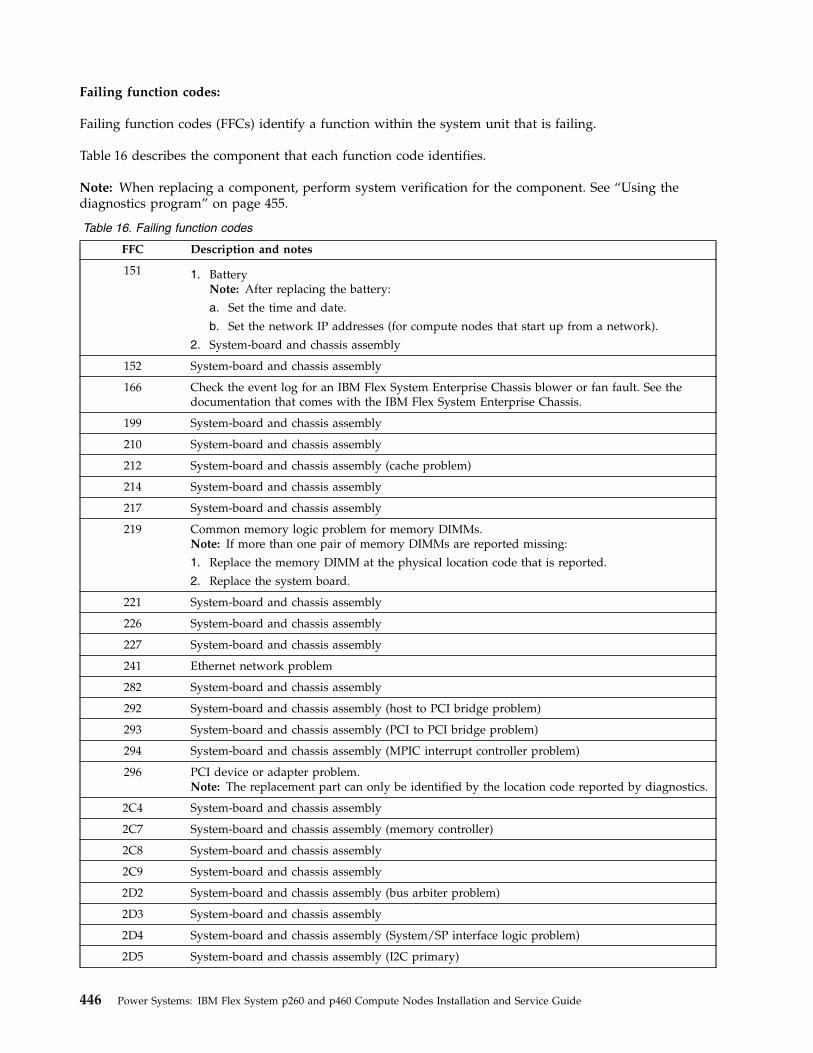
Failing function codes:
Failing function codes (FFCs) identify a function within the system unit that is failing.
Table 16 describes the component that each function code identifies.
Note: When replacing a component, perform system verification for the component. See “Using thediagnostics program” on page 455.
Table 16. Failing function codes
FFC Description and notes
151 1. BatteryNote: After replacing the battery:
a. Set the time and date.
b. Set the network IP addresses (for compute nodes that start up from a network).
2. System-board and chassis assembly
152 System-board and chassis assembly
166 Check the event log for an IBM Flex System Enterprise Chassis blower or fan fault. See thedocumentation that comes with the IBM Flex System Enterprise Chassis.
199 System-board and chassis assembly
210 System-board and chassis assembly
212 System-board and chassis assembly (cache problem)
214 System-board and chassis assembly
217 System-board and chassis assembly
219 Common memory logic problem for memory DIMMs.Note: If more than one pair of memory DIMMs are reported missing:
1. Replace the memory DIMM at the physical location code that is reported.
2. Replace the system board.
221 System-board and chassis assembly
226 System-board and chassis assembly
227 System-board and chassis assembly
241 Ethernet network problem
282 System-board and chassis assembly
292 System-board and chassis assembly (host to PCI bridge problem)
293 System-board and chassis assembly (PCI to PCI bridge problem)
294 System-board and chassis assembly (MPIC interrupt controller problem)
296 PCI device or adapter problem.Note: The replacement part can only be identified by the location code reported by diagnostics.
2C4 System-board and chassis assembly
2C7 System-board and chassis assembly (memory controller)
2C8 System-board and chassis assembly
2C9 System-board and chassis assembly
2D2 System-board and chassis assembly (bus arbiter problem)
2D3 System-board and chassis assembly
2D4 System-board and chassis assembly (System/SP interface logic problem)
2D5 System-board and chassis assembly (I2C primary)
446 Power Systems: IBM Flex System p260 and p460 Compute Nodes Installation and Service Guide
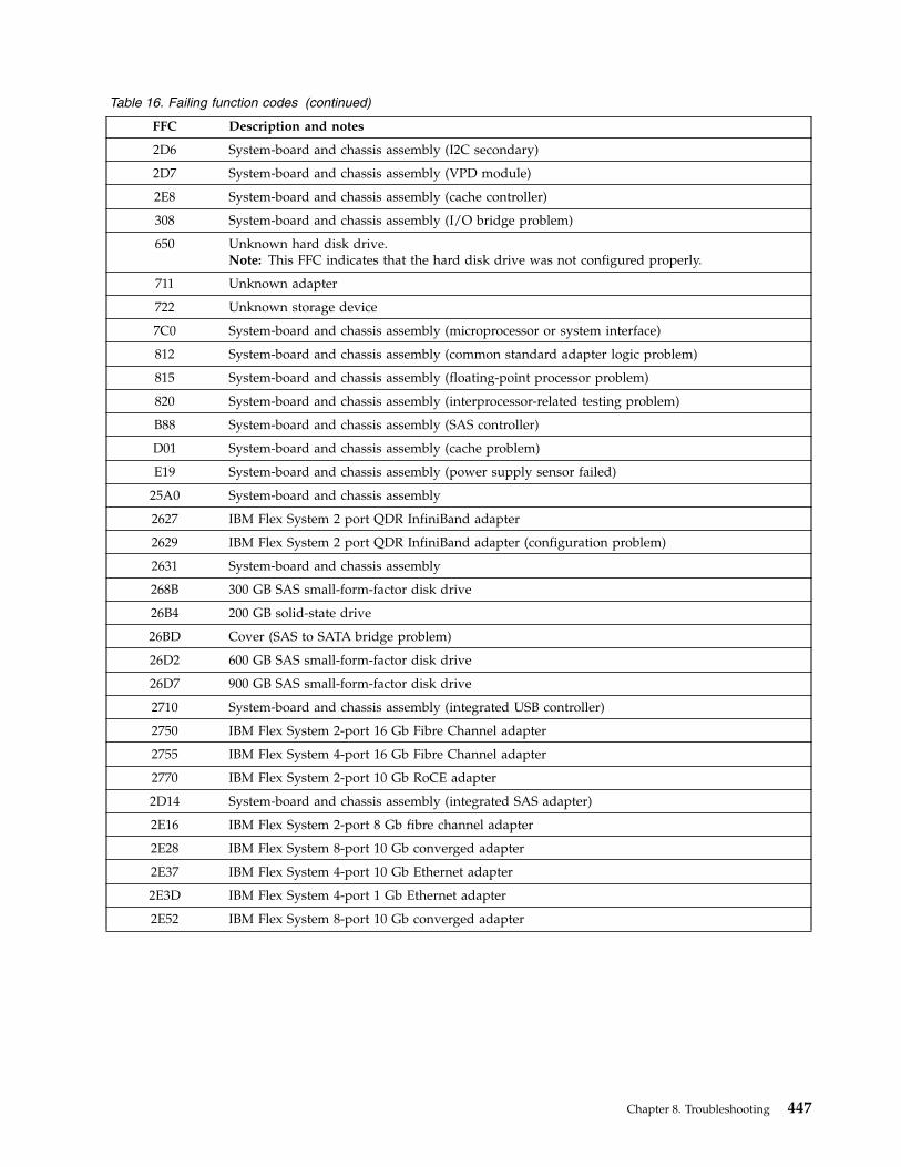
Table 16. Failing function codes (continued)
FFC Description and notes
2D6 System-board and chassis assembly (I2C secondary)
2D7 System-board and chassis assembly (VPD module)
2E8 System-board and chassis assembly (cache controller)
308 System-board and chassis assembly (I/O bridge problem)
650 Unknown hard disk drive.Note: This FFC indicates that the hard disk drive was not configured properly.
711 Unknown adapter
722 Unknown storage device
7C0 System-board and chassis assembly (microprocessor or system interface)
812 System-board and chassis assembly (common standard adapter logic problem)
815 System-board and chassis assembly (floating-point processor problem)
820 System-board and chassis assembly (interprocessor-related testing problem)
B88 System-board and chassis assembly (SAS controller)
D01 System-board and chassis assembly (cache problem)
E19 System-board and chassis assembly (power supply sensor failed)
25A0 System-board and chassis assembly
2627 IBM Flex System 2 port QDR InfiniBand adapter
2629 IBM Flex System 2 port QDR InfiniBand adapter (configuration problem)
2631 System-board and chassis assembly
268B 300 GB SAS small-form-factor disk drive
26B4 200 GB solid-state drive
26BD Cover (SAS to SATA bridge problem)
26D2 600 GB SAS small-form-factor disk drive
26D7 900 GB SAS small-form-factor disk drive
2710 System-board and chassis assembly (integrated USB controller)
2750 IBM Flex System 2-port 16 Gb Fibre Channel adapter
2755 IBM Flex System 4-port 16 Gb Fibre Channel adapter
2770 IBM Flex System 2-port 10 Gb RoCE adapter
2D14 System-board and chassis assembly (integrated SAS adapter)
2E16 IBM Flex System 2-port 8 Gb fibre channel adapter
2E28 IBM Flex System 8-port 10 Gb converged adapter
2E37 IBM Flex System 4-port 10 Gb Ethernet adapter
2E3D IBM Flex System 4-port 1 Gb Ethernet adapter
2E52 IBM Flex System 8-port 10 Gb converged adapter
Chapter 8. Troubleshooting 447
Controller maintenance analysis procedures:
These procedures are intended to resolve adapter, cache, or disk array problems associated with acontroller.
See “Service request numbers (SRNs)” on page 301 to identify which MAP to use.
MAP 3110:
Perform MAP 3110 in the Systems Hardware information center.
MAP 3111:
Perform MAP 3111 in the Systems Hardware information center.
MAP 3112:
Perform MAP 3112 in the Systems Hardware information center.
MAP 3113:
Perform MAP 3113 in the Systems Hardware information center.
MAP 3120:
Perform MAP 3120 in the Systems Hardware information center.
MAP 3121:
Perform MAP 3121 in the Systems Hardware information center.
MAP 3130:
Perform MAP 3130 in the Systems Hardware information center.
MAP 3131:
Perform MAP 3131 in the Systems Hardware information center.
MAP 3132:
448 Power Systems: IBM Flex System p260 and p460 Compute Nodes Installation and Service Guide

Perform MAP 3132 in the Systems Hardware information center.
MAP 3133:
Perform MAP 3133 in the Systems Hardware information center.
MAP 3134:
Perform MAP 3134 in the Systems Hardware information center.
MAP 3135:
Perform MAP 3135 in the Systems Hardware information center.
MAP 3140:
Perform MAP 3140 in the Systems Hardware information center.
MAP 3141:
Perform MAP 3141 in the Systems Hardware information center.
MAP 3142:
Perform MAP 3142 in the Systems Hardware information center.
MAP 3143:
Perform MAP 3143 in the Systems Hardware information center.
MAP 3144:
Perform MAP 3144 in the Systems Hardware information center.
MAP 3145:
Perform MAP 3145 in the Systems Hardware information center.
MAP 3146:
Chapter 8. Troubleshooting 449
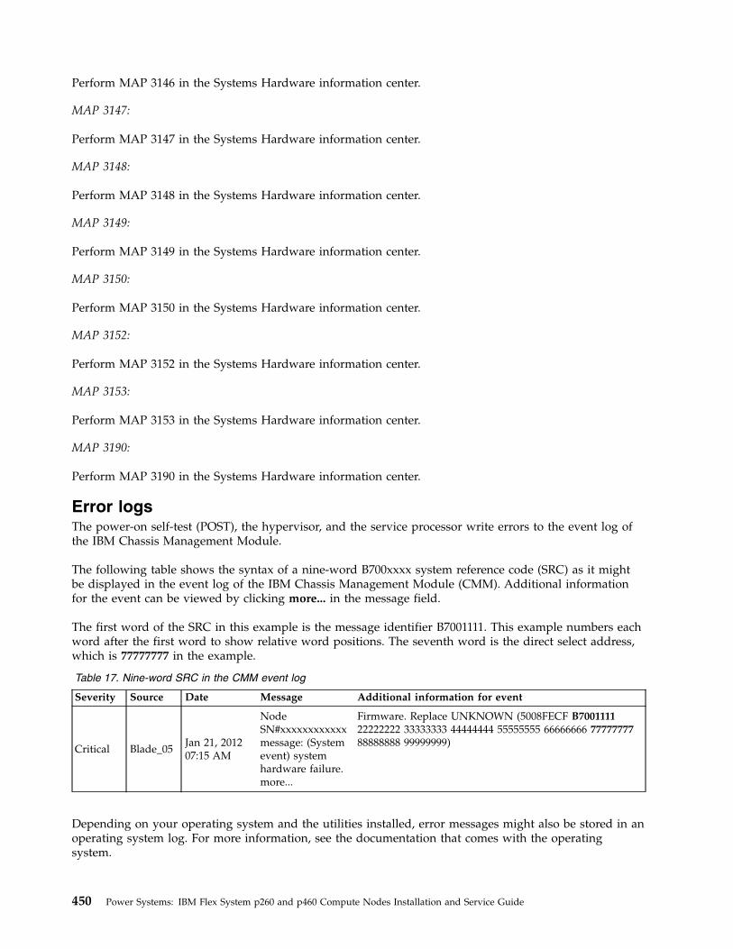
Perform MAP 3146 in the Systems Hardware information center.
MAP 3147:
Perform MAP 3147 in the Systems Hardware information center.
MAP 3148:
Perform MAP 3148 in the Systems Hardware information center.
MAP 3149:
Perform MAP 3149 in the Systems Hardware information center.
MAP 3150:
Perform MAP 3150 in the Systems Hardware information center.
MAP 3152:
Perform MAP 3152 in the Systems Hardware information center.
MAP 3153:
Perform MAP 3153 in the Systems Hardware information center.
MAP 3190:
Perform MAP 3190 in the Systems Hardware information center.
Error logsThe power-on self-test (POST), the hypervisor, and the service processor write errors to the event log ofthe IBM Chassis Management Module.
The following table shows the syntax of a nine-word B700xxxx system reference code (SRC) as it mightbe displayed in the event log of the IBM Chassis Management Module (CMM). Additional informationfor the event can be viewed by clicking more... in the message field.
The first word of the SRC in this example is the message identifier B7001111. This example numbers eachword after the first word to show relative word positions. The seventh word is the direct select address,which is 77777777 in the example.
Table 17. Nine-word SRC in the CMM event log
Severity Source Date Message Additional information for event
Critical Blade_05Jan 21, 201207:15 AM
NodeSN#xxxxxxxxxxxxmessage: (Systemevent) systemhardware failure.more...
Firmware. Replace UNKNOWN (5008FECF B700111122222222 33333333 44444444 55555555 66666666 7777777788888888 99999999)
Depending on your operating system and the utilities installed, error messages might also be stored in anoperating system log. For more information, see the documentation that comes with the operatingsystem.
450 Power Systems: IBM Flex System p260 and p460 Compute Nodes Installation and Service Guide
Checkout procedureThe checkout procedure is the sequence of tasks that you follow to diagnose a problem in the computenode.
About the checkout procedureReview this information before performing the checkout procedure.v Read the Safety topic and the “Installation guidelines” on page 35.v The firmware diagnostic program provides the primary methods of testing the major components of
the compute node. If you are not sure whether a problem is caused by the hardware or by thesoftware, you can use the firmware diagnostic program to confirm that the hardware is workingcorrectly. The firmware diagnostic program runs automatically when the compute node is turned on.
v A single problem might cause more than one error message. When this happens, correct the cause ofthe first error message. The other error messages usually will not occur the next time you run thediagnostic programs.
v If the compute node hangs on a POST checkpoint, see “POST progress codes (checkpoints)” on page233. If the compute node is halted and no error message is displayed, see “Troubleshooting bysymptom” on page 457 and “Solving undetermined problems” on page 498.
v For intermittent problems, check the management-module event log and “POST progress codes(checkpoints)” on page 233.
v If the compute node front panel shows no LEDs, verify the compute node status and errors in the IBMFlex System Enterprise Chassis Web interface. Also, see “Solving undetermined problems” on page 498.
v If device errors occur, see “Troubleshooting by symptom” on page 457.
Performing the check-out procedureFollow this procedure to perform the check-out.
About this task1. Establish a Serial over LAN (SOL) session. For information about starting an SOL session, see the IBM
Chassis Management Module Command-Line Interface Reference Guide. Continue to Step 2.
Note: If the compute node does not start, see “Troubleshooting by symptom” on page 457.2. Verify that you have looked up each error code or hung checkpoint and attempted the corrective
action before going to the next step:a. If the firmware hangs on an 8 digit progress code, see “POST progress codes (checkpoints)” on
page 233.b. If the firmware records an 8 digit error code, see “System reference codes (SRCs)” on page 116.c. If the AIX operating system records a service request number (SRN), see “Service request numbers
(SRNs)” on page 301.d. Check the event log. If an error was recorded by the system, see “POST progress codes
(checkpoints)” on page 233 or “System reference codes (SRCs)” on page 116.e. If no error was recorded, or if the login prompt appears and you still suspect a problem, continue
with the next step.3. Is the compute node running the AIX operating system?
Yes Record any information or messages that are in the event log, and go to Step 5.
No Go to Step 4.4. Is the compute node running the Linux operating system?
Yes Record any information or messages that are in the event log, and go to Step 7. If you cannotload the stand-alone diagnostics image, answer this question as No.
No Go to “Solving undetermined problems” on page 498.
Chapter 8. Troubleshooting 451
5. Perform the following steps:
Note: When possible, run AIX online diagnostics in concurrent mode. AIX online diagnostics performmore functions than the stand-alone diagnostics.a. Perform the AIX online diagnostics, see “Starting AIX concurrent diagnostics” on page 453. Record
any diagnostic results and see the “Service request numbers (SRNs)” on page 301 to identify thefailing component.
Note: When replacing a component, perform system verification for the component. See “Usingthe diagnostics program” on page 455.
b. If you cannot perform AIX concurrent online diagnostics, continue to Step 6.6. Perform the following steps:
a. Ensure that the device from which you load the stand-alone diagnostics is set as the first device inthe compute node boot sequence.
b. Turn off the system unit power and wait 45 seconds before proceeding.c. Turn on the compute node and establish an SOL session.d. Check for the following responses:
1) Progress codes are recorded in the event log.2) Record any messages or diagnostic information that might be in the log.
e. Load the stand-alone diagnostics. Go to “Starting stand-alone diagnostics” on page 453 or“Starting stand-alone diagnostics from a NIM server” on page 454.
f. If you have replaced the failing component, perform system verification for the component. See“Using the diagnostics program” on page 455.
This ends the AIX procedure.7. Perform the following steps:
a. Ensure that the device from which you load the stand-alone diagnostics is set as the first device inthe compute node boot sequence.
b. Turn off the compute node and wait 45 seconds before proceeding.c. Turn on the compute node and establish an SOL session.d. Check for the following responses:
1) Progress codes are recorded in the event log.2) Record any messages or diagnostic information that might be in the log.Continue with step 8.
8. Load the stand-alone diagnostics. Go to “Starting stand-alone diagnostics” on page 453 or “Startingstand-alone diagnostics from a NIM server” on page 454.Can you load the stand-alone diagnostics?
No Go to “Solving undetermined problems” on page 498.
Yes Select the resources to be tested and record any SRNs. Then go to “Service request numbers(SRNs)” on page 301.
This ends the Linux procedure.
For more information about installing and using all supported operating systems, search the IBM Supportwebsite.
452 Power Systems: IBM Flex System p260 and p460 Compute Nodes Installation and Service Guide
Verifying the partition configurationPerform this procedure if there is a configuration problem with the system or a logical partition.
Procedure1. Check the processor and memory allocations of the system or the partition. Processor or memory
resources that fail during system startup could cause the startup problem in the partition. Make surethat the processor and memory have enough functioning resources in the system for all the partitions.
2. Check the bus and virtual adapter allocations for the partition. Make sure that the partition has loadsource and console I/O resources.
3. Make sure that the boot mode partition properties are set to normal.4. If the problem remains, contact your software service provider for further assistance.
Running the diagnostics programYou can start or run the diagnostics program from the AIX operating system, from a CD, or from amanagement server.
Starting AIX concurrent diagnosticsPerform this procedure to start AIX concurrent diagnostics from the AIX operating system.
Procedure1. Log in to the AIX operating system as root user, or use the CE login. See “Creating a CE login” on
page 25 for more information. If you need help, contact the system operator.2. Type diag and press Enter at the operating system prompt to start the diagnostics program and to
display its Function Selection menu. See “Using the diagnostics program” on page 455 for moreinformation about running the diagnostics program.
3. When testing is complete, press F3 until the Diagnostic Operating Instructions panel is displayed, andthen press F3 to exit the diagnostic program.
Starting stand-alone diagnosticsPerform these procedures to start the stand-alone diagnostics from a CD or flash drive. These procedurescan be used if the compute node is running a Linux operating system or if an AIX operating systemcannot start the concurrent diagnostics program.
About this task
You can download the latest version of the stand-alone diagnostics from the Standalone Diagnostics CDpage.
Procedure1. Verify with the system administrator and system users that the compute node might be shut down.
Stop all programs, and then shut down the operating system and shut down the compute node. Seethe documentation that comes with your operating system documentation for information aboutshutting down the operating system.
Chapter 8. Troubleshooting 453
2. Using the management module Web interface, verify the following items:v The compute node firmware is at the latest version.v SOL is enabled for the compute node.v The CD or DVD drive or USB flash drive is selected as the first boot device for the compute node.
3. Insert diagnostic media.v If you are using a stand-alone diagnostics CD, plugin the external optical drive (CD- and
DVD-compatible) with a USB connection and insert the stand-alone diagnostics CD into the CD orDVD drive.
v If you are using a USB flash drive, insert the USB flash drive that has stand-alone diagnostic imagecopied in it.
4. Turn on the compute node and establish a Serial over LAN (SOL). For information about starting anSOL session, see the IBM Chassis Management Module Command-Line Interface Reference Guide.
Note: It can take several minutes to load the stand-alone diagnostics from the CD or flash drive.The window displays Please define the System Console.
5. Type 1 and press Enter to continue.The Diagnostic Operating Instructions window is shown.
6. Press Enter to continue.The Function Selection window is shown. See “Using the diagnostics program” on page 455 for moreinformation about running the diagnostics program.
Note: If the Define Terminal window is shown, type the terminal type and press Enter. The use ofvs100 as the terminal type is preferred. However, the function keys might not work. In this case, pressEsc and the number on the menus. For example, instead of F3, you can press Esc+3.
7. When testing is complete, press F3 until the Diagnostic Operating Instructions window is shown, andthen press F3 again to exit the diagnostic program.
8. Remove diagnostic media.v If you are using a stand-alone diagnostics CD, remove the CD from the CD or DVD drive.v If you are using a USB flash drive, remove the USB flash drive.
Starting stand-alone diagnostics from a NIM serverPerform this procedure to start the stand-alone diagnostics from a Network Installation Management(NIM) server.
About this task
Note: See Network Installation Management in the AIX Information Center for information aboutconfiguring the compute node as a NIM server client. Also see the Configuring the NIM Master andCreating Basic Installation Resources Web page.
Procedure1. Verify with the system administrator and system users that the compute node can be shut down. Stop
all programs, and then shut down the operating system and shut down the compute node. See thedocumentation that comes with your operating system for information about shutting down theoperating system.
454 Power Systems: IBM Flex System p260 and p460 Compute Nodes Installation and Service Guide
2. If the system is running in a full-machine partition, turn on the compute node and establish a Serialover LAN (SOL) session. For information about starting an SOL session, see the IBM ChassisManagement Module Command-Line Interface Reference Guide.
3. Perform the following steps to check the NIM server boot settings:a. When the POST menu is displayed, press 1 to start the SMS utility.b. From the SMS main menu, select Setup Remote IPL (Initial Program Load).c. From the NIC Adapters menu, select the network adapter that is attached to the NIM server.d. From the Network Parameters menu, select IP Parameters.e. Enter the client, server, and gateway IP addresses (if applicable), and enter the subnet mask. If
there is no gateway between the NIM server and the client, set the gateway address to 0.0.0.0. Seeyour network administrator to determine if there is a gateway.
f. If the NIM server is set up to allow pinging the client system, use the Ping Test option on theNetwork Parameters menu to verify that the client system can ping the NIM server.
Note: If the ping fails, see “Boot problem resolution” on page 456, and then follow the steps fornetwork boot problems.
4. When the ping is successful, start the compute node from the NIM server.5. Establish an SOL session.
If the Diagnostic Operating Instructions window is shown, the diagnostics program startedsuccessfully.
Note: If the AIX login prompt is displayed, the diagnostics program did not load. See “Boot problemresolution” on page 456, and then follow the steps for network boot problems.
6. Press Enter to continue.The Function Selection window is shown. See “Using the diagnostics program” for more informationabout running the diagnostics program.
Note: If the Define Terminal window is shown, type the terminal type and press Enter. The use ofvs100 as the terminal type is preferred. However, the function keys might not work. In this case, pressEsc and the number in the screen menus. For example, instead of F3, you can press Esc+3.
7. When testing is complete, press F3 until the Diagnostic Operating Instructions window is shown, andthen press F3 again to exit the diagnostic program.
Using the diagnostics programFollow the basic procedures for running the diagnostics program.
Procedure1. Start the diagnostics from the AIX operating system, from a CD, or from a management server. See
“Starting AIX concurrent diagnostics” on page 453, “Starting stand-alone diagnostics” on page 453, or“Starting stand-alone diagnostics from a NIM server” on page 454.
2. From the Function Selection menu, perform one of the following tasks using the steps listed:v Problem determination
a. Select Diagnostic Routines and press Enter.b. From the Diagnostic Mode Selection menu, select Problem Determination.c. Select the resource to be tested, and press F7=Commit.d. Record any results provided and go to “Service request numbers (SRNs)” on page 301 to
identify the failure and perform the actions.e. When testing is complete, press F3 to return to the Diagnostic Selection menu. If you want to
run another test, press F3 again to return to the Function Selection menu.v System verification
Chapter 8. Troubleshooting 455
a. Select Diagnostic Routines and press Enter.b. From the Diagnostic Mode Selection menu, select System Verification.c. Select the resource to be tested, and press F7=Commit.d. Record any results provided and go to “Service request numbers (SRNs)” on page 301 to
identify the failure and perform the action(s).e. When testing is complete, press F3 to return to the Diagnostic Selection menu. If you want to
run another test, press F3 again to return to the Function Selection menu.v Task selection
a. Select Task Selection and press Enter.b. Select the task to be run and press Enter.c. If the Resource Selection List menu is displayed, select the resource on which the task is to be
run and press F7=Commit.d. Follow the instruction for the selected task.e. When the task is complete, press F3 to return to the Task Selection List menu. If you want to
run another test, press F3 again to return to the Function Selection menu.3. When testing is complete, press F3 until the Diagnostic Operating Instructions window is displayed.
Then press F3 again to exit the diagnostic program.
Boot problem resolutionDepending on the boot device, a checkpoint might be displayed in the list of checkpoints in themanagement console for an extended period of time while the boot image is retrieved from the device.
About this task
This situation is particularly true for boot image and network boot attempts.
Note: For network boot attempts, if the system is not connected to an active network, or if there is nocompute node configured to respond to the system's boot request, the system will still attempt to boot.Because time-out durations are necessarily long to accommodate retry operations, the system mightappear to be hung.
If you suspect a problem loading the boot image, complete the following steps:
Procedure1. Make sure that your boot list is correct.
a. Use the management console to display the boot sequences for the compute nodes in your IBMFlex System Enterprise Chassis.
b. Find your compute node on the list that is displayed and make sure that the device from whichyou are attempting to boot is the first device in the boot sequence. If it is not, select your computenode from the list of compute nodes and change the boot sequence. Power off and then power onyour compute node to retry the boot.
Note: If Network is selected, the compute node tries to boot from both Ethernet ports on thesystem board.
c. If this boot attempt fails, complete the following steps:1) If you are attempting to boot from the network, go to Step 2.2) If you are attempting to boot from a hard disk drive, go to Step 3.
456 Power Systems: IBM Flex System p260 and p460 Compute Nodes Installation and Service Guide
2. If you are attempting to boot from the network:a. Make sure that the network cabling to the IBM Flex System Enterprise Chassis network switch is
correct.b. Check with the network administrator to make sure that the network is up.c. Verify that the compute node for your system is running and configured to respond to your
system.d. Turn the compute node power off, and then turn it on to retry the boot operation.e. If the boot still fails, replace the system-board and chassis assembly.
3. If you are attempting to boot from a hard disk drive:a. Verify that the hard disk drive is installed.b. Select the hard disk drive as the boot device.c. Reload the operating system onto the hard disk drive if the boot attempts from that disk continue
to fail.d. If you are not able to load the operating system, replace the suspected hard disk dricee. Replace the system board, and then retry loading the operating system.
Troubleshooting by symptomUse the troubleshooting tables to find solutions to problems that have identifiable symptoms.
About this task
If these symptoms relate to shared IBM Flex System Enterprise Chassis resources, see “Solving sharedIBM Flex System Enterprise Chassis resource problems” on page 496. If you cannot find the problem inthese tables, see “Running the diagnostics program” on page 453 for information about testing thecompute node.
If you have just added new software or a new optional device and the compute node is not working,complete the following steps before using the troubleshooting tables:1. Remove the software or device that you just added.2. Run the diagnostic tests to determine whether the compute node is running correctly.3. Reinstall the new software or new device.
Intermittent problemsIdentify intermittent problem symptoms and corrective actions.
v Follow the suggested actions in the order in which they are listed in the Action column until the problem issolved.
v See Chapter 7, “Parts listing for IBM Flex System p260 and p460 Compute Nodes,” on page 97 to determinewhich components are CRUs and which components are FRUs.
v If an action step is preceded by “Trained service technician only,” that step must be performed only by atrained service technician.
Symptom Action
Intermittent connectivityproblems (single compute node)
1. Make sure that the network cables are correctly connected in the switchmodule ports and that the switch module is correctly seated.
2. Update the network interface card (NIC) device driver or the storage devicecontroller device driver.
3. See the documentation for the I/O module for resolving connectivity problems.
Chapter 8. Troubleshooting 457
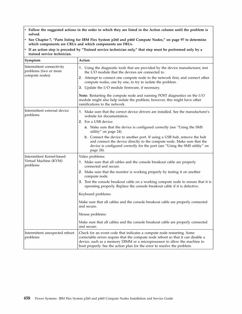
v Follow the suggested actions in the order in which they are listed in the Action column until the problem issolved.
v See Chapter 7, “Parts listing for IBM Flex System p260 and p460 Compute Nodes,” on page 97 to determinewhich components are CRUs and which components are FRUs.
v If an action step is preceded by “Trained service technician only,” that step must be performed only by atrained service technician.
Symptom Action
Intermittent connectivityproblems (two or morecompute nodes)
1. Using the diagnostic tools that are provided by the device manufacturer, testthe I/O module that the devices are connected to.
2. Attempt to connect one compute node to the network first, and connect othercompute nodes, one by one, to try to isolate the problem.
3. Update the I/O module firmware, if necessary.
Note: Restarting the compute node and running POST diagnostics on the I/Omodule might also help isolate the problem; however, this might have otherramifications to the network.
Intermittent external deviceproblems
1. Make sure that the correct device drivers are installed. See the manufacturer'swebsite for documentation.
2. For a USB device:
a. Make sure that the device is configured correctly (see “Using the SMSutility” on page 24).
b. Connect the device to another port. If using a USB hub, remove the huband connect the device directly to the compute node. Make sure that thedevice is configured correctly for the port (see “Using the SMS utility” onpage 24).
Intermittent Kernel-basedVirtual Machine (KVM)problems
Video problems:
1. Make sure that all cables and the console breakout cable are properlyconnected and secure.
2. Make sure that the monitor is working properly by testing it on anothercompute node.
3. Test the console breakout cable on a working compute node to ensure that it isoperating properly. Replace the console breakout cable if it is defective.
Keyboard problems:
Make sure that all cables and the console breakout cable are properly connectedand secure.
Mouse problems:
Make sure that all cables and the console breakout cable are properly connectedand secure.
Intermittent unexpected rebootproblems
Check for an event code that indicates a compute node restarting. Somecorrectable errors require that the compute node reboot so that it can disable adevice, such as a memory DIMM or a microprocessor to allow the machine toboot properly. See the action plan for the error to resolve the problem.
458 Power Systems: IBM Flex System p260 and p460 Compute Nodes Installation and Service Guide
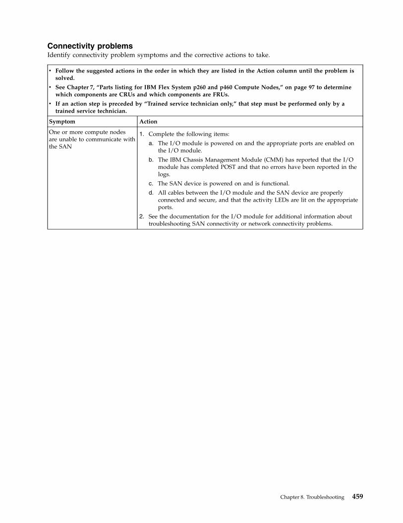
Connectivity problemsIdentify connectivity problem symptoms and the corrective actions to take.
v Follow the suggested actions in the order in which they are listed in the Action column until the problem issolved.
v See Chapter 7, “Parts listing for IBM Flex System p260 and p460 Compute Nodes,” on page 97 to determinewhich components are CRUs and which components are FRUs.
v If an action step is preceded by “Trained service technician only,” that step must be performed only by atrained service technician.
Symptom Action
One or more compute nodesare unable to communicate withthe SAN
1. Complete the following items:
a. The I/O module is powered on and the appropriate ports are enabled onthe I/O module.
b. The IBM Chassis Management Module (CMM) has reported that the I/Omodule has completed POST and that no errors have been reported in thelogs.
c. The SAN device is powered on and is functional.
d. All cables between the I/O module and the SAN device are properlyconnected and secure, and that the activity LEDs are lit on the appropriateports.
2. See the documentation for the I/O module for additional information abouttroubleshooting SAN connectivity or network connectivity problems.
Chapter 8. Troubleshooting 459
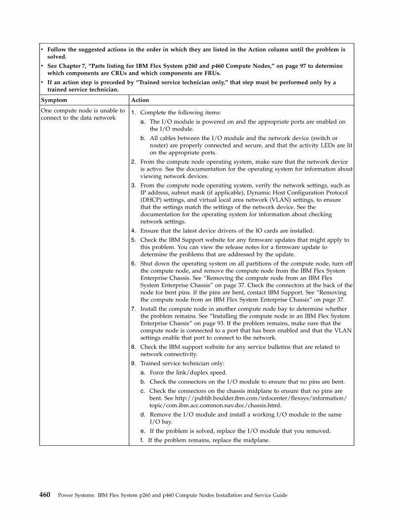
v Follow the suggested actions in the order in which they are listed in the Action column until the problem issolved.
v See Chapter 7, “Parts listing for IBM Flex System p260 and p460 Compute Nodes,” on page 97 to determinewhich components are CRUs and which components are FRUs.
v If an action step is preceded by “Trained service technician only,” that step must be performed only by atrained service technician.
Symptom Action
One compute node is unable toconnect to the data network
1. Complete the following items:
a. The I/O module is powered on and the appropriate ports are enabled onthe I/O module.
b. All cables between the I/O module and the network device (switch orrouter) are properly connected and secure, and that the activity LEDs are liton the appropriate ports.
2. From the compute node operating system, make sure that the network deviceis active. See the documentation for the operating system for information aboutviewing network devices.
3. From the compute node operating system, verify the network settings, such asIP address, subnet mask (if applicable), Dynamic Host Configuration Protocol(DHCP) settings, and virtual local area network (VLAN) settings, to ensurethat the settings match the settings of the network device. See thedocumentation for the operating system for information about checkingnetwork settings.
4. Ensure that the latest device drivers of the IO cards are installed.
5. Check the IBM Support website for any firmware updates that might apply tothis problem. You can view the release notes for a firmware update todetermine the problems that are addressed by the update.
6. Shut down the operating system on all partitions of the compute node, turn offthe compute node, and remove the compute node from the IBM Flex SystemEnterprise Chassis. See “Removing the compute node from an IBM FlexSystem Enterprise Chassis” on page 37. Check the connectors at the back of thenode for bent pins. If the pins are bent, contact IBM Support. See “Removingthe compute node from an IBM Flex System Enterprise Chassis” on page 37.
7. Install the compute node in another compute node bay to determine whetherthe problem remains. See “Installing the compute node in an IBM Flex SystemEnterprise Chassis” on page 93. If the problem remains, make sure that thecompute node is connected to a port that has been enabled and that the VLANsettings enable that port to connect to the network.
8. Check the IBM support website for any service bulletins that are related tonetwork connectivity.
9. Trained service technician only:
a. Force the link/duplex speed.
b. Check the connectors on the I/O module to ensure that no pins are bent.
c. Check the connectors on the chassis midplane to ensure that no pins arebent. See http://publib.boulder.ibm.com/infocenter/flexsys/information/topic/com.ibm.acc.common.nav.doc/chassis.html.
d. Remove the I/O module and install a working I/O module in the sameI/O bay.
e. If the problem is solved, replace the I/O module that you removed.
f. If the problem remains, replace the midplane.
460 Power Systems: IBM Flex System p260 and p460 Compute Nodes Installation and Service Guide
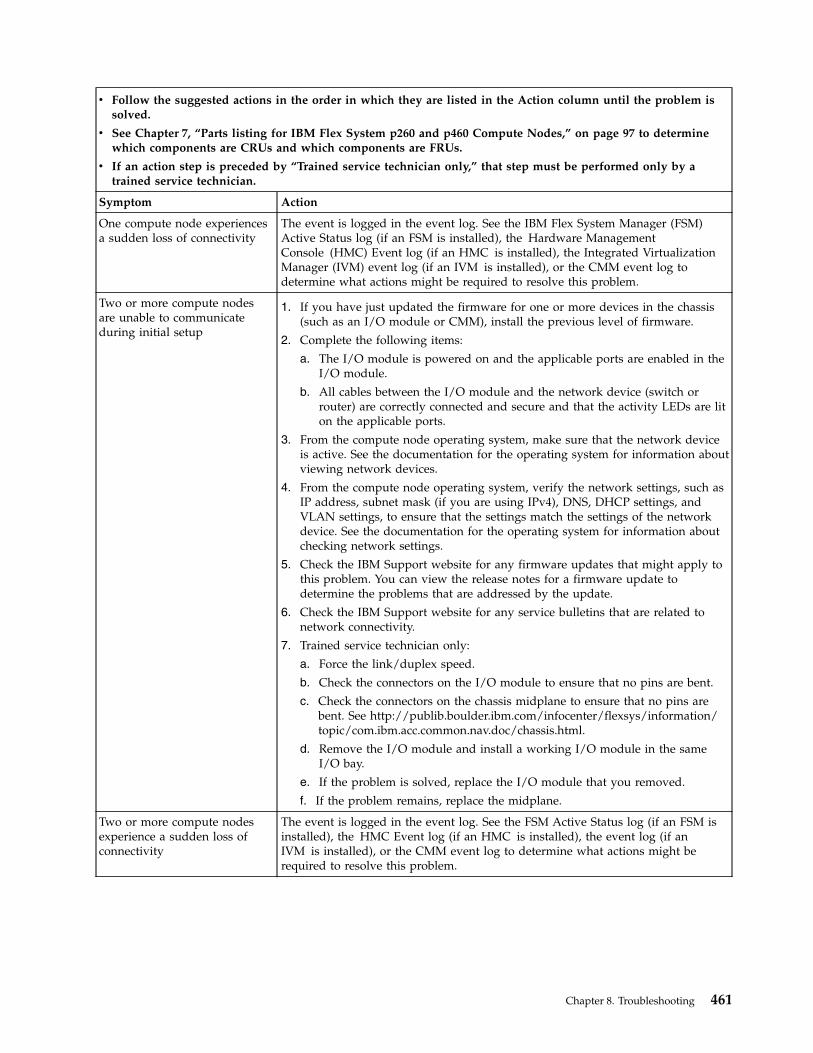
v Follow the suggested actions in the order in which they are listed in the Action column until the problem issolved.
v See Chapter 7, “Parts listing for IBM Flex System p260 and p460 Compute Nodes,” on page 97 to determinewhich components are CRUs and which components are FRUs.
v If an action step is preceded by “Trained service technician only,” that step must be performed only by atrained service technician.
Symptom Action
One compute node experiencesa sudden loss of connectivity
The event is logged in the event log. See the IBM Flex System Manager (FSM)Active Status log (if an FSM is installed), the Hardware ManagementConsole (HMC) Event log (if an HMC is installed), the Integrated VirtualizationManager (IVM) event log (if an IVM is installed), or the CMM event log todetermine what actions might be required to resolve this problem.
Two or more compute nodesare unable to communicateduring initial setup
1. If you have just updated the firmware for one or more devices in the chassis(such as an I/O module or CMM), install the previous level of firmware.
2. Complete the following items:
a. The I/O module is powered on and the applicable ports are enabled in theI/O module.
b. All cables between the I/O module and the network device (switch orrouter) are correctly connected and secure and that the activity LEDs are liton the applicable ports.
3. From the compute node operating system, make sure that the network deviceis active. See the documentation for the operating system for information aboutviewing network devices.
4. From the compute node operating system, verify the network settings, such asIP address, subnet mask (if you are using IPv4), DNS, DHCP settings, andVLAN settings, to ensure that the settings match the settings of the networkdevice. See the documentation for the operating system for information aboutchecking network settings.
5. Check the IBM Support website for any firmware updates that might apply tothis problem. You can view the release notes for a firmware update todetermine the problems that are addressed by the update.
6. Check the IBM Support website for any service bulletins that are related tonetwork connectivity.
7. Trained service technician only:
a. Force the link/duplex speed.
b. Check the connectors on the I/O module to ensure that no pins are bent.
c. Check the connectors on the chassis midplane to ensure that no pins arebent. See http://publib.boulder.ibm.com/infocenter/flexsys/information/topic/com.ibm.acc.common.nav.doc/chassis.html.
d. Remove the I/O module and install a working I/O module in the sameI/O bay.
e. If the problem is solved, replace the I/O module that you removed.
f. If the problem remains, replace the midplane.
Two or more compute nodesexperience a sudden loss ofconnectivity
The event is logged in the event log. See the FSM Active Status log (if an FSM isinstalled), the HMC Event log (if an HMC is installed), the event log (if anIVM is installed), or the CMM event log to determine what actions might berequired to resolve this problem.
Chapter 8. Troubleshooting 461

PCI expansion card (PIOCARD) problem isolation procedureThe hardware that controls PCI adapters and PCI card slots detected an error. The direct select address(DSA) portion of the system reference code (SRC) identifies the location code of the failing component.
The following table shows the syntax of a nine-word B700xxxx system reference code (SRC) as it mightbe displayed in the event log of the IBM Chassis Management Module (CMM). Additional informationfor the event can be viewed by clicking more... in the message field.
The first word of the SRC in this example is the message identifier B7001111. This example numbers eachword after the first word to show relative word positions. The seventh word is the direct select address,which is 77777777 in the example.
Table 18. Nine-word SRC in the CMM event log
Severity Source Date Message Additional information for event
Critical Blade_05Jan 21, 201207:15 AM
NodeSN#xxxxxxxxxxxxmessage: (Systemevent) systemhardware failure.more...
Firmware. Replace UNKNOWN (5008FECF B700111122222222 33333333 44444444 55555555 66666666 7777777788888888 99999999)
Depending on your operating system and the utilities installed, error messages might also be stored in anoperating system log. For more information, see the documentation that comes with the operatingsystem.
The Table 19 on page 463 shows the procedure for isolating which PCI expansion card is failing.
462 Power Systems: IBM Flex System p260 and p460 Compute Nodes Installation and Service Guide
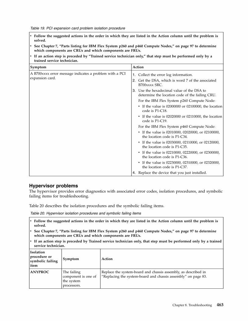
Table 19. PCI expansion card problem isolation procedure
v Follow the suggested actions in the order in which they are listed in the Action column until the problem issolved.
v See Chapter 7, “Parts listing for IBM Flex System p260 and p460 Compute Nodes,” on page 97 to determinewhich components are CRUs and which components are FRUs.
v If an action step is preceded by “Trained service technician only,” that step must be performed only by atrained service technician.
Symptom Action
A B700xxxx error message indicates a problem with a PCIexpansion card.
1. Collect the error log information.
2. Get the DSA, which is word 7 of the associatedB700xxxx SRC.
3. Use the hexadecimal value of the DSA todetermine the location code of the failing CRU.
For the IBM Flex System p260 Compute Node:
v If the value is 02000000 or 02100000, the locationcode is P1-C18.
v If the value is 02020000 or 02110000, the locationcode is P1-C19.
For the IBM Flex System p460 Compute Node:
v If the value is 02010000, 02020000, or 02100000,the location code is P1-C34.
v If the value is 02030000, 02110000, or 02120000,the location code is P1-C35.
v If the value is 02210000, 02220000, or 02300000,the location code is P1-C36.
v If the value is 02230000, 02310000, or 02320000,the location code is P1-C37.
4. Replace the device that you just installed.
Hypervisor problemsThe hypervisor provides error diagnostics with associated error codes, isolation procedures, and symbolicfailing items for troubleshooting.
Table 20 describes the isolation procedures and the symbolic failing items.
Table 20. Hypervisor isolation procedures and symbolic failing items
v Follow the suggested actions in the order in which they are listed in the Action column until the problem issolved.
v See Chapter 7, “Parts listing for IBM Flex System p260 and p460 Compute Nodes,” on page 97 to determinewhich components are CRUs and which components are FRUs.
v If an action step is preceded by Trained service technician only, that step must be performed only by a trainedservice technician.
Isolationprocedure orsymbolic failingitem
Symptom Action
ANYPROC The failingcomponent is one ofthe systemprocessors.
Replace the system-board and chassis assembly, as described in“Replacing the system-board and chassis assembly” on page 83.
Chapter 8. Troubleshooting 463
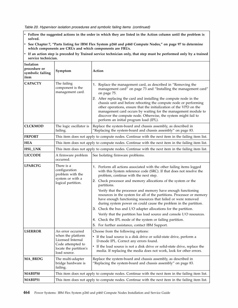
Table 20. Hypervisor isolation procedures and symbolic failing items (continued)
v Follow the suggested actions in the order in which they are listed in the Action column until the problem issolved.
v See Chapter 7, “Parts listing for IBM Flex System p260 and p460 Compute Nodes,” on page 97 to determinewhich components are CRUs and which components are FRUs.
v If an action step is preceded by Trained service technician only, that step must be performed only by a trainedservice technician.
Isolationprocedure orsymbolic failingitem
Symptom Action
CAPACTY The failingcomponent is themanagement card.
1. Replace the management card, as described in “Removing themanagement card” on page 73 and “Installing the management card”on page 75.
2. After replacing the card and installing the compute node in thechassis unit and before rebooting the compute node or performingother operations, ensure that the initialization of the VPD on themanagement card occurs by waiting for the management module todiscover the compute node. Otherwise, the system might fail toperform an initial program load (IPL).
CLCKMOD The logic oscillator isfailing.
Replace the system-board and chassis assembly, as described in“Replacing the system-board and chassis assembly” on page 83.
FRPORT This item does not apply to compute nodes. Continue with the next item in the failing item list.
HEA This item does not apply to compute nodes. Continue with the next item in the failing item list.
HSL_LNK This item does not apply to compute nodes. Continue with the next item in the failing item list.
LICCODE A firmware problemoccurred.
See Isolating firmware problems.
LPARCFG There is aconfigurationproblem with thesystem or with alogical partition.
1. Perform all actions associated with the other failing items loggedwith this System reference code (SRC). If that does not resolve theproblem, continue with the next step.
2. Check processor and memory allocations of the system or thepartitions.
Verify that the processor and memory have enough functioningresources in the system for all of the partitions. Processor or memoryhave enough functioning resources that failed or were removedduring system power on could cause the problem in the partition.
3. Check the bus and I/O adapter allocations for the partition.
Verify that the partition has load source and console I/O resources.
4. Check the IPL mode of the system or failing partition.
5. For further assistance, contact IBM Support.
LSERROR An error occurredwhen the platformLicensed InternalCode attempted tolocate the partition'sload source.
Choose from the following options:
v If the load source is a disk drive or solid-state drive, perform aD-mode IPL. Correct any errors found.
v If the load source is not a disk drive or solid-state drive, replace themedia. If replacing the media does not work, look for other errors.
MA_BRDG The multi-adapterbridge hardware isfailing.
Replace the system-board and chassis assembly, as described in“Replacing the system-board and chassis assembly” on page 83.
MABIP50 This item does not apply to compute nodes. Continue with the next item in the failing item list.
MABIP51 This item does not apply to compute nodes. Continue with the next item in the failing item list.
464 Power Systems: IBM Flex System p260 and p460 Compute Nodes Installation and Service Guide
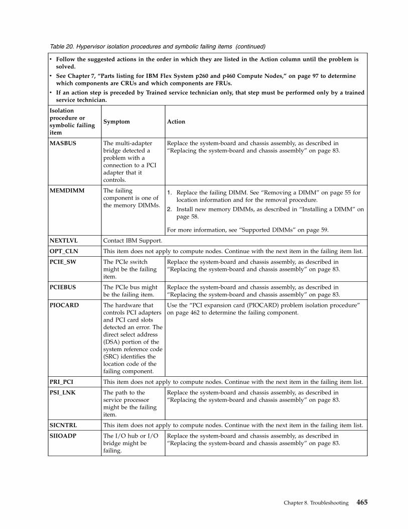
Table 20. Hypervisor isolation procedures and symbolic failing items (continued)
v Follow the suggested actions in the order in which they are listed in the Action column until the problem issolved.
v See Chapter 7, “Parts listing for IBM Flex System p260 and p460 Compute Nodes,” on page 97 to determinewhich components are CRUs and which components are FRUs.
v If an action step is preceded by Trained service technician only, that step must be performed only by a trainedservice technician.
Isolationprocedure orsymbolic failingitem
Symptom Action
MASBUS The multi-adapterbridge detected aproblem with aconnection to a PCIadapter that itcontrols.
Replace the system-board and chassis assembly, as described in“Replacing the system-board and chassis assembly” on page 83.
MEMDIMM The failingcomponent is one ofthe memory DIMMs.
1. Replace the failing DIMM. See “Removing a DIMM” on page 55 forlocation information and for the removal procedure.
2. Install new memory DIMMs, as described in “Installing a DIMM” onpage 58.
For more information, see “Supported DIMMs” on page 59.
NEXTLVL Contact IBM Support.
OPT_CLN This item does not apply to compute nodes. Continue with the next item in the failing item list.
PCIE_SW The PCIe switchmight be the failingitem.
Replace the system-board and chassis assembly, as described in“Replacing the system-board and chassis assembly” on page 83.
PCIEBUS The PCIe bus mightbe the failing item.
Replace the system-board and chassis assembly, as described in“Replacing the system-board and chassis assembly” on page 83.
PIOCARD The hardware thatcontrols PCI adaptersand PCI card slotsdetected an error. Thedirect select address(DSA) portion of thesystem reference code(SRC) identifies thelocation code of thefailing component.
Use the “PCI expansion card (PIOCARD) problem isolation procedure”on page 462 to determine the failing component.
PRI_PCI This item does not apply to compute nodes. Continue with the next item in the failing item list.
PSI_LNK The path to theservice processormight be the failingitem.
Replace the system-board and chassis assembly, as described in“Replacing the system-board and chassis assembly” on page 83.
SICNTRL This item does not apply to compute nodes. Continue with the next item in the failing item list.
SIIOADP The I/O hub or I/Obridge might befailing.
Replace the system-board and chassis assembly, as described in“Replacing the system-board and chassis assembly” on page 83.
Chapter 8. Troubleshooting 465
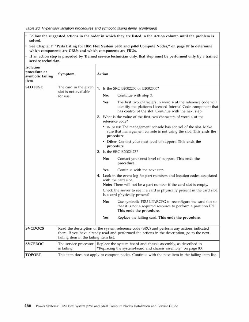
Table 20. Hypervisor isolation procedures and symbolic failing items (continued)
v Follow the suggested actions in the order in which they are listed in the Action column until the problem issolved.
v See Chapter 7, “Parts listing for IBM Flex System p260 and p460 Compute Nodes,” on page 97 to determinewhich components are CRUs and which components are FRUs.
v If an action step is preceded by Trained service technician only, that step must be performed only by a trainedservice technician.
Isolationprocedure orsymbolic failingitem
Symptom Action
SLOTUSE The card in the givenslot is not availablefor use.
1. Is the SRC B2002250 or B2002300?
No: Continue with step 3.
Yes: The first two characters in word 4 of the reference code willidentify the platform Licensed Internal Code component thathas control of the slot. Continue with the next step.
2. What is the value of the first two characters of word 4 of thereference code?
v 02 or 03: The management console has control of the slot. Makesure that management console is not using the slot. This ends theprocedure.
v Other: Contact your next level of support. This ends theprocedure.
3. Is the SRC B2002475?
No: Contact your next level of support. This ends theprocedure.
Yes: Continue with the next step.
4. Look in the event log for part numbers and location codes associatedwith the card slot.Note: There will not be a part number if the card slot is empty.
Check the server to see if a card is physically present in the card slot.Is a card physically present?
No: Use symbolic FRU LPARCFG to reconfigure the card slot sothat it is not a required resource to perform a partition IPL.This ends the procedure.
Yes: Replace the failing card. This ends the procedure.
SVCDOCS Read the description of the system reference code (SRC) and perform any actions indicatedthere. If you have already read and performed the actions in the description, go to the nextfailing item in the failing item list.
SVCPROC The service processoris failing.
Replace the system-board and chassis assembly, as described in“Replacing the system-board and chassis assembly” on page 83.
TOPORT This item does not apply to compute nodes. Continue with the next item in the failing item list.
466 Power Systems: IBM Flex System p260 and p460 Compute Nodes Installation and Service Guide
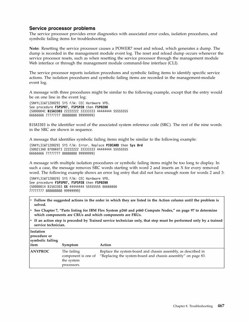
Service processor problemsThe service processor provides error diagnostics with associated error codes, isolation procedures, andsymbolic failing items for troubleshooting.
Note: Resetting the service processor causes a POWER7 reset and reload, which generates a dump. Thedump is recorded in the management module event log. The reset and reload dump occurs whenever theservice processor resets, such as when resetting the service processor through the management moduleWeb interface or through the management module command-line interface (CLI).
The service processor reports isolation procedures and symbolic failing items to identify specific serviceactions. The isolation procedures and symbolic failing items are recorded in the management-moduleevent log.
A message with three procedures might be similar to the following example, except that the entry wouldbe on one line in the event log:(SN#YL31W7120029) SYS F/W: CEC Hardware VPD.See procedure FSPSP07, FSPSP28 then FSP0200(5000004C B15A3303 22222222 33333333 44444444 5555555566666666 77777777 88888888 99999999)
B15A3303 is the identifier word of the associated system reference code (SRC). The rest of the nine wordsin the SRC are shown in sequence.
A message that identifies symbolic failing items might be similar to the following example:(SN#YL31W7120029) SYS F/W: Error. Replace PIOCARD then Sys Brd(500213A0 B7006973 22222222 33333333 44444444 5555555566666666 77777777 88888888 99999999)
A message with multiple isolation procedures or symbolic failing items might be too long to display. Insuch a case, the message removes SRC words starting with word 2 and inserts an X for every removedword. The following example shows an error log entry that did not have enough room for words 2 and 3:(SN#YL31W7120029) SYS F/W: CEC Hardware VPD.See procedure FSPSP07, FSPSP28 then FSP0200(50000014 B15A3303 XX 44444444 55555555 6666666677777777 888888888 99999999)
v Follow the suggested actions in the order in which they are listed in the Action column until the problem issolved.
v See Chapter 7, “Parts listing for IBM Flex System p260 and p460 Compute Nodes,” on page 97 to determinewhich components are CRUs and which components are FRUs.
v If an action step is preceded by Trained service technician only, that step must be performed only by a trainedservice technician.
Isolationprocedure orsymbolic failingitem Symptom Action
ANYPROC The failingcomponent is one ofthe systemprocessors.
Replace the system-board and chassis assembly, as described in“Replacing the system-board and chassis assembly” on page 83.
Chapter 8. Troubleshooting 467
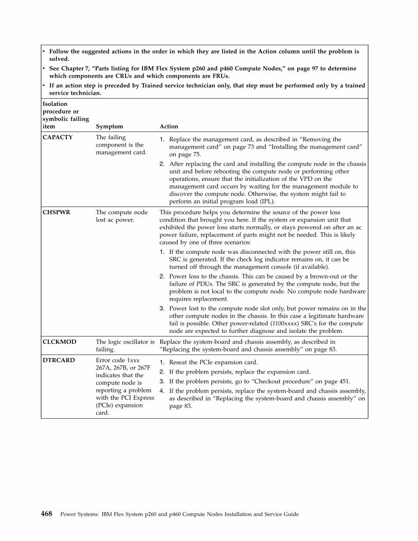
v Follow the suggested actions in the order in which they are listed in the Action column until the problem issolved.
v See Chapter 7, “Parts listing for IBM Flex System p260 and p460 Compute Nodes,” on page 97 to determinewhich components are CRUs and which components are FRUs.
v If an action step is preceded by Trained service technician only, that step must be performed only by a trainedservice technician.
Isolationprocedure orsymbolic failingitem Symptom Action
CAPACTY The failingcomponent is themanagement card.
1. Replace the management card, as described in “Removing themanagement card” on page 73 and “Installing the management card”on page 75.
2. After replacing the card and installing the compute node in the chassisunit and before rebooting the compute node or performing otheroperations, ensure that the initialization of the VPD on themanagement card occurs by waiting for the management module todiscover the compute node. Otherwise, the system might fail toperform an initial program load (IPL).
CHSPWR The compute nodelost ac power.
This procedure helps you determine the source of the power losscondition that brought you here. If the system or expansion unit thatexhibited the power loss starts normally, or stays powered on after an acpower failure, replacement of parts might not be needed. This is likelycaused by one of three scenarios:
1. If the compute node was disconnected with the power still on, thisSRC is generated. If the check log indicator remains on, it can beturned off through the management console (if available).
2. Power loss to the chassis. This can be caused by a brown-out or thefailure of PDUs. The SRC is generated by the compute node, but theproblem is not local to the compute node. No compute node hardwarerequires replacement.
3. Power lost to the compute node slot only, but power remains on in theother compute nodes in the chassis. In this case a legitimate hardwarefail is possible. Other power-related (1100xxxx) SRC's for the computenode are expected to further diagnose and isolate the problem.
CLCKMOD The logic oscillator isfailing.
Replace the system-board and chassis assembly, as described in“Replacing the system-board and chassis assembly” on page 83.
DTRCARD Error code 1xxx267A, 267B, or 267Findicates that thecompute node isreporting a problemwith the PCI Express(PCIe) expansioncard.
1. Reseat the PCIe expansion card.
2. If the problem persists, replace the expansion card.
3. If the problem persists, go to “Checkout procedure” on page 451.
4. If the problem persists, replace the system-board and chassis assembly,as described in “Replacing the system-board and chassis assembly” onpage 83.
468 Power Systems: IBM Flex System p260 and p460 Compute Nodes Installation and Service Guide
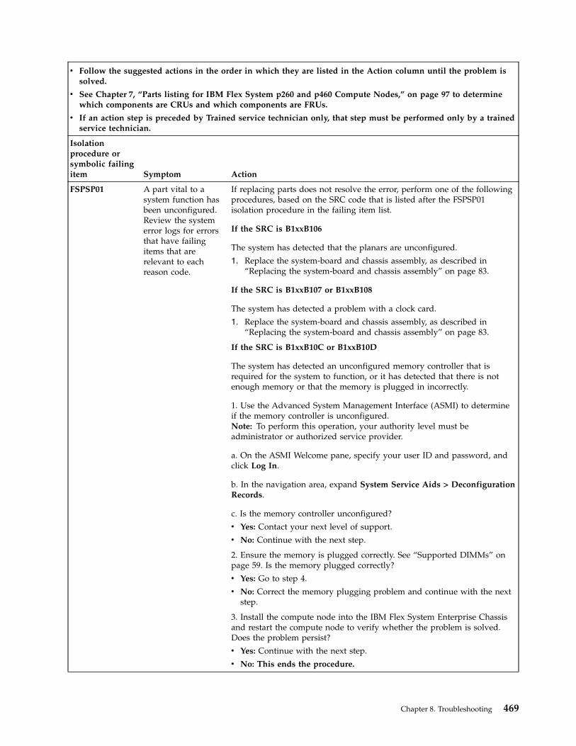
v Follow the suggested actions in the order in which they are listed in the Action column until the problem issolved.
v See Chapter 7, “Parts listing for IBM Flex System p260 and p460 Compute Nodes,” on page 97 to determinewhich components are CRUs and which components are FRUs.
v If an action step is preceded by Trained service technician only, that step must be performed only by a trainedservice technician.
Isolationprocedure orsymbolic failingitem Symptom Action
FSPSP01 A part vital to asystem function hasbeen unconfigured.Review the systemerror logs for errorsthat have failingitems that arerelevant to eachreason code.
If replacing parts does not resolve the error, perform one of the followingprocedures, based on the SRC code that is listed after the FSPSP01isolation procedure in the failing item list.
If the SRC is B1xxB106
The system has detected that the planars are unconfigured.
1. Replace the system-board and chassis assembly, as described in“Replacing the system-board and chassis assembly” on page 83.
If the SRC is B1xxB107 or B1xxB108
The system has detected a problem with a clock card.
1. Replace the system-board and chassis assembly, as described in“Replacing the system-board and chassis assembly” on page 83.
If the SRC is B1xxB10C or B1xxB10D
The system has detected an unconfigured memory controller that isrequired for the system to function, or it has detected that there is notenough memory or that the memory is plugged in incorrectly.
1. Use the Advanced System Management Interface (ASMI) to determineif the memory controller is unconfigured.Note: To perform this operation, your authority level must beadministrator or authorized service provider.
a. On the ASMI Welcome pane, specify your user ID and password, andclick Log In.
b. In the navigation area, expand System Service Aids > DeconfigurationRecords.
c. Is the memory controller unconfigured?
v Yes: Contact your next level of support.
v No: Continue with the next step.
2. Ensure the memory is plugged correctly. See “Supported DIMMs” onpage 59. Is the memory plugged correctly?
v Yes: Go to step 4.
v No: Correct the memory plugging problem and continue with the nextstep.
3. Install the compute node into the IBM Flex System Enterprise Chassisand restart the compute node to verify whether the problem is solved.Does the problem persist?
v Yes: Continue with the next step.
v No: This ends the procedure.
Chapter 8. Troubleshooting 469
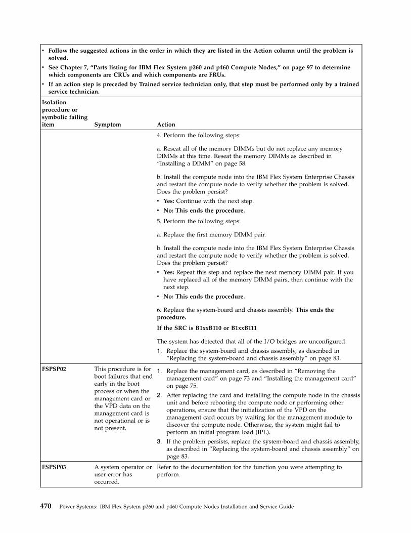
v Follow the suggested actions in the order in which they are listed in the Action column until the problem issolved.
v See Chapter 7, “Parts listing for IBM Flex System p260 and p460 Compute Nodes,” on page 97 to determinewhich components are CRUs and which components are FRUs.
v If an action step is preceded by Trained service technician only, that step must be performed only by a trainedservice technician.
Isolationprocedure orsymbolic failingitem Symptom Action
4. Perform the following steps:
a. Reseat all of the memory DIMMs but do not replace any memoryDIMMs at this time. Reseat the memory DIMMs as described in“Installing a DIMM” on page 58.
b. Install the compute node into the IBM Flex System Enterprise Chassisand restart the compute node to verify whether the problem is solved.Does the problem persist?
v Yes: Continue with the next step.
v No: This ends the procedure.
5. Perform the following steps:
a. Replace the first memory DIMM pair.
b. Install the compute node into the IBM Flex System Enterprise Chassisand restart the compute node to verify whether the problem is solved.Does the problem persist?
v Yes: Repeat this step and replace the next memory DIMM pair. If youhave replaced all of the memory DIMM pairs, then continue with thenext step.
v No: This ends the procedure.
6. Replace the system-board and chassis assembly. This ends theprocedure.
If the SRC is B1xxB110 or B1xxB111
The system has detected that all of the I/O bridges are unconfigured.
1. Replace the system-board and chassis assembly, as described in“Replacing the system-board and chassis assembly” on page 83.
FSPSP02 This procedure is forboot failures that endearly in the bootprocess or when themanagement card orthe VPD data on themanagement card isnot operational or isnot present.
1. Replace the management card, as described in “Removing themanagement card” on page 73 and “Installing the management card”on page 75.
2. After replacing the card and installing the compute node in the chassisunit and before rebooting the compute node or performing otheroperations, ensure that the initialization of the VPD on themanagement card occurs by waiting for the management module todiscover the compute node. Otherwise, the system might fail toperform an initial program load (IPL).
3. If the problem persists, replace the system-board and chassis assembly,as described in “Replacing the system-board and chassis assembly” onpage 83.
FSPSP03 A system operator oruser error hasoccurred.
Refer to the documentation for the function you were attempting toperform.
470 Power Systems: IBM Flex System p260 and p460 Compute Nodes Installation and Service Guide
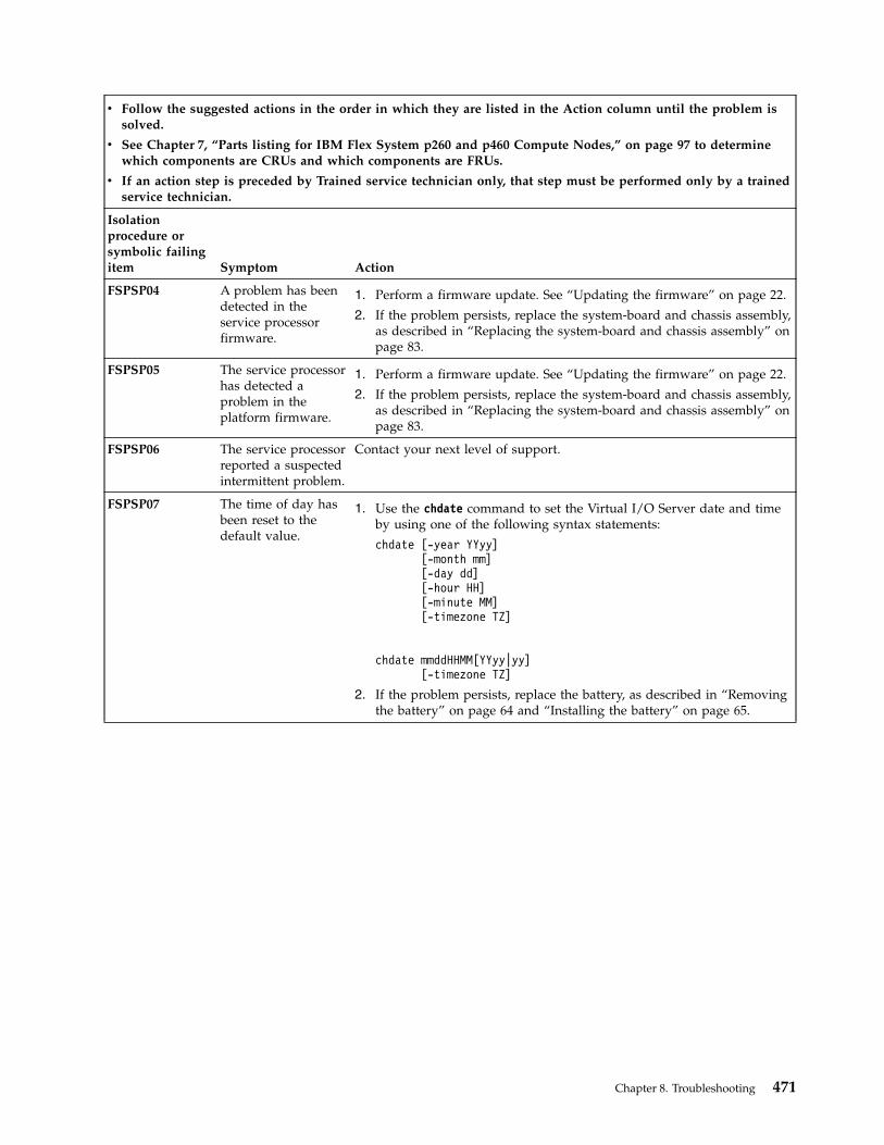
v Follow the suggested actions in the order in which they are listed in the Action column until the problem issolved.
v See Chapter 7, “Parts listing for IBM Flex System p260 and p460 Compute Nodes,” on page 97 to determinewhich components are CRUs and which components are FRUs.
v If an action step is preceded by Trained service technician only, that step must be performed only by a trainedservice technician.
Isolationprocedure orsymbolic failingitem Symptom Action
FSPSP04 A problem has beendetected in theservice processorfirmware.
1. Perform a firmware update. See “Updating the firmware” on page 22.
2. If the problem persists, replace the system-board and chassis assembly,as described in “Replacing the system-board and chassis assembly” onpage 83.
FSPSP05 The service processorhas detected aproblem in theplatform firmware.
1. Perform a firmware update. See “Updating the firmware” on page 22.
2. If the problem persists, replace the system-board and chassis assembly,as described in “Replacing the system-board and chassis assembly” onpage 83.
FSPSP06 The service processorreported a suspectedintermittent problem.
Contact your next level of support.
FSPSP07 The time of day hasbeen reset to thedefault value.
1. Use the chdate command to set the Virtual I/O Server date and timeby using one of the following syntax statements:
chdate [-year YYyy][-month mm][-day dd][-hour HH][-minute MM][-timezone TZ]
chdate mmddHHMM[YYyy|yy][-timezone TZ]
2. If the problem persists, replace the battery, as described in “Removingthe battery” on page 64 and “Installing the battery” on page 65.
Chapter 8. Troubleshooting 471
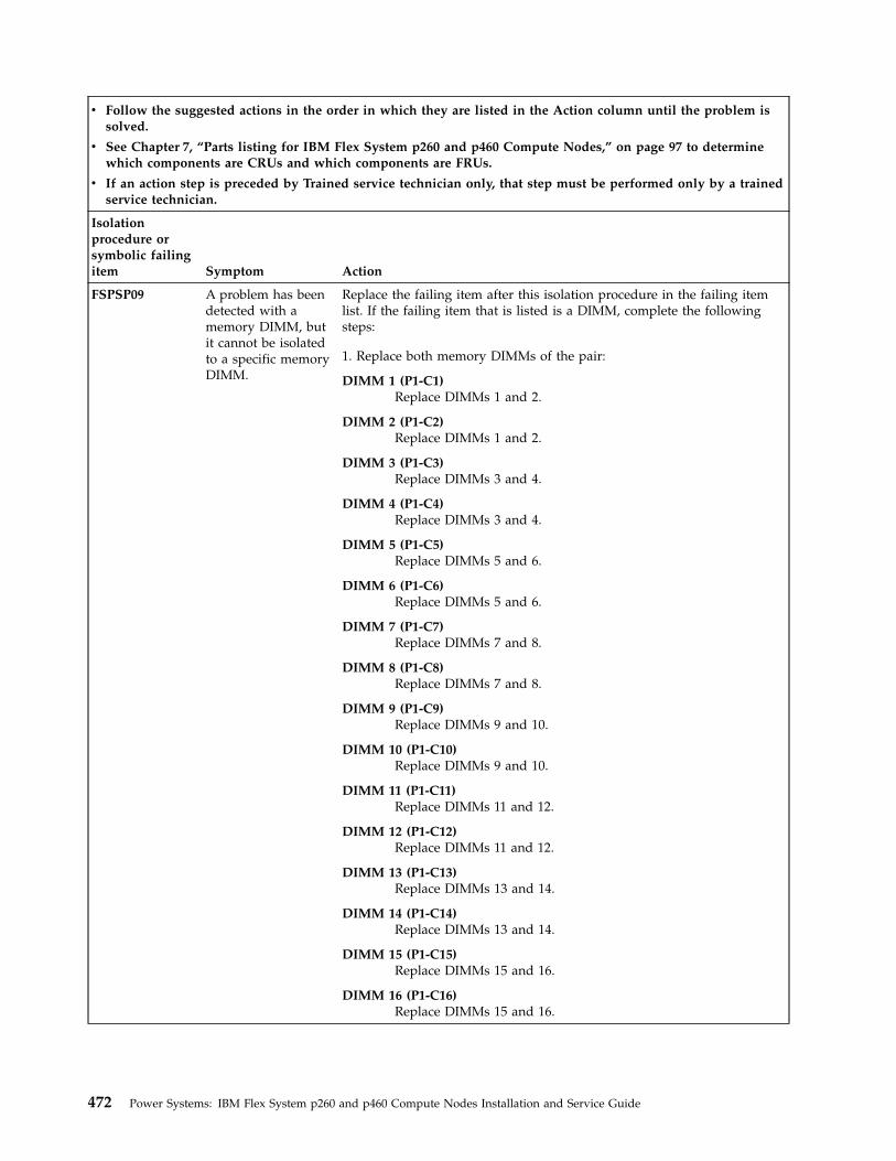
v Follow the suggested actions in the order in which they are listed in the Action column until the problem issolved.
v See Chapter 7, “Parts listing for IBM Flex System p260 and p460 Compute Nodes,” on page 97 to determinewhich components are CRUs and which components are FRUs.
v If an action step is preceded by Trained service technician only, that step must be performed only by a trainedservice technician.
Isolationprocedure orsymbolic failingitem Symptom Action
FSPSP09 A problem has beendetected with amemory DIMM, butit cannot be isolatedto a specific memoryDIMM.
Replace the failing item after this isolation procedure in the failing itemlist. If the failing item that is listed is a DIMM, complete the followingsteps:
1. Replace both memory DIMMs of the pair:
DIMM 1 (P1-C1)Replace DIMMs 1 and 2.
DIMM 2 (P1-C2)Replace DIMMs 1 and 2.
DIMM 3 (P1-C3)Replace DIMMs 3 and 4.
DIMM 4 (P1-C4)Replace DIMMs 3 and 4.
DIMM 5 (P1-C5)Replace DIMMs 5 and 6.
DIMM 6 (P1-C6)Replace DIMMs 5 and 6.
DIMM 7 (P1-C7)Replace DIMMs 7 and 8.
DIMM 8 (P1-C8)Replace DIMMs 7 and 8.
DIMM 9 (P1-C9)Replace DIMMs 9 and 10.
DIMM 10 (P1-C10)Replace DIMMs 9 and 10.
DIMM 11 (P1-C11)Replace DIMMs 11 and 12.
DIMM 12 (P1-C12)Replace DIMMs 11 and 12.
DIMM 13 (P1-C13)Replace DIMMs 13 and 14.
DIMM 14 (P1-C14)Replace DIMMs 13 and 14.
DIMM 15 (P1-C15)Replace DIMMs 15 and 16.
DIMM 16 (P1-C16)Replace DIMMs 15 and 16.
472 Power Systems: IBM Flex System p260 and p460 Compute Nodes Installation and Service Guide
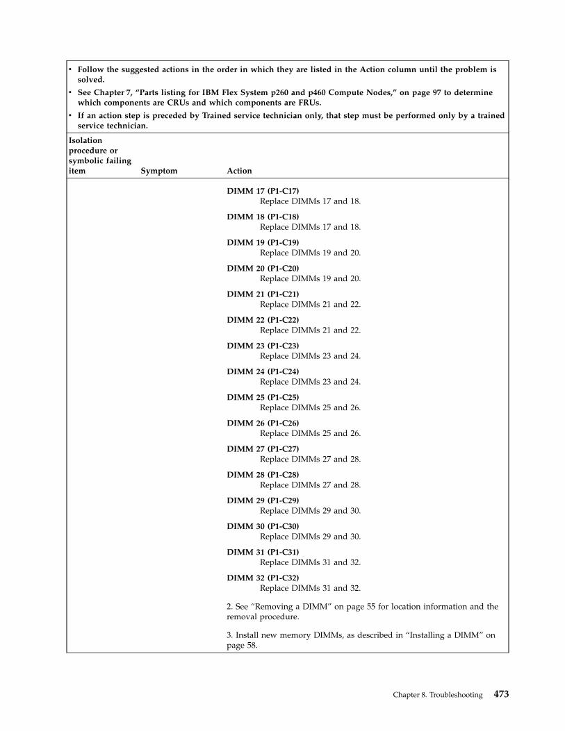
v Follow the suggested actions in the order in which they are listed in the Action column until the problem issolved.
v See Chapter 7, “Parts listing for IBM Flex System p260 and p460 Compute Nodes,” on page 97 to determinewhich components are CRUs and which components are FRUs.
v If an action step is preceded by Trained service technician only, that step must be performed only by a trainedservice technician.
Isolationprocedure orsymbolic failingitem Symptom Action
DIMM 17 (P1-C17)Replace DIMMs 17 and 18.
DIMM 18 (P1-C18)Replace DIMMs 17 and 18.
DIMM 19 (P1-C19)Replace DIMMs 19 and 20.
DIMM 20 (P1-C20)Replace DIMMs 19 and 20.
DIMM 21 (P1-C21)Replace DIMMs 21 and 22.
DIMM 22 (P1-C22)Replace DIMMs 21 and 22.
DIMM 23 (P1-C23)Replace DIMMs 23 and 24.
DIMM 24 (P1-C24)Replace DIMMs 23 and 24.
DIMM 25 (P1-C25)Replace DIMMs 25 and 26.
DIMM 26 (P1-C26)Replace DIMMs 25 and 26.
DIMM 27 (P1-C27)Replace DIMMs 27 and 28.
DIMM 28 (P1-C28)Replace DIMMs 27 and 28.
DIMM 29 (P1-C29)Replace DIMMs 29 and 30.
DIMM 30 (P1-C30)Replace DIMMs 29 and 30.
DIMM 31 (P1-C31)Replace DIMMs 31 and 32.
DIMM 32 (P1-C32)Replace DIMMs 31 and 32.
2. See “Removing a DIMM” on page 55 for location information and theremoval procedure.
3. Install new memory DIMMs, as described in “Installing a DIMM” onpage 58.
Chapter 8. Troubleshooting 473
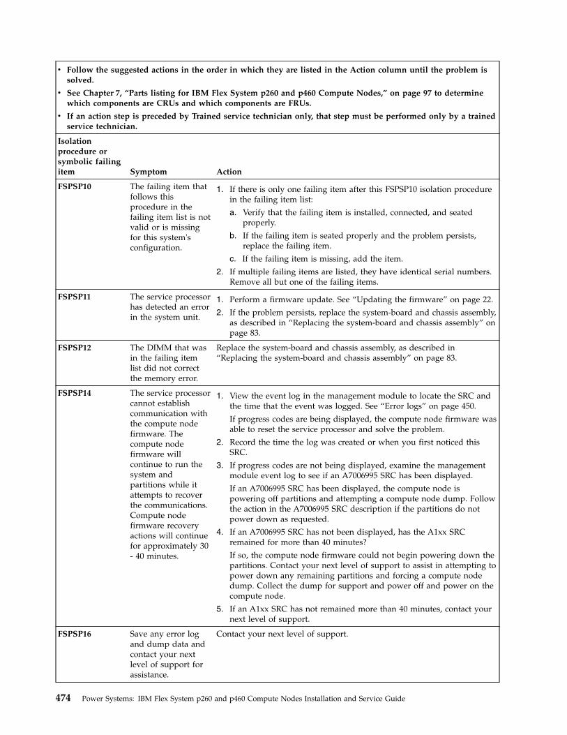
v Follow the suggested actions in the order in which they are listed in the Action column until the problem issolved.
v See Chapter 7, “Parts listing for IBM Flex System p260 and p460 Compute Nodes,” on page 97 to determinewhich components are CRUs and which components are FRUs.
v If an action step is preceded by Trained service technician only, that step must be performed only by a trainedservice technician.
Isolationprocedure orsymbolic failingitem Symptom Action
FSPSP10 The failing item thatfollows thisprocedure in thefailing item list is notvalid or is missingfor this system'sconfiguration.
1. If there is only one failing item after this FSPSP10 isolation procedurein the failing item list:
a. Verify that the failing item is installed, connected, and seatedproperly.
b. If the failing item is seated properly and the problem persists,replace the failing item.
c. If the failing item is missing, add the item.
2. If multiple failing items are listed, they have identical serial numbers.Remove all but one of the failing items.
FSPSP11 The service processorhas detected an errorin the system unit.
1. Perform a firmware update. See “Updating the firmware” on page 22.
2. If the problem persists, replace the system-board and chassis assembly,as described in “Replacing the system-board and chassis assembly” onpage 83.
FSPSP12 The DIMM that wasin the failing itemlist did not correctthe memory error.
Replace the system-board and chassis assembly, as described in“Replacing the system-board and chassis assembly” on page 83.
FSPSP14 The service processorcannot establishcommunication withthe compute nodefirmware. Thecompute nodefirmware willcontinue to run thesystem andpartitions while itattempts to recoverthe communications.Compute nodefirmware recoveryactions will continuefor approximately 30- 40 minutes.
1. View the event log in the management module to locate the SRC andthe time that the event was logged. See “Error logs” on page 450.
If progress codes are being displayed, the compute node firmware wasable to reset the service processor and solve the problem.
2. Record the time the log was created or when you first noticed thisSRC.
3. If progress codes are not being displayed, examine the managementmodule event log to see if an A7006995 SRC has been displayed.
If an A7006995 SRC has been displayed, the compute node ispowering off partitions and attempting a compute node dump. Followthe action in the A7006995 SRC description if the partitions do notpower down as requested.
4. If an A7006995 SRC has not been displayed, has the A1xx SRCremained for more than 40 minutes?
If so, the compute node firmware could not begin powering down thepartitions. Contact your next level of support to assist in attempting topower down any remaining partitions and forcing a compute nodedump. Collect the dump for support and power off and power on thecompute node.
5. If an A1xx SRC has not remained more than 40 minutes, contact yournext level of support.
FSPSP16 Save any error logand dump data andcontact your nextlevel of support forassistance.
Contact your next level of support.
474 Power Systems: IBM Flex System p260 and p460 Compute Nodes Installation and Service Guide
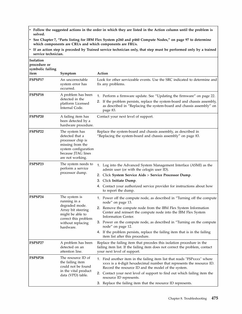
v Follow the suggested actions in the order in which they are listed in the Action column until the problem issolved.
v See Chapter 7, “Parts listing for IBM Flex System p260 and p460 Compute Nodes,” on page 97 to determinewhich components are CRUs and which components are FRUs.
v If an action step is preceded by Trained service technician only, that step must be performed only by a trainedservice technician.
Isolationprocedure orsymbolic failingitem Symptom Action
FSPSP17 An uncorrectablesystem error hasoccurred.
Look for other serviceable events. Use the SRC indicated to determine andfix any problems.
FSPSP18 A problem has beendetected in theplatform LicensedInternal Code.
1. Perform a firmware update. See “Updating the firmware” on page 22.
2. If the problem persists, replace the system-board and chassis assembly,as described in “Replacing the system-board and chassis assembly” onpage 83.
FSPSP20 A failing item hasbeen detected by ahardware procedure.
Contact your next level of support.
FSPSP22 The system hasdetected that aprocessor chip ismissing from thesystem configurationbecause JTAG linesare not working.
Replace the system-board and chassis assembly, as described in“Replacing the system-board and chassis assembly” on page 83.
FSPSP23 The system needs toperform a serviceprocessor dump.
1. Log into the Advanced System Management Interface (ASMI) as theadmin user (or with the celogin user ID).
2. Click System Service Aids > Service Processor Dump.
3. Click Initiate Dump.
4. Contact your authorized service provider for instructions about howto report the dump.
FSPSP24 The system isrunning in adegraded mode.Array bit steeringmight be able tocorrect this problemwithout replacinghardware.
1. Power off the compute node, as described in “Turning off the computenode” on page 13.
2. Remove the compute node from the IBM Flex System InformationCenter and reinsert the compute node into the IBM Flex SystemInformation Center.
3. Power on the compute node, as described in “Turning on the computenode” on page 12.
4. If the problem persists, replace the failing item that is in the failingitem list after this procedure.
FSPSP27 A problem has beendetected on anattention line.
Replace the failing item that precedes this isolation procedure in thefailing item list. If the failing item does not correct the problem, contactyour next level of support.
FSPSP28 The resource ID ofthe failing itemcould not be foundin the vital productdata (VPD) table.
1. Find another item in the failing item list that reads "FSPxxxx" wherexxxx is a 4-digit hexadecimal number that represents the resource ID.Record the resource ID and the model of the system.
2. Contact your next level of support to find out which failing item theresource ID represents.
3. Replace the failing item that the resource ID represents.
Chapter 8. Troubleshooting 475
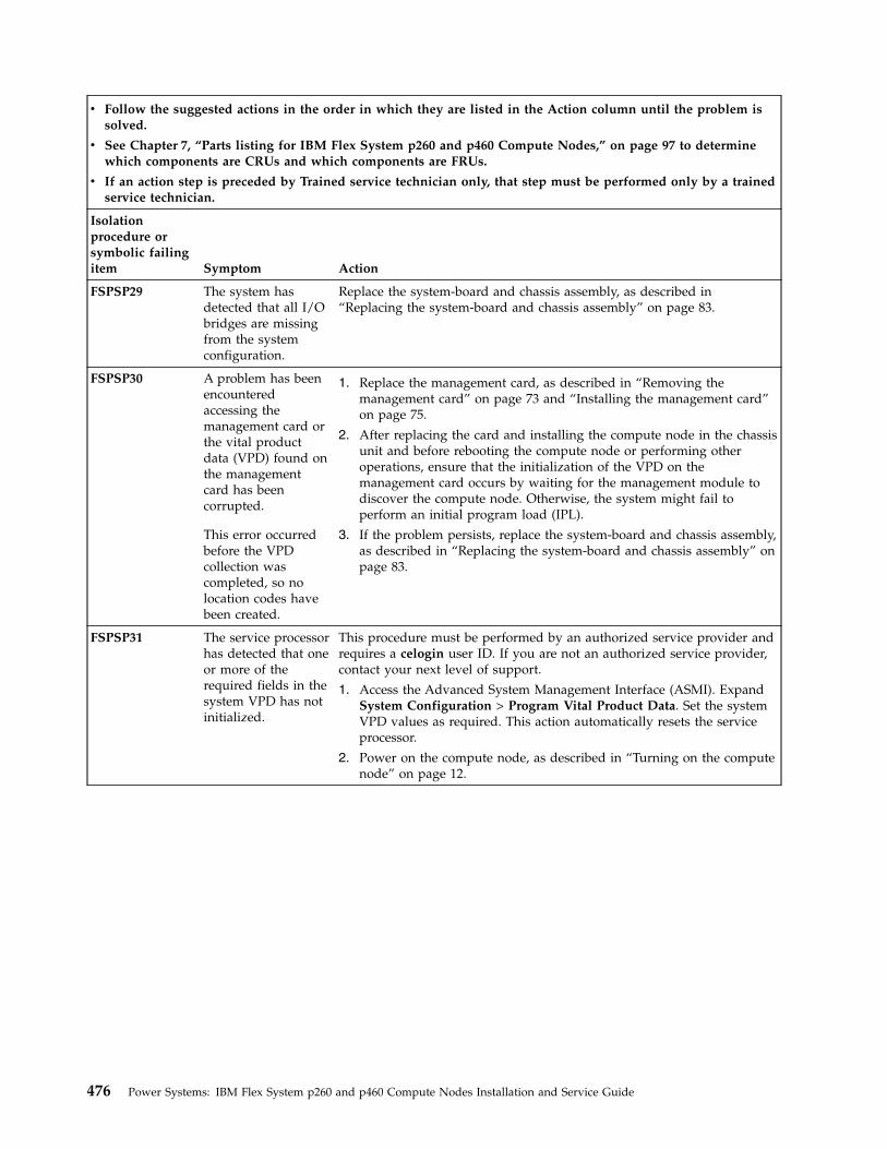
v Follow the suggested actions in the order in which they are listed in the Action column until the problem issolved.
v See Chapter 7, “Parts listing for IBM Flex System p260 and p460 Compute Nodes,” on page 97 to determinewhich components are CRUs and which components are FRUs.
v If an action step is preceded by Trained service technician only, that step must be performed only by a trainedservice technician.
Isolationprocedure orsymbolic failingitem Symptom Action
FSPSP29 The system hasdetected that all I/Obridges are missingfrom the systemconfiguration.
Replace the system-board and chassis assembly, as described in“Replacing the system-board and chassis assembly” on page 83.
FSPSP30 A problem has beenencounteredaccessing themanagement card orthe vital productdata (VPD) found onthe managementcard has beencorrupted.
This error occurredbefore the VPDcollection wascompleted, so nolocation codes havebeen created.
1. Replace the management card, as described in “Removing themanagement card” on page 73 and “Installing the management card”on page 75.
2. After replacing the card and installing the compute node in the chassisunit and before rebooting the compute node or performing otheroperations, ensure that the initialization of the VPD on themanagement card occurs by waiting for the management module todiscover the compute node. Otherwise, the system might fail toperform an initial program load (IPL).
3. If the problem persists, replace the system-board and chassis assembly,as described in “Replacing the system-board and chassis assembly” onpage 83.
FSPSP31 The service processorhas detected that oneor more of therequired fields in thesystem VPD has notinitialized.
This procedure must be performed by an authorized service provider andrequires a celogin user ID. If you are not an authorized service provider,contact your next level of support.
1. Access the Advanced System Management Interface (ASMI). ExpandSystem Configuration > Program Vital Product Data. Set the systemVPD values as required. This action automatically resets the serviceprocessor.
2. Power on the compute node, as described in “Turning on the computenode” on page 12.
476 Power Systems: IBM Flex System p260 and p460 Compute Nodes Installation and Service Guide
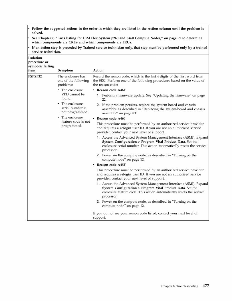
v Follow the suggested actions in the order in which they are listed in the Action column until the problem issolved.
v See Chapter 7, “Parts listing for IBM Flex System p260 and p460 Compute Nodes,” on page 97 to determinewhich components are CRUs and which components are FRUs.
v If an action step is preceded by Trained service technician only, that step must be performed only by a trainedservice technician.
Isolationprocedure orsymbolic failingitem Symptom Action
FSPSP32 The enclosure hasone of the followingproblems:
v The enclosureVPD cannot befound.
v The enclosureserial number isnot programmed.
v The enclosurefeature code is notprogrammed.
Record the reason code, which is the last 4 digits of the first word fromthe SRC. Perform one of the following procedures based on the value ofthe reason code:
v Reason code A46F
1. Perform a firmware update. See “Updating the firmware” on page22.
2. If the problem persists, replace the system-board and chassisassembly, as described in “Replacing the system-board and chassisassembly” on page 83.
v Reason code A460
This procedure must be performed by an authorized service providerand requires a celogin user ID. If you are not an authorized serviceprovider, contact your next level of support.
1. Access the Advanced System Management Interface (ASMI). ExpandSystem Configuration > Program Vital Product Data. Set theenclosure serial number. This action automatically resets the serviceprocessor.
2. Power on the compute node, as described in “Turning on thecompute node” on page 12.
v Reason code A45F
This procedure must be performed by an authorized service providerand requires a celogin user ID. If you are not an authorized serviceprovider, contact your next level of support.
1. Access the Advanced System Management Interface (ASMI). ExpandSystem Configuration > Program Vital Product Data. Set theenclosure feature code. This action automatically resets the serviceprocessor.
2. Power on the compute node, as described in “Turning on thecompute node” on page 12.
If you do not see your reason code listed, contact your next level ofsupport.
Chapter 8. Troubleshooting 477
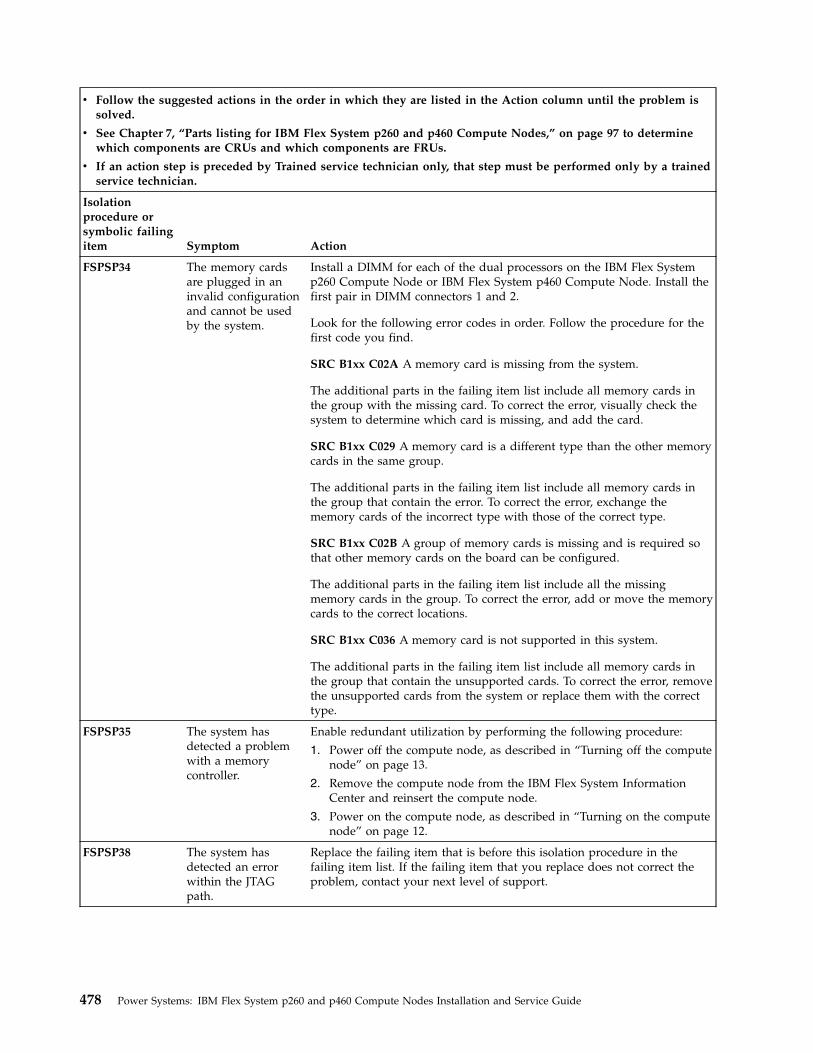
v Follow the suggested actions in the order in which they are listed in the Action column until the problem issolved.
v See Chapter 7, “Parts listing for IBM Flex System p260 and p460 Compute Nodes,” on page 97 to determinewhich components are CRUs and which components are FRUs.
v If an action step is preceded by Trained service technician only, that step must be performed only by a trainedservice technician.
Isolationprocedure orsymbolic failingitem Symptom Action
FSPSP34 The memory cardsare plugged in aninvalid configurationand cannot be usedby the system.
Install a DIMM for each of the dual processors on the IBM Flex Systemp260 Compute Node or IBM Flex System p460 Compute Node. Install thefirst pair in DIMM connectors 1 and 2.
Look for the following error codes in order. Follow the procedure for thefirst code you find.
SRC B1xx C02A A memory card is missing from the system.
The additional parts in the failing item list include all memory cards inthe group with the missing card. To correct the error, visually check thesystem to determine which card is missing, and add the card.
SRC B1xx C029 A memory card is a different type than the other memorycards in the same group.
The additional parts in the failing item list include all memory cards inthe group that contain the error. To correct the error, exchange thememory cards of the incorrect type with those of the correct type.
SRC B1xx C02B A group of memory cards is missing and is required sothat other memory cards on the board can be configured.
The additional parts in the failing item list include all the missingmemory cards in the group. To correct the error, add or move the memorycards to the correct locations.
SRC B1xx C036 A memory card is not supported in this system.
The additional parts in the failing item list include all memory cards inthe group that contain the unsupported cards. To correct the error, removethe unsupported cards from the system or replace them with the correcttype.
FSPSP35 The system hasdetected a problemwith a memorycontroller.
Enable redundant utilization by performing the following procedure:
1. Power off the compute node, as described in “Turning off the computenode” on page 13.
2. Remove the compute node from the IBM Flex System InformationCenter and reinsert the compute node.
3. Power on the compute node, as described in “Turning on the computenode” on page 12.
FSPSP38 The system hasdetected an errorwithin the JTAGpath.
Replace the failing item that is before this isolation procedure in thefailing item list. If the failing item that you replace does not correct theproblem, contact your next level of support.
478 Power Systems: IBM Flex System p260 and p460 Compute Nodes Installation and Service Guide

v Follow the suggested actions in the order in which they are listed in the Action column until the problem issolved.
v See Chapter 7, “Parts listing for IBM Flex System p260 and p460 Compute Nodes,” on page 97 to determinewhich components are CRUs and which components are FRUs.
v If an action step is preceded by Trained service technician only, that step must be performed only by a trainedservice technician.
Isolationprocedure orsymbolic failingitem Symptom Action
FSPSP42 An errorcommunicatingbetween two systemprocessors wasdetected.
Contact your next level of support.
FSPSP45 The system hasdetected an errorwithin the FSI path.
Replace the system-board and chassis assembly, as described in“Replacing the system-board and chassis assembly” on page 83.
FSPSP46 Some corrupt areasof flash or RAMhave been detectedon the serviceprocessor.
Replace the system-board and chassis assembly, as described in“Replacing the system-board and chassis assembly” on page 83.
FSPSP47 The system hasdetected an errorwithin the PSI link.
Replace the system-board and chassis assembly, as described in“Replacing the system-board and chassis assembly” on page 83.
FSPSP48 A diagnosticsfunction detects anexternal processorinterface problem.
If the failing items preceding this isolation procedure in the failing itemlist do not fix the problem, contact your next level of support.
FSPSP49 A diagnostic functiondetects an internalprocessor interfaceproblem.
If the failing items preceding this isolation procedure in the failing itemlist do not fix the problem, contact your next level of support.
FSPSP50 A diagnostic functiondetects a connectionproblem between aprocessor chip and aGX chip.
If the failing items preceding this isolation procedure in the failing itemlist do not fix the problem, contact your next level of support.
Chapter 8. Troubleshooting 479
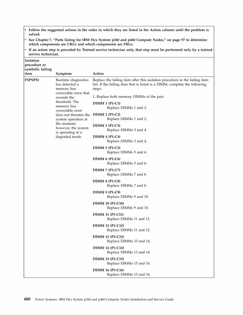
v Follow the suggested actions in the order in which they are listed in the Action column until the problem issolved.
v See Chapter 7, “Parts listing for IBM Flex System p260 and p460 Compute Nodes,” on page 97 to determinewhich components are CRUs and which components are FRUs.
v If an action step is preceded by Trained service technician only, that step must be performed only by a trainedservice technician.
Isolationprocedure orsymbolic failingitem Symptom Action
FSPSP51 Runtime diagnosticshas detected amemory buscorrectable error thatexceeds thethreshold. Thememory buscorrectable errordoes not threaten thesystem operation atthe moment;however, the systemis operating in adegraded mode.
Replace the failing item after this isolation procedure in the failing itemlist. If the failing item that is listed is a DIMM, complete the followingsteps:
1. Replace both memory DIMMs of the pair:
DIMM 1 (P1-C1)Replace DIMMs 1 and 2.
DIMM 2 (P1-C2)Replace DIMMs 1 and 2.
DIMM 3 (P1-C3)Replace DIMMs 3 and 4.
DIMM 4 (P1-C4)Replace DIMMs 3 and 4.
DIMM 5 (P1-C5)Replace DIMMs 5 and 6.
DIMM 6 (P1-C6)Replace DIMMs 5 and 6.
DIMM 7 (P1-C7)Replace DIMMs 7 and 8.
DIMM 8 (P1-C8)Replace DIMMs 7 and 8.
DIMM 9 (P1-C9)Replace DIMMs 9 and 10.
DIMM 10 (P1-C10)Replace DIMMs 9 and 10.
DIMM 11 (P1-C11)Replace DIMMs 11 and 12.
DIMM 12 (P1-C12)Replace DIMMs 11 and 12.
DIMM 13 (P1-C13)Replace DIMMs 13 and 14.
DIMM 14 (P1-C14)Replace DIMMs 13 and 14.
DIMM 15 (P1-C15)Replace DIMMs 15 and 16.
DIMM 16 (P1-C16)Replace DIMMs 15 and 16.
480 Power Systems: IBM Flex System p260 and p460 Compute Nodes Installation and Service Guide

v Follow the suggested actions in the order in which they are listed in the Action column until the problem issolved.
v See Chapter 7, “Parts listing for IBM Flex System p260 and p460 Compute Nodes,” on page 97 to determinewhich components are CRUs and which components are FRUs.
v If an action step is preceded by Trained service technician only, that step must be performed only by a trainedservice technician.
Isolationprocedure orsymbolic failingitem Symptom Action
DIMM 17 (P1-C17)Replace DIMMs 17 and 18.
DIMM 18 (P1-C18)Replace DIMMs 17 and 18.
DIMM 19 (P1-C19)Replace DIMMs 19 and 20.
DIMM 20 (P1-C20)Replace DIMMs 19 and 20.
DIMM 21 (P1-C21)Replace DIMMs 21 and 22.
DIMM 22 (P1-C22)Replace DIMMs 21 and 22.
DIMM 23 (P1-C23)Replace DIMMs 23 and 24.
DIMM 24 (P1-C24)Replace DIMMs 23 and 24.
DIMM 25 (P1-C25)Replace DIMMs 25 and 26.
DIMM 26 (P1-C26)Replace DIMMs 25 and 26.
DIMM 27 (P1-C27)Replace DIMMs 27 and 28.
DIMM 28 (P1-C28)Replace DIMMs 27 and 28.
DIMM 29 (P1-C29)Replace DIMMs 29 and 30.
DIMM 30 (P1-C30)Replace DIMMs 29 and 30.
DIMM 31 (P1-C31)Replace DIMMs 31 and 32.
DIMM 32 (P1-C32)Replace DIMMs 31 and 32.
2. See “Removing a DIMM” on page 55 for location information and theremoval procedure.
3. Install new memory DIMMs, as described in “Installing a DIMM” onpage 58.
Chapter 8. Troubleshooting 481
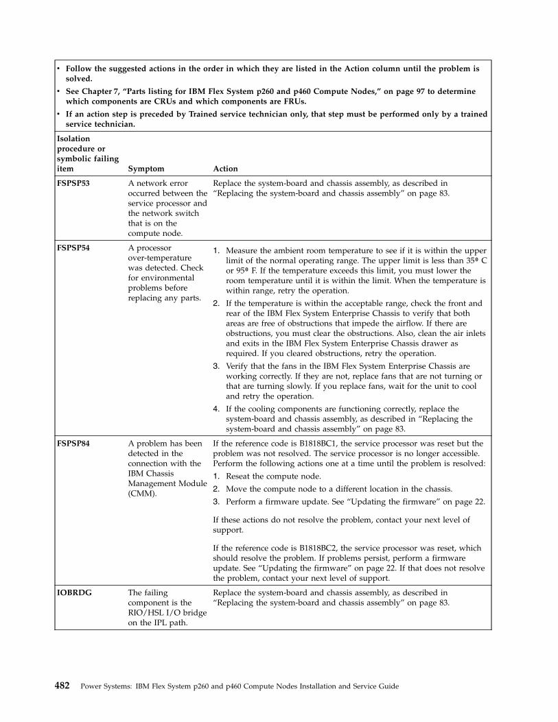
v Follow the suggested actions in the order in which they are listed in the Action column until the problem issolved.
v See Chapter 7, “Parts listing for IBM Flex System p260 and p460 Compute Nodes,” on page 97 to determinewhich components are CRUs and which components are FRUs.
v If an action step is preceded by Trained service technician only, that step must be performed only by a trainedservice technician.
Isolationprocedure orsymbolic failingitem Symptom Action
FSPSP53 A network erroroccurred between theservice processor andthe network switchthat is on thecompute node.
Replace the system-board and chassis assembly, as described in“Replacing the system-board and chassis assembly” on page 83.
FSPSP54 A processorover-temperaturewas detected. Checkfor environmentalproblems beforereplacing any parts.
1. Measure the ambient room temperature to see if it is within the upperlimit of the normal operating range. The upper limit is less than 35⁰ Cor 95⁰ F. If the temperature exceeds this limit, you must lower theroom temperature until it is within the limit. When the temperature iswithin range, retry the operation.
2. If the temperature is within the acceptable range, check the front andrear of the IBM Flex System Enterprise Chassis to verify that bothareas are free of obstructions that impede the airflow. If there areobstructions, you must clear the obstructions. Also, clean the air inletsand exits in the IBM Flex System Enterprise Chassis drawer asrequired. If you cleared obstructions, retry the operation.
3. Verify that the fans in the IBM Flex System Enterprise Chassis areworking correctly. If they are not, replace fans that are not turning orthat are turning slowly. If you replace fans, wait for the unit to cooland retry the operation.
4. If the cooling components are functioning correctly, replace thesystem-board and chassis assembly, as described in “Replacing thesystem-board and chassis assembly” on page 83.
FSPSP84 A problem has beendetected in theconnection with theIBM ChassisManagement Module(CMM).
If the reference code is B1818BC1, the service processor was reset but theproblem was not resolved. The service processor is no longer accessible.Perform the following actions one at a time until the problem is resolved:
1. Reseat the compute node.
2. Move the compute node to a different location in the chassis.
3. Perform a firmware update. See “Updating the firmware” on page 22.
If these actions do not resolve the problem, contact your next level ofsupport.
If the reference code is B1818BC2, the service processor was reset, whichshould resolve the problem. If problems persist, perform a firmwareupdate. See “Updating the firmware” on page 22. If that does not resolvethe problem, contact your next level of support.
IOBRDG The failingcomponent is theRIO/HSL I/O bridgeon the IPL path.
Replace the system-board and chassis assembly, as described in“Replacing the system-board and chassis assembly” on page 83.
482 Power Systems: IBM Flex System p260 and p460 Compute Nodes Installation and Service Guide
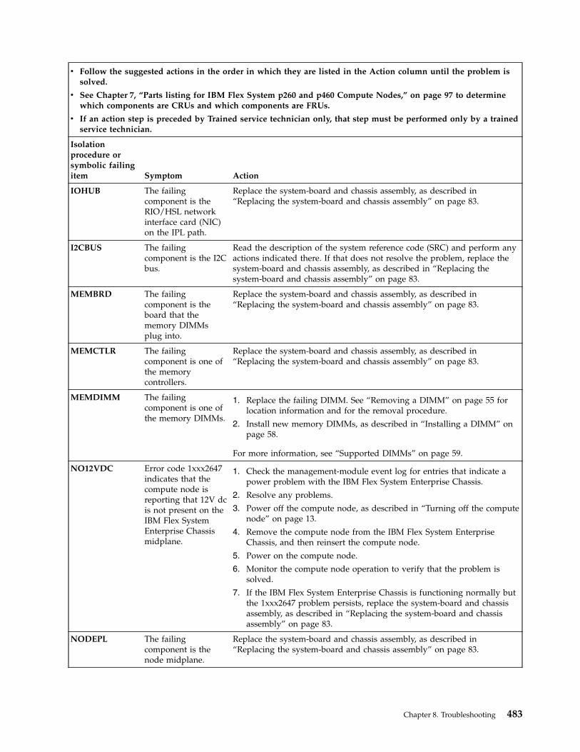
v Follow the suggested actions in the order in which they are listed in the Action column until the problem issolved.
v See Chapter 7, “Parts listing for IBM Flex System p260 and p460 Compute Nodes,” on page 97 to determinewhich components are CRUs and which components are FRUs.
v If an action step is preceded by Trained service technician only, that step must be performed only by a trainedservice technician.
Isolationprocedure orsymbolic failingitem Symptom Action
IOHUB The failingcomponent is theRIO/HSL networkinterface card (NIC)on the IPL path.
Replace the system-board and chassis assembly, as described in“Replacing the system-board and chassis assembly” on page 83.
I2CBUS The failingcomponent is the I2Cbus.
Read the description of the system reference code (SRC) and perform anyactions indicated there. If that does not resolve the problem, replace thesystem-board and chassis assembly, as described in “Replacing thesystem-board and chassis assembly” on page 83.
MEMBRD The failingcomponent is theboard that thememory DIMMsplug into.
Replace the system-board and chassis assembly, as described in“Replacing the system-board and chassis assembly” on page 83.
MEMCTLR The failingcomponent is one ofthe memorycontrollers.
Replace the system-board and chassis assembly, as described in“Replacing the system-board and chassis assembly” on page 83.
MEMDIMM The failingcomponent is one ofthe memory DIMMs.
1. Replace the failing DIMM. See “Removing a DIMM” on page 55 forlocation information and for the removal procedure.
2. Install new memory DIMMs, as described in “Installing a DIMM” onpage 58.
For more information, see “Supported DIMMs” on page 59.
NO12VDC Error code 1xxx2647indicates that thecompute node isreporting that 12V dcis not present on theIBM Flex SystemEnterprise Chassismidplane.
1. Check the management-module event log for entries that indicate apower problem with the IBM Flex System Enterprise Chassis.
2. Resolve any problems.
3. Power off the compute node, as described in “Turning off the computenode” on page 13.
4. Remove the compute node from the IBM Flex System EnterpriseChassis, and then reinsert the compute node.
5. Power on the compute node.
6. Monitor the compute node operation to verify that the problem issolved.
7. If the IBM Flex System Enterprise Chassis is functioning normally butthe 1xxx2647 problem persists, replace the system-board and chassisassembly, as described in “Replacing the system-board and chassisassembly” on page 83.
NODEPL The failingcomponent is thenode midplane.
Replace the system-board and chassis assembly, as described in“Replacing the system-board and chassis assembly” on page 83.
Chapter 8. Troubleshooting 483

v Follow the suggested actions in the order in which they are listed in the Action column until the problem issolved.
v See Chapter 7, “Parts listing for IBM Flex System p260 and p460 Compute Nodes,” on page 97 to determinewhich components are CRUs and which components are FRUs.
v If an action step is preceded by Trained service technician only, that step must be performed only by a trainedservice technician.
Isolationprocedure orsymbolic failingitem Symptom Action
TOD_BAT The battery for thetime-of-day batteryis low or failing.
Replace the battery, as described in “Removing the battery” on page 64and “Installing the battery” on page 65.
TPMD_OV The thermal powermanagementfirmware hasdetected that thesystem is operatingwithout powersupply redundancy.The maximumpower limit based onthe compute nodeconfiguration wasreached and actionwas taken to reducepower consumption.
1. Check the Active Status log from the IBM Flex System Manager orthe Event log from the Hardware Management Console (HMC), orthe application log from the Integrated Virtualization Manager (IVM)for any events that are related to power and resolve them. You canaccess the Active Status log or the Event log from the ChassisManager.
2. Check the power management policy that is in place for the IBM FlexSystem Enterprise Chassis. The power management policy can affectthe amount of power that is available to a compute node, which cancause the compute node to reduce power consumption.
3. Replace the system-board and chassis assembly, as described in“Replacing the system-board and chassis assembly” on page 83.
484 Power Systems: IBM Flex System p260 and p460 Compute Nodes Installation and Service Guide
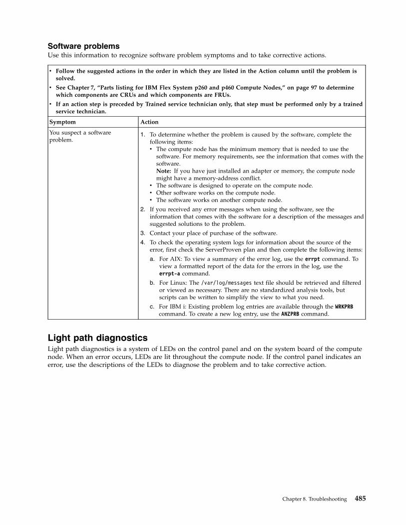
Software problemsUse this information to recognize software problem symptoms and to take corrective actions.
v Follow the suggested actions in the order in which they are listed in the Action column until the problem issolved.
v See Chapter 7, “Parts listing for IBM Flex System p260 and p460 Compute Nodes,” on page 97 to determinewhich components are CRUs and which components are FRUs.
v If an action step is preceded by Trained service technician only, that step must be performed only by a trainedservice technician.
Symptom Action
You suspect a softwareproblem.
1. To determine whether the problem is caused by the software, complete thefollowing items:v The compute node has the minimum memory that is needed to use the
software. For memory requirements, see the information that comes with thesoftware.Note: If you have just installed an adapter or memory, the compute nodemight have a memory-address conflict.
v The software is designed to operate on the compute node.v Other software works on the compute node.v The software works on another compute node.
2. If you received any error messages when using the software, see theinformation that comes with the software for a description of the messages andsuggested solutions to the problem.
3. Contact your place of purchase of the software.
4. To check the operating system logs for information about the source of theerror, first check the ServerProven plan and then complete the following items:
a. For AIX: To view a summary of the error log, use the errpt command. Toview a formatted report of the data for the errors in the log, use theerrpt-a command.
b. For Linux: The /var/log/messages text file should be retrieved and filteredor viewed as necessary. There are no standardized analysis tools, butscripts can be written to simplify the view to what you need.
c. For IBM i: Existing problem log entries are available through the WRKPRBcommand. To create a new log entry, use the ANZPRB command.
Light path diagnosticsLight path diagnostics is a system of LEDs on the control panel and on the system board of the computenode. When an error occurs, LEDs are lit throughout the compute node. If the control panel indicates anerror, use the descriptions of the LEDs to diagnose the problem and to take corrective action.
Chapter 8. Troubleshooting 485
LEDs are available for the following components:v Batteryv SAS disk drivev SSDv Management cardv Memory modules (DIMMs)v Network adapterv System-board and chassis assembly
Viewing the light path diagnostic LEDsAfter reading the required safety information, look at the control panel to determine whether the LEDsindicate a suboptimal condition or an error.
About this task
View the system LEDs remotely through the Chassis Manager in the web interface of the IBM FlexSystem Manager management software. To view the system LEDs remotely by using the HardwareManagement Console (HMC), see LED Status. To view the system LEDs status by using the IntegratedVirtualization Manager (IVM), see IVM lsled command. The main LED page shows the external LEDs onthe compute node. The internal compute node LEDs are also available through a link from the LED page.This function enables you to see the status of the internal LEDs on the compute node without having toturn off the compute node, remove it from the chassis, and activate the light path indications.
Before working inside the compute node to view light path diagnostic LEDs, see the Safety topic and the“Handling static-sensitive devices” on page 36 guidelines.
If an error occurs, view the light path diagnostic LEDs in the following order:
Procedure1. Look at the control panel on the front of the compute node. See “Compute node control panel button
and LEDs” on page 11.v If the check log LED is lit, it indicates that information about a suboptimal condition in the
compute node is available in the management-module event log.v If the enclosure fault LED is lit, it indicates that an error occurred and that you can proceed to the
next step.2. If an error occurred, view the light path diagnostics panel and LEDs:
a. Shut down the operating system on all partitions of the compute node, turn off the compute node,and remove the compute node from the IBM Flex System Enterprise Chassis. See “Removing thecompute node from an IBM Flex System Enterprise Chassis” on page 37.
b. Place the compute node on a flat, static-protective surface.c. Remove the cover from the compute node.d. Press and hold the power-control button on the front panel to relight the LEDs that were lit before
you removed the compute node from the IBM Flex System Enterprise Chassis. The LEDs willremain lit for as long as you press the power-control button, to a maximum of 30 seconds.
The following figure shows LEDs on the IBM Flex System p260 Compute Node. The following figuresand table shows the system-board LEDs.
486 Power Systems: IBM Flex System p260 and p460 Compute Nodes Installation and Service Guide
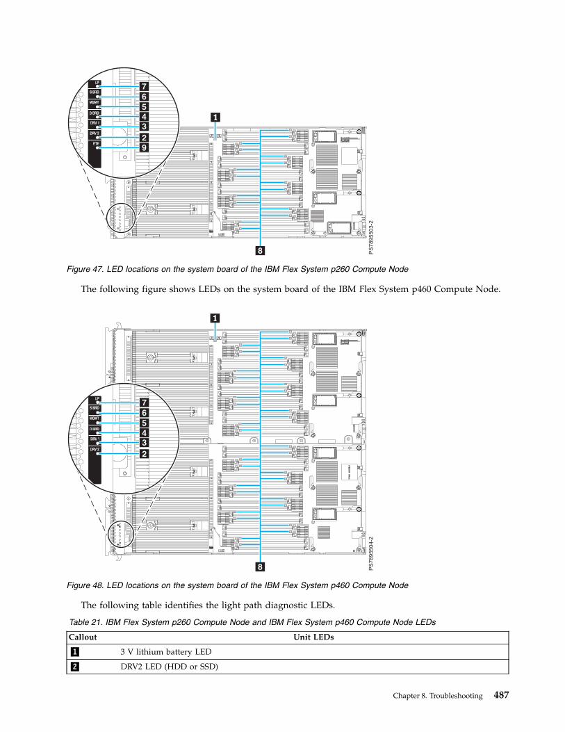
The following figure shows LEDs on the system board of the IBM Flex System p460 Compute Node.
The following table identifies the light path diagnostic LEDs.
Table 21. IBM Flex System p260 Compute Node and IBM Flex System p460 Compute Node LEDs
Callout Unit LEDs
▌1▐ 3 V lithium battery LED
▌2▐ DRV2 LED (HDD or SSD)
Figure 47. LED locations on the system board of the IBM Flex System p260 Compute Node
Figure 48. LED locations on the system board of the IBM Flex System p460 Compute Node
Chapter 8. Troubleshooting 487
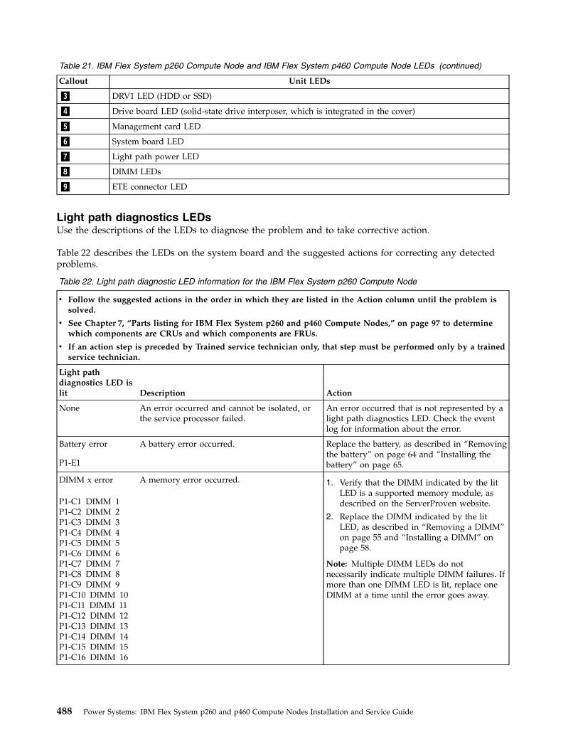
Table 21. IBM Flex System p260 Compute Node and IBM Flex System p460 Compute Node LEDs (continued)
Callout Unit LEDs
▌3▐ DRV1 LED (HDD or SSD)
▌4▐ Drive board LED (solid-state drive interposer, which is integrated in the cover)
▌5▐ Management card LED
▌6▐ System board LED
▌7▐ Light path power LED
▌8▐ DIMM LEDs
▌9▐ ETE connector LED
Light path diagnostics LEDsUse the descriptions of the LEDs to diagnose the problem and to take corrective action.
Table 22 describes the LEDs on the system board and the suggested actions for correcting any detectedproblems.
Table 22. Light path diagnostic LED information for the IBM Flex System p260 Compute Node
v Follow the suggested actions in the order in which they are listed in the Action column until the problem issolved.
v See Chapter 7, “Parts listing for IBM Flex System p260 and p460 Compute Nodes,” on page 97 to determinewhich components are CRUs and which components are FRUs.
v If an action step is preceded by Trained service technician only, that step must be performed only by a trainedservice technician.
Light pathdiagnostics LED islit Description Action
None An error occurred and cannot be isolated, orthe service processor failed.
An error occurred that is not represented by alight path diagnostics LED. Check the eventlog for information about the error.
Battery error
P1-E1
A battery error occurred. Replace the battery, as described in “Removingthe battery” on page 64 and “Installing thebattery” on page 65.
DIMM x error
P1-C1 DIMM 1P1-C2 DIMM 2P1-C3 DIMM 3P1-C4 DIMM 4P1-C5 DIMM 5P1-C6 DIMM 6P1-C7 DIMM 7P1-C8 DIMM 8P1-C9 DIMM 9P1-C10 DIMM 10P1-C11 DIMM 11P1-C12 DIMM 12P1-C13 DIMM 13P1-C14 DIMM 14P1-C15 DIMM 15P1-C16 DIMM 16
A memory error occurred. 1. Verify that the DIMM indicated by the litLED is a supported memory module, asdescribed on the ServerProven website.
2. Replace the DIMM indicated by the litLED, as described in “Removing a DIMM”on page 55 and “Installing a DIMM” onpage 58.
Note: Multiple DIMM LEDs do notnecessarily indicate multiple DIMM failures. Ifmore than one DIMM LED is lit, replace oneDIMM at a time until the error goes away.
488 Power Systems: IBM Flex System p260 and p460 Compute Nodes Installation and Service Guide
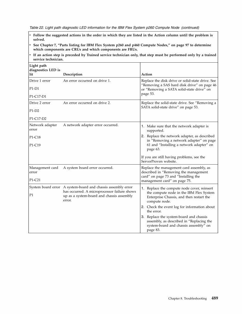
Table 22. Light path diagnostic LED information for the IBM Flex System p260 Compute Node (continued)
v Follow the suggested actions in the order in which they are listed in the Action column until the problem issolved.
v See Chapter 7, “Parts listing for IBM Flex System p260 and p460 Compute Nodes,” on page 97 to determinewhich components are CRUs and which components are FRUs.
v If an action step is preceded by Trained service technician only, that step must be performed only by a trainedservice technician.
Light pathdiagnostics LED islit Description Action
Drive 1 error
P1-D1
P1-C17-D1
An error occurred on drive 1. Replace the disk drive or solid-state drive. See“Removing a SAS hard disk drive” on page 46or “Removing a SATA solid-state drive” onpage 53.
Drive 2 error
P1-D2
P1-C17-D2
An error occurred on drive 2. Replace the solid-state drive. See “Removing aSATA solid-state drive” on page 53.
Network adaptererror
P1-C18
P1-C19
A network adapter error occurred. 1. Make sure that the network adapter issupported.
2. Replace the network adapter, as describedin “Removing a network adapter” on page61 and “Installing a network adapter” onpage 63.
If you are still having problems, see theServerProven website.
Management carderror
P1-C21
A system board error occurred. Replace the management card assembly, asdescribed in “Removing the managementcard” on page 73 and “Installing themanagement card” on page 75.
System board error
P1
A system-board and chassis assembly errorhas occurred. A microprocessor failure showsup as a system-board and chassis assemblyerror.
1. Replace the compute node cover, reinsertthe compute node in the IBM Flex SystemEnterprise Chassis, and then restart thecompute node.
2. Check the event log for information aboutthe error.
3. Replace the system-board and chassisassembly, as described in “Replacing thesystem-board and chassis assembly” onpage 83.
Chapter 8. Troubleshooting 489
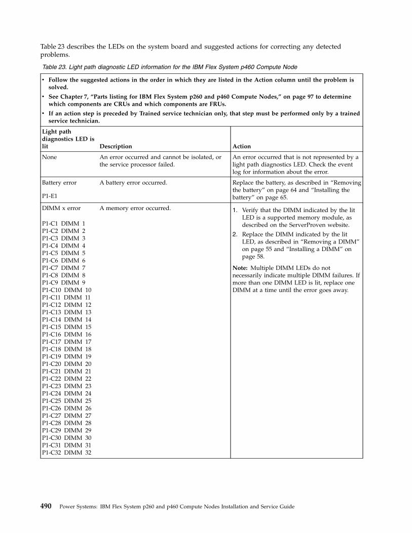
Table 23 describes the LEDs on the system board and suggested actions for correcting any detectedproblems.
Table 23. Light path diagnostic LED information for the IBM Flex System p460 Compute Node
v Follow the suggested actions in the order in which they are listed in the Action column until the problem issolved.
v See Chapter 7, “Parts listing for IBM Flex System p260 and p460 Compute Nodes,” on page 97 to determinewhich components are CRUs and which components are FRUs.
v If an action step is preceded by Trained service technician only, that step must be performed only by a trainedservice technician.
Light pathdiagnostics LED islit Description Action
None An error occurred and cannot be isolated, orthe service processor failed.
An error occurred that is not represented by alight path diagnostics LED. Check the eventlog for information about the error.
Battery error
P1-E1
A battery error occurred. Replace the battery, as described in “Removingthe battery” on page 64 and “Installing thebattery” on page 65.
DIMM x error
P1-C1 DIMM 1P1-C2 DIMM 2P1-C3 DIMM 3P1-C4 DIMM 4P1-C5 DIMM 5P1-C6 DIMM 6P1-C7 DIMM 7P1-C8 DIMM 8P1-C9 DIMM 9P1-C10 DIMM 10P1-C11 DIMM 11P1-C12 DIMM 12P1-C13 DIMM 13P1-C14 DIMM 14P1-C15 DIMM 15P1-C16 DIMM 16P1-C17 DIMM 17P1-C18 DIMM 18P1-C19 DIMM 19P1-C20 DIMM 20P1-C21 DIMM 21P1-C22 DIMM 22P1-C23 DIMM 23P1-C24 DIMM 24P1-C25 DIMM 25P1-C26 DIMM 26P1-C27 DIMM 27P1-C28 DIMM 28P1-C29 DIMM 29P1-C30 DIMM 30P1-C31 DIMM 31P1-C32 DIMM 32
A memory error occurred. 1. Verify that the DIMM indicated by the litLED is a supported memory module, asdescribed on the ServerProven website.
2. Replace the DIMM indicated by the litLED, as described in “Removing a DIMM”on page 55 and “Installing a DIMM” onpage 58.
Note: Multiple DIMM LEDs do notnecessarily indicate multiple DIMM failures. Ifmore than one DIMM LED is lit, replace oneDIMM at a time until the error goes away.
490 Power Systems: IBM Flex System p260 and p460 Compute Nodes Installation and Service Guide
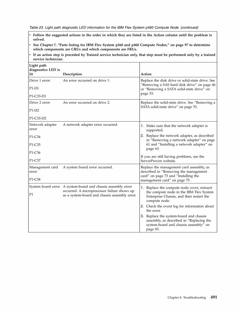
Table 23. Light path diagnostic LED information for the IBM Flex System p460 Compute Node (continued)
v Follow the suggested actions in the order in which they are listed in the Action column until the problem issolved.
v See Chapter 7, “Parts listing for IBM Flex System p260 and p460 Compute Nodes,” on page 97 to determinewhich components are CRUs and which components are FRUs.
v If an action step is preceded by Trained service technician only, that step must be performed only by a trainedservice technician.
Light pathdiagnostics LED islit Description Action
Drive 1 error
P1-D1
P1-C33-D1
An error occurred on drive 1. Replace the disk drive or solid-state drive. See“Removing a SAS hard disk drive” on page 46or “Removing a SATA solid-state drive” onpage 53.
Drive 2 error
P1-D2
P1-C33-D2
An error occurred on drive 2. Replace the solid-state drive. See “Removing aSATA solid-state drive” on page 53.
Network adaptererror
P1-C34
P1-C35
P1-C36
P1-C37
A network adapter error occurred. 1. Make sure that the network adapter issupported.
2. Replace the network adapter, as describedin “Removing a network adapter” on page61 and “Installing a network adapter” onpage 63.
If you are still having problems, see theServerProven website.
Management carderror
P1-C38
A system board error occurred. Replace the management card assembly, asdescribed in “Removing the managementcard” on page 73 and “Installing themanagement card” on page 75.
System board error
P1
A system-board and chassis assembly erroroccurred. A microprocessor failure shows upas a system-board and chassis assembly error.
1. Replace the compute node cover, reinsertthe compute node in the IBM Flex SystemEnterprise Chassis, and then restart thecompute node.
2. Check the event log for information aboutthe error.
3. Replace the system-board and chassisassembly, as described in “Replacing thesystem-board and chassis assembly” onpage 83.
Chapter 8. Troubleshooting 491

Isolating firmware problemsYou can use this procedure to isolate firmware problems.
About this task
To isolate a firmware problem, follow the procedure until the problem is solved.
Procedure1. If the compute node is operating, shut down the operating system. Use the CMM to perform a virtual
reseat. If the problem no longer occurs, no further action is necessary. You are finished with thisprocedure.
2. Start the PERM image. See “Starting the PERM image” on page 494.3. Verify the system firmware levels. See “Verifying the system firmware levels” on page 24.4. Choose one of the following options:v Remain on the current firmware level. See “Recovering the TEMP image from the PERM image” on
page 495.v Check the RETAIN tips and code change history. If a firmware update is needed, see “Updating the
firmware” on page 22.5. If the problem is not resolved, contact your next level of support.
Save vfchost map dataBefore you replace physical components on your compute node, it might be necessary to first save theoriginal virtual Fibre Channel vfchost data of your compute node.
Procedure
To save the original vfchost data and the original physical Fibre Channel adapter port (fcs) location codes,complete the following steps by using the padmin user account:1. To save the original vfchost data, use the lsmap command as follows. Enter the command from the
command-line interface on the source Virtual I/O Server (VIOS):lsmap -all -npiv | tee lsmap_OUTPUT_before
The output might look like the following example:Name Physloc ClntID ClntName ClntOS--------------- ---------------------------------------- ------- ---------- ------vfchost1 U7895.42X.9999999-V1-C32 3
Status NOT_LOGGED_INFC name fcs1 FC loc code:U78AF.001.startSN-P1-C35-L1-T2Ports logged in 0Flags 4<NOT_LOGGED>VFC client name VFC client DRC
Name Physloc ClntID ClntName ClntOS--------------- ---------------------------------------- ------- ---------- ------vfchost2 U7895.42X.9999999-V1-C33 4 cli_lpar_1 AIXStatus LOGGED_INFC name fcs0 FC loc code:U78AF.001.startSN-P1-C35-L1-T1Ports logged in 1Flags a<LOGGED_IN,STRIP_MERGE>VFC client name fcs1 VFC client DRC:U9999.999.9999999-V4-C32-T1
In this example, the original serial number is represented as startSN.
492 Power Systems: IBM Flex System p260 and p460 Compute Nodes Installation and Service Guide
2. To save the location code information for each Fibre Channel adapter (fcs), enter the lsdev commandas follows:lsdev -vpd | grep fcs | tee LSDEV_OUTPUT_before
The output might look like the following example:fcs0 U78AF.001.startSN-P1-C35-L1-T1 Dual Port 8Gb FC Mezzanine Card (7710322577107501)fcs1 U78AF.001.startSN-P1-C35-L1-T2 Dual Port 8Gb FC Mezzanine Card (7710322577107501)
In this example, the original serial number is represented as startSN.
Restore vfchost map dataAfter you replace physical components on your compute node, you must review the virtual FibreChannel vfchost mapping. If the vfchost mapping has changed after component replacement, you mustrestore the mapping.
Before you begin
To restore vfchost data, you must have first saved the original vfchost data and the physical FibreChannel adapter (fcs) location code information. For information, see “Save vfchost map data” on page492.
Procedure
To restore the vfchost mapping data, use the third field of the Fibre Channel adapter (fcs) location codes,which is the serial number field, and compare the new Fibre Channel adapter (fcs) location codes to theoriginal location codes. Perform a vfcmap of the new Fibre Channel adapter (fcs) to the appropriatevfchost.To restore the vfchost mapping data, complete the following steps by using the padmin user account:1. To save the new Fibre Channel adapter (fcs) location codes, use the lsdev –vpd command as follows.
Enter the command from the command-line interface on the source Virtual I/O Server (VIOS):lsdev -vpd | grep fcs | tee LSDEV_OUTPUT_after1
The output might look like the following example:fcs0 U78AF.001.startSN-P1-C35-L1-T1 Dual Port 8Gb FC Mezzanine Card (7710322577107501)fcs1 U78AF.001.startSN-P1-C35-L1-T2 Dual Port 8Gb FC Mezzanine Card (7710322577107501)
2. To associate the new fcsx adapter to the old fcsx adapter use the adapter slot number. Enter the grepcommand as shown in the example below:grep "P1-C35-L1-T1" LSDEV_OUTPUT_before LSDEV_OUTPUT_after
The output might look like the following example:LSDEV_OUTPUT_before:fcs0 U78AF.001.startSN-P1-C35-L1-T1 Dual Port 8Gb FC Mezzanine Card (7710322577107501)
LSDEV_OUTPUT_after1:fcs0 U78AF.001.newSN99-P1-C35-L1-T1 Dual Port 8Gb FC Mezzanine Card (7710322577107501)
In this example, the original serial number is represented as startSN, the new serial number isrepresented as newSN99, and the fcsx remained fcs0; therefore, fcs0 will be mapped to the vfchost.
Chapter 8. Troubleshooting 493
3. To restore the new fcsx device to the correct vfchost, enter the vfcmap command as follows:vfcmap -vadapter vfchost0 -fcp fcs0
4. To check the vfchost mapping, enter the lsmap command as follows:lsmap -vadapter vfchost2 -npiv
The output might look like the following example:Name Physloc ClntID ClntName ClntOS--------------- ---------------------------------------- ------- ---------- ------vfchost2 U7895.42X.9999999-V1-C33 4
Status NOT_LOGGED_INFC name fcs0 FC loc code:U78AF.001.newSN99-P1-C35-L1-T1Ports logged in 0Flags 4<NOT_LOGGED>VFC client name VFC client DRC
In this example, the new serial number is represented as newSN99.
Recovering the system firmwareThe system firmware is contained in separate temporary and permanent images in the flash memory ofthe compute node. These images are referred to as TEMP and PERM, respectively. The compute nodenormally starts from the TEMP image, and uses the PERM image as a backup. If the TEMP imagebecomes damaged, such as from a power failure during a firmware update, you can recover the TEMPimage from the PERM image.
About this task
If your system hangs, start the PERM image. See “Starting the PERM image.”
Starting the PERM imageYou can force the compute node to start the permanent (PERM) image.
About this task
To force the compute node to start the PERM image, see http://publib.boulder.ibm.com/infocenter/flexsys/information/topic/com.ibm.acc.psm.hosts.doc/dpsm_managing_hosts_power_firmware.html.
Starting the TEMP imageThe system firmware is contained in separate temporary and permanent images in the flash memory ofthe compute node. These images are referred to as TEMP and PERM, respectively. The compute nodenormally starts from the TEMP image. Start the TEMP image before you update the firmware.
494 Power Systems: IBM Flex System p260 and p460 Compute Nodes Installation and Service Guide

About this task
To start the TEMP image, see http://publib.boulder.ibm.com/infocenter/flexsys/information/topic/com.ibm.acc.psm.hosts.doc/dpsm_managing_hosts_power_firmware.html.
Recovering the TEMP image from the PERM imageTo recover the TEMP image from the PERM image, you must perform the reject function. The rejectfunction copies the PERM image into the TEMP image.
About this task
To perform the reject function, complete the following steps:
Procedure1. If you have not started the system from the PERM image, do so now. See “Starting the PERM image”
on page 494.2. Issue the appropriate command for your operating system to reject the TEMP image:v If you are using the Red Hat Enterprise Linux or SUSE Linux operating system, type the following
command:update_flash -r
v If you are using the AIX operating system, type the following command:/usr/lpp/diagnostics/bin/update_flash -r
3. Start the TEMP image, as described in “Starting the TEMP image” on page 24.
What to do next
You might need to update the firmware code to the latest version. See “Updating the firmware” on page22 for more information about how to update the firmware code.
Verifying the system firmware levelsThe diagnostics program displays the current system firmware levels for the temporary (TEMP) andpermanent (PERM) images. This function also displays which image the compute node used to start.
Procedure1. Start the diagnostics program.2. From the Function Selection menu, select Task Selection and press Enter.3. From the Tasks Selection List menu, select Update and Manage System Flash and press Enter.
The top of the Update and Manage System Flash menu displays the system firmware level for thePERM and the TEMP images and the image that the compute node used to start.
Note: If the TEMP image level is more current than the PERM image, commit the TEMP image.4. When you have verified the firmware levels, press F3 until the Diagnostic Operating Instructions
window is displayed, and then press F3 again to exit the diagnostic program.
Chapter 8. Troubleshooting 495

Committing the TEMP system firmware imageAfter updating the system firmware and successfully starting the compute node from the temporary(TEMP) image, copy the TEMP image to the permanent (PERM) image by using the diagnostics programcommit function.
About this task
Note: If you install the compute node firmware update permanently by committing the temporaryfirmware level from the temporary side to the permanent side, the temporary and permanent sidescontain the same level of firmware. You cannot return to the level that was previously on the permanentside.
Procedure1. Load the diagnostics program. See “Running the diagnostics program” on page 453.2. From the Function Selection menu, select Task Selection and press Enter.3. From the Tasks Selection List menu, select Update and Manage System Flash and press Enter.4. From the Update and Manage System Flash menu, select Commit the Temporary Image and press
Enter.5. When the commit function is complete, press F3 until the Diagnostic Operating Instructions window
is displayed. Then, press F3 again to exit the diagnostic program.
Solving shared IBM Flex System Enterprise Chassis resourceproblemsProblems with shared resources might appear to be in the compute node, but might actually be aproblem in a IBM Flex System Enterprise Chassis component.
About this task
This information provides procedures to help you isolate compute node problems from shared resourceproblems.
If the problem is thought to be with a shared resource, see the following documentation for additionalinformation:v Problem Determination and Service Guide for your IBM Flex System Enterprise Chassisv Hardware Maintenance Manual and Troubleshooting Guide for your IBM Flex System Enterprise Chassisv If the problem cannot be solved, see “Solving undetermined problems” on page 498.
To check the general function of shared resources, complete the following steps:
Procedure1. Verify that the required power modules are installed in the IBM Flex System Enterprise Chassis and
that the chassis is connected to a working power source.
496 Power Systems: IBM Flex System p260 and p460 Compute Nodes Installation and Service Guide
2. Verify that power management is set correctly for your IBM Flex System Enterprise Chassisconfiguration.
3. Verify whether the problem is being experienced on more than one compute node.4. Perform a test of the failing function on a compute node that is known to be operational.5. Try the compute node in a different bay.6. Try a compute node that is known to be operational in the bay with the failing compute node.7. Verify that the compute node and the monitor are powered on.8. Check for network connection problems, as described in “Solving shared network connection
problems.”9. Check for power problems, as described in “Solving shared power problems” on page 498.
Solving shared network connection problemsProblems with shared resources might appear to be in the compute node, but might actually be aproblem in a IBM Flex System Enterprise Chassis network connection resource.
About this task
To check the general function of shared network connection resources, complete the following steps:
Procedure1. Verify that the network cables are securely connected to the I/O module.2. Verify that the power configuration of the IBM Flex System Enterprise Chassis supports the I/O
module configuration.3. Verify that the installation of the I/O-module type is supported by the IBM Flex System Enterprise
Chassis and compute node hardware.4. Verify that the I/O modules for the network interface are installed in the correct bays of the IBM Flex
System Enterprise Chassis.5. Verify that the I/O modules for the network interface are configured correctly.6. Verify that the settings in the I/O module are correct for the compute node. Some settings in the I/O
module are specifically for each compute node.7. Verify that the I/O modules for the network interface are operating correctly.
Troubleshoot and replace the I/O module as indicated in the documentation for the I/O module.8. Verify that the management module is operating correctly.9. Replace the management module.
Chapter 8. Troubleshooting 497
Results
If these steps do not resolve the problem, it is probably a problem with the compute node. See“Connectivity problems” on page 459 for more information.
Solving shared power problemsProblems with shared resources might appear to be in the compute node, but might actually be aproblem in a IBM Flex System Enterprise Chassis power component.
About this task
To check the general function of shared power resources, complete the following steps:
Procedure1. Verify that the LEDs on all the power modules of the IBM Flex System Enterprise Chassis are lit.2. Verify that power is being supplied to the IBM Flex System Enterprise Chassis.3. Verify that the installation of the compute node type is supported by the IBM Flex System Enterprise
Chassis.4. Verify that the power configuration of the IBM Flex System Enterprise Chassis supports the bay
where your compute node is installed.5. Verify that the power management configuration and status of the IBM Flex System Enterprise
Chassis support compute node operation.See the information center for your management module or the Management Module User's Guide orthe Management Module Command-Line Interface Reference Guide for more information.
6. Verify that the local power control for the compute node is set correctly.See the information center for your management module or the Management Module User's Guide orthe Management Module Command-Line Interface Reference Guide for more information.
7. Verify that the IBM Flex System Enterprise Chassis blowers are correctly installed and operational.
Solving undetermined problemsWhen you are diagnosing a problem in the IBM Flex System p260 Compute Node or IBM Flex Systemp460 Compute Node, you must determine whether the problem is in the compute node or in the IBMFlex System Enterprise Chassis.
About this taskv If all of the compute nodes have the same symptom, it is probably a problem in the IBM Flex System
Enterprise Chassis.For more information, see the following documentation:– Hardware Maintenance Manual and Troubleshooting Guide for your IBM Flex System Enterprise Chassis– Problem Determination and Service Guide for your IBM Flex System Enterprise Chassis
v If the IBM Flex System Enterprise Chassis contains more than one compute node and only one of thecompute nodes has the problem, troubleshoot the compute node that has the problem.
Check the LEDs on all the power supplies of the IBM Flex System Enterprise Chassis where the computenode is installed. If the LEDs indicate that the power supplies are working correctly, and powering offand powering on the compute node does not correct the problem, complete the following steps:
Procedure
498 Power Systems: IBM Flex System p260 and p460 Compute Nodes Installation and Service Guide

1. Use the management console to determine if the compute node is recognized.2. Use the management console to ensure that power-on permission is not denied due to power policy
settings.3. Turn off the compute node.4. Remove the compute node from the IBM Flex System Enterprise Chassis, and remove the cover.5. Remove or disconnect the following devices, one at a time, until you find the failure. Reinstall, turn
on, and reconfigure the compute node each time.v I/O expansion cards.v Hard disk drives.v Memory modules. The minimum configuration requirement is 8 GB (two 4 GB DIMMs).The following minimum configuration is required for the compute node to start:v System-board and chassis assembly (with two microprocessors)v Two 4 GB DIMMsv A functioning IBM Flex System Enterprise Chassis
6. Install and turn on the compute node. If the problem remains, suspect the following components inorder:a. DIMMb. System-board and chassis assembly
Results
If the problem is solved when you remove an I/O expansion card from the compute node but theproblem recurs when you reinstall the same expansion card, suspect the expansion card; if the problemrecurs when you replace the expansion card with a different one, suspect the system-board and chassisassembly.
If you suspect a networking problem and the compute node passes all the system tests, suspect anetwork cabling problem that is external to the system.
Chapter 8. Troubleshooting 499

500 Power Systems: IBM Flex System p260 and p460 Compute Nodes Installation and Service Guide

Appendix. Notices
This information was developed for products and services offered in the U.S.A.
The manufacturer may not offer the products, services, or features discussed in this document in othercountries. Consult the manufacturer's representative for information on the products and servicescurrently available in your area. Any reference to the manufacturer's product, program, or service is notintended to state or imply that only that product, program, or service may be used. Any functionallyequivalent product, program, or service that does not infringe any intellectual property right of themanufacturer may be used instead. However, it is the user's responsibility to evaluate and verify theoperation of any product, program, or service.
The manufacturer may have patents or pending patent applications covering subject matter described inthis document. The furnishing of this document does not grant you any license to these patents. You cansend license inquiries, in writing, to the manufacturer.
The following paragraph does not apply to the United Kingdom or any other country where suchprovisions are inconsistent with local law: THIS PUBLICATION IS PROVIDED “AS IS” WITHOUTWARRANTY OF ANY KIND, EITHER EXPRESS OR IMPLIED, INCLUDING, BUT NOT LIMITED TO,THE IMPLIED WARRANTIES OF NON-INFRINGEMENT, MERCHANTABILITY OR FITNESS FOR APARTICULAR PURPOSE. Some states do not allow disclaimer of express or implied warranties in certaintransactions, therefore, this statement may not apply to you.
This information could include technical inaccuracies or typographical errors. Changes are periodicallymade to the information herein; these changes will be incorporated in new editions of the publication.The manufacturer may make improvements and/or changes in the product(s) and/or the program(s)described in this publication at any time without notice.
Any references in this information to websites not owned by the manufacturer are provided forconvenience only and do not in any manner serve as an endorsement of those websites. The materials atthose websites are not part of the materials for this product and use of those websites is at your own risk.
The manufacturer may use or distribute any of the information you supply in any way it believesappropriate without incurring any obligation to you.
Any performance data contained herein was determined in a controlled environment. Therefore, theresults obtained in other operating environments may vary significantly. Some measurements may havebeen made on development-level systems and there is no guarantee that these measurements will be thesame on generally available systems. Furthermore, some measurements may have been estimated throughextrapolation. Actual results may vary. Users of this document should verify the applicable data for theirspecific environment.
Information concerning products not produced by this manufacturer was obtained from the suppliers ofthose products, their published announcements or other publicly available sources. This manufacturer hasnot tested those products and cannot confirm the accuracy of performance, compatibility or any otherclaims related to products not produced by this manufacturer. Questions on the capabilities of productsnot produced by this manufacturer should be addressed to the suppliers of those products.
All statements regarding the manufacturer's future direction or intent are subject to change or withdrawalwithout notice, and represent goals and objectives only.
The manufacturer's prices shown are the manufacturer's suggested retail prices, are current and aresubject to change without notice. Dealer prices may vary.
© Copyright IBM Corp. 2012, 2015 501
This information is for planning purposes only. The information herein is subject to change before theproducts described become available.
This information contains examples of data and reports used in daily business operations. To illustratethem as completely as possible, the examples include the names of individuals, companies, brands, andproducts. All of these names are fictitious and any similarity to the names and addresses used by anactual business enterprise is entirely coincidental.
If you are viewing this information in softcopy, the photographs and color illustrations may not appear.
The drawings and specifications contained herein shall not be reproduced in whole or in part without thewritten permission of the manufacturer.
The manufacturer has prepared this information for use with the specific machines indicated. Themanufacturer makes no representations that it is suitable for any other purpose.
The manufacturer's computer systems contain mechanisms designed to reduce the possibility ofundetected data corruption or loss. This risk, however, cannot be eliminated. Users who experienceunplanned outages, system failures, power fluctuations or outages, or component failures must verify theaccuracy of operations performed and data saved or transmitted by the system at or near the time of theoutage or failure. In addition, users must establish procedures to ensure that there is independent dataverification before relying on such data in sensitive or critical operations. Users should periodically checkthe manufacturer's support websites for updated information and fixes applicable to the system andrelated software.
Homologation statement
This product may not be certified in your country for connection by any means whatsoever to interfacesof public telecommunications networks. Further certification may be required by law prior to making anysuch connection. Contact an IBM representative or reseller for any questions.
TrademarksIBM, the IBM logo, and ibm.com are trademarks or registered trademarks of International BusinessMachines Corp., registered in many jurisdictions worldwide. Other product and service names might betrademarks of IBM or other companies. A current list of IBM trademarks is available on the Web atCopyright and trademark information at www.ibm.com/legal/copytrade.shtml.
Adobe, the Adobe logo, PostScript, and the PostScript logo are either registered trademarks or trademarksof Adobe Systems Incorporated in the United States, and/or other countries.
INFINIBAND, InfiniBand Trade Association, and the INFINIBAND design marks are trademarks and/orservice marks of the INFINIBAND Trade Association.
Linux is a registered trademark of Linus Torvalds in the United States, other countries, or both.
Microsoft and Windows are trademarks of Microsoft Corporation in the United States, other countries, orboth.
Red Hat, the Red Hat "Shadow Man" logo, and all Red Hat-based trademarks and logos are trademarksor registered trademarks of Red Hat, Inc., in the United States and other countries.
502 Power Systems: IBM Flex System p260 and p460 Compute Nodes Installation and Service Guide

Electronic emission noticesWhen attaching a monitor to the equipment, you must use the designated monitor cable and anyinterference suppression devices supplied with the monitor.
Class A NoticesThe following Class A statements apply to the IBM servers that contain the POWER7 processor and itsfeatures unless designated as electromagnetic compatibility (EMC) Class B in the feature information.
Federal Communications Commission (FCC) statement
Note: This equipment has been tested and found to comply with the limits for a Class A digital device,pursuant to Part 15 of the FCC Rules. These limits are designed to provide reasonable protection againstharmful interference when the equipment is operated in a commercial environment. This equipmentgenerates, uses, and can radiate radio frequency energy and, if not installed and used in accordance withthe instruction manual, may cause harmful interference to radio communications. Operation of thisequipment in a residential area is likely to cause harmful interference, in which case the user will berequired to correct the interference at his own expense.
Properly shielded and grounded cables and connectors must be used in order to meet FCC emissionlimits. IBM is not responsible for any radio or television interference caused by using other thanrecommended cables and connectors or by unauthorized changes or modifications to this equipment.Unauthorized changes or modifications could void the user's authority to operate the equipment.
This device complies with Part 15 of the FCC rules. Operation is subject to the following two conditions:(1) this device may not cause harmful interference, and (2) this device must accept any interferencereceived, including interference that may cause undesired operation.
Industry Canada Compliance Statement
This Class A digital apparatus complies with Canadian ICES-003.
Avis de conformité à la réglementation d'Industrie Canada
Cet appareil numérique de la classe A est conforme à la norme NMB-003 du Canada.
European Community Compliance Statement
This product is in conformity with the protection requirements of EU Council Directive 2004/108/EC onthe approximation of the laws of the Member States relating to electromagnetic compatibility. IBM cannotaccept responsibility for any failure to satisfy the protection requirements resulting from anon-recommended modification of the product, including the fitting of non-IBM option cards.
This product has been tested and found to comply with the limits for Class A Information TechnologyEquipment according to European Standard EN 55022. The limits for Class A equipment were derived forcommercial and industrial environments to provide reasonable protection against interference withlicensed communication equipment.
European Community contact:IBM Deutschland GmbHTechnical Regulations, Department M372IBM-Allee 1, 71139 Ehningen, GermanyTele: +49 7032 15 2941email: [email protected]
Appendix. Notices 503

Warning: This is a Class A product. In a domestic environment, this product may cause radiointerference, in which case the user may be required to take adequate measures.
VCCI Statement - Japan
The following is a summary of the VCCI Japanese statement in the box above:
This is a Class A product based on the standard of the VCCI Council. If this equipment is used in adomestic environment, radio interference may occur, in which case, the user may be required to takecorrective actions.
Japanese Electronics and Information Technology Industries Association (JEITA)Confirmed Harmonics Guideline (products less than or equal to 20 A per phase)
Japanese Electronics and Information Technology Industries Association (JEITA)Confirmed Harmonics Guideline with Modifications (products greater than 20 A perphase)
Electromagnetic Interference (EMI) Statement - People's Republic of China
Declaration: This is a Class A product. In a domestic environment this product may cause radiointerference in which case the user may need to perform practical action.
504 Power Systems: IBM Flex System p260 and p460 Compute Nodes Installation and Service Guide
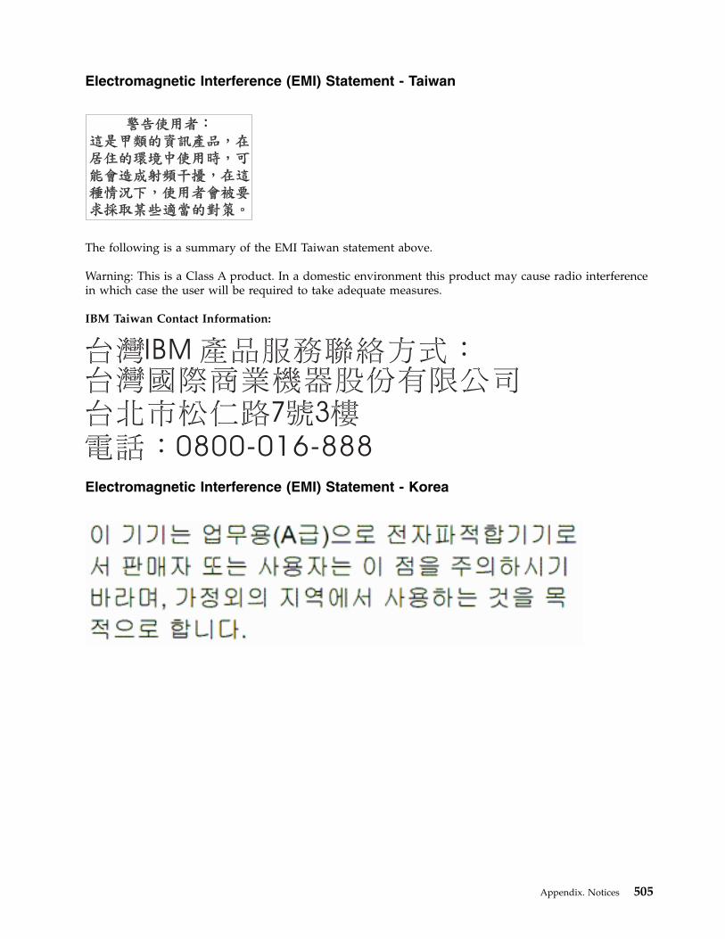
Electromagnetic Interference (EMI) Statement - Taiwan
The following is a summary of the EMI Taiwan statement above.
Warning: This is a Class A product. In a domestic environment this product may cause radio interferencein which case the user will be required to take adequate measures.
IBM Taiwan Contact Information:
Electromagnetic Interference (EMI) Statement - Korea
Appendix. Notices 505
Germany Compliance Statement
Deutschsprachiger EU Hinweis: Hinweis für Geräte der Klasse A EU-Richtlinie zurElektromagnetischen Verträglichkeit
Dieses Produkt entspricht den Schutzanforderungen der EU-Richtlinie 2004/108/EG zur Angleichung derRechtsvorschriften über die elektromagnetische Verträglichkeit in den EU-Mitgliedsstaaten und hält dieGrenzwerte der EN 55022 Klasse A ein.
Um dieses sicherzustellen, sind die Geräte wie in den Handbüchern beschrieben zu installieren und zubetreiben. Des Weiteren dürfen auch nur von der IBM empfohlene Kabel angeschlossen werden. IBMübernimmt keine Verantwortung für die Einhaltung der Schutzanforderungen, wenn das Produkt ohneZustimmung von IBM verändert bzw. wenn Erweiterungskomponenten von Fremdherstellern ohneEmpfehlung von IBM gesteckt/eingebaut werden.
EN 55022 Klasse A Geräte müssen mit folgendem Warnhinweis versehen werden:"Warnung: Dieses ist eine Einrichtung der Klasse A. Diese Einrichtung kann im WohnbereichFunk-Störungen verursachen; in diesem Fall kann vom Betreiber verlangt werden, angemesseneMaßnahmen zu ergreifen und dafür aufzukommen."
Deutschland: Einhaltung des Gesetzes über die elektromagnetische Verträglichkeit von Geräten
Dieses Produkt entspricht dem “Gesetz über die elektromagnetische Verträglichkeit von Geräten(EMVG)“. Dies ist die Umsetzung der EU-Richtlinie 2004/108/EG in der Bundesrepublik Deutschland.
Zulassungsbescheinigung laut dem Deutschen Gesetz über die elektromagnetische Verträglichkeit vonGeräten (EMVG) (bzw. der EMC EG Richtlinie 2004/108/EG) für Geräte der Klasse A
Dieses Gerät ist berechtigt, in Übereinstimmung mit dem Deutschen EMVG das EG-Konformitätszeichen- CE - zu führen.
Verantwortlich für die Einhaltung der EMV Vorschriften ist der Hersteller:International Business Machines Corp.New Orchard RoadArmonk, New York 10504Tel: 914-499-1900
Der verantwortliche Ansprechpartner des Herstellers in der EU ist:IBM Deutschland GmbHTechnical Regulations, Abteilung M372IBM-Allee 1, 71139 Ehningen, GermanyTel: +49 7032 15 2941email: [email protected]
Generelle Informationen:
Das Gerät erfüllt die Schutzanforderungen nach EN 55024 und EN 55022 Klasse A.
506 Power Systems: IBM Flex System p260 and p460 Compute Nodes Installation and Service Guide

Electromagnetic Interference (EMI) Statement - Russia
Class B NoticesThe following Class B statements apply to features designated as electromagnetic compatibility (EMC)Class B in the feature installation information.
Federal Communications Commission (FCC) statement
This equipment has been tested and found to comply with the limits for a Class B digital device,pursuant to Part 15 of the FCC Rules. These limits are designed to provide reasonable protection againstharmful interference in a residential installation.
This equipment generates, uses, and can radiate radio frequency energy and, if not installed and used inaccordance with the instructions, may cause harmful interference to radio communications. However,there is no guarantee that interference will not occur in a particular installation.
If this equipment does cause harmful interference to radio or television reception, which can bedetermined by turning the equipment off and on, the user is encouraged to try to correct the interferenceby one or more of the following measures:v Reorient or relocate the receiving antenna.v Increase the separation between the equipment and receiver.v Connect the equipment into an outlet on a circuit different from that to which the receiver is
connected.v Consult an IBM-authorized dealer or service representative for help.
Properly shielded and grounded cables and connectors must be used in order to meet FCC emissionlimits. Proper cables and connectors are available from IBM-authorized dealers. IBM is not responsible forany radio or television interference caused by unauthorized changes or modifications to this equipment.Unauthorized changes or modifications could void the user's authority to operate this equipment.
This device complies with Part 15 of the FCC rules. Operation is subject to the following two conditions:(1) this device may not cause harmful interference, and (2) this device must accept any interferencereceived, including interference that may cause undesired operation.
Appendix. Notices 507

Industry Canada Compliance Statement
This Class B digital apparatus complies with Canadian ICES-003.
Avis de conformité à la réglementation d'Industrie Canada
Cet appareil numérique de la classe B est conforme à la norme NMB-003 du Canada.
European Community Compliance Statement
This product is in conformity with the protection requirements of EU Council Directive 2004/108/EC onthe approximation of the laws of the Member States relating to electromagnetic compatibility. IBM cannotaccept responsibility for any failure to satisfy the protection requirements resulting from anon-recommended modification of the product, including the fitting of non-IBM option cards.
This product has been tested and found to comply with the limits for Class B Information TechnologyEquipment according to European Standard EN 55022. The limits for Class B equipment were derived fortypical residential environments to provide reasonable protection against interference with licensedcommunication equipment.
European Community contact:IBM Deutschland GmbHTechnical Regulations, Department M372IBM-Allee 1, 71139 Ehningen, GermanyTele: +49 7032 15 2941email: [email protected]
VCCI Statement - Japan
Japanese Electronics and Information Technology Industries Association (JEITA)Confirmed Harmonics Guideline (products less than or equal to 20 A per phase)
508 Power Systems: IBM Flex System p260 and p460 Compute Nodes Installation and Service Guide

Japanese Electronics and Information Technology Industries Association (JEITA)Confirmed Harmonics Guideline with Modifications (products greater than 20 A perphase)
IBM Taiwan Contact Information
Electromagnetic Interference (EMI) Statement - Korea
Germany Compliance Statement
Deutschsprachiger EU Hinweis: Hinweis für Geräte der Klasse B EU-Richtlinie zurElektromagnetischen Verträglichkeit
Dieses Produkt entspricht den Schutzanforderungen der EU-Richtlinie 2004/108/EG zur Angleichung derRechtsvorschriften über die elektromagnetische Verträglichkeit in den EU-Mitgliedsstaaten und hält dieGrenzwerte der EN 55022 Klasse B ein.
Um dieses sicherzustellen, sind die Geräte wie in den Handbüchern beschrieben zu installieren und zubetreiben. Des Weiteren dürfen auch nur von der IBM empfohlene Kabel angeschlossen werden. IBMübernimmt keine Verantwortung für die Einhaltung der Schutzanforderungen, wenn das Produkt ohneZustimmung von IBM verändert bzw. wenn Erweiterungskomponenten von Fremdherstellern ohneEmpfehlung von IBM gesteckt/eingebaut werden.
Deutschland: Einhaltung des Gesetzes über die elektromagnetische Verträglichkeit von Geräten
Dieses Produkt entspricht dem “Gesetz über die elektromagnetische Verträglichkeit von Geräten(EMVG)“. Dies ist die Umsetzung der EU-Richtlinie 2004/108/EG in der Bundesrepublik Deutschland.
Zulassungsbescheinigung laut dem Deutschen Gesetz über die elektromagnetische Verträglichkeit vonGeräten (EMVG) (bzw. der EMC EG Richtlinie 2004/108/EG) für Geräte der Klasse B
Appendix. Notices 509
Dieses Gerät ist berechtigt, in Übereinstimmung mit dem Deutschen EMVG das EG-Konformitätszeichen- CE - zu führen.
Verantwortlich für die Einhaltung der EMV Vorschriften ist der Hersteller:International Business Machines Corp.New Orchard RoadArmonk, New York 10504Tel: 914-499-1900
Der verantwortliche Ansprechpartner des Herstellers in der EU ist:IBM Deutschland GmbHTechnical Regulations, Abteilung M372IBM-Allee 1, 71139 Ehningen, GermanyTel: +49 7032 15 2941email: [email protected]
Generelle Informationen:
Das Gerät erfüllt die Schutzanforderungen nach EN 55024 und EN 55022 Klasse B.
Terms and conditionsPermissions for the use of these publications are granted subject to the following terms and conditions.
Applicability: These terms and conditions are in addition to any terms of use for the IBM website.
Personal Use: You may reproduce these publications for your personal, noncommercial use provided thatall proprietary notices are preserved. You may not distribute, display or make derivative works of thesepublications, or any portion thereof, without the express consent of IBM.
Commercial Use: You may reproduce, distribute and display these publications solely within yourenterprise provided that all proprietary notices are preserved. You may not make derivative works ofthese publications, or reproduce, distribute or display these publications or any portion thereof outsideyour enterprise, without the express consent of IBM.
Rights: Except as expressly granted in this permission, no other permissions, licenses or rights aregranted, either express or implied, to the Publications or any information, data, software or otherintellectual property contained therein.
IBM reserves the right to withdraw the permissions granted herein whenever, in its discretion, the use ofthe publications is detrimental to its interest or, as determined by IBM, the above instructions are notbeing properly followed.
You may not download, export or re-export this information except in full compliance with all applicablelaws and regulations, including all United States export laws and regulations.
IBM MAKES NO GUARANTEE ABOUT THE CONTENT OF THESE PUBLICATIONS. THEPUBLICATIONS ARE PROVIDED "AS-IS" AND WITHOUT WARRANTY OF ANY KIND, EITHEREXPRESSED OR IMPLIED, INCLUDING BUT NOT LIMITED TO IMPLIED WARRANTIES OFMERCHANTABILITY, NON-INFRINGEMENT, AND FITNESS FOR A PARTICULAR PURPOSE.
510 Power Systems: IBM Flex System p260 and p460 Compute Nodes Installation and Service Guide

Appendix. Notices 511

IBM®
Printed in USA