
Systematic transformation of functional analysis model into OO ...
190
This document is downloaded from DR‑NTU (https://dr.ntu.edu.sg) Nanyang Technological University, Singapore. Systematic transformation of functional analysis model into OO design and implementation Yang, Yong 2007 Yang, Y. (2007). Systematic transformation of functional analysis model into OO design and implementation. Doctoral thesis, Nanyang Technological University, Singapore. https://hdl.handle.net/10356/3481 https://doi.org/10.32657/10356/3481 Nanyang Technological University Downloaded on 26 Jan 2022 06:13:55 SGT
-
Upload
khangminh22 -
Category
Documents
-
view
0 -
download
0
Transcript of Systematic transformation of functional analysis model into OO ...

This document is downloaded from DR‑NTU (https://dr.ntu.edu.sg)Nanyang Technological University, Singapore.
Systematic transformation of functional analysismodel into OO design and implementation
Yang, Yong
2007
Yang, Y. (2007). Systematic transformation of functional analysis model into OO design andimplementation. Doctoral thesis, Nanyang Technological University, Singapore.
https://hdl.handle.net/10356/3481
https://doi.org/10.32657/10356/3481
Nanyang Technological University
Downloaded on 26 Jan 2022 06:13:55 SGT

SYSTEMATIC TRANSFORMATION OF FUNCTIONAL ANALYSIS MODEL INTO OO
DESIGN AND IMPLEMENTATION
YANG YONG
SCHOOL OF ELECTRICAL & ELECTRONIC ENGINEERING
2007
Systematic Transform
ation of Functional A
nalysis Model into O
O
Design and Im
plementation
YA
NG
YO
NG
2007
ATTENTION: The Singapore Copyright Act applies to the use of this document. Nanyang Technological University Library

Systematic Transformation of Functional Analysis Model into
OO Design and Implementation
Yang Yong
School of Electrical & Electronic Engineering
A thesis submitted to the Nanyang Technological University
in FULFILMENT of the requirement for the degree of Doctor of Philosophy
2007
ATTENTION: The Singapore Copyright Act applies to the use of this document. Nanyang Technological University Library

Statement of Originality
I hereby certify that the work embodied in this thesis is the result of original
research and has not been submitted for a higher degree to any other
University or Institution.
Date Yong Yang
ATTENTION: The Singapore Copyright Act applies to the use of this document. Nanyang Technological University Library

i
Acknowledgement
I would like to express my sincere appreciation to my supervisor, Dr Tan Hee Beng Kuan,
for years of professional guidance and supervision. In every sense, none of this thesis
would have been possible without his invaluable help. In addition to his knowledge,
experience and efforts, I am grateful for his understandings and cares.
This research receives both the financial and technical support from School of Electrical
& Electronic Engineering, Nanyang Technological University, which are greatly
acknowledged.
Special thanks also go to my parents and friends. Thanks for their support,
encouragement and being there when I need them. I also like to thank my lab mates from
ICIS for providing friendly environment, especially Ms Lee Hui Mien, Mr Teo, Chao
Boon and Mr Zhang Liang.
ATTENTION: The Singapore Copyright Act applies to the use of this document. Nanyang Technological University Library

ii
Summary
Functional model such as data flow diagram (DFD) has been well-used in the industry.
Due to the benefit of Object-Oriented (OO) methods in structuring software, OO methods
have replaced the functional methods. However, it is well-recognized that designing good
OO structure from requirements specified in use-cases is not an easy task, especially for
more complex use-cases.
This thesis proposes a systematic method, using DF net to construct the analysis
functional models which can be transformed into OO design for precise and semi-
automatic implementation. With the use of the proposed approach in the analysis stage,
use-cases with more complex functions are realized as functional models. In the design
stage, the resulting functional models are transformed into OO design and
implementation. In the implementation stage, program codes for operations to implement
those use-cases that are realized using the proposed approach can be merged and
generated automatically. In the development of an OO system, it is seamless to realize
some of the use-cases using the proposed approach and the remaining use-cases for the
same target system using existing OO methods. A comprehensive prototype system has
ATTENTION: The Singapore Copyright Act applies to the use of this document. Nanyang Technological University Library
iii
been developed to implement the proposed method. Case studies have also been
conducted to validate the proposed approach. Compared with the Unified Software
Development Process (USDP) approach, the proposed approach can construct the
functional analysis models more effectively and precisely through the using of functional
decomposition, which helps to bridge the gap between requirements and OO design in
future software design practice. Comparisons of the proposed approach with related
works have also been carried out. Future research recommendations to extend the
proposed approach in component-based software development and distributed database
transaction systems have also been discussed.
ATTENTION: The Singapore Copyright Act applies to the use of this document. Nanyang Technological University Library

iv
Contents
ACKNOWLEDGEMENT ............................................................................................................................ I
SUMMARY.................................................................................................................................................. II
CONTENTS................................................................................................................................................ IV
LIST OF FIGURES.................................................................................................................................. VII
LIST OF TABLES...................................................................................................................................... IX
1 INTRODUCTION .................................................................................................................................. 1
1.1 MOTIVATION ........................................................................................................................... 1
1.2 THE OBJECTIVES..................................................................................................................... 3
1.3 MAJOR CONTRIBUTIONS OF THE THESIS ......................................................................... 3
1.4 ORGANIZATION OF THE THESIS ......................................................................................... 4
2 RELATED WORK................................................................................................................................. 6
2.1 MAJOR SOFTWARE DEVELOPMENT METHODOLOGY................................................... 6
2.1.1 Structured Methodology ......................................................................................................... 6
2.1.2 Information Engineering ........................................................................................................ 8
2.1.3 OO Methodology .................................................................................................................... 9
2.2 OTHER RELATED WORK ..................................................................................................... 13
3 DATA FLOW NET (DF NET) ............................................................................................................ 32
3.1 SYNTAX................................................................................................................................... 34
3.2 SEMANTICS ............................................................................................................................ 37
ATTENTION: The Singapore Copyright Act applies to the use of this document. Nanyang Technological University Library

v
3.3 EXAMPLE – A DF NET .......................................................................................................... 41
4 THE PROPOSED ANALYSIS AND DESIGN TRANSFORMATION FOR USE-CASES .......... 45
4.1 ANALYSIS REALIZATION.................................................................................................... 46
4.2 DESIGN TRANSFORMATION............................................................................................... 48
4.2.1 Grouping of processes .......................................................................................................... 50
4.2.2 Realization of processes using classes.................................................................................. 52
4.2.3 Realizing processes using procedure.................................................................................... 63
4.2.4 Dealing with overlapping ..................................................................................................... 63
4.2.5 Example – A Design for the Realization of Two Use-Cases ................................................. 68
5 IMPLEMENTATION OF USE-CASES............................................................................................. 73
5.1 AUTOMATED GENERATION OF OPERATION.................................................................. 76
5.2 SCALABILITY AND LIMITATION....................................................................................... 85
6 THE PROTOTYPE SYSTEM, F2OO................................................................................................ 89
6.1 SYSTEM OVERVIEW............................................................................................................. 89
6.1.1 Components Overview.......................................................................................................... 89
6.1.2 Functions Overview.............................................................................................................. 90
6.2 IMPLEMENTATION DETAILS.............................................................................................. 91
6.2.1 System UI.............................................................................................................................. 93
6.2.2 System Model........................................................................................................................ 95
6.2.2.1 DF net Core Elements ................................................................................................. 96
6.2.2.2 Stage Control............................................................................................................. 104
6.2.2.2.1 Analysis Stage Control ......................................................................................... 106
6.2.2.2.1.1 DF net Diagram Constructing........................................................................ 106
6.2.2.2.1.2 DF net Artifacts Specification ....................................................................... 110
6.2.2.2.2 Design Stage Control ........................................................................................... 112
6.2.2.2.2.1 Process Grouping........................................................................................... 113
6.2.2.2.2.2 Design Artifact Specification ........................................................................ 114
ATTENTION: The Singapore Copyright Act applies to the use of this document. Nanyang Technological University Library

vi
6.2.2.2.3 Implementation Stage Control.............................................................................. 117
6.2.2.2.3.1 Implementation Artifact Specification........................................................... 117
6.2.2.2.3.2 Transformation .............................................................................................. 117
6.2.2.3 Validation.................................................................................................................. 124
6.2.2.3.1 Analysis Validation............................................................................................... 124
6.2.2.3.2 Design Validation................................................................................................. 125
6.2.2.3.3 Implementation Validation ................................................................................... 125
6.2.2.4 DF net File Management........................................................................................... 126
6.2.2.5 Algorithm.................................................................................................................. 128
6.2.3 System Control.................................................................................................................... 136
6.2.4 Helper ................................................................................................................................. 136
6.3 CONCLUSION ....................................................................................................................... 140
7 EVALUATION................................................................................................................................... 142
8 COMPARISON WITH RELATED WORK.................................................................................... 149
9 CONCLUSION AND RECOMMENDATIONS.............................................................................. 154
9.1 CONCLUSION ....................................................................................................................... 154
9.2 FURTHER RESEARCH RECOMMENDATIONS................................................................ 155
AUTHOR’S PUBLICATIONS................................................................................................................ 158
BIBLIOGRAPHY .................................................................................................................................... 160
APPENDIX A: JAVADOC FOR COM.DCFNET.UI.ACTIONS........................................................ 173
ATTENTION: The Singapore Copyright Act applies to the use of this document. Nanyang Technological University Library

vii
List of Figures
FIGURE 3-1 The DFD pattern represented by a primitive process in DF net ................. 35
FIGURE 3-2 The implied control flow of an ancestor or input sub-process (s)............... 41
FIGURE 3-3 The implied control flow of a main sub-process(s) .................................... 43
FIGURE 3-4 The DF net diagrams for three use-cases .................................................... 44
FIGURE 4-1 Process specification for three use-cases ................................................... 47
FIGURE 4-2 Classes designed for realizing three use-cases............................................ 53
FIGURE 5-1 The overall process ..................................................................................... 73
FIGURE 5-2 The classes and procedures coded for the allocate FYP use-case............... 77
FIGURE 5-3 The generated code for the allocate – FYP case ......................................... 88
FIGURE 6-1 F2OO System Architecture ......................................................................... 92
FIGURE 6-2 F2OO System functional features ............................................................... 93
FIGURE 6-3 System UI Application Window ................................................................. 94
FIGURE 6-4 Class diagram for System UI ...................................................................... 94
FIGURE 6-5 Class diagram for DF net Core Elements.................................................... 97
FIGURE 6-6 Checking design realizations for a DCFProcess ........................................ 99
FIGURE 6-7 Multiple Copies Schema for Data flow architecture................................. 102
FIGURE 6-8 The overall work flow of Stage Control ................................................... 105
FIGURE 6-9 Class diagram for JGraph related architecture .......................................... 107
FIGURE 6-10 Class diagram for GraphLayoutCache class ........................................... 109
FIGURE 6-11 Class diagram for DF net core elements’ editor classes ......................... 109
ATTENTION: The Singapore Copyright Act applies to the use of this document. Nanyang Technological University Library

viii
FIGURE 6-12 Class diagram for MarqueeHandler class ............................................... 110
FIGURE 6-13 Design Stage Work Flow ........................................................................ 113
FIGURE 6-14 Algorithm for Process Grouping in Design stage ................................... 116
FIGURE 6-15 Algorithm for processes sorting.............................................................. 118
FIGURE 6-16 Class diagram for transformation............................................................ 121
FIGURE 6-17 Algorithms for DF net Level Navigation ................................................ 129
FIGURE 6-18 Algorithm for path deduction.................................................................. 131
FIGURE 6-19 Algorithm for checking synchronization ................................................ 133
FIGURE 6-20 Algorithm for design artifact deduction.................................................. 134
FIGURE 6-21 Algorithm for deducing output data flow’s design artifacts ................... 137
FIGURE 6-22 MVC Architecture................................................................................... 138
FIGURE 6-23 Class diagram for Interactive Helper ...................................................... 139
ATTENTION: The Singapore Copyright Act applies to the use of this document. Nanyang Technological University Library

ix
List of Tables
Table 6-1 Attributes of DCFProcess................................................................................. 98
Table 6-2 Operations of DCFProcess ............................................................................. 100
Table 6-3 Attributes of DCFSubProcess......................................................................... 100
Table 6-4 Attributes of DCFDataflow ............................................................................ 101
Table 6-5 Classes for DF net Artifacts Specification in analysis stage .......................... 112
Table 6-6 Classes for Process Grouping in design stage ................................................ 114
Table 6-7 Classes for Design Artifact Specification in design stage.............................. 116
Table 6-8 Classes for transformation in implementation stage ...................................... 122
Table 6-9 Attributes of Symbol Class............................................................................. 122
Table 6-10 Operations of SymbolTable Class ................................................................ 123
Table 6-11 Operations of StructureReport Class ............................................................ 123
Table 6-12 Attributes for implementing process-based design artifacts deduction........ 135
Table 7-1 Some statistic taken in our case studies......................................................... 148
ATTENTION: The Singapore Copyright Act applies to the use of this document. Nanyang Technological University Library

1
1 Introduction
1.1 Motivation
Structured methodology [1], firstly proposed by T. DeMarco in 1970’s, was a mature
methodology after years of development. It provided a rich set of techniques and tools to
facilitate the construction of functional models for requirements analysis and modeling.
Data flow diagram (DFD) was firstly introduced in structured analysis and design [1]. It
had been widely used for the development of information systems by providing a visual
view on functional refinement [2].
Object-Oriented (OO) methodology, which emerged in early 1980’s, was claimed as a
very natural system development approach. Based on its strengths on abstraction,
encapsulation and inheritance, Object-Oriented approach has advantages over structured
methods in modeling, maintenance and reuse. Existing OO software development
methodologies [3, 4] identify objects and their interactions from informal textual
description at the early stage of requirements analysis. OO methodology, because of its
strength, has thrived in recent years. Many advanced technologies, such as J2EE, and
open frame works, such as struts, spring, hibernate, etc. have been proposed to make OO
methodology dominate the enterprise application development market.
ATTENTION: The Singapore Copyright Act applies to the use of this document. Nanyang Technological University Library

Chapter 1 Introduction
2
Despite of its strength, OO methodology suffers from the lack of functional
decomposition that is more natural for many software requirements. This has resulted in a
gap in requirements and OO design. The benefits of applying it have been discussed in [5,
6]. The need of incorporating functional refinement in OO software development,
especially for problems with more complex functions, has also been brought up in [7].
The importance of modeling functional aspects of a system in OO software development
is well recognized. Many OO approaches have attempted to incorporate DFDs into OO
paradigm to model the functional aspects of the systems [8-10]. However, except the
recent approach proposed in [11, 12] that distributes functions directly into objects in the
OO approach, no well-defined approach or method has been defined so far due to the
fundamental difference in the decomposition strategies between DFD and OO approaches.
DFD approach adopts system decomposition by functionalities while OO approach is by
static object structure.
On the other hand, motivated by the inconclusive and often conflicting results on
comparing the use of OO approach against the structured approach, a study was
conducted to compare the two approaches [13]. One main result obtained from this study
indicates that the OO approach is not “more natural” than the structured approach.
Functional decomposition is essential for decomposing large systems into several sub-
systems, each of which is associated with a specific function. Structure methodology
provides many tools, like DFD, to support the functional decomposition by adopting a
top-down strategy during the analysis stage, in which the system can be divided into sub-
systems for concurrent development among many teams. However, because of some
ATTENTION: The Singapore Copyright Act applies to the use of this document. Nanyang Technological University Library

Chapter 1 Introduction
3
inherent characteristics of OO methodology, such as encapsulation rule and bottom-up
object-based clustering philosophy, functional decomposition can’t be applied naturally.
Though several approaches [5, 7-11, 14] have attempted to incorporate functional
decomposition to OO methodology, none of them can transform DFDs systematically and
precisely into OO design and specifications. The provision of a systematic and precise
method for decomposing functional models seamlessly into Object-Oriented design and
implementation remains a question.
1.2 The Objectives
The objective of this thesis is as follows:
1) To develop a systematic approach for transforming functional analysis models
into OO design and implementation precisely.
2) To develop a comprehensive prototype system to validate the proposed approach.
1.3 Major Contributions of the Thesis
The major contributions of the thesis include the following:
1) Propose a systematic and semi-automated approach for transforming functional
models into OO design and implementation:
• In analysis stage, a proposed functional model DF net is used to
complement existing OO software development methods with functional
decomposition for realizing use-cases, especially those of more complex
systems.
ATTENTION: The Singapore Copyright Act applies to the use of this document. Nanyang Technological University Library

Chapter 1 Introduction
4
• In design stage, functional models represented in DF nets are transformed
into OO design artifacts semi-automatically. The functions modeled in
analysis models are distributed into different objects precisely and
seamlessly.
• In implementation stage, algorithms are provided to generate the java
source code for use-cases automatically.
2) Validate the proposed approach through a comprehensive prototype system.
1.4 Organization of the Thesis
The thesis is organized as follows:
Chapter 2 discusses the related work.
Chapter 3 introduces the DF net, including its syntax and semantics.
Chapter 4 discusses the proposed approach that uses DF net to realize use-cases
during the requirements analysis and transform the resulting analysis models into OO
design.
Chapter 5 discusses the automated transformation algorithm in the proposed approach
to transform the OO designs and DF nets into OO implementation.
ATTENTION: The Singapore Copyright Act applies to the use of this document. Nanyang Technological University Library

Chapter 1 Introduction
5
Chapter 6 provides the technical specifications of the prototype system, F2OO, which
implements the proposed approach.
Chapter 7 reports the evaluation of the proposed approach through case studies.
Chapter 8 compares the proposed approach with related approaches.
Finally, conclusion and future work are presented in chapter 9.
ATTENTION: The Singapore Copyright Act applies to the use of this document. Nanyang Technological University Library

6
2 Related Work
2.1 Major Software Development Methodology
The concept of SDLC (Software Development Life Cycle) was firstly proposed in late
1960’s, which divided the software development into several phases to facilitate the
development processes. By assigning different tasks among these phases, it helped the
developers to efficiently schedule and manage the project to fulfill user’s requirements.
Some major software development methodologies such as Structured Methodology,
Information Engineering and Object-Oriented Methodology had been proposed along
with years of practices.
Structured Methodology
Beginning in 1970’s, Structure Methodology was developed to bring easier and more
efficient designs of software systems. This top-down process-based methodology
provided the designers with graphical tools and techniques to model the systems through
global process-based views. It worked perfectly well with the procedure-based
programming languages, such as C. Among all the researchers, Yourdon and Constantine,
ATTENTION: The Singapore Copyright Act applies to the use of this document. Nanyang Technological University Library

Chapter 2 Related Work
7
[15] DeMarco [1, 16, 17], and Ward and Mellor [18] made the critical contributions in
the development of Structured Methodology.
Yourdon and Constantine’s approach used structure chart as the main tool to model the
system design. Essential models, based on user requirements, were mapped to different
processors. Then for each processor, designer was required to allocate the data and
process to realize the functions. Finally all these processes were organized in a hierarchy
module. Dataflow diagram and hierarchy diagram were also used in their approach.
DeMarco’s work combined the hierarchical data flow diagrams, product data
specifications and local functionality specifications to carry out the structured analysis of
systems. He suggested that modeling the existing systems was necessary because many
data and processes might be used for the new system. And through the analyzing of the
existing system, it could give the designer better understanding and start point for
partitioning the new system. Tools like Data Flow Diagram (DFD), min-specification and
data dictionary were used in his research.
Ward and Mellor proposed Real-time extensions for structured analysis (SA/RT), which
later became very popular in industrial practice. In his work, both the static and dynamic
behaviors of the system can be depicted by Entity-relationship Diagram (ERD) [19] and
state-transition diagram (STD) respectively. ERD described the entities used in the
system and their relations, while STD focused on the state transitions of the systems and
ATTENTION: The Singapore Copyright Act applies to the use of this document. Nanyang Technological University Library

Chapter 2 Related Work
8
their corresponding sub-systems, including the attributes of different states and events
which triggered the transitions.
The concept of Modern Structured Analysis was firstly proposed by Yourdon which
intended to integrate traditional structured analysis with modern techniques by
emphasizing on information modeling. He thoroughly discussed data modeling, real-time
systems and prototyping. Compared with earlier approaches, more efforts have been paid
on the modeling of data in his work,
Structured methodology provided various tools [20], such as DeMarco and Yourdon’s
Data Flow Diagram and Martin’s process decomposition diagram, to support top-down
functional decomposition [21, 22]. The decomposition process was carried out during
the start stage of the development process, where the whole system was decomposed into
small modules according to the functional requirements. All these modules were based on
procedures.
Information Engineering
Since late 1970’s, data modeling received more and more attentions in software design.
In order to solve the problems of the incompatibility between the existing systems and
new systems and the lack of integration among systems, Information Engineering was
proposed as an alternative for conventional structured methodology and was an extension
of data-oriented approach throughout the whole software life cycle. Martin’s information
engineering defined the following four phases [23]:
ATTENTION: The Singapore Copyright Act applies to the use of this document. Nanyang Technological University Library
Chapter 2 Related Work
9
Information strategy planning
Business area analysis
System design
Construction
He also provided comprehensive methodology to model the data across the systems,
which targeted to make the system easier to be modified and maintained.
Information engineering, compared with conventional structured methodology, provided
broader range of analysis and modeling tools, which improved not only the modeling of
business activities, but also data model constructions. Information engineering, to some
degree, blurred the distinction of the conventional structured methodology and OO
methodology.
OO Methodology
Starting from early 1980’s, object-oriented concept emerged as a novel approach, which
closely resembled the real world problem domain. OO methodology proposed object-
based view to take the place of traditional procedure-based one by supporting the
philosophy that everything was an object and all functions had to be encapsulated in
objects [24].
The question whether OO methodology was a radical change or further elaboration of
traditional structured methodology had received many debates in the development of OO
methodology. Booch, Coad and Yourdon were the representatives of the revolutionaries.
ATTENTION: The Singapore Copyright Act applies to the use of this document. Nanyang Technological University Library

Chapter 2 Related Work
10
They suggested that object-oriented design was fundamentally different from
conventional structured methodology, as these two approaches required totally different
decomposition strategies [25]. Researchers like Wasserman, Pircher, and Muller were on
the other side, who believed that OO methodology was an elaboration of structured
design. They argued that though object-oriented design was generally considered a
revolutionary approach, it was merely a refinement of some existing software practices.
Most of its principles came from the ideas of the past methodologies [26]. R. G. Fichman
and C. F. Kemerer provided detailed survey and analysis for this question [27]. They
suggested that Object-Oriented Analysis (OOA) methodology was a radical change,
compared with traditional structured methodology, while only an incremental
improvement on Martin’s Information engineering methodology. Object-Oriented Design
(OOD) methodology was a radical change for both traditional structured methodology
and information engineering.
OO methodology experienced rapid growth from early 1980’s to late 1990’s. Many
researchers had contributed by proposing various methods in OOA process, OOD process
or both processes. Among them, Coad and Yourdon’s OOA [28] approach, as what they
had claimed, synthesized good ideas from OO programming practice, information
modeling and knowledge systems [29]. Shlaer and Mellor’s OOA approach was one of
the earliest attempts to define structured method for object orientation. It supported three
essential principles in OOAD, namely classification, inheritance and encapsulation [30].
OMT [10, 31] approach was one of the most well developed OO methodologies, which
was not only rich in notations, but also provided comprehensive guide for the whole
ATTENTION: The Singapore Copyright Act applies to the use of this document. Nanyang Technological University Library

Chapter 2 Related Work
11
SDLC. Booch [32, 33] proposed his method of OO design in late 1980’s, which was
considered as one of the respected methods because of its maturity and richness in the
notations and supporting tools. He suggested that analysis process and design process
should be iterative and did not have very clear order and line. Hierarchical OO Design
[34], proposed by Robinson; Responsibility-Driven Design (RDD), proposed by Wirds-
Brock, Wilkerson and Wiener; together with UML (Unified Modeling Language) [3]
approach had contributed a lot in OOAD development.
OO methodology, different from Structured methodology, provided bottom-up
aggregations of the system functionalities. For OO methodology, everything was an
object. Thus classes and objects were basic constitutes, in which the operations were
encapsulated. The reason why functional decomposition can not be applied naturally in
OO methodology was that functional decomposition was based on functions, not on
objects. OO methodology applied a totally different decomposition mechanism based on
classes and objects. For large systems, this kind of decomposition resulted in hundreds of
top-level classes. Higher level and more abstract types of entities, other than objects and
classes, needed to be defined to solve this problem. Coad and Yourdon’s subject area,
WirfsBrock’s subsystems [35], Shaler and Mellor’s domain [36] and De Champeaux’s
ensembles [37] were of this kind. Compared with structured methodology, OO
methodology provided many tools to support the modeling of the active entity
communications, such as Coad and Yourdon’s class and objects diagram, and Shlaer and
Mellor’s object communication model etc. [38-40].
ATTENTION: The Singapore Copyright Act applies to the use of this document. Nanyang Technological University Library

Chapter 2 Related Work
12
OO methodology was rich in its support for reusability [41-45], because of the various
mechanisms OO method provided, such as inheritance, encapsulation, polymorphism and
dynamic binding. Booch’s [25] method had provided detailed guides for carrying out
design for reuse, however, his way of realizing design with use was vague. HOOD [34]
approach gave no specification on reusability issues. Rumbaugh’s OMT [46] only
considered the reuse of code and was more like an extension of structured methodology,
where the reuse of methods was highly emphasized. RDD/CRC, proposed by R.Wirf-
Brock [35], covered both design with use and design for use. In addition to the common
OO modeling, Coad and Yourdon’s OOA [28] further suggested the construction of
problem domains for both present reuse and future reuse to facilitate analysis [28].
Shlaer’s OOSA discussed only the reusing of processes, not objects and classes. He had
suggested that this allowed the reuse among domains. However, R.G. Fichman had
pointed out that all these OOAD methods emphasized a lot on sowing reuse [27], but
little attention was paid for harvesting reuse. It was pretty clear that carrying out
reusability analysis as early as possible would benefit the whole software developing
process; however, how to identify and use the existing reusable components was also
important for software development. De Chapeaux and Faure in [47], and Calediera and
Basili in [48] mentioned harvesting reuse in their works. De Chapeaux and Faure
proposed repository-based approach to handle the reusable analysis and design
components. Calidiera and Basili used “reuse specialist” to work in a “component
factory”, where the identifying and qualifying of reusable components were done.
ATTENTION: The Singapore Copyright Act applies to the use of this document. Nanyang Technological University Library
Chapter 2 Related Work
13
J2EE technology, especially Enterprise Java Bean (EJB) [49], promoted the reusability
by providing a standard for designing and developing software in a high-degree
componentization way. EJB-based applications, as what it claimed, greatly solved the
harvesting reuse problem, compared with previous OO approaches. By developing
various types of EJB in different problem domains, middleware developers provided
application developers highly-reusable components which facilitated the application
developing process. Newly established architectures, such as struts [50], spring [51],
hibernate [52] etc. contributed a lot in the portability and reusability of java-based
systems.
2.2 Other Related Work
Besides the major development methodologies, there were significant amount of works
that attempted to aid the development of OO software. This section gives a survey of
these works.
Along with the development of Object-Oriented methodology, many researchers had
realized the importance of modeling the functional aspects in OO development and
various researches had been carried out to bring functional decomposition methods [53-
56] to OO Design [57, 58].
Early in 1988, V. Rajlich and J. Silva realized the importance of combining functional
decomposition in OO methodology. In their work [59], they tried to combine function
decomposition with OO methodology by applying OO stepwise refinement (OOSR) and
ATTENTION: The Singapore Copyright Act applies to the use of this document. Nanyang Technological University Library

Chapter 2 Related Work
14
Object-Oriented Structured design (OOSD). For OOSR, they had defined backlog
interface, which contained all the entities to be defined. Iterative processes were carried
out in OOSR according to the following steps:
1) Firstly, a cluster of entities were selected from this backlog interface.
2) Entities within this cluster were defined and grouped into a package.
3) Entities defined in previous steps were taken away from the backlog interface and
new entities which appeared in previous steps were added in.
4) Completed the backlog interface.
Steps described in OOSD were as follows:
1) Data flow diagrams and corresponding data dictionary were constructed.
2) Data stores and input/output were put into different packages.
3) Structure charts were created following traditional SD approach and visibilities of
these packages were also modeled in the charts.
4) Procedures in the structure chart other than the ones obtained in step 2 were to be
grouped into additional packages.
Their comparison showed that for these two methodologies, OOSA was more flexible,
while OOSD was very time-consuming, as quite a lot of documentations were produced.
In terms of total efforts, OOSA was less than that of OOSD.
Ward, in his work [57], suggested that there was no conflict between using Object-
oriented language and Structured Analysis/Structured Design (SA/SD). He had also
proposed a real-time structured-design method, which extended the original SA/SD. He
believed that there was overlapping between OOAD and his real-time SA/SD. In his real-
ATTENTION: The Singapore Copyright Act applies to the use of this document. Nanyang Technological University Library

Chapter 2 Related Work
15
time extension, Entity-relationship diagrams were used to describe the application-
problem components. Transformation schema, an extension of the DFD was used to store
the names and contents of the flows derived from Entity-relationship diagram. Stimulus-
response analysis was also applied to analyze each stimulus. Real-time structured
analysis models can be constructed using above techniques. Some heuristics were also
proposed to map the elements in structured analysis model to object oriented model.
Importation of OO design concepts into real-time SA/SD was also discussed in their
work. Their approach was considered as one of the earliest attempts to incorporate
Structured Analysis and Design methodology into OO methodology for designing real-
time applications.
J.Rumbaugh included functional model in his OMT approach in [31, 60-65]. In his
research, functional model described the computation within the system. He used DFD to
represent the functional model and showed the flow of data from their source in objects
through processes which transformed them to their destinations in other objects. DFD
used in OMT, had four types of elements, which were process, data store, data flow and
actors, respectively. He proposed to construct the functional model of the system in five
steps. Firstly, designers identified the input and output values. Then they can use DFD to
show functional dependencies. After that, each individual function was studied and then
every constraint was identified. Finally, optimization criteria were specified. J.
Rumbaugh’s OMT was considered as a widely popular and comprehensive approach in
OOAD developing history. His using of DFD from structure methodology was an early
attempt to incorporate functional decomposition into OO methodology.
ATTENTION: The Singapore Copyright Act applies to the use of this document. Nanyang Technological University Library

Chapter 2 Related Work
16
P. Jalote in his work [7] had clearly pointed out that OO design lacked the support for
modeling transformation functions, because OO design assumed that functions were
straight forward after objects and their operations were specified. He suggested that for
complex systems, this assumption was invalid, and additional efforts were needed to
handle these complex transformation functions [7]. He had proposed an Extended OO
Design Methodology, in which three phases were applied, namely, initial design stage,
functional refinement stage and object refinement stage. In the initial design stage, target
systems were depicted by high-level informal descriptions, from which OO classes and
their corresponding operations can be identified. Later in the functional refinement stage,
along with our views of the system expanded, these inputs from first stage were refined
iteratively and new classes were identified. Functional refinement terminated at the state
of Problem Space Object Set (PSOS) and produced senior hierarchy [66]. In the object
refinement stage, based on every object gained in previous stage, its nested objects and
corresponding operations were identified and a parent-child hierarchy [66] was generated.
He tried to alleviate the limitation of OO methodology by incorporating functional
refinements in a separate stage, called Functional Refinement Stage.
Fichman and Kermerer compared the structure methodology and OO methodology in
their work [27]. They concluded that OO lacked the support for functional decomposition
due to the encapsulation rule. They insisted that process-based view was inherently
incompatible to OO view. OO view required everything to be encapsulated in objects;
however, in process-based view, some end-to-end global processes were not limited to be
within any object. In their work, they had also well recognized the importance of
ATTENTION: The Singapore Copyright Act applies to the use of this document. Nanyang Technological University Library

Chapter 2 Related Work
17
functional decomposition by stating that functional decomposition was essential for
decomposing large complex systems into sub-systems.
The research of S. C. Chou and J. Chen in [67] provided a parallel decomposition of
functions and data. They tried to associate objects and requirements within the same
diagram. Instead of showing the object collaborations which existed within an entire use
case or a system function, the diagrams broke a system function into many functional
components. The objects that collaborated for each sub-function were then designed to
each sub-function. However, in this research, messages between objects and method
decomposition were not modeled.
Wolber had also addressed the importance of incorporating functional decomposition in
his research work [5], indicating that the lack of emphasis on functional decomposition
resulted in two problems in object-oriented practice. Firstly, developers tended to write
long methods which can be simplified by introducing functional decomposition.
Secondly, though OO methodology was rich in providing techniques for modeling the
static behavior of objects, it did not provide enough support of the techniques for
modeling the dynamic features of these objects [5, 68]. He had proposed a revised use-
case structure chart to take the place of object interaction diagram [69] in the dynamic
modeling to provide method decomposition trees for even-driven systems. The
implementation of his approach included the following seven steps [5] :
Distributed the coding tasks based on each individual class.
Each developer coded and performed unit testing based on all methods of classes
ATTENTION: The Singapore Copyright Act applies to the use of this document. Nanyang Technological University Library

Chapter 2 Related Work
18
which were not dependent on other classes. Use-case structure chart was used
here to identify the dependency relations.
Each developer coded all methods of a class, which had dependency on other
classes. Use-case structure chart was used to determine the invocation relations of
the methods and their corresponding sub-methods.
Each developer published his codes and conducted unit testing based on the codes
which had already been published by other developers.
Integration testing was performed. Use-case chart was used to provide bottom-up
analysis to check whether objects were collaborating correctly.
System testing was performed whenever a root event-handler was reached. Use-
case charts were used to analyze and modify the use-case specification.
Maintenance: use-case charts were modified accordingly based on the end users’
new requirements changes.
By applying a bottom-up analysis before use-cases walk through, this approach claimed
to reestablish the importance of functional decomposition in OO methodology.
In Rosa and Silva’s work [70], they proposed two design patterns for functionality and
partitioning configuration, namely, Functionality Configurer Pattern and Partitioning
Configurer Pattern. Functionality Configurer Pattern was designed to separate the
configuration of component-based application functionality from its implementations.
And Partitioning Configurer Pattern was to decouple the partition configuration with the
functionalities of the elements of the application. Their approach can be used to enhance
OO design through improving the traceability of the fulfillment of both functional and
ATTENTION: The Singapore Copyright Act applies to the use of this document. Nanyang Technological University Library

Chapter 2 Related Work
19
non-functional requirements.
L. Gray [9], proposed a way to incorporate functional decompositions by transition from
structured analysis to OO design, where designers can identify the candidate classes and
operations based on the their structured analysis of the target system. The method
provided transition to create a list of candidate classes and operations first, and then
refined these classes and operations, finally implemented them. These three steps were
iterative until the transition was completed. In his work, he had also discussed some
techniques to identify the candidate classes and operations, refined these candidates and
implemented these candidates. In summary, transitioning from structured analysis to OO
design required the designers to identify a list of classes and operations, based on the
requirements gathered from end users and customers. The whole process needed to get
software requirements analysts involved and it was completed when all of such classes
and operations had been identified [9]. He had suggested that this transition process can
be automated, provided that all classes and operations had been clearly noted down by
the analysts. However, the most difficult part of his work was to refine the classes and
operation, he did provide some heuristics about how to achieve this, but he did not
provide a formal method. Most of this part relied heavily on the designer’s intuition and
experiences.
Alabiso [8], suggested that functional decomposition process and object decomposition
process were equally important. He believed that neither one should take the precedence
over the other. The combination of using these two kinds of decompositions would befit
ATTENTION: The Singapore Copyright Act applies to the use of this document. Nanyang Technological University Library

Chapter 2 Related Work
20
the designers. DFD decomposed functions, while other analysis techniques, such as
dictionary data definitions, were catering for providing abstractions to aid Object
Decomposition. He used Transition from Analysis to Design (TAD) to transform from
structure analysis model (represented as DFD) to OO model. It contained the following
steps:
Mapped the basic DFD elements with the OO concepts.
Mapped the DFD hierarchical decomposition with Design composition.
Expressed the event and ordering of resulting actions of control process for design
model, as defined in State Transition Diagram.
Data Decomposition was used to facilitate Object Decomposition.
He had also provided some semi-formal methods for converting his SA approach to OO
Design. He had highlighted that when we modeled both the dynamic and static features
of complex systems, the using of multiple models would provide us better understandings.
Therefore, SA models and OOA models were not necessarily to be used exclusively. SA
models had proven their strength in analyzing complex systems in pre-design stage, so
they should be useful whatever the design methodology chosen [8]. Compared with
Lewis Gray’s research, Alabiso was also transforming the DFD based analysis model into
OO design, but he provided more direct and formal transition methodology. Both of them
used existing DFD and did not transform DFDs systematically and precisely into OO
designs and implementations. Even if such transformation can be established, the
resulting OO design would violate Parnas’ widely accepted information hiding principle
[71], and thus, the design quality would be adversely affected.
ATTENTION: The Singapore Copyright Act applies to the use of this document. Nanyang Technological University Library

Chapter 2 Related Work
21
Denene and Snoeck proposed a flexible function modeling method in [72]. Different
from common OOAD practice, they proposed to use function class to model business
functionalities and information functionalities separately. Based on the business objects
of a specific system, even-object participation matrix and life cycles of these objects were
studied. Through analyzing narrative descriptions of information requirements, their
corresponding function classes were constructed and their relations to business classes
were modeled. Their work reflected the attentions of modeling function aspects in OOAD
among researchers. However, when the business models were more complex,
distinctions between function classes and business classes became very ambiguous. In
fact in most cases, overlapping did exist for these two types of classes.
J. George [73], tried to map the functional models directly into OO software models. In
his approach, functional models were represented by DFD, ERD and their corresponding
data dictionaries. Different from common OO modeling techniques, such as OMT [63]
etc, he had proposed a technique, called Object Structure and Message Diagram (OSMD)
to represent the OO models. He had also discussed the detailed strategies for mapping
according to the following steps:
1) Identifying the objects.
In this step, he provided some rules to map the DFD and ERD elements in OO
objects and some refinements were also carried out for common objects.
2) Identifying the attributes.
In this step, he had provided some heuristics to identify the attributes of the objects
from previous step. Most of these attributes were obtained from data dictionaries.
ATTENTION: The Singapore Copyright Act applies to the use of this document. Nanyang Technological University Library

Chapter 2 Related Work
22
3) Identifying the operations.
This step was the most complex one in his approach. He proposed a flattened DFD
(FDFD) to simply the DFD. Operations of the objects obtained in step 1 were
identified based on this FDFD.
4) Identifying the associations among objects.
In this step, each relation in ERD was studied to define the associations among the
classes.
5) Identifying the message among the objects.
Dynamic features among the objects were studied here. Invocation relations among
the objects and the operations they invoked were modeled here.
6) Creating and refining the Object Structure and Message Diagram.
OSMD was created based on previous analysis. This worked as the clean-up of the
first-cut representation to the systems. Refinements were carried out based on
designer’s experience.
J. George’s work was innovative as it attempted to map the functional model directly in
OO model, and some of the detailed strategies were also provided in his approach to
realize such mappings. However, his lack of emphasizing on some basic OO relations,
such as inheritance relation, whole-part relation etc. and reusability greatly affected the
effectiveness of his work. In his first step, though some mapping rules from DFD
elements to OO elements were provided, they were too generic. Coupling and cohesion
were never addressed in his work. And in his paper, he claimed that his approach was
automatic, however, he did not explain in detail which parts can be automated. As many
steps he proposed were greatly based on designers’ experience, little guidance was
ATTENTION: The Singapore Copyright Act applies to the use of this document. Nanyang Technological University Library

Chapter 2 Related Work
23
mentioned.
W. Schulte and K. Achatz’s work, described in [74], tried to combine the functional
programming with OO features by introducing a language, Object-Gofer [75-77]. They
proposed an extended – gofer to realize their methodology. In their approach, classes
were used like ordinary types. They can be embedded in other types and used in type
synonyms, or as parameters etc. Methods can be used like ordinary functions. They can
be instantiated partially and composed. Because of the underlying functional language,
the object-oriented extensions carried clear semantics [74]. Their work, compared with
the rest, was quite unique, in the sense that they attempted to bring OO features into
functional programming, though their work mainly focused on programming aspect.
T. Fetcke, A. Abran and T. Nguyen [78] proposed their way of mapping Jacobson’s [69]
OO approach into function point analysis [79-81] to measure the functional size of user
required functionalities. Their work had provided a way to measure functional features
for Jacobson’s OO method.
B. H. C. Cheng, and E. Y. Wang in their work [11, 12, 14], proposed their method to
integrate functional model and dynamic model with object model by distributing
functions directly into objects. Based on modified DFD and OMT [10], they formalized
the object model, functional model and dynamic model of a system. Algebraic
specifications were used to describe the object model. Dynamic model was formalized by
LOTOS [82] based on StateChart [83] and the formalization of functional model was
achieved through defining its context of integration with both the object model and the
ATTENTION: The Singapore Copyright Act applies to the use of this document. Nanyang Technological University Library

Chapter 2 Related Work
24
design model. They had provided their strategies to formalize and integrate the models in
OO software development to facilitate analysis, precise specification, design and model
verification.
Function-class Decomposition [84-87] approach defined its own method, called FCD to
integrate the structure analysis with OO methodology. In their approach, they applied a
top-down decomposition strategy where the whole system was treated as a single
functional module. Then, based on the user requirements, FCD was used to identify first
set of classes. Based on the responsibilities of each class within each functional model,
these classes were put into different groups for maximizing internal cohesion. Then
refinement of these groupings was carried out according to the use-cases to form new
functional models. Most of the requirements and scenarios were distributed into these
new models. Above steps were iterative till no further decomposition was needed. UML
model for each leaf functional model was constructed and later all these functional
models were integrated following bottom-up strategy [84]. They had also provided some
detailed methods for class grouping, grouping decision, allocation of requirements and
scenarios, and refining the decomposition. As what they had highlighted in their paper,
compared with traditional OO approach, FCD employed a top-down strategy in
subsystems identifications and decompositions which reduced the complexities of the
system [84, 88]. This iterative process provided support for functional composition
through using use-cases in initial analysis stage. It made the final architecture not only
support future maintenances, but also more easily adapted to the changing requirements
needs. They had firstly applied their approach to traditional OO practice. Later in their
ATTENTION: The Singapore Copyright Act applies to the use of this document. Nanyang Technological University Library
Chapter 2 Related Work
25
work [87], they had also applied FCD to distributed systems. Through identifying the
interacting classes early in the process, their approach simplified the partition process of
distributed systems. However, their approach did not use any existing tools and
techniques of structure methodology. Instead, they established their own FCD method,
whose feasibility still remained unproven. And in their approach, they had not mentioned
how to realize the reusability in their FCD method.
N. Juillerat and B. Hirsbrunner in their work [89] proposed an enhanced DFD, called
First-class Object Oriented Dataflow (FOOD), which was an agent-oriented dataflow
model. FOOD, as what they had claimed, can implicitly express the notations of OO
language and model both data and functionalities of multi-agent systems. FOOD,
different from traditional DFD, only had two notations: connects and dataunits. Dataunits
were used like data and units in traditional DFD. They can be structured and had their
own functionalities and static properties, which made them suitable to model both
structure dynamics and OO semantics. In FOOD, any field can be replaced at runtime and
each functionality of a structured dataunit can be replaced by another compatible dataunit
with a different implementation, which can better model the dynamic features of a system.
Their FOOD was particularly useful for modeling multi-agent systems.
FOOM [90], proposed by Shoval, was an integrated methodology for analysis and design
of information systems, which combined both functional methodology and Object-
Oriented Methodology. In FOOM, system analysis covered both functional analysis and
data analysis to construct a functional model and a data model of the system. These two
ATTENTION: The Singapore Copyright Act applies to the use of this document. Nanyang Technological University Library

Chapter 2 Related Work
26
different oriented analyses could be performed with any sequence. In his paper, he
described his approach according to the following steps:
1) FOOM analysis stage
During FOOM analysis stage, a hierarchy of Object-Oriented Data Flow
Diagrams (OO-DFDs) and an initial set of objects, which were derived directly
from initial requirements analysis or an Entity-Relationship Diagram (ERD), were
constructed.
2) FOOM Design stage
In design stage, initial set of objects were refined to a complete object schema,
including the classes and their relations, attributes and methods, etc. Object
classes for the menus, forms and reports were constructed; and so was its behavior
schema, which was transformed from DFDs by ADISSA [91].
D. Truscan, J. M. Fernandes and J. Lilus in their report [92-94], proposed their way to
map the DFD model directly into an DFD like object diagram for embedded system, by
transforming the artifacts in the DFD model on an one-one mapping. Their approach of
incorporating DFD and Object oriented paradigms also allowed designers to trace
individual functionality within the codes. They had also provided some transformation
scripts and discussed their contributions in re-engineering area. However, their mapping
only catered for embedded system, which made it not suitable for any other types of
applications. Some issues like reusability, class overlapping etc, had not been well-
covered in their report. And like what they had highlighted in their report, because they
were only catering for protocol processing applications targeted to hardware platform
ATTENTION: The Singapore Copyright Act applies to the use of this document. Nanyang Technological University Library

Chapter 2 Related Work
27
implementations, some of object-oriented mechanisms, such as inheritance and
polymorphism were avoided intentionally [92].
H. Hoffman [95] proposed his way to transform statemate-based function-driven system
engineering to UML-based object-oriented software engineering. Firstly, the statemate
models were constructed and their behaviors were specified by state charts, truth tables,
look-up tables, reactive or procedural MiniSpecs, Control Block Diagrams and legacy C-
Code. Then transformation was carried out based on these statemate models. Following
rules had also been proposed for the mappings:
1) Activities were mapped to Classes/Objects
2) Information flow elements were mapped to Messages
3) State charts were mapped to Class State charts
O.Greevy and S.Ducasse had addressed the importance of correctly assigning
functionalities to classes for maintaining and extending large and complex systems in
[96]. In their work, they proposed their distinct class/method characterization for feature
characterization in terms of Not Covered (NC), Single-Feature (SF), Group-Feature (GF)
and Infrastructural (I). Based on these feature analysis techniques, they firstly constructed
static model through static analysis of the source code, then built feature trace through
dynamic analysis and modeled the feature-traces as class entities and incorporated them
into static model. Finally they simplified the feature-traces by applying feature
characterization. Their approach was useful for interpreting the functional roles of the
classes in the system, which facilitated the maintenance of OO systems, especially
ATTENTION: The Singapore Copyright Act applies to the use of this document. Nanyang Technological University Library

Chapter 2 Related Work
28
complex ones.
Component Methodology [97, 98], which emerged in 1997, spawned a new and
interesting area of software development methodology. In Structured Methodology,
functional models of the system played the most important role; while in OO approach,
systems were decomposed based on data. Different from these two approaches,
Component Methodology was oriented toward structure [99]. Till now, various
technologies, such as CORBA [100], COM and Java bean [101], etc. have been
developed to support composition of the components [102]. Some researchers also tried
to bring functional allocation into Component-based methodology.
In [103], Sanchez proposes his approach of Pipelines of Processes in Object-Oriented
Architectures (PPOOA), which extended UML notions to segregate the structures and
functions to allow a bidirectional functional allocation [104]. In PPOOA, two views were
used to describe a system, which were structural view and behavior view, respectively.
Structural view was modeled by PPOOA architectural diagram, while Causal Flow of
Activities (CFAs) and activity diagrams were used to represent the functions. PPOOA-
VISIO case tool was developed to facilitate functional allocations through named
partitions in its corresponding activities diagrams. His approach was especially useful for
the system synthesis step.
Al-Hatali and Walton [105] in their research proposed their way to hide the unwanted
functionalities by using compositional wrappers. However, codes for implementing these
ATTENTION: The Singapore Copyright Act applies to the use of this document. Nanyang Technological University Library

Chapter 2 Related Work
29
unwanted functionalities, though hidden, still existed in final code set. H. Msheik
improved Al-Hatali and Walton’s approach by proposing Compositional Structured
Component Model (CSCM). In their work [106], this model provided a flexible way to
select composition of existing functionalities. By using a composition descriptor at run
rime, CSCM model allowed designers to select the functionalities they wanted to use to
construct software components. Software maintenances, modification and reuse can be
eased at the same time.
In [107], K. Levi and A. Arsanjani used the business-driven approach to construct goal-
oriented model during the initial analysis stage of a business system, then later
corresponding business architecture was developed and mapped into Component-based
Software Architecture (CBSA). They employed a functional decomposition approach
which was similar to Function-Class Decomposition [84]. Business processes were
represented by a group of use-cases and scenarios, which were used later to validate
whether functions had been correctly realized though business decomposition, based on
the goals and processes of the business.
The use of functional decomposition to improve the reusability of data in data analysis
application was addressed in [108]. In this approach, it decomposed the complicated
functions into a chain of primitive operations, in each of which a different query
algorithm was applied. They had proved that by using this functional decomposition in
data analysis application with multiple query batches executed, the performance of data
analysis applications can be enhanced.
ATTENTION: The Singapore Copyright Act applies to the use of this document. Nanyang Technological University Library

Chapter 2 Related Work
30
Rountev proposed a Component-level dataflow in [109]. In his approach, he defined a
conceptual model, component-level analysis (CLA) to take the place of whole-program
analysis, because the latter was considered as inefficient and impossible for analyzing
today’s complex systems. Though he had proposed his theoretical foundations and
several key issues were also discussed, whether his approach was applicable for real
world java programs had not been proven yet.
D. Liu and H. mei, in their work [110], had proposed a feature-oriented mapping from
requirements to software architecture to take the place of both structured method and OO
method. They suggested that both DFD model of structured method and OOA model of
OO method can’t model the requirements sufficiently and accurately. And feature-
oriented paradigm was proposed to be applied iteratively in both requirements
engineering and software engineering to facilitate the future direct and natural mapping
between requirement and SA. They suggested that their approach could be very useful for
CBSD methodology.
2.3 Summary and outlook
In this Chapter, firstly, a review of existing software development methodologies has
been presented. Then, various approaches to incorporate functional decomposition into
OOAD and component-based development methodology have been discussed. The
importance of modeling functional aspects of a system in OO software development is
well recognized in these approaches and many of them have attempted to incorporate
DFDs into OO paradigm. Though some of the approaches can distribute the functions
ATTENTION: The Singapore Copyright Act applies to the use of this document. Nanyang Technological University Library

Chapter 2 Related Work
31
directly into OO paradigm to model the functional aspects of systems, none of them can
transform DFDs systematically and precisely into OO design and specification. Till now,
no well-defined approach or method has been defined due to the fundamental difference
in the decomposition strategies between DFD and OO approaches. The provision of a
systematic and precise method for decomposing functional models into OO design and
implementation remains a question.
ATTENTION: The Singapore Copyright Act applies to the use of this document. Nanyang Technological University Library

32
3 Data Flow Net (DF net)
In this chapter, an enhanced DFD, called DF net, will be introduced to construct the
functional models in the requirement analysis stage of the proposed approach. Its syntax
and semantics are also discussed in this chapter.
As DFDs have been successfully used in structured analysis for functional refinement, in
the proposed approach, we adapt DFDs for functional refinement. Enhancement to DFD
is needed for the following reason. Our objective is to realize use-cases using a DFD-
based model in the requirements analysis stage such that a well-defined method can be
established to transform the constituents of the analysis models (processes and data flows)
into OO design and implementation (classes, their attributes and their operations). In the
original DFD, a process is required to include information on other processes for the
purpose of process interaction. For example, if we have two processes such that one gets
numeric values from a user and passes it as a data flow to the other one to compute a total
value, then:
ATTENTION: The Singapore Copyright Act applies to the use of this document. Nanyang Technological University Library

Chapter 3 Data Flow Net (DF net)
33
1) If the first process passes each value to the second process individually as its
output data flow, then the second process only needs to add up all the values
received.
2) If the first process puts all the values together in a container data structure and
passes it to the second process as its output data flow, then the second process
needs to get each value from the container before adding them together.
Therefore, the second process needs to know how the output data flow is structured in the
first process. Extended DFDs also inherit this characteristic [111-114] which violates
Parnas’ widely accepted information hiding principle due to its spreading of information
across modules [71] Therefore, if we use existing DFDs without enhancement, the OO
design derived will also inherently have the same problem. As a result, the design quality
will be adversely affected.
To enhance DFDs for the purpose of establishing a well-defined transformation from
DFD-based functional models into an OO model, our strategy is to structure and modify
DFDs such that:
1) All candidate class operations are reflected in processes.
2) All candidate class attributes, and operation arguments and return values are
reflected as data buffers and data flows between processes.
The control flow between processes is fully specified implicitly without any further
specification effort: By making the control flow fully implicitly defined, a process is no
longer required to include information on other processes for the purpose of process
ATTENTION: The Singapore Copyright Act applies to the use of this document. Nanyang Technological University Library

Chapter 3 Data Flow Net (DF net)
34
interaction among existing DFDs. This strategy supports the use of information hiding
principle [71].
The proposed enhanced DFD is called data flow net (DF net).
3.1 Syntax
In this thesis, the term, data flow, shall refer to data flow between processes (inter-
process data flow) unless otherwise stated.
A process in a DF net, we may designate one of its input data flows as its main input
data flow for the purpose of coordinating the control flow between the process and other
processes in the DF net.
Let (d1, d2,….…., dk) be a sequence of data flows in DF net, where k ≥ 2. If for
each j, 1 ≤ j ≤ k-1, dj+1 is an output data flow of a process whose main input data flow is
dj, then (d1, d2,….…., dk) is called a path from d1 to dk in DF net.
Let c and d be data flows in DF net. If there is a path from c to d, then c is called an
ancestor data flow of d and d is called a descendant data flow of c. In the DF net
shown in Figure 3-1, d1 and d2 are both ancestor data flows of f, but d3 and d4 are not
ancestor data flows of f.
If a process in a DF net has a main input data flow, then each of its remaining input data
flows must be a descendant data flow of the main input data flow.
ATTENTION: The Singapore Copyright Act applies to the use of this document. Nanyang Technological University Library

Chapter 3 Data Flow Net (DF net)
35
A process in a DF net is represented in the same way as a process in a DFD except that
main input data flows (discussed earlier), other inter-process data flows (that is, inter-
process data flows that are not main input data flows), and non-inter-process data flows
are differentiated by arrows with double solid arrowheads, single solid arrowhead and
single open arrowhead respectively.
FIGURE 3-1 The DFD pattern represented by a primitive process in DF net
In using DF net to specify a use-case, we apply hierarchical decomposition just like for
DFDs. That is, a process in a higher-level DF net can be specified by a lower-level DF
net. However, each lowest-level process P in a DF net, called a primitive process in the
DF net, represents a DFD pattern (please refer to Figure 3-1 for an example) that is
formed by the following primitive DFD sub-processes interacting through a single-
ATTENTION: The Singapore Copyright Act applies to the use of this document. Nanyang Technological University Library

Chapter 3 Data Flow Net (DF net)
36
instance local data buffer in P (“local” means the data buffer is only accessed in these
primitive DFD sub-processes) [112]
1) A collection of primitive DFD sub-processes each of which is specified with
respect to a unique data flow that is an ancestor data flow c of P’s main input-
data flow: The latter sub-process is called an ancestor sub-process registered
to c. It can reference c and its ancestor data flows. It can also reference and
define the data in the local data buffer.
2) A collection of primitive DFD sub-processes each of which is specified with
respect to a unique input data flow e of P: The latter sub-process is called an
input sub-process registered to e. Similar to an ancestor sub-process, it can
reference e and its ancestor data flows. It can also reference and define the
data in the local data buffer.
3) A separate primitive DFD sub-process: This sub-process is only applicable if
P has a main input data flow or does not have any inter-process input data
flow. It is called the main sub-process in P. It can reference any input data
flow in P and its ancestor data flows. It can also reference and define the data
in the local data buffer. The main sub-process produces the output data flows
of P.
Figure 3-1 shows a DF net and the DFD pattern represented by a primitive process P in it.
In Figure 3-1, note that d1 is an ancestor data flow of the main input data flow d2 of P and
there is an ancestor sub-process in P that is registered to d1. Furthermore, we assume that
ATTENTION: The Singapore Copyright Act applies to the use of this document. Nanyang Technological University Library

Chapter 3 Data Flow Net (DF net)
37
d1 is referenced by the main sub-process in P. As such, d1 serves as an input data flow to
both the ancestor sub-process and the main sub-process.
For ease of reference, we shall use primitive DFD sub-process (pdfd-sub-process) as a
general term to refer to ancestor sub-process, input sub-process and main sub-process. All
pdfd-sub-processes and the local data buffer in a primitive DF net process are not shown
in DF net diagram. Each pdfd-sub-process is specified by a specification. The local data
buffer is specified by a set of attributes, called the attributes of the process.
Furthermore, in DF net, we use the term output multiplicity of a data flow to refer to the
number of instances of the data flow that are produced upon each execution of the
process that produces the data flow. Output multiplicity of a data flow is specified as,
always one, at most one or multiple, denoted by “1”, “0..1” or “*” respectively along the
data flow somewhere close to the process that produces it.
3.2 Semantics
Semantically, each ancestor and input sub-process in a primitive process P in DF net is a
primitive DFD sub-process which input data flows are the data flows that are referenced
by the sub-process. The sub-process may reference to and update the local data buffer
specified for P (if any). It does not produce any output data flow.
Each ancestor and input sub-process registered to a data flow d is executed until its
completion upon the production of each instance of d (implicit invocation).
ATTENTION: The Singapore Copyright Act applies to the use of this document. Nanyang Technological University Library

Chapter 3 Data Flow Net (DF net)
38
The main sub-process in a primitive process P in DF net is a primitive DFD sub-process,
which input data flows are the data flows that are referenced by the main sub-process.
The output data flows of P serve as the output data flows of the sub-process. This sub-
process may reference to and update the local data buffer specified for P, if any.
If a primitive process P in DF net has a main input data flow, the execution of its main
sub-process is commenced when an instance of the data flow is produced and all
executions of input sub-processes in P resulting from the instance have been completed.
If P does not have a main input data flow, then the execution of the main sub-process is
commenced when the DF net is executed. Once an instance of an output data flow of P is
produced, the execution of its main sub-process is paused immediately and it will only be
resumed when all executions of pdfd-sub-processes in other primitive processes in the
same DF net resulting from the instance have been completed. The main sub-process is
executed in this to and fro manner until completion.
In the following discussion, a process in a DF net shall refer to a primitive process in the
DF nets unless otherwise noted.
As reflected in the above informal discussion on execution of pdfd-sub-processes, the
control flow between pdfd-sub-processes in processes in a DF net is fully specified
implicitly. Next, we introduce the following instrumentation to pdfd-sub-processes in DF
net depending on their types for a formal representation of the control flow:
1) Each ancestor and input sub-process in a process reports the completion of its
execution by sending a signal “completed” to the main sub-process in the
ATTENTION: The Singapore Copyright Act applies to the use of this document. Nanyang Technological University Library

Chapter 3 Data Flow Net (DF net)
39
process that produces the data flow to which the ancestor and input sub-
process respectively are registered.
2) After an instance of an output data flow d of a process is produced, when the
main sub-process in the process has received the above-mentioned signal
“completed” from all the ancestor and input sub-processes that are registered
to d, the main sub-process sends a signal “get ready” to all main sub-processes
in processes which main input data flows are d.
3) If a process P has a main input data flow, then its main sub-process reports the
completion of its execution by sending a signal “completed” to: a) the main
sub-process in the process that produces the main input data flow; and b) the
main sub-processes in processes that have identical main input data with P
such that some output data flows of P or their descendant data flows are non-
main input data flows of these processes.
With the above instrumentation, for each pdfd-sub-process s in a process P in a DF net,
depending on its type, its control flow can be formally represented by a state transition
diagram as follows:
1) If s is an ancestor or input sub-process, let pmsp be the main sub-process in
the process that produces the data flow to which s is registered (here, p stands
for “parent”), then its control flow can be represented by the state transition
diagram shown in Figure 3-2.
2) If s is the main sub-process in P, we define the following notations:
ATTENTION: The Singapore Copyright Act applies to the use of this document. Nanyang Technological University Library

Chapter 3 Data Flow Net (DF net)
40
a) If P has a main input data flow, let pmsp be the main sub-process in the
process that produces the main input data flow.
b) Let rmsp1, ….., rmspn be the main sub-processes in all the processes in the
DF net that have identical main input data flow with P such that for each
of these processes, some of its output data flows or their descendant data
flows are P’s non-main input data flows (here, r stands for “reference”).
c) Let dmsp1, ….., dmspv be the main sub-processes in all the processes in the
DF net that have identical main input data with P such that for each of
these processes, some output data flows of P or their descendant data
flows are non-main input data flows of the process (here, d stands for
“dependant”).
d) Let o1, …, om (m ≥ 0) be the output data flows of P. For each j, 1 ≤ j ≤ m,
we define the following:
i) Let 1,jsprg , …, jkjsprg , be the ancestor and input sub-processes that
are registered to data flow oj, in processes in the DF net.
ii) Let 1,jcmsp , …, jhjcmsp , be the main sub-processes in processes
which main input data flows are oj, in the DF net (here, c stands for
“child”).
Then, the control flow of the main sub-process s can be represented by the
state transition diagram shown in Figure 3-3.
Next, we define a term that will be used in this thesis before proceeding further. Let f be
an output data flow of a process P in a DF net such that f is referenced by another process
ATTENTION: The Singapore Copyright Act applies to the use of this document. Nanyang Technological University Library

Chapter 3 Data Flow Net (DF net)
41
Q. It can be verified that if f satisfies one of the following two conditions, then each
execution of Q references the instance/instances of f that are produced from the
associated execution of the P:
1) f is the main input data flow of Q or its ancestor data flow: The output
multiplicity of f is “1”
2) f is an non-main input data flow of Q: Except f and the main input data flow of
Q, the path from the main input data flow of Q to f does not contain any data
flow with output multiplicity = “*”.
This property is the reference to f in Q that is synchronized with output. Note that this
property can be derived automatically from the DF net structure.
FIGURE 3-2 The implied control flow of an ancestor or input sub-process (s)
3.3 Example – A DF net
Figure 3 - 4(a) shows the diagram of a DF net to realize a use-case that processes student
results to update subject average. Figure 4-1(a) shows its process specification. This use-
ATTENTION: The Singapore Copyright Act applies to the use of this document. Nanyang Technological University Library

Chapter 3 Data Flow Net (DF net)
42
case is decomposed into four functions each of which is represented by a process. The
process S3 has two attributes, total and count. Other processes do not have any attribute.
As an illustration of the support on information hiding in DF net, note that in the DF net
shown in Figure 3- 4(a), each process only specifies its own function and does not
include information on other processes for the interaction with them. For example, the
Compute Subject Average process (S3) does not bother how the process S2 outputs the
mark and passes to it (individually or together in a container data structure). It only says
that for each subject, total and count are initialized to zero. And, for each mark of the
subject, the mark is added to total and count is increased by 1. Finally, average is
computed as total divided by count. As a result, S3 can be reused in any use-case to
compute average.
ATTENTION: The Singapore Copyright Act applies to the use of this document. Nanyang Technological University Library

Chapter 3 Data Flow Net (DF net)
43
FIGURE 3-3 The implied control flow of a main sub-process(s)
ATTENTION: The Singapore Copyright Act applies to the use of this document. Nanyang Technological University Library

Chapter 3 Data Flow Net (DF net)
44
FIGURE 3-4 The DF net diagrams for three use-cases
ATTENTION: The Singapore Copyright Act applies to the use of this document. Nanyang Technological University Library

45
4 The Proposed Analysis and Design
Transformation for Use-cases
The main objective of the proposed approach is for OO software development to benefit
from applying functional refinement. The approach is not meant to replace existing OO
software development methods but to complement them for realizing use-cases with
more complex functions.
In the requirements analysis stage, the proposed approach realizes use-cases with more
complex functions through functional refinement and specifies them in DF nets. In the
design stage, it provides a comprehensive method to systematically and precisely
transform use-cases specified in DF nets into OO design. In the implementation stage, it
automates part of the coding. It is seamless to realize some use-cases using the proposed
approach and the remaining use-cases using any existing OO software development
methods in the development of an OO system. This section will touch on the analysis
realization before proceeding to the design transformation. The next section will discuss
the implementation.
ATTENTION: The Singapore Copyright Act applies to the use of this document. Nanyang Technological University Library

Chapter 4 The Proposed Analysis and Design Transformation for Use-Cases
46
4.1 Analysis Realization
The proposed approach is to be applied from requirements analysis stage onwards. In
requirements analysis stage, it realizes a use-case through functional decomposition and
specifies it in multi-levels DF nets hierarchically as at DFD until each lowest-level
process specifies a meaningful external interaction (including interaction with external
entity, data store or data buffer) or externally meaningful computation of data.
Throughout this thesis, we shall illustrate the proposed approach through applying it to
two use-cases with substantial overlapping in a university student project administration
system. These two use-cases also overlap with other use-cases in the system.
The first use-case is the allocating Final Year Project (FYP) use-case that assigns final
year projects to students who are working on general option of study. These final year
students are divided into groups of two to do a one-year project supervised by an
academic staff. Each group chooses ten projects from the list of projects proposed by the
academic staff and ranks them according to the order of preference. The allocate FYP
use-case assigns projects to as many groups as possible automatically according to the
selection stored in a database. In the automated assignment, all project selections will be
processed preference by preference in the order from the highest to the lowest. If a given
project is only selected by one group, then the project is assigned to that group. If more
than one group selects a project, then the project is assigned randomly.
ATTENTION: The Singapore Copyright Act applies to the use of this document. Nanyang Technological University Library

Chapter 4 The Proposed Analysis and Design Transformation for Use-Cases
47
FIGURE 4-1 Process specification for three use-cases
For the purpose of assigning projects to as many groups as possible, a number of trial
assignments are computed and compared. And, the trial assignment with the most groups
assigned with projects is taken as the final assignment. The number of trial assignments
ATTENTION: The Singapore Copyright Act applies to the use of this document. Nanyang Technological University Library

Chapter 4 The Proposed Analysis and Design Transformation for Use-Cases
48
to be computed and compared is specified by user as maximum cycle number
(maxCycNo). Figure 3-4(b) shows the diagram of a DF net for analysis realization of the
allocate FYP use-case. Figure 4-1(b) shows its process specification.
The second use-case is the allocate specialized-FYP use-case that allocates final year
projects to students who are working on specialized option of study. Priority is given to
area of specialization in the allocation of projects to these students. In the allocate
specialized-FYP use-case, projects are assigned in the same way as at the allocate FYP
use-case except that students whose specialization areas are identical with a project are
given with higher priority and each group selects five project instead of ten projects.
Figure 3- 4(c) shows the diagram of a DF net for analysis realization of the allocate
specialized FYP use-case. Figure 4-1(c) shows its process specification.
4.2 Design transformation
In the design stage, for all the use-cases specified in DF nets, designers synthesize and
realize each process in the DF nets using the methods that will be discussed shortly in this
section. Once this is done, for each use-case, a realization of the use-case as an operation
is automatically derived. Designers only need to decide a class to house the operation.
In OO design, clearly, the two alternatives for realizing a process are: using class or using
procedure. Processes that provide non-trivial functionality and do not have multiple
output data flows (inter-process output data flows) should be realized in classes to take
advantage from OO structure. Other processes should be realized using procedure. Note
ATTENTION: The Singapore Copyright Act applies to the use of this document. Nanyang Technological University Library

Chapter 4 The Proposed Analysis and Design Transformation for Use-Cases
49
that a process that has multiple output data flows cannot be realized using class. This is
because when a process is realized using class, all the output data flows will be produced
by an operation. And, we will not be able to identify the order that instances of different
output data flows are produced. In general, we require the order for preserving the
semantics of DF net.
In the realization of processes using class, designers group processes together in a group
to realize in a class. Groups of processes to be realized using class may overlap fully or
partially. They may also overlap with classes designed from existing OO methods for
realizing other use-cases in the same target system. All these must also be synthesized.
Before discussing the details for realizing processes, we shall introduce some terms and
notations.
In the following discussion, we shall use the term DF net artifact as a general term to
refer to group of processes, process, pdfd-sub-process, process attribute, data buffer,
output data flow, data flow referenced, output data flow attribute and data flow attribute
referenced, in a DF net. Likewise, the term design artifact refers to any class or
procedure constituent element as which a DF net artifact is realized. For a group of
processes in DF net, G, an output data flow of a process in G that is only referenced by
processes in G is called an internal data flow in G.
For a process P in DF net, P.msp, P.asp.c and P.isp.e denote its main sub-process, its
ancestor sub-process registered to data flow c and its input sub-process registered to data
ATTENTION: The Singapore Copyright Act applies to the use of this document. Nanyang Technological University Library

Chapter 4 The Proposed Analysis and Design Transformation for Use-Cases
50
flow e respectively. Likewise, P.x denotes the attribute x of process P. Similarly, for a
container design artifact v, v.clsRepEle denotes the class/type representing the elements
in v.
Grouping of processes
In the realization of processes using class, processes are grouped in a group and realized
as operations in a class. The class can be a new class to be designed or a pre-existing
class. This section discusses the grouping of processes. Next section will discuss the
realization of processes.
Class cohesion is an important criterion for good class design. The cohesion of a class is
determined by the degree to which the class is focused on a single functional requirement.
Hence, in the realization of processes using class, our basic strategy is to group processes
by functional requirement. Each group of processes should focus on a single functional
requirement. In this way, as no unnecessary groups that lead to unnecessary classes will
be formed, coupling of classes will also not be increased unnecessarily.
In realizing processes using class, based on the above-mentioned strategy, all processes
that focus on a single functional requirement in all the DF nets that specify the use-cases
in a system are grouped together to form a group for realizing in a class. More
specifically, the criteria for grouping are as follows:
1) Processes that deal with data store: For each data store in all the DF nets, all
the processes in the DF nets that deal with the retrieval and updating of the
ATTENTION: The Singapore Copyright Act applies to the use of this document. Nanyang Technological University Library

Chapter 4 The Proposed Analysis and Design Transformation for Use-Cases
51
data store are grouped together as they all focus on the handling of the data
store.
2) Processes that deal with data buffer: For each data buffer in the DF nets that
specify a use-case, all the processes in these DF nets that deal with the
retrieval and updating of the data buffer are grouped together as they all focus
on the handling of the data buffer. For example, for the allocate FYP use-case
shown in Figure 3- 4(b), since P3, P5, P7.1 and P7.4 are the processes in the
use-case that deal with the retrieval and updating of the data buffer,
GpPrjSelsAsgAll, following this criterion, we group them in a group and
realize them in a class named after the data buffer. The class is shown in
Figure 6(c).
3) Processes that interact with external entity (for example, user): For each use-
case, for each external entity in the DF nets that specify the use-case, all the
processes in these DF nets that interact with the external entity are grouped
together as they all focus on the interaction with the external entity.
4) Other Processes: These processes are grouped across the DF nets for all the
use-cases in a system. Those processes focus on a single functional
requirement with processes grouped by the above criteria should be grouped
together with the latter processes. Those processes focus on a single functional
requirement independently from processes grouped by the above criteria
should be grouped separately to form separate groups. As a syntactic
guideline, processes that share some data flows (for example, an output data
flow of one process serves as an input data flow to another process, one data
ATTENTION: The Singapore Copyright Act applies to the use of this document. Nanyang Technological University Library
Chapter 4 The Proposed Analysis and Design Transformation for Use-Cases
52
flow is an input data flow to two processes, etc.) could be candidates for
grouping. This is because these processes might work together through the
shared data flows to achieve some functionality together. For example, in the
allocate FYP use-case shown in Figure 3- 4(b), P7.3, P7.5 and P7.6 work
together to assign projects to as many student groups as possible based on a
given number of try. Following this criterion, they are grouped together in a
group and realized in the class FYPAsgAll shown in Figure 4-2(b). This class
inherits all the attributes and operations from its super-class PrjAsgAll shown
in Figure 4-2(c). The generalization structure is introduced to integrate the
design overlapping among use-cases. This will be discussed in Chapter 4.2.4.
Realization of processes using classes
To realize a group of processes in a class, firstly, the data buffer that is dealt with by
these processes is realized as class attributes. For example, in the realization of the group
{P3, P5, P7.1, P7.4} of processes shown in Figure 3-4(b) in the class GpPrjSelsAsgAll
shown in Figure 4-2(c), we realize the data buffer that is dealt with by these processes as
the attribute gpPrjSelsAsgAll in the class. Next, for each process in the group, we apply
one of the two alternative methods, pdfd-sub-process-based method and process-based
method, to realize it in the class.
ATTENTION: The Singapore Copyright Act applies to the use of this document. Nanyang Technological University Library

Chapter 4 The Proposed Analysis and Design Transformation for Use-Cases
53
FIGURE 4-2 Classes designed for realizing three use-cases
ATTENTION: The Singapore Copyright Act applies to the use of this document. Nanyang Technological University Library

Chapter 4 The Proposed Analysis and Design Transformation for Use-Cases
54
Pdfd-Sub-Process-Based Method
To realize a process P in a group G of processes in a class, the pdfd-sub-process-based
method realizes each pdfd-sub-process in P as an operation in the class as follows:
1) Attributes of P: As pdfd-sub-processes in P communicate through attributes of
P, we realize these attributes as attributes in the class.
2) Output data flow: Clearly, the two alternatives to realize the output data flow
of P are using class attribute or using operation return value. If an output data
flow is an internal data flow in G, then since it is local in G, following the
class encapsulation principle, it should be realized using class attribute to
encapsulate it in the class. Otherwise, if there is another process Q in G
references to the data flow such that the reference to the data flow in Q is
synchronized with output, then since the proportion of operations that access
common class attributes reflects the cohesiveness of a class [115], following
class cohesion principle, we realize it using class attribute. For other cases, we
can realize it using any of the two alternatives. Therefore, if P has an output
data flow d and the pdfd-sub-process is its main sub-process, then d is realized
in the following way depending on its output multiplicity:
a) Output multiplicity of d = “1”: If d is an internal data flow in G or there is
another process Q in G references to d such that the reference to d in Q is
synchronized with output, then we realize each d attribute as an attribute
in the class. Otherwise, we can still realize d in the same manner or realize
it using return value as follows. If d has multiple attributes, we realize
ATTENTION: The Singapore Copyright Act applies to the use of this document. Nanyang Technological University Library
Chapter 4 The Proposed Analysis and Design Transformation for Use-Cases
55
each d attribute as an attribute of the return value of the operation, else, we
realize the only d attribute as the return value.
b) Output multiplicity of d = “0..1”: If d is an internal data flow in G or there
is another process Q in G references to d such that the reference to d in Q
is synchronized with output, then we realize d’s instance existence
indicator and each d attribute as an attribute in the class. Otherwise, we
can still realize d in the same manner or realize it using return value as
follows. If d has attribute, we realize its existence indicator and each d
attribute as an attribute of the return value of the operation, else, we
realize the existence indicator of d as the return value.
c) Output multiplicity of d = “*”: First, if d is an internal data flow in G or
there is another process Q in G references to d such that the reference to d
in Q is synchronized with output, then we realize d as container attribute v
in the class, else, we realize d as container attribute v in the class or the
return value v of the operation that is set to container type. Next, if d has
multiple attributes, we realize each d attribute as an attribute of
v.clsRepEle, else, we realize the only d attribute as an element in v.
3) Data flow referenced: Clearly, the two alternatives to realize a data flow
referenced in the pdfd-sub-process are using class attribute or using operation
argument. If a data flow referenced by the pdfd-sub-process is an output data
flow of another process Q in G and the reference to the data flow in P is
synchronized with output, then in the output data flow realization for Q, it
should have been realized using class attribute, so, we follow the same
ATTENTION: The Singapore Copyright Act applies to the use of this document. Nanyang Technological University Library

Chapter 4 The Proposed Analysis and Design Transformation for Use-Cases
56
realization to realize its attributes referenced. Otherwise, since either the data
flow referenced is not produced by any process in G or not synchronized with
output, following the encapsulation principle for class design, the data flow
referenced should be realized using operation argument. The latter is because
if the data flow referenced is realized using class attribute, the resulting class
attributes will be updated by operations that realize other processes not in the
group. That is, they will be updated by operations in other classes. This
violates the encapsulation principle. Therefore, for each data flow d
referenced by the pdfd-sub-process, if d is an output data flow of another
process Q in G and the reference to d in P is synchronized with output, then
for each d attribute y referenced, we realize y as the same class attribute that
realizes y in the output data flow realization for Q, otherwise, for each d
attribute y referenced, we realize y as an argument of the operation.
The following two examples illustrate the use of the pdfd-sub-process-based method:
1) A case that involves the realization of output data flow and data flow
referenced using operation return value and argument respectively: In the
realization of the group {P3, P5, P7.1, P7.4} of processes shown in Figure
4(b) in a class named, GpPrjSelsAsgAll, shown in Figure 4-2 (c), we apply the
pdfd-sub-process-based method to realize P7.1 in the class as follows. P7.1
only has a main sub-process. We realize its main sub-process, P7.1.msp, as an
operation named, getUnasgGpAll, in the class as follows. P7.1 has an output
data flow gpPrjSel which output multiplicity is “*”. Since the output data flow
ATTENTION: The Singapore Copyright Act applies to the use of this document. Nanyang Technological University Library

Chapter 4 The Proposed Analysis and Design Transformation for Use-Cases
57
is not referenced by any process in the group, we can either realize it using
container class attribute or container return value of the operation. We decide
to realize the output data flow as the container return value of the operation –
a vector containing objects from a class named, GpPrjSel. And, we realize the
attributes of the output data flow, gpId and prjId, as attributes of GpPrjSel
with the same names. P7.1 only references to the data flow attribute prefNo.
As prefNo is not an output data flow attribute of any process in the group, we
realize it as an argument of the operation with the same name. Therefore, the
signature of the operation is getUnasgGpAll(prefNo: int): Vector of GpPrjSel.
2) A case that involves the realization of output data flow and data flow
referenced both using class attribute: The group {P7.3, P7.5, P7.6} of
processes shown in Figure 3-4(b) is realized in a class named, FYPAsgAll,
shown in Figure 4-2(b). Note that this class inherits all the attributes and
operations from its super-class PrjAsgAll shown in Figure 4-2(c). The
generalization structure is introduced to integrate the design overlapping
among use-cases. This will be discussed in Chapter 4.2.4. Meanwhile, please
treat the inherited attributes and operations of FYPAsgAll class as though they
are defined in the class. The realization is carried as follows:
a) We apply the pdfd-sub-process-based method to realize P7.3 in the class
FYPAsgAll. In the realization, we realize the main sub-process in P7.3 as
an operation named, asgPrj, in the class as follows. Since the output data
flow prjAsg of P7.3 is referenced by another process P7.5 in the group and
the reference to the data flow in P7.5 is synchronized with output, we
ATTENTION: The Singapore Copyright Act applies to the use of this document. Nanyang Technological University Library

Chapter 4 The Proposed Analysis and Design Transformation for Use-Cases
58
realize the output data flow using class attribute. As a result, its attributes,
prjId, gpId and prefNo, are realized as attributes in the class with the same
names. P7.3.msp only references to attributes of data flows prefNo and
prjGpSels. Since both of these data flows are not output data flows of
processes in the group, we realize their attributes, prjId, gpIds and prefNo,
that are referenced by P7.3.msp as arguments of the operation with the
same names. Therefore, the signature of the operation is asgPrj(prjId:
String; gpIds: Vector of String; prefNo: int).
b) We also apply the pdfd-sub-process-based method to realize P7.5 in the
class FYPAsgAll. In the realization, we realize the attribute curPrjAsgAll
of P7.5 as an attribute in the class with the same name. And, we realize its
input sub-process P7.5.isp.prjAsg as an operation named, insertPrjAsg, in
the class as follows. No output data flow realization is required as
P7.5.isp.prjAsg is an input sub-process. P7.5.isp.prjAsg only references to
the data flow prjAsg. Since this data flow is the output data flow of
another process P7.3 in the group and in the realization of output data flow
for P7.3 in a), we have realized it using class attribute. So, we follow the
same realization to realize the attributes of this data flow, prjId, gpId and
prefNo, that are referenced by P7.5.isp.prjAsg as attributes in the class
with the same names. Therefore the signature of the operation is
insertPrjAsg().
Process-Based Method
ATTENTION: The Singapore Copyright Act applies to the use of this document. Nanyang Technological University Library

Chapter 4 The Proposed Analysis and Design Transformation for Use-Cases
59
This method realizes the whole process as an operation in a class. It can only be applied
to a process that has main sub-process and has at most one non-main input data flow.
This latter property is needed because when the whole process is realized as an operation,
the instances of all the data flows referenced are supplied to the operation as class
attributes or arguments. As such, we will not be able to identify the order that instances of
different data flows referenced are produced. In general, we require the order for
preserving the semantics of DF net.
To realize a process P in a group G of processes in a class, the process-based method
realizes the whole process P as an operation in the class as follows:
1) Attributes of P: As the whole P is realized as the operation, each attribute of P
is realized as a variable in the operation.
2) Output data flow: The output data flow of P is realized as at the realization of
output data flow in the realization of the main sub-process in P using the pdfd-
sub-process-based method except that the operation involved is the operation
to realize the whole process.
3) Data flow referenced: The criteria for choosing between using class attribute
and operation argument for realizing data flow referenced is the same as the
pdfd-sub-process-based method. Therefore, for each data flow d referenced in
P that is an output data flow of another process Q in G such that the reference
to d in P is synchronized with output, in the output data flow realization for Q,
d should have been realized using class attribute, so, we realize d following
the same realization. For other data flows referenced in P, we classify them
ATTENTION: The Singapore Copyright Act applies to the use of this document. Nanyang Technological University Library

Chapter 4 The Proposed Analysis and Design Transformation for Use-Cases
60
into the following two types and realize them according to their types as
follows:
a) Those are P’s main input data flow and its ancestor data flows: We realize
each of their attributes referenced as an argument of the operation.
b) Those are data flows in the path from the main input data flow of P to its
only non-main input data flow (since P is realized using class, P has at
most one non-main input data flow): Clearly, the path can be expressed in
the form (f0, f1, …., fn), where f0 and fn are the main and non-main input
data flows respectively of P. For realizing data flows of type b), we
traverse each data flow in the path sequentially and keep the index of the
last data flow of type b) traversed and the home for the design artifact to
realize the data flow using two variables, lastIndexDfRef and homeDA,
respectively. So, firstly, we initialize lastIndexDfRef and homeDA to 0 and
“operation argument” respectively. Next, starting from 1 to n, for each k, 1
≤ k ≤ n, if fk is a data flow of type b), we realize it according to the
following two cases:
i) For all j, lastIndexDfRef < j ≤ k, none of the output multiplicity of fj is
“*”: For each attribute and instance existence indicator of fk that is
referenced in P, if homeDA = “operation argument”, we realize it as an
operation argument, else, we realize it as an attribute of
homeDA.clsRepEle.
ATTENTION: The Singapore Copyright Act applies to the use of this document. Nanyang Technological University Library

Chapter 4 The Proposed Analysis and Design Transformation for Use-Cases
61
ii) Otherwise: Firstly, if homeDA = “operation argument”, we realize fk as
a container operation argument v of the operation, else, we realize fk as
a container attribute v of homeDA.clsRepEle. Next, if there is a h, k < h
≤ n, such that fh is a data flow of type b) and the output multiplicity of
fh is “*”, then we set s to the smallest such h minus 1, else, we set s to
n. If there is only one fk’s attribute or instance existence indicator
referenced in P and for all j, k < j ≤ s, no fj is a data flow of type b),
then we realize the only attribute or instance existence indicator
referenced as an element in v, else, we realize each fk attribute
referenced in P as an attribute of v.clsRepEle. Lastly, we set homeDA
to v.
For both cases, we set lastIndexDfRef to k after we have realized fk.
The following example illustrates the use of the process-based method to realize the
process S3 – Compute Subject Average – in the update subject average use-case shown in
Figure 3-4(a). For illustration purpose, we assume that there is no other use-cases in the
system involve computation of statistics. Since S3 alone performs the computation of
average, following the fourth criterion for grouping of processes, we form a separate
group for it and realize it in a class named, Subject, shown in Figure 4-2(a) as follows.
We apply the process-based method to realize the whole S3 as an operation named,
computeAvg, in the class as follows. Firstly, each attribute of S3 is realized as a local
variable of the operation with the same names. Next, since the output data flow of S3 is
not referenced by any process in the group, we have two options to realize it – using class
ATTENTION: The Singapore Copyright Act applies to the use of this document. Nanyang Technological University Library

Chapter 4 The Proposed Analysis and Design Transformation for Use-Cases
62
attribute or using return value. We choose the former option and realize its only attribute,
average, as an attribute in the class with the same name. S3 only references to the data
flow, mark. Since this data flow is not an output data flow of any process in the group,
we realize the data flow referenced using operation argument. Since in the path,
(subjectId, mark), from the main input data flow of S3 to mark, the output multiplicity of
mark is “*”, we realize the data flow referenced as a container argument named,
markVector, of the operation. And, since only one attribute of the data flow, mark, is
referenced, we realize the attribute as an element in markVector. Therefore, the signature
of the operation is computeAvg(markAll: Vector of Integer).
Note that operation cohesion is a criterion for good class design. As discussed in Chapter
4.1, all processes in a DF net should specify a meaningful external interactions or
externally meaningful computations of data. Therefore, when these processes are realized
as operations in a class, the resulting operations will be highly cohesive as each of them
performs a single functional requirement.
The strengths of pdfd-process-based method and process-based method are narrower
interface and less invocation needed respectively. If each execution of a process
processes large number of instances of a data flow, then the first method would be more
suitable as storing these instances requires large memory. Otherwise, for cases where
performance is critical, the second method might be more suitable.
ATTENTION: The Singapore Copyright Act applies to the use of this document. Nanyang Technological University Library
Chapter 4 The Proposed Analysis and Design Transformation for Use-Cases
63
Realizing processes using procedure
To realize processes using procedure, for a use-case, for all the processes in the use-case
that are to be realized using procedure, firstly, each attribute of their output data flows is
realized as a variable for the use-case. Next, each data flow attribute that is referenced by
these processes and is not an attribute of their output data flows is also realized as a
variable for the use-case. Finally, for each of these processes, for each of its pdfd-sub-
processes, we realize it as a procedure that operates on these variables without any
declaration. In the procedure, for each attribute of the process, if the pdfd-sub-process is
the first one that defines it, we realize the attribute as a unique variable in the use-case
that is declared in the procedure; else, no declaration is needed for any reference or
definition of the attribute.
In the realization of the allocate FYP use-case shown in Figure 3-4(b), as P1, P4 and P6
only provide simple functionality, we realize them using procedure as follows. Their
output data flow attributes, maxCycNo, cycNo and prefNo, are realized as variables with
the same names for the use-case. Note that no additional data flow attributes are
referenced by these processes. Furthermore, these processes do not have attributes and
only have main sub-processes. Therefore, the main sub-processes of these processes are
realized as procedures through operating on the variables for the use-case without any
declaration.
Dealing with overlapping
In the development of a system, functionality required by use-cases frequently overlaps.
To integrate deigns for realizing all the use-cases in the system together, the proposed
ATTENTION: The Singapore Copyright Act applies to the use of this document. Nanyang Technological University Library

Chapter 4 The Proposed Analysis and Design Transformation for Use-Cases
64
approach provides the following two methods to deal with the overlapping:
1) Using Pre-Existing Class Designed by Existing OO Methods: This method
deals with overlapping between use-cases that are realized using the proposed
approach and use-cases that are realized using existing OO methods through
using classes designed from the latter methods.
2) Within the Proposed Approach: This method deals with overlapping in use-
cases that are all realized using the proposed approach.
Using Pre-Existing Class Designed by Existing OO Methods
For a group of processes to be realized using class, if all or part of the processes and their
associated DF net artifacts can be realized in classes that are designed using existing OO
methods for realizing other use-cases in the same target system according to the method
discussed in Section 4.2.2, then we realize them in these classes according to the method
except that in this case, we should choose the options, class attribute, operation argument
and return value, based on the design provided in the class for adopting the class instead
of the design principle. For the remaining processes in the group and their associated DF
net artifacts, we realize them as new design artifacts according to the method. We can put
the new design artifacts in the same classes by extending these classes or put them in new
subclasses defined for these classes. For those that achieve a significant functionality, we
should choose the latter option; else, we should choose the former option.
ATTENTION: The Singapore Copyright Act applies to the use of this document. Nanyang Technological University Library

Chapter 4 The Proposed Analysis and Design Transformation for Use-Cases
65
Next, we shall illustrate the use of this method for the realization of P2 and P7.7 in the
allocate FYP use-case shown in Figure 3- 4(b). In the above-mentioned student project
administration system, there are multiple use-cases dealing with the maintenance and
retrieval of project and student group selection information stored in a database. Before
the realization of the allocate FYP and allocate specialized-FYP use-cases, the two
shaded classes, Project and PrjSel, shown at the right-hand side in Figure 4-2 (c) have
been designed from other use-cases that are realized using existing OO methods. Note
that in Figure 4-2, all the classes that realize the overlapping between the allocate FYP
and allocate specialized-FYP use-cases are shaded and shown in Figure 4-2(c).
Since P2 is the only process in the allocate FYP use-case that deals with the data store,
FypSel, we form a separate group for it and realize it using class. Note that in the
realization of other use-cases using existing OO methods, the requirement for the
retrieval and updating of the data store, FypSel, has already been realized in the shaded
class PrjSel shown in Figure 4-2(c). P2 only has a main sub-process and its function has
already been provided by the operation, getGpPrjSelsAll, in the class. So, we apply the
pdfd-sub-process-based method to realize the main sub-process as the operation
getGpPrjSelsAll provided in the class as follows. As P2 has an output data flow,
gpPrjSels, with output multiplicity = “*”, we realize the output data flow as the container
return value provided by the operation – a vector containing objects of the class
GpPrjSels. Correspondingly, the attributes of the output data flow, gpId and prjIds, are
realized as attributes of GpPrjSels with the same names provided. As no data flow
attribute is referenced in the main sub-process, no realization of data flow referenced is
required.
ATTENTION: The Singapore Copyright Act applies to the use of this document. Nanyang Technological University Library

Chapter 4 The Proposed Analysis and Design Transformation for Use-Cases
66
Since P7.7 is the only process that deals with the data store, Project, we form a separate
group for it and realize it using class. As in the realization of other use-cases using
existing OO methods, the requirement for retrieval and updating of the data store, Project,
has already been realized in the shaded class, Project, shown in Figure 4-2(c), we realize
P7.7 in the Project class. However, the function of P7.7 -- updating of assignment -- has
not been provided in the class. As this function does not form a significant functionality
by itself, we apply the pdfd-sub-process-based method to realize P7.7 in the Project class
itself as follows. P7.7 only has a main sub-process. We realize the main sub-process as a
new operation named, updateAsg, added into the Project class shown in Figure 4-2(c) as
follows. As P7.7 does not have any output data flow, no output data flow realization is
required. The attributes, prjId, gpId and prefNo, referenced by the main sub-process are
not attributes of the output data flow of any process in the group, so we realize them as
arguments of the operation with the same names.
Within the Proposed Approach
We deal with the overlapping in use-cases that are realized using the proposed approach
under two types: intra-group overlapping and inter-group overlapping. Intra-group
overlapping refers to the existence of common DF net artifacts in processes within a
group of processes to be realized as a class. Inter-group overlapping refers to the
existence of common DF net artifacts between processes in different groups of processes
to be realized in classes.
Note that in realizing a group of processes in a class, for a DF net artifact associated with
a process that is identical or equivalent with a DF net artifact associated with another
ATTENTION: The Singapore Copyright Act applies to the use of this document. Nanyang Technological University Library

Chapter 4 The Proposed Analysis and Design Transformation for Use-Cases
67
process in the group semantically, we realize both of them as the same design artifact. As
such, the intra-group overlapping has already been synthesized into a single design
artifact during the realization.
Inter-group overlapping is synthesized into a single design artifact through the use of
generalization as follows:
1) For two equivalent groups of processes: We use the method discussed in
Section 4.2.2 to realize both groups of processes in the same class with
identical realization for equivalent DF net artifacts. For example, the group of
processes {P3, P5, P7.1, P7.4} in the allocate FYP use-case shown in Figure
3-4(b) is identical with the group of processes {Q3, Q5, Q7.1, Q7.4} in the
allocate specialized-FYP use-case shown in Figure 3-4(c). As such, both are
realized in the shaded class GpPrjSelsAsgAll shown in Figure 4-2(c).
2) For n groups of processes with overlapping (n ≥ 2): For each j, 1 ≤ j ≤ n, let Gj
be the set of DF net artifacts of the j-th group of processes. Depending on the
size and significant of the functionality provided by ini1i G==∩ , we may apply
the method discussed in Chapter 4.2.2 to realize ini1i G==∩ in a class, say C. If
we do so, then for each j, 1 ≤ j ≤ n, if Gj – ini1i G==∩ = ∅, then C realizes the j-
th group of processes. Otherwise, for realizing the j-th group of processes,
instead of applying the method discussed in Chapter 4.2.2 to realize Gj, we
apply the method to realize Gj – ini1i G==∩ in a class, say Cj. And, we declare Cj
as a subclass of C. As a result, Cj realizes the j-th group of processes. For
example, for the allocate FYP use-case shown in Figure 3-4(b), the group of
ATTENTION: The Singapore Copyright Act applies to the use of this document. Nanyang Technological University Library

Chapter 4 The Proposed Analysis and Design Transformation for Use-Cases
68
processes, {P7.3, P7.5, P7.6}, is formed for the assignment of FYPs. For the
allocate specialized-FYP use-case shown in Figure 3-4(c), the group of
processes, {Q7.3.4, Q7.5, Q7.6}, is formed for the assignment of specialized-
FYPs. As the two groups overlap, we realize the overlapping between the two
groups, {P7.5, P7.6, the output data flow of P7.3} = {Q7.5, Q7.6, the output
data flow of Q7.3.4}, in the shaded super-class named, PrjAsgAll, shown in
Figure 4-2(c). Note that the super-class is shaded to indicate that the class
realizes an overlapping between the two use-cases. The differences of the two
groups, {P7.3 except its output data flow} and {Q7.3.4 except its output data
flow}, are realized in the sub-classes named, FYPAsgAll and SFYPAsgAll,
respectively shown in Figure 4-2(b) and 4-2(d). Note these classes are not
shaded to indicate that they are designed for separate use-cases.
Furthermore, overlapping between overlaps should also be dealt with in the same manner.
Note that the above use of mathematical notations is based on semantics.
Example – A Design for the Realization of Two Use-Cases
The complete and integrated design for the allocate FYP and allocate specialized-FYP
use-cases shown in Figures 3-4(b) and 3-4(c) respectively, is shown in Figures 4-2(b), 4-
2(c) and 4-2(d). The classes designed for the overlapping between the two use-cases are
shaded and shown in Figure 4-2(c). Other classes designed for the two use-cases are
shown in Figure 4-2(b) and 4-2(d). The pre-existing classes (classes that have been
designed for other use-cases in the same system using existing OO methods) are shown in
ATTENTION: The Singapore Copyright Act applies to the use of this document. Nanyang Technological University Library

Chapter 4 The Proposed Analysis and Design Transformation for Use-Cases
69
the right-hand column. The following gives a brief sketch of the realization in which each
arrow points from a DF net artifact to the design artifact that realizes the DF net artifact:
1) {P3, P5, P7.1, P7.4} = {Q3, Q5, Q7.1, Q7.4} → a new class GpPrjSelsAsgAll a) P3 = Q3: i) P3.isp.maxCycNo → an operation, initialize(), in GpPrjSelsAsgAll class
ii) P3.isp.gpPrjSels → an operation, insertGp(gpId: String; prjIds: Vector of String), in GpPrjSelsAsgAll class
Data flow referenced: gpPrjSels.gpId → an argument gpId of insertGp operation gpPrjSels.prjIds → an argument prjIds of insertGp operation
iii) P3.msp → nil
b) P5 = Q5: i) P5.msp → an operation, resetHasAsg(), in GpPrjSelsAsgAll class
c) P7.1 = Q7.1: i) P7.1.msp → an operation, getUnasgGpAll(prefNo: int): Vector of GpPrjSel, in
GpPrjSelsAsgAll class Output data flow:
gpPrjSel → the return value, Vector of GpPrjSel, of getUnasgGpAll operation gpPrjSel.gpId → an attribute gpId of GpPrjSel gpPrjSel.prjId → an attribute prjId of GpPrjSel
Data flow referenced: prefNo → an argument prefNo of getUnasgGpAll operation
d) P7.4 = Q7.4:
i) P7.4.msp → an operation, updateAsgGp(prjId: String; gpId: String), in GpPrjSelsAsgAll class
Data flow referenced: prjAsg.prjId → an argument prjId of updateAsgGp operation prjAsg.gpId → an argument gpId of updateAsgGp operation
2) {P7.2} = {Q7.2} → a new class PrjGpSelsAll a) P7.2 = Q7.2:
i) the attribute of P7.2, prjGpSelsAll → a container attribute, prjGpSelsAll: Vector of PrjGpSels, in PrjGpSelsAll class
ii) P7.2.isp.prefNo → an operation, initialize(), in PrjGpSelsAll class iii) P7.2.isp.gpPrjSel → an operation, insertGpPrjSel(gpId: String; prjId: String), in
PrjGpSelsAll class Data flow referenced:
gpPrjSel.gpId → an argument gpId of insertGpPrjSel operation gpPrjSel.prjId → an argument prjId of insertGpPrjSel operation
iv) P7.2.msp → nil Output data flow:
prjGpSels → the attribute, prjGpSelsAll: Vector of PrjGpSels, in PrjGpSelsAll class
prjGpSels.prjId → the attribute prjId of PrjGpSels prjGpSels.gpIds → the attribute gpIds of PrjGpSels
3) {P2} = {Q2} → the pre-existing class PrjSel
a) P2 = Q2: i) P2.msp → the operation, getGpPrjSelsAll(): Vector of GpPrjSels, in
PrjSel class
ATTENTION: The Singapore Copyright Act applies to the use of this document. Nanyang Technological University Library

Chapter 4 The Proposed Analysis and Design Transformation for Use-Cases
70
Output data flow: gpPrjSels → the return value, Vector of GpPrjSels, of getGpPrjSelsAll operation gpPrjSels.gpId → the attribute gpId of GpPrjSels gpPrjSels.prjIds → the attribute prjIds of GpPrjSels
4) {P7.7=Q7.7, Q7.3.1} → the pre-existing class Project
a) P7.7 = Q7.7: i) P7.7.msp → the operation, updateAsg(prjId: String; gpId: String; prefNo: int) in
Project class Data flow referenced:
optPrjAsg.prjId → the argument prjId of updateAsg operation optPrjAsg.grpId → the argument gpId of updateAsg operation optPrjAsg.prefNo → the argument prefNo of updateAsg operation
b) Q7.3.1: i) Q7.3.1.msp → the operation, getPrjSpz(prjId: String): String, in Project class
Output data flow: prjSpz → the return value, String, of getPrjSpz operation
Data flow referenced: prjId → an argument prjId of getPrjSpz operation
5) {P7.3, P7.5, P7.6} and {Q7.3.4, Q7.5, Q7.6} that overlap partially 5.1) the overlapping = {P7.5, P7.6, prjAsg} = {Q7.5, Q7.6, prjAsg} → a new class PrjAsgAll a) prjAsg(the output data flow of P7.3) = prjAsg(the output data flow of Q7.3.4): i) Output data flow:
prjAsg.prjId → an attribute prjId of PrjAsgAll class prjAsg.gpId → an attribute gpId of PrjAsgAll class prjAsg.prefNo → an attribute prefNo of PrjAsgAll class
b) P7.5 = Q7.5:
i) the attribute of P7.5, curPrjAsgAll → a container attribute, curPrjAsgAll: Vector of PrjAsg, of PrjAsgAll class
ii) P7.5.isp.cycNo → an operation, initializeCurPrjAsgAll(), in PrjAsgAll class iii) P7.5.isp.prjAsg → an operation, insertPrjAsg(), in PrjAsgAll class
Data flow referenced: prjAsg.prjId → the attribute prjId of PrjAsgAll class prjAsg.gpId → the attribute gpId of PrjAsgAll class prjAsg.prefNo → the attribute prefNo of PrjAsgAll class
iv) P7.5.msp → nil Output data flow: curPrjAsgAll → the attribute curPrjAsgAll of PrjAsgAll class
c) P7.6 = Q7.6:
i) the attribute of P7.6, optPrjAsgAll → a container attribute, optPrjAsgAll: Vector of PrjAsg, of PrjAsgAll class
ii) P7.6.isp.maxCycNo → an operation, initializeOptPrjAsgAll(), in PrjAsgAll class iii) P7.6.isp.curPrjAsgAll → an operation, setOptPrjAsgAll(), in PrjAsgAll class:
Data flow referenced: curPrjAsgAll → the attribute curPrjAsgAll of PrjAsgAll class
vi) P7.6.msp → nil Output data flow:
optPrjAsg → the container attribute, optPrjAsgAll: Vector of PrjAsg, in PrjAsgAll class optPrjAsg.prjId → an attribute prjId of PrjAsg optPrjAsg.gpId → an attribute gpId of PrjAsg optPrjAsg.prefNo → an attribute prefNo of of PrjAsg
5.2) {P7.3. except its output data flow} → a new sub-class FYPAsgAll of PrjAsgAll
ATTENTION: The Singapore Copyright Act applies to the use of this document. Nanyang Technological University Library

Chapter 4 The Proposed Analysis and Design Transformation for Use-Cases
71
a) P7.3 except its output data flow: i) P7.3.msp → an operation, asgPrj(prjId: String; gpIds: Vector of String; prefNo: int), in FYPAsgAll class
Data flow referenced: prjGpSels.prjId → an argument prjId of asgPrj operation prjGpSels.gpIds → an argument gpIds of asgPrj operation prefNo → an argument prefNo of asgPrj operation
5.3) {Q7.3.4. except its output data flow} → a new sub-class SFYPAsgAll of PrjAsgAll a) Q7.3.4 except its output data flow:
i) Q7.3.4 → an operation, asgPrj(prjId: String; prjSpz: String; gpAll: Vector of Group; prefNo: int), in SFYPAsgAll class
Data flow referenced: prjGpSels.prjId → an argument prjId of asgPrj operation prjSpz → an argument prjSpz of asgPrj operation gpId → an attribute gpId of Group of asgPrj operation gpSpz → an attribute gpSpz of Group of asgPrj operation prefNo → an argument prefNo of asgPrj operation
6) {Q7.3.3} → the pre-existing class Group
a) Q7.3.3: i) Q7.3.3.msp → the operation, getGpSpz(gpId: String): String, in Group class
Output data flow: gpSpz → the return value, String, of getGpSpz operation
Data flow referenced: gpId → an argument gpId of getGpSpz operation
7) P1 = Q1 and P4 = Q4: Each pair of processes is realized using the same procedure as follows:
P1.msp = Q1.msp → a procedure P4.msp = Q4.msp → a procedure
with their output data flows realized as follows: maxCycNo → maxCycNo for both use-cases cycNo → cycNo for both use-cases
8) P6: This process is realized using procedure for as follows:
P6.msp → a procedure with their output data flows realized as follows: prefNo → prefNo for the allocate FYP use-case
9) Q6 and Q7.3.2: These processes are realized using procedure as follows:
Q6.msp → a procedure Q7.3.2.msp → a procedure with their output data flows realized as follows: prefNo → prefNo for the allocate specialized-FYP use-case gpId → gpId for the allocate specialized-FYP use-case and the data flow referenced, gpIds, in Q7.3.2 realized as follows: gpIds → gpIds for the allocate specialized-FYP use-case
In the above realization, note that no operation is required to realize P3.msp. This is
because the function of this main sub-process is only for signaling the completion of
process P3. And, the completion of process P3 can be derived automatically from the
ATTENTION: The Singapore Copyright Act applies to the use of this document. Nanyang Technological University Library

Chapter 4 The Proposed Analysis and Design Transformation for Use-Cases
72
completion of the operations that realize its input sub-processes and the DF net structure.
On the other hand, as the semantics of the attribute and the output data flow of P7.5 are
identical, they are both realized as the attribute curPrjAsgAll in PrjAsgAll class. Since
the function of P7.5.msp is to deliver the output data flow of P7.5 and the output data
flow has already been realized as a class attribute, P7.5.msp is not required to do anything.
As such, no operation (nil) is required to realize P7.5.msp. The situation for P7.2.msp is
similar.
ATTENTION: The Singapore Copyright Act applies to the use of this document. Nanyang Technological University Library

73
5 Implementation of Use-cases
Before proceeding to the proposed implementation, Figure 5-1 gives an overview of the
proposed approach. We have developed a prototype system to implement the whole
approach including all the automation.
FIGURE 5-1 The overall process
As shown in Figure 5-1, to facilitate the specification of use-cases in DF nets, common
functional requirements can be specified in DF net patterns and stored for reuse. In
applying transformation rules for transforming DF nets into OO design, it can be seen in
ATTENTION: The Singapore Copyright Act applies to the use of this document. Nanyang Technological University Library

Chapter 5 Implementation of Use-Cases
74
Chapter 4.2 that much information can be derived automatically to assist designers in
making decisions for defining design artifacts. To facilitate the transformation further,
alternative transformations for commonly used DF net patterns (mappings from DF net
segments into OO design) can also be stored as transformation patterns and reused. In
line with general design principle, the refinement of design can be carried out at various
levels. If the refinement is functional, then it should be refined from DF nets and driven
through the design. Otherwise, it should be refined solely within the design level.
There are two sub-stages in the implementation of use-cases that are realized using the
proposed approach: (1) coding of supporting classes and procedures; (2) automated
generation of operations.
In the coding of supporting procedures, for each process that is realized using procedure,
for each pdfd-sub-process in the process, a code segment is written to implement the
procedure that is designed to realize the pdfd-sub-process. We call the code segment, a
code segment for implementing the pdfd-sub-process.
In the automated generation of operations, for each use-case, once the name of a class to
home the operation is given, an operation for implementing the use-case can be
automatically generated. No additional coding is required. The main idea behind the
automated generation is as follows:
1) For each process P realized in a class, according to the DF net semantics, code
segments are generated to implement P through invoking class operations that
realize P. If pdfd-sub-process-based is applied to realize P, for each pdfd-sub-
ATTENTION: The Singapore Copyright Act applies to the use of this document. Nanyang Technological University Library

Chapter 5 Implementation of Use-Cases
75
process in P, through invoking the class operation that realizes the pdfd-sub-
process, a code segment for implementing the pdfd-sub-processes is
generated. If process-based method is applied to realize P, through invoking
the class operation that realizes the whole process, a code segment for
implementing P is generated. Furthermore, for the latter case, another code
segment is also generated to initialize container operation arguments that
realize data flows referenced in P. As these arguments store elements
according to the main input data flow d of P, the code segment is registered to
d and called an initialization code segment registered to d.
2) For all code segments including those written code segments for
implementing pdfd-sub-processes, “glue codes” are inserted to establish the
protocols for merging them together to form an operation for implementing
the use-case.
3) According to the implied control flow in DF net, all the resulting code
segments are merged according to the DF nets structure to form the source
code for an operation to implement the use-case.
Before discussing the details of the automated generation of operations, we shall
introduce a term. At the end of this section, we shall also touch on scalability and
limitation issues.
In a code segment for implementing a process or the main sub-process in a process, each
location at which an instance of an output data flow of the process is produced, is called a
port of the data flow. We include a remark statement in the code segment to indicate the
ATTENTION: The Singapore Copyright Act applies to the use of this document. Nanyang Technological University Library

Chapter 5 Implementation of Use-Cases
76
port. For example, the port of the output data flow, cycNo, of P4 in Figure 3- 4(b) is
indicated by the remark statement, “// port of cycNo”, in the code segment for
implementing its main sub-process, which is shown as the second procedure in the left
column in Figure 5-2.
5.1 Automated Generation of Operation
To facilitate a systematic description of the automated transformation of proposed
implementation model into OO implementation, we introduce the following notations.
We use f2d to denote a design mapping from the set of DF net artifacts that are realized
in a use-case into the set of design artifacts to realize the use-case. In the notation, “f”,
“2” and “d” denotes “functional artifacts”, “to” and “design artifacts” respectively. As
such, for a DF net artifact x that is realized as a design artifact, f2d(x) is defined as the
design artifact. Note that for each group G of processes in a use-case that are realized in a
class, then f2d(G) is defined as the class. For each process P in G, if P is realized using
process-based method, then f2d(P) is defined as the operation that realizes P, else, for
each pdfd-sub-process q in P, f2d(q) is defined as the operation that realizes q.
Furthermore, let d be a data flow in a DF net and y be an attribute in d. If d is an output
data flow of a process P, then d.P is defined as d serving as an output data flow in P and
ATTENTION: The Singapore Copyright Act applies to the use of this document. Nanyang Technological University Library

Chapter 5 Implementation of Use-Cases
77
FIGURE 5-2 The classes and procedures coded for the allocate FYP use-case
ATTENTION: The Singapore Copyright Act applies to the use of this document. Nanyang Technological University Library

Chapter 5 Implementation of Use-Cases
78
y.P is defined as y serving as an output data flow attribute in P. On the other hand, if d is
a data flow referenced in a process Q, then d.Q is defined as d serving as a data flow
referenced in Q, and, if Q references to y, then y.Q is defined as y serving as data flow
attribute reference in Q.
In brief, in the implementation stage, for each use-case in a proposed implementation
model, we automatically transform it according to the following way to an operation in a
class named by designer to implement the use-case:
1) For each process P that is realized using class, if the process-based method is
applied to P for the realization, we generate a code segment for
implementing P through invoking the class operation that realizes the whole
process, else, we generate a code segment for implementing each of the
pdfd-sub-processes in P through invoking the class operation that realizes the
pdfd-sub-process.
2) For each process that is realized using procedure, we insert the required “glue
code” into the code segments for implementing its pdfd-sub-processes
written during the implementation stage for the purpose of interconnecting
them to other code segments.
3) For each data flow referenced d that is realized as container operation
argument in the realization of processes, we generate a code segment to
initialize all these container operation arguments. We call the code segment an
initialization code segment registered to d.
ATTENTION: The Singapore Copyright Act applies to the use of this document. Nanyang Technological University Library

Chapter 5 Implementation of Use-Cases
79
4) Merge the resulting code segments according to the DF nets structure to form
the source code for implementing the operation.
Next, we shall define a term before proceeding further.
In a code segment for implementing a process or the main sub-process in a process, each
location at which an instance of an output data flow of the process is produced, is called a
port of the data flow. We include a remark statement in the code segment to indicate the
port. For example, the port of the output data flow, cycNo, of P4 in Figure 4-1 is
indicated by the remark statement, “// port of cycNo”, in the code segment for
implementing its main sub-process, which is shown as the second procedure in the left
column in Figure 5-3.
Each use-case V in a proposed implementation model can be transformed according to
the following three Steps automatically to the source code ℑ for an operation in a class
named by designer to implement V. In Step 1, we initialize ℑ to a sequence of statements
to declare and instantiate variables following some standard naming convention as
follows:
1) For each of the classes that realize processes in V, declare and instantiate an
instance variable for it.
2) For each of the operation return values that realize output data flows and their
attributes in V, declare a variable for it to store its value.
ATTENTION: The Singapore Copyright Act applies to the use of this document. Nanyang Technological University Library

Chapter 5 Implementation of Use-Cases
80
3) For each of the variables for V that realize output data flow attributes and data
flow attributes referenced for the realization of processes in V using
procedure, declare it.
4) Let Ω be the set of container operation arguments each of which realizes a
data flow d referenced in a process in V such that excluding d there are data
flows in the path from the main input data flow of the process to d with output
multiplicities = “*”. We partition Ω in such a way that container arguments
that realize the same data flow referenced in processes such that the same
attributes of the data flow are referenced in these processes and the paths
between the main input data flows of these processes do not include data
flows with output multiplicity = “*” are put together in the same partition (as
a result, operation arguments in the same partition have identical value). For
each partition, we declare a variable for all the container operation arguments
in the partition to store their values and a variable for the class/type
representing elements in these container operation arguments to store the
value of each of these elements.
Each of these variables implements the design artifact for which the variable is declared
for. If a variable implements a class, then each attribute of the variable implements the
corresponding attribute of the class. If a variable implements the class/type representing
elements in a container design artifact v, then each attribute of the variable implements
the corresponding attribute of v.clsRepEle. Each of these variables and attributes of
variables is called an implementation artifact. Note that from the above declaration of
variables for container operation arguments, for each container operation argument u that
ATTENTION: The Singapore Copyright Act applies to the use of this document. Nanyang Technological University Library

Chapter 5 Implementation of Use-Cases
81
realizes a data flow d referenced in a process such that no variable is declared for u, u and
the implementation artifact that is declared for the design artifact that realizes d as output
data flow always have the same value. As such, this implementation artifact also
implements u. Next, we include the required standard statements for an operation in ℑ
and a remark statement, “// initial port”, to indicate the starting location for inserting
statements for the operation.
To facilitate a systematic description of Step 2, we introduce another notation, d2i, to
denote the mapping from design artifacts into implementation artifacts that implement
them.
In Step 2, for each process P in the use-case V, we generate the required code segments
for implementing V as follows:
1) Initialization of code segment: If the process-based method is applied to P in
the design, we set the code segment for implementing P to an empty code
segment. Otherwise, if the pdfd-sub-process-based method is applied to P in
the design, for each pdfd-sub-process in P, we set the code segment for
implementing the pdfd-sub-process to an empty code segment, else, P must
have been realized using procedure, so, for each pdfd-sub-process in P, we set
the code segment for implementing the pdfd-sub-processes to the one written
in the implementation stage.
2) Invocation of class operation: If P is realized in a class, let G be the group of
processes in V that are realized in the class. If process-based method is applied
to P in the design, we generate a statement to invoke the class operation f2d(P)
ATTENTION: The Singapore Copyright Act applies to the use of this document. Nanyang Technological University Library

Chapter 5 Implementation of Use-Cases
82
operating on f2d°d2i(G) and append it to the code segment for implementing
P. If pdfd-sub-process-based method is applied to P in the design, for each
pdfd-sub-process q in P, we generate a statement to invoke the class operation
f2d(q) operating on f2d°d2i(G) and append it to the code segment for
implementing q. In each case, each operation argument x is substituted by
d2i(x), and the value of the operation return value r (if any) is assigned to
d2i(r). Note that f2d°d2i denotes the composition of the two mappings f2d and
d2i.
3) Establishing Protocol: For each output data flow e of P, if P is realized using
class by applying the process-based method in the design, then we perform the
following to the code segment for implementing P, else, we perform the
following to the code segment for implementing the main sub-process in P:
a) Making Single Output Instance Accessible: If P is realized using class, if e
is the main input data flow of another process, e is registered with some
pdfd-sub-processes in processes that are not realized using class by
applying process-based method or e is referenced by another process Q
such that f2d(e.Q) is a container operation argument and (f2d(e.P) is not
defined or f2d°d2i(e.Q) ≠ f2d°d2i(e.P)), then we generate the following
statements depending on the output multiplicity of e and append them to
the code segment:
i) Output multiplicity of e = “1”: A remark statement to indicate the port
of e.
ATTENTION: The Singapore Copyright Act applies to the use of this document. Nanyang Technological University Library
Chapter 5 Implementation of Use-Cases
83
ii) Output multiplicity of e = “0..1”: A selection construct to select only if
the value of f2d°d2i(x) shows that an e instance exists and include a
remark statement in the construct to indicate the port of e, where x is
the instance existence indicator of e.
iii) Output multiplicity of e = “*”: We form a loop to access each element
in f2d°d2i(e.P) and include a remark statement in the loop to indicate
the port of e.
b) Instantiating Container Argument Element: If e is referenced by another
process Q (Q ≠ P) such that f2d(e.Q) is an container operation argument
and (f2d(e.P) is not defined or f2d°d2i(e.Q) ≠ f2d°d2i(e.P)), then we
generate a statement to instantiate the variable, d2i(f2d(e.Q).clsRepEle),
and insert the statement immediately before the port of e.
c) Assigning Value: For each attribute and existence indicator, x, of e that is
referenced by another process Q such that f2d°d2i(x.Q) ≠ f2d°d2i(x.P), we
generate a statement to assign the value of f2d°d2i(x.Q) to the value of
f2d°d2i(x.P) and insert the statement immediately before the port of e.
d) Inserting Container Element: If e is referenced by another process Q (Q ≠
P) such that f2d(e.Q) is an container operation argument and (f2d(e.P) is
not defined or f2d°d2i(e.Q) ≠ f2d°d2i(e.P)) and if no descendant data
flows are realized as element’s attribute of d2i(e.Q).clsRepEle, then we
generate a statement to insert d2i(f2d(e.Q).clsRepEle) as an element into
f2d°d2i(e.Q) and insert the statement immediately before the port of e.
ATTENTION: The Singapore Copyright Act applies to the use of this document. Nanyang Technological University Library

Chapter 5 Implementation of Use-Cases
84
In Step 3, we insert the resulting code segments (from Step 2) in the source code ℑ
(initialized in Step 1) by traversing processes in V in such a way that a process will only
be traversed if all the processes, which produce its input data flows, have been traversed.
When a process P is traversed, we perform the following:
1) If P has a main input data flow, insert the following code segment
immediately before each port of its main input data flow in ℑ, else insert the
code segment immediately before “initial port” in ℑ:
a) If P has been realized in a class through applying process-based method,
then insert the code segment for implementing P.
b) Otherwise, insert the code segment for implementing the main sub-process
in P.
2) For each output data flow f of P, if Step 2 has generated an initialization code
segment registered to f, insert the code segment immediately before each port
of f in ℑ.
3) For each output data flow f of P, for each code segment for implementing an
ancestor or input process that is registered to f in processes in V, insert the
code segment immediately before each port of f in ℑ.
Finally, we remove all the remark statements that indicate ports of data flows.
As an illustration of the automated generation, for the allocate FYP use-case shown in
Figure 3-4(b), based on the design discussed in Section 4.2.5, the classes for realizing the
use-case are shown in Figure 4-2(b) and 4-2(c). Assuming that the pre-existing classes in
ATTENTION: The Singapore Copyright Act applies to the use of this document. Nanyang Technological University Library

Chapter 5 Implementation of Use-Cases
85
the figure, PrjSel and Project, which are designed from existing OO methods for realizing
other use-cases, have already been coded. So, with the required code written as shown in
Figure 5-2, the code for an operation to implement the use-case is generated
automatically. The generated code is shown in Figure 5-3. It is generated as follows. Note
that five classes, PrjSel, GpPrjSelsAsgAll, PrjGpSelsAll, FYPAsgAll and Project, are
used to realize the use-case. As such, in Step 1, we declare the variables, prjSel,
gpPrjSelsAsgAll, prjGpSelsAll, fypAsgAll and project, respectively for them. In these
classes, only the operation getUnasgGp of GpPrjSelsAsgAll class and the operation
getGpPrjSelsAll of PrjSel class have return value. So, we declare vector variables,
gpPrjSelAll and gpPrjSelsAll, respectively for the return values. We also declare the
three variables for the use-case, maxCycNo, cycNo and prefNo, that realize attributes of
output data flows and data flows referenced for realizing processes using procedure. As a
result, the code that is not enclosed in any bracket in Figure 5-3 is generated by Step 1.
The code segments generated in Step 2 for implementing each pdfd-sub-process are
shown in Figure 5-3 by pointing a label indicating a pdfd-sub-process (in a rounded
rectangle) to the code segment for implementing it. Note that when a code segment is
enclosed by an outer bracket, all the code segments enclosed by its inner brackets do not
belong to the code segment. The number shown at the left-hand-side in each rounded
rectangle indicates the sequence of insertion carried out in Step 3.
5.2 Scalability and limitation
Note that for any use-case realized using the proposed approach, once the classes and
procedures to realize its processes have been designed and coded, the design and code of
ATTENTION: The Singapore Copyright Act applies to the use of this document. Nanyang Technological University Library
Chapter 5 Implementation of Use-Cases
86
an operation to implement the use-case is fully automatically generated. Hence, the
design and coding of an operation to implement a complex use-case will not post any
problem to the use of the proposed approach. Therefore, the scalability issues with relate
to the proposed approach are the grouping of processes and the dealing with overlapping
in groups of processes upon a large number of complex use-cases. We propose that these
be handled as follows:
1) To deal with the complexity involved in grouping, we propose that grouping
of processes be carried out one use-case at a time. Any group formed for the
realization of use-cases for a target system will be shared among all the use-
cases in the system. When we realize a use-case in the design process, we may
add its processes to existing groups that have been formed earlier for realizing
other use-cases in the same target system or form new groups for its
processes.
2) To deal with the complexity in dealing with the overlapping in groups of
processes, we propose that the overlapping also be dealt with group by group.
Each time we deal with one group by identifying the overlapping between the
group and those groups that have been dealt with.
3) All the required classes will only be designed or assigned to pre-exiting
classes after we have completed the grouping for the whole target system and
the overlapping in the resulting groups has been dealt with.
In terms of limitation of the proposed approach, note that in the proposed approach, the
realization of use-cases is modeled based on processes interacting through data flows in
ATTENTION: The Singapore Copyright Act applies to the use of this document. Nanyang Technological University Library

Chapter 5 Implementation of Use-Cases
87
DF nets. The control flows associated with the interaction are derived fully from the
structure of the DF nets. This is suitable and natural for a large class of data-intensive
systems that are data driven. For systems that are time dependent and process a lot of
signals and events, the current DF net might not be sufficient for the analysis modeling of
their use-cases. However, we believe that DF net can be extended in a similar way as the
extension of DFD to cover control flow carried out in [112]. Based on such extension, the
proposed approach should be extendable to cover these systems.
ATTENTION: The Singapore Copyright Act applies to the use of this document. Nanyang Technological University Library

Chapter 5 Implementation of Use-Cases
88
FIGURE 5-3 The generated code for the allocate – FYP case
ATTENTION: The Singapore Copyright Act applies to the use of this document. Nanyang Technological University Library

89
6 The Prototype System, F2OO
This chapter describes the prototype system that implements the proposed approach.
Firstly, system overview is introduced. Then, the detailed implementations of each
individual component are discussed. Finally summary is presented.
6.1 System Overview
F2OO employs a process-based architecture to facilitate the designers to build their
functional models and transform them into OO design and implementation through three
stages, namely, analysis stage, design stage and implementation stage. F2OO is primarily
written in Java [116]. JGraph [117], JDOM [118], JACOB [119], Microsoft Agent [120]
and Mitr [121] are also used. F2OO operates on windows platform with SDK version 1.4
and later.
Components Overview
The prototype system design follows Model-View-Control (MVC) standard. The F2OO
system architecture is shown in Figure 6-1. It comprises four main components:
System UI: works as graphical user interfaces of the system.
ATTENTION: The Singapore Copyright Act applies to the use of this document. Nanyang Technological University Library

Chapter 6 The Prototype System, F2OO
90
System Model: most of the DF net logics are implemented herein. Based on the
functionalities, it comprises four sub-components, which are DF net Core
Elements, Stage Control, DF net File Management and Algorithm.
System Control: bridges the System UI with the System Model. It responds to
events, typically user actions, and invokes changes on the System Model
accordingly.
Helper: provides helping and guiding the analysis, design and implementation
tasks.
The detailed design and implementations of these components and their sub-components
will be discussed in section 6.2.
Functions Overview
The F2OO system provides users with functions to construct the functional models and
transform them into OO design and implementation. The whole process is divided into
three stages, namely, analysis stage, design stage and implementation stage. The
functional features of the F2OO system are depicted in Figure 6-2.
Based on these different stages, functional features provided by the system are
summarized as follows:
ATTENTION: The Singapore Copyright Act applies to the use of this document. Nanyang Technological University Library

Chapter 6 The Prototype System, F2OO
91
Analysis stage functions – In analysis stage, functions are provided to construct
the DF net diagram of DF net artifacts for a given use-case. These functions
involve drawing DF net diagram and specifying DF net artifacts.
Design stage functions – In design stage, users are required to map their DF net
artifacts with OO design artifacts (classes, methods, attributes etc). Major
functions provided in this stage include grouping processes and specifying design
artifacts for DF net artifacts.
Implementation stage functions – functions are provided to implement all the
design artifacts in the implementation stage. These include transformation and
displaying result. The design model constructed in previous stages will be
transformed to OO implementation automatically.
Other functions – validation function and helper function are provided in all
stages. Validation function can be categorized into three types, namely, analysis
validation, design validation and implementation validation. Helper function is
used for helping and guiding the analysis, design and implementation tasks.
In the rest of this chapter, the design and implementation of each individual component
which carries out these functions will be discussed.
6.2 Implementation Details
In this section, the detailed design and implementation of the four major components of
the F2OO system, namely, System UI, System Model, System Control and Helper, are
discussed.
ATTENTION: The Singapore Copyright Act applies to the use of this document. Nanyang Technological University Library

Chapter 6 The Prototype System, F2OO
92
FIGURE 6-1 F2OO System Architecture
ATTENTION: The Singapore Copyright Act applies to the use of this document. Nanyang Technological University Library

Chapter 6 The Prototype System, F2OO
93
FIGURE 6-2 F2OO System functional features
System UI
System UI provides the user graphical interfaces implemented by Java Swing. It allows
users to perform interactions with the prototype system and its application window is
captured in Figure 6-3.
System UI contains four major swing components, namely, System Menu, System
Toolbar, Navigation Panel and Document Panel. Figure 6-4 shows the class diagram for
DCFBuilder.java.
ATTENTION: The Singapore Copyright Act applies to the use of this document. Nanyang Technological University Library

Chapter 6 The Prototype System, F2OO
94
FIGURE 6-3 System UI Application Window
FIGURE 6-4 Class diagram for System UI
DCFBuilder is the top-level container of the prototype system, which is invoked by main
class DCFMain.
The prototype system uses internal frames to manage the documents. Every DF net file
will be added to an internal frame and put into desktop pane. These files can be accessed
ATTENTION: The Singapore Copyright Act applies to the use of this document. Nanyang Technological University Library

Chapter 6 The Prototype System, F2OO
95
by the methods provided in DCFBuilder, such as getAllDocuments(), shown in Figure 6-
4.
NavigationPanel comprises the following two tabbed panes and one helper pane:
Phase Pane, which provides work flow assistance for designers, especially new
users. It contains three buttons, namely, analysisButton, designButton and
implementationButton, which are the triggers for invoking corresponding stages.
Explorer Tree Pane, which is an instance of class ExplorerTree, subclass of JTree.
It provides the tree view of all the projects and DF net files in current workspace.
Helper Pane, where user can input keywords of their questions. Topics will be
shown through interactive Helper.
System Model
System Model covers the entire DF net logics. It acts as Model (M) in MVC structure of
the prototype system. The internal structure of System Model also follows MVC structure,
which share the similarities with Rational Rose. It has the following five components:
DF net Core Elements: implement all types of DF net artifacts.
Stage Control: control the work flow from analysis stage to implementation
stage. Analysis stage functions, design stage functions and implementation stage
functions are all implemented here.
ATTENTION: The Singapore Copyright Act applies to the use of this document. Nanyang Technological University Library

Chapter 6 The Prototype System, F2OO
96
DF net File Management: supports the decomposition of use-cases. It manages
all levels of DF net files of the use-case.
Algorithm: works as the repository of major algorithms used in the system.
Major algorithms are designed and implemented here.
Validation: provides the implementation of analysis validation, design
validation and implementation validation in the system.
These five components are discussed in the following sections. Their detailed design and
implementations are also introduced.
6.2.1.1 DF net Core Elements
DF net Core Elements contain all the elementary constitutions of DF net, which are
referred as “DF net artifact” in DF net. These include Process, Pdfd-sub-process, Data
buffer, Data entity, Data store and Dataflow. Figure 6-5 shows the class diagram for these
core elements. All these DF net artifacts classes are the sub-classes of DCFGraphCell.
The following gives the details of these classes:
1) DCFProcess Class
DCFProcess is designed to implement processes in DF net. There are two types of
DCFProcess. The first type includes the processes without lower-level DF net
files. The ones with lower level DF-net files belong to the other type. Table 6-1
shows the attributes of DCFProcess class.
ATTENTION: The Singapore Copyright Act applies to the use of this document. Nanyang Technological University Library

Chapter 6 The Prototype System, F2OO
97
FIGURE 6-5 Class diagram for DF net Core Elements
In DF net, DCFProcess can be mapped to one or more design artifacts in a class.
Users can choose pdfd-sub-process-based method or process-based method. For
pdfd-sub-process-based method, each of the process’s sub processes is mapped to
an operation in the class individually. While for process-based method, the whole
process will be transformed into one operation. DCFProcess can also be realized
as a procedure. Figure 6-6 shows the activity diagram of checking different types
of design realizations for a DCFProcess. Attributes cName and transformMethod
are used to uniquely identify these three types.
ATTENTION: The Singapore Copyright Act applies to the use of this document. Nanyang Technological University Library

Chapter 6 The Prototype System, F2OO
98
Because DCFProcess is inherited from DCFGraphCell, which is the subclass of
JGraph class, its operations can be divided into two categories. One is Graph-
based; the other is Logical-based. These two types are differentiated based on
whether a method is used in intra-level context or inter-level context. (Please refer
to 6.2.2.4 for level management).
For intra-level context, operations are based on the GraphModel of current graph
[117], so GraphModel works as an argument for these operations. For inter-level
context, operations are no longer based on any single graph. Instead, their
implementations depend on the information stored in the attributes of DF net core
Table 6-1 Attributes of DCFProcess
Attribute Name Attribute Type Description
cName String Name of the class which this process is grouped into in Design stage.
inDataflows Vector of DCFDataflow List of input data flows outDataflows Vector of DCFDataflow List of output data flows
mainInputDataflow DCFDataflow The main input dataflow
operationDeclaration DCFOperationDeclaration The operation signature which this process is transformed to in Design Stage
pAttributes Vector DCFPAttribute The list of process attributes
procedureCode Vector of String Implementation code of the process(available when process is transformed to a procedure in Design stage)
subProcesses Vector of DCFProcess The sub processes which belong to current process
transformMethod boolean To indicate the type of transform method of current process in Design stage true: pdfd-based false: process-based
class, which is gained after analyzing the whole structures of all the DF net files
for the use-case. Intra-level operations are more used in local deduction, while
inter-level operations are used for global deduction. These two types of operations
are used in different scenarios. Intra-level operations are frequently used in
ATTENTION: The Singapore Copyright Act applies to the use of this document. Nanyang Technological University Library

Chapter 6 The Prototype System, F2OO
99
analysis stage, where the skeletons of the DF net diagrams for the use-cases are
not well-constructed yet. While inter-level operations are mostly used in design
stage where the graph structures are well-formed Most of the inter-level
algorithms in design stage are based on latter one, such as finding the path of a
given input dataflow of a process. Table 6-2 shows some of these operations.
FIGURE 6-6 Checking design realizations for a DCFProcess
2) DCFSubProcess
DCFSubProcess is designed to realize sub processes in DF net. Table 6-3 shows
the attributes of DCFSubProcess class. For every instance of DCFProcess, it
ATTENTION: The Singapore Copyright Act applies to the use of this document. Nanyang Technological University Library

Chapter 6 The Prototype System, F2OO
100
should have at least an instance of DCFSubProcess class. Different sub process is
identified by pType together with its registeredDataflow.
Table 6-2 Operations of DCFProcess
Method Name Description getInputDataflow():Vector Get the input data flows getOutputDataflow():Vector Get the output data flows getInterProcessInputDataflows(GraphModel model) : ArrayList
Get the input data flows of the current process based on a given graph model
getInterProcessOutputDataflows(GraphModel model): ArrayList
Get the output data flows of the current process based on a given graph model
getMainInputDataflow():DCFDataflow Get the main input dataflow
getMainInputDataflows(GraphModel model):ArrayList Get the main input data flows of the current process based on a given graph model
getNonInterProcessInputDataflow(GraphModel model): ArrayList
Get the non-inter process input data flows of the current process based on a given graph model.
getNonInterProcessOutputDataflow(GraphModel model): ArrayList
Get the non-inter process output data flows of the current process based on a given graph model
setInDataflow(Vector hSource):void Set the input dataflow setOutDataflow(Vector hTarget): void Set the output dataflow
Table 6-3 Attributes of DCFSubProcess
Attribute Name Attribute Type Description
cName String The name of the class which the current sub-process is grouped into.
operationDeclaration String The operation signature which the process is transformed to.(only for pdfd-sub-process-based method)
pType int
Sub-process type, 102—ancestor sub-process, 100—input sub-process, 101—main sub-process
referencedDataflows Vector of DCFDataflow List of data flows which the current sub-process are referenced
registeredDataflow DCFDataflow The dataflow to which the current process is registered
3) DCFDataflow
ATTENTION: The Singapore Copyright Act applies to the use of this document. Nanyang Technological University Library

Chapter 6 The Prototype System, F2OO
101
DCFDataflow class is to realize dataflow in DF net. It has two types, namely,
inter-process data flow and non-inter-process dataflow. They are instantiated with
different parameters. Types of these parameters are pre-defined as follows:
• CELL_EDGE_DCF_MAININPUT_DATAFLOW: main input data flow
• CELL_EDGE_DCF_NON_MAININPUT_DATAFLOW: non-main inter-
process dataflow
• CELL_EDGE_DCF_IO_DATAFLOW: non-inter-process dataflow
Table 6-4 shows the attributes of DCFDataflow class.
DCFDataflow implements the interface Edge.java in JGraph, however, it differs
from Edge, as a port is added to realize the concept of branch. A Branch is a
special type of dataflow whose source object is another instance of DCFDataflow.
Table 6-4 Attributes of DCFDataflow
Attribute Name Attribute Type Description
containerType int Indicate the multiplicity of the dataflow. 1-container,2-non-contanier type,3-zero or one instance
dAttribute Vector of DCFPAttribute Storing dataflow attributes
groupRepresentationName String
For the process grouping in design stage, indicate the variable names of the instances of the class to which this dataflow is transformed.
groupType String For the process grouping in design stage, indicate the type of the class to which this dataflow is transformed.
name String Dataflow name
tranformType int Transform type, 1-pass-in-parameter;2-return value;3-class or procedure attribute,4-trigger; 5- mixed/combination
source Object Source object of the dataflow target Object Target object of the dataflow
ATTENTION: The Singapore Copyright Act applies to the use of this document. Nanyang Technological University Library

Chapter 6 The Prototype System, F2OO
102
The implementation of dataflow in prototype system follows Multiple Copies
Schema shown in Figure 6-7.
FIGURE 6-7 Multiple Copies Schema for Data flow architecture
When a data flow is referenced by different processes, some of its attributes, such
as containerType, transformMethod, etc may vary. For example, if process Q1
and Q2 both reference data flow d, it is possible that d is transformed as an
argument of an operation in Q1, while as a class attribute in Q2. In order to
capture and store these differences, we introduce Multiple Copies Mechanism for
DCFDataflow implementation. For every inter-process dataflow d, an instance of
DCFDataflow is initiated and added to the roots of its corresponding GraphModel.
This instance is called original data flow instance of d. Multiple copies of this
instance are cloned and added to the following attributes of the processes:
i) the attribute “outDataflow” of the processes whose output data flows
include d.
ATTENTION: The Singapore Copyright Act applies to the use of this document. Nanyang Technological University Library

Chapter 6 The Prototype System, F2OO
103
ii) the attribute “inDataflow” of the processes whose input data flows
include d.
iii) the attribute “referencedDataflow” of the processes whose referenced
data flows include d.
In Figure 6-7, data flow d is associated with its copies by dName (data flow
name). The data flow attributes of these copies are the subset of data flow
attributes of d. For example, if a process R references d, and d has two attributes
dA1, dA2, so the cloned instance of d in R’s referenced Dataflow can have
attributes dA1 or dA2 or both. It shares some similarities with pass-by-value
mechanism in java, where all these copies and the original data flow do not have
same references. Synchronizations are needed among original dataflow and its
cloned copies.
As for class attribute containerType in DCFDataflow, the original dataflow does
not have any multiplicity. Its cloned copies have their own multiplicities after
instantiated and given a specific role in a process. In Multiple Copies Schema,
cloned copies of the same original dataflow might have different multiplicities.
4) DCFEntity
DCFEntity class is designed to realize Entity in DF net. Typical DCFEntity are
“User” and “Designer” etc.
ATTENTION: The Singapore Copyright Act applies to the use of this document. Nanyang Technological University Library

Chapter 6 The Prototype System, F2OO
104
5) DCFDatastore
DCFDatastore class is designed to realize data stores in DF net. Data store in DF
net refers to the database which acts as the data source in the use-case.
6) DCFDataBuffer
DCFDatabuffer class is designed to realize data buffer in DF net. Data buffer
differs from data store in the sense that data buffer does not keep the persistence
of data. It does not refer to any database, but a temporary buffer for data storing.
In design stage, data buffer is transformed to Class Attribute (CA).
6.2.1.2 Stage Control
DF net divides the process from constructing analysis model to generating final OO
implementation into three stages, namely Analysis Stage, Design Stage and
Implementation Stage. Stage Control is designed to manage the work flow through these
three stages and provide the users with all the functionalities needed in every stage. The
whole work flow is shown in Figure 6- 8.
In Figure 6-8, step 1 is analysis stage. In this stage, users need to construct the analysis
model of the use-case using DF net and specify DF net artifacts. Step 2 is Design stage.
In this stage, users need to map the DF net artifacts gained in previous step into
corresponding design artifact, namely, class, methods, argument and return value.
ATTENTION: The Singapore Copyright Act applies to the use of this document. Nanyang Technological University Library

Chapter 6 The Prototype System, F2OO
105
FIGURE 6-8 The overall work flow of Stage Control
This step is semi-automated, because not all design artifacts need to be specified by the
users manually. With the design rules provided in DF net, some of the design artifacts
can match automatically with their corresponding DF net artifacts. After mapping the DF
net artifacts with their corresponding design artifacts, users can proceed to the later stage.
In Figure 6-8, step 3 and step 4 together, form the implementation stage. In step 3, users
are required to provide implementation artifacts for the design artifacts gained from
previous step. These implementation artifacts can either be coded by developers or reused
from some existing classes. Based on the design models constructed in step 3, step 4 will
automatically generate the java source code for the use-case.
Stage control has the following three components:
Analysis Stage Control: control the work flow and also implement all the
functions in analysis stage. These include drawing DF net diagram and specifying
DF net artifacts.
ATTENTION: The Singapore Copyright Act applies to the use of this document. Nanyang Technological University Library

Chapter 6 The Prototype System, F2OO
106
Design Stage Control: control the work flow and also implement all the functions
in design stage. These include grouping processes and specifying design artifacts.
Implementation Stage Control: control the work flow and also implement all the
functions in implementation stage. These include specifying implementation
artifacts and transformation.
The following sections discuss the design and implementation of Analysis Stage Control,
Design Stage Control and Implementation Stage Control.
6.2.1.2.1 Analysis Stage Control
Analysis Stage Control provides the users with all the functionalities needed in Analysis
stage. These include, drawing DF net diagram for given use-cases and specifying related
attributes of these DF net artifacts. The following sections introduce the detailed design
and implementation of these two functions.
6.2.1.2.1.1 DF net Diagram Constructing
Classes in DF net Diagram Constructing inherit from JGraph packages to provide users
with drawing function to construct their DF net graphs in requirement analysis stage.
JGraph API is an open source for drawing, implemented in pure java. Figure 6-9 shows
the class diagram and inheritance relations of the classes in this function. JGraph follows
Swing MVC architecture and it inherits from JTree. Different from Swing, class JGraph
has a reference to GraphLayoutCache, which acts like the root in Swing’s text
ATTENTION: The Singapore Copyright Act applies to the use of this document. Nanyang Technological University Library

Chapter 6 The Prototype System, F2OO
107
components. In Figure 6-9, DCFNetGraphModel and GraphLayoutCache work as M
(Model) and V (View) in MVC architecture respectively, while DCFEditorGraphModel
and MarqueeHandler work as C (Control).
FIGURE 6-9 Class diagram for JGraph related architecture
The following gives the details of the classes:
1) DCFNetGraphModel
DCFNetGraphModel class inherits from DefaultGraphModel class in JGraph. It
provides the data model for the graph. This includes Vertices (such as
DCFProcess, DCFEntity, DCFDatastore and DCFDataBuffer), edges (such as
DCFDataflow), ports and connectivity information. Vertices, edges and ports
ATTENTION: The Singapore Copyright Act applies to the use of this document. Nanyang Technological University Library

Chapter 6 The Prototype System, F2OO
108
form the GraphCell, shown in Figure 6-9. For every JGraph, it possesses its own
DCFNetGraphModel.
2) GraphLayoutCache
GraphLayoutCache inherits from CellMapper and has referenced to CellMapper.
GraphLayoutCache holds the views of the JGraph, one for each cell in
DCFNetGraphModel. These cell views are organized in two structures. One is an
array of ports views, and the other is a list of views for root cells. It also
references a hashtable, which keeps the mappings from cells to cell views. A
reference to JGraph is also included, which implements Interface
CellViewFactory to establish the association between a cell and its view. The
class diagram is shown in Figure 6-10.
3) DCFEditorGraphUI
DCFEditorGraphUI is designed to dispatch the user’s double click events to
corresponding editors of the DF net core elements. The class diagram for these
editor classes is shown in Figure 6-11.
ATTENTION: The Singapore Copyright Act applies to the use of this document. Nanyang Technological University Library

Chapter 6 The Prototype System, F2OO
109
FIGURE 6-10 Class diagram for GraphLayoutCache class
FIGURE 6-11 Class diagram for DF net core elements’ editor classes
4) MarqueeHandler
ATTENTION: The Singapore Copyright Act applies to the use of this document. Nanyang Technological University Library

Chapter 6 The Prototype System, F2OO
110
MarqueeHandler acts as a high-level mouse handler, with additional painting
capability. It captures various types of mouse events on the graph and provides
corresponding functions. The operations within this class are shown in Figure 6-
12.
FIGURE 6-12 Class diagram for MarqueeHandler class
6.2.1.2.1.2 DF net Artifacts Specification
After drawing the corresponding DF net diagrams of the use-cases, users also need to
specify the DF net artifacts in the analysis stage. These attributes, such as the name of
every process, every dataflow and every dataflow attribute etc, are referred as elementary
attributes of the DF net core elements. Some of the analysis stage validations are carried
out based on these attributes.
Classes used to implement this function are provided for the users to specify the attributes
of DF net core elements in analysis stage. They are invoked by double click events. Table
6- 5 shows these classes.
These classes and code segments can be divided in three categories. The following gives
the details of these three categories:
ATTENTION: The Singapore Copyright Act applies to the use of this document. Nanyang Technological University Library
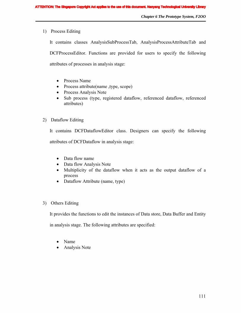
Chapter 6 The Prototype System, F2OO
111
1) Process Editing
It contains classes AnalysisSubProcessTab, AnalysisProcessAttributeTab and
DCFProcessEditor. Functions are provided for users to specify the following
attributes of processes in analysis stage:
• Process Name • Process attribute(name ,type, scope) • Process Analysis Note • Sub process (type, registered dataflow, referenced dataflow, referenced
attributes)
2) Dataflow Editing
It contains DCFDataflowEditor class. Designers can specify the following
attributes of DCFDataflow in analysis stage:
• Data flow name • Data flow Analysis Note • Multiplicity of the dataflow when it acts as the output dataflow of a
process • Dataflow Attribute (name, type)
3) Others Editing
It provides the functions to edit the instances of Data store, Data Buffer and Entity
in analysis stage. The following attributes are specified:
• Name • Analysis Note
ATTENTION: The Singapore Copyright Act applies to the use of this document. Nanyang Technological University Library

Chapter 6 The Prototype System, F2OO
112
Table 6-5 Classes for DF net Artifacts Specification in analysis stage
Class Name Description AnalysisGeneralTab The editing pane for DCFProcess in Analysis stage
AnalysisTabbedPane Container tab pane for AnalysisSubProcessTab and AnalysisProcessAttributeTab
AnalysisSubProcessTab Tab pane for editing sub-process AnalysisProcessAttributeTab Tab pane for editing process attributes
DCFProcessEditor (Analysis Segment) Container frame for AnalysisTabbedPane
DCFDataflowEditor Frame for dataflow editing in analysis Stage DCFDatastoreEditor (Analysis Segment) Frame for data store editing in analysis stage
DCFDataBufferEditor (Analysis Segment) Frame for data buffer editing in analysis stage
DCFEntityEditor (Analysis Segment) Frame for entity editing in analysis stage
6.2.1.2.2 Design Stage Control
Design stage is rightly after analysis stage. With its input of the DF net artifacts gained in
previous stage, users need to map these inputs with their corresponding design artifacts,
before proceed to the next stage. Design artifacts refer to any class’s or procedure’s
constituent elements as which DF net artifacts are realized. Design Stage Control
includes two major functions, namely Process Grouping and Design Artifact
Specification. The work flow of design stage is shown in Figure 6-13.
The following sections introduce the design and implementation of Process Grouping and
Design Artifacts Specification.
ATTENTION: The Singapore Copyright Act applies to the use of this document. Nanyang Technological University Library

Chapter 6 The Prototype System, F2OO
113
FIGURE 6-13 Design Stage Work Flow
6.2.1.2.2.1 Process Grouping
Process grouping function is provided to group or ungroup the processes in design stage.
Users can group the processes, based on the rules provided in DF net and specify the
group attributes, such as group’s name and identification color, etc. The outputs of this
process are groups of processes. For example, in Figure 6-13, Group A contains
processes A1 to Aj. For the processes, on which procedure-based transformation method
is applied (in Figure 6-13, {Process Pi}), users can input the java source code here, or
later in implementation stage.
In DF net, there are three transform methods for each process, namely, pdfd-sub-process
based transform method, process-based transform method and procedure-based transform
method. The first two methods require the users to group the processes into different
classes before proceeding to sub processes design. Figure 6-14 shows the activity
diagram of the grouping process. Functions implemented in process grouping reside in
the classes listed in Table 6-6.
ATTENTION: The Singapore Copyright Act applies to the use of this document. Nanyang Technological University Library

Chapter 6 The Prototype System, F2OO
114
Table 6-6 Classes for Process Grouping in design stage
Class Name Description ToolGroup Realize the work flow of grouping
ToolUngroup Realize the work flow of ungrouping
ToolGrpDlg Invoked by ToolGroup for user to select group name and color
ToolGpEditDlg Provided for user to edit the name and color of the existing group
6.2.1.2.2.2 Design Artifact Specification
Designing Artifact Specification provides functions to specify the detailed design
artifacts for all the DF net artifacts based on the outputs of the grouping process. For
processes which have been grouped, users need to match each of them with its design
artifact in OO methodology. For processes which are specified to be realized as
procedures, like Pj in Figure 6-13, users can provide java source code here. All DF net
artifacts need to be mapped with their specific design artifacts correspondingly. Table 6-7
shows some of the classes used in this function.
In design stage, attributes of the processes which need to be specified are shown as
follows:
• Implementation environment: currently the only option is Java.
• Operation signature: if pdfd-sub-process-based method is selected, user needs to
input the names of the operations which the sub processes are transformed to. If
process-based method is chosen, user needs to input the name of the operation to
which this process is transformed.
• Procedure code: if procedure-based method is selected, user needs to input the
java code for the procedure to which the current process is transformed.
ATTENTION: The Singapore Copyright Act applies to the use of this document. Nanyang Technological University Library

Chapter 6 The Prototype System, F2OO
115
• Procedure symbols: if procedure-based method is selected, users need to specify
the name and type of the variables used in the procedure code segment.
For each individual output data flow of the process, the following attributes need to be
specified:
• Design method: output data flows of a process can be transformed to either Class
Attribute (CA) or Return Value (RV). In some cases, users do not need to specify
them, because there are algorithms for automate deducing. Otherwise, users need
to specify.
• Multiplicity: user needs to specify the multiplicity of the output data flow. These
include multiplicities: 0…1, 1 or many.
• Variable type and name: in the prototype system, they are referred as groupType
and groupRepresentationName. For the output data flow with multiple dataflow
attributes and its design method is specified as RV, users need to group its data
flow attributes into a class and give the class type, name of an instance
accordingly.
For each individual referenced data flow of a process, it can be realized as either Class
Attribute (CA) or Pass-in Parameter (PI). Prototype system has provided some algorithms
for automate deduction.
ATTENTION: The Singapore Copyright Act applies to the use of this document. Nanyang Technological University Library

Chapter 6 The Prototype System, F2OO
116
Table 6-7 Classes for Design Artifact Specification in design stage
Class Name Description DesignTabbedPane Container pane
DesignImplEnvTransformOpSigTab Pane for editing implementation environment, process transform method and operation signature
DesignOutDFAttributesTab Pane for editing output data flow’s design artifacts
DesignRefInDFAttributesTab Pane for editing referenced data flow’s design artifacts of the process using pdfd-sub-process based method
DesignRefDFAttributesProcessBasedTab Pane for editing referenced data flows’ design artifacts of the process using process-based method
DesignClassAttributesTab Editing panel for process attribute
DCFProcessEditor (Design Segment)
Container frame for DesignTabbedPane and let the user to input source code and procedure symbol if procedure-based method is chosen.
DCFDataBufferEditor (Design Segment)
For users to specify the design artifact of the selected data buffer.
FIGURE 6-14 Algorithm for Process Grouping in Design stage
ATTENTION: The Singapore Copyright Act applies to the use of this document. Nanyang Technological University Library

Chapter 6 The Prototype System, F2OO
117
6.2.1.2.3 Implementation Stage Control
Implementation Stage Control provides the users with all the functions needed in
implementation stage. It comprises two major functions, which are Implementation
Artifacts Specification and Transformation respectively. Implementation Artifacts
Specification requires users to specify the implementation artifacts for the design artifacts,
while transformation of the use-case to java implementation is realized through
Transformation function. The detailed design and implementation of these two functions
are discussed in the following sections.
6.2.1.2.3.1 Implementation Artifact Specification
Implementation Artifact Specification includes the following two parts:
1) Java implementation of the class operations.
DCFProcessEditor.java has provided a notepad style editor for designers to code the
implementation for class operations specified in design stage.
2) Names of the instances declared for the classes and the data flows whose design
methods are PI or RV and multiplicities are many.
6.2.1.2.3.2 Transformation
Transformation function automatically generates the java source code for the use-case
specified and its corresponding OO structures are also shown in XML format. Based on
ATTENTION: The Singapore Copyright Act applies to the use of this document. Nanyang Technological University Library

Chapter 6 The Prototype System, F2OO
118
different functionalities, transformation function can be divided into three parts, namely,
Pre-processing, Transforming and Result Displaying. The following gives the details:
1) Pre-processing
Two tasks have been carried out in pre-processing to prepare for the transforming.
One is to get all the DCFProcess instances; the other is to sort them according to the
traversing requirements. The algorithm is depicted in Figure 6-15.
FIGURE 6-15 Algorithm for processes sorting
2) Processing
ATTENTION: The Singapore Copyright Act applies to the use of this document. Nanyang Technological University Library

Chapter 6 The Prototype System, F2OO
119
The conditions which will be used in algorithm description are listed as follows:
Condition (1): Partition Criteria: let Q be a set of container operation
arguments each of which realizes a data flow d referenced in a process such
that excluding d there are data flows in the path from the main input dataflow
of the process to d with output multiplicity =*. We partition Q in such a way
that container arguments that realize the same dataflow referenced in
processes such that the same attribute if the dataflow are referenced in these
processes and the paths between the main input data flows of these processes
do not include data flows with out put multiplicity = * are put together in the
same partition. (as a result, operation arguments in the same partition have
identical value).
Condition (2) : the output dataflow e of process P is registered with some
pdfd-sub-process in processes that are not realized using class by applying
process-based method or e is referenced by another process R such that
f2d(e.Q) is a container operation argument and (f2d(e.P) is not defined or
f2d○d2i(e.Q)!= f2d ○d2i(e.P)).
Condition (3): e is referenced by another process R such that f2d○d2i(e.Q)!=
f2d ○d2i(e.P)).
Condition (4): Traversing Criteria: processes will be traversed in such a way
that a process will only be traversed if all the processes, which produce its
input data flows, have been traversed.
The algorithm is as follows:
1. Declaration section
ATTENTION: The Singapore Copyright Act applies to the use of this document. Nanyang Technological University Library

Chapter 6 The Prototype System, F2OO
120
1.1 declare and instantiate an instance for the classes that realize process. 1.2 declare a variable for each output dataflow that are realized as RV 1.2 declare a variable for each output dataflow attribute and referenced dataflow
attribute of process p realized as procedure. 1.4 declare a variable for each partition which satisfies Condition (1). 1.5 Insert port of initialization.
2. Generating code for each process (P) section.
2.1 Initialization of code segment. 2.1.1 P is process-based, code segment = empty. 2.1.2 P is pdfd-sub-process based, its individual sub process’ code segment =
empty. 2.1.3 P is procedure-based, code segment = P’s procedure code.
2.2 Invocation of class operation. 2.2.1 P is pdfd-sub-process based. Append each individual class operation
statement to the corresponding sub process’s code segment. 2.2.2 P is process-based. Append P’s class operation statement to its code
segment. 2.3 Output dataflow realization. For each output data flow e of P,
2.3.1 Establishing protocol. If P is pdfd-sub-process based, append following statements to its main sub process’s code segment; if P is process-based, append following statements to its process’s code segment.
2.3.2 Making single output instance accessible, if satisfying condition (2). 2.3.2.1 if e’s multiplicity =1, append “// port of ”+ e’s name 2.3.2.2 if e’s multiplicity = 0..1, append selection construct and “// port of ”+
e’s name 2.3.2.3 if e’s multiplicity = *, append a loop and “//port of”+ e’s name within
the loop. 2.3.3 Instantiating Container Argument Element. If e satisfies condition (3) and e is
container type, instantiate an instance of container argument element’s type. Insert it before “//port of ”+e’s name.
2.3.4 Assigning Value. If e satisfies condition (3), generate an assigning statement, insert before “//port of”+ e’s name.
2.3.5 Inserting container Element: if e is referenced by another process as container type, and satisfies condition (3), generate insertion statement and insert it before “//port of”+ e’s name
3. Sequencing code segments of all process. Traversing follows condition (4), for each P,
3.1 if P’main input dataflow ! =null, insert following code segment before port of its main input dataflow, else insert the code segment before port of initialization.
3.1.1 P is process-based, insert its process’s code segment 3.1.2 otherwise, insert its main sub process’s code segment.
3.2 For each output data flow e of P, if there is initialization code segment registered to it, insert it before “//port of” + e’s name.
3.3 For each output data flow e of P, if there is ancestor or input sub process registered to it, insert it before “//port of” + e’s name.
Figure 6-16 is the class diagram for the classes used to implement the transformation
algorithm. The classes inherited from Statement.java are used to generate various types of
ATTENTION: The Singapore Copyright Act applies to the use of this document. Nanyang Technological University Library

Chapter 6 The Prototype System, F2OO
121
statements. These include, ForStatement, DeclarationStatement,
MethodInvocationStatement, AssignmentStatement, InitializationStatement,
DownCastingStatement and PortStatement. All these statement classes have provided the
operation getStringExpression():String, which returns the String representations of the
respective statements. Table 6-8 describes the major classes which are used in
transformation function.
FIGURE 6-16 Class diagram for transformation
Symbol class and SymbolTable class are designed to store and manage the variables used
in final transformation result code. During the transformation process, many variables
need to be defined. Symbol class encapsulates the information, such as variable’s name,
class type and its corresponding design artifact, etc. According to the algorithm, various
ATTENTION: The Singapore Copyright Act applies to the use of this document. Nanyang Technological University Library
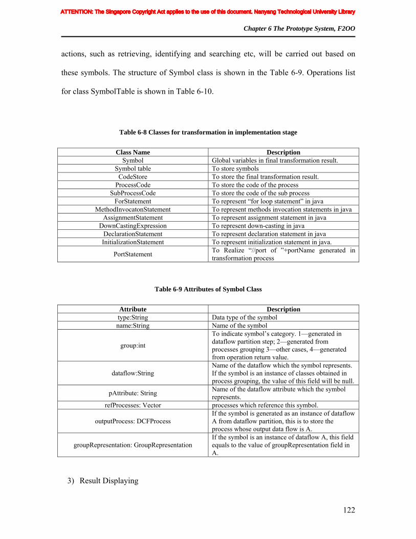
Chapter 6 The Prototype System, F2OO
122
actions, such as retrieving, identifying and searching etc, will be carried out based on
these symbols. The structure of Symbol class is shown in the Table 6-9. Operations list
for class SymbolTable is shown in Table 6-10.
Table 6-8 Classes for transformation in implementation stage
Class Name Description Symbol Global variables in final transformation result.
Symbol table To store symbols CodeStore To store the final transformation result.
ProcessCode To store the code of the process SubProcessCode To store the code of the sub process
ForStatement To represent “for loop statement” in java MethodInvocatonStatement To represent methods invocation statements in java
AssignmentStatement To represent assignment statement in java DownCastingExpression To represent down-casting in java
DeclarationStatement To represent declaration statement in java InitializationStatement To represent initialization statement in java.
PortStatement To Realize “//port of ”+portName generated in transformation process
Table 6-9 Attributes of Symbol Class
Attribute Description type:String Data type of the symbol name:String Name of the symbol
group:int
To indicate symbol’s category. 1—generated in dataflow partition step; 2—generated from processes grouping 3—other cases, 4—generated from operation return value.
dataflow:String Name of the dataflow which the symbol represents. If the symbol is an instance of classes obtained in process grouping, the value of this field will be null.
pAttribute: String Name of the dataflow attribute which the symbol represents.
refProcesses: Vector processes which reference this symbol.
outputProcess: DCFProcess If the symbol is generated as an instance of dataflow A from dataflow partition, this is to store the process whose output data flow is A.
groupRepresentation: GroupRepresentation If the symbol is an instance of dataflow A, this field equals to the value of groupRepresentation field in A.
3) Result Displaying
ATTENTION: The Singapore Copyright Act applies to the use of this document. Nanyang Technological University Library

Chapter 6 The Prototype System, F2OO
123
After transformation completes, the generated source code for the use-case and the
structure description will be displayed in “text/java” style.
Table 6-10 Operations of SymbolTable Class
Operation Description
addSTElement(symbol:Symbol) : boolean Adding a new symbol. search(type:String, grp:int): Vector Return symbols with given type and grp ID. searchType(name:String) : String Return the type of the symbol with given name.
search_two(type:String, outputProcess: String): String
Return the name of the symbol with given type and outputProcess name.
checkNew(d:DCFDataflow) : Symbol Return the symbol which represents the given dataflow d.
check(s:Symbol):boolean To check whether symbol s exists in the symbolTable
outputProcess: DCFProcess If this symbol is generated from dataflow partition, this is to store the processes whose output data flow is the dataflow this symbol represents.
JDOM is used to generate the structure reports in XML format. Class
StructureReport from package com.transformation handles the displaying.
Table 6-11 shows the operations in StructureReport.java.
Table 6-11 Operations of StructureReport Class
Operation Name/Inner class name Description
addCa(String className, String caType String caName):void
To add a class attribute with caType as its type and caName as its name to the class whose name is className
classStructureReport(Vector gList, DCFBuilder builder):void
Containing the work flow to show the structure report based on list of DCFGroupInfo.
domToXML():void Transforming DOM object to XML format getClassStructure(DCFGroupInfo gInfo,
DCFBuilder builder): ClassStructure To generate a class structure based on the specific DCFGroupInfo.
getClassAttributes(VClassStructure vClassStructure, DCFBuilder builder):
VCLassStructure
To add the class attributes which are transformed from output dataflows to VClassStructure.
ClassStructure(Inner classs) To store the structure of a class VClassStructure(Inner class) Vector of ClassStructure
ATTENTION: The Singapore Copyright Act applies to the use of this document. Nanyang Technological University Library

Chapter 6 The Prototype System, F2OO
124
6.2.1.3 Validation
This part provides the validation functions to the users throughout the whole process.
Based on the stage in which the validations are performed, it can be divided into three
categories, namely, Analysis Validation, Design Validation and Implementation
Validation. Their designs and implementations are discussed in the following sections.
6.2.1.3.1 Analysis Validation
Analysis validation is to check the structures of the DF net diagram drawn for the use-
case and the correctness of the attributes specified in analysis stage. It is performed when
user has finished the analysis stage and is about to move to design stage. Some of Multi-
level DF net files’ validations also fall into Analysis Validation. For illustration purpose,
these validations will be discussed later in DF net File Management section. Analysis
validations in this section only cater for those within the same DF net file. Validation
rules for processes are shown as follows:
• A process should have at least one input dataflow.
• A process should have at least one output dataflow.
• For process which does not have lower-level DF net file, should have at most one
main input dataflow.
• Process should have its unique name.
Validation rules for data flows are shown as follows:
• Different data flows should have different names.
ATTENTION: The Singapore Copyright Act applies to the use of this document. Nanyang Technological University Library

Chapter 6 The Prototype System, F2OO
125
• The source and target of the dataflow cannot both be null.
• The source and target of the dataflow cannot be the same.
• The source and target of inter-process dataflow should be process.
• The source and target of non-inter-process dataflow must be one of the following
pairs: Process & Data store, Data tore & Process, Process & Entity, Entity &
Process, Process & Data Buffer or Data Buffer & Process.
For Data store/Data Buffer, validation rules are listed as follows:
• A data store must have at least one connection to a process.
• A data buffer must have at least one input connection to a process and one output
connection to a process.
If analysis validation is successful, user can move to design stage.
6.2.1.3.2 Design Validation
Design Validation involves the consistency and correctness checking of all design
artifacts. Different from Analysis Validation, Design Validation is carried out not only
when user navigates from design stage to implementation stage, but also dispersed
throughout the entire design stage. Detailed descriptions will be covered in section
6.2.2.5, where most of the design rules are discussed.
6.2.1.3.3 Implementation Validation
ATTENTION: The Singapore Copyright Act applies to the use of this document. Nanyang Technological University Library

Chapter 6 The Prototype System, F2OO
126
Implementation Validation is carried out in implementation stage before transformation
process is triggered. Currently, it only contains some simple grammatical checking of the
java codes user input.
6.2.1.4 DF net File Management
In order to support hierarchical decomposition, DF net File Management function is
provided to manage different levels of DF net files for a use-case. In DF net, a process in
higher level DF net can be decomposed and modeled by a set of lower level DF nets.
Managing the relations among different levels of DF net files is needed. In the prototype
system, different levels of DF net files are identified by their file names.
DF net File Management also provides the functions of Level navigation and Inter-level
validation, which are shown as follows:
1) Level navigation.
Because a use-case can have many levels of DF net files, users need to specify DF
net artifacts, design artifacts and implementation artifacts for all these DF net files
before final transformation starts. Navigation among these different levels of DF
net files in different stages is needed. Figure 6-17 shows the activity diagram of
the navigation. Stage navigation among analysis stage, design stage and
implementation stage can only be performed when user is at the highest level DF
net files.
2) Inter-level validation
ATTENTION: The Singapore Copyright Act applies to the use of this document. Nanyang Technological University Library

Chapter 6 The Prototype System, F2OO
127
Navigations among different levels of DF net files require validations to
guarantee the consistency of the structural properties. Let Fl be a lower level DF
net file, Fh be Fl’s next higher level DF net file and p be a process in Fh which has
been decomposed and modeled by Fl. Inter-level validations cover the following
aspects:
Data store Validation: data stores connected to p in Fh should be exactly
the same as the corresponding data stores in Fl in both quantity and
content.
Data flow Validation: data flows which connect to p in Fh should be same
as the corresponding data flows in Fl. To satisfy above rule, the following
rules need to be met:
Number of p’s input data flows should be same as the number of
the data flows in Fl, whose source objects are null.
Number of p’s out put data flows should be same as the number of
the data flows in Fl, whose target objects are null.
For every input data flow d of p, there exists a data flow d1 in Fl,
whose source object is null, such that d and d1 have the same name,
same multiplicity, same number of data flow attributes and exactly
the same content of these data flow attributes (names and types).
For every output data flow d of p, there exists a data flow d1 in
Fl, whose target object is null, such that d and d1 have the same
name, same multiplicity, same number of data flow attributes and
ATTENTION: The Singapore Copyright Act applies to the use of this document. Nanyang Technological University Library
Chapter 6 The Prototype System, F2OO
128
exactly the same content of these data flow attributes (names and
types).
For every data flow d in Fl, whose source object is null, there exists
an input data flow d1 of p, such that d and d1 have the same name,
same multiplicity, same number of data flow attributes and exactly
the same content of these data flow attributes (names and types).
For every data flow d in Fl, whose target object is null, there exists
an output data flow d1 of p, such that d and d1 have the same name,
same multiplicity, same number of data flow attributes and exactly
the same content of these data flow attributes (names and types).
6.2.1.5 Algorithm
In summary, Algorithm function provides the algorithms used in the implementation of
the prototype system. It comprises two classes, namely Algorithm.java and
UserGuid.java from com.dcfnet.core. Some of the algorithms defined inside
Transformation.java are also included. Algorithm function comprises the following ten
major algorithms:
1) Inter-level navigation validation
Purpose: to validate inter-level navigation.
Realization Description: this algorithm is to check the validation rules
provided in the previous section of DF net File Management when user
navigates among different levels of DF net files.
ATTENTION: The Singapore Copyright Act applies to the use of this document. Nanyang Technological University Library
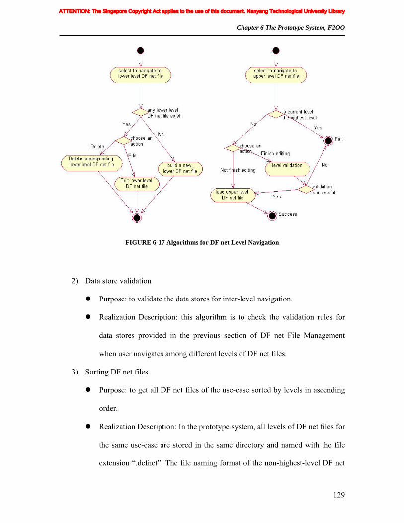
Chapter 6 The Prototype System, F2OO
129
FIGURE 6-17 Algorithms for DF net Level Navigation
2) Data store validation
Purpose: to validate the data stores for inter-level navigation.
Realization Description: this algorithm is to check the validation rules for
data stores provided in the previous section of DF net File Management
when user navigates among different levels of DF net files.
3) Sorting DF net files
Purpose: to get all DF net files of the use-case sorted by levels in ascending
order.
Realization Description: In the prototype system, all levels of DF net files for
the same use-case are stored in the same directory and named with the file
extension “.dcfnet”. The file naming format of the non-highest-level DF net
ATTENTION: The Singapore Copyright Act applies to the use of this document. Nanyang Technological University Library

Chapter 6 The Prototype System, F2OO
130
file is to append a string “sub__” as its prefix. This algorithm sorts the DF
net files according to the occurrence of the string “sub__” in ascending order.
For example , the highest level DF net file is marked as “Level 0”, the next
lower level DF net files which model any process in highest level DF net file
are marked as “Level 1”, so on and so forth.
4) Combination of processes
Purpose: to combine all the DCFProcess instances from sorted DF net files.
Realization Description: Before sorting the processes according to traversing
rule, we need to retrieve all the instances of DCFProcess for the use-case.
Firstly, all the instances of DCFProcess will be retrieved from graph models
of all the DF net files and put into a vector. Then the processes which have
lower level DF net files will be excluded.
5) Path deduction
Purpose: to find the path for a given dataflow.
Realization Description: the concept of Path plays a very important role in
DF net. However, for implementation purpose, the final result of this
algorithm not only includes the data flows (which are derived from the
definition of Path in DF net), but also the related processes. Figure 6-18
shows the algorithm.
6) Get ancestor data flow candidates for referencing
ATTENTION: The Singapore Copyright Act applies to the use of this document. Nanyang Technological University Library
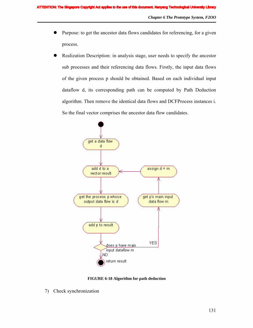
Chapter 6 The Prototype System, F2OO
131
Purpose: to get the ancestor data flows candidates for referencing, for a given
process.
Realization Description: in analysis stage, user needs to specify the ancestor
sub processes and their referencing data flows. Firstly, the input data flows
of the given process p should be obtained. Based on each individual input
dataflow d, its corresponding path can be computed by Path Deduction
algorithm. Then remove the identical data flows and DCFProcess instances i.
So the final vector comprises the ancestor data flow candidates.
FIGURE 6-18 Algorithm for path deduction
7) Check synchronization
ATTENTION: The Singapore Copyright Act applies to the use of this document. Nanyang Technological University Library

Chapter 6 The Prototype System, F2OO
132
Purpose: to check the given output dataflow f, together with the processes
which reference it, satisfy the synchronization condition or not.
Realization Description: this algorithm is widely used in deducing
input/referenced data flows’ multiplicities and referenced/output data flows’
design artifacts. Let f be an output data flow of a process P in a DF net such
that f is referenced by another process Q. It can be verified that if f satisfies
one of the following two conditions depending on which case it belongs to,
then each execution of Q references the instance/instances of f that is/are
produced from the associated execution of P:
f is the main input data flow of Q or its ancestor data flow: The
output multiplicity of f is “1”.
f is an non-main input data flow of Q: Except f and the main input
data flow of Q, the path from the main input data flow of Q to f
does not contain any data flow with output multiplicity = “*”.
Figure 6-19 shows the implementation of this algorithm.
8) Referenced data flow’s design artifact deduction (pdfd-based)
Purpose: if data flow f is referenced by a process P and P is realized using
pdfd-sub-process-based method, this algorithm is to deduce f’s design
artifacts including f’s multiplicity and f’s transformed method.
Realization Description: this algorithm is widely used in deducing
input/referenced data flows’ multiplicity and design artifacts. For the
referenced data flows whose multiplicity and design artifacts can be deduced
ATTENTION: The Singapore Copyright Act applies to the use of this document. Nanyang Technological University Library

Chapter 6 The Prototype System, F2OO
133
by the rules provided in this algorithm, Design Stage Control function will
invoke this algorithm to get the corresponding results automatically, which
makes the design stage semi-automated. Figure 6-20 provides the description
of this algorithm.
FIGURE 6-19 Algorithm for checking synchronization
ATTENTION: The Singapore Copyright Act applies to the use of this document. Nanyang Technological University Library

Chapter 6 The Prototype System, F2OO
134
FIGURE 6-20 Algorithm for design artifact deduction
9) Referenced data flow’s design artifact deduction (process-based)
Purpose: if data flow f is referenced by P and P is realized using process-
based method, this algorithm can be used to deduce f’s design artifacts.
Realization Description: this algorithm is used to deduce the design artifacts
of the data flows referenced by the processes which are realized using
process-based method. Most of the deduction process can be automated.
However, there are some cases that users need to provide the groupType and
groupRepresentationName. Algorithm implementation follows exactly the
same steps listed in DF net, except for the variable homeDA. In the
implementation, homeDA is realized by the variables listed in Table 6-13. In
ATTENTION: The Singapore Copyright Act applies to the use of this document. Nanyang Technological University Library

Chapter 6 The Prototype System, F2OO
135
the algorithm, under certain circumstances, referenced data flow attributes of
different referenced data flows will be grouped together to form a new class,
thus, homeDAclsRepEle and homeDAgroupRepresentationName are
introduced to store the user input class type and the name of the instance of
this type. Table 6-12 shows the parameters used in process-based design
artifacts deduction.
Table 6-12 Attributes for implementing process-based design artifacts deduction
Parameter name Description
homeDAFlag To indicate the “operation argument” in DF net(process-based)
homeDATransformMethod To indicate current homeDA’s transform method. 1---PI(pass-in parameter), 3---CA
homeMultiplicity To indicate current homeDA’s multiplicity. 2—non-container type, 1---container type
homeDAclsRepEle To indicate current homeDA’s group type homeDAgroupRepresentationName To indicate current homeDA’s groupRepresentationName
10) Output data flow’s design artifacts deduction
Purpose: if data flow f is the output dataflow of a process P, this is to deduce
f’s design artifacts including f’s transform method.
Realization Description: this algorithm is widely used in deducing output
data flow’s design artifacts. For the output data flows whose design artifacts
can be deduced by the rules provided in this algorithm, Design Stage Control
function will invoke this algorithm to get the corresponding results
automatically, which makes the design stage semi-automated. According to
the DF net, output dataflow will be realized as either CA or RV. There are
two cases in which the design artifact of output dataflow d of a process p can
be deduced, which are shown as follows:
ATTENTION: The Singapore Copyright Act applies to the use of this document. Nanyang Technological University Library

Chapter 6 The Prototype System, F2OO
136
case 1: if d is internal in the group which p belongs to, d will be
realized as CA;
case 2: if there exists a process q which references d and p, q are in
the same group such that referenced dataflow in q is synchronized
with d in p, d will be realized as CA.
Figure 6-21 shows the implementation of this algorithm.
System Control
System control bridges System UI with System Model. It responds to events, typically
user actions, and invokes changes on the model or the view accordingly. It follows MVC
structure, shown in Figure 6-22.
Inside of the main operation of DCFMain.java, an instance of DCFBuilder.java is
instantiated, which acts as the host for the prototype system. Classes within
com.dcfnet.ui.actions are designed for associating detailed mouse actions on certain
menu items with their corresponding operations on model. (Please refer to Appendix A)
Helper
Helper function provides helping and guiding for analysis, design and implementation
tasks. It comprises the following parts:
ATTENTION: The Singapore Copyright Act applies to the use of this document. Nanyang Technological University Library

Chapter 6 The Prototype System, F2OO
137
FIGURE 6-21 Algorithm for deducing output data flow’s design artifacts
1) Interactive Helper
An interactive Helper is implemented using Mitr packages [121], which is based
on JACOB [119]. Figure 6-23 shows the class diagram.
2) Helping Board
ATTENTION: The Singapore Copyright Act applies to the use of this document. Nanyang Technological University Library
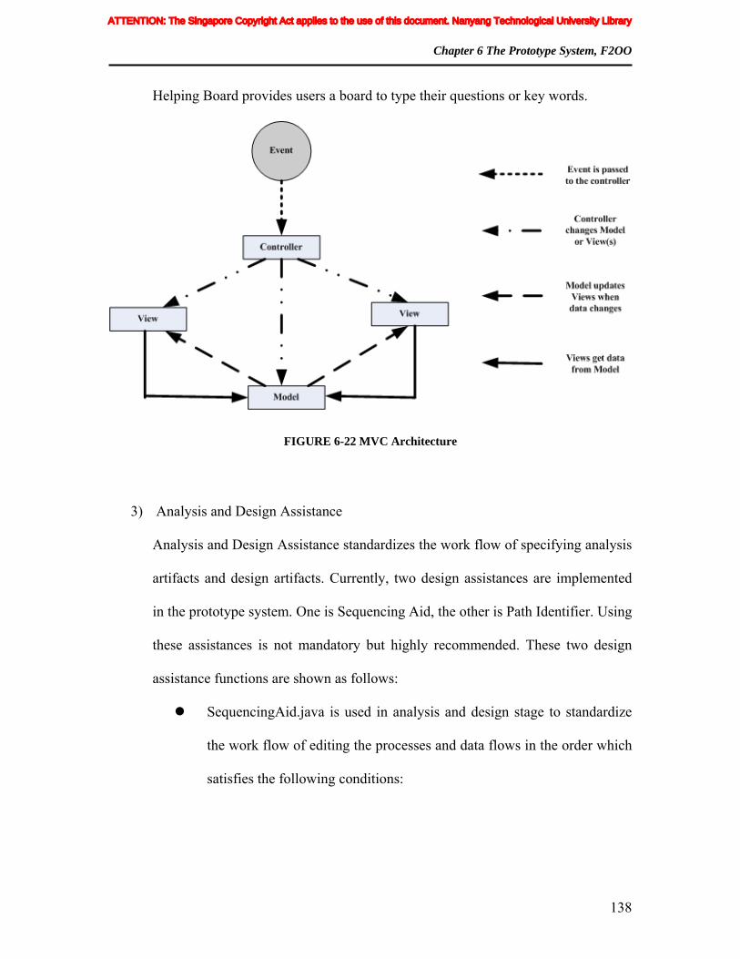
Chapter 6 The Prototype System, F2OO
138
Helping Board provides users a board to type their questions or key words.
FIGURE 6-22 MVC Architecture
3) Analysis and Design Assistance
Analysis and Design Assistance standardizes the work flow of specifying analysis
artifacts and design artifacts. Currently, two design assistances are implemented
in the prototype system. One is Sequencing Aid, the other is Path Identifier. Using
these assistances is not mandatory but highly recommended. These two design
assistance functions are shown as follows:
SequencingAid.java is used in analysis and design stage to standardize
the work flow of editing the processes and data flows in the order which
satisfies the following conditions:
ATTENTION: The Singapore Copyright Act applies to the use of this document. Nanyang Technological University Library

Chapter 6 The Prototype System, F2OO
139
FIGURE 6-23 Class diagram for Interactive Helper
In analysis stage, for a process p, the attributes of its analysis
artifacts can only be edited after its ancestor data flows and input
data flows are correctly specified.
In design stage, for a process p, the design artifacts of its
referenced data flow r can only be specified after the design
artifacts of r’s corresponding output dataflow of another process
q has been correctly specified. Design artifacts here refer to the
multiplicity and transformation method of r.
If the sequencing aid has been activated by the designer, warning
messages and proposed solutions will be displayed when these rules
have been violated.
ATTENTION: The Singapore Copyright Act applies to the use of this document. Nanyang Technological University Library

Chapter 6 The Prototype System, F2OO
140
ToolShowCandidateDataflow.java is provided to show the path to a
given process and the data flows which can be referenced.
6.3 Conclusion
F2OO provides software designers with a tool to construct their functional models and
transform them into OO design and implementation. F2OO’s architecture contains four
main components, namely, System UI, System Model, System Control and Helper. The
following functions are delivered by the system:
In analysis stage, the F2OO system helps the users to construct their own DF
net analysis models and specify the DF net artifacts.
In design stage, the F2OO system facilitates users to map their DF net
artifacts to design artifacts and specify the attributes of these design artifacts.
In implementation stage, the F2OO system provides the users with the
functions to specify the implementation artifacts of those design artifacts
gained from previous stage and transform the design model into OO
implementation.
Validation functions and helper functions are provided throughout the whole
process. Analysis validation, design validation and implementation validation
validate the user input in different stages, based on DF net semantics and
rules. Helper functions provide helping and guiding the analysis, design and
implementation tasks.
ATTENTION: The Singapore Copyright Act applies to the use of this document. Nanyang Technological University Library

Chapter 6 The Prototype System, F2OO
141
F2OO has also validated the effectiveness of the DF net approach, as for any use-case
realized using the proposed approach, once the classes and procedures to realize its
processes have been designed and coded, the design and code of an operation to
implement the use-case is fully automatically generated by using F2OO. The time and
efforts spent for transforming the DF net analysis models to OO implementation have
been greatly reduced. The design and coding of an operation to implement a complex
use-case will not post any problem to the use of the proposed approach.
ATTENTION: The Singapore Copyright Act applies to the use of this document. Nanyang Technological University Library

142
7 Evaluation
To evaluate the feasibility of using the proposed approach and validate the automated
transformation of the proposed implementation model into OO implementation, we have
developed a prototype system to support the use of the proposed approach from
requirements analysis to implementation and performed five case studies. The evaluation
focuses on the following key aspects:
1) The correctness of the automated transformation of proposed implementation
model into OO implementation: For this purpose, in our prototype system, we
implemented the automated transformation discussed in Section 4 for Java-
based language. And, we used the system for all the case studies and tested all
the generated OO codes.
2) The feasibility of using the proposed approach to complement existing OO
methods for the design and implementation of use-cases: For this purpose, in
each case study, one student used the proposed approach to complement the
Unified Software Development Process (USDP) [4] and another student used
the USDP solely, to design and develop OO software for implementing an
identical set of use-cases from a system. Both students developed the use-
ATTENTION: The Singapore Copyright Act applies to the use of this document. Nanyang Technological University Library

Chapter 7 Evaluation
143
cases using the same Java-based language. And, we ourselves and an
experience OO software designer from the industry compared and reviewed
the design and implementation delivered by the students independently. We
also compared the difficulties encountered by them.
3) The scalability of the proposed approach: To have a preliminary experience
on scalability, our case studies cover a variety of systems. Some of them are
relatively complex and with sizable overlapping.
We performed five case studies each of which has one student uses the proposed
approach to complement the USDP for use-cases with more complex functions and
another student uses the USDP solely to design and implement an identical set of use-
cases from a system. We shall refer to the former student and the latter student as the
proposed approach group and the USDP group respectively. All the students were doing
their MSc in Communication Software and Networks in our school on a part-time basis.
All of them are working as software engineers for about one to three years in the industry
and were randomly assigned to the case studies. They have completed the study of
Unified Modeling Language (UML) and USDP in one of their MSc subjects. We used
our prototype system and Rational Rose as development tools for supporting the use of
the proposed approach and the USDP respectively.
The inputs provided for all the students were UML use-case diagrams and use-case
descriptions. The USDP group follows the USDP described in [4] strictly. They realized
the use-cases using sequence diagrams in the analysis stage to discover classes. In the
design stage, they refined the sequence diagrams and classes. In the implementation stage,
ATTENTION: The Singapore Copyright Act applies to the use of this document. Nanyang Technological University Library

Chapter 7 Evaluation
144
they implemented the design and tested the use-cases. The proposed approach group
realized the use-cases in DF nets in the analysis stage. In the design stage, they
transformed the DF nets specified into OO design. In the implementation stage, they
coded the supporting classes and procedures. The coding of operations for implementing
the use-cases is automated by the prototype system. After generating the codes for the
operations, they tested the use-cases. In line with the usual practice in software
development, both group carried out these tasks with some iterations. Altogether, our
case studies designed and implemented 24 use-cases from five diverse systems: Order
Processing (OP); University Library (UL); Student Result Processing (SRP); Automated
Meeting Scheduler (AMS); and Sales Analysis (SA). All the use-cases were successfully
implemented in the same Java-based language. Each case study covers one system. Many
use-cases overlap with other use-cases in the same system.
The case study on OP has six use-cases that include the processing of customer orders
interactively, processing of outstanding orders (backorders processing), canceling orders,
canceling order items and the updating and maintenance of related information. The case
study on UL has seven use-cases that include borrow book, reserve book, return book,
add new book, terminate book, add new member and update member. The case study on
SRP has five use-cases that include the updating of subject statistics, the automated
computation of the grade of degree awarded for each graduating student based on project
grade and average mark for each year, mark entry and maintenance of related information.
The case study on AMS was obtained from [122]. It has five use-cases that include the
automated scheduling of meeting based on meeting requirements, room availability,
member availability and preferences with two variants of scheduling algorithms under
ATTENTION: The Singapore Copyright Act applies to the use of this document. Nanyang Technological University Library

Chapter 7 Evaluation
145
two use-cases, accept preferred periods, accept excluded periods and the updating of
related information. The case study on SA has only one use-case that prints a sales
analysis report with statistics at various levels of control breaks. For students who used
the proposed approach to complement the USDP, we identified the use-cases with more
complex functions beforehand for them to apply the proposed approach. Except the case
study on SA, these students used the proposed approach to realize the first three use-cases
stated earlier in the systems. For the case study on SA, the assigned student used the
proposed approach to realize the only use-case in it. Altogether, these students used the
proposed approach for 13 use-cases and used the USDP for 11 use-cases. Note that in the
case study on OP, the assigned student realized the canceling orders use-case using the
proposed approach and the canceling order items use-case using the USDP. And, in the
case study on AMS, the assigned student realized the accept preferred periods use-case
using the proposed approach and the accept excluded periods use-case using the USDP.
We intentionally used different methods for use-cases that are closely related or similar to
see how well the two methods can work together.
At the end of the case studies, an experienced OO software designer from the industry
conducted a validation testing for all the systems delivered by the two groups without
knowing which design outcome was from which group. Each student was required to
rectify and modify the design and implementation until the system delivered is
satisfactory. Finally, we ourselves and the software designer independently reviewed and
compared the design and implementation delivered from the two groups. The main
findings are quite consistent and they are as follows. All the reviewers are in the opinion
that the OO designs delivered by the proposed approach group are fully integrated and
ATTENTION: The Singapore Copyright Act applies to the use of this document. Nanyang Technological University Library

Chapter 7 Evaluation
146
better than the USDP group. Both reviewers find that in the proposed approach group,
there is sizable overlapping between the use-cases realized using the proposed approach
and the use-cases realized using the USDP. They find that the designs produced by the
proposed approach group for the overlapping are fully integrated. The proposed approach
group did better in the decomposition of use-cases into externally meaningful functions
and designed them as class operations. This could be due to the use of functional
decomposition in the proposed approach for the analysis realization of use-cases. The
USDP group failed to identify some of these functions, and therefore did not mange to
design operations for implementing them. On the other hand, the USDP group designed
many operations to get and set single attribute in a class. Many of these trivial operations
actually do not implement any externally meaningful function and therefore do not serve
much purpose. The implementations from both groups were tested, reviewed thoroughly
and affirmed as acceptable.
Table 7-1 shows the statistics taken in our case studies. Comparisons have been carried
out consistently based on four criteria, which are, namely, identifying external
meaningful functions by functional decomposition, synthesizing the overlapping in and
between use-cases into operations, coupling and cohesion. The proposed approach has
shown its strength in identifying the external meaningful functions, which is reflected by
the higher number of operations that implement externally meaningful functions but not
identified in the counterpart due to failure in functional decomposition. And the proposed
approach group seemed to synthesize the overlapping in and between use-cases into
operations better. These are reflected in the higher number of operations to realize the
overlapping and higher number of subclasses and super-classes designed by the proposed
ATTENTION: The Singapore Copyright Act applies to the use of this document. Nanyang Technological University Library

Chapter 7 Evaluation
147
approach group. This could be due to the clearer guidelines given in the proposed
approach for handling overlapping. Cohesion and coupling are two fundamental and
important quality attributes to measure a class design. In [115], a class is defined as
coupled to another class if one of them uses the other’s member functions and/or instance
variables. Coupling between object classes (CBO) of a class is defined as the number of
classes to which a given class is coupled. Lack of Cohesion on Methods (LCOM) is
defined as the number of pairs of member functions without shared instance variables,
minus the number of pairs of member functions with shared variables; however, the
metric is set to zero whenever the subtraction is negative. The statistics in the table show
that the proposed approach helps in designing classes with better cohesion, which is
reflected by the lower number of operations with LCOM. But for coupling between
classes, average CBO per classes in the table show that there is no significant difference
between the designs delivered by the two groups. From our observation through
comparing the time spent between the two groups, there is no irregular large increment
on the time spent in the use of the proposed approach when the complexity of a system
increases. AMS and SA are the more complex systems in our case studies. It can be seen
from the table that the increases on time spent for these two systems relative to other
systems are similar for both groups.
Furthermore, in our case studies, we have also observed that except processes that printed
report or delivered complex output through a user interface, all the processes at most had
three pdfd-sub-processes, one of each type. In a former process, each pdfd-sub-process
corresponds to a type of lines or output. As such, we can comprehend it easily by
associating it with the type of lines or output. This shows that although the general
ATTENTION: The Singapore Copyright Act applies to the use of this document. Nanyang Technological University Library

Chapter 7 Evaluation
148
structure of a process in DF net looks a bit complicated, in practical use, usually, the
structure is not too difficult to comprehend.
In summary, the result from the case studies in terms of using the proposed approach to
complement existing OO methods with functional decomposition is encouraging.
Through the use of the proposed approach in a number of quite complex use-cases, we
have also gained some positive experience on its scalability.
Table 7-1 Some statistic taken in our case studies
OP UL SRP AMS SA Total Metrics P U P U P U P U P U P U
No of classes designed to realize the use-cases
18 15 19 17 11 9 16 15 9 8 73 64
No of operations designed 32 42 29 39 21 24 28 26 10 5 120 136 No of operations that implement externally meaningful functions but not identified in the counterpart due to failure in functional decomposition
7
0 2 0 4 0 10 0 6 0 29 0
No of operations that get or set a single attribute and do not implement externally meaningful functions
0 10 0 12 0 4 0 0 0 0 0 26
No of operations to realize overlapping in and between use-cases
4 1 1 0 5 0 16 4 1 0 27 5
No of operations with LCOM > 0 0 2 0 0 0 0 0 0 0 0 0 2 Average CBO per class 1.9 2.2 2 2.1 1.1 1.1 2.5 2.7 2 2.2 1.9 2.1 No of super-classes designed 2 0 1 0 2 0 3 2 1 0 9 2 No of subclasses designed 7 0 3 0 5 0 5 2 2 0 22 2 Time spent (hour) 96 10
0 78 78 80 89 93 10
5 18 24 365 396
Legend - P: the proposed approach group; U: the USDP group
ATTENTION: The Singapore Copyright Act applies to the use of this document. Nanyang Technological University Library

149
8 Comparison with Related Work
The proposed approach shares the use of functional refinement in OO software
development with the approaches proposed in [5, 7]. However, the approach proposed in
[5] uses the use-case structure chart as a notation to document the realization of a use-
case in terms of the supporting class operations in a hierarchical structure, but it does not
deal with the process of identifying classes, their attributes and operations. In contrast
with this approach, the proposed approach deals with the latter process. The approach
proposed in [7] does not use any graphical model to systematically aid the functional
refinement process. A function is specified textually by an informal strategy. The
approach identifies objects and operations for realizing functions informally in the
process of functional refinement. In contrast to this approach, the proposed approach uses
a novel graphical model, DF net, to aid the functional refinement process. It transforms
the outputs from functional refinement, DF nets, systematically and precisely into OO
design and implementation.
Modeling functional aspects in OO approaches has received some attentions [10, 11, 14,
123]. The approach discussed in [10] can be viewed as a representative approach that
advocate the concurrent development of DFDs and object models, followed by an explicit
ATTENTION: The Singapore Copyright Act applies to the use of this document. Nanyang Technological University Library

Chapter 8 Comparison with Related Work
150
association of the processes to objects. Since the approach does not deal with the
fundamental difference in the decomposition strategy between DFD and OO approaches,
the association of processes and object methods at the end of the design phase is nearly
impossible. An approach was proposed in [11, 123] to formalize the functional model
within object-oriented design to address to this problem. This approach integrates
functional model with object model by distributing functions directly into objects. An
approach was also proposed in [14] to formalize and integrate the dynamic model for
object-oriented modeling. This approach proposes a well-defined formal model for both
the object and dynamic models and their integration. In this approach, functional model is
also integrated into object model through distributing functions directly into objects. In
terms of modeling, the proposed approach shares the modeling of functional aspects of
systems with these two approaches. However, both the two approaches distribute
functional model directly into object model. The proposed approach constructs functional
analysis model separately before the construction of OO design model. In term of the
objective, both the two approaches are for the formalization and integration of models in
OO software development to facilitate analysis, precise specification, design, and model
verification. In contrast with the two approaches, the proposed approach is for the
systematic and precise transformation of functional analysis models into OO design and
implementation.
Some approaches [8, 9] were proposed to transform DFD based analysis models into OO
designs. The proposed approach shares with these approaches on constructing OO
designs from DFD based analysis models. However, these approaches provide only
informal heuristic guidelines for defining OO designs from DFDs. They use existing
ATTENTION: The Singapore Copyright Act applies to the use of this document. Nanyang Technological University Library

Chapter 8 Comparison with Related Work
151
DFD and do not transform DFDs systematically and precisely into OO designs and
implementations. In fact, due to the need of including information on other processes in a
process for specifying process interaction in existing DFD as discussed in Section 2, even
such transformation can be established, the resulting OO design will violate Parnas’
widely accepted information hiding principle [71]. As a result, the design quality will be
adversely affected.
Jacobson proposed the use of statechart, activity or interaction diagram to supplement the
specification of use-cases when the informal textual description is not sufficient [3]. Due
to their nature, statechart diagram is more suitable for modeling state-event transitions
and interaction diagram is more suitable for modeling object interactions. They are not
suitable for functional refinement of use-cases. The use of activity diagram for functional
refinement will inherit much problem from flowchart due to the similarity in their nature.
These problems have already been overcome in existing DFD.
The proposed approach is to complement existing OO software development methods
with functional decomposition for realizing use-cases, especially those with more
complex functions. It can be applied to realize only those use-cases with more complex
functions. In the requirements analysis stage, the proposed approach applies functional
decomposition to these use-cases instead of OO decomposition directly. It realizes them
in DF nets. The need of functional decomposition in OO software development for use-
cases with more complex functions has been discussed in [7]. The importance and benefit
of applying functional decomposition in OO software development has also been
discussed in [5]. We believe that functional decomposition is more natural and therefore
ATTENTION: The Singapore Copyright Act applies to the use of this document. Nanyang Technological University Library

Chapter 8 Comparison with Related Work
152
easier for the realization of use-cases with more complex functions. In the design and
implementation stages, the proposed approach transforms the DF nets constructed
systematically and precisely into OO design and implementation. When the proposed
approach is only applied to some of the use-cases in a target system, the OO design and
implementation developed using the proposed approach is directly synthesized with the
OO design and implementation developed using other OO methods for the same target
system. The proposed design rules are general enough to allow designers to make any
good OO design decision. The automated transformation of proposed implementation
model into OO implementation is carried out according to designer decisions. So, the use
of the proposed approach would not constraint the OO design constructed.
There are some distinct differences between DF net and conventional DFD. A primitive
process in a DF net represents a composition of the pdfd-sub-processes (primitive DFD
sub-processes) in it. These pdfd-sub-processes are not explicitly shown in diagram. Due
to this, one may argue that the general structure of a process is quite complicated and not
easy to comprehend. However, our experience shows that in practical use, usually, except
processes that print report or deliver complex output through a user interface, most
processes at most have three pdfd-sub-processes, one of each type. For the former
processes, each of their pdfd-sub-processes usually corresponds to a type of lines or
output. As such, we can comprehend it easily by associating it to the type. Therefore,
usually, for practical use, it is not difficult to comprehend a process in DF net. This has
also been confirmed in our case studies. For the rare situation, an automated tool can be
developed to help in the comprehension of a complicated process in DF net by showing
the information that is not explicitly shown in diagram as and when required.
ATTENTION: The Singapore Copyright Act applies to the use of this document. Nanyang Technological University Library

Chapter 8 Comparison with Related Work
153
Coincidentally, it is stated in [124-126] that existing DFD and OO model are
incompatible. However, the proposed approach has shown that after some enhancement,
DFD based model can be transformed systematically and precisely into OO model.
ATTENTION: The Singapore Copyright Act applies to the use of this document. Nanyang Technological University Library
154
9 Conclusion and Recommendations
9.1 CONCLUSION
In this thesis, we have presented a proposed model, DF net for the modeling of functional
analysis models. DF net is an enhanced DFD model. Based on DF net, we have proposed
a systematic approach for the precise and semi-automated transformation of functional
analysis models into OO design and implementation. With the use of the proposed
approach, in the requirements analysis stage, use-cases with more complex functions are
realized and specified in DF nets. In the design stage, the resulting DF nets are
transformed into OO design. Based on the design, in the implementation stage, program
codes for class operations to implement the use-cases are merged and generated
automatically based on the codes for the supporting classes. The proposed approach can
be used seamlessly to complement existing OO approaches to realize use-cases with more
complex functions. We have also discussed the details of a comprehensive prototype
system that has been developed to implement the proposed approach. We have also
evaluated the proposed approach through case studies. A comparison of the proposed
approach with related approaches has also been discussed.
In summary, the contributions of the thesis are as follows:
ATTENTION: The Singapore Copyright Act applies to the use of this document. Nanyang Technological University Library

Chapter 9 Conclusion and Recommendations
155
1. The development of a systematic approach to complement existing OO
approaches for functional decomposition. The proposed approach specifies use-
cases in functional models during requirement analysis stage. It systematically
and precisely transforms functional analysis models into OO design and
implementation. In the development of an OO system, it is seamless to realize
some of the use-cases using the proposed approach and the remaining use-cases
in the same target systems using any existing OO software development
methods.
2. The implementation of a comprehensive prototype system to validate the
proposed approach.
9.2 FURTHER RESEARCH RECOMMENDATIONS
In DF net, as the control flow between processes is fully implied, a process is no longer
required to include information on other processes for the purpose of process interaction.
Thus, analysis models for commonly used functions represented by DF nets could be
more reusable. The extension of the proposed approach to component-based software
development is a natural extension. Reusability receives more and more attentions in
current practice and many component-based web technologies have been developed to
support this, such as Enterprise Java Bean (EJB). EJB has been widely used to promote
the components’ reusability in various ways. Firstly, it separates business logic from
presentation logic, which makes the modeling of the business functions independent from
presentation logic. Secondly, the business logic of enterprise beans can be reused through
ATTENTION: The Singapore Copyright Act applies to the use of this document. Nanyang Technological University Library

Chapter 9 Conclusion and Recommendations
156
java subclassing. In the analysis stage of these component-based web applications, the
proposed approach can be used to construct more reusable EJB analysis models based on
the decomposition of the business functions. Currently, because the implementation of
presentation logic involves a lot of non-java technologies, such as the use of xml
configuration files in struts application, it makes the analysis of control flows difficult.
However, because of the separation of business logic and presentation logic by EJB, the
proposed approach can be used in business function modeling without being affected by
those non-java technologies in presentation logic modeling. During the design stage of
the proposed approach, instead of mapping the DF net analysis models to ordinary classes
and operations, they can be mapped to entity beans, session beans and interfaces. This
allows the EJB applications to incorporate the advantages of the proposed approach in
functional decomposition during the analysis stage. In addition to this, the methods
discussed in the proposed approach to deal with the overlapping among use-cases can
also be applied in EJB business function modeling to improve the reusability of the
business logic of enterprise beans. Therefore, we believe that the proposed approach
might help in the development of more reusable analysis models and patterns that can be
associated with required design and implementation alternatives and reused on an
integrated basis from requirements analysis via design to implementation in component-
based web applications. This is a further research direction.
Another interesting direction would be to use the proposed approach to model distributed
database transaction systems. As for such data-intensive systems, the realization of some
of the use-cases can be modeled based on process interacting through data flows in DF
ATTENTION: The Singapore Copyright Act applies to the use of this document. Nanyang Technological University Library

Chapter 9 Conclusion and Recommendations
157
net. However, because the control flows are fully derived from DF net structure, future
research can be carried out to enhance the DF net structure to make it capable of
modeling the distributed control flows among the servers and clients.
In the proposed approach, the realization of use-cases is modeled based on processes
interacting through data flows in DF nets. The control flows associated with the
interaction are derived fully from the structure of the DF nets. This is suitable and natural
for a large class of data-intensive systems that are data driven. For systems that are time
dependent and process a lot of signals and events, such as concurrent systems etc, the
current DF net might not be sufficient for the analysis modeling of their use-cases. To
extend the DF net to represent the control flow and timing of such systems could be a
future direction
Software architecture has received much attention recently [127]. The bridging between
software requirements and architectures is one important issue [128-130]. Exploring on
the possible use of DF net to address this issue could also be a further research direction.
ATTENTION: The Singapore Copyright Act applies to the use of this document. Nanyang Technological University Library

158
Author’s Publications
[1] Hee Beng Kuan Tan, Yong Yang, Lei Bian, "Systematic Transformation of
Functional Analysis Model into OO Design and Implementation,” IEEE Trans.
Softw. Eng. , vol. 32 pp. 111-135, February 2006.
[2] Yong Yang, Hee Beng Kuan Tan, “Design and Implementation of a System for
Transforming Functional Model into OO Model,” submitted to Journal of
Information and Communication Technology.
[3] Hee Beng Kuan Tan, Yong Yang, Lei Bian, “Improving Use of Multiplicity in
UML Association” Accepted to be published in Journal of Object Technology.
[4] Yong Yang," Formalization of Multiplicity in UML Association" in Proceedings
of the 24th IASTED International Conference on Software Engineering, pp. 518-
088, 2006.
[5] Yong Yang, Tan H B K, "Automated extracting code fragments what implement
Security Functionality from Source Code" in Proceedings of the 5th
SNPD(International Conference on Software Engineering Artificial Intelligence,
Networking and Computing), pp. 252-258, 2004.
ATTENTION: The Singapore Copyright Act applies to the use of this document. Nanyang Technological University Library

Author’s Publications
159
[6] Yong Yang, Tan H B K and Lei Bian, "Do Not Use Getter/Setters too Lightly:
Design Class Interface from Request Service," GESTS Int’ Trans. Computer
Science and Engineering. , vol. 15 pp. 176-182, July 30th, 2005.
[7] Hee Beng Kuan Tan, Lun Hao, Yong Yang, "On Formalization of the Whole-Part
Relationship in the Unified Modeling Language,” IEEE Trans. Softw. Eng. , vol.
29 pp. 1054-1055, November 2003.
ATTENTION: The Singapore Copyright Act applies to the use of this document. Nanyang Technological University Library

160
Bibliography
[1] T. DeMarco, Structured Analysis and System Specification. Yourdon Inc.. New
York, 1978.
[2] R. S. Pressman, a Practitioner's Approach. McGraw-Hill, 2005.
[3] I. Jacobson, Booch and J. Rumbaugh, The Unified Software Development Process.
Addison-Wesley, 1999.
[4] M. Priestley, Practical Object-Oriented Design with UML. McGraw - Hill, 2004.
[5] D. Wolber, "Reviving Functional Decomposition in Object-Oriented Design,"
Journal of Object Oriented Programming, vol. 10, pp. 31-38, Oct. 1997.
[6] T. Moynihan, "An Experimental Comparison of Object-Orientation and
Functional-Decomposition as Paradigms for Communicating System
Functionality to Users," Journal of Systems and Software, vol. 33, pp. 163-169,
1996.
[7] P. Jalote, "Functional Refinement and Nested Objects for Object-Oriented
Design," IEEE Trans. Softw. Eng., vol. SE-15, pp. 264-270, Mar.1989.
[8] B. Alabiso, "Transformation of data flow analysis models to object oriented
design " in Conference proceedings on Object-oriented programming systems,
languages and applications. pp. 335, San Diego, California, USA, September 25-
30,1988.
ATTENTION: The Singapore Copyright Act applies to the use of this document. Nanyang Technological University Library

Bibliography
161
[9] L. Gray, "Transitioning from structured analysis to object-oriented design " in
Proceedings of the fifth Washington Ada symposium on Ada Tyson's Corner, pp.
151-162, Virginia, USA, June 27-30,1988.
[10] J. Rumbaugh, Blaha, M., Premerlani, W. Eddy, F., Lorensen, W., Object-
Oriented Modeling and Design. Englewood Cliffs, NJ: Prince-Hall, 1991.
[11] E. Y. Wang and B. H. C. Cheng, "Formalizing the Functional Model Within
Object-Oriented Design," Int'l J. Software Eng. and Knowledge Eng., vol. 10, pp.
5-30, 2000.
[12] E. Y. Wang and B. H. C. Cheng, "Formalizing the Functional Model into Object-
Oriented Design," in Proc. 10th Int. Conf. Software Eng. and Knowledge Eng.
San Francisco,USA, June 18-20,1998.
[13] M. G. Morris, C. Speier, and J. A. Hoffer, "The Impact of Experience on
Individual Performance and Workload Differences Using Object-Oriented and
Process-Oriented Systems Analysis Techniques " in Proceedings of the 29th
Hawaii International Conference on System Sciences (HICSS) Volume 2:
Decision Support and Knowledge-Based Systems IEEE Computer Society, pp.
232, Hawaii, USA, January 3-6,1996.
[14] B. H. C. Cheng and E. Y. Wang, "Formalizing and integrating the dynamic model
for object-oriented modeling,” IEEE Trans. Softw. Eng., vol. 28 pp. 747-762,
2002.
[15] E. Yourdon and L. Constantine, Structured Design: Fundamentals of a Discipline
of Computer Programming and Design, 2nd ed. Prentice Hall, New York, 1979.
[16] T. DeMarco and A. Soceneantu, "Data Flow Structures for System Specification
and Implementation " in Proceedings of the First International Conference on
Data Engineering IEEE Computer Society, pp. 356-361, Los Angeles, California,
USA, April 24-27,1984.
ATTENTION: The Singapore Copyright Act applies to the use of this document. Nanyang Technological University Library

Bibliography
162
[17] T. DeMarco and Tim Lister, "Software Development: State of the Art vs. State of
the Practice," in Proceedings of ICSE, pp.271-275, Pittsburg, PA, USA, May 15-
18, 1989.
[18] P. T Ward and S. J. Mellor, Structured Development of Real-Time Systems.
Englewood Cliffs, N.J.: Yourdon Press, 1985.
[19] P. P. S. Chen, "The entity-relationship model toward a unified view of data,"
ACM Trans. Database Syst., vol. 1, pp. 9-36, 1976.
[20] C. Gane. and T. Sarson, Structured Systems Analysis: Tools and Techniques.
Englewood Cliffs, NJ: Pretince-Hall, 1986.
[21] G. E. Kaiser and D. Garlan, "Melding data flow and object-oriented
programming" in Conference proceedings on Object-oriented programming
systems, languages and applications. pp. 254-267, Orlando, Florida, USA,
October 04-08, 1987.
[22] M. Jackson, Problem Frames: Analyzing and Structuring Software Development
Problems. Addison-Wesley, 2001.
[23] J. Martin, Information Eng. Books 1,2,3. Englewood Cliffs, N.J.: Prentice Hall,
1990.
[24] T. Korson and D. McGregor, "Understanding Object-Oriented: A Unifying
Paradigm," in Communications of the ACM, pp. 40-60, 1990.
[25] G. Booch, "What Is and What Isn't Object-Oriented Design?," Am. Programmer,
vol. 2, pp. 14-21, 1989.
[26] M. Page-Jones and S. Weiss, "Synthesis: An Object-Oriented Analysis and
Design Method," Am. Programmer, vol. 2, pp. 64-67, 1989.
[27] G. Fichman and F. Kemerer, "Object-Oriented and Conventional Analysis and
Design Methodologies: Comparison and Critique," IEEE Computer, vol. 25, pp.
22-39, 1992.
ATTENTION: The Singapore Copyright Act applies to the use of this document. Nanyang Technological University Library

Bibliography
163
[28] P. Coad and Yourdon, Object-Oriented Analysis. New Jersey: Yourdon Press,
Prentice Hall, 1990.
[29] S. Bilow, "Book Review: Object-Oriented Design," Journal of Object Oriented
Programming, vol. 4, pp. 73-74, Oct.1991.
[30] P. Biggs, "A Survey of Object-Oriented Methods," Technical Report(6/95), 1995.
[31] J. Rumbaugh, "OMT: The Functional Model," Journal of Object-Oriented
Programming, pp. 10-14, 1995.
[32] G. Booch, Object Oriented Design with Application. California:
Benjamin/Cummings, 1991.
[33] G. Booch, "Object-Oriented Development," IEEE Trans. Softw. Eng., vol. SE-12,
pp. 211-221, 1986.
[34] P. J. Robinson, Hierarchical Object-Oriented Design. Prentice Hall, 1992.
[35] B. W. R. Wirf-Brock, and L. Wiener, Designing Object-Oriented Software.
Englewood Cliffs, N.J.: Prentice Hall, 1990.
[36] S. Shlaer, and Mellor, S., Object Lifecycles Modeling the World in States.
Englewood Cliffs, NJ: Yourdon Press, 1992.
[37] D. Champeaux, "Object-Oriented Analysis and Top-Down Software
Development” in Proceedings of the European Conference on Object-Oriented
Programming Springer-Verlag, pp. 360-376, Geneva, Switzerland, July 15-
19,1991.
[38] D. Champeaux, "Structured Analysis and Object Oriented Analysis," in
ECOOP/OOPSLA: ACM Press, pp. 135-9, 1990.
[39] S. C. Bailin, "An object-oriented requirements specifications method," Commun.
ACM, vol. 32, pp. 608-623, 1989.
ATTENTION: The Singapore Copyright Act applies to the use of this document. Nanyang Technological University Library

Bibliography
164
[40] L. Constantine, "Objects, Functions, and Program Extensibility," in Computer
Language, pp. 74-82, 1990.
[41] M. L. Griss, "Systematic OO Reuse- A Tale Of Two Cultures," SIGSOFT Softw.
Eng. Notes, vol. 21, pp. 50-52, 1996.
[42] M. E. Fayad and D. C. Schmidt, "Lessons learned building reusable OO
frameworks for distributed software," Commun. ACM, vol. 40, pp. 85-87, 1997.
[43] J. Morris S. Johnson, "A survey of object-oriented reuse " in Proceedings of the
1995 conference of the Centre for Advanced Studies on Collaborative research,
pp. 35, Toronto, Ontario, Canada, November 07-09,1995.
[44] M. E. Fayad, W.-T. Tsai, and M. L. Fulghum, "Transition to object-oriented
software development," Commun. ACM, vol. 39, pp. 108-121, 1996.
[45] M. Ramachandran, "Software reuse guidelines," SIGSOFT Softw. Eng. Notes, vol.
30, pp. 1-8, 2005.
[46] M. E. S. Loomis, A. V. Shah, and J. E. Rumbaugh, "An object modelling
technique for conceptual design " in Proceedings of European conference on
object-oriented programming on ECOOP '87. pp. 192-202, Paris, France, June 18,
1987.
[47] D. De Champeaux and P. Faure, "A Comparative Study of Object - Oriented
Analysis Methods," Journal of Object Oriented Programming, vol. 5, pp. 21-33,
1992.
[48] G. Caldiera and R. Basili, "Identifying and Qualifying Reusable Software
Components," Computer, vol. 24, pp. 61-70, Feb.1991.
[49] Sun Microsystems, "J2EE, Enterprise JavaBeans Technology."
[50] T. A. S. Foundation, "Struts," http://struts.apache.org/userGuide/preface.html.
[51] S. Framework, "Spring,”http://www.springframework.org/.
ATTENTION: The Singapore Copyright Act applies to the use of this document. Nanyang Technological University Library

Bibliography
165
[52] Jakata Inc., "Hibernate," http://www.hibernate.org/.
[53] M. Jackson, System Development. Englewood Cliffs.N.J.: Prentice-Hall, 1983.
[54] V. Rajlich, "Refinement methodology for Ada, " IEEE Trans. Softw. Eng. , vol.
13 pp. 472-478, 1987
[55] D. T. Ross and J. Kenneth E. Schoman, "Structured analysis for Requirements
Definition," in Proceedings of the 2nd international conference on Software
engineering. pp. 1-7, San Francisco, California, USA, October 13-15,1976.
[56] N. Wirth, "Program development by stepwise refinement," Commun. ACM, pp.
221-227, 1971.
[57] P. T. Ward, "How to Integrate Object Orientation with Structured Analysis and
Design," IEEE Softw., vol. 6, pp. 74-82, 1989.
[58] R. L. Glass, "The Naturalness of Object Orientation: Beating a Dead Horse?,"
IEEE Softw., vol. 19, pp. 104, 2002.
[59] V. Rajlich and J. Silva, "Two object oriented decomposition methods," in
Proceedings of the fifth Washington Ada symposium on Ada. Tyson's Corner,
Virginia, United States: ACM Press, pp. 171-176, 1988.
[60] J. E. Rumbaugh, "A State of Mind," Journal of Object Oriented Programming,
vol. 9, pp. 14-18, 1996.
[61] J. E. Rumbaugh, "OMT: The Object Model," Journal of Object-Oriented
Programming, vol. 7, pp. 21-27,1995.
[62] J. E. Rumbaugh, "OMT: The Dynamic Model," Journal of Object-Oriented
Programming, vol. 7, pp. 06-12,1995.
[63] J. E. Rumbaugh, "OMT: The Development Process," Journal of Object-Oriented
Programming, vol. 8, pp.08-16,1995.
ATTENTION: The Singapore Copyright Act applies to the use of this document. Nanyang Technological University Library
Bibliography
166
[64] J. E. Rumbaugh, "To Form a More Perfect Union: Unifying the OMT and Booch
Methods," Journal of Object-Oriented Programming, vol. 8, pp. 14-18 .1996.
[65] J. E. Rumbaugh, "The Life of an Object Model," Journal of Object-Oriented
Programming, vol. 7, pp.24-31, 1994.
[66] V. C. Rajlich, "Paradigms for design and implementation in ADA," Commun.
ACM, vol. 28, pp. 718-727, 1985.
[67] S. C. Chou and J. Chen, "An Object-Oriented Analysis Model Based on Parallel
Decomposition of Function and Data," Report on Object Analysis and Design,
1996.
[68] K. Thrampoulidis, and K. Agavanakis, "Object-Interaction Diagram: A New
Technique in Object-Oriented Analysis and Design," Journal of Object Oriented
Programming, vol. 8, pp. 25-39, 1995.
[69] I. Jacobson, Christerson, M., Jonsson, P., Overgaard, G., Object-Oriented
Software Engineering - A Use Case Driven Approach. Mass. ACM Press,
Addison-Wesley, Reading, 1992.
[70] F. Rosa and A. Silva, "Functionality and Partitioning Configuration: Design
Patterns and Framework " in Proceedings of the International Conference on
Configurable Distributed Systems IEEE Computer Society, pp. 79, Annapolis,
MD, May 04-06,1988.
[71] D. L. Parnas, "On the criteria to be used in decomposing systems into modules,”
Communication ACM vol. 15 pp. 1053-1058, 1972.
[72] S. M. Dedene Guido, "Flexible function modeling around object-oriented
business models," in Proceedings of the Object Technology conference, pp. 42-65,
Oxford, UK, March 30-31, 1995.
ATTENTION: The Singapore Copyright Act applies to the use of this document. Nanyang Technological University Library

Bibliography
167
[73] J. George and B. D. Carter, "A strategy for mapping from function-oriented
software models to object-oriented software models, " SIGSOFT Softw. Eng.
Notes vol. 21 pp. 56-63, 1996.
[74] W. Schulte and K. Achatz, "Functional Object-oriented Programming with
Object-Gofer," Jahrestagung, vol. 3 pp. 552-561, 1997.
[75] M. P. Jones, "An introduction to Gofer(draft)," 1993.
[76] M. P. Jones, "Release notes for Gofer 2.30a," 1994.
[77] M. P. Jones, "Functional programming with overloading and higher-order
polymorphism," in Advanced Functional Programming., J. a. Meijer, Ed., 1995.
[78] T. Fetcke, A. Abran, and T.-H. Nguyen, "Mapping the OO-Jacobson Approach
into Function Point Analysis," in Proceedings of the Tools-23: Technology of
Object-Oriented Languages and Systems IEEE Computer Society, pp. 192, Santa
Barbara, July 18-August 1,1997.
[79] F. Goh, "Function Points methodology for object oriented software model,"
Ericsson Australia Pty Ltd, pp. 131-152, 1995.
[80] R. Gupta and S. K. Gupta, "Object Point Analysis," in Proceedings of IFPUG
1996 Fall Conference, pp. 15- 31, Dallas, Texas, USA, September 12-14, 1996.
[81] S. A. Whitmire, "Applying function points to object-oriented software models," in
Software engineering productivity handbook, J.Keyes, Ed.: McGraw-Hill, pp.
229-244, 1992.
[82] T. Bolognesi and E. Brinksma, "A introduction to the ISO Specification Language
LOTOS," in The Formal Description Technique LOTOS, C. A. V. P.H.J.V. Eijk,
and M. Diaz, Ed., pp. 23-73, 1989.
[83] D. Harel and A. Naamad, "The STATEMATE semantics of statecharts," ACM
Trans. Softw. Eng. Methodol., vol. 5, pp. 293-333, 1996.
ATTENTION: The Singapore Copyright Act applies to the use of this document. Nanyang Technological University Library

Bibliography
168
[84] C. K. Chang, J. Cleland-Haung, S. Hua, and A. Kuntzmann-Combelles,
"Function-Class Decomposition: A Hybrid Software Engineering Method,"
Computer, vol. 34, pp. 87-93, 2001.
[85] C. K. Chang and T. H. Kim, "Distributed Systems Design using Function-Class
Decomposition with Aspects", in Proceedings of 10th IEEE International
Workshop on Future Trends of Distributed Computing Systems (FTDCS 2004),
pp.148-153, Suzhou, China, May 26-28 ,2004.
[86] C. K. Chang and S. Hua, "A New Approach to Module-Oriented Design of OO
Software," in Proceedings of 18th International Computer Software and
Applications Conf., pp. 110-127, Taipei, Taiwan, March 01-03,1994.
[87] J. L. Huang and C. K. Chang, "Supporting the Partitioning of Distributed Systems
with Function-Class Decomposition," in Proceedings of 24th Int' Computer
Software and Applications Conf., pp. 351-356, Taipei, Taiwan, October 25-28,
2000.
[88] R. J. A. Buhr, "Use Case Maps as Architectural Entities for Complex Systems,"
IEEE Trans. Softw. Eng., vol. 24, pp. 1131-1155, 1998.
[89] B. H. Nicolas Juillerat, "FOOD: An Agent-Oriented Dataflow Model," in
Proceedings of ICAISC, pp. 835-840, Zakopane, Poland, June 07-11, 2004.
[90] P. Shoval and J. Kabeli, "FOOM-functional and object-oriented methodology for
analysis and design of information systems " in Advanced topics in database
research vol. 1 Idea Group Publishing, pp. 58-86, 2002.
[91] P. Shoval, "ADISSA: architectural design of information systems based on
structures analysis," inf. Syst., vol. 13, pp. 193-210, 1988.
[92] D. Truscan, J. M. Fernandes and J. Lilus, "Tool support for DFD to UML model-
based transformations," Turku Centre for Computer Science 519, 2003.
ATTENTION: The Singapore Copyright Act applies to the use of this document. Nanyang Technological University Library

Bibliography
169
[93] J. M. Fernandes, "Functional and Object-Oriented Modeling of Embedded
Software.," Turku Centre for Computer Science (TUCS), Turku, Finland 512,
2003.
[94] J. M. Fernandes, R. J. Machado, and H. D. Santos, "Modeling industrial
embedded systems with UML," in Proceedings of the eighth international
workshop on Hardware/software codesign. pp. 18-22, San Diego, California,
USA, May 03-05 ,2000.
[95] H. Hoffmann, "From Function-Driven Systems Engineering to Object Oriented
Software Engineering," I-logix, 2003.
[96] O. Greevy and S. Ducasse, "Characterizing the Functional Roles of Classes and
Methods by Analyzing Feature Trace," in Proceedings of WOOR, pp. 101- 113,
Glasgow, UK ,July ,2005.
[97] G. T. Heineman and W. T. Councill, Component-Based Software Engineering.
Boston: Addison-Wesley, 2001.
[98] C. Szyperski, Component Software: Beyond Object-Oriented Programming. New
York: Addison-Wesley, 1998.
[99] A. H. Dogru and M. M. Tanik, "A Process Model for Component-Oriented
Software Engineering," IEEE Softw., vol. 20, pp. 34-41, 2003.
[100] Microsoft Corporation, "The Component Object Model Specification," 1995.
[101] L. Vanhelsuwe, Mastering JavaBeans. Sybec Inc., 1997.
[102] J. Li, "A Survey of Microsoft Component-Based Programming Technologies,"
Concordia University,Montreal, 1999.
[103] J. L. Fenandez Sanchez and E. E. Betegon, "Supporting Functional Allocation in
Component-Based Architectures," in Proceeding of 18th International
ATTENTION: The Singapore Copyright Act applies to the use of this document. Nanyang Technological University Library

Bibliography
170
Conference on Software & Engineering and their Application, pp. 47-53, Paris,
France, November 29-30 ,2005.
[104] I. Jacohson, Component-based Development with UML, 1998.
[105] M. S. Al-Hatali and H. G. Walton, "Smart Features for Compositional Wrappers,"
in Proceedings of ICSR7 2002 Workshop on Component-based Software
Development Processes, pp. 120-131 ,Austin, Texas, USA, April 15-19, 2002.
[106] H. Msheik, A. Abran and E. Lefebvre, "Compositional Structured Component
Model: Handling Selective Functional Composition," in Proceeding of the 30th
EUROMICRO Conference, pp 74-81, Rennes, France, September 01-03, 2004.
[107] K. Levi and A. Arsanjani, "A goal-driven approach to enterprise component
identification and specification,” Commun. ACM vol. 45 pp. 45-52, 2002.
[108] H. Andrade, T. Kurc, A. Sussman, and J. Saltz, "Exploiting Functional
Decomposition for Efficient Parallel Processing of Multiple Data Analysis
Queries " in Proceedings of the 17th International Symposium on Parallel and
Distributed Processing IEEE Computer Society, pp. 81, Nice, France, April, 2003.
[109] A. Rountev, "Component-level Dataflow Analysis," in Proceedings of CBSE, pp.
82-89, St. Louis, MO, USA, May 14-15, 2005.
[110] D. Y. Liu, H. Mei, "Mapping requirements to software architecture by feature-
orientation," in Proc. of the 2nd Int'l Software Requirements to Architectures
Workshop, pp. 69-76, Portland, May 09,2003.
[111] D. J. Hatley, and I. A. Pirbhai, Strategies for Real-Time System Specification.
Dorest House Publishing, 1988.
[112] P. T. Ward, "The transformation schema: An extension of the data flow diagram
to represent control and timing, " IEEE Trans. Softw. Eng. , vol. 12 pp. 198-210,
1986.
ATTENTION: The Singapore Copyright Act applies to the use of this document. Nanyang Technological University Library

Bibliography
171
[113] R. B. France, "Semantically Extended Dataflow Diagrams: A Formal
Specification Tool, " IEEE Trans. Softw. Eng. , vol. 18 pp. 329-346, 1992.
[114] K. Rizman, and I. Rozman, "Making Data Flow Diagrams Executable by Adding
the Transformation Logic," in Computer and Inf. Science VI, a. B. O. E. M.Baray,
Ed., 1991.
[115] S. R. Chidamber and C. F. Kemerer, "A Metrics Suite for Object Oriented Design,
" IEEE Trans. Softw. Eng. , vol. 20 pp. 476-493, 1994.
[116] Sun Microsystem, "JDKTM 5.0 Documentation,"
http://java.sun.com/j2se/1.5.0/docs/, 2004.
[117] JGraph Ltd., "JGraph- Open Source Java Graph Visualization and Layout,"
http://www.jgraph.com/, 2005.
[118] Sun Microsystem, "Working with XML (The Java API for Xml Processing
Tutorial)," http://java.sun.com/xml/jaxp/dist/1.1/docs/tutorial/index.html, 2005.
[119] D. Adler, "The JACOB Project: A Java-COM Bridge," http://danadler.com/jacob/,
2004.
[120] Microsoft Corporation, "Microsoft Agent,"
http://www.microsoft.com/msagent/default.asp, 2002.
[121] B. C-DAC (Formerly NCST), "Mitr for windows,"
http://www.ncb.ernet.in/matrubhasha/mitr.shtml.
[122] Composable System Group, Carnegie Mellon University, "Calendar Scheduler,"
http://www.cs.cmu.edu/~Compose/html/ModProb/CS.html, 1995.
[123] E. Y. Wang and B. H. C. Cheng, "Formalizing and Integrating the Functional
Model into Object-Oriented Design," in Proc. 10th Int. Conf. Software Eng., pp.
115 -140, Tokyo, Japan, April 19-25,1998.
ATTENTION: The Singapore Copyright Act applies to the use of this document. Nanyang Technological University Library

Bibliography
172
[124] R. Wieringa, "A survey of structured and object-oriented software specification
methods and techniques,” ACM Comput. Surv. , vol. 30 pp. 459-527,1998.
[125] R. Wieringa, "Postmodern Software Design with NYAM: Not Yet Another
Method,"" in Requirement Targeting Software and Sys. Eng., a. R. R. M.Broy,
Eds., Ed., pp. 69-94, 1998.
[126] R. Wieringa, "Object-Oriented Analysis, Structured Analysis, and Jackson
System Development," in Proceeding of IFIP TC8/WG8.1 Working Conference
on the Object Oriented Approach in Information Systems, pp. 29,Quebec, Canada,
March,1991.
[127] M. Shaw, and D. Garlan, Software Architecture: Perspective on an Emerging
Discipline. Prentice Hall, Apr. 1996.
[128] A. E. P.Grunbacher, and N. Medvidovic, "Reconciling software requirements and
Architecture: the CBSP Approach," in Proc. 5th Int. Symposium on Requirements
Eng., pp.235-253, Toronto, Canada, August 27-31,2001.
[129] B. Nuseibeh, "Weaving Together Requirements and Architectures,” Computer
vol. 34 pp. 115-117, 2001.
[130] B. Rumpe, M. Schoenmakers, A. Radermacher, and A. Schurr, "UML + ROOM
as a Standard ADL," in Proceedings of the 5th International Conference on
Engineering of Complex Computer Systems. IEEE Computer Society, pp. 43, Las
Vegas, Nevada ,USA ,October 18-22, 1999.
ATTENTION: The Singapore Copyright Act applies to the use of this document. Nanyang Technological University Library

173
Appendix A: JavaDoc for com.dcfnet.ui.actions
Package com.dcfnet.ui.actions
Class Summary
AbstractActionDefault An abstract DCFBuilder action.
AbstractActionFile
EditCell Action that starts editing the first selected cell.
EditCopy Action that copy the selected cells to clipboard.
EditCut Action that cut the selected cells to clipboard.
EditDelete Action that delete the selected cells.
EditFind Action that finds the first cell to match the given regular expression.
EditFindAgain Action that finds the first cell to match the given regular expression after calling EditFind
EditInsertIntoLibrary Action that copy the selected cells and insert them into LibraryPanel.
EditPaste Action that paste content from clipboard to graph.
EditRedo Action that redo an action
EditUndo Action that undo the previous action
FileAddExisting Title: FileAddExisting Description: Action the add existing file to explorer project node Copyright: Copyright (c) 2003 Company: ICIS
FileAddNew Title: FileAddNew Description: Action the add new file to explorer project node Copyright: Copyright (c) 2003 Company: ICIS
FileAddProjectExisting Title: FileAddProjectExisting Description: Action the add existing project to explorer workspace
ATTENTION: The Singapore Copyright Act applies to the use of this document. Nanyang Technological University Library

Appendix A: JavaDoc for com.dcfnet.ui.actions
174
node Copyright: Copyright (c) 2003 Company: ICIS
FileAddProjectNew Title: FileAddProjectNew Description: Action the add new project to explorer workspace node Copyright: Copyright (c) 2003 Company: ICIS
FileClose Title: FileClose Description: Action the close the current file.
FileCloseWorkspace Title: FileCloseWorkspace Description: Action the close the current workspace.
FileExit implementation of the exit command
FileNewFile Title: FileNewFile Description: Action the create a new file.
FileNewProject Title: FileNewProject Description: Action the create a new project in the explorer tree.
FileNewWorkspace Title: FileNewWorkspace Description: Action the create a new workspace in explorer tree Copyright: Copyright (c) 2003 Company: ICIS
FileOpenFile Title: FileOpenFile Description: Action the open a file for display.
FileOpenProject Title: FileAddExisting Description: Action the open an existing project.
FileOpenWorkspace Title: FileOpenWorkspace Description: Action the open an existing workspace Copyright: Copyright (c) 2003 Company: ICIS
FilePopupOpen Title: FilePopupOpen Description: Action the open a file using a popup menu Copyright: Copyright (c) 2003 Company: ICIS
FilePopupRemoveFromProject
Title: FilePopupOpen Description: Action the remove a file from explorer tree using a popup menu Copyright: Copyright (c) 2003 Company: ICIS
FilePopupRename Title: FilePopupOpen Description: Action the rename a file in explorer tree using a popup menu.
FileSave Action opens a dialog to select the file.
FileSaveAll Title: FileSaveAll Description: Action to save all modified file in the project workspace.
FileSaveAs Action opens a dialog to select the file.
JFileFilter
ATTENTION: The Singapore Copyright Act applies to the use of this document. Nanyang Technological University Library

Appendix A: JavaDoc for com.dcfnet.ui.actions
175
ProjectRemove Title: FileSaveAll Description: Action to remove a project from the explorer workspace node Copyright: Copyright (c) 2003 Company: ICIS
ProjectRename Title: FileSaveAll Description: Action to rename a project Copyright: Copyright (c) 2003 Company: ICIS
ProjectSetAsActive Title: FileSaveAll Description: Action to set a selected project node as the active project in the explorer tree.
ShapeGroup Action that groups the current selection.
ShapeUngroup Action that ungroups all groups in the current selection.
SubLevelDFNet Action to navigate to lower level Df net
TimerToolShowCandidateDataflow to support candidate dataflows shown
ToolAddCandidateInputDataflow Title: Description: Copyright: Copyright (c) 2004 Company:
ToolBoxDCFAnd
Title: ToolBoxDCFAnd Description: Action to select dfnet logic graph cell as the active MarqueeHandler Copyright: Copyright (c) 2003 Company: ICIS
ToolBoxDCFASP Title: Description: Copyright: Copyright (c) 2004 Company:
ToolBoxDCFDataBuffer
Title: ToolBoxDCFDataBuffer Description: Action to select dfnet dataBuffer graph cell as the active MarqueeHandler Copyright: Copyright (c) 2003 Company: ICIS
ToolBoxDCFDatastore
Title: ToolBoxDCFDatastore Description: Action to select dfnet datastore graph cell as the active MarqueeHandler Copyright: Copyright (c) 2003 Company: ICIS
ToolBoxDCFDependency
Title: ToolBoxDCFDependency Description: Action to select dfnet dependency graph cell as the active MarqueeHandler Copyright: Copyright (c) 2003 Company: ICIS
ToolBoxDCFDependencyDF
Title: ToolBoxDCFDependencyDF Description: Action to select dfnet dependency dataflow graph cell as the active MarqueeHandler Copyright: Copyright (c) 2003 Company: ICIS
ToolBoxDCFEntity Title: ToolBoxDCFEntity Description: Action to select dfnet entity graph cell as the active
ATTENTION: The Singapore Copyright Act applies to the use of this document. Nanyang Technological University Library
Appendix A: JavaDoc for com.dcfnet.ui.actions
176
MarqueeHandler Copyright: Copyright (c) 2003 Company: ICIS
ToolBoxDCFIODF
Title: ToolBoxDCFIODF Description: Action to select dfnet I/O dataflow graph cell as the active MarqueeHandler Copyright: Copyright (c) 2003 Company: ICIS
ToolBoxDCFISP Title: Description: Copyright: Copyright (c) 2004 Company:
ToolBoxDCFMainInputDF
Title: ToolBoxDCFMainInputDF Description: Action to select dfnet main input dataflow graph cell as the active MarqueeHandler Copyright: Copyright (c) 2003 Company: ICIS
ToolBoxDCFNonMainInputDF
Title: ToolBoxDCFNonMainInputDF Description: Action to select dfnet Non-main input dataflow graph cell as the active MarqueeHandler Copyright: Copyright (c) 2003 Company: ICIS
ToolBoxDCFOr
Title: ToolBoxDCFOr Description: Action to select dfnet logic graph cell as the active MarqueeHandler Copyright: Copyright (c) 2003 Company: ICIS
ToolBoxDCFProcess
Title: ToolBoxDCFProcess Description: Action to select dfnet process graph cell as the active MarqueeHandler Copyright: Copyright (c) 2003 Company: ICIS
ToolBoxERDEntity
Title: ToolBoxERDEntity Description: Action to select erd entity graph cell as the active MarqueeHandler Copyright: Copyright (c) 2003 Company: ICIS
ToolBoxERDMany2Many
Title: ToolBoxERDMany2Many Description: Action to select erd Many2Many relationship graph cell as the active MarqueeHandler Copyright: Copyright (c) 2003 Company: ICIS
ToolBoxERDOne2Many
Title: ToolBoxERDOne2Many Description: Action to select erd One2Many relationship graph cell as the active MarqueeHandler Copyright: Copyright (c) 2003 Company: ICIS
ToolBoxERDOne2ManyNon
Title: ToolBoxERDOne2ManyNon Description: Action to select erd One2Many Non-identifying relationship graph cell as the active MarqueeHandler Copyright: Copyright (c) 2003 Company: ICIS
ATTENTION: The Singapore Copyright Act applies to the use of this document. Nanyang Technological University Library

Appendix A: JavaDoc for com.dcfnet.ui.actions
177
ToolBoxSelect Action to select dfnet Select marquee action as the active MarqueeHandler
ToolBoxText Action to select dfnet Text graph cell as the active MarqueeHandler
ToolBoxZoomArea Title: ToolBoxZoomArea Description: Action to zoom into/out of selected area in the graph.
ToolGenerate
Title: ToolGenerate Description: Action to generate dfnet fragment and database class for erdiagram constructed Copyright: Copyright (c) 2003 Company: ICIS
ToolGpEditDlg Action to edit the selected group
ToolGroup
Title : ToolGroup Function : Implement Grouping function for DFnet This function will group selected processes or dataflow into classes Author : Sean Lim Poh Keng History : 27 May 2004 initial release -- Allows user to helight cells 21 Jun 2004 Auto Default Color Selection 02 Aug 2004 rename function test() to ToolGrpMain 02 Aug 2004 Make grouping dialog to go on top 02 Aug 2004 set Cname when process are grouped
ToolGrpDlg Title:ToolGrpDlg Description: Action to group processes Copyright: Copyright (c) 2003 Company:
ToolRun Title: ToolRun Description: Action to compile and run active project application.
ToolShowCandidateDataflow
Title: ToolShowCandidateDataflow Description: Show the candidates dataflows can be referenced by current process Copyright: Copyright (c) 2004 Company:
ToolTransformation
Title: ToolTransformation Description: Action to perform validate and transformation of all graph in the active project Copyright: Copyright (c) 2003 Company: ICIS
ToolUngroup Action to ungroup processes
UpperLevelDFNet Action to navigate to upper level DF net
ATTENTION: The Singapore Copyright Act applies to the use of this document. Nanyang Technological University Library


![Panasonic SIVI-IS! ~~~ [}(]oo[po](https://static.fdokumen.com/doc/165x107/631d3a1b76d2a4450503e6ab/panasonic-sivi-is-oopo.jpg)