Environmental Impacts Assessment of Recycling ... - DTU Orbit
Upload
independentCategory
view
5download
0
Contents lists available at ScienceDirect
Acta Astronautica
Acta Astronautica 68 (2011) 862–872
0094-57
doi:10.1
$ Thin Corr
E-m
(R. Note
(C. Chas
journal homepage: www.elsevier.com/locate/actaastro
System test results from the GNC experiments on the PRISMAin-orbit test bed$
Per Bodin n, Ron Noteborn, Robin Larsson, Camille Chasset
Swedish Space Corporation, P.O. Box 4207, SE-171 04 Solna, Sweden
a r t i c l e i n f o
Article history:
Received 14 January 2010
Received in revised form
6 July 2010
Accepted 18 August 2010Available online 17 September 2010
Keywords:
Formation flying
Rendezvous
Passive orbits
Forced motion
Proximity operations
Hardware-in-the-loop
65/$ - see front matter & 2010 Elsevier Ltd. A
016/j.actaastro.2010.08.021
s paper was presented during the 60th IAC i
esponding author. Tel.: +46 8 627 62 00; fax
ail addresses: [email protected] (P. Bodin), r
born), [email protected] (R. Larsson), cam
set).
a b s t r a c t
The PRISMA in-orbit test bed will demonstrate guidance, navigation, and control
strategies for spacecraft formation flying and rendezvous. The project is funded by the
Swedish National Space Board and the prime contractor is the Swedish Space
Corporation. The project is further supported by the German Aerospace Center, the
Technical University of Denmark, and the French Space Agency. PRISMA was launched
on June 15, 2010 and after three weeks of operations, all on-board systems and units
have passed an initial commissioning phase. Separation of the two PRISMA satellites
from each other is expected by mid-August 2010.
PRISMA consists of two spacecraft: MAIN and TARGET. The MAIN spacecraft has full
orbit control capability while TARGET is attitude controlled only.
The Swedish Space Corporation is responsible for three groups of guidance,
navigation, and control experiments. These experiments include GPS- and vision-based
formation flying during which the spacecraft will fly in passive as well as forced motion.
The three experiments are: autonomous formation flying, proximity operations with
final approach/recede maneuvers, and autonomous rendezvous. This paper presents
system test results from two of these experiments as obtained with the flight-ready
system. The system tests consist of a series of simulations performed on the flight model
spacecraft with a large amount of hardware in the loop.
& 2010 Elsevier Ltd. All rights reserved.
1. Introduction
This paper presents test results from the guidance,navigation, and control (GNC) experiments developed forin-flight demonstration on the PRISMA formation-flyingsatellite mission [1–3]. The results presented in this paperare from the spacecraft system test and integrationcampaign and consist of closed loop test scenarios withreal flight model hardware-in-the-loop [4].
ll rights reserved.
n Daejeon.
: +46 8 98 70 69.
The PRISMA mission will develop and qualify newtechnology for future space missions. As part of this, themission implements a series of GNC experiments demon-strating several key aspects of formation flying [5,6]. Bymid-2009, the project passed its flight acceptance reviewand launch took place on June 15, 2010. After three weeksof operations, all on-board systems and units have passedan initial commissioning phase and routine operationshave started. Separation of TARGET from MAIN isexpected by mid-August 2010.
The PRISMA mission is funded by the Swedish NationalSpace Board (SNSB) with additional contributions fromthe German Aerospace Center (DLR), the French SpaceAgency (CNES), and the Technical University of Denmark(DTU). The Swedish Space Corporation (SSC) is the primecontractor for the mission.

P. Bodin et al. / Acta Astronautica 68 (2011) 862–872 863
Test results from the software system test campaignwere presented in [7]. These results consisted of real-timesystem level simulation results obtained from flight-representative hardware. The tests presented in thispaper are a natural continuation of these tests and wereexecuted during the spacecraft system test campaign.These tests were executed with the real flight hardware inthe loop including the complete on-board data handlingsystems and a selection of sensors and actuators.
There are several GNC experiments on PRISMA belong-ing to SSC, DLR, and CNES.
The GNC experiments developed by SSC include GPS-and vision-based formation flying for two spacecraft inboth passive and forced motion. Three groups of experi-ments are included: the first experiment consists of GPSbased passive autonomous formation flying (AFF). Typi-cally, these situations occur within Synthetic ApertureRadar Interferometry as in e.g. TanDEM-X [8] or in safeparking orbits within forced motion missions such as e.g.PROBA-3 [9].
The second experiment uses GPS and a vision basedsensor (VBS) in forced motion around a virtual structure.The experiment includes final approach and recedemaneuvers and is denoted PROX/FARM. The typicalbackground experiments are on-orbit servicing or inspec-tion such as e.g. DEOS [10] or motions associated withvirtual structures such as the PROBA-3 telescope [9]. Akey element in this case is also PRISMA’s ability to goback and forth between forced and passive motion todemonstrate the typical break-and-build of the PROBA-3telescope formation.
The third experiment demonstrates autonomous ren-dezvous (ARV) from several kilometers distance down toless than 1 m using VBS as the only navigation sensor.This experiment is designed to mimic a Mars sample andreturn scenario.
The control laws for the first two experiments arebased upon a model predictive control (MPC) frameworkas described in [11]. The principles for the ARV experi-ment are described in [12].
Rendezvous and docking aspects for formation offlying missions have been demonstrated in a number ofprevious missions. An early demonstration of GPS-basedautonomous rendezvous and docking was made by theEngineering and Test Satellite VII [13,14]. The Experi-mental Satellite System 11 [15,16] performed Lidar-basedrendezvous with several launcher upper stages andnonoperational satellites. Orbital Express [17,18] demon-strated several aspects of on-orbit servicing, inspection,and rendezvous. To some extent, the experiments per-formed in these missions overlap with the PRISMA GNCexperiments. The GPS experiment in PRISMA focus onpassive formations and constrained forced motion. Thevision-based experiments on PRISMA use a low-cost VBS[19,20] and the rendezvous experiments are based onmeasurements from this sensor and do not depend onlaser-based distance information.
The test results presented in this paper are producedfrom the system integration and test campaign of PRISMA.As part of this campaign, a series of closed loop tests areperformed in which sensors are stimulated from, or
replaced with signals from, a system level real-timesimulator. The tests use in this way as much as possiblethe on-board avionics and data handling system. Thesetup is based on a similar test setup developed forSMART-1 [21–23] and is described further in [4,7]. Someof the tests have also been performed with a GPS signalsimulator (GSS) used in closed loop to simulate radiofrequency (RF) signals for both PRISMA spacecraft [24].The tests were based on previous test bench resultspresented in [25,26].
Several similar approaches have been made to demon-strate the hardware-in-the-loop aspects of multispace-craft missions. An advanced test bed with spacecraftsimulators floating via air pads on a flat floor is describedin [27]. The environment was used to demonstrateautonomous vision-based docking and proximity opera-tions for the Orbital Express mission. The demonstrationaspects are limited to plane motion. The formation controltestbed (FCT) at NASA’s Jet Propulsion Laboratoryis a multiple 6 DOF robotic facility with air-bearingsuspended units. It is used for development andvalidation of formation flying control architectures andalgorithms [28].
In [29], a robotic arm is used to produce the truespacecraft motion in a full 6 DOF motion. The EuropeanProximity Operations Simulator (EPOS) at the GermanSpace Operations Center (GSOC) is a robotic facility whichis used for pre-flight testing and demonstration ofrendezvous and docking maneuvers [30]. Closed loopsimulations with GSS-generated RF signals were used inthe environment described in [31]. The feasibility ofautonomous control of satellite formations down to aminimum separation of at least 50 m is proven in [32].
In view of the missions and test benches mentionedabove, PRISMA brings together several key technologiesfor the demonstration into one single low-cost mission.The mission features high-precision GPS and RF naviga-tion, novel vision based sensor and propulsion technolo-gies, and advanced control strategies for several aspects offormation flying. In addition, taking into account the low-cost characteristics of the project, ground testing has beenachieved with the highest possible degree of flighthardware in the loop without the introduction of roboticsystems.
The work presented in this paper demonstrates theperformance of the flight-ready GNC system. The paper isorganized as follows: first, an overview of the PRISMAmission is given. This is followed by a very brief platformdescription and a description of SSC’s GNC experiments.The paper then gives closed loop test results from thesystem and integration campaign.
2. Mission
This section gives a brief overview of the differentexperiments on the PRISMA mission. More detaileddescriptions can be found in [1,2].
PRISMA is designed for launch in a sun synchronousorbit with 700 km altitude and 0600 h ascending node.The MAIN and TARGET spacecraft are launched clamped
P. Bodin et al. / Acta Astronautica 68 (2011) 862–872864
together. TARGET is then separated from MAIN after aninitial commissioning phase.
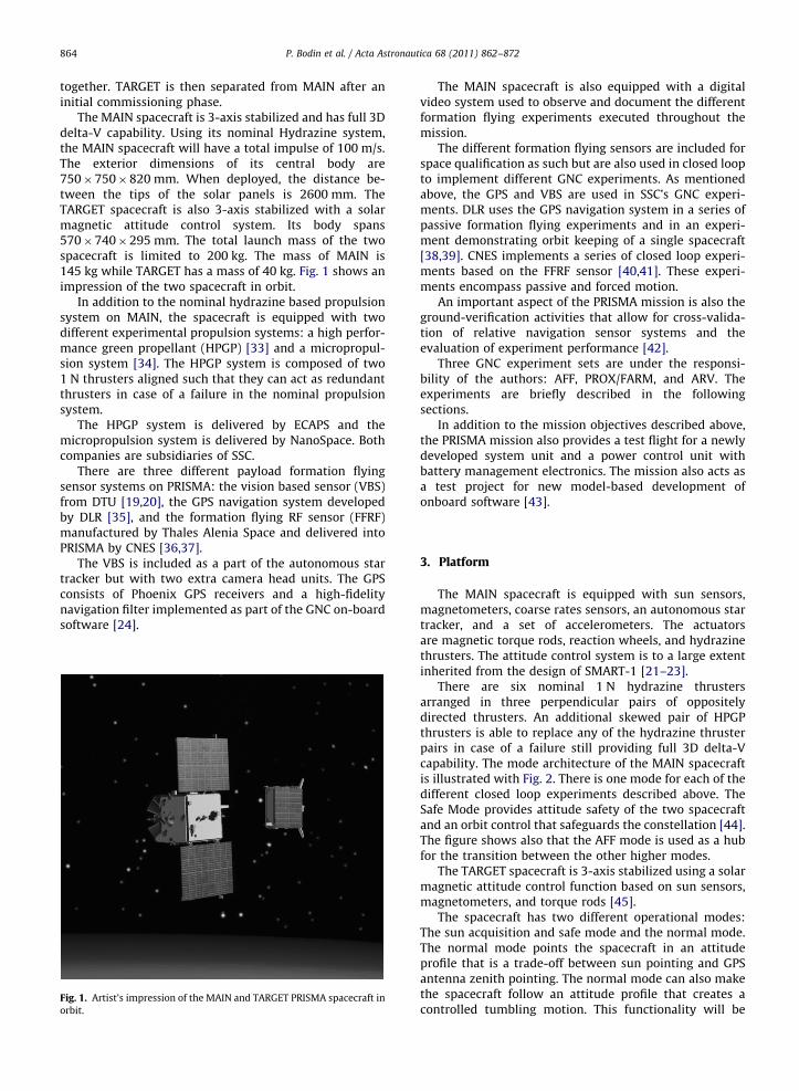
The MAIN spacecraft is 3-axis stabilized and has full 3Ddelta-V capability. Using its nominal Hydrazine system,the MAIN spacecraft will have a total impulse of 100 m/s.The exterior dimensions of its central body are750�750�820 mm. When deployed, the distance be-tween the tips of the solar panels is 2600 mm. TheTARGET spacecraft is also 3-axis stabilized with a solarmagnetic attitude control system. Its body spans570�740�295 mm. The total launch mass of the twospacecraft is limited to 200 kg. The mass of MAIN is145 kg while TARGET has a mass of 40 kg. Fig. 1 shows animpression of the two spacecraft in orbit.
In addition to the nominal hydrazine based propulsionsystem on MAIN, the spacecraft is equipped with twodifferent experimental propulsion systems: a high perfor-mance green propellant (HPGP) [33] and a micropropul-sion system [34]. The HPGP system is composed of two1 N thrusters aligned such that they can act as redundantthrusters in case of a failure in the nominal propulsionsystem.
The HPGP system is delivered by ECAPS and themicropropulsion system is delivered by NanoSpace. Bothcompanies are subsidiaries of SSC.
There are three different payload formation flyingsensor systems on PRISMA: the vision based sensor (VBS)from DTU [19,20], the GPS navigation system developedby DLR [35], and the formation flying RF sensor (FFRF)manufactured by Thales Alenia Space and delivered intoPRISMA by CNES [36,37].
The VBS is included as a part of the autonomous startracker but with two extra camera head units. The GPSconsists of Phoenix GPS receivers and a high-fidelitynavigation filter implemented as part of the GNC on-boardsoftware [24].
Fig. 1. Artist’s impression of the MAIN and TARGET PRISMA spacecraft in
orbit.
The MAIN spacecraft is also equipped with a digitalvideo system used to observe and document the differentformation flying experiments executed throughout themission.
The different formation flying sensors are included forspace qualification as such but are also used in closed loopto implement different GNC experiments. As mentionedabove, the GPS and VBS are used in SSC’s GNC experi-ments. DLR uses the GPS navigation system in a series ofpassive formation flying experiments and in an experi-ment demonstrating orbit keeping of a single spacecraft[38,39]. CNES implements a series of closed loop experi-ments based on the FFRF sensor [40,41]. These experi-ments encompass passive and forced motion.
An important aspect of the PRISMA mission is also theground-verification activities that allow for cross-valida-tion of relative navigation sensor systems and theevaluation of experiment performance [42].
Three GNC experiment sets are under the responsi-bility of the authors: AFF, PROX/FARM, and ARV. Theexperiments are briefly described in the followingsections.
In addition to the mission objectives described above,the PRISMA mission also provides a test flight for a newlydeveloped system unit and a power control unit withbattery management electronics. The mission also acts asa test project for new model-based development ofonboard software [43].
3. Platform
The MAIN spacecraft is equipped with sun sensors,magnetometers, coarse rates sensors, an autonomous startracker, and a set of accelerometers. The actuatorsare magnetic torque rods, reaction wheels, and hydrazinethrusters. The attitude control system is to a large extentinherited from the design of SMART-1 [21–23].
There are six nominal 1 N hydrazine thrustersarranged in three perpendicular pairs of oppositelydirected thrusters. An additional skewed pair of HPGPthrusters is able to replace any of the hydrazine thrusterpairs in case of a failure still providing full 3D delta-Vcapability. The mode architecture of the MAIN spacecraftis illustrated with Fig. 2. There is one mode for each of thedifferent closed loop experiments described above. TheSafe Mode provides attitude safety of the two spacecraftand an orbit control that safeguards the constellation [44].The figure shows also that the AFF mode is used as a hubfor the transition between the other higher modes.
The TARGET spacecraft is 3-axis stabilized using a solarmagnetic attitude control function based on sun sensors,magnetometers, and torque rods [45].
The spacecraft has two different operational modes:The sun acquisition and safe mode and the normal mode.The normal mode points the spacecraft in an attitudeprofile that is a trade-off between sun pointing and GPSantenna zenith pointing. The normal mode can also makethe spacecraft follow an attitude profile that creates acontrolled tumbling motion. This functionality will be
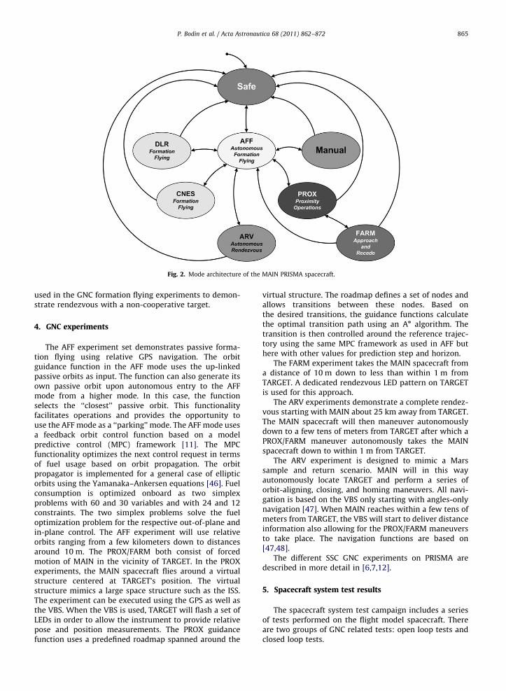
Fig. 2. Mode architecture of the MAIN PRISMA spacecraft.
P. Bodin et al. / Acta Astronautica 68 (2011) 862–872 865
used in the GNC formation flying experiments to demon-strate rendezvous with a non-cooperative target.
4. GNC experiments
The AFF experiment set demonstrates passive forma-tion flying using relative GPS navigation. The orbitguidance function in the AFF mode uses the up-linkedpassive orbits as input. The function can also generate itsown passive orbit upon autonomous entry to the AFFmode from a higher mode. In this case, the functionselects the ‘‘closest’’ passive orbit. This functionalityfacilitates operations and provides the opportunity touse the AFF mode as a ‘‘parking’’ mode. The AFF mode usesa feedback orbit control function based on a modelpredictive control (MPC) framework [11]. The MPCfunctionality optimizes the next control request in termsof fuel usage based on orbit propagation. The orbitpropagator is implemented for a general case of ellipticorbits using the Yamanaka–Ankersen equations [46]. Fuelconsumption is optimized onboard as two simplexproblems with 60 and 30 variables and with 24 and 12constraints. The two simplex problems solve the fueloptimization problem for the respective out-of-plane andin-plane control. The AFF experiment will use relativeorbits ranging from a few kilometers down to distancesaround 10 m. The PROX/FARM both consist of forcedmotion of MAIN in the vicinity of TARGET. In the PROXexperiments, the MAIN spacecraft flies around a virtualstructure centered at TARGET’s position. The virtualstructure mimics a large space structure such as the ISS.The experiment can be executed using the GPS as well asthe VBS. When the VBS is used, TARGET will flash a set ofLEDs in order to allow the instrument to provide relativepose and position measurements. The PROX guidancefunction uses a predefined roadmap spanned around the
virtual structure. The roadmap defines a set of nodes andallows transitions between these nodes. Based onthe desired transitions, the guidance functions calculatethe optimal transition path using an An algorithm. Thetransition is then controlled around the reference trajec-tory using the same MPC framework as used in AFF buthere with other values for prediction step and horizon.
The FARM experiment takes the MAIN spacecraft froma distance of 10 m down to less than within 1 m fromTARGET. A dedicated rendezvous LED pattern on TARGETis used for this approach.
The ARV experiments demonstrate a complete rendez-vous starting with MAIN about 25 km away from TARGET.The MAIN spacecraft will then maneuver autonomouslydown to a few tens of meters from TARGET after which aPROX/FARM maneuver autonomously takes the MAINspacecraft down to within 1 m from TARGET.
The ARV experiment is designed to mimic a Marssample and return scenario. MAIN will in this wayautonomously locate TARGET and perform a series oforbit-aligning, closing, and homing maneuvers. All navi-gation is based on the VBS only starting with angles-onlynavigation [47]. When MAIN reaches within a few tens ofmeters from TARGET, the VBS will start to deliver distanceinformation also allowing for the PROX/FARM maneuversto take place. The navigation functions are based on[47,48].
The different SSC GNC experiments on PRISMA aredescribed in more detail in [6,7,12].
5. Spacecraft system test results
The spacecraft system test campaign includes a seriesof tests performed on the flight model spacecraft. Thereare two groups of GNC related tests: open loop tests andclosed loop tests.

P. Bodin et al. / Acta Astronautica 68 (2011) 862–872866
The open loop tests are implemented to verify thecorrect sign of the response of different sensor-to-actuator chains including the in-between control soft-ware. The tests are performed by stimulation of thesensors checking the correct behavior of the associatedactuator.
Fig. 3. Closed loop system
Fig. 4. AFF relative spacecraft position. The figure shows the three planar projec
is indicated as gray spikes proportional to the thrust impulse.
The closed loop tests take place on a test environmentthat is illustrated with Fig. 3. The environment includes asystem level spacecraft simulator, called SatSim. Thesimulator includes models of all on-board sensors andactuators, spacecraft attitude and orbital dynamics, andspace environment. The simulator issues stimulation
test architecture.
tions of the relative trajectory as well as a 3-dimensional view. Thrusting

Fig. 5. AFF control errors. Thrusting is indicated as gray spikes proportional to the thrust impulse. The control box is indicated with horizontal lines.
Fig. 6. AFF navigation position errors. Thrusting is indicated as vertical gray lines.
P. Bodin et al. / Acta Astronautica 68 (2011) 862–872 867
signal messages over the UDP/IP network. These stimula-tion signals represent the analogue and digital outputsthat would come from the real on-board sensors and themessages are picked up by IP to analogue or digitalconversion boxes which are connected to the real on-board interface electronics which convert the sensor
measurements to CAN-bus messages that are picked upby the on-board computer. The conversion boxes arecalled platform unit simulators (PUSIMs) and areconstructed to represent the real sensor electrical inter-faces and the corresponding sensors are disconnected. TheSatSim simulator is configured not to issue the

Fig. 7. AFF navigation velocity errors. Thrusting is indicated as vertical gray lines.
Fig. 8. PROX experiment trajectory, flight map, and virtual structure.
The figure shows the relative trajectory as a gray and black line. The
figure shows the virtual structure as a space-station like structure. The
flight map of allowed paths is spanned around this structure.
P. Bodin et al. / Acta Astronautica 68 (2011) 862–872868
corresponding messages on the CAN-bus, but is able tolisten to all CAN communication issued by the on-boardcomputer. Typically this communication consists of the
actuator commands which in this way are fed into theSatSim simulator in order to close the loop. Some sensors,such as the star tracker, are equipped with dedicatedstimulation ports and do not need to be disconnectedat all.
The tests are based on different test scenariosconstructed to represent key phases of the mission suchas the initial acquisition, commissioning, and the differentexperimental phases. A number of test cases is executedwithin the framework of each scenario. The test cases areconstructed to verify each on-board function used withinthe scenario. The whole test setup is commanded andmonitored over the UDP/IP network from the SSCdeveloped command and checkout software RAMSES[49]. This system is also used for flight control duringthe PRISMA mission. The test cases are implemented asPLUTO test scripts [50].
The whole test setup is highly modular and can beconfigured to include anything from only some of the on-board hardware in the loop up to the complete on-board datahandling system with all corresponding interface electronics.In the most complex configuration, the setup included aPUSIM representing the FFRF-sensors as well an RF GPS signalsimulator (GSS) that was used dynamically in closed loop. Forthis purpose, SatSim was modified to take an external time-reference interrupt signal from the GSS.
The scenario based test approach is also constructed tobe highly modular so that the same test script can be usedin several scenarios. Since RAMSES is also used in flightoperations, several of the test scenario scripts haveevolved into flight operational procedures.
The experience from the test campaign, as well as theinitial flight results, indicates that the test environmentprovides high representativity and that it has been a cost
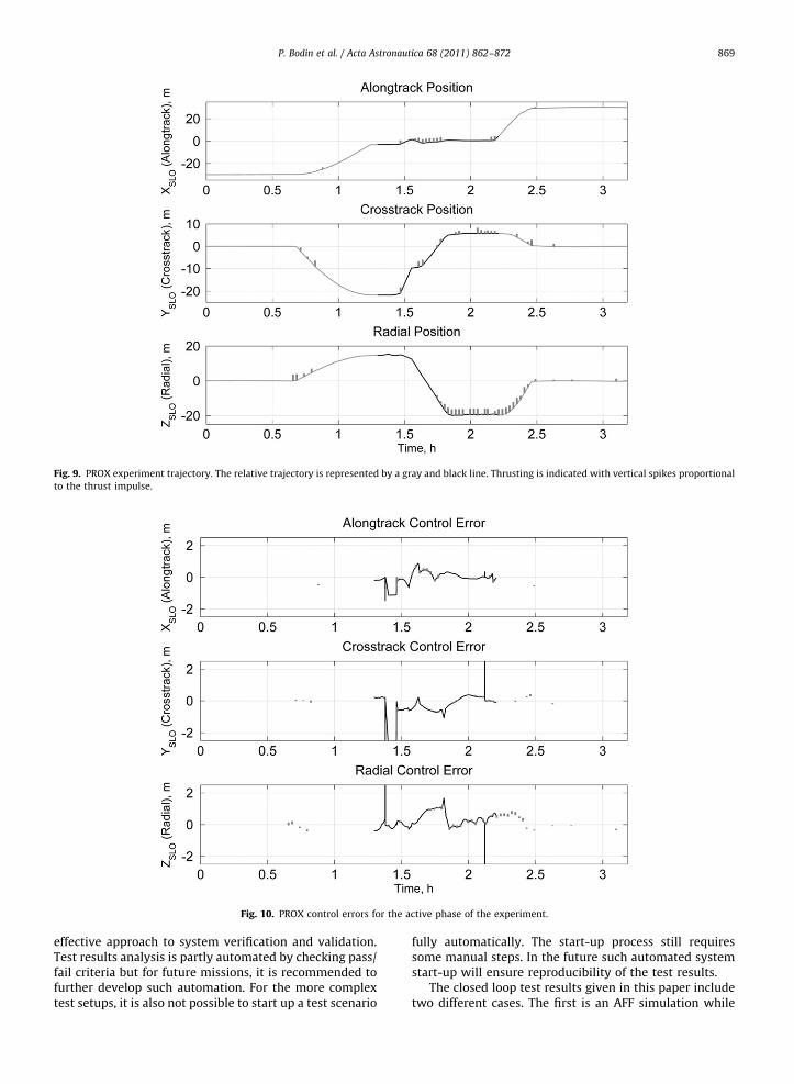
Fig. 9. PROX experiment trajectory. The relative trajectory is represented by a gray and black line. Thrusting is indicated with vertical spikes proportional
to the thrust impulse.
Fig. 10. PROX control errors for the active phase of the experiment.
P. Bodin et al. / Acta Astronautica 68 (2011) 862–872 869
effective approach to system verification and validation.Test results analysis is partly automated by checking pass/fail criteria but for future missions, it is recommended tofurther develop such automation. For the more complextest setups, it is also not possible to start up a test scenario
fully automatically. The start-up process still requiressome manual steps. In the future such automated systemstart-up will ensure reproducibility of the test results.
The closed loop test results given in this paper includetwo different cases. The first is an AFF simulation while
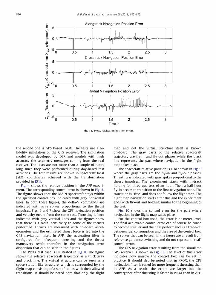
Fig. 11. PROX navigation position errors.
P. Bodin et al. / Acta Astronautica 68 (2011) 862–872870
the second one is GPS based PROX. The tests use a hi-fidelity simulation of the GPS receiver. The simulationmodel was developed by DLR and models with highaccuracy the telemetry messages coming from the realreceiver. The tests are not more than a couple of hourslong since they were performed during day-based testactivities. The test results are shown in spacecraft local(SLO) coordinates achieved with the transformationprovided in [51].
Fig. 4 shows the relative position in the AFF experi-ment. The corresponding control error is shown in Fig. 5.The figure shows that the MAIN spacecraft stays withinthe specified control box indicated with gray horizontallines. In both these figures, the delta-V commands areindicated with gray spikes proportional to the thrustimpulses. Figs. 6 and 7 show the GPS navigation positionand velocity errors from the same test. Thrusting is hereindicated with gray vertical lines and the figures showthat there is a radial sensitivity to some of the thrustsperformed. Thrusts are measured with on-board accel-erometers and the estimated thrust force is fed into theGPS navigation filter. In AFF, the navigation filter isconfigured for infrequent thrusting and the thrustmaneuvers result therefore in the navigation errordispersion that can be seen in the figures.
The PROX test case is illustrated in Fig. 8. The figureshows the relative spacecraft trajectory as a thick grayand black line. The virtual structure can be seen as aspace-station like structure, which is surrounded by theflight map consisting of a set of nodes with their allowedtransitions. It should be noted here that only the flight
map and not the virtual structure itself is knownon-board. The gray parts of the relative spacecrafttrajectory are fly-in and fly-out phases while the blackline represents the part where navigation in the flightmap takes place.
The spacecraft relative position is also shown in Fig. 9where the gray parts are the fly-in and fly-out phases.Thrusting is indicated with gray spikes proportional to thethrust impulses. The experiment starts with in-trackholding for three quarters of an hour. Then a half-hourfly-in occurs to transition to the first navigation node. Thetransition is ‘‘free’’ and does not follow the flight map. Theflight map navigation starts after this and the experimentends with fly-out and holding similar to the beginning ofthe test.
Fig. 10 shows the control error for the part wherenavigation in the flight map takes place.
For the control box used, the error is at meter-level.The final achievable control error can of course be tunedto become smaller and the final performance is a trade-offbetween fuel consumption and the size of the control box.The spikes that can be seen in the figure are a result fromreference guidance switching and do not represent ‘‘real’’control errors.
The GPS navigation error resulting from the simulatedGPS receiver is shown in Fig. 11. The level of this errorindicates how narrow the control box can be set inpractice. It should also be noted that in PROX, the GPSnavigation filter is tuned for more frequent thrusting thanin AFF. As a result, the errors are larger but theconvergence after thrusting is faster in PROX than in AFF.

P. Bodin et al. / Acta Astronautica 68 (2011) 862–872 871
6. Conclusions
This paper has given an overview of the PRISMAmission in general and SSC’s GNC experiments inparticular. The paper has demonstrated results from thespacecraft system tests performed on the flight modelspacecraft.
The results reflect the expected behavior and perfor-mance and the accuracy of the system corresponds towhat can be expected in flight. Initial flight commission-ing results also indicate that this is the case.
Already in the PRISMA mission it was decided not touse or develop a robotic test facility. The main reason forthis decision was of course the very slim project budgetbut also it was believed that the performance could besufficiently well-proven without such an approach. Theclosed loop spacecraft system test environment has in thisway proven to be a low-cost approach to systemverification and validation still providing high represen-tativity. The environment is modular and can be config-ured in many different ways depending on the purpose ofthe tests or the availability of hardware. Basically thesame environment has in this way been used throughoutthe software and spacecraft system tests as well as fortraining of the operational team. Probably the mostcumbersome part of the tests was the inclusion of theGSS in closed loop. In order to achieve this test setup,several modifications of the existing simulator interfacesand architecture had to be implemented.
A particularly strong point is that the RAMSEScommand and monitoring software is used in the testcampaigns and for flight operations.
The modularity of the scenario based testing has alsoproven to be a rewarding approach. For future missions,test execution and results analysis should be furtherautomated.
Acknowledgements
The authors would like to thank the rest of the PRISMAteam at SSC for the support to produce the presented testresults. The authors would also like to thank the SNSB forfunding the mission and DLR, CNES, and DTU for theircontributions.
References
[1] S. Persson, B. Jakobsson, E. Gill, PRISMA demonstration mission foradvanced rendezvous and formation flying technologies andsensors, in: 56th International Astronautical Congress, IAC-05-B5.6.B.07, October 2005.
[2] S. Persson, P. Bodin, E. Gill, J. Harr, J.L. Jørgensen, PRISMA—anautonomous formation flying mission, in: Proceedings of the 4SSymposium Small Satellites, Systems and Services, ESA SP-625,2006.
[3] S. Persson, S. Veldman, P. Bodin, PRISMA—a formation flying projectin implementation phase, Acta Astronautica Vol. 65 (9–10) (2009)1360–1374, doi:10.1016/j.actaastro.2009.03.067.
[4] S. Persson, The validation and testing of the PRISMA formationflying project, in: 59th International Astronautical Congress, IAC-08-B4.2.2, 2008.
[5] S. Berge, B. Jakobsson, P. Bodin, A. Edfors, S. Persson, Rendezvousand formation flying experiments within the PRISMA in-orbit
testbed, in: Proceedings of the 6th International ESA Conferenceon Guidance, Navigation and Control Systems, ESA SP-606, 2006, p.59.1.
[6] P. Bodin, et al., Guidance, navigation, and control experiments onthe PRISMA in-orbit test bed, in: 58th International AstronauticalCongress, IAC-07-C1.6.01, 2007.
[7] P. Bodin, R. Larsson, F. Nilsson, C. Chasset, R. Noteborn, M. Nylund,PRISMA: an in-orbit test bed for guidance, navigation, and controlexperiments, Journal of Spacecraft and Rockets 46 (3) (2009)615–623, doi:10.2514/1.40161.
[8] D. Schulze, M. Zink, G. Krieger, J. Boer, A. Moreira, TANDEM-XMission concept and status, in: Proceedings of FRINGE, November–December 2009.
[9] A. Wishart, F. Teston, S. Kemble, S. Grocott, A. Davies, C. Warren,K. Geelen, The PROBA-3 formation flying technology demonstrationmission, in: 58th International Astronautical Congress, IAC-07-C1.7.01, September 2007.
[10] T. Rupp, T. Boge, R. Kiehling, F. Sellmaier, Flight dynamicschallenges of the German on-orbit servicing mission DEOS,in: 21st International Symposium on Space Flight Dynamics,Toulouse, France, 2009.
[11] R. Larsson, S. Berge, P. Bodin, U. Jonsson, Fuel efficient relative orbitcontrol strategies for formation flying rendezvous within PRISMA,Advances in the Astronautical Sciences 125 (2006) 25–40 (Also AASPaper 06-025, February 2006).
[12] F. Nilsson, P. Bodin, Autonomous rendezvous experiments on thePRISMA in-orbit formation flying test bed, in: Proceedings of the3rd International Symposium on Formation Flying, Missions andTechnologies, ESA SP-654, 2008.
[13] I. Kawano, et al., First autonomous rendezvous using relative GPSnavigation by ETS-VII, in: Proceedings of ION GPS-1999, September1999, pp. 393–400.
[14] I. Kawano, et al., Analysis and evaluation of GPS relative navigationusing carrier phase for RVD experiment satellite of ETS-VII,in: Proceedings of ION GPS-2000, September 2000, pp. 1655–1660.
[15] A.R. Toso, Systems-level feasibility analysis of a microsatelliterendezvous with non-cooperative targets, Thesis AFIT/GSS/ENY/04-M06, Air Force Institute of Technology, March 2004.
[16] A. Tatsch, Fitz-Coy, N., Gladun, S., On-orbit servicing: a brief survey,in: Proceedings of the Performance Metrics for Intelligent SystemsConference, 2006.
[17] T.A. Mulder, Orbital express autonomous rendezvous and captureflight operations—part 1 of 2: mission description, AR&C exercises1, 2, and 3, Advances in the Astronautical Sciences 130 (2008)1649–1668 (Also AAS Paper 08-209, January 2008).
[18] T.A. Mulder, Orbital express autonomous rendezvous and captureflight operations—Part 2 of 2: AR&C Exercises 4, 5, and End-of-Life,AIAA Paper 2008-6768, August 2008.
[19] T. Denver, J.L. Jørgensen, R. Michelsen, P.S. Jørgensen, MicroASC StarTracker generic developments, in: Proceedings of the 4S Sympo-sium Small Satellites, Systems and Services, ESA SP-625, 2006.
[20] M. Benn, J.L. Jørgensen, Short range pose position determination ofspacecraft using a m-Advanced Stellar Compass, in: Proceedings ofthe 3rd International Symposium on Formation Flying, Missionsand Technologies, ESA SP-654, 2008.
[21] P. Bodin, et al., Development, test and flight of the SMART-1attitude and orbit control system, AIAA Paper 2005-5991, August2005.
[22] P. Bodin, et al., The attitude and orbit control system on the SMART-1Lunar Probe, in: 17th International Symposium on Space FlightDynamics, vol. 1, Keldysh Institute of Applied Mathematics, Moscow,Russia, 2003.
[23] P. Bodin, et al., The SMART-1 attitude and orbit control system:flight results from the first mission phase, AIAA Paper 2004-5244,August 2004.
[24] S. D’Amico, J.-S. Ardaens, O. Montenbruck, Navigation of formationflying spacecraft using GPS: the PRISMA technology demonstration,in: Proceedings of ION-GNSS-2009, September 2009, pp. 1427–1441.
[25] S. D’Amico, O. Montenbruck, R. Larsson, C. Chasset, GPS-basedrelative navigation during the separation sequence of the PRISMAformation, AIAA Paper 2008-6661.
[26] S. D’Amico, S. De Florio, J.-S. Ardaens, T. Yamamoto, Offline andhardware-in-the-loop validation of the GPS-based real-time navi-gation system for the PRISMA formation flying mission, in:Proceedings of the 3rd International Symposium on FormationFlying, Missions and Technologies, ESA SP-654, 2008.
[27] M. Romano, D.A. Friedman, T.J. Shay, Laboratory experimentation ofautonomous spacecraft approach and docking to a collaborativetarget, Journal of Spacecraft and Rockets 44 (1) (2007) 164–173.

P. Bodin et al. / Acta Astronautica 68 (2011) 862–872872
[28] M.W. Regehr, B. Acikmese, A. Ahmed, M. Aung, P. MacNeal,J. Shields, G. Singh, R. Bailey, C. Bushnell, A. Hicke, B. Lytle,R.E. Rassmussen, The formation control testbed, in: Proceedings ofIEEE Aerospace Conference, vol. 1, March 2004.
[29] A.G. Casas, A. Tomassini, F. Gandıa, PLATFORM: an integratedapproach to robotics and space navigation validation. Designingand setting the robotic test-bed, in: Proceedings of the 8thInternational Symposium on Artificial Intelligence, Robotics andAutomation in Space—iSAIRAS, ESA SP-603, 2005.
[30] T. Boge, T. Rupp, K. Landzettel, T. Wimmer, C. Mietner, J. Bosse,B. Thaler, Hardware in the Loop Simulator fur Rendezvous undDocking Manover, DGLR Jahrestagung, Aachen, 2009 September8–10.
[31] R. Burns, B. Naasz, D. Gaylor, J. Higinbotham, An environment forhardware-in-the-loop formation navigation and control, AIAAPaper 2004-4735, August 2004.
[32] E. Gill, B. Naasz, T. Ebinuma, First results from a hardware-in-the-loop demonstration of closed-loop autonomous formation flying,Advances in the Astronautical Sciences 113 (2003) 361–376 (AlsoAAS Paper 03–040, February 2003).
[33] K. Anflo, S. Persson, G. Bergman, P. Thormahlen, T. Hasanof, FlightDemonstration of an ADN-based propulsion system on the PRISMAsatellite, AIAA Paper 2006-5212, July 2006.
[34] T.-A. Gronland, P. Rangsten, M. Nese, M. Lang, Miniaturization ofcomponents and systems for space using MEMS-technology, ActaAstronautica 61 (1-6) (2007) 228–233.
[35] E. Gill, S. D’Amico, O. Montenbruck, Autonomous formation flyingfor the PRISMA mission, Journal of Spacecraft and Rockets 44 (3)(2007) 671–681, doi:10.2514/1.23015.
[36] T. Greiler, et al., GNSS in Space Part 2 Formation Flying RadioFrequency Techniques and Technology, InsideGNSS, January/Feb-ruary 2009, pp. 43–51.
[37] T. Greiler, et al., GNSS in Space Part 1 Formation Flying RadioFrequency Missions, Techniques, and Technology, InsideGNSS,November/December 2008, pp. 40–46.
[38] S. D’Amico, E. Gill, O. Montenbruck, Relative orbit control design forthe PRISMA formation flying mission, AIAA Paper 2006-6067,August 2006.
[39] S. De Florio, S. D’Amico, The precise autonomous orbit keepingexperiment on the PRISMA mission, Journal of the AstronauticalSciences 56 (4) (2009) 477–494.
[40] J. Harr, M. Delpech, L. Lestarquit, D. Seguela, RF metrologyvalidation and formation flying demonstration by small satelli-tes—the CNES participation on the PRISMA mission, in: Proceedingsof the 4S Symposium Small Satellites, Systems and Services, ESASP-625, 2006.
[41] J. Harr, M. Delpech, T. Grelier, D. Seguela, The FFIORD experiment:CNES’RF metrology validation and formation flying demonstrationon PRISMA, in: Proceedings of the 3rd International Symposium onFormation Flying, Missions and Technologies, ESA SP-654, 2008.
[42] O. Montenbruck, M. Delpech, J.-S. Ardanes, N. Delong, S. D’Amico,J. Harr, Cross-Validation of GPS- and FFRF-based relative navigationfor the PRISMA Mission, in: Proceedings of NAVITEC 2008, ESA,2008.
[43] T. Olsson, A. Edfors, Model-based onboard software design: thePRISMA case study, in: Proceedings of Data Systems in Aerospace,ESA SP-630, 2006, p. 43.1.
[44] R. Larsson, J. Mueller, S. Thomas, B. Jakobsson, P. Bodin, Orbitconstellation safety on the PRISMA in-orbit formation flying testbed, in: Proceedings of the 3rd International Symposium onFormation Flying, Missions and Technologies, ESA SP-654, 2008.
[45] C. Chasset, S. Berge, P. Bodin, B. Jakobsson, 3-Axis magnetic controlwith multiple attitude profile capabilities in the PRISMA mission,Space Technology 26 (3–4) (2007) 137–154.
[46] K. Yamanaka, F. Ankersen, New state transition matrix for relativemotion on an arbitrary elliptical orbit, Journal of Guidance, Control,and Dynamics 25 (1) (2002) 60–66.
[47] R.J.V. Chari, Autonomous orbital rendezvous using angles-onlynavigation, Thesis A115893, Massachusetts Institute of Technology,December 2001.
[48] H. Schaub, K.T. Alfriend, Impulsive feedback control to establishspecific mean orbit elements of spacecraft formations, Journal ofGuidance, Control, and Dynamics 24 (4) (2001) 739–745.
[49] A. Carlsson, A general control system for both sounding rockets andsatellites, in: Proceedings of the 18th ESA symposium on EuropeanRockets and Balloon Programmes and Related Research, ESASP-647, 2007.
[50] Space engineering: test and operations procedure language,ECSS-E-70-32A, April 2006.
[51] C.M. Lane, P. Axelrad, Formation design in eccentric orbits usinglinearized equations of relative motion, Journal of Guidance,Control, and Dynamics 29 (1) (2006) 146–160.
Copyright © 2022 FDOKUMEN