
Owner's Manual - Orbit Fitness
24
Owner’s Manual A
-
Upload
khangminh22 -
Category
Documents
-
view
0 -
download
0
Transcript of Owner's Manual - Orbit Fitness

Owner’s Manual
A

Table of Contents
Product Safety …………………………………………….. 01.
Part Drawing & Contents ……………………...………….. 02.
Hardware & Tools ………………………………………….. 03.
Assembly …………………………………….…………….. 04.
Adjustment …………………………………….…………….. 10.
Trouble Shooting & Maintenance ……………..………… 11.
Computer ………………………………….……..………… A.
Warm Up ……………………………………..……………. B.
Part List ……………………………………..…………….. C.
Exploded View ……………………………………………. #.
FE150A18-20150422.1

1
Product Safety
Basic precautions should always be followed, including the following safety instructions when using this
equipment: Read all instructions before using this equipment.
1. Read all the instructions in this manual and do warm up exercises before using this equipment.
2. Before exercise, in order to avoid injuring your muscles, warm-up exercise for every muscle group is highly
recommended. Please refer to the Warm Up pages for pre and post workout.
3. Please make sure all components are not damaged and in working order before use. This equipment should be
placed on a flat surface while in use. Using a mat or other material on the ground is recommended.
4. Please wear proper clothes and shoes when using this equipment; do not wear clothes that might catch in any
part of the equipment.
5. Do not attempt any maintenance or adjustments other than those described in this manual. Should any problems
arise, discontinue use and consult an Authorized Service Representative.
6. Be careful when stepping on or leaving the pedals. Always hold the handlebars first and make sure the pedal at
your side is at its lowest position. Step on the pedal, and stride over the main frame then step on the other pedal.
When using, please hold onto the handlebars. To ensure the pedals run smoothly push or pull on the handlebars
first, then follow with leg motion. When stepping off the machine, make sure one pedal is at its lowest position
and step out of there before stepping out of the pedal at the highest position.
7. Do not use the equipment outdoors.
8. This equipment is for household use only.
9. Only one person should be on the equipment while in use.
10. Keep children and pets away from the product while in use. This machine is designed for adults only. If you feel
any chest pains, nausea, dizziness, or short of breath, you should stop exercising immediately and consult your
physician before continuing.
11. If you feel any chest pains, nausea, dizziness, or short of breath, you should stop exercising immediately and
consult your physician before continuing.
12. The maximum weight capacity for this product is 275 lbs / 125 kgs.
WARNING: Before beginning any exercise program consult your physician. This is especially important for the
persons who are over 35 years old or who have pre-existing health problems. Read all instructions
before using any fitness equipment.
CAUTION: Read all instructions carefully before operating this product. Retain this Owner’s Manual for future
reference.

2
Part Drawing & Contents
Box Contents
A01 1Set A09 1Set A12/A13 2Set A07 1Set A08 1Set
Main Frame
Stationary Handlebar
Left/Right
Dual Action Handlebar
Front Stabilizer Tube Rear Stabilizer Tube
C12/C30 2PC C24 1PC C29/C31 2Set C03/C18 2Set C06/C27 1Set
Foot Pedal
Water Bottle Holder Dual Action Arm
Decorative Cover –A/B
Foot Tube Pivot
Decorative Cover –A/B
Hat Cover
Rubber Gasket
D02 1PC D08 1PC
Computer
AC Adapter

3
Hardware & Tools
Pack Contents
B01 (1) 6PC B05 (2) 8PC B04 (3) 4PC B12 (4) 4PC B02 (5) 6PC
Curve Washer M8
Bolt M6
Carriage Bolt M8
Curve Washer M8
Bolt M8
B19 (6) 18PC B09 (7) 4PC
Screw M5
Nut M8
(10) 1PC (8) 1PC (9) 1PC
Hex Tool with Phillips Screwdriver (13mm/14mm) Allen Key (M4) Allen Key (M5)

4
Assembly
1. Preparation
1.1 Clear a 2 meters time 2.5 meters working space before unpacking your Elliptical Cross Trainer.
1.2 The assembly steps required two persons.
2. Open carton
2.1 Use a sharp knife, open the carton and lay it flat on the floor.
2.2 Remove all loose components.
2.3 Refer to the checklist and check that everything is present.
NOTE:
To protect the Elliptical Cross Trainer while assembling we suggest that you do not remove the protective
packing material until it is absolutely necessary.
3. Remove Rear Protection Tube
3.1 Lift the rear of the machine off the floor and slide a polystyrene block under the rear of the machine.
3.2 Remove Two Bolts [B11], Two Washers [B10] and remove the Protection Tube.
[Remove bolts with the Hex Tool with Phillips Screw Driver provided.]

5
Assembly
4. Rear Stabilizer Tube Installation
4.1 Assemble the Rear Stabilizer Tube [A08] with Two Bolts [B11] and Two Washers [B10] which were removed from
step 3.2 and tighten firmly.
[Tighten bolts with the Hex Tool with Phillips Screw Driver provided.]
5. Upright Support Tube Installation
5.1 Lift the Upright Support Tube [A02] until it is vertical while the other person connects the matching connectors of
cable [D04/D05] as shown in the illustration below.
5.2 Then slide the Upright Support Tube [A02] into the hole of Main Frame [A01].
5.3 Assemble Six Blots [B02] by fingers, Six Curve Washers [B01] into Main Frame [A01]. Align all bolts slightly then
firmly tighten Six Bolts [B02].
5.4 Slide down the Hat Cover [C06] and push firmly.
[Tighten bolts with the M5 Allen Key provided.]
Attention: Cables can't be folded.
6. Remove Front Protection Tube
6.1 Remove the front polystyrene and place it under the front of the machine to lift it off the floor.
6.2 Refer the step 3 to remove Two Bolts [B11] and Two Washers [B10] from the front of machine and remove front
protection tube.
[Remove bolts with the Hex Tool with Phillips Screwdriver provided.]
D04
D05
C06
A01
A02
B02B01
A08
B10
B11
A01
6
Assembly
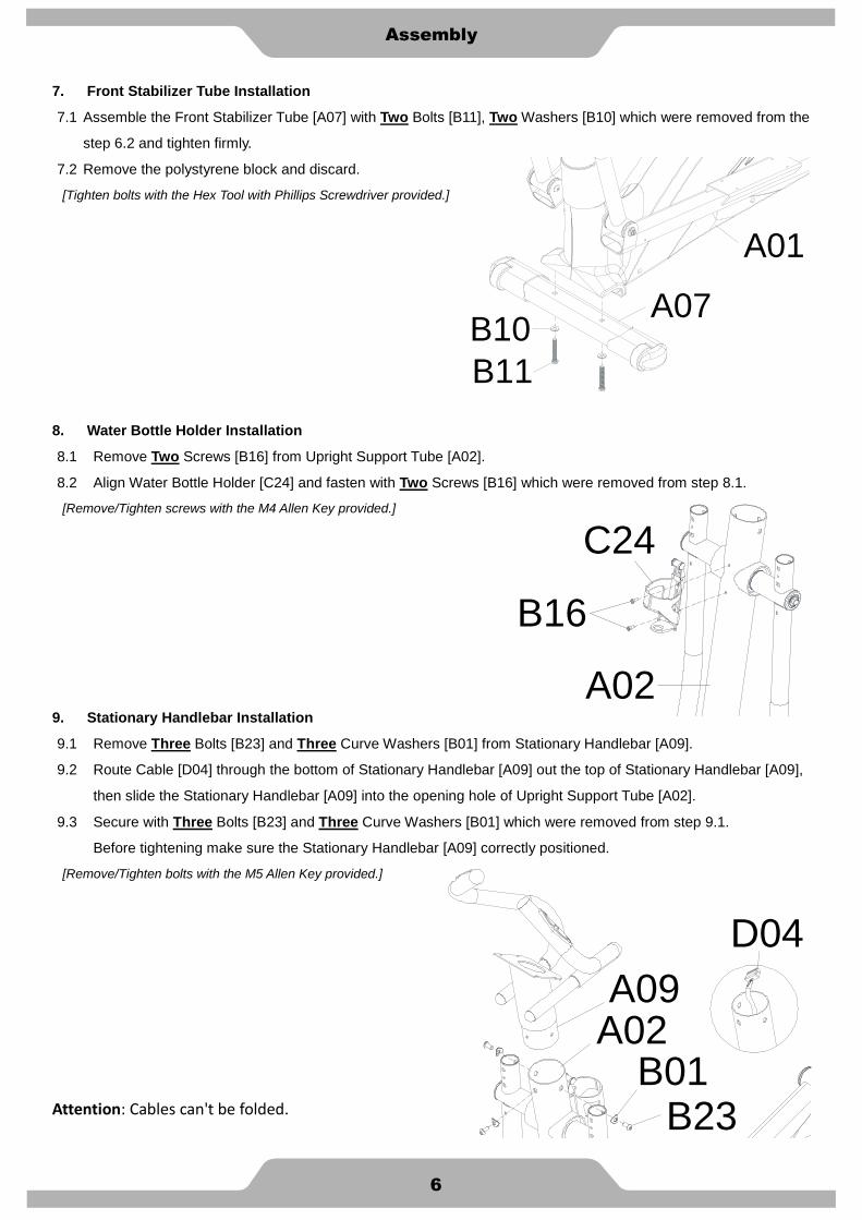
7. Front Stabilizer Tube Installation
7.1 Assemble the Front Stabilizer Tube [A07] with Two Bolts [B11], Two Washers [B10] which were removed from the
step 6.2 and tighten firmly.
7.2 Remove the polystyrene block and discard.
[Tighten bolts with the Hex Tool with Phillips Screwdriver provided.]
8. Water Bottle Holder Installation
8.1 Remove Two Screws [B16] from Upright Support Tube [A02].
8.2 Align Water Bottle Holder [C24] and fasten with Two Screws [B16] which were removed from step 8.1.
[Remove/Tighten screws with the M4 Allen Key provided.]
9. Stationary Handlebar Installation
9.1 Remove Three Bolts [B23] and Three Curve Washers [B01] from Stationary Handlebar [A09].
9.2 Route Cable [D04] through the bottom of Stationary Handlebar [A09] out the top of Stationary Handlebar [A09],
then slide the Stationary Handlebar [A09] into the opening hole of Upright Support Tube [A02].
9.3 Secure with Three Bolts [B23] and Three Curve Washers [B01] which were removed from step 9.1.
Before tightening make sure the Stationary Handlebar [A09] correctly positioned.
[Remove/Tighten bolts with the M5 Allen Key provided.]
Attention: Cables can't be folded.
B10
B11
A07
A01
A02
C24
B16
A09
B23B01
D04
A02
7
Assembly
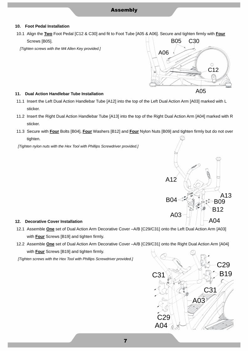
10. Foot Pedal Installation
10.1 Align the Two Foot Pedal [C12 & C30] and fit to Foot Tube [A05 & A06]. Secure and tighten firmly with Four
Screws [B05].
[Tighten screws with the M4 Allen Key provided.]
11. Dual Action Handlebar Tube Installation
11.1 Insert the Left Dual Action Handlebar Tube [A12] into the top of the Left Dual Action Arm [A03] marked with L
sticker.
11.2 Insert the Right Dual Action Handlebar Tube [A13] into the top of the Right Dual Action Arm [A04] marked with R
sticker.
11.3 Secure with Four Bolts [B04], Four Washers [B12] and Four Nylon Nuts [B09] and tighten firmly but do not over
tighten.
[Tighten nylon nuts with the Hex Tool with Phillips Screwdriver provided.]
12. Decorative Cover Installation
12.1 Assemble One set of Dual Action Arm Decorative Cover –A/B [C29/C31] onto the Left Dual Action Arm [A03]
with Four Screws [B19] and tighten firmly.
12.2 Assemble One set of Dual Action Arm Decorative Cover –A/B [C29/C31] onto the Right Dual Action Arm [A04]
with Four Screws [B19] and tighten firmly.
[Tighten screws with the Hex Tool with Phillips Screwdriver provided.]
A06
C30B05
C12
A05
A13
A12
A03A04
B04 B09
B12
C31
B19
C29
C29
C31
A03
A04

8
Assembly
13. Foot Tube Pivot Decorative Cover Installation
13.1 Assemble One set of Foot Tube Pivot Decorative Cover –A/B [C03/C18] onto Left Foot Tube [A05] with Five
Screws [B19] and tighten firmly.
13.2 Refer the same step to assemble the One set of Foot Tube Pivot Decorative Cover –A/B [C03/C18] onto Right
Foot Tube [A06].
[Remove/Tighten screws with the Hex Tool with Phillips Screwdriver provided.]
14. Computer Installation
14.1 Remove Four Screws [B21] from the bottom of Computer [D02].
14.2 Connect all matching connectors of cables which from Stationary Handlebar [A09] and Computer [D02].
14.3 Slide the extra length cables into the opening hole of Stationary Handlebar [A09].
14.4 There is the computer plate on the top of the Stationary Handlebar [A09]. Position the Computer [D02] on the
computer plate and secure with Four Screws [B21] which were removed from step 14.1.
[Remove/Tighten screws with the Hex Tool with Phillips Screwdriver provided.]
Attention: Cables can't be folded.
A05
C18C03
B19
B19
D02
B21
A09
9
Assembly
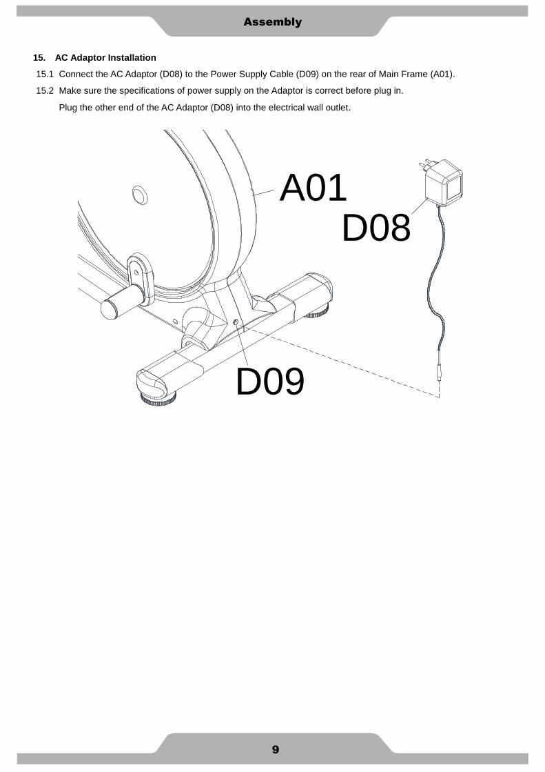
15. AC Adaptor Installation
15.1 Connect the AC Adaptor (D08) to the Power Supply Cable (D09) on the rear of Main Frame (A01).
15.2 Make sure the specifications of power supply on the Adaptor is correct before plug in.
Plug the other end of the AC Adaptor (D08) into the electrical wall outlet.
D08A01
D09

10
Adjustment
Adjustment
Adjusting the Adjustable Foot Pad
Adjust the Adjustable Foot Pad on the Main Frame as needed to level the Elliptical Trainer.
The Elliptical Trainer has to be leveled to prevent from wobble or shaking during the exercise.

11
Trouble shooting & Maintenance
Trouble Shooting
Computer not working correctly
Check to make sure the computer cable is connected securely.
The Elliptical Trainer wobbles when in use
Adjust the Adjustable Foot Pad on the Main Frame as needed to level the Elliptical Trainer.
Squeaking noise when in use
The bolts may be loose on the Elliptical Trainer, please inspect the bolts and tighten the loose ones.
No, inconsistent, or erratic heart rate reading
Always hold on to the handlebar grip sensors with two hands instead of just one.
Try to maintain moderate pressure while holding onto the hand pulse sensors.
Make sure that the wire connections for the hand pulse sensors are secure.
Maintenance
Cleaning
The Elliptical Trainer can be cleaned with a soft cloth and mild detergent. Do not use abrasives or solvents on plastic
parts. Please wipe your perspiration off the Elliptical Trainer after each use. Be careful not get excessive moisture on
the computer display panel as this might cause an electrical hazard or electronics to fail. Please keep the Elliptical
Trainer, specially, the computer console, out of direct sunlight to prevent screen damage. Please inspect all
assembly bolts and pedals on the machine for proper tightness every week.
Storage
Store the Elliptical Trainer in a clean and dry environment away from children.

Computer
A1
Owner’s Manual of Computer
The monitor is designed for programmable magnetic bike and elliptical trainer and introduced with
the following categories:
- Key Functions
- Displays
- Operating Ranges
- Notice Before Exercise
- Operation Instructions
● Key Functions
There are total 6 keys including UP, DOWN, RESET, START/STOP, RECOVERY, and MODE.
A. UP:To select training mode and adjust function value up.
B. DOWN:To select training mode and adjust function value down.
C. RESET:In stop mode, press the button back to main menu.
D. START/STOP:To start or stop exercise.
E. RECOVERY:To test hear rate recovery status.
F. MODE:In stop mode, the mode is to confirm all exercise data setting, and enter into
program.
● Display
A. Operation:
Power On
Plug in power supply, computer will power on and display all segments on LCD for 2
seconds.
After 4 minutes without pedaling or pulse input, console will enter into power saving mode.
Press any key may wake the console up.
B. Level:
Indicates the level of loading selected from LEVEL 1 to LEVEL 16.
SM2725(26)-71.1-20130802

Computer
A2
C. Loading Profiles:
There are 20 columns of loading bars, and 8 bars in each column. Each column represents
0.1 km workout (without the change of TIME value), and each bar represents 2 levels of
loading.
D. TIME Display:
Indicates the TIME displayed.
E. SPEED/RPM Display:
Indicates the value of RPM and SPEED.
F. WATT/LOAD Display:
Indicates the value of WATT and LOAD.
G. Message Display:
Indicates that the message displayed.
Fenster 1
Fenster 2
Fenster 3
Fenster 4
Window 1
Window 2
Window 3
Window 4
Computer
A3
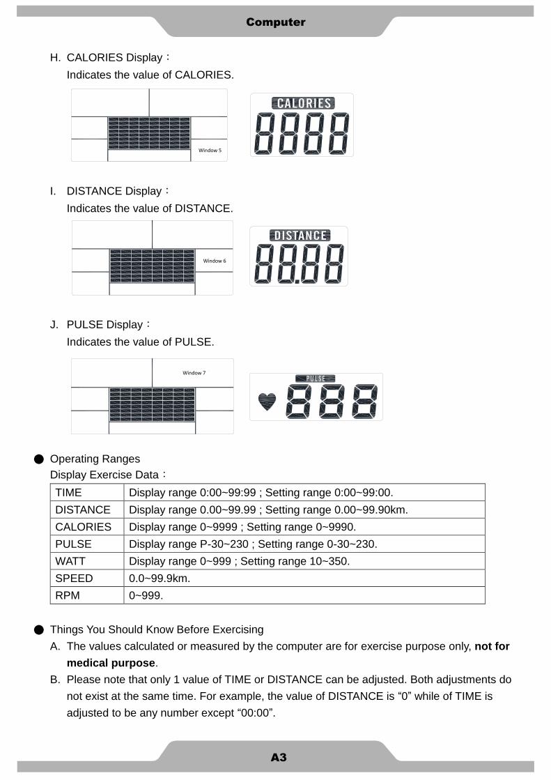
H. CALORIES Display:
Indicates the value of CALORIES.
I. DISTANCE Display:
Indicates the value of DISTANCE.
J. PULSE Display:
Indicates the value of PULSE.
● Operating Ranges
Display Exercise Data:
TIME Display range 0:00~99:99 ; Setting range 0:00~99:00.
DISTANCE Display range 0.00~99.99 ; Setting range 0.00~99.90km.
CALORIES Display range 0~9999 ; Setting range 0~9990.
PULSE Display range P-30~230 ; Setting range 0-30~230.
WATT Display range 0~999 ; Setting range 10~350.
SPEED 0.0~99.9km.
RPM 0~999.
● Things You Should Know Before Exercising
A. The values calculated or measured by the computer are for exercise purpose only, not for
medical purpose.
B. Please note that only 1 value of TIME or DISTANCE can be adjusted. Both adjustments do
not exist at the same time. For example, the value of DISTANCE is “0” while of TIME is
adjusted to be any number except “00:00”.
Fenster 5
Fenster 6
Fenster 7
Window 5
Window 6
Window 7

Computer
A4
Program Selection:
There are 19 programs with 1 Manual Program, 12 Preset Program, 4 Heart Rate Control
Program, 1 User Setting Program, 1 Watt Control Program, and 1 Pulse Recovery
Measuring.
C. Program Graph:
Each graph shown is the profile of the loading in each interval (column). With the value of
km counting up, each interval is 0.1 km that all the columns make up 2 km. With the value
of TIME counting down, each interval is the value of setup TIME divided by 20.
For example, if the time value is setup to 40 minutes, each interval will be 40 minutes
divided by 20 intervals (40/20=2). Then, each interval will be 2 minutes. The following
graphs are all the profiles in the monitor.
● Operation Instructions
A. Manual Mode:
Adjust resistance during workout manually.
Press START in main menu may start workout in manual mode.
You can also choose to into Mode function with following steps.
1. Press UP or DOWN to select workout program, choose Manual and press Mode to
enter.

Computer
A5
2. Press UP or DOWN to preset TIME, DISTANCE, CALORIES, PULSE and press MODE
to confirm.
3. Press START/STOP keys to start workout. Press UP or DOWN to adjust load level.
4. Press START/STOP keys to pause workout. Press RESET to reverse to main menu.
B. Program Mode:
Choose a preset workout program.
1. Press UP or DOWN to select workout program, choose the Program and press Mode to
enter. (Total Program = 12)
2. Press UP or DOWN to preset TIME.
3. Press START/STOP key to start workout. Press UP or DOWN to adjust load level.
4. Press START/STOP key to pause workout. Press RESET to reverse to main menu.
C. User Program Mode:
Press your own workout profile.
1. Press UP or DOWN to select workout program, choose User and press Mode to enter.
2. Press UP or DOWN to set load level of each column, and press MODE to next one.
3. Hold on pressing MODE to finish or quit setting.
4. Press UP or DOWN to preset workout TIME.
5. Press START/STOP key to start workout. Press UP or DOWN to adjust load level.
6. Press START/STOP key to pause workout. Press RESET to reverse to main menu.

Computer
A6
D. H.R.C. Mode:
1. Press UP or DOWN to select workout program, choose H.R.C. and press Mode to enter.
2. Press UP or DOWN to preset user age.
3. Press UP or DOWN to select 55%, 75%, 90%, or TAG (TARGET H.R.) (default:100).
4. Press UP or DOWN to preset workout TIME.
5. Press START/STOP key to start or stop workout. Press RESET to reverse to main
menu.
E. WATT Mode:
1. Preset UP or DOWN to preset WATT and press MODE to confirm.
2. Press UP or DOWN to preset WATT target. (default:120)
3. Press UP or DOWN to preset TIME.
4. Press START/STOP key to start workout. Press UP or DOWN to adjust Watt level.
5. Press START/STOP key to pause workout. Press RESET to reverse to main menu.

Computer
A7
F. Recovery:
Monitor heart rate recovery status.
1. User must be holding the handgrip. When the pulse value is displayed on the computer,
press on the RECOVERY key.
2. TIME shows “0:60” (seconds) and count down.
3. Computer will show F1 to F6 after count down to 0 to test heart rate recovery status.
※ Please see the F level chart below to determine the recovery level.
1.0 OUTSTANDING
1.0 < F < 2.0 EXCELLENT
2.0 < F < 2.9 GOOD
3.0 < F < 3.9 FAIR
4.0 < F < 5.9 BELOW AVERAGE
6.0 POOR
G. Smart Phone/Tablet PC USB Charger:
Please connect your USB smart phone/tablet PC charger to the USB connector at the side
of the computer. You can charge your smart phone/ tablet PC on the smart phone/tablet PC
dock. The smart phone/tablet PC dock on the computer is for most of smart phones.

Warm Up
B
Quadriceps Stretch
With one hand against a wall for balance, reach behind you and pull your right foot up. Bring your heel as close to
your buttocks as possible. Hold for 15 counts and repeat with left foot up.
Inner Thigh Stretch
Sit with the soles of your feet together with your knees pointing outward. Pull your feet as close into your groin as
possible. Gently push your knees towards the floor. Hold for 10 counts.
Toe Touches
Slowly bend forward from your waist, letting you back and shoulders relax as you stretch toward your toes. Reach
down as far as you can and hold for 15 counts.
Hamstring Stretches
Sit with your right leg extended. Rest the sole of your left foot against your right inner thigh. Stretch toward your toe
as far as possible. Hold for 15 counts Relax and then repeat with left leg extended.

Part List
C1
Part No Description Qty Part No Description Qty
A01 Welded, Main Frame 1 B25 M4 self-tapping screw 6
A02 Welded, Upright Support 1 B26 3/8" rivet nut 2
A03 Welded, Dual Action Arm /Left 1 B27 3/16" self-tapping screw 8
A04 Welded, Dual Action Arm /Right 1 B28 M4 self-tapping screw 2
A05 Welded, Foot Tube /Left 1 B29 M20 nut 1
A06 Welded, Foot Tube /Right 1 B30 M6 Screw 2
A07 Front Stabilizer Tube 1 B31 M6 Screw 8
A08 Rear Stabilizer Tube 1 B32 M6 Nylon Nut 8
A09 Welded, Stationary Handlebar 1 C01 Main cover- Right 1
A10 Welded, Cross Main Frame /Left 1 C02 Main cover- Left 1
A11 Welded, Cross Main Frame /Right 1 C03 Foot tube pivot decorative cover -A 2
A12 Dual Action Handlebar Tube /Left 1 C04 Wheel cap- Right 1
A13 Dual Action Handlebar Tube /Right 1 C05 Wheel cap- Left 1
A14 Welded, Short Crank 2 C06 Hat cover 1
B01 M8 curve washer 9 C07 Belt 1
B02 M8 bolt 6 C08 End cap 2
B03 M8 bolt 3 C09 Foam grip 2
B04 M8 carriage bolt 4 C10 Disk cover spacer 2
B05 M6 screw 8 C11 Upright tube spacer 2
B06 M8 bolt 4 C12 Foot pedal 1
B07 5/16" washer 6 C13 Adjustable foot pad 2
B08 M8 bolt 2 C14 Hand grip 2
B09 M8 nylon nut 6 C15 End cap 2
B10 3/8" washer 4 C16 Plug 2
B11 3/8" bolt 4 C17 Dual action handlebar knob 2
B12 M8 curve washer 4 C18 Foot tube pivot decorative cover -B 2
B13 Shaft 2 C19 Nut cap 2
B14 Spacer 1 C20 Bushing-standard 4
B15 Bushing spacer 8 C21 Disk cover plug 2
B16 M5 Screw 2 C22 Disk cover- Right 1
B17 M4 self-tapping screw 8 C23 Disk cover- Left 1
B18 M3 self-tapping screw 2 C24 Water bottle holder 1
B19 M5 self-tapping screw 24 C25 Bearing bushing 8
B20 #8 self-tapping screw 2 C26 Washer 4
B21 Screw for Computer 4 C27 Rubber Gasket 1
B22 M10 nut 1 C28 Bearing housing 8
B23 M8 bolt 3 C29 Dual action arm decorative cover -A 2
B24 M10 nut 1 C30 Foot pedal 1

Part List
C2
Part No Description Qty Part No Description Qty
C31 Dual action arm decorative cover -B 2 D07 Sensor cable 1
C32 Cover for Short Crank 2 D08 AC adaptor 1
D01 Hand pulse sensor 1 D09 AC plug cable 1
D02 Computer 1 D10 Hand pulse cable 1
D03 Magnetic flywheel 1 D11 Motor tension cable 1
D04 Cable 1 E01 Bearing 6004 2
D05 Cable 1 E02 Bearing 6003 8
D06 Motor with cable 1

D10
D06
D08
D09
D07
D05
D04B
21
B21
B29
B03
B18
B18
B27
B27
B17
B26
B26
C13
C08
C08
C13
B25
B25
B25
B25
B19
C07
B22
B24
B17
D03
D02
D01
D01
B16
C24
B14
C22
C23
C21
C21
C20
B09
B10
B11
B10
B11
B11
B11
B10
B10
B09
B08
C19
B07
B06
C17
C16
C15
C14
C14
C12
C09
C01
C02
C06
C05
C04
B05
B05
B04
C11
C11
E01
B17
B17
B02
B02
B02
B23
B23
B23
B01
B01
B01
B01
B01
B12
A12
A10
A11
A09
A08
A07
A05
A02
A01
B28
D10
D10
D11
B07
B19
B19
C27
B20
B20
B19
B19
B25
B19
B15
C20
B09
B09
B08
B07
B06
C17
C09
B04
C20
B12
A13
A06
A04
C30
B05
B05
B07 B
15 C25
E02
C28
C19 B
06
B07 B
15
C25 E
02 C
28
C26
B15
C25 E
02
C28
E02
C28
C25
B13
B15 C
26
B07
B06
C20
A03
B15
E02
C28
C25
E02
C28
C25
C26
B15 C
25 E
02 C
28
E02
C28
C25
B13
B15
C26
C18 B
19
C03
B19
C18 B
19
C03
B19
C31
C29
B19
B19
B19
C31
C29B19
A14
C32
B03
B30
A14
C32
B03
B30
B31
B31
B32
B32