SYSTEM APPLICATION - Implantate
68
SYSTEM APPLICATION Single-piece implants IMMEDIATE LOADING DENTAL IMPLANT SYSTEM
-
Upload
khangminh22 -
Category
Documents
-
view
0 -
download
0
Transcript of SYSTEM APPLICATION - Implantate
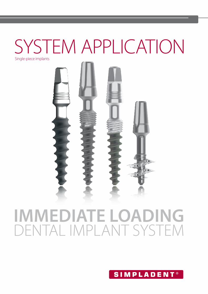
SYSTEM APPLICATIONSingle-piece implants
IMMEDIATE LOADING DENTAL IMPLANT SYSTEM
Simpladent GmbH Phone +41 (0)55 293 23 70 Dorfplatz 11 [email protected] - 8737 Gommiswald / SG www.simpladent-implants.comSWITZERLAND
CONTENT
KOC® instruction for application 5 Scanbodies 33
KOC® Classic implants 13 Instruments and tools 33
KOC® Classic X implants 14 Overview drilling depth and max. working length 34
KOC® B implants with small head for bridges 14 KOC® Mini implants 35
Impression taking and laboratory accessories 15 Surgery 36
KOC® PLUS implants 17 Accessories 37
Example of use of KOC® Plus implants 17 BECES® implants 40
KOC® TX implants 18 Fitting and cementing of prosthetics 41
Insertion tools 18 BECES® implants with small abutment head 42
Impression taking and laboratory accessories 18 BECES® implants with large abutment head 44
Einteilige Multi-Unit implants 19 Use of the handgrip 49
Accessories single-piece Multi-Unit implants 20 BECES® EX implants 49
Application of single-piece Multi-Unit implants 21 STRATEGIC IMPLANT® with small abutment head 50
KDS bone expanding screws 22 STRATEGIC IMPLANT® with large abutment head 51
Insertion tools 23 Accessories for BECES® and KOC® implants 53
Instruments and tools 23 Pathfinder and Twist drills 54
Handgrip 24 Insertion tools and adapter 55
Handgrip tray 24 Intra-oral welding 55
Instrument tray for KOC® and BECES® 25 Instrument tray for KOC® & BECES® 58
Drillstop tray 26 Insertion tools 59
Starter tray 26 Starter tray 59
KOC® implantations 27 Single Piece Implant Pro Kit 60
KOC® M andMicro implants 28 ZDI implants 61
Material / functionality / drilling procedure / insertion 29 Accessories for ZDI implants 61
KOC® M implants with small abutment head 30 ZDI MU implants 62
KOC® Micro implants with large abutment head 30 Accessories for ZDI MU implants 62
KOC® Micro D implants with large abutment head 31 Reprocessing of tools and drills 62
Impression taking and laboratory accessories
4
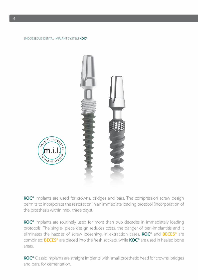
KOC® implants are used for crowns, bridges and bars. The compression screw design permits to incorporate the restoration in an immediate loading protocol (incorporation of the prosthesis within max. three days).
KOC® implants are routinely used for more than two decades in immediately loading protocols. The single- piece design reduces costs, the danger of peri-implantitis and it eliminates the hazzles of screw loosening. In extraction cases, KOC® and BECES® are combined: BECES® are placed into the fresh sockets, while KOC® are used in healed bone areas.
KOC® Classic implants are straight implants with small prosthetic head for crowns, bridges and bars, for cementation.
ENDOSSEOUS DENTAL IMPLANT SYSTEM KOC®

5
Angle piece-drill 2 mm Ø
Drill hole withguide sleeve
Surgical guide
DOS 1 DS 2Jaw
KOC® - INSTRUCTION FOR APPLICATION
PREPARATORY WORK
Get your lab to make a drilling template with the specified drill holes for the marking hole.
For the pilot hole, use DOS 1 or BCD 1 (yellow) as the primary reamer. Prepare the implant bed with the form drills at full length.
Please use an intermittent drilling technique with good NaCl cooling. If necessary, the laboratory can insert guide sleeves can in the drill holes (code BFH) through which the precise direction of drilling can be set.
If, due to high drilling resistance in hard bone, it is difficult to reach the complete drilling depth with DOS 1, the correct depth can be reached with the cylinder drill DS 2 (diameter 2 mm).
SURGERY
1. Drilling and preparation/compaction of the implant site
TW 2 Angle Piece
DRILL SEQUENCE FOR IMPLANTS WITHOUT MICROTHREAD / WITHOUT MICROGROOVE
or and or
ExampleKOC 3.7 15
DOS 2 Depth drill
black
BCD 2 black
DS 2 Pilot drill
KDS 3.7 15 for example
IT K
Inse
rtio
n to
ol
ITW
KIn
sert
ion
tool
DRILL SEQUENCE normal / hard bone DRILL SEQUENCE soft bone
Pilot drill Form drill KDS Implant Pilot drill Form drill KDS Implant
DOS 1
--- KDS 3.0 KOC 3.0
DOS 1
--- --- KOC 3.0
DOS 2 KDS 3.2 KOC 3.2 --- KDS 3.0 KOC 3.2
DOS 3 (4)KDS 3.7 KOC 3.7
DOS 2KDS 3.2 KOC 3.7
KDS 4.1 KOC 4.1 KDS 3.7 KOC 4.1
DOS 5 KDS 5.0 KOC 5.0 DOS 3 (4) KDS 4.1 KOC 5.0
In very hard bone the implants should be inserted slighty deeper and then turned back 1/2 round.
6
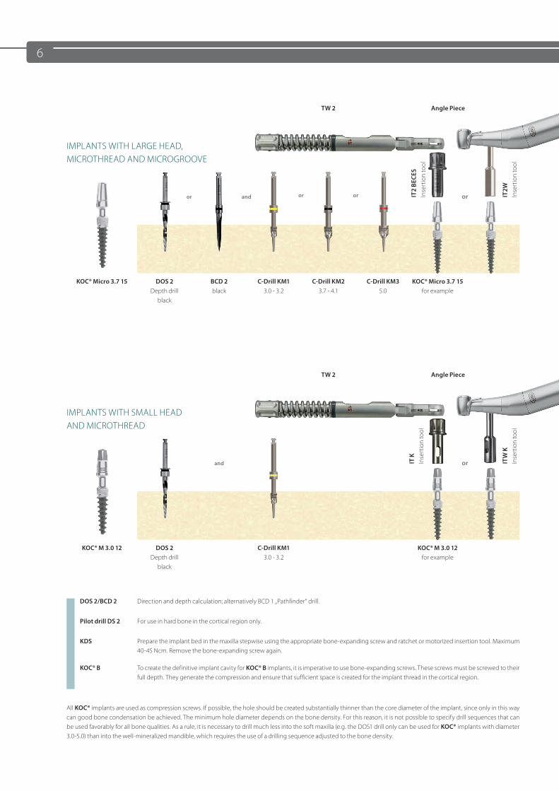
TW 2 Angle Piece
IMPLANTS WITH LARGE HEAD,MICROTHREAD AND MICROGROOVE
or and or
KOC® Micro 3.7 15 DOS 2 Depth drill
black
BCD 2 black
C-Drill KM13.0 - 3.2
C-Drill KM23.7 - 4.1
C-Drill KM35.0
KOC® Micro 3.7 15for example
TW 2 Angle Piece
IMPLANTS WITH SMALL HEADAND MICROTHREAD
and or
KOC® M 3.0 12 DOS 2 Depth drill
black
C-Drill KM13.0 - 3.2
KOC® M 3.0 12for example
DOS 2/BCD 2 Direction and depth calculation; alternatively BCD 1 „Pathfinder“ drill.
Pilot drill DS 2 For use in hard bone in the cortical region only.
KDS Prepare the implant bed in the maxilla stepwise using the appropriate bone-expanding screw and ratchet or motorized insertion tool. Maximum 40-45 Ncm. Remove the bone-expanding screw again.
KOC® B To create the definitive implant cavity for KOC® B implants, it is imperative to use bone-expanding screws. These screws must be screwed to their full depth. They generate the compression and ensure that sufficient space is created for the implant thread in the cortical region.
All KOC® implants are used as compression screws. If possible, the hole should be created substantially thinner than the core diameter of the implant, since only in this way can good bone condensation be achieved. The minimum hole diameter depends on the bone density. For this reason, it is not possible to specify drill sequences that can be used favorably for all bone qualities. As a rule, it is necessary to drill much less into the soft maxilla (e.g. the DOS1 drill only can be used for KOC® implants with diameter 3.0-5.0) than into the well-mineralized mandible, which requires the use of a drilling sequence adjusted to the bone density.
IT2W
Inse
rtio
n to
ol
IT K
Inse
rtio
n to
ol
ITW
KIn
sert
ion
tool
IT2
BECE
S In
sert
ion
tool
or or
7
or
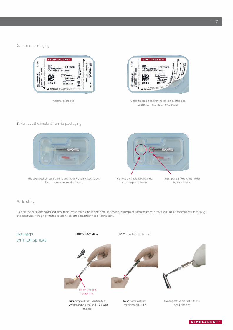
2. Implant packaging
Original packaging Open the sealed cover at the lid. Remove the label and place it into the patients record.
3. Remove the implant from its packaging
The open pack contains the implant, mounted to a plastic holder. The pack also contains the lab-set.
Remove the implant by holding onto the plastic holder
The implant is fixed to the holder by a break joint.
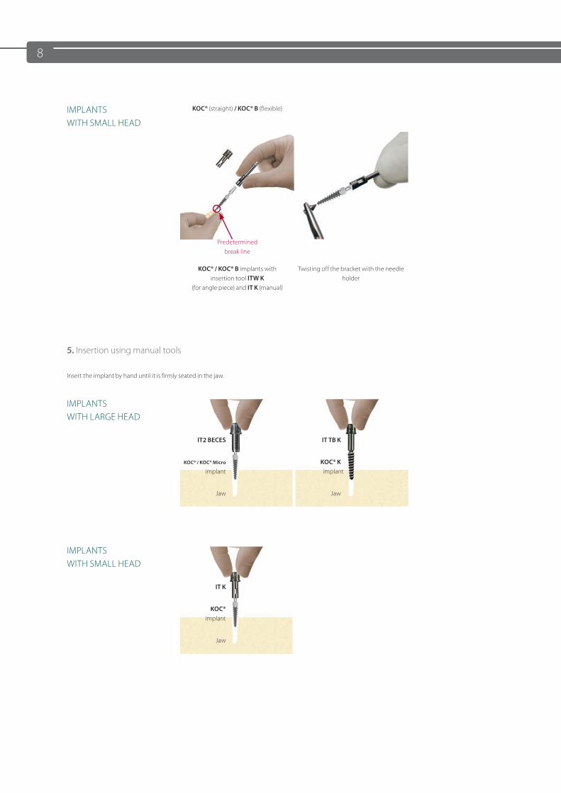
4. Handling
Hold the implant by the holder and place the insertion tool on the implant head. The endosseous implant surface must not be touched. Pull out the implant with the plug and then twist off the plug with the needle holder at the predetermined breaking point.
IMPLANTS WITH LARGE HEAD
KOC® / KOC® Micro KOC® K (for ball attachment)
Predetermined break line
KOC® implant with insertion tool IT2W (for angle piece) and IT2 BECES
(manual)
KOC® K implant with insertion tool IT TB K
Twisting off the bracket with the needle holder
8
IMPLANTS WITH SMALL HEAD
KOC® (straight) / KOC® B (flexible)
Predetermined break line
KOC® / KOC® B implants with insertion tool ITW K
(for angle piece) and IT K (manual)
Twisting off the bracket with the needle holder
5. Insertion using manual tools
Insert the implant by hand until it is firmly seated in the jaw.
IMPLANTS WITH LARGE HEAD
IT2 BECES IT TB K
KOC® / KOC® Micro implant
KOC® K implant
Jaw Jaw
IMPLANTS WITH SMALL HEAD
IT K
KOC® implant
Jaw
9
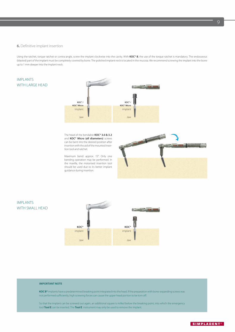
6. Definitive implant insertion
Using the ratchet, torque ratchet or contra-angle, screw the implant clockwise into the cavity. With KOC® B, the use of the torque ratchet is mandatory. The endosseous (blasted) part of the implant must be completely covered by bone. The polished implant neck is located in the mucosa. We recommend screwing the implant into the bone up to 1 mm deeper into the implant neck.
IMPLANTS WITH LARGE HEAD
KOC® / KOC® Micro
implant
KOC® / KOC® Micro
implant
Jaw Jaw
The head of the bendable KOC® 3.0 & 3.2 and KOC® Micro (all diameters) screws can be bent into the desired position after insertion with the aid of the mounted inser-tion tool and ratchet.
Maximum bend: approx. 15°. Only one bending operation may be performed. In the maxilla, the motorised insertion tool should be used due to its better implant guidance during insertion.
IMPLANTS WITH SMALL HEAD
KOC®implant
KOC®implant
Jaw Jaw
IMPORTANT NOTE
KOC B® implants have a predetermined breaking point integrated into the head. If the preparation with bone-expanding screws was not performed sufficiently, high screwing forces can cause the upper head portion to be torn off.
So that the implant can be screwed out again, an additional square is milled below the breaking point, into which the emergency tool Tool E can be inserted. The Tool E instrument may only be used to remove the implant.
10
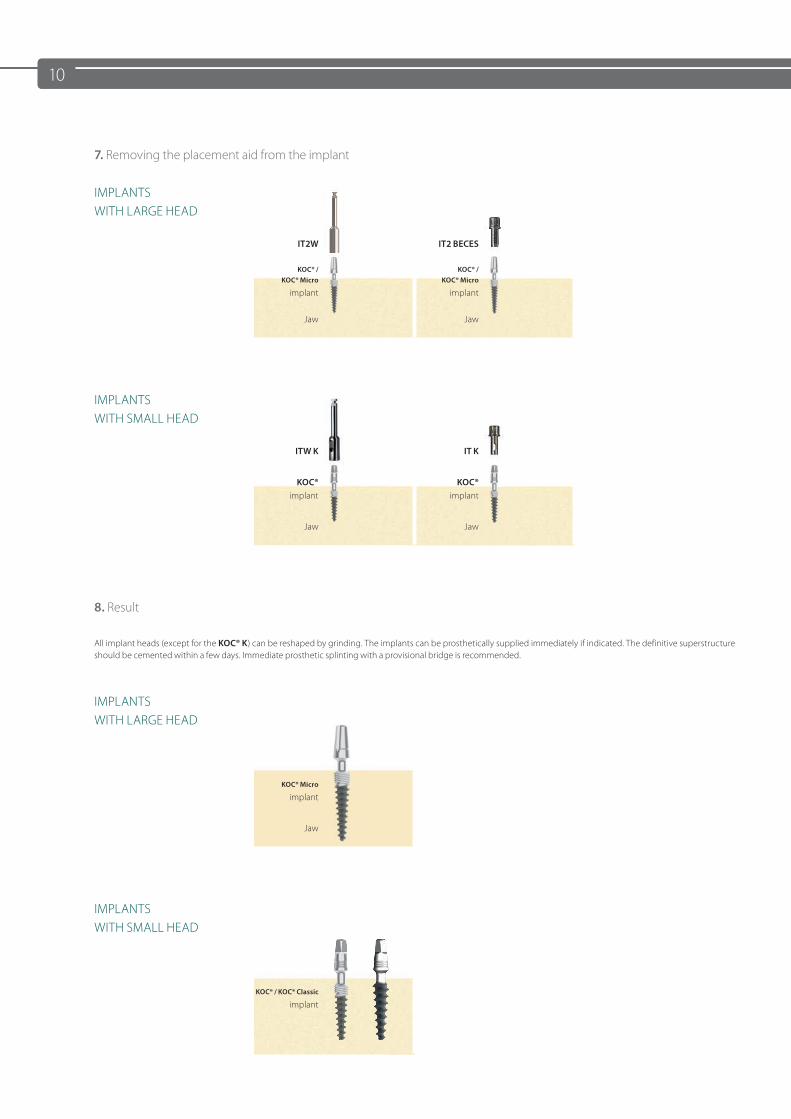
7. Removing the placement aid from the implant
IMPLANTS WITH LARGE HEAD
IT2W IT2 BECES
KOC® / KOC® Micro
implant
KOC® / KOC® Micro
implant
Jaw Jaw
IMPLANTS WITH SMALL HEAD
ITW K IT K
KOC®implant
KOC®implant
Jaw Jaw
8. Result
All implant heads (except for the KOC® K) can be reshaped by grinding. The implants can be prosthetically supplied immediately if indicated. The definitive superstructure should be cemented within a few days. Immediate prosthetic splinting with a provisional bridge is recommended.
IMPLANTS WITH LARGE HEAD
KOC® Micro
implant
Jaw
IMPLANTS WITH SMALL HEAD
KOC® / KOC® Classic
implant
11
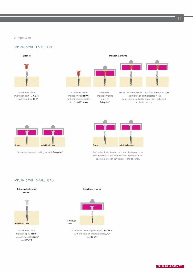
9. Impression
IMPLANTS WITH LARGE HEAD
Bridges Individual crowns
Attachment of the impression post TSPA 5, in-
ternally round, for KOC®
Attachment of the impression post TSPA 5, with anti-rotation protec-
tion, for KOC® Micro
Pressureless impression taking
e.g. with Safeprint®
Removal of the individual scoop from the implant post. The impression post is located in the
impression material. The impression can be sent to the laboratory.
Bridge Individual crown Bridge Individual crown
Pressureless impression taking e.g. with Safeprint® Removal of the individual scoop from the implant post. The impression post is located in the impression mate-
rial. The impression can be sent to the laboratory.
IMPLANTS WITH SMALL HEAD
Bridges / Individual crowns
Individual crowns
Individual crownIndividual crown
Attachment of the impression post TSPA 4,
Internally round, for KOC® and KOC® T
Attachment of the impression post TSKPA 4, with anti-rotation protection, for KOC®
and KOC® T
12
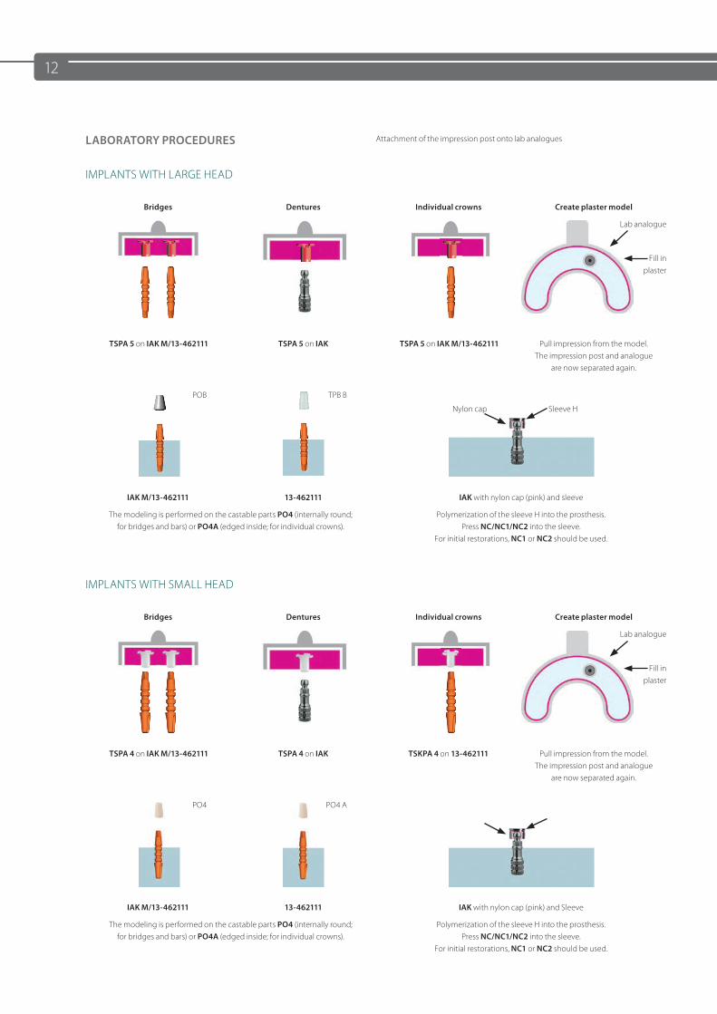
LABORATORY PROCEDURES Attachment of the impression post onto lab analogues
IMPLANTS WITH LARGE HEAD
Bridges Dentures Individual crowns Create plaster model
Lab analogue
Fill in plaster
TSPA 5 on IAK M/13-462111 TSPA 5 on IAK TSPA 5 on IAK M/13-462111 Pull impression from the model.The impression post and analogue
are now separated again.
POB TPB B
Nylon cap Sleeve H
IAK M/13-462111 13-462111 IAK with nylon cap (pink) and sleeve
The modeling is performed on the castable parts PO4 (internally round; for bridges and bars) or PO4A (edged inside; for individual crowns).
Polymerization of the sleeve H into the prosthesis.Press NC/NC1/NC2 into the sleeve.
For initial restorations, NC1 or NC2 should be used.
IMPLANTS WITH SMALL HEAD
Bridges Dentures Individual crowns Create plaster model
Lab analogue
Fill in plaster
TSPA 4 on IAK M/13-462111 TSPA 4 on IAK TSKPA 4 on 13-462111 Pull impression from the model.The impression post and analogue
are now separated again.
PO4 PO4 A
IAK M/13-462111 13-462111 IAK with nylon cap (pink) and Sleeve
The modeling is performed on the castable parts PO4 (internally round; for bridges and bars) or PO4A (edged inside; for individual crowns).
Polymerization of the sleeve H into the prosthesis.Press NC/NC1/NC2 into the sleeve.
For initial restorations, NC1 or NC2 should be used.
13
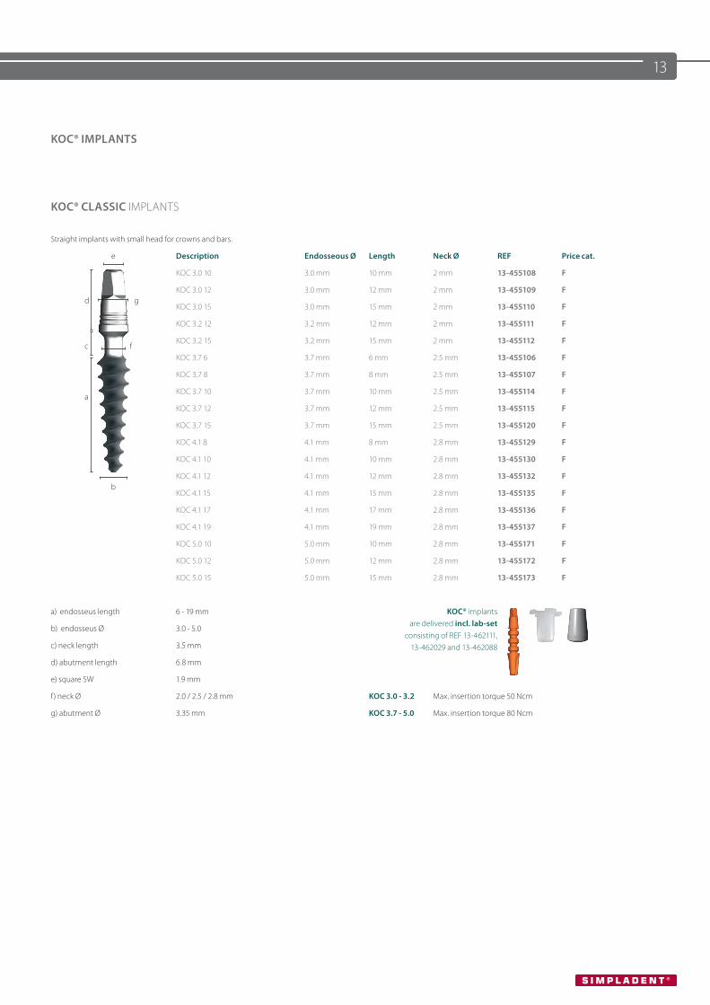
KOC® IMPLANTS
KOC® CLASSIC IMPLANTS
Straight implants with small head for crowns and bars.
e Description Endosseous Ø Length Neck Ø REF Price cat.
KOC 3.0 10 3.0 mm 10 mm 2 mm 13-455108 F
d gKOC 3.0 12 3.0 mm 12 mm 2 mm 13-455109 F
KOC 3.0 15 3.0 mm 15 mm 2 mm 13-455110 F
KOC 3.2 12 3.2 mm 12 mm 2 mm 13-455111 F
c fKOC 3.2 15 3.2 mm 15 mm 2 mm 13-455112 F
KOC 3.7 6 3.7 mm 6 mm 2.5 mm 13-455106 F
KOC 3.7 8 3.7 mm 8 mm 2.5 mm 13-455107 F
aKOC 3.7 10 3.7 mm 10 mm 2.5 mm 13-455114 F
KOC 3.7 12 3.7 mm 12 mm 2.5 mm 13-455115 F
KOC 3.7 15 3.7 mm 15 mm 2.5 mm 13-455120 F
KOC 4.1 8 4.1 mm 8 mm 2.8 mm 13-455129 F
KOC 4.1 10 4.1 mm 10 mm 2.8 mm 13-455130 F
bKOC 4.1 12 4.1 mm 12 mm 2.8 mm 13-455132 F
KOC 4.1 15 4.1 mm 15 mm 2.8 mm 13-455135 F
KOC 4.1 17 4.1 mm 17 mm 2.8 mm 13-455136 F
KOC 4.1 19 4.1 mm 19 mm 2.8 mm 13-455137 F
KOC 5.0 10 5.0 mm 10 mm 2.8 mm 13-455171 F
KOC 5.0 12 5.0 mm 12 mm 2.8 mm 13-455172 F
KOC 5.0 15 5.0 mm 15 mm 2.8 mm 13-455173 F
a) endosseus length 6 - 19 mm KOC® implants are delivered incl. lab-set
consisting of REF 13-462111, 13-462029 and 13-462088
b) endosseus Ø 3.0 - 5.0
c) neck length 3.5 mm
d) abutment length 6.8 mm
e) square SW 1.9 mm
f) neck Ø 2.0 / 2.5 / 2.8 mm KOC 3.0 - 3.2 Max. insertion torque 50 Ncm
g) abutment Ø 3.35 mm KOC 3.7 - 5.0 Max. insertion torque 80 Ncm
14
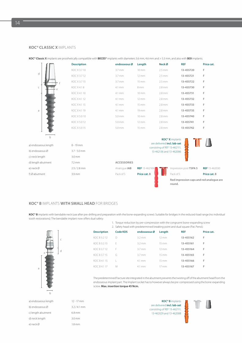
KOC® CLASSIC X IMPLANTS
KOC® Classic X implants are prosthetically compatible with BECES® implants with diameters 3.6 mm, 4.6 mm and > 5.5 mm, and also with BOI implants.
Description endosseous Ø Length Neck Ø REF Price cat.
dKOC X 3.7 10 3.7 mm 10 mm 2.5 mm 13-455720 F
KOC X 3.7 12 3.7 mm 12 mm 2.5 mm 13-455721 F
fKOC X 3.7 15 3.7 mm 15 mm 2.5 mm 13-455722 F
ce
KOC X 4.1 8 4.1 mm 8 mm 2.8 mm 13-455730 F
KOC X 4.1 10 4.1 mm 10 mm 2.8 mm 13-455731 F
KOC X 4.1 12 4.1 mm 12 mm 2.8 mm 13-455732 F
KOC X 4.1 15 4.1 mm 15 mm 2.8 mm 13-455733 F
a KOC X 4.1 19 4.1 mm 19 mm 2.8 mm 13-455735 F
KOC X 5.0 10 5.0 mm 10 mm 2.8 mm 13-455740 F
KOC X 5.0 12 5.0 mm 12 mm 2.8 mm 13-455741 F
KOC X 5.0 15 5.0 mm 15 mm 2.8 mm 13-455742 F
bKOC® X implants
are delivered incl. lab-set consisting of REF 13-462111,
13-462136 and 13-462086
a) endosseous length 8 - 19 mm
b) endosseous Ø 3.7 - 5.0 mm
c) neck length 3.0 mm
d) length abutment 7.2 mm ACCESSORIES
e) neck Ø 2.5 / 2.8 mm Analogue IAB REF 13-462106 Impression post TSPA 5 REF 13-462030
f) Ø abutment 3.9 mm Pack of 5 Price cat. B Pack of 5 Price cat. B
Red impression caps and red analogue are round.
KOC® B IMPLANTS WITH SMALL HEAD FOR BRIDGES
KOC® B implants with bendable neck (use after pre-drilling and preparation with the bone-expanding screw). Suitable for bridges in the reduced-load range (no individual tooth restorations). The bendable implant now offers dual safety:
1. Torque reduction by pre-compression with the congruent bone-expanding screw2. Safety head with predetermined breaking point and dual square (Pat. Pend.)
Description Code KDS endosseous Ø Length REF Price cat.
cKOC B 3.2 12 D 3.2 mm 12 mm 13-455162 F
KOC B 3.2 15 E 3.2 mm 15 mm 13-455161 F
ed
KOC B 3.7 12 F 3.7 mm 12 mm 13-455164 F
KOC B 3.7 15 G 3.7 mm 15 mm 13-455165 F
KOC B 4.1 15 L 4.1 mm 15 mm 13-455166 F
aKOC B 4.1 17 M 4.1 mm 17 mm 13-455167 F
The predetermined fracture site integrated in the abutment prevents the twisting off of the abutment head from the endosseous implant part. The implant socket has to however always be pre-compressed using the bone-expanding screw. Max. insertion torque 45 Ncm.
b
a) endosseous length 12 - 17 mm KOC® B implants are delivered incl. lab-set
consisting of REF 13-462111, 13-462029 and 13-462088
b) endosseous Ø 3.2 / 4.1 mm
c) length abutment 6.8 mm
d) neck length 3.0 mm
e) neck Ø 1.8 mm
15
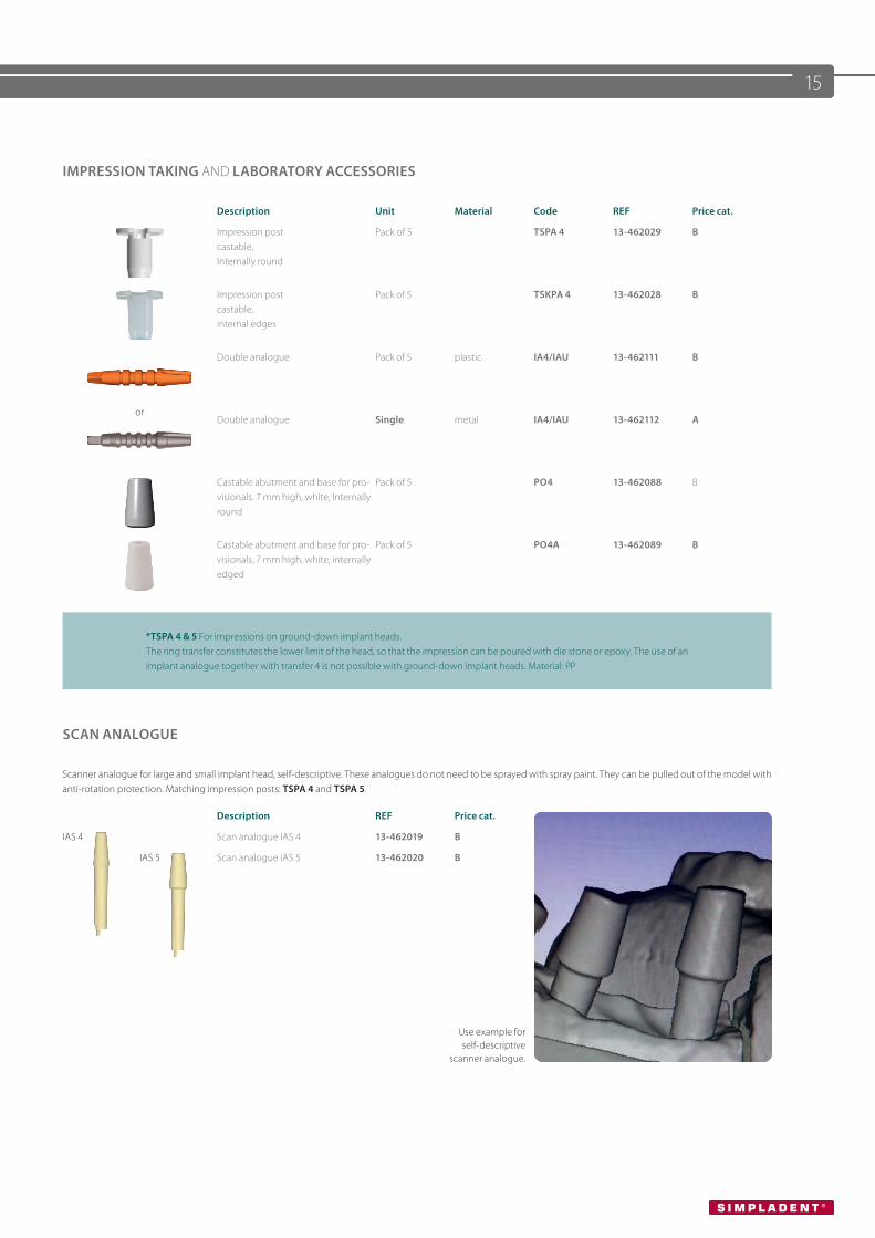
IMPRESSION TAKING AND LABORATORY ACCESSORIES
Description Unit Material Code REF Price cat.
Impression post castable,Internally round
Pack of 5 TSPA 4 13-462029 B
Impression post castable,internal edges
Pack of 5 TSKPA 4 13-462028 B
or
Double analogue Pack of 5 plastic IA4/IAU 13-462111 B
Double analogue Single metal IA4/IAU 13-462112 A
Castable abutment and base for pro-visionals. 7 mm high, white, Internally round
Pack of 5 PO4 13-462088 B
Castable abutment and base for pro-visionals. 7 mm high, white, internally edged
Pack of 5 PO4A 13-462089 B
*TSPA 4 & 5 For impressions on ground-down implant heads. The ring transfer constitutes the lower limit of the head, so that the impression can be poured with die stone or epoxy. The use of an implant analogue together with transfer 4 is not possible with ground-down implant heads. Material: PP
SCAN ANALOGUE
Scanner analogue for large and small implant head, self-descriptive. These analogues do not need to be sprayed with spray paint. They can be pulled out of the model with anti-rotation protection. Matching impression posts: TSPA 4 and TSPA 5.
Description REF Price cat.
IAS 4 Scan analogue IAS 4 13-462019 B
IAS 5 Scan analogue IAS 5 13-462020 B
Use example for self-descriptive
scanner analogue.
16
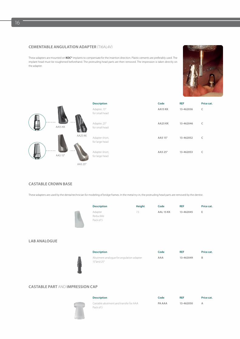
CEMENTABLE ANGULATION ADAPTER (TI6AL4V)
These adapters are mounted on KOC® implants to compensate for the insertion direction. Plastic cements are preferably used. The implant head must be roughened beforehand. The protruding head parts are then removed. The impression is taken directly on the adapter.
Description Code REF Price cat.
Adapter, 15°for small head
AA15 KK 13-462036 C
AA15 KK
AA25 KK
Adapter, 25°for small head
AA25 KK 13-462046 C
Adapter short, for large head
AA5 15° 13-462052 C
AA5 15°
AA5 25°
Adapter short, for large head
AA5 25° 13-462053 C
CASTABLE CROWN BASE
These adapters are used by the dental technician for modeling of bridge frames. In the metal try-in, the protruding head parts are removed by the dentist.
Description Height Code REF Price cat.
AdapterReduciblePack of 5
7.5 AAL 15 KK 13-462045 E
LAB ANALOGUE
Description Code REF Price cat.
Abutment analogue for angulation adapter15°and 25°
AAA 13-462049 B
CASTABLE PART AND IMPRESSION CAP
Description Code REF Price cat.
Castable abutment and transfer for AAA Pack of 5
PA AAA 13-462050 A
17
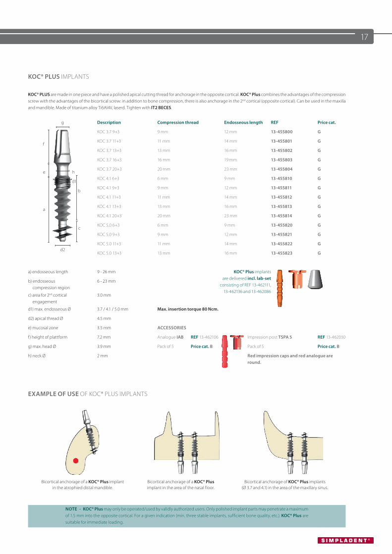
KOC® PLUS IMPLANTS
KOC® PLUS are made in one piece and have a polished apical cutting thread for anchorage in the opposite cortical. KOC® Plus combines the advantages of the compression screw with the advantages of the bicortical screw: in addition to bone compression, there is also anchorage in the 2nd cortical (opposite cortical). Can be used in the maxilla and mandible. Made of titanium alloy Ti6Al4V, laserd. Tighten with IT2 BECES.
g Description Compression thread Endosseous length REF Price cat.
KOC 3.7 9+3 9 mm 12 mm 13-455800 G
fKOC 3.7 11+3 11 mm 14 mm 13-455801 G
KOC 3.7 13+3 13 mm 16 mm 13-455802 G
KOC 3.7 16+3 16 mm 19 mm 13-455803 G
e hKOC 3.7 20+3 20 mm 23 mm 13-455804 G
d1KOC 4.1 6+3 6 mm 9 mm 13-455810 G
bKOC 4.1 9+3 9 mm 12 mm 13-455811 G
KOC 4.1 11+3 11 mm 14 mm 13-455812 G
aKOC 4.1 13+3 13 mm 16 mm 13-455813 G
KOC 4.1 20+3 20 mm 23 mm 13-455814 G
cKOC 5.0 6+3 6 mm 9 mm 13-455820 G
KOC 5.0 9+3 9 mm 12 mm 13-455821 G
d2KOC 5.0 11+3 11 mm 14 mm 13-455822 G
KOC 5.0 13+3 13 mm 16 mm 13-455823 G
a) endosseous length 9 - 26 mm KOC® Plus implants are delivered incl. lab-set
consisting of REF 13-462111, 13-462136 and 13-462086
b) endosseous compression region
6 - 23 mm
c) area for 2nd cortical engagement
3.0 mm
d1) max. endosseous Ø 3.7 / 4.1 / 5.0 mm Max. insertion torque 80 Ncm.
d2) apical thread Ø 4.5 mm
e) mucosal zone 3.5 mm ACCESSORIES
f) height of plattform 7.2 mm Analogue IAB REF 13-462106 Impression post TSPA 5 REF 13-462030
g) max. head Ø 3.9 mm Pack of 5 Price cat. B Pack of 5 Price cat. B
h) neck Ø 2 mm Red impression caps and red analogue are round.
EXAMPLE OF USE OF KOC® PLUS IMPLANTS
Bicortical anchorage of a KOC® Plus implant in the atrophied distal mandible.
Bicortical anchorage of a KOC® Plus implant in the area of the nasal floor.
Bicortical anchorage of KOC® Plus implants (Ø 3.7 and 4.1) in the area of the maxillary sinus.
NOTE - KOC® Plus may only be operated/used by validly authorized users. Only polished implant parts may penetrate a maximum of 1.5 mm into the opposite cortical. For a given indication (min. three stable implants, sufficient bone quality, etc.). KOC® Plus are suitable for immediate loading.
18
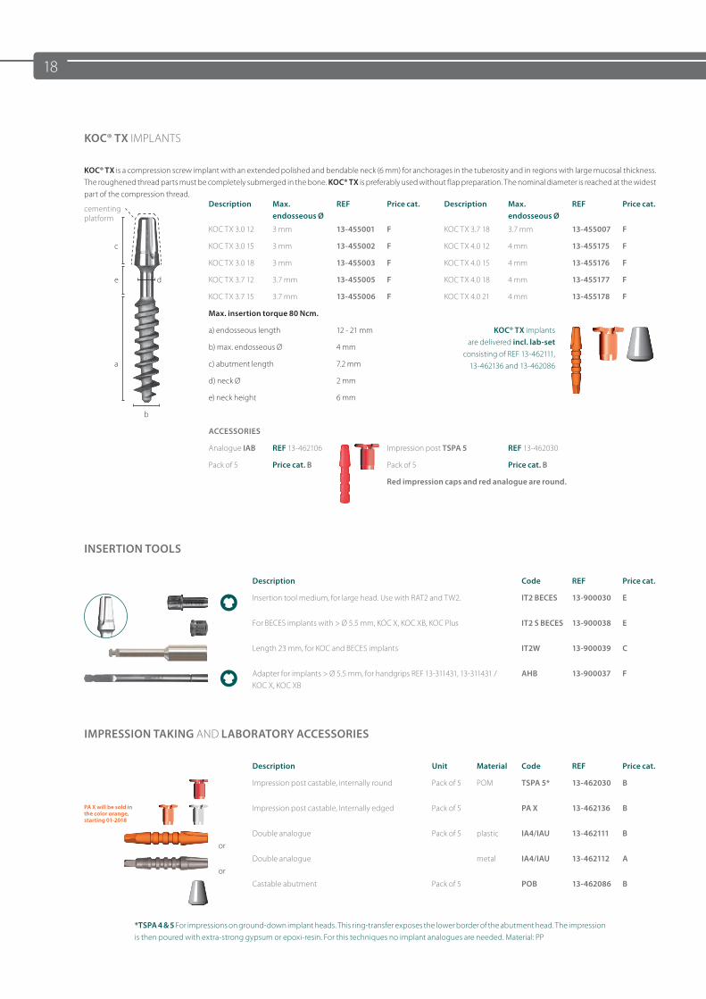
KOC® TX IMPLANTS
KOC® TX is a compression screw implant with an extended polished and bendable neck (6 mm) for anchorages in the tuberosity and in regions with large mucosal thickness. The roughened thread parts must be completely submerged in the bone. KOC® TX is preferably used without flap preparation. The nominal diameter is reached at the widest part of the compression thread.
cementing platform
Description Max. endosseous Ø
REF Price cat. Description Max. endosseous Ø
REF Price cat.
KOC TX 3.0 12 3 mm 13-455001 F KOC TX 3.7 18 3.7 mm 13-455007 F
c KOC TX 3.0 15 3 mm 13-455002 F KOC TX 4.0 12 4 mm 13-455175 F
KOC TX 3.0 18 3 mm 13-455003 F KOC TX 4.0 15 4 mm 13-455176 F
e d KOC TX 3.7 12 3.7 mm 13-455005 F KOC TX 4.0 18 4 mm 13-455177 F
KOC TX 3.7 15 3.7 mm 13-455006 F KOC TX 4.0 21 4 mm 13-455178 F
Max. insertion torque 80 Ncm.
a) endosseous length 12 - 21 mm KOC® TX implants are delivered incl. lab-set
consisting of REF 13-462111, 13-462136 and 13-462086
b) max. endosseous Ø 4 mm
a c) abutment length 7.2 mm
d) neck Ø 2 mm
e) neck height 6 mm
b
ACCESSORIES
Analogue IAB REF 13-462106 Impression post TSPA 5 REF 13-462030
Pack of 5 Price cat. B Pack of 5 Price cat. B
Red impression caps and red analogue are round.
INSERTION TOOLS
Description Code REF Price cat.
Insertion tool medium, for large head. Use with RAT2 and TW2. IT2 BECES 13-900030 E
For BECES implants with > Ø 5.5 mm, KOC X, KOC XB, KOC Plus IT2 S BECES 13-900038 E
Length 23 mm, for KOC and BECES implants IT2W 13-900039 C
Adapter for implants > Ø 5.5 mm, for handgrips REF 13-311431, 13-311431 / KOC X, KOC XB
AHB 13-900037 F
IMPRESSION TAKING AND LABORATORY ACCESSORIES
Description Unit Material Code REF Price cat.
Impression post castable, internally round Pack of 5 POM TSPA 5* 13-462030 B
PA X will be sold in the color orange, starting 01-2018
Impression post castable, Internally edged Pack of 5 PA X 13-462136 B
orDouble analogue Pack of 5 plastic IA4/IAU 13-462111 B
orDouble analogue metal IA4/IAU 13-462112 A
Castable abutment Pack of 5 POB 13-462086 B
*TSPA 4 & 5 For impressions on ground-down implant heads. This ring-transfer exposes the lower border of the abutment head. The impression is then poured with extra-strong gypsum or epoxi-resin. For this techniques no implant analogues are needed. Material: PP
19
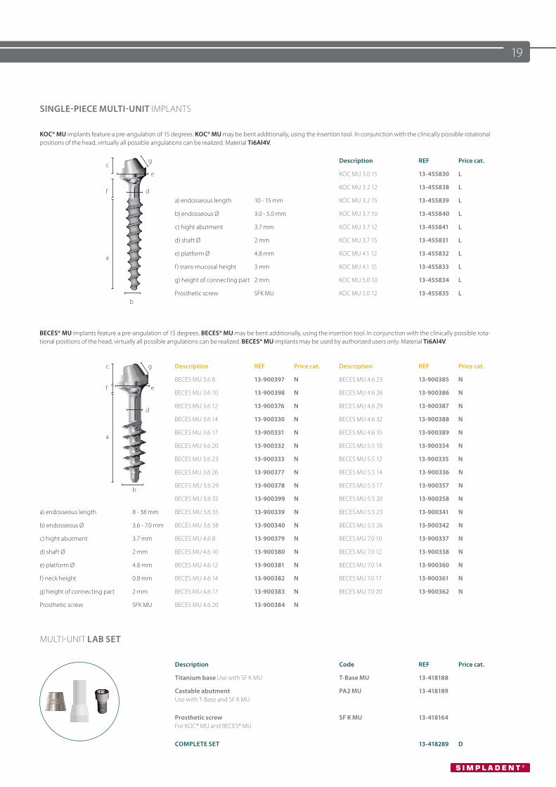
SINGLE-PIECE MULTI-UNIT IMPLANTS
KOC® MU implants feature a pre-angulation of 15 degrees. KOC® MU may be bent additionally, using the insertion tool. In conjunction with the clinically possible rotational positions of the head, virtually all possible angulations can be realized. Material Ti6Al4V.
cg Description REF Price cat.
e KOC MU 3.0 15 13-455830 L
f dKOC MU 3.2 12 13-455838 L
a) endosseous length 10 - 15 mm KOC MU 3.2 15 13-455839 L
b) endosseous Ø 3.0 - 5.0 mm KOC MU 3.7 10 13-455840 L
c) hight abutment 3.7 mm KOC MU 3.7 12 13-455841 L
d) shaft Ø 2 mm KOC MU 3.7 15 13-455831 L
ae) platform Ø 4.8 mm KOC MU 4.1 12 13-455832 L
f) trans-mucosal height 3 mm KOC MU 4.1 15 13-455833 L
g) height of connecting part 2 mm KOC MU 5.0 10 13-455834 L
bProsthetic screw SFK MU KOC MU 5.0 12 13-455835 L
BECES® MU implants feature a pre-angulation of 15 degrees. BECES® MU may be bent additionally, using the insertion tool. In conjunction with the clinically possible rota-tional positions of the head, virtually all possible angulations can be realized. BECES® MU implants may be used by authorized users only. Material Ti6Al4V.
c g Description REF Price cat. Description REF Price cat.
f eBECES MU 3.6 8 13-900397 N BECES MU 4.6 23 13-900385 N
BECES MU 3.6 10 13-900398 N BECES MU 4.6 26 13-900386 N
dBECES MU 3.6 12 13-900376 N BECES MU 4.6 29 13-900387 N
BECES MU 3.6 14 13-900330 N BECES MU 4.6 32 13-900388 N
aBECES MU 3.6 17 13-900331 N BECES MU 4.6 35 13-900389 N
BECES MU 3.6 20 13-900332 N BECES MU 5.5 10 13-900334 N
BECES MU 3.6 23 13-900333 N BECES MU 5.5 12 13-900335 N
BECES MU 3.6 26 13-900377 N BECES MU 5.5 14 13-900336 N
bBECES MU 3.6 29 13-900378 N BECES MU 5.5 17 13-900357 N
BECES MU 3.6 32 13-900399 N BECES MU 5.5 20 13-900358 N
a) endosseous length 8 - 38 mm BECES MU 3.6 35 13-900339 N BECES MU 5.5 23 13-900341 N
b) endosseous Ø 3.6 - 7.0 mm BECES MU 3.6 38 13-900340 N BECES MU 5.5 26 13-900342 N
c) hight abutment 3.7 mm BECES MU 4.6 8 13-900379 N BECES MU 7.0 10 13-900337 N
d) shaft Ø 2 mm BECES MU 4.6 10 13-900380 N BECES MU 7.0 12 13-900338 N
e) platform Ø 4.8 mm BECES MU 4.6 12 13-900381 N BECES MU 7.0 14 13-900360 N
f) neck height 0.8 mm BECES MU 4.6 14 13-900382 N BECES MU 7.0 17 13-900361 N
g) height of connecting part 2 mm BECES MU 4.6 17 13-900383 N BECES MU 7.0 20 13-900362 N
Prosthetic screw SFK MU BECES MU 4.6 20 13-900384 N
MULTI-UNIT LAB SET
Description Code REF Price cat.
Titanium base Use with SF K MU T-Base MU 13-418188
Castable abutment Use with T-Base and SF K MU
PA2 MU 13-418189
Prosthetic screw For KOC® MU and BECES® MU
SF K MU 13-418164
COMPLETE SET 13-418289 D
20
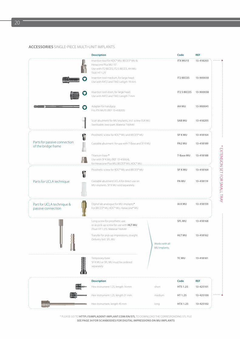
ACCESSORIES SINGLE-PIECE MULTI-UNIT IMPLANTS
Description Code REF
Insertion tool for KOC® MU, BECES® MU & Hexacone Plus MU 15°. Use with IT2 BECES, IT2 S BECES, AH MU.Tool: HT 1.25
ITX MU15 13-418203 *
Insertion tool medium, for large head. Use with RAT2 and TW2. Length 19 mm
IT2 BECES 13-900030
* EXTEN
SION
SET FOR SM
ALL TRAY
Insertion tool short, for large head. Use with RAT2 and TW2. Length 7 mm
IT2 S BECES 13-900038
Adapter for handgripFits ITX MU15 (REF 13-418203)
AH MU 13-900041
Scan abutment for MU implants, incl. screw SSA MU.Sterilisable, two-part. Material Ti6Al4V
SAB MU 13-418205
Parts for passive connection of the bridge frame
Prosthetic screw for KOC® MU and BECES® MU SF K MU 13-418164
Castable abutment for use with T-Base and SF K MU PA2 MU 13-418189
Titanium base *Use with SF K MU (REF 13-418164), for Hexacone Plus MU, BECES® MU, KOC® MU
T-Base MU 13-418188
Prosthetic screw for KOC® MU and BECES® MU SF K MU 13-418164
Parts for UCLA technique Castable abutment UCLA for direct use on MU-implants. SF K MU sold separately
PA MU 13-418119
Part for UCLA technique & passive connection
Digital lab analogue for MU-implants*For BECES® MU, KOC® MU, Hexacone® MU
IA K MU 13-418159
Long screw for prosthetic useor as pick-up screw for use with HLT MU(Tool: HT 1.25). Material Ti6Al4V
Works with all MU implants
SFL MU 13-418168
Transfer for pick-up impressions, straight.Delivery incl. SFL MU
HLT MU 13-418162
Temporary baseSF K MU or SFL MU must be ordered separately
TC MU 13-418161
Description Code REF
Hex-instrument 1.25, length 14 mm short HTS 1.25 13-425101
Hex-instrument 1.25, length 21 mm medium HT 1.25 13-425100 *
Hex-instrument, length 45 mm long HTX 1.25 13-425102
* PLEASE GO TO HTTP://SIMPLADENT-IMPLANT.COM/EN/STL TO DOWNLOAD THE CORRESPONDING STL FILE SEE PAGE 34 FOR SCANBODIES FOR DIGITAL IMPRESSIONS ON MU IMPLANTS
21
Applicationof insertion tool MU
Impression tray
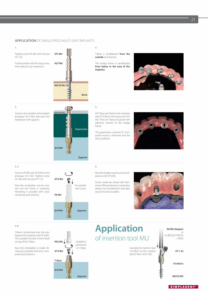
APPLICATION OF SINGLE-PIECE MULTI-UNIT IMPLANTS
1.
Tighten screw SFL MU with the tool HT 1.25.
Fix the transfer with the long screw, then take pick-up-impression.
SFL MU
HLT MU
BECES MU 20
Bone
4.
T-Base is sandblasted from the outside and cleaned.
The bridge frame is sandblasted from below in the area of the implants.
2.
Connect the transfer to the implant analogue (IA K MU) and pour the impression with gypsum.
Impression
IA K MU
Gypsum
5.
All T-Base are fixed to the implants with SF K MU or the long screw SFL MU. Then all T-Base are glued with adhesive cement to the bridge frame.
This guarantees a passive fit. Com-posite excess is removed and the site is polished.
3. a
Connect PA MU with SF K MU on the analogue IA K MU. Tighten screw SFL MU with the tool HT 1.25.
Now the modulation can be crea-ted and the frame is veneered. Veneering is possible with acryl, composite and ceramics.
SF K MU
PA MU
IA K MU
Fix castablewith screw.
Gypsum
6.
Now the bridge may be screwed on passive with SF K MU.
Screw canals are closed with tem-porary filling material or composite, taking into consideration that later access must be possible.
3. b
T-Base is positioned over the ana-logue and screwed on with SF K MU. The cartable PA2 MU is then fitted on top of the T-Base.
Now the modulation is made. Ve-neering is possible with acryl, com-posite and ceramics.
PA2 MU
SF K MU
T-Base
IA K MU
Castable ispositionedon T-Base.
Gypsum
Example for insertion tool ITX MU15 on the implant BECES® MU / KOC® MU.
AH MU Adapteror
IT2 BECES/IT BECES+ RAT2
HT 1.25
ITX MU15
BECES MU

22
KDS BONE EXPANDING SCREWS
For all KOC® B screw implants, bone-expanding screws are available as tools to create the definitive implant cavity. Basically, for each implant prior to insertion of a KOC® B screw implant, a bone compression with the bone-expanding screw should be performed. In addition, with a narrow alveolar ridge, an expansion of the alveolar ridge can be performed with the bone-expanding screw. By inserting the bone-expanding screw, it can be checked whether the KOC® B screw implant can be inserted into the bone easily and fully. Titanium alloy Ti6Al4V Eli, machined. Tighten with IT K, ITS K or ITX K using the torque ratchet TW2 (max. 45 Ncm), or alternatively RAT2. Package unit: 1 piece, non-sterile.
Description Code KDS Endosseous Ø Length Neck Ø REF Price cat.
KDS 3.0 10 A 3.0 mm 10 mm 2.0 mm 13-455212 F
dKDS 3.0 12 B 3.0 mm 12 mm 2.0 mm 13-455213 F
c KDS 3.0 15 C 3.0 mm 15 mm 2.0 mm 13-455214 F
f eKDS 3.2 12 D 3.2 mm 12 mm 2.5 mm 13-455223 F
KDS 3.2 15 E 3.2 mm 15 mm 2.5 mm 13-455224 F
KDS 3.7 12 F 3.7 mm 12 mm 2.8 mm 13-455233 F
KDS 3.7 15 G 3.7 mm 15 mm 2.8 mm 13-455234 F
KDS 4.1 8 H 4.1 mm 8 mm 2.8 mm 13-455241 F
a KDS 4.1 10 I 4.1 mm 10 mm 2.8 mm 13-455242 F
KDS 4.1 12 K 4.1 mm 12 mm 2.8 mm 13-455243 F
KDS 4.1 15 L 4.1 mm 15 mm 2.8 mm 13-455244 F
KDS 4.1 17 M 4.1 mm 17 mm 2.8 mm 13-455245 F
bKDS 4.1 19 N 4.1 mm 19 mm 2.8 mm 13-455246 F
a) endosseous length 8 - 19 mm The bone-expanding screws can easily be screwed in using suitable insertion tools and immedi-ately screwed out again after reaching the full insertion depth. Subsequently, the KOC® B implant is inserted. With the KOC® B (bendable), the use of bone-expanding screws is mandatory regardless of the region, so that the shear forces occurring during insertion do not fracture the implant neck.
Do not use for KOC® implants with microthread.
b) endosseous Ø 3.0 / 3.2 / 3.7 / 4.1 / 5 mm
c) length (non-blasted) 10 mm
d) length abutment 6.8 mm
e) neck Ø 2.0 - 2.8 mm
f) neck length 3 mm
23
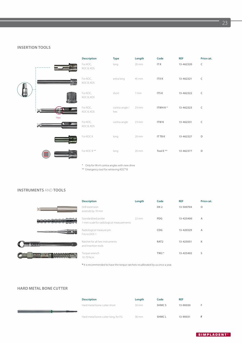
INSERTION TOOLS
Description Type Length Code REF Price cat.
For KOC, KOC B, KDS
long 20 mm IT K 13-462320 C
For KOC, KOC B, KDS
extra long 45 mm ITX K 13-462321 C
For KOC, KOC B, KDS
short 7 mm ITS K 13-462322 C
Hex
For KOC,KOC B, KDS
contra-angle /hex
23 mm ITWH K * 13-462323 C
For KOC, KOC B, KDS
contra-angle 23 mm ITW K 13-462331 C
For KOC K long 20 mm IT TB K 13-462327 D
For KOC B ** long 20 mm Tool E ** 13-462377 D
* Only for W+H contra-angles with new drive** Emergency tool for retrieving KOC® B
INSTRUMENTS AND TOOLS
Description Length Code REF Price cat.
Drill extensionextends by 19 mm
DX 2 13-500704 D
Standardized probe1-mm scale for radiological measurements
22 mm PDG 13-425400 A
Radiological measure pin Fits to DOS 1
CDG 13-420329 A
Ratchet for all hex instrumentsand insertion tools
RAT2 13-425051 K
Torque wrench10-70 Ncm
TW2 * 13-425402 S
* It is recommended to have the torque ratchets recalibrated by us once a year.
HARD METAL BONE CUTTER
Description Length Code REF
Hard metal bone cutter short 30 mm SHMC S 13-90030 F
Hard metal bone cutter long, for FG 36 mm SHMC L 13-90031 F
24
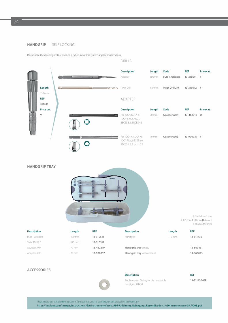
HANDGRIP SELF LOCKING
Please note the cleaning instructions on p. 57-58-61 of this system application brochure.
DRILLS
Description Length Code REF Price cat.
Adapter 100mm BCD 1 Adapter 13-310511 F
Length Twist Drill 110 mm Twist Drill 2.0 13-310512 F
110 mm
REF ADAPTER311431
Price cat. Description Length Code REF Price cat.
V For KOC®, KOC® B, KOC® T, KOC® KDS, BECES 3.5, BECES 4.5
70 mm Adapter AHK 13-462319 D
For KOC® X, KOC® XB, KOC® Plus, BECES 3.6, BECES 4.6, from > 5.5
70 mm Adapter AHB 13-900037 F
HANDGRIP TRAY
Size of closed tray B 195 mm T 90 mm H 45 mm
For all autoclaves
Description Length REF Description Length REF
BCD 1 Adapter 100 mm 13-310511 Handgrip 110 mm 13-311430
Twist Drill 2.0 110 mm 13-310512
Adapter AHK 70 mm 13-462319 Handgrip tray empty 13-60043
Adapter AHB 70 mm 13-900037 Handgrip tray with content 13-S60043
ACCESSORIESDescription REF
Replacement O-ring for demountable handgrip 311430
13-311430-OR
Please read our detailed instructions for cleaning and re-sterilization of surgical instruments onhttps://implant.com/images/Instructions/GA/Instrumente/Web_996-Anleitung_Reinigung_Resterilisation_%20Instrumenten-03_V008.pdf
25
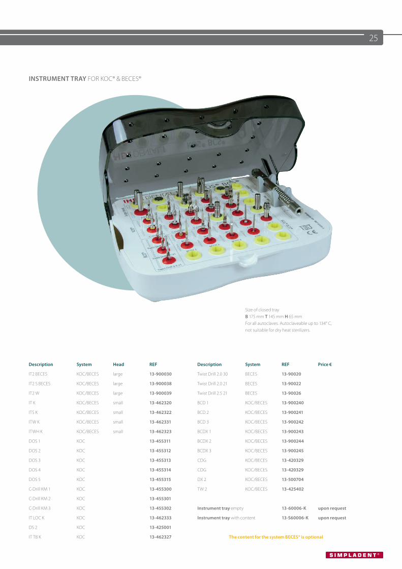
INSTRUMENT TRAY FOR KOC® & BECES®
Size of closed tray B 175 mm T 145 mm H 65 mm For all autoclaves. Autoclaveable up to 134° C, not suitable for dry heat sterilizers.
Description System Head REF Description System REF Price €
IT2 BECES KOC/BECES large 13-900030 Twist Drill 2.0 30 BECES 13-90020
IT2 S BECES KOC/BECES large 13-900038 Twist Drill 2.0 21 BECES 13-90022
IT2 W KOC/BECES large 13-900039 Twist Drill 2.5 21 BECES 13-90026
IT K KOC/BECES small 13-462320 BCD 1 KOC/BECES 13-900240
ITS K KOC/BECES small 13-462322 BCD 2 KOC/BECES 13-900241
ITW K KOC/BECES small 13-462331 BCD 3 KOC/BECES 13-900242
ITWH K KOC/BECES small 13-462323 BCDX 1 KOC/BECES 13-900243
DOS 1 KOC 13-455311 BCDX 2 KOC/BECES 13-900244
DOS 2 KOC 13-455312 BCDX 3 KOC/BECES 13-900245
DOS 3 KOC 13-455313 CDG KOC/BECES 13-420329
DOS 4 KOC 13-455314 CDG KOC/BECES 13-420329
DOS 5 KOC 13-455315 DX 2 KOC/BECES 13-500704
C-Drill KM 1 KOC 13-455300 TW 2 KOC/BECES 13-425402
C-Drill KM 2 KOC 13-455301
C-Drill KM 3 KOC 13-455302 Instrument tray empty 13-60006-K upon request
IT LOC K KOC 13-462333 Instrument tray with content 13-S60006-K upon request
DS 2 KOC 13-425001
IT TB K KOC 13-462327 The content for the system BECES® is optional
26
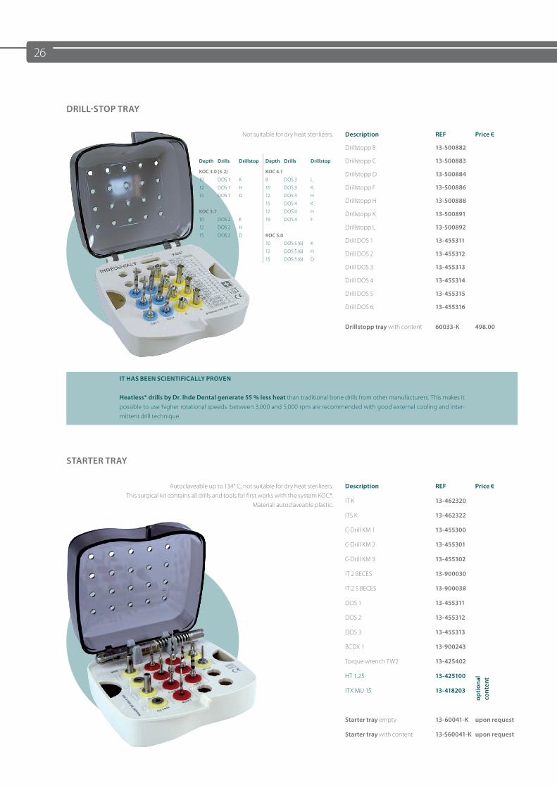
Depth Drills Drillstop Depth Drills Drillstop
KOC 3.0 (3.2) KOC 4.1
10 DOS 1 K 8 DOS 3 L
12 DOS 1 H 10 DOS 3 K
15 DOS 1 D 12 DOS 3 H
15 DOS 4 K
KOC 3.7 17 DOS 4 H
10 DOS 2 K 19 DOS 4 F
12 DOS 2 H
15 DOS 2 D KOC 5.0
10 DOS 5 (6) K
12 DOS 5 (6) H
15 DOS 5 (6) D
DRILL-STOP TRAY
Not suitable for dry heat sterilizers. Description REF Price €
Drillstopp B 13-500882
Drillstopp C 13-500883
Drillstopp D 13-500884
Drillstopp F 13-500886
Drillstopp H 13-500888
Drillstopp K 13-500891
Drillstopp L 13-500892
Drill DOS 1 13-455311
Drill DOS 2 13-455312
Drill DOS 3 13-455313
Drill DOS 4 13-455314
Drill DOS 5 13-455315
Drill DOS 6 13-455316
Drillstopp tray with content 60033-K 498.00
IT HAS BEEN SCIENTIFICALLY PROVEN
Heatless® drills by Dr. Ihde Dental generate 55 % less heat than traditional bone drills from other manufacturers. This makes it possible to use higher rotational speeds: between 3,000 and 5,000 rpm are recommended with good external cooling and inter-mittent drill technique.
STARTER TRAY
Autoclaveable up to 134° C, not suitable for dry heat sterilizers. This surgical kit contains all drills and tools for first works with the system KOC®.
Material: autoclaveable plastic.
Description REF Price €
IT K 13-462320
ITS K 13-462322
C-Drill KM 1 13-455300
C-Drill KM 2 13-455301
C-Drill KM 3 13-455302
IT 2 BECES 13-900030
IT 2 S BECES 13-900038
DOS 1 13-455311
DOS 2 13-455312
DOS 3 13-455313
BCDX 1 13-900243
Torque wrench TW2 13-425402
HT 1.25 13-425100
opt
iona
l co
nten
t
ITX MU 15 13-418203
Starter tray empty 13-60041-K upon request
Starter tray with content 13-S60041-K upon request
27
KOC® IMPLANTATIONS
Minimally invasive immediate load implantology with KOC® implants
1. Insertion of 21 KOC® implants in three hours.2. Maxilla restoration with new motorized screwing technology.3. Minimally invasive approach for beginners.
Authors Dr. Werner Mander, (IMF) Dr. Thomas Fabritius
Description REF Price cat.
DVD 13-6668 A
INDICATIONS KOC® II KOC® micro
• Anchorage of crowns, bridges and bars, with the presence of adequate bone supply in terms of bone quality, bone width and bone height.• Anchorage of prostheses via bar and button anchorage systems.• Not for use in combination with simultaneous bone augmentations
RESTRICTIONS FOR KOC® B APPLICATION
• These two implant types may only be used as support implants in the reduced-load area.• Splinting of at least three and possibly several implants for cross arch stabilisation.• At least one KOC® or KOC® Micro implant must be involved in the construction.• The prosthetic restoration must be securely fixed (with definitive cements).• Not to be used for segmented bridges without the involvement of at least two KOC® screws.• If in doubt, angulation adapters on KOC® screws are preferable to the KOC® B implant.• Not to be used for additional abutments in combination with natural teeth.• Not to be used under off-axis load as well as in deep-bite cases in the maxillary and mandibular anterior region.• Max. width of occlusal surface 5 mm.• Not to be used as terminal abutments.• Bendable up to 13 degrees.
NOTES ON THE CARE OF SURGICAL STEEL INSTRUMENTS
Surgical steel instruments can quickly become damaged if inadequately or improperly cared for. Only the special solvents for cleaning surgical steel should be used; in case of doubt, consult Dr. Ihde Dental GmbH / AG.
The following are not recommended:• Disinfectants/cleaners with a high chlorine content.• Disinfectants/cleaners with a high oxalic acid content.
For instruments with colour coding, the following are NOT recommended:• Excessively high solvent concentrations, disinfectants/cleaners with the components mentioned above.• Excessive temperatures during cleaning and sterilization (no dry heat sterilization).
28
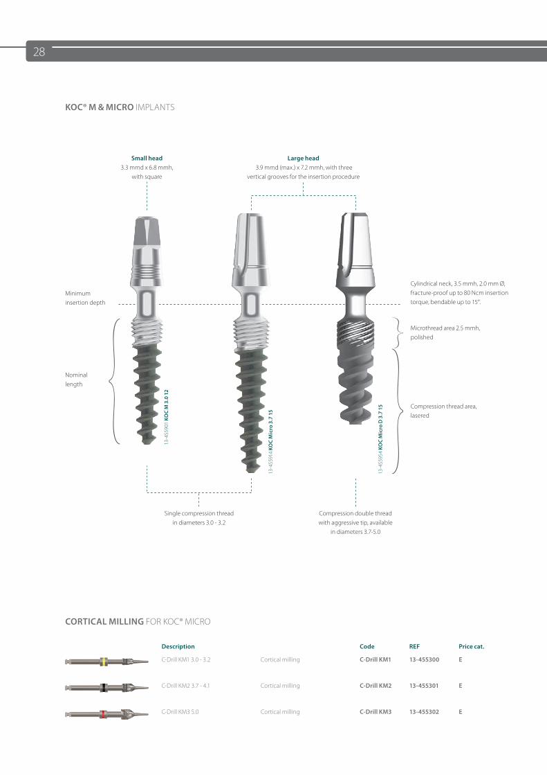
Cylindrical neck, 3.5 mmh, 2.0 mm Ø, fracture-proof up to 80 Ncm insertion torque, bendable up to 15°.
Nominal length
Minimum insertion depth
Small head 3.3 mmd x 6.8 mmh,
with square
Large head 3.9 mmd (max.) x 7.2 mmh, with three
vertical grooves for the insertion procedure
Single compression threadin diameters 3.0 - 3.2
Compression double thread with aggressive tip, available
in diameters 3.7-5.0
Compression thread area, lasered
Microthread area 2.5 mmh, polished
13-4
5590
1 KO
C M
3.0
12
13-4
5591
4 KO
C M
icro
3.7
15
13-4
5595
4 KO
C M
icro
D 3
.7 1
5
KOC® M & MICRO IMPLANTS
CORTICAL MILLING FOR KOC® MICRO
Description Code REF Price cat.
C-Drill KM1 3.0 - 3.2 Cortical milling C-Drill KM1 13-455300 E
C-Drill KM2 3.7 - 4.1 Cortical milling C-Drill KM2 13-455301 E
C-Drill KM3 5.0 Cortical milling C-Drill KM3 13-455302 E
29
MATERIAL
Ti6AL4V, also known as „Grade 5“, is the high-purity version of the conventional 6/4 Ti alloy, which is used for more than 50% of all metallic human implants. This material is the first choice for all applications which require high stability, corrosion resistance and mechanical strength. This is why today‘s most modern dental implant designs are made of this material. This titanium alloy is superior to the alternatively used pure titanium in terms of stability by more than 25%. Also regarding biocompatibility and the support of bone cell growth, this titanium alloy shows advantages compared to pure titanium.
FUNCTIONALITY
The one-piece KOC® M / KOC® Micro dental implant is preferably used in immediate loading. Unlike other compression screws, the polished neck has a cylindrical shape. Thus, the cortical is sealed, good retention is achieved in the cortical and the bone is protected against infections. At the same time, the endosseous implant part compresses the cancellous bone areas.
NOTE
The smooth microthread must be completely submerged below the bone level. The cylindrical neck must extend into the bone at least 1 mm deep. Therefore, the implant must be selected so that at least 1.5 mm more usable vertical bone is present than the nominal length of the implant. Example For KOC Micro 3.7 15, 17 mm of usable vertical bone must be present. If in doubt, a shorter implant should be selected so as to ensure a sufficient insertion depth.
DRILLING PROCEDURE
The pilot hole is made with the drills of the KOC® system. Except in very dense mandibular bone, the pilot hole is usually sufficient with BCD1 or DOS1.
INSERTION
The implant can be inserted most easily with the handgrip (REF 311431) and the adapter (REF 13-900 037). When using the ratchet RAT2, small or medium insertion tools are used. Max. torque is 80 Ncm.
THE IMPLANTS ARE SUPPLIED WITH TWO DIFFERENT HEAD SIZES
• KOC® M implants are supplied with a small head; they also fit in small individual tooth gaps.• KOC® Micro implants are supplied with a large head. This head permits easy and speedy prosthetic restoration.
30
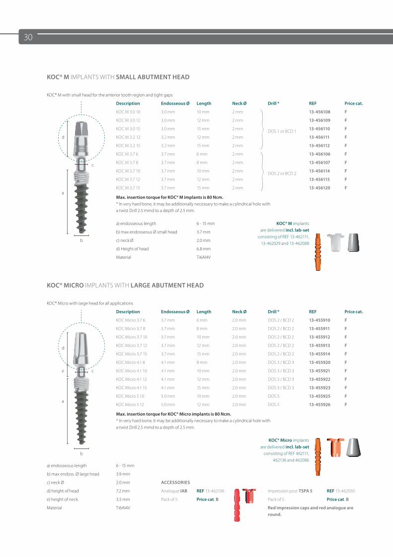
KOC® M IMPLANTS WITH SMALL ABUTMENT HEAD
KOC® M with small head for the anterior tooth region and tight gaps
Description Endosseous Ø Length Neck Ø Drill * REF Price cat.
KOC M 3.0 10 3.0 mm 10 mm 2 mm
DOS 1 or BCD 1
13-456108 F
KOC M 3.0 12 3.0 mm 12 mm 2 mm 13-456109 F
KOC M 3.0 15 3.0 mm 15 mm 2 mm 13-456110 F
d KOC M 3.2 12 3.2 mm 12 mm 2 mm 13-456111 F
KOC M 3.2 15 3.2 mm 15 mm 2 mm 13-456112 F
KOC M 3.7 6 3.7 mm 6 mm 2 mm
DOS 2 or BCD 2
13-456106 F
c KOC M 3.7 8 3.7 mm 8 mm 2 mm 13-456107 F
KOC M 3.7 10 3.7 mm 10 mm 2 mm 13-456114 F
KOC M 3.7 12 3.7 mm 12 mm 2 mm 13-456115 F
aKOC M 3.7 15 3.7 mm 15 mm 2 mm 13-456120 F
Max. insertion torque for KOC® M implants is 80 Ncm.* In very hard bone, it may be additionally necessary to make a cylindrical hole with a twist Drill 2.5 mmd to a depth of 2.5 mm.
a) endosseous length 6 - 15 mm KOC® M implants are delivered incl. lab-set
consisting of REF 13-462111, 13-462029 and 13-462088
b) max endosseous Ø small head 3.7 mm
b c) neck Ø 2.0 mm
d) Height of head 6.8 mm
Material Ti6Al4V
KOC® MICRO IMPLANTS WITH LARGE ABUTMENT HEAD
KOC® Micro with large head for all applications
Description Endosseous Ø Length Neck Ø Drill * REF Price cat.
KOC Micro 3.7 6 3.7 mm 6 mm 2.0 mm DOS 2 / BCD 2 13-455910 F
KOC Micro 3.7 8 3.7 mm 8 mm 2.0 mm DOS 2 / BCD 2 13-455911 F
KOC Micro 3.7 10 3.7 mm 10 mm 2.0 mm DOS 2 / BCD 2 13-455912 F
d KOC Micro 3.7 12 3.7 mm 12 mm 2.0 mm DOS 2 / BCD 2 13-455913 F
KOC Micro 3.7 15 3.7 mm 15 mm 2.0 mm DOS 2 / BCD 2 13-455914 F
KOC Micro 4.1 8 4.1 mm 8 mm 2.0 mm DOS 3 / BCD 3 13-455920 F
e c KOC Micro 4.1 10 4.1 mm 10 mm 2.0 mm DOS 3 / BCD 3 13-455921 F
KOC Micro 4.1 12 4.1 mm 12 mm 2.0 mm DOS 3 / BCD 3 13-455922 F
KOC Micro 4.1 15 4.1 mm 15 mm 2.0 mm DOS 3 / BCD 3 13-455923 F
aKOC Micro 5 10 5.0 mm 10 mm 2.0 mm DOS 5 13-455925 F
KOC Micro 5 12 5.0 mm 12 mm 2.0 mm DOS 5 13-455926 F
Max. insertion torque for KOC® Micro implants is 80 Ncm. * In very hard bone, it may be additionally necessary to make a cylindrical hole with a twist Drill 2.5 mmd to a depth of 2.5 mm.
KOC® Micro implants are delivered incl. lab-set
consisting of REF 462111, 462136 and 462086
b
a) endosseous length 6 - 15 mm
b) max endoss. Ø large head 3.9 mm
c) neck Ø 2.0 mm ACCESSORIES
d) height of head 7.2 mm Analogue IAB REF 13-462106 Impression post TSPA 5 REF 13-462030
e) height of neck 3.5 mm Pack of 5 Price cat. B Pack of 5 Price cat. B
Material Ti6Al4V Red impression caps and red analogue are round.
31
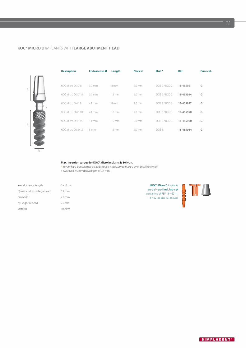
KOC® MICRO D IMPLANTS WITH LARGE ABUTMENT HEAD
Description Endosseous Ø Length Neck Ø Drill * REF Price cat.
dKOC Micro D 3.7 8 3.7 mm 8 mm 2.0 mm DOS 2 / BCD 2 13-455951 G
KOC Micro D 3.7 15 3.7 mm 15 mm 2.0 mm DOS 2 / BCD 2 13-455954 G
cKOC Micro D 4.1 8 4.1 mm 8 mm 2.0 mm DOS 3 / BCD 3 13-455957 G
KOC Micro D 4.1 10 4.1 mm 10 mm 2.0 mm DOS 3 / BCD 3 13-455958 G
aKOC Micro D 4.1 15 4.1 mm 15 mm 2.0 mm DOS 3 / BCD 3 13-455960 G
KOC Micro D 5.0 12 5 mm 12 mm 2.0 mm DOS 5 13-455964 G
b
Max. insertion torque for KOC® Micro implants is 80 Ncm. * In very hard bone, it may be additionally necessary to make a cylindrical hole witha twist Drill 2.5 mmd to a depth of 2.5 mm.
a) endosseous length 6 - 15 mm KOC® Micro D implants are delivered incl. lab-set
consisting of REF 13-462111, 13-462136 and 13-462086
b) max endoss. Ø large head 3.9 mm
c) neck Ø 2.0 mm
d) Height of head 7.2 mm
Material Ti6Al4V
32
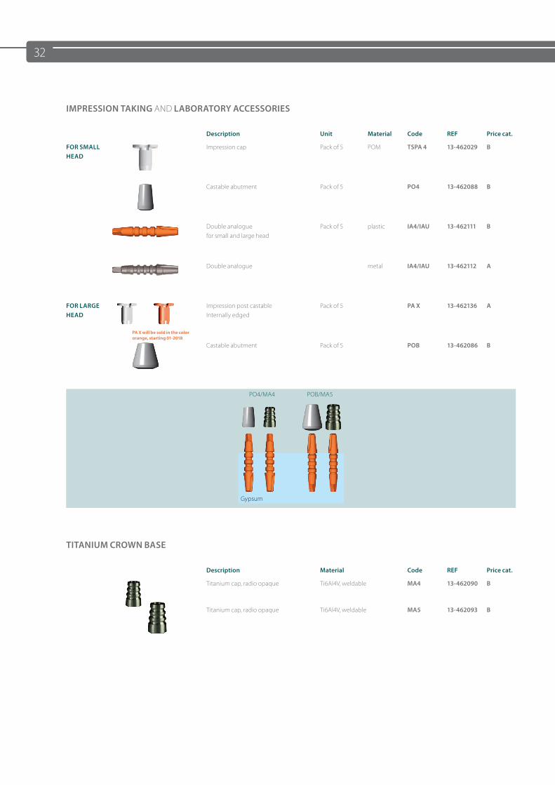
IMPRESSION TAKING AND LABORATORY ACCESSORIES
Description Unit Material Code REF Price cat.
FOR SMALL HEAD
Impression cap Pack of 5 POM TSPA 4 13-462029 B
Castable abutment Pack of 5 PO4 13-462088 B
Double analogue for small and large head
Pack of 5 plastic IA4/IAU 13-462111 B
Double analogue metal IA4/IAU 13-462112 A
FOR LARGE HEAD
PA X will be sold in the color orange, starting 01-2018
Impression post castable Internally edged
Pack of 5 PA X 13-462136 A
Castable abutment Pack of 5 POB 13-462086 B
PO4/MA4 POB/MA5
TITANIUM CROWN BASE
Description Material Code REF Price cat.
Titanium cap, radio opaque Ti6Al4V, weldable MA4 13-462090 B
Titanium cap, radio opaque Ti6Al4V, weldable MA5 13-462093 B
Gypsum
33
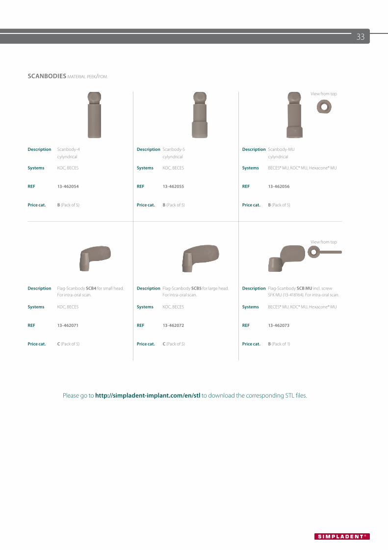
SCANBODIES material peek/pom
View from top
Description Scanbody-4
cylyndrical
Description Scanbody-5
cylyndrical
Description Scanbody-MU
cylyndrical
Systems KOC, BECES Systems KOC, BECES Systems BECES® MU, KOC® MU, Hexacone® MU
REF 13-462054 REF 13-462055 REF 13-462056
Price cat. B (Pack of 5) Price cat. B (Pack of 5) Price cat. B (Pack of 5)
View from top
Description Flag-Scanbody SCB4 for small head. For intra-oral scan.
Description Flag-Scanbody SCB5 for large head. For intra-oral scan.
Description Flag-Scanbody SCB MU incl. screw SFK MU (13-418164). For intra-oral scan.
Systems KOC, BECES Systems KOC, BECES Systems BECES® MU, KOC® MU, Hexacone® MU
REF 13-462071 REF 13-462072 REF 13-462073
Price cat. C (Pack of 5) Price cat. C (Pack of 5) Price cat. B (Pack of 1)
Please go to http://simpladent-implant.com/en/stl to download the corresponding STL files.
34
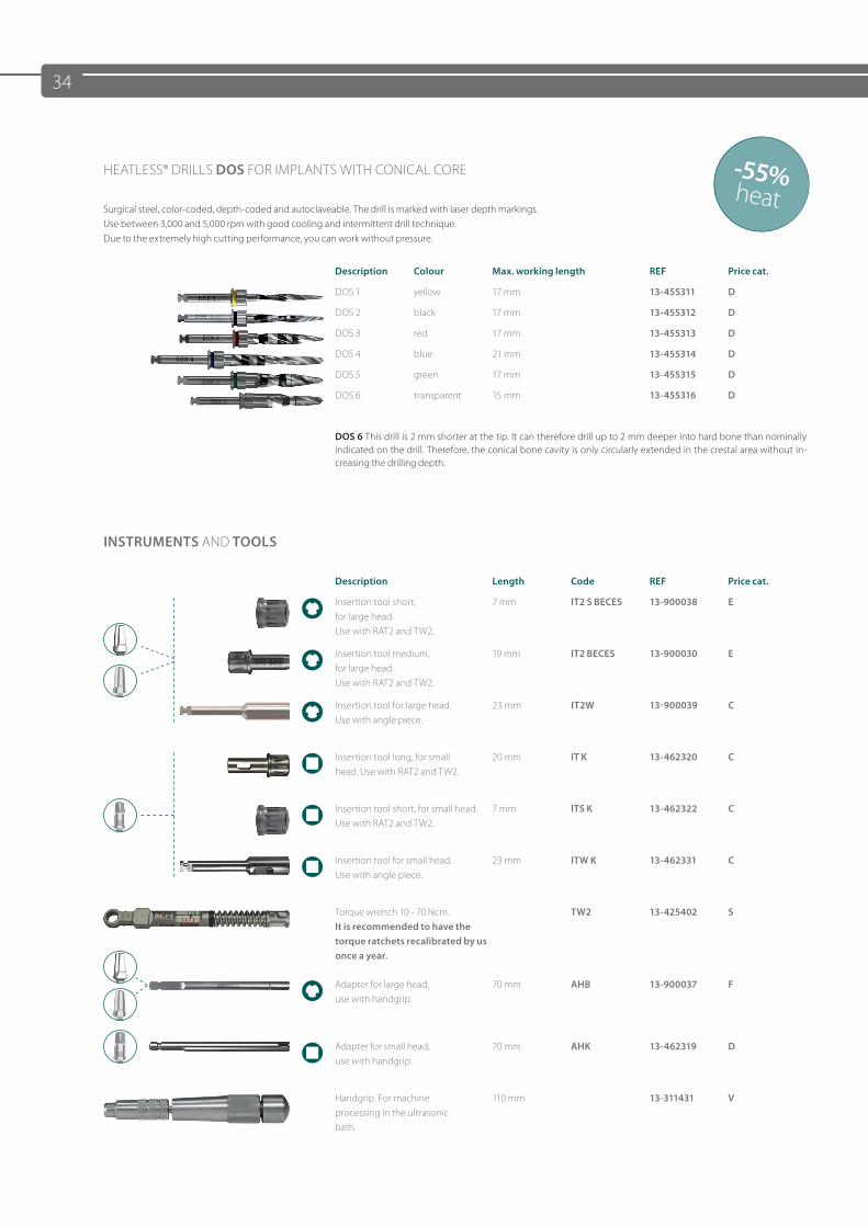
-55%heat
HEATLESS® DRILLS DOS FOR IMPLANTS WITH CONICAL CORE
Surgical steel, color-coded, depth-coded and autoclaveable. The drill is marked with laser depth markings. Use between 3,000 and 5,000 rpm with good cooling and intermittent drill technique. Due to the extremely high cutting performance, you can work without pressure.
Description Colour Max. working length REF Price cat.
DOS 1 yellow 17 mm 13-455311 D
DOS 2 black 17 mm 13-455312 D
DOS 3 red 17 mm 13-455313 D
DOS 4 blue 21 mm 13-455314 D
DOS 5 green 17 mm 13-455315 D
DOS 6 transparent 15 mm 13-455316 D
DOS 6 This drill is 2 mm shorter at the tip. It can therefore drill up to 2 mm deeper into hard bone than nominally indicated on the drill. Therefore, the conical bone cavity is only circularly extended in the crestal area without in-creasing the drilling depth.
INSTRUMENTS AND TOOLS
Description Length Code REF Price cat.
Insertion tool short, for large head. Use with RAT2 and TW2.
7 mm IT2 S BECES 13-900038 E
Insertion tool medium, for large head. Use with RAT2 and TW2.
19 mm IT2 BECES 13-900030 E
Insertion tool for large head. Use with angle piece.
23 mm IT2W 13-900039 C
Insertion tool long, for small head. Use with RAT2 and TW2.
20 mm IT K 13-462320 C
Insertion tool short, for small head. Use with RAT2 and TW2.
7 mm ITS K 13-462322 C
Insertion tool for small head.Use with angle piece.
23 mm ITW K 13-462331 C
Torque wrench 10 - 70 Ncm. It is recommended to have the torque ratchets recalibrated by us once a year.
TW2 13-425402 S
Adapter for large head, use with handgrip.
70 mm AHB 13-900037 F
Adapter for small head, use with handgrip.
70 mm AHK 13-462319 D
Handgrip. For machine processing in the ultrasonic bath.
110 mm 13-311431 V
35
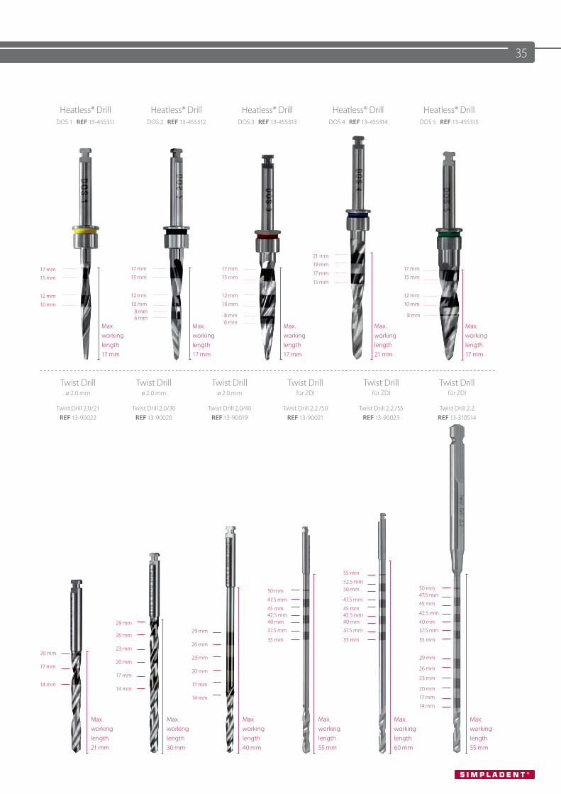
Heatless® Drill Heatless® Drill Heatless® Drill Heatless® Drill Heatless® DrillDOS 1 REF 13-455311 DOS 2 REF 13-455312 DOS 3 REF 13-455313 DOS 4 REF 13-455314 DOS 5 REF 13-455315
21 mm
19 mm17 mm
15 mm
17 mm
15 mm
17 mm
15 mm17 mm
17 mm
15 mm15 mm
12 mm
10 mm
12 mm
10 mm
12 mm
10 mm
12 mm
10 mm 8 mm 6 mm 8 mm 8 mm
Max. working length17 mm
Max. working length17 mm
6 mmMax. working length17 mm
Max. working length21 mm
Max. working length17 mm
Twist Drillø 2.0 mm
Twist Drillø 2.0 mm
Twist Drillø 2.0 mm
Twist Drill für ZDI
Twist Drill für ZDI
Twist Drill für ZDI
Twist Drill 2.0/21 REF 13-90022
Twist Drill 2.0/30 REF 13-90020
Twist Drill 2.0/40 REF 13-90019
Twist Drill 2.2 /50REF 13-90021
Twist Drill 2.2 /55REF 13-90023
Twist Drill 2.2 REF 13-310514
55 mm
50 mm
52.5 mm50 mm 50 mm
47.5 mm 47.5 mm47.5 mm
45 mm45 mm42.5 mm
45 mm42.5 mm 42.5 mm
29 mm29 mm
40 mm
37.5 mm
40 mm
37.5 mm
40 mm
37.5 mm26 mm
26 mm35 mm 35 mm 35 mm
20 mm23 mm
23 mm 29 mm
17 mm20 mm
20 mm 26 mm
14 mm
17 mm
17 mm23 mm
14 mm
14 mm
20 mm
17 mm
14 mm
Max. working length21 mm
Max. working length30 mm
Max. working length40 mm
Max. working length55 mm
Max. working length60 mm
Max. working length55 mm
36
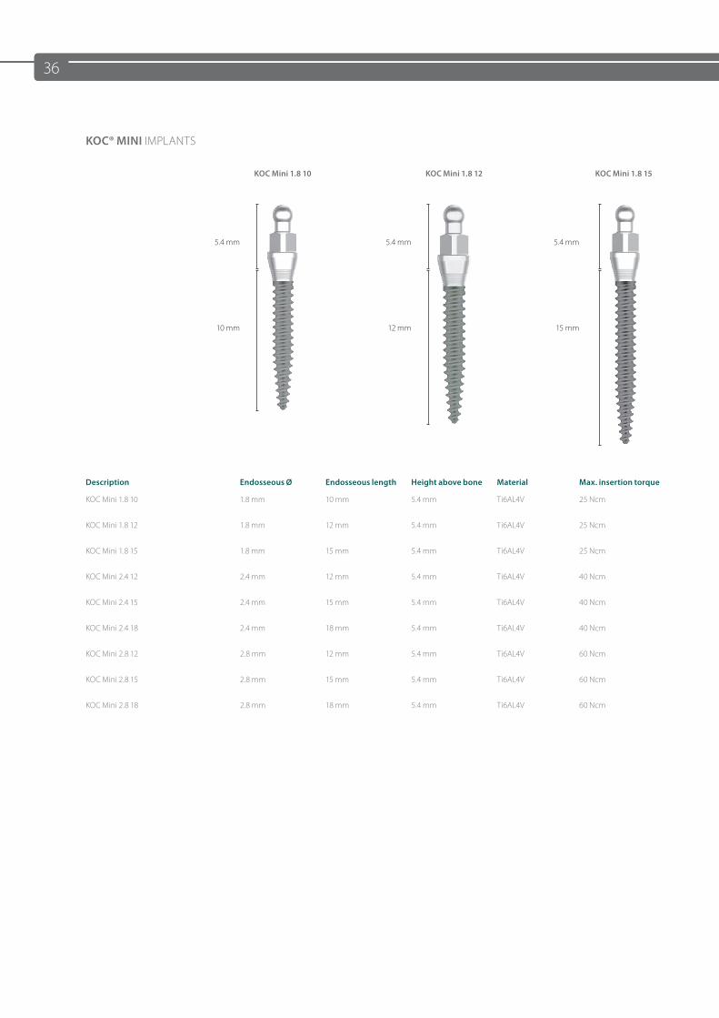
KOC® MINI IMPLANTS
KOC Mini 1.8 10 KOC Mini 1.8 12 KOC Mini 1.8 15
5.4 mm 5.4 mm 5.4 mm
10 mm 12 mm 15 mm
Description Endosseous Ø Endosseous length Height above bone Material Max. insertion torque
KOC Mini 1.8 10 1.8 mm 10 mm 5.4 mm Ti6AL4V 25 Ncm
KOC Mini 1.8 12 1.8 mm 12 mm 5.4 mm Ti6AL4V 25 Ncm
KOC Mini 1.8 15 1.8 mm 15 mm 5.4 mm Ti6AL4V 25 Ncm
KOC Mini 2.4 12 2.4 mm 12 mm 5.4 mm Ti6AL4V 40 Ncm
KOC Mini 2.4 15 2.4 mm 15 mm 5.4 mm Ti6AL4V 40 Ncm
KOC Mini 2.4 18 2.4 mm 18 mm 5.4 mm Ti6AL4V 40 Ncm
KOC Mini 2.8 12 2.8 mm 12 mm 5.4 mm Ti6AL4V 60 Ncm
KOC Mini 2.8 15 2.8 mm 15 mm 5.4 mm Ti6AL4V 60 Ncm
KOC Mini 2.8 18 2.8 mm 18 mm 5.4 mm Ti6AL4V 60 Ncm
37
10 mm 12 mm 12 mm12 mm
15 mm 15 mm15 mm
18 mm 18 mm
BON
E
BON
E
GINGIVAGINGIVA
SURGERY
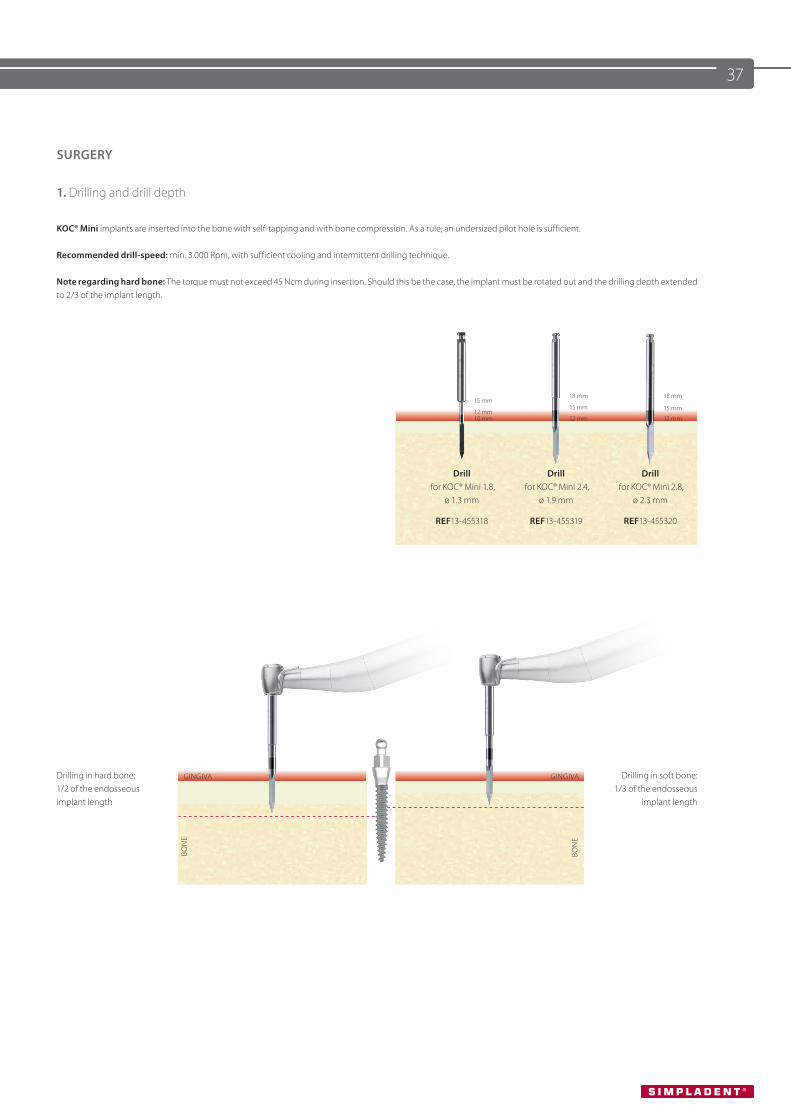
1. Drilling and drill depth
KOC® Mini implants are inserted into the bone with self-tapping and with bone compression. As a rule, an undersized pilot hole is sufficient.
Recommended drill-speed: min. 3.000 Rpm, with sufficient cooling and intermittent drilling technique.
Note regarding hard bone: The torque must not exceed 45 Ncm during insertion. Should this be the case, the implant must be rotated out and the drilling depth extended to 2/3 of the implant length.
Drill for KOC® Mini 1.8,
ø 1.3 mm
REF13-455318
Drill for KOC® Mini 2.4,
ø 1.9 mm
REF13-455319
Drill for KOC® Mini 2.8,
ø 2.3 mm
REF13-455320
Drilling in hard bone:1/2 of the endosseous implant length
Drilling in soft bone:1/3 of the endosseous
implant length
38
BON
E
GINGIVA
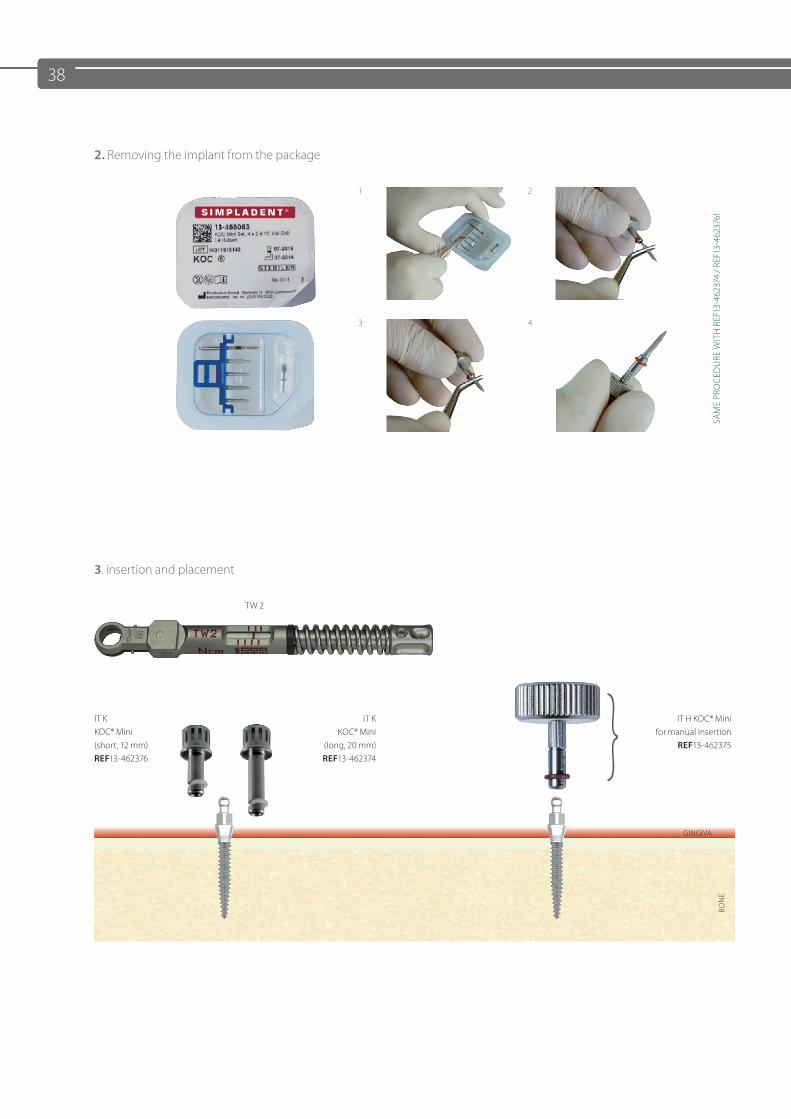
2. Removing the implant from the package
1 2
SAM
E PR
OCE
DU
RE W
ITH
REF
13-4
6237
4 / R
EF13
-462
376!
3 4
3. insertion and placement
TW 2
IT K KOC® Mini (short, 12 mm) REF13-462376
IT K KOC® Mini
(long, 20 mm) REF13-462374
IT H KOC® Mini for manual insertion
REF13-462375
39
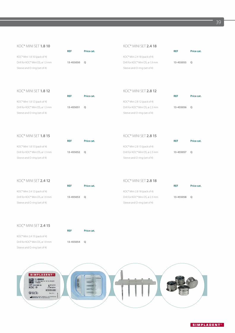
KOC® MINI SET 1.8 10 KOC® MINI SET 2.4 18REF Price cat. REF Price cat.
KOC® Mini 1.8 10 (pack of 4) KOC® Mini 2.4 18 (pack of 4)
Drill for KOC® Mini DS, ø 1.3 mm 13-455050 Q Drill for KOC® Mini DS, ø 1.9 mm 13-455055 Q
Sleeve and O-ring (set of 4) Sleeve and O-ring (set of 4)
KOC® MINI SET 1.8 12 KOC® MINI SET 2.8 12REF Price cat. REF Price cat.
KOC® Mini 1.8 12 (pack of 4) KOC® Mini 2.8 12 (pack of 4)
Drill for KOC® Mini DS, ø 1.3 mm 13-455051 Q Drill for KOC® Mini DS, ø 2.3 mm 13-455056 Q
Sleeve and O-ring (set of 4) Sleeve and O-ring (set of 4)
KOC® MINI SET 1.8 15 KOC® MINI SET 2.8 15REF Price cat. REF Price cat.
KOC® Mini 1.8 15 (pack of 4) KOC® Mini 2.8 15 (pack of 4)
Drill for KOC® Mini DS, ø 1.3 mm 13-455052 Q Drill for KOC® Mini DS, ø 2.3 mm 13-455057 Q
Sleeve and O-ring (set of 4) Sleeve and O-ring (set of 4)
KOC® MINI SET 2.4 12 KOC® MINI SET 2.8 18REF Price cat. REF Price cat.
KOC® Mini 2.4 12 (pack of 4) KOC® Mini 2.8 18 (pack of 4)
Drill for KOC® Mini DS, ø 1.9 mm 13-455053 Q Drill for KOC® Mini DS, ø 2.3 mm 13-455058 Q
Sleeve and O-ring (set of 4) Sleeve and O-ring (set of 4)
KOC® MINI SET 2.4 15REF Price cat.
KOC® Mini 2.4 15 (pack of 4)
Drill for KOC® Mini DS, ø 1.9 mm 13-455054 Q
Sleeve and O-ring (set of 4)
40
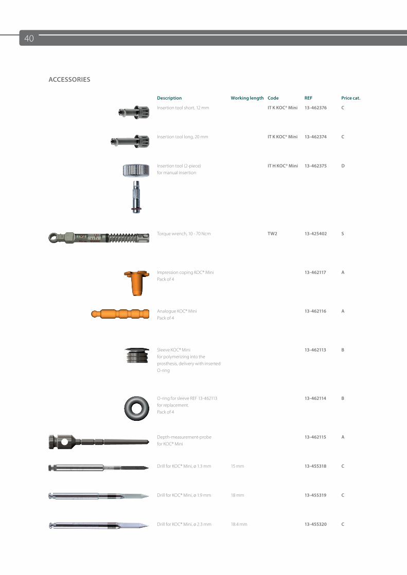
ACCESSORIES
Description Working length Code REF Price cat.
Insertion tool short, 12 mm IT K KOC® Mini 13-462376 C
Insertion tool long, 20 mm IT K KOC® Mini 13-462374 C
Insertion tool (2-piece) for manual insertion
IT H KOC® Mini 13-462375 D
Torque wrench, 10 - 70 Ncm TW2 13-425402 S
Impression coping KOC® MiniPack of 4
13-462117 A
Analogue KOC® MiniPack of 4
13-462116 A
Sleeve KOC® Minifor polymerizing into the prosthesis, delivery with inserted O-ring
13-462113 B
O-ring for sleeve REF 13-462113 for replacement. Pack of 4
13-462114 B
Depth-measurement-probe for KOC® Mini
13-462115 A
Drill for KOC® Mini, ø 1.3 mm 15 mm 13-455318 C
Drill for KOC® Mini, ø 1.9 mm 18 mm 13-455319 C
Drill for KOC® Mini, ø 2.3 mm 18.4 mm 13-455320 C
41
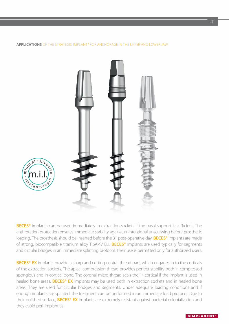
APPLICATIONS OF THE STRATEGIC IMPLANT® FOR ANCHORAGE IN THE UPPER AND LOWER JAW
BECES® implants can be used immediately in extraction sockets if the basal support is sufficient. The anti-rotation protection ensures immediate stability against unintentional unscrewing before prosthetic loading. The prosthesis should be inserted before the 3rd post-operative day. BECES® implants are made of strong, biocompatible titanium alloy Ti6Al4V ELI. BECES® implants are used typically for segments and circular bridges in an immediate splinting protocol. Their use is permitted only for authorized users.
BECES® EX implants provide a sharp and cutting central thread part, which engages in to the corticals of the extraction sockets. The apical compression thread provides perfect stability both in compressed spongious and in cortical bone. The coronal micro-thread seals the 1st cortical if the implant is used in healed bone areas. BECES® EX implants may be used both in extraction sockets and in healed bone areas. They are used for circular bridges and segments. Under adequate loading conditions and if enough implants are splinted, the treatment can be performed in an immediate load protocol. Due to their polished surface, BECES® EX implants are extremely resistant against bacterial colonialization and they avoid peri-implantitis.
42
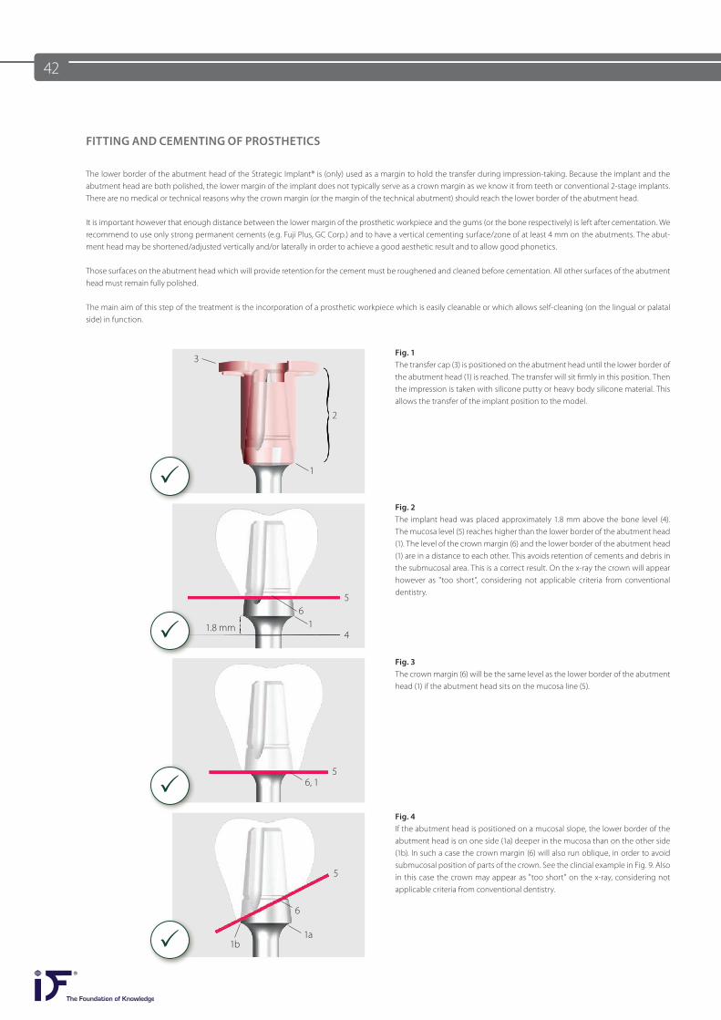
FITTING AND CEMENTING OF PROSTHETICS
The lower border of the abutment head of the Strategic Implant® is (only) used as a margin to hold the transfer during impression-taking. Because the implant and the abutment head are both polished, the lower margin of the implant does not typically serve as a crown margin as we know it from teeth or conventional 2-stage implants. There are no medical or technical reasons why the crown margin (or the margin of the technical abutment) should reach the lower border of the abutment head.
It is important however that enough distance between the lower margin of the prosthetic workpiece and the gums (or the bone respectively) is left after cementation. We recommend to use only strong permanent cements (e.g. Fuji Plus, GC Corp.) and to have a vertical cementing surface/zone of at least 4 mm on the abutments. The abut-ment head may be shortened/adjusted vertically and/or laterally in order to achieve a good aesthetic result and to allow good phonetics.
Those surfaces on the abutment head which will provide retention for the cement must be roughened and cleaned before cementation. All other surfaces of the abutment head must remain fully polished.
The main aim of this step of the treatment is the incorporation of a prosthetic workpiece which is easily cleanable or which allows self-cleaning (on the lingual or palatal side) in function.
Fig. 1The transfer cap (3) is positioned on the abutment head until the lower border of the abutment head (1) is reached. The transfer will sit firmly in this position. Then the impression is taken with silicone putty or heavy body silicone material. This allows the transfer of the implant position to the model.
Fig. 2 The implant head was placed approximately 1.8 mm above the bone level (4). The mucosa level (5) reaches higher than the lower border of the abutment head (1). The level of the crown margin (6) and the lower border of the abutment head (1) are in a distance to each other. This avoids retention of cements and debris in the submucosal area. This is a correct result. On the x-ray the crown will appear however as "too short”, considering not applicable criteria from conventional dentistry.
Fig. 3The crown margin (6) will be the same level as the lower border of the abutment head (1) if the abutment head sits on the mucosa line (5).
Fig. 4If the abutment head is positioned on a mucosal slope, the lower border of the abutment head is on one side (1a) deeper in the mucosa than on the other side (1b). In such a case the crown margin (6) will also run oblique, in order to avoid submucosal position of parts of the crown. See the clincial example in Fig. 9. Also in this case the crown may appear as "too short" on the x-ray, considering not applicable criteria from conventional dentistry.
3
2
1
11.8 mm
65
4
56, 1
1a
5
6
1b
P
P
P
P
43
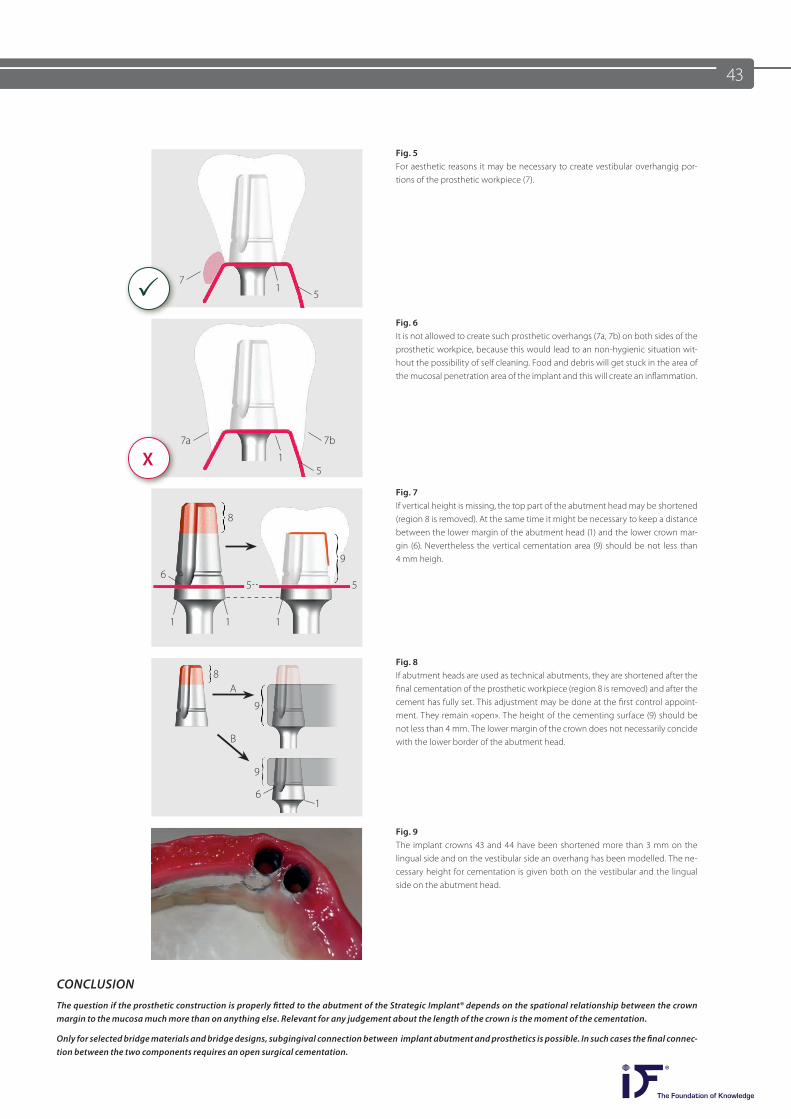
Fig. 5For aesthetic reasons it may be necessary to create vestibular overhangig por-tions of the prosthetic workpiece (7).
Fig. 6It is not allowed to create such prosthetic overhangs (7a, 7b) on both sides of the prosthetic workpice, because this would lead to an non-hygienic situation wit-hout the possibility of self cleaning. Food and debris will get stuck in the area of the mucosal penetration area of the implant and this will create an inflammation.
Fig. 7If vertical height is missing, the top part of the abutment head may be shortened (region 8 is removed). At the same time it might be necessary to keep a distance between the lower margin of the abutment head (1) and the lower crown mar-gin (6). Nevertheless the vertical cementation area (9) should be not less than 4 mm heigh.
Fig. 8If abutment heads are used as technical abutments, they are shortened after the final cementation of the prosthetic workpiece (region 8 is removed) and after the cement has fully set. This adjustment may be done at the first control appoint-ment. They remain «open». The height of the cementing surface (9) should be not less than 4 mm. The lower margin of the crown does not necessarily concide with the lower border of the abutment head.
Fig. 9The implant crowns 43 and 44 have been shortened more than 3 mm on the lingual side and on the vestibular side an overhang has been modelled. The ne-cessary height for cementation is given both on the vestibular and the lingual side on the abutment head.
CONCLUSIONThe question if the prosthetic construction is properly fitted to the abutment of the Strategic Implant® depends on the spational relationship between the crown margin to the mucosa much more than on anything else. Relevant for any judgement about the length of the crown is the moment of the cementation. Only for selected bridge materials and bridge designs, subgingival connection between implant abutment and prosthetics is possible. In such cases the final connec-tion between the two components requires an open surgical cementation.
1
11 1
1
1
7
6
5
55
8
8
9
9
9
A
B
6
P
X7a 7b
5
44
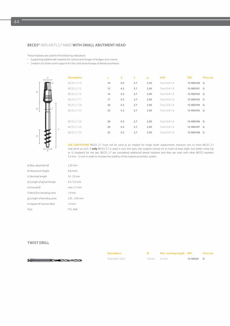
BECES® IMPLANTS 2.7 MMD WITH SMALL ABUTMENT HEAD
These implants are used for the following indications• Supporting (additional) implants for cortical anchorages of bridges and crowns• Creation of a three-point support for the cortical anchorage of dental prostheses
a Description c d e g Drill REF Price cat.
h BECES 2.7 10 10 4.5 2.7 2.55 Twist Drill 1.8 13-900190 G
bBECES 2.7 12 12 4.5 2.7 2.95 Twist Drill 1.8 13-900191 G
BECES 2.7 14 14 5.5 2.7 2.95 Twist Drill 1.8 13-900192 G
BECES 2.7 17 17 5.5 2.7 2.95 Twist Drill 1.8 13-900193 G
g fBECES 2.7 20 20 5.5 2.7 2.95 Twist Drill 1.8 13-900194 G
BECES 2.7 23 23 5.5 2.7 2.95 Twist Drill 1.8 13-900195 G
BECES 2.7 26 26 5.5 2.7 2.95 Twist Drill 1.8 13-900196 G
cBECES 2.7 29 29 5.5 2.7 2.95 Twist Drill 1.8 13-900197 G
dBECES 2.7 32 32 5.5 2.7 2.95 Twist Drill 1.8 13-900198 G
e
USE LIMITATIONS BECES 2.7 must not be used as an implant for single tooth replacement, however two or more BECES 2.7 may serve as such. If only BECES 2.7 is used in very thin jaws, the surgeon should try to insert at least eight, but better more (up to 12 implants) for this jaw. BECES 2.7 are considered additional dental implants and they are used with other BECES implants 3.5 mm - 12 mm in order to increase the stability of the implant-prosthetic system.
a) Max. abutment Ø 3.35 mm
b) Abutment height 6.8 mmh
c) Nominal length 10 - 32 mm
d) Length of apical thread 4.5 / 5.5 mm
e) Enossal Ø max. 2.7 mm
f) Neck Ø in bending zone 1.9 mm
g) Length of bending zone 2.55 - 2.95 mm
h) Square AF (across flats) 1.9 mm
Tool IT K, AHK
TWIST DRILL
Description Ø Max. working length REF Price cat.
Twist Drill 1.8/23 1.8 mm 23 mm 13-90024 D
45
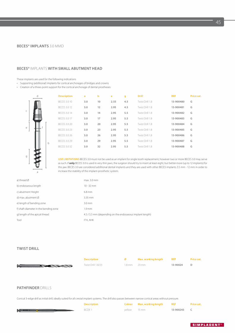
BECES® IMPLANTS 3.0 MMD
BECES® IMPLANTS WITH SMALL ABUTMENT HEAD
These implants are used for the following indications• Supporting (additional) implants for cortical anchorages of bridges and crowns• Creation of a three-point support for the cortical anchorage of dental prostheses
d Description a b e g Drill REF Price cat.
BECES 3.0 10 3.0 10 2.55 4.5 Twist Drill 1.8 13-900480 G
cBECES 3.0 12 3.0 12 2.95 4.5 Twist Drill 1.8 13-900481 G
BECES 3.0 14 3.0 14 2.95 5.5 Twist Drill 1.8 13-900482 G
BECES 3.0 17 3.0 17 2.95 5.5 Twist Drill 1.8 13-900483 G
e fBECES 3.0 20 3.0 20 2.95 5.5 Twist Drill 1.8 13-900484 G
BECES 3.0 23 3.0 23 2.95 5.5 Twist Drill 1.8 13-900485 G
BECES 3.0 26 3.0 26 2.95 5.5 Twist Drill 1.8 13-900486 G
bBECES 3.0 29 3.0 29 2.95 5.5 Twist Drill 1.8 13-900487 G
BECES 3.0 32 3.0 32 2.95 5.5 Twist Drill 1.8 13-900488 G
g
a
USE LIMITATIONS BECES 3.0 must not be used as an implant for single tooth replacement, however two or more BECES 3.0 may serve as such. If only BECES 3.0 is used in very thin jaws, the surgeon should try to insert at least eight, but better more (up to 12 implants) for this jaw. BECES 3.0 are considered additional dental implants and they are used with other BECES implants 3.5 mm - 12 mm in order to increase the stability of the implant-prosthetic system.
a) thread Ø max. 3.0 mm
b) endosseous length 10 - 32 mm
c) abutment Height 6.8 mm
d) max. abutment Ø 3.35 mm
e) length of bending zone 3.0 mm
f) shaft diameter in the bending zone 1.9 mm
g) length of the apical thread 4.5 / 5.5 mm (depending on the endosseous implant length)
Tool IT K, AHK
TWIST DRILL
Description Ø Max. working length REF Price cat.
Twist Drill 1.8/23 1.8 mm 23 mm 13-90024 D
PATHFINDER DRILLS
Conical 3-edge drill as initial drill, ideally suited for all crestal implant systems. The drill also passes between narrow cortical areas without pressure.
Description Colour Max. working length REF Price cat.
BCDX 1 yellow 15 mm 13-900243 C
46
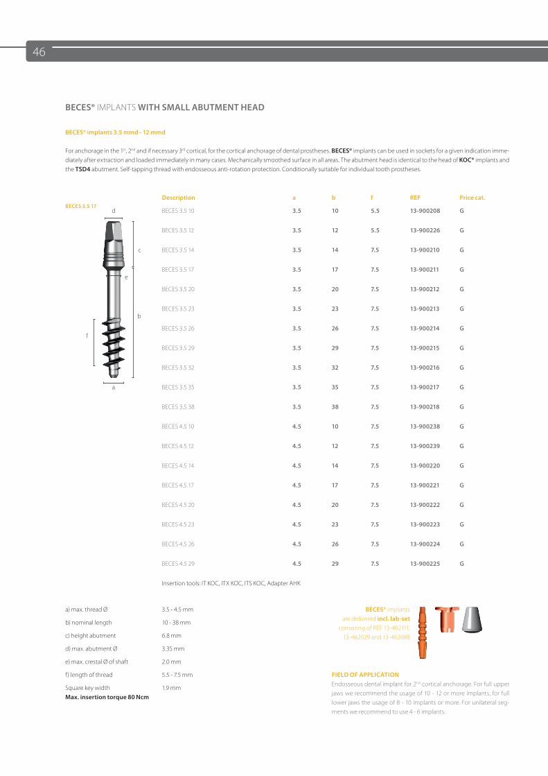
BECES® IMPLANTS WITH SMALL ABUTMENT HEAD
BECES® implants 3.5 mmd - 12 mmd
For anchorage in the 1st, 2nd and if necessary 3rd cortical, for the cortical anchorage of dental prostheses. BECES® implants can be used in sockets for a given indication imme-diately after extraction and loaded immediately in many cases. Mechanically smoothed surface in all areas. The abutment head is identical to the head of KOC® implants and the TSD4 abutment. Self-tapping thread with endosseous anti-rotation protection. Conditionally suitable for individual tooth prostheses.
BECES 3.5 17Description a b f REF Price cat.
d BECES 3.5 10 3.5 10 5.5 13-900208 G
BECES 3.5 12 3.5 12 5.5 13-900226 G
c BECES 3.5 14 3.5 14 7.5 13-900210 G
eBECES 3.5 17 3.5 17 7.5 13-900211 G
BECES 3.5 20 3.5 20 7.5 13-900212 G
bBECES 3.5 23 3.5 23 7.5 13-900213 G
fBECES 3.5 26 3.5 26 7.5 13-900214 G
BECES 3.5 29 3.5 29 7.5 13-900215 G
BECES 3.5 32 3.5 32 7.5 13-900216 G
a BECES 3.5 35 3.5 35 7.5 13-900217 G
BECES 3.5 38 3.5 38 7.5 13-900218 G
BECES 4.5 10 4.5 10 7.5 13-900238 G
BECES 4.5 12 4.5 12 7.5 13-900239 G
BECES 4.5 14 4.5 14 7.5 13-900220 G
BECES 4.5 17 4.5 17 7.5 13-900221 G
BECES 4.5 20 4.5 20 7.5 13-900222 G
BECES 4.5 23 4.5 23 7.5 13-900223 G
BECES 4.5 26 4.5 26 7.5 13-900224 G
BECES 4.5 29 4.5 29 7.5 13-900225 G
Insertion tools: IT KOC, ITX KOC, ITS KOC, Adapter AHK
a) max. thread Ø 3.5 - 4.5 mm BECES® implants are delivered incl. lab-set
consisting of REF 13-462111, 13-462029 and 13-462088
b) nominal length 10 - 38 mm
c) height abutment 6.8 mm
d) max. abutment Ø 3.35 mm
e) max. crestal Ø of shaft 2.0 mm
f) length of thread 5.5 - 7.5 mm FIELD OF APPLICATION Endosseous dental implant for 2nd cortical anchorage. For full upper jaws we recommend the usage of 10 - 12 or more implants, for full lower jaws the usage of 8 - 10 implants or more. For unilateral seg-ments we recommend to use 4 - 6 implants.
Square key widthMax. insertion torque 80 Ncm
1.9 mm
47
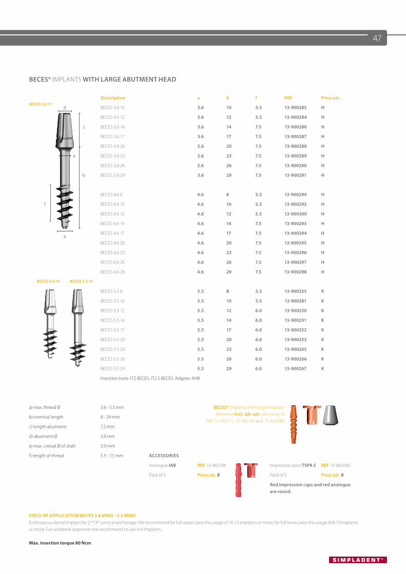
BECES® IMPLANTS WITH LARGE ABUTMENT HEAD
BECES 3.6 17Description a b f REF Price cat.
d BECES 3.6 10 3.6 10 5.5 13-900285 H
BECES 3.6 12 3.6 12 5.5 13-900284 H
c BECES 3.6 14 3.6 14 7.5 13-900286 H
BECES 3.6 17 3.6 17 7.5 13-900287 H
BECES 3.6 20 3.6 20 7.5 13-900288 H
e BECES 3.6 23 3.6 23 7.5 13-900289 H
BECES 3.6 26 3.6 26 7.5 13-900290 H
b BECES 3.6 29 3.6 29 7.5 13-900291 H
BECES 4.6 8 4.6 8 5.5 13-900299 H
f BECES 4.6 10 4.6 10 5.5 13-900292 H
BECES 4.6 12 4.6 12 5.5 13-900300 H
BECES 4.6 14 4.6 14 7.5 13-900293 H
aBECES 4.6 17 4.6 17 7.5 13-900294 H
BECES 4.6 20 4.6 20 7.5 13-900295 H
BECES 4.6 23 4.6 23 7.5 13-900296 H
BECES 4.6 26 4.6 26 7.5 13-900297 H
BECES 4.6 29 4.6 29 7.5 13-900298 H
BECES 4.6 14 BECES 5.5 14
BECES 5.5 8 5.5 8 5.5 13-900255 K
BECES 5.5 10 5.5 10 5.5 13-900281 K
BECES 5.5 12 5.5 12 6.0 13-900250 K
BECES 5.5 14 5.5 14 6.0 13-900251 K
BECES 5.5 17 5.5 17 6.0 13-900252 K
BECES 5.5 20 5.5 20 6.0 13-900253 K
BECES 5.5 23 5.5 23 6.0 13-900265 K
BECES 5.5 26 5.5 26 6.0 13-900266 K
BECES 5.5 29 5.5 29 6.0 13-900267 K
Insertion tools: IT2 BECES, IT2 S BECES, Adapter AHB
a) max. thread Ø 3.6 - 5.5 mm BECES® Implants with large head are delivered incl. lab-set consisting of
REF 13-462111, 13-462136 and 13-462086b) nominal length 8 - 29 mm
c) length abutment 7.2 mm
d) abutment Ø 3.9 mm
e) max. crestal Ø of shaft 2.0 mm
f) length of thread 5.5 - 7.5 mm ACCESSORIES
Analogue IAB REF 13-462106 Impression post TSPA 5 REF 13-462030
Pack of 5 Price cat. B Pack of 5 Price cat. B
Red impression caps and red analogue are round.
FIELD OF APPLICATION BECES 3.6 MMD - 5.5 MMDEndosseous dental implant for 2nd/3rd cortical anchorage. We recommend for full upper jaws the usage of 10-12 implants or more, for full lower jaws the usage of 8-10 implants or more. For unilateral segments we recommend to use 4-6 implants.
Max. insertion torque 80 Ncm
48
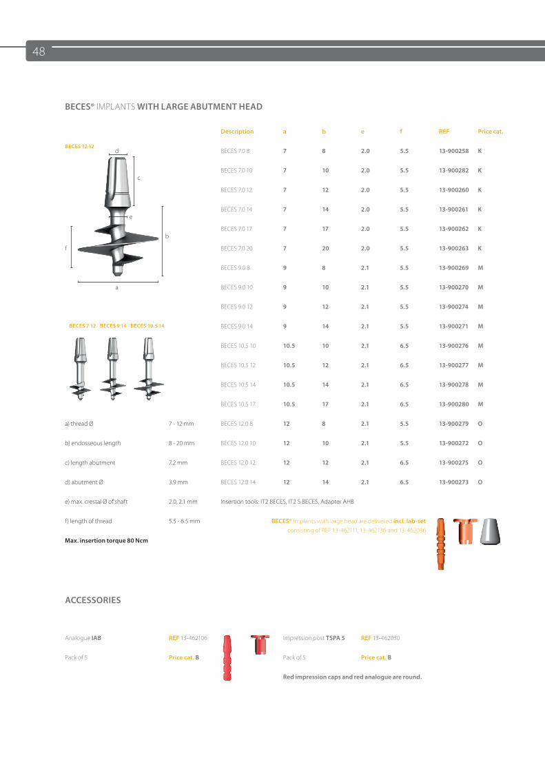
BECES® IMPLANTS WITH LARGE ABUTMENT HEAD
BECES 12 12
Description a b e f REF Price cat.
d BECES 7.0 8 7 8 2.0 5.5 13-900258 K
cBECES 7.0 10 7 10 2.0 5.5 13-900282 K
BECES 7.0 12 7 12 2.0 5.5 13-900260 K
eBECES 7.0 14 7 14 2.0 5.5 13-900261 K
bBECES 7.0 17 7 17 2.0 5.5 13-900262 K
f BECES 7.0 20 7 20 2.0 5.5 13-900263 K
BECES 9.0 8 9 8 2.1 5.5 13-900269 M
a BECES 9.0 10 9 10 2.1 5.5 13-900270 M
BECES 9.0 12 9 12 2.1 5.5 13-900274 M
BECES 7 12 BECES 9 14 BECES 10.5 14 BECES 9.0 14 9 14 2.1 5.5 13-900271 M
BECES 10.5 10 10.5 10 2.1 6.5 13-900276 M
BECES 10.5 12 10.5 12 2.1 6.5 13-900277 M
BECES 10.5 14 10.5 14 2.1 6.5 13-900278 M
BECES 10.5 17 10.5 17 2.1 6.5 13-900280 M
a) thread Ø 7 - 12 mm BECES 12.0 8 12 8 2.1 5.5 13-900279 O
b) endosseous length 8 - 20 mm BECES 12.0 10 12 10 2.1 5.5 13-900272 O
c) length abutment 7.2 mm BECES 12.0 12 12 12 2.1 6.5 13-900275 O
d) abutment Ø 3.9 mm BECES 12.0 14 12 14 2.1 6.5 13-900273 O
e) max. crestal Ø of shaft 2.0, 2.1 mm Insertion tools: IT2 BECES, IT2 S BECES, Adapter AHB
f) length of thread 5.5 - 6.5 mm BECES® Implants with large head are delivered incl. lab-set consisting of REF 13-462111, 13-462136 and 13-462086
Max. insertion torque 80 Ncm
ACCESSORIES
Analogue IAB REF 13-462106 Impression post TSPA 5 REF 13-462030
Pack of 5 Price cat. B Pack of 5 Price cat. B
Red impression caps and red analogue are round.
49
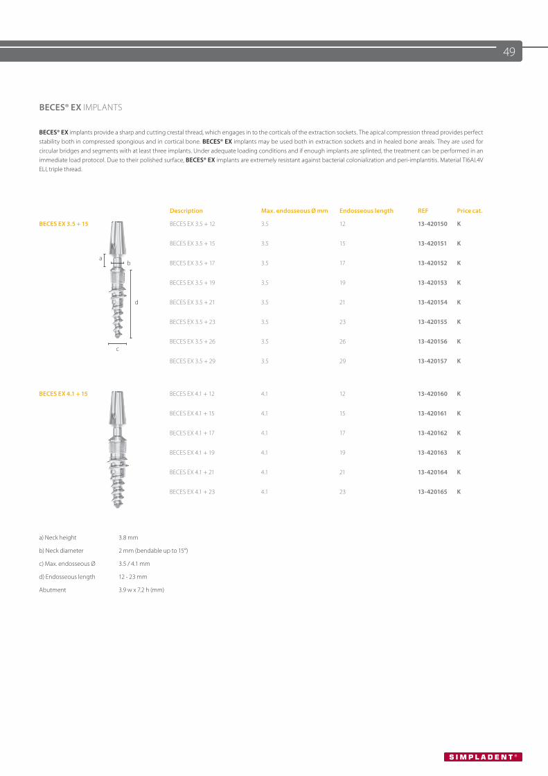
BECES® EX IMPLANTS
BECES® EX implants provide a sharp and cutting crestal thread, which engages in to the corticals of the extraction sockets. The apical compression thread provides perfect stability both in compressed spongious and in cortical bone. BECES® EX implants may be used both in extraction sockets and in healed bone areals. They are used for circular bridges and segments with at least three implants. Under adequate loading conditions and if enough implants are splinted, the treatment can be performed in an immediate load protocol. Due to their polished surface, BECES® EX implants are extremely resistant against bacterial colonialization and peri-implantitis. Material TI6AL4V ELI, triple thread.
Description Max. endosseous Ø mm Endosseous length REF Price cat.
BECES EX 3.5 + 15 BECES EX 3.5 + 12 3.5 12 13-420150 K
a
BECES EX 3.5 + 15 3.5 15 13-420151 K
b BECES EX 3.5 + 17 3.5 17 13-420152 K
BECES EX 3.5 + 19 3.5 19 13-420153 K
d BECES EX 3.5 + 21 3.5 21 13-420154 K
BECES EX 3.5 + 23 3.5 23 13-420155 K
cBECES EX 3.5 + 26 3.5 26 13-420156 K
BECES EX 3.5 + 29 3.5 29 13-420157 K
BECES EX 4.1 + 15 BECES EX 4.1 + 12 4.1 12 13-420160 K
BECES EX 4.1 + 15 4.1 15 13-420161 K
BECES EX 4.1 + 17 4.1 17 13-420162 K
BECES EX 4.1 + 19 4.1 19 13-420163 K
BECES EX 4.1 + 21 4.1 21 13-420164 K
BECES EX 4.1 + 23 4.1 23 13-420165 K
a) Neck height 3.8 mm
b) Neck diameter 2 mm (bendable up to 15°)
c) Max. endosseous Ø 3.5 / 4.1 mm
d) Endosseous length 12 - 23 mm
Abutment 3.9 w x 7.2 h (mm)
50
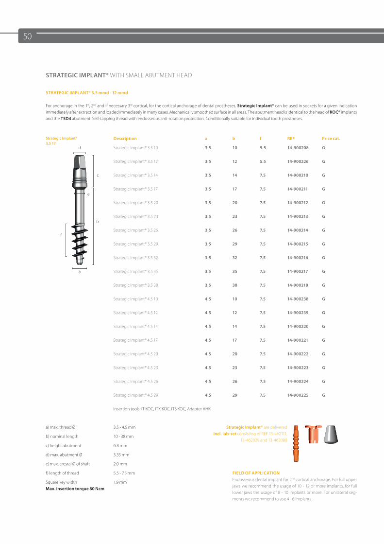
STRATEGIC IMPLANT® WITH SMALL ABUTMENT HEAD
STRATEGIC IMPLANT® 3.5 mmd - 12 mmd
For anchorage in the 1st, 2nd and if necessary 3rd cortical, for the cortical anchorage of dental prostheses. Strategic Implant® can be used in sockets for a given indication immediately after extraction and loaded immediately in many cases. Mechanically smoothed surface in all areas. The abutment head is identical to the head of KOC® implants and the TSD4 abutment. Self-tapping thread with endosseous anti-rotation protection. Conditionally suitable for individual tooth prostheses.
Strategic Implant®3.5 17
Description a b f REF Price cat.
d Strategic Implant® 3.5 10 3.5 10 5.5 14-900208 G
Strategic Implant® 3.5 12 3.5 12 5.5 14-900226 G
c Strategic Implant® 3.5 14 3.5 14 7.5 14-900210 G
eStrategic Implant® 3.5 17 3.5 17 7.5 14-900211 G
Strategic Implant® 3.5 20 3.5 20 7.5 14-900212 G
bStrategic Implant® 3.5 23 3.5 23 7.5 14-900213 G
fStrategic Implant® 3.5 26 3.5 26 7.5 14-900214 G
Strategic Implant® 3.5 29 3.5 29 7.5 14-900215 G
Strategic Implant® 3.5 32 3.5 32 7.5 14-900216 G
a Strategic Implant® 3.5 35 3.5 35 7.5 14-900217 G
Strategic Implant® 3.5 38 3.5 38 7.5 14-900218 G
Strategic Implant® 4.5 10 4.5 10 7.5 14-900238 G
Strategic Implant® 4.5 12 4.5 12 7.5 14-900239 G
Strategic Implant® 4.5 14 4.5 14 7.5 14-900220 G
Strategic Implant® 4.5 17 4.5 17 7.5 14-900221 G
Strategic Implant® 4.5 20 4.5 20 7.5 14-900222 G
Strategic Implant® 4.5 23 4.5 23 7.5 14-900223 G
Strategic Implant® 4.5 26 4.5 26 7.5 14-900224 G
Strategic Implant® 4.5 29 4.5 29 7.5 14-900225 G
Insertion tools: IT KOC, ITX KOC, ITS KOC, Adapter AHK
a) max. thread Ø 3.5 - 4.5 mm Strategic Implant® are delivered incl. lab-set consisting of REF 13-462111,
13-462029 and 13-462088b) nominal length 10 - 38 mm
c) height abutment 6.8 mm
d) max. abutment Ø 3.35 mm
e) max. crestal Ø of shaft 2.0 mm
f) length of thread 5.5 - 7.5 mm FIELD OF APPLICATION Endosseous dental implant for 2nd cortical anchorage. For full upper jaws we recommend the usage of 10 - 12 or more implants, for full lower jaws the usage of 8 - 10 implants or more. For unilateral seg-ments we recommend to use 4 - 6 implants.
Square key widthMax. insertion torque 80 Ncm
1.9 mm
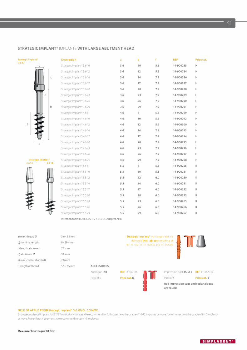
51
STRATEGIC IMPLANT® IMPLANTS WITH LARGE ABUTMENT HEAD
Strategic Implant® 3.6 17
Description a b f REF Price cat.
d Strategic Implant® 3.6 10 3.6 10 5.5 14-900285 H
Strategic Implant® 3.6 12 3.6 12 5.5 14-900284 H
c Strategic Implant® 3.6 14 3.6 14 7.5 14-900286 H
Strategic Implant® 3.6 17 3.6 17 7.5 14-900287 H
Strategic Implant® 3.6 20 3.6 20 7.5 14-900288 H
e Strategic Implant® 3.6 23 3.6 23 7.5 14-900289 H
Strategic Implant® 3.6 26 3.6 26 7.5 14-900290 H
b Strategic Implant® 3.6 29 3.6 29 7.5 14-900291 H
Strategic Implant® 4.6 8 4.6 8 5.5 14-900299 H
Strategic Implant® 4.6 10 4.6 10 5.5 14-900292 H
f Strategic Implant® 4.6 12 4.6 12 5.5 14-900300 H
Strategic Implant® 4.6 14 4.6 14 7.5 14-900293 H
Strategic Implant® 4.6 17 4.6 17 7.5 14-900294 H
aStrategic Implant® 4.6 20 4.6 20 7.5 14-900295 H
Strategic Implant® 4.6 23 4.6 23 7.5 14-900296 H
Strategic Implant® 4.6 26 4.6 26 7.5 14-900297 H
Strategic Implant® 4.6 14 5.5 14
Strategic Implant® 4.6 29 4.6 29 7.5 14-900298 H
Strategic Implant® 5.5 8 5.5 8 5.5 14-900255 K
Strategic Implant® 5.5 10 5.5 10 5.5 14-900281 K
Strategic Implant® 5.5 12 5.5 12 6.0 14-900250 K
Strategic Implant® 5.5 14 5.5 14 6.0 14-900251 K
Strategic Implant® 5.5 17 5.5 17 6.0 14-900252 K
Strategic Implant® 5.5 20 5.5 20 6.0 14-900253 K
Strategic Implant® 5.5 23 5.5 23 6.0 14-900265 K
Strategic Implant® 5.5 26 5.5 26 6.0 14-900266 K
Strategic Implant® 5.5 29 5.5 29 6.0 14-900267 K
Insertion tools: IT2 BECES, IT2 S BECES, Adapter AHB
a) max. thread Ø 3.6 - 5.5 mm Strategic Implant® with large head are delivered incl. lab-set consisting of
REF 13-462111, 13-462136 and 13-462086b) nominal length 8 - 29 mm
c) length abutment 7.2 mm
d) abutment Ø 3.9 mm
e) max. crestal Ø of shaft 2.0 mm
f) length of thread 5.5 - 7.5 mm ACCESSORIES
Analogue IAB REF 13-462106 Impression post TSPA 5 REF 13-462030
Pack of 5 Price cat. B Pack of 5 Price cat. B
Red impression caps and red analogue are round.
FIELD OF APPLICATION Strategic Implant® 3.6 MMD - 5.5 MMDEndosseous dental implant for 2nd/3rd cortical anchorage. We recommend for full upper jaws the usage of 10-12 implants or more, for full lower jaws the usage of 8-10 implants or more. For unilateral segments we recommend to use 4-6 implants.
Max. insertion torque 80 Ncm
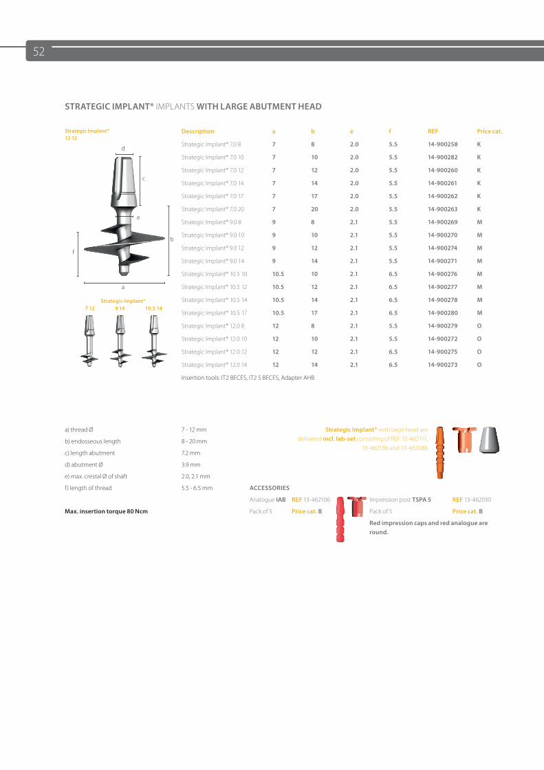
52
STRATEGIC IMPLANT® IMPLANTS WITH LARGE ABUTMENT HEAD
Strategic Implant®12 12
Description a b e f REF Price cat.
dStrategic Implant® 7.0 8 7 8 2.0 5.5 14-900258 K
Strategic Implant® 7.0 10 7 10 2.0 5.5 14-900282 K
cStrategic Implant® 7.0 12 7 12 2.0 5.5 14-900260 K
Strategic Implant® 7.0 14 7 14 2.0 5.5 14-900261 K
Strategic Implant® 7.0 17 7 17 2.0 5.5 14-900262 K
eStrategic Implant® 7.0 20 7 20 2.0 5.5 14-900263 K
Strategic Implant® 9.0 8 9 8 2.1 5.5 14-900269 M
bStrategic Implant® 9.0 10 9 10 2.1 5.5 14-900270 M
fStrategic Implant® 9.0 12 9 12 2.1 5.5 14-900274 M
Strategic Implant® 9.0 14 9 14 2.1 5.5 14-900271 M
Strategic Implant® 10.5 10 10.5 10 2.1 6.5 14-900276 M
a Strategic Implant® 10.5 12 10.5 12 2.1 6.5 14-900277 M
Strategic Implant® 7 12 9 14 10.5 14
Strategic Implant® 10.5 14 10.5 14 2.1 6.5 14-900278 M
Strategic Implant® 10.5 17 10.5 17 2.1 6.5 14-900280 M
Strategic Implant® 12.0 8 12 8 2.1 5.5 14-900279 O
Strategic Implant® 12.0 10 12 10 2.1 5.5 14-900272 O
Strategic Implant® 12.0 12 12 12 2.1 6.5 14-900275 O
Strategic Implant® 12.0 14 12 14 2.1 6.5 14-900273 O
Insertion tools: IT2 BECES, IT2 S BECES, Adapter AHB
a) thread Ø 7 - 12 mm Strategic Implant® with large head are delivered incl. lab-set consisting of REF 13-462111,
13-462136 and 13-462086b) endosseous length 8 - 20 mm
c) length abutment 7.2 mm
d) abutment Ø 3.9 mm
e) max. crestal Ø of shaft 2.0, 2.1 mm
f) length of thread 5.5 - 6.5 mm ACCESSORIES
Analogue IAB REF 13-462106 Impression post TSPA 5 REF 13-462030
Max. insertion torque 80 Ncm Pack of 5 Price cat. B Pack of 5 Price cat. B
Red impression caps and red analogue are round.
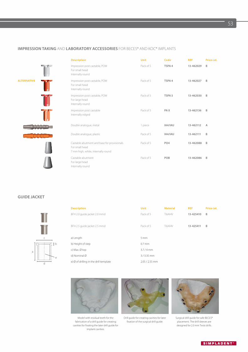
53
IMPRESSION TAKING AND LABORATORY ACCESSORIES FOR BECES® AND KOC® IMPLANTS
Description Unit Code REF Price cat.
Impression post castable, POMFor small head Internally round
Pack of 5 TSPA 4 13-462029 B
ALTERNATIVE Impression post castable, POMFor small head Internally round
Pack of 5 TSPA 4 13-462027 B
Impression post castable, POM For large head Internally round
Pack of 5 TSPA 5 13-462030 B
Impression post castable Internally edged
Pack of 5 PA X 13-462136 B
Double analogue, metal 1 piece IA4/IAU 13-462112 A
Double analogue, plastic Pack of 5 IA4/IAU 13-462111 B
Castable abutment and base for provisionalsFor small head7 mm high, white, internally round
Pack of 5 PO4 13-462088 B
Castable abutment For large head Internally round
Pack of 5 POB 13-462086 B
GUIDE JACKET
Description Unit Material REF Price cat.
BFH 2.0 guide jacket 2.0 mmd Pack of 5 Ti6Al4V 13-425410 B
BFH 2.5 guide jacket 2.5 mmd Pack of 5 Ti6Al4V 13-425411 B
c a) Length 5 mm
b b) Height of step 0.7 mm
ac) Max. Ø top 3.7 / 4 mm
ed) Nominal Ø 3 / 3.35 mm
de) Ø of drilling in the drill template 2.05 / 2.55 mm
Model with residual teeth for the fabrication of a drill guide for creating
cavities for fixating the later drill guide for implant cavities.
Drill guide for creating cavities for laterfixation of the surgical drill guide.
Surgical drill guide for safe BECES® placement. The drill sleeves are designed for 2.0 mm Twist drills.
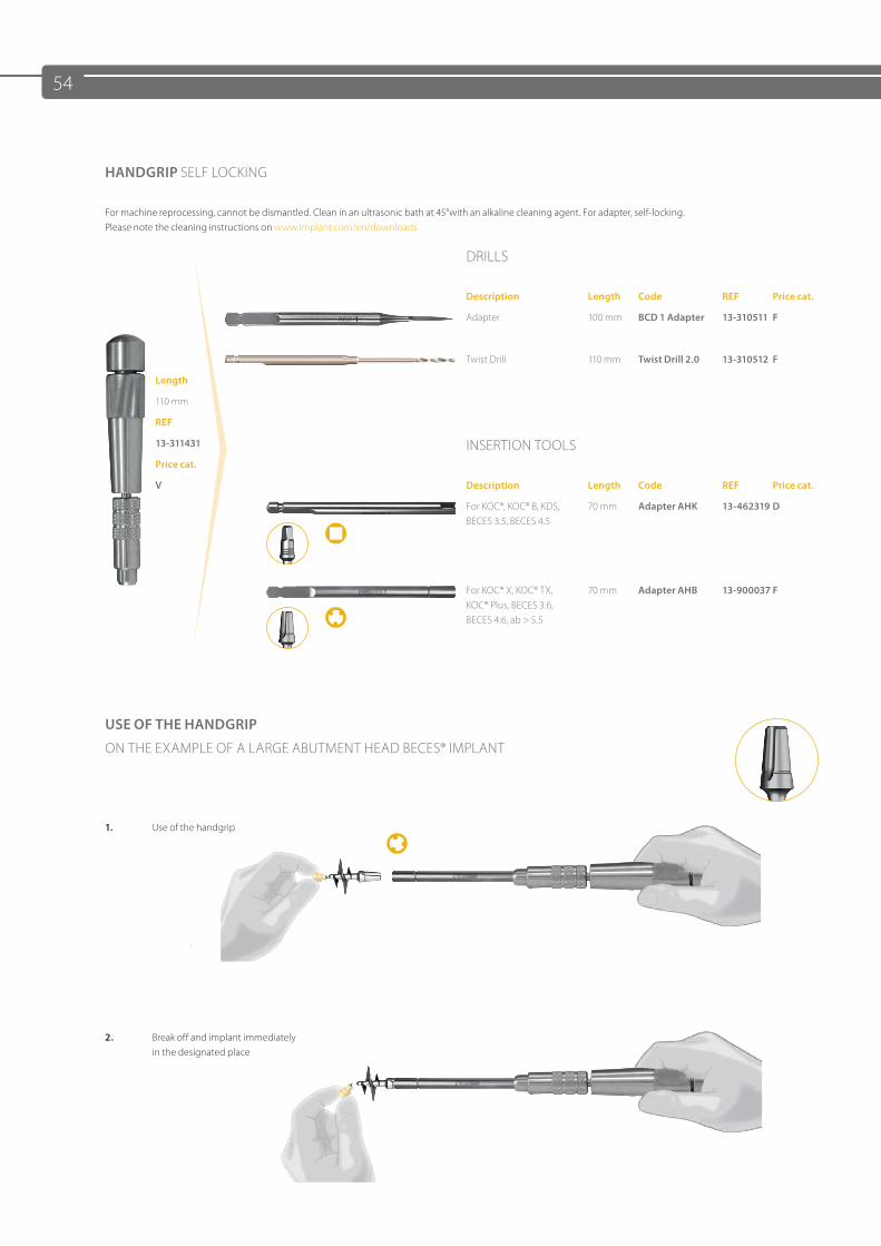
54
HANDGRIP SELF LOCKING
For machine reprocessing, cannot be dismantled. Clean in an ultrasonic bath at 45°with an alkaline cleaning agent. For adapter, self-locking. Please note the cleaning instructions on www.implant.com/en/downloads
DRILLS
Description Length Code REF Price cat.
Adapter 100 mm BCD 1 Adapter 13-310511 F
Twist Drill 110 mm Twist Drill 2.0 13-310512 F
Length
110 mm
REF
13-311431 INSERTION TOOLSPrice cat.
V Description Length Code REF Price cat.
For KOC®, KOC® B, KDS, BECES 3.5, BECES 4.5
70 mm Adapter AHK 13-462319 D
For KOC® X, KOC® TX, KOC® Plus, BECES 3.6, BECES 4.6, ab > 5.5
70 mm Adapter AHB 13-900037 F
USE OF THE HANDGRIP
ON THE EXAMPLE OF A LARGE ABUTMENT HEAD BECES® IMPLANT
1. Use of the handgrip
2. Break off and implant immediatelyin the designated place
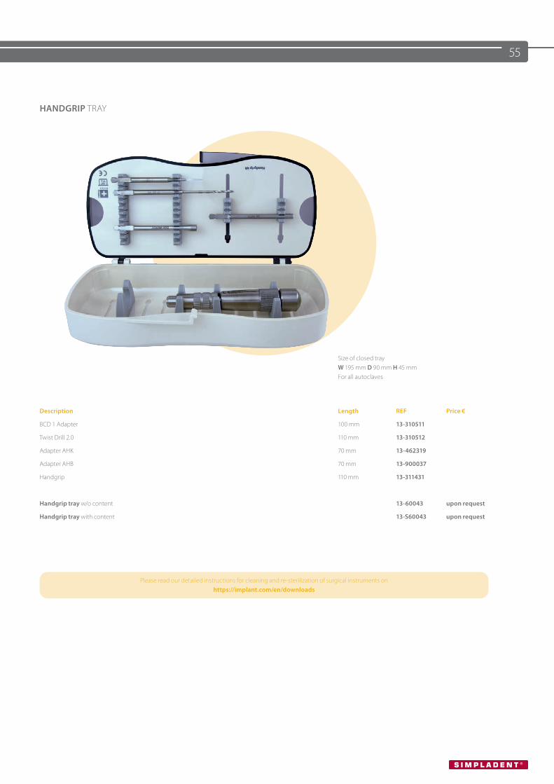
55
HANDGRIP TRAY
Size of closed tray W 195 mm D 90 mm H 45 mm For all autoclaves
Description Length REF Price €
BCD 1 Adapter 100 mm 13-310511
Twist Drill 2.0 110 mm 13-310512
Adapter AHK 70 mm 13-462319
Adapter AHB 70 mm 13-900037
Handgrip 110 mm 13-311431
Handgrip tray w/o content 13-60043 upon request
Handgrip tray with content 13-S60043 upon request
Please read our detailed instructions for cleaning and re-sterilization of surgical instruments onhttps://implant.com/en/downloads
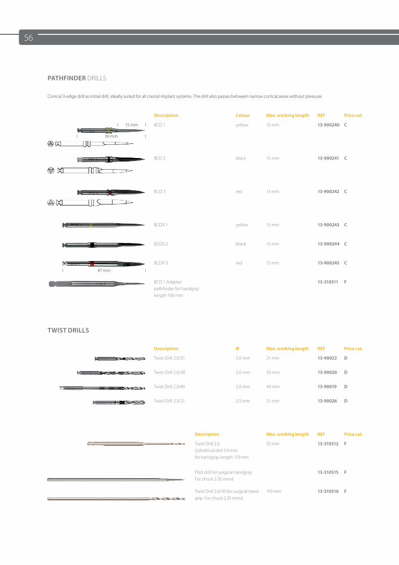
56
PATHFINDER DRILLS
Conical 3-edge drill as initial drill, ideally suited for all crestal implant systems. The drill also passes between narrow cortical areas without pressure.
Description Colour Max. working length REF Price cat.
BCD 1 yellow 15 mm 13-900240 C
BCD 2 black 15 mm 13-900241 C
BCD 3 red 13 mm 13-900242 C
BCDX 1 yellow 15 mm 13-900243 C
BCDX 2 black 15 mm 13-900244 C
BCDX 3 red 15 mm 13-900245 C
BCD 1 Adapterpathfinder for handgriplength 100 mm
13-310511 F
TWIST DRILLS
Description Ø Max. working length REF Price cat.
Twist Drill 2.0/21 2.0 mm 21 mm 13-90022 D
Twist Drill 2.0/30 2.0 mm 30 mm 13-90020 D
Twist Drill 2.0/40 2.0 mm 40 mm 13-90019 D
Twist Drill 2.5/21 2.5 mm 21 mm 13-90026 D
Description Max. working length REF Price cat.
Twist Drill 2.0 Cylindrical drill 2.0 mm for handgrip, length 110 mm
35 mm 13-310512 F
Pilot drill for surgical handgrip.For chuck 2.35 mmd
13-310515 F
Twist Drill 2.0/30 for surgical hand-grip. For chuck 2.35 mmd.
110 mm 13-310516 F
I 47 mm I
I 15 mm I
I 39 mm I
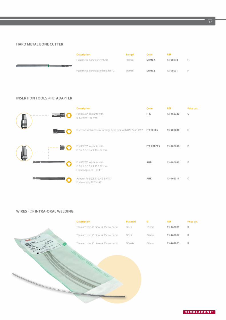
57
INSERTION TOOLS AND ADAPTER
Description Code REF Price cat.
For BECES® implants with Ø 3.5 mm + 4.5 mm
IT K 13-462320 C
Insertion tool medium, for large head. Use with RAT2 and TW2. IT2 BECES 13-900030 E
For BECES® implants with Ø 3.6, 4.6, 5.5, 7.9, 10.5, 12 mm
IT2 S BECES 13-900038 E
For BECES® implants with Ø 3.6, 4.6, 5.5, 7.9, 10.5, 12 mm. For handgrip REF 311431
AHB 13-900037 F
Adapter for BECES 3.5/4.5 & KOC®For handgrip REF 311431
AHK 13-462319 D
WIRES FOR INTRA-ORAL WELDING
Description Material Ø REF Price cat.
Titanium wire, (5 pieces á 15cm / pack) TiGr.2 1.5 mm 13-462001 B
Titanium wire, (5 pieces á 15cm / pack) TiGr.2 2.0 mm 13-462002 B
Titanium wire, (5 pieces á 15cm / pack) Ti6Al4V 2.0 mm 13-462003 B
HARD METAL BONE CUTTER
Description Length Code REF
Hard metal bone cutter short 30 mm SHMC S 13-90030 F
Hard metal bone cutter long, for FG 36 mm SHMC L 13-90031 F
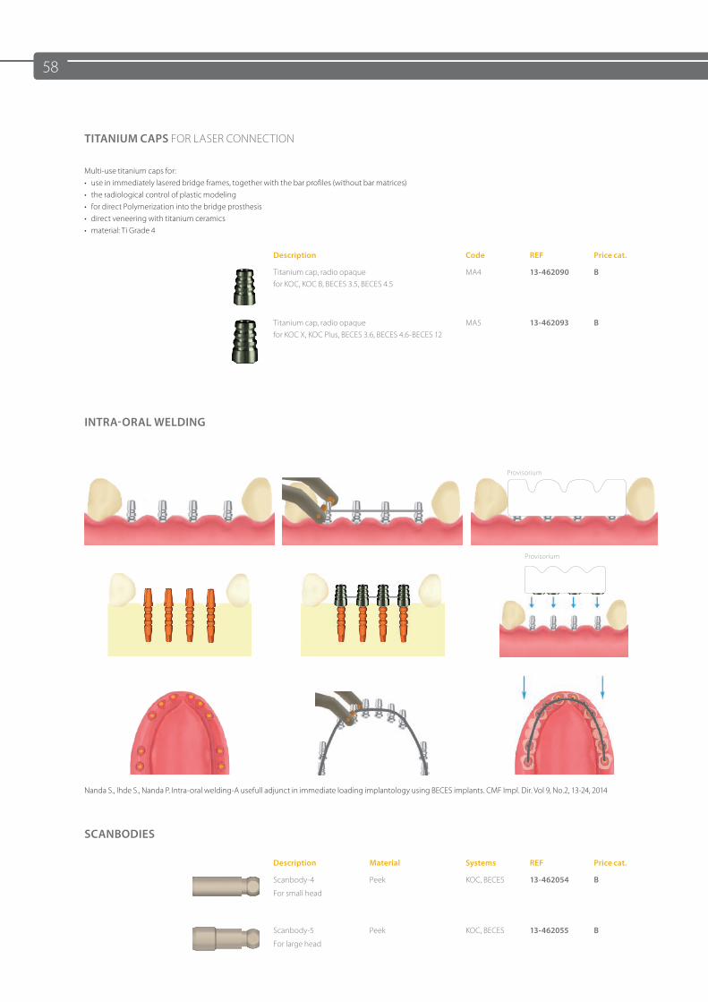
58
Provisorium
Provisorium
Nanda S., Ihde S., Nanda P. Intra-oral welding-A usefull adjunct in immediate loading implantology using BECES implants. CMF Impl. Dir. Vol 9, No.2, 13-24, 2014
TITANIUM CAPS FOR LASER CONNECTION
Multi-use titanium caps for:• use in immediately lasered bridge frames, together with the bar profiles (without bar matrices)• the radiological control of plastic modeling• for direct Polymerization into the bridge prosthesis• direct veneering with titanium ceramics• material: Ti Grade 4
Description Code REF Price cat.
Titanium cap, radio opaquefor KOC, KOC B, BECES 3.5, BECES 4.5
MA4 13-462090 B
Titanium cap, radio opaquefor KOC X, KOC Plus, BECES 3.6, BECES 4.6-BECES 12
MA5 13-462093 B
INTRA-ORAL WELDING
SCANBODIES
Description Material Systems REF Price cat.
Scanbody-4
For small head
Peek KOC, BECES 13-462054 B
Scanbody-5
For large head
Peek KOC, BECES 13-462055 B
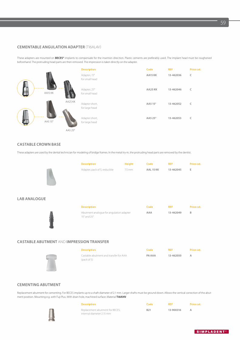
59
Nanda S., Ihde S., Nanda P. Intra-oral welding-A usefull adjunct in immediate loading implantology using BECES implants. CMF Impl. Dir. Vol 9, No.2, 13-24, 2014
CEMENTABLE ANGULATION ADAPTER (TI6AL4V)
These adapters are mounted on BECES® implants to compensate for the insertion direction. Plastic cements are preferably used. The implant head must be roughened beforehand. The protruding head parts are then removed. The impression is taken directly on the adapter.
Description Code REF Price cat.
Adapter, 15°for small head
AA15 KK 13-462036 C
AA15 KK
AA25 KK
Adapter, 25°for small head
AA25 KK 13-462046 C
Adapter short, for large head
AA5 15° 13-462052 C
AA5 15°
AA5 25°
Adapter short, for large head
AA5 25° 13-462053 C
CASTABLE CROWN BASE
These adapters are used by the dental technician for modeling of bridge frames. In the metal try-in, the protruding head parts are removed by the dentist.
Description Height Code REF Price cat.
Adapter, pack of 5, reducible 7.5 mm AAL 15 KK 13-462045 E
LAB ANALOGUE
Description Code REF Price cat.
Abutment analogue for angulation adapter15° and 25°
AAA 13-462049 B
CASTABLE ABUTMENT AND IMPRESSION TRANSFER
Description Code REF Price cat.
Castable abutment and transfer for AAA (pack of 5)
PA AAA 13-462050 A
CEMENTING ABUTMENT
Replacement abutment for cementing. For BECES implants up to a shaft diameter of 2.1 mm. Larger shafts must be ground down. Allows the vertical correction of the abut-ment position. Mounting e.g. with Fuji Plus. With drain hole, machined surface. Material Ti6Al4V.
Description Code REF Price cat.
Replacement abutment for BECES, internal diameter 2.15 mm
B21 13-900316 A
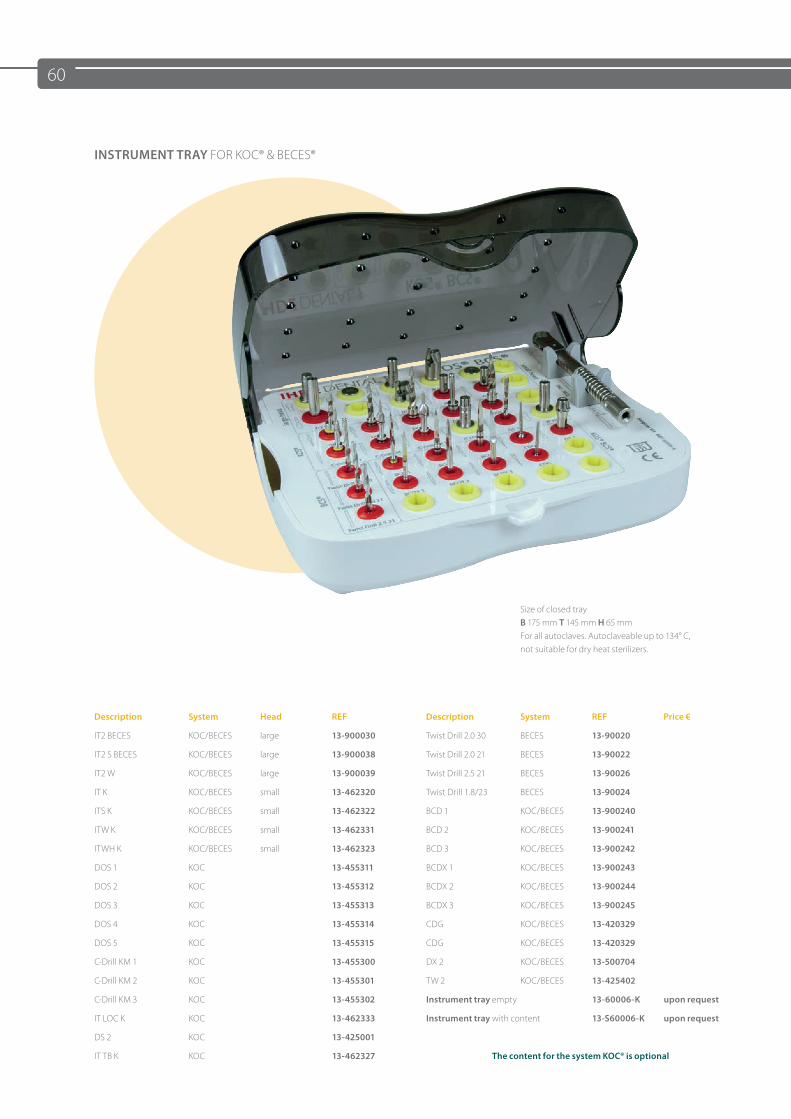
60
INSTRUMENT TRAY FOR KOC® & BECES®
Size of closed tray B 175 mm T 145 mm H 65 mm For all autoclaves. Autoclaveable up to 134° C, not suitable for dry heat sterilizers.
Description System Head REF Description System REF Price €
IT2 BECES KOC/BECES large 13-900030 Twist Drill 2.0 30 BECES 13-90020
IT2 S BECES KOC/BECES large 13-900038 Twist Drill 2.0 21 BECES 13-90022
IT2 W KOC/BECES large 13-900039 Twist Drill 2.5 21 BECES 13-90026
IT K KOC/BECES small 13-462320 Twist Drill 1.8/23 BECES 13-90024
ITS K KOC/BECES small 13-462322 BCD 1 KOC/BECES 13-900240
ITW K KOC/BECES small 13-462331 BCD 2 KOC/BECES 13-900241
ITWH K KOC/BECES small 13-462323 BCD 3 KOC/BECES 13-900242
DOS 1 KOC 13-455311 BCDX 1 KOC/BECES 13-900243
DOS 2 KOC 13-455312 BCDX 2 KOC/BECES 13-900244
DOS 3 KOC 13-455313 BCDX 3 KOC/BECES 13-900245
DOS 4 KOC 13-455314 CDG KOC/BECES 13-420329
DOS 5 KOC 13-455315 CDG KOC/BECES 13-420329
C-Drill KM 1 KOC 13-455300 DX 2 KOC/BECES 13-500704
C-Drill KM 2 KOC 13-455301 TW 2 KOC/BECES 13-425402
C-Drill KM 3 KOC 13-455302 Instrument tray empty 13-60006-K upon request
IT LOC K KOC 13-462333 Instrument tray with content 13-S60006-K upon request
DS 2 KOC 13-425001
IT TB K KOC 13-462327 The content for the system KOC® is optional
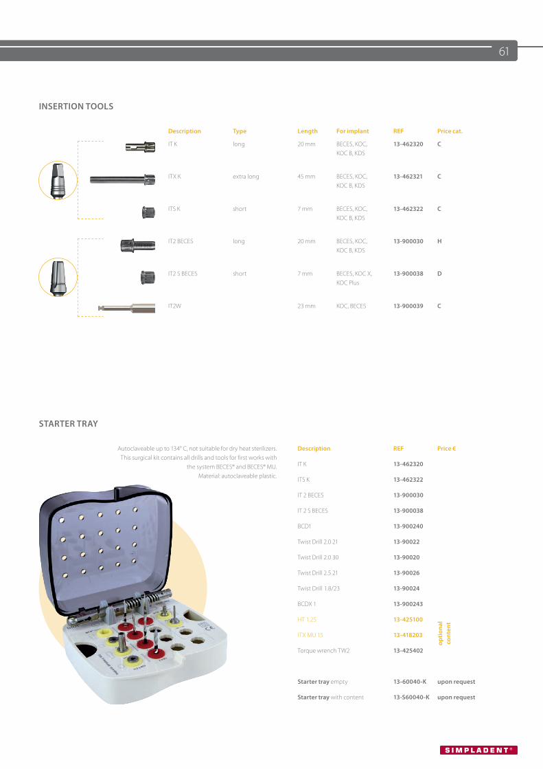
61
INSERTION TOOLS
Description Type Length For implant REF Price cat.
IT K long 20 mm BECES, KOC,KOC B, KDS
13-462320 C
ITX K extra long 45 mm BECES, KOC, KOC B, KDS
13-462321 C
ITS K short 7 mm BECES, KOC, KOC B, KDS
13-462322 C
IT2 BECES long 20 mm BECES, KOC, KOC B, KDS
13-900030 H
IT2 S BECES short 7 mm BECES, KOC X, KOC Plus
13-900038 D
IT2W 23 mm KOC, BECES 13-900039 C
STARTER TRAY
Autoclaveable up to 134° C, not suitable for dry heat sterilizers. This surgical kit contains all drills and tools for first works with
the system BECES® and BECES® MU. Material: autoclaveable plastic.
Description REF Price €
IT K 13-462320
ITS K 13-462322
IT 2 BECES 13-900030
IT 2 S BECES 13-900038
BCD1 13-900240
Twist Drill 2.0 21 13-90022
Twist Drill 2.0 30 13-90020
Twist Drill 2.5 21 13-90026
Twist Drill 1.8/23 13-90024
BCDX 1 13-900243
HT 1.25 13-425100
opti
onal
co
nten
t
ITX MU 15 13-418203
Torque wrench TW2 13-425402
Starter tray empty 13-60040-K upon request
Starter tray with content 13-S60040-K upon request
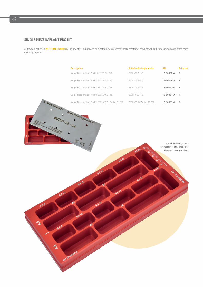
62
SINGLE PIECE IMPLANT PRO KIT
All trays are delivered WITHOUT CONTENT. The tray offers a quick overview of the different lengths and diameters at hand, as well as the available amount of the corre-sponding implants.
Description Suitable for implant size REF Price cat.
Single Piece Implant Pro Kit BECES® 2.7 - 3.0 BECES® 2.7 - 3.0 13-60062-A R
Single Piece Implant Pro Kit BECES® 3.5 - 4.5 BECES® 3.5 - 4.5 13-60066-A R
Single Piece Implant Pro Kit BECES® 3.6 - 4.6 BECES® 3.6 - 4.6 13-60067-A R
Single Piece Implant Pro Kit BECES® 4.5 - 4.6 BECES® 4.5 - 4.6 13-60064-A R
Single Piece Implant Pro Kit BECES® 5.5 / 7 / 9 / 10.5 / 12 BECES® 5.5 / 7 / 9 / 10.5 / 12 13-60065-A R
Quick and easy check of implant legths thanks to
the measurement chart
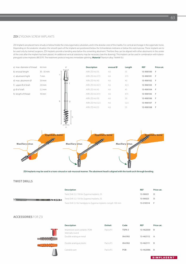
63
ZDI ZYGOMA SCREW IMPLANTS
ZDI implants are placed trans-sinualy or below/inside the crista zygomatico-alveolaris, and in the alveolar crest of the maxilla. For cortical anchorage in the zygomatic bone. Depending on the anatomic situation the smooth parts of the implants are positioned below the Schneiderian mebrane or below the oral muscosa. These implants are to be used only by trained surgeons. ZDI implants provide a bending area below the cementing abutment. Therfore they can be aligned with other abutments in the center of the crest after the implant has been placed. An additional vertical osteotomy may be necessary (see the drawing). This implant can be used in combination with tubero-pterygoid screw implants (BECES®). The treatment protocol requires immediate splinting. Material Titanium alloy Ti6AI4V ELI.
a) max. diameter of thread 4.6 mm d Description enossal Ø Length REF Price cat.
b) enossal length 35 - 55 mmc
Allfit ZDI 4.6 35 4.6 35 13-900100 F
c) abutment hight 7 mm Allfit ZDI 4.6 37.5 4.6 37.5 13-900101 F
d) max. abutment-Ø 3.9 mmf
Allfit ZDI 4.6 40 4.6 40 13-900102 F
f) upper Ø of shaft 2.0 mm Allfit ZDI 4.6 42.5 4.6 42.5 13-900103 F
g) Ø of shaft 2.2 mm Allfit ZDI 4.6 45 4.6 45 13-900104 F
h) length of thread 10 mm Allfit ZDI 4.6 47.5 4.6 47.5 13-900105 F
b gAllfit ZDI 4.6 50 4.6 50 13-900106 F
Allfit ZDI 4.6 52.5 4.6 52.5 13-900107 F
Allfit ZDI 4.6 55 4.6 55 13-900108 F
a
h
ZDI Implants may be used in a trans-sinusal or sub-mucosal manner. The abutment head is aligned with the tooth arch through bending.
Zygomatic bone Zygomatic bone Zygomatic bone
Maxillary sinus Maxillary sinus Maxillary sinus
TWIST DRILLS
Description REF Price cat.
Twist Drill 2.2 / 50 for Zygoma implants, SS 13-90021 D
Twist Drill 2.2 / 55 for Zygoma implants, SS 13-90023 D
Twist Drill 2.2 for handgrip to Zygoma implants. Length 100 mm 13-310514 F
ACCESSORIES FOR ZSI
Description Einheit Code REF Price cat.
Impression post castable, POM Internally round
Pack of 5 TSPA 5 13-462030 B
Double analogue metal IA4/IAU 13-462112 A
Double analogue plastic Pack of 5 IA4/IAU 13-462111 B
Castable part Pack of 5 POB 13-462086 B
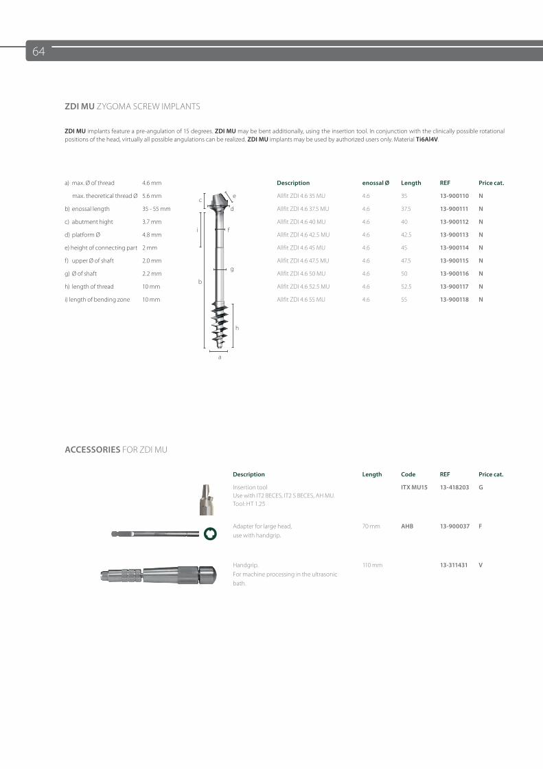
64
ZDI MU ZYGOMA SCREW IMPLANTS
ZDI MU implants feature a pre-angulation of 15 degrees. ZDI MU may be bent additionally, using the insertion tool. In conjunction with the clinically possible rotational positions of the head, virtually all possible angulations can be realized. ZDI MU implants may be used by authorized users only. Material Ti6Al4V.
a) max. Ø of thread 4.6 mm Description enossal Ø Length REF Price cat.
max. theoretical thread Ø 5.6 mmc
e Allfit ZDI 4.6 35 MU 4.6 35 13-900110 N
b) enossal length 35 - 55 mm d Allfit ZDI 4.6 37.5 MU 4.6 37.5 13-900111 N
c) abutment hight 3.7 mmi f
Allfit ZDI 4.6 40 MU 4.6 40 13-900112 N
d) platform Ø 4.8 mm Allfit ZDI 4.6 42.5 MU 4.6 42.5 13-900113 N
e) height of connecting part 2 mm Allfit ZDI 4.6 45 MU 4.6 45 13-900114 N
f) upper Ø of shaft 2.0 mmg
Allfit ZDI 4.6 47.5 MU 4.6 47.5 13-900115 N
g) Ø of shaft 2.2 mmb
Allfit ZDI 4.6 50 MU 4.6 50 13-900116 N
h) length of thread 10 mm Allfit ZDI 4.6 52.5 MU 4.6 52.5 13-900117 N
i) length of bending zone 10 mm Allfit ZDI 4.6 55 MU 4.6 55 13-900118 N
a
h
ACCESSORIES FOR ZDI MU
Description Length Code REF Price cat.
Insertion toolUse with IT2 BECES, IT2 S BECES, AH MU.Tool: HT 1.25
ITX MU15 13-418203 G
Adapter for large head, use with handgrip.
70 mm AHB 13-900037 F
Handgrip. For machine processing in the ultrasonic bath.
110 mm 13-311431 V
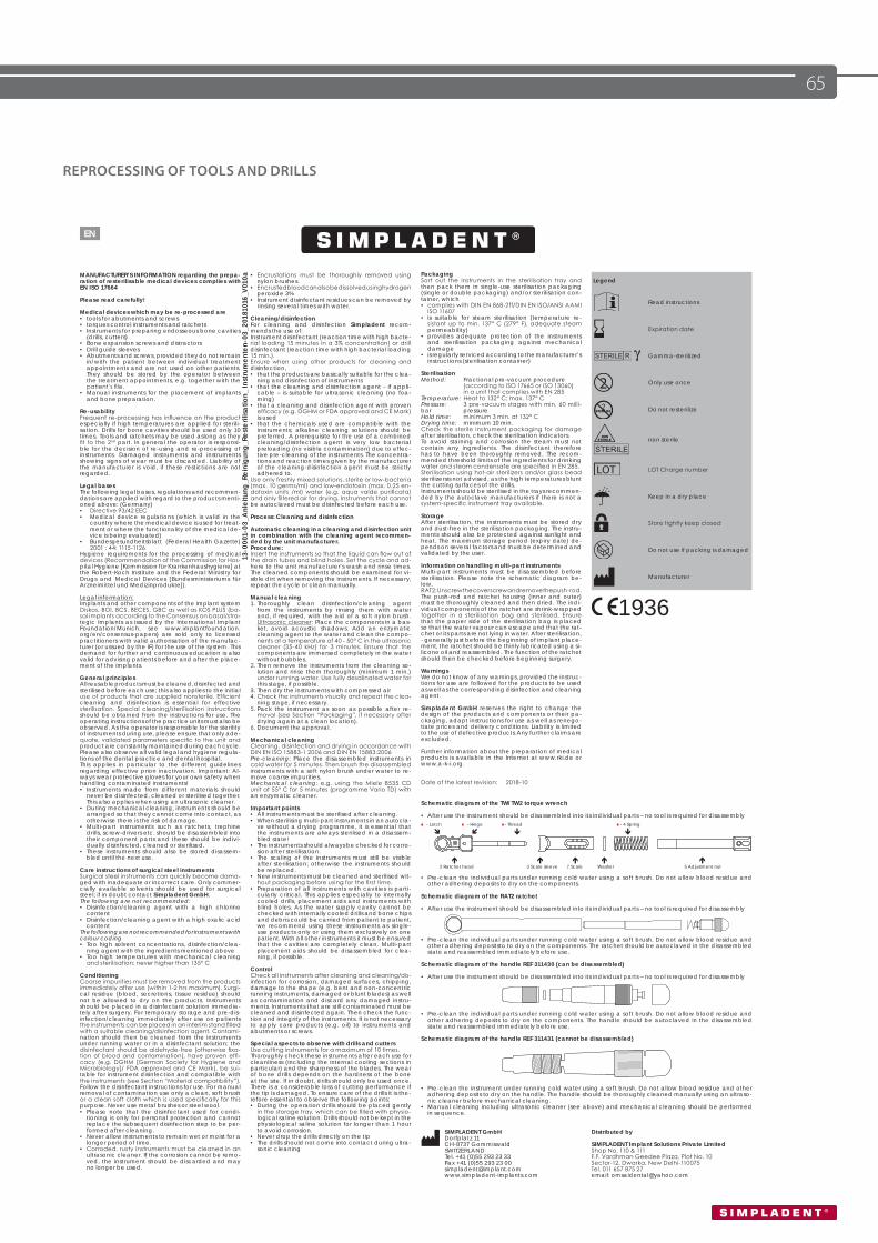
65
REPROCESSING OF TOOLS AND DRILLS
13-0
001-
03_A
nlei
tung
_Rei
nigu
ng_R
este
rilisa
tion_
Inst
rum
ente
n-03
_201
8101
6_V0
10a
1936
SIMPLADENT GmbHDorfplatz 11CH-8737 GommiswaldSWITZERLANDTel. +41 (0)55 293 23 33Fax +41 (0)55 293 23 [email protected]
2 Ratschenkopf 3 Skalenhülse 7 Skala Scheibe 5 Einstellmutter
- Schaltklinke - Gelenk - Gewinde - 4 Feder
Schematic diagram of the TW/TW2 torque wrench
• After use the instrument should be disassembled into its individual parts – no tool is required for disassembly
• Pre-clean the individual parts under running cold water using a soft brush. Do not allow blood residue and other adhering deposits to dry on the components.
Schematic diagram of the RAT2 ratchet
• After use the instrument should be disassembled into its individual parts – no tool is required for disassembly
• Pre-clean the individual parts under running cold water using a soft brush. Do not allow blood residue and other adhering depositsto to dry on the components. The ratchet should be autoclaved in the disassembled state and reassembled immediately before use.
Schematic diagram of the handle REF 311430 (can be disassembled)
• After use the instrument should be disassembled into its individual parts – no tool is required for disassembly
• Pre-clean the individual parts under running cold water using a soft brush. Do not allow blood residue and other adhering deposits to dry on the components. The handle should be autoclaved in the disassembled state and reassembled immediately before use.
Schematic diagram of the handle REF 311431 (cannot be disassembled)
• Pre-clean the instrument under running cold water using a soft brush. Do not allow blood residue and other adhering deposits to dry on the handle. The handle should be thoroughly cleaned manually using an ultraso-nic cleaner before mechanical cleaning.
• Manual cleaning including ultrasonic cleaner (see above) and mechanical cleaning should be performed in sequence.
MANUFACTURER’S INFORMATION regarding the prepa-ration of resterilisable medical devices complies with EN ISO 17664
Please read carefully!
Medical devices which may be re-processed are• tools for abutments and screws• torques control instruments and ratchets• Instruments for preparing endosseous bone cavities
(drills, cutters)• Bone expansion screws and distractors• Drill guide sleeves• Abutments and screws, provided they do not remain
in/with the patient between individual treatment appointments and are not used on other patients. They should be stored by the operator between the treatment appointments, e.g. together with the patient’s file.
• Manual instruments for the placement of implants and bone preparation.
Re-usabilityFrequent re-processing has influence on the product especially if high temperatures are applied for sterili-sation. Drills for bone cavities should be used only 10 times. Tools and ratchets may be used aslong as they fit to the 2nd part. In general the operator is responsi-ble for the decision of re-using and re-processing of instruments. Damaged instruments and instruments showing signs of wear must be discarded. Liability of the manufacturer is void, if these restictions are not regarded.
Legal basesThe following legal bases, regulations and recommen-dations are applied with regard to the products menti-oned above: (Germany)• Directive 93/42 EEC • Medical device regulations (which is valid in the
country where the medical device is used for treat-ment or where the functionality of the medical de-vice is being evaluated)
• Bundesgesundheitsblatt (Federal Health Gazette) 2001 : 44: 1115-1126
Hygiene requirements for the processing of medical devices (Recommendation of the Commission for Hos-pital Hygiene [Kommission für Krankenhaushygiene] at the Robert-Koch Institute and the Federal Ministry for Drugs and Medical Devices [Bundesministeriums für Arzneimittel und Medizinprodukte]).
Legal information:Implants and other components of the implant system Diskos, BOI, BCS, BECES, GBC as well as KOS PLUS (ba-sal implants according to the Consensus on basal/stra-tegic Implants as issued by the International Implant Foundation/Munich, see www.implantfoundation.org/en/consensus-papers) are sold only to licensed practitioners with valid authorisation of the manufac-turer (or ussued by the IF) for the use of the system. This demand for further and continuous education is also valid for advising patients before and after the place-ment of the implants.
General principlesAll reusable products must be cleaned, disinfected and sterilised before each use; this also applies to the initial use of products that are supplied nonsterile. Efficient cleaning and disinfection is essential for effective sterilisation. Special cleaning/sterilisation instructions should be obtained from the instructions for use. The operating instructions of the practice units must also be observed. As the operator is responsible for the sterility of instruments during use, please ensure that only ade-quate, validated parameters specific to the unit and product are constantly maintained during each cycle. Please also observe all valid legal and hygiene regula-tions of the dental practice and dental hospital.This applies in particular to the different guidelines regarding effective prion inactivation. Important: Al-ways wear protective gloves for your own safety when handling contaminated instruments!• Instruments made from different materials should
never be disinfected, cleaned or sterilised together. This also applies when using an ultrasonic cleaner.
• During mechanical cleaning, instruments should be arranged so that they cannot come into contact, as otherwise there is the risk of damage.
• Multi-part instruments such as ratchets, trephine drills, screw-drivers etc. should be disassembled into their component parts and these should be indivi-dually disinfected, cleaned or sterilised.
• These instruments should also be stored disassem-bled until the next use.
Care instructions of surgical steel instrumentsSurgical steel instruments can quickly become dama-ged with inadequate or incorrect care. Only commer-cially available solvents should be used for surgical steel; if in doubt contact Simpladent GmbH.The following are not recommended:• Disinfection/cleaning agent with a high chlorine
content• Disinfection/cleaning agent with a high oxalic acid
contentThe following are not recommended for instruments with colour coding• Too high solvent concentrations, disinfection/clea-
ning agent with the ingredients mentioned above• Too high temperatures with mechanical cleaning
and sterilisation; never higher than 135° C
ConditioningCoarse impurities must be removed from the products immediately after use (within 1-2 hrs maximum). Surgi-cal residue (blood, secretions, tissue residue) should not be allowed to dry on the products. Instruments should be placed in a disinfectant solution immedia-tely after surgery. For temporary storage and pre-dis-infection/cleaning immediately after use on patients the instruments can be placed in an interim stand filled with a suitable cleaning/disinfection agent. Contami-nation should then be cleaned from the instruments under running water or in a disinfectant solution; the disinfectant should be aldehyde-free (otherwise fixa-tion of blood and contamination), have proven effi-cacy (e.g. DGHM [German Society for Hygiene and Microbiology]/ FDA approved and CE Mark), be sui-table for instrument disinfection and compatible with the instruments (see Section “Material compatibility”). Follow the disinfectant instructions for use. For manual removal of contamination use only a clean, soft brush or a clean soft cloth which is used specifically for this purpose. Never use metal brushes or steel wool.• Please note that the disinfectant used for condi-
tioning is only for personal protection and cannot replace the subsequent disinfection step to be per-formed after cleaning.
• Never allow instruments to remain wet or moist for a longer period of time.
• Corroded, rusty instruments must be cleaned in an ultrasonic cleaner. If the corrosion cannot be remo-ved, the instrument should be discarded and may no longer be used.
Legend
Read instructions
Expiration date
Gamma-sterilized
Only use once
Do not resterilize
non sterile
LOT Charge number
Keep in a dry place
Store tightly keep closed
Do not use if packing is damaged
Manufacturer
• Encrustations must be thoroughly removed using nylon brushes.
• Encrusted blood can also be dissolved using hydrogen peroxide 3%
• Instrument disinfectant residues can be removed by rinsing several times with water.
Cleaning/disinfectionFor cleaning and disinfection Simpladent recom-mends the use of:Instrument disinfectant (reaction time with high bacte-rial loading 15 minutes in a 3% concentration) or drill disinfectant (reaction time with high bacterial loading 15 min.).Ensure when using other products for cleaning and disinfection,• that the products are basically suitable for the clea-
ning and disinfection of instruments• that the cleaning and disinfection agent – if appli-
cable – is suitable for ultrasonic cleaning (no foa-ming)
• that a cleaning and disinfection agent with proven efficacy (e.g. DGHM or FDA approved and CE Mark) is used
• that the chemicals used are compatible with the instruments; alkaline cleaning solutions should be preferred. A prerequisite for the use of a combined cleaning/disinfection agent is very low bacterial preloading (no visible contamination) due to effec-tive pre-cleaning of the instruments. The concentra-tions and reaction times given by the manufacturer of the cleaning-disinfection agent must be strictly adhered to.
Use only freshly mixed solutions, sterile or low-bacteria (max. 10 germs/ml) and low-endotoxin (max. 0.25 en-dotoxin units /ml) water (e.g. aqua valde purificata) and only filtered air for drying. Instruments that cannot be autoclaved must be disinfected before each use.
Process: Cleaning and disinfection
Automatic cleaning in a cleaning and disinfection unit in combination with the cleaning agent recommen-ded by the unit manufacturer.Procedure:Insert the instruments so that the liquid can flow out of the drain tubes and blind holes. Set the cycle and ad-here to the unit manufacturer’s wash and rinse times. The cleaned components should be examined for vi-sible dirt when removing the instruments. If necessary, repeat the cycle or clean manually.
Manual cleaning1. Thoroughly clean disinfection/cleaning agent
from the instruments by rinsing them with water and, if required, with the aid of a soft nylon brush. Ultrasonic cleaner: Place the components in a bas-ket, avoid acoustic shadows. Add an enzymatic cleaning agent to the water and clean the compo-nents at a temperature of 40 - 50° C in the ultrasonic cleaner (35-40 kHz) for 3 minutes. Ensure that the components are immersed completely in the water without bubbles.
2. Then remove the instruments from the cleaning so-lution and rinse them thoroughly (minimum 1 min.) under running water. Use fully desalinated water for this stage, if possible.
3. Then dry the instruments with compressed air4. Check the instruments visually and repeat the clea-
ning stage, if necessary.5. Pack the instrument as soon as possible after re-
moval (see Section “Packaging”, if necessary after drying again at a clean location).
6. Document the approval.
Mechanical cleaningCleaning, disinfection and drying in accordance with DIN EN ISO 15883-1 2006 and DIN EN 15883:2006Pre-cleaning: Place the disassembled instruments in cold water for 5 minutes. Then brush the disassembled instruments with a soft nylon brush under water to re-move coarse impurities.Mechanical cleaning: e.g. using the Miele 8535 CD unit at 55° C for 5 minutes (programme Vario TD) with an enzymatic cleaner.
Important points • All instruments must be sterilised after cleaning.• When sterilising multi-part instruments in an autocla-
ve without a drying programme, it is essential that the instruments are always sterilised in a disassem-bled state!
• The instruments should always be checked for corro-sion after sterilisation.
• The scaling of the instruments must still be visible after sterilisation; otherwise the instruments should be replaced.
• New instruments must be cleaned and sterilised wit-hout packaging before using for the first time.
• Preparation of all instruments with cavities is parti-cularly critical. This applies especially to internally cooled drills, placement aids and instruments with blind holes. As the water supply cavity cannot be checked with internally cooled drills and bone chips and debris could be carried from patient to patient, we recommend using these instruments as single-use products only or using them exclusively on one patient. With all other instruments it must be ensured that the cavities are completely clean. Multi-part placement aids should be disassembled for clea-ning, if possible.
ControlCheck all instruments after cleaning and cleaning/dis-infection for corrosion, damaged surfaces, chipping, damage to the shape (e.g. bent and non-concentric running instruments, damaged or blunt blades) as well as contamination and discard any damaged instru-ments. Instruments that are still contaminated must be cleaned and disinfected again. Then check the func-tion and integrity of the instruments. It is not necessary to apply care products (e.g. oil) to instruments and abutments or screws.
Special aspects to observe with drills and cuttersUse cutting instruments for a maximum of 10 times. Thoroughly check these instruments after each use for cleanliness (including the internal cooling sections in particular) and the sharpness of the blades. The wear of bone drills depends on the hardness of the bone at the site. If in doubt, drills should only be used once. There is a considerable loss of cutting performance if the tip is damaged. To ensure care of the drills it is the-refore essential to observe the following points:• During the operation drills should be placed gently
in the storage tray, which can be filled with physio-logical saline solution. Drills should not be kept in the physiological saline solution for longer than 1 hour to avoid corrosion.
• Never drop the drills directly on the tip• The drills should not come into contact during ultra-
sonic cleaning
PackagingSort out the instruments in the sterilisation tray and then pack them in single-use sterilisation packaging (single or double packaging) and/or sterilisation con-tainer, which• complies with DIN EN 868-2ff/DIN EN ISO/ANSI AAMI
ISO 11607• is suitable for steam sterilisation (temperature re-
sistant up to min. 137° C (279° F), adequate steam permeability)
• provides adequate protection of the instruments and sterilisation packaging against mechanical damage
• is regularly serviced according to the manufacturer’s instructions (sterilisation container)
SterilisationMethod: Fractional pre-vacuum procedure (according to ISO 17665 or ISO 13060) in a unit that complies with EN 285Temperature: Heat to 132° C; max. 137° CPressure: 3 pre-vacuum stages with min. 60 milli-bar pressureHold time: minimum 3 min. at 132° CDrying time: minimum 10 min.Check the sterile instrument packaging for damage after sterilisation, check the sterilisation indicators.To avoid staining and corrosion the steam must not contain any ingredients. The disinfectant therefore has to have been thoroughly removed. The recom-mended threshold limits of the ingredients for drinking water and steam condensate are specified in EN 285.Sterilisation using hot-air sterilizers and/or glass bead sterilizersis not advised, as the high temperatures blunt the cutting surfaces of the drills.Instruments should be sterilised in the trays recommen-ded by the autoclave manufacturers if there is not a system-specific instrument tray available.
StorageAfter sterilisation, the instruments must be stored dry and dust-free in the sterilisation packaging. The instru-ments should also be protected against sunlight and heat. The maximum storage period (expiry date) de-pends on several factors and must be determined and validated by the user.
Information on handling multi-part instrumentsMulti-part instruments must be disassembled before sterilisation. Please note the schematic diagram be-low.RAT2: Unscrew the cover screw and remove the push-rod. The push-rod and ratchet housing (inner and outer) must be thoroughly cleaned and then dried. The indi-vidual components of the ratchet are shrink-wrapped together in a sterilisation bag and sterilised. Ensure that the paper side of the sterilisation bag is placed so that the water vapour can escape and that the rat-chet or its parts are not lying in water. After sterilisation, - generally just before the beginning of implant place-ment, the ratchet should be thinly lubricated using a si-licone oil and reassembled. The function of the ratchet should then be checked before beginning surgery.
WarningsWe do not know of any warnings, provided the instruc-tions for use are followed for the products to be used as well as the corresponding disinfection and cleaning agent.
Simpladent GmbH reserves the right to change the design of the products and components or their pa-ckaging, adapt instructions for use as well as renego-tiate prices and delivery conditions. Liability is limited to the use of defective products.Any further claims are excluded.
Further information about the preparation of medical products is available in the Internet at www.rki.de or www.a-k-i.org.
Date of the latest revision: 2018-10
Distributed by
SIMPLADENT Implant Solutions Private LimitedShop No. 110 & 111F.F. Vardhman Geedee Plaza, Plot No. 10Sector-12, Dwarka, New Delhi-110075Tel. 011 657 875 27email: [email protected]
2 Ratchet head 3 Scale sleeve 7 Scale Washer 5 Adjustment nut
- Latch - Hinge - Thread - 4 Spring
EN

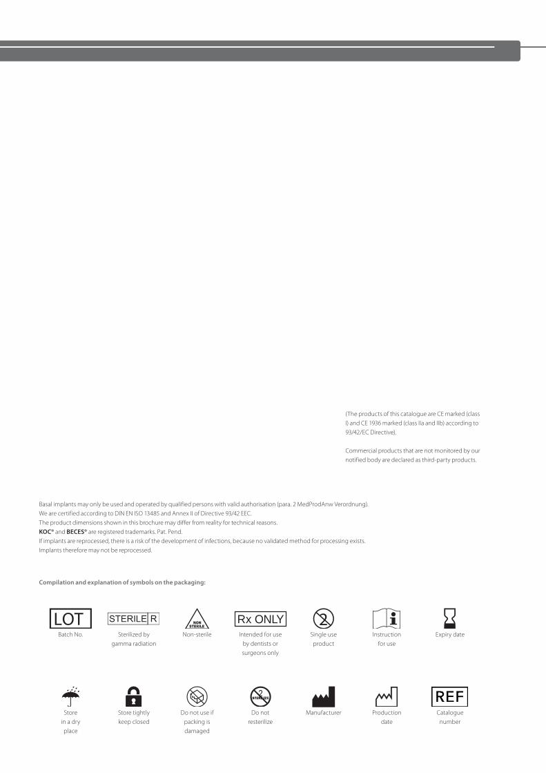
Basal implants may only be used and operated by qualified persons with valid authorisation (para. 2 MedProdAnw Verordnung). We are certified according to DIN EN ISO 13485 and Annex II of Directive 93/42 EEC. The product dimensions shown in this brochure may differ from reality for technical reasons. KOC® and BECES® are registered trademarks. Pat. Pend. If implants are reprocessed, there is a risk of the development of infections, because no validated method for processing exists. Implants therefore may not be reprocessed.
Compilation and explanation of symbols on the packaging:
Batch No. Sterilized bygamma radiation
Non-sterile Intended for useby dentists orsurgeons only
Single useproduct
Instructionfor use
Expiry date
Storein a dryplace
Store tightlykeep closed
Do not use ifpacking isdamaged
Do notresterilize
Manufacturer Productiondate
Catalogue number
Rx ONLY
(The products of this catalogue are CE marked (class I) and CE 1936 marked (class IIa and IIb) according to 93/42/EC Directive).
Commercial products that are not monitored by our notified body are declared as third-party products.
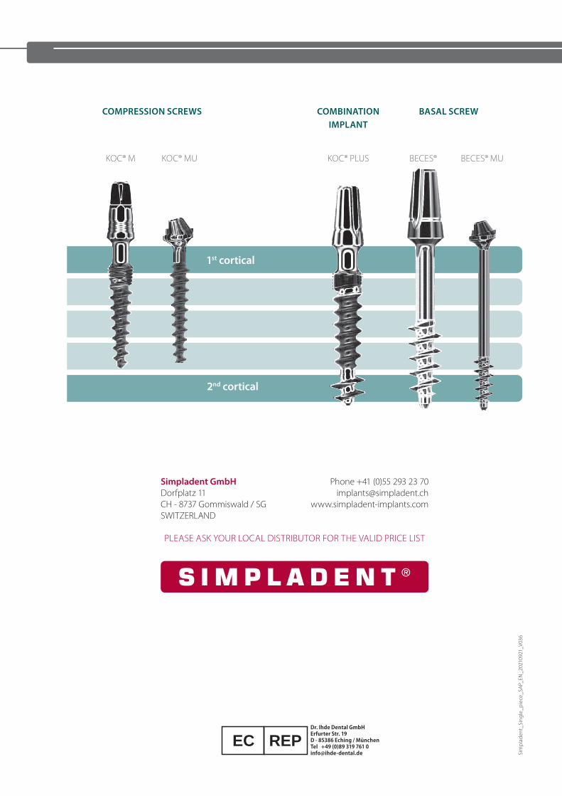
1st cortical
KOC® M BECES® KOC® MU BECES® MUKOC® PLUS
2nd cortical
COMPRESSION SCREWS COMBINATION IMPLANT
BASAL SCREW
Sim
plad
ent_
Sing
le_p
iece
_SA
P_EN
_202
1092
1_V0
36
Simpladent GmbH Phone +41 (0)55 293 23 70 Dorfplatz 11 [email protected] - 8737 Gommiswald / SG www.simpladent-implants.comSWITZERLAND
PLEASE ASK YOUR LOCAL DISTRIBUTOR FOR THE VALID PRICE LIST
Dr. Ihde Dental GmbHErfurter Str. 19D - 85386 Eching / MünchenTel +49 (0)89 319 761 [email protected]
EC REP